Page 1
Gas Hydrate Formation
And Dissociation Numerical Modelling with Nitrogen and Carbon
Dioxide
*Callum Smithcurtin university
Curtin University, 5 De Laeter Way, Bentley 6102, Perth WA. Australia
[email protected]
Ahmed Barifcanicurtin university
Curtin University, 5 De Laeter Way, Bentley 6102, Perth WA. Australia
[email protected]
David Packgas measurement & auditing pty ltd
Gas Measurement & Auditing Pty Ltd, P.O Box 458.Kalamunda 6926, Perth WA.
Australia
[email protected]
*Corresponding Author
Page 2
Abstract
This work aims at providing experimental data for various methane-based hydrates, namely
nitrogen and carbon dioxide gas mixtures with varying concentrations to provide an
empirically based hydrate equilibrium model. Acquired using a sapphire pressure – volume –
temperature (PVT) cell, this data is used as the foundation for the derivation of a model able
to calculate the equilibrium temperature of a nitrogen and/or carbon dioxide diluted methane
gas is accomplished. There are several theoretical predictive models used in software which
can provide hydrate formation and equilibrium data, however theoretical models appear to
outnumber experimental data and empirical models for which a comparison can be made.
The effect of nitrogen and carbon dioxide, an inhibitor and promotor respectively, on
methane hydrate formation and dissociation and their associated pressure and temperature
conditions are explored. The hydrate profiles for various gas mixtures containing the gases
mentioned are presented at pressures ranging between 40-180 bara. These hydrate profiles
and the model presented were compared to those predicted by hydrate computational
software and experimental data from other studies for verification. The derived model proved
to be reliable when applied to various gas mixtures at different pressure conditions and was
consistent when compared to computational software based on theoretical models.
Consistency of methane hydrate formation data was compared to dissociation data proved
that the formation temperature is not an accurate representation of the equilibrium
temperature. A simple statistical measure revealed the dissociation temperature
measurements to be more precise and agreed to a much larger degree with literature.
Keywords: Gas hydrate, numerical model, methane, nitrogen, carbon dioxide
1.0 Introduction and Background
Natural gas hydrates are crystalline solids composed of water and gas which occur in nature
at high pressure and low temperature conditions (E. D. Sloan 2008). The water (host) forms
hydrogen bonded cavities which surround and enclathrate the gas (guest) molecule to form
a crystalline solid resembling ice. Depending primarily on the size of the gas molecule, three
different common gas hydrate structure types exist; structure I (sI), structure II (sII) and more
recently structure H (sH). Smaller molecules such as methane, ethane and carbon dioxide
typically form sI hydrates which are the most abundantly occurring hydrate structure in
nature, with a preference to methane gas hydrates (Schicks 2010). Natural gas hydrates
continue to be a significant issue in oil and gas recovery and processing because of their
ability to form in convenient operating conditions. High pressure and low temperature are
Page 3
ideal conditions for gas hydrate formation, however several other factors contribute to
hydrate formation and the nature of their formation. In terms of stability, gas molecules are
required to be small enough to fit inside the water cavities but also be large enough to
provide stability to the hydrate structure (Buffet 2000). A guest molecule approximately 75%
the size of the cavity is required to provide adequate structural stability of the resultant
hydrate whereas if the molecule is over 100% the size of the cavity, the structure cannot
stabilize and the hydrate will not form. A similar situation arises if the gas molecule size is
significantly less than 75% of the cavity. In this case, the gas molecule is not large enough to
supply adequate stability therefore preventing formation from occurring (Christiansen and
Sloan 1994). This has given rise to a significant amount of research in this field to combat
the threats to productivity caused by gas hydrates.
Literature and experimental data informs us of nitrogen and carbon dioxide hydrate profiles
but less of it is concerned with the effect these gases have on the hydrate profile of methane
gas or natural gas for that matter, with methane being the primary component of natural gas.
Detailed in this article are hydrate profiles explaining and illustrating the effect these gases
have on methane gas from a hydrate perspective via experimental data collected using a
sapphire microcell. This study uses this information to construct an empirical model
describing these equilibrium conditions. Additionally, this data is compared to computational
software, namely Aspen HYSYS and Calsep PVTsim, to aid in the comparison between
experimental and theoretical hydrate data and to confirm the reliability of the derived
numerical model. The hydrate conditions predicted by these programs and their modes of
calculation are investigated by inspecting the method, sources of necessary parameters
such as critical properties and Langmuir constants associated with the equations of state
(EOS) and hydrate equilibrium computations performed respectively. Each is compared to
make a judgement on the cause of variation between predictions based on two equations of
state, Peng-Robinson (PR) and Soave-Redlich-Kwong (SRK). In addition, experimental data
from other works such as Jhaveri and Robinson (1965) and Adisasmito et al. (1991) are
portrayed to illustrate the likeness to the model presented as well as any disagreement.
1.1 Empirical Model Derivation
Using experimental data, a relationship between the hydrate dissociation conditions of a
methane-nitrogen-carbon dioxide gas has been developed. This has been achieved by
deriving a constant based on how much the inclusion of nitrogen and carbon dioxide
influence the dissociation temperature in a methane-based gas. The dissociation
temperature of a gas mixture containing methane, nitrogen and/or carbon dioxide is
Page 4
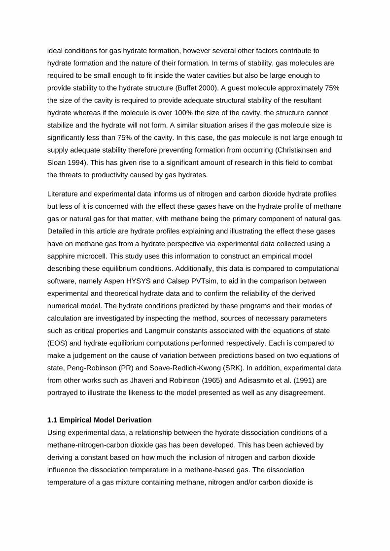
empirically derived using the exponential equations that best describe the experimental
nitrogen and carbon dioxide data.
Fig.1 – Methane Hydrate Profile Shift
The deviation from the methane reference due to nitrogen and carbon dioxide (Fig.1), is
summed by integrating between the appropriate pressure interval, P1-P0. These are denoted
∫ (T1-T
0
P1
P0)dT for nitrogen and ∫ (T
3-T
0
P1
P0)dT for carbon dioxide. These quantities are
compared to pure methane, ∫ (T2-T
0
P1
P0)dT, in the form of a ratio,
∫ T1-T0
P1P0
∫ T2-T0
P1P0
for nitrogen and
∫ T3-T0
P1P0
∫ T2-T0
P1P0
for carbon dioxide. The dissociation temperature, Td, is empirically expressed as,
Td(P,xN2, xCO2) = T2(P) + ln(P/aN2)xN2
xN2,refbN2
(∫ (T1-T
0)dT
P1
P0
∫ (T2-T0)dT
P1
P0
-∫ (T2-T
0)dT
P1
P0
∫ (T2-T0)dT
P1
P0
) …
…+ ln(P/aCO2)xCO2
xCO2,refbCO2
(∫ (T3-T
0)dT
P1
P0
∫ (T2-T0)dT
P1
P0
-∫ (T2-T
0)dT
P1
P0
∫ (T2-T0)dT
P1
P0
) …….. Eq. 1
Symbols have their usual meaning; P and T are pressure and temperature respectively, xN2
is the nitrogen mole fraction, xCO2 is the carbon-dioxide mole fraction, a and b are constants
from the exponential relation and xCO2,ref and xN2,ref are the mole fractions of the experimental
gases used to generate data. Generating experimental hydrate profiles allows the areas
Pre
ssu
re,
bara
Temperature, °C
Nitrogen
CO2
Methane T2 T1 T3 T0
P0
P1
Page 5
between the equilibrium lines to be evaluated. The model is not dependent on the volume of
water present on the basis that the water volume is small and is insignificant compared to
the moles of gas in each hydrate experiment. This is shown later on to be true (section 4.32);
the resultant model is presented in section 4.5.
2.0 Methodology
2.1 Introduction
The primary apparatus used for the research work was a sapphire cell and an associated
flow loop housed at the Clean Gas Technologies Australia (CGTA) laboratory. CGTA
specialises in hydrate technology and carbon dioxide capture. The simplistic flow loop was
designed to be as accessible as possible predominantly because of the use of manual ball
valves. All tubing used in the flow loop is 1/4 inch with all fittings.
Fig. 2 – Sapphire Cell Schematic
The PVT cell (Fig. 2) is capable of enduring pressures in the vicinity of 500 bara and
temperatures down to -160 °C when liquid nitrogen is used as the coolant, however cooling
water is sufficient. For the purpose of this work, the PVT cell was operated in the ranges of
40-180 bara and 0-30 °C. The volume of the cell is 80 cm3 non-inclusive of internal tubing;
P1 T1
P2
P3
T2
T3
Pump
Inlet
Sample
Point
Vent
Sample
Point
Cell
Drainage
Magnetic
Actuator
PVT
Cell
Air Bath
Piston
Pump
Page 6
this cannot be ignored because the volume of gas in the tubing is 25.8 cm3 based on its 74
cm length and 1/4 in diameter. This equates to a total volume of 105.8 cm3. The cell is
protected by thick glass allowing it to experience high pressures and is separated from the
outside environment by a reinforced and insulated door. Six clamps attached to the door
allow for a tight seal, minimizing heat transfer through the housing of the PVT cell.
2.2 Application of Apparatus
A piston pump is implemented for the pressurization of gas and is maintained via software
that controls the position of the piston. Pressure is monitored by pressure sensors and
controlled via a Baldor motion PID controller which is linked with Mint Workbench software
for inputting pressure set points and monitoring. This software also controls the temperature
of the cell. To provide constant temperature monitoring of the gas and liquid phase, a
thermocouple is secured at the top and bottom of the cell. The temperature of the water is
the control temperature which however affects the gas temperature. Temperature
increments are therefore small in order to ensure there is a minute temperature differential
between each phase. A computer interface used in conjunction with FALCON software
allows the set temperature to be input manually and is maintained with the proportional-
integral-derivative (PID) controller associated with the software. The cooling is supplied by a
chiller and for heating, the PVT cell uses an electrical heater. Cooling and heating is
amplified by the use of a fan which circulates the heated or cooled air throughout the air bath
chamber.
The process is fitted with sample points, allowing the gas to be analysed to confirm its
composition. For venting and purging, an additional line is connected to the cell in which gas
is safely vented through an outlet to the roof of the building and released to the atmosphere.
Finally, the magnetic stirrer provides adequate mixing and promotes hydrate formation; it is
controlled manually with a dial for changing the rotational velocity. The stirrer measures 2
inches across and is maintained at approximately 120 revolutions per minute (RPM) through
each experimental procedure. This stirrer is essential because it disturbs the surface of the
water. Without this disturbance, hydrates form only at the surface similar to a sheet of ice
which blocks further dissolving of gas molecules, therefore halting further hydrate formation.
This effect is observed when excess water was placed into the cell which adequately
covered the top of the mixer and resulted in the mixer being unable to sufficiently mix the top
region of water.
Page 7
2.3 Apparatus Operating Requirements
The temperature search method is employed as the technique used to determine the
hydrate formation and dissociation temperature of the nitrogen and carbon dioxide diluted
methane gas mixtures. This involved stimulation in the form of cooling and heating of the
PVT cell contents to promote hydrate formation and dissociation respectively. Temperature
control of the cell contents is an important aspect of the procedure because the point of
hydrate formation and dissociation is dependent on temperature. Changing the temperature
of the cell too quickly can result in skipping the observable moment of formation or
dissociation, giving biased results. For this reason, heating and cooling is used cautiously to
counteract the possibility of this occurrence.
2.4 Gas Preparation
Gas mixture preparation involved pressurizing individual gas canisters with methane gas and
the diluting gas, usually one or two of each depending on the pressure requirements of the
experiment. Initially, the canisters are vacuumed and weighed with an electronic balance
(linearity ± 0.02g) and then pressurized. They are then weighed again and the difference
calculated. This is converted into moles and the mol% is calculated. Gas is released from
the cylinder containing the excess gas or another canister is pressurized with the limiting gas
and the process is repeated until the molar ratios are correct. The methane, nitrogen and
carbon dioxide gas are all supplied by BOC Australia and are of high purity grade (99.99%)
and distilled water is used for the water in the cell. To analyse the gas composition of
prepared gas mixtures, an MSR Electronics methane composition analyser is used. Because
only bi-component mixtures are used, all of which include methane, the remaining gas
composition is easily determined.
2.5 Experimental Procedures
Prior to operation, the PVT cell, piston pump and flow loop are purged with nitrogen to
relieve the plant’s internals of any foreign species that may affect results. The remaining gas
is vacuumed and the gas canisters are connected to the manifold and their contents
released into the piston pump. Distilled water (5 mL) is syringed into the PVT cell through an
opening on the steel palette connecting the tubing to the cell chamber. The gas is
pressurized into the cell and allowed to thermally equilibrate before reducing the
temperature. A temperature close to, but within a safe distance of the formation temperature
is approached, which is estimated based on previous results and computational software.
The cooling rate is slowed significantly to approximately 2 °C per hour until hydrate
formation is clearly observed. Temperature is maintained until hydrate formation and
crystallization is complete. The hydrate solid is then heated to a temperature within range of
Page 8
the dissociation temperature and the heating rate reduced to 2 °C per hour when the
dissociation point is approached. Hydrates are allowed to fully dissociate while maintaining a
2 °C per hour heating rate. Finally, the apparatus is emptied of its contents and cleaned for
future experimental processes.
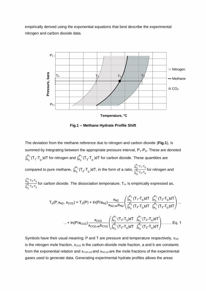
3.0 Macroscopic Observations
Fig.3 – (a) Initial Formation (b) Late Formation (c) Hydrate Growth (d) Crystallization
(e) Initial Dissociation (f) Late Dissociation
After an adequate degree of sub-cooling, usually 2-4 °C below the dissociation temperature,
unstable agglomerates formed upon the initial dissolving of gas molecules formed more
stable structures. These reached a critical size and formed observable nuclei, giving the
mixture an appearance akin to that of Fig.3 (a). This initial formation of hydrate solids
occurred at the interface of the liquid and gas phases. These observations are supported in
the works of Mori (1998) who performed a study and review of the characterization of
hydrate films where he also makes notes regarding hydrate formation initializing at the
interface. When allowed to progress, the mixture further developed into a more hydrate-
concentrated state, closely resembling crushed ice mixed with water (b). The mixture was
still very capable of flowing at this stage with very little observed resistance which was
(a) (b) (c)
(d) (e) (f)
Page 9
inferred from the ease of the actuator maintaining a constant rotational velocity. Hydrates
initially formed quite rapidly in which the rate of formation appeared to decrease over time.
This is explained by the reduced concentration difference between the solution and
hydrates; consequently the rate of formation reduces when the temperature is not changed.
As the contents transitioned to a crystallized state (d), the hydrate solids developed from
small solids to significantly larger solids (c) from further nucleation and growth. The
formation of these particular hydrate solids appeared to have little effect on the flow of the
mixture; however as larger sized hydrates developed, a noticeable decline in flow of the
mixture occurred. Consequently, the magnetic actuator struggled to maintain its normal
rotational velocity and often slipped. This phenomenon occurred more frequently and to a
greater extent as these solids further increased in size. The large hydrates eventually
increased to a very large size until the liquid phase was nearly consumed and crystallized to
form a continuous solid hydrate phase (d). Because of the reduced liquid medium, the
contents are completely immovable by the magnetic actuator. Under thermal stimulation of
the crystallized solid, dissociation subtly occurred and was sometimes difficult to notice
because of the slow rate of heating. It was detected by small cavities that appeared in the
hydrate phase (e) and was accompanied by a wet film. Under continued stimulation, the
structure decomposed from a single hydrate structure into fragments. This was accompanied
by simultaneous liquid formation which pooled at the bottom of the cell and enabled the
actuator to mobilize, although this mobilization was severely hampered by the large
fragments. Throughout the dissociation phase of the experiment, liquid formation was very
evident on the outside of the cylindrical hydrate structure caused by the radial dissociation.
The hydrate mixture flowed more easily as more liquid was produced and resulted in
reduced hydrate radii and concentration of the dissociating hydrate fragments. Hydrate
dissociation continued to reform the liquid and liberate gas from its hydrate state until the
hydrate solids were greatly diminished in size (f). Dirt is also commonly deposited on the
inside of the cell during dissociation and adheres to the glass and this outlines the
importance of purging and vacuuming which when not performed produces significantly
more dirt than illustrated (f). The mixture, now in a comparable state to (b), was able to flow
freely without any perceived significant resistance offered by the small hydrates still present.
The remaining hydrates were easily dissociated at which point no hydrate phase was
observed and the liquid and gas phases appeared to be completely restored.
4.0 Results and Discussion
It is well understood in the oil and gas industry that gas hydrates have a tendency to occur at
high pressure and low temperature conditions. This is well documented through the works of
Page 10
Sloan, Ripmeester and many others and is confirmed by the hydrate profiles constructed in
this study. As a reference, the hydrate profile for pure methane was established with
experimental data so that the hydrate data for nitrogen and carbon dioxide diluted methane
mixtures can be compared.
4.1 Equilibrium Results
Fig.4 – Dissociation Temperature Profile for Nitrogen in Methane
20
40
60
80
100
120
140
160
180
200
4 6 8 10 12 14 16 18
Pre
ssu
re,
bara
Temperature, °C
0% 1% 3% 25%
Page 11
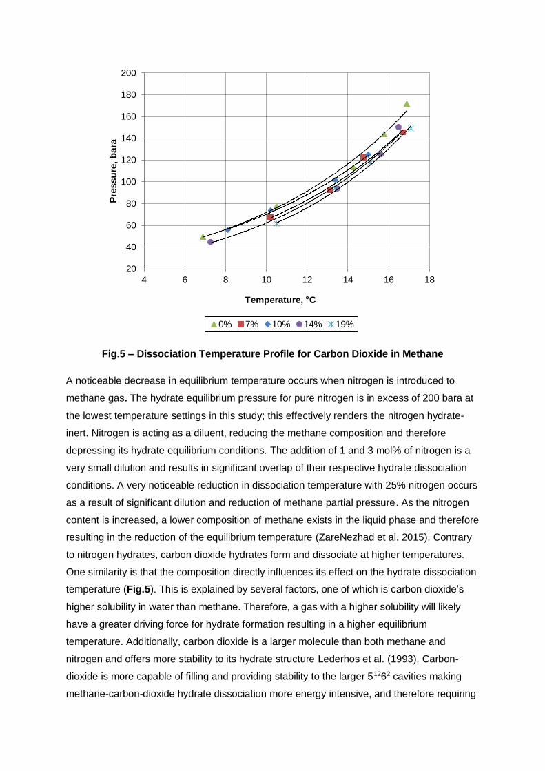
Fig.5 – Dissociation Temperature Profile for Carbon Dioxide in Methane
A noticeable decrease in equilibrium temperature occurs when nitrogen is introduced to
methane gas. The hydrate equilibrium pressure for pure nitrogen is in excess of 200 bara at
the lowest temperature settings in this study; this effectively renders the nitrogen hydrate-
inert. Nitrogen is acting as a diluent, reducing the methane composition and therefore
depressing its hydrate equilibrium conditions. The addition of 1 and 3 mol% of nitrogen is a
very small dilution and results in significant overlap of their respective hydrate dissociation
conditions. A very noticeable reduction in dissociation temperature with 25% nitrogen occurs
as a result of significant dilution and reduction of methane partial pressure. As the nitrogen
content is increased, a lower composition of methane exists in the liquid phase and therefore
resulting in the reduction of the equilibrium temperature (ZareNezhad et al. 2015). Contrary
to nitrogen hydrates, carbon dioxide hydrates form and dissociate at higher temperatures.
One similarity is that the composition directly influences its effect on the hydrate dissociation
temperature (Fig.5). This is explained by several factors, one of which is carbon dioxide’s
higher solubility in water than methane. Therefore, a gas with a higher solubility will likely
have a greater driving force for hydrate formation resulting in a higher equilibrium
temperature. Additionally, carbon dioxide is a larger molecule than both methane and
nitrogen and offers more stability to its hydrate structure Lederhos et al. (1993). Carbon-
dioxide is more capable of filling and providing stability to the larger 51262 cavities making
methane-carbon-dioxide hydrate dissociation more energy intensive, and therefore requiring
20
40
60
80
100
120
140
160
180
200
4 6 8 10 12 14 16 18
Pre
ssu
re,
bara
Temperature, °C
0% 7% 10% 14% 19%
Page 12
a higher temperature. These observations are similar to those made by Herri, et al. (2011)
whom performed experimental studies on similar gas mixtures. Although Raman
Spectroscopy and x-ray diffraction are the most accurate procedures when determining the
hydrate structure, use of the Clausius – Clapeyron equation can also be an effective
estimate (Juan, et al. 2015). This method confirmed the hydrate structure types that formed
in the hydrate experiments and is performed according to the equation,
dln(P)
d( 1 T⁄ )=
∆H
ZR . . . . . . . . . . . . . . . . . . . . . . Eq. 2
Using the dissociation conditions represented in previous figures, the data is easily
manipulated to be expressed as the Clausius – Clapeyron equation (Eq. 2) in graphical form.
Fig.6 – Clausius-Clapeyron Plot for Nitrogen in Methane
3
3.5
4
4.5
5
5.5
6
3.44 3.46 3.48 3.5 3.52 3.54 3.56 3.58
ln P
, b
ara
1000/T (K)
0% 1% 3% 25%
Page 13
Fig.7 – Clausius-Clapeyron Plot for Carbon-dioxide in Methane
Slopes in the ranges of approximately -8900 to -10250 were calculated for methane-nitrogen
hydrates and -9280 to -11100 for methane-carbon-dioxide hydrates. These are typical
values for sI hydrates which are often in the range for sI hydrates (Sloan and Fleyfel 1992).
This is expected to be the case simply by observing the plots in Fig.6 and Fig.7. Both
illustrations show only small deviations in the slope and therefore the hydrate structure is
consistent in each hydrate profile. This is also an indication that no sII forming contaminant
was present. Sloan (2008) also presented theoretical values for various gases. An
equilibrium pressure and temperature of 177 bara and 17.5 °C respectively is detailed for
methane. Interestingly, for nitrogen at a similar pressure of 160 bara, the corresponding
temperature is 3 °C, confirming the dilution effect of nitrogen (Fig.4). An equilibrium pressure
and temperature of 45 bara and 10 °C respectively are presented for pure carbon dioxide
and for methane at a similar pressure value of 43 bara, a temperature of 5 °C is given. The
increased hydrate temperature determined experimentally is supported by the trend
observed in these literature values.
4.2 Formation Vs Dissociation
Each experimental point in the presented hydrate profiles throughout represents one data
point. Ideally, three to four points would better represent each point in order to capture any
variation which may be caused by experimental and human errors. Consequently, a test was
3
3.5
4
4.5
5
5.5
6
3.44 3.46 3.48 3.5 3.52 3.54 3.56 3.58
ln P
, b
ara
1000/T, K
0% 7% 10% 14% 19%
Page 14
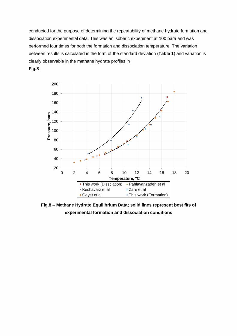
conducted for the purpose of determining the repeatability of methane hydrate formation and
dissociation experimental data. This was an isobaric experiment at 100 bara and was
performed four times for both the formation and dissociation temperature. The variation
between results is calculated in the form of the standard deviation (Table 1) and variation is
clearly observable in the methane hydrate profiles in
Fig.8.
Fig.8 – Methane Hydrate Equilibrium Data; solid lines represent best fits of
experimental formation and dissociation conditions
20
40
60
80
100
120
140
160
180
200
0 2 4 6 8 10 12 14 16 18 20
Pre
ssu
re,
bara
Temperature, °C
This work (Dissciation) Pahlavanzadeh et al
Keshavarz et al Zare et al
Gayet et al This work (Formation)
Page 15
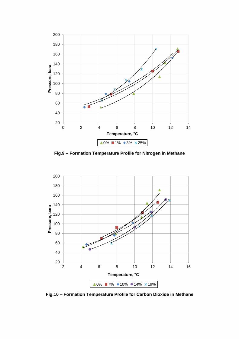
Fig.9 – Formation Temperature Profile for Nitrogen in Methane
Fig.10 – Formation Temperature Profile for Carbon Dioxide in Methane
20
40
60
80
100
120
140
160
180
200
0 2 4 6 8 10 12 14
Pre
ssu
re,
bara
Temperature, °C
0% 1% 3% 25%
20
40
60
80
100
120
140
160
180
200
2 4 6 8 10 12 14 16
Pre
ssu
re,
bara
Temperature, °C
0% 7% 10% 14% 19%
Page 16
The formation temperature shows a much larger degree of variance compared to the
dissociation temperatures due to its slight unpredictability arising from the large amount of
factors affecting hydrate formation. On the contrary, the dissociation temperatures are
consistent, only differing by a maximum of 0.3 °C. Because the dissociation temperature is
essentially the equilibrium temperature and therefore is a fixed thermodynamic property
(Tohidi, et al. 2000), this consistency is understandable. Contrarily, the formation
temperature shows significantly more variation amongst the recorded data. Hydrate
formation has a somewhat random nature to it, relying upon many factors but primarily the
driving force for hydrate formation, ∆μ,
∆μ = ∑ ni
i
(Tl, P, x)μsi
(Tl, P, x) + nwμw
(Tg, P, x) - nhμh(P,Tl, z) . . . . . . . . Eq. 3
In Eq. 3 (Kashchiev and Firoozabadi 2002) ni is the number of gas molecules in a hydrate
unit cell with nw water molecules, μsi is the chemical potential of dissolved gas species i, μ
w
is the chemical potential of water in solution, μh is the chemical potential of the hydrate
phase, nh is the number of moles of hydrate, Tg is the temperature of the gas, Tl is the
temperature of the aqueous solution or hydrate and x and z are the mole fractions of the
gases in the aqueous and hydrate phase respectively. A chemical potential driving force
between the solution and the hydrate phase is required to initiate the formation of the first
hydrate building blocks; it depends on the degree of sub-cooling, pressure and water content
which in turn influence how quickly hydrates form after sub-cooling (Hobbs 1974). This has
been shown by Christiansen and Sloan (1994) and in simulations (Ota and Qi 2000). The
presence of impurities and the introduction of mechanical agitation stimulate formation and
the nucleation rate reduce the degree of sub-cooling required for the time required for
hydrate formation to induce (Dai et al. 2014). These factors can be controlled to a certain
degree, but due to control limitations, conditions cannot be replicated exactly. Consequently,
there is often noticeable variation in the experimental formation temperatures (Fig.9 –
Table 1 – Methane at 100 bara
TEST
1 2 3 4 Average St. Dev
Formation (°C) 10.6 10.4 9.9 10.2 10.3 0.30
Dissociation (°C) 13.0 13.2 13.0 12.9 13.0 0.13
Page 17
Fig.10). The dissociation temperature is therefore better representative of the equilibrium
point and is used synonymously throughout this paper.
4.3 Software Hydrate Predictions
4.31 HYSYS Prediction-Experimental Deviation
Fig.11 – N2 HYSYS
0
5
10
15
20
25
6 8 10 12 14 16 18
Devia
tio
n, %
Dissociation Point, °C
C1, 100% (PR) C1, 100% (SRK)N2, 1% (PR) N2, 1% (SRK)N2, 3% (PR) N2, 3% (SRK)N2, 25% (PR) N2, 25% (SRK)
Page 18
Fig.12 – CO2 HYSYS
Utilising HYSYS’s hydrate prediction software is relatively straight forward. A flow stream is
simply created and specified with the correct composition, which is analysed by the hydrate
utility using the fluid package/s chosen, PR and SRK in this case. Depending on the
specified pressure, HYSYS then calculates the corresponding hydrate temperature based on
the selected fluid package and another parameter detailed as the ‘calculation mode’. Four
different modes are available, namely ‘Symmetric Model’, ‘Asymmetric Model’, ‘Vapour Only
Model’ and ‘Assume Free Water’. In all mixtures tested, the calculation mode had a very
negligible effect on the calculated hydrate temperature.
4.32 PVTsim Prediction-Experimental Deviations
0
5
10
15
20
6 8 10 12 14 16 18
Devia
tio
n, %
Dissociation Point, °C
C1, 100% (PR) C1, 100% (SRK)CO2, 7% (PR) CO2, 7% (SRK)CO2, 10% (PR) CO2, 10% (SRK)CO2, 14% (PR) CO2, 14% (SRK)CO2, 19% (PR) CO2, 19% (SRK)
Page 19
Fig.13 – N2 PVTsim
Fig.14 – CO2 PVTsim
0
5
10
15
20
25
6 8 10 12 14 16 18
Devia
tio
n, %
Dissociation Point, °C
C1, 100% (PR) C1, 100% (SRK)N2, 1% (PR) N2, 1% (SRK)N2, 3% (PR) N2, 3% (SRK)N2, 25% (PR) N2, 25% (SRK)
0
5
10
15
20
6 8 10 12 14 16 18
Devia
tio
n, %
Dissociation Point, °C
C1, 100% (PR) C1, 100% (SRK)
CO2, 7% (PR) CO2, 7% (SRK)
CO2, 10% (PR) CO2, 10% (SRK)
CO2, 14% (PR) CO2, 14% (SRK)
CO2, 19% (PR) CO2, 19% (SRK)
Page 20
PVTsim operates differently than HYSYS in that it doesn’t simulate chemical processes, but
focuses on analysing almost any fluid from a PVT perspective with a major focus on
petroleum fluids. Many different types of analyses are available ranging from phase
diagrams, saturation point, viscosity, wax, asphaltene, and reservoir and hydrate analysis.
The hydrate analysis only requires the composition of the gas mixture, which is input using
PVTsim’s fluid management tab and selecting an appropriate equation of state. Unlike
HYSYS, PVTsim prompts for the amount of water present, which is input as the water/gas
molar ratio. For all experiments, this ratio ranged between approximately 0.9 – 3.5 mol/mol
and was determined by the following procedure,
1. Calculate number of water moles for the 5 mL of water; 0.277 mol
2. Calculate the number of gas moles for both the highest, 180 bara, and lowest
pressures tested at, 50 bara; approximately 0.961 and 0.237 mol respectively using
n = PV
ZRT knowing the cell volume to be 105.8 cm3
3. Evaluate the water/gas molar ratio at each pressure to provide the range, 0.86 – 3.47
mol/mol
The hydrate temperatures calculated at these molar ratios differed on a very small scale for
each gas mixture, such that it was deemed negligible. Therefore the varying amounts of
water introduced into the cell relative to the moles of gas clearly do not influence the
equilibrium system significantly in this study.
4.4 Software Prediction Methods
There are many available software packages which have hydrate predictive capabilities.
These programs primarily make use of various thermodynamic equations and correlations to
provide an estimate of the conditions at which hydrates will form for a particular fluid. This
study has made use of Aspen HYSYS and Calsep PVTsim, for the purpose of comparing
experimental data from this work to the hydrate formation conditions calculated by these
software packages. Recommended by HYSYS and PVTsim, the Peng-Robinson (PR) and
Soave-Redlich-Kwong (SRK) fluid packages were used when utilising both programs. It is
noted that versions 7.2 and 20 of HYSYS and PVTsim respectively were used when
computing hydrate data. The hydrate data for pure methane, nitrogen and carbon-dioxide is
presented for each model as a source of comparison between hydrate predictions for pure
species and mixtures of these gases with methane (Fig.15 – Fig.17).
Page 21
Fig.15 – Software Hydrate Equilibrium Data for Methane
Fig.16 – Software Hydrate Equilibrium Data for Carbon-dioxide
0
50
100
150
200
250
-20 -10 0 10 20
Pre
ssu
re,
bara
Temperature, °C
HYSYS (PR) HYSYS (SRK)
PVTsim (PR) PVTsim (SRK)
0
50
100
150
200
250
0 3 6 9 12 15
Pre
ssu
re,
bara
Temperature, °C
HYSYS (PR) HYSYS (SRK)
PVTsim (PR) PVTsim (SRK)
Page 22
Fig.17 – Software Hydrate Equilibrium Data for Nitrogen
The variation in the predicted hydrate conditions vary to different extents for pure methane,
carbon-dioxide and nitrogen. There is very little disagreement between the model used and
the software for methane; almost 100% agreement across the full range of pressures. This is
mostly true for pure nitrogen or carbon dioxide of which demonstrate only small deviations
with the exception of the HYSYS SRK model, which showed significant deviation. However,
research into each program’s documentation revealed that they use the same variation of
each EOS (Table 2) and solve them analytically by default.
Table 2 – PVTsim and HYSYS EOS Calculation Parameters
Peng – Robinson Soave – Redlich – Kwong
Critical Values The Properties of Gases and Liquids (Reid et al. 1977)
Equation of
State P =
RT
V - b -
a (T)
V(V + b) + b(V - b)
P = RT
V - b -
a (T)
V(V + b)
0
50
100
150
200
250
-100 -75 -50 -25 0
Pre
ssu
re,
bara
Temperature, °C
HYSYS (PR) HYSYS (SRK)
PVTsim (PR) PVTsim (SRK)
Page 23
Z3 - (1 - B)Z
2 + (A - 2B - 3B
2)Z
- (AB - B2 - B
3) = 0
Z3 - Z2
+ (A - B - B2)Z - AB = 0
A aP
(RT)2
aP
(RT)2
B bP
RT
bP
RT
ai aciαi aciαi
aci 0.45724R
2Tci
2
Pci 0.42748
R2Tci
2
Pci
αi [1 + m (1 - (T
Tci
)
0.5
)]
2
[1 + m (1 - (T
Tci
)
0.5
)]
2
a ∑ ∑ xixj(aiaj)0.5
(1 - kij)
n
i=j
n
i=1
∑ ∑ xixj(aiaj)0.5
(1 - kij)
n
i=j
n
i=1
mi 0.37464 + 1.54226ωi
- 0.269922ωi2
0.480 + 1.547ωi - 0.176ωi2
mi (if ωi ≤ 0.49) 0.37464 + ωi(1.48503ωi
- 0.164423ωi + 0.01666ωi2)
-
ωi -log10
PriSat
at Tri=0.7 -log10
PriSat
at Tri = 0.7
bi 0.07780RTci
Pci
0.08664RTci
Pci
The identical methods shared between PVTsim and HYSYS imply that the EOS is not likely
a major source of discrepancy in the calculation of the hydrate equilibrium conditions. This
was tested by generating critical PVT data with each EOS for binary mixtures of methane
and nitrogen/carbon-dioxide. Data was generated for the critical pressure (Pc), critical
temperature (Tc), critical molar volume (V̅c) and critical compressibility (Zc). There were no
discernible differences in this data between HYSYS and PVTsim; a sample of this data is
listed in Table 3.
Page 24
Table 3 – PVTsim and HYSYS Critical Property Calculations
Peng – Robinson Soave – Redlich – Kwong
Critical
Property
0.9 CH4 - 0.1 CO2
0.9 CH4 - 0.1 N2
0.9 CH4 - 0.1 CO2
0.9 CH4 - 0.1 N2
HSYS PVTsim HSYS PVTsim HSYS PVTsim HSYS PVTsim
Pc, bara 53.85 52.48 48.69 48.23 54.16 52.69 48.6 48.21
Tc, °C -70.25 -71.55 -87.52 -87.58 -69.76 -71.23 -87.4 -87.45
V̅c, cm3/mol 95.65 97.53 100.3 101.23 103.9 106.0 109.2 110.5
Zc 0.3053 0.3054 0.3166 0.3164 0.3328 0.3326 0.3435 0.3436
With little variation between their respective PVT models, the calculation method of the
hydrate equilibrium properties must be different or use different reference values. The
general methods associated with most hydrate equilibrium calculations are centred on the
difference between the chemical potential of water in the hydrate state (μH) and the pure
water state (μα),
μH - μα = (μH - μβ) + (μβ - μα). . . . . . . . . . . . . . . Eq. 4
The μH - μβ term is the change in chemical potential of water from an empty lattice (β) to a
gas stabilized lattice (H) and μβ - μα represents the change in chemical potential from a pure
water state (α) to an empty hydrate lattice. HYSYS and PVTsim solve Eq. 4 by using their
own model based on the fundamental statistical thermodynamic equation developed by van
der Waals and Platteeuw (1959). The method in HYSYS uses an improved version to
incorporate modifications by Parrish and Prausnitz (1972) which was shown to improve the
predictability of the dissociation line in aqueous environments. The improvements of Ng and
Robinson (1976, 1977) which provided better predictability of the Kihara parameters
enabling better predictability in mixtures as well as aqueous systems is also incorporated.
Calculation of the Langmuir adsorption coefficient is based on a complex approach by
Ballard (2002). This approach proved to provide more accurate adsorption constants due to
a multilayered cage approximation. HYSYS combines these modifications in the formulation
of its own model, although the result of these modifications into a unified model is not directly
specified in the program. It is also unclear what source the program uses for reference
parameters associated with the transition from α to β. These reference parameters include
the chemical potential (Δμ0), the change in molar volume (ΔV0), and the change in molar
Page 25
enthalpy, (ΔH0). Reference data for these parameters in PVTsim is acquired from Erickson
(1983) and Rasmussen and Pederson (2002). The overall approach in PVTsim is similar to
HYSYS but one primary difference is the calculation of the Langmuir constant. PVTsim uses
a simpler temperature dependent model from Munck et al. (1988) whom provided accurate
Langmuir parameters in calculation of the temperature dependent model. Due the probability
of a particular molecule occupying a particular hydrate cavity depending on the Langmuir
constant for that unique occurrence, a noticeable difference in the hydrate equilibrium
conditions predictions between HYSYS and PVTsim is not unlikely. This has been observed
in this study and is summarized through Fig.11 – Fig.14.
4.5 Empirical Relation
Fig.18 – Methane – Nitrogen Hydrate Equilibrium Data; Solid Line and dashed lines
represent 11% and 27% model data respectively
20
40
60
80
100
120
140
160
180
200
0 2 4 6 8 10 12 14 16 18 20
Pre
ssu
re (
bara
)
Temperature (°C)
Empirical Model 11% Empirical Model 27%
Mei (1996) 11% HYSYS PR 11%
HYSYS SRK 11% PVTsim PR 11%
PVTsim SRK 11% Jhaveri and Robinson (1965) 27%
HYSYS PR 27% HYSYS SRK 27%
PVTsim PR 27% PVTsim SRK 27%
Page 26
Fig.19 – Methane – Carbon-dioxide Hydrate Equilibrium Data; Solid Line and dashed lines represent 8% and 40% model data respectively
Substituting the values for the integrals and empirical constants into Eq. 1 then simplifying
yields,
Td(P,xN2,xCO2) = 8.264ln(P/21.31) - 5.05ln(P/25.24)xN2+ 4.71ln(P/17.34)xCO2 . . . . . Eq. 5
The relationship expressed in Eq. 5 allows the calculation of the dissociation temperature of
a methane-based gas containing either or both nitrogen and carbon dioxide with a mole
fraction of xN2 and xCO2 respectively. Deriving the constant for nitrogen resulted in a
negative value, confirming that the introduction of nitrogen reduced the dissociation
temperature. The opposite occurred for carbon dioxide; a positive value was determined,
which is attributable to its hydrate stabilizing effect (Christiansen and Sloan 1994). The
relation is reliable in the ranges of 40-180 bara and within the composition ranges tested.
Inaccurate results were given when applying the model too far outside these ranges. This is
expected because the model has essentially averaged the promotion and dilution effects of
carbon-dioxide and nitrogen over the experimented pressure range. Therefore it less reliable
20
40
60
80
100
120
0 2 4 6 8 10 12 14 16 18 20
Pre
ssu
re (
bara
)
Temperature (°C)
Empirical Model 8% Empirical Model 40% Adisasmito (1991) 8%
HYSYS PR 8% HYSYS SRK 8% PVTsim PR 8%
PVTsim SRK 8% Adisasmito(1991) 40% HYSYS PR 40%
HYSYS SRK 40% PVTsim PR 40% PVTsim SRK 40%
Page 27
at the extremes of this range. Using Eq. 5, hydrate equilibrium data is generated using a
range of pressures and compositions. The model is tested in regions outside of the range of
tested conditions which the model was founded on in order to formally visualize any points of
weakness. This is portrayed to be the case in the results illustrated in Fig.18 and Fig.19.
5.0 Conclusion and Recommendations
An empirical model has been derived based solely on experimental data and incorporates
the influences of nitrogen and carbon dioxide on their introduction to methane gas. The
purpose of generating a model is to accurately calculate the dissociation temperature of a
particular methane gas mixture diluted with nitrogen, carbon dioxide or both with any
particular composition within range of those tested. It complements the experimental data
and conveniently describes these results mathematically. Multiple examples reveal that the
model is reliable based on comparison to the computed values generated by software
capable of hydrate temperature prediction. However when applied outside the recommended
ranges it became less reliable. The examples detailed in this paper deviate no more than
10% than those predicted and were often in the vicinity of 2-5% in the optimal working range,
confirming the reliability of the experimental data and the empirical relation. The raw data
also showed consistency with the temperatures computed via hydrate software, particularly
at higher pressures where PVTsim excelled, usually differing by only 1-4%. Clausius –
Clapeyron plots confirmed that sI hydrates formed in all experiments with methane-nitrogen
and methane-carbon-dioxide gases. Slopes ranged from -8900 to -11100 which are
consistent with literature values. The formation temperature was found to consistently occur
at approximately 2-4 °C lower than the dissociation temperature; statistical measures
confirmed that the dissociation temperature measurements are more precise and are
reflective of the equilibrium temperature. The non-stoichiometric and random nature about
gas hydrates and their formation are attributable to inconsistencies with expected trends with
composition as well as the ability of hydrates to form despite cavities being absent of
stabilizing guest molecules.
From a hydrate perspective, it is ideal that carbon dioxide is removed from production and
processing streamsearly in the natural gas recovery and refinement process.This provides
more leeway for processing conditions downstream on account of carbon dioxide’s ability to
promote hydrate forming conditions and its increasing stabilizing effect at higher pressures.
It would be beneficial to preserve and recycle any nitrogen recovered because of its ability to
suppress hydrate formation and dissociation conditions by dilution. Alternatively, nitrogen
can be introduced from an external source such as air where it may be considered as a
Page 28
replacement to common hydrate inhibitors.This would be particularly cost-saving when
operating conditions are known to be sitting on the verge of the hydrate zone as opposed to
inside where nitrogen can be introduced instead of conventional inhibitors to decrease the
likelihood of hydrate formation.
Acknowledgements
We’d like to acknowledge Shell Australia for their critical and financial support throughout the
course of this project. Their direction, enthusiasm and encouragement towards this research
is highly valued which has made this project possible.
References
Adisasmito, S, R. J Frank, and E. D Sloan. “Hydrates of Carbon Dioxide and Methane
Mixtures.” Journal of Chemical Engineering Data 36 (1), 1991: 68-71.
Bai, Yong, and Qiang Bai. Subsea Pipelines and Risers. Elsevier, 2005.
Ballard, A. L, and E.D Sloan. “The Next Generation of Hydrate Prediction: I. Hydrate
Standard States and Incorporation of Spectroscopy.” Fluid Phase Equilibria 194-197,
2002: 371-383.
Buffet, Bruce A. “Clathrate Hydrates.” Annual Review of Earth and Planetary Science,
Volume 28, 2000: 477-509.
Carrol, John. Natural Gas Hydrates: A Guide for Engineers. Elsevier Science & Technology
Books, 2002.
Christiansen, Richard L., and E. Dendy Sloan. “Mechanisms and Kinetics of Hydrate
Formation.” Annals New York Academy of Sciences, 1994: 283-305.
Dai, Sheng, Joo Yong Lee, and J. Carlos Santamarina. “Hydrate Nucleation in Quiscent and
Dynamic Conditions.” Fluid Phase Equilibria Vol. 378, 2014: 107-112.
Erickson, DD. Development of a Natural Gas Hydrate Prediction Computer Program. M.Sc.
Thesis, Colorado School of Mines, 1983.
Herri, J. M, A Bouchemoua, M Kwaterski, A Fezoua, Y Ouabbas, and A Cameirao. “Gas
Hydrate Equilibria for CO2-N2 and CO2-CH4 Gas Mixtures - Experimental Studies
and Thermodynamic Modelling.” Fluid Phase Equilibria, Vol. 301 (2), 2011: 171-190.
Hobbs, P. V. Ice Physics. Oxford: Clarendon Press, 1974.
Jhaveri, J, and D. B Robinson. “Hydrates in the Methane-Nitrogen System.” The Canadian
Journal of Chemical Engineering, 43, 1965: 75-78.
Page 29
Juan, Yu-Wan, Muoi Tang, Li-Jen Chen, Shaing-Lin Lin, Po-Chun Chen, and Yang-Ping
Chen. “Measurements for the Equilibrium Conditions of Methane Hydrate in the
Presence of Cyclopentanone or 4-Hydroxy-4-methyl-2-pentanone Additives.” Fluid
Phase Equilibria, Vol 386, 2015: 162-167.
Kashchiev, Dimo, and Abbas Firoozabadi. “Nucleation of Natural Gas Hydrates.” Journal of
Crystal Growth, 2002: 476-489.
Lederhos, J. P, L Christiansen, and E. D Sloan. “A First Order Method of Hydrate Equilibrium
Estimation and its Use With New Structures.” Fluid Phase Equilibria, 1993: 83-445.
Max, Michael D., Arthur H. Johnson, and William P. Dillon. Economic Geology of Natural
Gas Hydrate, Volume 9. Springer, 2006.
Mori, Yasukiko H. “Clathrate Hydrate Formation at the Interface Between Liquid CO2 and
Water Phases - A Review of Rival Models Characterizing "Hydrate Films".” Energy
Conservation and Management, 1998: 1537-1557.
Munck, Jan, Steen Skjold-Jorgensen, and Peter Rasmussen. “Computations of the
Formation of Gas Hydrates.” Chemical Engineering Science Vol. 43, 1988: 2661-
2672.
Ng, Heng-Joo, and Donald B. Robinson. “The Measurement and Prediction of Hydrate
Formation in Liquid Hydrocarbon-Water Systems.” AIChE Vol. 15, 1976: 293-298.
Ng, Heng-Joo, and Donald B. Robinson. “The Prediction of Hydrate Formation in Condensed
Systems.” AIChE Journal Vol. 23, 1977: 477-482.
Ota, M, and Y Qi. “Numerical Simulation of Nucleation Process of Clathrate Hydrates.”
JSME Int. J. Series B, 43, 2000: 719-726.
Parrish, William R., and John M. Prausnitz. “Dissociation of Gas Hydrates Formed by Gas
Mixtures.” Ind. Eng. Chem. Process Des. Develop. Vol 11, 1972: 26-35.
Rasmussen, C.P, and K.S Pederson. “Challenges in Modeling of Gas Hydrate Phase
Equilibria.” 4th International Conference on Gas Hydrates. Yokohama: Calsep, 2002.
Reid, Robert C, J. M Prausnitz, and Thomas K Sherwood. The Properties of Gases and
Liquids. Mcgraw-Hill, 1977.
Schicks, J. M. “Natural Gas Hydrates.” Handbook of Hydrocarbon and Lipid Microbiology,
2010: 67-77.
Shin, Hyung Joon, Yun-Je Lee, Jun-Hyuck Im, Kyu Won Han, Jon-Won Lee, and Yongjae
Lee. “Thermodynamic stability, spectroscopic identification and cage occupation of
binary CO2 Clathrate Hydrates.” Chemical Engineering Science, 2009: 5125-5130.
Sloan, E. D, and F Fleyfel. “Hydrate Dissociation Enthalpy and Guest Size.” Fluid Phase
Equilibria, 1992: 123-140.
Sloan, E. Dendy. Clathrate of Natural Gas Hydrates, Third Edition. Taylor & Francis Grou,
2008.
Page 30
“The Prediction of Hydrate Formation in Condensed Systems.” AIChE, 1977: 477-482.
Tohidi, B., R.W. Burgrass, A. Danesh, K.K. Ostergaard, and A.C. Todd. “Improving the
Accuracy of Gas Hydrate Dissociation Point Measurements.” Annals New York
Academy of Sciences, 2000: 924-931.
Van der Waals, J.H, and J.C Platteeuw. “Clathrate Solutions.” Advances in Chemical
Physics Vol. 2, 1959: 59-85.
ZareNezhad, Bahman, Mona Mottahedin, and Farshad Varaminian. “A New Approach for
Determination of Single Gas Hydrate Formation Kinetics in the Absence or Presence
of Kinetic Promoters.” Chemical Engineering Science, Vol. 137, 2015: 447-457.


![Effect of Perforation Interval Design on Gas Production from ......2020/04/09 · endothermic reaction [7], and reservoir deformation [8]. At present, in situ dissociation of hydrate](https://static.documents.pub/doc/80x56/60fda6849c7c993e3d0eae6c/effect-of-perforation-interval-design-on-gas-production-from-20200409.jpg)


