Heinzmann GmbH & Co. KG Engine & Turbine Controls Heinzmann GmbH & Co. KG Engine & Turbine Controls Am Haselbach 1 D-79677 Schönau (Schwarzwald) Germany Tel.: +49 7673 8208-0 Fax +49 7673 8208-188 E-mail [email protected]www.heinzmann.com USt-IdNr.: DE145551926 HEINZMANN ® Engine & Turbine Controls Gas Metering System ELEKTRA Lambda Control System KRONOS 30-M Integrated AFR / Speed-Load Control System Copyright 2007 by Heinzmann GmbH & Co. All rights reserved. This document must not be reproduced or handed on to third parties. Manual AFR 03 003-e / 01-08
Copyright 2007 by Heinzmann GmbH & Co. All rights reserved. This document must not be reproduced or handed on to third parties.
Manual AFR 03 003-e / 01-08
Read this entire manual and all other publications appertaining to the work to be performed before installing, operating or servicing your equipment.
Practice all plant and safety instructions and precautions.
Failure to follow instructions may result in personal injury and/or damage to property.
HEINZMANN will refuse all liability for injury or damage which results from not following instructions.
Please note before commissioning the installation: Before starting to install any equipment, the installation must have been switched dead!
Be sure to use cable shieldings and power supply connections meeting the requirements of the European Directive concerning EMI.
Check the functionality of the existing protection and monitoring systems.
To prevent damages to the equipment and personal injuries, it is imperative that the following monitoring and protection systems have been installed: Overspeed protection acting independently of the speed governor
Overtemperature protection
HEINZMANN will refuse all liability for damage which results from missing or insufficiently working overspeed protection
Generator installation will in addition require: Overcurrent protection
Protection against faulty synchronisation due to excessive frequency, voltage or phase differences
Reverse power protection
Overspeeding can be caused by:
Failure of the voltage supply
Failure of the actuator, the control unit or of any accessory device
Sluggish and blocking linkage
Warning
Danger
Danger
Danger!High
Voltage
Danger
The examples, data and any other information in this manual are intended exclusively as instruction aids and should not be used in any particular application without independent testing and verification by the person making the application.
Independent testing and verification are especially important in any application in which malfunction might result in personal injury or damage to property.
All of the components described in this manual may only be used in accordance with applicable regulations. Any uses other than those described in this manual are not permissible
HEINZMANN make no warranties, express or implied, that the examples, data, or other information in this volume are free of error, that they are consistent with industry standards, or that they will meet the requirements for any particular application.
HEINZMANN expressly disclaim the implied warranties of merchantability and of fitness for any particular purpose, even if HEINZMANN have been advised of a particular purpose and even if a particular purpose is indicated in the manual.
HEINZMANN also disclaim all liability for direct, indirect, incidental or consequential damages that result from any use of the examples, data, or other information contained in this manual.
HEINZMANN make no warranties for the conception and engineering of the technical installation as a whole. This is the responsibility of the user and of his planning staff and specialists. It is also their responsibility to verify whether the performance features of our devices will meet the intended purposes. The user is also responsible for a correct commissioning of the overall installation.
Warning
Danger
Contents
ELEKTRA / KRONOS 30
Contents
Page
1 Safety Instructions and Related Symbols............................................................................ 1 1.1 Basic Safety Measures for Normal Operation................................................................. 2 1.2 Basic Safety Measures for Servicing and Maintenance .................................................. 2 1.3 Before Putting an Installation into Service after Performing Maintenance and Repair Work ...................................................................................................................................... 3
4 System Concept ..................................................................................................................... 7
5 Operating Principle of the Lambda Control System ....................................................... 10
6 Sensors.................................................................................................................................. 14 6.1 Overview ....................................................................................................................... 14 6.2 Magnetic Pickup IA ...................................................................................................... 14
6.2.1 Technical Data ....................................................................................................... 14 6.2.2 Installation ............................................................................................................. 15 6.2.3 Tooth Profile .......................................................................................................... 15 6.2.4 Clearance of Magnetic Pickup............................................................................... 15 6.2.5 Mounting Measurements ....................................................................................... 16 6.2.6 Certification of the Magnetic Pickups according to ATEX................................... 17
6.3 DSU 01 Pressure Sensor between Air Filter and Venturi Mixer................................... 17 6.3.1 Technical Data ....................................................................................................... 17 6.3.2 Measurements ........................................................................................................ 18 6.3.3 Installation ............................................................................................................. 18 6.3.4 Certification of the DSU 01 Pressure Sensor according to ATEX........................ 19
6.4 TS 05-NTC Temperature Sensor between Air Filter and Venturi Mixer...................... 19 6.4.1 Technical Data ....................................................................................................... 19 6.4.2 Measurements ........................................................................................................ 20 6.4.3 Installation ............................................................................................................. 21 6.4.4 Certification of the TS 05-NTC Temperature Sensor according to ATEX ........... 21
7 Gas Metering Control Unit GMCU-50 / 85 ...................................................................... 22 7.1 Technical Data............................................................................................................... 24
7.1.1 General................................................................................................................... 24 7.1.2 Externally used Inputs and Outputs ....................................................................... 25
7.3 Installation ..................................................................................................................... 30 7.4 Certification of the Gas Metering Control Unit GMCU according to ATEX............... 30
8.2.1 Cable to Magnetic Pickup...................................................................................... 34 8.2.2 Cable to Air Temperature Sensor .......................................................................... 34 8.2.3 Cable to ELEKTRA Main Plug ............................................................................. 34 8.2.4 Pressure Pipes to Gas Mixer Delta-P Sensors ....................................................... 34
9 General Mounting Instructions.......................................................................................... 35
10 Parametrisation of ELEKTRA / KRONOS 30 Governors............................................ 36 10.1 Parametrisation with Hand Held Programmer HP 03 ................................................. 36 10.2 Parametrisation via PC / Laptop.................................................................................. 36
12 General Safety Information for Commisioning.............................................................. 38 12.1 General Safety Information for Commissioning ......................................................... 38 12.2 General notes concerning the first start of the engine ................................................. 38
13 Configuration and Calibration of Inputs and Outputs ................................................. 40 13.1 Selectable Inputs and Outputs ..................................................................................... 40 13.2 Analogue Inputs........................................................................................................... 41
13.2.1 Sensor Overview.................................................................................................. 42 13.2.2 Assigning Inputs to Sensors and Setpoint Adjusters ........................................... 43 13.2.3 Measuring Ranges of Sensors.............................................................................. 44 13.2.4 Modifying Reactions to Sensor Errors................................................................. 45 13.2.5 Calibration of analogue Inputs............................................................................. 47 13.2.6 Filtering of Analogue Inputs................................................................................ 48 13.2.7 Error Detection for Analogue Inputs ................................................................... 48 13.2.8 Overview of the Parameters associated with one analogue Input ....................... 50
13.3 Digital Inputs ............................................................................................................... 51 13.4 Analogue Outputs ........................................................................................................ 51
13.4.1 Assignment of Output Parameters to analogue Outputs...................................... 51 13.4.2 Value Range of Output Parameters ..................................................................... 52 13.4.3 Value Range of analogue Outputs ....................................................................... 53
13.5 Digital Outputs ............................................................................................................ 54 13.5.1 Assignment of Output Parameters ....................................................................... 54
14 Commissioning of ELEKTRA with Flow Control ......................................................... 56 14.1 General IO Configuration............................................................................................ 56
14.2.5.1 Zero Gas Delta Pressure............................................................................... 61 14.2.5.2 Low Gas Delta Pressure............................................................................... 62 14.2.5.3 High Gas Delta Pressure .............................................................................. 62 14.2.5.4 Low Gas Pressure......................................................................................... 62 14.2.5.5 High Gas Pressure ........................................................................................ 63 14.2.5.6 Low Gas Temperature.................................................................................. 63 14.2.5.7 High Gas Temperature ................................................................................. 63 14.2.5.8 Gas Flow Deviation ..................................................................................... 64
15 Commisioning of ELEKTRA with Lambda Control..................................................... 65 15.1 General IO Configuration............................................................................................ 65 15.2 CAN Communication.................................................................................................. 66 15.3 Functional Description and Configuration .................................................................. 68
15.3.1 ELEKTRA Setpoint............................................................................................. 68 15.3.1.1 Internal Lambda Setpoint............................................................................. 68 15.3.1.2 External Lambda Setpoint............................................................................ 68 15.3.1.3 Lambda Setpoint over DcDesk2000 ............................................................ 69 15.3.1.4 Gas Throttle Position Setpoint over DcDesk2000 ....................................... 69 15.3.1.5 Safety Remarks ............................................................................................ 69
15.3.2 Lambda Control Parameters ................................................................................ 70 15.3.3 Gas Quality .......................................................................................................... 70
15.3.3.1 Constant Gas Quality ................................................................................... 70 15.3.3.2 Variable Gas Quality.................................................................................... 70
15.3.4 Engine States........................................................................................................ 71 15.3.5 Gas Fuel Limitation ............................................................................................. 73
15.3.7.1 Overspeed..................................................................................................... 75 15.3.7.2 Zero Gas Delta Pressure............................................................................... 75 15.3.7.3 Low Gas Delta Pressure............................................................................... 76 15.3.7.4 High Gas Delta Pressure .............................................................................. 76 15.3.7.5 Low Gas Pressure......................................................................................... 76 15.3.7.6 High Gas Pressure ........................................................................................ 77 15.3.7.7 Low Gas Temperature.................................................................................. 77 15.3.7.8 High Gas Temperature ................................................................................. 77
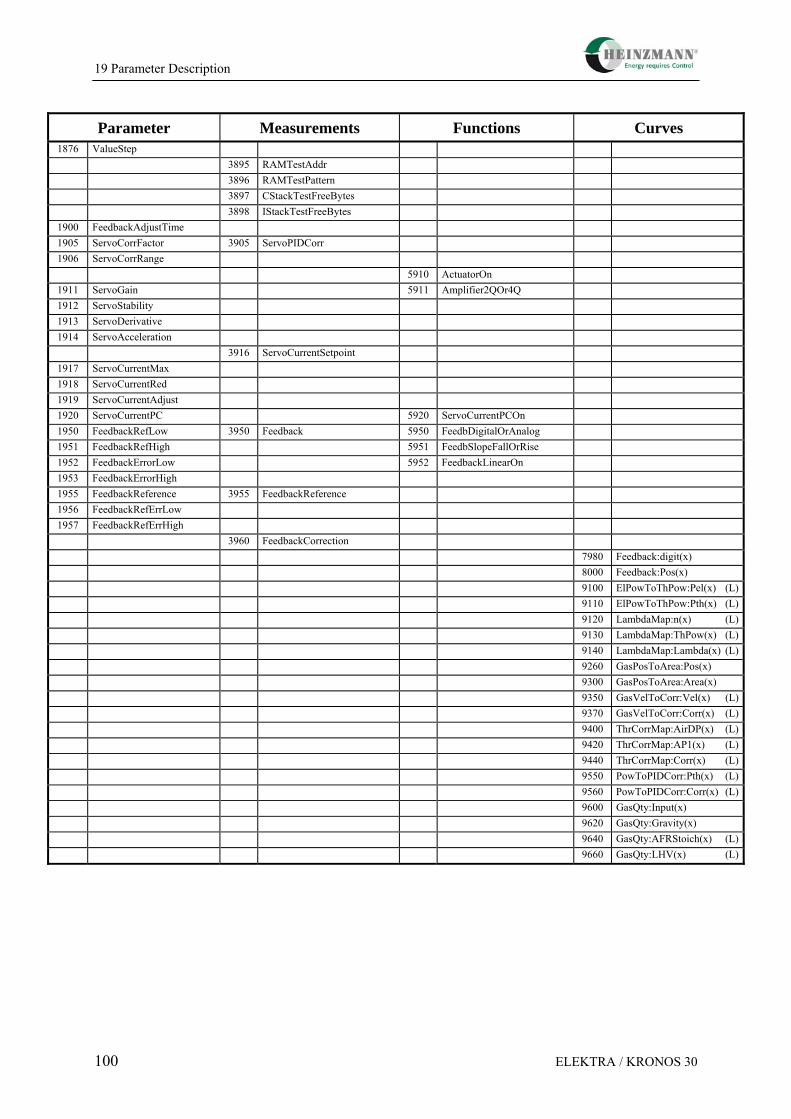
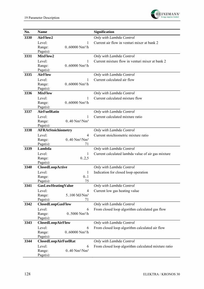
19 Parameter Description...................................................................................................... 93 19.1 Overview Table ........................................................................................................... 93 19.2 List 1: Parameters ...................................................................................................... 101 19.3 List 2: Measurements ................................................................................................ 116 19.4 List 3: Functions ........................................................................................................ 134 19.5 List 4: Characteristics and Maps ............................................................................... 139
20 Index of Figures............................................................................................................... 141
21 EU Statement of Compliance ......................................................................................... 142
22 Order Information for KRONOS Systems ................................................................... 143
23 Order Specifications for Manuals.................................................................................. 144
1 Safety Instructions and Related Symbols
ELEKTRA / KRONOS 30 1
1 Safety Instructions and Related Symbols
This publication offers wherever necessary practical safety instructions to indicate inevitable residual risks when operating the engine. These residual risks imply dangers to
persons
product and engine
the environment.
The symbols used in this publication are in the first place intended to direct your attention to the safety instructions!
This symbol is to indicate that there may be danger to the engine, to the material and to the environment.
This symbol is to indicate that there may be a danger to persons. (Danger to life, personal injury)
This symbol is to indicate that there exist particular danger due to electrical high tension. (Danger to life).
This symbol does not refer to any safety instructions but offers important notes for better understanding the functions that are being discussed. They should be observed and practiced by all means. The respective text is printed in italics.
The primary issue of these safety instructions is to prevent personal injuries! Whenever some safety instruction is preceded by a warning triangle labelled “Danger” this is to indicate that it is not possible to definitely exclude the presence of danger to persons, the engine, the material and/or the environment.
If, however, some safety instruction is preceded by the warning triangle labelled “Warning” this will indicate that danger of life or personal injury is not involved.
The symbols used in the text do not supersede the safety instructions. So please do not skip the respective texts but read them thoroughly!
Note
Warning
Danger
Danger!High
Voltage
1 Safety Instructions and Related Symbols
2 ELEKTRA / KRONOS 30
In this publication the Table of Contents is preceded by diverse instructions that among other things serve to ensure safety of operation. It is absolutely imperative that these hints be read and understood before commissioning or servicing the installation.
1.1 Basic Safety Measures for Normal Operation
• The installation may be operated only by authorized persons who have been duly trained and who are fully acquainted with the operating instructions so that they are capable of working in accordance with them.
• Before turning the installation on please verify and make sure that - only authorized persons are present within the working range of the engine; - nobody will be in danger of suffering injuries by starting the engine.
• Before starting the engine always check the installation for visible damages and make sure it is not put into operation unless it is in perfect condition. On detecting any faults please inform your superior immediately!
• Before starting the engine remove any unnecessary material and/or objects from the working range of the installation/engine.
• Before starting the engine check and make sure that all safety devices are working properly!
1.2 Basic Safety Measures for Servicing and Maintenance
• Before performing any maintenance or repair work make sure the working area of the engine has been closed to unauthorized persons. Put on a sign warning that maintenance or repair work is being done.
• Before performing any maintenance or repair work switch off the master switch of the power supply and secure it by a padlock! The key must be kept by the person who performs the maintenance and repair work.
• Before performing any maintenance and repair work make sure that all parts of the engine to be touched have cooled down to ambient temperature and are dead!
• Refasten loose connections!
• Replace at once any damaged lines and/or cables!
• Always keep the cabinet closed. Access should be permitted only to authorized persons having a key or tools.
1 Safety Instructions and Related Symbols
ELEKTRA / KRONOS 30 3
• Never use a water hose to clean cabinets or other casings of electric equipment!
1.3 Before Putting an Installation into Service after Performing Maintenance and Repair Work
• Check on all slackened screw connections to have been tightened again!
• Make sure the control linkage has been reattached and all cables have been reconnected.
• Make sure all safety devices of the installation are in perfect order and working properly!
2 Summary
4 ELEKTRA / KRONOS 30
2 Summary
The increasing use of bio gases and low heat value gases, as well as the stronger fluctuations of the gas quality frequently associated with it and the current emission regulations cause an growing demand for the Lambda control system of gas engines regarding range of application, control quality and flexibility. Over and above that, there is a need for appropriate air fuel mixture control systems which meet the requirements of engine manufacturers regarding the integration of partial components and functionalities and can also be applied in the context of retrofit measures as independent solutions for the complete Lambda control.
On the basis of a modular concept HEINZMANN have developed a system which is available in different versions as a pure gas dosing system, as a Lambda control system with external Lambda setpoint or as a complete stand alone control system with integrated speed and load dependant Lambda map. The system is combined of single modules and consists of proven components, such as a butterfly valve, actuator and digital controller which have already been used as independent units or integrated in other systems. This concept enables an economical and very flexible solution that permits also customized adaptations.
The gas metering valve is based on a butterfly valve with a directly flanged brushless and gearless solenoid actuator and a highly precise and stable non-contact position measuring system. Together with sensitive pressure sensors for inlet and differential pressures, as well as an inlet temperature sensor a high dosing accuracy is possible under any operating condition. The integrated and highly sophisticated digital electronic control as well as the algorithms used ensure a fast flow and Lambda control. The applied calculation model guarantees the dosing accuracy in a wide pressure and temperature range. The maximum compensation of input pressure fluctuations within the range up to 200 mbar permits the omission of the zero-pressure regulator normally used with Venturi based systems, which can result in substantial cost savings, in particular with weak gases due to the necessary pressure control valve size.
With additional information on the air or mixture mass flows the gas dosing system can be extended to a complete Lambda control system. In the standard version the flow measurement is made by pressure sensors at the calibrated Venturi gas mixer. As a Full Authority system no fundamental restrictions exist in the gas air to fuel proportion, so that a given device configuration can be used for all gas qualities.
The available, freely configurable analogue inputs and outputs as well as the CAN-bus capability of the flow control system permit various possibilities of integration into existing engine management systems.
The available test results on our own test stands and at several customers’ confirm expectations concerning accuracy, control dynamics and compensation of interference.
3 Introduction
ELEKTRA / KRONOS 30 5
3 Introduction
Within the gas engine range the use of gases from renewable sources has increased enormously over the past years. Certainly, the decrease of CO2 emissions is the centre of interest, but the perspective of a decentralised energy supply independent of imports plays also a role. Increasing There is an increasing interest exists infor the use of wood gas and further other weak gases. Apart from the conditioning of these gases the provision of the demanded gas air mixture mixture ratio relationship under all any operating conditions for a trouble free engine operation is an important task for trouble free engine operation. In addition wWith the use of these gases we have to meet the observance ofaggravating emission demands and take into account that the increasing requirements of actual the mixture quality required by these current gas engines must be strictly observedrequired mixture quality within a close band have to be regarded.
Entirely Venturi based mixture control systems are no longer applicable for weak gases with a low minimum air requirement, because their function is based on a minimum gas air ratio. Thus also the electronic trim systems which are based on Venturi systems come up to their limiting factors. Frequently a multi-gas ability of the mixture control system is desired to ensure a continuous engine operation also due to the uncertain availability of the renewable gases. Furthermore, the system should compensate for gas quality fluctuations as far as possible and offer a wide Lambda range for the start, no-load, partial load and full load operation ranges. In order to avoid both engine knocking and ignition misfire the mixture control system should provide a high accuracy and a fast response.
Engine manufacturers usually use their own engine management system, which normally requires the integration of supplier devices. An important factor is a comprehensive and simple integration of these components as well as quite often the integration of standard communication interfaces. Consequently, there is a need for gas metering systems, which convert a flow setpoint value with high accuracy and a good compensation of ambient influences. If the engine management is realized by packagers, you frequently need a solution which is capable of covering a complete functionality such as the Lambda control, and can be used also for a multiplicity of different applications without any hardware modifications. A further potential market is the retrofit of existing systems. Complete solutions which cover extensive engine management functions are in demand.
The goal of the development was a flexible system that meets the requirements of the diverse customer segments, i. e. engine manufacturers, packagers and end customers, and is expandable by new functions that meet the demands regarding gas metering and Lambda control. The use of existing and proven components and the modular concept of the gas metering valve should lead to an economical solution that also permits to realize customized special equipments.
A concept was implemented that integrates all the essential components in one system in order to minimize installation expenses. It is based on a standard butterfly valve with integrated actuator and uses a built-in sensor and controller box as well as measuring flanges
3 Introduction
6 ELEKTRA / KRONOS 30
on both sides. Two sizes cover an engine performance range from 250 to 4000 kW, dependent on the gas quality and the pressure ratio.
4 System Concept
ELEKTRA / KRONOS 30 7
4 System Concept
Current emission regulations, increasing requirements by modern gas engines concerning the air/fuel mixture quality as well as the use of gases with a low heat value and strongly varying gas quality result in high demands regarding the air/fuel mixture system. On the one hand, the gas air mixture ratio is expected to be freely adjustable over a wide range dependent on load and speed, as required, on the other hand the Lambda must be retained at a given value with a high accuracy under any operating condition and changing ambient conditions.
An ideal system should be universally usable for different kinds of gas and diverse areas of application, and should be adaptable to the particular application by a mere change of the parametrisation.
From the economic point of view, the rising share of bio gases within the range of gas operated Gensets makes low-pressure based mixture control systems advantageous compared with gas injecting valves, which are operated with pressures of >3 bar and require a complex compressor technology. Thus the gas supply can be realized without an increase in pressure or using economical blowers.
For gases with very low heat values, such as e. g. wood gas, which is currently experiencing increasing attention, a Lambda control is no longer possible with conventional venturi mixers based on Bernoullis law. The mixture control can no longer be carried out conventionally.
The requirements to be met by current mixture control systems are concerning new engines, which call for a particularly high control accuracy due to the narrow Lambda band between knocking and lean-run limits. Furthermore, it concerns old engines which are meant to be adapted to current emission limits by retrofitting.
Figure 1: Gas Metering Control Unit GMCU
4 System Concept
8 ELEKTRA / KRONOS 30
The aim was to develop a complete system with integrated electronics for gas metering of and control of the Lambda value, which covers the need both for retrofit applications and new engines with a high accuracy in a flexible way. It should alternatively provide the functions which are needed for the respective application. The system presented here (fig. 1) can be adapted regarding the aspects described below:
Engine Size
Two sizes cover a wide power output range, with natural gas from approx. 250 to 4000 KW, with biogas at present up to approx. 2000 KW, depending upon gas pressure and gas quality.
Function Range
- Pure gas metering system with flow setpoint value
- Lambda control system with external Lambda setpoint
- Stand alone Lambda control with integrated Lambda map (speed and load dependant)
- Open/Closed loop operation
- Measurement principle for air/mixture flow measurement:
- Venturi differential pressure measurement
- Air mass measurement
- Externally provided flow value
- Measured value for Closed Loop operation for compensation of changes in the site ambient conditions and/or the gas characteristics:
- Output power signal, Lambda sensor, heat value information, methane content information
- Ignition misfire identification
Flange Version
Standard flange or special solutions
Signal Specification
- Analogue control with voltage/current signal or PWM as well as additional freely configurable inputs and outputs
- CAN bus communication with different protocols
4 System Concept
ELEKTRA / KRONOS 30 9
Integration
Expandability with HEINZMANN systems for speed/load control, knock control, generator management, monitoring devices, human-machine interfaces up to the complete engine management.
5 Operating Principle of the Lambda Control System
10 ELEKTRA / KRONOS 30
5 Operating Principle of the Lambda Control System
In an extended version with additional sensors, a Venturi gas mixer and the appropriated software a stand alone air fuel ratio system is realized. For this purpose, in addition to the gas flow measurement/control the air or mix flow has to be measured, too, in order to determine the Lambda value. In order to implement a speed and load dependent Lambda set point map the required values are picked by a speed sensor and a load representing signal. If the direct load signal is not available the load can be represented by the manifold pressure. All signals can also be transmitted via CAN bus. This solution offers a simple integration into an existing gas engine management system.
Figure 2: Control of Lambda Control Unit
For measuring the air mass flow with a calibrated Venturi gas mixer a differential pressure measurement is performed. Contrary to conventional Venturi based mix control systems working within the zero-pressure range where the gas mixer determines the air fuel ratio considerably, we are dealing here with a Full Authority system, in which the gas mixer geometry does not affect the air fuel ratio. This flexibility permits practically any Lambda values and permits the multi-gas operation with different gas qualities without any change to the mechanical configuration. The slightly modified gas mixer serves to homogenize the mixture and works as an air flow sensor. An additional temperature sensor compensates changes of the intake air temperature. The additional pressure sensors are located in the sensor box. The connection to the measuring points in the gas mixers is made with suitable pipes. On
5 Operating Principle of the Lambda Control System
ELEKTRA / KRONOS 30 11
V-engines with two gas mixers the flow measurement is carried out at both mixers. The control system compares both flows. When the max. specified pressure difference is exceeded this is regarded as a system error or an engine problem, and an error signal is issued. Thus, to a large extent, the mixture control system can also work as an engine condition monitoring system to detect leakage of the air intake system or for problems of the turbocharger.
The square dependence of the Venturi mixer’s differential pressure on the flow rate and/or the speed in the Venturi leads to the fact that on the one hand the dimensioning of the gas mixer must agree with the respective engine, in order to achieve a sufficient pressure difference in no-load operation and with small load. On the other hand the engine operation in a higher partial load and full load reaches a very high accuracy so that the Lambda control shows a good quality in essential operating ranges altogether.
Figure 3: Test configuration of a complete Lambda Control Unit
Regarding the Lambda setpoint the ELEKTRA mixture control system can be operated in two modes:
1. The Lambda set point value is preset by an external control. By measurement of the intake air flow and the control of the gas flow the current Lambda value can be set.
2. The system uses an integrated, speed and load dependant Lambda map and performs the Lambda control self-sufficiently. Via the measured load signal a closed-loop operation is possible by determining the current mixture heat value which compensates any change of the gas quality or the site ambient conditions with a high accuracy. Furthermore, a closed-loop operation can also be realized alternatively with a Lambda sensor.
5 Operating Principle of the Lambda Control System
12 ELEKTRA / KRONOS 30
These configurations allow to adapt the system to the diverse requirements of engine manufacturers, packagers and engine operators and permit a flexible integration into an engine management system of HEINZMANN or an external supplier.
Figure 4: Principle of Lambda Control
Combined with a HEINZMANN speed/load control system a complete solution for the gas engine control is obtained. Both functions are generally independent, however the total expenditure can be reduced and the overall control quality can be improved by the exchange of operational data via CAN and by the common use of the sensors.
5 Operating Principle of the Lambda Control System
ELEKTRA / KRONOS 30 13
Figure 5: Lambda Control System with Speed / Load Control System (KRONOS 30-M)
6 Sensors
14 ELEKTRA / KRONOS 30
6 Sensors
6.1 Overview
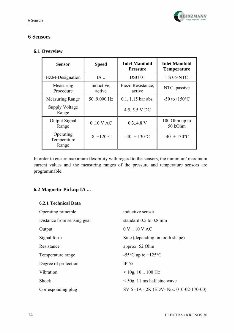
Sensor Speed Inlet Manifold Pressure
Inlet Manifold Temperature
HZM-Designation IA .. DSU 01 TS 05-NTC
Measuring Procedure
inductive, active
Piezo Resistance, active NTC, passive
Measuring Range 50..9.000 Hz 0.1..1.15 bar abs. -50 to+150°C
Supply Voltage Range
4.5..5.5 V DC
Output Signal Range 0..10 V AC 0.3..4.8 V 100 Ohm up to
50 kOhm
Operating Temperature
Range
-8..+120°C -40..+ 130°C -40..+ 130°C
In order to ensure maximum flexibility with regard to the sensors, the minimum/ maximum current values and the measuring ranges of the pressure and temperature sensors are programmable.
The installation of the pickup has to be arranged in such a way as to obtain a frequency as high as possible. Normally, the HEINZMANN governors of the series HELENOS are designed for a maximum frequency of 12,000 Hz. The frequency (in Hz) is calculated according to the formula
f (Hz) = n z( / min) *160
z = number of teeth on the pickup wheel
Example:
n = 1500
z = 160
f = 1500 *160 60
= 4,000 Hz
It should be taken care that the speed can be measured by the pulse pickup without any bias. For best results, the speed pickup should take the engine speed from the crankshaft. A suitable position for this is, e.g., the starter gear (but not the injection pump wheel).
The pickup gear must be made of magnetic material (e.g. steel, cast iron).
6.2.3 Tooth Profile
Any tooth profile is admissible. The top width of the tooth should be 2.5 mm minimum, the gap and the depth of the gap at least 4 mm. For index plates the same dimensions are valid.
Due to tolerances, a radial arrangement of the magnetic pickup is preferable.
6.2.4 Clearance of Magnetic Pickup
The distance between the magnetic pulse pickup and the tooth top should range from 0.5 to 0.8 mm. (It is possible to screw-in the magnetic pickup, until it touches the tooth and then unscrew it by about half a turn.)
6 Sensors
16 ELEKTRA / KRONOS 30
mind.4mm
mind. 2.5mm
mind. 4mm
0.5-0.8mm
Figure 6: Clearance of Pickup
6.2.5 Mounting Measurements
G
L 35
19
Figure 7: Magnetic Pickup
TYPE Thread Length (mm) Thread Size Remarks
IA 01-38 38 M 16 x 1.5
IA 02-76 76 M 16 x 1.5
IA 03-102 102 M 16 x 1.5 associated
IA 04-125 125 M16 x 1.5 plug:
IA 11-38 38 5/8"-18UNF-2A SV6-IA-2K
IA 12-76 76 5/8"-18UNF-2A
IA 13-102 102 5/8"-18UNF-2A
6 Sensors
ELEKTRA / KRONOS 30 17
Ordering specification, e.g. IA 02-76.
In order to ensure a sufficient flexibility with the sensors the minimum and maximum values of the pressure and temperature sensors are programmable.
6.2.6 Certification of the Magnetic Pickups according to ATEX
All magnetic pickups described in the previous chapters are certified according to EN 50021:1999 ignition protection grade “n“ ATEX. If the magnetic pickups are used in the corresponding areas and an ATEX certification is necessary, the wiring of the magnetic pickup has to be purchased from HEINZMANN, too. The following signboard has to be fixed to the cable near the magnetic pickup plug:
HEINZMANN GmbH & Co. KG Germanywww.heinzmann.de Tel.: +49 7673 8208-0Type: z.B. IA 02-76, II3G EEx nA II T4Tcable: -5°C to +80°C, Thousing: -8°C to +120°C
TÜV 06 ATEX 552893
WARNING - EXPLOSION HAZARD - DO NOT DISCONNECT WHILE CIRCUIT
IS LIVE UNLESS AREA IS KNOWNTO BE NON-HAZARDOUS
Figure 8: Signboard at Magnetic Pickup Cable, Front and Back Sides
6.3 DSU 01 Pressure Sensor between Air Filter and Venturi Mixer
The sensor is designed for mounting to a planar surface at the inlet manifold between air filter and venturi mixer. The pressure nozzle protrudes into the inlet manifold and is sealed to the atmosphere by an O-ring.
6 Sensors
ELEKTRA / KRONOS 30 19
It must be ensured that no condensate can be taken up in the pressure cell by mounting the unit adequately (such as pressure tapping on top of the pipe, pressure nozzle showing downward, and so on).
Additionally, the mounting should be made in such a way that the sensor is neither too close to the air filter nor too close to the throttle valve.
6.3.4 Certification of the DSU 01 Pressure Sensor according to ATEX
The pressure sensor DSU 01 is certified according to EN 50021:1999 ignition protection grade “n“ ATEX. If the sensor is used in the corresponding areas and an ATEX certification is required, the wiring of the sensor has to be delivered by HEINZMANN, too. In this case, the following signboard has to be fixed to the cable near the sensor plug:
HEINZMANN GmbH & Co. KG Germanywww.heinzmann.de Tel.: +49 7673 8208-0
Type: DSU 01, II3G EEx nA II T4Tcable: -5°C to +80°C, Thousing: -40°C to +130°C
TÜV 07 ATEX xxxxxx
WARNING - EXPLOSION HAZARD - DO NOT DISCONNECT WHILE CIRCUIT
IS LIVE UNLESS AREA IS KNOWNTO BE NON-HAZARDOUS
Figure 10: Signboard at DSU Sensor Cable, Front and Back Sides
6.4 TS 05-NTC Temperature Sensor between Air Filter and Venturi Mixer
6.4.1 Technical Data
Type NTC
Supply voltage 5±0.5 V
Temperature measuring range -50°C up to +15°C
Resistance at 20 °C (R20) 2.3 kOhm ±5 %
Resistance over measuring range approx. 100 Ohm to approx. 50 kOhm
Maximum measuring current 1 mA (5 V with 1 kOhm series resistance)
Time constant in fluids approx. 10 seconds
EMC 100 V/m
Ambiente temperature -40°C up to +125°C
Storing temperature -40°C up to +130°C
Degree of protection IP 55
6 Sensors
20 ELEKTRA / KRONOS 30
EDV-No.: 600-00-102-00
Associated cable Temperature sensor cable (EDV-No.: xxx-xx-..)
6.4.2 Measurements
6
17
22
12
G3/8
13,6
12
25,6
60
Figure 11: Measurements of Temperature Sensor TS 05-NTC
6 Sensors
ELEKTRA / KRONOS 30 21
6.4.3 Installation
The sensor is designed for mounting to a planar surface at the inlet manifold between air filter and venturi mixer. The pressure nozzle protrudes into the inlet manifold and is sealed to the atmosphere by an O-ring.
In order that the front part of the sensor is directly touched by the air stream, a suitable mounting has to be provided in the inlet manifold.
Additionally, the mounting should be made in such a way that the sensor is neither too close to the air filter nor too close to the throttle valve.
6.4.4 Certification of the TS 05-NTC Temperature Sensor according to ATEX
The TS 05-NTC temperature sensor is certified according to EN 50021:1999 ignition protection grade “n“ ATEX. If the sensor is used in the corresponding areas and an ATEX certification is required, the wiring of the sensor has to be purchased from HEINZMANN, too. In this case, the following signboard has to be fixed to the cable near the sensor plug:
HEINZMANN GmbH & Co. KG Germanywww.heinzmann.de Tel.: +49 7673 8208-0Type: TS 05-NTC, II3G EEx nA II T4
Tcable: -5°C to +80°C, Thousing: -50°C to +150°CTÜV 07 ATEX xxxxxx
WARNING - EXPLOSION HAZARD - DO NOT DISCONNECT WHILE CIRCUIT
IS LIVE UNLESS AREA IS KNOWNTO BE NON-HAZARDOUS
Figure 12: Signboard at Temperature Sensor Cable, Front and Back Sides
7 Gas Metering Control Unit GMCU-50 / 85
22 ELEKTRA / KRONOS 30
7 Gas Metering Control Unit GMCU-50 / 85
As the main component of the ELEKTRA Lambda control system the gas metering unit is based on a modular structure (fig. 2). It comprises to a large extent individual components which have been used in other applications for a long time. In this way, substantial development and manufacturing expenditure has been saved and a high level of reliability has been achieved from the very beginning .
Figure 13: Gas Metering Control Unit GMCU
The main component is a butterfly valve with integrated actuator. This unit has already been in use as an integrated mixture butterfly valve for some time. The available diameters are 50 and 85 mm, resp. Unlike the standard version, this unit has a non-contact position measuring system which ensures an 0.5 % accuracy with good long-term stability over a wide tem-perature range.
The butterfly valve unit is extended by sensor flanges which contain the measuring points for the necessary pressure and temperature measurement. All sensors for the measurement of absolute and differential pressures are arranged in a sensor box. The connection between measuring points and sensor box is realized over short hose connectors. Depending upon the version of the system the box is equipped differently with precision pressure sensors.
The controller electronics for the flow control and mix control in the extended version is based on the DC 6-controller which has been already used and approved in many applications (speed governor, positioner, Lambda controller, Dual Fuel controller). Apart from the CAN bus with flexible configuration this offers easily adaptable analogue and digital inputs and outputs, which allows a simple adaptation to the customer requirements and thus an easy
7 Gas Metering Control Unit GMCU-50 / 85
ELEKTRA / KRONOS 30 23
integration into existing environments. The integration of metering valve and electronic control represents a complete stand-alone system with little wiring and assembly work.
The system configuration, the diagnosis and calibration of the system are performed with the DcDesk 2000 communication software.
Figure 14: Control of Gas Metering Unit
In the version as a pure gas metering system the flow setpoint is given as analogue or digital value. Density of the gas must be known and parameterized. The actual flow value follows the given set point value in a wide pressure and temperature range and with a high dynamic and accuracy.
The flow control is realized by measuring the input pressure and temperature, as well as the differential pressure over the calibrated butterfly valve. The algorithm used shows a high accuracy of approx. 2 % in the range up to 200 mbar input pressure, as well as in a wide flow range. In the case of continuous updating of the gas data the metering accuracy can be guaranteed also when the gas quality varies.
Due to the precise compensation of changing ambient conditions the zero-pressure regulator normally used with venturi systems can be omitted, which means particularly clear cost advantages when gases with a low heat value are used. Furthermore, the possibility to operate the system with comparatively higher pressures leads to compact dimensions and a wide capacity range. So when using the 50-mm version with natural gas a capacity range up to approx. 2000 KW can be reached.
The use of corrosion resistant materials and a durable sensor technology permits the reliable operation with all usual types of gases in the natural gas, the biogas and wood gas range.
7 Gas Metering Control Unit GMCU-50 / 85
24 ELEKTRA / KRONOS 30
Both the gas metering unit and the gas mixers used for the air flow measurement are factory adjusted. This allows a fast and easy start-up.
To ensure save and reliable function the GMCU may only be combined with gas mixers that meet the HEINZMANN specifications. If a different gas mixer shall be used consult HEINZMANN.
7.1 Technical Data
7.1.1 General
Supply voltage 24 V DC Minimum voltage 18 V DC Maximum voltage 32 V DC
Residual ripple max. 10 % at 100 Hz
Current consumption max. 6 A
Permissible voltage dip at maximum current consumption max. 10 %
Fuse Protection 12 A
Gas inlet pressure 40 mbar up to 250 mbar
Pressure difference input/output 40 mbar up to 250 mbar
Flow rate measuring precision ±5% for the whole flow rate range
Admissible concentration of (H2S) hydrogen sulphide
max. 0.1 %
Fuels might not hold any corrosive constituents. If in doubt consult HEINZMANN
Storing temperature -30°C up to +85°C Operating temperature -30°C up to +80°C
Humidity up to 98 % at 55 °C
Vibration max. 2 mm at 10..20 Hz max. 0.24 m/s at 21..63 Hz max. 9 g at 64..2000 Hz
Shock 50 g, 11 ms, half-sine wave
Degree of protection IP 55
Hinweis
7 Gas Metering Control Unit GMCU-50 / 85
ELEKTRA / KRONOS 30 25
Insulation resistance > 1 MOhm at 48 V DC
EMC 89/336/EEC and 95/54/EEC
Weight GMCU-50 approx. 20 kg GMCU-85 approx. 35 kg
7.1.2 Externally used Inputs and Outputs
All inputs and outputs are protected against reverse-voltage and short circuit to battery plus and minus.
Digital input Engine Stop U0 < 2 V, U1 > 6,0 V, Rpd = 4,75 kΩ (plug X11, pin F) or Rpu = 4,75 kΩ oder Rpd = 150 kΩ
Reference voltage 5 V Uref = 5 V ±1 %, Iref < 30 mA (plug X11, pin C)
External analogue setpoint U = 0..5 V, Re = 100 kΩ, fg = 15 Hz (plug X11, pin H) or I = 4 .. 20 mA, Re = 200 Ω, fg = 15 Hz
Digital output error lamp Isink < 0.3 A, Urest < 1.0 V, Ileck < 0.1 mA (plug X11, pin E) Rpu = 4.75 kΩ oder Rpu = ∞, masseschaltend
Additional MF-Ports Ue = 0..10 V, Re = 20 kΩ, fg = 15 Hz (plug X11, pins A/K) or Ue = 0..5 V, Re = 100 kΩ, fg = 15 Hz or Ie = 4 .. 20 mA, Re = 200 Ω, fg = 15 Hz or U0 < 2 V, U1 > 6.5 V, Rpd = 4.75 kΩ or Rpu = 4.75 kΩ or Rpd = 150 kΩ
CAN-Bus HEINZMANN-CAN or on customer’s request (plug X11, pins R,S,T,U)
Serial interface ISO 9141, variable from 2.4 kbit/s to 57.6 kbit/s standard 9.6 kbit/s
Temperature input for PT1000 / Ni1000 sensors (plug X12, pin A) tolerances: < ±2°C at 0°C up to 130°C, rest < ±4°C
Speed sensing input for inductive sensor, with (plug X13, Pin B) fi = 25 to 9000 Hz, Ui = 0.5 to 30 V AC
7 Gas Metering Control Unit GMCU-50 / 85
26 ELEKTRA / KRONOS 30
7.2 Measurements
Figure 15: Dimensioned Drawing of GMCU-50-FC
7 Gas Metering Control Unit GMCU-50 / 85
ELEKTRA / KRONOS 30 27
Figure 16: Dimensioned drawing of GMCU-50-LC
7 Gas Metering Control Unit GMCU-50 / 85
28 ELEKTRA / KRONOS 30
Figure 17: Dimensioned drawing of GMCU-85-FC
7 Gas Metering Control Unit GMCU-50 / 85
ELEKTRA / KRONOS 30 29
Figure 18: Dimensioned drawing of GMCU-85-LC
7 Gas Metering Control Unit GMCU-50 / 85
30 ELEKTRA / KRONOS 30
7.3 Installation
The gas supplies to the GMCU are designed as flanges. This allows to screw the gas valve alternatively direct to the gas mixer. The standard pipe threads employed allow an easy connection to commercial gas pipes. For a reduced level of vibration it should be installed at the end of the gas supply line and linked to the gas mixer with a flexible hose. A flexible element between gas supply line and gas mixer must be provided in any case.
To ensure an interference-free and low-wear operation, a gas filter with a maximum 50 µm mesh size has to be installed in the gas supply line.
Any work at the valves must be performed by trained and qualified personnel under observance of the standards in force.
When selecting the location, ensure minimum vibration and oscillations.
Select a location according to the degree of protection.
Recommended mounting position for the GMCU is horizontal. Hose couplings of the pressure sensors must point upward. Contrary to that the plug connectors should not point upward. If any different mounting position should be necessary consult HEINZMANN.
The GMCU must be furnished with a sufficient potential equalisation. There is an extra screw with M6 thread at the GMCU where a potential compensation line can be connected.
7.4 Certification of the Gas Metering Control Unit GMCU according to ATEX
The GMCUs are certified according to EN 50021:1999 ignition protection grade “n“ ATEX. If the units are used in the corresponding areas and an ATEX certification is necessary, the wiring of the used gas metering control unit has to be purchased from HEINZMANN, too.
The ATEX evaluation does not include the inside of gas bearing parts.
The housing of the GMCU has three indicating labels.
Warning
Note
7 Gas Metering Control Unit GMCU-50 / 85
ELEKTRA / KRONOS 30 31
Label 1 contains the general and ATEX relevant information
II2G Ex nAR II T4Tamb: -30°C to +80°CTÜV 07 ATEX xxxxx
Figure 19: Label 1 with general and ATEX relevant information
Label 2 contains the particular type designation and serial number
Type: GMCU-85-FCSerial No: yy mm xxxx-zz
Figure 20: Label 2 with the type designation and serial number (for GMCU-85-FC)
Label 3 contains warnings about removing the plugs and the cover.
DO NOT DISCONNECT WHILE CIRCUIT IS LIVE UNLESS AREA IS KNOWN TO
BE NON-HAZARDOUS!
WARNING - EXPLOSION HAZARD
BEFORE REMOVING THE COVER, SWITCH OFF THE POWER SUPPLYAND WAIT AT MINIMUM 5 SECONDS
TO DISCHARGE THE ENERGY OF THE CAPACITIES!
Figure 21: Label 3 with warnings about removing the plugs and the cover
8 Electrical Connections
32 ELEKTRA / KRONOS 30
8 Electrical Connections
Any work at the cabling may only be performed by trained and qualified personnel under observance of the standards in force.
When installing electrical connections, follow the wiring diagrams of HEINZMANN and/or the packager. Use only specified cables for cabling the units. Keep strictly to the indicated cable cross sections.
The control valve is driven by a HEINZMANN control unit. In special cases the valve may be connected to an external control unit of the packager. In this case, the express approval by HEINZMANN is required. The relevant specification given by HEINZMANN must be observed absolutely.
Warning
Warning
8 Electrical Connections
ELEKTRA / KRONOS 30 33
8.1 Wiring Diagram G
MC
U-..
WZ
AK
BC
DE
HG
FP
LQ
UT
XS
RN
MY
JA
B
Power Supply
MultifunctionsIn-/Outputs
Common Alarm
CANCommunication
CANTermination
DcDesk2000Communication
Air Temperature Sensor
+24 V
MF-Port 1MF-Port 20 V
+5 V Ref out
0 VDigital outAnalogue In
Digital In
CAN LCAN H
CAN HCAN L
0 V+24 VTxDRxD
0 VSignal
0 V
Engine Stop
External Setpoint
AB Magnetic Pickup
(only with Lambda Control)0 VSignal
CD
EF
GH
IJ
X11
X12
X13
0 V
0 V
Signal
Signal
+5 V Ref outAir Pressure Sensor infront of venturi mixer 2(option)
Air Pressure Sensor infront of venturi mixer 1(option)
Figure 22: Wiring Diagram ELEKTRA
8 Electrical Connections
34 ELEKTRA / KRONOS 30
8.2 Cables supplied by HEINZMANN
The following cables are supplied by HEINZMANN in the required lengths.
8.2.1 Cable to Magnetic Pickup
Läng
e na
ch B
edar
f (m
ax. 1
5 m
)
Gehäuse1312 A
B SignalMasse
Abschirmung
12
Klemme Steckerpin Funktion No.Anschlussbelegungen der Kabel
Figure 23: Cable W4
8.2.2 Cable to Air Temperature Sensor
8.2.3 Cable to ELEKTRA Main Plug
8.2.4 Pressure Pipes to Gas Mixer Delta-P Sensors
9 General Mounting Instructions
ELEKTRA / KRONOS 30 35
9 General Mounting Instructions
For the assembly, make sure to install the components free from vibrations.
Tighten the screws firmly.
All the components must be integrated into equipotential bonding.
The components may only be installed in the permitted zones.
All the components must be installed in such a way that their plug-in connections are only subjected to a low risk of impact.
The inside of the components (gas-bearing components) is not included in the ATEX Specification.
Note
10 Parametrisation of ELEKTRA / KRONOS 30 Governors
36 ELEKTRA / KRONOS 30
10 Parametrisation of ELEKTRA / KRONOS 30 Governors
The software for HEINZMANN digital controllers is conceived in such a way that parameters can be set either at the engine manufacturer’s or at the final customer’s, if the necessary instruments (communications tool) are available. Only a few basic parameters are pre-set at the HEINZMANN factory. This means that the digital governor usually gets its definitive set of data from a source outside HEINZMANN.
An exception is made for control units delivered in large quantities. If HEINZMANN have been provided with a definitive set of data in advance this data can be supplied to the units at the factory.
As a principle, initial programming should be conducted by experienced personnel and must be verified before the first commissioning of the engine.
The adjustment and meaning of parameters are explained in detail in the "Basic information 2000" manual.
The following sections describe the possible parametrisation of the control unit:
10.1 Parametrisation with Hand Held Programmer HP 03
The complete parametrisation can be made via the hand held programmer HP 03. This handy device is particularly suited for development and series calibration as well as for servicing. This unit needs no external power supply.
10.2 Parametrisation via PC / Laptop
Parametrisation can also be conducted using a PC and the comfortable HEINZMANN DcDesk 2000 communication software. As compared with the hand held programmer, it offers the great advantage that various curves are graphically represented on the screen and changes can be made. Besides, time diagrams can be displayed without any oscilloscope when the control unit is commissioned on the engine. Furthermore, the PC offers a better overview, because the PC programme has a menu structure and allows to have several parameters continuously displayed.
Besides, the PC programme permits to save and download the operational data to and from the data media. Additionally, the following useful application is available:
Once the parameterisation has been completed for a specific engine type and its application, the data set can be stored to disk. For future applications of a similar type, the data sets can be downloaded and re-used with the new control units.
11 CAN-Bus
ELEKTRA / KRONOS 30 37
11 CAN-Bus
The HEINZMANN CAN bus allows to expand the functionality of the overall system by further modules. With a knock control unit, which can communicate directly with the ignition system via an additional CAN or Modbus interface, or by a HEINZMANN generator management system and further devices the system can be extended and adapted. Alternative extensions are e. g. a simple user interface unit or a high-resolution touch screen monitor with data logging functions for system parameterisation and monitoring.
12 General Safety Information for Commisioning
38 ELEKTRA / KRONOS 30
12 General Safety Information for Commisioning
The parametrisation, visualisation of measured data and diagnosis are performed by the DcDesk 2000 communication software. The well approved program is used for all digital HEINZMANN control devices and characterised by an extensive functionality and easy operation. Thus the configuration for the ELEKTRA start-up can be accomplished without difficulty, the representation of parameters and measured values is shown clearly in the form of tables, curves and maps. Furthermore, the software permits to store and load parameter sets and recorded data. The representation of measured values as curves over the time facilitates the evaluation and optimisation of dynamic procedures. DcDesk 2000 can also be used for remote control together with the HEINZMANN remote control system SATURN.
12.1 General Safety Information for Commissioning
Any commissioning work may only be performed by trained and qualified personnel observing the standards in force.
The user is responsible for the correct commissioning of the total installation.
Before commissioning the installation, please note the following information:
• Before starting to install any equipment, the installation must have been switched dead!
• Check the perfect functioning of the existing protection and monitoring systems.
• Commissioning may only be performed with the terminal box cover plate installed.
12.2 General notes concerning the first start of the engine
• Adjust speed pickup distance according to instructions.
• Verify correct software and essential parameters engine data, number of teeth, mixer data, gas valve data, sensor data, gas data, Lambda data etc.!
• Adjust the sensors, if necessary.
• Before starting the engine, check the electrical connections as well as the basic functions of the system in positioning mode (parameters 5705 and 5706)!
• It is recommendable to start the engine first of all without the control unit being connected.
Overspeed protection must be ensured!
Warning
Danger
12 General Safety Information for Commisioning
ELEKTRA / KRONOS 30 39
• Start the engine after finishing the presetting according to the description below.
• Optimise the Lambda map and correction values following the description below.
Knock monitoring must be activated or pay attention to audible knocking.
Warning
13 Configuration and Calibration of Inputs and Outputs
40 ELEKTRA / KRONOS 30
13 Configuration and Calibration of Inputs and Outputs
The ELEKTRA Gas Metering Control Unit has two multi-function ports which can be configured as analog input, analog output or digital output.
All other inputs and outputs are permanently preconfigured at the factory.
User definable parameters allow the analog inputs or outputs to ascertain whether the signal being utilized is meant to be a current or voltage signal.
All adjustments for inputs and outputs can be carried out comfortably using DcDesk 2000, where there are specific windows for all the important aspects, considerably simplifying the process of parameter setting.
13.1 Selectable Inputs and Outputs
The assignments of the channels cannot be altered during operation. It will therefore be necessary to save the data and restart the control unit with a reset of the control unit after configuration. The value ranges of analogue inputs and outputs then must be adapted again to the newly chosen electric unit.
The following table shows the configuration parameters of the selectable inputs and outputs.
Note
Note
13 Configuration and Calibration of Inputs and Outputs
ELEKTRA / KRONOS 30 41
Connection Designantion
Terminal / Pin
Configuration- Parameter Configuration
4800 Port1Type 0 = Analogue 1 1 = Digital 1
4801 Port1OutOrIn 0 = Input 1 1 = Output 1 if analogue output: 4..20 mA P1 2 / A
5510 AnalogIn1_Type
if analogue input: 1 = 0..5 V 2 = 4..20 mA 3 = 0..10 V
4802 Port2Type 0 = Analogue 2 1 = Digital 2
4803 Port2OutOrIn 0 = Input 2 1 = Output 2 if analogue output: 4..20 mA P2 1 / K
5520 AnalogIn2_Type
if analogue input: 1 = 0..5 V 2 = 4..20 mA 3 = 0..10 V
Parameterizing Example:
Multifunctional port 1 is used as current input 1 and multifunctional port 2 as digital output 2.
The Gas Metering Control Unit has a maximum of three external analog inputs. Analog input no. 3 already has Pin H reserved for the setpoint.
All three inputs can be configured for current or voltage by setting their respective parameters. Analog input 3 is set, similar to analog inputs 1 and 2, to either current or voltage via Parameter 5530 AnalogIn3Type (see previous chapter).
13 Configuration and Calibration of Inputs and Outputs
42 ELEKTRA / KRONOS 30
Input Designation Terminal / Pin Range
Analogue input 1 P1 2 / A 0..5 V or 4..20 mA or 0..10 V
Analogue input 2 P2 1 / K 0..5 V or 4..20 mA or 0..10 V
Analogue input 3 SpA 7 / H 0..5 V or 4..20 mA
Moreover, there are six internal analog inputs to measure the pressure and two internal analog inputs to measure the temperature, to which the sensors, which are part of the ELEKTRA Gas Metering Control Unit, have already been connected at the factory. These inputs are already permanently assigned, but can be recalibrated if necessary.
13.2.1 Sensor Overview
Sensors are needed to measure set values, pressures, temperatures, etc., and to execute functions depending on these quantities.
The following table provides an overview:
13 Configuration and Calibration of Inputs and Outputs
2906 AirPressure1 (i) Air pressure before venturi mixer
Absolute air pressure before venturi mixer for calculation of air flow
2907 Air Pressure2 (i) Air pressure before venturi mixer at bank 2
Absolute air pressure before venturi mixer for calculation of air flow at bank 2
2908 AirTemp (i) Air temperature Air temperature for calculation of air flow
2910 GasTemp (i) Gas temperature Gas temperature for calculation of gas flow
2914 GasPressure (i) Gas pressure Absolute gas pressure for calculation of gas flow
2915 GasDeltaPressure (i) Gas delta pressure Gas delta pressure for calculation of gas flow
2916 Vent1DeltaPressure (i) Venturi delta pressure Venturi delta pressure for calculation of air flow
2917 Vent2DeltaPressure (i) Venturi delta pressure at bank 2
Venturi delta pressure for calculation of air flow at bank 2
2918 MeasuredPower External load signal Load signal for closed loop operation
2924 Measured GasQuality Gas quality Gas quality for determining of methan content for calculation of gas heating vale
The sensors marked with (i) are those internal sensors which are already permanently configured and connected.
13.2.2 Assigning Inputs to Sensors and Setpoint Adjusters
Assignment of inputs to sensors and setpoint adjusters is made by entering the desired analogue input in the assigning parameters from 900 AssignIn... onward.
Entering the number 0 in the assignment parameter will signify that the respective sensor has neither been connected nor activated. Consequently, the input will not be subject to monitoring. Therefore, the assignment parameters of any sensors not needed should be set to 0. The sensor value during operation will then constantly be equal to the minimum value.
13 Configuration and Calibration of Inputs and Outputs
44 ELEKTRA / KRONOS 30
If an external analog setpoint is required, it must always be assigned to analog input 3 (pin H).
Parameterizing Example:
The external setpoint adjuster (indication parameter 2900) is to be connected to analogue input 3 and the current load value (indication parameter 2918) to analogue input 1. For the other sensors remaining unused the value 0 is to be entered.
Number Parameter Value Unit 900 AssignIn_SetpExt 3
918 AssignIn_MeasPower 1
13.2.3 Measuring Ranges of Sensors
In HEINZMANN controls, all sensor parameters and all relating values are provided with the maximum possible value range. Thus, temperature sensors can be utilized for a range from –100 to +1,000 °C and the current load signal up to 2500 kW. Pressure sensors cover a maximum range from 0 to 5 bar. Indication for sensors without physical ranges (setpoint adjuster) is by per cent
Since there exist pressure sensors with different measuring ranges, the control unit must be informed about the particular value ranges which may differ from the maximum possible physical value range. These ranges are defined as the physical values corresponding to minimum and maximum input values such as 0.5 to 4.5 Volts or 4 to 20 mA.
As temperature sensors show a non-linear behaviour, suitable linearization characteristics for the various types of temperature sensors are already implemented at the factory so there will be no need to specify physical measuring ranges for these sensors.
Note
13 Configuration and Calibration of Inputs and Outputs
ELEKTRA / KRONOS 30 45
Sensor Minimum Measuring Value
Maximum Measuring Value
External setpoint 950 SetpExtLow 951 SetpExtHigh
Air pressure bank 1 966 AirPress1Low 967 AirPress1High
Air pressure bank 2 968 AirPress2Low 969 AirPress2High
Gas pressure 978 GasPressLow 979 GasPressHigh
Gas delta pressure 980 GasDeltaPressLow 981 GasDeltaPressHigh
Venturi delta pressure Bank 1 982 Vent1DeltaPressLow 983 Vent1DeltaPressHigh
Venturi delta pressure Bank 2 984 Vent2DeltaPressLow 985 Vent2DeltaPressHigh
External current load signal 986 MeasPowerSensorLow 987 MeasPowerSensorHigh
External gas quality signal 998 MeasGasQualityLow 999 MeasGasQualityHigh
Parameterizing Example:
A gas pressure sensor with a measuring range from 0 to 2 bar is to be used.
Number Parameter Value Unit 978 GasPressLow 0.0 bar 979 GasPressHigh 2.0 bar
13.2.4 Modifying Reactions to Sensor Errors
Setpoint adjusters and sensors are being monitored with regard to their valid measuring ranges. On exceeding these ranges in either direction, a sensor error is detected. For any detected error, the respective response to this error can be modified by appropriate configuration which will allow to adjust the control's behaviour to the specific application and mode of operation in case of failure.
Substitute values may be set for setpoint adjusters and sensors by means of the parameters 1000 Subst.. This will permit the control to continue operation should the respective sensor fail. There also exists the possibility of reverting to the last valid value before the failure occurred rather than to maintain operation by resorting to a default value. The parameters 5000 SubstOrLast... are used to decide by which value the control is to continue operation in case the setpoint adjuster or the sensor is at fault. If the respective parameter is set to "1" the substitute value will be used as defined, if set to "0" the last valid value will be used. This method of error handling will in most cases permit to maintain safe emergency operation of the installation.
The below table lists both the parameters where the substitute values are stored and the associated parameters for selecting operation by default value or by the last valid value.
13 Configuration and Calibration of Inputs and Outputs
46 ELEKTRA / KRONOS 30
Substitute Value Selection of substitute Value Substitute Value for
1006 SubstAirPress1 5006 SubstOrLastAirPress1 Air pressure bank 1
1007 SubstAirPress2 5007 SubstOrLastAirPress2 Air pressure bank 2
1008 SubstAirTemp 5008 SubstOrLastAirTemp Air temperature
1010 SubstGasTemp 5010 SubstOrLastGasTemp Gas temperature
1014 SubstGasPress 5014 SubstOrLastGasPress Gas pressure
1015 SubstGasDeltaPress 5015 SubstOrLastGasDeltaP Gas delta pressure
1016 SubstVent1DeltaPress 5016 SubstOrLastVent1DP Venturi delta pressure bank 1
1017 SubstVent2DeltaPress 5017 SubstOrLastVent2DP Venturi delta pressure bank 2
1018 SubstMeasuredPower 5018 SubstOrLastMeasPower External load signal
1024 SubstMeasGasQuality 5024 SubstOrLastGasQy External gas quality signal
For setpoint and sensor inputs, the parameters 5040 HoldOrReset… offer the option to decide how the control is to react if an error clears itself (e.g., loose contact in wiring). If the respective parameter is set to "1" the error will be regarded to be latching. Therefore, there will be no reaction by the control when the sensor measurement is back within the valid range. If the parameter is set to "0" the error will be reset and operation continue using the signal coming from the sensor.
Parameter Reaction to Error at
5040 HoldOrResetSetpExt External setpoint
5046 HoldOrResetAirPress1 Air pressure bank 1
5047 HoldOrResetAirPress2 Air pressure bank 2
5048 HoldOrResetAirTemp Air temperature
5050 HoldOrResetGasTemp Gas temperature
5054 HoldOrResetGasPress Gas pressure
5055 HoldOrResetGasDeltaPress Gas delta pressure
5056 HoldOrResetVent1DeltaPress Venturi delta pressure bank 1
5057 HoldOrResetVent2DeltaPress Venturi delta pressure bank 2
5058 HoldOrResetMeasuredPower External load signal
5064 HoldOrResetMeasGasQuality External gas quality signal
13 Configuration and Calibration of Inputs and Outputs
ELEKTRA / KRONOS 30 47
13.2.5 Calibration of analogue Inputs
Sensors convert physical quantities (e.g., pressure) to electric quantities (voltage, current). The control unit measures voltage/current and indicates them directly. To enable the control to operate with the physical value transmitted by the sensor, it is necessary that the control be provided with two reference values informing it about the relation between the electrically measured values and the actual physical quantities. The two reference values are the sensor output values associated with the minimum and maximum measuring values as described in ↑ 13.2.3 Measuring Ranges of Sensors. With this information, the control is capable of normalizing the measured values and of displaying them specified in per cent of the sensor range or directly in terms of their physical values.
Each of the analogue inputs is associated with a low reference value (parameters 15xx AnalogInx_RefLow resp. IntAnalogInx_RefLow) and a high reference value (parameters 15xx AnalogInx_RefHigh resp. IntAnalogInx_RefHigh).
Error Limit 16000
Error Limit 64000
63100
18700
4.8
1.0
2.0
0.5
2.0
0.5
[bar] [V] [bar]
AIR PRESSURE SENSOR VOLTAGE VALUE MEASURED BY SENSOR
AIR PRESSURE VALUE
Figure 24: Calibration Procedure
Parameterizing example:
The delta pressure sensor from venturi mixer 1 has been connected to internal input 3. Its measuring range is supposed to be from 0 mbar to 100 mbar and is to be converted into voltages ranging from 0.5 V to 4.5 V. The parameter 3555 IntAnalogIn3 will display the actual measurement and the parameter 2916 Vent1DeltaPressure will read the converted measuring value in bar.
13 Configuration and Calibration of Inputs and Outputs
48 ELEKTRA / KRONOS 30
Number Parameter Value Unit 916 AssignIn_Vent1Dpress 3
982 Vent1DeltaPressLow 0 mbar
983 Vent1DeltaPressHigh 100 mbar 1560 IntAnalogIn3_RefLow 0.5 V 1561 IntAnalogIn3_RefHigh 4.5 V
13.2.6 Filtering of Analogue Inputs
The measured value of an analogue input can be filtered through a digital filter. The respective parameters are stored at the numbers 15x4 AnalogInx_Filter resp. IntAnalogInx_Filter.
Each of these parameters is to hold a filter value ranging from 1 to 255. The value 1 signifies that there will be no filtering. The filtering time constant can be derived from the filter values by the following equation:
τ = 5,62 valuefiltering [s].
For normally fast sensor changes filter value 8 will be best suited. For measuring quantities that change more slowly, such as temperatures, a filter value of about 50 can be used. The filtering time constant should correspond approximately to the sensor's time constant.
Parameterizing Example:
Number Parameter Value Unit
1524 AnalogIn2_Filter 8
τ =
862.5
[s] = 0.128 s
13.2.7 Error Detection for Analogue Inputs
If a sensor fails (e.g., by short circuit or cable break), the control will read voltages or currents lying outside the normal measuring range. These irregular measuring values can be used to define inadmissible operating ranges by which the control can recognize that the sensor is at fault.
The error limits are like the reference values entered in electric units.
The parameters 15x2 AnalogInx_ErrorLow resp. IntAnalogInx_ErrorLow and TempInx_ErrorLow resp. IntTempIn_ErrorLow define the lower error limits. The parameters 15x3 AnalogInx_ErrorHigh resp. IntAnalogInx_ErrorHigh and TempInx_ErrorHigh resp. IntTempIn_ErrorHigh determine the upper error limits.
13 Configuration and Calibration of Inputs and Outputs
ELEKTRA / KRONOS 30 49
Parameterizing Example:
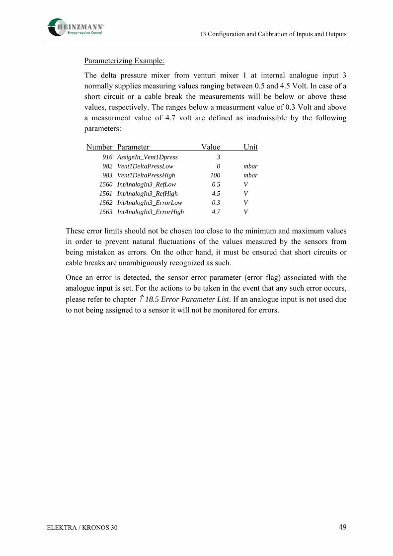
The delta pressure mixer from venturi mixer 1 at internal analogue input 3 normally supplies measuring values ranging between 0.5 and 4.5 Volt. In case of a short circuit or a cable break the measurements will be below or above these values, respectively. The ranges below a measurment value of 0.3 Volt and above a measurment value of 4.7 volt are defined as inadmissible by the following parameters:
Number Parameter Value Unit 916 AssignIn_Vent1Dpress 3
982 Vent1DeltaPressLow 0 mbar
983 Vent1DeltaPressHigh 100 mbar 1560 IntAnalogIn3_RefLow 0.5 V 1561 IntAnalogIn3_RefHigh 4.5 V 1562 IntAnalogIn3_ErrorLow 0.3 V 1563 IntAnalogIn3_ErrorHigh 4.7 V These error limits should not be chosen too close to the minimum and maximum values in order to prevent natural fluctuations of the values measured by the sensors from being mistaken as errors. On the other hand, it must be ensured that short circuits or cable breaks are unambiguously recognized as such.
Once an error is detected, the sensor error parameter (error flag) associated with the analogue input is set. For the actions to be taken in the event that any such error occurs, please refer to chapter ↑ 18.5 Error Parameter List. If an analogue input is not used due to not being assigned to a sensor it will not be monitored for errors.
13 Configuration and Calibration of Inputs and Outputs
50 ELEKTRA / KRONOS 30
13.2.8 Overview of the Parameters associated with one analogue Input
For inputs relating to setpoints and pressure the following parameters are provided:
Parameter Meaning
15x0 AnalogInx_RefLow resp. IntAnalogInx_RefLow
lower reference value
15x1 AnalogInx_RefHigh resp. IntAnalogInx_RefHigh
upper reference value
15x2 AnalogInx_ErrLow resp. IntAnalogInx_ErrLow
lower error limit
15x3 AnalogInx_ErrHigh resp. IntAnalogInx_ErrHigh
upper error limit
15x4 AnalogInx_Filter resp. IntAnalogInx_Filter
filtering constant
35x0 AnalogInx resp. IntAnalogInx
current measuring value in %
35x1 AnalogInx_Value resp. IntAnalogInx_Value
current measuring value in electrical unit
For temperature inputs the following parameters are provided:
Parameter Meaning
1542 TempIn_ErrorLow bzw. 1592 IntTempInErrorLow
lower error limit
1543 TempIn_ErrorHigh bzw. 1593 IntTempIn_ErrorHigh
upper error limit
1544 TempIn_Filter bzw. 1594 IntTempIn_Filter
filtering constant
3540 TempIn bzw. 3590 IntTempIn
current measuring value in °C
3541 TempIn_Value bzw. 3591 IntTempIn_Value
current measuring value in digits
Any inputs that have not been assigned a sensor will not be monitored for errors, and indicate only the measuring value 35xx AnalogInx_Value resp. TempIn_Value.
13 Configuration and Calibration of Inputs and Outputs
ELEKTRA / KRONOS 30 51
13.3 Digital Inputs
The ELEKTRA Gas Metering Control Unit has only one digital input. This input has already been permanently allocated by the factory for the stop signal. If this input is activated, the gas valve will close.
Parameter 4810 StopImpulseOrSwitch is meant to define whether a switching pulse is sufficient enough to close the gas valve, or if the switch needs to remain closed.
4810 StopImpulseOrSwitch = 0 the gas valve will only close when the switch is off 4810 StopImpulseOrSwitch = 1 Switching pulse is sufficient to close the gas valve
Using the parameter 4811 4811 StopOpenOrClose a switching input can be defined to be high active, i. e. active while the switch is closed, or to be "low" active, i. e. active while the switch is open.
4811 StopOpenOrClose = 0 active when switch is closed 4811 StopOpenOrClose = 1 active when switch is open
The 2810 SwitchEngineStop parameter indicates whether the relevant function is activated. The number "1" shows the function to be active while "0" means that it is inactive.
Since the input signal is debounced by the control electronics it must be supplied for at least 20 ms in order to be identified.
13.4 Analogue Outputs
The ELEKTRA Gas Metering Control Unit is equipped with two multi-function ports which may also be used as analog outputs with 4..20-mA current signals (↑ 13.1 Selectable Inputs and Outputs). These outputs may be used to indicate speed or actuator position or as a setpoint output for other devices.
13.4.1 Assignment of Output Parameters to analogue Outputs
Every parameter of the control unit can be read out via analogue outputs. Therefore only the parameter number of the output value has to be put-in in the following parameters.
1640 CurrentOut1_Assign Current Output 1 1645 CurrentOut2_Assign Current Output 2
Hinweis
13 Configuration and Calibration of Inputs and Outputs
52 ELEKTRA / KRONOS 30
Parameterizing Example:
We want to read out speed (indication parameter 2000) from analogue output 1 and actuator position (indication parameter 2300) from analogue output 2.
Number Parameter Value Unit 1640 AnalogOut1_Assign 2000
1645 AnalogOut2_Assign 2300
Signal output can be inverted (e.g., low current for high speeds) by entering the parameter numbers negative in sign.
13.4.2 Value Range of Output Parameters
When values are read out, sometimes it is convenient not to read out the entire range but only a part of it, for instance one might not wish to see the whole control unit’s speed range of 0..4000 rpm on an instrument but only the actually used range of 700..2100 rpm.
It is therefore possible to limit the output range with parameters 16x3 AnalogOutx_ValueMin and 16x4 AnalogOutx_ValueMax.
As there are a great many different value ranges, these parameters are to be set to the required low and high output values specified in per cent of the value range of the respective output parameter. If the entire value range is required, the minimum value is to be set to 0 % and the maximum value to 100 %.
The PC programme DcDesk 2000 allows to display output ranges in the parameter's specific measurement unit.
Parameterizing Example:
Current speed 2000 Speed is to be read out via a current output of 4..20 mA. The output range shall be restricted to 500 rpm through 1500 rpm. i.e., 500 rpm correspond to 4 mA and 1500 rpm to 20 mA. Since the values of this parameter have a range from 0 to 4000 rpm, output will have to be adjusted accordingly:
Note
Note
13 Configuration and Calibration of Inputs and Outputs
ELEKTRA / KRONOS 30 53
SPEED[rpm]
CURRENT [mA]
500
1500
4 20
Value Range of
Valu
e R
ange
of
Out
put P
aram
eter
analogue Output
0
Figure 25: Reading out a Parameter via an analogue Output
1643 CurrentOut1_ValueMin %5.12%100*4000500= =
1644 CurrentOut1_ValueMax %5.37%100*40001500= =
Number Parameter Value Unit 1640 CurrentOut1_Assign 2000
1643 CurrentOut1_ValueMin 12.5 %
1644 CurrentOut1_ValueMax 37.5 %
13.4.3 Value Range of analogue Outputs
In the majority of cases not the maximum output range of approx. 0..22 mA is required but the standard output range of 4..20 mA.
Parameters 16x1 AnalogOutx_RefLow and 16x2 AnalogOutx_RefHigh are provided to adapt the output range. The value to be entered is specified directly in mA.
13 Configuration and Calibration of Inputs and Outputs
54 ELEKTRA / KRONOS 30
Parameterizing Example:
Current speed 2000 Speed is to be output out via a current output of 4..20 mA, but with the range restricted to 500 rpm to 1500 rpm, Only the range from 500 rpm to 1500 rpm is to be output, i.e., 500 rpm correspond to 4 mA and 1500 rpm correspond to 20 mA.
Number Parameter Value Unit 1640 CurrentOut1_Assign 2000 1641 CurrentOut1_RefLow 4.00 mA 1642 CurrentOut1_RefHigh 2.00 mA 1643 CurrentOut1_ValueMin 1.5 %
1644 CurrentOut1_ValueMax 37.5 %
13.5 Digital Outputs
The ELEKTRA Gas Metering Control Unit is equipped with two multi-function ports which may also be used as digital outputs (↑ 13.1 Selectable Inputs and Outputs). These outputs can be used to activate optical or acoustical signal transmitters or to transmit signals to other devices. The maximum output current is 0.3 amps, each.
Every measured and indicated value of the [0.1] range from parameter list 2 can be assigned to a digital output. The currently displayed values are shown in parameters 2851 DigitalOut1 and 2852 DigitalOut2.
The parameter settings described in the following sections can be achieved in an easy and comfortable way using a dedicated window of DcDesk 2000. In addition, this window allows to conduct a test of the digital output’s connections.
13.5.1 Assignment of Output Parameters
Assignment is made by means of the parameters 851 DigitalOut1_Assign and 852 DigitalOut2_Assign. The parameter numbers of the desired measuring values must be entered there. If inverted output of the measurement is desired, the number of the measuring parameter is to be entered negative in sign.
Note
13 Configuration and Calibration of Inputs and Outputs
ELEKTRA / KRONOS 30 55
Parameterizing Example:
Output 1 is to indicate that the maximum fuel limitation is active and output 2 has to be active as long as engine start has not been enabled (i.e., as long as 3806 EngineRelease has not been activated):
Number Parameter Value Unit 851 DigitalOut1_Assign 2711
852 DigitalOut2_Assign -3806
14 Commissioning of ELEKTRA with Flow Control
56 ELEKTRA / KRONOS 30
14 Commissioning of ELEKTRA with Flow Control
14.1 General IO Configuration
For general information about the configuration and calibration of the inputs and outputs for ELEKTRA please refer to the chapter ↑ 13 Configuration and Calibration of Inputs and Outputs.
SetpExt (external flow setpoint) and GasQuality are the only available sensors in ELEKTRA. Additionally 3 so called internal sensors are also present in the control unit: GasTemp (Gas Temperature), GasPressure (Gas absolute Pressure before throttle) and GasDeltaPressure (Delta Pressure over throttle). They are calibrated at the HEINZMANN factory before delivery and normally do not need any further tuning. The actual values of these sensors are visible in parameters 2910 GasTemp, 2914 GasPressure and 2915 GasDeltaPressure.
It is recommended to regularly (for example every 6 months) check the calibration of the GasDeltaPressure Sensor and compensate a possible reasonable drift of the sensor. This should be done while the motor is stopped and no gas pressure is applied before the gas throttle (Gas Pressure regulator closed and gas vent valves open). In this case, the output of the GasDeltaPressure Sensor, visible in parameter 3556 IntAnalogIn2_Value should be around 0.5V (Delta pressure near to 0 mBar). To check the calibration of the sensor, please proceed as follows:
• Check the actual value of par. 3556 IntAnalogIn2_Value. If this value is bigger than 0.55V or lower than 0.45 V, the drift of the sensor is too big, the sensor should be replaced, please contact Heinzmann.
• Compare the values of parameter 3556 IntAnalogIn2_Value and parameter 1555 IntAnaIn2_RefLow. If a difference can be noticed, please copy the value of parameter 3556 IntAnalogIn2_Value into parameter 1555 IntAnaIn2_RefLow and save all the parameters in the control unit (F6 or Control Unit->Store parameters in control unit)
14.2 Functional Description and Configuration
14.2.1 ELEKTRA Setpoint
There are four different ways to give a Flow/Position setpoint to ELEKTRA:
14.2.1.1 External Flow Setpoint
This is ELEKTRA’s normal way of working: the flow setpoint is given by sensor ExtSetp. In order to use the external flow setpoint, follow the next steps:
14 Commissioning of ELEKTRA with Flow Control
ELEKTRA / KRONOS 30 57
Configure the sensor according to ↑ 13 Configuration and Calibration of Inputs and Outputs.
Set parameter 5300 GMUPosSetpointPCOn and parameter 5301 GMUFlowSetpoint-PCOn to 0.
When this configuration has been made the external flow setpoint value is visible in parameter 2900 SetpointExtern and 3303 NormGasFlowSetp.
14.2.1.2 Flow Setpoint over DcDesk2000
To support functional tests and commissioning, and assist trouble shooting it is possible, independent of the external setpoint, to give a flow setpoint via DcDesk2000. In this case, the external setpoint is deactivated and ELEKTRA controls the gas throttle to reach the DcDesk2000 flow setpoint. In order to use the DcDesk2000 flow setpoint, follow the next steps:
Set parameter 1301 GMUFlowSetpointPC to the desired flow setpoint
Set parameter 5300 GMUPosSetpointPCOn to 0 and 5301 GMUFlowSetpointPCOn to 1.
When this configuration has been made the actual value of the flow setpoint is visible in Par. 3303 NormGasFlowSetp. This means that both parameters 1301 GMUFlowSetpointPC and 3303 NormGasFlowSetp should have the same value.
14.2.1.3 Gas Throttle Position Setpoint over DcDesk2000
As an additional feature to support functional tests, commissioning and assist trouble shooting, it is possible to switch off the flow control algorithm and send a simple gas throttle position setpoint via DcDesk2000. In this case ELEKTRA will not regulate the gas flow anymore but will only drive the throttle to the given position setpoint. To configure this operation mode, please follow the next steps:
Set parameter 1300 GMUPosSetpointPC to the desired gas throttle position setpoint.
Set parameter 5300 GMUPosSetpointPCOn to 1 and parameter 5301 GMUFlow-SetpointPCOn to 0.
When this configuration has been made the actual value of the position setpoint is visible in Par. 2330 ActPosSetpoint. This means that both parameters 1300 GMUPosSetpointPC and 2330 ActPosSetpoint should have the same value.
If both parameters 5300 GMUPosSetpointPCOn and 5301 GMUFlowSetpointPCOn are set to 1, the DcDesk2000 gas throttle position setpoint will be active whereas the DcDesk2000 flow setpoint will be inactive. Warning
14 Commissioning of ELEKTRA with Flow Control
58 ELEKTRA / KRONOS 30
14.2.1.4 Safety Remarks
It is possible to use the DcDesk2000 flow and position setpoints while the engine is running. It is also possible to switch between the different setpoint modes during engine operation. It is important to understand that in these cases the normal external flow setpoint normally controlled by an external AFR-controller is deactivated. In other words, the AFR-control of the engine is inactive and the DcDesk2000 user is the only one responsible for the gas fuel feed and air fuel ratio control of the engine. This quasi manual control of the engine is slow and potentially dangerous; errors may easily occur and lead to severe damage to persons and material. HEINZMANN explicitly recommends to restrict the use of these features to advanced and experienced users.
14.2.2 Flow Control Parameters
While in gas flow control mode parameter 5300 GMUPosSetpointPCOn = 0, ELEKTRA regulates the gas flow by a PID control loop. The associated P, I and D-factors can be found in parameters 1322 GasFlowGovGain, 1323 GasFlowGovStability and 1324 GasFlowGovDerivative. They are normally set at the HEINZMANN factory but can be individually modified to optimize the behaviour of the gas flow controller on customer-specific engines.
14.2.3 Gas Gravity
The gas gravity is an essential information in ELEKTRA’s control algorithm and must be available to accurately regulate the gas flow. There are 2 ways to provide this information to ELEKTRA.
14.2.3.1 Constant Gas Gravity
For installations with constant gas quality, the gas gravity can be configured as a fixed value in ELEKTRA. To do that, please follow the next steps:
Set parameter 1303 NormGasGravity to the desired value in [kg/Nm³]
Verify that parameter 5303 GasQualityInputOn is set to 0
14.2.3.2 Variable Gas Gravity
Certain installations make use of different gases or one gas of variable quality. In those cases, it might be of interest to make the internally used gas gravity information in ELEKTRA follow an external analogue signal. Please follow the next steps:
14 Commissioning of ELEKTRA with Flow Control
ELEKTRA / KRONOS 30 59
Configure the GasQuality sensor according to ↑ 13.2 Analogue Inputs. Once this is done, the actual gas quality is displayed in parameter 2911 GasQuality in [%].
A curve of gas gravity depending on gas quality is provided in ELEKTRA (parameters 9600-9609 GasQty:Input(0-9), 9620-9629 GasQty:Gravity(0-9)). It contains 10 points which can be freely defined. Each point associates one gas quality to one gas gravity. Please set this curve according to demand.
Set parameter 5303 GasQualityInputOn to 1
The currently used gas gravity is displayed in parameter 3304 NormGasGravity.
14.2.4 Engine States
ELEKTRA determines 4 different engine states depending on the actual position or flow setpoint and the errors detected by the control unit. These 4 states are displayed in parameters 3802-3806 and are briefly described below:
Parameter 3802 EngineStop is set when a stop condition is detected (fatal error or external stop command).
If carried out as a switch (4810 StopImpulseOrSwitch =0), parameter 3802 EngineStop will be reset when no stop condition is present (no fatal error and no external stop command).
If carried out as an impulse (4810 StopImpulseOrSwitch = 1), parameter 3802 EngineStop will be reset when no stop condition is present (no fatal error and no external stop command) and the EngineStopped condition is detected.
Summarised by using just the parameter numbers and logic operators, this means:
3802 EngineStop = 1 if 3800 EmergencyAlarm = 1 (fatal error) or 2810 SwitchEngineStop = 1 (external stop command)
3802 EngineStop = 0 if 3800 EmergencyAlarm = 0 (no fatal error) and 2810 SwitchEngineStop = 0 (no external stop command) and (4810 StopImpulseOrSwitch = 0 (Switch)
14 Commissioning of ELEKTRA with Flow Control
60 ELEKTRA / KRONOS 30
or 3803 EngineStopped = 1
Parameter 3806 EngineReleased is set when EngineStop is not active (parameter 3802 EngineStop = 0). This means
3806 EngineReleased = 1, if 3802 EngineStop = 0 3806 EngineReleased = 0, if 3802 EngineStop = 1
Parameter 3805 EngineRunning is set when EngineRelease is set (3806 EngineReleased = 1, 3802 EngineStop = 0), the actual valid position or flow setpoint is not 0 and a zero-pressure condition is not detected over the unit.
Parameter 3805 EngineRunning is reset when the actual valid position or flow setpoint is 0.
This means:
3805 EngineRunning = 1, if 3806 EngineReleased = 1 (EngineRelease set, EngineStop not active) and [(5300 GMUPosSetpointPCOn = 1 and 1300 GMUPosSetpointPC > 0) (Position setpoint modus and position setpoint not 0) or (5300 GMUPosSetpointPCOn = 0 and 3303 NormGasFlowSetp > 0)] (Flow setpoint modus and flow setpoint not 0) and 2915 GasDeltaPressure > 1350 GasZero- Delta-PLimit (Deltapressure over unit > zero- pressure limit)
3805 EngineRunning = 0, if (5300 GMUPosSetpointPCOn = 1 and 1300 GMUPosSetpointPC = 0) (Position setpoint modus and position setpoint 0) or (5300 GMUPosSetpointPCOn = 0 and 3303 NormGasFlowSetp = 0) (Flow setpoint modus and flow setpoint 0)
14 Commissioning of ELEKTRA with Flow Control
ELEKTRA / KRONOS 30 61
3303 NormGasFlowSetp = 0, if (5301 GMUFlowSetpointPCOn = 0 and 2900 SetpointExtern = 0) (external flow setpoint active and external flow setpoint 0) or (5301 GMUFlowSetpointPCOn = 1 and 1301 GMUFlowSetpointPC = 0) (DcDesk2000 flow setpoint active and DcDesk2000 flow setpoint 0)
Parameter 3803 EngineStopped is set when EngineRunning is not active (3805 EngineRunning = 0). This means
3803 EngineStopped = 1, if 3805 EngineRunning = 0 3803 EngineStopped = 0, if 3805 EngineRunning = 1
A position or flow setpoint is active only in EngineRunning mode, this means only if EngineStop is not active and a certain (>1350 GasZeroDelta-PLimit) gas delta pressure has been detected over the gas throttle. In other cases, for example if no gas delta pressure is present, the gas throttle will remain closed.
14.2.5 Safety Functions
This chapter describes the safety functions included in ELEKTRA, the corresponding parameters, and the way to set a customer-specific configuration.
14.2.5.1 Zero Gas Delta Pressure
A zero gas delta pressure condition is detected by ELEKTRA if the gas delta pressure is below a certain limit:
2915 GasDeltaPressure ≤ 1350 GasZeroDeltaPLimit
As it is a normal state while the engine is stopped, the corresponding error 3030 ErrZeroGasDeltaP is only set and displayed if the zero gas delta pressure condition occurs while the engine is running (3805 EngineRunning = 1), EngineStop is not active and after a configurable time delay 1359 ThresholdSetDelay. During engine operation, this error is fatal, which means that it produces an engine stop condition (3800 EmergencyAlarm = 1) and the gas throttle closes. The error is reset when the
Note
14 Commissioning of ELEKTRA with Flow Control
62 ELEKTRA / KRONOS 30
EngineStopped condition is detected and after a configurable time delay 1360 ThresholdResetDelay.
14.2.5.2 Low Gas Delta Pressure
A low gas delta pressure condition is detected by ELEKTRA if the gas delta pressure is below a certain limit:
2915 GasDeltaPressure ≤ 1351 GasDeltaPressureMin
As it is a normal state while the engine is stopped, the corresponding error (parameter 3031 ErrLowGasDeltaP is only set and displayed if the low gas delta pressure condition occurs while the engine is running (3805 EngineRunning = 1), EngineStop is not active and after a configurable time delay 1359 ThresholdSetDelay. This error is only an alarm, it is not fatal and does not produce an engine stop condition (3800 EmergencyAlarm = 0, 3801 CommonAlarm =1), the gas throttle does not close. The error is reset when the low gas delta pressure condition disappears and after a configurable time delay 1360 ThresholdResetDelay.
14.2.5.3 High Gas Delta Pressure
A high gas delta pressure condition is detected by ELEKTRA if the gas delta pressure has exceeded a certain limit:
2915 GasDeltaPressure ≥ 1352 GasDeltaPressureMax
The corresponding error 3032 ErrHighGasDeltaP is always active independently from the engine running situation, and is set and displayed after a configurable time delay 1359 ThresholdSetDelay. During engine operation, this error is fatal, which means that it produces an engine stop condition (3800 EmergencyAlarm = 1) and the gas throttle closes. The error is reset when the EngineStopped condition is detected and after a configurable time delay 1360 ThresholdResetDelay.
14.2.5.4 Low Gas Pressure
A low gas pressure condition is detected by ELEKTRA if the absolute gas pressure before throttle is below a certain limit:
2914 GasPressure ≤ 1353 GasPressureMin
As it is a normal state while the engine is stopped, the corresponding error 3033 ErrLowGasPress is only set and displayed if the low gas pressure condition occurs while the engine is running (3805 EngineRunning = 1), EngineStop is not active and after a configurable time delay 1359 ThresholdSetDelay. This error is only an alarm, it is not fatal and does not produce an engine stop condition (3800 EmergencyAlarm
14 Commissioning of ELEKTRA with Flow Control
ELEKTRA / KRONOS 30 63
= 0, 3801 CommonAlarm =1), the gas throttle does not close. The error is reset when the low gas pressure condition disappears and after a configurable time delay 1360 ThresholdResetDelay.
14.2.5.5 High Gas Pressure
A high gas Pressure condition is detected by ELEKTA if the gas pressure before throttle is above a certain limit:
2914 GasPressure ≥ 1354 GasPressureMax
The corresponding error 3034 ErrHighGasPress is always active independently from engine running situation and is set and displayed after a configurable time delay 1359 ThresholdSetDelay. During engine operation, this error is fatal, which means that it produces an engine stop condition (3800 EmergencyAlarm = 1) and the gas throttle closes. The error is reset when the EngineStopped condition is detected and after a configurable time delay 1360 ThresholdResetDelay.
14.2.5.6 Low Gas Temperature
A low gas temperature condition is detected by ELEKTRA if the gas temperature before throttle is below a certain limit:
2910 GasTemp ≤ 1355 GasTemperatureMin
The corresponding error 3035 ErrLowGasTemp is always active independently from engine running situation and is set and displayed after a configurable time delay 1359 ThresholdSetDelay. This error is only an alarm, it is not fatal and does not produce an engine stop condition (3800 EmergencyAlarm = 0, 3801 CommonAlarm =1), the gas throttle does not close. The error is reset when the low gas temperature condition disappears and after a configurable time delay 1360 ThresholdResetDelay.
14.2.5.7 High Gas Temperature
A high gas temperature condition is detected by ELEKTRA if the gas temperature before throttle has exceeded a certain limit:
2910 GasTemp ≥ 1356 GasTemperatureMax
The corresponding error 3036 ErrHighGasTemp is always active independently from engine running situation and is set and displayed after a configurable time delay 1359 ThresholdSetDelay. During engine operation, this error is fatal, which means that it produces an engine stop condition (3800 EmergencyAlarm = 1) and the gas throttle closes. The error is reset when the EngineStopped condition is detected and after a configurable time delay 1360 ThresholdResetDelay.
14 Commissioning of ELEKTRA with Flow Control
64 ELEKTRA / KRONOS 30
14.2.5.8 Gas Flow Deviation
A gas flow deviation is detected by ELEKTRA if the difference between measured gas flow 3309 NormGasFlow and gas flow setpoint 3303 NormGasFlowSetp has exceeded a certain limit 1361 GasFlowDevLimit:
The corresponding error 3039 ErrGasFlowDeviation is only set and displayed while ELEKTRA is in flow setpoint mode (position setpoint off, 5300 GMUPosSetpoint-PCOn = 0), if the gas flow deviation occurs while the engine is running (3805 EngineRunning = 1), EngineStop is not active and after a configurable time delay 1362 GasFlowDevSetDelay. During engine operation, this error is fatal, which means that it produces an engine stop condition (3800 EmergencyAlarm = 1) and the gas throttle closes. The error is reset when the EngineStopped condition is detected and after a configurable time delay 1363 GasFlowDevResetDelay.
15 Commisioning of ELEKTRA with Lambda Control
ELEKTRA / KRONOS 30 65
15 Commisioning of ELEKTRA with Lambda Control
15.1 General IO Configuration
For general information about the configuration and calibration of the inputs and outputs for ELEKTRA please refer to the chapter ↑ 13 Configuration and Calibration of Inputs and Outputs.
SetpExt (external flow setpoint), GasQuality and MeasPower (electrical load) are the only available sensors in Elektra. Additionally up to 8 pre-configured sensors are also present in the control unit: GasTemp (Gas Temperature), GasPressure (Gas absolute Pressure before throttle), GasDeltaPressure (Delta Pressure over throttle), AirTemp (Air Temperature), Vent1DeltaPressure (Gas Mixer 1 Delta Pressure), Vent2DeltaPressure (Gas Mixer 2 Delta Pressure), AirPressure1 (Air Pressure before Gas Mixer 1), AirPressure2 (Air Pressure before Gas Mixer 2). They are calibrated at the Heinzmann factory before delivery and normally do not need any further tuning. The actual values of these sensors are visible in parameters 2910 GasTemp, 2914 GasPressure, 2915 GasDeltaPressure, 2908 AirTemp, 2916 Vent1DeltaPressure, 2917 Vent2Delta-Pressure, 2906 AirPressure1 and 2907 AirPressure2.
The Vent2DeltaPressure sensor is only used if 2 gas mixers are mounted on the engine and 5315 TwoOrOneGasMixer is set.
In normal cases, air pressure sensors before gas mixers are not used: air pressure before gas mixers is normally calculated using other sensors (GasPressure, GasDeltaPressure and Venturi1DeltaPressure/Venturi2DeltaPressure). Certain applications (for example wood-gas) require the use of special inserts in the gas mixers. In those cases, the calculation of the air pressure before gas mixers may be more complex, and the use of additional AirPressure1 and AirPressure2 sensors may be preferable. If these additional sensors are used, 5304 AirPressSensorOn should be 1. Otherwise the air pressures are calculated using the other present sensors.
It is recommended to regularly (for example every 6 months) check the calibration of the GasDeltaPressure, Vent1DeltaPressure and Vent2DeltaPressure sensors and to compensate any possible reasonable drift of the sensors. This should be done while the motor is stopped and no gas pressure is applied before the gas throttle (Gas Pressure regulator closed and gas vent valves open). In this case, the output of the GasDeltaPressure, Vent1DeltaPressure and Vent2DeltaPressure sensors, visible in parameters 3556 IntAnalogIn2_Value, 3561 IntAnalogIn3_Value, 3566 IntAnalogIn4_-Value should be around 0.5V (Delta pressures near 0 mbar). To check the calibration of the sensors, please proceed as follows:
• Check the actual value of par. 3556 IntAnalogIn2_Value. If this value is higher than 0.55V or lower than 0.45 V, the drift of the sensor is too big, the sensor should be replaced, please contact HEINZMANN.
15 Commisioning of ELEKTRA with Lambda Control
66 ELEKTRA / KRONOS 30
• Compare values of 3556 IntAnalogIn2_Value and 1555 IntAnaIn2_RefLow. If a difference can be noticed, please copy the value of 3556 IntAnalogIn2_Value in 1555 IntAnaIn2_RefLow and save all parameters in the control unit (F6 or Control Unit->Store parameters in control unit)
• Check the actual value of 3561 IntAnalogIn3_Value. If this value is higher than 0.55V or lower than 0.45 V, the drift of the sensor is too big, the sensor should be replaced, please contact HEINZMANN.
• Compare values of 3561 IntAnalogIn3_Value and 1560 IntAnaIn3_RefLow. If a difference can be noticed, please copy the value of 3561 IntAnalogIn3_Value in 1560 IntAnaIn3_RefLow and save all the parameters in the control unit (F6 or Control Unit->Store parameters in control unit)
• Check the actual value of 3566 IntAnalogIn4_Value. If this value is higher than 0.55V or lower than 0.45 V, the drift of the sensor is too big, the sensor should be replaced, please contact HEINZMANN.
• Compare values of 3566 IntAnalogIn4_Value and 1565 IntAnaIn4_RefLow. If a difference can be noticed, please copy the value of 3566 IntAnalogIn4_Value in 1565 IntAnaIn4_RefLow and save all parameters in the control unit (F6 or Control Unit ⇒ Store parameters in control unit)
If the two sensors Vent1DeltaPressure and Vent2DeltaPressure are used (5315 TwoOr-OneGasMixer = 1), and one of these sensors is faulty, a degraded mode is temporarily possible by assigning the faulty sensor to the right one. In this case, only one sensor will be used to calculate the air flows through both gas mixers. Examples:
• Vent1DeltaPressure is OK, but Vent2DeltaPressure is considered faulty (3566 IntAnalogIn4_Value < 0.45V). Assign Vent2DeltaPressure to Vent1DeltaPressure sensor by setting 917 AssignIn_Vent2DPress to 3.
• Vent2DeltaPressure is OK, but Vent2DeltaPressure is considered faulty (3561 IntAnalogIn3_Value < 0.45V). Assign Vent1DeltaPressure to Vent2DeltaPressure sensor by setting 916 AssignIn_Vent1DPress to 4.
The degraded mode should only be used if there is no unbalance between both air intakes (air filters in same state, no problem with one turbocharger …). It is recommended to use it only for a limited time.
15.2 CAN Communication
When an ELEKTRA Lambda Control is used together with a HEINZMANN Speed/Load controller (for example HELENOS), the complete system is called KRONOS 30M. In fact, the lambda and the speed/load controllers can still continue to work separately, but it is a
Note
15 Commisioning of ELEKTRA with Lambda Control
ELEKTRA / KRONOS 30 67
good practice to establish a CAN-communication between both control units: in most cases it reduces the amount of sensors needed and allows a good interaction between the 2 controllers and a quick reaction in case a failure is detected by one of the units.
For switching-on the CAN-Communication, follow the next steps:
• Set 4416 CanSegmentOrBaudrate to 1.
• Set 416 CanBaudrate to the desired CAN baud rate (125, 250, 500 or 1000 kBit/s). Please note: The CAN baud rates of all the devices present on the CAN bus should be the same. Particularly, par. 416 should have the same value in both the speed/load controller and ELEKTRA.
• Set 402 CanMyNodeNumber and 403 CanTxNodeNumber according to the CAN-Bus configuration. If possible, we recommend setting both parameters to the same value, for example 1 for the first KRONOS 30M on the bus, 2 for the second etc. In all cases, 402 CanMyNodeNumber in ELEKTRA and 404 CanPENodeNumber in HELENOS shall have the same value. Also 403 CanTxNodeNumber in ELEKTRA and 401 CanMyNodeNumber in HELENOS shall be identical.
• Set 4400 CanCommDCOn to 1. The CAN Communication is now activated.
Some parameters are available to switch on/off the communication of certain information by CAN:
• If 4440 CanTelActuatorPosOn = 1, ELEKTRA will send the gas throttle position to the speed/load controller. This information will be displayed in 2305 PEActPos of the speed/load controller. The sent rate of this message can be adjusted with the help of 440 CanActPosSendRate. If this par. is set to 0, the message will be sent every 16ms if the gas throttle position has changed since the last transmission.
• If 4447 CanTelMeasurementsOn = 1, ELEKTRA will send to the speed/load controller the main AFR-measurements parameters (parameters between 3300 and 3347). These measurements will be displayed in the speed/load controller in the same parameter-range.
• If 4448 CanErrorResetOn = 1, an error reset initiated by the user of DcDesk2000 connected to ELEKTRA will also produce an error reset in the speed/load controller. The error reset command will be transmitted to the speed/load controller by CAN.
• If 5305 SpeedOverCanOn = 1, ELEKTRA will receive the engine speed information from the speed/load governor over CAN, provided it is not set from the separate pickup which is directly connected to ELEKTRA.
• If 5306 MeasPowerOverCanOn = 1, ELEKTRA will receive the engine load information from the speed/load governor over CAN, provided it is not set from a separate load sensor directly connected to ELEKTRA.
15 Commisioning of ELEKTRA with Lambda Control
68 ELEKTRA / KRONOS 30
15.3 Functional Description and Configuration
15.3.1 ELEKTRA Setpoint
There are four different ways to give a Lambda/Position setpoint to ELEKTRA:
15.3.1.1 Internal Lambda Setpoint
In this operating mode, the lambda setpoint is calculated using a map depending on engine speed 2000 Speed and thermal power 3301 ThermalPower. The map contains 10 speed, 10 thermal power base points and 100 lambda setpoint values, which can be freely defined, and associates a couple (speed, thermal power) to a specific lambda setpoint. The map uses the following parameters:
9120-9129: LambdaMap:n(0)-(9), speed base points for the lambda map
9130-9139: LambdaMap:ThPow(0)-(9), thermal power base points for the lambda map
In order to use the internal lambda setpoint, follow the next steps:
• Configure the sensors according to ↑ 13.2 Analogue Inputs.
• Configure the lambda map according to engine performances.
• Set 5300 GMUPosSetpointPCOn to 0, 5301 LambdaSetpointPCOn to 0 and 5302 ExtOrIntLambdaSetp to 0.
When this configuration has been made, the value of the internal lambda setpoint is visible in 3303 LambdaSetpoint.
15.3.1.2 External Lambda Setpoint
In this operating mode, the lambda setpoint is directly given by the sensor ExtSetp, without use of the lambda map. In order to use the external lambda setpoint, follow the next steps:
• Configure the sensor according ↑ 13.2 Analogue Inputs.
• Set 5300 GMUPosSetpointPCOn to 0, 5301 LambdaSetpointPCOn to 0 and 5302 ExtOrIntLambdaSetp to 1.
When this configuration has been made, the value of the external lambda setpoint is visible in 2900 SetpointExtern and 3303 LambdaSetpoint.
15 Commisioning of ELEKTRA with Lambda Control
ELEKTRA / KRONOS 30 69
15.3.1.3 Lambda Setpoint over DcDesk2000
To support functional tests and commissioning, and to assist trouble shooting, it is possible, independent from the internal and external lambda setpoints, to give a lambda setpoint via DcDesk2000. In this case, the internal/external setpoint is deactivated and ELEKTRA controls the gas throttle to reach the DcDesk2000 lambda setpoint. To use the DcDesk2000 lambda setpoint, follow the next steps:
• Set 1301 LambdaSetpointPC to the desired lambda setpoint
• Set 5300 GMUPosSetpointPCOn to 0, 5301 LambdaSetpointPCOn to 1
When this configuration has been made, the actual value of the lambda setpoint is visible in 3303 LambdaSetpoint. This means that both parameters 1301 LambdaSetpointPC and 3303 LambdaSetpoint should have the same values.
15.3.1.4 Gas Throttle Position Setpoint over DcDesk2000
As an additional feature to support functional tests and commissioning, and to assist trouble shooting it is also possible to switch off the lambda control algorithm and use DcDesk2000 to send a simple gas throttle position setpoint. In this case, ELEKTRA will not regulate the air-fuel ratio anymore, but will only drive the throttle to the given position setpoint. To configure this operation mode, please follow these steps:
• Set 1300 GMUPosSetpointPC to the desired gas throttle position setpoint.
• Set 5300 GMUPosSetpointPCOn to 1, 5301 LambdaSetpointPCOn to 0.
When this configuration has been made, the actual value of the position setpoint is visible in 2330 ActPosSetpoint. This means that both parameters. 1300 GMUPosSetpointPC and 2330 ActPosSetpoint should have the same values.
If both Par. 5300 GMUPosSetpointPCOn and 5301 LambdaSetpoint-PCOn are set to 1, the DcDesk2000 gas throttle position setpoint will be active whereas the DcDesk2000 lambda setpoint will be inactive.
15.3.1.5 Safety Remarks
It is possible to use the DcDesk2000 gas throttle position setpoint while the engine is running. It is also possible to change over between the different setpoint modes during engine operation. It is important to understand that using the DcDesk2000 gas throttle position setpoint deactivates the AFR-control performed by ELEKTRA. In other words, the AFR-control of the engine is inactive and the DcDesk2000 user is the only one responsible for the gas fuel feed and air fuel ratio control of the engine. This quasi manual control of the engine is slow and potentially dangerous; mistakes
Note
15 Commisioning of ELEKTRA with Lambda Control
70 ELEKTRA / KRONOS 30
can easily occur and lead to severe damages to persons and material. HEINZMANN explicitly recommends to restrict the use of this feature to advanced and experienced users.
15.3.2 Lambda Control Parameters
While in lambda control mode (5300 GMUPosSetpointPCOn = 0), ELEKTRA regulates the lambda by a PID control loop. The associated P, I and D-factors can be found in 1322 LambdaGovGain, 1323 LambdaGovStability and 1324 LambdaGovDerivative. They are normally set at the HEINZMANN factory but can be individually modified to optimize the behaviour of the lambda controller on customerspecific engines.
If the lambda control needs to be fine-tuned to different engine loads, a PID correction curve depending on the thermal power is provided (9550-9559 PowToPIDCorr:Pth(0-9), 9560-9569 PowToPIDCorr:Corr(0-9)). It contains 10 points which can be freely defined. Each point associates one thermal power to one PID-correction. This correction is applied to the P, I and D-factors 1322 LambdaGovGain, 1323 LambdaGovStability and 1324 LambdaGovDerivative of the lambda control.
15.3.3 Gas Quality
The gas quality is an essential information in ELEKTRA’s control algorithm and must be provided to accurately regulate the air-fuel ratio. There are 2 ways to provide this information to ELEKTRA.
15.3.3.1 Constant Gas Quality
For installations with constant gas quality, the gas data can be configured as fixed values in ELEKTRA. To do that, please follow the next steps:
• Set 1303 NormGasGravity to the desired value in [kg/Nm³]
• Set 1320 AFRAtStoichiometry to the desired value in [Nm³/Nm³]
• Set 1340 GasLowHeatingValue to the desired value in [MJ/Nm³]
• Verify that 5303 GasQualityInputOn is set to 0
15.3.3.2 Variable Gas Quality
Certain installations use different gases or one gas of variable quality. In those cases, it may be of interest to make the internally used gas quality information in ELEKTRA follow an external analogue signal. Please follow the next steps:
15 Commisioning of ELEKTRA with Lambda Control
ELEKTRA / KRONOS 30 71
• Configure the GasQuality sensor according to ↑ 13.2 Analogue Inputs. Once this has been done, the actual gas quality is displayed in par. 2911 (GasQuality) in [%].
• A curve of gas gravity depending on gas quality is provided in Elektra (9600-9609 GasQty:Input(0-9), 9620-9629 GasQty:Gravity(0-9)). It contains 10 points which can be freely defined. Each point associates one gas quality to one gas gravity. Please set this curve according to demand.
• A curve of gas stoichiometric air-fuel ratio depending on gas quality is provided in ELEKTRA (9600-9609 GasQty:Input(0-9), 9640-9649 GasQty:AFRStoich(0-9)). It contains 10 points which can be freely defined. Each point associates one gas quality to one stoichiometric air-fuel ratio. Please set this curve according to demand.
• A curve of gas low heating value depending on gas quality is provided in ELEKTRA (9600-9609 GasQty:Input(0-9), 9660-9669 GasQty:LHV(0-9)). It contains 10 points which can be freely defined. Each point associates one gas quality to one gas low heating value. Please set this curve according to demand.
• Set 5303 GasQualityInputOn to 1
The currently used gas gravity, AFR at stoichiometry and low heating value are displayed in par. 3304 NormGasGravity, 3338 AFRAtStoichiometry and 3341 GasLowHeatingValue.
15.3.4 Engine States
ELEKTRA determines five different engine states depending on the engine speed and the errors detected by the control unit. These five states are displayed in parameters 3802-3806 and briefly described below:
3802 EngineStop is set when a stop condition is detected (fatal error or external stop command).
If carried out as a switch (4810 StopImpulseOrSwitch =0), 3802 EngineStop will be reset when no stop condition is present (no fatal error and no external stop command).
If carried out as an impulse (4810 StopImpulseOrSwitch = 1), 3802 EngineStop will be reset when no stop condition is present (no fatal error and no external stop command) and the EngineStopped condition is detected.
Summarised by just using parameter numbers and logic operators, this means:
3802 EngineStop = 1, if 3800 EmergencyAlarm = 1 (fatal error) or
15 Commisioning of ELEKTRA with Lambda Control
72 ELEKTRA / KRONOS 30
2810 SwitchEngineStop = 1 (external stop command)
3802 EngineStop = 0, if 3800 EmergencyAlarm = 0 (no fatal error) and 2810 SwitchEngineStop = 0 (no external stop command) and 4810 StopImpulseOrSwitch = 0 (Switch) or 3803 EngineStopped = 1
3803 EngineStopped is set when engine speed is 0. It is reset when the engine speed exceeds the certain limit 255 StartSpeed1.
3804 EngineStarting is set if the engine speed exceeds a certain limit while the engine is stopped.
3804 EngineStarting is reset if the engine stopped condition or if the engine running condition is detected.
This means:
3804 EngineStarting = 1, if 3803 EngineStopped = 1 and 2000 Speed >= 255 StartSpeed1
3804 EngineStarting = 0, if 3803 EngineStopped = 1 or 3805 EngineRunning = 1
3805 EngineRunning is set if the engine start condition is detected (with a certain delay if the variable starting fuel limitation has been chosen) and the engine speed exceeds the certain limit 256 StartSpeed2. It is reset when the “engine stopped” condition is detected.
In case of fixed starting fuel limitation (250 StartType = 1),
3805 EngineRunning = 1, if 3804 EngineStarting = 1 and 2000 Speed >= 256 StartSpeed2
15 Commisioning of ELEKTRA with Lambda Control
ELEKTRA / KRONOS 30 73
In case of variable starting fuel limitation (250 StartType = 2),
3805 EngineRunning = 1, if 3804 EngineStarting = 1 with a time delay corresponding to 265 StartDuration1 + 266 StartDuration2 and 2000 Speed >= 256 StartSpeed2
In both cases,
3805 EngineRunning = 0, if 3803 EngineStopped = 1
3806 EngineReleased is set when EngineStop is not active (3802 = 0). This means:
3806 EngineReleased = 1, if 3802 EngineStop = 0 3806 EngineReleased = 0, if 3802 EngineStop = 1
15.3.5 Gas Fuel Limitation
711 FuelLimitMaxAbsolut defines the absolute maximal gas throttle position. It is always active.
Besides this absolute limitation, there are 2 different ways to limit the gas fuel amount during engine start procedure. While the engine is running it is also possible to limit the gas throttle position depending on the engine speed.
15.3.5.1 Fixed Starting Fuel Limitation
On reaching the speed as set by 255 StartSpeed1, the control recognises that the engine is being cranked, and releases the starting fuel quantity as set by 260 StartFuel1. On reaching the speed as set by 256 StartSpeed2, the control recognizes that the engine is running. Starting fuel limitation 260 StartFuel1, however, is sustained for the duration set by 251 LimitsDelay. After that, the control will go over to using the speed dependent fuel limitation (if configured) or the absolute maximal fuel limitation.
In order to use the fixed starting fuel limitation set 250 StartType to 1.
15.3.5.2 Variable Starting Fuel Limitation
If within the time defined by 265 StartDuration1 the engine does not start off with starting fuel limitation set to 260 StartFuel1, the control will progressively increase the fuel limitation to 261 StartFuel2 for the time defined by 266 StartDuration2. This fuel limitation is kept until the engine starts off or the cranking sequence is aborted. On reaching speed as set by 256 StartSpeed2, the control recognizes that the
15 Commisioning of ELEKTRA with Lambda Control
74 ELEKTRA / KRONOS 30
engine is running. The starting limitation however, with which the engine had started off is sustained as a fuel limitation for the duration set by 251 LimitsDelay. After that, the control will go over to using the speed dependent fuel limitation (if configured) or the absolute maximal fuel limitation.
In order to use the variable starting fuel limitation set 250 StartType to 2.
15.3.5.3 Speed dependent Fuel Limitation
While the engine is running and the start limitation delay 251 LimitsDelay has elapsed, it is possible to switch on a speed dependent fuel limitation. To do that, please follow the next steps:
• A curve of gas throttle position limits depending on engine speed is provided in ELEKTRA (6700-6729 SpeedLimit1:n(0-29), 6750-6779 SpeedLimit1:f(0-29)). It contains 30 points which can be freely defined. Each point associates one engine speed to one gas throttle position limit. Please set this curve according to demand.
• Set 4700 SpeedLimitOn to 1.
15.3.6 Closed Loop Lambda Control
To compensate variations of gas quality, ambient air temperature, back pressure and other factors which affect the engine operation and emissions, a closed loop mode has been implemented. It uses the electrical power measurement as afeedback and tries to keep the mix heating value constant. To switch the closed loop lambda control on, please follow the next steps:
• Configure the sensor MeasPower according to ↑ 13.2 Analogue Inputs. For KRONOS 30 systems, which include a HELENOS speed/load governor, it is possible to use only one electrical power sensor connected to the Helenos and to send this information to ELEKTRA via CAN. In this case, you do not need to configure the sensor MeasPower in ELEKTRA. Follow the configuration of the CAN communication with HELENOS as described in ↑ 15.2 CAN Communication and set 5306 MeasPowerOverCanOn to 1. An electrical power measurement is needed for closed loop operation. If this information is not provided to ELEKTRA either as a hardwired sensor or as a CAN information from HELENOS, or in case of a sensor failure or CAN-bus errors, the closed loop operation will be switched off.
• In order to calculate the engine thermal power from the electrical power measurement, an efficiency curve (9100-9109 ElPowToThPow:Pel(0)-(9), 9110-9119 ElPowToThPow:Pth(0)-(9) is provided and must be calibrated. Each point of the curve associates one engine electrical power to the corresponding engine thermal power. During calibration of the efficiency curve, the gas quality must be constant and the actual gas data must be configured correctly in ELEKTRA (1303
15 Commisioning of ELEKTRA with Lambda Control
ELEKTRA / KRONOS 30 75
NormGasGravity, 1320 AFRAtStoichiometry and 1340 GasLowHeatingValue). Once this is done, the engine can be run step by step from 0 kWe to rated power. At each step, report the electrical power of the engine into a X-Value of the curve (9100-9109 ElPowToThPow:Pel(0)-(9)) and copy the thermal power calculated from the gas flow 3302 GasFlowThermalPower into the corresponding Y-value of the curve (9110-9119 ElPowToThPow:Pth(0)-(9)). Once the complete power range of the engine has been calibrated, save all parameters into the control unit.
• Set 1341 ClosedLoopPowerMin according to demand. Closed loop operation will only be allowed above this limit. When closed loop operation is active, 3340 ClosedLoopActive = 1. The closed loop lambda setpoint offset is visible in 3346 ClosedLoopLambdaTrim.
• 1342 ClosedLoopGov:I determines how fast the closed loop governor works. As closed-loop operation is normally a slow process, this parameter should not be set to high values (for example, 2% is suitable in most applications).
• To activate the closed loop control, set 5340 AFRClosedOrOpenLoop to 1.
15.3.7 Safety Functions
This chapter describes the safety functions included in ELEKTRA, the corresponding parameters and the way to set a customer-specific configuration.
15.3.7.1 Overspeed
The engine overspeed limit is configurable by 21 SpeedOver. If this limit is exceeded, the gas throttle closes. An overspeed error needs to be reset by the operator.
15.3.7.2 Zero Gas Delta Pressure
A zero gas delta pressure condition is detected by ELEKTRA if the gas delta pressure is below a certain limit:
2915 GasDeltaPressure ≤ 1350 GasZeroDeltaPLimit
As it is a normal state while the engine is stopped, the corresponding error 3030 ErrZeroGasDeltaP is only set and displayed if the zero gas delta pressure condition occurs while the engine is running (3805 EngineRunning = 1), EngineStop is not active and after a configurable time delay 1359 ThresholdSetDelay. During engine operation, this error is fatal, which means that it produces an engine stop condition (3800 EmergencyAlarm = 1) and the gas throttle closes. The error is reset when the
15 Commisioning of ELEKTRA with Lambda Control
76 ELEKTRA / KRONOS 30
EngineStopped condition is detected and after a configurable time delay 1360 ThresholdResetDelay.
15.3.7.3 Low Gas Delta Pressure
A low gas delta pressure condition is detected by ELEKTRA if the gas delta pressure is below a certain limit:
2915 GasDeltaPressure ≤ 1351 GasDeltaPressureMin
As it is a normal state while the engine is stopped, the corresponding error (parameter 3031 ErrLowGasDeltaP is only set and displayed if the low gas delta pressure condition occurs while the engine is running (3805 EngineRunning = 1), EngineStop is not active and after a configurable time delay 1359 ThresholdSetDelay. This error is only an alarm, it is not fatal and does not produce an engine stop condition (3800 EmergencyAlarm = 0, 3801 CommonAlarm =1), the gas throttle does not close. The error is reset when the low gas delta pressure condition disappears and after a configurable time delay 1360 ThresholdResetDelay.
15.3.7.4 High Gas Delta Pressure
A high gas delta pressure condition is detected by ELEKTRA if the gas delta pressure has exceeded a certain limit:
2915 GasDeltaPressure ≥ 1352 GasDeltaPressureMax
The corresponding error 3032 ErrHighGasDeltaP is always active independently from engine running situation and is set and displayed after a configurable time delay 1359 ThresholdSetDelay. During engine operation, this error is fatal, which means that it produces an engine stop condition (3800 EmergencyAlarm = 1) and the gas throttle closes. The error is reset when the EngineStopped condition is detected and after a configurable time delay 1360 ThresholdResetDelay.
15.3.7.5 Low Gas Pressure
A low gas pressure condition is detected by ELEKTRA if the absolute gas pressure before throttle is below a certain limit:
2914 GasPressure ≤ 1353 GasPressureMin
As it is a normal state while the engine is stopped, the corresponding error 3033 ErrLowGasPress is only set and displayed if the low gas pressure condition occurs while the engine is running (3805 EngineRunning = 1), EngineStop is not active and after a configurable time delay 1359 ThresholdSetDelay. This error is only an alarm, it is not fatal and does not produce an engine stop condition (3800 EmergencyAlarm
15 Commisioning of ELEKTRA with Lambda Control
ELEKTRA / KRONOS 30 77
= 0, 3801 CommonAlarm =1), the gas throttle does not close. The error is reset when the low gas pressure condition disappears and after a configurable time delay 1360 ThresholdResetDelay.
15.3.7.6 High Gas Pressure
A high gas Pressure condition is detected by ELEKTA if the gas pressure before throttle has exceeded a certain limit:
2914 GasPressure ≥ 1354 GasPressureMax
The corresponding error 3034 ErrHighGasPress is always active independently from engine running situation and is set and displayed after a configurable time delay 1359 ThresholdSetDelay. During engine operation, this error is fatal, which means that it produces an engine stop condition (3800 EmergencyAlarm = 1) and the gas throttle closes. The error is reset when the EngineStopped condition is detected and after a configurable time delay 1360 ThresholdResetDelay.
15.3.7.7 Low Gas Temperature
A low gas temperature condition is detected by ELEKTRA if the gas temperature before throttle is below a certain limit:
2910 GasTemp ≤ 1355 GasTemperatureMin
The corresponding error 3035 ErrLowGasTemp is always active independently from engine running situation and is set and displayed after a configurable time delay 1359 ThresholdSetDelay. This error is only an alarm, it is not fatal and does not produce an engine stop condition (3800 EmergencyAlarm = 0, 3801 CommonAlarm =1), the gas throttle does not close. The error is reset when the low gas temperature condition disappears and after a configurable time delay 1360 ThresholdResetDelay.
15.3.7.8 High Gas Temperature
A high gas temperature condition is detected by ELEKTRA if the gas temperature before throttle has exceeded a certain limit:
2910 GasTemp ≥ 1356 GasTemperatureMax
The corresponding error 3036 ErrHighGasTemp is always active independently from engine running situation and is set and displayed after a configurable time delay 1359 ThresholdSetDelay. During engine operation, this error is fatal, which means that it produces an engine stop condition (3800 EmergencyAlarm = 1) and the gas throttle closes. The error is reset when the EngineStopped condition is detected and after a configurable time delay 1360 ThresholdResetDelay.
16 Operation
78 ELEKTRA / KRONOS 30
16 Operation The system must be operated in such a way that any damages are definitely ruled out.
In particular, the system must be operated exclusively within the relevant specifications as far as the electrical and technical conditions are concerned.
Examine all the components at regular intervals, check if they are working correctly, and if there are any damages or wear.
The maximum content of H2S (hydrogen sulphide) in the gas must not exceed 0.1 %.
The gas must be dry.
A corrosion inspection must be carried out every six months on components of biogas installations which come into contact with the gas.
Corrosion damage caused either by excessive hydrogen sulphide content or residual moisture may cause the mechanical components to seize and could result in the motor being destroyed due to an overspeed condition.
The GMCU is designed only to be used as control valve! Never use as shut-off valve!
Warning
17 Maintenance and Service
ELEKTRA / KRONOS 30 79
17 Maintenance and Service
Any repairs of the HEINZMANN equipment must be carried out at the manufacturer’s plant exclusively.
Before cleaning the system, make sure to disconnect it completely from the power supply.
The KRONOS 30 system is constructed free from maintenance and requires no particular regular support. Nevertheless, the condition of the components, such as cables, plugs, sensors and gas valves has to be assessed and their correct operation examined at regular intervals. Under normal load it is recommended to examine with the engine at a standstill the dismantled valve once a year and inspect the throttle and the inside surface for corrosive aspect. Under a higher load, e. g. caused by vibration or soiling, the inspection has to be carried out more frequently at suitable intervals. If there is visible wear, make sure to replace the complete valve.
The control valve must remain in a perfect outer condition. Its surface must not be affected mechanically nor by chemical substances. Make sure to avoid any soiling of the surface, especially for preventing any accumulation of heat.
For cleaning, use only procedures which are approved for the relevant degree of protection.
The device must not be opened by the customer under any circumstances!
A corrosion inspection must be carried out every six months on components of Biogas installations which come into contact with the gas!
Corrosion damage caused either by excessive hydrogen sulphide content or residual moisture may cause the mechanical components to seize and could result in the motor being destroyed due to an overspeed condition! The GMCU must only be used as control valve! Never use as shut-off valve!
Warning
Danger
Warning
Warning
18 Error Handling
80 ELEKTRA / KRONOS 30
18 Error Handling
18.1 General
The HEINZMANN Digital Controls of the KRONOS 30 series include an integrated error monitoring system by which errors caused by sensors, speed pickups, etc., can be detected and reported. By means of one permanently assigned digital output the error types can be output via some visual or audible signal.
The different errors can be taken from the parameters 3000..3099. A currently set error parameter will show the value “1”, otherwise the value “0”.
Generally, the following types of errors can be distinguished:
Errors in configuring the control and adjusting the parameters These errors are caused by erroneous input on the part of the user and cannot be intercepted by either the PC or the Hand Held Programmer. They usually do not occur with controls from series production.
Errors occurring during operation These errors are the most significant ones when using governors produced in series. Errors such as failure of the speed pickups, setpoint adjusters, pressure and temperature sensor, or logical errors, such as excessive temperature or low boost pressure are typical of this category.
Internal computational errors of the control These errors may be due to defective components or other inadmissible operating conditions. Under normal circumstances, they are not likely to occur.
To eliminate an error, first find and eliminate its cause before clearing any of the current errors. Some errors are cleared automatically as soon as the cause of failure has been eliminated. Errors can be cleared via PC or the Hand Held Programmer. If the system does not stop reporting an error, the search for its cause must go on.
In general, the control starts operating on the assumption that there is no error and will only then begin to check for possible occurrences of errors. This implies that the control can be put into an error free state by a reset, but will immediately begin to report any errors that are currently active.
There are two categories of errors. One category comprises errors that permit to maintain the engine operation although the functionality will be restricted in some cases (e.g., sensor failures). The other category consists of so-called fatal errors that will cause an emergency shutdown of the engine (e.g. overspeeding, failure of both speed pickups).
18 Error Handling
ELEKTRA / KRONOS 30 81
These error categories are signalled by the following two parameters:
3800 EmergencyAlarm Emergeny alarm
3801 CommonAlarm Common alarm.
The parameter 3801 CommonAlarm will be set on the occurrence of any error, 3800 EmergencyAlarm only for fatal errors. Thus, 3800 EmergencyAlarm will never occur alone by itself.
These two parameters are output to a permanently assigned digital output, each, in order to enable signalization of the error state. The emergency alarm is usually output inverted (low-active) and interpreted as the signal “Governor ready” which would also signal a fatal error in case of missing power supply.
With this assignment, the outputs are to be interpreted as follows:
Status „Common alarm“ Status „Governor ready“ Signification
not active not active no power supply
not active active no error
active not active emergency alarm
active active common alarm
The “Governor ready” output, i.e., the inverted emergency alarm signal, is usually used to activate the overspeed protection device.
18.2 Error Memories
When the control is powered down it will lose any existing information on current errors. In order to be able to check upon which errors have occurred, a permanent error memory has been incorporated in the control. Any errors that have occurred at least once will be stored, the order and the time of their occurrence, however, will be ignored.
The control handles the values stored in the error memory merely as monitor values and they are not taken account of any further. In other words, it is only the errors occurring during operation that the control will respond to.
The permanent error memory can be inspected by means of the parameters that have been assigned numbers from 3100 upward so that the numbers of permanently stored errors will differ by 100 from those of the respective actual errors.
The permanent error memory can be cleared by means of the PC or the Hand Programmer only. After clearance, the control will revert to accumulating any occurring errors in the empty error memory.
18 Error Handling
82 ELEKTRA / KRONOS 30
When the parameter 5100 NoStoreSerrOn is set to “1” and the error memory is cleared, no errors will be stored in the error memory before the next reset of the control unit. This feature is meant to provide the possibility of shipping a control with customer specific data in an error-free state without having to stimulate the inputs with the correct values. The parameter 5100 itself cannot be stored.
18.3 Bootloader
The HEINZMANN Digital Controls include a so-called bootloader. This programme section is stored at a specific location of the read-only memory (ROM) and is programmed once for all at the factory. The bootloader cannot be cleared except by means of special devices.
On starting the control programme by powering it up or by a reset, the bootloader programme is always executed first. This programme performs various relevant tests to see whether the actual control programme is or is not operable. Based on these tests the bootloader decides whether the further execution of the programme can be handed on to the control programme or if the execution must remain confined to the bootloader to rule out any risk of personal injury or damage to the engine. As long as the programme is in bootloader mode, the engine cannot be started.
The entire bootloader tests and the subsequent initialization of the main programme will take about 500 ms.
18.3.1 Bootloader Start Tests
The following section describes the tests performed by the bootloader and the measures that may have to be taken. As long as these test are being conducted, there will be no communication with the device, especially when the programme is caught in an infinite loop due to some fatal error. For this reason, the current test mode is indicated on different displays of the circuit board.
Watchdog-Test This is to check whether the watchdog integrated into the processor is operable. This is to ensure that in case of an undefined programme execution the control will go to a safe status after a pre-defined time. If the outcome of the watchdog test is negative, the bootloader programme will remain in an endless loop, and the above indications will not change.
Note
Note
18 Error Handling
ELEKTRA / KRONOS 30 83
External RAM Test During this test, various binary patterns are written to the external RAM memory on the control circuit board and read out again. If at least one storage location does not contain the expected code, the bootloader programme enters into an endless loop, and the above indications are maintained.
Internal RAM-Test During this test, various binary patterns are written into the internal RAM memory and read out again. If at least one storage location does not contain the expected code, the booloader programme enters into an endless loop, and the above indications are retained.
Bootloader Programme Test A check-sum is calculated over the memory area containing the bootloader programme and compared with the check-sum pre-programmed at the factory. If the sums do not match, the bootloader programme will remain in an endless loop, and the above indications will be maintained.
Control Programme Test A check-sum is calculated over the memory area containing the control programme and compared with the check-sum pre-programmed at the factory. If the sums do not match, the bootloader will go into a state which is indicated by the error 3087 ErrMainCheckSum via serial communication (DcDesk 2000 PC programme or Hand Held Programmer).
Watchdog Triggering The bootloader passes into a state which is indicated as “watchdog error” 3089 ErrWatchdog via serial communication (DcDesk 2000 PC programme or Hand Held Programmer).
18.3.2 Bootloader Communication
With a HEINZMANN diagnostic tool the communication to the bootloader is enabled when the error output triggers the signal three times briefly with a long pause. The communication to the bootloader can also be recognized from the low number of parameters, as well as measured or indicated values. This operating condition serves on the one hand for indicating errors, but on the other hand it is the initial point for loading a new main program which is generally executed by the bootloader.
If the system remains in the bootloader unexpectedly please notify HEINZMANN, the control unit manufacturer. For a more detailed error diagnosis, read out the parameters or indicated values directly and give this error description to HEINZMANN.
Note
18 Error Handling
84 ELEKTRA / KRONOS 30
18.4 Emergency Shutdown Errors
The following list offers a summary of all the errors that will cause an emergency shutdown during operation or inhibit an engine start.
When at least one so-called fatal error has occurred 3800 EmergencyAlarm is activated and the signal “Governor ready” is cancelled.
Error Reason
3001 ErrPickup Error at pickup
3004 ErrOverspeed Overspeed
3005 ErrSetpointExtern Error at external setpoint
3019 ErrGasPress Error at gas pressure sensor before ELEKTRA
3020 ErrGasDeltaPress Error at gas delta pressure sensor on the ELEKTRA throttle valve
3030 ErrZeroGasDeltaP Error zero pressure condition at ELEKTRA throttle valve -Drosselklappe detected
3032 ErrHighGasDeltaP Error gas delta pressure to high
3034 ErrHighGasPress Error gas pressure to high
3036 ErrHighGasTemp Error gas temperature to high
3039 ErrGasFlowDeviation Error gas flow deviation (only GasFlowControl)
3050 ErrFeedback Error at feedback of actuator
3053 ErrActuatorDiff Error difference between actuator position setpoint and actual position
3060 ErrAmplifier Error output drive
3070 ErrCanBus For KRONOS 30M, CAN-Bus error, communication with HELENOS interfered
3071 ErrCanComm For KRONOS 30M, CAN communication error with HELENOS
3076 ErrParamStore Error when saving the parameters in flash memory
3077 ErrProgramTest Error during permanent check of programme memory
3078 ErrRAMTest Error during permanent check of RAM memory
3089 ErrMasterFatal For KRONOS 30M, fatal error in HELENOS
3090 ErrData No parameters or check sum over parameters wrong
The error parameter list below contains descriptions of the causes of each single error and of the control's response. Furthermore, it lists the appropriate actions to be taken for removing the respective error.
The errors are stored in the volatile error memory under parameter numbers 3000 and higher and (as far as provided) in the permanent error memory under parameter numbers from 3100 onward.
The errors are sorted by ascending numbers with the parameter on the left indicating the current error as stored in the volatile memory and with the parameter on the right indicating the error stored as a sentinel in the permanent error memory. As explained above, the control will only react to current errors whereas the permanent error memory serves no other purpose than to accumulate information about the occurrence of errors.
3001 ErrPickUp 3101 SErrPickUp
Cause: - Speed pickup is at fault. - Distance between speed pickup and gear rim is too large. - Speed pickup is supplying faulty redundant pulses. - Interruption of cable from speed pickup. - Speed pickup wrongly mounted.
Response: - Error message: Emergency alarm due to fatal error. - fale-safe operation with substitute value of valve position.
Action: - Check distance between speed pickup and gear rim. - Check preferred direction of speed pickup. - Check cable to speed pickup. - Check speed pickup, replace if necessary.
3004 ErrOverSpeed 3104 SErrOverSpeed
Cause: - Engine speed was/is exceeding overspeed.
Response: - Error message: Emergency alarm due to fatal error. - Fale-safe operation with substitute value of valve position.
Cause: - Some error has been detected for the respective sensor input (e.g., short circuit or cable break).
Response: - Error message: Common alarm. - Fale-safe operation with substitute value or with last valid sensor depending on the parametrization. - Depending on the selection, the error may disappear automatically when the values measured by the control are back within the error limits.
Action: - Check sensor cable for short circuit or cable break. - Check the respective sensor, replace if necessary. - Check error limits for this sensor.
Cause: - Some error has been detected for the respective sensor input (e.g., short circuit, cable break or leak at the connection hose).
Response: - Emergency shut down
Action: - Check tightness of corresponding connection hose between measuring place and sensor box - Check corresponding sensor cable between senor box and control unit for short circuit or cable break. - Check error limits for this sensor. - Check corresponding sensor, replace PCB in sensor box, if necessary. - Restart governor by reset.
3023 ErrMeasPower 3123 SErrMeasPower
Cause: - Some error has been detected for the respective sensor input (e.g., short circuit or cable break).
Response: - Closed loop operation will be disactivated.
Action: - Check sensor cable for short circuit or cable break. - Check corresponding sensor, replace if necessary. - Check error limits for this sensor.
18 Error Handling
ELEKTRA / KRONOS 30 87
3029 ErrMeasGasQuality 3129 SErrMeasGasQuality
Cause: - Some error has been detected for the respective sensor input (e.g., short circuit or cable break).
Response: - Closed loop operation will be disactivated.
Action: - Check sensor cable for short circuit or cable break. - Check corresponding sensor, replace if necessary. - Check error limits for this sensor.
3030 ErrZeroGasDeltaP 3130 SErrZeroGasDeltaP
Cause: - Refer to chapter 14.2.5.1 (gas flow control) or chapter 15.3.7.2 (Lambda control). The gas delta pressure at the trottle valve drops under a determined limitation value when engine is running.
Response: - Refer to chapter 14.2.5.1 (gas flow control) or Chapter 15.3.7.2 (lambda control).
Action: - Check of gas supply or change of pressure limitation.
3031 ErrLowGasDeltaP 3131 SErrLowGasDeltaP
Cause: - Refer to chapter 14.2.5.2 (gas flow control) or chapter 15.3.7.3 (lambda control). The gas delta pressure at the trottle valve drops under a determined limitation value when engine is running.
Response: - Refer to chapter 14.2.5.2 (gas flow control) or chapter 15.3.7.3 (lambda control).
Action: - Check of gas supply or change of pressure limitation.
3032 ErrHighGasDeltaP 3132 SErrHighGasDeltaP
Cause: - Refer to chapter 14.2.5.3 (gas flow control) or chapter 15.3.7.4 (lambda control). The gas delta pressure at the trottle valve raises over a determined limitation value when engine is running.
Response: - Refer to chapter 14.2.5.3 (gas flow control) or chapter 15.3.7.4 (lambda control).
Action: - Check of gas supply or change of pressure limitation.
18 Error Handling
88 ELEKTRA / KRONOS 30
3033 ErrLowGasPress 3133 SErrLowGasPress
Cause: - Refer to chapter 14.2.5.4 (gas flow control) or chapter 15.3.7.5 (lambda control). The gas pressure before the trottle valve drops under a determined limitation value.
Response: - Refer to chapter 14.2.5.4 (gas flow control) or chapter 15.3.7.5 (lambda control).
Action: - Check of gas supply or change of pressure limitation.
3034 ErrHighGasPress 3134 SErrHighGasPress
Cause: - Refer to chapter 14.2.5.5 (gas flow control) or chapter 15.3.7.6 (lambda control). The gas pressure before the trottle valve raises over a determined limitation value.
Response: - Refer to chapter 14.2.5.5 (gas flow control) or chapter 15.3.7.6 (lambda control).
Action: - Check of gas supply or change of pressure limitation.
3035 ErrLowGasTemp 3135 SErrLowGasTemp
Cause: - Refer to chapter 14.2.5.6 (gas flow control) or chapter 15.3.7.7 (lambda control). The gas temperature before the trottle valve drops under a determined limitation value.
Response: - Refer to chapter 14.2.5.6 (gas flow control) or chapter 15.3.7.7 (lambda control).
Action: - Check of gas supply and temperature sensor or change of temperature limitation
3036 ErrHighGasTemp 3136 SErrHighGasTemp
Cause: - Refer to chapter 14.2.5.7 (gas flow control) or chapter 15.3.7.8 (lambda control). The gas temperature before the trottle valve raises over a determined limitation value.
Response: - Refer to chapter 14.2.5.7 (gas flow control) or chapter 15.3.7.8 (lambda control).
Action: - Check of gas supply and temperature sensor or change of temperature limitation
18 Error Handling
ELEKTRA / KRONOS 30 89
3037 ErrLowPowerSupply 3137 SErrLowPowerSupply
Cause: - The supply voltage drops under a determined limitation value.
Response: - Error message
Action: - Check of voltage supply
3038 ErrHighPowerSupply 3138 SErrHighPowerSupply
Cause: - The supply voltage raises over a determined limitation value.
Cause: - Only with gas flow control. Refer to chapter 14.2.5.8. To large deviation between gas flow setpoint and current gas flow.
Response: - Emergency shut down
Action: - Check of actuator and throttle valve movability - Check of feedback - Check of gas supply and gas pressure before throttle valve - Restart governor by a reset.
3050 ErrFeedback 3150 SerrFeedback
Cause: - Error in feedback system of actuator, actuator not connected.
Response: - Governor cannot be put into operation. - Emergency shutdown.
Actions: - Check feedback cable to actuator. - Check actuator, replace if necessary. - Check error limits for feedback: 1952 FeedbackErrorLow / 1953 FeedbackErrorHigh - Restart governor by a reset.
3053 ErrActuatorDiff 3153 SerrActuatorDiff
Cause: - The difference between the actuator travel set and the actual actuator travel has exceeded 10 % of the total actuator travel for more than one second. This error occurs if the injection pump or the actuator are jamming or are not connected.
18 Error Handling
90 ELEKTRA / KRONOS 30
Response: - Error message. - Error will be cleared automatically, as soon as the difference is again below 10 %.
Actions: - Check injection pump resp. throttle valve, replace if necessary. - Check mechanical parts (linkage). - Check cables to actuator. - Check actuator, replace if necessary.
3060 ErrAmplifier 3160 SErrAmplifier
Cause: - Overload, overtemperature at amplifier.
Response: - Error message.
Actions: - Restart governor by reset. - Notify HEINZMANN.
3070 ErrCanBus 3170 SErrCanBus
Cause: - The CAN controller makes errors like BusStatus, ErrorStatus or DataOverrun. In spite of reinitialization of controller it is not possible to clear the errors permanently.
Response: - Depending on application
Action: - Check CAN module - Check CAN connection.
3071 ErrCanComm 3171 SErrCanComm
Cause: - There is an overrun in the destination buffer or a message cannot be fed into CAN bus.
Response: - Depending on the application.
Action: - Check CAN module. - Check CAN connection.
3076 ErrParamStore 3176 SErrParamStore
Cause: - Occurrence of an error on programming the control's flash memory.
Response: - Control cannot be put into operation. - Emergency shutdown.
Action: - Restart governor by a reset. - Notify HEINZMANN.
18 Error Handling
ELEKTRA / KRONOS 30 91
3077 ErrProgramTest 3177 SErrProgramTest
Cause: - Current monitoring of the programme memory reports an error.
Response: - Engine cannot be started. - Emergency shutdown.
Action: - Restart governor by a reset. - Notify HEINZMANN.
3078 ErrRAMTest 3178 SErrRAMTest
Cause: - Current monitoring of the working memory reports an error.
Response: - Engine cannot be started. - Emergency shutdown.
Action: - Note down the values of the parameters 3895 RAMTestAddrHigh and 3896 RAMTestAddrLow. - Restart governor by a reset. - Notify HEINZMANN.
3081 Err5V_Ref 3181 SErr5V_Ref
Cause: - The 5 V sensor reference voltage 3603 5V_Ref is not within the permissible range of 4.5 to 5.5 V.
Response: - Error message. - Error is cleared automatically as soon as the voltage is back within the normal range.
Action: - Sensorversorgung überprüfen.
3085 ErrVoltage 3185 SErrVoltage
Cause: - The supply voltage for the governor is not within the permissible range of 18 to 33 V.
Response: - Error message. - Error is cleared automatically as soon as the voltage is back within the normal range.
Action: - Check voltage supply.
3089 ErrMasterFatal 3189 SErrMasterFatal
Cause: - Fatal error in HELENOS (only at KRONOS 30 M)
Response: - Emergency shut down.
18 Error Handling
92 ELEKTRA / KRONOS 30
Action: - Check of errors in HELENOS - Restart governor by a reset.
3090 ErrData 3190 SErrData
Cause: - No data found, or check sum over data is wrong.
Response: - Engine cannot be started. - Governor is operating by default parameters.
Action: - Check data for correct setting, save parameters and restart control unit by a reset.
Note: This error will occur only when adjusting and saving parameters.
3092 ErrConfiguration 3192 SErrConfiguration
Cause: - Configuration error
Response: - Engine cannot be started. - Control unit is operating with default parameters.
Action: - Check data for correct setting, - Restart control by a reset.
3093 ErrStack 3193 SErrStack
Cause: - Internal programming or computing error, “stack-overflow”.
Response: - Control cannot be started. - Emergency shutdown.
Action: - Write down the value of parameter 3897 StackTestFreeBytes and notify HEINZMANN - Restart control by a reset.
3094 ErrIntern 3194 SErrIntern
Cause: Internal programming or computing error, so-called "EXCEPTION" error.
Response: - Control cannot be started. - Emergency shutdown.
Action: - Notify HEINZMANN. - Restart control by a reset.
19 Parameter Description
ELEKTRA / KRONOS 30 93
19 Parameter Description
19.1 Overview Table
The following table shows the individual groups of parameters arranged side by side. After that, a second table shows all the parameters with their numbers and designations in four lists side by side. This makes the functional interrelationship between the individual parameters obvious.
In the following list of all the parameters, those parameters marked with an (L) are only present with Lambda Control, whereas those marked with (G) are only present with Gas Flow Control.
Indication of emergency shutdown alarm due to fatal error
3801 CommonAlarm Level: 1
Range: 0..1 Page(s): 62, 63, 63, 76, 81
Indication of common alarm
3802 EngineStop Level: 1
Range: 0..1 Page(s): 59, 71
Indication when engine is stopped by internally or externally executed engine stop (engine stop request is active)
3803 EngineStopped Level: 1
Range: 0..1 Page(s): 60, 72
Indication when engine is stopped
3804 EngineStarting Only with Lambda Control Level: 1
Range: 0..1 Page(s): 72
Indication when engine is starting
3805 EngineRunning Level: 1
Range: 0..1 Page(s): 60, 61, 62, 64, 72, 75
Indication when engine is running
3806 EngineReleased Level: 1
Range: 0..1 Page(s): 55, 60, 73
Indication when air fuel ratio control is released
3807 MasterStopRequest Only with Lambda Control Level: 1
Range: 0..1 Page(s):
Indication when engine stop request is active
3808 SystemRunning Only with Lambda Control Level: 1
Range: 0..1 Page(s):
Indication when system is running
19 Parameter Description
132 ELEKTRA / KRONOS 30
No. Name Signification 3830 Phase Level: 1
Range: 0..9 Page(s):
Current phase of air fuel ratio control
3840 HardwareVersion Level: 1
Range: 00.00..99.99 Page(s):
Version number of control hardware
3841 AddHardwareVersion Level: 1
Range: 00.00..99.99 Page(s):
Additional version number of control hardware
3842 SoftwareVersion Level: 1
Range: 00.0.00..65.5.35 Page(s):
Version number of software (firmware) 2 digits customer number, 1 digit variation, 2 digits amendment index or 4 digits customer number, 2 digits variation, 2 digits amendment index
3843 BootSoftwareVersion Level: 1
Range: 00.0.00..65.5.35 Page(s):
Version number of bootsoftware
3844 SerialDate Level: 1
Range: 0000..9912 Page(s):
Serial date of control hardware
3845 SerialNumber Level: 1
Range: 00000..65535 Page(s):
Serial number of control hardware
3850 Identifier Level: 1
Range: 0..65535 Page(s):
Identification number of PC-programme / Hand Held Programmer
3851 LastIdentifier Level: 1
Range: 0..65535 Page(s):
Identification number of the parameter alteration saved last
3865 CalculationTime Level: 1
Range: 0..16,384 ms Page(s):
Necessary calculation time for main processor
3870 Timer Level: 1
Range: 0..65,535 s Page(s):
Internal milli second timer
19 Parameter Description
ELEKTRA / KRONOS 30 133
No. Name Signification 3871 OperatingHourMeter Level: 1
Range: 0..65535 h Page(s):
Hours of operating hours counter
3872 OperatingSecondMeter Level: 1
Range: 0..3599 s Page(s):
Seconds of operating hours counter
3895 RAMTestAddr Level: 6
Range: 0000..FFFF Hex Page(s):
Value of currently tested memory address
3896 RAMTestPattern Level: 6
Range: 0000..FFFF Hex Page(s):
Current test pattern for RAM test
3897 CstackTestFreeBytes Level: 6
Range: 0000..0200 Hex Page(s):
Indication of free bytes in c-stack
3898 IstackTestFreeBytes Level: 6
Range: 0000..0200 Hex Page(s):
Number of free bytes in I-stack
3905 ServoPIDCorr Level: 6
Range: 0..400 % Page(s):
Correction factor for PID parameters of servo circuit
3916 ServoCurrentSetpoint Level: 1
Range: -12.5..12.5 A Page(s):
Set value for current through actuator
3950 Feedback Level: 1
Range: 0..65535 Page(s):
Unnormalized value of feedback
3955 FeedbackReference Level: 1
Range: 0..65535 Page(s):
Unnormalized value of reference coil
3960 FeedbackCorrection Level: 1
Range: 0..65535 Page(s):
With refernce corrected value of feedback
19 Parameter Description
134 ELEKTRA / KRONOS 30
19.4 List 3: Functions
No. Name Signification 4400 CanCommDCOn Only with Lambda Control Level: 4
Range: 0..1 Page(s): 67
Activates the CAN communication with HELENOS
4416 CanSegmentOrBaudrate Only with Lambda Control Level: 4
Range: 0..1 Page(s): 67
HZM CAN: Selection of baud rate parametrization 0 = direct baud rate demand 1 = baud rate demand via segment setting
4440 CanTelActuatorPosOn Only with Lambda Control Level: 4
Range: 0..1 Page(s): 67
Activates the transfer of throttle valve position to HELENOS via CAN
4447 CanTelMeasurementsOn Only with Lambda Control Level: 4
Range: 0..1 Page(s): 67
Activates the transfer of AFR measuring values to HELENOS via CAN
4448 CanErrorResetOn Only with Lambda Control Level: 4
Range: 0..1 Page(s): 67
Activates the transfer of clear error command from ELEKTRA to HELENOS via CAN
4700 SpeedLimitOn Only with Lambda Control Level: 4
Range: 0..1 Page(s):
Enable/Disable speed dependent fuel limitation
4800 Port1Type Level: 6
Range: 0..2 Page(s): 41
Signal type of port 1: 0 = analogue 1 = PWM 2 = digital
4801 Port1OutOrIn Level: 6
Range: 0..1 Page(s): 41
Connection type of port 1 (terminal 2): 0 = input 1 = output
4802 Port2Type Level: 6
Range: 0..2 Page(s): 41
Signal type of port 2 (terminal 1): 0 = analogue 1 = PWM 2 = digital
4803 Port2OutOrIn Level: 6
Range: 0..1 Page(s): 41
Connection type of port 2: 0 = input 1 = output
4810 StopImpulseOrSwitch Level: 2
Range: 0..1 Page(s): 51, 59, 71
Mode of action of engine stop switch: 0 = stop active only while stop command is applied 1 = stop active by one single switch pulse until engine stops
19 Parameter Description
ELEKTRA / KRONOS 30 135
No. Name Signification 4811 StopOpenOrClose Level: 1
Range: 0..1 Page(s):
2. mode of action of engine stop switch: 0 = engine stop command active, when contact is closed1 = engine stop command active, when contact is open
5000 SubstOrLastSetp1Ext Only with Gas Flow Control Level: 4
Range: 0..1 Page(s): 46
Selection of substitute value if externalb speed setpoint adjuster is at fault (0 = last valid value, 1 = substitute value)
5006 SubstOrLastAirPress1 Only with Lambda Control Level: 4
Range: 0..1 Page(s): 46
Selection of substitute value if air pressure 1 sensor is at fault (0 = last valid value, 1 = substitute value)
5007 SubstOrLastAirPress2 Only with Lambda Control Level: 4
Range: 0..1 Page(s): 46
Selection of substitute value if air pressure 2 sensor is at fault (0 = last valid value, 1 = substitute value)
5008 SubstOrLastAirTemp Only with Lambda Control Level: 4
Range: 0..1 Page(s): 46
Selection of substitute value if air temperature sensor is at fault (0 = last valid value, 1 = substitute value)
5010 SubstOrLastGasTemp Level: 4
Range: 0..1 Page(s): 46
Selection of substitute value if gas temperature sensor is at fault (0 = last valid value, 1 = substitute value)
5014 SubstOrLastGasPress Level: 4
Range: 0..1 Page(s): 46
Selection of substitute value if gas pressure sensor is at fault (0 = last valid value, 1 = substitute value)
5015 SubstOrLastGasDeltaP Level: 4
Range: 0..1 Page(s): 46
Selection of substitute value if gas delta pressure sensor is at fault (0 = last valid value, 1 = substitute value)
5016 SubstOrLastVent1DP Only with Lambda Control Level: 4
Range: 0..1 Page(s): 46
Selection of substitute value if venturi delta pressure sensor is at fault (0 = last valid value, 1 = substitute value)
5017 SubstOrLastVent2DP Only with Lambda Control Level: 4
Range: 0..1 Page(s): 46
Selection of substitute value if gas delta pressure sensor at bank 2 is at fault (0 = last valid value, 1 = substitute value)
5018 SubstOrLastMeasPower Only with Lambda Control Level: 4
Range: 0..1 Page(s): 46
Selection of substitute value if power sensor is at fault (0 = last valid value, 1 = substitute value)
5024 SubstOrLastGasQy Level: 4
Range: 0..1 Page(s): 46
Selection of substitute value if gas quality sensor is at fault (0 = last valid value, 1 = substitute value)
19 Parameter Description
136 ELEKTRA / KRONOS 30
No. Name Signification 5040 HoldOrResetSetp1Ext Only with Gas Flow Control Level: 4
Range: 0..1 Page(s): 46
Selection whether the error at external speed setpoint adjuster is to be held or automatically reset (0 = to be automatically reset, 1 = error is to be held)
5046 HoldOrResetAirPress1 Only with Lambda Control Level: 4
Range: 0..1 Page(s): 46
Selection whether the error at air pressure 1 sensor is to be held or automatically reset (0 = to be automatically reset, 1 = error is to be held)
5047 HoldOrResetAirPress2 Only with Lambda Control Level: 4
Range: 0..1 Page(s): 46
Selection whether the error at air pressure 2 sensor is to be held or automatically reset (0 = to be automatically reset, 1 = error is to be held)
5048 HoldOrResetAirTemp Only with Lambda Control Level: 4
Range: 0..1 Page(s): 46
Selection whether the error at air temperature is to be held or automatically reset (0 = to be automatically reset, 1 = error is to be held)
5050 HoldOrResetGasTemp Level: 4
Range: 0..1 Page(s): 46
Selection whether the error at gas temperature sensor is to be held or automatically reset (0 = to be automatically reset, 1 = error is to be held)
5054 HoldOrResetGasPress Level: 4
Range: 0..1 Page(s): 46
Selection whether the error at gas pressure sensor is to be held or automatically reset (0 = to be automatically reset, 1 = error is to be held)
5055 HoldOrResetGasDeltaP Level: 4
Range: 0..1 Page(s): 46
Selection whether the error at gas delta pressure sensor is to be held or automatically reset (0 = to be automatically reset, 1 = error is to be held)
5056 HoldOrResetVent1DP Only with Lambda Control Level: 4
Range: 0..1 Page(s): 46
Selection whether the error at venturi delta pressure sensor is to be held or automatically reset (0 = to be automatically reset, 1 = error is to be held)
5057 HoldOrResetVent2DP Only with Lambda Control Level: 4
Range: 0..1 Page(s): 46
Selection whether the error at venturi delta pressure sensor at bank 2 is to be held or automatically reset (0 = to be automatically reset, 1 = error is to be held)
5058 HoldOrResetMeasPower Only with Lambda Control Level: 4
Range: 0..1 Page(s): 46
Selection whether the error at power sensor is to be held or automatically reset (0 = to be automatically reset, 1 = error is to be held)
5064 HoldOrResetMeasGasQy Level: 4
Range: 0..1 Page(s): 46
Selection whether the error at gas quality sensor is to be held or automatically reset (0 = to be automatically reset, 1 = error is to be held)
5100 NoStoreSErrOn Level: 6
Range: 0..1 Page(s): 84
Enable/Disable no saving of errors before next reset
19 Parameter Description
ELEKTRA / KRONOS 30 137
No. Name Signification 5300 GMUPosSetpointPCOn Level: 6
Range: 0..1 Page(s): 57, 58, 60, 64, 68, 68, 70
Activates the GMU position setpoint 1300 GMUPosSetpointPC via DcDesk2000
5301 GMUFlowSetpointPCOn Level: 6
Range: 0..1 Page(s): 57, 61, 68, 68
Activates the GMU flow setpoint 1301 GMUFlow-SetpointPC via DcDesk2000 if 5300 GMUPos-SetpointPCOn = 0
5302 ExtOrIntLambdaSetp Only with Lambda Control Level: 6
Bereich: 0..1 Seite(n): 68, 68
Activates the external lambda setpoint. If not activated, the internal lambda setpoint map will be activated
5303 GasQualityInputOn
Level: 6 Bereich: 0..1 Seite(n): 58, 70
Activates the gas quality correction
5304 AirPressSensorOn Only with Lambda Control Level: 6
Bereich: 0..1 Seite(n): 65
Activates the use of a absolute air pressure sensor before the venturi mixer
5305 SpeedOverCanOn Only with Lambda Control Level: 6
Bereich: 0..1 Seite(n): 67
Activates the receiving of current speed from HELENOS via CAN
5306 MeasPowerOverCanOn Only with Lambda Control Level: 6
Bereich: 0..1 Seite(n): 67, 74
Activates the receiving of current load HELENOS via CAN
5315 TwoOrOneGasMixer Only with Lambda Control Level: 6
Range: 0..1 Page(s): 65, 66
Selects, if one or two venturi mixers are used on the engine. (0 = 1 venturi mixer, 1 = 2 venturi mixer)
5340 AFRClosedOrOpenLoop Only with Lambda Control Level: 6
Range: 0..1 Page(s): 75
Activates closed loop operation
5346 LambdaPIDCorrOn Only with Lambda Control Level: 6
Range: 0..1 Page(s):
Activates lambda control PID correction
5510 AnalogIn1_Type Level: 6
Range: 1..3 Page(s): 41
Selection of signal type at analogue input 1 1 = 0..5 V 2 = 0..22,7 mA 3 = 0..10 V
5520 AnalogIn2_Type Level: 6
Range: 1..3 Page(s): 41
Selection of signal type at analogue input 2 1 = 0..5 V 2 = 0..22,7 mA 3 = 0..10 V
19 Parameter Description
138 ELEKTRA / KRONOS 30
No. Name Signification 5530 AnalogIn3_Type Only with Lambda Control Level: 6
Range: 1..2 Page(s): 41
Type of analogue input 3 1 = 0..5 V 2 = 0..22.7 mA
declares with reference to the following type examination certificate issued by the TÜV NORD CERT GmbH & CO. KG, TÜV CERT auditing office, id. no. 0032
on its sole responsibility that all the components of the ELEKTRA / KRONOS 30 series
the speed sensors (speed pickups) IA 01-38, IA 02-76, IA 03-102, IA 11-38, IA 12-76, IA 13-102
the pressure sensor DSU 01,
the temperature sensor TS 04-NTC,
the ELEKTRA gas metering units GMCU-50 FC, GMCU-50 LC, GMCU-85 FC, GMCU-85 LC with integrated actuators and butterfly valves DK 100-05 / StG 2010 and/or DK 140-05 / StG 2040
following the EC Type Examination Certificates TÜV 06 ATEX 552893 and TÜV 07 ATEX yyyyyyy
are meeting the requirements
laid down in DIRECTIVE 94/9/EC OF THE EUROPEAN PARLIAMENT AND THE COUNCIL of 23 March 1994 on the approximation of the laws of the Member States concerning equipment and protective systems intended for use in potentially explosive atmospheres, as well as in the corrected version as of 10 October 1996 (Official Journal EC No. L257 p. 44)
stipulated in
The products have been developed and manufactured in accordance with the approximated European law concerning electrical equipment for use in potentially explosive atmospheres:
EN 13 463-1:2001 Fundamental methods and requirements EN 13 463-5:2003 Protection by constructional safety “c”
The products are marked with the CE sign which confirms that all the relevant rules have been complied with.
This declaration is no undertaking as to quality as defined by the product liability act. The safety information and operating instructions must be observed!
(Anton Gromer) Managing Director Schönau/Germany, March 2007
There is no charge for our technical manuals when ordered in reasonable quantities.
Order the necessary manuals regarding our speed governors from your nearest HEINZMANN location. (Please see the list of our subsidiaries and agents around the world, on the following pages.)
Please include the following information:
• your name,
• the name and address of your company (you can simply enclose your business card),
• the address where you want the manuals sent (if different from above),
• the number(s) (as on front page, bottom right) and title(s) of the desired manual(s),
• or the technical data of your HEINZMANN equipment,
• the quantity you wish to order.
You can directly use the following fax form for ordering one or several manuals.
Most of the manuals are available as acrobat PDF-files, too. On request they can be sent via e-mail.
We would be pleased to receive your comments about the contents and presentation of our publications. Please, send your comments to:
HEINZMANN GmbH & Co. KG
Service Department
Am Haselbach 1
D-79677 Schönau
Germany
Fax Reply
Order for HEINZMANN technical manuals Fax-Hotline +49 7673 8208 194
Please send me the following manuals:
Quantity No. of the manual Title
Please send me your new sales documentation about
( ) the HEINZMANN Analogue Governors Application:....................................................
( ) the HEINZMANN Digital Governors Application:....................................................
( ) the HEINZMANN Gas Engine Equipment Application:....................................................
Company ......................................................................................................................................