Mitsubishi Heavy Industries Technical Review Vol. 46 No. 2 (June. 2009) 6 Gas Turbine Combustor Technology Contributing to Environmental Conservation KATSUNORI TANAKA KOICHI NISHIDA WATARU AKIZUKI In order to combat global warming, the reduction of greenhouse-gas emissions is required. The performance of gas turbines is enhanced by raising the operating temperature. With the growing number of high-efficiency combined-cycle power generation systems available, the demand for liquefied natural gas (LNG) has increased as the fuel. This LNG has a variable composition and differs depending on the production regions. However, the demand for sharing common facilities using the LNG is increasing. Additionally, it is desirable to utilize blast-furnace gases generated from steelworks in high-efficiency combined generation facilities. Considering such environmental backgrounds, this paper discusses technologies that enable the use of various types of fuels for stable combustion with high-temperature and low-pollution conditions. | 1. Introduction Various fuels are used in gas turbines, and each applicable combustor is selected based on both the fuel calorie and burning rate (Figure 1). Diffusion combustors are used for low-calorific fuels, and premixing combustors are used for high-calorific fuels. Gas turbines that are used for power generation are mainly fueled by natural gas. Under high-temperature combustion, aiming for high efficiency, the main problem is combustion pressure fluctuation, whereby changes such as properties or composition in the fuel supply result in pressure fluctuations inside the combustor. Excessive combustion pressure fluctuation can result in damage to the components of the combustors or turbines. The principle component of natural gas is methane. The burning rate of methane is low, and its combustibility is poor compared to other hydrocarbon components such as ethane or propane. For this reason, as the methane concentration in the fuel fluctuates, its combustibility changes and combustion pressure fluctuation is likely to rise (Figures 2 and 3). In this paper, we describe technologies corresponding to calorie fluctuation in natural gases, and combustors suited to dimethyl ether fuel (DME) and composition changes in fuel on behalf of various types of fuels. Figure 2 Fluctuation in combustion pressure fluctuation level versus methane concentration (high cycle frequency) Figure 3 Fluctuation in combustion pressure fluctuation level versus methane concentration (ultrahigh cycle frequency)
Gas Turbine Combustor Technology Contributing to Environmental Conservation
KATSUNORI TANAKA KOICHI NISHIDA WATARU AKIZUKI
In order to combat global warming, the reduction of greenhouse-gas emissions is required. The performance of gas turbines is enhanced by raising the operating temperature. With the growing number of high-efficiency combined-cycle power generation systems available, the demand for liquefied natural gas (LNG) has increased as the fuel. This LNG has a variable composition and differs depending on the production regions. However, the demand for sharing common facilities using the LNG is increasing. Additionally, it is desirable to utilize blast-furnace gases generated from steelworks in high-efficiency combined generation facilities. Considering such environmental backgrounds, this paper discusses technologies that enable the use of various types of fuels for stable combustion with high-temperature and low-pollution conditions.
|1. Introduction
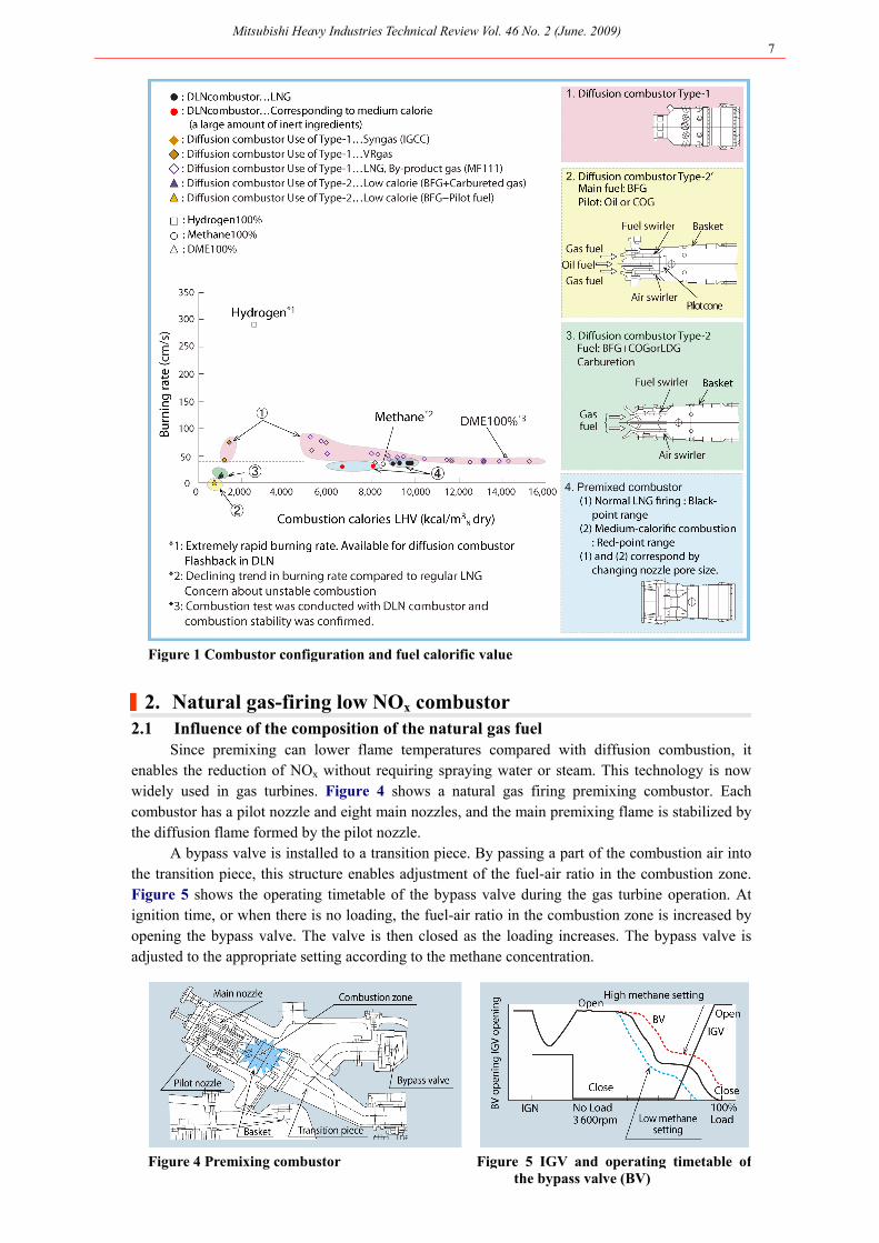
Various fuels are used in gas turbines, and each applicable combustor is selected based on both the fuel calorie and burning rate (Figure 1). Diffusion combustors are used for low-calorific fuels, and premixing combustors are used for high-calorific fuels. Gas turbines that are used for power generation are mainly fueled by natural gas. Under high-temperature combustion, aiming for high efficiency, the main problem is combustion pressure fluctuation, whereby changes such as properties or composition in the fuel supply result in pressure fluctuations inside the combustor.Excessive combustion pressure fluctuation can result in damage to the components of the combustors or turbines.
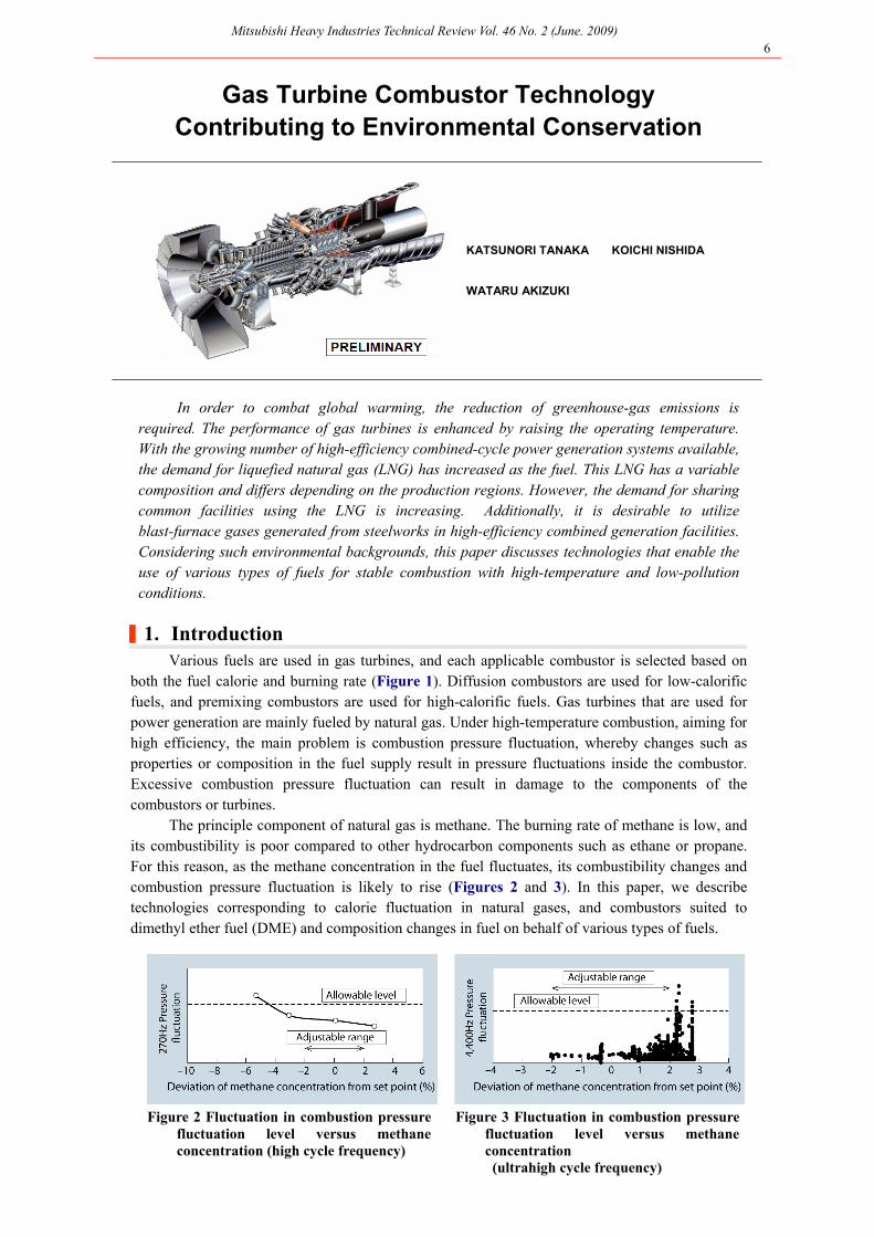
The principle component of natural gas is methane. The burning rate of methane is low, and its combustibility is poor compared to other hydrocarbon components such as ethane or propane. For this reason, as the methane concentration in the fuel fluctuates, its combustibility changes and combustion pressure fluctuation is likely to rise (Figures 2 and 3). In this paper, we describetechnologies corresponding to calorie fluctuation in natural gases, and combustors suited to dimethyl ether fuel (DME) and composition changes in fuel on behalf of various types of fuels.
Figure 2 Fluctuation in combustion pressure fluctuation level versus methane concentration (high cycle frequency)
Figure 3 Fluctuation in combustion pressure fluctuation level versus methane concentration (ultrahigh cycle frequency)
Figure 1 Combustor configuration and fuel calorific value
|2. Natural gas-firing low NOx combustor 2.1 Influence of the composition of the natural gas fuel
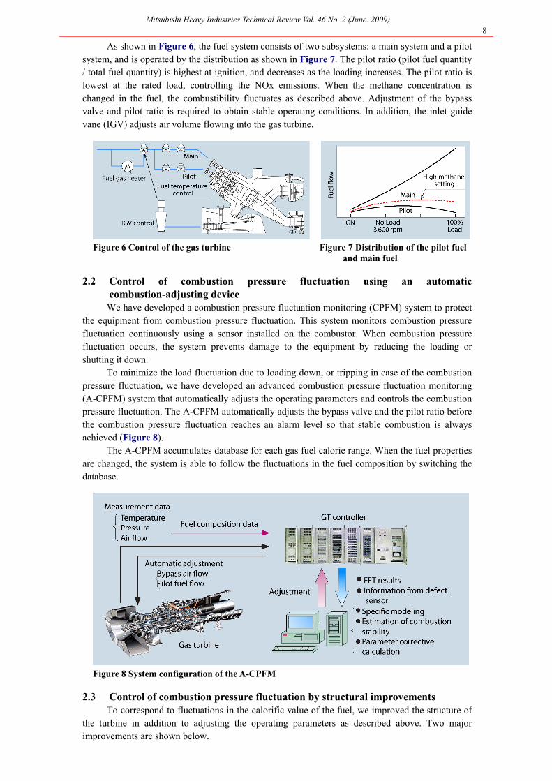
Since premixing can lower flame temperatures compared with diffusion combustion, it enables the reduction of NOx without requiring spraying water or steam. This technology is now widely used in gas turbines. Figure 4 shows a natural gas firing premixing combustor. Each combustor has a pilot nozzle and eight main nozzles, and the main premixing flame is stabilized by the diffusion flame formed by the pilot nozzle.
A bypass valve is installed to a transition piece. By passing a part of the combustion air into the transition piece, this structure enables adjustment of the fuel-air ratio in the combustion zone. Figure 5 shows the operating timetable of the bypass valve during the gas turbine operation. At ignition time, or when there is no loading, the fuel-air ratio in the combustion zone is increased by opening the bypass valve. The valve is then closed as the loading increases. The bypass valve is adjusted to the appropriate setting according to the methane concentration.
As shown in Figure 6, the fuel system consists of two subsystems: a main system and a pilot system, and is operated by the distribution as shown in Figure 7. The pilot ratio (pilot fuel quantity / total fuel quantity) is highest at ignition, and decreases as the loading increases. The pilot ratio is lowest at the rated load, controlling the NOx emissions. When the methane concentration is changed in the fuel, the combustibility fluctuates as described above. Adjustment of the bypass valve and pilot ratio is required to obtain stable operating conditions. In addition, the inlet guide vane (IGV) adjusts air volume flowing into the gas turbine.
Figure 6 Control of the gas turbine Figure 7 Distribution of the pilot fuel and main fuel
2.2 Control of combustion pressure fluctuation using an automatic combustion-adjusting device We have developed a combustion pressure fluctuation monitoring (CPFM) system to protect
the equipment from combustion pressure fluctuation. This system monitors combustion pressure fluctuation continuously using a sensor installed on the combustor. When combustion pressure fluctuation occurs, the system prevents damage to the equipment by reducing the loading or shutting it down.
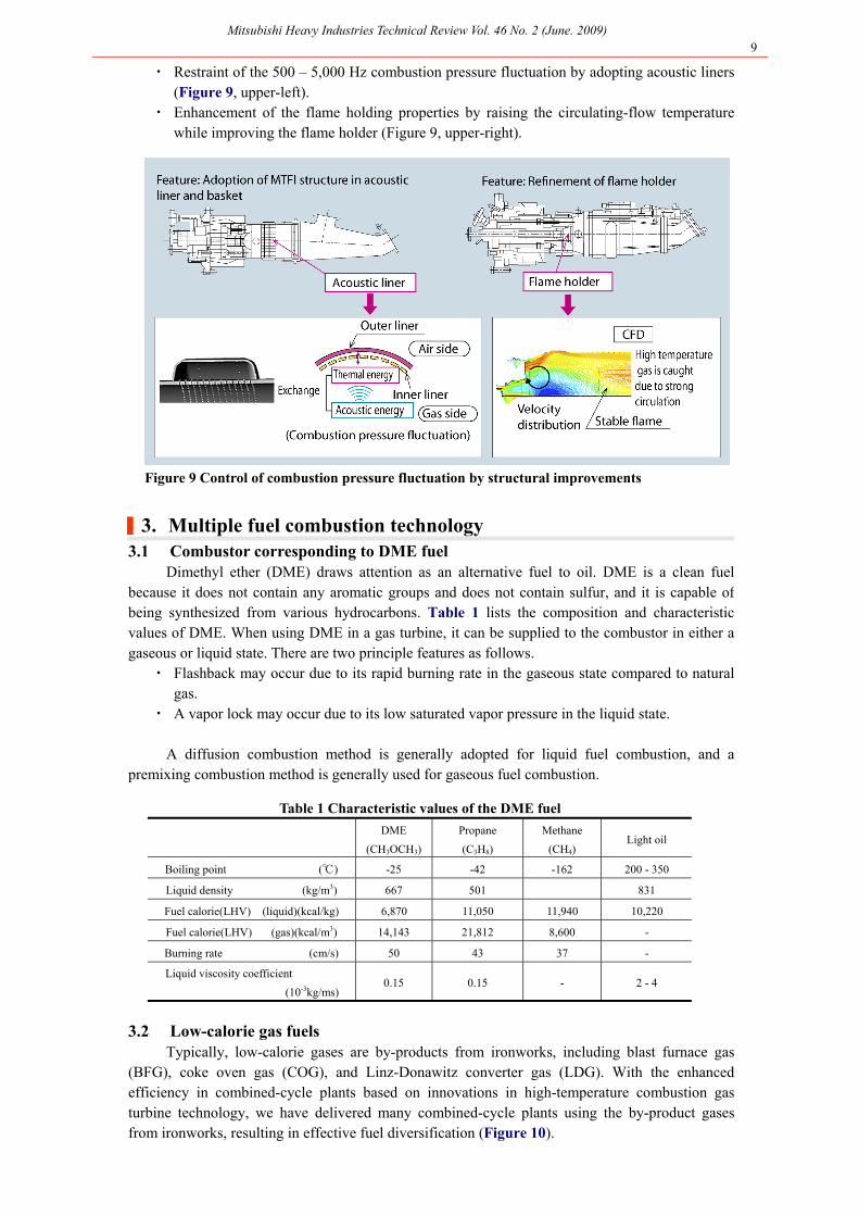
To minimize the load fluctuation due to loading down, or tripping in case of the combustion pressure fluctuation, we have developed an advanced combustion pressure fluctuation monitoring (A-CPFM) system that automatically adjusts the operating parameters and controls the combustion pressure fluctuation. The A-CPFM automatically adjusts the bypass valve and the pilot ratio before the combustion pressure fluctuation reaches an alarm level so that stable combustion is always achieved (Figure 8).
The A-CPFM accumulates database for each gas fuel calorie range. When the fuel properties are changed, the system is able to follow the fluctuations in the fuel composition by switching the database.
Figure 8 System configuration of the A-CPFM
2.3 Control of combustion pressure fluctuation by structural improvements To correspond to fluctuations in the calorific value of the fuel, we improved the structure of
the turbine in addition to adjusting the operating parameters as described above. Two major improvements are shown below.
Dimethyl ether (DME) draws attention as an alternative fuel to oil. DME is a clean fuel because it does not contain any aromatic groups and does not contain sulfur, and it is capable of being synthesized from various hydrocarbons. Table 1 lists the composition and characteristic values of DME. When using DME in a gas turbine, it can be supplied to the combustor in either a gaseous or liquid state. There are two principle features as follows.
・ Flashback may occur due to its rapid burning rate in the gaseous state compared to natural gas.
・ A vapor lock may occur due to its low saturated vapor pressure in the liquid state. A diffusion combustion method is generally adopted for liquid fuel combustion, and a
premixing combustion method is generally used for gaseous fuel combustion.
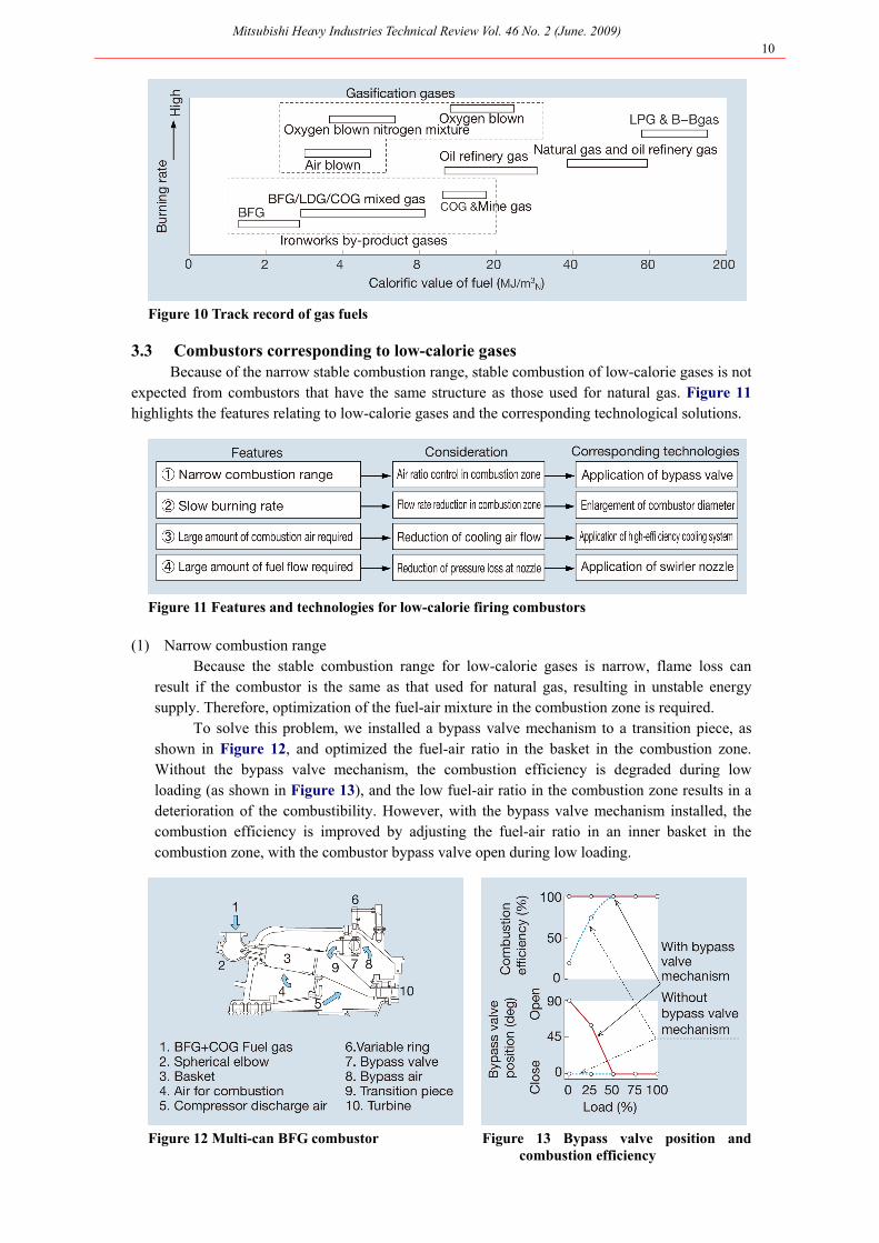
3.2 Low-calorie gas fuels Typically, low-calorie gases are by-products from ironworks, including blast furnace gas
(BFG), coke oven gas (COG), and Linz-Donawitz converter gas (LDG). With the enhanced efficiency in combined-cycle plants based on innovations in high-temperature combustion gas turbine technology, we have delivered many combined-cycle plants using the by-product gases from ironworks, resulting in effective fuel diversification (Figure 10).
3.3 Combustors corresponding to low-calorie gases Because of the narrow stable combustion range, stable combustion of low-calorie gases is not
expected from combustors that have the same structure as those used for natural gas. Figure 11highlights the features relating to low-calorie gases and the corresponding technological solutions.
Figure 11 Features and technologies for low-calorie firing combustors
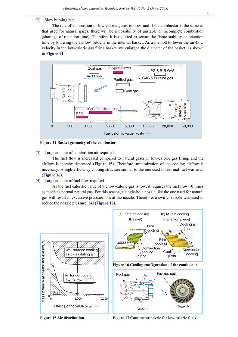
(1) Narrow combustion range Because the stable combustion range for low-calorie gases is narrow, flame loss can
result if the combustor is the same as that used for natural gas, resulting in unstable energy supply. Therefore, optimization of the fuel-air mixture in the combustion zone is required.
To solve this problem, we installed a bypass valve mechanism to a transition piece, as shown in Figure 12, and optimized the fuel-air ratio in the basket in the combustion zone. Without the bypass valve mechanism, the combustion efficiency is degraded during low loading (as shown in Figure 13), and the low fuel-air ratio in the combustion zone results in a deterioration of the combustibility. However, with the bypass valve mechanism installed, the combustion efficiency is improved by adjusting the fuel-air ratio in an inner basket in the combustion zone, with the combustor bypass valve open during low loading.
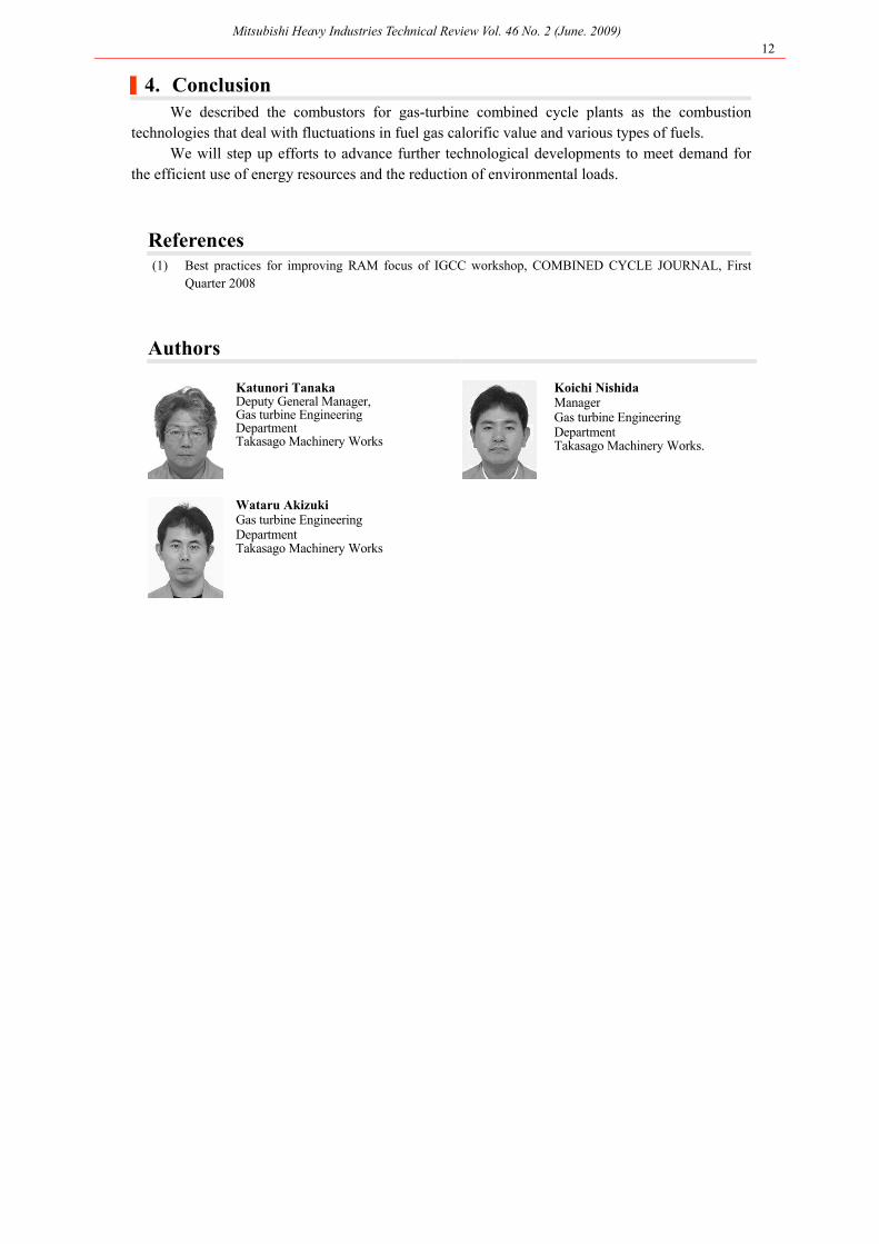
(2) Slow burning rate The rate of combustion of low-calorie gases is slow, and if the combustor is the same as
that used for natural gases, there will be a possibility of unstable or incomplete combustion (shortage of retention time). Therefore it is required to secure the flame stability or retention time by lowering the airflow velocity in the internal basket. As a method to lower the air-flow velocity in the low-calorie gas firing basket, we enlarged the diameter of the basket, as shown in Figure 14.
Figure 14 Basket geometry of the combustor
(3) Large amount of combustion air required The fuel flow is increased compared to natural gases in low-calorie gas firing, and the
airflow is thereby decreased (Figure 15). Therefore, minimization of the cooling airflow is necessary. A high-efficiency cooling structure similar to the one used for normal fuel was used (Figure 16).
(4) Large amount of fuel flow required As the fuel calorific value of the low-calorie gas is low, it requires the fuel flow 10 times
as much as normal natural gas. For this reason, a single-hole nozzle like the one used for natural gas will result in excessive pressure loss at the nozzle. Therefore, a swirler nozzle was used to reduce the nozzle pressure loss (Figure 17).
Figure 15 Air distribution Figure 17 Combustor nozzle for low-calorie fuels
|4. Conclusion We described the combustors for gas-turbine combined cycle plants as the combustion
technologies that deal with fluctuations in fuel gas calorific value and various types of fuels. We will step up efforts to advance further technological developments to meet demand for
the efficient use of energy resources and the reduction of environmental loads.
References (1) Best practices for improving RAM focus of IGCC workshop, COMBINED CYCLE JOURNAL, First
Quarter 2008
Authors
Katunori Tanaka Deputy General Manager, Gas turbine Engineering Department Takasago Machinery Works
Koichi Nishida Manager Gas turbine Engineering Department Takasago Machinery Works.
Wataru Akizuki Gas turbine Engineering Department Takasago Machinery Works