1 … 6 GasBloc Multifunctional gas control Combined regulator and safety shut�off valves Integrated gas�air system GB�GD 057 D01 Zero pressure regulator GB�ND 057 D01 Technical description Multifunctional gas control valve according to EN 126 for fully automatic operation: - Pneumatic integrated system comprising air signal or zero pressure mode - Offset correction of gas�air ratio at servo regulator - Limit of maximum flow through restrictor - Input pressures up to max. 65 mbar (6.5 kPa) - Different variants according to application Printed in Germany · Edition 01 Application For pre�mix burners and forced�draft burners. Suitable for gases according to EN 437 and other gaseous inert media. Approvals EU type test approval according to EU Gas Appliance Directive. GB�GD 057 D01 CE�0085 CM 0036 GB�ND 057 D01 CE�0085 CM 0036 CSA 240 9198 Approvals in other important gas�consuming countries.
Transcript
1 … 6
GasBlocMultifunctional gas controlCombined regulator and safety shut�off valvesIntegrated gas�air systemGB�GD 057 D01
Zero pressure regulatorGB�ND 057 D01
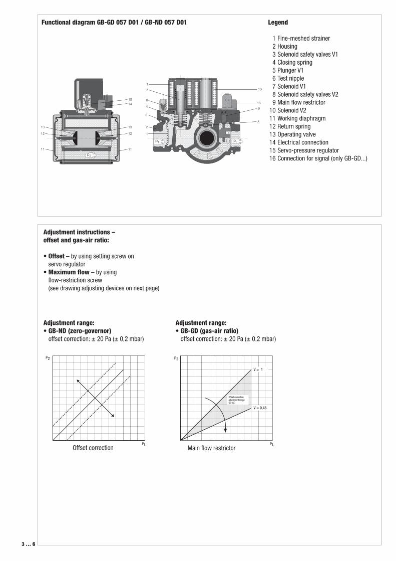
Technical descriptionMultifunctional gas control valve according to EN 126 for fully automatic operation:
- Pneumatic integrated system comprising air signal or zero pressure mode
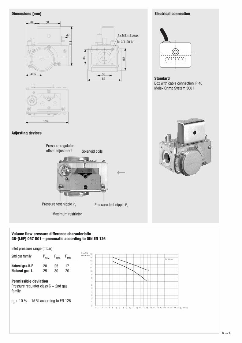
- Offset correction of gas�air ratio at servo regulator
- Limit of maximum flow through restrictor- Input pressures up to max. 65 mbar
(6.5 kPa)- Different variants according to application
Prin
ted
in G
erm
any
· Edi
tion
01
ApplicationFor pre�mix burners and forced�draft burners. Suitable for gases according to EN 437 and other gaseous inert media.
ApprovalsEU type test approval according to EU Gas Appliance Directive.
GB�GD 057 D01 CE�0085 CM 0036GB�ND 057 D01 CE�0085 CM 0036
CSA 240 9198
Approvals in other important gas�consuming countries.
2 … 6
Combinations Multifunctional gas control valve GB-GD 057 D01 and GB-ND 057 D01
Products
GB-GD 057 D01
GB-ND 057 D01
Specification
Serv
o�pr
essu
re
cont
rolle
r
Pressure regulatorThe pressure regulator includes a servo regulator to regulate pressure fluctuations in the mains supply. This ensures a precise volume flow and constant injector pressure.
In the combined gas�air valve GB�GD 055 the injector pressure follows the signal pressure applied to the servo diaphragm at a ratio of 1:1.The zero pressure valve GB�ND regulates the injector pressure at the valve outlet dependent on the vacuum generated, towards zero.
Solenoid safety valvesSolenoid safety valves according to EN 161, Class B. DC coils are protected against voltage transients.
Description of main components
Type key of GasBloc
A FilterB Automatic shut�off valvesC Pressure regulatorD Servo�pressure regulatorE Start gas settingp1 Test nipple, inletp2 Test nipple, outlet
Com
bine
d ga
s�ai
r re
gula
tor 1
:1
Zero
pre
ssur
e re
gula
tor
Offs
et c
orre
ctio
n
MPA
109
x
Block diagram
standard optional not available
Gas train schematic diagram1 = two class B solenoid valves with pressure regulator2 = two class B solenoid valves without pressure regulator
Design type (generation) D
Construction size, nominal diameter05 = pmax. = 65 mbar
Outlet pressure Inlet pressure0 = 0 mbar up to 65 mbar2 = 1,5 - 20 mbar up to 65 mbar4 = 3 - 40 mbar up to 65 mbar
Control of V1 and V20 = common2 = separated
Valve design 0 = Double safety valve1 = Single safety valve, right angle2 = Single safety valve, straight
GB- XXXXX XXX DXX SXX
Star
t gas
set
ting
B
B
B
B
Max
imum
re
stric
tor
Gas
pres
sure
sw
itch
GB-GD
GB-ND
V1V1 V2
C
PL
B B D
E
V1 V2
C
Pamb
B B D
EP2
P1A
P1A
Solenoid safety valve modesSolenoid safety valves V1 and V2 can be activated and opened either together or separately.
FilterFine�meshed strainer to protect fitting.
PilotgasPilotgas connection between solenoid safety valves V1 and V2.
Gas pressure switch Optional equipmentMonitors gas pressure on the inlet side for gas leakage protection. The pressure switch can be pre�adjusted and sealed to customer specifications.
Pressure instrument glandsOn inlet and outlet sides
Automatic shut�off valvesGroupPressure regulatorProportional adjustment range VMinimum signal pressureOffset correctionDegree of protectionOpening time
Closing timeSwitch on durationVoltage / frequency
Load of coil (24 V, 230 V)Electrical connection
Optional equipment
Installation position
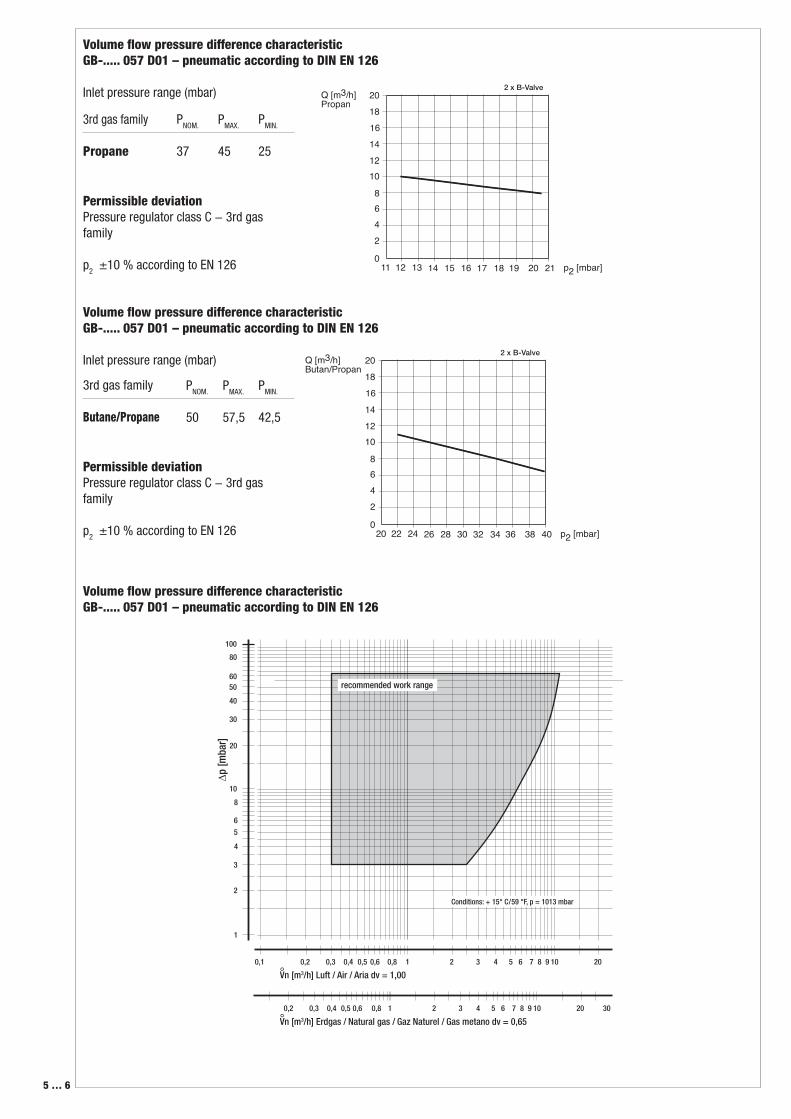
Specifications DN 15Rp 3/4 ISO 7/1Rp 3/4 ISO 7/1 ID65 mbar (6.5 kPa)5.3 m3/h (air) at ∆p 5 mbar (0.5 kPa), regulated15.4 m3/h (air) at ∆p 30 mbar (3.0 kPa), regulated-15 °C to +70 °C0 °C to 70 °C at LPGClass B according to EN 1262Class CV = pgas- pair = 0,45-10.3 mbar (0.03 kPa) at ∆pOffset = 0 Pa± 0.2 mbar (0.02 kPa)IP 40Fast�opening < 1 sSlow�opening < 10 s< 1 s100 %~(AC) 50 - 60 Hz 24 V +10 % – 15 % ~(AC) 50 - 60 Hz 230 V +10 % – 15 % 2 x 12,5 VAMolex System connection coil orOption: Connection box with integrated cable Electrical connections in Rast 5Automatic burner control MPA 109xGas pressure switch GW A5Solenoid at any position between vertical and horizontal axis.
We reserve the right to make any changes in the interest of technical progress.