GASKET SHEETS All information in this catalogue is based on years of experience in manufacture and use of the discussed products. Since sealing performance in the joint is subject to multiple factors such as mounting method, system parameters, and sealed medium, technical parameters specified herein are of informative nature only and cannot be used as grounds for any claims; any special uses of products are subject to consulting with the manufacturer. TECHNICAL SPECIFICATION Gasket sheet Gambit AF-1000 Material Gasket sheet GAMBIT AF-1000 is based on Kevlar® aramide fibres, mineral fibres, and fillers bound with NBR rubber-based binder; reinforced with galvanized steel mesh. Designation according to DIN 28091-2: FA-AM1-ST Kevlar® is a registered trademark of E. I. du Pont de Nemours and Company or its affiliates. General properties and applications Used in high temperature flange joints, in systems with high fluctuations in pressure and medium flow rate. Features high mechanical resistance. Can be used in automotive industry. It is not recommended with acids and bases. When working with steam mind using suitable mounting clamps. Water, steam, kerosene, gaso- line, fuel, and oil resistant. Admissions / Certificates Germanischer Lloyd Maximum working conditions Dimensions Peak temperature ° C 420 Temperature under continuous operation ° C 350 Temperature under continuous operation with steam ° C 250 Pressure MPa 12 Non-standard thicknesses and graphiting of sheet surfaces available upon request. Standard thicknesses of sheets /thicknesses above 5.0 mm are produced by gluing/ mm 0,8 1,0; 1,5; 2,0; 2,5 3,0; 4,0, 5,0; 6,0 ± 0,1 ± 10% ± 10% Standard dimensions of sheets /custom dimensions available within the total range of 1500x3000 mm/ mm 1500x1500 ± 10,0
Transcript
GASKET SHEETS
All information in this catalogue is based on years of experience in manufacture and use of the discussed products. Since sealing performance in the joint is subject to multiple factors such as mounting method, system parameters, and sealed medium,
technical parameters specifi ed herein are of informative nature only and cannot be used as grounds for any claims; any special uses of products are subject to consulting with the manufacturer.
TECHNICAL SPECIFICATION
Gasket sheet Gambit AF-1000
Material
Gasket sheet GAMBIT AF-1000 is based on Kevlar® aramide fi bres, mineral fi bres, and fi llers bound with NBR rubber-based binder; reinforced with galvanized steel mesh.
Designation according to DIN 28091-2: FA-AM1-STKevlar® is a registered trademark of E. I. du Pont de Nemours and Company or its affi liates.
General properties and applications
Used in high temperature fl ange joints, in systems with high fl uctuations in pressure and medium fl ow rate. Features high mechanical resistance. Can be used in automotive industry. It is not recommended with acids and bases. When working with steam mind using suitable mounting clamps. Water, steam, kerosene, gaso-line, fuel, and oil resistant.
Admissions / Certifi cates
Germanischer Lloyd
Maximum working conditions
Dimensions
Peak temperature °C 420Temperature under continuous operation °C 350
Temperature under continuous operation with steam °C 250
Pressure MPa 12
Non-standard thicknesses and graphiting of sheet surfaces available upon request.
Standard thicknesses of sheets/thicknesses above 5.0 mm are produced by gluing/ mm
0,8 1,0; 1,5; 2,0; 2,5 3,0; 4,0, 5,0; 6,0
± 0,1 ± 10%± 10%
Standard dimensions of sheets/custom dimensions available within the total range of 1500x3000 mm/
mm 1500x1500 ± 10,0
AF-1000
GASKET SHEETS
All information in this catalogue is based on years of experience in manufacture and use of the discussed products. Since sealing performance in the joint is subject to multiple factors such as mounting method, system parameters, and sealed medium,
technical parameters specifi ed herein are of informative nature only and cannot be used as grounds for any claims; any special uses of products are subject to consulting with the manufacturer.
Physical and chemical properties
(Values as detailed in table refer to 2.0 mm thick gasket sheets)
Density g/cm3 2,2 - 2,45 DIN 28090-2
Compressibility typical value % 9 ASTM F36
Elastic recovery min. % 50 ASTM F36
Residual stresses 50 MPa/16 h/300 °C/ min. MPa 32 DIN 52913
Residual stresses 50 MPa/16 h/175 °C/ min. MPa 35 DIN 52913
INCREASE IN THICKNESS
Oil IRM 903 150 °C/5h max. % 8 ASTM F146
Model fuel B 20 °C/5 h max. % 7 ASTM F146
Kerosene 20 °C/24 h max. % 6 ASTM F146
Colour graphite
Physical and chemical properties
It is not recommended that maximum tempera-ture and pressure are applied simultaneously. Pressure to temperature correlation for sheet thickness 2.0 mm is shown in the diagram.
There is no requirement for trials.
Trials should be run if the application involves steam.
GASKET SHEETS
All information in this catalogue is based on years of experience in manufacture and use of the discussed products. Since sealing performance in the joint is subject to multiple factors such as mounting method, system parameters, and sealed medium,
technical parameters specifi ed herein are of informative nature only and cannot be used as grounds for any claims; any special uses of products are subject to consulting with the manufacturer.
Non-standard thicknesses, graphiting of sheet surfaces, and reinforcement with metallic mesh available upon request.
TECHNICAL SPECIFICATION
Gasket sheet Gambit AF-153
Material
Gasket sheet GAMBIT AF-153 is based on natural fi bres, mineral fi bres, and fi llers bound with NBR, NR and SBR rubber-based binder.
Designation according to DIN 28091-2: FA-MN13-O
General properties and applications
Low-parameter sheet, recommended mostly for water supply and sewage mains.
Admissions / Certifi cates
WRAS* PZH
Maximum working conditions
Dimensions
Standard thicknesses of sheets/thicknesses above 4.0 mm are produced by gluing/ mm
0,5; 0,81,0; 1,5; 2,0; 2,5 3,0; 4,0; 5,0; 6,0
± 0,1 ± 10%± 10%
Standard dimensions of sheets/custom dimensions available within the total range of 1500x3000 mm/
mm 1500x1500 ±10,0
Peak temperature °C 180Temperature under continuous operation °C 155
Temperature under continuous operation with steam °C 130
Pressure MPa 4
* Certifi ed version available upon request.
GASKET SHEETS
All information in this catalogue is based on years of experience in manufacture and use of the discussed products. Since sealing performance in the joint is subject to multiple factors such as mounting method, system parameters, and sealed medium,
technical parameters specifi ed herein are of informative nature only and cannot be used as grounds for any claims; any special uses of products are subject to consulting with the manufacturer.
(Values as detailed in table refer to 2.0 mm thick gasket sheets)
Physical and chemical properties
Density ± 5% g/cm3 1,9 DIN 28090-2
Transverse tensile strength min. MPa 5 DIN 52910
Compressibility typical value % 10 ASTM F36
Elastic recovery min. % 50 ASTM F36
Residual stresses 50 MPa/16 h/175 °C/ min. MPa 20 DIN 52913
Colour light green
Physical and chemical properties
It is not recommended that maximum tempera-ture and pressure are applied simultaneously. Pressure to temperature correlation for sheet thickness 2.0 mm is shown in the diagram.
There is no requirement for trials.
Trials should be run if the application involves steam.
GASKET SHEETS
All information in this catalogue is based on years of experience in manufacture and use of the discussed products. Since sealing performance in the joint is subject to multiple factors such as mounting method, system parameters, and sealed medium,
technical parameters specifi ed herein are of informative nature only and cannot be used as grounds for any claims; any special uses of products are subject to consulting with the manufacturer.
TECHNICAL SPECIFICATION
Gasket sheet Gambit AF-200G
Material
Gasket sheet GAMBIT AF-200G is based on Kevlar® aramide fi bres, mineral fi bres, and fi llers bound with NBR rubber-based binder
Designation according to DIN 28091-2: FA-AM1-OKevlar® is a registered trademark of E. I. du Pont de Nemours and Company or its affi liates.
General properties and applications
High parameter sheet, containing special combination of aramide fi bres and graphite. The sheet features high elasticity. Recommended for applications with steam. Water, fuel, and oil resistant, among others.
Maximum working conditions
Dimensions
Peak temperature °C 380Temperature under continuous operation °C 320
Temperature under continuous operation with steam °C 250
Pressure MPa 8
AF-200G
Standard thicknesses of sheets/thicknesses above 5.0 mm are produced by gluing/ mm
Standard dimensions of sheets/custom dimensions available within the total range of 1500x3000 mm/
mm 1500x1500 ± 10,0
Non-standard thicknesses, graphiting of sheet surfaces, and reinforcement with metallic mesh available upon request.Metallic mesh reinforcement increases the maximum working pressure by 2 MPa (other physical and chemical properties are also changed).
GASKET SHEETS
All information in this catalogue is based on years of experience in manufacture and use of the discussed products. Since sealing performance in the joint is subject to multiple factors such as mounting method, system parameters, and sealed medium,
technical parameters specifi ed herein are of informative nature only and cannot be used as grounds for any claims; any special uses of products are subject to consulting with the manufacturer.
Physical and chemical properties
(Values as detailed in table refer to 2.0 mm thick gasket sheets)
Density ± 5% g/cm3 1,9 DIN 28090-2
Transverse tensile strength min. MPa 9 DIN 52910
Compressibility typical value % 10 ASTM F36
Elastic recovery min. % 50 ASTM F36
Residual stresses 50 MPa/16 h/300 °C/ min. MPa 25 DIN 52913
Residual stresses 50 MPa/16 h/175 °C/ min. MPa 30 DIN 52913
INCREASE IN THICKNESS
Oil IRM 903 150 °C/5 h max. % 5 ASTM F146
Model fuel B 20 °C/5 h max. % 6 ASTM F146
Colour graphite
Physical and chemical properties
It is not recommended that maximum tempera-ture and pressure are applied simultaneously. Pressure to temperature correlation for sheet thickness 2.0 mm is shown in the diagram.
There is no requirement for trials.
Trials should be run if the application involves steam.
GASKET SHEETS
All information in this catalogue is based on years of experience in manufacture and use of the discussed products. Since sealing performance in the joint is subject to multiple factors such as mounting method, system parameters, and sealed medium,
technical parameters specifi ed herein are of informative nature only and cannot be used as grounds for any claims; any special uses of products are subject to consulting with the manufacturer.
TECHNICAL SPECIFICATION
Gasket sheet Gambit AF-200 UNIVERSAL
Material
Gasket sheet GAMBIT AF-200 Universal is based on Kevlar® aramide fi bres, mineral fi bres, and fi llers bound with NBR rubber-based binder.
Designation according to DIN 28091-2: FA-AM1-OKevlar® is a registered trademark of E. I. du Pont de Nemours and Company or its affi liates.
General properties and applications
Versatile, oil resistant sheet designed for applications with the majority of media under medium temperatures and pressures. Environmentally friendly sheet type, free from N-nitrosamines.
Admissions / Certifi cates
DVGWGermanischer LloydINIGKTW
Maximum working conditions
Dimensions
Tetmperatura chwilowa °C 300Temperature under continuous operation °C 220
Temperature under continuous operation with steam °C 180
Pressure MPa 6
Standard thicknesses of sheets/thicknesses above 5.0 mm are produced by gluing/ mm
Standard dimensions of sheets/custom dimensions available within the total range of 1500x3000 mm/
mm 1500x1500 ± 10,0
AF-200 UNIVERSAL
Non-standard thicknesses, graphiting of sheet surfaces, and reinforcement with metallic mesh available upon request.
GASKET SHEETS
All information in this catalogue is based on years of experience in manufacture and use of the discussed products. Since sealing performance in the joint is subject to multiple factors such as mounting method, system parameters, and sealed medium,
technical parameters specifi ed herein are of informative nature only and cannot be used as grounds for any claims; any special uses of products are subject to consulting with the manufacturer.
(Values as detailed in table refer to 2.0 mm thick gasket sheets)
Density ± 5% g/cm3 2,0 DIN 28090-2
Transverse tensile strength min. MPa 7 DIN 52910
Compressibility typical value % 10 ASTM F36
Elastic recovery min. % 55 ASTM F36
Residual stresses 50 MPa/16 h/300 °C/ min. MPa 22 DIN 52913
Residual stresses 50 MPa/16 h/175 °C/ min. MPa 28 DIN 52913
It is not recommended that maximum tempera-ture and pressure are applied simultaneously. Pressure to temperature correlation for sheet thickness 2.0 mm is shown in the diagram.
There is no requirement for trials.
Trials should be run if the application involves steam.
GASKET SHEETS
All information in this catalogue is based on years of experience in manufacture and use of the discussed products. Since sealing performance in the joint is subject to multiple factors such as mounting method, system parameters, and sealed medium,
technical parameters specifi ed herein are of informative nature only and cannot be used as grounds for any claims; any special uses of products are subject to consulting with the manufacturer.
The below tests were run according to EN 13555, the most up-to-date norm in this domain. The results confi rm the quality of our products and assist the design of fl anges according to norm EN 1591-1+A1:2009/AC:2011.
The results have been approved by Center of Sealing Technologies (CST) at Münster University of Applied Sci-ences (MUAS) and published on www.gasketdata.org together with the datasheets of the world’s leading manu-facturers of sealing materials.
CST is an independent laboratory focused on the research and development in the fi eld of sealing materials in order to assist both the producers and the users.
Test Results of Gambit AF‒200 UNIVERSAL Published on Gasketdata.org
Gasket characteristics acc. EN 13555 (05/2005)required for design calculations acc. EN 1591-1+A1:2009/AC:2011
Sealing element dimensions [ mm ] 92 x 49 x 2
Relaxation ratio PQR for stiff ness C = 500 kN/mm
Gasket stress, MPa Ambient temperature Temperature 1 (175 °C) Temperature 2 (300 °C)
Stress level 1 (30 MPa) 0,96 0,84 0,54
Stress level 2 (50 MPa) 0,97 0,78 0,57
PQR at QSmax (220/60/60 MPa) 0,98 0,76 0,53
Maximal applicable gasket stress QSmax, MPa
QSmax, MPa ‒ ambient temperature QSmax, MPa ‒ temperature 1 (175 °C) QSmax, MPa ‒ temperature 2 (300 °C)
220 60 60
Sekant unloading modulus of the gasket EG, MPa and gasket thickness eG, mmGasket stress,
MPaAmbient temperature Temperature 1 (175 °C) Temperature 2 (300 °C)
All information in this catalogue is based on years of experience in manufacture and use of the discussed products. Since sealing performance in the joint is subject to multiple factors such as mounting method, system parameters, and sealed medium,
technical parameters specifi ed herein are of informative nature only and cannot be used as grounds for any claims; any special uses of products are subject to consulting with the manufacturer.
Leakage - ambient temperature / inner pressure = 40 bar
Leakage - ambient temperature / inner pressure = 10 bar
Minimum stress to seal Qmin(L) (at assembly), QSmin(L) (after off -loading) for inner pressure 10 bar
All information in this catalogue is based on years of experience in manufacture and use of the discussed products. Since sealing performance in the joint is subject to multiple factors such as mounting method, system parameters, and sealed medium,
technical parameters specifi ed herein are of informative nature only and cannot be used as grounds for any claims; any special uses of products are subject to consulting with the manufacturer.
TECHNICAL SPECIFICATION
Gasket sheet Gambit AF-202
Material
Gasket sheet GAMBIT AF-202 is based on Kevlar® aramide fi bres, mineral fi bres, and fi llers bound with NBR rubber-based binder.
Designation according to DIN 28091-2: FA-AM1-OKevlar® is a registered trademark of E. I. du Pont de Nemours and Company or its affi liates.
General properties and applications
Popular sheet designated for sealing in low temperature and low pressure applications. Particularly recom-mended for fuel oil installations.
Maximum working conditions
Dimensions
Peak temperature °C 200Temperature under continuous operation °C 180
Temperature under continuous operation with steam °C 150
Pressure MPa 4
Standard thicknesses of sheets/thicknesses above 4.0 mm are produced by gluing/ mm
0,5; 0,81,0; 1,5; 2,0; 2,5 3,0; 4,0; 5,0; 6,0
± 0,1 ± 10%± 10%
Standard dimensions of sheets/custom dimensions available within the total range of 1500x3000 mm/
mm 1500x1500 ± 10,0
Non-standard thicknesses, graphiting of sheet surfaces, and reinforcement with metallic mesh available upon request.
GASKET SHEETS
All information in this catalogue is based on years of experience in manufacture and use of the discussed products. Since sealing performance in the joint is subject to multiple factors such as mounting method, system parameters, and sealed medium,
technical parameters specifi ed herein are of informative nature only and cannot be used as grounds for any claims; any special uses of products are subject to consulting with the manufacturer.
Physical and chemical properties
(Values as detailed in table refer to 2.0 mm thick gasket sheets)
Density ± 5% g/cm3 2,0 DIN 28090-2
Transverse tensile strength min. MPa 6 DIN 52910
Compressibility typical value % 11 ASTM F36
Elastic recovery min. % 50 ASTM F36
Residual stresses 50 MPa/16 h/300 °C/ min. MPa 20 DIN 52913
Residual stresses 50 MPa/16 h/175 °C/ min. MPa 25 DIN 52913
INCREASE IN THICKNESS
Oil IRM 903 150 °C/5 h max. % 12 ASTM F146
Colour khaki
Physical and chemical properties
It is not recommended that maximum tempera-ture and pressure are applied simultaneously. Pressure to temperature correlation for sheet thickness 2.0 mm is shown in the diagram.
There is no requirement for trials.
Trials should be run if the application involves steam.
GASKET SHEETS
All information in this catalogue is based on years of experience in manufacture and use of the discussed products. Since sealing performance in the joint is subject to multiple factors such as mounting method, system parameters, and sealed medium,
technical parameters specifi ed herein are of informative nature only and cannot be used as grounds for any claims; any special uses of products are subject to consulting with the manufacturer.
TECHNICAL SPECIFICATION
Gasket sheet Gambit AF-300
Material
Gasket sheet GAMBIT AF-300 is based on Kevlar® aramide fi bres, mineral fi bres, and fi llers bound with NBR, NR and SBR rubber-based binder.
Designation according to DIN 28091-2: FA-AM13-OKevlar® is a registered trademark of E. I. du Pont de Nemours and Company or its affi liates.
General properties and applications
Elastic sheet easily following all the curves and irregularities of a fl ange. Particularly recommended for water and steam installations, in heating and power generation sector, as well as in municipal companies. The sheet is resistant to brake and cooling liquids, thus it is recommended for automotive applications.
Admissions / Certifi cates
INIG
Maximum working conditions
Dimensions
Peak temperature °C 320Temperature under continuous operation °C 280
Temperature under continuous operation with steam °C 220
Pressure MPa 10
Standard thicknesses of sheets/thicknesses above 5.0 mm are produced by gluing/ mm
Standard dimensions of sheets/custom dimensions available within the total range of 1500x3000 mm/
mm 1500x1500 ± 10,0
Non-standard thicknesses, graphiting of sheet surfaces, and reinforcement with metallic mesh available upon request.
GASKET SHEETS
All information in this catalogue is based on years of experience in manufacture and use of the discussed products. Since sealing performance in the joint is subject to multiple factors such as mounting method, system parameters, and sealed medium,
technical parameters specifi ed herein are of informative nature only and cannot be used as grounds for any claims; any special uses of products are subject to consulting with the manufacturer.
(Values as detailed in table refer to 2.0 mm thick gasket sheets)
Density ± 5% g/cm3 2,0 DIN 28090-2
Transverse tensile strength min. MPa 8 DIN 52910
Compressibility typical value % 11 ASTM F36
Elastic recovery min. % 50 ASTM F36
Residual stresses 50 MPa/16 h/300 °C/ min. MPa 22 DIN 52913
Residual stresses 50 MPa/16 h/175 °C/ min. MPa 28 DIN 52913
It is not recommended that maximum tempera-ture and pressure are applied simultaneously. Pressure to temperature correlation for sheet thickness 2.0 mm is shown in the diagram.
There is no requirement for trials.
Trials should be run if the application involves steam.
GASKET SHEETS
All information in this catalogue is based on years of experience in manufacture and use of the discussed products. Since sealing performance in the joint is subject to multiple factors such as mounting method, system parameters, and sealed medium,
technical parameters specifi ed herein are of informative nature only and cannot be used as grounds for any claims; any special uses of products are subject to consulting with the manufacturer.
TECHNICAL SPECIFICATION
Gasket sheet Gambit AF-400
Material
Gasket sheet GAMBIT AF-400 is based on Kevlar® aramide fi bres, mineral fi bres, and fi llers bound with NBR rubber-based binder.
Designation according to DIN 28091-2: FA-AM1-OKevlar® is a registered trademark of E. I. du Pont de Nemours and Company or its affi liates.
General properties and applications
High parameter sheet, made of top quality materials. Highly reliable, with broad range of applications. Desig-nated for use in supervised joints, and installations for transmission of natural gas. Resistant to water, steam, kerosene, fuel, oil, and solutions of salts, among others.
Admissions / Certifi cates
INIG
Maximum working conditions
Dimensions
Peak temperature °C 400Temperature under continuous operation °C 350
Temperature under continuous operation with steam °C 260
Pressure MPa 12
Standard thicknesses of sheets/thicknesses above 5.0 mm are produced by gluing/ mm
Standard dimensions of sheets/custom dimensions available within the total range of 1500x3000 mm/
mm 1500x1500 ± 10,0
Non-standard thicknesses, graphiting of sheet surfaces, and reinforcement with metallic mesh available upon request.
GASKET SHEETS
All information in this catalogue is based on years of experience in manufacture and use of the discussed products. Since sealing performance in the joint is subject to multiple factors such as mounting method, system parameters, and sealed medium,
technical parameters specifi ed herein are of informative nature only and cannot be used as grounds for any claims; any special uses of products are subject to consulting with the manufacturer.
Density ± 5% g/cm3 2,0 DIN 28090-2
Transverse tensile strength min. MPa 12 DIN 52910
Compressibility typical value % 10 ASTM F36
Elastic recovery min. % 55 ASTM F36
Residual stresses 50 MPa/16 h/300 °C/ min. MPa 30 DIN 52913
Residual stresses 50 MPa/16 h/175 °C/ min. MPa 35 DIN 52913
INCREASE IN THICKNESS
Oil IRM 903 150 °C/5 h max. % 6 ASTM F146
Model fuel B 20 °C/5 h max. % 6 ASTM F146
Kerosene 20 °C/24 h max. % 5 ASTM F146
Colour blue
(Values as detailed in table refer to 2.0 mm thick gasket sheets)
It is not recommended that maximum tempera-ture and pressure are applied simultaneously. Pressure to temperature correlation for sheet thickness 2.0 mm is shown in the diagram.
There is no requirement for trials.
Trials should be run if the application involves steam.
GASKET SHEETS
All information in this catalogue is based on years of experience in manufacture and use of the discussed products. Since sealing performance in the joint is subject to multiple factors such as mounting method, system parameters, and sealed medium,
technical parameters specifi ed herein are of informative nature only and cannot be used as grounds for any claims; any special uses of products are subject to consulting with the manufacturer.
TECHNICAL SPECIFICATION
Gasket sheet Gambit AF-CD
Material
Gasket sheet GAMBIT AF-CD is based on natural fi bres, mineral fi bres, and fi llers bound with NBR rubber-based binder.
Designation according to DIN 28091-2: FA-N1-O
General properties and applications
Based on natural fi bres the sheet is recommended mostly for heating installations and water supply mains, with both hot and cold water. It is also dedicated to sewage mains and industrial water cycles.
Admissions / Certifi cates
PZH
Maximum working conditions
Dimensions
Peak temperature °C 200Temperature under continuous operation °C 160
Temperature under continuous operation with steam °C 140
Pressure MPa 8
Standard thicknesses of sheets/thicknesses above 4.0 mm are produced by gluing/ mm
0,5; 0,81,0; 1,5; 2,0; 2,5 3,0; 4,0; 5,0; 6,0
± 0,1 ± 10%± 10%
Standard dimensions of sheets/custom dimensions available within the total range of 1500x3000 mm/
mm 1500x1500 ± 10,0
Non-standard thicknesses, graphiting of sheet surfaces, and reinforcement with metallic mesh available upon request.
GASKET SHEETS
All information in this catalogue is based on years of experience in manufacture and use of the discussed products. Since sealing performance in the joint is subject to multiple factors such as mounting method, system parameters, and sealed medium,
technical parameters specifi ed herein are of informative nature only and cannot be used as grounds for any claims; any special uses of products are subject to consulting with the manufacturer.
Density ±5 % g/cm3 1,8 DIN 28090-2
Transverse tensile strength min. MPa 7 DIN 52910
Compressibility typical value % 11 ASTM F36
Elastic recovery min. % 55 ASTM F36
Residual stresses 50 MPa/16 h/175 °C/ min. MPa 20 DIN 52913
INCREASE IN THICKNESS
Oil IRM 903 150 °C/5 h max. % 5 ASTM F146
Colour beige
(Values as detailed in table refer to 2.0 mm thick gasket sheets)
Physical and chemical propertiesPhysical and chemical properties
It is not recommended that maximum tempera-ture and pressure are applied simultaneously. Pressure to temperature correlation for sheet thickness 2.0 mm is shown in the diagram.
There is no requirement for trials.
Trials should be run if the application involves steam.
GASKET SHEETS
All information in this catalogue is based on years of experience in manufacture and use of the discussed products. Since sealing performance in the joint is subject to multiple factors such as mounting method, system parameters, and sealed medium,
technical parameters specifi ed herein are of informative nature only and cannot be used as grounds for any claims; any special uses of products are subject to consulting with the manufacturer.
TECHNICAL SPECIFICATION
Gasket sheet Gambit AF-CHEMACID
Material
Gasket sheet GAMBIT AF-CHEMACID is based on Kevlar® aramide fi bres, mineral fi bres, and fi llers bound with CSM rubber-based binder.
Designation according to DIN 28091-2: FA-AMZ-OKevlar® is a registered trademark of E. I. du Pont de Nemours and Company or its affi liates.
General properties and applications
Acid and base resistant. Recommended mostly for applications in chemical sector.
Maximum working conditions
Dimensions
Peak temperature °C 200Temperature under continuous operation °C 150
Pressure MPa 4
Standard thicknesses of sheets/thicknesses above 4.0 mm are produced by gluing/ mm
0,5; 0,8 1,0; 1,5; 2,0; 2,5 3,0; 4,0; 5,0; 6,0
± 0,1 ± 10%± 10%
Standard dimensions of sheets/custom dimensions available within the total range of 1500x3000 mm/
mm 1500x1500 ± 10,0
AF-CHEMACID
Non-standard thicknesses and graphiting of sheet surfaces available upon request.
GASKET SHEETS
All information in this catalogue is based on years of experience in manufacture and use of the discussed products. Since sealing performance in the joint is subject to multiple factors such as mounting method, system parameters, and sealed medium,
technical parameters specifi ed herein are of informative nature only and cannot be used as grounds for any claims; any special uses of products are subject to consulting with the manufacturer.
Density ± 5% g/cm3 2,0 DIN 28090-2
Transverse tensile strength min. MPa 9 DIN 52910
Compressibility typical value % 9 ASTM F36
Elastic recovery min. % 50 ASTM F36
Residual stresses 50 MPa/16 h/175 °C/ min. MPa 25 DIN 52913
INCREASE IN THICKNESS
40% HNO3 23 °C/18 h max. % 8 ASTM F146
65% H2SO4 23 °C/48 h max. % 10 ASTM F146
Colour light beige
Coeffi cients ASMETightness class Thickness m y
L0,1 2 mm 7,5 4,2 MPa
L1,0 2 mm 3,5 2,1 MPa
Physical and chemical properties
(Values as detailed in table refer to 2.0 mm thick gasket sheets)
Calculation coeffi cients
Physical and chemical properties
It is not recommended that maximum tempera-ture and pressure are applied simultaneously. Pressure to temperature correlation for sheet thickness 2.0 mm is shown in the diagram.
There is no requirement for trials.
CNC SERVICES
All information in this catalogue is based on years of experience in manufacture and use of the discussed products. Since sealing performance in the joint is subject to multiple factors such as mounting method, system parameters, and sealed medium,
technical parameters specifi ed herein are of informative nature only and cannot be used as grounds for any claims; any special uses of products are subject to consulting with the manufacturer.
General information
CNC tool shop in Gambit Lubawka Sp. z o.o. off ers:• manufacturing moulds for rubber products;• manufacturing injection moulds and blow moulds for plastics;• manufacturing punching dies, press tools;• manufacturing precision tools and machine parts, as per customer's specifi cation;• tools recovery;• manufacturing tools for scientifi c research;• CAD/CAM design and technical consulting.
Based on 3D CAD/CAM technologies we provide comprehensive, integrated computer operation in a wide range of design-to-fi nished product services.
Products are manufactured based on a specifi cation provided by a customer or developed by the experienced team of Gambit engineers using AutoCad and Inventor software.
Our machine stock includes the following: • CNC turning lathe (HAAS), turning diameter 400 mm, length 760 mm; • conventional turning lathe - turning diameter 560 mm, length 2000 mm; • CNC vertical milling machine (HAAS) - x/y/z axis feed - 760/500/500; • conventional milling machine - table 250x1200; • conventional milling machine - table 400x1400; • electro-erosion machine (Sodick) - table 750x550; max weight of an item 1000 kg; • wire electrical discharge machine (Sodick) - table 606x396; max weight of an item 500 kg; cutting angle ±25° at the length 100 mm; • Water Jet cutting machine - table size 2000x3000 mm; • surface grinder - table 350x1000; • cylinder and hole grinder - max outer diameter 280 mm; length 1000 mm.
CNC SERVICES
CNC SERVICES
All information in this catalogue is based on years of experience in manufacture and use of the discussed products. Since sealing performance in the joint is subject to multiple factors such as mounting method, system parameters, and sealed medium,
technical parameters specifi ed herein are of informative nature only and cannot be used as grounds for any claims; any special uses of products are subject to consulting with the manufacturer.
THERMAL INSULATIONS
All information in this catalogue is based on years of experience in manufacture and use of the discussed products. Since sealing performance in the joint is subject to multiple factors such as mounting method, system parameters, and sealed medium,
technical parameters specifi ed herein are of informative nature only and cannot be used as grounds for any claims; any special uses of products are subject to consulting with the manufacturer.
VACUUM FORMED THERMAL INSULATIONS CVGeneral information
Vacuum formed thermal insulation products type CV are made of ceramic fi bres and specially selected binders. They feature high resistance to heat, low thermal conductivity, low density and high resistance to temperature changes. Due to their excellent thermal insulation properties, resistance to thermal shocks, heat resistance and ease of processing (also mechanical - milling) they are commonly used in power generation sector, metal-lurgy, founding, and ceramic sector as the lining of glass, ceramic and metallurgical furnaces. CV thermal insulations are used as linings of furnace cars, fi llings of expansion joints, protections of riser heads in foundries, protections of thermocouples, high temperature gaskets, foundry spouts, and others.
The advantages of using vacuum formed thermal insulation products type CV:
• reduction in furnace weight
• extension of lining lifecycle, especially in batch furnaces
• reduction in costs and time of repairs and overhauls
Standard CV panels are manufactured in hard and soft version in sizes 1000x1000 mm and 1000x500 mm; thickness 5.0 mm to 200 mm. Boards in size above 200 mm are produced by gluing.
We also manufacture CV shapes: pipes, cylinders, cones, stops, arches, rings, and gutters. We off er milling of all kinds of shapes using the milling module of KIMLA plotter.
VACUUM FORMED THERMAL INSULATIONS CV
THERMAL INSULATIONS
All information in this catalogue is based on years of experience in manufacture and use of the discussed products. Since sealing performance in the joint is subject to multiple factors such as mounting method, system parameters, and sealed medium,
technical parameters specifi ed herein are of informative nature only and cannot be used as grounds for any claims; any special uses of products are subject to consulting with the manufacturer.
Type TmaxDensity kg/m3
Thermal conductivity at temp. °C
W/mK Type TmaxDensity kg/m3
Thermal conductivity at temp. °C
W/mK
CV-800(hard)
800 250 20 0,055 CV-800 M(elastic)
800 160-200 50 0,045
200 0,072 300 0,078
400 0,107 400 0,098
600 0,162 500 0,125
800 0,226 600 0,155
CV-1260(hard)
1260 250 27 0,067 CV-1260 M(elastic)
1260 160-200 20 0,05
200 0,065 200 0,08
400 0,108 300 0,09
600 0,166 500 0,14
800 0,245 700 0,22
1000 0,345 900 0,39
CV-1430(hard)
1430 250 20 0,064 CV-1430 M(elastic)
1430 180-200 30 0,041
200 0,066 200 0,063
400 0,107 400 0,112
600 0,161 600 0,186
800 0,232 800 0,322
900 0,274 1000 0,494
1000 0,324
1200 0,425
1400 0,575
After 4 - hour test under maximum working temperature, the shrinkage of material amounts to: max. 3 % in length, max. 4 % in thickness
Properties of thermal insulation material CVProperties of thermal insulation material CV
THERMAL INSULATIONS
All information in this catalogue is based on years of experience in manufacture and use of the discussed products. Since sealing performance in the joint is subject to multiple factors such as mounting method, system parameters, and sealed medium,
technical parameters specifi ed herein are of informative nature only and cannot be used as grounds for any claims; any special uses of products are subject to consulting with the manufacturer.
Results and data used in preparation of the diagrams were taken from thermal conductivity tests of CV materials, and are a part of Technical Data Sheets for thermal insulation materials CV. Readings (i.e. diagrams of CV) are estimatations only. They can only be used for the preliminary calculation of the insulating material thicknesses.
Reference diagrams for calculations of the thicknesses of insulating material CVReference diagrams for calculations of the thicknesses of insulating material CV
CV 800
CV 800 M
CV 1260CV 1430
CV 1260 MCV 1430 M
Temperature of the hot side [ °C ]
Temperature of the hot side [ °C ]
Temperature of the hot side [ °C ]
Thickness of the insulating material [ mm ]
Thickness of the insulating material [ mm ]
Thickness of the insulating material [ mm ]
THERMAL INSULATIONS
All information in this catalogue is based on years of experience in manufacture and use of the discussed products. Since sealing performance in the joint is subject to multiple factors such as mounting method, system parameters, and sealed medium,
technical parameters specifi ed herein are of informative nature only and cannot be used as grounds for any claims; any special uses of products are subject to consulting with the manufacturer.
Notes
RUBBER
All information in this catalogue is based on years of experience in manufacture and use of the discussed products. Since sealing performance in the joint is subject to multiple factors such as mounting method, system parameters, and sealed medium,
technical parameters specifi ed herein are of informative nature only and cannot be used as grounds for any claims; any special uses of products are subject to consulting with the manufacturer.
General information
Gambit Lubawka Sp. z o.o. is a manufacturer of a wide range of sealings and other rubber and rubber/metal products. They are all made of our own rubber mixtures, based on NR, NBR, SBR, EPDM rubbers and their com-binations, and third party mixtures FKM and VMQ. Rubber mixtures with standard parameters, as well as with customer defi ned parameters, can be packed according to the agreed shape and weight.
Range of applications and physical and mechanical properties are detailed in the table:
RUBBER PRODUCTS, RUBBER AND METAL PRODUCTS
Base rubber
IRHD hardness range [ °Sh ]
Tempe-rature range[ °C ]
Physical and mechanical parameters
Tensile strength [ MPa ]
Unit elongation
[ % ]Resistance to media
Nitrile NBR 40÷95 -30÷120 5,0÷20,0 max. 700
Animal and vegetable oils, mineral oils, lubricants, aliphatic hydrocarbons, alcohols, water, solutions of salt and majority of acids
and bases up to 60 °C.
Fluoride FKM 60÷95 -25÷220 8,0÷16,0 max. 300
Exceptional resistance to oils, fuels, hydraulic liquids, and other petroleum derivatives. Very high resistance to ozone and oxygen, alcohol, aromatic hydrocarbons, solutions of salts, acids and bases, including the oxidising ones.
Silicon VMQ 40÷90 -60÷220 2,0÷8,0 max. 500Good resistance to water solutions of salts, acids and bases, as well as some oils.
Exceptional electrical insulation properties.
Ethylene-propylene
EPDM45÷85 -55÷130 4,0÷14,0 max. 500
Excellent resistance to environmental conditions, including ozone. High resistance to water, steam, solutions of salts, majority of acids and bases, and many other substances, in particular polar ones. High elasticity at low temperatures. Good mechanical and dielectric
properties.
Natural NR 45÷90 -60÷70 4,0÷21,0 max. 500Excellent mechanical properties, good elastic-ity, resistance to abrasion and low temperature. Advantageous dynamic and fatigue properties.
Butadiene-styrene SBR+ butadiene BR
45÷90 -60÷120 6,0÷16,0 max. 400Very good resistance to abrasion and cracking. Exceptional elasticity at the broad range of temperatures. Good ageing resistance.
RUBBER
All information in this catalogue is based on years of experience in manufacture and use of the discussed products. Since sealing performance in the joint is subject to multiple factors such as mounting method, system parameters, and sealed medium,
technical parameters specifi ed herein are of informative nature only and cannot be used as grounds for any claims; any special uses of products are subject to consulting with the manufacturer.
Types of mixtures are defi ned in PN-82/C-94153 or in a customer's specifi cation.With years of experience in manufacturing and application of rubber mixtures and fi nished components we feel competent to select suitable mixture to a customer's specifi ed needs.
We produce a wide range of vulcanized products using presses or injection moulding machines, namely:
• Gaskets for piston rods of shock absorbers for motor industry.
• Gaskets for industrial fi ttings.
• Sealing rings of circular cross-section (O-ring type).
• Gaskets and rubber washers of rectangular cross-section.
• Rubber threads for hoisting machines.
• Rubber discs for belt conveyors.
• Membranes and diaphragms.
• Sleeves, bumpers, rubber and metal shock absorbers, silent blocks, etc.
• Mud fl aps.
• Other products on the basis of drawings and agreements with customers.
The antistatic and self-extinguishing rubber mixture, designed especially for mining applications, allowed launching the family of products dedicated to customers in that sector. Particularly interesting are rubber solids for circulation guides of hoisting machines, for which we are certifi ed with “B” safety symbol, and admis-sion to use in underground mining plants issued by the President of Central Mining Offi ce (WYG).
RUBBER
All information in this catalogue is based on years of experience in manufacture and use of the discussed products. Since sealing performance in the joint is subject to multiple factors such as mounting method, system parameters, and sealed medium,
technical parameters specifi ed herein are of informative nature only and cannot be used as grounds for any claims; any special uses of products are subject to consulting with the manufacturer.
In addition to standard products we are oriented on new launches. Our own design offi ce and Tool-and-Die Facilities allow us to design and execute the equipment necessary for manufacturing product matching a customer's expectations, in cost-optimized technology with regard to the size of production lot ordered. As opposed to many rubber plants focused on large-scale production we are ready to meet your needs and expectations.
We also manufacture the following rubber sheets from various rubber mixtures:
Sheets 1000x1000 are available in thickness 5 to 50 mm.Sheets 500x500 are available in thickness 2 to 40 mm.We do not reinforce sheets with fabric spacers.
All information in this catalogue is based on years of experience in manufacture and use of the discussed products. Since sealing performance in the joint is subject to multiple factors such as mounting method, system parameters, and sealed medium,
technical parameters specifi ed herein are of informative nature only and cannot be used as grounds for any claims; any special uses of products are subject to consulting with the manufacturer.
Notatki
COMPENSATORS
All information in this catalogue is based on years of experience in manufacture and use of the discussed products. Since sealing performance in the joint is subject to multiple factors such as mounting method, system parameters, and sealed medium,
technical parameters specifi ed herein are of informative nature only and cannot be used as grounds for any claims; any special uses of products are subject to consulting with the manufacturer.
General information
Industrial processes require a possibility of a fl exible joint of two or more components that move against each other, in such a way as to maintain tightness of the connection. The solution of this problem are compensa-tor fabrics produced by Gambit in accordance with individual needs of users or installation designers. They are used as fl exible joints compensating thermal deformations, side shift, and vibrations, while muffl ing and reducing transfer of noise across the installation. Compensators are used in power plants, gas turbines, chemi-cal industry, petrochemical industry, paper industry and cement industry. More and more compensators are used in exhaust gas treatment and desulphurisation. Our compensators are made of materials resistant to both high temperatures, up to 1000 °C, and aggressive chemical media. Working pressure of compensator fabric is -0.2 to 0.3 bar.Application of compensator fabrics has a number of advantages. Thanks to high elasticity with minimum installation space required, small forces required during assembling and installation, and easy retrofi tting, they can transfer and compensate displacements in all directions at the same time. Thanks to adoption of impenetrable materials (such as PTFE) they ensure high tightness of a joint at a wide range of temperatures and media.
Compensator fabrics are made in Gambit according to customer requirements, defi ned in drawings or speci-fi cations. The designs are very diversifi ed; from the simplest single-layer compensators to designs of many layers. The layers can be made of PTFE with increased resistance to chemicals as well as quartz or ceramic layers with increased resistance to heat. Upon a customer's request we can fi t them with additional thermal insulation. Thanks to implementation of the advancements in material engineering, today's fabrics, coated fabrics and fi lms demonstrate not only thermal and chemical resistance, but also high mechanical and fatigue resistance to multiple deformations.
Also the assembling method depends on a customer's specifi cation and considers local mounting conditions. Compensators can be fi nished with fl anges, a sleeve design directly mounted to a conduit can be applied, or we can provide a customer with compensator fabrics for independent assembly to the conduit. We off er fi ve standard designs of compensator fabrics.
COMPENSATORS AND COMPENSATOR FABRICS
Type of fabric Temperature
TKCH 280 up to 280 °C + chemically aggressive media*
TK 450 up to 450 °C
TK 600 up to 600 °C
TKCH 600 up to 600 °C + chemically aggressive media*
TK 800 up to 800 °C
* with the exception of fl uoride and hydrogen fl uoride
COMPENSATORS
All information in this catalogue is based on years of experience in manufacture and use of the discussed products. Since sealing performance in the joint is subject to multiple factors such as mounting method, system parameters, and sealed medium,
technical parameters specifi ed herein are of informative nature only and cannot be used as grounds for any claims; any special uses of products are subject to consulting with the manufacturer.
Due to diversity of tasks and local mounting and operating conditions, compensator fabrics are mostly de-signed according to customer's specifi cations. In order to design and manufacture effi cient compensators operating for a long time, detailed information are necessary, with a special focus on:
• sealed medium - of essential meaning to selection of materials. Compensators are generally used in fl ue-gas installations. What should be taken into account in this case, is to specify the combustion process, being the source of fl ue-gas, and consequently, its chemical compo-sition. Compounds of fl uoride and sulphur are the most aggressive ones. At extremely high temperatures attention to possible reducing environment should be paid. As chemical agents usually are more aggres-sive in liquid phase than in gaseous phase, humidity content in the transferred medium, as well as the con-densation preventing design should be considered. Also possible occurrence of soot or other particulates should be taken into account at the design stage. If solids occur, their concentration, shape and hardness, position of compensator, fl ow rate and direction should be taken into account. Sealed medium is another key criterion when it comes to compensator tightness. The solutions used when only dust-tightness is required diff er from the situation when gas or toxic vapour tightness is required - in the latter case nearly absolute tightness is mandatory.
• pressure and fl ow volume - aff ects the compensator construction, materials used, quantity and thickness of layers and possible guards. Pressure pulses or sudden pressure jumps are of particular importance. Com-pensators manufactured by Gambit operate up to the maximum pressure of 0.3 bar. Longer compensators are defi nitely more susceptible to increased pressure and pressure jumps. High fl ow volume can cause abrasion of a compensator, and when the condition of laminar fl ow is exceeded, uncontrolled and unpre-dictable pulsation can occur.
• displacements and mechanical interactions - result in both considering possible dimensional changes and application of stronger materials. Large displacements sometimes require substituting a single com-pensator with a battery of compensators. The analysis should consider axial compression and expansion, lateral displacement, side shift and twisting. Amplitude of displacements, their interval, and their simulta-neous occurrence are all important factors.
• temperature - one of the most diffi cult factors to be controlled when it comes to aff ecting a compensator. It is not only the problem of protecting against too high temperature, which can be solved by eff ective insulation. The problem is to apply insulation of compensator that prevents overheating of sealing layers, preventing condensation of humidity inside the compensator at the same time. In order to achieve such a balance, ambient temperature should be taken into account as well.
COMPENSATORS
All information in this catalogue is based on years of experience in manufacture and use of the discussed products. Since sealing performance in the joint is subject to multiple factors such as mounting method, system parameters, and sealed medium,
technical parameters specifi ed herein are of informative nature only and cannot be used as grounds for any claims; any special uses of products are subject to consulting with the manufacturer.
Please consider the above information when placing your order for a compensator. In order to enhance com-pletion of information, please fi ll in the questionnaire below.
I. Dimensions:Channel clearance: A x B or ф ...................................................................................Inner dimensions of compensator: Aw x Bw or фw . ............................................................................Outer dimensions of compensator: Az x Bz or фz ...............................................................................Distance between fl anges: C .....................................................................................................Eff ective dimensions for bolts: Ap x Bp orфp ............................................................................Фotw bolt hole: .........................................................................................................Distance between bolt holes or fl ange outline: ......................................................................................................... .........................................................................................................Flange thickness: .........................................................................................................Flange width: .........................................................................................................
II. MediumTemperature of the medium .........................................................................................................Type of the medium .........................................................................................................Dust content (g/Nm3): .........................................................................................................Solvent content (in %): .........................................................................................................Sulphur and sulphur compound content (in %): .........................................................................................................Fluoride compound content (in %): .........................................................................................................Humidity content (in % of relative humidity): .........................................................................................................Positive pressure (mbar): .........................................................................................................Negative pressure (mbar): .........................................................................................................Pressure jumps .........................................................................................................Value (mbar): .........................................................................................................Frequency (Hz): .........................................................................................................Medium fl ow rate (m/s): .........................................................................................................
All information in this catalogue is based on years of experience in manufacture and use of the discussed products. Since sealing performance in the joint is subject to multiple factors such as mounting method, system parameters, and sealed medium,
technical parameters specifi ed herein are of informative nature only and cannot be used as grounds for any claims; any special uses of products are subject to consulting with the manufacturer.
Notes
GASKET SHEETS
All information in this catalogue is based on years of experience in manufacture and use of the discussed products. Since sealing performance in the joint is subject to multiple factors such as mounting method, system parameters, and sealed medium,
technical parameters specifi ed herein are of informative nature only and cannot be used as grounds for any claims; any special uses of products are subject to consulting with the manufacturer.
TECHNICAL SPECIFICATION
Gasket sheet Gambit AF-OIL
Material
Gasket sheet GAMBIT AF-OIL is based on Kevlar® aramide fi bres, mineral fi bres, and fi llers bound with NBR rubber-based binder.
Designation according to DIN 28091-2: FA-AM1-OKevlar® is a registered trademark of E. I. du Pont de Nemours and Company or its affi liates.
General properties and applications
Oil-resistant gasket sheet, recommended for high temperatures and pressures. Designated for application in supervised joints. Suitable for natural gas and drinking water installations. Also recommended for applications with water, steam, kerosene, fuels, oils, brine, natural gas, propane-butane.
Admissions / Certifi cates
DVGWGermanischer LloydPZH
Maximum working conditions
Dimensions
Peak temperature °C 350Temperature under continuous operation °C 300
Temperature under continuous operation with steam °C 230
Temperatura minimalna °C -60
Pressure MPa 10
Standard thicknesses of sheets/thicknesses above 5.0 mm are produced by gluing/ mm
0,3; 0,5; 0,81,0; 1,5; 2,0; 2,53,0; 4,0; 5,0; 6,0
± 0,1 ± 10%± 10%
Standard dimensions of sheets/custom dimensions available within the total range of 1500x3000 mm/
mm 1500x1500 ± 10,0
Non-standard thicknesses, graphiting of sheet surfaces, and reinforcement with metallic mesh available upon request.
GASKET SHEETS
All information in this catalogue is based on years of experience in manufacture and use of the discussed products. Since sealing performance in the joint is subject to multiple factors such as mounting method, system parameters, and sealed medium,
technical parameters specifi ed herein are of informative nature only and cannot be used as grounds for any claims; any special uses of products are subject to consulting with the manufacturer.
Density ± 5 % g/cm3 2,0 DIN 28090-2
Transverse tensile strength min. MPa 9 DIN 52910
Compressibility typical value % 10 ASTM F36
Elastic recovery min. % 55 ASTM F36
Residual stresses 50 MPa/16 h/300 °C/ min. MPa 29 DIN 52913
Residual stresses 50 MPa/16 h/175 °C/ min. MPa 35 DIN 52913
(Values as detailed in table refer to 2.0 mm thick gasket sheets)
Physical and chemical properties
It is not recommended that maximum tempera-ture and pressure are applied simultaneously. Pressure to temperature correlation for sheet thickness 2.0 mm is shown in the diagram.
There is no requirement for trials.
Trials should be run if the application involves steam.
GASKET SHEETS
All information in this catalogue is based on years of experience in manufacture and use of the discussed products. Since sealing performance in the joint is subject to multiple factors such as mounting method, system parameters, and sealed medium,
technical parameters specifi ed herein are of informative nature only and cannot be used as grounds for any claims; any special uses of products are subject to consulting with the manufacturer.
The below tests were run according to EN 13555, the most up-to-date norm in this domain. The results confi rm the quality of our products and assist the design of fl anges according to norm EN 1591-1+A1:2009/AC:2011.
The results have been approved by Center of Sealing Technologies (CST) at Münster University of Applied Sci-ences (MUAS) and published on www.gasketdata.org together with the datasheets of the world’s leading manu-facturers of sealing materials.
CST is an independent laboratory focused on the research and development in the fi eld of sealing materials in order to assist both the producers and the users.
Test Results of Gambit AF-OIL Published on Gasketdata.org
Gasket characteristics acc. EN 13555 (05/2005)required for design calculations acc. EN 1591-1+A1:2009/AC:2011
Sealing element dimensions [mm] 92 x 49 x 2
Relaxation ratio PQR for stiff ness C = 500 kN/mm
Gasket stress, MPa Ambient temperature Temperature 1 (175 °C) Temperature 2 (300 °C)
Stress level 1 (30 MPa) 0,94 0,82 0,61
Stress level 2 (50 MPa) 0,97 0,90 0,69
PQR at QSmax (220/220/80 MPa) 0,99 0,86 0,67
Maximal applicable gasket stress QSmax, MPa
QSmax, MPa ‒ ambient temperature QSmax, MPa ‒ temperature 1 (175 °C) QSmax, MPa ‒ temperature 2 (300 °C)
220 220 80
Sekant unloading modulus of the gasket EG, MPa and gasket thickness eG, mmGasket stress,
MPaAmbient temperature Temperature 1 (175 °C) Temperature 2 (300 °C)
All information in this catalogue is based on years of experience in manufacture and use of the discussed products. Since sealing performance in the joint is subject to multiple factors such as mounting method, system parameters, and sealed medium,
technical parameters specifi ed herein are of informative nature only and cannot be used as grounds for any claims; any special uses of products are subject to consulting with the manufacturer.
Leakage - ambient temperature / inner pressure = 10 bar
Minimum stress to seal Qmin(L) (at assembly), QSmin(L) (after off -loading) for inner pressure 10 bar
Leakage - ambient temperature / inner pressure = 40 bar
FRICTION LININGS
All information in this catalogue is based on years of experience in manufacture and use of the discussed products. Since sealing performance in the joint is subject to multiple factors such as mounting method, system parameters, and sealed medium,
technical parameters specifi ed herein are of informative nature only and cannot be used as grounds for any claims; any special uses of products are subject to consulting with the manufacturer.
General information
Woven brake bands are designed for all types of brakes and drum clutches in most critical applications. They feature high and stable friction coeffi cient and guarantee meeting the strictest safety requirements because their design assures resistance to rapid failures, even in worst case. Such bands are based on highly durable and heat resistant yarns, featuring high friction coeffi cient. Special patent weave guarantees that the band does not delaminate, even in the most demanding working condi-tions. Special oil and synthetic impregnate ensure keeping stable braking conditions in the broad range of temperatures.Thanks to their undeniable advantages the woven brake bands are used in most critical and demanding appli-cations. BAC brake band is the only band with admission to use in hoisting machines for transport of humans in the mining sector, which is a safety critical application, issued by the President of Central Mining Offi ce (WUG).
Application:Woven friction linings are mostly used in drum brakes, in applications where high reliability and braking effi -ciency is necessary, e.g., in hoisting machines in mine shaft hoists, in stacking machines, stripping shovels and quarrying excavators, in harbour and shipborne cranes and elevators, steelwork overhead cranes or industrial eccentric presses.
Mounting:We advise to assemble the brake bands using hollow rivets with mushroom heads on metal surfaces and dow-els and glue on wooden surfaces. We recommend “RAKOL” glue for wooden surfaces and "Chester Molecular Super” for metal surfaces is recommended. Mounting instruction is included in Operational and Technical Manual provided upon request.
Placing orders:The best way is to place an order for bands in sections, thickness and width as required, specifi ed in conform-ity with the table on the reverse page. If required, specify the minimum length of the section. Manufacturing bands of the dimensions not specifi ed in the table is also possible, after consultation.
WOVEN BRAKE BANDS
FRICTION LININGS
All information in this catalogue is based on years of experience in manufacture and use of the discussed products. Since sealing performance in the joint is subject to multiple factors such as mounting method, system parameters, and sealed medium,
technical parameters specifi ed herein are of informative nature only and cannot be used as grounds for any claims; any special uses of products are subject to consulting with the manufacturer.
Woven brake band BAC
Design of the brake band BAC:Brake band BAC is a woven band of ceramic yarns with very thin monofi laments reinforced with brass wire. The wire acts as mechanical reinforcement and a medium carrying off heat from the working area. Special multi-layered weave prevents delamination of lining under high loads while braking. Such a woven band is soaked with top quality composition of natural and synthetic resins, which results in manufacturing a reliable and highly homogeneous friction material.
Application:Woven asbestos-free brake band BAC is designed for application in drum brakes of heavy machinery, wher-ever large braking forces are essential, at high temperatures and at places where high reliability of friction material is required.
Technical characteristics:Acceptable working parameters of woven brake band BAC: • maximum unit pressure for lining adhesion to brake raceway - 1,2 MPa• maximum tangential velocity of braking raceway - 20 m/s• maximum temperature under continuous operation - 350 °C• minimum kinetic friction coeffi cient - 0,40
Caution: in order to evaluate the temperature correctly, not only the ambient temperature in which the brake lining is assembled, but also the growth of temperature due to friction heat emission in working area should be taken into account. In case of intense braking, the temperature can increase by as much as 200 °C.
Approvals and admissions:Brake lining BAC has an admission no. GM-15/12 issued by the President of Central Mining Offi ce (WUG) for application in hoisting machines used in mine shaft hoists.
FRICTION LININGS
All information in this catalogue is based on years of experience in manufacture and use of the discussed products. Since sealing performance in the joint is subject to multiple factors such as mounting method, system parameters, and sealed medium,
technical parameters specifi ed herein are of informative nature only and cannot be used as grounds for any claims; any special uses of products are subject to consulting with the manufacturer.
Woven brake band ATU-AE
Design of the brake band ATU-AE:Brake band ATU-AE is a woven band of aramide yarns reinforced with brass wire. The wire acts as mechanical reinforcement and a medium carrying off heat from the working area. Special multi-layered weave prevents delamination of lining under high loads while braking. Such a woven band is soaked with top quality composi-tion of natural and synthetic resins, which results in manufacturing a reliable and highly homogeneous friction material, featuring high working culture and low aggressiveness towards mated parts.
Application:Woven asbestos-free brake band ATU-AE is designed for application in drum brakes of heavy machinery, wherever large braking forces are required, at high temepratures during operation and at places where high reliability of friction material and low wear of mated drum raceways is required. It is also recommended for use in equipment with high braking frequency.
Technical characteristics:Permissible working parameters of woven brake band ATU-AE:• maximum unit pressure for lining adhesion to brake raceway - 1,2 MPa• maximum tangential velocity of braking raceway - 20 m/s• maximum temperature under continuous operation - 280 °C• minimum kinetic friction coeffi cient - 0,40
Caution: in order to evaluate the temperature correctly not only the ambient temperature in which the brake lining is assembled, but also the growth of temperature due to friction heat emission in working area should be taken into account. In case of intense braking the temperature can increase by as much as 200 °C.
Woven brake band ATU-AE
FRICTION LININGS
All information in this catalogue is based on years of experience in manufacture and use of the discussed products. Since sealing performance in the joint is subject to multiple factors such as mounting method, system parameters, and sealed medium,
technical parameters specifi ed herein are of informative nature only and cannot be used as grounds for any claims; any special uses of products are subject to consulting with the manufacturer.
Structure of pressed friction lining:The friction lining produced by Gambit is an asbestos-free material, mould-pressed to customer's order, or pressed into sheets and cut to a customer's specifi cation. Composition of materials applied and special regi-mented mixing and pressing processes allow production of homogeneous and reliable material of high fric-tion coeffi cient in broad range of temperatures, low and even wear, as well as good performance, including low wear of mating surfaces, as well as quiet and stable operation. Signifi cant use of components with high thermal conductivity ensures eff ective lining braking, also in applications when a braking cycle is highly in-tensive. Use of aramide fi bres in pressed friction lining ensures maintaining suitable elasticity and cracking resistance.
Application:Pressed friction lining is designated for application in disc brakes, drum brakes, conical brakes and other types of brakes applied wherever large braking forces are required; at high temperature during operation; and when high reliability of friction material and low wear of mating drum raceways is necessary. It is also recommended for use in equipment with high braking frequency. Upon customer's request we can produce reinforced and cut pressed friction lining, designated for application in drum brakes.
Hardness categories and executions:Pressed friction linings GC-E, GC-ES, GC-MK and GC-PZ are produced in two standard degrees of hardness and manufactured according to the version chosen by a customer. The versions are marked as follows:
+ Z - reinforced with a metal net+ N - standard cut or in accordance with customer’s drawing+ 6 - hardness from 55° to 65° Sh D /standard/+ 8 - hardness above 75° Sh D /very hard/
Pressed friction linings of GC-BO type are produced only above 75° Sh D and in manufacture versions depend-ing on customer’s needs.
Examples of symbols:GC‒E + ZN6 - a lining reinforced with a net, chased, hardness 55° to 65° Sh D /standard/GC‒ES + 8 - a lining with hardness above 75° Sh D /very hard/GC‒MK + Z - a net reinforced lining with standard hardness
By placing an order please specify a shape, dimensions and tolerances according to technical requirements for the needed type of lining and in correspondence to a customer's technical documentation.
PRESSED FRICTION LININGS
FRICTION LININGS
All information in this catalogue is based on years of experience in manufacture and use of the discussed products. Since sealing performance in the joint is subject to multiple factors such as mounting method, system parameters, and sealed medium,
technical parameters specifi ed herein are of informative nature only and cannot be used as grounds for any claims; any special uses of products are subject to consulting with the manufacturer.
Types of manufactured friction linings
GC-E LINING Permissible working parameters:• maximum unit pressure for a lining adhesion to a brake raceway - 3,0 N/mm2
• maximum continuous temperature - 200 °C• maximum peak temperature - 300 °C• minimum kinetic friction coeffi cient (measured with a CEZAMET apparatus) - 0,45• material wear for +6 hardness - < 1,5 cm3/107J for +8 hardness - < 1 cm3/107J• density not higher than - 1,9 g/cm3
Caution: in order to evaluate the temperature correctly not only the ambient temperature in which the brake lin-ing is assembled, but also a growth of temperature due to friction heat emission in a working area should be considered. In case of intense braking the temperature can locally grow by as much as 200 °C.
GC-ES LININGPermissible working parameters:• maximum unit pressure for a lining adhesion to a brake raceway - 3,0 N/mm2
• maximum continuous temperature - 200 °C• maximum peak temperature - 300 °C• minimum kinetic friction coeffi cient (measured with a CEZAMET apparatus) - 0,40• material wear for +6 hardness - < 1,5 cm3/107J or 8+ hardness - < 1 cm3/107J• density not higher than - 2,1 g/cm3
Caution: in order to evaluate the temperature correctly not only the ambient temperature in which the brake lin-ing is assembled, but also a growth of temperature due to friction heat emission in a working area should be considered. In case of intense braking the temperature can locally grow by as much as 200 °C.
• density not higher than -
FRICTION LININGS
All information in this catalogue is based on years of experience in manufacture and use of the discussed products. Since sealing performance in the joint is subject to multiple factors such as mounting method, system parameters, and sealed medium,
technical parameters specifi ed herein are of informative nature only and cannot be used as grounds for any claims; any special uses of products are subject to consulting with the manufacturer.
LINING GC-MKPermissible working parameters:• maximum unit pressure for a lining adhesion to a brake raceway - 4,0 N/mm2
• maximum continuous temperaturej - 250 °C• maximum peak temperature - 350 °C• minimum kinetic friction coeffi cient (measured with a CEZAMET apparatus) - 0,45• material wear for +6 hardness - < 1 cm3/107J for +8 hardness - < 0,5 cm3/107J• density not higher than - 2,1 g/cm3
Caution: in order to evaluate the temperature correctly not only the ambient temperature in which the brake lin-ing is assembled, but also a growth of temperature due to friction heat emission in a working area should be considered. In case of intense braking the temperature can locally grow by as much as 200 °C.
LINING GC-PZPermissible working parameters:• surface resistance - < 1x10⁹ Ω• maximum unit pressure for a lining adhesion to a brake raceway - 3,0 N/mm2
• maximum continuous temperature - 200 °C• maximum peak temperature - 250 °C• minimum kinetic friction coeffi cient (measured with a CEZAMET apparatus) - 0,45• material wear for +6 hardness - < 1 cm3/107J for +8 hardness - < 0,5 cm3/107J• density not higher than - 2,0 g/cm3
Caution: in order to evaluate the temperature correctly not only the ambient temperature in which the brake lin-ing is assembled, but also a growth of temperature due to friction heat emission in a working area should be considered. In case of intense braking the temperature can locally grow by as much as 200 °C.
FRICTION LININGS
All information in this catalogue is based on years of experience in manufacture and use of the discussed products. Since sealing performance in the joint is subject to multiple factors such as mounting method, system parameters, and sealed medium,
technical parameters specifi ed herein are of informative nature only and cannot be used as grounds for any claims; any special uses of products are subject to consulting with the manufacturer.
LINING GC-BOPermissible working parameters:• maximum unit pressure for a lining adhesion to a brake raceway - 3,5 N/mm2
• maximum continuous temperature - 250 °C• maximum peak temperature - 350 °C• minimum kinetic friction coeffi cient (measured with a CEZAMET apparatus) - 0,45• wear - < 1 cm3/107J• density not higher than - 2,2 g/cm3
Caution: in order to evaluate the temperature correctly not only the ambient temperature in which the brake lin-ing is assembled, but also a growth of temperature due to friction heat emission in a working area should be considered. In case of intense braking the temperature can locally grow by as much as 200 °C.
Admissions and approvals:Friction lining GC-E is certifi ed with “B” safety symbol for applications in mining sector, in areas without an explosion hazard. Friction lining GC-PZ is B sign certifi ed for applications in mining sector, in areas with a methane and/or coal dust explosion hazard.
• density not higher than -
GASKET SHEETS
All information in this catalogue is based on years of experience in manufacture and use of the discussed products. Since sealing performance in the joint is subject to multiple factors such as mounting method, system parameters, and sealed medium,
technical parameters specifi ed herein are of informative nature only and cannot be used as grounds for any claims; any special uses of products are subject to consulting with the manufacturer.
TECHNICAL SPECIFICATION
Gasket sheet Gambit PARO-GAMBIT
Material
Gasket sheet PARO-GAMBIT is based on carbon fi bres, mineral fi bres, and fi llers bound with NBR rubber-based binder.
Designation according to DIN 28091-2: FA-CM1-O
General properties and applications
High performance sheet, recommended mostly for installations working with steam. Maximum working conditions
Dimensions
Peak temperature °C 450Temperature under continuous operation °C 350
Temperature under continuous operation with steam °C 350
Pressure MPa 10
Standard thicknesses of sheets/thicknesses above 4.0 mm are produced by gluing/ mm
0,5; 0,81,0; 1,5; 2,0; 2,53,0, 4,0; 5,0; 6,0
± 0,1 ± 10%± 10%
Standard dimensions of sheets/custom dimensions available within the total range of 1500x3000 mm/
mm 1500x1500 ± 10,0
Non-standard thicknesses, graphiting of sheet surfaces, and reinforcement with metallic mesh available upon request.
GASKET SHEETS
All information in this catalogue is based on years of experience in manufacture and use of the discussed products. Since sealing performance in the joint is subject to multiple factors such as mounting method, system parameters, and sealed medium,
technical parameters specifi ed herein are of informative nature only and cannot be used as grounds for any claims; any special uses of products are subject to consulting with the manufacturer.
Density ± 5% g/cm3 1,9 DIN 28090-2
Transverse tensile strength min. MPa 10 DIN 52910
Compressibility typical value % 11 ASTM F36
Elastic recovery min. % 55 ASTM F36
Residual stresses 50 MPa/16 h/300 °C/ min. MPa 32 DIN 52913
Residual stresses 50 MPa/16 h/175 °C/ min. MPa 35 DIN 52913
INCREASE IN THICKNESS
Oil IRM 903 150 °C/5 h max. % 12 ASTM F146
Colour ginger
Physical and chemical properties
Calculation coeffi cients
Coeffi cients DT ‒ UC ‒ 90/WO-0/19σm σr b
1 mm 2 mm 3 mm 1 mm 2 mm 3 mm 20 °C 200 °C 300 °C 400 °C
(Values as detailed in table refer to 2.0 mm thick gasket sheets)
It is not recommended that maximum tempera-ture and pressure are applied simultaneously. Pressure to temperature correlation for sheet thickness 2.0 mm is shown in the diagram.
There is no requirement for trials.
GASKET SHEETS
All information in this catalogue is based on years of experience in manufacture and use of the discussed products. Since sealing performance in the joint is subject to multiple factors such as mounting method, system parameters, and sealed medium,
technical parameters specifi ed herein are of informative nature only and cannot be used as grounds for any claims; any special uses of products are subject to consulting with the manufacturer.
GAMBIT AF series asbestos-free gasket sheets are state-of-the-art materials for technical sealing of various media, and for application in a broad range of temperatures and pressures. These products are composites of top quality aramide fi bres, specially composed inorganic fi bres, and fi llers, as well as elastomers selected for specifi c working conditions. Highly specialised calendering process of sheets, meeting the requirements of ISO-9001, guarantees high and stable quality.Technical parameters of GAMBIT AF sheets meet the requirements for the majority of applications. Wherever specifi c working conditions prevent using GAMBIT AF sheets we off er sheets based on expanded graphite, expanded vermiculite, or PTFE. All these products off er the highest level of quality and reliability.
GASKET SHEETS
GASKET SHEETS
All information in this catalogue is based on years of experience in manufacture and use of the discussed products. Since sealing performance in the joint is subject to multiple factors such as mounting method, system parameters, and sealed medium,
technical parameters specifi ed herein are of informative nature only and cannot be used as grounds for any claims; any special uses of products are subject to consulting with the manufacturer.
Suitable for use. Can be used only after successful trials under working conditions. Not suitable for use.
Chemical resistance of gasket sheets GAMBIT
Item Chemical medium
1 Acetone
2 Alcohol, ethyl
3 Alcohol, methyl
4 Ammonia
5 Aniline
6 Benzene
7 Gasoline
8 Chloride (wet)
9 Chloride (dry)
10 Chloroform
11 Cyclohexanone
12 Ethane
13 Phenol
14 Freon 11 and 12
15 Freon 22
16 Ethylene glycol
17 Nitric acid 20%
18 Nitric acid 40%
19 Phosphoric acid
20 Formic acid
21 Acetic acid
22 Sulfuric acid 20%
23 Fuming sulfuric acid
24 Sulfuric acid 65%
25 Hydrochloric acid 20%
26 Hydrochloric acid 36%
27 Soap
28 Potassium permanganate
29 Kerosene
30 Ethyl acetate
31 Hydraulic oil (mineral)
32 Hydraulic oil (phosphate ester type)
33 Silicone oil
34 Air
35 Trichloroethylene
36 Water
37 Sea water
38 Ammonium hydroxide
39 Potassium hydroxide
40 Sodium hydroxide
41 Calcium hydroxide
GAMBIT AF-1000
GAMBIT AF-400
GAMBIT AF-200G
GAMBIT AF-OIL
GAMBIT AF-300
GAMBIT AF-U
GAMBIT
AF-200 UNIVERSAL
GAMBIT AF-CD
GAMBIT AF-202
GAMBIT AF-153
GAMBIT SOFT
GAMBIT
AF-CHEMACID
PARO-GAMBIT
GASKET SHEETS
All information in this catalogue is based on years of experience in manufacture and use of the discussed products. Since sealing performance in the joint is subject to multiple factors such as mounting method, system parameters, and sealed medium,
technical parameters specifi ed herein are of informative nature only and cannot be used as grounds for any claims; any special uses of products are subject to consulting with the manufacturer.
Notes on selection and mounting of gaskets made of gambit gasket sheets
When selecting the material for sealing of individual nodes, consider the following factors. The most impor-tant are working temperature and pressure, type of sealed medium, and joint design. There are also other factors aff ecting the performance of sealing, such as cyclical nature of operations, mechanical vibrations, precision of mounting, and technical condition of fl anges.
Data and T-P diagrams referred to in this catalogue allow to select the material that best suits the require-ments with regard to working conditions of a given joint. Consider also that the working parameters should be within the suitable area of the diagram. This does not mean that the sealing cannot, in some cases, be eff ective when working parameters fall outside of the diagram. However, such situations require consulting our technical support team, or running trials.
In order for the sealing to work long and stable, it is necessary that certain requirements are met concern-ing fl anges, bolts and mounting. The key is to ensure parallel and fl at arrangement of mating fl anges. Only then the whole sealing surface is under mounting load exceeding that required by calculation procedures and, simultaneously, the stress does not exceed the value damaging the gasket under working conditions. In practice, however, there is a number of cases where torque spanners cannot be used during mounting. In such cases we recommend to exert such pressure between fl anges that the gasket is compressed by 8-10% of its original thickness. Such pressure is suffi cient, in most cases, to tighten the joint without causing dam-age to the gasket. To the same end we recommend using identical bolts for the whole joint. They should be in good technical condition and coated with a high-quality lubricant.
Gasket sheet material is a composite made of organic and inorganic components. It can work effi ciently at temperatures preventing the use of some of its individual components. You should however be always aware of specifi city of the material, its strengths and weaknesses.
All gaskets made of aramide and rubber sheets harden at temperatures above 200 °C. Good sheets, such as GAMBIT sheets, even then remain elastic enough to compensate for thermal movements of fl anges within the temperature range as specifi ed in this catalogue. This is the basic requirement for keeping the sealing tight, especially in the case of nodes subject to thermal cycles.
Another threat to aramide and rubber sheets at temperatures above 380 °C is oxidation. This process causes elastomer binding the sheet to burn out. In order to prevent it, the elastomer component is to be isolated from chemical eff ects of both sealed medium and ambient oxygen. This goal can be achieved in two ways. The fi rst is a suitable fl ange design, e.g. tongue/groove. The second is jacketing (securing gasket edge with metal). Jacketing is to be so executed that it protects the composite material from ingress of the medium, but permits response to thermal movements and vibrations of a fl ange joint. Jacketing acts as a mechanical reinforcement of the gasket, protects against diff usion of sealed medium via the gasket material, and, most of all, protects the composite materials of the gasket against adverse chemical eff ects of the sealed medium and the environment.
Correctly assembled fl ange joint, with properly selected and mounted gasket, allows to maintain tightness for a long time. However, it is prohibited to reuse gaskets once removed.
GASKET SHEETS
All information in this catalogue is based on years of experience in manufacture and use of the discussed products. Since sealing performance in the joint is subject to multiple factors such as mounting method, system parameters, and sealed medium,
technical parameters specifi ed herein are of informative nature only and cannot be used as grounds for any claims; any special uses of products are subject to consulting with the manufacturer.
Notes
GASKET SHEETS
All information in this catalogue is based on years of experience in manufacture and use of the discussed products. Since sealing performance in the joint is subject to multiple factors such as mounting method, system parameters, and sealed medium,
technical parameters specifi ed herein are of informative nature only and cannot be used as grounds for any claims; any special uses of products are subject to consulting with the manufacturer.
Non-standard thicknesses, graphiting of sheet surfaces, and reinforcement with metallic mesh available upon request.
TECHNICAL SPECIFICATION
Gasket sheet Gambit AF-153
Material
Gasket sheet GAMBIT AF-153 is based on natural fi bres, mineral fi bres, and fi llers bound with NBR, NR and SBR rubber-based binder.
Designation according to DIN 28091-2: FA-MN13-O
General properties and applications
Low-parameter sheet, recommended mostly for water supply and sewage mains.
Admissions / Certifi cates
WRAS* PZH
Maximum working conditions
Dimensions
Standard thicknesses of sheets/thicknesses above 4.0 mm are produced by gluing/ mm
0,5; 0,81,0; 1,5; 2,0; 2,5 3,0; 4,0; 5,0; 6,0
± 0,1 ± 10%± 10%
Standard dimensions of sheets/custom dimensions available within the total range of 1500x3000 mm/
mm 1500x1500 ±10,0
Peak temperature °C 180Temperature under continuous operation °C 155
Temperature under continuous operation with steam °C 130
Pressure MPa 4
* Certifi ed version available upon request.
GASKET SHEETS
All information in this catalogue is based on years of experience in manufacture and use of the discussed products. Since sealing performance in the joint is subject to multiple factors such as mounting method, system parameters, and sealed medium,
technical parameters specifi ed herein are of informative nature only and cannot be used as grounds for any claims; any special uses of products are subject to consulting with the manufacturer.
(Values as detailed in table refer to 2.0 mm thick gasket sheets)
Physical and chemical properties
Density ± 5% g/cm3 1,9 DIN 28090-2
Transverse tensile strength min. MPa 5 DIN 52910
Compressibility typical value % 10 ASTM F36
Elastic recovery min. % 50 ASTM F36
Residual stresses 50 MPa/16 h/175 °C/ min. MPa 20 DIN 52913
Colour light green
Physical and chemical properties
It is not recommended that maximum tempera-ture and pressure are applied simultaneously. Pressure to temperature correlation for sheet thickness 2.0 mm is shown in the diagram.
There is no requirement for trials.
Trials should be run if the application involves steam.
GASKET SHEETS
All information in this catalogue is based on years of experience in manufacture and use of the discussed products. Since sealing performance in the joint is subject to multiple factors such as mounting method, system parameters, and sealed medium,
technical parameters specifi ed herein are of informative nature only and cannot be used as grounds for any claims; any special uses of products are subject to consulting with the manufacturer.
TECHNICAL SPECIFICATION
Gasket sheet Gambit AF-1000
Material
Gasket sheet GAMBIT AF-1000 is based on Kevlar® aramide fi bres, mineral fi bres, and fi llers bound with NBR rubber-based binder; reinforced with galvanized steel mesh.
Designation according to DIN 28091-2: FA-AM1-STKevlar® is a registered trademark of E. I. du Pont de Nemours and Company or its affi liates.
General properties and applications
Used in high temperature fl ange joints, in systems with high fl uctuations in pressure and medium fl ow rate. Features high mechanical resistance. Can be used in automotive industry. It is not recommended with acids and bases. When working with steam mind using suitable mounting clamps. Water, steam, kerosene, gaso-line, fuel, and oil resistant.
Admissions / Certifi cates
Germanischer Lloyd
Maximum working conditions
Dimensions
Peak temperature °C 420Temperature under continuous operation °C 350
Temperature under continuous operation with steam °C 250
Pressure MPa 12
Non-standard thicknesses and graphiting of sheet surfaces available upon request.
Standard thicknesses of sheets/thicknesses above 5.0 mm are produced by gluing/ mm
0,8 1,0; 1,5; 2,0; 2,5 3,0; 4,0, 5,0; 6,0
± 0,1 ± 10%± 10%
Standard dimensions of sheets/custom dimensions available within the total range of 1500x3000 mm/
mm 1500x1500 ± 10,0
AF-1000
GASKET SHEETS
All information in this catalogue is based on years of experience in manufacture and use of the discussed products. Since sealing performance in the joint is subject to multiple factors such as mounting method, system parameters, and sealed medium,
technical parameters specifi ed herein are of informative nature only and cannot be used as grounds for any claims; any special uses of products are subject to consulting with the manufacturer.
Physical and chemical properties
(Values as detailed in table refer to 2.0 mm thick gasket sheets)
Density g/cm3 2,2 - 2,45 DIN 28090-2
Compressibility typical value % 9 ASTM F36
Elastic recovery min. % 50 ASTM F36
Residual stresses 50 MPa/16 h/300 °C/ min. MPa 32 DIN 52913
Residual stresses 50 MPa/16 h/175 °C/ min. MPa 35 DIN 52913
INCREASE IN THICKNESS
Oil IRM 903 150 °C/5h max. % 8 ASTM F146
Model fuel B 20 °C/5 h max. % 7 ASTM F146
Kerosene 20 °C/24 h max. % 6 ASTM F146
Colour graphite
Physical and chemical properties
It is not recommended that maximum tempera-ture and pressure are applied simultaneously. Pressure to temperature correlation for sheet thickness 2.0 mm is shown in the diagram.
There is no requirement for trials.
Trials should be run if the application involves steam.
GASKET SHEETS
All information in this catalogue is based on years of experience in manufacture and use of the discussed products. Since sealing performance in the joint is subject to multiple factors such as mounting method, system parameters, and sealed medium,
technical parameters specifi ed herein are of informative nature only and cannot be used as grounds for any claims; any special uses of products are subject to consulting with the manufacturer.
TECHNICAL SPECIFICATION
Gasket sheet Gambit AF-200 UNIVERSAL
Material
Gasket sheet GAMBIT AF-200 Universal is based on Kevlar® aramide fi bres, mineral fi bres, and fi llers bound with NBR rubber-based binder.
Designation according to DIN 28091-2: FA-AM1-OKevlar® is a registered trademark of E. I. du Pont de Nemours and Company or its affi liates.
General properties and applications
Versatile, oil resistant sheet designed for applications with the majority of media under medium temperatures and pressures. Environmentally friendly sheet type, free from N-nitrosamines.
Admissions / Certifi cates
DVGWGermanischer LloydINIGKTW
Maximum working conditions
Dimensions
Tetmperatura chwilowa °C 300Temperature under continuous operation °C 220
Temperature under continuous operation with steam °C 180
Pressure MPa 6
Standard thicknesses of sheets/thicknesses above 5.0 mm are produced by gluing/ mm
Standard dimensions of sheets/custom dimensions available within the total range of 1500x3000 mm/
mm 1500x1500 ± 10,0
AF-200 UNIVERSAL
Non-standard thicknesses, graphiting of sheet surfaces, and reinforcement with metallic mesh available upon request.
GASKET SHEETS
All information in this catalogue is based on years of experience in manufacture and use of the discussed products. Since sealing performance in the joint is subject to multiple factors such as mounting method, system parameters, and sealed medium,
technical parameters specifi ed herein are of informative nature only and cannot be used as grounds for any claims; any special uses of products are subject to consulting with the manufacturer.
(Values as detailed in table refer to 2.0 mm thick gasket sheets)
Density ± 5% g/cm3 2,0 DIN 28090-2
Transverse tensile strength min. MPa 7 DIN 52910
Compressibility typical value % 10 ASTM F36
Elastic recovery min. % 55 ASTM F36
Residual stresses 50 MPa/16 h/300 °C/ min. MPa 22 DIN 52913
Residual stresses 50 MPa/16 h/175 °C/ min. MPa 28 DIN 52913
It is not recommended that maximum tempera-ture and pressure are applied simultaneously. Pressure to temperature correlation for sheet thickness 2.0 mm is shown in the diagram.
There is no requirement for trials.
Trials should be run if the application involves steam.
GASKET SHEETS
All information in this catalogue is based on years of experience in manufacture and use of the discussed products. Since sealing performance in the joint is subject to multiple factors such as mounting method, system parameters, and sealed medium,
technical parameters specifi ed herein are of informative nature only and cannot be used as grounds for any claims; any special uses of products are subject to consulting with the manufacturer.
The below tests were run according to EN 13555, the most up-to-date norm in this domain. The results confi rm the quality of our products and assist the design of fl anges according to norm EN 1591-1+A1:2009/AC:2011.
The results have been approved by Center of Sealing Technologies (CST) at Münster University of Applied Sci-ences (MUAS) and published on www.gasketdata.org together with the datasheets of the world’s leading manu-facturers of sealing materials.
CST is an independent laboratory focused on the research and development in the fi eld of sealing materials in order to assist both the producers and the users.
Test Results of Gambit AF‒200 UNIVERSAL Published on Gasketdata.org
Gasket characteristics acc. EN 13555 (05/2005)required for design calculations acc. EN 1591-1+A1:2009/AC:2011
Sealing element dimensions [ mm ] 92 x 49 x 2
Relaxation ratio PQR for stiff ness C = 500 kN/mm
Gasket stress, MPa Ambient temperature Temperature 1 (175 °C) Temperature 2 (300 °C)
Stress level 1 (30 MPa) 0,96 0,84 0,54
Stress level 2 (50 MPa) 0,97 0,78 0,57
PQR at QSmax (220/60/60 MPa) 0,98 0,76 0,53
Maximal applicable gasket stress QSmax, MPa
QSmax, MPa ‒ ambient temperature QSmax, MPa ‒ temperature 1 (175 °C) QSmax, MPa ‒ temperature 2 (300 °C)
220 60 60
Sekant unloading modulus of the gasket EG, MPa and gasket thickness eG, mmGasket stress,
MPaAmbient temperature Temperature 1 (175 °C) Temperature 2 (300 °C)
All information in this catalogue is based on years of experience in manufacture and use of the discussed products. Since sealing performance in the joint is subject to multiple factors such as mounting method, system parameters, and sealed medium,
technical parameters specifi ed herein are of informative nature only and cannot be used as grounds for any claims; any special uses of products are subject to consulting with the manufacturer.
Leakage - ambient temperature / inner pressure = 40 bar
Leakage - ambient temperature / inner pressure = 10 bar
Minimum stress to seal Qmin(L) (at assembly), QSmin(L) (after off -loading) for inner pressure 10 bar
All information in this catalogue is based on years of experience in manufacture and use of the discussed products. Since sealing performance in the joint is subject to multiple factors such as mounting method, system parameters, and sealed medium,
technical parameters specifi ed herein are of informative nature only and cannot be used as grounds for any claims; any special uses of products are subject to consulting with the manufacturer.
TECHNICAL SPECIFICATION
Gasket sheet Gambit AF-200G
Material
Gasket sheet GAMBIT AF-200G is based on Kevlar® aramide fi bres, mineral fi bres, and fi llers bound with NBR rubber-based binder
Designation according to DIN 28091-2: FA-AM1-OKevlar® is a registered trademark of E. I. du Pont de Nemours and Company or its affi liates.
General properties and applications
High parameter sheet, containing special combination of aramide fi bres and graphite. The sheet features high elasticity. Recommended for applications with steam. Water, fuel, and oil resistant, among others.
Maximum working conditions
Dimensions
Peak temperature °C 380Temperature under continuous operation °C 320
Temperature under continuous operation with steam °C 250
Pressure MPa 8
AF-200G
Standard thicknesses of sheets/thicknesses above 5.0 mm are produced by gluing/ mm
Standard dimensions of sheets/custom dimensions available within the total range of 1500x3000 mm/
mm 1500x1500 ± 10,0
Non-standard thicknesses, graphiting of sheet surfaces, and reinforcement with metallic mesh available upon request.Metallic mesh reinforcement increases the maximum working pressure by 2 MPa (other physical and chemical properties are also changed).
GASKET SHEETS
All information in this catalogue is based on years of experience in manufacture and use of the discussed products. Since sealing performance in the joint is subject to multiple factors such as mounting method, system parameters, and sealed medium,
technical parameters specifi ed herein are of informative nature only and cannot be used as grounds for any claims; any special uses of products are subject to consulting with the manufacturer.
Physical and chemical properties
(Values as detailed in table refer to 2.0 mm thick gasket sheets)
Density ± 5% g/cm3 1,9 DIN 28090-2
Transverse tensile strength min. MPa 9 DIN 52910
Compressibility typical value % 10 ASTM F36
Elastic recovery min. % 50 ASTM F36
Residual stresses 50 MPa/16 h/300 °C/ min. MPa 25 DIN 52913
Residual stresses 50 MPa/16 h/175 °C/ min. MPa 30 DIN 52913
INCREASE IN THICKNESS
Oil IRM 903 150 °C/5 h max. % 5 ASTM F146
Model fuel B 20 °C/5 h max. % 6 ASTM F146
Colour graphite
Physical and chemical properties
It is not recommended that maximum tempera-ture and pressure are applied simultaneously. Pressure to temperature correlation for sheet thickness 2.0 mm is shown in the diagram.
There is no requirement for trials.
Trials should be run if the application involves steam.
GASKET SHEETS
All information in this catalogue is based on years of experience in manufacture and use of the discussed products. Since sealing performance in the joint is subject to multiple factors such as mounting method, system parameters, and sealed medium,
technical parameters specifi ed herein are of informative nature only and cannot be used as grounds for any claims; any special uses of products are subject to consulting with the manufacturer.
TECHNICAL SPECIFICATION
Gasket sheet Gambit AF-202
Material
Gasket sheet GAMBIT AF-202 is based on Kevlar® aramide fi bres, mineral fi bres, and fi llers bound with NBR rubber-based binder.
Designation according to DIN 28091-2: FA-AM1-OKevlar® is a registered trademark of E. I. du Pont de Nemours and Company or its affi liates.
General properties and applications
Popular sheet designated for sealing in low temperature and low pressure applications. Particularly recom-mended for fuel oil installations.
Maximum working conditions
Dimensions
Peak temperature °C 200Temperature under continuous operation °C 180
Temperature under continuous operation with steam °C 150
Pressure MPa 4
Standard thicknesses of sheets/thicknesses above 4.0 mm are produced by gluing/ mm
0,5; 0,81,0; 1,5; 2,0; 2,5 3,0; 4,0; 5,0; 6,0
± 0,1 ± 10%± 10%
Standard dimensions of sheets/custom dimensions available within the total range of 1500x3000 mm/
mm 1500x1500 ± 10,0
Non-standard thicknesses, graphiting of sheet surfaces, and reinforcement with metallic mesh available upon request.
GASKET SHEETS
All information in this catalogue is based on years of experience in manufacture and use of the discussed products. Since sealing performance in the joint is subject to multiple factors such as mounting method, system parameters, and sealed medium,
technical parameters specifi ed herein are of informative nature only and cannot be used as grounds for any claims; any special uses of products are subject to consulting with the manufacturer.
Physical and chemical properties
(Values as detailed in table refer to 2.0 mm thick gasket sheets)
Density ± 5% g/cm3 2,0 DIN 28090-2
Transverse tensile strength min. MPa 6 DIN 52910
Compressibility typical value % 11 ASTM F36
Elastic recovery min. % 50 ASTM F36
Residual stresses 50 MPa/16 h/300 °C/ min. MPa 20 DIN 52913
Residual stresses 50 MPa/16 h/175 °C/ min. MPa 25 DIN 52913
INCREASE IN THICKNESS
Oil IRM 903 150 °C/5 h max. % 12 ASTM F146
Colour khaki
Physical and chemical properties
It is not recommended that maximum tempera-ture and pressure are applied simultaneously. Pressure to temperature correlation for sheet thickness 2.0 mm is shown in the diagram.
There is no requirement for trials.
Trials should be run if the application involves steam.
GASKET SHEETS
All information in this catalogue is based on years of experience in manufacture and use of the discussed products. Since sealing performance in the joint is subject to multiple factors such as mounting method, system parameters, and sealed medium,
technical parameters specifi ed herein are of informative nature only and cannot be used as grounds for any claims; any special uses of products are subject to consulting with the manufacturer.
TECHNICAL SPECIFICATION
Gasket sheet Gambit AF-300
Material
Gasket sheet GAMBIT AF-300 is based on Kevlar® aramide fi bres, mineral fi bres, and fi llers bound with NBR, NR and SBR rubber-based binder.
Designation according to DIN 28091-2: FA-AM13-OKevlar® is a registered trademark of E. I. du Pont de Nemours and Company or its affi liates.
General properties and applications
Elastic sheet easily following all the curves and irregularities of a fl ange. Particularly recommended for water and steam installations, in heating and power generation sector, as well as in municipal companies. The sheet is resistant to brake and cooling liquids, thus it is recommended for automotive applications.
Admissions / Certifi cates
INIG
Maximum working conditions
Dimensions
Peak temperature °C 320Temperature under continuous operation °C 280
Temperature under continuous operation with steam °C 220
Pressure MPa 10
Standard thicknesses of sheets/thicknesses above 5.0 mm are produced by gluing/ mm
Standard dimensions of sheets/custom dimensions available within the total range of 1500x3000 mm/
mm 1500x1500 ± 10,0
Non-standard thicknesses, graphiting of sheet surfaces, and reinforcement with metallic mesh available upon request.
GASKET SHEETS
All information in this catalogue is based on years of experience in manufacture and use of the discussed products. Since sealing performance in the joint is subject to multiple factors such as mounting method, system parameters, and sealed medium,
technical parameters specifi ed herein are of informative nature only and cannot be used as grounds for any claims; any special uses of products are subject to consulting with the manufacturer.
(Values as detailed in table refer to 2.0 mm thick gasket sheets)
Density ± 5% g/cm3 2,0 DIN 28090-2
Transverse tensile strength min. MPa 8 DIN 52910
Compressibility typical value % 11 ASTM F36
Elastic recovery min. % 50 ASTM F36
Residual stresses 50 MPa/16 h/300 °C/ min. MPa 22 DIN 52913
Residual stresses 50 MPa/16 h/175 °C/ min. MPa 28 DIN 52913
It is not recommended that maximum tempera-ture and pressure are applied simultaneously. Pressure to temperature correlation for sheet thickness 2.0 mm is shown in the diagram.
There is no requirement for trials.
Trials should be run if the application involves steam.
GASKET SHEETS
All information in this catalogue is based on years of experience in manufacture and use of the discussed products. Since sealing performance in the joint is subject to multiple factors such as mounting method, system parameters, and sealed medium,
technical parameters specifi ed herein are of informative nature only and cannot be used as grounds for any claims; any special uses of products are subject to consulting with the manufacturer.
TECHNICAL SPECIFICATION
Gasket sheet Gambit AF-400
Material
Gasket sheet GAMBIT AF-400 is based on Kevlar® aramide fi bres, mineral fi bres, and fi llers bound with NBR rubber-based binder.
Designation according to DIN 28091-2: FA-AM1-OKevlar® is a registered trademark of E. I. du Pont de Nemours and Company or its affi liates.
General properties and applications
High parameter sheet, made of top quality materials. Highly reliable, with broad range of applications. Desig-nated for use in supervised joints, and installations for transmission of natural gas. Resistant to water, steam, kerosene, fuel, oil, and solutions of salts, among others.
Admissions / Certifi cates
INIG
Maximum working conditions
Dimensions
Peak temperature °C 400Temperature under continuous operation °C 350
Temperature under continuous operation with steam °C 260
Pressure MPa 12
Standard thicknesses of sheets/thicknesses above 5.0 mm are produced by gluing/ mm
Standard dimensions of sheets/custom dimensions available within the total range of 1500x3000 mm/
mm 1500x1500 ± 10,0
Non-standard thicknesses, graphiting of sheet surfaces, and reinforcement with metallic mesh available upon request.
GASKET SHEETS
All information in this catalogue is based on years of experience in manufacture and use of the discussed products. Since sealing performance in the joint is subject to multiple factors such as mounting method, system parameters, and sealed medium,
technical parameters specifi ed herein are of informative nature only and cannot be used as grounds for any claims; any special uses of products are subject to consulting with the manufacturer.
Density ± 5% g/cm3 2,0 DIN 28090-2
Transverse tensile strength min. MPa 12 DIN 52910
Compressibility typical value % 10 ASTM F36
Elastic recovery min. % 55 ASTM F36
Residual stresses 50 MPa/16 h/300 °C/ min. MPa 30 DIN 52913
Residual stresses 50 MPa/16 h/175 °C/ min. MPa 35 DIN 52913
INCREASE IN THICKNESS
Oil IRM 903 150 °C/5 h max. % 6 ASTM F146
Model fuel B 20 °C/5 h max. % 6 ASTM F146
Kerosene 20 °C/24 h max. % 5 ASTM F146
Colour blue
(Values as detailed in table refer to 2.0 mm thick gasket sheets)
It is not recommended that maximum tempera-ture and pressure are applied simultaneously. Pressure to temperature correlation for sheet thickness 2.0 mm is shown in the diagram.
There is no requirement for trials.
Trials should be run if the application involves steam.
GASKET SHEETS
All information in this catalogue is based on years of experience in manufacture and use of the discussed products. Since sealing performance in the joint is subject to multiple factors such as mounting method, system parameters, and sealed medium,
technical parameters specifi ed herein are of informative nature only and cannot be used as grounds for any claims; any special uses of products are subject to consulting with the manufacturer.
TECHNICAL SPECIFICATION
Gasket sheet Gambit AF-CD
Material
Gasket sheet GAMBIT AF-CD is based on natural fi bres, mineral fi bres, and fi llers bound with NBR rubber-based binder.
Designation according to DIN 28091-2: FA-N1-O
General properties and applications
Based on natural fi bres the sheet is recommended mostly for heating installations and water supply mains, with both hot and cold water. It is also dedicated to sewage mains and industrial water cycles.
Admissions / Certifi cates
PZH
Maximum working conditions
Dimensions
Peak temperature °C 200Temperature under continuous operation °C 160
Temperature under continuous operation with steam °C 140
Pressure MPa 8
Standard thicknesses of sheets/thicknesses above 4.0 mm are produced by gluing/ mm
0,5; 0,81,0; 1,5; 2,0; 2,5 3,0; 4,0; 5,0; 6,0
± 0,1 ± 10%± 10%
Standard dimensions of sheets/custom dimensions available within the total range of 1500x3000 mm/
mm 1500x1500 ± 10,0
Non-standard thicknesses, graphiting of sheet surfaces, and reinforcement with metallic mesh available upon request.
GASKET SHEETS
All information in this catalogue is based on years of experience in manufacture and use of the discussed products. Since sealing performance in the joint is subject to multiple factors such as mounting method, system parameters, and sealed medium,
technical parameters specifi ed herein are of informative nature only and cannot be used as grounds for any claims; any special uses of products are subject to consulting with the manufacturer.
Density ±5 % g/cm3 1,8 DIN 28090-2
Transverse tensile strength min. MPa 7 DIN 52910
Compressibility typical value % 11 ASTM F36
Elastic recovery min. % 55 ASTM F36
Residual stresses 50 MPa/16 h/175 °C/ min. MPa 20 DIN 52913
INCREASE IN THICKNESS
Oil IRM 903 150 °C/5 h max. % 5 ASTM F146
Colour beige
(Values as detailed in table refer to 2.0 mm thick gasket sheets)
Physical and chemical propertiesPhysical and chemical properties
It is not recommended that maximum tempera-ture and pressure are applied simultaneously. Pressure to temperature correlation for sheet thickness 2.0 mm is shown in the diagram.
There is no requirement for trials.
Trials should be run if the application involves steam.
GASKET SHEETS
All information in this catalogue is based on years of experience in manufacture and use of the discussed products. Since sealing performance in the joint is subject to multiple factors such as mounting method, system parameters, and sealed medium,
technical parameters specifi ed herein are of informative nature only and cannot be used as grounds for any claims; any special uses of products are subject to consulting with the manufacturer.
TECHNICAL SPECIFICATION
Gasket sheet Gambit AF-CHEMACID
Material
Gasket sheet GAMBIT AF-CHEMACID is based on Kevlar® aramide fi bres, mineral fi bres, and fi llers bound with CSM rubber-based binder.
Designation according to DIN 28091-2: FA-AMZ-OKevlar® is a registered trademark of E. I. du Pont de Nemours and Company or its affi liates.
General properties and applications
Acid and base resistant. Recommended mostly for applications in chemical sector.
Maximum working conditions
Dimensions
Peak temperature °C 200Temperature under continuous operation °C 150
Pressure MPa 4
Standard thicknesses of sheets/thicknesses above 4.0 mm are produced by gluing/ mm
0,5; 0,8 1,0; 1,5; 2,0; 2,5 3,0; 4,0; 5,0; 6,0
± 0,1 ± 10%± 10%
Standard dimensions of sheets/custom dimensions available within the total range of 1500x3000 mm/
mm 1500x1500 ± 10,0
AF-CHEMACID
Non-standard thicknesses and graphiting of sheet surfaces available upon request.
GASKET SHEETS
All information in this catalogue is based on years of experience in manufacture and use of the discussed products. Since sealing performance in the joint is subject to multiple factors such as mounting method, system parameters, and sealed medium,
technical parameters specifi ed herein are of informative nature only and cannot be used as grounds for any claims; any special uses of products are subject to consulting with the manufacturer.
Density ± 5% g/cm3 2,0 DIN 28090-2
Transverse tensile strength min. MPa 9 DIN 52910
Compressibility typical value % 9 ASTM F36
Elastic recovery min. % 50 ASTM F36
Residual stresses 50 MPa/16 h/175 °C/ min. MPa 25 DIN 52913
INCREASE IN THICKNESS
40% HNO3 23 °C/18 h max. % 8 ASTM F146
65% H2SO4 23 °C/48 h max. % 10 ASTM F146
Colour light beige
Coeffi cients ASMETightness class Thickness m y
L0,1 2 mm 7,5 4,2 MPa
L1,0 2 mm 3,5 2,1 MPa
Physical and chemical properties
(Values as detailed in table refer to 2.0 mm thick gasket sheets)
Calculation coeffi cients
Physical and chemical properties
It is not recommended that maximum tempera-ture and pressure are applied simultaneously. Pressure to temperature correlation for sheet thickness 2.0 mm is shown in the diagram.
There is no requirement for trials.
GASKET SHEETS
All information in this catalogue is based on years of experience in manufacture and use of the discussed products. Since sealing performance in the joint is subject to multiple factors such as mounting method, system parameters, and sealed medium,
technical parameters specifi ed herein are of informative nature only and cannot be used as grounds for any claims; any special uses of products are subject to consulting with the manufacturer.
TECHNICAL SPECIFICATION
Gasket sheet Gambit AF-OIL
Material
Gasket sheet GAMBIT AF-OIL is based on Kevlar® aramide fi bres, mineral fi bres, and fi llers bound with NBR rubber-based binder.
Designation according to DIN 28091-2: FA-AM1-OKevlar® is a registered trademark of E. I. du Pont de Nemours and Company or its affi liates.
General properties and applications
Oil-resistant gasket sheet, recommended for high temperatures and pressures. Designated for application in supervised joints. Suitable for natural gas and drinking water installations. Also recommended for applications with water, steam, kerosene, fuels, oils, brine, natural gas, propane-butane.
Admissions / Certifi cates
DVGWGermanischer LloydPZH
Maximum working conditions
Dimensions
Peak temperature °C 350Temperature under continuous operation °C 300
Temperature under continuous operation with steam °C 230
Temperatura minimalna °C -60
Pressure MPa 10
Standard thicknesses of sheets/thicknesses above 5.0 mm are produced by gluing/ mm
0,3; 0,5; 0,81,0; 1,5; 2,0; 2,53,0; 4,0; 5,0; 6,0
± 0,1 ± 10%± 10%
Standard dimensions of sheets/custom dimensions available within the total range of 1500x3000 mm/
mm 1500x1500 ± 10,0
Non-standard thicknesses, graphiting of sheet surfaces, and reinforcement with metallic mesh available upon request.
GASKET SHEETS
All information in this catalogue is based on years of experience in manufacture and use of the discussed products. Since sealing performance in the joint is subject to multiple factors such as mounting method, system parameters, and sealed medium,
technical parameters specifi ed herein are of informative nature only and cannot be used as grounds for any claims; any special uses of products are subject to consulting with the manufacturer.
Density ± 5 % g/cm3 2,0 DIN 28090-2
Transverse tensile strength min. MPa 9 DIN 52910
Compressibility typical value % 10 ASTM F36
Elastic recovery min. % 55 ASTM F36
Residual stresses 50 MPa/16 h/300 °C/ min. MPa 29 DIN 52913
Residual stresses 50 MPa/16 h/175 °C/ min. MPa 35 DIN 52913
(Values as detailed in table refer to 2.0 mm thick gasket sheets)
Physical and chemical properties
It is not recommended that maximum tempera-ture and pressure are applied simultaneously. Pressure to temperature correlation for sheet thickness 2.0 mm is shown in the diagram.
There is no requirement for trials.
Trials should be run if the application involves steam.
GASKET SHEETS
All information in this catalogue is based on years of experience in manufacture and use of the discussed products. Since sealing performance in the joint is subject to multiple factors such as mounting method, system parameters, and sealed medium,
technical parameters specifi ed herein are of informative nature only and cannot be used as grounds for any claims; any special uses of products are subject to consulting with the manufacturer.
The below tests were run according to EN 13555, the most up-to-date norm in this domain. The results confi rm the quality of our products and assist the design of fl anges according to norm EN 1591-1+A1:2009/AC:2011.
The results have been approved by Center of Sealing Technologies (CST) at Münster University of Applied Sci-ences (MUAS) and published on www.gasketdata.org together with the datasheets of the world’s leading manu-facturers of sealing materials.
CST is an independent laboratory focused on the research and development in the fi eld of sealing materials in order to assist both the producers and the users.
Test Results of Gambit AF-OIL Published on Gasketdata.org
Gasket characteristics acc. EN 13555 (05/2005)required for design calculations acc. EN 1591-1+A1:2009/AC:2011
Sealing element dimensions [mm] 92 x 49 x 2
Relaxation ratio PQR for stiff ness C = 500 kN/mm
Gasket stress, MPa Ambient temperature Temperature 1 (175 °C) Temperature 2 (300 °C)
Stress level 1 (30 MPa) 0,94 0,82 0,61
Stress level 2 (50 MPa) 0,97 0,90 0,69
PQR at QSmax (220/220/80 MPa) 0,99 0,86 0,67
Maximal applicable gasket stress QSmax, MPa
QSmax, MPa ‒ ambient temperature QSmax, MPa ‒ temperature 1 (175 °C) QSmax, MPa ‒ temperature 2 (300 °C)
220 220 80
Sekant unloading modulus of the gasket EG, MPa and gasket thickness eG, mmGasket stress,
MPaAmbient temperature Temperature 1 (175 °C) Temperature 2 (300 °C)
All information in this catalogue is based on years of experience in manufacture and use of the discussed products. Since sealing performance in the joint is subject to multiple factors such as mounting method, system parameters, and sealed medium,
technical parameters specifi ed herein are of informative nature only and cannot be used as grounds for any claims; any special uses of products are subject to consulting with the manufacturer.
Leakage - ambient temperature / inner pressure = 10 bar
Minimum stress to seal Qmin(L) (at assembly), QSmin(L) (after off -loading) for inner pressure 10 bar
Leakage - ambient temperature / inner pressure = 40 bar
GASKET SHEETS
All information in this catalogue is based on years of experience in manufacture and use of the discussed products. Since sealing performance in the joint is subject to multiple factors such as mounting method, system parameters, and sealed medium,
technical parameters specifi ed herein are of informative nature only and cannot be used as grounds for any claims; any special uses of products are subject to consulting with the manufacturer.
TECHNICAL SPECIFICATION
Gasket sheet Gambit AF-U
Material
Gasket sheet GAMBIT AF-U is based on Kevlar® aramide fi bres, mineral fi bres, and fi llers bound with NBR rub-ber-based binder.
Designation according to DIN 28091-2: FA-AM1-OKevlar® is a registered trademark of E. I. du Pont de Nemours and Company or its affi liates.
General properties and applications
Sheet designated for sealing in medium temperature and medium pressure applications. Specially designed for drinking water installations. Water, steam, kerosene, fuel, and oil resistant, among other media.
Admissions / Certifi cates
PZHTA Luft (VDI 2440)
Maximum working conditions
Dimensions
Peak temperature °C 350Temperature under continuous operation °C 250
Temperature under continuous operation with steam °C 200
Pressure MPa 10
Standard thicknesses of sheets/thicknesses above 5.0 mm are produced by gluing/ mm
Standard dimensions of sheets/custom dimensions available within the total range of 1500x3000 mm/
mm 1500x1500 ± 10,0
Non-standard thicknesses, graphiting of sheet surfaces, and reinforcement with metallic mesh available upon request.
GASKET SHEETS
All information in this catalogue is based on years of experience in manufacture and use of the discussed products. Since sealing performance in the joint is subject to multiple factors such as mounting method, system parameters, and sealed medium,
technical parameters specifi ed herein are of informative nature only and cannot be used as grounds for any claims; any special uses of products are subject to consulting with the manufacturer.
Density ± 5% g/cm3 2,0 DIN 28090-2
Transverse tensile strength min. MPa 8 DIN 52910
Compressibility typical value % 10 ASTM F36
Elastic recovery min. % 50 ASTM F36
Residual stresses 50 MPa/16 h/300 °C/ min. MPa 22 DIN 52913
Residual stresses 50 MPa/16 h/175 °C/ min. MPa 28 DIN 52913
INCREASE IN THICKNESS
Oil IRM 903 150 °C/5 h max. % 8 ASTM F146
Model fuel B 20 °C/5 h max. % 8 ASTM F146
Colour light blue
Physical and chemical properties
(Values as detailed in table refer to 2.0 mm thick gasket sheets)
It is not recommended that maximum tempera-ture and pressure are applied simultaneously. Pressure to temperature correlation for sheet thickness 2.0 mm is shown in the diagram.
There is no requirement for trials.
Trials should be run if the application involves steam.
GASKET SHEETS
All information in this catalogue is based on years of experience in manufacture and use of the discussed products. Since sealing performance in the joint is subject to multiple factors such as mounting method, system parameters, and sealed medium,
technical parameters specifi ed herein are of informative nature only and cannot be used as grounds for any claims; any special uses of products are subject to consulting with the manufacturer.
TECHNICAL SPECIFICATION
Gasket sheet Gambit PARO-GAMBIT
Material
Gasket sheet PARO-GAMBIT is based on carbon fi bres, mineral fi bres, and fi llers bound with NBR rubber-based binder.
Designation according to DIN 28091-2: FA-CM1-O
General properties and applications
High performance sheet, recommended mostly for installations working with steam. Maximum working conditions
Dimensions
Peak temperature °C 450Temperature under continuous operation °C 350
Temperature under continuous operation with steam °C 350
Pressure MPa 10
Standard thicknesses of sheets/thicknesses above 4.0 mm are produced by gluing/ mm
0,5; 0,81,0; 1,5; 2,0; 2,53,0, 4,0; 5,0; 6,0
± 0,1 ± 10%± 10%
Standard dimensions of sheets/custom dimensions available within the total range of 1500x3000 mm/ mm 1500x1500 ± 10,0
Non-standard thicknesses, graphiting of sheet surfaces, and reinforcement with metallic mesh available upon request.
GASKET SHEETS
All information in this catalogue is based on years of experience in manufacture and use of the discussed products. Since sealing performance in the joint is subject to multiple factors such as mounting method, system parameters, and sealed medium,
technical parameters specifi ed herein are of informative nature only and cannot be used as grounds for any claims; any special uses of products are subject to consulting with the manufacturer.
Density ± 5% g/cm3 1,9 DIN 28090-2
Transverse tensile strength min. MPa 10 DIN 52910
Compressibility typical value % 11 ASTM F36
Elastic recovery min. % 55 ASTM F36
Residual stresses 50 MPa/16 h/300 °C/ min. MPa 32 DIN 52913
Residual stresses 50 MPa/16 h/175 °C/ min. MPa 35 DIN 52913
INCREASE IN THICKNESS
Oil IRM 903 150 °C/5 h max. % 12 ASTM F146
Colour ginger
Physical and chemical properties
Calculation coeffi cients
Coeffi cients DT ‒ UC ‒ 90/WO-0/19σm σr b
1 mm 2 mm 3 mm 1 mm 2 mm 3 mm 20 °C 200 °C 300 °C 400 °C
(Values as detailed in table refer to 2.0 mm thick gasket sheets)
It is not recommended that maximum tempera-ture and pressure are applied simultaneously. Pressure to temperature correlation for sheet thickness 2.0 mm is shown in the diagram.
There is no requirement for trials.
GASKET SHEETS
All information in this catalogue is based on years of experience in manufacture and use of the discussed products. Since sealing performance in the joint is subject to multiple factors such as mounting method, system parameters, and sealed medium,
technical parameters specifi ed herein are of informative nature only and cannot be used as grounds for any claims; any special uses of products are subject to consulting with the manufacturer.
TECHNICAL SPECIFICATION
Gasket sheet Gambit SOFT
Material
Gasket sheet GAMBIT SOFT is based on natural fi bres, mineral fi bres, and fi llers bound with NR rubber-based binder.
Designation according to DIN 28091-2: FA-N1-O
General properties and applications
Elastic sheet for application in low parameter installations. Particularly recommended for heating, water sup-ply and sewage installations. Remains tight with low bolt load.
Maximum working conditions
Dimensions
Peak temperature °C 180Temperature under continuous operation °C 150
Temperature under continuous operation with steam °C 130
Pressure MPa 3
Standard thicknesses of sheets/thicknesses above 4.0 mm are produced by gluing/ mm
0,5; 0,81,0; 1,5; 2,0; 2,53,0; 4,0; 5,0; 6,0
± 0,1 ± 10%± 10%
Standard dimensions of sheets/custom dimensions available within the total range of 1500x3000 mm/
mm 1500x1500 ± 10,0
Non-standard thicknesses, graphiting of sheet surfaces, and reinforcement with metallic mesh available upon request.
GASKET SHEETS
All information in this catalogue is based on years of experience in manufacture and use of the discussed products. Since sealing performance in the joint is subject to multiple factors such as mounting method, system parameters, and sealed medium,
technical parameters specifi ed herein are of informative nature only and cannot be used as grounds for any claims; any special uses of products are subject to consulting with the manufacturer.
Physical and chemical properties
(Values as detailed in table refer to 2.0 mm thick gasket sheets)
It is not recommended that maximum tempera-ture and pressure are applied simultaneously. Pressure to temperature correlation for sheet thickness 2.0 mm is shown in the diagram.
There is no requirement for trials.
Trials should be run if the application involves steam.
Density ± 5% g/cm3 1,8 DIN 28090-2
Transverse tensile strength min. MPa 4 DIN 52910
Compressibility typical value % 18 ASTM F36
Elastic recovery min. % 50 ASTM F36
Colour sky blue
GASKET SHEETS
All information in this catalogue is based on years of experience in manufacture and use of the discussed products. Since sealing performance in the joint is subject to multiple factors such as mounting method, system parameters, and sealed medium,
technical parameters specifi ed herein are of informative nature only and cannot be used as grounds for any claims; any special uses of products are subject to consulting with the manufacturer.
TECHNICAL SPECIFICATION
Gasket sheet Gambit SOFT
Material
Gasket sheet GAMBIT SOFT is based on natural fi bres, mineral fi bres, and fi llers bound with NR rubber-based binder.
Designation according to DIN 28091-2: FA-N1-O
General properties and applications
Elastic sheet for application in low parameter installations. Particularly recommended for heating, water sup-ply and sewage installations. Remains tight with low bolt load.
Maximum working conditions
Dimensions
Peak temperature °C 180Temperature under continuous operation °C 150
Temperature under continuous operation with steam °C 130
Pressure MPa 3
Standard thicknesses of sheets/thicknesses above 4.0 mm are produced by gluing/ mm
0,5; 0,81,0; 1,5; 2,0; 2,53,0; 4,0; 5,0; 6,0
± 0,1 ± 10%± 10%
Standard dimensions of sheets/custom dimensions available within the total range of 1500x3000 mm/
mm 1500x1500 ± 10,0
Non-standard thicknesses, graphiting of sheet surfaces, and reinforcement with metallic mesh available upon request.
GASKET SHEETS
All information in this catalogue is based on years of experience in manufacture and use of the discussed products. Since sealing performance in the joint is subject to multiple factors such as mounting method, system parameters, and sealed medium,
technical parameters specifi ed herein are of informative nature only and cannot be used as grounds for any claims; any special uses of products are subject to consulting with the manufacturer.
Physical and chemical properties
(Values as detailed in table refer to 2.0 mm thick gasket sheets)
It is not recommended that maximum tempera-ture and pressure are applied simultaneously. Pressure to temperature correlation for sheet thickness 2.0 mm is shown in the diagram.
There is no requirement for trials.
Trials should be run if the application involves steam.
Density ± 5% g/cm3 1,8 DIN 28090-2
Transverse tensile strength min. MPa 4 DIN 52910
Compressibility typical value % 18 ASTM F36
Elastic recovery min. % 50 ASTM F36
Colour sky blue
BRAIDED PACKINGS
All information in this catalogue is based on years of experience in manufacture and use of the discussed products. Since sealing performance in the joint is subject to multiple factors such as mounting method, system parameters, and sealed medium,
technical parameters specifi ed herein are of informative nature only and cannot be used as grounds for any claims; any special uses of products are subject to consulting with the manufacturer.
General information
Braided packings are the most common sealings used in stuffi ng boxes of pumps and fi ttings. Easy-to-apply, versatile, long-lasting and relatively cheap, they are continuously a subject of users’ interest, although the number of alternative solutions is growing steadily. Implementation of advancements in material engineer-ing, new materials and ever further specialised material and design compositions, allow obtaining better and more durable sealing solutions, provided correct mounting and operation is ensured.
Operating principle of braided packing.Properly cut sections of braided packing placed in the stuffi ng box form a package (Fig.1).
The design of such a package, or each segment thereof, allows its pressing to a lateral surface of the stuffi ng box and to a shaft or a spindle. The press-ing should be strong enough to cause compression of the sealing material and fi lling of all irregularities in surfaces of mated shaft and stuffi ng box. Since one of the mated surfaces is moving, good packing should fl exibly follow the run-out or lack of align-ment of a shaft or a spindle.Majority of irregularities in operation of stuffi ng box sealing is a result of incorrect matching of packing to working conditions or incorrect mounting, so keeping predetermined mounting procedure is es-sential.
BRAIDED PACKINGS
Fig. 1Packed stuffi ng box with distribution of stresses.
dławnicowa
shaft
packing gland
stuffi ng box chamber
single cord
BRAIDED PACKINGS
All information in this catalogue is based on years of experience in manufacture and use of the discussed products. Since sealing performance in the joint is subject to multiple factors such as mounting method, system parameters, and sealed medium,
technical parameters specifi ed herein are of informative nature only and cannot be used as grounds for any claims; any special uses of products are subject to consulting with the manufacturer.
Sealing procedure for stuffi ng boxes in pumps.In case of packing of stuffi ng boxes in rotodynamic pumps, considerably high speed of the rotating shaft towards packing occurs. As a result of friction, signifi cant quantities of heat are emitted. Correct assembly and operation shall minimize occurrence of heat energy and drain it from the friction area. In order to achieve it, the following steps should be taken:
1. Remove old packing from the stuffi ng box, thoroughly clean the whole stuffi ng box and the shaft and check the condition of the shaft or a sleeve. In the event of excessive wear, regenerate or replace it with a new one.
2. Select suitable packing size. In order to do that, measure the diameter of the shaft or the sleeve and the outer diameter of stuffi ng box in sealing area. Target dimension of the packing equals half the diff erence in diameters.
3. When mounting in the stuffi ng box, use properly cut ring-shaped packing sections. Spiral winding of packing is not allowed. In practice, various methods of calculating the length of individual packing sec-tion are used. However, the most popular one is winding the packing on the pump shaft, previously removed from the stuffi ng box, or ‒ and this is even better ‒ winding it on a wooden shaft of diameter equal to diameter of the pump shaft in sealing area. For winding and cutting of packing, see fi gures.
The packing should be slightly, but not fully, tense while cut.
4. It is best to apply packing rings that have been formed (pressed) outside of the stuffi ng box. In such a case, the inner diameter of press socket should be 0.05 mm larger than diameter of a roller and in the same size as the diameter of stuffi ng box.
5. Insert the pressed rings, or the properly cut packing sections, into the stuffi ng box one by one, making sure that they fi ll the sealed area without gaps at joints of ring ends and without the ends overlapping each other. Then slide the rings, using a divided sleeve, so that they rest at the bottom of the stuffi ng box. Insert the consecutive rings in the same way, with the joints of subsequent rings moved by 90°, at the same time pressing them slightly against previously inserted packings. If possible, rotate the shaft whilst inserting packings, in order to achieve better mounting of individual packings in the stuffi ng box.
6. After inserting the last ring in the stuffi ng box, replace a packing gland, tighten the bolts with your fi n-gers or, very slightly, with a spanner.
7. In order to ensure correct guiding of the gland, adjust the height of the sealing package so that it is smaller than the length of stuffi ng box by at least 1/2 of packing thickness.
Fig . 2The method of cutting the braided packing
sections to a stuffi ng box of a pump.
BRAIDED PACKINGS
All information in this catalogue is based on years of experience in manufacture and use of the discussed products. Since sealing performance in the joint is subject to multiple factors such as mounting method, system parameters, and sealed medium,
technical parameters specifi ed herein are of informative nature only and cannot be used as grounds for any claims; any special uses of products are subject to consulting with the manufacturer.
8. After priming the pump with the sealed medium, start the pump. At the starting phase of operation the packing should leak ‒ even if the leak is substantial. A signifi cant leak in the beginning phase of opera-tion results in considerable increase in packing durability. At this stage the volume of packing increases due to thermal expansion and absorption of sealed medium. In consequence condensed packing and increased pressure against the shaft is obtained. This is the initial complementary sealing of the stuffi ng box. If during that phase the leak is stopped loosen the gland so that the leak continues.
9. After one hour tighten the gland gradually and evenly. Generally nuts are tightened every 5 minutes by 1/6th of a turn. The tightening process should be continued until the leak is reduced to 1-2 drops per minute per each centimetre of shaft length.
Controled leakage is necessary for correct operation of the packing of stuffi ng box in the pump.
Excessive tightening of the gland, manifesting itself in the temperature increase and lack of leak, shall cause increased friction and reduced carrying off heat from the friction area. As a result, the impregnating substances get squeezed out quickly, the packing at the point of contact with the shaft gets overheated and hardened, and, consequently, loss of elasticity occurs. Such packing is deprived of sealing properties and its further tightening can only cause damages to the shaft or the sleeve.
10. During operation check for leaks at least once a day. If they are higher than desired, adjust leaks accord-ing to principle in Clause 9.
11. Overall tightening of the gland during operation cannot exceed 40% of the original height of the pack-age. After that value is reached, the packing must be replaced. Adding new rings to extend the lifecycle of the package is not recommended, as packing causes the most serious damage in the last phase of operation, in the absence of lubricants, when it contains friction particles acquired from sealed medium and shaft wear products.
Sealing of fi ttings.The moving part of the sealed node of fi ttings performs relatively slow rotating movement, sometimes ac-companied with a limited movement along the axis. Due to relatively small quantities of friction energy re-leased, low speed of rotation permits application of much higher pressure of the gland, which takes eff ect in operation of the packing practically without leaks. However, it should be kept in mind that extensively high pressure applied when substantial gaps between the spindle and stuffi ng box enclosure appear, can cause an adverse eff ect of packing material getting inside the gap; this is why packings used in fi ttings should be more compact in design and more resistant to pressing into pump gaps. In order to carry out the correct assembly of packing in fi ttings, the following steps should be taken:
1. Remove old packing from the stuffi ng box, thoroughly clean the whole stuffi ng box and the shaft and check the condition of the shaft or a sleeve. In the event of excessive wear, regenerate or replace it with a new one.
2. Select suitable packing size. In order to do that, measure the diameter of the shaft or the sleeve and the outer diameter of stuffi ng box in sealing area. Target dimension of the packing equals half the diff erence in diameters.
BRAIDED PACKINGS
All information in this catalogue is based on years of experience in manufacture and use of the discussed products. Since sealing performance in the joint is subject to multiple factors such as mounting method, system parameters, and sealed medium,
technical parameters specifi ed herein are of informative nature only and cannot be used as grounds for any claims; any special uses of products are subject to consulting with the manufacturer.
3. When mounting in the stuffi ng box, use properly cut ring-shaped packing sections. Spiral winding of packing is not allowed. In practice, various methods of calculating the length of individual packing sec-tion are used. However, the most popular one is winding the packing on the pump shaft removed from the stuffi ng box, or ‒ and this is even better ‒ winding it on a wooden shaft of diameter equal to diameter of the pump shaft in sealing area. For winding and cutting of packing, see fi gures.
The packing should be slightly, but not fully, tense while cut.
4. It is best to apply packing rings that have been formed (pressed) outside of the stuffi ng box. In such a case, the inner diameter of press socket should be 0.05 mm larger than diameter of a roller and in the same size as the diameter of stuffi ng box.
5. Insert the pressed rings, or the properly cut packing sections, into the stuffi ng box one by one, making sure that they fi ll the sealed area without gaps at joints of ring ends and without the ends overlapping each other. Then slide the rings, using a divided sleeve, so that they rest at the bottom of the stuffi ng box. Insert the consecutive rings in the same way, with the joints of subsequent rings moved by 90°, at the same time pressing them slightly against previously inserted packings. If possible, rotate the spindle whilst inserting packings, in order to achieve better mounting of individual packings in the stuffi ng box.
6. Press the gland until a signifi cant resistance is felt. At the same time turn the valve spindle so as to deter-mine the need for adjustment of each packing inside the stuffi ng box.
7. After mounting of valve in the process line check the leak, and after ca. 1 day of operation tighten the gland, even if there is no leak. Obviously each leak is to be promptly eliminated by tightening of the gland.
Fig . 3The method of cutting the braided pack-ing sections to a stuffi ng box of a fi tting.
BRAIDED PACKINGS
All information in this catalogue is based on years of experience in manufacture and use of the discussed products. Since sealing performance in the joint is subject to multiple factors such as mounting method, system parameters, and sealed medium,
technical parameters specifi ed herein are of informative nature only and cannot be used as grounds for any claims; any special uses of products are subject to consulting with the manufacturer.
* except strong oxidants
Packing type
Material group Design and materials
Operating conditions
pH Temperature range, °C
605
Graphite
Diagonally braided packing of expanded graphite yarn on cotton carrier 0-14* -200÷+450
for steam 550
6051 Diagonally braided packing of expanded graphite yarn on inconel carrier 0-14* -200÷+450
for steam 600
6055 Diagonally braided packing of expanded graphite yarn with corrosion inhibitor, where each thread is over-braided with inconel mesh 0-14* -200÷+450
for steam 600
645 Diagonally braided packing of expanded graphite yarn on cotton carrier impregnated with PTFE 0-14* -200÷+280
608
PTFE
Diagonally braided packing of fi brous PTFE yarn with incorporated graphite and silicon oil 0-14 -200÷+280
6080 Diagonally braided packing of pure, fi brous PTFE yarn without added oils nor other lubricants 0-14 -150÷+280
6081 Diagonally braided packing of yarn of fi brous PTFE with silicon oil 0-14 -200÷+280
6084 Diagonally braided packing of fi brous PTFE yarn with incorporated graphite and large quantities of silicon oil 0-14 -200÷+280
6085N Diagonally braided packing of GORE yarn of fi brous PTFE with incorporated graphite and silicon oil 0-14 -200÷+280
6088 Diagonally braided packing of GORE G4 yarn of fi brous PTFE with incorporated graphite 0-14 -200÷+280
6491Synthetic
Diagonally braided packing of synthetic fi bres yarn impregnated with PTFE 1-13 -200÷+280
6493 Diagonally braided packing of aramide fi bres yarn impregnated with PTFE 2-13 -200÷+280
6086
Hybrid
Diagonally braided packing of fi brous PTFE yarn with incorporated graphite and silicon oil, and with an interweave of aramide yarn
impregnated with PTFE2-13 -200÷+280
6087Diagonally braided packing of fi brous PTFE yarn with incorporated graphite and silicon oil, and with edges reinforced with aramide yarn
impregnated with PTFE2-13 -200÷+280
6089Diagonally braided packing of fi brous PTFE yarn impregnated with silicon oil, and with edges reinforced with aramide yarn
impregnated with PTFE2-13 -200÷+280
611
Other, including cotton
Braided packing of cotton yarn soaked with oil impregnate with graphite 5-9 -30÷+120
621 Braided packing of cotton yarn soaked with oil impregnate with talc 5-9 -30÷+120
641 Braided packing of cotton yarn soaked with PTFE impregnate 5-9 -50÷+120
BRAIDED PACKINGS
All information in this catalogue is based on years of experience in manufacture and use of the discussed products. Since sealing performance in the joint is subject to multiple factors such as mounting method, system parameters, and sealed medium,
technical parameters specifi ed herein are of informative nature only and cannot be used as grounds for any claims; any special uses of products are subject to consulting with the manufacturer.
Graphite packings
Expanded graphite is one of the best materials for manufacturing dynamic sealings. Its heat resistance ranges from - 200 °C to + 2000 °C. Unfortunately its heat resistance decreases in the eff ect of air, steam and other oxidants. It is therefore assumed that good brands of expanded graphite can be used in the air up to 450 °C, in dynamic applications up to 550 °C, and in static applications, e.g. in valves, up to 600 °C. Expanded graphite features very good chemical resistance to practically all media, with the exception of strong oxidants; good thermal conductivity and low friction coeffi cient for steel.
PACKING TYPE 605
Characteristics:Packing made of expanded pure graphite yarn with a cotton core. Due to its thermal and chemical resistance, self-lubricating properties and good thermal conductivity, the expanded graphite is perfect for high tempera-ture braided packings used in both rotodynamic pumps and in fi ttings. Replacement of inconel reinforcement with cotton thread reduces mechanical parameters at high temperature but thanks to that the packing sets itself more softly inside the stuffi ng box and its friction coeffi cient is lower.
Application:Recommended for use in stuffi ng boxes of pumps and fi ttings at temperatures up to 450 °C, with water, steam, oils, solvents, salts, acids and alkalis, with exception of strong oxidants. Not recommended for use with liquid metals and abrasive media.Particularly recommended for use in rotodynamic pumps, where PTFE cannot be used due to temperature limitations.
pH Max. temp. Rotodynamic pumps
Piston pumps Fittings Dimension
range
0-14-200÷450 °C,
in steam up to 550 °C,in oxygen-free
atmosphere up to 2000 °C
p = 40 barv = 40 m/s
not recommended
p = 200 barv = 2 m/s 6-25 mm
BRAIDED PACKINGS
All information in this catalogue is based on years of experience in manufacture and use of the discussed products. Since sealing performance in the joint is subject to multiple factors such as mounting method, system parameters, and sealed medium,
technical parameters specifi ed herein are of informative nature only and cannot be used as grounds for any claims; any special uses of products are subject to consulting with the manufacturer.
PACKING TYPE 6051
Characteristics:Packing of expanded pure graphite yarn reinforced with a thin inconel wire. Due to its thermal and chemi-cal resistance, self-lubricating properties and good thermal conductivity, the expanded graphite is perfect for high temperature braided packings. Use of reinforcement a with thin inconel wire improves mechanical strength of the packing, while preventing it from entering into the gap between a shaft or a spindle and an enclosure of the stuffi ng box.
Application:Recommended for use in stuffi ng boxes of pumps and fi ttings at extremely high temperatures, with water, steam, oils, solvents, salts, acids and alkalis, with exception of strong oxidants. Not recommended for use with liquid metals, e.g. iron, and abrasive media.Particularly popular in professional power generation sector.
PACKING TYPE 6055
Characteristics:Packing of expanded pure graphite yarn reinforced with thin inconel wire, with each single thread over-bra-ided with inconel mesh. Due to its thermal and chemical resistance, self-lubricating properties and good ther-mal conductivity, expanded graphite is perfect for high temperature braided packings used in both rotodyna-mic pumps and in fi ttings. Use of reinforcement with dense inconel plait improves mechanical strength of the packing, while preventing it from entering into the gap between the shaft or the spindle and the stuffi ng box enclosure. This permits using the packing at extremely high pressure conditions. This type contains inhibitors of corrosion.
Application:Recommended for use in stuffi ng boxes of fi ttings at extremely high temperatures and pressures, with water, steam, oils, solvents, salts, acids and alkalis, with exception of strong oxidants. Not recommended for use with liquid metals, e.g. iron, and abrasive media.Particularly popular in professional power generation sector.
pH Max. temp. Rotodynamic pumps
Piston pumps Fittings Dimension
range
0-14-200÷+600 °C,in oxygen-free atmosphere up to
2000 °C
not recommended
not recommended
p = 320 barv = 2 m/s 6-25 mm
pH Max. temp. Rotodynamic pumps
Piston pumps Fittings Dimension
range
0-14-200÷+600 °C,in oxygen-free atmosphere up to
2000 °C
not recommended
not recommended
p = 600 barv = 1,5 m/s 6-25 mm
BRAIDED PACKINGS
All information in this catalogue is based on years of experience in manufacture and use of the discussed products. Since sealing performance in the joint is subject to multiple factors such as mounting method, system parameters, and sealed medium,
technical parameters specifi ed herein are of informative nature only and cannot be used as grounds for any claims; any special uses of products are subject to consulting with the manufacturer.
PACKING TYPE 645
Characteristics:Packing of expanded pure graphite yarn with cotton core, additionally impregnated with PTFE. Due to its ther-mal and chemical resistance, self-lubricating properties and good thermal conductivity, expanded graphite is perfect for high temperature braided packings used in both rotodynamic pumps and in fi ttings. Addition of PTFE reduces permissible working temperature but it improves friction coeffi cient and improves cohesion, which facilitates mounting in stuffi ng boxes of pumps.
Application:Recommended for use in stuffi ng boxes of pumps and fi ttings at temperatures up to 280 °C, with water, ste-am, oils, solvents, salts, acids and alkalis, with exception of strong oxidants. Not recommended for use with abrasive media.
pH Max. temp. Rotodynamic pumps
Piston pumps Fittings Dimension
range
0-14 -200÷+280 °C p = 25 barv = 25 m/s
not recommended
p = 100 barv = 2 m/s 6-25 mm
BRAIDED PACKINGS
All information in this catalogue is based on years of experience in manufacture and use of the discussed products. Since sealing performance in the joint is subject to multiple factors such as mounting method, system parameters, and sealed medium,
technical parameters specifi ed herein are of informative nature only and cannot be used as grounds for any claims; any special uses of products are subject to consulting with the manufacturer.
PTFE packings
PTFE (polytetrafl uoroethylene), also known as Tefl on, is a perfect sealant. Its good heat resistance up to 280°C, outstanding chemical resistance and low friction coeffi cient permit application of PTFE yarn both in stuffi ng boxes of pumps and fi ttings. Addition of incorporated graphite improves thermal conductivity and reduces tendency of PTFE to squeeze in gaps between the shaft or the spindle and stuffi ng box enclosure.
PACKING TYPE 608
Characteristics:Packing of fi brous PTFE yarn with incorporated graphite and soaked with silicon oil. Thanks to this composi-tion braided packing is only slightly prone to squeezing out of the stuffi ng box and softly adheres to the shape of the stuffi ng box. Low friction coeffi cient and high thermal conductivity protect the package against over-heating caused by high revolutions of the pump shaft. Thanks to all these characteristics the packing similar to packings of GFO at signifi cantly lower price is obtained.
Application:Recommended for use in stuffi ng boxes of pumps and fi ttings, with water, steam, oils, solvents, salts, acids and alkalis, with exception of very strong oxidants.The most popular of PTFE packings.
PACKING TYPE 6080
Characteristics:Packing of pure, fi brous PTFE yarn without any additives nor lubricants. Lack of any additives remarkably im-proves chemical resistance of the packing, including resistance to strong oxidants.
Application:Recommended for use in rotodynamic pumps, piston pumps and industrial fi ttings, in food, chemical and pharmaceutical sector, and in drinking water treatment plants. Can be used in installations containing oxygen. Resistant to water, steam, oils, liquid fuels, solvents, acids and alkalis.
pH Max. temp. Rotodynamic pumps
Piston pumps Fittings Dimension
range
0-14 -200÷+280 °C p = 20 barv = 10 m/s
p = 100 barv = 2 m/s
p = 100 barv = 2 m/s 4-25 mm
pH Max. temp. Rotodynamic pumps
Piston pumps Fittings Dimension
range
0-14 -150÷280 °C p = 8 barv = 8 m/s
p = 60 barv = 2 m/s
p = 150 barv = 2 m/s 4-25 mm
BRAIDED PACKINGS
All information in this catalogue is based on years of experience in manufacture and use of the discussed products. Since sealing performance in the joint is subject to multiple factors such as mounting method, system parameters, and sealed medium,
technical parameters specifi ed herein are of informative nature only and cannot be used as grounds for any claims; any special uses of products are subject to consulting with the manufacturer.
PACKING TYPE 6081 PTFE, “WHITE”
Characteristics:Braided packing of pure fi brous PTFE soaked in an impregnate based on silicon oil. Fibrous form of PTFE re-markably reduces a natural tendency of PTFE to "fl ow" and allows obtaining solid and eff ective sealing.
Application:Recommended for use in rotodynamic pumps, piston pumps and industrial fi ttings, in food, chemical and pharmaceutical sector, and in drinking water treatment plants. Resistant to water, steam, oils, liquid fuels, solvents, acids and alkalis, except for strong oxidants.
PACKING TYPE 6084
Characteristics:Packing made of fi brous PTFE yarn with incorporated graphite and large quantities of silicon oil. Exceptionally soft and elastic packing, with low friction coeffi cient and high thermal conductivity.
Application:Packing 6084 is a high quality packing for rotodynamic pumps used in all sectors of industry and economy. Due to its high resistance to media such as water, steam, oils, liquid fuels, acids and alkalis, it is particularly widely used in chemical and power generation sectors and in a municipal construction sector. Due to its soft-ness it requires stuffi ng boxes with small gaps between the shaft and the stuffi ng box enclosure.
pH Max. temp. Rotodynamic pumps
Piston pumps Fittings Dimension
range
0-14 -200÷+280 °C p = 20 barv = 10 m/s
p = 80 barv = 2m/s
p = 20 barv = 1 m/s 4-25 mm
pH Max. temp. Rotodynamic pumps
Piston pumps Fittings Dimension
range
0-14 -200÷+280 °C p = 20 barv = 15 m/s
p = 60 barv = 1 m/s
p = 80 barv = 1 m/s 4-25 mm
BRAIDED PACKINGS
All information in this catalogue is based on years of experience in manufacture and use of the discussed products. Since sealing performance in the joint is subject to multiple factors such as mounting method, system parameters, and sealed medium,
technical parameters specifi ed herein are of informative nature only and cannot be used as grounds for any claims; any special uses of products are subject to consulting with the manufacturer.
PACKING TYPE 6085N
Characteristics:Braided packing of top quality GORE yarn. The yarn is a composition of perfectly pulped PTFE fi lled with graph-ite and soaked in silicons. Thanks to superfi ne technology and reliability of yarn, the obtained packing meets the strictest requirements and is used in stuffi ng boxes of high speed pumps, and wherever the quality of packing is a key to success.
Application:Packing 6085N is a top quality packing for rotodynamic pumps used in all sectors of industry and economy. Due to its high resistance to such media as water, steam, oils, liquid fuels, acids and alkalis, it is particularly common in chemical sector, power generation sector and municipal construction sector.
PACKING TYPE 6088 GAMFLON G4
Characteristics:This high-pressure packing is braided using top quality GORE G4 yarn, which is a composition of pulped PTFE and graphite. Absence of oil impregnates improves resistance of packing of GORE G4 yarn to pressure. High quality of plait paired with high quality of yarns produced reliable packing with unique properties.
Application:Thanks to its properties, this packing is the most commonly used in fi ttings wherever high pressure and me-dia require the best possible product. GAMFLON G4 can be used with water, steam, liquid fuels, oils, solvents, acids and bases, with exception of strong oxidants.
pH Max. temp. Rotodynamic pumps
Piston pumps Fittings Dimension
range
0-14 -200÷+280 °C p = 20 barv = 25 m/s
p = 150 barv = 2 m/s
p = 200 barv = 2 m/s 4-25 mm
pH Max. temp. Rotodynamic pumps
Piston pumps Fittings Dimension
range
0-14 -200÷+280 °C p = 50 barv = 8 m/s
p = 200 barv = 2 m/s
p = 400 barv = 1 m/s 4-25 mm
BRAIDED PACKINGS
All information in this catalogue is based on years of experience in manufacture and use of the discussed products. Since sealing performance in the joint is subject to multiple factors such as mounting method, system parameters, and sealed medium,
technical parameters specifi ed herein are of informative nature only and cannot be used as grounds for any claims; any special uses of products are subject to consulting with the manufacturer.
Synthetic packings
Synthetic packings are braided of strong synthetic yarns, durable and resistant to heat and chemicals. Thanks to their fi brous structure they demonstrate very high elasticity and resistance to squeezing out of the stuffi ng box. Their heat resistance excels the heat resistance of PTFE which they are impregnated with.
PACKING TYPE 6491 GAMTEX
Characteristics:State-of-the-art braided packing of synthetic yarn, highly resistant to heat and chemicals, soaked with PTFE-based impregnating composition. That impregnate, applied on each fi bre, substantially reduces friction coef-fi cient and fi lls the slightest spaces between monofi laments.The packing features exceptional softness and elasticity. Perfectly adheres to the stuffi ng box.
Application:Specially recommended for applications with steam, as well as in high pressure pumps and fi ttings, with wa-ter, solutions of salt and medium strength acids and bases, and with organic substances, such as liquid fuels, oils, greases or solvents. Used in all sectors of industry and municipal economy.
PACKING TYPE 6493
Characteristics:Braided packing of aramide yarn, used in production of yarn guarantees exceptional resistance of packing both to mechanical and chemical factors, also at high temperatures. Soaking each thread separately with PTFE-based impregnate during the braiding process allows further signifi cant reduction in friction coeffi cient of packing on the shaft, as well as seals the spaces between monofi laments, resulting in unrivalled packing for many applications.
Application:Specially recommended fo ruse in pumps and fi ttings exposed to abrasives, such as suspensions of sand, sew-age and other materials with abrasive eff ect. Packing designed for use in high pressure pumps and fi ttings, with water, steam, solutions of salt and medium strength acids and bases, and with organic substances, such as liquid fuels, oils, lubricants or solvents. Used in all sectors of industry and municipal economy and in mining.
pH Max. temp. Rotodynamic pumps
Piston pumps Fittings Dimension
range
1-13 -200÷+280 °C p = 20 barv = 20 m/s
p = 80 barv = 2 m/s
p = 100 barv = 2 m/s 4-25 mm
pH Max. temp. Rotodynamic pumps
Piston pumps Fittings Dimension
range
2-13 -200÷+280 °C p = 25 barv = 20 m/s
p = 100 barv = 2 m/s
p = 100 barv = 2 m/s 4-25 mm
BRAIDED PACKINGS
All information in this catalogue is based on years of experience in manufacture and use of the discussed products. Since sealing performance in the joint is subject to multiple factors such as mounting method, system parameters, and sealed medium,
technical parameters specifi ed herein are of informative nature only and cannot be used as grounds for any claims; any special uses of products are subject to consulting with the manufacturer.
Hybrid packings
Bearing in mind specifi c properties of PTFE as a material with exceptional chemical resistance and low friction coeffi cient, but soft at the same time, and mechanical strength of aramide fi bres, we produced the combina-tion of both advantages using special weaves. Packings with uniformly interwoven aramide and PTFE yarns are designed for rotating movement, and packings in which aramide reinforces the edges, are designed for to-and-fro motion and for fi ttings.
PACKING TYPE 6086 ZEBRA
Characteristics:Packing made of PTFE yarn fi lled with graphite, and aramide yarn impregnated with PTFE. Thanks to special weave, the aramide fi bres evenly reinforce the packing. Thus developed packing is strong, softly fi lls the stuff -ing box and evenly works with rotating shaft or protecting sleeve.
Application:The packing was developed for users of rotodynamic pumps and other equipment working with water, water solutions of salts, acids and bases, liquid fuels, oils and solvents, and suspensions of solids in such media.
PACKING TYPE 6087 GAMFLON AR
Characteristics:The packing makes good use of excellent properties of PTFE yarns fi lled with graphite and with silicon oil, add-ing generally known mechanical strength of aramide. Special weave, of packing GAMFLON AR, which allows reinforcement of edges with aramide, does not reduce movement properties of PTFE.
Application:The packing was developed for users of pumps and fi ttings encountering problems with highly abrasive media. The packing is also perfect for piston pumps, where to-and-fro motion damages classical packings. Chemical resistance of GAMFLON AR permits the use of this packing with water, oils, liquid fuels, solvents, and medium strong acids and bases.
pH Max. temp. Rotodynamic pumps
Piston pumps Fittings Dimension
range
2-13 -200÷+280 °C p = 20 barv = 20 m/s
not recommended
p = 300 barv = 2 m/s 6-25 mm
pH Max. temp. Rotodynamic pumps
Piston pumps Fittings Dimension
range
2-13 -200÷+280 °C not recommended
p = 200 barv = 5 m/s
p = 300 barv = 2 m/s 6-25 mm
BRAIDED PACKINGS
All information in this catalogue is based on years of experience in manufacture and use of the discussed products. Since sealing performance in the joint is subject to multiple factors such as mounting method, system parameters, and sealed medium,
technical parameters specifi ed herein are of informative nature only and cannot be used as grounds for any claims; any special uses of products are subject to consulting with the manufacturer.
PACKING TYPE 6089
Characteristics:Packing design is similar to packing type 6087, the only diff erence being the type of used Tefl on yarn, without incorporated graphite.
Application:The packing was developed for users of pumps and fi ttings encountering diffi culties with highly abrasive media. The packing is also perfect for piston pumps, where to-and-fro motion damages classical packings. Using of white PTFE in the yarn allows its use wherever contamination of sealed medium with graphite is unacceptable.
Other packings, including cotton type
Recent years have seen the advent of many modern materials and yarns. This does not mean, however, that classic materials are forgotten. For example cotton-based packings are still widely used.
PACKING TYPE 611
Characteristics:Packing braided of cotton yarn with microfi brous structure, impregnated with composition of high quality lubricants enriched with high graphite content. The applied weave guarantees high softness and elasticity of packing. Lubricant used to soak the packing reduces friction and removes heat from the friction area.
Application:Recommended for use in fi ttings and high-speed rotodynamic pumps working with water, steam, oils, solu-tions of salts and medium strength acids and bases.
pH Max. temp. Rotodynamic pumps
Piston pumps Fittings Dimension
range
2-13 -200÷+280 °C not recommended
p = 200 barv = 5 m/s
p = 300 barv = 2 m/s 6-25 mm
pH Max. temp. Rotodynamic pumps
Piston pumps Fittings Dimension
range
5-9 -30÷+120 °C p = 10 barv = 5 m/s
p = 20 barv = 1,5 m/s
p = 60 barv = 2 m/s 8-50 mm
BRAIDED PACKINGS
All information in this catalogue is based on years of experience in manufacture and use of the discussed products. Since sealing performance in the joint is subject to multiple factors such as mounting method, system parameters, and sealed medium,
technical parameters specifi ed herein are of informative nature only and cannot be used as grounds for any claims; any special uses of products are subject to consulting with the manufacturer.
PACKING TYPE 621
Characteristics:Similarly to packing type 611, it is braided of natural cotton yarn impregnated with composition of lubricants in which graphite was substituted with talc. Thus developed packing can be used wherever even minimum contamination with graphite is unacceptable.
Application:Recommended for use in stuffi ng boxes of pumps and fi ttings in drinking water installations, in laundries, dye-ing plants, in textile and chemical industry.
PACKING TYPE 641
Characteristics:Packing braided of natural cotton saturated with special PTFE-based impregnate, thread by thread, during braiding process. The impregnate has a double function: it reduces friction coeffi cient while increasing chemi-cal resistance of the packing. At the same time delicate cotton fi bres make the resulting packing exceptionally soft and fi tting well in the stuffi ng box.
Application:General purpose packing. Recommended for use in stuffi ng boxes of pumps and fi ttings, in all sectors of industry, and in municipal economy. Resistant to water, oils, liquid fuels, lubricants and solvents, as well as to water solutions of salts and medium strength acids and bases.
We also manufacture braided packings from ceramic yarn, applied in sealings of fi ttings, of the following types:
• 616 - a packing made of bolus alba yarn, impregnated with a lubricant composition enriched with signifi cant quantity of graphite
• 646 - a packing made of bolus alba yarn, soaked with a PTFE-based impregnate
pH Max. temp. Rotodynamic pumps
Piston pumps Fittings Dimension
range
5-9 120 °C p = 10 barv = 5 m/s
p = 20 barv = 1,5 m/s
p = 60 barv = 2 m/s 8-50 mm
pH Max. temp. Rotodynamic pumps
Piston pumps Fittings Dimension
range
5-9 -50÷120 °C p = 10 barv = 10 m/s
p = 60 barv = 2 m/s
p = 150 barv = 2 m/s 6-25 mm
BRAIDED PACKINGS
All information in this catalogue is based on years of experience in manufacture and use of the discussed products. Since sealing performance in the joint is subject to multiple factors such as mounting method, system parameters, and sealed medium,
technical parameters specifi ed herein are of informative nature only and cannot be used as grounds for any claims; any special uses of products are subject to consulting with the manufacturer.
Notes
THERMAL INSULATIONS
All information in this catalogue is based on years of experience in manufacture and use of the discussed products. Since sealing performance in the joint is subject to multiple factors such as mounting method, system parameters, and sealed medium,
technical parameters specifi ed herein are of informative nature only and cannot be used as grounds for any claims; any special uses of products are subject to consulting with the manufacturer.
General information
Gambit Lubawka Sp. z o.o. is a manufacturer of braided packings for static and thermal insulation applications. Our off er features thermal insulation cords also. Braided packings are compositions of yarns braided diago-nally, whereas the cords have soft, fi brous core and yarn overbraiding. Design, yarns, and materials vary de-pending on a working temperature and pressure. In multiple cases combinations of yarns are used to achieve the optimal functionality. Packings and cords detailed herein are mostly used for thermal insulation of both hot and cold media, e.g., in various types of water, steam, ventilation, and fl ue ducts. They are used to insulate boilers, tanks, furnace chambers, and drier chambers, as well as ball and jet mills.
When installing contemplated packings and cords consider local conditions of mounting and use in a given application. Such factors as vibrations from installations, frequent opening of chamber doors, local overheat-ing, or occurrence of extraordinary, chemically aggressive substances, as well as signifi cant wear of the insu-lated node can aff ect the lifecycle and effi ciency of packings used. Over-braided cords produced by Gambit have dense braid, thanks to which they feature higher durability than twisted cords, and cords over-braided with just a thin mesh of yarns or wires. All packings are standardly executed in square version, however they can be executed in round version upon request. Hardness of packing and any custom designs are subject to arrangement.
Materials used in production of thermal insulation cords:
1. Glass rovings ‒ a bundle of parallel, continuous glass fi bres of type E glass.
2. Textured glass yarn ‒ a bunch of twisted, continuous glass fi bres type E; subjected to a curling process which increases the elasticity and improves the effi ciency of insulation.
3. Aluminosilicate yarn ‒ yarn based on ceramic, aluminosilicate fi bres featuring high chemical purity and in-creased heat resistance. It contains ca. 18% of organic fi bres, which in the beginning of operation burn out without aggravating utility properties of a packing/cord.
4. Core made of aluminosilicate fi bre ‒ cut aluminosilicate fi bre formed as soft and elastic core.
5. Bio-soluble ceramic yarn ‒ thanks to the addition of calcium oxide and magnesia, fi bres of this yarn type are biodegradable and, hence, considered safe to living organisms.
THERMAL INSULATION CORDS AND PACKINGS
THERMAL INSULATIONS
All information in this catalogue is based on years of experience in manufacture and use of the discussed products. Since sealing performance in the joint is subject to multiple factors such as mounting method, system parameters, and sealed medium,
technical parameters specifi ed herein are of informative nature only and cannot be used as grounds for any claims; any special uses of products are subject to consulting with the manufacturer.
GLASS CORD EXECUTED WITH KEMAFIL BRAIDING 4642 Characteristics:This cord is made by over-braiding a bunch of E glass yarns with glass silk mesh. The resulting product fi ts exceptionally well around insulated surfaces.
Application:This cord can be used as thermal insulation of all types of transfer ducts, heating installations, machinery and equipment.
Minimum temperature[ °C ]
Maximum peak temperature
[ °C ]
Maximum temperature under continuous operation
[ °C ]Dimension range
[ mm ]
-100 700 650 3-25
CORD OR PACKING?
Depending on specifi c design of the sealed node we can use either fully braided packing or cord.
Blade closure ‒ a metal sheet or a fl at section pressing the packing ‒ high surface pressures requires hard packing, preferably fully braided and relatively fi rm. The re-sult is good tightness and sealing capability of media under elevated pressure.
Pressing with a fl at surface allows to exert relatively small surface pressure on the sealing material. To achieve desired sealing eff ect the material should be relatively soft, hence the cord form.
Consider also possible vibrations of the cover against the body. In the event of vibrations it is of benefi t that the sealing material is not too rigid and that it vibrates with the moving part. This helps to avoid ruptures of packings and cords by mated metal parts.
THERMAL INSULATIONS
All information in this catalogue is based on years of experience in manufacture and use of the discussed products. Since sealing performance in the joint is subject to multiple factors such as mounting method, system parameters, and sealed medium,
technical parameters specifi ed herein are of informative nature only and cannot be used as grounds for any claims; any special uses of products are subject to consulting with the manufacturer.
Thermal insulation packings
PACKING TYPE 604
Characteristics:Braided packing made of type E textured glass. Its nominal diameter of fi bres is 6 to 11 micrometres. Thanks to suitable weave and texture the packing is elastic and has signifi cant volume of air trapped between fi bres. That phenomenon ensures excellent thermal insulation.
Application:Used for sealing chambers, driers and furnaces at high temperatures. High chemical resistance of glass fi bres allows to use this packing in chemical equipment, and exhaust systems for hot fl ue and post-reaction gases. This packing is resistant to majority of aggressive chemicals, except for fl uoride, strong alkalis, and phosphoric and sulphuric acid. Also used as thermal insulation of hot components.
PACKING TYPE 604HT
Characteristics:Braided packing made of textured HT glass with heat resistance increased to 750°C, and nominal diameter of fi bres 6 to 9 micrometres. Special composition of glass and surface treatment result in improved lifecycle at high temperatures. Thanks to texturing, this packing is similar to type 604 ‒ it is elastic, with signifi cant quanti-ties of air trapped between fi bres; hence excellent thermal insulation properties.
Application:Used for sealing chambers, driers and furnaces at high temperatures. High chemical resistance of glass fi bres allows to use this packing in chemical equipment, and exhaust systems for hot fl ue and post-reaction gases. This packing is resistant to majority of aggressive chemicals, except for fl uoride, strong alkalis, and phosphoric and sulphuric acid. Also used as thermal insulation of hot components.
Minimum temperature
[ °C ]
Maximum peak temperature
[ °C ]
Maximum temperature under continuous operation
[ °C ]
Permissible pressure[ bar ]
Dimension range[ mm ]
-100 800 750 1,0 6-50
Minimum temperature
[ °C ]
Maximum peak temperature
[ °C ]
Maximum temperature under continuous operation
[ °C ]
Permissible pressure[ bar ]
Dimension range[ mm ]
-100 700 650 1,0 6-50
THERMAL INSULATIONS
All information in this catalogue is based on years of experience in manufacture and use of the discussed products. Since sealing performance in the joint is subject to multiple factors such as mounting method, system parameters, and sealed medium,
technical parameters specifi ed herein are of informative nature only and cannot be used as grounds for any claims; any special uses of products are subject to consulting with the manufacturer.
PACKING TYPE 606
Characteristics:Stainless steel reinforced aluminosilicate yarn used in this packing provides excellent heat resistance com-bined with excellent thermal insulation property. Additionally, the style of braid enhances the characteristics with high elasticity. This packing contains up to 18% of organic fi bres which may burn out in the beginning of operation period without adverse eff ects to operational parameters of the packing.
Application:Used for sealing chambers, driers and furnaces at extremely high temperatures. High chemical resistance of aluminosilicate fi bres allows to adopt this packing in chemical equipment, and exhaust systems for hot fl ue and post-reaction gases. Also used as thermal insulation of hot components. This packing can be used for continuous operation in static applications at temperatures up to 1100 °C, and in dynamic applications up to 650 °C.
PACKING TYPE 606BIO
Characteristics:Stainless steel reinforced bio-soluble ceramic yarn used in this packing provides excellent heat resistance combined with excellent thermal insulation property. Additionally, the style of braiding enhances the cha-racteristics with high elasticity. This packing contains up to 18% of organic fi bres which may burn out in the beginning of operation period without adverse eff ects to operational parameters of the packing. Modifi cation of chemical composition allows to obtain a product that even when inhaled promptly exits the lungs, not causing any health risks.
Application:Used for sealing chambers, driers and furnaces at extremely high temperatures. High chemical resistance of aluminosilicate fi bres allows to adopt this packing in chemical equipment, and exhaust systems for hot fl ue and post-reaction gases. Also used as thermal insulation of hot components. This packing can be used for continuous operation in static applications at temperatures up to 1100 °C, and in dynamic applications up to 650 °C.
Minimum temperature
[ °C ]
Maximum peak temperature
[ °C ]
Maximum temperature under continuous operation [ °C ] Dimension range
[ mm ]static dynamic
-100 1100 1100 650 8-50
Minimum temperature
[ °C ]
Maximum peak temperature
[ °C ]
Maximum temperature under continuous operation [ °C ] Dimension range
[ mm ]static dynamic
-100 1200 1100 650 8-50
THERMAL INSULATIONS
All information in this catalogue is based on years of experience in manufacture and use of the discussed products. Since sealing performance in the joint is subject to multiple factors such as mounting method, system parameters, and sealed medium,
technical parameters specifi ed herein are of informative nature only and cannot be used as grounds for any claims; any special uses of products are subject to consulting with the manufacturer.
Thermal insulation cords
TWISTED GLASS CORD TYPE 454
Characteristics:This cord is produced by twisting a few to a dozen or more textured glass yarns type E around one axis. This twisted cord fi ts exceptionally well over isolated surfaces that it is wound around.
Application:This cord can be used as thermal insulation with all types of transfer ducts, heating installations, machinery and equipment. It is also used as static sealing in all types of chambers, driers and furnaces.
TWISTED ALUMINOSILICATE CORDS TYPE 455 AND 456 Characteristics:These cords are made of coaxially twisted aluminosilicate yarns. Such a design provides high tensile strength and allows for simple, on-site adjustment of the diameter by untwisting. As with the previous cord, these two types fi t exceptionally well over isolated surfaces that they are wound around.Type 455 is made of aluminosilicate yarn on glass carrier.Type 456 is made of aluminosilicate yarn reinforced with stainless steel wire.
Application:These two types can be used as thermal insulation with all types of transfer ducts, heating installations, machi-nery and equipment. They are also used as static sealing in all types of chambers, driers and furnaces.We generally recommend to use type 456, however, where the use of metal is not desirable, we recommend type 455.
Minimum temperature
[ °C ]
Maximum peak temperature
[ °C ]
Maximum temperature under continuous operation [ °C ] Dimension range
[ mm ]static dynamic
-100 1200 1100 650 3-12
Minimum temperature[ °C ]
Maximum peak temperature
[ °C ]
Maximum temperature under continuous operation
[ °C ]Dimension range
[ mm ]
-100 700 650 3-12
THERMAL INSULATIONS
All information in this catalogue is based on years of experience in manufacture and use of the discussed products. Since sealing performance in the joint is subject to multiple factors such as mounting method, system parameters, and sealed medium,
technical parameters specifi ed herein are of informative nature only and cannot be used as grounds for any claims; any special uses of products are subject to consulting with the manufacturer.
OVER-BRAIDED ALUMINOSILICATE CORDS TYPE 475 AND 476 Characteristics:These types are produced by over-braiding a core with aluminosilicate yarn. The core consists of either a bunch of aluminosilicate yarns, or soft aluminosilicate fi bres. In result, these cords are both soft and mechanically durable.Type 475 is made of aluminosilicate yarn on glass carrier.Type 476 is made of aluminosilicate yarn reinforced with stainless steel wire.
Application:These cords can be used as thermal insulation with all types of transfer ducts, heating installations, machinery and equipment. Thanks to their softness and elasticity they are also used as static sealing in all types of chambers, driers and furnaces.We generally recommend to use type 476, however, where the use of metal is not desirable, we recommend type 475.
OVER-BRAIDED GLASS CORD TYPE 494
Characteristics:This type consists of a glass core over-braided with textured glass yarn. In result, this product is both soft and mechanically durable.
Application:Type 494 can be used as thermal insulation with all kinds of transfer ducts, heating installations, machinery and equipment. Thanks to its softness and elasticity it is used as static sealing in all types of chambers, driers and furnaces. This type is recommended for use in systems for treatment and removal of fl ue and post-reaction gases. It is also popular as insulation of furnace and fi replace doors.
Minimum temperature
[ °C ]
Maximum peak temperature
[ °C ]
Maximum temperature under continuous operation [ °C ] Dimension range
[ mm ]static dynamic
-100 1200 1100 650 6-60
Minimum temperature
[ °C ]
Maximum peak temperature
[ °C ]
Maximum temperature under continuous operation [ °C ] Dimension range
[ mm ]static dynamic
-100 700 650 650 6-60
OVER-BRAIDED ALUMINOSILICATE CORDS TYPE 475 AND 476
THERMAL INSULATIONS
All information in this catalogue is based on years of experience in manufacture and use of the discussed products. Since sealing performance in the joint is subject to multiple factors such as mounting method, system parameters, and sealed medium,
technical parameters specifi ed herein are of informative nature only and cannot be used as grounds for any claims; any special uses of products are subject to consulting with the manufacturer.
MILLBOARD BAGeneral information
Thermal insulation millboards BA are produced on the basis of ceramic and mineral fi bres with wide-ranging resistance to heat, and heat-resistant fi llers and binders, with the use of paper technology.Thanks to the benefi ts off ered, i.e. low density, excellent thermal insulation properties, immunity to thermal shocks, heat resistance, and ease of processing, Gambit BA products are widely used in power generation, metallurgy, and ceramics sector. Paper technology adopted in the production process of millboards, consist-ing in ordered arrangement of fi bres, facilitates resistance to substantial mechanical loads and, thus, enables the use as a sealing material for fl ange joints.Characteristics and working parameters are detailed in tables below.
The most troublesome issue when selecting thermal insulation is estimation of thickness of layer required to achieve the desired insulation capacity. Above coeffi cients help calculating the thickness of thermal insulation layer required to reduce heat transfer via insulation. Calculation of actual heat loss or reduction in external temperature requires the knowledge of heat transfer and heat emission coeffi cients. These coeffi cients vary depending on local working conditions and the environment. Thus, as manufacturers of thermal insulation, we cannot guarantee achievement of the assumed insulating eff ect in the form of, e.g., external temperature of insulation.The thickness of insulation required to achieve the desired external temperature can be estimated using the nomogram below. It represents the thickness of insulation as a function of the cool-side temperature, with temperatures of the hot side given as curves.
Board symbolParameter Millboard
BA-700MillboardBA-1050
MillboardBA-1200
MillboardBA-1400
Thermal conductivity, W/mK
w 20 °C 0,117 0,090 0,121 0,106
w 300 °C 0,136 0,111 0,144 0,138
w 400 °C 0,149 - - -
w 600 °C 0,174 0,165 0,189 0,182
w 800 °C - 0,202 0,226 0,215
w 1000 °C - 0,259 0,282 0,266
w 1100 °C - - 0,319 -
w 1200 °C - - - 0,403
THERMAL INSULATIONS
All information in this catalogue is based on years of experience in manufacture and use of the discussed products. Since sealing performance in the joint is subject to multiple factors such as mounting method, system parameters, and sealed medium,
technical parameters specifi ed herein are of informative nature only and cannot be used as grounds for any claims; any special uses of products are subject to consulting with the manufacturer.
Board symbolParameter
MillboardBA-700
MillboardBA-1050
MillboardBA-1200
MillboardBA -1400
Maximum temperature 700 °C 1050 °C 1250 °C 1400 °C
Shrinkage after 2 h at 600 °C (max.) 15% 15% 15% 15%
Humidity (max.) 3,0% 3,0% 3,0% 3,0%
Dimensions of sheets in mm 1000x1000 1000x1000 1000x1000 1000x1000
Weight of sheet with thickness
2,0±0,24 mm - 1400 g 1400 g 1400 g
2,5±0,40 mm - 1800 g - -
3,0±0,40 mm 2250 g 2100 g 2100 g 2100 g
4,0±0,40 mm 3000 g 2800 g 2800 g 2800 g
5,0±0,49 mm 3700 g 3400 g 3400 g 3400 g
6,0±0,49 mm 4400 g 4000 g 4000 g 4000 g
7,0±0,49 mm 5050 g - - -
8, 0±0,49 mm 5600 g 5200 g 5200 g 5200 g
The nomogram is determined following the assumption of external temperature of 15 °C.
Temperatures of the hot side of insulating material: 200 °C, 400 °C, 600 °C, 800 °C, and 1000 °C.
Temperature on the outer side of the insulating material
Thickness of the insulating material [ mm ]
THERMAL INSULATIONS
All information in this catalogue is based on years of experience in manufacture and use of the discussed products. Since sealing performance in the joint is subject to multiple factors such as mounting method, system parameters, and sealed medium,
technical parameters specifi ed herein are of informative nature only and cannot be used as grounds for any claims; any special uses of products are subject to consulting with the manufacturer.
THERMAL INSULATION FABRICS AND TAPESGeneral information
We off er thermal insulation fabrics and multilayer tapes made of top quality materials. Our products in-clude thermal insulations, conveyor belts, and manhole tapes.
They are made using heat resistant glass, kaolin, aluminosilicate, quartz, and aramid yarns.
Thanks to specifi c structure and interweaving of yarns of various layers, the product is dense and resistant to delamination even under most demanding working conditions.Thermal insulation tapes and fabrics are used as thermal insulation in all types of machinery, equipment and installations exposed to high temperatures, and wherever reduction in heat transfer is an aim.They are frequently used as heat screens, insulations for annealing of welded structures, and as a protection of hoses and cables laid near heat sources. They are also used as static insulation wherever high temperatures are accompanied by relatively low pres-sure of sealed medium, and/or large wear of fl anges. To that end we can weave the tape with central section perforated in order to set the tape over the bolts of the sealed joint. Our tapes are also used in belt conveyors to transport hot objects and materials.Upon request we can produce self-adhesive glass and aramid tapes. However, please mind that the adhesive layer only facilitates mounting and shall burn out under working conditions.
Other yarns for tapes and fabrics are available subject to arrangement between the customer and the manu-facturer.
THERMAL INSULATION
THERMAL INSULATIONS
All information in this catalogue is based on years of experience in manufacture and use of the discussed products. Since sealing performance in the joint is subject to multiple factors such as mounting method, system parameters, and sealed medium,
technical parameters specifi ed herein are of informative nature only and cannot be used as grounds for any claims; any special uses of products are subject to consulting with the manufacturer.
30±2 A, S ,G A, S ,G A, S ,G A, S ,G A, S ,G A, S ,G A, S ,G - -
40±2 A, S ,G A, S ,G A, S ,G A, S ,G A, S ,G A, S ,G A, S ,G A, S ,G -
50±2 A, S ,G A, S ,G A, S ,G A, S ,G A, S ,G A, S ,G A, S ,G A, S ,G -
60±2 A, S ,G A, S ,G A, S ,G A, S ,G A, S ,G A, S ,G A, S ,G A, S ,G A, S ,G
80±2 A, S ,G A, S ,G A, S ,G A, S ,G A, S ,G A, S ,G A, S ,G A, S ,G A, S ,G
100±2 A, S ,G A, S ,G A, S ,G A, S ,G A, S ,G A, S ,G A, S ,G A, S ,G A, S ,G
120±2 A, S ,G A, S ,G A, S ,G A, S ,G A, S ,G A, S ,G A, S ,G A, S ,G A, S ,G
140±2 A, S ,G A, S ,G A, S ,G A, S ,G A, S ,G A, S ,G A, S ,G A, S ,G A, S ,G
160±2 A, S ,G A, S ,G A, S ,G A, S ,G A, S ,G A, S ,G A, S ,G A, S ,G A, S ,G
180±3 A, S ,G A, S ,G A, S ,G A, S ,G A, S ,G A, S ,G A, S ,G A, S ,G A, S ,G
200±3 A, S ,G A, S ,G A, S ,G A, S ,G A, S ,G A, S ,G A, S ,G A, S ,G A, S ,G
220±3 A, S ,G A, S ,G A, S ,G A, S ,G A, S ,G A, S ,G A, S ,G A, S ,G A, S ,G
250±3 A, S ,G A, S ,G A, S ,G A, S ,G A, S ,G A, S ,G A, S ,G A, S ,G -
300±4 A, S ,G A, S ,G A, S ,G A, S ,G A, S ,G A, S ,G A, S ,G A, S ,G -
400±4 A, S ,G A, S ,G A, S ,G A, S ,G - - - - -
500±5 A, S ,G A, S ,G - - - - - - -
600±6 A, S ,G A, S ,G - - - - - - -
800±8 A, S ,G A, S ,G - - - - - - -
1000±10 A, S ,G A, S ,G - - - - - - -
1200±10 A, S ,G A, S ,G - - - - - - -
Dimensions and dimensional tolerances
A - aramid tape or fabric S - glass tape or fabric G - ceramic tape or fabric
THERMAL INSULATIONS
All information in this catalogue is based on years of experience in manufacture and use of the discussed products. Since sealing performance in the joint is subject to multiple factors such as mounting method, system parameters, and sealed medium,
technical parameters specifi ed herein are of informative nature only and cannot be used as grounds for any claims; any special uses of products are subject to consulting with the manufacturer.
Glass tapes and fabrics
Glass tapes and fabrics are made of type E boroaluminosilicate glass, or type HT high temperature glass. Tex-tured glass yarn consists of a bunch of continuous glass fi bres of type E glass, subjected to curling process in order to increase its elasticity and improve the effi ciency of insulation. We produce fabrics and tapes of type E glass - heat resistance up to 650 °C, and of HT glass - working at temperatures up to 750 °C.
Technical parameters
Aramid tapes and fabrics
Aramid tapes and fabrics can be made from cut fi bres of aromatic polyamide braided around glass carrier, or from continuous aramid fi bre. Thanks to their excellent mechanical strength, tapes made of continuous aramid fi bre are used as conveyor belts. Aramid yarn is obtained by braiding bunches of aromatic polyamide fi bres around the glass core.
Technical parameters
Type of tape or fabric Glass E Glass HT
Type of tape or fabric, °C 650 750
Temp. under dynamic operation, °C 650 750
Weft density in one layer 19-23* 17-21**
Warp density in one layer 19-23* 17-21**
Shrinkage after 2h at 800 °C, % of weight max. 1,5
* for thicknesses 2-10 mm ** for thicknesses 12-20 mm
Type of tape or fabric Aramid
Temp. under static operation, °C 400
Temp. under dynamic operation, °C 300
Weft density in one layer 19-23* 17-21**
Warp density in one layer 19-23* 17-21**
Shrinkage after 2h at 400 °C, % of weight max. 1,5
* for thicknesses 2-10 mm ** for thicknesses 12-20 mm
THERMAL INSULATIONS
All information in this catalogue is based on years of experience in manufacture and use of the discussed products. Since sealing performance in the joint is subject to multiple factors such as mounting method, system parameters, and sealed medium,
technical parameters specifi ed herein are of informative nature only and cannot be used as grounds for any claims; any special uses of products are subject to consulting with the manufacturer.
Ceramic tapes and fabrics
Ceramic tapes and fabrics can be made of kaolin, aluminosilicate, and BIO aluminosilicate yarn. Ceramic yarn is made of ceramic fi bres braided on glass carrier. Up to 18% of cotton fi bres are added as process additive. During operation cotton fi bres burn out without aggravating the parameters of ceramic tapes and fabrics. In addition, the yarn can be reinforced with stainless steel or brass wire. Ceramic yarns include, among others, the following: a. kaolin yarn ‒ spun of fi bres which are extracted through melting and defi bering of natural kaolin. Since natural kaolin can include admixtures of various metals, resulting fi bres can be tinted and feature lower application temperature than that of aluminosilicate fi bres.
b. aluminosilicate yarn ‒ based on aluminosilicate fi bres featuring high chemical purity and increased heat resistance. Thanks to high chemical purity, it can be used at temperatures higher than kaolin yarn.
c. Bio-soluble ceramic yarn ‒ thanks to the addition of calcium oxide and magnesia, fi bres of this yarn type are biodegradable and, hence, considered safe to living organisms.
Technical parameters
Type of tape or fabric Kaolin Aluminosilicate Bio-soluble ceramic
Temp. under static operation, °C 800 1200 1100
Temp. under dynamic operation, °C 650 650 650
Weft density in one layer 19-23* 17-21**
Warp density in one layer 19-23* 17-21**
Shrinkage after 2h at 800 °C, % of weight max. 20
* for thicknesses 2-10 mm ** for thicknesses 12-20 mm
GASKET SHEETS
All information in this catalogue is based on years of experience in manufacture and use of the discussed products. Since sealing performance in the joint is subject to multiple factors such as mounting method, system parameters, and sealed medium,
technical parameters specifi ed herein are of informative nature only and cannot be used as grounds for any claims; any special uses of products are subject to consulting with the manufacturer.
TECHNICAL SPECIFICATION
Gasket sheet Gambit AF-U
Material
Gasket sheet GAMBIT AF-U is based on Kevlar® aramide fi bres, mineral fi bres, and fi llers bound with NBR rub-ber-based binder.
Designation according to DIN 28091-2: FA-AM1-OKevlar® is a registered trademark of E. I. du Pont de Nemours and Company or its affi liates.
General properties and applications
Sheet designated for sealing in medium temperature and medium pressure applications. Specially designed for drinking water installations. Water, steam, kerosene, fuel, and oil resistant, among other media.
Admissions / Certifi cates
PZHTA Luft (VDI 2440)
Maximum working conditions
Dimensions
Peak temperature °C 350Temperature under continuous operation °C 250
Temperature under continuous operation with steam °C 200
Pressure MPa 10
Standard thicknesses of sheets/thicknesses above 5.0 mm are produced by gluing/ mm
Standard dimensions of sheets/custom dimensions available within the total range of 1500x3000 mm/
mm 1500x1500 ± 10,0
Non-standard thicknesses, graphiting of sheet surfaces, and reinforcement with metallic mesh available upon request.
GASKET SHEETS
All information in this catalogue is based on years of experience in manufacture and use of the discussed products. Since sealing performance in the joint is subject to multiple factors such as mounting method, system parameters, and sealed medium,
technical parameters specifi ed herein are of informative nature only and cannot be used as grounds for any claims; any special uses of products are subject to consulting with the manufacturer.
Density ± 5% g/cm3 2,0 DIN 28090-2
Transverse tensile strength min. MPa 8 DIN 52910
Compressibility typical value % 10 ASTM F36
Elastic recovery min. % 50 ASTM F36
Residual stresses 50 MPa/16 h/300 °C/ min. MPa 22 DIN 52913
Residual stresses 50 MPa/16 h/175 °C/ min. MPa 28 DIN 52913
INCREASE IN THICKNESS
Oil IRM 903 150 °C/5 h max. % 8 ASTM F146
Model fuel B 20 °C/5 h max. % 8 ASTM F146
Colour light blue
Physical and chemical properties
(Values as detailed in table refer to 2.0 mm thick gasket sheets)
It is not recommended that maximum tempera-ture and pressure are applied simultaneously. Pressure to temperature correlation for sheet thickness 2.0 mm is shown in the diagram.
There is no requirement for trials.
Trials should be run if the application involves steam.
GASKETS
All information in this catalogue is based on years of experience in manufacture and use of the discussed products. Since sealing performance in the joint is subject to multiple factors such as mounting method, system parameters, and sealed medium,
technical parameters specifi ed herein are of informative nature only and cannot be used as grounds for any claims; any special uses of products are subject to consulting with the manufacturer.
General Information
Flange joints are the most common industrial joints used in pipelines, machineries and installations. The most popular materials that ensure their tightness are static gaskets. Gambit Lubawka Sp. z o.o. off ers a wide range of gasket types meeting various needs of customers.We manufacture gaskets for various fl ange types and sizes. The most popular norms whose requirements give basis for our products are the following:
EN 1759 ‒ fl anges defi ned in the metric system with the indication of classesEN 1092 ‒ fl anges defi ned in the metric system with the indication of PNEN-ISO 7005 ‒ fl anges defi ned in the metric system with the indication of PNASME B 16.5 ‒ fl anges defi ned in the imperial system with the indication of classes
After having fl anges defi ned by the customer, we off er gaskets according to relevant standards, and provide their design and dimensions. These standards are also quoted in the descriptions of individual gasket types.We also produce gaskets outside standard size ranges, based on specifi cations from our customers.
In order to meet the requirements of the customers who use various types of fl anges, we produce the following types of gaskets:
1. Cut gasket, also with clad edges.
2. Spiral wound gaskets: Gamspir and Azmes types.
3. Kammprofi le gaskets.
4. Metal jacketed gaskets.
Due to the diversity of designs and size ranges, when placing order, please specify:
1. Gasket geometry:
a. Type and size of the gasket.
b. Standard, nominal pressure and nominal diameter.
c. Drawings.
2. Gasket material.
3. Type of the sealed medium.
4. Temperature and pressure of the sealed medium.
5. Any other important requirements.
GASKETS FOR STATIC APPLICATIONS IN FLANGE JOINTS
GASKETS
All information in this catalogue is based on years of experience in manufacture and use of the discussed products. Since sealing performance in the joint is subject to multiple factors such as mounting method, system parameters, and sealed medium,
technical parameters specifi ed herein are of informative nature only and cannot be used as grounds for any claims; any special uses of products are subject to consulting with the manufacturer.
Cut gaskets
Gambit cut gaskets comprise a family of products which are made of a broad range of materials. In addition to Gambit gasket sheets, they can be cut out of high-temperature thermal insulation millboards, PTFE gasket sheets, expanded graphite, or expanded vermiculite. Among the cut gaskets off ered by Gambit, there are also gaskets cut from rubber, aluminium, and copper sheets, as well as fi bre washers.
Main working parameters of gaskets made of individual materials are detailed in the table:
GAMBIT SOFT 150 3 Water, solutions of weak acids and bases.
PARO-GAMBIT 350 10Fuels, oils, solvents, solutions of weak acids and bases. Particularly recommended for steam installations.
GAMBIT PTFE 250 6All media - including strong acids and bases, but excluding molten alkali metals, gaseous fl uorine, and hydrogen fl uoride.
GAMBIT GRZ 550 12Most chemicals, excluding strong oxidants, such as nitric acid,
chromic acid, and concentrated sulphuric acid.
THERMOGAMBIT 800 20Water, steam, fuels, oils, solvents, solutions of salts, solutions of weak acids and bases. Particularly recommended for fl ue-gas
removal systems.
BA-700 700 0,1For power generation, metallurgy, and other high temperature
applications.
BA-1050 1050 0,1For power generation, metallurgy, and other high temperature
applications.
BA-1200 1200 0,1For power generation, metallurgy, and other high temperature
applications.
BA-1400 1400 0,1For power generation, metallurgy, and other high temperature
applications.
GASKETS
All information in this catalogue is based on years of experience in manufacture and use of the discussed products. Since sealing performance in the joint is subject to multiple factors such as mounting method, system parameters, and sealed medium,
technical parameters specifi ed herein are of informative nature only and cannot be used as grounds for any claims; any special uses of products are subject to consulting with the manufacturer.
Working parameters referred to in the above table should be reduced if standardization documents for fl anges or gasket geometry so require.
Working parameters of gaskets made of various materials result from the parameters of such materials, as well as standardization documents according to which these gaskets are manufactured.
Gambit off ers gaskets with internal, or external edges reinforced with copper, or stainless steel. In addition to improving the tear strength of the gasket, such reinforcement improves also gasket tightness and protects the gasket material from chemical eff ects of the sealed medium.
We produce gaskets according to the following standards:
EN 1514-1EN 12560-1ISO 7483ASME B 16.5, B 16.21, B 16.47DIN 2690, 2691, 2692DIN 7168 PN 86/H74374/2÷4
Additionally, we are ready to supply non-standardized sizes, as well as custom gaskets, in line with customer's drawings, or samples.
GASKETS
All information in this catalogue is based on years of experience in manufacture and use of the discussed products. Since sealing performance in the joint is subject to multiple factors such as mounting method, system parameters, and sealed medium,
technical parameters specifi ed herein are of informative nature only and cannot be used as grounds for any claims; any special uses of products are subject to consulting with the manufacturer.
Spiral wound gaskets Gamspir and Azmes
Spiral wound gaskets are recommended for applications in petrochemical plants, refi neries, chemical and power systems, etc., i.e. wherever high working parameters must be accompanied with high reliability.
Thanks to their design, spiral wound gaskets com-bine high heat resistance and elasticity of steel with sealing properties of soft gasket materials, such as expanded graphite and PTFE. Such gaskets are eff ec-tive even with small mounting loads. They are non-fl ammable and blow-out resistant. Thanks to undeni-able advantages, spiral wound gaskets are becoming more and more popular in industrial applications.
At Gambit, we produce spiral wound gaskets using a semi-automatic winding and welding machine, provid-ing consistency of winding and welding parameters, and ensuring stable quality.
Our gaskets are manufactured according to the most popular standards:
ASME B16.20PN-EN 1514-2PN-EN 12560-2
According to these standards we manufacture the following types:• GAMSPIR - without centering rings• GAMSPIR I - with the inner centering ring• GAMSPIR O - with the outer centering ring• GAMSPIR IO - with inner and outer centering rings
Our standard design comprises steel type SS316L (inner centering ring and metallic spiral), galvanised carbon steel (outer centering ring), and expanded graphite or PTFE (fi ller). Such execution makes the gasket useful in the range of pressures as defi ned in the standards, and at temperatures up to 550 °C.
We off er spiral wound gaskets in the following size range: • without the inner ring - up to 24’’ (610 mm)• with the inner ring - up to 14’’ (356 mm)• thickness 4.5 mm (3.2 mm when assembled)
Non-standard sizes and material versions for specifi c working conditions are available upon request.
Oval gaskets AZMES, designed for sealing manholes and handholes in pressure vessels and boilers, are of similar design. This type is executed without centering rings. Our standard materials are steel tape made of SS316L, and expanded graphite tape as the fi ller. Other material versions are available upon request.
Sealing material
Steel tape
GASKETS
All information in this catalogue is based on years of experience in manufacture and use of the discussed products. Since sealing performance in the joint is subject to multiple factors such as mounting method, system parameters, and sealed medium,
technical parameters specifi ed herein are of informative nature only and cannot be used as grounds for any claims; any special uses of products are subject to consulting with the manufacturer.
Jacketed gaskets with BA fi ller
Wherever classic gaskets, cut out of gasket sheets, cannot be used due to temperature, pressure, or chemical eff ect of the sealed medium, we recommend jacketed gaskets with BA fi ller.
Gambit Lubawka Sp. z o.o. manufactures this type of gaskets from copper sheets, with fi ller material made of thermal insulation millboard. Thanks to soft annealed copper material they fi t well the sealed surface, pre-venting the leakage of medium across the gasket and isolating the fi lling material from its chemical eff ects. The fi ller is usually made of thermal insulation millboard based on mineral or ceramic fi bres resistant to high temperatures. Thanks to its laminar structure, millboard material provides appropriate elasticity to ensure tightness of joints across a wide temperature range.
Jacketed gaskets are mostly used in the construction and repair of machinery and equipment for such do-mains as transportation, power generation, chemical and petrochemical sector, i.e. in applications with sud-den and substantial changes in the pressure of sealed medium. These gaskets can be used within temperature range -200÷+600 °C, and at pressures up to 12 MPa. Depending on the design of a joint, it is permitted to exceed the above-mentioned working parameters after completion of trial operation.
Jacketed gaskets cannot be used with compressed oxygen or media aggressive to the metal used.
Jacketed gaskets are executed according to our technical documentation WT 296/2010. They are manufac-tured in two types:
• double jacketed gasket
• single jacketed gasket
GASKETS
All information in this catalogue is based on years of experience in manufacture and use of the discussed products. Since sealing performance in the joint is subject to multiple factors such as mounting method, system parameters, and sealed medium,
technical parameters specifi ed herein are of informative nature only and cannot be used as grounds for any claims; any special uses of products are subject to consulting with the manufacturer.
Manufactured sizes of gaskets
Gaskets made in other sizes, and of other materials, are available subject to agreement.

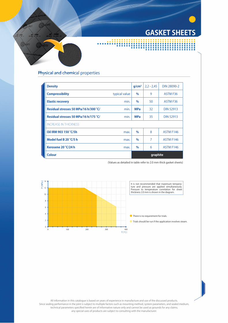


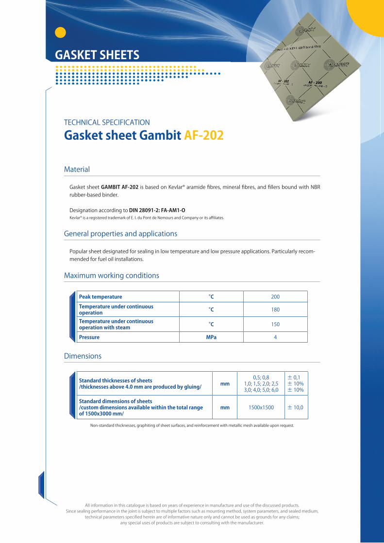


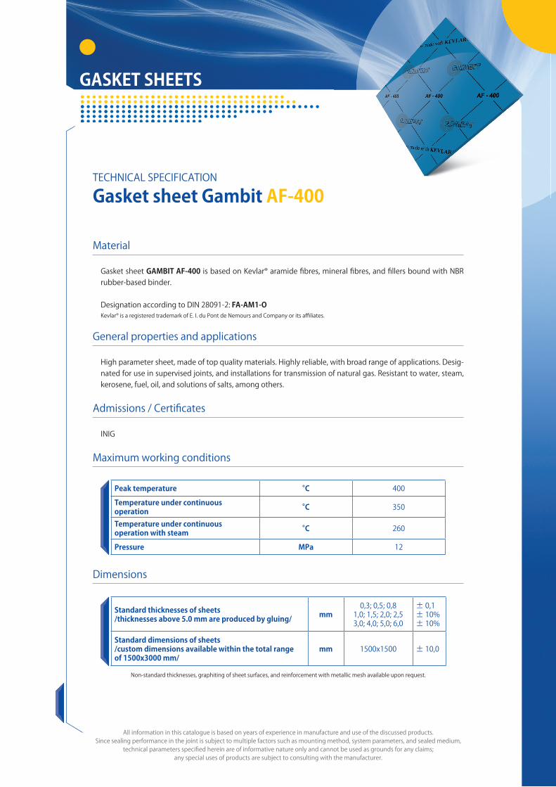
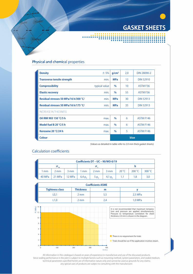


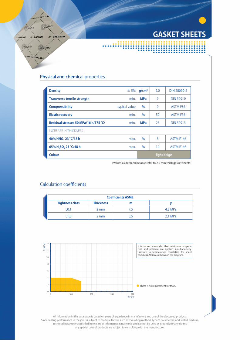

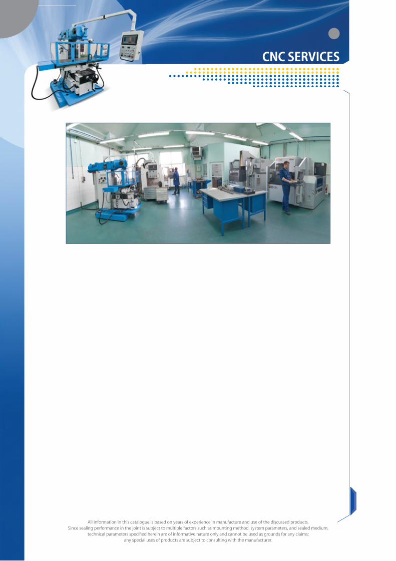

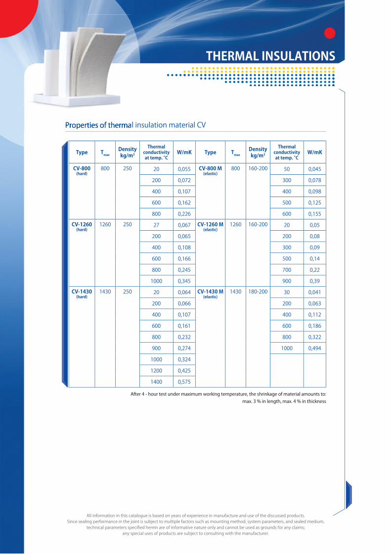


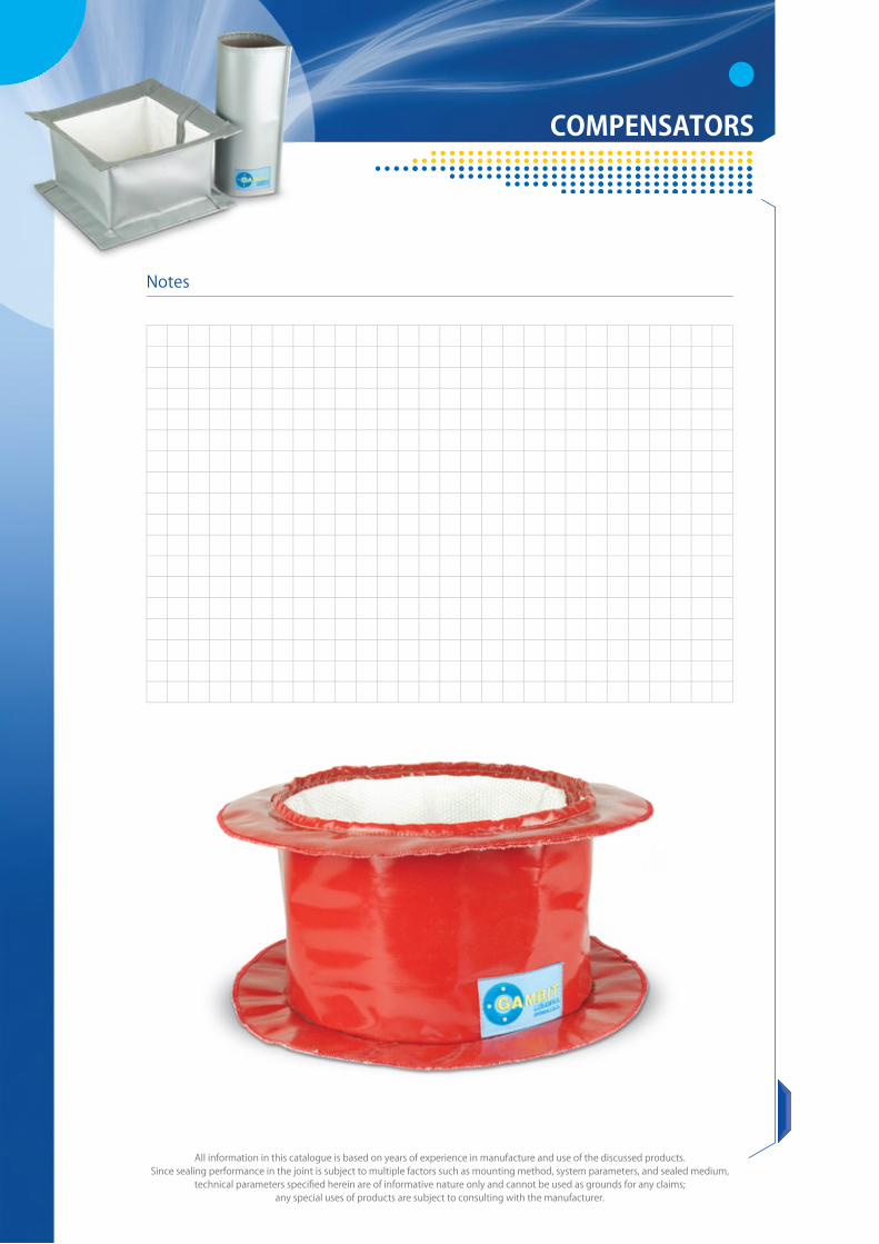
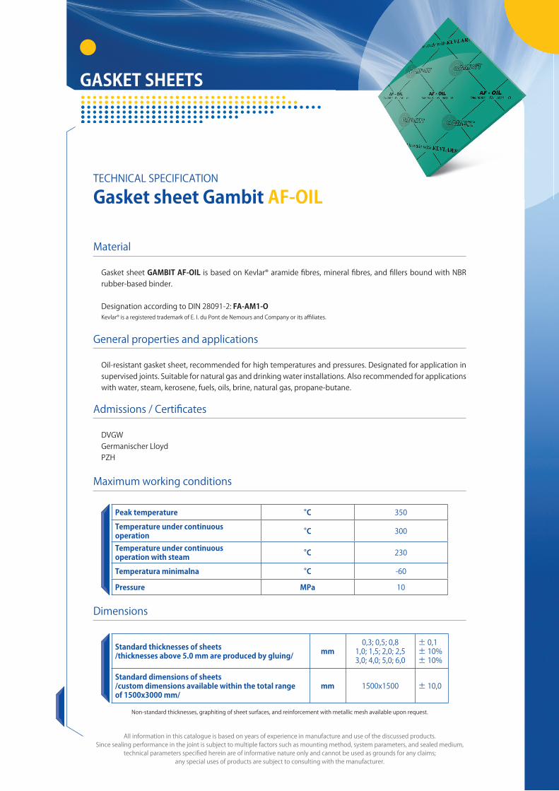

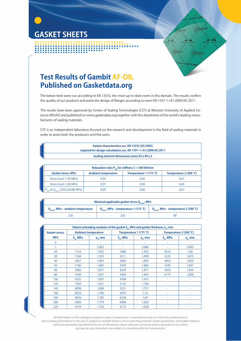


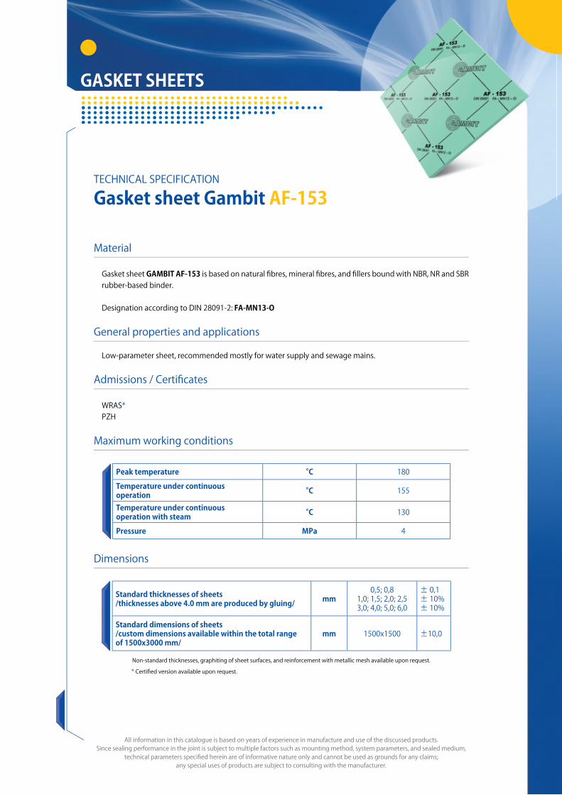


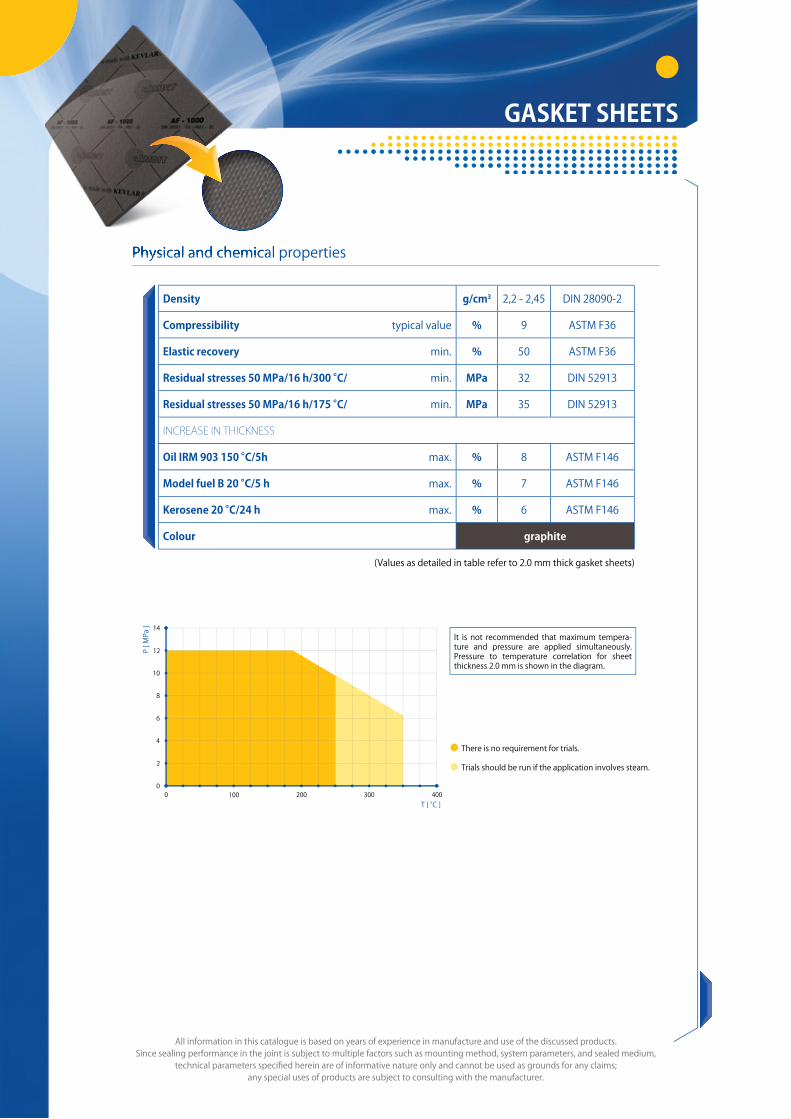


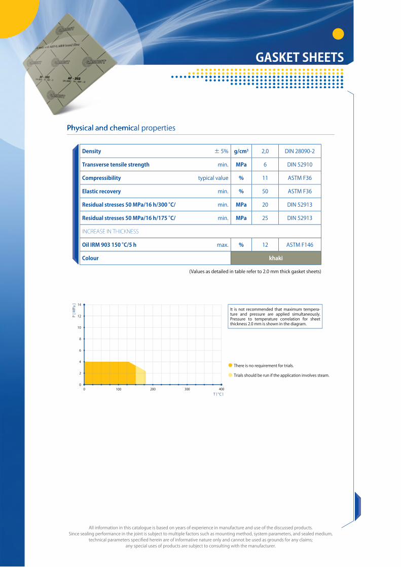


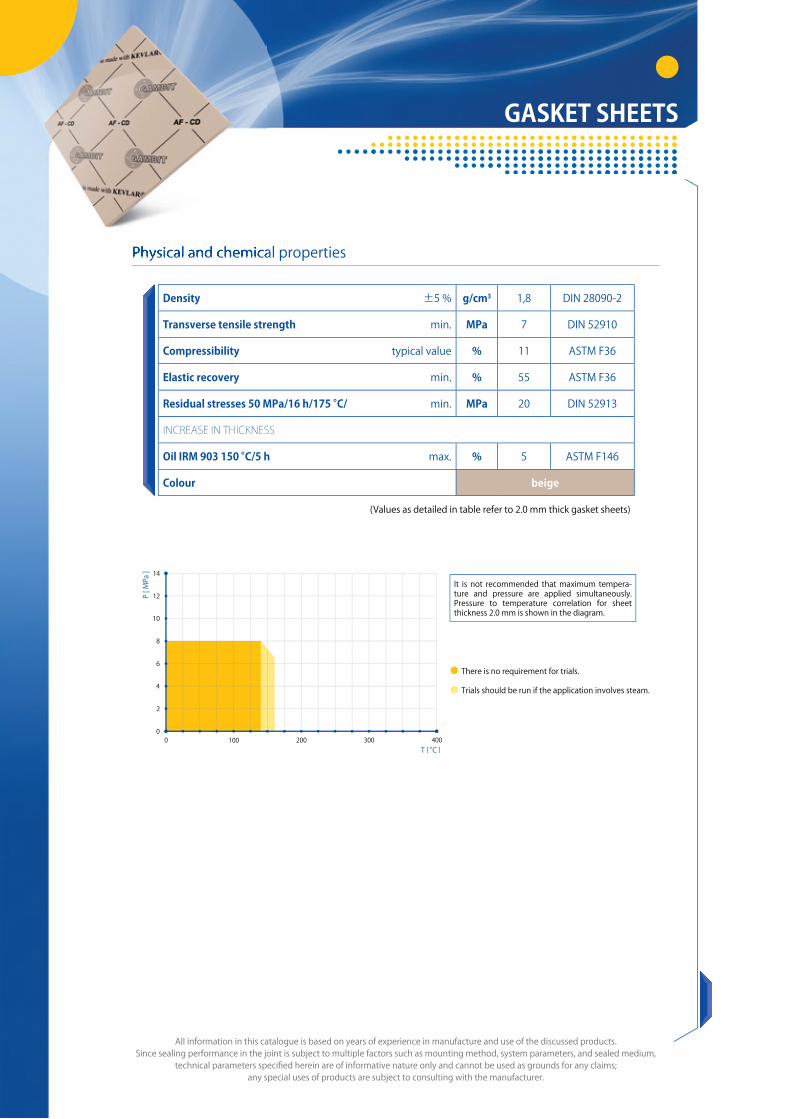


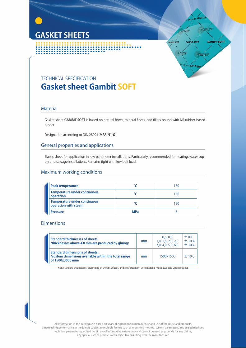
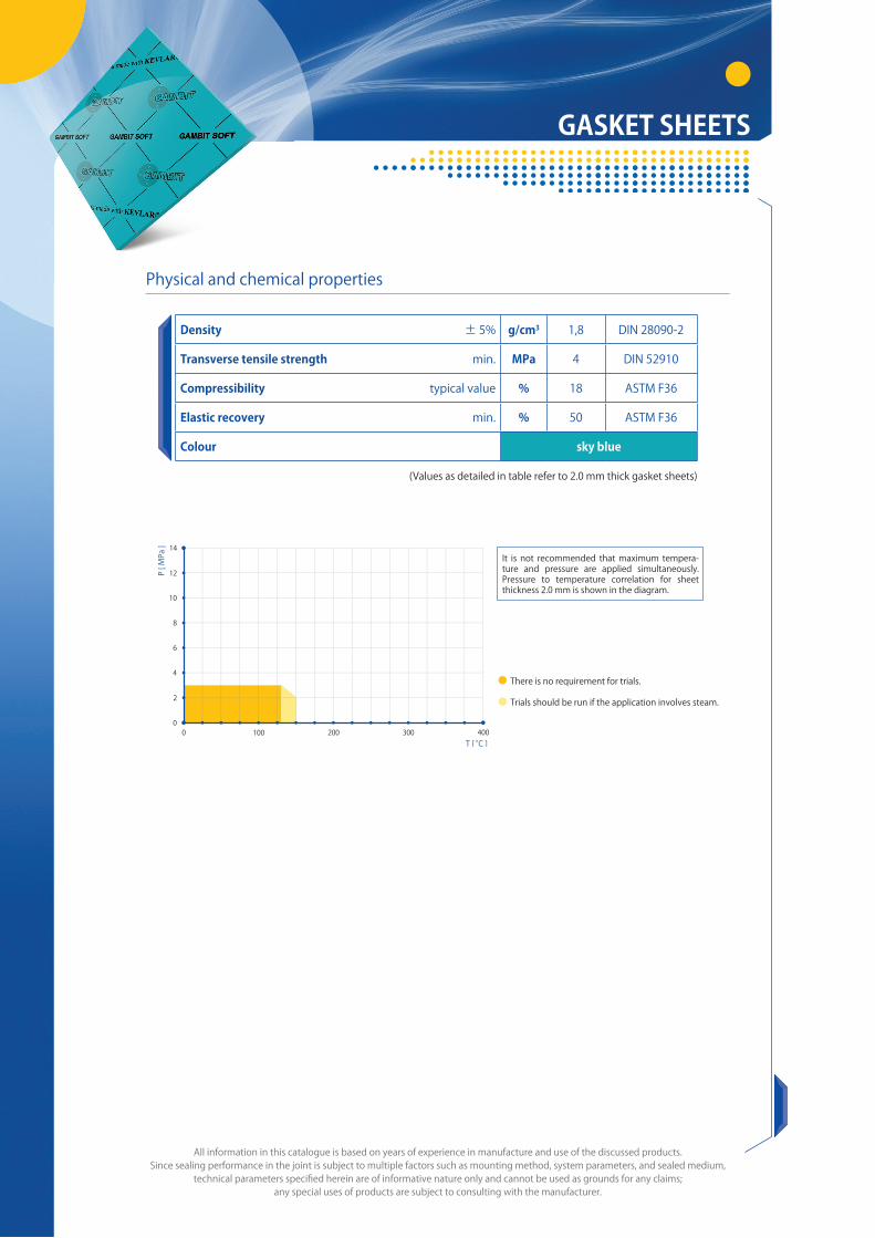
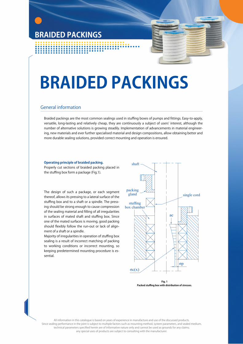
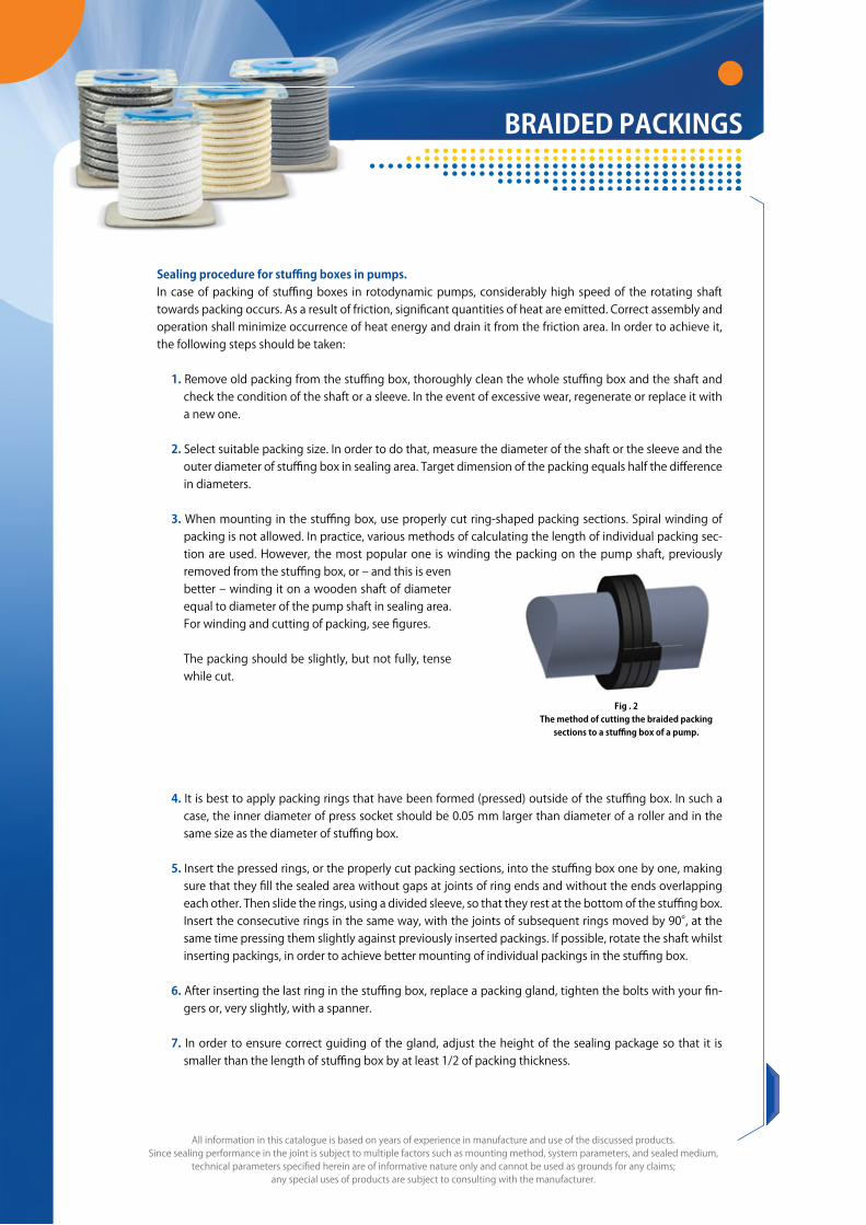


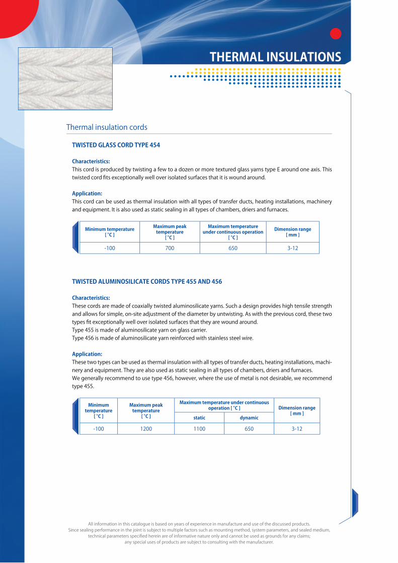
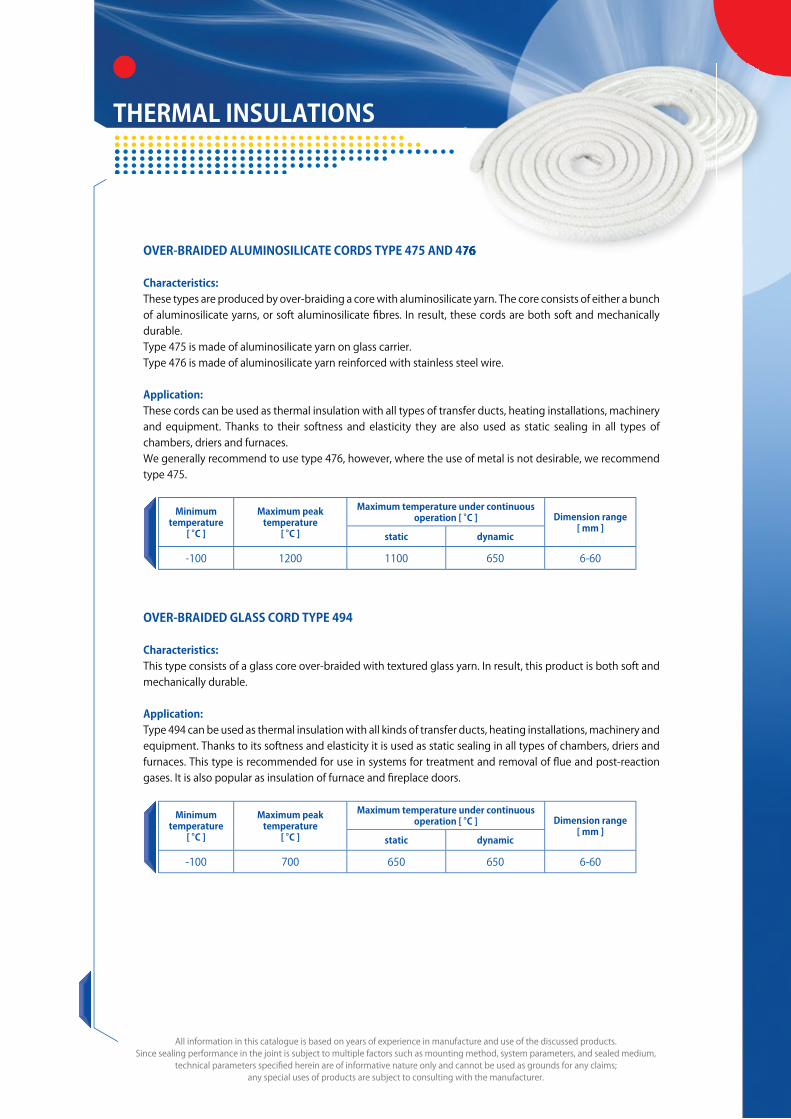


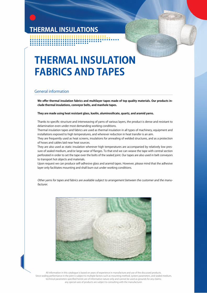
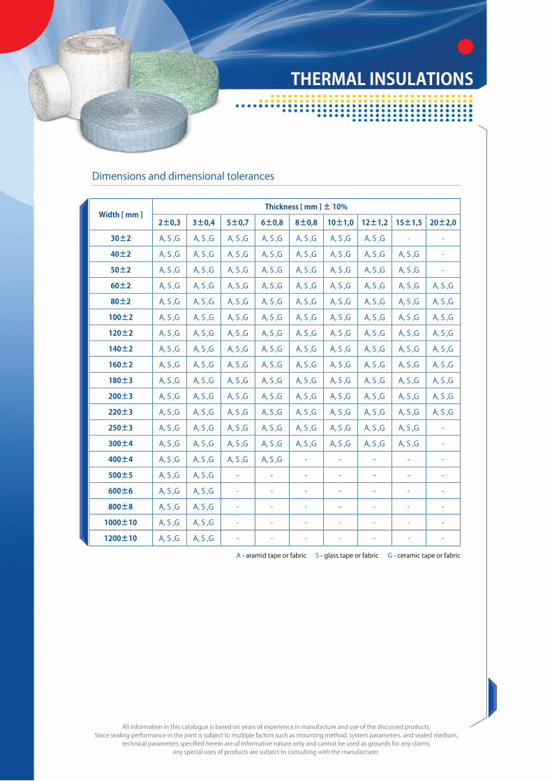
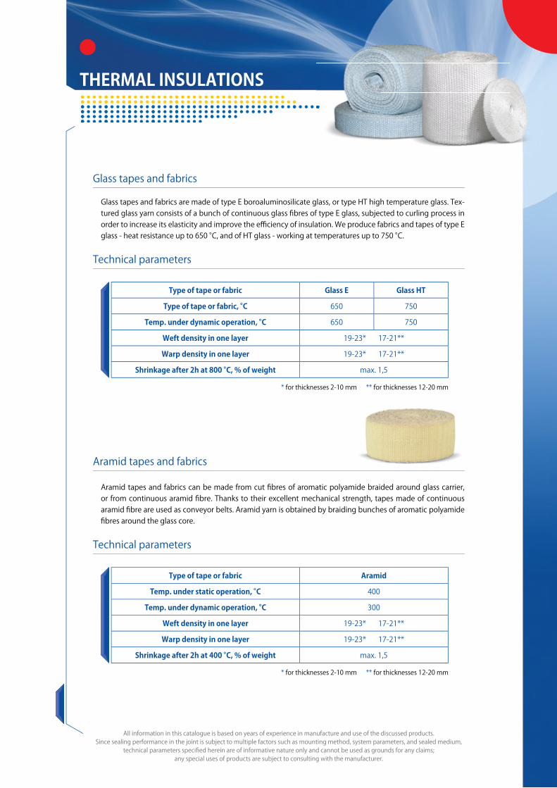


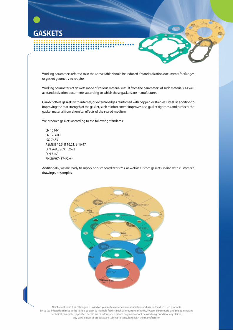

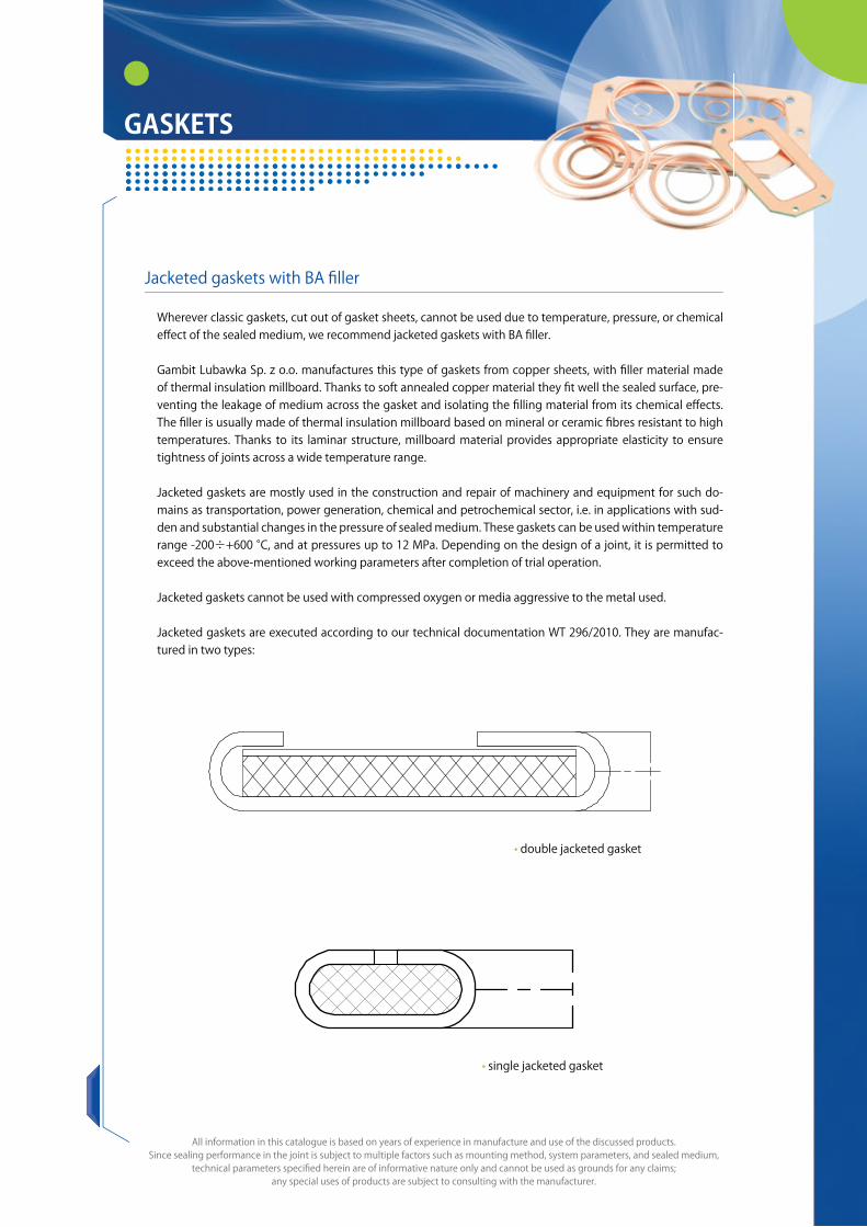


![N Tarrasch Gambit classic …studimonetari.org/edg/latex/tarraschclassico.pdf · Tarrasch Gambit classic Database: ... Tarrasch’s Gambit] Generated by Scid 4.2.2, ... Gundavaa 2460](https://static.documents.pub/doc/80x56/5a7897a67f8b9a273b8bacbd/n-tarrasch-gambit-classic-gambit-classic-database-tarraschs-gambit.jpg)

