High-Efficiency Separation Down to 4 Microns The unique two-stage design of these Type CLC Coalescers/Separators allows them to remove 99% of all liquid and solid particles larger than 4 microns in size. Standard, one-stage separators are only capable of removing particles larger than 10 microns in size. The efficiency of Eaton’s Coalescer/Separator far exceeds that of any other type of centrifugal, cyclone, turbine or vane type separator. And it works with no moving parts to fail or wear out. Applications The Eaton Coalescer/Separator provides two-stage separation of liquid that is in the form of a fine mist or fog from a gas or vapor. The Coalescer/ Separator is primarily used in applications where a fine mist is encountered in processes involving cooling, condensation, flashing, or evaporation, such as: • Compressed refrigeration gases • Evaporator overhead steam • Compressed air prior to desiccant dryer beds • High-pressure gas at injection wells • Fuel gas lines to engines in power • Industrial plants • Natural gas and gas distribution lines • Regulator stations Two-Stage Separation In the first stage, the coalescer stage, smaller liquid droplets enter a special wire mesh de-misting pad in the vessel. The pad’s purpose is to increase the size of the droplets as they pass through it so they can be removed. The larger liquid droplets exit the de-misting pad and enter the second, separation stage. In the second stage, the droplets are centrifugally thrown to the outside wall of the vessel by a unique Cenpellar™ and flow to the bottom for draining. Eaton’s Vortex Containment Plate (VCP) prevents the droplets from being re-entrained after separation. Easy Maintenance The only maintenance required is the inspection, cleaning, or replacement of the de-misting pad. This is easily accomplished through either a quick-opening body closure or body flanges. Engineering Specifications All gas/liquid separators are fabricated carbon steel or stainless steel construction with two-stage coalescer/ separator design and flanged connections. Separators have an ASME Code Stamp. Type 35-L with Side Inlet for Vertical Upflow FEATURES • Removes 99% of Liquid and Solid Entrainment Particles Larger Than 4 Microns • Easy Maintenance • Three Flow Configurations • Gas, Steam, or Air Applications • High Efficiency Over Wide Flow Range OPTIONS • ASME Code Stamp Type CLC Coalescer/Separator Gas/Liquid Separators • Centrifugal In-line Gas/Liquid Separators • Two-Stage Design for Maximum Efficiency • Flanged Connections • Carbon Steel or Stainless Steel Construction • Horizontal or Vertical Flow Model 36L-CLC with Vertical Upflow Inlet and Horizontal Outlet Gas/Liquid Separation Fabricated Construction Model 35L-CLC with side Inlet for Vertical Upflow Model 31L-CLC for Horizontal or Vertical Applications
Transcript
High-Efficiency Separation Down to 4 Microns
The unique two-stage design of these Type CLC Coalescers/Separators allows them to remove 99% of all liquid and solid particles larger than 4 microns in size. Standard, one-stage separators are only capable of removing particles larger than 10 microns in size. The efficiency of Eaton’s Coalescer/Separator far exceeds that of any other type of centrifugal, cyclone, turbine or vane type separator. And it works with no moving parts to fail or wear out.
Applications
The Eaton Coalescer/Separator provides two-stage separation of liquid that is in the form of a fine mist or fog from a gas or vapor. The Coalescer/Separator is primarily used in applications where a fine mist is encountered in processes involving cooling, condensation, flashing, or evaporation, such as:
• Compressed refrigeration gases
• Evaporator overhead steam
• Compressed air prior to desiccant dryer beds
• High-pressure gas at injection wells
• Fuel gas lines to engines in power
• Industrial plants
• Natural gas and gas distribution lines
• Regulator stations
Two-Stage Separation
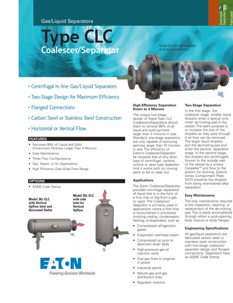
In the first stage, the coalescer stage, smaller liquid droplets enter a special wire mesh de-misting pad in the vessel. The pad’s purpose is to increase the size of the droplets as they pass through it so they can be removed. The larger liquid droplets exit the de-misting pad and enter the second, separation stage. In the second stage, the droplets are centrifugally thrown to the outside wall of the vessel by a unique Cenpellar™ and flow to the bottom for draining. Eaton’s Vortex Containment Plate (VCP) prevents the droplets from being re-entrained after separation.
Easy Maintenance
The only maintenance required is the inspection, cleaning, or replacement of the de-misting pad. This is easily accomplished through either a quick-opening body closure or body flanges.
Engineering Specifications
All gas/liquid separators are fabricated carbon steel or stainless steel construction with two-stage coalescer/separator design and flanged connections. Separators have an ASME Code Stamp.
Type 35-L with Side Inlet for Vertical Upflow
FEATURES
• Removes 99% of Liquid and Solid Entrainment Particles Larger Than 4 Microns
• Easy Maintenance
• Three Flow Configurations
• Gas, Steam, or Air Applications
• High Efficiency Over Wide Flow Range
OPTIONS
• ASME Code Stamp
Type CLCCoalescer/Separator
Gas/Liquid Separators
• Centrifugal In-line Gas/Liquid Separators
• Two-Stage Design for Maximum Efficiency
• Flanged Connections
• Carbon Steel or Stainless Steel Construction
• Horizontal or Vertical Flow
Model 36L-CLC with Vertical Upflow Inlet and Horizontal Outlet
Gas/
Liqui
d Se
para
tion
Fabr
icat
ed
Cons
truct
ion
Model 35L-CLC with side Inlet for Vertical Upflow
Model 31L-CLC for Horizontal or Vertical Applications
For more information, please email us at [email protected] or visit www.eaton.com/filtration