1
Gasoline Water Pump
Owner’s Manual
Max Tool Customer Service
[email protected] or call 1-800-629-3325 (option 3)
Monday -Thursday 6am to 7pm, Friday - Saturday 6am to 3pm. PST
Product Support (Product: information, application & warranty questions)
[email protected] or call 1-800-629-3325 (option 3)
Monday -Thursday 6am to 7pm, Friday - Saturday 6am to 3pm. PST
Downloaded from www.Manualslib.com manuals search engine
2
This manual provides information regarding the operation and maintenance of these products. We have
made every effort to ensure the accuracy of the information in this manual. We reserve the right to
change this product at any time without prior notice.
Please keep this manual available to all users during the entire life of the gasoline water pump.
CONTENTS
. General Safeguards 1
. Location of Component Parts 3
. Operation before Starting Up 4
. Starting of Engine 9
. Use in Highland Areas 11
. Operation of Water Pump 12
. Shutting Down the Engine 13
. Maintenance 14
. Transportation and Storage 19
. Troubleshooting 21
. Specifications 23
Downloaded from www.Manualslib.com manuals search engine
3
. General Safeguards
Safety Precautions
Before starting the engine, perform inspections according to the
procedures described on pre-operation inspections to avoid
accidents and damage to your machine.
For safety, never attempt using this GEP (gasoline engine
powered) water pump to deliver inflammable or corrosive liquids
(such as gasoline and acids). Likewise, corrosive mediums,
seawater, chemical solvents, alkaline liquids (such as used gasoline,
liquor and honey) should be avoided.
Place the water pump on a solid, level position surface to avoid
tilting or turnover that may give rise to spilling of fuel.
To prevent fire hazards, keep the pump well ventilated during
operation and maintain a distance of at least l meter between the
machine and the wall or other machines. Keep away from
inflammable substances.
Do not allow children and pets to enter the working area as this
may increase the chance of their getting burned by hot surfaces of
the operating parts.
Know how to stop the water pump quickly how to operate the
controls. Do not use the pump against the prescribed operating
rules.
WARNING
Safety Precautions
The gasoline fuel is highly inflammable and may explode under
certain conditions.
Do the fueling with the engine shut down and in a well-ventilated
Please read this operation manual to have a
thorough understanding of the content there
before use the product. Failure to do so may
lead to personal injury or mechanical damage.
Downloaded from www.Manualslib.com manuals search engine
4
environment. No smoking is allowed and no open fire or sparks
allowed to exist in areas where fueling is carried out or the fuel is
stored.
Do not allow the fuel to overflow the fuel tank. Be sure to recap
the tank and tighten it after refueling.
When fueling, take care not to spill the gasoline about as the
gasoline vapor may easily get ignited to cause a fire hazard. Be sure
to remove the spilled gasoline as by wiping before starting the
engine.
Do not run the engine indoors or in a poorly ventilated space as
the exhaust gas produced by the running engine contains toxic
carbon monoxide that may cause the loss of personal
consciousness or even death.
Downloaded from www.Manualslib.com manuals search engine
5
. Location of Component Parts
Downloaded from www.Manualslib.com manuals search engine
6
. Operation before Starting Up
1. Connecting the water inlet
Connect the water inlet with a commercially available hose,
connector and fastener clip. The inlet hose must be a continuous
non-foldable structure with a length not more than required and
should be placed near to the source of water so as to achieve the
pump should be fitted to the end of the hose with the hose connector
as shown in the figure below.
CAUTION: Before pumping water, attach the filter to the end of the
hose to filter out foreign matters in the water, the presence of which
may cause clogging and damage to the wane wheel.
NOTE: The hose connector and fastener clip should be securely
fastened to prevent air leaks and reduction in suction power. A loose
hose will reduce the pump performance and self-suction capacity.
2. Connecting the water outlet
Connect the water outlet with a commercially available hose, hose
connector and fastener clip. Large diameter hoses are the most
effective while small ones will increase the flow resistance and
reduce the output power of the pump.
Downloaded from www.Manualslib.com manuals search engine
7
NOTE:
Be sure to the fastener clip is securely fastened to prevent the
outlet hose from coming off under high water pressure.
3.Checking the oil level
CAUTION:
The oil is one of the major factors affecting engine performance
and life. Do not use dirty oil or vegetable oil.
Be sure to check the oil level with the engine shut down and
placed on a level surface.
Please use the SE15-40, 4-stroke engine oil as recommended.
Please use the type of oil with a proper viscosity according to the
local average temperature.
Oil shortage alarm system (OSAS) (installation position)
The OSAS is designed to avoid damage of the engine due to the
shortage of oil in the crankcase. The system will automatically shut
down the engine just before the crankcase oil level drops down to
the minimum line of safety (with the engine switch staying in the ON
position).
If the engine is shut down and cannot be started again, check the
oil level before initiating further troubleshooting procedures.
Remove the oil dipstick and wipe it dry.
Insert the dipstick into the oil filler but not screw it in.
Replenish the crankcase with the recommended type of oil until
Downloaded from www.Manualslib.com manuals search engine
8
the oil level comes up to the upper most position of the refilled if the
existing oil level is found too low.
CAUTON:
Running the engine at a low oil level will cause damage to it.
4. Checking the fuel level
Uncap the fuel tank and check the fuel level. Pouring gasoline if
the fuel level is found too low.
Please use the type of gasoline recommended by the Dealer
(Using the low lead content or lead-free gasoline type is good for
minimizing carbon deposits inside the combustion chamber).
Do not use a mixture of gasoline and oil or dirty gasoline to
prevent dirt, dust or water from entering the fuel tank.
CAUTION:
The gasoline fuel is highly inflammable and may explode under
certain conditions.
Do the fueling with the engine shut down and in a well-ventilated
environment. No smoking is allowed and no open fire or sparks
allowed to exist in areas where fueling is carried out or the fuel is
stored.
Do not allow the fuel to overflow the fuel tank. Be sure to recap
the tank and tighten it after refueling.
Downloaded from www.Manualslib.com manuals search engine
9
When fueling, take care not to spill the gasoline about as the
gasoline vapor may easily get ignited to cause a fire hazard. Be sure
to remove the spilled gasoline as by wiping before starting the
engine.
Avoid frequent or extensive exposure of the skin to gasoline or
breathing in the gasoline vapor. Keep the gasoline out of the reach of
children.
Fuel tank capacity: 1.0 gallons (US. 3.6 liters)
5. Checking the air cleaner filter element
Screw the wing nut and remove the washer and cleaner cover.
Check the filter element to see if it is too dirty and clean it if
necessary.
CAUTION:
Do not run the engine without the air cleaner as this may quicken
engine wear if dirt or dust is sucked into the engine through the
carburetor.
Downloaded from www.Manualslib.com manuals search engine
10
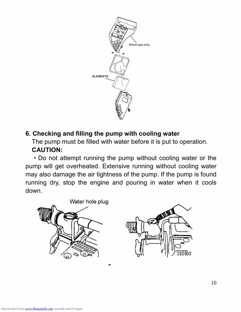
6. Checking and filling the pump with cooling water
The pump must be filled with water before it is put to operation.
CAUTION:
Do not attempt running the pump without cooling water or the
pump will get overheated. Extensive running without cooling water
may also damage the air tightness of the pump. If the pump is found
running dry, stop the engine and pouring in water when it cools
down.
Downloaded from www.Manualslib.com manuals search engine
11
. Starting engine
1. Turn on the fuel tap (by setting it to the ON position).
2. Close the choke.
NOTE:
The choke is not required when starting the engine warm or the
ambient temperature is rather high, (i.e. keep the choke open when
starting the engine).
3. Set the engine switch to the ON position.
4. Turn the throttle control lever slowly to the left.
Downloaded from www.Manualslib.com manuals search engine
12
5. Gently pull up the starter lever until a resistance is felt and then
quickly pull it up.
CAUTION:
Do not allow the starter lever to retract quickly into the engine. Let
it go back gently to avoid damaging the starter.
.Use in Highland Areas
Operation in Highland Conditions
In highland areas (with a high ASL elevation), the air-fuel mixture
produced by a standard carburetor will be too thick and result in a
reduced engine performance and soared fuel consumption. For
operation in highland areas, the engine performance may be
increased by using a smaller diameter carburetor nozzle and
readjusting the carburetor idle speed. If the water pump is frequently
used in areas with a ASL elevation of more than 1800 meters (6000
feet), ask the local dealer to replace or readjust the carburetor
beforehand. Even if the engine is fitted with a carburetor nozzle of an
appropriate size, the engine power will still go down by about 3.5%
each time when the ASL elevation goes up by 305 meters (1000
feet). If no replacement or readjustment is ever made of the
carburetor, the highland effect of the engine output power will be
even more obvious.
CAUTION:
Downloaded from www.Manualslib.com manuals search engine
13
Using the water pump in areas where the ASL elevation is lower
than suitable for the carburetor nozzle will lead to a decreased
engine performance and overheating of the engine and even cause
serious damage to the engine due to an extremely thin air-fuel
mixture.
. Operation of the Water Pump
1. Gradually open the choke after the engine warms up.
2. Set the throttle to the predetermined RPM.
. Shutting Down the Engine
1. Set the throttle control lever to the right end.
Downloaded from www.Manualslib.com manuals search engine
14
2. Set the engine switch to the OFF position.
3. Turn off the fuel tap (by setting to the OFF position).
NOTE:
To shut down the engine in an emergency, simply set the engine
switch to the OFF position.
. Maintenance
Periodic inspections and fine-tuning are simply indispensable to
keep the water pump working with high performance and regular
maintenance may also lengthen the pump life. Supplied in the table
on the next page are intervals at which the schedules maintenance
jobs are to be done.
WARNING:
Before any maintenance attempt, be sure to shut down the
engine. If the maintenance job has to be done with the engine at
work, it should take place in a well-ventilated space as the exhaust
gas contains toxic carbon monoxide that causes the loss of personal
consciousness or even death.
Downloaded from www.Manualslib.com manuals search engine
15
CAUTION:
In cases when the pump is used to suck up seawater, be sure to
flush it with fresh water immediately after use to minimize corrosion
and remove deposits.
Always use the original parts and relevant tools supplied with the
machine to carry out maintenance. Failure to do this may cause
damage to the pump.
NOTE:
Inspection and maintenance should take place more frequently
if the pump is used in a dirty environment.
Leave the following inspection and maintenance jobs to the
authorized dealers unless you, the user, have the relevant tools and
necessary DIY skills. In the latter case, refer to service manual.
Table of Maintenance Schedules
Normal
maintenance
Item period
Each
time
Per
month
or 20
hours
Per
month
or 50
hours
Per
month
or 100
hours
Per
month
or 300
hours
Check engine oil
lever
Replace engine oil
lever
Air cleaner check
Air cleaner for clean
Spark plug *
Fuel supply Replace per every two years
Wane wheel *
Pump case cover *
Downloaded from www.Manualslib.com manuals search engine
16
Water inlet *
Note: “*” items will be maintained with the help of dealers from
general power machinery Co., Ltd.
1. Replacing the engine oil
Oil drains easily and quickly while the engine is warm.
1. Remove the oil dipstick and drain bolt to let out the oil.
2. Screw the drain bolt back in place and tighten it.
3. Pour in clean oil until the desired level is reached.
Oil sump capacity: 0.6 liters
Clean the hands with soap if stained with the engine oil.
NOTE: Be sure to keep the environment clean when disposing
used engine oil. We suggest you collect the waste oil in a container
to be sent to a waste disposal site or a recycling service center of
spill it in the garbage or on the ground.
2. Maintaining the air cleaner
A dirty air cleaner will let less air into the carburetor. To prevent
carburetor malfunctions, be sure to maintain the air cleaner
periodically. More frequent maintenance of the air cleaner will be
necessary if the pump is working in an extremely dirty environment.
DO not clean the air cleaner with a low ignition point solvent
because it may get enflamed or even explode under certain
Downloaded from www.Manualslib.com manuals search engine
17
circumstances.
CAUTION: Do not use the water pump without an air cleaner. The
dirt or dust if sucked into the engine may quicken engine wear.
1) Unscrew the wing nut and remove the air cleaner cover and
filter element.
2) Clean the filter element with a detergent solution inflammable or
with a high ignition point and let it dry thoroughly after cleaning.
3) Immerse the filter element into clean oil and then squeeze out
the excessive amount of oil.
4) Put the filter element as well as the air cleaner back in place.
3. Maintaining the spark plug
The recommended type of spark plug is NHSP LD P6RTCU.
To ensure normal operation of the engine, the spark plug should
have a correct gap and should remain free of carbon deposits.
1) Remove the plug cap.
The muffler may be very hot if the engine is still running. Take care
not to touch the muffler.
2) Check the spark plug visually. Discard the spark plug if it is
Downloaded from www.Manualslib.com manuals search engine
18
obviously worn out or the insulation ring on it is broken or cracked.
Clean the spark plug with a brush when put it back in place.
3) Check the plug gap with a feeler gauge.
Vary the gap by moving the side electrode.
Normal plug gap: 0.70~0.80mm
4) Check the plug O-ring for normal condition. Screw it in with the
plug wrench to protect the plug thread.
NOTE:
In the case of screwing in a new spark plug, tighten it by an
additional 1/2 screw turn after the plug reaches and pushes on the
O-ring, while in the case of a used spark plug, an additional 1/2~1/4
screw turn is necessary.
CAUTION:
Make sure the spark plug is properly tightened. Improper
Downloaded from www.Manualslib.com manuals search engine
19
tightening may cause the engine to be overheated or damaged.
Never use spark plugs with an incorrect thermal value range.
. Transportation and Storage
CAUTION:
To avoid causing a fire hazard, let the engine cool down before
transportation or indoor storage of the pump.
Before transporting the pump, set the fuel tap to the OFF position
and place the pump body in a level position to prevent the fuel from
spilling out. The spilled gasoline or the gasoline vapor may get
ignited.
Note and do the following before storing pump for an extended
period of time:
1) Make sure the storage area is free of moisture or dust.
2) Ch\lean the inside of the pump.
The pump may get clogged if it is used to suck up water containing
such matters as earth, sand or heavy fragments.
Before storing, clean the pump by sucking up clean water or
otherwise the wane wheel may be damaged when the pump is put to
use again. After cleaning, unscrew the water drain plug to drain off
the water from inside the pump casing as much as possible. Then
screw the drain plug back into place.
3) Drain off the fuel.
a. Turn off the fuel tap (OFF position), unscrew the drain screw
from the carburetor float chamber to drain off the fuel from inside the
carburetor and collect the gasoline in a suitable container.
b. Turn on the fuel tap (ON position) and collect the gasoline in a
suitable container.
c. Screw the carburetor fuel drain screw back into place.
Downloaded from www.Manualslib.com manuals search engine
20
4) Replace the engine oil.
5) Screw off the spark plug, pour a spoonful of clean oil into the
cylinder, turn the engine alternatively for several times to allow
uniform distribution of oil, and then screw in the spark plug again.
6) Pull up the starter lever until a resistance is felt. Stop pull for a
while and pull it up again until the triangle mark on the starter wheel
gets into collimation with the screw hole in the starter (as shown the
sketch below). In this position, both the inlet valve and outlet valve is
closed to prevent corrosion inside the engine.
7) Cover up the pump to keep out dust.
. Troubleshooting
Engine unable to get started:
1) Is there enough fuel?
2) Is the fuel tap turned on?
Downloaded from www.Manualslib.com manuals search engine
21
3) Has the fuel reached the carburetor? Make the check by
unscrewing the oil drain screw from under the carburetor with the
fuel tap turned on.
WARNING:
Should there be a spill of fuel, be sure to clean it before checking
the spark plug and start the engine or otherwise the spilled fuel or
fuel vapor may get ignited
4) Is the engine switch set to the ON position?
5) Is there enough oil in the crankcase?
6) Is the spark plug generating sparks?
a. Uncap the spark plug, clear off the dirt from around the plug and
remove the spark plug.
b. Fit the spark plug into the plug cap.
c. Turn on the engine with the side electrode and pull up the starter
lever to see if there is sparks generated.
d. Ground the engine with the side electrode and pull up the starter
lever to see if there is sparks generated.
e. Replace the spark plug if no spark is found.
Start the engine as directed in the operation manual if sparks are
generated.
7) If the engine still refuses to get started, send the pump to any of
the authorized dealers.
Downloaded from www.Manualslib.com manuals search engine
22
The pump unable to such up water:
1) Is it filled with enough amount of water?
2) Is the filter clogged?
3) Is the hose fastener clip tightened?
4) Is the hose damaged?
5) Is the suction head too high?
6) If the pump still fails to work, send it to any of the authorized
dealers.
. Specifications
Type XP652WP XP650WP XP904WP
Engine type XP6.5HP XP6.5HP XP9.0HP
Max. Power 4.7kw(7HP) 4.7kw(7HP) 6.5kw(9.0HP)
Displacement 208cc 208cc 270cc
Fuel tank capacity 1.0 Gallons 1.0 Gallons 1.7 Gallons
Oil capacity 0.63 US. Qt. 0.63 US. Qt. 1.16 US. Qt.
Downloaded from www.Manualslib.com manuals search engine
23
Water intake pipe dia. 2 3 4
Water output pipe dia. 2 3 4
Revolution 3600rpm 3600rpm 3600rpm
Max. overhead lift 92ft 98ft 98ft
Max. suction lift 26ft 26ft 26ft
Max. flow rate 158 GPM 220 GPM 427 GPM
Size18.7 15.6
15.4(in.)
21.3 17.5
19.3(in.)
25.2 20.7
22.3(in.)
Downloaded from www.Manualslib.com manuals search engine
24
PA
RT
S L
IST
AN
D A
SS
EM
BLY
(XP
65
2W
P/X
P6
50W
P)
Downloaded from www.Manualslib.com manuals search engine
25
Ite
mP
art
Qt
y
De
scrip
tio
nIt
e
m
Part
Qty
De
scrip
tio
n
1G
BT
57
89
-86
13
Fla
nge
bolt M
6×
12
45
DJ1
70
F-1
110
0-C
1C
ran
k c
ase
assy.
2D
J1
68
F-1
13
00
-B1
Co
ve
r a
sse
mbly
46
GB
27
6-8
9-6
20
52
Ra
dia
l b
all
bea
ring
(6
02
5)
3D
J1
68
F-1
10
11
-A1
co
ve
r assem
bly
47
DJ1
68
F-1
510
0-A
1S
pe
ed
Re
gu
latin
g G
ea
r
4D
J1
68
F-1
320
4-A
1L
ock N
ut
48
DJ1
68
F-1
510
0-A
1ce
ntr
ifu
ga
l assy.
5D
J1
68
F-1
320
3-A
1A
dju
stin
g N
ut
49
DJ1
68
F-1
310
0-B
1C
am
sha
ft a
ssy.
6D
J1
68
F-1
320
1-A
1A
rm,
va
lve
rocker
50
DJ1
68
F-1
210
0-W
1C
ran
ksh
aft A
sse
mb
ly
7D
J1
68
F-1
300
6-A
1R
ota
tor, v
alv
e5
1D
J1
70
F-1
220
0-B
1T
ie-r
od
Asse
mb
ly
8D
J1
68
F-1
320
2-A
2F
aste
nin
g B
olt
52
DJ1
68
F-1
10
02
-D1
Pin
, d
ow
el, 7
×1
2
9D
J1
68
F-1
300
5-A
1R
eta
ine
r, E
X.
Va
lve
sp
rin
g5
3D
J1
70
F-1
10
03
-B1
Cra
nkca
se G
aske
t
10
DJ1
68
F-1
300
4-A
1R
eta
ine
r, I
N.
Va
lve
sp
rin
g5
4D
J1
68
F-1
10
07
-A1
Oil
Fill
er
Asse
mbly
11
DJ1
68
F-1
330
0-A
1P
late
, p
ush
ro
d g
uid
e5
5D
J1
68
F-1
10
01
-C1
Cra
nkca
se c
ove
r
12
DJ1
68
F-1
300
3-A
2S
pri
ng
, va
lve
56
DJ1
68
F-1
16
00
-A1
Dip
stick c
ove
r
Downloaded from www.Manualslib.com manuals search engine
26
13
DJ1
68
F-1
301
0-A
1R
etu
rnre
r,E
xh
au
st
Va
lve
57
DJ1
68
F-1
10
14
-A2
Oil
sea
l, 2
5.1
4×
35
×7
14
GB
T5
78
7-B
8-6
04
Fla
nge
bolt M
8×
60
58
GB
T5
78
7-B
8-3
56
bo
lt M
8×
35
15
DJ1
68
F-1
850
0-B
1S
pa
rk P
lug
F7
TC
59
DJ1
68
F-1
810
0-C
1Ig
nitio
n C
oil
16
DJ1
70
F-1
12
00
-B1
He
ad
co
mp,
cylin
de
r6
0G
BT
57
87
-B6
-25
2b
olt M
6×
25
17
DJ1
68
F-1
400
6-C
1O
utle
t G
aske
t6
11
Air
-le
ad
ing C
ove
r
18
DJ1
70
N-1
44
00
-A1
Mu
ffe
r A
ssem
bly
62
DJ1
70
N-1
52
00
-A1
sp
eed
adju
ste
r
19
DJ1
68
F-1
400
2-A
2B
olt h
ea
d,
M8
×3
56
3D
J1
70
N-1
52
01
-A1
Sp
ee
d R
egu
latin
g B
ar
20
GB
T6
17
7-N
-82
Fla
nge
nut
M8
64
DJ1
68
F-1
620
0-C
1F
lyw
he
el
21
DJ1
68
F-1
400
1-A
2B
olt S
tud
, 6
×90
65
DJ1
68
F-1
600
2-A
1F
lyw
he
el F
an
22
DJ1
68
F-1
400
3-B
1In
let
Gaske
t6
6D
J1
68
F-1
600
0-A
1S
tart
ing
Cup
23
DJ1
68
F-1
400
4-A
1C
on
ne
cting
Blo
ck,C
arb
reto
r
67
GB
T6
17
7-N
-14
1F
lan
ge
nut
M1
4
24
DJ1
68
F-1
400
5-A
1C
arb
reto
r G
aske
t6
8D
J1
68
F-1
14
00
-A1
Win
d S
hie
l Assem
bly
25
DJ1
70
N-1
41
00
-A1
Ca
rbu
reto
r A
ssem
bly
69
DJ1
70
N-1
61
21
-A1
Re
co
il S
are
r
Downloaded from www.Manualslib.com manuals search engine
27
26
DJ1
68
F-1
402
7-A
1A
ir C
lean
er
Ga
ske
t7
0D
J1
70
N-1
61
22
-A1
reco
il s
tart
er
27
DJ1
70
N-1
101
3-A
1T
ub
e,
Bre
ath
er
71
GB
T5
78
7-B
6-8
3B
olt F
lan
ge
M6
×8
28
DJ1
70
N-1
142
0-A
1A
irC
lea
ne
r A
ssem
bly
72
DJ1
68
F-1
500
1-A
1S
ha
ft, g
ove
rno
r a
ssy.
29
GB
T6
17
7-N
-82
Fla
nge
nut
M8
73
DJ1
68
F-1
500
3-A
1P
in L
ock
30
DJ1
70
F-1
23
01
-A4
Pis
ton R
ing A
74
DJ1
68
F-1
500
4-A
1S
pe
ed
Re
gu
latin
g A
rm
31
DJ1
70
F-1
23
02
-A1
Pis
ton R
ing B
75
DJ1
68
F-1
500
5-A
1L
ock B
olt
32
DJ170F-12304-A
1S
ide
Rin
g7
6G
BT
61
77
-N-6
3F
lan
ge
nut
M6
33
DJ
17
0F
-12
303
-A1
Wa
ve
Rin
g7
7D
J1
70
F-1
500
7-B
1B
ack S
prin
g B
34
DJ
17
0F
-12
304
-A1
Sid
e R
ing
78
DJ1
68
F-1
500
6-A
1P
ulli
ng
Ro
d
35
DJ1
70
F-1
230
0-A
1S
cra
pe
r R
ing
Se
t,P
isto
n7
9D
J1
70
F-1
500
8-A
1F
ine
Reg
ula
ting
Sp
ring
C
36
DJ1
68
F-1
200
3-A
2C
lip,
pis
ton
pin
80
DJ1
P6
5F
-14
00
8-A
2T
ub
e c
lip
37
DJ1
70
F-1
200
2-A
1P
in,
pis
ton
81
DJ1
70
N-1
40
07
-A1
Ou
tle
t pip
eφ
6×
φ1
0×
29
5
38
DJ1
70
F-1
200
1-B
1P
isto
n8
2D
J1
68
F-1
830
0-A
1A
mp
lifie
r
39
DJ1
68
F-1
300
2-A
1In
take
Va
lve
83
DJ1
68
F-1
820
0-A
1O
il S
enso
r A
ssem
bly
Downloaded from www.Manualslib.com manuals search engine
28
40
DJ1
68
F-1
300
1-A
1E
xh
au
st
Va
lve
84
GB
T5
78
7-B
6-1
62
bo
lt M
6×
16
41
DJ1
70
F-1
300
8-A
2R
od
, p
ush
85
DJ1
68
F-1
10
04
-A2
Dra
in P
lug
Wash
er
42
DJ1
70
F-1
300
9-A
2Ta
pp
et
Litte
r V
alv
e8
6D
J1
68
F-1
10
05
-A2
Wash
er,
dra
in lu
g
43
DJ1
70
F-1
10
10
-C1
Ca
sket,
cylin
de
r h
ead
87
DJ1
70
N-1
43
02
-A1
Fu
el cock
44
DJ1
68
F-1
10
09
-A2
Se
t P
in, 1
0×
14
88
DJ1
70
N-1
43
00
-A1
Fu
el ta
nk
89
GB
T5
78
7-B
6-1
63
bo
lt M
6×
16
90
GB
T9
3-L
W-8
2sp
ring
wa
sh
er
Downloaded from www.Manualslib.com manuals search engine
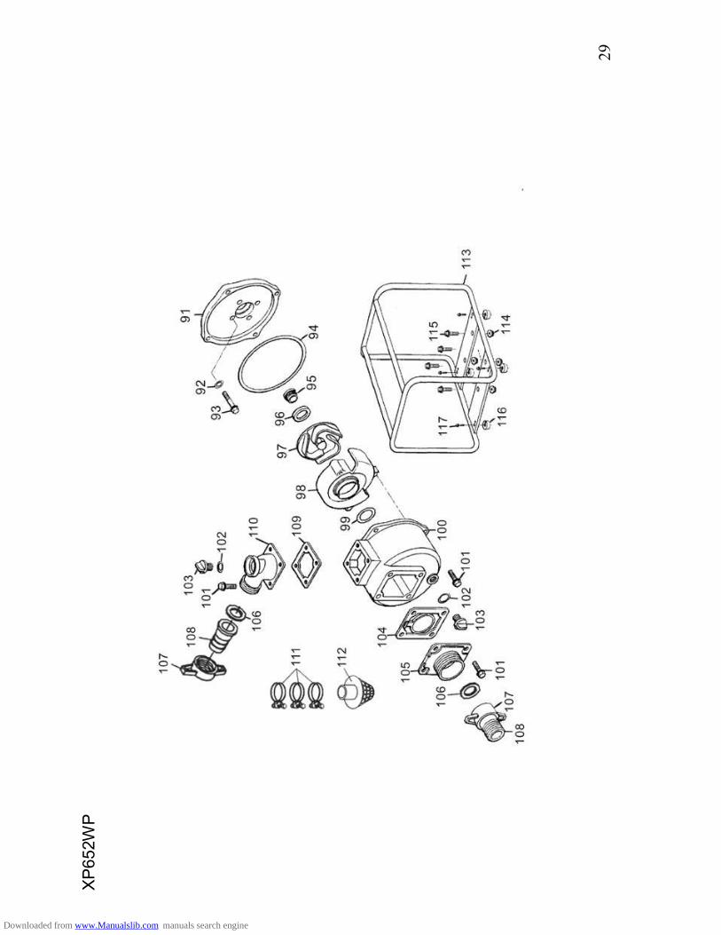
29
XP
65
2W
P
Downloaded from www.Manualslib.com manuals search engine
30
Ite
mP
art
Qty
De
sc
rip
tio
nIt
em
Pa
rt
Qty
De
sc
rip
tio
n
91
DS
20
-32
00
1-A
1C
asin
g1
05
DS
20
-32
00
3-A
1S
uctio
n p
ort
92
GB
97
.1-W
-84
Ga
ske
t8
x1
.6,
10
6D
S2
0-3
200
8-A
2C
ou
plin
g P
ackin
g
93
GB
70
-B8
-60
4F
lan
ge
Bo
lt M
8×
60
10
7D
S2
0-3
201
0-A
2H
ose
Jo
int
94
DS
20
-32
05
2-A
1C
asin
g G
aske
t1
08
DS
20
-32
20
0-A
2H
ose
Co
up
ling
95
DS
20
-32
01
3-A
1M
ech
an
ical se
al A
10
9D
S2
0-3
200
9-A
1D
ischa
rge
gaske
t
96
DS
20
-32
01
3-B
1M
ech
an
ical se
al B
11
0D
S2
0-3
200
4-A
1D
ischa
rge
po
rt
97
DS
20
-32
00
5-A
1Im
pelle
r111
DS
20
-32
01
6-A
3H
ose
Ban
d
98
DS
20
-32
00
6-A
1C
ase
Volu
te11
2D
S2
0-3
202
0-A
1S
tra
ine
r
99
DS
20
-32
011
-A1
O-r
ing
se
al
11
3X
P65
2W
P-3
110
0-A
1F
ram
e
10
0D
S2
0-3
200
2-A
1P
um
p c
ase
ho
usin
g11
4G
B6
17
7-N
84
Fla
nge
nut
M8
10
1G
B5
78
7-B
8-2
51
2F
lan
ge
Bo
lt M
8×
25
11
5G
B5
78
7-B
8-3
54
Fla
nge
bolt M
8×
35
10
2D
S2
0-3
205
0-A
2O
-rin
g,
Plu
g11
6D
S2
0-3
120
3-A
4R
ub
be
r pa
d, d
am
pin
g
10
3D
S2
0-3
204
9-A
2P
lug
11
7G
B5
78
7-8
64
Fla
nge
Bo
lt M
6×
12
10
4D
S2
0-3
203
0-A
1F
lap
pe
r va
lve
gaske
t
Downloaded from www.Manualslib.com manuals search engine
31
XP
65
0W
P
Downloaded from www.Manualslib.com manuals search engine
32
Ite
mP
art
Qty
De
sc
rip
tio
nIt
em
Pa
rt
Qt
y
De
sc
rip
tio
n
91
DS
30
-32
00
1-A
1C
asin
g1
05
DS
30
-32
00
3-A
1S
uctio
n p
ort
92
GB
97
.1-W
-84
Ga
ske
t8
x1
.6
10
6D
S3
0-3
200
8-A
2C
ou
plin
g P
ackin
g
93
GB
70
-B8
-60
4F
lan
ge
Bo
lt M
8×
60
10
7D
S3
0-3
201
0-A
2H
ose
Jo
int
94
DS
30
-32
05
2-A
1C
asin
g G
aske
t1
08
DS
30
-32
20
0-A
2H
ose
Co
up
ling
95
DS
30
-32
01
3-A
1M
ech
an
ical se
al A
10
9D
S3
0-3
200
9-A
1D
ischa
rge
gaske
t
96
DS
30
-32
01
3-B
1M
ech
an
ical se
al B
11
0D
S3
0-3
200
4-A
1D
ischa
rge
po
rt
97
DS
30
-32
00
5-A
1Im
pelle
r111
DS
30
-32
01
6-A
3H
ose
Ban
d
98
DS
30
-32
00
6-A
1C
ase
Volu
te11
2D
S3
0-3
202
0-A
1S
tra
ine
r
99
DS
30
-32
011
-A1
O-R
ing
Se
al
11
3X
P6
50W
P-3
110
0
-A
1F
ram
e
10
0D
S3
0-3
200
2-A
1P
um
p c
ase
ho
usin
g11
4G
B6
17
7-N
84
Fla
nge
nut
M8
10
1G
B5
78
7-B
8-2
51
2F
lan
ge
Bo
ltM
8×
25
11
5G
B5
78
7-B
8-3
54
Fla
nge
bolt M
8×
35
10
2D
S3
0-3
205
0-A
2O
-rin
g,
Plu
g11
6D
S2
0-3
120
3-A
4R
ub
be
r pa
d, d
am
pin
g
10
3D
S3
0-3
204
9-A
2P
lug
11
7G
B5
78
7-B
6-1
24
Fla
nge
Bo
lt M
6×
12
10
4D
S3
0-3
203
0-A
1F
lap
pe
r va
lve
gaske
t
Downloaded from www.Manualslib.com manuals search engine
33
PA
RT
S L
IST
AN
D A
SS
EM
BLY
(XP
90
4W
P)
Downloaded from www.Manualslib.com manuals search engine
34
Ite
mP
art
Qty
De
scrip
tio
nIt
em
Part
Qty
De
scrip
tio
n
11
61
02
1S
tart
er
com
p, re
co
il2
11
81
05
1C
ord
sto
p s
witch
2G
B5
78
7-8
63
Fla
ng
e b
olt M
6×
82
21
50
09
Oil
sea
l, 8
×1
4×
5
31
84
00
1E
ngin
e s
witch
23
GB
/T2
76
-94
2R
adia
l b
all
be
arin
g (
620
2)
41
61
03
1F
an
, co
ve
r com
p2
41
50
01
1S
haft, g
ove
rno
r a
rm
5G
B5
78
7-8
61
2F
lan
ge
bo
lt M
6×
12
25
15
003
1P
in, lo
ck, 1
0m
m
611
01
21
Sh
roud
com
p2
61
50
02
1W
ashe
r, 8
.2×
17
×0
.8
71
60
01
1P
ulle
y, s
tart
er
27
GB
617
7-8
61
Fla
ng
e n
ut M
10
81
60
02
1F
an
, coo
ling
28
18
201
1O
-rin
g, 1
4m
m
9G
B6
17
7-8
61
Fla
ng
e n
ut M
16
29
18
200
1S
witch
assy.
oil
leve
l
10
11
03
91
Clip
. W
ire
ha
rne
ss
30
12
004
1W
eig
ht, b
ala
nce
r
11
16
200
1F
lyw
he
el com
p3
11
21
00
1C
ranksh
aft c
om
p
12
11
01
42
Oil
sea
l, 3
5×
52
×8
32
GB
/T 9
9-8
81
Ke
y
13
111
00
1C
rank c
ase
assy.
33
GB
/T2
76
-94
2R
adia
l b
all
be
arin
g (
620
7)
14
11
00
42
Bolt, d
rain
lu
g3
411
01
01
Ca
ske
t, c
ylin
de
r h
ead
15
18
300
1A
mplif
ier
35
11
00
92
Pin
, d
ow
el, 1
2×
20
16
11
00
52
Washe
r, d
rain
lu
g3
61
40
01
2B
olt h
ea
d, 8
×111
17
18
009
1C
lip, w
ire
37
14
003
1P
ackin
g, in
su
lato
r
Downloaded from www.Manualslib.com manuals search engine
35
18
GB
578
9-8
62
Fla
ng
e b
olt M
6×
25
38
14
004
1In
su
lato
r, c
arb
ure
tor
19
18
100
1C
oil
assy.
ig
nitio
n3
91
40
05
1P
ackin
g, ca
rbu
reto
r
20
11
01
71
Gro
mm
et co
rd
40
14
100
1C
arb
ure
tor
assy.
41
14
11
31
Sta
y m
an
ual choke
63
13
001
1V
alv
e, IN
.
42
14
207
2P
ackin
g, a
ir c
lea
ne
r6
41
30
02
1V
alv
e, E
X.
43
GB
617
7-8
65
Fla
ng
e n
ut M
66
51
30
08
2R
od
, pu
sh
44
14
208
1C
ase
com
p, air
cle
an
er
66
13
007
1S
ea
t, v
alv
e s
pri
ng
45
GB
578
9-8
61
Fla
ng
e b
olt M
6×
20
67
13
003
2S
prin
g, va
lve
46
14
206
1S
eal, a
ir c
lea
ne
r 6
81
30
04
1R
eta
ine
r, IN
. V
alv
e s
pri
ng
47
14
212
2N
ut, M
66
91
33
00
1P
late
, p
ush
ro
d g
uid
e
48
14
209
2W
ashe
r, d
rain
lu
g7
01
32
02
2B
olt, p
ivo
t
49
14
201
1E
lem
en
t a
ssy.
air
cle
an
er
71
13
006
1R
ota
tor, v
alv
e
50
14
203
1S
epa
rato
r, a
ir c
lea
ne
r7
21
30
05
1R
eta
ine
r, E
X. V
alv
e s
prin
g
51
14
204
1C
ove
r com
p, air
cle
an
er
73
13
201
2A
rm, va
lve
ro
cke
r
52
11
01
51
Bolt, h
ea
d c
ove
r7
41
32
03
2N
ut, A
rm, va
lve
ro
cke
r
53
11
01
61
Washe
r com
p h
ea
d c
ove
r7
51
32
04
2N
ut, p
ivo
t a
dju
sting
54
11
30
01
Co
ve
r com
p, h
ea
d7
6G
B6
17
7-8
66
Fla
ng
e n
ut M
8
55
11
011
1E
xha
ust p
ipe
r7
71
40
06
1C
aske
t (B
) E
X. P
ipe
56
GB
578
9-8
64
Fla
ng
e b
olt M
10
×8
07
81
40
09
1P
ipe
com
p E
X.
57
11
01
31
Tu
be
, b
rea
the
r7
91
40
10
1M
uffle
r sta
y
Downloaded from www.Manualslib.com manuals search engine
36
58
11
20
11
He
ad
com
p, cylin
de
r8
01
44
06
1A
rre
ste
r, s
pa
rk
59
14
002
2B
olt h
ea
d, M
8×
34
81
14
400
1M
uffle
r
60
18
500
1P
lug
, spa
rk8
21
44
17
1M
uffle
r gu
ard
61
13
101
1C
am
sh
aft a
ssy.
83
GB
847
-85
5S
cre
w, ta
ppin
g M
5×
8
62
13
009
2L
ifte
r, v
alv
e8
4G
B5
78
9-8
67
Fla
ng
e b
olt M
8×
35
85
11
00
61
Ca
p, oil
ho
le9
81
50
08
1S
prin
g, th
rottle
re
turn
86
11
00
11
Cra
nkca
se
co
ve
r9
91
50
05
1B
olt, g
ove
rno
r a
rm
87
11
00
31
Pa
ckin
g, ca
se
co
ve
r1
00
15
004
1A
rm, g
ove
rno
r
88
11
00
22
Pin
, d
ow
el, 8
×12
10
11
43
00
1F
uel ta
nk
89
11
00
71
Ca
p a
ssy.
oil
fille
r1
02
GB
578
9-8
62
Fla
ng
e b
olt M
8×
25
90
15
100
1G
ove
rno
r kit
10
311
01
31
Ru
bb
er, s
up
po
rte
r
91
12
003
2C
lip, pis
ton
pin
10
41
40
08
1F
uel co
ck
92
12
002
1P
in, p
isto
n1
05
14
007
1O
utle
t p
ipeφ
4.5
×2
35
93
12
300
1P
ing
se
t a
ssy.
pis
ton
10
61
40
26
1Jo
int, fu
el ta
nk
94
12
001
1P
isto
n
10
71
4311
1R
ubb
er
join
t, fu
el ta
nk
95
12
200
1C
onn
ectin
g r
od
assy.
10
81
43
07
1F
uel filte
r
96
15
200
1C
on
trol a
ssy.
10
91
43
06
1F
uel fille
r cap
com
p
97
15
007
1S
prin
g, g
ove
rno
r
Downloaded from www.Manualslib.com manuals search engine
37
Downloaded from www.Manualslib.com manuals search engine
ITE
MP
AR
TQ
TY
DE
SC
RIP
TIO
NIT
EM
PA
RT
QT
YD
ES
CR
IPT
ION
10
9D
S4
0-3
20
01
1A
SS
EM
BL
Y,
PU
MP
CO
VE
R1
23
DS
40
-32
00
31
SU
CT
ION
PO
RT
11
0D
S4
0-3
20
15
4W
AS
HE
R1
24
DS
40
-32
00
82
CO
UP
LIN
G P
AC
KIN
G
11
1G
B5
78
7-8
64
FL
AN
GE
BO
LT
M8
X4
51
25
DS
40
-32
01
02
HO
SE
JO
INT
11
2D
S4
0-3
20
12
1O
-RIN
G,
WA
TE
R P
UM
P1
26
DS
40
-32
20
02
HO
SE
CO
UP
LIN
G
11
3D
S4
0-3
02
58
1M
EC
HA
NIC
AL
SE
AL
A1
27
DS
40
-32
00
91
DIS
CH
AR
GE
GA
SK
ET
11
4D
S4
0-3
20
38
1M
EC
HA
NIC
AL
SE
AL
B1
28
DS
40
-32
00
41
DIS
CH
AR
GE
PO
RT
11
5D
S4
0-3
20
05
1IM
PE
LL
ER
, W
AT
ER
PU
MP
12
9D
S4
0-3
20
16
3H
OS
E B
AN
D
11
6D
S4
0-3
20
06
1V
OL
UT
E C
AS
ING
13
0D
S4
0-3
20
20
1S
TR
AIN
ER
11
7D
S4
0-3
20
11
1R
ING
, V
OL
UT
E C
AS
ING
13
1D
S4
0-3
11
00
1F
RA
ME
11
8D
S4
0-3
20
02
1P
UM
P C
AS
E H
OU
SIN
G1
32
GB
61
77
-86
4F
LA
NG
E N
UT
M1
0
11
9G
B5
78
7-8
61
2F
LA
NG
E B
OL
T M
10
X2
51
33
GB
57
89
-86
4F
LA
NG
E B
OL
T M
10
X3
5
12
0D
S4
0-3
20
50
2O
-RIN
G,
PL
UG
13
4D
S4
0-3
12
03
4R
UB
BE
R P
AD
, D
AM
PIN
G
12
1D
S4
0-3
20
49
2P
LU
G1
35
GB
57
87
-86
4F
LA
NG
E B
OL
T M
6X
16
12
2D
S4
0-3
20
30
1F
LA
PP
ER
VA
LV
E G
AS
KE
T
Downloaded from www.Manualslib.com manuals search engine