ME Branch GATE Paper 2008 Page : 1 GATE: 2008 ME: Mechanical Engineering Q. 1 – Q. 20 Carry One Mark Each. 1. In the Taylor series expansion of e x about x = 2, the coefficient of (x 2) 4 is (A) 1 4! (B) 4 2 4! (C) 2 4! e (D) 4 4! e 2. Given that x + 3x = 0, and x(0) = 1, x(0) = 0, what is x(1)? (A) 0.99 (B) 0.16 (C) 0.16 (D) 0.99 3. The value of 8 lim x → 1 3 2 ( 8) x x − − is (A) 1 16 (B) 1 12 (C) 1 8 (D) 1 4 4. A coin is tossed 4 times. What is the probability of getting heads exactly 3 times? (A) 1 4 (B) 3 8 (C) 1 2 (D) 3 4 5. The matrix has one Eigen value equal to 3. The sum of the other two eigenvalues is (A) p (B) p 1 (C) p 2 (D) p 3 6. The divergence of the vector field ( ) ( ) ^ ^ ^ ( ) x yi y xj x y zk − + − + + + is (A) 0 (B) 1 (C) 2 (D) 3 7. The transverse shear stress acting in a beam of rectangular cross-section, subjected to a transverse shear load, is
Transcript
ME Branch GATE Paper 2008
Page : 1
GATE: 2008 ME: Mechanical Engineering
Q. 1 – Q. 20 Carry One Mark Each.
1. In the Taylor series expansion of ex about x = 2, the coefficient of (x 2)4 is
(A) 1
4!
(B) 42
4!
(C) 2
4!e
(D) 4
4!e
2. Given that x + 3x = 0, and x(0) = 1, x(0) = 0, what is x(1)? (A) 0.99 (B) 0.16
(C) 0.16 (D) 0.99
3. The value of 8limx→
13 2
( 8)xx
−−
is
(A)
116
(B)
112
(C) 18
(D) 14
4. A coin is tossed 4 times. What is the probability of getting heads exactly 3 times?
(A)
14
(B)
38
(C) 12
(D) 34
5. The matrix has one Eigen value equal to 3. The sum of the other two eigenvalues is
(A) p (B) p 1 (C) p 2 (D) p 3
6. The divergence of the vector field ( ) ( )^ ^ ^
( )x y i y x j x y z k− + − + + + is
(A) 0 (B) 1
(C) 2 (D) 3
7. The transverse shear stress acting in a beam of rectangular cross-section, subjected to a transverse shear load, is
ME Branch GATE Paper 2008
Page : 2
(A) variable with maximum at the bottom of the beam (B) variable with maximum at the top of the beam (C) uniform (D) variable with maximum of the neutral axis
8. A rod of Length L and diameter D is subjected to a tensile load P. Which of the following is sufficient to calculate the resulting change in diameter? (A) Young’s modulus (B) Shear modulus (C) Poisson’s ratio (D) Both Young’s modulus and shear modulus
9. A straight rod of length L(t), hinged at one end and freely extensible at the other end, rotates through an angle about the hinge. At time t, L(t) =1m, = 1m/s, = rad and = 1 rad/s. The magnitude of the velocity at the other end of the rod is (A) 1 m/s (B) m/s
(C) m/s (D) 2m/s
10. A cantilever type gate hinged at Q is shown in the figure. P and R are the centers of gravity of the
cantilever part and the counterweight respectively. The mass of the cantilever part is 75 kg. The mass of the counterweight, for static balance, is (A) 75 kg (B) 150 kg
(C) 225 kg (D) 300 kg
11. A Planner mechanism has 8 links and 10 rotary joints. The number of degrees of freedom of the
mechanism, using Gruebler’s criterion is (A) 0 (B) 1
(C) 2 (D) 3
12. An axial residual compressive stress due to a manufacturing process is present on the outer surface of a rotating shaft subjected to bending. Under a given bending load, the fatigue life of the shaft in the presence of the residual compressive stress is (A) decreased (B) increased or decreased, depending on the external bending load
Q
R
0.5m 2.0m
P
ME Branch GATE Paper 2008
Page : 3
(C) neither decreased nor increased (D) increased
13. 2 moles of oxygen are mixed adiabatically with another 2 moles of oxygen in mixing chamber, so that the final total pressure and temperature of the mixture become same as those of the individual constituents at their initial states. The universal gas constant is given as R. The change in entropy due to mixing, per mole of oxygen, is given by (A) –R (B) 0 (C) R (D) R n4
14. For flow of fluid over a heated plate, the following fluid properties are known Viscosity = 0.001 Pa.s ; specific heat at constant pressure = 1kj/kg.K; thermal conductivity = 1 W/mk. The hydrodynamic boundary layer thickness at a specified location on the plate is 1 mm. The thermal boundary layer thickness at the same location is (A) 0.001 mm (B) 0.01 mm
(C) 1 mm (D) 1000 mm
15. For the continuity equation given by to be valid, where is the velocity vector, which one of the following is a necessary condition? (A) steady flow (B) irrotational flow
(C) inviscid flow (D) incompressible flow
16. Which one of the following is NOT a necessary assumption for the air-standard Otto cycle? (A) All processes are both internally as well as externally reversible. (B) Intake and exhaust processes are constant volume heat rejection processes. (C) The combustion process is a constant volume heat addition process. (D) The working fluid is an ideal gas with constant specific heats.
17. In an M/M/1 queuing system, the number of arrivals in an interval of length T is a Poisson random variable (i.e. the probability of there being n arrivals in an interval of length T is a
( )).
!
nTe Tn
λ λ−
The probability density function f(t) of the inter-arrival time is given by
(A) ( )22 te λλ −
(B) 2
2
te λ
λ
−
(C) te λλ −
(D) te λ
λ
−
18. A set of 5 jobs is to be processed on a single machine. The processing time (in days) table below. The holding cost for each job is Rs. K per day
ME Branch GATE Paper 2008
Page : 4
Job
Processing time
P 5 Q 2 R 3 S 2 T 1
A schedule that minimizes the total inventory cost is (A) T – S – Q – R – P (B) P – R – S – Q – T
(C) T – R – S – Q – P (D) P – Q – R – S – T
19. For generating a Coon’s surface we require (A) a set of grid points on the surface (B) a set of grid control points (C) four bounding curves defining the surface (D) two bounding curves and a set of grid control points
20. Internal gear cutting operation can be performed by (A) milling (B) shaping with rack cutter
(C) shaping with pinion cutter (D) hobbing
Q. 21 to Q. 75 Carry Two Marks Each. 21. Consider the shaded triangular region P shown in the figure. What is
p∫∫ xydxdy?
(A)
16
(B) 29
0
P
1
2 x
y
ME Branch GATE Paper 2008
Page : 5
(C) 1
16
(D) 1
22. The directional derivative of the scalar function f(x, y, z) = 2 22x y z+ + at the point P = (1, 1,
2) in the direction of the vector ^ ^
3 4a i j= −
is (A) 4 (B) 2
(C) 1 (D) 1
23. For what value of a, if any, will the following system of equations in x, y and z have a solution? 2x + 3y = 4 x + y + x = 4 x + 2y z = a
(A) Any real number (B) 0
(C) 1 (D) There is no such value
24. Which of the following integrals is unbounded?
(A)
4
0
tan xdx
π
∫
(B) 2
0
11
dxx
∞
+∫
(C) 0
xxe dx∞
−∫
(D) 1
0
11
dxx−∫
25. The integral evaluated around the unit circle on the complex plane for coszfz
z= is
(A) 2 iπ (B) 4 iπ (C) 2 iπ (D) 0
26. The length of the curve between x = 0 and x = 1 is
(A) 0.27 (B) 0.67
(C) 1 (D) 1.22
27. The eigenvectors of the matrix are written in the form and . What is a + b?
ME Branch GATE Paper 2008
Page : 6
(A) 0
(B)
12
(C) 1 (D) 2
28. Let f = yx. What is 2f
x y∂∂ ∂
at x = 2, y = 1?
(A) 0 (B) In 2 (C) 1
(D) 12In
29. It is given that y” + 2y’ + y = 0, y (0) = 0, y(1) = 0. What is y (0.5)? (A) 0 (B) 0.37
(C) 0.62 (D) 1.13
30. The strain energy stored in the beam with flexural rigidity FL and loaded as shown in the figure is
(A)
2 3
3P L
EI
(B) 2 32
3P LEI
(C) 2 34
3P LEI
(D)
2 383P LEI
31. For the component loaded with a force F as shown in the figure, the axial stress at the corner
point P is
(A) 3
(3 )4
F L bb−
(B) 3
(3 )4
F L bb+
(C) 3
(3 4 )4
F L bb+
(D) 3
(3 2 )4
F L bb+
P P
2L L L
ME Branch GATE Paper 2008
Page : 7
32. A solid circular shaft of diameter 100 mm is subjected to an axial stress of 50 Mpa. It is further
subjected to a torque of 10 kNm. The maximum principal stress experienced on the shaft is closest to (A) 41 MPa (B) 82 MPa
(C) 164 MPa (D) 204 MPa
33. A circular disk of radius R rolls without slipping at a velocity v. The magnitude of the velocity at point P (see figure) is
(A) 3 v
(B) 3 v/2 (C) v/2
(D) 2v/ 3
V R
P
30°
2b
2b
L b
L
L
P F
ME Branch GATE Paper 2008
Page : 8
34. Consider a truss PQR loaded at P with a force F as shown in the figure. The tension in the member QR is (A) 0.5 F (B) 0.63 F
(C) 0.73 F (D) 0.87 F
35. The natural frequency of the spring mass system shown in the figure is closest to
(A) 8 Hz (B) 10 Hz
(C) 12 Hz (D) 14 Hz
36. The rod PQ of length L with flexural rigidity EI is hinged at both ends. For what minimum force F is it expected to buckle?
(A)
(B)
(C)
(D)
F
P
Q R
45° 30°
ME Branch GATE Paper 2008
Page : 9
37. In a cam design, the rise motion is given by a simple harmonic motion (SHM) s =
where h is total rise, θ is camshaft angle, β is the total angle of the rise interval. The jerk is given by (A)
(B)
(C)
(D)
38. A uniform rigid rod of mass m = 1kg and length L = 1m is hinged at its centre and laterally supported at one end by a spring of spring constant k = 300 N/m. The natural frequency ωn in rad/s is (A) 10 (B) 20
(C) 30 (D) 40
39. A compression spring is made of music wire of 2mm diameter having a shear strength and shear modulus of 800 MPa and 80 GPa respectively. The mean coil diameter is 20mm, free length is 40mm and the number of active coils is 10. If the mean coil diameter is reduced to 10mm, the stiffness of the spring is approximately (A) decreased by 8 times (B) decreased by 2 times
(C) increased by 2 times (D) increased by 8 times
40. A journal bearing has shaft diameter of 40mm and a length of 40mm. The shaft is rotating at 20 rad/s and the viscosity of the lubricant is 20 mPa.s. The clearance is 0.020mm .The loss of torque due to the viscosity of the lubricant is approximately (A) 0.040 Nm (B) 0.252 Nm
(C) 0.400 Nm (D) 0.652 Nm
41. A clutch has outer and inner diameters 100mm and 40 mm respectively. Assuming a uniform pressure of 2 MPa and coefficient of friction of liner material 0.4, the torque carrying capacity of the clutch is (A) 148NM (B) 196Nm
p
F Q
ME Branch GATE Paper 2008
Page : 10
(C) 372Nm (D) 490Nm 42. A spur gear has a module of 3 mm, number of teeth 16, a face width of 36 mm and a pressure
angle of 20°. It is transmitting a power of 3 kW at 20 rev/s. Taking a velocity factor of 1.5, and a form factor of 0.3, the stress in the gear tooth is about (A) 32MPa (B) 46 MPa
(C) 58MPa (D) 70 MPa
43. Match the type of gears with their most appropriate description.
Type of gear Description P Helical 1 Axes non parallel and non intersection Q Spiral Bevel 2 Axes parallel and teeth are inclined to the axis R Hypoid 3 Axes are parallel and teeth are parallel to the axis S Rack and pinion 4 Axes are perpendicular and intersecting, and teeth are inclined to the axis 5 Axes are perpendicular and used for large speed reduction 6 Axes parallel and one of the gears has infinite radius
(A) (B)
(C) (D)
44. A gas expands in a frictionless piston cylinder arrangement. The expansion process is very slow, and is resisted by an ambient pressure of 100kPa. During the expansion process, the pressure of the system (gas) remains constant at 300kPa. The change in volume of the gas is 0.01m3. The maximum amount of work that could be utilized from the above process is (A) 0 kJ (B) 1 kJ
(C) 2 kJ (D) 3 kJ
45. The logarithmic mean temperature difference (LMTD) of a counterflow heat exchanger is 200C. The cold fluid enters at 200 C and the hot fluid enters at 1000 C. Mass flow rate of the cold fluid is twice that of the hot fluid. Specific heat at constant pressure of the hot fluid is twice that of the cold fluid. The exit temperature of the cold fluid (A) is (B) is
(C) is (D) cannot be determined
46. A two dimensional fluid element rotates like a rigid body. At a point within the element, the pressure is 1 unit. Radius of the Mohr’s circle, characterizing the state of stress at the point, is (A) 0.5 unit (B) 0 unit
(C) 1 unit (D) 2 unit
47. A cyclic device operates between three thermal reservoirs, as shown in the figure. Heat is transferred to/form the cyclic device. It is assumed that heat transfer between each thermal reservoir and the cyclic device takes place across negligible temperature difference. Interactions between the cyclic device and the respective thermal reservoirs that are shown in the figure are all in the form of heat transfer.
ME Branch GATE Paper 2008
Page : 11
The cyclic device can be (A) a reversible hear engine (B) a reversible heat pump or a reversible refrigerator (C) an irreversible heat engine (D) an irreversible heat pump or an irreversible refrigerator
48. A balloon containing an ideal gas is initially kept in an evacuated and insulated room. The balloon ruptures and the gas fills up the entire room. Which one of the following statements is TRUE at the end of above process? (A) The internal energy of the gas decreases from its initial value, but the enthalpy remains
constant (B) The internal energy of the gas increases from its initial value, but the enthalpy remains
constant (C) Both internal energy and enthalpy of the gas remain constant (D) Both internal energy and enthalpy of the gas increase
49. A rigid, insulated tank is initially evacuated. The tank is connected with a supply line through which air (assumed to be ideal gas with constant specific heats) passes at 1 MPa, 350 C° . A valve connected with the supply line is opened and the tank is charged with air until the final pressure inside the tank reaches 1 MPa. The final temperature inside the tank
(A) is greater than 350 C° (B) is less than 350 C° (C) is equal to 350 C° (D) may be greater than, less than, or equal to 350 C° , depending on the volume of the tank
1000K 500K 300K
Cyclic device
100KJ 60KJ
50KJ
ME Branch GATE Paper 2008
Page : 12
50. For the three-dimensional object shown in the figure below, five faces are insulated. The sixth face (PQRS), which is not insulated, interacts thermally with the ambient, with a convective heat transfer coefficient of 10 W/m2.K. The ambient temperature is C. Heat is uniformly generated inside the object at the rate of 100 W/m3. Assuming the face PQRS to be at uniform temperature, its steady state temperature is (A) (B)
(C) (D)
51. Water, having a density of 1000 kg/ , issues from a nozzle with a velocity of 10 m/s and the jet
strikes a bucket mounted on a Pelton wheel. The wheel rotates at 10 rad/s. The mean diameter of the wheel is 1 m. The jet is split into two equal streams by the bucket, such that each stream is deflected by 120°, as shown in the figure. Friction in the bucket may be neglected. Magnitude of the torque exerted by the water on the wheel, per unit mass flow rate of the incoming jet, is (A) 0 (N.m)/(kg/s) (B) 1.25 (N.m)/(kg/s)
P E G
R
Q F
S H
1m
2m 2m
Tank
valve
Air supply line
ME Branch GATE Paper 2008
Page : 13
(C) 2.5(N.m)/(kg/s) (D) 3.75(N.m)/(kg/s)
52. A thermal power plant operates on a regenerative cycle with a single open feedwater heater, as
shown in the figure. For the state points shown, the specific enthalpies are: h1 = 2800 kJ/kg and h2 = 200 kJ/kg. The bleed to the feedwater heater is 20% of the boiler steam generation rate. The specific enthaply at state 3 is (A) 720 kJ/kg (B) 2280 kJ/kg
(C) 1500 kJ/kg (D) 3000 kJ/kg
53. Moist air at a pressure of 100 kPa is compressed to 500 kPa and then cooled to 35 C° in an aftercooler. The air at the entry to the aftercooler is unsaturated and becomes just saturated at the exit of the aftercooler. The saturation pressure of water at 35 C° is 5.628 kPa. The partial pressure of water vapour (in kPa) in the moist air entering the compressor is closest to (A) 0.57 (B) 1.13
Condenser 1
2 3
Condensate extraction pump
Open feedwater heater
Boiler feed pump Boiler Turbine
Deflected jet
Incoming jet
Deflected jet
120°
120°
ME Branch GATE Paper 2008
Page : 14
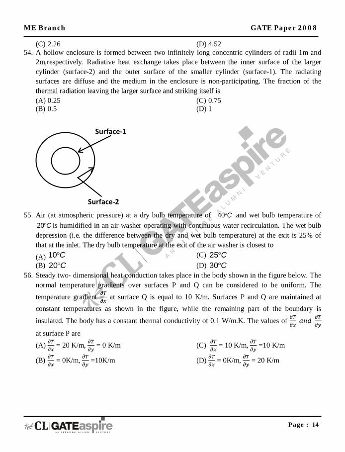
(C) 2.26 (D) 4.52 54. A hollow enclosure is formed between two infinitely long concentric cylinders of radii 1m and
2m,respectively. Radiative heat exchange takes place between the inner surface of the larger cylinder (surface-2) and the outer surface of the smaller cylinder (surface-1). The radiating surfaces are diffuse and the medium in the enclosure is non-participating. The fraction of the thermal radiation leaving the larger surface and striking itself is (A) 0.25 (B) 0.5
(C) 0.75 (D) 1
55. Air (at atmospheric pressure) at a dry bulb temperature of 40 C° and wet bulb temperature of
20 C° is humidified in an air washer operating with continuous water recirculation. The wet bulb depression (i.e. the difference between the dry and wet bulb temperature) at the exit is 25% of that at the inlet. The dry bulb temperature at the exit of the air washer is closest to
(A) 10 C° (B) 20 C°
(C) 25 C° (D) 30 C°
56. Steady two- dimensional heat conduction takes place in the body shown in the figure below. The normal temperature gradients over surfaces P and Q can be considered to be uniform. The temperature gradient at surface Q is equal to 10 K/m. Surfaces P and Q are maintained at constant temperatures as shown in the figure, while the remaining part of the boundary is
insulated. The body has a constant thermal conductivity of 0.1 W/m.K. The values of
at surface P are (A) = 20 K/m, = 0 K/m
(B) = 0K/m, =10K/m
(C) = 10 K/m, =10 K/m
(D) = 0K/m, = 20 K/m
Surface-2
Surface-1
ME Branch GATE Paper 2008
Page : 15
57. In a steady state steady flow process taking place in a device with a single inlet and a single
outlet, the work done per unit mass flow rate is given by w = , where v is the specific volume and p is the pressure. The expression for w given above (A) is valid only if the process is both reversible and adiabatic (B) is valid only if the process is both reversible and isothermal (C) is valid for any reversible process (D) is incorrect; it must be w =
58. For the standard transportation linear programme with m sources and n destinations and total supply equaling total demand, an optimal solution (lowest cost) with the smallest number of non-zero xij values (amounts from source i to destination j) is desired. The best upper bound for this number is (A) mn (B) 2(m + n)
(C) m + n (D) m + n 1
59. A moving average system is used for forecasting weekly demand. F1(t) and F2(t) are sequences of forecasts with parameters m1 and m2 , respectively, where m1 and m2 (m1 > m2) denote the numbers of weeks over which the moving averages are taken. The actual demand shows a step increase from d1 to d2 at a certain time. Subsequently, (A) neither F1(t) not F2(t) will catch up with the value d2 (B) both sequences F1(t) and F2(t) will reach d2 in the same period (C) F1(t) will attain the value d2 before F2(t) (D) F2(t) will attain the value d2 before F1(t)
60. For the network below, the objective is to find the length of the shortest path from node P to node G. Let dij be the length of directed are from node i to node j.
surface Q,0 C
Surface P,100 C
2m 1m
y
x
ME Branch GATE Paper 2008
Page : 16
Let sj be the length of the shortest path from P to node j. Which of the following equations can be used to find sG? (A) SG = Min(SQ, SR) (B) SG = Min (SQ dQG, SR dRG) (C) SG = Min(SQ+dQG, SR+dRG) (D) SG = Min(dQG,dRG)
61. The product structure of an assembly P is shown in the figure.
Estimated demand for end product P is as follows Week 1 2 3 4 5 6 Demand 1000 1000 1000 1000 1200 1200
ignore lead times for assembly and sub-assembly. Production capacity (per week) for component R is the bottleneck operation. Starting with zero inventory, the smallest capacity that will ensure a feasible production plan up to week 6 is (A) 1000 (B) 1200
(C) 2200 (D) 2400
P
Q R
R S
Assembly
Sub-Assembly
G P
R
Q
ME Branch GATE Paper 2008
Page : 17
62. One tooth of a gear having 4 module and 32 teeth is shown in the figure. Assume that the gear tooth and the corresponding tooth space make equal intercepts on the pitch circumference. The dimensions ‘a’ and ‘b’, respectively, are closed to
(A) 6.08 mm, 4 mm (B) 6.48mm, 4.2 mm
(C) 6.28mm, 4.3 mm (D) 6.28mm, 4.1 mm
63. While cooling, a cubical casting of side 40 mm undergoes 3%, 4% and 5% volume shrinkage during the liquid state, phase transition and solid state, respectively. The volume of metal compensated from the riser is (A) 2% (B) 7%
(C) 8% (D) 9%
64. In a single point turning tool, the side rake angle and orthogonal rake angle are equal. φ is the principal cutting edge angle and its range is 0° ≤ φ ≤ 90°. The chip flows in the orthogonal plane. The value of φ is closest to (A) 0° (B) 45°
(C) 0° (D) 90°
65. A researcher conducts electrochemical machining (ECM) on a binary allow (density 6000 kg/ ) of iron (atomic weight 56, valency 2) and metal P (atomic weight 24, valency 4). Faraday’s constant = 96500 coulomb/mole. Volumetric material removal rate of the alloy is 50 /3 at a current of 2000 A. The percentage of the metal P in the alloy is closest to (A) 40 (B) 25
(C) 15 (D) 79
66. In a single pass rolling operation, a 20 mm thick plate with plate width of 100 mm, is reduced to 18 mm. The roller radius is 250 mm and rotational speed is 10 rpm. The average flow stress for the plate material is 300 MPa. The power required for the rolling operation in kW is closest to (A) 15.2 (B) 18.2
(C) 30.4 (D) 45.6
67. In arc welding of a butt joint, the welding speed is to be selected such that highest cooling rate is achieved. Melting efficiency and heat transfer efficiency are 0.5 and 0.7, respectively. The area of the weld cross section is 5 and the unit energy required to melt the metal is 10 J/ . If the welding power is 2 kW, the welding speed in mm/s is closest to
ME Branch GATE Paper 2008
Page : 18
(A) 4 (B) 14
(C) 24 (D) 34
68. In the deep drawing of cups, blanks show a tendency to wrinkle up around the periphery (flange). The most likely cause and remedy of the phenomenon are, respectively, (A) Buckling due to circumferential compression; Increase blank holder pressure (B) High blank holder pressure and high friction; Reduce blank holder pressure and apply
lubricant (C) High temperature causing increase in circumferential length; Apply coolant to blank (D) Buckling due to circumferential compression; decrease blank holder pressure
69. The figure shows an incomplete schematic of a conventional lathe to be used for cutting threads with, different pitches. The speed gear box U, is shown and the feed gear box U, is to be placed. P, Q, R and S denote locations and have no other significance. Changes in U, should NOT affect the pitch of the thread being cut and changes in U, should NOT affect the cutting speed.
The correct connections and the correct placement of U are given by (A) Q and E are connected. U, is placed between P and Q. (B) S and E are connected. U, is placed between R and S. (C) Q and E are connected. U, is placed between Q and E. (D) S and E are connected. U, is placed between S and E.
70. A displacement sensor (a dial indicator) measures the lateral displacement of a mandrel mounted on the taper hole inside a drill spindle. The mandrel axis is an extension of the drill spindle taper hole axis and the protruding portion of the mandrel surface is perfectly cylindrical. Measurements are taken with the sensor placed at two positions P and Q as shown in figure. The readings are recorded as Rx = maximum deflection minus minimum deflection, corresponding to sensor position at X, over one rotation.
Motor P Q
R S
Work piece
Half – Nut
Spindle
Cutting tool
Lead screw E
ME Branch GATE Paper 2008
Page : 19
If Rp = RQ > 0, which one of the following would be consistent with the observation? (A) The drill spindle rotational axis is coincident with the drill spindle taper hole axis (B) The drill spindle rotational axis intersects the drill spindle taper hole axis at point P (C) The drill spindle rotational axis is parallel to the drill spindle taper hole axis (D) The drill spindle rotational axis intersects the drill spindle taper hole axis at point Q.
Common Data Questions Common Data for Questions 71, 72 and 73: In the figure shown, the system is a pure substance kept in a piston- cylinder arrangement. The system is initially a two-phase mixture containing 1 kg of liquid and 0.03 kg of vapour at a pressure of 100 kPa. Initially, the piston rests on a set of stops, as shown in the figure. A pressure of 200kPa is required to exactly balance the weight of the piston and the outside atmospheric pressure. Heat transfer takes place into the system until its volume increases by 50%. Heat transfer to the system occurs in such a manner that the piston, when allowed to move, does so in a very slow (quasi – static / quasi – equilibrium) process. The thermal reservoir from which heat is transferred to the system has a temperature of 4000C. Average temperature of the system boundary can be taken as 1750C. The heat transfer to the system is 1kJ, during which its entropy increase by 10 J/K.
Drill spindle
mandrel
Drill table
sensor
P
Q
ME Branch GATE Paper 2008
Page : 20
Specific volume of liquid (vf) and vapour (vg) phases, as well as values of saturation temperatures, are given in the below.
71. At the end of the process, which one of the following situations will be true?
(A) superheated vapour will be left in the system (B) no vapour will be left in the system (C) a liquid + vapour mixture will be left in the system (D) the mixture will exist at a dry saturate vapour state
72. The work done by the system during the process is (A) 0.1 kJ (B) 0.2 kJ
(C) 0.3 kJ (D) 0.4 kJ
73. The net entropy generation (considering the system and the thermal reservoir together) during the process is closest to (A) 7.5 J/K (B) 7.7 J/K
(C) 8.5 J/K (D) 10 J/K
Common Data for Questions 74 and 75: Consider the Linear Programme (LP) Max 4x + 6y subject to 3x + 2y ≤ 6 2x +3y ≤ 6
Atmospheric pressure
Piston
System Stop
9
ME Branch GATE Paper 2008
Page : 21
x, y ≥ 0 74. After introducing slack variables s and t, the initial basic feasible solution is represented by the
table below (basic variables are s = 6 and t = 6, and the objective function value is 0). 4 6 0 0 0 s 3 2 1 0 6 t 2 3 0 1 6 x y s t RHS
After some simplex iterations, the following table is obtained
0 0 0 2 12 s 5/3 0 1 1/3 2 y 2/3 1 0 1/3 2 x y s t RHS
From this, one can conclude that (A) the LP has a unique optimal solution (B) the LP has an optimal solution that is not unique (C) the LP is infeasible (D) the LP is unbounded
75. The dual for the LP in Q 74 is (A) Min 6u + 6v
subject to 3u + 2v ≥ 4 2u + 3v ≥ 6 u, v ≥ 0
(B) Max 6u + 6v subject to 3u + 2v ≤ 4 2u + 3v ≥ 6 u, v ≥ 0
(C) Max 4u + 6v subject to 3u + 2v ≥ 6 2u + 3v ≥ 6 u, v ≥ 0
(D) Min 4u + 6v subject to 3u + 2v ≤ 6 2u + 3v ≥ 6 u, v ≥ 0
ME Branch GATE Paper 2008
Page : 22
Linked Answer Questions: Q. 76 to Q. 85 Carry Two Marks Each. Statement for Linked Answer Questions 76 and 77: A cylindrical container of radius R = 1 m, wall thickness 1 mm is filled with water up to a depth of 2 m and suspended along its upper rim. The density of water is 1000kg/m3 and acceleration due to gravity is 10 m/s2. The self-weight of the cylinder is negligible. The formula for hoop stress in a thin – walled cylinder can be used at all points along the height of the cylindrical container.
76. The axial and circumferential stress (σd, σc) experienced by the cylinder wall at mid-depth (1 m as shown) are (A) (10, 10) MPa (B) (5, 10) MPa
(C) (10, 5) MPa (D) (5, 5) MPa
77. If the Young’s modulus and Poisson’s ratio of the container material are 100GPa and 0.3, respectively, the axial strain in the cylinder wall at mid-depth is (A) 2 × 10⁻⁵ (B) 6 × 10⁻⁵
(C) 7 × 10⁻⁵ (D) 1.2 × 10⁻⁴
Statement for Linked Answer Questions 78 and 79: A steel bar of 10 × 50 mm is cantilevered with two M 12 bolts (P and Q) to support a static load of 4 kN as shown in the figure.
2R
1m
2m
1mm
ME Branch GATE Paper 2008
Page : 23
78. The primary and secondary shear loads on bolt P, respectively, are
(A) 2kN, 20kN (B) 20kN, 2 kN,
(C) 20 kN, 0kN (D) 0kN, 20 kN
79. The resultant shear stress on bolt P is closest to (A) 132MPa (B) 159 MPa
(C) 178 MPa (D) 195 MPa
Statement for Linked Answer Questions 80 and 81: The gap between a moving circular plate and a stationary surface is being continuously reduced, as the circular plate comes down at a uniform speed V towards the stationary bottom surface, as shown in the figure. In the process, the fluid contained between the two plates flows out radially. The fluid is assumed to be incompressible and inviscid.
h
R
T
V
Moving circular plate
Stationary surface
P Q
1.7m
4kN
100 400 100
ME Branch GATE Paper 2008
Page : 24
80. The radial velocity at any radium r, when the gap width is h, is (A)
(B)
(C)
(D) 81. The radial component of the fluid acceleration at r = R is
(A)
(B)
(C)
(D)
Statement for Linked Answer Questions 82 and 83: Orthogonal turning is performed on a cylindrical workpiece with shear strength of 250 MPa. The following conditions are used: cutting velocity is 180 m/min, feed is 0.20 mm/rev, depth of cut is 3 mm, chip thickness ratio = 0.5. The orthogonal rake angle is 7˚. Apply Merchant’s theory for analysis.
82. The shear plane angle (in degrees) and the shear force respectively are (A) 52; 320N (B) 52; 400N
(C) 28 ; 400 N (D) 28 ; 320 N
83. The cutting and frictional forces, respectively, are (A) 568 N ; 387 N (B) 565 N ; 381 N
(C) 440 N ; 342 N (D) 480 N ; 356 N
Statement for Linked Answer Questions 84 and 85: In the feed drive of a Point – to – point open loop CNC drive, a steeper motor rotating at 200 steps/rev drives a table through a gear box and lead screw – nut mechanism (pitch = 4mm, number of starts =1). The gear ratio = is given by U = . The stepper
motor (driven by voltage pulses from a pulse generator) executes 1 step/ pulse of the pulse generator. The frequency of the pulse train from the pulse generator is f = 10,000 pulses per minute.
84. The Basic Length Unit (BLU), i.e. , the table movement corresponding to 1 pulse of the pulse generator, is
Pulse Generator
Table
Lead screw
Gear Box
Nut Steeper motor
f
ME Branch GATE Paper 2008
Page : 25
(A) 0.5 microns (B) 5 microns
(C) 50 microns (D) 500 microns
85. A customer insists on a modification to change the BLU the CNC drive to 10 microns without changing the table speed. The modification can be accomplished by (A) changing U to and reducing f to
(B) changing U to and increasing f to 2f
(C) changing U to and keeping f unchanged (D) keeping U unchanged and increasing f to 2f.