EE Branch GATE Paper 2010 Page : 1 GATE 2010 Electrical Engineering Q.1 – Q.25 carry one mark each 1. The value of the quantity P, where = ∫ ݔ௫ ݔଵ , is equal to (A) 0 (B) 1 (C) e (D) 1/e 2. Divergence of the three-dimensional radial vector field ݎis (A) 3 (B) 1/r (C) ଓ̂ + ଔ̂ + (D) 3(ଓ + ଔ̂ + ) 3. The period of the signal x(t) = 8 sin ቀ0.8 ݐߨ+ గ ସ ቁ is (A) 0.4ߨs (B) 0.8ߨs (C) 1.25s (D) 2.5s 4. The system represented by the input-output relationship ݕ(ݐ)= ∫ ݔ(), ݐ>0 ହ௧ ஶ is (A) Linear and causal (B) Linear but not causal (C) Causal but not linear (D) Neither linear nor causal 5. The switch in the circuit has been closed for a long time. It is opened at t = 0. At = ݐ=0 ା , the current through the 1µF capacitor is (A) 0A (B) 1A (C) 1.25A (D) 5A t =0 5V 1Ω 4Ω 1µF
Transcript
EE Branch GATE Paper 2010
Page : 1
GATE 2010 Electrical Engineering
Q.1 – Q.25 carry one mark each
1. The value of the quantity P, where 푃 = ∫ 푥푒 푑푥, is equal to (A) 0 (B) 1
(C) e (D) 1/e
2. Divergence of the three-dimensional radial vector field 푟 is
(A) 3 (B) 1/r
(C) 횤 + 횥 + 푘 (D) 3(횤 + 횥 + 푘)
3. The period of the signal x(t) = 8 sin 0.8휋푡 + is
(A) 0.4휋s (B) 0.8휋s
(C) 1.25s (D) 2.5s
4. The system represented by the input-output relationship 푦(푡) = ∫ 푥(휏)푑휏, 푡 > 0 is (A) Linear and causal (B) Linear but not causal
(C) Causal but not linear (D) Neither linear nor causal
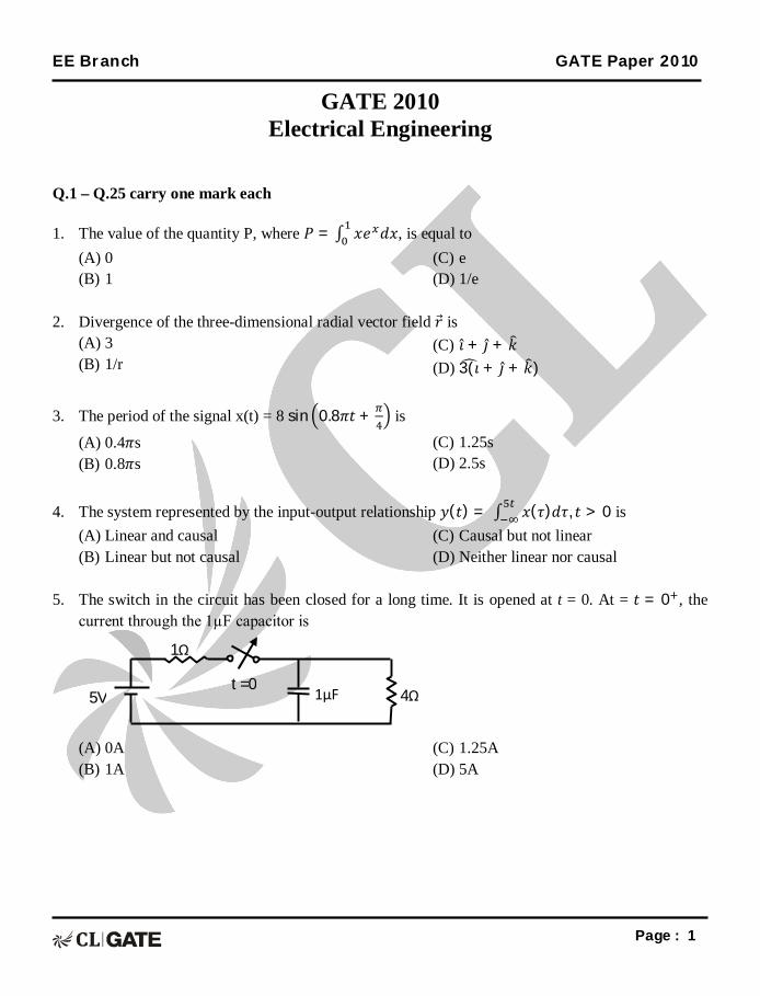
5. The switch in the circuit has been closed for a long time. It is opened at t = 0. At = 푡 = 0 , the
current through the 1µF capacitor is
(A) 0A (B) 1A
(C) 1.25A (D) 5A
t =0 5V
1Ω
4Ω 1µF
EE Branch GATE Paper 2010
Page : 2
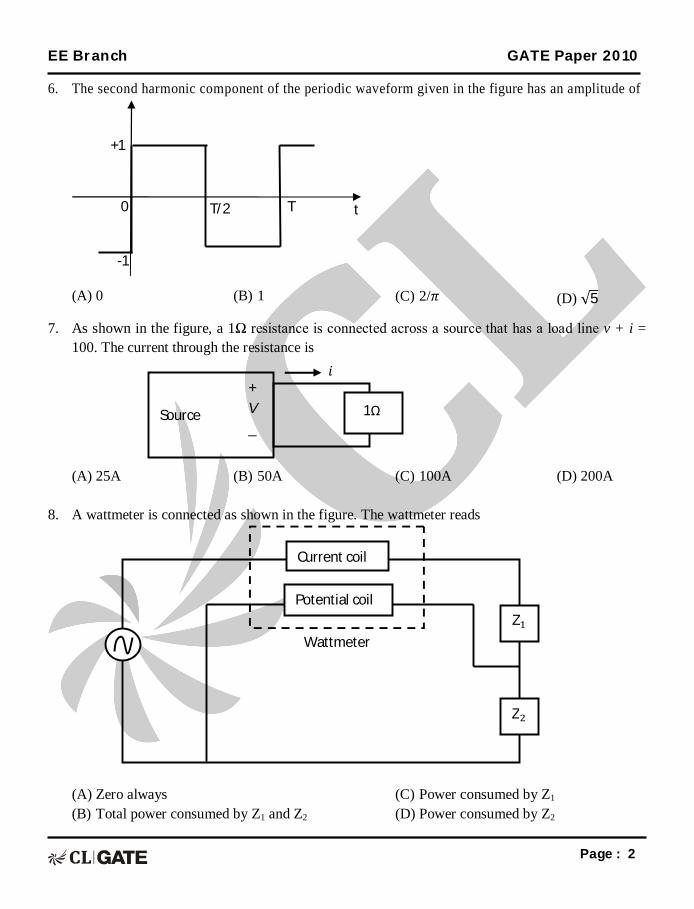
6. The second harmonic component of the periodic waveform given in the figure has an amplitude of
(A) 0 (B) 1 (C) 2/휋 (D) √5
7. As shown in the figure, a 1Ω resistance is connected across a source that has a load line v + i = 100. The current through the resistance is
(A) 25A (B) 50A (C) 100A (D) 200A
8. A wattmeter is connected as shown in the figure. The wattmeter reads
(A) Zero always (B) Total power consumed by Z1 and Z2
(C) Power consumed by Z1 (D) Power consumed by Z2
Z
Z
Current coil
Potential coil
Wattmeter
Source
+ V _
1Ω
푖
+1
-1
0 T/2 T t
EE Branch GATE Paper 2010
Page : 3
9. An ammeter has a current range of 0-5A, and its internal resistance is 0.2Ω. In order to change the range to 0 – 25A, we need to add a resistance of (A) 0.8Ω in series with the meter. (B) 1.0Ω in series with the meter.
(C) 0.04Ω in parallel with the meter. (D) 0.05Ω in parallel with the meter.
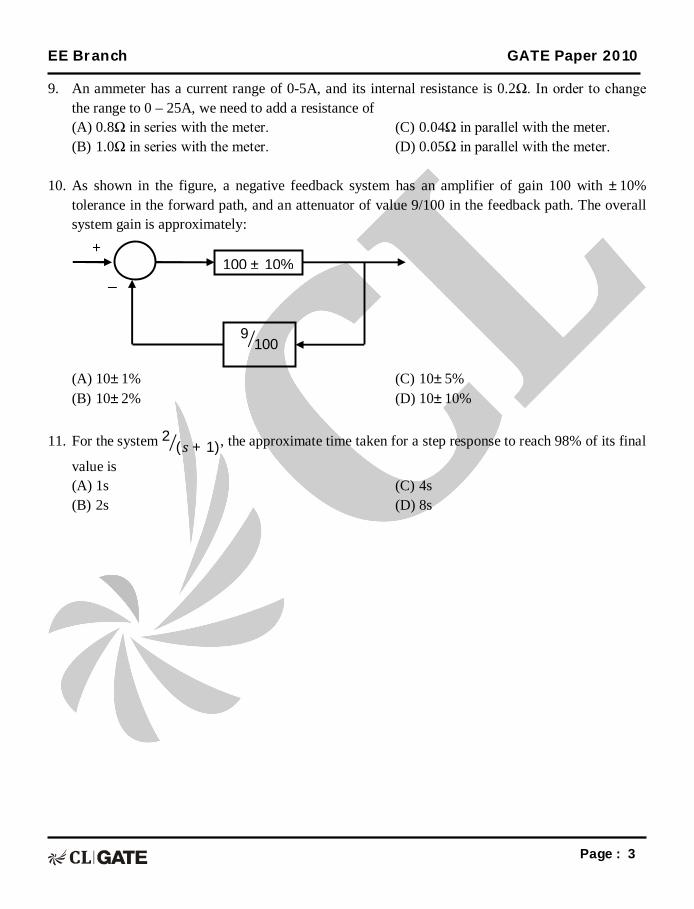
10. As shown in the figure, a negative feedback system has an amplifier of gain 100 with ±10%
tolerance in the forward path, and an attenuator of value 9/100 in the feedback path. The overall system gain is approximately:
(A) 10±1% (B) 10±2%
(C) 10±5% (D) 10±10%
11. For the system 2 (푠 + 1), the approximate time taken for a step response to reach 98% of its final
value is (A) 1s (B) 2s
(C) 4s (D) 8s
100 ± 10%
9100
+
−
EE Branch GATE Paper 2010
Page : 4
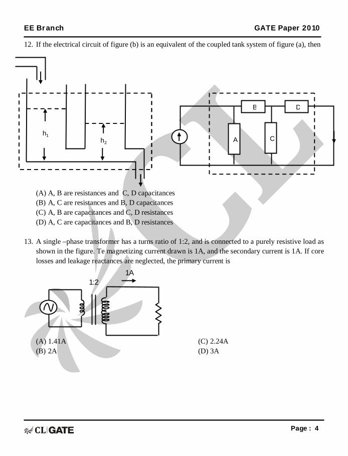
12. If the electrical circuit of figure (b) is an equivalent of the coupled tank system of figure (a), then
(A) A, B are resistances and C, D capacitances (B) A, C are resistances and B, D capacitances (C) A, B are capacitances and C, D resistances (D) A, C are capacitances and B, D resistances
13. A single –phase transformer has a turns ratio of 1:2, and is connected to a purely resistive load as shown in the figure. Te magnetizing current drawn is 1A, and the secondary current is 1A. If core losses and leakage reactances are neglected, the primary current is
(A) 1.41A (B) 2A
(C) 2.24A (D) 3A
1A 1:2
h h
A
C
B D
EE Branch GATE Paper 2010
Page : 5
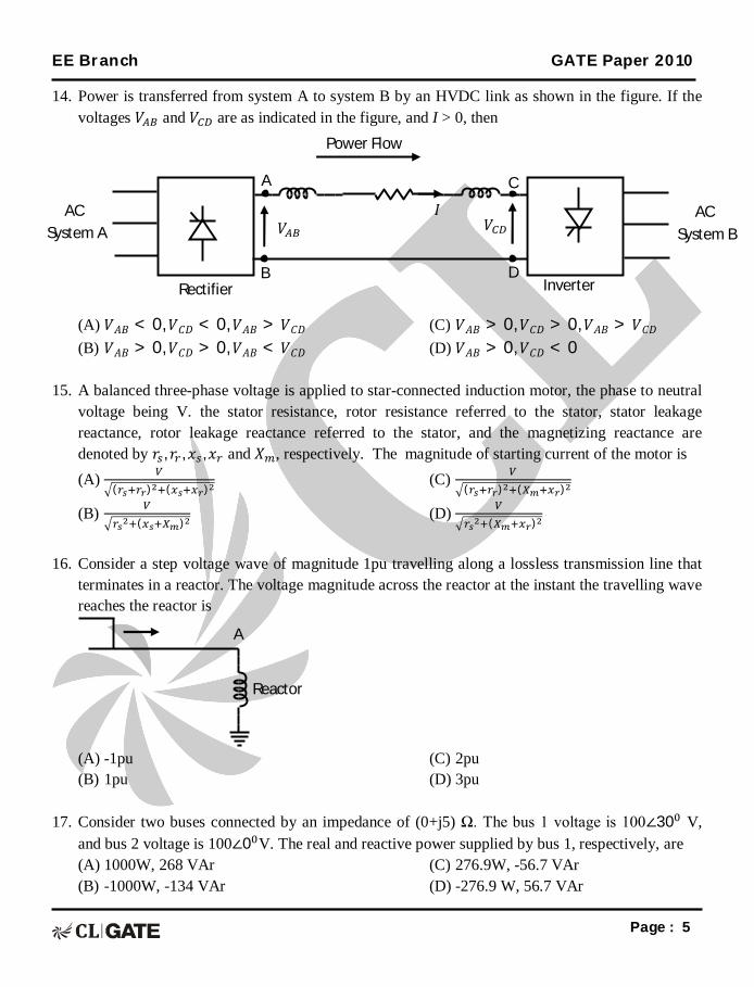
14. Power is transferred from system A to system B by an HVDC link as shown in the figure. If the voltages 푉 and 푉 are as indicated in the figure, and I > 0, then
15. A balanced three-phase voltage is applied to star-connected induction motor, the phase to neutral
voltage being V. the stator resistance, rotor resistance referred to the stator, stator leakage reactance, rotor leakage reactance referred to the stator, and the magnetizing reactance are denoted by 푟 , 푟 , 푥 ,푥 and 푋 , respectively. The magnitude of starting current of the motor is (A)
( ) ( )
(B) ( )
(C) ( ) ( )
(D) ( )
16. Consider a step voltage wave of magnitude 1pu travelling along a lossless transmission line that
terminates in a reactor. The voltage magnitude across the reactor at the instant the travelling wave reaches the reactor is
(A) -1pu (B) 1pu
(C) 2pu (D) 3pu
17. Consider two buses connected by an impedance of (0+j5) Ω. The bus 1 voltage is 100∠30 V,
and bus 2 voltage is 100∠0 V. The real and reactive power supplied by bus 1, respectively, are (A) 1000W, 268 VAr (B) -1000W, -134 VAr
(C) 276.9W, -56.7 VAr (D) -276.9 W, 56.7 VAr
A
Reactor
A
B
C
D
푉 푉 퐼 AC
System B
AC System A
Rectifier Inverter
Power Flow
EE Branch GATE Paper 2010
Page : 6
18. A three-phase, 33kV oil circuit breaker is rated 1200A, 2000MVA, 3s. The symmetrical breaking
current is (A) 1200A (B) 3600A
(C) 35kA (D) 104.8kA
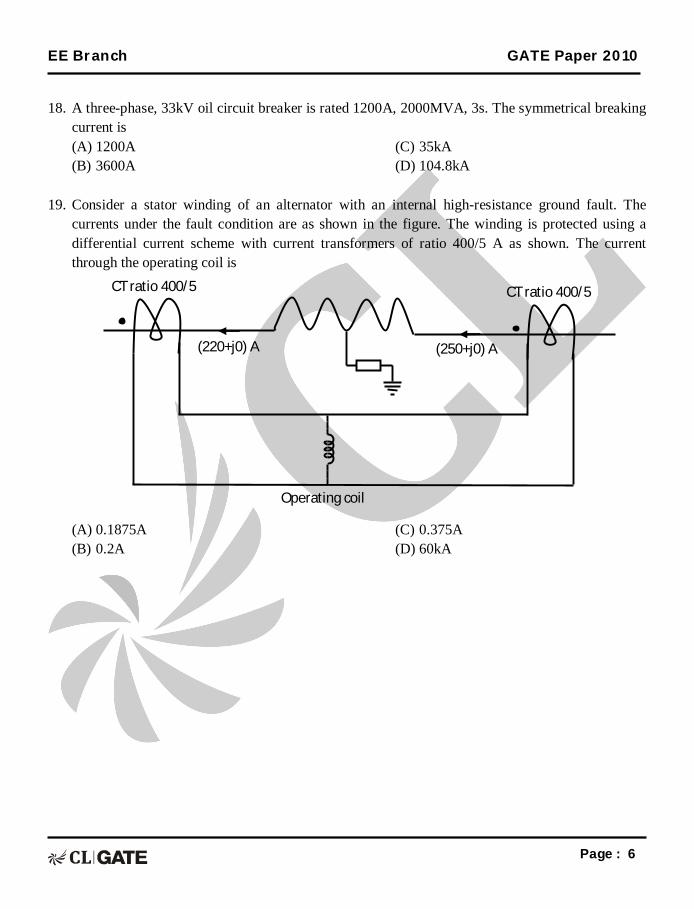
19. Consider a stator winding of an alternator with an internal high-resistance ground fault. The
currents under the fault condition are as shown in the figure. The winding is protected using a differential current scheme with current transformers of ratio 400/5 A as shown. The current through the operating coil is
(A) 0.1875A (B) 0.2A
(C) 0.375A (D) 60kA
CT ratio 400/5 CT ratio 400/5
(220+j0) A
(250+j0) A
Operating coil
EE Branch GATE Paper 2010
Page : 7
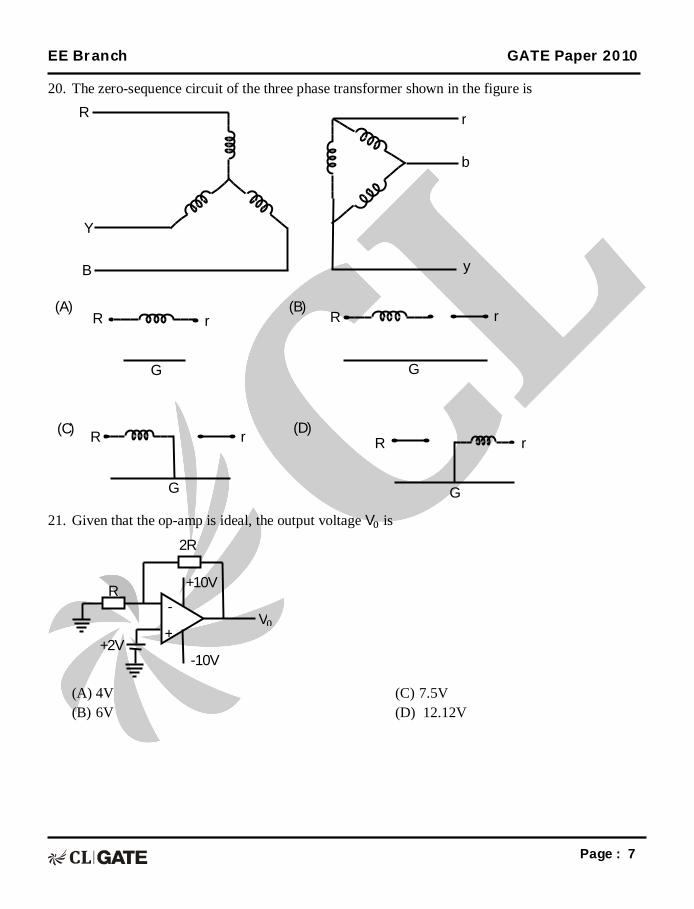
20. The zero-sequence circuit of the three phase transformer shown in the figure is
21. Given that the op-amp is ideal, the output voltage V is
(A) 4V (B) 6V
(C) 7.5V (D) 12.12V
+ V
2R
- R
+2V -10V
+10V
R
R R
R
G G
G G
r r
r r
(A) (B)
(C) (D)
R
Y
B
b
r
y
EE Branch GATE Paper 2010
Page : 8
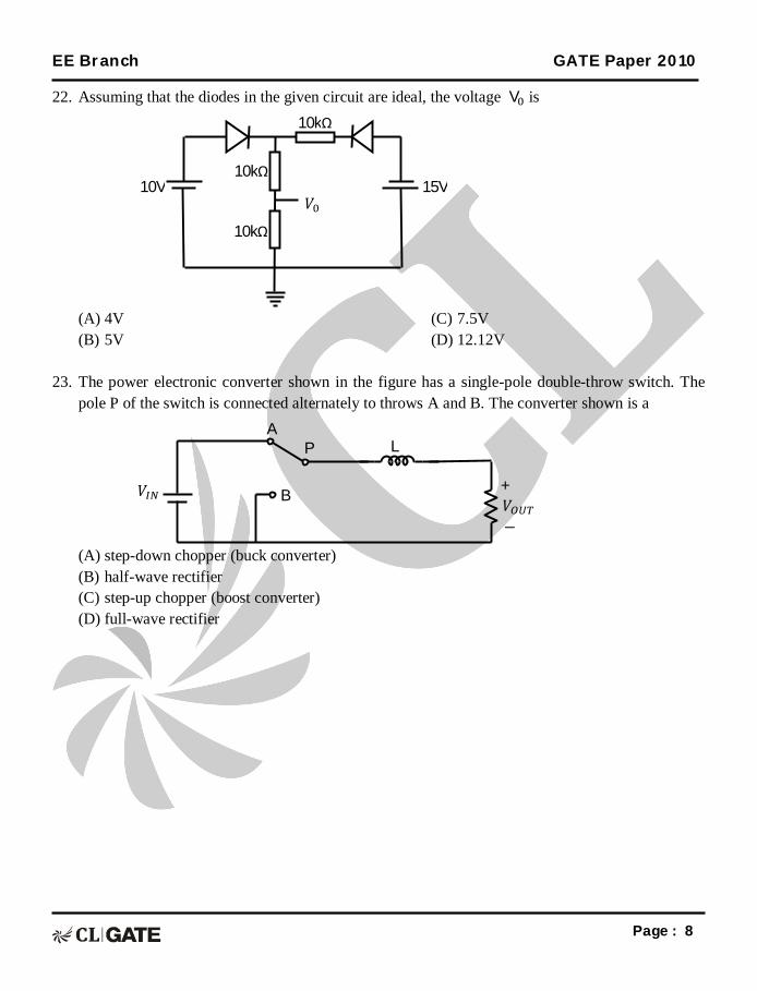
22. Assuming that the diodes in the given circuit are ideal, the voltage V is
(A) 4V (B) 5V
(C) 7.5V (D) 12.12V
23. The power electronic converter shown in the figure has a single-pole double-throw switch. The
pole P of the switch is connected alternately to throws A and B. The converter shown is a
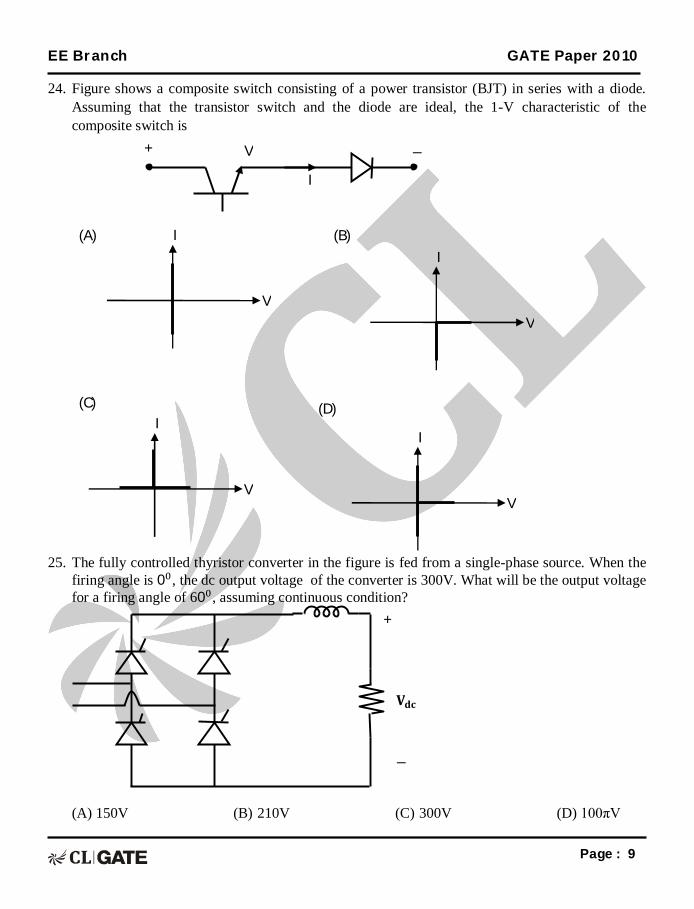
24. Figure shows a composite switch consisting of a power transistor (BJT) in series with a diode. Assuming that the transistor switch and the diode are ideal, the 1-V characteristic of the composite switch is
25. The fully controlled thyristor converter in the figure is fed from a single-phase source. When the firing angle is 0 , the dc output voltage of the converter is 300V. What will be the output voltage for a firing angle of 60 , assuming continuous condition?
(A) 150V (B) 210V (C) 300V (D) 100πV
+
퐕퐝퐜
−
+ − V
I
V
I
V
I
V
I
V
I
(A) (B)
(C) (D)
EE Branch GATE Paper 2010
Page : 10
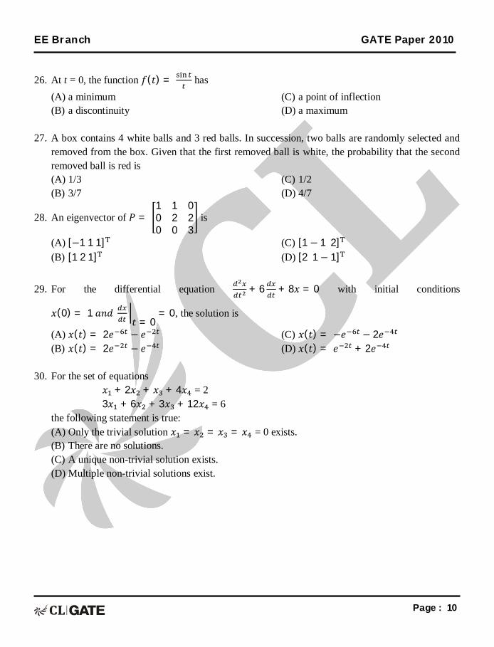
26. At t = 0, the function 푓(푡) = has
(A) a minimum (B) a discontinuity
(C) a point of inflection (D) a maximum
27. A box contains 4 white balls and 3 red balls. In succession, two balls are randomly selected and
removed from the box. Given that the first removed ball is white, the probability that the second removed ball is red is (A) 1/3 (B) 3/7
(C) 1/2 (D) 4/7
28. An eigenvector of 푃 = 1 1 00 2 20 0 3
is
(A) [−1 1 1] (B) [1 2 1]
(C) [1 − 1 2] (D) [2 1− 1]
29. For the differential equation + 6 + 8푥 = 0 with initial conditions
푥(0) = 1 푎푛푑
푡 = 0= 0, the solution is
(A) 푥(푡) = 2푒 − 푒 (B) 푥(푡) = 2푒 − 푒
(C) 푥(푡) = −푒 − 2푒 (D) 푥(푡) = 푒 + 2푒
30. For the set of equations
푥 + 2푥 + 푥 + 4푥 = 2 3푥 + 6푥 + 3푥 + 12푥 = 6
the following statement is true: (A) Only the trivial solution 푥 = 푥 = 푥 = 푥 = 0 exists. (B) There are no solutions. (C) A unique non-trivial solution exists. (D) Multiple non-trivial solutions exist.
EE Branch GATE Paper 2010
Page : 11
31. 푥(푡) is a positive rectangular pulse from 푡 = −1 푡표 푡 = +1 with unit height as shown in the figure. The value of ∫ |푋(휔)| 푑휔 where 푋(휔) is the Fourier transform of 푥(푡) is
(A) 2 (B) 2π
(C) 4 (D) 4π
32. Given the finite length input x[n] and the corresponding finite length output y[n] of an LTI
system as shown below, the impulse response h[n] of the system is
(A) h[n] = 1, 0, 0, 1
↑ (B) h[n] = 1, 0, 1
↑ (C) h[n] = 1, 1, 1, 1
↑ (D) h[n] = 1, 1, 1
↑
h[n]
↑ x[n] = 1, −1 y[n] = 1, 0, 0, 0, −1
↑
x(t)
1
−1 ퟎ ퟏ 풕
EE Branch GATE Paper 2010
Page : 12
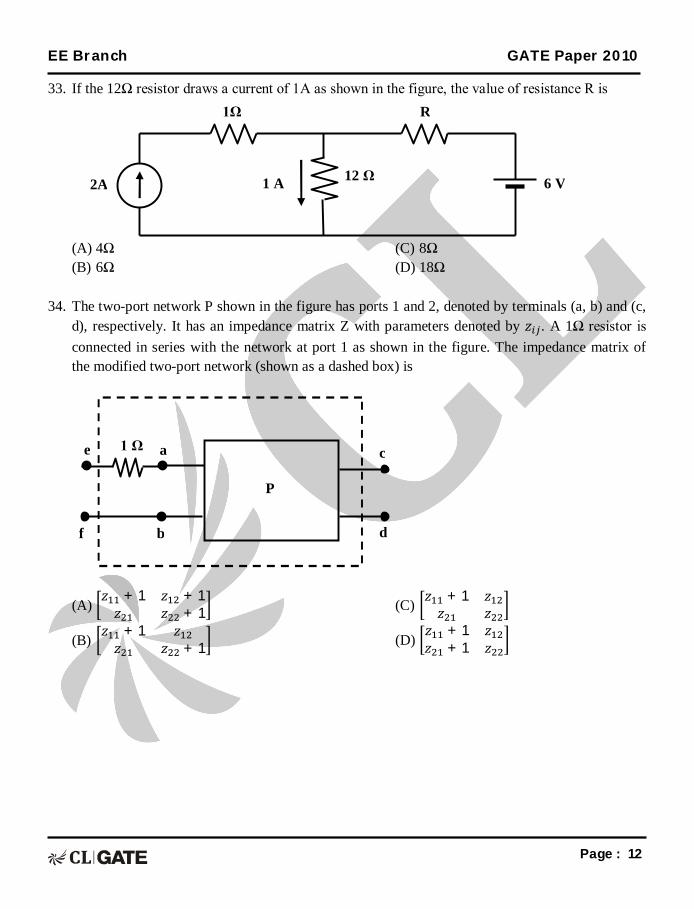
33. If the 12Ω resistor draws a current of 1A as shown in the figure, the value of resistance R is
(A) 4Ω (B) 6Ω
(C) 8Ω (D) 18Ω
34. The two-port network P shown in the figure has ports 1 and 2, denoted by terminals (a, b) and (c,
d), respectively. It has an impedance matrix Z with parameters denoted by 푧 . A 1Ω resistor is connected in series with the network at port 1 as shown in the figure. The impedance matrix of the modified two-port network (shown as a dashed box) is
(A) 푧 + 1 푧 + 1푧 푧 + 1
(B) 푧 + 1 푧푧 푧 + 1
(C) 푧 + 1 푧푧 푧
(D) 푧 + 1 푧푧 + 1 푧
1 Ω a e
b f
P
d
c
1Ω R
12 Ω 1 A 2A 6 V
EE Branch GATE Paper 2010
Page : 13
35. The Maxwell’s bridge shown in the figure is at balance. The parameters of the inductive coil are
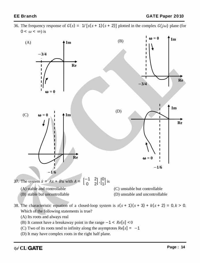
36. The frequency response of 퐺(푠) = 1/[푠(푠 + 1)(푠 + 2)] plotted in the complex 퐺(푗휔) plane (for 0 < 휔 < ∞) is
37. The system 푥 = 퐴푥 + 퐵푢 with 퐴 = −1 2
0 2 , 01 is
(A) stable and controllable (B) stable but uncontrollable
(C) unstable but controllable (D) unstable and uncontrollable
38. The characteristic equation of a closed-loop system is 푠(푠 + 1)(푠 + 3) + 푘(푠 + 2) = 0,푘 > 0.
Which of the following statements is true? (A) Its roots and always real (B) It cannot have a breakaway point in the range −1 < 푅푒[푠] <0 (C) Two of its roots tend to infinity along the asymptotes Re[푠] = −1 (D) It may have complex roots in the right half plane.
Re
−3/4
Im
= 0
−3/4
Im = 0
Re
= 0 Im
−1/6
Re = 0
−1/6
Re
Im
(A) (B)
(C) (D)
EE Branch GATE Paper 2010
Page : 15
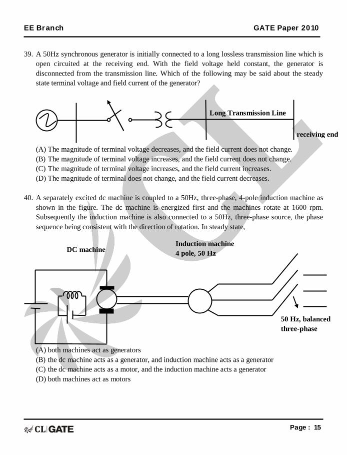
39. A 50Hz synchronous generator is initially connected to a long lossless transmission line which is
open circuited at the receiving end. With the field voltage held constant, the generator is disconnected from the transmission line. Which of the following may be said about the steady state terminal voltage and field current of the generator?
(A) The magnitude of terminal voltage decreases, and the field current does not change. (B) The magnitude of terminal voltage increases, and the field current does not change. (C) The magnitude of terminal voltage increases, and the field current increases. (D) The magnitude of terminal does not change, and the field current decreases.
40. A separately excited dc machine is coupled to a 50Hz, three-phase, 4-pole induction machine as shown in the figure. The dc machine is energized first and the machines rotate at 1600 rpm. Subsequently the induction machine is also connected to a 50Hz, three-phase source, the phase sequence being consistent with the direction of rotation. In steady state,
(A) both machines act as generators (B) the dc machine acts as a generator, and induction machine acts as a generator (C) the dc machine acts as a motor, and the induction machine acts a generator (D) both machines act as motors
DC machine Induction machine 4 pole, 50 Hz
50 Hz, balanced three-phase supply
Long Transmission Line
receiving end
EE Branch GATE Paper 2010
Page : 16
41. A balanced star-connected and purely resistive load is connected at the secondary of a star-delta transformer as shown in figure. The line-to-line voltage rating of the transformer is 110V/220V. Neglecting the non-idealities of the transformer, the impedance ‘Z’ of the equivalent star-connected load, referred to the primary side o the transformer, is:
(A) (3 + j 0) Ω (B) (0.866 – j 0.5) Ω
(C) (0.866 + j 0.5) Ω (D) (1+ j 0) Ω
r R
Y
B
4Ω
4Ω
4Ω b
y
R
Y
B
Z
Z
Z
110/220V
EE Branch GATE Paper 2010
Page : 17
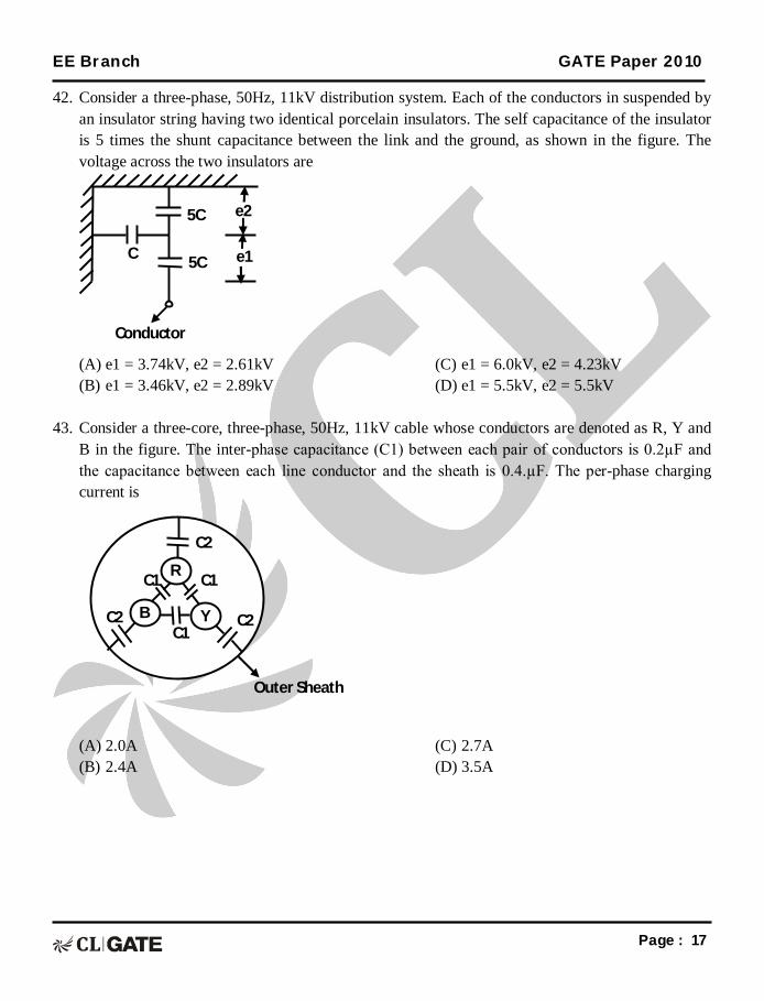
42. Consider a three-phase, 50Hz, 11kV distribution system. Each of the conductors in suspended by an insulator string having two identical porcelain insulators. The self capacitance of the insulator is 5 times the shunt capacitance between the link and the ground, as shown in the figure. The voltage across the two insulators are
43. Consider a three-core, three-phase, 50Hz, 11kV cable whose conductors are denoted as R, Y and
B in the figure. The inter-phase capacitance (C1) between each pair of conductors is 0.2µF and the capacitance between each line conductor and the sheath is 0.4.µF. The per-phase charging current is
(A) 2.0A (B) 2.4A
(C) 2.7A (D) 3.5A
C1
C1 C1
C2 C2
C2
R
Y
Outer Sheath
B
e2
e1
5C
5C C
Conductor
EE Branch GATE Paper 2010
Page : 18
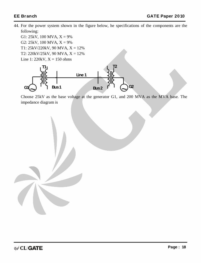
44. For the power system shown in the figure below, he specifications of the components are the following: G1: 25kV, 100 MVA, X = 9% G2: 25kV, 100 MVA, X = 9% T1: 25kV/220kV, 90 MVA, X = 12% T2: 220kV/25kV, 90 MVA, X = 12% Line 1: 220kV, X = 150 ohms
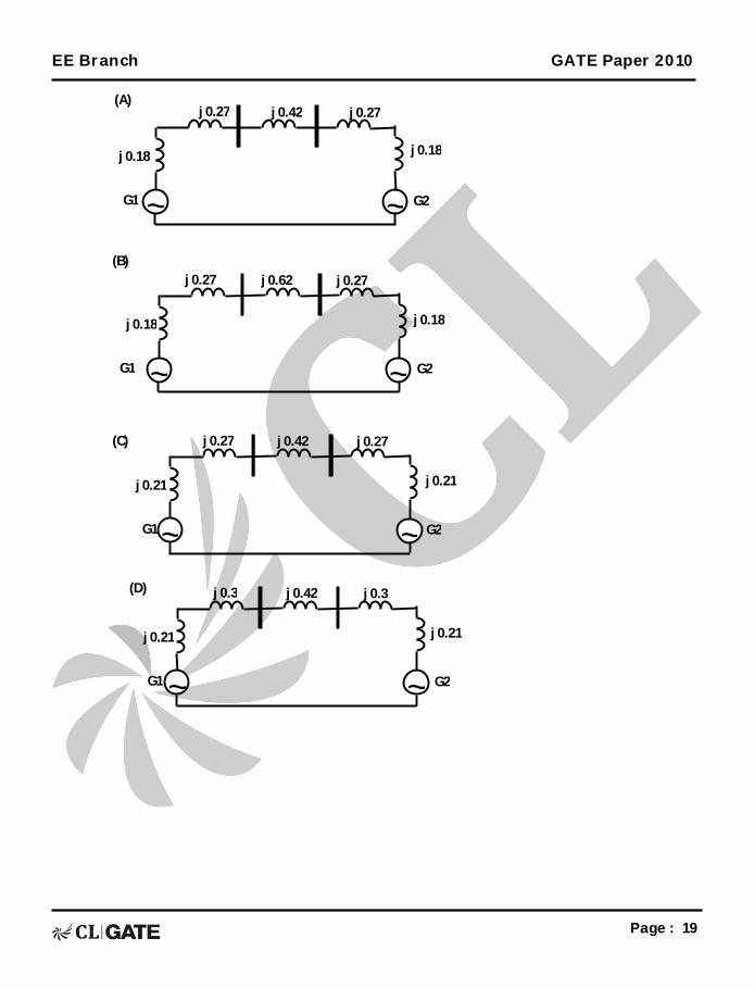
Choose 25kV as the base voltage at the generator G1, and 200 MVA as the MVA base. The impedance diagram is
~ ~ G2 G1 Bus 1 Bus 2
Line 1
T2 T1
EE Branch GATE Paper 2010
Page : 19
~ ~ G2 G1
j 0.18
j 0.27 j 0.42 j 0.27
~ ~ G2 G1
j 0.18
j 0.27 j 0.62 j 0.27
~ ~ G2 G1
j 0.21
j 0.27 j 0.42 j 0.27
~ ~ G2 G1
j 0.21
j 0.3 j 0.42 j 0.3
j 0.18
j 0.18
j 0.21
j 0.21
(A)
(B)
(C)
(D)
EE Branch GATE Paper 2010
Page : 20
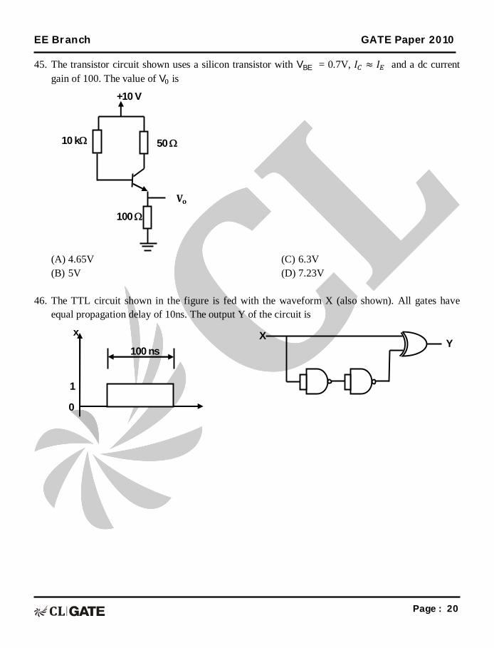
45. The transistor circuit shown uses a silicon transistor with VBE = 0.7V, 퐼 ≈ 퐼 and a dc current gain of 100. The value of V is
(A) 4.65V (B) 5V
(C) 6.3V (D) 7.23V
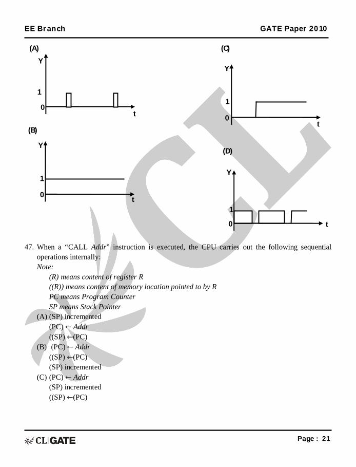
46. The TTL circuit shown in the figure is fed with the waveform X (also shown). All gates have
equal propagation delay of 10ns. The output Y of the circuit is
1
0
x
100 ns
X Y
100
50 10 k
+10 V
퐕퐨
EE Branch GATE Paper 2010
Page : 21
47. When a “CALL Addr” instruction is executed, the CPU carries out the following sequential operations internally: Note: (R) means content of register R
((R)) means content of memory location pointed to by R PC means Program Counter SP means Stack Pointer
(A) (SP) incremented (PC) ← Addr ((SP) ←(PC)
(B) (PC) ← Addr ((SP) ←(PC) (SP) incremented
(C) (PC) ← Addr (SP) incremented ((SP) ←(PC)
(C)
t
1
0
Y
(D)
t
1
0
Y
(B)
t
1
0
Y
(A)
t
1
0
Y
EE Branch GATE Paper 2010
Page : 22
(D) ((SP) ←(PC) (SP) incremented (PC) ← Addr
Common Data Questions
Common Data for Questions 48 and 49:
A separately excited DC motor runs at 1500 rpm under no-load with 200V applied to the armature. The field voltage is maintained at its rated value. The speed of the motor, when it delivers at torque of 5 Nm, is 1400 rpm as shown in the figure. The rotational losses and armature reaction are neglected.
48. The armature resistance of the motor is.
(A) 2Ω (B) 3.4Ω
(C) 4.4Ω (D) 7.7Ω
49. For the motor to deliver a torque of 2.5Nm at 140 rpm, the armature voltage to be applied is
(A) 125.5V (B) 193.3V
(C) 200V (D) 241.7V
1500
1400
torque (Nm)
Speed (rpm)
5 0
EE Branch GATE Paper 2010
Page : 23
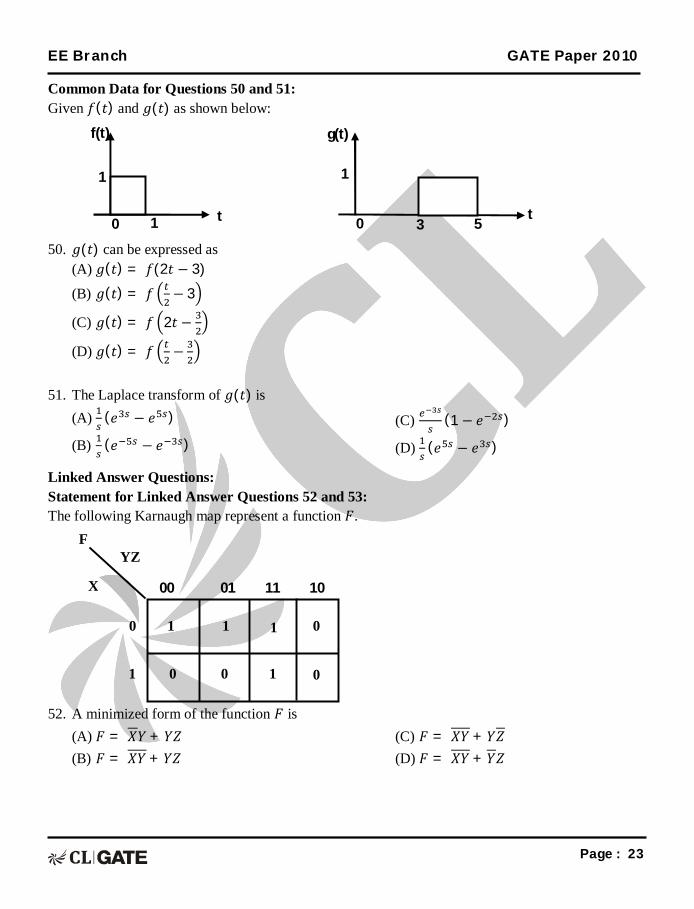
Common Data for Questions 50 and 51: Given 푓(푡) and 푔(푡) as shown below:
50. 푔(푡) can be expressed as
(A) 푔(푡) = 푓(2푡 − 3)
(B) 푔(푡) = 푓 − 3
(C) 푔(푡) = 푓 2푡 −
(D) 푔(푡) = 푓 −
51. The Laplace transform of 푔(푡) is (A) (푒 − 푒 )
(B) (푒 − 푒 )
(C) (1 − 푒 )
(D) (푒 − 푒 )
Linked Answer Questions: Statement for Linked Answer Questions 52 and 53: The following Karnaugh map represent a function 퐹.
52. A minimized form of the function 퐹 is
(A) 퐹 = 푋푌 + 푌푍 (B) 퐹 = 푋푌 + 푌푍
(C) 퐹 = 푋푌 + 푌푍 (D) 퐹 = 푋푌 + 푌푍
F YZ
X
0
1
1 1 1 0
0 1 0 0
00 01 11 10
t 1 0
f(t)
1
t 3 0
g(t)
1
5
EE Branch GATE Paper 2010
Page : 24
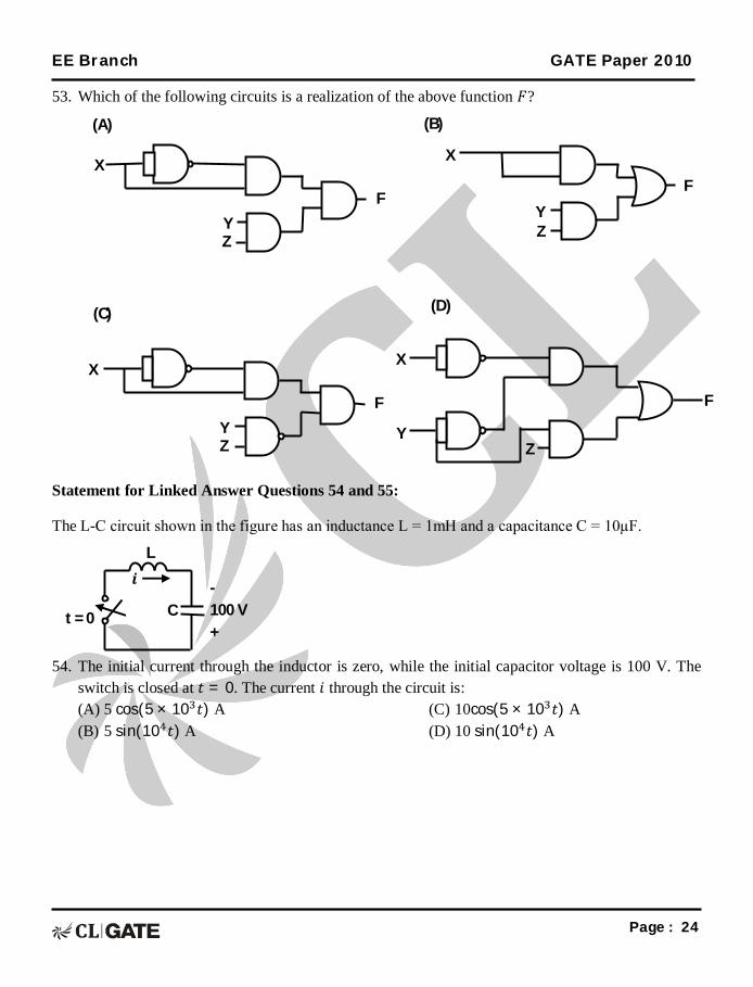
53. Which of the following circuits is a realization of the above function 퐹?
Statement for Linked Answer Questions 54 and 55:
The L-C circuit shown in the figure has an inductance L = 1mH and a capacitance C = 10µF.
54. The initial current through the inductor is zero, while the initial capacitor voltage is 100 V. The
switch is closed at 푡 = 0. The current 푖 through the circuit is: (A) 5 cos(5 × 10 푡) A (B) 5 sin(10 푡) A
(C) 10cos(5 × 10 푡) A (D) 10 sin(10 푡) A
- 100 V +
C
풊 L
t = 0
F
Y Z
X
(A)
F
Y Z
X
(C)
F
Y Z
X
(B)
(D)
Z Y
X
F
EE Branch GATE Paper 2010
Page : 25
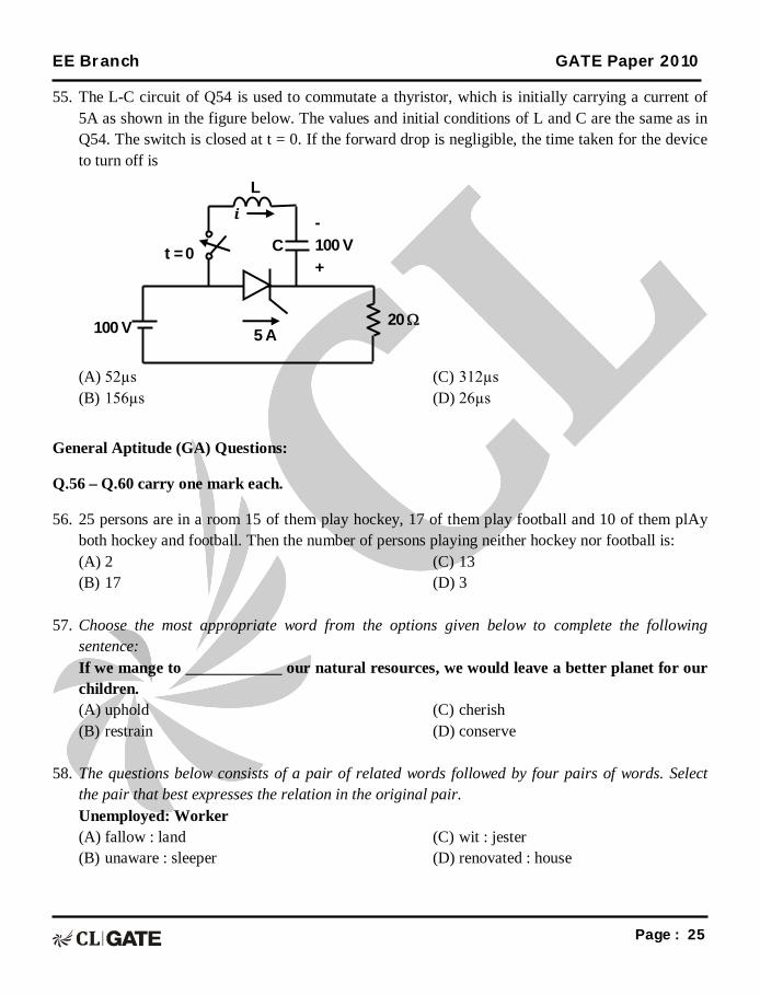
55. The L-C circuit of Q54 is used to commutate a thyristor, which is initially carrying a current of 5A as shown in the figure below. The values and initial conditions of L and C are the same as in Q54. The switch is closed at t = 0. If the forward drop is negligible, the time taken for the device to turn off is
(A) 52µs (B) 156µs
(C) 312µs (D) 26µs
General Aptitude (GA) Questions:
Q.56 – Q.60 carry one mark each.
56. 25 persons are in a room 15 of them play hockey, 17 of them play football and 10 of them plAy both hockey and football. Then the number of persons playing neither hockey nor football is: (A) 2 (B) 17
(C) 13 (D) 3
57. Choose the most appropriate word from the options given below to complete the following
sentence: If we mange to ____________ our natural resources, we would leave a better planet for our children. (A) uphold (B) restrain
(C) cherish (D) conserve
58. The questions below consists of a pair of related words followed by four pairs of words. Select
the pair that best expresses the relation in the original pair. Unemployed: Worker (A) fallow : land (B) unaware : sleeper
(C) wit : jester (D) renovated : house
- 100 V +
C
풊 L
t = 0
100 V 20 5 A
EE Branch GATE Paper 2010
Page : 26
59. Which of the following options is the closest in meaning to the word below: Circuitous (A) cyclic (B) indirect
(C) confusing (D) crooked
60. Choose the most appropriate word from the options given below to complete the following
sentence: His rather casual remarks on politics ___________his lack of seriousness about the subject. (A) masked (B) belied