GB-1136 Issue Date: Reference No: 29 February 2012 T1128/0233 Signatory: for P R Dixon Chief Executive National Measurement Office | Stanton Avenue | Teddington | TW11 0JZ | United Kingdom Tel +44 (0)20 8943 7272 | Fax +44 (0)20 8943 7270 | Web www.bis.gov.uk/nmo EC Test Certificate – Rev 1 - 05 September 2011 EC Test Certificate GB-1136 Revision 6 Issued by The National Measurement Office Notified Body Number 0126 In accordance with Paragraph 8.1 of the European Standard on Metrological Aspects of Non-automatic Weighing Instruments EN45501:1992. The applied error fraction pi with reference to paragraph 3.5.4 of this standard is 0.5. Applicant Cardinal Scale Manufacturing Co. PO. Box 151 Webb City Missouri, 64870 USA In respect of The model of an Indicating Device tested as a part of a weighing instrument. Manufacturer: Cardinal Scale Manufacturing Co. Type: 758 CSV Indicator Characteristics Suitable for a non-automatic weighing instrument with the following characteristics: n ≤ 5000 for Class III instruments with single interval. n ≤ 1000 for Class IIII instruments with single interval. Further details are provided in the Descriptive Annex. Description and documentation The Indicating device is described in the Descriptive Annex. Documents appertaining to this test certificate are held by the National measurement Office. Remarks The Indicator has been tested and found to conform to the relevant parts of EN45501 and WELMEC Guide 2.1. A summary of the tests performed in support of this Test Certificate is provided in the Appendix to the Descriptive Annex. This revision replaces previous versions of the certificate.
Transcript
GB-1136
Issue Date:
Reference No:
29 February 2012
T1128/0233
Signatory:
for
P R Dixon
Chief Executive
National Measurement Office | Stanton Avenue | Teddington | TW11 0JZ | United Kingdom
Tel +44 (0)20 8943 7272 | Fax +44 (0)20 8943 7270 | Web www.bis.gov.uk/nmo
EC Test Certificate – Rev 1 - 05 September 2011
EC Test Certificate
GB-1136 Revision 6
Issued by The National Measurement Office
Notified Body Number 0126
In accordance
with
Paragraph 8.1 of the European Standard on Metrological Aspects of Non-automatic Weighing Instruments EN45501:1992. The applied error fraction pi with reference to paragraph 3.5.4 of this standard is 0.5.
Applicant
Cardinal Scale Manufacturing Co.
PO. Box 151
Webb City
Missouri, 64870
USA
In respect of The model of an Indicating Device tested as a part of a weighing instrument.
Suitable for a non-automatic weighing instrument with the following characteristics: n ≤ 5000 for Class III instruments with single interval. n ≤ 1000 for Class IIII instruments with single interval.
Further details are provided in the Descriptive Annex.
Description and
documentation
The Indicating device is described in the Descriptive Annex. Documents appertaining to this test certificate are held by the National measurement Office.
Remarks
The Indicator has been tested and found to conform to the relevant parts of EN45501 and WELMEC Guide 2.1. A summary of the tests performed in support of this Test Certificate is provided in the Appendix to the Descriptive Annex.
This revision replaces previous versions of the certificate.
2/12
TEST CERTIFICATION NO GB-1136 Revision 6
Descriptive Annex
1 INTRODUCTION
The 758 CSV indicator is a mains or battery operated digital indicating device (Figure 1).
2 FUNCTIONAL DESCRIPTION
2.1 Devices:
− Semi-automatic zero setting device
− Zero-tracking device
− Zero indicator
− Stability indicator
− Net / Gross Indicator
− Semi automatic tare device
− Pre-set tare device
− Tare weighing device
− Display test device
− Low battery indicating device
− Body mass index function
2.2 Construction
The indicator consists of a stainless steel enclosure, which has two stainless steel end plates, which prevent access to the calibration/setup button.
The indicator weight display consists of a 5 digit, 13 mm high, 7 segment LCD. A 3 digit, 13 mm high 7 segment display is used to display body mass index (BMI), and a 4 digit, 9 mm high, 7 segment display is used for height entry for the BMI function (Figure 2). The membrane keyboard consists of 10 numeric keys and 9 function keys, which control the following functions:
− On/Off
− Zero
− Units (kg only)
− Lock/Release (Not for article 1(2)(a) applications.)
− Net/Gross
− Tare
− ID/Height
− 0 – 9 numeric keys
− Enter
− Clear
3/12
Fourteen enunciators are available to indicate:
− Battery low
− Gross
− Tare
− Net
− Stability
− Zero
− Weighing unit
− ID
− Height
− Body Mass Index
− Low – high bar type enunciator
− Percentage
Access to the battery compartment can be gained from the back of the enclosure (Figure 3).
2.3 Functions
The primary functions are detailed below:
2.3.1 The Lock/Release key shall not be enabled.
2.3.2 Power up
On power up, the weight indicator will test all memory functions, then test the display by turning on all the display segments and enunciators for about two seconds. After the display test, the instrument model number then software version number will be shown, before the current weight value using the previously established zero reference is displayed.
This test sequence may also be initiated manually by pressing the ON/OFF key to switch off the indicator then pressing it again to turn the indicator on and perform the test.
2.3.3 Display range
The indicator will display a weight value up to Max +9e; the error “OCAP” will be displayed to the operator for any weights above this.
2.3.4 Zero-Setting
Pressing the ZERO key causes a new zero reference to be established and the ZERO enunciator to turn on indicating the display is at the centre of zero; zero setting can only be successfully completed when the weight display is stable.
Zero-setting range is ≤4% of Max.
4/12
2.3.5 Zero-Tracking
Zero tracking operates when the indication is at zero, (or gross zero after a tare),
when the weight display is stable and at a rate of ≤0.5d/s within 4% Max.
2.3.6 Units
The UNITS key is used to select the units in which the weight is displayed, and this is displayed on the weight display.
Available units of measure are kilograms (kg) or grams (g).
2.3.7 Tare
Semi-automatic Tare
The TARE key must be pressed twice to operate the semi-automatic tare device. The Net enunciator will be illuminated.
Pre-set Tare
The first press of the TARE key will display the current gross weight value with the least significant digit flashing. The numeric keys are used to enter the tare value followed by pressing the ENTER key.
The Net or Gross weight can be indicated by pressing the NET/GROSS key.
Tare Weighing
The current tare value can be viewed by pressing the TARE key. The display will show the TARE enunciator and display the tare value for approximately 1 second before switching back to the net weight mode and displaying the NET enunciator.
2.3.8 Body Mass Index Display
The Body Mass Index (BMI) function is initiated by pressing the ID-HEIGHT key. When the ID-HEIGHT key is pressed, the weight value is blanked and the numeric keys are used to enter the subject’s height in either feet and inches or in centimetres followed by the ENTER key. The BMI value is displayed to the right of the weight display and also shown as an analogue value using the bar graph display below the digital BMI value.
The BMI function is enunciated by the words “BODY MASS INDEX” on the display when the function is in use.
2.3.9 Software Version
The software version number is displayed during the power up sequence of the instrument. The software version uses a format of XX.YY.ZZ where XX is the version of the legally relevant software and YY.ZZ are the versions of the non-legally relevant software. Software versions up to and including 3.YY.ZZ are covered by this approval.
5/12
2.4 Electronics
The 758CSV indicator uses a single printed circuit board, which contains all of the instrument circuitry. The indicator uses an ST Microelectronic 8-bit micro-controller, which has 32 Kb of flash program memory, 1 Kb of static ram and 2 Kb of EEPROM. All calibration and metrological set-up data is contained in non-volatile memory.
The power supply is provided by one of the two external mains power adapter modules specified below. Both can accept an input voltage from the from 190 to 230 VAC 50 or 60 Hz. The indicator may be powered from six internal “C” size batteries. The minimum battery operating voltage is 5.3 VDC.
Minimum input voltage per verification scale interval
1.2 µV
Measuring range minimum voltage 6 mV
Measuring range maximum voltage 15 mV
Fraction of maximum permissible error
Pind = 0.5
Operating temperature range -10°C to +40°C
Loadcell cable 4 conductor per core, shielded, polymer overall sheath. Maximum length = 3 m
4 INTERFACES
The back of the instrument has the following protected interfaces:
- 12 VDC power input - 9 pin “D” sub-miniature connector for the loadcell signal input.
6/12
5 LOCATION OF INSCRIPTIONS
5.1 The indicator shall bear the following markings:
Manufacturers mark or name Test Certificate number Figure 4 shows the data plate for the indicator when part of a complete instrument.
6 LOCATION OF SEALS, VERIFICATION MARKS AND CE MARK
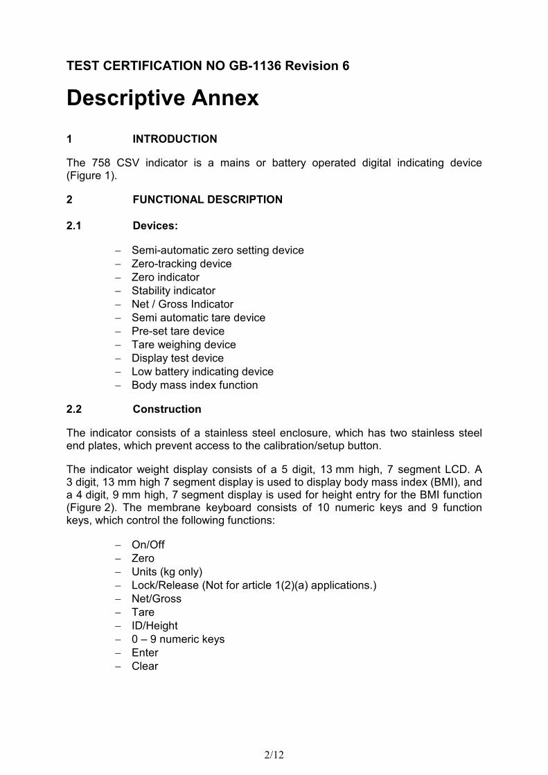
6.1 Access to the PCB and the calibration/setup button is prevented by the use of a stainless steel end plate, which is secured into position by a wire and lead seal through the drilled heads of the retaining screws (Figure 5).
The load cell cable connector is also secured to the indicator by the use of a wire and lead seal (Figure 5).
Components that may not be dismantled or adjusted by the user will be secured by a wire and lead seal and securing mark. The securing mark may be either:
- a mark of the manufacturer and/or manufacturer’s representative, or - an official mark of a verification officer.
6.2 The data plate will be mounted on the top-side of the indicator and will be mounted in such a manner that it is easily accessible and clearly visible in its regular operating position.
The CE and verification mark shall be affixed to the instrument and distinctly grouped together. It shall be impossible to remove the CE mark without damaging it. The data plate shall be impossible to remove without it being destroyed.
The markings and inscriptions shall fulfil the requirements of Paragraph 1 of Annex IV of the Directive 2009/23/EC.
7 ALTERNATIVES
7.1 Having a time and date feature included in the software.
7.2 Having an RS232 serial protected interface.
7.3 Having rechargeable batteries. The indicator contains a battery charging circuit. The external power supply, although of the same type, may be of a larger capacity.
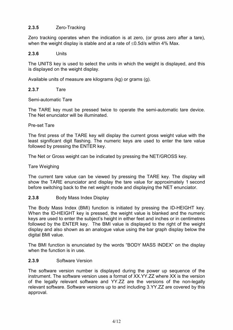
7.4 Having the legends on the keyboard replaced by pictograms, as shown in Figure 6. The pictograms are explained in the instruction manual.
7.5 Having a facility for a technician or dealer to connect a computer, or similar device, to modify the language and/or format of the printed ticket. The metrological data cannot be changed by this means, remaining fully under the control of the indicator software.
7/12
7.6 Having the indicator powered from any suitable external mains power adaptor module instead of those detailed in Section 2.4 above, but only if the indicator serial number shows that the date of manufacture was day 305 of the year 2005, or later.
Explanation: The serial number is of the form “EXXXYY-ZZZ”, where XXX is the day of the year (from 001 to 365), YY is the last two digits of the year, and ZZZ is a sequential number for that day of manufacture. All these indicators have a low-voltage inhibit which prevents operation when powered from a battery supply if that supply voltage drops too low. On indicators having a serial number of E30505-001 or later, this low-voltage inhibit also operates when an external mains power adaptor module is used.
7.7 Having a modified indicator as follows:
− Microprocessor changed from an ST Microelectronics part number ST72F324K6T6 to a Freescale microprocessor part number MC9S08JM60
− Event counter added to the log calibration and non legal-for-trade parameters
− Amplifier changed from a Linear Tech part number LT1112 to a Texas Instruments part number OPA2333
− Painted metal enclosure
− Additional USB, Ethernet and Digital Height rod interfaces Drawings for this construction are as follows:
− Controller circuit diagram 8555-D444-02 rev B
− PCB 8555-D444-0A rev E
8 ILLUSTRATIONS
Figure 1 758 CSV indicator Figure 2 LCD display and enunciators Figure 3 758 CSV back panel Figure 4 Data plate Figure 5 Sealing diagrams Figure 6 Keyboard with pictograms
8/12
9 TEST CERTIFICATE HISTORY
ISSUE NO. DATE DESCRIPTION
GB-1136 22 October 2002 Test certificate first issued.
GB-1136 Revision 1
8 June 2004 Addition of alternative 7.1 and 7.2.
GB-1136 Revision 2
15 August 2005 Addition of alternative 7.3.
GB-1136 Revision 3
14 December 2005
Addition of alternatives 7.4 and 7.5.
GB-1136 Revision 4
19 January 2006 Addition of alternative 7.6.
GB-1136 Revision 5
17 November 2009
Maximum tare effect added to technical data. Addition of alternative 7.7.
GB-1136 Revision 6
29 February 2012 Section 2.3.9 modified to specify the version numbers covered by the certificate. Section 5 modified to reflect the markings for the indicator only.
9/12
APPENDIX TO DESCRIPTIVE ANNEX
TESTS CARRIED OUT
The following tests were performed with the indicator connected to a loadcell simulator or to a small platform incorporating a loadcell, as specified in WELMEC 2.1 par. 5.
758 CSV:
EN45501 ref.
Test Report number
A.4.4 Weighing performance TR 562
A.4.6.1 Weighing accuracy with tare TR 562
A.4.10 Repeatability TR 562
A.5.2 Warm-up test TR 562
A.5.3.1 Weighing performance at static temperatures TR 562
A.5.3.2 Temperature effect on no load indication SN 1122