Manuale d’uso Rasaerba Robot User's manual Lawn Mower Robot Manuel d’utilisation Tondeuse à gazon Robot Bedienungshandbuch Rasenmähroboter Manual de uso Cortadora de césped Robot Gebruiksaanwijzingen Grasmaaimachine I GB F D E NL Italiano English Français Deutsch Español Nederlands C141501700.fm Congratulazioni per aver acquistato il rasaerba AMBROGIO. L'aver scelto questo prodotto potrà soddisfare le vostre esigenze e aspettative. Questo progetto nasce da ZUCCHETTI CENTRO SISTEMI S.p.A. (Azienda certificata UNI EN ISO 9001) software house che, dal 1982, ha consolidato la propria attività e la propria presenza sul mercato internazionale. Le soluzioni applicative del software abbinate al settore industriale di automazione, fanno nascere prodotti nuovi che ottimizzano le procedure di lavoro. È così che è nato, dai laboratori di ricerca, AMBROGIO. Congratulations for having purchased the AMBROGIO lawn mower. This choice will surely meet your needs and expectations. This product is the result of research at the ZUCCHETTI CENTRO SISTEMI S.p.A. (certified UNI EN ISO 9001) software house that, since 1982, has been consolidating its role on the international market. Innovative software solutions applied to the industrial automation sector introduce new products that optimise working procedures. AMBROGIO was developed on the basis of this research. Tous nos compliments pour avoir acheté la tondeuse à gazon AMBROGIO. Vous avez choisi un produit qui répondra à vos besoins et à vos attentes. Ce projet naît au ZUCCHETTI CENTRO SISTEMI S.p.A. (Entreprise certifiée UNI EN ISO 9001) software house qui, depuis 1982, a consolidé son activité et sa présence sur le marché international. Les solutions d’application du logiciel, jumelées au secteur industriel d’automation, ont permis la naissance de nouveaux produits qui optimisent les procédures de travail. C’est ainsi que, dans nos laboratoires de recherche, est né AMBROGIO. Wir gratulieren zum Kauf des Rasenmähers AMBROGIO. Ihre Bedürfnisse und Erwartungen werden durch die Wahl dieses Produkts mit Sicherheit erfüllt. Die Firma ZUCCHETTI CENTRO SISTEMI S.p.A. (mit UNI EN ISO 9001 ausgezeichneter Betrieb) Software House, die ihre Produktion seit 1982 festigt und damit auf dem internationalen Markt vertreten ist, zeichnet für dieses Produkt verantwortlich. Die angewandten Softwarelösungen führen in Kombination mit der industriellen Automatisierung zur Entstehung neuer Produkte für eine Optimierung von Arbeitsprozessen. Auf diese Weise entstand in den Forschungslabors AMBROGIO. Felicidades por haber adquirido la cortadora de césped AMBROGIO. Podrá satisfacer sus exigencias y expectativas al haber elegido este producto. Este producto nace de ZUCCHETTI CENTRO SISTEMI S.p.A. (Empresa certificada UNI EN ISO 9001) software house que, desde 1982, ha consolidado su propia actividad y su propia presencia en el mercado internacional. Las soluciones de aplicación del software combinadas con el sector industrial de automatizando, hacen nacer nuevos productos que optimizan los procedimientos de trabajo. Es así que ha nacido, en los laboratorios de investigación, AMBROGIO. Wij wensen u van harte geluk met de aanschaf van uw AMBROGIO. Wij zijn er zeker van dat deze machine voldoet aan al uw verwachtingen en vereisten. AMBROGIO is een project van ZUCCHETTI (met UNI EN ISO 9001 certificaties), een softwarebedrijf dat sinds 1982 met haar activiteiten een eigen plaats verwierf op de internationale markt. De combinatie van de oplossingen die worden geboden door softwaretoepassingen en de industriële automatisering resulteert in nieuwe producten om de bedrijfsprocessen te optimaliseren. Zo ontstond in onze onderzoekscentra AMBROGIO.
Transcript
Manuale d’uso
Rasaerba Robot
User's manual
Lawn Mower Robot
Manuel d’utilisation
Tondeuse à gazon Robot
Bedienungshandbuch
Rasenmähroboter
Manual de uso
Cortadora de césped Robot
Gebruiksaanwijzingen
Grasmaaimachine
I
GB
F
D
E
NL
Italiano
English
Français
Deutsch
Español
Nederlands
C141501700.fm
Congratulazioni per aver acquistato il rasaerba AMBROGIO. L'averscelto questo prodotto potrà soddisfare le vostre esigenze easpettative. Questo progetto nasce da ZUCCHETTI CENTROSISTEMI S.p.A. (Azienda certificata UNI EN ISO 9001) softwarehouse che, dal 1982, ha consolidato la propria attività e lapropria presenza sul mercato internazionale. Le soluzioniapplicative del software abbinate al settore industriale diautomazione, fanno nascere prodotti nuovi che ottimizzano leprocedure di lavoro. È così che è nato, dai laboratori di ricerca,AMBROGIO.
Congratulations for having purchased the AMBROGIO lawnmower. This choice will surely meet your needs andexpectations. This product is the result of research at theZUCCHETTI CENTRO SISTEMI S.p.A. (certified UNI EN ISO9001) software house that, since 1982, has beenconsolidating its role on the international market. Innovativesoftware solutions applied to the industrial automation sectorintroduce new products that optimise working procedures.AMBROGIO was developed on the basis of this research.
Tous nos compliments pour avoir acheté la tondeuse à gazonAMBROGIO. Vous avez choisi un produit qui répondra à vosbesoins et à vos attentes. Ce projet naît au ZUCCHETTI CENTROSISTEMI S.p.A. (Entreprise certifiée UNI EN ISO 9001) softwarehouse qui, depuis 1982, a consolidé son activité et sa présencesur le marché international. Les solutions d’application dulogiciel, jumelées au secteur industriel d’automation, ont permisla naissance de nouveaux produits qui optimisent lesprocédures de travail. C’est ainsi que, dans nos laboratoires derecherche, est né AMBROGIO.
Wir gratulieren zum Kauf des Rasenmähers AMBROGIO. IhreBedürfnisse und Erwartungen werden durch die Wahl diesesProdukts mit Sicherheit erfüllt. Die Firma ZUCCHETTI CENTROSISTEMI S.p.A. (mit UNI EN ISO 9001 ausgezeichneter Betrieb)Software House, die ihre Produktion seit 1982 festigt unddamit auf dem internationalen Markt vertreten ist, zeichnet fürdieses Produkt verantwortlich. Die angewandtenSoftwarelösungen führen in Kombination mit der industriellenAutomatisierung zur Entstehung neuer Produkte für eineOptimierung von Arbeitsprozessen. Auf diese Weise entstandin den Forschungslabors AMBROGIO.
Felicidades por haber adquirido la cortadora de céspedAMBROGIO. Podrá satisfacer sus exigencias y expectativas alhaber elegido este producto. Este producto nace deZUCCHETTI CENTRO SISTEMI S.p.A. (Empresa certificada UNIEN ISO 9001) software house que, desde 1982, haconsolidado su propia actividad y su propia presencia en elmercado internacional. Las soluciones de aplicación delsoftware combinadas con el sector industrial deautomatizando, hacen nacer nuevos productos que optimizanlos procedimientos de trabajo. Es así que ha nacido, en loslaboratorios de investigación, AMBROGIO.
Wij wensen u van harte geluk met de aanschaf van uwAMBROGIO. Wij zijn er zeker van dat deze machine voldoet aanal uw verwachtingen en vereisten. AMBROGIO is een projectvan ZUCCHETTI (met UNI EN ISO 9001 certificaties), eensoftwarebedrijf dat sinds 1982 met haar activiteiten een eigenplaats verwierf op de internationale markt. De combinatie vande oplossingen die worden geboden doorsoftwaretoepassingen en de industriële automatiseringresulteert in nieuwe producten om de bedrijfsprocessen teoptimaliseren. Zo ontstond in onze onderzoekscentraAMBROGIO.
C141501700.fm
Dichiarazione di conformità (98/37 CE allegato II punto A)ZUCCHETTI Centro Sistemi S.p.A. Via dell’Olmo 99 A/BTerranuova B.ni (AR) ITALIA, dichiara che la macchina,identificabile dai dati riportati in calce, da utilizzare per rasareprati in ambienti domestici e non, è conforme alle direttive:98/37 CE - 78/23 CEE - 89/336 CEE. Per queste ultimesono compresi i successivi emendamenti.
Declaration of conformity (98/37 CE annex II paragraph A)ZUCCHETTI Centro Sistemi S.p.A., Via dell’Olmo 99 A/BTerranuova B.ni (AR) ITALY, declares that the machine,identified by the data included hereafter, to be used for lawnmowing in household and other environments, complies withdirectives: 98/37 EC - 78/23 EEC - 89/336 EEC andamendments thereto.
Déclaration de conformité (98/37 CE annexe II paragraphe A)ZUCCHETTI Centro Sistemi S.p.A. Via dell’Olmo 99 A/B
Terranuova B.ni (AR) ITALIE, déclare que la machine,identifiable par les données rapportées plus bas, servant àtondre les pelouses en milieu domestique et non, est conformeaux directives : 98/37 CE - 78/23 CEE - 89/336 CEE. Pources dernières, sont inclus les amendements additionnels.
Konformitätsbestätigung (98/37 CE Beilage II Punkt A)Die Firma ZUCCHETTI Centro Sistemi S.p.A., Via dell’Olmo 99A/B Terranuova B.ni (AR) ITALIEN, erklärt, daß die mit denunten angegebenen Daten gekennzeichnete Maschine, diedazu bestimmt ist, zum Mähen von Rasenflächen in Wohn- undanderer Umgebung eingesetzt zu werden, folgendenRichtlinien entspricht: 98/37 CE - 78/23 CEE - 89/336 CEE.Letztere schließen nachfolgende Abänderungen mit ein.
Declaración de conformidad (98/37 CE anexo II punto A)ZUCCHETTI Centro Sistemi S.p.A. Via dell’Olmo 99 A/BTerranuova B.ni (AR) ITALIA, declara que la máquina, que sepuede identificar por los datos al pie de la página, y que tienecomo uso cortar prados tanto en ambientes domésticos comono domésticos, es conforme a las directivas: 98/37 CE - 78/23 CEE - 89/336 CEE. Para estas últimas están incluidas lasenmiendas sucesivas.
Verklaring van overeenstemming (98/37 EG bijlage II punt A)ZUCCHETTI Via dell'Olmo 99 A/B Terranuova B.ni (AR) ITALIA,
verklaart dat de machine waarvan de identificatiegegevenshiernaast worden vermeld en die bedoeld is om gras te maaienin huishoudelijke en andere omgevingen, voldoet aan derichtlijnen: 98/37 EG - 78/23 EEG - 89/336 EEG. In delaatste richtlijnen zijn ook de latere wijzigingen inbegrepen.
GENERAL INFORMATION .............................. 4TECHNICAL INFORMATION .......................... 5SAFETY INFORMATION .................................. 9INSTALLATION ................................................ 11ADJUSTMENTS .............................................. 27
USE AND FUNCTIONING ............................ 29ORDINARY MAINTENANCE ...................... 48FAILURES, CAUSES AND SOLUTIONS .. 50PARTS REPLACEMENTS ............................ 55
CONTENTS
AAdjusting the cutting height, 28Adjustment reminders, 27Automatic cycle start, 38BBatteries replacement, 56Battery installation and connection, 23Blade installation, 23DDisplay visualisation in work phase, 42EEnter password, 42Equipment general description, 5Equipment installation planning, 12IIdentification of manufacturer and appliance, 4Installation of recharging station and transmitter-power supplier group, 20MMaintenance reminders, 48Manual startup and stop of robot (in closed areas), 40OOperating reminders, 48PPackaging and unpacking, 11Parts replacement reminders, 55Perimeter wire installation, 17Preparation and delimitation of work areas (main and secondary), 14Programmed maintenance intervals chart, 48Programming mode, 31Prolonged inactivity and service restart, 42Purpose of this manual, 4
RRain sensor adjustment, 29Recharge batteries for extended inactivity, 44Recharge batteries on first use, 27Recommendations for use, 29Remote control description, 31Replace the blade, 61Requesting technical assistance, 5Robot automatic stop, 39Robot cleaning, 49Robot controls description, 30Robot disposal, 62Robot safety stop, 39Robot start without perimeter wire, 41SSafety for man and the environment during disposal, 10Safety rules, 9Safety signals, 11Setting for rapid robot re-entry into the recharging station, 19Specifications, 7TTelecommand batteries replacement, 62Troubleshooting, 50
The constructor has produced this man-ual, which forms an integral part of theappliance, to provide the necessary infor-mation for those authorised to interactwith it during its working life.Personnel working with the machine mustadopt correct working practices and mustalso carefully read and strictly follow all theinstructions given in this manual.This manual is written by the manufac-turer in the original language (Italian). Itmay be translated into other languagesto satisfy commercial and/or legal re-quirements.Study this manual carefully. It will helpyou avoid unnecessary risks to personalhealth and safety and risks of damage toequipment.The constructor reserves the right tomake changes without any obligation toprovide any prior notice.Some information and illustrations setout in the present manual may not per-fectly correspond with the one in yourpossession, but that does not compro-mise its validity.
The manufacturer reserves the right tomake all necessary changes without pri-or notice of any kind.The following symbols are used through-out this manual to identify particularly im-portant sections of text or data.
Danger - AttentionThis symbol identifies situations of im-minent danger which, if ignored, lead toserious risks to personal health andsafety.
Warning - CautionThis symbol identifies situations inwhich it is essential to behave in a cer-tain way to avoid risks to personalhealth and safety and risks of damageto equipment.
ImportantThis symbol identifies specially impor-tant technical information that mustnot be ignored.
The dataplate shown here is fit-ted directly to the appliance. Itfeatures references and all es-sential information for operatingsafety.A) Name of manufacturerB) CE conformity label.C) Serial model/number year of
construction.D) Technical specifications
GENERAL INFORMATION
PURPOSE OF THIS MANUAL
IDENTIFICATION OF MANUFACTURER AND APPLIANCE
IDM - 41501700100.tif
manufacturer identification (A)
CE conformity marking (B)
model (C)
technical specifications(D)
serial number (C)
manufacturing year (C)
- 5 -
C14
1501
700.
fm
User's manual
GB
For every technical service request re-garding the machine, please indicate thedata found on the identification plate, the
approximate hours of use and the type offault detected.
The appliance Ambrogio Line200 is a robot designed and builtto automatically trim grass in gar-dens and house lawns in any timeof the day. It is small, compact, si-lent, waterproof and easy totransport.
Relative to the various specifica-tions of the sufrace to be mown,the robot can be programmed tomachine a number of areas: amain one and, in addition, two orthree secondary areas.
During its functioning the robottrims the area marked off by theperimeter wire and/or by barri-ers (fences, walls, etc.)
When the robot detects the per-imter wire or meets an obstacle itchanges trajectory in a randommanner and starts again in a newdirection.
According to its functioning prin-ciple ("random"), the robot car-ries out an automatic andcomplete trimming of themarked off lawn (see figure).
The lawn surface that the robotis able to trim depends on a series of fac-tors.– robot model and type of batteries in-
stalled– area features (irregular perimeters,
uneven surface, divided area, etc.)
– lawn features (type and height ofgrass, moisture, etc.)
– blade conditions (with efficient sharp-ening, without residues and deposits,etc)
REQUESTING TECHNICAL ASSISTANCE
TECHNICAL INFORMATION
EQUIPMENT GENERAL DESCRIPTION
IDM - 41501700200.tif
robot
robot
- 6 -
C14
1501
700.
fm
User's manual
GB
The robot Ambrogio Line 200 is pro-duced in the BASIC, DELUXE and EVOLU-TION versions.BASIC version: basic model which canmow surfaces up to 1500 m2. On re-quest, it can be equipped with two leadbatteries or a lithium battery.DELUXE version: model able to mowsurfaces up to 2600 m2. On request, itcan be equipped with two lithium batter-ies, which make it possible to mow sur-faces up to 3000 m2.EVOLUTION version: model able to mowsurfaces up to 3000 m2. It is equippedwith two lithium batteries, telecommandand sensor to detect the "mown lawn".
All models are equipped with a sensorwhich, when it rains, stops the blade andmakes the robot return to its rechargingstation.
On request, models can be equippedwith an amplified transmitter, electro-magnetic interferences filter, electronicalarm and power supply protection box.
For more details, consult the table show-ing technical data
Each robot is provided with a recognitionpassword in order to impede its useshould it be stolen.
When the purchased, the password in-serted by the manufacturer comprisesfour numbers (0000).
To customise the password see "Pro-gramming mode" (§ "Enter password").
Main parts– Accumulator batteries (A): they en-
ergize the motors of the blade and ofthe wheel control system.The robot is supplied with lead batter-ies or with one or two lithium batter-ies, which assure a longer workingsession.
– Recharging station (B): used tocharge or keep the batteries charged(A).
– Electronic card (C): it checks the au-tomatic functions of the robot.
– Control keyboard (D): it is used to setand visualise the functioning modes ofthe robot.
– Cutting blade (E): it trims the lawn.– Electric motor (F): it starts the cut-
ting blade (E).– Electric motor (G): one actions the
right wheel transmission group whilethe other actions the left wheel.
– Transmitter (H): it transmits the sig-nal to the perimeter wire.
– Power supply unit (L): it energizes, atlow tension, the battery power.
ImportantThe power supply unit (L) varies ac-cording to the type of batteries in-stalled (lead or lithium batteries).
– Impacts sensor (M): detects robotimpact against an obstacle and ena-bles a change of trajectory in a ran-dom manner.
– Remote control (N): it is used tocheck the robot functions in a remoteposition.
– Rain sensor (P): detects rain and en-ables the return of the robot to itscharging station (P).
– Sensor (Q): detects the perimeterwire and enables a change of robottrajectory in a random manner.
Class 1 (Vin 115-230 Vac 50Hz) Fuse 5x20 4A F (inside) 27,6 Vac Fuse 5x20 10A F (replaceable) Selector 115-230 Vac
Power supply unit (for lithium battery)
Class 1 (Vin 115-230 Vac 50Hz) Fuse 5x20 4A F (inside) 29,3 Vac Fuse 5x20 10A F (replaceable) Selector 115-230 Vac
Section perimeter wire (to lay underground)
(mm) ø1,5 ø1,5 ø1,5
Perimeter wire maximum length (approximate, calculated according to a regular perimeter)
(m) 600 600 600
Fittings
Sinusoidal perimeter signal (patented)
standard standard standard
Rain sensor standard standard standard
Intelligent spiral not available standard standard
Blade modulation not available standard standard
Trimmed lawn sensor -Auto-programming (patented)
not available not available standard
Remote control on request on request standard
Alarm on request on request standard
Kit for working with gradients higher than 27° (1) on request on request standard
Perimeter wire (m) 100 150 150
Fixing nails (n°) 100 200 200
Upgraded transmitter on request on request on request
Electromagnetic interference filter
on request on request on request
Power supply safety box on request on request on request
DescriptionModel
BASIC DELUXE EVOLUTION
- 9 -
C14
1501
700.
fm
User's manual
GB
– During design and construction, themanufacturer has carefully consid-ered the possible hazards and per-sonal risks that may result frominteraction with the machine. In addi-tion to observing the specific laws inforce, the manufacturer has adoptedall "exemplary construction techniqueprinciples". The purpose of this infor-mation is to advise the users to useextreme caution to avoid risks. How-ever, discretion is invaluable. Safety isalso in the hands of all the operatorswho interact with the machine.
– When using the robot for the firsttime, it is recommended to carefullyread the whole manual and to besure to have it completely under-stood, in particular all the informa-tion relating to safety.
– Carefully read all instructions in thismanual and those applied directly tothe machine, taking particular care toread and follow safety precautions.Time dedicated to reading these pre-cautions can prevent regrettable ac-cidents. It is always too late toremember what you should havedone after an accident has happened.
– Perform lifting and handling observingthe information found directly on thepackaging, on the machine and in theinstructions furnished by the manu-facturer.
– Pay attention to the symbols that ap-pear on all the safety labels. They arecoded by colour and shape to en-hance safety. Keep all safety labelslegible and always respect the instruc-tions they give.
– The lawn mower may be used only bythose who know how to operate it af-ter reading and understanding the in-structions in this manual.
– Only use the machine for the purpos-es specified by the manufacturer. Useof the machine for other purposesmay be hazardous to personal safetyand health and provoke economicloss.
– Before using the lawn mower makesure that no objects are on the lawn(toys, tree branches, items of cloth-ing, etc.).
– When using the machine, make surethere are no risks especially for chil-dren, pets and things.
– Do not place hands or feet under themachine when running especially inthe wheel area.
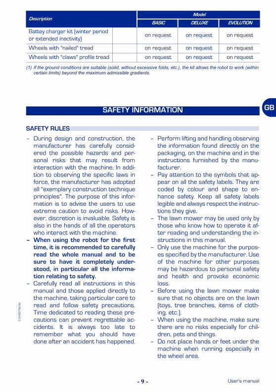
Battey charger kit (winter period or extended inactivity)
on request on request on request
Wheels with "nailed" tread on request on request on request
Wheels with "claws" profile tread on request on request on request
(1) If the ground conditions are suitable (solid, without excessive folds, etc.), the kit allows the robot to work (within certain limits) beyond the maximum admissible gradients.
SAFETY INFORMATION
SAFETY RULES
DescriptionModel
BASIC DELUXE EVOLUTION
- 10 -
C14
1501
700.
fm
User's manual
GB
– Never tamper with, avoid, remove orbypass installed safety devices. Suchactions could lead to serious risk topersonal health and safety.
– Keep the lawn mower in perfect oper-ating conditions by performing themaintenance procedures outlined bythe manufacturer. Good maintenanceguarantees better performance andlonger service life.
– Before maintenance and setting pro-cedures are performed – also by theuser, if possessing the necessarytechnical skills – disconnect the pow-er supply. The user must in any caseoperate in full safety conditions, espe-cially when working on the lower partof the lawn mower, following the pro-cedures as illustrated by the manu-facturer.
– Use personal protections as recom-mended by the manufacturer, espe-cially the protective gloves whenhandling blades and cutting discs.
– Always remove the blade before re-placing the batteries.
– In order not to irreversibly damageelectric and electronic parts, do notwash the robot with water jets at ahigh pressure and do not plunge itpartially or thoroughly in water, as itis not watertight.
– The operators performing repair in-terventions during the working life ofthe robot must have technical exper-tise, special abilities and experience,acquired and acknowledged in thisspecific sector. The lack of these re-quirements may cause damage to thesafety and health of people.
– All operations, which must be carriedout in the recharge base (optional),must be performed with the powersupply plug disconnected.
– Replace deteriorated parts with origi-nals to ensure functionality and theforeseen safety level.
Do not dispose of pollutant materials inthe environment. Dispose of all suchmaterials in compliance with applica-ble legislation.With reference to the WEEE directive(Waste of Electrical and ElectronicEquipment), during dismantling, the usermust separate the electrical and theelectronic components and disposethem in the appropriate authorized col-lection centres or give them back as theyare to the seller, when a new purchase ismade.All the components, which must be sep-arated and disposed of in a specific man-ner, are marked with a special mark.The unauthorized disposal of Waste ofElectrical and Electronic Equipment(WEEE) is subject to fine according to
sanctions regulated by the laws in forcein the territory where the infraction hasbeen verified.As implementation of the European di-rectives (2002/95/CE, 2002/96/CE,2003/108/CE) in the Italian territory,for example, a law decree (n. 151 datedJuly 25 2005) has been enacted, thusproviding for an administrative fine of€ 2000÷5000.
Danger - AttentionThe Waste of Electrical and ElectronicEquipment may contain dangeroussubstances with potentially harmful ef-fects on the environment and on peo-ple. It is recommended to correctlydispose them.
SAFETY FOR MAN AND THE ENVIRONMENT DURING DISPOSAL
- 11 -
C14
1501
700.
fm
User's manual
GB
Danger signal: indicatesthat the user should not ap-proach to the blades whilethe lawn mower is operat-ing.
Safety signal: indicatesthat the user should care-fully read the manual be-fore operating the lawnmower.
The machine is delivered suitably pack-aged. When unpacking, remove carefullyand check component integrity.
All the necessary information for han-dling is found on the packaging.
Packaging content– Robot (A);– Power supply unit (B)– Power supply cable (C)– Reload station (D)– Transmitter (E)– Perimeter wire hank (F)– Nails (G) for wire fixing– User manual (H)– Lithium or lead accumulator batteries
(L): the quantity of batteries can varyrelative to the purchase order.
– Blade (M)– Telecommand (N) (only for some ver-
sions, see "Specifications").
ImportantThe list includes only the componentssupplied with the equipment. Check thequantity and the integrity of any option-al parts requested.
Keep packaging material for subse-quent use.
SAFETY SIGNALS
INSTALLATION
PACKAGING AND UNPACKING
IDM - 41501700400.tif
user manual (H)
robot (A)
wire fixing nails (G)
perimeter wire (F)
remote control (N)
cutting blade (M)
power supply unit (B)
Reload station (D)
transmitter (E)
accumulator batteries(L)
power cable (C)
- 12 -
C14
1501
700.
fm
User's manual
GB
Robot installation does not involve inter-ventions that are difficult to carry out,but requires a minimum of preliminaryplanning to define the best area to install
the charging station, power supply-trans-mitter group and to lay out the perime-ter wire.
Power supplier-transmittergroup and recharging station in-stallation area– Power supplier-transmitter
group and recharging stationmust be installed inside themain work area and near toeach other.
– The recharging station must bepositioned on a flat and stablesurface and able to guaranteegood drainage to avoid flooding.
– The section of input wire mustbe rectilinear and aligned per-pendicularly to the rechargingstation for at least 2 m and theoutput section must be locatedat least 30 cm from the re-charging station; this makes itpossible for the robot to entercorrectly.
EQUIPMENT INSTALLATION PLANNING
IDM - 41501700500.tif
power supply-transmitter unit
perimeter wire
wire laying directionIDM - 41501700500.tif
Reload stationperimeter wire
power supply-transmitter unit
power supply-transmitter unit
IDM - 41501700600.tif
power supply-transmitter unit
IDM - 41500902400.tif
- 13 -
C14
1501
700.
fm
User's manual
GB
ImportantTo permit the robot to re-enter the re-charging station, it is necessary to in-stall the same within the work areahaving larger dimensions, hereafter re-ferred to as the "Main Area".
– Make sure that any irrigators ,present in the installation area do notdirect a jet of water into the recharg-ing station.
– The transmitter - power suppliergroup must be in a ventilated position,protected from the atmosphericagents and from direct sunlight.
– The transmitter - power suppliergroup must not be in direct contactwith the ground and damp environ-ments.
Warning - CautionTo carry out electric connection, it isnecessary to arrange a power supplysocket near the installation area. Makesure that the connection to the powersupply complies to the laws in force onthe subject.
ImportantIs it advisable to install the unit in acloset for electric components (for out-doors or indoors), well ventilated tokeep a correct air recirculation andprovided with a key closure.
Warning - CautionAssure that the access to the powersupply-transmitter unit is allowed onlyto authorized people.
Perimeter wire path definition
– Check the whole surface of thelawn and assess whether it isnecessary to divide it in moreseparated working areas.
– When positioning the perimterwire, respect the rotation direc-tion around the bays (anticlock-wise).
– Define the perimeter of themain area, any secondary are-as, and carry out the opera-tions in the sequence indicated.
1-Preparation and delimitationof work areas (main and sec-ondary) (see page 14)
2-Perimeter wire installation(see page 17)
3-Installation of recharging sta-tion and transmitter-powersupplier group (see page 20)
IDM - 41500902500.tif
track for perimeter wire laying
- 14 -
C14
1501
700.
fm
User's manual
GB
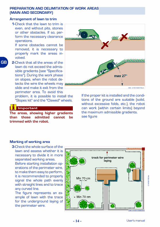
Arrangement of lawn to trim1-Check that the lawn to trim is
even, and without pits, stonesor other obstacles. If so, per-form the necessary clearanceoperations.If some obstacles cannot beremoved, it is necessary toproperly mark the areas in-volved.
2-Check that all the areas of thelawn do not exceed the admis-sible gradients (see "Specifica-tions"). During the work phaseon slopes, when the robot de-tects the wire the wheels mayslide and make it exit from theperimeter area. To avoid thisproblem, it is possible to install the"Slopes kit" and the "Clawed" wheels.
ImportantThe areas, showing higher gradientsthan those admitted cannot betrimmed with the robot.
If the proper kit is installed and the condi-tions of the ground are suitable (solid,without excessive folds, etc.), the robotcan work (within certain limits) beyondthe maximum admissible gradients.see figure
PREPARATION AND DELIMITATION OF WORK AREAS(MAIN AND SECONDARY)
Marking of working area3-Check the whole surface of the
lawn and assess whether it isnecessary to divide it in moreseparated working areas.Before starting installation op-erations of the perimeter wire,to make them easy to perform,it is recommended to properlysignal the whole path evenlywith straight lines and to traceany curved line.The figure represents an ex-ample of lawn with the tracefor the underground laying ofthe perimeter wire.
IDM - 41501700800.tif
track for perimeter wire laying
IDM - 41501600700.tif
- 15 -
C14
1501
700.
fm
User's manual
GB
ImportantTo ensure the robot can operate,it is necessary for the distanceseparating the delimitation oftwo elements to be greater than70 cm. This distance is requiredto permit robot passage.
When the connection betweenone surface and another of thelawn is represented by a pas-sage (corridor) with a width ofless than 70 cm and not greaterthan 2 m, it is necessary to de-limit the same with the perime-ter wire in a number of workareas that are connected toeach other.
IDM - 41501700900.tif
house
passage aisle
house
passage aisle (<70cm)
MAIN AREA SECONDARY AREA
MAIN AREA
Closed area
- 16 -
C14
1501
700.
fm
User's manual
GB
4-Mark and trace the perime-ters of the inside and marginalelements of the working areathat obstruct the correct func-tioning of the robot.
ImportantThe figure represents an exam-ple of inside an marginal ele-ments of the working area andthe distances that must be re-spected for the tracing of the un-derground laying of theperimeter wire.
Mark and trace the perimetersof all the elements in iron or inother metals (manholes, electricconnections, etc.) to avoid inter-ferences to the signal of the pe-rimeter wire.
Do not mark those obstacles(trees, poles, etc.) that do nothamper the normal functioningof the robot.
IDM - 41501601100.tifIDM - 41501711400.tif
bed
manhole
hedge
protruding roots
wall
pool
shower dish
IDM - 41501701000.tif
tree pole
- 17 -
C14
1501
700.
fm
User's manual
GB
5-Mark the areas, located in alower position compared tothe lawn surface (pools, areaswith significant drops, stairs,etc.) (see example in figure).
ImportantStrictly respect the distances toavoid that the robot falls with therisk of breaking and/or seriouslygetting damaged.
6-Mark and trace the perime-ters as shown in the figure.
– With small paths at the sameheight as the lawn: 5 cm
– With small paths higher thanthe lawn: 35 cm
– In presence of a fencing wall:35 cm
ImportantThe passage paths (at the samelevel of the lawn), necessary forthe robot to pass from one areato the other, must not bemarked.
The perimeter wire may be laid un-derground or on the ground.
ImportantStart laying the perimeter wirefrom the installation area of therecharging station , leave twometres in excess and then cut itas appropriate in the group con-nections phase.
PERIMETER WIRE INSTALLATION
pool
IDM - 41501701100.tif
elevated areaperimeter wire
pedestrian crossing
wallpedestrian crossing
IDM - 41501701200.tif
perimeter wire
perimeter wire
perimeter wire
IDM - 41501601600.tif
- 18 -
C14
1501
700.
fm
User's manual
GB
Wire laid on the ground1-Place the wire clockwise along
the whole path and fix it withthe appropriate nails supplied(distance between the nails1÷2 m).
– When positioning the perimterwire, respect the rotation di-rection around the bays (anti-clockwise).
– In the straight stretches, fix thewire so that it is not excessivelytight, wavy and/or twisted.
– In the not straight stretches, fixthe wire so that it does nottwist, but so that it takes on aregular bending.
Underground laid wire1-Dig up the ground evenly and sym-
metrically compared to the tracedline highlighted on the ground.
2-Place the wire clockwise along thewhole path at the depth of some cen-timetres (about 2÷3 cm) so not toreduce the quality and the intensity ofthe signal captured by the robot.
3-When laying the wire, if necessary,block it in some points with the appro-priate nails to keep it in position dur-ing the ground covering stage.
4-Cover up the whole wire with the soiland make sure that it does not twist,but that it remains straight and that,in the curving stretches, it takes onan even bending.
ImportantIn the path stretches, where it isnecessary to pass two parallelwires (for example: connectionbetween the outside perimeterand the inside marked areas),they must be at a distance,which must not exceed 1 cm.
IDM - 41501600900.tif
wire fixing nails
wire fixing nails
perimeter wire
perimeter wire
IDM - 41501701300.tif
passage aisle (<70cm)
MAIN AREA
Closed area
- 19 -
C14
1501
700.
fm
User's manual
GB
Perimeter wire joint
ImportantIn the case of underground wireas well as of ground laid wire, ifnecessary, properly join it withsome other wire, having thesame features (see figure).
During the joint stage, it is rec-ommended to use self-amalga-mating tape (for example: 3MScotch 23). Do not use isolatingtape or other types of joints (ter-minals, clamps, etc.).
To reduce the times for robot re-entry into the recharging station,carry out settings along the perim-eter wire to permit a change of ro-bot direction. In this way, it ispossible to reduce the robot re-en-try route.To carry out the re-entry setting,position the perimeter wire alongthe route< so as to form an equi-lateral triangle of 40 cm per side.Carry out the rapid re-entry set-ting at a point that is preceded byat least 2 m of rectilinear wire andis followed by at least 1.5 m of rec-tilinear wire.The setting must not be carriedout along the rectilinear sectionthat immediately precedes the recharg-ing station or near to obstacles. Makesure that along the rapid re-entry trajec-tory, there are no obstacles that can im-pede rapid re-entry.
ImportantThe rapid re-entry setting at an incor-rect point may prevent the robot fromrapidly re-entering the recharging sta-tion.
When the robot moves along the pe-rimeter to reach a secondary area itdoes not detect the rapid re-entry set-ting.
The illustration provides some useful in-dications for correctly installing the rapidre-entry setting.
SETTING FOR RAPID ROBOT RE-ENTRY INTO THERECHARGING STATION
IDM - 41501701400.tif
IDM - 41501602000.tif
- 20 -
C14
1501
700.
fm
User's manual
GB
1-Identify the recharging stationinstallation area and the trans-mitter-power supply group.
Warning - CautionBefore carrying out any interven-tion deactivate the general elec-tricity power supply.
2-Installation of the power sup-ply-transmitter unit (A-B).
3-Remove the shield (L).
INSTALLATION OF RECHARGING STATION AND TRANSMITTER-POWER SUPPLIER GROUP
IDM - 41501701700.tif
power supply unit (A)
transmitter (B)
IDM - 41501701500.tif
guard (L)
- 21 -
C14
1501
700.
fm
User's manual
GB
4-Position the base in the prede-fined area.
5-Insert the perimeter wire (M)under the base.
6-Connect the two ends of thewire to the terminals of thebase.
7-Fasten the base (N) to theground with nails (P). If neces-sary, fasten the base with ex-pansion inserts (Q).
IDM - 41501701600.tifperimeter wire (M)
Red terminalBlack terminal
IDM - 41501711600.tif
Black terminalRed terminal
Red terminalBlack terminal
IDM - 41501701800.tif
nails (P)
Expansion inserts (Q)
Reload station (N)
- 22 -
C14
1501
700.
fm
User's manual
GB
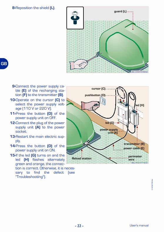
8-Reposition the shield (L).
9-Connect the power supply ca-ble (E) of the recharging sta-tion (F) to the transmitter (B).
10-Operate on the cursor (C) toselect the power supply volt-age (110 V or 220 V).
11-Press the button (D) of thepower supply unit on OFF.
12-Connect the plug of the powersupply unit (A) to the powersocket.
13-Restart the main electric sup-ply.
14-Press the button (D) of thepower supply unit on ON.
15-If the led (G) turns on and theled (H) flashes alternatelygreen and orange, the connec-tion is correct. Otherwise, it is neces-sary to find the defect (see"Troubleshooting").
IDM - 41501701500.tif
guard (L)
IDM - 41501701700.tif
Reload stationperimeter wire
cursor (C)
transmitter (B)
power supplyunit (A)
led (G)
power cable (E)
led (H)
pushbutton (D)
- 23 -
C14
1501
700.
fm
User's manual
GB
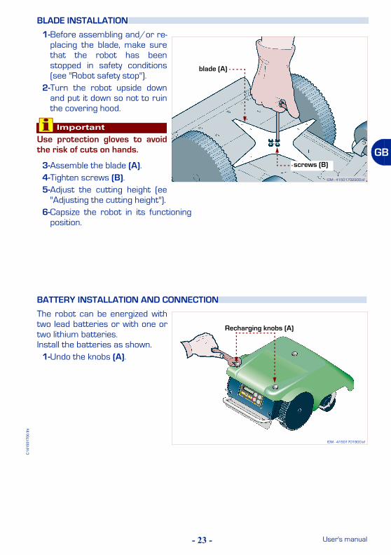
1-Before assembling and/or re-placing the blade, make surethat the robot has beenstopped in safety conditions(see "Robot safety stop").
2-Turn the robot upside downand put it down so not to ruinthe covering hood.
ImportantUse protection gloves to avoidthe risk of cuts on hands.
3-Assemble the blade (A).4-Tighten screws (B).5-Adjust the cutting height (ee
"Adjusting the cutting height").6-Capsize the robot in its functioning
position.
The robot can be energized withtwo lead batteries or with one ortwo lithium batteries.Install the batteries as shown.
1-Undo the knobs (A).
BLADE INSTALLATION
BATTERY INSTALLATION AND CONNECTION
IDM - 41501702900.tif
blade (A)
screws (B)
IDM - 41501701900.tif
Recharging knobs (A)
- 24 -
C14
1501
700.
fm
User's manual
GB
2-Remove the hood (B).
3-Undo the bolts (C) and removethe guard (D).
4-Unscrew the nuts (E) and un-thread the brackets (F).
IDM - 41501702100.tif
guard (D)
screw (C)
screw (C)
screw (C)
IDM - 41501702200.tif
nut (E)
bracket (F)
bracket (F)
IDM - 41501702000.tif
hood (B)
- 25 -
C14
1501
700.
fm
User's manual
GB
5-Insert the batteries (G) in theappropriate positions.
6-Assemble the brackets (F)complete with batteries.
7-Tighten the nuts (E).
ImportantThe connection must be carriedout in accordance with the pro-cedures given, relative to thetype of battery installed (lead orlithium).
Lead battery connection1-Connect the connector (H)
(red colour with blue)2-Connect the connector (L) (red
colour with red cable)�3-Connect the connector (M)
(black colour with blue cable)4-Connect the connector (N)
(black colour with black cable)
IDM - 41501702300.tif
battery (G)
battery (G)
IDM - 41501702400.tif
nut (E)
bracket (F)
bracket (F)
IDM - 41501702500.tif
LEAD BATTERY
connector (H)
connector (L)
connector (M)
connector (N)
- 26 -
C14
1501
700.
fm
User's manual
GB
Lithium battery connection1-Connect the connector (P)
(black colour with black cable)2-Connect the connector (Q)
(red colour with red cable)�3-Connect the connector (R)
(red colour with red cable) (on-ly when installing 2 lithium bat-teries).
4-Connect the connector (S)(black colour with black cable)(only when installing 2 lithiumbatteries).
On completing the batteries con-nections proceed as indicated.
1-Reassemble body cover (D)and tighten screws (C).
2-Assemble the hood (B).3-Tighten the knobs (A).4-Insert the robot inside the re-
charging station.
Warning - CautionBefore performing the first re-charge, check that the powersupply unit is suitable for thetype of batteries installed (pow-er supply unit for lead or lithiumbatteries).
IDM - 41501702600.tif
LITHIUM BATTERY
connector (P)
connector (Q)
connector (R)
connector (S)
IDM - 41501702700.tif
guard (D)
screw (C)
screw (C)
screw (C)
IDM - 41501702800.tif
Recharging knobs (A)
hood (B)
- 27 -
C14
1501
700.
fm
User's manual
GB
ImportantBefore using the robot, perform a com-plete recharge of the new batteries(see "Recharge batteries on first use").
At this point, the robot is ready to use(see "Use and functioning").
1-Insert the robot inside the re-charging station.
2-Press key ON.3-After a few seconds the mes-
sage "LOADING" appears onthe display.
4-Press the key "Start/Pause".
On the display the dis-play the "PAUSE"function appears.The batteries startthe recharging cycle.
ImportantAt the first recharge, the batteriesmust be connected at least 24 hours.
5-When recharging has finished it ispossible to programme the robot foroperational activity (see "Program-ming mode").
ImportantThe user must carry out the adjust-ments according to the procedures de-scribed in the manual. Do not performany adjustments not explicitly indicat-ed in the manual.
Any extraordinary adjustments, not ex-plicitly indicated in the manual, must becarried out only by the staff of the Au-thorized Assistance Centres of theManufacturer.
RECHARGE BATTERIES ON FIRST USE
ADJUSTMENTS
ADJUSTMENT REMINDERS
IDM - 41501703000.tif
Key“Start/Pause”
Key “ON”
- 28 -
C14
1501
700.
fm
User's manual
GB
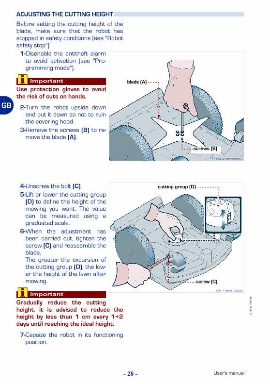
Before setting the cutting height of theblade, make sure that the robot hasstopped in safety conditions (see "Robotsafety stop").
1-Disenable the antitheft alarmto avoid activation (see "Pro-gramming mode").
ImportantUse protection gloves to avoidthe risk of cuts on hands.
2-Turn the robot upside downand put it down so not to ruinthe covering hood.
3-Remove the screws (B) to re-move the blade (A).
4-Unscrew the bolt (C).5-Lift or lower the cutting group
(D) to define the height of themowing you want. The valuecan be measured using agraduated scale.
6-When the adjustment hasbeen carried out, tighten thescrew (C) and reassemble theblade.The greater the excursion ofthe cutting group (D), the low-er the height of the lawn aftermowing.
ImportantGradually reduce the cuttingheight. it is advised to reduce theheight by less than 1 cm every 1÷2days until reaching the ideal height.
7-Capsize the robot in its functioningposition.
ADJUSTING THE CUTTING HEIGHT
IDM - 41501702900.tif
screws (B)
blade (A)
IDM - 41501610300.tif
screw (C)
cutting group (D)
- 29 -
C14
1501
700.
fm
User's manual
GB
1-Stop the robot in safety condi-tions (see "Robot safety stop").
2-Adjust the distance betweenthe pins (A-B) via rotation ofthe pin (A).
ImportantThe sensitivity of the sensor in-creases with a decrease in thedistance between the pins. Werecommend not bringing thepins. too close together
When the sensor detects rainconditions, the robot carries outits functions as programmed (see"Programming mode").
ImportantWhen using the robot for the firsttime, it is recommended to carefullyread the whole manual and to be sureto have it completely understood, inparticular all the information relatingto safety.
Use the equipment only for the tasksauthorised by the manufacturer and donot tamper with any device to achievea different performance from the oper-ating one.
RAIN SENSOR ADJUSTMENT
USE AND FUNCTIONING
RECOMMENDATIONS FOR USE
IDM - 41501710400.tif
eccentric pin (A)
pin (B)
- 30 -
C14
1501
700.
fm
User's manual
GB
The figure shows the control position onmachine board.A) Display: shows all functions.B) ON: press to turn on the lawn mower.C) PAUSE: press to stop the lawn
mower, the display is in “stand-by”; itis now possible to program the lawnmower. When pressed again, thelawn mower resumes working. If thekey is pressed during batteryrecharging, the lawn mower does notresume working until the key ispressed again and 'Pause'disappears from the display.
D) CHARGE: press to bring the lawnmower back to the base andrecharge the battery in advance. Ifthe key is pressed while the lawnmower is recharging, recharging isinterrupted and the lawn mowerresumes working.
E) OFF/STOP: press to stop the lawnmower; the display turns off.
F) Key "+": when working, press torestart the previously stopped blade.When programming press toincrease the items indicated by themenu.
G) ENTER: when working, press to startthe spiral function. Whenprogramming press to confirm andsave the selection performed.
H) Key "-": when working, press to stopthe blade. When programming pressto decrease items indicated by themenu.
ROBOT CONTROLS DESCRIPTION
IDM - 41501703500.tif
Key “Start/Pause” (C)
Key “ON” (B)
display (A)
Key “Charge” (D)
Key “Off/Stop” (E)
Key “-” (H)
Key “Enter” (G)
Key “+” (F)
- 31 -
C14
1501
700.
fm
User's manual
GB
– Push buttons (A-B): they areused to make the robot bendtowards right or left.
The robot keeps on bending to-wards a direction or the other un-til the relating push button (rightor left) is kept pressed. When thepush button is released, the robotproceeds along a straight path.– "Start" button (C): used to ac-
tivate the robot at a distance(handling, stop and restart ofthe blade and transfer fromone area to another).
– "Charge" button (D): used tocarry out the operations listed.
Remove the equipment from therecharging base and start the work cy-cle only if it has been programmed.The equipment must perform a spiralmotion (only if switched on and in mo-tion).Recharge the equipment (only ifswitched on and in pause mode).Remove the equipment from the perime-ter wire if the equipment follows the wireand does not perform its work correctly.
ImportantThe remote control is provided alreadyprogrammed with a univocal code as-sociated to the referring robot.
If the remote control does not work,because it does not recognize the codeassociated to the referring robot, it isnecessary to carry out its program-ming (see "Programming mode").
Proceed as indicated.1-Press key.
2-Insert the pass-word (if request-ed) (see "Enterpassword").
3-If the robot is switched on inside therecharging base, after a few sec-onds, the message "LOADING" ap-pears on the display.
4-Press key.
On the display the dis-play the "PAUSE"function appears.
5-Press key.
REMOTE CONTROL DESCRIPTION
PROGRAMMING MODE
IDM - 41501703600.tif
pushbutton “Charge”
pushbutton“Start/Pause” (C)
Right arrow (B)
Left arrow (A)
- 32 -
C14
1501
700.
fm
User's manual
GB
The "ALARM" func-tion appears on thedisplay.
ImportantTo memorise the function displayed,press the key "Pausa" or the key "En-ter".
If you press the key "Pausa", "PAUSE"appears on the display. If, however, youpress the key "Enter", the next functionappears on the display.
The function does not remain memo-rised if you press key "Stop" before key"Enter" or key "Pausa". The robot deac-tivates.
ALARM: (only for some versions, see"Specifications") function to enableand disenable the antitheft function.
1-Press one of the keys "+", "-" to acti-vate or deactivate the functions.
Enable: used to activate the alarm. If therobot is lifted using the handle, the alarmis triggered. A triple sound signals activa-tion.Disenable: used to deactivate or switchoff the alarm where there is activation. Acontinual and descending sound indi-cates deactivation.
ImportantThe "ALARM" function can be activat-ed, deactivated and stopped only by us-ing the password (see "Enterpassword").
To ensure the alarm functions correct-ly, the robot must have its "buffer bat-tery" charged.
To carry out recharging of the "bufferbattery" , it is necessary to start up therobot inside the station during the bat-teries recharging phase or leave it func-tioning during normal work activity.
The first recharging of the "buffer bat-tery" must be at least 6 hours.
To switch off the alarm it is necesary toproceed as indicated.
2-Switch on the robot.3-Access the "ALARM" function.4-Press one of the keys "+", "-" to dis-
play "Disenable".5-Insert the password (see "Enter
password").6-Press the key "Enter" to switch off
the acoustic alarm.The function "LAN-GUAGE" appears onthe display.
LANGUAGE: function for selecting themessages display language.
1-Press the "+" Key and the "-" Key toscroll the available languages.
2-Press the key "Enter" to confirm thelanguage selected.
The "DATE" functionappears on the dis-play.
DATE: function to set solar or legaltime, day, month and year.
1-Press one of thekeys "+", "-" to setthe day.
2-Press the key "En-ter" to confirm.The cursormoves on to thenext position.
3-Press one of thekeys "+", "-" to setthe month.
4-Press the key "En-ter" to confirm.The cursormoves on to thenext position.
- 33 -
C14
1501
700.
fm
User's manual
GB
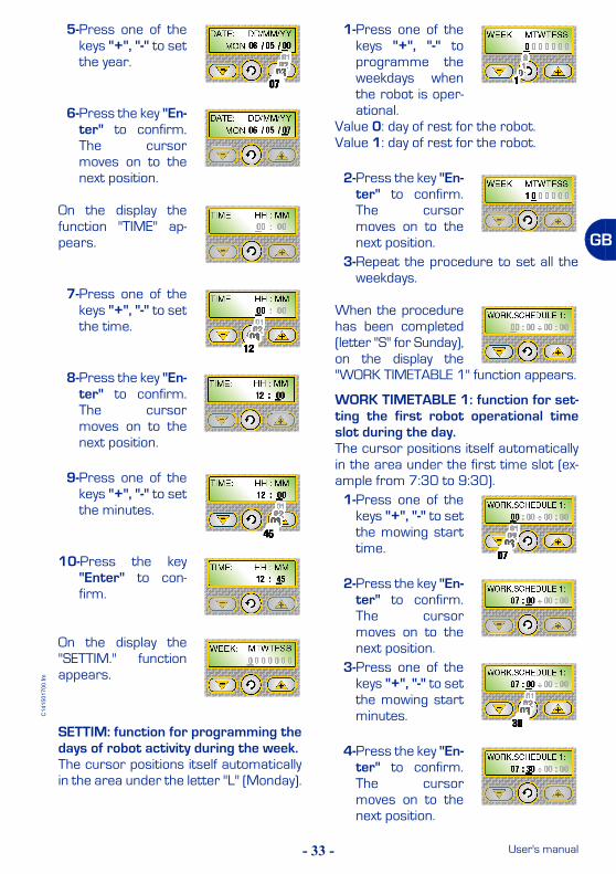
5-Press one of thekeys "+", "-" to setthe year.
6-Press the key "En-ter" to confirm.The cursormoves on to thenext position.
On the display thefunction "TIME" ap-pears.
7-Press one of thekeys "+", "-" to setthe time.
8-Press the key "En-ter" to confirm.The cursormoves on to thenext position.
9-Press one of thekeys "+", "-" to setthe minutes.
10-Press the key"Enter" to con-firm.
On the display the"SETTIM." functionappears.
SETTIM: function for programming thedays of robot activity during the week.The cursor positions itself automaticallyin the area under the letter "L" (Monday).
1-Press one of thekeys "+", "-" toprogramme theweekdays whenthe robot is oper-ational.
Value 0: day of rest for the robot.Value 1: day of rest for the robot.
2-Press the key "En-ter" to confirm.The cursormoves on to thenext position.
3-Repeat the procedure to set all theweekdays.
When the procedurehas been completed(letter "S" for Sunday),on the display the"WORK TIMETABLE 1" function appears.
WORK TIMETABLE 1: function for set-ting the first robot operational timeslot during the day.The cursor positions itself automaticallyin the area under the first time slot (ex-ample from 7:30 to 9:30).
1-Press one of thekeys "+", "-" to setthe mowing starttime.
2-Press the key "En-ter" to confirm.The cursormoves on to thenext position.
3-Press one of thekeys "+", "-" to setthe mowing startminutes.
4-Press the key "En-ter" to confirm.The cursormoves on to thenext position.
- 34 -
C14
1501
700.
fm
User's manual
GB
5-Press one of thekeys "+", "-" to setthe mowing endtime.
6-Press the key "En-ter" to confirm.The cursormoves on to thenext position.
7-Press one of thekeys "+", "-" to setthe mowing endminutes.
8-Press the key "En-ter" to confirm.
On the display the"WORK TIMETABLE2" function appears.
WORK TIMETABLE 2: function for set-ting the second robot activity time slotduring the day.To programme the work timetable forthe second time slot of the day (examplefrom 19.00 to 22.00) repeat the sameprocedure indicated for "WORK TIMETA-BLE 1".
On completion of theprocedure, the "SEC-ONDARY AREA 1 -No. Cycles" functionappears on the display.
SECONDARY AREA 1: functionto define automatic mowing of asecondary area 1.Programme the time that the ro-bot takes to reach the secondaryarea along the perimeter wire.Keep to the following instructionsto detect the time:
1-Position the robot outside therecharging base in the direc-tion of the wire in output.
2-Press the keys ON, PAUSAand CHARGE to start the ro-bot.
3-Measure the timethat the robot takes toreach the half-waypoint of the secondaryarea route.
ImportantIf along the route toreach the secondaryarea rapid re-entrieshave been set, it is nec-essary to manually carry
IDM - 41501711300.tif
perimeter wire
IDM - 41501711500.tif
MAIN AREA
SECONDARY AREA 1
SECONDARY AREA 2
- 35 -
C14
1501
700.
fm
User's manual
GB
the robot immediately after rapid re-entry setting.
4-Press the "+" Keyand the "-" Key toenter the numberof work cycles toperform in themain area, the lawn mower startsthen to machine the first secondaryarea.
ImportantIf secondary areas are provided (type 1or 2), to complete the field of functionsrelative to the number of cycles andtime it is necessary to insert the value0.
5-Press the key "En-ter" to confirm.
On the display "SEC-ONDARY AREA 1 -Time" appears.
6-Press one of thekeys "+", "-" to in-sert the time (inminutes) meas-ured to reach thesecondary area.
7-Press the key "En-ter" to confirm.The cursormoves on to thenext position.
8-Press one of thekeys "+", "-" to in-sert the time (inseconds).
9-Press the key toconfirm.
ImportantIf secondary areas are provided (type 1or 2), to complete the field of functionsrelative to the number of cycles and timeit is necessary to insert the value 0.
On completion of theprocedure, on thedisplay the " SEC-ONDARY AREA 2 -No. Cycles" function appears.
SECONDARY AREA 2: function to de-fine automatic mowing of a secondaryarea 2.
1-To set the number of cycles and timeof the secondary area 2, repeat thesame procedure indicated for "SEC-ONDARY AREA 1".
ImportantIf secondary areas are provided (type 1or 2), to complete the field of functionsrelative to the number of cycles and timeit is necessary to insert the value 0.
On completion of theprocedure, on thedisplay the "PERIME-TER" function ap-pears.
PERIMETER: function for setting therobot with the impact or perimeterwire recognition modality.
1-Press one of the keys "+", "-" to setthe type of delimitation installedalong the perimeter.
Select YES if the perimeter wire is in-stalled.Select NO if the perimeter wire is not in-stalled.Select ×2 in case of signal problems (pe-rimeter wire installed).
- 36 -
C14
1501
700.
fm
User's manual
GB
Select ×4 if the problem is not solved byselecting ×2.Select ×6 if the problem is not solved byselecting ×4.
ImportantWhen switched on, the lawn mower isautomatically positioned in the Perime-ter YES mode. The NO, ×2, ×4 and ×6options are disabled when the lawnmower is switched off. Use these op-tions with great care and only in the ab-sence of swimming pools or steepslopes.
2-Press the key "Enter" to confirm.When the procedurehas been completed,on the display the"RAIN SENSOR" func-tion appears.
RAIN SENSOR: function for setting therobot when it rains.
1-Press one of the keys "+", "-" to acti-vate or deactivate the functions.
Disenabled: when it rains the robot con-tinues to mow.Pause: when it rains the robot returns tothe station and stays there (in "recharg-ing" modality) until the key "Pause" ispressed.Restart: when it rains the robot returnsto the station and stays there in "re-charging" modality. Once the rechargingcycle has finished the robot starts againand only starts to mow if it is no longingraining.
2-Press the key "Enter" to confirm.On the display "AUTO-PROGRAMMING" ap-pears.
AUTOPROGRAMMING: (only for someversions, see "Specifications") functionfor automatically reducing the mowingtime of the robot on the basis of lawnconditions.
1-Press "+" and "-" to disable this op-tion or set the percent of mowedlawn grass to be used for auto-pro-gramming function start.
The auto-programming function reducesmachine work time based on grass con-ditions. When the lawn surface is cut ina percent higher than the one set in the"Autoprogramm." Menu item, the ma-chine automatically set an idle intervalthat delays the next exits from the charg-er base; the higher the percentage ofmowed lawn, the longer the machine idleinterval.
2-Press the key "Enter" to confirm.On the display the"TELECOMMAND"function appears.
TELECOMMAND: (only for some ver-sions, see "Specifications") functionfor reprogramming the telecommand.
1-Press one of the keys "+", "-" to se-lect one of the functions.
Configure: used to reprogramme thetelecommand with the univocal code as-sociated with the reference robot.
2-To reprogramme the telecommandselect "Configure".
3-On the display"TELECOM-MAND Configure"appears.
4-Position yourself with the telecom-mand near the robot.
5-Press the key "En-ter" to confirm.
- 37 -
C14
1501
700.
fm
User's manual
GB
6-Press at the same time thekeys "DX", "SX" of the telecom-mnad within 10 seconds (seefigure).Activation of a double sound in-dicates that robot and tele-command matching hasoccurred.
7-Press the key "Enter" to con-firm.
On the display "PASS-WORD" appears.
PASSWORD: function for setting ormodifying the password.
1-Press one of the keys "+", "-" to acti-vate or deactivate the functions.
Yes: used to insert a new password.No: used to leave the previously insertedpassword.
2-Press the key "En-ter" to confirm.
ImportantTo set or modify the password it is nec-essary to first insert the previous oneand then proceed with insertion of thecustomised one.
When the purchased, the password in-serted by the manufacturer comprisesfour numbers (0000).
3-Press one of thekeys "+", "-" to setthe first number.
4-Press the key "En-ter" to confirm.The cursormoves on to thenext position.
5-Repeat the procedure to set all thenumbers of the password.
6-When the proce-dure has beencompleted, on thedisplay the func-tion "NEW PASSWORD" appears.
The cursor automatically positions itselfin the area under the first number.
7-Press one of thekeys "+", "-" to setthe first number.
8-Press the key "En-ter" to confirm.The cursormoves on to thenext position.
9-Repeat the procedure to set all thenumbers of the password.
10-When the proce-dure has beencompleted, on thedisplay the "RE-PEAT PASSWORD" function ap-pears.
IDM - 41501709300.tif
Right arrow (DX)
Left arrow (SX)
- 38 -
C14
1501
700.
fm
User's manual
GB
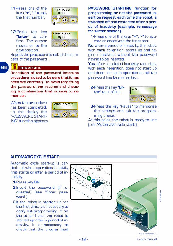
11-Press one of thekeys "+", "-" to setthe first number.
12-Press the key"Enter" to con-firm. The cursormoves on to thenext position.
Repeat the procedure to set all the num-bers of the password.
ImportantRepetition of the password insertionprocedure is used to be sure that it hasbeen set correctly. To avoid forgettingthe password, we recommend choos-ing a combination that is easy to re-member.
When the procedurehas been completed,on the display the"PASSWORD START-ING" function appears.
PASSWORD STARTING: function forprogramming or not the password in-sertion request each time the robot isswitched off and restarted after a peri-od of inactivity (example, remessagefor winter season).
1-Press one of the keys "+", "-" to acti-vate or deactivate the functions.
No: after a period of inactivity, the robot,with each re-ignition, starts up and be-gins operations without the passwordhaving to be inserted.Yes: after a period of inactivity, the robot,with each re-ignition, does not start upand does not begin operations until thepassword has been inserted.
2-Press the key "En-ter" to confirm.
3-Press the key "Pausa" to memorisethe settings and exit the program-ming phase.
At this point, the robot is ready to use(see "Automatic cycle start").
Automatic cycle start-up is car-ried out when operational activityfirst starts or after a period of in-activity.
1-Press key ON.2-Insert the password (if re-
quested) (see "Enter pass-word").
3-If the robot is started up forthe first time, it is necessary tocarry out programming. If, onthe other hand, the robot isstarted up after a period of in-activity, it is necessary tocheck that the programmed
AUTOMATIC CYCLE START
IDM - 41501703000.tif
Key “ON”
- 39 -
C14
1501
700.
fm
User's manual
GB
functions correspond to the effectivestatus of the surfaces to be mown(e.g. addition of a swimming pool,plants etc.) (see "Programmingmode").
4-Adjust the cutting height (see "Ad-justing the cutting height").
5-Adjust the sensitivity of the rain sen-sor (see "Rain sensor adjustment").
6-Position the robot inside the recharg-ing station.
ImportantIf the antitheft alarm is enabled, disen-able it before lifting the robot (see"Programming mode").
7-After some seconds, on the displaythe "LOADING" message appears.
8-The robot starts to mow the lawn inaccordance with the programmedmodalities.
When using the robot, it may nec-essary to stop it in safety condi-tions to avoid the ranger to asudden start of the blade.Press the key "Off/Stop" (A) tostop the robot.
ImportantThe stop of the robot in safetyconditions is necessary in orderto carry out maintenance and re-pair interventions (for example:battery replacement and/or re-charge, blade replacement,cleaning operations, etc.).
The robot stops automatically when thelisted conditions occur.– Run-down batteriesThe robot automatically re-enters the re-charging station.– RainWhen it rains the robot auotmatically en-ters the recharging station and func-tions in accordance with programmedmodalities (see "Programming mode").
– Trimmed lawnThe sensor detects the mown lawn, therobot automatically re-enters the re-charging station and again starts tofunction in accordance with pro-grammed modalities (see "Program-ming mode").– End of work periodWhen it has completed its work period,the robot automatically re-enters the re-charging station and again starts tofunction in accordance with pro-grammed modalities (see "Program-ming mode").
ROBOT SAFETY STOP
ROBOT AUTOMATIC STOP
IDM - 41501710200.tif
Key “Off/Stop” (A)
- 40 -
C14
1501
700.
fm
User's manual
GB
Start-up of the robot in manualmode must be carried out to mowareas that are not included in theprogramming of surfaces to bemown in automatic modality.Place the robot inside the workingarea at least 1 m far from the pe-rimeter wire and from any otherobstacle.
1-Press key ON (A).2-Insert the password (if re-
quested) (see "Enter pass-word").
3-On the display thedisplay the"PAUSE" functionappears.
4-Press in se-quence the keys "-", "+". On the dis-play "EXTERIOR -60 Min" appears (default value).
5-Press one of thekeys "+", "-" to setthe minutes.
6-Press the key "En-ter" to confirm.
ImportantThe value inserted is not memorised.
7-Press the key "Start/Pause" (B) tostart up the robot.At the end of the set time, the robotstops in safe conditions near the pe-rimeter wire.
8-Position the robot inside the recharg-ing station.
ImportantIf the antitheft alarm is enabled, disen-able it before lifting the robot (see"Programming mode").
MANUAL STARTUP AND STOP OF ROBOT (IN CLOSED AREAS)
IDM - 41501709500.tif
IDM - 41501710200.tif
Key “ON” (A) Key “Start/Pause” (B)
- 41 -
C14
1501
700.
fm
User's manual
GB
This mode can be carried out withthe remote control to perform thetrimming of areas completelymarked by fences or to trim, forexample, small areas, where itwas not possible to mark or forpractical demonstrations on thefunctioning of the robot
ImportantWhen the robot is used withoutthe perimeter wire, it is recom-mended to make sure that therobot does not hit into obstacles,corners or blunt objects so to avoiddamages or breaks.
1-Press key ON (A).2-Insert the password (if requested)
(see "Enter password").
The following mes-sage appears of thedisplay:
3-Press the key "En-ter" until displaying "Perimeter" (see"Programming mode").
The following mes-sage appears of thedisplay:
4-Press one of thekeys "+", "-" to set "NO".
5-Press the key "En-ter" to confirmthe selection.
6-Press the key "Start/Pause" (B)twice consecutively to start the robot
7-Manoeuvre the robot with the tele-command (see "Remote control de-scription").
ImportantIt is advisable to operate the robot withthe remote control to carry out thetrimming inside a narrow area, well vis-ible and to avoid, if possible, making ithit into obstacles.
8-Having finished mowing, press thekey "Off/Stop" (C) to stop the robotin safely (see "Robot safety stop").
ImportantIf the antitheft alarm is enabled, disen-able it before lifting the robot (see"Programming mode").
9-Position the robot inside the recharg-ing station.
ROBOT START WITHOUT PERIMETER WIRE
IDM - 41501710200.tif
Key “ON” (A)
Key “Off/Stop” (C)
Key “Start/Pause” (B)
- 42 -
C14
1501
700.
fm
User's manual
GB
The robot can be protected by a pass-word comprising four figures which theuser can enable, disenable and custom-ise (see "Programming mode").
1-The followingmessage ap-pears of the dis-play:
2-Press one of thekeys "+", "-" to setthe first figure.
3-Press the key "En-ter" to confirm.The cursormoves on to thenext position.
4-Repeat the procedure to set all thenumbers of the password.
At this point, the robot is ready to use.
While the lawn mow-er is operating, thefollowing data are dis-played:– Left wheel motor speed– Cutting blade motor speed– Right wheel motor speed– Battery voltage.
When the lawn mower is being re-charged, the message "RECHARGE" ap-pears in the display.
If the lawn mower is out of its work time-table, the display shows the day and timeof work start.
In case of prolonged inactivity of the ro-bot, it is necessary to carry out a seriesof operations to assure its correct func-tioning when it is reused.
1-Carefully clean the robot and the re-charging station (see "Robot clean-ing").
2-Carry out battery recharge at leastonce a month for lead batteries andevery 5 months for lithium batteries(see "Recharge batteries for extend-ed inactivity").
ImportantIf the antitheft alarm is enabled, disen-able it before lifting the robot (see"Programming mode").
3-Place the robot in a safe and dryplace, at a suitable room tempera-ture 10-30 °C and not easily reacha-ble by unfamiliar people (children,animals, etc.).
ENTER PASSWORD
DISPLAY VISUALISATION IN WORK PHASE
PROLONGED INACTIVITY AND SERVICE RESTART
- 43 -
C14
1501
700.
fm
User's manual
GB
4-Disconnect the plug of thepower supply unit (A).
5-Cover the recharging station(C) to prevent any material en-tering it (leaves, paper etc.)and to protect the contactplates.
Service restartBefore restarting the robot after along inactivity, proceed as shown.
1-Connect the plug of the powersupply unit (A) to the powersocket.
2-Restart the main electric sup-ply.
3-Press the button (B) of thepower supply unit on ON.
ImportantIf the antitheft alarm is enabled,disenable it before lifting the robot(see "Programming mode").
4-Position the robot inside the recharg-ing station.
5-Press key ON (A).6-Insert the password (if re-
quested) (see "Enter pass-word").
7-After a few seconds the mes-sage "LOADING" appears onthe display.
8-At this point, the robot is readyto use (see "Programmingmode").
IDM - 41501710500.tif
Reload station (C)
power supply unit (A)
pushbutton (B)
IDM - 41501710200.tif
Key “ON” (A)
- 44 -
C14
1501
700.
fm
User's manual
GB
Carry out battery recharge atleast once a month for lead bat-teries and every 5 months for lith-ium batteries.
1-Power the recharging baseand make sure that the platesare clean.
ImportantIf the antitheft alarm is enabled,disenable it before lifting the ro-bot (see "Programming mode").
2-Position the robot inside therecharging station.
3-Press key "ON" (A).4-Insert the password (if re-
quested) (see "Enter pass-word").
5-After a few seconds the mes-sage "LOADING" appears onthe display.
6-Press key "Start/Pausa" (B).The batteries start the re-charging cycle.
7-On completion of recharging(approx. 6 hours) press key"Off/Stop" (C).
8-Place the robot in a safe anddry place, at a suitable roomtemperature 10-30 °C andnot easily reachable by unfa-miliar people (children, ani-mals, etc.).
RECHARGE BATTERIES FOR EXTENDED INACTIVITY
IDM - 41501703000.tif
Key “ON” (A)
IDM - 41501710200.tif
Key “Off/Stop” (C)
Key “Start/Pause” (B)
- 45 -
C14
1501
700.
fm
User's manual
GB
Batteries reset with winter re-charging kit (optional)The kit makes it possible to re-charge the batteries or keep themcharged, during the winter period,without using the recharging sta-tion.
1-Press the button (D) of thepower supply unit on OFF.
2-Disconnect the plug of thepower supply unit (A).
3-Disconnect the cable (E) fromthe transmitter group (B).
4-Connect the cable for the kit(F) to the transmitter group(B).
5-Connect the plug of the powersupply unit.
6-Press the button (D) of thepower supply unit on ON.
ImportantIf the antitheft alarm is enabled,disenable it before lifting the ro-bot (see "Programming mode").
7-Position the robot near thetransmitter-power supplygroup.
IDM - 41501710800.tif
transmitter (B)
pushbutton (D)
"Winter recharging kit"cable (F)
IDM - 41501710500.tif
Reload station
transmitter (B)
power cable (E)
power supply unit (A)
pushbutton (D)
- 46 -
C14
1501
700.
fm
User's manual
GB
8-Press key ON (G).9-Insert the password (if re-
quested) (see "Enter pass-word").
10-The followingmessage ap-pears of the dis-play:
11-After some sec-onds, the mes-sage appears onthe display.
12-Connect the connector (H) (red, po-larity +).
13-Connect the connector (L) (black, po-larity -).
Warning - CautionA wrong connection of the poles may ir-reversibly damage the batteries andthe electronic circuits.
ImportantThe connection of the connectors mustbe carried out within 30 seconds fromactivation of the key "ON". Once thatperiod has elapsed, the robot automat-ically switches off. Repress key "ON" tocomplete the operation.
14-the following mes-sage appears ofthe display:The batteriesstart the recharging cycle.
15-On completion of recharging (approx.6 hours) press key "Off/Stop" (M).
16-Disconnect the connector (H) (red,polarity +).
17-Disconnect the connector (L) (black,polarity -).
18-Place the robot in a safe and dryplace, at a suitable room tempera-ture 10-30 °C and not easily reacha-ble by unfamiliar people (children,animals, etc.).
IDM - 41501710900.tif
Key“ON” (G)
Key“Off/Stop” (M)
black connector (L)
red connector(H)
- 47 -
C14
1501
700.
fm
User's manual
GB
Once the winter season has end-ed, disconnect the kit and reacti-vate the recharging station.
1-Press the button (D) of thepower supply unit on OFF.
2-Disconnect the plug of thepower supply unit (A).
3-Disconnect the cable (F) fromthe transmitter group (B).
4-Connect the cable for the kit(E) to the transmitter group(B) (see "Installation of re-charging station and transmit-ter-power supplier group").
5-Connect the plug of the powersupply unit (A).
6-Press the button (D) of thepower supply unit on ON.
7-Position the robot inside therecharging station.
IDM - 41501710800.tif
transmitter (B)
pushbutton (D)
"Winter recharging kit"cable (F)
power supply unit (A)
IDM - 41501710500.tif
Reload station
transmitter (B)
power cable (E)
power supply unit (A)
pushbutton (D)
- 48 -
C14
1501
700.
fm
User's manual
GB
Here below are some indications to fol-low during the use of the robot.– Even after a proper reading of instruc-
tions, at its first use, simulate sometest moves to detect the controls andthe main functions.
– Check that the nuts and bolts secur-ing all main parts are tight.
– Carry out a frequent trimming of thelawn to avoid an excessive growing ofthe grass.
– Do not use the robot to trim grasshigher than 10 cm.
– If the lawn is equipped with an auto-matic irrigation system, programme
the robot so that it re-enters the re-charging station at least 1 hour be-fore the start of irrigation.
– Check the ground gradient and makesure that it does not exceed the maxi-mum values allowed so that the use ofthe robot does not cause dangers.
– The lawn mower should be pro-grammed in order to prevent it fromworking more than necessary; alwaysconsider the different growth of thegrass according to the season in or-der to avoid a useless wear of thelawn mower and a decrease in thebattery life.
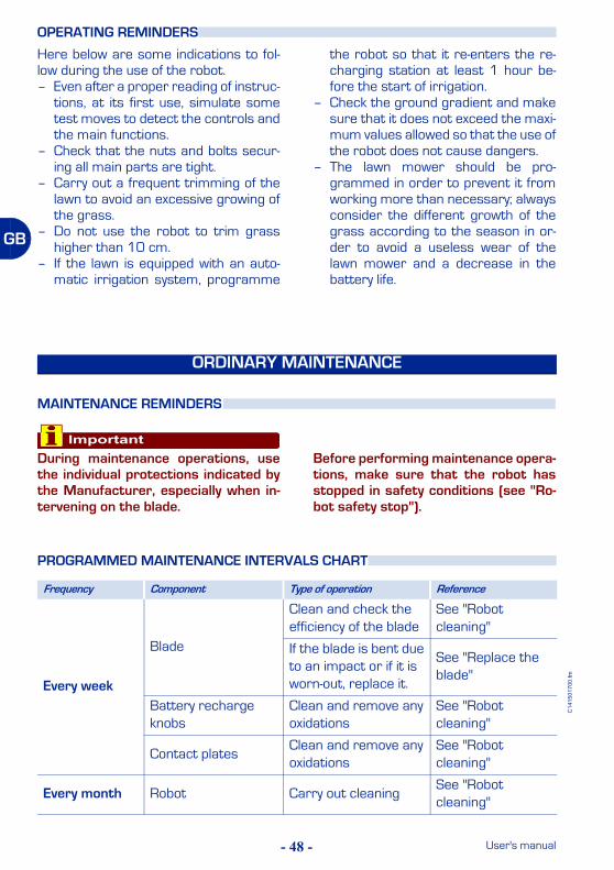
ImportantDuring maintenance operations, usethe individual protections indicated bythe Manufacturer, especially when in-tervening on the blade.
Before performing maintenance opera-tions, make sure that the robot hasstopped in safety conditions (see "Ro-bot safety stop").
OPERATING REMINDERS
ORDINARY MAINTENANCE
MAINTENANCE REMINDERS
PROGRAMMED MAINTENANCE INTERVALS CHART
Frequency Component Type of operation Reference
Every week
Blade
Clean and check the efficiency of the blade
See "Robot cleaning"
If the blade is bent due to an impact or if it is worn-out, replace it.
See "Replace the blade"
Battery recharge knobs
Clean and remove any oxidations
See "Robot cleaning"
Contact platesClean and remove any oxidations
See "Robot cleaning"
Every month Robot Carry out cleaningSee "Robot cleaning"
- 49 -
C14
1501
700.
fm
User's manual
GB
1-Stop the robot in safety conditions(see "Robot safety stop").
ImportantIf the antitheft alarm is enabled, disen-able it before lifting the robot (see"Programming mode").
2-Clean all the outside surfaces of therobot with a sponge soaked in warmwater and neutral soap and rinseproperly.
3-Do not use solvents or benzine so notto damage the varnished surfacesand the plastic components.
4-Do not wash the inside parts of therobot and do not use water jets inpressure so not to damage the elec-tric and the electronic components.
Warning - CautionIn order not to irreversibly damage theelectric and electronic components, donot plunge the robot, partially or com-pletely in water, as it is not watertight.
5-Check the lower part of the robot(cutting blade area and wheels) andremove the deposits and/or resi-dues that might obstruct the correctfunctioning of the robot.
6-To remove the deposits and/or oth-er residues from the blade, use asuitable brush.
Warning - CautionUse protection gloves to avoid the riskof cuts on hands.
7-Clean the batteries recharging knobs(A), contact plates (B) and eliminateany oxidation or residues due to elec-trical contacts with a dry cloth and, ifnecessary, with fine grain abrasivepaper.
8-Clean the interior of the rechargingstation from any accumulated resi-dues.
ROBOT CLEANING
IDM - 41501703100.tif
Recharging knobs (A)
contact plates (B)
- 50 -
C14
1501
700.
fm
User's manual
GB
The information given below is designedto help identify and correct any faultsand malfunctions that may occur duringoperation.Some failures may be resolved by the us-
er; others require precise technical skillsor special abilities and must be exclusive-ly resolved by qualified personnel withcertified experience, achieved in the spe-cific intervention field.
FAILURES, CAUSES AND SOLUTIONS
TROUBLESHOOTING
Problem Causes SolutionsThe antitheft alarm remains operative
Alarm activatedDeactivate the alarm (see "Programming mode")
Antitheft alarm does not work
Alarm deactivatedActivate the alarm (see "Pro-gramming mode")
"Buffer battery" flat
Carry out battery recharge.To carry out recharging of the "buffer battery" , it is neces-sary to start up the robot insi-de the station during the batteries recharging phase or leave it functioning during normal work activity.The first recharging of the "buffer battery" must be at le-ast 6 hours.
ImportantIf the problem persists,contact the assistanceservice
- 51 -
C14
1501
700.
fm
User's manual
GBThe robot is very noisy
Damaged cutting blade Replace the blade with a new one (see "Replace the blade")
Cutting blade flooded by residues (tapes, ropes, plastic fragments, etc.).
Stop the robot in safety condi-tions (see "Robot safety stop")
CautionUse protection gloves toavoid the risk of cuts onhands.
Remove the flood cause from the blade.
The start of the robot oc-curred with obstacles being too close (less than m away) or in presence of unexpected obstacles (fallen branches, forgot-ten objects, etc.).
Stop the robot in safety condi-tions (see "Robot safety stop")
Remove the obstacles and re-start the robot (see "Manual startup and stop of robot (in closed areas)")
Electrical motor malfunc-tion
Get the motor repaired or re-placed by the nearest authori-zed Assistance centre.
Grass too high
Increase the cutting height (see "Adjusting the cutting height")Carry out preliminary cutting of the area with a normal lawn mower.
The robot does not position itself cor-rectly inside the re-charging station
Erroneous position of the perimeter wire or re-charging station power supply cable.
Check the conneciton of the recharging station (see "In-stallation of recharging sta-tion and transmitter-power supplier group")
Ground subsidence near the recharging station
Position the recharging sta-tion on a flat and stable surfa-ce 8see "Equipment installation planning")
The robot behaves in an anomalous manner around the flower beds.
Perimeter cable incor-rectly placed.
Relocate the perimeter wire correctly (anticlockwise direc-tion) (see "Perimeter wire in-stallation")
The robot works at erroneous times
Wrong clock setting Reset the robot clock (see "Programming mode")
Wrong work timetable setting
Reset the work timetable (see "Programming mode")
The robot does not carry out rapid re-entry
Rapid re-entry not cor-rectly set
Check the exact setting of the rapid re-entry (see "Setting for rapid robot re-entry into the recharging station")
Problem Causes Solutions
- 52 -
C14
1501
700.
fm
User's manual
GB
The working area is not completely trimmed
Insufficient work hours Extend the work timetable (see "Programming mode")
Cutting blade with deposi-ts and/or residues
Stop the robot in safety condi-tions (see "Robot safety stop")
CautionUse protection gloves toavoid the risk of cuts onhands.
Clean the cutting blade
Cutting blade worn outReplace the blade with an ori-ginal spare part (see "Replace the blade")
Working area too big compared to the actual capacity of the robot.
Ad just the working area (see "Specifications")
Batteries are about to deplete their life cycle.
Replace the batteries with ori-ginal spare part (see "Batte-ries replacement")
The batteries do not re-charge completely.
Clean and eliminate any oxida-tion from the batteries con-tact points (see "Robot cleaning").Recharge the batteries for at least 12 hours.
Secondary area not completely mown
Wrong programmingCorrectly programme the se-condary area (see "Program-ming mode")
On the display "No Signal" appears.
The perimeter wire is not correctly connected (bro-ken wire, lack of electric connection, etc.).
Check the functionality of the electricity supply, correct con-nection of the transmitter-power supply group and that of the recharging station (see "Installation of recharging sta-tion and transmitter-power supplier group")
Problem Causes Solutions
- 53 -
C14
1501
700.
fm
User's manual
GB
On the display "Off Perimeter" appe-ars
Excessive ground slope.
Mark the area with excessive gradient (see "Equipment in-stallation planning").Install the Kit for working on slopes greater than 27° (see "Specifications").
Perimeter cable incor-rectly placed
Check that the wire is instal-led properly (too deep, close to metal objects, distance between the wire that marks two elements less than 70 cm, etc.) (see "Equipment in-stallation planning")
Perimeter wire marking inside areas (beds, bu-shes, etc.) placed clockwise.
Relocate the perimeter wire correctly (anticlockwise direc-tion) (see "Perimeter wire in-stallation")
Overheated power supply unit
Adopt suitable solutions to re-duce the temperature of the power supply unit (air or chan-ge the installation area, etc.) (see "Equipment installation planning")
The wheel drive is not correct
Check and, if necessary, cor-rectly fasten the wheels.
On the display "Blackout" appe-ars.
Power supply break to the transmitter Restart the robot
Overheated power supply unit
Adopt suitable solutions to re-duce the temperature of the power supply unit (air or chan-ge the installation area, etc.) (see "Equipment installation planning")
Presence of other near-by installations
Contact an Assistance Cen-tre authorized by the Manu-facturer
On the display "Wheel motor er-ror" appears
Rough ground or with ob-stacles that hinder move-ment
Check that the lawn to trim is even, and without pits, stones or other obstacles. If so, per-form the necessary clearan-ce operations (see "Preparation and delimitation of work areas (main and se-condary)")
One or both motors, star-ting the wheel transmis-sion, in breakdown
Get the motor repaired or re-placed by the nearest authori-zed Assistance centre.
On the display "Bump Error" ap-pears
The shock sensors are blocked
Remove the hood and check that the sensors are functio-ning.
Problem Causes Solutions
- 54 -
C14
1501
700.
fm
User's manual
GB
On the display "Sync Error" appe-ars
The robot receiver does not recognise the signal
Switch off the equipment and switch it on again.If the problem persists, con-tact the assistance service
On the display "Tall grass" appears
Damaged cutting bladeReplace the blade with a new one (see "Replace the blade")
Cutting blade flooded by residues (tapes, ropes, plastic fragments, etc.)
Stop the robot in safety condi-tions (see "Robot safety stop")
CautionUse protection gloves toavoid the risk of cuts onhands.
Remove the flood cause from the blade.
The start of the robot oc-curred with obstacles being too close (less than m away) or in presence of unexpected obstacles (fallen branches, forgot-ten objects, etc.).
Stop the robot in safety condi-tions (see "Robot safety stop")
Remove the obstacles and re-start the robot (see "Manual startup and stop of robot (in closed areas)")
Electrical motor malfunc-tion
Get the motor repaired or re-placed by the nearest authori-zed Assistance centre.
Grass too high
Increase the cutting height (see "Adjusting the cutting height").Carry out preliminary cutting of the area with a normal lawn mower.
The telecommand does not function
Wrong programmingCorrectly programme the te-lecommand (see "Program-ming mode")
The led on the telecom-mand does not come on
Remove the battery and fit the replacement (see "Tele-command batteries replace-ment the blade")
After installation of the robot, distur-bances are noti-ced relative to domestic applian-ces (radio, televi-sion, electric gates etc.).
Interference with other electrical devices
Contact an Assistance Cen-tre authorized by the Manu-facturer
Problem Causes Solutions
- 55 -
C14
1501
700.
fm
User's manual
GB
ImportantAlways replace and repair the parts incompliance with the Manufacturer’sinstructions, otherwise contact the As-
sistance Service if these operationsare not described in the manual.
The led (D) of the power supply unit does not turn on.
There is no power volta-ge
Check that the position of the cursor (B) matches with the power voltage and that the push button (A) is on "ON".Check that the power supply unit is correctly connected to the power socket.
Blown fuseGet the fuse replaced by the nearest authorized Assistan-ce centre.
The led (C) (green) of the transmitter is on.
Interrupted perimeter wire
Stop the robot in safety condi-tions (see "Robot safety stop").Press the button (A) of the power supply unit on OFF.Carry out the joint of the peri-meter wire.
The led (C) (oran-ge) of the transmit-ter turns on repeatedly with consecutive flashes (less than 4).
Perimeter wire too long. Install the signal amplification kit.
Perimeter wire damaged or oxidized.
Check any joints. if necessary, replace the wire.
The led (C) (red) of the transmitter is on.
Connections not perfor-med correctly.
Get the check carried out by the nearest authorized Assi-stance centre.
Problem Causes Solutions
B
A
D
C
PARTS REPLACEMENTS
PARTS REPLACEMENT REMINDERS
- 56 -
C14
1501
700.
fm
User's manual
GB
1-Stop the robot in safety condi-tions (see "Robot safety stop").
2-Undo the knobs (A).
3-Remove the hood (B).
4-Undo the bolts (C) and removethe guard (D).
ImportantBatteries replacement should becarried out relative to the typeinstalled (lithium or lead).
BATTERIES REPLACEMENT
IDM - 41501701900.tif
Recharging knobs (A)
IDM - 41501702000.tif
hood (B)
IDM - 41501703300.tif
guard (D)
screw (C)
screw (C)
screw (C)
- 57 -
C14
1501
700.
fm
User's manual
GB
Lead battery1-Disconnect the cables in se-
quence (L-N-M-H).
2-Unscrew the nuts (E) and un-thread the brackets (F).
3-Remove the battery (G) and fitthe replacement.
4-Perform the same operationsto replace the other battery(G).
ImportantDo not dump used batteries.Spent batteries must be dis-posed of in accordance with cur-rent statutory regulations.
IDM - 41501702400.tif
nut (E)
bracket (F)
bracket (F)
IDM - 41501703400.tif
battery (G)
battery (G)
IDM - 41501702500.tif
LEAD BATTERY
connector (H)
connector (L)
connector (M)
connector (N)
- 58 -
C14
1501
700.
fm
User's manual
GB
5-Assemble the brackets (F)complete with batteries.
6-Tighten the nuts (E).
7-Connect the connector (H)(red colour with blue)
8-Connect the connector (L)(red colour with red cable)
9-Connect the connector (M)(black colour with blue cable)
10-Connect the connector (N)(black colour with black cable)
Lithium battery connection1-Disconnect the cables in se-
quence (R-S-Q-P).
IDM - 41501702400.tif
nut (E)
bracket (F)
bracket (F)
IDM - 41501702500.tif
LEAD BATTERY
connector (H)
connector (L)
connector (M)
connector (N)
IDM - 41501702600.tif
LITHIUM BATTERY
connector (P)
connector (Q)
connector (R)
connector (S)
- 59 -
C14
1501
700.
fm
User's manual
GB
2-Unscrew the nuts (E) and un-thread the brackets (F).
3-Remove the battery (G) and fitthe replacement.
4-Perform the same operationsto replace the other battery(G) (if present).
ImportantDo not dump used batteries.Spent batteries must be dis-posed of in accordance with cur-rent statutory regulations.
5-Assemble the brackets (F)complete with batteries.
6-Tighten the nuts (E).
IDM - 41501702400.tif
nut (E)
bracket (F)
bracket (F)
IDM - 41501703400.tif
battery (G)
battery (G)
IDM - 41501702400.tif
nut (E)
bracket (F)
bracket (F)
- 60 -
C14
1501
700.
fm
User's manual
GB
7-Connect the connector (P)(black colour with black cable)
8-Connect the connector (Q)(red colour with red cable)
9-Connect the connector (R)(red colour with red cable)
10-Connect the connector (S)(black colour with black cable)
On completing the batteries con-nections proceed as indicated.
1-Reassemble body cover (D)and tighten screws (C).
2-Assemble the hood (B).3-Tighten the knobs (A).
IDM - 41501702800.tif
Recharging knobs (A)
hood (B)
IDM - 41501702700.tif
guard (D)
screw (C)
screw (C)
screw (C)
IDM - 41501702600.tif
LITHIUM BATTERY
connector (P)
connector (Q)
connector (R)
connector (S)
- 61 -
C14
1501
700.
fm
User's manual
GB
4-Position the robot inside the recharg-ing station.
5-Carry out battery recharge.
Warning - CautionBefore performing the first recharge,check that the power supply unit is
suitable for the type of batteries in-stalled (power supply unit for lead orlithium batteries) (see "Recharge bat-teries on first use").
At this point, the robot is ready to use(see "Use and functioning").
1-Stop the robot in safety condi-tions (see "Robot safety stop").
2-Turn the robot upside downand put it down so not to ruinthe covering hood.
3-Remove the screws (B) to re-move the blade (A).
ImportantUse protection gloves to avoidthe risk of cuts on hands.
4-Insert the new blade and fas-ten screws.
5-Adjust the cutting height (see"Adjusting the cutting height").
6-Capsize the robot in its functioningposition.
REPLACE THE BLADE
IDM - 41501702900.tif
screws (B)
blade (A)
- 62 -
C14
1501
700.
fm
User's manual
GB
1-Stop the robot in safety condi-tions (see "Robot safety stop").
2-Remove the cover (A).3-Extract the battery (B) and re-
place it with one of equal volt-age
ImportantWhen reassembling the new bat-tery respect the relative polari-ties (+ e -).
Do not damage the circuits in-side the telecommand.
4-Install the cover (A).Start the robot and manoeuvre itwith the telecommand to check bat-tery efficiency.
Danger - AttentionDo not dispose of pollutant materials inthe environment. Dispose of all suchmaterials in compliance with applica-ble legislation.