52
GB Intelligent Drivesystems, Worldwide Services SK 200E Decentralised drive technology

GB
Intelligent Drivesystems, Worldwide Services
SK 200EDecentralised drive technology

2 F 3020 GB

F 3020 GB 3
ContentsProduct Series Page
SK 2xxE product series 4
Technical configuration 6
Performance grading 8
System overview 11
OptionsVariable configuration 12
Customer units 14
Operation with switch and potentiometer 16
Technology Units 18
Control units 24
NORD CON software 27
Flexible ApplicationVariable installation 28
NORD frequency inverters in system combination 30
Flexible plug-in systems 31
Device PropertiesDevice configuration 34
Status and diagnostic cockpit 35
Applicatory functions 36
Technical data 39
Braking resistors 46
NORD Electronic DRIVESYSTEMS 50

4 F 3020 GB
Size 10.25 - 2.2 kW
Size 23 - 4 kW
Size 35.5 - 7.5 kW
Size 411 - 22 kW
SK 2x0E power range: 1~230 V 0.25 - 0.55 kW 3~230 V 0.25 - 11 kW 3~400 V 0.55 - 22 kW
SK 2x5E power range: 1~115 V 0.25 - 0.75 kW 1~230 V 0.25 - 1.1 kW 3~230 V 0.25 - 4 kW 3~400 V 0.55 - 7.5 kW

F 3020 GB 5
Decentralised frequency inverters with application-orientated configuration With many years of experience in the field of electronic drive technology NORD has also produced decentralised drive technology with frequency inverters since the end of the 1990's. The SK 200E series is now the 3rd generation of decentralised frequency inverters and the scaling of the series has been structured for economy, in order to cover the specific requirements of a wide range of customers. In this way, the customer has to only invest in those technical features that are specifically required, with the benefit that the drive solution is optimally matched to the application.
Product Series
Conveying applications
Characteristics:
Separate voltage levels 400 V/24 V, e.g. for separate operation of bus system/control level and power
Adjustable brake control with integrated rectifier
No processing of analogue values required as bus control is used frequently
Pump/fan applications
Characteristics:
Speed setpoints/process signals via analogue input, e.g. pressure sensors
“Stand alone” operation for single drives or mobile equipment
No motor brake control required
When considering application sectors for decentralised drive technology, conveying and pump/fan applications appear to be predominant.
This product series was specially designed to economically meet these varied technical requirements.
Technical configuration in application areas:

6 F 3020 GB
Technical configurationSK 2x0E pump/fan
SK 210ESK 220E
SK 230E
SK 200E0.25 - 22 KW
Suitable application fields Pump/fan/blower “Stand alone” operation Processing of process signals (Size 4 and above) Conveyor systems (Size 4 and above) Motors with electro-mechanical brake
Basic equipmentControl signals
4 digital inputse.g. for left/right release, fixed frequencies or switching over of parameters
2 digital outputse.g. reporting of error or various limit values
1 or 2 analogue inputsConnection, e.g. for speed setpoint or process signals
Integrated 24V power supply
24V24V external control voltage “Stand alone” operation

F 3020 GB 7
Technical configurationConveying technology SK 2x5E
SK 215ESK 225E
SK 235E
SK 205E0.25 – 7.5 kW*
Suitable application fields Decentralised configuration of several drives in a system Conveying systems Motors with electro-mechanical brake
Basic equipment * for powers > 7.5 kWUse SK 2x0E, Size 4
Control signals
4 digital inputse.g. for left/right release, fixed frequencies or switching over of parameters
1 Digital outpute.g. reporting of error or various limit values
External 24V supply
24V
Connection for external 24 V power supplySeparate voltage levels for power and control, e.g. for separate start-up or online availability with power switched off.
Control of electro-mechanical brake
BRE
Integrated half-wave rectifierApplication and release time optimally adjustable with parameter.

8 F 3020 GB
SK 210ESK 220E
SK 230E
SK 200E0.25 - 22 KW
SK 215ESK 225E
SK 235E
SK 205E0.25 - 7.5 KW
Performance grading of SK 200E product series
With its comprehensive basic equipment the SK 2xxE can be used for a wide variety of applications. All basic functions are available throughout the
entire product range. Operation and handling is straightforward, to enable quick and easy commissioning.
SK 200E basic equipment:
Integrated 24V power supply
External control voltage 24V (only Size 4)
Sensor-less current vector control (ISD)
Plug-in memory storage module (EEPROM)
4x digital inputs, 2x digital outputs
1 or 2 analogue inputs*
PTC input
Status LED for digital inputs (only Size 4)
Brake control (integrated in the rectifier) (only Size 4)
2 setpoint potentiometers (only Size 4)
Immediate-access RS 232 diagnostic interface
Energy-saving function
Incremental encoder evaluation
POSICON positioning control
* SK 220E / SK230E Sizes 1 – 3 1 analogue input, otherwise 2 analogue inputs
SK 205E basic equipment:
Integrated 24V power supply
24V external control voltage
Sensor-less current vector control (ISD)
Plug-in memory storage module (EEPROM)
4x digital inputs, 1x digital output
Analogue input
PTC input
Digital input status LEDs
Brake control (rectifier integrated)
2 setpoint potentiometers
Immediate-access RS 232 diagnostic interface
Energy-saving function
Incremental encoder evaluation
POSICON positioning control

F 3020 GB 9
SK 210ESK 220E
SK 230E
SK 200E0.25 - 22 KW
SK 215ESK 225E
SK 235E
SK 205E0.25 - 7.5 KW
* Only 3 digital inputs available with safety function "Safe stop".
M
24 V- Supply voltage
Safety switching device
Safety-orientated 24V supply
Mains voltage
Motor
Frequency inverter SK 2xxE with "Safe Stop"
Emergency stop
Emergency stop
Reset
24V impulse block
UVW
UN
Safety function "Safe stop"
The safety function "Safe stop" or STO-Safe Torque Off is a very practical and efficient method of preventing a motor from restarting, as required by the relevant standards. This prevents injury to personnel working in the vicinity of the rotating drive.
• STO-SafeTorqueOff • "Safeimpulseblock"withext.24Vsupply • Safetyswitchingdevicerequired • Safeprotectionagainstmotorrestart • Noneedfordisconnectionofsupplyvoltage
Standards • EN13849-1:PerformanceLevele • EN61508:SIL3 • EN60204-1:Stopfunction • EN61800-5-2:Safetyfunctions
Applications • Rotatingmachinetools(e.g.millingmachines) • Closedmovingsystemswithsafetydoors
Advantages at a glance • Highmachineavailabilitythroughcontinuous
online operation • Reductionincircuitbreakercomponents • Noinverterinitialisationdelays • Longservicelifethroughelectronicswitching
(No electro-mechanical contacts) • Lowcostsolutionwithcompactdevice
SK 210E / SK 215E
with safety technology:
SK 200E / SK 205E basic configuration*
Safety function "Safe stop"
AS interface on board

10 F 3020 GB
SK 210ESK 220E
SK 230E
SK 200E0.25 - 22 KW
SK 215ESK 225E
SK 235E
SK 205E0.25 - 7.5 KW
SK 210ESK 220E
SK 230E
SK 200E0.25 - 22 KW
SK 215ESK 225E
SK 235E
SK 205E0.25 - 7.5 KW
* Only 3 digital inputs available with safety function "Safe stop".
SK 220E / SK 225E with efficient bus system:
SK 200E / SK 205E basic configuration
Safety function "Safe stop"
AS interface on board
SK 220E / SK 225E with safety technology and efficient bus system:
SK 200E / SK 205E basic configuration
Safety function "Safe stop"
AS interface on board
The SK 220E / SK 225E is equipped with an AS interface. The simplicity and low cost of this sensor/actuator bus system is especially cost-effective in large plant facilities.
• ASinterfaceprotocol2.4withcyclical4I/4Odataexchange
• StatusLEDondevice
This performance level combines the safety function "Safe stop" with the AS interface bus system. The SK 230E / SK 235E therefore provides the greatest range of functions within the SK 200E series.

F 3020 GB 11
SK 200E system overview
SK 205E SK 205E SK 205E SK 205E SK 205E SK 205E SK 205E SK 205EPower range 0.25 kW - 7.5 kW (IP55/IP66)
Desi
gn Same design
Motor and wall mounting possible
Char
acte
ristic
s
All standard drive functions
Consistent parameter structure
Simple to operate
All current field bus systems
Basi
c fu
nctio
ns
Integrated 24V power supply
24 V control voltage required * *
Brake management, mech. motor brake ** ** ** **
Brake chopper (brake resistor optional)
Sensorless current vector control (ISD control)
Plug-in memory storage module (EEPROM)
Line filter Class C2
Switchable parameter sets
Process controller / PID controller
Incremental encoder evaluation (speed control)
POSICON (positioning control)
Automatic flux optimisation (energy saving function)
Spec
ial
func
tions "Safe stop" function
AS interface on board
Opt
ions
Bus modules with/without M12 plug connectors for I/Os
I/O Modules
"Stand-alone" operation (integrated 24V power supply) * *
System connectors (e.g. Harting HAN 10E)
Internal/external brake resistors
Potentiometer versions
Standard Optional* 24V supply via AS-i** Size 4 and above, incl. brake management
SK 200E SK 205E SK 210E SK 215E SK 220E SK 225E SK 230E SK 235E

12 F 3020 GB
Variable configuration
Braking resistors As standard, the inverters have an integrated brake resistor to divert generated energy. Depending on the level of such energy, internal or external brake resistors can be used for energy conversion.
Customer unitsApplication-specific interfaces in the inverter allow communication via field bus systems (Profibus, CANopen, DeviceNet) or control signals to be added (analogue and digital input/output signals)
PotiAdapterFor direct control, a convenient switch (left/right) and potenti-ometer unit can be implemented with the PotiAdapter. This is a very practical solution for pumps.
External brake resistor
Internal brake resistor

F 3020 GB 13
Technology UnitsRobust units add field bus interfaces (Profibus, CANopen, Device-Net, EtherCat) for field connection of sensor/actuator with and without M12 sockets to the SK 2xxE. Technology units can be fitted on the device or remotely (wall mount).
Control unitsConvenient handheld boxes allow for local operation of the device. The ParameterBox lets you store 5 data sets.

14 F 3020 GB
Internal customer interfaces enable the expansion of the range of functions of SK 200E frequency inverters without changing the physical size. Users have access to both communication modules and an internal power supply or an I/O expansion.
Customer units

F 3020 GB 15
SK CU4-PBR Part. No.275 271 000
Bus interface PROFIBUS
Baud rate Max. 12 MBit/s
Protocol DPV 0 and DPV 1
Digital inputs 2
Status LED BG status, BG fault, DIN1, DIN2, Bus status, Bus fault
SK CU4-DEVPart. No.275 710 002
Bus interface DeviceNet
Baud rate Max. 500 kBit/s
Protocol AC-Drive
Digital inputs 2
Status LED BG status, BG fault, DIN1, DIN2, Bus status, Bus fault
SK CU4-CAO Part. No.275 271 001
Bus interface CANopen
Baud rate Max. 1 MBit/s
Protocol DS301 and DS402
Digital inputs 2
Status LED BG status, BG fault, DIN1, DIN2, Bus status, Bus fault
SK CU4-RELPart. No.275 271 011(only feasible for SK 2x0E)
Module for bipolar setpoint signals and relay changeover contacts
Analogue inputs 2 (-10 V ...+10 V)
Analogue outputs 2 (0 ...+10 V)
Digital inputs 2
Relay outputs(changeover) 2
Max. permissible permanent relay current
100 mA (≤30 VDC)
Setpoint converter
Communication
SK CU4-MBRPart. No.275 271 010(only feasible for SK 2x0E Sizes 1-3)
Module for electronic control of an electro-magnetic brake
Mains voltage 230 V~ or 400 V~
Digital input 1 (for brake control)
Digital output 1 (Feedback)
Technical dataMax. permissible permanent relay current 0.5 A, suppression level C2
Electronic brake rectifier

16 F 3020 GB
I/O extension
24V power supply
PotiAdapterWith the PotiAdapter a robust unit with switching (right-0-left) and potentiometer can be integrated. This only changes the physical size by the size of the control elements. Connection is by means of an internal24Vpowersupply.ProtectionclassIP66.
Robust switches / potentiometers
SK CU4-POT Part. No. 275 271 207
Module with switch L-0-R and potentiometer
NoteAdditional option with analogue input required for SK 2x5E
SK CU4-IOEPart. No.275271006
The internal I/O unit can record sensor and actuator signals.
Digital inputs 2
Analogue inputs 2
Analogue output 1
Status LED Bus status, bus fault
SK CU4-24V-123Part. No.275271108
SK CU4-24V-140Part. No.275 271 109
This generates the internal control voltage (24 V) from the available SK 2x5E supply voltage (115 V / 230 V / 400 V).
Analogue input 1
Separate units with switch L-0-R and potentiometer
SK TIE4-SWTPart. No.275 274 701
SK TIE4-POT Part. No.275 274 700
Note Connection to digital inputs
Additional option with analogue input required for SK 2x5E

F 3020 GB 17
Manual control via right-O-left switch and potentiometer
PotiAdapter
• SK CU4-POT (Part. No. 275271207)Additionally for SK 2x5 devices: • SKCU4-24V-123-B(Part.No.275271108) (for 230V version) • SK CU4-24V-140-B (Part. No. 275271109) (for 400V version)
Potentiometer Technology Unit
• SKTU4-POT-123-B(Part.No.275281110) (for 230V version) • SKTU4-POT-140-B(Part.No.275281111) (for 400V version)and • SKTI4-TU-NET (Part.No.275280100)
External Potentiometer Unit
• SKPOT1-1 (Part.No.278910120)Additionally for SK 2x5 devices: • SKCU4-24V-123-B(Part.No.275271108) (for 230V version) • SK CU4-24V-140-B (Part. No. 275271109) (for 400V version)
Flush-mounted switches / potentiometers
• SKTIE4-SWT (Part.No.278274701) • SKTIE4-POT (Part.No.278274700)Additionally for SK TIE-POT for SK 2x5 devices: • SKCU4-24V-123-B(Part.No.275271108) (for 230V version) • SK CU4-24V-140-B (Part. No. 275271109) (for 400V version)
Operation with switch and potentiometer
StandardIP66
StandardIP66
Standard IP55, optionalIP66
StandardIP66

18 F 3020 GB
Technology UnitsVariable mountingFor the SK 200E product series, optional Technology Units are available, which can be mounted directly on the device or separately on the machine frame or other plant components. Communication systems both with and without connection facilities for sensors, actuators and control modules are available for all current applications. As standard, they have protection class IP55 but are optionally available asIP66.TheIP66variantcomeswiththeextension “...-C” in its type designation.
Technology Unit mounted directly on the FI
Technology Units for wall mounting
Tunneling of parameter data via the system bus
The bus Technology Unit of the SK 200E provides user-friendly and economic configuration of the drive systems in the field. As the technology units are designed as bus system with gateway functionality, several units can be addressed. Up to 4 frequency inverters and the bus Technology Unit can be linked with the standard integrated system bus. Therefore the connection to the host bus system is made at a single point. However,all data sets can be accessed by tunneling of the parameter data. Both the Technology Unit and the data sets of each of the connected SK 200E devices can be accessed via the RS 232 interface.
Field bus (e.g. Profibus)
System bus

F 3020 GB 19
SK TU4-PBR(275281100)IP55
SK TU4-PBR-C(275281150)IP66
SK TU4-PBR-M12(275281200)IP55
SK TU4-PBR-M12-C(275281250)IP66
PROFIBUS interface with and without M12 connector for sensors and actuators
Required adapter unit
SK TI4-TU-BUS (275280000)IP55
SK TI4-TU-BUS-C(275280500)IP66
Baud rate Max. 12 MBit/s
Protocol DPV 0 and DPV 1
Digital inputs 4
Digital outputs 2
SK TU4-CAO(275281101)IP55
SK TU4-CAO-C(275281151)IP66
SK TU4-CAO-M12(275281201)IP55
SK TU4-CAO-M12-C(275281251)IP66
CANopen interface with and without M12 connector for sensors and actuators
Required adapter unit
SK TI4-TU-BUS (275280000)IP55
SK TI4-TU-BUS-C(275280500)IP66
Baud rate Max. 1 MBit/s
Protocol DS 301 and DS 402
Digital inputs 4
Digital outputs 2

20 F 3020 GB
SK TU4-DEV(275281102)IP55
SK TU4-DEV-C(275281152)IP66
SK TU4-DEV-M12(275281202)IP55
SK TU4-DEV-M12-C(275281252)IP66
DeviceNet interface with and without M12 connector for sensors and actuators
Required adapter unit
SK TI4-TU-BUS (275280000)IP55
SK TI4-TU-BUS-C(275280500)IP66
Baud rate Max. 500 kBit/s
Protocol AC-Drive
Digital inputs 4
Digital outputs 2
SK TU4-ECT(275281117)IP55
SK TU4-ECT-C(275281167)IP66
Ethernet based bus system EtherCAT, with M12 Bus-In/ Out connectors
Required adapter unit
SK TI4-TU-BUS (275280000)IP55
SK TI4-TU-BUS-C(275280500)IP66
Baud rate Max. 100 MBit/s
Protocol CoE
Digital inputs 8
Digital outputs 2
Technology Units

F 3020 GB 21
SK TU4-PNT (275281115)IP55
SK TU4-PNT-C(275281165)IP66
Ethernet based PROFINET bus system, with RJ45 connector acc. to AIDA specification
Required adapter unit
SK TI4-TU-BUS (275280000)IP55
SK TI4-TU-BUS-C(275280500)IP66
Baud rate Max. 100 MBit/s
ProtocolPROFINET IO Conformance Class B
Digital inputs 8
Digital outputs 2
SK TU4-IOE(275281106)IP55
SK TU4-IOE-C(275281156)IP66
SK TU4-IOE-M12(275281206)IP55
SK TU4-IOE-M12-C(275281256)IP66
Technology unit for recording digital signals. Optional with terminal block or external M12 connectors.
Required adapter unit
SK TI4-TU-BUS (275280000)IP55
SK TI4-TU-BUS-C(275280500)IP66
Digital inputs 4
Digital outputs 2
Analogue inputs 2
Analogue outputs 1
I/O extensionWith the external I/O units, digital signals (e.g. sensor and actuator signals) can be included at any point in the decentralised drive structures. These are transferred to the frequency inverter via the system bus. There these can be used for a drive function or forwarded to a host bus system (e.g. Profibus).

22 F 3020 GB
Technology Units
SK 2x5E as an independent systemFor independent applications, the SK 200E can be equipped with options which only require a power connection (e.g. 3~ 400V). For this, a power supply or a control element - the PotiBox - can be selected as an addition.
24V power supplyThis generates the internal control voltage (24V) from the available supply voltage (115V / 230V / 400V). A separate control cable is not necessary. An analogue input is available for the specification of setpoint values.
SK TU4-24V-123(275281108)IP55
SK TU4-24V-140(275281109)IP55
SK TU4-24V-123-C(275281158)IP55
SK TU4-24V-140-C(275281159)IP55
This generates the internal control voltage (24V) from the available supply voltage (115V / 230V / 400V).
Required adapter unit
SK TI4-TU-NET(275280100)IP55
SK TI4-TU-BUS-C(275280600)IP66
Analogue input 1
Voltage ranges-123 100-240V~-140 380-500V~
Max. permissible permanent current
420 mA

F 3020 GB 23
PotiBoxAs an addition to the power supply, the PotiBox provides robust control elements for right-hand/ left-hand operation and a setpoint potentiometer. This version allows direct operation of the device.
Maintenance switchWith this unit, you can switch off the supply or motor voltage of a drive and secure it against switching on if required when servicing or repairing a drive.
SK TU4-POT-123(275281110)IP55
SK TU4-POT-140(275281111)IP55
SK TU4-POT-123-C(275281160)IP55
SK TU4-POT-140-C(275281161)IP55
Foil pushbuttons Left/Off/Right Robust rotary knob for speed control
Required adapter unit
SK TI4-TU-NET(275280100)IP55
SK TI4-TU-BUS-C(275280600)IP66
Voltage ranges-123 100-240V~-140 380-500V~
Max. permissible permanent current
420 mA
SK TU4-MSW(275281123)IP55
SK TU4-MSW-C(275281173)IP55(only feasible up to Size 3)
Service/repair switch, black lockable
Required adapter unit
SK TI4-TU-MSW(275280200)IP55
SK TI4-TU-MSW-C(275280700)IP66
Status display 3 LEDs for active phases
Max. permissible permanent current
16A

24 F 3020 GB
Convenient operation and diagnostics with electronic boxes
According to the application, there are various methods of controlling, parameterising or diagnosing a SK 200E frequency inverter.
•ParameterBox•SimpleBox•SetpointBox•PC/laptopwithNORDCONsoftware•Dipswitchinthedevice
* At plug socket IP20, otherwise IP54 ** At front
Control units
SimpleBox
SKCSX-3HHandheld(275281013)IP54*
SK CSX - 3EControl cabinet installation(275281413)IP54**
Operating panel for easy and fast operation.
Display 4-digit, 7-segment display
ParameterBox
SKPAR-3HHandheld(275281014)IP54*
SK PAR - 3EControl cabinet installation (275281414)IP54**
Convenient control panel for text-controlled commissioning, parameterisation and control of the frequency inverter. 5 data sets can be stored. Direct connection to a PC is possible via USB with the handheld version.
Display Multi-language plain text display

F 3020 GB 25
Service kit•ConvenientbagforSKCSX-3HandSKPAR-3Hcontrolboxes•Separatepocketforconnection
cable
SetpointBox
SK SSX - 3A(275281513)IP54
For direct local operation (e.g. on the machine), this setpoint box can be installed permanently. As an option, a simple adjustment of the setpoint or a switchover to a SimpleBox mode also allowing parameter set-up is possible.
Display 4-digit, 7-segment display

26 F 3020 GB
F 3020 GB 27
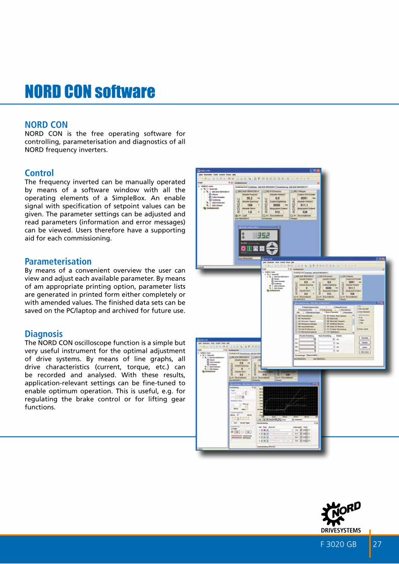
NORD CONNORD CON is the free operating software for controlling, parameterisation and diagnostics of all NORD frequency inverters.
ControlThe frequency inverted can be manually operated by means of a software window with all the operating elements of a SimpleBox. An enable signal with specification of setpoint values can be given. The parameter settings can be adjusted and read parameters (information and error messages) can be viewed. Users therefore have a supporting aid for each commissioning.
ParameterisationBy means of a convenient overview the user can view and adjust each available parameter. By means of am appropriate printing option, parameter lists are generated in printed form either completely or with amended values. The finished data sets can be saved on the PC/laptop and archived for future use.
DiagnosisThe NORD CON oscilloscope function is a simple but very useful instrument for the optimal adjustment of drive systems. By means of line graphs, all drive characteristics (current, torque, etc.) can be recorded and analysed. With these results, application-relevant settings can be fine-tuned to enable optimum operation. This is useful, e.g. for regulating the brake control or for lifting gear functions.
NORD CON software

28 F 3020 GB
Flexible mounting possibilities
Wall-mountingMotor Assembly
Wall-mounting(with or without fan)
Motor Assembly
Frequency inverter as motor- or wall-mounting
Technology box on SK 2xxE or wall-mounted

F 3020 GB 29
Motor-integrated SK 2xxE with Technology Unit
Wall-mounted variant of SK 2xxE and Technology Unit
Motor-integrated SK 2xxE with wall-mounted Technology Unit
System bus
System bus
Motor supply cable

30 F 3020 GB
Control cabinet
Field level
NORD provides consistency with all product series Same software Same parameter structure Same terminal labelling Same operating interface Same commissioning
Power and communication (e.g. CANopen or system bus)
Connection to automation systems
Modular technology units with bus interfaces, I/O control signals (optionally with M12) or control units
Integrated modules (Customer Unit) with bus interfaces, I/O control signals or power supply with analogue input
All common bus systems (e.g. Profibus, CANopen, DeviceNet), including with gateway functionality
Ethernet-based Bus Systems (e.g. EtherCAT, Profinet)
NORD frequency inverters in system combination

F 3020 GB 31
1
5L
432
3A3B
45
678
System connectorsPowerSKTIE4-HAN-10E Motorpoweroutput(HAN10E)SKTIE4-HAN-04-2 Powerin/out(HANQ4-2)SKTIE4-HAN-05 Powerin/out(HANQ5)OperationSK TIE4-Key-Switch Key switchSK TIE4-POT PotentiometerSK TIE4-SWT Switch L-0-RBus systemSK TIE4-M12-ASI AS interface (M12)SK TIE4-M12-ASI-AUX AS interface (AUX, M12)SK TIE4-M12-CAO CANopen (M12)SK TIE4-M12-PBR Profibus (M12)SK TIE4-M12-SYSM System bus (M12) masterSK TIE4-M12-SYSS System bus (M12) slaveControl signalsSK TIE4-M12-ANA Analogue value (M12)SKTIE4-M12-HTL Incrementalencoder(M12)SK TIE4-M12-INI Initiator (M12)SK TIE4-M12-POW 24 V supply (M12)SKTIE4-M12-SH Safestop(M12)
System connectors
The screw connections on the respective adapter unit can be fitted with system connectors for power, motor output, control and bus signals.
Flexible plug-in systems
R
L
5R
Adapter unit Frequency inverter
Connection unit - Technology Unit
Option slots of SK TI4-...(R or L assignment, view towards the motor fan)3 L/R 2x M25 screw connection (A/B)4 L/R M16screwconnection5 L/R M16screwconnection6 L/R M12 screw connection, Size 4 M167 L/R M12 screw connection, Size 4 M168 L/R M12 screw connection, Size 4 M16
Size 4 one additional screw connector L/R: M32
Option slots of SK TI4-TU-...1 M16screwconnection2 M16screwconnection3 M16screwconnection4 M16screwconnection5 L/R M20 screw connection

32 F 3020 GB
AS interface connection with M12 plug connectors
Power (115V/230V/400V)
AS Interface incl. 24V supply for SK 2xxE
SK 215ESK 225E
SK 235E
SK 205E0.25 - 7.5 KW
SK 210ESK 220E
SK 230E
SK 200E0.25 - 22 KW
Versions with AS-i on board: SK 220E: basic variant of SK 200E + AS interface on
board
SK 230E: basic variant of SK 200E + AS interface on board + “Safe stop”
Modern automation systems have a wide range of requirements, so that a suitable bus system and drive components must be selected in order to ensure efficient implementation. For the lower field level, the AS interface is a cost-effective solution which enables the networking of binary sensors and actuators. Special versions of the SK 200E product series, which provide an appropriate solution by means of an AS interface, are available for this price-sensitive area.
The supply voltage (power) is via appropriate terminals according to the version (1~/3~, 115/ 230/ 400V). The control voltage of the inverter is supplied separately. For the control unit of the inverter and the AS interface, the supply is via the (yellow) AS interface cable. This eliminates the need for an additional AUX cable (black).
Versions with AS-i on board: SK 225E: basic variant of SK 205E + AS interface on
board
SK 235E: basic variant of SK 205E + AS interface on board + “Safe stop”
F 3020 GB 33
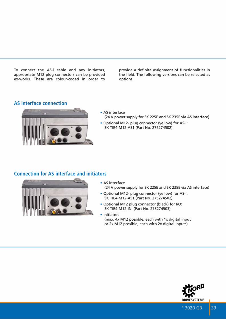
AS interface connection
•AS interface(24 V power supply for SK 225E and SK 235E via AS interface)
• Optional M12- plug connector (yellow) for AS-i:SK TIE4-M12-AS1 (Part No. 275274502)
Connection for AS interface and initiators
•AS interface(24 V power supply for SK 225E and SK 235E via AS interface)
• Optional M12- plug connector (yellow) for AS-i:SK TIE4-M12-AS1 (Part No. 275274502)
• Optional M12 plug connector (black) for I/O:SK TIE4-M12-INI (Part No. 275274503)
• Initiators(max. 4x M12 possible, each with 1x digital input or 2x M12 possible, each with 2x digital inputs)
To connect the AS-i cable and any initiators, appropriate M12 plug connectors can be provided ex-works. These are colour-coded in order to
provide a definite assignment of functionalities in the field. The following versions can be selected as options.
34 F 3020 GB
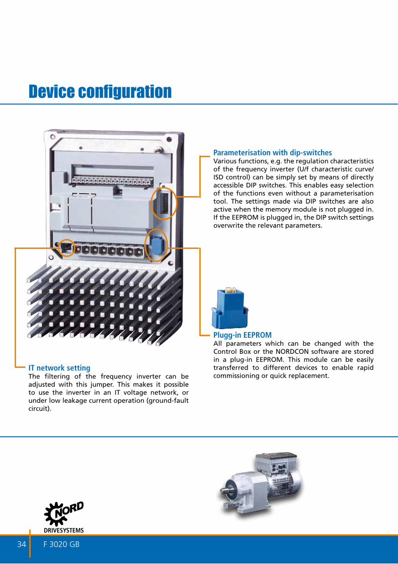
Device configuration
Parameterisation with dip-switchesVarious functions, e.g. the regulation characteristics of the frequency inverter (U/f characteristic curve/ISD control) can be simply set by means of directly accessible DIP switches. This enables easy selection of the functions even without a parameterisation tool. The settings made via DIP switches are also active when the memory module is not plugged in. If the EEPROM is plugged in, the DIP switch settings overwrite the relevant parameters.
IT network settingThe filtering of the frequency inverter can be adjusted with this jumper. This makes it possible to use the inverter in an IT voltage network, or under low leakage current operation (ground-fault circuit).
Plugg-in EEPROMAll parameters which can be changed with the Control Box or the NORDCON software are stored in a plug-in EEPROM. This module can be easily transferred to different devices to enable rapid commissioning or quick replacement.
F 3020 GB 35
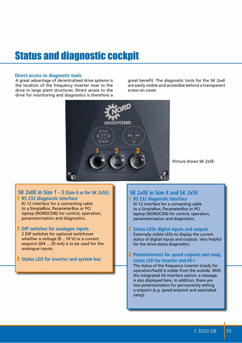
Status and diagnostic cockpit
1 32
SK 2x0E in Size 1 - 3 (Size 4 as for SK 2x5E)1 RS 232 diagnostic interface
RJ 12 interface for a connecting cable to a SimpleBox, ParameterBox or PC/laptop (NORDCON) for control, operation, parameterisation and diagnostics.
2 DIP switches for analogue inputs2 DIP switches for optional switchover whether a voltage (0 ...10 V) or a current setpoint (0/4 ... 20 mA) is to be used for the analogue inputs.
3 Status LED for inverter and system bus
SK 2x0E in Size 4 and SK 2x5E1 RS 232 diagnostic interface
RJ 12 interface for a connecting cable to a SimpleBox, ParameterBox or PC/laptop (NORDCON) for control, operation, parameterisation and diagnostics.
2 Status-LEDs digital inputs and outputsExternally visible LEDs to display the current status of digital inputs and outputs. Very helpful for the drive status diagnostics.
3 Potentiometers for speed setpoint and ramp, status LED for inverter and AS-iThe status of the frequency inverter (ready for operation/fault) is visible from the outside. With the integrated AS interface option, a message is also displayed here. In addition, there are two potentiometers for permanently setting a setpoint (e.g. speed setpoint and associated ramp).
Picture shows SK 2x5E
A great advantage of decentralised drive systems is the location of the frequency inverter near to the drive in large plant structures. Direct access to the drive for monitoring and diagnostics is therefore a
great benefit. The diagnostic tools for the SK 2xxE are easily visible and accessible behind a transparent screw-on cover.
Direct-access to diagnostic tools

36 F 3020 GB
Application functions of the SK 2xxE
Energy-saving function•Automatic flux optimisation for pump/fan
applications
•Large energy savings
•Simple setting via parameters
Lifting gear functions•Highprecisionsensorlesscurrentvectorcontrol
(ISD control)
•Integrated brake chopper to divert generated energy to a brake resistor (optional)
•Optimised operation with only a few parameter settings
Process controller, PI controller•All SK 2x0E devices feature 1 or 2 integrated
analogue inputs. (SK 220E/SK 230E Size 1-3, 1 AIN otherwise 2 AIN)
•The basic variant of SK 2x5E does not come with an analogue input. This is available as an option with the power supply module or I/O extension (CU4 or TU4 resp.)
•P and I component can be set separately
•Highprecisionregulation
Einsatz von energieeffi zienten NORD-Produkten
Ener
giee
insp
arun
g
Integrated functions for a wide range of applications
SK 210ESK 220E
SK 230E
SK 200E
SK 210ESK 220E
SK 230E
SK 200E
SK 215ESK 225E
SK 235E
SK 205E
SK 210E
SK 215E
SK 220E
SK 225E
SK 230E
SK 235E
SK 200E
SK 205E
SK 215ESK 225E
SK 235E
SK 205E
Ene
rgy
savi
ng
With energy-efficient products from NORD
F 3020 GB 37
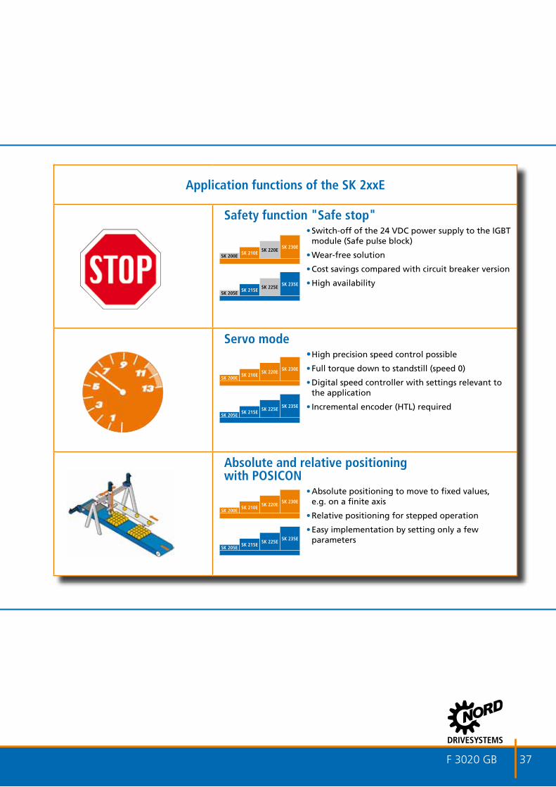
Application functions of the SK 2xxE
Safety function "Safe stop"•Switch-off of the 24 VDC power supply to the IGBT
module (Safe pulse block)
•Wear-free solution
•Cost savings compared with circuit breaker version
•Highavailability
Servo mode•Highprecisionspeedcontrolpossible
•Full torque down to standstill (speed 0)
•Digital speed controller with settings relevant to the application
•Incrementalencoder(HTL)required
Absolute and relative positioning with POSICON
•Absolute positioning to move to fixed values, e.g. on a finite axis
•Relative positioning for stepped operation
•Easy implementation by setting only a few parameters
SK 210ESK 220E
SK 230E
SK 200E
SK 215ESK 225E
SK 235E
SK 205E
SK 210ESK 220E
SK 230E
SK 200E
SK 215ESK 225E
SK 235E
SK 205E
SK 210ESK 220E
SK 230E
SK 200E
SK 215ESK 225E
SK 235E
SK 205E
38 F 3020 GB
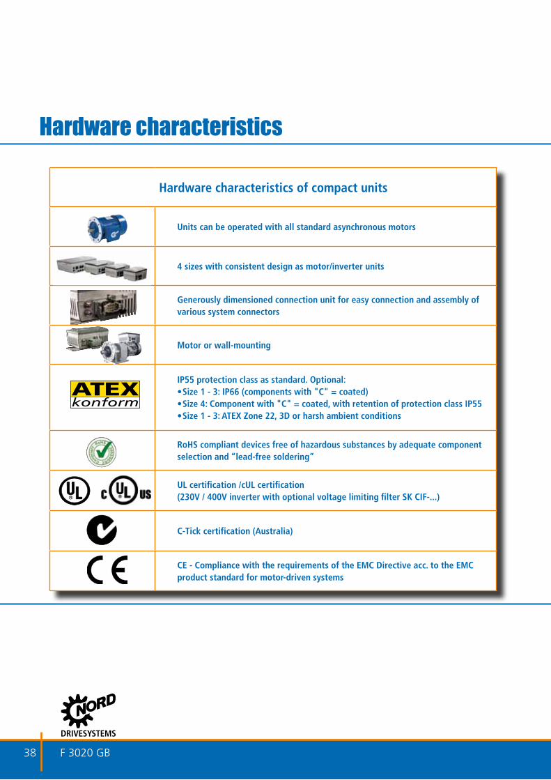
Hardware characteristics of compact units
Units can be operated with all standard asynchronous motors
4 sizes with consistent design as motor/inverter units
Generously dimensioned connection unit for easy connection and assembly of various system connectors
Motor or wall-mounting
IP55 protection class as standard. Optional:•Size1-3:IP66(componentswith"C"=coated)•Size4:Componentwith"C"=coated,withretentionofprotectionclassIP55•Size1-3:ATEXZone22,3Dorharshambientconditions
RoHS compliant devices free of hazardous substances by adequate component selection and “lead-free soldering”
UL certification /cUL certification (230V / 400V inverter with optional voltage limiting filter SK CIF-...)
C-Tick certification (Australia)
CE - Compliance with the requirements of the EMC Directive acc. to the EMC product standard for motor-driven systems
Hardware characteristics

F 3020 GB 39
Function Specification
Power / Voltage
SK 2x0E1 ~ 200...240 V -/+10% 0.25 - 0.55 kW3 ~ 200...240 V -/+10% 0.25 - 11 kW3 ~ 380...500 V -20%/+10% 0.55 - 22 kW
SK 2x5E1 ~ 100..0.120V -/+10% 0.25 - 0.75 kW1 ~ 200...240 V -/+10% 0.25 - 1.1 kW3 ~ 200...240 V -/+10% 0.25 - 4 kW3 ~ 380...500 V -20%/+10% 0.55 - 7.5 kW
Standard
•Integrated24Vpowersupply•4digitalinputs,PTCinput•2digitaloutputs•RS232&RS485(RJ12connector)
diagnostic interface
•4digitalinputs,PTCinput•Brakeresistorcontrol•1Digitaloutput•RS232&RS485(RJ12connector)
diagnostic interface•StatusLEDs•Setpointpotentiometer(speedandramp)
Output frequency 0,0...400.0Hz
Rated overload capacity 200%for3.5s,150%for60s
Protective measures against
overtemperature,shortcircuit,earthfault,over/under-voltage,overload
Regulation and controlSensorlesscurrentvectorcontrol(ISD),linearV/fcharacteristiccurve,automatic
fluxadaptation(energy-savingfunction)
Motor temperature monitoring
Temperaturesensor(PTC),temperaturemonitor(bimetal),I2t- motor
Standard interfacesRS485(USS),RS232(commissioninganddiagnosis),systembus,
ASinterface(OnlySK225EandSK235E)
Ambient temperature -25°C...+40°C(S1-100%ED),-25°C...+50°C(S3-75%ED15min)*
Version Motor-mounted,wallmounted
Protection classIP55(Size1-3:optionalIP66)**
IP66measures: •Coatedaluminiumcomponents•CoatedPCBs •Lowpressuretest •Membranevalve
Technical data
* note the technical data for wall mounting**Size4optionallyavailablewithIP66measures,
however with retention of protection class IP55

40 F 3020 GB
SK 2xxE 1 ~ 100 ... 120V and 1 ~ 200 ... 240VInverter type
SK2xxE...SK
2x0E..SK
2x5E..Size
Mains
voltageOutput voltage
Nominal motor power
230V [kW]
Nominal motor power
230V [hp]
Nominal output current
rms[A]
Typical input current
rms[A]
1 ~ 10
0 ... 1
20V -250-112-O(-C) 1
1~100...120V
-/+10%
47...63Hz
3 AC
0–200...240V
0,25 13 1.7 8.9
-370-112-O(-C) 1 0,37 12 2.2 11
-550-112-O(-C) 2 0,55 34 3.0 13.1
750-112-O(-C) 2 0,75 1 4.0 20.1
Inverter typeSK2xxE...
SK 2x0E..
SK 2x5E..
SizeMains
voltageOutput voltage
Nominal motor power
230 V [kW]
Nominal motor power
230 V [hp]
Nominal output current
rms[A]
Typical input current
rms[A]
1 ~ 20
0 ... 2
40V
-250-123-A(-C) 1
1~200...240V
-/+10%
47...63Hz
3 AC
0–200...240V
0.25 13 1.7 3.9
-370-123-A(-C) 1 0.37 12 2.2 5.8
-550-123-A(-C) 1 0.55 34 3.0 7.3
-750-123-A(-C) 2 0.75 1 4.0 10.2
-111-123-A(-C) 2 1.1 11 2 5.5 14.7
Standard protection class IP55
(-C)=protectionclassIP66

F 3020 GB 41
Inverter typeSK2xxE...
SK 2x0E..
SK 2x5E..
SizeMains
voltageOutput voltage
Nominal motor power
230V [kW]
Nominal motor power
230V [hp]
Nominal output current
rms[A]
Typical input current
rms[A]
1 ~ 10
0 ... 1
20V -250-112-O(-C) 1
1~100...120V
-/+10%
47...63Hz
3 AC
0–200...240V
0,25 13 1.7 8.9
-370-112-O(-C) 1 0,37 12 2.2 11
-550-112-O(-C) 2 0,55 34 3.0 13.1
750-112-O(-C) 2 0,75 1 4.0 20.1
Inverter typeSK2xxE...
SK 2x0E..
SK 2x5E..
SizeMains
voltageOutput voltage
Nominal motor power
230 V [kW]
Nominal motor power
230 V [hp]
Nominal output current
rms[A]
Typical input current
rms[A]
1 ~ 20
0 ... 2
40V
-250-123-A(-C) 1
1~200...240V
-/+10%
47...63Hz
3 AC
0–200...240V
0.25 13 1.7 3.9
-370-123-A(-C) 1 0.37 12 2.2 5.8
-550-123-A(-C) 1 0.55 34 3.0 7.3
-750-123-A(-C) 2 0.75 1 4.0 10.2
-111-123-A(-C) 2 1.1 11 2 5.5 14.7

42 F 3020 GB
SK 2xxE 3 ~ 200 ... 240VInverter type
SK2xxE...SK
2x0E..SK
2x5E..Size Mains voltage
Nominal motor power
230V [kW]
Nominal motor power
230V [hp]
Nominal output current
rms[A]
Typical input current
rms[A]
3 ~ 20
0 ... 2
40V
-250-323-A(-C) 1
3~200...240V
-/+10%
47...63Hz
0.25 13 1.7 1.4
-370-323-A(-C) 1 0.37 12 2.2 1.9
-550-323-A(-C) 1 0.55 34 3.0 2.6
-750-323-A(-C) 1 0.75 1 4.0 3.5
-111-323-A(-C) 1 1.1 11 2 5.5 5.1
-151-323-A(-C) 2 1.5 2 7.0 6.6
-221-323-A(-C) 2 2.2 3 9.5 9.1
-301-323-A(-C) 3 3 4 12.5 11.8
-401-323-A(-C) 3 4 5 16.0 15.1
-551-323-A(-C) 4 5.5 71 2 23.0 23.5
-751-323-A(-C) 4 7.5 10 29.0 29.5
-112-323-A(-C) 4 11 15 40.0 40.5
Standard protection class IP55
(-C)=ProtectionclassIP66(Size1-3),
Size4IP66measures,
whowever with protection class IP55

F 3020 GB 43
Inverter typeSK2xxE...
SK 2x0E..
SK 2x5E..
Size Mains voltageNominal motor power
230V [kW]
Nominal motor power
230V [hp]
Nominal output current
rms[A]
Typical input current
rms[A]
3 ~ 20
0 ... 2
40V
-250-323-A(-C) 1
3~200...240V
-/+10%
47...63Hz
0.25 13 1.7 1.4
-370-323-A(-C) 1 0.37 12 2.2 1.9
-550-323-A(-C) 1 0.55 34 3.0 2.6
-750-323-A(-C) 1 0.75 1 4.0 3.5
-111-323-A(-C) 1 1.1 11 2 5.5 5.1
-151-323-A(-C) 2 1.5 2 7.0 6.6
-221-323-A(-C) 2 2.2 3 9.5 9.1
-301-323-A(-C) 3 3 4 12.5 11.8
-401-323-A(-C) 3 4 5 16.0 15.1
-551-323-A(-C) 4 5.5 71 2 23.0 23.5
-751-323-A(-C) 4 7.5 10 29.0 29.5
-112-323-A(-C) 4 11 15 40.0 40.5

44 F 3020 GB
Inverter typeSK2xxE...
SK 2x0E..
SK 2x5E..
Size Mains voltageNominal motor power
400V [kW]
Nominal motor power
460V [hp]
Nominal output current
rms[A]
Typical input current
rms[A]
3 ~ 38
0 ... 5
00V
-550-340-A(-C) 1
3~380...500V
-20%/+10%
47...63Hz
0.55 34 1.7 1.6
-750-340-A(-C) 1 0.75 1 2.3 2.2
-111-340-A(-C) 1 1.1 11 2 3.1 2.9
-151-340-A(-C) 1 1.5 2 4.0 3.7
-221-340-A(-C) 1 2.2 3 5.5 5.7
-301-340-A(-C) 2 3.0 4 7.5 7.0
-401-340-A(-C) 2 4.0 5 9.5 8.3
-551-340-A(-C) 3 5.5 71 2 12.5 11.7
-751-340-A(-C) 3 7.5 10 16.0 15.0
-112-340-A(-C) 4 11.0 15 23.0 23.6
-152-340-A(-C) 4 15.0 20 32.0 32.0
-182-340-A(-C) 4 18.5 25 40.0 40.5
-222-340-A(-C) 4 22.0 30 46.0 46.5
SK 2xxE 3 ~ 380 ... 500V
Standard protection class IP55
(-C)=ProtectionclassIP66(Size1-3)

F 3020 GB 45
Inverter typeSK2xxE...
SK 2x0E..
SK 2x5E..
Size Mains voltageNominal motor power
400V [kW]
Nominal motor power
460V [hp]
Nominal output current
rms[A]
Typical input current
rms[A]
3 ~ 38
0 ... 5
00V
-550-340-A(-C) 1
3~380...500V
-20%/+10%
47...63Hz
0.55 34 1.7 1.6
-750-340-A(-C) 1 0.75 1 2.3 2.2
-111-340-A(-C) 1 1.1 11 2 3.1 2.9
-151-340-A(-C) 1 1.5 2 4.0 3.7
-221-340-A(-C) 1 2.2 3 5.5 5.7
-301-340-A(-C) 2 3.0 4 7.5 7.0
-401-340-A(-C) 2 4.0 5 9.5 8.3
-551-340-A(-C) 3 5.5 71 2 12.5 11.7
-751-340-A(-C) 3 7.5 10 16.0 15.0
-112-340-A(-C) 4 11.0 15 23.0 23.6
-152-340-A(-C) 4 15.0 20 32.0 32.0
-182-340-A(-C) 4 18.5 25 40.0 40.5
-222-340-A(-C) 4 22.0 30 46.0 46.5

46 F 3020 GB
Braking resistorsInverter typeSK 2xxE...
Resistor type Part number Resistance[Ω]
Continuous rating[W]
Energy consumption*)[kWs]
1~11
5V … -250-112-O to… -750-112-O
SK BRI 4- 1-100-100 275272005 100 100 1.0
1~23
0V … -250-123-A to… -111-123-A
SK BRI 4- 1-100-100 275272005 100 100 1.0
3~23
0V
… -250-323-A to… -221-323-A
SK BRI 4- 1-200-100 275272008 200 100 1.0
… -301-323-A to… -401-323-A
SK BRI 4- 2-100-200 275272105 100 200 2.0
...-551-323-Ato
...-751-323-ASK BRI 4- 3-047-300 275272201 47 300 3.0
...-112-323-A SK BRI 4- 3-023-600 275272800 23 600 6.0
3~40
0V
… -550-340-A to… -401-340-A
SK BRI 4- 1-400-100 275272012 400 100 1.0
… -551-340-A to… -751-340-A
SK BRI 4- 2-200-200 275272108 200 200 2.0
...-112-340-Ato
...-152-340-ASK BRI 4- 3-100-300 275272205 100 300 3.0
...-182-340-Ato
...-222-340-ASK BRI 4- 3-050-600 275272801 50 600 6.0
Internal brake resistors
Internal brake resistor

F 3020 GB 47
Inverter typeSK 2xxE...
Resistor type Part number Resistance[Ω]
Continuous rating[W]
Energy consumption*)[kWs]
1~11
5V … -250-112-O to… -750-112-O
SK BRI 4- 1-100-100 275272005 100 100 1.0
1~23
0V … -250-123-A to… -111-123-A
SK BRI 4- 1-100-100 275272005 100 100 1.0
3~23
0V
… -250-323-A to… -221-323-A
SK BRI 4- 1-200-100 275272008 200 100 1.0
… -301-323-A to… -401-323-A
SK BRI 4- 2-100-200 275272105 100 200 2.0
...-551-323-Ato
...-751-323-ASK BRI 4- 3-047-300 275272201 47 300 3.0
...-112-323-A SK BRI 4- 3-023-600 275272800 23 600 6.0
3~40
0V
… -550-340-A to… -401-340-A
SK BRI 4- 1-400-100 275272012 400 100 1.0
… -551-340-A to… -751-340-A
SK BRI 4- 2-200-200 275272108 200 200 2.0
...-112-340-Ato
...-152-340-ASK BRI 4- 3-100-300 275272205 100 300 3.0
...-182-340-Ato
...-222-340-ASK BRI 4- 3-050-600 275272801 50 600 6.0
*) Permissible max. once within 120 sec.

48 F 3020 GB
Braking resistorsInverter typeSK 2xxE
Resistor type Part number Resistance[Ω]
Continuous rating[W]
Energy consumption*)[kWs]
1~11
5V
… -250-112-O to
… -750-112-O
SK BRE 4- 1-100-100 275273005 100 100 2.2
Alternatively:SKBRE4-2-100-200 275273105 100 200 4.4
1~23
0V
… -250-123-A to
… -111-123-A
SK BRE 4- 1-100-100 275273005 100 100 2.2
Alternatively:SK BRE 4- 2-100-200 275273105 100 200 4.4
3~23
0V
… -250-323-A to
… -221-323-A
SK BRE 4- 1-200-100 275273008 200 100 2.2
Alternatively:SKBRE4-2-200-200 275273108 200 200 4.4
… -301-323-A to… -401-323-A
SK BRE 4- 2-100-200 275273105 100 200 4.4
… -551-323-A to… -112-323-A
SK BRE 4- 3-050-450 in preparation 50 450 approx.9.0
3~40
0V
… -550-340-A to
… -401-340-A
SK BRE 4- 1-400-100 275273012 400 100 2.2
Alternatively:SKBRE4-2-200-200 275273108 200 200 4.4
… -551-340-A to… -751-340-A
SK BRE 4- 2-200-200 275273108 200 200 4.4
… -112-340-A to … -222-340-A
SK BRE 4- 3-050-450 in preparation 50 450 approx.9.0
External brake resistors
External brake resistor

F 3020 GB 49
Inverter typeSK 2xxE
Resistor type Part number Resistance[Ω]
Continuous rating[W]
Energy consumption*)[kWs]
1~11
5V
… -250-112-O to
… -750-112-O
SK BRE 4- 1-100-100 275273005 100 100 2.2
Alternatively:SKBRE4-2-100-200 275273105 100 200 4.4
1~23
0V
… -250-123-A to
… -111-123-A
SK BRE 4- 1-100-100 275273005 100 100 2.2
Alternatively:SK BRE 4- 2-100-200 275273105 100 200 4.4
3~23
0V
… -250-323-A to
… -221-323-A
SK BRE 4- 1-200-100 275273008 200 100 2.2
Alternatively:SKBRE4-2-200-200 275273108 200 200 4.4
… -301-323-A to… -401-323-A
SK BRE 4- 2-100-200 275273105 100 200 4.4
… -551-323-A to… -112-323-A
SK BRE 4- 3-050-450 in preparation 50 450 approx.9.0
3~40
0V
… -550-340-A to
… -401-340-A
SK BRE 4- 1-400-100 275273012 400 100 2.2
Alternatively:SKBRE4-2-200-200 275273108 200 200 4.4
… -551-340-A to… -751-340-A
SK BRE 4- 2-200-200 275273108 200 200 4.4
… -112-340-A to … -222-340-A
SK BRE 4- 3-050-450 in preparation 50 450 approx.9.0
*) Permissible max. once within 120 sec.

50 F 3020 GB
NORD Electronic DRIVESYSTEMSDrive electronics produced in-house
NORD Electronic DRIVESYSTEMS, a subsidiary of Getriebebau NORD in Bargteheide, has had a productionfacilityinAurichsince1984.Attheendof 2005 the new factory in Aurich / Schirum started operation. Here, 110 employees produce driveelectronics such as frequency inverters, decentralised drive technology and servo controllers. The products are produced for sale throughout the world by Getriebebau NORD.
Automatic high voltage testing system
Automatic assembly of circuit boards
"One Piece flow" in the modern assembly lineThe production process is divided into two main sections. One section is PCB production. Here,electronic components are positioned on a printed circuit board, soldered and subjected to a function test. In the second stage, the devices are assembled. This stage is completed with a quality inspection. Then the finished products are sent for dispatch. In combination with modern, efficient production technology, the strategy of great depth of production ensures a high delivery performance. Standard frequency inverters are supplied from stock.
High speed SMD assembly plant

F 3020 GB 51
1984 Start of in-house development and production of frequency inverters
1992 Mixed product range based on cooperations and in-house production
1997 Philosophy: Only in-house
products
2005 Opening of NORD Electronic DRivESyStEMS

F302
0 Pa
rt. N
o. 6
03 3
2 02
/ 11
12
NORD DRIVESYSTEMS GROUP
Getriebebau NORD GmbH & Co. KG, Rudolf-Diesel-Str. 1, D-22941 BargteheideFon +49 (0) 45 32 / 401 - 0 , Fax +49 (0) 45 32 / 401 - 253, [email protected]
Getriebebau NORD GmbH, A-4030 Linz, Deggendorfstrasse 8Fon +43 (0) 732 / 31 89 20, Fax +43 (0) 732 / 31 89 20 – 85, [email protected]
Getriebebau NORD AG, Bächigenstraße 18, CH-9212 ArneggFon +41-71-38899 11, Fax +41-71-38899 15, [email protected]
DE
AT
CH
www.nord.com/locator


