28
GBAS ICAO Provisions Presented by Sylvie GRAND-PERRET EUROCONTROL Navigation Unit ICAO EUR GBAS Implementation Workshop Paris 18th March 2010

GBAS
ICAO Provisions
Presented by Sylvie GRAND-PERRET
EUROCONTROL Navigation Unit
ICAO EUR GBAS Implementation Workshop
Paris 18th March 2010

Applicable ICAO provisions
ICAO Global provisions– ANNEX 10
– PANS ATM
– ANNEX 6
– ANNEX 4
– ANNEX 15
– PANS OPS
– ANNEX 14
– ANNEX 11
– AWO Manual
ICAO EUR DOC– EUR DOC 011
– EUR DOC 013
– EUR DOC 015

ANNEX 10
• GBAS CAT I SARPs update completed
• Remaining issue: Positioning service– Existing provision does not sufficiently separate
approach and positioning services
– GS-based integrity mechanism difficult to ensure at edge of coverage (unobservable iono errors) above 23NM
– Operation for which positioning service is used is not known by the ground system => no predefined performance and error size limit for GS to protect
– Review ongoing at NSP

PANS ATMParallel Operations
Normal operating zone (NOZ).
Airspace of defined dimensions extending to either side of an ILS localizer course and/or MLS final approach track. Only the inner half of the normal operating zone is taken into account in independent parallel approaches.
6.7.3.2.1 Independent parallel approaches
b) instrument landing system (ILS) and/or microwave landing system (MLS) approaches are being conducted on both runways;
6.7.3.4.1 Dependent parallel approaches may be conducted to parallel runways provided:
d) ILS and/or MLS approaches are being conducted on both runways;
6.7.3.5 REQUIREMENTS AND PROCEDURES FOR SEGREGATED PARALLEL OPERATIONS
6.7.3.5.3 a) ILS and/or MLS precision approach;
8.9 USE OF ATS SURVEILLANCE SYSTEMS IN THE APPROACH CONTROL SERVICE (just ILS)

PANS ATMPhraseology (1/2)
Philosophy : GBAS for system status –GLS for approach type
• 12.3.1.11 OPERATIONAL STATUS OF VISUAL AND NON-VISUAL AIDSc) GBAS/SBAS/MLS/ILS CATEGORY (category) (serviceability state)
• 12.3.3.2 APPROACH INSTRUCTIONSCLEARED (type of approach GLS??) APPROACH [RUNWAY(number)];
• 12.4.2.2 VECTORING FOR ILS AND OTHER PILOT-INTERPRETED AIDS
e) REPORT ESTABLISHED ON [ILS] LOCALIZER (or ON GBAS/SBAS/MLS APPROACH COURSE);
• 12.4.2.3 MANOEUVRE DURING INDEPENDENT AND DEPENDENT PARALLEL APPROACHES
b) YOU HAVE CROSSED THE LOCALIZER (or GBAS/SBAS/MLS FINAL APPROACH COURSE). TURN LEFT (or RIGHT) IMMEDIATELYAND RETURN TO THE LOCALIZER (or GBAS/SBAS/MLS FINAL APPROACH COURSE);
c) ILS (or MLS) RUNWAY (number) LEFT (or RIGHT) LOCALIZER (or MLS) FREQUENCY IS (frequency);
PANS ATM Phraseology (2/2) & Flight Plan
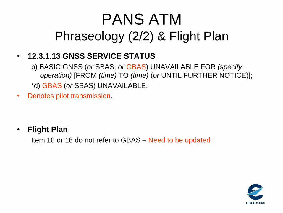
• 12.3.1.13 GNSS SERVICE STATUS
b) BASIC GNSS (or SBAS, or GBAS) UNAVAILABLE FOR (specify
operation) [FROM (time) TO (time) (or UNTIL FURTHER NOTICE)];
*d) GBAS (or SBAS) UNAVAILABLE.
• Denotes pilot transmission.
• Flight Plan
Item 10 or 18 do not refer to GBAS – Need to be updated

ANNEX 6
No mention of GBAS:
• Flight data recorder requirement (Part II):
– Vertical deviation*: ILS glide path, MLS elevation, GNSS approach path
– Horizontal deviation*: ILS localizer, MLS azimuth, GNSS approach path
– Primary navigation system reference*: GNSS, INS, VOR/DME, MLS, Loran C, ILS
• No specific approval for GBAS or CAT I
ANNEX 4 (1/4)
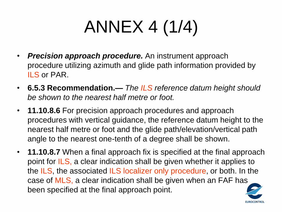
• Precision approach procedure. An instrument approach
procedure utilizing azimuth and glide path information provided by
ILS or PAR.
• 6.5.3 Recommendation.— The ILS reference datum height should
be shown to the nearest half metre or foot.
• 11.10.8.6 For precision approach procedures and approach
procedures with vertical guidance, the reference datum height to the
nearest half metre or foot and the glide path/elevation/vertical path
angle to the nearest one-tenth of a degree shall be shown.
• 11.10.8.7 When a final approach fix is specified at the final approach
point for ILS, a clear indication shall be given whether it applies to
the ILS, the associated ILS localizer only procedure, or both. In the
case of MLS, a clear indication shall be given when an FAF has
been specified at the final approach point.

ANNEX 4 (2/4)
• 13.6.1 This chart shall show:
c) elevations and geoid undulations, to the nearest half-metre or foot, of
the precision approach runway threshold, the geometric centre of the
touchdown and lift-off area, and at the highest elevation of the
touchdown zone of a precision approach runway
• Table 2. Elevation/altitude/height
– Runway or FATO threshold, precision approaches : 0.5 m or 1 ft; 1 ×
10-8 / critical
– Threshold crossing height, precision approaches : 0.5 m or 1 ft 1 × 10⁻⁸
/ critical
• Table 3. Gradients and angles
– Precision approach glide path/elevation angle : 0.1 degree 1 × 10⁻⁸ /
critical

ANNEX 4 (3/4)
Applicable to GBAS but no reference to GBAS:
11.10.4 Radio communication facilities and navigation aids• 11.10.4.1 Radio navigation aids required for the procedures together with their frequencies,
identifications and track-defining characteristics, if any, shall be shown. In the case of a procedure in which more than one station is located on the final approach track, the facility to be used for track guidance for final approach shall be clearly identified. In addition, consideration shall be given to the elimination from the approach chart of those facilities that are not used by the procedure.
• 11.10.4.2 The initial approach fix (IAF), the intermediate approach fix (IF), the final approach fix (FAF) (or final approach point (FAP) for an ILS approach procedure), the missed approach point (MAPt), where established, and other essential fixes or points comprising the procedure shall be shown and identified.
• 11.10.4.3 Recommendation.— The final approach fix (or final approach point for an ILS approach procedure) should be identified with its geographical coordinates in degrees, minutes and seconds.
• 11.10.4.4 Radio navigation aids that might be used in diversionary procedures together with their track-defining characteristics, if any, shall be shown or indicated on the chart.
• 11.10.4.5 Radio communication frequencies, including call signs, that are required for the execution of the procedures shall be shown.
• 11.10.4.6 When required by the procedures, the distance to the aerodrome from each radio navigation aid concerned with the final approach shall be shown to the nearest kilometre or nautical mile. When no track-defining aid indicates the bearing of the aerodrome, the bearing shall also be shown to the nearest degree.

ANNEX 4 (4/4)
Radio Navigation aids
• Item 108 : only ILS
• Table 5: Bearing (No GBAS)
• ILS localizer alignment: 1 degree 1 × 10⁻⁵ / essential
• MLS zero azimuth alignment : 1 degree 1 × 10⁻⁵ /
essential

ANNEX 15
Amend Annex 15, Appendix 1, Section AD 2.19, as follows:
3) frequency(ies) and channel(s), as appropriate.
6) elevation of the transmitting antenna of DME to the nearest
30 m (100 ft) and of DME/P to the nearest 3 m (10 ft); elevation of the GBAS ground station reference point (Annex 10, App B, §3.6.4.3) to the nearest 1 m or 1 ft (Annex 4, §2.18.2),
7) service volume radius (Dmax Annex 10, Volume, App B, §3.6.4.3) of GBAS ground station to the nearest kilometre or nautical mile, and
8) remarks
Note: The complete set of GBAS FAS Data Block information is not to be promulgated on the chart. The process to transfer the FAS data block information to industry still needs to be standardized. FAS data block information is to be uploaded by the ground station or a simulator.

PANS OPS (1/4)
• 6.1.5.4 - Note 1.— While specific GBAS distributions for the existing
CRM are being developed, use should be made of the current ILS
CRM. (verification of decorrelation to be done for CAT II/III)
• 6.1.7 GBAS with glide path inoperative
The GBAS with glide path inoperative is a non-precision approach
procedure. The principles of Chapter 3, ―Non precision approach
procedures‖ apply. – To be deleted – Point already highlighted
• Parallel operations:
A single GBAS is capable of serving both runways, however, a separate
safety study needs to be carried out when it is intended to use GBAS for
both runways.

PANS OPS (2/4)
• 6.8.1 General
• The instrument approach chart for a GBAS approach procedure shall be
identified by the title GLS Rwy XX. If more than one GBAS approach is
published for the same runway, the Duplicate Procedure Title convention
shall be applied, with the approach having the lowest minima being
identified as GLS Z Rwy XX.
• 6.4 QUALITY REQUIREMENTS
• Note 2.— The 1 x 10⁻⁸ data integrity requirement can be met by conducting
a flight evaluation after the FAS data block has been defined, provided the
flight evaluation system verifies the CRC and determines that the approach
path is acceptable.

PANS OPS (3/4) 6.8.7 Minimum Procedure Information (1/2)
1. Reference Path Identifier (RPI). The RPI, as defined in Part III, Section 2, Chapter 6, Appendix A, paragraph 3.h., is to be promulgated with the procedure information. This is required for charting and for database encoding.
2. Local Horizontal Reference Datum. The position and MSL altitude of the threshold shall be published, as well as the horizontal position of the Flight Path Alignment Point (FPAP, see Annex 10, Volume I, App B, 3.6.4.5.1) with precision as requested in Annex 4 section 2.18. Note: The LTP/FTP positions broadcast by the ground station are not necessarily located at the threshold and need not be promulgated with the procedure information.
3. GBAS Approach Channel Number. The channel number assigned to the GBAS Approach, as defined in Annex 10, Volume I, Appendix B, section 3.6.5.7 and Attachment D, paragraph 7.7, is to be promulgated with the procedure information. This is required for charting and for database encoding.
4. Other GBAS approach information: Other GBAS approach information to be promulgated is:runway number, runway letter, glide path angle, indication if autoland is not supported on this approach and coordinates of the waypoint used for altitude crosscheck (outer marker equivalent), if used. This is required for database encoding and charting.

PANS OPS (4/4) 6.8.7 Minimum Procedure Information (1/2)
5. GBAS Ground Station Information. The following information about the GBAS Ground Station is to be promulgated in the aerodrome section of the AIP.: The GBAS station identifier (ref Annex 10, Volume I, App B, 3.6.3.4.1), latitude, longitude, MSL altitude and undulation of the GBAS
reference point (with precision as requested in Annex 4 section 2.18) , service volume radius (Dmax), constellations supported (GPS/GLONASS), type of polarization (horizontal/elliptical), services supported (approach, DCPS, GRAS). Note: The position of the GBAS reference point shall also be provided in the appropriate navigation aid section of the AIP. Note: Refer to Annex 10, Volume I, App B, 3.6.4.3 for definitions of the GBAS reference point and Dmax).
6. The channel number for DCPS should be promulgated on RNAV charts, not GLS precision approach charts.
7. Waypoint Information. All waypoints required for RNAV transition and capture of the procedure as well as RNAV missed approach procedure are to be promulgated with their identifier and latitude/longitude to the correct resolution, as defined in Annex 15, Table A7-1. See also Document 8168, Volume II, Part III, Section 5, Chapter 1.

ANNEX 14
• No direct mention of GBAS operations so far – need to
verify where GBAS needs to be included – notably verify
all ILS/MLS occurrences)
• However additionally to minimize loss of runway
throughput during LVP (so GBAS CAT II/III):
– OFZ scope, Runway strip and Runway vacating sign need to be
reviewed.
– This review needs to be performed in conjunction with PANS
ATM (« Runway vacated ») & Doc 9137

ANNEX 11 (CAT II/III issue)
• 3.8 Control of persons and vehicles at aerodromes
a) persons and vehicles operating on the manoeuvring area of an
aerodrome shall be restricted to the essential minimum, and particular
regard shall be given to the requirements to protect the ILS/MLS
sensitive area(s) when Category II or Category III precision instrument
operations are in progress;
c) when mixed ILS and MLS Category II or Category III precision instrument
operations are taking place to the same runway continuously, the more
restrictive ILS or MLS critical and sensitive areas shall be protected.
• 4.3.4.3 Voice-ATIS broadcasts shall not be transmitted on the voice
channel of an ILS.
• Do we need addition on GBAS naming convention?

AWO Manual (1/2) Update not yet approved
• GLS. An instrument approach operation that is based on GBAS. (need harmonisation with PANS OPS amendment which includes also S-CAT I)
• 3.2.14 Alternate visual aid requirements for RNP based procedures, and for GLS may be applicable. This is because both RNP and GLS procedures may be established to runways where it is impractical to install or maintain traditional visual aids in the approach zone, or where the RNP
paths may not necessarily follow a long straight-in final segment.
• 4.2.3 The following are examples of minimum equipment combinations acceptable for Category I operations by air-carrier aeroplanes using ILS, MLS or GLS for either manual or automatic approaches:
– Equipment type/specification
– ILS, MLS or GLS receiver (GBAS?)
– Display of deviation data based on the ILS, MLS or GLS service (GBAS service?)
• 5.2.11 The ILS, MLS and GLS ground equipment
• 5.2.14 GLS
• TBD

AWO manual (2/2) Update not yet approved
• 5.7.5 Flight crews must be able to make full use of ground and airborne equipment intended for use during Category II and IIIoperations. They must, therefore, be instructed in how to obtain maximum benefit from redundancy provided in the airborne equipment and to fully understand the limitations of the total system, including both ground and airborne elements. The ground instruction should cover at least:
• a) the characteristics, capabilities and limitations of the navaids involved (e.g. ILS, GLS) including the effect on aeroplane systems performance of interference to the ILS signal caused by other landing, departing, or overflying aeroplanes, and the effect of the infringement of ILS critical and sensitive areas by aeroplanes or vehicles in the manoeuvring area;

EUR Doc 011
• Frequency coordination
– Existing text requires to coordinate GBAS
frequency and used slots in 500NM radius
– SARPS maintenance changes agreed for
Amendment 86 also require to coordinate:
• RPDS and RSDS (unique approach identifier)
• RPI’s used (approach name)
• GBAS ID (typically set to the airport ID)
– Doc011 change after SARPS publication

EUR DOC 013
• GBAS will be added – AWOG 15 action
EUR DOC 015
EANPG COG 45:
– Revisit Doc 015 in relation to GBAS

Any Additions or Questions???
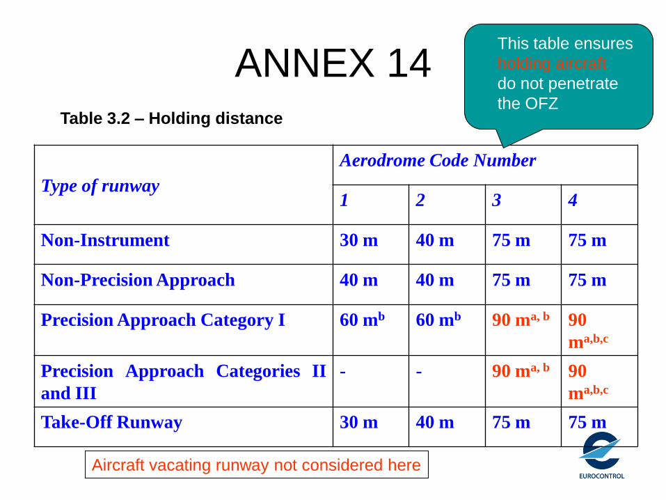
ANNEX 14
Type of runway
Aerodrome Code Number
1 2 3 4
Non-Instrument 30 m 40 m 75 m 75 m
Non-Precision Approach 40 m 40 m 75 m 75 m
Precision Approach Category I 60 mb 60 mb 90 ma, b 90
ma,b,c
Precision Approach Categories II
and III
- - 90 ma, b 90
ma,b,c
Take-Off Runway 30 m 40 m 75 m 75 m
Table 3.2 – Holding distance
Aircraft vacating runway not considered here
This table ensures
holding aircraft
do not penetrate
the OFZ

ANNEX 14 - runway strip:
• a defined area including the runway and
stop way, if provided, intended:a) to reduce the risk of damage to aircraft running off
a runway; and
b) to protect aircraft flying over it during take-off or
landing operations.”

Annex 14 section 3.3.7
• defines the rules to apply for fixed object and mobile object on the runway strip as follows:
• “3.3.7 No fixed object, other than visual aids required for air navigation purposes and satisfying the relevant frangibility requirement in Chapter 5, shall be permitted on a runway strip:– within 77.5 m of the runway centre line of a precision approach runway
category I, II or III where the code number is 4 and the code letter is F;
– or within 60 m of the runway centre line of a precision approach runway category I, II or III where the code number is 3 or 4;
– or within 45 m of the runway centre line of a precision approach runway category I where the code number is 1 or 2.
• No mobile object shall be permitted on this part of the runway strip during the use of the runway for landing or take-off.”

ICAO Doc 9137
Part 6 Control of obstacles
• The OFZ shall be kept free
from fixed objects,… and from transient
objects such as aircraft and vehicles when
the runway is being used for category II or
III ILS approaches.
• When an OFZ is established for a precision approach runway
category I, it shall be clear of such objects when the runway is used
for category I ILS approaches.


![The GBAS Landing SystemThe GBAS Landing SystemTitle: Microsoft PowerPoint - Boeing GBAS Presentation, Beijing, October 29, 2009.ppt [兼容模式] Author: Shile Created Date: 11/10/2009](https://static.documents.pub/doc/80x56/5a727f467f8b9ac0538da536/the-gbas-landing-systemthe-gbas-landing-systemtitle-microsoft-powerpoint-boeing.jpg)


