GCI BRUTALIST JR. BUILD GUIDE The Brutalist Jr. is the DIY little brother to the GCI Brutalist, a high powered distortion pedal loosely based on the Providence Stampede SDT-1. It runs on 9v DC power or 9v battery and has controls for volume, loudness (a high and low boost chained into one control), and gain (distortion.) Components have been carefully chosen to provide a powerful distorted sound when placed in front of a semi-clean tube amp, but please feel free to experiment with component choices. Alternate resistors, capacitors, and diodes can change the tonal and gain characteristics of the circuit. External switches can be added to make these choices switchable. If you are inexperienced with soldering, please watch YouTube tutoritals and get comfortable with “tinning” wire ends and making solder connections to PCBs and pots before beginning this build. This kit is designed was designed and prototyped in the USA. Consequently, these instructions are in English units. Apologies to any non-US builders who need to convert to metric from this antiquated system. If you enjoy building this kit and find it useful, please show us your work by tagging www.facebook.com/KurtBallou/ or www.instagram.com/godcitymusic/ and use the hashtags #godcityinstruments and #brutalistjr.
Transcript
GCI BRUTALIST JR. BUILD GUIDE
The Brutalist Jr. is the DIY little brother to the GCI Brutalist, a high powered distortion pedal loosely based on the Providence Stampede SDT-1. It runs on 9v DC power or 9v battery and has controls for volume, loudness (a high and low boost chained into one control), and gain (distortion.) Components have been carefully chosen to provide a powerful distorted sound when placed in front of a semi-clean tube amp, but please feel free to experiment with component choices. Alternate resistors, capacitors, and diodes can change the tonal and gain characteristics of the circuit. External switches can be added to make these choices switchable.
If you are inexperienced with soldering, please watch YouTube tutoritals and get comfortable with “tinning” wire ends and making solder connections to PCBs and pots before beginning this build.
This kit is designed was designed and prototyped in the USA. Consequently, these instructions are in English units. Apologies to any non-US builders who need to convert to metric from this antiquated system.
If you enjoy building this kit and find it useful, please show us your work by tagging www.facebook.com/KurtBallou/ or www.instagram.com/godcitymusic/ and use the hashtags #godcityinstruments and #brutalistjr.
Feel free to buy parts a la carte from any electronics supplier, but Small Bear Electronics http://www.smallbear-electronics.mybigcommerce.com/ have been kind enough to create a parts kit for this project. Full kit (includes everything except PCB) and mini kit (includes everything except PCB, enclosure, and knobs) available here: http://smallbear-electronics.mybigcommerce.com/kit-the-gc-brutalist-jr/
MODS
At the end of this build guide is a section of suggested mods. Remember to add components for desired mods when ordering parts. For mods which require additional pots and/or switches, consider using a larger enclosure such as the 1790NS.
ENCLOSURE
The kit includes a 125BB size enclosure that will need to be drilled per instructions on the attached drill template PDF. If a different sized enclosure is chosen, adapt the drill template for that enclosure, taking care to provide clearance for pots, jacks, LED, and switches.
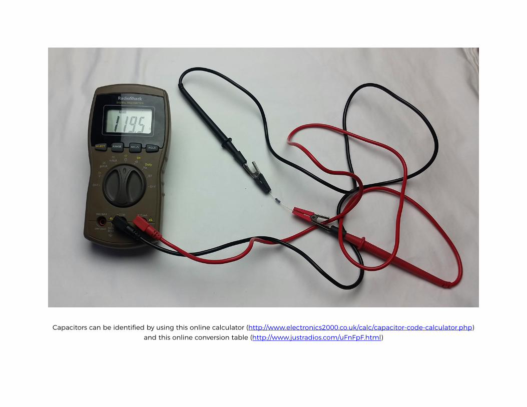
Capacitors can be identified by using this online calculator (http://www.electronics2000.co.uk/calc/capacitor-code-calculator.php) and this online conversion table (http://www.justradios.com/uFnFpF.html)
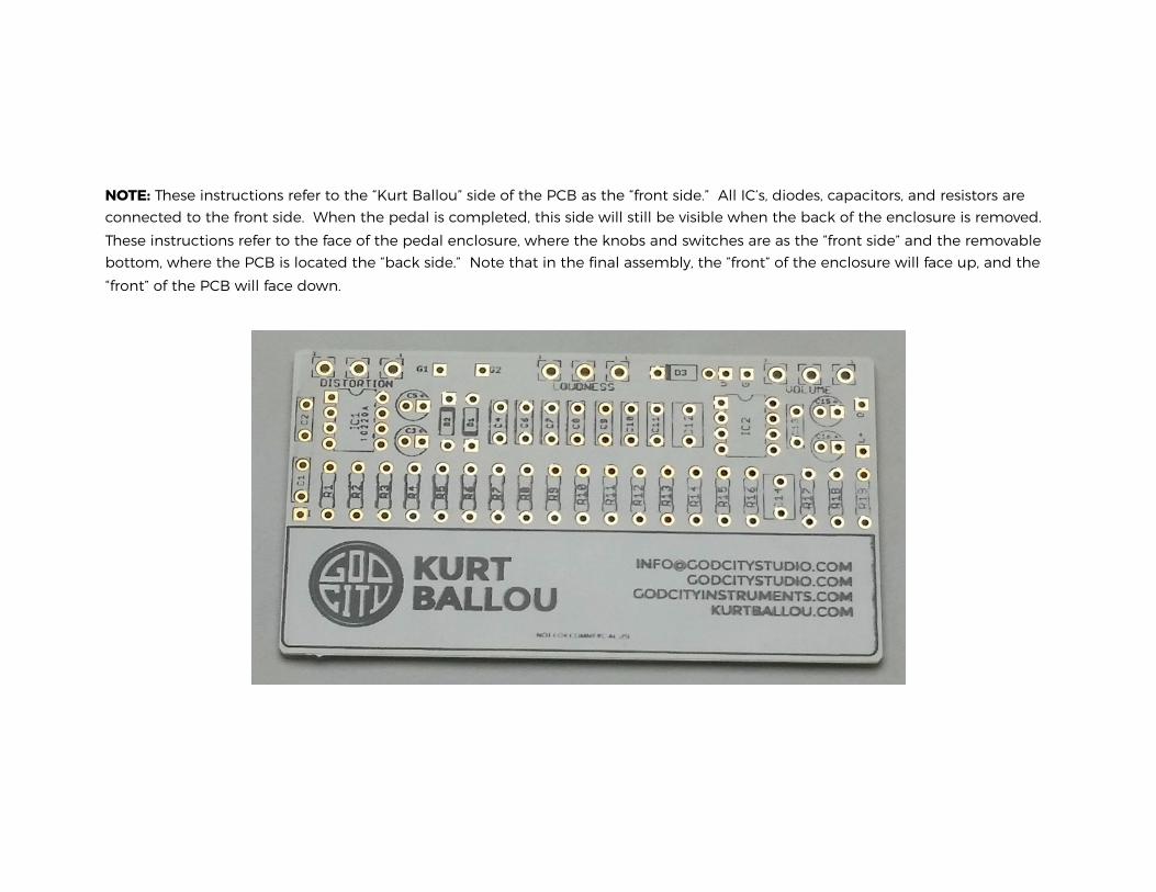
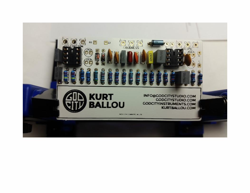
NOTE: These instructions refer to the “Kurt Ballou” side of the PCB as the “front side.” All IC’s, diodes, capacitors, and resistors are connected to the front side. When the pedal is completed, this side will still be visible when the back of the enclosure is removed. These instructions refer to the face of the pedal enclosure, where the knobs and switches are as the “front side” and the removable bottom, where the PCB is located the “back side.” Note that in the final assembly, the “front” of the enclosure will face up, and the “front” of the PCB will face down.
!
POPULATE THE PCB
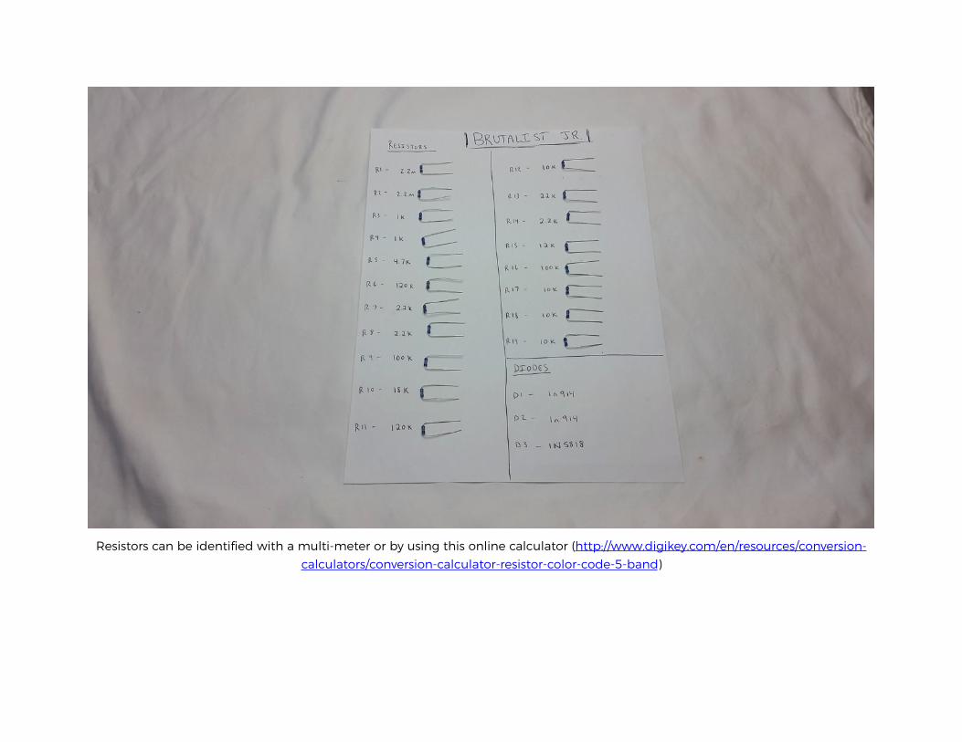
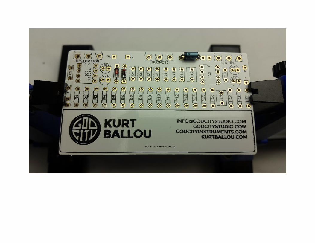
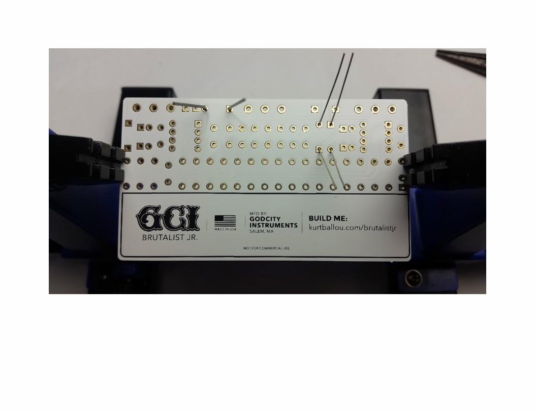
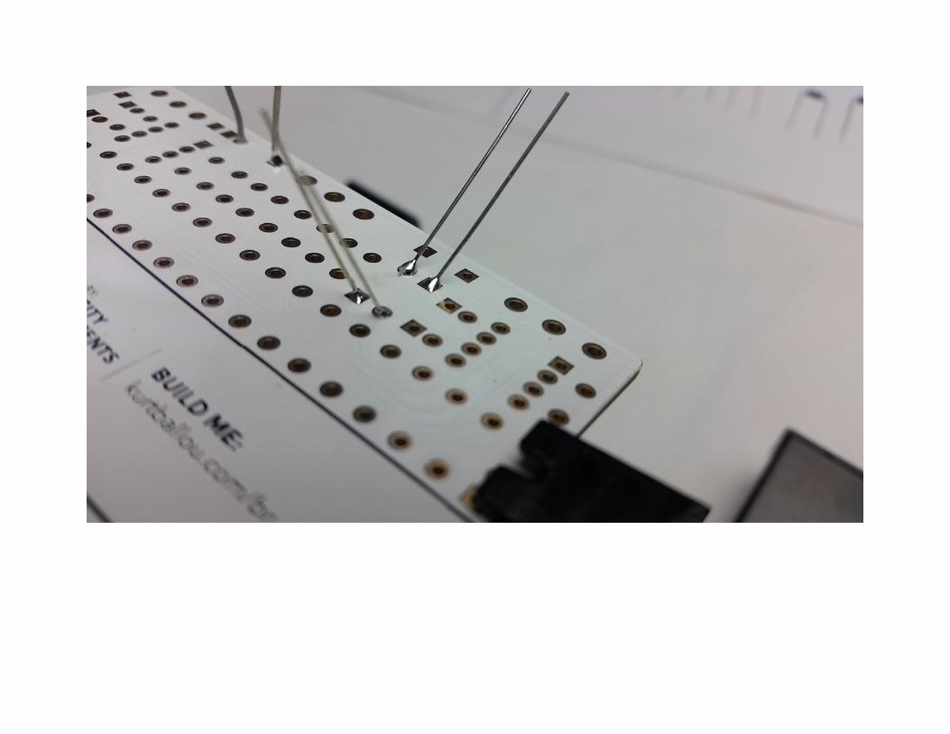
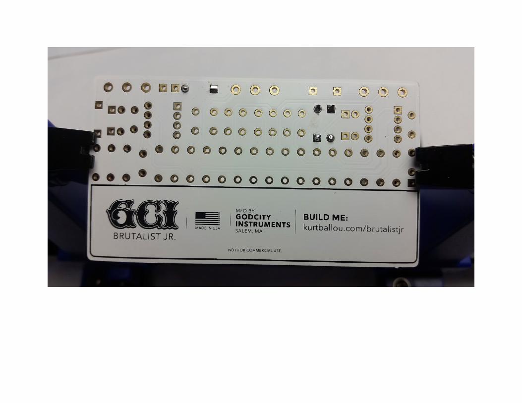
Step 1: Add the diodes. First find the 1N5818 diode. This provides protection against incorrect power supply polarity. Next find a pair of 1N914 diodes. These are the clipping diodes. Bend each diode’s legs at 90 degrees and install them through the front side of the PCB. The 1N5818 goes in the D3 slot and the 1N914s go in the D1 and D2 slots. Be sure to match the end of the diode with the stripe to the stripe on the PCB next to the square pad. Proper orientation of diodes is critical. Then, from the back side of the PCB, bend their legs out to hold them in place until it’s time to solder. Solder all diodes and trim the excess length of the legs with a side cutter, being sure not to scratch or damage the PCB.
!
!
!
!
!
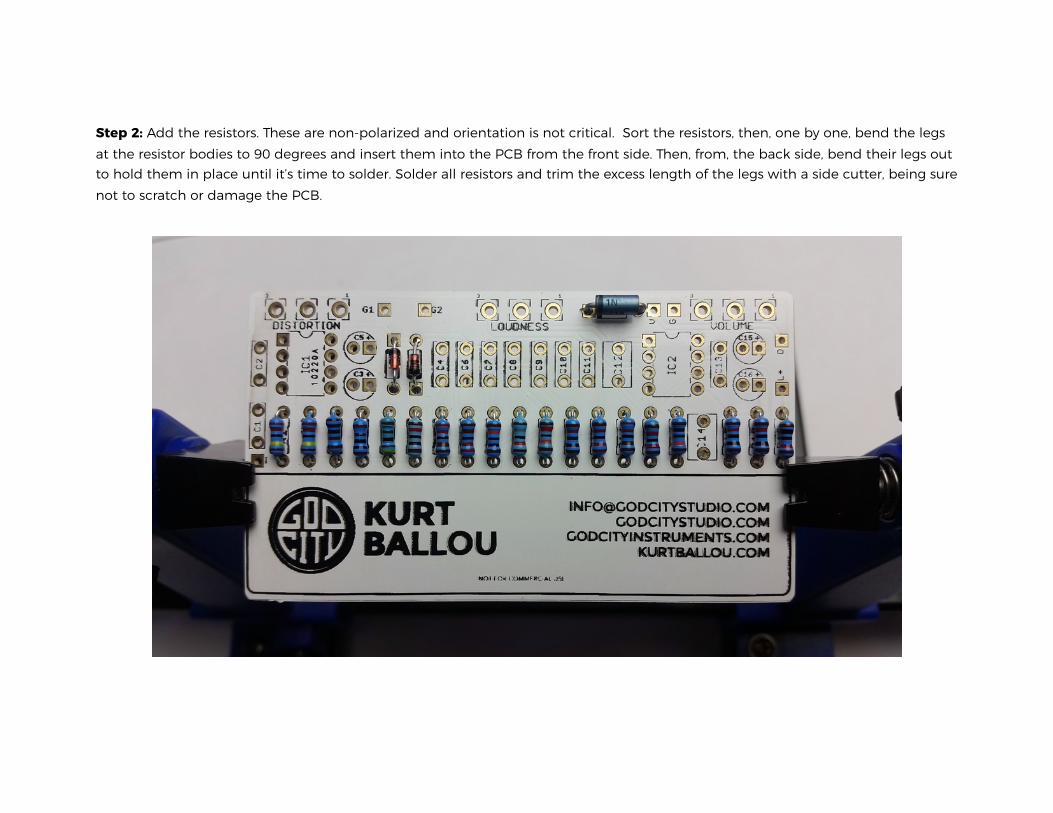
Step 2: Add the resistors. These are non-polarized and orientation is not critical. Sort the resistors, then, one by one, bend the legs at the resistor bodies to 90 degrees and insert them into the PCB from the front side. Then, from, the back side, bend their legs out to hold them in place until it’s time to solder. Solder all resistors and trim the excess length of the legs with a side cutter, being sure not to scratch or damage the PCB.
!
!
!
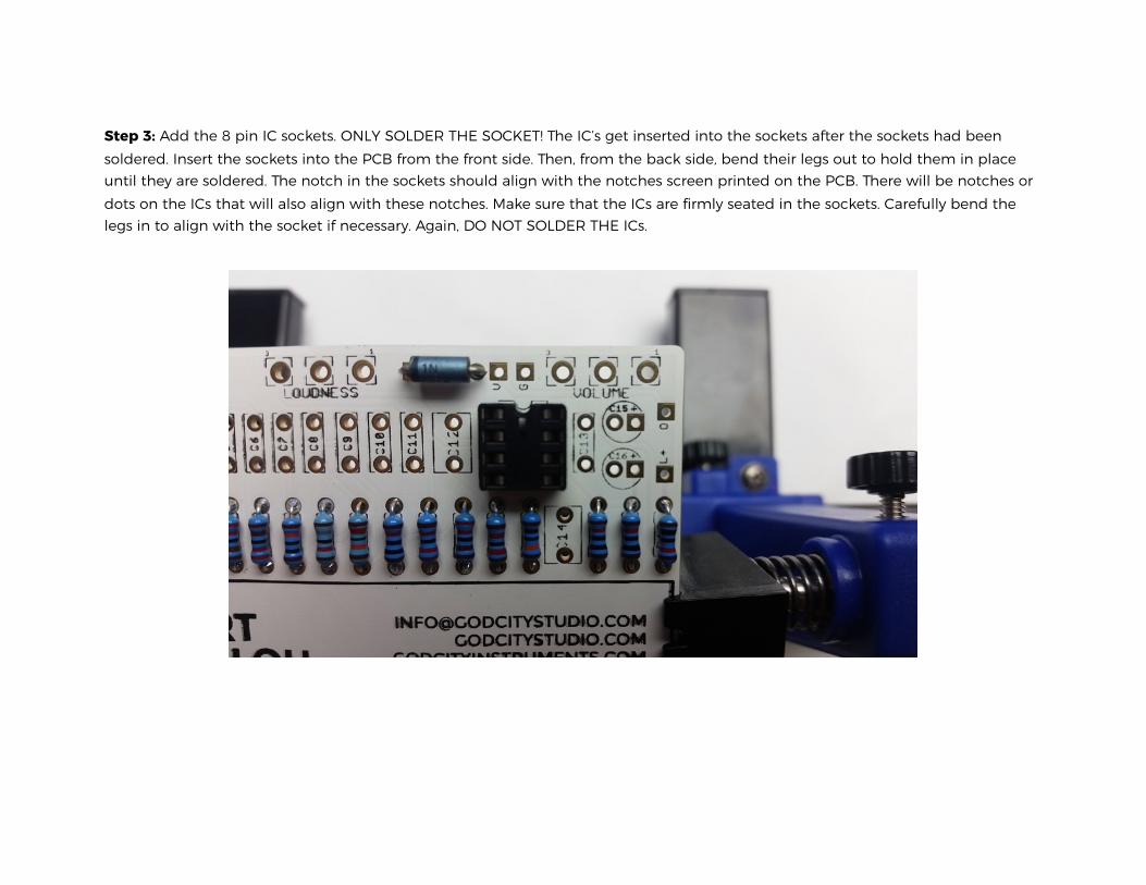
Step 3: Add the 8 pin IC sockets. ONLY SOLDER THE SOCKET! The IC’s get inserted into the sockets after the sockets had been soldered. Insert the sockets into the PCB from the front side. Then, from the back side, bend their legs out to hold them in place until they are soldered. The notch in the sockets should align with the notches screen printed on the PCB. There will be notches or dots on the ICs that will also align with these notches. Make sure that the ICs are firmly seated in the sockets. Carefully bend the legs in to align with the socket if necessary. Again, DO NOT SOLDER THE ICs.
!
!
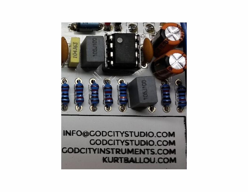
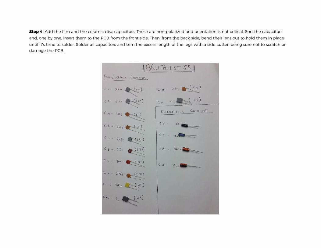
Step 4: Add the film and the ceramic disc capacitors. These are non-polarized and orientation is not critical. Sort the capacitors and, one by one, insert them to the PCB from the front side. Then, from the back side, bend their legs out to hold them in place until it’s time to solder. Solder all capacitors and trim the excess length of the legs with a side cutter, being sure not to scratch or damage the PCB.
!
!
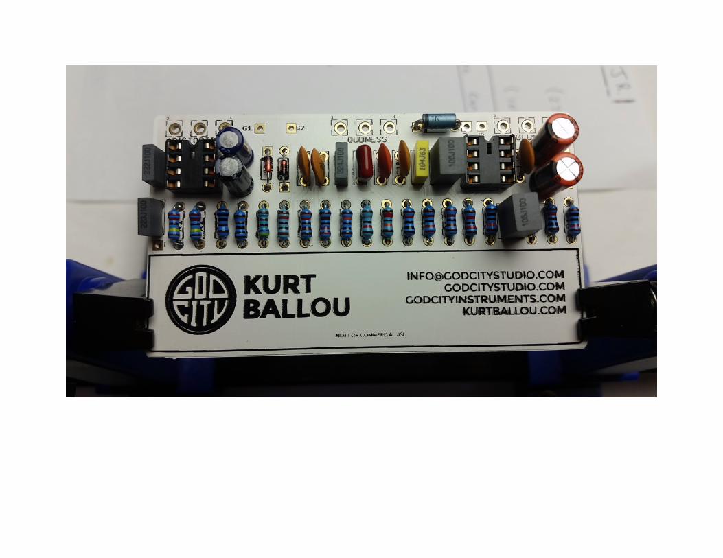
Step 5: Add the electrolytic capacitors. These are polarized, which means the orientation is critical. The positive side will have a longer lead and goes into the square solder pad. The negative side will have a shorter lead and a stripe running along the side of the cap, and goes into the round solder pad. Sort the capacitors then, one by one, insert them to the PCB from the front side. Then, from the back side, bend their legs out to hold them in place until it’s time to solder. Solder all capacitors and trim the excess length of the legs with your side cutter, being sure not to scratch or damage the PCB.
!
!
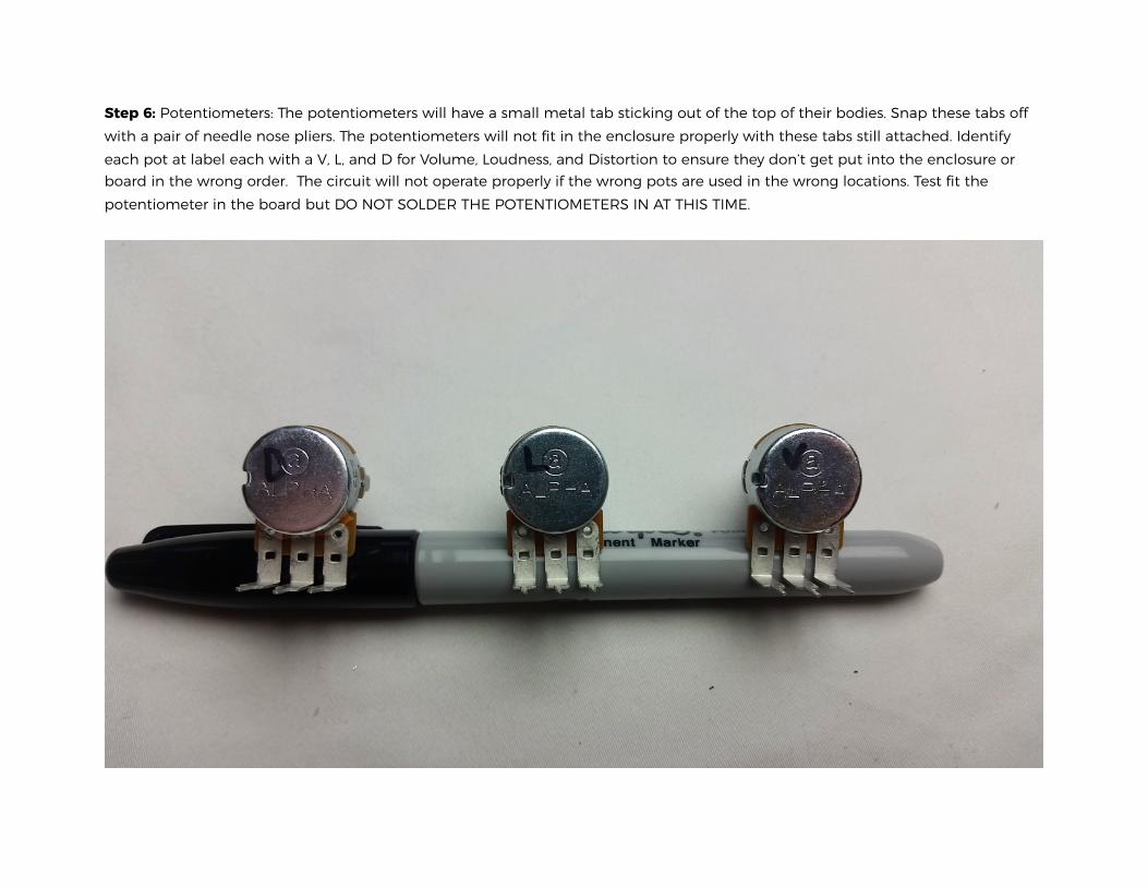
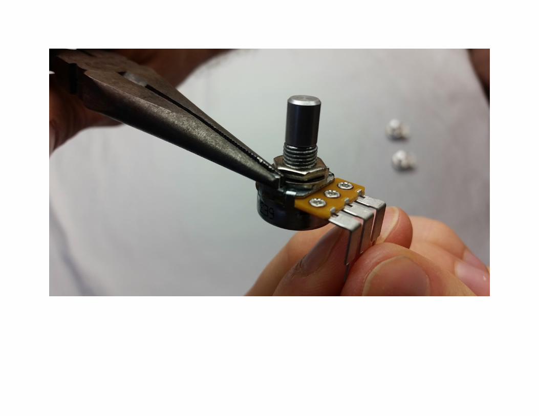
Step 6: Potentiometers: The potentiometers will have a small metal tab sticking out of the top of their bodies. Snap these tabs off with a pair of needle nose pliers. The potentiometers will not fit in the enclosure properly with these tabs still attached. Identify each pot at label each with a V, L, and D for Volume, Loudness, and Distortion to ensure they don’t get put into the enclosure or board in the wrong order. The circuit will not operate properly if the wrong pots are used in the wrong locations. Test fit the potentiometer in the board but DO NOT SOLDER THE POTENTIOMETERS IN AT THIS TIME.
!
!
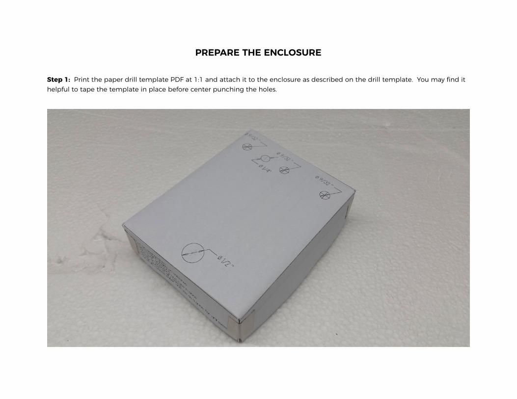
PREPARE THE ENCLOSURE
Step 1: Print the paper drill template PDF at 1:1 and attach it to the enclosure as described on the drill template. You may find it helpful to tape the template in place before center punching the holes.
!
!
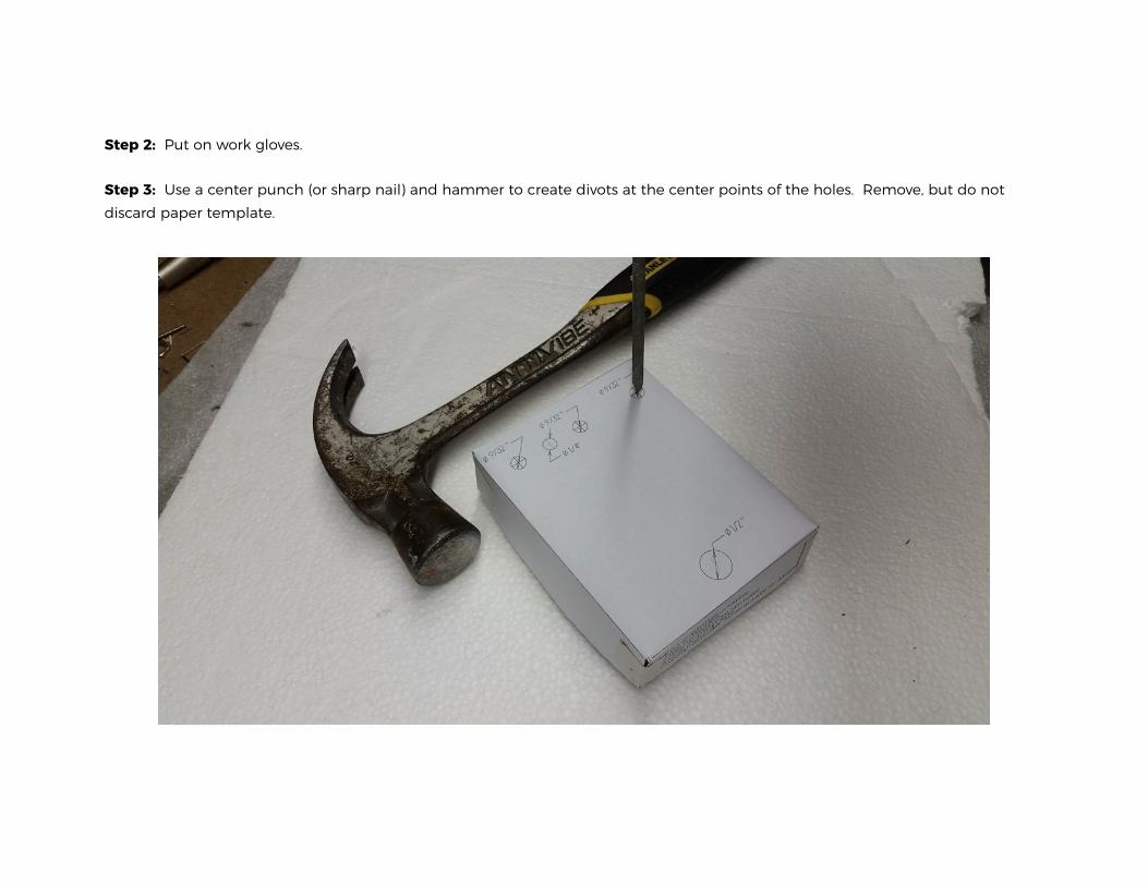
Step 2: Put on work gloves.
Step 3: Use a center punch (or sharp nail) and hammer to create divots at the center points of the holes. Remove, but do not discard paper template.
!
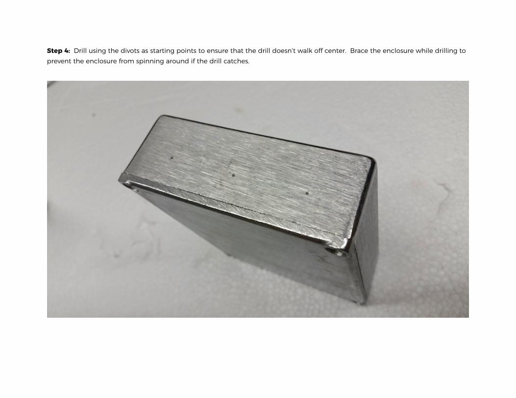
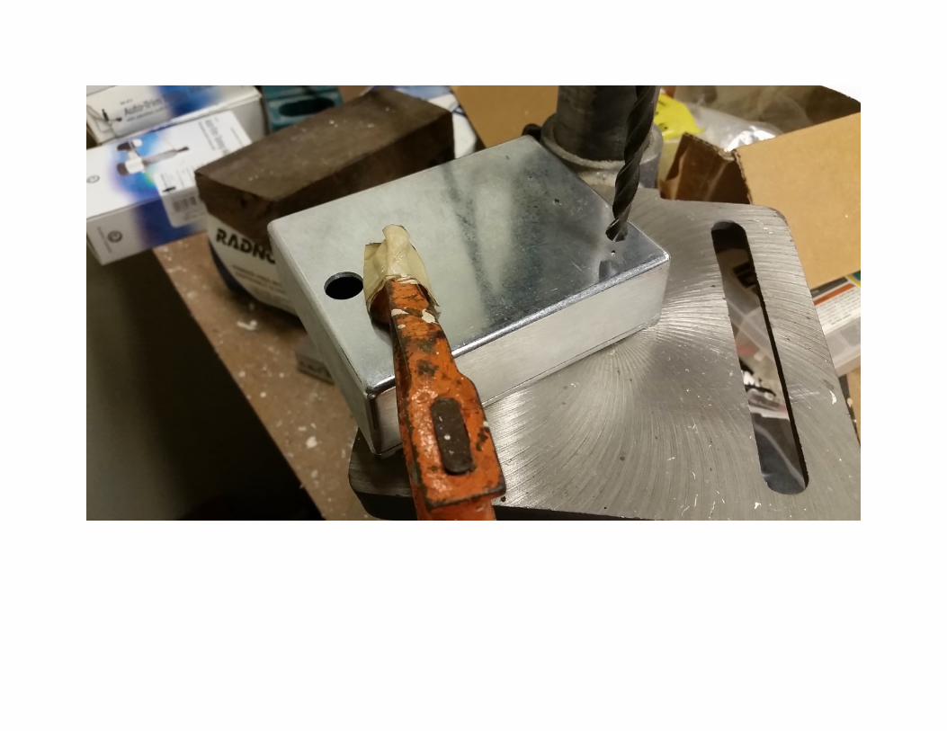
Step 4: Drill using the divots as starting points to ensure that the drill doesn’t walk off center. Brace the enclosure while drilling to prevent the enclosure from spinning around if the drill catches.
!
!
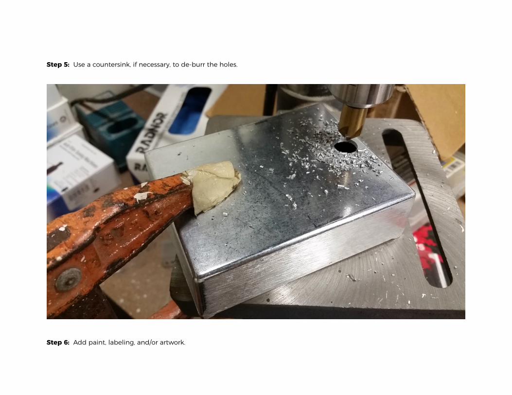
Step 5: Use a countersink, if necessary, to de-burr the holes.
!
Step 6: Add paint, labeling, and/or artwork.
ASSEMBLY
Gather all of the remaining hardware, the populated PCB, and the finished and drilled enclosure. It is time to assemble. As hardware is added to the enclosure, tighten each with a pair of pliers or appropriate size socket.
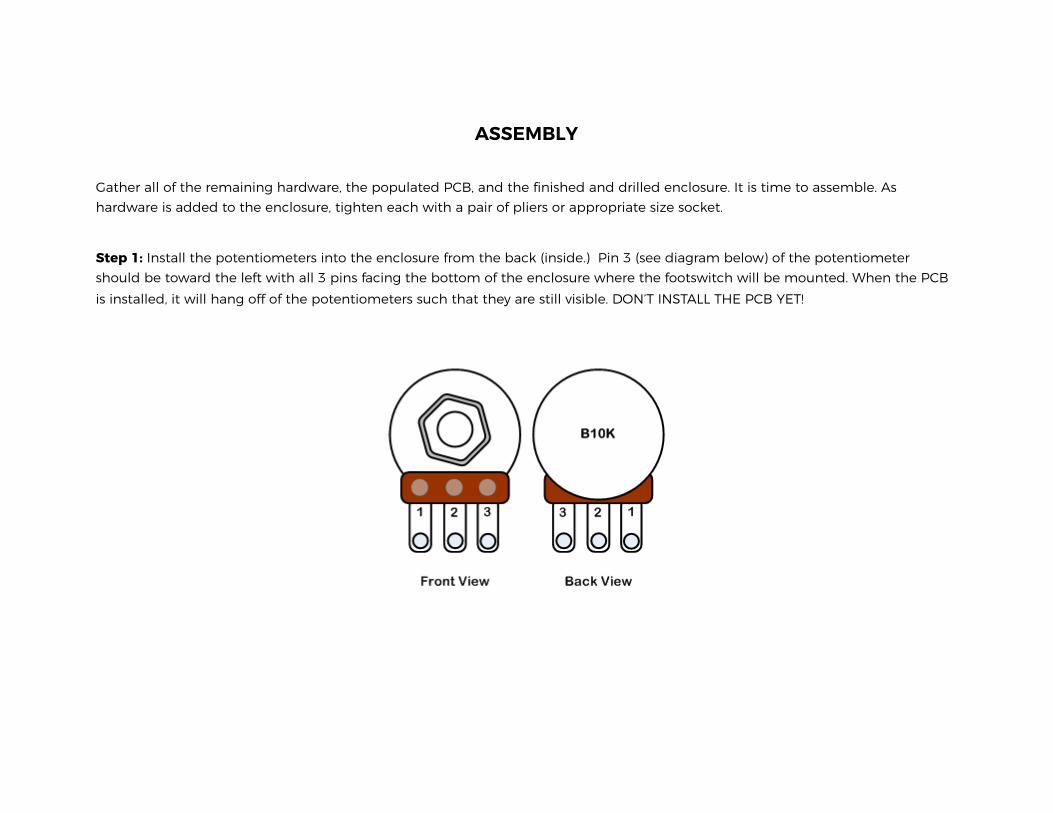
Step 1: Install the potentiometers into the enclosure from the back (inside.) Pin 3 (see diagram below) of the potentiometer should be toward the left with all 3 pins facing the bottom of the enclosure where the footswitch will be mounted. When the PCB is installed, it will hang off of the potentiometers such that they are still visible. DON’T INSTALL THE PCB YET!
!
!
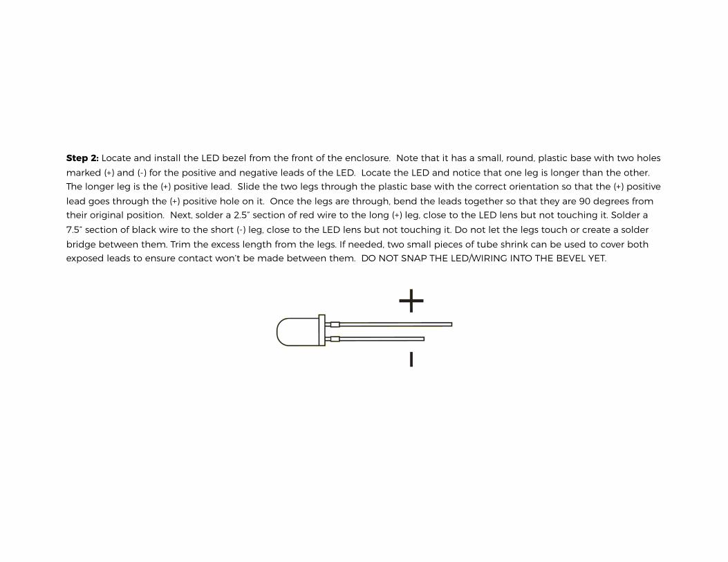
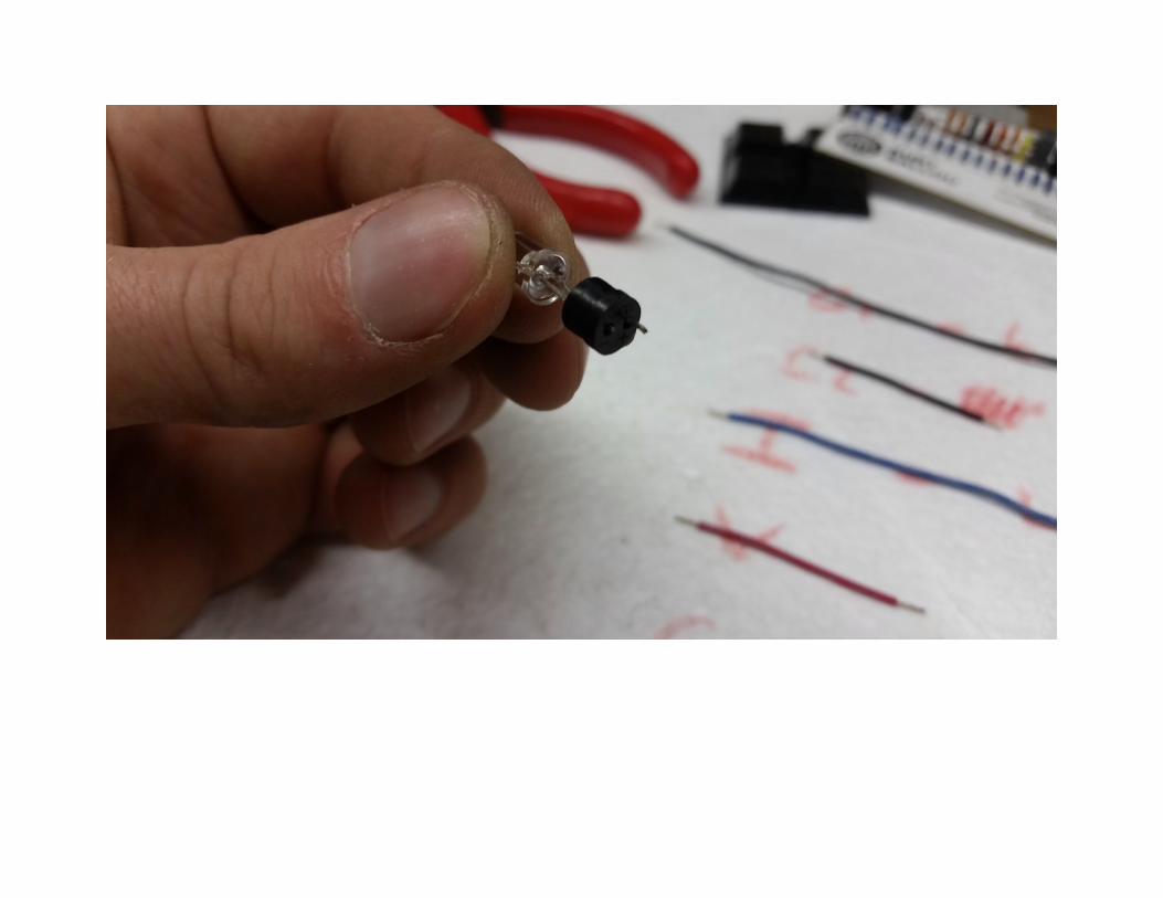
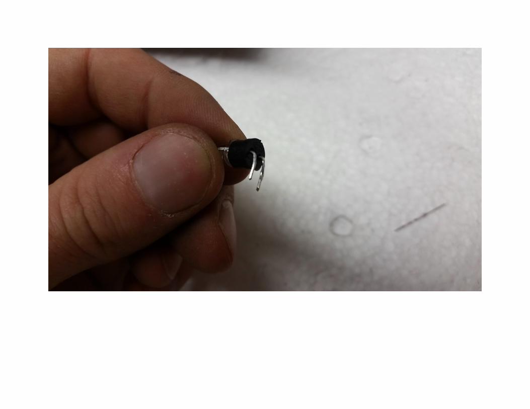
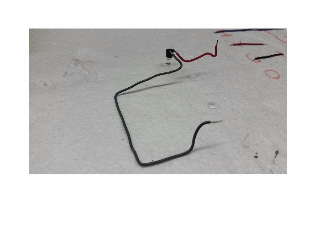
Step 2: Locate and install the LED bezel from the front of the enclosure. Note that it has a small, round, plastic base with two holes marked (+) and (-) for the positive and negative leads of the LED. Locate the LED and notice that one leg is longer than the other. The longer leg is the (+) positive lead. Slide the two legs through the plastic base with the correct orientation so that the (+) positive lead goes through the (+) positive hole on it. Once the legs are through, bend the leads together so that they are 90 degrees from their original position. Next, solder a 2.5” section of red wire to the long (+) leg, close to the LED lens but not touching it. Solder a 7.5” section of black wire to the short (-) leg, close to the LED lens but not touching it. Do not let the legs touch or create a solder bridge between them. Trim the excess length from the legs. If needed, two small pieces of tube shrink can be used to cover both exposed leads to ensure contact won’t be made between them. DO NOT SNAP THE LED/WIRING INTO THE BEVEL YET.
!
!
!
!
Step 3: Install the power jack through the enclosure and tighten the nut from the inside. Be careful to not over tighten as the plastic threads could strip.
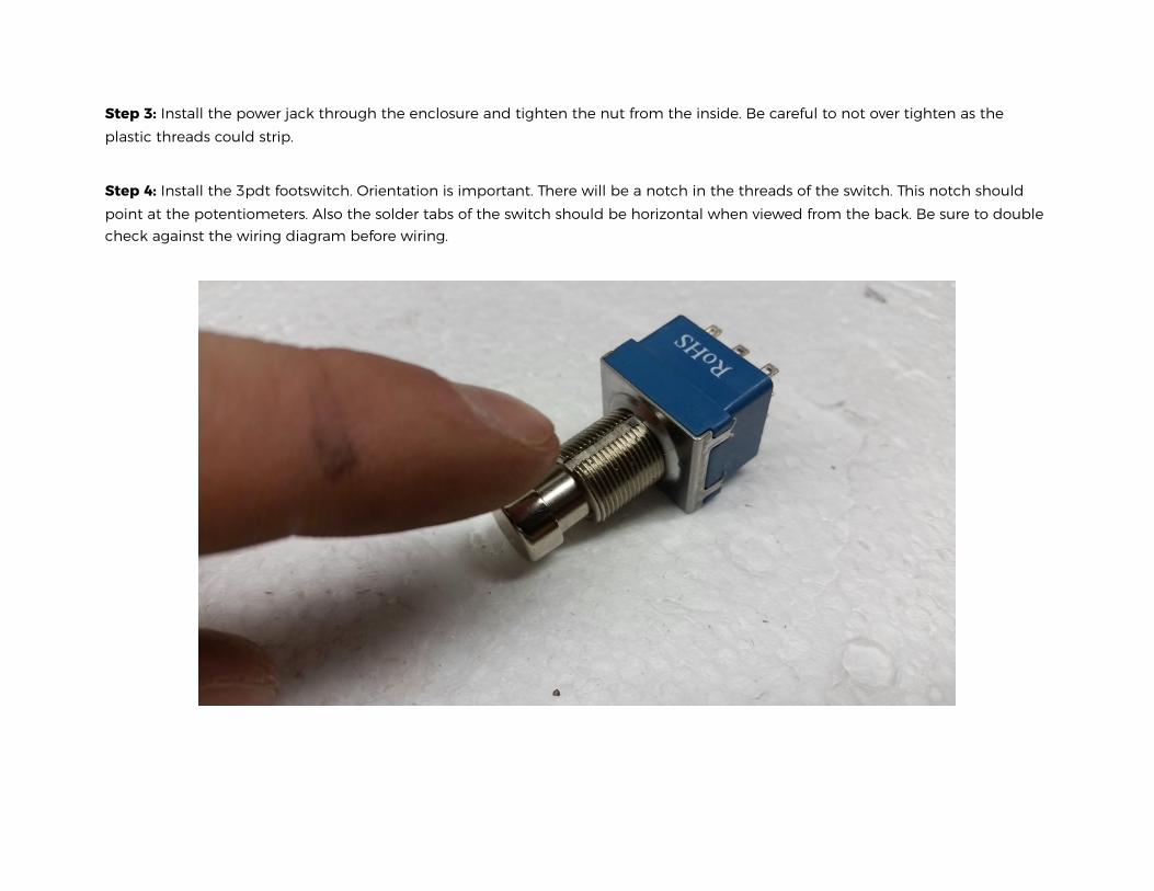
Step 4: Install the 3pdt footswitch. Orientation is important. There will be a notch in the threads of the switch. This notch should point at the potentiometers. Also the solder tabs of the switch should be horizontal when viewed from the back. Be sure to double check against the wiring diagram before wiring.
!
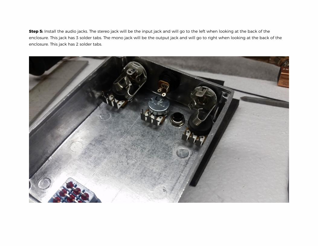
Step 5: Install the audio jacks. The stereo jack will be the input jack and will go to the left when looking at the back of the enclosure. This jack has 3 solder tabs. The mono jack will be the output jack and will go to right when looking at the back of the enclosure. This jack has 2 solder tabs.
!
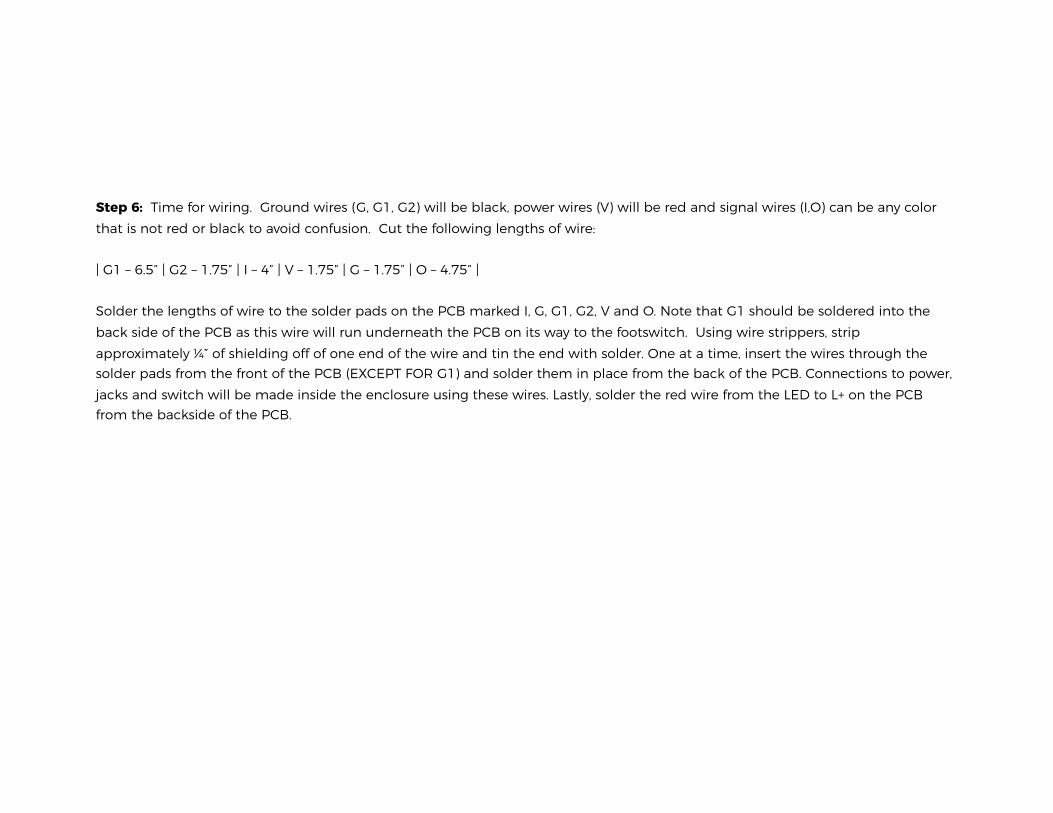
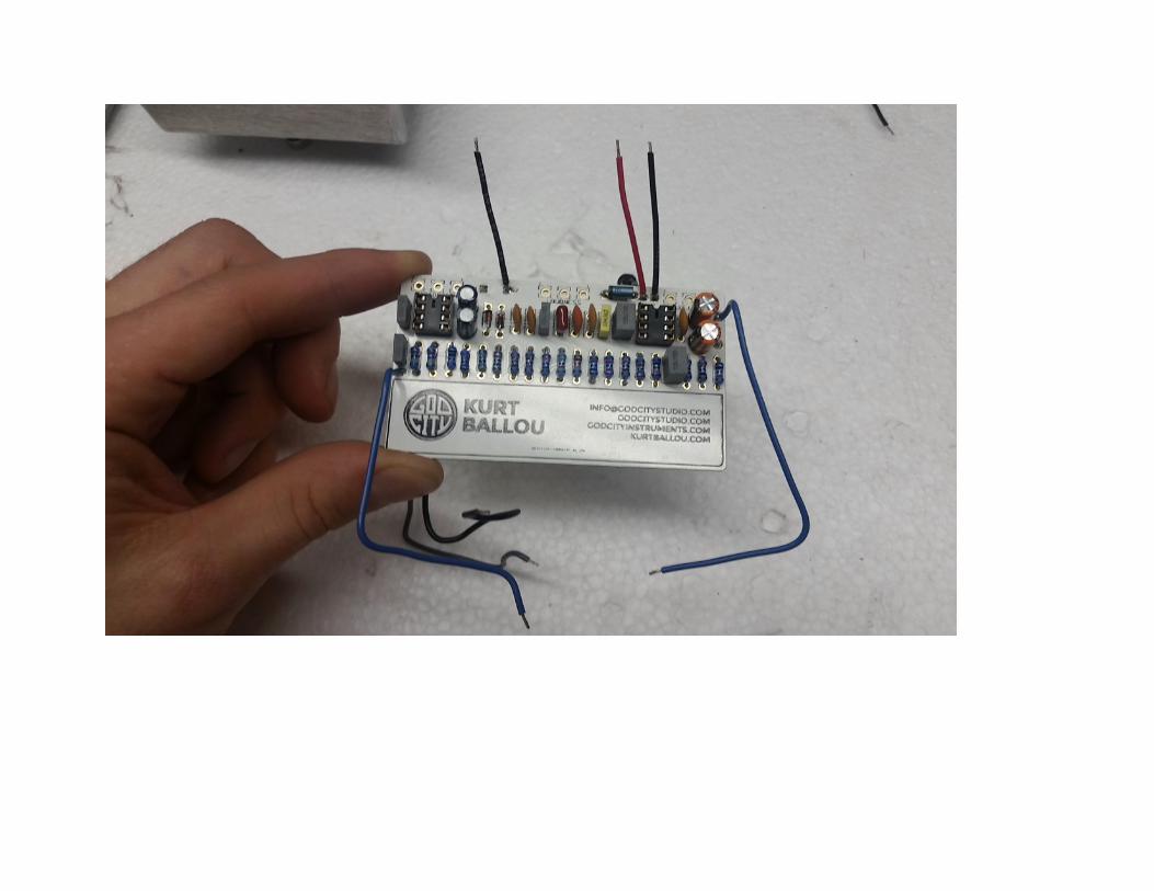
Step 6: Time for wiring. Ground wires (G, G1, G2) will be black, power wires (V) will be red and signal wires (I,O) can be any color that is not red or black to avoid confusion. Cut the following lengths of wire:
| G1 – 6.5” | G2 – 1.75” | I – 4” | V – 1.75” | G – 1.75” | O – 4.75” |
Solder the lengths of wire to the solder pads on the PCB marked I, G, G1, G2, V and O. Note that G1 should be soldered into the back side of the PCB as this wire will run underneath the PCB on its way to the footswitch. Using wire strippers, strip approximately ¼” of shielding off of one end of the wire and tin the end with solder. One at a time, insert the wires through the solder pads from the front of the PCB (EXCEPT FOR G1) and solder them in place from the back of the PCB. Connections to power, jacks and switch will be made inside the enclosure using these wires. Lastly, solder the red wire from the LED to L+ on the PCB from the backside of the PCB.
!
!
Step 7: First, install the LED into the bezel. Next, install the PCB on to the potentiometers and solder them in place. PCB should be oriented such that the “Kurt Ballou” side with all the components faces out. When properly installed all 3 pins of each potentiometer should pass through the PCB. There is no need to bend these pins before soldering and there is no need to trim them after the soldering is completed.
!
!
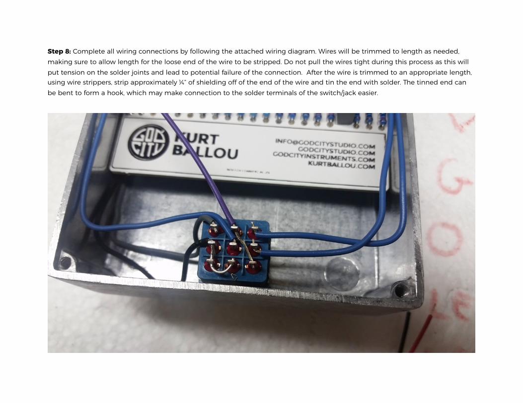
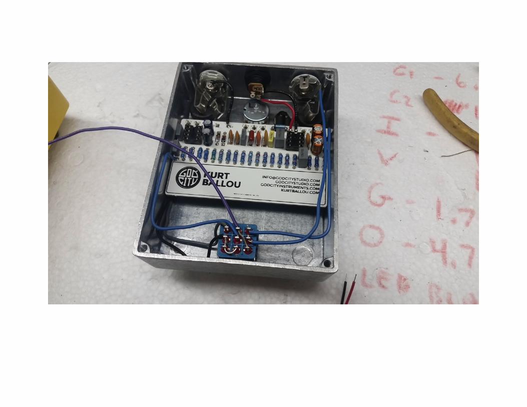
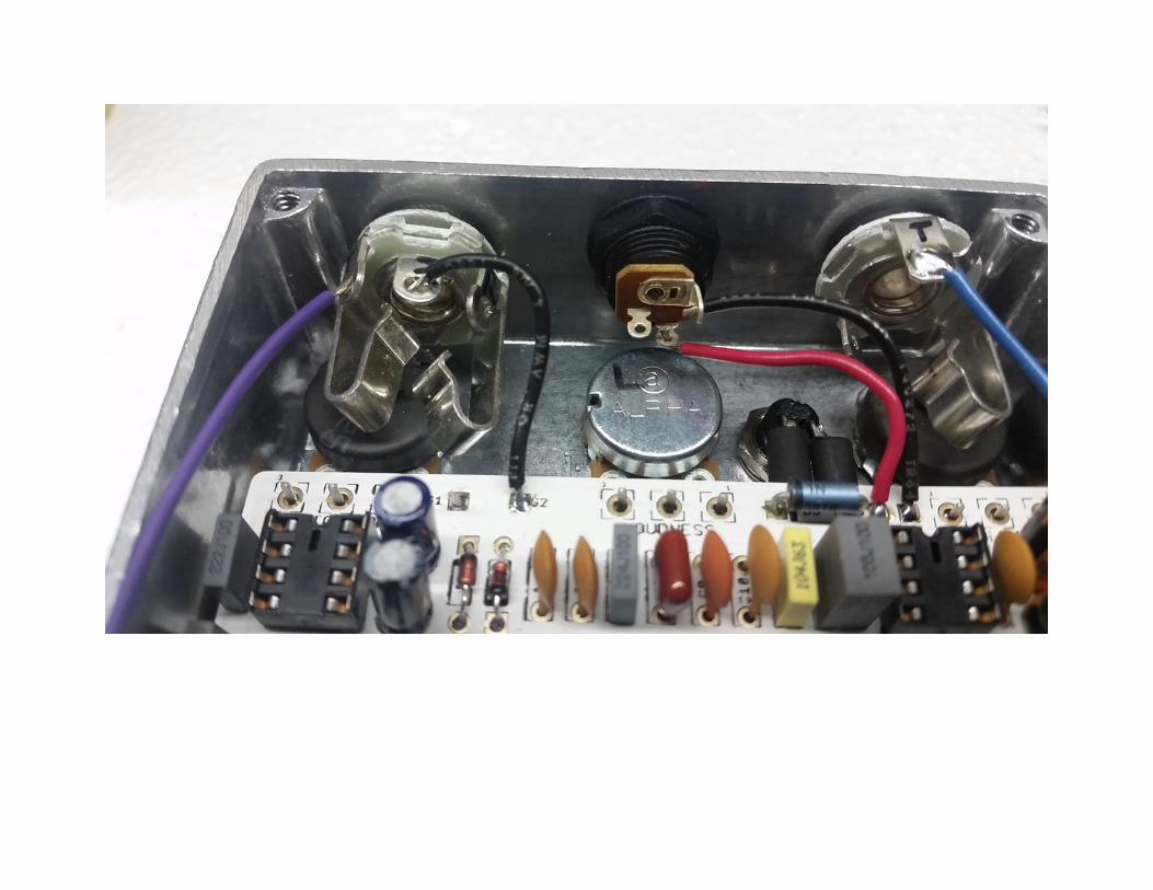
Step 8: Complete all wiring connections by following the attached wiring diagram. Wires will be trimmed to length as needed, making sure to allow length for the loose end of the wire to be stripped. Do not pull the wires tight during this process as this will put tension on the solder joints and lead to potential failure of the connection. After the wire is trimmed to an appropriate length, using wire strippers, strip approximately ¼” of shielding off of the end of the wire and tin the end with solder. The tinned end can be bent to form a hook, which may make connection to the solder terminals of the switch/jack easier.
!
!
!
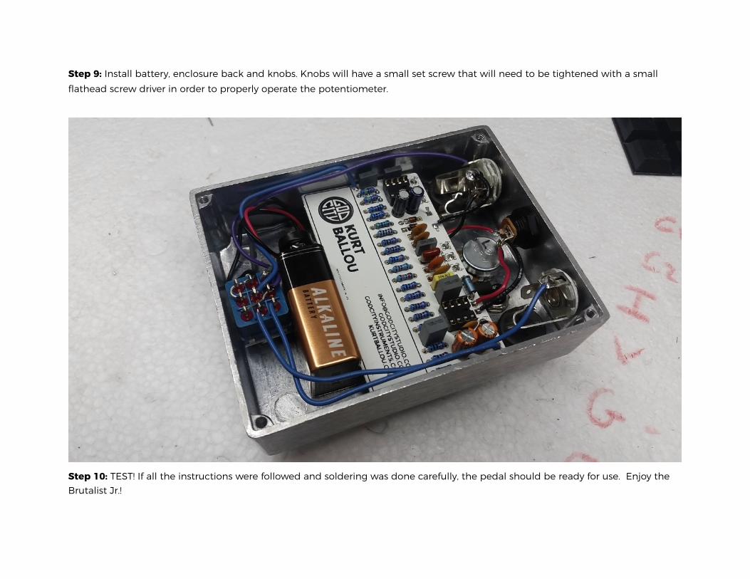
Step 9: Install battery, enclosure back and knobs. Knobs will have a small set screw that will need to be tightened with a small flathead screw driver in order to properly operate the potentiometer.
! Step 10: TEST! If all the instructions were followed and soldering was done carefully, the pedal should be ready for use. Enjoy the Brutalist Jr.!
TECH SUPPORT
Due to the nature of this project, there is no specialized technical support. Look in the mirror, say to yourself “I can do this” three times, then try again. If you’re still having trouble, ask a friend with building experience. DIY!
SUGGESTED MODS
If you like tweaking, here’s a few places to start. We have not yet tried all of these, so take all these suggestions with a grain of salt.
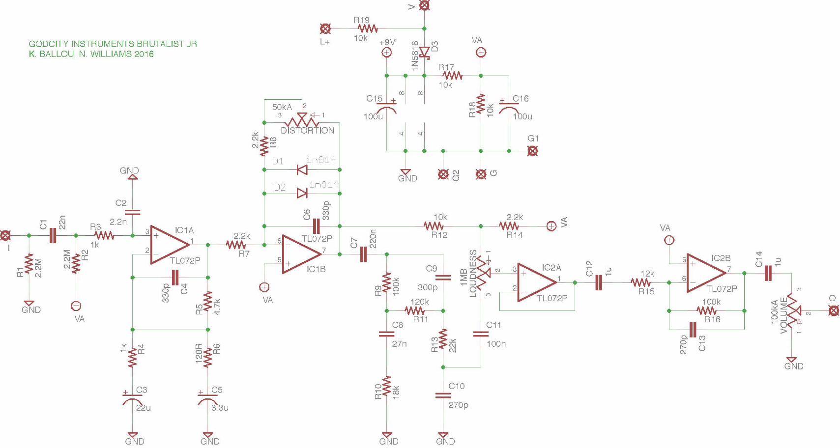
Clipping Diodes: D1 and D2 can be adjusted to produce a variety of changes to the compression, harmonics, and volume of the clipping. LEDs have a larger clipping threshold and will result in less compression and more overall volume. Germanium and Schottky diodes have the lowest clipping threshold and will result in the least amount of overall volume. Mismatching the types of diodes in D1 and D2 creates asymmetric clipping (different clipping thresholds on each half of the AC signal). Do not be afraid to experiment with various clipping diodes to achieve an optimum distortion and/or using toggle switches to allow for multiple clipping options. Red 3mm LED’s, 1n4001’s, 1n34a, or nothing at all are common choices.
Increasing Maximum Distortion: Increasing the maximum distortion level is optimally achieved by increasing R5. Try doubling or tripling the value to increase the maximum distortion level but be careful as overall noise floor will increase as R5 increases.
Op Amp Replacements: Here is a list of op-amps that can replace IC1 and/or IC2:
• RC4558 • NE5532 • OPA2134
• TL082 Generally any op-amp that is pin compatible with a TL072 could be swapped into the circuit. However, be mindful that very high performance op-amps may not be the best choice. They generally require more careful PCB design than is afforded in this kit.
Global Treble Adjustment: C13 is used to control the final treble response of the circuit. Increasing the value will darken the overall tone while decreasing the value will brighten the tone. Try values between 100p and 470p.
Loudness Treble Adjustment: C10 (in part) adjusts the high shelf of the Loudness control. Increasing the value will shift the center frequency down while decreasing the value shifts the frequency up. Try values between 100p and 470p.
Loudness Bass Adjustment: C8 (in part) adjusts the low shelf of the Loudness control. Increasing the value will shift the center frequency down while decreasing the value shifts the frequency up. Lowering this frequency may make the pedal better suited for bass guitar or provide a “scooped” effect to the EQ on guitar. C7 can be used to lower the overall bass level. Decreasing the value will decrease the overall bass response. Increasing it will increase the bass but above 1uF the returns are diminishing.
High Pass Filtering: There are two RC pairs that control bass cut-off, the first of which is R4/C3, the second of which is R6/C5. Reduce the value of these capacitors will increase bass roll off and make for a tighter playing response, albeit thinner sound. However, increasing the bass response in the Loudness control can compensate for a loss of bass in the high pass filter. Try between 4.7 and 33uF for C3 and between 4.7uF and 47uF for C5.
Response Mod: Replace R6 with a potentiometer. Aside from affecting the high pass filter, R6 also has an effect on gain. By sweeping the R6 pot in one direction, high pass filtering and gain will increase simultaneously, possibly making the pedal better suited for tight heavy metal rhythm playing. By sweeping in the other direction, bass increases while gain decreases, making the pedal bigger and looser sounding. Try a 1k reverse log pot in series with a 47 ohms resistor.