304
http://www.cncspares.com/ GE Fanuc Automation Computer Numerical Control Products Alpha Series AC Servo Motor Descriptions Manual GFZ-65142E/04 February 2001
http://www.cncspares.com/GE Fanuc Automation
Computer Numerical Control Products
Alpha Series AC Servo Motor
Descriptions Manual
GFZ-65142E/04 February 2001
http://www.cncspares.com/
GFL-001
Warnings, Cautions, and Notesas Used in this Publication
WarningWarning notices are used in this publication to emphasize that hazardous voltages, currents,temperatures, or other conditions that could cause personal injury exist in this equipment or maybe associated with its use.
In situations where inattention could cause either personal injury or damage to equipment, aWarning notice is used.
CautionCaution notices are used where equipment might be damaged if care is not taken.
NoteNotes merely call attention to information that is especially significant to understanding andoperating the equipment.
This document is based on information available at the time of its publication. While effortshave been made to be accurate, the information contained herein does not purport to cover alldetails or variations in hardware or software, nor to provide for every possible contingency inconnection with installation, operation, or maintenance. Features may be described herein whichare not present in all hardware and software systems. GE Fanuc Automation assumes noobligation of notice to holders of this document with respect to changes subsequently made.
GE Fanuc Automation makes no representation or warranty, expressed, implied, or statutorywith respect to, and assumes no responsibility for the accuracy, completeness, sufficiency, orusefulness of the information contained herein. No warranties of merchantability or fitness forpurpose shall apply.
©Copyright 2001 GE Fanuc Automation North America, Inc.
All Rights Reserved.
http://www.cncspares.com/
s–1
SAFETY PRECAUTIONSFANUC SERVO MOTOR series
This ”Safety Precautions” section describes the precautions which must be observed to ensure safety when usingFANUC servo motors (including spindle motors). Users of any servo motor model are requested to read thismanual carefully before using the servo motor.The users are also requested to read this manual carefully and understand each function of the motor for correctuse.The users are basically forbidden to do any behavior or action not mentioned in the ”Safety Precautions.” Theyare invited to ask FANUC previously about what behavior or action is prohibited.
Contents
1. DEFINITION OF WARNING, CAUTION, AND NOTE s–2. . . . . . . . . . . . . . . . . . . . . . .
2. WARNING s–3. . . . . . . . . . . . . . . . . . . . . . . . . . . . . . . . . . . . . . . . . . . . . . . . . . . . . . . . . . . .
3. CAUTION s–5. . . . . . . . . . . . . . . . . . . . . . . . . . . . . . . . . . . . . . . . . . . . . . . . . . . . . . . . . . . .
4. NOTE s–6. . . . . . . . . . . . . . . . . . . . . . . . . . . . . . . . . . . . . . . . . . . . . . . . . . . . . . . . . . . . . . . .
http://www.cncspares.com/
SAFETY PRECAUTIONS B–65142E/04
s–2
1 DEFINITION OF WARNING, CAUTION, AND NOTE
This manual includes safety precautions for protecting the user and preventing damage to themachine. Precautions are classified into Warning and Caution according to their bearing on safety.Also, supplementary information is described as a Note. Read the Warning, Caution, and Notethoroughly before attempting to use the machine.
WARNING
Applied when there is a danger of the user being injured or when there is a damage of both the userbeing injured and the equipment being damaged if the approved procedure is not observed.
CAUTION
Applied when there is a danger of the equipment being damaged, if the approved procedure is notobserved.
NOTE
The Note is used to indicate supplementary information other than Warning and Caution.
Read this manual carefully, and store it in a safe place.
http://www.cncspares.com/
B–65142E/04 SAFETY PRECAUTIONS
s–3
2 WARNING
WARNING
Be safely dressed when handling a motor.
Wear safety shoes or gloves when handling a motor as you may get hurt on any edge or protrusionon it or electric shocks.
Use a crane or lift to move a motor from one place to another.
Motors are heavy. When moving them, use a crane or lift as required. (For the weight of motors,refer to their respective specification manuals.)When moving a motor using a crane or lift, use a hanging bolt if the motor has a correspondingtapped hole, or textile rope if it has no tapped hole. If a motor is attached with a machine or anyother heavy stuff, do not use a hanging bolt to move the motor as the hanging bolt and/or motormay get broken. When moving a motor, be careful not to apply excessive force to its windingsas the windings may break and/or their insulation may deteriorate.
Do not touch a motor with a wet hand.
A failure to observe this caution is vary dangerous because you may get electric shocks.
Before starting to connect a motor to electric wires, make sure they areisolated from an electric power source.
A failure to observe this caution is vary dangerous because you may get electric shocks.
Do not bring any dangerous stuff near a motor.
Motors are connected to a power line, and may get hot. If a flammable is placed near a motor,it may be ignited, catch fire, or explode.
Be sure to ground a motor frame.
To avoid electric shocks, be sure to connect the grounding terminal in the terminal box to thegrounding terminal of the machine.
Do not ground a motor power wire terminal or short–circuit it to anotherpower wire terminal.
A failure to observe this caution may cause electric shocks or a burned wiring.
Some motors require a special connection such as a winding changeover. Refer to theirrespective motor specification manuals for details.
http://www.cncspares.com/
SAFETY PRECAUTIONS B–65142E/04
s–4
WARNING
Connect power wires securely so that they will not get loose.
A failure to observe this caution may cause a wire to be disconnected, resulting in a ground fault,short circuit, or electric shock.
Do not supply the power to the motor while any terminal is exposed.
A failure to observe this caution is very dangerous because you may get electric shocks if yourbody or any conductive stuff touches an exposed terminal.
Do not get close to a rotary section of a motor when it is rotating.
A rotating part may catch your cloths or fingers. Before starting a motor, ensure that there is nostuff that can fly away (such as a key) on the motor.
Before touching a motor, shut off the power to it.
Even if a motor is not rotating, there may be a voltage across the terminals of the motor. Especially before touching a power supply connection, take sufficient precautions. Otherwiseyou may get electric shocks.
Do not touch any terminal of a motor for a while (at least 5 minutes) afterthe power to the motor is shut off.
High voltage remains across power line terminals of a motor for a while after the power to themotor is shut off. So, do not touch any terminal or connect it to any other equipment. Otherwise,you may get electric shocks or the motor and/or equipment may get damaged.
To drive a motor, use a specified amplifier and parameters.
An incorrect combination of a motor, amplifier, and parameters may cause the motor to behaveunexpectedly. This is dangerous, and the motor may get damaged.
Do not touch a motor when it is running or immediately after it stops.
A motor may get hot when it is running. Do not touch the motor before it gets cool enough.Otherwise, you may get burned.
Be careful not get your hair or cloths caught in a fan.
Be careful especially for a fan used to generate an inward air flow.Be careful also for a fan even when the motor is stopped, because it continues to rotate while theamplifier is turned on.
Ensure that motors and related components are mounted securely.
If a motor or its component slips out of place or comes off when the motor is running, it is verydangerous.
http://www.cncspares.com/
B–65142E/04 SAFETY PRECAUTIONS
s–5
3 CAUTION
CAUTION
FANUC motors are designed for use with machines. Do not use them forany other purpose.
If a FANUC motor is used for an unintended purpose, it may cause an unexpected symptom ortrouble. If you want to use a motor for an unintended purpose, previously consult with FANUC.
Ensure that a base or frame on which a motor is mounted is strongenough.
Motors are heavy. If a base or frame on which a motor is mounted is not strong enough, it isimpossible to achieve the required precision.
Be sure to connect motor cables correctly.
An incorrect connection of a cable cause abnormal heat generation, equipment malfunction, orfailure. Always use a cable with an appropriate current carrying capacity (or thickness). For howto connect cables to motors, refer to their respective specification manuals.
Ensure that motors are cooled if they are those that require forciblecooling.
If a motor that requires forcible cooling is not cooled normally, it may cause a failure or trouble.For a fan–cooled motor, ensure that it is not clogged or blocked with dust and dirt. For aliquid–cooled motor, ensure that the amount of the liquid is appropriate and that the liquid pipingis not clogged. For both types, perform regular cleaning and inspection.
When attaching a component having inertia, such as a pulley, to a motor,ensure that any imbalance between the motor and component isminimized.
If there is a large imbalance, the motor may vibrates abnormally, resulting in the motor beingbroken.
Be sure to attach a key to a motor with a keyed shaft.
If a motor with a keyed shaft runs with no key attached, it may impair torque transmission orcause imbalance, resulting in the motor being broken.
http://www.cncspares.com/
SAFETY PRECAUTIONS B–65142E/04
s–6
4 NOTE
NOTE
Do not step or sit on a motor.
If you step or sit on a motor, it may get deformed or broken. Do not put a motor on another unlessthey are in packages.
When storing a motor, put it in a dry (non–condensing) place at roomtemperature (0 to 40 °C).
If a motor is stored in a humid or hot place, its components may get damaged or deteriorated.In addition, keep a motor in such a position that its shaft is held horizontal and its terminal boxis at the top.
Do not remove a nameplate from a motor.
If a nameplate comes off, be careful not to lose it. If the nameplate is lost, the motor becomesunidentifiable, resulting in maintenance becoming impossible. For a nameplate for a built–inspindle motor, keep the nameplate with the spindle.
Do not apply shocks to a motor or cause scratches to it.
If a motor is subjected to shocks or is scratched, its components may be adversely affected,resulting in normal operation being impaired. Be very careful when handling plastic portions,sensors, and windings, because they are very liable to break. Especially, avoid lifting a motorby pulling its plastic portion, winding, or power cable.
Do not conduct dielectric strength or insulation test for a detector.
Such a test can damage elements in the detector.
When testing the winding or insulation resistance of a motor, satisfy theconditions stipulated in IEC34.
Testing a motor under a condition severer than those specified in IEC34 may damage the motor.
Do not disassemble a motor.
Disassembling a motor may cause a failure or trouble in it. If disassembly is in need because of maintenance or repair, please contact a service representativeof FANUC.
Do not modify a motor.
Do not modify a motor unless directed by FANUC. Modifying a motor may cause a failure ortrouble in it.

http://www.cncspares.com/
B–65142E/04 SAFETY PRECAUTIONS
s–7
NOTE
Use a motor under an appropriate environmental condition.
Using a motor in an adverse environment may cause a failure or trouble in it. Refer to theirrespective specification manuals for details of the operating and environmental conditions formotors.
Do not apply a commercial power source voltage directly to a motor.
Applying a commercial power source voltage directly to a motor may result in its windings beingburned. Be sure to use a specified amplifier for supplying voltage to the motor.
For a motor with a terminal box, make a conduit hole for the terminal boxin a specified position.
When making a conduit hole, be careful not to break or damage unspecified portions. Refer toan applicable specification manual.
Before using a motor, measure its winding and insulation resistances, andmake sure they are normal.
Especially for a motor that has been stored for a prolonged period of time, conduct these checks.A motor may deteriorate depending on the condition under which it is stored or the time duringwhich it is stored. For the winding resistances of motors, refer to their respective specificationmanuals, or ask FANUC. For insulation resistances, see the following table.
To use a motor as long as possible, perform periodic maintenance andinspection for it, and check its winding and insulation resistances.
Note that extremely severe inspections (such as dielectric strength tests) of a motor may damageits windings. For the winding resistances of motors, refer to their respective specificationmanuals, or ask FANUC. For insulation resistances, see the following table.
http://www.cncspares.com/
SAFETY PRECAUTIONS B–65142E/04
s–8
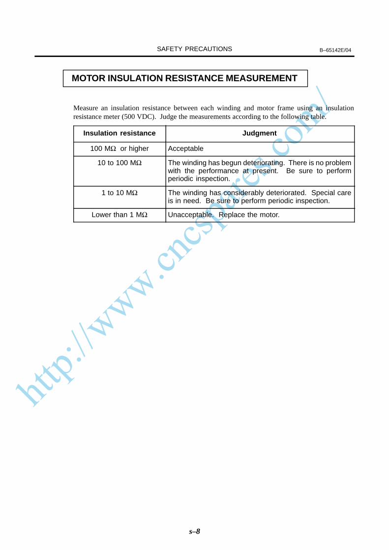
MOTOR INSULATION RESISTANCE MEASUREMENT
Measure an insulation resistance between each winding and motor frame using an insulationresistance meter (500 VDC). Judge the measurements according to the following table.
Insulation resistance Judgment
100 MΩ or higher Acceptable
10 to 100 MΩ The winding has begun deteriorating. There is no problemwith the performance at present. Be sure to performperiodic inspection.
1 to 10 MΩ The winding has considerably deteriorated. Special careis in need. Be sure to perform periodic inspection.
Lower than 1 MΩ Unacceptable. Replace the motor.
http://www.cncspares.com/
B–65142E/04 PREFACE
p–1
This manual describes the specifications and characteristics of the seriesservo motors. The manual consists of the following chapters:
I. SPECIFICATIONS FOR THE α series
This chapter provides general notes on the use of the series andexplains how to select the optimum motor for a given application.This chapter also provides the specifications common to each modelof the α series, concerning the detectors, internal brakes, plugconnectors, and so forth.
II. FANUC AC SERVO MOTOR α series
This chapter explains how to specify a certain series servo motor andprovides specifications, dimensions, and data sheets for the entirerange of α series servo motors.
III. FANUC AC SERVO MOTOR αM series
This chapter explains how to specify a certain αM series servo motorand provides specifications, dimensions, and data sheets for the entirerange of αM series servo motors.
IV. FANUC AC SERVO MOTOR αL series
This chapter explains how to specify a certain αL series servo motorand provides specifications, dimensions, and data sheets for the entirerange of αL series servo motors.
V. FANUC AC SERVO MOTOR αC series
This chapter explains how to specify a certain C series servo motorand provides specifications, dimensions, and data sheets for the entirerange of αC series servo motors.
VI. FANUC AC SERVO MOTOR (HV) series
This chapter explains how to specify a certain (HV) series servomotor and provides specifications, dimensions, and data sheets for theentire range of α(HV) series servo motors.
VII. FANUC AC SERVO MOTOR M(HV) series
This chapter explains how to specify a certain (HV) series servomotor and provides specifications, dimensions, and data sheets for theentire range of α(HV) series servo motors.
http://www.cncspares.com/
PREFACE B–65142E/04
p–2
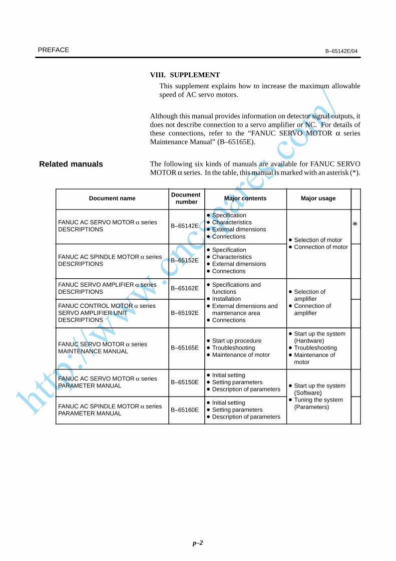
VIII. SUPPLEMENT
This supplement explains how to increase the maximum allowablespeed of AC servo motors.
Although this manual provides information on detector signal outputs, itdoes not describe connection to a servo amplifier or NC. For details ofthese connections, refer to the “FANUC SERVO MOTOR α seriesMaintenance Manual” (B–65165E).
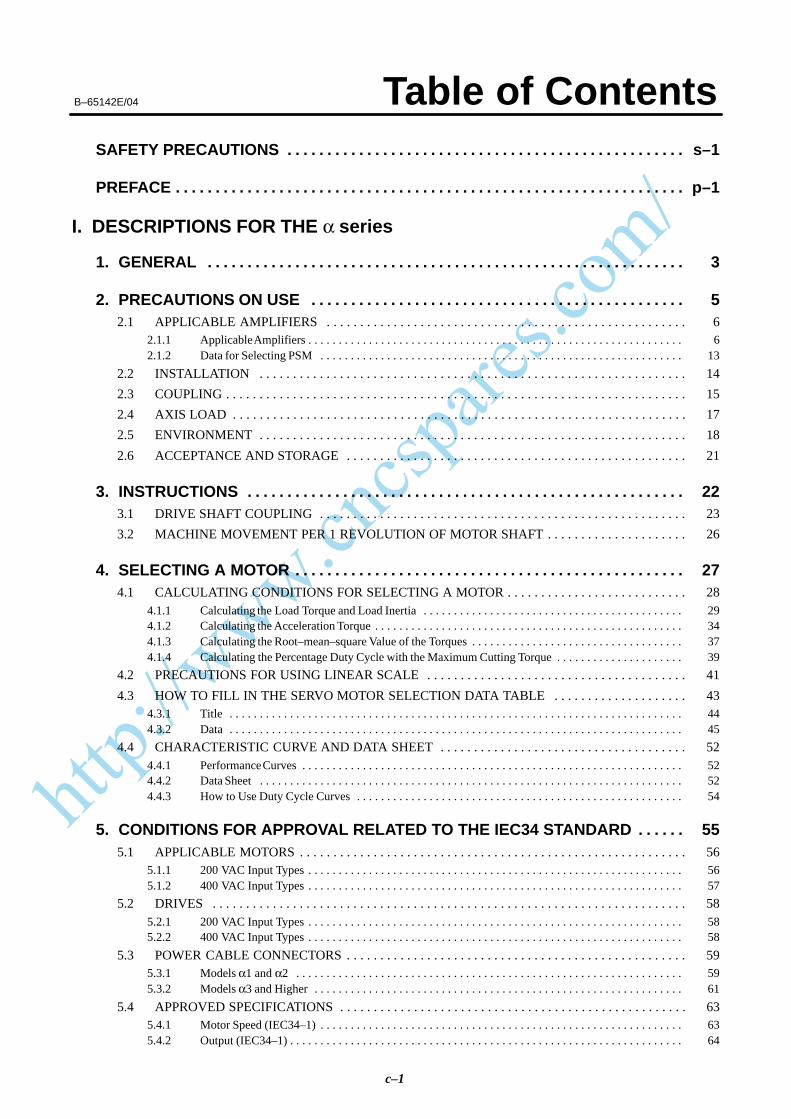
The following six kinds of manuals are available for FANUC SERVOMOTOR α series. In the table, this manual is marked with an asterisk (*).
Document name Document number Major contents Major usage
FANUC AC SERVO MOTOR α seriesDESCRIPTIONS
B–65142E
Specification Characteristics External dimensions Connections
Selection of motor
*
FANUC AC SPINDLE MOTOR α seriesDESCRIPTIONS
B–65152E
Specification Characteristics External dimensions Connections
Selection of motor Connection of motor
FANUC SERVO AMPLIFIER α seriesDESCRIPTIONS
B–65162E Specifications and
functions
Selection of
FANUC CONTROL MOTOR α seriesSERVO AMPLIFIER UNITDESCRIPTIONS
B–65192E
Installation External dimensions and
maintenance area Connections
amplifier Connection of
amplifier
FANUC SERVO MOTOR α seriesMAINTENANCE MANUAL
B–65165E Start up procedure Troubleshooting Maintenance of motor
Start up the system(Hardware)
Troubleshooting Maintenance of
motor
FANUC AC SERVO MOTOR α seriesPARAMETER MANUAL
B–65150E Initial setting Setting parameters Description of parameters
Start up the system(Software)
FANUC AC SPINDLE MOTOR α seriesPARAMETER MANUAL
B–65160E Initial setting Setting parameters Description of parameters
(Software) Tuning the system
(Parameters)
Related manuals
http://www.cncspares.com/
B–65142E/04 Table of Contents
c–1
SAFETY PRECAUTIONS s–1. . . . . . . . . . . . . . . . . . . . . . . . . . . . . . . . . . . . . . . . . . . . . . . . . .
PREFACE p–1. . . . . . . . . . . . . . . . . . . . . . . . . . . . . . . . . . . . . . . . . . . . . . . . . . . . . . . . . . . . . . . .
I. DESCRIPTIONS FOR THE α series
1. GENERAL 3. . . . . . . . . . . . . . . . . . . . . . . . . . . . . . . . . . . . . . . . . . . . . . . . . . . . . . . . . . . .
2. PRECAUTIONS ON USE 5. . . . . . . . . . . . . . . . . . . . . . . . . . . . . . . . . . . . . . . . . . . . . . . 2.1 APPLICABLE AMPLIFIERS 6. . . . . . . . . . . . . . . . . . . . . . . . . . . . . . . . . . . . . . . . . . . . . . . . . . . . . .
2.1.1 Applicable Amplifiers 6. . . . . . . . . . . . . . . . . . . . . . . . . . . . . . . . . . . . . . . . . . . . . . . . . . . . . . . . . . . . . . 2.1.2 Data for Selecting PSM 13. . . . . . . . . . . . . . . . . . . . . . . . . . . . . . . . . . . . . . . . . . . . . . . . . . . . . . . . . . . .
2.2 INSTALLATION 14. . . . . . . . . . . . . . . . . . . . . . . . . . . . . . . . . . . . . . . . . . . . . . . . . . . . . . . . . . . . . . . .
2.3 COUPLING 15. . . . . . . . . . . . . . . . . . . . . . . . . . . . . . . . . . . . . . . . . . . . . . . . . . . . . . . . . . . . . . . . . . . . .
2.4 AXIS LOAD 17. . . . . . . . . . . . . . . . . . . . . . . . . . . . . . . . . . . . . . . . . . . . . . . . . . . . . . . . . . . . . . . . . . . .
2.5 ENVIRONMENT 18. . . . . . . . . . . . . . . . . . . . . . . . . . . . . . . . . . . . . . . . . . . . . . . . . . . . . . . . . . . . . . . .
2.6 ACCEPTANCE AND STORAGE 21. . . . . . . . . . . . . . . . . . . . . . . . . . . . . . . . . . . . . . . . . . . . . . . . . . .
3. INSTRUCTIONS 22. . . . . . . . . . . . . . . . . . . . . . . . . . . . . . . . . . . . . . . . . . . . . . . . . . . . . . . 3.1 DRIVE SHAFT COUPLING 23. . . . . . . . . . . . . . . . . . . . . . . . . . . . . . . . . . . . . . . . . . . . . . . . . . . . . . .
3.2 MACHINE MOVEMENT PER 1 REVOLUTION OF MOTOR SHAFT 26. . . . . . . . . . . . . . . . . . . . .
4. SELECTING A MOTOR 27. . . . . . . . . . . . . . . . . . . . . . . . . . . . . . . . . . . . . . . . . . . . . . . . . 4.1 CALCULATING CONDITIONS FOR SELECTING A MOTOR 28. . . . . . . . . . . . . . . . . . . . . . . . . . .
4.1.1 Calculating the Load Torque and Load Inertia 29. . . . . . . . . . . . . . . . . . . . . . . . . . . . . . . . . . . . . . . . . . . 4.1.2 Calculating the Acceleration Torque 34. . . . . . . . . . . . . . . . . . . . . . . . . . . . . . . . . . . . . . . . . . . . . . . . . . . 4.1.3 Calculating the Root–mean–square Value of the Torques 37. . . . . . . . . . . . . . . . . . . . . . . . . . . . . . . . . . . 4.1.4 Calculating the Percentage Duty Cycle with the Maximum Cutting Torque 39. . . . . . . . . . . . . . . . . . . . .
4.2 PRECAUTIONS FOR USING LINEAR SCALE 41. . . . . . . . . . . . . . . . . . . . . . . . . . . . . . . . . . . . . . .
4.3 HOW TO FILL IN THE SERVO MOTOR SELECTION DATA TABLE 43. . . . . . . . . . . . . . . . . . . . 4.3.1 Title 44. . . . . . . . . . . . . . . . . . . . . . . . . . . . . . . . . . . . . . . . . . . . . . . . . . . . . . . . . . . . . . . . . . . . . . . . . . . 4.3.2 Data 45. . . . . . . . . . . . . . . . . . . . . . . . . . . . . . . . . . . . . . . . . . . . . . . . . . . . . . . . . . . . . . . . . . . . . . . . . . .
4.4 CHARACTERISTIC CURVE AND DATA SHEET 52. . . . . . . . . . . . . . . . . . . . . . . . . . . . . . . . . . . . . 4.4.1 Performance Curves 52. . . . . . . . . . . . . . . . . . . . . . . . . . . . . . . . . . . . . . . . . . . . . . . . . . . . . . . . . . . . . . . 4.4.2 Data Sheet 52. . . . . . . . . . . . . . . . . . . . . . . . . . . . . . . . . . . . . . . . . . . . . . . . . . . . . . . . . . . . . . . . . . . . . . 4.4.3 How to Use Duty Cycle Curves 54. . . . . . . . . . . . . . . . . . . . . . . . . . . . . . . . . . . . . . . . . . . . . . . . . . . . . .
5. CONDITIONS FOR APPROVAL RELATED TO THE IEC34 STANDARD 55. . . . . . 5.1 APPLICABLE MOTORS 56. . . . . . . . . . . . . . . . . . . . . . . . . . . . . . . . . . . . . . . . . . . . . . . . . . . . . . . . . .
5.1.1 200 VAC Input Types 56. . . . . . . . . . . . . . . . . . . . . . . . . . . . . . . . . . . . . . . . . . . . . . . . . . . . . . . . . . . . . . 5.1.2 400 VAC Input Types 57. . . . . . . . . . . . . . . . . . . . . . . . . . . . . . . . . . . . . . . . . . . . . . . . . . . . . . . . . . . . . .
5.2 DRIVES 58. . . . . . . . . . . . . . . . . . . . . . . . . . . . . . . . . . . . . . . . . . . . . . . . . . . . . . . . . . . . . . . . . . . . . . . 5.2.1 200 VAC Input Types 58. . . . . . . . . . . . . . . . . . . . . . . . . . . . . . . . . . . . . . . . . . . . . . . . . . . . . . . . . . . . . . 5.2.2 400 VAC Input Types 58. . . . . . . . . . . . . . . . . . . . . . . . . . . . . . . . . . . . . . . . . . . . . . . . . . . . . . . . . . . . . .
5.3 POWER CABLE CONNECTORS 59. . . . . . . . . . . . . . . . . . . . . . . . . . . . . . . . . . . . . . . . . . . . . . . . . . . 5.3.1 Models α1 and α2 59. . . . . . . . . . . . . . . . . . . . . . . . . . . . . . . . . . . . . . . . . . . . . . . . . . . . . . . . . . . . . . . . 5.3.2 Models α3 and Higher 61. . . . . . . . . . . . . . . . . . . . . . . . . . . . . . . . . . . . . . . . . . . . . . . . . . . . . . . . . . . . .
5.4 APPROVED SPECIFICATIONS 63. . . . . . . . . . . . . . . . . . . . . . . . . . . . . . . . . . . . . . . . . . . . . . . . . . . . 5.4.1 Motor Speed (IEC34–1) 63. . . . . . . . . . . . . . . . . . . . . . . . . . . . . . . . . . . . . . . . . . . . . . . . . . . . . . . . . . . . 5.4.2 Output (IEC34–1) 64. . . . . . . . . . . . . . . . . . . . . . . . . . . . . . . . . . . . . . . . . . . . . . . . . . . . . . . . . . . . . . . . .
http://www.cncspares.com/
B–65142E/04Table of Contents
c–2
5.4.3 Protection Type (IEC34–5) 64. . . . . . . . . . . . . . . . . . . . . . . . . . . . . . . . . . . . . . . . . . . . . . . . . . . . . . . . . . 5.4.4 Cooling Method (ICE34–6) 64. . . . . . . . . . . . . . . . . . . . . . . . . . . . . . . . . . . . . . . . . . . . . . . . . . . . . . . . . 5.4.5 Mounting Method (IEC34–7) 65. . . . . . . . . . . . . . . . . . . . . . . . . . . . . . . . . . . . . . . . . . . . . . . . . . . . . . . . 5.4.6 Heat Protection (IEC34–11) 65. . . . . . . . . . . . . . . . . . . . . . . . . . . . . . . . . . . . . . . . . . . . . . . . . . . . . . . . .
6. FEEDBACK DETECTOR 66. . . . . . . . . . . . . . . . . . . . . . . . . . . . . . . . . . . . . . . . . . . . . . . . 6.1 BUILT–IN DETECTOR 67. . . . . . . . . . . . . . . . . . . . . . . . . . . . . . . . . . . . . . . . . . . . . . . . . . . . . . . . . . .
6.2 PULSE CODER RESOLUTION AND CONTROL RESOLUTION 68. . . . . . . . . . . . . . . . . . . . . . . .
6.3 ABSOLUTE–TYPE PULSE CODER 69. . . . . . . . . . . . . . . . . . . . . . . . . . . . . . . . . . . . . . . . . . . . . . . .
6.4 DETECTOR INPUT/OUTPUT SIGNALS 70. . . . . . . . . . . . . . . . . . . . . . . . . . . . . . . . . . . . . . . . . . . .
6.5 SEPARATE TYPE POSITION DETECTOR 71. . . . . . . . . . . . . . . . . . . . . . . . . . . . . . . . . . . . . . . . . . . 6.5.1 Separate Type Pulse Coder Type and Specifications 71. . . . . . . . . . . . . . . . . . . . . . . . . . . . . . . . . . . . . . . 6.5.2 Separate Type Pulse Coder Specifications 72. . . . . . . . . . . . . . . . . . . . . . . . . . . . . . . . . . . . . . . . . . . . . . . 6.5.3 Input Signals and Layout of Connector Pins of Separate Type Pulse Coder 73. . . . . . . . . . . . . . . . . . . . . 6.5.4 External Dimensions of Separate Type Pulse Coder 75. . . . . . . . . . . . . . . . . . . . . . . . . . . . . . . . . . . . . . .
7. BUILT–IN BRAKE 79. . . . . . . . . . . . . . . . . . . . . . . . . . . . . . . . . . . . . . . . . . . . . . . . . . . . . . 7.1 BRAKE SPECIFICATIONS 80. . . . . . . . . . . . . . . . . . . . . . . . . . . . . . . . . . . . . . . . . . . . . . . . . . . . . . . .
7.2 CAUTIONS 81. . . . . . . . . . . . . . . . . . . . . . . . . . . . . . . . . . . . . . . . . . . . . . . . . . . . . . . . . . . . . . . . . . . . .
7.3 CONNECTOR SHAPES 82. . . . . . . . . . . . . . . . . . . . . . . . . . . . . . . . . . . . . . . . . . . . . . . . . . . . . . . . . . .
7.4 CONNECTION OF THE BRAKES 83. . . . . . . . . . . . . . . . . . . . . . . . . . . . . . . . . . . . . . . . . . . . . . . . . .
7.5 RECOMMENDED PARTS IN BRAKE CIRCUITS 84. . . . . . . . . . . . . . . . . . . . . . . . . . . . . . . . . . . . .
7.6 BRAKE CABLE (TUV/EMC COMPATIBLE) 84. . . . . . . . . . . . . . . . . . . . . . . . . . . . . . . . . . . . . . . . .
7.7 REDUCING THE BRAKE SHAFT FALL AMOUNT 85. . . . . . . . . . . . . . . . . . . . . . . . . . . . . . . . . . .
8. CONNECTORS 86. . . . . . . . . . . . . . . . . . . . . . . . . . . . . . . . . . . . . . . . . . . . . . . . . . . . . . . . 8.1 CONNECTOR ON THE MOTOR SIDE 87. . . . . . . . . . . . . . . . . . . . . . . . . . . . . . . . . . . . . . . . . . . . . .
8.1.1 Specifications of Connectors on the Motor Side 87. . . . . . . . . . . . . . . . . . . . . . . . . . . . . . . . . . . . . . . . . .
8.2 CONNECTORS ON THE CABLE SIDE (MODELS α1 AND α2) 89. . . . . . . . . . . . . . . . . . . . . . . . . 8.2.1 Connector Kit Specifications 89. . . . . . . . . . . . . . . . . . . . . . . . . . . . . . . . . . . . . . . . . . . . . . . . . . . . . . . . 8.2.2 Cable Assembly Specifications (14m Standard) (for α1 and α2) 90. . . . . . . . . . . . . . . . . . . . . . . . . . . . .
8.3 SPECIFICATIONS OF THE CONNECTORS ON THE CABLE SIDE(MODELS α3 AND HIGHER) 91. . . . . . . . . . . . . . . . . . . . . . . . . . . . . . . . . . . . . . . . . . . . . . . . . . . . .
8.3.1 Specifications of Plug Connectors on the Cable Side (Waterproof TÜV–approved Type) 93. . . . . . . . . . 8.3.2 Specifications of Plug Connectors on the Cable Side (Waterproof Type) 94. . . . . . . . . . . . . . . . . . . . . . . 8.3.3 Specifications of Plug Connectors on the Cable Side (Non–waterproof Type) 96. . . . . . . . . . . . . . . . . . . 8.3.4 Cable Assembly Specifications (α3 or Above) (14m Standard) 98. . . . . . . . . . . . . . . . . . . . . . . . . . . . . .
9. COOLING FAN 99. . . . . . . . . . . . . . . . . . . . . . . . . . . . . . . . . . . . . . . . . . . . . . . . . . . . . . . . 9.1 COOLING FAN SPECIFICATIONS 100. . . . . . . . . . . . . . . . . . . . . . . . . . . . . . . . . . . . . . . . . . . . . . . . .
9.2 MOTOR CONNECTOR SPECIFICATIONS 100. . . . . . . . . . . . . . . . . . . . . . . . . . . . . . . . . . . . . . . . . . .
9.3 ABOUT CONNECTOR CABLES 100. . . . . . . . . . . . . . . . . . . . . . . . . . . . . . . . . . . . . . . . . . . . . . . . . . .
9.4 WIRING DIAGRAM 101. . . . . . . . . . . . . . . . . . . . . . . . . . . . . . . . . . . . . . . . . . . . . . . . . . . . . . . . . . . . .
II. FANUC AC SERVO MOTOR α series 103. . . . . . . . . . . . . . . . . . . . . . . . . . . . .
1. GENERAL 105. . . . . . . . . . . . . . . . . . . . . . . . . . . . . . . . . . . . . . . . . . . . . . . . . . . . . . . . . . . .
2. TYPES OF MOTORS AND DESIGNATION 106. . . . . . . . . . . . . . . . . . . . . . . . . . . . . . . .
http://www.cncspares.com/
B–65142E/04
c–3
3. SPECIFICATIONS AND CHARACTERISTICS 109. . . . . . . . . . . . . . . . . . . . . . . . . . . . . 3.1 TYPE OF MOTORS AND SPECIFICATIONS 110. . . . . . . . . . . . . . . . . . . . . . . . . . . . . . . . . . . . . . . . .
3.2 CHARACTERISTIC CURVE AND DATA SHEET 112. . . . . . . . . . . . . . . . . . . . . . . . . . . . . . . . . . . . .
3.3 OUTLINE DRAWINGS 128. . . . . . . . . . . . . . . . . . . . . . . . . . . . . . . . . . . . . . . . . . . . . . . . . . . . . . . . . . .
3.4 CONNECTION OF POWER LINE 144. . . . . . . . . . . . . . . . . . . . . . . . . . . . . . . . . . . . . . . . . . . . . . . . . .
III. FANUC AC SERVO MOTOR αM series
1. GENERAL 149. . . . . . . . . . . . . . . . . . . . . . . . . . . . . . . . . . . . . . . . . . . . . . . . . . . . . . . . . . . .
2. TYPES OF MOTORS AND DESIGNATION 150. . . . . . . . . . . . . . . . . . . . . . . . . . . . . . . .
3. SPECIFICATIONS AND CHARACTERISTICS 152. . . . . . . . . . . . . . . . . . . . . . . . . . . . . 3.1 TYPES OF MOTORS AND SPECIFICATIONS 153. . . . . . . . . . . . . . . . . . . . . . . . . . . . . . . . . . . . . . . .
3.2 CHARACTERISTIC CURVE AND DATA SHEET 154. . . . . . . . . . . . . . . . . . . . . . . . . . . . . . . . . . . . .
3.3 OUTLINE DRAWINGS 166. . . . . . . . . . . . . . . . . . . . . . . . . . . . . . . . . . . . . . . . . . . . . . . . . . . . . . . . . . .
3.4 CONNECTION OF POWER LINE 180. . . . . . . . . . . . . . . . . . . . . . . . . . . . . . . . . . . . . . . . . . . . . . . . . .
IV. FANUC AC SERVO MOTOR αL series
1. GENERAL 183. . . . . . . . . . . . . . . . . . . . . . . . . . . . . . . . . . . . . . . . . . . . . . . . . . . . . . . . . . . .
2. TYPES OF MOTORS AND DESIGNATION 184. . . . . . . . . . . . . . . . . . . . . . . . . . . . . . . .
3. SPECIFICATIONS AND CHARACTERISTICS 185. . . . . . . . . . . . . . . . . . . . . . . . . . . . . 3.1 TYPES OF MOTORS AND SPECIFICATIONS 186. . . . . . . . . . . . . . . . . . . . . . . . . . . . . . . . . . . . . . . .
3.2 CHARACTERISTIC CURVE AND DATA SHEET 187. . . . . . . . . . . . . . . . . . . . . . . . . . . . . . . . . . . . .
3.3 OUTLINE DRAWINGS 193. . . . . . . . . . . . . . . . . . . . . . . . . . . . . . . . . . . . . . . . . . . . . . . . . . . . . . . . . . .
3.4 CONNECTION OF POWER LINE 198. . . . . . . . . . . . . . . . . . . . . . . . . . . . . . . . . . . . . . . . . . . . . . . . . .
V. FANUC AC SERVO MOTOR αC series
1. GENERAL 201. . . . . . . . . . . . . . . . . . . . . . . . . . . . . . . . . . . . . . . . . . . . . . . . . . . . . . . . . . . .
2. TYPES OF MOTORS AND DESIGNATION 202. . . . . . . . . . . . . . . . . . . . . . . . . . . . . . . .
3. SPECIFICATIONS AND CHARACTERISTICS 203. . . . . . . . . . . . . . . . . . . . . . . . . . . . . 3.1 TYPES OF MOTORS AND SPECIFICATIONS 204. . . . . . . . . . . . . . . . . . . . . . . . . . . . . . . . . . . . . . . .
3.2 CHARACTERISTIC CURVE AND DATA SHEET 205. . . . . . . . . . . . . . . . . . . . . . . . . . . . . . . . . . . . .
3.3 OUTLINE DRAWINGS 210. . . . . . . . . . . . . . . . . . . . . . . . . . . . . . . . . . . . . . . . . . . . . . . . . . . . . . . . . . .
3.4 CONNECTION OF POWER LINE 217. . . . . . . . . . . . . . . . . . . . . . . . . . . . . . . . . . . . . . . . . . . . . . . . . .
VI. FANUC AC SERVO MOTOR α (HV) series
1. GENERAL 221. . . . . . . . . . . . . . . . . . . . . . . . . . . . . . . . . . . . . . . . . . . . . . . . . . . . . . . . . . . .
2. TYPES OF MOTORS AND DESIGNATION 222. . . . . . . . . . . . . . . . . . . . . . . . . . . . . . . .

http://www.cncspares.com/
B–65142E/04Table of Contents
c–4
3. SPECIFICATIONS AND CHARACTERISTICS 224. . . . . . . . . . . . . . . . . . . . . . . . . . . . . 3.1 TYPES OF MOTORS AND SPECIFICATIONS 225. . . . . . . . . . . . . . . . . . . . . . . . . . . . . . . . . . . . . . . .
3.2 CHARACTERISTIC CURVE AND DATA SHEET 226. . . . . . . . . . . . . . . . . . . . . . . . . . . . . . . . . . . . .
3.3 OUTLINE DRAWINGS 236. . . . . . . . . . . . . . . . . . . . . . . . . . . . . . . . . . . . . . . . . . . . . . . . . . . . . . . . . . .
3.4 CONNECTION OF POWER LINE 247. . . . . . . . . . . . . . . . . . . . . . . . . . . . . . . . . . . . . . . . . . . . . . . . . .
VII. FANUC AC SERVO MOTOR αM (HV) series
1. GENERAL 251. . . . . . . . . . . . . . . . . . . . . . . . . . . . . . . . . . . . . . . . . . . . . . . . . . . . . . . . . . . .
2. TYPES OF MOTORS AND DESIGNATION 252. . . . . . . . . . . . . . . . . . . . . . . . . . . . . . . .
3. SPECIFICATIONS AND CHARACTERISTICS 254. . . . . . . . . . . . . . . . . . . . . . . . . . . . . 3.1 TYPES OF MOTORS AND SPECIFICATIONS 255. . . . . . . . . . . . . . . . . . . . . . . . . . . . . . . . . . . . . . . .
3.2 CHARACTERISTIC CURVE AND DATA SHEET 256. . . . . . . . . . . . . . . . . . . . . . . . . . . . . . . . . . . . .
3.3 OUTLINE DRAWINGS 264. . . . . . . . . . . . . . . . . . . . . . . . . . . . . . . . . . . . . . . . . . . . . . . . . . . . . . . . . . .
3.4 CONNECTION OF POWER LINE 274. . . . . . . . . . . . . . . . . . . . . . . . . . . . . . . . . . . . . . . . . . . . . . . . . .
VIII. SUPPLEMENT(Following AC servo motors are extended the allowable maximum speed.)
1. REQUIRED CONDITIONS 277. . . . . . . . . . . . . . . . . . . . . . . . . . . . . . . . . . . . . . . . . . . . . . .
2. SERVO MOTOR 278. . . . . . . . . . . . . . . . . . . . . . . . . . . . . . . . . . . . . . . . . . . . . . . . . . . . . . .
3. SERVO SOFTWARE 279. . . . . . . . . . . . . . . . . . . . . . . . . . . . . . . . . . . . . . . . . . . . . . . . . . .
4. SERVO PARAMETER 280. . . . . . . . . . . . . . . . . . . . . . . . . . . . . . . . . . . . . . . . . . . . . . . . . .
5. SELECTING PSM 281. . . . . . . . . . . . . . . . . . . . . . . . . . . . . . . . . . . . . . . . . . . . . . . . . . . . . .
6. “CHARACTERISTICS CURVE” AND “DATA SHEET” 282. . . . . . . . . . . . . . . . . . . . . .
http://www.cncspares.com/
I. DESCRIPTIONS FOR THE α series
http://www.cncspares.com/
B–65142E/04 1. GENERALDESCRIPTIONS FOR THE α series
3
1
The FANUC AC servo motor α series has been designed for machine toolfeed axis applications. This servo motor α series has the followingfeatures:
The special magnetic pole shape minimizes torque ripples which, whencombined with precise current control and accurate pulse coder feedback,enables extremely smooth motor rotation.
The use of a special rotor shape results in motors that are smaller andlighter than previous models, but which can develop a high level oftorque. These motors, therefore, provide excellent accelerationcharacteristics.
A totally–enclosed, friction–free brushless design is used. This allowsthe servo motors to be used in demanding environments with no need forspecial checks or maintenance.
A low–indexing–error optical encoder (pulse coder) is built into themotors. This pulse coder enables precise positioning.Pulse coders that output 65,536, or 1,000,000 pulses per rotation areavailable. As such, the α series motors can be used for positioningapplications ranging from simple positioning to those requiring a highdegree of precision. (Available pulse coders vary with the series andmodel of the motor being used.)
The FANUC AC servo motor α series consists of the α , αM, αC, α (HV)series, and αM (HV), all of which are suitable general machine tool,control applications, and the αL series, designed for controlling machinetools that require frequent positioning operations, such as punch pressesand PCB drilling machines.Each of these series is further divided into the following models:
α seriesα1/3000, α2/2000, α2/3000, α3/3000, α6/2000, α6/3000, α12/2000,α12/3000, α22/1500, α22/2000, α22/3000, α30/1200, α30/2000,α30/3000, α40/2000, α40/2000 (with fan), α65/2000, α100/2000,α150/2000, α300/2000, α400/2000
αM seriesαM2/3000, αM2.5/3000, αM6/3000, αM9/3000, αM22/3000,αM30/3000, αM40/3000, αM40/3000 (with fan)
αL seriesαL6/3000, αL9/3000, αL25/3000, αL50/2000
αC series,αC3/2000, αC6/2000, αC12/2000, αC22/1500
Smooth rotation
Excellent acceleration
High reliability
Built–in, high–precisiondetector
http://www.cncspares.com/
1. GENERAL B–65142E/04DESCRIPTIONS FOR THE α series
4
α(HV) seriesα3/3000HV, α6/3000HV, α12/3000HV, α22/3000HV, 30/3000HV,α40/2000HV, α1000/2000HV
αM(HV) seriesαM6/3000 (HV), αM9/3000 (HV), αM22/3000 (HV), αM30/3000 (HV), αM40/3000 (HV)
http://www.cncspares.com/
B–65142E/04 2. PRECAUTIONS ON USEDESCRIPTIONS FOR THE α series
5
2
http://www.cncspares.com/
2. PRECAUTIONS ON USE B–65142E/04DESCRIPTIONS FOR THE α series
6
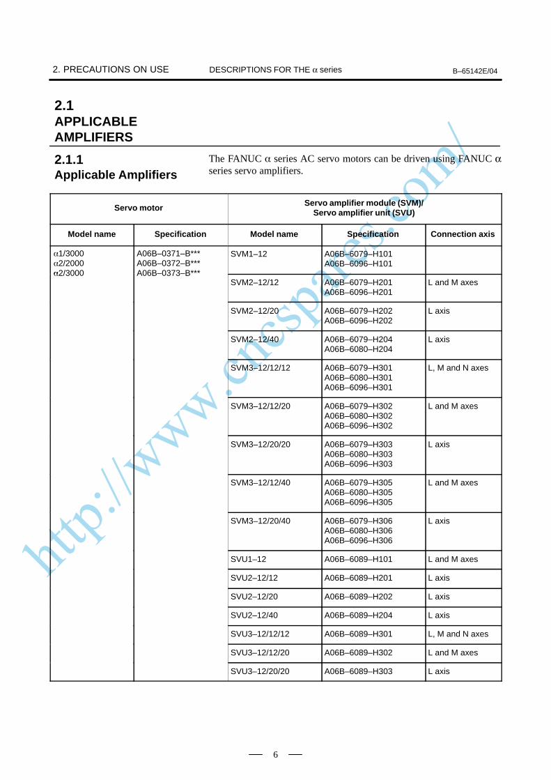
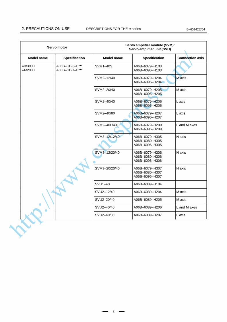
The FANUC series AC servo motors can be driven using FANUC αseries servo amplifiers.
Servo motor Servo amplifier module (SVM)/Servo amplifier unit (SVU)
Model name Specification Model name Specification Connection axis
1/30002/2000
A06B–0371–B***A06B–0372–B***
SVM1–12 A06B–6079–H101A06B–6096–H101
2/3000 A06B–0373–B***SVM2–12/12 A06B–6079–H201
A06B–6096–H201L and M axes
SVM2–12/20 A06B–6079–H202A06B–6096–H202
L axis
SVM2–12/40 A06B–6079–H204A06B–6080–H204
L axis
SVM3–12/12/12 A06B–6079–H301A06B–6080–H301A06B–6096–H301
L, M and N axes
SVM3–12/12/20 A06B–6079–H302A06B–6080–H302A06B–6096–H302
L and M axes
SVM3–12/20/20 A06B–6079–H303A06B–6080–H303A06B–6096–H303
L axis
SVM3–12/12/40 A06B–6079–H305A06B–6080–H305A06B–6096–H305
L and M axes
SVM3–12/20/40 A06B–6079–H306A06B–6080–H306A06B–6096–H306
L axis
SVU1–12 A06B–6089–H101 L and M axes
SVU2–12/12 A06B–6089–H201 L axis
SVU2–12/20 A06B–6089–H202 L axis
SVU2–12/40 A06B–6089–H204 L axis
SVU3–12/12/12 A06B–6089–H301 L, M and N axes
SVU3–12/12/20 A06B–6089–H302 L and M axes
SVU3–12/20/20 A06B–6089–H303 L axis
2.1APPLICABLEAMPLIFIERS
2.1.1Applicable Amplifiers
http://www.cncspares.com/
B–65142E/04 2. PRECAUTIONS ON USEDESCRIPTIONS FOR THE α series
7
Servo motorServo amplifier module (SVM)/
Servo amplifier unit (SVU)
Model name Connection axisSpecificationModel nameSpecification
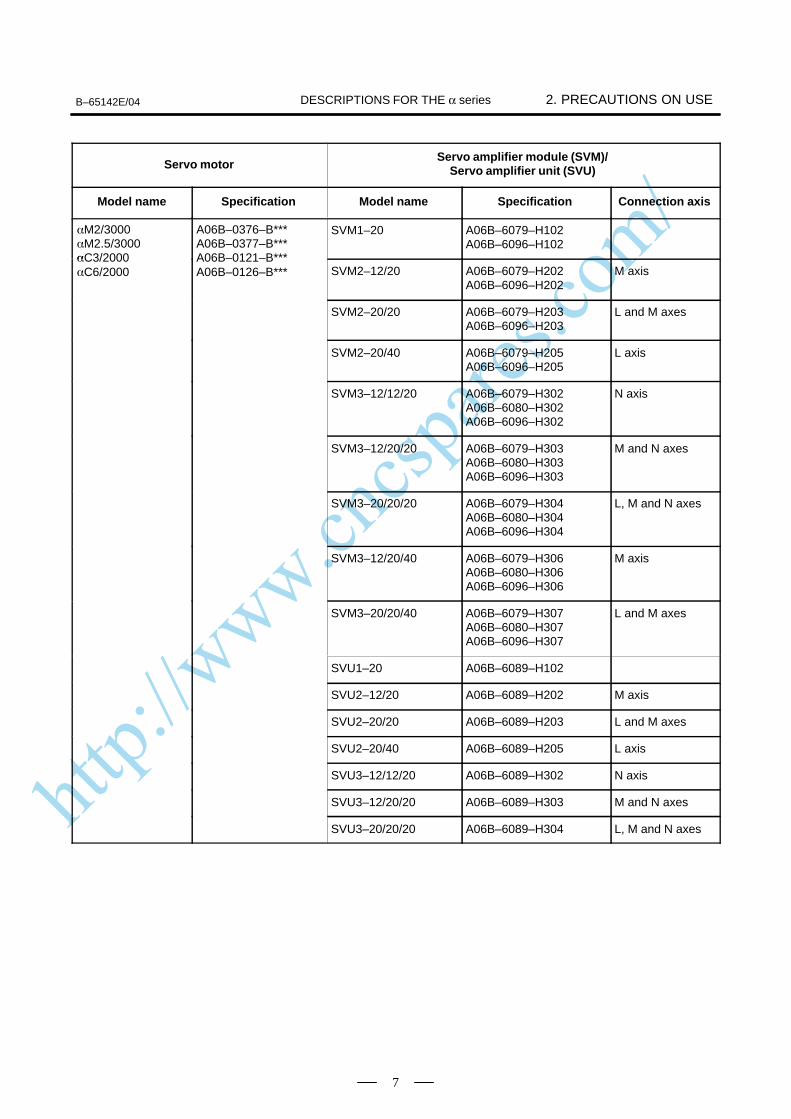
M2/3000M2.5/3000
A06B–0376–B***A06B–0377–B***
SVM1–20 A06B–6079–H102A06B–6096–H102
C3/2000C6/2000
A06B–0121–B***A06B–0126–B*** SVM2–12/20 A06B–6079–H202
A06B–6096–H202M axis
SVM2–20/20 A06B–6079–H203A06B–6096–H203
L and M axes
SVM2–20/40 A06B–6079–H205A06B–6096–H205
L axis
SVM3–12/12/20 A06B–6079–H302A06B–6080–H302A06B–6096–H302
N axis
SVM3–12/20/20 A06B–6079–H303A06B–6080–H303A06B–6096–H303
M and N axes
SVM3–20/20/20 A06B–6079–H304A06B–6080–H304A06B–6096–H304
L, M and N axes
SVM3–12/20/40 A06B–6079–H306A06B–6080–H306A06B–6096–H306
M axis
SVM3–20/20/40 A06B–6079–H307A06B–6080–H307A06B–6096–H307
L and M axes
SVU1–20 A06B–6089–H102
SVU2–12/20 A06B–6089–H202 M axis
SVU2–20/20 A06B–6089–H203 L and M axes
SVU2–20/40 A06B–6089–H205 L axis
SVU3–12/12/20 A06B–6089–H302 N axis
SVU3–12/20/20 A06B–6089–H303 M and N axes
SVU3–20/20/20 A06B–6089–H304 L, M and N axes
http://www.cncspares.com/
2. PRECAUTIONS ON USE B–65142E/04DESCRIPTIONS FOR THE α series
8
Servo motorServo amplifier module (SVM)/
Servo amplifier unit (SVU)
Model name Connection axisSpecificationModel nameSpecification
3/30006/2000
A06B–0123–B***A06B–0127–B***
SVM1–40S A06B–6079–H103A06B–6096–H103
SVM2–12/40 A06B–6079–H204A06B–6096–H204
M axis
SVM2–20/40 A06B–6079–H205A06B–6096–H205
M axis
SVM2–40/40 A06B–6079–H206A06B–6096–H206
L axis
SVM2–40/80 A06B–6079–H207A06B–6096–H207
L axis
SVM2–40L/40L A06B–6079–H209A06B–6096–H209
L and M axes
SVM3–12/12/40 A06B–6079–H305A06B–6080–H305A06B–6096–H305
N axis
SVM3–12/20/40 A06B–6079–H306A06B–6080–H306A06B–6096–H306
N axis
SVM3–20/20/40 A06B–6079–H307A06B–6080–H307A06B–6096–H307
N axis
SVU1–40 A06B–6089–H104
SVU2–12/40 A06B–6089–H204 M axis
SVU2–20/40 A06B–6089–H205 M axis
SVU2–40/40 A06B–6089–H206 L and M axes
SVU2–40/80 A06B–6089–H207 L axis
http://www.cncspares.com/
B–65142E/04 2. PRECAUTIONS ON USEDESCRIPTIONS FOR THE α series
9
Servo motorServo amplifier module (SVM)/
Servo amplifier unit (SVU)
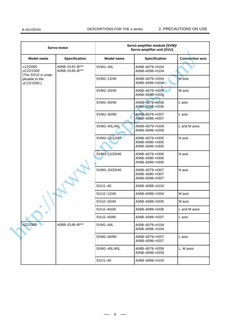
Model name Connection axisSpecificationModel nameSpecification
12/2000C22/1500
A06B–0142–B***A06B–0145–B***
SVM1–40L A06B–6079–H104A06B–6096–H104
(The SVU2 is unap-plicable to theC22/1500.)
SVM2–12/40 A06B–6079–H204A06B–6096–H204
M axis
SVM2–20/40 A06B–6079–H205A06B–6096–H205
M axis
SVM2–40/40 A06B–6079–H206A06B–6096–H206
L axis
SVM2–40/80 A06B–6079–H207A06B–6096–H207
L axis
SVM2–40L/40L A06B–6079–H209A06B–6096–H209
L and M axes
SVM3–12/12/40 A06B–6079–H305A06B–6080–H305A06B–6096–H305
N axis
SVM3–12/20/40 A06B–6079–H306A06B–6080–H306A06B–6096–H306
N axis
SVM3–20/20/40 A06B–6079–H307A06B–6080–H307A06B–6096–H307
N axis
SVU1–40 A06B–6089–H104
SVU2–12/40 A06B–6089–H204 M axis
SVU2–20/40 A06B–6089–H205 M axis
SVU2–40/40 A06B–6089–H206 L and M axes
SVU2–40/80 A06B–6089–H207 L axis
22/1500 A06B–0146–B*** SVM1–40L A06B–6079–H104A06B–6096–H104
SVM2–40/80 A06B–6079–H207A06B–6096–H207
L axis
SVM2–40L/40L A06B–6079–H209A06B–6096–H209
L, M axes
SVU1–40 A06B–6089–H104
http://www.cncspares.com/
2. PRECAUTIONS ON USE B–65142E/04DESCRIPTIONS FOR THE α series
10
Servo motorServo amplifier module (SVM)/
Servo amplifier unit (SVU)
Model name Connection axisSpecificationModel nameSpecification
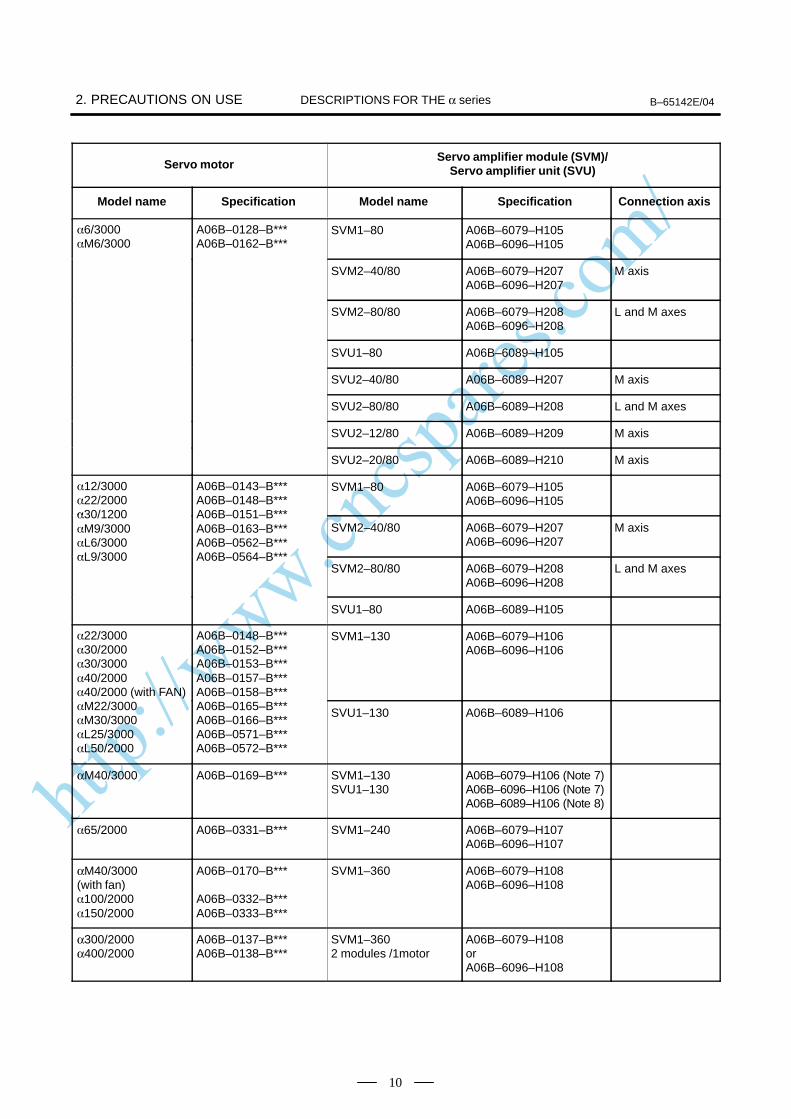
6/3000M6/3000
A06B–0128–B***A06B–0162–B***
SVM1–80 A06B–6079–H105A06B–6096–H105
SVM2–40/80 A06B–6079–H207A06B–6096–H207
M axis
SVM2–80/80 A06B–6079–H208A06B–6096–H208
L and M axes
SVU1–80 A06B–6089–H105
SVU2–40/80 A06B–6089–H207 M axis
SVU2–80/80 A06B–6089–H208 L and M axes
SVU2–12/80 A06B–6089–H209 M axis
SVU2–20/80 A06B–6089–H210 M axis
12/300022/2000
A06B–0143–B***A06B–0148–B***
SVM1–80 A06B–6079–H105A06B–6096–H105
30/1200M9/3000L6/3000
A06B–0151–B***A06B–0163–B***A06B–0562–B***
SVM2–40/80 A06B–6079–H207A06B–6096–H207
M axis
L9/3000 A06B–0564–B***SVM2–80/80 A06B–6079–H208
A06B–6096–H208L and M axes
SVU1–80 A06B–6089–H105
22/300030/200030/300040/200040/2000 (with FAN)
A06B–0148–B***A06B–0152–B***A06B–0153–B***A06B–0157–B***A06B–0158–B***
SVM1–130 A06B–6079–H106A06B–6096–H106
M22/3000M30/3000L25/3000L50/2000
A06B–0165–B***A06B–0166–B***A06B–0571–B***A06B–0572–B***
SVU1–130 A06B–6089–H106
αM40/3000 A06B–0169–B*** SVM1–130SVU1–130
A06B–6079–H106 (Note 7)A06B–6096–H106 (Note 7)A06B–6089–H106 (Note 8)
65/2000 A06B–0331–B*** SVM1–240 A06B–6079–H107A06B–6096–H107
αM40/3000 (with fan)100/2000150/2000
A06B–0170–B***
A06B–0332–B***A06B–0333–B***
SVM1–360 A06B–6079–H108A06B–6096–H108
α300/2000α400/2000
A06B–0137–B***A06B–0138–B***
SVM1–3602 modules /1motor
A06B–6079–H108orA06B–6096–H108
http://www.cncspares.com/
B–65142E/04 2. PRECAUTIONS ON USEDESCRIPTIONS FOR THE α series
11
Servo motorServo amplifier module (SVM)/
Servo amplifier unit (SVU)
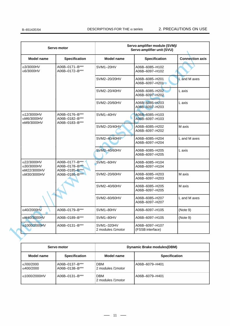
Model name Connection axisSpecificationModel nameSpecification
3/3000HV6/3000HV
A06B–0171–B***A06B–0172–B***
SVM1–20HV A06B–6085–H102A06B–6097–H102
SVM2–20/20HV A06B–6085–H201A06B–6097–H201
L and M axes
SVM2–20/40HV A06B–6085–H202A06B–6097–H202
L axis
SVM2–20/60HV A06B–6085–H203A06B–6097–H203
L axis
12/3000HVM6/3000HV
A06B–0176–B***A06B–0182–B***
SVM1–40HV A06B–6085–H103A06B–6097–H103
M9/3000HV A06B–0183–B***SVM2–20/40HV A06B–6085–H202
A06B–6097–H202M axis
SVM2–40/40HV A06B–6085–H204A06B–6097–H204
L and M axes
SVM2–40/60HV A06B–6085–H205A06B–6097–H205
L axis
22/3000HV30/3000HV
A06B–0177–B***A06B–0178–B***
SVM1–60HV A06B–6085–H104A06B–6097–H104
M22/3000HVM30/3000HV
A06B–0185–B***A06B–0186–B*** SVM2–20/60HV A06B–6085–H203
A06B–6097–H203M axis
SVM2–40/60HV A06B–6085–H205A06B–6097–H205
M axis
SVM2–60/60HV A06B–6085–H207A06B–6097–H207
L and M axes
α40/2000HV A06B–0179–B*** SVM1–80HV A06B–6097–H105 (Note 9)
αM40/3000HV A06B–0189–B*** SVM1–80HV A06B–6097–H105 (Note 9)
α1000/2000HV A06B–0131–B*** SVM1–320HV2 modules /1motor
A06B–6097–H107(FSSB interface)
Servo motor Dynamic Brake modules(DBM)
Model name Specification Model name Specification
00/2000400/2000
A06B–0137–B***A06B–0138–B***
DBM2 modules /1motor
A06B–6079–H401
1000/2000HV A06B–0131–B*** DBM2 modules /1motor
A06B–6079–H401
http://www.cncspares.com/
2. PRECAUTIONS ON USE B–65142E/04DESCRIPTIONS FOR THE α series
12
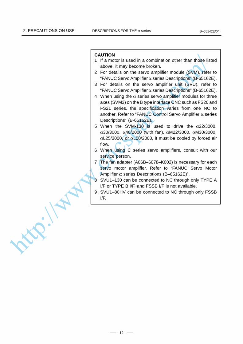
CAUTION1 If a motor is used in a combination other than those listed
above, it may become broken.2 For details on the servo amplifier module (SVM), refer to
“FANUC Servo Amplifier α series Descriptions” (B-65162E).3 For details on the servo amplifier unit (SVU), refer to
“FANUC Servo Amplifier α series Descriptions” (B-65162E).4 When using the α series servo amplifier modules for three
axes (SVM3) on the B type interface CNC such as FS20 andFS21 series, the specification varies from one NC toanother. Refer to “FANUC Control Servo Amplifier α seriesDescriptions” (B-65162E).
5 When the SVM-130 is used to drive the α22/3000,α30/3000, α40/2000 (with fan), αM22/3000, αM30/3000,αL25/3000, or αL50/2000, it must be cooled by forced airflow.
6 When using C series servo amplifiers, consult with ourservice person.
7 The fan adapter (A06B–6078–K002) is necessary for eachservo motor amplifier. Refer to “FANUC Servo MotorAmplifier α series Descriptions (B–65162E)”.
8 SVU1–130 can be connected to NC through only TYPE AI/F or TYPE B I/F, and FSSB I/F is not available.
9 SVU1–80HV can be connected to NC through only FSSBI/F.
http://www.cncspares.com/
B–65142E/04 2. PRECAUTIONS ON USEDESCRIPTIONS FOR THE α series
13
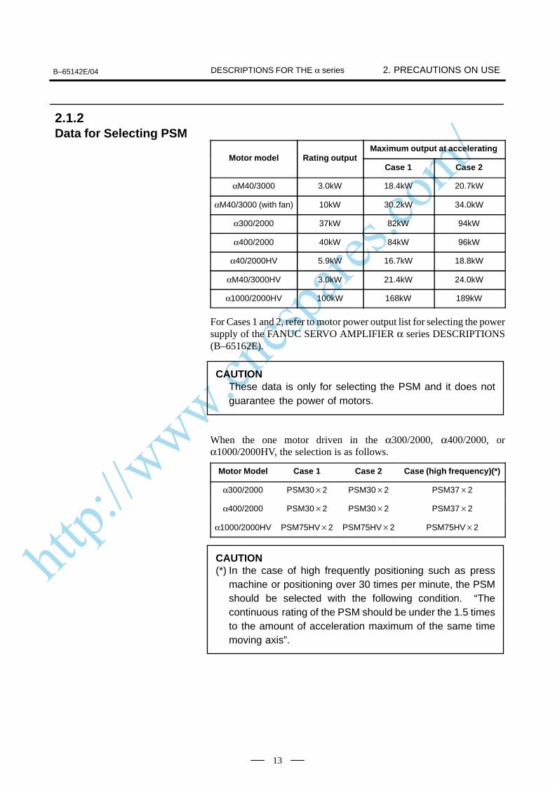
Maximum output at acceleratingMotor model Rating output
Case 1 Case 2
αM40/3000 3.0kW 18.4kW 20.7kW
αM40/3000 (with fan) 10kW 30.2kW 34.0kW
α300/2000 37kW 82kW 94kW
α400/2000 40kW 84kW 96kW
α40/2000HV 5.9kW 16.7kW 18.8kW
αM40/3000HV 3.0kW 21.4kW 24.0kW
α1000/2000HV 100kW 168kW 189kW
For Cases 1 and 2, refer to motor power output list for selecting the powersupply of the FANUC SERVO AMPLIFIER α series DESCRIPTIONS(B–65162E).
CAUTIONThese data is only for selecting the PSM and it does notguarantee the power of motors.
When the one motor driven in the α300/2000, α400/2000, orα1000/2000HV, the selection is as follows.
Motor Model Case 1 Case 2 Case (high frequency)(*)
α300/2000 PSM302 PSM302 PSM372
α400/2000 PSM302 PSM302 PSM372
α1000/2000HV PSM75HV2 PSM75HV2 PSM75HV2
CAUTION(*) In the case of high frequently positioning such as press
machine or positioning over 30 times per minute, the PSMshould be selected with the following condition. “Thecontinuous rating of the PSM should be under the 1.5 timesto the amount of acceleration maximum of the same timemoving axis”.
2.1.2Data for Selecting PSM
http://www.cncspares.com/
2. PRECAUTIONS ON USE B–65142E/04DESCRIPTIONS FOR THE α series
14
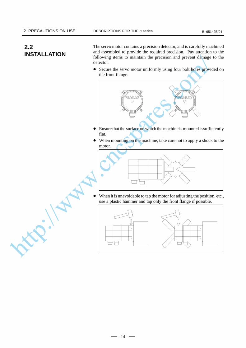
The servo motor contains a precision detector, and is carefully machinedand assembled to provide the required precision. Pay attention to thefollowing items to maintain the precision and prevent damage to thedetector.
Secure the servo motor uniformly using four bolt holes provided onthe front flange.
Ensure that the surface on which the machine is mounted is sufficientlyflat.
When mounting on the machine, take care not to apply a shock to themotor.
When it is unavoidable to tap the motor for adjusting the position, etc.,use a plastic hammer and tap only the front flange if possible.
2.2INSTALLATION

http://www.cncspares.com/
B–65142E/04 2. PRECAUTIONS ON USEDESCRIPTIONS FOR THE α series
15
A precision detector is directly connected to the servo motor shaft.Pay attention to the following items to prevent damage to the detector.
When connecting the power transmission elements such as a gear, apulley and a coupling to the shaft, take care not to apply a shock to theshaft.
Generally, in the case of straight shaft, use a span ring for connectionwith the shaft.
In the case of tapered shaft, match the tapered surface with the powertransmission element and fix by tightening the screw at the end. Whenthe woodruff key is too tight, don’t tap it with a hammer. Use thewoodruff key mainly for positioning, and use the tapered surface fortorque transmission. Machine the tapered surface of the powertransmission element so that over 70% of the whole surface iscontacted.
To remove the connected power transmission element, be sure to usea jig such as a gear puller.
2.3COUPLING
http://www.cncspares.com/
2. PRECAUTIONS ON USE B–65142E/04DESCRIPTIONS FOR THE α series
16
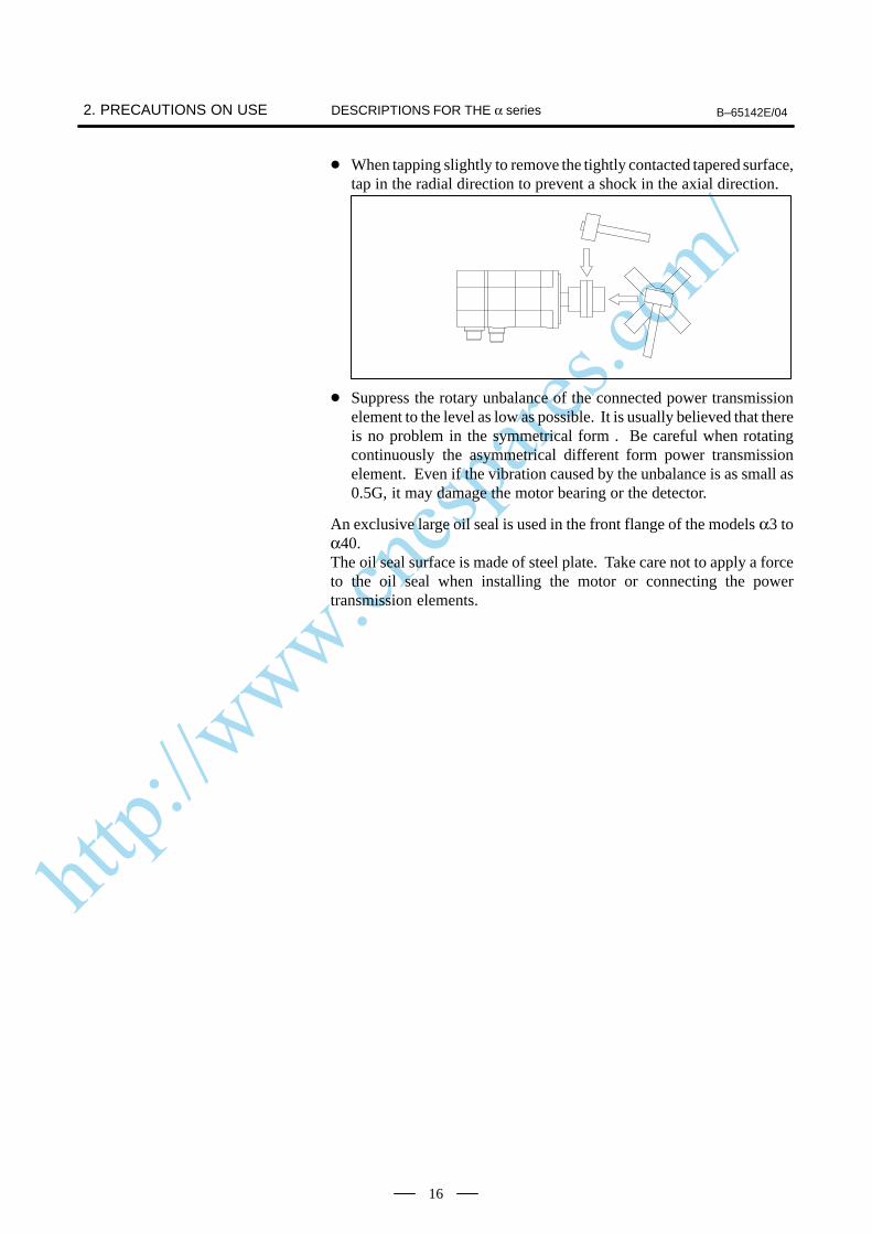
When tapping slightly to remove the tightly contacted tapered surface,tap in the radial direction to prevent a shock in the axial direction.
Suppress the rotary unbalance of the connected power transmissionelement to the level as low as possible. It is usually believed that thereis no problem in the symmetrical form . Be careful when rotatingcontinuously the asymmetrical different form power transmissionelement. Even if the vibration caused by the unbalance is as small as0.5G, it may damage the motor bearing or the detector.
An exclusive large oil seal is used in the front flange of the models α3 toα40. The oil seal surface is made of steel plate. Take care not to apply a forceto the oil seal when installing the motor or connecting the powertransmission elements.
http://www.cncspares.com/
B–65142E/04 2. PRECAUTIONS ON USEDESCRIPTIONS FOR THE α series
17
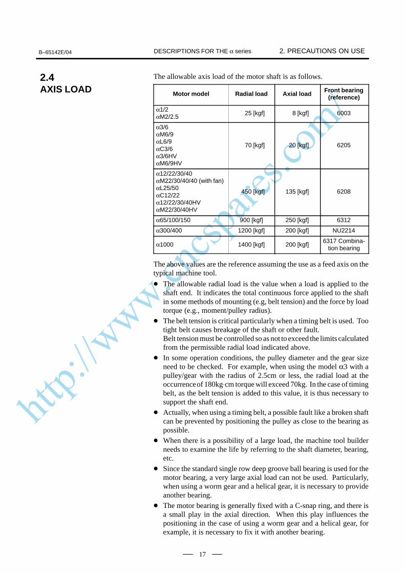
The allowable axis load of the motor shaft is as follows.
Motor model Radial load Axial load Front bearing(reference)
α1/2αM2/2.5
25 [kgf] 8 [kgf] 6003
α3/6αM6/9αL6/9αC3/6α3/6HVαM6/9HV
70 [kgf] 20 [kgf] 6205
α12/22/30/40αM22/30/40/40 (with fan)αL25/50αC12/22α12/22/30/40HVαM22/30/40HV
450 [kgf] 135 [kgf] 6208
α65/100/150 900 [kgf] 250 [kgf] 6312
α300/400 1200 [kgf] 200 [kgf] NU2214
α1000 1400 [kgf] 200 [kgf]6317 Combina-
tion bearing
The above values are the reference assuming the use as a feed axis on thetypical machine tool.
The allowable radial load is the value when a load is applied to theshaft end. It indicates the total continuous force applied to the shaftin some methods of mounting (e.g, belt tension) and the force by loadtorque (e.g., moment/pulley radius).
The belt tension is critical particularly when a timing belt is used. Tootight belt causes breakage of the shaft or other fault.Belt tension must be controlled so as not to exceed the limits calculatedfrom the permissible radial load indicated above.
In some operation conditions, the pulley diameter and the gear sizeneed to be checked. For example, when using the model α3 with apulley/gear with the radius of 2.5cm or less, the radial load at theoccurrence of 180kg⋅cm torque will exceed 70kg. In the case of timingbelt, as the belt tension is added to this value, it is thus necessary tosupport the shaft end.
Actually, when using a timing belt, a possible fault like a broken shaftcan be prevented by positioning the pulley as close to the bearing aspossible.
When there is a possibility of a large load, the machine tool builderneeds to examine the life by referring to the shaft diameter, bearing,etc.
Since the standard single row deep groove ball bearing is used for themotor bearing, a very large axial load can not be used. Particularly,when using a worm gear and a helical gear, it is necessary to provideanother bearing.
The motor bearing is generally fixed with a C-snap ring, and there isa small play in the axial direction. When this play influences thepositioning in the case of using a worm gear and a helical gear, forexample, it is necessary to fix it with another bearing.
2.4AXIS LOAD
http://www.cncspares.com/
2. PRECAUTIONS ON USE B–65142E/04DESCRIPTIONS FOR THE α series
18
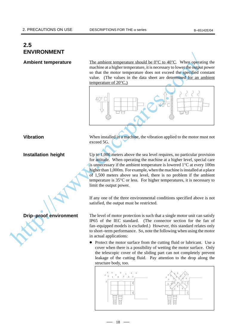
The ambient temperature should be 0°C to 40°C. When operating themachine at a higher temperature, it is necessary to lower the output powerso that the motor temperature does not exceed the specified constantvalue. (The values in the data sheet are determined for an ambienttemperature of 20°C.)
When installed in a machine, the vibration applied to the motor must notexceed 5G.
Up to 1,000 meters above the sea level requires, no particular provisionfor attitude. When operating the machine at a higher level, special careis unnecessary if the ambient temperature is lowered 1°C at every 100mhigher than 1,000m. For example, when the machine is installed at a placeof 1,500 meters above sea level, there is no problem if the ambienttemperature is 35°C or less. For higher temperatures, it is necessary tolimit the output power.
If any one of the three environmental conditions specified above is notsatisfied, the output must be restricted.
The level of motor protection is such that a single motor unit can satisfyIP65 of the IEC standard. (The connector section for the fan offan–equipped models is excluded.) However, this standard relates onlyto short–term performance. So, note the following when using the motorin actual applications:
Protect the motor surface from the cutting fluid or lubricant. Use acover when there is a possibility of wetting the motor surface. Onlythe telescopic cover of the sliding part can not completely preventleakage of the cutting fluid. Pay attention to the drop along thestructure body, too.
2.5ENVIRONMENT
Ambient temperature
Vibration
Installation height
Drip–proof environment
http://www.cncspares.com/
B–65142E/04 2. PRECAUTIONS ON USEDESCRIPTIONS FOR THE α series
19
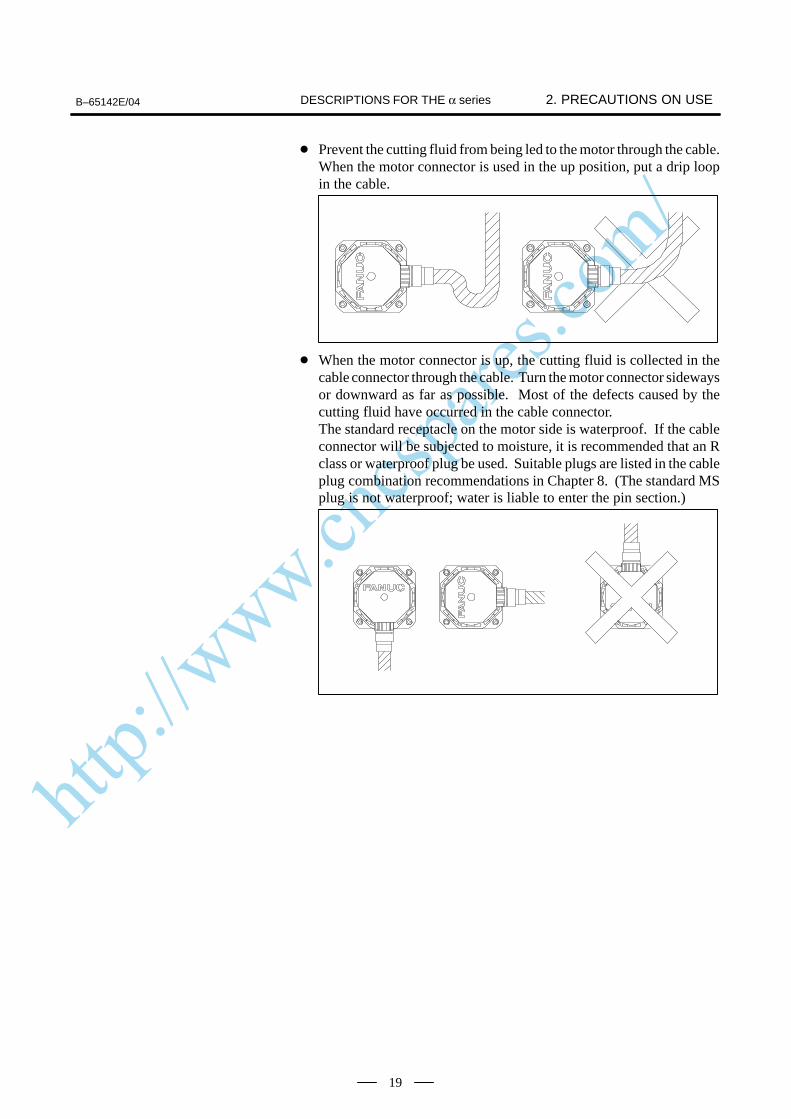
Prevent the cutting fluid from being led to the motor through the cable.When the motor connector is used in the up position, put a drip loopin the cable.
When the motor connector is up, the cutting fluid is collected in thecable connector through the cable. Turn the motor connector sidewaysor downward as far as possible. Most of the defects caused by thecutting fluid have occurred in the cable connector.The standard receptacle on the motor side is waterproof. If the cableconnector will be subjected to moisture, it is recommended that an Rclass or waterproof plug be used. Suitable plugs are listed in the cableplug combination recommendations in Chapter 8. (The standard MSplug is not waterproof; water is liable to enter the pin section.)
http://www.cncspares.com/
2. PRECAUTIONS ON USE B–65142E/04DESCRIPTIONS FOR THE α series
20
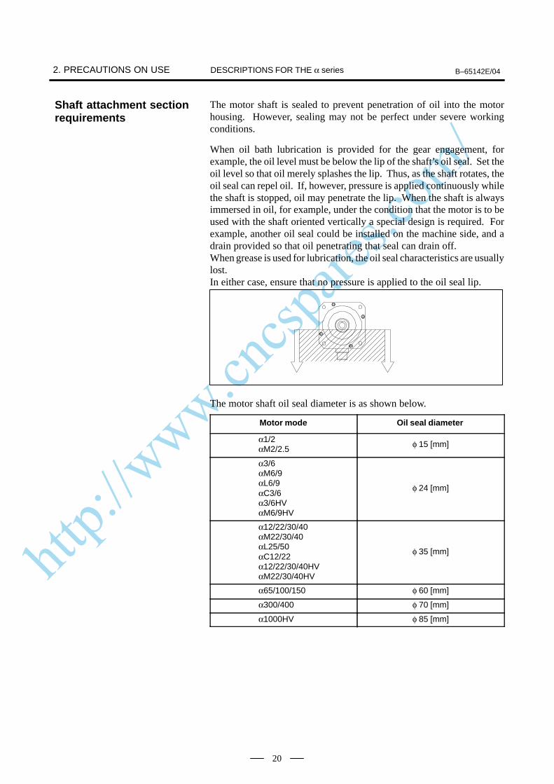
The motor shaft is sealed to prevent penetration of oil into the motorhousing. However, sealing may not be perfect under severe workingconditions.
When oil bath lubrication is provided for the gear engagement, forexample, the oil level must be below the lip of the shaft’s oil seal. Set theoil level so that oil merely splashes the lip. Thus, as the shaft rotates, theoil seal can repel oil. If, however, pressure is applied continuously whilethe shaft is stopped, oil may penetrate the lip. When the shaft is alwaysimmersed in oil, for example, under the condition that the motor is to beused with the shaft oriented vertically a special design is required. Forexample, another oil seal could be installed on the machine side, and adrain provided so that oil penetrating that seal can drain off.When grease is used for lubrication, the oil seal characteristics are usuallylost.In either case, ensure that no pressure is applied to the oil seal lip.
The motor shaft oil seal diameter is as shown below.
Motor mode Oil seal diameter
α1/2αM2/2.5
φ 15 [mm]
α3/6αM6/9αL6/9αC3/6α3/6HVαM6/9HV
φ 24 [mm]
α12/22/30/40αM22/30/40αL25/50αC12/22α12/22/30/40HVαM22/30/40HV
φ 35 [mm]
α65/100/150 φ 60 [mm]
α300/400 φ 70 [mm]
α1000HV φ 85 [mm]
Shaft attachment sectionrequirements
http://www.cncspares.com/
B–65142E/04 2. PRECAUTIONS ON USEDESCRIPTIONS FOR THE α series
21
When the servo motor is delivered, check the following items.
The motor meets the specifications.(Specifications of the model/shaft/detector)
Damage caused by the transportation.
The shaft is normal when rotated by hand.
The brake works.
Looseness or play in screws.
FANUC servo motors are completely checked before shipment, and theinspection at acceptance is normally unnecessary. When an inspection isrequired, check the specifications (wiring, current, voltage, etc.) of themotor and detector.Store the motor indoors. The storage temperature is -20°C to +60°C.Avoid storing in the following places.
Place with high humidity so condensation will form.
Place with extreme temperature changes.
Place always exposed to vibration.(The bearing may be damaged.)
Place with much dust.
2.6ACCEPTANCE ANDSTORAGE
http://www.cncspares.com/
3. INSTRUCTIONS B–65142E/04DESCRIPTIONS FOR THE α series
22
3

http://www.cncspares.com/
B–65142E/04 3. INSTRUCTIONSDESCRIPTIONS FOR THE α series
23
There are four methods for connecting the motor shaft to the ball screw: Direct connection through a flexible coupling Direct connection through a rigid coupling Connection through gears Connection through timing beltsIt is important to understand the advantages and disadvantages of eachmethod, and select one that is most suitable for the machine.
Direct connection by a flexible coupling has the following advantagesover connection using gears:
Even if the angle of the motor shaft to the ball screw changes, it canbe compensated to a certain extent.
Because a flexible coupling connects elements with less backlash,driving noise from joints can be significantly suppressed.
However, this method has the following disadvantages:
The motor shaft and the ball screw must not slide from each other inthe radial direction (for single coupling).
Loose assembly may result in lower rigidity.
When the motor shaft needs to be connected directly to the ball screw,connecting them using a flexible coupling facilitates adjustment andinstallation of the motor.To use a single coupling, the machine needs to be designed so that thecenters of the motor shaft and the ball screw are aligned. (In the same wayas with a rigid coupling, the use of a single coupling demands that therebe almost no relative eccentricity between the axes.)If it is difficult to align the centers, a double coupling needs to beemployed.
3.1DRIVE SHAFTCOUPLING
Direct connection usinga flexible coupling
http://www.cncspares.com/
3. INSTRUCTIONS B–65142E/04DESCRIPTIONS FOR THE α series
24
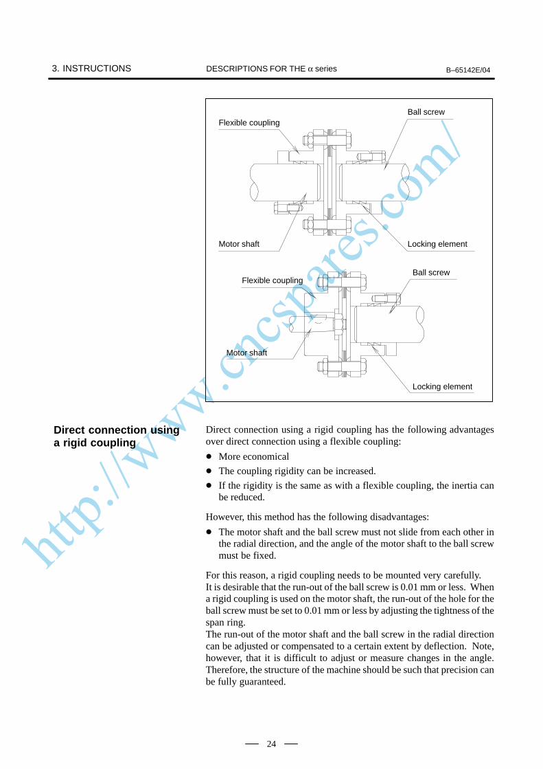
Flexible coupling
Motor shaft
Ball screw
Locking element
Flexible coupling
Motor shaft
Ball screw
Locking element
Direct connection using a rigid coupling has the following advantagesover direct connection using a flexible coupling:
More economical
The coupling rigidity can be increased.
If the rigidity is the same as with a flexible coupling, the inertia canbe reduced.
However, this method has the following disadvantages:
The motor shaft and the ball screw must not slide from each other inthe radial direction, and the angle of the motor shaft to the ball screwmust be fixed.
For this reason, a rigid coupling needs to be mounted very carefully.It is desirable that the run-out of the ball screw is 0.01 mm or less. Whena rigid coupling is used on the motor shaft, the run-out of the hole for theball screw must be set to 0.01 mm or less by adjusting the tightness of thespan ring.The run-out of the motor shaft and the ball screw in the radial directioncan be adjusted or compensated to a certain extent by deflection. Note,however, that it is difficult to adjust or measure changes in the angle.Therefore, the structure of the machine should be such that precision canbe fully guaranteed.
Direct connection usinga rigid coupling
http://www.cncspares.com/
B–65142E/04 3. INSTRUCTIONSDESCRIPTIONS FOR THE α series
25
This method is used when the motor cannot be put in line with the ballscrew because of the mechanical interference problem or when thereduction gear is required in order to obtain large torque. The followingattention should be paid to the gear coupling method:
Grinding finish should be given to the gear, and eccentricity, pitcherror, tooth-shape deviations etc. should be reduced as much aspossible. Please use the JIS, First Class as a reference of precision.
Adjustment of backlash should be carefully performed. Generally, ifthere is too little backlash, a high-pitched noise will occur duringhigh-speed operation, and if the backlash is too big, a drumming soundof the tooth surfaces will occur during acceleration/deceleration.Since these noises are sensitive to the amount of backlash, the structureshould be so that adjustment of backlash is possible at constructiontime.
A timing belt is used in the same cases as gear connection, but incomparison, it has advantages such as low cost and reduced noise duringoperation, etc. However, it is necessary to correctly understand thecharacteristics of timing belts and use them appropriately to maintainhigh precision.Generally, the rigidity of timing belt is sufficiently higher than that ofother mechanical parts such as ball screw or bearing, so there is no dangerof inferiority of performance of control caused by reduction of rigidity byusing timing belt. When using a timing belt with a position detector onthe motor shaft, there are cases where poor precision caused by backlashof the belt tooth and pulley tooth, or elongation of belt after a long timebecomes problem, so consideration should be given to whether theseerrors significantly affect precision. In case the position detector ismounted behind the timing belt (for example, on the ball screw axis), aproblem of precision does not occur.Life of the timing belt largely varies according to mounting precision andtension adjustment. Please refer to the manufacturer’s Instruction Manualfor correct use.
To use a straight shaft that has no key groove, connect the shaft with acoupling using a span ring. Because the span ring connects elements by the friction generated whenthe screw is tightened, it is free from backlash and the concentration ofstress. For this reason, the span ring is highly reliable for connectingelements. To assure sufficient transmission with the span ring, factors such as thetightening torque of the screw, the size of the screw, the number of screws,the clamping flange, and the rigidity of connecting elements areimportant. Refer to the manufacturer’s specifications before using thespan ring.When a coupling or gear is mounted using the span ring, tighten thescrews to remove a run-out of the coupling or gear including the shaft.
Gears
Timing belt
Connection between thestraight shaft and aconnecting element
http://www.cncspares.com/
3. INSTRUCTIONS B–65142E/04DESCRIPTIONS FOR THE α series
26
The machine movement per 1 revolution of motor shaft must bedetermined at the first stage of machine design referring the load torque,load inertia, rapid traverse speed, and relation between minimumincrement and resolution of the position sensor mounted on the motorshaft. To determine this amount, the following conditions should be takeninto consideration.
The machine movement per 1 revolution of motor shaft (“L”) must besuch that the desired rapid traverse speed can be obtained. Forexample, if the maximum motor speed is 1500 min–1 and the rapidtraverse speed must be 12 m/min., the amount of “L” must be 8mm/rev. or higher.
As the machine movement per 1 revolution of motor shaft is reduced,both the load torque and the load inertia reflected to motor shaft alsodecrease. Therefore, to obtain large thrust, the amount of “L” should be thelowest value at which the desired rapid traverse speed can be obtained.
Assuming that the accuracy of the reduction gear is ideal, it isadvantageous to make the machine movement per 1 rev. of motor shaftas low as possible to obtain the highest accuracy in mechanical servooperations. In addition, minimizing the machine movement per 1 rev.of motor shaft can increase the servo rigidity as seen from themachine’s side, which can contribute to system accuracy andminimize the influence of external load changes.
When the machine is operation is characterized by repeatedacceleration/deceleration cycles, a heating problem may occur due tothe current flow caused by the acceleration and deceleration. Shouldthis occur, the machine travel distance per motor shaft revolutionshould be modified. Given optimum conditions, the machine traveldistance per motor shaft revolution is set such that the motor’s rotorinertia equals the load inertia based on motor shaft conversion. Formachines such as punch presses and PCB drilling machines, themachine’s travel distance per motor shaft revolution should be set soas to satisfy this optimum condition as far as possible, while alsoconsidering the rapid traverse rate and increment system.
3.2MACHINEMOVEMENT PER 1REVOLUTION OFMOTOR SHAFT
http://www.cncspares.com/
B–65142E/04 4. SELECTING A MOTORDESCRIPTIONS FOR THE α series
27
4
When selecting an applicable motor, the load, rapid traverse feedrate,increment system, and other conditions must be considered. This sectiondescribes how to calculate the load and other conditions, showing anexample of a table with a horizontal axis.Motors are subjected to two types of torque: constant load torque(including friction), and cutting power and acceleration/decelerationtorque. Calculate the two loads accurately and select a motor that satisfiesthe following conditions:
Condition 1When the machine is operating without any load, the torque iswithin about 70% of the continuous torque rating.When the machine tool is stopped, the motor is generating torque ina balanced state with the friction–induced load. If acceleration/deceleration torque required for actual operation is added when thisvalue is close to the rated torque, the rated torque may be exceeded asthe average torque, and the motor is more likely to overheat.This figure of “within 70% of the continuous torque rating” is forreference only. Determine the appropriate torque based upon actualmachine tool conditions.
Condition 2Acceleration can be made with a desired time constant. Generally, the load torque helps deceleration. If acceleration can beexecuted with a desired time constant, deceleration can be made withthe same time constant. Calculate the acceleration torque and checkthat the torque required for acceleration is within the intermittentoperating zone of the motor.
Condition 3The frequency of positioning in rapid traverse is set to a desiredvalue. The greater the frequency of positioning in rapid traverse, thegreater the ratio of acceleration time to the entire operation time. Thismay overheat the motor. When the acceleration time constant isincreased according to the rapid traverse feedrate and positioningfrequency constant, the amount of produced heat decreases in inverseproportion to the acceleration time constant.
Condition 4If the load condition varies during a single cycle, theroot–mean–square value of the torques is smaller than or equal tothe rated torque.
Condition 5The time for which the table can be moved with the maximumcutting torque (percentage duty cycle and ON time) is within adesired range.
The procedure for selecting a motor is described below:
http://www.cncspares.com/
4. SELECTING A MOTOR B–65142E/04DESCRIPTIONS FOR THE α series
28
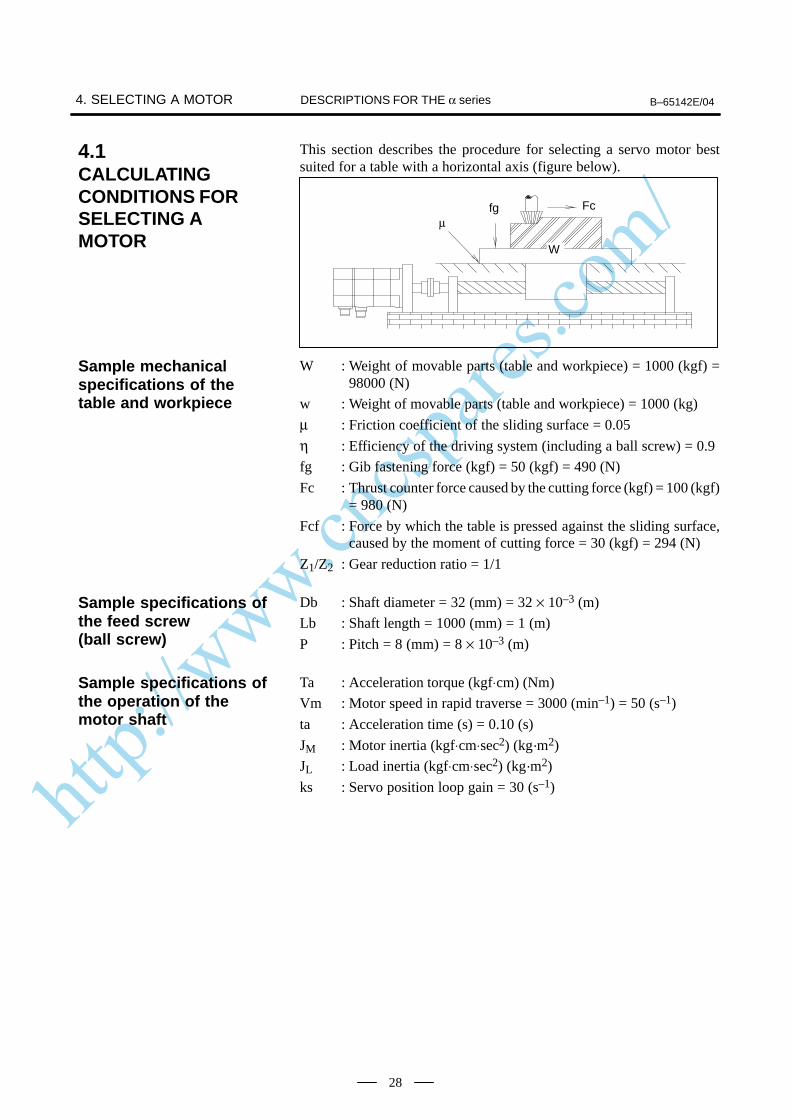
This section describes the procedure for selecting a servo motor bestsuited for a table with a horizontal axis (figure below).
fgµ
Fc
W
W : Weight of movable parts (table and workpiece) = 1000 (kgf) =98000 (N)
w : Weight of movable parts (table and workpiece) = 1000 (kg)
µ : Friction coefficient of the sliding surface = 0.05
η : Efficiency of the driving system (including a ball screw) = 0.9
fg : Gib fastening force (kgf) = 50 (kgf) = 490 (N)
Fc : Thrust counter force caused by the cutting force (kgf) = 100 (kgf)= 980 (N)
Fcf : Force by which the table is pressed against the sliding surface,caused by the moment of cutting force = 30 (kgf) = 294 (N)
Z1/Z2 : Gear reduction ratio = 1/1
Db : Shaft diameter = 32 (mm) = 32 × 10–3 (m)
Lb : Shaft length = 1000 (mm) = 1 (m)
P : Pitch = 8 (mm) = 8 × 10⁻³ (m)
Ta : Acceleration torque (kgf⋅cm) (Nm)
Vm : Motor speed in rapid traverse = 3000 (min–1) = 50 (s–1)
ta : Acceleration time (s) = 0.10 (s)
JM : Motor inertia (kgf⋅cm⋅sec2) (kg·m2)
JL : Load inertia (kgf⋅cm⋅sec2) (kg·m2)
ks : Servo position loop gain = 30 (s–1)
4.1CALCULATINGCONDITIONS FORSELECTING AMOTOR
Sample mechanicalspecifications of thetable and workpiece
Sample specifications ofthe feed screw(ball screw)
Sample specifications ofthe operation of themotor shaft
http://www.cncspares.com/
B–65142E/04 4. SELECTING A MOTORDESCRIPTIONS FOR THE α series
29
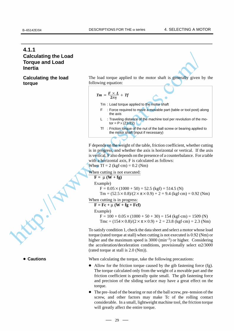
The load torque applied to the motor shaft is generally given by thefollowing equation:
Tm F L
2 Tf
Tm : Load torque applied to the motor shaft
F : Force required to move a movable part (table or tool post) alongthe axis
L : Traveling distance of the machine tool per revolution of the mo-tor = P(Z1/Z2)
Tf : Friction torque of the nut of the ball screw or bearing applied tothe motor shaft (input if necessary)
F depends on the weight of the table, friction coefficient, whether cuttingis in progress, and whether the axis is horizontal or vertical. If the axisis vertical, F also depends on the presence of a counterbalance. For a tablewith a horizontal axis, F is calculated as follows:When Tf = 2 (kgf·cm) = 0.2 (Nm)
When cutting is not executed:F = µ (W + fg)Example)
F = 0.05(1000 + 50) = 52.5 (kgf) = 514.5 (N)Tm = (52.50.8)/(2π0.9) + 2 = 9.4 (kgf⋅cm) = 0.92 (Nm)
When cutting is in progress:F = Fc + µ (W + fg + Fcf)Example)
F = 100 + 0.05(1000 + 50 + 30) = 154 (kgf·cm) = 1509 (N)Tmc = (1540.8)/(2π0.9) + 2 = 23.8 (kgf⋅cm) = 2.3 (Nm)
To satisfy condition 1, check the data sheet and select a motor whose loadtorque (rated torque at stall) when cutting is not executed is 0.92 (Nm) orhigher and the maximum speed is 3000 (min–1) or higher. Consideringthe acceleration/deceleration conditions, provisionally select α2/3000(rated torque at stall is 2.0 (Nm)).
When calculating the torque, take the following precautions:
Allow for the friction torque caused by the gib fastening force (fg).The torque calculated only from the weight of a movable part and thefriction coefficient is generally quite small. The gib fastening forceand precision of the sliding surface may have a great effect on thetorque.
The pre–load of the bearing or nut of the ball screw, pre–tension of thescrew, and other factors may make Tc of the rolling contactconsiderable. In a small, lightweight machine tool, the friction torquewill greatly affect the entire torque.
4.1.1Calculating the LoadTorque and LoadInertia
Calculating the loadtorque
Cautions

http://www.cncspares.com/
4. SELECTING A MOTOR B–65142E/04DESCRIPTIONS FOR THE α series
30
Allow for an increase in friction on the sliding surface (Fcf) caused bythe cutting resistance. The cutting resistance and the driving forcegenerally do not act through a common point as illustrated below.When a large cutting resistance is applied, the moment increases theload on the sliding surface.When calculating the torque during cutting, allow for the frictiontorque caused by the load.
Cutting force
Cutting force
Driving forceDriving force
The feedrate may cause the friction torque to vary greatly. Obtain anaccurate value by closely examining variations in friction dependingon variations in speed, the mechanism for supporting the table (slidingcontact, rolling contact, static pressure, etc.), material of the slidingsurface, lubricating system, and other factors.
The friction torque of a single machine varies widely due toadjustment conditions, ambient temperature, and lubricationconditions. Collect a great amount of measurement data of identicalmodels so that a correct load torque can be calculated. When adjustingthe gib fastening force and backlash, monitor the friction torque.Avoid generating an unnecessarily great torque.
Unlike the load torque, an accurate load inertia can be obtained just bycalculation. The inertia of all objects moved by the revolution of a drivingmotor forms the load inertia of the motor. It does not matter whether theobject is rotated or moved along a straight line. Calculate the inertiavalues of individual moving objects separately, then add the valuestogether, according to a rule, to obtain the load inertia. The inertia ofalmost all objects can be calculated according to the following basic rules:
Db
Lb
Calculating the loadinertia
Inertia of a cylindricalobject (ball screw, gear,coupling, etc.)
http://www.cncspares.com/
B–65142E/04 4. SELECTING A MOTORDESCRIPTIONS FOR THE α series
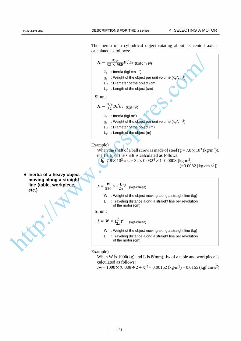
31
The inertia of a cylindrical object rotating about its central axis iscalculated as follows:
Jb b
32 980Db
4Lb
Jb : Inertia (kgf⋅cm⋅s2)
γb : Weight of the object per unit volume (kg/cm3)
Db : Diameter of the object (cm)
Lb : Length of the object (cm)
(kgf⋅cm⋅s)
SI unit
Jb b
32Db
4Lb
Jb : Inertia (kgf⋅m2)
γb : Weight of the object per unit volume (kg/cm3)
Db : Diameter of the object (m)
Lb : Length of the object (m)
(kgf⋅m)
Example)When the shaft of a ball screw is made of steel (g = 7.8103 (kg/m3)),inertia Jb of the shaft is calculated as follows:
Jb=7.8103π320.0324
1=0.0008 [kg⋅m2] (=0.0082 [kg⋅cm⋅s2])
J W
980 ( L
2)2
W : Weight of the object moving along a straight line (kg)
L : Traveling distance along a straight line per revolutionof the motor (cm)
(kgf⋅cm⋅s)
J W ( L2
)2
W : Weight of the object moving along a straight line (kg)
L : Traveling distance along a straight line per revolutionof the motor (cm)
(kgf⋅cm⋅s)
SI unit
Example)When W is 1000(kg) and L is 8(mm), Jw of a table and workpiece iscalculated as follows:Jw = 1000(0.0082π)2 = 0.00162 (kg⋅m2) = 0.0165 (kgf⋅cm⋅s2)
Inertia of a heavy objectmoving along a straightline (table, workpiece,etc.)
http://www.cncspares.com/
4. SELECTING A MOTOR B–65142E/04DESCRIPTIONS FOR THE α series
32
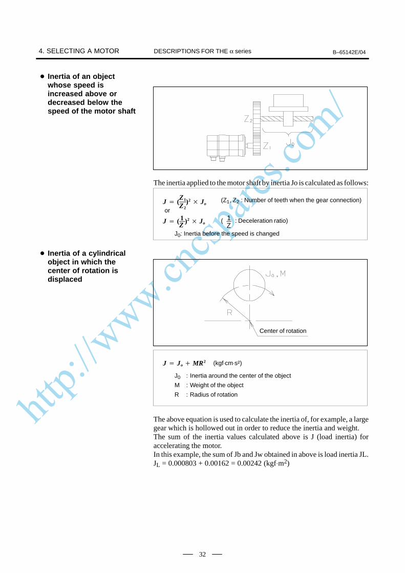
The inertia applied to the motor shaft by inertia Jo is calculated as follows:
J (Z1
Z2)2 Jo
J0: Inertia before the speed is changed
J ( 1Z
)2 Jo
or
(Z1, Z2 : Number of teeth when the gear connection)
( : Deceleration ratio)1Z
Center of rotation
J Jo MR2
J0 : Inertia around the center of the object
M : Weight of the object
R : Radius of rotation
(kgf⋅cm⋅s)
The above equation is used to calculate the inertia of, for example, a largegear which is hollowed out in order to reduce the inertia and weight.The sum of the inertia values calculated above is J (load inertia) foraccelerating the motor.In this example, the sum of Jb and Jw obtained in above is load inertia JL.JL = 0.000803 + 0.00162 = 0.00242 (kgf⋅m2)
Inertia of an objectwhose speed isincreased above ordecreased below thespeed of the motor shaft
Inertia of a cylindricalobject in which thecenter of rotation isdisplaced
http://www.cncspares.com/
B–65142E/04 4. SELECTING A MOTORDESCRIPTIONS FOR THE α series
33
The load inertia has a great effect on the controllability of the motor aswell as the time for acceleration/deceleration in rapid traverse. When theload inertia is increased, the following two problems may occur: Whena command is changed, it takes more time for the motor to reach the speedspecified by the new command. When a machine tool is moved along twoaxes at a high speed to cut an arc or curve, a larger error occurs.When the load inertia is smaller than or equal to the rotor inertia of themotor, those problems will not occur. When the load inertia is up to threetimes the rotor inertia, the controllability may have to be lowered a little.Actually, this will not adversely affect the operation of an ordinary metalcutting machine. If a router for woodworking or a machine to cut a curveat a high speed is used, it is recommended that the load inertia be smallerthan or equal to the rotor inertia.When the load inertia is greater than the rotor inertia by a factor of morethan 3 to 5, the controllability of the motor will be adversely affected. Ifthe load inertia much larger than three times the rotor inertia, anadjustment in the normal range may be insufficient. Avoid using amachine with such a great load inertia.
Note Limitations onload inertia
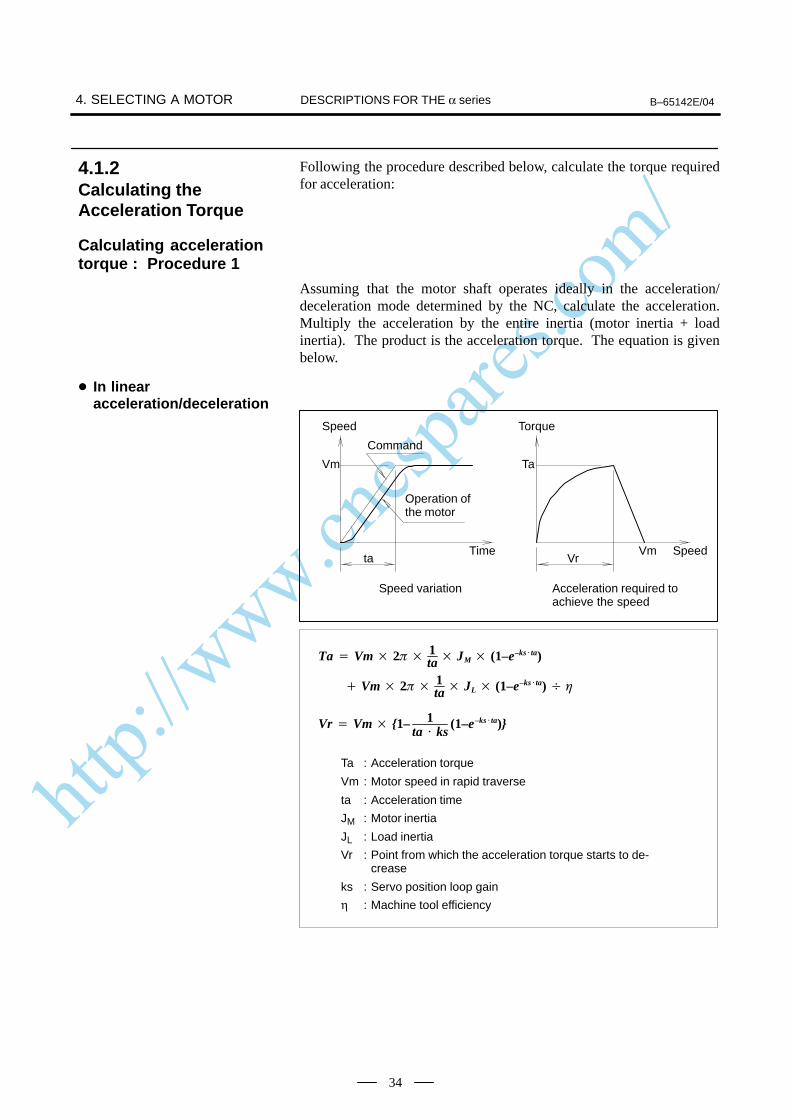
http://www.cncspares.com/
4. SELECTING A MOTOR B–65142E/04DESCRIPTIONS FOR THE α series
34
Following the procedure described below, calculate the torque requiredfor acceleration:
Assuming that the motor shaft operates ideally in the acceleration/deceleration mode determined by the NC, calculate the acceleration.Multiply the acceleration by the entire inertia (motor inertia + loadinertia). The product is the acceleration torque. The equation is givenbelow.
Time
Vm
ta
Ta
VrVm
Speed
Command
Operation of the motor
Torque
Speed
Speed variation Acceleration required toachieve the speed
Ta Vm 21ta JM (1–e–ksta)
Ta : Acceleration torque
Vm : Motor speed in rapid traverse
ta : Acceleration time
JM : Motor inertia
JL : Load inertia
Vr : Point from which the acceleration torque starts to de-crease
ks : Servo position loop gain
η : Machine tool efficiency
Vm 21ta JL (1–e–ksta)
Vr Vm 1– 1ta ks
(1–e–ksta)
4.1.2Calculating theAcceleration Torque
Calculating accelerationtorque : Procedure 1
In linearacceleration/deceleration
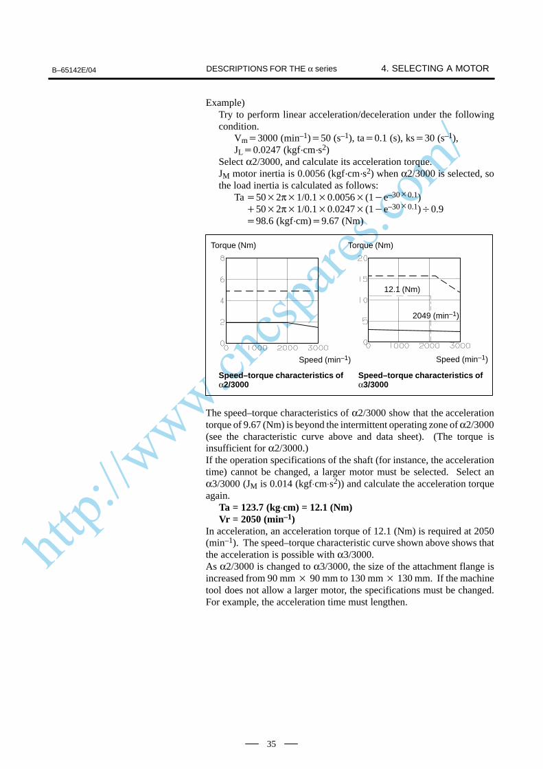
http://www.cncspares.com/
B–65142E/04 4. SELECTING A MOTORDESCRIPTIONS FOR THE α series
35
Example)Try to perform linear acceleration/deceleration under the followingcondition.
Vm3000 (min–1)50 (s–1), ta0.1 (s), ks30 (s–1),JL0.0247 (kgf·cm·s2)
Select α2/3000, and calculate its acceleration torque.JM motor inertia is 0.0056 (kgf·cm·s2) when α2/3000 is selected, sothe load inertia is calculated as follows:
Ta502π1/0.10.0056(1e–300.1)502π1/0.10.0247(1e–300.1)0.998.6 (kgf·cm)9.67 (Nm)
Torque (Nm)
Speed (min–1)
Speed–torque characteristics of α2/3000
12.1 (Nm)
2049 (min–1)
Torque (Nm)
Speed (min–1)
Speed–torque characteristics of α3/3000
The speed–torque characteristics of α2/3000 show that the accelerationtorque of 9.67 (Nm) is beyond the intermittent operating zone of α2/3000(see the characteristic curve above and data sheet). (The torque isinsufficient for α2/3000.)If the operation specifications of the shaft (for instance, the accelerationtime) cannot be changed, a larger motor must be selected. Select anα3/3000 (JM is 0.014 (kgf⋅cm⋅s2)) and calculate the acceleration torqueagain. Ta = 123.7 (kg⋅cm) = 12.1 (Nm) Vr = 2050 (min–1)In acceleration, an acceleration torque of 12.1 (Nm) is required at 2050(min–1). The speed–torque characteristic curve shown above shows thatthe acceleration is possible with α3/3000.As α2/3000 is changed to α3/3000, the size of the attachment flange isincreased from 90 mm 90 mm to 130 mm 130 mm. If the machinetool does not allow a larger motor, the specifications must be changed.For example, the acceleration time must lengthen.
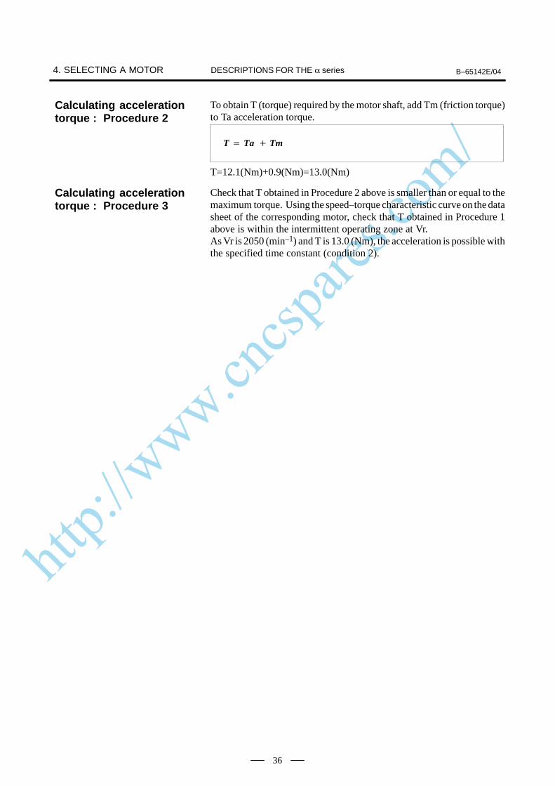
http://www.cncspares.com/
4. SELECTING A MOTOR B–65142E/04DESCRIPTIONS FOR THE α series
36
To obtain T (torque) required by the motor shaft, add Tm (friction torque)to Ta acceleration torque.
T Ta Tm
T=12.1(Nm)+0.9(Nm)=13.0(Nm)
Check that T obtained in Procedure 2 above is smaller than or equal to themaximum torque. Using the speed–torque characteristic curve on the datasheet of the corresponding motor, check that T obtained in Procedure 1above is within the intermittent operating zone at Vr.As Vr is 2050 (min–1) and T is 13.0 (Nm), the acceleration is possible withthe specified time constant (condition 2).
Calculating accelerationtorque : Procedure 2
Calculating accelerationtorque : Procedure 3

http://www.cncspares.com/
B–65142E/04 4. SELECTING A MOTORDESCRIPTIONS FOR THE α series
37
Generate an operation cycle which includes rapid traverse. Write thetime–speed graph and time–torque graph as shown below.In a common cutting machine, the frequency of positioning in rapidtraverse will cause no problems. In a special machine tool whichfrequently executes rapid traverse, however, the motor must be checkedto see whether it is overheated by the current required for acceleration ordeceleration.
t1 t2 t3to
t1
Ta+Tm
Tm
ToTm–Ta
to
t1 t2 t1 t3
Time
Speed Torque
Time
From the time–torque graph, obtain the root–mean–square value oftorques applied to the motor during the single operation cycle. Checkwhether the value is smaller than or equal to the rated torque (condition3).
Trms (Ta Tm)2t1 Tm2t2 (Ta–Tm)2t1 To2t3
tO
Ta : Acceleration torque
Tm : Friction torque
To : Torque when stopped
If Trms is smaller than or equal to 90% of the rated torque at stall (Ts), themotor is judged to be usable.(A margin including the overall thermal efficiency is considered.)
Example)When an α3/3000 (Ts = 31 (kgf⋅cm) = 3.0 (Nm)) is used under thefollowing conditions: Ta = 12.1 (Nm), Tm = To = 0.9 (Nm), t1 = 0.1(s), t2 = 1.8 (s), t3 = 7.0 (s)
Trms (12.1 0.9)2
0.1 0.92 1.8 (12.1–0.9)2
0.1 0.92 7
tO
20.2(Nm) Ts 0.9 2.9 0.9 2.61(Nm)
The α3/3000 can be used for operation. (Condition 3)
4.1.3Calculating theRoot–mean–squareValue of the Torques
Calculating thefrequency of positioningin rapid traverse
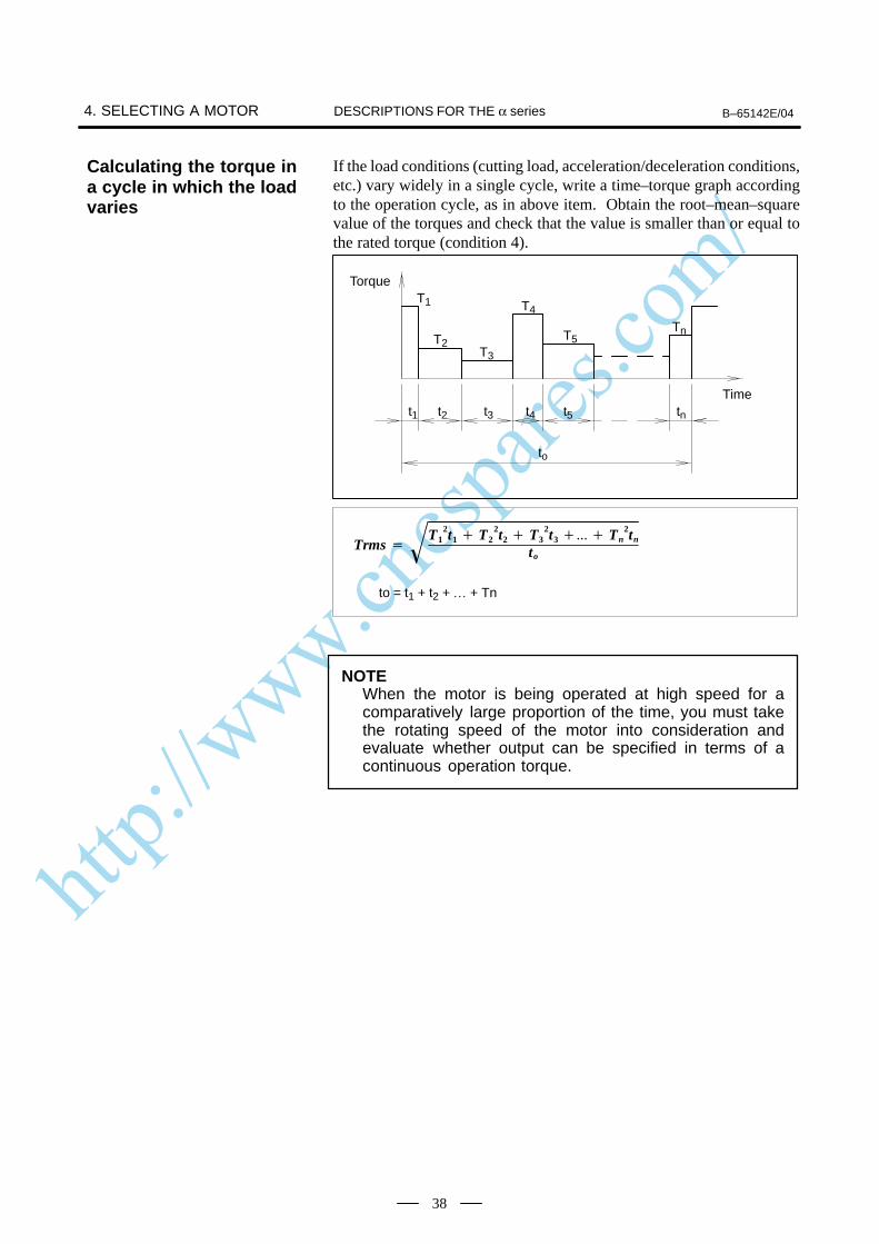
http://www.cncspares.com/
4. SELECTING A MOTOR B–65142E/04DESCRIPTIONS FOR THE α series
38
If the load conditions (cutting load, acceleration/deceleration conditions,etc.) vary widely in a single cycle, write a time–torque graph accordingto the operation cycle, as in above item. Obtain the root–mean–squarevalue of the torques and check that the value is smaller than or equal tothe rated torque (condition 4).
t1 t2 t3
T1
t4 t5 tn
T2T3
T4
T5Tn
to
Torque
Time
Trms T1
2t1 T22t2 T3
2t3 Tn2tn
to
to = t1 + t2 + … + Tn
NOTEWhen the motor is being operated at high speed for acomparatively large proportion of the time, you must takethe rotating speed of the motor into consideration andevaluate whether output can be specified in terms of acontinuous operation torque.
Calculating the torque ina cycle in which the loadvaries
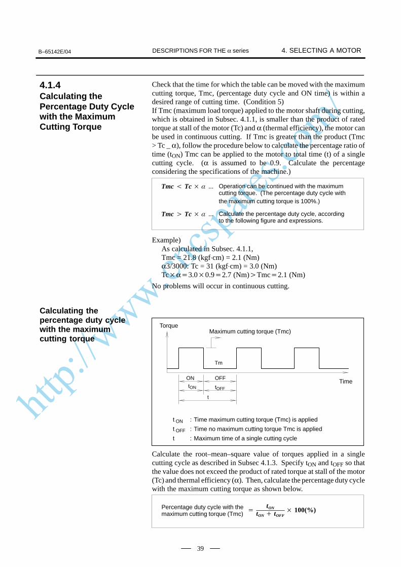
http://www.cncspares.com/
B–65142E/04 4. SELECTING A MOTORDESCRIPTIONS FOR THE α series
39
Check that the time for which the table can be moved with the maximumcutting torque, Tmc, (percentage duty cycle and ON time) is within adesired range of cutting time. (Condition 5)If Tmc (maximum load torque) applied to the motor shaft during cutting,which is obtained in Subsec. 4.1.1, is smaller than the product of ratedtorque at stall of the motor (Tc) and α (thermal efficiency), the motor canbe used in continuous cutting. If Tmc is greater than the product (Tmc> Tc _ α), follow the procedure below to calculate the percentage ratio oftime (tON) Tmc can be applied to the motor to total time (t) of a singlecutting cycle. (α is assumed to be 0.9. Calculate the percentageconsidering the specifications of the machine.)
Tmc Tc Operation can be continued with the maximumcutting torque. (The percentage duty cycle withthe maximum cutting torque is 100%.)
Tmc Tc Calculate the percentage duty cycle, accordingto the following figure and expressions.
Example)As calculated in Subsec. 4.1.1, Tmc = 21.8 (kgf⋅cm) = 2.1 (Nm) α3/3000: Tc = 31 (kgf⋅cm) = 3.0 (Nm) Tcα3.00.92.7 (Nm)Tmc2.1 (Nm)
No problems will occur in continuous cutting.
t ON : Time maximum cutting torque (Tmc) is applied
t OFF : Time no maximum cutting torque Tmc is applied
t : Maximum time of a single cutting cycle
Maximum cutting torque (Tmc)Torque
TimeON OFF
tON
t
tOFF
Tm
Calculate the root–mean–square value of torques applied in a singlecutting cycle as described in Subsec 4.1.3. Specify tON and tOFF so thatthe value does not exceed the product of rated torque at stall of the motor(Tc) and thermal efficiency (α). Then, calculate the percentage duty cyclewith the maximum cutting torque as shown below.
tON
tON tOFF 100(%)Percentage duty cycle with the
maximum cutting torque (Tmc)
4.1.4Calculating thePercentage Duty Cyclewith the MaximumCutting Torque
Calculating thepercentage duty cyclewith the maximumcutting torque
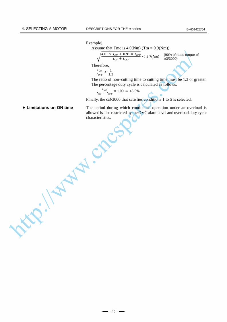
http://www.cncspares.com/
4. SELECTING A MOTOR B–65142E/04DESCRIPTIONS FOR THE α series
40
Example)Assume that Tmc is 4.0(Nm) (Tm = 0.9(Nm)).
4.02 tON 0.92
tOFF
tON tOFF 2.7(Nm) (90% of rated torque of
α3/3000)
Therefore, tON
tOFF
11.3
The ratio of non–cutting time to cutting time must be 1.3 or greater.The percentage duty cycle is calculated as follows:
tON
tON tOFF 100 43.5%
Finally, the α3/3000 that satisfies conditions 1 to 5 is selected.
The period during which continuous operation under an overload isallowed is also restricted by the OVC alarm level and overload duty cyclecharacteristics.
Limitations on ON time
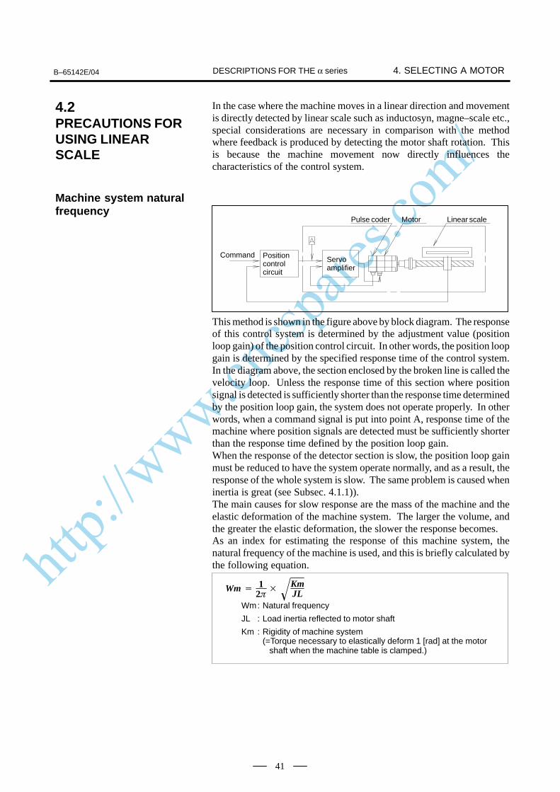
http://www.cncspares.com/
B–65142E/04 4. SELECTING A MOTORDESCRIPTIONS FOR THE α series
41
In the case where the machine moves in a linear direction and movementis directly detected by linear scale such as inductosyn, magne–scale etc.,special considerations are necessary in comparison with the methodwhere feedback is produced by detecting the motor shaft rotation. Thisis because the machine movement now directly influences thecharacteristics of the control system.
Command Positioncontrolcircuit
Servoamplifier
Pulse coder Motor Linear scale
This method is shown in the figure above by block diagram. The responseof this control system is determined by the adjustment value (positionloop gain) of the position control circuit. In other words, the position loopgain is determined by the specified response time of the control system.In the diagram above, the section enclosed by the broken line is called thevelocity loop. Unless the response time of this section where positionsignal is detected is sufficiently shorter than the response time determinedby the position loop gain, the system does not operate properly. In otherwords, when a command signal is put into point A, response time of themachine where position signals are detected must be sufficiently shorterthan the response time defined by the position loop gain.When the response of the detector section is slow, the position loop gainmust be reduced to have the system operate normally, and as a result, theresponse of the whole system is slow. The same problem is caused wheninertia is great (see Subsec. 4.1.1)).The main causes for slow response are the mass of the machine and theelastic deformation of the machine system. The larger the volume, andthe greater the elastic deformation, the slower the response becomes.As an index for estimating the response of this machine system, thenatural frequency of the machine is used, and this is briefly calculated bythe following equation.
Wm 1
2
KmJL
Wm: Natural frequency
JL : Load inertia reflected to motor shaft
Km : Rigidity of machine system(=Torque necessary to elastically deform 1 [rad] at the motor shaft when the machine table is clamped.)
4.2PRECAUTIONS FORUSING LINEARSCALE
Machine system naturalfrequency
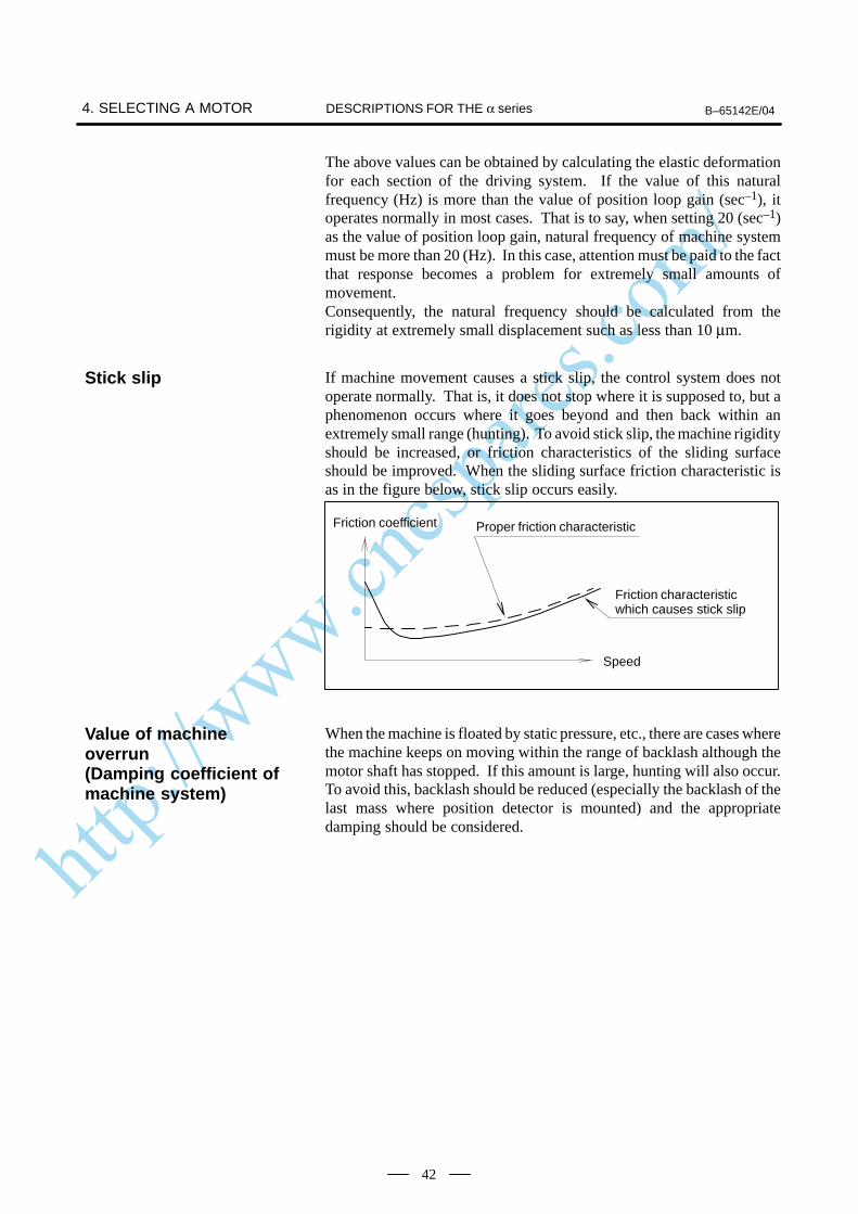
http://www.cncspares.com/
4. SELECTING A MOTOR B–65142E/04DESCRIPTIONS FOR THE α series
42
The above values can be obtained by calculating the elastic deformationfor each section of the driving system. If the value of this naturalfrequency (Hz) is more than the value of position loop gain (sec–1), itoperates normally in most cases. That is to say, when setting 20 (sec–1)as the value of position loop gain, natural frequency of machine systemmust be more than 20 (Hz). In this case, attention must be paid to the factthat response becomes a problem for extremely small amounts ofmovement.Consequently, the natural frequency should be calculated from therigidity at extremely small displacement such as less than 10 µm.
If machine movement causes a stick slip, the control system does notoperate normally. That is, it does not stop where it is supposed to, but aphenomenon occurs where it goes beyond and then back within anextremely small range (hunting). To avoid stick slip, the machine rigidityshould be increased, or friction characteristics of the sliding surfaceshould be improved. When the sliding surface friction characteristic isas in the figure below, stick slip occurs easily.
Friction coefficient Proper friction characteristic
Friction characteristicwhich causes stick slip
Speed
When the machine is floated by static pressure, etc., there are cases wherethe machine keeps on moving within the range of backlash although themotor shaft has stopped. If this amount is large, hunting will also occur.To avoid this, backlash should be reduced (especially the backlash of thelast mass where position detector is mounted) and the appropriatedamping should be considered.
Stick slip
Value of machineoverrun(Damping coefficient ofmachine system)
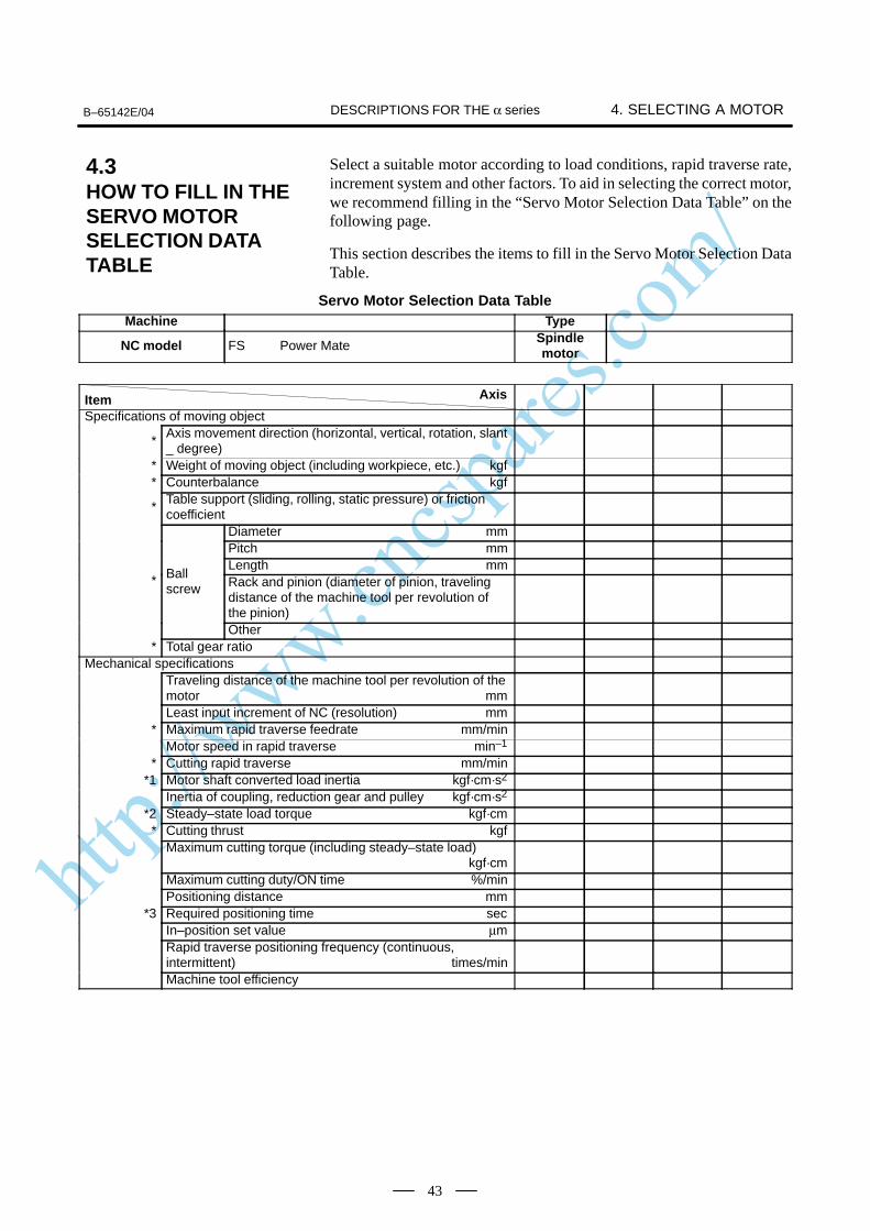
http://www.cncspares.com/
Axis
B–65142E/04 4. SELECTING A MOTORDESCRIPTIONS FOR THE α series
43
Select a suitable motor according to load conditions, rapid traverse rate,increment system and other factors. To aid in selecting the correct motor,we recommend filling in the “Servo Motor Selection Data Table” on thefollowing page.
This section describes the items to fill in the Servo Motor Selection DataTable.
Servo Motor Selection Data TableMachine Type
NC model FS Power MateSpindlemotor
ItemSpecifications of moving object
*Axis movement direction (horizontal, vertical, rotation, slant_ degree)
* Weight of moving object (including workpiece, etc.) kgf* Counterbalance kgf
*Table support (sliding, rolling, static pressure) or frictioncoefficient
Diameter mmPitch mmLength mm
* Ballscrew Rack and pinion (diameter of pinion, traveling
distance of the machine tool per revolution ofthe pinion)Other
* Total gear ratioMechanical specifications
Traveling distance of the machine tool per revolution of themotor mmLeast input increment of NC (resolution) mm
* Maximum rapid traverse feedrate mm/minMotor speed in rapid traverse min–1
* Cutting rapid traverse mm/min*1 Motor shaft converted load inertia kgf·cm·s2
Inertia of coupling, reduction gear and pulley kgf·cm·s2
*2 Steady–state load torque kgf·cm* Cutting thrust kgf
Maximum cutting torque (including steady–state load)kgf·cm
Maximum cutting duty/ON time %/minPositioning distance mm
*3 Required positioning time secIn–position set value µmRapid traverse positioning frequency (continuous,intermittent) times/minMachine tool efficiency
4.3HOW TO FILL IN THESERVO MOTORSELECTION DATATABLE
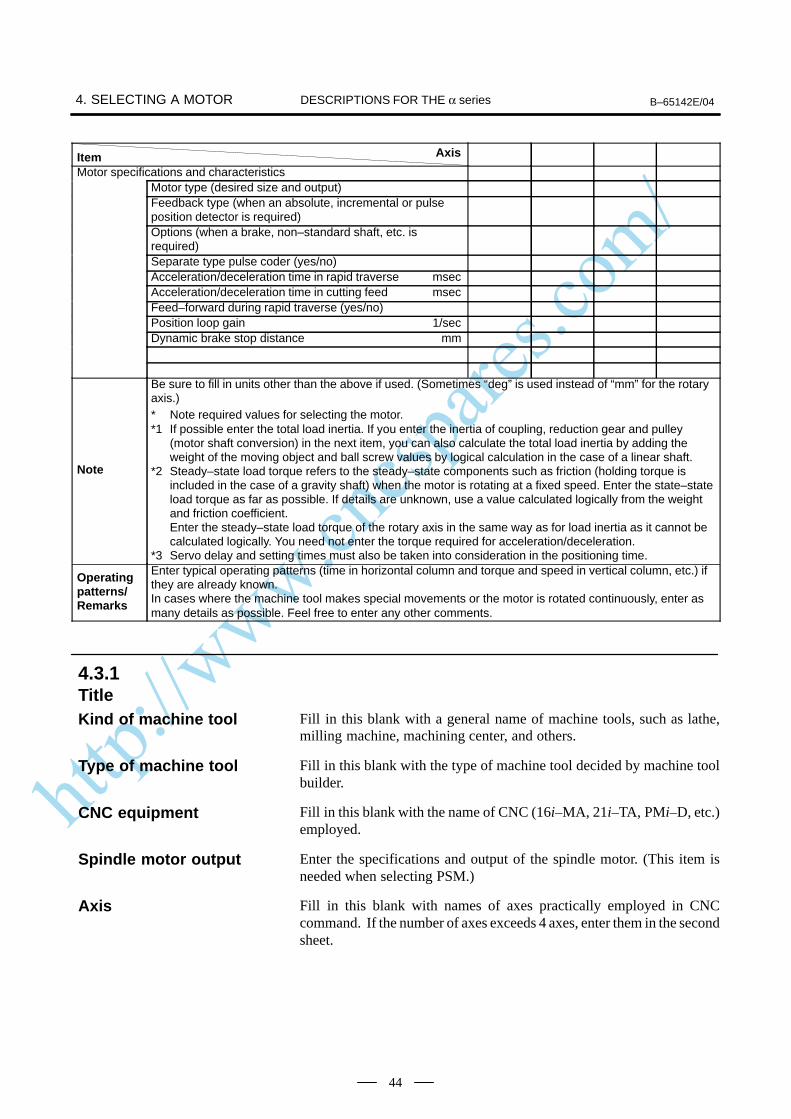
http://www.cncspares.com/
Axis
4. SELECTING A MOTOR B–65142E/04DESCRIPTIONS FOR THE α series
44
ItemMotor specifications and characteristics
Motor type (desired size and output)Feedback type (when an absolute, incremental or pulseposition detector is required)Options (when a brake, non–standard shaft, etc. isrequired)Separate type pulse coder (yes/no)Acceleration/deceleration time in rapid traverse msecAcceleration/deceleration time in cutting feed msecFeed–forward during rapid traverse (yes/no)Position loop gain 1/secDynamic brake stop distance mm
Note
Be sure to fill in units other than the above if used. (Sometimes “deg” is used instead of “mm” for the rotaryaxis.)* Note required values for selecting the motor.*1 If possible enter the total load inertia. If you enter the inertia of coupling, reduction gear and pulley
(motor shaft conversion) in the next item, you can also calculate the total load inertia by adding theweight of the moving object and ball screw values by logical calculation in the case of a linear shaft.
*2 Steady–state load torque refers to the steady–state components such as friction (holding torque isincluded in the case of a gravity shaft) when the motor is rotating at a fixed speed. Enter the state–stateload torque as far as possible. If details are unknown, use a value calculated logically from the weightand friction coefficient.Enter the steady–state load torque of the rotary axis in the same way as for load inertia as it cannot becalculated logically. You need not enter the torque required for acceleration/deceleration.
*3 Servo delay and setting times must also be taken into consideration in the positioning time.
Operatingpatterns/Remarks
Enter typical operating patterns (time in horizontal column and torque and speed in vertical column, etc.) ifthey are already known.In cases where the machine tool makes special movements or the motor is rotated continuously, enter asmany details as possible. Feel free to enter any other comments.
Fill in this blank with a general name of machine tools, such as lathe,milling machine, machining center, and others.
Fill in this blank with the type of machine tool decided by machine toolbuilder.
Fill in this blank with the name of CNC (16i–MA, 21i–TA, PMi–D, etc.)employed.
Enter the specifications and output of the spindle motor. (This item isneeded when selecting PSM.)
Fill in this blank with names of axes practically employed in CNCcommand. If the number of axes exceeds 4 axes, enter them in the secondsheet.
4.3.1TitleKind of machine tool
Type of machine tool
CNC equipment
Spindle motor output
Axis
http://www.cncspares.com/
B–65142E/04 4. SELECTING A MOTORDESCRIPTIONS FOR THE α series
45
Be sure to enter data in this row. Data entered here is needed fordetermining the approximate motor load conditions (inertia, load torque).
Enter the movement directions of driven parts such as the table and toolpost (e.g. horizontal, vertical). Write their angle from the horizontal levelif their movement directions are slant (e.g. slant 60°).
Enter the weight of driven parts, such as table, tool post, etc. by themaximum value including the weight of workpiece, jig, and so on. Donot include the weight of the counter balance in the next item in this item.
Enter the weight of the counter balance in the vertical axis, if provided.Enter whether the counter balance is made by a weight or force as thisinfluences inertia.
Enter the type of table slide (e.g. rolling, sliding or static pressure).Enter a special slide way material like Turcite, if used. Also enter thefriction coefficient value. This item is significant in estimating the frictioncoefficient for calculating mainly the load torque.
Enter the diameter, pitch, and axial length of the lead screw in order.If a rack and pinion or other mechanism is used, also enter the travelingdistance of the machine tool per revolution of the pinion.
Enter the gear ratio between the ball screw and the servo motor, gear ratiobetween the final stage pinion and the servo motor in case of the rackpinion drive, or gear ratio between the table and the motor in case of rotarytable.
Enter basic data that is required for selecting the motor.For details on how to calculate each of the items, see 4.1 to 4.2.Pay special attention to the unit for calculating and expressing torque.
Enter the movement of the machine tool when the motor rotates one turn.Example
When the pitch of ball screw is 12 mm and the gear ratio is 2/3, 122/3 = 8 mm
When the gear ratio is 1/72 in rotary table ;3601/72 = 5 deg
Enter the least input increment of NC command. (The standard value is0.001 mm.)
Enter the rapid traverse rate required for machine tool specifications.
Enter the motor speed during rapid traverse.
Enter the rapid traverse rate required for machine tool specifications.
Enter a load inertia applied by the moving object reflected on the motorshaft. Do not include the inertia of the motor proper in this value. Fordetails on this calculation, see 4.1.1.In the case of a linear shaft, enter the load inertia calculated by logicalcalculation if you enter the next item. In the case of a rotary shaft,however, the load inertia cannot be calculated by logical calculation.
4.3.2DataSpecifications of movingobject Axis movement direction
weight of driven parts
Counter balance
Table support
Feed screw
Total gear ratio
Mechanicalspecifications
Movement per rotation ofmotor
Least input incrementCNC
Rapid traverse rate
Motor speed in rapidtraverse
Cutting rapid traverse
Motor shaft convertedload inertia
http://www.cncspares.com/
4. SELECTING A MOTOR B–65142E/04DESCRIPTIONS FOR THE α series
46
Enter values to two digits past the decimal point. (e.g. 0.2865 0.29)
Enter load inertia applied on transfer mechanisms other than couplings,moving objects and ball screw.
Enter the torque obtained by calculating the force applied for moving themachine tool and state–state components such as friction (includingholding torque in the case of a gravity shaft) reflected on the motor shaftwhen it is rotating at a fixed speed. (Do not include any torque requiredfor acceleration/deceleration in this item.) If details are unknown, use avalue calculated logically from the weight and friction coefficient. Enterthe steady–state load torque of the rotary axis in the same way as for loadinertia as it cannot be calculated logically.
If the load torque values differ during lifting and lowering in the verticalaxis, enter both values. Also, if the load torque values differ during rapidtraverse and cutting feed, enter a notice to that effect.Since torque produced in low speed without cutting may be applied evenwhen the motor has stopped, a sufficient allowance is necessary ascompared with the continued rated torque of the motor. Suppress this loadtorque so that it is lower than 70% of the rated torque.
Enter the maximum value of the force applied during cutting by the forcein the feed axis direction.
Enter the torque value on the motor shaft corresponding to the maximumvalue of the above cutting thrust. When you enter this value, add thesteady–state load to the motor shaft converted value for the cutting thrust.Since the torque transfer efficiency may substantially deteriorate to a largeextent due to the reaction from the slideway, etc. produced by the cuttingthrust, obtain an accurate value by taking measured values in similarmachine tools and other data into account.
Inertia of coupling,reduction gear andpulley
Steady–state load torque
Cutting thrust
Maximum cutting torque
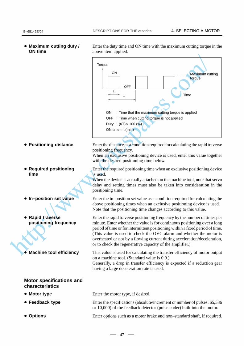
http://www.cncspares.com/
B–65142E/04 4. SELECTING A MOTORDESCRIPTIONS FOR THE α series
47
Enter the duty time and ON time with the maximum cutting torque in theabove item applied.
ON
OFFt
T
Torque
Maximum cuttingtorque
Time
ON : Time that the maximum cutting torque is applied
OFF : Time when cutting torque is not applied
Duty : (t/T)100 (%)
ON time = t (min)
Enter the distance as a condition required for calculating the rapid traversepositioning frequency.When an exclusive positioning device is used, enter this value togetherwith the desired positioning time below.
Enter the required positioning time when an exclusive positioning deviceis used.When the device is actually attached on the machine tool, note that servodelay and setting times must also be taken into consideration in thepositioning time.
Enter the in–position set value as a condition required for calculating theabove positioning times when an exclusive positioning device is used.Note that the positioning time changes according to this value.
Enter the rapid traverse positioning frequency by the number of times perminute. Enter whether the value is for continuous positioning over a longperiod of time or for intermittent positioning within a fixed period of time.(This value is used to check the OVC alarm and whether the motor isoverheated or not by a flowing current during acceleration/deceleration,or to check the regenerative capacity of the amplifier.)
This value is used for calculating the transfer efficiency of motor outputon a machine tool. (Standard value is 0.9.)Generally, a drop in transfer efficiency is expected if a reduction gearhaving a large deceleration rate is used.
Enter the motor type, if desired.
Enter the specifications (absolute/increment or number of pulses: 65,536or 10,000) of the feedback detector (pulse coder) built into the motor.
Enter options such as a motor brake and non–standard shaft, if required.
Maximum cutting duty /ON time
Positioning distance
Required positioningtime
In–position set value
Rapid traversepositioning frequency
Machine tool efficiency
Motor specifications andcharacteristics
Motor type
Feedback type
Options
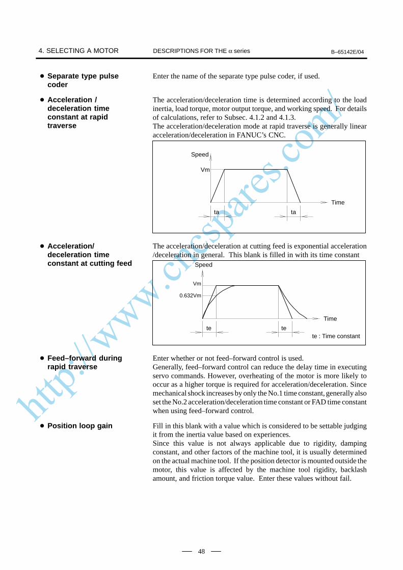
http://www.cncspares.com/
4. SELECTING A MOTOR B–65142E/04DESCRIPTIONS FOR THE α series
48
Enter the name of the separate type pulse coder, if used.
The acceleration/deceleration time is determined according to the loadinertia, load torque, motor output torque, and working speed. For detailsof calculations, refer to Subsec. 4.1.2 and 4.1.3.The acceleration/deceleration mode at rapid traverse is generally linearacceleration/deceleration in FANUC’s CNC.
Speed
Vm
ta ta
Time
The acceleration/deceleration at cutting feed is exponential acceleration/deceleration in general. This blank is filled in with its time constant
Vm
0.632Vm
te te
Speed
te : Time constant
Time
Enter whether or not feed–forward control is used.Generally, feed–forward control can reduce the delay time in executingservo commands. However, overheating of the motor is more likely tooccur as a higher torque is required for acceleration/deceleration. Sincemechanical shock increases by only the No.1 time constant, generally alsoset the No.2 acceleration/deceleration time constant or FAD time constantwhen using feed–forward control.
Fill in this blank with a value which is considered to be settable judgingit from the inertia value based on experiences.Since this value is not always applicable due to rigidity, dampingconstant, and other factors of the machine tool, it is usually determinedon the actual machine tool. If the position detector is mounted outside themotor, this value is affected by the machine tool rigidity, backlashamount, and friction torque value. Enter these values without fail.
Separate type pulsecoder
Acceleration /deceleration timeconstant at rapidtraverse
Acceleration/deceleration timeconstant at cutting feed
Feed–forward duringrapid traverse
Position loop gain
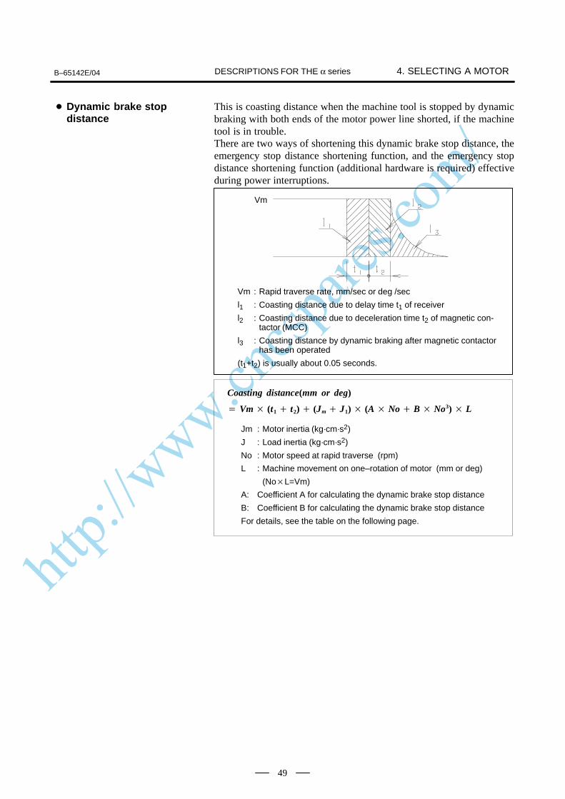
http://www.cncspares.com/
B–65142E/04 4. SELECTING A MOTORDESCRIPTIONS FOR THE α series
49
This is coasting distance when the machine tool is stopped by dynamicbraking with both ends of the motor power line shorted, if the machinetool is in trouble.There are two ways of shortening this dynamic brake stop distance, theemergency stop distance shortening function, and the emergency stopdistance shortening function (additional hardware is required) effectiveduring power interruptions.
Vm : Rapid traverse rate, mm/sec or deg /sec
l1 : Coasting distance due to delay time t1 of receiver
l2 : Coasting distance due to deceleration time t2 of magnetic con-tactor (MCC)
l3 : Coasting distance by dynamic braking after magnetic contactorhas been operated
(t1+t2) is usually about 0.05 seconds.
Vm
Coasting distance(mm or deg)
Jm : Motor inertia (kg·cm·s2)
J : Load inertia (kg·cm·s2)
No : Motor speed at rapid traverse (rpm)
L : Machine movement on one–rotation of motor (mm or deg)
(NoL=Vm)
A: Coefficient A for calculating the dynamic brake stop distance
B: Coefficient B for calculating the dynamic brake stop distance
For details, see the table on the following page.
Vm (t1 t2) (Jm J1) (A No B No3) L
Dynamic brake stopdistance
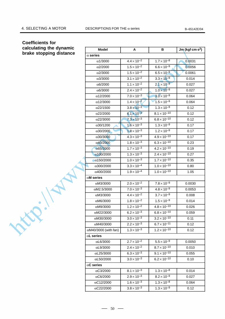
http://www.cncspares.com/
4. SELECTING A MOTOR B–65142E/04DESCRIPTIONS FOR THE α series
50
Model A B Jm (kgf⋅cm⋅s2)
α series
α1/3000 4.410–2 1.710–8 0.0031
α2/2000 1.510–2 6.610–9 0.0056
α2/3000 1.510–2 6.510–9 0.0061
α3/3000 3.110–2 3.310–9 0.014
α6/2000 1.110–2 2.110–9 0.027
α6/3000 2.410–2 1.010–9 0.027
α12/2000 7.010–3 3.010–9 0.064
α12/3000 1.410–2 1.510–9 0.064
α22/1500 3.810–3 1.310–9 0.12
α22/2000 6.110–3 8.110–10 0.12
α22/3000 7.310–3 6.810–10 0.12
α30/1200 1.610–3 1.310–9 0.17
α30/2000 1.810–3 1.210–9 0.17
α30/3000 4.310–3 4.910–10 0.17
α40/2000 1.810–3 6.310–10 0.23
α65/2000 1.710–3 4.210–10 0.19
α100/2000 1.310–3 2.410–10 0.27
α150/2000 1.010–3 1.710–10 0.35
α300/2000 3.310–4 1.010–10 0.80
α400/2000 1.910–4 1.010–10 1.05
αM series
αM3/3000 2.010–2 7.810–9 0.0030
αM2.5/3000 7.010–3 4.810–9 0.0053
αM3/3000 4.410–2 3.710–9 0.008
αM6/3000 1.810–2 1.510–9 0.014
αM9/3000 1.210–2 4.810–10 0.026
αM22/3000 6.210–3 6.810–10 0.059
αM30/3000 3.010–3 3.210–10 0.11
αM40/3000 2.210–3 6.710–11 0.12
αM40/3000 (with fan) 1.310–3 1.210–10 0.12
αL series
αL6/3000 2.710–2 5.510–9 0.0050
αL9/3000 2.410–2 8.710–10 0.010
αL25/3000 6.310–3 9.110–10 0.055
αL50/2000 3.010–3 6.210–10 0.10
αC series
αC3/2000 8.110–3 1.310–8 0.014
αC6/2000 2.910–3 8.210–9 0.027
αC12/2000 1.610–3 1.310–8 0.064
αC22/2000 3.810–3 1.310–9 0.12
Coefficients forcalculating the dynamicbrake stopping distance
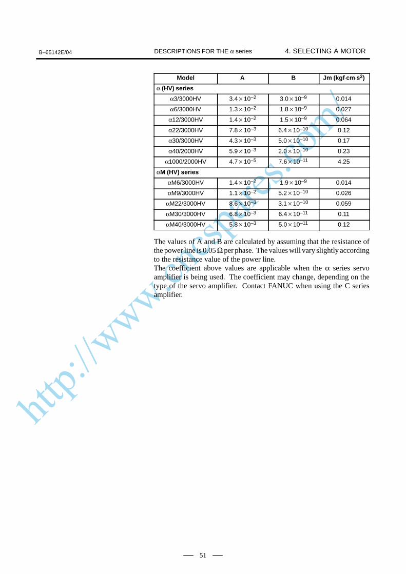
http://www.cncspares.com/
B–65142E/04 4. SELECTING A MOTORDESCRIPTIONS FOR THE α series
51
Model Jm (kgf⋅cm⋅s2)BA
α (HV) series
α3/3000HV 3.410–2 3.010–9 0.014
α6/3000HV 1.310–2 1.810–9 0.027
α12/3000HV 1.410–2 1.510–9 0.064
α22/3000HV 7.810–3 6.410–10 0.12
α30/3000HV 4.310–3 5.010–10 0.17
α40/2000HV 5.910–3 2.010–10 0.23
α1000/2000HV 4.710–5 7.610–11 4.25
αM (HV) series
αM6/3000HV 1.410–2 1.910–9 0.014
αM9/3000HV 1.110–2 5.210–10 0.026
αM22/3000HV 8.610–3 3.110–10 0.059
αM30/3000HV 6.810–3 6.410–11 0.11
αM40/3000HV 5.810–3 5.010–11 0.12
The values of A and B are calculated by assuming that the resistance ofthe power line is 0.05 Ω per phase. The values will vary slightly accordingto the resistance value of the power line.The coefficient above values are applicable when the α series servoamplifier is being used. The coefficient may change, depending on thetype of the servo amplifier. Contact FANUC when using the C seriesamplifier.
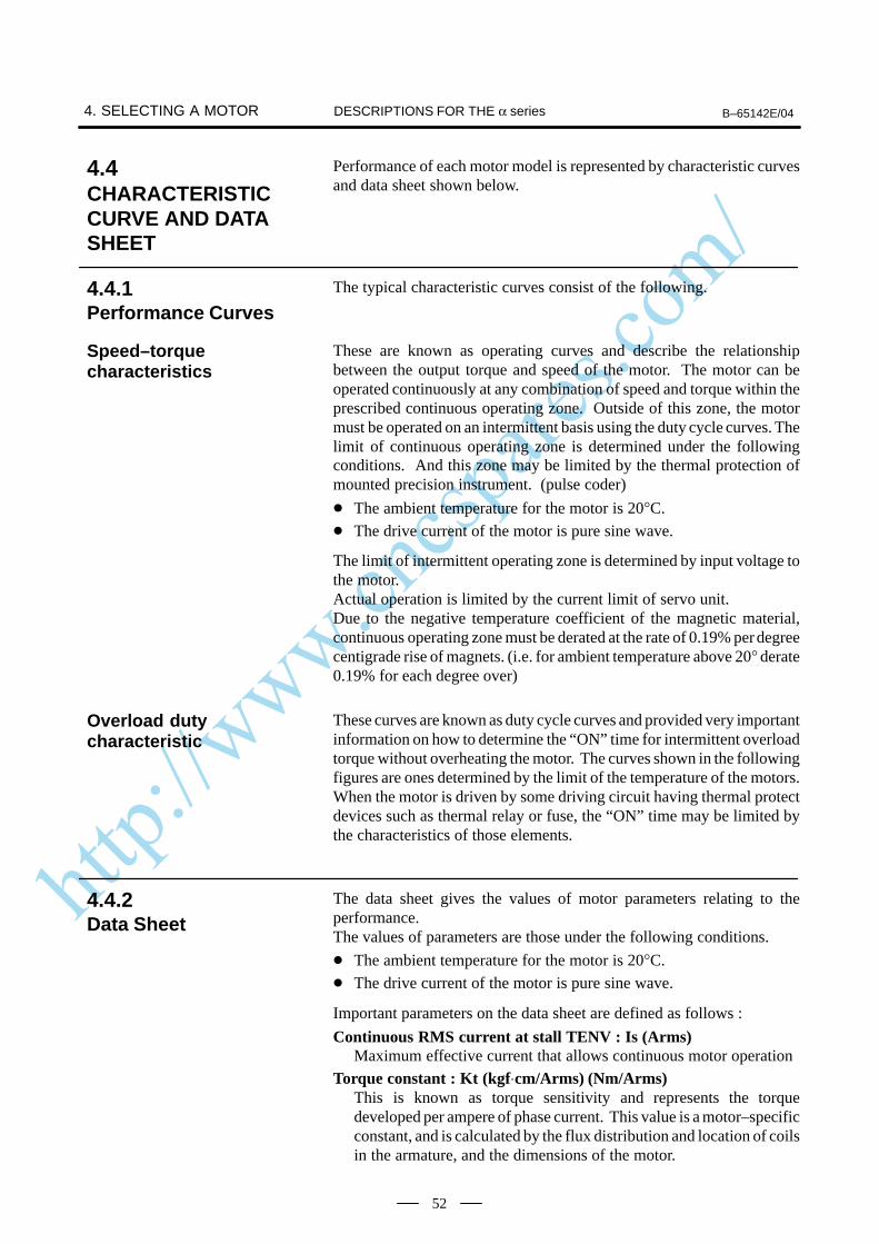
http://www.cncspares.com/
4. SELECTING A MOTOR B–65142E/04DESCRIPTIONS FOR THE α series
52
Performance of each motor model is represented by characteristic curvesand data sheet shown below.
The typical characteristic curves consist of the following.
These are known as operating curves and describe the relationshipbetween the output torque and speed of the motor. The motor can beoperated continuously at any combination of speed and torque within theprescribed continuous operating zone. Outside of this zone, the motormust be operated on an intermittent basis using the duty cycle curves. Thelimit of continuous operating zone is determined under the followingconditions. And this zone may be limited by the thermal protection ofmounted precision instrument. (pulse coder)
The ambient temperature for the motor is 20°C.
The drive current of the motor is pure sine wave.
The limit of intermittent operating zone is determined by input voltage tothe motor.Actual operation is limited by the current limit of servo unit.Due to the negative temperature coefficient of the magnetic material,continuous operating zone must be derated at the rate of 0.19% per degreecentigrade rise of magnets. (i.e. for ambient temperature above 20° derate0.19% for each degree over)
These curves are known as duty cycle curves and provided very importantinformation on how to determine the “ON” time for intermittent overloadtorque without overheating the motor. The curves shown in the followingfigures are ones determined by the limit of the temperature of the motors.When the motor is driven by some driving circuit having thermal protectdevices such as thermal relay or fuse, the “ON” time may be limited bythe characteristics of those elements.
The data sheet gives the values of motor parameters relating to theperformance.The values of parameters are those under the following conditions.
The ambient temperature for the motor is 20°C.
The drive current of the motor is pure sine wave.
Important parameters on the data sheet are defined as follows :
Continuous RMS current at stall TENV : Is (Arms)Maximum effective current that allows continuous motor operation
Torque constant : Kt (kgf⋅cm/Arms) (Nm/Arms)This is known as torque sensitivity and represents the torquedeveloped per ampere of phase current. This value is a motor–specificconstant, and is calculated by the flux distribution and location of coilsin the armature, and the dimensions of the motor.
4.4CHARACTERISTICCURVE AND DATASHEET
4.4.1Performance Curves
Speed–torquecharacteristics
Overload dutycharacteristic
4.4.2Data Sheet
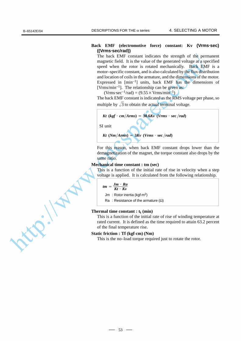
http://www.cncspares.com/
B–65142E/04 4. SELECTING A MOTORDESCRIPTIONS FOR THE α series
53
Back EMF (electromotive force) constant: Kv (Vrms·sec)((Vrms·sec/rad))The back EMF constant indicates the strength of the permanentmagnetic field. It is the value of the generated voltage at a specifiedspeed when the rotor is rotated mechanically. Back EMF is amotor–specific constant, and is also calculated by the flux distributionand location of coils in the armature, and the dimensions of the motor.Expressed in [min–1] units, back EMF has the dimensions of[Vrms/min–1]. The relationship can be given as:
(Vrms·sec–1/rad) = (9.55Vrms/min–1)The back EMF constant is indicated as the RMS voltage per phase, so
multiple by 3 to obtain the actual terminal voltage.
Kt (kgf cmArms) 30.6Kv (Vrms sec rad)
SI unit
Kt (NmArms) 3Kv (Vrms sec rad)
For this reason, when back EMF constant drops lower than thedemagnetization of the magnet, the torque constant also drops by thesame ratio.
Mechanical time constant : tm (sec)This is a function of the initial rate of rise in velocity when a stepvoltage is applied. It is calculated from the following relationship.
tm Jm RaKt Kv
Jm : Rotor inertia (kgf⋅m2)
Ra : Resistance of the armature (Ω)
Thermal time constant : tt (min)This is a function of the initial rate of rise of winding temperature atrated current. It is defined as the time required to attain 63.2 percentof the final temperature rise.
Static friction : Tf (kgf⋅cm) (Nm)This is the no–load torque required just to rotate the rotor.

http://www.cncspares.com/
4. SELECTING A MOTOR B–65142E/04DESCRIPTIONS FOR THE α series
54
Servo motors can be operated in the range exceeding continuous ratedtorque depending on thermal time constant. Duty characteristics showsthe Duty (%) and the “ON” time in which motor can be operated underthe given overload conditions. Calculation procedure is as follows.
1 Calculate Torque percent by formula (b) below.
2 Motor can be operated at any point on and inside the curvecorresponding to the given over load conditions obtained form 1.
3 Calculate tF by formula (a)
tF tR ( 100Duty percent
–1)
TMD
Load torqueContinuous rated torque
(a). . . . . . . . .
(b). . . . . . . . .
tF : “OFF” time
tR : “ON” time
The values of tR and tF obtained form the above mentioned procedureshows the ones limited by motor thermal conditions.Note that thermal protection devices such as a circuit breaker andthermal circuit are incorporated into the drive amplifier. These devicesalso impose a restriction on motor usage.When the motor is overloaded, the software (OVC alarm) imposes anadditional restriction on motor drive duration.
4.4.3How to Use Duty CycleCurves
http://www.cncspares.com/
B–65142E/04
5. CONDITIONS FOR APPROVAL RELATED TO THE IEC34
STANDARDDESCRIPTIONS FOR THE α series
55
5 CONDITIONS FOR APPROVAL RELATED TO THE IEC34STANDARD
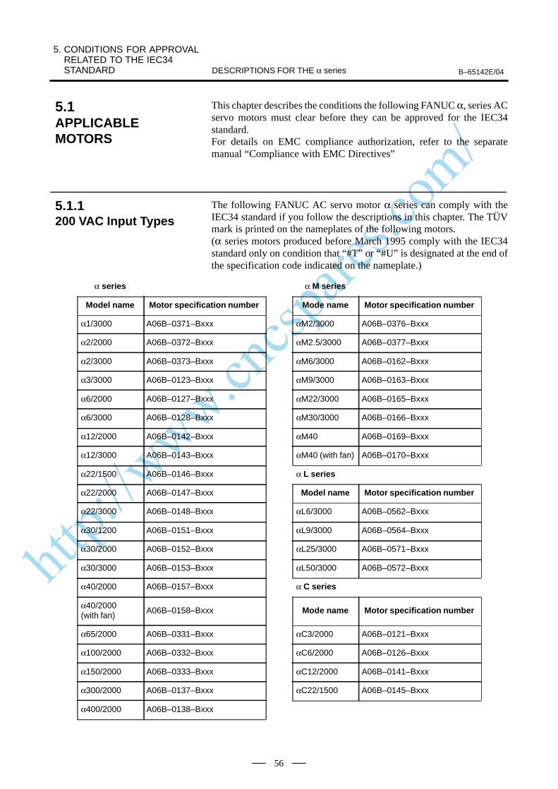
http://www.cncspares.com/
5. CONDITIONS FOR APPROVAL RELATED TO THE IEC34 STANDARD B–65142E/04DESCRIPTIONS FOR THE α series
56
This chapter describes the conditions the following FANUC α, series ACservo motors must clear before they can be approved for the IEC34standard.For details on EMC compliance authorization, refer to the separatemanual “Compliance with EMC Directives”
The following FANUC AC servo motor α series can comply with theIEC34 standard if you follow the descriptions in this chapter. The TÜVmark is printed on the nameplates of the following motors.(α series motors produced before March 1995 comply with the IEC34standard only on condition that “#T” or “#U” is designated at the end ofthe specification code indicated on the nameplate.)
α series α M series
Model name Motor specification number Mode name Motor specification number
α1/3000 A06B–0371–Bxxx αM2/3000 A06B–0376–Bxxx
α2/2000 A06B–0372–Bxxx αM2.5/3000 A06B–0377–Bxxx
α2/3000 A06B–0373–Bxxx αM6/3000 A06B–0162–Bxxx
α3/3000 A06B–0123–Bxxx αM9/3000 A06B–0163–Bxxx
α6/2000 A06B–0127–Bxxx αM22/3000 A06B–0165–Bxxx
α6/3000 A06B–0128–Bxxx αM30/3000 A06B–0166–Bxxx
α12/2000 A06B–0142–Bxxx αM40 A06B–0169–Bxxx
α12/3000 A06B–0143–Bxxx αM40 (with fan) A06B–0170–Bxxx
α22/1500 A06B–0146–Bxxx α L series
α22/2000 A06B–0147–Bxxx Model name Motor specification number
α22/3000 A06B–0148–Bxxx αL6/3000 A06B–0562–Bxxx
α30/1200 A06B–0151–Bxxx αL9/3000 A06B–0564–Bxxx
α30/2000 A06B–0152–Bxxx αL25/3000 A06B–0571–Bxxx
α30/3000 A06B–0153–Bxxx αL50/3000 A06B–0572–Bxxx
α40/2000 A06B–0157–Bxxx α C series
α40/2000 (with fan)
A06B–0158–Bxxx Mode name Motor specification number
α65/2000 A06B–0331–Bxxx αC3/2000 A06B–0121–Bxxx
α100/2000 A06B–0332–Bxxx αC6/2000 A06B–0126–Bxxx
α150/2000 A06B–0333–Bxxx αC12/2000 A06B–0141–Bxxx
α300/2000 A06B–0137–Bxxx αC22/1500 A06B–0145–Bxxx
α400/2000 A06B–0138–Bxxx
5.1APPLICABLEMOTORS
5.1.1200 VAC Input Types

http://www.cncspares.com/
B–65142E/04
5. CONDITIONS FOR APPROVAL RELATED TO THE IEC34
STANDARDDESCRIPTIONS FOR THE α series
57
The following FANUC AC servo motor αHV series can comply with theIEC34 standard if you follow the descriptions in this chapter. The TÜVmark is printed on the nameplates of the following motors.(α series motors produced before March 1995 comply with the IEC34standard only on condition that “#T” or “#U” is designated at the end ofthe specification code indicated on the nameplate.)
α(HV) series
Model name Motor specification number
α3/3000HV A06B–0171–Bxxx
α6/3000HV A06B–0172–Bxxx
α12/3000HV A06B–0176–Bxxx
α22/3000HV A06B–0177–Bxxx
α30/3000HV A06B–0178–Bxxx
α40/2000HV A06B–0179–Bxxx
α1000/2000HV A06B–0131–Bxxx
αM(HV) series
Model name Motor specification number
αM6/3000HV A06B–0182–Bxxx
αM9/3000HV A06B–0183–Bxxx
αM22/3000HV A06B–0185–Bxxx
αM30/3000HV A06B–0186–Bxxx
αM40/3000HV A06B–0189–Bxxx
5.1.2400 VAC Input Types
http://www.cncspares.com/
5. CONDITIONS FOR APPROVAL RELATED TO THE IEC34 STANDARD B–65142E/04DESCRIPTIONS FOR THE α series
58
The FANUC α , αM, αL, and αC series AC servo motors can be drivenonly by the FANUC servo amplifiers for 200 to 230 VAC.
The FANUC α (HV) series and αM(HV) series AC servo motors can bedriven only by the FANUC servo amplifiers for 400 to 460 VAC.
5.2DRIVES
5.2.1200 VAC Input Types
5.2.2400 VAC Input Types
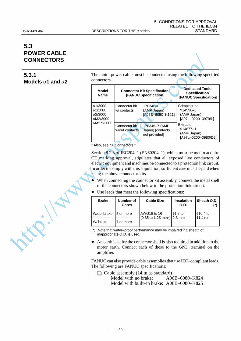
http://www.cncspares.com/
B–65142E/04
5. CONDITIONS FOR APPROVAL RELATED TO THE IEC34
STANDARDDESCRIPTIONS FOR THE α series
59
The motor power cable must be connected using the following specifiedconnectors.
ModelName
Connector Kit Specification [FANUC Specification]
Dedicated Tools Specification
[FANUC Specification]
α1/3000α2/2000α2/3000αM2/3000
Connector kit w/ contacts
176346–8 (AMP Japan)[A06B–6050–K121]
Crimping tool914596–3 (AMP Japan)[A97L–0200–0979/L]
αM2.5/3000Connector kit w/out contacts
176346–7 (AMPJapan) [contactsnot provided]
Extractor914677–1 (AMP Japan)[A97L–0200–0980/D3]
* Also, see “8. Connectors.”
Section 8.2.3 of IEC204–1 (EN60204–1), which must be met to acquireCE marking approval, stipulates that all exposed live conductors ofelectric equipment and machines be connected to a protection link circuit.In order to comply with this stipulation, sufficient care must be paid whenusing the above connector kits.
When connecting the connector kit assembly, connect the metal shellof the connectors shown below to the protection link circuit.
Use leads that meet the following specifications:
Brake Number ofCores
Cable Size InsulationO.D.
Sheath O.D. (*)
W/out brake 5 or more AWG18 to 162
φ1.8 to φ10.4 to
W/ brake 7 or more(0.85 to 1.25 mm2) 2.8 mm 11.4 mm
(*) Note that water–proof performance may be impaired if a sheath ofinappropriate O.D. is used.
An earth lead for the connector shell is also required in addition to themotor earth. Connect each of these to the GND terminal on theamplifier.
FANUC can also provide cable assemblies that use IEC–compliant leads.The following are FANUC specifications:
Cable assembly (14 m as standard)Model with no brake: A06B–6080–K824Model with built–in brake: A06B–6080–K825
5.3POWER CABLECONNECTORS
5.3.1Models 1 and 2
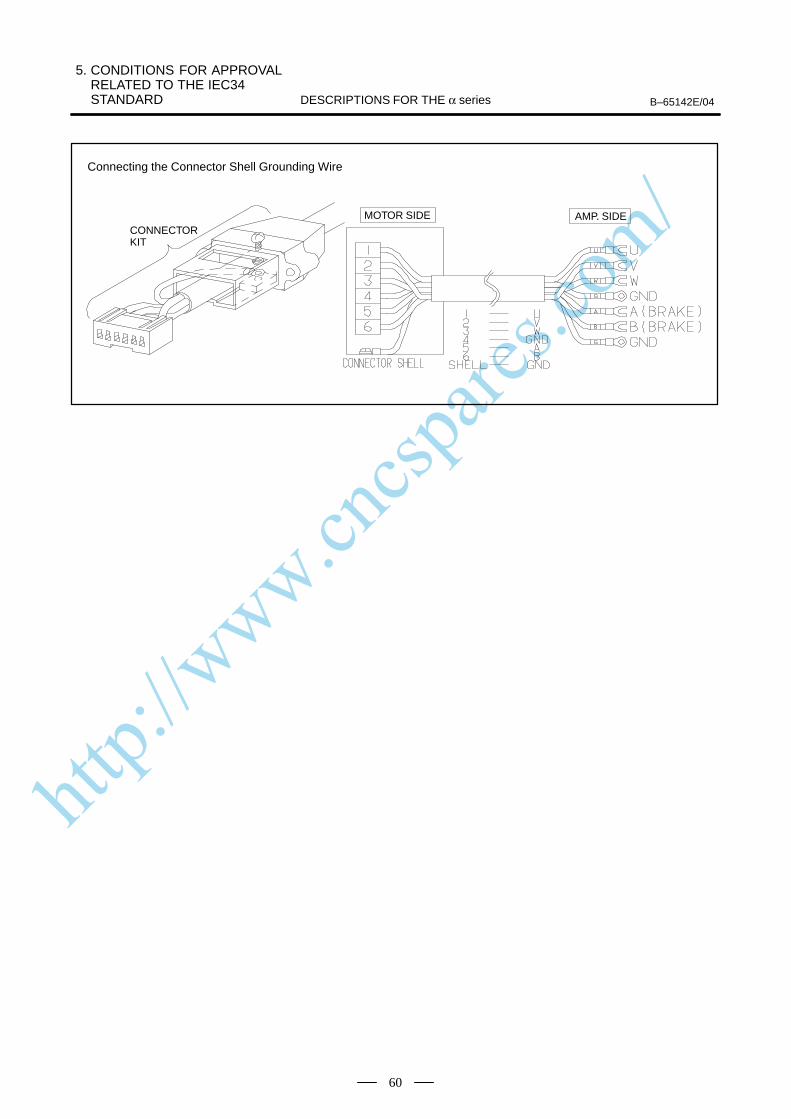
http://www.cncspares.com/
5. CONDITIONS FOR APPROVAL RELATED TO THE IEC34 STANDARD B–65142E/04DESCRIPTIONS FOR THE α series
60
MOTOR SIDE
Connecting the Connector Shell Grounding Wire
AMP. SIDECONNECTORKIT
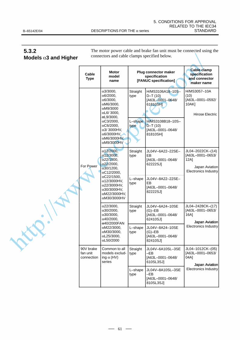
http://www.cncspares.com/
B–65142E/04
5. CONDITIONS FOR APPROVAL RELATED TO THE IEC34
STANDARDDESCRIPTIONS FOR THE α series
61
The motor power cable and brake fan unit must be connected using theconnectors and cable clamps specified below.
CableType
Motormodelname
Plug connector makerspecification
[FANUC specification]
Cable clampspecification
and connectormaker name
α3/3000,α6/2000,α6/3000,αM6/3000,αM9/3000αL6/ 3000,α
Straighttype
H/MS3106A18–10S–D–T (10)[A63L–0001–0648/61810SH]
H/MS3057–10A(10)[A63L–0001–0592/10AK]
Hirose ElectricαL9/3000,αC3/2000,αC6/2000,α3/ 3000HV,α6/3000HV,αM6/3000HV,αM9/3000HV
L–shapetype
H/MS3108B18–10S–D–T (10)[A63L–0001–0648/81810SH]
For Power
α12/2000,α12/3000,α22/1500,α22/2000,α30/1200,αC12/2000,
Straighttype
JL04V–6A22–22SE–EB[A63L–0001–0648/62222SJ]
JL04–2022CK–(14)[A63L–0001–0653/12A]
Japan AviationElectronics Industry
αC22/1500,α12/3000HV,α22/3000HV,α30/3000HV,αM22/3000HV,αM30/3000HV
L–shapetype
JL04V–8A22–22SE–EB[A63L–0001–0648/82222SJ]
α22/3000,α30/2000,α30/3000,α40/2000,α
Straighttype
JL04V–6A24–10SE(G)–EB[A63L–0001–0648/62410SJ]
JL04–2428CK–(17)[A63L–0001–0653/16A]
Japan Aviationα40/2000FANαM22/3000,αM30/3000,αL25/3000,αL50/2000
L–shapetype
JL04V–8A24–10SE(G)–EB[A63L–0001–0648/82410SJ]
Japan AviationElectronics Industry
90V brakefan unit connection
Common to allmodels exclud-ing α (HV) series
Straighttype
JL04V–6A10SL–3SE–EB[A63L–0001–0648/610SL3SJ]
JL04–1012CK–(05)[A63L–0001–0653/04A]
Japan AviationL–shapetype
JL04V–8A10SL–3SE–EB[A63L–0001–0648/810SL3SJ]
Japan AviationElectronics Industry
5.3.2Models 3 and Higher
http://www.cncspares.com/
5. CONDITIONS FOR APPROVAL RELATED TO THE IEC34 STANDARD B–65142E/04DESCRIPTIONS FOR THE α series
62
Also see Section 8.
The power cable for the α22/3000, α30/2000, α30/3000, α40/2000,α40/2000FAN, αM22/3000, αM30/3000, αL25/3000, andαL50/2000 has 7 conductors. Its grounding wire (one conductor)must have a cross section not less than that for the U, V, or W line (twoconductors). For the grounding wire for the other connectors, its crosssection must not be less than that for the U, V, or W line.
TUV have certified that the plug connector and cable clamp mentionedabove, when combined with the FANUC α series servo motors, satisfythe VDE0627 safety standard. As indicated in the table below, severalmanufacturers offer other plug connectors. For information aboutwhether the plug connectors satisfy the safety standard whencombined with the FANUC α series servo motors, contact thecorresponding manufacturer. Contact the manufacturers if you requiredetails of their products.
Manufacturer Product series name
Hirose Electric (HRS) H/MS310 TUV–conforming series
Japan Aviation Electronics Industry(JAE)
JL04V series
DDK Ltd. (DDK) CE05 series
If a cable or conduit hose seal adapter is used, consult an appropriateconnector maker.
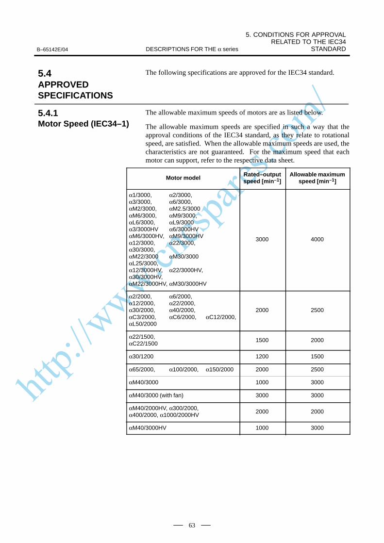
http://www.cncspares.com/
B–65142E/04
5. CONDITIONS FOR APPROVAL RELATED TO THE IEC34
STANDARDDESCRIPTIONS FOR THE α series
63
The following specifications are approved for the IEC34 standard.
The allowable maximum speeds of motors are as listed below.
The allowable maximum speeds are specified in such a way that theapproval conditions of the IEC34 standard, as they relate to rotationalspeed, are satisfied. When the allowable maximum speeds are used, thecharacteristics are not guaranteed. For the maximum speed that eachmotor can support, refer to the respective data sheet.
Motor model Rated–outputspeed [min–1]
Allowable maximumspeed [min–1]
α1/3000, α2/3000,α3/3000, α6/3000,αM2/3000, αM2.5/3000αM6/3000, αM9/3000,αL6/3000, αL9/3000α3/3000HV α6/3000HVαM6/3000HV, αM9/3000HVα12/3000, α22/3000,α30/3000,αM22/3000 αM30/3000αL25/3000,α12/3000HV, α22/3000HV,α30/3000HV,αM22/3000HV, αM30/3000HV
3000 4000
α2/2000, α6/2000,α12/2000, α22/2000,α30/2000, α40/2000,αC3/2000, αC6/2000, αC12/2000,αL50/2000
2000 2500
α22/1500,αC22/1500
1500 2000
α30/1200 1200 1500
α65/2000, α100/2000, α150/2000 2000 2500
αM40/3000 1000 3000
αM40/3000 (with fan) 3000 3000
αM40/2000HV, α300/2000,α400/2000, α1000/2000HV
2000 2000
αM40/3000HV 1000 3000
5.4APPROVEDSPECIFICATIONS
5.4.1Motor Speed (IEC34–1)
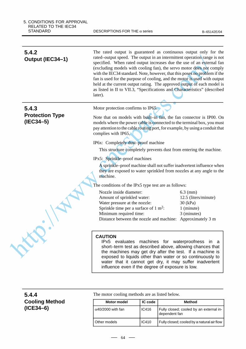
http://www.cncspares.com/
5. CONDITIONS FOR APPROVAL RELATED TO THE IEC34 STANDARD B–65142E/04DESCRIPTIONS FOR THE α series
64
The rated output is guaranteed as continuous output only for therated–output speed. The output in an intermittent operation range is notspecified. When rated output increases due the use of an external fan(excluding models with cooling fan), the servo motor does not complywith the IEC34 standard. Note, however, that this poses no problem if thefan is used for the purpose of cooling, and the motor is used with outputheld at the current output rating. The approved output of each model isas listed in II to VII.3, “Specifications and Characteristics” (describedlater).
Motor protection confirms to IP65.
Note that on models with built–in fan, the fan connector is IP00. Onmodels where the power cable is connected to the terminal box, you mustpay attention to the cable routing port, for example, by using a conduit thatcomplies with IP65.
IP6x: Completely dust–proof machine
This structure completely prevents dust from entering the machine.
IPx5: Sprinkle–proof machines
A sprinkle–proof machine shall not suffer inadvertent influence whenthey are exposed to water sprinkled from nozzles at any angle to themachine.
The conditions of the IPx5 type test are as follows:
Nozzle inside diameter: 6.3 (mm)Amount of sprinkled water: 12.5 (liters/minute)Water pressure at the nozzle: 30 (kPa)Sprinkle time per a surface of 1 m2: 1 (minute)Minimum required time: 3 (minutes)Distance between the nozzle and machine: Approximately 3 m
CAUTIONIPx5 evaluates machines for waterproofness in ashort–term test as described above, allowing chances thatthe machines may get dry after the test. If a machine isexposed to liquids other than water or so continuously towater that it cannot get dry, it may suffer inadvertentinfluence even if the degree of exposure is low.
The motor cooling methods are as listed below.
Motor model IC code Method
α40/2000 with fan IC416 Fully closed; cooled by an external in-dependent fan
Other models IC410 Fully closed; cooled by a natural air flow
5.4.2Output (IEC34–1)
5.4.3Protection Type(IEC34–5)
5.4.4Cooling Method(ICE34–6)
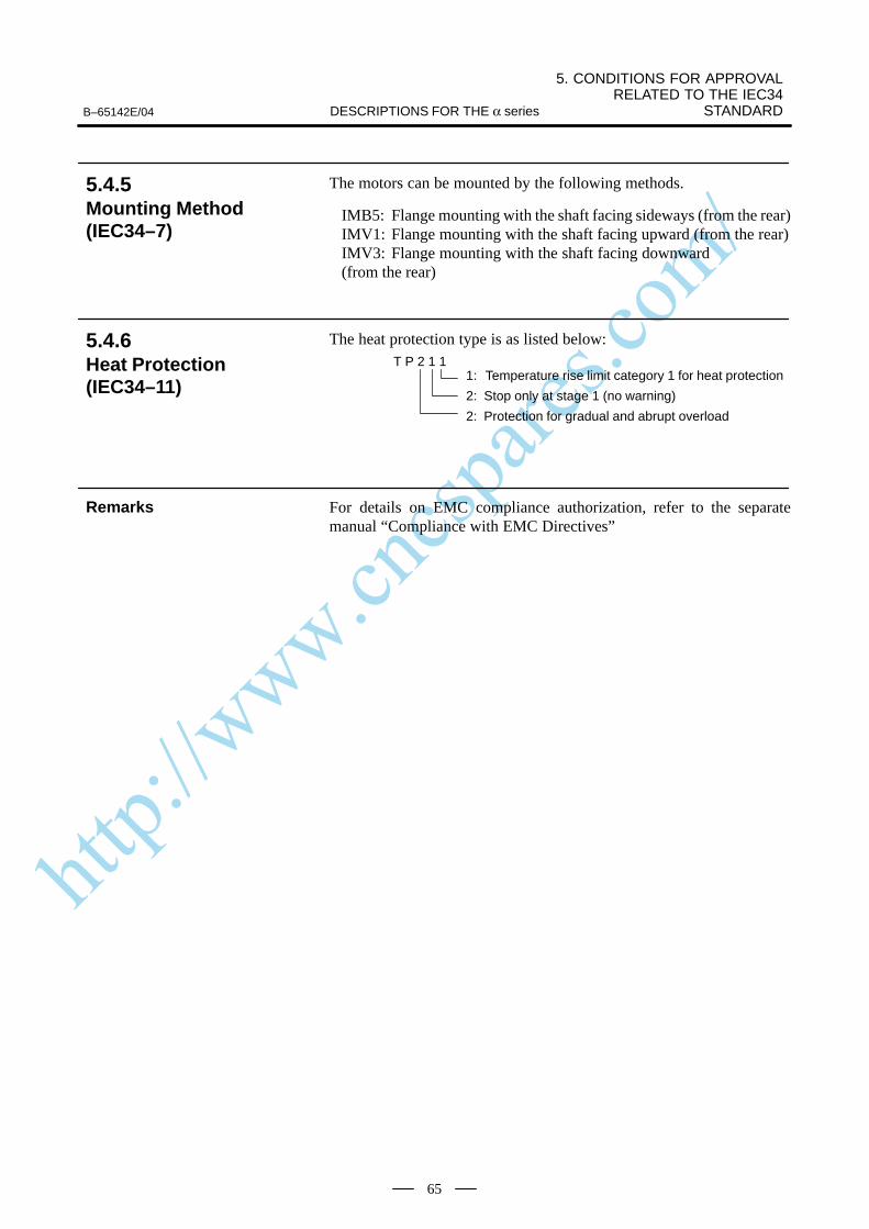
http://www.cncspares.com/
B–65142E/04
5. CONDITIONS FOR APPROVAL RELATED TO THE IEC34
STANDARDDESCRIPTIONS FOR THE α series
65
The motors can be mounted by the following methods.
IMB5: Flange mounting with the shaft facing sideways (from the rear)IMV1: Flange mounting with the shaft facing upward (from the rear)IMV3: Flange mounting with the shaft facing downward (from the rear)
The heat protection type is as listed below:
1: Temperature rise limit category 1 for heat protection
2: Stop only at stage 1 (no warning)
2: Protection for gradual and abrupt overload
T P 2 1 1
For details on EMC compliance authorization, refer to the separatemanual “Compliance with EMC Directives”
5.4.5Mounting Method(IEC34–7)
5.4.6Heat Protection(IEC34–11)
Remarks
http://www.cncspares.com/
6. FEEDBACK DETECTOR B–65142E/04DESCRIPTIONS FOR THE α series
66
6
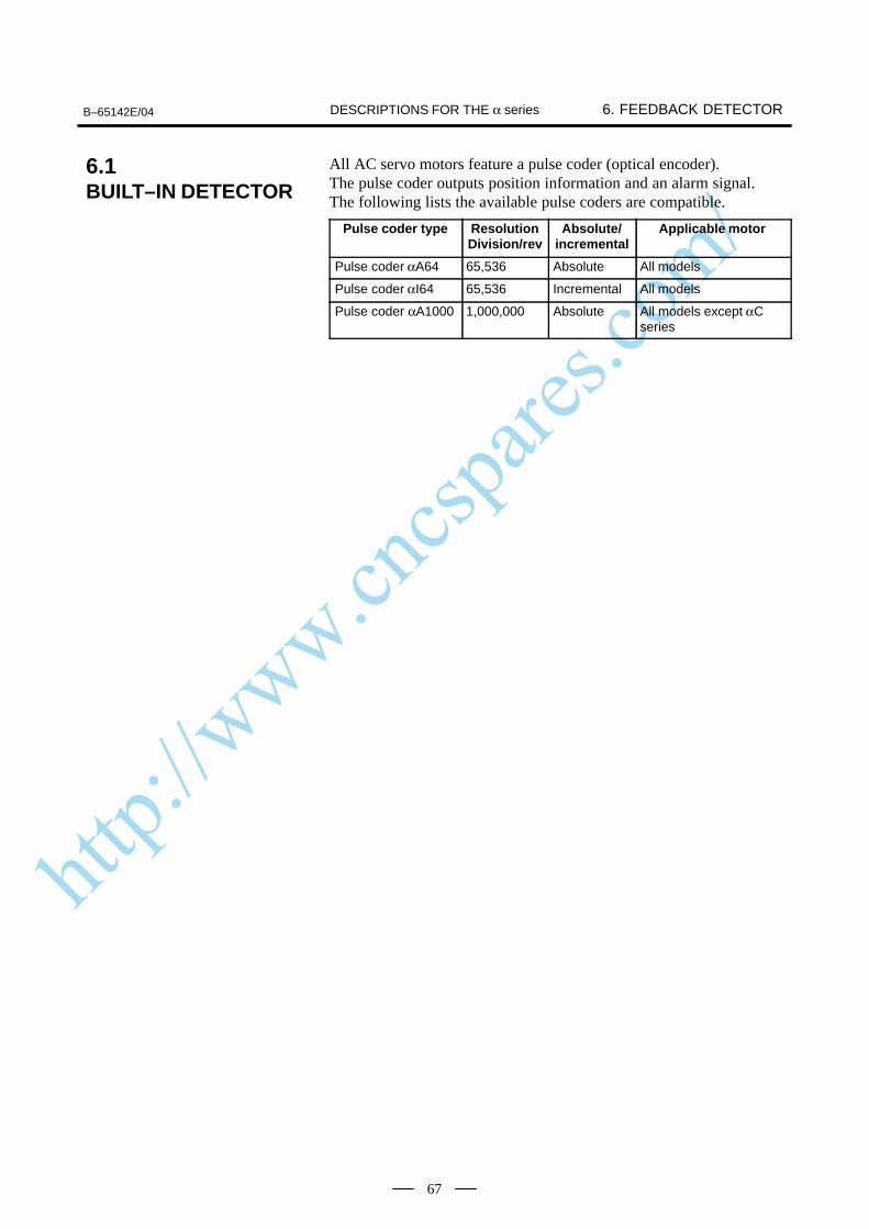
http://www.cncspares.com/
B–65142E/04 6. FEEDBACK DETECTORDESCRIPTIONS FOR THE α series
67
All AC servo motors feature a pulse coder (optical encoder).The pulse coder outputs position information and an alarm signal.The following lists the available pulse coders are compatible.
Pulse coder type ResolutionDivision/rev
Absolute/incremental
Applicable motor
Pulse coder αA64 65,536 Absolute All models
Pulse coder αI64 65,536 Incremental All models
Pulse coder αA1000 1,000,000 Absolute All models except αCseries
6.1BUILT–IN DETECTOR
http://www.cncspares.com/
6. FEEDBACK DETECTOR B–65142E/04DESCRIPTIONS FOR THE α series
68
With the NC’s flexible feed gear function, 1–µm control can be performedfor feed pitches of up to 30 mm per motor revolution.
With the NC’s flexible feed gear function 0.1–µm control (up to 100mm/revolution) and 0.01–µm control (up to 10 mm/revolution) can beperformed.Increasing the speed loop gain as far as possible is effective. This can beeasily achieved by increasing the resolution
6.2PULSE CODERRESOLUTION ANDCONTROLRESOLUTION
65,536divisions/revolution
1,000,000divisions/revolution
http://www.cncspares.com/
B–65142E/04 6. FEEDBACK DETECTORDESCRIPTIONS FOR THE α series
69
When the NC is turned off, the pulse coder position detection function isbacked up by battery. So, when the NC is next turned on, the operator doesnot have to perform reference position return.For backup, a battery unit must be installed in the NC or servo amplifier.If a low–battery indication appears on the NC, renew the battery as soonas possible.Replace the battery while the NC is turned on.
6.3ABSOLUTE–TYPEPULSE CODER
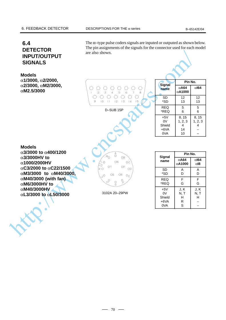
http://www.cncspares.com/
6. FEEDBACK DETECTOR B–65142E/04DESCRIPTIONS FOR THE α series
70
The α–type pulse coders signals are inputed or outputed as shown below.The pin assignments of the signals for the connector used for each modelare also shown.
Pin No.Signalname αA64
αA1000αI64
SD*SD
1213
1213
REQ*REQ
56
56
+5V0V
Shield+6VA0VA
8, 151, 2, 3
41410
8, 151, 2, 3
4––
Pin No.Signalname αA64
αA1000αI64αI8
SD*SD
AD
AD
REQ*REQ
FG
FG
+5V0V
Shield+6VA0VA
J, KN, T
HRS
J, KN, T
H––
6.4DETECTORINPUT/OUTPUTSIGNALS
Models α1/3000, α2/2000,α2/3000, αM2/3000,αM2.5/3000
D–SUB 15P
Models α3/3000 to α400/1200α3/3000HV to α1000/2000HVαC3/2000 to αC22/1500αM3/3000 to αM40/3000,αM40/3000 (with fan)αM6/3000HV to αM40/3000HVαL3/3000 to αL50/3000 3102A 20–29PW
http://www.cncspares.com/
B–65142E/04 6. FEEDBACK DETECTORDESCRIPTIONS FOR THE α series
71
For detecting a position by attaching directly to a ball screw or a machine,use a separate type position detector. Pay attention to the following itemswhen using the separate type position detector.
Increase the machine rigidity between the servo motor and the positiondetector to minimize mechanical vibration. If the machine rigidity islow or the structure vibrates, poor performance, over shoot is likely tooccur.
Generally, when the separate type detector is used, the influence ofgear, ball screw pitch error or table inclination is decreased and thepositioning accuracy and geometrical accuracy (roundness, etc.) areincreased, but the smoothness may deteriorate due to the elasticity inthe machine between the servo motor and the position detector.
It is necessary to use the built-in pulse coder with a resolution equalto or finer than that of the separate type position detector.
To connect the separate type position detector to the NC, connect only thesignals described in the connecting manual. (A, B, Z, 0V, 5V and REQif necessary)When the other signal is connected, the unit may malfunction.Do not connect the C1, C2, C4, and C8 signals output from the separatetype pulse coder unit.FANUC provides the following external position (rotary) detector.
Four types of separate type pulse coder are available. Features and rapidtraverse–related limitations are the same as the built–in pulse coder.
A860–0372–T001
1,000,000 P/rev (Up to 4000 min–1)
A860–0301–T0
01 : 2000P/rev (Up to 3000min -1)02 : 2500P/rev (Up to 2400min -1)03 : 3000P/rev (Up to 2000min -1)04 : 4000P/rev (Up to 1500min -1)
A860–0324–T1
01 : 2000P/rev (Up to 3000min -1)02 : 2500P/rev (Up to 2400min -1)03 : 3000P/rev (Up to 2000min -1)04 : 4000P/rev (Up to 1500min -1)
6.5SEPARATE TYPEPOSITIONDETECTOR
6.5.1Separate Type PulseCoder Type andSpecifications
Pulse coder αA1000S
Incremental pulse coderunit
Absolute pulse coderunit
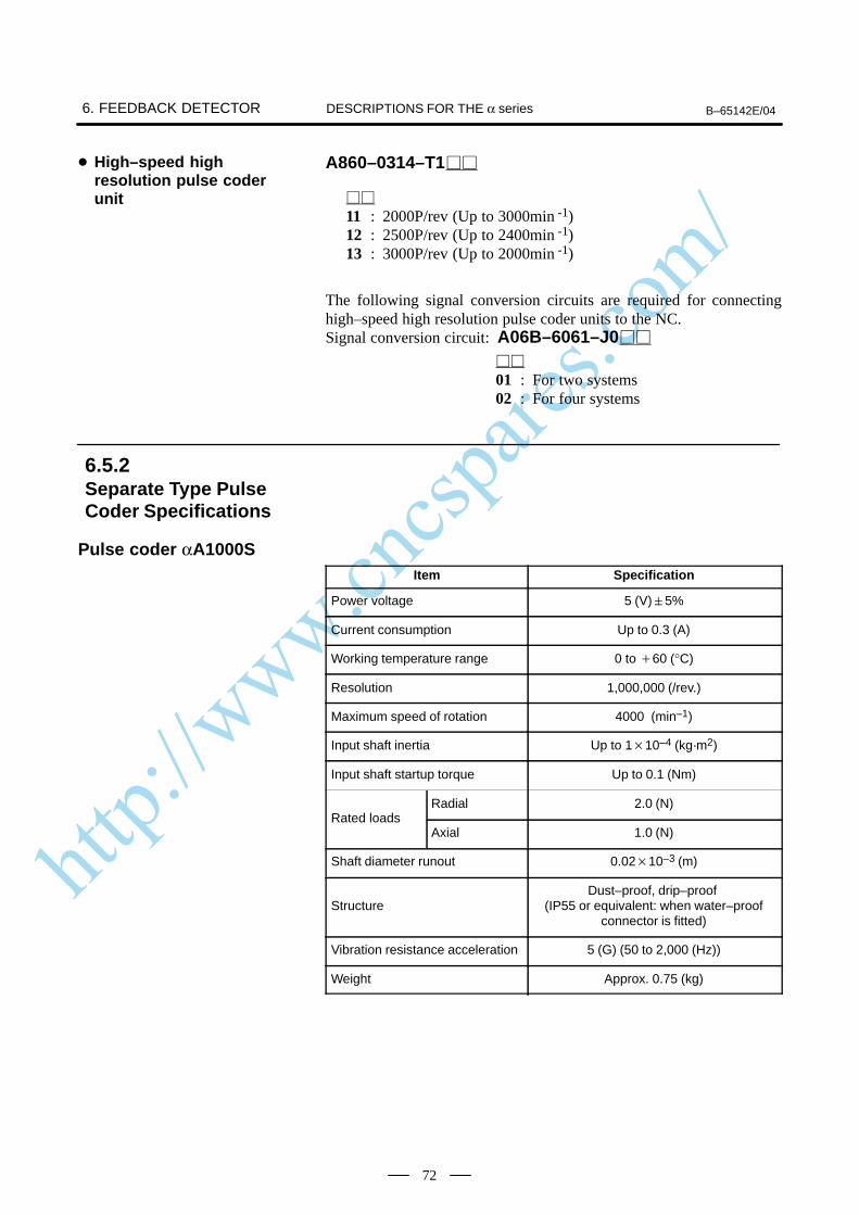
http://www.cncspares.com/
6. FEEDBACK DETECTOR B–65142E/04DESCRIPTIONS FOR THE α series
72
A860–0314–T1
11 : 2000P/rev (Up to 3000min -1)12 : 2500P/rev (Up to 2400min -1)13 : 3000P/rev (Up to 2000min -1)
The following signal conversion circuits are required for connectinghigh–speed high resolution pulse coder units to the NC.Signal conversion circuit: A06B–6061–J0
01 : For two systems02 : For four systems
Item Specification
Power voltage 5 (V) 5%
Current consumption Up to 0.3 (A)
Working temperature range 0 to 60 (°C)
Resolution 1,000,000 (/rev.)
Maximum speed of rotation 4000 (min–1)
Input shaft inertia Up to 110–4 (kg·m2)
Input shaft startup torque Up to 0.1 (Nm)
Radial 2.0 (N)Rated loads
Axial 1.0 (N)
Shaft diameter runout 0.0210–3 (m)
StructureDust–proof, drip–proof
(IP55 or equivalent: when water–proofconnector is fitted)
Vibration resistance acceleration 5 (G) (50 to 2,000 (Hz))
Weight Approx. 0.75 (kg)
High–speed highresolution pulse coderunit
6.5.2Separate Type PulseCoder Specifications
Pulse coder αA1000S

http://www.cncspares.com/
B–65142E/04 6. FEEDBACK DETECTORDESCRIPTIONS FOR THE α series
73
Item Specification
Power voltage 5 (V) 5%
Current consumption Up to 0.35 (A)
Working temperature range 0 to 60 (°C)
Maximum response frequency 100103 (Hz)
Input shaft inertia Up to 510–3 (kg·m2)
Input shaft startup torque Up to 0.8 (Nm)
Radial 20 (N)Rated loads
Axial 10 (N)
Shaft diameter runout 0.0210–3 (m)
Weight Approx. 2.0 (kg)
Pin No.
Signal name αA1000S3102A20–29P
SD*SD
AD
REQ*REQ
FG
+5V0V
J, KN, T
Shield H
+6VA0VA
RS
Incremental pulse coderunit
Absolute pulse coderunit
High–speed andhigh–resolution pulsecoder unit
6.5.3Input Signals andLayout of ConnectorPins of Separate TypePulse Coder
Pulse coder αA1000S
3102A20–29PW
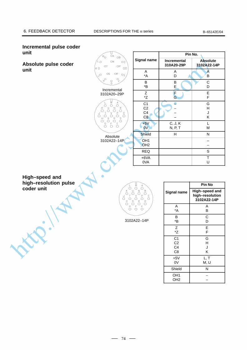
http://www.cncspares.com/
6. FEEDBACK DETECTOR B–65142E/04DESCRIPTIONS FOR THE α series
74
Pin No.
Signal name Incremental310A20-29P
Absolute3102A22-14P
A*A
AD
AB
B*B
BE
CD
Z*Z
FG
EF
C1C2C4C8
––––
GHJK
+5V0V
C, J, KN, P, T
LM
Shield H N
OH1OH2
––
REQ S
+6VA0VA
TU
Pin No
Signal name High–speed andhigh–resolution
3102A22-14P
A*A
AB
B*B
CD
Z*Z
EF
C1C2C4C8
GHJK
+5V0V
L, TM, U
Shield N
OH1OH2
––
Incremental pulse coderunit
Absolute pulse coderunit
Incremental3102A20–29P
Absolute3102A22–14P
High–speed andhigh–resolution pulsecoder unit
3102A22–14P
http://www.cncspares.com/
B–65142E/04 6. FEEDBACK DETECTORDESCRIPTIONS FOR THE α series
75
Separate Type Pulse Coder Name Dwg. No.
Pulse coder αA1000S Fig. 6.5.4 (a)
Incremental pulse coder unit Fig. 6.5.4 (b)
Absolute pulse coder unitHigh–speed and high–resolution pulse coder unit
Fig. 6.5.4 (c)
6.5.4External Dimensions ofSeparate Type PulseCoder
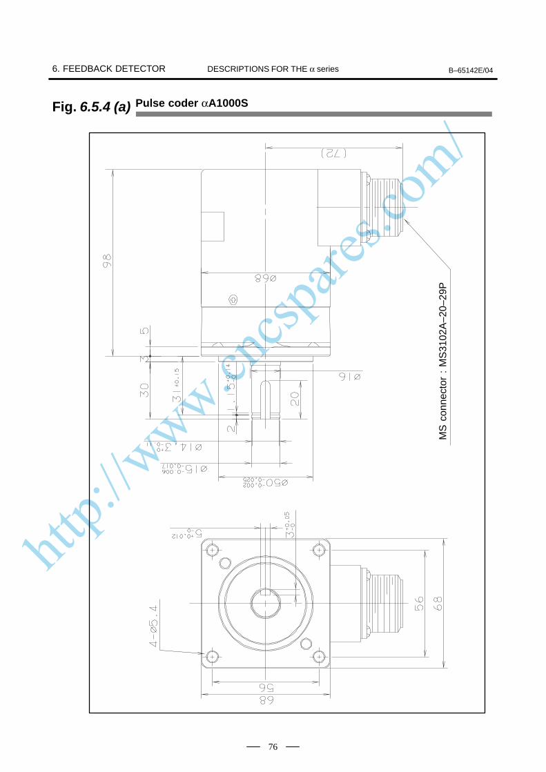
http://www.cncspares.com/
6. FEEDBACK DETECTOR B–65142E/04DESCRIPTIONS FOR THE α series
76
Fig. 6.5.4 (a) Pulse coder αA1000S
ÃÃÃÃÃÃÃÃÃÃÃÃÃÃÃÃÃÃÃÃÃÃÃÃÃÃÃÃ
MS
con
nect
or :
MS
3102
A–2
0–29
P
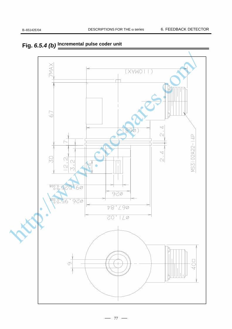
http://www.cncspares.com/
B–65142E/04 6. FEEDBACK DETECTORDESCRIPTIONS FOR THE α series
77
Fig. 6.5.4 (b) Incremental pulse coder unit
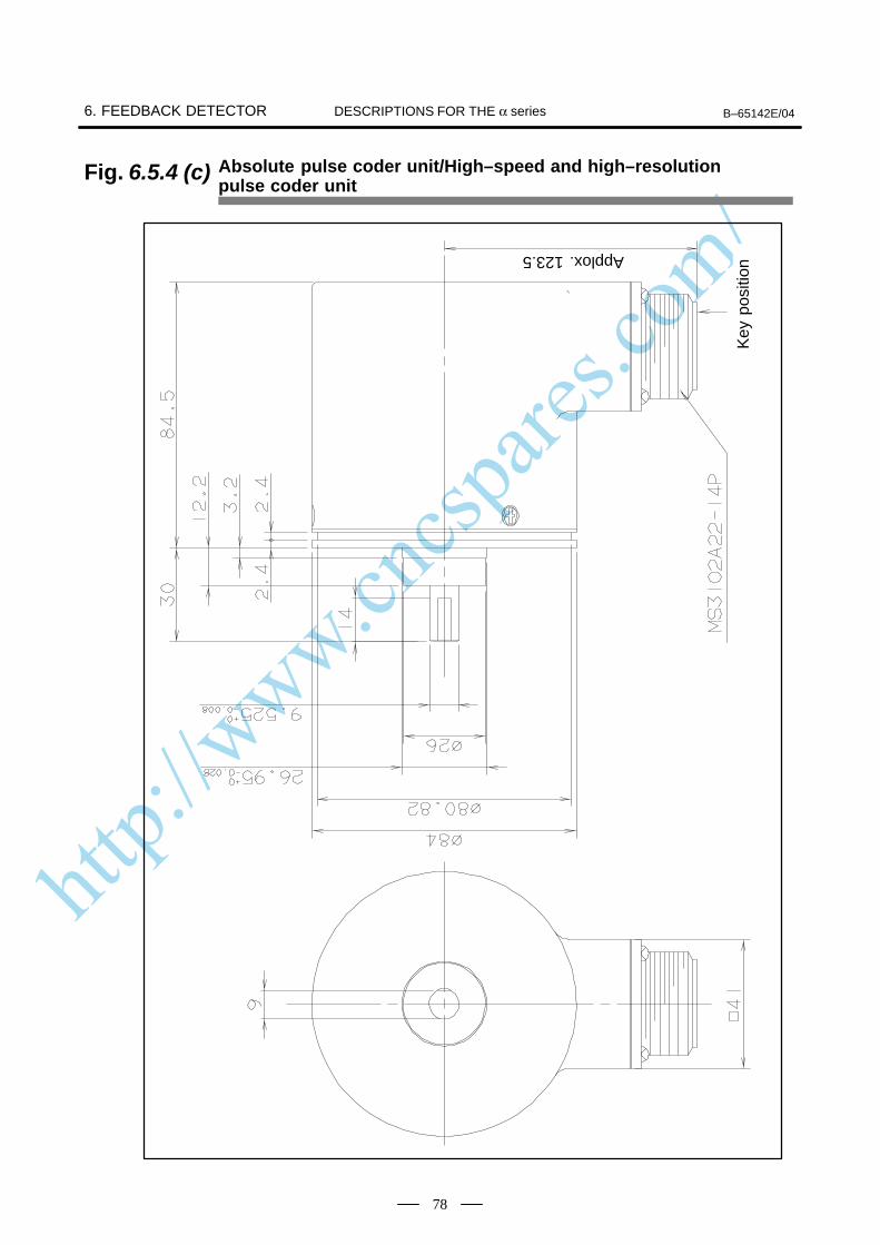
http://www.cncspares.com/
6. FEEDBACK DETECTOR B–65142E/04DESCRIPTIONS FOR THE α series
78
Absolute pulse coder unit/High–speed and high–resolution pulse coder unit
Fig. 6.5.4 (c)
ÃÃÃÃÃÃÃÃÃÃÃÃÃÃ
Key
pos
itionÃÃÃÃÃÃÃ
ÃÃÃÃÃÃÃ
Applox. 123.5
http://www.cncspares.com/
B–65142E/04 7. BUILT–IN BRAKEDESCRIPTIONS FOR THE α series
79
7
Some of the α, α(HV), αC, αM, and αL series Models use motors thatcontain a holding brake to prevent falling along a vertical axis.Motors with a built-in brake have different outlines and weight from othertypes of motors. For their outlines, refer to appropriate outline drawings.
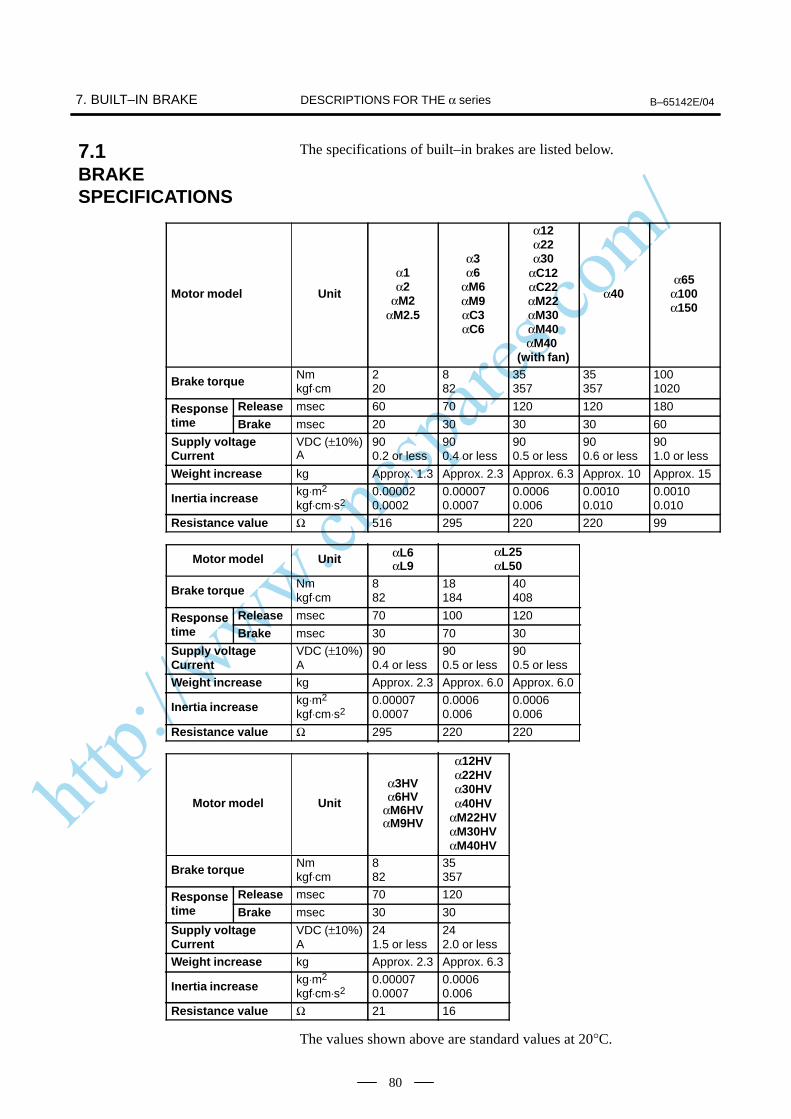
http://www.cncspares.com/
7. BUILT–IN BRAKE B–65142E/04DESCRIPTIONS FOR THE α series
80
The specifications of built–in brakes are listed below.
Motor model Unit
α1α2
αM2αM2.5
α3α6
αM6αM9αC3αC6
α12α22α30
αC12αC22αM22αM30αM40αM40
(with fan)
α40α65
α100α150
Brake torque Nmkgf⋅cm
220
882
35357
35357
1001020
Response Release msec 60 70 120 120 180Responsetime Brake msec 20 30 30 30 60
Supply voltage Current
VDC (±10%)A
900.2 or less
900.4 or less
900.5 or less
900.6 or less
901.0 or less
Weight increase kg Approx. 1.3 Approx. 2.3 Approx. 6.3 Approx. 10 Approx. 15
Inertia increase kg⋅m2
kgf⋅cm⋅s20.000020.0002
0.000070.0007
0.00060.006
0.00100.010
0.00100.010
Resistance value Ω 516 295 220 220 99
Motor model Unit αL6αL9
αL25αL50
Brake torque Nmkgf⋅cm
882
18184
40408
Response Release msec 70 100 120Responsetime Brake msec 30 70 30
Supply voltageCurrent
VDC (±10%)A
900.4 or less
900.5 or less
900.5 or less
Weight increase kg Approx. 2.3 Approx. 6.0 Approx. 6.0
Inertia increase kg⋅m2
kgf⋅cm⋅s20.000070.0007
0.00060.006
0.00060.006
Resistance value Ω 295 220 220
Motor model Unit
α3HVα6HV
αM6HVαM9HV
α12HVα22HVα30HVα40HV
αM22HVαM30HVαM40HV
Brake torque Nmkgf⋅cm
882
35357
Response Release msec 70 120Responsetime Brake msec 30 30
Supply voltageCurrent
VDC (±10%)A
241.5 or less
242.0 or less
Weight increase kg Approx. 2.3 Approx. 6.3
Inertia increase kg⋅m2
kgf⋅cm⋅s20.000070.0007
0.00060.006
Resistance value Ω 21 16
The values shown above are standard values at 20°C.
7.1BRAKESPECIFICATIONS

http://www.cncspares.com/
B–65142E/04 7. BUILT–IN BRAKEDESCRIPTIONS FOR THE α series
81
CAUTIONPay attention to the following points when motors withbrakes are used.
1 Configure the brake circuit referring to the brake wiringdiagrams and recommended parts described in thefollowing items.
2 For the α, αM, αL and αC brake power supplies, use thefull–wave rectified 100 VAC or 90 VDC power supplies. Theallowable voltage fluctuation for both of these powersupplies is ±10%. Do not use a half–wave rectified 200 VACpower supply. Doing so will damage the surge absorber.
3 For the α(HV) and αM(HV), use the 24 VDC power supply.The allowable voltage fluctuation for this power supply is±10%.
4 The brake in the motor is used to hold the machine when theservo motor control is OFF. It is possible to brake themachine by turning OFF the brake power in an emergencystop or during a power interruption. However, it is impossibleto use this brake to reduce the stop distance in normaloperation.
5 Allow sufficient time to start the servo motor beforereleasing the brake. Don’t use the brake as an aid for theaxis to stop at the same position for a long time, such as anindex table. Turn the servo off when holding the axis by thebuilt-in brake or another holding means. At this time, allowsufficient time to set the brake before turning off the servo.
6 Models α40/2000 are longer because they contain a brake.If an excessive load is applied to the opposite side of theflange, the flange may be damaged. Do not apply any loadto the opposite side of the flange. Do not subject the motorto excessive force.
7 Motor brake connectors do not have polarity.
7.2CAUTIONS
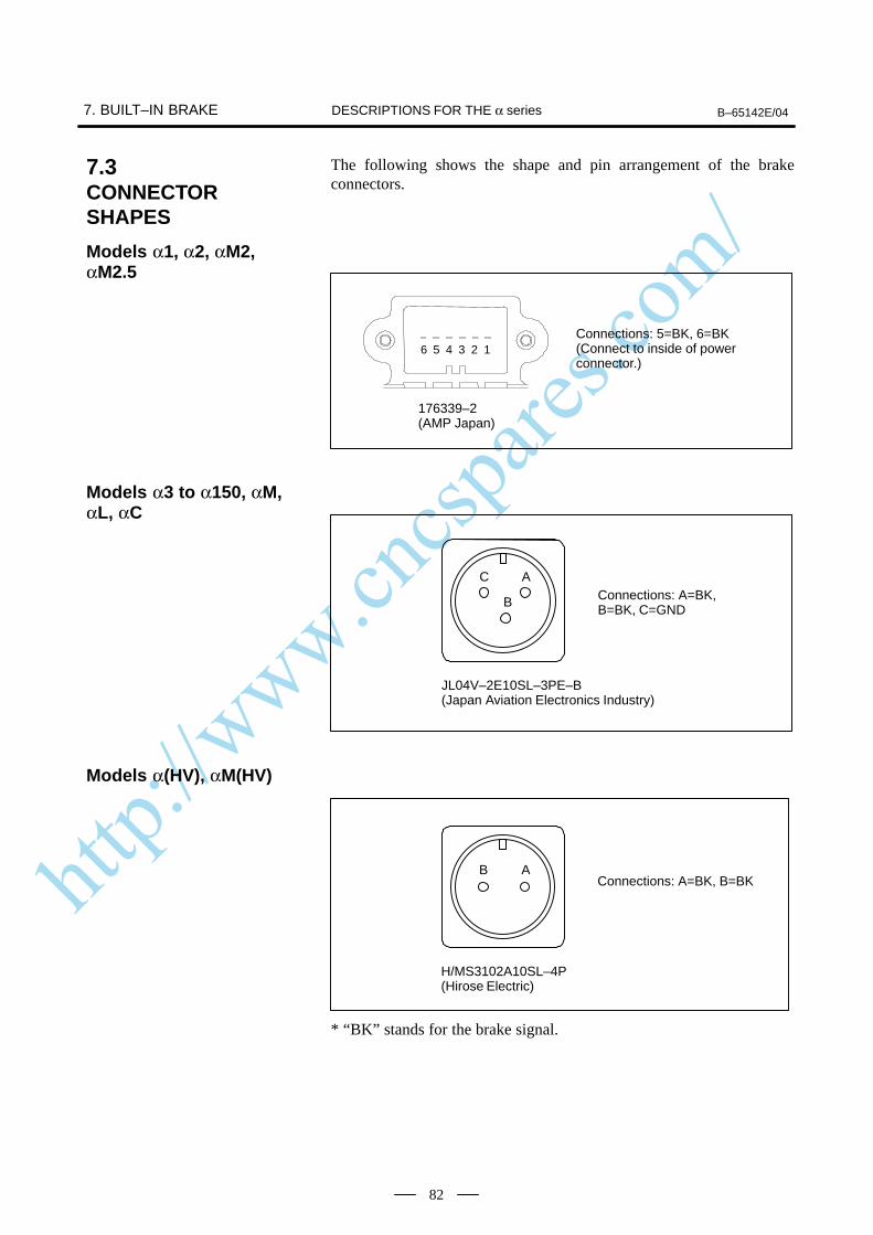
http://www.cncspares.com/
7. BUILT–IN BRAKE B–65142E/04DESCRIPTIONS FOR THE α series
82
The following shows the shape and pin arrangement of the brakeconnectors.
Connections: 5=BK, 6=BK(Connect to inside of power connector.)
176339–2(AMP Japan)
6 5 4 3 2 1
Connections: A=BK, B=BK, C=GND
AC
B
JL04V–2E10SL–3PE–B(Japan Aviation Electronics Industry)
Connections: A=BK, B=BKAB
H/MS3102A10SL–4P(Hirose Electric)
* “BK” stands for the brake signal.
7.3CONNECTORSHAPES
Models α1, α2, αM2,αM2.5
Models α3 to α150, αM,αL, αC
Models α(HV), αM(HV)
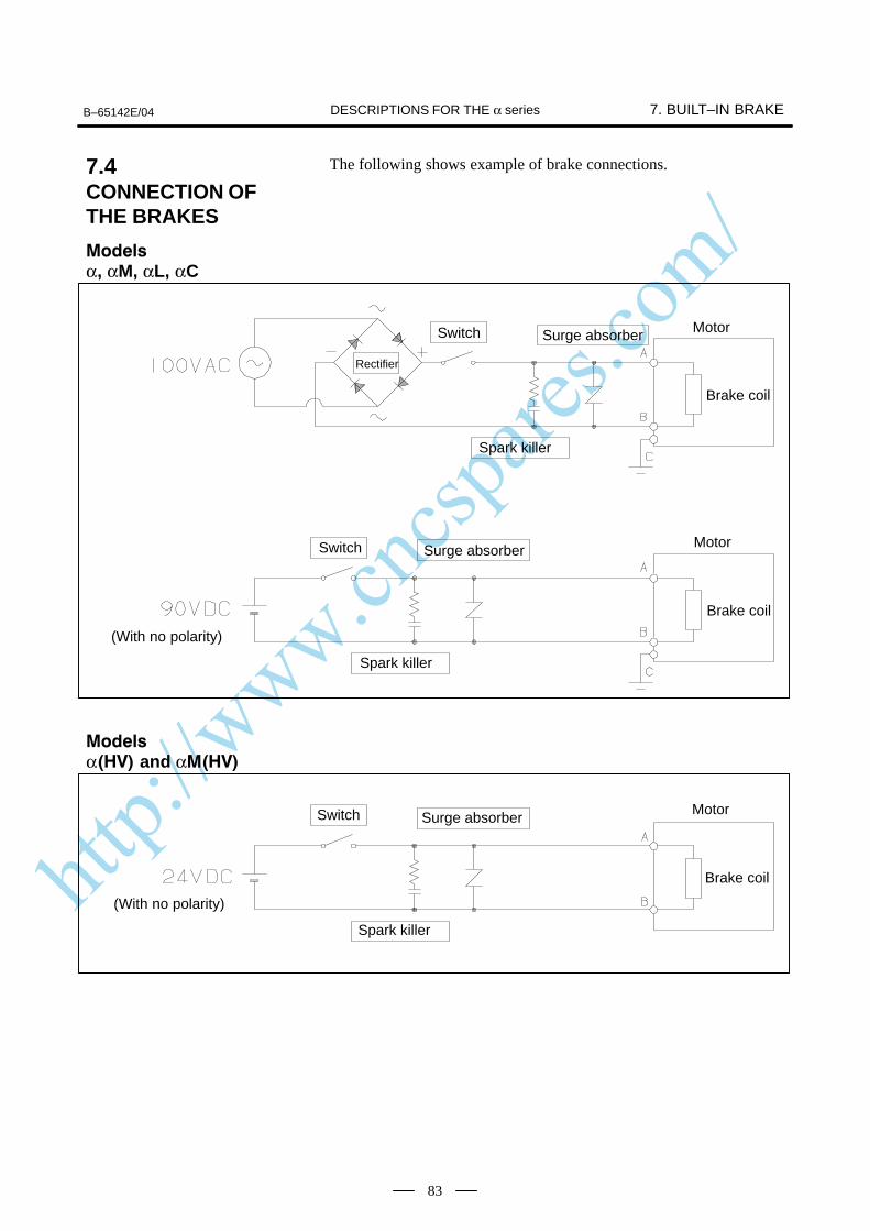
http://www.cncspares.com/
B–65142E/04 7. BUILT–IN BRAKEDESCRIPTIONS FOR THE α series
83
The following shows example of brake connections.
Switch Surge absorber Motor
Spark killer
Brake coil
Switch Surge absorber Motor
Spark killer
Brake coil
Rectifier
(With no polarity)
ÃÃ
ÃÃÃÃ
Switch Surge absorber Motor
Spark killer
Brake coil
(With no polarity)
7.4CONNECTION OFTHE BRAKES
α, αM, αL, αC
α and α
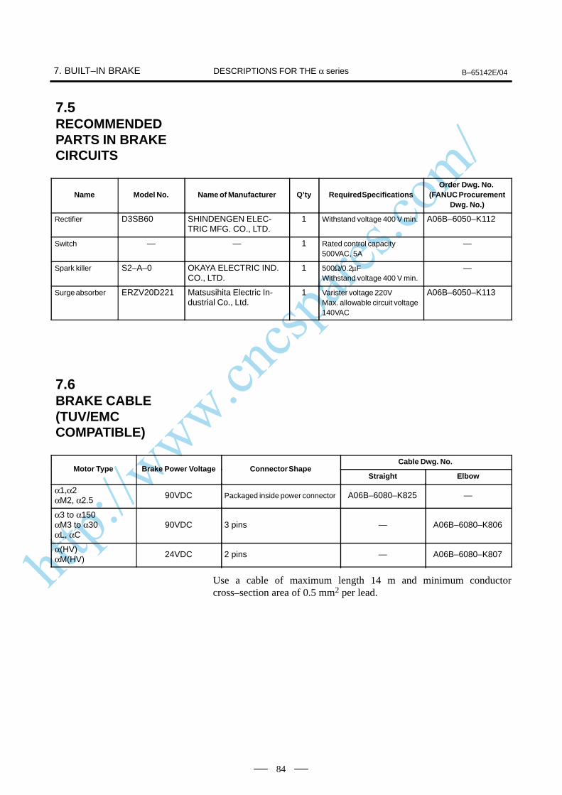
http://www.cncspares.com/
7. BUILT–IN BRAKE B–65142E/04DESCRIPTIONS FOR THE α series
84
Name Model No. Name of Manufacturer Q’ty Required SpecificationsOrder Dwg. No.
(FANUC ProcurementDwg. No.)
Rectifier D3SB60 SHINDENGEN ELEC-TRIC MFG. CO., LTD.
1 Withstand voltage 400 V min. A06B–6050–K112
Switch — — 1 Rated control capacity500VAC, 5A
—
Spark killer S2–A–0 OKAYA ELECTRIC IND.CO., LTD.
1 500Ω/0.2µFWithstand voltage 400 V min.
—
Surge absorber ERZV20D221 Matsusihita Electric In-dustrial Co., Ltd.
1 Varister voltage 220VMax. allowable circuit voltage140VAC
A06B–6050–K113
Cable Dwg. No.Motor Type Brake Power Voltage Connector Shape
Straight Elbow
α1,α2αM2, α2.5
90VDC Packaged inside power connector A06B–6080–K825 —
α3 to α150αM3 to α30αL, αC
90VDC 3 pins — A06B–6080–K806
α(HV)αM(HV)
24VDC 2 pins — A06B–6080–K807
Use a cable of maximum length 14 m and minimum conductorcross–section area of 0.5 mm2 per lead.
7.5RECOMMENDEDPARTS IN BRAKECIRCUITS
7.6BRAKE CABLE(TUV/EMCCOMPATIBLE)
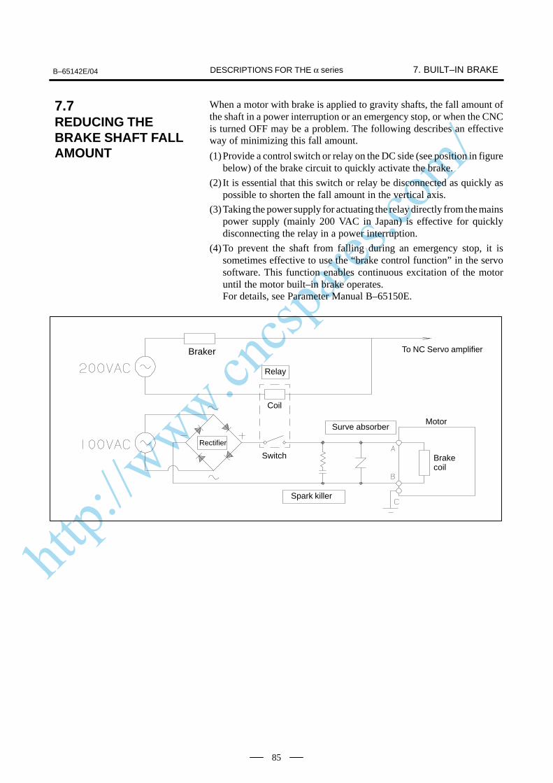
http://www.cncspares.com/
B–65142E/04 7. BUILT–IN BRAKEDESCRIPTIONS FOR THE α series
85
When a motor with brake is applied to gravity shafts, the fall amount ofthe shaft in a power interruption or an emergency stop, or when the CNCis turned OFF may be a problem. The following describes an effectiveway of minimizing this fall amount.
(1)Provide a control switch or relay on the DC side (see position in figurebelow) of the brake circuit to quickly activate the brake.
(2) It is essential that this switch or relay be disconnected as quickly aspossible to shorten the fall amount in the vertical axis.
(3)Taking the power supply for actuating the relay directly from the mainspower supply (mainly 200 VAC in Japan) is effective for quicklydisconnecting the relay in a power interruption.
(4)To prevent the shaft from falling during an emergency stop, it issometimes effective to use the “brake control function” in the servosoftware. This function enables continuous excitation of the motoruntil the motor built–in brake operates.For details, see Parameter Manual B–65150E.
Braker
Relay
Coil
Spark killer
Surve absorberMotor
Brakecoil
Switch
Rectifier
To NC Servo amplifier
ÃÃ
7.7REDUCING THEBRAKE SHAFT FALLAMOUNT
http://www.cncspares.com/
8. CONNECTORS B–65142E/04DESCRIPTIONS FOR α series
86
8 CONNECTORS
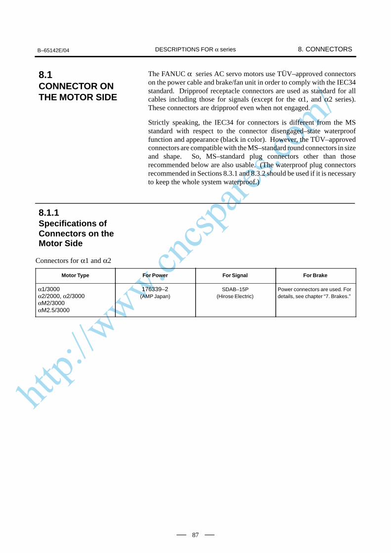
http://www.cncspares.com/
B–65142E/04 8. CONNECTORSDESCRIPTIONS FOR α series
87
The FANUC α series AC servo motors use TÜV–approved connectorson the power cable and brake/fan unit in order to comply with the IEC34standard. Dripproof receptacle connectors are used as standard for allcables including those for signals (except for the α1, and α2 series).These connectors are dripproof even when not engaged.
Strictly speaking, the IEC34 for connectors is different from the MSstandard with respect to the connector disengaged–state waterprooffunction and appearance (black in color). However, the TÜV–approvedconnectors are compatible with the MS–standard round connectors in sizeand shape. So, MS–standard plug connectors other than thoserecommended below are also usable. (The waterproof plug connectorsrecommended in Sections 8.3.1 and 8.3.2 should be used if it is necessaryto keep the whole system waterproof.)
Connectors for α1 and α2
Motor Type For Power For Signal For Brake
α1/3000α2/2000, α2/3000αM2/3000αM2.5/3000
176339–2(AMP Japan)
SDAB–15P(Hirose Electric)
Power connectors are used. Fordetails, see chapter “7. Brakes.”
8.1CONNECTOR ONTHE MOTOR SIDE
8.1.1Specifications ofConnectors on theMotor Side

http://www.cncspares.com/
8. CONNECTORS B–65142E/04DESCRIPTIONS FOR α series
88
Connectors for α3 to α40
Motor Type For Power For Signal For Brake
α3/3000, α6/2000 α6/3000αM6/3000, αM9/3000,αL6/3000, αL9/3000,αC3/2000, αC6/2000 H/MS3102A18–10P–D–T (10)
JL04V–2E10SL–3PE–B(Japan Aviation ElectronicsIndustry)
α3/3000HVα6/3000HVαM6/3000HVαM9/3000HV
(Hirose Electric)
H/MS3102A10SL–4P (Hirose Electric)
α12/2000, α12/3000α22/1500, α22/2000α30/1200αC12/2000, αC22/1500 H/MS3102A20–29PCW4 (10)
JL04V–2E10SL–3PE–B(Japan Aviation ElectronicsIndustry)
α12/3000HV, α22/3000HV α30/3000HVα40/2000HVαM22/3000HVαM30/3000HVαM40/3000HV
JL04HV–2E22–22PE–B(Japan Aviation ElectronicsIndustry)
H/MS3102A20–29PCW4 (10)(Hirose Electric)
H/MS3102A10SL–4P (Hirose Electric)
α22/3000, α30/2000 α30/3000, α40/2000α40/2000FANαM22/3000, αM30/3000,αM40/3000,αM40/3000FAN,αL25/3000, αL50/2000
JL04V–2E24–10PE(G)–B(Japan Aviation ElectronicsIndustry)
JL04V–2E10SL–3PE–B(Japan Aviation ElectronicsIndustry)
Fan connectors
Motor Type For Fan
α40/2000FANαM40/3000FAN
JL04V–2E10SL–3PE–B(Japan Aviation ElectronicsIndustry)
α300, α400H/MS3102A18–10P–D–T(10)(Hirose Electric)
CAUTION1 The motors should be installed with their connector facing downward as long as possible.
When it is impossible to install a motor in this position, allow slack in the cable to keep liquidssuch as a dielectric fluid from going along the cable into the cable or motor. If there is apossibility that the motors and connectors get wet, provide a cover to protect them.
2 If a motor is not connected to the earth ground through the machine (frame), connect the motorgrounding point and the amplifier grounding point to absorb noise using a 1.25 mm2 or largerconductor other than the grounding conductor in the power cable. Keep the groundingconductor as far from the power cable as possible.
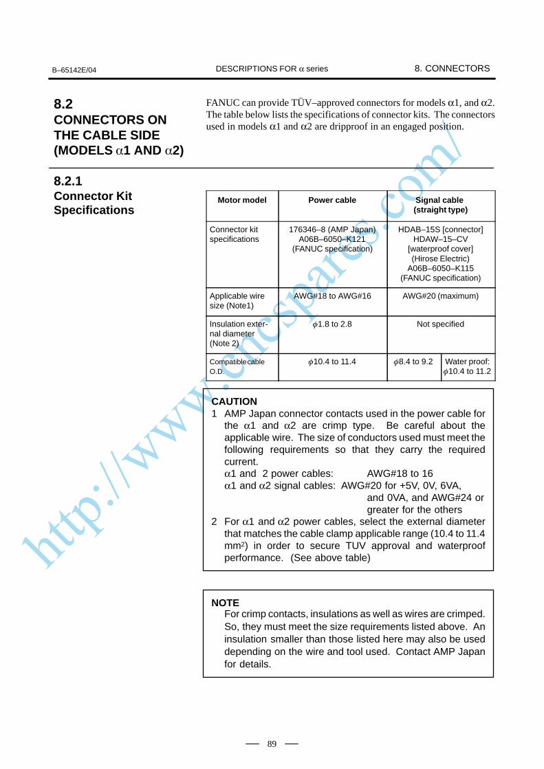
http://www.cncspares.com/
B–65142E/04 8. CONNECTORSDESCRIPTIONS FOR α series
89
FANUC can provide TÜV–approved connectors for models α1, and α2.The table below lists the specifications of connector kits. The connectorsused in models α1 and α2 are dripproof in an engaged position.
Motor model Power cable Signal cable (straight type)
Connector kitspecifications
176346–8 (AMP Japan)A06B–6050–K121
(FANUC specification)
HDAB–15S [connector]HDAW–15–CV
[waterproof cover](Hirose Electric)
A06B–6050–K115(FANUC specification)
Applicable wiresize (Note1)
AWG#18 to AWG#16 AWG#20 (maximum)
Insulation exter-nal diameter (Note 2)
1.8 to 2.8 Not specified
Compatible cableO.D.
10.4 to 11.4 8.4 to 9.2 Water proof:10.4 to 11.2
CAUTION1 AMP Japan connector contacts used in the power cable for
the α1 and α2 are crimp type. Be careful about theapplicable wire. The size of conductors used must meet thefollowing requirements so that they carry the requiredcurrent.α1 and 2 power cables: AWG#18 to 16 α1 and α2 signal cables: AWG#20 for +5V, 0V, 6VA,
and 0VA, and AWG#24 orgreater for the others
2 For α1 and α2 power cables, select the external diameterthat matches the cable clamp applicable range (10.4 to 11.4mm2) in order to secure TUV approval and waterproofperformance. (See above table)
NOTEFor crimp contacts, insulations as well as wires are crimped.So, they must meet the size requirements listed above. Aninsulation smaller than those listed here may also be useddepending on the wire and tool used. Contact AMP Japanfor details.
8.2CONNECTORS ONTHE CABLE SIDE(MODELS 1 AND 2)
8.2.1Connector KitSpecifications
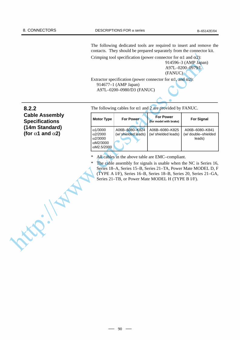
http://www.cncspares.com/
8. CONNECTORS B–65142E/04DESCRIPTIONS FOR α series
90
The following dedicated tools are required to insert and remove thecontacts. They should be prepared separately from the connector kit.
Crimping tool specification (power connector for α1 and α2):914596–3 (AMP Japan)A97L–0200–0979/L(FANUC)
Extractor specification (power connector for α1, and α2):914677–1 (AMP Japan)A97L–0200–0980/D3 (FANUC)
The following cables for α1 and 2 are provided by FANUC.
Motor Type For Power For Power(for model with brake)
For Signal
α1/3000α2/2000α2/3000αM2/3000αM2.5/2000
A06B–6080–K824(w/ shielded leads)
A06B–6080–K825(w/ shielded leads)
A06B–6080–K841(w/ double–shielded
leads)
* All cables in the above table are EMC–compliant.
* The cable assembly for signals is usable when the NC is Series 16,Series 18–A, Series 15–B, Series 21–TA, Power Mate MODEL D, F(TYPE A I/F), Series 16–B, Series 18–B, Series 20, Series 21–GA,Series 21–TB, or Power Mate MODEL H (TYPE B I/F).
8.2.2Cable AssemblySpecifications (14m Standard) (for α1 and α2)
http://www.cncspares.com/
B–65142E/04 8. CONNECTORSDESCRIPTIONS FOR α series
91
To meet the IEC34 standard, TÜV–approved plug connectors and cableclamps should be used in connecting the power cable and brake/fan unit.To meet the IEC34 standard by using a cable or conduit hose seal adaptor,contact the manufacturer for details.
FANUC can provide TÜV–approved types (waterproof) and waterprooftypes as plug connectors on the cable side for the FANUC α series ACservo motors; all these connectors are black. Of course, conventional plugconnectors may be used, because they are MS–compatible.
The specifications of each connector are explained based on the examplesshown below.
8.3SPECIFICATIONS OFTHE CONNECTORSON THE CABLE SIDE(MODELS 3 ANDHIGHER)
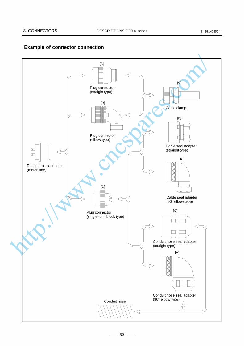
http://www.cncspares.com/
8. CONNECTORS B–65142E/04DESCRIPTIONS FOR α series
92
Example of connector connection
[A]
[C]
[B]
[E]
[F]
[D]
[G]
[H]
Plug connector(straight type)
Plug connector(elbow type)
Cable clamp
Plug connector(single–unit block type)
Cable seal adapter(straight type)
Cable seal adapter(90° elbow type)
Conduit hose seal adapter(straight type)
Conduit hose seal adapter(90° elbow type)
Receptacle connector(motor side)
Conduit hose
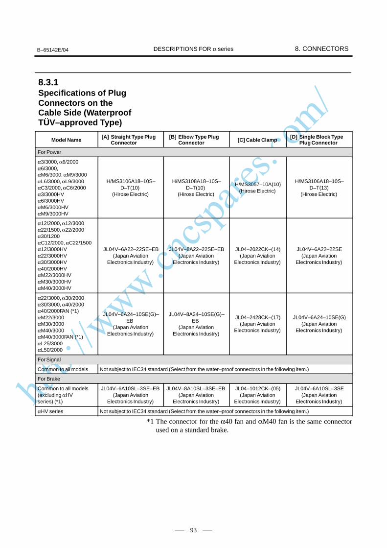
http://www.cncspares.com/
B–65142E/04 8. CONNECTORSDESCRIPTIONS FOR α series
93
Model Name[A] Straight Type Plug
Connector[B] Elbow Type Plug
Connector [C] Cable Clamp[D] Single Block Type
Plug Connector
For Power
α3/3000, α6/2000α6/3000,αM6/3000, αM9/3000αL6/3000, αL9/3000αC3/2000, αC6/2000α3/3000HVα6/3000HVαM6/3000HVαM9/3000HV
H/MS3106A18–10S–D–T(10)
(Hirose Electric)
H/MS3108A18–10S–D–T(10)
(Hirose Electric)
H/MS3057–10A(10)(Hirose Electric)
H/MS3106A18–10S–D–T(13)
(Hirose Electric)
α12/2000, α12/3000α22/1500, α22/2000α30/1200αC12/2000, αC22/1500α12/3000HVα22/3000HVα30/3000HVα40/2000HVαM22/3000HVαM30/3000HVαM40/3000HV
JL04V–6A22–22SE–EB(Japan Aviation
Electronics Industry)
JL04V–8A22–22SE–EB(Japan Aviation
Electronics Industry)
JL04–2022CK–(14)(Japan Aviation
Electronics Industry)
JL04V–6A22–22SE(Japan Aviation
Electronics Industry)
α22/3000, α30/2000α30/3000, α40/2000α40/2000FAN (*1)αM22/3000αM30/3000αM40/3000αM40/3000FAN (*1)αL25/3000αL50/2000
JL04V–6A24–10SE(G)–EB
(Japan AviationElectronics Industry)
JL04V–8A24–10SE(G)–EB
(Japan AviationElectronics Industry)
JL04–2428CK–(17)(Japan Aviation
Electronics Industry)
JL04V–6A24–10SE(G)(Japan Aviation
Electronics Industry)
For Signal
Common to all models Not subject to IEC34 standard (Select from the water–proof connectors in the following item.)
For Brake
Common to all models (excluding αHV series) (*1)
JL04V–6A10SL–3SE–EB (Japan Aviation
Electronics Industry)
JL04V–8A10SL–3SE–EB (Japan Aviation
Electronics Industry)
JL04–1012CK–(05)(Japan Aviation
Electronics Industry)
JL04V–6A10SL–3SE(Japan Aviation
Electronics Industry)
αHV series Not subject to IEC34 standard (Select from the water–proof connectors in the following item.)
*1 The connector for the α40 fan and αM40 fan is the same connectorused on a standard brake.
8.3.1Specifications of PlugConnectors on theCable Side (WaterproofTÜV–approved Type)
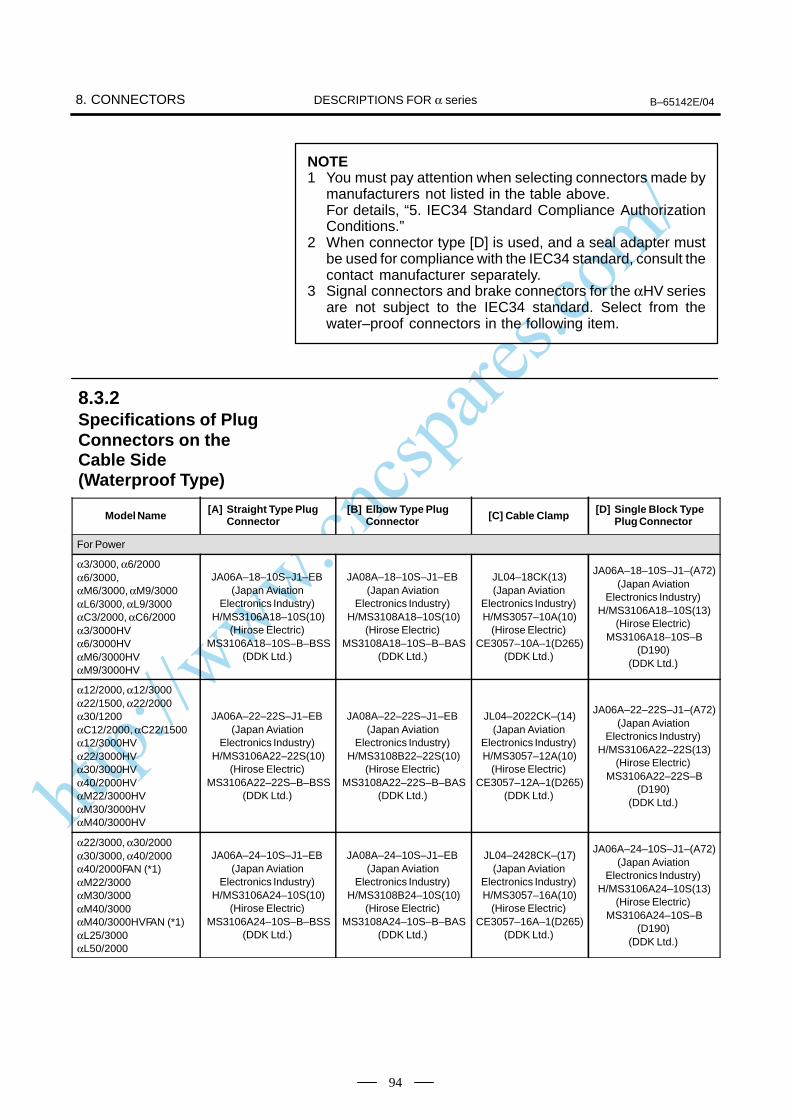
http://www.cncspares.com/
8. CONNECTORS B–65142E/04DESCRIPTIONS FOR α series
94
NOTE1 You must pay attention when selecting connectors made by
manufacturers not listed in the table above.For details, “5. IEC34 Standard Compliance AuthorizationConditions.”
2 When connector type [D] is used, and a seal adapter mustbe used for compliance with the IEC34 standard, consult thecontact manufacturer separately.
3 Signal connectors and brake connectors for the αHV seriesare not subject to the IEC34 standard. Select from thewater–proof connectors in the following item.
Model Name[A] Straight Type Plug
Connector[B] Elbow Type Plug
Connector [C] Cable Clamp[D] Single Block Type
Plug Connector
For Power
α3/3000, α6/2000α6/3000,αM6/3000, αM9/3000αL6/3000, αL9/3000αC3/2000, αC6/2000α3/3000HVα6/3000HVαM6/3000HVαM9/3000HV
JA06A–18–10S–J1–EB (Japan Aviation
Electronics Industry)H/MS3106A18–10S(10)
(Hirose Electric)MS3106A18–10S–B–BSS
(DDK Ltd.)
JA08A–18–10S–J1–EB (Japan Aviation
Electronics Industry)H/MS3108A18–10S(10)
(Hirose Electric)MS3108A18–10S–B–BAS
(DDK Ltd.)
JL04–18CK(13)(Japan Aviation
Electronics Industry)H/MS3057–10A(10)
(Hirose Electric)CE3057–10A–1(D265)
(DDK Ltd.)
JA06A–18–10S–J1–(A72)(Japan Aviation
Electronics Industry)H/MS3106A18–10S(13)
(Hirose Electric)MS3106A18–10S–B
(D190)(DDK Ltd.)
α12/2000, α12/3000α22/1500, α22/2000α30/1200αC12/2000, αC22/1500α12/3000HVα22/3000HVα30/3000HVα40/2000HVαM22/3000HVαM30/3000HVαM40/3000HV
JA06A–22–22S–J1–EB (Japan Aviation
Electronics Industry)H/MS3106A22–22S(10)
(Hirose Electric)MS3106A22–22S–B–BSS
(DDK Ltd.)
JA08A–22–22S–J1–EB (Japan Aviation
Electronics Industry)H/MS3108B22–22S(10)
(Hirose Electric)MS3108A22–22S–B–BAS
(DDK Ltd.)
JL04–2022CK–(14)(Japan Aviation
Electronics Industry)H/MS3057–12A(10)
(Hirose Electric)CE3057–12A–1(D265)
(DDK Ltd.)
JA06A–22–22S–J1–(A72)(Japan Aviation
Electronics Industry)H/MS3106A22–22S(13)
(Hirose Electric)MS3106A22–22S–B
(D190)(DDK Ltd.)
α22/3000, α30/2000α30/3000, α40/2000α40/2000FAN (*1)αM22/3000αM30/3000αM40/3000αM40/3000HVFAN (*1)αL25/3000αL50/2000
JA06A–24–10S–J1–EB (Japan Aviation
Electronics Industry)H/MS3106A24–10S(10)
(Hirose Electric)MS3106A24–10S–B–BSS
(DDK Ltd.)
JA08A–24–10S–J1–EB (Japan Aviation
Electronics Industry)H/MS3108B24–10S(10)
(Hirose Electric)MS3108A24–10S–B–BAS
(DDK Ltd.)
JL04–2428CK–(17)(Japan Aviation
Electronics Industry)H/MS3057–16A(10)
(Hirose Electric)CE3057–16A–1(D265)
(DDK Ltd.)
JA06A–24–10S–J1–(A72)(Japan Aviation
Electronics Industry)H/MS3106A24–10S(13)
(Hirose Electric)MS3106A24–10S–B
(D190)(DDK Ltd.)
8.3.2Specifications of PlugConnectors on theCable Side (Waterproof Type)
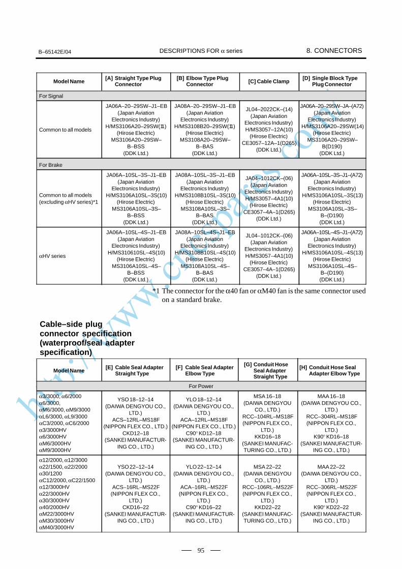
http://www.cncspares.com/
B–65142E/04 8. CONNECTORSDESCRIPTIONS FOR α series
95
Model Name[D] Single Block Type
Plug Connector[C] Cable Clamp[B] Elbow Type Plug
Connector[A] Straight Type Plug
Connector
For Signal
Common to all models
JA06A–20–29SW–J1–EB(Japan Aviation
Electronics Industry)H/MS3106A20–29SW(11)
(Hirose Electric)MS3106A20–29SW–
B–BSS(DDK Ltd.)
JA08A–20–29SW–J1–EB(Japan Aviation
Electronics Industry)H/MS3108B20–29SW(11)
(Hirose Electric)MS3108A20–29SW–
B–BAS(DDK Ltd.)
JL04–2022CK–(14)(Japan Aviation
Electronics Industry)H/MS3057–12A(10)
(Hirose Electric)CE3057–12A–1(D265)
(DDK Ltd.)
JA06A–20–29SW–JA–(A72)(Japan Aviation
Electronics Industry)H/MS3106A20–29SW(14)
(Hirose Electric)MS3106A20–29SW–
B(D190)(DDK Ltd.)
For Brake
Common to all models (excluding αHV series)*1
JA06A–10SL–3S–J1–EB(Japan Aviation
Electronics Industry)H/MS3106A10SL–3S(10)
(Hirose Electric)MS3106A10SL–3S–
B–BSS(DDK Ltd.)
JA08A–10SL–3S–J1–EB(Japan Aviation
Electronics Industry)H/MS3108B10SL–3S(10)
(Hirose Electric)MS3108A10SL–3S–
B–BAS(DDK Ltd.)
JA04–1012CK–(06)(Japan Aviation
Electronics Industry)H/MS3057–4A1(10)
(Hirose Electric)CE3057–4A–1(D265)
(DDK Ltd.)
JA06A–10SL–3S–J1–(A72)(Japan Aviation
Electronics Industry)H/MS3106A10SL–3S(13)
(Hirose Electric)MS3106A10SL–3S–
B–(D190)(DDK Ltd.)
αHV series
JA06A–10SL–4S–J1–EB(Japan Aviation
Electronics Industry)H/MS310610SL–4S(10)
(Hirose Electric)MS3106A10SL–4S–
B–BSS(DDK Ltd.)
JA08A–10SL–4S–J1–EB(Japan Aviation
Electronics Industry)H/MS3108B10SL–4S(10)
(Hirose Electric)MS3108A10SL–4S–
B–BAS(DDK Ltd.)
JL04–1012CK–(06)(Japan Aviation
Electronics Industry)H/MS3057–4A1(10)
(Hirose Electric)CE3057–4A–1(D265)
(DDK Ltd.)
JA06A–10SL–4S–J1–(A72)(Japan Aviation
Electronics Industry)H/MS3106A10SL–4S(13)
(Hirose Electric)MS3106A10SL–4S–
B–(D190)(DDK Ltd.)
*1 The connector for the α40 fan or M40 fan is the same connector usedon a standard brake.
Model Name[E] Cable Seal Adapter
Straight Type[F] Cable Seal Adapter
Elbow Type
[G] Conduit HoseSeal AdapterStraight Type
[H] Conduit Hose SealAdapter Elbow Type
For Power
α3/3000, α6/2000α6/3000,αM6/3000, αM9/3000αL6/3000, αL9/3000αC3/2000, αC6/2000α3/3000HVα6/3000HVαM6/3000HVαM9/3000HV
YSO 18–12–14(DAIWA DENGYOU CO.,
LTD.)ACS–12RL–MS18F
(NIPPON FLEX CO., LTD.)CKD12–18
(SANKEI MANUFACTUR-ING CO., LTD.)
YLO 18–12–14(DAIWA DENGYOU CO.,
LTD.)ACA–12RL–MS18F
(NIPPON FLEX CO., LTD.)C90° KD12–18
(SANKEI MANUFACTUR-ING CO., LTD.)
MSA 16–18(DAIWA DENGYOU
CO., LTD.)RCC–104RL–MS18F(NIPPON FLEX CO.,
LTD.)KKD16–18
(SANKEI MANUFAC-TURING CO., LTD.)
MAA 16–18(DAIWA DENGYOU CO.,
LTD.)RCC–304RL–MS18F(NIPPON FLEX CO.,
LTD.)K90° KD16–18
(SANKEI MANUFACTUR-ING CO., LTD.)
α12/2000, α12/3000α22/1500, α22/2000α30/1200αC12/2000, αC22/1500α12/3000HVα22/3000HVα30/3000HVα40/2000HVαM22/3000HVαM30/3000HVαM40/3000HV
YSO 22–12–14(DAIWA DENGYOU CO.,
LTD.)ACS–16RL–MS22F
(NIPPON FLEX CO.,LTD.)
CKD16–22(SANKEI MANUFACTUR-
ING CO., LTD.)
YLO 22–12–14(DAIWA DENGYOU CO.,
LTD.)ACA–16RL–MS22F
(NIPPON FLEX CO.,LTD.)
C90° KD16–22(SANKEI MANUFACTUR-
ING CO., LTD.)
MSA 22–22(DAIWA DENGYOU
CO., LTD.)RCC–106RL–MS22F(NIPPON FLEX CO.,
LTD.)KKD22–22
(SANKEI MANUFAC-TURING CO., LTD.)
MAA 22–22(DAIWA DENGYOU CO.,
LTD.)RCC–306RL–MS22F(NIPPON FLEX CO.,
LTD.)K90° KD22–22
(SANKEI MANUFACTUR-ING CO., LTD.)
Cable–side plugconnector specification(waterproof/seal adapterspecification)
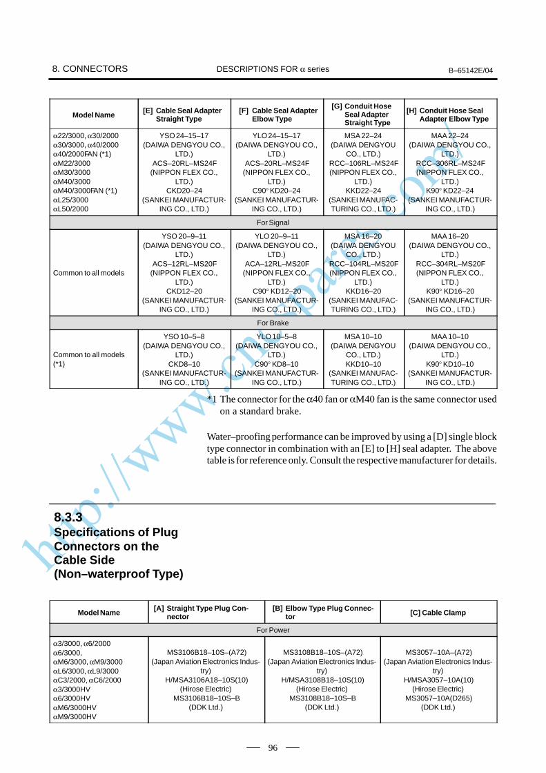
http://www.cncspares.com/
8. CONNECTORS B–65142E/04DESCRIPTIONS FOR α series
96
Model Name[H] Conduit Hose Seal
Adapter Elbow Type
[G] Conduit HoseSeal AdapterStraight Type
[F] Cable Seal AdapterElbow Type
[E] Cable Seal AdapterStraight Type
α22/3000, α30/2000α30/3000, α40/2000α40/2000FAN (*1)αM22/3000αM30/3000αM40/3000αM40/3000FAN (*1)αL25/3000αL50/2000
YSO 24–15–17(DAIWA DENGYOU CO.,
LTD.)ACS–20RL–MS24F
(NIPPON FLEX CO.,LTD.)
CKD20–24(SANKEI MANUFACTUR-
ING CO., LTD.)
YLO 24–15–17(DAIWA DENGYOU CO.,
LTD.)ACS–20RL–MS24F
(NIPPON FLEX CO.,LTD.)
C90° KD20–24(SANKEI MANUFACTUR-
ING CO., LTD.)
MSA 22–24(DAIWA DENGYOU
CO., LTD.)RCC–106RL–MS24F(NIPPON FLEX CO.,
LTD.)KKD22–24
(SANKEI MANUFAC-TURING CO., LTD.)
MAA 22–24(DAIWA DENGYOU CO.,
LTD.)RCC–306RL–MS24F(NIPPON FLEX CO.,
LTD.)K90° KD22–24
(SANKEI MANUFACTUR-ING CO., LTD.)
For Signal
Common to all models
YSO 20–9–11(DAIWA DENGYOU CO.,
LTD.)ACS–12RL–MS20F
(NIPPON FLEX CO.,LTD.)
CKD12–20(SANKEI MANUFACTUR-
ING CO., LTD.)
YLO 20–9–11(DAIWA DENGYOU CO.,
LTD.)ACA–12RL–MS20F
(NIPPON FLEX CO.,LTD.)
C90° KD12–20(SANKEI MANUFACTUR-
ING CO., LTD.)
MSA 16–20(DAIWA DENGYOU
CO., LTD.)RCC–104RL–MS20F(NIPPON FLEX CO.,
LTD.)KKD16–20
(SANKEI MANUFAC-TURING CO., LTD.)
MAA 16–20(DAIWA DENGYOU CO.,
LTD.)RCC–304RL–MS20F(NIPPON FLEX CO.,
LTD.)K90° KD16–20
(SANKEI MANUFACTUR-ING CO., LTD.)
For Brake
Common to all models (*1)
YSO 10–5–8(DAIWA DENGYOU CO.,
LTD.)CKD8–10
(SANKEI MANUFACTUR-ING CO., LTD.)
YLO 10–5–8(DAIWA DENGYOU CO.,
LTD.)C90° KD8–10
(SANKEI MANUFACTUR-ING CO., LTD.)
MSA 10–10(DAIWA DENGYOU
CO., LTD.)KKD10–10
(SANKEI MANUFAC-TURING CO., LTD.)
MAA 10–10(DAIWA DENGYOU CO.,
LTD.)K90° KD10–10
(SANKEI MANUFACTUR-ING CO., LTD.)
*1 The connector for the α40 fan or M40 fan is the same connector usedon a standard brake.
Water–proofing performance can be improved by using a [D] single blocktype connector in combination with an [E] to [H] seal adapter. The abovetable is for reference only. Consult the respective manufacturer for details.
Model Name[A] Straight Type Plug Con-
nector[B] Elbow Type Plug Connec-
tor [C] Cable Clamp
For Power
α3/3000, α6/2000α6/3000,αM6/3000, αM9/3000αL6/3000, αL9/3000αC3/2000, αC6/2000α3/3000HVα6/3000HVαM6/3000HVαM9/3000HV
MS3106B18–10S–(A72)(Japan Aviation Electronics Indus-
try)H/MSA3106A18–10S(10)
(Hirose Electric)MS3106B18–10S–B
(DDK Ltd.)
MS3108B18–10S–(A72)(Japan Aviation Electronics Indus-
try)H/MSA3108B18–10S(10)
(Hirose Electric)MS3108B18–10S–B
(DDK Ltd.)
MS3057–10A–(A72)(Japan Aviation Electronics Indus-
try)H/MSA3057–10A(10)
(Hirose Electric)MS3057–10A(D265)
(DDK Ltd.)
8.3.3Specifications of PlugConnectors on theCable Side(Non–waterproof Type)
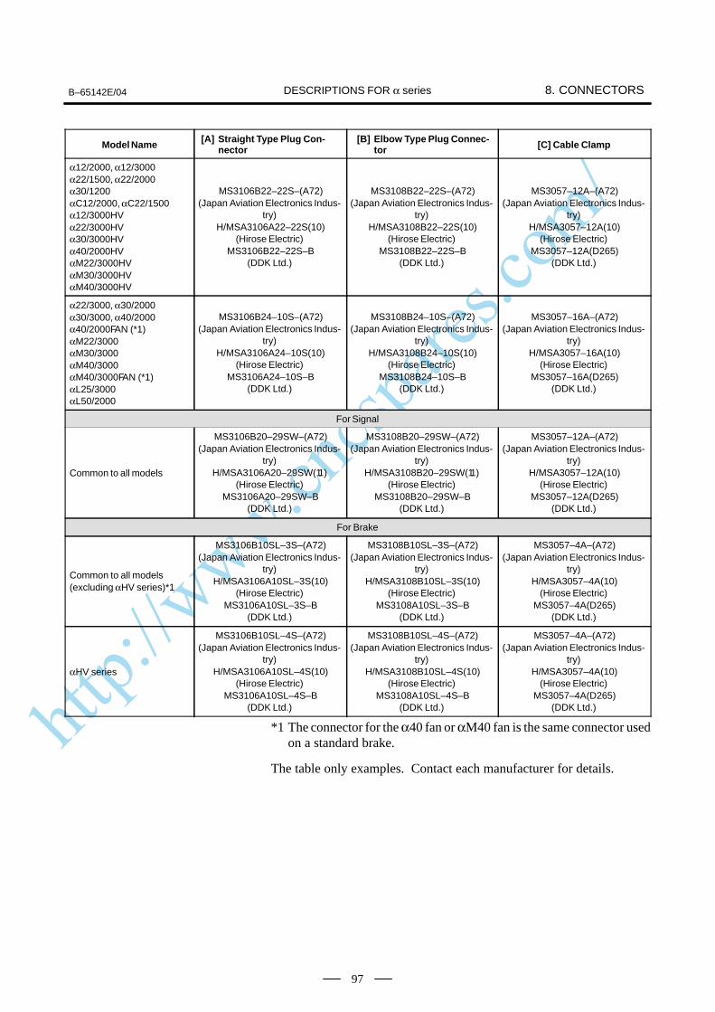
http://www.cncspares.com/
B–65142E/04 8. CONNECTORSDESCRIPTIONS FOR α series
97
Model Name [C] Cable Clamp[B] Elbow Type Plug Connec-
tor[A] Straight Type Plug Con-
nector
α12/2000, α12/3000α22/1500, α22/2000α30/1200αC12/2000, αC22/1500α12/3000HVα22/3000HVα30/3000HVα40/2000HVαM22/3000HVαM30/3000HVαM40/3000HV
MS3106B22–22S–(A72)(Japan Aviation Electronics Indus-
try)H/MSA3106A22–22S(10)
(Hirose Electric)MS3106B22–22S–B
(DDK Ltd.)
MS3108B22–22S–(A72)(Japan Aviation Electronics Indus-
try)H/MSA3108B22–22S(10)
(Hirose Electric)MS3108B22–22S–B
(DDK Ltd.)
MS3057–12A–(A72)(Japan Aviation Electronics Indus-
try)H/MSA3057–12A(10)
(Hirose Electric)MS3057–12A(D265)
(DDK Ltd.)
α22/3000, α30/2000α30/3000, α40/2000α40/2000FAN (*1)αM22/3000αM30/3000αM40/3000αM40/3000FAN (*1)αL25/3000αL50/2000
MS3106B24–10S–(A72)(Japan Aviation Electronics Indus-
try)H/MSA3106A24–10S(10)
(Hirose Electric)MS3106A24–10S–B
(DDK Ltd.)
MS3108B24–10S–(A72)(Japan Aviation Electronics Indus-
try)H/MSA3108B24–10S(10)
(Hirose Electric)MS3108B24–10S–B
(DDK Ltd.)
MS3057–16A–(A72)(Japan Aviation Electronics Indus-
try)H/MSA3057–16A(10)
(Hirose Electric)MS3057–16A(D265)
(DDK Ltd.)
For Signal
Common to all models
MS3106B20–29SW–(A72)(Japan Aviation Electronics Indus-
try)H/MSA3106A20–29SW(11)
(Hirose Electric)MS3106A20–29SW–B
(DDK Ltd.)
MS3108B20–29SW–(A72)(Japan Aviation Electronics Indus-
try)H/MSA3108B20–29SW(11)
(Hirose Electric)MS3108B20–29SW–B
(DDK Ltd.)
MS3057–12A–(A72)(Japan Aviation Electronics Indus-
try)H/MSA3057–12A(10)
(Hirose Electric)MS3057–12A(D265)
(DDK Ltd.)
For Brake
Common to all models (excluding αHV series)*1
MS3106B10SL–3S–(A72)(Japan Aviation Electronics Indus-
try)H/MSA3106A10SL–3S(10)
(Hirose Electric)MS3106A10SL–3S–B
(DDK Ltd.)
MS3108B10SL–3S–(A72)(Japan Aviation Electronics Indus-
try)H/MSA3108B10SL–3S(10)
(Hirose Electric)MS3108A10SL–3S–B
(DDK Ltd.)
MS3057–4A–(A72)(Japan Aviation Electronics Indus-
try)H/MSA3057–4A(10)
(Hirose Electric)MS3057–4A(D265)
(DDK Ltd.)
αHV series
MS3106B10SL–4S–(A72)(Japan Aviation Electronics Indus-
try)H/MSA3106A10SL–4S(10)
(Hirose Electric)MS3106A10SL–4S–B
(DDK Ltd.)
MS3108B10SL–4S–(A72)(Japan Aviation Electronics Indus-
try)H/MSA3108B10SL–4S(10)
(Hirose Electric)MS3108A10SL–4S–B
(DDK Ltd.)
MS3057–4A–(A72)(Japan Aviation Electronics Indus-
try)H/MSA3057–4A(10)
(Hirose Electric)MS3057–4A(D265)
(DDK Ltd.)
*1 The connector for the α40 fan or αM40 fan is the same connector usedon a standard brake.
The table only examples. Contact each manufacturer for details.
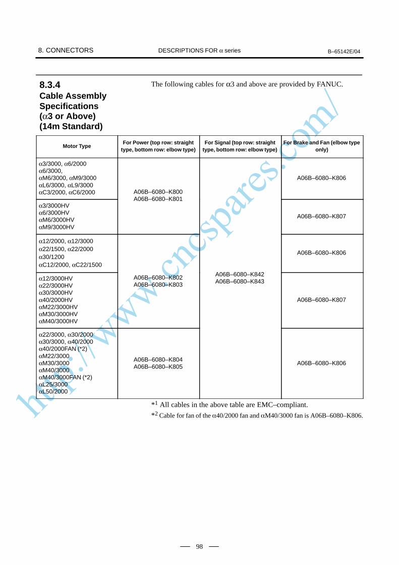
http://www.cncspares.com/
8. CONNECTORS B–65142E/04DESCRIPTIONS FOR α series
98
The following cables for α3 and above are provided by FANUC.
Motor TypeFor Power (top row: straight
type, bottom row: elbow type)For Signal (top row: straight
type, bottom row: elbow type)For Brake and Fan (elbow type
only)
α3/3000, α6/2000α6/3000,αM6/3000, αM9/3000αL6/3000, αL9/3000αC3/2000, αC6/2000 A06B–6080–K800
A06B–6080–K806
α3/3000HVα6/3000HVαM6/3000HVαM9/3000HV
A06B–6080–K801
A06B–6080–K807
α12/2000, α12/3000α22/1500, α22/2000α30/1200αC12/2000, αC22/1500
A06B–6080–K806
α12/3000HVα22/3000HVα30/3000HVα40/2000HVαM22/3000HVαM30/3000HVαM40/3000HV
A06B–6080–K802A06B–6080–K803
A06B–6080–K842A06B–6080–K843
A06B–6080–K807
α22/3000, α30/2000α30/3000, α40/2000α40/2000FAN (*2)αM22/3000αM30/3000αM40/3000αM40/3000FAN (*2)αL25/3000αL50/2000
A06B–6080–K804A06B–6080–K805
A06B–6080–K806
*1 All cables in the above table are EMC–compliant.
*2 Cable for fan of the 40/2000 fan and M40/3000 fan is A06B–6080–K806.
8.3.4Cable AssemblySpecifications (α3 or Above) (14m Standard)
http://www.cncspares.com/
B–65142E/04 9. COOLING FANDESCRIPTIONS FOR THE α series
99
9
Models α40, αM40, α300, α400, and α1000 can be fitted with anoptional cooling fan. The cooling fan requires a single–phase 200 VACor three–phase 200VAC power supply.The specifications and connection diagram are given below. Use fuses ora circuit breaker in the power magnetics cabinet.
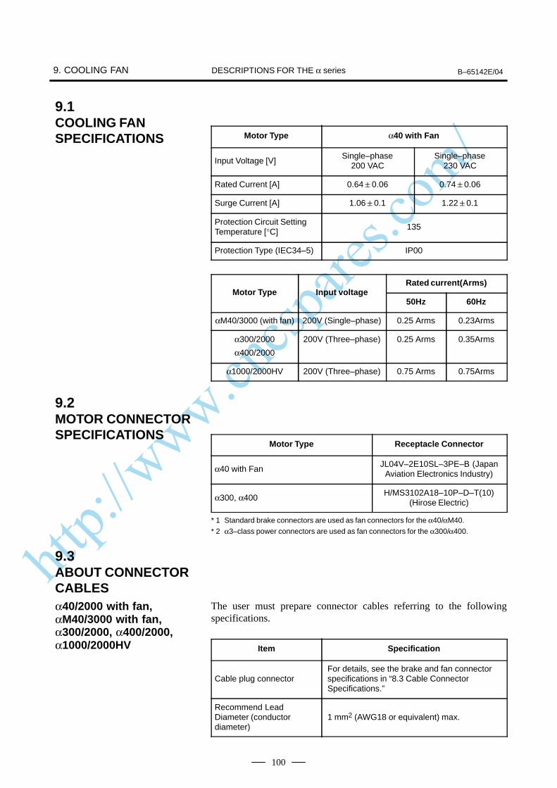
http://www.cncspares.com/
9. COOLING FAN B–65142E/04DESCRIPTIONS FOR THE α series
100
Motor Type α40 with Fan
Input Voltage [V]Single–phase
200 VACSingle–phase
230 VAC
Rated Current [A] 0.64 0.06 0.74 0.06
Surge Current [A] 1.06 0.1 1.22 0.1
Protection Circuit SettingTemperature [°C]
135
Protection Type (IEC34–5) IP00
Rated current(Arms)Motor Type Input voltage
50Hz 60Hz
αM40/3000 (with fan) 200V (Single–phase) 0.25 Arms 0.23Arms
α300/2000
α400/2000
200V (Three–phase) 0.25 Arms 0.35Arms
α1000/2000HV 200V (Three–phase) 0.75 Arms 0.75Arms
Motor Type Receptacle Connector
α40 with FanJL04V–2E10SL–3PE–B (Japan
Aviation Electronics Industry)
α300, α400H/MS3102A18–10P–D–T(10)
(Hirose Electric)
* 1 Standard brake connectors are used as fan connectors for the α40/αM40.
* 2 α3–class power connectors are used as fan connectors for the α300/α400.
The user must prepare connector cables referring to the followingspecifications.
Item Specification
Cable plug connectorFor details, see the brake and fan connectorspecifications in “8.3 Cable ConnectorSpecifications.”
Recommend LeadDiameter (conductordiameter)
1 mm2 (AWG18 or equivalent) max.
9.1COOLING FANSPECIFICATIONS
9.2MOTOR CONNECTORSPECIFICATIONS
9.3ABOUT CONNECTORCABLESα40/2000 with fan,αM40/3000 with fan,α300/2000, α400/2000,α1000/2000HV
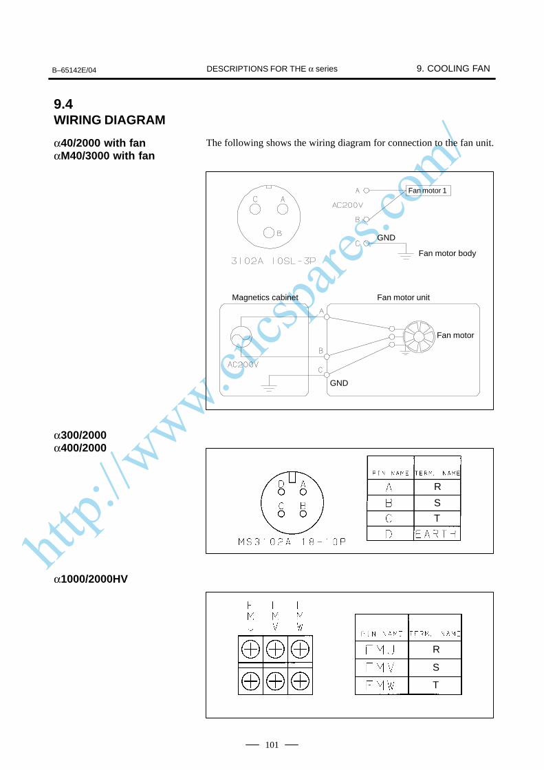
http://www.cncspares.com/
B–65142E/04 9. COOLING FANDESCRIPTIONS FOR THE α series
101
The following shows the wiring diagram for connection to the fan unit.
Fan motor 1
Fan motor body
Magnetics cabinet Fan motor unit
Fan motor
GND
GND
R
S
T
R
S
T
9.4WIRING DIAGRAM
α40/2000 with fanαM40/3000 with fan
α300/2000α400/2000
α1000/2000HV
http://www.cncspares.com/
II. FANUC AC SERVO MOTOR α series
http://www.cncspares.com/
B–65142E/04 1. GENERALFANUC AC SERVO MOTOR α series
105
1
The FANUC AC servo motor α series consists of a range of servo motorsthat are suitable for the feed axes of machine tools. They have thefollowing features:
The rotor inertia has been reduced without sacrificing maximum outputtorque. As a result, the motors offer excellent acceleration characteristics.
The use of the latest ferrite magnet, combined with an optimizedmechanical design, reduces both the overall length and weight. The resultis compact, lightweight servo motors.
The use of waterproof connectors and FANUC’s unique stator sealprovide excellent waterproofing, ensuring that no liquid, such as coolant,can enter the motor.
The use of the latest servo software minimizes the heat generated byhigh–speed rotation, allowing continuous operation over a wide range.
Further improvements have been made to the unique magnetic pole shapeto minimize torque ripple. The result is extremely smooth rotation.
The use of the latest servo software maintains controllability even whena disturbance occurs.
The high–resolution pulse coder model αA1000, αA64 or αI64 isprovided as standard. This pulse coder allows precise positioning.
A powerful brake with an increased holding torque is available as anoption. The brake uses an asbestos–free design.
Excellent accelerationcharacteristics
Compact
Excellent waterproofing
Extendedcontinuous–operation
Smooth rotation
Controllability
High–performancedetector
Powerful brake
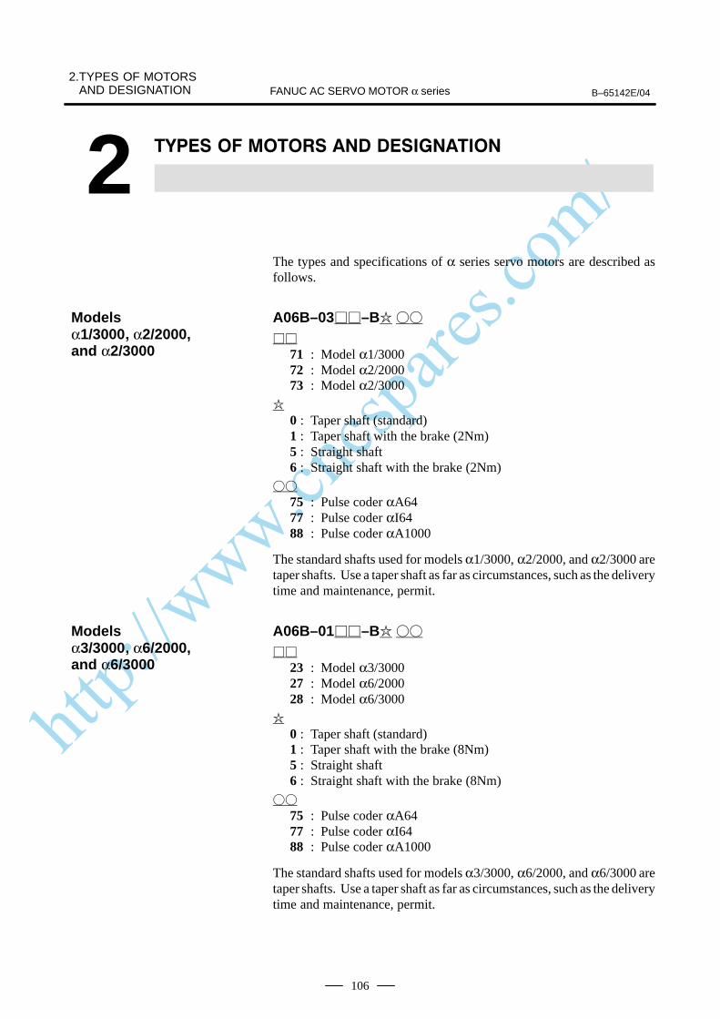
http://www.cncspares.com/
2.TYPES OF MOTORSAND DESIGNATION B–65142E/04FANUC AC SERVO MOTOR α series
106
2
The types and specifications of α series servo motors are described asfollows.
A06B–03–B
71 : Model α1/300072 : Model α2/200073 : Model α2/3000
0 : Taper shaft (standard)1 : Taper shaft with the brake (2Nm)5 : Straight shaft6 : Straight shaft with the brake (2Nm)
75 : Pulse coder αA6477 : Pulse coder αI6488 : Pulse coder αA1000
The standard shafts used for models α1/3000, α2/2000, and α2/3000 aretaper shafts. Use a taper shaft as far as circumstances, such as the deliverytime and maintenance, permit.
A06B–01–B
23 : Model α3/300027 : Model α6/200028 : Model α6/3000
0 : Taper shaft (standard)1 : Taper shaft with the brake (8Nm)5 : Straight shaft6 : Straight shaft with the brake (8Nm)
75 : Pulse coder αA6477 : Pulse coder αI6488 : Pulse coder αA1000
The standard shafts used for models α3/3000, α6/2000, and α6/3000 aretaper shafts. Use a taper shaft as far as circumstances, such as the deliverytime and maintenance, permit.
Modelsα1/3000 α2/2000, and α2/3000
Modelsα3/3000 α6/2000, and α6/3000
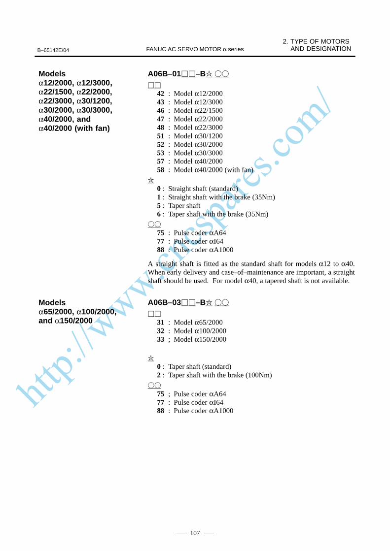
http://www.cncspares.com/
B–65142E/04
2. TYPE OF MOTORS AND DESIGNATIONFANUC AC SERVO MOTOR α series
107
A06B–01–B
42 : Model α12/200043 : Model α12/300046 : Model α22/150047 : Model α22/200048 : Model α22/300051 : Model α30/120052 : Model α30/200053 : Model α30/300057 : Model α40/200058 : Model α40/2000 (with fan)
0 : Straight shaft (standard)1 : Straight shaft with the brake (35Nm)5 : Taper shaft6 : Taper shaft with the brake (35Nm)
75 : Pulse coder αA6477 : Pulse coder αI6488 : Pulse coder αA1000
A straight shaft is fitted as the standard shaft for models α12 to α40.When early delivery and case–of–maintenance are important, a straightshaft should be used. For model α40, a tapered shaft is not available.
A06B–03–B
31 : Model α65/200032 : Model α100/200033 ; Model α150/2000
0 : Taper shaft (standard)2 : Taper shaft with the brake (100Nm)
75 ; Pulse coder αA6477 : Pulse coder αI6488 : Pulse coder αA1000
Modelsα12/2000, α12/3000α22/1500, α22/2000,α22/3000 α30/1200, α30/2000, α30/3000α40/2000, andα40/2000 (with fan)
Modelsα65/2000, α100/2000, and α150/2000
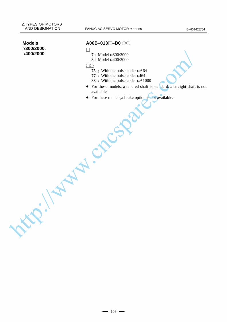
http://www.cncspares.com/
2.TYPES OF MOTORSAND DESIGNATION B–65142E/04FANUC AC SERVO MOTOR α series
108
A06B–013–B0
7 : Model α300/20008 : Model α400/2000
75 ; With the pulse coder αA6477 : With the pulse coder αI6488 : With the pulse coder αA1000
For these models, a tapered shaft is standard. a straight shaft is notavailable.
For these models,a brake option is not available.
Modelsα300/2000,α400/2000
http://www.cncspares.com/
B–65142E/04
3. SPECIFICATIONS ANDCHARACTERISTICSFANUC AC SERVO MOTOR α series
109
3
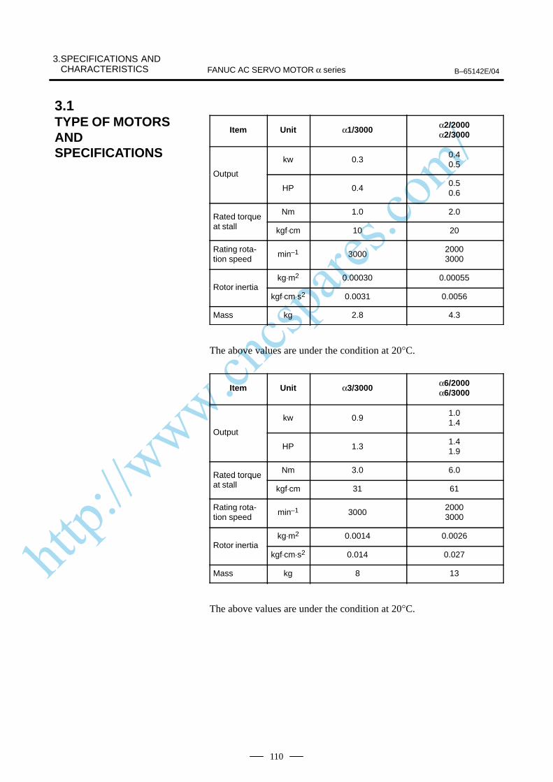
http://www.cncspares.com/
3.SPECIFICATIONS AND CHARACTERISTICS B–65142E/04FANUC AC SERVO MOTOR α series
110
Item Unit α1/3000 α2/2000α2/3000
kw 0.30.40.5
Output
HP 0.40.50.6
Rated torqueNm 1.0 2.0
Rated torqueat stall kgf⋅cm 10 20
Rating rota-tion speed
min–1 300020003000
kg⋅m2 0.00030 0.00055Rotor inertia
kgf⋅cm⋅s2 0.0031 0.0056
Mass kg 2.8 4.3
The above values are under the condition at 20°C.
Item Unit α3/3000 α6/2000α6/3000
kw 0.91.01.4
Output
HP 1.31.41.9
Rated torqueNm 3.0 6.0
Rated torqueat stall kgf⋅cm 31 61
Rating rota-tion speed
min–1 300020003000
kg⋅m2 0.0014 0.0026Rotor inertia
kgf⋅cm⋅s2 0.014 0.027
Mass kg 8 13
The above values are under the condition at 20°C.
3.1TYPE OF MOTORSANDSPECIFICATIONS
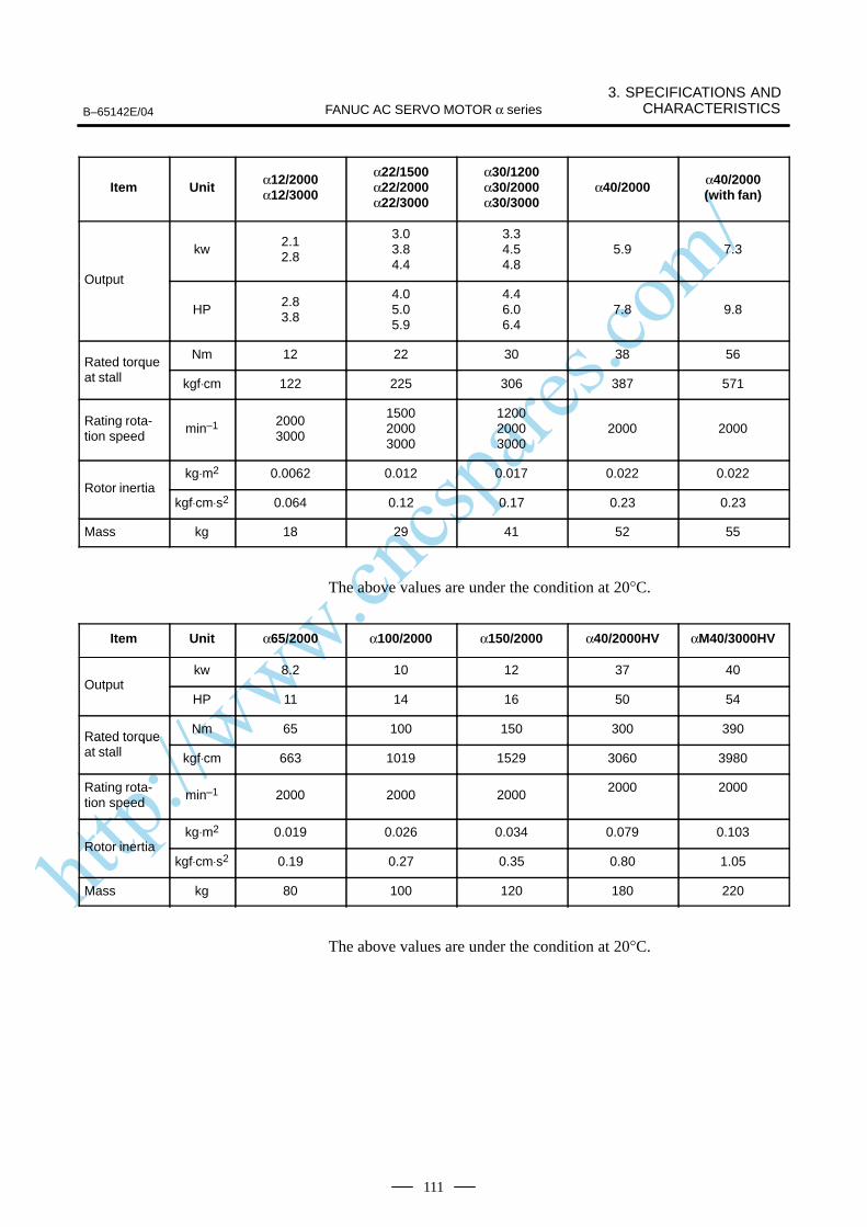
http://www.cncspares.com/
B–65142E/04
3. SPECIFICATIONS ANDCHARACTERISTICSFANUC AC SERVO MOTOR α series
111
Item Unit α12/2000α12/3000
α22/1500α22/2000α22/3000
α30/1200α30/2000α30/3000
α40/2000 α40/2000(with fan)
kw2.12.8
3.03.84.4
3.34.54.8
5.9 7.3
Output
HP2.83.8
4.05.05.9
4.46.06.4
7.8 9.8
Rated torqueNm 12 22 30 38 56
Rated torqueat stall kgf⋅cm 122 225 306 387 571
Rating rota-tion speed
min–1 20003000
150020003000
120020003000
2000 2000
kg⋅m2 0.0062 0.012 0.017 0.022 0.022Rotor inertia
kgf⋅cm⋅s2 0.064 0.12 0.17 0.23 0.23
Mass kg 18 29 41 52 55
The above values are under the condition at 20°C.
Item Unit α65/2000 α100/2000 α150/2000 α40/2000HV αM40/3000HV
kw 8.2 10 12 37 40Output
HP 11 14 16 50 54
Rated torqueNm 65 100 150 300 390
Rated torqueat stall kgf⋅cm 663 1019 1529 3060 3980
Rating rota-tion speed
min–1 2000 2000 20002000 2000
kg⋅m2 0.019 0.026 0.034 0.079 0.103Rotor inertia
kgf⋅cm⋅s2 0.19 0.27 0.35 0.80 1.05
Mass kg 80 100 120 180 220
The above values are under the condition at 20°C.
http://www.cncspares.com/
3.SPECIFICATIONS AND CHARACTERISTICS B–65142E/04FANUC AC SERVO MOTOR α series
112
The intermittent operation zone is determined by the input voltageapplied to the drive amplifier. The curve shown is the value for the ratedinput voltage (200V).On models α1 to 6, the maximum speed of rotation is increased by usingHRV control. The speed-torque characteristics for when HRV control isused are described at the end of this item.
The overload duty characteristic curves are determined based on thetemperature restriction for the single motor unit (the temperature isrestricted by means of a thermal trip built into the motor). The curves aredetermined by assuming that the temperature increases gradually undercertain overload conditions. Therefore, the curves do not apply to therapid temperature rise which occurs, for example, when the motor shaftis locked. (An overcurrent flows in the motor windings until the thermaltrip operates. The temperature rises momentarily.)To detect such an abrupt temperature rise, the FANUC digital servosystem provides a software thermal function that uses servo software toobserve the current. During operation that is characterized by frequentacceleration/deceleration cycles, control is imposed by the softwarethermal function.Driving units (such as amplifiers) and built–in detectors contain their ownoverheating protection devices. Therefore, note that control may beimposed according to how the equipment is being used.
The parameters given in the data sheet are representative values for anambient temperature of 20°C. They are subject to an error of +10%.The indicated logical values are threshold values for the single motor unit(when the motor is not restricted by the control system).The maximum torque that can be produced during acceleration ordeceleration in actual use is calculated as the approximate product of themotor torque constant and the current limit value of the amplifier.Example : α3/3000 Motor torque constant = 0.65 (Nm/Arms) Amplifier limit value = 40 Apeak Maximum torque value
= 40 x 0.707 x 0.65 (Converted to an effective value) = 18.4 Nm
This value is for reference only. The actual value will vary depending onchanges in the power supply, as well as variations in motor parameters andamplifier limit values.In some models, if the maximum current flows in the motor, the actualmaximum torque is affected by, for example, magnetic saturation. As aresult, the actual maximum torque will be lower than the calculated value.The intermittent operation area (maximum torque value) indicated in thespeed to torque characteristics is the effective value, determinedaccording to the combination with the amplifier.
3.2CHARACTERISTICCURVE AND DATASHEETSpeed–torquecharacteristics
Overload dutycharacteristic
Data sheet
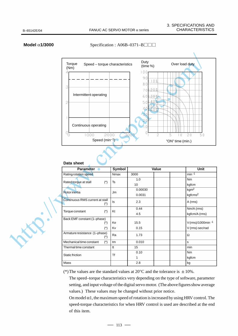
http://www.cncspares.com/
B–65142E/04
3. SPECIFICATIONS ANDCHARACTERISTICSFANUC AC SERVO MOTOR α series
113
Specification : A06B–0371–B
Speed – torque characteristics
Speed (min–1) ”ON” time (min.)
Torque (Nm)
Over load dutyDuty (time %)
ÃÃÃÃÃÃÃIntermittent operating
ÃÃÃÃÃÃÃContinuous operating
Data sheetParameter Symbol Value Unit
Rating rotation speed Nmax 3000 min -1
Rated torque at stall (*) Ts1.0
10
Nm
kgfcm
Rotor inertia Jm 0.00030
0.0031
kgm2
kgfcms2
Continuous RMS current at stall (*) Is 2.3 A (rms)
Torque constant (*) Kt 0.44
4.5
Nm/A (rms)
kgfcm/A (rms)
Back EMF constant (1–phase)(*)
(*)
Ke
Kv
15.5
0.15
V (rms)/1000min -1
V (rms)·sec/rad
Armature resistance (1–phase)(*) Ra 1.73 Ω
Mechanical time constant (*) tm 0.010 s
Thermal time constant tt 15 min
Static friction Tf 0.10
1
Nm
kgfcm
Mass 2.8 kg
(*)The values are the standard values at 20°C and the tolerance is 10%.
The speed–torque characteristics very depending on the type of software, parameter
setting, and input voltage of the digital servo motor. (The above figures show average
values.) These values may be changed without prior notice.
On model α1, the maximum speed of rotation is increased by using HRV control. The
speed-torque characteristics for when HRV control is used are described at the end
of this item.
Model α1/3000
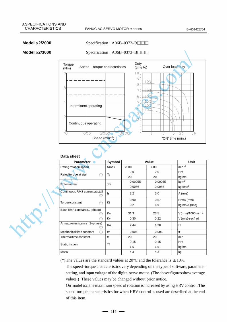
http://www.cncspares.com/
3.SPECIFICATIONS AND CHARACTERISTICS B–65142E/04FANUC AC SERVO MOTOR α series
114
Specification : A06B–0372–B
Specification : A06B–0373–B
Speed – torque characteristics
Speed (min–1) ”ON” time (min.)
Over load dutyTorque (Nm)
Duty (time %)
ÃÃÃÃÃÃÃÃÃÃÃÃÃÃ
Intermittent operating
ÃÃÃÃÃÃÃÃÃÃÃÃÃÃ
Continuous operating
Data sheetParameter Symbol Value Unit
Rating rotation speed Nmax 2000 3000 min -1
Rated torque at stall (*) Ts 2.0
20
2.0
20
Nm
kgfcm
Rotor inertia Jm 0.00055
0.0056
0.00055
0.0056
kgm2
kgfcms2
Continuous RMS current at stall (*) Is 2.2 3.0 A (rms)
Torque constant (*) Kt 0.90
9.2
0.67
6.9
Nm/A (rms)
kgfcm/A (rms)
Back EMF constant (1–phase)(*)
(*)
Ke
Kv
31.3
0.30
23.5
0.22
V (rms)/1000min -1
V (rms)·sec/rad
Armature resistance (1–phase)(*) Ra 2.44 1.38 Ω
Mechanical time constant (*) tm 0.005 0.005 s
Thermal time constant tt 20 20 min
Static friction Tf 0.15
1.5
0.15
1.5
Nm
kgfcm
Mass 4.3 4.3 kg
(*)The values are the standard values at 20°C and the tolerance is 10%.
The speed–torque characteristics very depending on the type of software, parameter
setting, and input voltage of the digital servo motor. (The above figures show average
values.) These values may be changed without prior notice.
On model α2, the maximum speed of rotation is increased by using HRV control. The
speed-torque characteristics for when HRV control is used are described at the end
of this item.
Model α2/2000
Model α2/3000
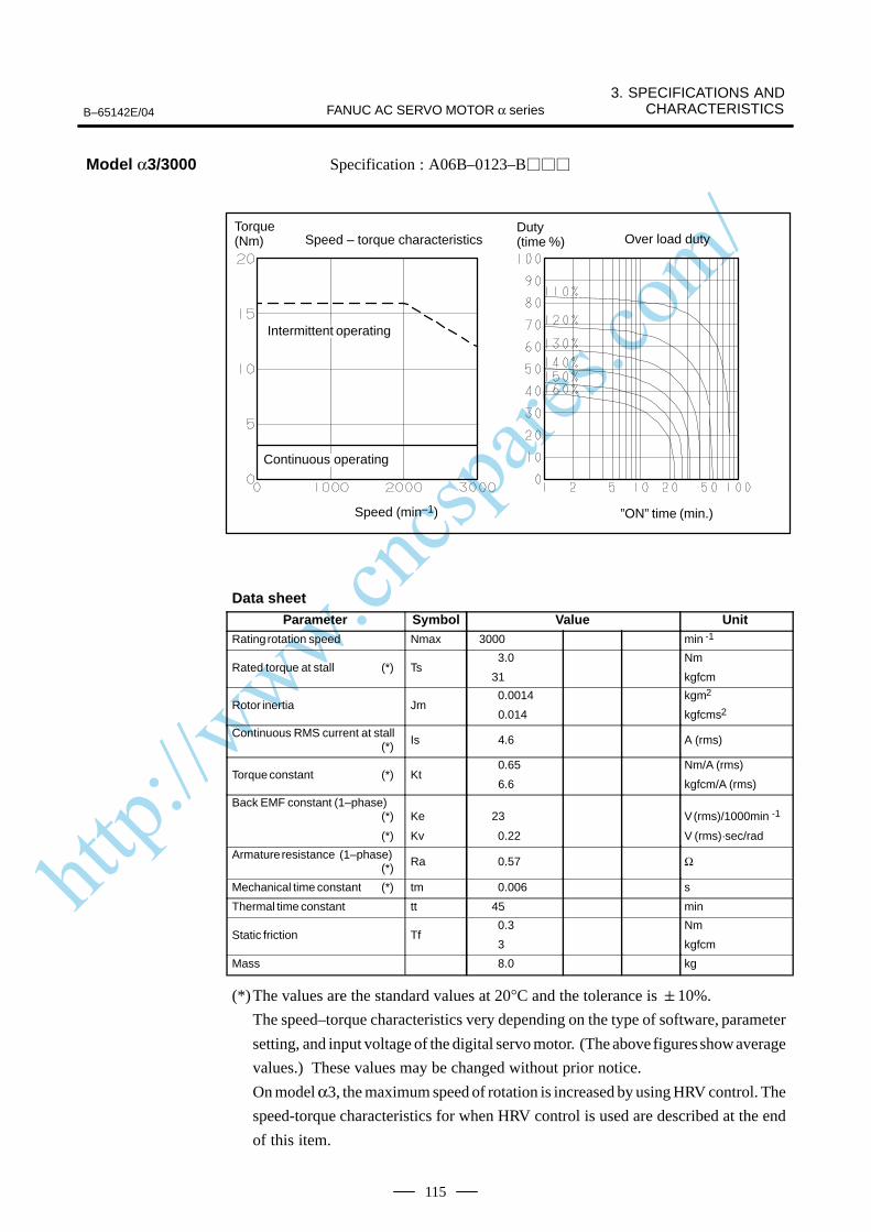
http://www.cncspares.com/
B–65142E/04
3. SPECIFICATIONS ANDCHARACTERISTICSFANUC AC SERVO MOTOR α series
115
Specification : A06B–0123–B
Speed – torque characteristics
Speed (min–1) ”ON” time (min.)
Over load dutyTorque (Nm)
Duty (time %)
ÃÃÃÃÃÃÃÃÃÃÃÃÃÃ
Intermittent operating
ÃÃÃÃÃÃÃContinuous operating
Data sheetParameter Symbol Value Unit
Rating rotation speed Nmax 3000 min -1
Rated torque at stall (*) Ts 3.0
31
Nm
kgfcm
Rotor inertia Jm 0.0014
0.014
kgm2
kgfcms2
Continuous RMS current at stall (*) Is 4.6 A (rms)
Torque constant (*) Kt 0.65
6.6
Nm/A (rms)
kgfcm/A (rms)
Back EMF constant (1–phase)(*)
(*)
Ke
Kv
23
0.22
V (rms)/1000min -1
V (rms)·sec/rad
Armature resistance (1–phase)(*) Ra 0.57 Ω
Mechanical time constant (*) tm 0.006 s
Thermal time constant tt 45 min
Static friction Tf 0.3
3
Nm
kgfcm
Mass 8.0 kg
(*)The values are the standard values at 20°C and the tolerance is 10%.
The speed–torque characteristics very depending on the type of software, parameter
setting, and input voltage of the digital servo motor. (The above figures show average
values.) These values may be changed without prior notice.
On model α3, the maximum speed of rotation is increased by using HRV control. The
speed-torque characteristics for when HRV control is used are described at the end
of this item.
Model α3/3000
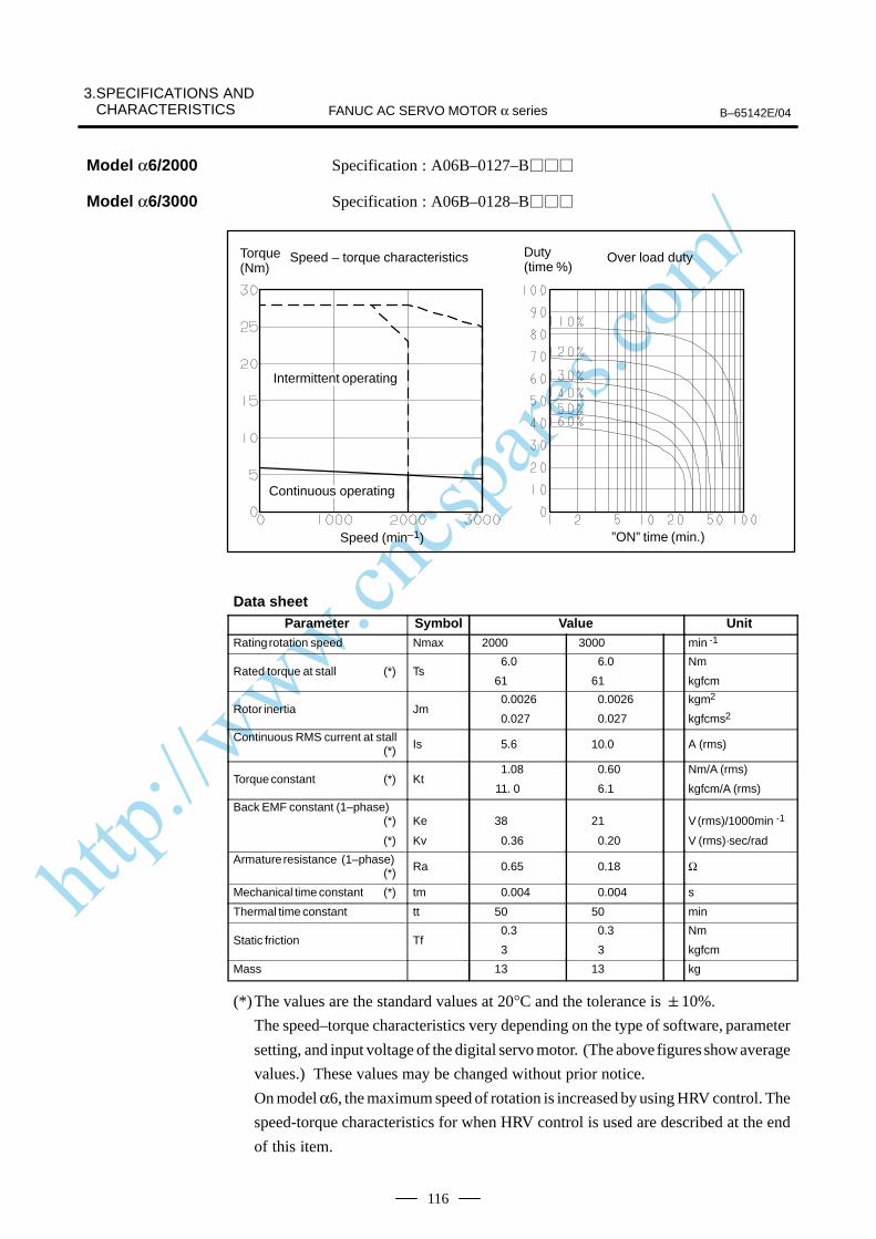
http://www.cncspares.com/
3.SPECIFICATIONS AND CHARACTERISTICS B–65142E/04FANUC AC SERVO MOTOR α series
116
Specification : A06B–0127–B
Specification : A06B–0128–B
Speed – torque characteristics
Speed (min–1) ”ON” time (min.)
Over load dutyTorque (Nm)
Duty (time %)
ÃÃÃÃÃÃÃÃÃÃÃÃÃÃ
Intermittent operating
ÃÃÃÃÃÃÃÃÃÃÃÃÃÃ
Continuous operating
Data sheetParameter Symbol Value Unit
Rating rotation speed Nmax 2000 3000 min -1
Rated torque at stall (*) Ts6.0
61
6.0
61
Nm
kgfcm
Rotor inertia Jm0.0026
0.027
0.0026
0.027
kgm2
kgfcms2
Continuous RMS current at stall (*) Is 5.6 10.0 A (rms)
Torque constant (*) Kt1.08
11. 0
0.60
6.1
Nm/A (rms)
kgfcm/A (rms)
Back EMF constant (1–phase)(*)
(*)
Ke
Kv
38
0.36
21
0.20
V (rms)/1000min -1
V (rms)·sec/rad
Armature resistance (1–phase)(*) Ra 0.65 0.18 Ω
Mechanical time constant (*) tm 0.004 0.004 s
Thermal time constant tt 50 50 min
Static friction Tf0.3
3
0.3
3
Nm
kgfcm
Mass 13 13 kg
(*)The values are the standard values at 20°C and the tolerance is 10%.
The speed–torque characteristics very depending on the type of software, parameter
setting, and input voltage of the digital servo motor. (The above figures show average
values.) These values may be changed without prior notice.
On model α6, the maximum speed of rotation is increased by using HRV control. The
speed-torque characteristics for when HRV control is used are described at the end
of this item.
Model α6/2000
Model α6/3000
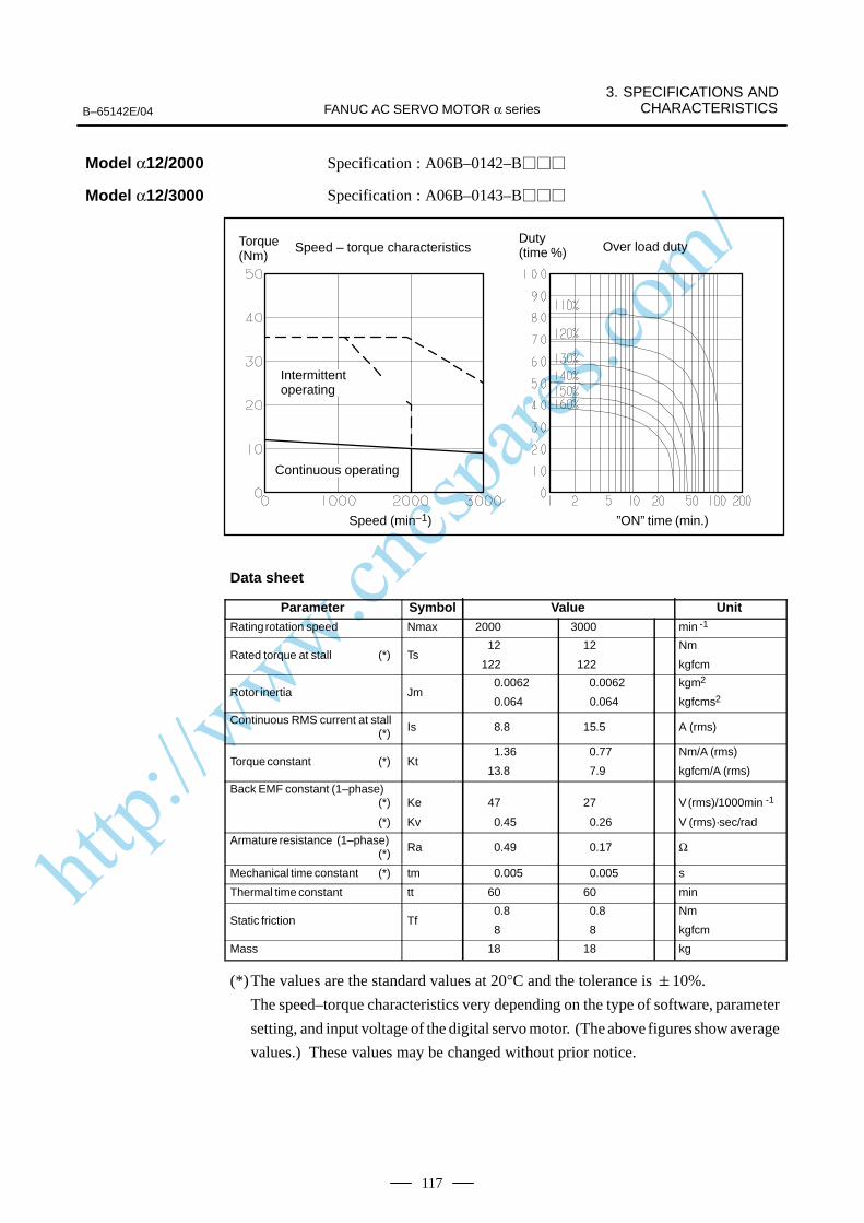
http://www.cncspares.com/
B–65142E/04
3. SPECIFICATIONS ANDCHARACTERISTICSFANUC AC SERVO MOTOR α series
117
Specification : A06B–0142–B
Specification : A06B–0143–B
Speed – torque characteristics
Speed (min–1) ”ON” time (min.)
Over load dutyTorque (Nm)
Duty (time %)
ÃÃÃÃÃÃÃÃ
Intermittentoperating
ÃÃÃÃÃÃÃÃÃÃÃÃÃÃ
Continuous operating
Data sheet
Parameter Symbol Value UnitRating rotation speed Nmax 2000 3000 min -1
Rated torque at stall (*) Ts12
122
12
122
Nm
kgfcm
Rotor inertia Jm0.0062
0.064
0.0062
0.064
kgm2
kgfcms2
Continuous RMS current at stall (*) Is 8.8 15.5 A (rms)
Torque constant (*) Kt1.36
13.8
0.77
7.9
Nm/A (rms)
kgfcm/A (rms)
Back EMF constant (1–phase)(*)
(*)
Ke
Kv
47
0.45
27
0.26
V (rms)/1000min -1
V (rms)·sec/rad
Armature resistance (1–phase)(*) Ra 0.49 0.17 Ω
Mechanical time constant (*) tm 0.005 0.005 s
Thermal time constant tt 60 60 min
Static friction Tf0.8
8
0.8
8
Nm
kgfcm
Mass 18 18 kg
(*)The values are the standard values at 20°C and the tolerance is 10%.
The speed–torque characteristics very depending on the type of software, parameter
setting, and input voltage of the digital servo motor. (The above figures show average
values.) These values may be changed without prior notice.
Model α12/2000
Model α12/3000

http://www.cncspares.com/
3.SPECIFICATIONS AND CHARACTERISTICS B–65142E/04FANUC AC SERVO MOTOR α series
118
Specification : A06B–0146–B
Specification : A06B–0147–B
Specification : A06B–0148–B
Speed – torque characteristics
Speed (min–1) ”ON” time (min.)
Over load dutyTorque (Nm)
Duty (time %)
ÃÃÃÃÃÃÃÃÃÃÃÃ
Intermittentoperating
ÃÃÃÃÃÃÃÃÃÃÃÃ
Continuousoperating
Data sheetParameter Symbol Value Unit
Rating rotation speed Nmax 1500 2000 3000 min -1
Rated torque at stall (*) Ts 22
224
22
224
22
224
Nm
kgfcm
Rotor inertia Jm 0.012
0.12
0.012
0.12
0.012
0.12
kgm2
kgfcms2
Continuous RMS current at stall (*) Is 12.5 18.7 32.1 A (rms)
Torque constant (*) Kt1.76
18.0
1.17
12.0
0.68
7.0
Nm/A (rms)
kgfcm/A (rms)
Back EMF constant (1–phase)(*)
(*)
Ke
Kv
62
0.59
41
0.39
24
0.23
V (rms)/1000min -1
V (rms)·sec/rad
Armature resistance (1–phase)(*) Ra 0.315 0.140 0.049 Ω
Mechanical time constant (*) tm 0.004 0.004 0.004 s
Thermal time constant tt 65 65 65 min
Static friction Tf1.2
12
1.2
12
1.2
12
Nm
kgfcm
Mass 29 29 29 kg
(*)The values are the standard values at 20°C and the tolerance is 10%.
The speed–torque characteristics very depending on the type of software, parameter
setting, and input voltage of the digital servo motor. (The above figures show average
values.) These values may be changed without prior notice.
Model α22/1500
Model α22/2000
Model α22/3000
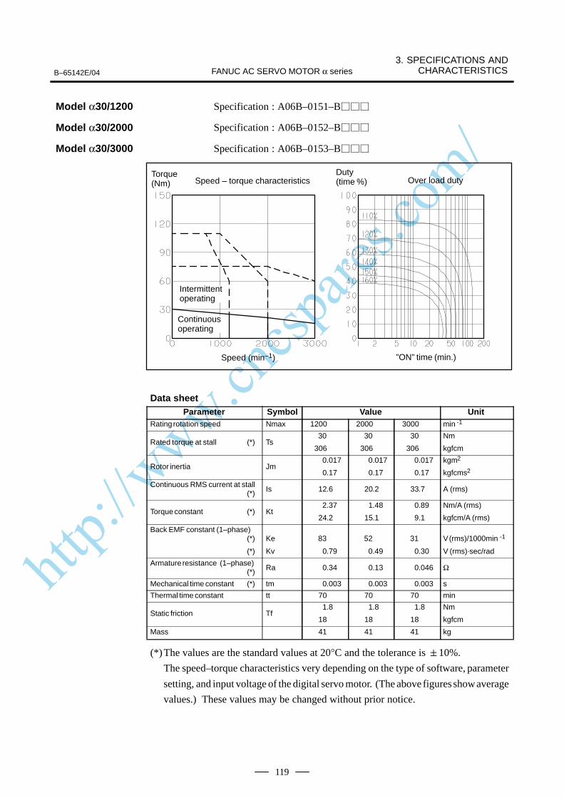
http://www.cncspares.com/
B–65142E/04
3. SPECIFICATIONS ANDCHARACTERISTICSFANUC AC SERVO MOTOR α series
119
Specification : A06B–0151–B
Specification : A06B–0152–B
Specification : A06B–0153–B
Speed – torque characteristics
Speed (min–1) ”ON” time (min.)
Over load dutyTorque (Nm)
Duty (time %)
ÃÃÃÃÃÃÃÃContinuousoperating
ÃÃÃÃÃÃÃÃ
Intermittentoperating
Data sheetParameter Symbol Value Unit
Rating rotation speed Nmax 1200 2000 3000 min -1
Rated torque at stall (*) Ts 30
306
30
306
30
306
Nm
kgfcm
Rotor inertia Jm 0.017
0.17
0.017
0.17
0.017
0.17
kgm2
kgfcms2
Continuous RMS current at stall(*) Is 12.6 20.2 33.7 A (rms)
Torque constant (*) Kt 2.37
24.2
1.48
15.1
0.89
9.1
Nm/A (rms)
kgfcm/A (rms)
Back EMF constant (1–phase)(*)
(*)
Ke
Kv
83
0.79
52
0.49
31
0.30
V (rms)/1000min -1
V (rms)·sec/rad
Armature resistance (1–phase)(*) Ra 0.34 0.13 0.046 Ω
Mechanical time constant (*) tm 0.003 0.003 0.003 s
Thermal time constant tt 70 70 70 min
Static friction Tf 1.8
18
1.8
18
1.8
18
Nm
kgfcm
Mass 41 41 41 kg
(*)The values are the standard values at 20°C and the tolerance is 10%.
The speed–torque characteristics very depending on the type of software, parameter
setting, and input voltage of the digital servo motor. (The above figures show average
values.) These values may be changed without prior notice.
Model α30/1200
Model α30/2000
Model α30/3000
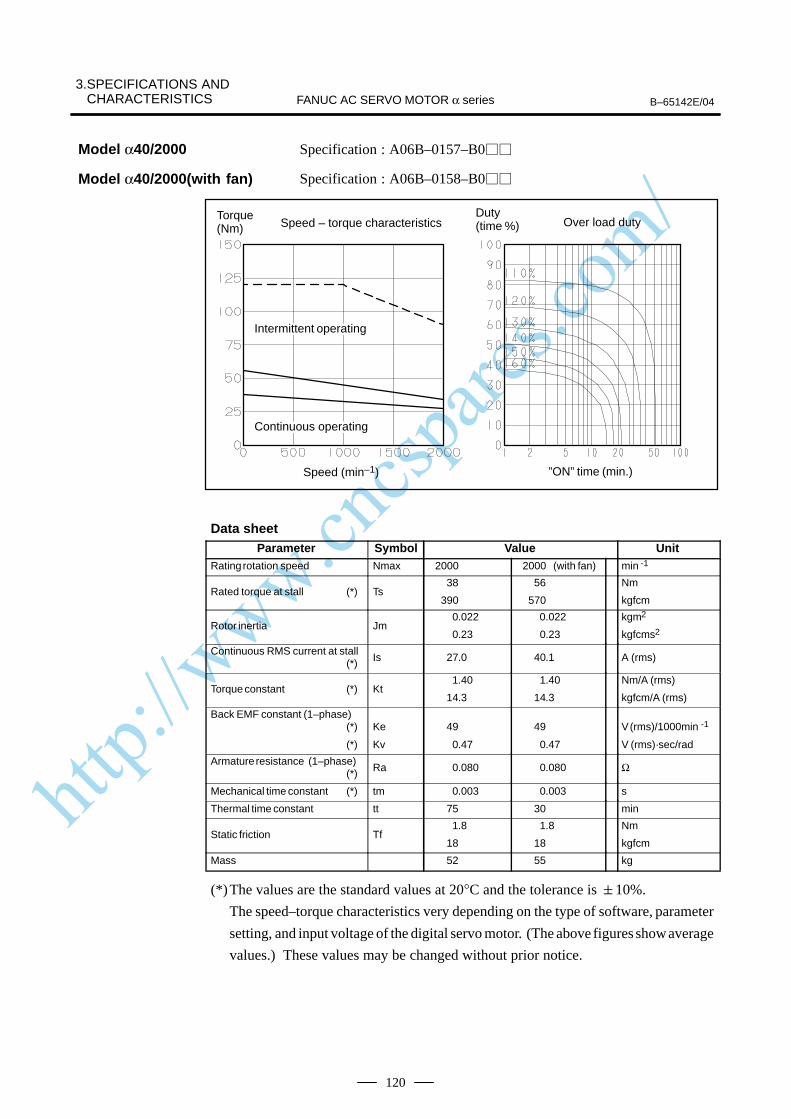
http://www.cncspares.com/
3.SPECIFICATIONS AND CHARACTERISTICS B–65142E/04FANUC AC SERVO MOTOR α series
120
Specification : A06B–0157–B0
Specification : A06B–0158–B0
Speed – torque characteristics
Speed (min–1) ”ON” time (min.)
Over load dutyTorque (Nm)
Duty (time %)
ÃÃÃÃÃÃÃÃÃÃÃÃÃÃ
Intermittent operating
ÃÃÃÃÃÃÃÃÃÃÃÃÃÃ
Continuous operating
Data sheetParameter Symbol Value Unit
Rating rotation speed Nmax 2000 2000 (with fan) min -1
Rated torque at stall (*) Ts38
390
56
570
Nm
kgfcm
Rotor inertia Jm0.022
0.23
0.022
0.23
kgm2
kgfcms2
Continuous RMS current at stall (*) Is 27.0 40.1 A (rms)
Torque constant (*) Kt1.40
14.3
1.40
14.3
Nm/A (rms)
kgfcm/A (rms)
Back EMF constant (1–phase)(*)
(*)
Ke
Kv
49
0.47
49
0.47
V (rms)/1000min -1
V (rms)·sec/rad
Armature resistance (1–phase)(*) Ra 0.080 0.080 Ω
Mechanical time constant (*) tm 0.003 0.003 s
Thermal time constant tt 75 30 min
Static friction Tf1.8
18
1.8
18
Nm
kgfcm
Mass 52 55 kg
(*)The values are the standard values at 20°C and the tolerance is 10%.
The speed–torque characteristics very depending on the type of software, parameter
setting, and input voltage of the digital servo motor. (The above figures show average
values.) These values may be changed without prior notice.
Model α40/2000
Model α40/2000(with fan)
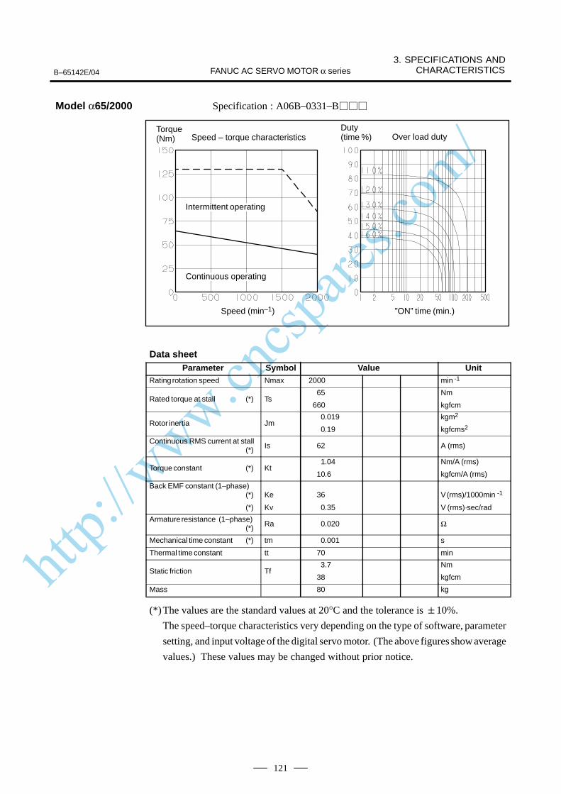
http://www.cncspares.com/
B–65142E/04
3. SPECIFICATIONS ANDCHARACTERISTICSFANUC AC SERVO MOTOR α series
121
Specification : A06B–0331–B
Speed – torque characteristics
Speed (min–1) ”ON” time (min.)
Over load dutyTorque (Nm)
Duty (time %)
ÃÃÃÃÃÃÃIntermittent operating
ÃÃÃÃÃÃÃÃÃÃÃÃÃÃ
Continuous operating
Data sheetParameter Symbol Value Unit
Rating rotation speed Nmax 2000 min -1
Rated torque at stall (*) Ts65
660
Nm
kgfcm
Rotor inertia Jm0.019
0.19
kgm2
kgfcms2
Continuous RMS current at stall (*) Is 62 A (rms)
Torque constant (*) Kt1.04
10.6
Nm/A (rms)
kgfcm/A (rms)
Back EMF constant (1–phase)(*)
(*)
Ke
Kv
36
0.35
V (rms)/1000min -1
V (rms)·sec/rad
Armature resistance (1–phase)(*) Ra 0.020 Ω
Mechanical time constant (*) tm 0.001 s
Thermal time constant tt 70 min
Static friction Tf 3.7
38
Nm
kgfcm
Mass 80 kg
(*)The values are the standard values at 20°C and the tolerance is 10%.
The speed–torque characteristics very depending on the type of software, parameter
setting, and input voltage of the digital servo motor. (The above figures show average
values.) These values may be changed without prior notice.
Model α65/2000

http://www.cncspares.com/
3.SPECIFICATIONS AND CHARACTERISTICS B–65142E/04FANUC AC SERVO MOTOR α series
122
Specification : A06B–0332–B
Speed – torque characteristics
Speed (min–1) ”ON” time (min.)
Over load dutyTorque (Nm)
Duty (time %)
ÃÃÃÃÃÃÃÃÃÃÃÃÃÃ
Intermittent operating
ÃÃÃÃÃÃÃContinuous operating
Data sheetParameter Symbol Value Unit
Rating rotation speed Nmax 2000 min -1
Rated torque at stall (*) Ts100
1020
Nm
kgfcm
Rotor inertia Jm 0.026
0.27
kgm2
kgfcms2
Continuous RMS current at stall (*) Is 85 A (rms)
Torque constant (*) Kt1.17
12.0
Nm/A (rms)
kgfcm/A (rms)
Back EMF constant (1–phase)(*)
(*)
Ke
Kv
41
0.39
V (rms)/1000min -1
V (rms)·sec/rad
Armature resistance (1–phase)(*) Ra 0.014 Ω
Mechanical time constant (*) tm 0.001 s
Thermal time constant tt 80 min
Static friction Tf 5.5
56
Nm
kgfcm
Mass 100 kg
(*)The values are the standard values at 20°C and the tolerance is 10%.
The speed–torque characteristics very depending on the type of software, parameter
setting, and input voltage of the digital servo motor. (The above figures show average
values.) These values may be changed without prior notice.
Model α100/2000

http://www.cncspares.com/
B–65142E/04
3. SPECIFICATIONS ANDCHARACTERISTICSFANUC AC SERVO MOTOR α series
123
Specification : A06B–0333–B
Speed – torque characteristics
Speed (min–1) ”ON” time (min.)
Over load dutyTorque (Nm)
Duty (time %)
ÃÃÃÃÃÃÃÃÃÃÃÃÃÃ
Intermittent operating
ÃÃÃÃÃÃÃÃÃÃÃÃÃÃ
Continuous operating
Data sheetParameter Symbol Value Unit
Rating rotation speed Nmax 2000 min -1
Rated torque at stall (*) Ts150
1530
Nm
kgfcm
Rotor inertia Jm 0.034
0.35
kgm2
kgfcms2
Continuous RMS current at stall (*) Is 113 A (rms)
Torque constant (*) Kt 1.31
13.3
Nm/A (rms)
kgfcm/A (rms)
Back EMF constant (1–phase)(*)
(*)
Ke
Kv
46
0.44
V (rms)/1000min -1
V (rms)·sec/rad
Armature resistance (1–phase)(*) Ra 0.011 Ω
Mechanical time constant (*) tm 0.001 s
Thermal time constant tt 90 min
Static friction Tf7.4
75
Nm
kgfcm
Mass 120 kg
(*)The values are the standard values at 20°C and the tolerance is 10%.
The speed–torque characteristics very depending on the type of software, parameter
setting, and input voltage of the digital servo motor. (The above figures show average
values.) These values may be changed without prior notice.
Model α150/2000
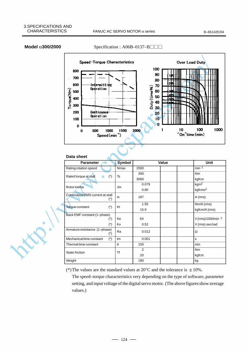
http://www.cncspares.com/
3.SPECIFICATIONS AND CHARACTERISTICS B–65142E/04FANUC AC SERVO MOTOR α series
124
Specification : A06B–0137–B
Data sheetParameter Symbol Value Unit
Rating rotation speed Nmax 2000 min -1
Rated torque at stall (*) Ts300
3060
Nm
kgfcm
Rotor inertia Jm 0.079
0.80
kgm2
kgfcms2
Continuous RMS current at stall (*) Is 187 A (rms)
Torque constant (*) Kt 1.55
15.9
Nm/A (rms)
kgfcm/A (rms)
Back EMF constant (1–phase)(*)
(*)
Ke
Kv
54
0.52
V (rms)/1000min -1
V (rms)·sec/rad
Armature resistance (1–phase)(*) Ra 0.012 Ω
Mechanical time constant (*) tm 0.001 s
Thermal time constant tt 150 min
Static friction Tf2
20
Nm
kgfcm
Weight 180 kg
(*)The values are the standard values at 20°C and the tolerance is 10%.
The speed–torque characteristics very depending on the type of software, parameter
setting, and input voltage of the digital servo motor. (The above figures show average
values.)
Model α300/2000

http://www.cncspares.com/
B–65142E/04
3. SPECIFICATIONS ANDCHARACTERISTICSFANUC AC SERVO MOTOR α series
125
Specification : A06B–0138–B
Data sheetParameter Symbol Value Unit
Rating rotation speed Nmax 2000 min -1
Rated torque at stall (*) Ts390
3980
Nm
kgfcm
Rotor inertia Jm 0.103
1.05
kgm2
kgfcms2
Continuous RMS current at stall (*) Is 183 A (rms)
Torque constant (*) Kt 2.07
21.2
Nm/A (rms)
kgfcm/A (rms)
Back EMF constant (1–phase)(*)
(*)
Ke
Kv
72
0.69
V (rms)/1000min -1
V (rms)·sec/rad
Armature resistance (1–phase)(*) Ra 0.014 Ω
Mechanical time constant (*) tm 0.001 s
Thermal time constant tt 180 min
Static friction Tf2
20
Nm
kgfcm
Weight 220 kg
(*)The values are the standard values at 20°C and the tolerance is 10%.
The speed–torque characteristics very depending on the type of software, parameter
setting, and input voltage of the digital servo motor. (The above figures show average
values.)
Model α400/2000
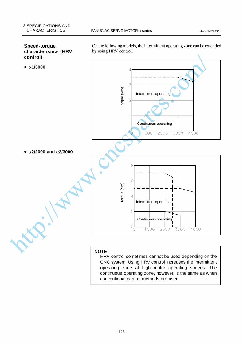
http://www.cncspares.com/
3.SPECIFICATIONS AND CHARACTERISTICS B–65142E/04FANUC AC SERVO MOTOR α series
126
On the following models, the intermittent operating zone can be extendedby using HRV control.
Torq
ue (N
m)
ÃÃÃÃÃÃÃÃÃÃÃÃÃÃ
Intermittent operating
ÃÃÃÃÃÃÃÃÃÃÃÃÃÃ
Continuous operatingTo
rque
(Nm
)
ÃÃÃÃÃÃÃIntermittent operating
ÃÃÃÃÃÃÃÃÃÃÃÃÃÃ
Continuous operating
NOTEHRV control sometimes cannot be used depending on theCNC system. Using HRV control increases the intermittentoperating zone at high motor operating speeds. Thecontinuous operating zone, however, is the same as whenconventional control methods are used.
Speed-torquecharacteristics (HRVcontrol)
α1/3000
α2/2000 and α2/3000
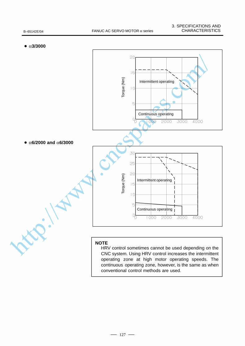
http://www.cncspares.com/
B–65142E/04
3. SPECIFICATIONS ANDCHARACTERISTICSFANUC AC SERVO MOTOR α series
127
Torq
ue (N
m)
ÃÃÃÃÃÃÃÃÃÃÃÃÃÃ
Continuous operating
ÃÃÃÃÃÃÃÃÃÃÃÃÃÃ
Intermittent operating
Torq
ue (N
m)
ÃÃÃÃÃÃÃIntermittent operating
ÃÃÃÃÃÃÃÃÃÃÃÃÃÃ
Continuous operating
NOTEHRV control sometimes cannot be used depending on theCNC system. Using HRV control increases the intermittentoperating zone at high motor operating speeds. Thecontinuous operating zone, however, is the same as whenconventional control methods are used.
α3/3000
α6/2000 and α6/3000
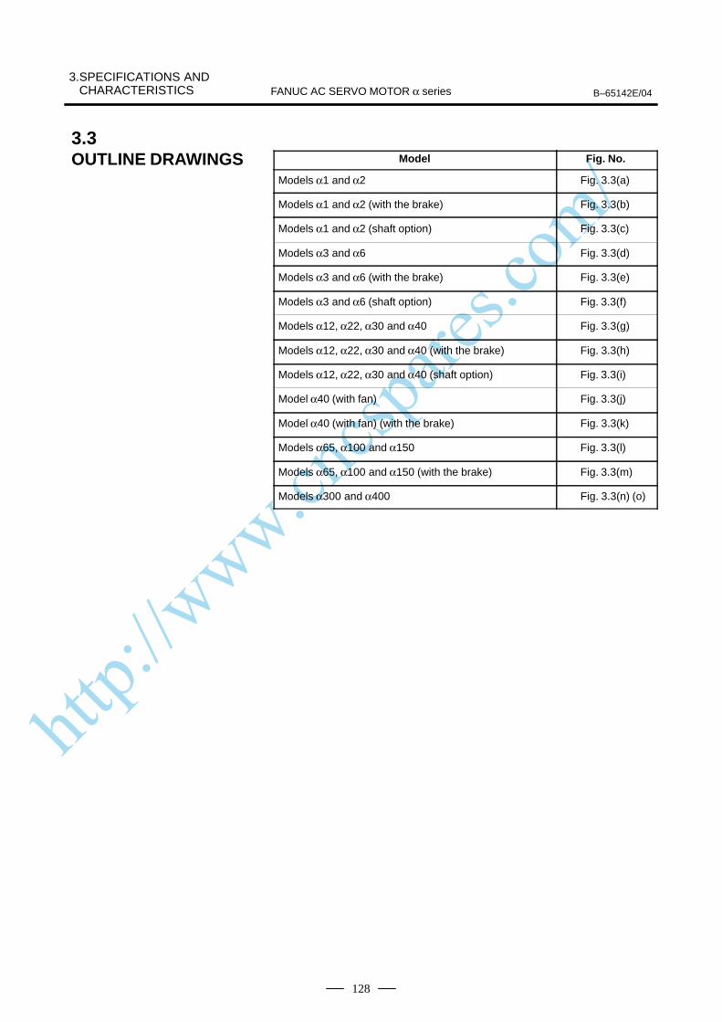
http://www.cncspares.com/
3.SPECIFICATIONS AND CHARACTERISTICS B–65142E/04FANUC AC SERVO MOTOR α series
128
Model Fig. No.
Models α1 and α2 Fig. 3.3(a)
Models α1 and α2 (with the brake) Fig. 3.3(b)
Models α1 and α2 (shaft option) Fig. 3.3(c)
Models α3 and α6 Fig. 3.3(d)
Models α3 and α6 (with the brake) Fig. 3.3(e)
Models α3 and α6 (shaft option) Fig. 3.3(f)
Models α12, α22, α30 and α40 Fig. 3.3(g)
Models α12, α22, α30 and α40 (with the brake) Fig. 3.3(h)
Models α12, α22, α30 and α40 (shaft option) Fig. 3.3(i)
Model α40 (with fan) Fig. 3.3(j)
Model α40 (with fan) (with the brake) Fig. 3.3(k)
Models α65, α100 and α150 Fig. 3.3(l)
Models α65, α100 and α150 (with the brake) Fig. 3.3(m)
Models α300 and α400 Fig. 3.3(n) (o)
3.3OUTLINE DRAWINGS
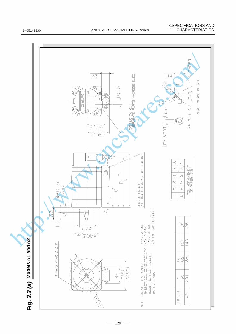
http://www.cncspares.com/
3.SPECIFICATIONS ANDCHARACTERISTICSFANUC AC SERVO MOTOR α seriesB–65142E/04
129
Fig
. 3.3
(a)
Mo
del
s α1
an
d α
2
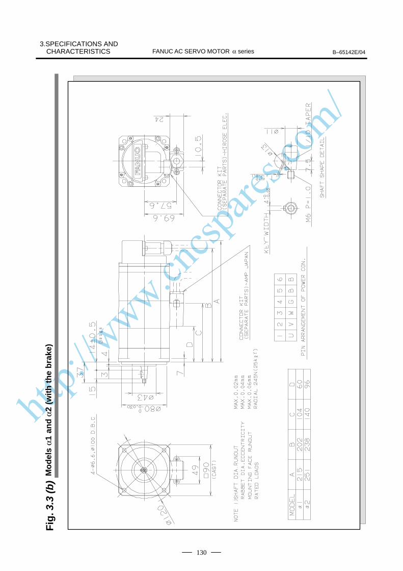
http://www.cncspares.com/
B–65142E/04FANUC AC SERVO MOTOR α series3.SPECIFICATIONS AND
CHARACTERISTICS
130
Fig
. 3.3
(b)
Mo
del
s α1
an
d α
2 (w
ith
th
e b
rake
)
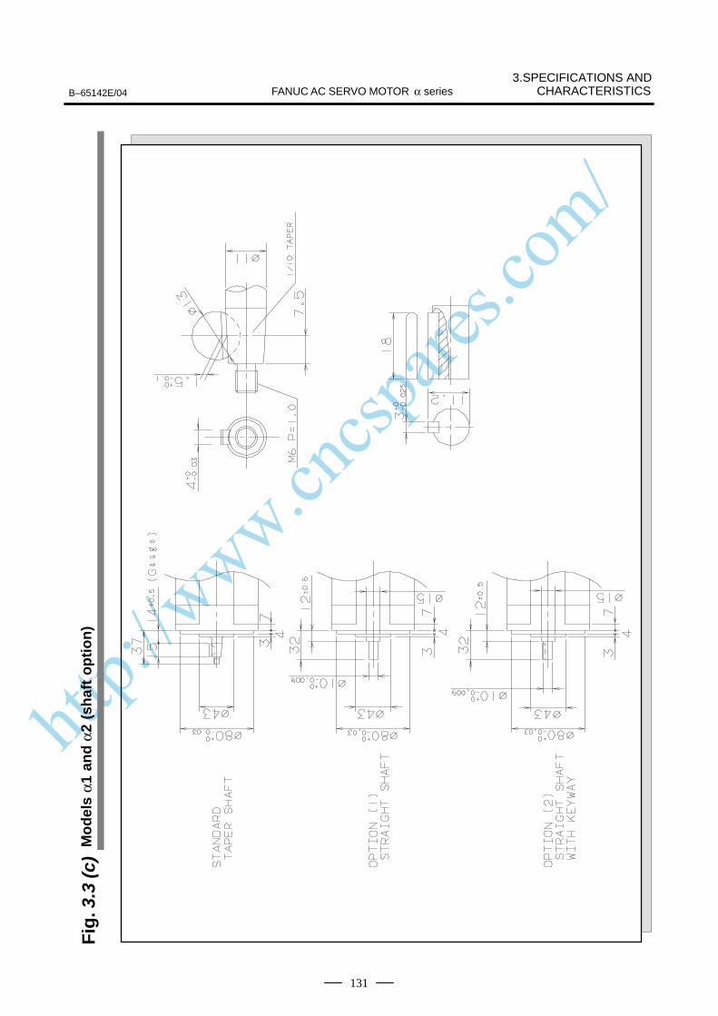
http://www.cncspares.com/
3.SPECIFICATIONS ANDCHARACTERISTICSFANUC AC SERVO MOTOR α seriesB–65142E/04
131
Fig
. 3.3
(c)
Mo
del
s α1
an
d α
2 (s
haf
t o
pti
on
)
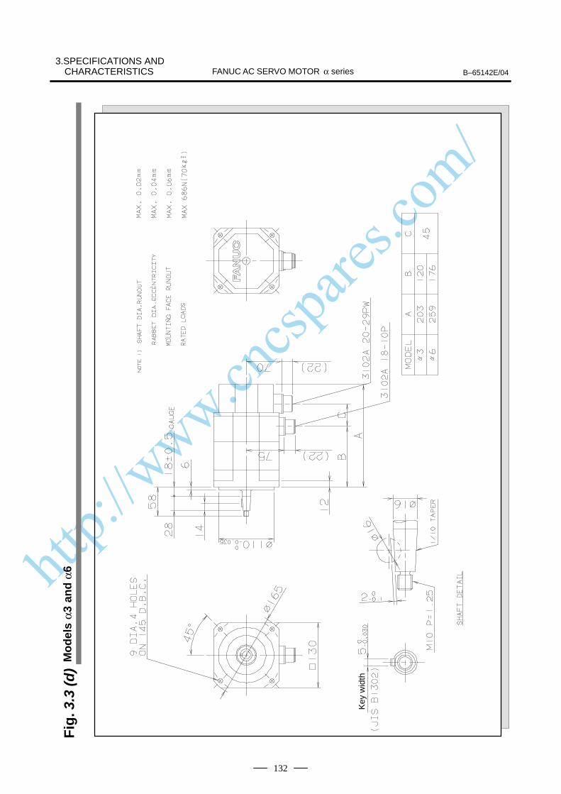
http://www.cncspares.com/
B–65142E/04FANUC AC SERVO MOTOR α series3.SPECIFICATIONS AND
CHARACTERISTICS
132
Fig
. 3.3
(d)
Mo
del
s α3
an
d α
6
Key
wid
th
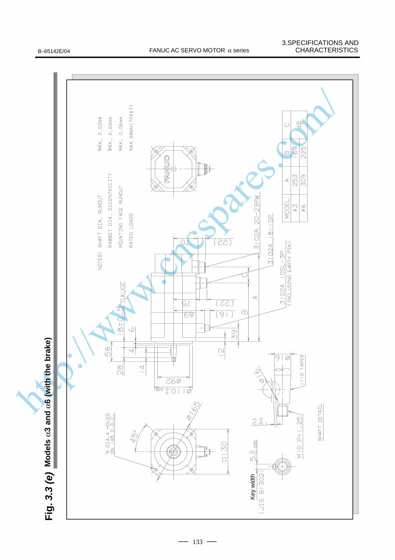
http://www.cncspares.com/
3.SPECIFICATIONS ANDCHARACTERISTICSFANUC AC SERVO MOTOR α seriesB–65142E/04
133
Fig
. 3.3
(e)
Mo
del
s α3
an
d α
6 (w
ith
th
e b
rake
)
Key
wid
th
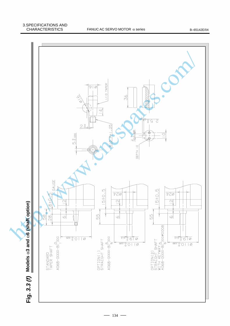
http://www.cncspares.com/
B–65142E/04FANUC AC SERVO MOTOR α series3.SPECIFICATIONS AND
CHARACTERISTICS
134
Fig
. 3.3
(f)
Mo
del
s α3
an
d α
6 (s
haf
t o
pti
on
)
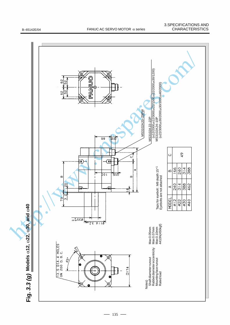
http://www.cncspares.com/
3.SPECIFICATIONS ANDCHARACTERISTICSFANUC AC SERVO MOTOR α seriesB–65142E/04
135
Fig
. 3.3
(g)
Mo
del
s α1
2, α
22, α
30, a
nd
α40
Not
es)
Sha
ft di
amet
er ru
nout
Max
0.0
5mm
Rab
bet d
iam
eter
ecc
entr
icity
Max
0.0
7mm
Mou
ntin
g fa
ce ru
nout
Max
0.1
0mm
Rat
ed lo
ad44
10N
(450
kgf)
Taps
for e
yebo
lt : M
8 de
pth
15+
1
Eye
bolts
are
not
atta
ched
MS
3102
A 2
0–29
PW
MS
3102
A 2
2–22
P
(α12
/200
0,α1
2/30
00,α
22/1
500,
α22/
2000
,α30
/120
0)M
S31
02A
24–
10P
(α22
/300
0,α3
0/20
00,α
30/3
000,
α40/
2000
)
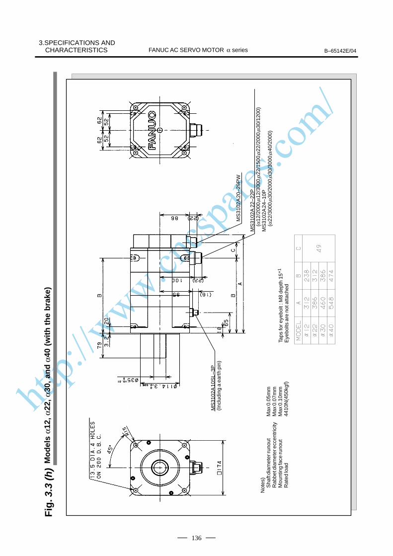
http://www.cncspares.com/
B–65142E/04FANUC AC SERVO MOTOR α series3.SPECIFICATIONS AND
CHARACTERISTICS
136
Fig
. 3.3
(h)
Mo
del
s α1
2, α
22, α
30, a
nd
α40
(w
ith
th
e b
rake
)
Not
es)
Sha
ft di
amet
er ru
nout
Max
0.0
5mm
Rab
bet d
iam
eter
ecc
entr
icity
Max
0.0
7mm
Mou
ntin
g fa
ce ru
nout
Max
0.1
0mm
Rat
ed lo
ad44
10N
(450
kgf)
MS
3102
A 1
0SL–
3P(I
nclu
ding
a e
arth
pin
)
Taps
for e
yebo
lt : M
8 de
pth
15+
1
Eye
bolts
are
not
atta
ched
MS
3102
A 2
0–29
PW
MS
3102
A 2
2–22
P
(α12
/200
0,α1
2/30
00,α
22/1
500,
α22/
2000
,α30
/120
0)M
S31
02A
24–
10P
(α22
/300
0,α3
0/20
00,α
30/3
000,
α40/
2000
)
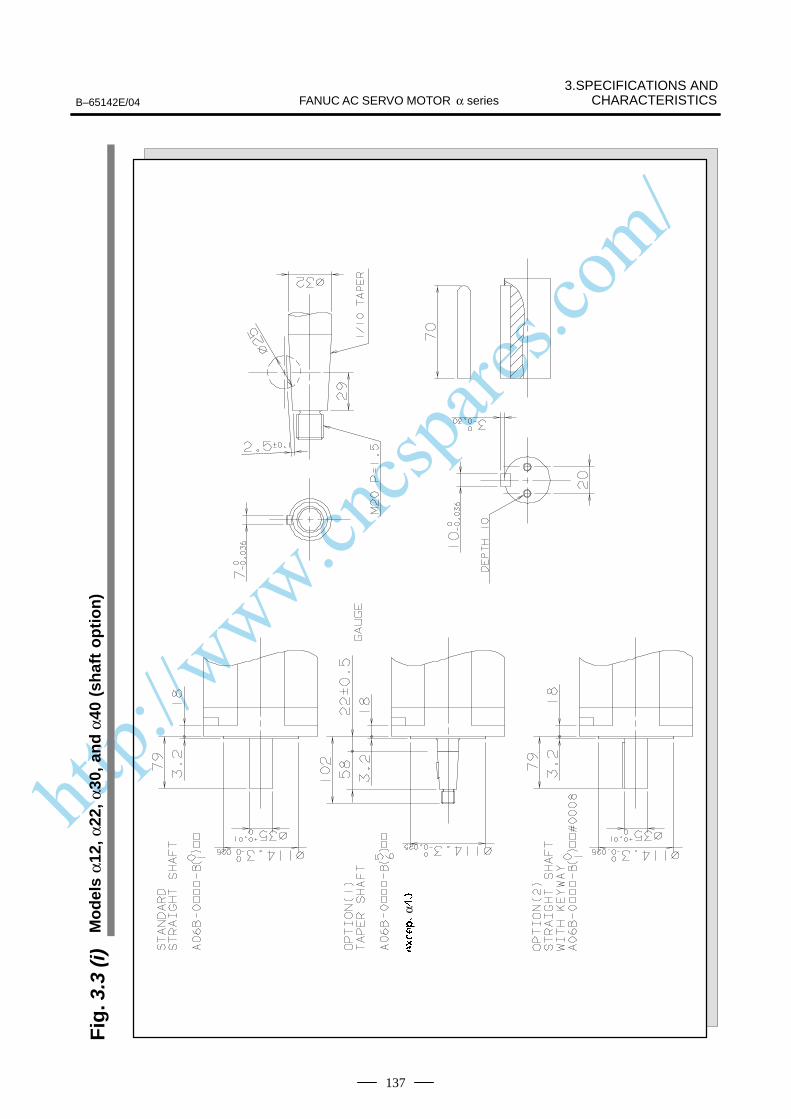
http://www.cncspares.com/
3.SPECIFICATIONS ANDCHARACTERISTICSFANUC AC SERVO MOTOR α seriesB–65142E/04
137
Fig
. 3.3
(i)
Mo
del
s α1
2, α
22, α
30, a
nd
α40
(sh
aft
op
tio
n)
α
Á ÁÁ ÁÁÁÁÁÁ ÁÁ ÁÁ ÁÁ ÁÁÁÁÁ
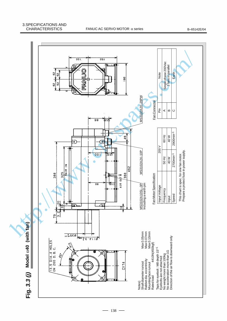
http://www.cncspares.com/
B–65142E/04FANUC AC SERVO MOTOR α series3.SPECIFICATIONS AND
CHARACTERISTICS
138
Fig
. 3.3
(j)
Mo
del
α40
(w
ith
fan
)
Not
es)
Sha
ft di
amet
er ru
nout
Max
0.0
5mm
Rab
bet d
ia. e
ccen
tric
ityM
ax 0
.07m
mM
ount
ing
face
runo
utM
ax 0
.10m
mR
ated
load
4410
N(4
50kg
f)
Taps
for e
yebo
lt : M
8 de
pth
15+
1
Eye
bolts
are
not
atta
ched
No
wei
ght m
ore
than
100
kgN
o ac
cele
ratio
n m
ore
than
1G
Dire
ctio
n of
the
air f
low
is d
ownw
ard
only
MS
3102
A 1
0SL–
3PIn
clud
ing
a ea
rth
pin
MS
3102
A 2
4–10
PM
S31
02A
20–
29P
W
Thi
s ch
art i
s sp
ec. f
or o
ne fa
n m
otor
.P
repa
re a
pro
tect
fuse
in p
ower
sup
ply.
Inpu
t Vol
tage
Fre
quen
cy
Inpu
t
Spe
ed
200
V
50 H
z60
Hz
40 W
40 W
2700
min
–129
00m
in–1
Fan
Mot
or S
peci
ficat
ion
Fan
Con
nect
or
Pin A CB
Not
e
Sin
gle
phas
e 20
0Vac
2 fa
ns in
par
alle
l
Ear
th
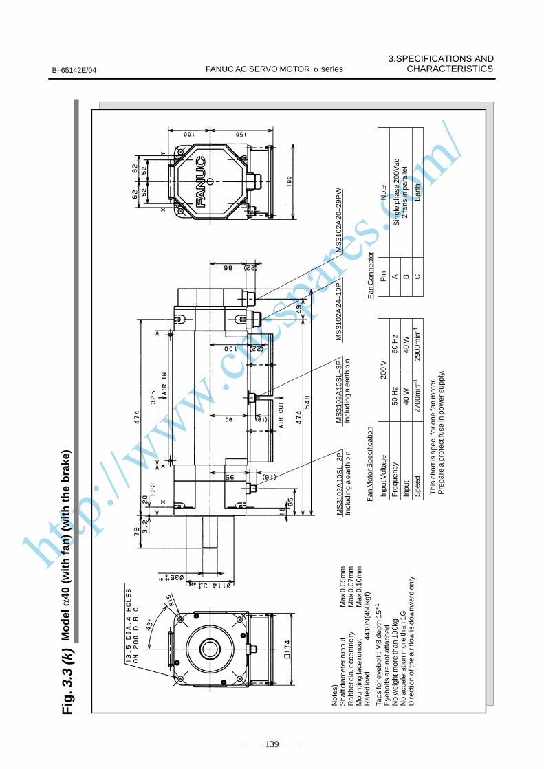
http://www.cncspares.com/
3.SPECIFICATIONS ANDCHARACTERISTICSFANUC AC SERVO MOTOR α seriesB–65142E/04
139
Fig
. 3.3
(k)
Mo
del
α40
(w
ith
fan
) (w
ith
th
e b
rake
)
Not
es)
Sha
ft di
amet
er ru
nout
Max
0.0
5mm
Rab
bet d
ia. e
ccen
tric
ityM
ax 0
.07m
mM
ount
ing
face
runo
utM
ax 0
.10m
mR
ated
load
4410
N(4
50kg
f)
Taps
for e
yebo
lt : M
8 de
pth
15+
1
Eye
bolts
are
not
atta
ched
No
wei
ght m
ore
than
100
kgN
o ac
cele
ratio
n m
ore
than
1G
Dire
ctio
n of
the
air f
low
is d
ownw
ard
only
MS
3102
A 1
0SL–
3PIn
clud
ing
a ea
rth
pin
MS
3102
A 2
0–29
PW
Thi
s ch
art i
s sp
ec. f
or o
ne fa
n m
otor
.P
repa
re a
pro
tect
fuse
in p
ower
sup
ply.
Inpu
t Vol
tage
Fre
quen
cy
Inpu
t
Spe
ed
200
V
50 H
z60
Hz
40 W
40 W
2700
min
–129
00m
in–1
Fan
Mot
or S
peci
ficat
ion
Fan
Con
nect
or
Pin A CB
Not
e
Sin
gle
phas
e 20
0Vac
2 fa
ns in
par
alle
l
Ear
th
MS
3102
A 1
0SL–
3PIn
clud
ing
a ea
rth
pin
MS
3102
A 2
4–10
P
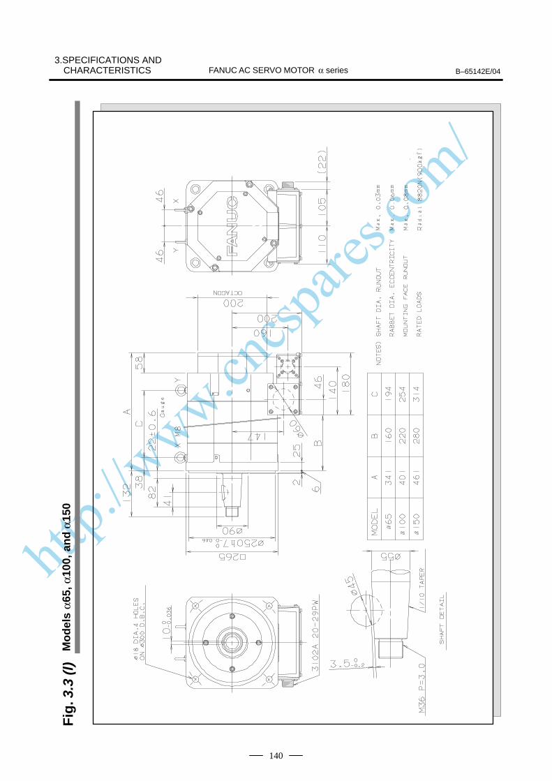
http://www.cncspares.com/
B–65142E/04FANUC AC SERVO MOTOR α series3.SPECIFICATIONS AND
CHARACTERISTICS
140
Fig
. 3.3
(l)
Mo
del
s α6
5, α
100,
an
d α
150
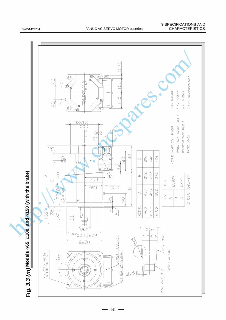
http://www.cncspares.com/
3.SPECIFICATIONS ANDCHARACTERISTICSFANUC AC SERVO MOTOR α seriesB–65142E/04
141
Fig
. 3.3
(m)M
od
els
α65,
α10
0, a
nd
α15
0 (w
ith
th
e b
rake
)
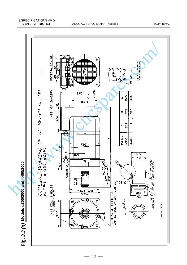
http://www.cncspares.com/
B–65142E/04FANUC AC SERVO MOTOR α series3.SPECIFICATIONS AND
CHARACTERISTICS
142
Fig
. 3.3
(n)
Mo
del
s α3
00/2
000
and
α40
0/20
00
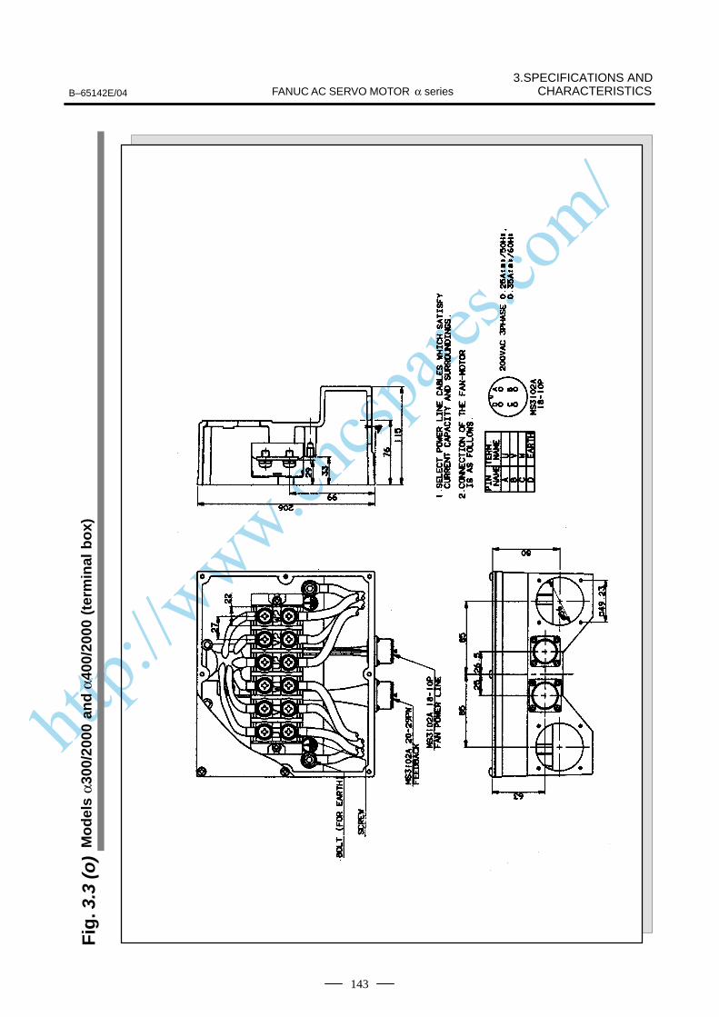
http://www.cncspares.com/
3.SPECIFICATIONS ANDCHARACTERISTICSFANUC AC SERVO MOTOR α seriesB–65142E/04
143
Fig
. 3.3
(o)
Mo
del
s α3
00/2
000
and
α40
0/20
00 (
term
inal
bo
x)

http://www.cncspares.com/
3.SPECIFICATIONS AND CHARACTERISTICS B–65142E/04FANUC AC SERVO MOTOR α series
144
1
2
3
4
5
6
Brakecoil
Only the motor with thebrake
Ground plate
Motor body
Motor coil
Note)No surge absorber for brake is contained inthe motor.Prepare a surge absorber in the power magnetics cabinet.
Special connector(AMP JAPAN, LTD.)
A
B
C
D
3102A 18–10P
Grounding plate
Motor body
Motor coil
A
B
C
D
3102A 22–22P
Grounding plate
Motor body
Motor coil
3.4CONNECTION OFPOWER LINE
Models α1/3000 α2/2000, andα2/3000
Models α3/3000, α6/2000, andα6/3000
Models α12/2000, α12/3000, α22/1500, α22/2000, and α30/1200
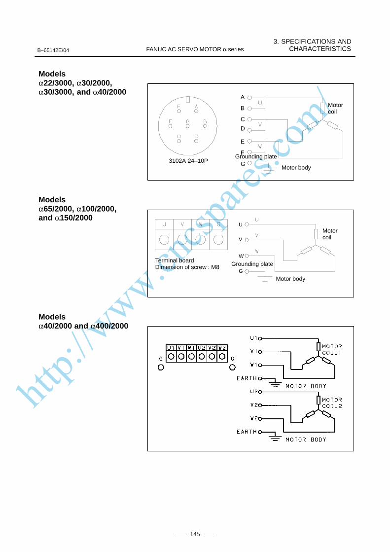
http://www.cncspares.com/
B–65142E/04
3. SPECIFICATIONS ANDCHARACTERISTICSFANUC AC SERVO MOTOR α series
145
A
B
C
D
3102A 24–10P
E
F
GGrounding plate
Motor body
Motor coil
U
V
W
G
Terminal boardDimension of screw : M8 Grounding plate
Motor body
Motor coil
Models α22/3000, α30/2000, α30/3000, and α40/2000
Models α65/2000, α100/2000,and α150/2000
Models α40/2000 and α400/2000

http://www.cncspares.com/
3.SPECIFICATIONS AND CHARACTERISTICS B–65142E/04FANUC AC SERVO MOTOR α series
146
CAUTION1 The motors should be installed with their connector facing
downward as long as possible. When it is impossible toinstall a motor in this position, allow slack in the cable tokeep liquids such as a dielectric fluid from going along thecable into the cable or motor. If there is a possibility that themotors and connectors get wet, provide a cover to protectthem.
2 If a motor is not connected to the earth ground through themachine (frame), connect the motor grounding point andthe amplifier grounding point to absorb noise using a 1.25mm2 or larger conductor other than the groundingconductor in the power cable. Keep the groundingconductor as far from the power cable as possible.
http://www.cncspares.com/
III. FANUC AC SERVO MOTOR αM series

http://www.cncspares.com/
B–65142E/04 1. GENERALFANUC AC SERVO MOTOR αM series
149
1
The FANUC AC servo motor αM series is suitable for application to thefeed axes of small machine tools. It has the following features:
A high maximum output torque and intermediate rotor inertia result inexcellent acceleration characteristics.
The use of the latest neodymium ferrite magnet further reduces the sizeand weight of the servo motors. This produces a servo motor that issufficiently compact to allow its use in small machine tools.
The use of waterproof connectors and FANUC’s unique stator sealprovide excellent waterproofing, ensuring that no liquid, such as coolant,can enter the motor.
The use of the latest servo software minimizes the heat generated byhigh–speed rotation, allowing continuous operation over a wide range.
Further improvements have been made to the unique magnetic pole shapeto minimize torque ripple. The result is extremely smooth rotation.
The use of the latest servo software maintains controllability even whena disturbance occurs.
High–resolution pulse coder αA1000, αA64, αI64 is used in the standardconfiguration, enabling precise positioning.
A powerful brake with an increased holding torque is available as anoption. The brake uses an asbestos–free design.
The types and specifications of αM series servo motors are described asfollows.
The αM series includes the following models:
Models αM2 and αM2.5 (excluding shaft type models) that arecompatible with the installation dimensions of the α series models α1and 2.
Models αM3, αM6, and αM9 that are compatible with the installationdimensions of the α series models α3 and 6.
Models αM22 and αM30 that are compatible with the installationdimensions of the α series models α12, 22, and 30.
Excellent accelerationcharacteristics
Compact
Excellent waterproofing
Extendedcontinuous–operation
Smooth rotation
Controllability
High–performancedetector
Powerful brake
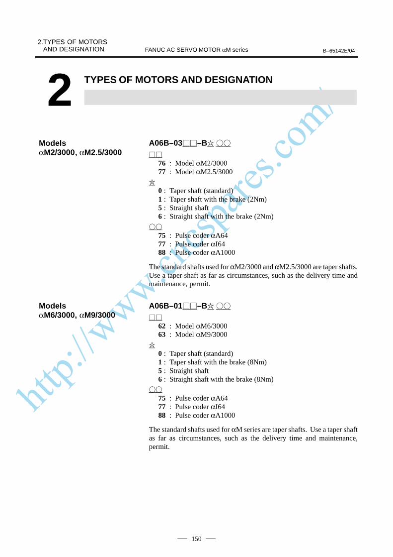
http://www.cncspares.com/
2.TYPES OF MOTORSAND DESIGNATION B–65142E/04FANUC AC SERVO MOTOR αM series
150
2 TYPES OF MOTORS AND DESIGNATION
A06B–03–B
76 : Model αM2/300077 : Model αM2.5/3000
0 : Taper shaft (standard)1 : Taper shaft with the brake (2Nm)5 : Straight shaft6 : Straight shaft with the brake (2Nm)
75 : Pulse coder αA6477 : Pulse coder αI6488 : Pulse coder αA1000
The standard shafts used for αM2/3000 and αM2.5/3000 are taper shafts.Use a taper shaft as far as circumstances, such as the delivery time andmaintenance, permit.
A06B–01–B
62 : Model αM6/300063 : Model αM9/3000
0 : Taper shaft (standard)1 : Taper shaft with the brake (8Nm)5 : Straight shaft6 : Straight shaft with the brake (8Nm)
75 : Pulse coder αA6477 : Pulse coder αI6488 : Pulse coder αA1000
The standard shafts used for αM series are taper shafts. Use a taper shaftas far as circumstances, such as the delivery time and maintenance,permit.
ModelsαM2/3000 αM2.5/3000
ModelsαM6/3000, αM9/3000
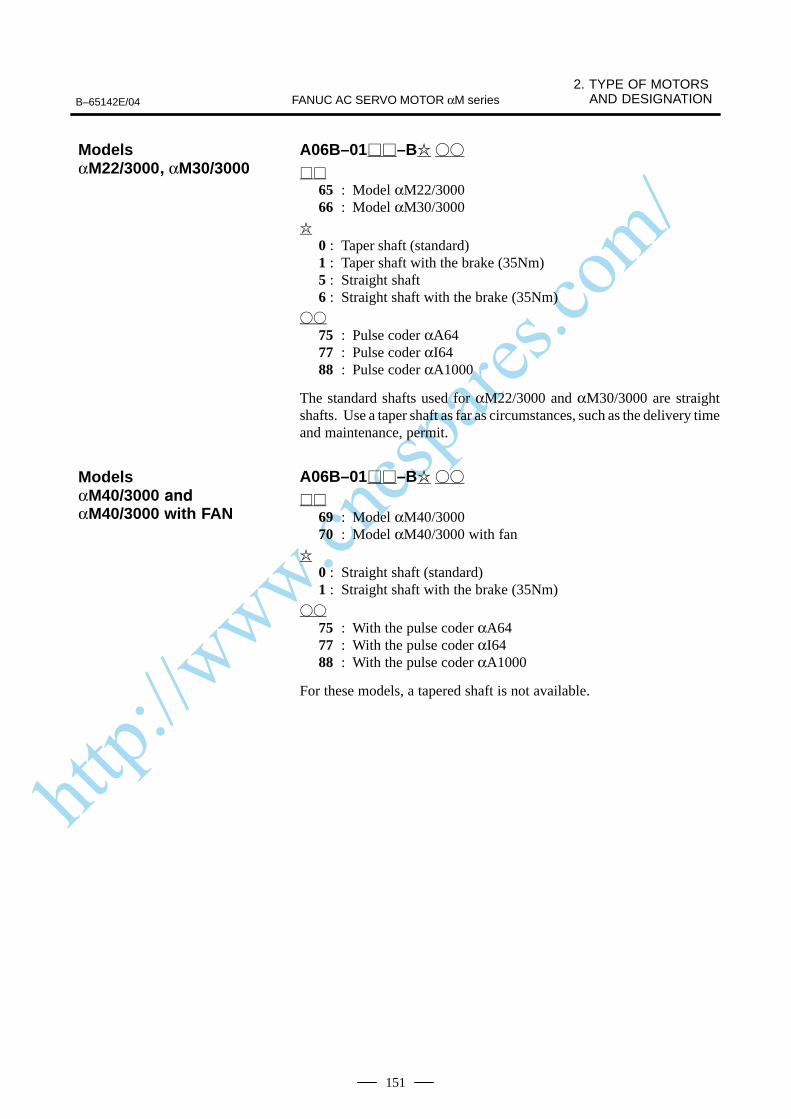
http://www.cncspares.com/
B–65142E/04
2. TYPE OF MOTORS AND DESIGNATIONFANUC AC SERVO MOTOR αM series
151
A06B–01–B
65 : Model αM22/300066 : Model αM30/3000
0 : Taper shaft (standard)1 : Taper shaft with the brake (35Nm)5 : Straight shaft6 : Straight shaft with the brake (35Nm)
75 : Pulse coder αA6477 : Pulse coder αI6488 : Pulse coder αA1000
The standard shafts used for αM22/3000 and αM30/3000 are straightshafts. Use a taper shaft as far as circumstances, such as the delivery timeand maintenance, permit.
A06B–01–B
69 : Model αM40/300070 : Model αM40/3000 with fan
0 : Straight shaft (standard)1 : Straight shaft with the brake (35Nm)
75 : With the pulse coder αA6477 : With the pulse coder αI6488 : With the pulse coder αA1000
For these models, a tapered shaft is not available.
ModelsαM22/3000 αM30/3000
ModelsαM40/3000
αM40/3000 with FAN

http://www.cncspares.com/
3.SPECIFICATIONS AND CHARACTERISTICS B–65142E/04FANUC AC SERVO MOTOR αM series
152
3 SPECIFICATIONS AND CHARACTERISTICS
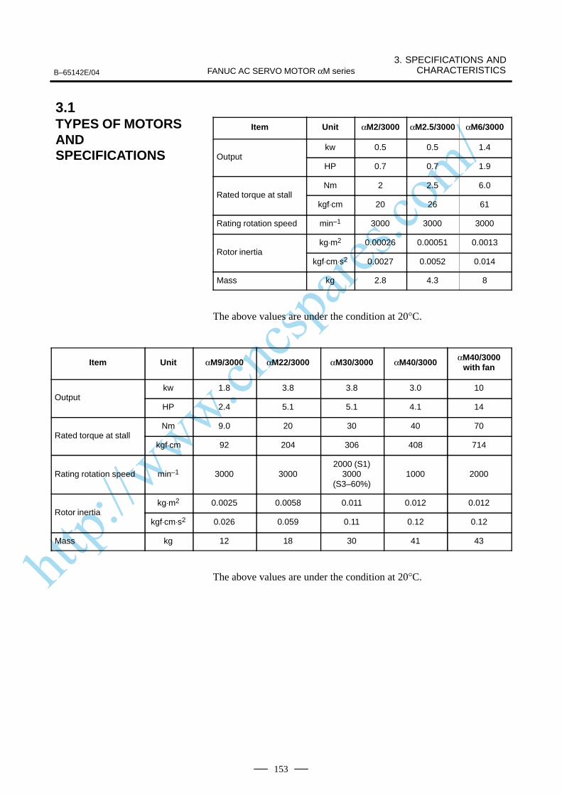
http://www.cncspares.com/
B–65142E/04
3. SPECIFICATIONS ANDCHARACTERISTICSFANUC AC SERVO MOTOR αM series
153
Item Unit αM2/3000 αM2.5/3000 αM6/3000
kw 0.5 0.5 1.4Output
HP 0.7 0.7 1.9
Nm 2 2.5 6.0Rated torque at stall
kgf⋅cm 20 26 61
Rating rotation speed min–1 3000 3000 3000
kg⋅m2 0.00026 0.00051 0.0013Rotor inertia
kgf⋅cm⋅s2 0.0027 0.0052 0.014
Mass kg 2.8 4.3 8
The above values are under the condition at 20°C.
Item Unit αM9/3000 αM22/3000 αM30/3000 αM40/3000 αM40/3000with fan
kw 1.8 3.8 3.8 3.0 10Output
HP 2.4 5.1 5.1 4.1 14
Nm 9.0 20 30 40 70Rated torque at stall
kgf⋅cm 92 204 306 408 714
Rating rotation speed min–1 3000 30002000 (S1)
3000(S3–60%)
1000 2000
kg⋅m2 0.0025 0.0058 0.011 0.012 0.012Rotor inertia
kgf⋅cm⋅s2 0.026 0.059 0.11 0.12 0.12
Mass kg 12 18 30 41 43
The above values are under the condition at 20°C.
3.1TYPES OF MOTORSANDSPECIFICATIONS
http://www.cncspares.com/
3.SPECIFICATIONS AND CHARACTERISTICS B–65142E/04FANUC AC SERVO MOTOR αM series
154
The intermittent operation zone is determined by the input voltageapplied to the drive amplifier. The curve shown is the value for the ratedinput voltage (200V).“Intermittent operating zone (S3)” in the speed-torque characteristicsrefers to the intermittent cycle operating zone in the IEC34-1 standard. Inthis zone, ON operation of six minutes and OFF operation of four minutesin a 10-minute cycle is possible.On models αM40/3000 and αM40/3000 with fan “Intermittent operating(S3–25%)” in the “Speed–torque characteristics is permitting operatingzone in IEC34–1, and it enables to operate 2.5min ON and 7.5min OFFin 10min cycle time.Equally, (S3–60%)” in the “Speed–torque characteristics enables tooperate 6min ON and 4min OFF in 10min cycle time.On models αM2 to M9, the maximum speed of rotation is increased byusing HRV control. The speed-torque characteristics for when HRVcontrol is used are described at the end of this item.
The overload duty characteristic curves are determined based on thetemperature restriction for the single motor unit (the temperature isrestricted by means of a thermal trip built into the motor). The curves aredetermined by assuming that the temperature increases gradually undercertain overload conditions. Therefore, the curves do not apply to therapid temperature rise which occurs, for example, when the motor shaftis locked. (An overcurrent flows in the motor windings until the thermaltrip operates. The temperature rises momentarily.)To detect such an abrupt temperature rise, the FANUC digital servosystem provides a software thermal function that uses servo software toobserve the current. During operation that is characterized by frequentacceleration/deceleration cycles, control is imposed by the softwarethermal function.Driving units (such as amplifiers) and built–in detectors contain their ownoverheating protection devices. Therefore, note that control may beimposed according to how the equipment is being used.
3.2CHARACTERISTICCURVE AND DATASHEETSpeed–torquecharacteristics
Overload dutycharacteristic
http://www.cncspares.com/
B–65142E/04
3. SPECIFICATIONS ANDCHARACTERISTICSFANUC AC SERVO MOTOR αM series
155
The parameters given in the data sheet are representative values for anambient temperature of 20°C. They are subject to an error of 10%.The indicated logical values are threshold values for the single motor unit(when the motor is not restricted by the control system).The maximum torque that can be produced during acceleration ordeceleration in actual use is calculated as the approximate product of themotor torque constant and the current limit value of the amplifier.This value is for reference only. The actual value will vary depending onchanges in the power supply, as well as variations in motor parameters andamplifier limit values.In some models, if the maximum current flows in the motor, the actualmaximum torque is affected by, for example, magnetic saturation. As aresult, the actual maximum torque will be lower than the calculated value.The intermittent operation area (maximum torque value) indicated in thespeed to torque characteristics is the effective value, determinedaccording to the combination with the amplifier.
Data sheet

http://www.cncspares.com/
3.SPECIFICATIONS AND CHARACTERISTICS B–65142E/04FANUC AC SERVO MOTOR αM series
156
Specification : A06B–0376–B
Speed – torque characteristics
Speed (min–1) ”ON” time (min.)
Over load dutyTorque (Nm)
Duty (time %)
ÂÂÂÂÂÂÂÂÂÂÂÂIntermittent operating
ÂÂÂÂÂÂÂÂÂÂÂÂÂÂContinuous operating
Data sheetParameter Symbol Value Unit
Rating rotation speed Nmax 3000 min -1
Rated torque at stall (*) Ts2.0
20
Nm
kgfcm
Rotor inertia Jm0.00027
0.0028
kgm2
kgfcms2
Continuous RMS current at stall (*) Is 3.0 A (rms)
Torque constant (*) Kt0.67
6.8
Nm/A (rms)
kgfcm/A (rms)
Back EMF constant (1–phase)(*)
(*)
Ke
Kv
23
0.22
V (rms)/1000min -1
V (rms)·sec/rad
Armature resistance (1–phase)(*) Ra 1.73 Ω
Mechanical time constant (*) tm 0.003 s
Thermal time constant tt 15 min
Static friction Tf 0.15
1.5
Nm
kgfcm
Mass 2.8 kg
(*)The values are the standard values at 20°C and the tolerance is 10%.
The speed–torque characteristics very depending on the type of software, parameter
setting, and input voltage of the digital servo motor. (The above figures show average
values.) These values may be changed without prior notice.
On model αM2, the maximum speed of rotation is increased by using HRV control.
The speed-torque characteristics for when HRV control is used are described at the
end of this item
Model αM2/3000

http://www.cncspares.com/
B–65142E/04
3. SPECIFICATIONS ANDCHARACTERISTICSFANUC AC SERVO MOTOR αM series
157
Specification : A06B–0377–B
Speed – torque characteristics
Speed (min–1) ”ON” time (min.)
Over load dutyTorque (Nm)
Duty (time %)
ÂÂÂÂÂÂÂÂÂÂÂÂIntermittent operating
ÂÂÂÂÂÂÂÂÂÂÂÂÂÂContinuous operating
Data sheetParameter Symbol Value Unit
Rating rotation speed Nmax 3000 min -1
Rated torque at stall (*) Ts2.5
26
Nm
kgfcm
Rotor inertia Jm 0.00052
0.0053
kgm2
kgfcms2
Continuous RMS current at stall (*) Is 3.7 A (rms)
Torque constant (*) Kt0.67
6.8
Nm/A (rms)
kgfcm/A (rms)
Back EMF constant (1–phase)(*)
(*)
Ke
Kv
23
0.22
V (rms)/1000min -1
V (rms)·sec/rad
Armature resistance (1–phase)(*) Ra 0.59 Ω
Mechanical time constant (*) tm 0.002 s
Thermal time constant tt 20 min
Static friction Tf0.2
2
Nm
kgfcm
Mass 4.3 kg
(*)The values are the standard values at 20°C and the tolerance is 10%.
The speed–torque characteristics very depending on the type of software, parameter
setting, and input voltage of the digital servo motor. (The above figures show average
values.) These values may be changed without prior notice.
On model αM2.5, the maximum speed of rotation is increased by using HRV control.
The speed-torque characteristics for when HRV control is used are described at the
end of this item
Model αM2.5/3000
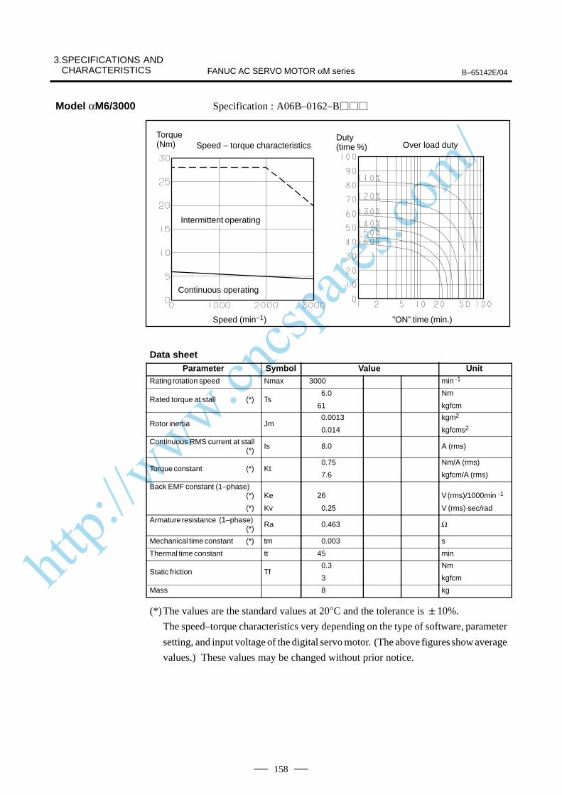
http://www.cncspares.com/
3.SPECIFICATIONS AND CHARACTERISTICS B–65142E/04FANUC AC SERVO MOTOR αM series
158
Specification : A06B–0162–B
Speed – torque characteristics
Speed (min–1) ”ON” time (min.)
Over load dutyTorque (Nm)
Duty (time %)
ÂÂÂÂÂÂÂÂÂÂÂÂÂÂ
Intermittent operating
ÂÂÂÂÂÂÂÂÂÂÂÂÂÂContinuous operating
Data sheetParameter Symbol Value Unit
Rating rotation speed Nmax 3000 min -1
Rated torque at stall (*) Ts 6.0
61
Nm
kgfcm
Rotor inertia Jm 0.0013
0.014
kgm2
kgfcms2
Continuous RMS current at stall (*) Is 8.0 A (rms)
Torque constant (*) Kt0.75
7.6
Nm/A (rms)
kgfcm/A (rms)
Back EMF constant (1–phase)(*)
(*)
Ke
Kv
26
0.25
V (rms)/1000min -1
V (rms)·sec/rad
Armature resistance (1–phase)(*) Ra 0.463 Ω
Mechanical time constant (*) tm 0.003 s
Thermal time constant tt 45 min
Static friction Tf0.3
3
Nm
kgfcm
Mass 8 kg
(*)The values are the standard values at 20°C and the tolerance is 10%.
The speed–torque characteristics very depending on the type of software, parameter
setting, and input voltage of the digital servo motor. (The above figures show average
values.) These values may be changed without prior notice.
Model αM6/3000
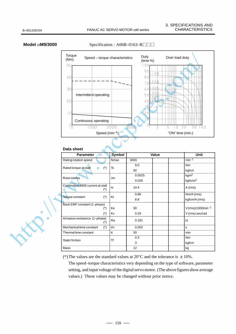
http://www.cncspares.com/
B–65142E/04
3. SPECIFICATIONS ANDCHARACTERISTICSFANUC AC SERVO MOTOR αM series
159
Specification : A06B–0163–B
Speed – torque characteristics
Speed (min–1) ”ON” time (min.)
Over load dutyTorque (Nm)
Duty (time %)
ÂÂÂÂÂÂÂIntermittent operating
ÂÂÂÂÂÂÂÂÂÂÂÂÂÂContinuous operating
Data sheetParameter Symbol Value Unit
Rating rotation speed Nmax 3000 min -1
Rated torque at stall (*) Ts9.0
92
Nm
kgfcm
Rotor inertia Jm0.0025
0.026
kgm2
kgfcms2
Continuous RMS current at stall (*) Is 10.4 A (rms)
Torque constant (*) Kt0.86
8.8
Nm/A (rms)
kgfcm/A (rms)
Back EMF constant (1–phase)(*)
(*)
Ke
Kv
30
0.29
V (rms)/1000min -1
V (rms)·sec/rad
Armature resistance (1–phase)(*) Ra 0.181 Ω
Mechanical time constant (*) tm 0.002 s
Thermal time constant tt 50 min
Static friction Tf 0.3
3
Nm
kgfcm
Mass 12 kg
(*)The values are the standard values at 20°C and the tolerance is 10%.
The speed–torque characteristics very depending on the type of software, parameter
setting, and input voltage of the digital servo motor. (The above figures show average
values.) These values may be changed without prior notice.
Model αM9/3000

http://www.cncspares.com/
3.SPECIFICATIONS AND CHARACTERISTICS B–65142E/04FANUC AC SERVO MOTOR αM series
160
Specification : A06B–0165–B
Speed – torque characteristics
Speed (min–1) ”ON” time (min.)
Over load dutyTorque (Nm)
Duty (time %)
ÂÂÂÂÂÂÂIntermittent operating
ÂÂÂÂÂÂÂContinuous operating
Data sheetParameter Symbol Value Unit
Rating rotation speed Nmax 3000 min -1
Rated torque at stall (*) Ts20
204
Nm
kgfcm
Rotor inertia Jm0.0058
0.059
kgm2
kgfcms2
Continuous RMS current at stall (*) Is 26.5 A (rms)
Torque constant (*) Kt0.75
7.7
Nm/A (rms)
kgfcm/A (rms)
Back EMF constant (1–phase)(*)
(*)
Ke
Kv
26
0.25
V (rms)/1000min -1
V (rms)·sec/rad
Armature resistance (1–phase)(*) Ra 0.07 Ω
Mechanical time constant (*) tm 0.002 s
Thermal time constant tt 60 min
Static friction Tf0.8
8
Nm
kgfcm
Mass 18 kg
(*)The values are the standard values at 20°C and the tolerance is 10%.
The speed–torque characteristics very depending on the type of software, parameter
setting, and input voltage of the digital servo motor. (The above figures show average
values.) These values may be changed without prior notice.
Model αM22/3000

http://www.cncspares.com/
B–65142E/04
3. SPECIFICATIONS ANDCHARACTERISTICSFANUC AC SERVO MOTOR αM series
161
Specification : A06B–0166–B
Intermittent operating(S3–60%)
Speed – torque characteristics
Speed (min–1) ”ON” time (min.)
Over load dutyTorque (Nm)
Duty (time %)
ÂÂÂÂÂÂÂÂÂÂÂÂÂÂ
Intermittent operating
ÂÂÂÂÂÂÂÂÂÂÂÂÂÂ
Continuous operating(S1)
Data sheetParameter Symbol Value Unit
Rating rotation speed Nmax2000 (S1) 3000 (S3–60%) min -1
Rated torque at stall (*) Ts 30
306
Nm
kgfcm
Rotor inertia Jm 0.011
0.11
kgm2
kgfcms2
Continuous RMS current at stall (*) Is 27.9 A (rms)
Torque constant (*) Kt1.08
11.0
Nm/A (rms)
kgfcm/A (rms)
Back EMF constant (1–phase)(*)
(*)
Ke
Kv
38
0.36
V (rms)/1000min -1
V (rms)·sec/rad
Armature resistance (1–phase)(*) Ra 0.05 Ω
Mechanical time constant (*) tm 0.001 s
Thermal time constant tt 65 min
Static friction Tf 1.2
12
Nm
kgfcm
Mass 30 kg
(*)The values are the standard values at 20°C and the tolerance is 10%.
The speed–torque characteristics very depending on the type of software, parameter
setting, and input voltage of the digital servo motor. (The above figures show average
values.) These values may be changed without prior notice.
The 2000 to 3000 rpm range of this servo motor is the intermittent operation range,
and is used mainly for positioning. In the intermittent operation range (S3 to 60%),
ON operation of six minutes and OFF operation of four minutes in a 10-minute cycle
is possible.
Model αM30/3000
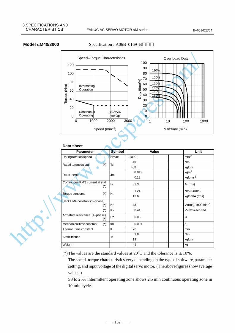
http://www.cncspares.com/
3.SPECIFICATIONS AND CHARACTERISTICS B–65142E/04FANUC AC SERVO MOTOR αM series
162
Specification : A06B–0169–B
0
10
20
30
40
50
60
70
80
90
100
1 10 100 10000
20
40
60
80
100
120
0 1000 2000 3000
110%
120%
130%140%150%160%
Over Load Duty
“On”time (min)
Speed–Torque Characteristics
Speed (min–1)
IntermittingOperation
S3–25%Inter.Op.
Torq
ue (N
m)
Dut
y (t
ime%
)
ContinuousOperating
Data sheetParameter Symbol Value Unit
Rating rotation speed Nmax 1000 min -1
Rated torque at stall (*) Ts 40
408
Nm
kgfcm
Rotor inertia Jm 0.012
0.12
kgm2
kgfcms2
Continuous RMS current at stall (*) Is 32.3 A (rms)
Torque constant (*) Kt1.24
12.6
Nm/A (rms)
kgfcm/A (rms)
Back EMF constant (1–phase)(*)
(*)
Ke
Kv
43
0.41
V (rms)/1000min -1
V (rms)·sec/rad
Armature resistance (1–phase)(*) Ra 0.05 Ω
Mechanical time constant (*) tm 0.001 s
Thermal time constant tt 70 min
Static friction Tf 1.8
18
Nm
kgfcm
Weight 41 kg
(*)The values are the standard values at 20°C and the tolerance is 10%.
The speed–torque characteristics very depending on the type of software, parameter
setting, and input voltage of the digital servo motor. (The above figures show average
values.)
S3 to 25% intermittent operating zone shows 2.5 min continuous operating zone in
10 min cycle.
Model αM40/3000
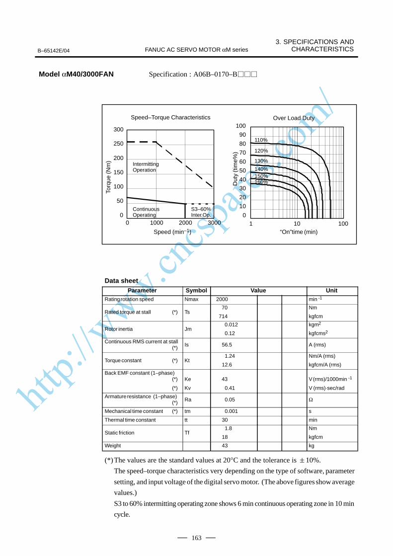
http://www.cncspares.com/
B–65142E/04
3. SPECIFICATIONS ANDCHARACTERISTICSFANUC AC SERVO MOTOR αM series
163
Specification : A06B–0170–B
0
10
20
30
40
50
60
70
80
90
100
1 10 1000
50
100
150
200
250
300
0 1000 2000 3000
110%
120%
130%
140%150%160%
Over Load Duty
“On”time (min)
Speed–Torque Characteristics
Speed (min–1)
IntermittingOperation
S3–60%Inter.Op.
Torq
ue (N
m)
Dut
y (t
ime%
)
ContinuousOperating
Data sheetParameter Symbol Value Unit
Rating rotation speed Nmax 2000 min -1
Rated torque at stall (*) Ts 70
714
Nm
kgfcm
Rotor inertia Jm 0.012
0.12
kgm2
kgfcms2
Continuous RMS current at stall (*) Is 56.5 A (rms)
Torque constant (*) Kt1.24
12.6
Nm/A (rms)
kgfcm/A (rms)
Back EMF constant (1–phase)(*)
(*)
Ke
Kv
43
0.41
V (rms)/1000min -1
V (rms)·sec/rad
Armature resistance (1–phase)(*) Ra 0.05 Ω
Mechanical time constant (*) tm 0.001 s
Thermal time constant tt 30 min
Static friction Tf 1.8
18
Nm
kgfcm
Weight 43 kg
(*)The values are the standard values at 20°C and the tolerance is 10%.
The speed–torque characteristics very depending on the type of software, parameter
setting, and input voltage of the digital servo motor. (The above figures show average
values.)
S3 to 60% intermitting operating zone shows 6 min continuous operating zone in 10 min
cycle.
Model αM40/3000FAN
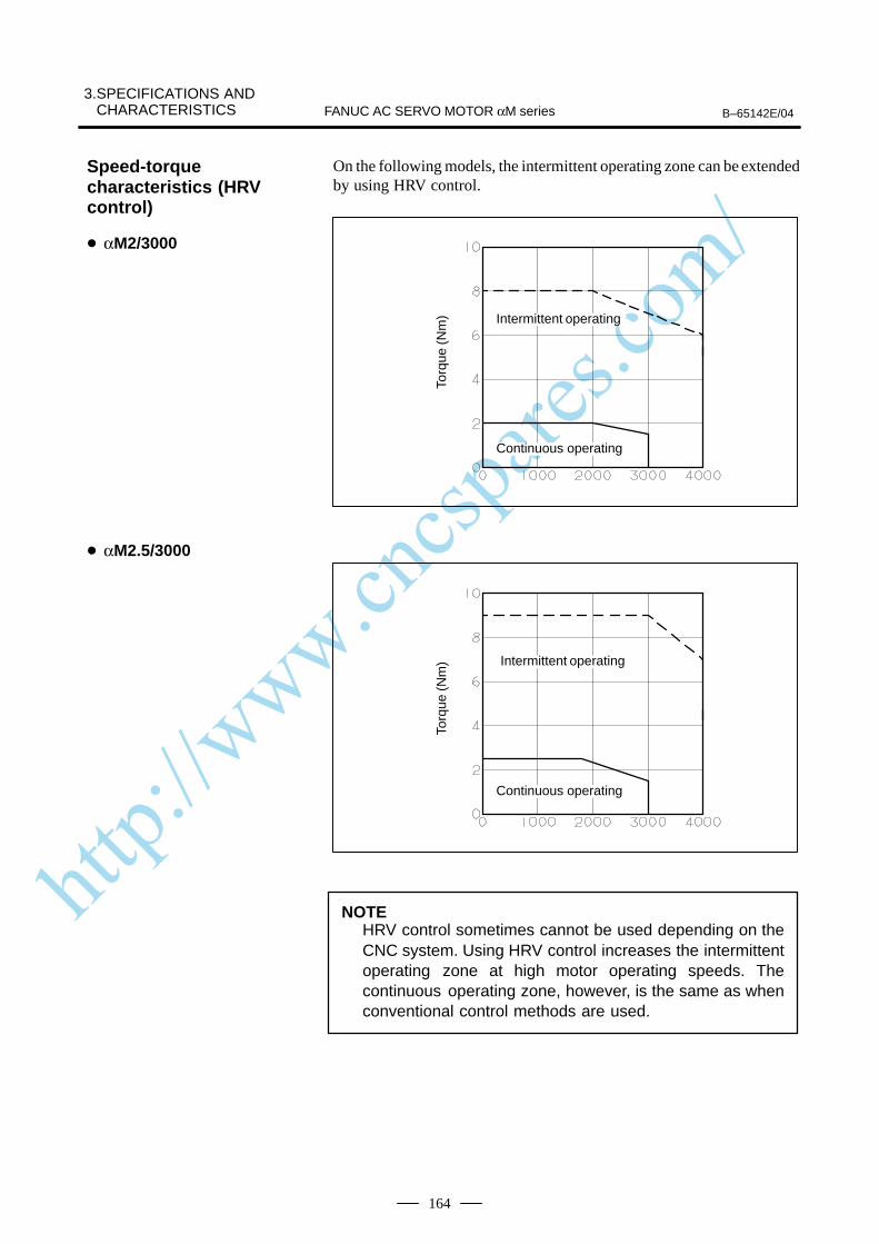
http://www.cncspares.com/
3.SPECIFICATIONS AND CHARACTERISTICS B–65142E/04FANUC AC SERVO MOTOR αM series
164
On the following models, the intermittent operating zone can be extendedby using HRV control.
Torq
ue (N
m) ÂÂÂÂÂÂÂ
ÂÂÂÂÂÂÂIntermittent operating
ÂÂÂÂÂÂÂÂÂÂÂÂÂÂ
Continuous operatingTo
rque
(Nm
)
ÂÂÂÂÂÂÂÂÂÂÂÂÂÂ
Intermittent operating
ÂÂÂÂÂÂÂÂÂÂÂÂÂÂ
Continuous operating
NOTEHRV control sometimes cannot be used depending on theCNC system. Using HRV control increases the intermittentoperating zone at high motor operating speeds. Thecontinuous operating zone, however, is the same as whenconventional control methods are used.
Speed-torquecharacteristics (HRVcontrol)
αM2/3000
αM2.5/3000

http://www.cncspares.com/
B–65142E/04
3. SPECIFICATIONS ANDCHARACTERISTICSFANUC AC SERVO MOTOR αM series
165
Torq
ue (N
m)
ÂÂÂÂÂÂIntermittent operating
ÂÂÂÂÂÂÂÂÂÂÂÂÂÂ
Continuous operating
Torq
ue (N
m)
ÂÂÂÂÂÂIntermittent operating
ÂÂÂÂÂÂÂContinuous operating
NOTEHRV control sometimes cannot be used depending on theCNC system. Using HRV control increases the intermittentoperating zone at high motor operating speeds. Thecontinuous operating zone, however, is the same as whenconventional control methods are used.
αM6/3000
αM9/3000
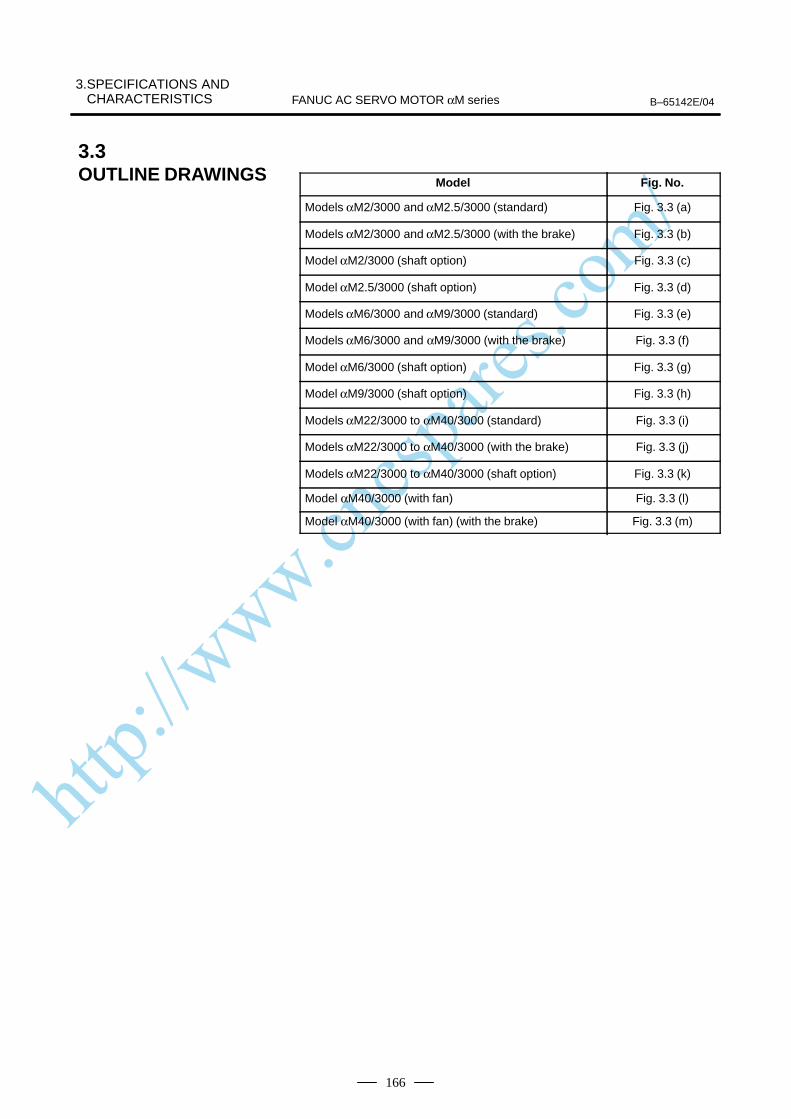
http://www.cncspares.com/
3.SPECIFICATIONS AND CHARACTERISTICS B–65142E/04FANUC AC SERVO MOTOR αM series
166
Model Fig. No.
Models αM2/3000 and αM2.5/3000 (standard) Fig. 3.3 (a)
Models αM2/3000 and αM2.5/3000 (with the brake) Fig. 3.3 (b)
Model αM2/3000 (shaft option) Fig. 3.3 (c)
Model αM2.5/3000 (shaft option) Fig. 3.3 (d)
Models αM6/3000 and αM9/3000 (standard) Fig. 3.3 (e)
Models αM6/3000 and αM9/3000 (with the brake) Fig. 3.3 (f)
Model αM6/3000 (shaft option) Fig. 3.3 (g)
Model αM9/3000 (shaft option) Fig. 3.3 (h)
Models αM22/3000 to αM40/3000 (standard) Fig. 3.3 (i)
Models αM22/3000 to αM40/3000 (with the brake) Fig. 3.3 (j)
Models αM22/3000 to αM40/3000 (shaft option) Fig. 3.3 (k)
Model αM40/3000 (with fan) Fig. 3.3 (l)
Model αM40/3000 (with fan) (with the brake) Fig. 3.3 (m)
3.3OUTLINE DRAWINGS

http://www.cncspares.com/
FANUC AC SERVO MOTOR αM series3.SPECIFICATIONS AND
CHARACTERISTICSB–65142E/04
167
Fig
. 3.3
(a)
Mo
del
s αM
2/30
00 a
nd
αM
2.5/
3000
(st
and
ard
)
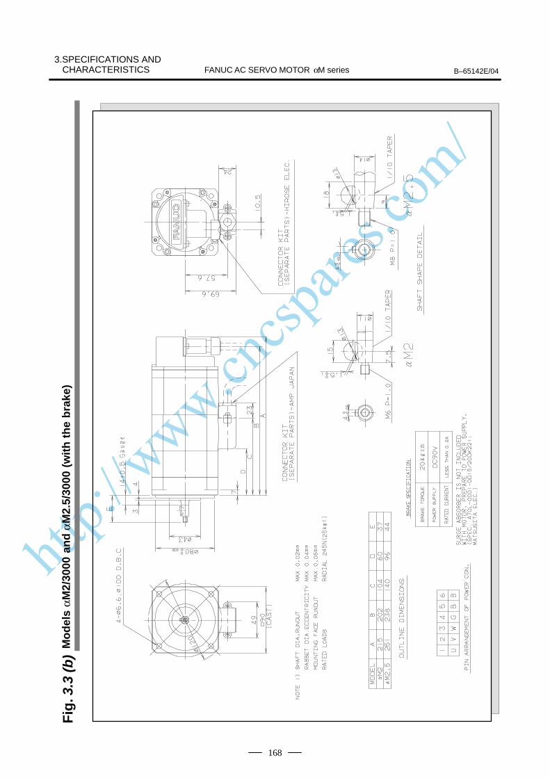
http://www.cncspares.com/
FANUC AC SERVO MOTOR αM series B–65142E/04
3.SPECIFICATIONS ANDCHARACTERISTICS
168
Fig
. 3.3
(b)
Mo
del
s αM
2/30
00 a
nd
αM
2.5/
3000
(w
ith
th
e b
rake
)
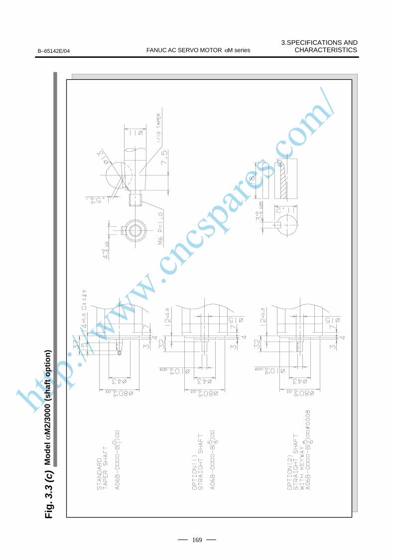
http://www.cncspares.com/
FANUC AC SERVO MOTOR αM series3.SPECIFICATIONS AND
CHARACTERISTICSB–65142E/04
169
Fig
. 3.3
(c)
Mo
del
αM
2/30
00 (
shaf
t o
pti
on
)
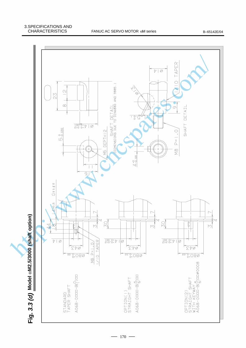
http://www.cncspares.com/
FANUC AC SERVO MOTOR αM series B–65142E/04
3.SPECIFICATIONS ANDCHARACTERISTICS
170
Fig
. 3.3
(d)
Mo
del
αM
2.5/
3000
(sh
aft
op
tio
n)

http://www.cncspares.com/
FANUC AC SERVO MOTOR αM series3.SPECIFICATIONS AND
CHARACTERISTICSB–65142E/04
171
Fig
. 3.3
(e)
Mo
del
s αM
6/30
00 a
nd
αM
9/30
00 (
stan
dar
d)
Ser
ial A
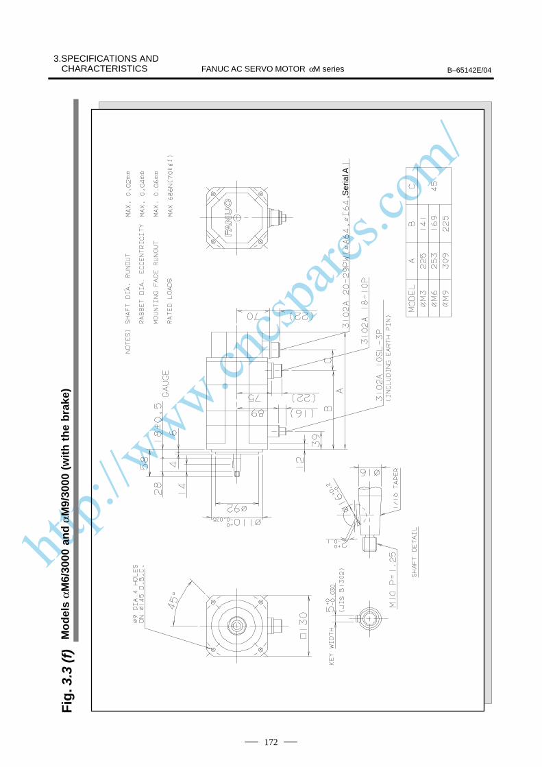
http://www.cncspares.com/
FANUC AC SERVO MOTOR αM series B–65142E/04
3.SPECIFICATIONS ANDCHARACTERISTICS
172
Fig
. 3.3
(f)
Mo
del
s αM
6/30
00 a
nd
αM
9/30
00 (
wit
h t
he
bra
ke)
Ser
ial A
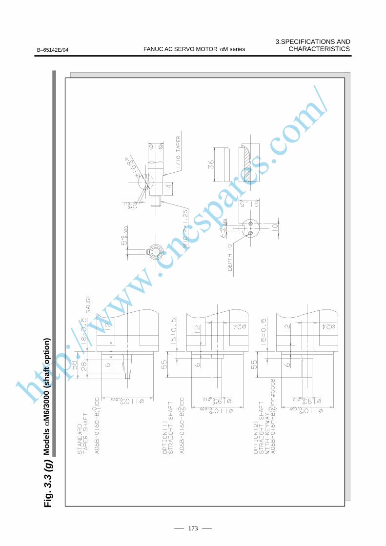
http://www.cncspares.com/
FANUC AC SERVO MOTOR αM series3.SPECIFICATIONS AND
CHARACTERISTICSB–65142E/04
173
Fig
. 3.3
(g)
Mo
del
s αM
6/30
00 (
shaf
t o
pti
on
)
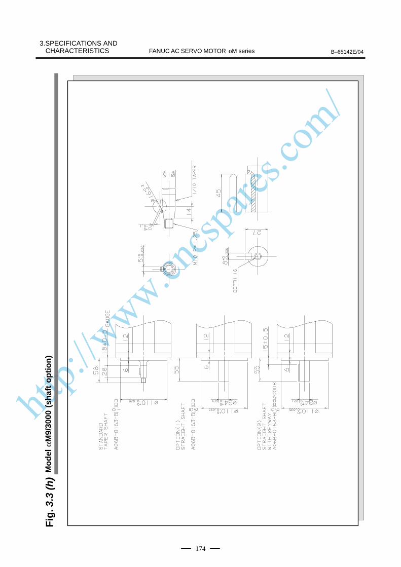
http://www.cncspares.com/
FANUC AC SERVO MOTOR αM series B–65142E/04
3.SPECIFICATIONS ANDCHARACTERISTICS
174
Fig
. 3.3
(h)
Mo
del
αM
9/30
00 (
shaf
t o
pti
on
)
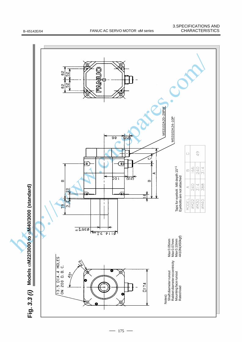
http://www.cncspares.com/
FANUC AC SERVO MOTOR αM series3.SPECIFICATIONS AND
CHARACTERISTICSB–65142E/04
175
Fig
. 3.3
(i)
Mo
del
s αM
22/3
000
to α
M40
/300
0 (s
tan
dar
d)
Not
es)
Sha
ft di
amet
er ru
nout
Max
0.0
5mm
Rab
bet d
iam
eter
ecc
entr
icity
Max
0.0
7mm
Mou
ntin
g fa
ce ru
nout
Max
0.1
0mm
Rat
ed lo
ad44
10N
(450
kgf)
Taps
for e
yebo
lt : M
8 de
pth
15+
1
Eye
bolts
are
not
atta
ched
MS
3102
A 2
0–29
PW
MS
3102
A 2
4–10
P
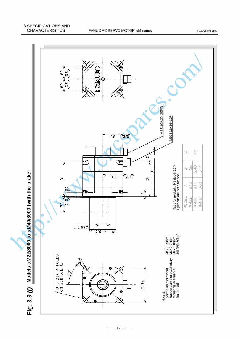
http://www.cncspares.com/
FANUC AC SERVO MOTOR αM series B–65142E/04
3.SPECIFICATIONS ANDCHARACTERISTICS
176
Fig
. 3.3
(j)
Mo
del
s αM
22/3
000
to α
M40
/300
0 (w
ith
th
e b
rake
)
Not
es)
Sha
ft di
amet
er ru
nout
Max
0.0
5mm
Rab
bet d
iam
eter
ecc
entr
icity
Max
0.0
7mm
Mou
ntin
g fa
ce ru
nout
Max
0.1
0mm
Rat
ed lo
ad44
10N
(450
kgf)
Taps
for e
yebo
lt : M
8 de
pth
15+
1
Eye
bolts
are
not
atta
ched
MS
3102
A 2
0–29
PW
MS
3102
A 2
4–10
P
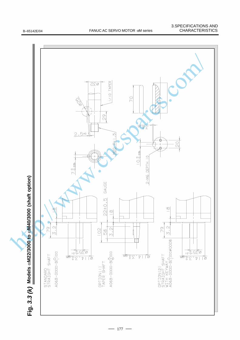
http://www.cncspares.com/
FANUC AC SERVO MOTOR αM series3.SPECIFICATIONS AND
CHARACTERISTICSB–65142E/04
177
Fig
. 3.3
(k)
Mo
del
s αM
22/3
000
to α
M40
/300
0 (s
haf
t o
pti
on
)
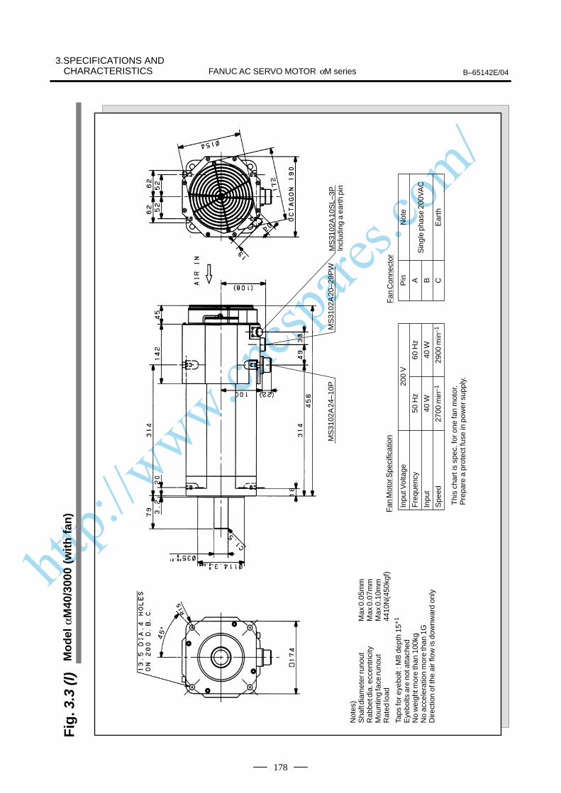
http://www.cncspares.com/
FANUC AC SERVO MOTOR αM series B–65142E/04
3.SPECIFICATIONS ANDCHARACTERISTICS
178
Fig
. 3.3
(l)
Mo
del
αM
40/3
000
(wit
h f
an)
Not
es)
Sha
ft di
amet
er ru
nout
Max
0.0
5mm
Rab
bet d
ia. e
ccen
tric
ityM
ax 0
.07m
mM
ount
ing
face
runo
utM
ax 0
.10m
mR
ated
load
4410
N(4
50kg
f)
Taps
for e
yebo
lt : M
8 de
pth
15+
1
Eye
bolts
are
not
atta
ched
No
wei
ght m
ore
than
100
kgN
o ac
cele
ratio
n m
ore
than
1G
Dire
ctio
n of
the
air f
low
is d
ownw
ard
only
MS
3102
A 2
0–29
PW
Thi
s ch
art i
s sp
ec. f
or o
ne fa
n m
otor
.P
repa
re a
pro
tect
fuse
in p
ower
sup
ply.
Inpu
t Vol
tage
Fre
quen
cy
Inpu
t
Spe
ed
200
V
50 H
z60
Hz
40 W
40 W
2700
min
–129
00m
in–1
Fan
Mot
or S
peci
ficat
ion
Fan
Con
nect
or
Pin A CB
Not
e
Sin
gle
phas
e 20
0VA
C
Ear
th
MS
3102
A 1
0SL–
3PIn
clud
ing
a ea
rth
pin
MS
3102
A 2
4–10
P
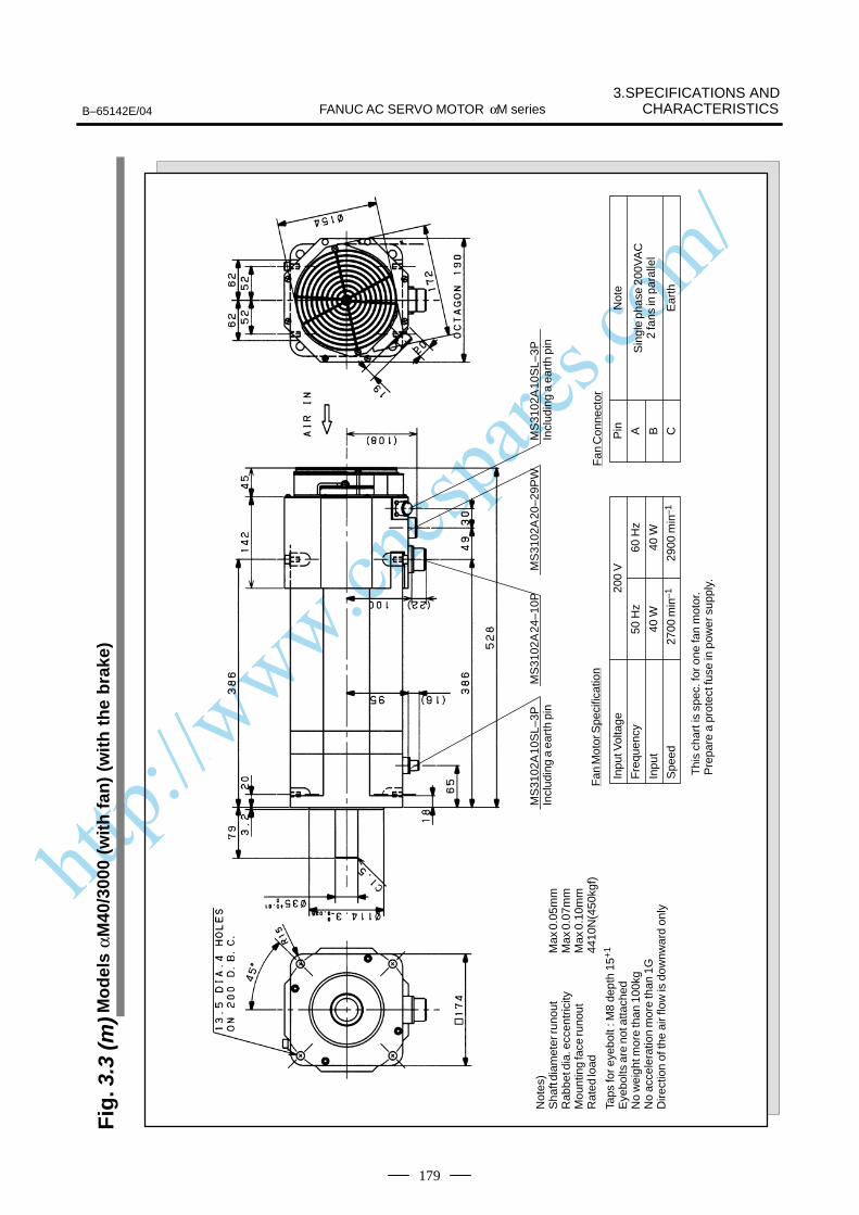
http://www.cncspares.com/
FANUC AC SERVO MOTOR αM series3.SPECIFICATIONS AND
CHARACTERISTICSB–65142E/04
179
Fig
. 3.3
(m)M
od
els
αM40
/300
0 (w
ith
fan
) (w
ith
th
e b
rake
)
Not
es)
Sha
ft di
amet
er ru
nout
Max
0.0
5mm
Rab
bet d
ia. e
ccen
tric
ityM
ax 0
.07m
mM
ount
ing
face
runo
utM
ax 0
.10m
mR
ated
load
4410
N(4
50kg
f)
Taps
for e
yebo
lt : M
8 de
pth
15+
1
Eye
bolts
are
not
atta
ched
No
wei
ght m
ore
than
100
kgN
o ac
cele
ratio
n m
ore
than
1G
Dire
ctio
n of
the
air f
low
is d
ownw
ard
only
MS
3102
A 1
0SL–
3PIn
clud
ing
a ea
rth
pin
MS
3102
A 2
0–29
PW
Thi
s ch
art i
s sp
ec. f
or o
ne fa
n m
otor
.P
repa
re a
pro
tect
fuse
in p
ower
sup
ply.
Inpu
t Vol
tage
Fre
quen
cy
Inpu
t
Spe
ed
200
V
50 H
z60
Hz
40 W
40 W
2700
min
–129
00m
in–1
Fan
Mot
or S
peci
ficat
ion
Fan
Con
nect
or
Pin A CB
Not
e
Sin
gle
phas
e 20
0VA
C2
fans
in p
aral
lel
Ear
th
MS
3102
A 1
0SL–
3PIn
clud
ing
a ea
rth
pin
MS
3102
A 2
4–10
P
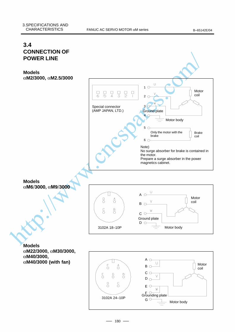
http://www.cncspares.com/
3.SPECIFICATIONS AND CHARACTERISTICS B–65142E/04FANUC AC SERVO MOTOR αM series
180
1
2
3
4
5
6
Brakecoil
Only the motor with thebrake
Ground plate
Motor body
Motor coil
Note)No surge absorber for brake is contained inthe motor.Prepare a surge absorber in the power magnetics cabinet.
Special connector(AMP JAPAN, LTD.)
3102A 18–10P
A
B
C
D
Motor coil
Ground plate
Motor body
A
B
C
D
3102A 24–10P
E
F
GGrounding plate
Motor body
Motor coil
3.4CONNECTION OFPOWER LINE
Models αM2/3000, αM2.5/3000
Models α α
Models αM22/3000, αM30/3000,αM40/3000, αM40/3000 (with fan)
http://www.cncspares.com/
IV. FANUC AC SERVO MOTOR αL series
http://www.cncspares.com/
B–65142E/04 1. GENERALFANUC AC SERVO MOTOR αL series
183
1 GENERAL
The FANUC AC servo motor αL series is suitable for high–speedpositioning. It has the following features:
The latest neodymium ferrite magnet is employed, and the rotor inertiais minimized. The result is a motor that offers excellent acceleration.
The use of waterproof connectors and FANUC’s unique stator sealprovide excellent waterproofing, ensuring that no liquid, such as coolant,can enter the motor.
The use of the latest servo software minimizes the heat generated byhigh–speed rotation, allowing continuous operation over a wide range.
Further improvements have been made to the unique magnetic pole shapeto minimize torque ripple. The result is extremely smooth rotation.
The use of the latest servo software maintains controllability even whena disturbance occurs.
High–resolution pulse coder αA1000, αA64, αI64 is used in the standardconfiguration, enabling precise positioning.
A powerful brake with an increased holding torque is available as anoption. The brake uses an asbestos–free design.
The L series models αL6, and αL9, all of which are compatible withseries models α3 and α6 in their installation size, and models αL25 andαL50, which are compatible with series models α12 and α22 in theirinstallation size. All these αL series models are compatible with theconventional FANUC AC servo motor αL series in their installation size.
Excellent accelerationcharacteristics
Excellent waterproofing
Extendedcontinuous–operation
Smooth rotation
Controllability
High–performancedetector
Powerful brake
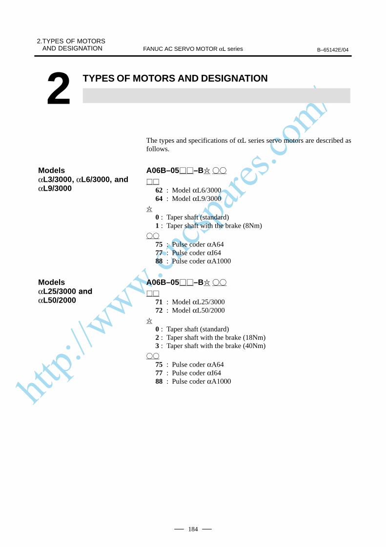
http://www.cncspares.com/
2.TYPES OF MOTORSAND DESIGNATION B–65142E/04FANUC AC SERVO MOTOR αL series
184
2 TYPES OF MOTORS AND DESIGNATION
The types and specifications of αL series servo motors are described asfollows.
A06B–05–B
62 : Model αL6/300064 : Model αL9/3000
0 : Taper shaft (standard)1 : Taper shaft with the brake (8Nm)
75 : Pulse coder αA6477 : Pulse coder αI6488 : Pulse coder αA1000
A06B–05–B
71 : Model αL25/300072 : Model αL50/2000
0 : Taper shaft (standard)2 : Taper shaft with the brake (18Nm)3 : Taper shaft with the brake (40Nm)
75 : Pulse coder αA6477 : Pulse coder αI6488 : Pulse coder αA1000
ModelsαL3/3000 αL6/3000, andαL9/3000
ModelsαL25/3000
αL50/2000

http://www.cncspares.com/
B–65142E/04
3. SPECIFICATIONS ANDCHARACTERISTICSFANUC AC SERVO MOTOR αL series
185
3 SPECIFICATIONS AND CHARACTERISTICS
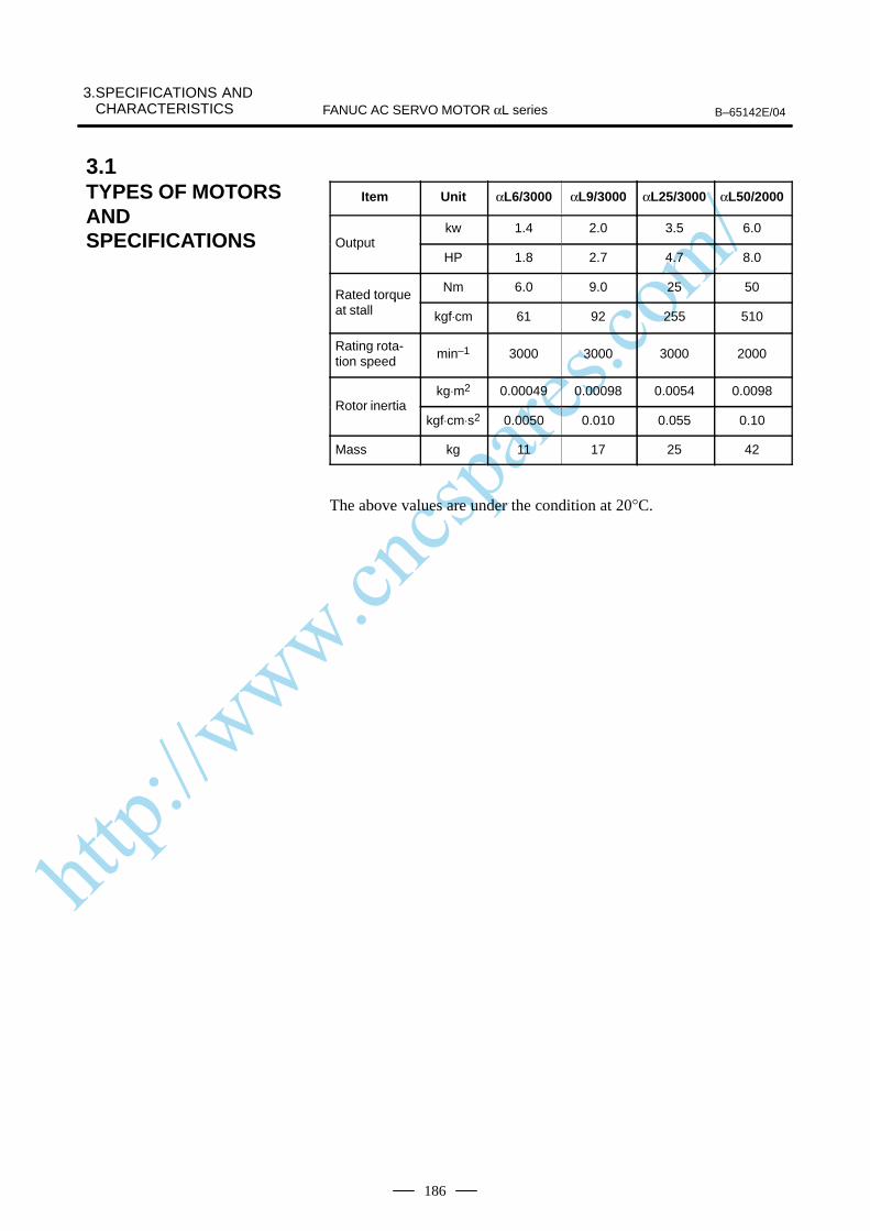
http://www.cncspares.com/
3.SPECIFICATIONS AND CHARACTERISTICS B–65142E/04FANUC AC SERVO MOTOR αL series
186
Item Unit αL6/3000 αL9/3000 αL25/3000 αL50/2000
kw 1.4 2.0 3.5 6.0Output
HP 1.8 2.7 4.7 8.0
Rated torqueNm 6.0 9.0 25 50
Rated torqueat stall kgf⋅cm 61 92 255 510
Rating rota-tion speed
min–1 3000 3000 3000 2000
kg⋅m2 0.00049 0.00098 0.0054 0.0098Rotor inertia
kgf⋅cm⋅s2 0.0050 0.010 0.055 0.10
Mass kg 11 17 25 42
The above values are under the condition at 20°C.
3.1TYPES OF MOTORSANDSPECIFICATIONS
http://www.cncspares.com/
B–65142E/04
3. SPECIFICATIONS ANDCHARACTERISTICSFANUC AC SERVO MOTOR αL series
187
The intermittent operation zone is determined by the input voltageapplied to the drive amplifier. The curve shown is the value for the ratedinput voltage (200V).On models αL6 to αL9, the maximum speed of rotation is increased byusing HRV control. The speed-torque characteristics for when HRVcontrol is used are described at the end of this item
The overload duty characteristic curves are determined based on thetemperature restriction for the single motor unit (the temperature isrestricted by means of a thermal trip built into the motor). The curves aredetermined by assuming that the temperature increases gradually undercertain overload conditions. Therefore, the curves do not apply to therapid temperature rise which occurs, for example, when the motor shaftis locked. (An overcurrent flows in the motor windings until the thermaltrip operates. The temperature rises momentarily.)To detect such an abrupt temperature rise, the FANUC digital servosystem provides a software thermal function that uses servo software toobserve the current. During operation that is characterized by frequentacceleration/deceleration cycles, control is imposed by the softwarethermal function.Driving units (such as amplifiers) and built–in detectors contain their ownoverheating protection devices. Therefore, note that control may beimposed according to how the equipment is being used.
The parameters given in the data sheet are representative values for anambient temperature of 20°C. They are subject to an error of 10%.The indicated logical values are threshold values for the single motor unit(when the motor is not restricted by the control system).The maximum torque that can be produced during acceleration ordeceleration in actual use is calculated as the approximate product of themotor torque constant and the current limit value of the amplifier.This value is for reference only. The actual value will vary depending onchanges in the power supply, as well as variations in motor parameters andamplifier limit values.In some models, if the maximum current flows in the motor, the actualmaximum torque is affected by, for example, magnetic saturation. As aresult, the actual maximum torque will be lower than the calculated value.The intermittent operation area (maximum torque value) indicated in thespeed to torque characteristics is the effective value, determinedaccording to the combination with the amplifier.
3.2CHARACTERISTICCURVE AND DATASHEETSpeed–torquecharacteristics
Overload dutycharacteristic
Data sheet

http://www.cncspares.com/
3.SPECIFICATIONS AND CHARACTERISTICS B–65142E/04FANUC AC SERVO MOTOR αL series
188
Specification : A06B–0562–B
Speed – torque characteristics
Speed (min–1) ”ON” time (min.)
Over load dutyTorque (Nm)
Duty (time %)
ÂÂÂÂÂÂÂIntermittent operating
ÂÂÂÂÂÂÂContinuous operating
Data sheetParameter Symbol Value Unit
Rating rotation speed Nmax 3000 min -1
Rated torque at stall (*) Ts6.0
61
Nm
kgfcm
Rotor inertia Jm0.00049
0.0050
kgm2
kgfcms2
Continuous RMS current at stall (*) Is 11.4 A (rms)
Torque constant (*) Kt0.52
5.3
Nm/A (rms)
kgfcm/A (rms)
Back EMF constant (1–phase)(*)
(*)
Ke
Kv
18
0.17
V (rms)/1000min -1
V (rms)·sec/rad
Armature resistance (1–phase)(*) Ra 0.275 Ω
Mechanical time constant (*) tm 0.001 s
Thermal time constant tt 25 min
Static friction Tf0.5
5
Nm
kgfcm
Mass 11 kg
(*)The values are the standard values at 20°C and the tolerance is 10%.
The speed–torque characteristics very depending on the type of software, parameter
setting, and input voltage of the digital servo motor. (The above figures show average
values.) These values may be changed without prior notice.
On model αL6, the maximum speed of rotation is increased by using HRV control.
The speed-torque characteristics for when HRV control is used are described at the
end of this item
Model αL6/3000
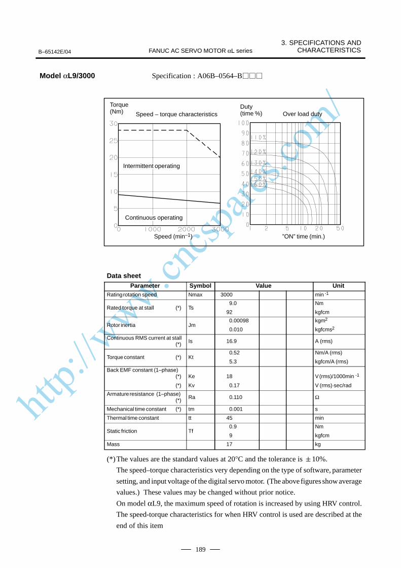
http://www.cncspares.com/
B–65142E/04
3. SPECIFICATIONS ANDCHARACTERISTICSFANUC AC SERVO MOTOR αL series
189
Specification : A06B–0564–B
Speed – torque characteristics
Speed (min–1) ”ON” time (min.)
Over load duty
Torque (Nm)
Duty (time %)
ÂÂÂÂÂÂÂÂÂÂÂÂÂÂ
Intermittent operating
ÂÂÂÂÂÂÂÂÂÂÂÂÂÂ
Continuous operating
Data sheetParameter Symbol Value Unit
Rating rotation speed Nmax 3000 min -1
Rated torque at stall (*) Ts 9.0
92
Nm
kgfcm
Rotor inertia Jm 0.00098
0.010
kgm2
kgfcms2
Continuous RMS current at stall (*) Is 16.9 A (rms)
Torque constant (*) Kt0.52
5.3
Nm/A (rms)
kgfcm/A (rms)
Back EMF constant (1–phase)(*)
(*)
Ke
Kv
18
0.17
V (rms)/1000min -1
V (rms)·sec/rad
Armature resistance (1–phase)(*) Ra 0.110 Ω
Mechanical time constant (*) tm 0.001 s
Thermal time constant tt 45 min
Static friction Tf 0.9
9
Nm
kgfcm
Mass 17 kg
(*)The values are the standard values at 20°C and the tolerance is 10%.
The speed–torque characteristics very depending on the type of software, parameter
setting, and input voltage of the digital servo motor. (The above figures show average
values.) These values may be changed without prior notice.
On model αL9, the maximum speed of rotation is increased by using HRV control.
The speed-torque characteristics for when HRV control is used are described at the
end of this item
Model αL9/3000
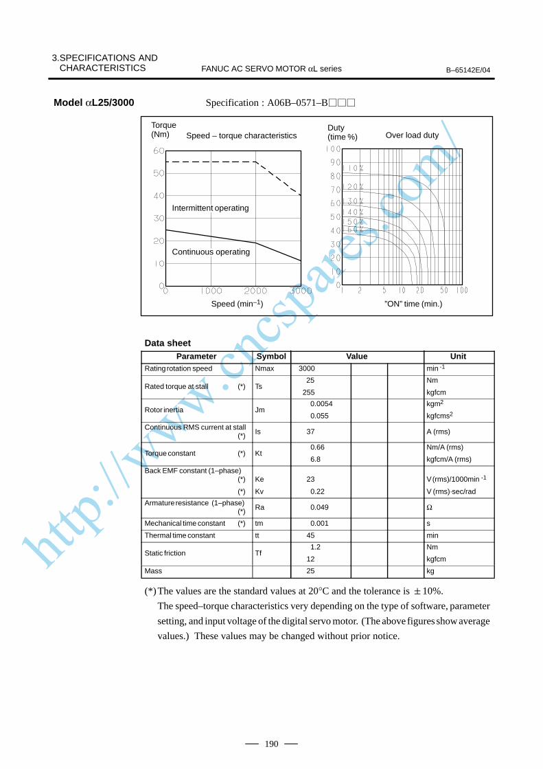
http://www.cncspares.com/
3.SPECIFICATIONS AND CHARACTERISTICS B–65142E/04FANUC AC SERVO MOTOR αL series
190
Specification : A06B–0571–B
Speed – torque characteristics
Speed (min–1) ”ON” time (min.)
Over load dutyTorque (Nm)
Duty (time %)
ÂÂÂÂÂÂÂÂÂÂÂÂIntermittent operating
ÂÂÂÂÂÂÂÂÂÂÂÂÂÂContinuous operating
Data sheetParameter Symbol Value Unit
Rating rotation speed Nmax 3000 min -1
Rated torque at stall (*) Ts 25
255
Nm
kgfcm
Rotor inertia Jm 0.0054
0.055
kgm2
kgfcms2
Continuous RMS current at stall (*) Is 37 A (rms)
Torque constant (*) Kt0.66
6.8
Nm/A (rms)
kgfcm/A (rms)
Back EMF constant (1–phase)(*)
(*)
Ke
Kv
23
0.22
V (rms)/1000min -1
V (rms)·sec/rad
Armature resistance (1–phase)(*) Ra 0.049 Ω
Mechanical time constant (*) tm 0.001 s
Thermal time constant tt 45 min
Static friction Tf1.2
12
Nm
kgfcm
Mass 25 kg
(*)The values are the standard values at 20°C and the tolerance is 10%.
The speed–torque characteristics very depending on the type of software, parameter
setting, and input voltage of the digital servo motor. (The above figures show average
values.) These values may be changed without prior notice.
Model αL25/3000

http://www.cncspares.com/
B–65142E/04
3. SPECIFICATIONS ANDCHARACTERISTICSFANUC AC SERVO MOTOR αL series
191
Specification : A06B–0572–B
Speed – torque characteristics
Speed (min–1) ”ON” time (min.)
Torque (Nm) Over load duty
Duty (time %)
ÂÂÂÂÂÂÂÂÂÂÂÂÂÂ
Intermittent operating
ÂÂÂÂÂÂÂContinuous operating
Data sheetParameter Symbol Value Unit
Rating rotation speed Nmax 2000 min -1
Rated torque at stall (*) Ts50
510
Nm
kgfcm
Rotor inertia Jm 0.0098
0.10
kgm2
kgfcms2
Continuous RMS current at stall (*) Is 51 A (rms)
Torque constant (*) Kt 0.96
9.8
Nm/A (rms)
kgfcm/A (rms)
Back EMF constant (1–phase)(*)
(*)
Ke
Kv
33
0.32
V (rms)/1000min -1
V (rms)·sec/rad
Armature resistance (1–phase)(*) Ra 0.038 Ω
Mechanical time constant (*) tm 0.001 s
Thermal time constant tt 70 min
Static friction Tf 1.8
18
Nm
kgfcm
Mass 42 kg
(*)The values are the standard values at 20°C and the tolerance is 10%.
The speed–torque characteristics very depending on the type of software, parameter
setting, and input voltage of the digital servo motor. (The above figures show average
values.) These values may be changed without prior notice.
Model αL50/2000
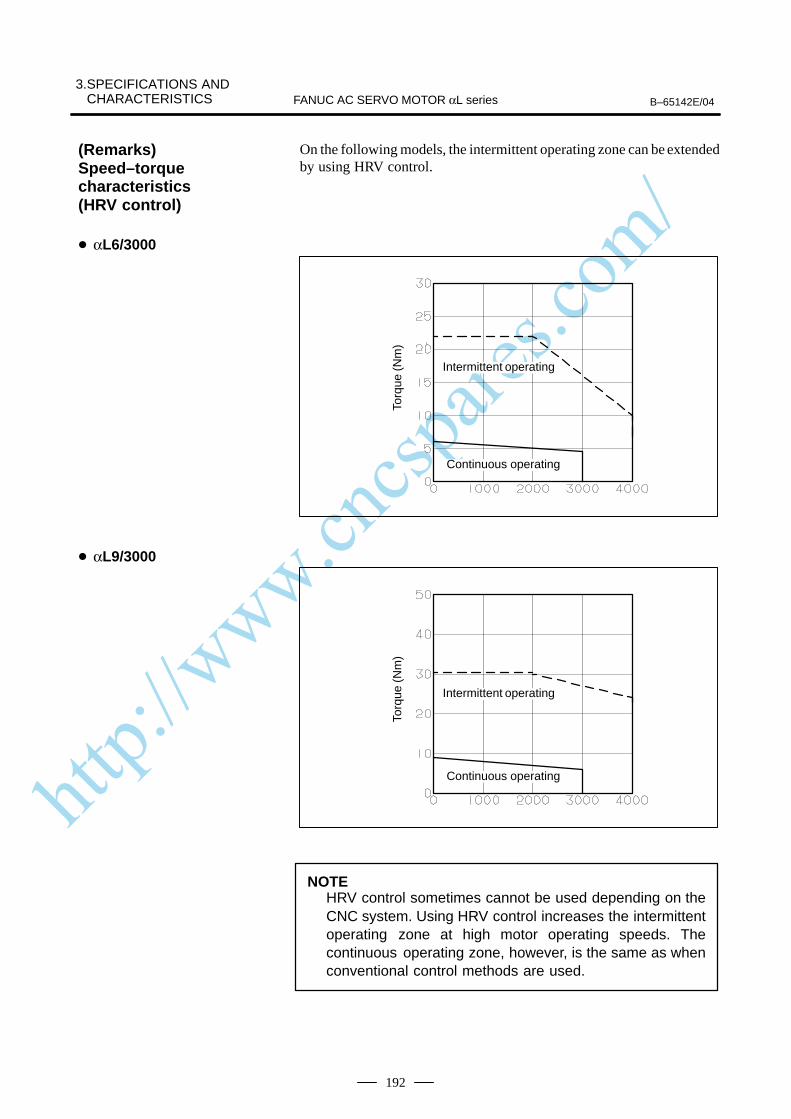
http://www.cncspares.com/
3.SPECIFICATIONS AND CHARACTERISTICS B–65142E/04FANUC AC SERVO MOTOR αL series
192
On the following models, the intermittent operating zone can be extendedby using HRV control.
Torq
ue (N
m)
ÂÂÂÂÂÂÂÂÂÂÂÂÂÂ
Intermittent operating
ÂÂÂÂÂÂÂÂÂÂÂÂÂÂ
Continuous operating
Torq
ue (N
m)
ÂÂÂÂÂÂÂÂÂÂÂÂÂÂ
Intermittent operating
ÂÂÂÂÂÂÂÂÂÂÂÂÂÂ
Continuous operating
NOTEHRV control sometimes cannot be used depending on theCNC system. Using HRV control increases the intermittentoperating zone at high motor operating speeds. Thecontinuous operating zone, however, is the same as whenconventional control methods are used.
(Remarks)Speed–torquecharacteristics (HRV control)
αL6/3000
αL9/3000
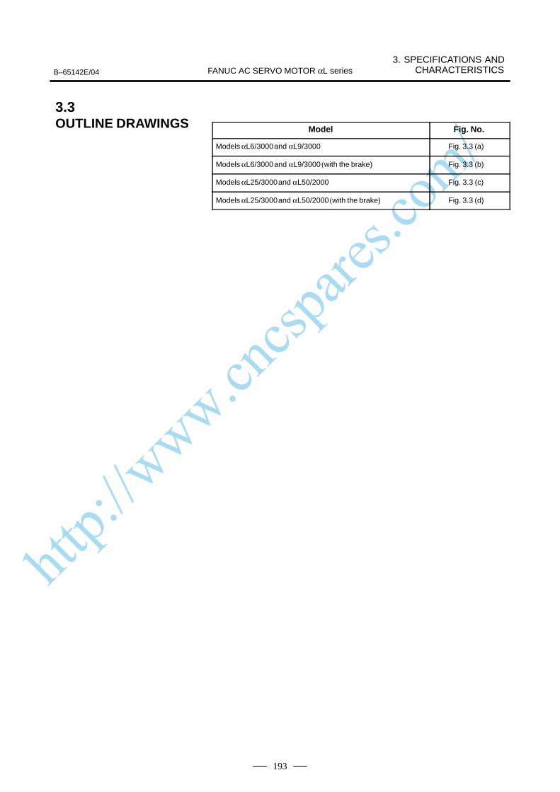
http://www.cncspares.com/
B–65142E/04
3. SPECIFICATIONS ANDCHARACTERISTICSFANUC AC SERVO MOTOR αL series
193
Model Fig. No.
Models αL6/3000 and αL9/3000 Fig. 3.3 (a)
Models αL6/3000 and αL9/3000 (with the brake) Fig. 3.3 (b)
Models αL25/3000 and αL50/2000 Fig. 3.3 (c)
Models αL25/3000 and αL50/2000 (with the brake) Fig. 3.3 (d)
3.3OUTLINE DRAWINGS
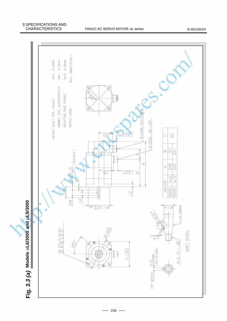
http://www.cncspares.com/
FANUC AC SERVO MOTOR αL series B–65142E/04
3.SPECIFICATIONS ANDCHARACTERISTICS
194
Fig
. 3.3
(a)
Mo
del
s αL
6/30
00 a
nd
αL
9/30
00
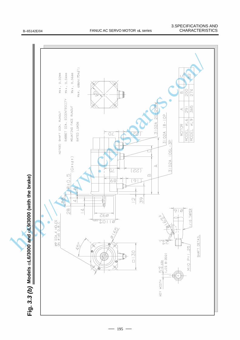
http://www.cncspares.com/
3.SPECIFICATIONS ANDCHARACTERISTICSB–65142E/04 FANUC AC SERVO MOTOR αL series
195
Fig
. 3.3
(b)
Mo
del
s αL
6/30
00 a
nd
αL
9/30
00 (
wit
h t
he
bra
ke)
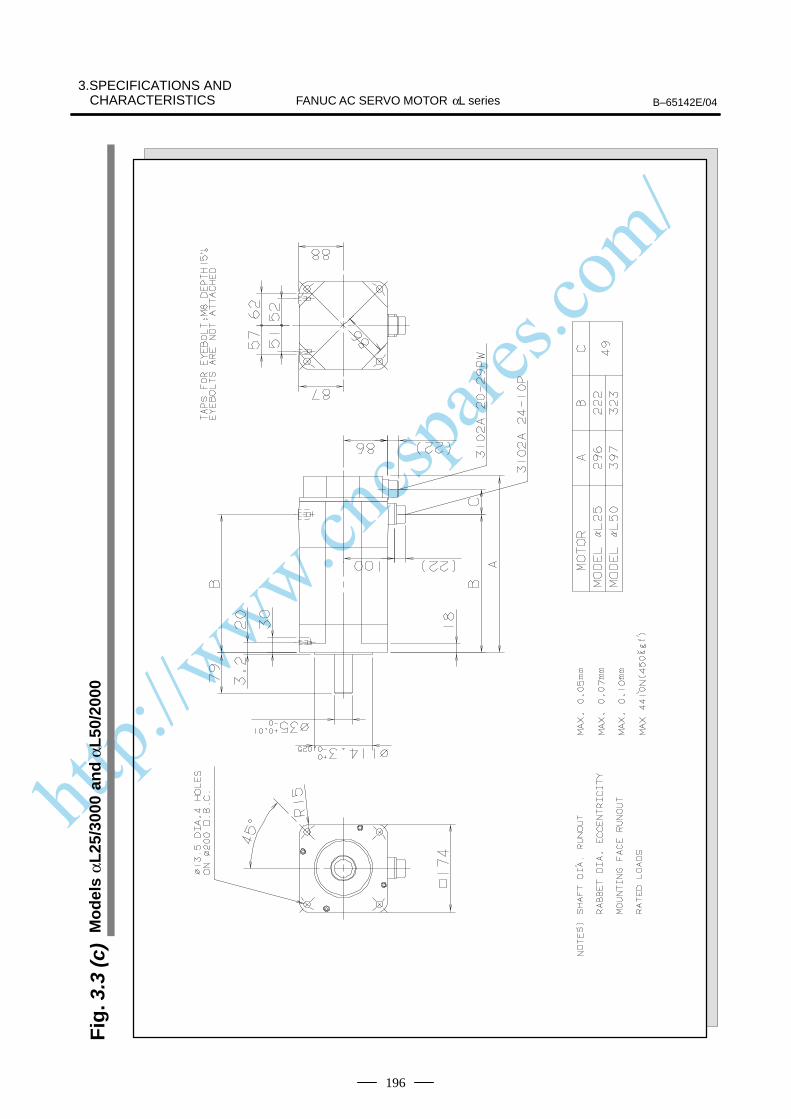
http://www.cncspares.com/
FANUC AC SERVO MOTOR αL series B–65142E/04
3.SPECIFICATIONS ANDCHARACTERISTICS
196
Fig
. 3.3
(c)
Mo
del
s αL
25/3
000
and
αL
50/2
000
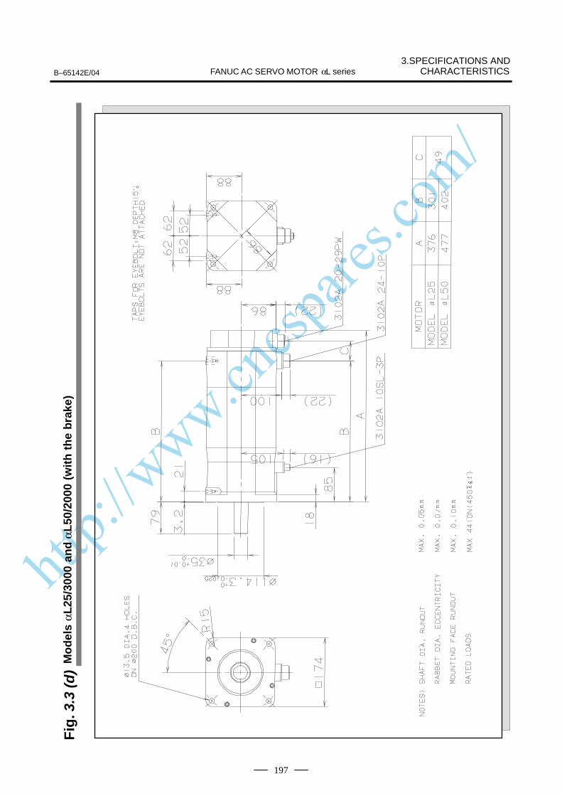
http://www.cncspares.com/
3.SPECIFICATIONS ANDCHARACTERISTICSB–65142E/04 FANUC AC SERVO MOTOR αL series
197
Fig
. 3.3
(d)
Mo
del
s αL
25/3
000
and
αL
50/2
000
(wit
h t
he
bra
ke)
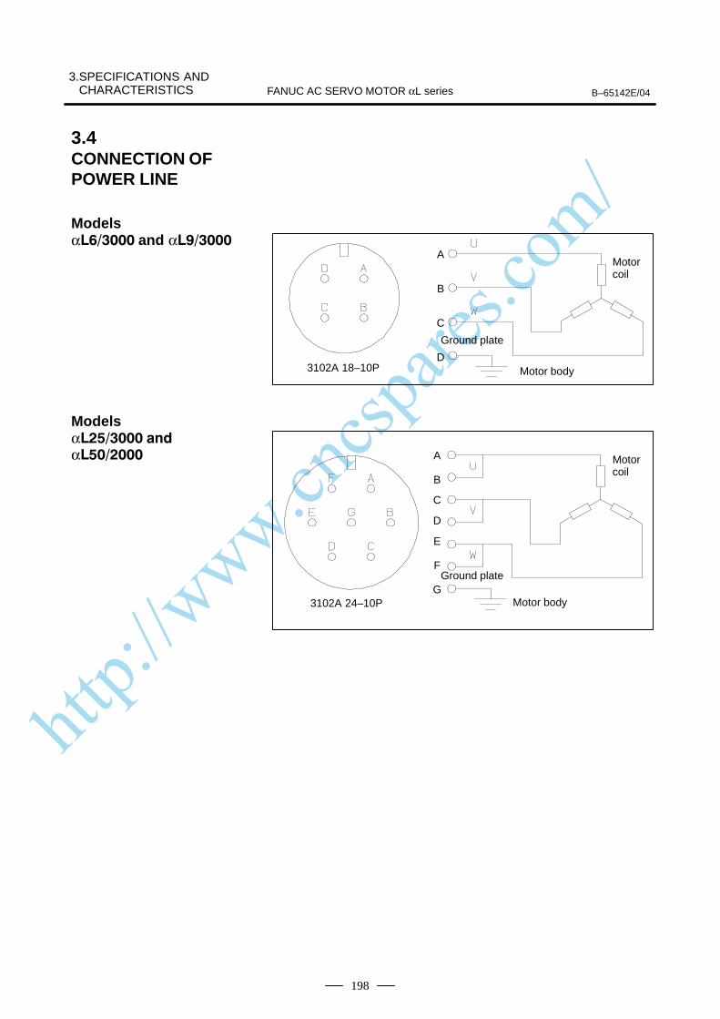
http://www.cncspares.com/
3.SPECIFICATIONS AND CHARACTERISTICS B–65142E/04FANUC AC SERVO MOTOR αL series
198
3102A 18–10P
A
B
C
D
Motor coil
Ground plate
Motor body
Motor coil
3102A 24–10P
Ground plate
Motor body
A
B
C
D
E
F
G
3.4CONNECTION OFPOWER LINE
Models α and α
Models α
α

http://www.cncspares.com/
V. FANUC AC SERVO MOTOR αC series
http://www.cncspares.com/
B–65142E/04 1. GENERALFANUC AC SERVO MOTOR αC series
201
1 GENERAL
The FANUC AC servo motor αC series is suitable for application to thefeed axes of machine tools. These motors have the following features:
High cost–effectiveness has been achieved. Although a low–poweramplifier is used, high acceleration is offered.
The use of the latest ferrite magnet, combined with an optimizedmechanical design, reduces both the overall length and weight. The resultis compact, lightweight servo motors.
The use of waterproof connectors and FANUC’s unique stator sealprovide excellent waterproofing, ensuring that no liquid, such as coolant,can enter the motor.
Further improvements have been made to the unique magnetic pole shapeto minimize torque ripple. The result is extremely smooth rotation.
The use of the latest servo software maintains controllability even whena disturbance occurs.
High–resolution pulse coder αA1000, αA64, αI64 is used in the standardconfiguration, enabling precise positioning.
A powerful brake with an increased holding torque is available as anoption. The brake uses an asbestos–free design.
The αC series includes models αC3 and αC6, both of which arecompatible with α series models α3 and α6 in their installation size, andmodels αC12 and αC22, which are compatible with series models α12and α22 in their installation size.
High cost–effectiveness
Compact
Excellent waterproofing
Smooth rotation
Controllability
High–performancedetector
Powerful brake
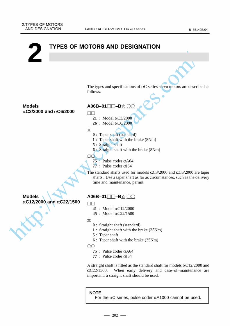
http://www.cncspares.com/
2.TYPES OF MOTORSAND DESIGNATION B–65142E/04FANUC AC SERVO MOTOR αC series
202
2
The types and specifications of αC series servo motors are described asfollows.
A06B–01–B
21 : Model αC3/200026 : Model αC6/2000
0 : Taper shaft (standard)1 : Taper shaft with the brake (8Nm)5 : Straight shaft6 : Straight shaft with the brake (8Nm)
75 : Pulse coder αA6477 : Pulse coder αI64
The standard shafts used for models αC3/2000 and αC6/2000 are tapershafts. Use a taper shaft as far as circumstances, such as the deliverytime and maintenance, permit.
A06B–01–B
41 : Model αC12/200045 : Model αC22/1500
0 : Straight shaft (standard)1 : Straight shaft with the brake (35Nm)5 : Taper shaft6 : Taper shaft with the brake (35Nm)
75 : Pulse coder αA6477 : Pulse coder αI64
A straight shaft is fitted as the standard shaft for models αC12/2000 andαC22/1500. When early delivery and case–of–maintenance areimportant, a straight shaft should be used.
NOTEFor the αC series, pulse coder αA1000 cannot be used.
ModelsαC3/2000 αC6/2000
ModelsαC12/2000 and αC22/1500

http://www.cncspares.com/
B–65142E/04
3. SPECIFICATIONS ANDCHARACTERISTICSFANUC AC SERVO MOTOR αC series
203
3 SPECIFICATIONS AND CHARACTERISTICS
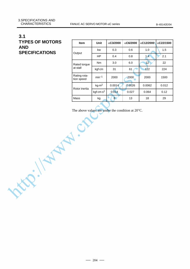
http://www.cncspares.com/
3.SPECIFICATIONS AND CHARACTERISTICS B–65142E/04FANUC AC SERVO MOTOR αC series
204
Item Unit αC3/2000 αC6/2000 αC12/2000 αC22/1500
kw 0.3 0.6 1.0 1.5Output
HP 0.4 0.8 1.4 2.1
Rated torqueNm 3.0 6.0 12 22
Rated torqueat stall kgf⋅cm 31 61 122 224
Rating rota-tion speed
min–1 2000 2000 2000 1500
kg⋅m2 0.0014 0.0026 0.0062 0.012Rotor inertia
kgf⋅cm⋅s2 0.014 0.027 0.064 0.12
Mass kg 8 13 18 29
The above values are under the condition at 20°C.
3.1TYPES OF MOTORSANDSPECIFICATIONS
http://www.cncspares.com/
B–65142E/04
3. SPECIFICATIONS ANDCHARACTERISTICSFANUC AC SERVO MOTOR αC series
205
The intermittent operation zone is determined by the input voltageapplied to the drive amplifier. The curve shown is the value for the ratedinput voltage (200V).
The overload duty characteristic curves are determined based on thetemperature restriction for the single motor unit (the temperature isrestricted by means of a thermal trip built into the motor). The curves aredetermined by assuming that the temperature increases gradually undercertain overload conditions. Therefore, the curves do not apply to therapid temperature rise which occurs, for example, when the motor shaftis locked. (An overcurrent flows in the motor windings until the thermaltrip operates. The temperature rises momentarily.)To detect such an abrupt temperature rise, the FANUC digital servosystem provides a software thermal function that uses servo software toobserve the current. During operation that is characterized by frequentacceleration/deceleration cycles, control is imposed by the softwarethermal function.Driving units (such as amplifiers) and built–in detectors contain their ownoverheating protection devices. Therefore, note that control may beimposed according to how the equipment is being used.
The parameters given in the data sheet are representative values for anambient temperature of 20°C. They are subject to an error of +10%.The indicated logical values are threshold values for the single motor unit(when the motor is not restricted by the control system).The maximum torque that can be produced during acceleration ordeceleration in actual use is calculated as the approximate product of themotor torque constant and the current limit value of the amplifier.
Example : αC3/2000
Motor torque constant = 1.06 (Nm/Arms)
Amplifier limit value = 20 Apeak
Maximum torque value = 20 x 0.707 x 1.06 (Converted to an effective value) = 14.9 Nm
This value is for reference only. The actual value will vary depending onchanges in the power supply, as well as variations in motor parameters andamplifier limit values.In some models, if the maximum current flows in the motor, the actualmaximum torque is affected by, for example, magnetic saturation. As aresult, the actual maximum torque will be lower than the calculated value.The intermittent operation area (maximum torque value) indicated in thespeed to torque characteristics is the effective value, determinedaccording to the combination with the amplifier.
3.2CHARACTERISTICCURVE AND DATASHEET
Speed–torquecharacteristics
Overload dutycharacteristic
Data sheet
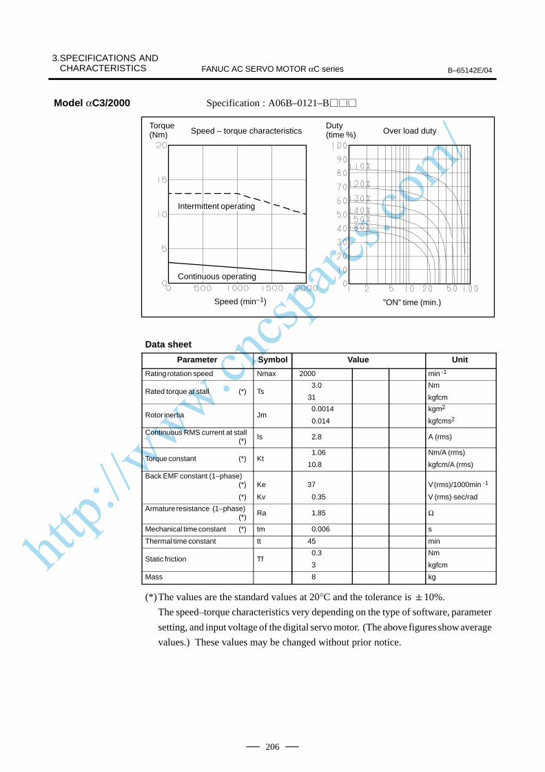
http://www.cncspares.com/
3.SPECIFICATIONS AND CHARACTERISTICS B–65142E/04FANUC AC SERVO MOTOR αC series
206
Specification : A06B–0121–B
Speed – torque characteristics
Speed (min–1) ”ON” time (min.)
Torque (Nm) Over load duty
Duty (time %)
ÂÂÂÂÂÂÂIntermittent operating
ÂÂÂÂÂÂÂContinuous operating
Data sheet
Parameter Symbol Value Unit
Rating rotation speed Nmax 2000 min -1
Rated torque at stall (*) Ts 3.0
31
Nm
kgfcm
Rotor inertia Jm 0.0014
0.014
kgm2
kgfcms2
Continuous RMS current at stall (*) Is 2.8 A (rms)
Torque constant (*) Kt1.06
10.8
Nm/A (rms)
kgfcm/A (rms)
Back EMF constant (1–phase)(*)
(*)
Ke
Kv
37
0.35
V (rms)/1000min -1
V (rms)·sec/rad
Armature resistance (1–phase)(*) Ra 1.85 Ω
Mechanical time constant (*) tm 0.006 s
Thermal time constant tt 45 min
Static friction Tf0.3
3
Nm
kgfcm
Mass 8 kg
(*)The values are the standard values at 20°C and the tolerance is 10%.
The speed–torque characteristics very depending on the type of software, parameter
setting, and input voltage of the digital servo motor. (The above figures show average
values.) These values may be changed without prior notice.
Model αC3/2000
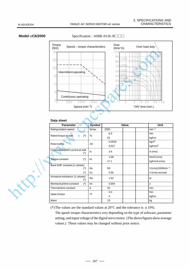
http://www.cncspares.com/
B–65142E/04
3. SPECIFICATIONS ANDCHARACTERISTICSFANUC AC SERVO MOTOR αC series
207
Specification : A06B–0126–B
Speed – torque characteristics
Speed (min–1) ”ON” time (min.)
Over load dutyTorque (Nm)
Duty (time %)
ÂÂÂÂÂÂÂIntermittent operating
ÂÂÂÂÂÂÂContinuous operating
Data sheetParameter Symbol Value Unit
Rating rotation speed Nmax 2000 min -1
Rated torque at stall (*) Ts6.0
61
Nm
kgfcm
Rotor inertia Jm 0.0026
0.027
kgm2
kgfcms2
Continuous RMS current at stall (*) Is 3.6 A (rms)
Torque constant (*) Kt1.68
17.1
Nm/A (rms)
kgfcm/A (rms)
Back EMF constant (1–phase)(*)
(*)
Ke
Kv
59
0.56
V (rms)/1000min -1
V (rms)·sec/rad
Armature resistance (1–phase)(*) Ra 1.52 Ω
Mechanical time constant (*) tm 0.004 s
Thermal time constant tt 50 min
Static friction Tf 0.3
3
Nm
kgfcm
Mass 13 kg
(*)The values are the standard values at 20°C and the tolerance is 10%.
The speed–torque characteristics very depending on the type of software, parameter
setting, and input voltage of the digital servo motor. (The above figures show average
values.) These values may be changed without prior notice.
Model αC6/2000
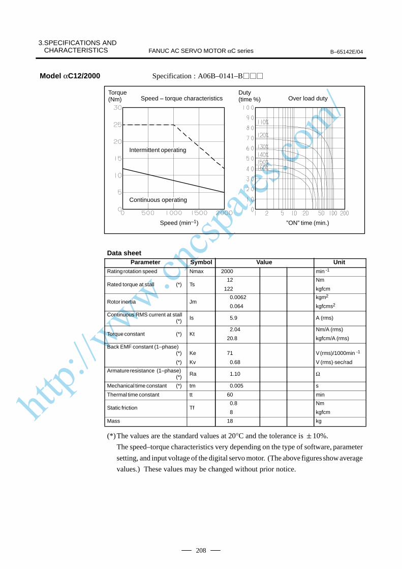
http://www.cncspares.com/
3.SPECIFICATIONS AND CHARACTERISTICS B–65142E/04FANUC AC SERVO MOTOR αC series
208
Specification : A06B–0141–B
Speed – torque characteristics
Speed (min–1) ”ON” time (min.)
Over load dutyTorque (Nm)
Duty (time %)
ÂÂÂÂÂÂÂIntermittent operating
ÂÂÂÂÂÂÂContinuous operating
Data sheetParameter Symbol Value Unit
Rating rotation speed Nmax 2000 min -1
Rated torque at stall (*) Ts12
122
Nm
kgfcm
Rotor inertia Jm0.0062
0.064
kgm2
kgfcms2
Continuous RMS current at stall (*) Is 5.9 A (rms)
Torque constant (*) Kt2.04
20.8
Nm/A (rms)
kgfcm/A (rms)
Back EMF constant (1–phase)(*)
(*)
Ke
Kv
71
0.68
V (rms)/1000min -1
V (rms)·sec/rad
Armature resistance (1–phase)(*) Ra 1.10 Ω
Mechanical time constant (*) tm 0.005 s
Thermal time constant tt 60 min
Static friction Tf0.8
8
Nm
kgfcm
Mass 18 kg
(*)The values are the standard values at 20°C and the tolerance is 10%.
The speed–torque characteristics very depending on the type of software, parameter
setting, and input voltage of the digital servo motor. (The above figures show average
values.) These values may be changed without prior notice.
Model αC12/2000

http://www.cncspares.com/
B–65142E/04
3. SPECIFICATIONS ANDCHARACTERISTICSFANUC AC SERVO MOTOR αC series
209
Specification : A06B–0145–B
ÂÂÂÂÂÂÂÂ
Continuous operating
Speed – torque characteristics
Speed (min–1) ”ON” time (min.)
Over load dutyTorque (Nm)
Duty (time %)
ÂÂÂÂÂÂÂIntermittent operating
Data sheetParameter Symbol Value Unit
Rating rotation speed Nmax 1500 min -1
Rated torque at stall (*) Ts 22
224
Nm
kgfcm
Rotor inertia Jm 0.012
0.12
kgm2
kgfcms2
Continuous RMS current at stall (*) Is 12.5 A (rms)
Torque constant (*) Kt 1.76
18.0
Nm/A (rms)
kgfcm/A (rms)
Back EMF constant (1–phase)(*)
(*)
Ke
Kv
62
0.59
V (rms)/1000min -1
V (rms)·sec/rad
Armature resistance (1–phase)(*) Ra 0.32 Ω
Mechanical time constant (*) tm 0.003 s
Thermal time constant tt 65 min
Static friction Tf 1.2
12
Nm
kgfcm
Mass 29 kg
(*)The values are the standard values at 20°C and the tolerance is 10%.
The speed–torque characteristics very depending on the type of software, parameter
setting, and input voltage of the digital servo motor. (The above figures show average
values.) These values may be changed without prior notice.
Model αC22/1500
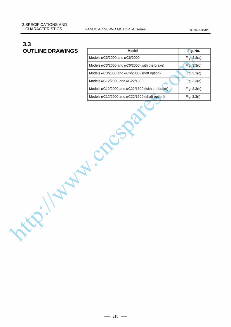
http://www.cncspares.com/
3.SPECIFICATIONS AND CHARACTERISTICS B–65142E/04FANUC AC SERVO MOTOR αC series
210
Model Fig. No.
Models αC3/2000 and αC6/2000 Fig. 3.3(a)
Models αC3/2000 and αC6/2000 (with the brake) Fig. 3.3(b)
Models αC3/2000 and αC6/2000 (shaft option) Fig. 3.3(c)
Models αC12/2000 and αC22/1500 Fig. 3.3(d)
Models αC12/2000 and αC22/1500 (with the brake) Fig. 3.3(e)
Models αC12/2000 and αC22/1500 (shaft option) Fig. 3.3(f)
3.3OUTLINE DRAWINGS

http://www.cncspares.com/
3.SPECIFICATIONS ANDCHARACTERISTICSB–65142E/04 FANUC AC SERVO MOTOR αC series
211
Fig
. 3.3
(a)
Mo
del
s αC
3/20
00 a
nd
αC
6/20
00
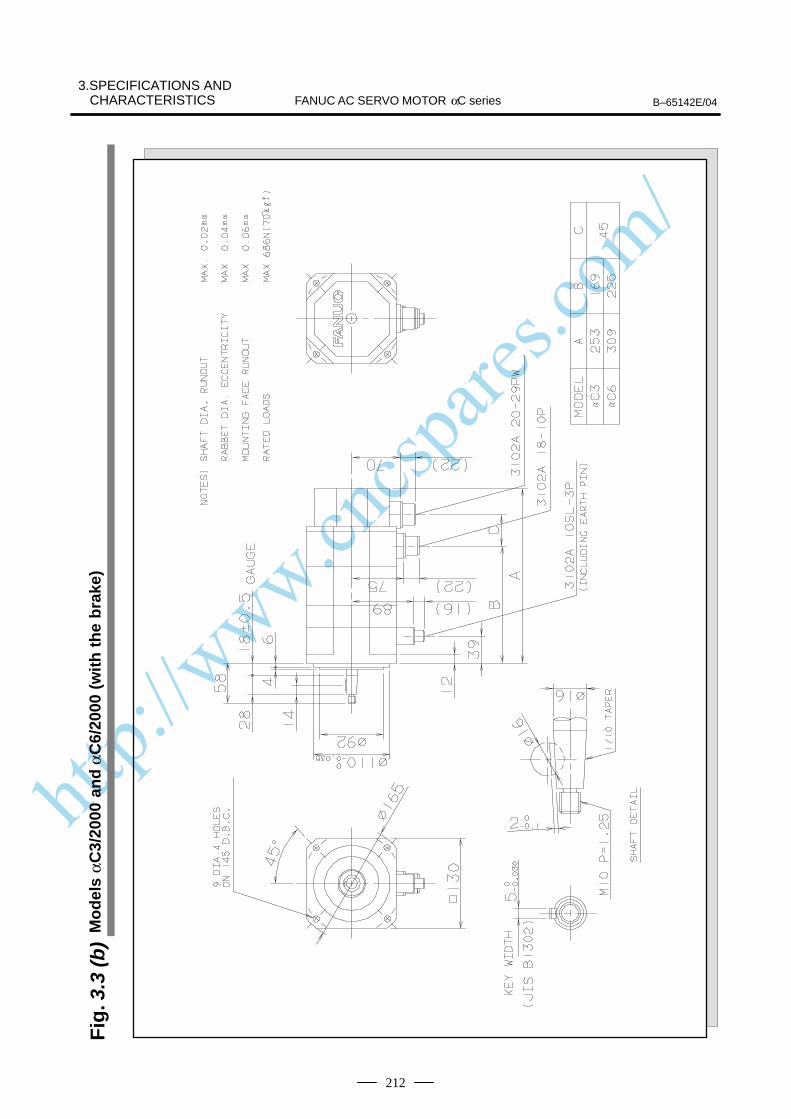
http://www.cncspares.com/
FANUC AC SERVO MOTOR αC series B–65142E/04
3.SPECIFICATIONS ANDCHARACTERISTICS
212
Fig
. 3.3
(b)
Mo
del
s αC
3/20
00 a
nd
αC
6/20
00 (
wit
h t
he
bra
ke)

http://www.cncspares.com/
3.SPECIFICATIONS ANDCHARACTERISTICSB–65142E/04 FANUC AC SERVO MOTOR αC series
213
Fig
. 3.3
(c)
Mo
del
s αC
3/20
00 a
nd
αC
6/20
00 (
shaf
t o
pti
on
)
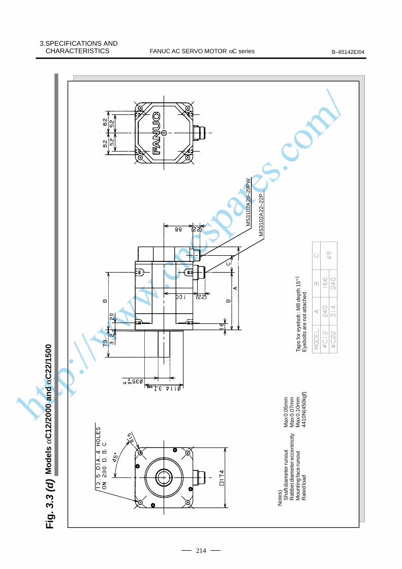
http://www.cncspares.com/
FANUC AC SERVO MOTOR αC series B–65142E/04
3.SPECIFICATIONS ANDCHARACTERISTICS
214
Fig
. 3.3
(d)
Mo
del
s αC
12/2
000
and
αC
22/1
500
Not
es)
Sha
ft di
amet
er ru
nout
Max
0.0
5mm
Rab
bet d
iam
eter
ecc
entr
icity
Max
0.0
7mm
Mou
ntin
g fa
ce ru
nout
Max
0.1
0mm
Rat
ed lo
ad44
10N
(450
kgf)
Taps
for e
yebo
lt : M
8 de
pth
15+
1
Eye
bolts
are
not
atta
ched
MS
3102
A 2
2–22
P
MS
3102
A 2
0–29
PW
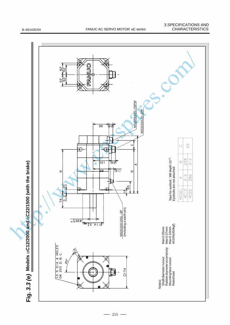
http://www.cncspares.com/
3.SPECIFICATIONS ANDCHARACTERISTICSB–65142E/04 FANUC AC SERVO MOTOR αC series
215
Fig
. 3.3
(e)
Mo
del
s αC
12/2
000
and
αC
22/1
500
(wit
h t
he
bra
ke)
Not
es)
Sha
ft di
amet
er ru
nout
Max
0.0
5mm
Rab
bet d
iam
eter
ecc
entr
icity
Max
0.0
7mm
Mou
ntin
g fa
ce ru
nout
Max
0.1
0mm
Rat
ed lo
ad44
10N
(450
kgf)
Taps
for e
yebo
lt : M
8 de
pth
15+
1
Eye
bolts
are
not
atta
ched
MS
3102
A 2
0–29
PW
MS
3102
A 2
2–22
P
MS
3102
A 1
0SL–
3P(I
nclu
ding
a e
arth
pin
)
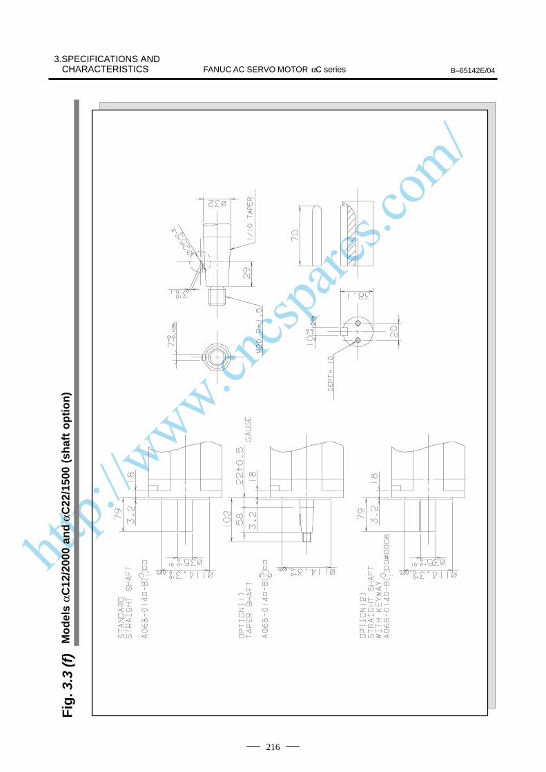
http://www.cncspares.com/
FANUC AC SERVO MOTOR αC series B–65142E/04
3.SPECIFICATIONS ANDCHARACTERISTICS
216
Fig
. 3.3
(f)
Mo
del
s αC
12/2
000
and
αC
22/1
500
(sh
aft
op
tio
n)
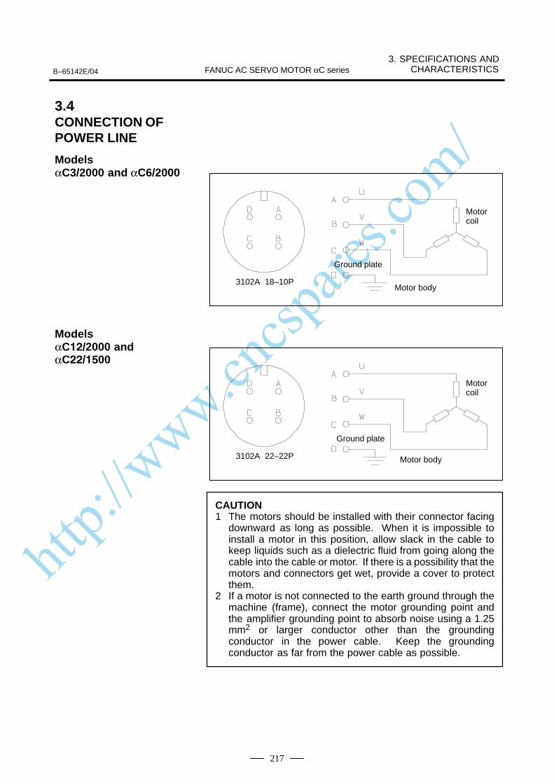
http://www.cncspares.com/
B–65142E/04
3. SPECIFICATIONS ANDCHARACTERISTICSFANUC AC SERVO MOTOR αC series
217
3102A 18–10P
Ground plate
Motor body
Motor coil
3102A 22–22P
Ground plate
Motor body
Motor coil
CAUTION1 The motors should be installed with their connector facing
downward as long as possible. When it is impossible toinstall a motor in this position, allow slack in the cable tokeep liquids such as a dielectric fluid from going along thecable into the cable or motor. If there is a possibility that themotors and connectors get wet, provide a cover to protectthem.
2 If a motor is not connected to the earth ground through themachine (frame), connect the motor grounding point andthe amplifier grounding point to absorb noise using a 1.25mm2 or larger conductor other than the groundingconductor in the power cable. Keep the groundingconductor as far from the power cable as possible.
3.4CONNECTION OFPOWER LINE
ModelsαC3/2000 and αC6/2000
Models αC/2000 andαC/00

http://www.cncspares.com/
VI. FANUC AC SERVO MOTOR
α (HV) series
http://www.cncspares.com/
B–65142E/04 1. GENERALFANUC AC SERVO MOTOR α (HV) series
221
1
The FANUC AC servo motor α(HV) series is suitable for application tothe feed axes of machine tools. These motors have the following features:
A 400V power source can be connected directly without using atransformer.
The use of the latest ferrite magnet, combined with an optimizedmechanical design, reduces both the overall length and weight. The resultis compact, lightweight servo motors.
The use of waterproof connectors and FANUC’s unique stator sealprovide excellent waterproofing, ensuring that no liquid, such as coolant,can enter the motor.
Further improvements have been made to the unique magnetic pole shapeto minimize torque ripple. The result is extremely smooth rotation.
The use of the latest servo software maintains controllability even whena disturbance occurs.
A high–resolution pulse coder αA1000, αA64, αI64 is provided asstandard, assuring accurate positioning.
A powerful brake with an increased holding torque is available as anoption. The brake uses an asbestos–free design.
The α(HV) series includes models α3HV and α6HV, both of which arecompatible with α series models α3 and α6 in their installation size, andmodels α12HV, α22HV, α30HV, and α40HV, which are compatible withseries models α12, α22, α30 and α40 in their installation size.
Direct connection to a400V power source
Compact
Excellent waterproofing
Smooth rotation
Controllability
Built–inhigh–performancedetector
Powerful brake
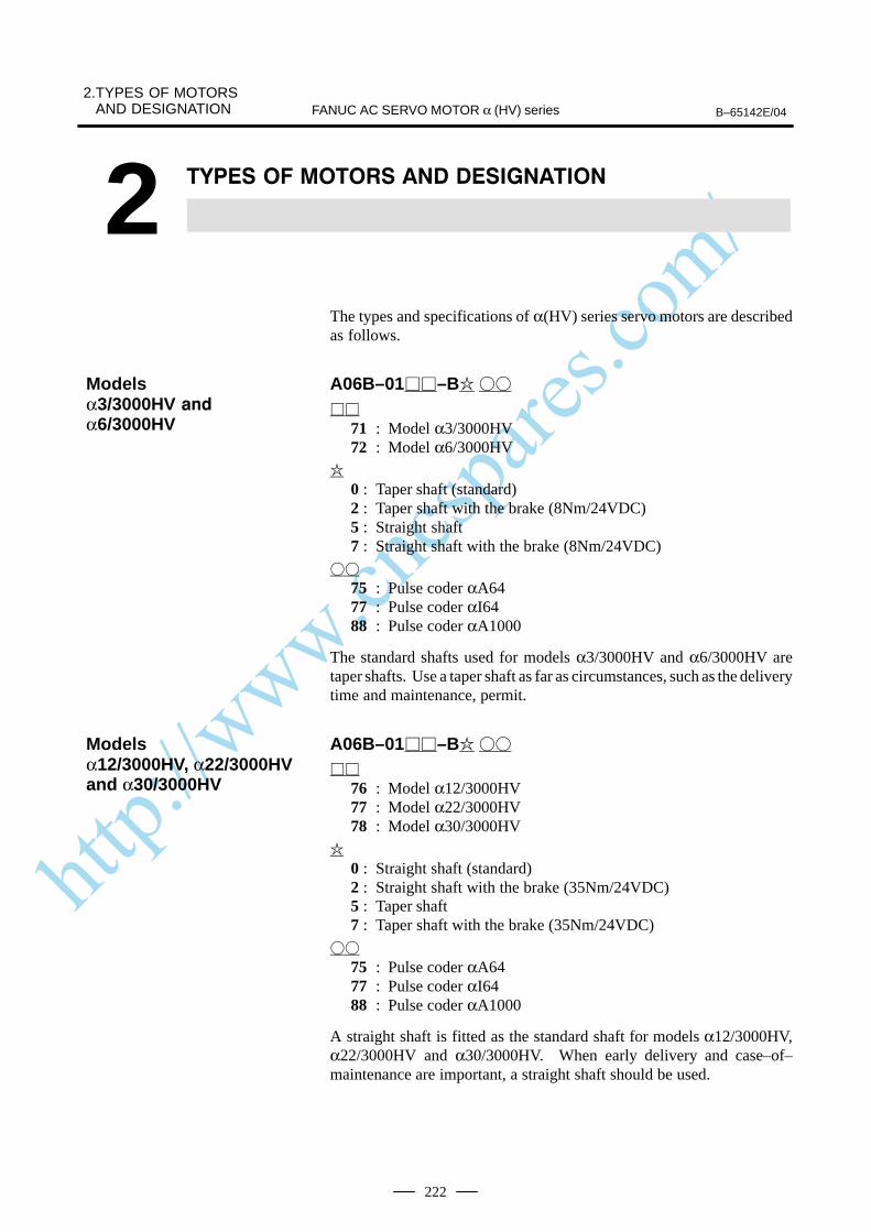
http://www.cncspares.com/
2.TYPES OF MOTORSAND DESIGNATION B–65142E/04FANUC AC SERVO MOTOR α (HV) series
222
2
The types and specifications of α(HV) series servo motors are describedas follows.
A06B–01–B
71 : Model α3/3000HV72 : Model α6/3000HV
0 : Taper shaft (standard)2 : Taper shaft with the brake (8Nm/24VDC)5 : Straight shaft7 : Straight shaft with the brake (8Nm/24VDC)
75 : Pulse coder αA6477 : Pulse coder αI6488 : Pulse coder αA1000
The standard shafts used for models α3/3000HV and α6/3000HV aretaper shafts. Use a taper shaft as far as circumstances, such as the deliverytime and maintenance, permit.
A06B–01–B
76 : Model α12/3000HV77 : Model α22/3000HV78 : Model α30/3000HV
0 : Straight shaft (standard)2 : Straight shaft with the brake (35Nm/24VDC)5 : Taper shaft7 : Taper shaft with the brake (35Nm/24VDC)
75 : Pulse coder αA6477 : Pulse coder αI6488 : Pulse coder αA1000
A straight shaft is fitted as the standard shaft for models α12/3000HV,α22/3000HV and α30/3000HV. When early delivery and case–of–maintenance are important, a straight shaft should be used.
Modelsα3/3000HV
α6/3000HV
Modelsα12/3000HV, α22/3000HVand α30/3000HV
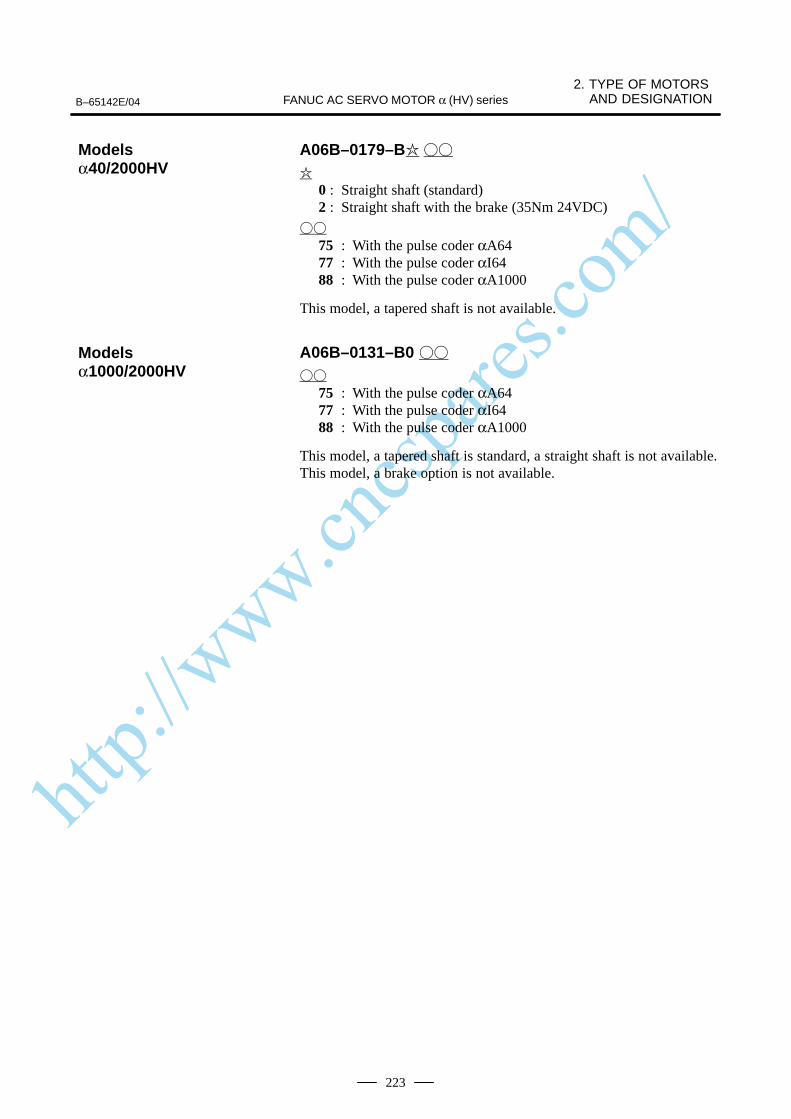
http://www.cncspares.com/
B–65142E/04
2. TYPE OF MOTORS AND DESIGNATIONFANUC AC SERVO MOTOR α (HV) series
223
A06B–0179–B
0 : Straight shaft (standard)2 : Straight shaft with the brake (35Nm 24VDC)
75 : With the pulse coder αA6477 : With the pulse coder αI6488 : With the pulse coder αA1000
This model, a tapered shaft is not available.
A06B–0131–B0
75 : With the pulse coder αA6477 : With the pulse coder αI6488 : With the pulse coder αA1000
This model, a tapered shaft is standard, a straight shaft is not available.This model, a brake option is not available.
Modelsα40/2000HV
Modelsα1000/2000HV

http://www.cncspares.com/
3.SPECIFICATIONS AND CHARACTERISTICS B–65142E/04FANUC AC SERVO MOTOR α (HV) series
224
3

http://www.cncspares.com/
B–65142E/04
3. SPECIFICATIONS ANDCHARACTERISTICSFANUC AC SERVO MOTOR α (HV) series
225
Item Unit α3/3000HV α6/3000HV
kw 0.9 1.4Output
HP 1.3 1.9
Nm 3.0 6.0Rated torque at stall
kgf⋅cm 31 61
Rating rotation speed min–1 3000 3000
kg⋅m2 0.0014 0.0026Rotor inertia
kgf⋅cm⋅s2 0.014 0.027
Mass kg 8 13
The above values are under the condition at 20°C.
Item Unit α12/3000HV α22/3000HV α30/3000HV α40/2000HV α1000/2000HV
kw 2.8 4.4 4.8 5.9 100Output
HP 3.8 5.9 6.4 7.9 136
Nm 12 22 30 38 900Rated torque at stall
kgf⋅cm 122 224 306 390 9180
Rating rotation speed min–1 3000 3000 3000 2000 2000
kg⋅m2 0.0062 0.012 0.017 0.022 0.417Rotor inertia
kgf⋅cm⋅s2 0.064 0.12 0.17 0.23 4.25
Mass kg 18 29 41 52 470
The above values are under the condition at 20°C.
3.1TYPES OF MOTORSANDSPECIFICATIONS
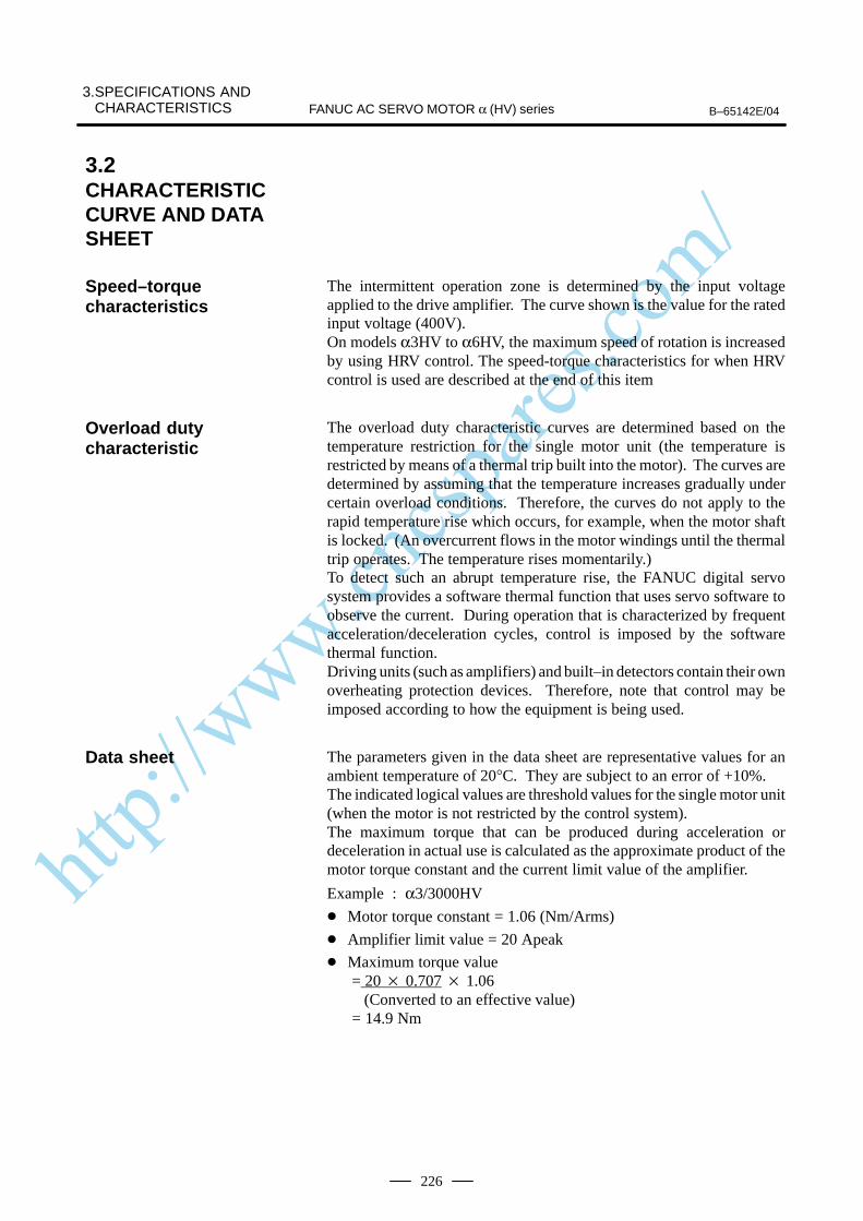
http://www.cncspares.com/
3.SPECIFICATIONS AND CHARACTERISTICS B–65142E/04FANUC AC SERVO MOTOR α (HV) series
226
The intermittent operation zone is determined by the input voltageapplied to the drive amplifier. The curve shown is the value for the ratedinput voltage (400V).On models α3HV to α6HV, the maximum speed of rotation is increasedby using HRV control. The speed-torque characteristics for when HRVcontrol is used are described at the end of this item
The overload duty characteristic curves are determined based on thetemperature restriction for the single motor unit (the temperature isrestricted by means of a thermal trip built into the motor). The curves aredetermined by assuming that the temperature increases gradually undercertain overload conditions. Therefore, the curves do not apply to therapid temperature rise which occurs, for example, when the motor shaftis locked. (An overcurrent flows in the motor windings until the thermaltrip operates. The temperature rises momentarily.)To detect such an abrupt temperature rise, the FANUC digital servosystem provides a software thermal function that uses servo software toobserve the current. During operation that is characterized by frequentacceleration/deceleration cycles, control is imposed by the softwarethermal function.Driving units (such as amplifiers) and built–in detectors contain their ownoverheating protection devices. Therefore, note that control may beimposed according to how the equipment is being used.
The parameters given in the data sheet are representative values for anambient temperature of 20°C. They are subject to an error of +10%.The indicated logical values are threshold values for the single motor unit(when the motor is not restricted by the control system).The maximum torque that can be produced during acceleration ordeceleration in actual use is calculated as the approximate product of themotor torque constant and the current limit value of the amplifier.
Example : α3/3000HV
Motor torque constant = 1.06 (Nm/Arms)
Amplifier limit value = 20 Apeak
Maximum torque value = 20 0.707 1.06 (Converted to an effective value) = 14.9 Nm
3.2CHARACTERISTICCURVE AND DATASHEET
Speed–torquecharacteristics
Overload dutycharacteristic
Data sheet

http://www.cncspares.com/
B–65142E/04
3. SPECIFICATIONS ANDCHARACTERISTICSFANUC AC SERVO MOTOR α (HV) series
227
This value is for reference only. The actual value will vary depending onchanges in the power supply, as well as variations in motor parameters andamplifier limit values.In some models, if the maximum current flows in the motor, the actualmaximum torque is affected by, for example, magnetic saturation. As aresult, the actual maximum torque will be lower than the calculated value.The intermittent operation area (maximum torque value) indicated in thespeed to torque characteristics is the effective value, determinedaccording to the combination with the amplifier.
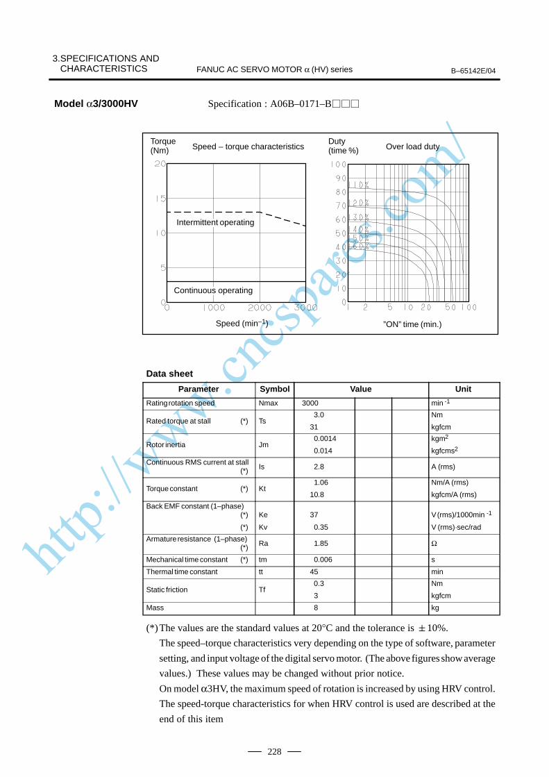
http://www.cncspares.com/
3.SPECIFICATIONS AND CHARACTERISTICS B–65142E/04FANUC AC SERVO MOTOR α (HV) series
228
Specification : A06B–0171–B
Speed – torque characteristics
Speed (min–1) ”ON” time (min.)
Torque (Nm) Over load duty
Duty (time %)
ÂÂÂÂÂÂÂÂÂÂÂÂÂÂ
Intermittent operating
ÂÂÂÂÂÂÂContinuous operating
Data sheet
Parameter Symbol Value Unit
Rating rotation speed Nmax 3000 min -1
Rated torque at stall (*) Ts 3.0
31
Nm
kgfcm
Rotor inertia Jm0.0014
0.014
kgm2
kgfcms2
Continuous RMS current at stall (*) Is 2.8 A (rms)
Torque constant (*) Kt1.06
10.8
Nm/A (rms)
kgfcm/A (rms)
Back EMF constant (1–phase)(*)
(*)
Ke
Kv
37
0.35
V (rms)/1000min -1
V (rms)·sec/rad
Armature resistance (1–phase)(*) Ra 1.85 Ω
Mechanical time constant (*) tm 0.006 s
Thermal time constant tt 45 min
Static friction Tf 0.3
3
Nm
kgfcm
Mass 8 kg
(*)The values are the standard values at 20°C and the tolerance is 10%.
The speed–torque characteristics very depending on the type of software, parameter
setting, and input voltage of the digital servo motor. (The above figures show average
values.) These values may be changed without prior notice.
On model α3HV, the maximum speed of rotation is increased by using HRV control.
The speed-torque characteristics for when HRV control is used are described at the
end of this item
Model α3/3000HV

http://www.cncspares.com/
B–65142E/04
3. SPECIFICATIONS ANDCHARACTERISTICSFANUC AC SERVO MOTOR α (HV) series
229
Specification : A06B–0172–B
Speed – torque characteristics
Speed (min–1) ”ON” time (min.)
Over load dutyTorque (Nm)
Duty (time %)
ÂÂÂÂÂÂÂÂÂÂÂÂÂÂ
Intermittent operating
ÂÂÂÂÂÂÂÂÂÂÂÂÂÂContinuous operating
Data sheetParameter Symbol Value Unit
Rating rotation speed Nmax 3000 min -1
Rated torque at stall (*) Ts 6.0
61
Nm
kgfcm
Rotor inertia Jm 0.0026
0.027
kgm2
kgfcms2
Continuous RMS current at stall (*) Is 3.6 A (rms)
Torque constant (*) Kt1.68
17.1
Nm/A (rms)
kgfcm/A (rms)
Back EMF constant (1–phase)(*)
(*)
Ke
Kv
59
0.56
V (rms)/1000min -1
V (rms)·sec/rad
Armature resistance (1–phase)(*) Ra 1.52 Ω
Mechanical time constant (*) tm 0.004 s
Thermal time constant tt 50 min
Static friction Tf0.3
3
Nm
kgfcm
Mass 13 kg
(*)The values are the standard values at 20°C and the tolerance is 10%.
The speed–torque characteristics very depending on the type of software, parameter
setting, and input voltage of the digital servo motor. (The above figures show average
values.) These values may be changed without prior notice.
On model α6HV, the maximum speed of rotation is increased by using HRV control.
The speed-torque characteristics for when HRV control is used are described at the
end of this item
Model α6/3000HV

http://www.cncspares.com/
3.SPECIFICATIONS AND CHARACTERISTICS B–65142E/04FANUC AC SERVO MOTOR α (HV) series
230
Specification : A06B–0176–B
Speed – torque characteristics
Speed (min–1) ”ON” time (min.)
Over load dutyTorque (Nm)
Duty (time %)
ÂÂÂÂÂÂÂÂÂÂÂÂÂÂ
Intermittent operating
ÂÂÂÂÂÂÂÂÂÂÂÂÂÂ
Continuous operating
Data sheetParameter Symbol Value Unit
Rating rotation speed Nmax 3000 min -1
Rated torque at stall (*) Ts12
122
Nm
kgfcm
Rotor inertia Jm 0.0062
0.064
kgm2
kgfcms2
Continuous RMS current at stall (*) Is 8.8 A (rms)
Torque constant (*) Kt1.36
13.8
Nm/A (rms)
kgfcm/A (rms)
Back EMF constant (1–phase)(*)
(*)
Ke
Kv
47
0.45
V (rms)/1000min -1
V (rms)·sec/rad
Armature resistance (1–phase)(*) Ra 0.49 Ω
Mechanical time constant (*) tm 0.005 s
Thermal time constant tt 60 min
Static friction Tf 0.8
8
Nm
kgfcm
Mass 18 kg
(*)The values are the standard values at 20°C and the tolerance is 10%.
The speed–torque characteristics very depending on the type of software, parameter
setting, and input voltage of the digital servo motor. (The above figures show average
values.) These values may be changed without prior notice.
Model α12/3000HV
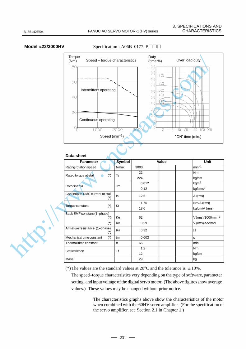
http://www.cncspares.com/
B–65142E/04
3. SPECIFICATIONS ANDCHARACTERISTICSFANUC AC SERVO MOTOR α (HV) series
231
Specification : A06B–0177–B
Speed – torque characteristics
Speed (min–1) ”ON” time (min.)
Over load dutyTorque (Nm)
Duty (time %)
ÂÂÂÂÂÂÂÂÂÂÂÂÂÂ
Intermittent operating
ÂÂÂÂÂÂÂÂÂÂÂÂÂÂ
Continuous operating
Data sheetParameter Symbol Value Unit
Rating rotation speed Nmax 3000 min -1
Rated torque at stall (*) Ts 22
224
Nm
kgfcm
Rotor inertia Jm 0.012
0.12
kgm2
kgfcms2
Continuous RMS current at stall (*) Is 12.5 A (rms)
Torque constant (*) Kt1.76
18.0
Nm/A (rms)
kgfcm/A (rms)
Back EMF constant (1–phase)(*)
(*)
Ke
Kv
62
0.59
V (rms)/1000min -1
V (rms)·sec/rad
Armature resistance (1–phase)(*) Ra 0.32 Ω
Mechanical time constant (*) tm 0.003 s
Thermal time constant tt 65 min
Static friction Tf1.2
12
Nm
kgfcm
Mass 29 kg
(*)The values are the standard values at 20°C and the tolerance is 10%.
The speed–torque characteristics very depending on the type of software, parameter
setting, and input voltage of the digital servo motor. (The above figures show average
values.) These values may be changed without prior notice.
The characteristics graphs above show the characteristics of the motorwhen combined with the 60HV servo amplifier. (For the specification ofthe servo amplifier, see Section 2.1 in Chapter 1.)
Model α22/3000HV
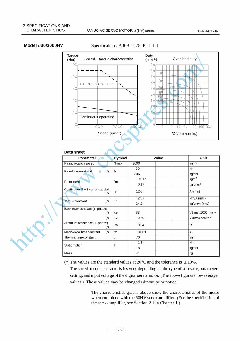
http://www.cncspares.com/
3.SPECIFICATIONS AND CHARACTERISTICS B–65142E/04FANUC AC SERVO MOTOR α (HV) series
232
Specification : A06B–0178–B
Speed – torque characteristics
Speed (min–1) ”ON” time (min.)
Over load dutyTorque (Nm)
Duty (time %)
ÂÂÂÂÂÂÂIntermittent operating
ÂÂÂÂÂÂÂÂÂÂÂÂÂÂ
Continuous operating
Data sheetParameter Symbol Value Unit
Rating rotation speed Nmax 3000 min -1
Rated torque at stall (*) Ts 30
306
Nm
kgfcm
Rotor inertia Jm 0.017
0.17
kgm2
kgfcms2
Continuous RMS current at stall (*) Is 12.6 A (rms)
Torque constant (*) Kt2.37
24.2
Nm/A (rms)
kgfcm/A (rms)
Back EMF constant (1–phase)(*)
(*)
Ke
Kv
83
0.79
V (rms)/1000min -1
V (rms)·sec/rad
Armature resistance (1–phase)(*) Ra 0.34 Ω
Mechanical time constant (*) tm 0.003 s
Thermal time constant tt 70 min
Static friction Tf1.8
18
Nm
kgfcm
Mass 41 kg
(*)The values are the standard values at 20°C and the tolerance is 10%.
The speed–torque characteristics very depending on the type of software, parameter
setting, and input voltage of the digital servo motor. (The above figures show average
values.) These values may be changed without prior notice.
The characteristics graphs above show the characteristics of the motorwhen combined with the 60HV servo amplifier. (For the specification ofthe servo amplifier, see Section 2.1 in Chapter 1.)
Model α30/3000HV

http://www.cncspares.com/
B–65142E/04
3. SPECIFICATIONS ANDCHARACTERISTICSFANUC AC SERVO MOTOR α (HV) series
233
Specification : A06B–0179–B
0
10
20
30
40
50
6070
80
90
100
1 10 100 10000
20
40
60
80
100
120
0 500 1000 1500 2000
140%150%160%
110%
120%
130%
Over Load Duty
“On”time (min)
Speed–Torque Characteristics
Speed (min–1)
IntermittingOperation
Torq
ue (N
m)
Dut
y (t
ime%
)
ContinuousOperating
Data sheetParameter Symbol Value Unit
Rating speed Nmax 2000 min -1
Rated torque at stall (*) Ts 38
390
Nm
kgfcm
Rotor inertia Jm 0.022
0.23
kgm2
kgfcms2
Continuous RMS current at stall (*) Is 19.2 A (rms)
Torque constant (*) Kt1.98
20.2
Nm/A (rms)
kgfcm/A (rms)
Back EMF constant (1–phase)(*)
(*)
Ke
Kv
69
0.66
V (rms)/1000min -1
V (rms)·sec/rad
Armature resistance (1–phase)(*) Ra 0.16 Ω
Mechanical time constant (*) tm 0.003 s
Thermal time constant tt 75 min
Static friction Tf1.8
18
Nm
kgfcm
Weight 52 kg
(*)The values are the standard values at 20°C and the tolerance is 10%.
The speed–torque characteristics very depending on the type of software, parameter
setting, and input voltage of the digital servo motor. (The above figures show average
values.)
These values may be changed without prior notice.
Model α40/2000HV
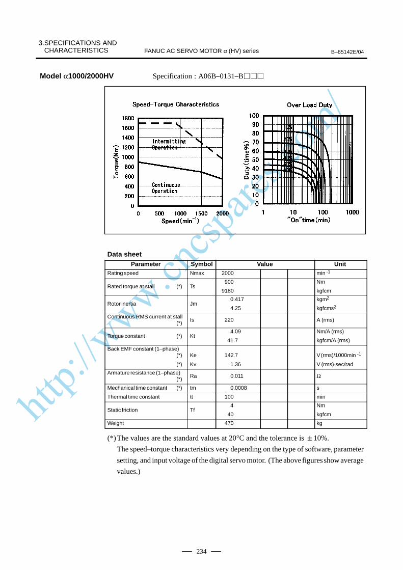
http://www.cncspares.com/
3.SPECIFICATIONS AND CHARACTERISTICS B–65142E/04FANUC AC SERVO MOTOR α (HV) series
234
Specification : A06B–0131–B
Data sheetParameter Symbol Value Unit
Rating speed Nmax 2000 min -1
Rated torque at stall (*) Ts900
9180
Nm
kgfcm
Rotor inertia Jm 0.417
4.25
kgm2
kgfcms2
Continuous RMS current at stall (*) Is 220 A (rms)
Torque constant (*) Kt4.09
41.7
Nm/A (rms)
kgfcm/A (rms)
Back EMF constant (1–phase)(*)
(*)
Ke
Kv
142.7
1.36
V (rms)/1000min -1
V (rms)·sec/rad
Armature resistance (1–phase)(*) Ra 0.011 Ω
Mechanical time constant (*) tm 0.0008 s
Thermal time constant tt 100 min
Static friction Tf4
40
Nm
kgfcm
Weight 470 kg
(*)The values are the standard values at 20°C and the tolerance is 10%.
The speed–torque characteristics very depending on the type of software, parameter
setting, and input voltage of the digital servo motor. (The above figures show average
values.)
Model α1000/2000HV
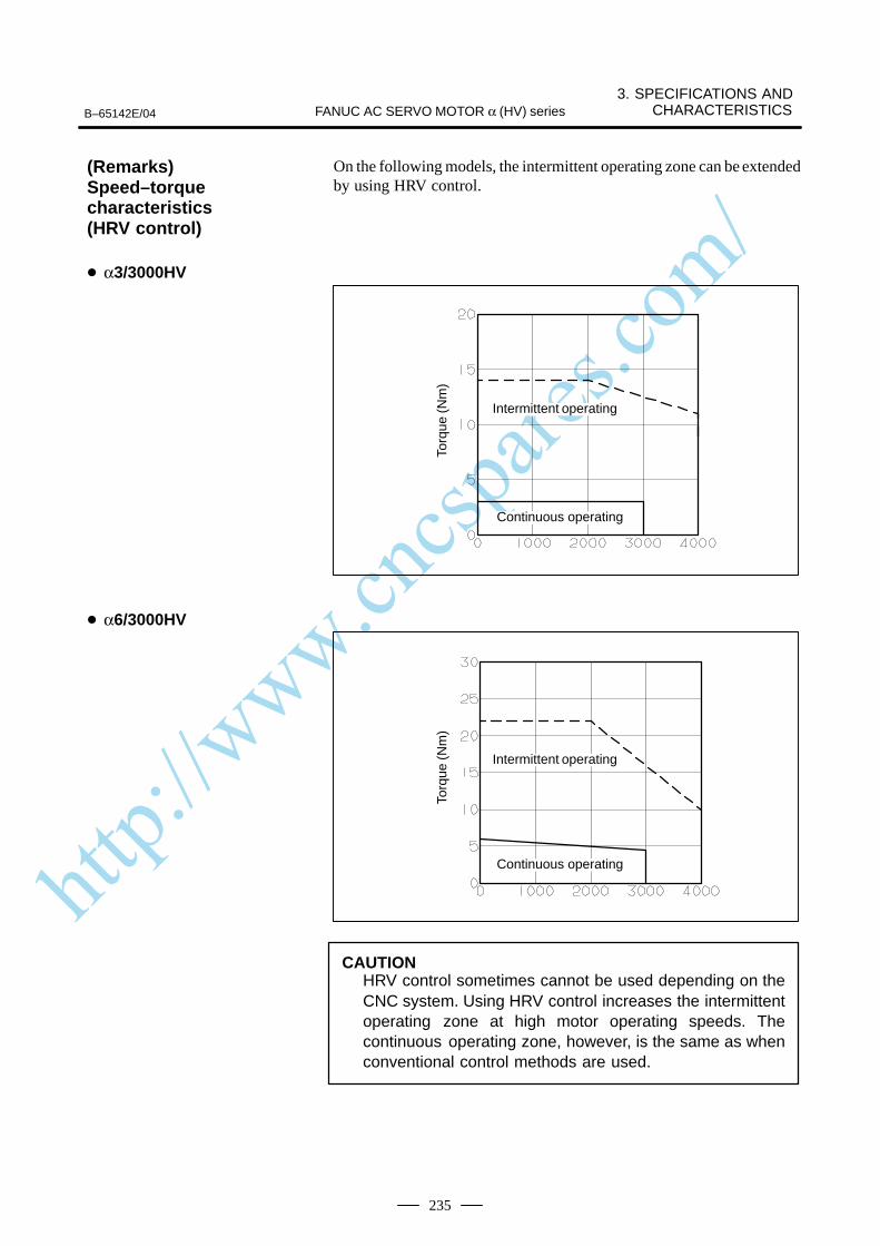
http://www.cncspares.com/
B–65142E/04
3. SPECIFICATIONS ANDCHARACTERISTICSFANUC AC SERVO MOTOR α (HV) series
235
On the following models, the intermittent operating zone can be extendedby using HRV control.
Torq
ue (N
m)
ÂÂÂÂÂÂÂÂÂÂÂÂÂÂ
Intermittent operating
ÂÂÂÂÂÂÂÂÂÂÂÂÂÂ
Continuous operating
Torq
ue (N
m)
ÂÂÂÂÂÂÂIntermittent operating
ÂÂÂÂÂÂÂÂÂÂÂÂÂÂ
Continuous operating
CAUTIONHRV control sometimes cannot be used depending on theCNC system. Using HRV control increases the intermittentoperating zone at high motor operating speeds. Thecontinuous operating zone, however, is the same as whenconventional control methods are used.
(Remarks)Speed–torquecharacteristics (HRV control)
α3/3000HV
α6/3000HV
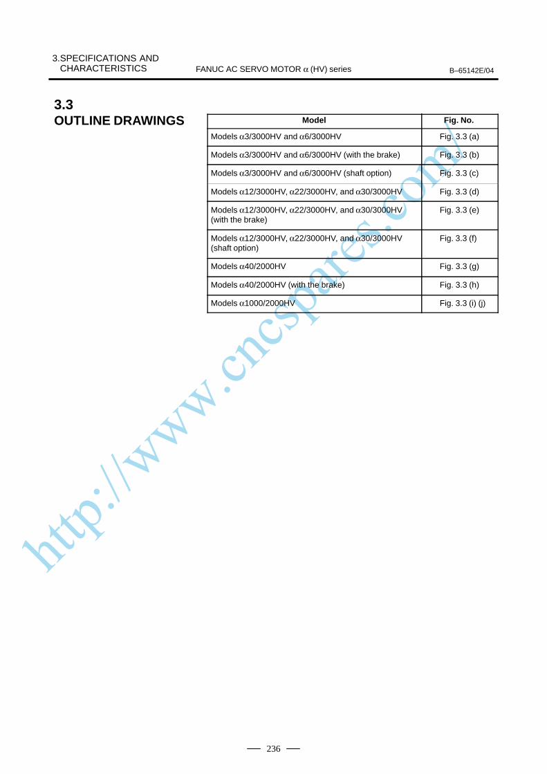
http://www.cncspares.com/
3.SPECIFICATIONS AND CHARACTERISTICS B–65142E/04FANUC AC SERVO MOTOR α (HV) series
236
Model Fig. No.
Models α3/3000HV and α6/3000HV Fig. 3.3 (a)
Models α3/3000HV and α6/3000HV (with the brake) Fig. 3.3 (b)
Models α3/3000HV and α6/3000HV (shaft option) Fig. 3.3 (c)
Models α12/3000HV, α22/3000HV, and α30/3000HV Fig. 3.3 (d)
Models α12/3000HV, α22/3000HV, and α30/3000HV(with the brake)
Fig. 3.3 (e)
Models α12/3000HV, α22/3000HV, and α30/3000HV(shaft option)
Fig. 3.3 (f)
Models α40/2000HV Fig. 3.3 (g)
Models α40/2000HV (with the brake) Fig. 3.3 (h)
Models α1000/2000HV Fig. 3.3 (i) (j)
3.3OUTLINE DRAWINGS
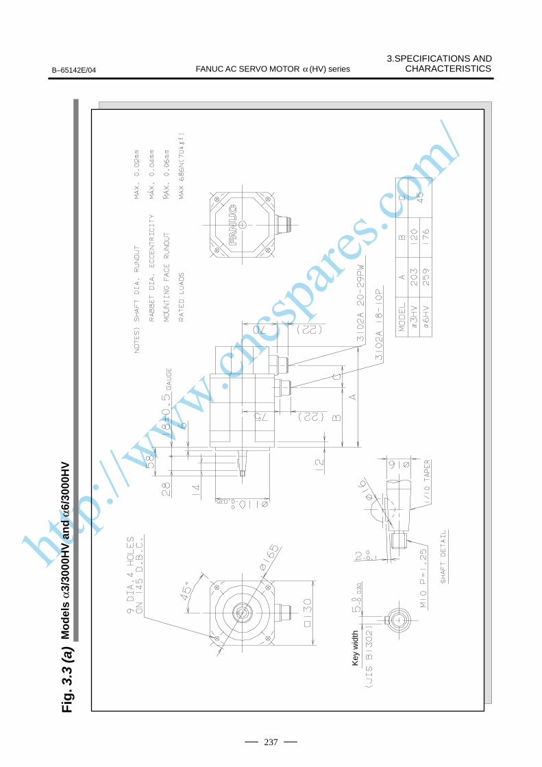
http://www.cncspares.com/
3.SPECIFICATIONS ANDCHARACTERISTICSB–65142E/04 FANUC AC SERVO MOTOR α (HV) series
237
Fig
. 3.3
(a)
Mo
del
s α3
/300
0HV
an
d α
6/30
00H
V
Key
wid
th

http://www.cncspares.com/
FANUC AC SERVO MOTOR α (HV) series B–65142E/04
3.SPECIFICATIONS ANDCHARACTERISTICS
238
Fig
. 3.3
(b)
Mo
del
s α3
/300
0HV
an
d α
6/30
00H
V (
wit
h t
he
bra
ke)
Key
wid
th
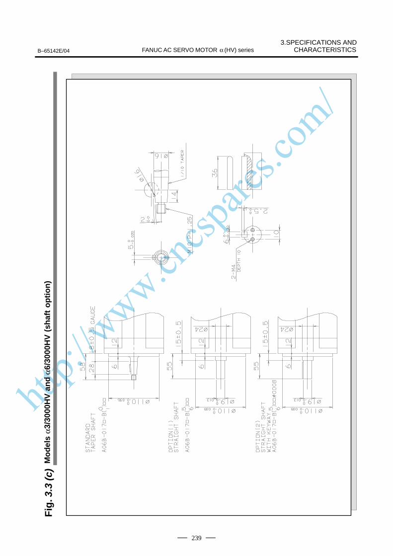
http://www.cncspares.com/
3.SPECIFICATIONS ANDCHARACTERISTICSB–65142E/04 FANUC AC SERVO MOTOR α (HV) series
239
Fig
. 3.3
(c)
Mo
del
s α3
/300
0HV
an
d α
6/30
00H
V (
shaf
t o
pti
on
)
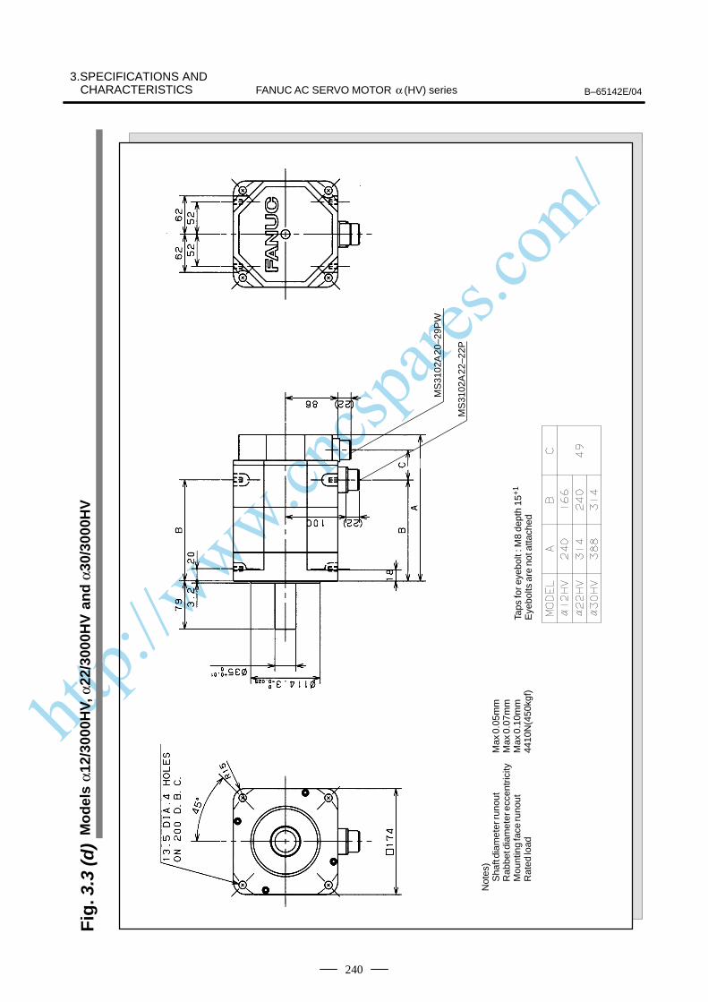
http://www.cncspares.com/
FANUC AC SERVO MOTOR α (HV) series B–65142E/04
3.SPECIFICATIONS ANDCHARACTERISTICS
240
Fig
. 3.3
(d)
Mo
del
s α1
2/30
00H
V, α
22/3
000H
V a
nd
α30
/300
0HV
Not
es)
Sha
ft di
amet
er ru
nout
Max
0.0
5mm
Rab
bet d
iam
eter
ecc
entr
icity
Max
0.0
7mm
Mou
ntin
g fa
ce ru
nout
Max
0.1
0mm
Rat
ed lo
ad44
10N
(450
kgf)
Taps
for e
yebo
lt : M
8 de
pth
15+
1
Eye
bolts
are
not
atta
ched
MS
3102
A 2
0–29
PW
MS
3102
A 2
2–22
P

http://www.cncspares.com/
3.SPECIFICATIONS ANDCHARACTERISTICSB–65142E/04 FANUC AC SERVO MOTOR α (HV) series
241
Fig
. 3.3
(e)
Mo
del
s α1
2/30
00H
V, α
22/3
000H
V a
nd
α30
/300
0HV
(w
ith
th
e b
rake
)
Not
es)
Sha
ft di
amet
er ru
nout
Max
0.0
5mm
Rab
bet d
iam
eter
ecc
entr
icity
Max
0.0
7mm
Mou
ntin
g fa
ce ru
nout
Max
0.1
0mm
Rat
ed lo
ad44
10N
(450
kgf)
Taps
for e
yebo
lt : M
8 de
pth
15+
1
Eye
bolts
are
not
atta
ched
MS
3102
A 2
0–29
PW
MS
3102
A 2
2–22
P
MS
3102
A 1
0SL–
4P(W
ithou
t a e
arth
pin
)

http://www.cncspares.com/
FANUC AC SERVO MOTOR α (HV) series B–65142E/04
3.SPECIFICATIONS ANDCHARACTERISTICS
242
Fig
. 3.3
(f)
Mo
del
s α1
2/30
00H
V, α
22/3
000H
V a
nd
α30
/300
0HV
(sh
aft
op
tio
n)

http://www.cncspares.com/
3.SPECIFICATIONS ANDCHARACTERISTICSB–65142E/04 FANUC AC SERVO MOTOR α (HV) series
243
Fig
. 3.3
(g)
Mo
del
α40
/200
0HV

http://www.cncspares.com/
FANUC AC SERVO MOTOR α (HV) series B–65142E/04
3.SPECIFICATIONS ANDCHARACTERISTICS
244
Fig
. 3.3
(h)
Mo
del
α40
/200
0HV
(w
ith
th
e b
rake
)
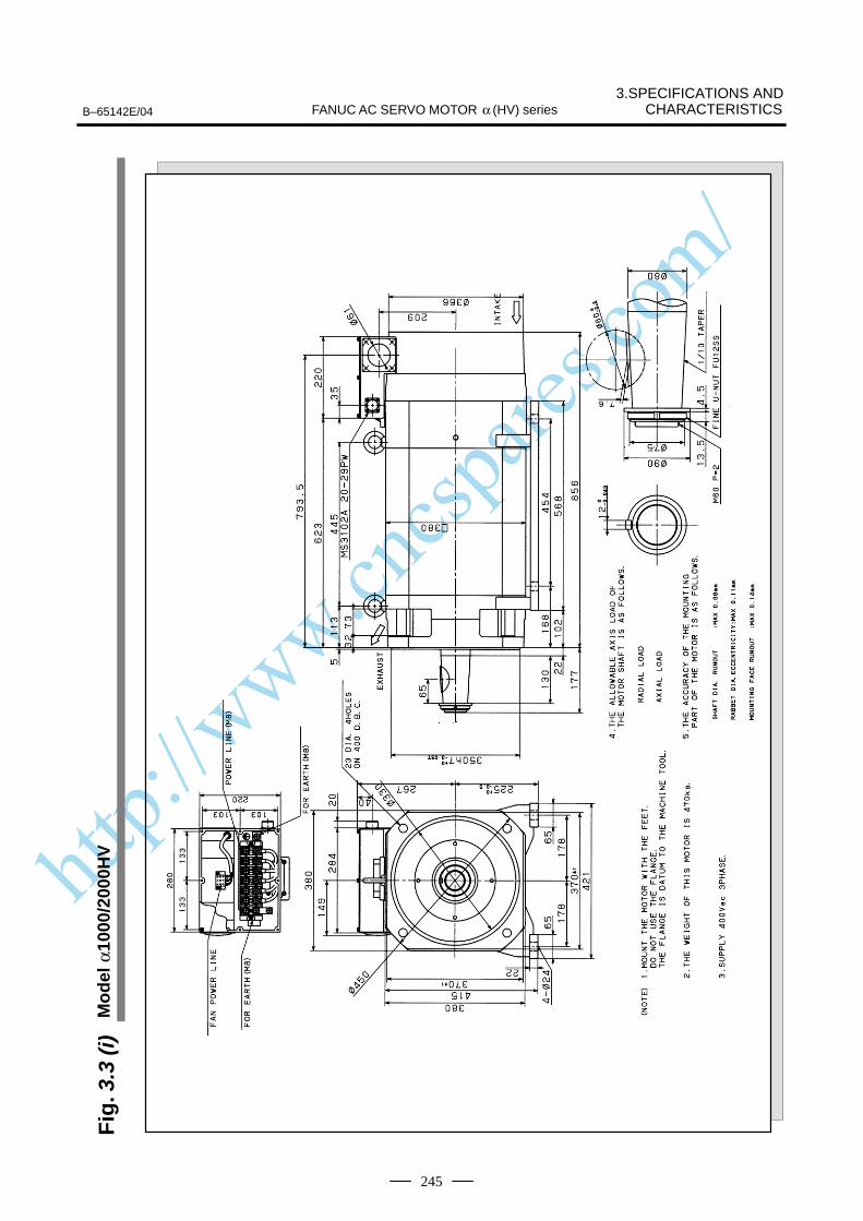
http://www.cncspares.com/
3.SPECIFICATIONS ANDCHARACTERISTICSB–65142E/04 FANUC AC SERVO MOTOR α (HV) series
245
Fig
. 3.3
(i)
Mo
del
α10
00/2
000H
V
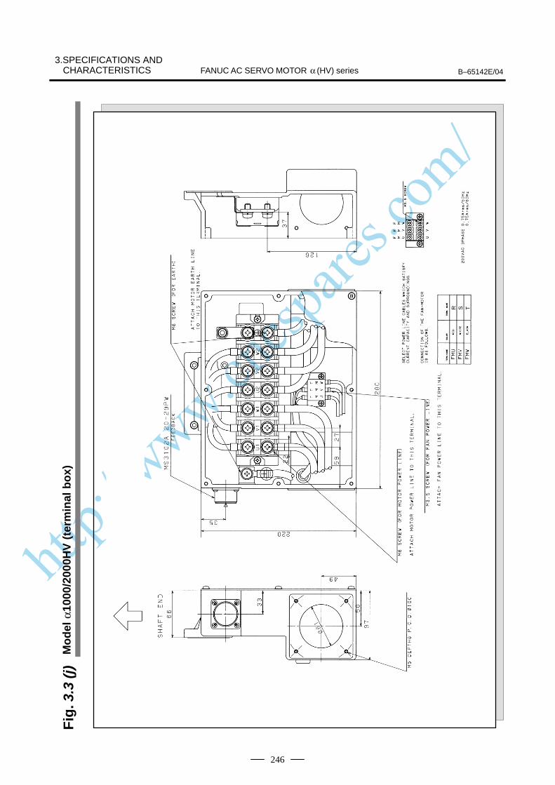
http://www.cncspares.com/
FANUC AC SERVO MOTOR α (HV) series B–65142E/04
3.SPECIFICATIONS ANDCHARACTERISTICS
246
Fig
. 3.3
(j)
Mo
del
α10
00/2
000H
V (
term
inal
bo
x)
R S T
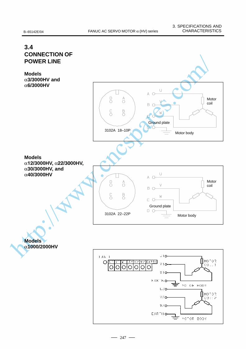
http://www.cncspares.com/
B–65142E/04
3. SPECIFICATIONS ANDCHARACTERISTICSFANUC AC SERVO MOTOR α (HV) series
247
3102A 18–10P
Ground plate
Motor body
Motor coil
3102A 22–22P
Ground plate
Motor body
Motor coil
3.4CONNECTION OFPOWER LINE
Modelsα3/3000HV andα6/3000HV
Models α/3000HV, α/00HV,α30/3000HV, andα40/3000HV
Modelsα1000/2000HV
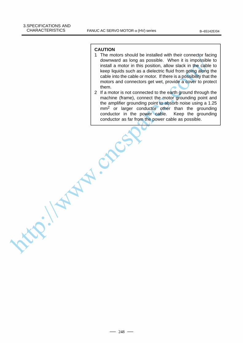
http://www.cncspares.com/
3.SPECIFICATIONS AND CHARACTERISTICS B–65142E/04FANUC AC SERVO MOTOR α (HV) series
248
CAUTION1 The motors should be installed with their connector facing
downward as long as possible. When it is impossible toinstall a motor in this position, allow slack in the cable tokeep liquids such as a dielectric fluid from going along thecable into the cable or motor. If there is a possibility that themotors and connectors get wet, provide a cover to protectthem.
2 If a motor is not connected to the earth ground through themachine (frame), connect the motor grounding point andthe amplifier grounding point to absorb noise using a 1.25mm2 or larger conductor other than the groundingconductor in the power cable. Keep the groundingconductor as far from the power cable as possible.
http://www.cncspares.com/
VII. FANUC AC SERVO MOTOR αM (HV) series
http://www.cncspares.com/
B–65142E/04 1. GENERALFANUC AC SERVO MOTOR αM (HV) series
251
1 GENERAL
The FANUC AC servo motor αM(HV) series is ideal for the feed shaftsof small machine tools. The features of this servo motor are as follows:
A 400V power source can be connected directly without using atransformer.
A high maximum output torque and intermediate rotor inertia result inexcellent acceleration characteristics.
The use of the latest ferrite magnet, combined with an optimizedmechanical design, reduces both the overall length and weight. The resultis compact, lightweight servo motors.
The use of waterproof connectors and FANUC’s unique stator sealprovide excellent waterproofing, ensuring that no liquid, such as coolant,can enter the motor.
The latest servo software minimizes heat generation at high operatingspeeds, and extends the continuous operating zone.
Further improvements have been made to the unique magnetic pole shapeto minimize torque ripple. The result is extremely smooth rotation.
The use of the latest servo software maintains controllability even whena disturbance occurs.
High–resolution pulse coder αA1000, αA64, αI64 is used in the standardconfiguration, enabling precise positioning.
A powerful brake with an increased holding torque is available as anoption. The brake uses an asbestos–free design.
The αM (HV) series includes the following models:
Models αM6HV and αM9HV that are compatible with the installationdimensions of the α series models α3 and α6
Models αM22HV, αM30HV, and αM40HV that are compatible withthe installation dimensions of the α series models α12, α22, α30, andα40
Direct connection to a400V power source
Excellent accelerationcharacteristics
Compact
Excellent waterproofing
Wide continuousoperating zone
Smooth rotation
Controllability
High–performancedetector
Powerful brake
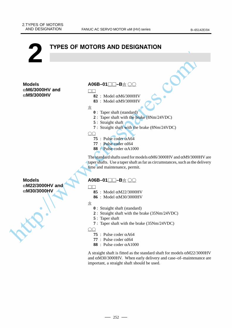
http://www.cncspares.com/
2.TYPES OF MOTORSAND DESIGNATION B–65142E/04FANUC AC SERVO MOTOR αM (HV) series
252
2
A06B–01–B
82 : Model αM6/3000HV83 : Model αM9/3000HV
0 : Taper shaft (standard)2 : Taper shaft with the brake (8Nm/24VDC)5 : Straight shaft7 : Straight shaft with the brake (8Nm/24VDC)
75 : Pulse coder αA6477 : Pulse coder αI6488 : Pulse coder αA1000
The standard shafts used for models αM6/3000HV and αM9/3000HV aretaper shafts. Use a taper shaft as far as circumstances, such as the deliverytime and maintenance, permit.
A06B–01–B
85 : Model αM22/3000HV86 : Model αM30/3000HV
0 : Straight shaft (standard)2 : Straight shaft with the brake (35Nm/24VDC)5 : Taper shaft7 : Taper shaft with the brake (35Nm/24VDC)
75 : Pulse coder αA6477 : Pulse coder αI6488 : Pulse coder αA1000
A straight shaft is fitted as the standard shaft for models αM22/3000HVand αM30/3000HV. When early delivery and case–of–maintenance areimportant, a straight shaft should be used.
ModelsαM6/3000HV
αM9/3000HV
ModelsαM22/3000HV andαM30/3000HV
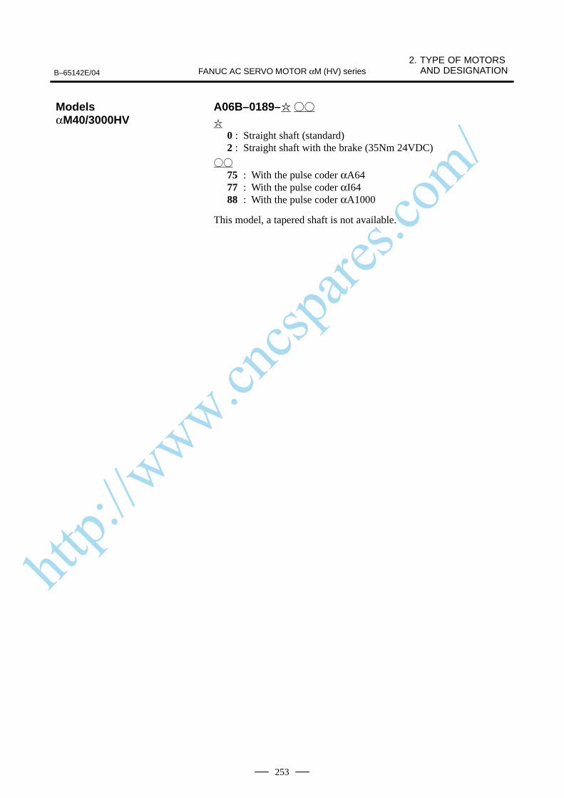
http://www.cncspares.com/
B–65142E/04
2. TYPE OF MOTORS AND DESIGNATIONFANUC AC SERVO MOTOR αM (HV) series
253
A06B–0189–
0 : Straight shaft (standard)2 : Straight shaft with the brake (35Nm 24VDC)
75 : With the pulse coder αA6477 : With the pulse coder αI6488 : With the pulse coder αA1000
This model, a tapered shaft is not available.
ModelsαM40/3000HV
http://www.cncspares.com/
3.SPECIFICATIONS AND CHARACTERISTICS B–65142E/04FANUC AC SERVO MOTOR αM (HV) series
254
3 SPECIFICATIONS AND CHARACTERISTICS
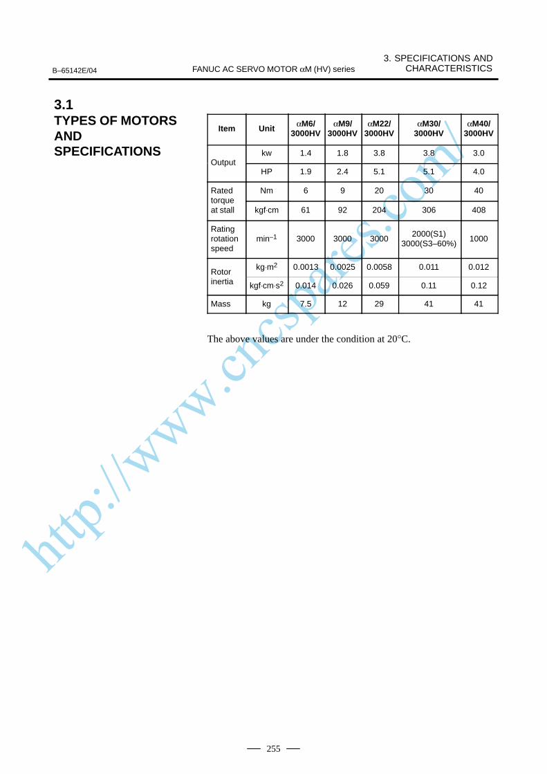
http://www.cncspares.com/
B–65142E/04
3. SPECIFICATIONS ANDCHARACTERISTICSFANUC AC SERVO MOTOR αM (HV) series
255
Item Unit αM6/3000HV
αM9/3000HV
αM22/3000HV
αM30/3000HV
αM40/3000HV
kw 1.4 1.8 3.8 3.8 3.0Output
HP 1.9 2.4 5.1 5.1 4.0
Rated Nm 6 9 20 30 40torqueat stall kgf⋅cm 61 92 204 306 408
Ratingrotationspeed
min–1 3000 3000 30002000(S1)
3000(S3–60%)1000
Rotor kg⋅m2 0.0013 0.0025 0.0058 0.011 0.012
Rotor inertia kgf⋅cm⋅s2 0.014 0.026 0.059 0.11 0.12
Mass kg 7.5 12 29 41 41
The above values are under the condition at 20°C.
3.1TYPES OF MOTORSANDSPECIFICATIONS
http://www.cncspares.com/
3.SPECIFICATIONS AND CHARACTERISTICS B–65142E/04FANUC AC SERVO MOTOR αM (HV) series
256
The intermittent operation zone is determined by the input voltageapplied to the drive amplifier. The curve shown is the value for the ratedinput voltage (400V).On model αM40/3000HV, “Intermittent operating (S3 to 25%)” in the“Speed–torque characteristics” is permitting operating zone in IEC34–1,and it enables to operate 2.5 min ON and 7.5 min OFF in 10 min cycletime.Equally, (S3 to 60%)” in the “Speed–torque characteristics” enables tooperate 6 min ON and 4 min OFF in 10 min cycle time.On models αM6HV to αM9HV, the maximum speed of rotation isincreased by using HRV control. The speed-torque characteristics forwhen HRV control is used are described at the end of this item
The overload duty characteristic curves are determined based on thetemperature restriction for the single motor unit (the temperature isrestricted by means of a thermal trip built into the motor). The curves aredetermined by assuming that the temperature increases gradually undercertain overload conditions. Therefore, the curves do not apply to therapid temperature rise which occurs, for example, when the motor shaftis locked. (An overcurrent flows in the motor windings until the thermaltrip operates. The temperature rises momentarily.)To detect such an abrupt temperature rise, the FANUC digital servosystem provides a software thermal function that uses servo software toobserve the current. During operation that is characterized by frequentacceleration/deceleration cycles, control is imposed by the softwarethermal function.Driving units (such as amplifiers) and built–in detectors contain their ownoverheating protection devices. Therefore, note that control may beimposed according to how the equipment is being used.
The parameters given in the data sheet are representative values for anambient temperature of 20°C. They are subject to an error of +10%.The indicated logical values are threshold values for the single motor unit(when the motor is not restricted by the control system).The maximum torque that can be produced during acceleration ordeceleration in actual use is calculated as the approximate product of themotor torque constant and the current limit value of the amplifier.
Example : αM6/3000HV
Motor torque constant = 1.50 (Nm/Arms)
Amplifier limit value = 40 (Apeak)
Maximum torque value = 40 0.707 1.50 (Nm) (Converted to an effective value)
3.2CHARACTERISTICCURVE AND DATASHEET
Speed–torquecharacteristics
Overload dutycharacteristic
Data sheet
http://www.cncspares.com/
B–65142E/04
3. SPECIFICATIONS ANDCHARACTERISTICSFANUC AC SERVO MOTOR αM (HV) series
257
This value is for reference only. The actual value will vary depending onchanges in the power supply, as well as variations in motor parameters andamplifier limit values.In some models, if the maximum current flows in the motor, the actualmaximum torque is affected by, for example, magnetic saturation. As aresult, the actual maximum torque will be lower than the calculated value.The intermittent operation area (maximum torque value) indicated in thespeed to torque characteristics is the effective value, determinedaccording to the combination with the amplifier.
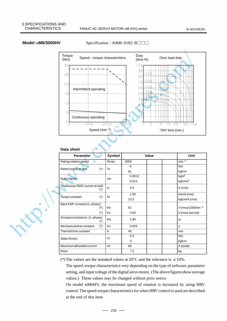
http://www.cncspares.com/
3.SPECIFICATIONS AND CHARACTERISTICS B–65142E/04FANUC AC SERVO MOTOR αM (HV) series
258
Specification : A06B–0182–B
Speed – torque characteristics
Speed (min–1) ”ON” time (min.)
Torque (Nm) Over load duty
Duty (time %)
ÂÂÂÂÂÂÂÂÂÂÂÂÂÂ
Intermittent operating
ÂÂÂÂÂÂÂÂÂÂÂÂÂÂContinuous operating
Data sheet
Parameter Symbol Value Unit
Rating rotation speed Nmax 3000 min -1
Rated torque at stall (*) Ts 6
61
Nm
kgfcm
Rotor inertia Jm 0.0013
0.014
kgm2
kgfcms2
Continuous RMS current at stall (*) Is 4.0 A (rms)
Torque constant (*) Kt1.50
15.3
Nm/A (rms)
kgfcm/A (rms)
Back EMF constant (1–phase)(*)
(*)
Ke
Kv
52
0.50
V (rms)/1000min -1
V (rms)·sec/rad
Armature resistance (1–phase)(*) Ra 1.80 Ω
Mechanical time constant (*) tm 0.003 s
Thermal time constant tt 45 min
Static friction Tf0.3
3
Nm
kgfcm
Maximum allowable current Im 60 A (peak)
Mass 7.5 kg
(*)The values are the standard values at 20°C and the tolerance is 10%.
The speed–torque characteristics very depending on the type of software, parameter
setting, and input voltage of the digital servo motor. (The above figures show average
values.) These values may be changed without prior notice.
On model αM6HV, the maximum speed of rotation is increased by using HRV
control. The speed-torque characteristics for when HRV control is used are described
at the end of this item
Model αM6/3000HV

http://www.cncspares.com/
B–65142E/04
3. SPECIFICATIONS ANDCHARACTERISTICSFANUC AC SERVO MOTOR αM (HV) series
259
Specification : A06B–0183–B
Speed – torque characteristics
Speed (min–1) ”ON” time (min.)
Over load dutyTorque (Nm)
Duty (time %)
ÂÂÂÂÂÂÂIntermittent operating
ÂÂÂÂÂÂÂContinuous operating
Data sheetParameter Symbol Value Unit
Rating rotation speed Nmax 3000 min -1
Rated torque at stall (*) Ts 9
92
Nm
kgfcm
Rotor inertia Jm0.0025
0.026
kgm2
kgfcms2
Continuous RMS current at stall (*) Is 5.8 A (rms)
Torque constant (*) Kt1.56
15.9
Nm/A (rms)
kgfcm/A (rms)
Back EMF constant (1–phase)(*)
(*)
Ke
Kv
54
0.52
V (rms)/1000min -1
V (rms)·sec/rad
Armature resistance (1–phase)(*) Ra 0.67 Ω
Mechanical time constant (*) tm 0.002 s
Thermal time constant tt 50 min
Static friction Tf 0.3
3
Nm
kgfcm
Maximum allowable current Im 120 A (peak)
Mass 12 kg
(*)The values are the standard values at 20°C and the tolerance is 10%.
The speed–torque characteristics very depending on the type of software, parameter
setting, and input voltage of the digital servo motor. (The above figures show average
values.) These values may be changed without prior notice.
On model αM9HV, the maximum speed of rotation is increased by using HRV
control. The speed-torque characteristics for when HRV control is used are described
at the end of this item
Model αM9/3000HV

http://www.cncspares.com/
3.SPECIFICATIONS AND CHARACTERISTICS B–65142E/04FANUC AC SERVO MOTOR αM (HV) series
260
Specification : A06B–0185–B
Speed – torque characteristics
Speed (min–1) ”ON” time (min.)
Over load dutyTorque (Nm)
Duty (time %)
ÂÂÂÂÂÂÂÂÂÂÂÂÂÂContinuous operating
ÂÂÂÂÂÂIntermittent operating
Data sheetParameter Symbol Value Unit
Rating rotation speed Nmax 3000 min -1
Rated torque at stall (*) Ts 20
204
Nm
kgfcm
Rotor inertia Jm 0.0058
0.059
kgm2
kgfcms2
Continuous RMS current at stall (*) Is 12.1 A (rms)
Torque constant (*) Kt1.66
16.9
Nm/A (rms)
kgfcm/A (rms)
Back EMF constant (1–phase)(*)
(*)
Ke
Kv
58
0.55
V (rms)/1000min -1
V (rms)·sec/rad
Armature resistance (1–phase)(*) Ra 0.26 Ω
Mechanical time constant (*) tm 0.002 s
Thermal time constant tt 60 min
Static friction Tf 0.8
8
Nm
kgfcm
Maximum allowable current Im 90 A (peak)
Mass 18 kg
(*)The values are the standard values at 20°C and the tolerance is 10%.
The speed–torque characteristics very depending on the type of software, parameter
setting, and input voltage of the digital servo motor. (The above figures show average
values.) These values may be changed without prior notice.
Model αM22/3000HV
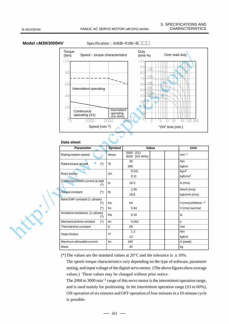
http://www.cncspares.com/
B–65142E/04
3. SPECIFICATIONS ANDCHARACTERISTICSFANUC AC SERVO MOTOR αM (HV) series
261
Specification : A06B–0186–B
Speed – torque characteristics
Speed (min–1) ”ON” time (min.)
Over load dutyTorque (Nm)
Duty (time %)
ÂÂÂÂÂÂÂÂÂÂÂÂIntermittent operating
ÂÂÂÂÂÂÂÂÂÂÂÂ
Intermittent operating(S3–60%)
ÂÂÂÂÂÂÂÂÂÂ
Continuous operating (S1)
Data sheetParameter Symbol Value Unit
Rating rotation speed Nmax2000 (S1)3000 (S3–60%) min -1
Rated torque at stall (*) Ts30
306
Nm
kgfcm
Rotor inertia Jm 0.011
0.11
kgm2
kgfcms2
Continuous RMS current at stall (*) Is 16.3 A (rms)
Torque constant (*) Kt1.85
18.8
Nm/A (rms)
kgfcm/A (rms)
Back EMF constant (1–phase)(*)
(*)
Ke
Kv
64
0.64
V (rms)/1000min -1
V (rms)·sec/rad
Armature resistance (1–phase)(*) Ra 0.16 Ω
Mechanical time constant (*) tm 0.002 s
Thermal time constant tt 65 min
Static friction Tf 1.2
12
Nm
kgfcm
Maximum allowable current Im 160 A (peak)
Mass 30 kg
(*)The values are the standard values at 20°C and the tolerance is 10%.
The speed–torque characteristics very depending on the type of software, parameter
setting, and input voltage of the digital servo motor. (The above figures show average
values.) These values may be changed without prior notice.
The 2000 to 3000 min–1 range of this servo motor is the intermittent operation range,
and is used mainly for positioning. In the intermittent operation range (S3 to 60%),
ON operation of six minutes and OFF operation of four minutes in a 10-minute cycle
is possible.
Model αM30/3000HV
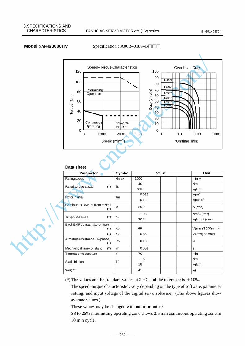
http://www.cncspares.com/
3.SPECIFICATIONS AND CHARACTERISTICS B–65142E/04FANUC AC SERVO MOTOR αM (HV) series
262
Specification : A06B–0189–B
0
10
20
30
40
50
6070
80
90
100
1 10 100 10000
20
40
60
80
100
120
0 1000 2000 3000
140%150%160%
110%
120%
130%
Over Load Duty
“On”time (min)
Speed–Torque Characteristics
Speed (min–1)
IntermittingOperation
S3–25%Inter.Op.
Torq
ue (N
m)
Dut
y (t
ime%
)
ContinuousOperating
Data sheetParameter Symbol Value Unit
Rating speed Nmax 1000 min -1
Rated torque at stall (*) Ts40
408
Nm
kgfcm
Rotor inertia Jm 0.012
0.12
kgm2
kgfcms2
Continuous RMS current at stall (*) Is 20.2 A (rms)
Torque constant (*) Kt1.98
20.2
Nm/A (rms)
kgfcm/A (rms)
Back EMF constant (1–phase)(*)
(*)
Ke
Kv
69
0.66
V (rms)/1000min -1
V (rms)·sec/rad
Armature resistance (1–phase)(*) Ra 0.13 Ω
Mechanical time constant (*) tm 0.001 s
Thermal time constant tt 70 min
Static friction Tf 1.8
18
Nm
kgfcm
Weight 41 kg
(*)The values are the standard values at 20°C and the tolerance is 10%.
The speed–torque characteristics very depending on the type of software, parameter
setting, and input voltage of the digital servo software. (The above figures show
average values.)
These values may be changed without prior notice.
S3 to 25% intermitting operating zone shows 2.5 min continuous operating zone in
10 min cycle.
Model αM40/3000HV

http://www.cncspares.com/
B–65142E/04
3. SPECIFICATIONS ANDCHARACTERISTICSFANUC AC SERVO MOTOR αM (HV) series
263
On the following models, the intermittent operating zone can be extendedby using HRV control.
Torq
ue (N
m)
ÂÂÂÂÂÂÂÂÂÂÂÂÂÂIntermittent operating
ÂÂÂÂÂÂÂÂÂÂÂÂÂÂContinuous operating
Torq
ue (N
m)
ÂÂÂÂÂÂÂÂÂÂÂÂÂÂ
Intermittent operating
ÂÂÂÂÂÂÂÂÂÂÂÂÂÂContinuous operating
NOTEHRV control sometimes cannot be used depending on theCNC system. Using HRV control increases the intermittentoperating zone at high motor operating speeds. Thecontinuous operating zone, however, is the same as whenconventional control methods are used.
(Remarks)Speed–torquecharacteristics (HRV control)
αM6/3000HV
αM9/3000HV
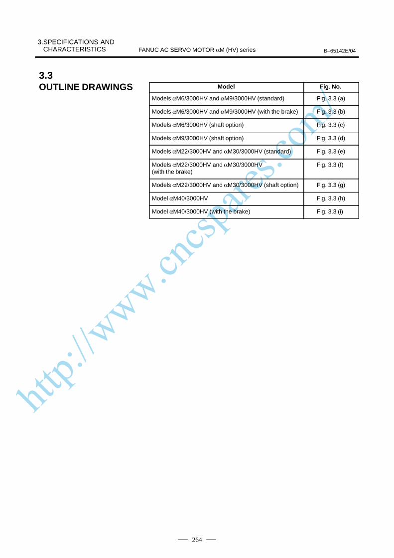
http://www.cncspares.com/
3.SPECIFICATIONS AND CHARACTERISTICS B–65142E/04FANUC AC SERVO MOTOR αM (HV) series
264
Model Fig. No.
Models αM6/3000HV and αM9/3000HV (standard) Fig. 3.3 (a)
Models αM6/3000HV and αM9/3000HV (with the brake) Fig. 3.3 (b)
Models αM6/3000HV (shaft option) Fig. 3.3 (c)
Models αM9/3000HV (shaft option) Fig. 3.3 (d)
Models αM22/3000HV and αM30/3000HV (standard) Fig. 3.3 (e)
Models αM22/3000HV and αM30/3000HV (with the brake)
Fig. 3.3 (f)
Models αM22/3000HV and αM30/3000HV (shaft option) Fig. 3.3 (g)
Model αM40/3000HV Fig. 3.3 (h)
Model αM40/3000HV (with the brake) Fig. 3.3 (i)
3.3OUTLINE DRAWINGS
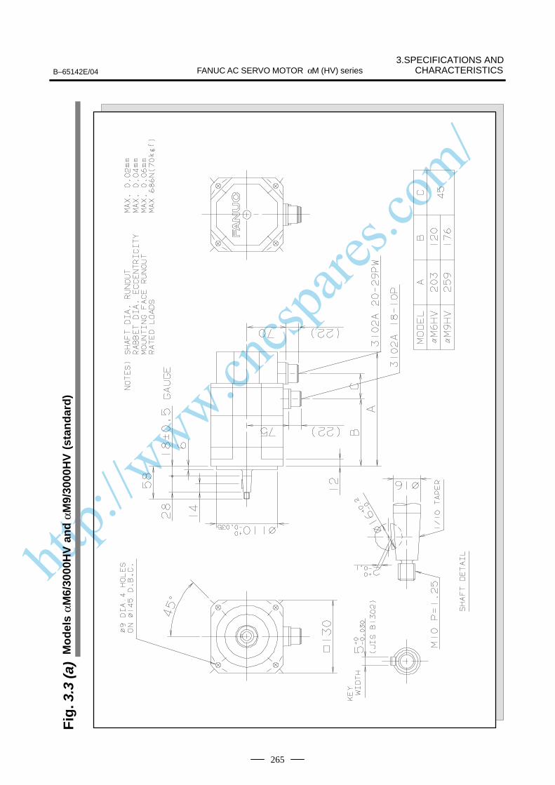
http://www.cncspares.com/
3.SPECIFICATIONS ANDCHARACTERISTICSB–65142E/04 FANUC AC SERVO MOTOR αM (HV) series
265
Fig
. 3.3
(a)
Mo
del
s αM
6/30
00H
V a
nd
αM
9/30
00H
V (
stan
dar
d)
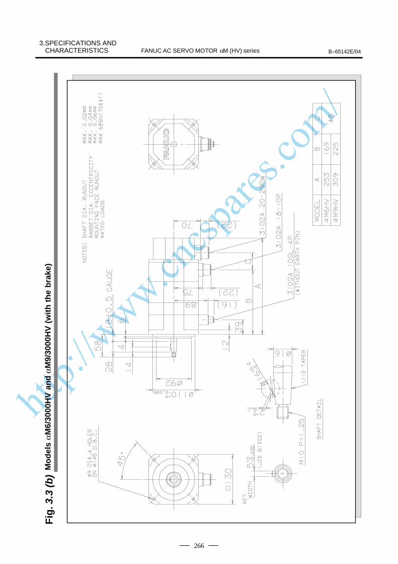
http://www.cncspares.com/
FANUC AC SERVO MOTOR αM (HV) series B–65142E/04
3.SPECIFICATIONS ANDCHARACTERISTICS
266
Fig
. 3.3
(b)
Mo
del
s αM
6/30
00H
V a
nd
αM
9/30
00H
V (
wit
h t
he
bra
ke)
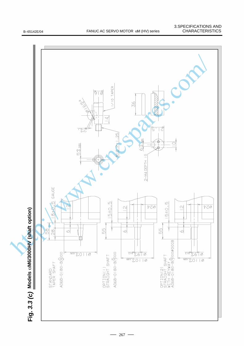
http://www.cncspares.com/
3.SPECIFICATIONS ANDCHARACTERISTICSB–65142E/04 FANUC AC SERVO MOTOR αM (HV) series
267
Fig
. 3.3
(c)
Mo
del
s αM
6/30
00H
V (
shaf
t o
pti
on
)
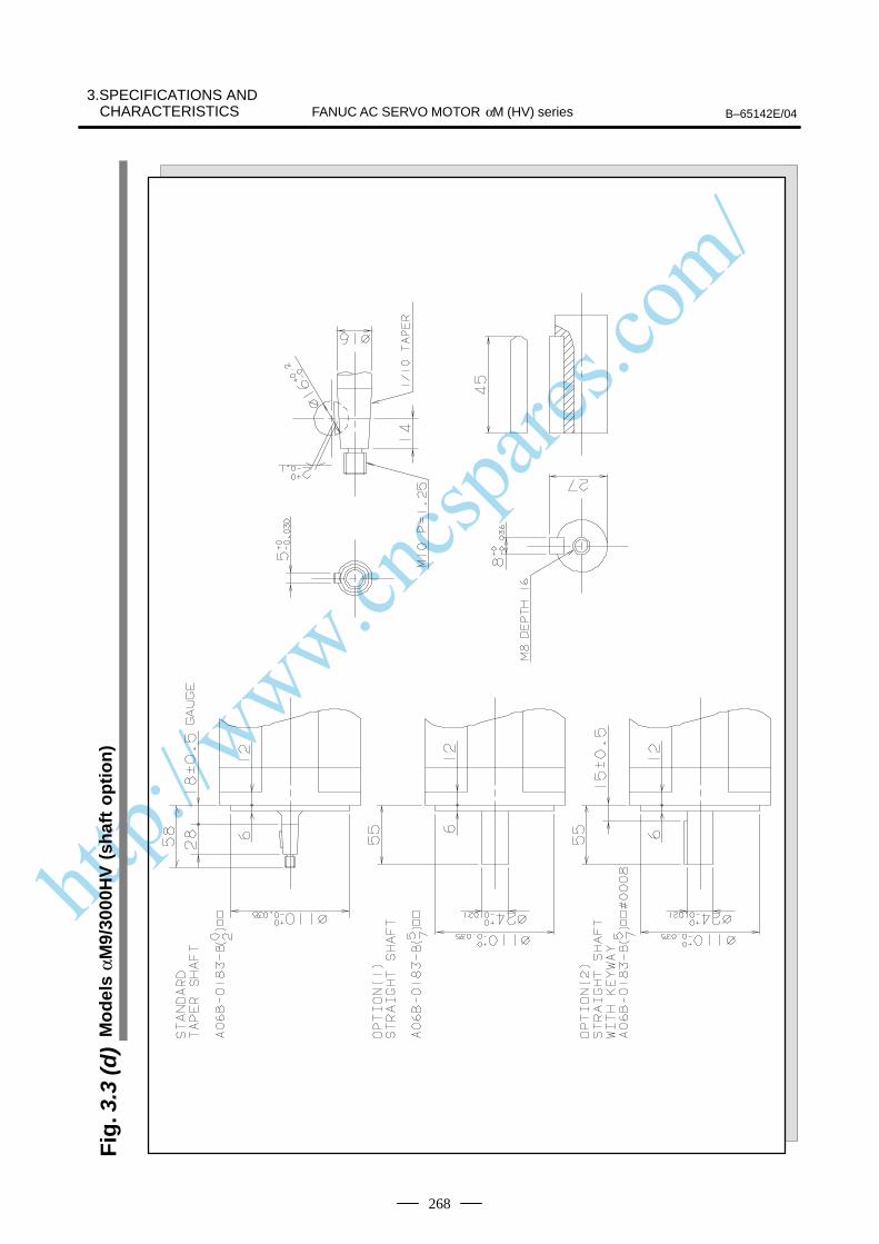
http://www.cncspares.com/
FANUC AC SERVO MOTOR αM (HV) series B–65142E/04
3.SPECIFICATIONS ANDCHARACTERISTICS
268
Fig
. 3.3
(d)
Mo
del
s αM
9/30
00H
V (
shaf
t o
pti
on
)
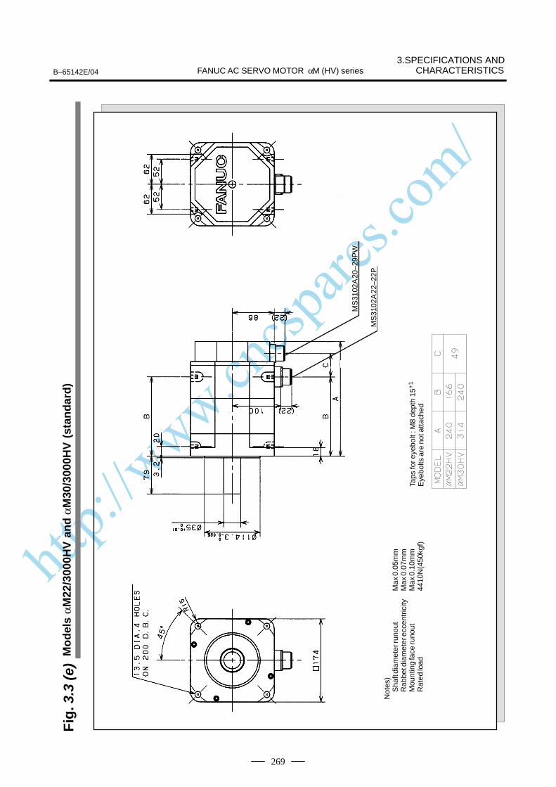
http://www.cncspares.com/
3.SPECIFICATIONS ANDCHARACTERISTICSB–65142E/04 FANUC AC SERVO MOTOR αM (HV) series
269
Fig
. 3.3
(e)
Mo
del
s αM
22/3
000H
V a
nd
αM
30/3
000H
V (
stan
dar
d)
Not
es)
Sha
ft di
amet
er ru
nout
Max
0.0
5mm
Rab
bet d
iam
eter
ecc
entr
icity
Max
0.0
7mm
Mou
ntin
g fa
ce ru
nout
Max
0.1
0mm
Rat
ed lo
ad44
10N
(450
kgf)
Taps
for e
yebo
lt : M
8 de
pth
15+
1
Eye
bolts
are
not
atta
ched
MS
3102
A 2
0–29
PW
MS
3102
A 2
2–22
P
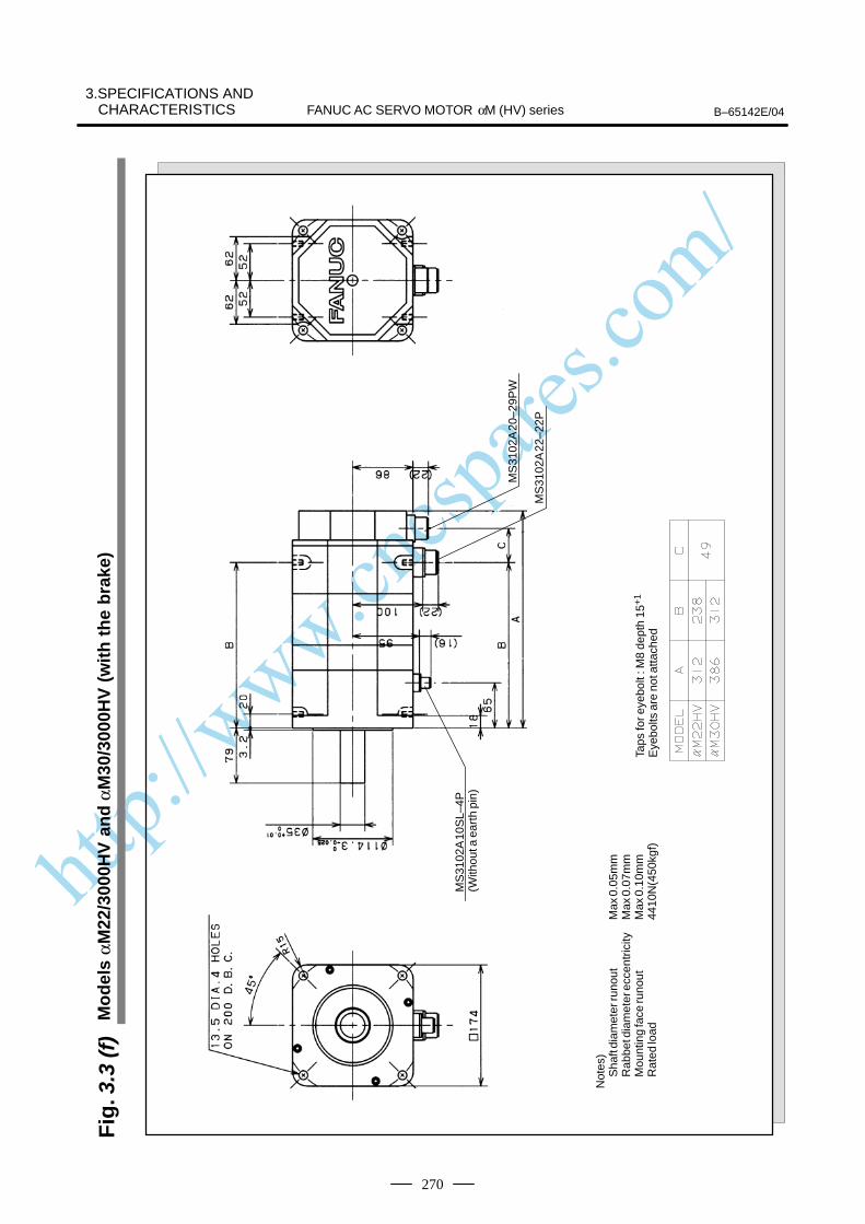
http://www.cncspares.com/
FANUC AC SERVO MOTOR αM (HV) series B–65142E/04
3.SPECIFICATIONS ANDCHARACTERISTICS
270
Fig
. 3.3
(f)
Mo
del
s αM
22/3
000H
V a
nd
αM
30/3
000H
V (
wit
h t
he
bra
ke)
Not
es)
Sha
ft di
amet
er ru
nout
Max
0.0
5mm
Rab
bet d
iam
eter
ecc
entr
icity
Max
0.0
7mm
Mou
ntin
g fa
ce ru
nout
Max
0.1
0mm
Rat
ed lo
ad44
10N
(450
kgf)
Taps
for e
yebo
lt : M
8 de
pth
15+
1
Eye
bolts
are
not
atta
ched
MS
3102
A 1
0SL–
4P(W
ithou
t a e
arth
pin
)
MS
3102
A 2
0–29
PW
MS
3102
A 2
2–22
P
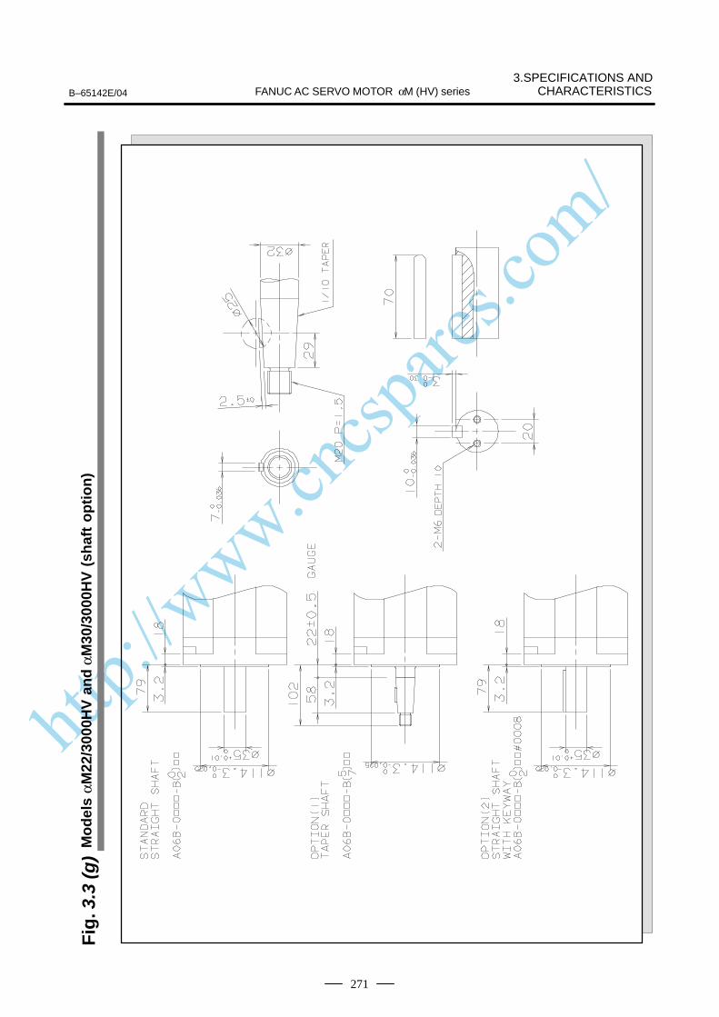
http://www.cncspares.com/
3.SPECIFICATIONS ANDCHARACTERISTICSB–65142E/04 FANUC AC SERVO MOTOR αM (HV) series
271
Fig
. 3.3
(g)
Mo
del
s αM
22/3
000H
V a
nd
αM
30/3
000H
V (
shaf
t o
pti
on
)
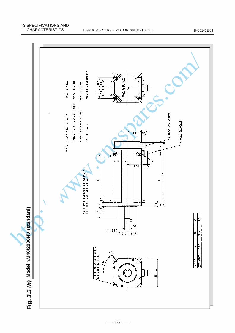
http://www.cncspares.com/
FANUC AC SERVO MOTOR αM (HV) series B–65142E/04
3.SPECIFICATIONS ANDCHARACTERISTICS
272
Fig
. 3.3
(h)
Mo
del
αM
40/2
000H
V (
stan
dar
d)

http://www.cncspares.com/
3.SPECIFICATIONS ANDCHARACTERISTICSB–65142E/04 FANUC AC SERVO MOTOR αM (HV) series
273
Fig
. 3.3
(i)
Mo
del
αM
40/2
000H
V (
wit
h t
he
bra
ke)
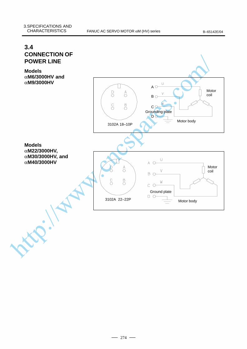
http://www.cncspares.com/
3.SPECIFICATIONS AND CHARACTERISTICS B–65142E/04FANUC AC SERVO MOTOR αM (HV) series
274
A
B
C
D
3102A 18–10P
Grounding plate
Motor body
Motor coil
3102A 22–22P
Ground plate
Motor body
Motor coil
3.4CONNECTION OFPOWER LINE
Models αM6/3000HV andαM9/3000HV
Models αM22/3000HV,αM30/3000HV, andαM40/3000HV
http://www.cncspares.com/
VIII. SUPPLEMENT
(Following AC servo motors are extended theallowable maximum speed.)
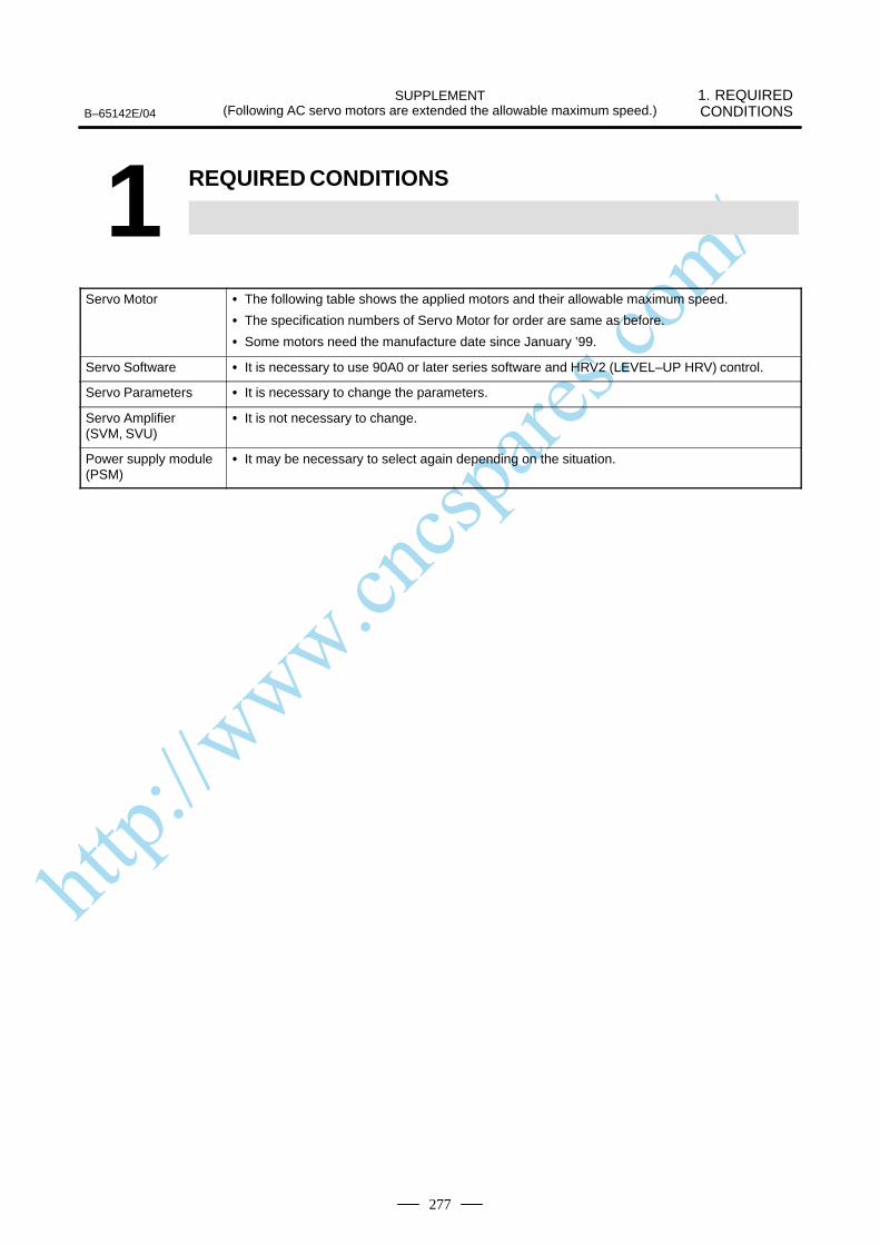
http://www.cncspares.com/
1. REQUIRED CONDITIONS
SUPPLEMENT(Following AC servo motors are extended the allowable maximum speed.)B–65142E/04
277
1 REQUIRED CONDITIONS
Servo Motor The following table shows the applied motors and their allowable maximum speed.
The specification numbers of Servo Motor for order are same as before.
Some motors need the manufacture date since January ’99.
Servo Software It is necessary to use 90A0 or later series software and HRV2 (LEVEL–UP HRV) control.
Servo Parameters It is necessary to change the parameters.
Servo Amplifier (SVM, SVU)
It is not necessary to change.
Power supply module (PSM)
It may be necessary to select again depending on the situation.

http://www.cncspares.com/
2. SERVO MOTOR
SUPPLEMENT(Following AC servo motors are extended the allowable maximum speed.) B–65142E/04
278
2
The following table shows the applied motors and their allowablemaximum speed.
The specification numbers of Servo Motor for order are same asbefore.
Some motors need the manufacture date since January ’99.
Allowable maximum speed Applicable
Before After
Applicablemanufacture date
α12/3000 3000min–1 4000min–1 since Jan. 1999
α22/3000 3000min–1 4000min–1 since Jan. 1999
α30/3000 3000min–1 4000min–1 since Jan. 1999
α40/2000 2000min–1 2500min–1 – not required
α40/2000 withfan
2000min–1 2500min–1 – not required
α65/2000 2000min–1 2500min–1 – not required
α100/2000 2000min–1 2500min–1 – not required
α150/2000 2000min–1 2500min–1 – not required
αM22/3000 3000min–1 4000min–1 – not required
αM30/3000 3000min–1 4000min–1 – not required
α12/3000HV 3000min–1 4000min–1 since Jan. 1999
αM22/3000HV 3000min–1 4000min–1 – not required
αM30/3000HV 3000min–1 4000min–1 – not required
NOTEα22/3000HV and α30/3000HV are not extend themaximum allowable speed for the moment.
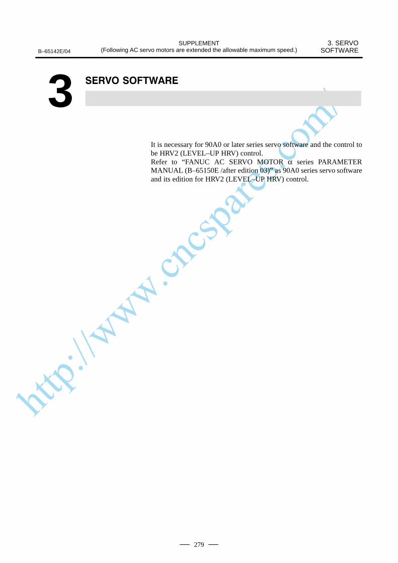
http://www.cncspares.com/
3. SERVOSOFTWARE
SUPPLEMENT(Following AC servo motors are extended the allowable maximum speed.)B–65142E/04
279
3
It is necessary for 90A0 or later series servo software and the control tobe HRV2 (LEVEL–UP HRV) control.Refer to “FANUC AC SERVO MOTOR α series PARAMETERMANUAL (B–65150E /after edition 03)” as 90A0 series servo softwareand its edition for HRV2 (LEVEL–UP HRV) control.
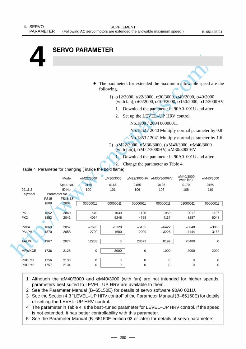
http://www.cncspares.com/
4. SERVOPARAMETER
SUPPLEMENT(Following AC servo motors are extended the allowable maximum speed.) B–65142E/04
280
4
The parameters for extended the maximum allowable speed are thefollowing.
1) α12/3000, α22/3000, α30/3000, α40/2000, α40/2000 (with fan), α65/2000, α100/2000, α150/2000, α12/3000HV
1. Download the parameter in 90A0–001U and after.
2. Set up the LEVEL–UP HRV control.
No.1809 / 2004 00000011
No.1852 / 2040 Multiply normal parameter by 0.8
No.1853 / 2041 Multiply normal parameter by 1.6
2) αM22/3000, αM30/3000, (αM40/3000, αM40/3000 (with fan)), αM22/3000HV, αM30/3000HV
1. Download the parameter in 90A0–001U and after.
2. Change the parameter as Table 4.Table 4 Parameter for changing ( inside the bold flame)
Model αM22/3000 αM30/3000 αM22/3000HV αM30/3000HV αM40/3000(with fan) αM40/3000
Spec. No. 0165 0166 0185 0186 0170 016999.11.2 ID No. 100 101 106 107 108 110
Symbol Parameter No.FS15 FS16,181809 2004 00000011 00000011 00000011 00000011 01000011 00000011
PK1 1852 2040 670 1030 1120 1059 2017 1197PK2 1853 2041 –4054 –5246 –4755 –4117 –8287 –5048
PVPA 1869 2057 –7695 –5129 –5135 –6422 –3848 –3865PALPH 1870 2058 –2700 –1680 –2000 –3226 –1144 –3168
AALPH 1967 2074 12288 0 28672 8192 20480 0
MFWKCE 1736 2128 0 8000 0 1000 2000 2000
PHDLY1 1756 2133 0 0 0 0 0 0PHDLY2 1757 2134 0 0 0 0 0 0
1 Although the αM40/3000 and αM40/3000 (with fan) are not intended for higher speeds,parameters best suited to LEVEL–UP HRV are available to them.
2 See the Parameter Manual (B–65150E) for details of servo software 90A0 001U.3 See the Section 4.3 “LEVEL–UP HRV control” of the Parameter Manual (B–65150E) for details
of setting the LEVEL–UP HRV control.4 The parameter in Table 4 is the best–tuned parameter for LEVEL–UP HRV control. If the speed
is not extended, it has better controllability with this parameter.5 See the Parameter Manual (B–65150E edition 03 or later) for details of servo parameters.

http://www.cncspares.com/
5. SELECTING PSM
SUPPLEMENT(Following AC servo motors are extended the allowable maximum speed.)B–65142E/04
281
5
In case of the using motors with extended speed, it is necessary to use“Case 2” for accelerating maximum output in “FANUC SERVOAMPLIFIER α series DESCRIPTIONS (B–65162/after edition 03)” Refer to FANUC SERVO AMPLIFIER α series DESCRIPTIONS(B–65162/after edition 03)” as the details.
http://www.cncspares.com/
6. “CHARACTERISTICS CURVE” AND “DATA SHEET”
SUPPLEMENT(Following AC servo motors are extended the allowable maximum speed.) B–65142E/04
282
6 “ “
“Characteristics Curve” and “Data sheet” are shown in following pages.

http://www.cncspares.com/
6. “CHARACTERISTICS CURVE” AND
“DATA SHEET”SUPPLEMENT
(Following AC servo motors are extended the allowable maximum speed.)B–65142E/04
283
Specification : A06B–0143–B
0
10
20
30
40
50
6070
80
90
100
1 10 100 1000
110%
120%
130%
140%150%160%
0
5
10
15
20
25
30
35
40
0 1000 2000 3000 4000
Over Load Duty
“On”time (min)
Speed–Torque Characteristics
Speed (min–1)
IntermittingOperation
S3–60%Inter.Op.
Torq
ue (N
m)
Dut
y (t
ime%
)
ContinuousOperating
Data sheetParameter Symbol Value Unit
Rating speed Nmax 3000 min -1
Maximum speed Nlim 4000 min -1
Rated torque at stall (*) Ts12
122
Nm
kgfcm
Rotor inertia Jm6.2E–3
6.4E–2
kgm2
kgfcms2
Continuous RMS current at stall (*) Is 15.5 A (rms)
Torque constant (*) Kt0.77
7.9
Nm/A (rms)
kgfcm/A (rms)
Back EMF constant (1–phase)(*)
(*)
Ke
Kv
27.1
0.26
V (rms)/1000min -1
V (rms)·sec/rad
Armature resistance (1–phase)(*) Ra 0.18 Ω
Mechanical time constant (*) tm 0.006 s
Thermal time constant tt 60 min
Static friction Tf0.8
8
Nm
kgfcm
Weight 18 kg
(*)The values are the standard values at 20°C and the tolerance is 10%.
The speed–torque characteristics very depending on the type of software, parameter
setting, and input voltage of the digital servo software. (The above figures show
average values.)
These values may be changed without prior notice.
S3 to 60% intermitting operating zone shows 6 min “ON” and 4 min “OFF” in 10 min
cycle.
Model α12/3000

http://www.cncspares.com/
6. “CHARACTERISTICS CURVE” AND “DATA SHEET”
SUPPLEMENT(Following AC servo motors are extended the allowable maximum speed.) B–65142E/04
284
Specification : A06B–0148–B
0
10
20
30
40
50
6070
80
90
100
1 10 100 1000
110%
120%
130%
140%150%160%
0 1000 2000 3000 40000
10
20
30
40
50
60
70Over Load Duty
“On”time (min)
Speed–Torque Characteristics
Speed (min–1)
IntermittingOperation
S3–60%Inter.Op.
Torq
ue (N
m)
Dut
y (t
ime%
)
ContinuousOperating
Data sheetParameter Symbol Value Unit
Rating speed Nmax 3000 min -1
Maximum speed Nlim 4000 min -1
Rated torque at stall (*) Ts22
224
Nm
kgfcm
Rotor inertia Jm1.2E–2
1.2E–1
kgm2
kgfcms2
Continuous RMS current at stall (*) Is 32.1 A (rms)
Torque constant (*) Kt0.68
7.0
Nm/A (rms)
kgfcm/A (rms)
Back EMF constant (1–phase)(*)
(*)
Ke
Kv
23.9
0.23
V (rms)/1000min -1
V (rms)·sec/rad
Armature resistance (1–phase)(*) Ra 0.05 Ω
Mechanical time constant (*) tm 0.004 s
Thermal time constant tt 65 min
Static friction Tf1.2
12
Nm
kgfcm
Weight 30 kg
(*)The values are the standard values at 20°C and the tolerance is 10%.
The speed–torque characteristics very depending on the type of software, parameter
setting, and input voltage of the digital servo software. (The above figures show
average values.)
These values may be changed without prior notice.
S3 to 60% intermitting operating zone shows 6 min “ON” and 4 min “OFF” in 10 min
cycle.
Model α22/3000

http://www.cncspares.com/
6. “CHARACTERISTICS CURVE” AND
“DATA SHEET”SUPPLEMENT
(Following AC servo motors are extended the allowable maximum speed.)B–65142E/04
285
Specification : A06B–0153–B
0
10
20
30
40
50
6070
80
90
100
1 10 100 1000
110%
120%
130%
140%150%160%
0 1000 2000 3000 40000
10
20
30
40
50
60
70
80Over Load Duty
“On”time (min)
Speed–Torque Characteristics
Speed (min–1)
IntermittingOperation
S3–60%Inter.Op.
Torq
ue (N
m)
Dut
y (t
ime%
)
ContinuousOperating
Data sheetParameter Symbol Value Unit
Rating speed Nmax 3000 min -1
Maximum speed Nlim 4000 min -1
Rated torque at stall (*) Ts30
306
Nm
kgfcm
Rotor inertia Jm1.7E–2
1.7E–1
kgm2
kgfcms2
Continuous RMS current at stall (*) Is 33.7 A (rms)
Torque constant (*) Kt0.89
9.1
Nm/A (rms)
kgfcm/A (rms)
Back EMF constant (1–phase)(*)
(*)
Ke
Kv
31.1
0.30
V (rms)/1000min -1
V (rms)·sec/rad
Armature resistance (1–phase)(*) Ra 0.05 Ω
Mechanical time constant (*) tm 0.003 s
Thermal time constant tt 70 min
Static friction Tf1.8
18
Nm
kgfcm
Weight 41 kg
(*)The values are the standard values at 20°C and the tolerance is 10%.
The speed–torque characteristics very depending on the type of software, parameter
setting, and input voltage of the digital servo software. (The above figures show
average values.)
These values may be changed without prior notice.
S3 to 60% intermitting operating zone shows 6 min “ON” and 4 min “OFF” in 10 min
cycle.
Model α30/3000
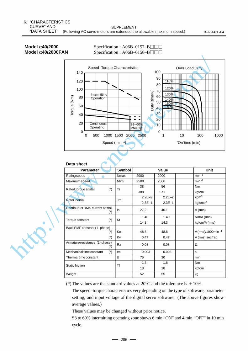
http://www.cncspares.com/
6. “CHARACTERISTICS CURVE” AND “DATA SHEET”
SUPPLEMENT(Following AC servo motors are extended the allowable maximum speed.) B–65142E/04
286
Specification : A06B–0157–B
Specification : A06B–0158–B
0
10
20
30
40
50
6070
80
90
100
1 10 100 1000
110%
120%
130%
140%150%160%
0
20
40
60
80
100
120
140
0 500 1000 1500 2000 2500
Over Load Duty
“On”time (min)
Speed–Torque Characteristics
Speed (min–1)
IntermittingOperation
S3–60%Inter.Op.
Torq
ue (N
m)
Dut
y (t
ime%
)
ContinuousOperating
Data sheetParameter Symbol Value Unit
Rating speed Nmax 2000 2000 min -1
Maximum speed Nlim 2500 2500 min -1
Rated torque at stall (*) Ts38
388
56
571
Nm
kgfcm
Rotor inertia Jm2.2E–2
2.3E–1
2.2E–2
2.3E–1
kgm2
kgfcms2
Continuous RMS current at stall (*) Is 27.2 40.1 A (rms)
Torque constant (*) Kt1.40
14.3
1.40
14.3
Nm/A (rms)
kgfcm/A (rms)
Back EMF constant (1–phase)(*)
(*)
Ke
Kv
48.8
0.47
48.8
0.47
V (rms)/1000min -1
V (rms)·sec/rad
Armature resistance (1–phase)(*) Ra 0.08 0.08 Ω
Mechanical time constant (*) tm 0.003 0.003 s
Thermal time constant tt 75 30 min
Static friction Tf1.8
18
1.8
18
Nm
kgfcm
Weight 52 55 kg
(*)The values are the standard values at 20°C and the tolerance is 10%.
The speed–torque characteristics very depending on the type of software, parameter
setting, and input voltage of the digital servo software. (The above figures show
average values.)
These values may be changed without prior notice.
S3 to 60% intermitting operating zone shows 6 min “ON” and 4 min “OFF” in 10 min
cycle.
Model α40/2000Model α40/2000FAN

http://www.cncspares.com/
6. “CHARACTERISTICS CURVE” AND
“DATA SHEET”SUPPLEMENT
(Following AC servo motors are extended the allowable maximum speed.)B–65142E/04
287
Specification : A06B–0331–B
Over Load Duty
0
10
20
30
40
50
60
70
80
90
100
1 10 100 1000
“On”time (min)
110%
120%
130%140%150%160%
Speed–Torque Characteristics
0
20
40
60
80
100
120
140
160
180
0 500 1000 1500 2000 2500
Speed (min–1)
IntermittingOperation
S3–60%Inter.Op.
Torq
ue (N
m)
Dut
y (t
ime%
)
ContinuousOperating
Data sheetParameter Symbol Value Unit
Rating speed Nmax 2000 min -1
Maximum speed Nlim 2500 min -1
Rated torque at stall (*) Ts65
663
Nm
kgfcm
Rotor inertia Jm1.8E–2
1.9E–1
kgm2
kgfcms2
Continuous RMS current at stall (*) Is 62.5 A (rms)
Torque constant (*) Kt1.04
10.6
Nm/A (rms)
kgfcm/A (rms)
Back EMF constant (1–phase)(*)
(*)
Ke
Kv
36.3
0.35
V (rms)/1000min -1
V (rms)·sec/rad
Armature resistance (1–phase)(*) Ra 0.02 Ω
Mechanical time constant (*) tm 0.001 s
Thermal time constant tt 120 min
Static friction Tf3.7
38
Nm
kgfcm
Weight 80 kg
(*)The values are the standard values at 20°C and the tolerance is 10%.
The speed–torque characteristics very depending on the type of software, parameter
setting, and input voltage of the digital servo software. (The above figures show
average values.)
These values may be changed without prior notice.
S3 to 60% intermitting operating zone shows 6 min “ON” and 4 min “OFF” in 10 min
cycle.
Model α65/2000
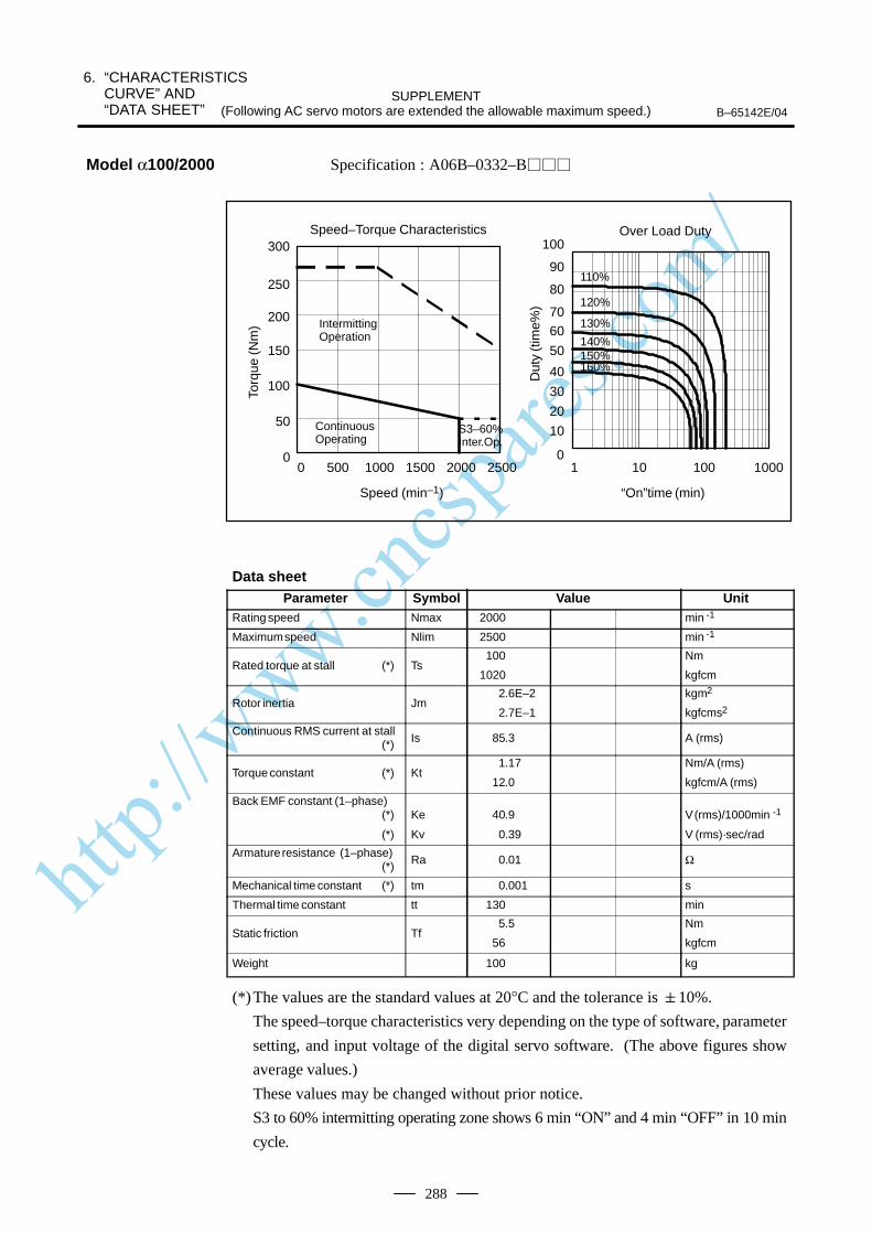
http://www.cncspares.com/
6. “CHARACTERISTICS CURVE” AND “DATA SHEET”
SUPPLEMENT(Following AC servo motors are extended the allowable maximum speed.) B–65142E/04
288
Specification : A06B–0332–B
0
10
20
30
40
50
6070
80
90
100
1 10 100 1000
110%
120%
130%
140%150%160%
0
50
100
150
200
250
300
0 500 1000 1500 2000 2500
Over Load Duty
“On”time (min)
Speed–Torque Characteristics
Speed (min–1)
IntermittingOperation
S3–60%Inter.Op.
Torq
ue (N
m)
Dut
y (t
ime%
)
ContinuousOperating
Data sheetParameter Symbol Value Unit
Rating speed Nmax 2000 min -1
Maximum speed Nlim 2500 min -1
Rated torque at stall (*) Ts100
1020
Nm
kgfcm
Rotor inertia Jm2.6E–2
2.7E–1
kgm2
kgfcms2
Continuous RMS current at stall (*) Is 85.3 A (rms)
Torque constant (*) Kt1.17
12.0
Nm/A (rms)
kgfcm/A (rms)
Back EMF constant (1–phase)(*)
(*)
Ke
Kv
40.9
0.39
V (rms)/1000min -1
V (rms)·sec/rad
Armature resistance (1–phase)(*) Ra 0.01 Ω
Mechanical time constant (*) tm 0.001 s
Thermal time constant tt 130 min
Static friction Tf5.5
56
Nm
kgfcm
Weight 100 kg
(*)The values are the standard values at 20°C and the tolerance is 10%.
The speed–torque characteristics very depending on the type of software, parameter
setting, and input voltage of the digital servo software. (The above figures show
average values.)
These values may be changed without prior notice.
S3 to 60% intermitting operating zone shows 6 min “ON” and 4 min “OFF” in 10 min
cycle.
Model α100/2000
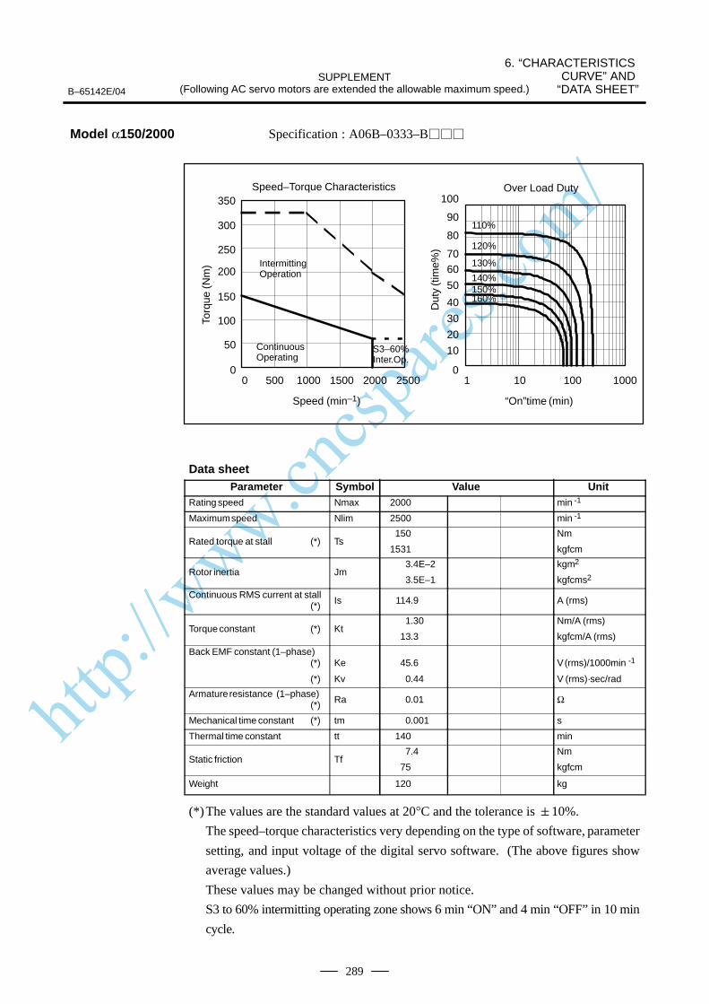
http://www.cncspares.com/
6. “CHARACTERISTICS CURVE” AND
“DATA SHEET”SUPPLEMENT
(Following AC servo motors are extended the allowable maximum speed.)B–65142E/04
289
Specification : A06B–0333–B
0
10
20
30
40
50
6070
80
90
100
1 10 100 1000
110%
120%
130%
140%150%160%
0 500 1000 1500 2000 25000
50
100
150
200
250
300
350Over Load Duty
“On”time (min)
Speed–Torque Characteristics
Speed (min–1)
IntermittingOperation
S3–60%Inter.Op.
Torq
ue (N
m)
Dut
y (t
ime%
)
ContinuousOperating
Data sheetParameter Symbol Value Unit
Rating speed Nmax 2000 min -1
Maximum speed Nlim 2500 min -1
Rated torque at stall (*) Ts150
1531
Nm
kgfcm
Rotor inertia Jm3.4E–2
3.5E–1
kgm2
kgfcms2
Continuous RMS current at stall (*) Is 114.9 A (rms)
Torque constant (*) Kt1.30
13.3
Nm/A (rms)
kgfcm/A (rms)
Back EMF constant (1–phase)(*)
(*)
Ke
Kv
45.6
0.44
V (rms)/1000min -1
V (rms)·sec/rad
Armature resistance (1–phase)(*) Ra 0.01 Ω
Mechanical time constant (*) tm 0.001 s
Thermal time constant tt 140 min
Static friction Tf7.4
75
Nm
kgfcm
Weight 120 kg
(*)The values are the standard values at 20°C and the tolerance is 10%.
The speed–torque characteristics very depending on the type of software, parameter
setting, and input voltage of the digital servo software. (The above figures show
average values.)
These values may be changed without prior notice.
S3 to 60% intermitting operating zone shows 6 min “ON” and 4 min “OFF” in 10 min
cycle.
Model α150/2000

http://www.cncspares.com/
6. “CHARACTERISTICS CURVE” AND “DATA SHEET”
SUPPLEMENT(Following AC servo motors are extended the allowable maximum speed.) B–65142E/04
290
Specification : A06B–0165–B
0
10
20
30
40
50
6070
80
90
100
1 10 100 1000
110%
120%
130%
140%150%160%
00
10
20
30
40
50
60
1000 2000 3000 4000
Over Load Duty
“On”time (min)
Speed–Torque Characteristics
Speed (min–1)
IntermittingOperation
S3–60%Inter.Op.
Torq
ue (N
m)
Dut
y (t
ime%
)
ContinuousOperating
Data sheetParameter Symbol Value Unit
Rating speed Nmax 3000 min -1
Maximum speed Nlim 4000 min -1
Rated torque at stall (*) Ts20
204
Nm
kgfcm
Rotor inertia Jm5.8E–3
5.9E–2
kgm2
kgfcms2
Continuous RMS current at stall (*) Is 26.5 A (rms)
Torque constant (*) Kt0.75
7.7
Nm/A (rms)
kgfcm/A (rms)
Back EMF constant (1–phase)(*)
(*)
Ke
Kv
26.3
0.25
V (rms)/1000min -1
V (rms)·sec/rad
Armature resistance (1–phase)(*) Ra 0.07 Ω
Mechanical time constant (*) tm 0.002 s
Thermal time constant tt 60 min
Static friction Tf0.8
8
Nm
kgfcm
Weight 18 kg
(*)The values are the standard values at 20°C and the tolerance is 10%.
The speed–torque characteristics very depending on the type of software, parameter
setting, and input voltage of the digital servo software. (The above figures show
average values.)
These values may be changed without prior notice.
S3 to 60% intermitting operating zone shows 6 min “ON” and 4 min “OFF” in 10 min
cycle.
Model αM22/3000

http://www.cncspares.com/
6. “CHARACTERISTICS CURVE” AND
“DATA SHEET”SUPPLEMENT
(Following AC servo motors are extended the allowable maximum speed.)B–65142E/04
291
Specification : A06B–0166–B
0
10
20
30
40
50
6070
80
90
100
1 10 100 1000
110%
120%
130%
140%150%160%
00
10
20
30
40
50
60
7080
90
100
1000 2000 3000 4000
Over Load Duty
“On”time (min)
Speed–Torque Characteristics
Speed (min–1)
IntermittingOperation
S3–60%Inter.Op.
Torq
ue (N
m)
Dut
y (t
ime%
)
ContinuousOperating
Data sheetParameter Symbol Value Unit
Rating speed Nmax 2000 min -1
Maximum speed Nlim 4000 min -1
Rated torque at stall (*) Ts30
306
Nm
kgfcm
Rotor inertia Jm1.1E–2
1.1E–1
kgm2
kgfcms2
Continuous RMS current at stall (*) Is 27.9 A (rms)
Torque constant (*) Kt1.08
11.0
Nm/A (rms)
kgfcm/A (rms)
Back EMF constant (1–phase)(*)
(*)
Ke
Kv
37.6
0.36
V (rms)/1000min -1
V (rms)·sec/rad
Armature resistance (1–phase)(*) Ra 0.05 Ω
Mechanical time constant (*) tm 0.001 s
Thermal time constant tt 65 min
Static friction Tf1.2
12
Nm
kgfcm
Weight 30 kg
(*)The values are the standard values at 20°C and the tolerance is 10%.
The speed–torque characteristics very depending on the type of software, parameter
setting, and input voltage of the digital servo software. (The above figures show
average values.)
These values may be changed without prior notice.
S3 to 60% intermitting operating zone shows 6 min “ON” and 4 min “OFF” in 10 min
cycle.
Model αM30/3000
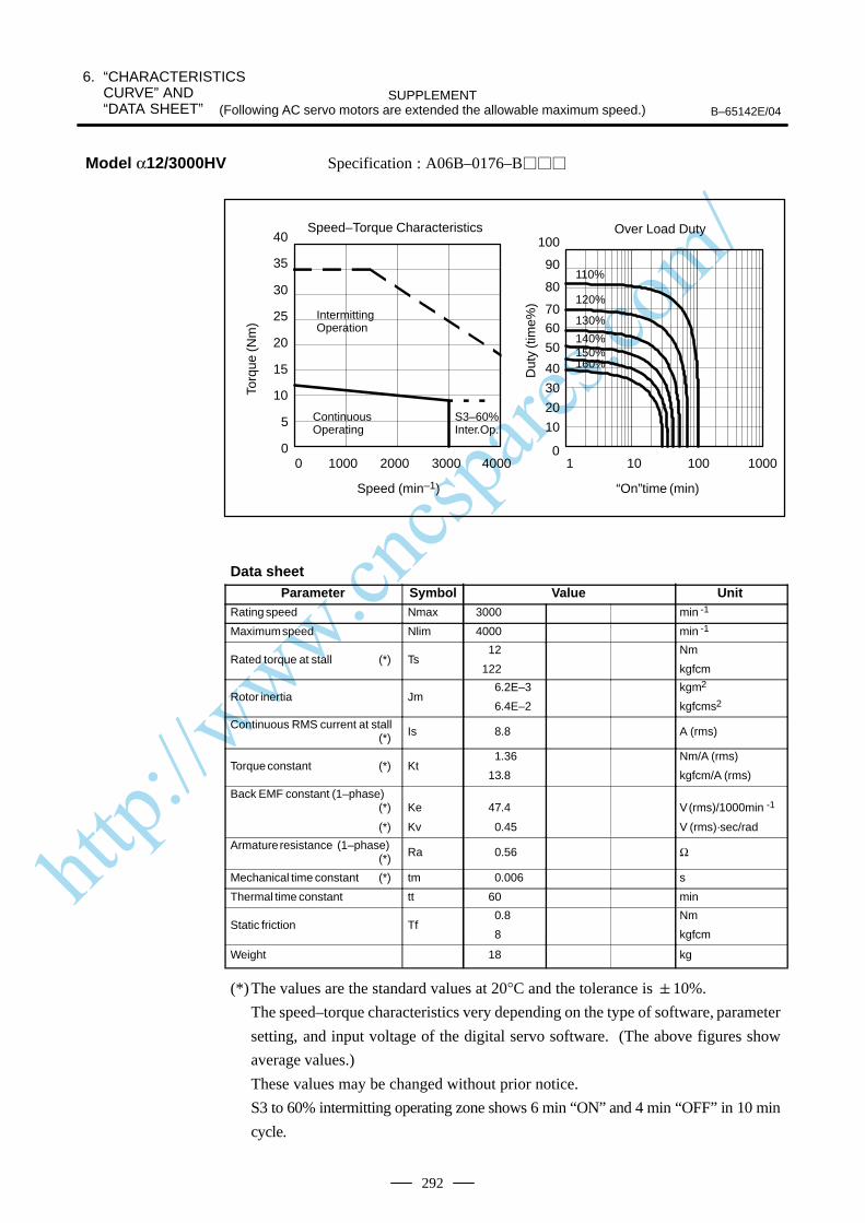
http://www.cncspares.com/
6. “CHARACTERISTICS CURVE” AND “DATA SHEET”
SUPPLEMENT(Following AC servo motors are extended the allowable maximum speed.) B–65142E/04
292
Specification : A06B–0176–B
0
5
10
15
20
25
30
35
0
10
20
30
40
50
6070
80
90
100
1 10 100 1000
110%
120%
130%
140%150%160%
0
40
1000 2000 3000 4000
Over Load Duty
“On”time (min)
Speed–Torque Characteristics
Speed (min–1)
IntermittingOperation
S3–60%Inter.Op.
Torq
ue (N
m)
Dut
y (t
ime%
)
ContinuousOperating
Data sheetParameter Symbol Value Unit
Rating speed Nmax 3000 min -1
Maximum speed Nlim 4000 min -1
Rated torque at stall (*) Ts12
122
Nm
kgfcm
Rotor inertia Jm6.2E–3
6.4E–2
kgm2
kgfcms2
Continuous RMS current at stall (*) Is 8.8 A (rms)
Torque constant (*) Kt1.36
13.8
Nm/A (rms)
kgfcm/A (rms)
Back EMF constant (1–phase)(*)
(*)
Ke
Kv
47.4
0.45
V (rms)/1000min -1
V (rms)·sec/rad
Armature resistance (1–phase)(*) Ra 0.56 Ω
Mechanical time constant (*) tm 0.006 s
Thermal time constant tt 60 min
Static friction Tf0.8
8
Nm
kgfcm
Weight 18 kg
(*)The values are the standard values at 20°C and the tolerance is 10%.
The speed–torque characteristics very depending on the type of software, parameter
setting, and input voltage of the digital servo software. (The above figures show
average values.)
These values may be changed without prior notice.
S3 to 60% intermitting operating zone shows 6 min “ON” and 4 min “OFF” in 10 min
cycle.
Model α12/3000HV
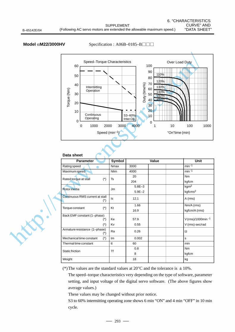
http://www.cncspares.com/
6. “CHARACTERISTICS CURVE” AND
“DATA SHEET”SUPPLEMENT
(Following AC servo motors are extended the allowable maximum speed.)B–65142E/04
293
Specification : A06B–0185–B
0
10
20
30
40
50
6070
80
90
100
1 10 100 1000
110%
120%
130%
140%150%160%
0 1000 2000 3000 40000
10
20
30
40
50
60Over Load Duty
“On”time (min)
Speed–Torque Characteristics
Speed (min–1)
IntermittingOperation
S3–60%Inter.Op.
Torq
ue (N
m)
Dut
y (t
ime%
)
ContinuousOperating
Data sheetParameter Symbol Value Unit
Rating speed Nmax 3000 min -1
Maximum speed Nlim 4000 min -1
Rated torque at stall (*) Ts20
204
Nm
kgfcm
Rotor inertia Jm5.8E–3
5.9E–2
kgm2
kgfcms2
Continuous RMS current at stall (*) Is 12.1 A (rms)
Torque constant (*) Kt1.66
16.9
Nm/A (rms)
kgfcm/A (rms)
Back EMF constant (1–phase)(*)
(*)
Ke
Kv
57.9
0.55
V (rms)/1000min -1
V (rms)·sec/rad
Armature resistance (1–phase)(*) Ra 0.26 Ω
Mechanical time constant (*) tm 0.002 s
Thermal time constant tt 60 min
Static friction Tf0.8
8
Nm
kgfcm
Weight 18 kg
(*)The values are the standard values at 20°C and the tolerance is 10%.
The speed–torque characteristics very depending on the type of software, parameter
setting, and input voltage of the digital servo software. (The above figures show
average values.)
These values may be changed without prior notice.
S3 to 60% intermitting operating zone shows 6 min “ON” and 4 min “OFF” in 10 min
cycle.
Model αM22/3000HV

http://www.cncspares.com/
6. “CHARACTERISTICS CURVE” AND “DATA SHEET”
SUPPLEMENT(Following AC servo motors are extended the allowable maximum speed.) B–65142E/04
294
Specification : A06B–0186–B
0
10
20
30
40
50
6070
80
90
100
1 10 100 1000
110%
120%
130%
140%150%160%
0 1000 2000 3000 4000
0
10
20
30
40
50
60
70
80Over Load Duty
“On”time (min)
Speed–Torque Characteristics
Speed (min–1)
IntermittingOperation
S3–60%Inter.Op.
Torq
ue (N
m)
Dut
y (t
ime%
)
ContinuousOperating
Data sheetParameter Symbol Value Unit
Rating speed Nmax 3000 min -1
Maximum speed Nlim 4000 min -1
Rated torque at stall (*) Ts30
306
Nm
kgfcm
Rotor inertia Jm1.1E–2
1.1E–1
kgm2
kgfcms2
Continuous RMS current at stall (*) Is 16.3 A (rms)
Torque constant (*) Kt1.85
18.8
Nm/A (rms)
kgfcm/A (rms)
Back EMF constant (1–phase)(*)
(*)
Ke
Kv
64.5
0.62
V (rms)/1000min -1
V (rms)·sec/rad
Armature resistance (1–phase)(*) Ra 0.16 Ω
Mechanical time constant (*) tm 0.002 s
Thermal time constant tt 65 min
Static friction Tf1.2
12
Nm
kgfcm
Weight 30 kg
(*)The values are the standard values at 20°C and the tolerance is 10%.
The speed–torque characteristics very depending on the type of software, parameter
setting, and input voltage of the digital servo software. (The above figures show
average values.)
These values may be changed without prior notice.
S3 to 60% intermitting operating zone shows 6 min “ON” and 4 min “OFF” in 10 min
cycle.
Model αM30/3000HV
http://www.cncspares.com/
IndexB–65142E/04
i–1
[Numbers]200 VAC input types, 56, 58
400 VAC input types, 57, 58
[A]About connector cables, 100
Absolute–type pulse coder, 69
Acceptance and storage, 21
Applicable Amplifiers, 6
Applicable amplifiers, 6
Applicable motors, 56
Approved specifications, 63
Axis load, 17
[B]Brake cable (TUV/EMC compatible), 84
Brake specifications, 80
Built–in brake, 79
Built–in detector, 67
[C]Cable assembly specifications (α3 or above) (14m
standard), 98
Cable assembly specifications (14m standard) (for α1and α2), 90
Calculating conditions for selecting a motor, 28
Calculating the acceleration torque, 34
Calculating the load torque and load inertia, 29
Calculating the percentage duty cycle with the maxi-mum cutting torque, 39
Calculating the root–mean–square value of thetorques, 37
Characteristic curve and data sheet, 52, 112, 154, 187,205, 226, 256
Characteristics Curve” and “Data Sheet”, 282
Conditions for approval related to the IEC34 standard,55
Connection of power line, 144, 180, 198, 217, 247,274
Connection of the brakes, 83
Connector kit specifications, 89
Connector on the motor side, 87
Connector shapes, 82
Connectors, 86
Connectors on the cable side (models α1 and α2), 89
Cooling fan, 99
Cooling fan specifications, 100
Cooling method (ICE34–6), 64
Coupling, 15
[D]Data, 45
Data for Selecting PSM, 13
Data sheet, 52
Detector input/output signals, 70
Drive shaft coupling, 23
Drives, 58
[E]Environment, 18
External dimensions of separate type pulse coder, 75
[F]Feedback detector, 66
[H]Heat protection (IEC34–11), 65
How to fill in the servo motor selection data table, 43
How to use duty cycle curves, 54
[I]Input signals and layout of connector pins of separate
type pulse coder, 73
Installation, 14
Instructions, 22
[M]Machine movement per 1 revolution of motor shaft,
26
Models α1 and α2, 59
Models α3 and higher, 61
Motor connector specifications, 100
http://www.cncspares.com/
Index B–65142E/04
i–2
Motor speed (IEC34–1), 63
Mounting method (IEC34–7), 65
[O]Outline drawings, 128, 166, 193, 210, 236, 264
Output (IEC34–1), 64
[P]Performance curves, 52
Power cable connectors, 59
Precautions for using linear scale, 41
Precautions on use, 5
Protection type (IEC34–5), 64
Pulse coder resolution and control resolution, 68
[R]Recommended parts in brake circuits, 84
Reducing the brake shaft fall amount, 85
Required Conditions, 277
[S]Selecting a motor, 27
Selecting PSM, 281
Separate type position detector, 71
Separate type pulse coder specifications, 72
Separate type pulse coder type and specifications, 71
Servo Motor, 278
Servo Parameter, 280
Servo Software, 279
Specifications and characteristics, 109, 152, 185, 203,224, 254
Specifications of connectors on the motor side, 87
Specifications of plug connectors on the cable side(non–waterproof type), 96
Specifications of plug connectors on the cable side(waterproof TÜV–approved type), 93
Specifications of plug connectors on the cable side(waterproof type), 94
Specifications of the connectors on the cable side(models α3 and higher), 91
[T]Title, 44
Type of motors and specifications, 110
Types of motors and designation, 106, 150, 184, 202,222, 252
Types of motors and specifications, 153, 186, 204,225, 255
[W]Wiring diagram, 101
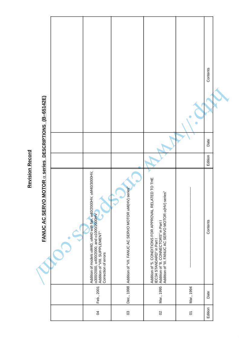
http://www.cncspares.com/
Rev
isio
n R
eco
rd
FAN
UC
AC
SE
RV
O M
OTO
R
ser
ies
DE
SC
RIP
TIO
NS
(B
–651
42E
)
04F
eb.,
2001
Add
ition
of m
odel
s αM
40, α
M40
with
fan,
α40
/200
0HV
, αM
40/3
000H
V,
α300
/200
0, α
400/
2000
, and
α10
00/2
000H
VA
dditi
on o
f “V
III. S
UP
PLE
ME
NT
”C
orre
ctio
n of
err
ors
03D
ec.,
1998
Add
ition
of “
VII.
FA
NU
C A
C S
ER
VO
MO
TO
R α
M(H
V) s
erie
s”
02M
ar.,
1995
Add
ition
of “
5. C
ON
DIT
ION
S F
OR
AP
PR
OV
AL
RE
LAT
ED
TO
TH
EIE
C34
STA
ND
AR
D”
in P
art I
Add
ition
of “
8. C
ON
NE
CT
OR
S”
in P
art I
A
dditi
on o
f “III
. FA
NU
C A
C S
ER
VO
MO
TO
R α
(HV
) ser
ies”
01M
ar.,
1994
____
____
____
____
____
____
____
____
____
____
Edi
tion
Dat
eC
onte
nts
Edi
tion
Dat
eC
onte
nts

http://www.cncspares.com/
· No part of this manual may bereproduced in any form.
· All specifications and designsare subject to change withoutnotice.


