579
GE Fanuc Automation Computer Numerical Control Products Series 15 i / 150 i–Model A Connection Manual (Function) (Volume 2 of 3) GFZ-63323EN-1/03 October 2000

GE Fanuc Automation
Computer Numerical Control Products
Series 15 i / 150 i–Model A
Connection Manual (Function)(Volume 2 of 3)
GFZ-63323EN-1/03 October 2000

GFL-001
Warnings, Cautions, and Notesas Used in this Publication
WarningWarning notices are used in this publication to emphasize that hazardous voltages, currents,temperatures, or other conditions that could cause personal injury exist in this equipment or maybe associated with its use.
In situations where inattention could cause either personal injury or damage to equipment, aWarning notice is used.
CautionCaution notices are used where equipment might be damaged if care is not taken.
NoteNotes merely call attention to information that is especially significant to understanding andoperating the equipment.
This document is based on information available at the time of its publication. While effortshave been made to be accurate, the information contained herein does not purport to cover alldetails or variations in hardware or software, nor to provide for every possible contingency inconnection with installation, operation, or maintenance. Features may be described herein whichare not present in all hardware and software systems. GE Fanuc Automation assumes noobligation of notice to holders of this document with respect to changes subsequently made.
GE Fanuc Automation makes no representation or warranty, expressed, implied, or statutorywith respect to, and assumes no responsibility for the accuracy, completeness, sufficiency, orusefulness of the information contained herein. No warranties of merchantability or fitness forpurpose shall apply.
©Copyright 2000 GE Fanuc Automation North America, Inc.
All Rights Reserved.
B-63323EN-1/03 DEFINITION OF WARNING, CAUTION, AND NOTE
s-1
DEFINITION OF WARNING, CAUTION, AND NOTE
This manual includes safety precautions for protecting the user and preventing damage to the machine.Precautions are classified into Warning and Caution according to their bearing on safety. Also,supplementary information is described as a Note. Read the Warning, Caution, and Note thoroughlybefore attempting to use the machine.
WARNING
Applied when there is a danger of the user being injured or when there is a damage of both the userbeing injured and the equipment being damaged if the approved procedure is not observed.
CAUTION
Applied when there is a danger of the equipment being damaged, if the approvedprocedure is not observed.
NOTE
The Note is used to indicate supplementary information other than Warning andCaution.
- Read this manual carefully, and store it in a safe place.
B-63323EN-1/03 TABLE OF CONTENTS (Volume 1 of 3)
c - 1
TABLE OF CONTENTS (Volume 1 of 3)
1 AXIS CONTROL.....................................................................................11.1 NUMBER OF CONTROLLED AXES .............................................................2
1.2 SETTING EACH AXIS ...................................................................................3
1.2.1 Axis Name ............................................................................................................... 3
1.2.2 Increment System .................................................................................................... 6
1.2.3 Rotation Axis Specification................................................................................... 10
1.2.4 Controlled Axes Detach ........................................................................................ 14
1.2.5 Outputting the Movement State of an Axis ........................................................... 17
1.2.6 Mirror Image.......................................................................................................... 19
1.2.7 Follow-up............................................................................................................... 22
1.2.8 Servo Off (Mechanical handle) ............................................................................. 24
1.2.9 Position Switch...................................................................................................... 26
1.2.10 Vertical Axis Drop Prevention Function............................................................... 30
1.3 ERROR COMPENSATION..........................................................................32
1.3.1 Stored Pitch Error Compensation.......................................................................... 32
1.3.2 Backlash Compensation ........................................................................................ 44
1.3.3 Straightness Compensation.................................................................................... 52
1.3.4 Interpolated straightness compensation................................................................. 57
1.3.5 128 straightness compensation points ................................................................... 60
1.3.6 Interpolated pitch error compensation................................................................... 68
1.3.7 Cyclic second pitch error compensation................................................................ 70
1.3.8 Gradient Compensation ......................................................................................... 76
1.3.9 Bidirectional Pitch Error Compensation ............................................................... 79
1.3.10 Nano Interpolation Type Error Compensation ...................................................... 87
1.3.11 Smooth Backlash Compensation ........................................................................... 89
1.3.12 Addition of 5000 Pitch Error Compensation Points.............................................. 96
1.3.13 Thermal Growth Compensation along Tool Vector .............................................. 98
1.4 THREE-DIMENSIONAL ERROR COMPENSATION.................................111
1.5 SETTINGS RELATED TO SERVO CONTROLLED AXES........................118
1.5.1 Servo Parameter................................................................................................... 119
1.5.2 Absolute Position Detection ................................................................................ 131
1.5.3 FSSB Setting........................................................................................................ 134
1.6 SETTINGS RELATED TO COORDINATE SYSTEMS ..............................158
1.6.1 Machine Coordinate System................................................................................ 158

TABLE OF CONTENTS (Volume 1 of 3) B-63323EN-1/03
c - 2
1.6.2 Workpiece Coordinate System/Addition of Workpiece Coordinate System
Pair ................................................................................................................... 159
1.6.3 Rotation Axis Roll-over....................................................................................... 162
1.6.4 Cutting/Rapid Traverse In-position Check.......................................................... 165
1.7 PARALLEL AXIS CONTROL .....................................................................169
1.8 TANDEM CONTROL .................................................................................175
1.9 SYNCHRONOUS CONTROL ....................................................................185
1.9.1 Configuration of Synchronous Control Axes ...................................................... 186
1.9.2 Synchronous Error Compensation....................................................................... 188
1.9.3 Synchronization Alignment ................................................................................. 190
1.9.4 Synchronous Error Check.................................................................................... 193
1.9.5 Recovery from Excessive Synchronous Error Alarm.......................................... 195
1.9.6 Torque Difference Alarm Detection for Synchronous Control........................... 197
1.10 TWIN-TABLE CONTROL ..........................................................................219
1.10.1 Tool Length Compensation in Tool Axis Direction with Twin Table Control... 224
1.11 CHOPPING FUNCTION ............................................................................232
1.12 ELECTRONIC GEAR BOX ........................................................................246
1.12.1 Command Description (G80.5, G81.5)................................................................ 246
1.12.2 Description of Commands Compatible with Those for a Hobbing Machine ...... 249
1.12.3 Configuration Examples of Controlled Axes ...................................................... 253
1.12.4 Retraction Function ............................................................................................. 256
1.12.5 Automatic phase matching function with electronic gear box ............................ 258
1.13 EGB AXIS SKIP FUNCTION .....................................................................276
1.14 TURNING MODE AND COMPENSATION CLAMP OF DUAL
POSITION FEEDBACK .............................................................................280
1.15 DECELERATION STOP AT POWER FAILURE........................................283
1.16 HIGH SPEED HRV MODE ........................................................................285
1.17 SETUP OF FSSBs IF USING HIGH SPEED HRV CONTROL ..................288
1.18 LOADING OF MULTIPLE SERVO PROGRAMS.......................................294
2 PREAPARATIONS FOR OPERATION...............................................2962.1 EMERGENCY STOP .................................................................................297
2.2 READY SIGNALS......................................................................................301
2.3 OVERTRAVEL CHECK .............................................................................303
2.3.1 Overtravel Signal ................................................................................................. 303
2.3.2 Stored Stroke Check 1 ......................................................................................... 306
2.3.3 Stroke Check 2..................................................................................................... 310
2.3.4 Stroke Limit Check Prior to Performing Movement ........................................... 316
B-63323EN-1/03 TABLE OF CONTENTS (Volume 1 of 3)
c - 3
2.4 ALARM SIGNALS......................................................................................319
2.5 INTERLOCK ..............................................................................................322
2.6 MODE SELECTION...................................................................................327
2.7 STATUS OUTPUT SIGNAL.......................................................................334
2.8 VRDY OFF ALARM IGNORE SIGNAL ......................................................336
2.9 ABNORMAL LOAD DETECTION ..............................................................339
3 MANUAL OPERATION ......................................................................3473.1 JOG FEED/INCREMENTAL FEED............................................................348
3.2 MANUAL HANDLE FEED..........................................................................357
3.3 MANUAL HANDLE CONNECTED TO I/O LINK ........................................362
3.4 MANUAL HANDLE INTERRUPTION.........................................................366
3.5 THREE-DIMENSIONAL HANDLE FEED...................................................367
3.6 MANUAL INTERRUPTION FUNCTION FOR THREE-DIMENSIONAL
COORDINATE CONVERSION..................................................................409
3.7 MANUAL NUMERIC COMMAND ..............................................................412
3.8 MANUAL ARBITRARY-ANGLE FEED.......................................................416
4 REFERENCE POSITION ESTABLISHMENT.....................................4214.1 MANUAL REFERENCE POSITION RETURN...........................................422
4.2 SETTING THE REFERENCE POSITION WITHOUT DOGS ....................435
4.3 REFERENCE POSITION SHIFT ...............................................................439
4.4 REFERENCE POSITION RETURN...........................................................444
4.5 2ND REFERENCE POSITION RETURN/3RD, 4TH REFERENCE
POSITION RETURN..................................................................................446
4.6 FLOATING REFERENCE POSITION RETURN........................................449
4.7 LINEAR SCALE WITH REFERENCE MARKS ..........................................452
4.7.1 Enhancement of Distance Coded Linear Scale ................................................... 461
5 AUTOMATIC OPERATION ................................................................4665.1 CYCLE START/FEED HOLD.....................................................................467
5.2 RESET AND REWIND...............................................................................472
5.3 TESTING A PROGRAM ............................................................................476
5.3.1 Machine Lock...................................................................................................... 476
5.3.2 Dry Run ............................................................................................................... 479
5.3.3 Single Block ........................................................................................................ 483
5.4 MANUAL ABSOLUTE ON/OFF .................................................................486
5.5 OPTIONAL BLOCK SKIP/ADDITION OF OPTIONAL BLOCK SKIP.........489
5.6 SEQUENCE NUMBER COMPARISON AND STOP..................................492
TABLE OF CONTENTS (Volume 1 of 3) B-63323EN-1/03
c - 4
5.7 PROGRAM RESTART...............................................................................493
5.8 BLOCK RESTART.....................................................................................499
5.9 RETRACE..................................................................................................507
5.10 WITHDRAWING AND RETURNING A TOOL ...........................................512
5.11 ACTIVE BLOCK CANCEL .........................................................................519
5.12 EXACT STOP/EXACT STOP MODE/TAPPING MODE/CUTTING
MODE ........................................................................................................524
5.13 DNC OPERATION.....................................................................................526
5.14 REGAINING A MANUAL INTERVENTION AMOUNT DURING
AUTOMATIC OPERATION........................................................................528
5.15 SIMULTANEOUS AUTOMATIC AND MANUAL OPERATION..................534
5.16 DNC OPERATION FROM OPEN CNC SELECTING SIGNAL ..................541
5.17 DNC OPERATION FROM MEMORY CARD INTERFACE ........................543
6 INTERPOLATION FUNCTION ...........................................................5466.1 POSITIONING ...........................................................................................547
6.2 LINEAR INTERPOLATION........................................................................549
6.3 CIRCULAR INTERPOLATION...................................................................552
6.4 THREADING..............................................................................................558
6.4.1 Threading............................................................................................................. 558
6.4.2 Threading Based on an Arbitrary Spindle Gear Ratio......................................... 561
6.5 SINGLE DIRECTION POSITIONING ........................................................566
6.6 HELICAL INTERPOLATION......................................................................568
6.7 HELICAL INTERPOLATION B...................................................................570
6.8 INVOLUTE INTERPOLATION...................................................................572
6.9 SPLINE INTERPOLATION ........................................................................578
6.10 POLAR COORDINATE INTERPOLATION................................................579
6.11 CYLINDRICAL INTERPOLATION .............................................................582
6.12 CYLINDRICAL INTERPOLATION CUTTING POINT CONTROL..............586
6.13 NORMAL DIRECTION CONTROL ............................................................593
6.14 EXPONENTIAL INTERPOLATION............................................................597
6.15 SMOOTH INTERPOLATION .....................................................................599
6.16 HYPOTHETICAL AXIS INTERPOLATION ................................................602
6.17 SPIRAL INTERPOLATION, CONICAL INTERPOLATION ........................603
6.18 NURBS INTERPOLATION ........................................................................607
6.18.1 NURBS Interpolation Additional Functions ....................................................... 610
6.19 3-DIMENSIONAL CIRCULAR INTERPOLATION (G02.4 AND G03.4) .....613

B-63323EN-1/03 TABLE OF CONTENTS (Volume 2 of 3)
c - 5
TABLE OF CONTENTS (Volume 2 of 3)
7 FEEDRATE CONTROL/ACCELERATION AND DECELERATIONCONTROL..........................................................................................6157.1 FEEDRATE CONTROL .............................................................................616
7.1.1 Rapid Traverse Rate ............................................................................................ 617
7.1.2 Cutting Feedrate Clamp....................................................................................... 620
7.1.3 Feed Per Minute .................................................................................................. 621
7.1.4 Feed Per Revolution/Feed Per Revolution Without Position Coder ................... 623
7.1.5 F1-digit Feed........................................................................................................ 625
7.1.6 Feedrate Inverse Time Specification ................................................................... 629
7.1.7 Override ............................................................................................................... 630
7.1.8 Automatic Corner Override ................................................................................. 638
7.1.9 External Deceleration .......................................................................................... 643
7.1.10 Feed Stop Function.............................................................................................. 645
7.1.11 Deceleration Based on Acceleration during Circular Interpolation .................... 646
7.1.12 Advanced Preview Control.................................................................................. 651
7.1.13 Nano Interpolation............................................................................................... 652
7.1.14 Fine HPCC........................................................................................................... 653
7.1.15 Machining type in HPCC screen programming................................................... 667
7.1.16 Feedrate Specification on a Virtual Circle for a Rotary Axis ............................. 668
7.1.17 Automatic Feedrate Control by Area................................................................... 672
7.2 ACCELERATION AND DECELERATION CONTROL ...............................677
7.2.1 Post-interpolation Automatic Acceleration/Deceleration ................................... 677
7.2.2 Look-ahead Acceleration/Deceleration Before interpolation.............................. 687
7.2.3 Corner Control..................................................................................................... 704
7.2.4 Feed Forward in Rapid Traverse ......................................................................... 707
7.2.5 Acceleration/Deceleration before Interpolation of Linear Type Rapid
Traverse ............................................................................................................... 708
8 MISCELLANEOUS FUNCTION .........................................................7128.1 MISCELLANEOUS FUNCTION/2ND AUXILIARY FUNCTION..................713
8.2 AUXILIARY FUNCTION LOCK..................................................................725
8.3 MULTIPLE M COMMANDS IN A SIGLE BLOCK ......................................726
8.4 HIGH-SPEED M/S/T/B INTERFACE .........................................................730
9 SPINDLE FUNCTION.........................................................................734

TABLE OF CONTENTS (Volume 2 of 3) B-63323EN-1/03
c - 6
9.1 SPINDLE SPEED FUNCTION (S CODE OUTPUT) ..................................735
9.2 SPINDLE SERIAL OUTPUT/SPINDLE ANALOG OUTPUT......................737
9.3 SPINDLE CONTROL.................................................................................766
9.4 CONSTANT SURFACE SPEED CONTROL .............................................787
9.5 ACTUAL SPINDLE SPEED OUTPUT .......................................................794
9.6 SPINDLE POSITIONING...........................................................................796
9.7 Cs CONTOUR CONTROL.........................................................................855
9.8 RIGID TAPPING ........................................................................................874
9.8.1 Rigid Tapping Additional Function..................................................................... 934
9.9 SPINDLE ORIENTATION..........................................................................937
9.10 SPINDLE OUTPUT SWITCHING ..............................................................940
9.11 SPINDLE SPEED FLUCTUATION DETECTION.......................................941
10 TOOL FUNCTION ..............................................................................94910.1 TOOL FUNCTION......................................................................................950
10.2 TOOL COMPENSATION VALUE/TOOL COMPENSATION NUMBER/
TOOL COMPENSATION MEMORY..........................................................952
10.2.1 Specification of Diameter Entry for Tool Compensation Value......................... 956
10.3 TOOL LIFE MANAGEMENT FUNCTION ..................................................957
10.4 TOOL COMPENSATION FUNCTION........................................................975
10.4.1 Tool Length Offset .............................................................................................. 975
10.4.2 Tool Offset........................................................................................................... 979
10.4.3 Cutter Compensation ........................................................................................... 982
10.4.4 Three-dimensional Tool Compensation .............................................................. 991
10.4.5 Tool Offsets Based on Tool Numbers ................................................................. 997
10.4.6 Tool Axis Direction Tool Length Compensation.............................................. 1008
10.4.7 Rotary Table Dynamic Fixture Offset ............................................................... 1019
10.4.8 Three-dimensional Cutter Compensation.......................................................... 1026
10.4.9 Designation Direction Tool Length Compensation........................................... 1041
10.4.10 Tool Center Point Control ................................................................................. 1052
10.4.11 Control Point Compensation of Tool Length Compensation Along Tool Axis 1061
10.4.12 Grinding Wheel Wear Compensation................................................................ 1069
10.4.13 Cutter Compensation for Rotary Table ............................................................. 1080
11 PROGRAM COMMAND...................................................................108811.1 DECIMAL POINT PROGRAMMING/POCKET CALCULATOR TYPE
DECIMAL POINT PROGRAMMING ........................................................1089
11.2 PROGRAM CONFIGURATION ...............................................................1091
B-63323EN-1/03 TABLE OF CONTENTS (Volume 2 of 3)
c - 7
11.3 INCH/METRIC CONVERSION ................................................................1094
11.4 DIAMETER SPECIFICATION AND RADIUS SPECIFICATION ..............1097
11.5 CUSTOM MACRO ...................................................................................1099
11.5.1 Custom Macro ................................................................................................... 1099
11.5.2 Interruption Type Custom Macro ...................................................................... 1122
11.6 CANNED CYCLE SPINDLE CONTROL ..................................................1125
11.7 EXTERNAL MOTION FUNCTION ...........................................................1136
11.8 INDEX TABLE INDEXING FUNCTION....................................................1138
11.9 MULTIPLE ROTARY CONTROL AXIS FUNCTION ................................1148
11.10 SCALING .................................................................................................1150
11.11 COORDINATE SYSTEM ROTATION (G68,G69)....................................1154
11.12 THREE-DIMENSIONAL COORDINATE CONVERSION.........................1157
11.13 AXIS INTERCHANGE..............................................................................1165
11.14 OILING SIGNAL (CANNED CYCLE) .......................................................1170

TABLE OF CONTENTS (Volume 3 of 3) B-63323EN-1/03
c - 8
TABLE OF CONTENTS (Volume 1 of 3)
12 DISPLAY/SET/EDIT .........................................................................117512.1 DISPLEY/SET..........................................................................................1176
12.1.1 Clock Function .................................................................................................. 1176
12.1.2 Operation/Alarm History Screen ....................................................................... 1177
12.1.3 Alarm Display.................................................................................................... 1179
12.1.4 Operator Message Display................................................................................. 1181
12.1.5 Servo Adjustment Screen .................................................................................. 1182
12.1.6 Spindle Adjustment Screen ............................................................................... 1183
12.1.7 Waveform Diagnosis Display............................................................................ 1184
12.1.8 Self-diagnosis .................................................................................................... 1185
12.1.9 Hardware/Software System Configuration Screen............................................ 1186
12.1.10 Machined Part Count and Operation Time Display .......................................... 1187
12.1.11 Tool Path Drawing and Background Drawing .................................................. 1191
12.1.12 Operating Monitor Screen ................................................................................. 1193
12.1.13 Machining Time Stamp ..................................................................................... 1194
12.1.14 Menu Switches .................................................................................................. 1196
12.1.15 Software Operator’s Panel ................................................................................. 1197
12.1.16 National Language Display ............................................................................... 1206
12.1.17 Screen Clear Function and Automatic Screen Clear Function.......................... 1207
12.1.18 Touch Panel ....................................................................................................... 1210
12.1.19 Periodic Maintenance Screen ............................................................................ 1214
12.1.20 Maintenance Information Screen....................................................................... 1216
12.1.21 High-speed High-precision Machining Setting Screen ..................................... 1217
12.1.22 Pitch Error Compensation Screen ..................................................................... 1220
12.1.23 Power Mate CNC Manager Function ................................................................ 1222
12.1.24 DI/DO Monitor Function................................................................................... 1231
12.1.25 Brightness Adjustment Screen for Monochrome Display Unit with Graphic
Function ............................................................................................................. 1236
12.1.26 Fine Torque Sensing.......................................................................................... 1238
12.1.27 2-LCD-unit Connection Function...................................................................... 1243
12.1.28 Changing Blinking Displays in G05.1 Q1 Mode............................................... 1246
12.2 EDITING ..................................................................................................1249
12.2.1 Tape Length for Part Program Storage.............................................................. 1249
12.2.2 Number of Programs Stored .............................................................................. 1250
B-63323EN-1/03 TABLE OF CONTENTS (Volume 3 of 3)
c - 9
12.2.3 Memory Protection Keys................................................................................... 1251
12.2.4 Program Encryption........................................................................................... 1252
12.2.5 Background Editing........................................................................................... 1256
12.2.6 Playback............................................................................................................. 1257
12.2.7 Automatic Sequence Number Insertion............................................................. 1259
12.2.8 Editing a Running Program ............................................................................... 1260
12.2.9 DO Signal Output by Soft Key.......................................................................... 1261
12.3 READER/PUNCHER INTERFACE..........................................................1269
13 MEASUREMENT..............................................................................127913.1 TOOL LENGTH MANUAL MEASUREMENT...........................................1280
13.2 WORKPIECE ORIGIN MANUAL SETTING.............................................1281
13.3 TOOL LENGTH/WORKPIECE ORIGIN MEASUREMENT......................1282
13.4 AUTOMATIC TOOL LENGTH MEASUREMENT (G37) ..........................1288
13.4.1 High-speed Measuring Position Reached Signal............................................... 1295
13.5 SKIP FUNCTION .....................................................................................1297
13.5.1 Skip Function..................................................................................................... 1297
13.5.2 High-speed Skip Signal ..................................................................................... 1302
13.5.3 Multi-step Skip .................................................................................................. 1303
13.5.4 Torque Limit Skip ............................................................................................. 1311
13.6 CHANGING ACTIVE OFFSET VALUE WITH MANUAL MOVE..............1317
14 PMC CONTROL FUNCTION............................................................132614.1 PMC AXIS CONTROL .............................................................................1327
14.2 EXTERNAL DATA INPUT........................................................................1377
14.3 EXTERNAL WORKPIECE NUMBER SEARCH.......................................1393
14.4 KEY INPUT FROM PMC .........................................................................1397
��������
A INTERFACE BETWEEN CNC AND PMC ........................................1401A.1 ADDRESS LIST.......................................................................................1402
A.1.1 PMC to NC ........................................................................................................ 1402
A.1.2 CNC to PMC ..................................................................................................... 1423
A.2 SIGNAL LIST ...........................................................................................1444
A.2.1 Signal List (In Order of Symbol)....................................................................... 1444
A.2.2 Signal List (In Order of Address) ...................................................................... 1516

B-63323EN-1/03 7.FEEDRATE CONTROL/ACCELERATION AND DECELERATION CONTROL
- 615 -
7 FEEDRATE CONTROL/ACCELERATIONAND DECELERATION CONTROL

7.FEEDRATE CONTROL/ACCELERATION AND DECELERATION CONTROL B-63323EN-1/03
- 616 -
7.1 FEEDRATE CONTROL
The feed functions control the feedrate of the tool. The following twofeedfunctions are available:1. Rapid traverse
When the positioning command (G00) is specified, the tool movesat a rapid traverse rate set in the CNC.
2. Cutting feedThe tool moves at a programmed cutting feedrate.
Override can be applied to a rapid traverse rate or cutting feedrate usingthe override signal.
B-63323EN-1/03 7.FEEDRATE CONTROL/ACCELERATION AND DECELERATION CONTROL
- 617 -
7.1.1 Rapid Traverse Rate
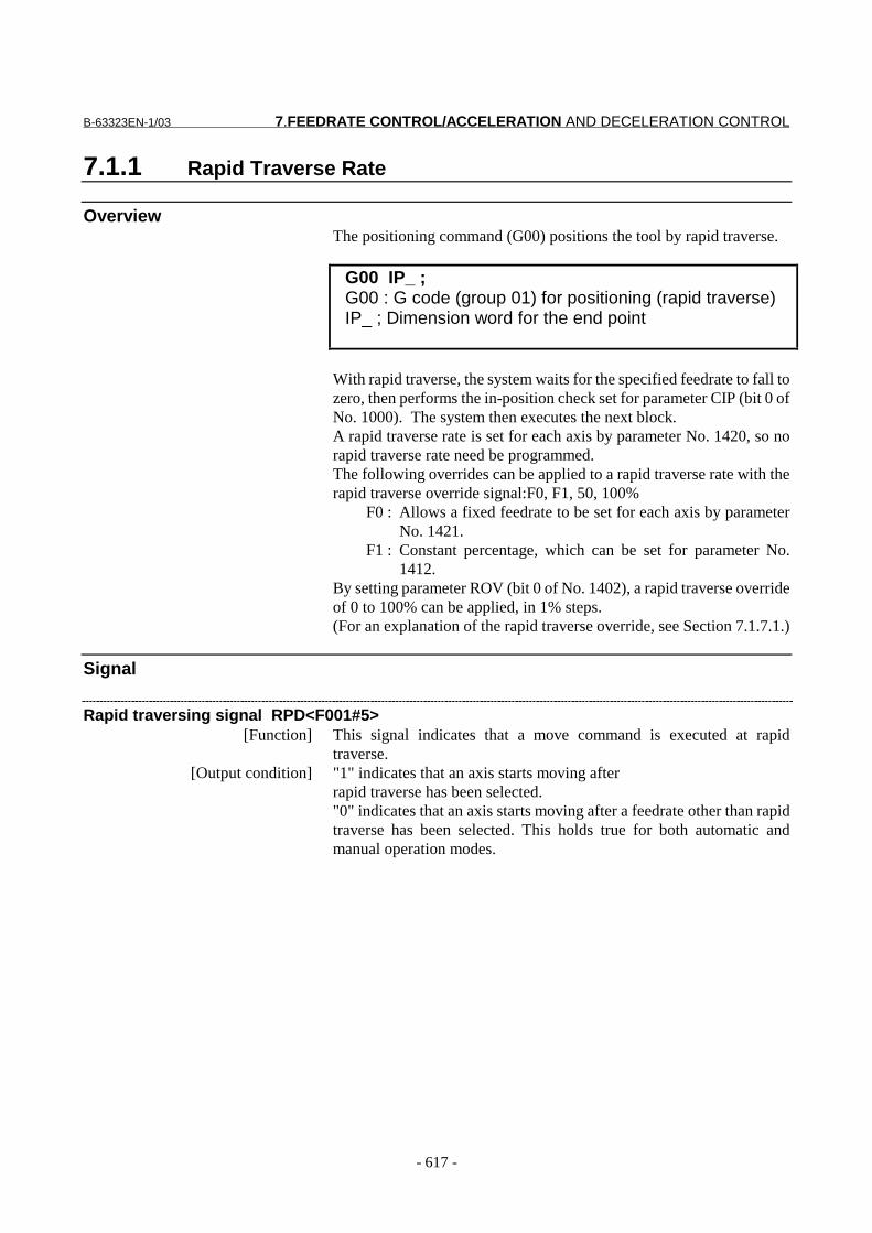
OverviewThe positioning command (G00) positions the tool by rapid traverse.
G00 IP_ ;G00 : G code (group 01) for positioning (rapid traverse)IP_ ; Dimension word for the end point
With rapid traverse, the system waits for the specified feedrate to fall tozero, then performs the in-position check set for parameter CIP (bit 0 ofNo. 1000). The system then executes the next block.A rapid traverse rate is set for each axis by parameter No. 1420, so norapid traverse rate need be programmed.The following overrides can be applied to a rapid traverse rate with therapid traverse override signal:F0, F1, 50, 100%
F0 : Allows a fixed feedrate to be set for each axis by parameterNo. 1421.
F1 : Constant percentage, which can be set for parameter No.1412.
By setting parameter ROV (bit 0 of No. 1402), a rapid traverse overrideof 0 to 100% can be applied, in 1% steps.(For an explanation of the rapid traverse override, see Section 7.1.7.1.)
Signal
Rapid traversing signal RPD<F001#5>[Function] This signal indicates that a move command is executed at rapid
traverse.[Output condition] "1" indicates that an axis starts moving after
rapid traverse has been selected."0" indicates that an axis starts moving after a feedrate other than rapidtraverse has been selected. This holds true for both automatic andmanual operation modes.
7.FEEDRATE CONTROL/ACCELERATION AND DECELERATION CONTROL B-63323EN-1/03
- 618 -
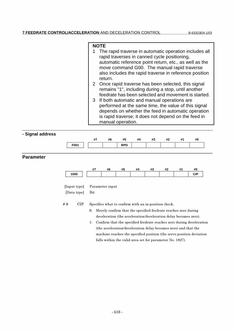
NOTE1 The rapid traverse in automatic operation includes all
rapid traverses in canned cycle positioning,automatic reference point return, etc., as well as themove command G00. The manual rapid traversealso includes the rapid traverse in reference positionreturn.
2 Once rapid traverse has been selected, this signalremains "1", including during a stop, until anotherfeedrate has been selected and movement is started.
3 If both automatic and manual operations areperformed at the same time, the value of this signaldepends on whether the feed in automatic operationis rapid traverse; it does not depend on the feed inmanual operation.
- Signal address#7 #6 #5 #4 #3 #2 #1 #0
F001 RPD
Parameter
#7 #6 #5 #4 #3 #2 #1 #0
1000 CIP
���������� �� ��� ������
��������� ���
� � � � ��� ��� ��������������������� ���������������������������
�� !������� ����������������"��" ��� �����# ��"� ��$
"�! ������%������! �����&"�! ������"!���'�����# �(�
)� ����� ����������������"��" ��� �����# ��"� ��$�"�! �����
%������! �����&"�! ������"!���'�����# �(���"��������
������� ��������������"����������%���� *�����������"*������
��!!������������*�!�"�� ������� ��� ��� �+���),-.(�

B-63323EN-1/03 7.FEEDRATE CONTROL/ACCELERATION AND DECELERATION CONTROL
- 619 -
#7 #6 #5 #4 #3 #2 #1 #0
1400 LRP RDR
���������� �� ��� ������
��������� ���
� � � � ��� /�/ ������������ �" �� ��������'�� �� �"��� ���� ���"�� �* �
������"�
�� �������'�� �� �"�
)� ����'�� �� �"�
� � � � ��0 1/� �!�����������"���"��� �����������$�%2��(�
�� +���!��� ���� ��!������%�����3�����*����"��"��!�������� ���"
� �* ���" ��(
)� 1��� ���� ��!������%���!���������!��� (
4�������$��� �"��������!���� "��������* ����5����)�
#7 #6 #5 #4 #3 #2 #1 #0
1401 RFO
���������� �� ��� ������
��������� ���
� � � � ��6 /78 ������������ ���������"� ��$� ���"�� �* ���������������$��" ��
�* �"�����������9�
0: Stop.
1: Do not stop.
1420 Rapid traverse feedrate along each axis
���������� �� ��� ������
��������� /�!�3��
�:�������"��� ��&���5�����&���5�"$ &����%�����������(
� ���������������"��� ���"���������� �������������������!�"��3��
�;�!�"�"���� ��$ /� �����������"� "��� ��� ������$���'!�%�(
%4��������� �����������������5�������<-0������(
������ ���"�� �* ���" ����� ������3����� ����� ���"�� �* �
�* �"����)��9�
Reference itemSeries15i/150i-MA Operator’s Manual
(Programming)(B-63324EN)
II-5.2 Rapid traverse
7.FEEDRATE CONTROL/ACCELERATION AND DECELERATION CONTROL B-63323EN-1/03
- 620 -
7.1.2 Cutting Feedrate Clamp
OverviewA common upper limit can be set on the cutting feedrate along eachaxis with parameter No. 1422. If an actual cutting feedrate (with anoverride applied) exceeds a specified upper limit, it is clamped to theupper limit.Set the clamp value in mm/min or inch/min.Convert the feed per revolution into mm/min or inch/min, using thefollowing formula:
fm = fr×Rwhere fm: Feedrate per minute in mm/min or inch/minfr: Rate of feed per revolution in mm/rev or inch/revR: Spindle speed in rpm (rev/min)
Parameter1422 Maximum cutting feedrate for each axis
���������� �� ��� ������
��������� /�!�3��
�:�������"��� ��&���5�����&���5�"$ &����%�����������(
� ���������������"��� ���"���������� �������������������!�"��3��
�;�!�"�"���� ��$ /� �����������"� "��� ��� ������$���'!�%�(
%4��������� �����������������5�������<-0������(
��������3�����������$��" ����� ������3���
Alarm and message
Number Message ContentsPS0190 PARAMETER ZERO (CUT MAX) The maximum cutting feedrate parameter No. 1422 has
been set to 0.
WarningWARNING
The arithmetic operation error of the CNC for thevalue specified for a feedrate is 2%. This does not,however, apply during acceleration/deceleration.The above error is incurred when measuring the timerequired for the tool to move a distance of 500 mm ormore after the stable state has been attained.
Reference itemSeries15i/150i-MA Operator’s Manual
(Programming)(B-63324EN)
II-5.3 Cutting feed
B-63323EN-1/03 7.FEEDRATE CONTROL/ACCELERATION AND DECELERATION CONTROL
- 621 -
7.1.3 Feed Per Minute
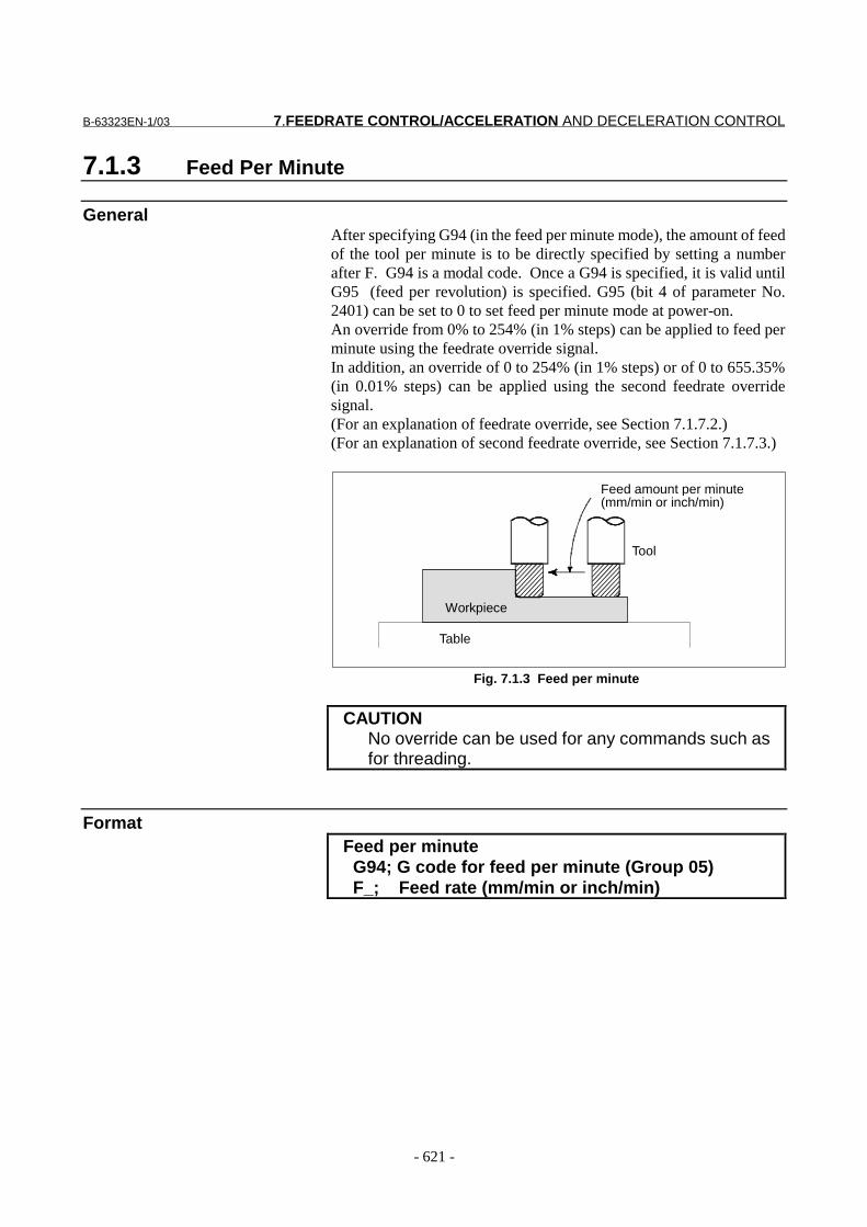
GeneralAfter specifying G94 (in the feed per minute mode), the amount of feedof the tool per minute is to be directly specified by setting a numberafter F. G94 is a modal code. Once a G94 is specified, it is valid untilG95 (feed per revolution) is specified. G95 (bit 4 of parameter No.2401) can be set to 0 to set feed per minute mode at power-on.An override from 0% to 254% (in 1% steps) can be applied to feed perminute using the feedrate override signal.In addition, an override of 0 to 254% (in 1% steps) or of 0 to 655.35%(in 0.01% steps) can be applied using the second feedrate overridesignal.(For an explanation of feedrate override, see Section 7.1.7.2.)(For an explanation of second feedrate override, see Section 7.1.7.3.)
Workpiece
Table
Tool
Feed amount per minute(mm/min or inch/min)
Fig. 7.1.3 Feed per minute
CAUTIONNo override can be used for any commands such asfor threading.
FormatFeed per minute G94; G code for feed per minute (Group 05) F_; Feed rate (mm/min or inch/min)

7.FEEDRATE CONTROL/ACCELERATION AND DECELERATION CONTROL B-63323EN-1/03
- 622 -
Parameter
#7 #6 #5 #4 #3 #2 #1 #0
2400 F41
���������� �� ��� ������
��������� ���
� � � � ��) 70) �������"�� ����������7���"�%2=0���"(������ "������ ����������
���"����!������5������������
�� )���&���
)� ��)���&���
����������� "���������"����!������5�������������!�������&����
NOTEIt is not effective if the increment system is IS-A.
#7 #6 #5 #4 #3 #2 #1 #0
2401 G95
���������� �� ��� ������
��������� ���
� � � � ��0 2=> �"������� ������"�����!� �������
0: G94 mode (feed per minute)
1: G95 mode (feed per revolution)
Alarm and message
Number Message Contents
PS0187 FEED ZERO ( COMMAND ) The cutting feedrate instructed by an F code has been set to 0.This alarm is also generated if the F code instructed for the S codeis set extremely small in a rigid tapping instruction as the toolcannot cut at the programmed lead.
Reference itemSeries15i/150i-MA Operator’s Manual
(Programming)(B-63324EN)
II-5.3 Cutting feed

B-63323EN-1/03 7.FEEDRATE CONTROL/ACCELERATION AND DECELERATION CONTROL
- 623 -
7.1.4 Feed Per Revolution/Feed Per Revolution Without PositionCoder
Overview
- Feed per revolutionSpecify G95 (feed-per-revolution mode), then directly specify anumeric value, preceded by F, to indicate the amount by which the toolis to be fed per rotation about the spindle. G95 is modal; once it isspecified, it remains effective until G94 (feed-per-minute mode) isspecified. Feedrate overrides can be applied to feed per revolution, inthe same way as feed per minute.
Fig. 7.1.4 (a) Feed per revolution
Position-coder-less feed per revolutionFor a machine without a position coder (or a machine that does not useone), the feedrate specified in feed-per-revolution mode is convertedinto a feedrate per minute, assuming that the spindle rotates under thecontrol of the spindle speed command (S code), and that tool is movedalong the feed axis at that rate.
Feed amount per spindle revolution(mm/rev or inch/rev)
F
7.FEEDRATE CONTROL/ACCELERATION AND DECELERATION CONTROL B-63323EN-1/03
- 624 -
Parameter#7 #6 #5 #4 #3 #2 #1 #0
2405 RSO FPR
���������� �� ��� ������
��������� ���
� � � � ��? 7�/ ������������ ��������������� ��"�� � ��������������������������
��" �%�������������� ����* ���$��"�� � ��������7�������"�� �
������7(������"��������"�� � ����������"�%2=>(�
�� +�����"�
)� :�"�
� � � � ��. /�8 ������������ �����"!��* �"������'!"������������������� ��"�
� � �����������������������������" �%�������������� ����* ���$��"�
� � ��������7�������"�� �������7(����'��$���"��������"�� �
����������"�%2=>(�
0: Disabled.
1: Enabled.
CautionCAUTION1 For feed per revolution, if the spindle speed is low,
the feedrate will be uneven. The lower the spindlespeed, the more uneven the feedrate.
2 Threading is performed according to the signalreturned from the position coder, even if the systemhas been set up to use position-coder-less feed perrevolution.In other words, position-coder-less feed perrevolution is not enabled for the threadingcommand.
3 When position-coder-less feed per revolution isenabled, the following functions are also enabled:- Feedrate override signal- Spindle override signal- Dry run signal- Clamping of the maximum cutting feedrate on
each axis- Dwell per revolution
Reference itemSeries15i/150i-MA Operator’s Manual
(Programming)(B-63324EN)
II-5.3 Cutting feed
B-63323EN-1/03 7.FEEDRATE CONTROL/ACCELERATION AND DECELERATION CONTROL
- 625 -
7.1.5 F1-digit Feed
GeneralWhen a one-digit number from 1 to 9 is specified after F, the feedrateset for that number in a parameter (Nos. 1451 to 1459) is used. WhenF0 is specified, the rapid traverse rate is applied.The feedrate corresponding to the number currently selected can beincreased or decreased by turning on the switch for changing F1-digitfeedrate on the machine operator’s panel, then by rotating the manualpulse generator.The increment/decrement, DF, in feedrate per scale of the manual pulsegenerator is as follows:
X100
maxFF =∆
Fmax : feedrate upper limit for F1-F4 set by parameter 1460, orfeedrate upper limit for F5-F9 set by parameter 1461X : any value of 1-127 set by parameter 1450
The feedrate set or altered is kept even while the power is off.
Signal
F1-digit feed select signal F1D<G005#3>[Classification] Input signal
[Function] Increases or decreases F1-digit speed set by the parameters No. 1451 to1459 using the manual pulse generator.Since the manual pulse generator may also be used for axis feeding,signal F1D (G016#7) designates which function may be used.
[Operation] When the signal is "1", the F1-digit speed can be increased/decreasedusing the manual pulse generator.- If, in automatic operation mode, the tool is not moved under the
control of single-digit F command, single-digit F feedrateadjustment cannot be performed. Because, however, the manualpulse generator is reserved for that purpose, the manual pulsegenerator cannot be used for axis feed.
- In manual operation mode, this signal is meaningless. Even if it is"1," manual handle feed is possible.
- Signal address#7 #6 #5 #4 #3 #2 #1 #0
G005 F1D

7.FEEDRATE CONTROL/ACCELERATION AND DECELERATION CONTROL B-63323EN-1/03
- 626 -
Parameter#7 #6 #5 #4 #3 #2 #1 #0
1406 F1O
���������� �� ��� ������
��������� ���
� � � � ��� 7)8 ������������ ������'!��" ����* �"5�����"��" ����* �"5
��"��* �"�����!!�������� �����" �������7���"������������"�$��
���' �%7)����7=(�
�� ����'!�����
)� @��'!�����
NOTERapid traverse override is enabled for the feedrate of F0,regardless of the setting of this parameter.
1450 Resolution of the feedrate specified by the F code with a one-digit number
���������� �� ��� ������
��������� ���$
�;�!�"�"���� ��$ )���)-.
�����������������"����"� �����������$��������" ���������
�����!���!��$� ��� ���� ����"����$ �"����������!������7���"�����
�����"�$������' ����������"�
� � � � � � � � � � � 7��3�
� � � � ¢7�A� i��A�)5�- j
� � � � � � � � � � � )��B
C������ ��� ���� � ���"��������'�*�3� ������������!�� �B�
���B����"� ��������������������������!���!��$� ��� ��"����
'� ����"��� �����" ������'����7��3�� � 7��3��������'�*
3� ������ � ����������� �!������� �����" ���������"�'�����7
��"�����������"�$������' �� � C��!���������������� ��� �+����)0?�
��"�)0?)�
7��3)�� � :�� ��" ���!������� �7)����70�%)0?�(
7��3-�� � :�� ��" ���!������� �7>����7=�%)0?)(

B-63323EN-1/03 7.FEEDRATE CONTROL/ACCELERATION AND DECELERATION CONTROL
- 627 -
1451 F1 feedrate
1452 F2 feedrate
1453 F3 feedrate
1454 F4 feedrate
1455 F5 feedrate
1456 F6 feedrate
1457 F7 feedrate
1458 F8 feedrate
1459 F9 feedrate
���������� �����$������
��������� /�!
�:�������"��� ��&���5�����&���5�"$ &����%�����������(
� ���������������"��� ���"���������� ���������������� � ����3��
�;�!�"�"���� ��$ /� �����������"� "��� ��� ������$���'!�%�(
%4��������� �����������������5�������<-0������(
�����������" �������$�"�������7���"�����������"�$������' �7�
%�A)����=(�� � 4�������" ����������$"�'����������!���!�
$� ��� 5�������� ��� �����$���!��$�������������$��������" ���
7.FEEDRATE CONTROL/ACCELERATION AND DECELERATION CONTROL B-63323EN-1/03
- 628 -
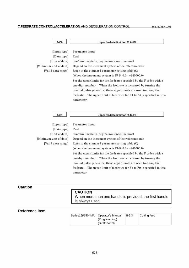
1460 Upper feedrate limit for F1 to F4
���������� �� ��� ������
��������� /�!
�:�������"��� ��&���5�����&���5�"$ &����%�����������(
� ���������������"��� ���"���������� ���������������� � ����3��
�;�!�"�"���� ��$ /� �����������"� "��� ��� ������$���'!�%�(
%4��������� �����������������5�������<-0������(
��������� �!�������� �����" ����������"�'�����7���"��������
���"�$������' �� � 4�������" ��������� ��"�'���� ���$���
�����!���!��$� ��� 5�������� �!������� ���"�����!������
�" ���� � C����� �!���������" ������ �7)����70����������"��������
�� ��� �
1461 Upper feedrate limit for F5 to F9
���������� �� ��� ������
��������� /�!
�:�������"��� ��&���5�����&���5�"$ &����%�����������(
� ���������������"��� ���"���������� ���������������� � ����3��
�;�!�"�"���� ��$ /� �����������"� "��� ��� ������$���'!�%�(
%4��������� �����������������5�������<-0������(
��������� �!�������� �����" ����������"�'�����7���"��������
���"�$������' �� � 4�������" ��������� ��"�'���� ���$���
�����!���!��$� ��� 5�������� �!������� ���"�����!������
�" ���� � C����� �!���������" ������ �7>����7=����������"��������
�� ��� �
CautionCAUTIONWhen more than one handle is provided, the first handleis always used.
Reference itemSeries15i/150i-MA Operator’s Manual
(Programming)(B-63324EN)
II-5.3 Cutting feed
B-63323EN-1/03 7.FEEDRATE CONTROL/ACCELERATION AND DECELERATION CONTROL
- 629 -
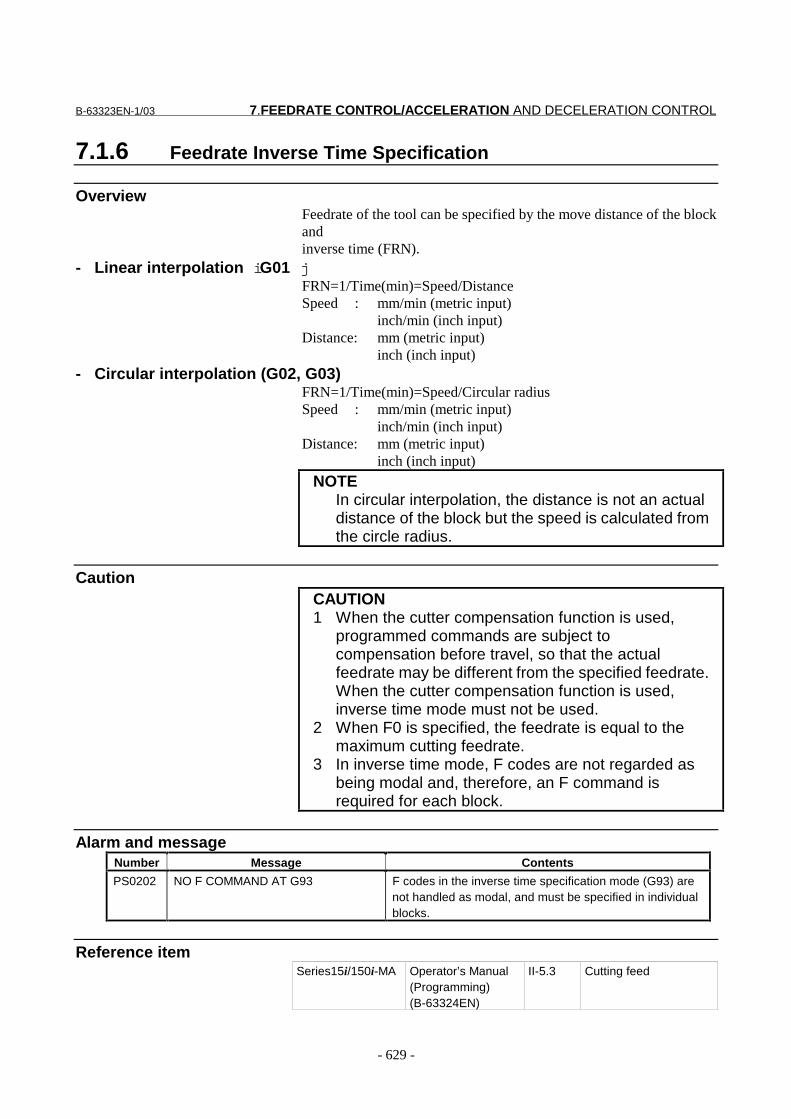
7.1.6 Feedrate Inverse Time Specification
OverviewFeedrate of the tool can be specified by the move distance of the blockandinverse time (FRN).
- Linear interpolation iG01 jFRN=1/Time(min)=Speed/DistanceSpeed : mm/min (metric input) inch/min (inch input)Distance: mm (metric input) inch (inch input)
- Circular interpolation (G02, G03)FRN=1/Time(min)=Speed/Circular radiusSpeed : mm/min (metric input) inch/min (inch input)Distance: mm (metric input) inch (inch input)
NOTEIn circular interpolation, the distance is not an actualdistance of the block but the speed is calculated fromthe circle radius.
CautionCAUTION1 When the cutter compensation function is used,
programmed commands are subject tocompensation before travel, so that the actualfeedrate may be different from the specified feedrate.When the cutter compensation function is used,inverse time mode must not be used.
2 When F0 is specified, the feedrate is equal to themaximum cutting feedrate.
3 In inverse time mode, F codes are not regarded asbeing modal and, therefore, an F command isrequired for each block.
Alarm and messageNumber Message Contents
PS0202 NO F COMMAND AT G93 F codes in the inverse time specification mode (G93) arenot handled as modal, and must be specified in individualblocks.
Reference itemSeries15i/150i-MA Operator’s Manual
(Programming)(B-63324EN)
II-5.3 Cutting feed

7.FEEDRATE CONTROL/ACCELERATION AND DECELERATION CONTROL B-63323EN-1/03
- 630 -
7.1.7 Override
7.1.7.1 Rapid traverse override
OverviewThe rapid traverse rate can be overridden as follows:
F0, F1%, 50%, 100%F0:Feedrate to be set for each axis (parameter No. 1421)F1:Percentage (parameter No. 1412)
or, 0% to 100% (in steps of 1%) by setting bit 0 (ROV) ofparameter No. 1402
Fig. 7.1.7 (a) Rapid traverse override
- FeedrateActual feedrate is obtained by multiplying the rapid traverse rate presetby parameter no.1420 by the override value determined by this signal,whether in automatic or manual operation (including manual referenceposition return).
- F0 rateFor F0 value, an absolute value is set by parameter no.1421 within arange of 0 to rapid traverse rate (for each axis).
- F1%Set F1, i.e., the feedrate override value, for parameter No. 1412, to avalue in the range of 0 to 100%.
- 1% step rapid traverse override selection signal1% step rapid traverse override selection signal ROV iNo.1402#0 jdetermines whether rapid traverse override specified with rapidtraverse override signals ROV1 and ROV2 is used or 1% step rapidtraverse override is used.When signal ROV is 0, override is applied to the rapid traverse rateusing signals ROV1 and ROV2.When signal ROV is 1, ROV1 and ROV2 are ignored, 1% step rapidtraverse override signals *RV0B to *RV6B being used to override therapid traverse rate.
- PMC axis controlControl signals are dedicated to PMC axis control. The rapid traverseoverrides described in this section are not effective.(See Chapter 15 PMC axis control.)
Rapid traverse rate10 m/min
Override 50% 5m/min
B-63323EN-1/03 7.FEEDRATE CONTROL/ACCELERATION AND DECELERATION CONTROL
- 631 -
Signal
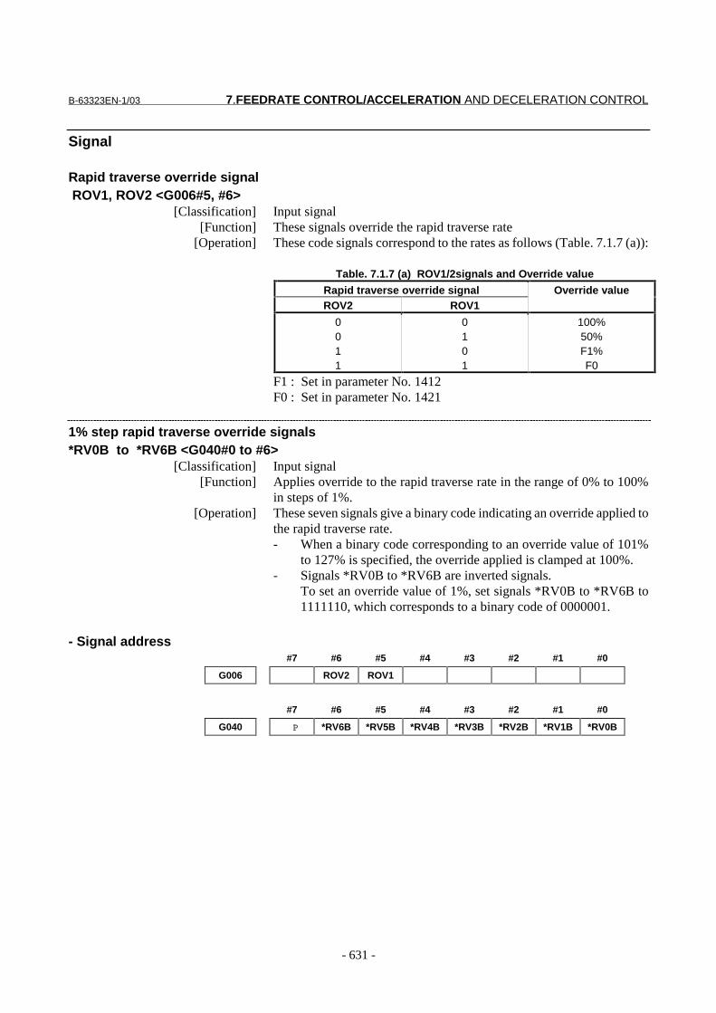
Rapid traverse override signal ROV1, ROV2 <G006#5, #6>
[Classification] Input signal[Function] These signals override the rapid traverse rate
[Operation] These code signals correspond to the rates as follows (Table. 7.1.7 (a)):
Table. 7.1.7 (a) ROV1/2signals and Override value
Rapid traverse override signalROV2 ROV1
Override value
0011
0101
100%50%F1%F0
F1 : Set in parameter No. 1412F0 : Set in parameter No. 1421
1% step rapid traverse override signals*RV0B to *RV6B <G040#0 to #6>
[Classification] Input signal[Function] Applies override to the rapid traverse rate in the range of 0% to 100%
in steps of 1%.[Operation] These seven signals give a binary code indicating an override applied to
the rapid traverse rate.- When a binary code corresponding to an override value of 101%
to 127% is specified, the override applied is clamped at 100%.- Signals *RV0B to *RV6B are inverted signals.
To set an override value of 1%, set signals *RV0B to *RV6B to1111110, which corresponds to a binary code of 0000001.
- Signal address#7 #6 #5 #4 #3 #2 #1 #0
G006 ROV2 ROV1
#7 #6 #5 #4 #3 #2 #1 #0
G040 P *RV6B *RV5B *RV4B *RV3B *RV2B *RV1B *RV0B
7.FEEDRATE CONTROL/ACCELERATION AND DECELERATION CONTROL B-63323EN-1/03
- 632 -
Parameter
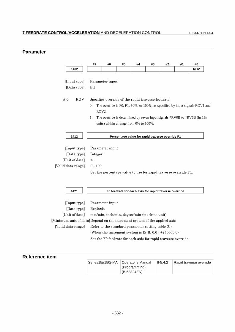
#7 #6 #5 #4 #3 #2 #1 #0
1402 ROV
���������� �� ��� ������
��������� ���
� � � � ��� /8; ���������* �"������� ���"�� �* ���" ���
0: The override is F0, F1, 50%, or 100%, as specified by input signals ROV1 and
ROV2.
1: The override is determined by seven input signals *RV0B to *RV6B (in 1%
units) within a range from 0% to 100%.
1412 Percentage value for rapid traverse override F1
���������� �� ��� ������
��������� ���$
�:�������"��� 9
�;�!�"�"���� ��$ ����)��
������� ����$�*�!���������� � ���"�� �* ���* �"�7)�
1421 F0 feedrate for each axis for rapid traverse override
���������� �� ��� ������
��������� /�!�3��
�:�������"��� ��&���5�����&���5�"$ &����%�����������(
� ���������������"������"���������� �������������������!�"��3��
�;�!�"�"���� ��$ /� �����������"� "��� ��� ������$���'!�%�(
%4��������� �����������������5�������<-0������(
������7���" ����� ������3����� � ���"�� �* ���* �"�
Reference itemSeries15i/150i-MA Operator’s Manual
(Programming)(B-63324EN)
II-5.4.2 Rapid traverse override
B-63323EN-1/03 7.FEEDRATE CONTROL/ACCELERATION AND DECELERATION CONTROL
- 633 -
7.1.7.2 Feedrate override
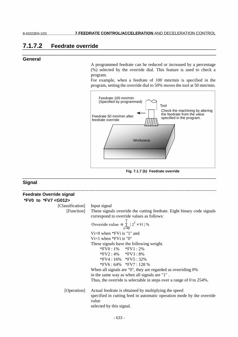
GeneralA programmed feedrate can be reduced or increased by a percentage(%) selected by the override dial. This feature is used to check aprogram.For example, when a feedrate of 100 mm/min is specified in theprogram, setting the override dial to 50% moves the tool at 50 mm/min.
Fig. 7.1.7 (b) Feedrate override
Signal
Feedrate Override signal *FV0 to *FV7 <G012>
[Classification] Input signal[Function] These signals override the cutting feedrate. Eight binary code signals
correspond to override values as follows:
∑ ×.
�A��A*�!��8* �" %|2| Vii@
Vi=0 when *FVi is "1" andVi=1 when *FVi is "0"These signals have the following weight.
*FV0 : 1% *FV1 : 2%*FV2 : 4% *FV3 : 8%*FV4 : 16% *FV5 : 32%*FV6 : 64% *FV7 : 128 %
When all signals are "0", they are regarded as overriding 0%in the same way as when all signals are "1" .Thus, the override is selectable in steps over a range of 0 to 254%.
[Operation] Actual feedrate is obtained by multiplying the speedspecified in cutting feed in automatic operation mode by the overridevalueselected by this signal.
ToolCheck the machining by alteringthe feedrate from the valuespecified in the program.
Feedrate 100 mm/min(Specified by programmed)
Feedrate 50 mm/min afterfeedrate override
Workpiece
7.FEEDRATE CONTROL/ACCELERATION AND DECELERATION CONTROL B-63323EN-1/03
- 634 -
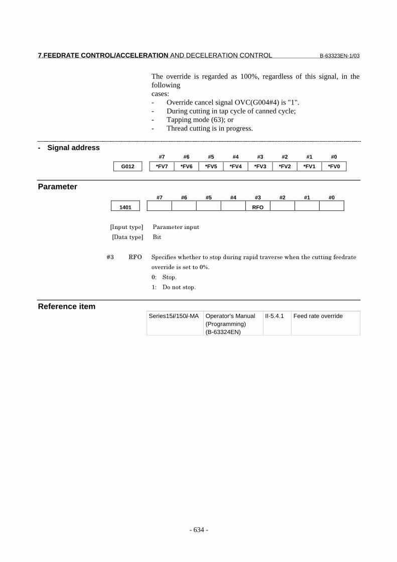
The override is regarded as 100%, regardless of this signal, in thefollowingcases:- Override cancel signal OVC(G004#4) is "1".- During cutting in tap cycle of canned cycle;- Tapping mode (63); or- Thread cutting is in progress.
- Signal address#7 #6 #5 #4 #3 #2 #1 #0
G012 *FV7 *FV6 *FV5 *FV4 *FV3 *FV2 *FV1 *FV0
Parameter#7 #6 #5 #4 #3 #2 #1 #0
1401 RFO
���������� �� ��� ������
��������� ���
� � � � �6 /78 ������������ ���������"� ��$� ���"�� �* ���������������$��" ��
�* �"�����������9�
��� � �����
)�� � ������������
Reference itemSeries15i/150i-MA Operator’s Manual
(Programming)(B-63324EN)
II-5.4.1 Feed rate override

B-63323EN-1/03 7.FEEDRATE CONTROL/ACCELERATION AND DECELERATION CONTROL
- 635 -
7.1.7.3 Second feedrate override
OverviewThese signals override the cutting feedrate after the cutting feedrate hasbeen overridden by first override *FV0 to *FV7.There are two types of second feedrate override:- 0 to 254% (in 1-% steps)- 0 to 655.34% (in 0.01-% steps)Which of the above is to be used can be specified using parameter APO(bit 0 of No. 1403).
Signal
- Second feedrate override signal *AFV0 to *AFV7 <G013>
[Classification] Input signal[Function] Applies second feedrate override to the cutting feedrate. These eight
binary code signals correspond to the override values as follows.
∑ ×.
�A��A*�!��8* �" %|2| Vii@
Vi=0 when *AFVi is "1" andVi=1 when *AFVi is "0"These signals have the following weight.*AFV0=1% *AFV1=2%*AFV2=4% *AFV3=8%*AFV4=16% *AFV5=32%*AFV6=64% *AFV7=128%If all signals are "0" or "1", the override is regarded as0%. The override is selectable in steps over a range of 0 to 254%.
[Operation] For cutting feed during automatic operation, the actual feedrate is theresult of applying the first override and then the override value selectedwith this signal to the specified feedrate.The conditions under which the first override is assumed to be 100%remain effective. If any of the conditions is satisfied, second feedrateoverride is also assumed to be 100%.
- Second feedrate override signal B *AFV0B to *AFV15B <G146 to G147>
[Classification] Input signal[Function] Applies second feedrate override to the cutting feedrate. These sixteen
binary code signals correspond to the override values as follows.
∑ ××�)>
�A�����)�A*�!��8* �" %|2| Vii
@
Vi=0 when *AFViB is "1" andVi=1 when *AFViB is "0"If all signals are "0" or "1", the override is regarded as0%. The override is selectable in 0.01 steps over a range of 0 to655.34%.
[Operation] Has the same function as the second feedrate override signal.
7.FEEDRATE CONTROL/ACCELERATION AND DECELERATION CONTROL B-63323EN-1/03
- 636 -
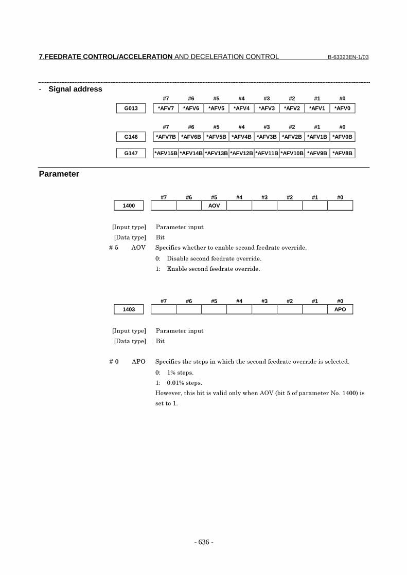
- Signal address#7 #6 #5 #4 #3 #2 #1 #0
G013 *AFV7 *AFV6 *AFV5 *AFV4 *AFV3 *AFV2 *AFV1 *AFV0
#7 #6 #5 #4 #3 #2 #1 #0
G146 *AFV7B *AFV6B *AFV5B *AFV4B *AFV3B *AFV2B *AFV1B *AFV0B
G147 *AFV15B *AFV14B *AFV13B *AFV12B *AFV11B *AFV10B *AFV9B *AFV8B
Parameter
#7 #6 #5 #4 #3 #2 #1 #0
1400 AOV
���������� �� ��� ������
��������� ���
� � � �� ��> D8; ������������ ������'!�����"��" ����* �"�
�� ����'!�����"��" ����* �"�
)� @��'!�����"��" ����* �"�
#7 #6 #5 #4 #3 #2 #1 #0
1403 APO
���������� �� ��� ������
��������� ���
� � � � ��� D�8 ��������������������������������"��" ����* �"�����!��"�
�� )9������
)� ���)9������
E��* 5������'������*�!�"���!������D8;�%'���>������ ��� �+���)0��(���
������)�

B-63323EN-1/03 7.FEEDRATE CONTROL/ACCELERATION AND DECELERATION CONTROL
- 637 -
7.1.7.4 Override cancel
OverviewThe override cancel signal fixes the feedrate override to 100%.
Signal
Override cancel signal OVC <G004#4>[Classification] Input signal
[Function] Feedrate override is fixed to 100%.[Operation] When the signal is "1", the CNC operates as follows:
- The override is fixed to 100% regardless of the feedrate overrideand second feedrate override signals. Thus, the tool operatesexactly at the specified feedrate.
- Rapid traverse override and spindle speed override are notaffected.
- Signal address#7 #6 #5 #4 #3 #2 #1 #0
G004 OVC
7.FEEDRATE CONTROL/ACCELERATION AND DECELERATION CONTROL B-63323EN-1/03
- 638 -
7.1.8 Automatic Corner Override
Overview- Inner corner automatic override
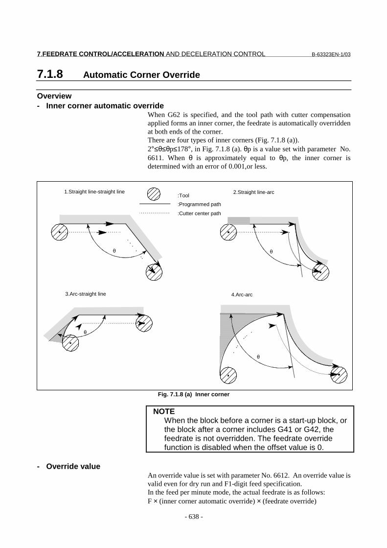
When G62 is specified, and the tool path with cutter compensationapplied forms an inner corner, the feedrate is automatically overriddenat both ends of the corner.There are four types of inner corners (Fig. 7.1.8 (a)).2°≤θ≤θp≤178°, in Fig. 7.1.8 (a). θp is a value set with parameter No.6611. When θ is approximately equal to θp, the inner corner isdetermined with an error of 0.001,or less.
Fig. 7.1.8 (a) Inner corner
NOTEWhen the block before a corner is a start-up block, orthe block after a corner includes G41 or G42, thefeedrate is not overridden. The feedrate overridefunction is disabled when the offset value is 0.
- Override valueAn override value is set with parameter No. 6612. An override value isvalid even for dry run and F1-digit feed specification.In the feed per minute mode, the actual feedrate is as follows:F × (inner corner automatic override) × (feedrate override)
1.Straight line-straight line
:Cutter center path
:Tool
:Programmed path
2.Straight line-arc
3.Arc-straight line 4.Arc-arc
θ
θ
θθ
B-63323EN-1/03 7.FEEDRATE CONTROL/ACCELERATION AND DECELERATION CONTROL
- 639 -
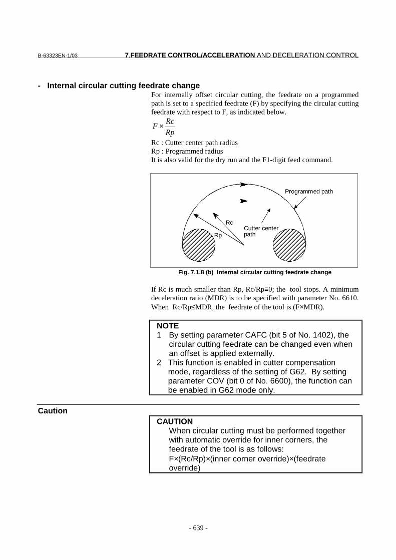
- Internal circular cutting feedrate changeFor internally offset circular cutting, the feedrate on a programmedpath is set to a specified feedrate (F) by specifying the circular cuttingfeedrate with respect to F, as indicated below.
Rp
RcF ×
Rc : Cutter center path radiusRp : Programmed radiusIt is also valid for the dry run and the F1-digit feed command.
Fig. 7.1.8 (b) Internal circular cutting feedrate change
If Rc is much smaller than Rp, Rc/Rp≡0; the tool stops. A minimumdeceleration ratio (MDR) is to be specified with parameter No. 6610.When Rc/Rp≤MDR, the feedrate of the tool is (F×MDR).
NOTE1 By setting parameter CAFC (bit 5 of No. 1402), the
circular cutting feedrate can be changed even whenan offset is applied externally.
2 This function is enabled in cutter compensationmode, regardless of the setting of G62. By settingparameter COV (bit 0 of No. 6600), the function canbe enabled in G62 mode only.
CautionCAUTION
When circular cutting must be performed togetherwith automatic override for inner corners, thefeedrate of the tool is as follows:F×(Rc/Rp)×(inner corner override)×(feedrateoverride)
Programmed path
Cutter centerpath
Rc
Rp
7.FEEDRATE CONTROL/ACCELERATION AND DECELERATION CONTROL B-63323EN-1/03
- 640 -
Parameter
#7 #6 #5 #4 #3 #2 #1 #0
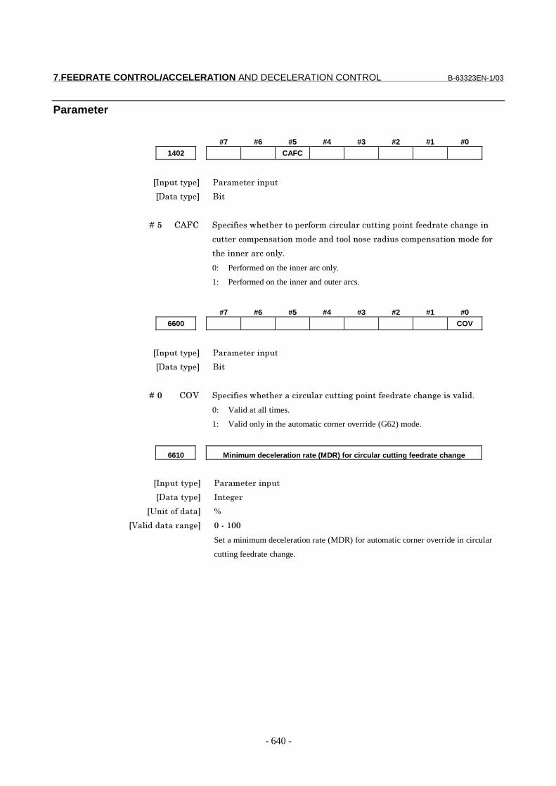
1402 CAFC
���������� �� ��� ������
��������� ���
� � � � ��> �D7� ������������ ����� �� ���� ��!� �������$��������" �������$���
���� ���������������"���"����!����� �"������������������"���
������ �� ����!��
0: Performed on the inner arc only.
1: Performed on the inner and outer arcs.
#7 #6 #5 #4 #3 #2 #1 #0
6600 COV
���������� �� ��� ������
��������� ���
� � � � ��� �8; ������������ ����� ��!� �������$��������" �������$����*�!�"�
0: Valid at all times.
1: Valid only in the automatic corner override (G62) mode.
6610 Minimum deceleration rate (MDR) for circular cutting feedrate change
���������� �� ��� ������
��������� ���$
�:�������"��� 9
�;�!�"�"���� ��$ ����)��
Set a minimum deceleration rate (MDR) for automatic corner override in circular
cutting feedrate change.
B-63323EN-1/03 7.FEEDRATE CONTROL/ACCELERATION AND DECELERATION CONTROL
- 641 -
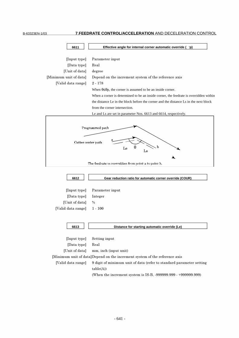
6611 Effective angle for internal corner automatic override ( p̆)
���������� �� ��� ������
��������� /�!
�:�������"��� "$
� ���������������"��� ���"���������� ���������������� � ����3��
�;�!�"�"���� ��$ -���).,
When θ≤θp, the corner is assumed to be an inside corner.
When a corner is determined to be an inside corner, the feedrate is overridden within
the distance Le in the block before the corner and the distance Ls in the next block
from the corner intersection.
Le and Ls are set in parameter Nos. 6613 and 6614, respectively.
��������������� ���������������������������
�������������
���������������
11�
'θ
6612 Gear reduction ratio for automatic corner override (COUR)
���������� �� ��� ������
��������� ���$
�:�������"��� 9
�;�!�"�"���� ��$ )���)��
6613 Distance for starting automatic override (Le)
���������� �����$������
��������� /�!
�:�������"��� ��5������%����������(
� ���������������"������"���������� ���������������� � ����3��
�;�!�"�"���� ��$ =�"�$����������������������"����% � ��������"� "��� ��� ������$
��'!%D((
%4��������� �����������������5��======�===���<======�===(

7.FEEDRATE CONTROL/ACCELERATION AND DECELERATION CONTROL B-63323EN-1/03
- 642 -
6614 Distance for ending automatic override (Ls)
���������� �����$������
��������� /�!
�:�������"��� ��5������%����������(
� ���������������"��� ���"���������� ���������������� � ����3��
�;�!�"�"���� ��$ =�"�$����������������������"����% � ��������"� "��� ��� ������$
��'!%D((
%4��������� �����������������5��======�===���<======�===(
Reference itemSeries15i/150i-MA Operator’s Manual
(Programming)(B-63324EN)
II-5.5.2 Automatic corneroverride
B-63323EN-1/03 7.FEEDRATE CONTROL/ACCELERATION AND DECELERATION CONTROL
- 643 -
7.1.9 External Deceleration
GeneralThese signals decelerate the feedrate of the control axes down to thespeed which has been set by parameter No. 1426 and 1427.
Signal
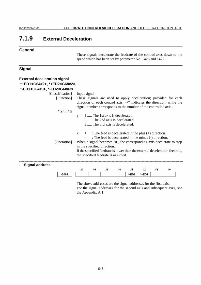
External deceleration signal *+ED1<G64#2>, *+ED2<G68#2>, ... *-ED1<G64#3>, *-ED2<G68#3>, ...
[Classification] Input signal[Function] These signals are used to apply deceleration; provided for each
direction of each control axis; +/* indicates the direction, while thesignal number corresponds to the number of the controlled axis.
* x E D yy : 1 ..... The 1st axis is decelerated.
2 ..... The 2nd axis is decelerated.3 ..... The 3rd axis is decelerated.:
x : + : The feed is decelerated in the plus (+) direction.- : The feed is decelerated in the minus (-) direction.
[Operation] When a signal becomes "0", the corresponding axis decelerate to stopin the specified direction.If the specified feedrate is lower than the external deceleration feedrate,the specified feedrate is assumed.
- Signal address#7 #6 #5 #4 #3 #2 #1 #0
G064 *-ED1 *+ED1
The above addresses are the signal addresses for the first axis.For the signal addresses for the second axis and subsequent axes, seethe Appendix A.1.

7.FEEDRATE CONTROL/ACCELERATION AND DECELERATION CONTROL B-63323EN-1/03
- 644 -
Parameter#7 #6 #5 #4 #3 #2 #1 #0
1005 EDM EDP
���������� �� ��� ������
��������� ����3��
� � � � ��0 @�� 7� ������3��5������������� ����3� ��!�"�! ��������$��!��� ���
������*�"� ���������*�!�"�"� ��$�������$��"�
�� ��*�!�"�
)� ;�!�"�
� � � � ��> @� 7� ������3��5������������� ����3� ��!�"�! ��������$��!��� ���
�$���*�"� ���������*�!�"�"� ��$�������$��"�
0: Invalid.
1: Valid.
1426 External deceleration rate during cutting feed
���������� �� ��� ������
��������� /�!
�:�������"��� ��&���5�����&���5�"$ &����%�����������(
� ���������������"��� ���"���������� ���������������� � ����3��
�;�!�"�"���� ��$ /� �����������"� "��� ��� ������$���'!�%�(
%4��������� �����������������5�������<-0������(
������3� ��!�"�! ������ �����"�"� ��$�������$��"���"
����������$�����$�!��� ���� ��!������%2��(�
1427 External deceleration rate for each axis during rapid traverse
���������� �� ��� ������
��������� /�!�3��
�:�������"��� ��&���5�����&���5�"$ &����%�����������(
� ���������������"��� ���"���������� �������������������!�"��3��
�;�!�"�"���� ��$ /� �����������"� "��� ��� ������$���'!�%�(
%4��������� �����������������5�������<-0������(
C������ ��� ��������3� ��!�"�! �������" �����"���� ���"
� �* ��

B-63323EN-1/03 7.FEEDRATE CONTROL/ACCELERATION AND DECELERATION CONTROL
- 645 -
7.1.10 Feed Stop Function
OverviewDuring axis motion, the feed stop function checks a position deviationamount at all times. When the amount exceeds the "feed stop positiondeviation amount" set by the parameter (No. 1832), the functionsuspends pulse distribution and acceleration/deceleration controlduring such a period of time, and terminates the move command for thepositioning control circuit. Thus the function can minimize anovershoot that may occur with a large servo motor in rapid traverseacceleration operation.
Parameter
1832 Feed-stop position deviation for each axis
[Input type] Parameter input
[Data type] Integeraxis
[Unit of data] detection unit
[Valid data range] 0 - 99999999
Specify the feed-stop position deviation for each axis. If the
positioning deviation of an axis while it is moving exceeds the feed-
stop position deviation for the axis, pulse distribution and
acceleration/deceleration control are temporarily stopped. When
the positioning deviation becomes less than the feed-stop position
deviation, pulse distribution and acceleration/deceleration control
are restarted.
The feed-stop function is mainly used for decreasing overshoot
when a large servo motor is accelerated or decelerated.
Generally, specify the intermediate value between the positioning
deviation limit while the tool moving and the positioning deviation
limit for the axis in the rapid traverse mode as the feed-stop
position deviation.
Speed
Time
Feed stop
Specified speed
Actual speed

7.FEEDRATE CONTROL/ACCELERATION AND DECELERATION CONTROL B-63323EN-1/03
- 646 -
7.1.11 Deceleration Based on Acceleration during CircularInterpolation
GeneralWhen cutting is performed at high speed for circular, helical, or spiralinterpolation, the actual tool path will vary slightly from that intended..This error in circular interpolation can be approximated by the formulagiven below:
a)22
T21
T(2
1
r
2v)2
2T2
1T(
2
1r ⋅+=+=∆ ................ (Equation 1)
When actual machining is performed, radius r of the arc to be machinedand permissible error Dr are given. Then, maximum allowableacceleration a (mm/sec2) is determined from the above expression.The function for clamping the feedrate by the accelerationautomatically clamps the feedrate of arc cutting to the value set in aparameter. This function is effective when the specified feedrate maycause the radial error for an arc with a programmed radius to exceed thepermissible degree of error.When the permissible maximum acceleration for each axis is set for aparameter, and the larger of the permissible maximum accelerations forthe two axes used for circular interpolation is assumed to be A, thepermissible maximum feedrate v at the radius r specified by theprogram is
rAv ⋅= .............................................................. (Equation 2)If the specified feedrate exceeds feedrate v, determined with equation 2,the feedrate is automatically clamped to the determined feedrate.
Programmedpath
Actual path
∆r : Maximum radial error (mm)v : Feedrate (mm/sec)r : Arc radius (mm)a : Acceleration (mm/sec2)T1 : Time constant (s) for
exponential acceleration /deceleration of cutting feed(sec)
T2 : Time constant of the servomotor (sec)
∆r : Error
0
Y
X
r
B-63323EN-1/03 7.FEEDRATE CONTROL/ACCELERATION AND DECELERATION CONTROL
- 647 -
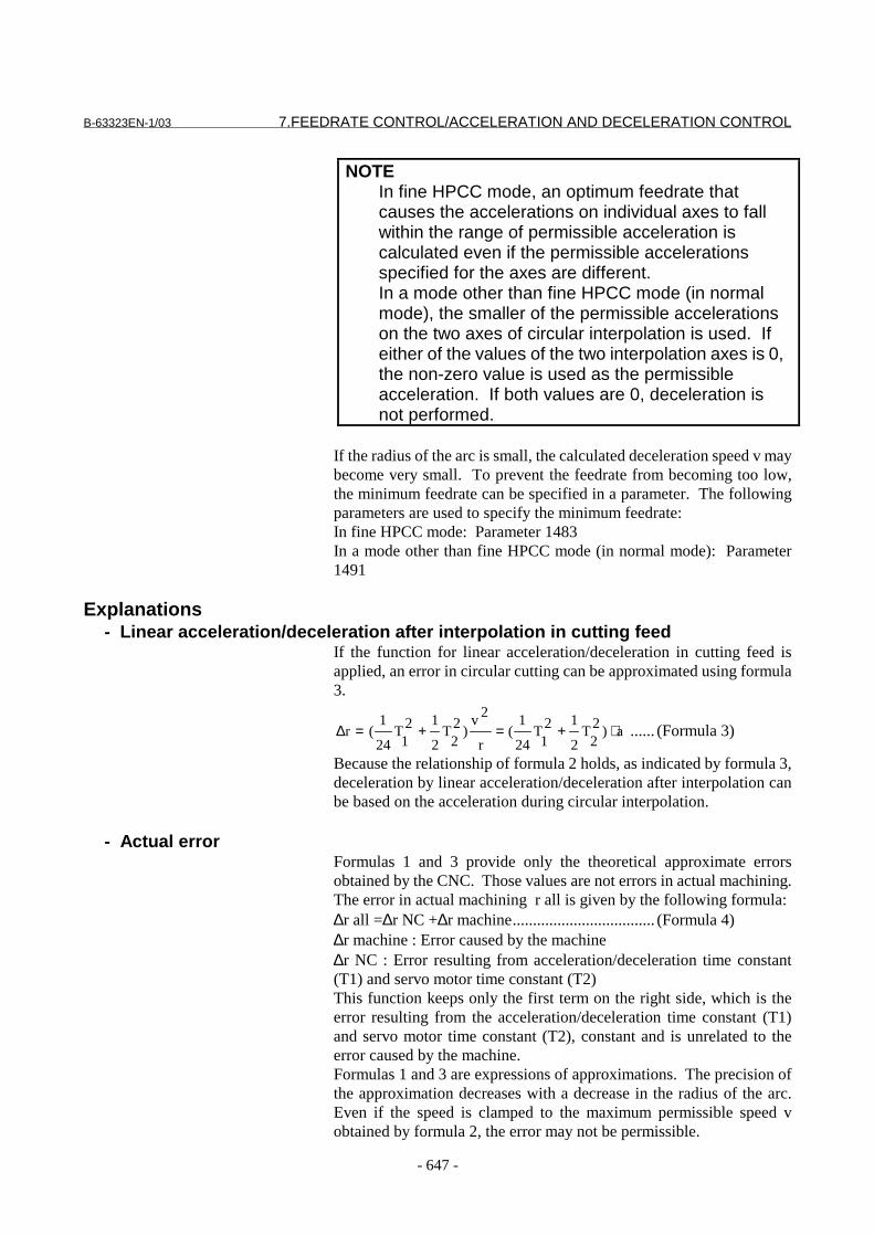
NOTEIn fine HPCC mode, an optimum feedrate thatcauses the accelerations on individual axes to fallwithin the range of permissible acceleration iscalculated even if the permissible accelerationsspecified for the axes are different.In a mode other than fine HPCC mode (in normalmode), the smaller of the permissible accelerationson the two axes of circular interpolation is used. Ifeither of the values of the two interpolation axes is 0,the non-zero value is used as the permissibleacceleration. If both values are 0, deceleration isnot performed.
If the radius of the arc is small, the calculated deceleration speed v maybecome very small. To prevent the feedrate from becoming too low,the minimum feedrate can be specified in a parameter. The followingparameters are used to specify the minimum feedrate:In fine HPCC mode: Parameter 1483In a mode other than fine HPCC mode (in normal mode): Parameter1491
Explanations- Linear acceleration/deceleration after interpolation in cutting feed
If the function for linear acceleration/deceleration in cutting feed isapplied, an error in circular cutting can be approximated using formula3.
a)22
T2
121
T24
1(
r
2v)2
2T
2
121
T24
1(r ⋅+=+=∆ ...... (Formula 3)
Because the relationship of formula 2 holds, as indicated by formula 3,deceleration by linear acceleration/deceleration after interpolation canbe based on the acceleration during circular interpolation.
- Actual errorFormulas 1 and 3 provide only the theoretical approximate errorsobtained by the CNC. Those values are not errors in actual machining.The error in actual machining r all is given by the following formula:∆r all =∆r NC +∆r machine................................... (Formula 4)∆r machine : Error caused by the machine∆r NC : Error resulting from acceleration/deceleration time constant(T1) and servo motor time constant (T2)This function keeps only the first term on the right side, which is theerror resulting from the acceleration/deceleration time constant (T1)and servo motor time constant (T2), constant and is unrelated to theerror caused by the machine.Formulas 1 and 3 are expressions of approximations. The precision ofthe approximation decreases with a decrease in the radius of the arc.Even if the speed is clamped to the maximum permissible speed vobtained by formula 2, the error may not be permissible.
7.FEEDRATE CONTROL/ACCELERATION AND DECELERATION CONTROL B-63323EN-1/03
- 648 -
Parameter
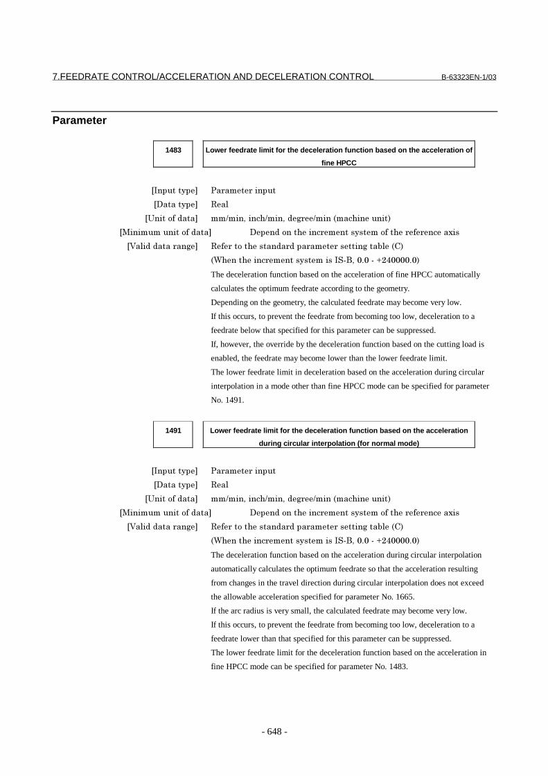
1483 Lower feedrate limit for the deceleration function based on the acceleration of
fine HPCC
���������� �� ��� ������
��������� ���
������������� �������������������� ������������������
��������������������� �������������� ���������������� � ���� ��
�!���������� ��� �� ������������� ���� ��� ����������"���#�
�$��������� ��������������%&'��()(�&�*+,(((()(�
The deceleration function based on the acceleration of fine HPCC automatically
calculates the optimum feedrate according to the geometry.
Depending on the geometry, the calculated feedrate may become very low.
If this occurs, to prevent the feedrate from becoming too low, deceleration to a
feedrate below that specified for this parameter can be suppressed.
If, however, the override by the deceleration function based on the cutting load is
enabled, the feedrate may become lower than the lower feedrate limit.
The lower feedrate limit in deceleration based on the acceleration during circular
interpolation in a mode other than fine HPCC mode can be specified for parameter
No. 1491.
1491 Lower feedrate limit for the deceleration function based on the acceleration
during circular interpolation (for normal mode)
���������� �� ��� ������
��������� ���
������������� �������������������� ������������������
��������������������� �������������� ���������������� � ���� ��
�!���������� ��� �� ������������� ���� ��� ����������"���#�
�$��������� ��������������%&'��()(�&�*+,(((()(�
The deceleration function based on the acceleration during circular interpolation
automatically calculates the optimum feedrate so that the acceleration resulting
from changes in the travel direction during circular interpolation does not exceed
the allowable acceleration specified for parameter No. 1665.
If the arc radius is very small, the calculated feedrate may become very low.
If this occurs, to prevent the feedrate from becoming too low, deceleration to a
feedrate lower than that specified for this parameter can be suppressed.
The lower feedrate limit for the deceleration function based on the acceleration in
fine HPCC mode can be specified for parameter No. 1483.

B-63323EN-1/03 7.FEEDRATE CONTROL/ACCELERATION AND DECELERATION CONTROL
- 649 -
1663 Allowable acceleration in the deceleration function based on the acceleration
of fine HPCC for each axis
���������� �� ��� ������
��������� ���� ��
������������� ������������������������ ��������������������
��������������������� �������������� ������������������������ ��
�!���������� ��� �� ������������� ���� ��� ����������"�����
�$������������������������ ����������()(�&�*-((((()()�$�����
������������������������������������()(�&�*-(((()(�
Specify the allowable acceleration that may occur due to changes in the direction of
tool travel.
For an axis for which this parameter is set to 0, the deceleration function based on
the acceleration is disabled. If 0 is set for all axes, the feedrate is not determined
based on the acceleration.
In the 15B, the time for the maximum cutting rate (parameter No. 1422) was set
for parameter No. 1643 to set the allowable acceleration. In the 15i, on the other
hand, the acceleration is directly specified for this parameter.
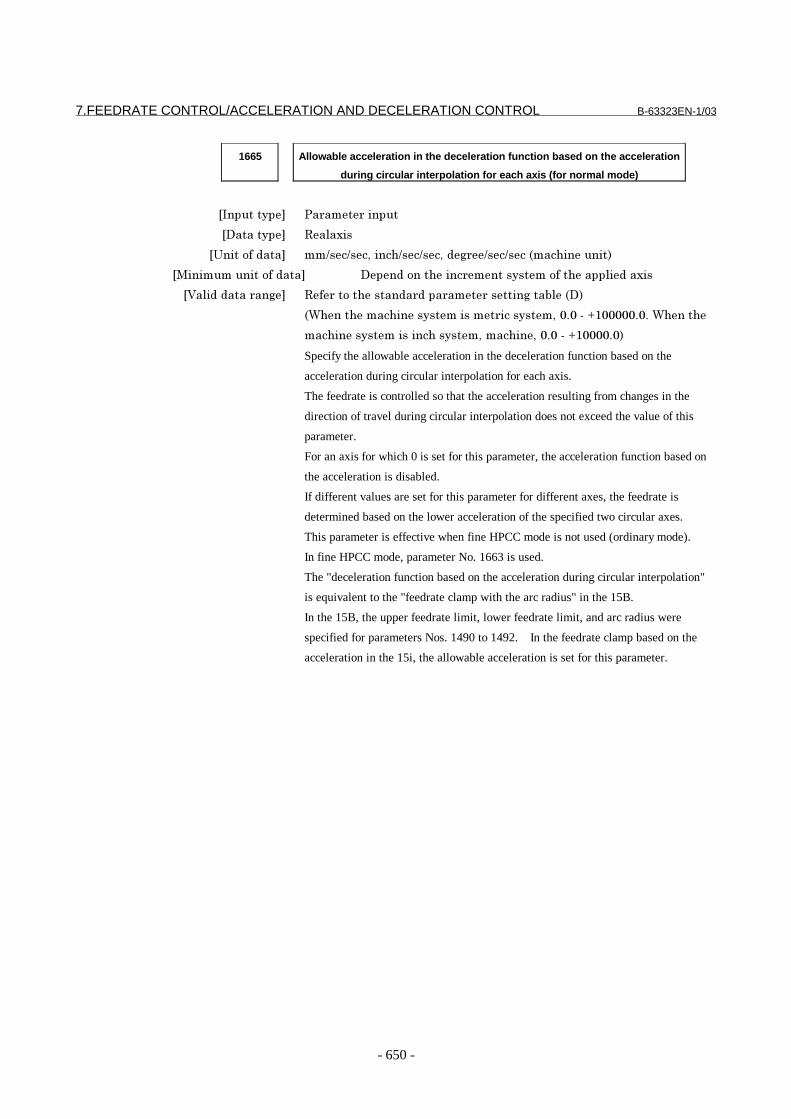
7.FEEDRATE CONTROL/ACCELERATION AND DECELERATION CONTROL B-63323EN-1/03
- 650 -
1665 Allowable acceleration in the deceleration function based on the acceleration
during circular interpolation for each axis (for normal mode)
���������� �� ��� ������
��������� ���� ��
������������� ������������������������ ��������������������
��������������������� �������������� ������������������������ ��
�!���������� ��� �� ������������� ���� ��� ����������"�����
�$������������������������ ����������()(�&�*-((((()()�$�����
������������������������������������()(�&�*-(((()(�
Specify the allowable acceleration in the deceleration function based on the
acceleration during circular interpolation for each axis.
The feedrate is controlled so that the acceleration resulting from changes in the
direction of travel during circular interpolation does not exceed the value of this
parameter.
For an axis for which 0 is set for this parameter, the acceleration function based on
the acceleration is disabled.
If different values are set for this parameter for different axes, the feedrate is
determined based on the lower acceleration of the specified two circular axes.
This parameter is effective when fine HPCC mode is not used (ordinary mode).
In fine HPCC mode, parameter No. 1663 is used.
The "deceleration function based on the acceleration during circular interpolation"
is equivalent to the "feedrate clamp with the arc radius" in the 15B.
In the 15B, the upper feedrate limit, lower feedrate limit, and arc radius were
specified for parameters Nos. 1490 to 1492. In the feedrate clamp based on the
acceleration in the 15i, the allowable acceleration is set for this parameter.
B-63323EN-1/03 7.FEEDRATE CONTROL/ACCELERATION AND DECELERATION CONTROL
- 651 -
7.1.12 Advanced Preview Control
GeneralThis function is provided to enable high-speed high-precisionmachining with the FANUC Series 16i. With the FANUC Series 15i,on the other hand, the look-ahead acceleration/deceleration beforeinterpolation function is used for high-speed high-precision machining,instead of advanced preview control.The look-ahead acceleration/deceleration before interpolation functioncontains functions equivalent to the linear acceleration/decelerationbefore interpolation function and the automatic corner decelerationfunction contained in the advanced preview control.
For details, see the section on look-ahead acceleration/decelerationbefore interpolation.
Reference itemSeries15i/150i-MA Operator’s Manual
(Programming)(B-63324EN)
II-18.4 Look-aheadacceleration/deceleration before interpolation
Series15i/150i-MODEL A
Connection Manual(This manual)
7.2.2 Look-aheadacceleration/deceleration before interpolation

7.FEEDRATE CONTROL/ACCELERATION AND DECELERATION CONTROL B-63323EN-1/03
- 652 -
7.1.13 Nano Interpolation
GeneralThe output from the NC to the servo is usually in units of detectionunits. This function allows output to the servo in units of thousandthsof detection units, thereby improving machining precision. This isparticularly effective for improving the surface roughness.Note that the positioning precision depends on the machine conditions,such as the resolution of the detector.
This function is part of the look-ahead acceleration/deceleration beforeinterpolation function. When the look-ahead acceleration/decelerationbefore interpolation function is enabled, nano interpolation is alsoenabled.
For details, see the section on look-ahead acceleration/decelerationbefore interpolation.
NoteNOTE
This function is most effective when the resolutionof the detector is higher than the detection units.Even when the resolution of the detector is thesame as the detection units (in the case of a closedloop, for example), it is effective if the feed forwardfunction is used.
Reference item
Series15i/150i-MA Operator’s Manual(Programming)(B-63324EN)
II-18.4 Look-aheadacceleration/deceleration before interpolation
Series15i/150i-MODEL A
Connection Manual(This manual)
7.2.2 Look-aheadacceleration/deceleration before interpolation
B-63323EN-1/03 7.FEEDRATE CONTROL/ACCELERATION AND DECELERATION CONTROL
- 653 -
7.1.14 Fine HPCC
GeneralThis function is designed to achieve high-speed, high-precisionmachining with a program involving a sequence of very small straightlines and NURBS curved lines, like those used for metal die machining.This function can suppress the servo system delay and delay caused byacceleration/deceleration that increase as a higher feedrate is used.This function can be used to ensure that the tool strictly traces thespecified values, thus minimizing machining profile errors andachieving high-speed, high-precision machining.HPCC stands for high precision contour control. In fine HPCC mode,acceleration/deceleration is performed more precisely than in theconventional HPCC mode, resulting in an increase in the cutting speed.
FormatThus, this function can be used to ensure that the tool strictly traces thespecified values, thus minimizing machining profile errors for higher-speed, higher-precision machining.
G05.1 Q1 : Look-ahead acceleration/decelerationbefore interpolation mode on
(Multi-buffer mode is set at the same time.)G05.1 Q0 : Look-ahead acceleration/decelerationbefore interpolation mode off
(Multi-buffer mode remains set.)G05.1 P1 Q0: Look-ahead acceleration/decelerationbefore interpolation mode off
(Multi-buffer mode is cleared.)
Specify G05.1 alone in a block.Fine HPCC mode can be automatically turned on atpower-up and upon a reset if the MBF bit (bit 6 ofparameter 2401) is specified accordingly.Fine HPCC mode can be turned on and off byG05P10000 and G05P0, which specify theapplication of high precision contour control by the64-bit RISC processor of the FANUC Series 15-MB.For details, see "Specifying G05P10000/G05P0,"below.
- Functions enabledIn fine HPCC mode, the following functions are enabled:(1) Linear acceleration/deceleration before interpolation or bell-
shaped acceleration/deceleration before interpolation(2) Deceleration function based on feedrate differences at corners(3) Advanced feed-forward function(4) Nano interpolation
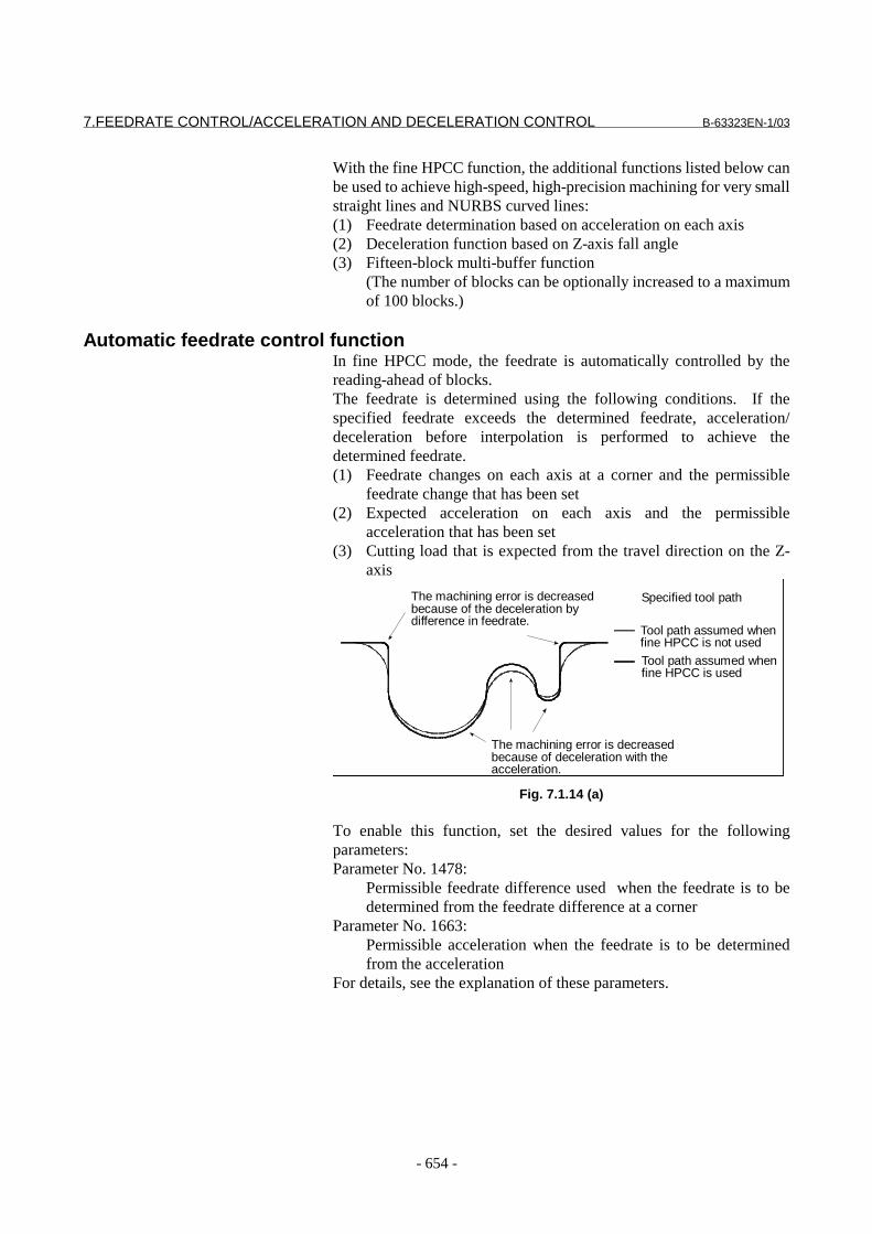
7.FEEDRATE CONTROL/ACCELERATION AND DECELERATION CONTROL B-63323EN-1/03
- 654 -
With the fine HPCC function, the additional functions listed below canbe used to achieve high-speed, high-precision machining for very smallstraight lines and NURBS curved lines:(1) Feedrate determination based on acceleration on each axis(2) Deceleration function based on Z-axis fall angle(3) Fifteen-block multi-buffer function
(The number of blocks can be optionally increased to a maximumof 100 blocks.)
Automatic feedrate control functionIn fine HPCC mode, the feedrate is automatically controlled by thereading-ahead of blocks.The feedrate is determined using the following conditions. If thespecified feedrate exceeds the determined feedrate, acceleration/deceleration before interpolation is performed to achieve thedetermined feedrate.(1) Feedrate changes on each axis at a corner and the permissible
feedrate change that has been set(2) Expected acceleration on each axis and the permissible
acceleration that has been set(3) Cutting load that is expected from the travel direction on the Z-
axis
Specified tool path
Tool path assumed whenfine HPCC is not used
Tool path assumed whenfine HPCC is used
The machining error is decreasedbecause of deceleration with theacceleration.
The machining error is decreasedbecause of the deceleration bydifference in feedrate.
Fig. 7.1.14 (a)
To enable this function, set the desired values for the followingparameters:Parameter No. 1478:
Permissible feedrate difference used when the feedrate is to bedetermined from the feedrate difference at a corner
Parameter No. 1663:Permissible acceleration when the feedrate is to be determinedfrom the acceleration
For details, see the explanation of these parameters.
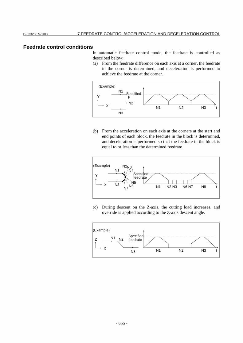
B-63323EN-1/03 7.FEEDRATE CONTROL/ACCELERATION AND DECELERATION CONTROL
- 655 -
Feedrate control conditionsIn automatic feedrate control mode, the feedrate is controlled asdescribed below:(a) From the feedrate difference on each axis at a corner, the feedrate
in the corner is determined, and deceleration is performed toachieve the feedrate at the corner.
(b) From the acceleration on each axis at the corners at the start andend points of each block, the feedrate in the block is determined,and deceleration is performed so that the feedrate in the block isequal to or less than the determined feedrate.
(c) During descent on the Z-axis, the cutting load increases, andoverride is applied according to the Z-axis descent angle.
N2N1
Specified F
N3 t
N1
N2
N3
Y
X
(Example)
N2 N3 N6 N7N1
Specifiedfeedrate
N8 t
N1N2N3
Y
X
(Example)
N7N6
N4
N5N8
N2N1 N3 t
N1 N2
N3
Z
X
(Example)
Specifiedfeedrate

7.FEEDRATE CONTROL/ACCELERATION AND DECELERATION CONTROL B-63323EN-1/03
- 656 -
Example of determining the feedrate from the feedrate difference on each axisThe feedrate at a corner is calculated from the feedrate difference oneach axis, as described below.he tangent feedrate that does not cause the feedrate change on each axisto exceed the permissible feedrate difference set for parameter No.1478 is calculated, and deceleration at performed at the corner.
- ExampleWhen the tool travel direction changes by 90 degrees from the X-axisto the Y-axis, deceleration is performed as shown below, if the feedrateis 1000 mm/min and the permissible feedrate difference is 500mm/min.
Fig. 7.1.14 (b) Example of Determining the Feedrate from the FeedrateDifference
N2N1 G01 G91 X100. F1000 ;N2 Y100. ;
N1
Tool path assumed if decelerationis not performed at the corner
' @Tool path assumed if deceleration is@ @performed at the corner
If deceleration is notperformed at the cornerIf deceleration is performedat the corner
N1 N2 Time
N2 Time
Time
Feedrate
F1000
F500
Feedrate on theX-axis
Feedrate on theY-axis
Tangent feedrate
Feedrate
F1000
F500
Feedrate
F1000
F500

B-63323EN-1/03 7.FEEDRATE CONTROL/ACCELERATION AND DECELERATION CONTROL
- 657 -
NOTEThe method of deceleration with the feedratedifference differs depending on the setting ofparameter FNW (bit 6 of No. 1517). For details,refer to the section on " Look-ahead acceleration/deceleration before interpolation " in this manual.
Example of determining the feedrate with the acceleration on each axisWhen consecutive small lines are used to form a curve, as in theexample shown in the figure below, the feedrate differences on eachaxis at the individual corners are not very large. Thus, deceleration withthe feedrate differences is not effective. Consecutive small feedratedifferences, however, cause a large acceleration on each axis, as awhole.In such a case, deceleration can be performed to reduce the impact onthe machine and the machining error caused by too large anacceleration. The deceleration feedrate is determined to be the feedratethat does not cause the acceleration on each axis to exceed thepermissible acceleration set for parameter No. 1663.The deceleration feedrate is determined for each corner. The actualfeedrate is the smaller of the deceleration feedrate determined at thestart point of the block and that determined at the end point.
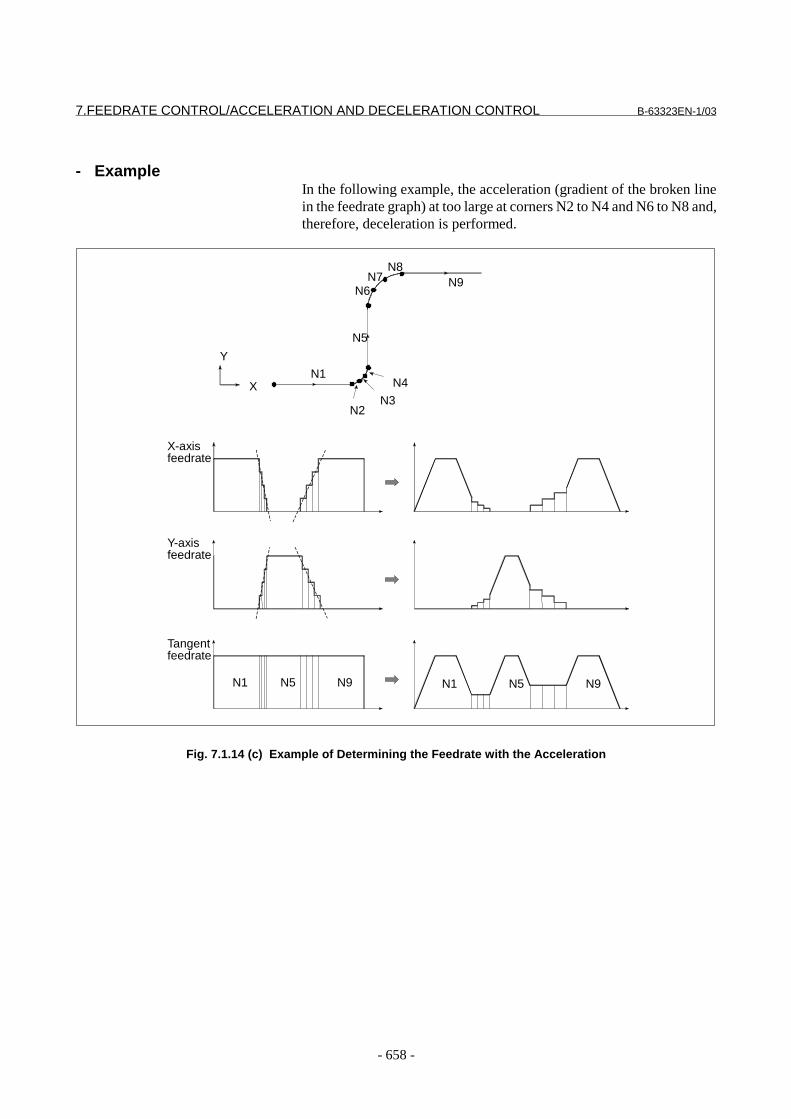
7.FEEDRATE CONTROL/ACCELERATION AND DECELERATION CONTROL B-63323EN-1/03
- 658 -
- ExampleIn the following example, the acceleration (gradient of the broken linein the feedrate graph) at too large at corners N2 to N4 and N6 to N8 and,therefore, deceleration is performed.
Fig. 7.1.14 (c) Example of Determining the Feedrate with the Acceleration
X-axisfeedrate
N1
N2
Y
XN3
N4
N6N7
N8
Y-axisfeedrate
Tangentfeedrate
N1 N5 N9 N1 N5 N9
N9
N5
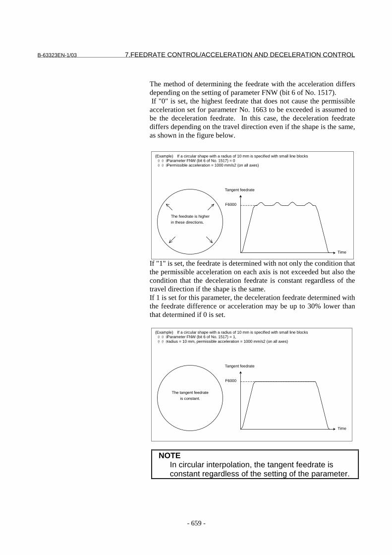
B-63323EN-1/03 7.FEEDRATE CONTROL/ACCELERATION AND DECELERATION CONTROL
- 659 -
The method of determining the feedrate with the acceleration differsdepending on the setting of parameter FNW (bit 6 of No. 1517). If "0" is set, the highest feedrate that does not cause the permissibleacceleration set for parameter No. 1663 to be exceeded is assumed tobe the deceleration feedrate. In this case, the deceleration feedratediffers depending on the travel direction even if the shape is the same,as shown in the figure below.
If "1" is set, the feedrate is determined with not only the condition thatthe permissible acceleration on each axis is not exceeded but also thecondition that the deceleration feedrate is constant regardless of thetravel direction if the shape is the same.If 1 is set for this parameter, the deceleration feedrate determined withthe feedrate difference or acceleration may be up to 30% lower thanthat determined if 0 is set.
NOTEIn circular interpolation, the tangent feedrate isconstant regardless of the setting of the parameter.
(Example) If a circular shape with a radius of 10 mm is specified with small line blocks@ @ @Parameter FNW (bit 6 of No. 1517) = 0@ @ @Permissible acceleration = 1000 mm/s2 (on all axes)
The feedrate is higher
in these directions.
Tangent feedrate
Time
F6000
(Example) If a circular shape with a radius of 10 mm is specified with small line blocks@ @ @Parameter FNW (bit 6 of No. 1517) = 1,@ @ @radius = 10 mm, permissible acceleration = 1000 mm/s2 (on all axes)
The tangent feedrate
is constant.
Tangent feedrate
Time
F6000

7.FEEDRATE CONTROL/ACCELERATION AND DECELERATION CONTROL B-63323EN-1/03
- 660 -
Example of determining the feedrate with the cutting loadThis function is enabled when parameter ZAG (bit 4 of No. 7565) is setto 1.
Fig. 7.1.14 (d) During ascent on the Z-axis
Fig. 7.1.14 (e) During descent on the Z-axis
Usually, the cutting resistance is higher when machining is performedwith the bottom of the cutter, as shown in Fig. 7.1.14 (a) an whenmachining is performed with the side of the cutter, as shown in Fig.7.1.14 (d). Deceleration is, therefore, required. In fine HPCC, the tooltravel direction on the Z-axis is used as a condition for calculating themachining feedrate.The descent angle during descent on the Z-axis (angle formed by theXY plane and the tool center path) is as shown in Fig. 7.1.14 (e). Thedescent angle is divided into four areas, and the override values for theindividual areas are set for the following parameters:
Parameter No. 7591 for area 2Parameter No. 7592 for area 3Parameter No. 7593 for area 4
For area 1, however, no parameter is available, and an override of100% is used at all times. The feedrate obtained according to otherfeedrate control is multiplied by the override value of the area to whichdescent angle belongs.
Area1 0° ≤ θ <30°Area2 30° ≤ θ <45°Area3 45° ≤ θ <60°Area4 60° ≤ θ ≤90°
θ
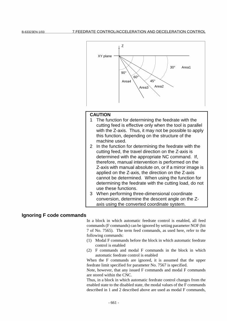
B-63323EN-1/03 7.FEEDRATE CONTROL/ACCELERATION AND DECELERATION CONTROL
- 661 -
XY plane
Z
30°
45°60°
90°Area1
Area2Area3
Area4
CAUTION1 The function for determining the feedrate with the
cutting feed is effective only when the tool is parallelwith the Z-axis. Thus, it may not be possible to applythis function, depending on the structure of themachine used.
2 In the function for determining the feedrate with thecutting feed, the travel direction on the Z-axis isdetermined with the appropriate NC command. If,therefore, manual intervention is performed on theZ-axis with manual absolute on, or if a mirror image isapplied on the Z-axis, the direction on the Z-axiscannot be determined. When using the function fordetermining the feedrate with the cutting load, do notuse these functions.
3 When performing three-dimensional coordinateconversion, determine the descent angle on the Z-axis using the converted coordinate system.
Ignoring F code commandsIn a block in which automatic feedrate control is enabled, all feedcommands (F commands) can be ignored by setting parameter NOF (bit7 of No. 7565). The term feed commands, as used here, refer to thefollowing commands:(1) Modal F commands before the block in which automatic feedrate
control is enabled(2) F commands and modal F commands in the block in which
automatic feedrate control is enabledWhen the F commands are ignored, it is assumed that the upperfeedrate limit specified for parameter No. 7567 is specified.Note, however, that any issued F commands and modal F commandsare stored within the CNC.Thus, in a block in which automatic feedrate control changes from theenabled state to the disabled state, the modal values of the F commandsdescribed in 1 and 2 described above are used as modal F commands,

7.FEEDRATE CONTROL/ACCELERATION AND DECELERATION CONTROL B-63323EN-1/03
- 662 -
instead of the modal values of the F commands calculated by automaticfeedrate control.
Another example of determining the feedrateIf the calculated feedrate exceeds either the upper limit (parameter No.7567) for automatic feedrate control that is set for the appropriateparameter or the feedrate specified with an F command, clamping isperformed with the smaller of the upper limit feedrate and the feedratespecified with the F command.If the feedrate calculated by the deceleration function based on theacceleration is smaller than the lower feedrate limit for the decelerationfunction based on the acceleration of fine HPCC set for parameter No.1483, the lower feedrate limit is used for the feedrate. If, however, thespecified feedrate is smaller than the lower feedrate limit, the specifiedfeedrate is used.

B-63323EN-1/03 7.FEEDRATE CONTROL/ACCELERATION AND DECELERATION CONTROL
- 663 -
ParameterSee also the explanation of those parameters for look-aheadacceleration/deceleration before interpolation because this functionuses it.
1483 Lower feedrate limit for the deceleration function based on the acceleration
of fine HPCC
���������� �� ��� ������
��������� ���
������������� �������������������� ������������������
��������������������� �������������� ���������������� � ���� ��
�!���������� ��� �� ������������� ���� ��� ����������"���#�
�$��������� ��������������%&'��()(�&�*+,(((()(�
.����� ���������������"�������������� �������������/�##
������������������������������������� ������� ����������
���� �)
������������������ ������������������ �������"����0 �
��1)
������������ ������� 0�������� ���� ���"�������������1�
��� ������������� ���"��1���������������� �������� ��� �����"
���� ���)
������10 ������0 ���"�������� ���������������"���������
������������������"��������� �������"������1 �����������1
�� ��������)
.����1 ��� ��������������� ������"�������������� �������� ���
�� ���� ���� ��������������������� ����������/�##���������"
���������� ��� ��� �2�)�-,3-)
NOTEDuring involute interpolation, the lower feedrate limit for the"acceleration clamp in the vicinity of the basic circle" of involuteinterpolation automatic feedrate control is applied.
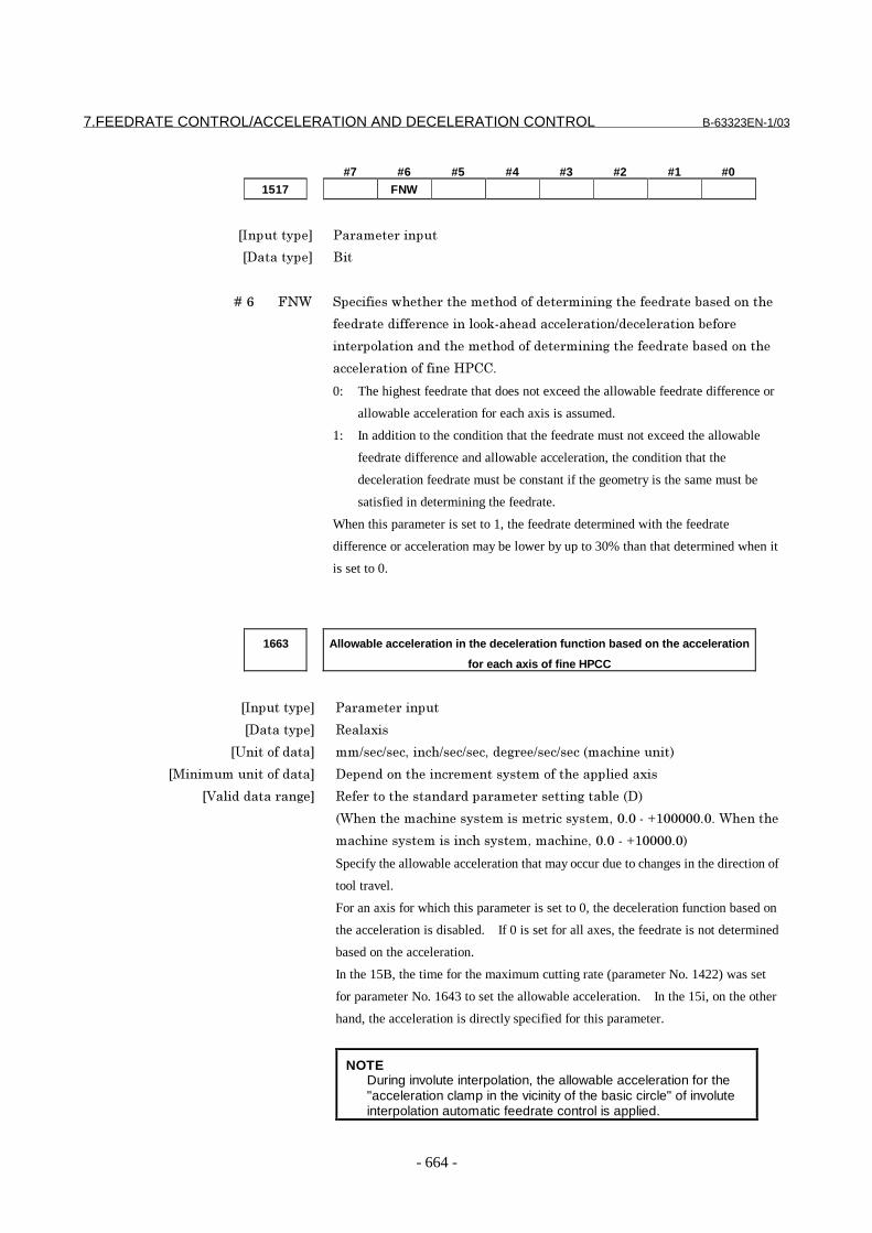
7.FEEDRATE CONTROL/ACCELERATION AND DECELERATION CONTROL B-63323EN-1/03
- 664 -
#7 #6 #5 #4 #3 #2 #1 #0
1517 FNW
���������� �� ��� ������
��������� '��
� � � � 4�5 62$ %�������1��� ��������������� ������������ ���"���������
�� ������� ���������7&��������� ��������� ������"��
��� ��������������������������� ������������ ���"���������
���� �������������/�##)
0: The highest feedrate that does not exceed the allowable feedrate difference or
allowable acceleration for each axis is assumed.
1: In addition to the condition that the feedrate must not exceed the allowable
feedrate difference and allowable acceleration, the condition that the
deceleration feedrate must be constant if the geometry is the same must be
satisfied in determining the feedrate.
When this parameter is set to 1, the feedrate determined with the feedrate
difference or acceleration may be lower by up to 30% than that determined when it
is set to 0.
1663 Allowable acceleration in the deceleration function based on the acceleration
for each axis of fine HPCC
���������� �� ��� ������
��������� ���� ��
������������� ������������������������ ��������������������
��������������������� �������������� ������������������������ ��
�!���������� ��� �� ������������� ���� ��� ����������"�����
�$������������������������ ����������()(�&�*-((((()()�$�����
������������������������������������()(�&�*-(((()(�
Specify the allowable acceleration that may occur due to changes in the direction of
tool travel.
For an axis for which this parameter is set to 0, the deceleration function based on
the acceleration is disabled. If 0 is set for all axes, the feedrate is not determined
based on the acceleration.
In the 15B, the time for the maximum cutting rate (parameter No. 1422) was set
for parameter No. 1643 to set the allowable acceleration. In the 15i, on the other
hand, the acceleration is directly specified for this parameter.
NOTEDuring involute interpolation, the allowable acceleration for the"acceleration clamp in the vicinity of the basic circle" of involuteinterpolation automatic feedrate control is applied.

B-63323EN-1/03 7.FEEDRATE CONTROL/ACCELERATION AND DECELERATION CONTROL
- 665 -
#7 #6 #5 #4 #3 #2 #1 #0
7565 NOF ZAG
���������� %�����������
��������� '��
� � � � 4�, 89: %�������1��� ����� �� �������� ������������������� ������"�
8&� �����������������"���������������������������/�##)
0: Do not perform.
1: Perform.
After setting 1 in this parameter, be sure to set parameter No. 7591, No. 7592, and
No. 9593.
� � � � 4�; 2<6 %�������1��� �������� ����6����������������/�##)
(= ����������� )
-= ���� )
$���-����������������� ��� ��������������������������� ��� ��
����������� ��� �2�)�;>5;����������)
7567 Upper feedrate limit for fine HPCC
���������� %�����������
��������� ���
������������� �������������������� �����������������
��������������������� �������������� ���������������� � ���� ��
�!���������� ��� �� ������������� ���� ��� ����������"���#�
�$��������� ��������������%&'��()(�&�*+,(((()(�
%�������� ��� ����������� �����/�##)� � ������� ������� ��������
0����������������� ��� ����������������������/�##��������
�� �������������������0����������������� ��� )
$���(����������������� ��� ������� ����������������)
$���"���;��2<6������� ��� �2�)�;>5>����������-��������������������
����� ���������������� ��� ����������)� � ���(��������������
�� ��� ������������������%(-?;���� ����������)
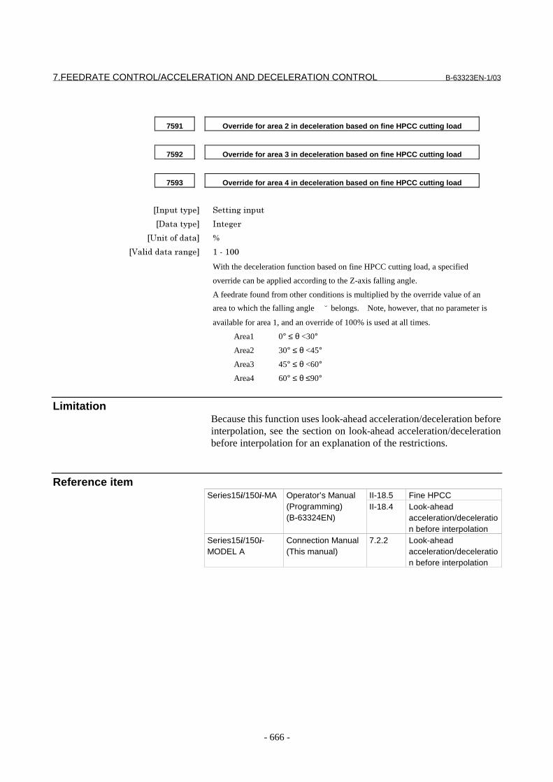
7.FEEDRATE CONTROL/ACCELERATION AND DECELERATION CONTROL B-63323EN-1/03
- 666 -
7591 Override for area 2 in deceleration based on fine HPCC cutting load
7592 Override for area 3 in deceleration based on fine HPCC cutting load
7593 Override for area 4 in deceleration based on fine HPCC cutting load
���������� %�����������
��������� ����
������������� @
�!���������� ��� -�&�-((
With the deceleration function based on fine HPCC cutting load, a specified
override can be applied according to the Z-axis falling angle.
A feedrate found from other conditions is multiplied by the override value of an
area to which the falling angle ̆ belongs. Note, however, that no parameter is
available for area 1, and an override of 100% is used at all times.
Area1 0° ≤ θ <30°
Area2 30° ≤ θ <45°
Area3 45° ≤ θ <60°
Area4 60° ≤ θ ≤90°
LimitationBecause this function uses look-ahead acceleration/deceleration beforeinterpolation, see the section on look-ahead acceleration/decelerationbefore interpolation for an explanation of the restrictions.
Reference itemII-18.5 Fine HPCCSeries15i/150i-MA Operator’s Manual
(Programming)(B-63324EN)
II-18.4 Look-aheadacceleration/deceleration before interpolation
Series15i/150i-MODEL A
Connection Manual(This manual)
7.2.2 Look-aheadacceleration/deceleration before interpolation

B-63323EN-1/03 7.FEEDRATE CONTROL/ACCELERATION AND DECELERATION CONTROL
- 667 -
7.1.15 Machining type in HPCC screen programming
GeneralThe high-speed high-precision machining setting screen supports threemachining parameter sets (FINE, MEDIUM, and ROUGH). Theparameter set to use can be selected in MDI mode. Selecting oneparameter set causes the working parameters to be rewritten. If FINE isselected, for example, the values of the finish machining parameterslisted below are set in the working parameters.
Finish machiningparameter
Workingparameter
ACC/DEC LEVEL 1533 (None)ACC FOR BIPL 1534 1660(*1)
ACC CHANGE TIME (BELL) 1536 1656MAX ACCELERATION 1535 1663(*2)
T-CONST AIPL ACC/DEC 1522 1635CORNER FEED 1524 1478FEED FORWARD COEFFICIENT 1529 1985, 3344(*3)
*1, *2 These values have been overridden on the acceleration/deceleration level.*3 These values apply only when parameter TSP (bit 0 of parameterNo. 8403) is set to 1.This function enables a machining parameter set to be selected by acommand in a program during operation as well as in MDI mode. Theselected machining parameters are reflected on the high-speed high-precision machining setting screen.
Parameter#7 #6 #5 #4 #3 #2 #1 #0
8403 TSP
[Input type] Parameter input[Data type] Bit
# 0 TSP Specifies whether to transfer the same advance feedforwardcoefficient to the corresponding working parameter on the spindleside (parameter No. 3344) and to the servo side (parameter No.1985), using the high-speed high-precision machining setting screenor the pattern program command function for individual machiningtypes, as follows:0: Do not transfer1: Transfer
AlarmNumber Message ContentsPS0302 ILLEGAL DATA NUMBER The pattern program command for individual machining
types on the high-speed high-precision setting screencontains an incorrect value for address R.

7.FEEDRATE CONTROL/ACCELERATION AND DECELERATION CONTROL B-63323EN-1/03
- 668 -
7.1.16 Feedrate Specification on a Virtual Circle for a Rotary Axis
This function improves a method of specifying a speed for a machinehaving a rotation axis.[Conventional method]
Program exampleN1G91G01X10.F100.N2C10.F50
The rotation axis commandspecifies the speed of therotation axis.
Specified speed(deg/min)
X
Y
N2
N1
C
[Method of specifying the speed on a virtual circle for a rotation axis]
Specified speed(mm/min)
Virtual-circleradius
X
YProgram exampleN1G91G01X10.F100.N2C10.
The speed at which the tool movesalong a virtual circle having a radiusspecified using a parameterbecomes the "specified speed."Using a virtual-circle radius of 0 canexclude the rotation axis fromspeed calculation.
N2
N1
C
NOTEUsing this function causes the movement speed alonga virtual circle to be used as the specified speed.This does not generally mean that a speed at acutting point becomes the specified speed.
ExplanationThe following description exemplifies a machine having three linearaxes (X, Y, Z) and two rotation axes (B, C).
- Calculating the rotation axis feedrate[Conventional method]
Conventionally, the feedrate has been controlled in such a waythat it takes the time T, calculated using the following expression,to move through the specified distance.
F
LT
CBZYXL
=
∆+∆+∆+∆+∆= 22222
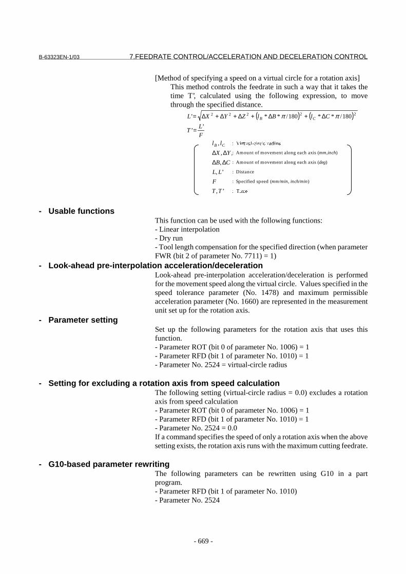
B-63323EN-1/03 7.FEEDRATE CONTROL/ACCELERATION AND DECELERATION CONTROL
- 669 -
[Method of specifying a speed on a virtual circle for a rotation axis]This method controls the feedrate in such a way that it takes thetime T’, calculated using the following expression, to movethrough the specified distance.
( ) ( )
��
����
��
�� �
�� �
�����
:’,
min)/min,/(:
:’,
(deg):,
),(:,,
:,
’’
180/**180/**’ 22222
TT
inchmmF
LL
CB
inchmmZYX
llF
LT
ClBlZYXL
CB
CB
∆∆∆∆∆
=
∆+∆+∆+∆+∆= ππ
- Usable functionsThis function can be used with the following functions:- Linear interpolation- Dry run- Tool length compensation for the specified direction (when parameterFWR (bit 2 of parameter No. 7711) = 1)
- Look-ahead pre-interpolation acceleration/decelerationLook-ahead pre-interpolation acceleration/deceleration is performedfor the movement speed along the virtual circle. Values specified in thespeed tolerance parameter (No. 1478) and maximum permissibleacceleration parameter (No. 1660) are represented in the measurementunit set up for the rotation axis.
- Parameter settingSet up the following parameters for the rotation axis that uses thisfunction.- Parameter ROT (bit 0 of parameter No. 1006) = 1- Parameter RFD (bit 1 of parameter No. 1010) = 1- Parameter No. 2524 = virtual-circle radius
- Setting for excluding a rotation axis from speed calculationThe following setting (virtual-circle radius = 0.0) excludes a rotationaxis from speed calculation- Parameter ROT (bit 0 of parameter No. 1006) = 1- Parameter RFD (bit 1 of parameter No. 1010) = 1- Parameter No. 2524 = 0.0If a command specifies the speed of only a rotation axis when the abovesetting exists, the rotation axis runs with the maximum cutting feedrate.
- G10-based parameter rewritingThe following parameters can be rewritten using G10 in a partprogram.- Parameter RFD (bit 1 of parameter No. 1010)- Parameter No. 2524
����������������� ���
: Amount of movement along each axis (mm,inch)
: Amount of movement along each axis (deg)
: Distance
: Specified speed (mm/min, inch/min)
�������

7.FEEDRATE CONTROL/ACCELERATION AND DECELERATION CONTROL B-63323EN-1/03
- 670 -
Restrictions
- Unusable functionsThis function cannot be used with the following functions:- The following G functions in group 01
PositioningCircular interpolation, helical interpolation, spiral interpolation,and conical interpolationArc threading BInvolute interpolationExponential interpolationThree-dimensional circular interpolationSpline interpolationNURBS interpolation
- Cylindrical interpolation- Polar coordinate interpolation- Normal-direction control- Feed per rotation- Inverse time feed
- Parallel-axis control and twin-table controlTo use this function together with parallel-axis or twin-table control,set parameter No. 2524 with the same value for the master and slaveaxes.
Parameters#7 #6 #5 #4 #3 #2 #1 #0
1010 RFD
���������� �� ��� ������
��������� '���� ��
� � � � 4�- �6� �6��������������� ������� ����� ��� ��������� �����������1�=
0: Conventional method
1: Method of specifying the speed on a virtual circle for a rotation axis
B-63323EN-1/03 7.FEEDRATE CONTROL/ACCELERATION AND DECELERATION CONTROL
- 671 -
2524 Virtual-circle radius in specifying the speed on a virtual circle for a rotation
axis
���������� �� ��� ������
��������� ���&���" �� ��
������������� ���������������������
������������������������ ������������ ����� ��������� ��
�!���������� ��� (�� �3������������������������� ����������������������0�������
���A%����� ���� ��� �%������.�"���'�)A�
�6� ��%&'��()(����*333333)333�
Specify the radius of a virtual circle for the method of specifying the speed on a
virtual circle for a rotation axis.
Specifying 0.0 in this parameter causes the rotation axis to be excluded from speed
calculation.
Reference itemFANUC Series15i/150i-MA
Operator’s Manual(Programming)(B-6332EN)
U.5.3 Cutting Feed
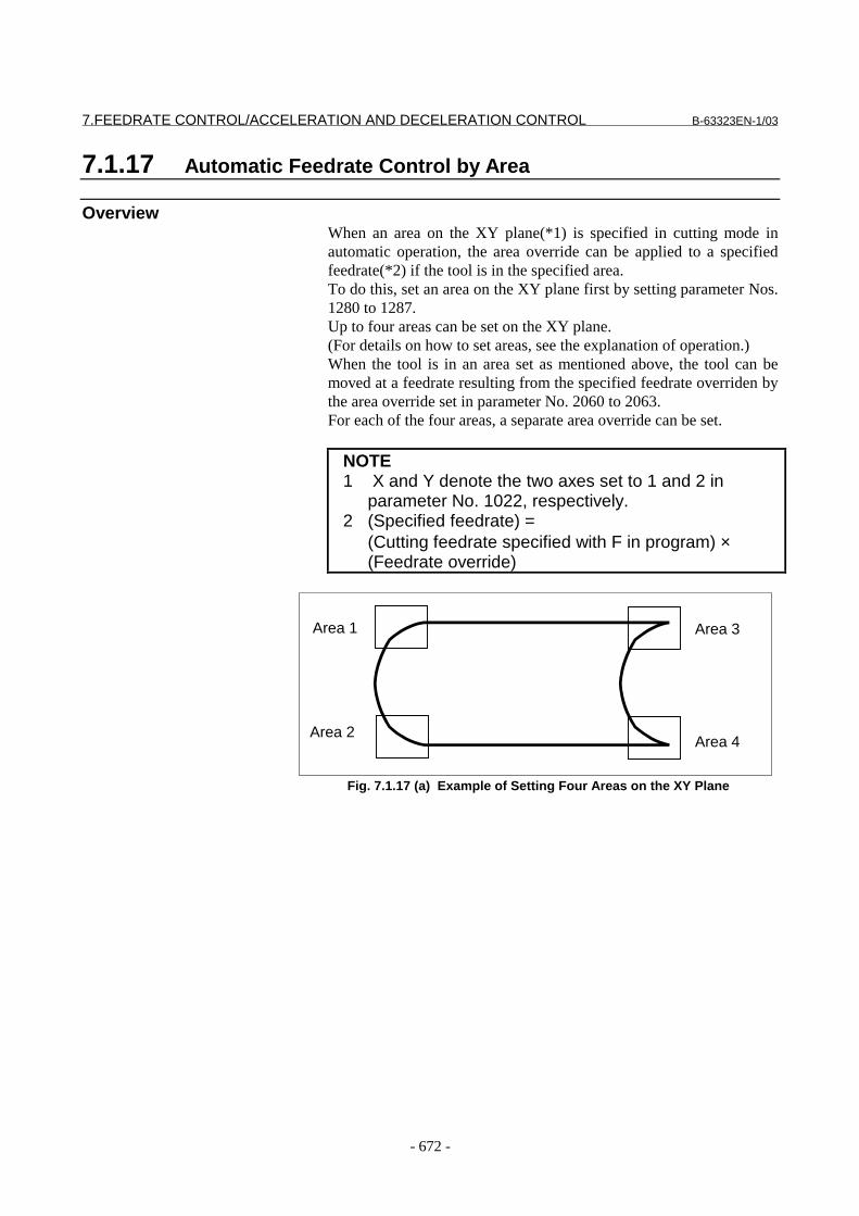
7.FEEDRATE CONTROL/ACCELERATION AND DECELERATION CONTROL B-63323EN-1/03
- 672 -
7.1.17 Automatic Feedrate Control by Area
OverviewWhen an area on the XY plane(*1) is specified in cutting mode inautomatic operation, the area override can be applied to a specifiedfeedrate(*2) if the tool is in the specified area.To do this, set an area on the XY plane first by setting parameter Nos.1280 to 1287.Up to four areas can be set on the XY plane.(For details on how to set areas, see the explanation of operation.)When the tool is in an area set as mentioned above, the tool can bemoved at a feedrate resulting from the specified feedrate overriden bythe area override set in parameter No. 2060 to 2063.For each of the four areas, a separate area override can be set.
NOTE1 X and Y denote the two axes set to 1 and 2 in
parameter No. 1022, respectively.2 (Specified feedrate) =
(Cutting feedrate specified with F in program) ×(Feedrate override)
Area 1
Area 2
Area 3
Area 4
Fig. 7.1.17 (a) Example of Setting Four Areas on the XY Plane

B-63323EN-1/03 7.FEEDRATE CONTROL/ACCELERATION AND DECELERATION CONTROL
- 673 -
Defining areas- Up to four areas can be set. We’ll use area numbers to call these
areas area 1 to area 4.- Each area is set as a quadrangle whose sides are parallel to the X-
and Y-axes.Each area includes the border of the quadrangle.
- An area is defined by setting one of the two pairs of diagonalvertexes of a quadrangle. (See Fig. 7.1.17(b).)Either of the two vertex pairs may be used to determine a uniquequadrangle.If two diagonal vertexes are at the same coordinates, the area is apoint.
- When two or more areas overlap each other, the area override forthe area with the smallest area number is used for the overlapportion. (See Fig. 7.1.17(c).)
X-axis
Y-axis
Vertex pair 1
Vertex pair 1Vertex pair 2
Vertex pair 2
Fig. 7.1.17 (b) Two Pairs of Diagonal Vertexes of a Quadrangle
X-axis
Y-axisArea 4, area override 4
Area 1, area override 1
In the portion where
areas 1 and 4
overlap, area
override 1 is
applied.
Fig. 7.1.17 (c) When Areas Overlap One Another
7.FEEDRATE CONTROL/ACCELERATION AND DECELERATION CONTROL B-63323EN-1/03
- 674 -
Determining whether the tool is in an areaWhether the tool has entered an area is checked based on the machinecoordinates.
Setting an areaThere are three methods for setting an area, that is, for setting two diagonalvertexes, as follows:(1) Specify and write a parameter number in G10.
Press the [Setting] key several times to display the automatic feedratecontrol: area setting screen.(2) Enter the necessary data directly in MDI mode.(3) Move the tool manually to a desired position, then press CRT/MDI soft
key [Area setting] to record the position. Then, the coordinates of the current cursor position are changed.
Setting an area overrideAn area override is set within the range from 0% to 127%.For each of four areas, a separate area override can be set.There are two methods of setting an area override as follows:(1) Specify and write a parameter number in G10.Press the [Setting] key several times to display the automatic feedratecontrol: area setting screen.(2) Enter the necessary data directly in MDI mode.
NotesNOTE1 In cutting mode in automatic operation, a check is
made to see whether the tool has entered an area,and the tool is moved at a feedrate multiplied by thepercentage set in parameter Nos. 2060 to 2063.
2 This function is disabled in the following modes:Threading, Feed per revolution, Tapping
3 This function is also disabled when the X-axis andY-axis are used as axes subjected to the following:PMC axis control, Chopping
4 The percentage of the cutting feedrate is obtained bymultiplying the normal feedrate override by the areaoverride of this function. If the multiplication resultexceeds 254%, it is clamped to 254%.
5 This function is disabled when the tool moves at a dryrun speed.
6 In three-dimensional coordinate conversion mode,this function is valid for areas on the XY plane in themachine coordinate system.
7 In synchronization control, areas are set for themaster axis. The area override of this function isapplied to all the synchronized axes.
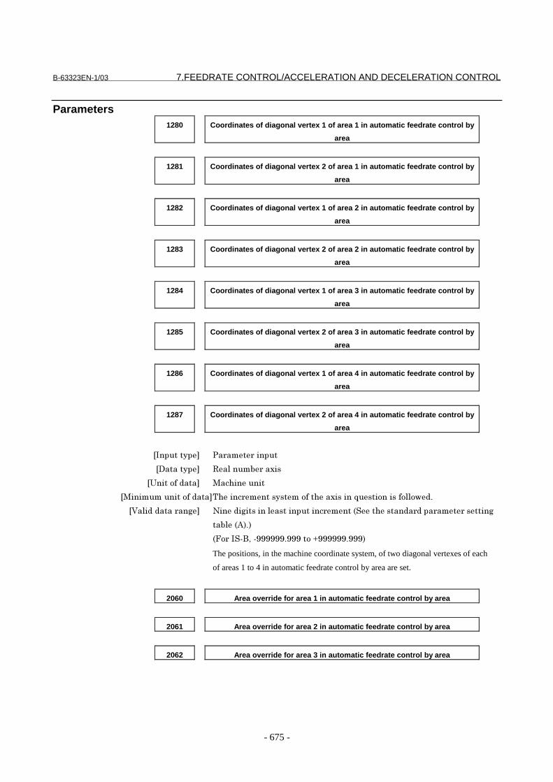
B-63323EN-1/03 7.FEEDRATE CONTROL/ACCELERATION AND DECELERATION CONTROL
- 675 -
Parameters1280 Coordinates of diagonal vertex 1 of area 1 in automatic feedrate control by
area
1281 Coordinates of diagonal vertex 2 of area 1 in automatic feedrate control by
area
1282 Coordinates of diagonal vertex 1 of area 2 in automatic feedrate control by
area
1283 Coordinates of diagonal vertex 2 of area 2 in automatic feedrate control by
area
1284 Coordinates of diagonal vertex 1 of area 3 in automatic feedrate control by
area
1285 Coordinates of diagonal vertex 2 of area 3 in automatic feedrate control by
area
1286 Coordinates of diagonal vertex 1 of area 4 in automatic feedrate control by
area
1287 Coordinates of diagonal vertex 2 of area 4 in automatic feedrate control by
area
���������� �� ��� ������
��������� �������" �� ��
������������� �����������
���������������������.����� ����������������� ������B���������������1�)
�!���������� ��� 2��������������������������� �����%���������� ���� ��� �������
��"���9�)�
�6� ��%&'��&333333)333����*333333)333�
The positions, in the machine coordinate system, of two diagonal vertexes of each
of areas 1 to 4 in automatic feedrate control by area are set.
2060 Area override for area 1 in automatic feedrate control by area
2061 Area override for area 2 in automatic feedrate control by area
2062 Area override for area 3 in automatic feedrate control by area

7.FEEDRATE CONTROL/ACCELERATION AND DECELERATION CONTROL B-63323EN-1/03
- 676 -
2063 Area override for area 4 in automatic feedrate control by area
���������� �� ��� ������
��������� ����
������������� @
�!���������� ��� (����-+;
The area overrides for areas 1 to 4 in automatic feedrate control by area are set as
percentages. If 0 is set for an area, the setting for the area becomes invalid.
The area override is applied to the feedrate resulting from the override of a
specified feedrate.
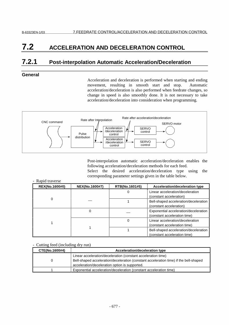
B-63323EN-1/03 7.FEEDRATE CONTROL/ACCELERATION AND DECELERATION CONTROL
- 677 -
7.2 ACCELERATION AND DECELERATION CONTROL
7.2.1 Post-interpolation Automatic Acceleration/Deceleration
GeneralAcceleration and deceleration is performed when starting and endingmovement, resulting in smooth start and stop. Automaticacceleration/deceleration is also performed when feedrate changes, sochange in speed is also smoothly done. It is not necessary to takeacceleration/deceleration into consideration when programming.
Post-interpolation automatic acceleration/deceleration enables thefollowing acceleration/deceleration methods for each feed.Select the desired acceleration/deceleration type using thecorresponding parameter settings given in the table below.
- Rapid traverseREX(No.1600#0) NEX(No.1600#7) RTB(No.1601#5) Acceleration/deceleration type
0 Linear acceleration/deceleration(constant acceleration)
0 __1 Bell-shaped acceleration/deceleration
(constant acceleration)0 __ Exponential acceleration/deceleration
(constant acceleration time)0 Linear acceleration/deceleration
(constant acceleration time)1
11 Bell-shaped acceleration/deceleration
(constant acceleration time)
- Cutting feed (including dry run)CTE(No.1600#4) Acceleration/deceleration type
0Linear acceleration/deceleration (constant acceleration time)Bell-shaped acceleration/deceleration (constant acceleration time) if the bell-shapedacceleration/deceleration option is supported.
1 Exponential acceleration/deceleration (constant acceleration time)
CNC command
Pulsedistribution
Rate after InterpolationRate after acceleration/deceleration
SERVO motor
Acceleration/deceleration
controlSERVOcontrol
SERVOcontrol
Acceleration/deceleration
control

7.FEEDRATE CONTROL/ACCELERATION AND DECELERATION CONTROL B-63323EN-1/03
- 678 -
- Jog feedJGE(No.1600#5) Acceleration/deceleration type
0Linear acceleration/deceleration (constant acceleration time)Bell-shaped acceleration/deceleration (constant acceleration time) if the bell-shapedacceleration/deceleration option is supported.
1 Exponential acceleration/deceleration (constant acceleration time)
- Constant acceleration and constant acceleration time acceleration/decelerationWith constant acceleration acceleration/deceleration,acceleration/deceleration can be performed efficiently with theacceleration set for each axis. Because acceleration/deceleration isperformed for each axis, the specified path may be shifted, and constantacceleration acceleration/deceleration can be applied to rapid traverseonly. (When linear interpolated positioning is performed, the path maynot be on the specified line.)With constant acceleration time acceleration/deceleration, thespecified path will not be shifted. Because the time constant is constantregardless of the specified feedrate, the time required foracceleration/deceleration does not change, no matter how small thespecified feedrate.
C o n s ta n t a cc e le ra tio n
C o n s ta n t a c c e le ra tio n t im e
T im e
F e e d ra te
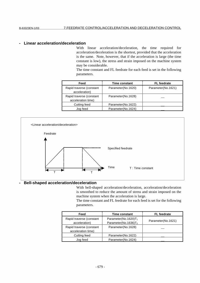
B-63323EN-1/03 7.FEEDRATE CONTROL/ACCELERATION AND DECELERATION CONTROL
- 679 -
- Linear acceleration/decelerationWith linear acceleration/deceleration, the time required foracceleration/deceleration is the shortest, provided that the accelerationis the same. Note, however, that if the acceleration is large (the timeconstant is low), the stress and strain imposed on the machine systemmay be considerable.The time constant and FL feedrate for each feed is set in the followingparameters.
Feed Time constant FL feedrate
Rapid traverse (constantacceleration)
Parameter(No.1620) Parameter(No.1621)
Rapid traverse (constantacceleration time)
Parameter(No.1628) __
Cutting feed Parameter(No.1622) __Jog feed Parameter(No.1624) __
- Bell-shaped acceleration/decelerationWith bell-shaped acceleration/deceleration, acceleration/decelerationis smoothed to reduce the amount of stress and strain imposed on themachine system when the acceleration is large.The time constant and FL feedrate for each feed is set for the followingparameters.
Feed Time constant FL feedrate
Rapid traverse (constantacceleration)
Parameter(No.1620)T1
Parameter(No.1636)T2Parameter(No.1621)
Rapid traverse (constantacceleration time)
Parameter(No.1628) __
Cutting feed Parameter(No.1622) __Jog feed Parameter(No.1624) __
<Linear acceleration/deceleration>
Feedrate
Specified feedrate
Time T : Time constantT T
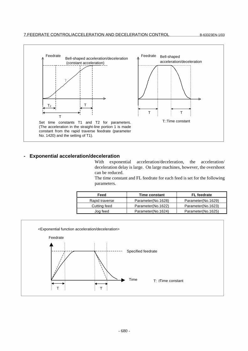
7.FEEDRATE CONTROL/ACCELERATION AND DECELERATION CONTROL B-63323EN-1/03
- 680 -
T::Time constant
Feedrate Bell-shapedacceleration/deceleration
T T
FeedrateBell-shaped acceleration/deceleration (constant acceleration)
T2 T
T
Set time constants T1 and T2 for parameters.(The acceleration in the straight-line portion 1 is madeconstant from the rapid traverse feedrate (parameterNo. 1420) and the setting of T1).
?
- Exponential acceleration/decelerationWith exponential acceleration/deceleration, the acceleration/deceleration delay is large. On large machines, however, the overshootcan be reduced.The time constant and FL feedrate for each feed is set for the followingparameters.
Feed Time constant FL feedrate
Rapid traverse Parameter(No.1628) Parameter(No.1629)Cutting feed Parameter(No.1622) Parameter(No.1623)
Jog feed Parameter(No.1624) Parameter(No.1625)
<Exponential function acceleration/deceleration>
Feedrate
Specified feedrate
Time T: @Time constant
T T
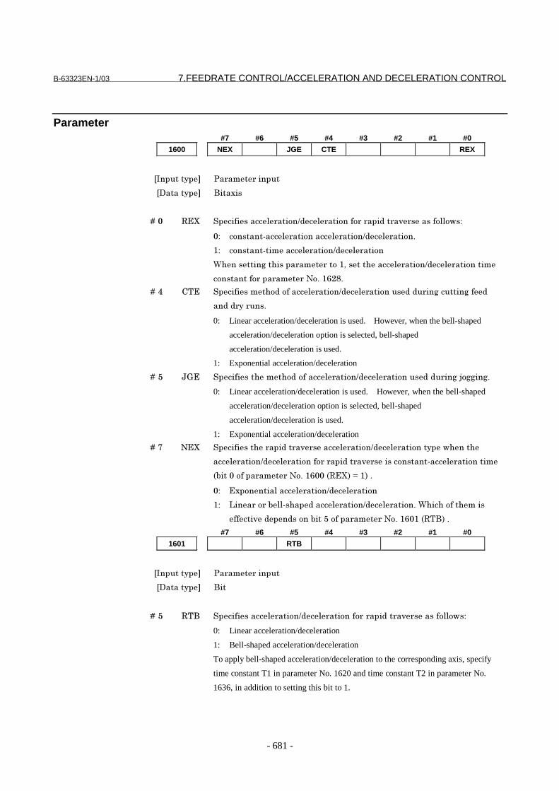
B-63323EN-1/03 7.FEEDRATE CONTROL/ACCELERATION AND DECELERATION CONTROL
- 681 -
Parameter#7 #6 #5 #4 #3 #2 #1 #0
1600 NEX JGE CTE REX
���������� �� ��� ������
��������� �������
� � � � ��� ��� ������������ ��������� �������� � ������ � ����������!�"
�" ��������#���� ���������� ��������� �����$
%" ��������#�������� ��������� �����
&'�������(��'����� ��� ����%)�����'����� ��������� ���������
����������� ��� ��� �*�$�%+,-$
� � � � ��. /0� ����������'���������� ��������� ������������ ��(�������(���
����� �� ���$
0: Linear acceleration/deceleration is used. However, when the bell-shaped
acceleration/deceleration option is selected, bell-shaped
acceleration/deceleration is used.
1: Exponential acceleration/deceleration
� � � � ��1 23� ���������'���'���������� ��������� ������������ ��(�4�((��($
0: Linear acceleration/deceleration is used. However, when the bell-shaped
acceleration/deceleration option is selected, bell-shaped
acceleration/deceleration is used.
1: Exponential acceleration/deceleration
� � � � ��5 *�� ���������'� ������ � ������ ��������� ����������!'���'
���� ��������� �������� � ������ � �������������#���� ���������
67���������� ��� �*�$�%+���6���8�9�%8�$
�" ��������������� ��������� �����
%" :��� �� �7��#�'�������� ��������� �����$�&'��'�����'����
����� ����������7���1������ ��� �*�$�%+�%�6�0�8�$
#7 #6 #5 #4 #3 #2 #1 #0
1601 RTB
���������� �� ��� ������
��������� ���
� � � � ��1 �0� ������������ ��������� �������� � ������ � ����������!�"
0: Linear acceleration/deceleration
1: Bell-shaped acceleration/deceleration
To apply bell-shaped acceleration/deceleration to the corresponding axis, specify
time constant T1 in parameter No. 1620 and time constant T2 in parameter No.
1636, in addition to setting this bit to 1.

7.FEEDRATE CONTROL/ACCELERATION AND DECELERATION CONTROL B-63323EN-1/03
- 682 -
1620 Time constant (T) for linear acceleration/deceleration or time constant (T1)
for bell-shaped acceleration/deceleration for rapid traverse along each axis
���������� �� ��� ������
��������� ���( ����
�;����������� ���
�<���������� ��( ��#�.���
Example: Linear type
=� ��������� � �� ��
6�� ��� � *�$� %.,�8
0��00
T: Value set in parameter No. 1620
@ @ @Bell-shaped type
=� ��������� � �� ��
6�� ��� �*�$�%.,�8
0��
0�
0� 0
�0�
0�
0�
T1: Value set in parameter No. 1620
T2 : Value set in parameter No. 1636 (Set these parameters so that T1 ≥ T2 .)
Total acceleration (deceleration) time: T1 + T2
Time of the linear portion: T1 - T2
Time of the curved portions: T2 × 2
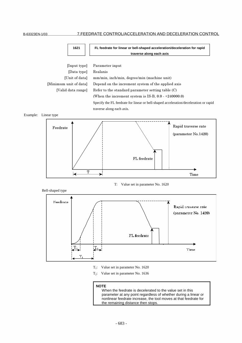
B-63323EN-1/03 7.FEEDRATE CONTROL/ACCELERATION AND DECELERATION CONTROL
- 683 -
1621 FL feedrate for linear or bell-shaped acceleration/deceleration for rapid
traverse along each axis
���������� �� ��� ������
��������� �������
�;����������� ������)����'����)��( �����6���'�������8
�>������������������� ���������'���� ��������������'������������
�<���������� ��( �� �����'������� ���� ��� ������(���7��6/8
6&'���'���� ���������������#�)��$��#�?,.����$�8
Specify the FL feedrate for linear or bell-shaped acceleration/deceleration or rapid
traverse along each axis.
Example: Linear type
=� �� ������� � �� ��
6�� ��� �*�$%.,�8
0��0
=:��� ��
T: Value set in parameter No. 1620
Bell-shaped type
��������
����������������
�����������������
���
��
�� �
�
����������
T1: Value set in parameter No. 1620
T2: Value set in parameter No. 1636
NOTEWhen the feedrate is decelerated to the value set in thisparameter at any point regardless of whether during a linear ornonlinear feedrate increase, the tool moves at that feedrate forthe remaining distance then stops.

7.FEEDRATE CONTROL/ACCELERATION AND DECELERATION CONTROL B-63323EN-1/03
- 684 -
1622 Cutting feed acceleration/deceleration time constant for each axis
���������� �� ��� ������
��������� ���( ����
�;����������� ���
�<���������� ��( ��#�.���
For each axis, set the time constant used for acceleration/deceleration during
cutting feed.
The time constant is fixed irrespective of the feedrate (fixed time constant method).
=� ��
0��0�����������
Linear acceleration/deceleration after
cutting feed interpolation
Bell-shaped acceleration/deceleration after
cutting feed interpolation
=� ��
0��0�����������
NOTEHowever, note that the valid range is 0 to 2000 when the bell-shaped acceleration/deceleration option is provided.Except in special cases, this time constant should be set to thesame value for all axes. When different values are specified,the desired straight and curved lines will not be obtained.
1623 FL feedrate for cutting feed acceleration/deceleration after interpolation
along each axis
���������� �� ��� ������
��������� �������
�;����������� ������)����'����)��( �����6���'�������8
�>������������������� ���������'���� ��������������'������������
�<���������� ��( �� �����'������� ���� ��� ������(���7��6/8
6&'���'���� ���������������#�)��$��#�?,.����$�8
NOTEBe sure to always set 0 in this parameter for all axes, except for aspecial application. Otherwise, correct linear or circular figurescannot be obtained.

B-63323EN-1/03 7.FEEDRATE CONTROL/ACCELERATION AND DECELERATION CONTROL
- 685 -
1624 Jog acceleration/deceleration time constant for each axis
���������� �� ��� ������
��������� ���( ����
�;����������� ���
�<���������� ��( ��#�.���
=� ���'�����)�����'�������������������� ����� ��������� �����
�� ��(�4�(���$
1625 FL feedrate for each axis for acceleration/deceleration during jog feed
���������� �� ��� ������
��������� �������
�;����������� ������)����'����)��( �����6���'�������8
�>������������������� ���������'���� ��������������'������������
�<���������� ��( �� �����'������� ���� ��� ������(���7��6/8
6&'���'���� ���������������#�)��$��#�?,.����$�8
=� ���'�����)�����'�=:��� ��������� ����� ��������� �����
�� ��(�4�(���$
1628 Time constant for rapid traverse acceleration/deceleration with constant
time for individual axes
���������� �� ��� ������
��������� ���( ����
�;����������� ���
�<���������� ��( ��#�.���
���������'���������������� � ������ � ��!��'����������������
���� ���������$
0'����� ��� ��������� ������!'��7���������� ��� �*�$�%+���6���8
���������%$
1629 FL feedrate for rapid traverse acceleration/deceleration with constant time
for each axis
���������� �� ��� ������
��������� �������
�;����������� ������)����'����)��( �����6���'�������8
�>������������������� ���������'���� ��������������'������������
�<���������� ��( �� �����'������� ���� ��� ������(���7��6/8
6&'���'���� ���������������#�)��$��#�?,.����$�8
��������'�=:��� ����� � ������ � ������ ��������� ������!��'
�����������������(���'�����$
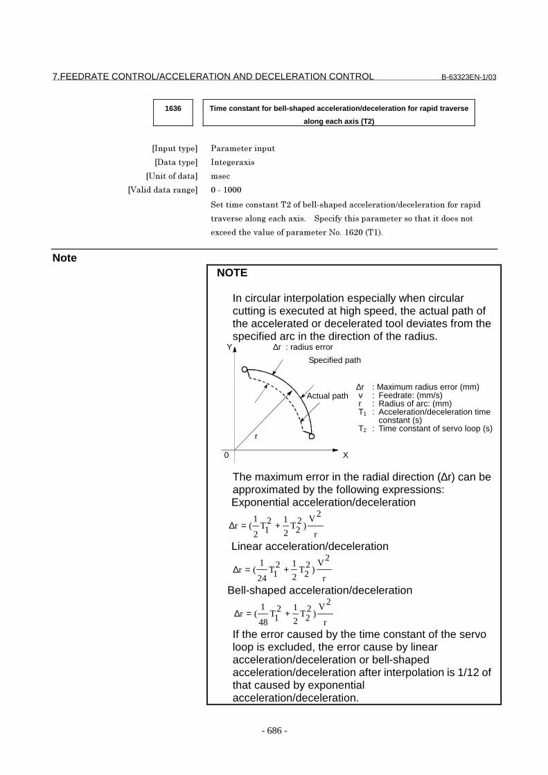
7.FEEDRATE CONTROL/ACCELERATION AND DECELERATION CONTROL B-63323EN-1/03
- 686 -
1636 Time constant for bell-shaped acceleration/deceleration for rapid traverse
along each axis (T2)
���������� �� ��� ������
��������� ���( ����
�;����������� ���
�<���������� ��( ��#�%���
����������������0,����7��#�'�������� ��������� �������� � ����
� � ������(���'�����$� � ��������'����� ��� �����'�������������
�����'� ��������� ��� �*�$�%+,��60%8$
NoteNOTE
In circular interpolation especially when circularcutting is executed at high speed, the actual path ofthe accelerated or decelerated tool deviates from thespecified arc in the direction of the radius.
The maximum error in the radial direction (∆r) can beapproximated by the following expressions:Exponential acceleration/deceleration
r
2V)2
2T2
121T
2
1(r +=∆
Linear acceleration/deceleration
r
2V)2
2T2
121T
24
1(r +=∆
Bell-shaped acceleration/deceleration
r
2V)2
2T2
121T
48
1(r +=∆
If the error caused by the time constant of the servoloop is excluded, the error cause by linearacceleration/deceleration or bell-shapedacceleration/deceleration after interpolation is 1/12 ofthat caused by exponentialacceleration/deceleration.
Specified path
Actual path∆r : Maximum radius error (mm)v : Feedrate: (mm/s)r : Radius of arc: (mm)T1 : Acceleration/deceleration time
constant (s)T2 : Time constant of servo loop (s)
∆r : radius error
0
Y
X
r
B-63323EN-1/03 7.FEEDRATE CONTROL/ACCELERATION AND DECELERATION CONTROL
- 687 -
7.2.2 Look-ahead Acceleration/Deceleration Before interpolation
GeneralWhen acceleration/deceleration after interpolation is used,acceleration/deceleration is applied to the interpolated data.Consequently, the interpolated data is changed by acceleration/deceleration. When acceleration/deceleration before interpolation isused, however, acceleration/deceleration is applied to the feedrate databefore interpolation. Consequently, the interpolated data is notchanged by acceleration/deceleration. Accordingly, interpolation dataensures that machining follows a specified line or curve at all times,thus eliminating the machining profile errors that result from delays inacceleration/deceleration.High-precision machining using continuous minute line segments orNURBS curve commands, such as metal die machining, additionallyrequires the use of the fine HPCC function.
FormatG05.1 Q1 : Look-ahead acceleration/deceleration
before interpolation mode on(The multi-buffer mode is also set to on.)
G05.1 Q0 : Look-ahead acceleration/decelerationbefore interpolation mode off(Multi-buffer mode is kept on.)
G05.1 P1 Q0 : Look-ahead acceleration/decelerationbefore interpolation mode off(Multi-buffer mode is set off.)
Specify only G05.1 in a single block.Look-ahead acceleration/deceleration beforeinterpolation mode can be automatically turned on atpower-up and upon a reset if the MBF bit (bit 6 ofparameter 2401) is specified accordingly.
Valid functionsIn look-ahead acceleration/deceleration before interpolation mode, thefollowing functions are valid:(1) Linear acceleration/deceleration before interpolation or bell-
shaped acceleration/deceleration before interpolation(2) Deceleration based on a feedrate difference at a corner(3) Advance feed forward(4) Nano interpolation
- Fine high-precision contour control (fine HPCC)If the fine HPCC function is provided, fine HPCC mode is turned onwhen the CNC enters the look-ahead acceleration/deceleration beforeinterpolation mode.

7.FEEDRATE CONTROL/ACCELERATION AND DECELERATION CONTROL B-63323EN-1/03
- 688 -
Acceleration/deceleration typesThere are two types of acceleration/deceleration, the linearacceleration/deceleration type and the bell-shaped acceleration/deceleration type. By setting a non-zero value for parameter No. 1656,bell-shaped acceleration/deceleration is assumed. Bell-shapedacceleration/deceleration produces smoother acceleration/deceleration.
Look-ahead linear acceleration/deceleration before interpolationIf 0 is set for parameter No. 1656, linear acceleration/deceleration isapplied as the acceleration/deceleration before interpolation.
- Example of decelerationDeceleration starts in advance so that the feedrate specified for a blockcan be attained when the block is executed.
To decrease the feedrate from F3 to F2, deceleration must be startedfrom P1.To decrease the feedrate from F2 to F1, deceleration must be startedfrom P2.Because multiple blocks are read in advance, deceleration can beperformed over all those blocks.
Programmed speedFeedrate obtained byacceleration/decelerationbefore interpolationP1
P2
N2N1F1
F2
F3
Feedrate
Time

B-63323EN-1/03 7.FEEDRATE CONTROL/ACCELERATION AND DECELERATION CONTROL
- 689 -
- Example of accelerationAcceleration is performed so that the feedrate specified for a block isattained when the block is executed.
- Look-ahead bell-shaped acceleration/deceleration before interpolation
If a non-zero value is set for parameter No. 1656, bell-shapedacceleration/deceleration is applied as the acceleration/decelerationbefore interpolation.
- Setting an accelerationA permissible acceleration for the linear acceleration/deceleration ofeach axis is set in parameter 1660. Acceleration change time (B)(period of transition from constant speed state (A) to constantacceleration/deceleration state (C)) is set in parameter 1656 (commonto all axes). In the constant acceleration/deceleration state (C),acceleration/deceleration is performed with the maximum tangentialacceleration not exceeding the permissible acceleration of each axisspecified in parameter 1660.The acceleration change time specified in parameter 1656 is heldconstant, regardless of the tangential acceleration.
Programmed speedFeedrate obtained byacceleration/decelerationbefore interpolation
N2N1F1
F2
F3
Feedrate
Time
Tangential feedrate
An optimum gradient is automatically
calculated from the setting made in
parameter 1660.
Time set in parameter 1656
(A) (B) (B) (B) (B)(A) (A)(C) (C)

7.FEEDRATE CONTROL/ACCELERATION AND DECELERATION CONTROL B-63323EN-1/03
- 690 -
EMethod of determining the tangent acceleration
Acceleration/deceleration is performed with the largest tangentacceleration/deceleration that does not exceed the acceleration set foreach axis.
(Example)X-axis permissible acceleration: 1000 mm/sec2
Y-axis permissible acceleration: 1200 mm/sec2
Acceleration change time: 20 msec
Program:N1 G01 G91 X20. F6000 Move on the X-axis.G04 X0.01N2 Y20. Move on the Y-axis.G04 X0.01N3 X20. Y20. Move in the XY direction (at 45 degrees).
The acceleration in N3 is 1414 mm/sec2 . At this point, the accelerationon the X-axis is equal to the set value (1000 mm/sec ).
20ms
1000 mm/sec2
gradient
20ms
20ms
1200mm/sec2
gradient
20ms
1414mm/sec2
gradient
Tangent feedrate
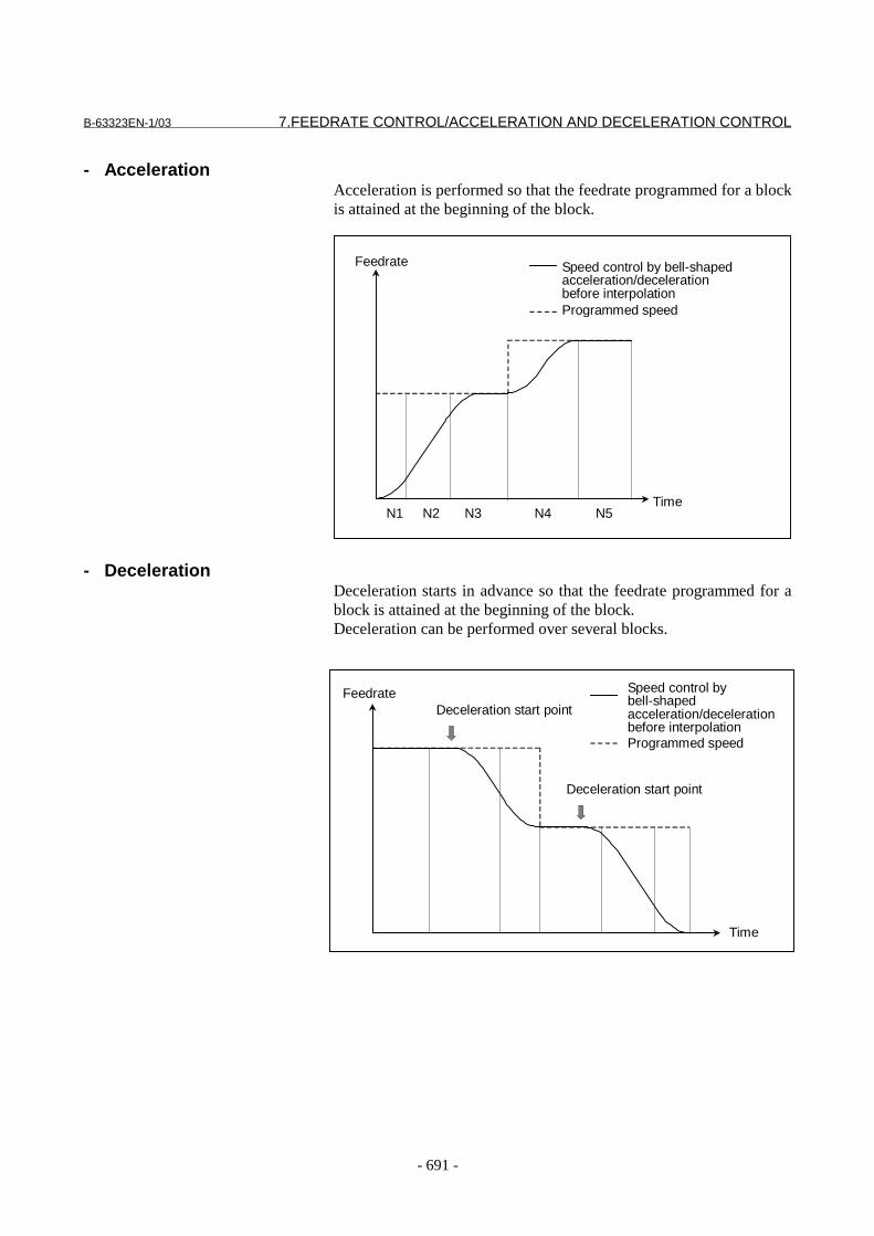
B-63323EN-1/03 7.FEEDRATE CONTROL/ACCELERATION AND DECELERATION CONTROL
- 691 -
- AccelerationAcceleration is performed so that the feedrate programmed for a blockis attained at the beginning of the block.
- DecelerationDeceleration starts in advance so that the feedrate programmed for ablock is attained at the beginning of the block.Deceleration can be performed over several blocks.
Speed control by bell-shapedacceleration/decelerationbefore interpolationProgrammed speed
N2N1
Feedrate
TimeN4N3 N5
Feedrate
Time
Deceleration start point
Deceleration start point
Speed control bybell-shapedacceleration/decelerationbefore interpolationProgrammed speed
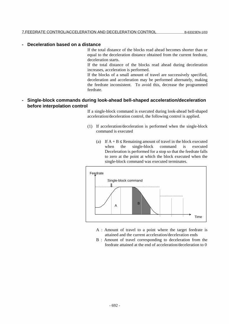
7.FEEDRATE CONTROL/ACCELERATION AND DECELERATION CONTROL B-63323EN-1/03
- 692 -
- Deceleration based on a distanceIf the total distance of the blocks read ahead becomes shorter than orequal to the deceleration distance obtained from the current feedrate,deceleration starts.If the total distance of the blocks read ahead during decelerationincreases, acceleration is performed.If the blocks of a small amount of travel are successively specified,deceleration and acceleration may be performed alternately, makingthe feedrate inconsistent. To avoid this, decrease the programmedfeedrate.
- Single-block commands during look-ahead bell-shaped acceleration/decelerationbefore interpolation control
If a single-block command is executed during look-ahead bell-shapedacceleration/deceleration control, the following control is applied.
(1) If acceleration/deceleration is performed when the single-blockcommand is executed
(a) If A + B ≤ Remaining amount of travel in the block executedwhen the single-block command is executedDeceleration is performed for a stop so that the feedrate fallsto zero at the point at which the block executed when thesingle-block command was executed terminates.
A : Amount of travel to a point where the target feedrate isattained and the current acceleration/deceleration ends
B : Amount of travel corresponding to deceleration from thefeedrate attained at the end of acceleration/deceleration to 0
B
Feedrate
Time
A
Single-block command
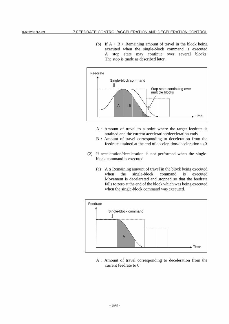
B-63323EN-1/03 7.FEEDRATE CONTROL/ACCELERATION AND DECELERATION CONTROL
- 693 -
(b) If A + B > Remaining amount of travel in the block beingexecuted when the single-block command is executedA stop state may continue over several blocks.The stop is made as described later.
A : Amount of travel to a point where the target feedrate isattained and the current acceleration/deceleration ends
B : Amount of travel corresponding to deceleration from thefeedrate attained at the end of acceleration/deceleration to 0
(2) If acceleration/deceleration is not performed when the single-block command is executed
(a) A ≤ Remaining amount of travel in the block being executedwhen the single-block command is executedMovement is decelerated and stopped so that the feedratefalls to zero at the end of the block which was being executedwhen the single-block command was executed.
A : Amount of travel corresponding to deceleration from thecurrent feedrate to 0
Feedrate
Time
BA
Single-block command
Stop state continuing overmultiple blocks
Feedrate
Time
A
Single-block command

7.FEEDRATE CONTROL/ACCELERATION AND DECELERATION CONTROL B-63323EN-1/03
- 694 -
(b) If A > Remaining amount of travel in the block beingexecuted when the single-block command is executedA stop state may continue over several blocks.The stop is made as described later.
Feedrate
Time
A
Single-block command
Stop state continuing overmultiple blocks
A : Amount of travel corresponding to deceleration from thecurrent feedrate to 0
(3) Stopping a movement if the stop may continue over several blocksAcceleration/deceleration is performed over several blocks to
decrease the feedrate to zero.
Feedrate
Time
Single-block command
Deceleration based on the feedrate difference at a cornerWith look-ahead acceleration/deceleration before interpolation, thetangent feedrate is changed smoothly. Thus, no path error occurs dueto acceleration/deceleration delay. With this acceleration/declaration,however, acceleration/deceleration is not performed for any feedratechange on any axis that may be made where the travel directionchanges.By using the function for deceleration based on the feedrate differenceat a corner, if a feedrate change occurs on an axis at a corner, thefeedrate is determined so that any feedrate difference exceeding thepermissible feedrate difference on that axis that has been set forparameter No. 1478 does not occur, and deceleration is automaticallyperformed.
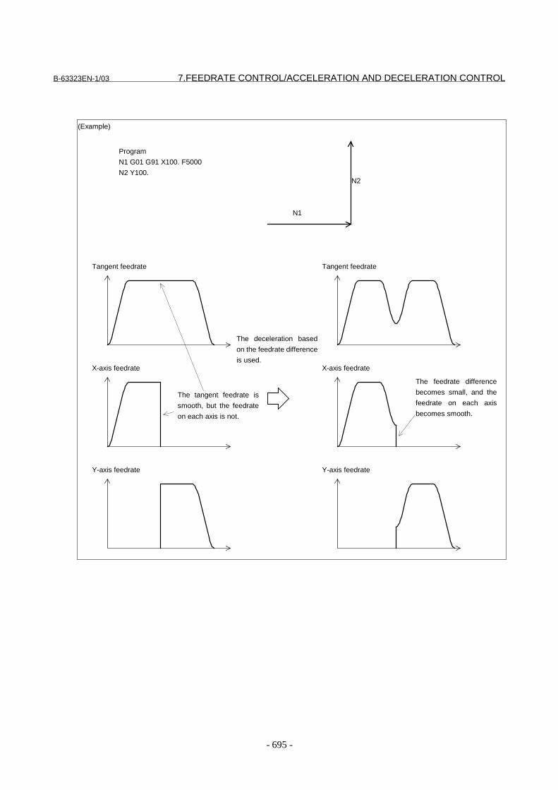
B-63323EN-1/03 7.FEEDRATE CONTROL/ACCELERATION AND DECELERATION CONTROL
- 695 -
(Example)
Program
N1 G01 G91 X100. F5000
N2 Y100.
N1
N2
Tangent feedrate
X-axis feedrate
Y-axis feedrate
The deceleration based
on the feedrate difference
is used.
Tangent feedrate
X-axis feedrate
Y-axis feedrate
The feedrate difference
becomes small, and the
feedrate on each axis
becomes smooth.
The tangent feedrate is
smooth, but the feedrate
on each axis is not.

7.FEEDRATE CONTROL/ACCELERATION AND DECELERATION CONTROL B-63323EN-1/03
- 696 -
The method of deceleration based on the feedrate difference differsdepending on the setting made for parameter FNW (bit 6 of No. 1517). If "0" is set, the largest feedrate that does not exceed the permissiblefeedrate difference set for parameter No. 1478 is assumed to be thedeceleration feedrate. In this case, the deceleration feedrate differs ifthe travel direction differs, even if the shape is the same.
If "1" is set, the feedrate is determined not only with the condition thatthe permissible feedrate difference and permissible acceleration oneach axis are not exceeded, but also that the deceleration feedrate isconstant regardless of the travel direction if the shape is the same.If 1 is set for this parameter, the deceleration feedrate determined withthe feedrate difference or acceleration may be up to 30% lower thanthat determined if 0 is set.
Override to a determined feedrate
The following gives the specifications of override to a feedratedetermined by functions such as deceleration based on feedratedifference in look-ahead acceleration/deceleration before interpolationand deceleration based on acceleration rate in fine HPCC.
Deceleration to
500 mm/min
Deceleration to
354 mm/min
(Example)
@If parameter FNW (bit 6 of No. 1517) = 0 and the@permissible feedrate difference = 500 mm/min (on all axes)
Deceleration to
354 mm/min
Deceleration to
354 mm/min
(Example)
@If parameter FNW (bit 6 of No. 1517) = 1 and@permissible feedrate difference = 500 mm/min (on all axes)

B-63323EN-1/03 7.FEEDRATE CONTROL/ACCELERATION AND DECELERATION CONTROL
- 697 -
- When bit 6 (OVR) of parameter No. 1403 = 0The conventional specifications apply.Override is invalid for deceleration functions such as decelerationbased on feedrate difference and deceleration based onacceleration rate.
- When bit 6 (OVR) of parameter No. 1403 = 1Override is valid for deceleration functions such as decelerationbased on feedrate difference and deceleration based onacceleration rate.
When bit 6 (OVR) of parameter No. 1403 is 1, the following feedratescan be overridden:- Feedrate decelerated by deceleration based on feedrate difference
in look-ahead acceleration/deceleration before interpolation- Feedrate decelerated by deceleration based on acceleration rate in
fine HPCC.- Feedrate decelerated by deceleration based on acceleration rate in
circular interpolation- Feedrate decelerated by acceleration clamp in involute
interpolation- Minimum feedrate for deceleration based on acceleration rate in
fine HPCC and circular interpolation- Maximum feedrate of fine HPCC
Even when the feedrate is overridden, the resulting feedrate does notexceed the maximum cutting feedrate (parameter No. 1422).
Restrictions
- Conditions under which look-ahead acceleration/deceleration before interpolationare performed
Even when look-ahead acceleration/deceleration before interpolationmode are specified, look-ahead acceleration/deceleration beforeinterpolation are not performed if any of the following conditions issatisfied:
- The system is in threading mode.- The system is in feed-per-revolution mode (G95).- The system is in tapping mode (G93).- The system is in a canned cycle (other than G80).- No move command is issued.- The machine is positioning the spindle- One-shot G code other than G38, G45, G46, G47, G48, G39, and
G09- Positioning (G00, G60)- Block with an alarm
In look-ahead acceleration/deceleration before interpolation mode, thefollowing functions cannot be executed. To execute any of thefollowing functions, cancel look-ahead acceleration/deceleration

7.FEEDRATE CONTROL/ACCELERATION AND DECELERATION CONTROL B-63323EN-1/03
- 698 -
before interpolation mode, execute the desired function, then set look-ahead acceleration/deceleration before interpolation mode again.
- Cs contour axis control function- Hypothetical axis interpolation function- Electronic gear box function (EGB)
- Setting of acceleration/deceleration, and feedrateUpon executing a command that requires an acceleration time of onesecond or longer if look-ahead acceleration/deceleration beforeinterpolation is performed, the specified feedrate may not be reached.By setting "1" for parameter FCC (bit 7 of No. 1517), the feedrate canbe increased. If it is increased, however, the interpolation precisionmay decrease in curve interpolation such as circular and NURBSinterpolation.
Signal
Look-ahead acceleration/deceleration before interpolation mode signal ADMOD <F159#2> [Classification] Output signal
[Function] Notifies the user that the system is in look-ahead acceleration/deceleration before interpolation mode.
[Output condition] This signal is set to "1" if G05.1Q1 (look-ahead acceleration/deceleration before interpolation mode ON) is specified by theprogram and the look-ahead acceleration/deceleration beforeinterpolation conditions such as a cutting command are satisfied.This signal is set to "0" if:(1) The system is in the automatic operation deactivated state.(2) The system is in the automatic operation stopped state.(3) Any of the conditions that automatically cancel look-ahead
acceleration/deceleration before interpolation, such as threadingand rapid traverse, is satisfied.
(4) Look-ahead acceleration/deceleration before interpolation modeis canceled.
Signal address
#7 #6 #5 #4 #3 #2 #1 #0
F159 ADMOD
B-63323EN-1/03 7.FEEDRATE CONTROL/ACCELERATION AND DECELERATION CONTROL
- 699 -
Parameter#7 #6 #5 #4 #3 #2 #1 #0
1403 OVR
[Input type] Parameter input[Data type] Bit
# 6 OVR In look-ahead acceleration/deceleration before interpolation and fineHPCC:0: Override is disabled for deceleration functions such as deceleration
based on feedrate difference and deceleration based onacceleration rate.
1: Override is enabled for deceleration functions such as decelerationbased on feedrate difference and deceleration based onacceleration rate.
This function allows the following feedrates to be overridden:- Feedrate decelerated by deceleration based on feedrate difference
in look-ahead acceleration/deceleration before interpolation- Feedrate decelerated by deceleration based on acceleration rate in
fine HPCC.- Feedrate decelerated by deceleration based on acceleration rate in
circular interpolation- Feedrate decelerated by acceleration clamp in involute
interpolation- Minimum feedrate for deceleration based on acceleration rate in
fine HPCC and circular interpolation- Maximum feedrate of fine HPCC
Even when the feedrate is overridden by this function, the resultingfeedrate does not exceed the maximum cutting feedrate (parameter No.1422).
1478 Allowable feedrate difference for corner deceleration based on the feedrate
difference
���������� �� ��� ������
��������� �������
�;����������� ������)����'����)��( �����6���'�������8
�>������������������� ���������'���� ��������������'������������
�<���������� ��( �� �����'������� ���� ��� ������(���7��6/8
6&'���'���� ���������������#�)��$��#�?,.����$�8
When a function for determining the feedrate based on the corner feedrate
difference is used, if a change in a feedrate component on each axis at a boundary
between blocks is about to exceed the value set in this parameter,
acceleration/deceleration before interpolation is applied to reduce the feedrate to
the value obtained for that purpose. This reduces the impact on the machine
around corners and the machining error.

7.FEEDRATE CONTROL/ACCELERATION AND DECELERATION CONTROL B-63323EN-1/03
- 700 -
#7 #6 #5 #4 #3 #2 #1 #0
1517 FCC FNW
���������� �� ��� ������
��������� ���
� � � � ��+ =*& ��������!'�' ��'���'�������� �����(��'��� ���7��������'
�� ������� ���������@#�'������� ��������� ������7��
��� ��������������'���'�������� �����(��'��� ���7��������'
���� �������������A�//�� ��'���������'�������'�%1�$
0: Same as those of the 15B. Thus, the highest feedrate that does not exceed the
allowable feedrate difference or allowable acceleration for each axis is
assumed.
1: In addition to the condition that the feedrate must not exceed the allowable
feedrate difference and allowable acceleration, the condition that the
deceleration feedrate must be constant if the geometry is the same must be
satisfied in determining the feedrate.
When this parameter is set to 1, the feedrate determined with the feedrate
difference or acceleration may be lower by up to 30% than that determined when it
is set to 0.
� � � � ��5 =// ��)�������@#�'������� ��������� ������7�� ���� ��������)��' ���
���������� �!'��'��'����� ����������������������� ����( "
0: The specified feedrate may not be attained because the precision is important.
1: The specified feedrate will be attained because the feedrate is important.
NOTEWhen this parameter is set to 1, the precision of curveinterpolation such as circular and NURBS interpolation mayreduce.
1635 Time constant for cutting feed acceleration/deceleration after interpolation in
the mode of look-ahead acceleration/deceleration before interpolation
���������� �� ��� ������
��������� ���( ����
�;����������� ���
�<���������� ��( ��#�.���
In the mode of look-ahead acceleration/deceleration before interpolation and in
fine HPCC mode, this parameter is used instead of the ordinary time constant
(parameter No. 1622).
Be sure to always set the same time constant in this parameter for all axes, except
for a special application. Otherwise, correct linear or circular figures cannot be
obtained.
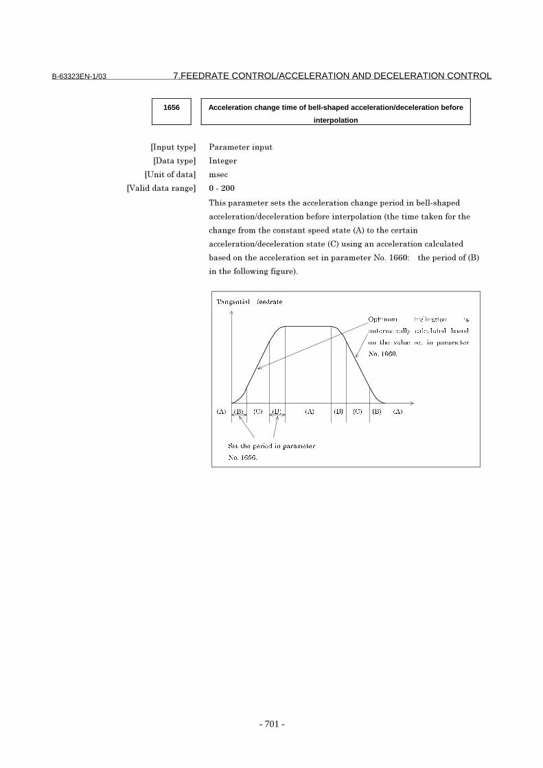
B-63323EN-1/03 7.FEEDRATE CONTROL/ACCELERATION AND DECELERATION CONTROL
- 701 -
1656 Acceleration change time of bell-shaped acceleration/deceleration before
interpolation
���������� �� ��� ������
��������� ���(
�;����������� ���
�<���������� ��( ��#�,��
0'����� ��� ������'����� �������'��(�� �������7��#�'���
���� ��������� ������7�� ���� ���������6�'�������@���� ��'
�'��(�� ����'�������������������6B8�����'�� ����
���� ��������� �����������6/8�����(�������� ���������������
7��������'����� �������������� ��� �*�$�%++�"� � �'�� �������6�8
����'������!��(���(� 8$
���������� �������
������ ����������� ��
������������� ���������� �����
�� ��� ����� ��� �� ���������
��������
�����������������������
��������
� ! �"! �"! �"! �"!� ! � !�#! �#!
7.FEEDRATE CONTROL/ACCELERATION AND DECELERATION CONTROL B-63323EN-1/03
- 702 -
1660 Maximum allowable acceleration of acceleration/deceleration before
interpolation for each axis
���������� �� ��� ������
��������� �������
�;����������� ��������)����'������)��( �������6���'�������8
�>������������������� ���������'���� ��������������'������������
�<���������� ��( �� �����'������� ���� ��� ������(���7��6�8
6&'���'����'�������������� ��������)��$��#�?%�����$�$�&'���'
���'���������������'������)����'��)��$��#�?%����$�8
Specify the maximum allowable acceleration of acceleration/deceleration before
interpolation for each axis.
If a value greater than 100000.0 is set, it is clamped to 100000.0.
If 0 is set, it is regarded to be 100000.0. If 0 is set for all axes, look-ahead
acceleration/deceleration before interpolation will not be performed.
If the allowable acceleration for one axis is twice as large as that for another or
more, the feedrate may temporarily reduce around corners where the direction to
travel changes suddenly.
#7 #6 #5 #4 #3 #2 #1 #0
2401 MBF
���������� �� ��� ������
��������� ���
� � � � ��+ >�= ������� ���������'������7��� ����������! ������������'����
����$
0: Cancels the multibuffer mode.
1: Selects the multibuffer mode. (When the optional multibuffer 15-block/100-
block function is not provided, five buffer blocks are used for the look-ahead
operation.)
When the multibuffer mode is selected, look-ahead acceleration/deceleration before
interpolation is enabled at the same time.
If the fine HPCC option is provided, fine HPCC mode is enabled at the same time.
NOTEThis parameter becomes valid when the system is reset.
B-63323EN-1/03 7.FEEDRATE CONTROL/ACCELERATION AND DECELERATION CONTROL
- 703 -
NoteNOTE1 If the permissible acceleration set for one axis is two
or more times greater than that set for another, thefeedrate may decrease temporarily at those cornerswhere the travel direction changes abruptly.
2 If the machine lock signal is turned on during travel inlook-ahead acceleration/deceleration beforeinterpolation mode, the machine enters the machinelock state after the end of deceleration.
3 If there is a block with no travel or a one-shot G codecommand such as G04 in look-aheadacceleration/deceleration before interpolation mode,deceleration is performed for a stop in the precedingblock.
4 If the dry run signal changes from "0" to "1" or from "1"to "0" during travel on an axis,acceleration/deceleration is performed to achievethe prescribed feedrate without deceleration tofeedrate 0.The function for deceleration with the feedratedifference at a corner is effective even during dryrun.
Reference itemSeries15i/150i-MA Operator’s Manual
(Programming)(B-63324EN)
II-18.4 Look-aheadacceleration/deceleration before interpolatin
Series15i/150i-MODEL A
Connection Manual(This manual)
7.1.13 Nano interpolation
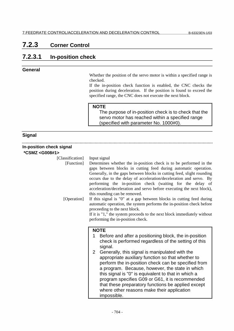
7.FEEDRATE CONTROL/ACCELERATION AND DECELERATION CONTROL B-63323EN-1/03
- 704 -
7.2.3 Corner Control
7.2.3.1 In-position check
GeneralWhether the position of the servo motor is within a specified range ischecked.If the in-position check function is enabled, the CNC checks theposition during deceleration. If the position is found to exceed thespecified range, the CNC does not execute the next block.
NOTEThe purpose of in-position check is to check that theservo motor has reached within a specified range(specified with parameter No. 1000#0).
Signal
In-position check signal *CSMZ <G008#1>
[Classification] Input signal [Function] Determines whether the in-position check is to be performed in the
gaps between blocks in cutting feed during automatic operation.Generally, in the gaps between blocks in cutting feed, slight roundingoccurs due to the delay of acceleration/deceleration and servo. Byperforming the in-position check (waiting for the delay ofacceleration/deceleration and servo before executing the next block),this rounding can be removed.
[Operation] If this signal is "0" at a gap between blocks in cutting feed duringautomatic operation, the system performs the in-position check beforeproceeding to the next block.If it is "1," the system proceeds to the next block immediately withoutperforming the in-position check.
NOTE1 Before and after a positioning block, the in-position
check is performed regardless of the setting of thissignal.
2 Generally, this signal is manipulated with theappropriate auxiliary function so that whether toperform the in-position check can be specified froma program. Because, however, the state in whichthis signal is "0" is equivalent to that in which aprogram specifies G09 or G61, it is recommendedthat these preparatory functions be applied exceptwhere other reasons make their applicationimpossible.
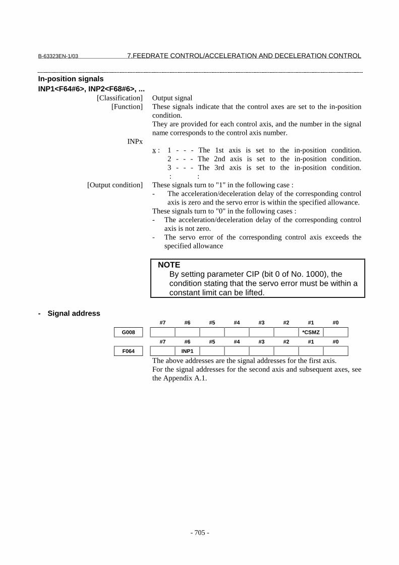
B-63323EN-1/03 7.FEEDRATE CONTROL/ACCELERATION AND DECELERATION CONTROL
- 705 -
In-position signalsINP1<F64#6>, INP2<F68#6>, ...
[Classification] Output signal [Function] These signals indicate that the control axes are set to the in-position
condition.They are provided for each control axis, and the number in the signalname corresponds to the control axis number.
INPxx : 1 - - - The 1st axis is set to the in-position condition.
2 - - - The 2nd axis is set to the in-position condition.3 - - - The 3rd axis is set to the in-position condition. : :
[Output condition] These signals turn to "1" in the following case :- The acceleration/deceleration delay of the corresponding control
axis is zero and the servo error is within the specified allowance.These signals turn to "0" in the following cases :- The acceleration/deceleration delay of the corresponding control
axis is not zero.- The servo error of the corresponding control axis exceeds the
specified allowance
NOTEBy setting parameter CIP (bit 0 of No. 1000), thecondition stating that the servo error must be within aconstant limit can be lifted.
- Signal address#7 #6 #5 #4 #3 #2 #1 #0
G008 *CSMZ
#7 #6 #5 #4 #3 #2 #1 #0
F064 INP1
The above addresses are the signal addresses for the first axis.For the signal addresses for the second axis and subsequent axes, seethe Appendix A.1.
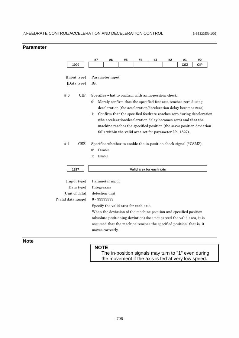
7.FEEDRATE CONTROL/ACCELERATION AND DECELERATION CONTROL B-63323EN-1/03
- 706 -
Parameter
#7 #6 #5 #4 #3 #2 #1 #0
1000 CSZ CIP
���������� �� ��� ������
��������� ���
� � � � ��� /�� ��������!'����������� ��!��'������#����������'�@$
�" > �������� ���'����'����������� ��� ��'��C ���� ��(
��� ������6�'����� ��������� �����������7�����C �8$
%" /���� ���'����'����������� ��� ��'��C ���� ��(���� �����
6�'����� ��������� �����������7�����C �8������'����'
���'��� ��'���'������������������6�'�� ������������ ������
������!��'����'� ������ ������� ��� ��� �*�$�%-,58$
� � � � ��% /�D ��������!'�' ������7���'���#����������'�@���(����6E/�>D8$
0: Disable
1: Enable
1827 Valid area for each axis
���������� �� ��� ������
��������� ���( ����
�;����������� ������������
�<���������� ��( ��#�FFFFFFFF
��������'� ������ ���� ���'�����$
&'���'�� �����������'����'��������������������������������
6�7����������������(�� ������8��������������'� ������ �)������
��������'����'����'��� ��'���'�����������������)��'�����)���
�� ���� ����$
NoteNOTE
The in-position signals may turn to "1" even duringthe movement if the axis is fed at very low speed.

B-63323EN-1/03 7.FEEDRATE CONTROL/ACCELERATION AND DECELERATION CONTROL
- 707 -
7.2.4 Feed Forward in Rapid Traverse
GeneralFeed-forward control can be performed even during rapid traverse. Inthis case, the servo position error is reduced, thus reducing the timerequired for positioning to within the specified range.
Parameter
#7 #6 #5 #4 #3 #2 #1 #0
1800 RFW
���������� �� ��� ������
��������� ���
� � � � ��G �=& ��������!'�' ������7���� !� ��������� ����� ��(� ������ � �$
�" ����7����� !� ��������� ��$
%" ���7����� !� ��������� ��$
*� �����)��� !� ��������� ��������7��������!'��������(������
� �� ��$� � &'���'����� ��� ����������%)��� !� ���������������7��
�� ��(� ������ � �$� � 0'����� ���������������� �����������'�� �)
�����(��'������� ��� ��(��������� �� ���� ��(�����������($
Reference itemFor details of this function, refer to the "FANUC SERVO MOTOR αseries Maintenance Manual (B-65165E)."
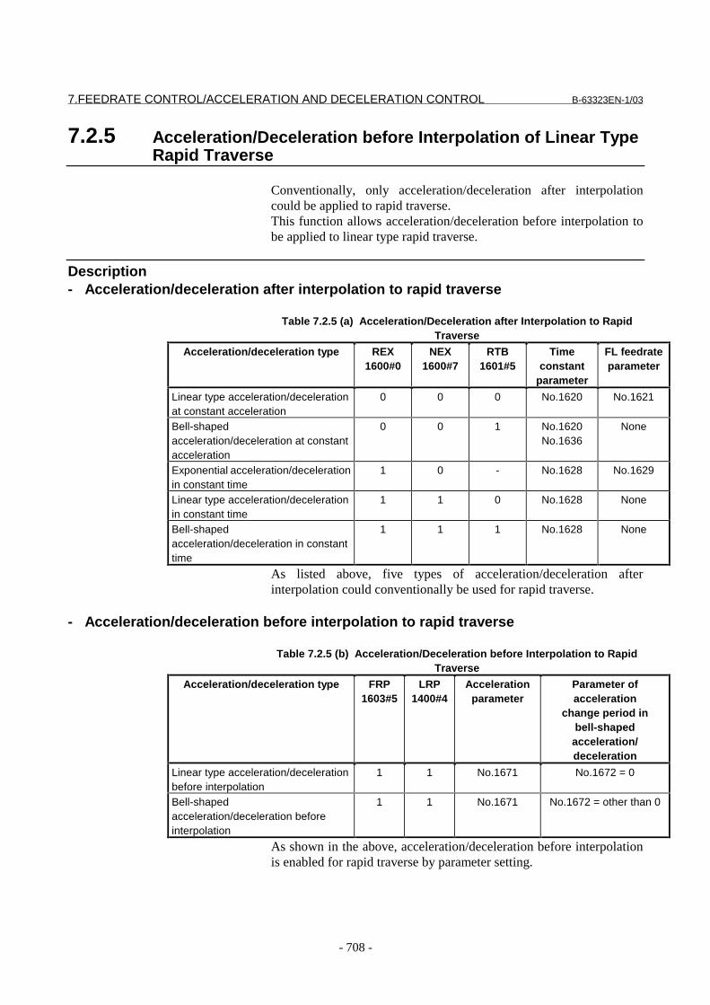
7.FEEDRATE CONTROL/ACCELERATION AND DECELERATION CONTROL B-63323EN-1/03
- 708 -
7.2.5 Acceleration/Deceleration before Interpolation of Linear TypeRapid Traverse
Conventionally, only acceleration/deceleration after interpolationcould be applied to rapid traverse.This function allows acceleration/deceleration before interpolation tobe applied to linear type rapid traverse.
Description- Acceleration/deceleration after interpolation to rapid traverse
Table 7.2.5 (a) Acceleration/Deceleration after Interpolation to RapidTraverse
Acceleration/deceleration type REX1600#0
NEX1600#7
RTB1601#5
Timeconstant
parameter
FL feedrateparameter
Linear type acceleration/decelerationat constant acceleration
0 0 0 No.1620 No.1621
Bell-shapedacceleration/deceleration at constantacceleration
0 0 1 No.1620No.1636
None
Exponential acceleration/decelerationin constant time
1 0 - No.1628 No.1629
Linear type acceleration/decelerationin constant time
1 1 0 No.1628 None
Bell-shapedacceleration/deceleration in constanttime
1 1 1 No.1628 None
As listed above, five types of acceleration/deceleration afterinterpolation could conventionally be used for rapid traverse.
- Acceleration/deceleration before interpolation to rapid traverse
Table 7.2.5 (b) Acceleration/Deceleration before Interpolation to RapidTraverse
Acceleration/deceleration type FRP1603#5
LRP1400#4
Accelerationparameter
Parameter ofacceleration
change period inbell-shaped
acceleration/deceleration
Linear type acceleration/decelerationbefore interpolation
1 1 No.1671 No.1672 = 0
Bell-shapedacceleration/deceleration beforeinterpolation
1 1 No.1671 No.1672 = other than 0
As shown in the above, acceleration/deceleration before interpolationis enabled for rapid traverse by parameter setting.

B-63323EN-1/03 7.FEEDRATE CONTROL/ACCELERATION AND DECELERATION CONTROL
- 709 -
Restrictions
- Conditions for acceleration/deceleration before interpolationWhen the conditions listed below are all satisfied,acceleration/deceleration before interpolation becomes valid for rapidtraverse. The acceleration used is set to the maximum value that doesnot exceed the maximum allowable acceleration for each axis, as set inparameter No. 1671.(1) Bit 5 (FRP) of parameter No. 1603 = 1(2) Bit 4 (LRP) of parameter No. 1400 = 1: Linear interpolation type
positioning(3) A non-zero value is set for any axis in parameter No. 1671.(4) Look-ahead acceleration/deceleration before interpolation (or
fine HPCC) mode is currently set.(5) The conditions for look-ahead acceleration/deceleration before
interpolation are satisfied.
When acceleration/deceleration before interpolation becomes valid,acceleration/deceleration after interpolation set in Table 7.2.5 (a) isdisabled. This means that only acceleration/deceleration beforeinterpolation is applied.If the above conditions are not satisfied, acceleration/deceleration afterinterpolation set in Table 7.2.5 (a) becomes valid.
Parameters#7 #6 #5 #4 #3 #2 #1 #0
1603 FRP
[Input type] Parameter input[Data type] Bit
# 5 FRP To linear type rapid traverse:0: Acceleration/deceleration after interpolation is applied.
The type of acceleration/deceleration after interpolation isdetermined by bit 0 (REX) of parameter No. 1600, bit 7 (NEX) ofparameter No. 1600, and bit 5 (RTB) of parameter No. 1601.
1: Acceleration/deceleration before interpolation is applied.The maximum allowable acceleration for each axis is set inparameter No. 1671.When using bell-shaped acceleration/deceleration beforeinterpolation, set the acceleration change period in parameter No.1672.
When this parameter is set to 1, acceleration/deceleration beforeinterpolation is also applied to rapid traverse if the conditions listedbelow are all satisfied. In this case, acceleration/deceleration afterinterpolation is not applied.-Bit 4 (LRP) of parameter No. 1400 = 1: Linear interpolation typepositioning-A non-zero value is set for any axis in parameter No. 1671.

7.FEEDRATE CONTROL/ACCELERATION AND DECELERATION CONTROL B-63323EN-1/03
- 710 -
-Look-ahead acceleration/deceleration before interpolation (or fineHPCC) mode is currently set.-The conditions for look-ahead acceleration/deceleration beforeinterpolation are satisfied.If the conditions listed above are not satisfied,acceleration/deceleration after interpolation is applied.
1671 Maximum allowable acceleration for each axis in acceleration/deceleration
before interpolation to linear type rapid traverse
[Input type] Parameter input[Data type] Real number axis
[Unit of data] mm/sec/sec, inch/sec/sec, degrees/sec/sec (machine unit)[Minimum unit of data] The increment system of the axis in question is followed.[Valid data range] See the standard parameter setting table (D).
(For millimeter machines, 0.0 to +100000.0; for inch machines, 0.0 to+10000.0)This parameter sets the maximum allowable value ofacceleration/deceleration before interpolation to linear type rapidtraverse. If a value in excess of 100000.0 is set, the acceleration isclamped to 100000.0.If 0 is set, the following value is assumed: 1000.0 mm/sec/sec 100.0 inch/sec/sec 100.0 degrees/sec/secIf 0 is set for all axes, acceleration/deceleration before interpolation isnot performed.
1672 Acceleration change period of bell-shaped acceleration/deceleration before
interpolation to linear type rapid traverse
[Input type] Parameter input[Data type] Integer
[Unit of data] msec[Valid data range] 0 to 200
This parameter sets the acceleration change period of bell-shapedacceleration/deceleration before interpolation to linear type rapidtraverse (the period during which the acceleration changes fromconstant feedrate state (A) to constant acceleration/deceleration state(C) with the acceleration calculated based on the acceleration value setin parameter No. 1671: portion (B) in the following figure).
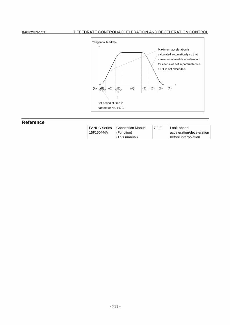
B-63323EN-1/03 7.FEEDRATE CONTROL/ACCELERATION AND DECELERATION CONTROL
- 711 -
ReferenceFANUC Series15i/150i-MA
Connection Manual(Function)(This manual)
7.2.2 Look-aheadacceleration/decelerationbefore interpolation
Tangential feedrate
Maximum acceleration is
calculated automatically so that
maximum allowable acceleration
for each axis set in parameter No.
1671 is not exceeded.
Set period of time in
parameter No. 1672.
(A) (B) (B) (B) (B)(A) (A)(C) (C)

8.MISCELLANEOUS FUNCTION B-63323EN-1/03
- 712 -
8 MISCELLANEOUS FUNCTION
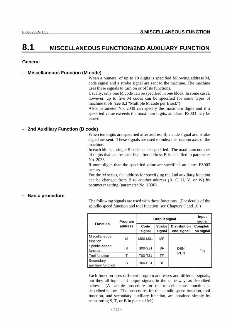
B-63323EN-1/03 8.MISCELLANEOUS FUNCTION
- 713 -
8.1 MISCELLANEOUS FUNCTION/2ND AUXILIARY FUNCTION
General
- Miscellaneous Function (M code)When a numeral of up to 10 digits is specified following address M,code signal and a strobe signal are sent to the machine. The machineuses these signals to turn on or off its functions.Usually, only one M code can be specified in one block. In some cases,however, up to five M codes can be specified for some types ofmachine tools (see 8.3 "Multiple M code per Block")Also, parameter No. 2030 can specify the maximum digits and if aspecified value exceeds the maximum digits, an alarm PS003 may beissued.
- 2nd Auxiliary Function (B code)When ten digits are specified after address B, a code signal and strobesignal are sent. These signals are used to index the rotation axis of themachine.In each block, a single B code can be specified. The maximum numberof digits that can be specified after address B is specified in parameterNo. 2033.If more digits than the specified value are specified, an alarm PS003occurs.For the M series, the address for specifying the 2nd auxiliary functioncan be changed from B to another address (A, C, U, V, or W) byparameter setting (parameter No. 1030).
- Basic procedureThe following signals are used with these functions. (For details of thespindle-speed function and tool function, see Chapters 9 and 10.)
Output signalInputsignal
FunctionProgramaddress Code
signalStrobesignal
Distributionend signal
Completion signal
Miscellaneousfunction
M M00-M31 MF
Spindle-speedfunction
S S00-S31 SF
Tool function T T00-T31 TFSecondaryauxiliary function
B B00-B31 BF
DENIPEN
FIN
Each function uses different program addresses and different signals,but they all input and output signals in the same way, as describedbelow. (A sample procedure for the miscellaneous function isdescribed below. The procedures for the spindle-speed function, toolfunction, and secondary auxiliary function, are obtained simply bysubstituting S, T, or B in place of M.)

8.MISCELLANEOUS FUNCTION B-63323EN-1/03
- 714 -
(1) Suppose that Mxxx is specified in a program.The maximum allowable number of digits can be specified foreach function by using parameter No. 2030 to 2033. A commandlonger than the maximum allowable number of digits causes analarm (PS0003).
(2) Code signal M00 to M31 is sent. After period TMF, specified inparameter No. 2010, strobe signal MF is set to 1. The code signalis the binary representation of the programmed value xxx. If themove, dwell, spindle-speed, or another function is specified at thesame time as the miscellaneous function, the execution of theother function is started when the code signal of the miscellaneousfunction is sent.
(3) When the strobe signal is set to 1, the PMC reads the code signaland performs the corresponding operation.
(4) To execute an operation after the completion of the move, dwellor other function specified in the block, wait until distribution endsignal DEN or IPEN is set to 1.
(5) Upon completion of the operation, the PMC sets completionsignal FIN to 1. The completion signal is used by themiscellaneous function, spindle-speed function, tool function,secondary auxiliary function, external operation functiondescribed later, and other functions. If any of these functions areexecuted simultaneously, the completion signal must be set to 1upon completion of all the functions.
(6) If the completion signal remains set to 1 for longer than periodTFIN, specified in parameter No. 2011 , the CNC sets the strobesignal to 0 and reports that the completion signal has beenreceived.
(7) When the strobe signal is set to 0, set the completion signal to 0 inthe PMC.
(8) When the completion signal is set to 0, the sequence of anauxiliary function is completed.
The timing diagram is shown below:
Example 1) Single miscellaneous function specified in a block
M command (independent)Mxxx
Code signals M00-M31
Strobe signals MF
PMC side action
End signal FIN
Distribution end signals DEN
(1) (2) (3) (5) (6) (7) (8)
TMF TFIN
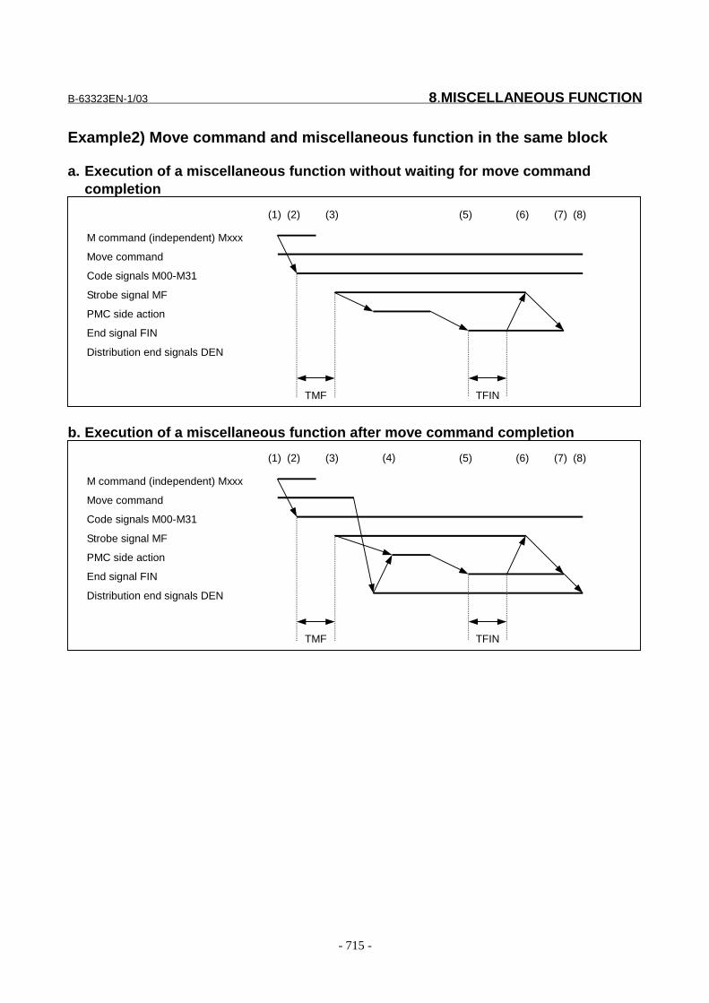
B-63323EN-1/03 8.MISCELLANEOUS FUNCTION
- 715 -
Example2) Move command and miscellaneous function in the same block
a. Execution of a miscellaneous function without waiting for move commandcompletion
M command (independent) Mxxx
Move command
Code signals M00-M31
Strobe signal MF
PMC side action
End signal FIN
Distribution end signals DEN
(1) (2) (3) (5) (6) (7) (8)
TMF TFIN
b. Execution of a miscellaneous function after move command completion
M command (independent) Mxxx
Move command
Code signals M00-M31
Strobe signal MF
PMC side action
End signal FIN
Distribution end signals DEN
(1) (2) (3) (5) (6) (7) (8)
TMF TFIN
(4)

8.MISCELLANEOUS FUNCTION B-63323EN-1/03
- 716 -
SignalMiscellaneous function code signals M00-M31 <F016-F019>Miscellaneous function strobe signal MF <F008#0>
[Classification] Output signal[Function] These signals report the specification of miscellaneous functions.
[Output condition] For the output conditions and procedure, see the description of "Basicprocedure" above.
NOTE1 The following miscellaneous functions are only
processed internally by the control unit; they are notsubject to output even when specified:- M98, M99, M198- M code that calls a sub program (parameter No.
6071 to 6079)- M code that calls a custom macro (parameter No.
6080 to 6089)- M codes for turning on and off an interrupt macro
@(M96, M97, or parameter Nos. 7033 to 7034)2 Decode signals as well as the code signals and
strobe signal are output for the miscellaneousfunctions listed below.M00, M01, M02, M30
Decode M signals DM00 <F009#4>/DM01 <F009#5>/DM02 <F009#6>/DM30 <F009#7>[Classification] Output signal
[Function] These signals report particular miscellaneous functionsare specified. The miscellaneous functions in a command programcorrespondto output signals as indicated below.
Command program Output signal
M00M01M02M30
DM00DM01DM02DM30
[Output condition] A decode M signal goes "1" when:- The corresponding miscellaneous function is specified, and any
move commands and dwell commands specified in the same blockare completed. These signals are not output when the end signalof the miscellaneous function is returned before completion ofsuch move commands and dwell commands.
A decode M signal goes "0" when:- The FIN signal goes "1"- Reset occurs
B-63323EN-1/03 8.MISCELLANEOUS FUNCTION
- 717 -
Spindle-speed code signals S00 to S31<F020 to F023>Spindle-speed strobe signal SF<F008#1>
[Classification] Output signal[Function] These signals report that spindle speed functions have been specified.
[Output condition] For the output conditions and procedure, see the description of "Basicprocedure" above.
Tool function code signals T00 to T31<F024 to F027>Tool function strobe signal TF<F008#2>
[Classification] Output signal[Function] These signals report that tool functions have been specified.
[Output condition] For the output conditions and procedure, see the description of "Basicprocedure" above.
Second auxiliary function code signals B00 to B31<F028 to F031>Second auxiliary function strobe signal BF<F008#3>
[Classification] Output signal [Function] These signals report that second auxiliary functions have been
specified.[Output condition] For the output conditions and procedure, see the description of "Basic
procedure" above.
End signal FIN<G005#1>[Classification] Input signal
[Function] This signal reports the completion of a miscellaneous function,spindle-speed function, tool function, second auxiliary function, orexternal operation function.
[Operation] For the control unit operation and procedure when this signal goes "1",see the description of "Basic procedure" above.The FIN signal must remain "1" for a certain time (TFIN, which is setby aparameter No. 2011) or longer. The FIN signal driven "1" is ignored iftheFIN signal goes "0" before TFIN elapses.
CAUTION1 Only one end signal is used for all functions above.
The end signal must go "1" after all functions arecompleted.
2 In addition to the functions described above, thiscompletion signal can be used for the spindle-speedfunction for canned cycles by parameter setting. Fordetails, see "Spindle-Speed Function for CannedCycles" in Section 9.5.
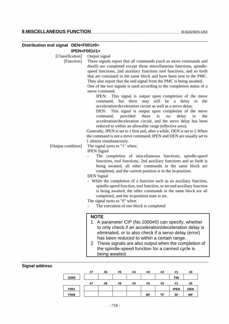
8.MISCELLANEOUS FUNCTION B-63323EN-1/03
- 718 -
Distribution end signal DEN<F001#0>IPEN<F001#1>
[Classification] Output signal[Function] These signals report that all commands (such as move commands and
dwell) are completed except those miscellaneous functions, spindle-speed functions, 2nd auxiliary functions tool functions, and so forththat are contained in the same block and have been sent to the PMC.They also report that the end signal from the PMC is being awaited.One of the two signals is used according to the completion status of amove command.
IPEN: This signal is output upon completion of the movecommand, but there may still be a delay in theacceleration/deceleration circuit as well as a servo delay.DEN: This signal is output upon completion of the movecommand, provided there is no delay in theacceleration/deceleration circuit, and the servo delay has beenreduced to within an allowable range (effective area).
Generally, IPEN is set to 1 first and, after a while, DEN is set to 1.Whenthe command is not a move command, IPEN and DEN are usually set to1 almost simultaneously.
[Output condition] The signal turns to "1" when:IPEN Signal- The completion of miscellaneous functions, spindle-speed
functions, tool functions, 2nd auxiliary functions and so forth isbeing awaited, all other commands in the same block arecompleted, and the current position is in the in-position.
DEN Signal- While the completion of a function such as an auxiliary function,
spindle-speed function, tool function, or second auxiliary functionis being awaited, the other commands in the same block are allcompleted, and the in-position state is set.
The signal turns to "0" when- The execution of one block is completed
NOTE1 A parameter CIP (No.1000#0) can specify, whether
to only check if an acceleration/deceleration delay iseliminated, or to also check if a servo delay (error)has been reduced to within a certain range.
2 These signals are also output when the completion ofthe spindle-speed function for a canned cycle isbeing awaited.
Signal address#7 #6 #5 #4 #3 #2 #1 #0
G005 FIN
#7 #6 #5 #4 #3 #2 #1 #0
F001 IPEN DEN
F008 BF TF SF MF

B-63323EN-1/03 8.MISCELLANEOUS FUNCTION
- 719 -
F009 DM30 DM02 DM01 DM00
F016 M07 M06 M05 M04 M03 M02 M01 M00
F017 M15 M14 M13 M12 M11 M10 M09 M08
F018 M23 M22 M21 M20 M19 M18 M17 M16
F019 M31 M30 M29 M28 M27 M26 M25 M24
F020 S07 S06 S05 S04 S03 S02 S01 S00
F021 S15 S14 S13 S12 S11 S10 S09 S08
F022 S23 S22 S21 S20 S19 S18 S17 S16
F023 S31 S30 S29 S28 S27 S26 S25 S24
F024 T07 T06 T05 T04 T03 T02 T01 T00
F025 T15 T14 T13 T12 T11 T10 T09 T08
F026 T23 T22 T21 T20 T19 T18 T17 T16
F027 T31 T30 T29 T28 T27 T26 T25 T24
F028 B07 B06 B05 B04 B03 B02 B01 B00
F029 B15 B14 B13 B12 B11 B10 B09 B08
F030 B23 B22 B21 B20 B19 B18 B17 B16
F031 B31 B30 B29 B28 B27 B26 B25 B24
Parameter
1030 Command address of the second miscellaneous function
���������� �� ��� ������
��������� ����
������������ ��� �������
Specify the command address of the second miscellaneous function as A, B, C, U,
V, or W. However, any address already used as an axis name cannot also be used
as the command address of the second miscellaneous function.
Name A B C U V W
Setting 65 66 67 85 86 87
#7 #6 #5 #4 #3 #2 #1 #0
2003 BSN TSN SSN MSN
���������� �� ��� ������
��������� ���
� � � � ��� ��� �� �!�"�#$�$ �������"�%�&� ���'��"���������� (�)
0: Cannot be used
1: Can be used
� � � � ��* ��� �� �!�"�#$�$ �������"�%�&� ���'��"���������� (�)
0: Cannot be used
1: Can be used
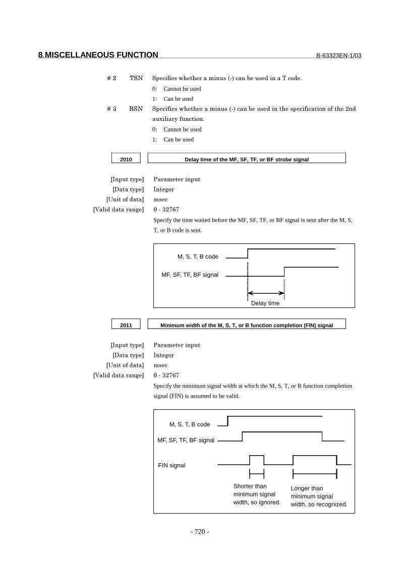
8.MISCELLANEOUS FUNCTION B-63323EN-1/03
- 720 -
� � � � ��+ ,�� �� �!�"�#$�$ �������"�%�&� ���'��"�������,� (�)
0: Cannot be used
1: Can be used
� � � � ��- ��� �� �!�"�#$�$ �������"�%�&� ���'��"������$�"� �!� ���(��(!��$�+��
��.���� ��!�� ��(�)
0: Cannot be used
1: Can be used
2010 Delay time of the MF, SF, TF, or BF strobe signal
���������� �� ��� ������
��������� ����
�/����(!����� �"
������������ ��� ����-+���
Specify the time waited before the MF, SF, TF, or BF signal is sent after the M, S,
T, or B code is sent.
M, S, T, B code
MF, SF, TF, BF signal
Delay time
2011 Minimum width of the M, S, T, or B function completion (FIN) signal
���������� �� ��� ������
��������� ����
�/����(!����� �"
������������ ��� ����-+���
Specify the minimum signal width at which the M, S, T, or B function completion
signal (FIN) is assumed to be valid.
M, S, T, B code
MF, SF, TF, BF signal
FIN signal
Shorter thanminimum signalwidth, so ignored.
Longer thanminimum signalwidth, so recognized.
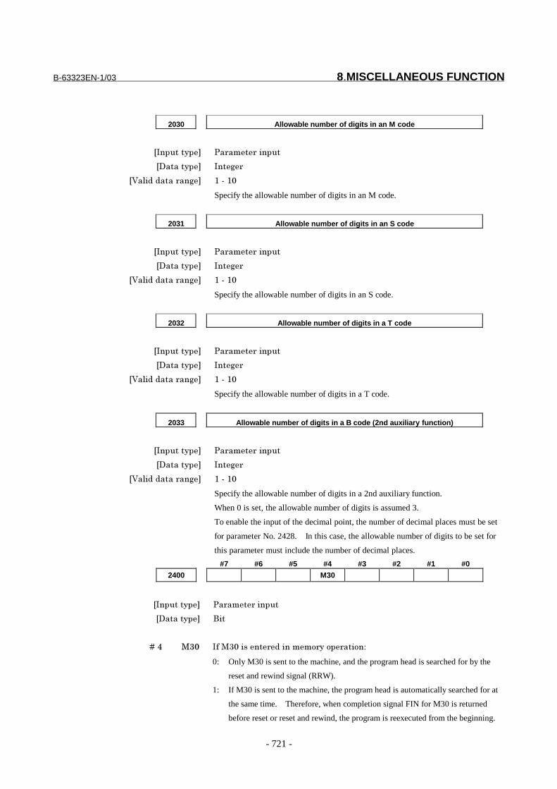
B-63323EN-1/03 8.MISCELLANEOUS FUNCTION
- 721 -
2030 Allowable number of digits in an M code
���������� �� ��� ������
��������� ����
������������ ��� *���*�
Specify the allowable number of digits in an M code.
2031 Allowable number of digits in an S code
���������� �� ��� ������
��������� ����
������������ ��� *���*�
Specify the allowable number of digits in an S code.
2032 Allowable number of digits in a T code
���������� �� ��� ������
��������� ����
������������ ��� *���*�
Specify the allowable number of digits in a T code.
2033 Allowable number of digits in a B code (2nd auxiliary function)
���������� �� ��� ������
��������� ����
������������ ��� *���*�
Specify the allowable number of digits in a 2nd auxiliary function.
When 0 is set, the allowable number of digits is assumed 3.
To enable the input of the decimal point, the number of decimal places must be set
for parameter No. 2428. In this case, the allowable number of digits to be set for
this parameter must include the number of decimal places.
#7 #6 #5 #4 #3 #2 #1 #0
2400 M30
���������� �� ��� ������
��������� ���
� � � � ��0 �-� �!��-���"��� �������( ��(� ���(�1
0: Only M30 is sent to the machine, and the program head is searched for by the
reset and rewind signal (RRW).
1: If M30 is sent to the machine, the program head is automatically searched for at
the same time. Therefore, when completion signal FIN for M30 is returned
before reset or reset and rewind, the program is reexecuted from the beginning.
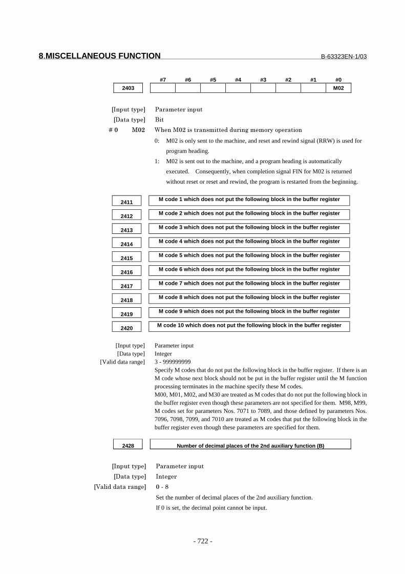
8.MISCELLANEOUS FUNCTION B-63323EN-1/03
- 722 -
#7 #6 #5 #4 #3 #2 #1 #0
2403 M02
���������� �� ��� ������
��������� ���
� � � � ��� ��+ 2$����+��"�� ��"�������� ������( ��(� ���(�
0: M02 is only sent to the machine, and reset and rewind signal (RRW) is used for
program heading.
1: M02 is sent out to the machine, and a program heading is automatically
executed. Consequently, when completion signal FIN for M02 is returned
without reset or reset and rewind, the program is restarted from the beginning.
2411 M code 1 which does not put the following block in the buffer register
2412 M code 2 which does not put the following block in the buffer register
2413 M code 3 which does not put the following block in the buffer register
2414 M code 4 which does not put the following block in the buffer register
2415 M code 5 which does not put the following block in the buffer register
2416 M code 6 which does not put the following block in the buffer register
2417 M code 7 which does not put the following block in the buffer register
2418 M code 8 which does not put the following block in the buffer register
2419 M code 9 which does not put the following block in the buffer register
2420 M code 10 which does not put the following block in the buffer register
[Input type] Parameter input[Data type] Integer
[Valid data range] 3 - 999999999Specify M codes that do not put the following block in the buffer register. If there is anM code whose next block should not be put in the buffer register until the M functionprocessing terminates in the machine specify these M codes.M00, M01, M02, and M30 are treated as M codes that do not put the following block inthe buffer register even though these parameters are not specified for them. M98, M99,M codes set for parameters Nos. 7071 to 7089, and those defined by parameters Nos.7096, 7098, 7099, and 7010 are treated as M codes that put the following block in thebuffer register even though these parameters are specified for them.
2428 Number of decimal places of the 2nd auxiliary function (B)
���������� �� ��� ������
��������� ����
������������ ��� �����
Set the number of decimal places of the 2nd auxiliary function.
If 0 is set, the decimal point cannot be input.
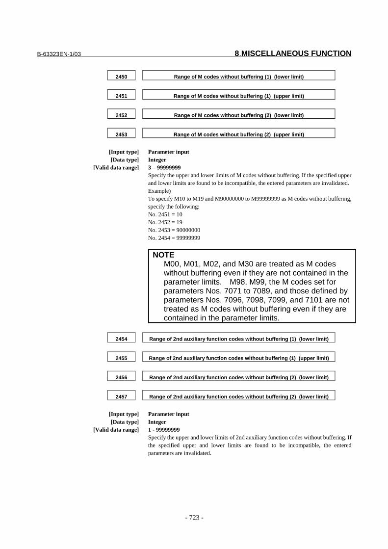
B-63323EN-1/03 8.MISCELLANEOUS FUNCTION
- 723 -
2450 Range of M codes without buffering (1) (lower limit)
2451 Range of M codes without buffering (1) (upper limit)
2452 Range of M codes without buffering (2) (lower limit)
2453 Range of M codes without buffering (2) (upper limit)
[Input type] Parameter input[Data type] Integer
[Valid data range] 3 – 99999999Specify the upper and lower limits of M codes without buffering. If the specified upperand lower limits are found to be incompatible, the entered parameters are invalidated.Example)To specify M10 to M19 and M90000000 to M99999999 as M codes without buffering,specify the following:No. 2451 = 10No. 2452 = 19No. 2453 = 90000000No. 2454 = 99999999
NOTEM00, M01, M02, and M30 are treated as M codeswithout buffering even if they are not contained in theparameter limits. M98, M99, the M codes set forparameters Nos. 7071 to 7089, and those defined byparameters Nos. 7096, 7098, 7099, and 7101 are nottreated as M codes without buffering even if they arecontained in the parameter limits.
2454 Range of 2nd auxiliary function codes without buffering (1) (lower limit)
2455 Range of 2nd auxiliary function codes without buffering (1) (upper limit)
2456 Range of 2nd auxiliary function codes without buffering (2) (lower limit)
2457 Range of 2nd auxiliary function codes without buffering (2) (lower limit)
[Input type] Parameter input[Data type] Integer
[Valid data range] 1 - 99999999Specify the upper and lower limits of 2nd auxiliary function codes without buffering. Ifthe specified upper and lower limits are found to be incompatible, the enteredparameters are invalidated.

8.MISCELLANEOUS FUNCTION B-63323EN-1/03
- 724 -
NoteNOTE1 When a move command and miscellaneous
function are specified in the same block, thecommands are executed in one of the following twoways:i) Simultaneous execution of the move command
and miscellaneous function commands.ii) Executing miscellaneous function commands
upon completion of move command execution.The selection of either sequence depends on thesequence of PMC.
2 When the 2nd auxiliary function is provided, theaddress used for specifying the 2nd auxiliaryfunction (B or the address specified with parameterNo. 1030) cannot be used as an axis address.
3 The block following M00, M01, M02 and M30, is notread into the input buffer register, if present.Similarly, ten M codes which do not buffer can be setby parameters (No. 2411 to 2418).
4 For M00 and M01 only, miscellaneous function codesignal, auxiliary function strobe signal, and Mdecode signals are sent; the control of program stopand optional stop shall be designed on the PMCside.
5 When the automatic operation is stopped by M02 orM30, it is necessary to send the external reset signalfrom the machine side to the CNC, instead of theFIN signal, When the external reset signal isreturned against the M02 or M30, the control returnsto the top of the program recently executed andenters the reset state.
Reference itemII-11.1 Miscellaneous function
(M function)Series15i/150i-MA Operator’s Manual
(Programming)(B-63324EN) II-11.3 Second auxiliary
function

B-63323EN-1/03 8.MISCELLANEOUS FUNCTION
- 725 -
8.2 AUXILIARY FUNCTION LOCK
GeneralInhibits execution of a specified M, S, T and B function.That is, code signals and strobe signals are not issued.This function is used to check a program.
SignalAuxiliary function lock signal AFL<G004#0>
[Classification] Input signal[Function] This signal selects auxiliary function lock. That is, this signal disables
the execution of specified M, S, T, and B functions.[Operation] When this signal turns to "1", the control unit functions as described
below.(1) The control unit does not execute M, S, T, and B functions
specified for memory operation, DNC operation, or MDIoperation. That is, the control unit stops the output of code signalsand strobe signals (MF, SF, TF, BF).
(2) If this signal turns to "1" after code signal output, the outputoperation is executed in the ordinary manner until its completion(that is, until the FIN signal is received, and the strobe signal turnsto "0").
(3) Among the miscellaneous functions, M00, M01, M02, and M30are executed even when this signal is "1". All code signals, strobesignals, decode signals are output in the ordinary manner.
(4) Among the miscellaneous functions, even when this signal is "1",those functions (M98 and M99) that are executed in the controlunit without outputting their execution results are executed in theordinary manner.
Auxiliary function lock check signal MAFL<F004#0>[Classification] Output signal
[Function] This signal reports the state of the auxiliary function lock signal AFL.[Output condition] This signal turns to "1" when:
- The auxiliary function lock signal AFL is "1"This signal turns to "0" when:- The auxiliary function lock signal AFL is "0"
Signal address#7 #6 #5 #4 #3 #2 #1 #0
G004 AFL
#7 #6 #5 #4 #3 #2 #1 #0
F004 MAFL
Reference itemSeries15i/150i-MA Operator’s Manual
(Operation)(B-63324EN-1)
II-5.1 Machine lock andmiscellaneous function

8.MISCELLANEOUS FUNCTION B-63323EN-1/03
- 726 -
8.3 MULTIPLE M COMMANDS IN A SIGLE BLOCK
GeneralSo far, one block has been able to contain only one M code. However,this function allows up to three M codes to be contained in one block.Up to five M codes specified in a block are simultaneously output to themachine.This means that compared with the conventional method of a single Mcommand in a single block, a shorter cycle time can be realized inmachining.For the first of the five M codes, the maximum allowable number ofdigits can be specified in parameter No. 2030. A command longer thanthe maximum allowable number of digits causes an alarm (PS0003).The second to fifth M codes may each consist of up to four digits.
(Example)One M command in a single block Multiple M commands in a single
block
M40;M50;M60;
G28G91X0Y0Z0;:::
M40M50M60;G28G91X0Y0Z0;
:::::
- Basic procedure(1) Assume that "MaaMbbMcc;" was commanded by the program.(2) For each M command, one of the code signals listed below is sent,
and after the time set by parameter No. 2010, TMF, elapses eachstrobe signal is set to 1.
Table. 8.3 Code signals and strobe signals for multiple M
M command Code signal Strobe signalFirst iMaa j M00 to M31 i32 bit j MFSecond iMbb j M200 to M215 i16 bit j MF2Third iMcc j M300 to M315 i16 bit j MF3Fourth iMdd j M400 to M415 i16 bit j MF4Fifth iMee j M500 to M515 i16 bit j MF5
The code signals for the first to fifth M commands are sent at thesame time. Strobe signals MF, MF2, MF3, MF4, and MF5 are allset to 1 at the same time.The code signal is a binary notation of the program command aa,bb and cc.
(3) On the PMC side, the code signals corresponding to the respectivestrobe signals are read when the strobe signals become "1", andthe appropriate operations are performed.
(4) When the operation of all M commands ends on the PMC side, theend signal (FIN) is set to "1".
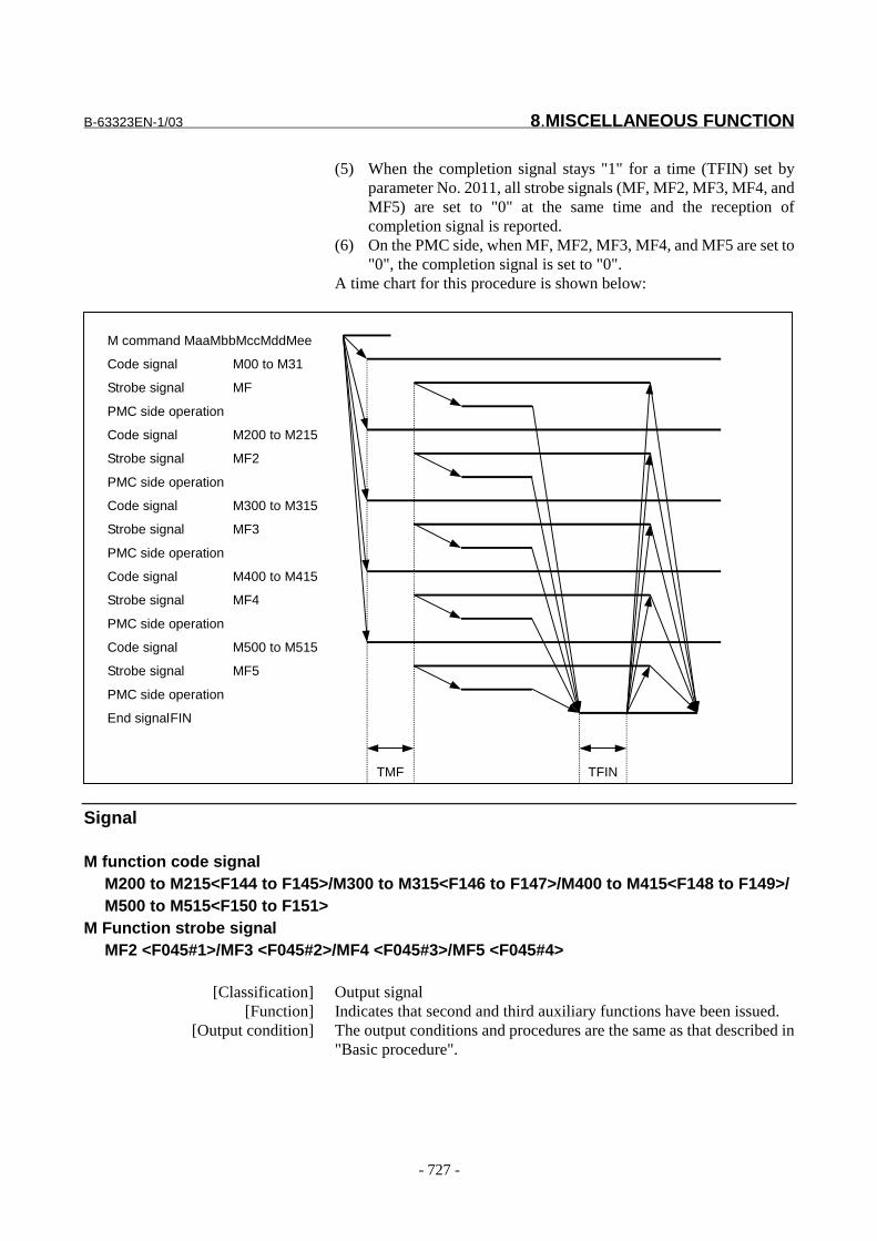
B-63323EN-1/03 8.MISCELLANEOUS FUNCTION
- 727 -
(5) When the completion signal stays "1" for a time (TFIN) set byparameter No. 2011, all strobe signals (MF, MF2, MF3, MF4, andMF5) are set to "0" at the same time and the reception ofcompletion signal is reported.
(6) On the PMC side, when MF, MF2, MF3, MF4, and MF5 are set to"0", the completion signal is set to "0".
A time chart for this procedure is shown below:
M command MaaMbbMccMddMee
Code signal M00 to M31
Strobe signal MF
PMC side operation
Code signal M200 to M215
Strobe signal MF2
PMC side operation
Code signal M300 to M315
Strobe signal MF3
PMC side operation
Code signal M400 to M415
Strobe signal MF4
PMC side operation
Code signal M500 to M515
Strobe signal MF5
PMC side operation
End signalFIN
TMF TFIN
Signal
M function code signalM200 to M215<F144 to F145>/M300 to M315<F146 to F147>/M400 to M415<F148 to F149>/M500 to M515<F150 to F151>
M Function strobe signalMF2 <F045#1>/MF3 <F045#2>/MF4 <F045#3>/MF5 <F045#4>
[Classification] Output signal[Function] Indicates that second and third auxiliary functions have been issued.
[Output condition] The output conditions and procedures are the same as that described in"Basic procedure".
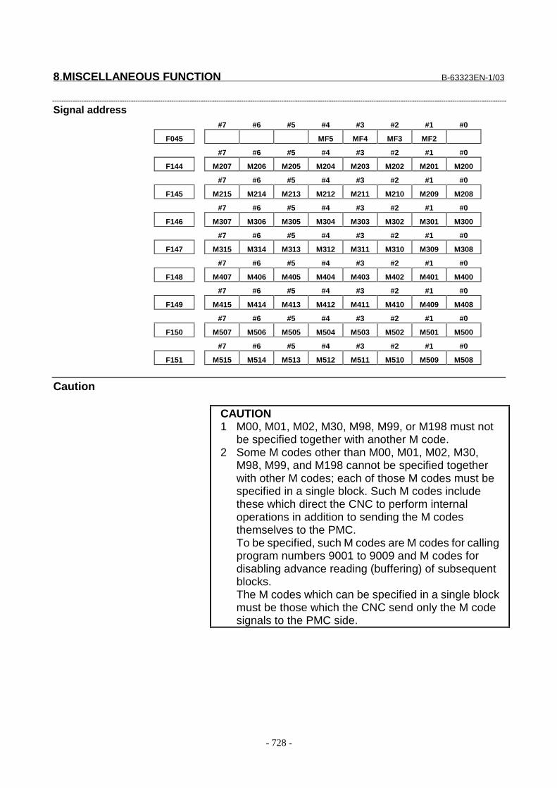
8.MISCELLANEOUS FUNCTION B-63323EN-1/03
- 728 -
Signal address#7 #6 #5 #4 #3 #2 #1 #0
F045 MF5 MF4 MF3 MF2
#7 #6 #5 #4 #3 #2 #1 #0
F144 M207 M206 M205 M204 M203 M202 M201 M200
#7 #6 #5 #4 #3 #2 #1 #0
F145 M215 M214 M213 M212 M211 M210 M209 M208
#7 #6 #5 #4 #3 #2 #1 #0
F146 M307 M306 M305 M304 M303 M302 M301 M300
#7 #6 #5 #4 #3 #2 #1 #0
F147 M315 M314 M313 M312 M311 M310 M309 M308
#7 #6 #5 #4 #3 #2 #1 #0
F148 M407 M406 M405 M404 M403 M402 M401 M400
#7 #6 #5 #4 #3 #2 #1 #0
F149 M415 M414 M413 M412 M411 M410 M409 M408
#7 #6 #5 #4 #3 #2 #1 #0
F150 M507 M506 M505 M504 M503 M502 M501 M500
#7 #6 #5 #4 #3 #2 #1 #0
F151 M515 M514 M513 M512 M511 M510 M509 M508
Caution
CAUTION1 M00, M01, M02, M30, M98, M99, or M198 must not
be specified together with another M code.2 Some M codes other than M00, M01, M02, M30,
M98, M99, and M198 cannot be specified togetherwith other M codes; each of those M codes must bespecified in a single block. Such M codes includethese which direct the CNC to perform internaloperations in addition to sending the M codesthemselves to the PMC.To be specified, such M codes are M codes for callingprogram numbers 9001 to 9009 and M codes fordisabling advance reading (buffering) of subsequentblocks.The M codes which can be specified in a single blockmust be those which the CNC send only the M codesignals to the PMC side.
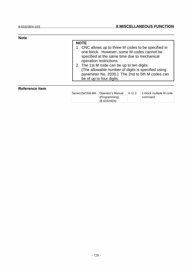
B-63323EN-1/03 8.MISCELLANEOUS FUNCTION
- 729 -
NoteNOTE1 CNC allows up to three M codes to be specified in
one block. However, some M codes cannot bespecified at the same time due to mechanicaloperation restrictions.
2 The 1st M code can be up to ten digits.(The allowable number of digits is specified usingparameter No. 2030.) The 2nd to 5th M codes canbe of up to four digits.
Reference itemSeries15i/150i-MA Operator’s Manual
(Programming)(B-63324EN)
II-11.2 1-block multiple M codecommand
8.MISCELLANEOUS FUNCTION B-63323EN-1/03
- 730 -
8.4 HIGH-SPEED M/S/T/B INTERFACE
GeneralTo accelerate M/S/T/B function execution, the high-speed M/S/T/Binterface has simplified the transfer of the strobe and completionsignals of the M/S/T/B functions.Whether to use the usual system or high-speed system for strobe signaland completion signal handling can be specified by parameter MHI (No.2004#0).The description below uses the miscellaneous functions (M codecommands) as an example. The same description applies to thespindle-speed function (S code), tool function (T code) and 2ndauxiliary function (B code).
- Basic procedure(1) Assume that the following program is given:
Mxx;Myy;
(2) In response to an M command, the NC system sends out the codesignals M00 to M31.The NC system inverts the logical level of the strobe signal MF,that is, from "0"to "1", or from "1" to "0".
(3) The CNC system inverts the strobe signal, then when the logicallevel of the auxiliary function completion signal MFIN becomesthe same as the strobe signal, the CNC assumes the completion ofPMC sequence.With the usual method, the operation is assumed to be completedwhen a falling edge ("1" to "0") of the M/S/T/B completion signalFIN is received after a rising edge ("0" to "1") of the FIN signal isdetected. This new system, on the other hand, assumes theoperation has been completed upon detection of only onetransition of the completion signal.In addition , the usual system uses only one completion signal(FIN) common to the M/S/T/B functions. This new system uses adifferent completion signal for each of the M, S, T, and Bfunctions; the completion signals for the M, S, T, and B functionsare MFIN, SFIN, TFIN, and BFIN, respectively. The Fig. 8.4 (a)below shows the timing chart of these signals with the new system.For comparison, Fig. 8.4 (b) shows the timing chart of theconventional system.

B-63323EN-1/03 8.MISCELLANEOUS FUNCTION
- 731 -
Mxx Myy
Next block
Code signal
Strobe signal MF
PMC side operation
Miscellaneous functioncompletion signal MFIN
Fig. 8.4 (a) Timing chart of the high-speed system
Mxx Myy
Next block
Code signal
Strobe signal MF
PMC side operation
Completion signal FIN
Fig. 8.4 (b) Timing chart of the usual system
A high-speed interface can also be used for multiple M commandsissued for one block. This interface provides separate completionsignals for each M code. They are called MFIN (the same name as forthe single M command per block function), MFIN2, MFIN3, MFIN4,and MFIN5, respectively. The signal transfer sequence for multiple Mcodes per block is the same as that for a single M code per block.
Signal
Miscellaneous function completion signalMFIN<G046#0>
[Classification] Input signal[Function] Reports that the execution of a miscellaneous function using the high-
speed M/S/T/B interface is completed.[Operation] For the operation and a procedure of the control unit when this signal
turns to "1" and "0", see the description of "Basic procedure" above.

8.MISCELLANEOUS FUNCTION B-63323EN-1/03
- 732 -
Spindle function completion signalSFIN<G046#1>
[Classification] Input signal[Function] Reports that the execution of a spindle speed function using the high-
speed M/S/T/B interface is completed.[Operation] For the operation and procedure of the control unit when this signal
turns to "1" and "0", see the description of "Basic procedure" above.
Tool function completion signalTFIN<G046#2>
[Classification] Input signal[Function] Reports that the execution of a tool function using the high-speed
M/S/T/B interface is completed.[Operation] For the operation and procedure of the control unit when this signal
turns to "1" and "0", see the description of "Basic procedure" above.
2nd auxiliary function completion signalBFIN<G046#3>
[Classification] Input signal[Function] Reports that the execution of a second auxiliary function using the
high-speed M/S/T/B interface is completed.[Operation] For the operation and procedure of the control unit when this signal
turns to "1" and "0", see the description of "Basic procedure" above.
M function completion signalsMFIN2<G047#1>/MFIN3<G047#2>/MFIN4<G047#3>/MFIN5<G047#4>
[Classification] Input signal[Function] Indicate that when the high-speed interface is used for multiple M
commands per block, the second to fifth M functions have beencompleted.
[Operation] For the operation and procedure of the control unit when this signalturns to "1" and "0", see the description of "Basic procedure" above.
Signal address#7 #6 #5 #4 #3 #2 #1 #0
G046 BFIN TFIN SFIN MFIN
#7 #6 #5 #4 #3 #2 #1 #0
G047 MFIN5 MFIN4 MFIN3 MFIN2

B-63323EN-1/03 8.MISCELLANEOUS FUNCTION
- 733 -
Parameter#7 #6 #5 #4 #3 #2 #1 #0
2004 MHI
���������� �� ��� ������
��������� ���
� � � � ��� �3� ,$�"� ('����� (�����(��"�����"�!( ��$��4��4�,4�( ��� (�"��
� ��"����������$1
0: Normal system.
1: High-speed system.
NoteNOTE1 The strobe signals MF, SF, TF, and BF are "0" when
the power is turned on.2 When the control unit is reset, MF, SF, TF, and BF
are set to "0".3 This function is not used for the FFIN and FIN
signals which are the completion signals for spindlestop command signal SSP and reserve spindlerotation command signal SSV for canned cycles.These signals are transferred using the normalmethod.
4 This function is not used for the FIN signal which isthe completion signal for the external operationsignal EF sent by G81 to specify an externaloperation command. These signals are transferredusing the normal method.
Reference item8.1 Miscellaneous
function/secondauxiliary function
8.3 1-block multiple M codecommand
Series15i/150i-MODEL A
Connection Manual(This manual)
11.7 External motion function
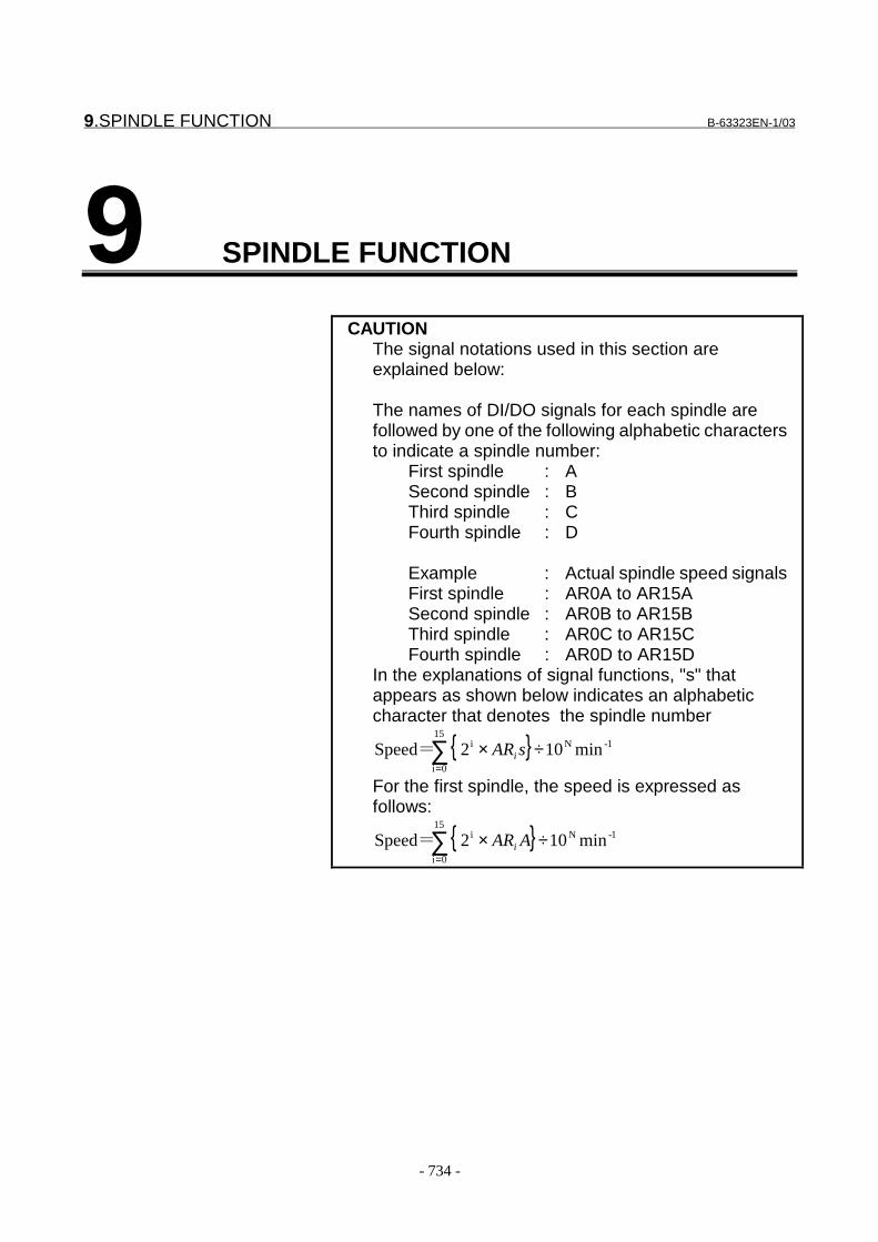
9.SPINDLE FUNCTION B-63323EN-1/03
- 734 -
9 SPINDLE FUNCTION
CAUTIONThe signal notations used in this section areexplained below:
The names of DI/DO signals for each spindle arefollowed by one of the following alphabetic charactersto indicate a spindle number:
First spindle : ASecond spindle : BThird spindle : CFourth spindle : D
Example : Actual spindle speed signalsFirst spindle : AR0A to AR15ASecond spindle : AR0B to AR15BThird spindle : AR0C to AR15CFourth spindle : AR0D to AR15D
In the explanations of signal functions, "s" thatappears as shown below indicates an alphabeticcharacter that denotes the spindle number
{ }∑=
÷×15
0i
1-Ni min102 �Speed sARi
For the first spindle, the speed is expressed asfollows:
{ }∑=
÷×15
0i
1-Ni min102 �Speed AARi
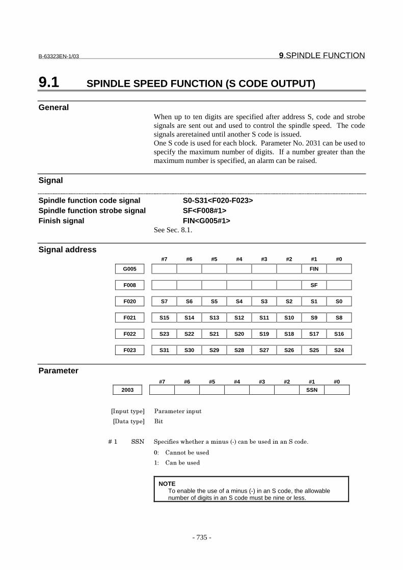
B-63323EN-1/03 9.SPINDLE FUNCTION
- 735 -
9.1 SPINDLE SPEED FUNCTION (S CODE OUTPUT)
GeneralWhen up to ten digits are specified after address S, code and strobesignals are sent out and used to control the spindle speed. The codesignals areretained until another S code is issued.One S code is used for each block. Parameter No. 2031 can be used tospecify the maximum number of digits. If a number greater than themaximum number is specified, an alarm can be raised.
Signal
Spindle function code signal S0-S31<F020-F023>Spindle function strobe signal SF<F008#1>Finish signal FIN<G005#1>
See Sec. 8.1.
Signal address#7 #6 #5 #4 #3 #2 #1 #0
G005 FIN
F008 SF
F020 S7 S6 S5 S4 S3 S2 S1 S0
F021 S15 S14 S13 S12 S11 S10 S9 S8
F022 S23 S22 S21 S20 S19 S18 S17 S16
F023 S31 S30 S29 S28 S27 S26 S25 S24
Parameter#7 #6 #5 #4 #3 #2 #1 #0
2003 SSN
���������� �� ��� ������
��������� ���
� � � � ��� ��� ������������ �������������������������������� �!
"# $��� �������
�# $��������
NOTETo enable the use of a minus (-) in an S code, the allowablenumber of digits in an S code must be nine or less.
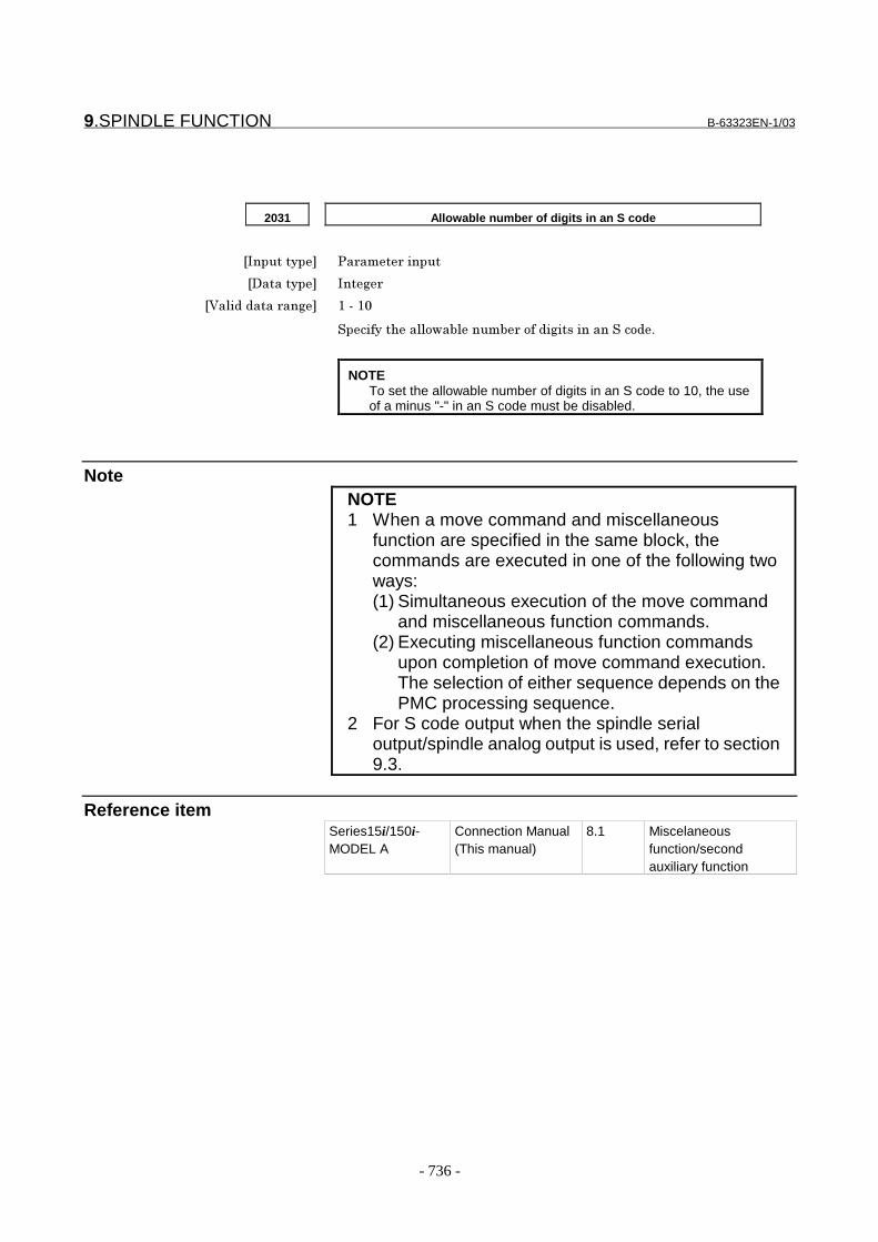
9.SPINDLE FUNCTION B-63323EN-1/03
- 736 -
2031 Allowable number of digits in an S code
���������� �� ��� ������
��������� ���%
�&�'�������� ��% �����"
�����������'' ���'����� � ����%������������� �!
NOTETo set the allowable number of digits in an S code to 10, the useof a minus "-" in an S code must be disabled.
NoteNOTE1 When a move command and miscellaneous
function are specified in the same block, thecommands are executed in one of the following twoways:(1) Simultaneous execution of the move command
and miscellaneous function commands.(2) Executing miscellaneous function commands
upon completion of move command execution.The selection of either sequence depends on thePMC processing sequence.
2 For S code output when the spindle serialoutput/spindle analog output is used, refer to section9.3.
Reference itemSeries15i/150i-MODEL A
Connection Manual(This manual)
8.1 Miscelaneousfunction/secondauxiliary function

B-63323EN-1/03 9.SPINDLE FUNCTION
- 737 -
9.2 SPINDLE SERIAL OUTPUT/SPINDLE ANALOG OUTPUT
GeneralThere are two types of spindle motor control interfaces, spindle serialoutput and spindle analog output.
The spindle serial output interface can control four serial spindles. Thespindle analog output interface can control one analog spindle.
- Spindle control interface and spindle configurationO : Can be used X : Can not be used
Spindle serialoutput
Spindleanalog output
First spindlemotor
Second spindlemotor
Third spindlemotor
Fourth spindlemotor
O O First serial spindleThe PC can beused.
Second serialspindleThe PC can beused.
Analog spindleThe PC cannot beused.
__
O X First serial spindleThe PC can beused.
Second serialspindleThe PC can beused.
Third serial spindleThe PC can beused.
Fourth serial spindleThe PC can beused.
X O Analog spindleThe PC can beused.
__ __ __
X X No spindle (Control is performed by the PMC through an external interface.)
* PC Position coder
- Spindles and available functionsO : Can be used X : Can not be used
Serial spindle Analog spindleSpindle
FunctionFirst, second, third,
and fourth serialspindles
When used as the firstspindle (with no serial SP)
When used as the thirdspindle (with a serial SP)
Thread cutting/feed per revolution(synchronous feed) iNOTE1 j
O O X
Constant surface speed controliNOTE1 j
O O O
Spindle speed fluctuationdetection iNOTE1 j
O O X
Actual spindle speed output O O XSpindle positioning O O XCs contour control O X XRigid tapping iNOTE1 j O O XSpindle control unit functions(NOTE 2), such as spindleorientation, spindleoutput switching, spindleswitching, and etc.
O O O
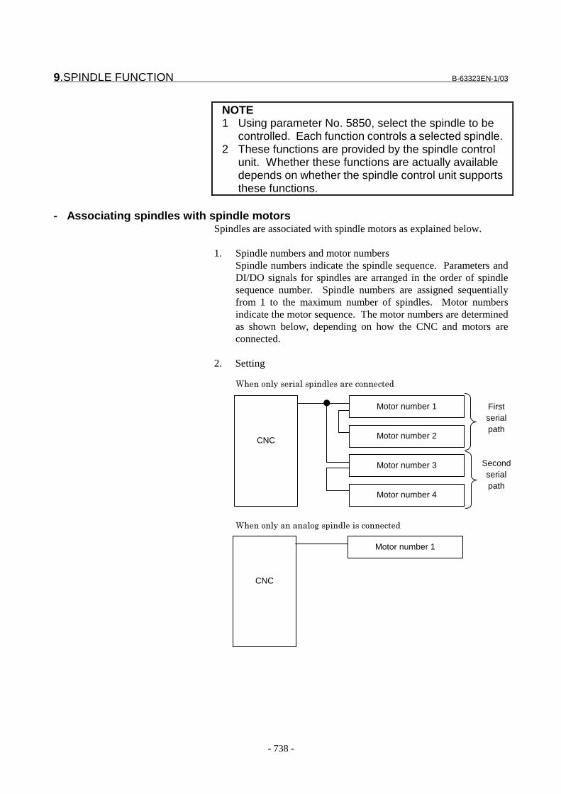
9.SPINDLE FUNCTION B-63323EN-1/03
- 738 -
NOTE1 Using parameter No. 5850, select the spindle to be
controlled. Each function controls a selected spindle.2 These functions are provided by the spindle control
unit. Whether these functions are actually availabledepends on whether the spindle control unit supportsthese functions.
- Associating spindles with spindle motorsSpindles are associated with spindle motors as explained below.
1. Spindle numbers and motor numbersSpindle numbers indicate the spindle sequence. Parameters andDI/DO signals for spindles are arranged in the order of spindlesequence number. Spindle numbers are assigned sequentiallyfrom 1 to the maximum number of spindles. Motor numbersindicate the motor sequence. The motor numbers are determinedas shown below, depending on how the CNC and motors areconnected.
2. Setting
(��� �'��� ��'������'��� �� �����
CNC
Motor number 1
Motor number 2
Motor number 3
Motor number 4
Firstserialpath
Secondserialpath
CNC
Motor number 1
(��� �'��������' %������'����� �����
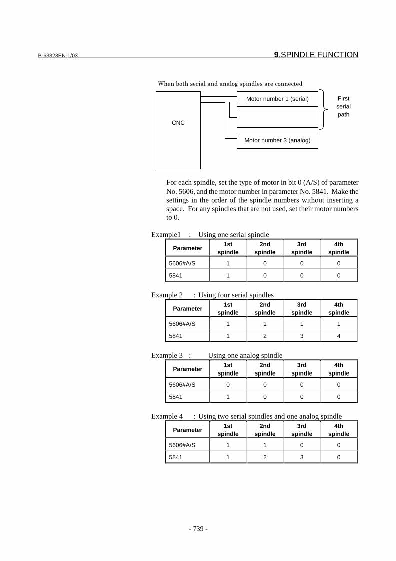
B-63323EN-1/03 9.SPINDLE FUNCTION
- 739 -
For each spindle, set the type of motor in bit 0 (A/S) of parameterNo. 5606, and the motor number in parameter No. 5841. Make thesettings in the order of the spindle numbers without inserting aspace. For any spindles that are not used, set their motor numbersto 0.
Example1 : Using one serial spindle
Parameter1st
spindle2nd
spindle3rd
spindle4th
spindle
5606#A/S 1 0 0 0
5841 1 0 0 0
Example 2 : Using four serial spindles
Parameter1st
spindle2nd
spindle3rd
spindle4th
spindle
5606#A/S 1 1 1 1
5841 1 2 3 4
Example 3 : Using one analog spindle
Parameter1st
spindle2nd
spindle3rd
spindle4th
spindle
5606#A/S 0 0 0 0
5841 1 0 0 0
Example 4 : Using two serial spindles and one analog spindle
Parameter1st
spindle2nd
spindle3rd
spindle4th
spindle
5606#A/S 1 1 0 0
5841 1 2 3 0
CNC
Motor number 1 (serial)
Motor number 3 (analog)
(���� ���� ��'��������' %������'��� �� �����
Firstserialpath

9.SPINDLE FUNCTION B-63323EN-1/03
- 740 -
Example 5 : Using one serial spindle and one analog spindle
Parameter1st
spindle2nd
spindle3rd
spindle4th
spindle
5606#A/S 1 0 0 0
5841 1 3 0 0
- Selecting a spindle to be controlledWhen there are two or more spindles, you must select a spindle that iscurrently controlled by the CNC.The spindle to be controlled is:(1) Spindle for which the spindle speed is displayed on a screen such
as the position display screen or program check screen.(2) Target spindle for an S command, threading, feed per revolution,
constant surface speed control, rigid tapping, canned cycle,spindle speed fluctuation detection, and so forth.
Set the spindle number of a spindle to be controlled in parameter No.5850.
CAUTIONBefore rewriting this parameter during automaticoperation, always use the M code set in parameterNos. 2411 to 2420 which is used as a non-bufferingM code. Always rewrite the parameter in the non-buffering state.
- Differences in controlling spindle control unitsWhen controlling the spindle control units directly, there aredifferences between spindle serial output and spindle analog output, asfollows:
Spindle control unit for spindle serialoutput interface
Spindle control unit for spindle analog outputinterface
Parameters for thespindle control unit
Specified as CNC parameters (3000 to3393)Used after being transferred to the spindlecontrol unit
Directly specified for the spindle control unit
Connected to the PMC via the CNCAddresses for the first spindleG200 to 201G226 to 229F228 to 231Addresses for the second spindleG202 to 203G234 to 237F244 to 247
Control signal for thespindle control unit
Addresses for the third spindleG204 to 205G210 to 213F196 to 199
Connected to the PMC via an external contact
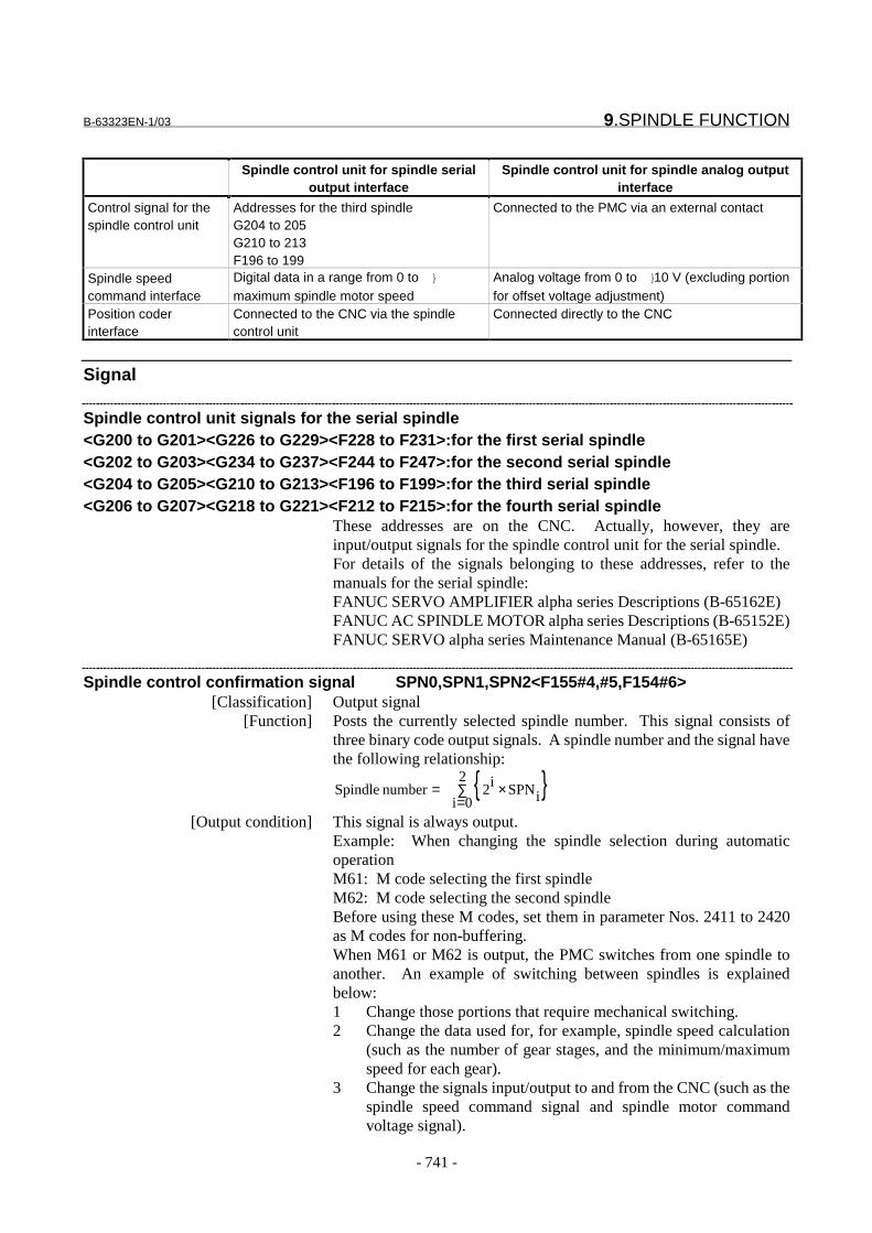
B-63323EN-1/03 9.SPINDLE FUNCTION
- 741 -
Spindle control unit for spindle serialoutput interface
Spindle control unit for spindle analog outputinterface
Control signal for thespindle control unit
Addresses for the third spindleG204 to 205G210 to 213F196 to 199
Connected to the PMC via an external contact
Spindle speedcommand interface
Digital data in a range from 0 to }
maximum spindle motor speedAnalog voltage from 0 to }10 V (excluding portionfor offset voltage adjustment)
Position coderinterface
Connected to the CNC via the spindlecontrol unit
Connected directly to the CNC
Signal
Spindle control unit signals for the serial spindle<G200 to G201><G226 to G229><F228 to F231>:for the first serial spindle<G202 to G203><G234 to G237><F244 to F247>:for the second serial spindle<G204 to G205><G210 to G213><F196 to F199>:for the third serial spindle<G206 to G207><G218 to G221><F212 to F215>:for the fourth serial spindle
These addresses are on the CNC. Actually, however, they areinput/output signals for the spindle control unit for the serial spindle.For details of the signals belonging to these addresses, refer to themanuals for the serial spindle:FANUC SERVO AMPLIFIER alpha series Descriptions (B-65162E)FANUC AC SPINDLE MOTOR alpha series Descriptions (B-65152E)FANUC SERVO alpha series Maintenance Manual (B-65165E)
Spindle control confirmation signal SPN0,SPN1,SPN2<F155#4,#5,F154#6>[Classification] Output signal
[Function] Posts the currently selected spindle number. This signal consists ofthree binary code output signals. A spindle number and the signal havethe following relationship:
{ }∑=
×=2
0i iSPNi2 number Spindle
[Output condition] This signal is always output.Example: When changing the spindle selection during automaticoperationM61: M code selecting the first spindleM62: M code selecting the second spindleBefore using these M codes, set them in parameter Nos. 2411 to 2420as M codes for non-buffering.When M61 or M62 is output, the PMC switches from one spindle toanother. An example of switching between spindles is explainedbelow:1 Change those portions that require mechanical switching.2 Change the data used for, for example, spindle speed calculation
(such as the number of gear stages, and the minimum/maximumspeed for each gear).
3 Change the signals input/output to and from the CNC (such as thespindle speed command signal and spindle motor commandvoltage signal).

9.SPINDLE FUNCTION B-63323EN-1/03
- 742 -
4 Change the setting of parameter No. 5850 for spindle selection byusing functions such as the NC window function.
5 After completing all the processing required for spindle switching,return completion signal FIN for M61 or M62.
M61 ; .........................................................Select 1st spindleM03 ;G01 G95 F1. S1000 ; ................................Feed per revolutionG91 X100. ;G94 S0 ;M05 ;G84.2 X10. Z-30. R-10. F100. S100 ;.......Rigid tappingG80 ;
M62 ; .........................................................Select 2nd spindleM04 ;G01 G95 F2. S2000 ; ................................Feed per revolutionG91 X200. ;G94 S0 ;M05 ;G84.3 X10. Z-30. R-10. F200. S200 ;.......Rigid tappingG80 ;
�����
����'��
��
''�
)��������'��
��
''�
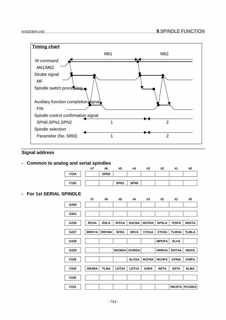
B-63323EN-1/03 9.SPINDLE FUNCTION
- 743 -
Signal address
- Common to analog and serial spindles#7 #6 #5 #4 #3 #2 #1 #0
F154 SPN2
F155 SPN1 SPN0
- For 1st SERIAL SPINDLE#7 #6 #5 #4 #3 #2 #1 #0
G200
G201
G226 RCHA RSLA INTGA SOCNA MCFNA SPSLA *ESPA ARSTA
G227 MRDYA ORCMA SFRA SRVA CTH1A CTH2A TLMHA TLMLA
G228 MPOFA SLVA
G229 INCMDA OVRIDA NRROA ROTAA INDXA
F228 SLVSA RCFNA RCHPA CFINA CHIPA
F229 ORARA TLMA LDT2A LDT1A SARA SDTA SSTA ALMA
F230
F231 INCSTA PC1DEA
Timing chart
M61 M62
M command
M61/M62
Strobe signal
MF
Spindle switch processing
Auxiliary function completion signal
FIN
Spindle control confirmation signal
SPN0,SPN1,SPN2 1 2
Spindle selection
Parameter (No. 5850) 1 2

9.SPINDLE FUNCTION B-63323EN-1/03
- 744 -
- For 2nd SERIAL SPINDLE#7 #6 #5 #4 #3 #2 #1 #0
G202
G203
G234 RCHB RSLB INTGB SOCNB MCFNB SPSLB *ESPB ARSTB
G235 MRDYB ORCMB SFRB SRVB CTH1B CTH2B TLMHB TLMLB
G236 MPOFB SLVB
G237 INCMDB OVRIDB NRROB ROTAB INDXB
F244 SLVSB RCFNB RCHPB CFINB CHIPB
F245 ORARB TLMB LDT2B LDT1B SARB SDTB SSTB ALMB
F246
F247 INCSTB PC1DEB
- For 3rd SERIAL SPINDLE#7 #6 #5 #4 #3 #2 #1 #0
G204
G205
G210 RCHC RSLC INTGC SOCNC MCFNC SPSLC *ESPC ARSTC
G211 MRDYC ORCMC SFRC SRVC CTH1C CTH2C TLMHC TLMLC
G212 MPOFC SLVC
G213 INCMDC OVRIDC NRROC ROTAC INDXC
F196 SLVSC RCFNC RCHPC CFINC CHIPC
F197 ORARC TLMC LDT2C LDT1C SARC SDTC SSTC ALMC
F198
F199 INCSTC PC1DEC
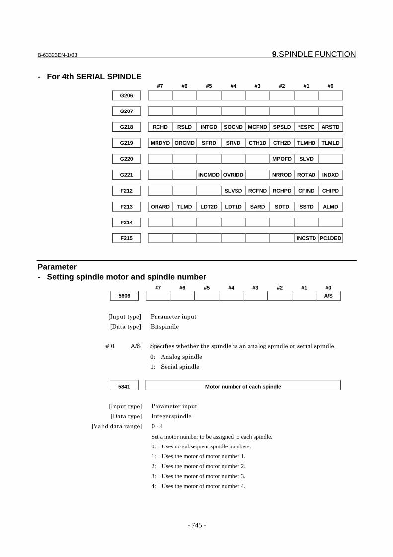
B-63323EN-1/03 9.SPINDLE FUNCTION
- 745 -
- For 4th SERIAL SPINDLE#7 #6 #5 #4 #3 #2 #1 #0
G206
G207
G218 RCHD RSLD INTGD SOCND MCFND SPSLD *ESPD ARSTD
G219 MRDYD ORCMD SFRD SRVD CTH1D CTH2D TLMHD TLMLD
G220 MPOFD SLVD
G221 INCMDD OVRIDD NRROD ROTAD INDXD
F212 SLVSD RCFND RCHPD CFIND CHIPD
F213 ORARD TLMD LDT2D LDT1D SARD SDTD SSTD ALMD
F214
F215 INCSTD PC1DED
Parameter- Setting spindle motor and spindle number
#7 #6 #5 #4 #3 #2 #1 #0
5606 A/S
���������� �� ��� ������
��������� ��������'
� � � � ��" *+� ������������ ���������'����������' %������'� �� ��'������'!
"# *��' %������'
�# � ��'������'
5841 Motor number of each spindle
���������� �� ��� ������
��������� ���% �����'
�&�'�������� ��% "���,
Set a motor number to be assigned to each spindle.
0: Uses no subsequent spindle numbers.
1: Uses the motor of motor number 1.
2: Uses the motor of motor number 2.
3: Uses the motor of motor number 3.
4: Uses the motor of motor number 4.
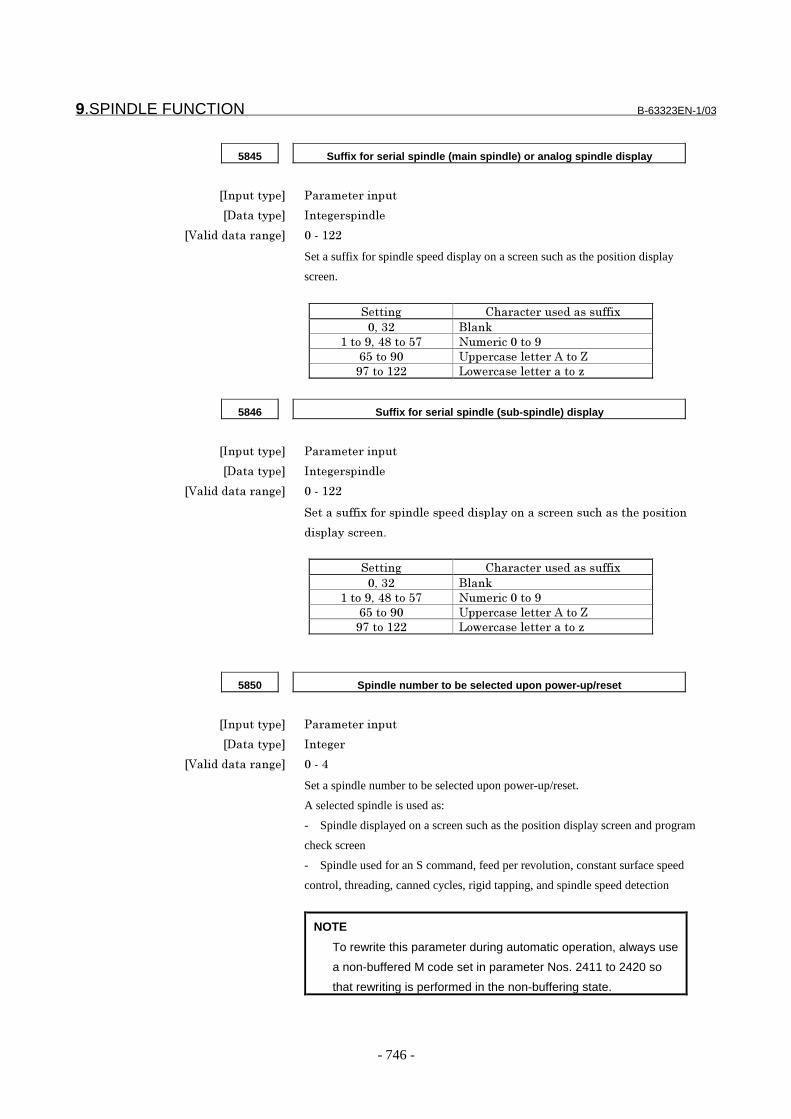
9.SPINDLE FUNCTION B-63323EN-1/03
- 746 -
5845 Suffix for serial spindle (main spindle) or analog spindle display
���������� �� ��� ������
��������� ���% �����'
�&�'�������� ��% "����))
Set a suffix for spindle speed display on a screen such as the position display
screen.
�����% $�� ��� �������������-
".�/) �'��0
��� �1.�,2�� �34 ��� ���"�� �1
53�� �1" 6�� ����'�� �*�� �7
14�� ��)) 8 � ����'�� ���� �9
5846 Suffix for serial spindle (sub-spindle) display
���������� �� ��� ������
��������� ���% �����'
�&�'�������� ��% "����))
����������-�� ������'���������'��� ������ �������������� ���� �
����'����� �!
�����% $�� ��� �������������-
".�/) �'��0
��� �1.�,2�� �34 ��� ���"�� �1
53�� �1" 6�� ����'�� �*�� �7
14�� ��)) 8 � ����'�� ���� �9
5850 Spindle number to be selected upon power-up/reset
���������� �� ��� ������
��������� ���%
�&�'�������� ��% "���,
Set a spindle number to be selected upon power-up/reset.
A selected spindle is used as:
- Spindle displayed on a screen such as the position display screen and program
check screen
- Spindle used for an S command, feed per revolution, constant surface speed
control, threading, canned cycles, rigid tapping, and spindle speed detection
NOTE
To rewrite this parameter during automatic operation, always use
a non-buffered M code set in parameter Nos. 2411 to 2420 so
that rewriting is performed in the non-buffering state.

B-63323EN-1/03 9.SPINDLE FUNCTION
- 747 -
- Connecting an analog spindle control unit
5613 Compensation value for the offset voltage of the spindle speed analog
output
���������� �� ��� ������
��������� ���% �����'
�6���� ������ &'
�&�'�������� ��% ��"),����"),
Set the compensation value for the offset voltage of the spindle speed analog
output.
�*�:������ ; ���0���:������.�� '' ������ ��� �-�'������' �#
(1) Set the standard setting 0.
(2) Specify the spindle speed at which the spindle speed analog output becomes 0.
(3) Measure the output voltage.
(4) Set the value obtained from the following equation in the parameter.
(5) After setting the parameter, specify the spindle speed again at which the
spindle speed analog output becomes 0, then check that the output voltage is 0
V.
12.5
(V) voltagemeasured8191Setting
×−

9.SPINDLE FUNCTION B-63323EN-1/03
- 748 -
5614 Data for adjusting the gain of the spindle speed analog output
���������� �� ��� ������
��������� ���% �����'
�&�'�������� ��% 4""����)3"
��������� ���:�����%����%���� ����������'��������' %� �����!
�*�:������ <�0���:����������� '' ���%����� ��� �-�'������' �#
��� ������������ �������%�� �2""!
�)� ���������������'����������������������'��������' %� �����
= '��%������-���9����"�&�!
�/� <��� ���� ������= '��%!
�,� ������=�'�� �������� ������ '' ���%�>���� ���������� ��� !
�3� *�� ������%������ ��� .����������������'������%������������
��������'��������' %� ������= '��%������-���9�.��������0
�������� ������= '��%�����"�&!
800(V) voltageMeasured
10(V)Setting ×
- Connecting a serial spindle control unit#7 #6 #5 #4 #3 #2 #1 #0
5603 APW
���������� �� ��� ������
��������� ��������'
� � � � ��/ *�( ������������ �� �� ���� ��� ��� �� !�/")"��� �%��� !�/"/��
�� ��� �� !�/"""��� �%��//1/�� �����$�$�� ���������'����'���
������� ��'������'�������!
"# ; ���� ��� ��� �� !�/")"��� �%��� !�/"/�!
�# ; ���� ��� ��� �� !�/"""��� �%��� !�//1/!
����� �'��� �� ��'������'���:������!
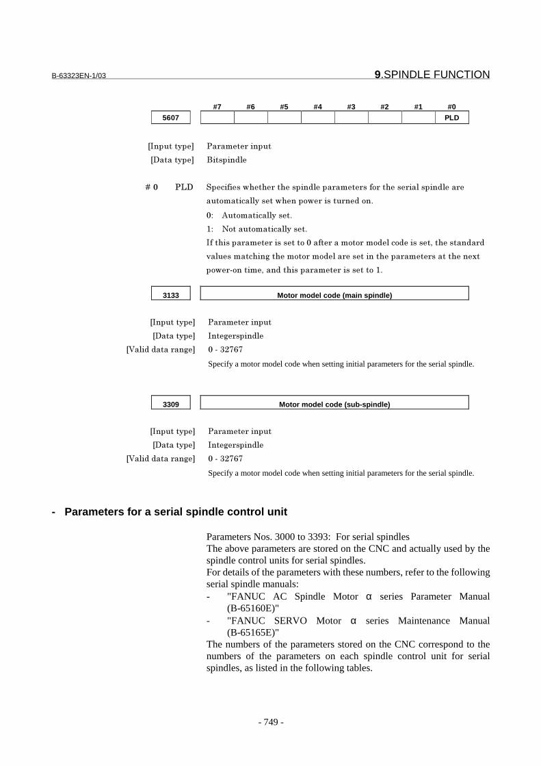
B-63323EN-1/03 9.SPINDLE FUNCTION
- 749 -
#7 #6 #5 #4 #3 #2 #1 #0
5607 PLD
���������� �� ��� ������
��������� ��������'
� � � � ��" �8� ������������ ���������'��� ��� ��� ����� ��'������'��
��� ������''���������� � ������ ��� �!
"# *�� ������''����!
�# � ����� ������''����!
���������� ��� �������� �"���� ���� � �� �'�� �������.���������� �
=�'����������%����� � �� �'�� ������������ ��� ���������-�
� � � �����.������������ ��� �������� ��!
3133 Motor model code (main spindle)
���������� �� ��� ������
��������� ���% �����'
�&�'�������� ��% "���/)454
Specify a motor model code when setting initial parameters for the serial spindle.
3309 Motor model code (sub-spindle)
���������� �� ��� ������
��������� ���% �����'
�&�'�������� ��% "���/)454
Specify a motor model code when setting initial parameters for the serial spindle.
- Parameters for a serial spindle control unit
Parameters Nos. 3000 to 3393: For serial spindlesThe above parameters are stored on the CNC and actually used by thespindle control units for serial spindles.For details of the parameters with these numbers, refer to the followingserial spindle manuals:- "FANUC AC Spindle Motor α series Parameter Manual
(B-65160E)"- "FANUC SERVO Motor α series Maintenance Manual
(B-65165E)"The numbers of the parameters stored on the CNC correspond to thenumbers of the parameters on each spindle control unit for serialspindles, as listed in the following tables.
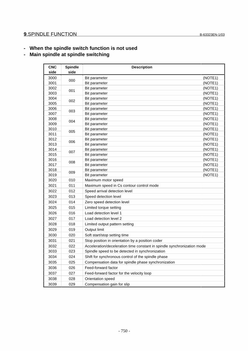
9.SPINDLE FUNCTION B-63323EN-1/03
- 750 -
- When the spindle switch function is not used- Main spindle at spindle switching
CNCside
Spindleside
Description
3000 Bit parameter (NOTE1)3001
000Bit parameter (NOTE1)
3002 Bit parameter (NOTE1)3003
001Bit parameter (NOTE1)
3004 Bit parameter (NOTE1)3005
002Bit parameter (NOTE1)
3006 Bit parameter (NOTE1)3007
003Bit parameter (NOTE1)
3008 Bit parameter (NOTE1)3009
004Bit parameter (NOTE1)
3010 Bit parameter (NOTE1)3011
005Bit parameter (NOTE1)
3012 Bit parameter (NOTE1)3013
006Bit parameter (NOTE1)
3014 Bit parameter (NOTE1)3015
007Bit parameter (NOTE1)
3016 Bit parameter (NOTE1)3017
008Bit parameter (NOTE1)
3018 Bit parameter (NOTE1)3019
009Bit parameter (NOTE1)
3020 010 Maximum motor speed
3021 011 Maximum speed in Cs contour control mode
3022 012 Speed arrival detection level
3023 013 Speed detection level
3024 014 Zero speed detection level
3025 015 Limited torque setting
3026 016 Load detection level 1
3027 017 Load detection level 2
3028 018 Limited output pattern setting
3029 019 Output limit
3030 020 Soft start/stop setting time
3031 021 Stop position in orientation by a position coder
3032 022 Acceleration/deceleration time constant in spindle synchronization mode3033 023 Spindle speed to be detected in synchronization
3034 024 Shift for synchronous control of the spindle phase
3035 025 Compensation data for spindle phase synchronization
3036 026 Feed-forward factor
3037 027 Feed-forward factor for the velocity loop
3038 028 Orientation speed
3039 029 Compensation gain for slip

B-63323EN-1/03 9.SPINDLE FUNCTION
- 751 -
CNCside
Spindleside
Description
3040 030 Proportional gain of the velocity loop in normal operation mode (high-speed gear)3041 031 Proportional gain of the velocity loop in normal operation mode (low-speed gear)3042 032 Proportional gain of the velocity loop in orientation (high-speed gear)
3043 033 Proportional gain of the velocity loop in orientation (low-speed gear)
3044 034 Proportional gain of the velocity loop in servo mode/synchronization control mode(high-speed gear)
3045 035 Proportional gain of the velocity loop in servo mode/synchronization control mode(low-speed gear)
3046 036 Proportional gain of the velocity loop in Cs contour control mode (high-speed gear)3047 037 Proportional gain of the velocity loop in Cs contour control mode (low-speed gear)3048 038 Integral gain of the velocity loop in normal operation mode (high-speed gear)3049 039 Integral gain of the velocity loop in normal operation mode (low-speed gear)3050 040 Integral gain of the velocity loop in orientation (high-speed gear)3051 041 Integral gain of the velocity loop in orientation (low-speed gear)3052 042 Integral gain of the velocity loop in servo mode/synchronization control mode
(high-speed gear)3053 043 Integral gain of the velocity loop in servo mode/synchronization control mode (low-
speed gear)3054 044 Integral gain of the velocity loop in Cs contour control mode (high-speed gear)3055 045 Integral gain of the velocity loop in Cs contour control mode (low-speed gear)3056 046 Gear ratio (high-speed gear)
3057 047 Gear ratio (medium high-speed gear)
3058 048 Gear ratio (medium low-speed gear)
3059 049 Gear ratio (low-speed gear)
3060 050 Position gain in orientation (high-speed gear)
3061 051 Position gain in orientation (medium high-speed gear)
3062 052 Position gain in orientation (medium low-speed gear)
3063 053 Position gain in orientation (low-speed gear)
3064 054 Rate of change in position gain upon completion of orientation
3065 055 Position gain in servo mode/synchronization control mode (high-speed gear)3066 056 Position gain in servo mode/synchronization control mode (medium-speed high
gear)3067 057 Position gain in servo mode/synchronization control mode (medium low-speed
gear)3068 058 Position gain in servo mode/synchronization control mode (low-speed gear)3069 059 Position gain in Cs contour control mode (high-speed gear)
3070 060 Position gain in Cs contour control mode (medium high-speed gear)
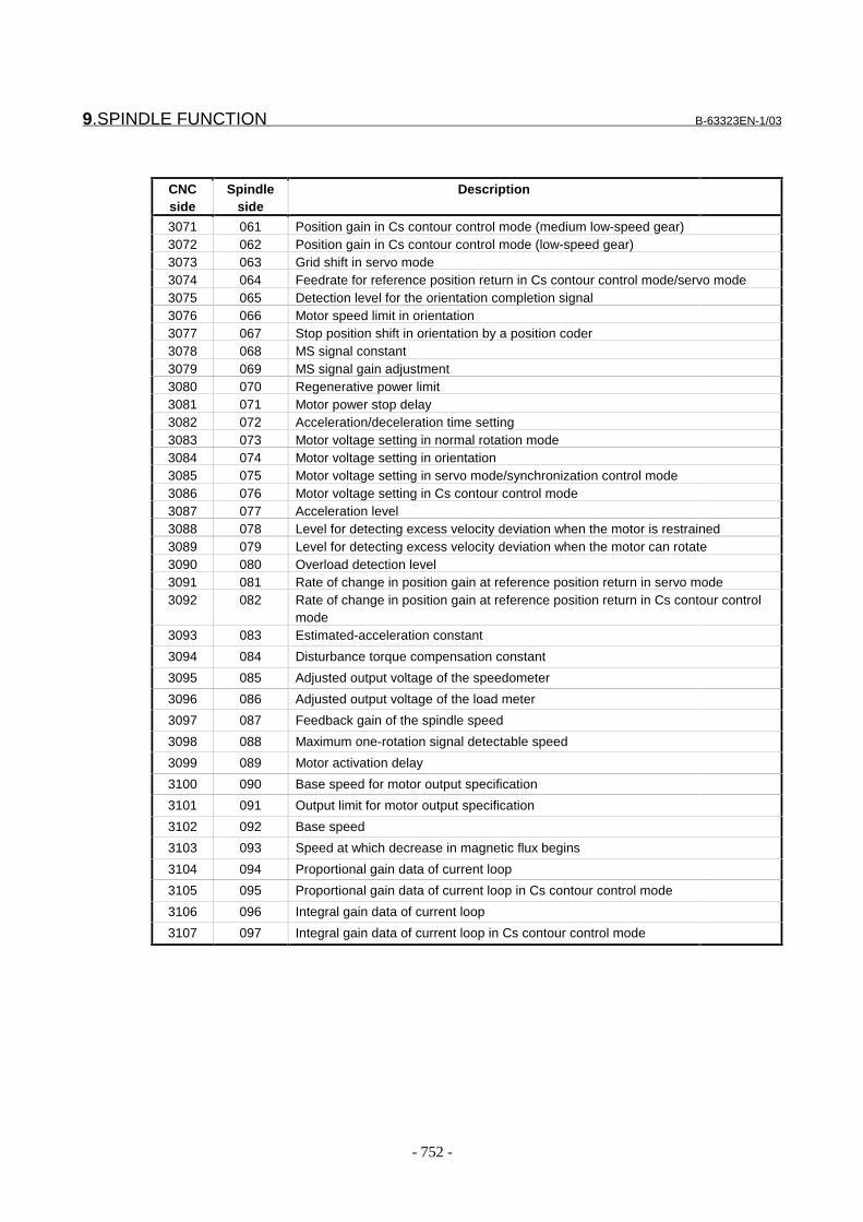
9.SPINDLE FUNCTION B-63323EN-1/03
- 752 -
CNCside
Spindleside
Description
3071 061 Position gain in Cs contour control mode (medium low-speed gear)3072 062 Position gain in Cs contour control mode (low-speed gear)3073 063 Grid shift in servo mode3074 064 Feedrate for reference position return in Cs contour control mode/servo mode3075 065 Detection level for the orientation completion signal3076 066 Motor speed limit in orientation3077 067 Stop position shift in orientation by a position coder3078 068 MS signal constant3079 069 MS signal gain adjustment3080 070 Regenerative power limit3081 071 Motor power stop delay3082 072 Acceleration/deceleration time setting3083 073 Motor voltage setting in normal rotation mode3084 074 Motor voltage setting in orientation3085 075 Motor voltage setting in servo mode/synchronization control mode3086 076 Motor voltage setting in Cs contour control mode3087 077 Acceleration level3088 078 Level for detecting excess velocity deviation when the motor is restrained3089 079 Level for detecting excess velocity deviation when the motor can rotate3090 080 Overload detection level3091 081 Rate of change in position gain at reference position return in servo mode3092 082 Rate of change in position gain at reference position return in Cs contour control
mode3093 083 Estimated-acceleration constant
3094 084 Disturbance torque compensation constant
3095 085 Adjusted output voltage of the speedometer
3096 086 Adjusted output voltage of the load meter
3097 087 Feedback gain of the spindle speed
3098 088 Maximum one-rotation signal detectable speed
3099 089 Motor activation delay
3100 090 Base speed for motor output specification
3101 091 Output limit for motor output specification
3102 092 Base speed
3103 093 Speed at which decrease in magnetic flux begins
3104 094 Proportional gain data of current loop
3105 095 Proportional gain data of current loop in Cs contour control mode
3106 096 Integral gain data of current loop
3107 097 Integral gain data of current loop in Cs contour control mode

B-63323EN-1/03 9.SPINDLE FUNCTION
- 753 -
CNCside
Spindleside
Description
3108 098 Velocity at which current loop integral gain is zero
3109 099 Velocity factor for integral gain of current loop
3110 100 Current conversion constant
3111 101 Secondary current factor for activating current
3112 102 Expected-current constant
3113 103 Slip constant
3114 104 Compensation constant for high-speed-rotation slip
3115 105 Compensation constant for voltage applied to motor in the dead zone3116 106 Compensation factor for electromotive force
3117 107 Compensation factor for the phase of electromotive force
3118 108 Velocity factor to correct electromotive force
3119 109 Time constant for the voltage filter to correct electromotive force
3120 110 Dead zone compensation data3121 111 Time constant for changing the torque3122 112 Time constant for the velocity detecting filter3123 113 Short overload detection time3124 114 Voltage compensation factor at deceleration3125 115 Timer setting for automatic operation3126 116 Velocity command in automatic operation mode3127 117 Load meter indication at maximum output3128 118 Velocity at which the maximum output limit is zero3129 119 Secondary current factor for rigid tapping3130 120 Compensation constant for the phase of electromotive force at deceleration3131 121 Time constant for the velocity detecting filter in Cs contour control mode3132 122 Current conversion constant for the V phase3133 123 Motor model code (main spindle)
1243134
125(NOTE Q)
1263135
127Grid shift in Cs contour control mode (NOTE Q)
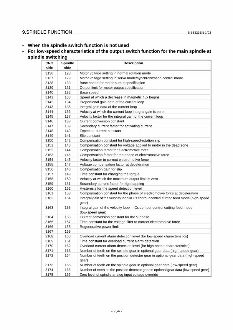
9.SPINDLE FUNCTION B-63323EN-1/03
- 754 -
- When the spindle switch function is not used- For low-speed characteristics of the output switch function for the main spindle at
spindle switchingCNCside
Spindleside
Description
3136 128 Motor voltage setting in normal rotation mode3137 129 Motor voltage setting in servo mode/synchronization control mode3138 130 Base speed for motor output specification3139 131 Output limit for motor output specification3140 132 Base speed3141 133 Speed at which a decrease in magnetic flux begins3142 134 Proportional gain data of the current loop3143 135 Integral gain data of the current loop3144 136 Velocity at which the current loop integral gain is zero3145 137 Velocity factor for the integral gain of the current loop3146 138 Current conversion constant3147 139 Secondary current factor for activating current3148 140 Expected-current constant3149 141 Slip constant3150 142 Compensation constant for high-speed-rotation slip3151 143 Compensation constant for voltage applied to motor in the dead zone3152 144 Compensation factor for electromotive force3153 145 Compensation factor for the phase of electromotive force3154 146 Velocity factor to correct electromotive force3155 147 Voltage compensation factor at deceleration3156 148 Compensation gain for slip3157 149 Time constant for changing the torque3158 150 Velocity at which the maximum output limit is zero3159 151 Secondary current factor for rigid tapping3160 152 Hysteresis for the speed detection level3161 153 Compensation constant for the phase of electromotive force at deceleration3162 154 Integral gain of the velocity loop in Cs contour control cutting feed mode (high-speed
gear)3163 155 Integral gain of the velocity loop in Cs contour control cutting feed mode
(low-speed gear)3164 156 Current conversion constant for the V phase3165 157 Time constant for the voltage filter to correct electromotive force3166 158 Regenerative power limit3167 1593168 160 Overload current alarm detection level (for low-speed characteristics)3169 161 Time constant for overload current alarm detection3170 162 Overload current alarm detection level (for high-speed characteristics)3171 163 Number of teeth on the spindle gear in optional gear data (high-speed gear)3172 164 Number of teeth on the position detector gear in optional gear data (high-speed
gear)3173 165 Number of teeth on the spindle gear in optional gear data (low-speed gear)3174 166 Number of teeth on the position detector gear in optional gear data (low-speed gear)3175 167 Zero level of spindle analog input voltage override

B-63323EN-1/03 9.SPINDLE FUNCTION
- 755 -
- Sub-spindle at spindle switchingCNCside
Spindleside
Description
3176 Bit parameter (NOTE1)3177
168Bit parameter (NOTE1)
3178 Bit parameter (NOTE1)3179
169Bit parameter (NOTE1)
3180 Bit parameter (NOTE1)3181
170Bit parameter (NOTE1)
3182 Bit parameter (NOTE1)3183
171Bit parameter (NOTE1)
3184 Bit parameter (NOTE1)3185
172Bit parameter (NOTE1)
3186 Bit parameter (NOTE1)3187
173Bit parameter (NOTE1)
3188 Bit parameter (NOTE1)3189
174Bit parameter (NOTE1)
3190 Bit parameter (NOTE1)3191
175Bit parameter (NOTE1)
3192 Bit parameter (NOTE1)3193
176Bit parameter (NOTE1)
3194 Bit parameter (NOTE1)3195
177Bit parameter (NOTE1)
3196 178 Maximum motor speed3197 179 Speed arrival detection level3198 180 Speed detection level3199 181 Zero speed detection level3200 182 Limited torque setting3201 183 Load detection level 13202 184 Limited output pattern setting3203 185 Output limit3204 186 Stop position in orientation by a position coder3205 187 Orientation speed3206 188 Proportional gain of velocity loop in normal operation mode (high-speed gear)3207 189 Proportional gain of velocity loop in normal operation mode (low-speed gear)3208 190 Proportional gain of velocity loop in orientation (high-speed gear)3209 191 Proportional gain of velocity loop in orientation (low-speed gear)3210 192 Proportional gain of velocity loop in servo mode (high-speed gear)3211 193 Proportional gain of velocity loop in servo mode (low-speed gear)3212 194 Integral gain of velocity loop in normal operation mode3213 195 Integral gain of velocity loop in orientation3214 196 Integral gain of velocity loop in servo mode3215 1973216 198 Gear ratio (high-speed gear)3217 199 Gear ratio (low-speed gear)3218 200 Position gain in orientation (high-speed gear)3219 201 Position gain in orientation (low-speed gear)3220 202 Rate of change in position gain upon completion of orientation3221 203 Position gain in servo mode (high-speed gear)3222 204 Position gain in servo mode (low-speed gear)3223 205 Grid shift in servo mode3224 206

9.SPINDLE FUNCTION B-63323EN-1/03
- 756 -
CNCside
Spindleside
Description
3225 2073226 208 Detection level for the orientation completion signal3227 209 Motor speed limit in orientation3228 210 Stop position shift in orientation by a position coder3229 211 MS signal constant3230 212 MS signal gain adjustment3231 213 Regenerative power limit3232 214 Motor power stop delay3233 215 Acceleration/deceleration time setting3234 216 Observer gain for the spindle load monitor 13235 217 Observer gain for the spindle load monitor 23236 218 Motor voltage setting in normal rotation mode3237 219 Motor voltage setting in orientation3238 220 Motor voltage setting in servo mode3239 221 Rate of change in position gain at reference position return in servo mode3240 222 Feed-forward factor3241 223 Feed-forward factor for the velocity loop3242 2243243 225 Number of teeth on the spindle gear in optional gear data (high-speed gear)3244 226 Number of teeth on the position detector gear in optional gear data (high-speed
gear)3245 227 Number of teeth on the spindle gear in optional gear data (low-speed gear)3246 228 Number of teeth on the position detector gear in optional gear data (low-speed gear)3247 229 Time constant for magnetic flux compensation for the spindle load monitor (for main
spindle high-speed characteristics)3248 230 Torque constant for spindle load monitor (for main spindle high-
speed characteristics)3249 231 Observer gain for the spindle load monitor 1 (for the main spindle)3250 232 Observer gain for the spindle load monitor 2 (for the main spindle)3251 233 Time constant for magnetic flux compensation for the spindle load monitor (for main
spindle low-speed characteristics)3252 234 Time constant for magnetic flux compensation for spindle load monitor (for high-
speed characteristics)3253 235 Time constant for magnetic flux compensation for spindle load monitor (for low-
speed characteristics)3254 236 Compensation gain for slip (for high-speed characteristics)3255 237 Compensation gain for slip (for low-speed characteristics)3256 238 Base speed for motor output specification3257 239 Output limit for motor output specification3258 240 Base speed3259 241 Speed at which a decrease in magnetic flux begins3260 242 Proportional gain data of current loop3261 243 Integral gain data of current loop3262 244 Velocity at which current loop integral gain is zero3263 245 Velocity factor for the integral gain of current loop3264 246 Current conversion constant3265 247 Secondary current factor for activating current3266 248 Expected-current constant3267 249 Slip constant

B-63323EN-1/03 9.SPINDLE FUNCTION
- 757 -
CNCside
Spindleside
Description
3268 250 Compensation constant for high-speed-rotation slip3269 251 Compensation constant for voltage applied to motor in the dead zone3270 252 Compensation factor for electromotive force3271 253 Compensation factor for the phase of electromotive force3272 254 Velocity factor to correct electromotive force3273 255 Time constant for changing the torque3274 256 Load meter indication at maximum output3275 257 Velocity at which maximum output limit is zero3276 258 Secondary current factor for rigid tapping3277 259 Compensation constant for the phase of electromotive force at deceleration3278 260 Time constant for velocity detection filter3279 2613280 262 Time constant for voltage filter to correct electromotive force3281 263 Torque constant for spindle load monitor (for main spindle low-speed
characteristics)3282 264 Torque constant for spindle load monitor (for high-speed characteristics)3283 265 Torque constant for spindle load monitor (for low-speed characteristics)
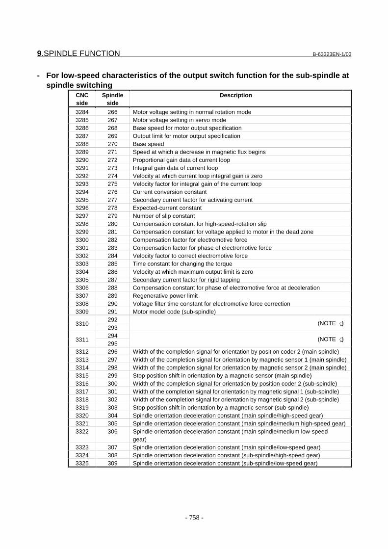
9.SPINDLE FUNCTION B-63323EN-1/03
- 758 -
- For low-speed characteristics of the output switch function for the sub-spindle atspindle switching
CNCside
Spindleside
Description
3284 266 Motor voltage setting in normal rotation mode3285 267 Motor voltage setting in servo mode3286 268 Base speed for motor output specification3287 269 Output limit for motor output specification3288 270 Base speed3289 271 Speed at which a decrease in magnetic flux begins3290 272 Proportional gain data of current loop3291 273 Integral gain data of current loop3292 274 Velocity at which current loop integral gain is zero3293 275 Velocity factor for integral gain of the current loop3294 276 Current conversion constant3295 277 Secondary current factor for activating current3296 278 Expected-current constant3297 279 Number of slip constant3298 280 Compensation constant for high-speed-rotation slip3299 281 Compensation constant for voltage applied to motor in the dead zone3300 282 Compensation factor for electromotive force3301 283 Compensation factor for phase of electromotive force3302 284 Velocity factor to correct electromotive force3303 285 Time constant for changing the torque3304 286 Velocity at which maximum output limit is zero3305 287 Secondary current factor for rigid tapping3306 288 Compensation constant for phase of electromotive force at deceleration3307 289 Regenerative power limit3308 290 Voltage filter time constant for electromotive force correction3309 291 Motor model code (sub-spindle)
2923310
293(NOTE Q)
2943311
295(NOTE Q)
3312 296 Width of the completion signal for orientation by position coder 2 (main spindle)3313 297 Width of the completion signal for orientation by magnetic sensor 1 (main spindle)3314 298 Width of the completion signal for orientation by magnetic sensor 2 (main spindle)3315 299 Stop position shift in orientation by a magnetic sensor (main spindle)3316 300 Width of the completion signal for orientation by position coder 2 (sub-spindle)3317 301 Width of the completion signal for orientation by magnetic signal 1 (sub-spindle)3318 302 Width of the completion signal for orientation by magnetic signal 2 (sub-spindle)3319 303 Stop position shift in orientation by a magnetic sensor (sub-spindle)3320 304 Spindle orientation deceleration constant (main spindle/high-speed gear)3321 305 Spindle orientation deceleration constant (main spindle/medium high-speed gear)3322 306 Spindle orientation deceleration constant (main spindle/medium low-speed
gear)3323 307 Spindle orientation deceleration constant (main spindle/low-speed gear)3324 308 Spindle orientation deceleration constant (sub-spindle/high-speed gear)3325 309 Spindle orientation deceleration constant (sub-spindle/low-speed gear)
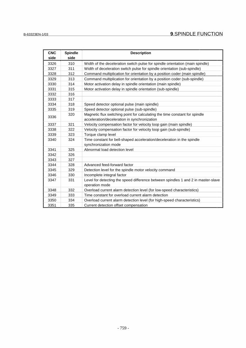
B-63323EN-1/03 9.SPINDLE FUNCTION
- 759 -
CNCside
Spindleside
Description
3326 310 Width of the deceleration switch pulse for spindle orientation (main spindle)3327 311 Width of deceleration switch pulse for spindle orientation (sub-spindle)3328 312 Command multiplication for orientation by a position coder (main spindle)3329 313 Command multiplication for orientation by a position coder (sub-spindle)3330 314 Motor activation delay in spindle orientation (main spindle)3331 315 Motor activation delay in spindle orientation (sub-spindle)3332 3163333 3173334 318 Speed detector optional pulse (main spindle)3335 319 Speed detector optional pulse (sub-spindle)
3336320 Magnetic flux switching point for calculating the time constant for spindle
acceleration/deceleration in synchronization3337 321 Velocity compensation factor for velocity loop gain (main spindle)3338 322 Velocity compensation factor for velocity loop gain (sub-spindle)3339 323 Torque clamp level3340 324 Time constant for bell-shaped acceleration/deceleration in the spindle
synchronization mode3341 325 Abnormal load detection level3342 3263343 3273344 328 Advanced feed-forward factor3345 329 Detection level for the spindle motor velocity command3346 330 Incomplete integral factor3347 331 Level for detecting the speed difference between spindles 1 and 2 in master-slave
operation mode3348 332 Overload current alarm detection level (for low-speed characteristics)3349 333 Time constant for overload current alarm detection3350 334 Overload current alarm detection level (for high-speed characteristics)3351 335 Current detection offset compensation
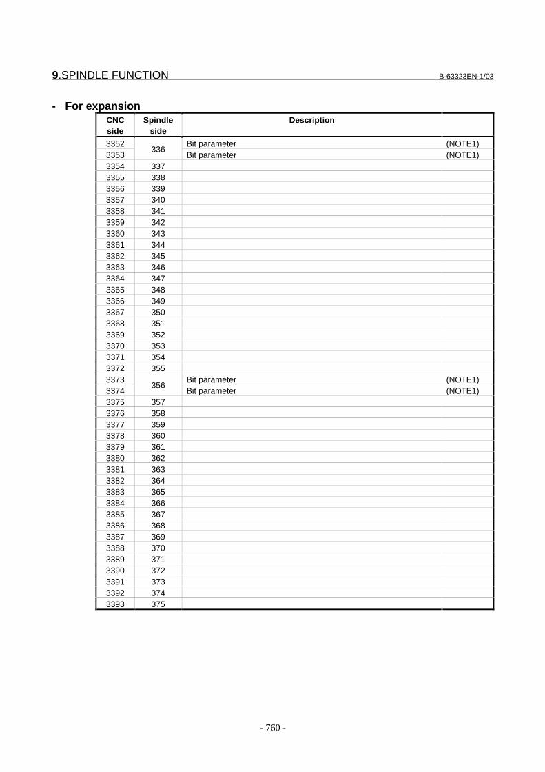
9.SPINDLE FUNCTION B-63323EN-1/03
- 760 -
- For expansionCNCside
Spindleside
Description
3352 Bit parameter (NOTE1)3353
336Bit parameter (NOTE1)
3354 3373355 3383356 3393357 3403358 3413359 3423360 3433361 3443362 3453363 3463364 3473365 3483366 3493367 3503368 3513369 3523370 3533371 3543372 3553373 Bit parameter (NOTE1)3374
356Bit parameter (NOTE1)
3375 3573376 3583377 3593378 3603379 3613380 3623381 3633382 3643383 3653384 3663385 3673386 3683387 3693388 3703389 3713390 3723391 3733392 3743393 375
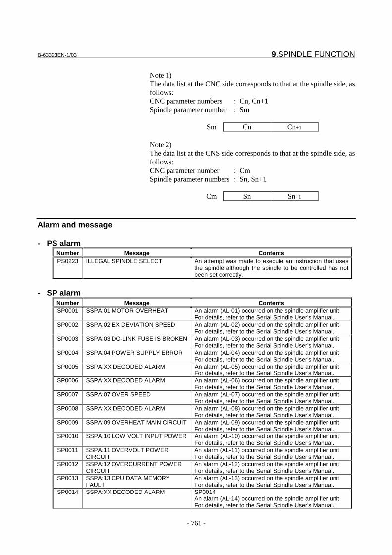
B-63323EN-1/03 9.SPINDLE FUNCTION
- 761 -
Note 1)The data list at the CNC side corresponds to that at the spindle side, asfollows:CNC parameter numbers : Cn, Cn+1Spindle parameter number : Sm
Sm Cn Cn+1
Note 2)The data list at the CNS side corresponds to that at the spindle side, asfollows:CNC parameter number : CmSpindle parameter numbers : Sn, Sn+1
Cm Sn Sn+1
Alarm and message
- PS alarmNumber Message ContentsPS0223 ILLEGAL SPINDLE SELECT An attempt was made to execute an instruction that uses
the spindle although the spindle to be controlled has notbeen set correctly.
- SP alarmNumber Message ContentsSP0001 SSPA:01 MOTOR OVERHEAT An alarm (AL-01) occurred on the spindle amplifier unit
For details, refer to the Serial Spindle User’s Manual.SP0002 SSPA:02 EX DEVIATION SPEED An alarm (AL-02) occurred on the spindle amplifier unit
For details, refer to the Serial Spindle User’s Manual.SP0003 SSPA:03 DC-LINK FUSE IS BROKEN An alarm (AL-03) occurred on the spindle amplifier unit
For details, refer to the Serial Spindle User’s Manual.SP0004 SSPA:04 POWER SUPPLY ERROR An alarm (AL-04) occurred on the spindle amplifier unit
For details, refer to the Serial Spindle User’s Manual.SP0005 SSPA:XX DECODED ALARM An alarm (AL-05) occurred on the spindle amplifier unit
For details, refer to the Serial Spindle User’s Manual.SP0006 SSPA:XX DECODED ALARM An alarm (AL-06) occurred on the spindle amplifier unit
For details, refer to the Serial Spindle User’s Manual.SP0007 SSPA:07 OVER SPEED An alarm (AL-07) occurred on the spindle amplifier unit
For details, refer to the Serial Spindle User’s Manual.SP0008 SSPA:XX DECODED ALARM An alarm (AL-08) occurred on the spindle amplifier unit
For details, refer to the Serial Spindle User’s Manual.SP0009 SSPA:09 OVERHEAT MAIN CIRCUIT An alarm (AL-09) occurred on the spindle amplifier unit
For details, refer to the Serial Spindle User’s Manual.SP0010 SSPA:10 LOW VOLT INPUT POWER An alarm (AL-10) occurred on the spindle amplifier unit
For details, refer to the Serial Spindle User’s Manual.SP0011 SSPA:11 OVERVOLT POWER
CIRCUITAn alarm (AL-11) occurred on the spindle amplifier unitFor details, refer to the Serial Spindle User’s Manual.
SP0012 SSPA:12 OVERCURRENT POWERCIRCUIT
An alarm (AL-12) occurred on the spindle amplifier unitFor details, refer to the Serial Spindle User’s Manual.
SP0013 SSPA:13 CPU DATA MEMORYFAULT
An alarm (AL-13) occurred on the spindle amplifier unitFor details, refer to the Serial Spindle User’s Manual.
SP0014 SSPA:XX DECODED ALARM SP0014An alarm (AL-14) occurred on the spindle amplifier unitFor details, refer to the Serial Spindle User’s Manual.

9.SPINDLE FUNCTION B-63323EN-1/03
- 762 -
Number Message ContentsSP0015 SSPA:15 SPINDLE SWITCHING
FAULTAn alarm (AL-15) occurred on the spindle amplifier unitFor details, refer to the Serial Spindle User’s Manual.
SP0016 SSPA:16 RAM ERROR An alarm (AL-16) occurred on the spindle amplifier unitFor details, refer to the Serial Spindle User’s Manual.
SP0017 SSPA:XX DECODED ALARM An alarm (AL-17) occurred on the spindle amplifier unitFor details, refer to the Serial Spindle User’s Manual.
SP0018 SSPA:18 SUMCHECK ERRORPROGRAM ROM
SP0018An alarm (AL-18) occurred on the spindle amplifier unitFor details, refer to the Serial Spindle User’s Manual.
SP0019 SSPA:19 EXCESS OFFSETCURRENT U
An alarm (AL-19) occurred on the spindle amplifier unitFor details, refer to the Serial Spindle User’s Manual.
SP0020 SSPA:20 EXCESS OFFSETCURRENT V
An alarm (AL-20) occurred on the spindle amplifier unitFor details, refer to the Serial Spindle User’s Manual.
SP0021 SSPA:XX DECODED ALARM An alarm (AL-21) occurred on the spindle amplifier unitFor details, refer to the Serial Spindle User’s Manual.
SP0022 SSPA:XX DECODED ALARM An alarm (AL-22) occurred on the spindle amplifier unitFor details, refer to the Serial Spindle User’s Manual.
SP0023 SSPA:XX DECODED ALARM An alarm (AL-23) occurred on the spindle amplifier unitFor details, refer to the Serial Spindle User’s Manual.
SP0024 SSPA:24 SERIAL TRANSFERERROR
An alarm (AL-24) occurred on the spindle amplifier unitFor details, refer to the Serial Spindle User’s Manual.
SP0025 SSPA:25 SERIAL TRANSFER STOP An alarm (AL-25) occurred on the spindle amplifier unitFor details, refer to the Serial Spindle User’s Manual.
SP0026 SSPA:26 DISCONNECT CSVELOCITY DETECTOR
An alarm (AL-26) occurred on the spindle amplifier unitFor details, refer to the Serial Spindle User’s Manual.
SP0027 SSPA:27 DISCONNECT POSITIONCODER
An alarm (AL-27) occurred on the spindle amplifier unitFor details, refer to the Serial Spindle User’s Manual.
SP0028 SSPA:28 DISCONNECT CSPOSITION DETECTOR
An alarm (AL-28) occurred on the spindle amplifier unitFor details, refer to the Serial Spindle User’s Manual.
SP0029 SSPA:29 OVERLOAD An alarm (AL-29) occurred on the spindle amplifier unitFor details, refer to the Serial Spindle User’s Manual.
SP0030 SSPA:30 OVERCURRENT INPUTCIRCUIT
An alarm (AL-32) occurred on the spindle amplifier unitFor details, refer to the Serial Spindle User’s Manual.
SP0031 SSPA:31 MOTOR LOCK ORDISCONNECT DETECTOR
An alarm (AL-31) occurred on the spindle amplifier unitFor details, refer to the Serial Spindle User’s Manual.
SP0032 SSPA:32 SIC-LSI RAM FAULT An alarm (AL-32) occurred on the spindle amplifier unitFor details, refer to the Serial Spindle User’s Manual.
SP0033 SSPA:33 SHORTAGE POWERCHARGE
An alarm (AL-33) occurred on the spindle amplifier unitFor details, refer to the Serial Spindle User’s Manual.
SP0034 SSPA:34 ILLEGAL PARAMETER An alarm (AL-34) occurred on the spindle amplifier unitFor details, refer to the Serial Spindle User’s Manual.
SP0035 SSPA:35 ILLEGAL GEAR RATIOPARAMETER
An alarm (AL-35) occurred on the spindle amplifier unitFor details, refer to the Serial Spindle User’s Manual.
SP0036 SSPA:36 OVERFLOW ERRORCOUNTER
An alarm (AL-36) occurred on the spindle amplifier unitFor details, refer to the Serial Spindle User’s Manual.
SP0037 SSPA:37 ILLEGAL SETTINGVELOCITY DETECTOR
An alarm (AL-37) occurred on the spindle amplifier unitFor details, refer to the Serial Spindle User’s Manual.
SP0038 SSPA:XX DECODED ALARM An alarm (AL-38) occurred on the spindle amplifier unitFor details, refer to the Serial Spindle User’s Manual.
SP0039 SSPA:39 ILLEGAL 1REV SIGN OF CSDETECTOR
An alarm (AL-39) occurred on the spindle amplifier unitFor details, refer to the Serial Spindle User’s Manual.
SP0040 SSPA:40 NO 1REV SIGN OF CSDETECTOR
An alarm (AL-40) occurred on the spindle amplifier unitFor details, refer to the Serial Spindle User’s Manual.
SP0041 SSPA:41 ILLEGAL 1REV SIGN OFPOSITION CODER
An alarm (AL-41) occurred on the spindle amplifier unitFor details, refer to the Serial Spindle User’s Manual.
SP0042 SSPA:42 NO 1REV SIGN OFPOSITION CODER
An alarm (AL-42) occurred on the spindle amplifier unitFor details, refer to the Serial Spindle User’s Manual.
SP0043 SSPA:43 DISCONNECT POSITIONCODER DEF. SPEED
An alarm (AL-43) occurred on the spindle amplifier unitFor details, refer to the Serial Spindle User’s Manual.
SP0044 SSPA:44 ILLEGAL A/D CONVERT An alarm (AL-44) occurred on the spindle amplifier unitFor details, refer to the Serial Spindle User’s Manual.

B-63323EN-1/03 9.SPINDLE FUNCTION
- 763 -
Number Message ContentsSP0045 SSPA:XX DECODED ALARM An alarm (AL-45) occurred on the spindle amplifier unit
For details, refer to the Serial Spindle User’s Manual.SP0046 SSPA:46 ILLEGAL 1REV SIGN OF
SCREW CUTAn alarm (AL-46) occurred on the spindle amplifier unitFor details, refer to the Serial Spindle User’s Manual.
SP0047 SSPA:47 ILLEGAL SIGNAL OFPOSITION CODER
An alarm (AL-47) occurred on the spindle amplifier unitFor details, refer to the Serial Spindle User’s Manual.
SP0048 SSPA:XX DECODED ALARM An alarm (AL-48) occurred on the spindle amplifier unitFor details, refer to the Serial Spindle User’s Manual.
SP0049 SSPA:49 DEF. SPEED IS OVERVALUE
An alarm (AL-49) occurred on the spindle amplifier unitFor details, refer to the Serial Spindle User’s Manual.
SP0050 SSPA:50 SYNCRONOUS VALUE ISOVER SPEED
An alarm (AL-50) occurred on the spindle amplifier unitFor details, refer to the Serial Spindle User’s Manual.
SP0051 SSPA:51 LOW VOLT POWERCIRCUIT
An alarm (AL-51) occurred on the spindle amplifier unitFor details, refer to the Serial Spindle User’s Manual.
SP0052 SSPA:52 ITP FAULT 1 An alarm (AL-52) occurred on the spindle amplifier unitFor details, refer to the Serial Spindle User’s Manual.
SP0053 SSPA:53 ITP FAULT 2 An alarm (AL-53) occurred on the spindle amplifier unitFor details, refer to the Serial Spindle User’s Manual.
SP0054 SSPA:54 OVERCURRENT An alarm (AL-54) occurred on the spindle amplifier unitFor details, refer to the Serial Spindle User’s Manual.
SP0055 SSPA:55 ILLEGAL POWER LINE An alarm (AL-55) occurred on the spindle amplifier unitFor details, refer to the Serial Spindle User’s Manual.
SP0056 SSPA:56 FAN FOR CONTROLCIRCUIT IS STOP
An alarm (AL-56) occurred on the spindle amplifier unitFor details, refer to the Serial Spindle User’s Manual.
SP0057 SSPA:XX DECODED ALARM An alarm (AL-57) occurred on the spindle amplifier unitFor details, refer to the Serial Spindle User’s Manual.
SP0058 SSPA:58 MAIN CIRCUIT OVERLOAD An alarm (AL-58) occurred on the spindle amplifier unitFor details, refer to the Serial Spindle User’s Manual.
SP0059 SSPA:59 FAN STOP An alarm (AL-59) occurred on the spindle amplifier unitFor details, refer to the Serial Spindle User’s Manual.
Alarms SP001 to SP099 are detected by control units for serial spindles.For details of alarms with these numbers, refer to the following serialspindle manuals:- "FANUC Servo Amplifier α series Descriptions (B-65162E)"- "FANUC Servo Motor α series Maintenance Manual
(B-65165E)"
Number Message ContentsSP0201 MOTOR NUMBER DUPLICATE Two or more of the same motor Nos. other than "0" were
set in parameter No. 5841.SP0202 SPINDLE SELECT ERROR A spindle No. exceeding the number of spindles were set in
parameter No. 5850.SP0220 NO SPINDLE AMP. Either the cable connected to a serial spindle amplifier is
broken, or the serial spindle amplifier is not connected.SP0221 ILLEGAL MOTOR NUMBER The spindle No. and the motor No. are incorrectly matched.SP0222 CAN NOT USE ANALOG SPINDLE The machine tool does not support analog spindles.SP0223 CAN NOT USE SERIAL SPINDLE The machine tool does not support digital spindles.SP0224 ILLEGAL SPINDLE-POSITION
CODER GEAR RATIOThe spindle-position coder gear ratio was incorrect.
SP0225 CRC ERROR (SERIAL SPINDLE) A CRC error (communications error) occurred incommunications between the CNC and the serial spindleamplifier.
SP0226 FRAMING ERROR (SERIALSPINDLE)
A framing error occurred in communications between theCNC and the serial spindle amplifier.
SP0227 RECEIVING ERROR (SERIALSPINDLE)
A receive error occurred in communications between theCNC and the serial spindle amplifier.
SP0228 COMMUNICATION ERROR (SERIALSPINDLE)
A communications error occurred between the CNC andthe serial spindle amplifier.

9.SPINDLE FUNCTION B-63323EN-1/03
- 764 -
Number Message ContentsSP0229 COMMUNICATION ERROR SERIAL
SPINDLE AMP.A communications error occurred between serial spindleamplifiers (motor Nos. 1 and 2, or motor Nos. 3-4).
SP0230 MOTOR NUMBER OUT OF RANGE The setting of parameter No. 5841 is out of range.SP0231 SPINDLE EXCESS ERROR
(MOVING)The position deviation during spindle rotation was greaterthan the value set in parameters.
SP0232 SPINDLE EXCESS ERROR (STOP) The position deviation during spindle stop was greater thanthe value set in parameters.
SP0233 POSITION CODER OVERFLOW The error counter/speed instruction value of the positioncoder overflowed.
SP0234 GRID SHIFT OVERFLOW Grid shift overflowed.SP0235 ORIENTATION COMMAND
OVERFLOWThe orientation speed is too fast.
SP0236 DUPLICATE SPINDLE CONTROLMODE (CHANGING)
An attempt was made to change the spindle mode duringspindle mode switching.
SP0237 DUPLICATE SPINDLE CONTROLMODE (SPOS)
An attempt was made to change the spindle mode duringthe spindle positioning mode.
SP0238 DUPLICATE SPINDLE CONTROLMODE (RIGID TAP)
An attempt was made to change the spindle mode duringthe rigid tapping mode.
SP0239 DUPLICATE SPINDLE CONTROLMODE (CS)
An attempt was made to change the spindle mode duringthe Cs contour control mode.
SP0240 DISCONNECT POSITION CODER The analog spindle position coder is broken.SP0241 D/A CONVERTER ERROR The D/A converter for controlling analog spindles is
erroneous.SP0968 SSPA:XX DECODED ALARM An alarm occurred in the spindle amplifier unit for the serial
spindle. For details, refer to the Serial Spindle User’sManual.
SP0969 SPINDLE CONTROL ERROR An error occurred in the spindle control software.SP0970 SPINDLE CONTROL ERROR Initialization of spindle control ended in error.SP0971 SPINDLE CONTROL ERROR An error occurred in the spindle control software.SP0972 SPINDLE CONTROL ERROR An error occurred in the spindle control software.SP0973 SPINDLE CONTROL ERROR An error occurred in the spindle control software.SP0974 ANALOG SPINDLE CONTROL
ERRORAn error occurred in the spindle control software.
SP0975 ANALOG SPINDLE CONTROLERROR
An position coder error was detected on the analog spindle.
SP0976 SERIAL SPINDLE COMMUNICATIONERROR
The amplifier No. could not be set to the serial spindleamplifier.
SP0977 SERIAL SPINDLE COMMUNICATIONERROR
An error occurred in the spindle control software.
SP0978 SERIAL SPINDLE COMMUNICATIONERROR
A time-out was detected during communications with theserial spindle amplifier.
SP0979 SERIAL SPINDLE COMMUNICATIONERROR
The communications sequence was no longer correctduring communications with the serial spindle amplifier.
SP0980 SERIAL SPINDLE AMP. ERROR Defective SIC-LSI on serial spindle amplifierSP0981 SERIAL SPINDLE AMP. ERROR An error occurred during reading of the data from SIC-LSI
on the analog spindle amplifier side.SP0982 SERIAL SPINDLE AMP. ERROR An error occurred during reading of the data from SIC-LSI
on the serial spindle amplifier side.SP0983 SERIAL SPINDLE AMP. ERROR Could not clear on the spindle amplifier side.SP0984 SERIAL SPINDLE AMP. ERROR An error occurred during re-initialization of the spindle
amplifier.SP0985 SERIAL SPINDLE CONTROL ERROR Failed to automatically set parametersSP0986 SERIAL SPINDLE CONTROL ERROR An error occurred in the spindle control software.SP0987 SERIAL SPINDLE CONTROL ERROR Defective SIC-LSI on the CNCSP0988 SPINDLE CONTROL ERROR An error occurred in the spindle control software.SP0989 SPINDLE CONTROL ERROR An error occurred in the spindle control software.SP0996 ILLEGAL SPINDLE PARAMETER
SETTINGIllegal spindle and spindle motor setting

B-63323EN-1/03 9.SPINDLE FUNCTION
- 765 -
Reference itemSeries15i/150i-MODEL A
Connection Manual(This manual)
9.3 Spindle control
FANUC SERVO AMPLIFIER αseriesDescriptions
B-65162E
FANUC AC SPINDLE MOTOR α seriesParameter Manual
B-65160E
FANUC AC SPINDLE MOTOR α seriesDescriptions
B-65152E
FANUC SERVO MOTOR α seriesMaintenance Manual
B-65165E

9.SPINDLE FUNCTION B-63323EN-1/03
- 766 -
9.3 SPINDLE CONTROL
GeneralThis section describes spindle speed control. It also explains thepositioncoder.
-Command flow of spindle speed controlOutlines of spindle speed control for analog and serial spindles areshown below.

B-63323EN-1/03 9.SPINDLE FUNCTION
- 767 -
Analog spindle
Spindle motor
Orientation, gearswitching, addition circuit
D/A converter
Spindle voltageoutput
Spindle actualspeed watching
Constant spindlespeed
Contact point I/O
Command voltagecalculation
Spindle override
Gear selection
Orientation
Spindle speedcheck
Operator’spanel
Position coder
Return pulse,one-rotationsignal
Spindlemotorcommand
Spindlemotorcommand
M code
Actual spindlespeed
S code
Command spindle
Maximum spindlespeed
Mcommand
S
G92 Scommand
M03,M04,M05,M19
Gear selection,orientationcommand, etc.
$�$ �<$
Spindle override, etc.
Feed perrevolution, threadcutting
Speed arrival signal,alarm signal, etc.
Spindle amp.
Gear changemechanism
Spindle
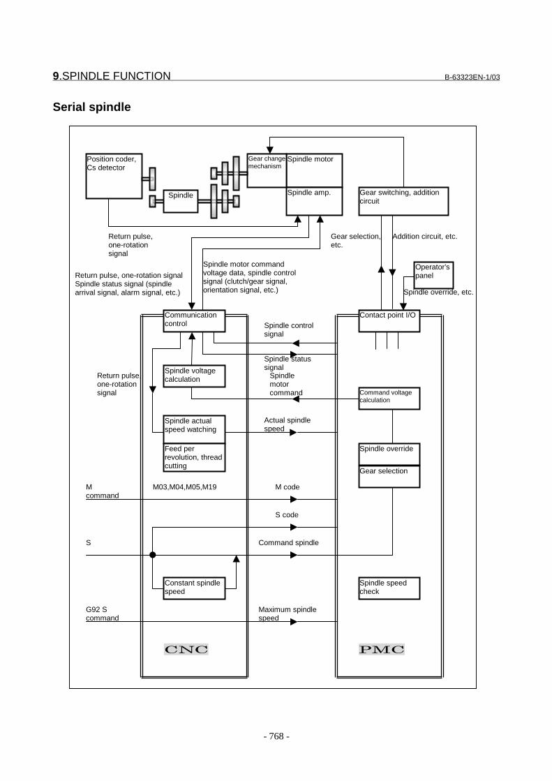
9.SPINDLE FUNCTION B-63323EN-1/03
- 768 -
Serial spindle
Communicationcontrol
Spindle voltagecalculation
Spindle actualspeed watching
Constant spindlespeed
Contact point I/O
Command voltagecalculation
Spindle override
Gear selection
Spindle speedcheck
Operator’spanel
Position coder,Cs detector
Return pulse,one-rotationsignal
Spindle motor commandvoltage data, spindle controlsignal (clutch/gear signal,orientation signal, etc.)
Spindlemotorcommand
M code
Actual spindlespeed
S code
Command spindle
Maximum spindlespeed
Mcommand
S
G92 Scommand
M03,M04,M05,M19
Gear selection,etc.
$�$ �<$
Spindle override, etc.
Feed perrevolution, threadcutting
Addition circuit, etc.
Return pulse,one-rotationsignal
Spindle statussignal
Spindle controlsignal
Return pulse, one-rotation signalSpindle status signal (spindlearrival signal, alarm signal, etc.)
Spindle motor
Gear switching, additioncircuit
Spindle amp.
Gear changemechanism
Spindle
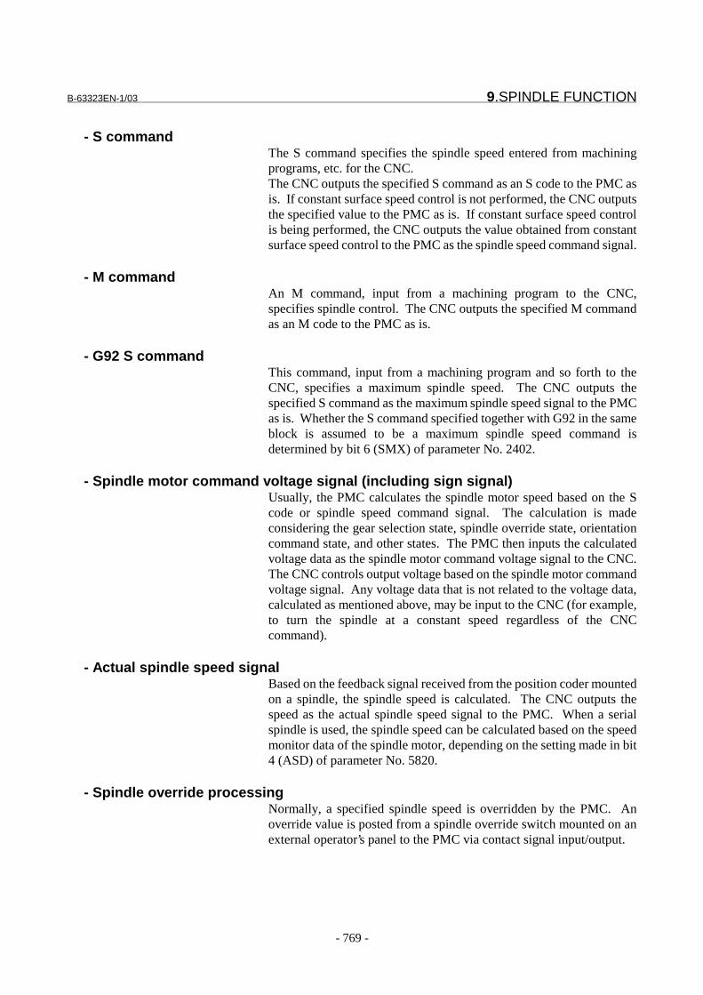
B-63323EN-1/03 9.SPINDLE FUNCTION
- 769 -
- S commandThe S command specifies the spindle speed entered from machiningprograms, etc. for the CNC.The CNC outputs the specified S command as an S code to the PMC asis. If constant surface speed control is not performed, the CNC outputsthe specified value to the PMC as is. If constant surface speed controlis being performed, the CNC outputs the value obtained from constantsurface speed control to the PMC as the spindle speed command signal.
- M commandAn M command, input from a machining program to the CNC,specifies spindle control. The CNC outputs the specified M commandas an M code to the PMC as is.
- G92 S commandThis command, input from a machining program and so forth to theCNC, specifies a maximum spindle speed. The CNC outputs thespecified S command as the maximum spindle speed signal to the PMCas is. Whether the S command specified together with G92 in the sameblock is assumed to be a maximum spindle speed command isdetermined by bit 6 (SMX) of parameter No. 2402.
- Spindle motor command voltage signal (including sign signal)Usually, the PMC calculates the spindle motor speed based on the Scode or spindle speed command signal. The calculation is madeconsidering the gear selection state, spindle override state, orientationcommand state, and other states. The PMC then inputs the calculatedvoltage data as the spindle motor command voltage signal to the CNC.The CNC controls output voltage based on the spindle motor commandvoltage signal. Any voltage data that is not related to the voltage data,calculated as mentioned above, may be input to the CNC (for example,to turn the spindle at a constant speed regardless of the CNCcommand).
- Actual spindle speed signalBased on the feedback signal received from the position coder mountedon a spindle, the spindle speed is calculated. The CNC outputs thespeed as the actual spindle speed signal to the PMC. When a serialspindle is used, the spindle speed can be calculated based on the speedmonitor data of the spindle motor, depending on the setting made in bit4 (ASD) of parameter No. 5820.
- Spindle override processingNormally, a specified spindle speed is overridden by the PMC. Anoverride value is posted from a spindle override switch mounted on anexternal operator’s panel to the PMC via contact signal input/output.
9.SPINDLE FUNCTION B-63323EN-1/03
- 770 -
- Gear change processingIn response to a specified spindle speed, gear selection and changeprocessing is normally performed by the PMC. According to the gearselected by the PMC, gear change is performed by the gear changefunction via contact signal input/output.
- Command output to a spindleAccording to the speed command output and its polarity determinedthrough the above processing flow, the following is output to issue acommand to the spindle control unit:- When a serial spindle is used -> Digital data from 0 to }16383- When an analog spindle is used -> Analog voltage from 0 to }10 V
- Spindle control signalsWhen using a serial spindle, do not transfer control signals for thespindle motor speed amplifier (such as the clutch/gear and orientationsignals) from the PMC to the speed amplifier directly; transfer thesesignals via the CNC.
- Spindle status signalsWhen using a serial spindle, do not transfer status signals from thespindle motor speed amplifier (such as the speed arrival and alarmsignals) to the PMC directly; transfer these signals via the CNC.
- Gain and offsetThe analog spindle may require gain and offset voltage adjustmentdepending on the spindle motor speed amplifier being used.The following parameters are available for such adjustment.-Offset voltage compensation : Parameter iNo.5613 j-Gain adjustment data :Parameter iNo.5614 j
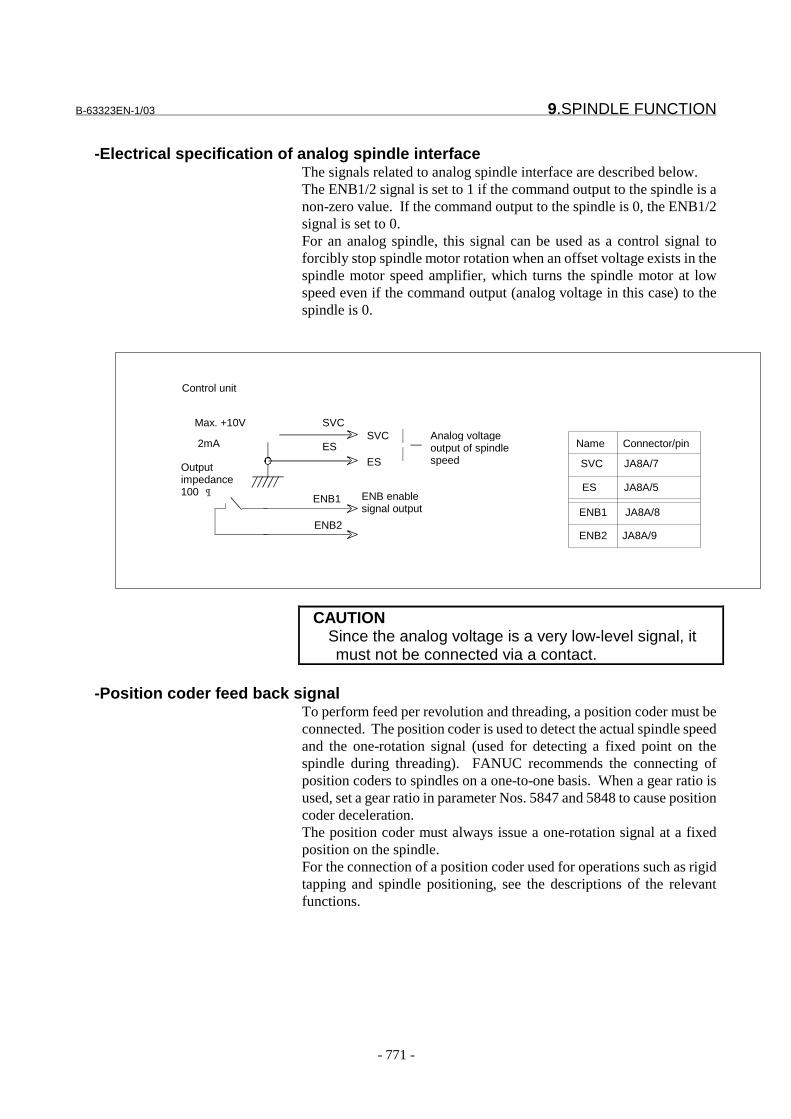
B-63323EN-1/03 9.SPINDLE FUNCTION
- 771 -
-Electrical specification of analog spindle interfaceThe signals related to analog spindle interface are described below.The ENB1/2 signal is set to 1 if the command output to the spindle is anon-zero value. If the command output to the spindle is 0, the ENB1/2signal is set to 0.For an analog spindle, this signal can be used as a control signal toforcibly stop spindle motor rotation when an offset voltage exists in thespindle motor speed amplifier, which turns the spindle motor at lowspeed even if the command output (analog voltage in this case) to thespindle is 0.
CAUTIONSince the analog voltage is a very low-level signal, itmust not be connected via a contact.
-Position coder feed back signalTo perform feed per revolution and threading, a position coder must beconnected. The position coder is used to detect the actual spindle speedand the one-rotation signal (used for detecting a fixed point on thespindle during threading). FANUC recommends the connecting ofposition coders to spindles on a one-to-one basis. When a gear ratio isused, set a gear ratio in parameter Nos. 5847 and 5848 to cause positioncoder deceleration.The position coder must always issue a one-rotation signal at a fixedposition on the spindle.For the connection of a position coder used for operations such as rigidtapping and spindle positioning, see the descriptions of the relevantfunctions.
ENB2
ENB enablesignal output
Analog voltageoutput of spindlespeed
SVC
ESES
SVC
ENB1
Control unit
Max. +10V
2mA
Outputimpedance100 
Name Connector/pin
SVC JA8A/7
ES JA8A/5
ENB1 JA8A/8
ENB2 JA8A/9
9.SPINDLE FUNCTION B-63323EN-1/03
- 772 -
Signal
Signals common to analog and serial spindles
Spindle speed command signal RO0A-RO15A<F010,F011>:For 1st spindle RO0B-RO15B<F320,F321>:For 2nd spindle RO0C-RO15C<F326,F327>:For 3rd spindle RO0D-RO15D<F332,F333>:For 4th spindle
[Classification] Output signal[Function] Posts a specified spindle speed. When constant surface speed control is
being performed, the spindle speed resulting from constant surfacespeed control is posted. This signal consists of 16 binary code outputsignals.
{ }∑=
−÷×=15
0
1min102i
NsiROispeedSpindle
The spindle speed and signal are related as follows:here, N is the value set in parameter No. 5612.
[Output condition] This signal is always output. The signal value changes only when anSxxxx command is specified in a program, unless constant surfacespeed control is applied.
Maximum spindle speed signals MR0A-MR15A<F014,F015>:For 1st spindle MR0B to MR15B<F324,F325>:For 2nd spindle MR0C to MR15C<F330,F331>:For 3rd spindle MR0D to MR15D<F336,F337>:For 4th spindle
[Classification] Output signal[Function] Posts a maximum spindle speed specified by G92 Sxxxx. Whether the
spindle speed is clamped to this value only during constant surfacespeed control, or whether it is always clamped depends on the PMCspecifications. This signal consists of 16 binary code output signals.The maximum spindle speed and signal are related as follows:
{ }∑=
−÷×=15
0
1min102i
NsiMRispeedSpindle
Where, N is the value set in parameter No. 5612.[Output condition] This signal is always output. The signal value changes when G92
Sxxxx is specified in a program.

B-63323EN-1/03 9.SPINDLE FUNCTION
- 773 -
Spindle motor command voltage signal RISGNA,RI0A to RI15A<G024,G025>:For 1st spindle RISGNB,RI0B to RI15B<G232,G233>:For 2nd spindle RISGNC,RI0C to RI15C<G208,G209>:For 3rd spindle RISGND,RI0D to RI15D<G216,G217>:For 4th spindle
[Classification] Input signal[Function] Specifies a voltage output to the spindle motor. With this input signal
only, the CNC controls a command voltage output to the spindle motor,regardless of the spindle speed output by the CNC. Using the spindlespeed specified by the CNC, the PMC may make calculationsaccording to the selected gear and input the calculation result to thissignal.Alternatively, the PMC may input a different speed (for example, aspeed for spindle orientation).This signal consists of polarity signal RISGNs that determines thevoltage polarity and 13 binary code signals RI0s to RI12s. Accordingto polarity signal RISGNs, the following is output:When RISGNs is 0, a positive (+) voltage is output.When RISGNs is 1, a negative (-) voltage is output.The spindle command voltage and signal are related as follows:
{ }∑=
÷×=15
0 81912
ivolt
EsiRIivoltageCommand
Where, E is the maximum voltage (constant) determined by thehardware.
Spindle ready signal SRRDYA<F341#0>:For 1st spindleSRRDYB<F342#0>:For 2nd spindleSRRDYC<F343#0>:For 3rd spindleSRRDYD<F344#0>:For 4th spindle
[Classification] Output signal[Function] Spindle ready signal
SRRDYs 1 : The spindle is ready for operation.0 : The spindle is not ready for operation.
[Output condition] his signal is output when a spindle is set.
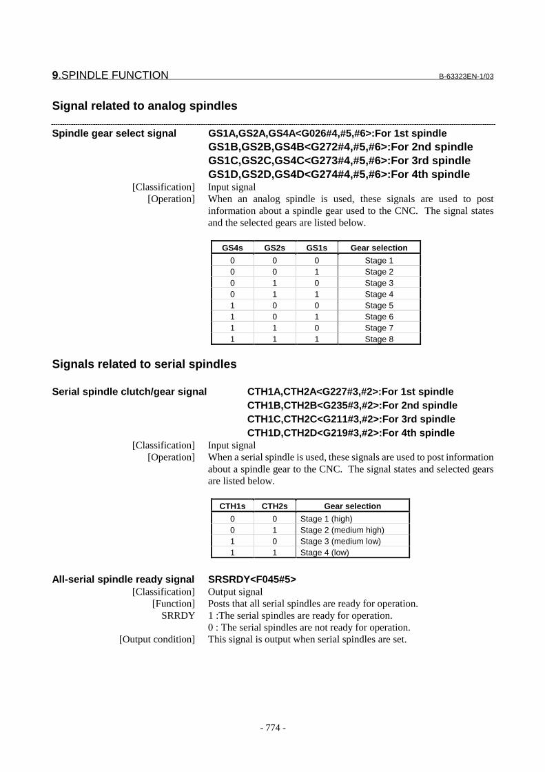
9.SPINDLE FUNCTION B-63323EN-1/03
- 774 -
Signal related to analog spindles
Spindle gear select signal GS1A,GS2A,GS4A<G026#4,#5,#6>:For 1st spindleGS1B,GS2B,GS4B<G272#4,#5,#6>:For 2nd spindleGS1C,GS2C,GS4C<G273#4,#5,#6>:For 3rd spindleGS1D,GS2D,GS4D<G274#4,#5,#6>:For 4th spindle
[Classification] Input signal[Operation] When an analog spindle is used, these signals are used to post
information about a spindle gear used to the CNC. The signal statesand the selected gears are listed below.
GS4s GS2s GS1s Gear selection
0 0 0 Stage 10 0 1 Stage 20 1 0 Stage 30 1 1 Stage 41 0 0 Stage 51 0 1 Stage 61 1 0 Stage 71 1 1 Stage 8
Signals related to serial spindles
Serial spindle clutch/gear signal CTH1A,CTH2A<G227#3,#2>:For 1st spindleCTH1B,CTH2B<G235#3,#2>:For 2nd spindleCTH1C,CTH2C<G211#3,#2>:For 3rd spindleCTH1D,CTH2D<G219#3,#2>:For 4th spindle
[Classification] Input signal[Operation] When a serial spindle is used, these signals are used to post information
about a spindle gear to the CNC. The signal states and selected gearsare listed below.
CTH1s CTH2s Gear selection
0 0 Stage 1 (high)0 1 Stage 2 (medium high)1 0 Stage 3 (medium low)1 1 Stage 4 (low)
All-serial spindle ready signal SRSRDY<F045#5>[Classification] Output signal
[Function] Posts that all serial spindles are ready for operation.SRRDY 1 :The serial spindles are ready for operation.
0 : The serial spindles are not ready for operation.[Output condition] This signal is output when serial spindles are set.
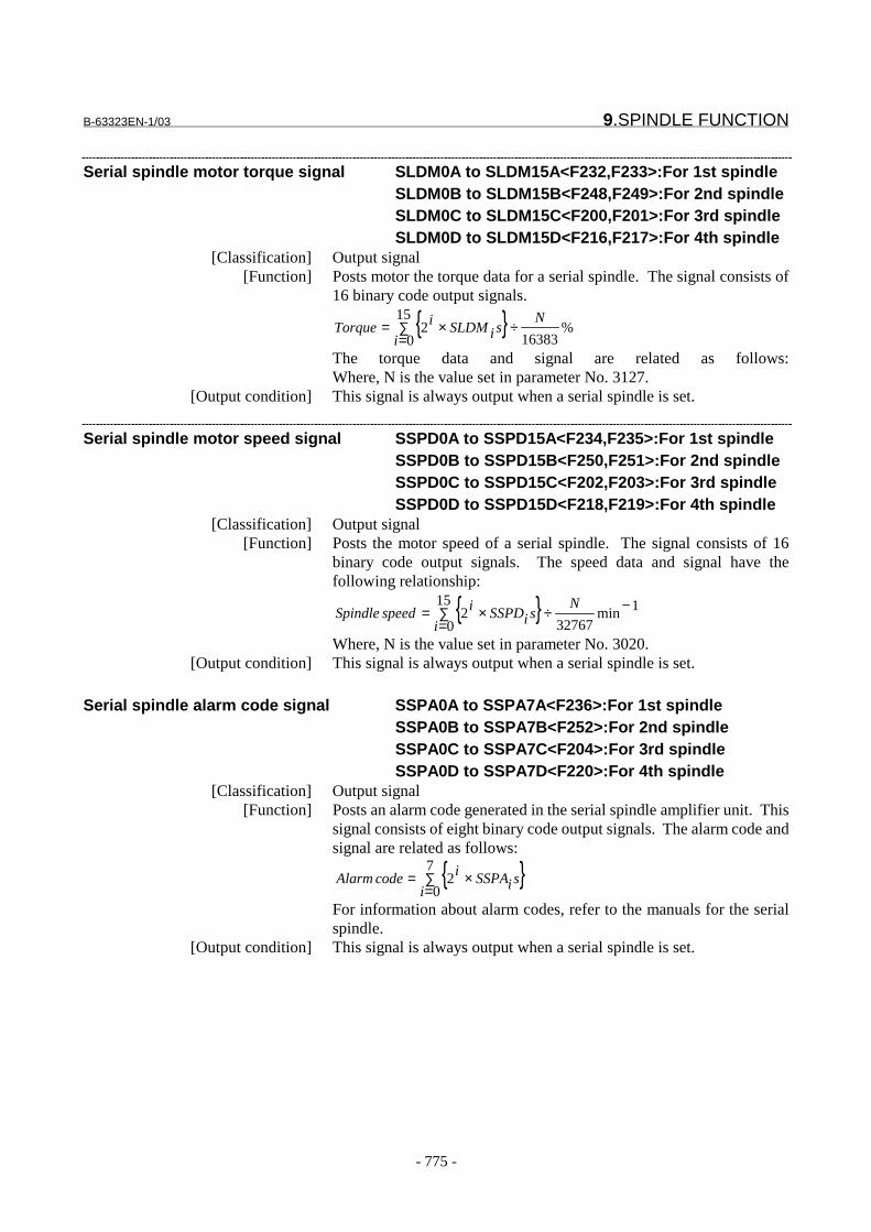
B-63323EN-1/03 9.SPINDLE FUNCTION
- 775 -
Serial spindle motor torque signal SLDM0A to SLDM15A<F232,F233>:For 1st spindle SLDM0B to SLDM15B<F248,F249>:For 2nd spindle SLDM0C to SLDM15C<F200,F201>:For 3rd spindle SLDM0D to SLDM15D<F216,F217>:For 4th spindle
[Classification] Output signal[Function] Posts motor the torque data for a serial spindle. The signal consists of
16 binary code output signals.
{ }∑=
÷×=15
0%
163832
i
NsiSLDMiTorque
The torque data and signal are related as follows:Where, N is the value set in parameter No. 3127.
[Output condition] This signal is always output when a serial spindle is set.
Serial spindle motor speed signal SSPD0A to SSPD15A<F234,F235>:For 1st spindle SSPD0B to SSPD15B<F250,F251>:For 2nd spindle SSPD0C to SSPD15C<F202,F203>:For 3rd spindle SSPD0D to SSPD15D<F218,F219>:For 4th spindle
[Classification] Output signal[Function] Posts the motor speed of a serial spindle. The signal consists of 16
binary code output signals. The speed data and signal have thefollowing relationship:
{ }∑=
−÷×=15
0
1min32767
2i
NsiSSPDispeedSpindle
Where, N is the value set in parameter No. 3020.[Output condition] This signal is always output when a serial spindle is set.
Serial spindle alarm code signal SSPA0A to SSPA7A<F236>:For 1st spindle SSPA0B to SSPA7B<F252>:For 2nd spindle SSPA0C to SSPA7C<F204>:For 3rd spindle SSPA0D to SSPA7D<F220>:For 4th spindle
[Classification] Output signal[Function] Posts an alarm code generated in the serial spindle amplifier unit. This
signal consists of eight binary code output signals. The alarm code andsignal are related as follows:
{ }∑=
×=7
02
isiSSPAicodeAlarm
For information about alarm codes, refer to the manuals for the serialspindle.
[Output condition] This signal is always output when a serial spindle is set.
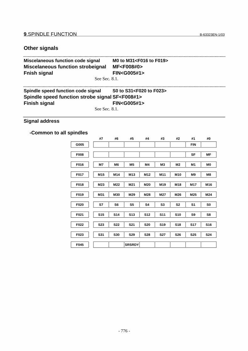
9.SPINDLE FUNCTION B-63323EN-1/03
- 776 -
Other signals
Miscelaneous function code signal M0 to M31<F016 to F019>Miscelaneous function strobeignal MF<F008#0>Fnish signal FIN<G005#1>
See Sec. 8.1.
Spindle speed function code signal S0 to S31<F020 to F023>Spindle speed function strobe signal SF<F008#1>Finish signal FIN<G005#1>
See Sec. 8.1.
Signal address
-Common to all spindles#7 #6 #5 #4 #3 #2 #1 #0
G005 FIN
F008 SF MF
F016 M7 M6 M5 M4 M3 M2 M1 M0
F017 M15 M14 M13 M12 M11 M10 M9 M8
F018 M23 M22 M21 M20 M19 M18 M17 M16
F019 M31 M30 M29 M28 M27 M26 M25 M24
F020 S7 S6 S5 S4 S3 S2 S1 S0
F021 S15 S14 S13 S12 S11 S10 S9 S8
F022 S23 S22 S21 S20 S19 S18 S17 S16
F023 S31 S30 S29 S28 S27 S26 S25 S24
F045 SRSRDY
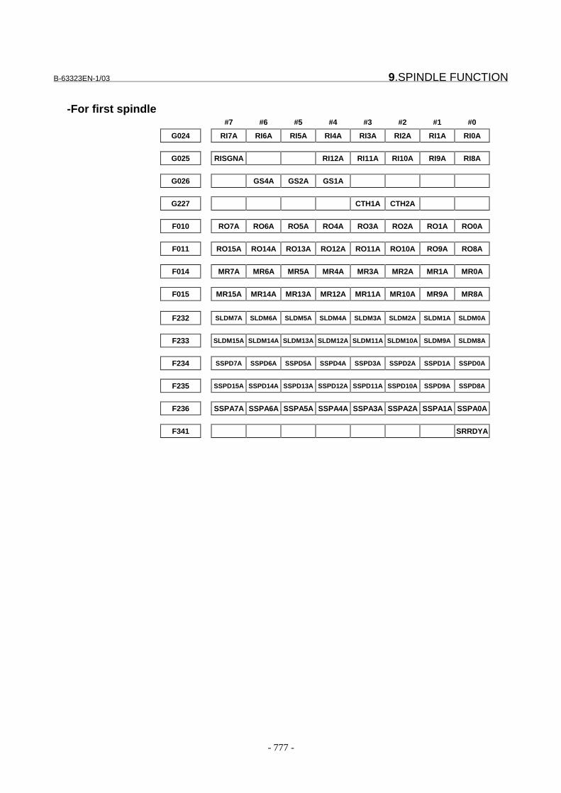
B-63323EN-1/03 9.SPINDLE FUNCTION
- 777 -
-For first spindle#7 #6 #5 #4 #3 #2 #1 #0
G024 RI7A RI6A RI5A RI4A RI3A RI2A RI1A RI0A
G025 RISGNA RI12A RI11A RI10A RI9A RI8A
G026 GS4A GS2A GS1A
G227 CTH1A CTH2A
F010 RO7A RO6A RO5A RO4A RO3A RO2A RO1A RO0A
F011 RO15A RO14A RO13A RO12A RO11A RO10A RO9A RO8A
F014 MR7A MR6A MR5A MR4A MR3A MR2A MR1A MR0A
F015 MR15A MR14A MR13A MR12A MR11A MR10A MR9A MR8A
F232 SLDM7A SLDM6A SLDM5A SLDM4A SLDM3A SLDM2A SLDM1A SLDM0A
F233 SLDM15A SLDM14A SLDM13A SLDM12A SLDM11A SLDM10A SLDM9A SLDM8A
F234 SSPD7A SSPD6A SSPD5A SSPD4A SSPD3A SSPD2A SSPD1A SSPD0A
F235 SSPD15A SSPD14A SSPD13A SSPD12A SSPD11A SSPD10A SSPD9A SSPD8A
F236 SSPA7A SSPA6A SSPA5A SSPA4A SSPA3A SSPA2A SSPA1A SSPA0A
F341 SRRDYA

9.SPINDLE FUNCTION B-63323EN-1/03
- 778 -
-For 2nd spindle#7 #6 #5 #4 #3 #2 #1 #0
G232 RI7B RI6B RI5B RI4B RI3B RI2B RI1B RI0B
G233 RISGNB RI12B RI11B RI10B RI9B RI8B
G235 CTH1B CTH2B
G272 GS4B GS2B GS1B
F248 SLDM7B SLDM6B SLDM5B SLDM4B SLDM3B SLDM2B SLDM1B SLDM0B
F249 SLDM15B SLDM14B SLDM13B SLDM12B SLDM11B SLDM10B SLDM9B SLDM8B
F250 SSPD7B SSPD6B SSPD5B SSPD4B SSPD3B SSPD2B SSPD1B SSPD0B
F251 SSPD15B SSPD14B SSPD13B SSPD12B SSPD11B SSPD10B SSPD9B SSPD8B
F252 SSPA7B SSPA6B SSPA5B SSPA4B SSPA3B SSPA2B SSPA1B SSPA0B
F320 RO7B RO6B RO5B RO4B RO3B RO2B RO1B RO0B
F321 RO15B RO14B RO13B RO12B RO11B RO10B RO9B RO8B
F324 MR7B MR6B MR5B MR4B MR3B MR2B MR1B MR0B
F325 MR15B MR14B MR13B MR12B MR11B MR10B MR9B MR8B
F342 SRRDYB
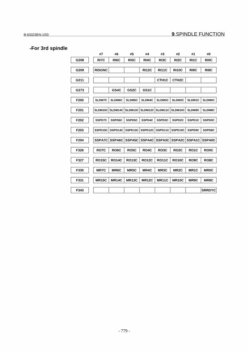
B-63323EN-1/03 9.SPINDLE FUNCTION
- 779 -
-For 3rd spindle#7 #6 #5 #4 #3 #2 #1 #0
G208 RI7C RI6C RI5C RI4C RI3C RI2C RI1C RI0C
G209 RISGNC RI12C RI11C RI10C RI9C RI8C
G211 CTH1C CTH2C
G273 GS4C GS2C GS1C
F200 SLDM7C SLDM6C SLDM5C SLDM4C SLDM3C SLDM2C SLDM1C SLDM0C
F201 SLDM15C SLDM14C SLDM13C SLDM12C SLDM11C SLDM10C SLDM9C SLDM8C
F202 SSPD7C SSPD6C SSPD5C SSPD4C SSPD3C SSPD2C SSPD1C SSPD0C
F203 SSPD15C SSPD14C SSPD13C SSPD12C SSPD11C SSPD10C SSPD9C SSPD8C
F204 SSPA7C SSPA6C SSPA5C SSPA4C SSPA3C SSPA2C SSPA1C SSPA0C
F326 RO7C RO6C RO5C RO4C RO3C RO2C RO1C RO0C
F327 RO15C RO14C RO13C RO12C RO11C RO10C RO9C RO8C
F330 MR7C MR6C MR5C MR4C MR3C MR2C MR1C MR0C
F331 MR15C MR14C MR13C MR12C MR11C MR10C MR9C MR8C
F343 SRRDYC

9.SPINDLE FUNCTION B-63323EN-1/03
- 780 -
-For 4th spindle#7 #6 #5 #4 #3 #2 #1 #0
G216 RI7D RI6D RI5D RI4D RI3D RI2D RI1D RI0D
G217 RISGND RI12D RI11D RI10D RI9D RI8D
G219 CTH1D CTH2D
G274 GS4D GS2D GS1D
F216 SLDM7D SLDM6D SLDM5D SLDM4D SLDM3D SLDM2D SLDM1D SLDM0D
F217 SLDM15D SLDM14D SLDM13D SLDM12D SLDM11D SLDM10D SLDM9D SLDM8D
F218 SSPD7D SSPD6D SSPD5D SSPD4D SSPD3D SSPD2D SSPD1D SSPD0D
F219 SSPD15D SSPD14D SSPD13D SSPD12D SSPD11D SSPD10D SSPD9D SSPD8D
F220 SSPA7D SSPA6D SSPA5D SSPA4D SSPA3D SSPA2D SSPA1D SSPA0D
F332 RO7D RO6D RO5D RO4D RO3D RO2D RO1D RO0D
F333 RO15D RO14D RO13D RO12D RO11D RO10D RO9D RO8D
F336 MR7D MR6D MR5D MR4D MR3D MR2D MR1D MR0D
F337 MR15D MR14D MR13D MR12D MR11D MR10D MR9D MR8D
F344 SRRDYD
ParameterE Analog/serial spindle common setting
#7 #6 #5 #4 #3 #2 #1 #0
2204 NOS
���������� �� ��� ������
��������� ���
� � � � ��" �?� ������������ ���������'������'������������'���!
"# ����'���
�# � ������'���
;�������'������'������������'��������� ����������0������
� ���� ��� � ������''�������������'!� � @ �� ��'������'�.���������'
�����'���������������'��������� ���������� ��� ������� ����
�����'�� � .�������%� ����������%� ��*��������,� ���� ��� �� !
32)"�!
���������� ��������������� ������� ���� ��� � ���������
�������� ��� �� >�� ��� ����%������������ ���� �� ����� ���
� �������� �����'�����������'������'����!
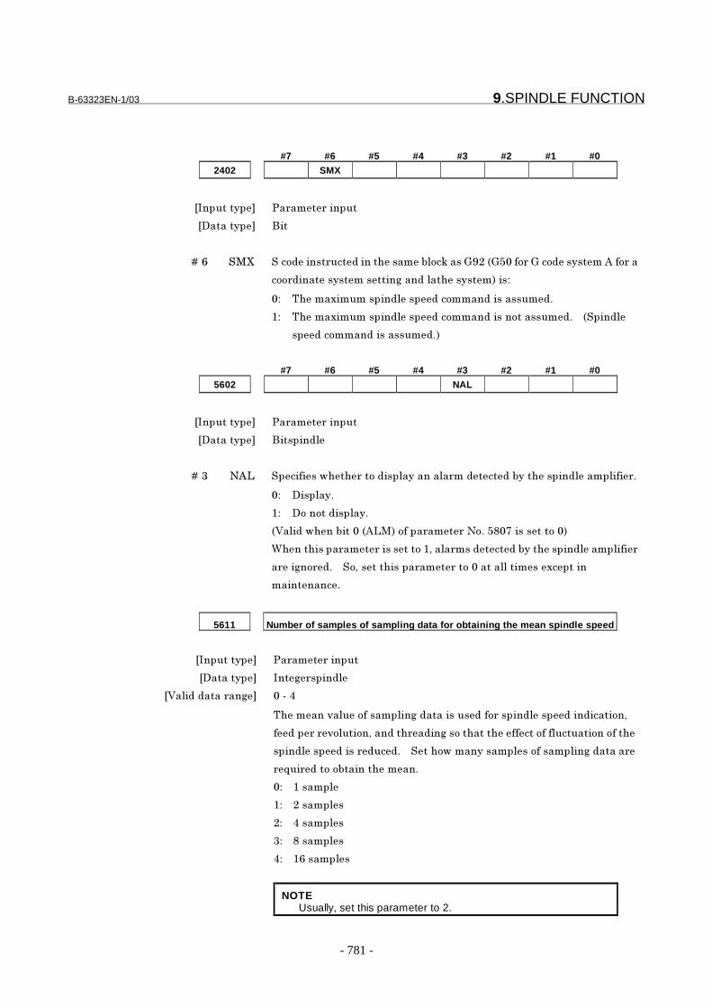
B-63323EN-1/03 9.SPINDLE FUNCTION
- 781 -
#7 #6 #5 #4 #3 #2 #1 #0
2402 SMX
���������� �� ��� ������
��������� ���
� � � � ��5 �<A ��� ������ ����������������' �0����B1)��B3"�� �B�� ��������*�� ��
� �����������������%�����'�������������#
"# ;����-����������'������ ���������������!
�# ;����-����������'������ ���������� ��������!� � ������'
����� ���������������!�
#7 #6 #5 #4 #3 #2 #1 #0
5602 NAL
���������� �� ��� ������
��������� ��������'
� � � � ��/ �*8 ������������ �� �����'�������'� �������������������'����'��� !
"# ����'��!
�# � �� ������'��!
�&�'�����������"��*8<�� ���� ��� �� !�32"4�������� �"�
(���������� ��� �������� ��.��'� ��������������������'����'���
� ��%� �!� � � .����������� ��� �� �"�����''������-������
���������!
5611 Number of samples of sampling data for obtaining the mean spindle speed
���������� �� ��� ������
��������� ���% �����'
�&�'�������� ��% "���,
;������=�'�� ������'��%�������������� ������'������������� �.
���� � = '��� �.������� ����%�� �������������� ���'������� �� ����
�����'�������� ����!� � ���� �����������'�� ������'��%�������
>�� ��� � ������������!
"#� � ������'
�#� � )�����'�
)#� � ,�����'�
/#� � 2�����'�
,#� � �5�����'�
NOTEUsually, set this parameter to 2.
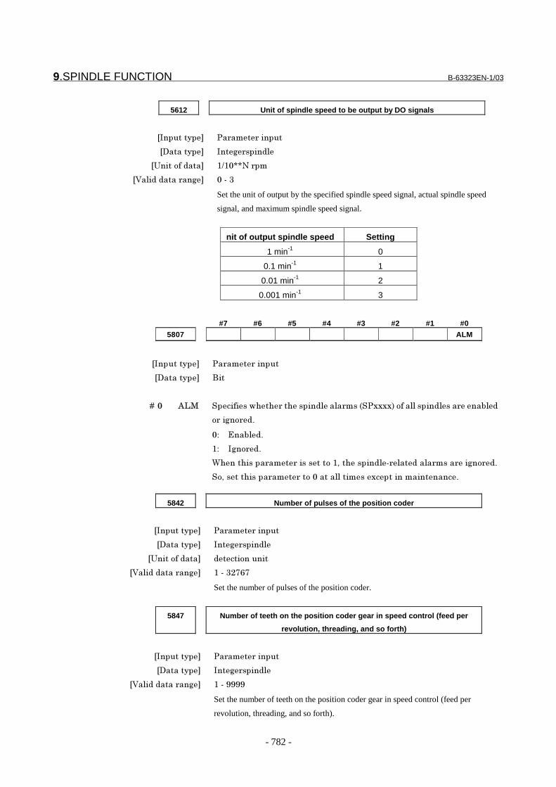
9.SPINDLE FUNCTION B-63323EN-1/03
- 782 -
5612 Unit of spindle speed to be output by DO signals
���������� �� ��� ������
��������� ���% �����'
�6���� ������ �+�"CC�� ��
�&�'�������� ��% "���/
Set the unit of output by the specified spindle speed signal, actual spindle speed
signal, and maximum spindle speed signal.
nit of output spindle speed Setting
1 min-1 0
0.1 min-1 1
0.01 min-1 2
0.001 min-1 3
#7 #6 #5 #4 #3 #2 #1 #0
5807 ALM
���������� �� ��� ������
��������� ���
� � � � ��" *8< ������������ ���������'��'� ������----�� ���''������'��� ����'�
��%� �!
"# D���'�!
�# �%� �!
(���������� ��� �������� ��.���������'� '�����'� ���� ��%� �!
� .����������� ��� �� �"�����''������-����������������!
5842 Number of pulses of the position coder
���������� �� ��� ������
��������� ���% �����'
�6���� ������ ����� ������
�&�'�������� ��% ����/)454
Set the number of pulses of the position coder.
5847 Number of teeth on the position coder gear in speed control (feed per
revolution, threading, and so forth)
���������� �� ��� ������
��������� ���% �����'
�&�'�������� ��% ����1111
Set the number of teeth on the position coder gear in speed control (feed per
revolution, threading, and so forth).

B-63323EN-1/03 9.SPINDLE FUNCTION
- 783 -
5848 Number of teeth on the spindle gear in speed control (feed per revolution,
threading, and so forth)
���������� �� ��� ������
��������� ���% �����'
�&�'�������� ��% ����1111
Set the number of teeth on the spindle gear in speed control (feed per revolution,
threading, and so forth).
5850 Spindle number to be selected upon power-up/reset
���������� �� ��� ������
��������� ���%
�&�'�������� ��% "���,
����������'����� �� ����'������ ��� � ���+ ��!
*��'���������'����������#
�� � �����'�����'���� ������ �������������� ���� ������'����� �����
� % ������0��� �
�� � �����'������ ������� �����.����� � = '��� �.�� ��������� ���
����� �� '.��� ����%.����������'�.� �%���������%.����������'
��������� �
NOTE
To rewrite this parameter during automatic operation, always use
a non-buffered M code set in parameter Nos. 2411 to 2420 so
that rewriting is performed in the non-buffering state.
- Analog spindle
#7 #6 #5 #4 #3 #2 #1 #0
5603 NDP
���������� �� ��� ������
��������� ��������'
� � � � ��4 ��� ������������ �� ���0���� ���� ��� � ����� ����� �����0�������
���' %������'�������!
"# <�0������0!
�# � �� ����0������0!
�&�'�����������/���*8�� ���� ��� �� !�35")��������� �"�
���������� ��� �� ������� �� ���� ��� � ���������''������������' %
�����'�������!
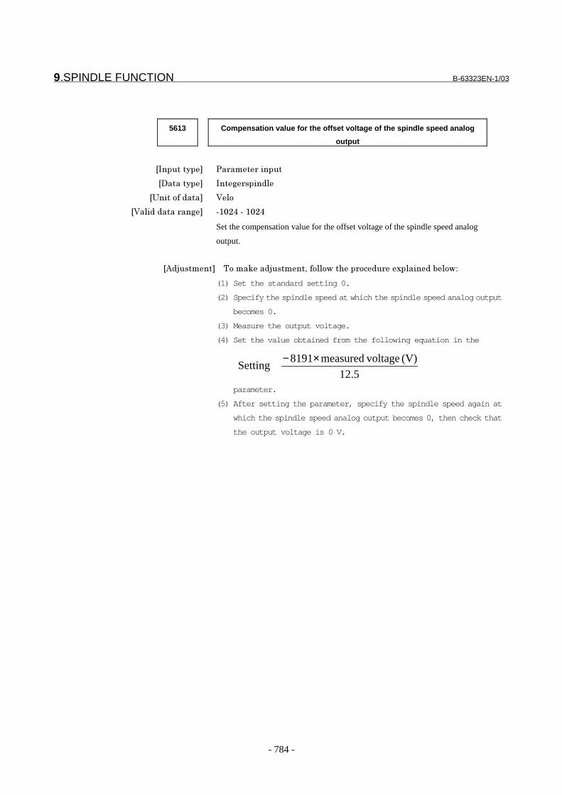
9.SPINDLE FUNCTION B-63323EN-1/03
- 784 -
5613 Compensation value for the offset voltage of the spindle speed analog
output
���������� �� ��� ������
��������� ���% �����'
�6���� ������ &'
�&�'�������� ��% ��"),����"),
Set the compensation value for the offset voltage of the spindle speed analog
output.
�*�:������� � ; ���0���:������.�� '' ������ ��� �-�'������' �#
(1) Set the standard setting 0.
(2) Specify the spindle speed at which the spindle speed analog output
becomes 0.
(3) Measure the output voltage.
(4) Set the value obtained from the following equation in the
parameter.
(5) After setting the parameter, specify the spindle speed again at
which the spindle speed analog output becomes 0, then check that
the output voltage is 0 V.
12.5
(V) voltagemeasured8191Setting
×−

B-63323EN-1/03 9.SPINDLE FUNCTION
- 785 -
5614 Data for adjusting the gain of the spindle speed analog output
���������� �� ��� ������
��������� ���% �����'
�&�'�������� ��% 4""����)3"
Set data for adjusting the gain of the spindle speed analog output.
�*�:������� � <�0���:����������� '' ���%����� ��� �-�'������' �#
(1) Set the standard setting to 800.
(2) Specify the spindle speed at which the spindle speed analog output voltage is
maximized (10 V).
(3) Measure the output voltage.
(4) Set the value obtained from the following equation in the
parameter.
(5) After setting the parameter, specify the spindle speed again at which the
spindle speed analog output voltage is maximized, then check that the output
voltage is 10 V.
800(V) voltageMeasured
10(V)Setting ×
- Serial spindle
#7 #6 #5 #4 #3 #2 #1 #0
5820 ASD
���������� �� ��� ������
��������� ��������'
� � � � ��, *�� ������������ ���������'����� ����� ��'������'������'��'����� �
�����0���'���� ������ ���� ��� � � �� ������� ��� �����!
"# $�'��'����� �������0���'���� ������ ���� ��� � !
�# $�'��'����� ������� ��� �����!
CautionCAUTION
This section mentioned a spindle speed control thatshould be prepared on the CNC side. But it is alsonecessary to design the signals to the spindle controlunit.Consult the manual of the spindle control unit usedand take necessary actions on the spindle controlunit.

9.SPINDLE FUNCTION B-63323EN-1/03
- 786 -
Alarm and message
-PS alarmNumber Message ContentsPS0223 ILLEGAL SPINDLE SELECT An attempt was made to execute an instruction that uses
the spindle although the spindle to be controlled has notbeen set correctly.
-SP alarmNumber Message ContentsSP0224 ILLEGAL SPINDLE-POSITION
CODER GEAR RATIOThe spindle-position coder gear ratio was incorrect.
SP0233 POSITION CODER OVERFLOW The error counter/speed instruction value of the positioncoder overflowed.
SP0240 DISCONNECT POSITION CODER The analog spindle position coder is broken.SP0241 D/A CONVERTER ERROR The D/A converter for controlling analog spindles is
erroneous.SP0975 ANALOG SPINDLE CONTROL
ERRORAn position coder error was detected on the analog spindle.
Reference item8.1 Miscellaneous
function/secondauxiliary function
Series15i/150i-MODEL A
Connection Manual(This manual)
9.2 Spindle serialoutput/analog output
FANUC SERVO AMPLIFIER α seriesDescriptions
B-65162E
FANUC AC SPINDLE MOTOR α seriesParameter Manual
B-65160E
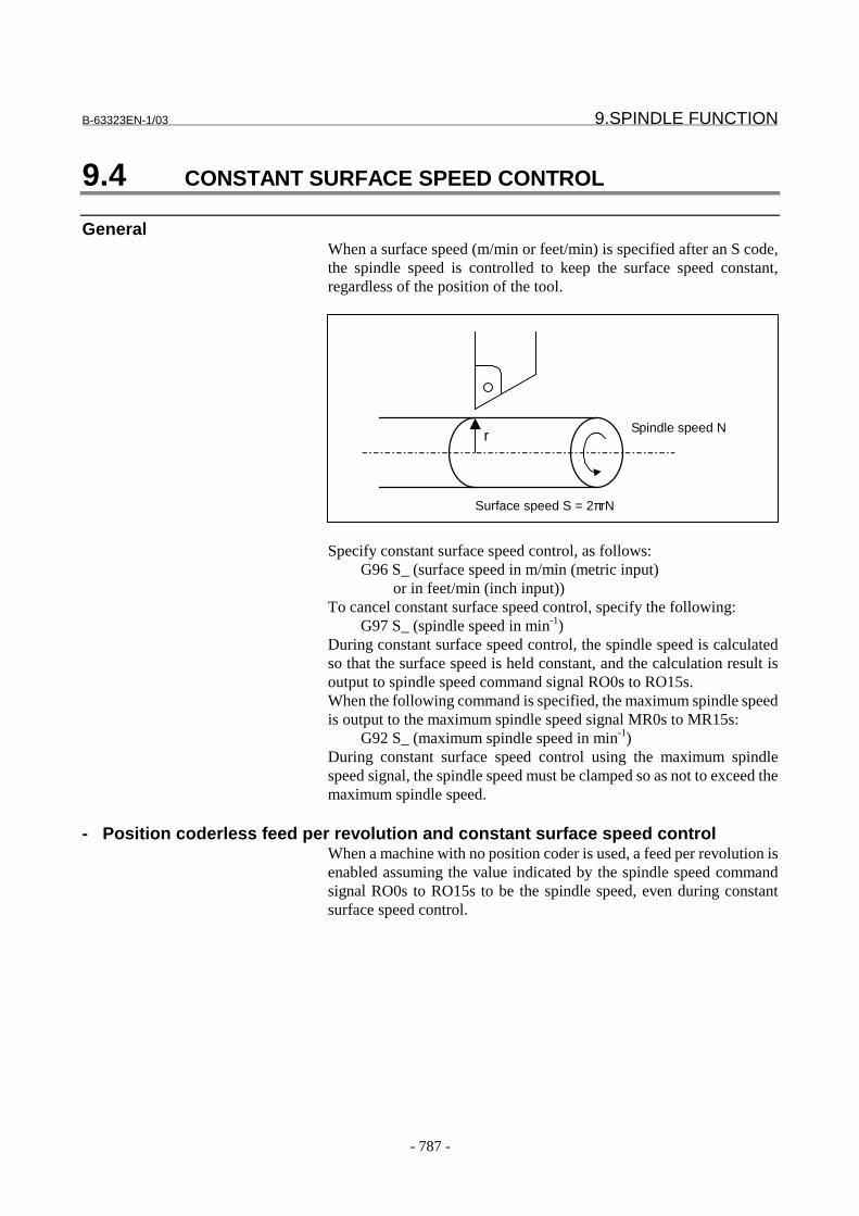
B-63323EN-1/03 9.SPINDLE FUNCTION
- 787 -
9.4 CONSTANT SURFACE SPEED CONTROL
GeneralWhen a surface speed (m/min or feet/min) is specified after an S code,the spindle speed is controlled to keep the surface speed constant,regardless of the position of the tool.
r
Surface speed S = 2πrN
Spindle speed N
Specify constant surface speed control, as follows:G96 S_ (surface speed in m/min (metric input)
or in feet/min (inch input))To cancel constant surface speed control, specify the following:
G97 S_ (spindle speed in min-1)During constant surface speed control, the spindle speed is calculatedso that the surface speed is held constant, and the calculation result isoutput to spindle speed command signal RO0s to RO15s.When the following command is specified, the maximum spindle speedis output to the maximum spindle speed signal MR0s to MR15s:
G92 S_ (maximum spindle speed in min-1)During constant surface speed control using the maximum spindlespeed signal, the spindle speed must be clamped so as not to exceed themaximum spindle speed.
- Position coderless feed per revolution and constant surface speed controlWhen a machine with no position coder is used, a feed per revolution isenabled assuming the value indicated by the spindle speed commandsignal RO0s to RO15s to be the spindle speed, even during constantsurface speed control.
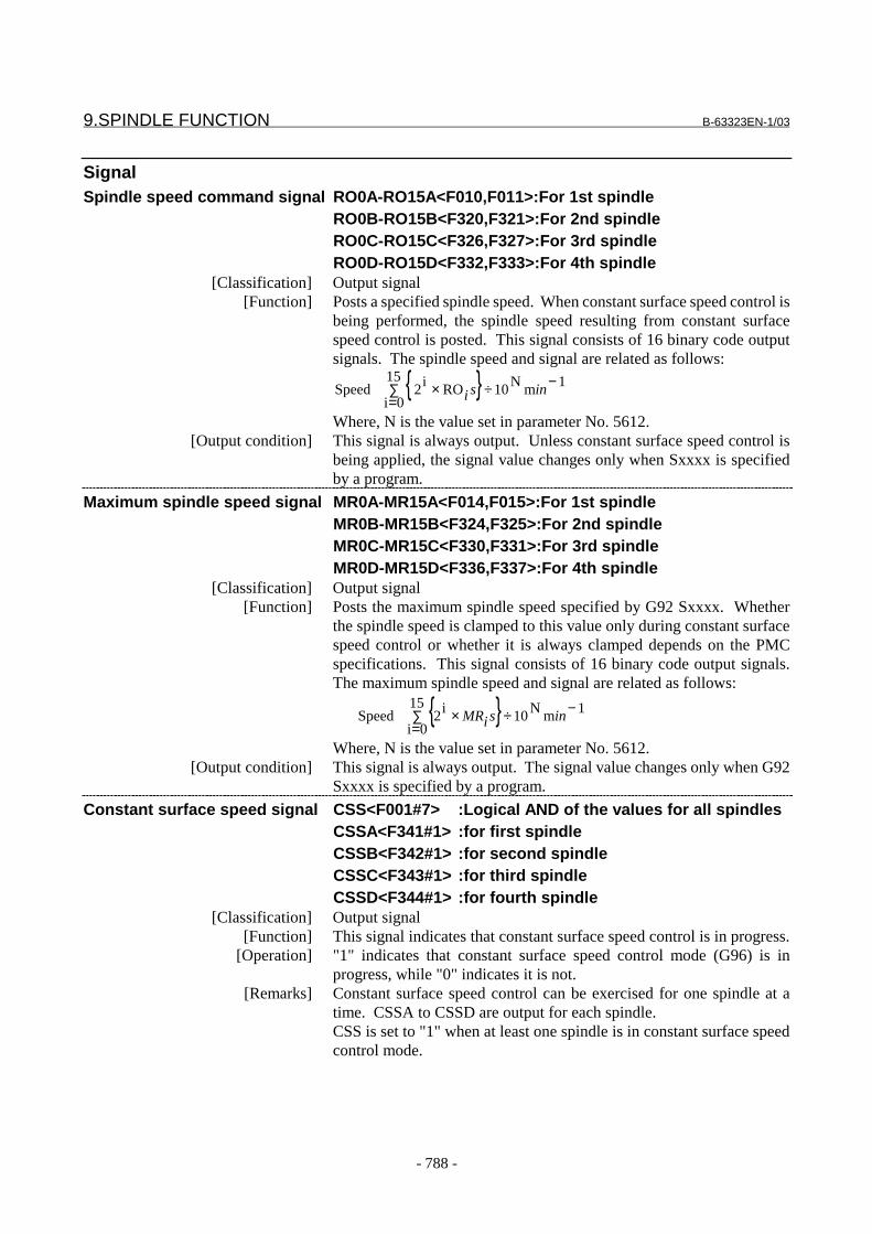
9.SPINDLE FUNCTION B-63323EN-1/03
- 788 -
SignalSpindle speed command signal RO0A-RO15A<F010,F011>:For 1st spindle
RO0B-RO15B<F320,F321>:For 2nd spindleRO0C-RO15C<F326,F327>:For 3rd spindleRO0D-RO15D<F332,F333>:For 4th spindle
[Classification] Output signal[Function] Posts a specified spindle speed. When constant surface speed control is
being performed, the spindle speed resulting from constant surfacespeed control is posted. This signal consists of 16 binary code outputsignals. The spindle speed and signal are related as follows:
{ }∑=
−÷×15
0i
1mN10ROi2 Speed insi
Where, N is the value set in parameter No. 5612.[Output condition] This signal is always output. Unless constant surface speed control is
being applied, the signal value changes only when Sxxxx is specifiedby a program.
Maximum spindle speed signal MR0A-MR15A<F014,F015>:For 1st spindleMR0B-MR15B<F324,F325>:For 2nd spindleMR0C-MR15C<F330,F331>:For 3rd spindleMR0D-MR15D<F336,F337>:For 4th spindle
[Classification] Output signal[Function] Posts the maximum spindle speed specified by G92 Sxxxx. Whether
the spindle speed is clamped to this value only during constant surfacespeed control or whether it is always clamped depends on the PMCspecifications. This signal consists of 16 binary code output signals.The maximum spindle speed and signal are related as follows:
Where, N is the value set in parameter No. 5612.[Output condition] This signal is always output. The signal value changes only when G92
Sxxxx is specified by a program.
Constant surface speed signal CSS<F001#7> :Logical AND of the values for all spindlesCSSA<F341#1> :for first spindleCSSB<F342#1> :for second spindleCSSC<F343#1> :for third spindleCSSD<F344#1> :for fourth spindle
[Classification] Output signal[Function] This signal indicates that constant surface speed control is in progress.
[Operation] "1" indicates that constant surface speed control mode (G96) is inprogress, while "0" indicates it is not.
[Remarks] Constant surface speed control can be exercised for one spindle at atime. CSSA to CSSD are output for each spindle.CSS is set to "1" when at least one spindle is in constant surface speedcontrol mode.
{ }∑=
−÷×15
0i
1mN10i2Speed insiMR
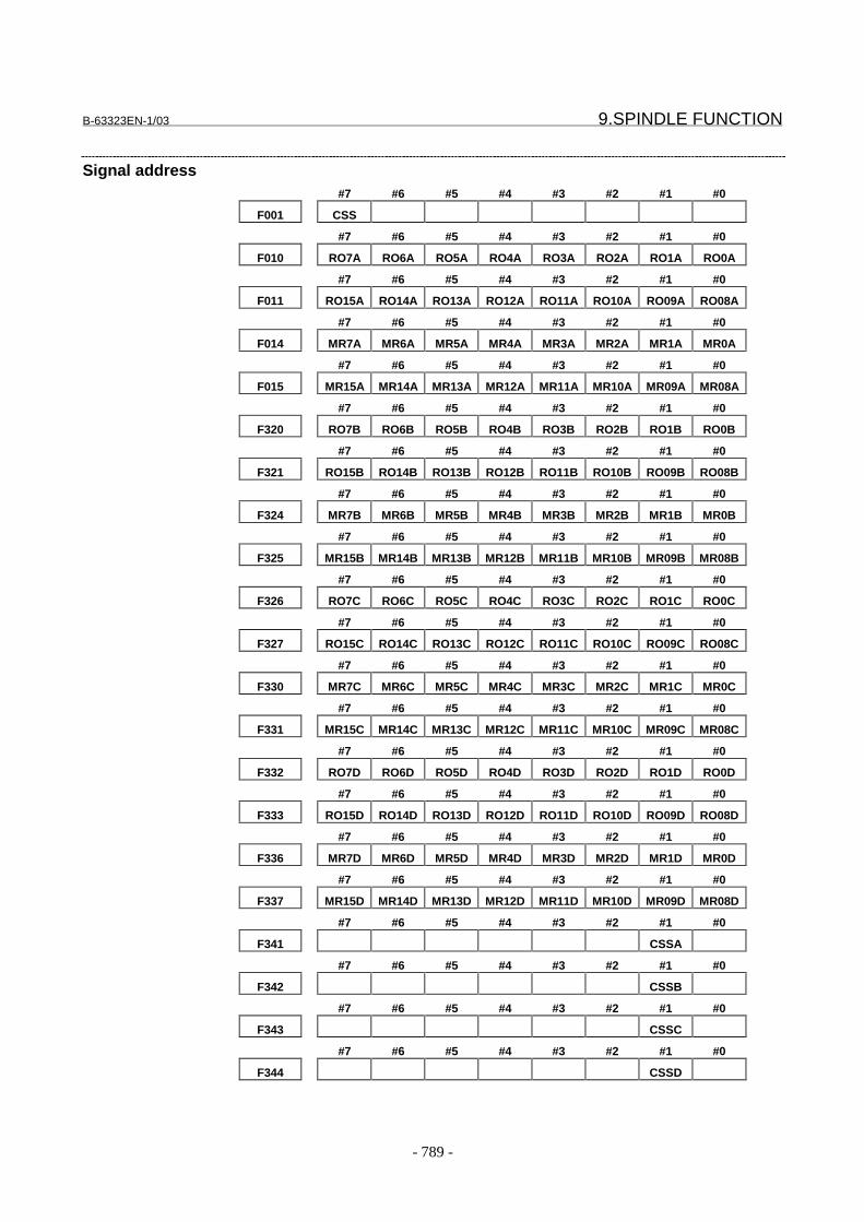
B-63323EN-1/03 9.SPINDLE FUNCTION
- 789 -
Signal address#7 #6 #5 #4 #3 #2 #1 #0
F001 CSS
#7 #6 #5 #4 #3 #2 #1 #0
F010 RO7A RO6A RO5A RO4A RO3A RO2A RO1A RO0A
#7 #6 #5 #4 #3 #2 #1 #0
F011 RO15A RO14A RO13A RO12A RO11A RO10A RO09A RO08A
#7 #6 #5 #4 #3 #2 #1 #0
F014 MR7A MR6A MR5A MR4A MR3A MR2A MR1A MR0A
#7 #6 #5 #4 #3 #2 #1 #0
F015 MR15A MR14A MR13A MR12A MR11A MR10A MR09A MR08A
#7 #6 #5 #4 #3 #2 #1 #0
F320 RO7B RO6B RO5B RO4B RO3B RO2B RO1B RO0B
#7 #6 #5 #4 #3 #2 #1 #0
F321 RO15B RO14B RO13B RO12B RO11B RO10B RO09B RO08B
#7 #6 #5 #4 #3 #2 #1 #0
F324 MR7B MR6B MR5B MR4B MR3B MR2B MR1B MR0B
#7 #6 #5 #4 #3 #2 #1 #0
F325 MR15B MR14B MR13B MR12B MR11B MR10B MR09B MR08B
#7 #6 #5 #4 #3 #2 #1 #0
F326 RO7C RO6C RO5C RO4C RO3C RO2C RO1C RO0C
#7 #6 #5 #4 #3 #2 #1 #0
F327 RO15C RO14C RO13C RO12C RO11C RO10C RO09C RO08C
#7 #6 #5 #4 #3 #2 #1 #0
F330 MR7C MR6C MR5C MR4C MR3C MR2C MR1C MR0C
#7 #6 #5 #4 #3 #2 #1 #0
F331 MR15C MR14C MR13C MR12C MR11C MR10C MR09C MR08C
#7 #6 #5 #4 #3 #2 #1 #0
F332 RO7D RO6D RO5D RO4D RO3D RO2D RO1D RO0D
#7 #6 #5 #4 #3 #2 #1 #0
F333 RO15D RO14D RO13D RO12D RO11D RO10D RO09D RO08D
#7 #6 #5 #4 #3 #2 #1 #0
F336 MR7D MR6D MR5D MR4D MR3D MR2D MR1D MR0D
#7 #6 #5 #4 #3 #2 #1 #0
F337 MR15D MR14D MR13D MR12D MR11D MR10D MR09D MR08D
#7 #6 #5 #4 #3 #2 #1 #0
F341 CSSA
#7 #6 #5 #4 #3 #2 #1 #0
F342 CSSB
#7 #6 #5 #4 #3 #2 #1 #0
F343 CSSC
#7 #6 #5 #4 #3 #2 #1 #0
F344 CSSD
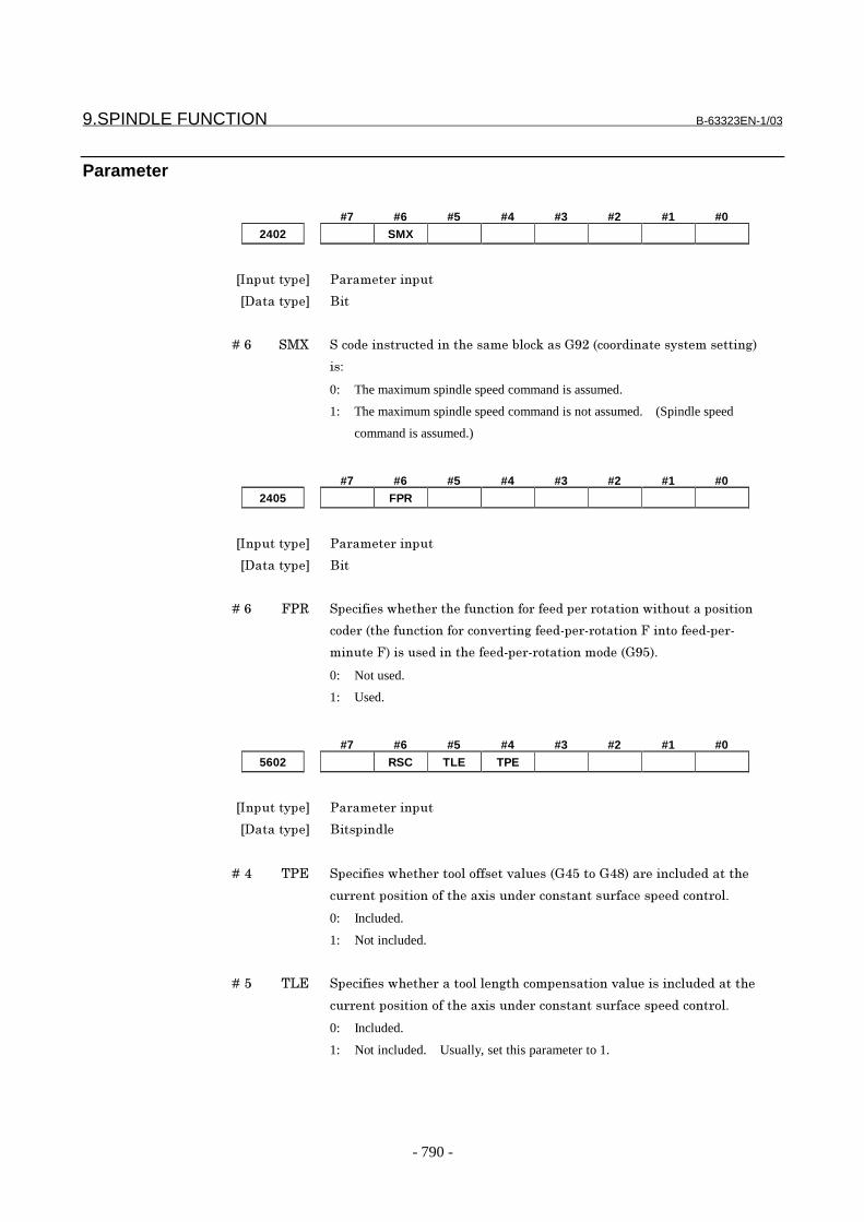
9.SPINDLE FUNCTION B-63323EN-1/03
- 790 -
Parameter
#7 #6 #5 #4 #3 #2 #1 #0
2402 SMX
���������� �� ��� ������
��������� ���
� � � � ��� ��� ���������� ������������������������� !�"��� �����������������#$
��%
0: The maximum spindle speed command is assumed.
1: The maximum spindle speed command is not assumed. (Spindle speed
command is assumed.)
#7 #6 #5 #4 #3 #2 #1 #0
2405 FPR
���������� �� ��� ������
��������� ���
� � � � ��� &�' ����(���)��� ����(��������(� �(��� � ��������)�����������������
��� �"���(��������(� ����* ���#�(�+� + ��������&������(�+� +
������&$��������������(�+� + ������������"� ,$-
0: Not used.
1: Used.
#7 #6 #5 #4 #3 #2 #1 #0
5602 RSC TLE TPE
���������� �� ��� ������
��������� ���������
� � � � ��. /�0 ����(���)��� �������((���*�����"�.,�����.1$�� ��������������
�� �������������(�����2������ ������������ (����������� ��-
0: Included.
1: Not included.
� � � � ��, /30 ����(���)��� ����������#���������������*��������������������
�� �������������(�����2������ ������������ (����������� ��-
0: Included.
1: Not included. Usually, set this parameter to 1.

B-63323EN-1/03 9.SPINDLE FUNCTION
- 791 -
� � � � ��� '�4 ����(���)��� ������������ ������������(� �������������#��������
"���������55$���� ������������ (����������� ��-
0: Use.
1: Do not use. Instead, the coordinates of an end point are used for constant
surface speed control.
5850 Spindle number to be selected upon power-up/reset
���������� �� ��� ������
��������� ���#
�6���������� ��# 5�+�.
Set a spindle number to be selected upon power-up/reset.
A selected spindle is used as:
- Spindle displayed on a screen such as the position display screen and program
check screen
- Spindle used for an S command, feed per revolution, constant surface speed
control, threading, canned cycles, rigid tapping, and spindle speed detection
NOTE
To rewrite this parameter during automatic operation, always use
a non-buffered M code set in parameter Nos. 2411 to 2420 so
that rewriting is performed in the non-buffering state.
5612 Unit of spindle speed to be output by DO signals
���������� �� ��� ������
��������� ���# ������
�7�����(����� 8985�������
�6���������� ��# 5�+�:
Set the unit of output by the specified spindle speed signal, actual spindle speed
signal, and maximum spindle speed signal.
nit of output spindle speed Setting
1. min-1 0
0.1 min-1 1
0.01 min-1 2
0.001 min-1 3

9.SPINDLE FUNCTION B-63323EN-1/03
- 792 -
5844 Axis number subject to constant surface speed control
���������� �� ��� ������
��������� ���# ������
�6���������� ��# 5�+���2��2�
Specify the ordinal number of an axis that is subject to constant surface speed
control. If an axis is specified in the program (G96P_), constant surface speed
control is applied to the axis.
If no axis is specified in the program (G96P_), or P0 is specified, constant surface
speed control is applied to the axis set in this parameter.
NOTE
If 0 is set, the P value programmed with G96P_ is ignored, and
constant surface speed control is always performed on the X-
axis.
Alarm and messageNumber Message Contents
PS0195 ILLEGAL AXIS SELECTED (G96) An illegal value was specified in P in a G96 block orparameter No. 5844.
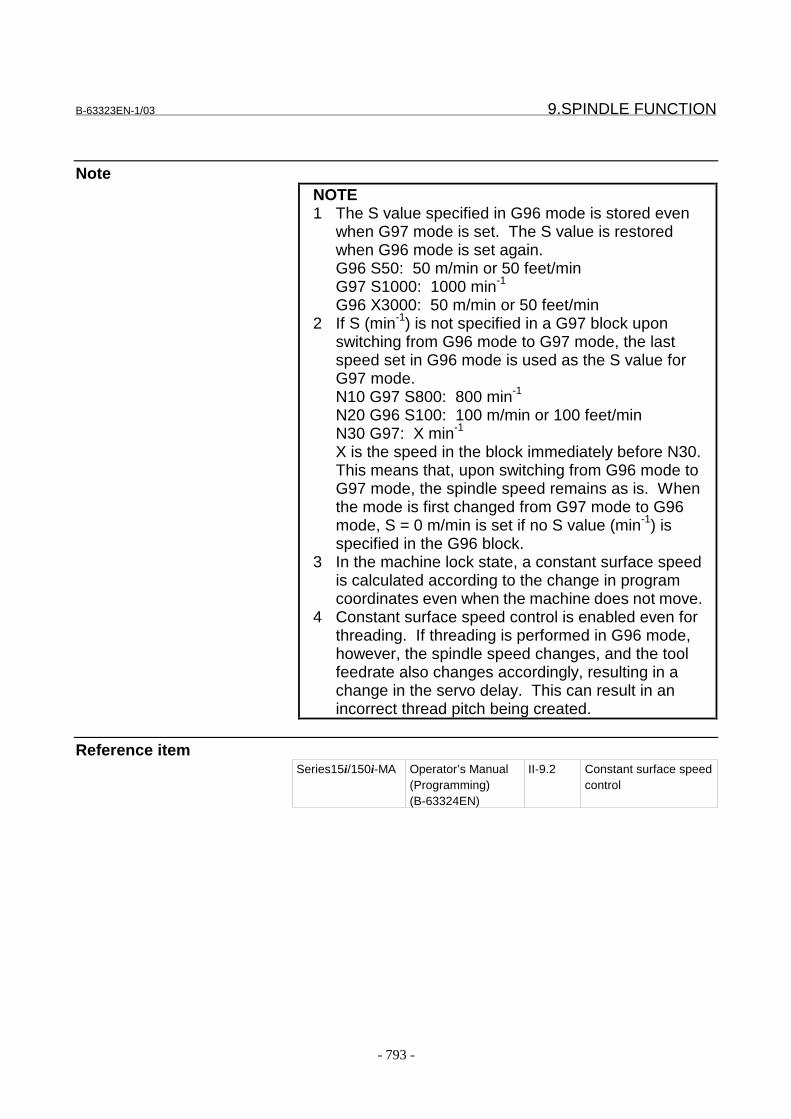
B-63323EN-1/03 9.SPINDLE FUNCTION
- 793 -
NoteNOTE1 The S value specified in G96 mode is stored even
when G97 mode is set. The S value is restoredwhen G96 mode is set again.G96 S50: 50 m/min or 50 feet/minG97 S1000: 1000 min-1
G96 X3000: 50 m/min or 50 feet/min2 If S (min-1) is not specified in a G97 block upon
switching from G96 mode to G97 mode, the lastspeed set in G96 mode is used as the S value forG97 mode.N10 G97 S800: 800 min-1
N20 G96 S100: 100 m/min or 100 feet/minN30 G97: X min-1
X is the speed in the block immediately before N30.This means that, upon switching from G96 mode toG97 mode, the spindle speed remains as is. Whenthe mode is first changed from G97 mode to G96mode, S = 0 m/min is set if no S value (min-1) isspecified in the G96 block.
3 In the machine lock state, a constant surface speedis calculated according to the change in programcoordinates even when the machine does not move.
4 Constant surface speed control is enabled even forthreading. If threading is performed in G96 mode,however, the spindle speed changes, and the toolfeedrate also changes accordingly, resulting in achange in the servo delay. This can result in anincorrect thread pitch being created.
Reference itemSeries15i/150i-MA Operator’s Manual
(Programming)(B-63324EN)
II-9.2 Constant surface speedcontrol

9.SPINDLE FUNCTION B-63323EN-1/03
- 794 -
9.5 ACTUAL SPINDLE SPEED OUTPUT
GeneralBased on a feedback signal from a position coder mounted on a spindle,the CNC calculates the spindle speed and outputs it to the PMC.When a serial spindle is used, the spindle speed can also be calculatedbased on the speed monitor data of the spindle motor by setting bit 4(ASD) of parameter No. 5820.
SignalActual spindle speed signal AR0A-AR15A<F012,F013>:for first spindle
AR0B-AR15B<F322,F323>:for second spindleAR0C-AR15C<F328,F329>:for third spindleAR0D-AR15D<F334,F335>:for fourth spindle
[Classification] Output signal[Function] These 16-bit binary code signals output from the CNC to the PMC the
actual spindle speed obtained by feedback pulses from the positioncoder mounted on the spindle. When a serial spindle is used, thespindle speed can also be calculated based on the speed monitor data ofthe spindle motor by setting bit 4 (ASD) of parameter No. 5820.This signal consists of 16 binary code output signals. The actualspindle speed and signal are related as follows:
Where, N is the value set in parameter No. 5612.[Output condition] This signal is always output.
Signal address- For first spindle
#7 #6 #5 #4 #3 #2 #1 #0
F012 AR7A AR6A AR5A AR4A AR3A AR2A AR1A AR0A
F013 AR15A AR14A AR13A AR12A AR11A AR10A AR9A AR8A
- For second spindle#7 #6 #5 #4 #3 #2 #1 #0
F322 AR7B AR6B AR5B AR4B AR3B AR2B AR1B AR0B
F323 AR15B AR14B AR13B AR12B AR11B AR10B AR9B AR8B
- For third spindle#7 #6 #5 #4 #3 #2 #1 #0
F328 AR7C AR6C AR5C AR4C AR3C AR2C AR1C AR0C
F329 AR15C AR14C AR13C AR12C AR11C AR10C AR9C AR8C
{ }∑=
÷×15
0i
1-Ni min102 Speed sARi
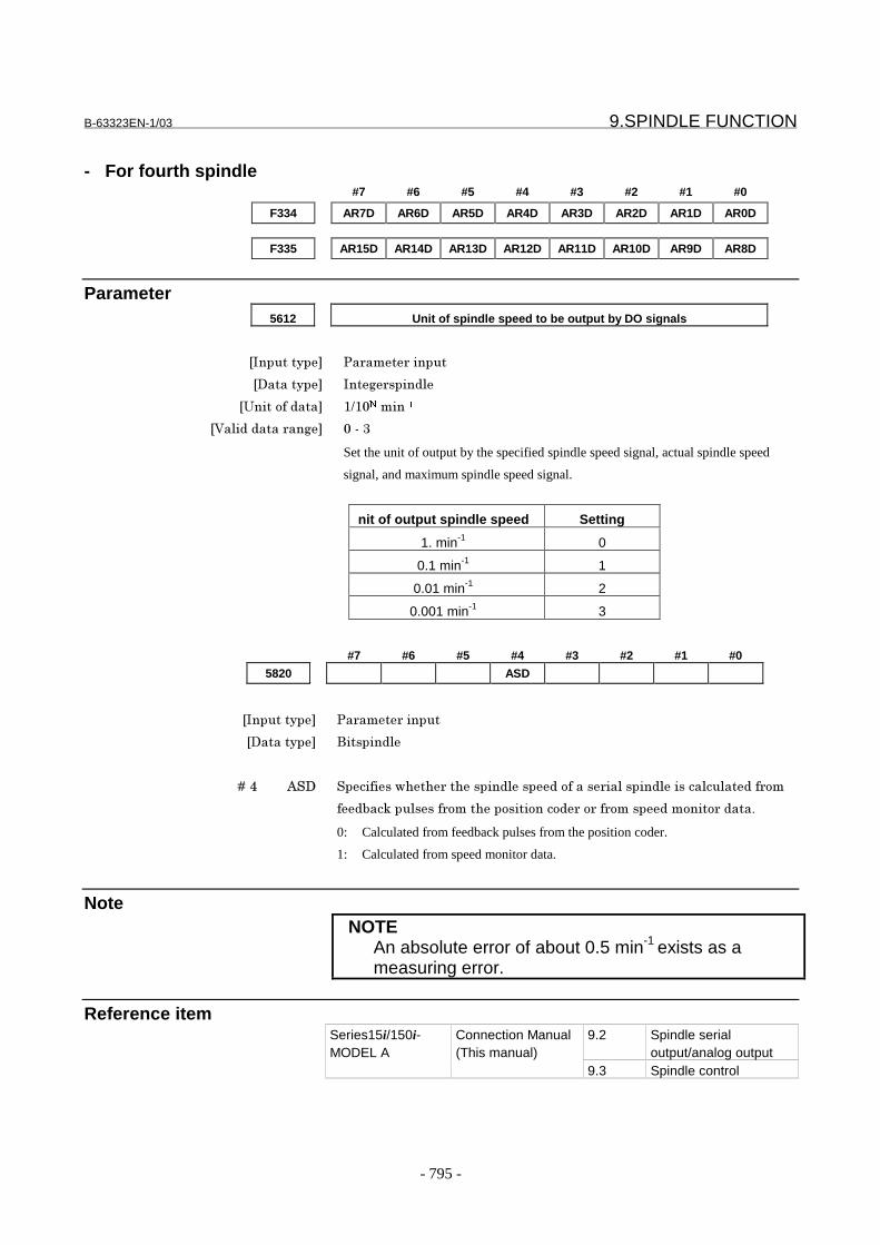
B-63323EN-1/03 9.SPINDLE FUNCTION
- 795 -
- For fourth spindle#7 #6 #5 #4 #3 #2 #1 #0
F334 AR7D AR6D AR5D AR4D AR3D AR2D AR1D AR0D
F335 AR15D AR14D AR13D AR12D AR11D AR10D AR9D AR8D
Parameter5612 Unit of spindle speed to be output by DO signals
���������� �� ��� ������
��������� ���# ������
�7�����(����� 8985�������
�6���������� ��# 5�+�:
Set the unit of output by the specified spindle speed signal, actual spindle speed
signal, and maximum spindle speed signal.
nit of output spindle speed Setting
1. min-1 0
0.1 min-1 1
0.01 min-1 2
0.001 min-1 3
#7 #6 #5 #4 #3 #2 #1 #0
5820 ASD
���������� �� ��� ������
��������� ���������
� � � � ��. ;�� ����(���)��� ����������������(���� ������������������������( ��
(������������( ������������������ �� �( ������������� �����-
0: Calculated from feedback pulses from the position coder.
1: Calculated from speed monitor data.
NoteNOTE
An absolute error of about 0.5 min-1 exists as ameasuring error.
Reference item9.2 Spindle serial
output/analog outputSeries15i/150i-MODEL A
Connection Manual(This manual)
9.3 Spindle control
9.SPINDLE FUNCTION B-63323EN-1/03
- 796 -
9.6 SPINDLE POSITIONING
GeneralThis function positions the spindle using the spindle motor and positioncoder.
The function has a coarser least command increment compared withthe Cs contour control function and has no interpolation capability withother axes. However, it can be installed with ease because the positiondetector is a position coder.Generally, the spindle positioning axes are clamped mechanicallyexcept when positioning is under way.In the turning process, the workpiece is rotated by the spindle to whichit is attached (spindle rotation mode), at the speed specified for thespindle motor. The value for the spindle speed is input from the spindlecontroller to the spindle amplifier.When the optional spindle positioning function is activated, the spindleis moved to a defined angle, and the workpiece is repositioned at thatangle.The specified move distance is input to the error counter, and thevelocity command is issued for the spindle motor through the spindleamplifier. The position of the spindle is detected by the installedposition coder (Spindle positioning mode).The spindle positioning function can perform the following operations:- Release the spindle rotation mode and enter the spindle
positioning mode Specifying a particular M code sets areference position in the spindle positioning mode. (This is calledspindle orientation.)
- Position the spindle in the spindle positioning modePosition an optional angle using address C (H), and position asemi-fixed angle using a specific M code parameter.
- Release the spindle positioning mode and enter the spindlerotation modeSpecifying a particular M code parameter changes the spindle tothe spindle rotation mode.
The least command increment, least input increment, and maximumvalue for the spindle positioning axis are set as follows:
- Least command increment
- Minimum input increment0.001 deg (IS-B)
- Maximum command value±999999.999 deg
0.088deg4096
360 ≅
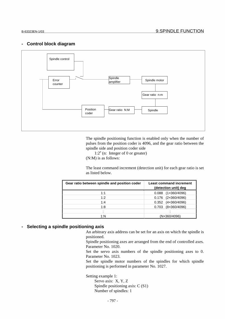
B-63323EN-1/03 9.SPINDLE FUNCTION
- 797 -
- Control block diagram
The spindle positioning function is enabled only when the number ofpulses from the position coder is 4096, and the gear ratio between thespindle side and position coder side
1:2n (n: Integer of 0 or greater)(N:M) is as follows:
The least command increment (detection unit) for each gear ratio is setas listed below.
Gear ratio between spindle and position coder Least command increment(detection unit) deg
1:1 0.088 (1×360/4096)1:2 0.176 (2×360/4096)1:4 0.352 (4×360/4096)1:8 0.703 (8×360/4096)
: :1:N (N×360/4096)
- Selecting a spindle positioning axisAn arbitrary axis address can be set for an axis on which the spindle ispositioned.Spindle positioning axes are arranged from the end of controlled axes.Parameter No. 1020.Set the servo axis numbers of the spindle positioning axes to 0.Parameter No. 1023.Set the spindle motor numbers of the spindles for which spindlepositioning is performed in parameter No. 1027.
Setting example 1:Servo axis: X, Y, ZSpindle positioning axis: C (S1)Number of spindles: 1
Spindle control
Spindleamplifier Spindle motor
Spindle
Gear ratio n:m
Errorcounter
Gear ratio N:MPositioncoder

9.SPINDLE FUNCTION B-63323EN-1/03
- 798 -
Controlled-axis No.
Parameter1020
Parameter1023
Parameter1027
1 ��� w� 1 02 89( x) 2 03 90( y) 3 04 67( b) 0 1
Setting example 2:Servo axis: X, ZSpindle positioning axis: C (S1), B (S2)Number of spindles: 2
Controlled-axis No.
Parameter1020
Parameter1023
Parameter1027
1 88(X) 1 02 90(Z) 2 03 67(C) 0 14 66(B) 0 2
Switching to spindle positioning mode (Spindle orientation)Orientation is required in advance if spindle positioning is firstperformed after the spindle motor is used as a normal spindle, or whenspindle positioning is interrupted. The orientation stops the spindle in aconstant position.The orientation position can be sifted in the range of }180deg bysetting the parameter (No.5980) for analog spindle and in the rangefrom 0 to 360 deg by setting the parameter (No.3073) for serial spindle.To specify orientation, use the M code whose parameter No. 5680.The orientation direction is specified by using parameters OMINo.5808 #0 for analog or SVO No. 3000#4 for serial spindles.
B-63323EN-1/03 9.SPINDLE FUNCTION
- 799 -
- Orientation speedWhen an analog spindle is used, the tool moves at the rapid traverserate set in parameter No. 5977 until a speed that allows orientation isreached. After a one-rotation signal is detected, spindle orientation isperformed at the FL feedrate set in parameter No. 5979.* Speed allowing orientationSet the speed so that the following condition is satisfied:
F : Feedrate (deg/min)G : Position gain (1/sec)P : Gear ratio between the spindle and position coder
If the above condition is not satisfied, a one-rotation signal cannot bedetected, so movement continues at the rapid traverse rate.
* FL feedrateSet the FL feedrate so that the following condition is satisfied:
FL : Feedrate (deg/min)G : Position gain (1/sec)P : Gear ratio between the spindle and position coder
If the above condition is not satisfied, an accurate stop position cannotbe detected, so orientation is performed again stating from the rapidtraverse operation.
The serial spindle stops at the orientation position as soon as thecommand is issued. The lower limit to the rapid traverse speed valuedoes not need to be specified for the serial spindle to reach theorientation enable speed.The analog spindle stops after the spindle speed is changed from rapidtraverse to the FL speed. The rapid traverse speed lower limit must bespecified for the analog spindle, or obtaining the orientation enablespeed need not be specified for the serial spindle. However, it must bespecified for the analog spindle.
- Omitting an orientation operationWhen reference position return is not required when performingorientation (for example, when no start position is specified, and onlyincremental positioning starting from the current position is needed),the reference position return operation performed upon orientation canbe omitted by setting bit 0 (ZRN) of parameter No. 1005. In this case,when an M code for orientation is specified, only change of the spindlecontrol mode is performed. Then, operation is completed withoutreference position return.
)(088.060
1024 pulsesG
PFL�������������� ������≥
×××≥
088.0601024 pulses
G
PF��� �≥
×××≥
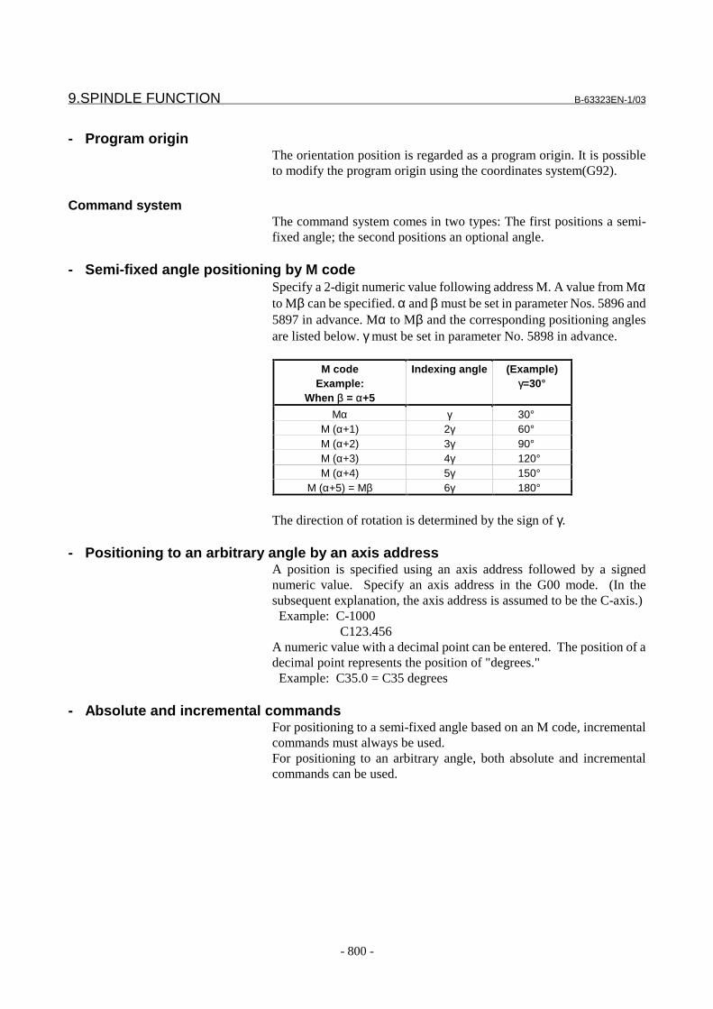
9.SPINDLE FUNCTION B-63323EN-1/03
- 800 -
- Program originThe orientation position is regarded as a program origin. It is possibleto modify the program origin using the coordinates system(G92).
Command systemThe command system comes in two types: The first positions a semi-fixed angle; the second positions an optional angle.
- Semi-fixed angle positioning by M codeSpecify a 2-digit numeric value following address M. A value from Mαto Mβ can be specified. α and β must be set in parameter Nos. 5896 and5897 in advance. Mα to Mβ and the corresponding positioning anglesare listed below. γ must be set in parameter No. 5898 in advance.
M codeExample:
When β = α+5
Indexing angle (Example)γ=30°
Mα γ 30°M (α+1) 2γ 60°M (α+2) 3γ 90°M (α+3) 4γ 120°M (α+4) 5γ 150°
M (α+5) = Mβ 6γ 180°
The direction of rotation is determined by the sign of γ.
- Positioning to an arbitrary angle by an axis addressA position is specified using an axis address followed by a signednumeric value. Specify an axis address in the G00 mode. (In thesubsequent explanation, the axis address is assumed to be the C-axis.) Example: C-1000
C123.456A numeric value with a decimal point can be entered. The position of adecimal point represents the position of "degrees." Example: C35.0 = C35 degrees
- Absolute and incremental commandsFor positioning to a semi-fixed angle based on an M code, incrementalcommands must always be used.For positioning to an arbitrary angle, both absolute and incrementalcommands can be used.

B-63323EN-1/03 9.SPINDLE FUNCTION
- 801 -
Command methodAddress used and
G-codeCommand of A-Bon the above Fig.
Absolute command Direct the end point position bythe distance from the programorigin.
G90,C G90C180.0 ;
Incrementalcommand
Command by the distancebetween the start and end points.
G91,C G91C90.0 ;
- Spindle positioning feedrateAs the feedrate used for positioning, the rapid traverse rate specified inparameter No. 1420 is used.
Spindle positioning resetA specific M code (parameter no. 5681) must be set when the mode ischanged from spindle positioning to normal spindle rotation.
Spindle positioning mode is also canceled in any of the followingcases:
1. A servo alarm is issued.2. A spindle alarm is issued.3. The spindle is stopped during orientation due to a reset, alarm, or
similar.4. The spindle is stopped upon the cancellation of positioning due to
a reset, alarm, and so forth.5. When a reset is caused: Depends on bit 4 (IOR) of parameter No.
5605.6. When an emergency stop is caused: Depends on bit 1 (IOE) of
parameter No. 5809.
180°
90°
B
A
Program origin
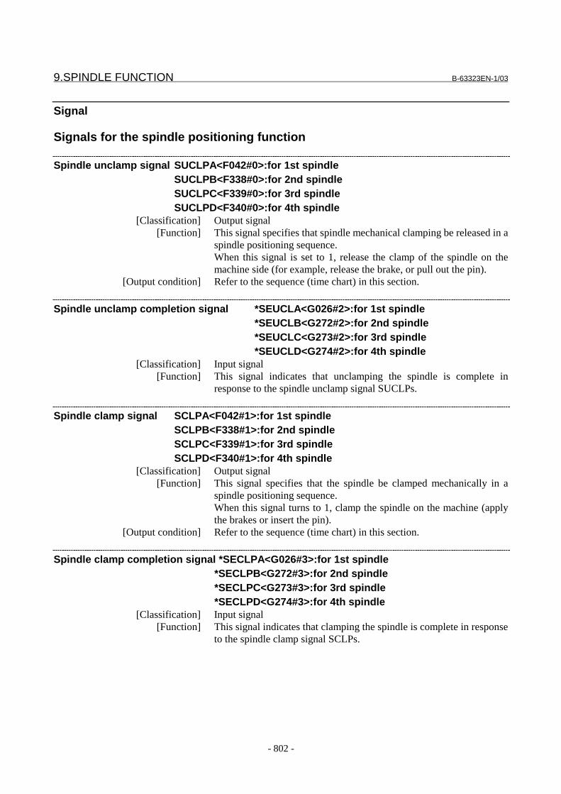
9.SPINDLE FUNCTION B-63323EN-1/03
- 802 -
Signal
Signals for the spindle positioning function
Spindle unclamp signal SUCLPA<F042#0>:for 1st spindleSUCLPB<F338#0>:for 2nd spindleSUCLPC<F339#0>:for 3rd spindleSUCLPD<F340#0>:for 4th spindle
[Classification] Output signal[Function] This signal specifies that spindle mechanical clamping be released in a
spindle positioning sequence.When this signal is set to 1, release the clamp of the spindle on themachine side (for example, release the brake, or pull out the pin).
[Output condition] Refer to the sequence (time chart) in this section.
Spindle unclamp completion signal *SEUCLA<G026#2>:for 1st spindle*SEUCLB<G272#2>:for 2nd spindle*SEUCLC<G273#2>:for 3rd spindle*SEUCLD<G274#2>:for 4th spindle
[Classification] Input signal[Function] This signal indicates that unclamping the spindle is complete in
response to the spindle unclamp signal SUCLPs.
Spindle clamp signal SCLPA<F042#1>:for 1st spindleSCLPB<F338#1>:for 2nd spindleSCLPC<F339#1>:for 3rd spindleSCLPD<F340#1>:for 4th spindle
[Classification] Output signal[Function] This signal specifies that the spindle be clamped mechanically in a
spindle positioning sequence.When this signal turns to 1, clamp the spindle on the machine (applythe brakes or insert the pin).
[Output condition] Refer to the sequence (time chart) in this section.
Spindle clamp completion signal *SECLPA<G026#3>:for 1st spindle*SECLPB<G272#3>:for 2nd spindle*SECLPC<G273#3>:for 3rd spindle*SECLPD<G274#3>:for 4th spindle
[Classification] Input signal[Function] This signal indicates that clamping the spindle is complete in response
to the spindle clamp signal SCLPs.
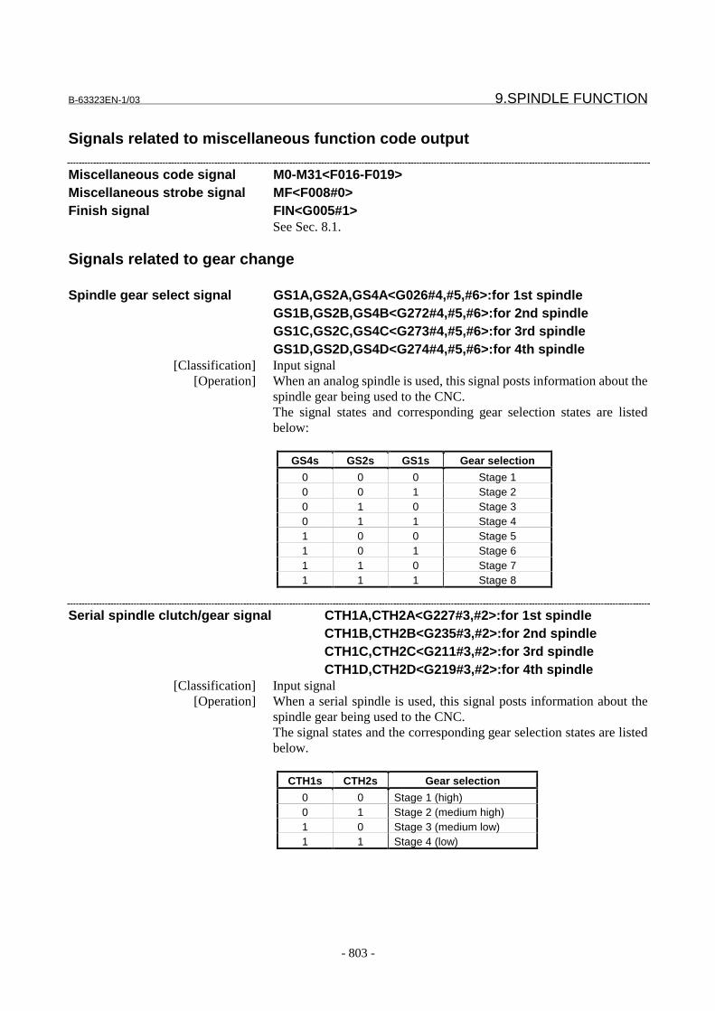
B-63323EN-1/03 9.SPINDLE FUNCTION
- 803 -
Signals related to miscellaneous function code output
Miscellaneous code signal M0-M31<F016-F019>Miscellaneous strobe signal MF<F008#0>Finish signal FIN<G005#1>
See Sec. 8.1.
Signals related to gear change
Spindle gear select signal GS1A,GS2A,GS4A<G026#4,#5,#6>:for 1st spindleGS1B,GS2B,GS4B<G272#4,#5,#6>:for 2nd spindleGS1C,GS2C,GS4C<G273#4,#5,#6>:for 3rd spindleGS1D,GS2D,GS4D<G274#4,#5,#6>:for 4th spindle
[Classification] Input signal[Operation] When an analog spindle is used, this signal posts information about the
spindle gear being used to the CNC.The signal states and corresponding gear selection states are listedbelow:
GS4s GS2s GS1s Gear selection
0 0 0 Stage 10 0 1 Stage 20 1 0 Stage 30 1 1 Stage 41 0 0 Stage 51 0 1 Stage 61 1 0 Stage 71 1 1 Stage 8
Serial spindle clutch/gear signal CTH1A,CTH2A<G227#3,#2>:for 1st spindleCTH1B,CTH2B<G235#3,#2>:for 2nd spindleCTH1C,CTH2C<G211#3,#2>:for 3rd spindleCTH1D,CTH2D<G219#3,#2>:for 4th spindle
[Classification] Input signal[Operation] When a serial spindle is used, this signal posts information about the
spindle gear being used to the CNC.The signal states and the corresponding gear selection states are listedbelow.
CTH1s CTH2s Gear selection
0 0 Stage 1 (high)0 1 Stage 2 (medium high)1 0 Stage 3 (medium low)1 1 Stage 4 (low)

9.SPINDLE FUNCTION B-63323EN-1/03
- 804 -
Other signals
Spindle stop confirmation signal SPSTPA<G026#0>:for 1st spindleSPSTPB<G272#0>:for 2nd spindleSPSTPC<G273#0>:for 3rd spindleSPSTPD<G274#0>:for 4th spindle
[Classification] Input signal[Function] After checking that this signal has been set to 1, the CNC performs
spindle orientation, spindle positioning, and cancellation of spindlepositioning.
Reference position return completion signal ZP1<F064#0>, ZP2<F068#0>, ...[Classification] Output signal
[Function] Indicates that spindle orientation for a spindle positioning axis has beencompleted.ZPxx : 1 ... Completion signal for spindle orientation on the first axis
2 ... Completion signal for spindle orientation on the second axis3 ... Completion signal for spindle orientation on the third axis : : : :
[Output condition] When spindle orientation is completed, this signal is set to 1. Thesignal is set to 0 when spindle positioning is performed or canceled.
Signal address
- All axes common#7 #6 #5 #4 #3 #2 #1 #0
G005 FIN
F008 MF
F016 M7 M6 M5 M4 M3 M2 M1 M0
F017 M15 M14 M13 M12 M11 M10 M9 M8
F018 M23 M22 M21 M20 M19 M18 M17 M16
F019 M31 M30 M29 M28 M27 M26 M25 M24
F064 ZP1
The above addresses are the signal addresses for the first axis.For the signal addresses for the second axis and subsequent axes, seethe Appendix A.1.

B-63323EN-1/03 9.SPINDLE FUNCTION
- 805 -
- For 1st spindle#7 #6 #5 #4 #3 #2 #1 #0
G026 GS4A GS2A GS1A *SECLPA*SEUCLA SPSTPA
G227 CTH1A CTH2A
F042 SCLPA SUCLPA
- For 2nd spindl#7 #6 #5 #4 #3 #2 #1 #0
G272 GS4B GS2B GS1B *SECLPB*SEUCLB SPSTPB
G235 CTH1B CTH2B
F338 SCLPB SUCLPB
- For 3rd spindl#7 #6 #5 #4 #3 #2 #1 #0
G211 CTH1C CTH2C
G273 GS4C GS2C GS1C *SECLPC*SEUCLC SPSTPC
F339 SCLPC SUCLPC
- For 4th spindle#7 #6 #5 #4 #3 #2 #1 #0
G219 CTH1D CTH2D
G274 GS4D GS2D GS1D *SECLPD*SEUCLD SPSTPD
F340 SCLPD SUCLPD
Sequence (time chart)
Spindle orientationTo cancel spindle rotation mode then enter spindle positioning mode,specify Mxx in a program.xx must be set in parameter No. 5680 in advance. The sequence patternmust be set in parameter No. 5895.
1. Assume that Mxx is programmed.2. A miscellaneous function code signal M0 to M31 is sent, and at
the same time, miscellaneous function strobe signal MF is set to 1.This sending procedure is the same as that for ordinarymiscellaneous functions.
3. When strobe signal FM is set to 1, the PMC reads the code signal.After confirming that the code signal is xx, the PMC must respondappropriately. For example, suppose that Mxx is specified whilethe spindle is rotating. The PMC may respond in either of two

9.SPINDLE FUNCTION B-63323EN-1/03
- 806 -
ways. Firstly, in response to the Mxx command, the PMC maystop spindle rotation. Secondly, the PMC may issue an alarm byusing the external data input/output function, assuming that theMxx command is not permitted during spindle rotation.Generally, the second response is recommended because thespindle is stopped by specifying M05. Regardless of whichresponse is made, the PMC must set spindle stop confirmationsignal SPSTPs to 1 when the spindle is stopped.
4. As soon as strobe signal MF is set to 1, the CNC checks whetherspindle stop confirmation signal SPSTPs is 1. If the SPSTPssignal is 1, the control mode for the spindle is changed fromspindle control to position control.
5. If sequence pattern 2, 3, or 4 is set, the CNC places spindleposition control in the servo-on state.
6. Spindle unclamp signal SUCLPs is set to 1.7. When spindle unclamp signal SUCLPs is set to 1, the PMC
unclamps the spindle. Upon the completion of the unclampoperation, the PMC must set spindle unclamp completion signal*SEUCLs to 0.
8. When spindle unclamp completion signal *SEUCLs is set to 0, theCNC sets spindle unclamp signal SUCLPs to 0 to indicate that theCNC has received the *SEUCLs signal.
9. If sequence pattern 1 is set, the CNC places spindle positioncontrol in the servo-on state.
10. When spindle unclamp signal SUCLPs is set to 0, the PMC mustset spindle unclamp completion signal *SEUCLs to 1.
11. The CNC rotates the spindle, and stops it at a certain position.(This operation is generally called spindle orientation.) Then, theCNC sets reference position return completion signal ZPj (j is thecontrolled axis number of the spindle) to 1.
12. If sequence pattern 1 is set, the CNC places spindle positioncontrol in the servo-off state.
13. The CNC sets spindle clamp signal SCLPs to 1.14. When spindle clamp signal SCLPs is set to 1, the PMC clamps the
spindle mechanically by using, for example, the clutch or a shotpin. After clamping, the PMC sets spindle clamp completionsignal *SECLPs to 0.
15. When spindle clamp completion signal *SECLPs is set to 0, theCNC sets spindle clamp signal SCLPs to 0 to indicate that theCNC has received *SECLPs.
16. If sequence pattern 2 is set, the CNC places spindle positioncontrol in the servo-off state.
17. When spindle clamp signal SCLPs is set to 0, the PMC must setspindle clamp completion signal *SECLPs to 1.
18. Finally, the PMC must set completion signal FIN for themiscellaneous function strobe signal MF to 1. In response to this,the CNC sets the MF signal to 0. Then, the PMC must set the FINsignal to 0.
If sequence pattern 4 is set, spindle unclamp signal SUCLPs, spindleunclamp completion signal *SEUCLs, spindle clamp signal SCLPs,
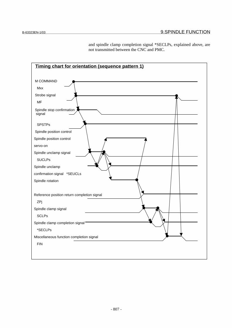
B-63323EN-1/03 9.SPINDLE FUNCTION
- 807 -
and spindle clamp completion signal *SECLPs, explained above, arenot transmitted between the CNC and PMC.
Timing chart for orientation (sequence pattern 1)
M COMMAND
Mxx
Strobe signal
MF
Spindle stop confirmation signal
SPSTPs
Spindle position control
Spindle position control
servo-on
Spindle unclamp signal
SUCLPs
Spindle unclamp
confirmation signal *SEUCLs
Spindle rotation
Reference position return completion signal
ZPj
Spindle clamp signal
SCLPs
Spindle clamp completion signal
*SECLPs
Miscellaneous function completion signal
FIN
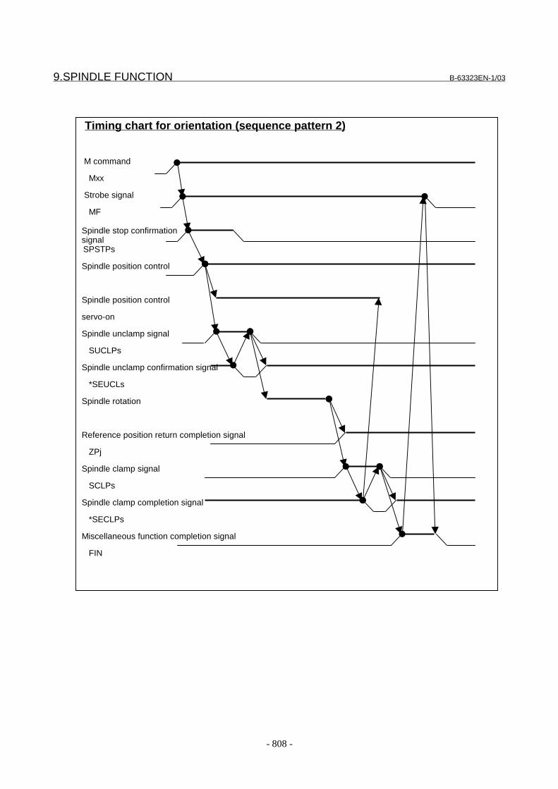
9.SPINDLE FUNCTION B-63323EN-1/03
- 808 -
Timing chart for orientation (sequence pattern 2)
M command
Mxx
Strobe signal
MF
Spindle stop confirmationsignal
SPSTPs
Spindle position control
Spindle position control
servo-on
Spindle unclamp signal
SUCLPs
Spindle unclamp confirmation signal
*SEUCLs
Spindle rotation
Reference position return completion signal
ZPj
Spindle clamp signal
SCLPs
Spindle clamp completion signal
*SECLPs
Miscellaneous function completion signal
FIN

B-63323EN-1/03 9.SPINDLE FUNCTION
- 809 -
Timing chart for orientation (sequence pattern 3)
M command
Mxx
Strobe signal
MF
Spindle stop confirmationsignal
SPSTPs
Spindle position control
Spindle position control
servo-on
Spindle unclamp signal
SUCLPs
Spindle unclamp confirmation signal
*SEUCLs
Spindle rotation
Reference position return completion signal
ZPj
Spindle clamp signal
SCLPs
Spindle clamp completion signal
*SECLPs
Miscellaneous function completion signal
FIN
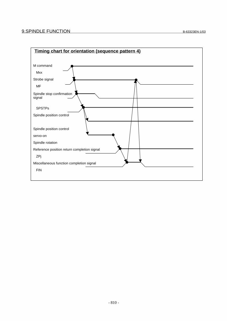
9.SPINDLE FUNCTION B-63323EN-1/03
- 810 -
Timing chart for orientation (sequence pattern 4)
M command
Mxx
Strobe signal
MF
Spindle stop confirmationsignal
SPSTPs
Spindle position control
Spindle position control
servo-on
Spindle rotation
Reference position return completion signal
ZPj
Miscellaneous function completion signal
FIN

B-63323EN-1/03 9.SPINDLE FUNCTION
- 811 -
Spindle positioningIn spindle positioning mode, positioning is performed using one of thefollowing two methods:1) Semi-fixed angle positioning by specifying Myy2) Arbitrary angle positioning by specifying an axis addressThe above operations are the same except that, in arbitrary anglepositioning, there is no input/output signal transmission formiscellaneous functions.yy must be set in parameter Nos. 5896 and 5897 in advance. Asequence pattern must be set in parameter No. 5895.
1. Suppose that Myy is specified in a program. When Myy isspecified in spindle rotation mode, the CNC sets the alarm state.
2. A miscellaneous function code signal M0 to M31 is sent, and atthe same time, miscellaneous function strobe signal MF is set to 1.This transmission procedure is the same as that for ordinarymiscellaneous functions.
3. When strobe signal MF is set to 1, the PMC reads the code signal.After confirming that the code signal is yy, the PMC must respondwith an appropriate operation. In this case, however, no particularoperation is required. The PMC must prevent completion signalFIN for miscellaneous function strobe signal MF from being set to1 until the operation procedure explained below is completed.When the spindle is stopped, the PMC sets the spindle stopconfirmation signal SPSTPs to 1.
4. As soon as strobe signal MF is set to 1, the CNC checks whetherspindle stop confirmation signal SPSTPs is 1. If the SPSTPssignal is 1, the CNC sets spindle unclamp signal SUCLPs to 1.
5. If sequence pattern 2 is set, the CNC places spindle positioncontrol in the servo-on state.
6. When spindle unclamp signal SUCLPs is set to 1, the PMCunclamps the spindle and, upon completion of the unclampoperation, the PMC sets spindle unclamp completion signal*SEUCLs to 0.
7. When spindle unclamp completion signal *SEUCLs is set to 0, theCNC sets spindle unclamp signal SUCLPs to 0 to indicate that theCNC has received the *SEUCLs signal.
8. If sequence pattern 1 is set, the CNC places spindle positioncontrol in the servo-on state.
9. When spindle unclamp signal SUCLPs is set to 0, the PMC mustset spindle unclamp completion signal *SEUCLs to 1. Aftersetting the SUCLPs signal to 0, the CNC rotates the spindle, thenstops it at the specified position.
10. If sequence pattern 1 is specified, the CNC places spindle positioncontrol in the servo-off state.
11. The CNC sets spindle clamp signal SCLPs to 1.12. When spindle clamp signal SCLPs is set to 1, the PMC clamps the
spindle mechanically as required using, for example, the clutch ora shot pin. Upon the completion of the clamp operation, the PMCsets spindle clamp completion signal *SECLPs to 0.
9.SPINDLE FUNCTION B-63323EN-1/03
- 812 -
13. When spindle clamp completion signal *SECLPs is set to 0, theCNC sets spindle clamp signal SCLPs to 0 to indicate that theCNC has received *SECLPs.
14. If sequence pattern 2 is set, the CNC places spindle positioncontrol in the servo-off state.
15. When spindle clamp signal SCLPs is set to 0, the PMC must setspindle clamp completion signal *SECLPs to 1.
16. Finally, the PMC must set completion signal FIN for themiscellaneous function strobe signal MF to 1. In response to this,the CNC sets the MF signal to 0. Then, the PMC must set the FINsignal to 0.
If sequence pattern 4 is set, spindle unclamp signal SUCLPs, spindleunclamp completion signal *SEUCLs, spindle clamp signal SCLPs,and spindle clamp completion signal *SECLPs, explained above, arenot transmitted between the CNC and PMC.
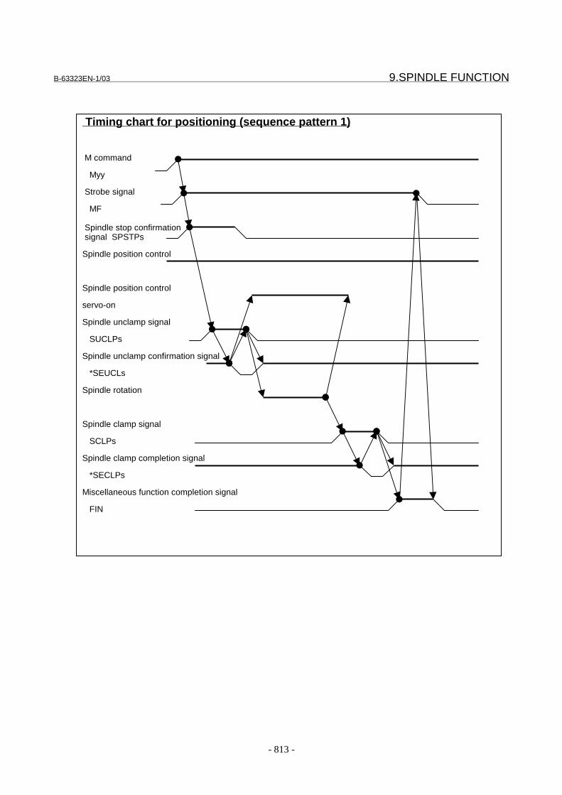
B-63323EN-1/03 9.SPINDLE FUNCTION
- 813 -
Timing chart for positioning (sequence pattern 1)
M command
Myy
Strobe signal
MF
Spindle stop confirmation signal SPSTPs
Spindle position control
Spindle position control
servo-on
Spindle unclamp signal
SUCLPs
Spindle unclamp confirmation signal
*SEUCLs
Spindle rotation
Spindle clamp signal
SCLPs
Spindle clamp completion signal
*SECLPs
Miscellaneous function completion signal
FIN
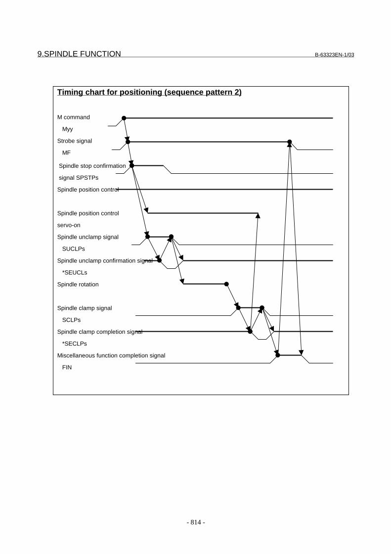
9.SPINDLE FUNCTION B-63323EN-1/03
- 814 -
Timing chart for positioning (sequence pattern 2)
M command
Myy
Strobe signal
MF
Spindle stop confirmation
signal SPSTPs
Spindle position control
Spindle position control
servo-on
Spindle unclamp signal
SUCLPs
Spindle unclamp confirmation signal
*SEUCLs
Spindle rotation
Spindle clamp signal
SCLPs
Spindle clamp completion signal
*SECLPs
Miscellaneous function completion signal
FIN
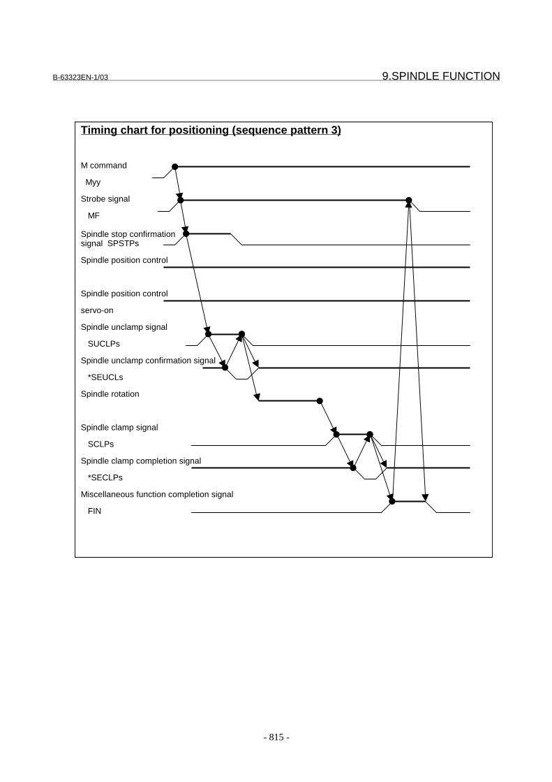
B-63323EN-1/03 9.SPINDLE FUNCTION
- 815 -
Timing chart for positioning (sequence pattern 3)
M command
Myy
Strobe signal
MF
Spindle stop confirmationsignal SPSTPs
Spindle position control
Spindle position control
servo-on
Spindle unclamp signal
SUCLPs
Spindle unclamp confirmation signal
*SEUCLs
Spindle rotation
Spindle clamp signal
SCLPs
Spindle clamp completion signal
*SECLPs
Miscellaneous function completion signal
FIN
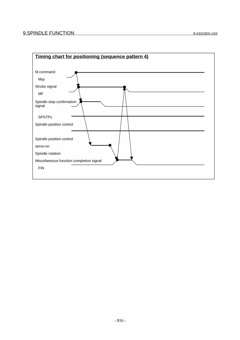
9.SPINDLE FUNCTION B-63323EN-1/03
- 816 -
Timing chart for positioning (sequence pattern 4)
M command
Myy
Strobe signal
MF
Spindle stop confirmationsignal
SPSTPs
Spindle position control
Spindle position control
servo-on
Spindle rotation
Miscellaneous function completion signal
FIN
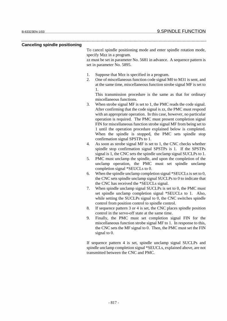
B-63323EN-1/03 9.SPINDLE FUNCTION
- 817 -
Canceling spindle positioningTo cancel spindle positioning mode and enter spindle rotation mode,specify Mzz in a program.zz must be set in parameter No. 5681 in advance. A sequence pattern isset in parameter No. 5895.
1. Suppose that Mzz is specified in a program.2. One of miscellaneous function code signal M0 to M31 is sent, and
at the same time, miscellaneous function strobe signal MF is set to1.This transmission procedure is the same as that for ordinarymiscellaneous functions.
3. When strobe signal MF is set to 1, the PMC reads the code signal.After confirming that the code signal is zz, the PMC must respondwith an appropriate operation. In this case, however, no particularoperation is required. The PMC must present completion signalFIN for miscellaneous function strobe signal MF from being set to1 until the operation procedure explained below is completed.When the spindle is stopped, the PMC sets spindle stopconfirmation signal SPSTPs to 1.
4. As soon as strobe signal MF is set to 1, the CNC checks whetherspindle stop confirmation signal SPSTPs is 1. If the SPSTPssignal is 1, the CNC sets the spindle unclamp signal SUCLPs to 1.
5. PMC must unclamp the spindle, and upon the completion of theunclamp operation, the PMC must set spindle unclampcompletion signal *SEUCLs to 0.
6. When the spindle unclamp completion signal *SEUCLs is set to 0,the CNC sets spindle unclamp signal SUCLPs to 0 to indicate thatthe CNC has received the *SEUCLs signal.
7. When spindle unclamp signal SUCLPs is set to 0, the PMC mustset spindle unclamp completion signal *SEUCLs to 1. Also,while setting the SUCLPs signal to 0, the CNC switches spindlecontrol from position control to spindle control.
8. If sequence pattern 3 or 4 is set, the CNC places spindle positioncontrol in the servo-off state at the same time.
9. Finally, the PMC must set completion signal FIN for themiscellaneous function strobe signal MF to 1. In response to this,the CNC sets the MF signal to 0. Then, the PMC must set the FINsignal to 0.
If sequence pattern 4 is set, spindle unclamp signal SUCLPs andspindle unclamp completion signal *SEUCLs, explained above, are nottransmitted between the CNC and PMC.
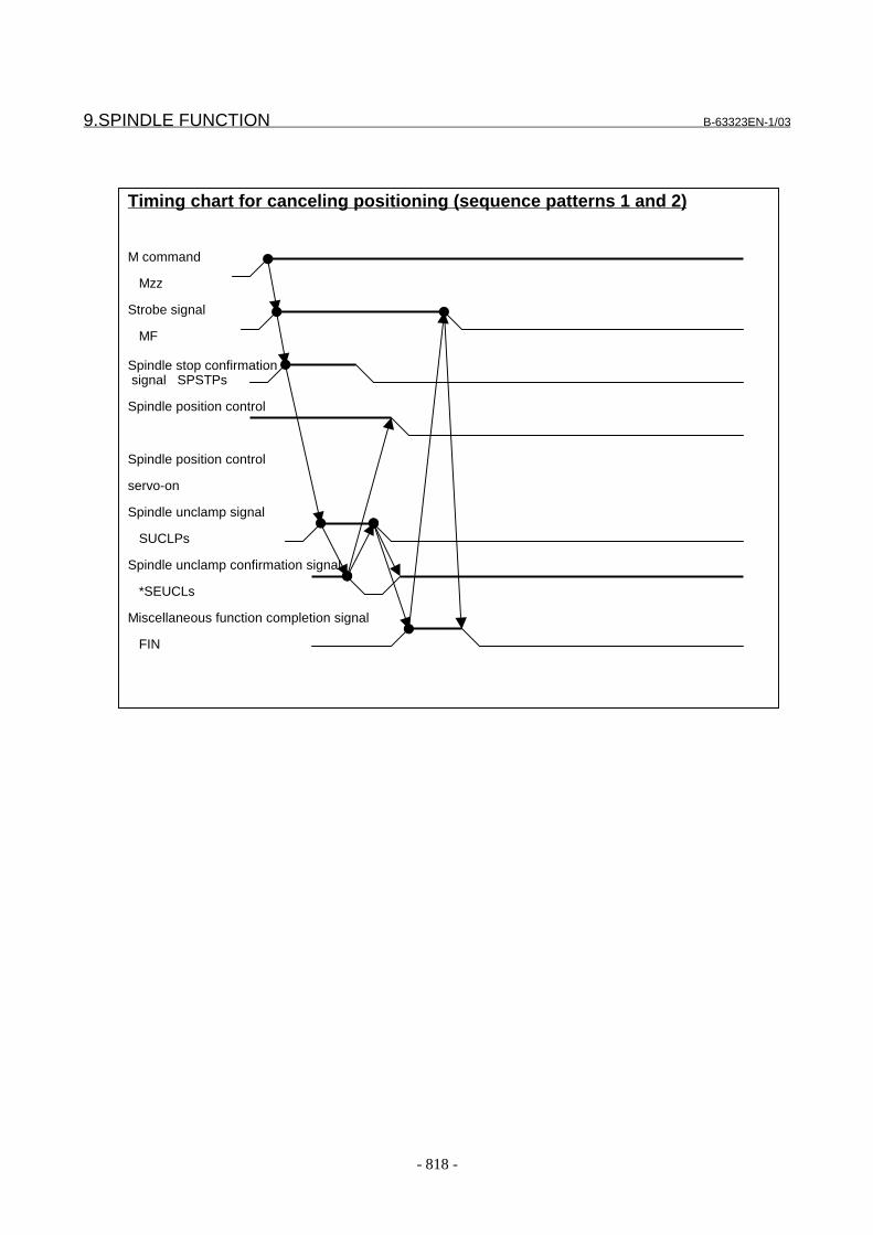
9.SPINDLE FUNCTION B-63323EN-1/03
- 818 -
Timing chart for canceling positioning (sequence patterns 1 and 2)
M command
Mzz
Strobe signal
MF
Spindle stop confirmation signal SPSTPs
Spindle position control
Spindle position control
servo-on
Spindle unclamp signal
SUCLPs
Spindle unclamp confirmation signal
*SEUCLs
Miscellaneous function completion signal
FIN

B-63323EN-1/03 9.SPINDLE FUNCTION
- 819 -
Timing chart for canceling positioning (sequence patterns 3)
M command
Mzz
Strobe signal
MF
Spindle stop confirmationsignal SPSTPs
Spindle position control
Spindle position control
servo-on
Spindle unclamp signal
SUCLPs
Spindle unclamp confirmation signal
*SEUCLs
Miscellaneous function completion signal
FIN
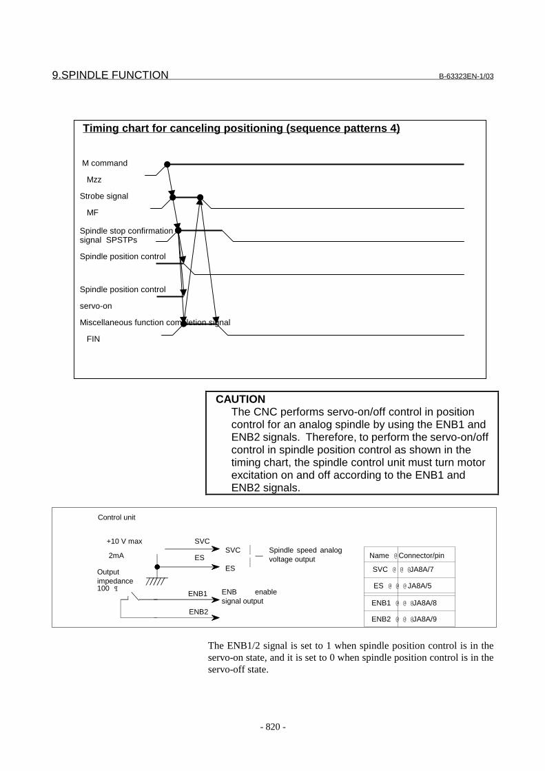
9.SPINDLE FUNCTION B-63323EN-1/03
- 820 -
CAUTIONThe CNC performs servo-on/off control in positioncontrol for an analog spindle by using the ENB1 andENB2 signals. Therefore, to perform the servo-on/offcontrol in spindle position control as shown in thetiming chart, the spindle control unit must turn motorexcitation on and off according to the ENB1 andENB2 signals.
The ENB1/2 signal is set to 1 when spindle position control is in theservo-on state, and it is set to 0 when spindle position control is in theservo-off state.
Timing chart for canceling positioning (sequence patterns 4)
M command
Mzz
Strobe signal
MF
Spindle stop confirmationsignal SPSTPs
Spindle position control
Spindle position control
servo-on
Miscellaneous function completion signal
FIN
ENB2
ENB enablesignal output
Spindle speed analogvoltage output
SVC
ES
ES
SVC
ENB1
Control unit
+10 V max
2mA
Outputimpedance100 
Name @ Connector/pin
SVC @ @ @JA8A/7
ES @ @ @ JA8A/5
ENB1 @ @ @JA8A/8
ENB2 @ @ @JA8A/9

B-63323EN-1/03 9.SPINDLE FUNCTION
- 821 -
Parameter- Common to analog and serial spindles
#7 #6 #5 #4 #3 #2 #1 #0
1005 PLZ ALZ ZMG ZRN
���������� �������������
��������� ������
� � � � �� !"# ��������$%�%���&�����������������������������&���&��������%����&
'��������&�����������&$��(&����������������������&��������
&���������&����)��&������&%���%���%��$�%�*��������)
��&����&�����&�+
0: Issue an alarm ("PS181 ZERO RETURN NOT FINISHED").
1: Do not issue an alarm but execute operation.
For the spindle positioning axis which does not need reference position return, set 1.
� � � � ��� !,* ��������������������&���&����������%&���&����%�����+
-� � *������%&�
�-� � ,�)�����$�%���%&�
.&��%�����������&���&���)�����/�������� +
� � � � ��� 01! ��������%����%&��&������&����&��������������&���&�������
�*���+
- "�����&�����������&���&������)��&���&���)�&��&��������
��������+
�������������&���&��������%����&�'��������&�����������&$��(&�/�����
����&���������)�%�������&�����&����2������&�����������������
�&���&�������+
�- 3���%�������&�����&����2���������&�������������������&���&�
�����+
.&��%�����������&���&���)�����/���� +
� � � � ��4 �1! ��������%��&����&���&���������)�%��$&�5�&&�������������$%��
�����������������&���&���������������&����+
- ������&����$%�����������������+)+�6����)�������&���+
�- 0�$���������+
���!#�/�'����&�����������#&+��7 �/�$%�%����&��&��&���������+
.&��%�����������&���&���)�����/�����+

9.SPINDLE FUNCTION B-63323EN-1/03
- 822 -
#7 #6 #5 #4 #3 #2 #1 #0
1006 DIA ROP ROS ROT
���������� �������������
��������� ������
� � � � �� "68 ��������$%�%���%���������2��������%9�����&������&�+
0: Axis requires inch/metric conversion (linear axis).
1: Axis does not require inch/metric conversion (rotation axis).
For the spinlde positioning axis, set 1.
� � � � ��� "6 ��������$%�%���%����%����&&�������������������&����&5��%�5
������&��������������&���&������������������&���&��&���+
0: Linear (linear axis)
1: Rotation (rotation axis)
For the spinlde positioning axis, set 1.
� � � � ��� "6� ��������$%�%���%����%����&&������������������&�����&���%�
����������%����&��&�������&������������&���&��&���+
0: Linear (linear axis)
1: Rotation (rotation axis)
For the spinlde positioning axis, set 1.
� � � � ��4 ��0 ,&���&��������&����%�����������������������)-
0: Radius specification
1: Diameter specification
If bit 5 (PDC) of parameter No. 1001 is 1, DIA has the following meaning:
The scale of the parameter, offset, and graphic screens is indicated using:
0: Radius specification
1: Diameter specification
For the spinlde positioning axis, set 0.
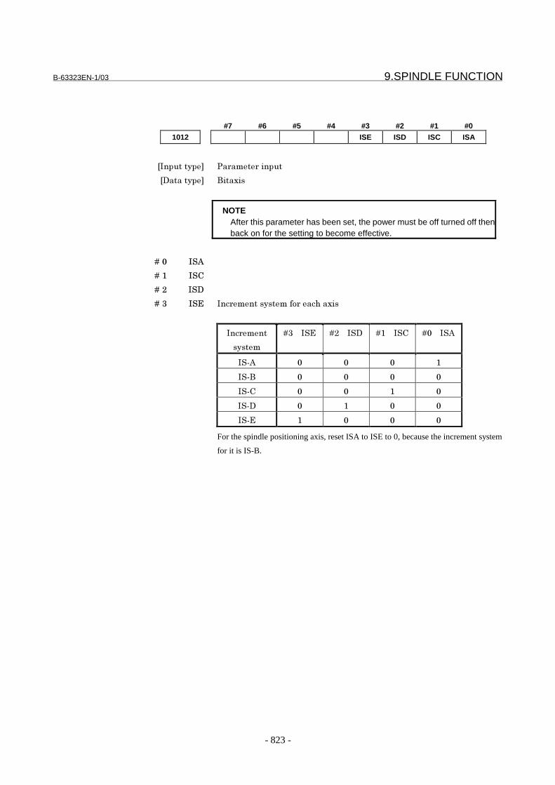
B-63323EN-1/03 9.SPINDLE FUNCTION
- 823 -
#7 #6 #5 #4 #3 #2 #1 #0
1012 ISE ISD ISC ISA
���������� �������������
��������� ������
NOTEAfter this parameter has been set, the power must be off turned off thenback on for the setting to become effective.
� � � � �� � 0
� � � � ��� � :
� � � � ��� � �
� � � � ��4 � ; ���������������&����%�����
�������
�����
�4� � � ; ��� � � � ��� � � : � � � � 0
� (0 �
� (�
� (: �
� (� �
� (; �
For the spindle positioning axis, reset ISA to ISE to 0, because the increment system
for it is IS-B.

9.SPINDLE FUNCTION B-63323EN-1/03
- 824 -
1020 Program axis name for each axis
���������� �������������
��������� ���)������
�<������������)�� =>�(�?
The programmed axis name of each controlled axis is set according to the following
table:
Axis name Setting
X 88
Y 89
Z 90
A 65
B 66
C 67
U 85
V 86
W 87
NOTE
1 When the option for tool axis direction tool length compensation
is provided, always set the A, B, or C value.
2 When the axis name extension function (option) is used, the
following addresses can be used as axis names:
Axis name Setting
I 73
J 74
K 75
E 69
1023 Servo axis number of each axis
NOTEAfter this parameter has been set, the power must be off turned off thenback on for the setting to become effective.
���������� �������������
��������� ���)������
�<������������)�� �(��
Specify the number of the servo axis that corresponds to each control axis.
For the spindle positioning axis , set 0.

B-63323EN-1/03 9.SPINDLE FUNCTION
- 825 -
1027 Spindle number of a spindle positioning axis
NOTEAfter this parameter has been set, the power must be off turned off thenback on for the setting to become effective.
���������� �������������
��������� ���)������
�<������������)�� �(�7
��%����������'����&����%�&��&������/����&�'����&��$�%
���������#&+�� �4+
������%��&��&�������&��$%�%�&�����&������������&���&���)/�'�
����)�%�������������'�����&�%���&&�����'�����&��%�����������+
8%���&��&$��)�������&����������&���-
(� � �� ��&��%&���&��&�������&��$%�%����������&���&���)�����&�&�'�
����&����+
(� � 0����)��������������&�'�����&����&���������&��&������+
(� � 0����������������&���&���)���������%�����'���&��������������'�
��+
(� � 0����������&���&���)����������'����������&��%������&����&��&�
����+
;���������� � ���&�����-� � @/�A/�!
� � � � � � � � � � ��������&���&���)�����-� � :�� ��
� � � � � � � � � � #��'���&����������-� � �
:&��&����(
��������'��
��������
#&+�� �
��������
#&+�� �4
��������
#&+�� �B
P W W i w j P O
Q W X i x j Q O
R X O i y j R O
S U V i b j O P
;���������� � ���&�����-� � @/�!
� � � � � � � � � � ��������&���&���)�����-� � :� ��/��� ��
� � � � � � � � � � #��'���&����������-� � �
:&��&����(
��������'��
��������
#&+�� �
��������
#&+�� �4
��������
#&+�� �B
P W W i w j P O
Q X O i y j Q O
R U V i b j O P
S U U i a j O Q
NOTENote that this parameter is changed when automatic setting isperformed on the FSSB setting screen.
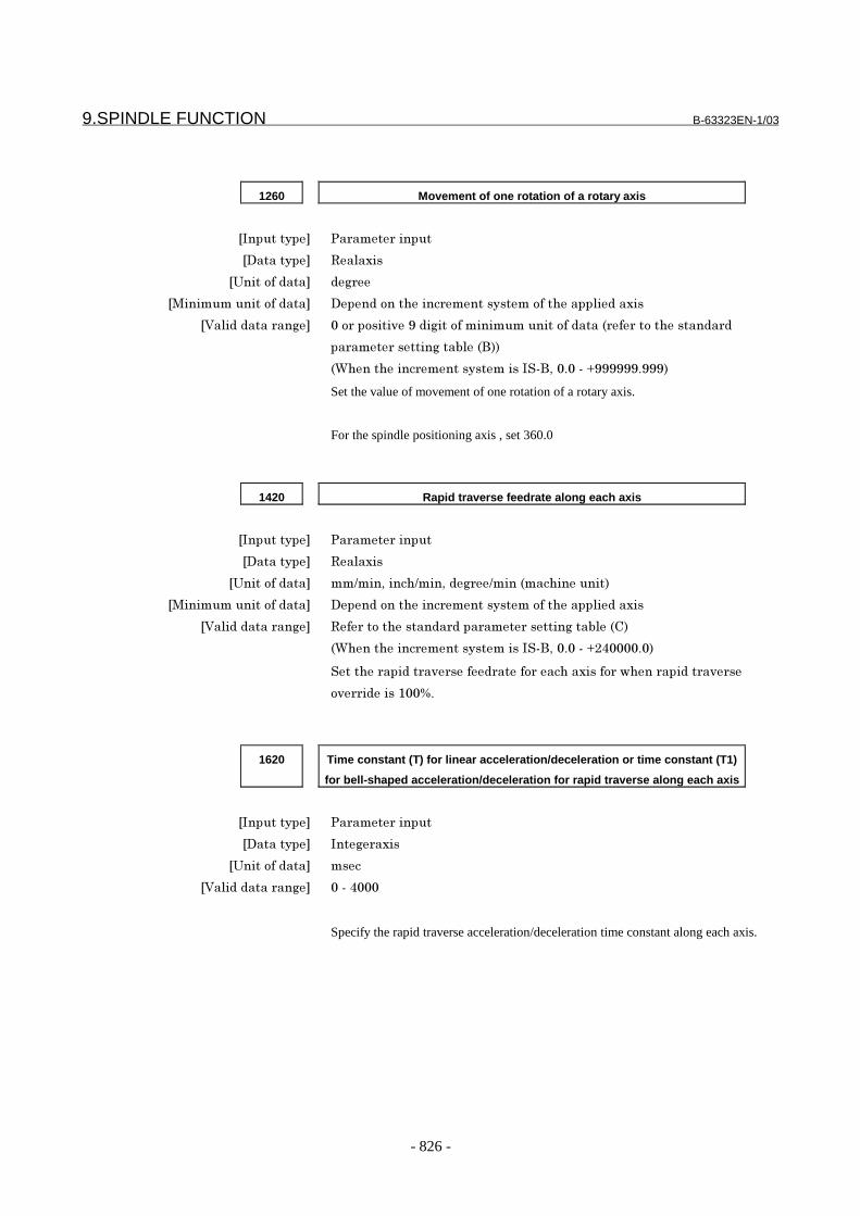
9.SPINDLE FUNCTION B-63323EN-1/03
- 826 -
1260 Movement of one rotation of a rotary axis
���������� �������������
��������� "�������
�3���&������ ��)���
�,�����������&������ �������&��%����������������&��%��������������
�<������������)�� �&���&������?���)��&��������������&�������������&�%���������
�������������)��'�������
�C%���%�������������������� (�/� + �(�D??????+???�
Set the value of movement of one rotation of a rotary axis.
For the spindle positioning axis , set 360.0
1420 Rapid traverse feedrate along each axis
���������� �������������
��������� "�������
�3���&������ ��9���/���%9���/���)���9�������%��������
�,�����������&������ �������&��%����������������&��%��������������
�<������������)�� "�����&�%�����������������������)��'����:�
�C%���%�������������������� (�/� + �(�D�7 + �
��%�������������������������&����%�������&��$%����������������
&������������ E+
1620 Time constant (T) for linear acceleration/deceleration or time constant (T1)
for bell-shaped acceleration/deceleration for rapid traverse along each axis
���������� �������������
��������� ���)������
�3���&������ ���
�<������������)�� �(�7
Specify the rapid traverse acceleration/deceleration time constant along each axis.

B-63323EN-1/03 9.SPINDLE FUNCTION
- 827 -
1621 FL feedrate for linear or bell-shaped acceleration/deceleration for rapid
traverse along each axis
���������� �������������
��������� "�������
�3���&������ ��9���/���%9���/���)���9�������%��������
�,�����������&������ �������&��%����������������&��%��������������
�<������������)�� "�����&�%�����������������������)��'����:�
�C%���%�������������������� (�/� + �(�D??????+???�
Specify the FL feedrate for linear or bell-shaped acceleration/deceleration or rapid
traverse along each axis.
1820 Command multiplier for each axis (CMR)
NOTEAfter this parameter has been set, the power must be off turned off thenback on for the setting to become effective.
���������� �������������
��������� ���)������
�3���&������ +>
�<������������)�� ��&�?=
For the spindle positioning axis , set 2
#7 #6 #5 #4 #3 #2 #1 #0
2203 MCN
���������� �������������
��������� ��
� � � � ��� ,:# 8%����%�����&���&�����������������&��%��:"8-
- ���������������&����������������%����&�������%����&�������%
��%���������������&��%������&�����+
�- ���������������&������������&�������%����&����%�����+
For the spindle positioning axis , set 1

9.SPINDLE FUNCTION B-63323EN-1/03
- 828 -
#7 #6 #5 #4 #3 #2 #1 #0
5605 IOR
���������� �������������
��������� ���������
� � � � ��7 �6" ��������$%�%���&������%�����������&���&���)��&�����&������+
- �&��&�����+
�- :����+
5680 M code for specifying spindle orientation
���������� �������������
��������� ���)���������
�<������������)�� =�(�?B
�����,�&����&����������&������&��&�����������&���&���)�����
NOTE- When this parameter is set to 0, all spindle positioning functionsfor the spindle are disabled.- M00 to M05, M30, M98, and M99 cannot be set.- No other M codes for the spindle positioning function can beset at the same time.- M codes used for other functions cannot be set at the sametime.
5681 M code for canceling the spindle positioning mode
���������� �������������
��������� ���)���������
�<������������)�� =�(�?B
�����,�&����&��������)�%�����������&���&���)��&���&���������
�&���&���)�����+
NOTE- M00 to M05, M30, M98, and M99 cannot be set.- No other M codes for the spindle positioning function can beset at the same time.- M codes used for other functions cannot be set at the sametime.
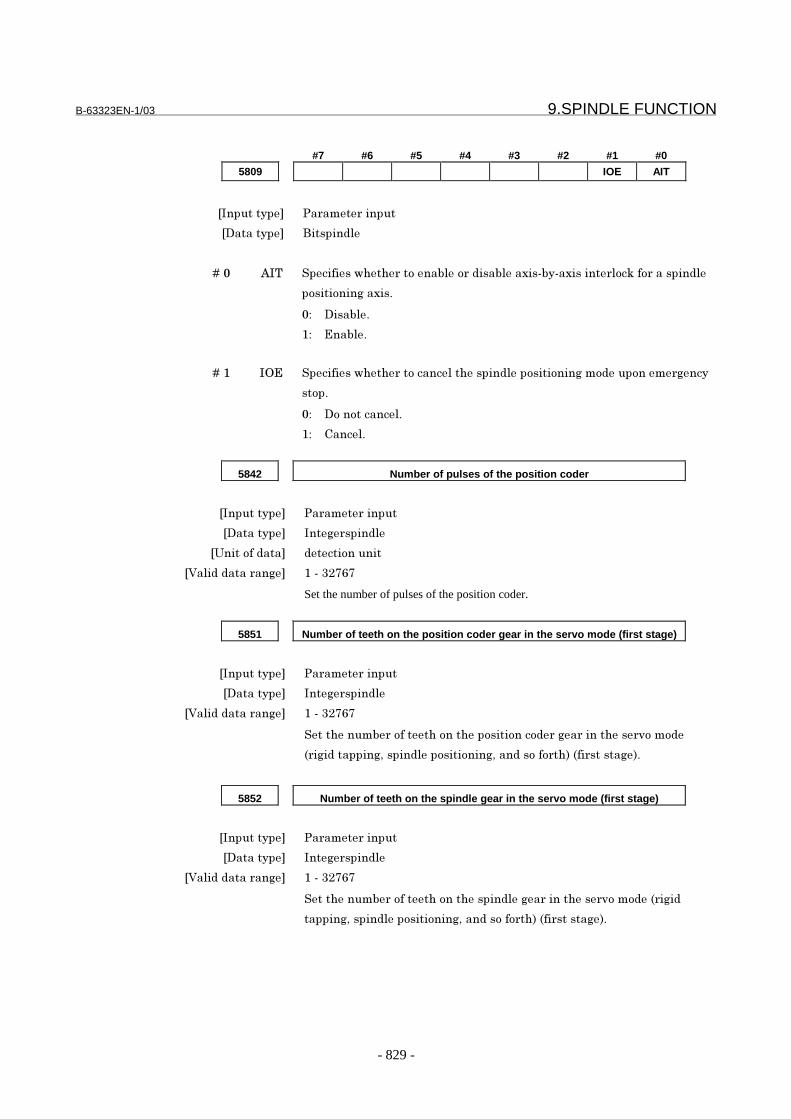
B-63323EN-1/03 9.SPINDLE FUNCTION
- 829 -
#7 #6 #5 #4 #3 #2 #1 #0
5809 IOE AIT
���������� �������������
��������� ���������
� � � � �� 0�8 ��������$%�%���&����'���&������'�������('�(����������&5��&�����������
�&���&���)�����+
- ����'��+
�- ;��'��+
� � � � ��� �6; ��������$%�%���&������%�����������&���&���)��&�����&������)���
�&�+
- �&��&�����+
�- :����+
5842 Number of pulses of the position coder
���������� �������������
��������� ���)���������
�3���&������ ����&�����
�<������������)�� ��(�4�B=B
Set the number of pulses of the position coder.
5851 Number of teeth on the position coder gear in the servo mode (first stage)
���������� �������������
��������� ���)���������
�<������������)�� ��(�4�B=B
��%�����'���&����%�&��%���&���&��&����)�������%������&��&��
���)��������)/����������&���&���)/������&��&�%����������)��+
5852 Number of teeth on the spindle gear in the servo mode (first stage)
���������� �������������
��������� ���)���������
�<������������)�� ��(�4�B=B
��%�����'���&����%�&��%����������)�������%������&��&������)��
�����)/����������&���&���)/������&��&�%����������)��+

9.SPINDLE FUNCTION B-63323EN-1/03
- 830 -
5853 Backlash compensation in the servo mode (first stage)
���������� �������������
��������� ���)���������
�3���&������ ����&�����
�<������������)�� (????�(�????
����'�5���%�&�������&�����%������&��&������)��������)/��������
�&���&���)/������&��&�%����������)��+
5854 Number of teeth on the position coder gear in the servo mode (second stage)
���������� �������������
��������� ���)���������
�<������������)�� ��(�4�B=B
��%�����'���&����%�&��%���&���&��&����)�������%������&��&��
���)��������)/����������&���&���)/������&��&�%�����&�����)��+
5855 Number of teeth on the spindle gear in the servo mode (second stage)
���������� �������������
��������� ���)���������
�<������������)�� ��(�4�B=B
��%�����'���&����%�&��%����������)�������%������&��&������)��
�����)/����������&���&���)/������&��&�%�����&�����)��+
5856 Backlash compensation in the servo mode (second stage)
���������� �������������
��������� ���)���������
�3���&������ ����&�����
�<������������)�� (????�(�????
����'�5���%�&�������&�����%������&��&������)��������)/��������
�&���&���)/������&��&�%�����&�����)��+
5857 Number of teeth on the position coder gear in the servo mode (third stage)
���������� �������������
��������� ���)���������
�<������������)�� ��(�4�B=B
��%�����'���&����%�&��%���&���&��&����)�������%������&��&��
���)��������)/����������&���&���)/������&��&�%���%������)��+

B-63323EN-1/03 9.SPINDLE FUNCTION
- 831 -
5858 Number of teeth on the spindle gear in the servo mode (third stage)
���������� �������������
��������� ���)���������
�<������������)�� ��(�4�B=B
��%�����'���&����%�&��%����������)�������%������&��&������)��
�����)/����������&���&���)/������&��&�%���%������)��+
5859 Backlash compensation in the servo mode (third stage)
���������� �������������
��������� ���)���������
�3���&������ ����&�����
�<������������)�� (????�(�????
����'�5���%�&�������&�����%������&��&������)��������)/��������
�&���&���)/������&��&�%���%������)��+
5860 Number of teeth on the position coder gear in the servo mode (fourth stage)
���������� �������������
��������� ���)���������
�<������������)�� ��(�4�B=B
��%�����'���&����%�&��%���&���&��&����)�������%������&��&��
���)��������)/����������&���&���)/������&��&�%����&��%���)��+
5861 Number of teeth on the spindle gear in the servo mode (fourth stage)
���������� �������������
��������� ���)���������
�<������������)�� ��(�4�B=B
��%�����'���&����%�&��%����������)�������%������&��&������)��
�����)/����������&���&���)/������&��&�%����&��%���)��+
5862 Backlash compensation in the servo mode (fourth stage)
���������� �������������
��������� ���)���������
�3���&������ ����&�����
�<������������)�� (????�(�????
����'�5���%�&�������&�����%������&��&������)��������)/��������
�&���&���)/������&��&�%����&��%���)��+

9.SPINDLE FUNCTION B-63323EN-1/03
- 832 -
5863 Number of teeth on the position coder gear in the servo mode (fifth stage)
���������� �������������
��������� ���)���������
�<������������)�� ��(�4�B=B
��%�����'���&����%�&��%���&���&��&����)�������%������&��&��
���)��������)/����������&���&���)/������&��&�%������%���)��+
5864 Number of teeth on the spindle gear in the servo mode (fifth stage)
���������� �������������
��������� ���)���������
�<������������)�� ��(�4�B=B
��%�����'���&����%�&��%����������)�������%������&��&������)��
�����)/����������&���&���)/������&��&�%������%���)��+
5865 Backlash compensation in the servo mode (fifth stage)
���������� �������������
��������� ���)���������
�3���&������ ����&�����
�<������������)�� (????�(�????
����'�5���%�&�������&�����%������&��&������)��������)/��������
�&���&���)/������&��&�%������%���)��+
5866 Number of teeth on the position coder gear in the servo mode (sixth stage)
���������� �������������
��������� ���)���������
�<������������)�� ��(�4�B=B
��%�����'���&����%�&��%���&���&��&����)�������%������&��&��
���)��������)/����������&���&���)/������&��&�%������%���)��+
5867 Number of teeth on the spindle gear in the servo mode (sixth stage)
���������� �������������
��������� ���)���������
�<������������)�� ��(�4�B=B
��%�����'���&����%�&��%����������)�������%������&��&������)��
�����)/����������&���&���)/������&��&�%������%���)��+
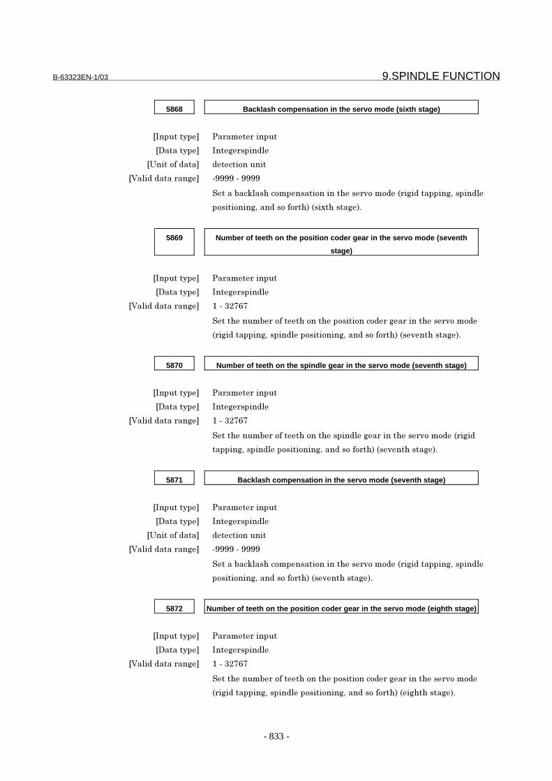
B-63323EN-1/03 9.SPINDLE FUNCTION
- 833 -
5868 Backlash compensation in the servo mode (sixth stage)
���������� �������������
��������� ���)���������
�3���&������ ����&�����
�<������������)�� (????�(�????
����'�5���%�&�������&�����%������&��&������)��������)/��������
�&���&���)/������&��&�%������%���)��+
5869 Number of teeth on the position coder gear in the servo mode (seventh
stage)
���������� �������������
��������� ���)���������
�<������������)�� ��(�4�B=B
��%�����'���&����%�&��%���&���&��&����)�������%������&��&��
���)��������)/����������&���&���)/������&��&�%��������%���)��+
5870 Number of teeth on the spindle gear in the servo mode (seventh stage)
���������� �������������
��������� ���)���������
�<������������)�� ��(�4�B=B
��%�����'���&����%�&��%����������)�������%������&��&������)��
�����)/����������&���&���)/������&��&�%��������%���)��+
5871 Backlash compensation in the servo mode (seventh stage)
���������� �������������
��������� ���)���������
�3���&������ ����&�����
�<������������)�� (????�(�????
����'�5���%�&�������&�����%������&��&������)��������)/��������
�&���&���)/������&��&�%��������%���)��+
5872 Number of teeth on the position coder gear in the servo mode (eighth stage)
���������� �������������
��������� ���)���������
�<������������)�� ��(�4�B=B
��%�����'���&����%�&��%���&���&��&����)�������%������&��&��
���)��������)/����������&���&���)/������&��&�%�����)%%���)��+
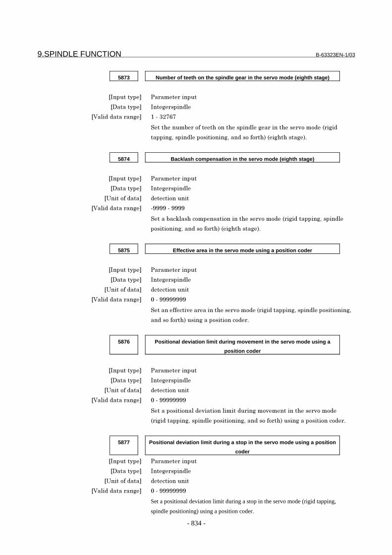
9.SPINDLE FUNCTION B-63323EN-1/03
- 834 -
5873 Number of teeth on the spindle gear in the servo mode (eighth stage)
���������� �������������
��������� ���)���������
�<������������)�� ��(�4�B=B
��%�����'���&����%�&��%����������)�������%������&��&������)��
�����)/����������&���&���)/������&��&�%�����)%%���)��+
5874 Backlash compensation in the servo mode (eighth stage)
���������� �������������
��������� ���)���������
�3���&������ ����&�����
�<������������)�� (????�(�????
����'�5���%�&�������&�����%������&��&������)��������)/��������
�&���&���)/������&��&�%�����)%%���)��+
5875 Effective area in the servo mode using a position coder
���������� �������������
��������� ���)���������
�3���&������ ����&�����
�<������������)�� �(�????????
���������������������%������&��&������)��������)/����������&���&���)/
�����&��&�%������)����&���&��&���+
5876 Positional deviation limit during movement in the servo mode using a
position coder
���������� �������������
��������� ���)���������
�3���&������ ����&�����
�<������������)�� �(�????????
�����&���&����������&������������)��&���������%������&��&��
���)��������)/����������&���&���)/������&��&�%������)����&���&��&���+
5877 Positional deviation limit during a stop in the servo mode using a position
coder
���������� �������������
��������� ���)���������
�3���&������ ����&�����
�<������������)�� �(�????????
Set a positional deviation limit during a stop in the servo mode (rigid tapping,
spindle positioning) using a position coder.
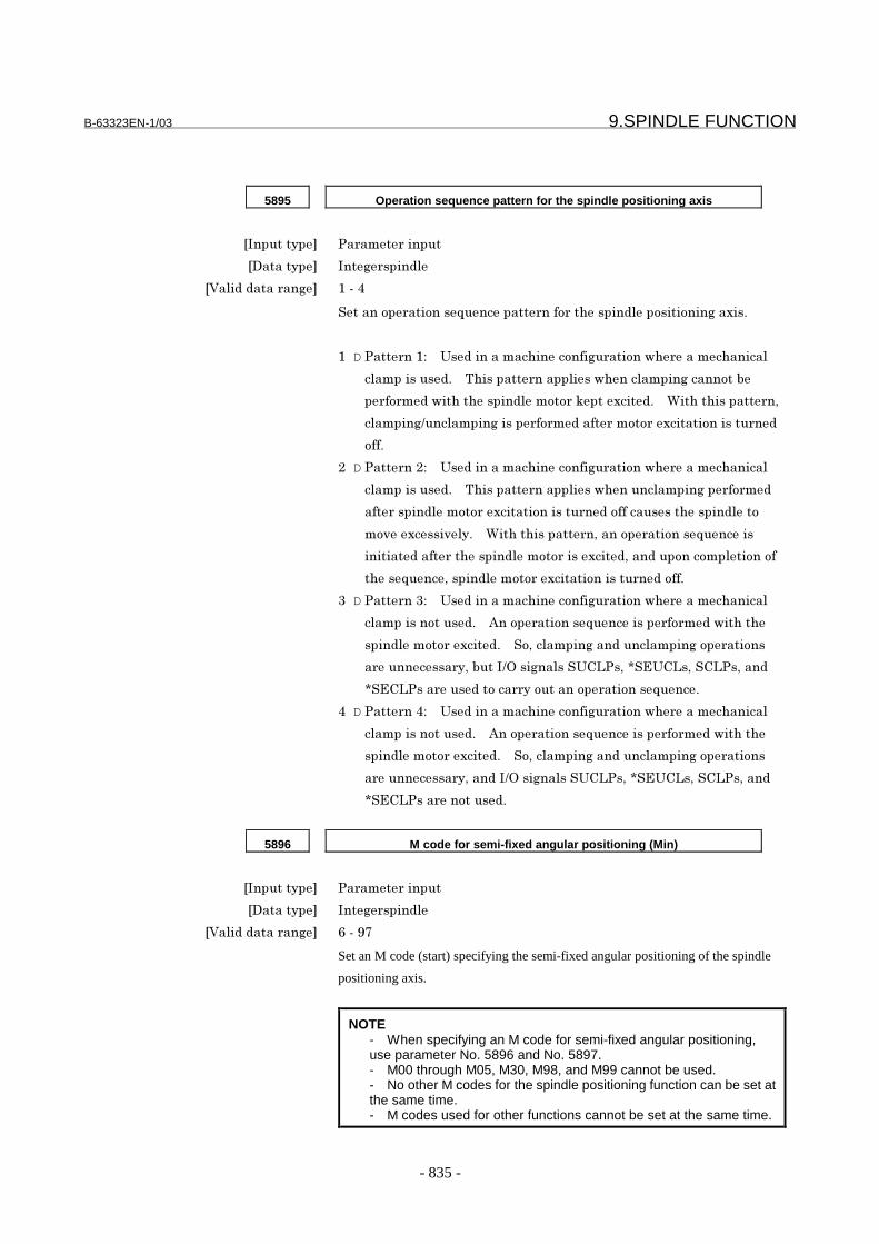
B-63323EN-1/03 9.SPINDLE FUNCTION
- 835 -
5895 Operation sequence pattern for the spindle positioning axis
���������� �������������
��������� ���)���������
�<������������)�� ��(�7
�����&�����&����2������������&��%�����������&���&���)�����+
� D �������-� � 3�����������%����&���)����&��$%��������%�����
������������+� � 8%�����������������$%���������)����&�'�
����&�����$�%�%�����������&&��5��������+� � C�%�%��������/
������)9��������)��������&�����������&&�������&����������
&��+
� D �������-� � 3�����������%����&���)����&��$%��������%�����
������������+� � 8%�����������������$%�����������)�����&����
��������������&&�������&�����������&���������%����������&
�&�������������+� � C�%�%��������/����&�����&����2�������
�������������%�����������&&����������/�������&��&�����&��&�
%����2����/����������&&�������&�����������&��+
4 D ������4-� � 3�����������%����&���)����&��$%��������%�����
���������&�����+� � 0��&�����&����2������������&�����$�%�%�
���������&&�������+� � &/�������)�������������)�&�����&��
��������������/�'���96���)����� 3:1��/�F ;3:1�/� :1��/����
F ;:1������������&������&�����&�����&����2����+
7 D ������7-� � 3�����������%����&���)����&��$%��������%�����
���������&�����+� � 0��&�����&����2������������&�����$�%�%�
���������&&�������+� � &/�������)�������������)�&�����&��
��������������/������96���)����� 3:1��/�F ;3:1�/� :1��/����
F ;:1��������&�����+
5896 M code for semi-fixed angular positioning (Min)
���������� �������������
��������� ���)���������
�<������������)�� =�(�?B
Set an M code (start) specifying the semi-fixed angular positioning of the spindle
positioning axis.
NOTE- When specifying an M code for semi-fixed angular positioning,use parameter No. 5896 and No. 5897.- M00 through M05, M30, M98, and M99 cannot be used.- No other M codes for the spindle positioning function can be set atthe same time.- M codes used for other functions cannot be set at the same time.

9.SPINDLE FUNCTION B-63323EN-1/03
- 836 -
5897 M code for semi-fixed angular positioning (Max)
���������� �������������
��������� ���)���������
�<������������)�� =�(�?B
�����,�&�����������������)�%������(��������)������&���&���)�&��%�
���������&���&���)�����+
NOTE- When specifying an M code for semi-fixed angular positioning,use parameter No. 5896 and No. 5897.- M00 through M05, M30, M98, and M99 cannot be used.- No other M codes for the spindle positioning function can beset at the same time.- M codes used for other functions cannot be set at the sametime.
5898 Basic angle for semi-fixed angular positioning
[Input type] Parameter input[Data type] Realspindle
[Unit of data] degree[Minimum unit of data] Depend on the increment system of the applied axis
[Valid data range] -60 - 60
Set a basic angle for semi-fixed angular positioning. Let α be thesetting of parameter No. 5896, βbe the setting of parameter No. 5897,and γ be the setting of parameter No. 5898. Then, the relationshipbetween the specified M code and the amount of movement is asdescribed below.
M code α α+1 α+2 α+3 . . . βAngular
displacementγ γ×2 γ×3 γ×4 . . . γ× (β-α+1)
- For analog spindles#7 #6 #5 #4 #3 #2 #1 #0
5808 OMI
���������� �������������
��������� ���������
� � � � �� 6,� ��������$%�%���%�����������&���&���)�&������&�������&�����%������
�����&��&�������������&��$%����������&)����������������+
- ����������&�
�- ,����������&�
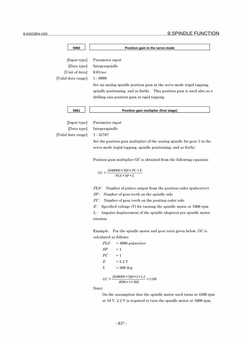
B-63323EN-1/03 9.SPINDLE FUNCTION
- 837 -
5960 Position gain in the servo mode
���������� �������������
��������� ���)���������
�3���&������ + �9��
�<������������)�� ��(�????
���������&)����������&���&��)�������%������&��&������)��������)/
���������&���&���)/������&��&�%�+� � 8%����&���&��)���������������&�����
�������)�������&���&��)���������)��������)+
5961 Position gain multiplier (first stage)
���������� �������������
��������� ���)���������
�<������������)�� ��(�4�B=B
��%���&���&��)��������������&��%������&)����������&��)���������%�
����&��&������)��������)/����������&���&���)/������&��&�%�+
�&���&��)��������������*:����&'��������&��%���&��&$��)��2���&�-
����-� � #��'���&���������&������&��%���&���&��&�����������9����
���-� � #��'���&��)������%�&��%��������������
���-� � #��'���&��)������%�&��%���&���&��&��������
��-� � ���������&��)���<���&�������)�%�����������&&����� ����
��-� � 0�)����������������&��%�������������)�������������������&&�
�&��&�
;������-� � .&��%�����������&&������)�������&�)�����'��&$/�*:���
������������&��&$�-
���� G�7 ?=�������9���
�� G��
�� G��
� G��+��<
� G�4= ���)
#&��
6��%���������&��%��%�����������&&��������������7> ����
��� �</��+��<������2������&�����%�����������&&����� ����+
LSPPLS
EPCGC
×××××= 3602048000
110036014096
2.213602048000 =××
×××=GC
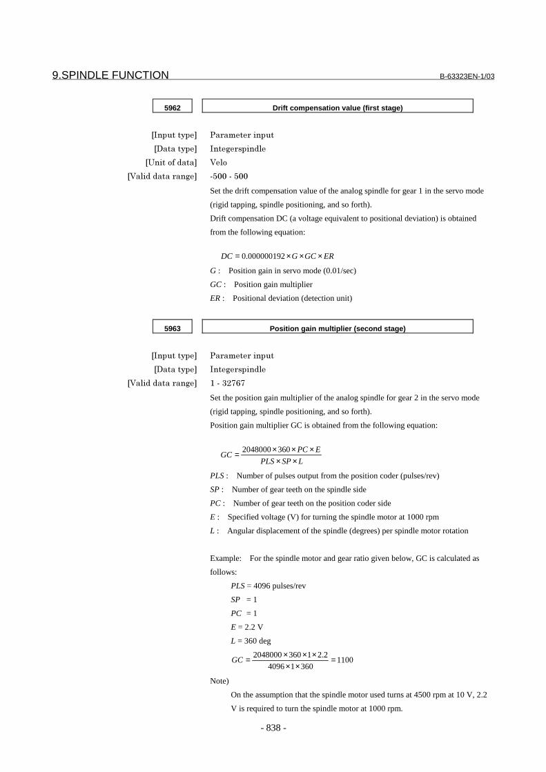
9.SPINDLE FUNCTION B-63323EN-1/03
- 838 -
5962 Drift compensation value (first stage)
���������� �������������
��������� ���)���������
�3���&������ <��&
�<������������)�� (> �(�>
Set the drift compensation value of the analog spindle for gear 1 in the servo mode
(rigid tapping, spindle positioning, and so forth).
Drift compensation DC (a voltage equivalent to positional deviation) is obtained
from the following equation:
G : Position gain in servo mode (0.01/sec)
GC : Position gain multiplier
ER : Positional deviation (detection unit)
ERGCGDC ×××= 000000192.0
5963 Position gain multiplier (second stage)
���������� �������������
��������� ���)���������
�<������������)�� ��(�4�B=B
Set the position gain multiplier of the analog spindle for gear 2 in the servo mode
(rigid tapping, spindle positioning, and so forth).
Position gain multiplier GC is obtained from the following equation:
PLS : Number of pulses output from the position coder (pulses/rev)
SP : Number of gear teeth on the spindle side
PC : Number of gear teeth on the position coder side
E : Specified voltage (V) for turning the spindle motor at 1000 rpm
L : Angular displacement of the spindle (degrees) per spindle motor rotation
Example: For the spindle motor and gear ratio given below, GC is calculated as
follows:
PLS = 4096 pulses/rev
SP = 1
PC = 1
E = 2.2 V
L = 360 deg
Note)
On the assumption that the spindle motor used turns at 4500 rpm at 10 V, 2.2
V is required to turn the spindle motor at 1000 rpm.
LSPPLS
EPCGC
×××××= 3602048000
110036014096
2.213602048000 =××
×××=GC

B-63323EN-1/03 9.SPINDLE FUNCTION
- 839 -
5964 Drift compensation value (second stage)
���������� �������������
��������� ���)���������
�3���&������ <��&
�<������������)�� (> �(�>
Set the drift compensation value of the analog spindle for gear 2 in the servo mode
(rigid tapping, spindle positioning, and so forth).
Drift compensation DC (a voltage equivalent to positional deviation) is obtained
from the following equation:
G : Position gain in servo mode (0.01/sec)
GC : Position gain multiplier
ER : Positional deviation (detection unit)
ERGCGDC ×××= 000000192.0
5965 Position gain multiplier (third stage)
���������� �������������
��������� ���)���������
�<������������)�� ��(�4�B=B
Set the position gain multiplier of the analog spindle for gear 3 in the servo mode
(rigid tapping, spindle positioning, and so forth).
Position gain multiplier GC is obtained from the following equation:
PLS : Number of pulses output from the position coder (pulses/rev)
SP : Number of gear teeth on the spindle side
PC : Number of gear teeth on the position coder side
E : Specified voltage (V) for turning the spindle motor at 1000 rpm
L : Angular displacement of the spindle (degrees) per spindle motor rotation
Example: For the spindle motor and gear ratio given below, GC is calculated as
follows:
PLS = 4096 pulses/rev
SP = 1
PC = 1
E = 2.2 V
L = 360 deg
Note)
On the assumption that the spindle motor used turns at 4500 rpm at 10 V, 2.2
V is required to turn the spindle motor at 1000 rpm.
LSPPLS
EPCGC
×××××= 3602048000
110036014096
2.213602048000 =××
×××=GC

9.SPINDLE FUNCTION B-63323EN-1/03
- 840 -
5966 Drift compensation value (third stage)
���������� �������������
��������� ���)���������
�3���&������ <��&
�<������������)�� (> �(�>
Set the drift compensation value of the analog spindle for gear 3 in the servo mode
(rigid tapping, spindle positioning, and so forth).
Drift compensation DC (a voltage equivalent to positional deviation) is obtained
from the following equation:
G : Position gain in servo mode (0.01/sec)
GC : Position gain multiplier
ER : Positional deviation (detection unit)
ERGCGDC ×××= 000000192.0
5967 Position gain multiplier (fourth stage)
���������� �������������
��������� ���)���������
�<������������)�� ��(�4�B=B
Set the position gain multiplier of the analog spindle for gear 4 in the servo mode
(rigid tapping, spindle positioning, and so forth).
Position gain multiplier GC is obtained from the following equation:
PLS : Number of pulses output from the position coder (pulses/rev)
SP : Number of gear teeth on the spindle side
PC : Number of gear teeth on the position coder side
E : Specified voltage (V) for turning the spindle motor at 1000 rpm
L : Angular displacement of the spindle (degrees) per spindle motor rotation
Example: For the spindle motor and gear ratio given below, GC is calculated as
follows:
PLS = 4096 pulses/rev
SP = 1
PC = 1
E = 2.2 V
L = 360 deg
Note)
On the assumption that the spindle motor used turns at 4500 rpm at 10 V, 2.2
V is required to turn the spindle motor at 1000 rpm.
LSPPLS
EPCGC
×××××= 3602048000
110036014096
2.213602048000 =××
×××=GC
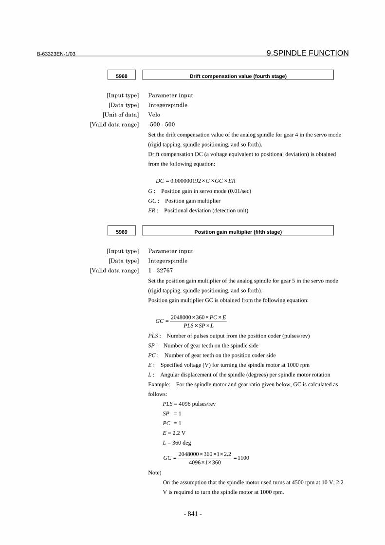
B-63323EN-1/03 9.SPINDLE FUNCTION
- 841 -
5968 Drift compensation value (fourth stage)
���������� �������������
��������� ���)���������
�3���&������ <��&
�<������������)�� (> �(�>
Set the drift compensation value of the analog spindle for gear 4 in the servo mode
(rigid tapping, spindle positioning, and so forth).
Drift compensation DC (a voltage equivalent to positional deviation) is obtained
from the following equation:
G : Position gain in servo mode (0.01/sec)
GC : Position gain multiplier
ER : Positional deviation (detection unit)
ERGCGDC ×××= 000000192.0
5969 Position gain multiplier (fifth stage)
���������� �������������
��������� ���)���������
�<������������)�� ��(�4�B=B
Set the position gain multiplier of the analog spindle for gear 5 in the servo mode
(rigid tapping, spindle positioning, and so forth).
Position gain multiplier GC is obtained from the following equation:
PLS : Number of pulses output from the position coder (pulses/rev)
SP : Number of gear teeth on the spindle side
PC : Number of gear teeth on the position coder side
E : Specified voltage (V) for turning the spindle motor at 1000 rpm
L : Angular displacement of the spindle (degrees) per spindle motor rotation
Example: For the spindle motor and gear ratio given below, GC is calculated as
follows:
PLS = 4096 pulses/rev
SP = 1
PC = 1
E = 2.2 V
L = 360 deg
Note)
On the assumption that the spindle motor used turns at 4500 rpm at 10 V, 2.2
V is required to turn the spindle motor at 1000 rpm.
LSPPLS
EPCGC
×××××= 3602048000
110036014096
2.213602048000 =××
×××=GC

9.SPINDLE FUNCTION B-63323EN-1/03
- 842 -
5970 Drift compensation value (fifth stage)
���������� �������������
��������� ���)���������
�3���&������ <��&
�<������������)�� (> �(�>
Set the drift compensation value of the analog spindle for gear 5 in the servo mode
(rigid tapping, spindle positioning, and so forth).
Drift compensation DC (a voltage equivalent to positional deviation) is obtained
from the following equation:
G : Position gain in servo mode (0.01/sec)
GC : Position gain multiplier
ER : Positional deviation (detection unit)
ERGCGDC ×××= 000000192.0
5971 Position gain multiplier (sixth stage)
���������� �������������
��������� ���)���������
�<������������)�� ��(�4�B=B
Set the position gain multiplier of the analog spindle for gear 6 in the servo mode
(rigid tapping, spindle positioning, and so forth).
Position gain multiplier GC is obtained from the following equation:
PLS : Number of pulses output from the position coder (pulses/rev)
SP : Number of gear teeth on the spindle side
PC : Number of gear teeth on the position coder side
E : Specified voltage (V) for turning the spindle motor at 1000 rpm
L : Angular displacement of the spindle (degrees) per spindle motor rotation
Example: For the spindle motor and gear ratio given below, GC is calculated as
follows:
PLS = 4096 pulses/rev
SP = 1
PC = 1
E = 2.2 V
L = 360 deg
Note)
On the assumption that the spindle motor used turns at 4500 rpm at 10 V, 2.2
V is required to turn the spindle motor at 1000 rpm.
LSPPLS
EPCGC
×××××= 3602048000
110036014096
2.213602048000 =××
×××=GC

B-63323EN-1/03 9.SPINDLE FUNCTION
- 843 -
5972 Drift compensation value (sixth stage)
���������� �������������
��������� ���)���������
�3���&������ <��&
�<������������)�� (> �(�>
Set the drift compensation value of the analog spindle for gear 6 in the servo mode
(rigid tapping, spindle positioning, and so forth).
Drift compensation DC (a voltage equivalent to positional deviation) is obtained
from the following equation:
G : Position gain in servo mode (0.01/sec)
GC : Position gain multiplier
ER : Positional deviation (detection unit)
ERGCGDC ×××= 000000192.0
5973 Position gain multiplier (seventh stage)
���������� �������������
��������� ���)���������
�<������������)�� ��(�4�B=B
Set the position gain multiplier of the analog spindle for gear 7 in the servo mode
(rigid tapping, spindle positioning, and so forth).
Position gain multiplier GC is obtained from the following equation:
PLS : Number of pulses output from the position coder (pulses/rev)
SP : Number of gear teeth on the spindle side
PC : Number of gear teeth on the position coder side
E : Specified voltage (V) for turning the spindle motor at 1000 rpm
L : Angular displacement of the spindle (degrees) per spindle motor rotation
Example: For the spindle motor and gear ratio given below, GC is calculated as
follows:
PLS = 4096 pulses/rev
SP = 1
PC = 1
E = 2.2 V
L = 360 deg
Note)
On the assumption that the spindle motor used turns at 4500 rpm at 10 V, 2.2
V is required to turn the spindle motor at 1000 rpm.
LSPPLS
EPCGC
×××××= 3602048000
110036014096
2.213602048000 =××
×××=GC

9.SPINDLE FUNCTION B-63323EN-1/03
- 844 -
5974 Drift compensation value (seventh stage)
���������� �������������
��������� ���)���������
�3���&������ <��&
�<������������)�� (> �(�>
Set the drift compensation value of the analog spindle for gear 7 in the servo mode
(rigid tapping, spindle positioning, and so forth).
Drift compensation DC (a voltage equivalent to positional deviation) is obtained
from the following equation:
G : Position gain in servo mode (0.01/sec)
GC : Position gain multiplier
ER : Positional deviation (detection unit)
ERGCGDC ×××= 000000192.0
5975 Position gain multiplier (eighth stage)
���������� �������������
��������� ���)���������
�<������������)�� ��(�4�B=B
Set the position gain multiplier of the analog spindle for gear 8 in the servo mode
(rigid tapping, spindle positioning, and so forth).
Position gain multiplier GC is obtained from the following equation:
PLS : Number of pulses output from the position coder (pulses/rev)
SP : Number of gear teeth on the spindle side
PC : Number of gear teeth on the position coder side
E : Specified voltage (V) for turning the spindle motor at 1000 rpm
L : Angular displacement of the spindle (degrees) per spindle motor rotation
Example: For the spindle motor and gear ratio given below, GC is calculated as
follows:
PLS = 4096 pulses/rev
SP = 1
PC = 1
E = 2.2 V
L = 360 deg
Note)
On the assumption that the spindle motor used turns at 4500 rpm at 10 V, 2.2
V is required to turn the spindle motor at 1000 rpm.
LSPPLS
EPCGC
×××××= 3602048000
110036014096
2.213602048000 =××
×××=GC
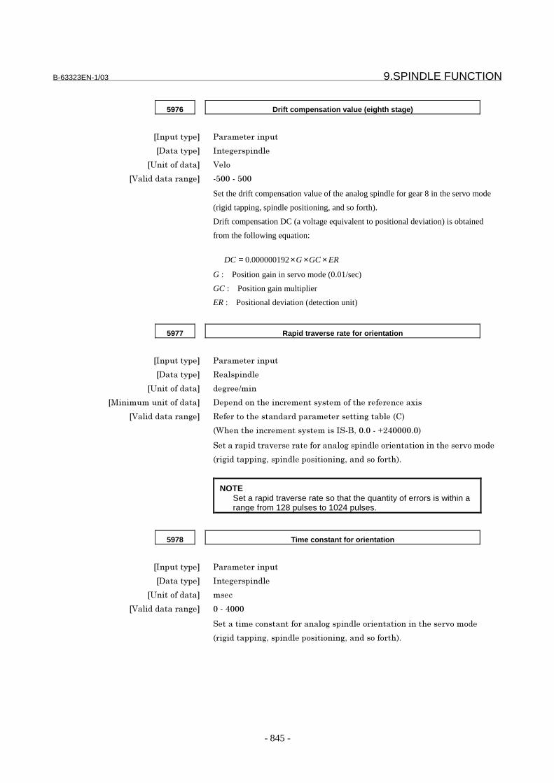
B-63323EN-1/03 9.SPINDLE FUNCTION
- 845 -
5976 Drift compensation value (eighth stage)
���������� �������������
��������� ���)���������
�3���&������ <��&
�<������������)�� (> �(�>
Set the drift compensation value of the analog spindle for gear 8 in the servo mode
(rigid tapping, spindle positioning, and so forth).
Drift compensation DC (a voltage equivalent to positional deviation) is obtained
from the following equation:
G : Position gain in servo mode (0.01/sec)
GC : Position gain multiplier
ER : Positional deviation (detection unit)
ERGCGDC ×××= 000000192.0
5977 Rapid traverse rate for orientation
���������� �������������
��������� "����������
�3���&������ ��)���9���
�,�����������&������ �������&��%����������������&��%���������������
�<������������)�� "�����&�%�����������������������)��'����:�
�C%���%�������������������� (�/� + �(�D�7 + �
�����������������������&������&)���������&������&�����%������&��&��
���)��������)/����������&���&���)/������&��&�%�+
NOTESet a rapid traverse rate so that the quantity of errors is within arange from 128 pulses to 1024 pulses.
5978 Time constant for orientation
���������� �������������
��������� ���)���������
�3���&������ ���
�<������������)�� �(�7
��������&������&������&)���������&������&�����%������&��&��
���)��������)/����������&���&���)/������&��&�%�+

9.SPINDLE FUNCTION B-63323EN-1/03
- 846 -
5979 FL feedrate for orientation
���������� �������������
��������� "����������
�3���&������ ��)���9���
�,�����������&������ �������&��%����������������&��%���������������
�<������������)�� "�����&�%�����������������������)��'����:�
�C%���%�������������������� (�/� + �(�D�7 + �
�����.1����������&������&)���������&������&�����%������&��&������)��
�����)/����������&���&���)/������&��&�%�+
NOTESet an FL feedrate rate so that the quantity of errors is within arange from the effective area to 1024 pulses.
5980 Grid shift value for orientation
���������� �������������
��������� ���)���������
�3���&������ ����&�����
�<������������)�� (� 7��(�� 7�
����)�����%�����������&��%��&������&���&���&���&��&��%������&)
�����������%������&��&������)��������)/����������&���&���)/������&
�&�%�+
- For serial spindles#7 #6 #5 #4 #3 #2 #1 #0
3000 SVO
���������� �������������
��������� ���������
� � � � �7 <6 �����&��&������������&���&���������������&��&������)��������)/��������
�&���&���)/������&��&�%�
-� � 8%�����������������&�%������������&���&��&�����&5$��������$��
��&��%���&&��&���������+
�-� � 8%�����������������&�%������������&���&���&5$��������$�����&�
%���&&��&���������+
NOTEThe orientation (reference position return) direction ofspindle positioning using a serial spindle depends onthe specification of this parameter.

B-63323EN-1/03 9.SPINDLE FUNCTION
- 847 -
3044 Proportional gain of the velocity loop in the servo mode/synchronization
control mode (high-speed gear)
���������� �������������
��������� ���)���������
�3���&������ + �9��
�<������������)�� �(�4�B=B
��%����&�&��&����)����&��%�����&����&&���&��%��%�)%(������)������
����&��&������)��������)/����������&���&���)/������&��&�%�+
3045 Proportional gain of the velocity loop in servo mode/synchronization control
mode (low-speed gear)
���������� �������������
��������� ���)���������
�3���&������ + �9��
�<������������)�� �(�4�B=B
��%����&�&��&����)����&��%�����&����&&���&��%���&$(������)������
����&��&������)��������)/����������&���&���)/������&��&�%�+
3052 Integral gain of the velocity loop in servo mode/synchronization control
mode (high-speed gear)
���������� �������������
��������� ���)���������
�3���&������ + �9��
�<������������)�� �(�4�B=B
��%�����)����)����&��%�����&����&&���&��%��%�)%(������)�����������&
�&������)��������)/����������&���&���)/������&��&�%�+
3053 Integral gain of the velocity loop in servo mode/synchronization control
mode (low-speed gear)
���������� �������������
��������� ���)���������
�3���&������ + �9��
�<������������)�� �(�4�B=B
��%�����)����)����&��%�����&����&&���&��%���&$(������)�����������&
�&������)��������)/����������&���&���)/������&��&�%�+
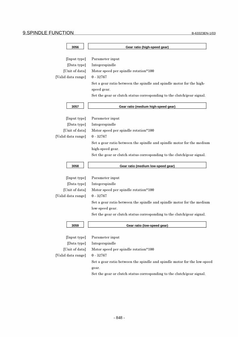
9.SPINDLE FUNCTION B-63323EN-1/03
- 848 -
3056 Gear ratio (high-speed gear)
���������� �������������
��������� ���)���������
�3���&������ ,&&���������������������&��&�F�
�<������������)�� �(�4�B=B
����)�������&�'�$����%�����������������������&&���&��%��%�)%(
������)���+
��%��)����&����%������&�����&����)�&�%����%9)������)���+
3057 Gear ratio (medium high-speed gear)
���������� �������������
��������� ���)���������
�3���&������ ,&&���������������������&��&�F�
�<������������)�� �(�4�B=B
����)�������&�'�$����%�����������������������&&���&��%��������
%�)%(������)���+
��%��)����&����%������&�����&����)�&�%����%9)������)���+
3058 Gear ratio (medium low-speed gear)
���������� �������������
��������� ���)���������
�3���&������ ,&&���������������������&��&�F�
�<������������)�� �(�4�B=B
����)�������&�'�$����%�����������������������&&���&��%��������
�&$(������)���+
��%��)����&����%������&�����&����)�&�%����%9)������)���+
3059 Gear ratio (low-speed gear)
���������� �������������
��������� ���)���������
�3���&������ ,&&���������������������&��&�F�
�<������������)�� �(�4�B=B
����)�������&�'�$����%�����������������������&&���&��%���&$(�����
)���+
��%��)����&����%������&�����&����)�&�%����%9)������)���+

B-63323EN-1/03 9.SPINDLE FUNCTION
- 849 -
3065 Position gain in servo mode/synchronization control mode
(high-speed gear)
���������� �������������
��������� ���)���������
�3���&������ + �9��
�<������������)�� �(�4�B=B
��%���&���&��)�����&��%��%�)%(������)�����������&��&������)��������)/
���������&���&���)/������&��&�%���������%�&��H��&��&��&���&��+
3066 Position gain in servo mode/synchronization control mode
(medium high-speed gear)
���������� �������������
��������� ���)���������
�3���&������ + �9��
�<������������)�� �(�4�B=B
��%���&���&��)�����&��%���������%�)%(������)�����������&��&��
���)��������)/����������&���&���)/������&��&�%���������%�&��H��&�
&��&���&��+
3067 Position gain in servo mode/synchronization control mode
(medium low-speed gear)
���������� �������������
��������� ���)���������
�3���&������ + �9��
�<������������)�� �(�4�B=B
��%���&���&��)�����&��%����������&$(������)�����������&��&������)��
�����)/����������&���&���)/������&��&�%���������%�&��H��&��&��&�
�&��+
3068 Position gain in the servo mode/synchronization control mode
(low-speed gear)
���������� �������������
��������� ���)���������
�3���&������ + �9��
�<������������)�� �(�4�B=B
��%���&���&��)�����&��%���&$(������)�����������&��&������)��������)/
���������&���&���)/������&��&�%���������%�&��H��&��&��&���&��+
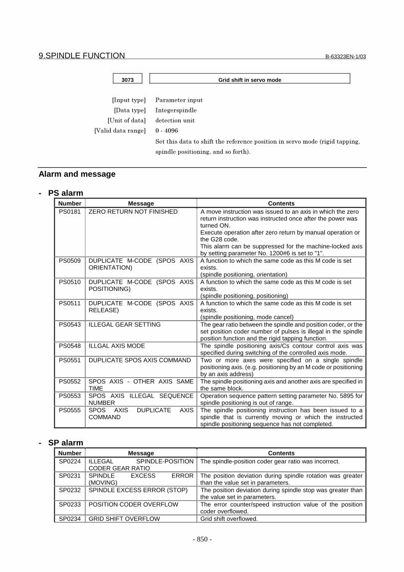
9.SPINDLE FUNCTION B-63323EN-1/03
- 850 -
3073 Grid shift in servo mode
���������� �������������
��������� ���)���������
�3���&������ ����&�����
�<������������)�� �(�7 ?=
��%�������&��%���%������������&���&���������&��&������)��������)/
���������&���&���)/������&��&�%�+
Alarm and message
- PS alarmNumber Message ContentsPS0181 ZERO RETURN NOT FINISHED A move instruction was issued to an axis in which the zero
return instruction was instructed once after the power wasturned ON.Execute operation after zero return by manual operation orthe G28 code.This alarm can be suppressed for the machine-locked axisby setting parameter No. 1200#6 is set to "1".
PS0509 DUPLICATE M-CODE (SPOS AXISORIENTATION)
A function to which the same code as this M code is setexists.(spindle positioning, orientation)
PS0510 DUPLICATE M-CODE (SPOS AXISPOSITIONING)
A function to which the same code as this M code is setexists.(spindle positioning, positioning)
PS0511 DUPLICATE M-CODE (SPOS AXISRELEASE)
A function to which the same code as this M code is setexists.(spindle positioning, mode cancel)
PS0543 ILLEGAL GEAR SETTING The gear ratio between the spindle and position coder, or theset position coder number of pulses is illegal in the spindleposition function and the rigid tapping function.
PS0548 ILLGAL AXIS MODE The spindle positioning axis/Cs contour control axis wasspecified during switching of the controlled axis mode.
PS0551 DUPLICATE SPOS AXIS COMMAND Two or more axes were specified on a single spindlepositioning axis. (e.g. positioning by an M code or positioningby an axis address)
PS0552 SPOS AXIS - OTHER AXIS SAMETIME
The spindle positioning axis and another axis are specified inthe same block.
PS0553 SPOS AXIS ILLEGAL SEQUENCENUMBER
Operation sequence pattern setting parameter No. 5895 forspindle positioning is out of range.
PS0555 SPOS AXIS DUPLICATE AXISCOMMAND
The spindle positioning instruction has been issued to aspindle that is currently moving or which the instructedspindle positioning sequence has not completed.
- SP alarmNumber Message ContentsSP0224 ILLEGAL SPINDLE-POSITION
CODER GEAR RATIOThe spindle-position coder gear ratio was incorrect.
SP0231 SPINDLE EXCESS ERROR(MOVING)
The position deviation during spindle rotation was greaterthan the value set in parameters.
SP0232 SPINDLE EXCESS ERROR (STOP) The position deviation during spindle stop was greater thanthe value set in parameters.
SP0233 POSITION CODER OVERFLOW The error counter/speed instruction value of the positioncoder overflowed.
SP0234 GRID SHIFT OVERFLOW Grid shift overflowed.

B-63323EN-1/03 9.SPINDLE FUNCTION
- 851 -
Number Message ContentsSP0235 ORIENTATION COMMAND
OVERFLOWThe orientation speed is too fast.
SP0236 DUPLICATE SPINDLE CONTROLMODE (CHANGING)
An attempt was made to change the spindle mode duringspindle mode switching.
SP0237 DUPLICATE SPINDLE CONTROLMODE (SPOS)
An attempt was made to change the spindle mode during thespindle positioning mode.
SP0240 DISCONNECT POSITION CODER The analog spindle position coder is broken.SP0241 D/A CONVERTER ERROR The D/A converter for controlling analog spindles is
erroneous.SP0975 ANALOG SPINDLE CONTROL
ERRORAn position coder error was detected on the analog spindle.
CautionCAUTION1. During the operations required for spindle
positioning (operations for canceling spindle rotationmode and entering spindle positioning mode,operations for positioning the spindle in spindlepositioning mode, and operations for canceling thespindle positioning mode then entering spindlerotation mode), automatic operation stop signal *SPis ignored. Even when the *SP signal is set to 0,automatic operation is not halted until all thesequence is completed.
2. Dry run and machine lock are disabled duringspindle positioning.
3. For M codes for the spindle positioning function,auxiliary function lock is disabled.
4. The spindle positioning axis is handled as one of thecontrolled axes. Therefore, signals related tocontrolled axes (such as the overtravel signal) mustbe set.
5. When using an analog spindle, set the driftcompensation parameters (parameter Nos. 5962 to5976) accurately. If the drift compensation value isnot appropriate, the following phenomena mayoccur during spindle orientation and spindlepositioning:- The spindle is stopped in the in-position wait state.- The spindle position is shifted (the spindle does
not reach a specified position or passes aspecified position).
6. For the spindle positioning axis, CMR = 1 and DMR= 4 are always set.
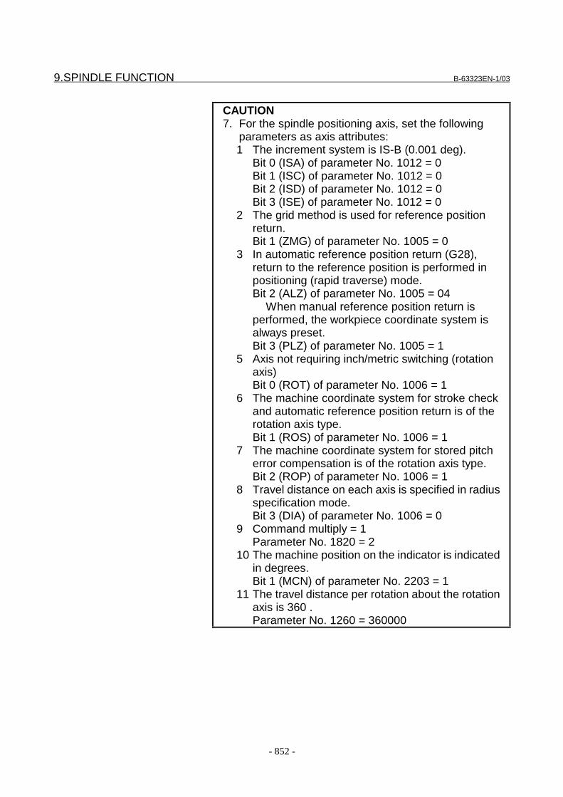
9.SPINDLE FUNCTION B-63323EN-1/03
- 852 -
CAUTION7. For the spindle positioning axis, set the following
parameters as axis attributes:1 The increment system is IS-B (0.001 deg).
Bit 0 (ISA) of parameter No. 1012 = 0Bit 1 (ISC) of parameter No. 1012 = 0Bit 2 (ISD) of parameter No. 1012 = 0Bit 3 (ISE) of parameter No. 1012 = 0
2 The grid method is used for reference positionreturn.Bit 1 (ZMG) of parameter No. 1005 = 0
3 In automatic reference position return (G28),return to the reference position is performed inpositioning (rapid traverse) mode.Bit 2 (ALZ) of parameter No. 1005 = 04
When manual reference position return isperformed, the workpiece coordinate system isalways preset.Bit 3 (PLZ) of parameter No. 1005 = 1
5 Axis not requiring inch/metric switching (rotationaxis)Bit 0 (ROT) of parameter No. 1006 = 1
6 The machine coordinate system for stroke checkand automatic reference position return is of therotation axis type.Bit 1 (ROS) of parameter No. 1006 = 1
7 The machine coordinate system for stored pitcherror compensation is of the rotation axis type.Bit 2 (ROP) of parameter No. 1006 = 1
8 Travel distance on each axis is specified in radiusspecification mode.Bit 3 (DIA) of parameter No. 1006 = 0
9 Command multiply = 1Parameter No. 1820 = 2
10 The machine position on the indicator is indicatedin degrees.Bit 1 (MCN) of parameter No. 2203 = 1
11 The travel distance per rotation about the rotationaxis is 360 .Parameter No. 1260 = 360000
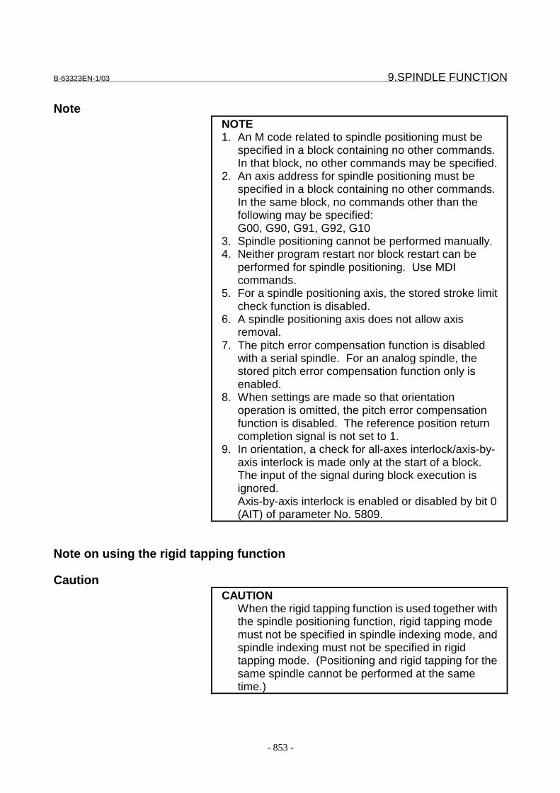
B-63323EN-1/03 9.SPINDLE FUNCTION
- 853 -
NoteNOTE1. An M code related to spindle positioning must be
specified in a block containing no other commands.In that block, no other commands may be specified.
2. An axis address for spindle positioning must bespecified in a block containing no other commands.In the same block, no commands other than thefollowing may be specified:G00, G90, G91, G92, G10
3. Spindle positioning cannot be performed manually.4. Neither program restart nor block restart can be
performed for spindle positioning. Use MDIcommands.
5. For a spindle positioning axis, the stored stroke limitcheck function is disabled.
6. A spindle positioning axis does not allow axisremoval.
7. The pitch error compensation function is disabledwith a serial spindle. For an analog spindle, thestored pitch error compensation function only isenabled.
8. When settings are made so that orientationoperation is omitted, the pitch error compensationfunction is disabled. The reference position returncompletion signal is not set to 1.
9. In orientation, a check for all-axes interlock/axis-by-axis interlock is made only at the start of a block.The input of the signal during block execution isignored.Axis-by-axis interlock is enabled or disabled by bit 0(AIT) of parameter No. 5809.
Note on using the rigid tapping function
CautionCAUTION
When the rigid tapping function is used together withthe spindle positioning function, rigid tapping modemust not be specified in spindle indexing mode, andspindle indexing must not be specified in rigidtapping mode. (Positioning and rigid tapping for thesame spindle cannot be performed at the sametime.)
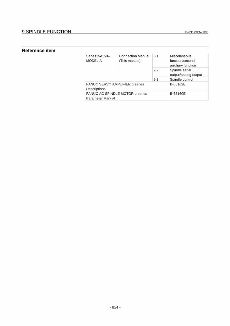
9.SPINDLE FUNCTION B-63323EN-1/03
- 854 -
Reference item8.1 Miscelaneous
function/secondauxiliary function
9.2 Spindle serialoutput/analog output
Series15i/150i-MODEL A
Connection Manual(This manual)
9.3 Spindle controlFANUC SERVO AMPLIFIER α seriesDescriptions
B-65162E
FANUC AC SPINDLE MOTOR α seriesParameter Manual
B-65160E
B-63323EN-1/03 9.SPINDLE FUNCTION
- 855 -
9.7 Cs CONTOUR CONTROL
GeneralA spindle motor controlled by the spindle serial output function iscalled a serial spindle.For a serial spindle, positioning and interpolation with other servo axescan be performed. In other words, linear interpolation, circularinterpolation, and so forth can be specified between the spindle andservo axis.Cs contour control can be applied simultaneously to up to fourspindles.
Limitation
- Increment systemUse the IS-B setting for the least input increment.
- Command multiplicationSet 2 (one time) for the command multiplication.
- Reference position returnSpecify that the workpiece coordinate system is always preset atmanual reference position return.
ExplanationFor a serial spindle, positioning and interpolation between anotherservo axis and Cs contour control axis can be performed. In otherwords, linear interpolation, circular interpolation, and so forth can bespecified between a Cs contour control axis and servo axis and betweenCs contour control axes.Rotating a serial spindle with a velocity command is referred to asspindle rotation control. Controlling the position of a spindle with amove command is referred to as Cs contour control.Switching between spindle rotation control and Cs contour control isperformed by the DI signal from the PMC.Manual and automatic operation for Cs contour control axes areperformed in Cs contour control mode in the same way as for normalservo axes.(For an explanation of reference position return operation, see theexplanation of reference position return in this section.)
Setting a Cs contour control axisPlace a Cs contour control axis as one of CNC controlled axes. Anycontrolled axis can be selected as a Cs contour control axis.Set the following parameters for a Cs contour control axis:1 Servo axis number (set parameter No. 1023 to "0.")2 Spindle number (parameter No. 1028)3 Rotation axis setting (set ROT, bit 0 of parameter No. 1006, to "1.")4 Setting a Cs contour control axis (set CNT, bit 7 of parameter No.
1804, to "1.")Parameters 1 and 2 can be set by FSSB automatic setting.
9.SPINDLE FUNCTION B-63323EN-1/03
- 856 -
Command addressAny address can be selected for a Cs contour control move command.The value set for parameter No. 1020 is used as the axis name.
Switching between spindle rotation control and Cs contour control- Switching from the spindle rotation control mode to the Cs
contour control modeSet DI signal SCNTR1, SCNTR2, SCNTR3, ... <G067#7, G071#7,G075#7, ...> to "1" to switch the serial spindle to Cs contourcontrol mode.When switching to Cs contour control is executed during spindlerotation, the spindle immediately stops and switching is executed.
- Switching from Cs contour control mode to spindle rotationcontrol modeSet DI signal SCNTR1, SCNTR2, SCNTR3, ... <G067#7, G071#7,G075#7, ...> to "0" to switch the serial spindle to spindle rotationcontrol mode.Confirm that the move commands for spindles during bothautomatic and manual operation completely terminate, thenexecute switching. If switching is executed while the spindle isrotating, an alarm indicating the interlock state or excesspositional deviation occurs.
- Automatic position gain setting at switching between spindlerotation control and Cs contour control1. Switching from spindle rotation control to Cs contour
controlIf different position gains are set for the Cs contour controlaxis and other servo axes at control switching, linear orcircular interpolation with the Cs contour control axis is notperformed normally.For this reason, the position gain (parameter No. 3069, 3070,3071, or 3072) selected by the clutch/gear signal (CTH1A,CTH2A) is automatically set for servo axes other than the Cscontour control axis.When there are two or more Cs contour control axes, theminimum value among the selected position gains isautomatically set for other Cs contour control axes and servoaxes.
2. Switching from Cs contour control to spindle rotationcontrolThe original position gain (parameter No. 1825) isautomatically set for the servo axes.When there are two or more Cs contour control axes andthese axes continue to be used as Cs contour control axes, theminimum value among the position gains selected forremaining Cs contour control axes is automatically set forother Cs contour control axes and servo axes.
3. Switching between spindle rotation control and Cs contourcontrol during automatic operationDuring automatic operation, switching cannot be performedwhile the tool is moving along an axis.

B-63323EN-1/03 9.SPINDLE FUNCTION
- 857 -
Switching from spindle rotation control to Cs contourcontrol or vice versa may be performed in a block duringautomatic operation. In this case, the position gain is notswitched immediately. The CNC automatically sets theposition gain after confirming that all controlled axes stopcompletely.
4. The CNC automatically sets the position gain afterconfirming that all the controlled axes stop completely whenswitching between spindle rotation control and Cs contourcontrol is performed during other than automatic operation.
5. When the gain is not switchedGain switching is not required when there is no interpolationbetween the Cs contour control axis and another axis andwhen the same position gain is set for the Cs contour controlaxis and servo axes.In this case, set no gain switching (set NGC, bit 0 ofparameter No. 5609, to 1).
Reference position return of the Cs contour control axisAlways perform reference position return because the current positionis missing immediately after switching the serial spindle from spindlerotation control to Cs contour control. However, the tool can be movedwithout reference position return when a setting (setting ZRN, bit 0 ofparameter No. 1005, to "1") is made to provide no reference positionreturn function and the coordinate system need not be established.Reference position return is performed for the Cs contour control axisas follows:- Manual reference position return
When feed axis and direction selection signal (+J1<G65#0>,+J2<G69#0>, ..., -J1<G65#1>, -J2<J69#1>, ...) is set to "1" inreference position return mode after the serial spindle is switchedto Cs contour control mode, the spindle starts reference positionreturn operation. After the spindle is positioned at the referenceposition, reference position return end signal ZPn<F06#0>... is setto "1." When feed axis and direction selection signal +Jn or -Jn isset to "1," the spindle moves in the reference position returndirection. Set the direction of reference position return using CSO(bit 3 of parameter No. 3000).
- Reference position return in automatic operation mode (G28command)When G28 is issued after the serial spindle is switched to the Cscontour control mode, the spindle motor stops, then the spindlemoves to the intermediate position. Then, reference positionreturn is performed. After the spindle is positioned to thereference position, reference position return end signal ZPn<F064#0>... is set to "1."When reference position return is performed once after the serialspindle is switched to Cs contour control mode, the spindle ispositioned to the reference position and ZPn is set to "1." Thefeedrate set for parameter No. 3074 is used for reference positionreturn.

9.SPINDLE FUNCTION B-63323EN-1/03
- 858 -
Set the direction of reference position return using CSO (bit 3 ofparameter No. 3000).
- Stopping reference position return(i) For manual operation
When the reset, emergency stop, or feed axis and directionselection signal is set to "0," reference position return isstopped. Use STJ (bit 2 of parameter No. 5821) to specifywhether reference position return is to be stopped by settingthe feed axis and direction selection signal to "0." Afterstopping reference position return, perform referenceposition return again from the first step, if required.
(ii) For automatic operationReference position return can be stopped by a reset,emergency stop, or feed hold. In any case, after stoppingreference position return, perform reference position returnagain from the first step, if required.
Operating the Cs contour control axis (automatic/manual)After reference position return after switching to Cs contour controlmode, the axis can be operated in the same way as normal servo axes.In the spindle rotation control mode, no commands for Cs contourcontrol axes can be accepted. During automatic operation, alarmPS0571 or PS0572 occurs.Perform manual operation for a Cs contour control axis so that it is notperformed in spindle rotation mode by the PMC ladder.
SignalCs contour control mode switching signalsSCNTR1, SCNTR2, SCNTR3, ... <G067#7, G071#7,G075#7, ...>
[Classification] Input signal[Function] These signals are used to switch between spindle rotation control mode
and Cs contour control mode.These signals are provided for axes on a one-to-one correspondence. Anumber appended to a signal name represents a controlled axis number.Use the signal with the controlled axis number of a Cs contour controlaxis.
SCNTRx : x:1 ... Cs contour control mode switching signal for the first axis2 ... Cs contour control mode switching signal for the second axis3 ... Cs contour control mode switching signal for the third axis
[Operation] When this signal is set to "0," spindle rotation mode is set. When it isset to "1," Cs contour control mode is set. Before switching from Cscontour control mode to spindle rotation control mode, confirm that themove command for the spindle has terminated completely. The spindlecan be switched from spindle rotation control mode to Cs contourcontrol mode while it is rotating.
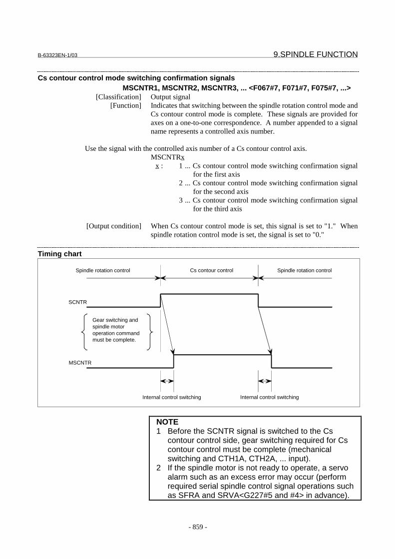
B-63323EN-1/03 9.SPINDLE FUNCTION
- 859 -
Cs contour control mode switching confirmation signalsMSCNTR1, MSCNTR2, MSCNTR3, ... <F067#7, F071#7, F075#7, ...>
[Classification] Output signal[Function] Indicates that switching between the spindle rotation control mode and
Cs contour control mode is complete. These signals are provided foraxes on a one-to-one correspondence. A number appended to a signalname represents a controlled axis number.
Use the signal with the controlled axis number of a Cs contour control axis.MSCNTRx
x : 1 ... Cs contour control mode switching confirmation signalfor the first axis
2 ... Cs contour control mode switching confirmation signalfor the second axis
3 ... Cs contour control mode switching confirmation signalfor the third axis
[Output condition] When Cs contour control mode is set, this signal is set to "1." Whenspindle rotation control mode is set, the signal is set to "0."
Timing chart
NOTE1 Before the SCNTR signal is switched to the Cs
contour control side, gear switching required for Cscontour control must be complete (mechanicalswitching and CTH1A, CTH2A, ... input).
2 If the spindle motor is not ready to operate, a servoalarm such as an excess error may occur (performrequired serial spindle control signal operations suchas SFRA and SRVA<G227#5 and #4> in advance).
Spindle rotation control Cs contour control Spindle rotation control
SCNTR
Gear switching andspindle motoroperation commandmust be complete.
MSCNTR
Internal control switching Internal control switching
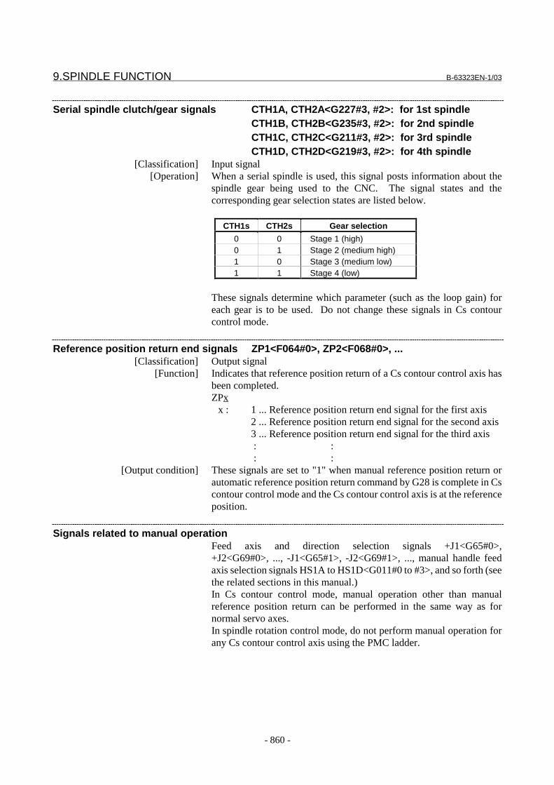
9.SPINDLE FUNCTION B-63323EN-1/03
- 860 -
Serial spindle clutch/gear signals CTH1A, CTH2A<G227#3, #2>: for 1st spindleCTH1B, CTH2B<G235#3, #2>: for 2nd spindleCTH1C, CTH2C<G211#3, #2>: for 3rd spindleCTH1D, CTH2D<G219#3, #2>: for 4th spindle
[Classification] Input signal[Operation] When a serial spindle is used, this signal posts information about the
spindle gear being used to the CNC. The signal states and thecorresponding gear selection states are listed below.
CTH1s CTH2s Gear selection
0 0 Stage 1 (high)0 1 Stage 2 (medium high)1 0 Stage 3 (medium low)1 1 Stage 4 (low)
These signals determine which parameter (such as the loop gain) foreach gear is to be used. Do not change these signals in Cs contourcontrol mode.
Reference position return end signals ZP1<F064#0>, ZP2<F068#0>, ...[Classification] Output signal
[Function] Indicates that reference position return of a Cs contour control axis hasbeen completed.ZPx
x : 1 ... Reference position return end signal for the first axis2 ... Reference position return end signal for the second axis3 ... Reference position return end signal for the third axis : : : :
[Output condition] These signals are set to "1" when manual reference position return orautomatic reference position return command by G28 is complete in Cscontour control mode and the Cs contour control axis is at the referenceposition.
Signals related to manual operationFeed axis and direction selection signals +J1<G65#0>,+J2<G69#0>, ..., -J1<G65#1>, -J2<G69#1>, ..., manual handle feedaxis selection signals HS1A to HS1D<G011#0 to #3>, and so forth (seethe related sections in this manual.)In Cs contour control mode, manual operation other than manualreference position return can be performed in the same way as fornormal servo axes.In spindle rotation control mode, do not perform manual operation forany Cs contour control axis using the PMC ladder.

B-63323EN-1/03 9.SPINDLE FUNCTION
- 861 -
Signal address#7 #6 #5 #4 #3 #2 #1 #0
G067 SCNTR1
G227 CTH1A CTH2A
G235 CTH1B CTH2B
G211 CTH1C CTH2C
G219 CTH1D CTH2D
F064 ZP1
F067 MSCNTR1
ParameterMain related parameters are shown below.In addition, parameters related to feedrates for axes,acceleration/deceleration, display, and so forth are available.
#7 #6 #5 #4 #3 #2 #1 #0
1005 PLZ ALZ ZMG ZRN
���������� �������������
��������� ������
� � � � �� !"# ��������$%�%���&�����������������������������&���&��������%����&
'��������&�����������&$��(&����������������������&��������
&���������&����)��&������&%���%���%��$�%�*��������)
��&����&�����&�+
0: Issue an alarm ("PS181 ZERO RETURN NOT FINISHED").
1: Do not issue an alarm but execute operation.
For the Cs contouring axis which does not need the reference position return, set 1.
� � � � ��� 01! ��������%����%&��&������&����&��������������&���&���������*���+
0: Return to reference position using positioning control (rapid traverse).
If reference position return has not been performed since power-on, it is
performed using the same operation sequence for manual reference position
return.
1: Use the same operation sequence as for manual reference position return.
For the Cs contouring axis, set 0.

9.SPINDLE FUNCTION B-63323EN-1/03
- 862 -
� � � � ��4 �1! ��������%��&����&���&���������)�%��$&�5�&&�������������$%��
�����������������&���&���������������&����+
0: Preset only when in reset state (e.g. OP signal is off).
1: Always preset.
See ZNP, bit 2 of parameter No. 2402, which is common to all axes.
For the Cs contouring axis, set 1.
#7 #6 #5 #4 #3 #2 #1 #0
1006 DIA ROP ROS ROT
���������� �������������
��������� ������
� � � � �� "68 ��������$%�%���%���������2��������%9�����&������&�+
0: Axis requires inch/metric conversion (linear axis).
1: Axis does not require inch/metric conversion (rotation axis).
For the Cs contouring axis, set 1.
� � � � ��� "6 ��������$%�%���%����%����&&�������������������&����&5��%�5
������&��������������&���&������������������&���&��&���+
0: Linear (linear axis)
1: Rotation (rotation axis)
For the Cs contouring axis, set 1.
� � � � ��� "6� ��������$%�%���%����%����&&������������������&�����&���%�
����������%����&��&�������&������������&���&��&���+
0: Linear (linear axis)
1: Rotation (rotation axis)
For the Cs contouring axis, set 1.
� � � � ��4 ��0 ,&���&��������&����%�����������������������)-
0: Radius specification
1: Diameter specification
If bit 5 (PDC) of parameter No. 1001 is 1, DIA has the following meaning:
The scale of the parameter, offset, and graphic screens is indicated using:
0: Radius specification
1: Diameter specification
For the Cs contouring axis, set 0.
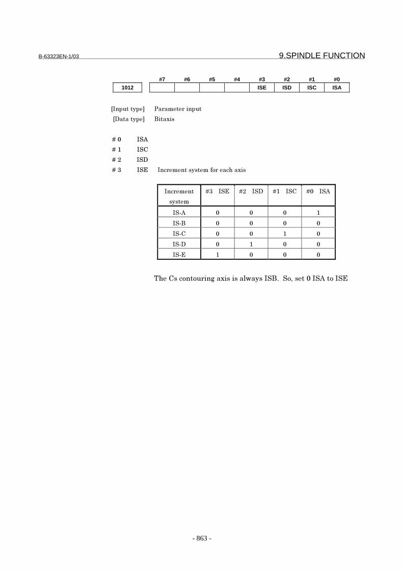
B-63323EN-1/03 9.SPINDLE FUNCTION
- 863 -
#7 #6 #5 #4 #3 #2 #1 #0
1012 ISE ISD ISC ISA
���������� �������������
��������� ������
� � � � �� � 0
� � � � ��� � :
� � � � ��� � �
� � � � ��4 � ; ���������������&����%�����
�������
�����
�4� � � ; ��� � � � ��� � � : � � � � 0
� (0 �
� (�
� (: �
� (� �
� (; �
8%��:��&�&����)�����������$����� �+�� &/���� �� 0�&�� ;
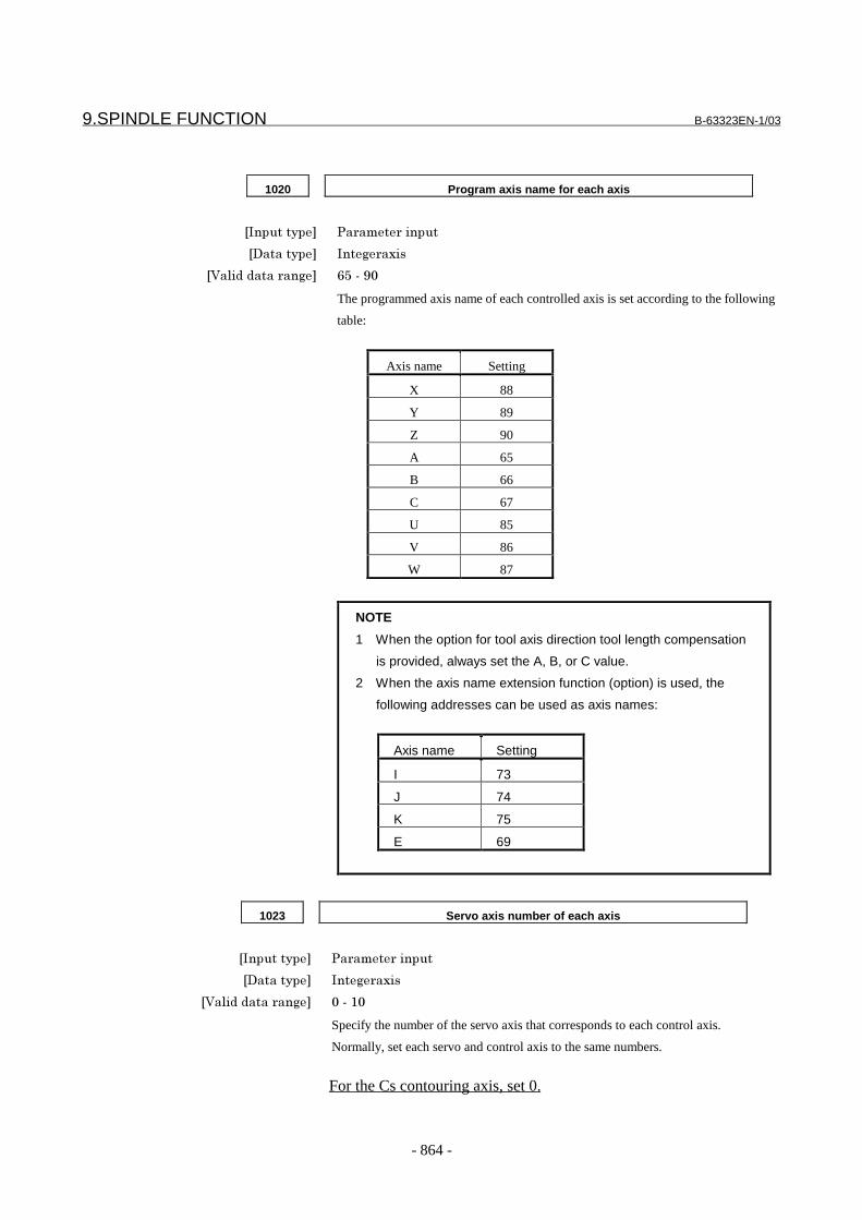
9.SPINDLE FUNCTION B-63323EN-1/03
- 864 -
1020 Program axis name for each axis
���������� �������������
��������� ���)������
�<������������)�� =>�(�?
The programmed axis name of each controlled axis is set according to the following
table:
Axis name Setting
X 88
Y 89
Z 90
A 65
B 66
C 67
U 85
V 86
W 87
NOTE
1 When the option for tool axis direction tool length compensation
is provided, always set the A, B, or C value.
2 When the axis name extension function (option) is used, the
following addresses can be used as axis names:
Axis name Setting
I 73
J 74
K 75
E 69
1023 Servo axis number of each axis
���������� �������������
��������� ���)������
�<������������)�� �(��
Specify the number of the servo axis that corresponds to each control axis.
Normally, set each servo and control axis to the same numbers.
For the Cs contouring axis, set 0.

B-63323EN-1/03 9.SPINDLE FUNCTION
- 865 -
1028 Spindle number of a Cs contour control axis
NOTEAfter this parameter has been set, the power must be off turned off thenback on for the setting to become effective.
���������� �������������
��������� ���)������
�<������������)�� �I�7
8%�������������������/����&�J���&��$�%����������#&+�� �4/�&
�������%�����'����&����%�&��&���������+� � C%���&��&�������������
&�'����'J����&�:��&�&���&��&�/����%�������������'������%��
%���%���&&�����'�������%�����������+� � 8%���&��&$��)�������&��
����������&��%������)�&��%����������+
-For controlled axes not to be subjected to Cs contour control, the parameter must
be reset to 0.
-It is impossible to assign one spindle to more than one controlled axis.
-It is possible to set up as many Cs contour controlled axes as the number of
spindles.
-Axis assignment for Cs contour must begin at the largest axis number and proceed
sequentially to a lower axis number.
Example of setting 1) Servo axes: X, Y, Z
Cs contour controlled axis: C(S1)
Number of spindles: 1
Controlled
axis number
Parameter
1020
Parameter
1023
Parameter
1028
1 �����@�� 1 0
2 89 ��A�� 2 0
3 90 ��!�� 3 0
4 67 ( C ) 0 1
Example of setting 2) Servo axes: X, Z
Cs contour controlled axes: C(S1), B(S2)
Number of spindles: 2
Controlled
axis number
Parameter
1020
Parameter
1023
Parameter
1028
1 �����@�� 1 0
2 90 ��!�� 2 0
3 67 ��:�� 0 1
4 66 ( B ) 0 2
NOTEAutomatic setting on the FSSB setting screen affects thisparameter.

9.SPINDLE FUNCTION B-63323EN-1/03
- 866 -
1260 Movement of one rotation of a rotary axis
���������� �������������
��������� "�������
�3���&������ ��)���
�,�����������&������ �������&��%����������������&��%��������������
�<������������)�� �&���&������?���)��&��������������&�������������&�%���������
�������������)��'�������
�C%���%�������������������� (�/� + �(�D??????+???�
Set the value of movement of one rotation of a rotary axis.
For the Cs contouring axis, set 360.0.
1420 Rapid traverse feedrate along each axis
���������� �������������
��������� "�������
�3���&������ ��9���/���%9���/���)���9�������%��������
�,�����������&������ �������&��%����������������&��%��������������
�<������������)�� "�����&�%�����������������������)��'����:�
�C%���%�������������������� (�/� + �(�D??????+???�
��%�������������������������&����%�������&��$%����������������
&������������ E+
1620 Time constant (T) for linear acceleration/deceleration or time constant (T1)
for bell-shaped acceleration/deceleration for rapid traverse along each axis
���������� �������������
��������� ���)������
�3���&������ ���
�<������������)�� �(�7
Specifies a rapid traverse acceleration/deceleration time constant for a Cs contour
controlled axis.

B-63323EN-1/03 9.SPINDLE FUNCTION
- 867 -
1621 FL feedrate for linear or bell-shaped acceleration/deceleration for rapid
traverse along each axis
���������� �������������
��������� "�������
�3���&������ ��9���/���%9���/���)���9�������%��������
�,�����������&������ �������&��%����������������&��%��������������
�<������������)�� "�����&�%�����������������������)��'����:�
�C%���%�������������������� (�/� + �(�D??????+???�
Specify the FL feedrate for linear or bell-shaped acceleration/deceleration or rapid
traverse along each axis.
NOTEWhen the feedrate is decelerated to the value set in this parameter atany point regardless of whether during a linear or nonlinear feedrateincrease, the tool moves at that feedrate for the remaining distancethen stops.
#7 #6 #5 #4 #3 #2 #1 #0
1804 CNT
���������� �������������
��������� ������
� � � � ��B :#8 ��������$%�%���&����������������&�&���&��&���&��%��������
���������������+
- �&����&����������������&�&���&��&�+
�- ����������������&�&���&��&�+
1820 Command multiplier for each axis (CMR)
���������� �������������
��������� ���)������
�3���&������ +>
�<������������)�� ��&�?=
For the Cs contouring axis, set 2.
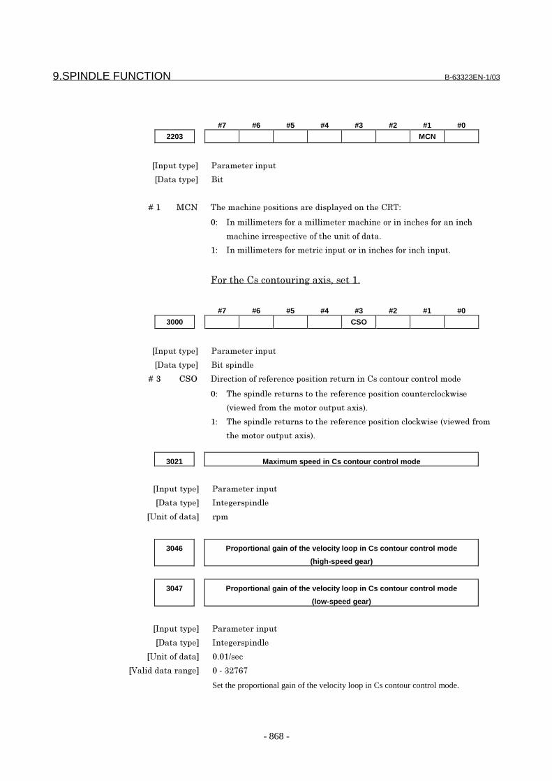
9.SPINDLE FUNCTION B-63323EN-1/03
- 868 -
#7 #6 #5 #4 #3 #2 #1 #0
2203 MCN
���������� �������������
��������� ��
� � � � ��� ,:# 8%����%�����&���&�����������������&��%��:"8-
- ���������������&����������������%����&�������%����&�������%
��%���������������&��%������&�����+
�- ���������������&������������&�������%����&����%�����+
.&��%��:��&�&����)�����/�����+
#7 #6 #5 #4 #3 #2 #1 #0
3000 CSO
���������� �������������
��������� ����������
� � � � ��4 : 6 �����&��&������������&���&�����������:��&�&���&��&���&��
- 8%�����������������&�%������������&���&��&�����&5$���
����$�����&��%���&&��&���������+
�- 8%�����������������&�%������������&���&���&5$��������$�����&�
%���&&��&���������+
3021 Maximum speed in Cs contour control mode
���������� �������������
��������� ���)���������
�3���&������ ���
3046 Proportional gain of the velocity loop in Cs contour control mode
(high-speed gear)
3047 Proportional gain of the velocity loop in Cs contour control mode
(low-speed gear)
���������� �������������
��������� ���)���������
�3���&������ + �9��
�<������������)�� �(�4�B=B
Set the proportional gain of the velocity loop in Cs contour control mode.
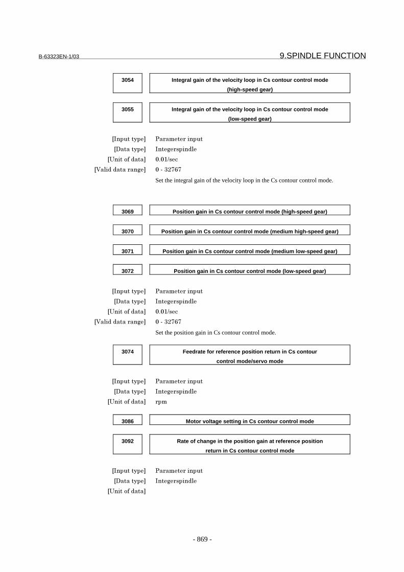
B-63323EN-1/03 9.SPINDLE FUNCTION
- 869 -
3054 Integral gain of the velocity loop in Cs contour control mode
(high-speed gear)
3055 Integral gain of the velocity loop in Cs contour control mode
(low-speed gear)
���������� �������������
��������� ���)���������
�3���&������ + �9��
�<������������)�� �(�4�B=B
Set the integral gain of the velocity loop in the Cs contour control mode.
3069 Position gain in Cs contour control mode (high-speed gear)
3070 Position gain in Cs contour control mode (medium high-speed gear)
3071 Position gain in Cs contour control mode (medium low-speed gear)
3072 Position gain in Cs contour control mode (low-speed gear)
���������� �������������
��������� ���)���������
�3���&������ + �9��
�<������������)�� �(�4�B=B
Set the position gain in Cs contour control mode.
3074 Feedrate for reference position return in Cs contour
control mode/servo mode
���������� �������������
��������� ���)���������
�3���&������ ���
3086 Motor voltage setting in Cs contour control mode
3092 Rate of change in the position gain at reference position
return in Cs contour control mode
���������� �������������
��������� ���)���������
�3���&������

9.SPINDLE FUNCTION B-63323EN-1/03
- 870 -
3105 Proportional gain data of the current loop in Cs contour control mode
3107 Integral gain data of the current loop in Cs contour control mode
���������� �������������
��������� ���)���������
3135 Grid shift in Cs contour control mode
���������� �������������
��������� ���)���������
�3���&������ ����&�����
�<������������)�� C�%���D�&����&��&����&���������/�(4= �&�4= �$%���%�
����&��������� + �� ��%��)�����%������:��&�&���&��&���&��
����������&��%��&��(�&��&����)����&�%����%����H��&��&���+
3162 Integral gain of the velocity loop in Cs contour control cutting feed mode
(high-speed gear)
3163 Integral gain of the velocity loop in Cs contour control cutting feed mode
(low-speed gear)
���������� �������������
��������� ���)���������
#7 #6 #5 #4 #3 #2 #1 #0
5609 NGC
���������� �������������
��������� ���������
� � � � �� #*: ��������$%�%���%���&���&��)����&��%��:��&�&���&��&������������
:��&�&���&��&�������&������������&��&%�������&�����+
- ����&�������+
�- #&������&�������+

B-63323EN-1/03 9.SPINDLE FUNCTION
- 871 -
#7 #6 #5 #4 #3 #2 #1 #0
5821 STJ
���������� �������������
��������� ���������
� � � � ��� 8K ��������$%���&��&���������)�%��:��&�&���&��&�������&�%�
����������&���&�+
- 0��������&������)�����&�
�- 0�������/�����)�����&�/�&��$%���%�����������������&�������&�
��)����������&�L +L
5843 Number of pulses of the position detector for a Cs contour control axis
NOTEAfter this parameter has been set, the power must be off turned off thenback on for the setting to become effective.
���������� �������������
��������� ���)���������
�3���&������ ����&�����
�<������������)�� ��(�??????
��%�����'���&���������&��%���&���&�����&���&����:��&�&���&��&�
����+
5879 Effective area under Cs contour control
���������� �������������
��������� ���)���������
�3���&������ ����&�����
�<������������)�� �(�????????
������������������������:��&�&���&��&�+
5880 Positional deviation limit during movement under Cs contour control
���������� �������������
��������� ���)���������
�3���&������ ����&�����
�<������������)�� �(�????????
�����&���&����������&������������)��&������������:��&�&��
&��&�+

9.SPINDLE FUNCTION B-63323EN-1/03
- 872 -
5881 Positional deviation limit during a stop under Cs contour control
���������� �������������
��������� ���)���������
�3���&������ ����&�����
�<������������)�� �(�????????
�����&���&����������&������������)����&��������:��&�&���&��&�+
5882 Positional deviation limit during servo-off under Cs contour control
���������� �������������
��������� ���)���������
�3���&������ ����&�����
�<������������)�� �(�????????
�����&���&����������&������������)�����&(&���������:��&�&��
&��&�+
Alarm and message
Number Message Contents
PS0571 CS AXIS DUPLICATE AXIS MODE The Cs contour control axis has been specified on an axisthat is not in the Cs contour control mode.
PS0572 CS AXIS DUPLICATE AXISCOMMAND
A currently moving axis has been specified as the Cscontour control axis.
Displaying the positional deviation and other data for a Cs contour control axisThe positional deviation and other data can be checked on the spindlescreen for monitoring the operation status.For details, refer to "FANUC Series 15i/150i-MODEL A MaintenanceManual" (B-63325EN).
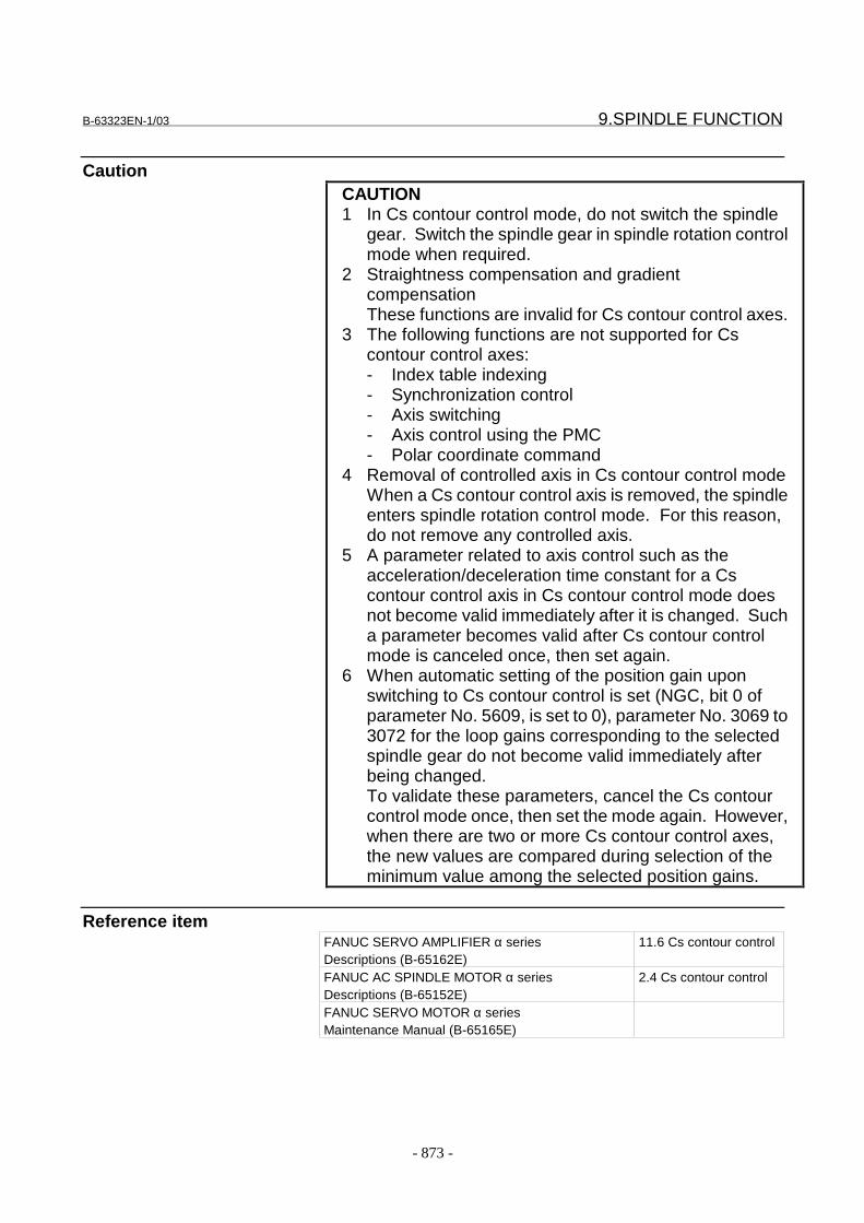
B-63323EN-1/03 9.SPINDLE FUNCTION
- 873 -
CautionCAUTION1 In Cs contour control mode, do not switch the spindle
gear. Switch the spindle gear in spindle rotation controlmode when required.
2 Straightness compensation and gradientcompensationThese functions are invalid for Cs contour control axes.
3 The following functions are not supported for Cscontour control axes:- Index table indexing- Synchronization control- Axis switching- Axis control using the PMC- Polar coordinate command
4 Removal of controlled axis in Cs contour control modeWhen a Cs contour control axis is removed, the spindleenters spindle rotation control mode. For this reason,do not remove any controlled axis.
5 A parameter related to axis control such as theacceleration/deceleration time constant for a Cscontour control axis in Cs contour control mode doesnot become valid immediately after it is changed. Sucha parameter becomes valid after Cs contour controlmode is canceled once, then set again.
6 When automatic setting of the position gain uponswitching to Cs contour control is set (NGC, bit 0 ofparameter No. 5609, is set to 0), parameter No. 3069 to3072 for the loop gains corresponding to the selectedspindle gear do not become valid immediately afterbeing changed.To validate these parameters, cancel the Cs contourcontrol mode once, then set the mode again. However,when there are two or more Cs contour control axes,the new values are compared during selection of theminimum value among the selected position gains.
Reference itemFANUC SERVO AMPLIFIER α seriesDescriptions (B-65162E)
11.6 Cs contour control
FANUC AC SPINDLE MOTOR α seriesDescriptions (B-65152E)
2.4 Cs contour control
FANUC SERVO MOTOR α seriesMaintenance Manual (B-65165E)
9.SPINDLE FUNCTION B-63323EN-1/03
- 874 -
9.8 RIGID TAPPING
GeneralIn tapping, the feed amount along the Z-axis per spindle rotation mustequal the thread pitch of the tapper. Therefore, the most desirabletapping satisfies the following equation: P = F/Swhere, P: Thread pitch of the tapper (mm, inch)
F: Z-axis feedrate (mm/min, inch/min)S: Spindle speed (rpm)
In the tapping cycle (G84) and reverse tapping cycle (G74), spindlerotation and Z-axis feed are controlled independently. This means thatthe above equation is not always satisfied. At the bottom of a hole, inparticular, spindle rotation and Z-axis feed both decelerate and stop,then start moving and accelerate in the opposite direction. Sincespindle rotation and Z-axis feed accelerate/decelerate independently, itis generally difficult to satisfy the above equation. For accuratetapping, a spring is generally installed inside the holder of the tapper toprovide compensation.With the rigid tapping cycle (G84.2) and reverse rigid tapping cycle(G84.3), spindle rotation and Z-axis feed are controlled so that they arealways synchronized. In normal operation, the spindle rotation iscontrolled to achieve the desired speed. In rigid tapping, on the otherhand, the spindle rotation is controlled considering the position also.Spindle rotation and Z-axis feed are therefore controlled based ontwo-axis linear interpolation. As a result, the equation P = F/S can alsobe satisfied during deceleration and acceleration near the bottom of thehole, thus enabling accurate tapping.Use G84.2 for specifying the rigid tapping cycle, and G84.3 for thereverse rigid tapping cycle.The explanation given in this section assumes the tapping axis to be theZ-axis. In actual operation, whether the tapping axis is always set to theZ-axis or set to a programmed axis can be specified with bit 0 (FXY) ofparameter No. 6200.
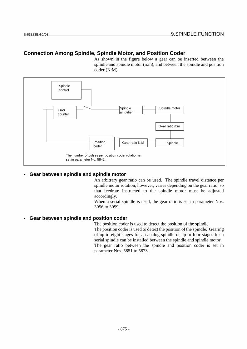
B-63323EN-1/03 9.SPINDLE FUNCTION
- 875 -
Connection Among Spindle, Spindle Motor, and Position CoderAs shown in the figure below a gear can be inserted between thespindle and spindle motor (n:m), and between the spindle and positioncoder (N:M).
- Gear between spindle and spindle motorAn arbitrary gear ratio can be used. The spindle travel distance perspindle motor rotation, however, varies depending on the gear ratio, sothat feedrate instructed to the spindle motor must be adjustedaccordingly.When a serial spindle is used, the gear ratio is set in parameter Nos.3056 to 3059.
- Gear between spindle and position coderThe position coder is used to detect the position of the spindle.The position coder is used to detect the position of the spindle. Gearingof up to eight stages for an analog spindle or up to four stages for aserial spindle can be installed between the spindle and spindle motor.The gear ratio between the spindle and position coder is set inparameter Nos. 5851 to 5873.
Spindlecontrol
Spindleamplifier
Spindle motor
Spindle
Gear ratio n:m
Errorcounter
Gear ratio N:MPositioncoder
The number of pulses per position coder rotation isset in parameter No. 5842.
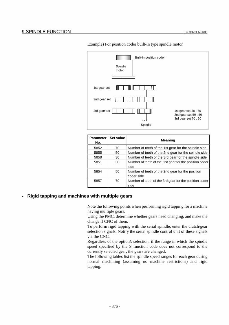
9.SPINDLE FUNCTION B-63323EN-1/03
- 876 -
Example) For position coder built-in type spindle motor
ParameterNo.
Set valueMeaning
5852 70 Number of teeth of the 1st gear for the spindle side5855 50 Number of teeth of the 2nd gear for the spindle side5858 30 Number of teeth of the 3rd gear for the spindle side5851 30 Number of teeth of the 1st gear for the position coder
side5854 50 Number of teeth of the 2nd gear for the position
coder side5857 70 Number of teeth of the 3rd gear for the position coder
side
- Rigid tapping and machines with multiple gears
Note the following points when performing rigid tapping for a machinehaving multiple gears.Using the PMC, determine whether gears need changing, and make thechange if CNC of them.To perform rigid tapping with the serial spindle, enter the clutch/gearselection signals. Notify the serial spindle control unit of these signalsvia the CNC.Regardless of the option’s selection, if the range in which the spindlespeed specified by the S function code does not correspond to thecurrently selected gear, the gears are changed.The following tables list the spindle speed ranges for each gear duringnormal machining (assuming no machine restrictions) and rigidtapping:
Spindlemotor
Built-in position coder
1st gear set 30 : 702nd gear set 50 : 503rd gear set 70 : 30
1st gear set
2nd gear set
3rd gear set
Spindle

B-63323EN-1/03 9.SPINDLE FUNCTION
- 877 -
Spindle speed range (normal machining)Gear
Lower limit Upper limit
Low-speedgear
1 revolution Maximum low-speed gear speed Maximum spindle motor speed×L%= Low-speed gear ratio
Mediumspeedgear
Maximum low-speedgear speed + 1
revolution
Maximum medium-speed gear speed Maximum spindle motor speed×L%= Medium speed gear ratio
High-speedgear
Maximum medium-speed gear speed +1
revolution
Maximum high-speed gear speed Maximum spindle motor speed×L%= High-speed gear ratio
NOTEThis table shows an example of three gears. L%indicates a spindle motor protection constant (up to100).
Set the spindle speed range for each gear during rigid tapping as listedin the table below.
Spindle speed range (during rigid tapping)GearLower limit Upper limit
Low-speedgear
1 revolution Maximum low-speed gear speed Basic spindle motor speed + α= Low-speed gear ratio
Mediumspeedgear
Maximum low-speedgear speed + 1
revolution
Maximum medium-speed gear speed Basic spindle motor speed + α= Medium speed gear ratio
High-speedgear
Maximum medium-speed gear speed +1
revolution
Maximum high-speed gear speed Basic spindle motor speed + α= High-speed gear ratio
NOTEThis table show an example of three gears. For thebasic spindle motor speed, refer to the spindle motordescription manual. "+α" means that the spindlemotor speed may slightly exceed the basic spindlemotor speed.

9.SPINDLE FUNCTION B-63323EN-1/03
- 878 -
Rigid Tapping Specification
- Feed rateIn rigid tapping mode, the tapping axis is fed at a rate specified by F;the spindle speed is S times 360(deg/min). Override is invalid for bothof them.The speed of extraction can be overridden by 1% to 200% dependingon the override value set in parameter No. 5883.
CAUTIONThe thread pitch of the tapper must equal the pitch (F,S) specified in a program. If they do not match, thetool or workpiece may be damaged.
- Acceleration and decelerationExponential acceleration/deceleration or linearacceleration/deceleration can be applied to rigid tapping. This isselected by bit 1 (TEL) of parameter No. 5605.The time constant can be changed in four steps, according to thespecified spindle speed, by setting bit 2 (TSC) of parameter No. 5605.
Parameters used when the time constant is not changedTime constant (TC) FL feedrate (FL) Spindle speed (S)
5751 5752 5757
Acceleration/decelerationtime
Acceleration/decelerationtime
TC TC
S SS command S command
Linear acceleration/deceleration Exponential acceleration/deceleration
Parameters when the time constant is changedStep (n) Time
constant(TCn)
FL feedrate(FLn)
Spindlespeed (Sn)
Applicablespeed
1 5884 5885 5886 S ≤ S12 5887 5888 5889 S1 < S ≤ S23 5890 5891 5892 S2 < S ≤ S34 5893 5894 - S3 < S
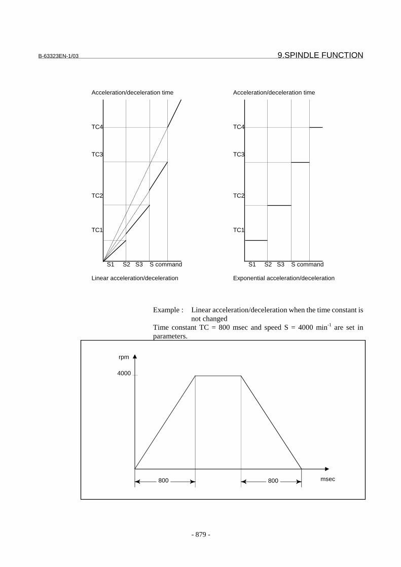
B-63323EN-1/03 9.SPINDLE FUNCTION
- 879 -
Example : Linear acceleration/deceleration when the time constant isnot changed
Time constant TC = 800 msec and speed S = 4000 min-1 are set inparameters.
rpm
4000
msec800800
Acceleration/deceleration time
TC4
TC3
TC2
TC1
S1 S2 S3 S command
Linear acceleration/deceleration
Acceleration/deceleration time
TC4
TC3
TC2
TC1
S1 S2 S3 S command
Exponential acceleration/deceleration
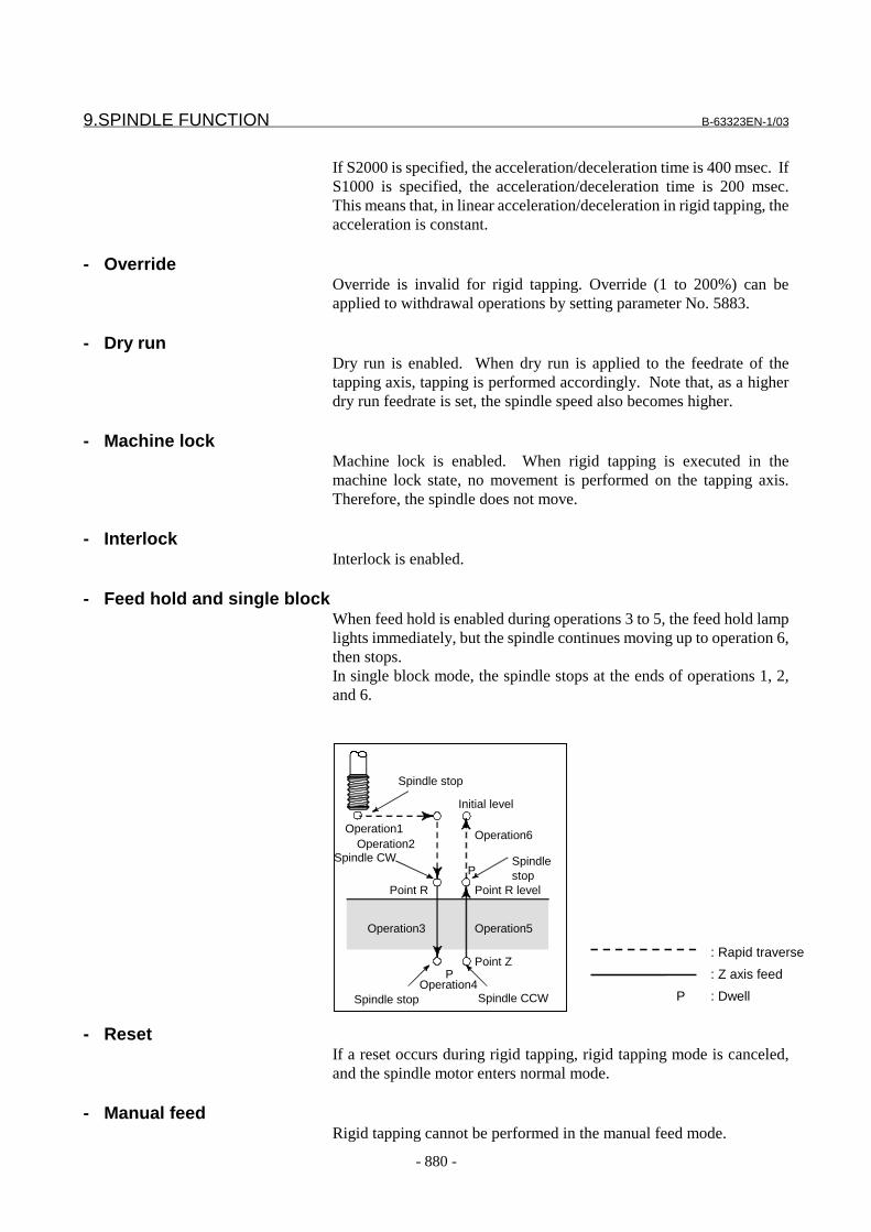
9.SPINDLE FUNCTION B-63323EN-1/03
- 880 -
If S2000 is specified, the acceleration/deceleration time is 400 msec. IfS1000 is specified, the acceleration/deceleration time is 200 msec.This means that, in linear acceleration/deceleration in rigid tapping, theacceleration is constant.
- OverrideOverride is invalid for rigid tapping. Override (1 to 200%) can beapplied to withdrawal operations by setting parameter No. 5883.
- Dry runDry run is enabled. When dry run is applied to the feedrate of thetapping axis, tapping is performed accordingly. Note that, as a higherdry run feedrate is set, the spindle speed also becomes higher.
- Machine lockMachine lock is enabled. When rigid tapping is executed in themachine lock state, no movement is performed on the tapping axis.Therefore, the spindle does not move.
- InterlockInterlock is enabled.
- Feed hold and single blockWhen feed hold is enabled during operations 3 to 5, the feed hold lamplights immediately, but the spindle continues moving up to operation 6,then stops.In single block mode, the spindle stops at the ends of operations 1, 2,and 6.
- ResetIf a reset occurs during rigid tapping, rigid tapping mode is canceled,and the spindle motor enters normal mode.
- Manual feedRigid tapping cannot be performed in the manual feed mode.
Initial level
Point R
Spindlestop
Spindle CW
Point ZP
Point R level
Operation2Operation1 Operation6
Operation3
Operation4
Operation5
Spindle stop Spindle CCW
Spindle stop
P
: Rapid traverse
: Z axis feed
: DwellP
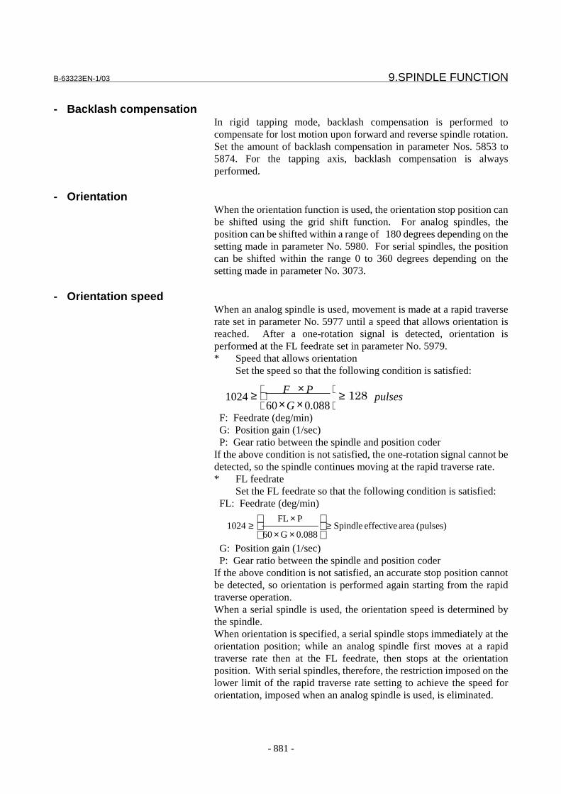
B-63323EN-1/03 9.SPINDLE FUNCTION
- 881 -
- Backlash compensationIn rigid tapping mode, backlash compensation is performed tocompensate for lost motion upon forward and reverse spindle rotation.Set the amount of backlash compensation in parameter Nos. 5853 to5874. For the tapping axis, backlash compensation is alwaysperformed.
- OrientationWhen the orientation function is used, the orientation stop position canbe shifted using the grid shift function. For analog spindles, theposition can be shifted within a range of 180 degrees depending on thesetting made in parameter No. 5980. For serial spindles, the positioncan be shifted within the range 0 to 360 degrees depending on thesetting made in parameter No. 3073.
- Orientation speedWhen an analog spindle is used, movement is made at a rapid traverserate set in parameter No. 5977 until a speed that allows orientation isreached. After a one-rotation signal is detected, orientation isperformed at the FL feedrate set in parameter No. 5979.* Speed that allows orientation
Set the speed so that the following condition is satisfied:
F: Feedrate (deg/min) G: Position gain (1/sec) P: Gear ratio between the spindle and position coderIf the above condition is not satisfied, the one-rotation signal cannot bedetected, so the spindle continues moving at the rapid traverse rate.* FL feedrate
Set the FL feedrate so that the following condition is satisfied: FL: Feedrate (deg/min)
G: Position gain (1/sec) P: Gear ratio between the spindle and position coderIf the above condition is not satisfied, an accurate stop position cannotbe detected, so orientation is performed again starting from the rapidtraverse operation.When a serial spindle is used, the orientation speed is determined bythe spindle.When orientation is specified, a serial spindle stops immediately at theorientation position; while an analog spindle first moves at a rapidtraverse rate then at the FL feedrate, then stops at the orientationposition. With serial spindles, therefore, the restriction imposed on thelower limit of the rapid traverse rate setting to achieve the speed fororientation, imposed when an analog spindle is used, is eliminated.
)pulses( area effective Spindle088.0G60
PFL1024 ≥
××
×≥
088.0601024 pulses
G
PF��� �≥
×××≥
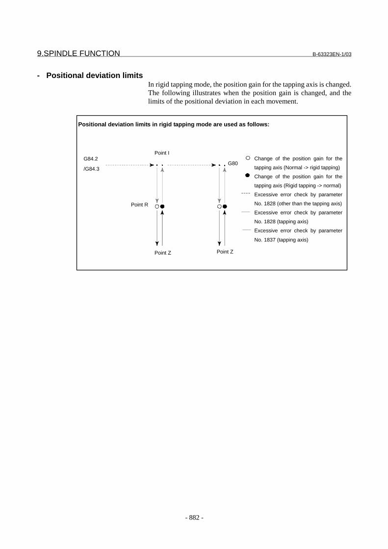
9.SPINDLE FUNCTION B-63323EN-1/03
- 882 -
- Positional deviation limitsIn rigid tapping mode, the position gain for the tapping axis is changed.The following illustrates when the position gain is changed, and thelimits of the positional deviation in each movement.
Positional deviation limits in rigid tapping mode are used as follows:
G84.2
/G84.3
Point I
Point R
Point Z Point Z
G80Change of the position gain for the
tapping axis (Normal -> rigid tapping)
Change of the position gain for the
tapping axis (Rigid tapping -> normal)
Excessive error check by parameter
No. 1828 (other than the tapping axis)
Excessive error check by parameter
No. 1828 (tapping axis)
Excessive error check by parameter
No. 1837 (tapping axis)
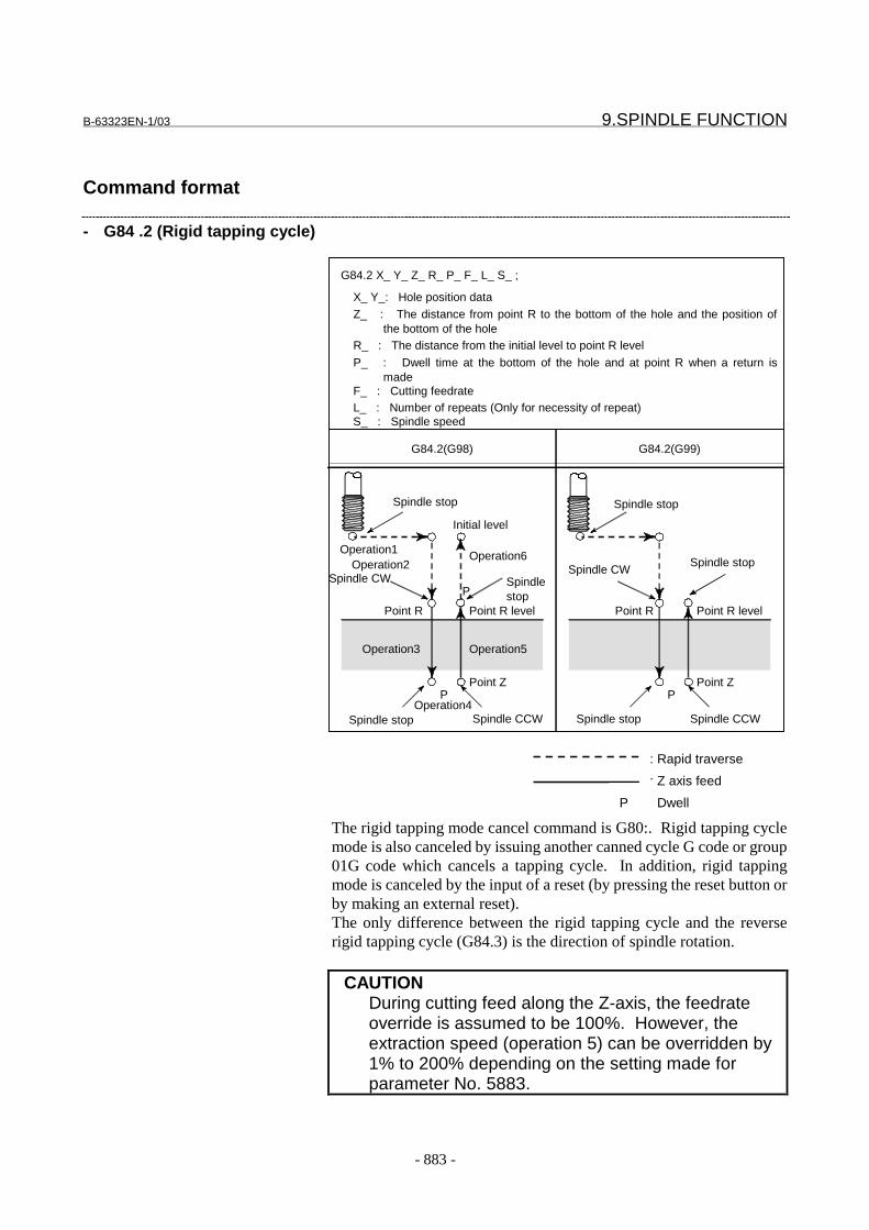
B-63323EN-1/03 9.SPINDLE FUNCTION
- 883 -
Command format
- G84 .2 (Rigid tapping cycle)
The rigid tapping mode cancel command is G80:. Rigid tapping cyclemode is also canceled by issuing another canned cycle G code or group01G code which cancels a tapping cycle. In addition, rigid tappingmode is canceled by the input of a reset (by pressing the reset button orby making an external reset).The only difference between the rigid tapping cycle and the reverserigid tapping cycle (G84.3) is the direction of spindle rotation.
CAUTIONDuring cutting feed along the Z-axis, the feedrateoverride is assumed to be 100%. However, theextraction speed (operation 5) can be overridden by1% to 200% depending on the setting made forparameter No. 5883.
: Rapid traverse
: Z axis feed
: DwellP
G84.2(G98) G84.2(G99)
G84.2 X_ Y_ Z_ R_ P_ F_ L_ S_ ;
X_ Y_: Hole position data
Z_ : The distance from point R to the bottom of the hole and the position of the bottom of the holeR_ : The distance from the initial level to point R level
P_ : Dwell time at the bottom of the hole and at point R when a return is madeF_ : Cutting feedrateL_ : Number of repeats (Only for necessity of repeat)
Initial level
Point R
Spindlestop
Spindle CW
Point ZP
Point R level
Operation2Operation1 Operation6
Operation3
Operation4
Operation5
Spindle stop Spindle CCW
Point R
Spindle CW
Point ZP
Point R level
Spindle stop Spindle CCW
Spindle stop Spindle stop
Spindle stop
P
S_ : Spindle speed
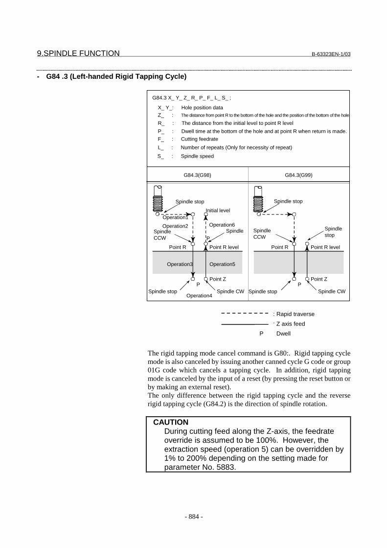
9.SPINDLE FUNCTION B-63323EN-1/03
- 884 -
- G84 .3 (Left-handed Rigid Tapping Cycle)
SpindleCCW
G84.3(G98) G84.3(G99)
G84.3 X_ Y_ Z_ R_ P_ F_ L_ S_ ;
X_ Y_: Hole position dataZ_ : The distance from point R to the bottom of the hole and the position of the bottom of the hole
R_ : The distance from the initial level to point R level
P_ : Dwell time at the bottom of the hole and at point R when return is made.
F_ : Cutting feedrate
L_ : Number of repeats (Only for necessity of repeat)
Initial level
Point R
Spindle
Point ZP
Point R level
Operation2
Operation1Operation6
Operation3
Operation4
Operation5
Spindle stop Spindle CW
Point R
SpindleCCW
Point ZP
Point R level
Spindle stop Spindle CW
Spindle stop Spindle stop
Spindlestop
P
S_ : Spindle speed
The rigid tapping mode cancel command is G80:. Rigid tapping cyclemode is also canceled by issuing another canned cycle G code or group01G code which cancels a tapping cycle. In addition, rigid tappingmode is canceled by the input of a reset (by pressing the reset button orby making an external reset).The only difference between the rigid tapping cycle and the reverserigid tapping cycle (G84.2) is the direction of spindle rotation.
CAUTIONDuring cutting feed along the Z-axis, the feedrateoverride is assumed to be 100%. However, theextraction speed (operation 5) can be overridden by1% to 200% depending on the setting made forparameter No. 5883.
: Rapid traverse
: Z axis feed
: DwellP
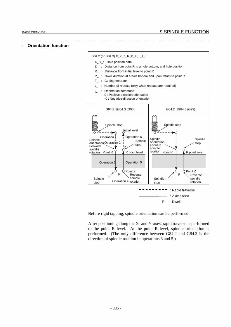
B-63323EN-1/03 9.SPINDLE FUNCTION
- 885 -
- Orientation function
Before rigid tapping, spindle orientation can be performed.
After positioning along the X- and Y-axes, rapid traverse is performedto the point R level. At the point R level, spindle orientation isperformed. (The only difference between G84.2 and G84.3 is thedirection of spindle rotation in operations 3 and 5.)
G84.2 EG84.3 (G98) G84.2 EG84.3 (G99)
G84.2 (or G84.3) X_Y_Z_R_P_F_L_I_ ;
X_ Y_: Hole position dataZ_ : Distance from point R to a hole bottom, and hole position
R_ : Distance from initial level to point R
P_ : Dwell duration at a hole bottom and upon return to point R
F_ : Cutting feedrate
L_ : Number of repeats (only when repeats are required)
Initial level
Point R
Spindlestop
Point ZP
R point level
Operation 2
Operation 1 Operation 6
Operation 3
Operation 4
Operation 5
Spindlestop
Reversespindlerotation
Point ZP
R point level
Spindlestop
Reversespindlerotation
Spindle stop Spindle stop
Spindlestop
P
I_ : Orientation command 0 : Positive-direction orientation - 0 : Negative-direction orientation
SpindleorientationForwardspindlerotation
SpindleorientationForwardspindlerotation Point R
: Rapid traverse
: Z axis feed
: DwellP

9.SPINDLE FUNCTION B-63323EN-1/03
- 886 -
CAUTION1 The orientation function is enabled only when the
number of pulses from the position coder is 4096,and the gear ratio between the spindle and positioncoder is as follows: 1 : 2n (n: Integer not less than 0)
2 When a serial interface spindle is used, orientation isperformed in the direction set by bit 4 (SVO) ofparameter No. 3000, regardless of the sign specifiedin I.
3 The orientation command is valid only when specifiedin the first block that enters rigid tapping mode.Orientation commands specified in the second andsubsequent blocks in rigid tapping mode are allignored.
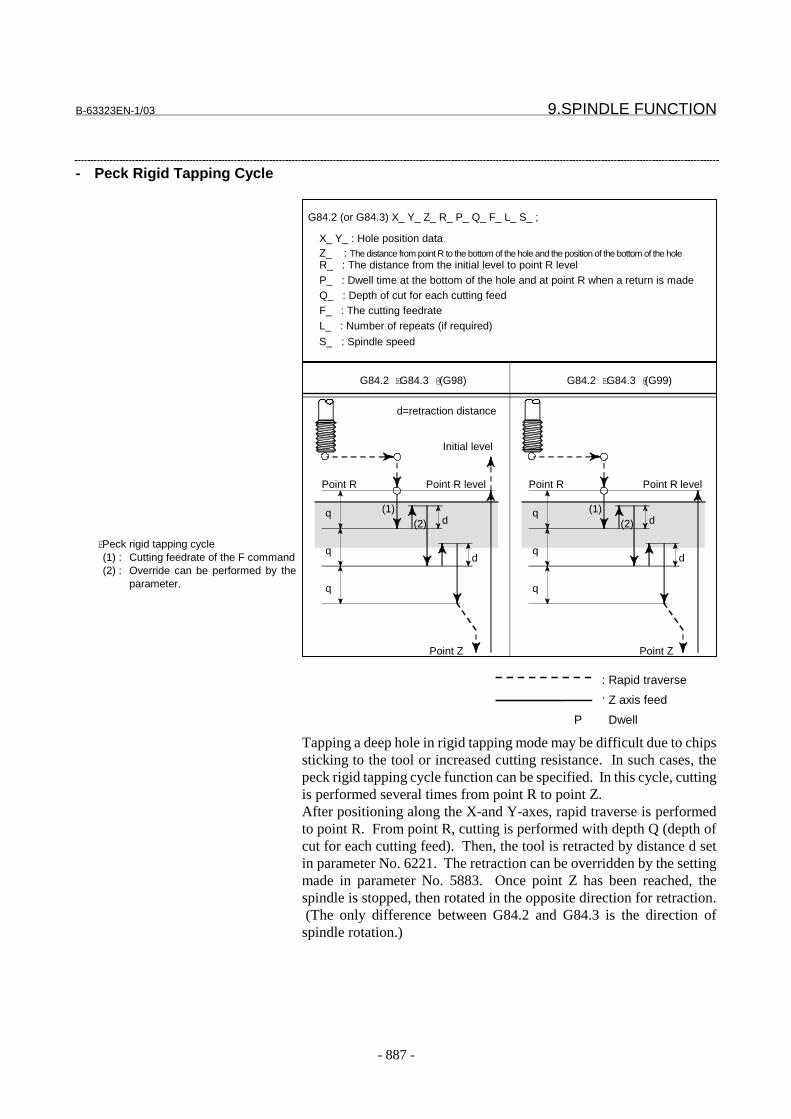
B-63323EN-1/03 9.SPINDLE FUNCTION
- 887 -
- Peck Rigid Tapping Cycle
Tapping a deep hole in rigid tapping mode may be difficult due to chipssticking to the tool or increased cutting resistance. In such cases, thepeck rigid tapping cycle function can be specified. In this cycle, cuttingis performed several times from point R to point Z.After positioning along the X-and Y-axes, rapid traverse is performedto point R. From point R, cutting is performed with depth Q (depth ofcut for each cutting feed). Then, the tool is retracted by distance d setin parameter No. 6221. The retraction can be overridden by the settingmade in parameter No. 5883. Once point Z has been reached, thespindle is stopped, then rotated in the opposite direction for retraction. (The only difference between G84.2 and G84.3 is the direction ofspindle rotation.)
EPeck rigid tapping cycle(1) : Cutting feedrate of the F command(2) : Override can be performed by the
parameter.
G84.2 EG84.3 @(G98) G84.2 EG84.3 @(G99)
G84.2 (or G84.3) X_ Y_ Z_ R_ P_ Q_ F_ L_ S_ ;
X_ Y_ : Hole position dataZ_ : The distance from point R to the bottom of the hole and the position of the bottom of the holeR_ : The distance from the initial level to point R levelP_ : Dwell time at the bottom of the hole and at point R when a return is madeQ_ : Depth of cut for each cutting feedF_ : The cutting feedrateL_ : Number of repeats (if required)
Initial level
d
Point Z
Point R
q
q
q
d
(1)(2)
Point R level
d
Point Z
Point R
q
q
q
d
(1)(2)
Point R level
d=retraction distance
S_ : Spindle speed
: Rapid traverse
: Z axis feed
: DwellP
9.SPINDLE FUNCTION B-63323EN-1/03
- 888 -
CAUTIONThe peck rigid tapping cycle command is valid withina block containing G84.2 (G84.3), or it is made validby specifying the Q command in rigid tapping orreverse rigid tapping cycle mode.
Rigid tapping command in feed-per-minute/feed-per-revolution modeRigid tapping may be specified in feed-per-minute mode (G94) or inthe feed-per-revolution mode (G95).
Example:To tap a tread with a lead of 1 mm at a spindle speed 1000 rpm infeed-per-minute mode, specify the following (in feed-per-minute mode,the thread lead is F/S):G94 ; Feed-per-minute commandG00 X120.0 Y100.0 ; PositioningG84.2 Z-100.0 R-20.0 F1000 S1000 ; Rigid tapping
To tap the same thread as mentioned above under the same condition infeed-per-revolution mode, specify the following (in the feed-per-revolution mode, the thread lead is F):G95 ; Feed-per-revolution commandG00 X120.0 Y100.0 ; PositioningG84.2 Z-100.0 R-20.0 F1 S1000 ; Rigid tapping
NOTE1 In feed-per-revolution mode, distribution is performed
by conversion to a command for feed per minute. So,strictly speaking, this mode is not feed per revolutionmode. If spindle rotation is stopped for some reason,movement along the tapping axis (Z-axis) does notstop.
B-63323EN-1/03 9.SPINDLE FUNCTION
- 889 -
Signal
Signals for the rigid tapping function
Rigid tapping in-progress signal RTAP<F040#4>[Classification] Output signal
[Function] This signal notifies the PMC that rigid tapping mode is set.RTAP 1 : Rigid tapping mode is currently set.
0 : Rigid tapping mode is not currently set.
Spindle rotation direction signals RSPP,RSPM<F155#0,#1>[Classification] Output signal
[Function] During rigid tapping, these signals notify the PMC of whether thespindle is rotating in the forward or reverse direction.During rigid tapping, the spindle is:
RSPP 1 : Rotating in the forward direction (CW).0 : Not rotating in the forward direction.
RSPM 1 : Rotating in the reverse direction (CCW).0 : Not rotating in the reverse direction.
[Output condition] These signals are output when the spindle is rotating in rigid tappingmode. This means that, even in rigid tapping mode, these signals arenot output, for example, when the spindle is being positioned to a holeposition, or a dwell operation is in progress at the bottom of a hole or atan R point.When the spindle is placed in the interlock stop state, feed hold state, orsingle block stop state, these signals are output.
Constant spindle speed signal RSPC<F155#2>[Classification] Output signal
[Function] Reports that the spindle speed during tapping has become constant inrigid tapping mode.
RSPC 1 : The spindle speed has become constant.0 : The spindle speed is not constant.
[Output condition] This signal is output once the spindle speed has become constantduring tapping. This signal continues to be output while the spindlespeed is constant.

9.SPINDLE FUNCTION B-63323EN-1/03
- 890 -
Reverse spindle rotation signal RSPR<G148#3>[Classification] Input signal
[Function] When the rigid tapping cycle (G84.2) or reverse rigid tapping cycle(G84.3) command is executed in canned cycle cancel mode (G80), thedirection of the spindle rotation can be reversed during rigid tapping byusing this signal.
RSPR 0 : Does not reverse the direction of rotation.1 : Reverses the direction of rotation.
Example: When RSPR = 1 during execution of the G84.2 command
When RSPR = 1 during execution of the G84.3 command
G84.2(G98) G84.2(G99)
Initial level
Point R
Spindlestop
Spindle CCW
Point ZP
Point R level
Operation2Operation1 Operation6
Operation3
Operation4
Operation5
Spindle stop Spindle CCW
Point R
Spindle CCW
Point ZP
Point R level
Spindle stop Spindle CCW
Spindle stop Spindle stop
Spindle stop
P
: Rapid traverse
: Z axis feed
: DwellP

B-63323EN-1/03 9.SPINDLE FUNCTION
- 891 -
CAUTIONEven when the status of the reverse spindle rotationsignal is changed in rigid tapping mode, the change isignored. To change the direction of the spindlerotation, specify a cancel command (G80), changethe status of the reverse spindle rotation signal, thenspecify the G84.2 or G84.3 command.
Example:N09 G80 ;N10 G91 G84.3 X10. Z10. R50. F100. S100 ;N11 X20. Z-50. R-10. ;N12 X30. Z-50. R-10. ; : :N20 G80 ;N21 G84.2 X10. Z-50. R-10. F100. S100 ;N22 Z-100. ;
During execution of the above program, the status ofthe reverse spindle rotation signal is recognizedwhen N10 and N21 are executed. In the otherblocks, the reverse spindle rotation signal is notrecognized even if its status is changed.
9.SPINDLE FUNCTION B-63323EN-1/03
- 892 -
Signals related to S code output
Spindle function code signal S0-S31<F020-F023>Spindle function strobe signal SF<F008#1>Completion signal FIN<G005#1>
See Sec. 8.1.
Signals related to gear change
Spindle gear select signal GS1A,GS2A,GS4A<G026#4,#5,#6>:For 1st spindleGS1B,GS2B,GS4B<G272#4,#5,#6>:For 2nd spindleGS1C,GS2C,GS4C<G273#4,#5,#6>:For 3rd spindleGS1D,GS2D,GS4D<G274#4,#5,#6>:For 4th spindle
[Classification] Input signal[Operation] When an analog spindle is used, these signals notify the CNC of
information about the spindle gear being used. The signal states andthe corresponding gear selection states are listed below.
GS4s GS2s GS1s Gear selection
0 0 0 Stage 10 0 1 Stage 20 1 0 Stage 30 1 1 Stage 41 0 0 Stage 51 0 1 Stage 61 1 0 Stage 71 1 1 Stage 8
Serial spindle clutch/gear signal CTH1A,CTH2A<G227#3,#2>:For 1st spindleCTH1B,CTH2B<G235#3,#2>:For 2nd spindleCTH1C,CTH2C<G211#3,#2>:For 3rd spindleCTH1D,CTH2D<G219#3,#2>:For 4th spindle
[Classification] Input signal[Operation] When a serial spindle is used, these signals notify the CNC of
information about the spindle gear being used. The signal states andthe corresponding gear selection states are listed below.
CTH1s CTH2s Gear selection
0 0 Stage 1 (high)0 1 Stage 2 (medium high)1 0 Stage 3 (medium low)1 1 Stage 4 (low)

B-63323EN-1/03 9.SPINDLE FUNCTION
- 893 -
Other signals
Spindle stop confirmation signal SPSTPA<G026#0>:For 1st spindleSPSTPB<G272#0>:For 2nd spindleSPSTPC<G273#0>:For 3rd spindleSPSTPD<G274#0>:For 4th spindle
[Classification] Input signal[Function] When the CNC confirms that this signal has been set to 1, the CNC
changes spindle control from speed control mode to position controlmode.When rigid tapping is canceled, tapping can be terminated after the 0state of this signal is confirmed. This can be allowed by setting bit 2(RES) of parameter No. 6201.
Signal address
- All axes common#7 #6 #5 #4 #3 #2 #1 #0
G005 FIN
G148 RSPR
F008 SF
F020 S7 S6 S5 S4 S3 S2 S1 S0
F021 S15 S14 S13 S12 S11 S10 S9 S8
F022 S23 S22 S21 S20 S19 S18 S17 S16
F023 S31 S30 S29 S28 S27 S26 S25 S24
F040 RTAP
F155 RSPC RSPM RSPP
- For 1st spindle#7 #6 #5 #4 #3 #2 #1 #0
G026 GS4A GS2A GS1A SPSTPA
G227 CTH1A CTH2A
- For 2nd spindle#7 #6 #5 #4 #3 #2 #1 #0
G235 CTH1B CTH2B
G272 GS4B GS2B GS1B SPSTPB

9.SPINDLE FUNCTION B-63323EN-1/03
- 894 -
- For 3rd spindle#7 #6 #5 #4 #3 #2 #1 #0
G211 CTH1C CTH2C
G273 GS4C GS2C GS1C SPSTPC
- For 4th spindle#7 #6 #5 #4 #3 #2 #1 #0
G219 CTH1D CTH2D
G274 GS4D GS2D GS1D SPSTPD
Sequence(Time chart)
The following is an example of the PMC processing procedure usedwhen rigid tapping is specified:
G84.2(G98) G84.2(G99)
G84.2 X_ Y_ Z_ R_ P_ F_ L_ S_ ;
X_ Y_: Hole position data
Z_ : The distance from point R to the bottom of the hole and the position of the bottom of the holeR_ : The distance from the initial level to point R level
P_ : Dwell time at the bottom of the hole and at point R when a return is madeF_ : Cutting feedrateL_ : Number of repeats (Only for necessity of repeat)
Initial level
Point R
Spindlestop
Spindle CW
Point ZP
Point R level
Operation2Operation1 Operation6
Operation3
Operation4
Operation5
Spindle stop Spindle CCW
Point R
Spindle CW
Point ZP
Point R level
Spindle stop Spindle CCW
Spindle stop Spindle stop
Spindle stop
P
S_ : Spindle speed
: Rapid traverse
: Z axis feed
: DwellP

B-63323EN-1/03 9.SPINDLE FUNCTION
- 895 -
1. Assume that the G84.2 command is specified. The spindle speedmust be specified with an S command in the block containingG84.2 or in a block before that block.
2. The CNC starts movement along the X- and Y-axes to the tappedhole position and simultaneously sets rigid tapping signal RTAPto 1.
3. When the G84.2 command is specified, the spindle may havealready been stopped by M05 which may have been specifiedbefore G84.2, or the spindle may be rotating at a speed specifiedby the S command with M03 or M04 maintained. In either case,when the RTAP signal is set to 1, the machine (PMC) mustperform the following:(1) Set all the spindle motor command voltage signals to 0 so that
the spindle speed voltage from the CNC becomes 0 V on thespindle amplifier side. Also reset, to 0, the spindle normalrotation command SFR and the spindle reverse rotationcommand SRV to be sent to the spindle amplifier at the sametime.Resetting all the spindle motor command signals to 0 sets thespindle speed voltage sent from the CNC to the spindleamplifier to 0 V, causing the spindle motor to stop.
(2) When the stop state of the spindle is confirmed by checkingthat speed zero signal SST of the spindle amplifier is set to 1,set torque limit signal TLML to 1 first, which is an outputsignal to the spindle amplifier. (Only the FANUC analogspindle amplifier requires that a torque limit signal be input.Do not input it for the serial spindle amplifier.) Then, setforward spindle rotation command SFR to 1, and reversespindle rotation command SRV to 0 so that a positive spindlespeed voltage causes forward spindle rotation, and a negativespindle speed voltage causes reverse spindle rotation. Afterwaiting at least 400 msec, set spindle stop confirmationsignal SPSTPs to 1. (Only the FANUC analog spindleamplifier needs to wait at least 400 ms. This is unnecessaryfor the serial spindle amplifier, because a parameter is used tospecify a necessary condition.)
4. After setting the RTAP signal to 1, the CNC makes a movementalong the X- and Y-axes to the tapped hole position, then makes amovement along the Z-axis to point R. These operations areperformed regardless of the PMC processing described in 3.
5. After movement to point R along the Z-axis, the CNC checkswhether the SPSTPs signal is 1. If the signal is 0, the CNC waitsuntil the signal is set to 1. When the signal is set to 1, the CNCchanges the spindle control mode from speed control mode toposition control mode.
6. After the change of the position control mode is completed, theCNC starts two-axis linear interpolation between the Z-axis andthe spindle. Before starting the linear interpolation, the CNC setsthe same time constant for each of the acceleration/decelerationcircuits of the Z-axis and spindle. For the position control circuits

9.SPINDLE FUNCTION B-63323EN-1/03
- 896 -
of the Z-axis and spindle, the CNC sets the same position gain.These values are set in parameters in advance.
7. Linear interpolation between the Z-axis and spindle is executed.8. After dwell, if required, is performed at the bottom of the hole,
linear interpolation between the Z-axis and spindle is executed tocause retraction from point Z to point R on the Z-axis while thespindle is being rotated in the reverse direction. The Z-axis andspindle movement directions are opposite to the directions of theZ-axis and spindle movements made in 7.
9. After movement to point R along the Z-axis, the CNC restores theoriginal time constant for the Z-axis. The CNC also restores theoriginal position gain value for the Z-axis.
10. When initial point return (G98) is specified, movement to theinitial point on the Z-axis is made.
This completes all the operations. If G84.2 is also specified in the nextblock, the above procedure is repeated. When the second andsubsequent G84.2 commands are executed, the control mode for thespindle is already set to position control mode, so the control modechange processing in 5 is not performed.
If one of the commands explained below is specified in G84.2 mode,the spindle control mode is changed from position control mode tospeed control mode, then the RTAP signal is set to 0. Then, the nextoperation is performed. When the RTAP signal is set to 0, the PMCmust set the torque limit signal TLML to 0. (Only the FANUC analogspindle amplifier requires that a torque limit signal be manipulated.)
(1) A canned cycle other than G84.3 is specified. For example, G81is specified.
(2) The hole machining canned cycle is canceled. That is, G80 isspecified, or a G code of group 01 such as G00, G01, or G02 isspecified.
NOTEThe reason why the spindle stop confirmation signalSPSTP must be set to 1 after at least 400 msec in 3 isto allow sufficient time for the spindle motor to be fullyexcited. This is because there is no means ofconfirming the completion of spindle motor excitation.The time required for excitation varies depending onthe spindle motor and amplifier. As a guideline, 400ms is assumed.
The timing chart for the procedure described above is shown below.
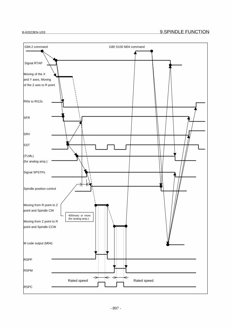
B-63323EN-1/03 9.SPINDLE FUNCTION
- 897 -
G84.2 command G80 S100 M04 command
Signal RTAP
Moving of the X
and Y axes, Moving
of the Z axis to R point
RI0s to RI12s
SFR
SRV
SST
(TLML)
(for analog amp.)
Signal SPSTPs
Spindle position control
Moving from R point to Z
point and Spindle CW
Moving from Z point to R
point and Spindle CCW
M code output (M04)
RSPP
RSPM
RSPC
400msec or more(for analog amp.)
Rated speed Rated speed
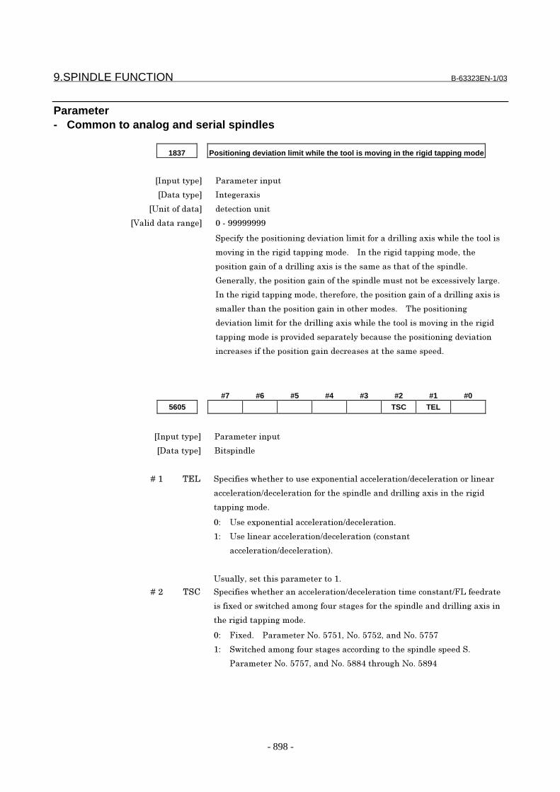
9.SPINDLE FUNCTION B-63323EN-1/03
- 898 -
Parameter- Common to analog and serial spindles
1837 Positioning deviation limit while the tool is moving in the rigid tapping mode
�������� ������������
�������� ����������
����������� ����������
���������������� ����
!�������"���������������#�������������������������������$"����"��������
��#�������"�������������������%� � ���"�������������������&�"�
�����������������������������������"����������"�����"���������%
'��������&�"������������������"����������������(���������#���������%
���"�������������������&�"�������&�"������������������������������������
��������"���"�������������������"��������%� � )"������������
��#���������������"����������������$"����"�����������#�������"�������
������������������#���������������(������"���������������#�����
�������������"���������������������������"������������%
#7 #6 #5 #4 #3 #2 #1 #0
5605 TSC TEL
�������� ������������
�������� *��������
� � � � +�� ),- !���������$"�"������������������������������.���������������������
�����������.����������������"�������������������������������"�������
�����������%
�/ ��������������������������.�����������%
�/ ����������������������.������������0������
�����������.�����������1%
������&����"���������������%
� � � � +�� )!2 !���������$"�"�����������������.����������������������.3-��������
�������������$��"�����������������������"������������������������������
"�������������������%
�/ 3����%� � ���������4�%�565�&�4�%�565�&�����4�%�5656
�/ !$��"�������������������������������"����������������!%
���������4�%�5656&�����4�%�5��7�"���"�4�%�5� 7
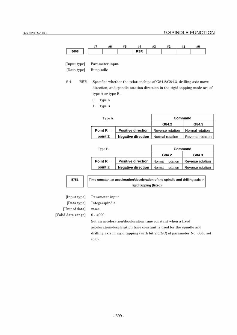
B-63323EN-1/03 9.SPINDLE FUNCTION
- 899 -
#7 #6 #5 #4 #3 #2 #1 #0
5608 RSR
�������� ������������
�������� *��������
� � � � +�7 8!8 !���������$"�"���"����������"�������'�7%�.'�7%9&�����������������#�
��������&��������������������������������"��������������������������
����:��������*%
0: Type A
1: Type B
Type A: Command
G84.2 G84.3
Positive direction Reverse rotation Normal rotationPoint R →
point Z Negative direction Normal rotation Reverse rotation
Type B: Command
G84.2 G84.3
Positive direction Normal rotation Reverse rotationPoint R →
point Z Negative direction Normal rotation Reverse rotation
5751 Time constant at acceleration/deceleration of the spindle and drilling axis in
rigid tapping (fixed)
�������� ������������
�������� �������������
����������� ����
���������������� ����7���
!����������������.�����������������������$"����������
�����������.����������������������������������"�������������
������������������������������0$�"�(����0)!21�������������4�%�5;�5���
���1%
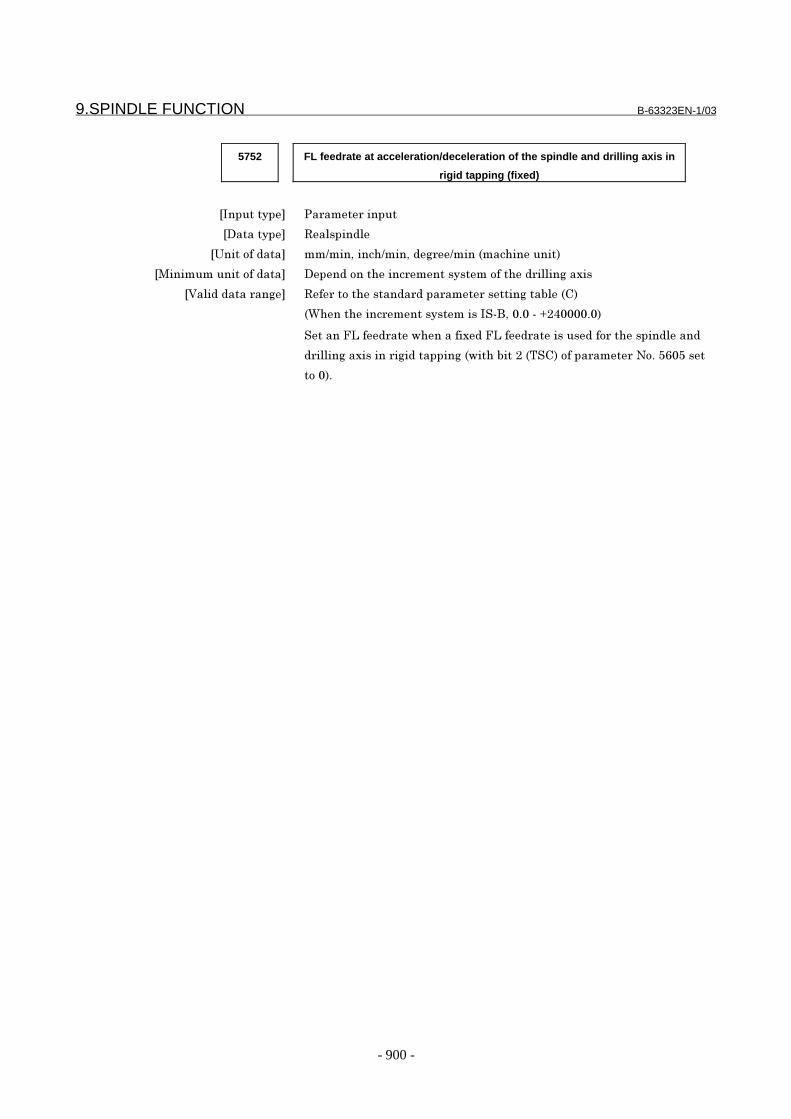
9.SPINDLE FUNCTION B-63323EN-1/03
- 900 -
5752 FL feedrate at acceleration/deceleration of the spindle and drilling axis in
rigid tapping (fixed)
�������� ������������
�������� 8����������
����������� ��.���&����".���&�������.����0���"������1
�<��������������� ����������"��������������������"���������������
���������������� 8�������"��������������������������(���021
0="���"���������������������!�*&��%����>�7����%�1
!�����3-���������$"�����������3-��������������������"�������������
������������������������������0$�"�(����0)!21�������������4�%�5;�5���
���1%

B-63323EN-1/03 9.SPINDLE FUNCTION
- 901 -
5757 Spindle speed for determining acceleration/deceleration for cutting feed in
rigid tapping (fixed)
�������� ������������
�������� �������������
����������� ���
���������������� ����9�6;6
Set a spindle speed when a fixed acceleration/deceleration time constant/FL
feedrate is used for the spindle and drilling axis in rigid tapping (with bit 2 (TSC) of
parameter No. 5602 set to 0).
When the type of acceleration/deceleration used for rigid tapping is linear
acceleration/deceleration (with bit 1 (TEL) of parameter No. 5605 set to 1), the
speed set in this parameter is increased or decreased for the time set in parameter
No. 5751.
Acceleration/dec
eleration time
Acceleration/dec
eleration time
TC TC
S S
command
S S
commandRelationship between Scommand and actualacceleration/decelerationtime during linearacceleration/deceleration
Relationship between S command and actual acceleration/deceleration time during exponential acceleration/deceleration

9.SPINDLE FUNCTION B-63323EN-1/03
- 902 -
5804 Allowable range for constant spindle speed signal output in exponential
acceleration/deceleration
�������� ������������
�������� �������������
����������� ����������
���������������� ����
The constant spindle speed signal is output when the difference in the number of
remaining pulses held in the acceleration/deceleration circuit between two adjacent
distribution periods (ITPs) is zero. In exponential acceleration/deceleration,
however, the difference in the number of remaining pulses between two adjacent
ITPs does not become zero even when a constant speed is kept. In this case, a
constant speed is assumed to be reached when the difference in the number of
remaining pulses is within the range specified in this parameter.
In the figure shown below, the number of pulses accummulated in the
acceleration/deceleration circuit at ITP6 is:
α1+α2+α3+α4+α5+α6
At ITP7, the number of accummulated pulses is:
α1+α2+α3+α4+α5+α6+α7
Therefore, the difference in pulses accummulated in the acceleration/deceleration
circuit at ITP6 and ITP7 is α7.
The difference will not become 0 indefinitely.
�)��
:�����������
)���
3������
�������������3
�)�� �)�9 �)�7 �)�5 �)�; �)�6
��
��
�9
�7�5
�;�6
α1
α2
α3α4
α5α6 α7
��/� � 4�(�����������������������)�
α�/� � 4�(������������������������"�������������.��������������������������)�

B-63323EN-1/03 9.SPINDLE FUNCTION
- 903 -
5842 Number of pulses of the position coder
�������� ������������
�������� �������������
����������� ����������
���������������� ����9�6;6
Set the number of pulses of the position coder.
5851 Number of teeth on the position coder gear in the servo mode (first stage)
�������� ������������
�������� �������������
���������������� ����9�6;6
!��"����(��������"����"������������������������"�����#������
0������������&�������������������&�����������"1�0���������1%
5852 Number of teeth on the spindle gear in the servo mode (first stage)
�������� ������������
�������� �������������
���������������� ����9�6;6
!��"����(��������"����"������������������"�����#�������0�����
������&�������������������&�����������"1�0���������1%
5853 Backlash compensation in the servo mode (first stage)
�������� ������������
�������� �������������
����������� ����������
���������������� � ���
!����(��?���"����������������"�����#�������0������������&��������
����������&�����������"1�0���������1%
5854 Number of teeth on the position coder gear in the servo mode (second stage)
�������� ������������
�������� �������������
���������������� ����9�6;6
!��"����(��������"����"������������������������"�����#������
0������������&�������������������&�����������"1�0�����������1%
9.SPINDLE FUNCTION B-63323EN-1/03
- 904 -
5855 Number of teeth on the spindle gear in the servo mode (second stage)
�������� ������������
�������� �������������
���������������� ����9�6;6
!��"����(��������"����"������������������"�����#�������0�����
������&�������������������&�����������"1�0�����������1%
5856 Backlash compensation in the servo mode (second stage)
�������� ������������
�������� �������������
����������� ����������
���������������� � ���
!����(��?���"����������������"�����#�������0������������&��������
����������&�����������"1�0�����������1%
5857 Number of teeth on the position coder gear in the servo mode (third stage)
�������� ������������
�������� �������������
���������������� ����9�6;6
!��"����(��������"����"������������������������"�����#������
0������������&�������������������&�����������"1�0"��������1%
5858 Number of teeth on the spindle gear in the servo mode (third stage)
�������� ������������
�������� �������������
���������������� ����9�6;6
!��"����(��������"����"������������������"�����#�������0�����
������&�������������������&�����������"1�0"��������1%
5859 Backlash compensation in the servo mode (third stage)
�������� ������������
�������� �������������
����������� ����������
���������������� � ���
!����(��?���"����������������"�����#�������0������������&��������
����������&�����������"1�0"��������1%

B-63323EN-1/03 9.SPINDLE FUNCTION
- 905 -
5860 Number of teeth on the position coder gear in the servo mode (fourth stage)
�������� ������������
�������� �������������
���������������� ����9�6;6
!��"����(��������"����"������������������������"�����#������
0������������&�������������������&�����������"1�0���"�����1%
5861 Number of teeth on the spindle gear in the servo mode (fourth stage)
�������� ������������
�������� �������������
���������������� ����9�6;6
!��"����(��������"����"������������������"�����#�������0�����
������&�������������������&�����������"1�0���"�����1%
5862 Backlash compensation in the servo mode (fourth stage)
�������� ������������
�������� �������������
����������� ����������
���������������� � ���
!����(��?���"����������������"�����#�������0������������&��������
����������&�����������"1�0���"�����1%
5863 Number of teeth on the position coder gear in the servo mode (fifth stage)
�������� ������������
�������� �������������
���������������� ����9�6;6
!��"����(��������"����"������������������������"�����#������
0������������&�������������������&�����������"1�0���"�����1%
5864 Number of teeth on the spindle gear in the servo mode (fifth stage)
�������� ������������
�������� �������������
���������������� ����9�6;6
!��"����(��������"����"������������������"�����#�������0�����
������&�������������������&�����������"1�0���"�����1%
9.SPINDLE FUNCTION B-63323EN-1/03
- 906 -
5865 Backlash compensation in the servo mode (fifth stage)
�������� ������������
�������� �������������
����������� ����������
���������������� � ���
!����(��?���"����������������"�����#�������0������������&��������
����������&�����������"1�0���"�����1%
5866 Number of teeth on the position coder gear in the servo mode (sixth stage)
�������� ������������
�������� �������������
���������������� ����9�6;6
!��"����(��������"����"������������������������"�����#������
0������������&�������������������&�����������"1�0���"�����1%
5867 Number of teeth on the spindle gear in the servo mode (sixth stage)
�������� ������������
�������� �������������
���������������� ����9�6;6
!��"����(��������"����"������������������"�����#�������0�����
������&�������������������&�����������"1�0���"�����1%
5868 Backlash compensation in the servo mode (sixth stage)
�������� ������������
�������� �������������
����������� ����������
���������������� � ���
!����(��?���"����������������"�����#�������0������������&��������
����������&�����������"1�0���"�����1%
5869 Number of teeth on the position coder gear in the servo mode (seventh
stage)
�������� ������������
�������� �������������
���������������� ����9�6;6
!��"����(��������"����"������������������������"�����#������
0������������&�������������������&�����������"1�0��#��"�����1%
B-63323EN-1/03 9.SPINDLE FUNCTION
- 907 -
5870 Number of teeth on the spindle gear in the servo mode (seventh stage)
�������� ������������
�������� �������������
���������������� ����9�6;6
!��"����(��������"����"������������������"�����#�������0�����
������&�������������������&�����������"1�0��#��"�����1%
5871 Backlash compensation in the servo mode (seventh stage)
�������� ������������
�������� �������������
����������� ����������
���������������� � ���
!����(��?���"����������������"�����#�������0������������&��������
����������&�����������"1�0��#��"�����1%
5872 Number of teeth on the position coder gear in the servo mode (eighth stage)
�������� ������������
�������� �������������
���������������� ����9�6;6
!��"����(��������"����"������������������������"�����#������
0������������&�������������������&�����������"1�0���""�����1%
5873 Number of teeth on the spindle gear in the servo mode (eighth stage)
�������� ������������
�������� �������������
���������������� ����9�6;6
!��"����(��������"����"������������������"�����#�������0�����
������&�������������������&�����������"1�0���""�����1%
5874 Backlash compensation in the servo mode (eighth stage)
�������� ������������
�������� �������������
����������� ����������
���������������� � ���
!����(��?���"����������������"�����#�������0������������&��������
����������&�����������"1�0���""�����1%

9.SPINDLE FUNCTION B-63323EN-1/03
- 908 -
5875 Effective area in the servo mode using a position coder
�������� ������������
�������� �������������
����������� ����������
���������������� ����
!�����������#����������"�����#�������0������������&�������������������&
����������"1���������������������%
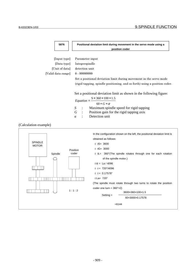
B-63323EN-1/03 9.SPINDLE FUNCTION
- 909 -
5876 Positional deviation limit during movement in the servo mode using a
position coder
�������� ������������
�������� �������������
����������� ����������
���������������� ����
!����������������#�������������������#��������"�����#������
0������������&�������������������&�����������"1���������������������%
Set a positional deviation limit as shown in the following figure:
α××
×××=
GEquation
60
5.1100360S
S : Maximum spindle speed for rigid tappingG : Position gain for the rigid tapping axisα : Detection unit
(Calculation example)
1 : 1 : 2
In the configuration shown on the left, the positional deviation limit is
obtained as follows:
@ @S= 3600
@ @G= 3000
@ @L= 360°(The spindle rotates through one for each rotation
of the spindle motor.)
@ α = La / 4096
@ @ = 720°/4096
@ @ = 0.17578°
@ La= 720°
(The spindle must rotate through two turns to rotate the position
coder one turn = 360°×2)
60×3000×0.17578
3600×360×100×1.5Setting =
=6144
SPINDLEMOTOR
SpindlePositioncoder
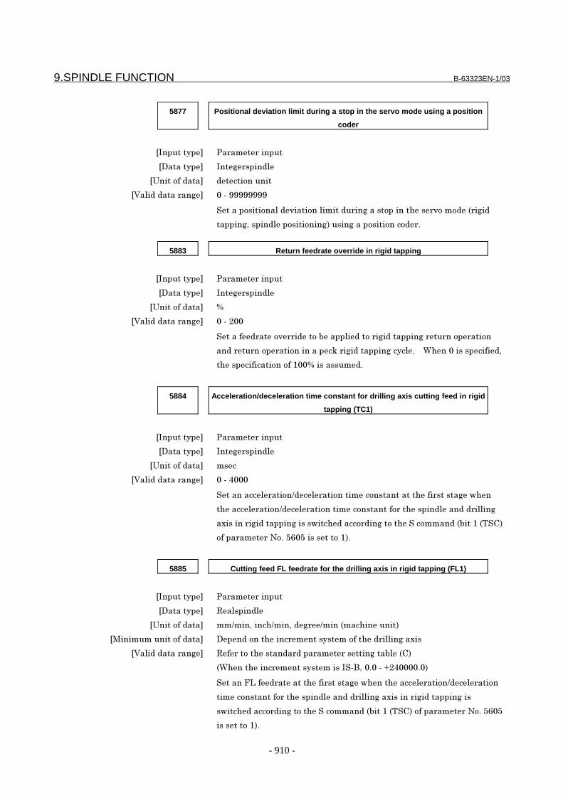
9.SPINDLE FUNCTION B-63323EN-1/03
- 910 -
5877 Positional deviation limit during a stop in the servo mode using a position
coder
�������� ������������
�������� �������������
����������� ����������
���������������� ����
!����������������#��������������������������"�����#�������0�����
������&�������������������1���������������������%
5883 Return feedrate override in rigid tapping
�������� ������������
�������� �������������
����������� @
���������������� �������
!�������������#���������(��������������������������������������
��������������������������?�������������������%� � ="�����������������&
"���������������������@����������%
5884 Acceleration/deceleration time constant for drilling axis cutting feed in rigid
tapping (TC1)
�������� ������������
�������� �������������
����������� ����
���������������� ����7���
!����������������.�������������������������"������������$"��
"�������������.���������������������������"����������������������
�������������������������$��"���������������"��!���������0(����0)!21
������������4�%�5;�5����������1%
5885 Cutting feed FL feedrate for the drilling axis in rigid tapping (FL1)
�������� ������������
�������� 8����������
����������� ��.���&����".���&�������.����0���"������1
�<��������������� ����������"��������������������"���������������
���������������� 8�������"��������������������������(���021
0="���"���������������������!�*&��%����>�7����%�1
!�����3-�����������"������������$"���"�������������.�����������
���������������"����������������������������������������������
�$��"���������������"��!���������0(����0)!21�������������4�%�5;�5
���������1%
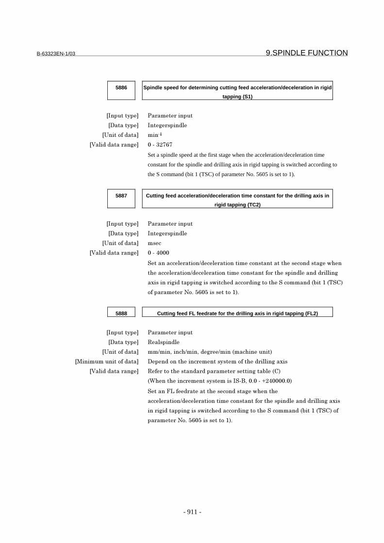
B-63323EN-1/03 9.SPINDLE FUNCTION
- 911 -
5886 Spindle speed for determining cutting feed acceleration/deceleration in rigid
tapping (S1)
�������� ������������
�������� �������������
����������� �����
���������������� ����9�6;6
Set a spindle speed at the first stage when the acceleration/deceleration time
constant for the spindle and drilling axis in rigid tapping is switched according to
the S command (bit 1 (TSC) of parameter No. 5605 is set to 1).
5887 Cutting feed acceleration/deceleration time constant for the drilling axis in
rigid tapping (TC2)
�������� ������������
�������� �������������
����������� ����
���������������� ����7���
!����������������.�������������������������"��������������$"��
"�������������.���������������������������"����������������������
�������������������������$��"���������������"��!���������0(����0)!21
������������4�%�5;�5����������1%
5888 Cutting feed FL feedrate for the drilling axis in rigid tapping (FL2)
�������� ������������
�������� 8����������
����������� ��.���&����".���&�������.����0���"������1
�<��������������� ����������"��������������������"���������������
���������������� 8�������"��������������������������(���021
0="���"���������������������!�*&��%����>�7����%�1
!�����3-�����������"��������������$"���"�
�����������.���������������������������"���������������������������
��������������������$��"���������������"��!���������0(����0)!21���
���������4�%�5;�5����������1%
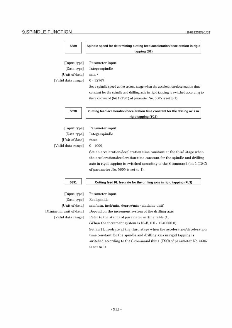
9.SPINDLE FUNCTION B-63323EN-1/03
- 912 -
5889 Spindle speed for determining cutting feed acceleration/deceleration in rigid
tapping (S2)
�������� ������������
�������� �������������
����������� �����
���������������� ����9�6;6
Set a spindle speed at the second stage when the acceleration/deceleration time
constant for the spindle and drilling axis in rigid tapping is switched according to
the S command (bit 1 (TSC) of parameter No. 5605 is set to 1).
5890 Cutting feed acceleration/deceleration time constant for the drilling axis in
rigid tapping (TC3)
�������� ������������
�������� �������������
����������� ����
���������������� ����7���
!����������������.�������������������������"��"���������$"��
"�������������.���������������������������"����������������������
�������������������������$��"���������������"��!���������0(����0)!21
������������4�%�5;�5����������1%
5891 Cutting feed FL feedrate for the drilling axis in rigid tapping (FL3)
�������� ������������
�������� 8����������
����������� ��.���&����".���&�������.����0���"������1
�<��������������� ����������"��������������������"���������������
���������������� 8�������"��������������������������(���021
0="���"���������������������!�*&��%����>�7����%�1
!�����3-�����������"��"���������$"���"�������������.�����������
���������������"����������������������������������������������
�$��"���������������"��!���������0(����0)!21�������������4�%�5;�5
���������1%

B-63323EN-1/03 9.SPINDLE FUNCTION
- 913 -
5892 Spindle speed for determining cutting feed acceleration/deceleration in rigid
tapping (S3)
�������� ������������
�������� �������������
����������� �����
���������������� ����9�6;6
Set a spindle speed at the third stage when the acceleration/deceleration time
constant for the spindle and drilling axis in rigid tapping is switched according to
the S command (bit 1 (TSC) of parameter No. 5605 is set to 1).
5893 Cutting feed acceleration/deceleration time constant for the drilling axis in
rigid tapping (TC4)
�������� ������������
�������� �������������
����������� ����
���������������� ����7���
!����������������.�������������������������"�����"������$"��
"�������������.���������������������������"����������������������
�������������������������$��"���������������"��!���������0(����0)!21
������������4�%�5;�5����������1%

9.SPINDLE FUNCTION B-63323EN-1/03
- 914 -
5894 Cutting feed FL feedrate for the drilling axis in rigid tapping (FL4)
�������� ������������
�������� 8����������
����������� ��.���&����".���&�������.����0���"������1
�<��������������� ����������"��������������������"���������������
���������������� 8�������"��������������������������(���021
0="���"���������������������!�*&��%����>�7����%�1
Set an FL feedrate at the fourth stage when the acceleration/deceleration time
constant for the spindle and drilling axis in rigid tapping is switched according to
the S command (bit 1 (TSC) of parameter No. 5605 is set to 1).
Parameter Nos. 5884 to 5894 are used to change the cutting feed
acceleration/deceleration time constant/FL feedrate on the hole machining axis in
rigid tapping according to the S command. These parameters set the time constant
(TCx)/FL feedrate (FLx) at each level and the spindle speed (Sx) to set levels.
The following show the relationship between the S command and FL feedrate, the
relationship between the S command and actual acceleration/deceleration time in
linear acceleration/deceleration, and the relationship between the S command and
actual acceleration/deceleration time in exponential acceleration/deceleration:
Spindle speed command S FL feedrate
S≤S1 FL1
S1<S≤S2 FL2
S2<S≤S3 FL3
S3<S FL4Relationship between S command and FL feedrate
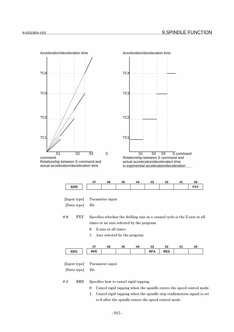
B-63323EN-1/03 9.SPINDLE FUNCTION
- 915 -
Acceleration/deceleration time
TC4
TC3
TC2
TC1
S1 S2 S3 ScommandRelationship between S command andactual acceleration/deceleration time
Acceleration/deceleration time
TC4
TC3
TC2
TC1
S1 S2 S3 S commandRelationship between S command andactual acceleration/deceleration timein exponential acceleration/deceleration
#7 #6 #5 #4 #3 #2 #1 #0
6200 FXY
�������� ������������
�������� *�
� � � � +�� 3AB !���������$"�"���"�������������������������������������"��C�����������
������������������������(��"���������%
�/ C����������������
�/ :������������(��"���������
#7 #6 #5 #4 #3 #2 #1 #0
6201 RFE RFA RES
�������� ������������
�������� *�
� � � � +�� 8,! !���������"�$����������������������%
�/ 2�������������������$"���"����������������"�������������������%
�/ 2�������������������$"���"��������������������������������������
���������"����������������"�������������������%

9.SPINDLE FUNCTION B-63323EN-1/03
- 916 -
� � � � +�9 83: !���������$"�"��������������������������3���������"��"��
����������������������������������������������������%
�/ �������������������%
�/ �������������%
� � � � +�6 83, !���������"�$�����������������������������"������������������������
������3�������������������������%
0: Digits after the decimal point are truncated.
1: Digits specified after the decimal point are valid.
Example of F
command
F10. or F10.0 F10.5
RFA=1,
RFE=0 or RFE=1
F10.0 PS530 (incorrect use of
decimal point) is issued.
RFA=0, RFE=0 F10.0 F10.0
RFA=0, RFE=1 F10.0 F10.5
6221 Return distance in a peck rigid tapping cycle
�������� !��������
�������� 8���
����������� ��&����"�0������1
�<��������������� ����������"��������������������"���������������
���������������� ����������#�� ��������������������������0��������"���������
����������������(���0*11
0="���"���������������������!�*&��%����> % 1
!�������������������������?�������������������%
- For analog spindles5960 Position gain in the servo mode
�������� ������������
�������� �������������
����������� �%��.���
���������������� ����
!������������������������������������"�����#�������0������������&
������������������&�����������"1%� � )"��������������������������������
������������������������������������������%
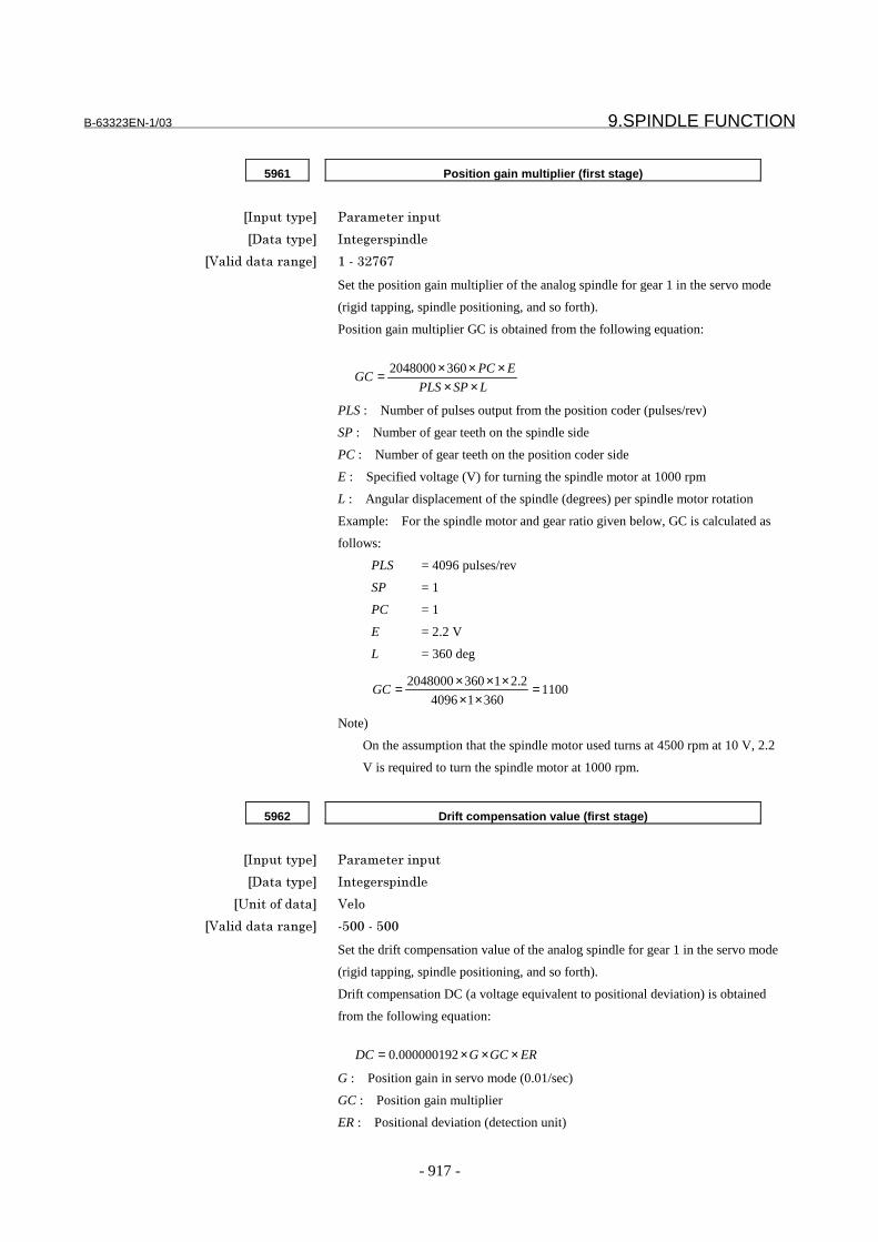
B-63323EN-1/03 9.SPINDLE FUNCTION
- 917 -
5961 Position gain multiplier (first stage)
�������� ������������
�������� �������������
���������������� ����9�6;6
Set the position gain multiplier of the analog spindle for gear 1 in the servo mode
(rigid tapping, spindle positioning, and so forth).
Position gain multiplier GC is obtained from the following equation:
PLS : Number of pulses output from the position coder (pulses/rev)
SP : Number of gear teeth on the spindle side
PC : Number of gear teeth on the position coder side
E : Specified voltage (V) for turning the spindle motor at 1000 rpm
L : Angular displacement of the spindle (degrees) per spindle motor rotation
Example: For the spindle motor and gear ratio given below, GC is calculated as
follows:
PLS = 4096 pulses/rev
SP = 1
PC = 1
E = 2.2 V
L = 360 deg
Note)
On the assumption that the spindle motor used turns at 4500 rpm at 10 V, 2.2
V is required to turn the spindle motor at 1000 rpm.
LSPPLS
EPCGC
×××××= 3602048000
110036014096
2.213602048000 =××
×××=GC
5962 Drift compensation value (first stage)
�������� ������������
�������� �������������
����������� ����
���������������� �5�����5��
Set the drift compensation value of the analog spindle for gear 1 in the servo mode
(rigid tapping, spindle positioning, and so forth).
Drift compensation DC (a voltage equivalent to positional deviation) is obtained
from the following equation:
G : Position gain in servo mode (0.01/sec)
GC : Position gain multiplier
ER : Positional deviation (detection unit)
ERGCGDC ×××= 000000192.0
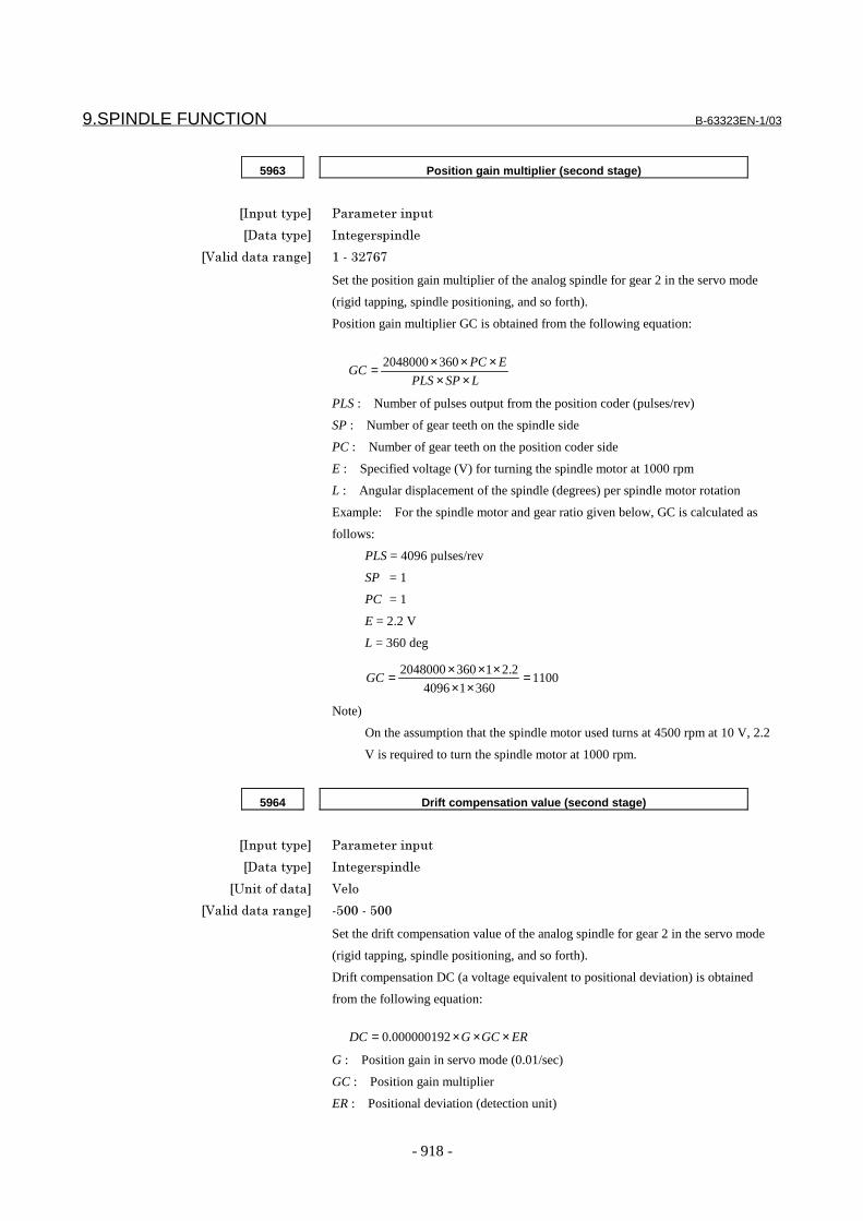
9.SPINDLE FUNCTION B-63323EN-1/03
- 918 -
5963 Position gain multiplier (second stage)
�������� ������������
�������� �������������
���������������� ����9�6;6
Set the position gain multiplier of the analog spindle for gear 2 in the servo mode
(rigid tapping, spindle positioning, and so forth).
Position gain multiplier GC is obtained from the following equation:
PLS : Number of pulses output from the position coder (pulses/rev)
SP : Number of gear teeth on the spindle side
PC : Number of gear teeth on the position coder side
E : Specified voltage (V) for turning the spindle motor at 1000 rpm
L : Angular displacement of the spindle (degrees) per spindle motor rotation
Example: For the spindle motor and gear ratio given below, GC is calculated as
follows:
PLS = 4096 pulses/rev
SP = 1
PC = 1
E = 2.2 V
L = 360 deg
Note)
On the assumption that the spindle motor used turns at 4500 rpm at 10 V, 2.2
V is required to turn the spindle motor at 1000 rpm.
LSPPLS
EPCGC
×××××= 3602048000
110036014096
2.213602048000 =××
×××=GC
5964 Drift compensation value (second stage)
�������� ������������
�������� �������������
����������� ����
���������������� �5�����5��
Set the drift compensation value of the analog spindle for gear 2 in the servo mode
(rigid tapping, spindle positioning, and so forth).
Drift compensation DC (a voltage equivalent to positional deviation) is obtained
from the following equation:
G : Position gain in servo mode (0.01/sec)
GC : Position gain multiplier
ER : Positional deviation (detection unit)
ERGCGDC ×××= 000000192.0
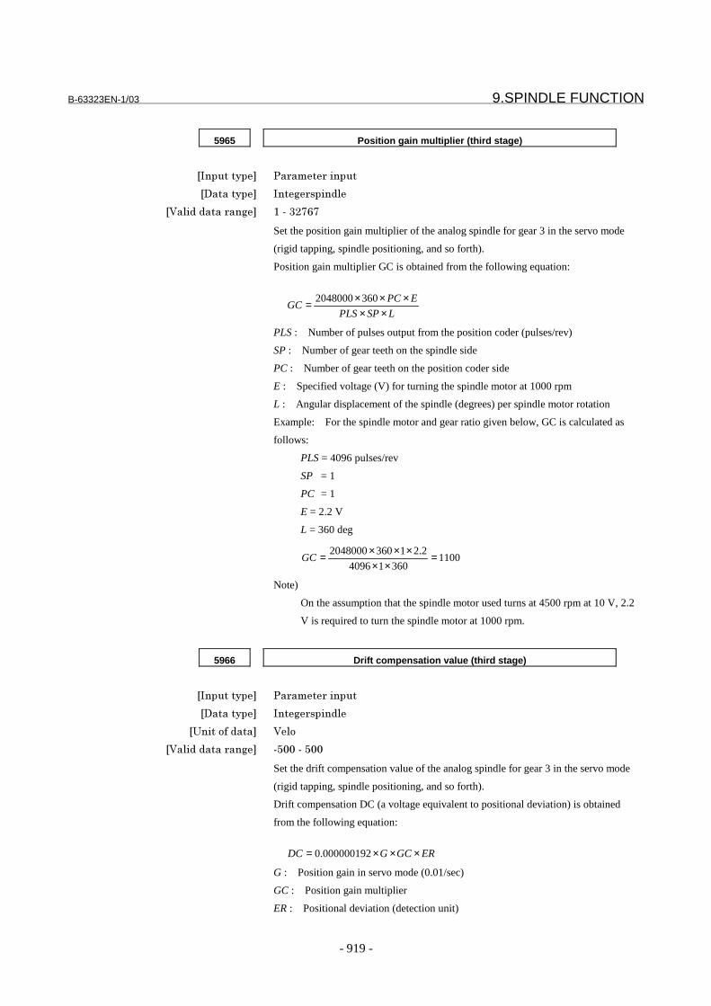
B-63323EN-1/03 9.SPINDLE FUNCTION
- 919 -
5965 Position gain multiplier (third stage)
�������� ������������
�������� �������������
���������������� ����9�6;6
Set the position gain multiplier of the analog spindle for gear 3 in the servo mode
(rigid tapping, spindle positioning, and so forth).
Position gain multiplier GC is obtained from the following equation:
PLS : Number of pulses output from the position coder (pulses/rev)
SP : Number of gear teeth on the spindle side
PC : Number of gear teeth on the position coder side
E : Specified voltage (V) for turning the spindle motor at 1000 rpm
L : Angular displacement of the spindle (degrees) per spindle motor rotation
Example: For the spindle motor and gear ratio given below, GC is calculated as
follows:
PLS = 4096 pulses/rev
SP = 1
PC = 1
E = 2.2 V
L = 360 deg
Note)
On the assumption that the spindle motor used turns at 4500 rpm at 10 V, 2.2
V is required to turn the spindle motor at 1000 rpm.
LSPPLS
EPCGC
×××××= 3602048000
110036014096
2.213602048000 =××
×××=GC
5966 Drift compensation value (third stage)
�������� ������������
�������� �������������
����������� ����
���������������� �5�����5��
Set the drift compensation value of the analog spindle for gear 3 in the servo mode
(rigid tapping, spindle positioning, and so forth).
Drift compensation DC (a voltage equivalent to positional deviation) is obtained
from the following equation:
G : Position gain in servo mode (0.01/sec)
GC : Position gain multiplier
ER : Positional deviation (detection unit)
ERGCGDC ×××= 000000192.0

9.SPINDLE FUNCTION B-63323EN-1/03
- 920 -
5967 Position gain multiplier (fourth stage)
�������� ������������
�������� �������������
���������������� ����9�6;6
Set the position gain multiplier of the analog spindle for gear 4 in the servo mode
(rigid tapping, spindle positioning, and so forth).
Position gain multiplier GC is obtained from the following equation:
PLS : Number of pulses output from the position coder (pulses/rev)
SP : Number of gear teeth on the spindle side
PC : Number of gear teeth on the position coder side
E : Specified voltage (V) for turning the spindle motor at 1000 rpm
L : Angular displacement of the spindle (degrees) per spindle motor rotation
Example: For the spindle motor and gear ratio given below, GC is calculated as
follows:
PLS = 4096 pulses/rev
SP = 1
PC = 1
E = 2.2 V
L = 360 deg
Note)
On the assumption that the spindle motor used turns at 4500 rpm at 10 V, 2.2
V is required to turn the spindle motor at 1000 rpm.
LSPPLS
EPCGC
×××××= 3602048000
110036014096
2.213602048000 =××
×××=GC
5968 Drift compensation value (fourth stage)
�������� ������������
�������� �������������
����������� ����
���������������� �5�����5��
Set the drift compensation value of the analog spindle for gear 4 in the servo mode
(rigid tapping, spindle positioning, and so forth).
Drift compensation DC (a voltage equivalent to positional deviation) is obtained
from the following equation:
G : Position gain in servo mode (0.01/sec)
GC : Position gain multiplier
ER : Positional deviation (detection unit)
ERGCGDC ×××= 000000192.0

B-63323EN-1/03 9.SPINDLE FUNCTION
- 921 -
5969 Position gain multiplier (fifth stage)
�������� ������������
�������� �������������
���������������� ����9�6;6
Set the position gain multiplier of the analog spindle for gear 5 in the servo mode
(rigid tapping, spindle positioning, and so forth).
Position gain multiplier GC is obtained from the following equation:
PLS : Number of pulses output from the position coder (pulses/rev)
SP : Number of gear teeth on the spindle side
PC : Number of gear teeth on the position coder side
E : Specified voltage (V) for turning the spindle motor at 1000 rpm
L : Angular displacement of the spindle (degrees) per spindle motor rotation
Example: For the spindle motor and gear ratio given below, GC is calculated as
follows:
PLS = 4096 pulses/rev
SP = 1
PC = 1
E = 2.2 V
L = 360 deg
Note)
On the assumption that the spindle motor used turns at 4500 rpm at 10 V, 2.2
V is required to turn the spindle motor at 1000 rpm.
LSPPLS
EPCGC
×××××= 3602048000
110036014096
2.213602048000 =××
×××=GC
5970 Drift compensation value (fifth stage)
�������� ������������
�������� �������������
����������� ����
���������������� �5�����5��
Set the drift compensation value of the analog spindle for gear 5 in the servo mode
(rigid tapping, spindle positioning, and so forth).
Drift compensation DC (a voltage equivalent to positional deviation) is obtained
from the following equation:
G : Position gain in servo mode (0.01/sec)
GC : Position gain multiplier
ER : Positional deviation (detection unit)
ERGCGDC ×××= 000000192.0

9.SPINDLE FUNCTION B-63323EN-1/03
- 922 -
5971 Position gain multiplier (sixth stage)
�������� ������������
�������� �������������
���������������� ����9�6;6
Set the position gain multiplier of the analog spindle for gear 6 in the servo mode
(rigid tapping, spindle positioning, and so forth).
Position gain multiplier GC is obtained from the following equation:
PLS : Number of pulses output from the position coder (pulses/rev)
SP : Number of gear teeth on the spindle side
PC : Number of gear teeth on the position coder side
E : Specified voltage (V) for turning the spindle motor at 1000 rpm
L : Angular displacement of the spindle (degrees) per spindle motor rotation
Example: For the spindle motor and gear ratio given below, GC is calculated as
follows:
PLS = 4096 pulses/rev
SP = 1
PC = 1
E = 2.2 V
L = 360 deg
Note)
On the assumption that the spindle motor used turns at 4500 rpm at 10 V, 2.2
V is required to turn the spindle motor at 1000 rpm.
LSPPLS
EPCGC
×××××= 3602048000
110036014096
2.213602048000 =××
×××=GC
5972 Drift compensation value (sixth stage)
�������� ������������
�������� �������������
����������� ����
���������������� �5�����5��
Set the drift compensation value of the analog spindle for gear 6 in the servo mode
(rigid tapping, spindle positioning, and so forth).
Drift compensation DC (a voltage equivalent to positional deviation) is obtained
from the following equation:
G : Position gain in servo mode (0.01/sec)
GC : Position gain multiplier
ER : Positional deviation (detection unit)
ERGCGDC ×××= 000000192.0

B-63323EN-1/03 9.SPINDLE FUNCTION
- 923 -
5973 Position gain multiplier (seventh stage)
�������� ������������
�������� �������������
���������������� ����9�6;6
Set the position gain multiplier of the analog spindle for gear 7 in the servo mode
(rigid tapping, spindle positioning, and so forth).
Position gain multiplier GC is obtained from the following equation:
PLS : Number of pulses output from the position coder (pulses/rev)
SP : Number of gear teeth on the spindle side
PC : Number of gear teeth on the position coder side
E : Specified voltage (V) for turning the spindle motor at 1000 rpm
L : Angular displacement of the spindle (degrees) per spindle motor rotation
Example: For the spindle motor and gear ratio given below, GC is calculated as
follows:
PLS = 4096 pulses/rev
SP = 1
PC = 1
E = 2.2 V
L = 360 deg
Note)
On the assumption that the spindle motor used turns at 4500 rpm at 10 V, 2.2
V is required to turn the spindle motor at 1000 rpm.
LSPPLS
EPCGC
×××××= 3602048000
110036014096
2.213602048000 =××
×××=GC
5974 Drift compensation value (seventh stage)
�������� ������������
�������� �������������
����������� ����
���������������� �5�����5��
Set the drift compensation value of the analog spindle for gear 7 in the servo mode
(rigid tapping, spindle positioning, and so forth).
Drift compensation DC (a voltage equivalent to positional deviation) is obtained
from the following equation:
G : Position gain in servo mode (0.01/sec)
GC : Position gain multiplier
ER : Positional deviation (detection unit)
ERGCGDC ×××= 000000192.0

9.SPINDLE FUNCTION B-63323EN-1/03
- 924 -
5975 Position gain multiplier (eighth stage)
�������� ������������
�������� �������������
���������������� ����9�6;6
Set the position gain multiplier of the analog spindle for gear 8 in the servo mode
(rigid tapping, spindle positioning, and so forth).
Position gain multiplier GC is obtained from the following equation:
PLS : Number of pulses output from the position coder (pulses/rev)
SP : Number of gear teeth on the spindle side
PC : Number of gear teeth on the position coder side
E : Specified voltage (V) for turning the spindle motor at 1000 rpm
L : Angular displacement of the spindle (degrees) per spindle motor rotation
Example: For the spindle motor and gear ratio given below, GC is calculated as
follows:
PLS = 4096 pulses/rev
SP = 1
PC = 1
E = 2.2 V
L = 360 deg
Note)
On the assumption that the spindle motor used turns at 4500 rpm at 10 V, 2.2
V is required to turn the spindle motor at 1000 rpm.
LSPPLS
EPCGC
×××××= 3602048000
110036014096
2.213602048000 =××
×××=GC
5976 Drift compensation value (eighth stage)
�������� ������������
�������� �������������
����������� ����
���������������� �5�����5��
Set the drift compensation value of the analog spindle for gear 8 in the servo mode
(rigid tapping, spindle positioning, and so forth).
Drift compensation DC (a voltage equivalent to positional deviation) is obtained
from the following equation:
G : Position gain in servo mode (0.01/sec)
GC : Position gain multiplier
ER : Positional deviation (detection unit)
ERGCGDC ×××= 000000192.0

B-63323EN-1/03 9.SPINDLE FUNCTION
- 925 -
5977 Rapid traverse rate for orientation
�������� ������������
�������� 8����������
����������� ������.���
�<��������������� ����������"��������������������"����������������
���������������� 8�������"��������������������������(���021
0="���"���������������������!�*&��%����>�7����%�1
!������������#�����������������������������������������"�����#������
0������������&�������������������&�����������"1%
NOTESet a rapid traverse rate so that the quantity of errors is within arange from 128 pulses to 1024 pulses.
5978 Time constant for orientation
�������� ������������
�������� �������������
����������� ����
���������������� ����7���
!�����������������������������������������������"�����#������
0������������&�������������������&�����������"1%
5979 FL feedrate for orientation
�������� ������������
�������� 8����������
����������� ������.���
�<��������������� ����������"��������������������"����������������
���������������� 8�������"��������������������������(���021
0="���"���������������������!�*&��%����>�7����%�1
!�����3-�����������������������������������������"�����#�������0�����
������&�������������������&�����������"1%
NOTESet an FL feedrate rate so that the quantity of errors is within arange from the effective area to 1024 pulses.

9.SPINDLE FUNCTION B-63323EN-1/03
- 926 -
5980 Grid shift value for orientation
�������� ������������
�������� �������������
����������� ����������
���������������� ���7������7�
!����������"���#���������"���������������������������"��������
�����������"�����#�������0������������&�������������������&�������
���"1%
- For serial spindles#7 #6 #5 #4 #3 #2 #1 #0
3000 SVO
�������� ������������
�������� *��������
� � � � +�7 !�D �����������������������������������������#�������0������������&��������
����������&�����������"1
��/ )"������������������"�����������������������������?$����0#��$��
�����"��������������1%
��/ )"������������������"������������������������?$����0#��$�������
"��������������1%
NOTEThe orientation (reference position return) direction ofspindle positioning using a serial spindle depends onthe specification of this parameter.
3044 Proportional gain of the velocity loop in servo mode
/synchronization control mode (high-speed gear)
�������� ������������
�������� �������������
����������� �%��.���
���������������� ����9�6;6
Set the proportional gain of the velocity loop for the high-speed gear in the servo
mode (rigid tapping, spindle positioning, and so forth).
servo mode (rigid tapping, spindle positioning, and so forth).

B-63323EN-1/03 9.SPINDLE FUNCTION
- 927 -
3045 Proportional gain of the velocity loop in servo mode
/synchronization control mode (low-speed gear)
�������� ������������
�������� �������������
����������� �%��.���
���������������� ����9�6;6
Set the proportional gain of the velocity loop for the low-speed gear in servo mode
(rigid tapping, spindle positioning, and so forth).
l gain of the velocity loop for the low-speed gear in
3052 Integral gain of the velocity loop in servo mode
/synchronization control mode (high-speed gear)
�������� ������������
�������� �������������
����������� �%��.���
���������������� ����9�6;6
Set the integral gain of the velocity loop for the high-speed gear in servo mode
(rigid tapping, spindle positioning, and so forth).
3053 Integral gain of the velocity loop in servo mode
/synchronization control mode (low-speed gear)
�������� ������������
�������� �������������
����������� �%��.���
���������������� ����9�6;6
Set the integral gain of the velocity loop for the low-speed gear in servo mode (rigid
tapping, spindle positioning, and so forth).
3056 Gear ratio (high-speed gear)
�������� ������������
�������� �������������
����������� <���������������������������� ~���
���������������� ����9�6;6
Set a gear ratio between the spindle and spindle motor for the high-speed gear.
Set the gear or clutch status corresponding to the clutch/gear signal.
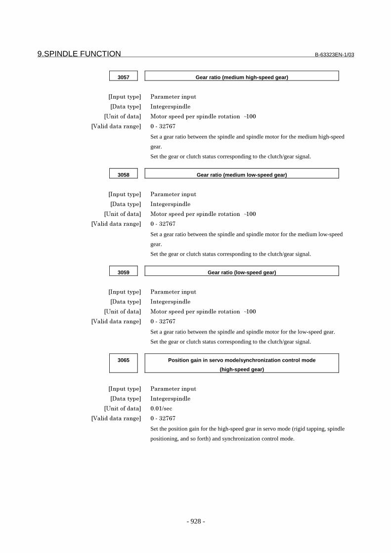
9.SPINDLE FUNCTION B-63323EN-1/03
- 928 -
3057 Gear ratio (medium high-speed gear)
�������� ������������
�������� �������������
����������� <���������������������������� ~���
���������������� ����9�6;6
Set a gear ratio between the spindle and spindle motor for the medium high-speed
gear.
Set the gear or clutch status corresponding to the clutch/gear signal.
3058 Gear ratio (medium low-speed gear)
�������� ������������
�������� �������������
����������� <���������������������������� ~���
���������������� ����9�6;6
Set a gear ratio between the spindle and spindle motor for the medium low-speed
gear.
Set the gear or clutch status corresponding to the clutch/gear signal.
3059 Gear ratio (low-speed gear)
�������� ������������
�������� �������������
����������� <���������������������������� ~���
���������������� ����9�6;6
Set a gear ratio between the spindle and spindle motor for the low-speed gear.
Set the gear or clutch status corresponding to the clutch/gear signal.
3065 Position gain in servo mode/synchronization control mode
(high-speed gear)
�������� ������������
�������� �������������
����������� �%��.���
���������������� ����9�6;6
Set the position gain for the high-speed gear in servo mode (rigid tapping, spindle
positioning, and so forth) and synchronization control mode.
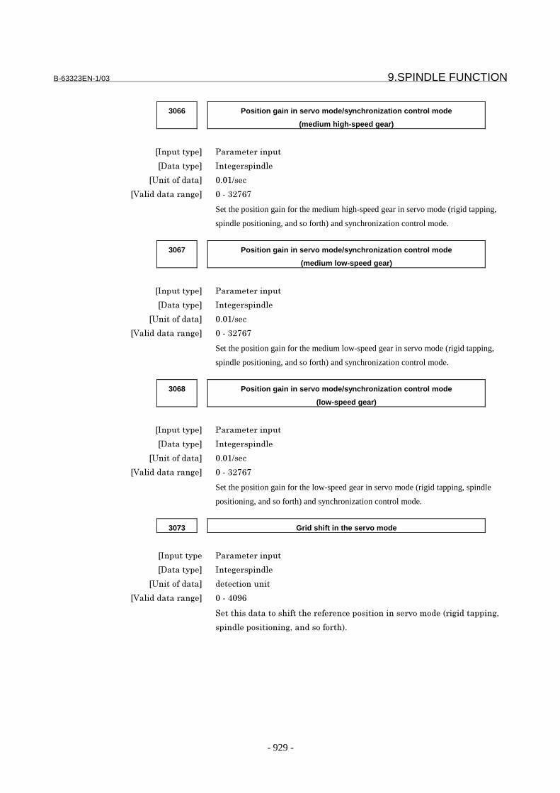
B-63323EN-1/03 9.SPINDLE FUNCTION
- 929 -
3066 Position gain in servo mode/synchronization control mode
(medium high-speed gear)
�������� ������������
�������� �������������
����������� �%��.���
���������������� ����9�6;6
Set the position gain for the medium high-speed gear in servo mode (rigid tapping,
spindle positioning, and so forth) and synchronization control mode.
3067 Position gain in servo mode/synchronization control mode
(medium low-speed gear)
�������� ������������
�������� �������������
����������� �%��.���
���������������� ����9�6;6
Set the position gain for the medium low-speed gear in servo mode (rigid tapping,
spindle positioning, and so forth) and synchronization control mode.
3068 Position gain in servo mode/synchronization control mode
(low-speed gear)
�������� ������������
�������� �������������
����������� �%��.���
���������������� ����9�6;6
Set the position gain for the low-speed gear in servo mode (rigid tapping, spindle
positioning, and so forth) and synchronization control mode.
3073 Grid shift in the servo mode
�������� ������������
�������� �������������
����������� ����������
���������������� ����7� ;
!��"����������"���"��������������������������#�������0������������&
������������������&�����������"1%
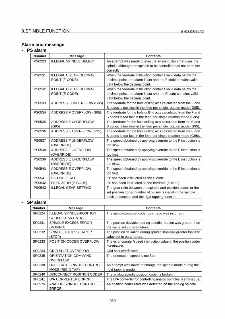
9.SPINDLE FUNCTION B-63323EN-1/03
- 930 -
Alarm and message- PS alarm
Number Message Contents
PS0223 ILLEGAL SPINDLE SELECT An attempt was made to execute an instruction that uses thespindle although the spindle to be controlled has not been setcorrectly.
PS0531 ILLEGAL USE OF DECIMALPOINT (F-CODE)
When the feedrate instruction contains valid data below thedecimal point, the alarm is set and the F code contains validdata below the decimal point.
PS0532 ILLEGAL USE OF DECIMALPOINT (E-CODE)
When the feedrate instruction contains valid data below thedecimal point, the alarm is set and the E code contains validdata below the decimal point.
PS0533 ADDRESS F UNDERFLOW (G95) The feedrate for the hole drilling axis calculated from the F andS codes is too slow in the feed per single rotation mode (G95).
PS0534 ADDRESS F OVERFLOW (G95) The feedrate for the hole drilling axis calculated from the F andS codes is too fast in the feed per single rotation mode (G95).
PS0535 ADDRESS E UNDERFLOW(G95)
The feedrate for the hole drilling axis calculated from the E andS codes is too slow in the feed per single rotation mode (G95).
PS0536 ADDRESS E OVERFLOW (G95) The feedrate for the hole drilling axis calculated from the E andS codes is too fast in the feed per single rotation mode (G95).
PS0537 ADDRESS F UNDERFLOW(OVERRIDE)
The speed obtained by applying override to the F instruction istoo slow.
PS0538 ADDRESS F OVERFLOW(OVERRIDE)
The speed obtained by applying override to the F instruction istoo fast.
PS0539 ADDRESS E UNDERFLOW(OVERRIDE)
The speed obtained by applying override to the E instruction istoo slow.
PS0540 ADDRESS E OVERFLOW(OVERRIDE)
The speed obtained by applying override to the E instruction istoo fast.
PS0541 S-CODE ZERO "0" has been instructed as the S code.PS0542 FEED ZERO (E-CODE) "0" has been instructed as the feedrate (E code).PS0543 ILLEGAL GEAR SETTING The gear ratio between the spindle and position coder, or the
set position coder number of pulses is illegal in the spindleposition function and the rigid tapping function.
- SP alarmNumber Message Contents
SP0224 ILLEGAL SPINDLE-POSITIONCODER GEAR RATIO
The spindle-position coder gear ratio was incorrect.
SP0231 SPINDLE EXCESS ERROR(MOVING)
The position deviation during spindle rotation was greater thanthe value set in parameters.
SP0232 SPINDLE EXCESS ERROR(STOP)
The position deviation during spindle stop was greater than thevalue set in parameters.
SP0233 POSITION CODER OVERFLOW The error counter/speed instruction value of the position coderoverflowed.
SP0234 GRID SHIFT OVERFLOW Grid shift overflowed.SP0235 ORIENTATION COMMAND
OVERFLOWThe orientation speed is too fast.
SP0238 DUPLICATE SPINDLE CONTROLMODE (RIGID TAP)
An attempt was made to change the spindle mode during therigid tapping mode.
SP0240 DISCONNECT POSITION CODER The analog spindle position coder is broken.SP0241 D/A CONVERTER ERROR The D/A converter for controlling analog spindles is erroneous.SP0975 ANALOG SPINDLE CONTROL
ERRORAn position coder error was detected on the analog spindle.
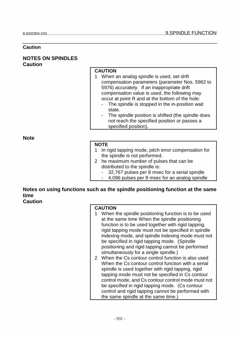
B-63323EN-1/03 9.SPINDLE FUNCTION
- 931 -
Caution
NOTES ON SPINDLESCaution
CAUTION1 When an analog spindle is used, set drift
compensation parameters (parameter Nos. 5962 to5976) accurately. If an inappropriate driftcompensation value is used, the following mayoccur at point R and at the bottom of the hole:- The spindle is stopped in the in-position wait
state.- The spindle position is shifted (the spindle does
not reach the specified position or passes aspecified position).
NoteNOTE1 In rigid tapping mode, pitch error compensation for
the spindle is not performed.2 he maximum number of pulses that can be
distributed to the spindle is:- 32,767 pulses per 8 msec for a serial spindle- 4,096 pulses per 8 msec for an analog spindle
Notes on using functions such as the spindle positioning function at the sametimeCaution
CAUTION1 When the spindle positioning function is to be used
at the same time When the spindle positioningfunction is to be used together with rigid tapping,rigid tapping mode must not be specified in spindleindexing mode, and spindle indexing mode must notbe specified in rigid tapping mode. (Spindlepositioning and rigid tapping cannot be performedsimultaneously for a single spindle.)
2 When the Cs contour control function is also usedWhen the Cs contour control function with a serialspindle is used together with rigid tapping, rigidtapping mode must not be specified in Cs contourcontrol mode, and Cs contour control mode must notbe specified in rigid tapping mode. (Cs contourcontrol and rigid tapping cannot be performed withthe same spindle at the same time.)
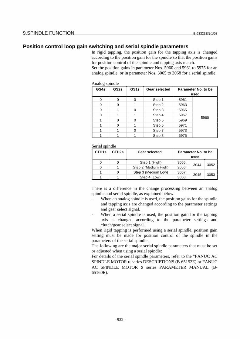
9.SPINDLE FUNCTION B-63323EN-1/03
- 932 -
Position control loop gain switching and serial spindle parametersIn rigid tapping, the position gain for the tapping axis is changedaccording to the position gain for the spindle so that the position gainsfor position control of the spindle and tapping axis match.Set the position gains in parameter Nos. 5960 and 5961 to 5975 for ananalog spindle, or in parameter Nos. 3065 to 3068 for a serial spindle.
Analog spindleGS4s GS2s GS1s Gear selected Parameter No. to be
used
0 0 0 Step 1 59610 0 1 Step 2 59630 1 0 Step 3 59650 1 1 Step 4 59671 0 0 Step 5 59691 0 1 Step 6 59711 1 0 Step 7 59731 1 1 Step 8 5975
5960
Serial spindleCTH1s CTH2s Gear selected Parameter No. to be
used
0 0 Step 1 (High) 30650 1 Step 2 (Medium High) 3066
3044 3052
1 0 Step 3 (Medium Low) 30671 1 Step 4 (Low) 3068
3045 3053
There is a difference in the change processing between an analogspindle and serial spindle, as explained below.- When an analog spindle is used, the position gains for the spindle
and tapping axis are changed according to the parameter settingsand gear select signal.
- When a serial spindle is used, the position gain for the tappingaxis is changed according to the parameter settings andclutch/gear select signal.
When rigid tapping is performed using a serial spindle, position gainsetting must be made for position control of the spindle in theparameters of the serial spindle.The following are the major serial spindle parameters that must be setor adjusted when using a serial spindle:For details of the serial spindle parameters, refer to the "FANUC ACSPINDLE MOTOR α series DESCRIPTIONS (B-65152E) or FANUCAC SPINDLE MOTOR α series PARAMETER MANUAL (B-65160E).
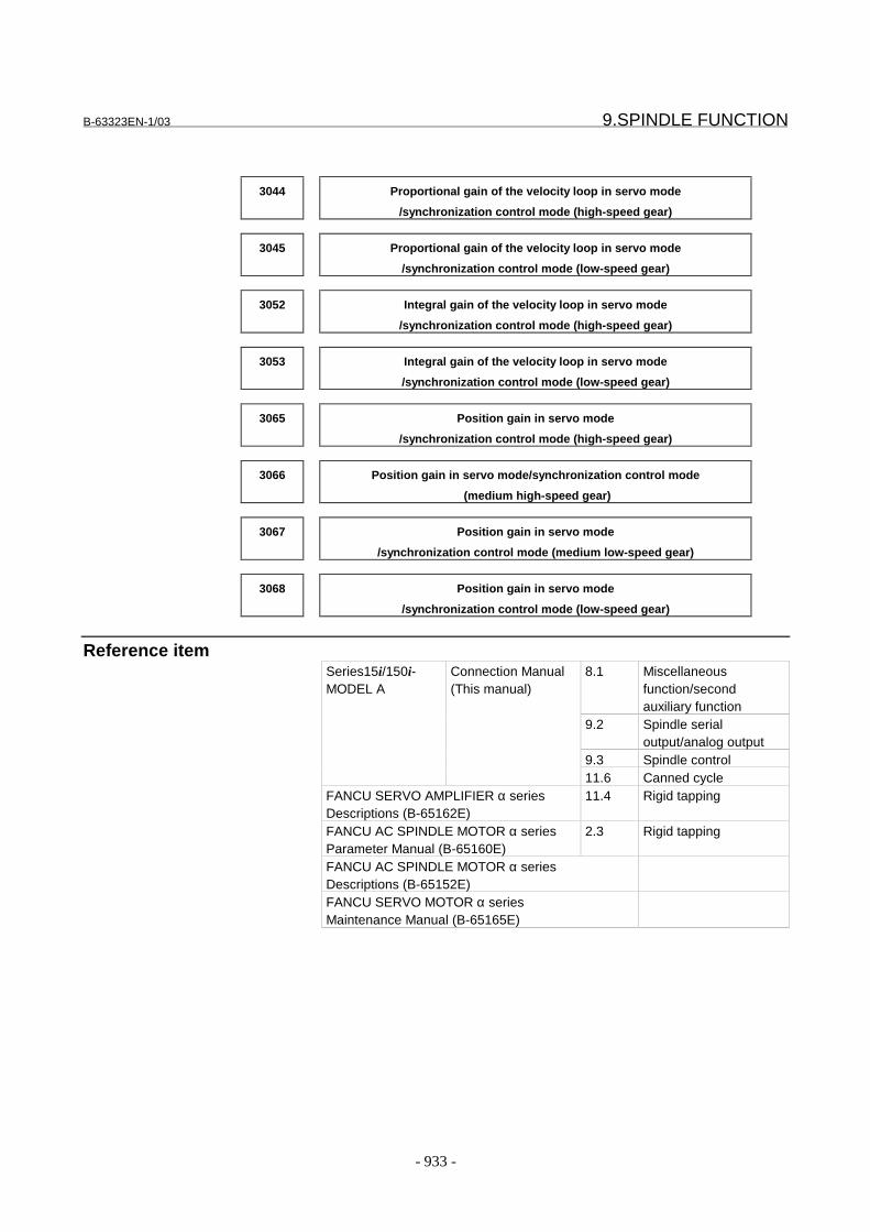
B-63323EN-1/03 9.SPINDLE FUNCTION
- 933 -
3044 Proportional gain of the velocity loop in servo mode
/synchronization control mode (high-speed gear)
3045 Proportional gain of the velocity loop in servo mode
/synchronization control mode (low-speed gear)
3052 Integral gain of the velocity loop in servo mode
/synchronization control mode (high-speed gear)
3053 Integral gain of the velocity loop in servo mode
/synchronization control mode (low-speed gear)
3065 Position gain in servo mode
/synchronization control mode (high-speed gear)
3066 Position gain in servo mode/synchronization control mode
(medium high-speed gear)
3067 Position gain in servo mode
/synchronization control mode (medium low-speed gear)
3068 Position gain in servo mode
/synchronization control mode (low-speed gear)
Reference item8.1 Miscellaneous
function/secondauxiliary function
9.2 Spindle serialoutput/analog output
9.3 Spindle control
Series15i/150i-MODEL A
Connection Manual(This manual)
11.6 Canned cycleFANCU SERVO AMPLIFIER α seriesDescriptions (B-65162E)
11.4 Rigid tapping
FANCU AC SPINDLE MOTOR α seriesParameter Manual (B-65160E)
2.3 Rigid tapping
FANCU AC SPINDLE MOTOR α seriesDescriptions (B-65152E)FANCU SERVO MOTOR α seriesMaintenance Manual (B-65165E)

9.SPINDLE FUNCTION B-63323EN-1/03
- 934 -
9.8.1 Rigid Tapping Additional Function
- Overview- A parameter can be used to specify whether to perform spindle
orientation when rigid tapping is started.- A parameter can be used to specify to check whether the specified
S command exceeds the maximum spindle rotation speed for anindividual gear.
- A diagnosis screen can be used to check a synchronization errorbetween the tapping axis and spindle.
- Parameters#7 #6 #5 #4 #3 #2 #1 #0
5606 ORD ORN
[Input type] Parameter input[Data type] Bitspindle
NOTEAfter this parameter has been set, the power mustbe off turned off then back on for the setting tobecome effective.
# 6 ORN Specifies whether to perform spindle orientation at the beginning ofrigid tapping as follows:0: Do not perform.1: Perform.
# 7 ORD Specifies the direction of spindle orientation at the beginning ofanalog spindle rigid tapping as follows:0: Positive direction1: Negative directionThis parameter is valid when parameter ORN (bit 6 of parameter No.5606) = 1.
For a serial spindle, bit 4 of parameter No. 3004 is used to specifythe direction of spindle orientation. Refer to the FANUC ACSPINDLE MOTOR α series Parameter Manual (B-65160E) fordetails.
NOTEWhen this parameter is 0, the direction of spindleorientation is negative if a G84.2/G84.3 blockissues an I/O command (for specifying anegative direction). When the parameter is 1,the direction of spindle orientation is negativealso if a G84.2/G83.3 block issues an I/Ocommand (for specifying a positive direction).

B-63323EN-1/03 9.SPINDLE FUNCTION
- 935 -
5711 Maximum spindle speed during rigid tapping (first stage)
5712 Maximum spindle speed during rigid tapping (second stage)
5713 Maximum spindle speed during rigid tapping (third stage)
5714 Maximum spindle speed during rigid tapping (fourth stage)
5715 Maximum spindle speed during rigid tapping (fifth stage)
5716 Maximum spindle speed during rigid tapping (sixth stage)
5717 Maximum spindle speed during rigid tapping (seventh stage)
5718 Maximum spindle speed during rigid tapping (eighth stage)
[Input type] Parameter input[Data type] Integerspindle
[Unit of data] min-1
[Valid data range] 0 - 999999999These parameters specify the maximum spindle speed used for eachgear stage during rigid tapping. Issuing an S command having avalue larger than each specified value is results in an alarm.
NOTENo check is made if all of values specified inparameter Nos. 5711 to 5718 are 0.
If a nonzero value is specified in a parameter forthe "ath" gear stage, and all the parameters forgears lower than the "ath" gear stage are resetto 0, a check is made with a value specified forthe "ath" gear stage if the "ath" stage or a lowerstage is selected.
For example, when parameter Nos. 5711 to5713 = 0, parameter No. 5714 = 800, andparameter Nos. 5715 to 5718 = 0, a check ismade with an upper limit of S800 if the fourthstage or a lower stage is selected.
- AlarmNumber Message Description
PS0544 S-CODE OVER MAX The S command has exceeded the maximum spindlerotation speed.
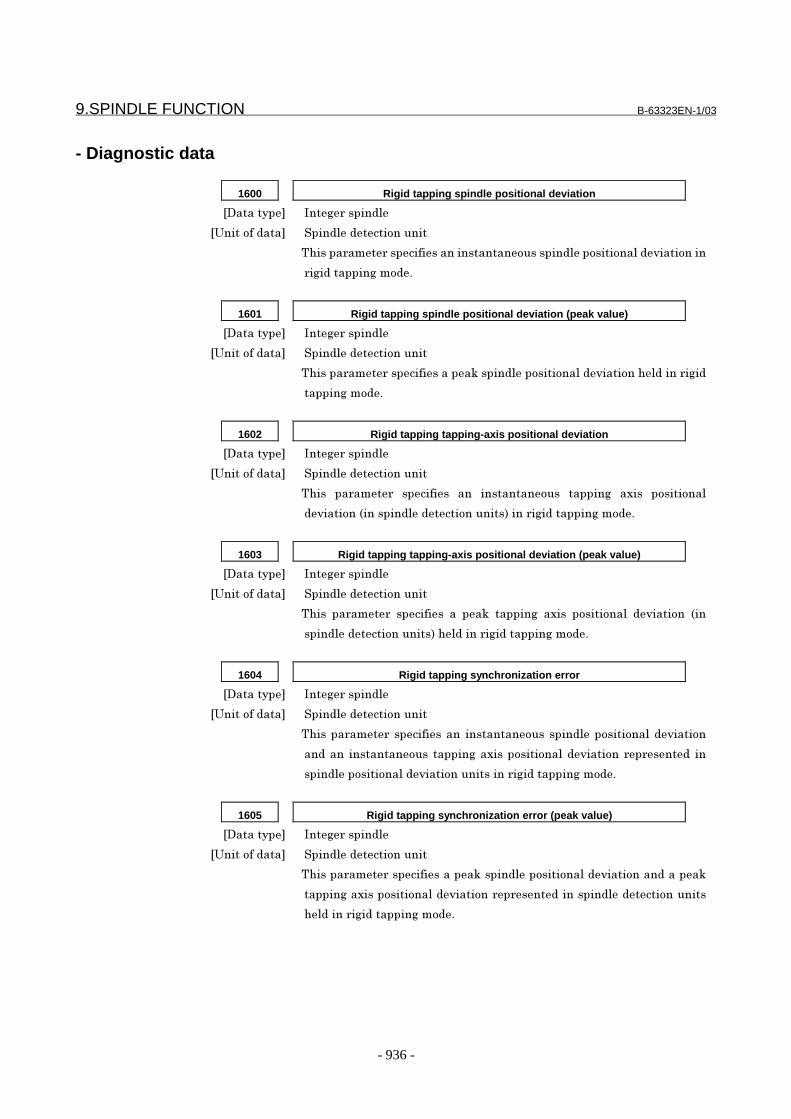
9.SPINDLE FUNCTION B-63323EN-1/03
- 936 -
- Diagnostic data
1600 Rigid tapping spindle positional deviation
�������� ��������������
����������� !�����������������
)"��������������������������������������������������������#��������
�����������������%
1601 Rigid tapping spindle positional deviation (peak value)
�������� ��������������
����������� !�����������������
)"���������������������������?���������������������#������"������������
�����������%
1602 Rigid tapping tapping-axis positional deviation
�������� ��������������
����������� !�����������������
)"��� ��������� ���������� ��� ����������� ������� ����� ���������
��#������0����������������������1���������������������%
1603 Rigid tapping tapping-axis positional deviation (peak value)
�������� ��������������
����������� !�����������������
)"��� ��������� ���������� �� ���?� ������� ����� ���������� ��#������ 0��
�������������������1�"������������������������%
1604 Rigid tapping synchronization error
�������� ��������������
����������� !�����������������
)"������������ ������������� ����������� ��������������������#�����
������� ����������� ������������������������#����������������� ��
��������������������#������������������������������%
1605 Rigid tapping synchronization error (peak value)
�������� ��������������
����������� !�����������������
)"���������������������������?���������������������#���������������?
������������������������#���������������������������������������
"������������������������%
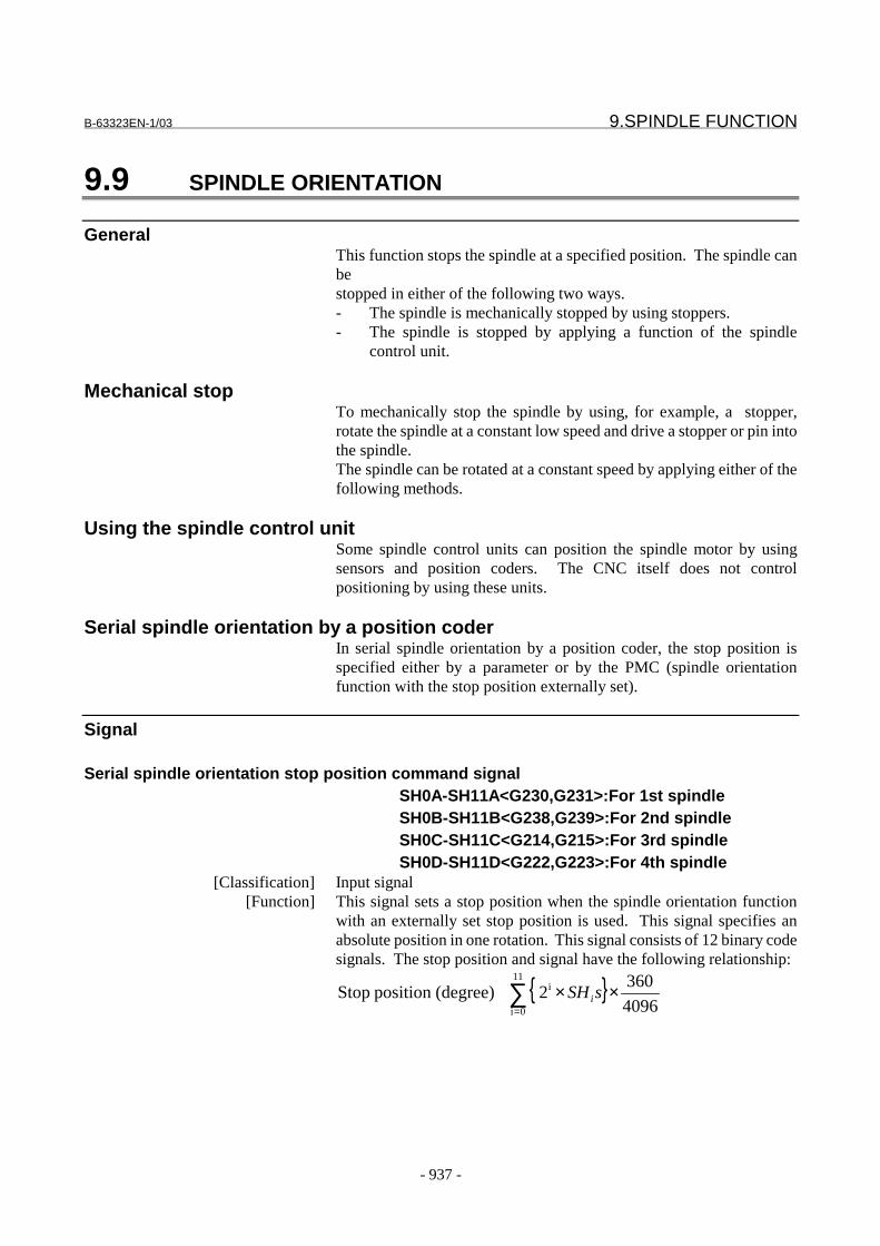
B-63323EN-1/03 9.SPINDLE FUNCTION
- 937 -
9.9 SPINDLE ORIENTATION
GeneralThis function stops the spindle at a specified position. The spindle canbestopped in either of the following two ways.- The spindle is mechanically stopped by using stoppers.- The spindle is stopped by applying a function of the spindle
control unit.
Mechanical stopTo mechanically stop the spindle by using, for example, a stopper,rotate the spindle at a constant low speed and drive a stopper or pin intothe spindle.The spindle can be rotated at a constant speed by applying either of thefollowing methods.
Using the spindle control unitSome spindle control units can position the spindle motor by usingsensors and position coders. The CNC itself does not controlpositioning by using these units.
Serial spindle orientation by a position coderIn serial spindle orientation by a position coder, the stop position isspecified either by a parameter or by the PMC (spindle orientationfunction with the stop position externally set).
Signal
Serial spindle orientation stop position command signalSH0A-SH11A<G230,G231>:For 1st spindleSH0B-SH11B<G238,G239>:For 2nd spindleSH0C-SH11C<G214,G215>:For 3rd spindleSH0D-SH11D<G222,G223>:For 4th spindle
[Classification] Input signal[Function] This signal sets a stop position when the spindle orientation function
with an externally set stop position is used. This signal specifies anabsolute position in one rotation. This signal consists of 12 binary codesignals. The stop position and signal have the following relationship:
{ }∑=
××11
0i
i
4096
3602 (degree)position Stop sSHi
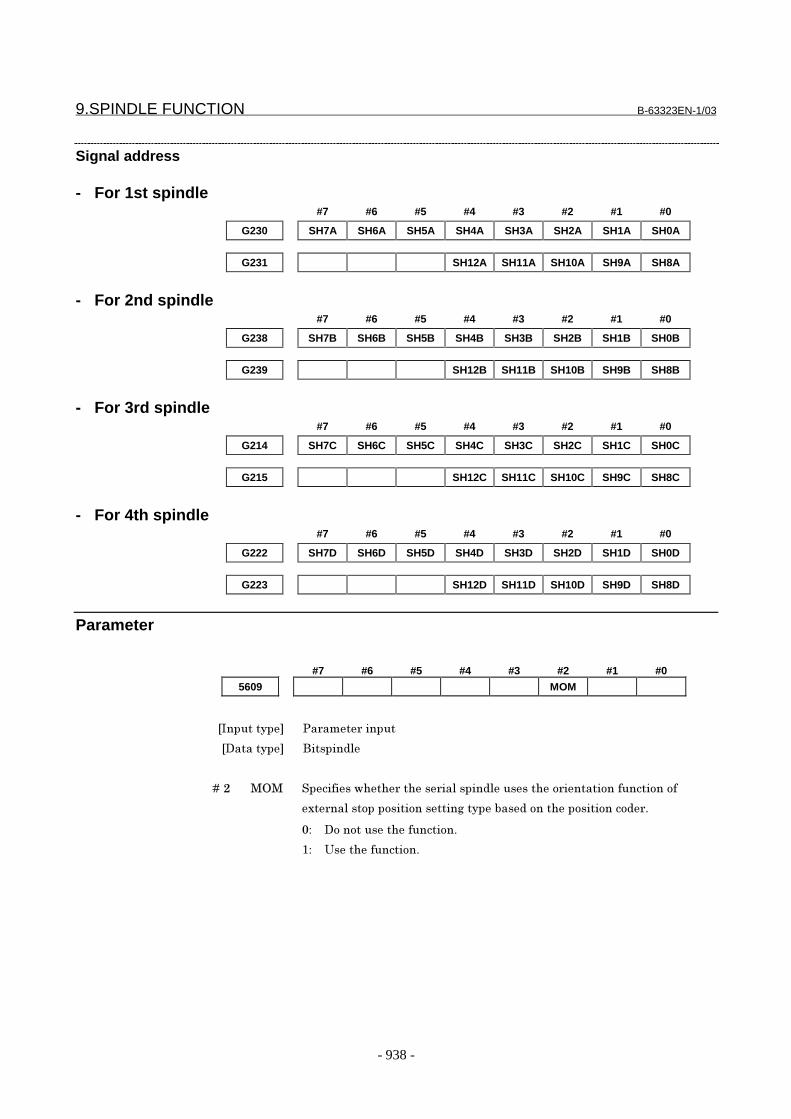
9.SPINDLE FUNCTION B-63323EN-1/03
- 938 -
Signal address
- For 1st spindle#7 #6 #5 #4 #3 #2 #1 #0
G230 SH7A SH6A SH5A SH4A SH3A SH2A SH1A SH0A
G231 SH12A SH11A SH10A SH9A SH8A
- For 2nd spindle#7 #6 #5 #4 #3 #2 #1 #0
G238 SH7B SH6B SH5B SH4B SH3B SH2B SH1B SH0B
G239 SH12B SH11B SH10B SH9B SH8B
- For 3rd spindle#7 #6 #5 #4 #3 #2 #1 #0
G214 SH7C SH6C SH5C SH4C SH3C SH2C SH1C SH0C
G215 SH12C SH11C SH10C SH9C SH8C
- For 4th spindle#7 #6 #5 #4 #3 #2 #1 #0
G222 SH7D SH6D SH5D SH4D SH3D SH2D SH1D SH0D
G223 SH12D SH11D SH10D SH9D SH8D
Parameter
#7 #6 #5 #4 #3 #2 #1 #0
5609 MOM
���������� �� ��� ������
��������� ���������
� � � � ��� ��� ������������ ����� ������������������� ��������������������
�� ����������������������� �����!���������������������� "
#$ ���������������������"
%$ &�������������"

B-63323EN-1/03 9.SPINDLE FUNCTION
- 939 -
CautionCAUTION1 To perform spindle orientation by using the spindle
control unit, the signals of the spindle control unitmust be used.To perform serial spindle orientation by using aposition coder (to perform serial spindle orientationwith the stop position set externally), the serialspindle control unit signals must be used.
2 When the spindle orientation function of stopposition external setting type is used, the stopposition parameters in spindle orientation with aposition coder (No. 3031 and 3204) are invalid.
NoteNOTE
Spindle orientation with the spindle positioningfunction differs from that described in this section.For details, see "Spindle Positioning."
Reference item9.2 Spindle serial
output/analog outputSeries15i/150i-MODEL A
Connection Manual(This manual)
9.3 Spindle controlFANCU SERVO AMPLIFIER α seriesDescriptions
B-65162E
FANCU AC SPINDLE MOTOR α seriesParameter Manual
B-65160E
9.SPINDLE FUNCTION B-63323EN-1/03
- 940 -
9.10 SPINDLE OUTPUT SWITCHING
GeneralSpindle output switching switches between the two windings, one forlow speed and the other for high speed, incorporated into the specialspindle motors. This ensures that the spindle motor demonstrates stable outputcharacteristics over a wide range.Since spindle output switching is a function of the spindle control unit,see also the manual for the spindle control unit being used.This section describes the relationship between spindle outputswitching and the spindle control function in the CNC.
Operation of output-switchable spindle motorTo switch the spindle output characteristics, the windings are usuallyswitched using a relay. Prior to the completion of winding switching,the spindle rotates free from drive.Output switching changes the relationship between a speed command,issued from the CNC to the spindle, and the output characteristics ofthe spindle motor.However, the relationship between the speed command and spindlemotor speed is not changed.
Output switching timingDuring actual machining, the spindle is usually controlled in thefollowingway.(1) Constant spindle speed during cutting, such as milling(2) Continuously changing spindle speed during cutting, such as in
constant surface speed control(3) Controlling the position loop including the spindle motor during
rigid tapping, spindle positioning, Cs contour control, etc.For applications such as those in (1), we recommend switching theoutput characteristics for low speed and high speed by using thespindle motor speed detection signal of the spindle control unit.For applications such as those described in (2) and (3), the spindle shallnot rotate with no drive applied during cutting or positioning. It isnecessary for the output characteristics to be switched appropriatelybefore machining or for output switching to be masked by using a PMCladder sequence.
Reference item9.2 Spindle serial output/analog outputConnection Manual
(This manual) 9.3 Spindle controlFANCU SERVO AMPLIFIER α seriesDescriptions
B-65162E
FANCU AC SPINDLE MOTOR α seriesParameter Manual
B-65160E
B-63323EN-1/03 9.SPINDLE FUNCTION
- 941 -
9.11 SPINDLE SPEED FLUCTUATION DETECTION
GeneralIf the actual spindle speed becomes lower or higher than that specifiedbecause of the condition of the machine, an overheat alarm (SP0242) isissued, and spindle speed fluctuation detection alarm signal SPAL isoutput. This signal can be used to prevent the guide bushing fromburning out.
Method for detecting spindle speed fluctuationIf a difference between the actual spindle speed and the specifiedspindle speed becomes larger than the allowable fluctuation widthspecified in the address R and I commands in a G26 command block orparameter Nos. 5702 and 5721 (if the following two conditions aresatisfied), an alarm is issued to indicate that the fluctuation has becomehigher than a permissible level.(1) |Sc - Sa| ≥ Sr(2) |Sc - Sa| ≥ SiSc: Specified spindle speedSa: Actual spindle speedSr: Spindle speed fluctuation range calculated from spindle speed
fluctuation ratio (address R command in a G26 block orparameter No. 5702)
If parameter FLR (bit 1 of parameter No. 5808) is 0
Sr = Sc * r / 100
If parameter FLR (bit 1 of parameter No. 5808) is 1
Sr = Sc * r / 1000
Si: Permissible range of fluctuation that does not cause a spindle speedfluctuation detection alarm to be output (address I command in aG26 block or parameter (No. 5721) setting)
NOTEEven when the conditions for issuing an alarm related tospindle speed fluctuation detection have not beensatisfied in spindle speed detection enabled mode (G26),a spindle speed fluctuation detection overheat alarm isissued if:
- A spindle speed has been specified, and the actualspindle speed remains at 0 min-1 for at least one second.
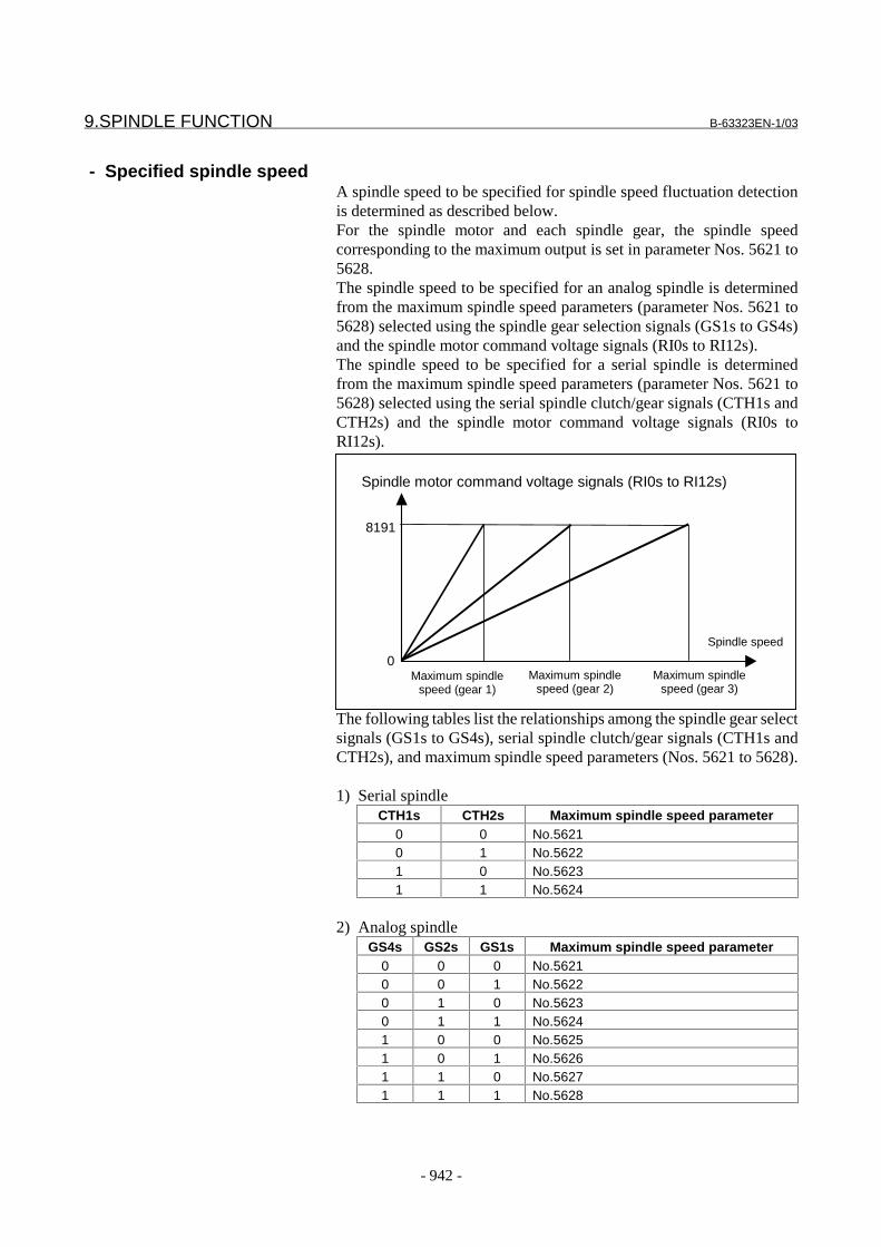
9.SPINDLE FUNCTION B-63323EN-1/03
- 942 -
- Specified spindle speedA spindle speed to be specified for spindle speed fluctuation detectionis determined as described below.For the spindle motor and each spindle gear, the spindle speedcorresponding to the maximum output is set in parameter Nos. 5621 to5628.The spindle speed to be specified for an analog spindle is determinedfrom the maximum spindle speed parameters (parameter Nos. 5621 to5628) selected using the spindle gear selection signals (GS1s to GS4s)and the spindle motor command voltage signals (RI0s to RI12s).The spindle speed to be specified for a serial spindle is determinedfrom the maximum spindle speed parameters (parameter Nos. 5621 to5628) selected using the serial spindle clutch/gear signals (CTH1s andCTH2s) and the spindle motor command voltage signals (RI0s toRI12s).
The following tables list the relationships among the spindle gear selectsignals (GS1s to GS4s), serial spindle clutch/gear signals (CTH1s andCTH2s), and maximum spindle speed parameters (Nos. 5621 to 5628).
1) Serial spindleCTH1s CTH2s Maximum spindle speed parameter
0 0 No.56210 1 No.56221 0 No.56231 1 No.5624
2) Analog spindleGS4s GS2s GS1s Maximum spindle speed parameter
0 0 0 No.56210 0 1 No.56220 1 0 No.56230 1 1 No.56241 0 0 No.56251 0 1 No.56261 1 0 No.56271 1 1 No.5628
Spindle motor command voltage signals (RI0s to RI12s)
8191
0Maximum spindle
speed (gear 1)
Spindle speed
Maximum spindlespeed (gear 2)
Maximum spindlespeed (gear 3)
B-63323EN-1/03 9.SPINDLE FUNCTION
- 943 -
- Actual spindle speedThe actual spindle speed is calculated from the feedback pulse receivedfrom the position coder mounted on the spindle.
- Conditions for starting spindle speed fluctuation detectionIf the specified spindle speed changes after G26 is issued or in spindlespeed fluctuation detection enabled mode, spindle speed fluctuationdetection begins when one of the following conditions is satisfied.(1) The time specified in parameter No. 5722 elapses since a change
in the specified spindle speed after G26 is issued or in spindlespeed fluctuation detection enabled mode
(2) The actual spindle speed and specified spindle speed permissionratio becomes lower than or equal to the value specified inparameter No. 5701, so it is assumed that the specified speed hasbeen reached.
Actual spindle speed and specified spindle speed permission ratio= (1 - Actual spindle speed / Specified spindle speed ) * 100
NOTEEven if a condition for starting spindle speedfluctuation detection is satisfied, spindle speedfluctuation detection is not started under any of thefollowing conditions.
1 The machine is in spindle speed fluctuation detectiondisabled mode (G25).
2 The specified spindle speed is 0 min-1.3 A search due to program restart is under way.
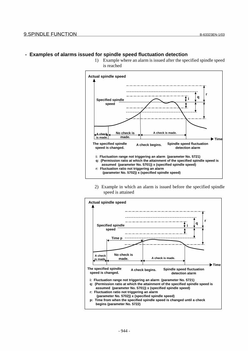
9.SPINDLE FUNCTION B-63323EN-1/03
- 944 -
- Examples of alarms issued for spindle speed fluctuation detection1) Example where an alarm is issued after the specified spindle speed
is reached
2) Example in which an alarm is issued before the specified spindlespeed is attained
i: Fluctuation range not triggering an alarm (parameter No. 5721)q: (Permission ratio at which the attainment of the specified spindle speed is
assumed (parameter No. 5701)) x (specified spindle speed)r: Fluctuation ratio not triggering an alarm
(parameter No. 5702)) x (specified spindle speed)
Actual spindle speed
Specified spindlespeed
The specified spindlespeed is changed.
Spindle speed fluctuationdetection alarm
A check begins.
Time
rqi
A checkis made.
No check ismade.
A check is made.
Actual spindle speed
Specified spindlespeed
iq
r
Time
Time p
A checkis made.
No check ismade. A check is made.
The specified spindlespeed is changed.
Spindle speed fluctuationdetection alarm
A check begins.
i: Fluctuation range not triggering an alarm (parameter No. 5721)q: (Permission ratio at which the attainment of the specified spindle speed is
assumed (parameter No. 5701)) x (specified spindle speed)r: Fluctuation ratio not triggering an alarm
(parameter No. 5702)) x (specified spindle speed)p: Time from when the specified spindle speed is changed until a check
begins (parameter No. 5722)

B-63323EN-1/03 9.SPINDLE FUNCTION
- 945 -
- System with more than one spindleIn a system with more than one spindle, spindle speed fluctuationdetection is performed for the spindle described below.1) If the system has no spindle control switching function
Spindle speed fluctuation detection is performed for the firstspindle.
2) If the system has a spindle control switching functionSpindle speed fluctuation detection is performed for the spindleselected in spindle control switching.Spindle speed fluctuation detection is not performed for a spindlethat is not selected in spindle control switching.
Signal
Spindle speed command signal SPALA<F042#2> : For 1st spindleSPALB<F338#2> : For 2nd spindleSPALC<F339#2> : For 3rd spindleSPALD<F340#2> : For 4th spindle
[Classification] Output signal[Function] Indicates that the actual spindle speed has fluctuated by more than the
permissible amount corresponding to the specified spindle speed.[Output condition] These signals become 1 when:
- The actual spindle speed fluctuates more than the permissibleamount corresponding to the specified spindle speed.
These signals become 0 when:- No spindle speed fluctuation detection alarm has been issued, or- The control unit is reset to cancel the alarm when the signals are 1.
Signal address#7 #6 #5 #4 #3 #2 #1 #0
F042 SPALA
F338 SPALB
F339 SPALC
F340 SPALD
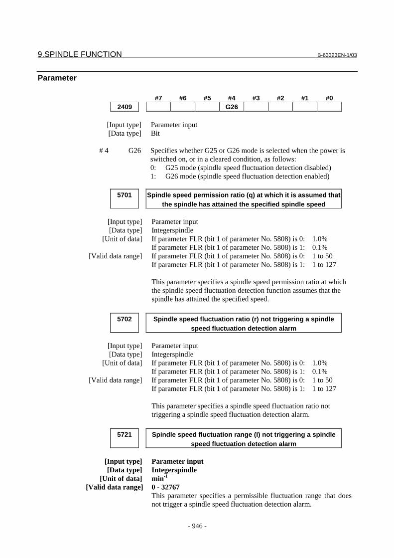
9.SPINDLE FUNCTION B-63323EN-1/03
- 946 -
Parameter
#7 #6 #5 #4 #3 #2 #1 #02409 G26
[Input type] Parameter input[Data type] Bit
# 4 G26 Specifies whether G25 or G26 mode is selected when the power isswitched on, or in a cleared condition, as follows:0: G25 mode (spindle speed fluctuation detection disabled)1: G26 mode (spindle speed fluctuation detection enabled)
5701 Spindle speed permission ratio (q) at which it is assumed thatthe spindle has attained the specified spindle speed
[Input type] Parameter input[Data type] Integerspindle
[Unit of data] If parameter FLR (bit 1 of parameter No. 5808) is 0: 1.0%If parameter FLR (bit 1 of parameter No. 5808) is 1: 0.1%
[Valid data range] If parameter FLR (bit 1 of parameter No. 5808) is 0: 1 to 50If parameter FLR (bit 1 of parameter No. 5808) is 1: 1 to 127
This parameter specifies a spindle speed permission ratio at whichthe spindle speed fluctuation detection function assumes that thespindle has attained the specified speed.
5702 Spindle speed fluctuation ratio (r) not triggering a spindlespeed fluctuation detection alarm
[Input type] Parameter input[Data type] Integerspindle
[Unit of data] If parameter FLR (bit 1 of parameter No. 5808) is 0: 1.0%If parameter FLR (bit 1 of parameter No. 5808) is 1: 0.1%
[Valid data range] If parameter FLR (bit 1 of parameter No. 5808) is 0: 1 to 50If parameter FLR (bit 1 of parameter No. 5808) is 1: 1 to 127
This parameter specifies a spindle speed fluctuation ratio nottriggering a spindle speed fluctuation detection alarm.
5721 Spindle speed fluctuation range (I) not triggering a spindlespeed fluctuation detection alarm
[Input type] Parameter input[Data type] Integerspindle
[Unit of data] min-1
[Valid data range] 0 - 32767This parameter specifies a permissible fluctuation range that doesnot trigger a spindle speed fluctuation detection alarm.
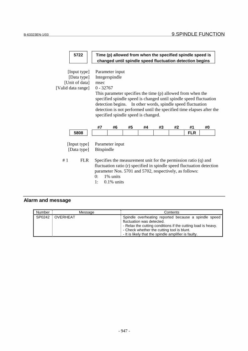
B-63323EN-1/03 9.SPINDLE FUNCTION
- 947 -
5722 Time (p) allowed from when the specified spindle speed ischanged until spindle speed fluctuation detection begins
[Input type] Parameter input[Data type] Integerspindle
[Unit of data] msec[Valid data range] 0 - 32767
This parameter specifies the time (p) allowed from when thespecified spindle speed is changed until spindle speed fluctuationdetection begins. In other words, spindle speed fluctuationdetection is not performed until the specified time elapses after thespecified spindle speed is changed.
#7 #6 #5 #4 #3 #2 #1 #05808 FLR
[Input type] Parameter input[Data type] Bitspindle
# 1 FLR Specifies the measurement unit for the permission ratio (q) andfluctuation ratio (r) specified in spindle speed fluctuation detectionparameter Nos. 5701 and 5702, respectively, as follows:0: 1% units1: 0.1% units
Alarm and message
Number Message ContentsSP0242 OVERHEAT Spindle overheating reported because a spindle speed
fluctuation was detected.- Relax the cutting conditions if the cutting load is heavy.- Check whether the cutting tool is blunt.- It is likely that the spindle amplifier is faulty.
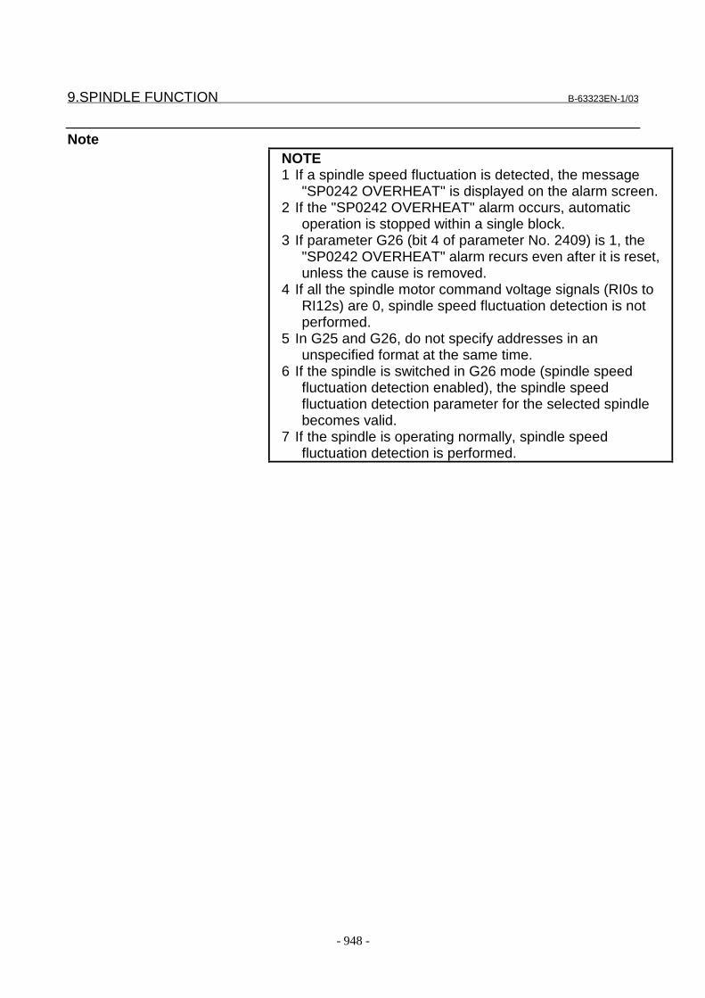
9.SPINDLE FUNCTION B-63323EN-1/03
- 948 -
NoteNOTE1 If a spindle speed fluctuation is detected, the message
"SP0242 OVERHEAT" is displayed on the alarm screen.2 If the "SP0242 OVERHEAT" alarm occurs, automatic
operation is stopped within a single block.3 If parameter G26 (bit 4 of parameter No. 2409) is 1, the
"SP0242 OVERHEAT" alarm recurs even after it is reset,unless the cause is removed.
4 If all the spindle motor command voltage signals (RI0s toRI12s) are 0, spindle speed fluctuation detection is notperformed.
5 In G25 and G26, do not specify addresses in anunspecified format at the same time.
6 If the spindle is switched in G26 mode (spindle speedfluctuation detection enabled), the spindle speedfluctuation detection parameter for the selected spindlebecomes valid.
7 If the spindle is operating normally, spindle speedfluctuation detection is performed.

B-63323EN-1/03 10.TOOL FUNCTION
- 949 -
10 TOOL FUNCTION

10.TOOL FUNCTION B-63323EN-1/03
- 950 -
10.1 TOOL FUNCTION
GeneralA tool can be selected by specifying its tool number following addressT. The tool number consists of a numeric value of no more than 10digits.When a T code is specified, the code signal for a specified tool numberand strobe signal are sent. These are used for selecting a tool on themachine side. This code signal is maintained until another T code isspecified.
Only one T code can be specified in one block. The maximum numberof digits can be specified in parameter No. 2032. If a command longerthan the maximum number of digits is specified, an alarm can beissued.
Values that can be set as the allowable number of digits and the rangesof valid settings are listed below. When the allowable number of digitsis set to 10, a negative value cannot be specified in the T code.
Table 10.1 Allowable Numbers of Digits in the T Code and Valid Setting Ranges
Allowable number of digitsParameter(No.2032)
Negative value specificationpermitted/not permitted (bit 2(TSN) of parameter No. 2003)
Range of valid settings
Disabled 0 to 91
Enabled -9 to 9Disabled 0 to 99
2Enabled -99 to 99Disabled 0 to 999
3Enabled -999 to 999Disabled 0 to 9,999
4Enabled -9,999 to 9,999Disabled 0 to 99,999
5Enabled -99,999 to 99,999Disabled 0 to 999,999
6Enabled -999,999 to 999,999Disabled 0 to 9,999,999
7Disabled -9,999,999 to 9,999,999Disabled 0 to 99,999,999
8Enabled -99,999,999 to 99,999,999Disabled 0 to 999,999,999
9Enabled -999,999,999 to 999,999,999
10 Disabled 0 to 4,294,967,295
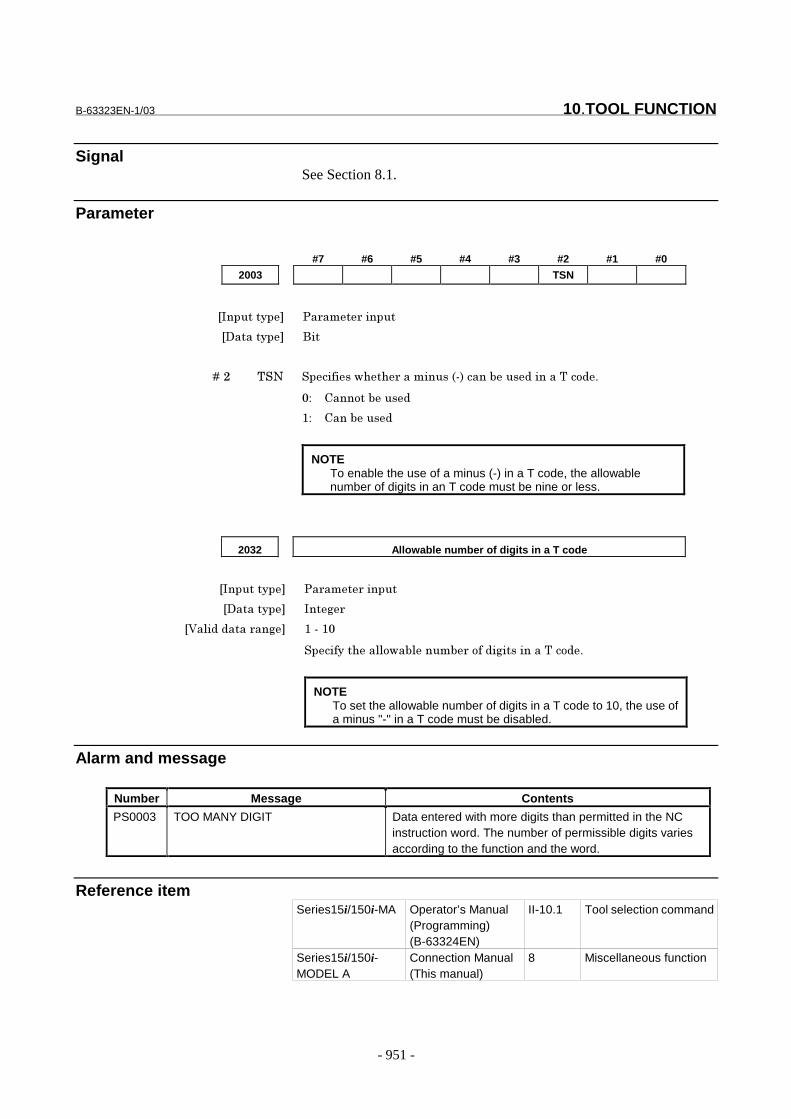
B-63323EN-1/03 10.TOOL FUNCTION
- 951 -
SignalSee Section 8.1.
Parameter
#7 #6 #5 #4 #3 #2 #1 #0
2003 TSN
���������� �� ��� ������
��������� ���
� � � � ��� ��� ������������ ��������������������� ���������! "
#$ %���!������
&$ %�������
NOTETo enable the use of a minus (-) in a T code, the allowablenumber of digits in an T code must be nine or less.
2032 Allowable number of digits in a T code
���������� �� ��� ������
��������� ���'
�(�)� � ���� ��' &���&#
�����������))!���)����� �!�� �'������������! "
NOTETo set the allowable number of digits in a T code to 10, the use ofa minus "-" in a T code must be disabled.
Alarm and message
Number Message Contents
PS0003 TOO MANY DIGIT Data entered with more digits than permitted in the NCinstruction word. The number of permissible digits variesaccording to the function and the word.
Reference itemSeries15i/150i-MA Operator’s Manual
(Programming)(B-63324EN)
II-10.1 Tool selection command
Series15i/150i-MODEL A
Connection Manual(This manual)
8 Miscellaneous function

10.TOOL FUNCTION B-63323EN-1/03
- 952 -
10.2 TOOL COMPENSATION VALUE/TOOL COMPENSATIONNUMBER/TOOL COMPENSATION MEMORY
GeneralTool compensation values include tool geometry compensation valuesand tool wear compensation values.
OFSG
OFSW
OFSG : Geometry compensation valueOFSW : Wear compensation value
Standard position
Fig. 10.2 Geometric compensation and wear compensationTool compensation values can be entered into CNC memory from theCRT/MDI panel or from a program.A tool compensation value is selected from the CNC memory when thecorresponding code is specified after address H or D in a program.The value is used for tool length compensation, cutter compensation, orthe tool offset.
¥ Increment system and valid range of tool offset valuesThe increment system and valid range of tool offset values depend onthe following parameters:
Parameter OFA(No.6002#0)Parameter OFC(No.6002#1)Parameter OFD(No.6004#0)Parameter OFE(No.6007#0)
Table 10.2 (a) Increment and setting range of tool offset value (metric input)
OFE OFD OFC OFA Increment Geometry offsetvalue
Wear offset value
0 0 0 1 0.01 mm ±9999.99 mm ±9999.99 mm0 0 0 0 0.001 mm ±9999.999 mm ±9999.999 mm0 0 1 0 0.0001 mm ±9999.9999 mm ±9999.9999 mm0 1 0 0 0.00001 mm ±9999.99999 mm ±9999.99999 mm1 0 0 0 0.000001 mm ±999.999999 mm ±999.999999 mm
Table 10.2 (b) Increment and setting range of tool offset value (inch input)
OFE OFD OFC OFA Increment Geometry offsetvalue
Wear offset value
0 0 0 1 0.001 inch ±999.999 inch ±999.999 inch0 0 0 0 0.0001 inch ±999.9999 inch ±999.9999 inch0 0 1 0 0.00001 inch ±999.99999 inch ±999.99999 inch0 1 0 0 0.000001 inch ±999.999999 inch ±999.999999 inch1 0 0 0 0.0000001 inch ±99.9999999 inch ±99.9999999 inch
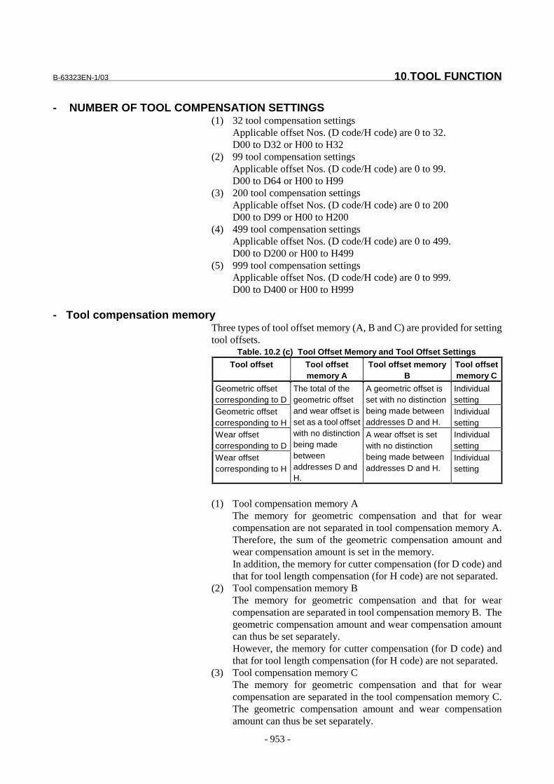
B-63323EN-1/03 10.TOOL FUNCTION
- 953 -
- NUMBER OF TOOL COMPENSATION SETTINGS(1) 32 tool compensation settings
Applicable offset Nos. (D code/H code) are 0 to 32.D00 to D32 or H00 to H32
(2) 99 tool compensation settingsApplicable offset Nos. (D code/H code) are 0 to 99.D00 to D64 or H00 to H99
(3) 200 tool compensation settingsApplicable offset Nos. (D code/H code) are 0 to 200D00 to D99 or H00 to H200
(4) 499 tool compensation settingsApplicable offset Nos. (D code/H code) are 0 to 499.D00 to D200 or H00 to H499
(5) 999 tool compensation settingsApplicable offset Nos. (D code/H code) are 0 to 999.D00 to D400 or H00 to H999
- Tool compensation memoryThree types of tool offset memory (A, B and C) are provided for settingtool offsets.
Table. 10.2 (c) Tool Offset Memory and Tool Offset Settings
Tool offset Tool offsetmemory A
Tool offset memoryB
Tool offsetmemory C
Geometric offsetcorresponding to D
Individualsetting
Geometric offsetcorresponding to H
A geometric offset isset with no distinctionbeing made betweenaddresses D and H.
Individualsetting
Wear offsetcorresponding to D
Individualsetting
Wear offsetcorresponding to H
The total of thegeometric offsetand wear offset isset as a tool offsetwith no distinctionbeing madebetweenaddresses D andH.
A wear offset is setwith no distinctionbeing made betweenaddresses D and H.
Individualsetting
(1) Tool compensation memory AThe memory for geometric compensation and that for wearcompensation are not separated in tool compensation memory A.Therefore, the sum of the geometric compensation amount andwear compensation amount is set in the memory.In addition, the memory for cutter compensation (for D code) andthat for tool length compensation (for H code) are not separated.
(2) Tool compensation memory BThe memory for geometric compensation and that for wearcompensation are separated in tool compensation memory B. Thegeometric compensation amount and wear compensation amountcan thus be set separately.However, the memory for cutter compensation (for D code) andthat for tool length compensation (for H code) are not separated.
(3) Tool compensation memory CThe memory for geometric compensation and that for wearcompensation are separated in the tool compensation memory C.The geometric compensation amount and wear compensationamount can thus be set separately.

10.TOOL FUNCTION B-63323EN-1/03
- 954 -
In addition, separate memories are provided for cuttercompensation (for D code) and for tool length compensation (forH code).
Parameter#7 #6 #5 #4 #3 #2 #1 #0
6000 PNH EVO
���������� �� ��� ������
��������� ���
� � � � ��# *(+ ������������ ����!���������'����,�)� ���� ���'����������-���)!�.
�� �����! �/��! ���������� �! �����-���)!�.��!������� "
#$ (�)� ���� ���'����������-���)!�.��� �����! �/��! ���������� "
&$ (�)� ���� ���'����������-���)!�.����� "
� � � � ��& ��/ ������������ ����!��������� �!�����!!)�!������012��!�013����
������ �����'������! �! �/��! ���! ����4�� ���!�)��"
#$ ������ �����'������! "
&$ ������ �����'����/��! "
5���))�6����������� ��� ��!�#"
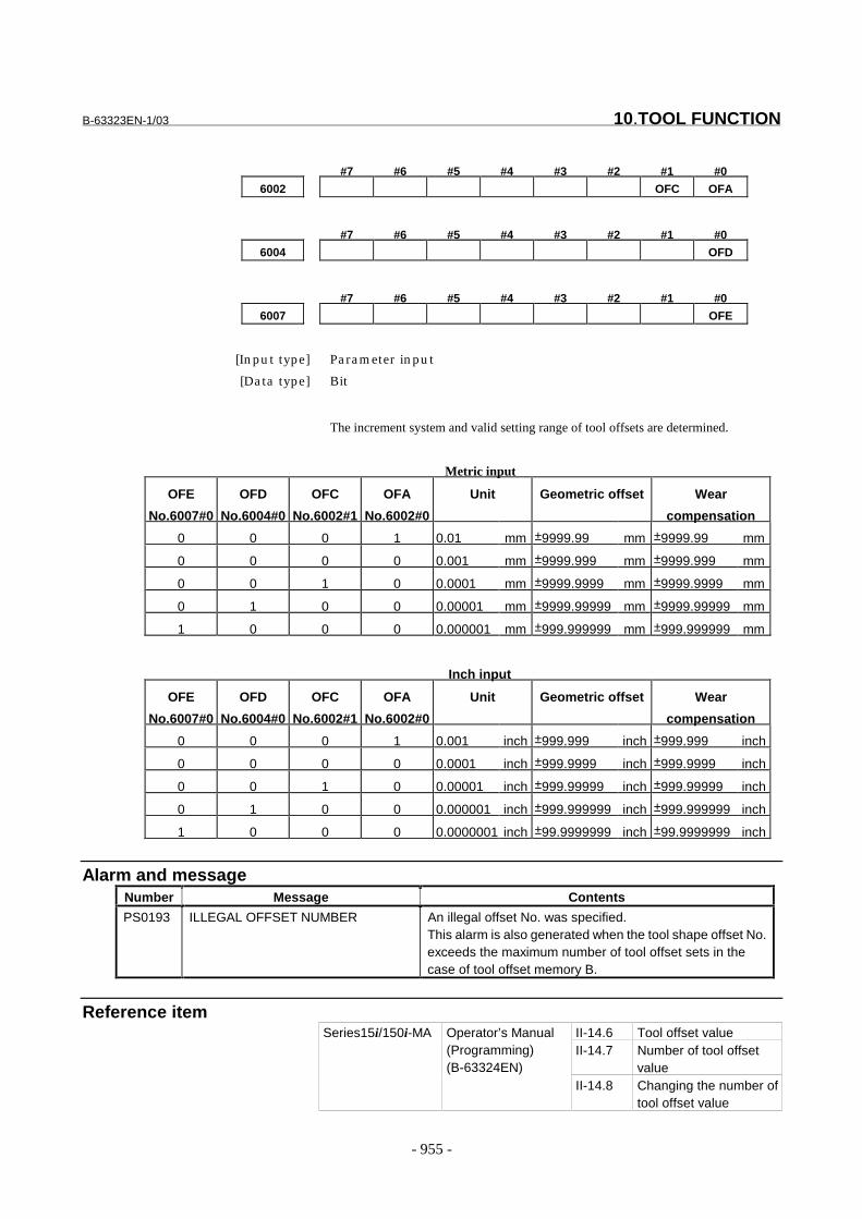
B-63323EN-1/03 10.TOOL FUNCTION
- 955 -
#7 #6 #5 #4 #3 #2 #1 #0
6002 OFC OFA
#7 #6 #5 #4 #3 #2 #1 #0
6004 OFD
#7 #6 #5 #4 #3 #2 #1 #0
6007 OFE
[Input type] Parameter input
[Data type] Bit
The increment system and valid setting range of tool offsets are determined.
Metric input
OFE
No.6007#0
OFD
No.6004#0
OFC
No.6002#1
OFA
No.6002#0
Unit Geometric offset Wear
compensation
0 0 0 1 0.01 mm ±9999.99 mm ±9999.99 mm
0 0 0 0 0.001 mm ±9999.999 mm ±9999.999 mm
0 0 1 0 0.0001 mm ±9999.9999 mm ±9999.9999 mm
0 1 0 0 0.00001 mm ±9999.99999 mm ±9999.99999 mm
1 0 0 0 0.000001 mm ±999.999999 mm ±999.999999 mm
Inch input
OFE
No.6007#0
OFD
No.6004#0
OFC
No.6002#1
OFA
No.6002#0
Unit Geometric offset Wear
compensation
0 0 0 1 0.001 inch ±999.999 inch ±999.999 inch
0 0 0 0 0.0001 inch ±999.9999 inch ±999.9999 inch
0 0 1 0 0.00001 inch ±999.99999 inch ±999.99999 inch
0 1 0 0 0.000001 inch ±999.999999 inch ±999.999999 inch
1 0 0 0 0.0000001 inch ±99.9999999 inch ±99.9999999 inch
Alarm and messageNumber Message Contents
PS0193 ILLEGAL OFFSET NUMBER An illegal offset No. was specified.This alarm is also generated when the tool shape offset No.exceeds the maximum number of tool offset sets in thecase of tool offset memory B.
Reference itemII-14.6 Tool offset valueII-14.7 Number of tool offset
value
Series15i/150i-MA Operator’s Manual(Programming)(B-63324EN)
II-14.8 Changing the number oftool offset value
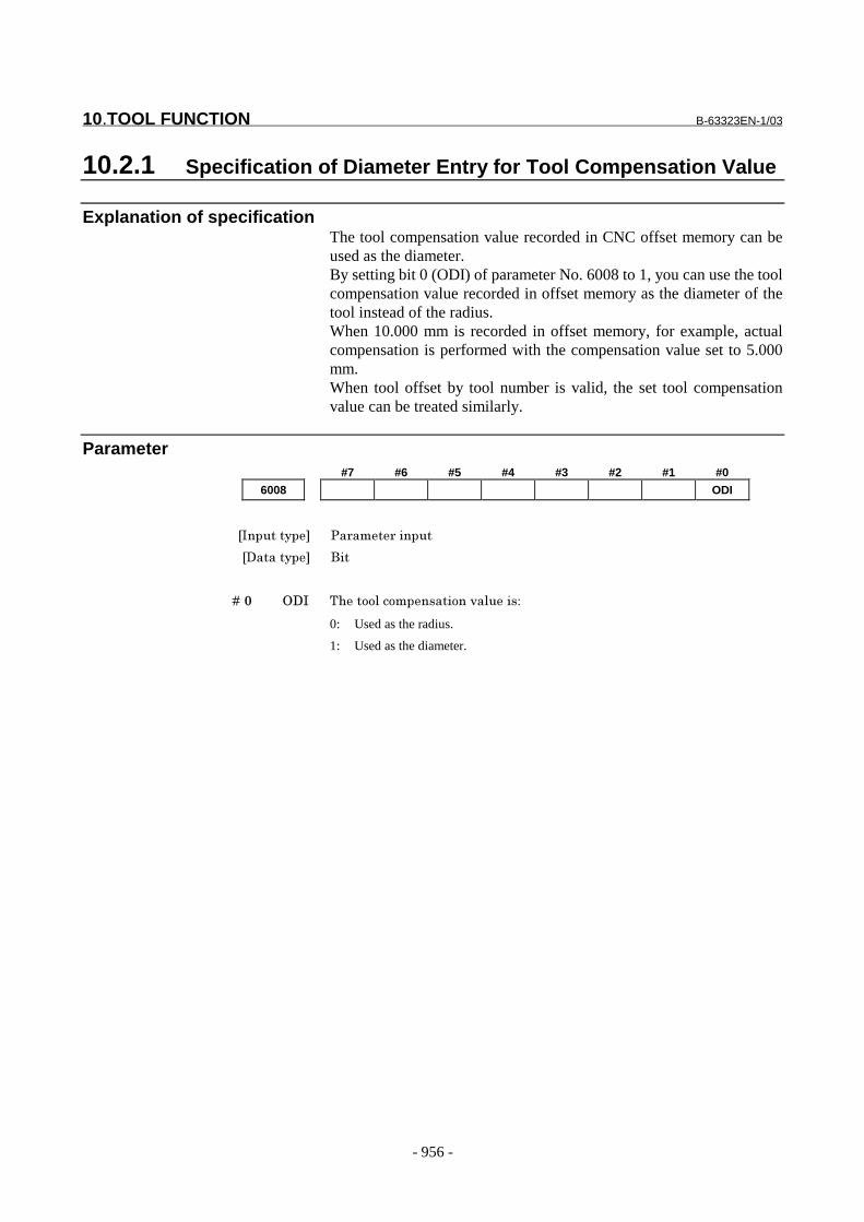
10.TOOL FUNCTION B-63323EN-1/03
- 956 -
10.2.1 Specification of Diameter Entry for Tool Compensation Value
Explanation of specificationThe tool compensation value recorded in CNC offset memory can beused as the diameter.By setting bit 0 (ODI) of parameter No. 6008 to 1, you can use the toolcompensation value recorded in offset memory as the diameter of thetool instead of the radius.When 10.000 mm is recorded in offset memory, for example, actualcompensation is performed with the compensation value set to 5.000mm.When tool offset by tool number is valid, the set tool compensationvalue can be treated similarly.
Parameter#7 #6 #5 #4 #3 #2 #1 #0
6008 ODI
���������� �� ��� ������
��������� ���
� � � � ��# +�� ����!!)��!�������!��,�)����$
0: Used as the radius.
1: Used as the diameter.

B-63323EN-1/03 10.TOOL FUNCTION
- 957 -
10.3 TOOL LIFE MANAGEMENT FUNCTION
GeneralTools are grouped and the tool life (use count or use time) ispredetermined for each group. Each time a tool belonging to a group isused, its life value is incremented. Once the predetermined tool lifevalue is reached, a new tool is automatically selected according to thepredefined tool order in the group. This allows continuous machiningas well as tool life management.The tool life management data, including tool group numbers, tool lifevalues, and tool compensation codes, is stored in the CNC.
Tool group number m
Tool life value l
1 Tool number(T) Code specifying tool
compensation value(H/D)
The first tool life management data
2 : : The second tool life management data
:
:
:
:
:
:
:
:
n : : The nth tool life management data
Fig. 10.3 (a) Tool life management data/ Machining program/Machine and CNC operations
Tool life management data
Tool group number 1::
Tool group number m::
Tool group number p
Machining program
:::
Command for selectingtool group m
::
Tool change command(M06)
::
Machine and CNC operations
Machine CNC
Places aSelected tool inThe wait state
Automatically selects,from tool group m, atool whose life has notexpired.
Attaches the toolIn the wait stateTo the spindle(tool change).
Starts counting the lifeof the tool attached tothe spindle.l
Toolselection
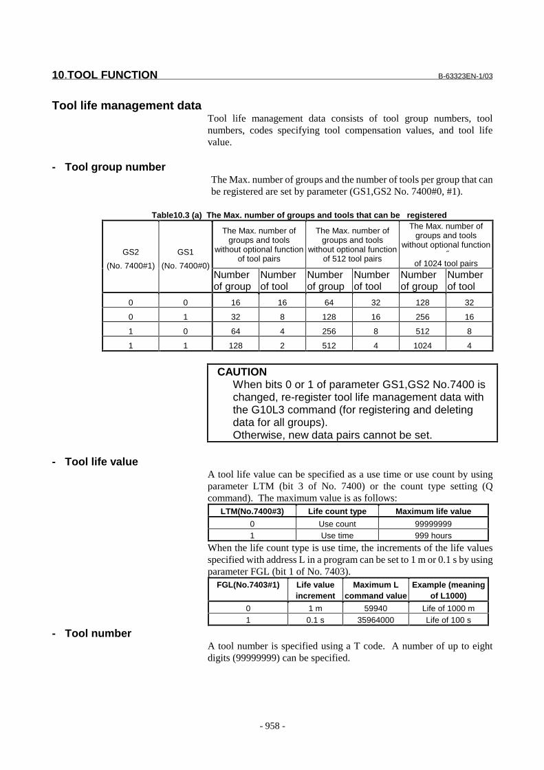
10.TOOL FUNCTION B-63323EN-1/03
- 958 -
Tool life management dataTool life management data consists of tool group numbers, toolnumbers, codes specifying tool compensation values, and tool lifevalue.
- Tool group numberThe Max. number of groups and the number of tools per group that canbe registered are set by parameter (GS1,GS2 No. 7400#0, #1).
Table10.3 (a) The Max. number of groups and tools that can be registered
The Max. number ofgroups and tools
without optional functionof tool pairs
The Max. number ofgroups and tools
without optional functionof 512 tool pairs
The Max. number ofgroups and tools
without optional function˝
of 1024 tool pairsGS2
(No. 7400#1)
GS1
(No. 7400#0)Numberof group
Numberof tool
Numberof group
Numberof tool
Numberof group
Numberof tool
0 0 16 16 64 32 128 32
0 1 32 8 128 16 256 16
1 0 64 4 256 8 512 8
1 1 128 2 512 4 1024 4
CAUTIONWhen bits 0 or 1 of parameter GS1,GS2 No.7400 ischanged, re-register tool life management data withthe G10L3 command (for registering and deletingdata for all groups).Otherwise, new data pairs cannot be set.
- Tool life valueA tool life value can be specified as a use time or use count by usingparameter LTM (bit 3 of No. 7400) or the count type setting (Qcommand). The maximum value is as follows:
LTM(No.7400#3) Life count type Maximum life value
0 Use count 999999991 Use time 999 hours
When the life count type is use time, the increments of the life valuesspecified with address L in a program can be set to 1 m or 0.1 s by usingparameter FGL (bit 1 of No. 7403).
FGL(No.7403#1) Life valueincrement
Maximum Lcommand value
Example (meaningof L1000)
0 1 m 59940 Life of 1000 m1 0.1 s 35964000 Life of 100 s
- Tool numberA tool number is specified using a T code. A number of up to eightdigits (99999999) can be specified.
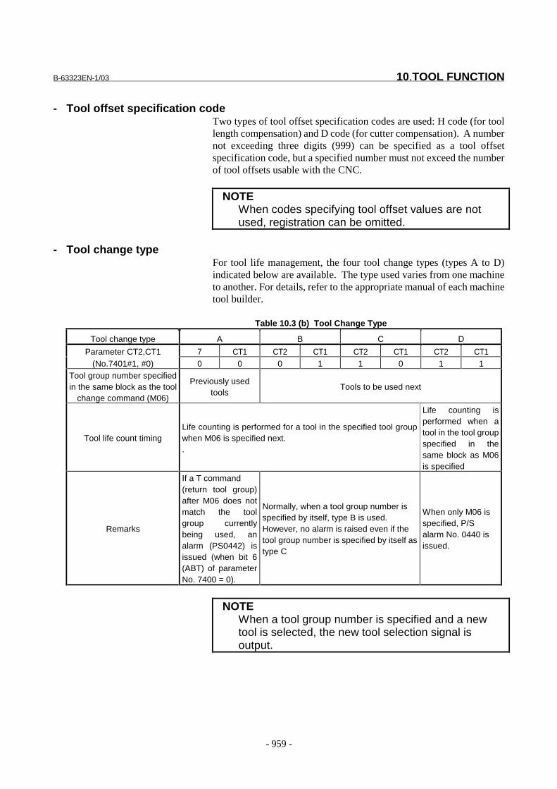
B-63323EN-1/03 10.TOOL FUNCTION
- 959 -
- Tool offset specification codeTwo types of tool offset specification codes are used: H code (for toollength compensation) and D code (for cutter compensation). A numbernot exceeding three digits (999) can be specified as a tool offsetspecification code, but a specified number must not exceed the numberof tool offsets usable with the CNC.
NOTEWhen codes specifying tool offset values are notused, registration can be omitted.
- Tool change typeFor tool life management, the four tool change types (types A to D)indicated below are available. The type used varies from one machineto another. For details, refer to the appropriate manual of each machinetool builder.
Table 10.3 (b) Tool Change Type
Tool change type A B C D
Parameter CT2,CT1 7 CT1 CT2 CT1 CT2 CT1 CT2 CT1(No.7401#1, #0) 0 0 0 1 1 0 1 1
Tool group number specifiedin the same block as the tool
change command (M06)
Previously usedtools
Tools to be used next
Tool life count timingLife counting is performed for a tool in the specified tool groupwhen M06 is specified next..
Life counting isperformed when atool in the tool groupspecified in thesame block as M06is specified
Remarks
If a T command(return tool group)after M06 does notmatch the toolgroup currentlybeing used, analarm (PS0442) isissued (when bit 6(ABT) of parameterNo. 7400 = 0).
Normally, when a tool group number isspecified by itself, type B is used.However, no alarm is raised even if thetool group number is specified by itself astype C
When only M06 isspecified, P/Salarm No. 0440 isissued.
NOTEWhen a tool group number is specified and a newtool is selected, the new tool selection signal isoutput.
10.TOOL FUNCTION B-63323EN-1/03
- 960 -
Tool service life count and tool selectionA count-based or time-based tool service life count system is selectedusing bit 3 (LTM) of parameter No. 7400. Service life counting isperformed group by group. Service life count data is not lost when thepower is turned off.
Tool life countsystem
Count specification Time specification
Bit 3 (LTM) ofparameter No. 7400
0 1
Life count interval
Incremented by 1 for a toolused in a program.Recounting is made possiblewith the M code for tool lifecount restart M code(parameter No. 7442).
Bit 0 (FCO) ofparameter No. 74030 : At intervals of 1second1 : At intervals of 0.1secondThese intervals can beoverridden.
- Count specification (LTM = 0)When a tool group command (T code) is specified, a tool whose servicelife has not expired is selected from the group. Then, the service lifecount for the selected tool is incremented by 1 with the tool changecommand (M06). Unless the tool service life count restart M code isused, however, the selection and count-up of a new tool are allowedusing only the first tool group number command and tool changecommand after the control unit state is changed from the reset state tothe automatic operation start state.Therefore, note that even when the same tool group number is specifiedmore than once in a single process, the count is not incremented, and anew tool is not selected.
- Time specification (LTM = 1)Once all the registered tool life management data has been deleted,programmed tool life management data is registered.When a tool group command (T code) is specified, a tool whose servicelife has not expired is selected from the group. The service lifemanagement for the selected tool is started with the tool changecommand (M06). Service management (counting) is performed atcertain intervals (1 second or 0.1 second) while the tool is actuallybeing used in cutting mode. This service life count interval can bespecified using bit 0 (FCO) of parameter No. 7403. The time requiredfor single block stop, feed hold, dwell, machine lock, and interlock isnot counted.By setting bit 3 (LFV) of parameter No. 7401, service life count can beoverridden using the service life count override signal. An override of0 to 99.8 times can be used. When 0 times is specified, no count isperformed.
B-63323EN-1/03 10.TOOL FUNCTION
- 961 -
Tool life count restart M codeWith the count-based tool life count system, when the tool life countrestart M code is specified and the life of at least one tool group hasexpired, the tool change signal is output. When a tool group command(T code) is specified after the tool life count restart M code is specified,a tool whose life has not expired is selected from the group. Then, thelife count is incremented by 1 with the next tool change command(M06). Thus, tool life count is enabled with a command other than thefirst tool change command (M06) after the control unit status ischanged from the reset state to the automatic operation start state.Specify the tool life count restart M code using parameter No. 7442.
Signal
Tool change signal TLCHA<F007#6>[Classification] Output signal
[Function] Posts that all the tools of a group have reached the end of their servicelives. Generally, upon receiving this signal, the PMC lights anindicator on the machine operator’s panel, asking the operator tochange the tools.
[Output condition] This signal is set to 1 when:- All the tools of a group have reached the ends of their service
lives.If time is specified for the life count type, this signal is set to 1immediately when the life of the last tool in a group has expired.If frequency is specified as the life count type, this signal is set to1 when the control unit is reset by a command such as M02 orM30, or if an M code for restarting tool life count is specified afterthe service life of the last tool in a group has expired.
This signal is set to 0 when:- Every group has tools whose lives have not yet expired.
When this signal is 1, the tool change reset signal TLRST is issuedor an MDI operation is performed from the PMC to notify theCNC that tool change has been performed for all those groupswhose service lives have expired. Then, this signal is set to 0.
Tool change reset signal TLRST<G010#7>[Classification] Input signal
[Function] Notifies the control unit that all the tools of a group, which havealready reached the ends of their service lives, have been replaced withnew tools. Before inputting this signal, input the tool group signal(TL1 to TL256) to notify the control unit of the target group for toolreplacement. By setting bit 4 (RAG) of parameter No. 7400 to 1, thereplacement of all registered groups with new tools can be postedwithout inputting a tool group number.
[Operation] When this signal status changes from 0 to 1, the control unit operates asfollows:- When the service lives of all the tools of a group specified by the
tool group signal (TL1 to TL512) have already been reached, therelevant information is cleared. Therefore, if this group number is

10.TOOL FUNCTION B-63323EN-1/03
- 962 -
subsequently specified in a program, the first tool is selected again.If a group specified by the tool group signal (TL1 to TL512)contains a tool whose service life has not yet been reached, nooperation is performed.
NOTEChange the status of tool change reset signalTLRST from 0 to 1 while the control unit is not beingreset (the RST signal is not 1), and the followingstate is observed:
1) When bit 5 (TRS) of parameter No. 7401 = 0:In the reset state (the OP signal is set to 0).
2) When bit 5 (TRS) of parameter No. 7401 = 1:(1) In the reset state (the OP signal is set to 0).(2) In the automatic operation stop state (STL and
SPL are set to 0, and OP is set to 1).(3) In the automatic operation hold state (STL is
set to 0, and SPL is set to 1).(Tool change reset signal TLRST is ignored in theautomatic operation stop state, automatic operationhold state, and automatic operation start state (STLis set to 1) during the execution of a data settingcommand (G10L3).)
B-63323EN-1/03 10.TOOL FUNCTION
- 963 -
Tool skip signal TLSKP<G009#7>[Classification] Input signal
[Function] Directs the control unit to skip a tool whose service life has not beenreached and selects the next tool. The following two methods can beused, one of which can be selected by specifying bit 2 (SIG) ofparameter No. 7400:- Not specifying a group number with the tool group signal (SIG =
0)When the status of tool skip signal TLSKP changes from 0 to 1,the group of the currently selected tool is assumed to have beenspecified.When this group is specified again by a Txxxxxxxx command, thenext tool within the group is newly selected.
- Specifying a group number with the tool group signal (SIG = 1)The group number of a group to which a tool to be skippedbelongs is specified with the tool group signal (TL1 to TL512),then the tool skip signal TLSKP is set to 1. When this group isspecified again with a Txxxxxxxx command, the next tool withinthe group is selected.
[Operation] When the status of this signal changes from 0 to 1, the control unitoperates as follows:- Among the tools in a skip operation target group, which have not
yet reached the end of their service lives, a tool having the lowesttool number in the tool life management table is indicated by #.When this group is specified again by a Txxxxxxxx command, itis posted that the marked tool is skipped and the next tool isselected. If, in the skip operation target group, the tool whose lifehas not expired is the last tool in the tool life management table,tool change signal TLCHA is set to 1 immediately.
CAUTIONSet tool skip signal TLSKP to 1 when the control unitis in the reset state or automatic operation stopstate. In other words, change the tool skip signalstatus from 0 to 1 when automatic operation startsignal STL and automatic operation hold signal SPLare both 0.
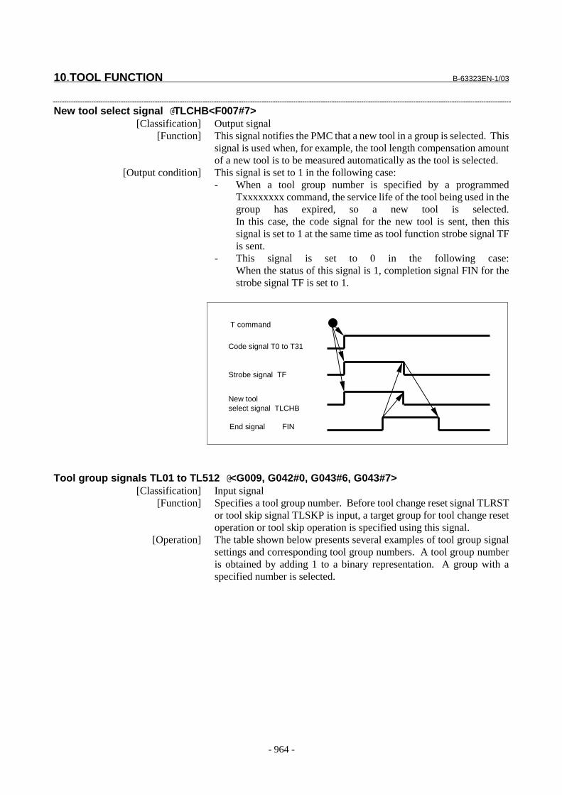
10.TOOL FUNCTION B-63323EN-1/03
- 964 -
New tool select signal @TLCHB<F007#7>[Classification] Output signal
[Function] This signal notifies the PMC that a new tool in a group is selected. Thissignal is used when, for example, the tool length compensation amountof a new tool is to be measured automatically as the tool is selected.
[Output condition] This signal is set to 1 in the following case:- When a tool group number is specified by a programmed
Txxxxxxxx command, the service life of the tool being used in thegroup has expired, so a new tool is selected.In this case, the code signal for the new tool is sent, then thissignal is set to 1 at the same time as tool function strobe signal TFis sent.
- This signal is set to 0 in the following case:When the status of this signal is 1, completion signal FIN for thestrobe signal TF is set to 1.
Tool group signals TL01 to TL512 @<G009, G042#0, G043#6, G043#7>[Classification] Input signal
[Function] Specifies a tool group number. Before tool change reset signal TLRSTor tool skip signal TLSKP is input, a target group for tool change resetoperation or tool skip operation is specified using this signal.
[Operation] The table shown below presents several examples of tool group signalsettings and corresponding tool group numbers. A tool group numberis obtained by adding 1 to a binary representation. A group with aspecified number is selected.
T command
Code signal T0 to T31
Strobe signal TF
New toolselect signal TLCHB
End signal FIN
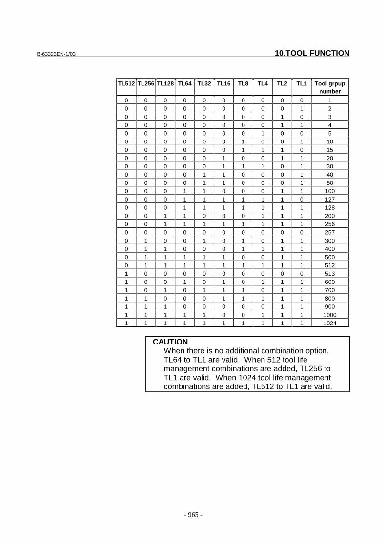
B-63323EN-1/03 10.TOOL FUNCTION
- 965 -
TL512 TL256 TL128 TL64 TL32 TL16 TL8 TL4 TL2 TL1 Tool grpupnumber
0 0 0 0 0 0 0 0 0 0 10 0 0 0 0 0 0 0 0 1 20 0 0 0 0 0 0 0 1 0 30 0 0 0 0 0 0 0 1 1 40 0 0 0 0 0 0 1 0 0 50 0 0 0 0 0 1 0 0 1 100 0 0 0 0 0 1 1 1 0 150 0 0 0 0 1 0 0 1 1 200 0 0 0 0 1 1 1 0 1 300 0 0 0 1 1 0 0 0 1 400 0 0 0 1 1 0 0 0 1 500 0 0 1 1 0 0 0 1 1 1000 0 0 1 1 1 1 1 1 0 1270 0 0 1 1 1 1 1 1 1 1280 0 1 1 0 0 0 1 1 1 2000 0 1 1 1 1 1 1 1 1 2560 0 0 0 0 0 0 0 0 0 2570 1 0 0 1 0 1 0 1 1 3000 1 1 0 0 0 1 1 1 1 4000 1 1 1 1 1 0 0 1 1 5000 1 1 1 1 1 1 1 1 1 5121 0 0 0 0 0 0 0 0 0 5131 0 0 1 0 1 0 1 1 1 6001 0 1 0 1 1 1 0 1 1 7001 1 0 0 0 1 1 1 1 1 8001 1 1 0 0 0 0 0 1 1 9001 1 1 1 1 0 0 1 1 1 10001 1 1 1 1 1 1 1 1 1 1024
CAUTIONWhen there is no additional combination option,TL64 to TL1 are valid. When 512 tool lifemanagement combinations are added, TL256 toTL1 are valid. When 1024 tool life managementcombinations are added, TL512 to TL1 are valid.
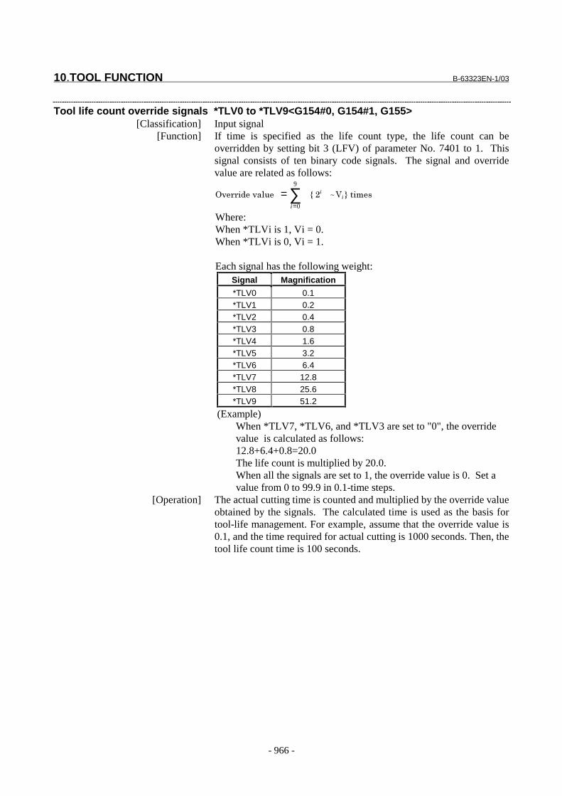
10.TOOL FUNCTION B-63323EN-1/03
- 966 -
Tool life count override signals *TLV0 to *TLV9<G154#0, G154#1, G155>[Classification] Input signal
[Function] If time is specified as the life count type, the life count can beoverridden by setting bit 3 (LFV) of parameter No. 7401 to 1. Thissignal consists of ten binary code signals. The signal and overridevalue are related as follows:
+, � �,�)��� ∑=
=9
0i
7��i�� ~�(i�8�����
Where:When *TLVi is 1, Vi = 0.When *TLVi is 0, Vi = 1.
Each signal has the following weight:Signal Magnification
*TLV0 0.1*TLV1 0.2*TLV2 0.4*TLV3 0.8*TLV4 1.6*TLV5 3.2*TLV6 6.4*TLV7 12.8*TLV8 25.6*TLV9 51.2
(Example)When *TLV7, *TLV6, and *TLV3 are set to "0", the overridevalue is calculated as follows:12.8+6.4+0.8=20.0The life count is multiplied by 20.0.When all the signals are set to 1, the override value is 0. Set avalue from 0 to 99.9 in 0.1-time steps.
[Operation] The actual cutting time is counted and multiplied by the override valueobtained by the signals. The calculated time is used as the basis fortool-life management. For example, assume that the override value is0.1, and the time required for actual cutting is 1000 seconds. Then, thetool life count time is 100 seconds.
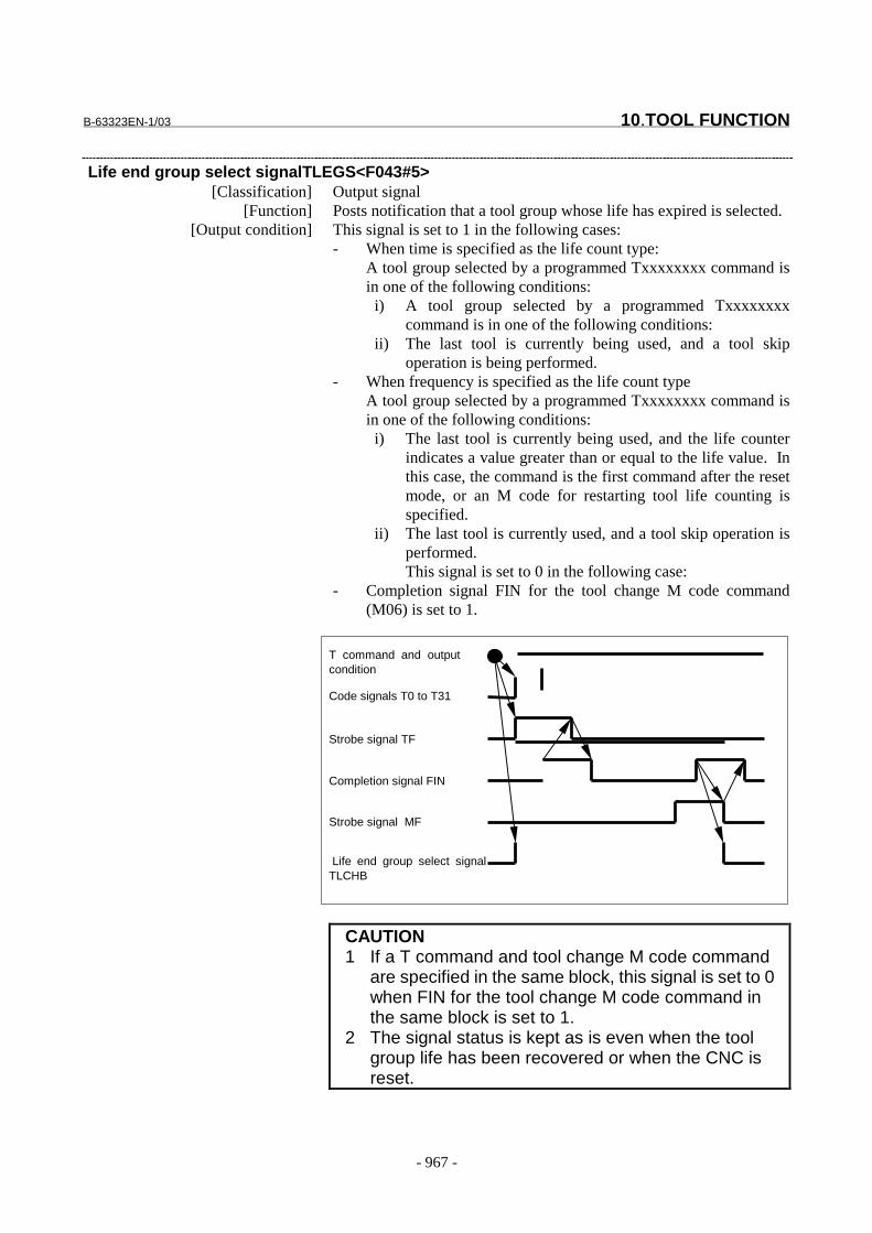
B-63323EN-1/03 10.TOOL FUNCTION
- 967 -
Life end group select signalTLEGS<F043#5>[Classification] Output signal
[Function] Posts notification that a tool group whose life has expired is selected.[Output condition] This signal is set to 1 in the following cases:
- When time is specified as the life count type:A tool group selected by a programmed Txxxxxxxx command isin one of the following conditions:
i) A tool group selected by a programmed Txxxxxxxxcommand is in one of the following conditions:
ii) The last tool is currently being used, and a tool skipoperation is being performed.
- When frequency is specified as the life count typeA tool group selected by a programmed Txxxxxxxx command isin one of the following conditions:
i) The last tool is currently being used, and the life counterindicates a value greater than or equal to the life value. Inthis case, the command is the first command after the resetmode, or an M code for restarting tool life counting isspecified.
ii) The last tool is currently used, and a tool skip operation isperformed.This signal is set to 0 in the following case:
- Completion signal FIN for the tool change M code command(M06) is set to 1.
CAUTION1 If a T command and tool change M code command
are specified in the same block, this signal is set to 0when FIN for the tool change M code command inthe same block is set to 1.
2 The signal status is kept as is even when the toolgroup life has been recovered or when the CNC isreset.
T command and outputcondition
Code signals T0 to T31
Strobe signal TF
Life end group select signalTLCHB
Completion signal FIN
Strobe signal MF
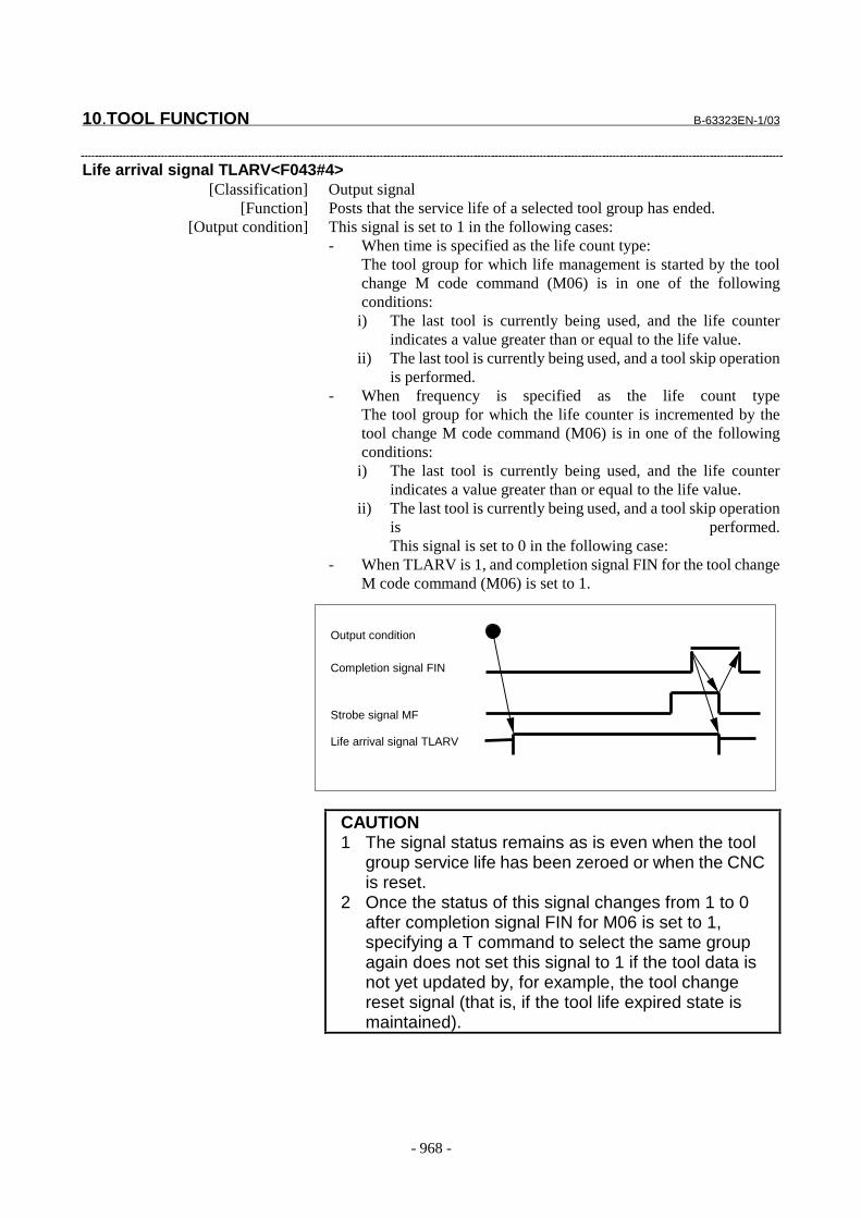
10.TOOL FUNCTION B-63323EN-1/03
- 968 -
Life arrival signal TLARV<F043#4>[Classification] Output signal
[Function] Posts that the service life of a selected tool group has ended.[Output condition] This signal is set to 1 in the following cases:
- When time is specified as the life count type:The tool group for which life management is started by the toolchange M code command (M06) is in one of the followingconditions:
i) The last tool is currently being used, and the life counterindicates a value greater than or equal to the life value.
ii) The last tool is currently being used, and a tool skip operationis performed.
- When frequency is specified as the life count typeThe tool group for which the life counter is incremented by thetool change M code command (M06) is in one of the followingconditions:
i) The last tool is currently being used, and the life counterindicates a value greater than or equal to the life value.
ii) The last tool is currently being used, and a tool skip operationis performed.This signal is set to 0 in the following case:
- When TLARV is 1, and completion signal FIN for the tool changeM code command (M06) is set to 1.
CAUTION1 The signal status remains as is even when the tool
group service life has been zeroed or when the CNCis reset.
2 Once the status of this signal changes from 1 to 0after completion signal FIN for M06 is set to 1,specifying a T command to select the same groupagain does not set this signal to 1 if the tool data isnot yet updated by, for example, the tool changereset signal (that is, if the tool life expired state ismaintained).
Output condition
Strobe signal MF
Life arrival signal TLARV
Completion signal FIN
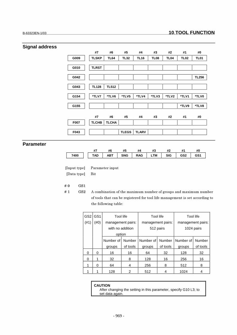
B-63323EN-1/03 10.TOOL FUNCTION
- 969 -
Signal address#7 #6 #5 #4 #3 #2 #1 #0
G009 TLSKP TL64 TL32 TL16 TL08 TL04 TL02 TL01
G010 TLRST
G042 TL256
G043 TL128 TL512
G154 *TLV7 *TLV6 *TLV5 *TLV4 *TLV3 *TLV2 *TLV1 *TLV0
G155 *TLV9 *TLV8
#7 #6 #5 #4 #3 #2 #1 #0
F007 TLCHB TLCHA
F043 TLEGS TLARV
Parameter#7 #6 #5 #4 #3 #2 #1 #0
7400 TAD ABT SNG RAG LTM SIG GS2 GS1
���������� �� ��� ������
��������� ���
� � � � ��# 0�&
� � � � ��& 0�� 9��!�������!��!�������-��������� �!��' !������ ���-���������
!���!!)������������� '��� ��! ��!!)�)�������'�������������! ��'��!
����!))!���'����)$
GS2
(#1)
GS1
(#0)
Tool life
management pairs:
with no addition
option
Tool life
management pairs:
512 pairs
Tool life
management pairs:
1024 pairs
Number of
groups
Number
of tools
Number of
groups
Number
of tools
Number of
groups
Number
of tools
0 0 16 16 64 32 128 32
0 1 32 8 128 16 256 16
1 0 64 4 256 8 512 8
1 1 128 2 512 4 1024 4
CAUTIONAfter changing the setting in this parameter, specify G10 L3; toset data again.

10.TOOL FUNCTION B-63323EN-1/03
- 970 -
� � � � ��� ��0 ������������ ��!����������' !������� ��! ��!!)��.����������'��
��'��)"
#$ �!��!��������"
&$ ������"
NOTEIf no group number is specified using a signal, tool skip isperformed for the tool of the group currently used.
� � � � ��: ;�4 ������������ ��!��!�����!!)�)����������! �� <����"
#$ %!�����!!)�)������� <����"
&$ %!�����!!)�)���������"
NOTEAfter changing the setting of this parameter, reenter the data withG10 L3;.
� � � � ��1 =90 ���������!���!��)� �' !���-����!�� ������������!!)�����'� ��
��'��)���;=��������� "
#$ %)� ����-����!�� ����!���������� �' !���������)���!�����' !��
����-�� "
&$ %)� ����-����!�� ����!���))� '��� �' !���"
� � � � ��> ��0 ���������!���!���� )�����!!)��.�����'��)���;�?����� ��������!!)
��!��)�������!������' ������ "
#$ �.�������!!)�!�����' !����!��� ���)���� �! ����' !��������� ���
���������0��!���� ��� ��!"�@1##"
&$ �'�! �����!!)��.�����'��)"� � �!!)��.������ �!��4���!� ���!������)�!
���������)"
� � � � ��2 9�� ������������ ��!����������)� ��������� �� ���!!)����� � !���!�
�)!�'��!������ ��)���� �' !�������!!)� �)������9"
#$ ���������)� �����#11��"
&$ �!��!�����������)� �"
� � � � ��@ �9� ������������ ��!����������)� �������!����!���� ���������� ���
����)!�.���������)� ��4#2�����!!)� �)�������"
#$ �!���!�����������)� �"
&$ ����������)� �����#11#�"
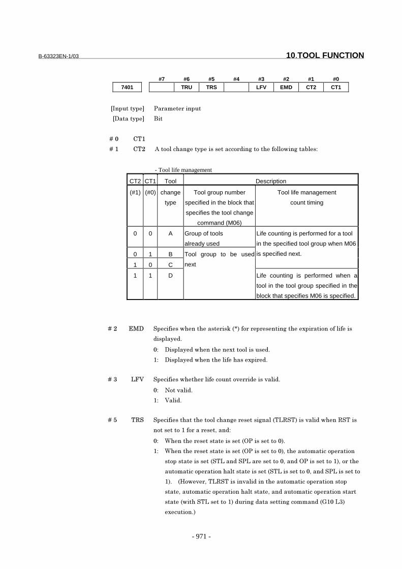
B-63323EN-1/03 10.TOOL FUNCTION
- 971 -
#7 #6 #5 #4 #3 #2 #1 #0
7401 TRU TRS LFV EMD CT2 CT1
���������� �� ��� ������
��������� ���
� � � � ��# %�&
� � � � ��& %�� 9��!!)�����'��������������! ��'��!�����!))!���'����)�$
- Tool life management
CT2 CT1 Tool Description
(#1) (#0) change
type
Tool group number
specified in the block that
specifies the tool change
command (M06)
Tool life management
count timing
0 0 A Group of tools
already used
0 1 B
1 0 C
Life counting is performed for a tool
in the specified tool group when M06
is specified next.
1 1 D
Tool group to be used
next
Life counting is performed when a
tool in the tool group specified in the
block that specifies M06 is specified.
� � � � ��� *4� ������������������ ��.��A���! � � �����'����-�� ���!��!��)�����
���)�� "
#$ ����)�� ���������-���!!)������ "
&$ ����)�� ��������)�������-�� "
� � � � ��: ;B( ������������ �)����!����!, � ����,�)� "
#$ �!��,�)� "
&$ (�)� "
� � � � ��> �=� �����������������!!)�����'� �����'��)���;=�������,�)� �����=�����
�!������!�&��! ��� ��6��� $
#$ C������ ���������������+���������!�#�"
&$ C������ ���������������+���������!�#�6�������!������!� ���!�
��!����������������;��� ���;�� �����!�#6��� �+���������!�&�6�! ���
���!������!� ���!����)����������������;��������!�#6��� ���;��������!
&�"� � �/!�, 6��;=��������,�)� ����������!������!� ���!����!�
����6����!������!� ���!����)������6��� ����!������!� ���!����� �
�������������;�����!�&�� � ��'� ���������'��!���� ��0&#�;:�
-����!�"�
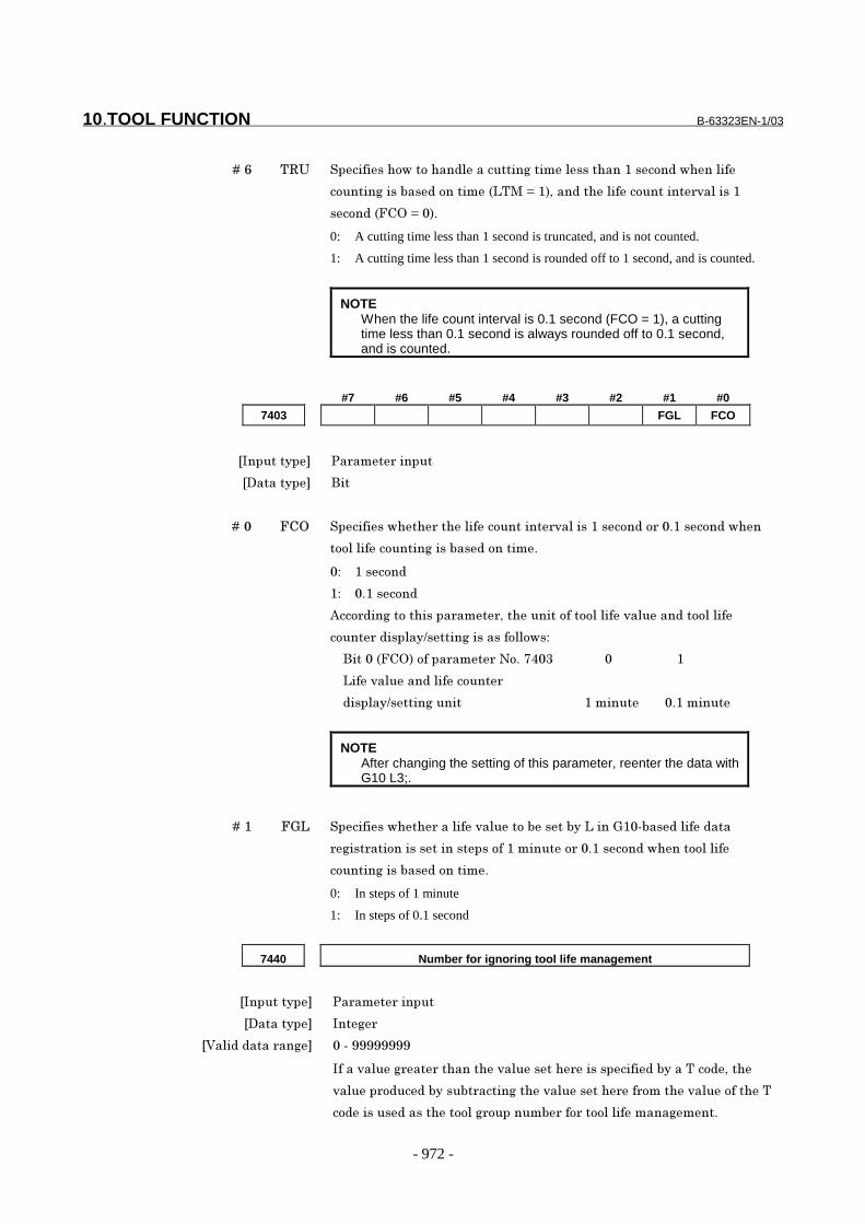
10.TOOL FUNCTION B-63323EN-1/03
- 972 -
� � � � ��2 �=5 ���������!���!���� )���������'�����)��������&���!� �����)��
�!�����'������� �!�������;�4�D�&�6��� ����)����!������� ,�)����&
��!� ��B%+�D�#�"
0: A cutting time less than 1 second is truncated, and is not counted.
1: A cutting time less than 1 second is rounded off to 1 second, and is counted.
NOTEWhen the life count interval is 0.1 second (FCO = 1), a cuttingtime less than 0.1 second is always rounded off to 0.1 second,and is counted.
#7 #6 #5 #4 #3 #2 #1 #0
7403 FGL FCO
���������� �� ��� ������
��������� ���
� � � � ��# B%+ ������������ ����)����!������� ,�)����&���!� �! �#"&���!� ����
�!!)�)����!�����'������� �!�����"
#$ &���!�
&$ #"&���!�
9��! ��'��!�������� ��� 6���������!���!!)�)���,�)���� ��!!)�)��
�!��� � ���)��E�����'��������!))!��$
� � ����#��B%+��!���� ��� ��!"�@1#:� � � � � � � � #� � � � � � � � � � &
� � ;���,�)���� �)����!���
� � ���)��E�����'������ � � � � � � � � � � � � � � � � � � &������� � � � #"&������
NOTEAfter changing the setting of this parameter, reenter the data withG10 L3;.
� � � � ��& B0; ������������ ���)���,�)���!���������;����0&#���� �)��� ���
'��� ���!����������������!��&�������! �#"&���!� ������!!)�)��
�!�����'������� �!�����"
0: In steps of 1 minute
1: In steps of 0.1 second
7440 Number for ignoring tool life management
���������� �� ��� ������
��������� ���'
�(�)� � ���� ��' #���FFFFFFFF
�����,�)��' �� ���������,�)������ ���������� ���������! 6���
,�)��� ! �� �������� �����'����,�)������ �� !�����,�)��!������
�! ������ ��������!!)�' !������� ��! ��!!)�)�������'���"
B-63323EN-1/03 10.TOOL FUNCTION
- 973 -
7442 M code used to restart tool life counting
���������� �� ��� ������
��������� ���'
�(�)� � ���� ��' B !��#��� !�'��FFFFFFFF��*-�)� ��'�#&6�#�6�:#6�F36�FF��� ���))��'�4
�! �
C�������!!)�)������������ ������������� �!�����������!!)�������
�� 6�����!!)�����'���'��)���;%/9��������� ��������!!)�)���!������!�
!������!!)�' !��������-�� �����������!������������!��!�����4��!
�� ��!� ��� ���!!)�)����!�����'"
������! ���!!)�)�������'����' !����!���� �������� ���� ����4
�! ��� ��!� ��� ���!!)�)����!�����'��)�������!!)���!��)��������!�
-�� ����� !����������� �' !��"� � ����-��4#2��! ���� �������
�!!)�)����!��� ����!�"
C�������!!)�)������������ �����������������!!)���������� 6
��������'����4��! ��� ��!� ��� ���!!)�)����!�����'� !���!����������
!� ���!�"� � C���#����������������� ��� 6����4��! ��� ��!� ��� �
�!!)�)����!�����'������!�����"
7443 H code for enabling tool length compensation specified by group number
���������� �� ��� ������
��������� ���'
�(�)� � ���� ��' #���FFFF
��6����������� ��� 6����/��! ��! ����)��'��!!)�)�'����!�������!�
������ ��������� ��)���)�� �' !������� "� � C���#��������������
�� ��� 6��!�������!��������) ����/FF"
7444 D code for enabling cutter compensation specified by group number
���������� �� ��� ������
��������� ���'
�(�)� � ���� ��' #���FFFF
��6����������� ��� 6������! ��! ����)��'����� ��!�������!�
������ ��������� ��)���)�� �' !������� "� � C���#��������������
�� ��� 6��!�������!��������) �����FF"
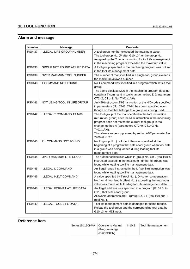
10.TOOL FUNCTION B-63323EN-1/03
- 974 -
Alarm and message
Number Message Contents
PS0437 ILLEGAL LIFE GROUP NUMBER A tool group number exceeded the maximum value.The tool group No. (P after G10 L3:) or the group No.assigned by the T code instruction for tool life managementin the machining program exceeded the maximum value.
PS0438 GROUP NOT FOUND AT LIFE DATA A tool group specified in the machining program was not setin the tool life management data.
PS0439 OVER MAXIMUM TOOL NUMBER The number of tool specified in a single tool group exceedsthe maximum allowed number.
PS0440 T COMMAND NOT FOUND No T command was specified in a program which sets a toolgroup.The same block as M06 in the machining program does notcontain a T command in tool change method D (parametersCT2=2, CT1=1: No. 7401#1/#0).
PS0441 NOT USING TOOL IN LIFE GROUP An H99 instruction, D99 instruction or the H/D code specifiedin parameters (No. 7443, 7444) has been specified eventhough no tool that belongs to a group was being used.
PS0442 ILLEGAL T COMMAND AT M06 The tool group of the tool specified in the tool instruction(return tool group) after the M06 instruction in the machiningprogram does not match the current tool group in toolchange method A (parameters CT2=0, CT1=0: No.7401#1/#0).This alarm can be suppressed by setting ABT parameter No.7400#6 to "1".
PS0443 P,L COMMAND NOT FOUND No P (group No. ) or L (tool life) was specified at thebeginning of a program that sets a tool group when tool datain a group was being loaded during loading tool lifemanagement data.
PS0444 OVER MAXIMUM LIFE GROUP The number of blocks in which P (group No. ) or L (tool life) isinstructed exceeding the maximum number of groups wasfound while loading tool life management data.
PS0445 ILLEGAL L COMMAND An illegal range instructed in the L (tool life) instruction wasfound while loading tool life management data.
PS0446 ILLEGAL H,D,T COMMAND A value specified by T (tool No. ), D (cutter compensationNo. ) or H (tool length offset No. ) exceeding the maximumvalue was found while loading tool life management data.
PS0448 ILLEGAL FORMAT AT LIFE DATA An illegal address was specified in a program (G10 L3: toG11;) that sets a tool group.Allowable addresses are P (group No. ), L (tool life) and T(tool No. ).
PS0449 ILLEGAL TOOL LIFE DATA Tool life management data is damaged for some reason.Reload the tool group and the corresponding tool data byG10 L3; or MDI input.
Reference itemSeries15i/150i-MA Operator’s Manual
(Programming)(B-63324EN)
II-10.2 Tool life management
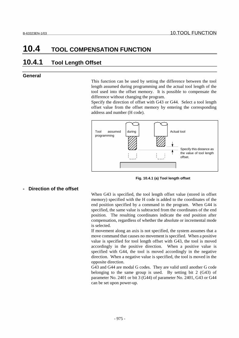
B-63323EN-1/03 10.TOOL FUNCTION
- 975 -
10.4 TOOL COMPENSATION FUNCTION
10.4.1 Tool Length Offset
GeneralThis function can be used by setting the difference between the toollength assumed during programming and the actual tool length of thetool used into the offset memory. It is possible to compensate thedifference without changing the program.Specify the direction of offset with G43 or G44. Select a tool lengthoffset value from the offset memory by entering the correspondingaddress and number (H code).
Fig. 10.4.1 (a) Tool length offset
- Direction of the offsetWhen G43 is specified, the tool length offset value (stored in offsetmemory) specified with the H code is added to the coordinates of theend position specified by a command in the program. When G44 isspecified, the same value is subtracted from the coordinates of the endposition. The resulting coordinates indicate the end position aftercompensation, regardless of whether the absolute or incremental modeis selected.If movement along an axis is not specified, the system assumes that amove command that causes no movement is specified. When a positivevalue is specified for tool length offset with G43, the tool is movedaccordingly in the positive direction. When a positive value isspecified with G44, the tool is moved accordingly in the negativedirection. When a negative value is specified, the tool is moved in theopposite direction.G43 and G44 are modal G codes. They are valid until another G codebelonging to the same group is used. By setting bit 2 (G43) ofparameter No. 2401 or bit 3 (G44) of parameter No. 2401, G43 or G44can be set upon power-up.
Specify this distance asthe value of tool lengthoffset.
Tool assumed duringprogramming
Actual tool

10.TOOL FUNCTION B-63323EN-1/03
- 976 -
- Specification of the tool length offset valueThe tool length offset value assigned to the number (offset number)specified in the H code is selected from offset memory and added to orsubtracted from the moving command in the program.The tool length offset value may be set in the offset memory throughthe MDI panel.The range of values that can be set as the tool length offset value is asfollows.
- Specifying offset along two or more axesWhen LXY (bit 4 of parameter No. 6000) is set to 1, offset can beperformed along any axes specified in the program. When two or moreaxes are specified, offset can be performed along all specified axes.
Offset in X and Y axes:G43 X_ Y_ H_ ;
- Canceling tool length compensationTo cancel the offset, command a G49 or assign offset H0. When G49 iscommanded, the canceling action is taken immediately.
When LXY, bit 4 of parameter No.6000, is set to 0 (tool lengthcompensation is applied along the Z-axis), the offset can be canceledsimply by specifying H00.When LXY, bit 4 of parameter No.6000, is set to 1, tool lengthcompensation is applied along the axis specified in the program.
G43 X_ H_ ; (specified tool length compensation along the X-axis):
G43 X_ H0 ; (Cancels tool length compensation along the X-axis)
Parameter
#7 #6 #5 #4 #3 #2 #1 #0
2401 G44 G43
���������� �� ��� ������
��������� ���
� � � � ��� ���
� � � � ��� ��� �������������������������� ���������������� ��������� ���
�� ��������������� � ��� ���������� !� ���"!� �#�� ����� �$%
G43 G44 G43, G44, or G49 mode
0 0 G49 mode
0 1 G44 mode
1 0 G43 mode

B-63323EN-1/03 10.TOOL FUNCTION
- 977 -
#7 #6 #5 #4 #3 #2 #1 #0
2409 K43
���������� �� ��� ������
��������� ���
� � � � ��& '�� (���!������� ����� � ������� � �)���������������*��� ��������
�������������� �������) ���������+���������������������� ��%
,- . � �%
/- 0���� � ��������*�%
#7 #6 #5 #4 #3 #2 #1 #0
6000 LXY EVO
���������� �� ��� ������
��������� ���
� � � � ��, 123 (���!������� �����!!�������)����*� ������ ���)����������4��� ��5
�� ������ �+������������!���� �����4��� ��5��������!! �%
,- 2� ������ ���)����������4��� ��5��� ������ �+������������!��%
/- 2� ������ ���)����������4��� ��5���!! �%
� � � � ��� 678 (���!������� �����4��������������� � �)���������������"��������$
������ ���������9:�4������� �������� ����� ��� � ��� �) ������4���"!�
���#�� ����� �$%
,- 9:�4������� �����%
/- ; ��� � ��� �) ������4��%

10.TOOL FUNCTION B-63323EN-1/03
- 978 -
#7 #6 #5 #4 #3 #2 #1 #0
6007 ZMV
���������� �� ��� ������
��������� ���
� � � � ��& 9#2 <�������!!����!���� � �)����������������������)�������������"678$
�!��� ��� �0�%�=,,,�������,���������,�"123$��!��� ��� �0�%�=,,,���
���/���������!!���������*� ���! ��-
0: A block to be buffered next;
1: A block containg the next Z-axis move command or H code command.
This parameter is valid only when bit 4 (LXY) of parameter No. 6000 is set to 0.
ZMV and bit 0 (EVO) of parameter No. 6000 have the following relationship:
ZMV
(No.6007#5)
EVO
(No.6000#0)
Time when a new offset becomes
valid
| 0 New offset becomes valid in a block
specifying the next H code.
0 1 New offset becomes valid in a block
to be buffered next.
1 1 New offset becomes valid in a block
specifying the next Z-axis move
command or H code.
Reference itemSeries15i/150i-MA Operator’s Manual
(Programming)(B-63324EN)
II-14.1 Tool lengthcompensation

B-63323EN-1/03 10.TOOL FUNCTION
- 979 -
10.4.2 Tool Offset
GeneralThe programmed travel distance of the tool can be increased ordecreased by a specified tool offset value or by twice the offset value.The tool offset function can also be applied to an additional axis.
Fig. 10.4.2 (a) Tool offset
Programmed pathTool center pathTool
Workpiece

10.TOOL FUNCTION B-63323EN-1/03
- 980 -
- Increase and decreaseAs shown in Fig. 10.4.2(a), the travel distance of the tool is increased ordecreased by the specified tool offset value.In the absolute mode, the travel distance is increased or decreased asthe tool is moved from the end position of the previous block to theposition specified by the block containing G45 to G48.
Table 10.4.2 (a) Increase and decrease of the tool travel distance
G code When a positive tool offsetvalue is specified
When a negative tool offsetvalue is specified
G45
G46
G47
G48
If a move command with a travel distance of zero is specified in the
incremental command (G91) mode, the tool is moved by the distancecorresponding to the specified tool offset value.If a move command with a travel distance of zero is specified in theabsolute command (G90) mode, the tool is not moved.
- Tool offset valueOnce selected by D code, the tool offset value remains unchanged untilanother tool offset value is selected.
Start position End position End positionStart position
End positionStart position Start position End position
Start position Start positionEnd position End position
Start position End positionStart position End position
Programmed movementTool offset valueActual movement position
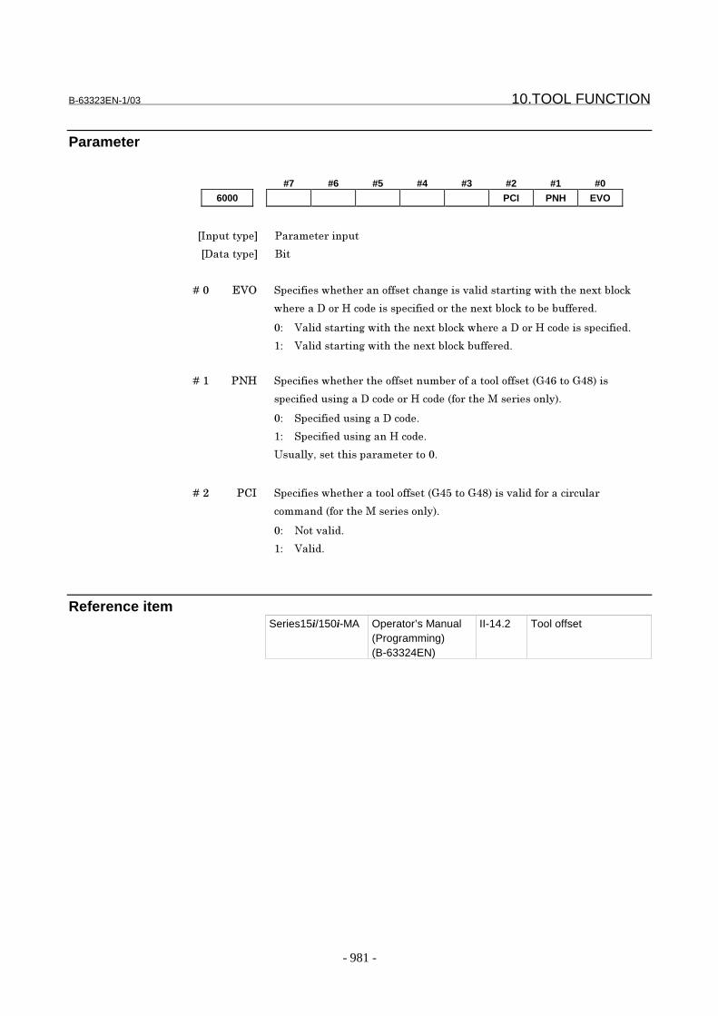
B-63323EN-1/03 10.TOOL FUNCTION
- 981 -
Parameter
#7 #6 #5 #4 #3 #2 #1 #0
6000 PCI PNH EVO
���������� �� ��� ������
��������� ���
� � � � ��, 123 (���!������� �����!!�������)����*� ������ ���)����������4��� ��5
�� ������ �+������������!���� �����4��� ��5��������!! �%
,- 2� ������ ���)����������4��� ��5��� ������ �+������������!��%
/- 2� ������ ���)����������4��� ��5���!! �%
� � � � ��/ �0+ (���!������� �����!!������� ��!������ ��!!���"��=������>$���
����!�������)���������� �+�����"!� ����#�� ����� �$%
,- (���!�������)��������%
/- (���!�������)����+����%
?��� ������������� ��� ����,%
� � � � ��� �.� (���!������� ������ ��!!���"��&������>$����*� ���!� ����� �� �
��������"!� ����#�� ����� �$%
,- 0���*� ��%
/- 2� ��%
Reference itemSeries15i/150i-MA Operator’s Manual
(Programming)(B-63324EN)
II-14.2 Tool offset
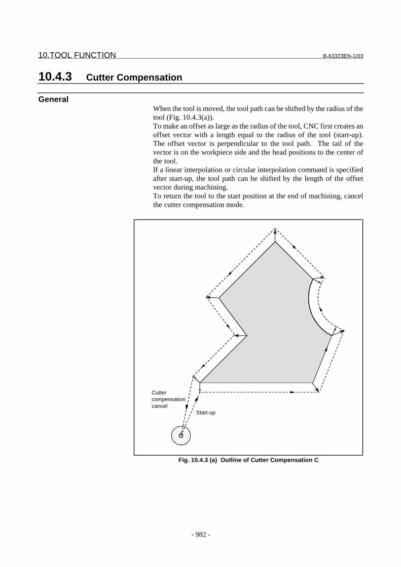
10.TOOL FUNCTION B-63323EN-1/03
- 982 -
10.4.3 Cutter Compensation
GeneralWhen the tool is moved, the tool path can be shifted by the radius of thetool (Fig. 10.4.3(a)).To make an offset as large as the radius of the tool, CNC first creates anoffset vector with a length equal to the radius of the tool (start-up).The offset vector is perpendicular to the tool path. The tail of thevector is on the workpiece side and the head positions to the center ofthe tool.If a linear interpolation or circular interpolation command is specifiedafter start-up, the tool path can be shifted by the length of the offsetvector during machining.To return the tool to the start position at the end of machining, cancelthe cutter compensation mode.
Fig. 10.4.3 (a) Outline of Cutter Compensation C
Start-up
Cuttercompensationcancel
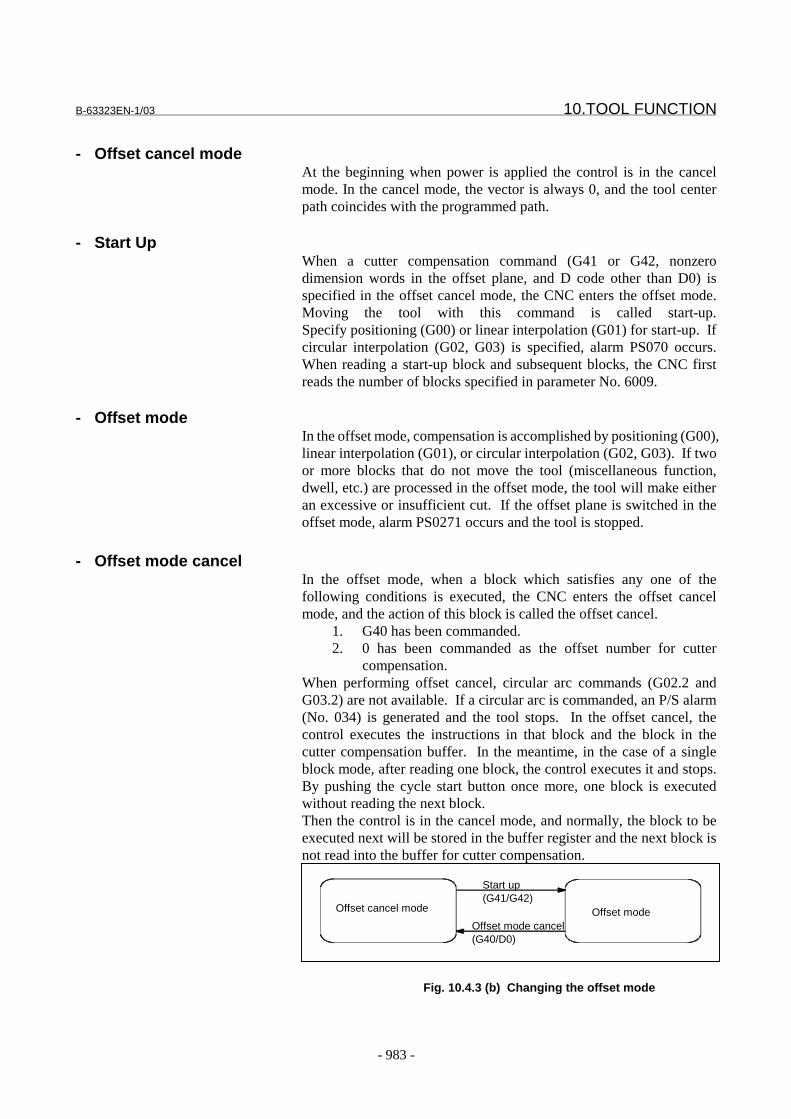
B-63323EN-1/03 10.TOOL FUNCTION
- 983 -
- Offset cancel modeAt the beginning when power is applied the control is in the cancelmode. In the cancel mode, the vector is always 0, and the tool centerpath coincides with the programmed path.
- Start UpWhen a cutter compensation command (G41 or G42, nonzerodimension words in the offset plane, and D code other than D0) isspecified in the offset cancel mode, the CNC enters the offset mode.Moving the tool with this command is called start-up.Specify positioning (G00) or linear interpolation (G01) for start-up. Ifcircular interpolation (G02, G03) is specified, alarm PS070 occurs.When reading a start-up block and subsequent blocks, the CNC firstreads the number of blocks specified in parameter No. 6009.
- Offset modeIn the offset mode, compensation is accomplished by positioning (G00),linear interpolation (G01), or circular interpolation (G02, G03). If twoor more blocks that do not move the tool (miscellaneous function,dwell, etc.) are processed in the offset mode, the tool will make eitheran excessive or insufficient cut. If the offset plane is switched in theoffset mode, alarm PS0271 occurs and the tool is stopped.
- Offset mode cancelIn the offset mode, when a block which satisfies any one of thefollowing conditions is executed, the CNC enters the offset cancelmode, and the action of this block is called the offset cancel.
1. G40 has been commanded.2. 0 has been commanded as the offset number for cutter
compensation.When performing offset cancel, circular arc commands (G02.2 andG03.2) are not available. If a circular arc is commanded, an P/S alarm(No. 034) is generated and the tool stops. In the offset cancel, thecontrol executes the instructions in that block and the block in thecutter compensation buffer. In the meantime, in the case of a singleblock mode, after reading one block, the control executes it and stops.By pushing the cycle start button once more, one block is executedwithout reading the next block.Then the control is in the cancel mode, and normally, the block to beexecuted next will be stored in the buffer register and the next block isnot read into the buffer for cutter compensation.
Fig. 10.4.3 (b) Changing the offset mode
Offset cancel mode Offset modeOffset mode cancel(G40/D0)
Start up(G41/G42)
10.TOOL FUNCTION B-63323EN-1/03
- 984 -
- Setting the cutter compensation valueAssign a cutter compensation values to the D codes on the MDI panel.
- Offset vectorThe offset vector is the two dimensional vector that is equal to thecutter compensation value assigned by D code. It is calculated insidethe control unit, and its direction is up-dated in accordance with theprogress of the tool in each block.The offset vector is deleted by reset.
- Specifying a cutter compensation valueSpecify a cutter compensation value with a number assigned to it. Thenumber consists of 1 to 3 digits after address D (D code). The D code isvalid until another D code is specified. The D code is used to specifythe tool offset value as well as the cutter compensation value.
- Plane selection and vectorOffset calculation is carried out in the plane determined by G17, G18and G19, (G codes for plane selection). This plane is called the offsetplane.Compensation is not executed for the coordinate of a position which isnot in the specified plane. The programmed values are used as they areIn simultaneous 3 axes control, the tool path projected on the offsetplane is compensated.The offset plane is changed during the offset cancel mode. If it isperformed during the offset mode, a alarm (PS0271) is displayed andthe machine is stopped.
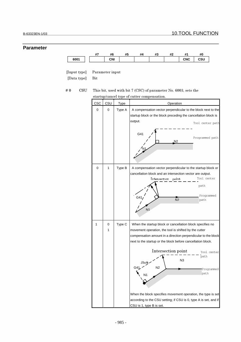
B-63323EN-1/03 10.TOOL FUNCTION
- 985 -
Parameter#7 #6 #5 #4 #3 #2 #1 #0
6001 CNI CNC CSU
���������� �� ��� ������
��������� ���
� � � � ��, .(? @����������������������A�".(.$��!��� ��� �0�%�=,,���������
��� ���B���� ������!����� ������������%
CSC CSU Type Operation
0 0 Type A A compensation vector perpendicular to the block next to the
startup block or the block preceding the cancellation block is
output.
0 1 Type B A compensation vector perpendicular to the startup block or
cancellation block and an intersection vector are output.
1 0
1
Type C When the startup block or cancellation block specifies no
movement operation, the tool is shifted by the cutter
compensation amount in a direction perpendicular to the block
next to the startup or the block before cancellation block.
When the block specifies movement operation, the type is set
according to the CSU setting; if CSU is 0, type A is set, and if
CSU is 1, type B is set.
Tool center path
Programmed path
N1
N2
G41
N1
N2
N3
��� ������������
�����
G41
Tool center
path
N1
N2
���������� �����
G41Programmedpath
Programmedpath
Tool centerpath
10.TOOL FUNCTION B-63323EN-1/03
- 986 -
� � � � ��/ .0. @����������������������=�".0�$��!��� ��� �0�%�=,,/��� ������������
!� ���5��)������� ! ������5�������� ����������������%
CNI CNC Operation
0 0 Interference check is enabled. The direction and the anlgle of
an arc are checked.
0 1 Interference check is enabled. Only the angle of an arc is
checked.
1 | Interference check is disabled.
For the operation taken when the interference check shows the occurrence of an
rference (overcutting), see the description of bit 5 (CAV) of parameter No. 6008.
NOTEChecking of only the direction cannot be set.
� � � � ��= .0� (���!������� ������� ! ������5����������� ����������������
���*� ��%
,- 2� ��%� � ��������)�����/�".0.$��!��� ��� �0�%�=,,/������ �����
���5������� �� � ���) ����5�� ����%
/- 0���*� ��%
#7 #6 #5 #4 #3 #2 #1 #0
6003 CSC
���������� �� ��� ������
��������� ���
� � � � ��A .(. (���!�����������!��� ������������ !� ��������� �:������
���� �������!���� ������!!���������� �������������� ��� :
��������� ����� ������������%
,- @���;�� ������%� � "<��������������������� ������������,�".(?$
�!��� ��� �0�%�=,,/%$
/- @���.%
#7 #6 #5 #4 #3 #2 #1 #0
6005 AIM
���������� �� ��� ������
��������� ���
B-63323EN-1/03 10.TOOL FUNCTION
- 987 -
� � � � ��/ ;�# (���!������� ������������� � ���������� ���������������
����!���������#������%
0: Issue no alarm. (In this case, cutter compensation is enabled for commands in
the MDI mode, and an intersection calculation is made. If MDI intervention is
performed, however, no intersection calculation is made, and the previous
vector is held.)
1: Issue an alarm (PS0275).
#7 #6 #5 #4 #3 #2 #1 #0
6008 NAG NAA CAV CCC
���������� �� ��� ������
��������� ���
� � � � ��� ... (���!������� ���������!���� ��� � ���������������������
������������������� ��� ���������������� ��� �� � ��������������%
,- 6��� ��������������
/- .� �� � ��������������
� � � � ��& .;2 (���!����� ������������ !� ������������� ! ������5����
������������� ����!���� ! ���"�* ������)$%
,- ;��� � ��"�(,�A�$�����������������������)�����������"��� ! ��
���5�� � ��!�������$%
/- @����� �������������)������*������� ! ���"�* ������)$�����
��������)�������������"��� ! ������5��*�������!�������$%
C� �����������!���� ! ������5���������� ���������!�����/�".0�$��!
�� ��� �0�%�=,,/���������=�".;2$��!��� ��� �0�%�=,,/%
� � � � ��= 0;; �!������� ! ������5��*�������!��������D��)�����������*������
�� �������� ������) ����� ������!� �� ���� ! ����� ����� �!� ���
��� ! ����*�������*��� �����!� ����)����������5��� ��-
,- ;��� � ����������%
� � � � �!�����*��������� ����������� �������������) ������ � �
�(,�A>���������%
� � � � �!�!� �� ���� ! ���!� ������� ! ����*�������*��� ���
�� ������� � ���(,�A����������%
/- @���*��������� �������� �����������������������)������ � �%
NOTENormally, this bit should be set to 0.
� � � � ��A 0;� �!����)���*��� � �)���!� ������� ! ������5��*�������!��������!�
���� ����������������,-
,- ;*����������� !� ��%
/-� � ;*��������������� !� ��%

10.TOOL FUNCTION B-63323EN-1/03
- 988 -
6009 Number of blocks to be read in the cutter compensation mode
���������� (����)������
��������� ���)
�2� �������� ��) ��:�>
(���!��������� ��!�� ��5������� ������������� ����������������%
�!���*� ��E�� ����� � �����������������!�����������!���������!���� ��5�
���������%� � �!���*� ��E�� ����� �) �� ������>��������!������
����!���������!�>�� ��5�����������%� � ;���� �� ��5��� � ������
�* ������)�"��� ! ��$�!� ���������������!� �������� �� ��5�
����%� � ����������������* ���� �� ��5��� � ���������� �F�����
������� ��) �� ��5�� ������)�������� E�� �%
@������ ��� ����������� ��������� ���������#���������������
�������)�������� ����������������%� � @����������)��!�����
�� ��� ������� ������������� �����������������������
���� ���������������������)���%

B-63323EN-1/03 10.TOOL FUNCTION
- 989 -
6010 Limit for ignoring the small movement resulting from cutter compensation
���������� (����)������
��������� G�
�?�����!����� ���������"����������$
�#�������������!����� �������������� �����������!���� ! ����4��
�2� �������� ��) ����)����!���������������!������" ! ���������� ���� ��� ������)
��� ";$$
"<��������� ��������������(:���:������%����:�H������%���$
When the tool moves around a corner in cutter compensation mode, the limit for
ignoring the small travel amount resulting from cutter compensation is set. This
limit eliminates the interruption of buffering caused by the small travel amount
generated at the corner and any change in feedrate due to the interruption.
Even if ∆Vx≤∆Vlimit and ∆VY≤∆Vlimit, vector to single-block stop pointremains.
Tool center path
Programmed path
If ∆Vx≤∆Vlimit and ∆VY
≤∆Vlimit, this vector is ignored.
S∆VY
∆Vx
r
∆Vlimit is determined depending on the setting in parameter No. 6010.
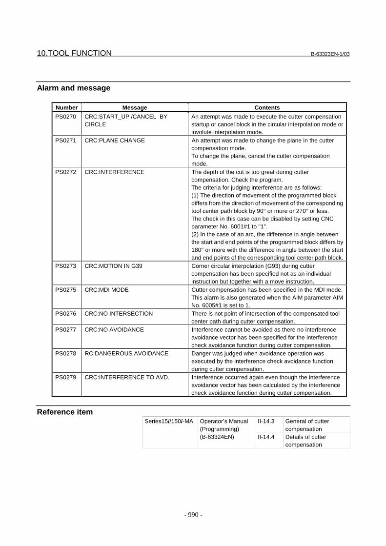
10.TOOL FUNCTION B-63323EN-1/03
- 990 -
Alarm and message
Number Message Contents
PS0270 CRC:START_UP /CANCEL BYCIRCLE
An attempt was made to execute the cutter compensationstartup or cancel block in the circular interpolation mode orinvolute interpolation mode.
PS0271 CRC:PLANE CHANGE An attempt was made to change the plane in the cuttercompensation mode.To change the plane, cancel the cutter compensationmode.
PS0272 CRC:INTERFERENCE The depth of the cut is too great during cuttercompensation. Check the program.The criteria for judging interference are as follows:(1) The direction of movement of the programmed blockdiffers from the direction of movement of the correspondingtool center path block by 90° or more or 270° or less.The check in this case can be disabled by setting CNCparameter No. 6001#1 to "1".(2) In the case of an arc, the difference in angle betweenthe start and end points of the programmed block differs by180° or more with the difference in angle between the startand end points of the corresponding tool center path block.
PS0273 CRC:MOTION IN G39 Corner circular interpolation (G93) during cuttercompensation has been specified not as an individualinstruction but together with a move instruction.
PS0275 CRC:MDI MODE Cutter compensation has been specified in the MDI mode.This alarm is also generated when the AIM parameter AIMNo. 6005#1 is set to 1.
PS0276 CRC:NO INTERSECTION There is not point of intersection of the compensated toolcenter path during cutter compensation.
PS0277 CRC:NO AVOIDANCE Interference cannot be avoided as there no interferenceavoidance vector has been specified for the interferencecheck avoidance function during cutter compensation.
PS0278 RC:DANGEROUS AVOIDANCE Danger was judged when avoidance operation wasexecuted by the interference check avoidance functionduring cutter compensation.
PS0279 CRC:INTERFERENCE TO AVD. Interference occurred again even though the interferenceavoidance vector has been calculated by the interferencecheck avoidance function during cutter compensation.
Reference itemII-14.3 General of cutter
compensationSeries15i/150i-MA Operator’s Manual
(Programming)(B-63324EN) II-14.4 Details of cutter
compensation

B-63323EN-1/03 10.TOOL FUNCTION
- 991 -
10.4.4 Three-dimensional Tool Compensation
GeneralIn cutter compensation, two-dimensional offset is performed for aselected plane. In three-dimensional tool compensation, the tool can beshifted three-dimensionally when a three-dimensional offset directionis programmed.
Fig. 10.4.4 (a) Three-dimensional tool compensation valueAs shown in Fig. 10.4.4 (a), the tool is moved with the tool centercoordinates (x’, y’, z’) shifted from the programmed coordinates (x, y, z)by the tool offset value, according to the programmed surface normalvector (I, J, K). In this case, the three-dimensional tool compensationvector has the same magnitude as the tool offset value and the samedirection as that of the surface normal vector (I, J, K).
Tool center coordinatevalue (x’, y’, z’)
Surface normal directionvector(I, J, K)
Program coordinate value,(x, y, z)
Tool compensation value
Three-dimensional toolcompensation vector
X(I)Y(J)
Z(K)
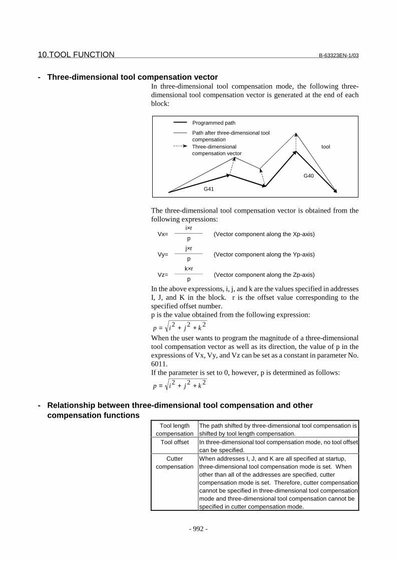
10.TOOL FUNCTION B-63323EN-1/03
- 992 -
- Three-dimensional tool compensation vectorIn three-dimensional tool compensation mode, the following three-dimensional tool compensation vector is generated at the end of eachblock:
The three-dimensional tool compensation vector is obtained from thefollowing expressions:
i×rVx=
p(Vector component along the Xp-axis)
j×rVy=
p(Vector component along the Yp-axis)
k×rVz=
p(Vector component along the Zp-axis)
In the above expressions, i, j, and k are the values specified in addressesI, J, and K in the block. r is the offset value corresponding to thespecified offset number.p is the value obtained from the following expression:
222 kjip ++=When the user wants to program the magnitude of a three-dimensionaltool compensation vector as well as its direction, the value of p in theexpressions of Vx, Vy, and Vz can be set as a constant in parameter No.6011.If the parameter is set to 0, however, p is determined as follows:
222 kjip ++=
- Relationship between three-dimensional tool compensation and othercompensation functions
Tool lengthcompensation
The path shifted by three-dimensional tool compensation isshifted by tool length compensation.
Tool offset In three-dimensional tool compensation mode, no tool offsetcan be specified.
Cuttercompensation
When addresses I, J, and K are all specified at startup,three-dimensional tool compensation mode is set. Whenother than all of the addresses are specified, cuttercompensation mode is set. Therefore, cutter compensationcannot be specified in three-dimensional tool compensationmode and three-dimensional tool compensation cannot bespecified in cutter compensation mode.
Programmed path
Path after three-dimensional toolcompensationThree-dimensional toolcompensation vector
G41
G40
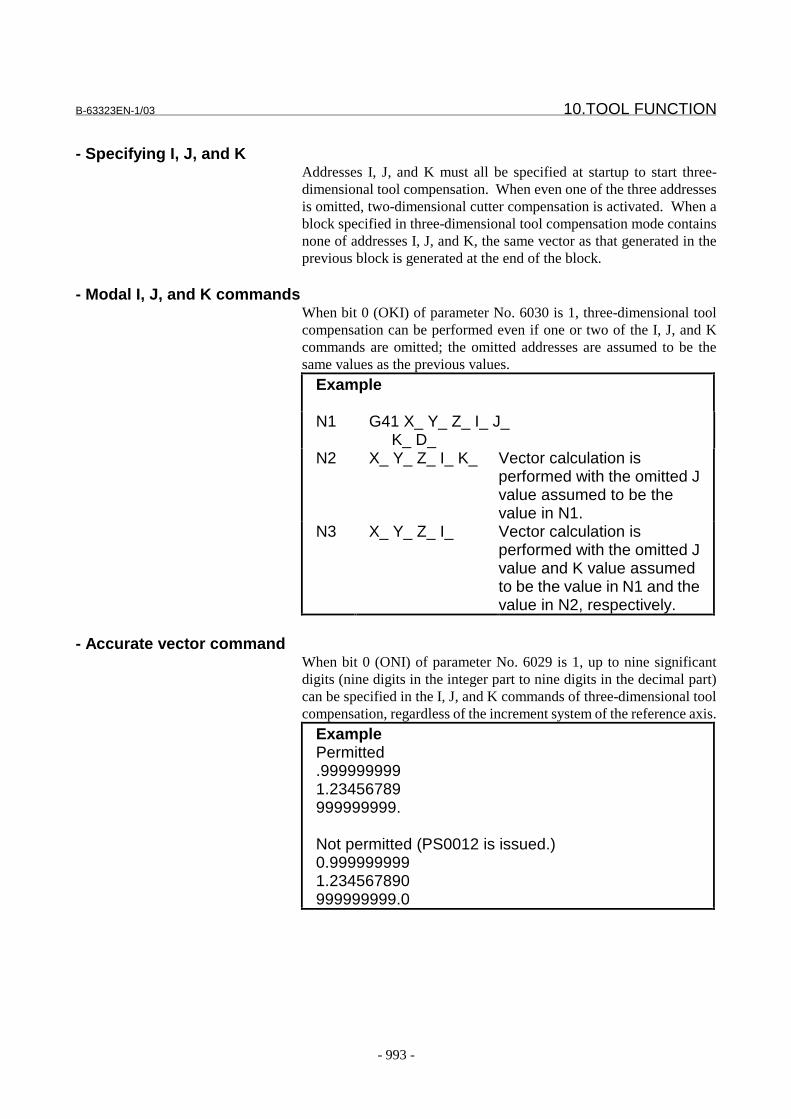
B-63323EN-1/03 10.TOOL FUNCTION
- 993 -
- Specifying I, J, and KAddresses I, J, and K must all be specified at startup to start three-dimensional tool compensation. When even one of the three addressesis omitted, two-dimensional cutter compensation is activated. When ablock specified in three-dimensional tool compensation mode containsnone of addresses I, J, and K, the same vector as that generated in theprevious block is generated at the end of the block.
- Modal I, J, and K commandsWhen bit 0 (OKI) of parameter No. 6030 is 1, three-dimensional toolcompensation can be performed even if one or two of the I, J, and Kcommands are omitted; the omitted addresses are assumed to be thesame values as the previous values.
Example
N1 G41 X_ Y_ Z_ I_ J_K_ D_
N2 X_ Y_ Z_ I_ K_ Vector calculation isperformed with the omitted Jvalue assumed to be thevalue in N1.
N3 X_ Y_ Z_ I_ Vector calculation isperformed with the omitted Jvalue and K value assumedto be the value in N1 and thevalue in N2, respectively.
- Accurate vector commandWhen bit 0 (ONI) of parameter No. 6029 is 1, up to nine significantdigits (nine digits in the integer part to nine digits in the decimal part)can be specified in the I, J, and K commands of three-dimensional toolcompensation, regardless of the increment system of the reference axis.
ExamplePermitted.9999999991.23456789999999999.
Not permitted (PS0012 is issued.)0.9999999991.234567890999999999.0

10.TOOL FUNCTION B-63323EN-1/03
- 994 -
NOTE1 When bit 0 (ONI) of parameter No. 6029 is 1, the
functions using the I, J, and K commands listedbelow must not be used in three-dimensional toolcompensation mode. Otherwise, the PS0282alarm is issued.Exponential interpolation (I, J, and K commands ofG02.3/G03.2)Canned cycle shift amount (I and J commands ofG76 and G87)Type 2 of tool center point control (I, J, and Kcommands of G43.5)Direction of rigid tapping orientation (I command ofG84.2/G84.3)
2 When bit 0 (ONI) of parameter No. 6029 is 1, the I,J, and K commands must be specified using thedecimal point. If these commands are specifiedwithout the decimal point, a PS0283 alarm isissued.
3 When bit 0 (ONI) of parameter No. 6029 is 1, macrovariables cannot be used for the I, J, and Kcommands.
- Offset vector in interpolationWhen circular interpolation, helical interpolation (both specified withG02, G03), or involute interpolation (G02.2, G03.2) is specified, thevector generated in the previous block is maintained.
- Alarm in three-dimensional tool compensation modeIf one of the following G codes is specified in three-dimensional toolcompensation mode, an alarm is issued:
G31 Skip function (PS alarm No. 0282)G37 Automatic tool length measurement
(PS alarm No. 0282)
Vector generated in the block before an arc
Programmed path
Path after three-dimensionaltool compensation
Three-dimensional tool compensation vector
The same vector is generated.
B-63323EN-1/03 10.TOOL FUNCTION
- 995 -
Parameter6011 Constant denominator for three-dimensional tool compensation or tool
length compensation in a specified direction
���������� ����� ������
��������� ���
������������� ���������������������
��������������������� �����������������������������������������
� ������������� !��� ���������������������������������������������������������
��"��#��
�$�������������������������%&��%!!!!!!'!!!�%�(!!!!!!'!!!�
������������ �����������������������)����'
$�������������������������*�� 222 KJI ++ ������'
#7 #6 #5 #4 #3 #2 #1 #0
6029 ONI
���������� ����� ������
��������� &��
� � � � +�* ,-� .�����/������0����������������%������������������������������
����������������1�2
0: The increment system of the reference axis is used.
1: Up to nine significant digits (nine digits in the integer part to nine digits in the
decimal part) can be specified.
NOTEWhen this parameter is set to 1, the I, J, and K commands ofthree-dimensional tool compensation must be specified using thedecimal point. If these commands are specified without thedecimal point, alarm PS0283 is issued.
10.TOOL FUNCTION B-63323EN-1/03
- 996 -
#7 #6 #5 #4 #3 #2 #1 #0
6030 OKI
���������� 3������������
��������� &��
� � � � +�* ,0� .�����/������0����������������%�������������������������������
����������2
0: The conventional specifications.
- When the I, J, and K commands are all omitted in three-dimensional tool
compensation mode, the previous vector is maintained.
- When one or two of the I, J, and K commands are omitted in three-dimensional
tool compensation mode, their components are assumed to be 0.
1: The new specifications.
- When the I, J, and K commands are all omitted in three-dimensional tool
compensation mode, the previous vector is maintained.
- When one or two of the I, J, and K commands are omitted in three-dimensional
tool compensation mode, the previous values are assumed.
Alarm and message
Number Message Contents
PS0282 ILLEGAL COMMAND IN 3-D OFFSET An illegal G code was specified in the 3-dimensional tooloffset mode. Skip instructions and tool lengthmeasurement cannot be specified.
PS0283 ILLEGAL IJK IN 3-D OFFSET When bit 0 (ONI) of parameter No. 6029 is 1, the I, J, and Kcommands are specified without the decimal point inthree-dimensional tool compensation mode.
Reference itemSeries15i/150i-MA Operator’s Manual
(Programming)(B-63324EN)
II-14.5 Three dimensional tooloffset
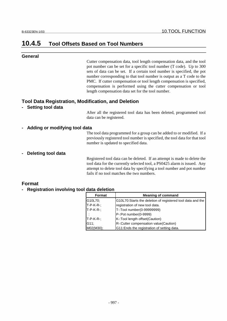
B-63323EN-1/03 10.TOOL FUNCTION
- 997 -
10.4.5 Tool Offsets Based on Tool Numbers
GeneralCutter compensation data, tool length compensation data, and the toolpot number can be set for a specific tool number (T code). Up to 300sets of data can be set. If a certain tool number is specified, the potnumber corresponding to that tool number is output as a T code to thePMC. If cutter compensation or tool length compensation is specified,compensation is performed using the cutter compensation or toollength compensation data set for the tool number.
Tool Data Registration, Modification, and Deletion- Setting tool data
After all the registered tool data has been deleted, programmed tooldata can be registered.
- Adding or modifying tool dataThe tool data programmed for a group can be added to or modified. If apreviously registered tool number is specified, the tool data for that toolnumber is updated to specified data.
- Deleting tool dataRegistered tool data can be deleted. If an attempt is made to delete thetool data for the currently selected tool, a PS0425 alarm is issued. Anyattempt to delete tool data by specifying a tool number and pot numberfails if no tool matches the two numbers.
Format- Registration involving tool data deletion
Format Meaning of command
G10L70;T-P-K-R-;T-P-K-R-; :T-P-K-R-;G11;M02(M30);
G10L70:Starts the deletion of registered tool data and theregistration of new tool data.T-:Tool number(0-99999999)P-:Pot number(0-9999)K-:Tool length offset(Caution)R-:Cutter compensation value(Caution)G11:Ends the registration of setting data.
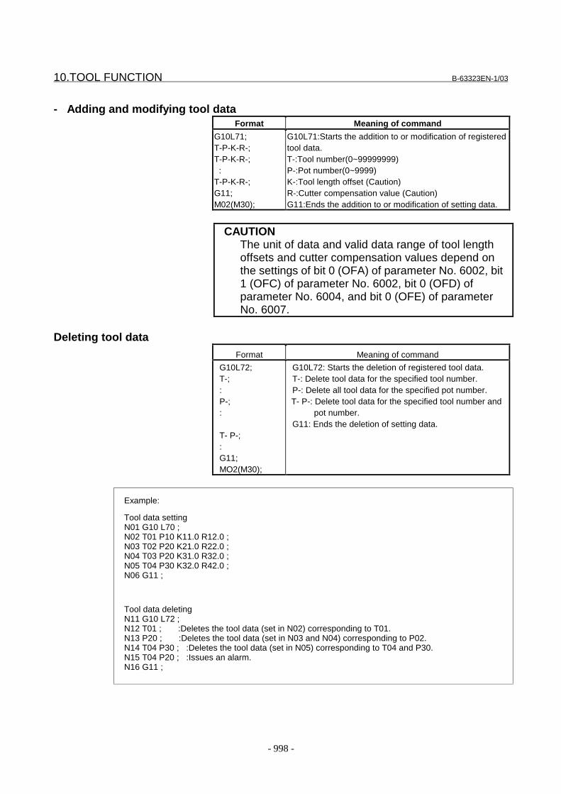
10.TOOL FUNCTION B-63323EN-1/03
- 998 -
- Adding and modifying tool dataFormat Meaning of command
G10L71;T-P-K-R-;T-P-K-R-; :T-P-K-R-;G11;M02(M30);
G10L71:Starts the addition to or modification of registeredtool data.T-:Tool number(0~99999999)P-:Pot number(0~9999)K-:Tool length offset (Caution)R-:Cutter compensation value (Caution)G11:Ends the addition to or modification of setting data.
CAUTIONThe unit of data and valid data range of tool lengthoffsets and cutter compensation values depend onthe settings of bit 0 (OFA) of parameter No. 6002, bit1 (OFC) of parameter No. 6002, bit 0 (OFD) ofparameter No. 6004, and bit 0 (OFE) of parameterNo. 6007.
Deleting tool dataFormat Meaning of command
G10L72;T-;:P-;:
T- P-;:G11;MO2(M30);
G10L72: Starts the deletion of registered tool data.T-: Delete tool data for the specified tool number.P-: Delete all tool data for the specified pot number.T- P-: Delete tool data for the specified tool number and
pot number.G11: Ends the deletion of setting data.
Example:
Tool data settingN01 G10 L70 ;N02 T01 P10 K11.0 R12.0 ;N03 T02 P20 K21.0 R22.0 ;N04 T03 P20 K31.0 R32.0 ;N05 T04 P30 K32.0 R42.0 ;N06 G11 ;
Tool data deletingN11 G10 L72 ;N12 T01 ; :Deletes the tool data (set in N02) corresponding to T01.N13 P20 ; :Deletes the tool data (set in N03 and N04) corresponding to P02.N14 T04 P30 ; :Deletes the tool data (set in N05) corresponding to T04 and P30.N15 T04 P20 ; :Issues an alarm.N16 G11 ;
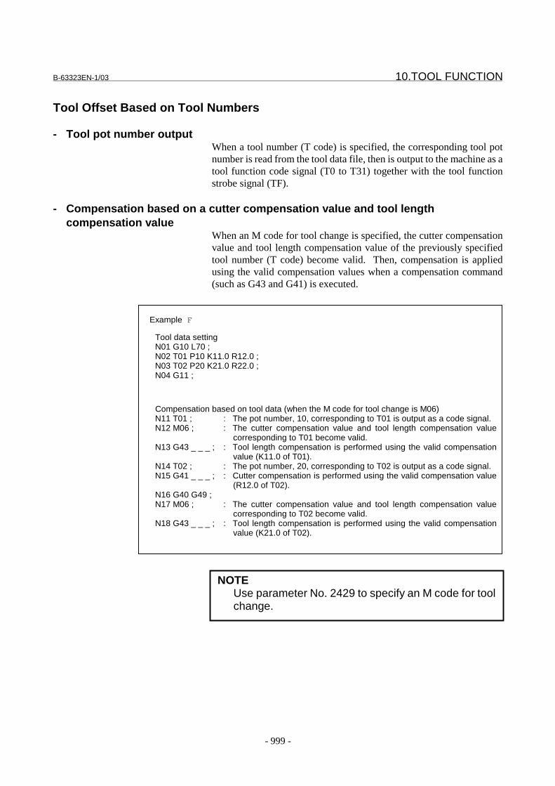
B-63323EN-1/03 10.TOOL FUNCTION
- 999 -
Tool Offset Based on Tool Numbers
- Tool pot number outputWhen a tool number (T code) is specified, the corresponding tool potnumber is read from the tool data file, then is output to the machine as atool function code signal (T0 to T31) together with the tool functionstrobe signal (TF).
- Compensation based on a cutter compensation value and tool lengthcompensation value
When an M code for tool change is specified, the cutter compensationvalue and tool length compensation value of the previously specifiedtool number (T code) become valid. Then, compensation is appliedusing the valid compensation values when a compensation command(such as G43 and G41) is executed.
NOTEUse parameter No. 2429 to specify an M code for toolchange.
Example F
Tool data settingN01 G10 L70 ;N02 T01 P10 K11.0 R12.0 ;N03 T02 P20 K21.0 R22.0 ;N04 G11 ;
Compensation based on tool data (when the M code for tool change is M06)N11 T01 ; : The pot number, 10, corresponding to T01 is output as a code signal.N12 M06 ; : The cutter compensation value and tool length compensation value
corresponding to T01 become valid.N13 G43 _ _ _ ; : Tool length compensation is performed using the valid compensation
value (K11.0 of T01).N14 T02 ; : The pot number, 20, corresponding to T02 is output as a code signal.N15 G41 _ _ _ ; : Cutter compensation is performed using the valid compensation value
(R12.0 of T02).N16 G40 G49 ;N17 M06 ; : The cutter compensation value and tool length compensation value
corresponding to T02 become valid.N18 G43 _ _ _ ; : Tool length compensation is performed using the valid compensation
value (K21.0 of T02).
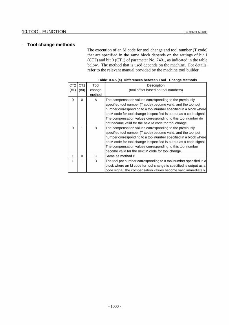
10.TOOL FUNCTION B-63323EN-1/03
- 1000 -
- Tool change methodsThe execution of an M code for tool change and tool number (T code)that are specified in the same block depends on the settings of bit 1(CT2) and bit 0 (CT1) of parameter No. 7401, as indicated in the tablebelow. The method that is used depends on the machine. For details,refer to the relevant manual provided by the machine tool builder.
Table10.4.5 (a) Differences between Tool Change Methods
CT2(#1)
CT1(#0)
Toolchangemethod
Description(tool offset based on tool numbers)
0 0 A The compensation values corresponding to the previouslyspecified tool number (T code) become valid, and the tool potnumber corresponding to a tool number specified in a block wherean M code for tool change is specified is output as a code signal.The compensation values corresponding to this tool number donot become valid for the next M code for tool change.
0 1 B The compensation values corresponding to the previouslyspecified tool number (T code) become valid, and the tool potnumber corresponding to a tool number specified in a block wherean M code for tool change is specified is output as a code signal.The compensation values corresponding to this tool numberbecome valid for the next M code for tool change.
1 0 C Same as method B1 1 D The tool pot number corresponding to a tool number specified in a
block where an M code for tool change is specified is output as acode signal; the compensation values become valid immediately.
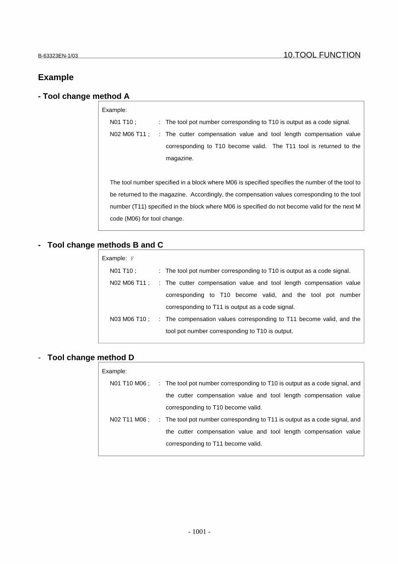
B-63323EN-1/03 10.TOOL FUNCTION
- 1001 -
Example
- Tool change method A
Example:
N01 T10 ; : The tool pot number corresponding to T10 is output as a code signal.
N02 M06 T11 ; : The cutter compensation value and tool length compensation value
corresponding to T10 become valid. The T11 tool is returned to the
magazine.
The tool number specified in a block where M06 is specified specifies the number of the tool to
be returned to the magazine. Accordingly, the compensation values corresponding to the tool
number (T11) specified in the block where M06 is specified do not become valid for the next M
code (M06) for tool change.
- Tool change methods B and C
Example: F
N01 T10 ; : The tool pot number corresponding to T10 is output as a code signal.
N02 M06 T11 ; : The cutter compensation value and tool length compensation value
corresponding to T10 become valid, and the tool pot number
corresponding to T11 is output as a code signal.
N03 M06 T10 ; : The compensation values corresponding to T11 become valid, and the
tool pot number corresponding to T10 is output.
- Tool change method D
Example:
N01 T10 M06 ; : The tool pot number corresponding to T10 is output as a code signal, and
the cutter compensation value and tool length compensation value
corresponding to T10 become valid.
N02 T11 M06 ; : The tool pot number corresponding to T11 is output as a code signal, and
the cutter compensation value and tool length compensation value
corresponding to T11 become valid.
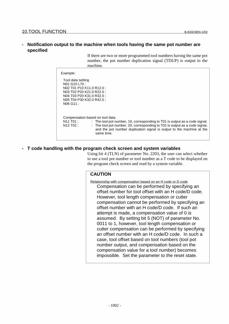
10.TOOL FUNCTION B-63323EN-1/03
- 1002 -
- Notification output to the machine when tools having the same pot number arespecified
If there are two or more programmed tool numbers having the same potnumber, the pot number duplication signal (TDUP) is output to themachine.
Example:
Tool data settingN01 G10 L70 ;N02 T01 P10 K11.0 R12.0 ;N03 T02 P20 K21.0 R22.0 ;N04 T03 P20 K31.0 R32.0 ;N05 T04 P30 K32.0 R42.0 ;N06 G11 ;
Compensation based on tool dataN11 T01 ; : The tool pot number, 10, corresponding to T01 is output as a code signal.N12 T02 ; : The tool pot number, 20, corresponding to T02 is output as a code signal,
and the pot number duplication signal is output to the machine at thesame time.
- T code handling with the program check screen and system variablesUsing bit 4 (TLN) of parameter No. 2203, the user can select whetherto use a tool pot number or tool number as a T code to be displayed onthe program check screen and read by a system variable.
CAUTION
Relationship with compensation based on an H code or D code
Compensation can be performed by specifying anoffset number for tool offset with an H code/D code.However, tool length compensation or cuttercompensation cannot be performed by specifying anoffset number with an H code/D code. If such anattempt is made, a compensation value of 0 isassumed. By setting bit 5 (NOT) of parameter No.0011 to 1, however, tool length compensation orcutter compensation can be performed by specifyingan offset number with an H code/D code. In such acase, tool offset based on tool numbers (tool potnumber output, and compensation based on thecompensation value for a tool number) becomesimpossible. Set the parameter to the reset state.
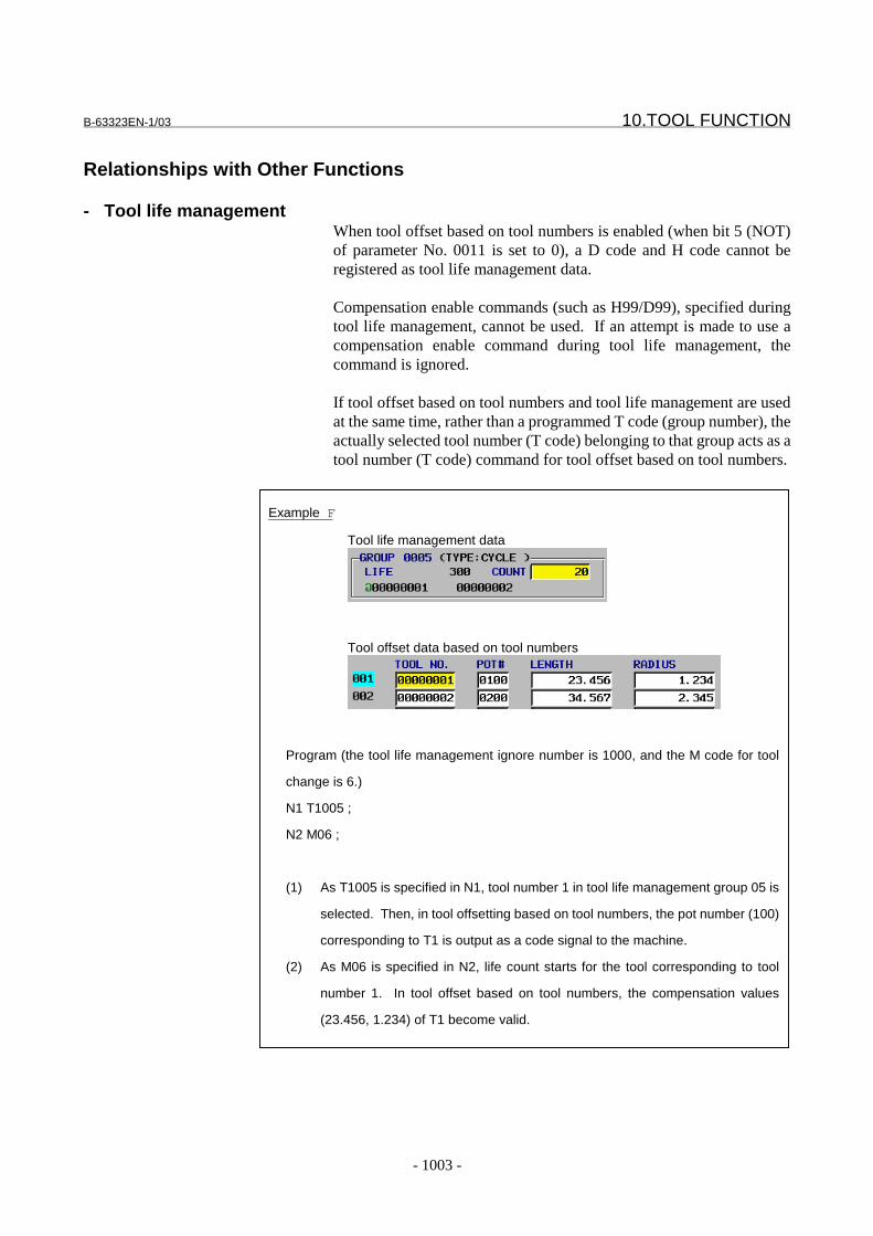
B-63323EN-1/03 10.TOOL FUNCTION
- 1003 -
Example F
Tool life management data
Tool offset data based on tool numbers
Program (the tool life management ignore number is 1000, and the M code for tool
change is 6.)
N1 T1005 ;
N2 M06 ;
(1) As T1005 is specified in N1, tool number 1 in tool life management group 05 is
selected. Then, in tool offsetting based on tool numbers, the pot number (100)
corresponding to T1 is output as a code signal to the machine.
(2) As M06 is specified in N2, life count starts for the tool corresponding to tool
number 1. In tool offset based on tool numbers, the compensation values
(23.456, 1.234) of T1 become valid.
Relationships with Other Functions
- Tool life managementWhen tool offset based on tool numbers is enabled (when bit 5 (NOT)of parameter No. 0011 is set to 0), a D code and H code cannot beregistered as tool life management data.
Compensation enable commands (such as H99/D99), specified duringtool life management, cannot be used. If an attempt is made to use acompensation enable command during tool life management, thecommand is ignored.
If tool offset based on tool numbers and tool life management are usedat the same time, rather than a programmed T code (group number), theactually selected tool number (T code) belonging to that group acts as atool number (T code) command for tool offset based on tool numbers.
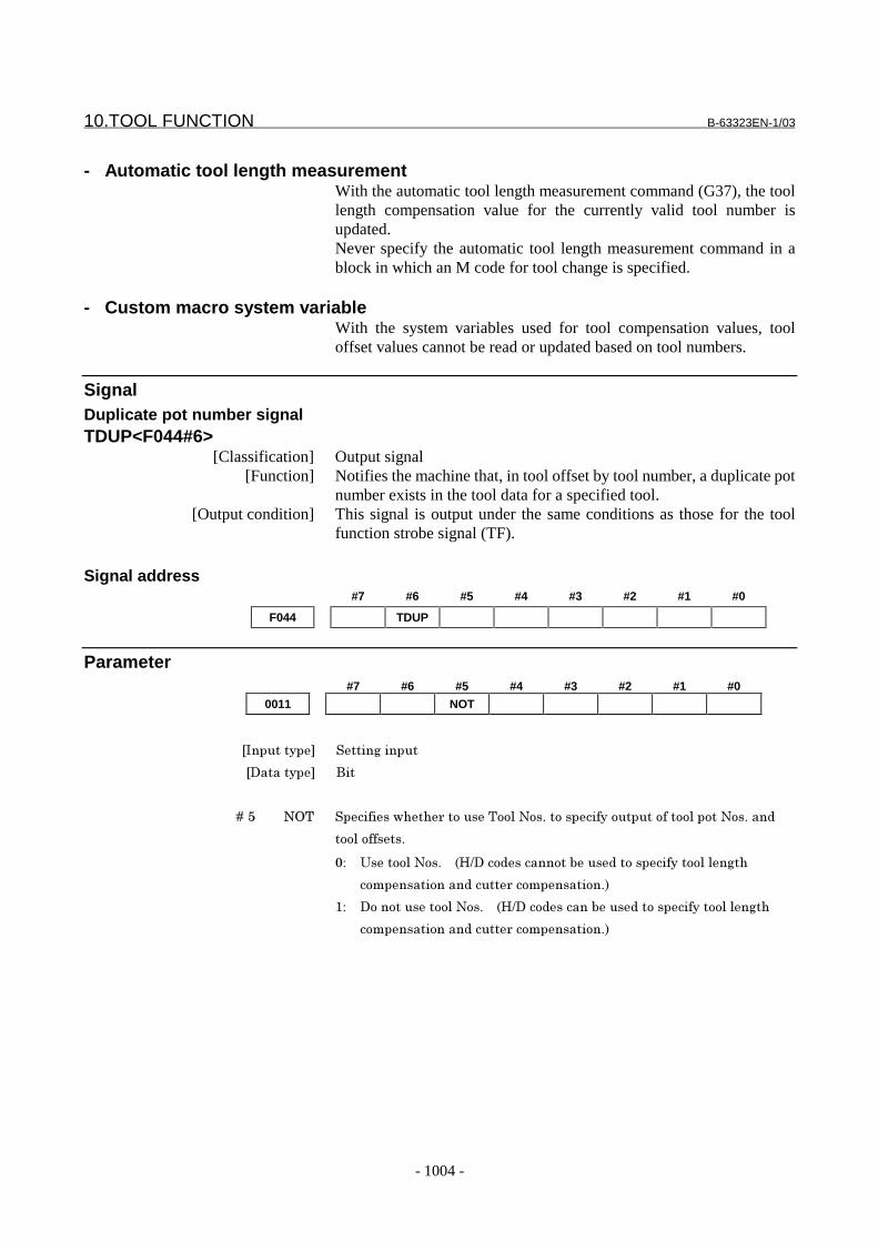
10.TOOL FUNCTION B-63323EN-1/03
- 1004 -
- Automatic tool length measurementWith the automatic tool length measurement command (G37), the toollength compensation value for the currently valid tool number isupdated.Never specify the automatic tool length measurement command in ablock in which an M code for tool change is specified.
- Custom macro system variableWith the system variables used for tool compensation values, tooloffset values cannot be read or updated based on tool numbers.
SignalDuplicate pot number signalTDUP<F044#6>
[Classification] Output signal[Function] Notifies the machine that, in tool offset by tool number, a duplicate pot
number exists in the tool data for a specified tool.[Output condition] This signal is output under the same conditions as those for the tool
function strobe signal (TF).
Signal address#7 #6 #5 #4 #3 #2 #1 #0
F044 TDUP
Parameter#7 #6 #5 #4 #3 #2 #1 #0
0011 NOT
���������� ����� ������
��������� &��
� � � � +�4 -,. ��������1�����������.����-��'������������������������������-��'����
�����������'
*2 ��������-��'� � �56��������������"���������������������� ��
���������������������������������'�
72 ���������������-��'� � �56�����������"���������������������� ��
���������������������������������'�

B-63323EN-1/03 10.TOOL FUNCTION
- 1005 -
#7 #6 #5 #4 #3 #2 #1 #0
2203 TLN
���������� 3������������
��������� &��
� � � � +�8 .9- .������������������������ �������:����������.���������������"
����1����������)����"����������
0: Pot numbers
1: Tool numbers
2429 M code for tool replacement
���������� 3������������
��������� ��� �
� ������������� ;����*������ ��!!!!!!!!��������� �*7��*<��=*��!>��!!����������� ��
����
�������������������������������������������������������� ���
������������������"�������������"�'� � ���*������������ ��������?���*?�'
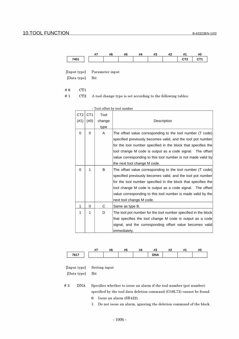
10.TOOL FUNCTION B-63323EN-1/03
- 1006 -
#7 #6 #5 #4 #3 #2 #1 #0
7401 CT2 CT1
���������� 3������������
��������� &��
� � � � +�* @.7
� � � � +�7 @.< #���������� ������������������� ������������1�� ���"��2
- Tool offset by tool number
CT2
(#1)
CT1
(#0)
Tool
change
type
Description
0 0 A The offset value corresponding to the tool number (T code)
specified previously becomes valid, and the tool pot number
for the tool number specified in the block that specifies the
tool change M code is output as a code signal. The offset
value corresponding to this tool number is not made valid by
the next tool change M code.
0 1 B The offset value corresponding to the tool number (T code)
specified previously becomes valid, and the tool pot number
for the tool number specified in the block that specifies the
tool change M code is output as a code signal. The offset
value corresponding to this tool number is made valid by the
next tool change M code.
1 0 C Same as type B.
1 1 D The tool pot number for the tool number specified in the block
that specifies the tool change M code is output as a code
signal, and the corresponding offset value becomes valid
immediately.
#7 #6 #5 #4 #3 #2 #1 #0
7617 DNA
���������� ����� ������
��������� &��
� � � � +�= �-# ��������1������������������������������������"����������"��
��������"�������������������������������A7*9B<���������"������'
*2 �����������������8<<�'
72 ����������������������� ����� �������������������������"���:'
B-63323EN-1/03 10.TOOL FUNCTION
- 1007 -
Alarm and messageNumber Message Contents
PS0421 SETTING COMMAND ERROR The instruction for setting tool data (G10L70 to G11,G10L71 to G11) is in error.
PS0422 NOT FOUND TOOL DATA The specified tool No. pot No. , for the tool No. , tool lengthcompensation data, and cutter compensation data has notbeen set.
PS0423 TOOL DATA WRITE ERROR Writing occurred simultaneously on tool set data by a toolNo.
PS0424 OVER MAXIMUM TOOL DATA An attempt was made to set tool data exceeding themaximum number of tool data sets.
PS0425 NOT DELETE TOOL DATA INOPERATION
Tool data cannot be deleted.
Reference itemSeries15i/150i-MA Operator’s Manual
(Programming)(B-63324EN)
II-14.11.2 Tool offset by toolnumber
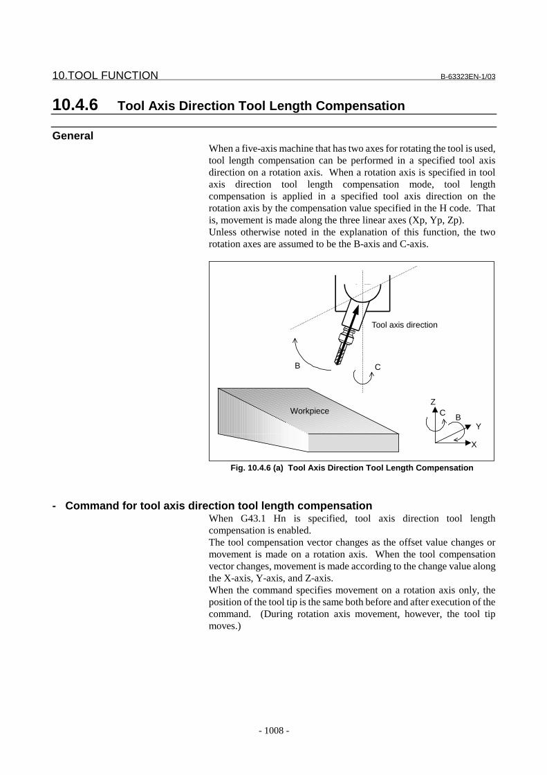
10.TOOL FUNCTION B-63323EN-1/03
- 1008 -
10.4.6 Tool Axis Direction Tool Length Compensation
GeneralWhen a five-axis machine that has two axes for rotating the tool is used,tool length compensation can be performed in a specified tool axisdirection on a rotation axis. When a rotation axis is specified in toolaxis direction tool length compensation mode, tool lengthcompensation is applied in a specified tool axis direction on therotation axis by the compensation value specified in the H code. Thatis, movement is made along the three linear axes (Xp, Yp, Zp).Unless otherwise noted in the explanation of this function, the tworotation axes are assumed to be the B-axis and C-axis.
C B
Z
Y
X
Workpiece
CB
Tool axis direction
Fig. 10.4.6 (a) Tool Axis Direction Tool Length Compensation
- Command for tool axis direction tool length compensationWhen G43.1 Hn is specified, tool axis direction tool lengthcompensation is enabled.The tool compensation vector changes as the offset value changes ormovement is made on a rotation axis. When the tool compensationvector changes, movement is made according to the change value alongthe X-axis, Y-axis, and Z-axis.When the command specifies movement on a rotation axis only, theposition of the tool tip is the same both before and after execution of thecommand. (During rotation axis movement, however, the tool tipmoves.)

B-63323EN-1/03 10.TOOL FUNCTION
- 1009 -
- Examples of machine configuration and rotation axis calculation formatsLet Vx, Vy, Vz, Lc, a, b, and c be as follows:
Vx,Vy,Vz : Tool compensation vectors along the X-axis, Y-axis, and Z-axis
Lc : Offset valuea,b,c : Absolute coordinates on the A-axis, B-axis and C-axis
Then, the tool compensation vector on each axis in each machineconfiguration is indicated below.
(1) A-axis and C-axis, with the tool axis on the Z-axis
CA
Z
X
Y
Workpiece
CA
Vx = Lc * sin(a) * sin(c)Vy = -Lc * sin(a) * cos(c)Vz = Lc * cos(a)
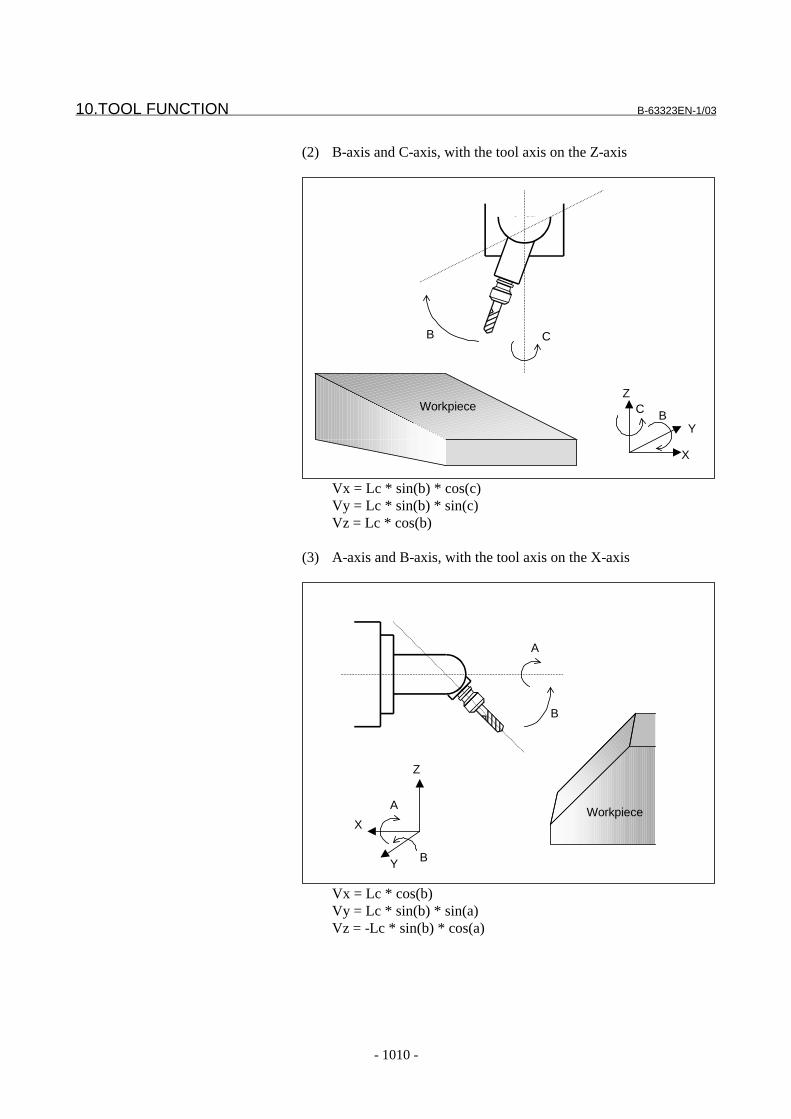
10.TOOL FUNCTION B-63323EN-1/03
- 1010 -
(2) B-axis and C-axis, with the tool axis on the Z-axis
C B
Z
Y
X
Workpiece
CB
Vx = Lc * sin(b) * cos(c)Vy = Lc * sin(b) * sin(c)Vz = Lc * cos(b)
(3) A-axis and B-axis, with the tool axis on the X-axis
Workpiece
B
A
Z
Y
X
A
B
Vx = Lc * cos(b)Vy = Lc * sin(b) * sin(a)Vz = -Lc * sin(b) * cos(a)
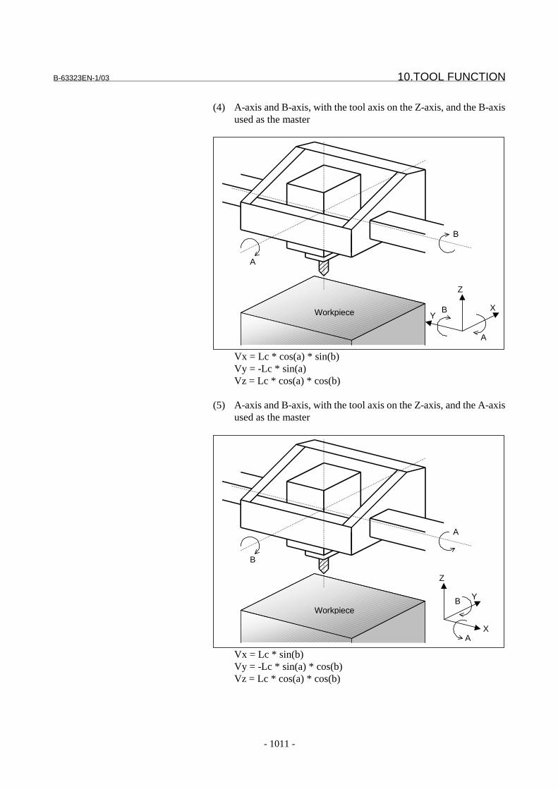
B-63323EN-1/03 10.TOOL FUNCTION
- 1011 -
(4) A-axis and B-axis, with the tool axis on the Z-axis, and the B-axisused as the master
B
A
Z
YXWorkpiece
B
A
Vx = Lc * cos(a) * sin(b)Vy = -Lc * sin(a)Vz = Lc * cos(a) * cos(b)
(5) A-axis and B-axis, with the tool axis on the Z-axis, and the A-axisused as the master
B
A
Z
X
Y
Workpiece
A
B
Vx = Lc * sin(b)Vy = -Lc * sin(a) * cos(b)Vz = Lc * cos(a) * cos(b)
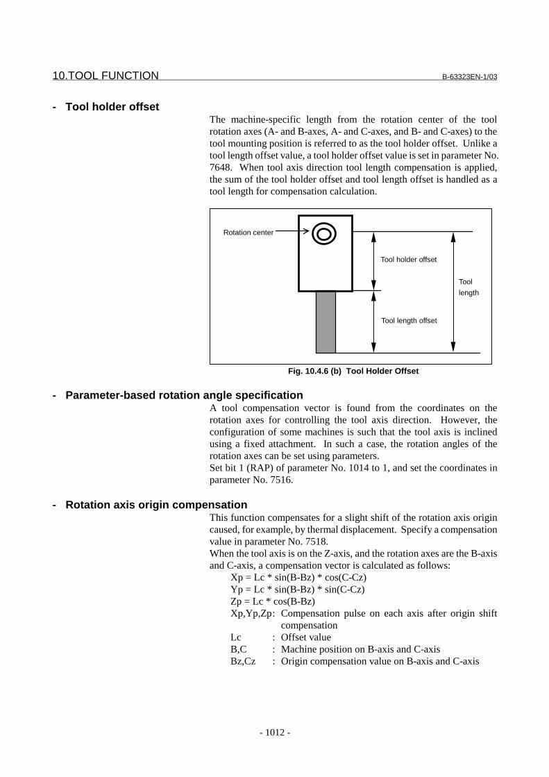
10.TOOL FUNCTION B-63323EN-1/03
- 1012 -
- Tool holder offsetThe machine-specific length from the rotation center of the toolrotation axes (A- and B-axes, A- and C-axes, and B- and C-axes) to thetool mounting position is referred to as the tool holder offset. Unlike atool length offset value, a tool holder offset value is set in parameter No.7648. When tool axis direction tool length compensation is applied,the sum of the tool holder offset and tool length offset is handled as atool length for compensation calculation.
Tool holder offset
Tool length offset
Rotation center
Tool
length
Fig. 10.4.6 (b) Tool Holder Offset
- Parameter-based rotation angle specificationA tool compensation vector is found from the coordinates on therotation axes for controlling the tool axis direction. However, theconfiguration of some machines is such that the tool axis is inclinedusing a fixed attachment. In such a case, the rotation angles of therotation axes can be set using parameters.Set bit 1 (RAP) of parameter No. 1014 to 1, and set the coordinates inparameter No. 7516.
- Rotation axis origin compensationThis function compensates for a slight shift of the rotation axis origincaused, for example, by thermal displacement. Specify a compensationvalue in parameter No. 7518.When the tool axis is on the Z-axis, and the rotation axes are the B-axisand C-axis, a compensation vector is calculated as follows:
Xp = Lc * sin(B-Bz) * cos(C-Cz)Yp = Lc * sin(B-Bz) * sin(C-Cz)Zp = Lc * cos(B-Bz)Xp,Yp,Zp: Compensation pulse on each axis after origin shift
compensationLc : Offset valueB,C : Machine position on B-axis and C-axisBz,Cz : Origin compensation value on B-axis and C-axis
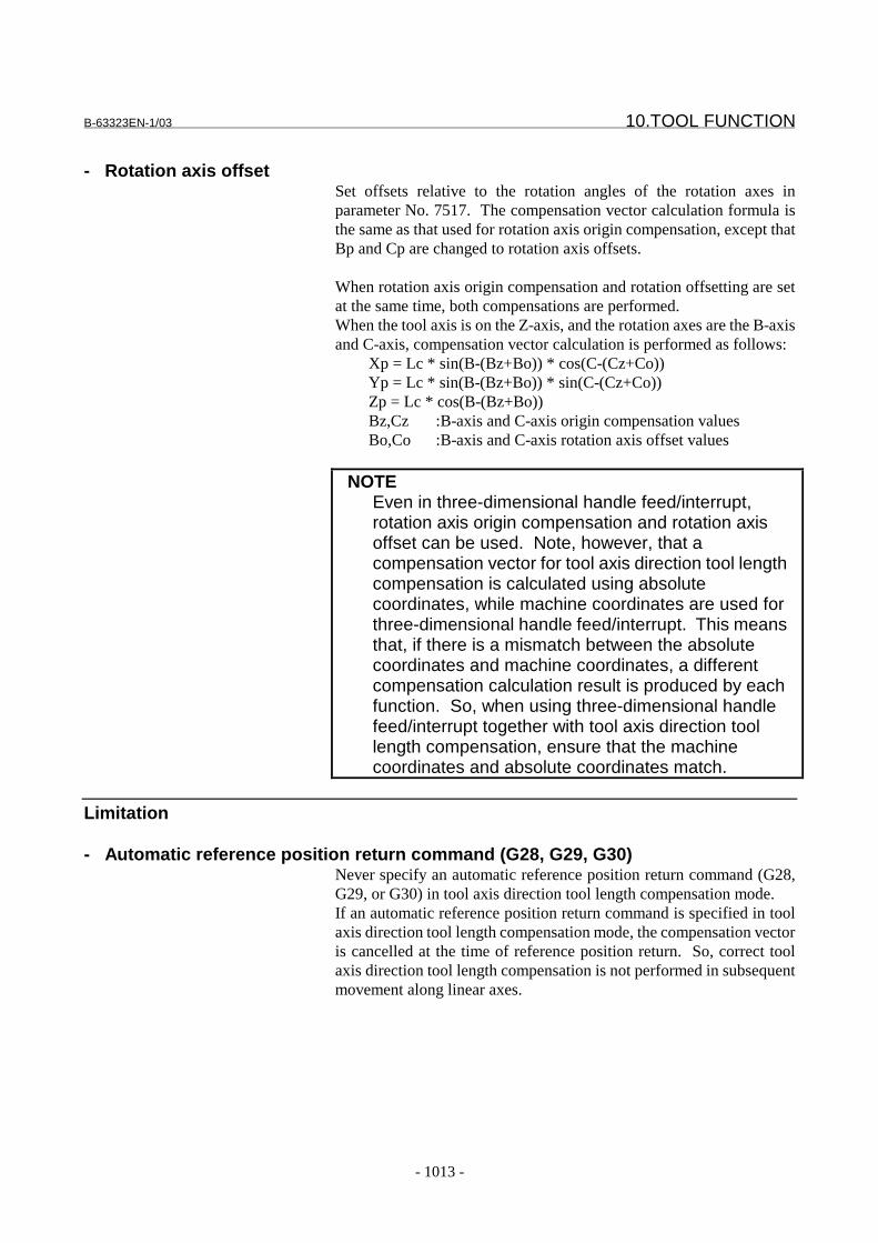
B-63323EN-1/03 10.TOOL FUNCTION
- 1013 -
- Rotation axis offsetSet offsets relative to the rotation angles of the rotation axes inparameter No. 7517. The compensation vector calculation formula isthe same as that used for rotation axis origin compensation, except thatBp and Cp are changed to rotation axis offsets.
When rotation axis origin compensation and rotation offsetting are setat the same time, both compensations are performed.When the tool axis is on the Z-axis, and the rotation axes are the B-axisand C-axis, compensation vector calculation is performed as follows:
Xp = Lc * sin(B-(Bz+Bo)) * cos(C-(Cz+Co))Yp = Lc * sin(B-(Bz+Bo)) * sin(C-(Cz+Co))Zp = Lc * cos(B-(Bz+Bo))Bz,Cz :B-axis and C-axis origin compensation valuesBo,Co :B-axis and C-axis rotation axis offset values
NOTEEven in three-dimensional handle feed/interrupt,rotation axis origin compensation and rotation axisoffset can be used. Note, however, that acompensation vector for tool axis direction tool lengthcompensation is calculated using absolutecoordinates, while machine coordinates are used forthree-dimensional handle feed/interrupt. This meansthat, if there is a mismatch between the absolutecoordinates and machine coordinates, a differentcompensation calculation result is produced by eachfunction. So, when using three-dimensional handlefeed/interrupt together with tool axis direction toollength compensation, ensure that the machinecoordinates and absolute coordinates match.
Limitation
- Automatic reference position return command (G28, G29, G30)Never specify an automatic reference position return command (G28,G29, or G30) in tool axis direction tool length compensation mode.If an automatic reference position return command is specified in toolaxis direction tool length compensation mode, the compensation vectoris cancelled at the time of reference position return. So, correct toolaxis direction tool length compensation is not performed in subsequentmovement along linear axes.
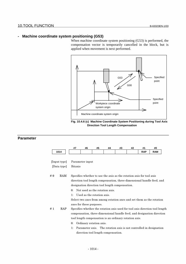
10.TOOL FUNCTION B-63323EN-1/03
- 1014 -
- Machine coordinate system positioning (G53)When machine coordinate system positioning (G53) is performed, thecompensation vector is temporarily cancelled in the block, but isapplied when movement is next performed.
Workpiece coordinate
system origin
Machine coordinate system origin
G00
G53
Specified
point
Specified
point
Fig. 10.4.6 (c) Machine Coordinate System Positioning during Tool AxisDirection Tool Length Compensation
Parameter
#7 #6 #5 #4 #3 #2 #1 #0
1014 RAP RAM
���������� 3������������
��������� &������
� � � � +�* �#� ��������1����������������������������������������������������
���������������� �������������������%������������������������
��� ����������������������� ��������������'
*2 -��������������������������'
72 �����������������������'
������1��������������� ���������������������������������������
�������������������'
� � � � +�7 �#3 ��������1�������������������������������������������������������� ��
����������������%���������������������������� ���������������
������� �������������������������������������������'
*2 ,���������������������'
72 3�����������'� � .��������������������������������������� ������
���������������� ��������������'
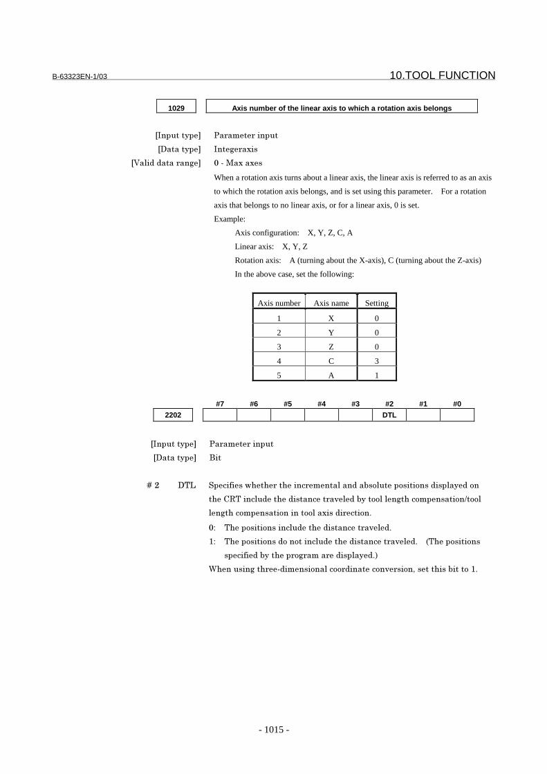
B-63323EN-1/03 10.TOOL FUNCTION
- 1015 -
1029 Axis number of the linear axis to which a rotation axis belongs
���������� 3������������
��������� ��� �����
� ������������� *�%��������
When a rotation axis turns about a linear axis, the linear axis is referred to as an axis
to which the rotation axis belongs, and is set using this parameter. For a rotation
axis that belongs to no linear axis, or for a linear axis, 0 is set.
Example:
Axis configuration: X, Y, Z, C, A
Linear axis: X, Y, Z
Rotation axis: A (turning about the X-axis), C (turning about the Z-axis)
In the above case, set the following:
Axis number Axis name Setting
1 X 0
2 Y 0
3 Z 0
4 C 3
5 A 1
#7 #6 #5 #4 #3 #2 #1 #0
2202 DTL
���������� 3������������
��������� &��
� � � � +�< �.9 ��������1�����������������������"���������������������������
���@�.����������������������)���"��������� ��������������6����
�� ������������������������������������'
*2 .���������������������������������)��'
72 .����������������������������������������)��'� � �.�����������
��������"�������� ���������������'�
$������� ����%������������������������)���������������"������7'
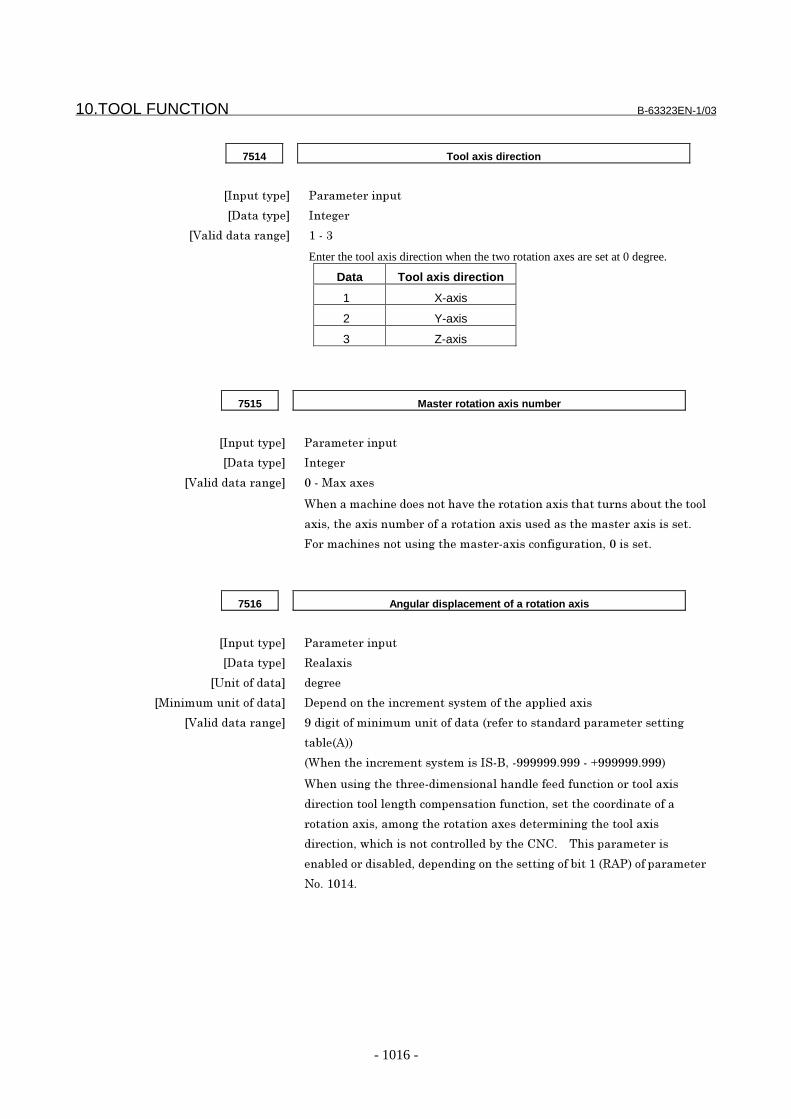
10.TOOL FUNCTION B-63323EN-1/03
- 1016 -
7514 Tool axis direction
���������� 3������������
��������� ��� �
� ������������� 7�%�=
Enter the tool axis direction when the two rotation axes are set at 0 degree.
Data Tool axis direction
1 X-axis
2 Y-axis
3 Z-axis
7515 Master rotation axis number
���������� 3������������
��������� ��� �
� ������������� *�%��������
$����������������������)������������������������������"�����������
�����������������"�����������������������������������������������'
;������������������� ���������%���������� ���������*������'
7516 Angular displacement of a rotation axis
���������� 3������������
��������� �������
������������� � �
��������������������� ������������������������������������������
� ������������� !��� ���������������������������������������������������������
��"��#��
�$�������������������������%&��%!!!!!!'!!!�%�(!!!!!!'!!!�
$������� �������%�����������������������������������������
���������������� ���������������������������������������������
������������������� ������������������������� �������������
����������1����������������������"�����@-@'� � .��������������
��"����������"���������� ������������ ����"���7���#3������������
-�'�7*78'
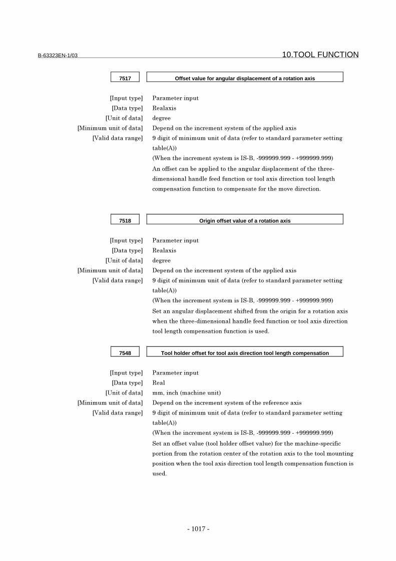
B-63323EN-1/03 10.TOOL FUNCTION
- 1017 -
7517 Offset value for angular displacement of a rotation axis
���������� 3������������
��������� �������
������������� � �
��������������������� ������������������������������������������
� ������������� !��� ���������������������������������������������������������
��"��#��
�$�������������������������%&��%!!!!!!'!!!�%�(!!!!!!'!!!�
#������������"���������������� �������������������������%
���������������������������������������������������������� ��
������������������������������������������)���������'
7518 Origin offset value of a rotation axis
���������� 3������������
��������� �������
������������� � �
��������������������� ������������������������������������������
� ������������� !��� ���������������������������������������������������������
��"��#��
�$�������������������������%&��%!!!!!!'!!!�%�(!!!!!!'!!!�
�������� ���������������������������������� ����������������������
1���������%��������������������������������������������������
������� ������������������������������'
7548 Tool holder offset for tool axis direction tool length compensation
���������� 3������������
��������� ���
������������� ����������������������
��������������������� �����������������������������������������
� ������������� !��� ���������������������������������������������������������
��"��#��
�$�������������������������%&��%!!!!!!'!!!�%�(!!!!!!'!!!�
������������)����������������������)������������������%�������
��������������������������������������������������������������������
���������1�������������������������������� ��������������������������
���'
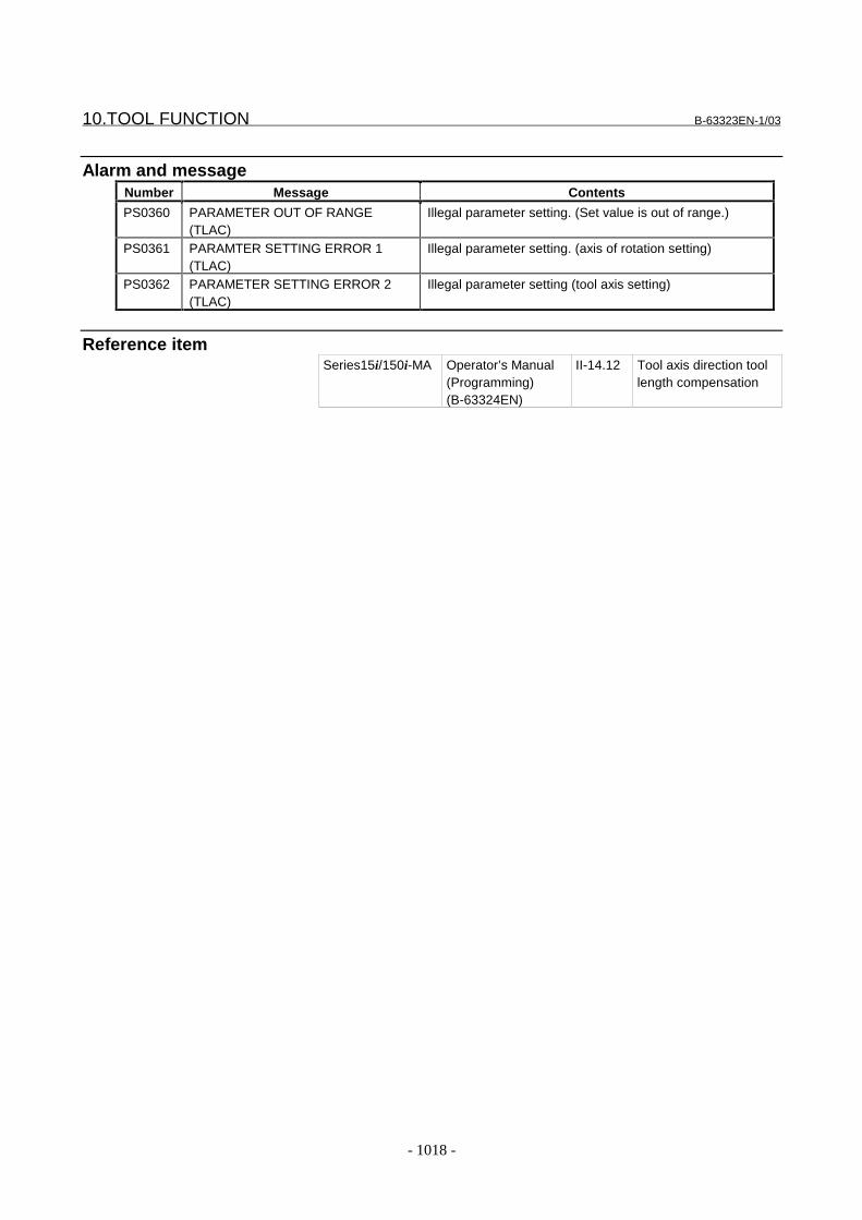
10.TOOL FUNCTION B-63323EN-1/03
- 1018 -
Alarm and messageNumber Message Contents
PS0360 PARAMETER OUT OF RANGE(TLAC)
Illegal parameter setting. (Set value is out of range.)
PS0361 PARAMTER SETTING ERROR 1(TLAC)
Illegal parameter setting. (axis of rotation setting)
PS0362 PARAMETER SETTING ERROR 2(TLAC)
Illegal parameter setting (tool axis setting)
Reference itemSeries15i/150i-MA Operator’s Manual
(Programming)(B-63324EN)
II-14.12 Tool axis direction toollength compensation
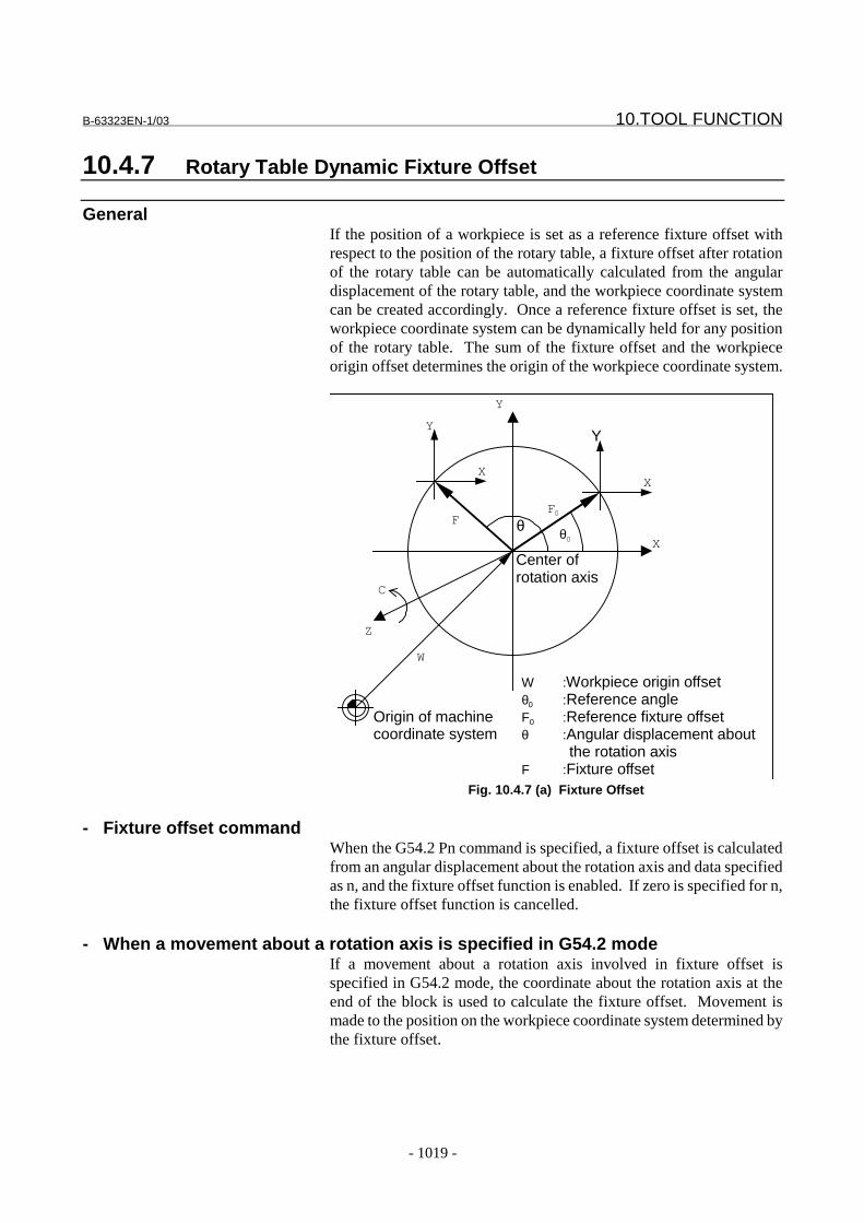
B-63323EN-1/03 10.TOOL FUNCTION
- 1019 -
10.4.7 Rotary Table Dynamic Fixture Offset
GeneralIf the position of a workpiece is set as a reference fixture offset withrespect to the position of the rotary table, a fixture offset after rotationof the rotary table can be automatically calculated from the angulardisplacement of the rotary table, and the workpiece coordinate systemcan be created accordingly. Once a reference fixture offset is set, theworkpiece coordinate system can be dynamically held for any positionof the rotary table. The sum of the fixture offset and the workpieceorigin offset determines the origin of the workpiece coordinate system.
X
Y
X
Y
X
Y
F0F
θ0θ
Z
W
Origin of machinecoordinate system
W :Workpiece origin offsetθ0 :Reference angleF0 :Reference fixture offsetθ :Angular displacement about
the rotation axisF :Fixture offset
C
Center ofrotation axis
Fig. 10.4.7 (a) Fixture Offset
- Fixture offset commandWhen the G54.2 Pn command is specified, a fixture offset is calculatedfrom an angular displacement about the rotation axis and data specifiedas n, and the fixture offset function is enabled. If zero is specified for n,the fixture offset function is cancelled.
- When a movement about a rotation axis is specified in G54.2 modeIf a movement about a rotation axis involved in fixture offset isspecified in G54.2 mode, the coordinate about the rotation axis at theend of the block is used to calculate the fixture offset. Movement ismade to the position on the workpiece coordinate system determined bythe fixture offset.
10.TOOL FUNCTION B-63323EN-1/03
- 1020 -
- Operation upon a resetThe setting of the KWZ bit (bit 6 of parameter 2409) determineswhether the fixture offset is cancelled upon a reset. If the setting is 1,the vector before the reset is held. If the setting is 0, the vector iscleared. Clearing the vector, however, does not cause any movementupon a reset.
- Setting data(1) Groups of three parameters specifying a rotation axis and two
linear axes constituting a rotation plane(parameters 6068 to 6076)The first parameter of each group specifies the number of therotation axis, and the second and third parameters specify thenumbers of the linear axes. The order in which the two linear axesare specified must be such that rotation in the positive directionabout the rotation axis agrees with the rotation from the positiveside of the first linear axis to the positive side of the second linearaxis.Example) Let three axes X, Y, and Z of a four-axis machine form
a right-handed coordinate system and the remaining axis Cbe such a rotation axis that the positive rotation about theaxis matches the counterclockwise rotation about the Z-axiswhen the negative side of the Z-axis is viewed from thepositive side. Then, the three parameters specify thefollowing:
First parameter : 4 (C-axis)Second parameter : 1 (X-axis)Third parameter : 2 (Y-axis)
Up to three groups of parameters can be specified. In fixtureoffset calculation, the data of the rotation axis of the first group iscalculated first. From the result, the data of the second and thirdgroups is calculated. If there are two or more rotation axes and ifa rotation plane varies with the rotation about another rotationaxis, the rotation plane with the relative rotation axis set to the 0position should be specified.
(2) Reference angle of the rotation axis and corresponding referencefixture offsetThe position of the rotation axis (reference angle) and thecorresponding fixture offset (reference fixture offset) arespecified.The data is specified on the fixture offset screen.Up to eight pairs can be specified.
(3) Parameter for enabling or disabling fixture offset for eachaxis(FAX bit (bit 0 of parameter 1007))The bit is set to 1 for an axis for which fixture offset is enabled.This setting is unnecessary for a rotation axis.
(4) Parameter specifying a fixture offset type(FTP bit (bit 1 of parameter 6004))This parameter specifies whether movement is made according toa change in the vector of fixture offset (when movement is madeabout the rotation axis by the G54.2 command or in G54.2 mode).
B-63323EN-1/03 10.TOOL FUNCTION
- 1021 -
When 0 is specified, movement is made.(The workpiece coordinates of the current position do not change,and the corresponding machine coordinates change.)When 1 is specified, no movement is made.(The workpiece coordinates of the current position change, butthe corresponding machine coordinates do not change.)
- Input/output of fixture offsetThe data can be programmed and can be input from or output toexternal equipment, as described below:(1) Setting a reference fixture offset by G10
G10 L21 PnP;n: Reference fixture offset numberP: Reference angle or reference fixture offset on each axis
With this command, a reference fixture offset or reference anglecan be programmed.If the command is executed in G90 mode, the specified value is setdirectly. If the command is executed in G91 mode, the sum of thespecified value and the previous value is set.
NOTEThis operation requires the programmable datainput (G10) function.
(2) Reading or writing a system variable of a custom macroWith the following system variable, a reference fixture offset orreference angle can be read or written:
15001 + 20*(n - 1) + (m - 1)n: Reference fixture offset number (1 to 8)m: Axis number (1 to number of controlled axes)
NOTEThis operation requires the use of the custom macrofunction.
(3) Reading and writing the PMC windowData can be read or written as a system variable of a custom macroin the PMC window.
NOTEThis operation requires the use of an NC windowand a custom macro function.
(4) Output to external equipmentWhen the punch soft key is selected on the fixture offset screen,data can be output to external equipment such as a FloppyCassette via the RS-232C interface.Data is output in G10 format without a program number.

10.TOOL FUNCTION B-63323EN-1/03
- 1022 -
NOTEThis operation requires a reader/punch interfaceand a programmable data input function.
(5) Input from external equipmentWhen the read soft key is selected on the fixture offset screen,data can be input from external equipment such as a FloppyCassette via the RS-232C interface.Data is input in G10 format without a program number.
NOTEThis operation requires the use of a reader/punchinterface and a programmable data input function.
- Calculating a fixture offset(1) Relationship between rotation axes and linear axes
First group: 4 (B-axis), 3 (Z-axis), 1 (X-axis)Second group: 5 (C-axis), 1 (X-axis), 2 (Y-axis)Third group: 0, 0, 0
(2) Reference angle and reference fixture offsetX:F0X
Y:F0Y
Z:F0Z
B:θ0
C:φ0
When the above values are specified for the following:O : Center of rotary tableW : Workpiece origin offsetF0 : Fixture offset when B equals θ0 and C equals φ0
FA : Fixture offset (FAX, FAY, FAZ) when B equals 0 and Cequals 0
F : Fixture offset (FX, FY, FZ) when B equals θ and C equalsthe fixture offset is calculated as shown below: φ
( ) ( )
( ) ( )
( ) ( )( ) ( )
−−−−−
−−−
−−=
Z
Y
X
AZ
AY
AX
F
F
F
F
F
F
0
0
0
00
00
00
00
100
0cossin
0sincos
cos0sin
010
sin0cos
φφφφ
θθ
θθ
( ) ( )( ) ( )
( ) ( )
( ) ( )
−
−=
AZ
AY
AX
Z
Y
X
F
F
F
F
F
F
θθ
θθφφφφ
cos0sin
010
sin0cos
100
0cossin
0sincos
Limitation
- If data is changed in G54.2 modeIf a parameter setting or reference fixture offset is changed in G54.2mode, the new data is valid from the next block to be buffered.
B-63323EN-1/03 10.TOOL FUNCTION
- 1023 -
- Movement resulting from a change in the vector of the fixture offsetThe movement resulting from a change in the vector of the fixtureoffset is made according to the current modal G code of group 01. Ifthe G code is not G00 or G01 (if the code is G02, G03, etc.), themovement is temporarily made according to G01.
- If manual intervention is made on the rotation axisIf automatic operation is stopped by a SBK stop or similar in G54.2mode, and if manual movement is made about the rotation axis, thevector of the fixture offset does not change. When a rotation axiscommand is specified in automatic operation or MDI operation orwhen G54.2 is specified, the vector is calculated.When a movement about the rotation axis is specified in incrementalmode (G91 mode) after manual intervention is made with the ABS bit(bit 3 of parameter 2409) set to 0 and the manual absolute switch is seton, the vector is calculated, using coordinates which do not reflect theamount of manual intervention.Example)
N1 G90 G00 C10.0;N2 G54.2 P1;
After executing the program, perform manual intervention with themanual absolute switch set to on. Then, make a movement of +20.0about the C-axis. When
N3 G91 C30.0;is specified, the C coordinate is 60.0 in the workpiece coordinatesystem. In the fixture offset calculation, however, C coordinate 40.0 isused.If the ABS bit (bit 3 of parameter 2409) is set to 1 when N3 is executed,programmed C coordinate 40.0 (10.0 + 30.0) is directly used for thecalculation.
- If compensation is made on the rotation axisThe coordinate of the rotation axis in the workpiece coordinate systemis used for the fixture offset calculation. If a tool offset or anotheroffset is made, the coordinate before the offset is used. If mirror imageor scaling is performed, the coordinate before the operation is used.
- Commands for which fixture offset is not calculatedIf any of the following commands is executed for the rotation axis inG54.2 mode, the vector of fixture offset is not calculated:
Command in the machine coordinate system (G53)Command for changing the workpiece coordinate system (G54 toG59, G54.1, G92, G52)Command related to reference position return (G27, G28, G29,G30, G30.1)
- Rotation axis used for fixture offsetThe rotation axis used for polar coordinate interpolation (G12.1)cannot be set for fixture offset.

10.TOOL FUNCTION B-63323EN-1/03
- 1024 -
Parameter
#7 #6 #5 #4 #3 #2 #1 #0
1007 FAX
���������� 3������������
��������� &������
� � � � +�* ;#C ��������1������������������������)�����������������'
*2 ��)����'
72 ����'
#7 #6 #5 #4 #3 #2 #1 #0
2409 KWZ
���������� 3������������
��������� &��
� � � � +�? 0$D ��������1�������������A48����A4!�������������A����� �����1�����
������������'
*2 @����'� � ���������E�����A48'�
72 -���������"�����)�'
$������������������������1������������������������������1�����
������������������������������ ����������������'
#7 #6 #5 #4 #3 #2 #1 #0
6004 FTP
���������� 3������������
��������� &��
� � � � +�7 ;.3 ������������������������������'
*2 ��)����'� � �#���)�����������1���������������������
���� ���
72 ���������'� � �-����)�����������1���������������������
���� �'�
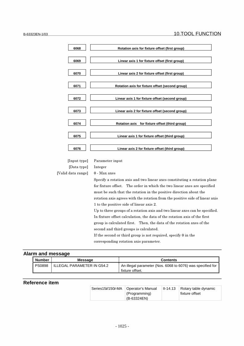
B-63323EN-1/03 10.TOOL FUNCTION
- 1025 -
6068 Rotation axis for fixture offset (first group)
6069 Linear axis 1 for fixture offset (first group)
6070 Linear axis 2 for fixture offset (first group)
6071 Rotation axis for fixture offset (second group)
6072 Linear axis 1 for fixture offset (second group)
6073 Linear axis 2 for fixture offset (second group)
6074 Rotation axis for fixture offset (third group)
6075 Linear axis 1 for fixture offset (third group)
6076 Linear axis 2 for fixture offset (third group)
���������� 3������������
��������� ��� �
� ������������� *�%��������
����������������������������1����������������������� ����������������
����������������'� � .����������1���������1����������������������
�����"�����������������������������������)�����������"������
��������������� ���1������������������������������)������������������
7�������������)�������������������<'
���������� ������������������������������1����������������"��������'
��������������������������������������������������������������������
�����������������������'� � .������������������������������������
���������������� ������������������'
��������������������� �������������F�������������*������
����������� ����������������������'
Alarm and messageNumber Message Contents
PS0898 ILLEGAL PARAMETER IN G54.2 An illegal parameter (Nos. 6068 to 6076) was specified forfixture offset.
Reference itemSeries15i/150i-MA Operator’s Manual
(Programming)(B-63324EN)
II-14.13 Rotary table dynamicfixture offset

10.TOOL FUNCTION B-63323EN-1/03
- 1026 -
10.4.8 Three-dimensional Cutter Compensation
GeneralThe three-dimensional cutter compensation function is used withmachines that can control the direction of tool axis movement by usingrotation axes (such as the B- and C-axes). This function performscutter compensation by calculating a tool vector from the positions ofthe rotation axes, then calculating a compensation vector in a plane(compensation plane) that is perpendicular to the tool vector.There are two types of cutter compensation: Tool side compensationand leading edge compensation. Which is used depends on the type ofmachining.
- Tool Side CompensationTool side compensation is a type of cutter compensation that performsthree-dimensional compensation on a plane (compensation plane)perpendicular to a tool direction vector.
Compensationplane
YZ
X
Tool vector
Cutter compensation amount
Programmed tool path(before compensation)
Cutter compensationvector
Tool centerpath(aftercompensation)
Fig.10.4.8 (a) Tool side compensation
- Leading Edge OffsetLeading edge offset is a type of cutter compensation that is used when aworkpiece is machined with the edge of a tool. A tool is automaticallyshifted by a specified cutter compensation value on the line where aplane formed by a tool direction vector and tool movement directionintersects a plane perpendicular to the tool axis direction.
Tool used
Referencetool
Cutter compensationvector Cutter compensation
amount
Tool center path(aftercompensation)
Programmedtool path
Tool vector
Fig. 10.4.8 (b) Reading edge offset

B-63323EN-1/03 10.TOOL FUNCTION
- 1027 -
Parameter
(1) Parameters setting the relationship between the rotation axis and rotation plane with which the tool iscontrolled
(1) Relationship between the rotation axis and rotation plane Parameter i No.6080 to 6089 j
(2) Direction of the tool axis Parameter i No.6106 to 6107 j
(3) Reference angle for the rotation axis Parameter i No.6104 to 6105 j
(2) Parameters for tool side compensation
Limit for ignoring the small movement Parameter i No.6114 j
Interference check at compensation plane switching Parameter NIC i No.0014#5 j
Parameter i No.6261 j
(3) Parameter for leading edge offset
Angle variation range Parameter i No.6115 j
(4) Parameters for cutter compensation
Single block stop in an internally generated block Parameter SBO i No.0010#7 j
Displayed incremental and absolute positions not including the cuttercompensation vector
Parameter DCR i No.2202#3 j
Validating an offset change starting with the next buffered block Parameter EV0 i No.6000#0 j
Startup B Parameter CSU i No.6001#0 j
Making no interference check in the move direction Parameter CNC i No.6001#1 j
Making no interference check Parameter CNI i No.6001#6 j
Startup C Parameter CSC i No.6003#7 j
Limit for ignoring the small movement Parameter i No.6010 j
For parameters (4), see the section on cutter compensation.

10.TOOL FUNCTION B-63323EN-1/03
- 1028 -
6080 Rotation axis for three-dimensional cutter compensation and so forth (first
group)
6081 Linear axis 1 for three-dimensional cutter compensation and so forth (first
group)
6082 Linear axis 2 for three-dimensional cutter compensation and so forth (first
group)
6083 Linear axis 3 for three-dimensional cutter compensation and so forth (first
group)
���������� �� ��� ������
��������� ����
������������ ��� �����������
������ ��������������������� ��������� �� ���� ����������������
�������������������������������������������� ��� ����������
������������������ �� ���� ���!"
6084 Angle of inclination for the rotation axis for three-dimensional cutter
compensation and so forth (first group)
���������� �� ��� ������
��������� #��
�$����������� ��
��������������������� �������������� ���������������� � �������
������������ ��� %������������������������������� � ���������� ���� ��� �������
��&� '!!
(��������� ����������������)*��%%%%%%"%%%���+%%%%%%"%%%!
�������������� ���������� ���� ����������������� �� ���� �
��������������� ��������������������������������������������
��� ����������������������������� �� ���� ���!"
6085 Rotation axis for three-dimensional cutter compensation and so forth
(second group)
6086 Linear axis 1 for three-dimensional cutter compensation and so forth
(second group)
6087 Linear axis 2 for three-dimensional cutter compensation and so forth
(second group)

B-63323EN-1/03 10.TOOL FUNCTION
- 1029 -
6088 Linear axis 3 for three-dimensional cutter compensation and so forth
(second group)
���������� �� ��� ������
��������� ����
������������ ��� �������& �������� ��������
������ ��������������������� ��������� �� ���� ����������������
�������������������������������������������� ��� ����������
������������������ ������� ���!"
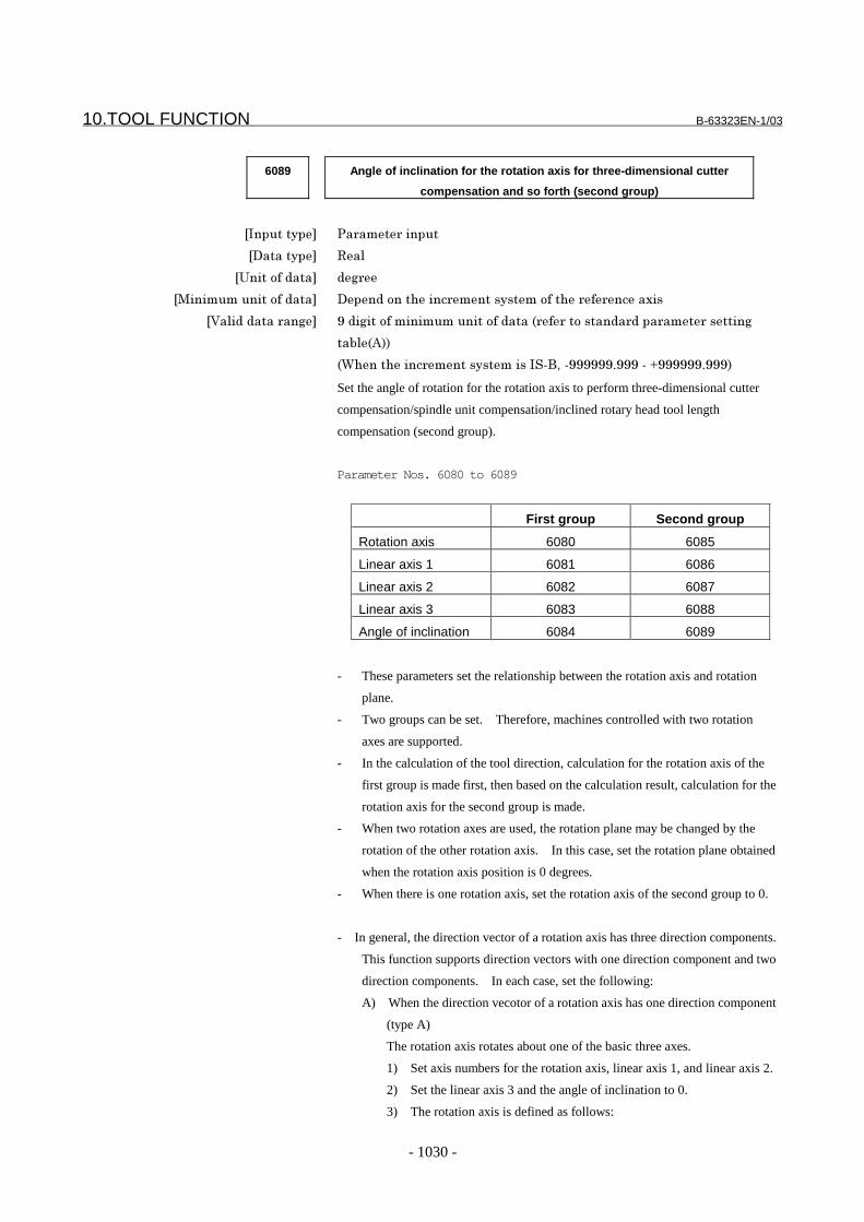
10.TOOL FUNCTION B-63323EN-1/03
- 1030 -
6089 Angle of inclination for the rotation axis for three-dimensional cutter
compensation and so forth (second group)
���������� �� ��� ������
��������� #��
�$����������� ��
��������������������� �������������� ���������������� � �������
������������ ��� %������������������������������� � ���������� ���� ��� �������
��&� '!!
(��������� ����������������)*��%%%%%%"%%%���+%%%%%%"%%%!
Set the angle of rotation for the rotation axis to perform three-dimensional cutter
compensation/spindle unit compensation/inclined rotary head tool length
compensation (second group).
Parameter Nos. 6080 to 6089
First group Second group
Rotation axis 6080 6085
Linear axis 1 6081 6086
Linear axis 2 6082 6087
Linear axis 3 6083 6088
Angle of inclination 6084 6089
- These parameters set the relationship between the rotation axis and rotation
plane.
- Two groups can be set. Therefore, machines controlled with two rotation
axes are supported.
- In the calculation of the tool direction, calculation for the rotation axis of the
first group is made first, then based on the calculation result, calculation for the
rotation axis for the second group is made.
- When two rotation axes are used, the rotation plane may be changed by the
rotation of the other rotation axis. In this case, set the rotation plane obtained
when the rotation axis position is 0 degrees.
- When there is one rotation axis, set the rotation axis of the second group to 0.
- In general, the direction vector of a rotation axis has three direction components.
This function supports direction vectors with one direction component and two
direction components. In each case, set the following:
A) When the direction vecotor of a rotation axis has one direction component
(type A)
The rotation axis rotates about one of the basic three axes.
1) Set axis numbers for the rotation axis, linear axis 1, and linear axis 2.
2) Set the linear axis 3 and the angle of inclination to 0.
3) The rotation axis is defined as follows:
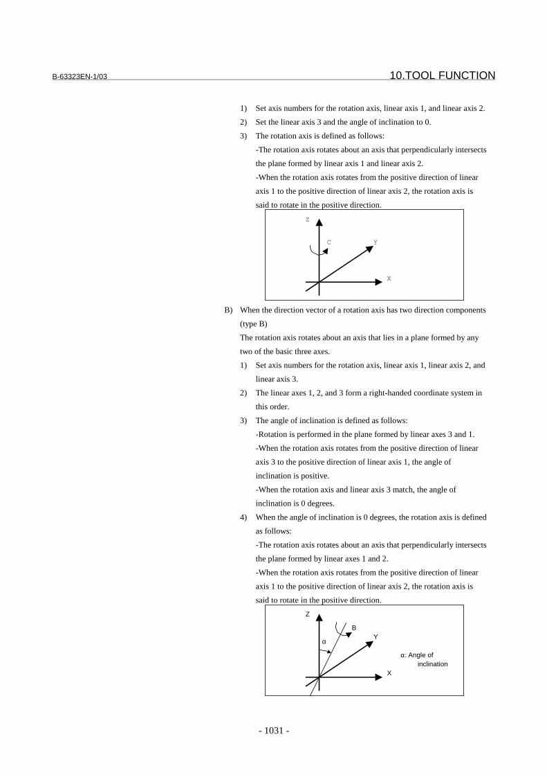
B-63323EN-1/03 10.TOOL FUNCTION
- 1031 -
1) Set axis numbers for the rotation axis, linear axis 1, and linear axis 2.
2) Set the linear axis 3 and the angle of inclination to 0.
3) The rotation axis is defined as follows:
-The rotation axis rotates about an axis that perpendicularly intersects
the plane formed by linear axis 1 and linear axis 2.
-When the rotation axis rotates from the positive direction of linear
axis 1 to the positive direction of linear axis 2, the rotation axis is
said to rotate in the positive direction.
X
Y
Z
C
B) When the direction vector of a rotation axis has two direction components
(type B)
The rotation axis rotates about an axis that lies in a plane formed by any
two of the basic three axes.
1) Set axis numbers for the rotation axis, linear axis 1, linear axis 2, and
linear axis 3.
2) The linear axes 1, 2, and 3 form a right-handed coordinate system in
this order.
3) The angle of inclination is defined as follows:
-Rotation is performed in the plane formed by linear axes 3 and 1.
-When the rotation axis rotates from the positive direction of linear
axis 3 to the positive direction of linear axis 1, the angle of
inclination is positive.
-When the rotation axis and linear axis 3 match, the angle of
inclination is 0 degrees.
4) When the angle of inclination is 0 degrees, the rotation axis is defined
as follows:
-The rotation axis rotates about an axis that perpendicularly intersects
the plane formed by linear axes 1 and 2.
-When the rotation axis rotates from the positive direction of linear
axis 1 to the positive direction of linear axis 2, the rotation axis is
said to rotate in the positive direction.
X
Y
Z
B
α
α: Angle of inclination

10.TOOL FUNCTION B-63323EN-1/03
- 1032 -
X
Y
Z
B
α
α: Angle of inclination
6104 Reference angle for the rotation axis for three-dimensional cutter
compensation and so forth (first group)
6105 Reference angle for the rotation axis for three-dimensional cutter
compensation and so forth (second group)
���������� �� ��� ������
��������� #��
�$����������� ��
��������������������� �������������� ���������������� � �������
������������ ��� %������������������������������� � ���������� ���� ��� �������
��&� '!!
(��������� ����������������)*��%%%%%%"%%%���+%%%%%%"%%%!
����� � ���������� ���� ����������������� �� ���� �����������
���� ��������������������� ��� ����������������������������"
������������� ���� ��������������������,����������������� �����
�� ��� �-�"�./�.����-�"�./�0!������"
$������*�����"�"

B-63323EN-1/03 10.TOOL FUNCTION
- 1033 -
6106 Reference angle for the tool axis in the plane formed by linear axes 2 and 3
(RA)
6107 Reference angle for the tool axis in the plane formed by linear axes 3 and 1
(RB)
���������� �� ��� ������
��������� #��
�$����������� ��
��������������������� �������������� ���������������� � �������
������������ ��� %������������������������������� � ���������� ���� ��� �������
��&� '!!
(��������� ����������������)*��%%%%%%"%%%���+%%%%%%"%%%!
�������� ������������� ����������������� �� ���� �����������
���� ��������������������� ��� �����������������������������&�
������������#'�����#)"
�� ��� �-��"�./�.����./�0
1���� �����������������������2��� �������&������������������
����������� #���#�!�� �������� ������������� ������3"
#�4� � #������������ �� ���������������� ���&������ ������5����
���� ������3"� � (��� ������������ �� ���� ������������2
�� ������������� ������5�������������2��� ������������� ������3*���
�� ������������ �����������������2"
#�4� � #������������ �� ���������������� ���&������ ������3����
���� ������/"� � (��� ������������ �� ���� ������������2
�� ������������� ������3�������������2��� ������������� ������/*���
�� ������������ �����������������2"
6��� �����/*�5*�����3�� ��������� ��� �-��"�.�7/����.�73"
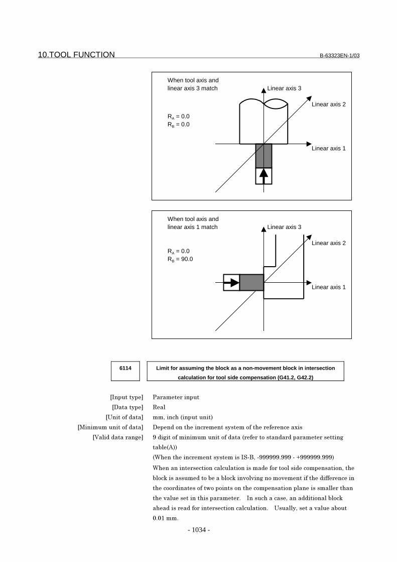
10.TOOL FUNCTION B-63323EN-1/03
- 1034 -
Linear axis 2
Linear axis 1
Linear axis 3When tool axis andlinear axis 3 match
RA = 0.0RB = 0.0
Linear axis 2
Linear axis 1
Linear axis 3When tool axis andlinear axis 1 match
RA = 0.0RB = 90.0
6114 Limit for assuming the block as a non-movement block in intersection
calculation for tool side compensation (G41.2, G42.2)
���������� �� ��� ������
��������� #��
�$����������� ��*������ ����������!
��������������������� �������������� ���������������� � �������
������������ ��� %������������������������������� � ���������� ���� ��� �������
��&� '!!
(��������� ����������������)*��%%%%%%"%%%���+%%%%%%"%%%!
(��������� ���������������������������� ���������������������*���
&���8��������������&���&���8���2��2���������2�������������� �����
������ �����������,���������������������������������������� �����
���2����������������� ��� "� � �������������*���������������&���8
�������� ����� ���� ������������������"� � $������*������2�����&���
�"�/���"
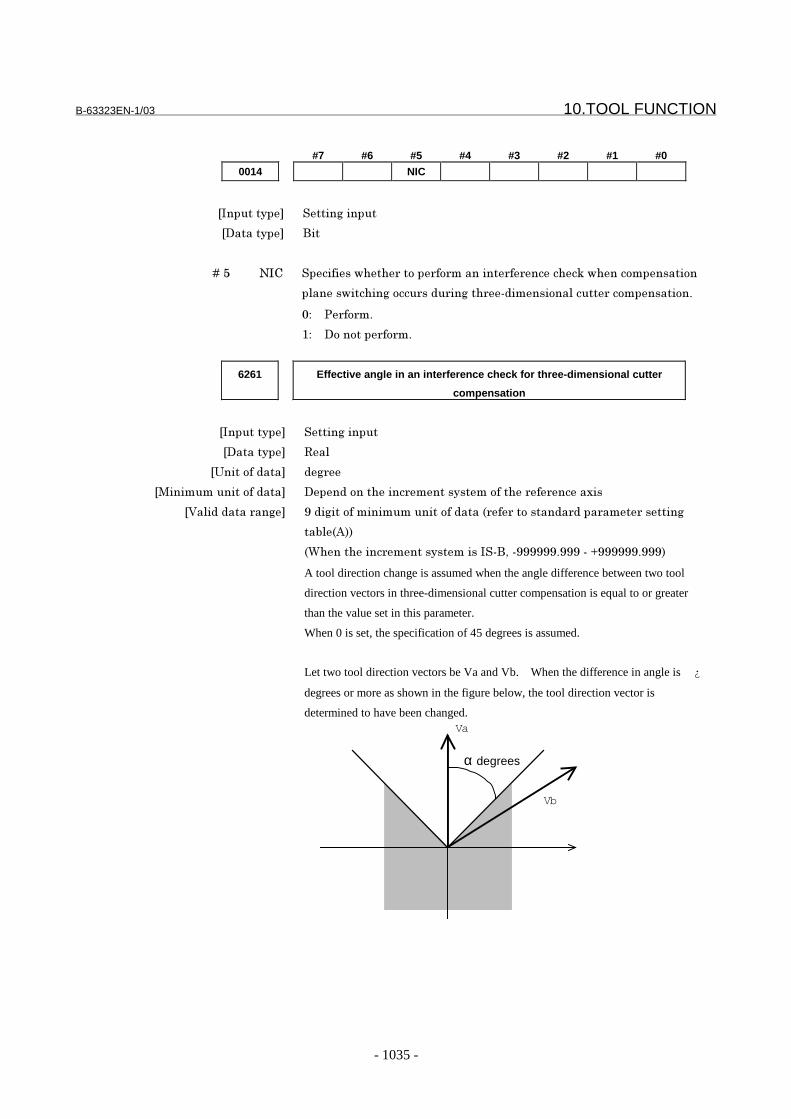
B-63323EN-1/03 10.TOOL FUNCTION
- 1035 -
#7 #6 #5 #4 #3 #2 #1 #0
0014 NIC
���������� ������������
��������� )��
� � � � 9�: -�; ��������,��� ����� �� �������� � ������8�,��������������
������,������������ ���� ������ ���������������� ������������"
�4 � �� �"
/4 �������� �� �"
6261 Effective angle in an interference check for three-dimensional cutter
compensation
���������� ������������
��������� #��
�$����������� ��
��������������������� �������������� ���������������� � �������
������������ ��� %������������������������������� � ���������� ���� ��� �������
��&� '!!
(��������� ����������������)*��%%%%%%"%%%���+%%%%%%"%%%!
A tool direction change is assumed when the angle difference between two tool
direction vectors in three-dimensional cutter compensation is equal to or greater
than the value set in this parameter.
When 0 is set, the specification of 45 degrees is assumed.
Let two tool direction vectors be Va and Vb. When the difference in angle is ¿
degrees or more as shown in the figure below, the tool direction vector is
determined to have been changed.
α degrees
Va
Vb
10.TOOL FUNCTION B-63323EN-1/03
- 1036 -
6115 Angle determination fluctuation value for leading edge offset
���������� �� ��� ������
��������� #��
�$����������� ��
��������������������� �������������� ���������������� � �������
������������ ��� %������������������������������� � ���������� ���� ��� �������
��&� '!!
(��������� ����������������)*��%%%%%%"%%%���+%%%%%%"%%%!
This parameter sets a variation range used to determine whether the included angle
between the tool direction vector (VT) and move direction vector (VM) is 0°, 180°,
or 90° during leading edge offsetting.
For example, let the included angle between VT and VM beθ (0≤θ≤180), and the
angle set in this parameter be ∆ ˘. Then, θ is determined as follows:
When 0≤θ≤∆θ θ=0°
When (180-∆θ) ≤θ≤180 θ=180°
When (90-∆θ) ≤θ≤ (90 {∆ ˘) θ=90°
Normally, set around 1.0 in this parameter.
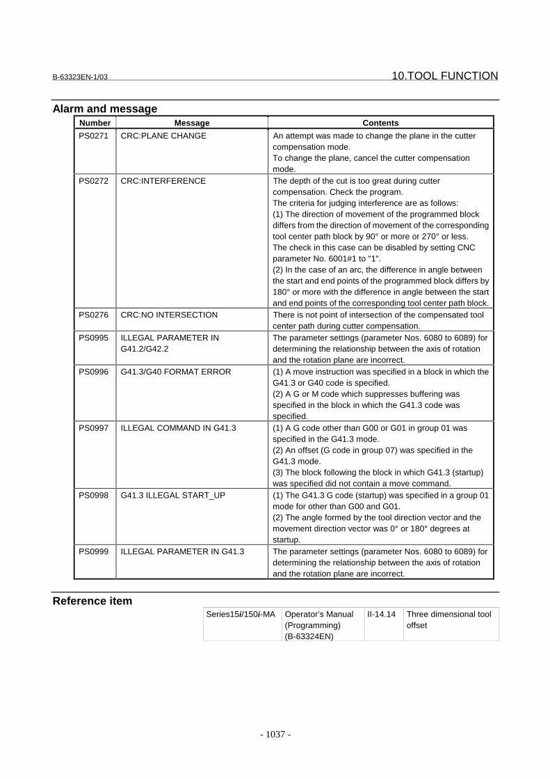
B-63323EN-1/03 10.TOOL FUNCTION
- 1037 -
Alarm and messageNumber Message Contents
PS0271 CRC:PLANE CHANGE An attempt was made to change the plane in the cuttercompensation mode.To change the plane, cancel the cutter compensationmode.
PS0272 CRC:INTERFERENCE The depth of the cut is too great during cuttercompensation. Check the program.The criteria for judging interference are as follows:(1) The direction of movement of the programmed blockdiffers from the direction of movement of the correspondingtool center path block by 90° or more or 270° or less.The check in this case can be disabled by setting CNCparameter No. 6001#1 to "1".(2) In the case of an arc, the difference in angle betweenthe start and end points of the programmed block differs by180° or more with the difference in angle between the startand end points of the corresponding tool center path block.
PS0276 CRC:NO INTERSECTION There is not point of intersection of the compensated toolcenter path during cutter compensation.
PS0995 ILLEGAL PARAMETER ING41.2/G42.2
The parameter settings (parameter Nos. 6080 to 6089) fordetermining the relationship between the axis of rotationand the rotation plane are incorrect.
PS0996 G41.3/G40 FORMAT ERROR (1) A move instruction was specified in a block in which theG41.3 or G40 code is specified.(2) A G or M code which suppresses buffering wasspecified in the block in which the G41.3 code wasspecified.
PS0997 ILLEGAL COMMAND IN G41.3 (1) A G code other than G00 or G01 in group 01 wasspecified in the G41.3 mode.(2) An offset (G code in group 07) was specified in theG41.3 mode.(3) The block following the block in which G41.3 (startup)was specified did not contain a move command.
PS0998 G41.3 ILLEGAL START_UP (1) The G41.3 G code (startup) was specified in a group 01mode for other than G00 and G01.(2) The angle formed by the tool direction vector and themovement direction vector was 0° or 180° degrees atstartup.
PS0999 ILLEGAL PARAMETER IN G41.3 The parameter settings (parameter Nos. 6080 to 6089) fordetermining the relationship between the axis of rotationand the rotation plane are incorrect.
Reference itemSeries15i/150i-MA Operator’s Manual
(Programming)(B-63324EN)
II-14.14 Three dimensional tooloffset
10.TOOL FUNCTION B-63323EN-1/03
- 1038 -
10.4.8.1 Three-dimensional cutter compensation at tool center point
For machines with a rotation axis for rotating a tool, this functionperforms three-dimensional cutter compensation at the tool tip positionif the program-specified point is specified with a pivot point.When this function is used, the program-specified point (pivot point) isconverted into a tool tip position (cutting point) and a three-dimensional cutter compensation vector is calculated for the latterposition. Then, the program-specified point (pivot point) iscompensated for with the three-dimensional cutter compensationvector.If the tool side offset (G41.2/G42.2) of three-dimensional cuttercompensation is performed, the operation of this function will be asfollows:
(1) If parameter No. 6130 is 0 (conventional specification)The three-dimensional cutter compensation vector is calculated atthe program-specified point (pivot point).
(2) If parameter No. 6130 is not 0 (this function)The three-dimensional cutter compensation vector is calculated atthe tool tip position (cutting point).
DescriptionThis function calculates a vector at the tool tip position for the three-dimensional cutter compensation function as described below.
(1) Convert the programmed coordinates from a program-specifiedpoint (pivot point) to a tool tip position (cutting point). ParameterNo. 6130 is used to store the distance from the program-specifiedpoint (pivot point) to the tool tip position (cutting point).
(2) Calculate a three-dimensional cutter compensation vector at thetool tip position (cutting point).
(3) Add the cutter compensation vector to the program-specified point(pivot point).
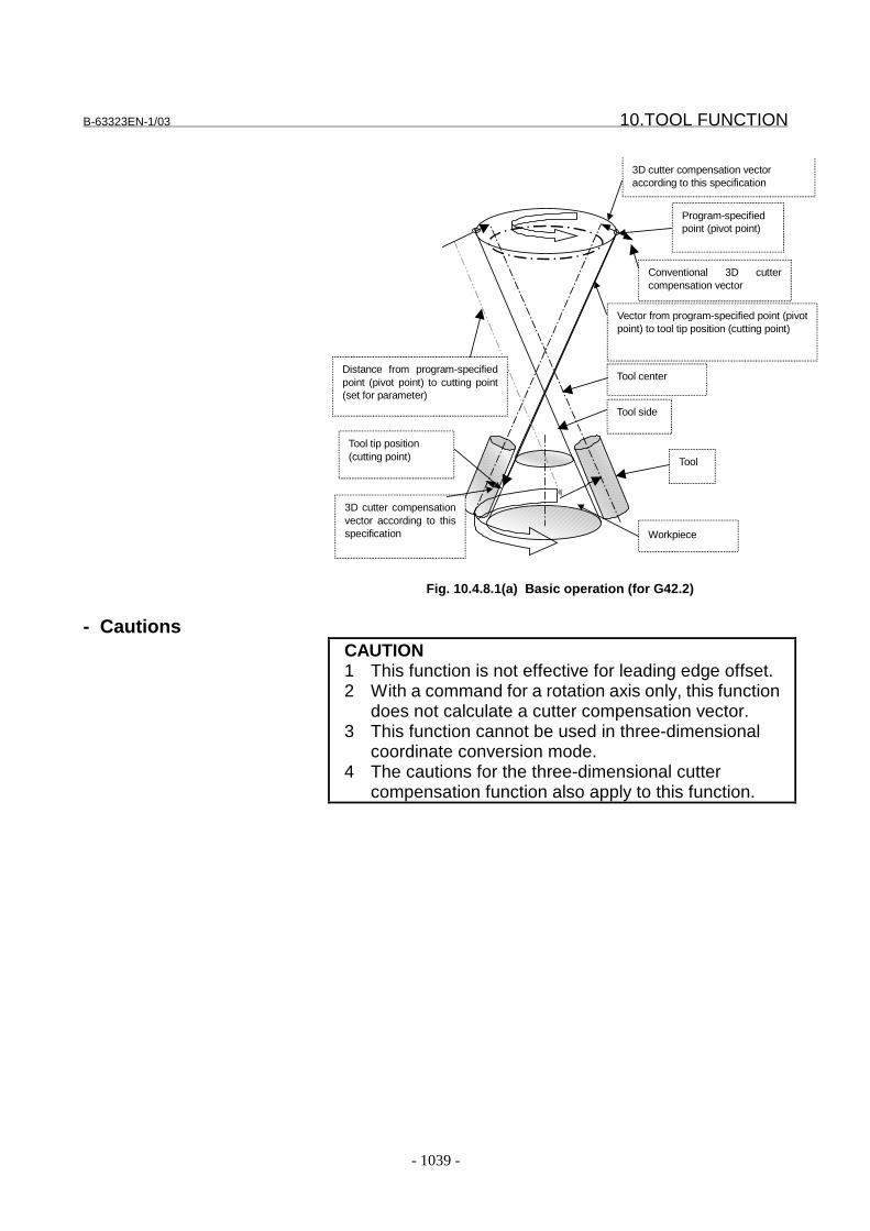
B-63323EN-1/03 10.TOOL FUNCTION
- 1039 -
Program-specifiedpoint (pivot point)
Workpiece
Tool center
Tool side
Distance from program-specifiedpoint (pivot point) to cutting point(set for parameter)
Vector from program-specified point (pivotpoint) to tool tip position (cutting point)
Tool tip position(cutting point)
3D cutter compensation vectoraccording to this specification
Tool
Conventional 3D cuttercompensation vector
3D cutter compensationvector according to thisspecification
Fig. 10.4.8.1(a) Basic operation (for G42.2)
- CautionsCAUTION1 This function is not effective for leading edge offset.2 With a command for a rotation axis only, this function
does not calculate a cutter compensation vector.3 This function cannot be used in three-dimensional
coordinate conversion mode.4 The cautions for the three-dimensional cutter
compensation function also apply to this function.
10.TOOL FUNCTION B-63323EN-1/03
- 1040 -
Parameters(1) Parameters defining the relationship between the rotation axis for controlling the tool and the rotationplane
1. Relationship between rotation axis and rotation plane Parameters No. 6080 to 60892. Direction of the tool axis Parameters No. 6106 to 61073. Reference angle for the rotation axis Parameters No. 6104 to 6105
(2) Tool tip position support parameter
Distance from the program-specified point (pivot point) to the tool tip position(cutting point)
Parameter No. 6130
For details of (1), see the section on three-dimensional cuttercompensation.
6130 Distance from the program-specified point (pivot point) to the tool tip
position (cutting point)
���������� �� ��� ������
��������� #��
�$����������� ��*������ ����������!
����������������������������������� ���������������� � �������"
������������ ��� %���������������������������������� � ���������� ���� ��� �������
��&�� '!!
(��������� �������������)*��%%%%%%"%%%���+%%%%%%"%%%!
Set the distance from the program-specified point to the actual cutting point to
calculate a three-dimensional cutter compensation vector at the tool tip position.
If this parameter is 0, the tool tip support of the three-dimensional cutter
compensation function is not effective.
Change the setting of this parameter before turning the three-dimensional cutter
compensation mode to on.
Reference itemsConnection Manual
i This manual j10.4.8 Three-dimensional tool
compensation
Operator’s Manual(Programming)(B-63324EN)
II.14.14 Three-dimensional toolcompensation
FANUC Series15i/150i-MA
Parameter Manual(B-63330EN)
4.4.29 5-Axes controlparameters
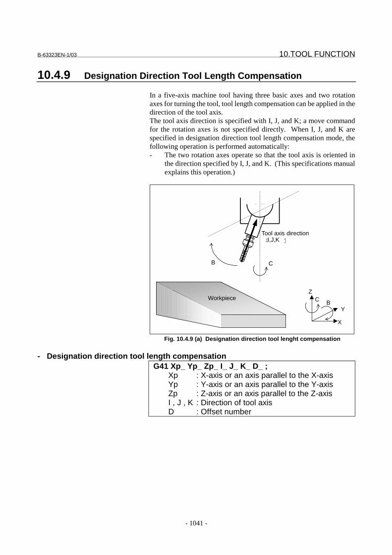
B-63323EN-1/03 10.TOOL FUNCTION
- 1041 -
10.4.9 Designation Direction Tool Length Compensation
In a five-axis machine tool having three basic axes and two rotationaxes for turning the tool, tool length compensation can be applied in thedirection of the tool axis.The tool axis direction is specified with I, J, and K; a move commandfor the rotation axes is not specified directly. When I, J, and K arespecified in designation direction tool length compensation mode, thefollowing operation is performed automatically:- The two rotation axes operate so that the tool axis is oriented in
the direction specified by I, J, and K. (This specifications manualexplains this operation.)
C B
Z
Y
X
Workpiece
CB
Tool axis directioni I,J,K j
Fig. 10.4.9 (a) Designation direction tool lenght compensation
- Designation direction tool length compensationG41 Xp_ Yp_ Zp_ I_ J_ K_ D_ ;
Xp : X-axis or an axis parallel to the X-axisYp : Y-axis or an axis parallel to the Y-axisZp : Z-axis or an axis parallel to the Z-axisI , J , K : Direction of tool axisD : Offset number

10.TOOL FUNCTION B-63323EN-1/03
- 1042 -
NOTE1 The format of specified-direction tool length
compensation is the same as that for three-dimensional tool compensation. When usingspecified-direction tool length compensation, set bit0 (DDT) of parameter No. 7711 to 1.
2 A three-dimensional space in which specified-direction tool length compensation is to beperformed is determined by the axis addressesspecified in G41. If Xp, Yp, or Zp is not specified,specified-direction tool length compensation isperformed along the X-axis, Y-axis, or Z-axis.
3 Specify I, J, and K in a G41 block at all times. If anyof I, J, or K is missing, ordinary tool lengthcompensation is performed.
4 Usually, specified-direction tool lengthcompensation is started by the G41 command.When the G42 command is specified, compensationis performed in the direction opposite to that of G41.
- Canceling designation direction tool length compensationG40 Xp_ Yp_ Zp_ B_ C_ ;
NOTEA compensation vector can be cancelled byspecifying G40; only. In this case, no movement ismade on a rotation axis.

B-63323EN-1/03 10.TOOL FUNCTION
- 1043 -
- Operation in the specified-direction tool length compensation mode(1) Movement is made on all five axes simultaneously to the position
( cbzyx ,,,, ) calculated as shown below.
I
Jc
K
JIb
KJI
KlZz
KJI
JlYy
KJI
IlXx
1
221
222
222
222
tan
tan
−
−
=
+=
+++=
+++=
+++=
zyx ,, : Tool center position
cb, : Rotation axis position
ZYX ,, : tip position
(programmed position)
KJI ,, : Tool axis direction
l : Tool offset value
All positions are represented by absolute
coordinates.),,( ZYX
),,( zyx
),,( KJI
l
Fig. 10.4.9 (b) Expression for Compensation Calculation
(2) When circular interpolation or helical interpolation (G02, G03) isspecifiedI, J, and K have no effect on specified-direction tool lengthcompensation. A compensation vector generated in the previousblock is used as is.
Programmed path
Tool center path
Compensation vector
of the previous block
The same vector
is generated.
Fig. 10.4.9 (c) Compensation Vector in Circular Interpolation
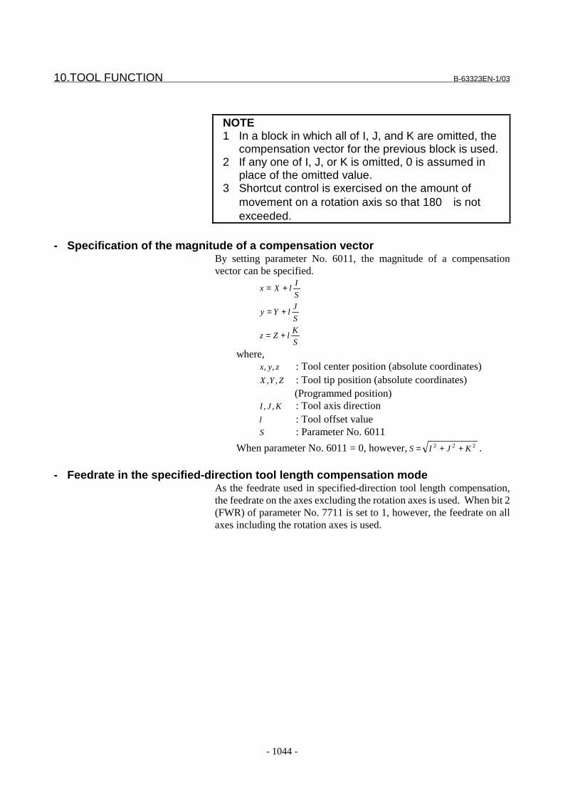
10.TOOL FUNCTION B-63323EN-1/03
- 1044 -
NOTE1 In a block in which all of I, J, and K are omitted, the
compensation vector for the previous block is used.2 If any one of I, J, or K is omitted, 0 is assumed in
place of the omitted value.3 Shortcut control is exercised on the amount of
movement on a rotation axis so that 180 is notexceeded.
- Specification of the magnitude of a compensation vectorBy setting parameter No. 6011, the magnitude of a compensationvector can be specified.
S
IlXx +=
S
JlYy +=
S
KlZz +=
where,zyx ,, : Tool center position (absolute coordinates)ZYX ,, : Tool tip position (absolute coordinates)
(Programmed position)KJI ,, : Tool axis direction
l : Tool offset valueS : Parameter No. 6011
When parameter No. 6011 = 0, however, 222 KJIS ++= .
- Feedrate in the specified-direction tool length compensation modeAs the feedrate used in specified-direction tool length compensation,the feedrate on the axes excluding the rotation axes is used. When bit 2(FWR) of parameter No. 7711 is set to 1, however, the feedrate on allaxes including the rotation axes is used.
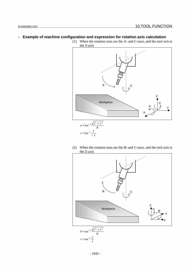
B-63323EN-1/03 10.TOOL FUNCTION
- 1045 -
- Example of machine configuration and expression for rotation axis calculation(1) When the rotation axes are the A- and C-axes, and the tool axis is
the Z-axis
CA
Z
X
Y
Workpiece
CA
J
Ic
K
JIa
−=
+=
−
−
1
221
tan
tan
(2) When the rotation axes are the B- and C-axes, and the tool axis isthe Z-axis
C B
Z
Y
X
Workpiece
CB
I
Jc
K
JIb
1
221
tan
tan
−
−
=
+=

10.TOOL FUNCTION B-63323EN-1/03
- 1046 -
(3) When the rotation axes are the A- and B-axes, and the tool axis isthe X-axis
Workpiece
B
A
Z
Y
X
A
B
I
KJb
K
Ja
221
1
tan
tan
+=
−=
−
−
(4) When the rotation axes are the A- and B-axes, and the tool axis isthe Z-axis (master axis: B-axis)
B
A
Z
YXWorkpiece
B
A
K
Ib
KI
Ja
1
22
1
tan
tan
−
−
=
+
−=
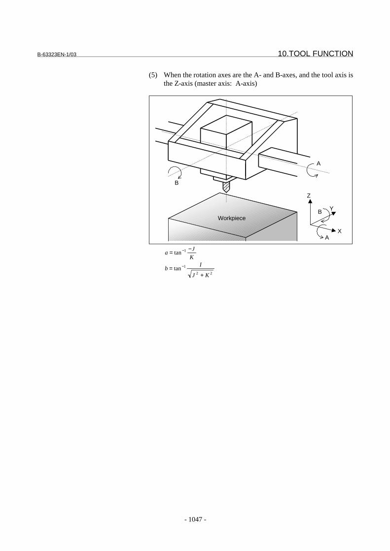
B-63323EN-1/03 10.TOOL FUNCTION
- 1047 -
(5) When the rotation axes are the A- and B-axes, and the tool axis isthe Z-axis (master axis: A-axis)
B
A
Z
X
Y
Workpiece
A
B
22
1
1
tan
tan
KJ
Ib
K
Ja
+=
−=
−
−
10.TOOL FUNCTION B-63323EN-1/03
- 1048 -
Limitation
- Rotation axis specificationA rotation axis must not be specified in specified-direction tool lengthcompensation mode. Otherwise, an alarm (PS0809) is issued.
- Commands related to reference position returnThe specified-direction tool length compensation mode must becancelled before any of the following can be specified:- Reference position return check (G27)- Return to reference position (G28)- Return to 2nd reference position (G30)- Return from reference position (G29)
- Coordinate system rotation, scalingIn specified-direction tool length compensation mode, coordinatesystem rotation and scaling are applied to the tool tip position.
- Three-dimensional coordinate conversionWhen specified-direction tool length compensation is used duringthree-dimensional coordinate conversion, three-dimensionalcoordinate conversion is applied to the tool axis directions (I, J, K) aswell.
- Relationships with other compensation functions(1) Tool length compensation
Tool length compensation is applied to a path resulting fromspecified-direction tool length compensation.
(2) Tool offsetThe tool offset function cannot be used in specified-direction toollength compensation mode.
(3) Cutter compensationIf all of I, J, and K are specified in a G41 block, the specified-direction tool length compensation mode is set. If any one of I, J,or K is omitted, cutter compensation mode is set. This means thatboth modes cannot be set at the same time.
(4) Tool axis direction tool length compensationIn specified-direction tool length compensation mode, tool axisdirection tool length compensation cannot be used.

B-63323EN-1/03 10.TOOL FUNCTION
- 1049 -
Parameter#7 #6 #5 #4 #3 #2 #1 #0
1014 RAP RAM
���������� �� ��� ������
��������� )������
� � � � 9�� #'� ��������,��� ��������������������� ��������������� ����������
�� ����������������������������*��� ��������������������*����
������������� ����������������������������"
�4 -������������� ������������"
/4 $��������� ������������"
������,������� ��������� ����������������������������� �������
������ ������� ����"
� � � � 9�/ #'� ��������,��� ���� ������������������� ������������� ����������������
�����������*��� ��������������������*������������������ �����
������������������������������ ���� �� ������������"
�4 < ���� �� ������������"
/4 �� ��� �����"� � 1�� ������������������������ ������������������
�� ����������������������������"
1029 Axis number of the linear axis to which a rotation axis belongs
���������� �� ��� ������
��������� ���� ����
������������ ��� �����������
When a rotation axis turns about a linear axis, the linear axis is referred to as an axis
to which the rotation axis belongs, and is set using this parameter. For a rotation
axis that belongs to no linear axis, or for a linear axis, 0 is set.
Example:
Axis configuration: X, Y, Z, C, A
Linear axis: X, Y, Z
Rotation axis: A (turning about the X-axis), C (turning about the Z-axis)
In the above case, set the following:
Axis name Setting
1 X 0
2 Y 0
3 Z 0
4 C 3
5 A 1
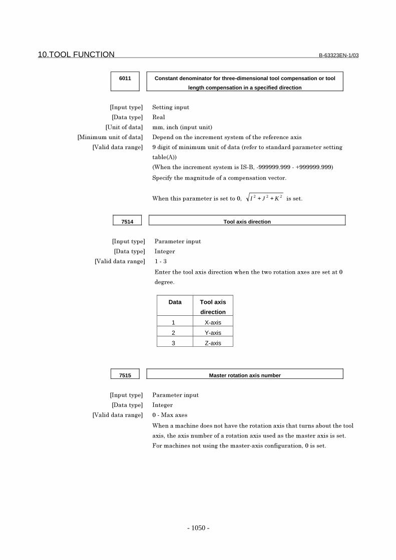
10.TOOL FUNCTION B-63323EN-1/03
- 1050 -
6011 Constant denominator for three-dimensional tool compensation or tool
length compensation in a specified direction
���������� ������������
��������� #��
�$����������� ��*������ ����������!
��������������������� �������������� ���������������� � �������
������������ ��� %������������������������������� � ���������� ���� ��� �������
��&� '!!
(��������� ����������������)*��%%%%%%"%%%���+%%%%%%"%%%!
������������������������������������2��� "
(���������� ��� �����������*� 222 KJI ++ ������"
7514 Tool axis direction
���������� �� ��� ������
��������� ����
������������ ��� /���3
=�� ���������������� ������,�������,�� ������������� ��������
�� "
Data Tool axis
direction
1 X-axis
2 Y-axis
3 Z-axis
7515 Master rotation axis number
���������� �� ��� ������
��������� ����
������������ ��� �����������
(����������������������2���� �������������������� ����&�����������
����*������������& ������ ��������������������������� �����������"
>� �������������������������� ������������� �����*��������"
B-63323EN-1/03 10.TOOL FUNCTION
- 1051 -
CautionCAUTION
Always set the following parameters to 1 for therotation axis for designation direction tool lengthcompensation:Parameter ROT i No.1006#0 jParameter ROL i No.1009#2 j
Alarm and messageNumber Message Contents
PS0809 ILLEGAL COMMAND IN G41/G42 Specified direction tool length compensation parametersare incorrect.A move instruction for a axis of rotation was specified in thespecified direction tool length compensation mode.
Reference itemSeries15i/150i-MA Operator’s Manual
(Programming)(B-63324EN)
II-14.15 Designation directiontool lengthcompensation

10.TOOL FUNCTION B-63323EN-1/03
- 1052 -
10.4.10 Tool Center Point Control
On a five-axis machine having two rotation axes that turn a tool, toollength compensation can be performed momentarily even in the middleof a block.This tool length compensation is classified into two types by thedifference in programming method. In the explanation of this function,the two rotation axes are assumed to be the B- and C-axes.(1) Type 1
The rotation axis position (B, C) is specified.The CNC applies tool length compensation by the compensationamount along the tool axis of which orientation is calculated fromthe specified rotation axis position. This means thatcompensation is performed by moving the three linear axes.
(2) Type 2The tool axis orientation (I, J, K) is specified.The CNC controls the two rotation axes so that the tool is orientedas specified, and performs tool length compensation along the toolaxis by the compensation amount. This means that compensationis performed by moving the two rotation axes and three linearaxes.
Tool center point control (type 1) differs from tool lengthcompensation along the tool axis as shown below:
Tool center point control (type 1)The path of the tool tip center is linear as specified.
Tool length compensation along the tool axisThe path of the tool tip center is not linear.
Tool pivot point= interpolation path(not linear)
Tool tip center path(linear)
Tool pivot point= interpolation path(linear)
Tool tip center path(not linear)
Fig. 10.4.10 (a) Difference between Tool Center Point Control and Tool LengthCompensation along the Tool Axis
B-63323EN-1/03 10.TOOL FUNCTION
- 1053 -
NOTEThe length from the tool tip to tool pivot point mustequal the sum of the tool length compensation andtool holder offset.
The difference between tool center point control (type 2) anddesignation direction tool length compensation is also the same asshown in Fig. 10.4.10 (a).
Format- Specifying tool center point control (type 1)
G43.4 H_ GH : Offset number
- Specifying tool center point control (type 2)G43.5 I_ J_ K_ H_ Q_ G
I,J,K : Tool axis orientationH : Offset numberQ : Tool inclination angle (degrees)
NOTES1 The command format of tool center point control (type
2) is very different from the command format ofdesignation direction tool length compensation(G41I_J_K_D_).
2 When I, J, and K are all omitted form a block, thecompensation vector in the previous block is used.
3 When any of I, J, and K is omitted, the omitted I, J, or Kis assumed to be 0.
4 Movement of the rotation axes is controlled by ashortcut control so that the amount of movementdoes not exceed 180°.
- Canceling tool center point controlG49 G
NOTEThe command for canceling tool center point control(type 2) differs from the command for cancelingdesignation direction tool length compensation(G40).
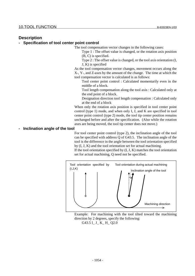
10.TOOL FUNCTION B-63323EN-1/03
- 1054 -
Description- Specification of tool center point control
The tool compensation vector changes in the following cases:Type 1 : The offset value is changed, or the rotation axis position(B, C) is specified.Type 2 : The offset value is changed, or the tool axis orientation (I,J, K) is specified
As the tool compensation vector changes, movement occurs along theX-, Y-, and Z-axes by the amount of the change. The time at which thetool compensation vector is calculated is as follows:
Tool center point control : Calculated momentarily even in themiddle of a block.Tool length compensation along the tool axis : Calculated only atthe end point of a block.Designation direction tool length compensation : Calculated onlyat the end of a block
When only the rotation axis position is specified in tool center pointcontrol (type 1) mode, and when only I, J, and K are specified in toolcenter point control (type 2) mode, the tool tip center position remainsunchanged before and after the specification. (Also while the rotationaxes are being moved, the tool tip center does not move.)
- Inclination angle of the toolFor tool center point control (type 2), the inclination angle of the toolcan be specified with address Q of G43.5. The inclination angle of thetool is the difference in the angle between the tool orientation specifiedby (I, J, K) and the tool orientation set for actual machining.If the tool orientation specified by (I, J, K) matches the tool orientationset for actual machining, Q need not be specified.
Tool orientation specified by(I,J,K)
Tool orientation during actual machining
Machining direction
Inclination angle of the tool
Example: For machining with the tool tilted toward the machiningdirection by 2 degrees, specify the following:
G43.5 I_ J_ K_ H_ Q2.0
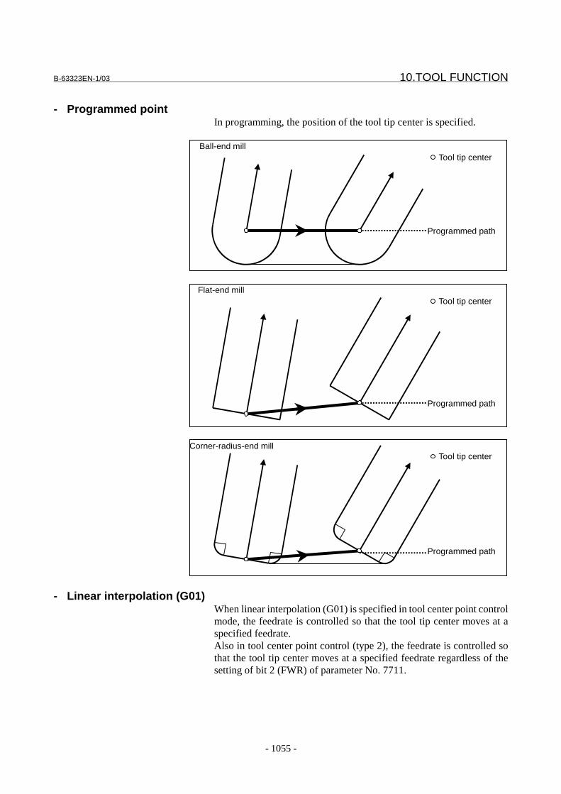
B-63323EN-1/03 10.TOOL FUNCTION
- 1055 -
- Programmed pointIn programming, the position of the tool tip center is specified.
Ball-end mill
Programmed path
Tool tip center
Flat-end mill
Programmed path
Tool tip center
Corner-radius-end mill
Programmed path
Tool tip center
- Linear interpolation (G01)When linear interpolation (G01) is specified in tool center point controlmode, the feedrate is controlled so that the tool tip center moves at aspecified feedrate.Also in tool center point control (type 2), the feedrate is controlled sothat the tool tip center moves at a specified feedrate regardless of thesetting of bit 2 (FWR) of parameter No. 7711.
10.TOOL FUNCTION B-63323EN-1/03
- 1056 -
- Specification of rotation axes(1) Type 1
When only the rotation axes are specified in tool center pointcontrol (type 1) mode, the feedrate of the rotation axes is set to themaximum cutting feedrate (parameter No. 1422).
(2) Type 2In tool center point control (type 2) mode, the rotation axes cannotbe specified. If the rotation axes are specified, alarm (PS1061)occurs.
- Positioning (G00)NOTE1 Set the following parameters:
(1) Bit 4 (LRP) of parameter No.1400 = 1: Linear typerapid traverse
(2) Bit 5 (FRP) of parameter No.1603 = 1:Acceleration/deceleration before interpolation is usedin rapid traverse.
(3) Parameter No.1671: Acceleration ofacceleration/deceleration before interpolation forrapid traverse
(4) Parameter No.1672: Acceleration change periodof bell-shaped acceleration/deceleration beforeinterpolation for rapid traverse
2 If the above settings are not made, or if look-aheadacceleration/deceleration before interpolation is notvalid, axis movement may be performed at a higherfeedrate than the rapid traverse rate.
- Operation at start and cancellation(1) Type 1
When tool center point control (type 1) starts (G43.4H_) andwhen it is canceled (G49), the CNC calculates the compensationvector only at the end of the block.
(2) Type 2When tool center point control (type 2) starts (G43.5H_) andwhen it is canceled (G49), the CNC calculates the compensationvector only at the end of the block.
- Operation of tool center point control (type 1)The following items are the same as for tool length compensation alongthe tool axis:-Machine configuration example and equation for rotation axiscalculation-Tool holder offset-Specification of angular displacement in a parameter-Zero-point compensation for the rotation axes-Rotation axis offset
B-63323EN-1/03 10.TOOL FUNCTION
- 1057 -
- Operation of tool center point control (type 2)The following item is the same as for tool length compensation alongthe tool axis:- Tool holder offsetThe following items are the same as for tool length compensation in aspecified direction:- Operation in tool length compensation in a specified direction- Machine configuration example and equation for rotation axis
calculation- Tool offset by tool number
When the tool offset by tool number is used, the tool lengthcompensation amount corresponding to a tool number (T code) is usedfor tool center point control.
- Tool life managementWhen tool life management is used, the tool length compensationamount of the tool used is used for tool center point control.
- Three-dimensional cutter compensationTool center point control and three-dimensional cutter compensationcan be used at the same time.Three-dimensional cutter compensation is applied to a specified tooltip point. Three-dimensional cutter compensation, however, is notperformed momentarily in the middle of a block; it is performed only atthe end of a block.
- Three-dimensional coordinate conversionWhen tool center point control (type 2) is used during three-dimensional coordinate conversion, the tool axis orientation (I, J, K) isalso subjected to three-dimensional coordinate conversion.
- Rotation axis rolloverNOTE
Whenever using tool center point control (type 2), setbit 2 (ROL) of parameter No. 1009 to 1 to performrotation axis rollover.
Restrictions- Axis name extension
NOTEWhen I, J, and K are used as axis names by axisname extension, tool center point control (type 2)cannot be used.
- Manual interventionWhen manual intervention is made for a rotation axis with the manualabsolute switch set to off, the compensation vector is calculated usingthe rotation axis position that was found just before the manualintervention.Example: When the manual absolute switch is turned off with B
positioned to 30.0, then a manual intervention by 1.0 degree ismade for the B-axis, the machine coordinate position of the B-axisis 31.0. Then, starting automatic operation sets the absolutecoordinate position of the B-axis to 30.0. In tool center point
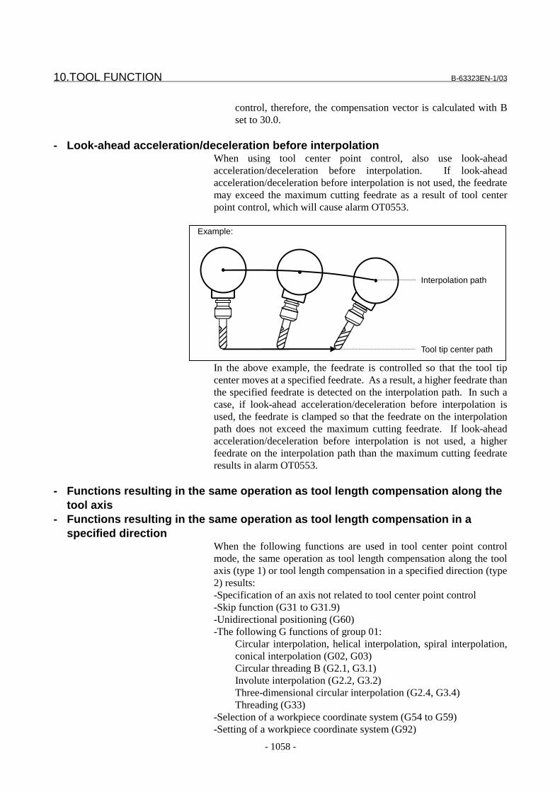
10.TOOL FUNCTION B-63323EN-1/03
- 1058 -
control, therefore, the compensation vector is calculated with Bset to 30.0.
- Look-ahead acceleration/deceleration before interpolationWhen using tool center point control, also use look-aheadacceleration/deceleration before interpolation. If look-aheadacceleration/deceleration before interpolation is not used, the feedratemay exceed the maximum cutting feedrate as a result of tool centerpoint control, which will cause alarm OT0553.
Example:
Interpolation path
Tool tip center path
In the above example, the feedrate is controlled so that the tool tipcenter moves at a specified feedrate. As a result, a higher feedrate thanthe specified feedrate is detected on the interpolation path. In such acase, if look-ahead acceleration/deceleration before interpolation isused, the feedrate is clamped so that the feedrate on the interpolationpath does not exceed the maximum cutting feedrate. If look-aheadacceleration/deceleration before interpolation is not used, a higherfeedrate on the interpolation path than the maximum cutting feedrateresults in alarm OT0553.
- Functions resulting in the same operation as tool length compensation along thetool axis
- Functions resulting in the same operation as tool length compensation in aspecified direction
When the following functions are used in tool center point controlmode, the same operation as tool length compensation along the toolaxis (type 1) or tool length compensation in a specified direction (type2) results:-Specification of an axis not related to tool center point control-Skip function (G31 to G31.9)-Unidirectional positioning (G60)-The following G functions of group 01:
Circular interpolation, helical interpolation, spiral interpolation,conical interpolation (G02, G03)Circular threading B (G2.1, G3.1)Involute interpolation (G2.2, G3.2)Three-dimensional circular interpolation (G2.4, G3.4)Threading (G33)
-Selection of a workpiece coordinate system (G54 to G59)-Setting of a workpiece coordinate system (G92)

B-63323EN-1/03 10.TOOL FUNCTION
- 1059 -
-Feed per revolution (G95)-Inverse time feed (G93)
- Unavailable functions 1In tool center point control mode, the functions listed below cannot beused.If these functions are used, the compensation vector of the previousblock is used as is.-The following G functions of group 01:
Exponential interpolation (G2.3, G3.3)Spline interpolation (G6.1)Smooth interpolation (G5.1Q2)NURBS interpolation (G6.2)
-Cylindrical interpolation (G7.1)-Polar coordinate interpolation (G12.1)-Normal-direction control (G41.1, G42.1)
- Unavailable functions 2In tool center point control mode, the functions listed below cannot beused.To use these functions, specify G49 to cancel tool center point control,then specify these functions.-Reference position return check (G27)-Automatic reference position return command (G28, G29, G30)-Positioning of the machine coordinate system (G53)
ParametersThe parameters used are the same as those for tool length compensationalong the tool axis and tool length compensation in a specifieddirection.
Parameters common to types 1 and 2Parameter No. Data type Description
1014#0 Bit axis Rotation axis selection1014#1 Bit axis Parameter axis selection
1029 Integer axis Linear axis as the center about whichthe rotation axis rotates
7514 Integer Tool axis orientation7515 Integer Axis number of the master axis of
rotation axes7548 Real
numberTool holder offset

10.TOOL FUNCTION B-63323EN-1/03
- 1060 -
Parameters for type 1Parameter No. Data type Description
7516 Realnumber axis
Angular displacement of the rotationaxes
7517 Realnumber axis
Offset of angular displacement of therotation axes
7518 Realnumber axis
Rotation axis reference positioncompensation amount
Alarms and messages
No. Message Description
PS0217 ILLEGAL OFFSET VALUE The offset number is illegal.PS1060 ILLEGAL PARAMETER IN
G43.4/G43.5There is an illegal parameter relating to tool center pointcontrol.
PS1061 ILLEGAL COMMAND IN G43.4/G43.5 Rotation axes are specified in tool center point control (type2).
OT0553 EXCESS VELOCITY IN G43.4/G43.5 As a result of tool center point control, the feedrate along anaxis exceeds the maximum cutting feedrate.
Reference10.4.6 Tool length
compensation along toolaxis
FANUC Series15i/150i-MA
Connection Manual(Function)(B-63323EN-1)
10.4.9 Designation direction toollength compensation

B-63323EN-1/03 10.TOOL FUNCTION
- 1061 -
10.4.11 Control Point Compensation of Tool Length CompensationAlong Tool Axis
Normally, the control point of tool length compensation along the toolaxis is the point of intersection of the centers of two rotation axes. Themachine coordinates also indicate this control point.This section explains the compensation performed when the centers ofthe two rotation axes do not intersect and also explains how to place thecontrol point at a convenient position on the machine.
Description- Compensation of the rotation centers of two rotation axes
Compensation when the rotation centers of two rotation axes do notmatch is performed.The length from the tool mounting position to the first rotation axiscenter is set as the tool holder offset value in parameter No. 7548.The vector from the first rotation axis center to the second rotation axiscenter is set as the rotation center compensation vector in parameter No.7519. Since parameter No. 7519 is an axis type parameter, thecompensation amount for three axes (X, Y, and Z) can be set in thisparameter.
Workpiece
Tool lengthcompensation amount
Tool holderoffset
Rotation centercompensation vector
A axiscenter
B axis center
B
A
Z
YX
B
A
Fig. 10.4.11 (a) Compensation of Rotation Centers of Two Rotation Axes

10.TOOL FUNCTION B-63323EN-1/03
- 1062 -
According to the machine type, set the values listed in the followingtable:
Table 10.4.11 (a) Setting the Tool Holder Offset and Rotation CenterCompensation Vector
Machine type Tool holder offsetParameter No. 7548
Rotation centercompensation vectorParameter No. 7519
(1) A- and C- axes. Toolaxis is Z-axis.
Length from tool mountingposition to A-axis center
Vector from A-axis centerto C-axis center
(2) B- and C-axes. Toolaxis is Z-axis.
Length from tool mountingposition to B-axis center
Vector from B-axis centerto C-axis center
(3) A- and B-axes. Toolaxis is X-axis.
Length from tool mountingposition to B-axis center
Vector from B-axis centerto A-axis center
(4) A- and B-axes. Toolaxis is Z-axis.B-axis is master.
Length from tool mountingposition to A-axis center
Vector from A-axis centerto B-axis center
(5) A- and B-axes. Toolaxis is Z-axis.A-axis is master.
Length from tool mountingposition to B-axis center
Vector from B-axis centerto A-axis center
NOTEWhen using the spindle center compensationdescribed below, set the length from the toolmounting position to the spindle center as the toolholder offset.
- Spindle center compensationCompensation of the spindle center is performed.The amount of spindle center compensation is set in parameter No.7520. Since parameter No. 7520 is an axis type parameter, thecompensation amount for three axes (X, Y, and Z) can be set in thisparameter.
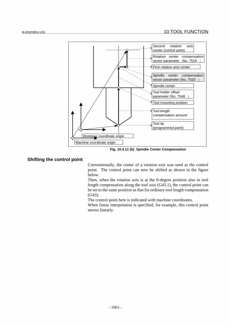
B-63323EN-1/03 10.TOOL FUNCTION
- 1063 -
Tool tip(programmed point)
Tool lengthcompensation amount
Second rotation axiscenter (control point)
Rotation center compensationvector parameter i No. 7519 j
First rotation axis center
Tool holder offsetparameter (No. 7548 j
Tool mounting position
Spindle center
Spindle center compensationvector parameter (No. 7520 j
Machine coordinate origin
Workpice coordinate origin
Fig. 10.4.11 (b) Spindle Center Compensation
Shifting the control pointConventionally, the center of a rotation axis was used as the controlpoint. The control point can now be shifted as shown in the figurebelow.Then, when the rotation axis is at the 0-degree position also in toollength compensation along the tool axis (G43.1), the control point canbe set to the same position as that for ordinary tool length compensation(G43).The control point here is indicated with machine coordinates.When linear interpolation is specified, for example, this control pointmoves linearly.
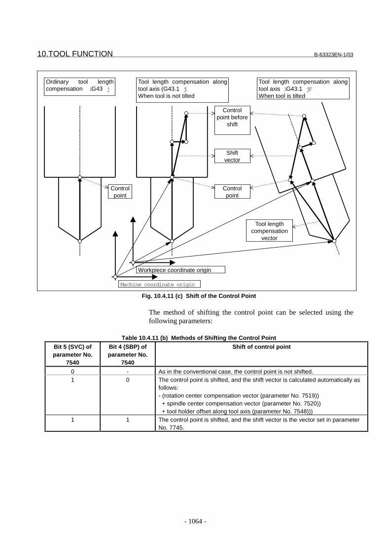
10.TOOL FUNCTION B-63323EN-1/03
- 1064 -
Shiftvector
Ordinary tool lengthcompensation i G43 j
Tool length compensation alongtool axis (G43.1 j :When tool is not tilted
Controlpoint
Controlpoint before
shift
Controlpoint
Tool length compensation alongtool axis i G43.1 jFWhen tool is tilted
Machine coordinate origin
Workpiece coordinate origin
Tool lengthcompensation
vector
Fig. 10.4.11 (c) Shift of the Control Point
The method of shifting the control point can be selected using thefollowing parameters:
Table 10.4.11 (b) Methods of Shifting the Control Point
Bit 5 (SVC) ofparameter No.
7540
Bit 4 (SBP) ofparameter No.
7540
Shift of control point
0 - As in the conventional case, the control point is not shifted.1 0 The control point is shifted, and the shift vector is calculated automatically as
follows:- (rotation center compensation vector (parameter No. 7519)) + spindle center compensation vector (parameter No. 7520)) + tool holder offset along tool axis (parameter No. 7548)))
1 1 The control point is shifted, and the shift vector is the vector set in parameterNo. 7745.
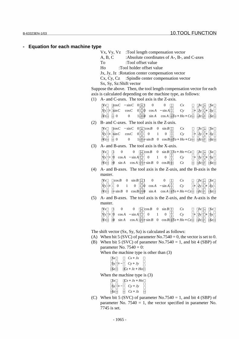
B-63323EN-1/03 10.TOOL FUNCTION
- 1065 -
- Equation for each machine typeVx, Vy, Vz :Tool length compensation vectorA, B, C :Absolute coordinates of A-, B-, and C-axesTo :Tool offset valueHo :Tool holder offset valueJx, Jy, Jz :Rotation center compensation vectorCx, Cy, Cz :Spindle center compensation vectorSx, Sy, Sz:Shift vector
Suppose the above. Then, the tool length compensation vector for eachaxis is calculated depending on the machine type, as follows:(1) A- and C-axes. The tool axis is the Z-axis.
+
+
++
−
−=
Sz
Sy
Sx
Jz
Jy
Jx
CzHoTo
Cy
Cx
AA
AACC
CC
Vz
Vy
Vx
cossin0
sincos0
001
100
0cossin
0sincos
(2) B- and C-axes. The tool axis is the Z-axis.
+
+
++
−
−=
Sz
Sy
Sx
Jz
Jy
Jx
CzHoTo
Cy
Cx
BB
BB
CC
CC
Vz
Vy
Vx
cos0sin
010
sin0cos
100
0cossin
0sincos
(3) A- and B-axes. The tool axis is the X-axis.
+
+
++
−
−=
Sz
Sy
Sx
Jz
Jy
Jx
Cz
Cy
CxHoTo
BB
BB
AA
AA
Vz
Vy
Vx
cos0sin
010
sin0cos
cossin0
sincos0
001
(4) A- and B-axes. The tool axis is the Z-axis, and the B-axis is themaster.
+
+
++
−
−=
Sz
Sy
Sx
Jz
Jy
Jx
CzHoTo
Cy
Cx
AA
AA
BB
BB
Vz
Vy
Vx
cossin0
sincos0
001
cos0sin
010
sin0cos
(5) A- and B-axes. The tool axis is the Z-axis, and the A-axis is themaster.
+
+
++
−
−=
Sz
Sy
Sx
Jz
Jy
Jx
CzHoTo
Cy
Cx
BB
BB
AA
AA
Vz
Vy
Vx
cos0sin
010
sin0cos
cossin0
sincos0
001
The shift vector (Sx, Sy, Sz) is calculated as follows:(A) When bit 5 (SVC) of parameter No.7540 = 0, the vector is set to 0.(B) When bit 5 (SVC) of parameter No.7540 = 1, and bit 4 (SBP) of
parameter No. 7540 = 0:When the machine type is other than (3)
++++
−=
HoJzCz
JyCy
JxCx
Sz
Sy
Sx
When the machine type is (3)
++
++−=
JzCz
JyCy
HoJxCx
Sz
Sy
Sx
(C) When bit 5 (SVC) of parameter No.7540 = 1, and bit 4 (SBP) ofparameter No. 7540 = 1, the vector specified in parameter No.7745 is set.
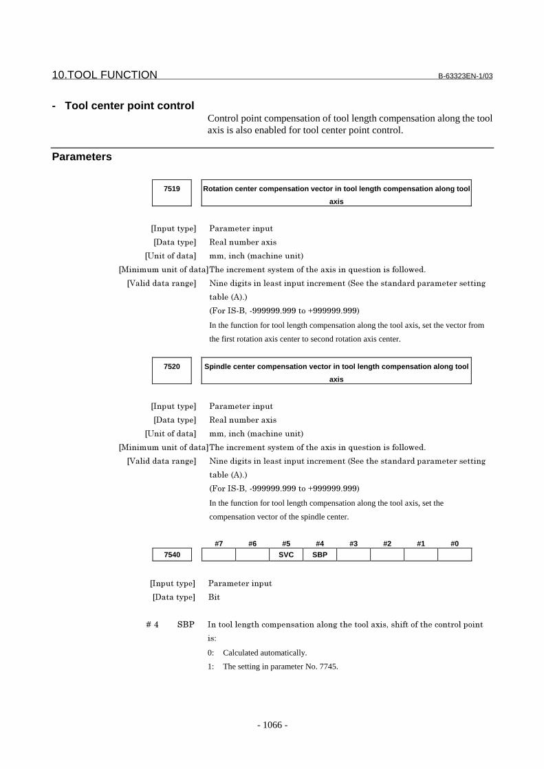
10.TOOL FUNCTION B-63323EN-1/03
- 1066 -
- Tool center point controlControl point compensation of tool length compensation along the toolaxis is also enabled for tool center point control.
Parameters
7519 Rotation center compensation vector in tool length compensation along tool
axis
���������� �� ��� ������
��������� #������& �����
�$����������� ��*������ �����������!
���������������������1����� ������������������������?���������������,�"
������������ ��� -��������������������������� ���� ����������� ���� ��� �������
��&�� '!"!
>� ����)*��%%%%%%"%%%����+%%%%%%"%%%!
In the function for tool length compensation along the tool axis, set the vector from
the first rotation axis center to second rotation axis center.
7520 Spindle center compensation vector in tool length compensation along tool
axis
���������� �� ��� ������
��������� #������& �����
�$����������� ��*������ �����������!
���������������������1����� ������������������������?���������������,�"
������������ ��� -��������������������������� ���� ����������� ���� ��� �������
��&�� '!"!
>� ����)*��%%%%%%"%%%����+%%%%%%"%%%!
In the function for tool length compensation along the tool axis, set the
compensation vector of the spindle center.
#7 #6 #5 #4 #3 #2 #1 #0
7540 SVC SBP
���������� �� ��� ������
��������� )��
� � � � 9�@ �)� ��������������������������������������������*����������������� ��������
��4
0: Calculated automatically.
1: The setting in parameter No. 7745.
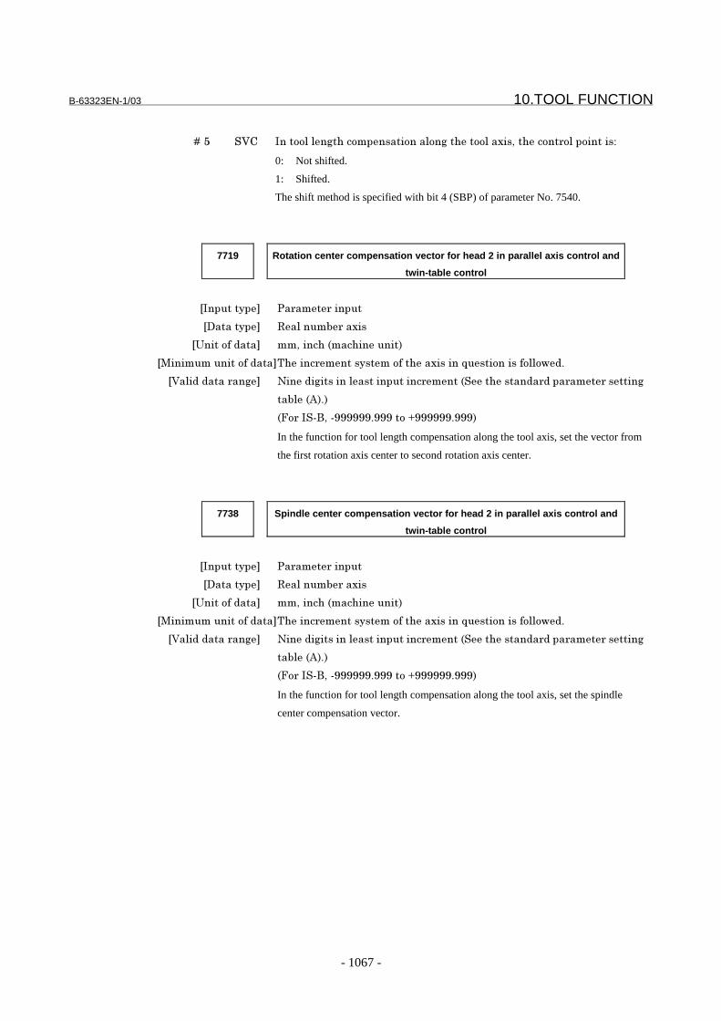
B-63323EN-1/03 10.TOOL FUNCTION
- 1067 -
� � � � 9�: ��; ��������������������������������������������*�������� �����������4
0: Not shifted.
1: Shifted.
The shift method is specified with bit 4 (SBP) of parameter No. 7540.
7719 Rotation center compensation vector for head 2 in parallel axis control and
twin-table control
���������� �� ��� ������
��������� #������& �����
�$����������� ��*������ �����������!
���������������������1����� ������������������������?���������������,�"
������������ ��� -��������������������������� ���� ����������� ���� ��� �������
��&�� '!"!
>� ����)*��%%%%%%"%%%����+%%%%%%"%%%!
In the function for tool length compensation along the tool axis, set the vector from
the first rotation axis center to second rotation axis center.
7738 Spindle center compensation vector for head 2 in parallel axis control and
twin-table control
���������� �� ��� ������
��������� #������& �����
�$����������� ��*������ �����������!
���������������������1����� ������������������������?���������������,�"
������������ ��� -��������������������������� ���� ����������� ���� ��� �������
��&�� '!"!
>� ����)*��%%%%%%"%%%����+%%%%%%"%%%!
In the function for tool length compensation along the tool axis, set the spindle
center compensation vector.
10.TOOL FUNCTION B-63323EN-1/03
- 1068 -
7745 Shift vector in tool length compensation along tool axis
���������� �� ��� ������
��������� #������& �����
�$����������� ��*������ �����������!
���������������������1����� ������������������������?���������������,�"
������������ ��� -��������������������������� ���� ����������� ���� ��� �������
��&�� '!"!
>� ����)*��%%%%%%"%%%����+%%%%%%"%%%!
In the function for tool length compensation along the tool axis, set the control
point shift vector. This parameter is valid when bit 5 (SVC) of parameter No.
7540 is 1 and bit 4 (SBP) of parameter No. 7540 is 1.
7746 Shift vector of tool length compensation along tool axis for head 2 in parallel
axis control and twin-table control
���������� �� ��� ������
��������� #������& �����
�$����������� ��*������ �����������!
���������������������1����� ������������������������?���������������,�"
������������ ��� -��������������������������� ���� ����������� ���� ��� �������
��&�� '!"!
>� ����)*��%%%%%%"%%%����+%%%%%%"%%%!
In the function for tool length compensation along the tool axis, set the control
point shift vector. This parameter is valid when bit 5 (SVC) of parameter No.
7540 is 1 and bit 4 (SBP) of parameter No. 7540 is 1.
Reference10.4.6 Tool length
compensation along toolaxis
FANUC Series15i/150i-MA
Connection Manual(Function)(B-63323EN-1)
10.4. Tool Center Point Control

B-63323EN-1/03 10.TOOL FUNCTION
- 1069 -
10.4.12 Grinding Wheel Wear Compensation
On a specified compensation plane, a compensation vector is createdon an extension of a straight line starting from a specified point(compensation center) toward a command end point.
Compensation vector
Programmed path
Tool center path
Compensation center
Fig. 10.4.12 (a) Grinding Wheel Wear Compensation
Format- Grinding wheel wear compensation (start of grinding wheel wear compensation)
G41 P_ D_ GP_ : Number of compensation center position
P1 (Selection of first compensation center) P2 (Selection of second compensation center) P3 (Selection of third compensation center)
D_ : Non-zero offset number
- Canceling the compensation vectorD0 GCancels just the compensation vector.
- - Maintaining the compensation vectorG40 GWhen a D code with a non-zero value has been specified,specifying G40 sets the mode in which the compensationvector is maintained.
- Canceling grinding wheel wear compensationG40 D0 G

10.TOOL FUNCTION B-63323EN-1/03
- 1070 -
Description- Grinding wheel wear compensation (start of grinding wheel wear compensation)
Up to three compensation center positions can be set. Set thecoordinates (in the workpiece coordinate system) of thesecompensation center positions in parameter Nos. 6050 to 6055.With the Pn (n = 1, 2, or 3) command, select the number of acompensation center position.
P1 - - - - Selects the first compensation center.P2 - - - - Selects the second compensation center.P3 - - - - Selects the third compensation center.
When G41P_ (selection of a compensation center position) and a Dcode with a non-zero value are specified, a compensation vector iscreated, and movement takes place even if there is no move commandspecified in the block.The D code may be specified in a block before or after G41P_.
Example
NOTE1 Specify the P_ command and G41 command at the
same time. If they are not specified at the same time,or if a value other than 1 to 3 is specified in the P_command, alarm PS618 is issued.
2 When the selected compensation center positionand absolute coordinate match on an axis, thecompensation vector component on that axisbecomes 0.
- Canceling the compensation vectorSpecifying D0 cancels the compensation vector.When D0 is specified in a block, movement due to the cancellationtakes place even if the block contains no move command.Then, when a D code with a non-zero value is specified again, acompensation vector is created, and movement takes place.
- Maintaining the compensation vectorWhen a D code with a non-zero value has been specified, specifyingG40 sets the mode that maintains the created compensation vector.When compensation vector maintenance mode has been entered, thecommand end position is shifted by the amount of the maintainedvector.To create a new compensation vector again, specify the grinding wheelwear compensation start command (G41 P_ D_). To cancel themaintained vector, specify D0. Specifying D0 cancels grinding wheelwear compensation, therefore, canceling the maintained vector. In thiscase, movement due to the cancellation takes place.
G41 P1 G
D2 GSelects the first compensation center.Creates a compensation vector and performs movement.
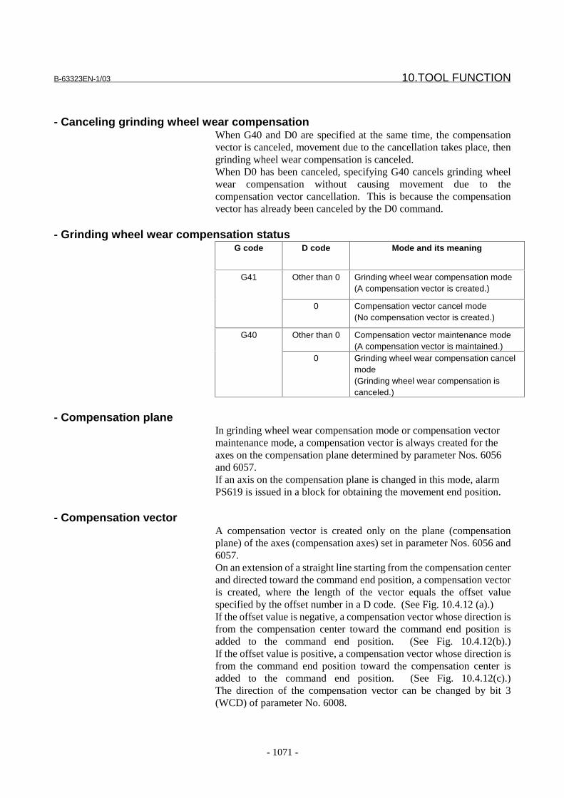
B-63323EN-1/03 10.TOOL FUNCTION
- 1071 -
- Canceling grinding wheel wear compensationWhen G40 and D0 are specified at the same time, the compensationvector is canceled, movement due to the cancellation takes place, thengrinding wheel wear compensation is canceled.When D0 has been canceled, specifying G40 cancels grinding wheelwear compensation without causing movement due to thecompensation vector cancellation. This is because the compensationvector has already been canceled by the D0 command.
- Grinding wheel wear compensation statusG code D code Mode and its meaning
Other than 0 Grinding wheel wear compensation mode(A compensation vector is created.)
G41
0 Compensation vector cancel mode(No compensation vector is created.)
Other than 0 Compensation vector maintenance mode(A compensation vector is maintained.)
G40
0 Grinding wheel wear compensation cancelmode(Grinding wheel wear compensation iscanceled.)
- Compensation planeIn grinding wheel wear compensation mode or compensation vectormaintenance mode, a compensation vector is always created for theaxes on the compensation plane determined by parameter Nos. 6056and 6057.If an axis on the compensation plane is changed in this mode, alarmPS619 is issued in a block for obtaining the movement end position.
- Compensation vectorA compensation vector is created only on the plane (compensationplane) of the axes (compensation axes) set in parameter Nos. 6056 and6057.On an extension of a straight line starting from the compensation centerand directed toward the command end position, a compensation vectoris created, where the length of the vector equals the offset valuespecified by the offset number in a D code. (See Fig. 10.4.12 (a).)If the offset value is negative, a compensation vector whose direction isfrom the compensation center toward the command end position isadded to the command end position. (See Fig. 10.4.12(b).)If the offset value is positive, a compensation vector whose direction isfrom the command end position toward the compensation center isadded to the command end position. (See Fig. 10.4.12(c).)The direction of the compensation vector can be changed by bit 3(WCD) of parameter No. 6008.
10.TOOL FUNCTION B-63323EN-1/03
- 1072 -
CAUTION The offset value is used as a radius. It can also be
used as a diameter by setting bit 0 (ODI) ofparameter No. 6008 to 1.
Compensation vector
Programmed path
Tool center path
Compensationcenter
Z
Y
Fig. 10.4.12 (b) Offset Value (-)
Compensation vector
Programmed pathTool center path
Compensationcenter
Z
Y
Fig. 10.4.12 (c) Offset Value (+)

B-63323EN-1/03 10.TOOL FUNCTION
- 1073 -
- Compensation plane and plane selection by G17/G18/G19Creation of a compensation vector is not related to plane selection byG17/G18/G19.For example, while circular interpolation is being performed on the XY(G17) plane, compensation can be applied to a compensation plane(such as the YZ plane). In grinding wheel wear compensation mode, ifthe creation of a compensation vector results in a change in the vectorcomponent, movement along a compensation axis is performed evenwhen no move command is specified for that axis.
Example 1With the Y- and Z-axes set as the compensation axes,a linear interpolation command is executed for the X-and Y-axes.
Y
X
b
Y
Compensationcenter
b
Z
a
a’
b’
a
Vay
a’
Vby
b’
Vay
Vby
Vaz
Vbz
Va
Vb
Programmed path a->b Path after compensation a’->b’
Example 2With the Y- and Z- axes set as the compensation axes,an arc command is executed for the X- and Y-axes.
Y
X
b
Y
Compensa-tion center
b
Z
a
a’
b’
a
Vay
a’
Vby
b’
Vay
Vby
Vaz
Vbz
Va
Vb
Programmed path a->b Path after compensation a’->b’
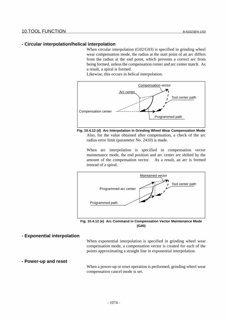
10.TOOL FUNCTION B-63323EN-1/03
- 1074 -
- Circular interpolation/helical interpolationWhen circular interpolation (G02/G03) is specified in grinding wheelwear compensation mode, the radius at the start point of an arc differsfrom the radius at the end point, which prevents a correct arc frombeing formed, unless the compensation center and arc center match. Asa result, a spiral is formed.Likewise, this occurs in helical interpolation.
Compensation vector
Programmed path
Tool center path
Compensation center
Arc center
Fig. 10.4.12 (d) Arc Interpolation in Grinding Wheel Wear Compensation ModeAlso, for the value obtained after compensation, a check of the arcradius error limit (parameter No. 2410) is made.
When arc interpolation is specified in compensation vectormaintenance mode, the end position and arc center are shifted by theamount of the compensation vector. As a result, an arc is formedinstead of a spiral.
Maintained vector
Programmed path
Tool center pathProgrammed arc center
Fig. 10.4.12 (e) Arc Command in Compensation Vector Maintenance Mode(G40)
- Exponential interpolationWhen exponential interpolation is specified in grinding wheel wearcompensation mode, a compensation vector is created for each of thepoints approximating a straight line in exponential interpolation.
- Power-up and resetWhen a power-up or reset operation is performed, grinding wheel wearcompensation cancel mode is set.

B-63323EN-1/03 10.TOOL FUNCTION
- 1075 -
- Available compensation functionsThe commands listed below can be used in grinding wheel wearcompensation mode. In these command modes, grinding wheel wearcompensation can also be used.- Tool length compensation (G43, G44, G49)- Position offset (G45 to G48)
Restrictions- Changing a compensation axis
Before changing a compensation axis, set compensation vector cancelmode, or cancel grinding wheel wear compensation.
- Changing the coordinate systemBefore changing the coordinate system, set compensation vector cancelmode, or cancel grinding wheel wear compensation.
- Commands related to reference position returnBefore issuing the following commands, set compensation vectorcancel mode, or cancel grinding wheel wear compensation:- Reference position return check (G27)- Reference position return (G28)- Second reference position return (G30)- Return from the reference position (G29)- Floating reference position return (G30.1)
- Relation with other compensation functionsFor a system having the grinding wheel wear compensation function,the following functions cannot be added:- Functions belonging to G code group 07 except this function
Cutter compensation (G40, G41, G42), three-dimensional toolcompensation (G40, G41), three-dimensional cuttercompensation (G41.3, G41.2, G42.2), tool length compensation ina specified direction (G41)
The grinding wheel wear compensation function cannot be used whenthe tool offset function by tool number is valid. Before using thegrinding wheel wear compensation function, disable the tool offsetfunction by tool number by setting bit 5 (NOT) of parameter No. 0011to 1.
The commands listed below are invalid for the coordinates of thecompensation center of grinding wheel wear compensation. Whenthese commands are executed in grinding wheel wear compensationmode, a compensation vector is created on an extension of the lineconnecting the compensation center and the command end position ofthe following functions:- Scaling (G51)- Coordinate system rotation (G68)

10.TOOL FUNCTION B-63323EN-1/03
- 1076 -
- Relation with compensation functionsThe commands listed below cannot be used in grinding wheel wearcompensation function mode. Before using these commands, cancelgrinding wheel wear compensation. Also, grinding wheel wearcompensation cannot be used in a mode of these commands.- Three-dimensional circular interpolation (G02.4, G03.4)- Hypothetical axis interpolation (G07)- Polar coordinate interpolation (G12.1, G13.1)- Cylindrical interpolation (G07.1)- Spline interpolation (G06.1)- Smooth interpolation (G05.1)- NURBS interpolation (G06.2)
- Relation with functions that simplify programming
The following command is invalid for the coordinates of thecompensation center of grinding wheel wear compensation:- Programmable mirror image (G51.1)
A compensation vector is created on an extension of the lineconnecting the compensation center and the command end positionto which programmable mirror image is applied.
The commands listed below cannot be used in grinding wheel wearcompensation function mode. Before using these commands, cancelgrinding wheel wear compensation. Also, in mode of these commands,grinding wheel wear compensation cannot be used.- Chamfering at an arbitrary angle, corner rounding- Figure copy (G72.1, G72.2)- Normal direction control (G40.1, G41.1, G42.1)- Three-dimensional coordinate conversion (G68, G69)
- Relation with measurement functionsThe commands listed below cannot be used in grinding wheel wearcompensation function mode. Before using these commands, cancelgrinding wheel wear compensation.- Skip function/multiple-command skip function (G31)- Multistage skip (G31.1 to G31.4)- Automatic tool measurement (G37)
- Relation with other functions- Background drawing
A program producing a spiral tool center path cannot be drawncorrectly.
- Binary input operation by a remote bufferThis function cannot be used in grinding wheel wear compensationfunction mode. Before using this function, cancel grinding wheelwear compensation.

B-63323EN-1/03 10.TOOL FUNCTION
- 1077 -
Parameters
6050 First axis coordinate of compensation center 1 in grinding wheel wear
compensation
6051 Second axis coordinate of compensation center 1 in grinding wheel wear
compensation
6052 First axis coordinate of compensation center 2 in grinding wheel wear
compensation
6053 Second axis coordinate of compensation center 2 in grinding wheel wear
compensation
6054 First axis coordinate of compensation center 3 in grinding wheel wear
compensation
6055 Second axis coordinate of compensation center 3 in grinding wheel wear
compensation
���������� �� ��� ������
��������� #������&
�$����������� ��*������ ����������!
���������������������1����� ���������������� � ����������������,�"
������������ ��� -��������������������������� ���� ����������� ���� ��� �������
��&�� '!"!
>� ����)*��%%%%%%"%%%����+%%%%%%"%%%!
Set the coordinates (in the workpiece coordinate system) of a compensation center
in grinding wheel wear compensation.
6056 Axis number of the first axis of the compensation plane in grinding wheel
wear compensation
6057 Axis number of the second axis of the compensation plane in grinding wheel
wear compensation
���������� �� ��� ������
��������� ����
������������ ��� /����������& �������� ��������
Set the controlled-axis numbers of the first and second linear axes to which
grinding wheel wear compensation is applied.
NOTEBefore changing an axis of the compensation plane, setcompensation vector cancel mode, or cancel grinding wheel wearcompensation.
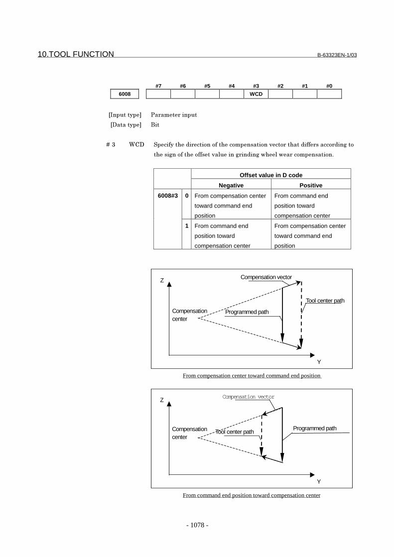
10.TOOL FUNCTION B-63323EN-1/03
- 1078 -
#7 #6 #5 #4 #3 #2 #1 #0
6008 WCD
���������� �� ��� ������
��������� )��
� � � 9�3 (;� ������������ ������������������������2��� ���������� ������ �������
��������������������2�������� �������,���,� ������������"
Offset value in D code
Negative Positive
0 From compensation center
toward command end
position
From command end
position toward
compensation center
6008#3
1 From command end
position toward
compensation center
From compensation center
toward command end
position
Compensation vector
Programmed path
Tool center path
Compensationcenter
Z
Y
From compensation center toward command end position
Compensation vector
Programmed pathTool center pathCompensation
center
Z
Y
From command end position toward compensation center

B-63323EN-1/03 10.TOOL FUNCTION
- 1079 -
Alarms and messages
No. Message Description
PS0618 ILLEGAL P-DATA (WHEEL WEARCOMPENSATION)
The P data for selecting the compensation center ingrinding wheel wear compensation is illegal.
PS0619 ILLEGAL AXIS(WHEEL WEARCOMPENSATION)
A compensation axis has been changed in grinding wheelwear compensation mode or compensation vectormaintenance mode. Alternatively, the settings inparameter Nos. 6056 and 6057 that determine the targetaxes for grinding wheel wear compensation are illegal.
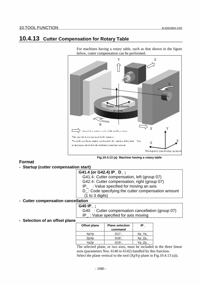
10.TOOL FUNCTION B-63323EN-1/03
- 1080 -
10.4.13 Cutter Compensation for Rotary Table
For machines having a rotary table, such as that shown in the figurebelow, cutter compensation can be performed.
)
'
A
B
C
B
C
A
���������������� ���� ��
���������������������������� ������ �����
���� ������������������������������ ����
������������������������ ������������������������������������� � ���
���� ���������������������������������������� �
1�&����� �����
�����
Fig.10.4.13 (a) Machine having a rotary table
Format- Startup (cutter compensation start)
G41.4 (or G42.4) IP_ D_ ;G41.4: Cutter compensation, left (group 07)G42.4: Cutter compensation, right (group 07)IP_ : Value specified for moving an axisD_ : Code specifying the cutter compensation amount(1 to 3 digits)
- Cutter compensation cancellationG40 IP_ ;
G40 : Cutter compensation cancellation (group 07)IP_ : Value specified for axis moving
- Selection of an offset planeOffset plane Plane selection
commandIP_
XpYp G17 ; Xp_Yp_ZpXp G18 ; Xp_Zp_YpZp G19 ; Yp_Zp_
The selected plane, or two axes, must be included in the three linearaxes (parameters Nos. 6140 to 6142) handled by this function.Select the plane vertical to the tool (XpYp plane in Fig.10.4.13 (a)).
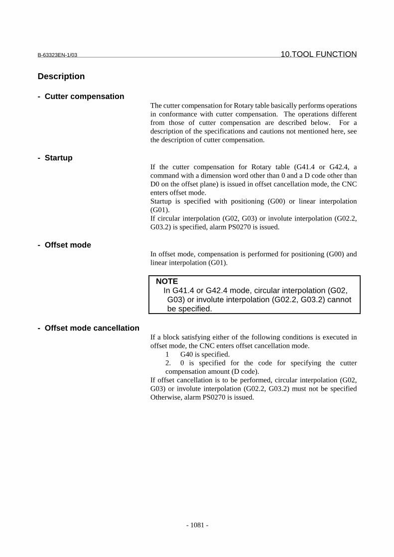
B-63323EN-1/03 10.TOOL FUNCTION
- 1081 -
Description
- Cutter compensationThe cutter compensation for Rotary table basically performs operationsin conformance with cutter compensation. The operations differentfrom those of cutter compensation are described below. For adescription of the specifications and cautions not mentioned here, seethe description of cutter compensation.
- StartupIf the cutter compensation for Rotary table (G41.4 or G42.4, acommand with a dimension word other than 0 and a D code other thanD0 on the offset plane) is issued in offset cancellation mode, the CNCenters offset mode.Startup is specified with positioning (G00) or linear interpolation(G01).If circular interpolation (G02, G03) or involute interpolation (G02.2,G03.2) is specified, alarm PS0270 is issued.
- Offset modeIn offset mode, compensation is performed for positioning (G00) andlinear interpolation (G01).
NOTEIn G41.4 or G42.4 mode, circular interpolation (G02,G03) or involute interpolation (G02.2, G03.2) cannotbe specified.
- Offset mode cancellationIf a block satisfying either of the following conditions is executed inoffset mode, the CNC enters offset cancellation mode.
1 G40 is specified.2. 0 is specified for the code for specifying the cuttercompensation amount (D code).
If offset cancellation is to be performed, circular interpolation (G02,G03) or involute interpolation (G02.2, G03.2) must not be specifiedOtherwise, alarm PS0270 is issued.

10.TOOL FUNCTION B-63323EN-1/03
- 1082 -
Example
- Parameter specification exampleOn the machine shown in Fig.10.4.13 (a) parameters must be specifiedas follows:The axis numbers are assumed as follows: X = 1, Y = 2, Z = 3, A = 4, B= 5
ParameterNo.
Setting Description
6140 1 (X) Axis number of linear axis 16141 2 (Y) Axis number of linear axis 26142 3 (Z) Axis number of linear axis 36143 -5 (B) Axis number of rotation axis (first set)6144 2 (Y) Axis number of the linear axis corresponding to the
rotation axis (first set)6145 -4 (A) Axis number of rotation axis (second set)6146 1 (X) Axis number of the linear axis corresponding to the
rotary axis (second set)6150 0.0 Reference angle for the rotation axis (first set)6151 0.0 Reference angle for the rotation axis (second set)
- FormulasWith the above settings, the cutter compensation vector at end point N2in the following program is calculated as follows:(1) Part program
A part program is created in the workpiece coordinate system.G42.4 D1N1 X 1x Y 1y Z 1z A 1a B 1b
N2 X 2x Y 2y Z 2z A 2a B 2b
N3 X 3x Y 3y Z 3z A 3a B 3b
(2) Definitions1P = ( 1x , 1y , 1z ) , 2P = ( 2x , 2y , 2z ) , 3P = ( 3x , 3y , 3z )
0P : Origin of the table coordinate system (parameter No. 6154)(3) Calculation of the matrix for conversion from the workpiece
coordinate system to the table coordinate systemReference angle conversion matrix
−
−=
00
00
00
000
cos0sin
010
sin0cos
cossin0
sincos0
001
bb
bb
aa
aaM
where 0a and 0b are the reference angles specified forparameters Nos. 6150 and 6151.
1P conversion matrix
−
−=
11
11
11
111
cos0sin
010
sin0cos
cossin0
sincos0
001
bb
bb
aa
aaM
2P conversion matrix
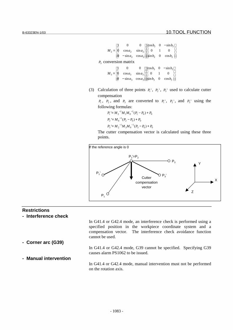
B-63323EN-1/03 10.TOOL FUNCTION
- 1083 -
−
−=
22
22
22
222
cos0sin
010
sin0cos
cossin0
sincos0
001
bb
bb
aa
aaM
3P conversion matrix
−
−=
33
33
33
333
cos0sin
010
sin0cos
cossin0
sincos0
001
bb
bb
aa
aaM
(3) Calculation of three points ’1P , ’2P , ’3P used to calculate cuttercompensation
1P , 2P , and 3P are converted to ’1P , ’2P , and ’3P using thefollowing formulas:
0011
011
21 )(’ PPPMMMP +−= −−
0021
02 )(’ PPPMP +−= −
0031
031
23 )(’ PPPMMMP +−= −−
The cutter compensation vector is calculated using these threepoints.
If the reference angle is 0
P1’
P2’=P2
P1
P3’
P3
X
Y
Z
Cuttercompensation
vector
Restrictions- Interference check
In G41.4 or G42.4 mode, an interference check is performed using aspecified position in the workpiece coordinate system and acompensation vector. The interference check avoidance functioncannot be used.
- Corner arc (G39)In G41.4 or G42.4 mode, G39 cannot be specified. Specifying G39causes alarm PS1062 to be issued.
- Manual interventionIn G41.4 or G42.4 mode, manual intervention must not be performedon the rotation axis.
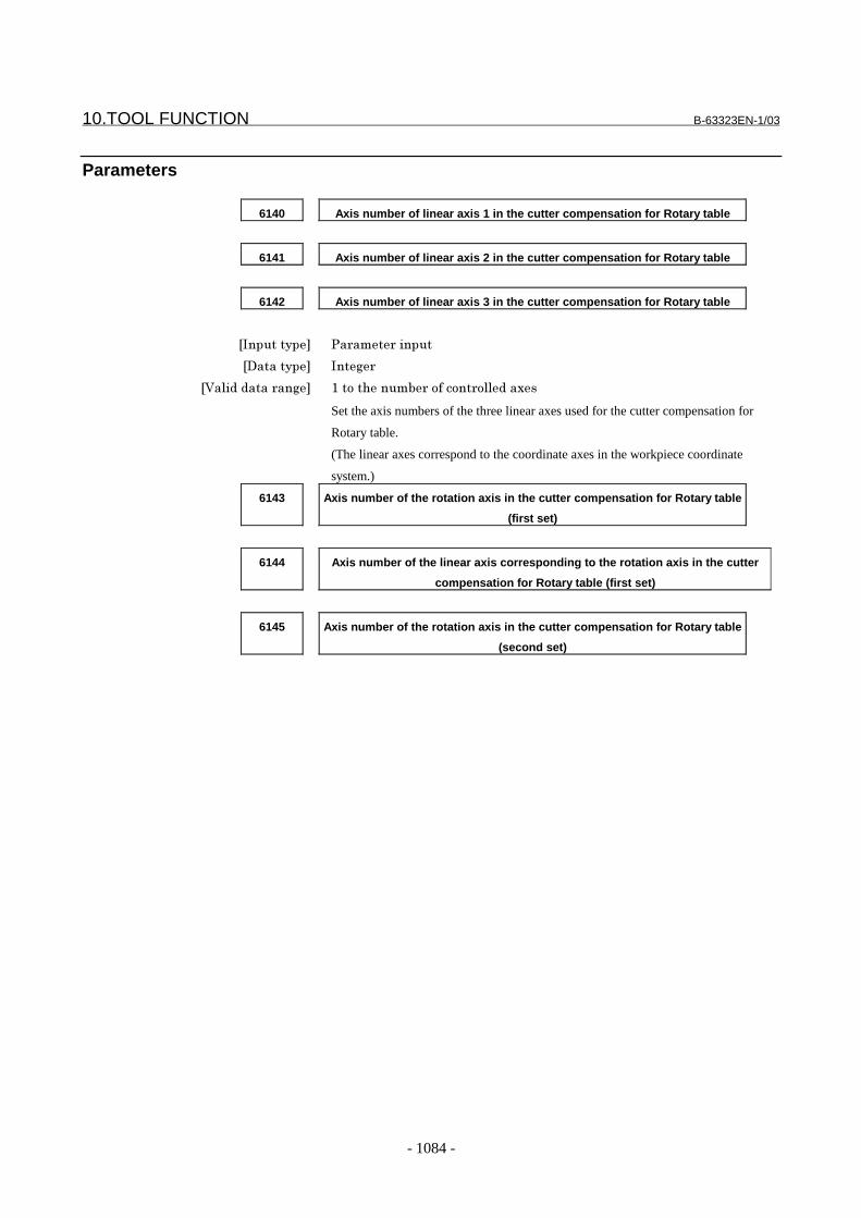
10.TOOL FUNCTION B-63323EN-1/03
- 1084 -
Parameters
6140 Axis number of linear axis 1 in the cutter compensation for Rotary table
6141 Axis number of linear axis 2 in the cutter compensation for Rotary table
6142 Axis number of linear axis 3 in the cutter compensation for Rotary table
���������� �� ��� ������
��������� ����
������������ ��� /����������& �������� ��������
Set the axis numbers of the three linear axes used for the cutter compensation for
Rotary table.
(The linear axes correspond to the coordinate axes in the workpiece coordinate
system.)
6143 Axis number of the rotation axis in the cutter compensation for Rotary table
(first set)
6144 Axis number of the linear axis corresponding to the rotation axis in the cutter
compensation for Rotary table (first set)
6145 Axis number of the rotation axis in the cutter compensation for Rotary table
(second set)
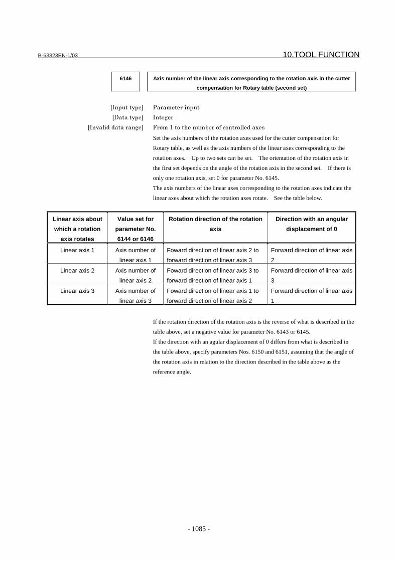
B-63323EN-1/03 10.TOOL FUNCTION
- 1085 -
6146 Axis number of the linear axis corresponding to the rotation axis in the cutter
compensation for Rotary table (second set)
���������� �� ��� ������
��������� ����
���2���������� ��� > ���/����������& �������� ��������
Set the axis numbers of the rotation axes used for the cutter compensation for
Rotary table, as well as the axis numbers of the linear axes corresponding to the
rotation axes. Up to two sets can be set. The orientation of the rotation axis in
the first set depends on the angle of the rotation axis in the second set. If there is
only one rotation axis, set 0 for parameter No. 6145.
The axis numbers of the linear axes corresponding to the rotation axes indicate the
linear axes about which the rotation axes rotate. See the table below.
Linear axis about
which a rotation
axis rotates
Value set for
parameter No.
6144 or 6146
Rotation direction of the rotation
axis
Direction with an angular
displacement of 0
Linear axis 1 Axis number of
linear axis 1
Foward direction of linear axis 2 to
forward direction of linear axis 3
Forward direction of linear axis
2
Linear axis 2 Axis number of
linear axis 2
Foward direction of linear axis 3 to
forward direction of linear axis 1
Forward direction of linear axis
3
Linear axis 3 Axis number of
linear axis 3
Foward direction of linear axis 1 to
forward direction of linear axis 2
Forward direction of linear axis
1
If the rotation direction of the rotation axis is the reverse of what is described in the
table above, set a negative value for parameter No. 6143 or 6145.
If the direction with an agular displacement of 0 differs from what is described in
the table above, specify parameters Nos. 6150 and 6151, assuming that the angle of
the rotation axis in relation to the direction described in the table above as the
reference angle.
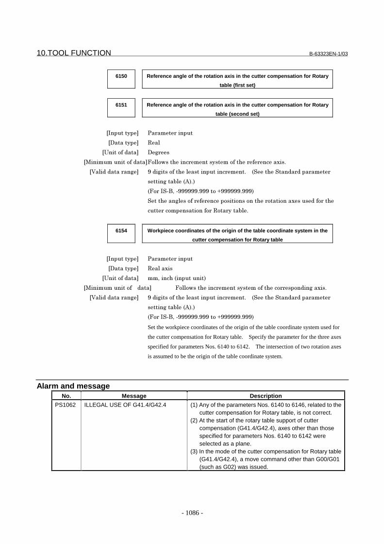
10.TOOL FUNCTION B-63323EN-1/03
- 1086 -
6150 Reference angle of the rotation axis in the cutter compensation for Rotary
table (first set)
6151 Reference angle of the rotation axis in the cutter compensation for Rotary
table (second set)
���������� �� ��� ������
��������� #��
�$����������� �� �
���������������������>����,�������� ���������������� � �������"
������������ ��� %���������������������������� ���"� � ����������� ���� ���
���������&�� '!"!
>� ����)*��%%%%%%"%%%����+%%%%%%"%%%!
��������������� � ������������������� ������������������ ���
���� ��������������� �#��� ����&�"
6154 Workpiece coordinates of the origin of the table coordinate system in the
cutter compensation for Rotary table
���������� �� ��� ������
��������� #�������
�$����������� ��*������ ����������!
����������������� � ���� >����,�������� ������������������ �������������"
������������ ��� %���������������������������� ���"� � ����������� ���� ���
���������&�� '!"!
>� ����)*��%%%%%%"%%%����+%%%%%%"%%%!
Set the workpiece coordinates of the origin of the table coordinate system used for
the cutter compensation for Rotary table. Specify the parameter for the three axes
specified for parameters Nos. 6140 to 6142. The intersection of two rotation axes
is assumed to be the origin of the table coordinate system.
Alarm and messageNo. Message Description
PS1062 ILLEGAL USE OF G41.4/G42.4 (1) Any of the parameters Nos. 6140 to 6146, related to thecutter compensation for Rotary table, is not correct.
(2) At the start of the rotary table support of cuttercompensation (G41.4/G42.4), axes other than thosespecified for parameters Nos. 6140 to 6142 wereselected as a plane.
(3) In the mode of the cutter compensation for Rotary table(G41.4/G42.4), a move command other than G00/G01(such as G02) was issued.

B-63323EN-1/03 10.TOOL FUNCTION
- 1087 -
Reference itemFANUC Series15i/150i-MA
OPERATOR’SMANUAL(PROGRAMMING)(B-63324EN)
II.14.3 CUTTERCOMPENSATION C

11.PROGRAM COMMAND B-63323EN-1/03
- 1088 -
11 PROGRAM COMMAND
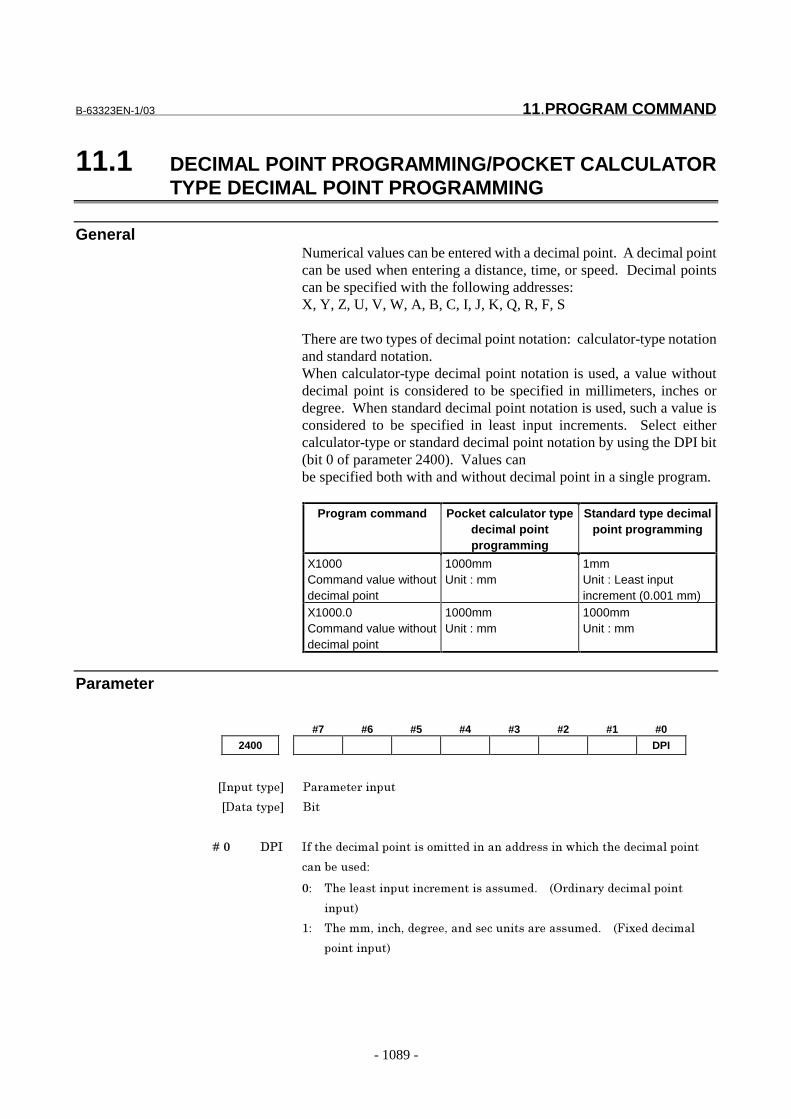
B-63323EN-1/03 11.PROGRAM COMMAND
- 1089 -
11.1 DECIMAL POINT PROGRAMMING/POCKET CALCULATORTYPE DECIMAL POINT PROGRAMMING
GeneralNumerical values can be entered with a decimal point. A decimal pointcan be used when entering a distance, time, or speed. Decimal pointscan be specified with the following addresses:X, Y, Z, U, V, W, A, B, C, I, J, K, Q, R, F, S
There are two types of decimal point notation: calculator-type notationand standard notation.When calculator-type decimal point notation is used, a value withoutdecimal point is considered to be specified in millimeters, inches ordegree. When standard decimal point notation is used, such a value isconsidered to be specified in least input increments. Select eithercalculator-type or standard decimal point notation by using the DPI bit(bit 0 of parameter 2400). Values canbe specified both with and without decimal point in a single program.
Program command Pocket calculator typedecimal pointprogramming
Standard type decimalpoint programming
X1000Command value withoutdecimal point
1000mmUnit : mm
1mmUnit : Least inputincrement (0.001 mm)
X1000.0Command value withoutdecimal point
1000mmUnit : mm
1000mmUnit : mm
Parameter
#7 #6 #5 #4 #3 #2 #1 #0
2400 DPI
���������� �� ��� ������
��������� ���
� � � � ��� ��� �������������������������������������� ���������������������������
����������
�� ����������������� ��������������� � ! ���� ��������������
�����"
#� �����$�����$��% $��������������� ��������� � &�'��������
�����������"

11.PROGRAM COMMAND B-63323EN-1/03
- 1090 -
Alarm And message
Number Message Contents
PS0007 ILLEGAL USE OF DECIMAL POINT A decimal point (.) was specified at an address where nodecimal point may be specified, or two decimal points werespecified.
Reference itemSeries15i/150i-MA Operator’s Manual
(Programming)(B-63324EN)
II-8.4 Decimal pointprogramming/pocketcalculator type decimalpoint programming
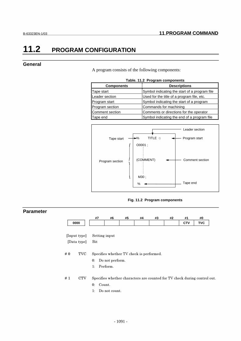
B-63323EN-1/03 11.PROGRAM COMMAND
- 1091 -
11.2 PROGRAM CONFIGURATION
GeneralA program consists of the following components:
Table. 11.2 Program components
Components Descriptions
Tape start Symbol indicating the start of a program fileLeader section Used for the title of a program file, etc.Program start Symbol indicating the start of a programProgram section Commands for machiningComment section Comments or directions for the operatorTape end Symbol indicating the end of a program file
Fig. 11.2 Program components
Parameter#7 #6 #5 #4 #3 #2 #1 #0
0000 CTV TVC
���������� (����%������
��������� ���
� � � � ��� �)* (����������� ��)����+����� �� ���
�� �������� �� ��
#� � �� ��
� � � � ��# *�) (����������� ���� ��� ��� ���������� ��)����+��� ��%����� �������
�� *�����
#� �������������
Tape start % TITLE G
O0001 ;
M30 ;
%
(COMMENT)Program section
Leader section
Program start
Comment section
Tape end

11.PROGRAM COMMAND B-63323EN-1/03
- 1092 -
#7 #6 #5 #4 #3 #2 #1 #0
2200 NM9 NPE
���������� �� ��� ������
��������� ���
� � � � ��, -�. /������� �% �����������$�0�1$�0,�$�� �022����
�� 3�������������� �% ������
#� -������������������ �% ������� � �����������$������ �������+������
� �% �������������������� �% ������� �
� � � � ��4 -02 /������� �% �����������$�022����
�� 3�������������� �% ������
#� -������������������ �% ������
��������%����������� ��� ����5��������������-�.�6���� � -����$���
������������ ��� �������������022$�����0�1�� �0,������������������
� �% �������� ��%�� �% ���������%$����-�.����������-02����#�
#7 #6 #5 #4 #3 #2 #1 #0
7616 EXT
���������� �� ��� ������
��������� ���
� � � � ��, .7� (����������� ����� �� ��'� �����5������� �% ���������
�� �������� �� ��
#� � �� ��
/����������%����������������'� �����5������� �% ���������� ����
� �� ��$�0#28������������������ ���� ��0�����
#7 #6 #5 #4 #3 #2 #1 #0
2404 SFL
���������� �� ��� ������
��������� ���
� � � � ��9 (&: (����������� �������������� �% ������� �� ��������� ��� ���
��� ������� ����������'� �����5������� �% ��������
�� (��������� �% ������� �
#� (���������������� �
B-63323EN-1/03 11.PROGRAM COMMAND
- 1093 -
2431 M code to execute external device subprogram calls
���������� (����%������
��������� ���%
�)���������� ��% ��;�22222222
(�����0��������'����'� �����5������� �% ���������� � /�������
��$�0#28��������� � 0�#$�0�1$�0,�$�028$�����022����������������
'����'� �����5������� �% ���������� � /������%���5����� $�#$
1$�,�$�28$�� �22��������� �������� ��� $�0#28�����������'����'� ���
�5������� �% ���������
Alarm And message
Number Message Contents
PS0590 TH ERROR A TH error was detected during reading from an inputdevice.The read code that caused the TH error and how manystatements it is from the block can be verified in thediagnostics screen.
PS0591 TV ERROR An error was detected during the single-block TV error.The TV check can be suppressed by setting TVCparameter No. 0000#0 to "0".
PS0592 END OF RECORD The EOR (End of Record) code is specified in the middle ofa block.This alarm is also generated when the percentage at theend of the NC program is read.
Reference itemSeries15i/150i-MA Operator’s Manual
(Programming)(B-63324EN)
II-12 Program configuration

11.PROGRAM COMMAND B-63323EN-1/03
- 1094 -
11.3 INCH/METRIC CONVERSION
GeneralEither inch or metric input can be selected by G code.
Signal
Inch input signal INCH<F001#3>
[Classification] Output signal[Function] This signal indicates that inch input mode is in progress.
[Output condition] "1"indicates that the inch input mode (G20) is in progress, and "0"indicates that metric input mode (G21) is in progress.This signal changes to the corresponding state when modes areswitched using the setting data display on the MDI panel.
Signal address#7 #6 #5 #4 #3 #2 #1 #0
F001 INCH
Parameter#7 #6 #5 #4 #3 #2 #1 #0
0010 INI
���������� (����%������
��������� ���
� � � � ��� �-� (����������� ������� ��������������� ���� ����������
�� 0� ��������
#� ����������
#7 #6 #5 #4 #3 #2 #1 #0
1002 INM
���������� �� ��� ������
��������� ���
� � � � ��# �-0 (����������� �������������������� ������ �������� ��'�����
�� ���� ����������
�� 0� ���� � ���������������������� ��������"
#� ������� � ����������������������������"
B-63323EN-1/03 11.PROGRAM COMMAND
- 1095 -
NOTEAfter this parameter has been set, the power must beoff turned off then back on for the setting to becomeeffective.
#7 #6 #5 #4 #3 #2 #1 #0
1006 ROP ROS ROT
���������� �� ��� ������
��������� ����'��
NOTEAfter this parameter has been set, the power must be off turned off thenback on for the setting to become effective.
� � � � ��� <!� (����������� �����'��� =�� ������>�� ������5 �����
�� 3'��� =�� ������>�� ������5 ����� ���� ��'��"�
#� 3'����������� =�� �����>�� ������5 ����� ���������'��"�
� � � � ��# <!( (����������� �������������� ������������������ ��� �+����+
�������������� � ������������ �� ��������� �� � ����������
�� :��� � ���� ��'��"
#� <�������� ���������'��"
&� ��� ���������'��$�������������� ����������������� ����?��������
�����%��� ������������� � ������������������ ��� ��� �-���#1@��
�����������$����������� � ������������ �� �� A18$�A,�"����� �� ��
������������ ���������������� � ������������ �� ��������
��%��� ��������������������'���,@���% ��� � 3���������������
�� ��� �-���#1@��
� � � � ��1 <!� (����������� �������������� �������������������� �� ����
������������ � �������������������� �� � ����������
�� :��� � ���� ��'��"
#� <�������� ���������'��"
/��������� ������������������� ���������$������������%�������
�� ��������������������� ������������ � �����������������������
��������� � ������������������������������������ �� ����� ������
������������������������ ������,@���% ��� � 3���������������
�� ��� �-���9419�

11.PROGRAM COMMAND B-63323EN-1/03
- 1096 -
#7 #6 #5 #4 #3 #2 #1 #0
2400 G70 F41
���������� �� ��� ������
��������� ���
� � � � ��# &4# ���������� ����������&����� A24����"������ ������� ����������
���������������$������������
�� #���>���
#� ��#���>���
����������� ����������������������$���������������������>����
NOTEIt is not effective if the increment system is IS-A.
� � � � ��1 AB� ����������������� ���������� �����������������������
�� A1�� ����������"�����A1#� �� ��������"
#� AB�� ����������"�����AB#� �� ��������"
#7 #6 #5 #4 #3 #2 #1 #0
2203 MCN
���������� �� ��� ������
��������� ���
� � � � ��# 0*- ��������������������� ����������������*<��
�� ���������� ���� ���������� ��������� ������������ ��������
�������� �����5��������������������
#� ���������� ���� ��� ���������� ������������ ������������
NoteNOTE1 When the least input increment and the least
command increment systems are different, themaximum error is half of the least commandincrement. This error is not accumulated.
2 For the first G28 command after switching from inchinput to metric input or vice versa, low-speedreference position return is performed.
3 Inch input and metric input can also be switchedusing bit 0 (INI) of parameter No. 0010.
Reference itemSeries15i/150i-MA Operator’s Manual
(Programming)(B-63324EN)
II-8.3 Inch/metric systemconversion
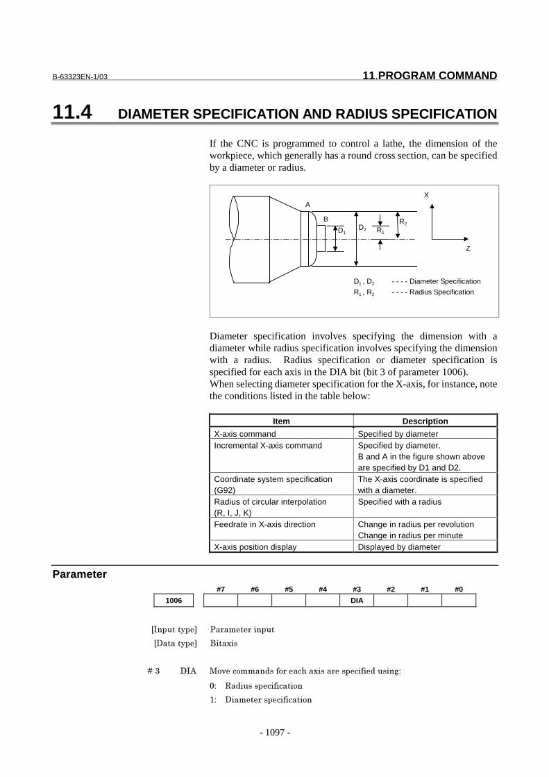
B-63323EN-1/03 11.PROGRAM COMMAND
- 1097 -
11.4 DIAMETER SPECIFICATION AND RADIUS SPECIFICATION
If the CNC is programmed to control a lathe, the dimension of theworkpiece, which generally has a round cross section, can be specifiedby a diameter or radius.
D1D2 R1
R2
A
B
D1 , D2 - - - - Diameter Specification
R1 , R2 - - - - Radius Specification
X
Z
Diameter specification involves specifying the dimension with adiameter while radius specification involves specifying the dimensionwith a radius. Radius specification or diameter specification isspecified for each axis in the DIA bit (bit 3 of parameter 1006).When selecting diameter specification for the X-axis, for instance, notethe conditions listed in the table below:
Item Description
X-axis command Specified by diameterIncremental X-axis command Specified by diameter.
B and A in the figure shown aboveare specified by D1 and D2.
Coordinate system specification(G92)
The X-axis coordinate is specifiedwith a diameter.
Radius of circular interpolation(R, I, J, K)
Specified with a radius
Feedrate in X-axis direction Change in radius per revolutionChange in radius per minute
X-axis position display Displayed by diameter
Parameter#7 #6 #5 #4 #3 #2 #1 #0
1006 DIA
���������� �� ��� ������
��������� ����'��
� � � � ��, ��3 0�5������������ ������'���� �������������%�
�� <������������������
#� ����� �������������

11.PROGRAM COMMAND B-63323EN-1/03
- 1098 -
Reference itemSeries15i/150i-MA Operator’s Manual
(Programming)(B-63324EN)
II-8.5 Diameter specificationand radius specification
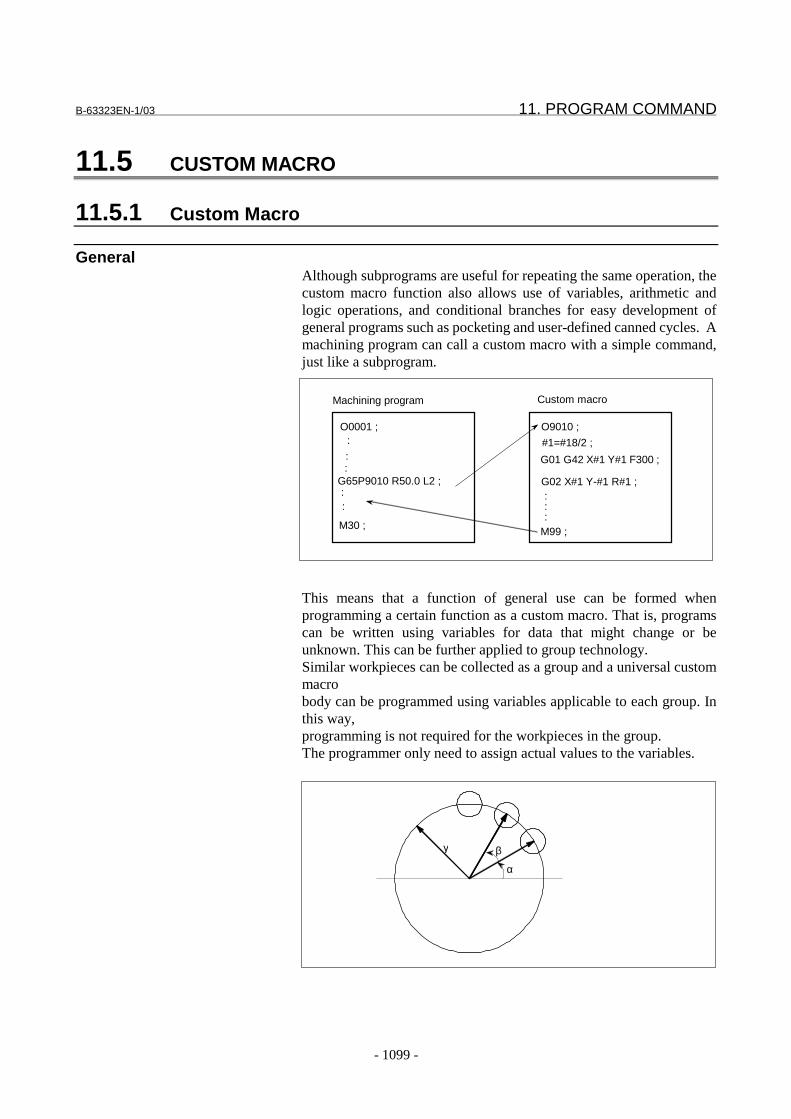
B-63323EN-1/03 11. PROGRAM COMMAND
- 1099 -
11.5 CUSTOM MACRO
11.5.1 Custom Macro
GeneralAlthough subprograms are useful for repeating the same operation, thecustom macro function also allows use of variables, arithmetic andlogic operations, and conditional branches for easy development ofgeneral programs such as pocketing and user-defined canned cycles. Amachining program can call a custom macro with a simple command,just like a subprogram.
This means that a function of general use can be formed whenprogramming a certain function as a custom macro. That is, programscan be written using variables for data that might change or beunknown. This can be further applied to group technology.Similar workpieces can be collected as a group and a universal custommacrobody can be programmed using variables applicable to each group. Inthis way,programming is not required for the workpieces in the group.The programmer only need to assign actual values to the variables.
O0001 ; :
: :
G65P9010 R50.0 L2 ; : :
M30 ;
Machining program Custom macro
O9010 ;
#1=#18/2 ;
G01 G42 X#1 Y#1 F300 ;
G02 X#1 Y-#1 R#1 ; : : :M99 ;
γ β
α
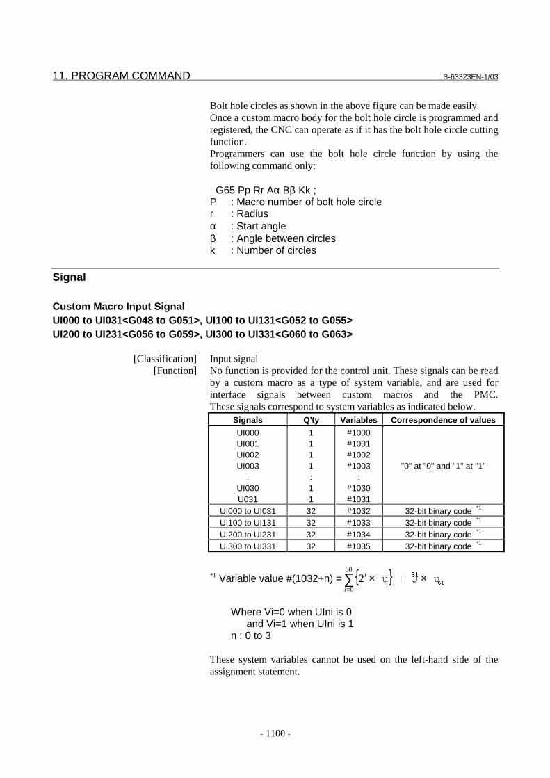
11. PROGRAM COMMAND B-63323EN-1/03
- 1100 -
Bolt hole circles as shown in the above figure can be made easily.Once a custom macro body for the bolt hole circle is programmed andregistered, the CNC can operate as if it has the bolt hole circle cuttingfunction.Programmers can use the bolt hole circle function by using thefollowing command only:
G65 Pp Rr Aα Bβ Kk ;P : Macro number of bolt hole circler : Radiusα : Start angleβ : Angle between circlesk : Number of circles
Signal
Custom Macro Input SignalUI000 to UI031<G048 to G051>, UI100 to UI131<G052 to G055>UI200 to UI231<G056 to G059>, UI300 to UI331<G060 to G063>
[Classification] Input signal[Function] No function is provided for the control unit. These signals can be read
by a custom macro as a type of system variable, and are used forinterface signals between custom macros and the PMC.These signals correspond to system variables as indicated below.
Signals Q’ty Variables Correspondence of values
UI000UI001UI002UI003
:UI030U031
1111:11
#1000#1001#1002#1003
:#1030#1031
"0" at "0" and "1" at "1"
UI000 to UI031 32 #1032 32-bit binary code *1
UI100 to UI131 32 #1033 32-bit binary code *1
UI200 to UI231 32 #1034 32-bit binary code *1
UI300 to UI331 32 #1035 32-bit binary code *1
*1 Variable value #(1032+n) = { }∑=
××30
0
2i
i��
��
�u| Qu
Where Vi=0 when UIni is 0and Vi=1 when UIni is 1
n : 0 to 3
These system variables cannot be used on the left-hand side of theassignment statement.
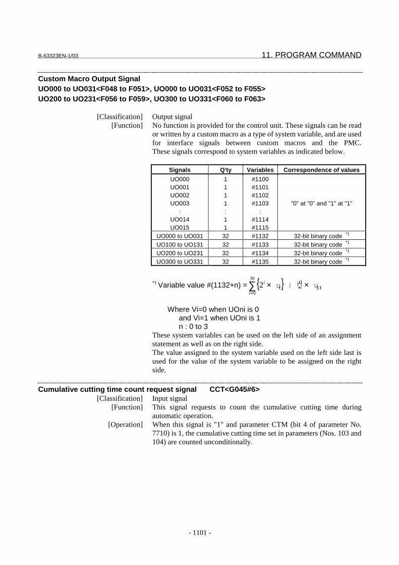
B-63323EN-1/03 11. PROGRAM COMMAND
- 1101 -
Custom Macro Output SignalUO000 to UO031<F048 to F051>, UO000 to UO031<F052 to F055>UO200 to UO231<F056 to F059>, UO300 to UO331<F060 to F063>
[Classification] Output signal[Function] No function is provided for the control unit. These signals can be read
or written by a custom macro as a type of system variable, and are usedfor interface signals between custom macros and the PMC.These signals correspond to system variables as indicated below.
Signals Q’ty Variables Correspondence of values
UO000UO001UO002UO003
:UO014UO015
1111:11
#1100#1101#1102#1103
:#1114#1115
"0" at "0" and "1" at "1"
UO000 to UO031 32 #1132 32-bit binary code *1
UO100 to UO131 32 #1133 32-bit binary code *1
UO200 to UO231 32 #1134 32-bit binary code *1
UO300 to UO331 32 #1135 32-bit binary code *1
*1 Variable value #(1132+n) = { }∑=
××30
0
2i
i��
��
�u| Qu
Where Vi=0 when UOni is 0and Vi=1 when UOni is 1n : 0 to 3
These system variables can be used on the left side of an assignmentstatement as well as on the right side.The value assigned to the system variable used on the left side last isused for the value of the system variable to be assigned on the rightside.
Cumulative cutting time count request signal CCT<G045#6>[Classification] Input signal
[Function] This signal requests to count the cumulative cutting time duringautomatic operation.
[Operation] When this signal is "1" and parameter CTM (bit 4 of parameter No.7710) is 1, the cumulative cutting time set in parameters (Nos. 103 and104) are counted unconditionally.
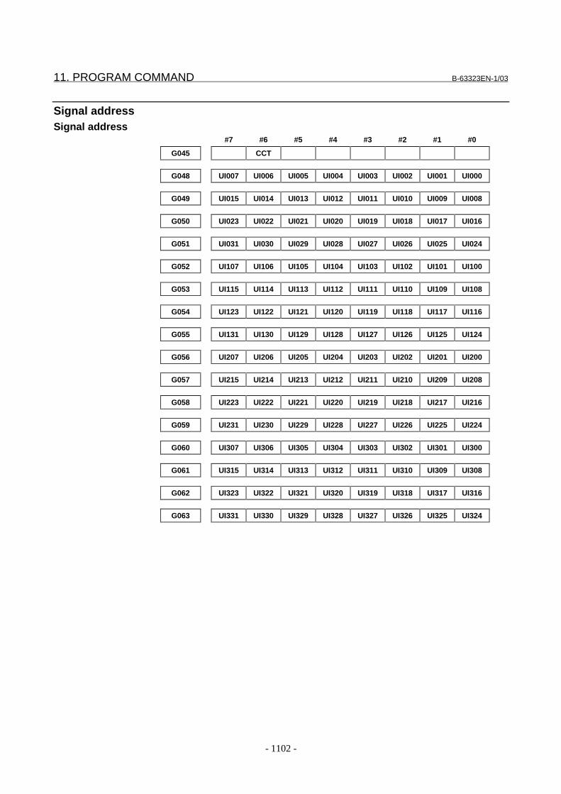
11. PROGRAM COMMAND B-63323EN-1/03
- 1102 -
Signal addressSignal address
#7 #6 #5 #4 #3 #2 #1 #0
G045 CCT
G048 UI007 UI006 UI005 UI004 UI003 UI002 UI001 UI000
G049 UI015 UI014 UI013 UI012 UI011 UI010 UI009 UI008
G050 UI023 UI022 UI021 UI020 UI019 UI018 UI017 UI016
G051 UI031 UI030 UI029 UI028 UI027 UI026 UI025 UI024
G052 UI107 UI106 UI105 UI104 UI103 UI102 UI101 UI100
G053 UI115 UI114 UI113 UI112 UI111 UI110 UI109 UI108
G054 UI123 UI122 UI121 UI120 UI119 UI118 UI117 UI116
G055 UI131 UI130 UI129 UI128 UI127 UI126 UI125 UI124
G056 UI207 UI206 UI205 UI204 UI203 UI202 UI201 UI200
G057 UI215 UI214 UI213 UI212 UI211 UI210 UI209 UI208
G058 UI223 UI222 UI221 UI220 UI219 UI218 UI217 UI216
G059 UI231 UI230 UI229 UI228 UI227 UI226 UI225 UI224
G060 UI307 UI306 UI305 UI304 UI303 UI302 UI301 UI300
G061 UI315 UI314 UI313 UI312 UI311 UI310 UI309 UI308
G062 UI323 UI322 UI321 UI320 UI319 UI318 UI317 UI316
G063 UI331 UI330 UI329 UI328 UI327 UI326 UI325 UI324
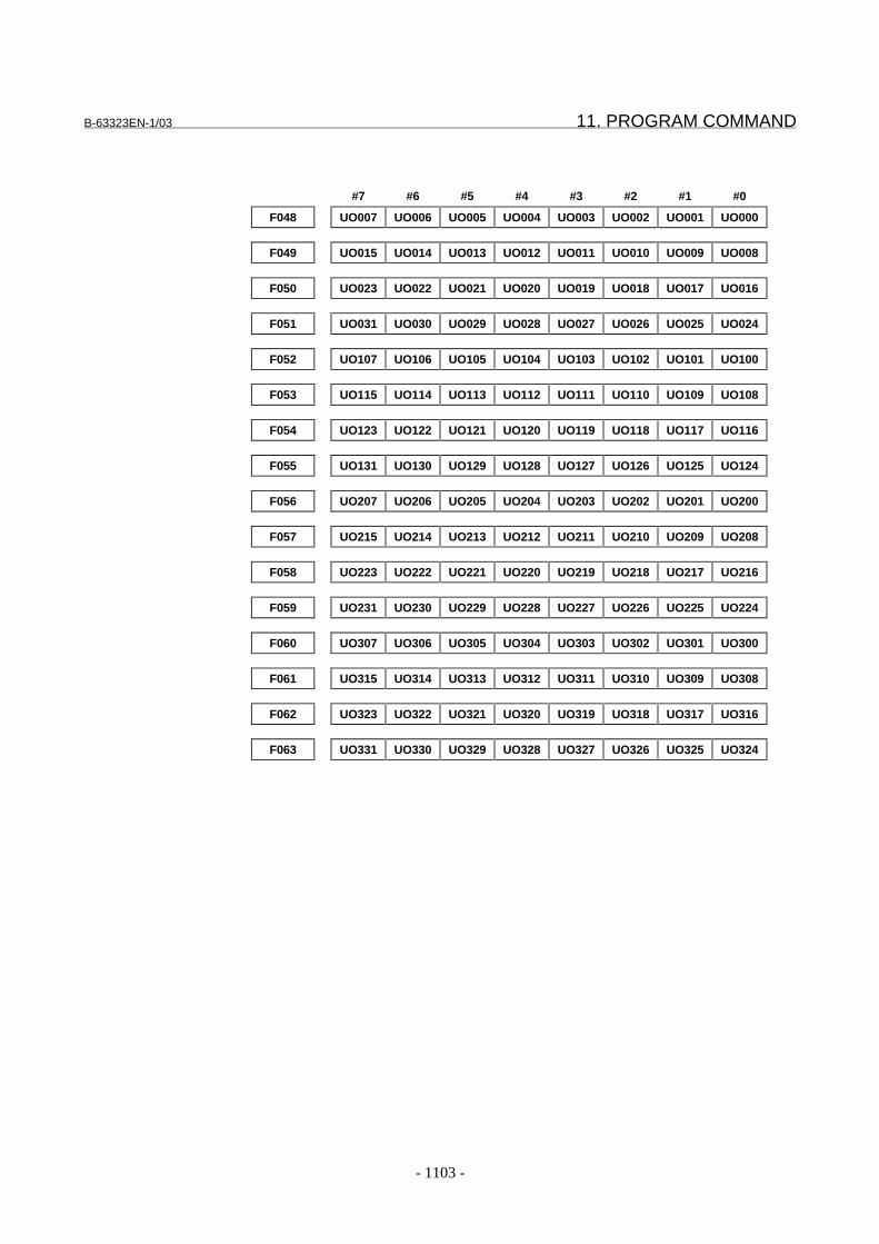
B-63323EN-1/03 11. PROGRAM COMMAND
- 1103 -
#7 #6 #5 #4 #3 #2 #1 #0
F048 UO007 UO006 UO005 UO004 UO003 UO002 UO001 UO000
F049 UO015 UO014 UO013 UO012 UO011 UO010 UO009 UO008
F050 UO023 UO022 UO021 UO020 UO019 UO018 UO017 UO016
F051 UO031 UO030 UO029 UO028 UO027 UO026 UO025 UO024
F052 UO107 UO106 UO105 UO104 UO103 UO102 UO101 UO100
F053 UO115 UO114 UO113 UO112 UO111 UO110 UO109 UO108
F054 UO123 UO122 UO121 UO120 UO119 UO118 UO117 UO116
F055 UO131 UO130 UO129 UO128 UO127 UO126 UO125 UO124
F056 UO207 UO206 UO205 UO204 UO203 UO202 UO201 UO200
F057 UO215 UO214 UO213 UO212 UO211 UO210 UO209 UO208
F058 UO223 UO222 UO221 UO220 UO219 UO218 UO217 UO216
F059 UO231 UO230 UO229 UO228 UO227 UO226 UO225 UO224
F060 UO307 UO306 UO305 UO304 UO303 UO302 UO301 UO300
F061 UO315 UO314 UO313 UO312 UO311 UO310 UO309 UO308
F062 UO323 UO322 UO321 UO320 UO319 UO318 UO317 UO316
F063 UO331 UO330 UO329 UO328 UO327 UO326 UO325 UO324
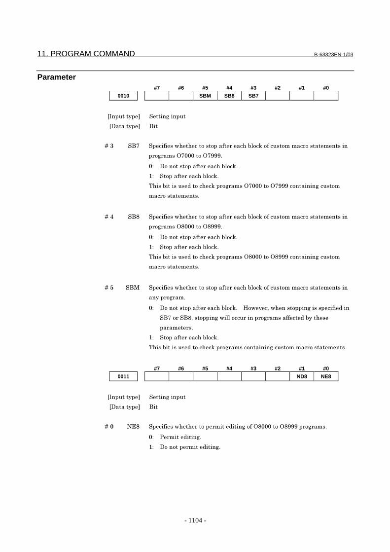
11. PROGRAM COMMAND B-63323EN-1/03
- 1104 -
Parameter#7 #6 #5 #4 #3 #2 #1 #0
0010 SBM SB8 SB7
���������� ����� ������
��������� ���
� � � � ��� ��� ����������������������������������������������������������������
��� ������� ������!!!"
# ��������������������������"
$# �������������������"
%�������������&������������ ������� ������!!!���������� �������
��������������"
� � � � ��' ��( ����������������������������������������������������������������
��� ������( �����(!!!"
# ��������������������������"
$# �������������������"
%�������������&������������ ������( �����(!!!���������� �������
��������������"
� � � � ��) ��* ����������������������������������������������������������������
������� ���"
# ��������������������������"� � +��,�-������������ ����������&���
���������(-�������� ������������������ ����������&�������
��������"
$# �������������������"
%�������������&������������ �������������� ����������������������"
#7 #6 #5 #4 #3 #2 #1 #0
0011 ND8 NE8
���������� ����� ������
��������� ���
� � � � �� ./( �����������������������&���� �����( �����(!!!���� ����"
# 0�����&���� "
$# �������������&���� "
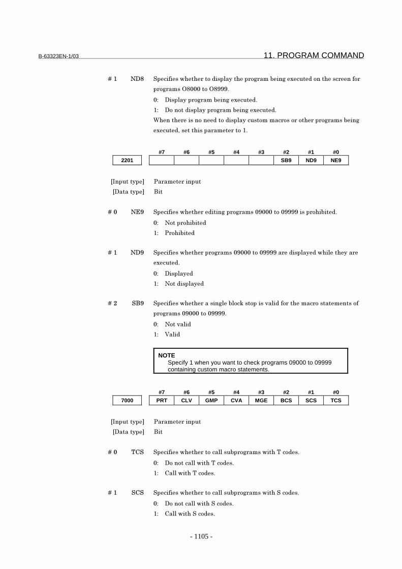
B-63323EN-1/03 11. PROGRAM COMMAND
- 1105 -
� � � � ��$ .�( �����������������&������������� ������� �1���&���������������
��� ������( �����(!!!"
# ����������� ������� �1���&"
$# �������&���������� ������� �1���&"
2��������������&����&�������������������������������� ��������
1���&-��������������������$"
#7 #6 #5 #4 #3 #2 #1 #0
2201 SB9 ND9 NE9
���������� 0������������
��������� ���
� � � � �� ./! ��������������&���� ���� ����� ! ���� !!!!������������&"
# .�����������&
$# 0�������&
� � � � ��$ .�! ����������������� ����� ! ���� !!!!����&������&������������
1���&"
# �������&
$# .���&������&
� � � � ��3 ��! ������������������� ����������������,���&�������������������������
��� ����� ! ���� !!!!"
# .���,���&
$# 4���&
NOTESpecify 1 when you want to check programs 09000 to 09999containing custom macro statements.
#7 #6 #5 #4 #3 #2 #1 #0
7000 PRT CLV GMP CVA MGE BCS SCS TCS
���������� 0������������
��������� ���
� � � � �� %5� ���������������������������� ����������%���&�"
# �����������������%���&�"
$# 5���������%���&�"
� � � � ��$ �5� ���������������������������� ��������������&�"
# ���������������������&�"
$# 5�������������&�"
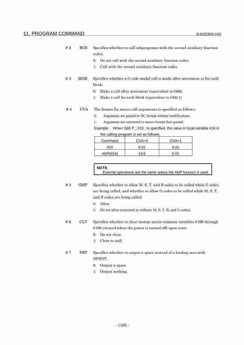
11. PROGRAM COMMAND B-63323EN-1/03
- 1106 -
� � � � ��3 �5� ���������������������������� �����������������&���1���������������
��&�"
# ������������������������&���1������������������&�"
$# 5����������������&���1������������������&�"
� � � � ��� *6/ ����������������6���&���&�������������&��������,��������������
�����"
# *�����������������,����78��,��������699:"
$# *������������������������78��,��������699"$:
� � � � ��' 54; %�������������������������� ���������������&�����������#
0: Arguments are passed in NC format without modifications.
1: Arguments are converted to macro format then passed.
Example: When G65 P_ X10 ; is specified, the value in local variable #24 in
the calling program is set as follows:
Command CVA=0 CVA=1
#24 0.01 0.01
ADP[#24] 10.0 0.01
NOTEExternal operations are the same unless the ADP function is used.
� � � � ��) 6*0 �����������������������*-��-�%-���&�����&�����������&������6���&�
������ �����&-���&����������������6���&�����������&������*-��-�%-
��&�����&�������� �����&"
0: Allow.
1: Do not allow (executed as ordinary M, S, T, B, and G codes).
� � � � ��9 5<4 ������������������������������������������,���������$ ������ �
�$!!�7����&��������������������&����:���������"
# �����������"
$# 5�����������"
� � � � ��� 0=% ������������������������������������&��������&�� �>�������
�0=.%"
# �������������"
$# ������������� "
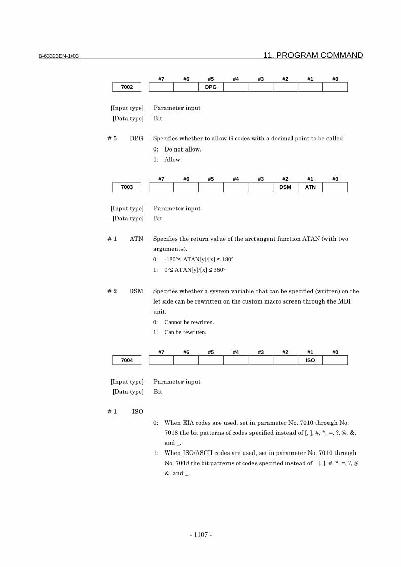
B-63323EN-1/03 11. PROGRAM COMMAND
- 1107 -
#7 #6 #5 #4 #3 #2 #1 #0
7002 DPG
���������� 0������������
��������� ���
� � � � ��) �06 �����������������������6���&���������&���������������������&"
# ������������"
$# ;����"
#7 #6 #5 #4 #3 #2 #1 #0
7003 DSM ATN
���������� 0������������
��������� ���
� � � � ��$ ;%. �����������������,���������������� ������������;%;.�7��������
�� �����:"
0: -180°≤ ATAN[y]/[x] ≤ 180°
1: 0°≤ ATAN[y]/[x] ≤ 360°
� � � � ��3 ��* ����������������������,������������������������&�7������:������
�����&�������������������������������������������� �����*��
����"
0: Cannot be rewritten.
1: Can be rewritten.
#7 #6 #5 #4 #3 #2 #1 #0
7004 ISO
���������� 0������������
��������� ���
� � � � ��$ ���
# 2���/�;���&�������&-���������������.�"�� $ ������ ��.�"
� $(���������������������&��������&������&�����-�-��-�?-�@-�A-�B-�C-
��&�D"
$# 2������E;�5�����&�������&-���������������.�"�� $ ������ �
.�"�� $(���������������������&��������&������&���� � �-�-��-�?-�@-�A-�B-
C-���&�D"

11. PROGRAM COMMAND B-63323EN-1/03
- 1108 -
#7 #6 #5 #4 #3 #2 #1 #0
7010 [7 [6 [5 [4 [3 [2 [1 [0
7011 ]7 ]6 ]5 ]4 ]3 ]2 ]1 ]0
7012 #7 #6 #5 #4 #3 #2 #1 #0
7013 *7 *6 *5 *4 *3 *2 *1 *0
7014 =7 =6 =5 =4 =3 =2 =1 =0
7015 ?7 ?6 ?5 ?4 ?3 ?2 ?1 ?0
7016 @7 @6 @5 @4 @3 @2 @1 @0
7017 &7 &6 &5 &4 &3 &2 &1 &0
7018 _7 _6 _5 _4 _3 _2 _1 _0
���������� 0������������
��������� ���
� � � � � ������� #� � � � %�������������������/�;�������E;�5�����&���&������ ��������"
� � � � ������ #� � � � %�������������������/�;�������E;�5�����&���&������ �������"
� � � � � ������� #� � � � %�������������������/�;�������E;�5�����&���&������ ��������"
� � � � ? ����?�� #� � � � %�������������������/�;�������E;�5�����&���&������ �?������"
� � � � @ ����@�� #� � � � %�������������������/�;�������E;�5�����&���&������ �@������"
� � � � A ����A�� #� � � � %�������������������/�;�������E;�5�����&���&������ �A������"
� � � � B ����B��#� � � � %�������������������/�;�������E;�5�����&���&������ �B������"
� � � � C ����C� #� � � � %�������������������/�;�������E;�5�����&���&������ �C������"
� � � � D ����D�� #� � � � %�������������������/�;�������E;�5�����&���&������ �D������"
� � � � � � � � � � � � � � � � � � #� � ;���������&�� �������� "
� � � � � � � � � � � � � � � � � � $#� � ;���������&�� ��������$"
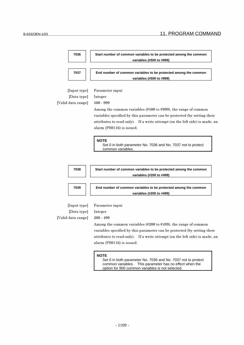
B-63323EN-1/03 11. PROGRAM COMMAND
- 1109 -
7036 Start number of common variables to be protected among the common
variables (#500 to #999)
7037 End number of common variables to be protected among the common
variables (#500 to #999)
���������� 0������������
��������� ��� �
�4���&�&������� ) �F�!!!
;��� �����������,��������7�) �����!!!:-������� ����������
,��������������&�����������������������������&�7�������� �����
���������������&F����:"� � �����������������7������������&:������&-���
������70� $$9:��������&"
NOTESet 0 in both parameter No. 7036 and No. 7037 not to protectcommon variables.
7038 Start number of common variables to be protected among the common
variables (#200 to #499)
7039 End number of common variables to be protected among the common
variables (#200 to #499)
���������� 0������������
��������� ��� �
�4���&�&������� 3 �F�'!!
;��� �����������,��������7�3 �����'!!:-������� ����������
,��������������&�����������������������������&�7�������� �����
���������������&F����:"� � �����������������7������������&:������&-���
������70� $$9:��������&"
NOTESet 0 in both parameter No. 7036 and No. 7037 not to protectcommon variables. This parameter has no effect when theoption for 900 common variables is not selected.
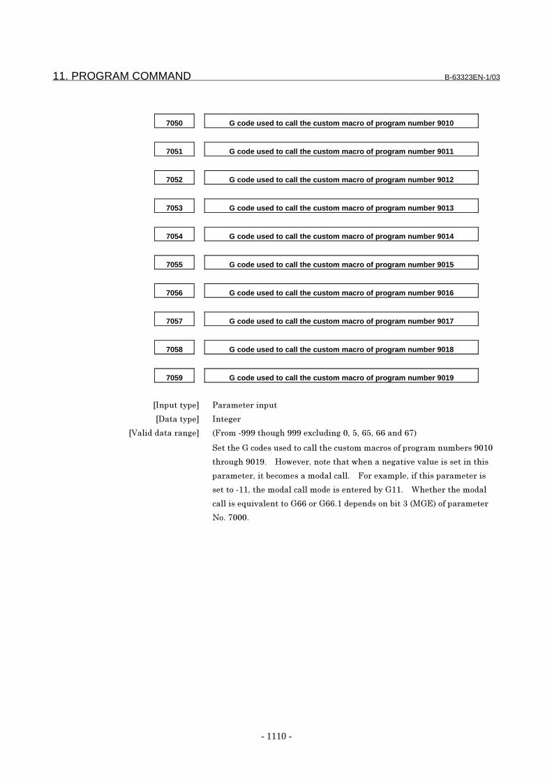
11. PROGRAM COMMAND B-63323EN-1/03
- 1110 -
7050 G code used to call the custom macro of program number 9010
7051 G code used to call the custom macro of program number 9011
7052 G code used to call the custom macro of program number 9012
7053 G code used to call the custom macro of program number 9013
7054 G code used to call the custom macro of program number 9014
7055 G code used to call the custom macro of program number 9015
7056 G code used to call the custom macro of program number 9016
7057 G code used to call the custom macro of program number 9017
7058 G code used to call the custom macro of program number 9018
7059 G code used to call the custom macro of program number 9019
���������� 0������������
��������� ��� �
�4���&�&������� 7G����F!!!����� ��!!!�1���&�� � -�)-�9)-�99���&�9�:
������6���&����&�������������������������������� �����������! $
����� ��! $!"� � +��,�-����������������� ���,�,�����������������
�������-��������������&�������"� � G���1����-�������������������
������F$$-������&����������&�������&����6$$"� � 2����������&��
��������8��,��������699����699"$�&��&�����������7*6/:�����������
.�"�� "

B-63323EN-1/03 11. PROGRAM COMMAND
- 1111 -
7060 G code with a decimal point used to call the custom macro of program
number 9040
7061 G code with a decimal point used to call the custom macro of program
number 9041
7062 G code with a decimal point used to call the custom macro of program
number 9042
7063 G code with a decimal point used to call the custom macro of program
number 9043
7064 G code with a decimal point used to call the custom macro of program
number 9044
7065 G code with a decimal point used to call the custom macro of program
number 9045
7066 G code with a decimal point used to call the custom macro of program
number 9046
7067 G code with a decimal point used to call the custom macro of program
number 9047
7068 G code with a decimal point used to call the custom macro of program
number 9048
7069 G code with a decimal point used to call the custom macro of program
number 9049
���������� 0������������
��������� ��� �
�4���&�&������� F!!!�F�!!!
Set the G codes used to call the custom macros of program numbers 9040 through
9049. However, note that when a negative value is set in this parameter, it
becomes a modal call. For example, if this parameter is set to -11, the modal call
mode is entered by G1.1. Whether the modal call is equivalent to G66 or G66.1
depends on bit 3 (MGE) of parameter No. 7000. Set G codes in the format Gm.n.
The value expressed by (m*10+n) is set in the parameter. The values m and n
must satisfy the following relationships: 0 ≤ m ≤ 99, 0 ≤ n ≤ 9.
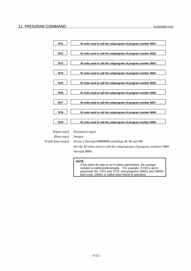
11. PROGRAM COMMAND B-63323EN-1/03
- 1112 -
7071 M code used to call the subprogram of program number 9001
7072 M code used to call the subprogram of program number 9002
7073 M code used to call the subprogram of program number 9003
7074 M code used to call the subprogram of program number 9004
7075 M code used to call the subprogram of program number 9005
7076 M code used to call the subprogram of program number 9006
7077 M code used to call the subprogram of program number 9007
7078 M code used to call the subprogram of program number 9008
7079 M code used to call the subprogram of program number 9009
���������� 0������������
��������� ��� �
�4���&�&������� 7G����������� ��!!!!!!!!�1���&�� �� -�!(���&�!!:
������*���&����&������������������ ����������� �����������! $
����� ��! !"
NOTEIf the same M code is set in these parameters, the youngernumber is called preferentially. For example, if 100 is set inparameter No. 7071 and 7072, and programs O9001 and O9002both exist, O9001 is called when M100 is specified.

B-63323EN-1/03 11. PROGRAM COMMAND
- 1113 -
7080 M code used to call the custom macro of program number 9020
7081 M code used to call the custom macro of program number 9021
7082 M code used to call the custom macro of program number 9022
7083 M code used to call the custom macro of program number 9023
7084 M code used to call the custom macro of program number 9024
7085 M code used to call the custom macro of program number 9025
7086 M code used to call the custom macro of program number 9026
7087 M code used to call the custom macro of program number 9027
7088 M code used to call the custom macro of program number 9028
7089 M code used to call the custom macro of program number 9029
���������� 0������������
��������� ��� �
�4���&�&������� 7G����������� ��!!!!!!!!�1���&�� �� -�!(���&�!!:
Set the M codes used to call the custom macros of program numbers 9020 through
9029. The simple call mode is set.
NOTE1. If the same M code is set in these parameters, the younger
number is called preferentially. For example, if 200 is set inparameter No. 7081 and No. 7082, and programs O9021 andO9022 both exist, O9021 is called when M200 is specified.
2. If the same M code is set in a parameter (No. 7071 to No. 7079)used to call subprograms and in a parameter (No. 7080 to No.7089) used to call custom macros, a custom macro is calledpreferentially. For example, if 300 is set in parameter No. 7071and No. 7081, and programs O9001 and O9021 both exist,O9021 is called when M300 is specified.
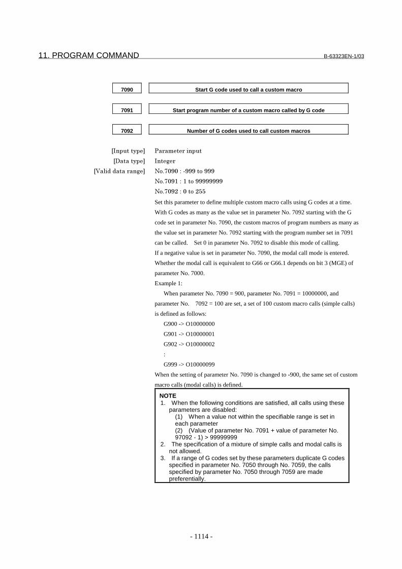
11. PROGRAM COMMAND B-63323EN-1/03
- 1114 -
7090 Start G code used to call a custom macro
7091 Start program number of a custom macro called by G code
7092 Number of G codes used to call custom macros
���������� 0������������
��������� ��� �
�4���&�&������� .�"� ! �#�F!!!����!!!
.�"� !$�#�$����!!!!!!!!
.�"� !3�#� ����3))
Set this parameter to define multiple custom macro calls using G codes at a time.
With G codes as many as the value set in parameter No. 7092 starting with the G
code set in parameter No. 7090, the custom macros of program numbers as many as
the value set in parameter No. 7092 starting with the program number set in 7091
can be called. Set 0 in parameter No. 7092 to disable this mode of calling.
If a negative value is set in parameter No. 7090, the modal call mode is entered.
Whether the modal call is equivalent to G66 or G66.1 depends on bit 3 (MGE) of
parameter No. 7000.
Example 1:
When parameter No. 7090 = 900, parameter No. 7091 = 10000000, and
parameter No. 7092 = 100 are set, a set of 100 custom macro calls (simple calls)
is defined as follows:
G900 -> O10000000
G901 -> O10000001
G902 -> O10000002
:
G999 -> O10000099
When the setting of parameter No. 7090 is changed to -900, the same set of custom
macro calls (modal calls) is defined.
NOTE1. When the following conditions are satisfied, all calls using these
parameters are disabled:(1) When a value not within the specifiable range is set ineach parameter(2) (Value of parameter No. 7091 + value of parameter No.97092 - 1) > 99999999
2. The specification of a mixture of simple calls and modal calls isnot allowed.
3. If a range of G codes set by these parameters duplicate G codesspecified in parameter No. 7050 through No. 7059, the callsspecified by parameter No. 7050 through 7059 are madepreferentially.

B-63323EN-1/03 11. PROGRAM COMMAND
- 1115 -
7093 Start G code with a decimal point used to call a custom macro
7094 Start program number of a custom macro called by G code with a decimal point
7095 Number of G codes with a decimal point used to call custom macros
���������� 0������������
��������� ��� �
�4���&�&������� .�"� !��#�F!!!����!!!
.�"� !'�#�$����!!!!!!!!
.�"� !)�#� ����3))
Set this parameter to define multiple custom macro calls using G codes with a
decimal point at a time. With G codes with a decimal point as many as the value
set in parameter No. 7095 starting with the G code with a decimal point set in
parameter No. 7093, the custom macros of program numbers as many as the value
set in parameter No. 7095 starting with the program number set in 7094 can be
called. Set 0 in parameter No. 7095 to disable this mode of calling.
If a negative value is set in parameter No. 7093, the modal call mode is entered.
Whether the modal call is equivalent to G66 or G66.1 depends on bit 3 (MGE) of
parameter No. 7000.
Example:
When parameter No. 7093 = 900, parameter No. 7094 = 20000000, and
parameter No. 7095 = 100 are set, a set of 100 custom macro calls (simple calls)
is defined as follows:
G90.0 -> O20000000
G90.1 -> O20000001
G90.2 -> O20000002
:
G99.9 -> O20000099
When the setting of parameter No. 7093 is changed to -900, the same set of custom
macro calls (modal calls) is defined.
NOTE1. When the following conditions are satisfied, all calls using these
parameters are disabled:(1) When a value not within the specifiable range is set ineach parameter(2) (Value of parameter No. 7094 + value of parameter No.7095 - 1) > 99999999(3) When bit 5 (DPG) of parameter No. 7002 = 0 (to disablecalls using G codes with a decimal point)
2. The specification of a mixture of simple calls and modal calls isnot allowed.
3. If a range of G codes set by these parameters duplicate G codesspecified in parameter No. 7060 through No. 7069, the callsspecified by parameter No. 7060 through 7069 are madepreferentially.
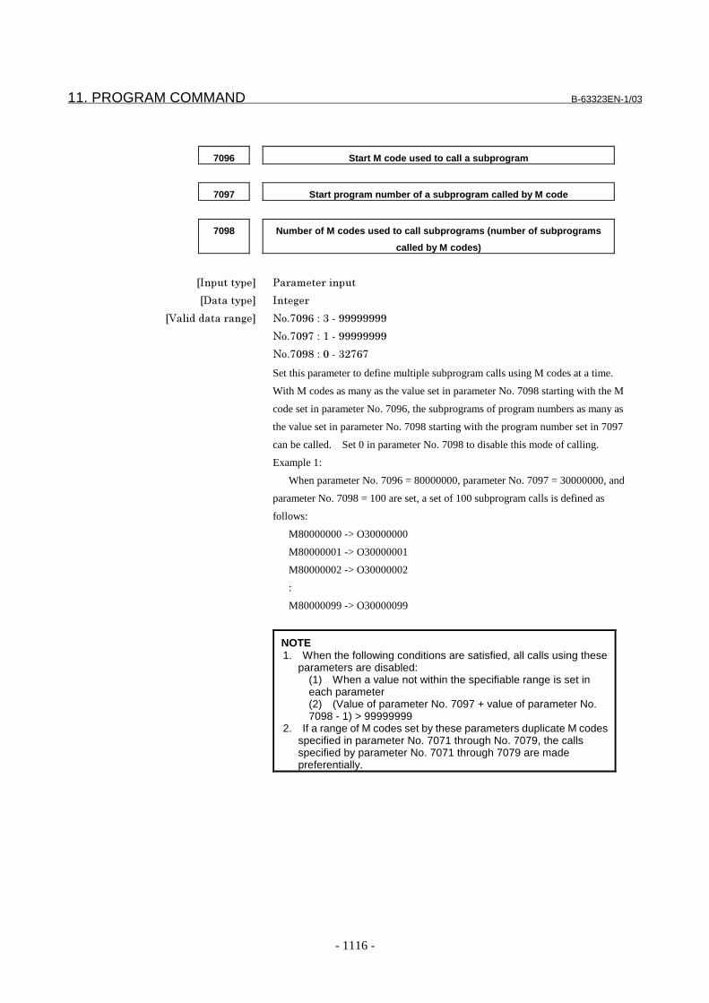
11. PROGRAM COMMAND B-63323EN-1/03
- 1116 -
7096 Start M code used to call a subprogram
7097 Start program number of a subprogram called by M code
7098 Number of M codes used to call subprograms (number of subprograms
called by M codes)
���������� 0������������
��������� ��� �
�4���&�&������� .�"� !9�#���F�!!!!!!!!
.�"� !��#�$�F�!!!!!!!!
.�"� !(�#� �F��3�9�
Set this parameter to define multiple subprogram calls using M codes at a time.
With M codes as many as the value set in parameter No. 7098 starting with the M
code set in parameter No. 7096, the subprograms of program numbers as many as
the value set in parameter No. 7098 starting with the program number set in 7097
can be called. Set 0 in parameter No. 7098 to disable this mode of calling.
Example 1:
When parameter No. 7096 = 80000000, parameter No. 7097 = 30000000, and
parameter No. 7098 = 100 are set, a set of 100 subprogram calls is defined as
follows:
M80000000 -> O30000000
M80000001 -> O30000001
M80000002 -> O30000002
:
M80000099 -> O30000099
NOTE1. When the following conditions are satisfied, all calls using these
parameters are disabled:(1) When a value not within the specifiable range is set ineach parameter(2) (Value of parameter No. 7097 + value of parameter No.7098 - 1) > 99999999
2. If a range of M codes set by these parameters duplicate M codesspecified in parameter No. 7071 through No. 7079, the callsspecified by parameter No. 7071 through 7079 are madepreferentially.
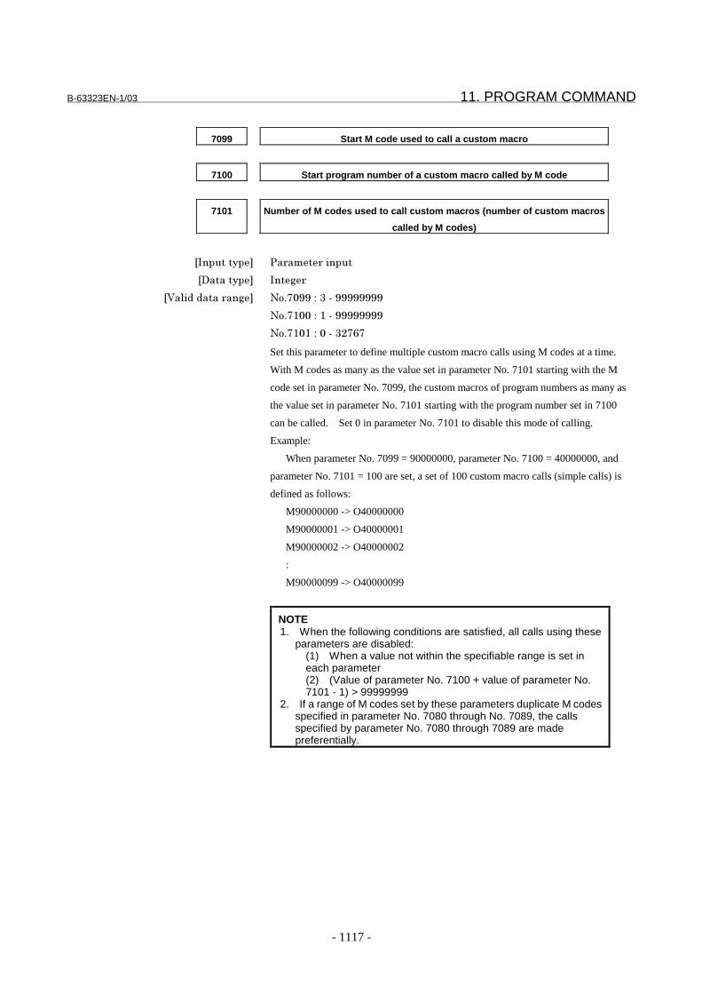
B-63323EN-1/03 11. PROGRAM COMMAND
- 1117 -
7099 Start M code used to call a custom macro
7100 Start program number of a custom macro called by M code
7101 Number of M codes used to call custom macros (number of custom macros
called by M codes)
���������� 0������������
��������� ��� �
�4���&�&������� .�"� !!�#���F�!!!!!!!!
.�"�$ �#�$�F�!!!!!!!!
.�"�$ $�#� �F��3�9�
Set this parameter to define multiple custom macro calls using M codes at a time.
With M codes as many as the value set in parameter No. 7101 starting with the M
code set in parameter No. 7099, the custom macros of program numbers as many as
the value set in parameter No. 7101 starting with the program number set in 7100
can be called. Set 0 in parameter No. 7101 to disable this mode of calling.
Example:
When parameter No. 7099 = 90000000, parameter No. 7100 = 40000000, and
parameter No. 7101 = 100 are set, a set of 100 custom macro calls (simple calls) is
defined as follows:
M90000000 -> O40000000
M90000001 -> O40000001
M90000002 -> O40000002
:
M90000099 -> O40000099
NOTE1. When the following conditions are satisfied, all calls using these
parameters are disabled:(1) When a value not within the specifiable range is set ineach parameter(2) (Value of parameter No. 7100 + value of parameter No.7101 - 1) > 99999999
2. If a range of M codes set by these parameters duplicate M codesspecified in parameter No. 7080 through No. 7089, the callsspecified by parameter No. 7080 through 7089 are madepreferentially.
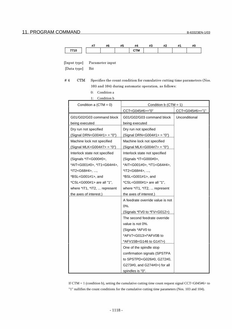
11. PROGRAM COMMAND B-63323EN-1/03
- 1118 -
#7 #6 #5 #4 #3 #2 #1 #0
7710 CTM
���������� 0������������
��������� ���
� � � � ��' 5%* ��������������������&������������������,������� ��������������7.��"
$ ����&�$ ':�&���� �������������������-�����������#
0: Condition a
1: Condition b
Condition a (CTM = 0) Condition b (CTM = 1)
CCT<G045#6>=”0” CCT<G045#6>=”1”
G01/G02/G03 command block
being executed
G01/G02/G03 command block
being executed
Unconditional
Dry run not specified
(Signal DRN<G004#1> = "0")
Dry run not specified
(Signal DRN<G004#1> = "0")
Machine lock not specified
(Signal MLK<G004#7> = "0")
Machine lock not specified
(Signal MLK<G004#7> = "0")
Interlock state not specified
(Signals *IT<G000#0>,
*AIT<G001#0>, *IT1<G64#4>,
*IT2<G68#4>, ...,
*BSL<G001#1>, and
*CSL<G000#1> are all "1",
where *IT1, *IT2, ... represent
the axes of interest.)
Interlock state not specified
(Signals *IT<G000#0>,
*AIT<G001#0>, *IT1<G64#4>,
*IT2<G68#4>, ...,
*BSL<G001#1>, and
*CSL<G000#1> are all "1",
where *IT1, *IT2, ... represent
the axes of interest.)
A feedrate override value is not
0%.
(Signals *FV0 to *FV<G012>)
The second feedrate override
value is not 0%.
(Signals *AFV0 to
*AFV7<G013>/*AFV0B to
*AFV15B<G146 to G147>)
One of the spindle stop
confirmation signals (SPSTPA
to SPSTPD<G026#0, G272#0,
G273#0, and G274#0>) for all
spindles is "0".
If CTM = 1 (condition b), setting the cumulative cutting time count request signal CCT<G045#6> to
"1" nullifies the count conditions for the cumulative cutting time parameters (Nos. 103 and 104).

B-63323EN-1/03 11. PROGRAM COMMAND
- 1119 -
Alarm And messageNumber Message Contents
PS0090 DUPLICATE NC,MACROSTATEMENT
An NC statement and macro statement were specified inthe same block.
PS0091 DUPLICATE SUB-CALL WORD More than one subprogram call instruction was specified inthe same block.
PS0092 DUPLICATE MACRO-CALL WORD More than one macro call instruction was specified in thesame block.
PS0093 DUPLICATE NC-WORD & M99 An address other than O, N, P or L was specified in thesame block as M99 during the macro modal call state.
PS0094 USE ’G’ AS ARGUMENT Address G was used as the argument of a custom macrocall. Address G can be used as the argument in individualblock call (G66.1).
PS0095 TOO MANY TYPE-2 ARGUMENT More than ten sets of I, J and K arguments were specified inthe type-II arguments (A, B, C, I, J, K, I, J, K, ...) for custommacros.
PS0096 ILLEGAL VARIABLE NAME An illegal variable name was specified.A code that cannot be specified as a variable name wasspecified.[#_OFSxx] does not match the tool offset memory optionconfiguration.
PS0097 TOO LONG VARIABLE NAME The specified variable name is too long.PS0098 NO VARIABLE NAME The specified variable name cannot be used as it is not
registered.PS0099 ILLLEGAL SUFFIX [ ] A suffix was not specified to a variable name that required a
suffix enclosed by [ ].A suffix was specified to a variable name that did notrequire a suffix enclosed by [ ].The value enclosed by the specified [ ] was out of range.
PS0100 CANCEL WITHOUT MODAL CALL Call mode cancel (G67) was specified even though macrocontinuous-state call mode (G66) was not in effect.
PS0101 ILLEGAL CNC STATEMENT IRT. An interrupt was made in a state where a custom macrointerrupt containing a move instruction could not beexecuted.
PS0110 OVERFLOW :INTEGER An integer went out of range during arithmetic calculations.PS0111 OVERFLOW :FLOATING A decimal point (floating point number format data) went
out of range during arithmetic calculations.PS0112 ZERO DIVIDE An attempt was made to divide by zero in a custom macro.PS0114 VARIABLE NO. OUT OF RANGE An illegal No. was specified in a local variable, common
variable or a system variable in a custom macro.A non-existent custom macro variable No. was specified inthe EGB axis skip function (G31.8), or there are not enoughcustom macro variables for storing the skip position.
PS0115 READ PROTECTED VARIABLE An attempt was made in a custom macro to use on the rightside of an expression a variable that can only be used onthe left side of an expression.
PS0116 WRITE PROTECTED VARIABLE An attempt was made in a custom macro to use on the leftside of an expression a variable that can only be used onthe right side of an expression.
PS0118 TOO MANY BRACKET NESTING Too many brackets "[]" were nested in a custom macro.The nesting level including function brackets is 5.
PS0119 ARGUMENT VALUE OUT OF RANGE The value of an argument in a custom macro function is outof range.
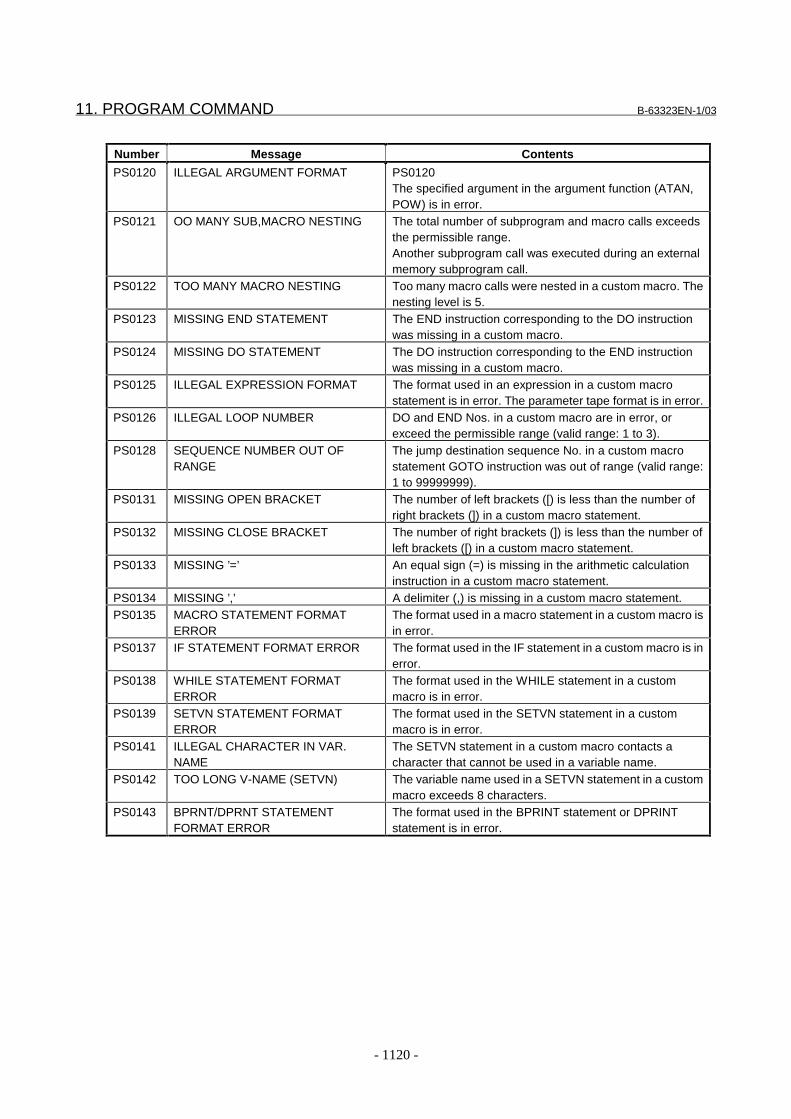
11. PROGRAM COMMAND B-63323EN-1/03
- 1120 -
Number Message Contents
PS0120 ILLEGAL ARGUMENT FORMAT PS0120The specified argument in the argument function (ATAN,POW) is in error.
PS0121 OO MANY SUB,MACRO NESTING The total number of subprogram and macro calls exceedsthe permissible range.Another subprogram call was executed during an externalmemory subprogram call.
PS0122 TOO MANY MACRO NESTING Too many macro calls were nested in a custom macro. Thenesting level is 5.
PS0123 MISSING END STATEMENT The END instruction corresponding to the DO instructionwas missing in a custom macro.
PS0124 MISSING DO STATEMENT The DO instruction corresponding to the END instructionwas missing in a custom macro.
PS0125 ILLEGAL EXPRESSION FORMAT The format used in an expression in a custom macrostatement is in error. The parameter tape format is in error.
PS0126 ILLEGAL LOOP NUMBER DO and END Nos. in a custom macro are in error, orexceed the permissible range (valid range: 1 to 3).
PS0128 SEQUENCE NUMBER OUT OFRANGE
The jump destination sequence No. in a custom macrostatement GOTO instruction was out of range (valid range:1 to 99999999).
PS0131 MISSING OPEN BRACKET The number of left brackets ([) is less than the number ofright brackets (]) in a custom macro statement.
PS0132 MISSING CLOSE BRACKET The number of right brackets (]) is less than the number ofleft brackets ([) in a custom macro statement.
PS0133 MISSING ’=’ An equal sign (=) is missing in the arithmetic calculationinstruction in a custom macro statement.
PS0134 MISSING ’,’ A delimiter (,) is missing in a custom macro statement.PS0135 MACRO STATEMENT FORMAT
ERRORThe format used in a macro statement in a custom macro isin error.
PS0137 IF STATEMENT FORMAT ERROR The format used in the IF statement in a custom macro is inerror.
PS0138 WHILE STATEMENT FORMATERROR
The format used in the WHILE statement in a custommacro is in error.
PS0139 SETVN STATEMENT FORMATERROR
The format used in the SETVN statement in a custommacro is in error.
PS0141 ILLEGAL CHARACTER IN VAR.NAME
The SETVN statement in a custom macro contacts acharacter that cannot be used in a variable name.
PS0142 TOO LONG V-NAME (SETVN) The variable name used in a SETVN statement in a custommacro exceeds 8 characters.
PS0143 BPRNT/DPRNT STATEMENTFORMAT ERROR
The format used in the BPRINT statement or DPRINTstatement is in error.

B-63323EN-1/03 11. PROGRAM COMMAND
- 1121 -
CautionCAUTION
Machine tool builders: You are requested to attachyour custom macro program tape or program list tothe CNC unit without fail.If it is necessary to replace part program storagememory due to a failure, FANUC servicemen or enduser in charge of maintenance should know thecontents of your custom macro for the purpose ofrepairing the trouble immediately.
Reference itemSeries15i/150i-MA Operator’s Manual
(Programming)(B-63324EN)
II-17 Custom macro
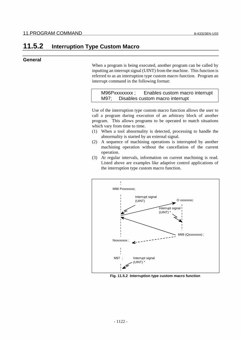
11.PROGRAM COMMAND B-63323EN-1/03
- 1122 -
11.5.2 Interruption Type Custom Macro
GeneralWhen a program is being executed, another program can be called byinputting an interrupt signal (UINT) from the machine. This function isreferred to as an interruption type custom macro function. Program aninterrupt command in the following format:
M96Pxxxxxxxx ; Enables custom macro interruptM97; Disables custom macro interrupt
Use of the interruption type custom macro function allows the user tocall a program during execution of an arbitrary block of anotherprogram. This allows programs to be operated to match situationswhich vary from time to time.(1) When a tool abnormality is detected, processing to handle the
abnormality is started by an external signal.(2) A sequence of machining operations is interrupted by another
machining operation without the cancellation of the currentoperation.
(3) At regular intervals, information on current machining is read.Listed above are examples like adaptive control applications ofthe interruption type custom macro function.
Fig. 11.5.2 Interruption type custom macro function
Interrupt signal(UINT) *
Interrupt signal(UINT)
Interrupt signal(UINT) *
M96 Pxxxxxxxx;
Nxxxxxxxx ;
M97 ;
M99 (Qxxxxxxxx) ;
O xxxxxxxx;
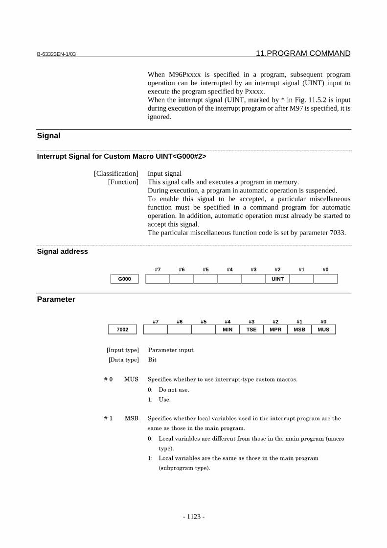
B-63323EN-1/03 11.PROGRAM COMMAND
- 1123 -
When M96Pxxxx is specified in a program, subsequent programoperation can be interrupted by an interrupt signal (UINT) input toexecute the program specified by Pxxxx.When the interrupt signal (UINT, marked by * in Fig. 11.5.2 is inputduring execution of the interrupt program or after M97 is specified, it isignored.
Signal
Interrupt Signal for Custom Macro UINT<G000#2>
[Classification] Input signal[Function] This signal calls and executes a program in memory.
During execution, a program in automatic operation is suspended.To enable this signal to be accepted, a particular miscellaneousfunction must be specified in a command program for automaticoperation. In addition, automatic operation must already be started toaccept this signal.The particular miscellaneous function code is set by parameter 7033.
Signal address
#7 #6 #5 #4 #3 #2 #1 #0
G000 UINT
Parameter
#7 #6 #5 #4 #3 #2 #1 #0
7002 MIN TSE MPR MSB MUS
���������� �� ��� ������
��������� ���
� � � � ��� ��� ������������ ���������� ������������������ ���
�� ����������
� ���
� � � � �� ��� ������������ �!���!�"� ��#!����$���������� ����� �% ���� ���
������������������������ �% ���
�� &���!�"� ��#!��� �$��� ���� �������������������� �% ���'��� �
���(�
� &���!�"� ��#!��� ���������������������������� �% ��
'��#� �% ������(�

11.PROGRAM COMMAND B-63323EN-1/03
- 1124 -
� � � � ��) ��* ������������$�������� ���$������#!�� �$���#!���� ��������������
��� ���
�� �+,-�+.
� ����$����������� ��� �'�� ��� �/���.�00�� �/���.�01(
� � � � ��0 2�3 ������������ ����������$%�� �%% �� ��������� �%% ������������
���������� ����� ������%��!�
�� ������$%�� �%% �' ����%�$%(�
� ������������� �%% �
� � � � ��1 ��/ ���������������4����5/5������������������� ����� �% ���
�� 34����5/5����������#����� �����%����#!��6�#��%�4���$���
������ ���$�� �% ���'���� (�
� 34����5/5������������� ������ ���#!��6���������� ���$
� �% �������#��4���$�'����)(�
7033 M code for turning on custom macro interrupt
7034 M code for turning off custom macro interrupt
���������� �� ��� ������
��������� ���%
�7�!�$�$���� ��% 8 ���0��� ��%��++++++++�'4�!�$��%�0�9�+:���$�++(
;���#���)�'��*(������ ��� �/���.��)���������� 9��������9������
�� ��� ������$��������������$��� ���#!��%-$���#!��%���� �������
���������� ��9����������������$����������� ��� �
Alarm And message
Number Message Contents
PS0101 ILLEGAL CNC STATEMENT IRT. An interrupt was made in a state where a custom macrointerrupt containing a move instruction could not beexecuted.
Reference itemSeries15i/150i-MA Operator’s Manual
(Programming)(B-63324EN)
II-17.14 Interruption type custommacro
B-63323EN-1/03 11.PROGRAM COMMAND
- 1125 -
11.6 CANNED CYCLE SPINDLE CONTROL
GeneralCanned cycles make it easier for the programmer to create programs.With a canned cycle, a frequently-used machining operation can bespecified in a single block with a G function; without canned cycles,normally more than one block is required. In addition, the use ofcanned cycles can shorten the program to save memory.For operation in a canned cycle, refer to the operator’s manual. Thissection explains those functions requiring spindle control.
- Types of spindle controlThere are two types of canned cycles, as follows, depending on thesignals used for spindle control in a canned cycle:Canned cycle I: Dedicated signals (such as SSP and SRV) are used.Canned cycle II: Ordinary miscellaneous functions (such as M03 andM05) are used.The canned cycle type to be used is selected by bit 0 (FXB) ofparameter No. 6201.
Canned cycle
- Functions require spindle controlThe following four functions require spindle control:
Table. 11.6 (a) Functions require spindle control for canned cycle I
G code Operation on the holebottom
Use
G74 Spindle CW Left-hand tappingG84 Spindle CCW TappingG86 Spindle stop BoringG88 Dwell → spindle stop Boring
NOTE1 The fine boring cycle (G76) requires spindle
orientation. Since no special signals are provided forspindle orientation, this cycle cannot be used incanned cycle I.
2 G87 is used as an ordinary boring cycle; it is not usedas the back boring cycle that requires spindleorientation. Therefore, spindle control is not requiredin canned cycle I.

11.PROGRAM COMMAND B-63323EN-1/03
- 1126 -
- Basic transmission procedureThe following four functions require spindle control:
Table. 11.6 (b) Dedicated Signals for Spindle Control
Function Inputsignal
Outputsignal
Spindle stop SSPReverse spindle rotation SRVCanned cycle auxiliary signalread
FMF
Canned cycle auxiliary signalcompletion
FFIN
Procedure when the SSP or SRV signal is set to 11. The CNC sets SSP or SRV to 1 at the necessary positions in a
canned cycle.2. When SSP or SRV is set to 1, the PMC must perform the
following:- When SSP is set to 1, stops the spindle.- When SRV is set to 1, rotates the spindle in the reverse
direction.3. At the same time as when setting SSP or SRV to 1, the CNC sets
the canned cycle auxiliary signal FMF to 1.4. After completing an appropriate operation, the PMC must set the
canned cycle auxiliary signal completion signal FFIN to 1.5. When the FFIN signal is set to 1, the CNC sets the auxiliary
function read signal FMF to 0 to notify the PMC of the receptionof the FFIN signal.
6. When the FMF signal is set to 0, the PMC must set the completionsignal FFIN to 0.
7. When the FFIN signal is set to 0, the CNC proceeds to the nextoperation.
The above procedure is usually used. When bit 6 (NFM) of parameterNo. 6201 is set to 1, confirmation steps 3 to 7 are omitted.
Procedure when the SSP or SRV signal is set to 0Generally, the SSP and SRV signals can just be set to 0; noconfirmation steps are performed. By setting bit 5 (FM2) of parameterNo. 6201 to 1, however, confirmation steps 3 to 7, mentioned above,can also be performed.When many holes spaced at short intervals are to be machined, thespindle speed may not reach the required level before the start ofmachining for the next hole. In such cases, the above parameter is set.In this case, both the SSP and SRV signals are in the 0 state. Check thatthe operation corresponding to the signal state is completed, then setthe FFIN signal to 1.
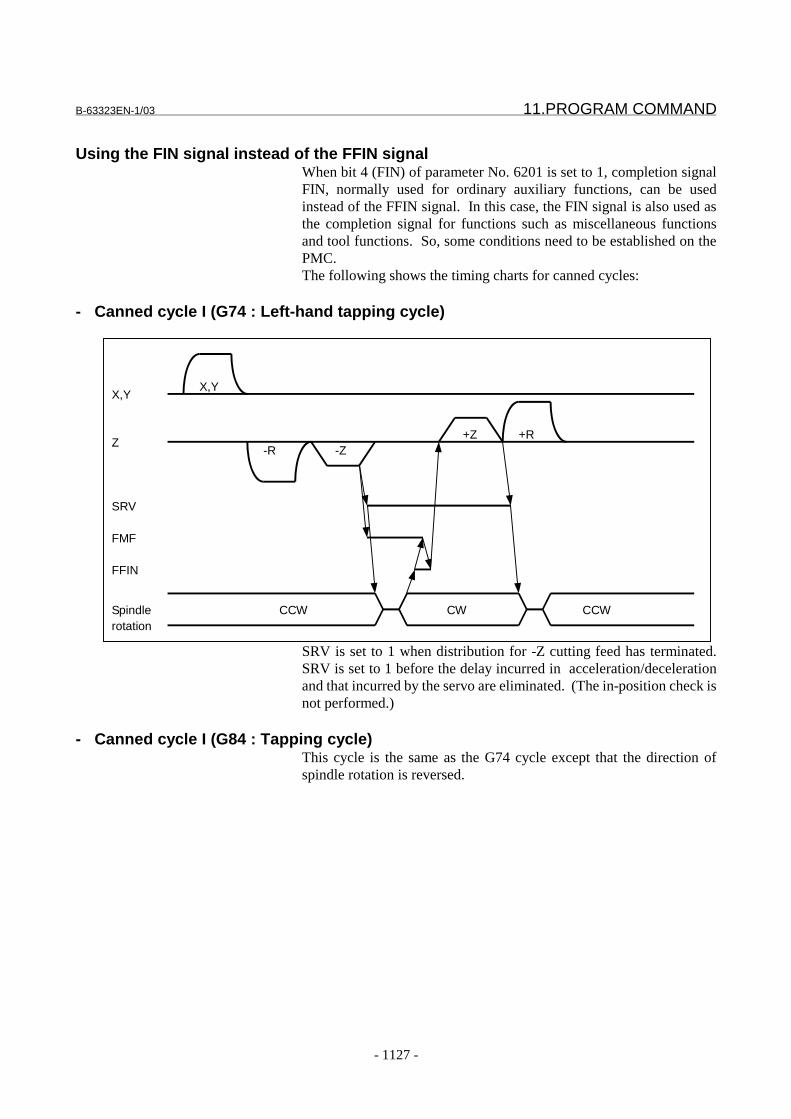
B-63323EN-1/03 11.PROGRAM COMMAND
- 1127 -
Using the FIN signal instead of the FFIN signalWhen bit 4 (FIN) of parameter No. 6201 is set to 1, completion signalFIN, normally used for ordinary auxiliary functions, can be usedinstead of the FFIN signal. In this case, the FIN signal is also used asthe completion signal for functions such as miscellaneous functionsand tool functions. So, some conditions need to be established on thePMC.The following shows the timing charts for canned cycles:
- Canned cycle I (G74 : Left-hand tapping cycle)
X,Y
Z
SRV
FMF
FFIN
Spindlerotation
CCW CW CCW
-R -Z+Z +R
X,Y
SRV is set to 1 when distribution for -Z cutting feed has terminated.SRV is set to 1 before the delay incurred in acceleration/decelerationand that incurred by the servo are eliminated. (The in-position check isnot performed.)
- Canned cycle I (G84 : Tapping cycle)This cycle is the same as the G74 cycle except that the direction ofspindle rotation is reversed.
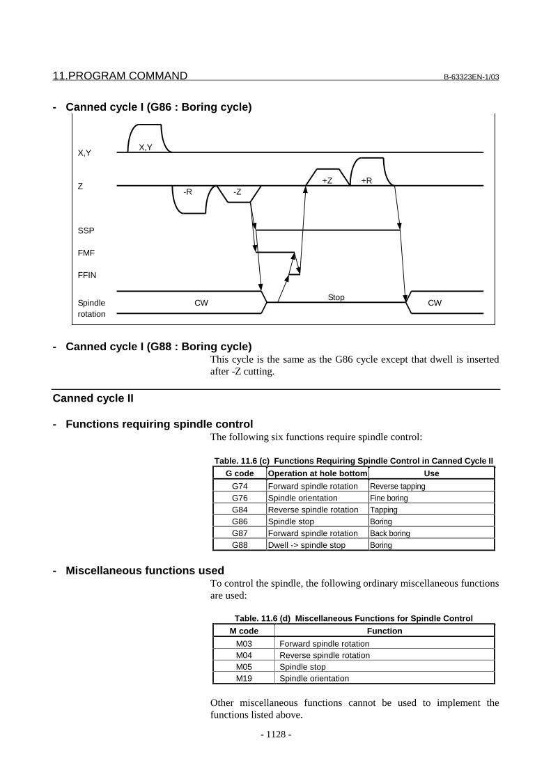
11.PROGRAM COMMAND B-63323EN-1/03
- 1128 -
- Canned cycle I (G86 : Boring cycle)
X,Y
Z
SSP
FMF
FFIN
Spindlerotation
CWStop
CW
-R -Z+Z +R
X,Y
- Canned cycle I (G88 : Boring cycle)This cycle is the same as the G86 cycle except that dwell is insertedafter -Z cutting.
Canned cycle II
- Functions requiring spindle controlThe following six functions require spindle control:
Table. 11.6 (c) Functions Requiring Spindle Control in Canned Cycle II
G code Operation at hole bottom Use
G74 Forward spindle rotation Reverse tappingG76 Spindle orientation Fine boringG84 Reverse spindle rotation TappingG86 Spindle stop BoringG87 Forward spindle rotation Back boringG88 Dwell -> spindle stop Boring
- Miscellaneous functions usedTo control the spindle, the following ordinary miscellaneous functionsare used:
Table. 11.6 (d) Miscellaneous Functions for Spindle Control
M code Function
M03 Forward spindle rotationM04 Reverse spindle rotationM05 Spindle stopM19 Spindle orientation
Other miscellaneous functions cannot be used to implement thefunctions listed above.

B-63323EN-1/03 11.PROGRAM COMMAND
- 1129 -
- Sending M05 when rotating the spindle in the reverse directionWhen the spindle is rotated in the reverse direction (from M03 to M04or vice versa), whether to send M05 can be selected by setting bit 1(NM5) of parameter No. 6201.
- Canned cycle II (G84 : Tapping cycle)
X,Y
Z
DEN
M code
MF
FIN
FMF
-R -Z+Z +R
X,Y
M05 M04 M05 M03
- Canned cycle II (G74 : Reverse tapping cycle)This cycle is the same as the G84 cycle except that M03 and M04 areswitched.
- Canned cycle II (G86, G88 : Boring cycle)
X,Y
Z
DEN
M code
MF
FIN
-R -Z+Z,+R
X,Y
M05 M03

11.PROGRAM COMMAND B-63323EN-1/03
- 1130 -
- Canned cycle II (G87 : Back boring cycle)
X,Y
Z
DEN
M code
MF
FIN
-R+Z
Initial point
X,Y
M03 M05 M19
Shift
M05 M19
Reverse shift
M03
ShiftReverse shift
- Canned cycle II (G76 : Fine boring cycle)
X,Y
Z
DEN
M code
MF
FIN
-R -Z+Z,+R
X,Y
M05 M03M19
ShiftReverse shift
Signal
Canned cycle spindle stop command signal SSP<F008#7>[Classification] Output signal
[Function] Specifies stopping of the spindle.While this signal is 1, the spindle stopped state must be maintained and,when the signal is set to 0, the previous state must be restored.
[Output condition] See the basic transmission procedure for canned cycle I.
Canned cycle spindle reverse command signal SRV<F008#6>[Classification] Output signal
[Function] Specifies reversal of the spindle rotation direction.While this signal is 1, the reversed spindle rotation state must bemaintained and, when the signal is set to 0, the previous state must berestored.
[Output condition] See the basic transmission procedure for canned cycle I.
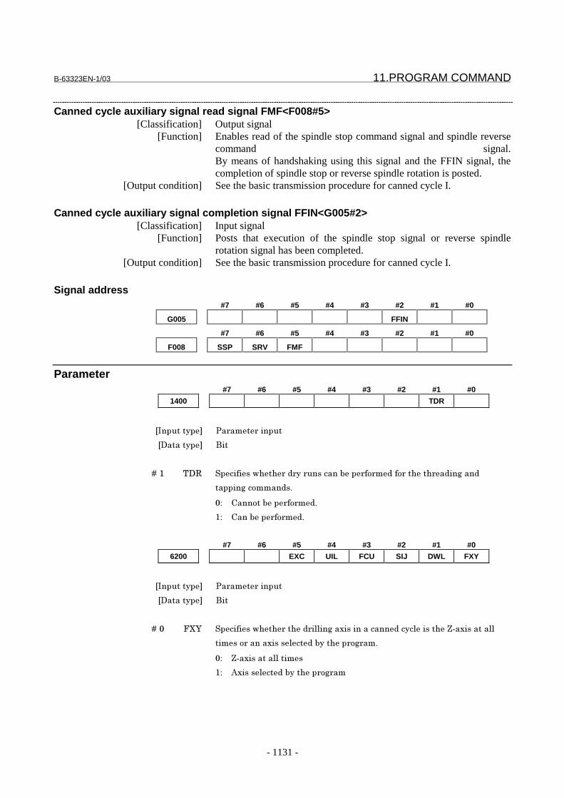
B-63323EN-1/03 11.PROGRAM COMMAND
- 1131 -
Canned cycle auxiliary signal read signal FMF<F008#5>[Classification] Output signal
[Function] Enables read of the spindle stop command signal and spindle reversecommand signal.By means of handshaking using this signal and the FFIN signal, thecompletion of spindle stop or reverse spindle rotation is posted.
[Output condition] See the basic transmission procedure for canned cycle I.
Canned cycle auxiliary signal completion signal FFIN<G005#2>[Classification] Input signal
[Function] Posts that execution of the spindle stop signal or reverse spindlerotation signal has been completed.
[Output condition] See the basic transmission procedure for canned cycle I.
Signal address#7 #6 #5 #4 #3 #2 #1 #0
G005 FFIN
#7 #6 #5 #4 #3 #2 #1 #0
F008 SSP SRV FMF
Parameter#7 #6 #5 #4 #3 #2 #1 #0
1400 TDR
���������� �� ��� ������
��������� ���
� � � � �� 2�* ������������ �$ �� ��������#�� �� �$��� ������ �$��%���$
������%�������$��
�� 5������#�� �� �$�
� 5���#�� �� �$�
#7 #6 #5 #4 #3 #2 #1 #0
6200 EXC UIL FCU SIJ DWL FXY
���������� �� ��� ������
��������� ���
� � � � ��� 8<= ������������ ����$ �!!��%��4������������$����!�������>��4�������!!
������ �����4����!��$�#������ �% ���
�� >��4�������!!�����
� ?4����!��$�#������ �% ��
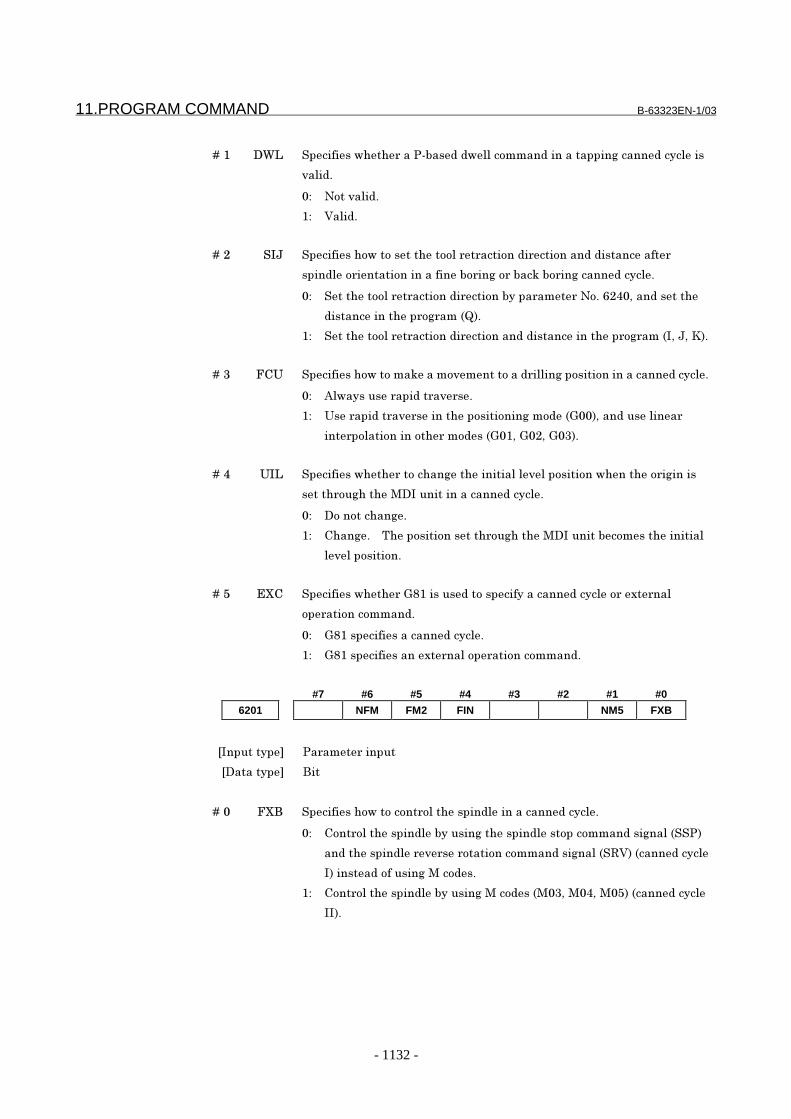
11.PROGRAM COMMAND B-63323EN-1/03
- 1132 -
� � � � �� �;& ������������ �����#��$�$�!!�������$������������%�����$����!���
"�!�$�
�� /���"�!�$�
� 7�!�$�
� � � � ��) ��@ ������������������������!� � �������$� ��������$�$����������
����$!�� ������������������#� ��%�� �#��6�#� ��%�����$����!�
�� ���������!� � �������$� ������#���� ��� �/���,)1�9���$������
$�������������� �% ���'A(�
� ���������!� � �������$� ��������$�$�������������� �% ���'�9�@9�B(�
� � � � ��0 85� �����������������6�����"���������$ �!!��%�������������������$����!�
�� ?!�������� ���$�� �" ��
� ��� ���$�� �" ������������������%���$�'C��(9���$����!���
��� ��!������������ ���$��'C� 9�C�)9�C�0(�
� � � � ��1 ��& ������������ ��������%����������!�!"!������������������ �%�����
����� ��%�����������������������$����!�
�� �����������%�
� 5���%�� � 2���������������� ��%��������������#��������������!
!"!����������
� � � � ��D 3<5 ������������ �C: ������$�����������������$����!�� �4� ��!
�� ������������$�
�� C: ���������������$����!�
� C: ������������4� ��!��� ������������$�
#7 #6 #5 #4 #3 #2 #1 #0
6201 NFM FM2 FIN NM5 FXB
���������� �� ��� ������
��������� ���
� � � � ��� 8<� ������������������� �!��������$!����������$����!�
�� 5��� �!��������$!�#������%��������$!������������$���%��!�'���(
��$��������$!� " �� ��������������$���%��!�'�*7(�'����$����!
�(������$��������%�����$��
� 5��� �!��������$!�#������%�����$��'��09���19���D(�'����$����!
��(�

B-63323EN-1/03 11.PROGRAM COMMAND
- 1133 -
� � � � �� /�D ������������ �������������D��������$� ��������� �������������
����$!��������%$�� ����� �� $�'��0(���� " ��'��1(�� �"���" �������
����$����!�
�� E��������D�� � 2������9���D�����������#�� ���0�� ���1�����������
'��D���1�� ���D���0(
� ����������������D�� � 2������9���D���������������#�� ���0�� ���1���
�������
2������ ��� ����"�!�$�����#�����'8<�(������ ��� �/���,)� ���������
�
� � � � ��1 8�/ �������������%��!����#��� $������$����������� �������� ���
����$!������������$���%��!�'���(�� ��������$!� " �� �������
������$���%��!�'�*7(�����#������!�$�
�� 88�/���%��!�'����!�������%��!�$$����$�������������$��*7
��%��!�(
� 8�/���%��!�'����!�������%��!��� ��9��9�29���$�����$�(
2������ ��� ����"�!�$�����#�����'8<�(������ ��� �/���,)� ���������
��
� � � � ��D 8�) ������������ ������$����8�8���%��!���� � �� �����������*�� ���
������!���������������������$!������������$���%��!�'���(�� �����$!
" �� ��������������$���%��!�'�*7(�����������
�� ���������$����8�8���%��!�'������$��� � �$��%����������$��*7
��%��!�(�
� ��$����8�8���%��!�
2������ ��� ����"�!�$�����#���,�'/8�(������ ��� �/���,)� ���������
��
� � � � ��, /8� ������������ ������$����8�8���%��!������������$!�����
������$���%��!�'���(�� �����$!� " �� ��������������$���%��!�'�*7(
����������
�� ��$����8�8���%��!�'������$��� � �$��%����������$��*7
��%��!�(�
� ���������$����8�8���%��!�
6210 Return distance in canned cycle G73
���������� �����%������
��������� *�!
���������$��� ��9������'����������(
�����������������$��� ���$���������� ���������������� � ����4��
�7�!�$�$���� ��% +�$�%����������������������$����' � ��������$� $��� ��� ������%
��#!'?((
';��������� �����������������9��++++++�+++���F++++++�+++(
����� �� ��$��������������$����!�C.0�

11.PROGRAM COMMAND B-63323EN-1/03
- 1134 -
6211 Clearance in canned cycle G83
���������� �����%������
��������� *�!
���������$��� ��9������'����������(
�����������������$��� ���$���������� ���������������� � ����4��
�7�!�$�$���� ��% +�$�%����������������������$����' � ��������$� $��� ��� ������%
��#!'?((
';��������� �����������������9��++++++�+++���F++++++�+++(
������!� �����������$����!�C:0�
6240 Tool retraction direction after G86.1 and G87 orientation
���������� �� ��� ������
��������� ���% �4��
�7�!�$�$���� ��% � ���� �
���������!� � ��������4�����$�$� ��������$���� �����$!�� ��������
�������$����!�C:,� �� �C:)�� � 8� �����$ �!!��%��4��9�������!� � ������
�4�����$�$� ��������� �� �������������#����� � �����������4������#
�!��%����������%��'F�� ���(�������������$� ������
34���!�� � ������������!!����%�
;������$ �!!��%��4���������<��4��9�������!� � �������$� ���������
� �������������=�
;������$ �!!��%��4���������=��4��9�������!� � �������$� ���������
� ������������F>�
;������$ �!!��%��4���������>��4��9�������!� � �������$� ���������
� �������������<�
2��9��������� ��� �������!!����'�������%����������� ����4��9�����$
�4��9���$���� $��4���� ����<��4��9�=��4��9���$�>��4��(�
�������� ��� ��� ������ ����4�������)�'������!� � �������$� ��������
�=(�
�������� ��� ��� ��������$��4������0�'������!� � �������$� ��������
F>(�
�������� ��� ��� ������� $��4������� �'������!� � �������$� ��������
�<(�
������� ���� ��4��
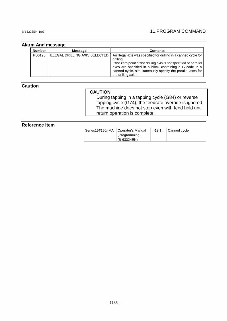
B-63323EN-1/03 11.PROGRAM COMMAND
- 1135 -
Alarm And messageNumber Message ContentsPS0196 ILLEGAL DRILLING AXIS SELECTED An illegal axis was specified for drilling in a canned cycle for
drilling.If the zero point of the drilling axis is not specified or parallelaxes are specified in a block containing a G code in acanned cycle, simultaneously specify the parallel axes forthe drilling axis.
CautionCAUTION
During tapping in a tapping cycle (G84) or reversetapping cycle (G74), the feedrate override is ignored.The machine does not stop even with feed hold untilreturn operation is complete.
Reference itemSeries15i/150i-MA Operator’s Manual
(Programming)(B-63324EN)
II-13.1 Canned cycle
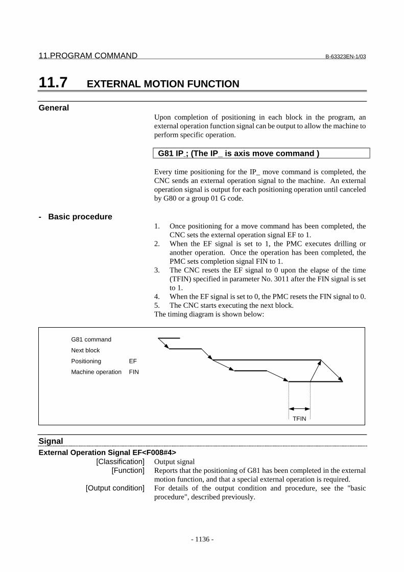
11.PROGRAM COMMAND B-63323EN-1/03
- 1136 -
11.7 EXTERNAL MOTION FUNCTION
GeneralUpon completion of positioning in each block in the program, anexternal operation function signal can be output to allow the machine toperform specific operation.
G81 IP ; (The IP_ is axis move command )
Every time positioning for the IP_ move command is completed, theCNC sends an external operation signal to the machine. An externaloperation signal is output for each positioning operation until canceledby G80 or a group 01 G code.
- Basic procedure1. Once positioning for a move command has been completed, the
CNC sets the external operation signal EF to 1.2. When the EF signal is set to 1, the PMC executes drilling or
another operation. Once the operation has been completed, thePMC sets completion signal FIN to 1.
3. The CNC resets the EF signal to 0 upon the elapse of the time(TFIN) specified in parameter No. 3011 after the FIN signal is setto 1.
4. When the EF signal is set to 0, the PMC resets the FIN signal to 0.5. The CNC starts executing the next block.The timing diagram is shown below:
G81 command
Next block
Positioning EF
Machine operation FIN
TFIN
SignalExternal Operation Signal EF<F008#4>
[Classification] Output signal[Function] Reports that the positioning of G81 has been completed in the external
motion function, and that a special external operation is required.[Output condition] For details of the output condition and procedure, see the "basic
procedure", described previously.
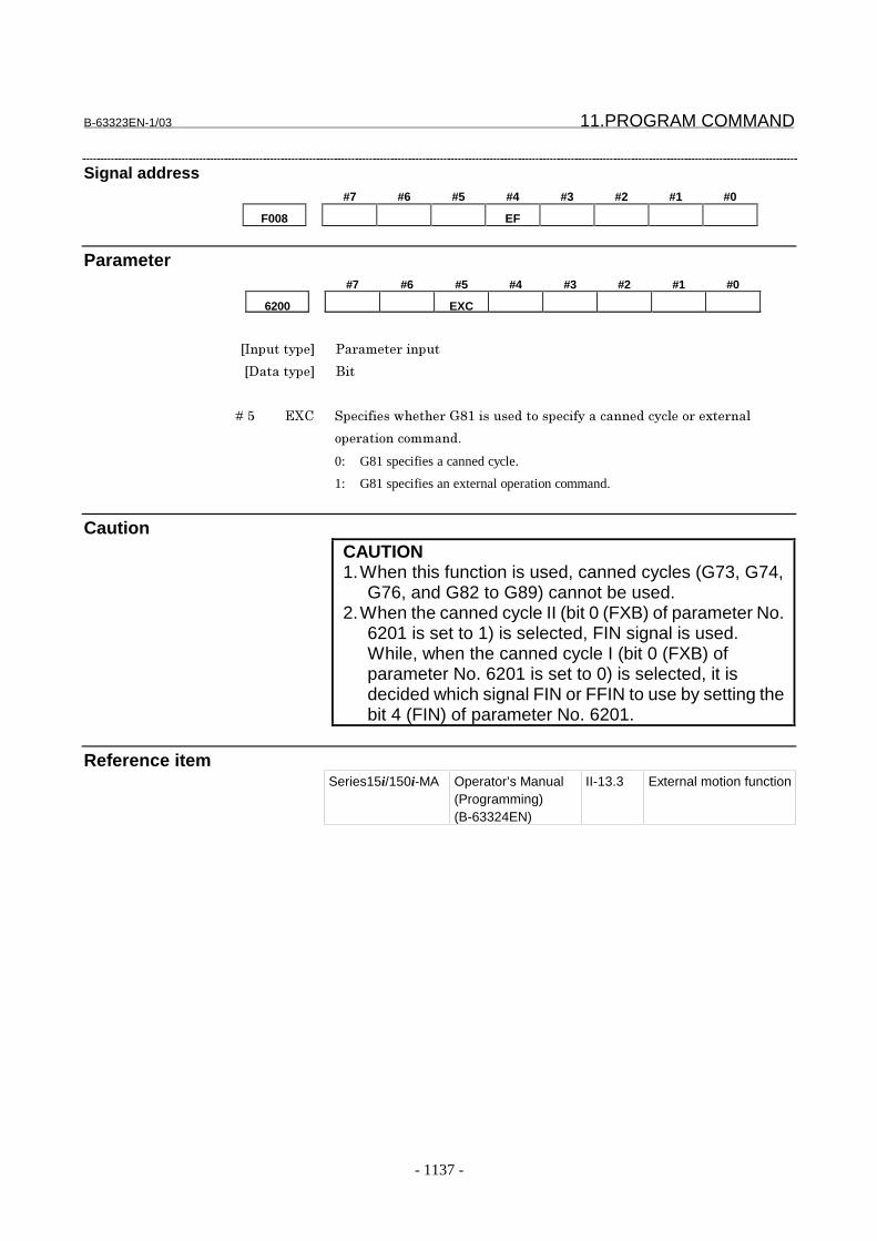
B-63323EN-1/03 11.PROGRAM COMMAND
- 1137 -
Signal address#7 #6 #5 #4 #3 #2 #1 #0
F008 EF
Parameter#7 #6 #5 #4 #3 #2 #1 #0
6200 EXC
���������� �� ��� ������
��������� ���
� � � � ��D 3<5 ������������ �C: ������$�����������������$����!�� �4� ��!
�� ������������$�
0: G81 specifies a canned cycle.
1: G81 specifies an external operation command.
CautionCAUTION1. When this function is used, canned cycles (G73, G74,
G76, and G82 to G89) cannot be used.2. When the canned cycle II (bit 0 (FXB) of parameter No.
6201 is set to 1) is selected, FIN signal is used.While, when the canned cycle I (bit 0 (FXB) ofparameter No. 6201 is set to 0) is selected, it isdecided which signal FIN or FFIN to use by setting thebit 4 (FIN) of parameter No. 6201.
Reference itemSeries15i/150i-MA Operator’s Manual
(Programming)(B-63324EN)
II-13.3 External motion function

11.PROGRAM COMMAND B-63323EN-1/03
- 1138 -
11.8 INDEX TABLE INDEXING FUNCTION
GeneralBy specifying indexing positions (angles) for the indexing axis (onerotation axis, A, B, or C), the index table of the machining center can beindexed.Before and after indexing, the index table is automatically unclampedor clamped.
- Basic ProcedureThe positioning angle for the index table is commanded by the numericfollowing "B" in the program command, which is an independent block.Both absolute and incremental commands are possible, but the valueafter "B" is the integer times the numeric set by the parameter:(Example) G00G90B100000; Absolute command
(Positioning angle 10 degrees)G00G91B20.0; Incremental command(Move distance 20 degrees)
There are two variations of the procedure (type A and type B) to set theindex table position; the difference is in the ON/OFF timing of theposition control servo. The sequence of events and the differencebetween the variations are described below, followed by time chartsshowing them graphically.(1) Assume Bbbbb is ordered by the command program.(2) The CNC turns the B axis unclamp signal BUCLP to "1". (Type B
-- When BUCLP is turned to " 1 ", the position control servo forthe B axis is turned ON.)
(3) On the PMC side, the clamp of the B axis is released; whencompleted, the B axis unclamp completion signal *BEUCL turnsto "0".
(4) The CNC then turns the B axis unclamp signal BUCLP to "0", toindicate it received the *BEUCL signal.
(5) When the PMC is notified that BUCLP has been turned to "0", thePMC should turn *BEUCL to "1".In type B, B-axis unclamp signal BUCLP is turned to "0", B-axisposition control is made in servo-on state, B-axis is rotated, andthe B axis is stopped at the specified position. B axis alwaysmoves at rapid traverse.
(6) When the B axis stops at the specified position, CNC turns B-axisclamp signal BCLP to 1. In type A, signal BCLP is set to "1" andB-axis position control is made in servo-off state.
(7) When BCLP is turned to "1" on the PMC side, the B axis isclamped mechanically (with a clutch or shot pin, for example).When the clamp is completed, the B axis clamp completion signal*BECLP is turned to "0".
(8) When *BECLP is turned to "0", the CNC then turns BCLP to "0",informing it received the *BECLP signal. (Type B -- When BCLPturns to "0", the B axis position control servo is turned off.)
(9) On the PMC side, when BCLP changes to "0", *BECLP is turnedto "1".
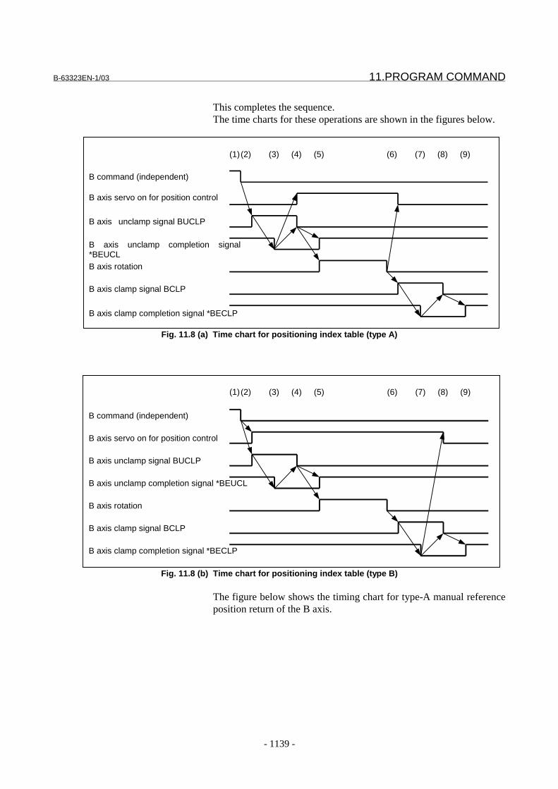
B-63323EN-1/03 11.PROGRAM COMMAND
- 1139 -
This completes the sequence.The time charts for these operations are shown in the figures below.
B command (independent)
B axis servo on for position control
B axis unclamp signal BUCLP
B axis unclamp completion signal*BEUCLB axis rotation
B axis clamp signal BCLP
B axis clamp completion signal *BECLP
(1)(2) (3) (4) (5) (6) (7) (8) (9)
Fig. 11.8 (a) Time chart for positioning index table (type A)
B command (independent)
B axis servo on for position control
B axis unclamp signal BUCLP
B axis unclamp completion signal *BEUCL
B axis rotation
B axis clamp signal BCLP
B axis clamp completion signal *BECLP
(1)(2) (3) (4) (5) (6) (7) (8) (9)
Fig. 11.8 (b) Time chart for positioning index table (type B)
The figure below shows the timing chart for type-A manual referenceposition return of the B axis.

11.PROGRAM COMMAND B-63323EN-1/03
- 1140 -
B axis manual feed selection signal +Jα
B axis position control servo ON
B axis unclamp signal BUCLP
B axis unclamp completion signal *BEUCL
B axis rotation
B axis deceleration signal *DECα
B axis return completion signal ZPα
B axis clamp signal BCLP
B axis clamp completion signal *BECLP
Fig. 11.8 (c) Manual reference position return of B axis time chart (type A)
- Type A and Type BAs described in the basic procedure, type A differs from type B in thatthe servo used for B-axis position control is turned on or off at thedifferent timing.Type A is suitable for a system in which the B-axis is clamped withshot pins.Type B is suitable for a system in which the B-axis is clamped with aclutch.
- Indexing axis settingSet a rotation axis as an index table indexing axis. That is, set thefollowing:
Bit 0 (ROT) of parameter No. 1006 = 1Bit 1 (ROS) of parameter No. 1006 = 1Bit 2 (ROP) of parameter No. 1006 = 1
Disable the servo-off signal for an index table indexing axis. That is,set the following:
Bit 1 (SVF) of parameter No. 1802 = 0Usually, the servo-off state is set for an index table indexing axis.
- Absolute/incremental programmingOne of the following indexing positions is used, depending on bit 3(G90) of parameter No. 7602:
0: Value according to an absolute/incremental G code (G90/G91)1: Absolute value at all times
An indexing position assumes a positive value for the counterclockwisedirection, and a negative value for the clockwise direction.
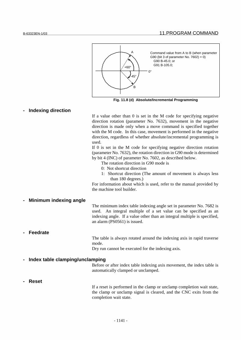
B-63323EN-1/03 11.PROGRAM COMMAND
- 1141 -
0°
-45°
+60°
Command value from A to B (when parameterG90 (bit 3 of parameter No. 7602) = 0)
G90 B-45.0; orG91 B-105.0;
A
B
Fig. 11.8 (d) Absolute/Incremental Programming
- Indexing directionIf a value other than 0 is set in the M code for specifying negativedirection rotation (parameter No. 7632), movement in the negativedirection is made only when a move command is specified togetherwith the M code. In this case, movement is performed in the negativedirection, regardless of whether absolute/incremental programming isused.If 0 is set in the M code for specifying negative direction rotation(parameter No. 7632), the rotation direction in G90 mode is determinedby bit 4 (INC) of parameter No. 7602, as described below.
The rotation direction in G90 mode is0: Not shortcut direction1: Shortcut direction (The amount of movement is always less
than 180 degrees.)For information about which is used, refer to the manual provided bythe machine tool builder.
- Minimum indexing angleThe minimum index table indexing angle set in parameter No. 7682 isused. An integral multiple of a set value can be specified as anindexing angle. If a value other than an integral multiple is specified,an alarm (PS0561) is issued.
- FeedrateThe table is always rotated around the indexing axis in rapid traversemode.Dry run cannot be executed for the indexing axis.
- Index table clamping/unclampingBefore or after index table indexing axis movement, the index table isautomatically clamped or unclamped.
- ResetIf a reset is performed in the clamp or unclamp completion wait state,the clamp or unclamp signal is cleared, and the CNC exits from thecompletion wait state.

11.PROGRAM COMMAND B-63323EN-1/03
- 1142 -
- Index table indexing function and other functions
Item Explanation
Relative position display This value can be rounded by setting bit 2 (REL) of parameter No.7602.
Absolute position display This value is rounded at all times.Automatic return from the referenceposition (G29)Second reference position return (G30)
Return is impossible.
Machine coordinate system selection(G53)
No movement is allowed.
Single direction positioning (G60) Not specifiableSecond auxiliary function Ensure that a second auxiliary function axis name does not duplicate
an indexing axis name.Operation during index table indexing axismovement
Unless otherwise processed by the machine, feed hold, interlock, andemergency stop can be executed during index table indexing axismovement.Machine lock can be executed after indexing has been completed.
Servo-off signal Disable the servo-off signal for the index table indexingaxis. That is, set bit 1 (SVF) of parameter No. 1802 to 0.Usually, the index table indexing axis is in the servo-offstate.
Incremental command for theindex table indexing axis
When incremental programming is used for index tableindexing (when bit 3 (G90) of parameter No. 7602 is set to0), the workpiece origin offset of the index table axis mustalways be 0. That is, there must always be a matchbetween the workpiece coordinate system and machinecoordinate system of an index table indexing axis.
Operation for an index tableindexing axis
Operation in jog/step/handle mode for an index tableindexing axis is disabled. However, manual referenceposition return is possible. If the axis selection signal isset to 0 during manual reference position return, themovement stops immediately, and the clamp command isnot executed.
Limitation
- Simultaneous specification together with other controlled axesSpecify an indexing command singly in a block. If an indexingcommand is specified in a block that specifies other controlled axes aswell, an alarm (PS0564) is issued.
- Command specifying zero move amountWhen the amount of movement is 0, a clamp/unclamp operation is notperformed. In automatic reference position return based on G28,clamp/unclamp is performed even if the amount of movement is 0.

B-63323EN-1/03 11.PROGRAM COMMAND
- 1143 -
Signal
B axis clamp signal BCLP<F007#1>[Classification] Output signal
[Function] Instructs the PMC side to clamp the B axis mechanically with a clutchor shot pin.
[Output condition] The output condition and procedure are the same as those described inthe basic procedure for positioning the index table.
B axis clamp completion signal BECLP<G019#7>[Classification] Input signal
[Function] Notifies the CNC of completion of the B axis clamp operation.[Operation] The output condition and procedure are the same as those described in
the basic procedure for positioning the index table.
B axis unclamp signal BUCLP<F007#0>[Classification] Output signal
[Function] Instructs the PMC side to release the B axis from the mechanical clamp.[Output condition] The output condition and procedure are the same as those described in
the basic procedure for positioning the index table.
B axis unclamp completion signal BEUCL<G019#6>[Classification] Input signal
[Function] Notifies the CNC of completion of the release of the B axis from themechanical clamp.
[Operation] The output condition and procedure are the same as those described inthe basic procedure for positioning the index table.
Signal address#7 #6 #5 #4 #3 #2 #1 #0
G019 *BECLP *BEUCL
#7 #6 #5 #4 #3 #2 #1 #0
F007 BCLP BUCLP

11.PROGRAM COMMAND B-63323EN-1/03
- 1144 -
Parameter#7 #6 #5 #4 #3 #2 #1 #0
7602 DDP INC G90 REL TYB
���������� �� ��� ������
��������� ���
� � � � ��� 2=� ������������ ������ �������G������������$4���#!���$4��%��4��
����������?�� �������
�� 2���?
� 2����
� � � � ��) *3& ������������ ���� ���$���$4���#!���$4��%��4������������$���!��
���������� �������������� !���"���� $�����������
�� ������� ���$�
� *���$�
� � � � ��0 C+� ������������ �������������������������$4���#!���$4��%��4�����!!���
����#��!�����$-��� ����!���$��������������� ���������$����#
������$��������#��!���������$�
�� 8�!!�������#��!��-��� ����!���$��������������
� ?����$����#�����#��!���������$�����!!������
� � � � ��1 �/5 ������������ ������������� �����$� ������������$� ��������� �������
������C+����$������������$��� ��%���"�$� ������ �������
�������������'�� ��� �/���.,0)(�����������
�� ���������������� �����$� ������
� ��������� �����$� ������
� � � � ��D ��� ������������ �������������"������!��� ����� ������4$��������� ���
����������$����$����!��������������� ���$4���#!���$4��%��4��
�������������
�� 5��"������!��� ���
� 8�4$��������� ���
7631 Controlled axis number of an index table indexing axis
���������� �� ��� ������
��������� ���%
�7�!�$�$���� ��% ������4��4�
Set the controlled axis number of an index table indexing axis.
When 0 is set, the fourth axis is assumed.
B-63323EN-1/03 11.PROGRAM COMMAND
- 1145 -
7632 M code used to specify the negative-direction rotation of an index table
indexing axis
���������� �� ��� ������
��������� ���%
�7�!�$�$���� ��% ���� ).
��� � 2�� ��������$� ��������������$4���#!���$4��%��4������$� ���$
#����������%��������� ��� ���$�������$�
���� ).�� � 2�� ��������$� ��������������$4���#!���$4��%��4�����
�!�����������"�� � 2�� ��������$� ����������%���"���!����������"
������$����������$���%�� �������������$����
7682 Minimum positioning angle for an index table indexing axis
���������� �� ��� ������
��������� *�!
���������$��� $%
�����������������$��� ���$���������� ���������������� � ����4��
�7�!�$�$���� ��% +�$�%����������������������$����' � ��������$� $��� ��� ������%
��#!'?((
';��������� �����������������9��++++++�+++���F++++++�+++(
�����������������������%���%!�'��%�!� �$���!�����(��� ������$4
��#!���$4��%��4���� � ?����%�!� �$���!�������� �����������%
�������������������!�����#�������% �!���!���!������������%��������
�� ��� �� � ;��������������$9������%�!� �$���!���������6���
��$�
/�����!��������$��#����!������ $����������������%����$��� 6���
� �%���������� � � ����6$��� ���������������������%���%!�

11.PROGRAM COMMAND B-63323EN-1/03
- 1146 -
Alarm And messageNumber Message Contents
PS0560 INDEX TABLE AXIS ERROR A conflict has arisen in the CNC during the execution of anindex table axis command.
PS0561 ILLEGAL INDEXING ANGLE The specified angle of rotation is not an integer multiple ofthe minimum indexing angle.
PS0562 INDEX TABLE AXIS COMMAND CANNOT START
The specified index table indexing sequence is illegal.
PS0563 EXCESS ERROR OF INDEXINGANGLE
The specified index table indexing angle is illegal.
PS0564 INDEX TABLE AXIS - OTHER AXISSAME TIME
The index table indexing axis and another axis have beenspecified in the same block.
PS0566 INDEX TABLE AXIS DUPLICATEAXIS MODE
A move instruction has been issued to an axis that is not anindex table indexing axis.
PS0567 INDEX TABLE AXIS DUPLICATEAXIS COMMAND
Index table indexing was specified during axis movement oron an axis for which the index table indexing sequence wasnot completed.
CautionCAUTION1 While the index table is being positioned, input
signals that reset the CNC, such as emergency stop,feed hold, and interlock are functional.If a stop at an any position is not suitable for themachine, appropriate processing is required on themachine.
2 If the axis selection signal is set to 0 during manualreference position return, movement is stoppedimmediately, and the clamp command is notexecuted. If this proves inconvenient, measuresmust be taken on the machine side so that, after theaxis selection signal is set to 1, it is not set to 0 untilreference position return is completed.
3 If a reset is made during indexing of the index table,a reference position return must be made before theindex table is indexed subsequently.
4 When an incremental command is used for indexingthe index table (when bit 3 (G90) of parameter No.7602 is 0), the workpiece origin offset for the indextable axis must always be 0. This means that theworkpiece coordinate system and machinecoordinate system of the index table axis mustalways match.
NoteNOTE
Dry run cannot be used for positioning the index tableindexing axis.

B-63323EN-1/03 11.PROGRAM COMMAND
- 1147 -
Reference itemSeries15i/150i-MA Operator’s Manual
(Programming)(B-63324EN)
II-13.6 Index table indexingfunction

11.PROGRAM COMMAND B-63323EN-1/03
- 1148 -
11.9 MULTIPLE ROTARY CONTROL AXIS FUNCTION
GeneralA rotary axis is specified in the ROT bit (bit 1 of parameter 1008).When incremental programming is specified for the rotary axis, aspecified value directly determines the travel distance. When absoluteprogramming is selected, either of the following two operations can bespecified by the RSR bit (bit 2 of parameter 1007).(1) The NC unit rounds down the value specified in the absolute
command (G90) to a value indicating a full turn or less. Thedifference between the rounded value and the current position isthe angular displacement. When the bit 5(INC) in parameter No.1007 is specified, short-cut control can be executed. When thedifference between the rounded value and the current positionindicates more than a half turn, the short-cut control functionallows reverse rotation up to the specified position.
(2) The sign of the specified value indicates the direction of rotation.(The plus sign (+) indicates counterclockwise rotation and theminus sign (-) clockwise rotation). The absolute value of thespecified value indicates the destination.
An absolute value of a position relative to the rotary axis is representedby an equivalent value within the amount of travel for a singlerevolution as specified in parameter 1260.
Parameter#7 #6 #5 #4 #3 #2 #1 #0
1007 INC REL G90 RSR
���������� �� ��� ������
��������� ����4��
� � � � ��) *�* ;�������#��!���������$����4���$�'�����/59�#���D������ ��� �/�
��.9�����������(9������������� ����$� ��������� �����������$� ���$
#�������%��������"�!��������$�#�����������$�
�� /���$� ���$�
� �� ���$�#��������$�"�!��'����� �!��6��������"�!����
������"���$��!��6��������"�!������%���"(
� � � � ��0 C+� ������������������������$����$��� ���� ��� ������ �!��4��
�� 3��� ��#��!���� ���� ����!�������$��$� ���$�#��C+��� �C+
��$
� ?#��!���������$�
B-63323EN-1/03 11.PROGRAM COMMAND
- 1149 -
� � � � ��1 *3& ������������ ������ ��������������� ��� ������ �!��4�������
!���"���� $��������������$���!��$���������"�!�� ���$$�����������
��� ��������
�� /���� �� �$�
� � �� �$�
� � � � ��D �/5 ��� ��� ���4������� �!9��������/5����" ������������$�"�!�������
�� ����$��%�"�!������������ ����������$������ ������������#��%
%� $$���������%�!� �$���!�������� ��%������������4���������#
����$9������#��������������� ������ ����������" �$� �����
������H�����$���!���������C+����$�
0: Do not turn to closest direction.
1: Turn to closest direction.
#7 #6 #5 #4 #3 #2 #1 #0
1008 ROT
���������� �� ��� ������
��������� ����4��
� � � � �� *E2
�� /�����!���!� ��� ������ �!��4��
� ��!���!� ��� ������ �!��4��
1260 Movement of one rotation of a rotary axis
���������� �� ��� ������
��������� *�!�4��
���������$��� $%
�����������������$��� ���$���������� �������������������!�$��4��
�7�!�$�$���� ��% ��� �������"�+�$�%����������������������$����' � �����������$� $
�� ��� ������%���#!�'�((
';��������� �����������������9�������F++++++�+++(
Set the value of movement of one rotation of a rotary axis.
NoteNOTE
This function is effective only for a rotary axis.
Reference itemSeries15i/150i-MA Operator’s Manual
(Programming)(B-63324EN)
II-19.8 Multiple rotary controlaxis function
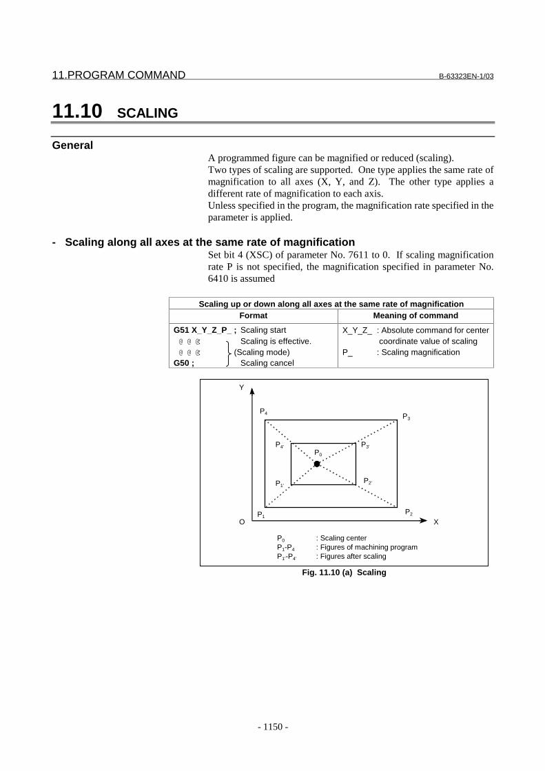
11.PROGRAM COMMAND B-63323EN-1/03
- 1150 -
11.10 SCALING
GeneralA programmed figure can be magnified or reduced (scaling).Two types of scaling are supported. One type applies the same rate ofmagnification to all axes (X, Y, and Z). The other type applies adifferent rate of magnification to each axis.Unless specified in the program, the magnification rate specified in theparameter is applied.
- Scaling along all axes at the same rate of magnificationSet bit 4 (XSC) of parameter No. 7611 to 0. If scaling magnificationrate P is not specified, the magnification specified in parameter No.6410 is assumed
Scaling up or down along all axes at the same rate of magnificationFormat Meaning of command
G51 X_Y_Z_P_ ; Scaling start@ @ @: Scaling is effective.@ @ @: (Scaling mode)
G50 ; Scaling cancel
X_Y_Z_ : Absolute command for center coordinate value of scaling
P_ : Scaling magnification
Y
X
P4
P4’
P1
P1’
P3’
P2’
P2
P3
P0
P0 : Scaling centerP1-P4 : Figures of machining programP1’-P4’ : Figures after scaling
O
Fig. 11.10 (a) Scaling
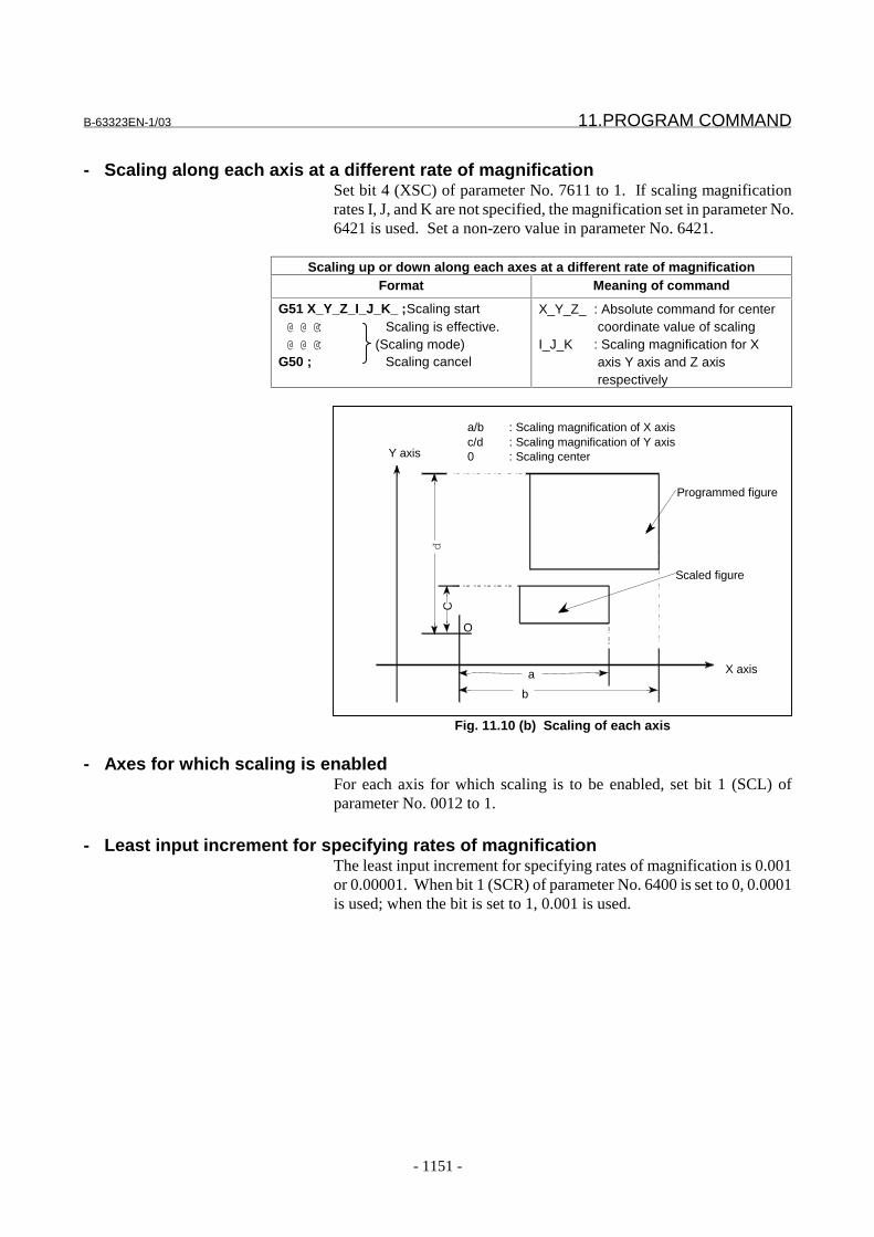
B-63323EN-1/03 11.PROGRAM COMMAND
- 1151 -
- Scaling along each axis at a different rate of magnificationSet bit 4 (XSC) of parameter No. 7611 to 1. If scaling magnificationrates I, J, and K are not specified, the magnification set in parameter No.6421 is used. Set a non-zero value in parameter No. 6421.
Scaling up or down along each axes at a different rate of magnificationFormat Meaning of command
G51 X_Y_Z_I_J_K_ ;Scaling start@ @ @: Scaling is effective.@ @ @: (Scaling mode)
G50 ; Scaling cancel
X_Y_Z_ : Absolute command for center coordinate value of scaling
I_J_K : Scaling magnification for X axis Y axis and Z axis respectively
CY axis
X axis
b
a
p
a/b : Scaling magnification of X axisc/d : Scaling magnification of Y axis0 : Scaling center
Programmed figure
Scaled figure
O
Fig. 11.10 (b) Scaling of each axis
- Axes for which scaling is enabledFor each axis for which scaling is to be enabled, set bit 1 (SCL) ofparameter No. 0012 to 1.
- Least input increment for specifying rates of magnificationThe least input increment for specifying rates of magnification is 0.001or 0.00001. When bit 1 (SCR) of parameter No. 6400 is set to 0, 0.0001is used; when the bit is set to 1, 0.001 is used.
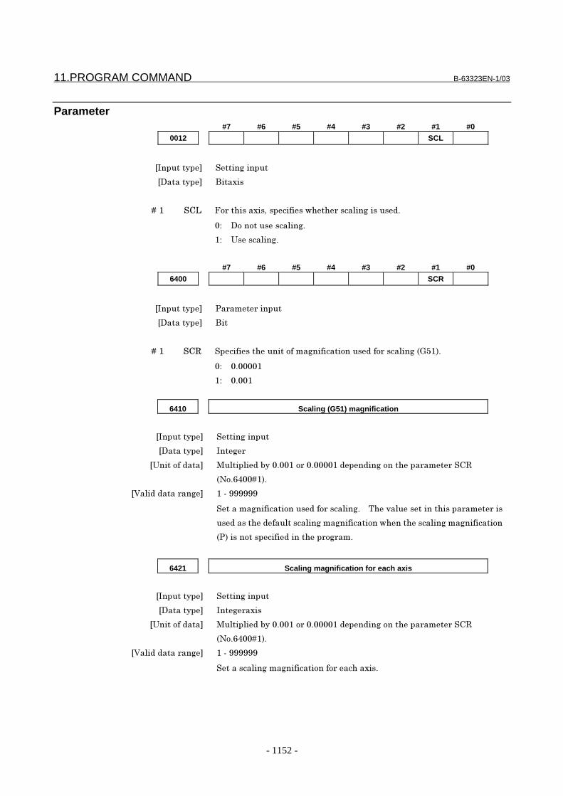
11.PROGRAM COMMAND B-63323EN-1/03
- 1152 -
Parameter#7 #6 #5 #4 #3 #2 #1 #0
0012 SCL
���������� ����� ������
��������� �������
� � � � ��� ��� ����������������������������������� ������ !
"# ���������������� !
�# $�������� !
#7 #6 #5 #4 #3 #2 #1 #0
6400 SCR
���������� %���&��������
��������� ���
� � � � ��� ��' �������������������&� ������������� ����������� �()*�+!
"# "!""""�
�# "!""�
6410 Scaling (G51) magnification
���������� ����� ������
��������� ��� �
�$������� ��� ,������� �-��"!""�����"!""""�� �� �� �����������&�����'
(.�!/0""��+!
�1��� � ������� ��2�333333
�����&� ������������� ����������� !� � 4��5�������������������&�����
�� ������� ������������ �&� ������������������������ �&� ����������
(%+�������������� ���������� ��&!
6421 Scaling magnification for each axis
���������� ����� ������
��������� ��� �����
�$������� ��� ,������� �-��"!""�����"!""""�� �� �� �����������&�����'
(.�!/0""��+!
�1��� � ������� ��2�333333
����������� �&� �����������������������!

B-63323EN-1/03 11.PROGRAM COMMAND
- 1153 -
#7 #6 #5 #4 #3 #2 #1 #0
7611 XSC
���������� ����� ������
��������� ���
� � � � ��0 6�� ������������������2-�2����������� �&� ���������������� ����5��� !
"# .���5��� !
�# 1��� !
Reference itemSeries15i/150i-MA Operator’s Manual
(Programming)(B-63324EN)
II-14.9 Scaling

11.PROGRAM COMMAND B-63323EN-1/03
- 1154 -
11.11 COORDINATE SYSTEM ROTATION (G68,G69)
GeneralA programmed shape can be rotated. By using this function it becomespossible, for example, to modify a program using a rotation commandwhen a workpiece has been placed with some angle rotated from theprogrammed position on the machine. Further, when there is a patterncomprising some identical shapes in the positions rotated from a shape,the time required for programming and the length of the program canbe reduced by preparing a subprogram of the shape and calling it afterrotation.
Angle of rotation
Center of rotation
Y
XO
Fig. 11.11 Coordinate system rotation
FormatFormat
G17G18 @ @G68 α_ β_ R_ ; Start rotation of a coordinate system.G19@: Coordinate system rotation mode@:
G69 ; Coordinate system rotation cancel commandMeaning of command
G17(G18 or G19) : Select the plane in which contains the figure to be rotated.
α_ β_ : Absolute command for two of the x_, y_, and Z_ axes thatcorrespond to the current plane selected by a command(G17, G18, or G19). The command specifies thecoordinates of the center of rotation for the values specifiedsubsequent to G68.
R_ : Angular displacement with a positive value indicates counterclockwise rotation.

B-63323EN-1/03 11.PROGRAM COMMAND
- 1155 -
- Least input increment for specifying coordinate system rotation anglesThe least input increment for specifying coordinate system rotationangles is 0.001 degree or 0.00001 degree. When bit 2 (RTR) ofparameter No. 6400 is set to 0, 0.00001 degree is used; when the bit isset to 1, 0.001 degree is used.
- specify angular displacement (R_)Bit 0 of parameter 6400 selects whether the specified angulardisplacement is always considered an absolute value or is consideredan absolute or incremental value depending on the specified G code(G90 or G91).When R_ is not specified, the value specified in parameter 6411 isassumed as the angular displacement.
Parameter#7 #6 #5 #4 #3 #2 #1 #0
6400 RTR RIN
���������� %���&��������
��������� ���
� � � � ��" '�. ������������������������-������5������������� �������������� �
('+��������� ���������&����������()/7+!
"# $������-������5�������������&�!
�# ��� �������&� �(�-������&� �()3"+��������&�����&�
()3�++!
� � � � ��8 '4' ����������� ��������� ������������ ���������� ���������&
����������� ����2 �&������������ ��������5������()/7+!
"# "!""""��
�# "!""��
6411 Rotation angle for coordinate system rotation (G68)
���������� ����� ������
��������� ��� �
�$������� ��� "!""�� ������"!""""�� ��� �� �� �����������&���'4'
(.�!/0""�8+!
�1��� � ������� ���&�29/""""������ ��9/""""����29/""""""������ ��9/""""""
�� �� �����������&���'4'�(.�!/0""�8+!
���������������� ���������� ���������&���������!� � 4��5���������
���������&�������� ������� ����������������� ���������� ����
����&��������������������� ���������&������������ ��('+�������
������ ���������� ��&!

11.PROGRAM COMMAND B-63323EN-1/03
- 1156 -
Reference itemSeries15i/150i-MA Operator’s Manual
(Programming)(B-63324EN)
II-14.10 Coordinate systemrotation
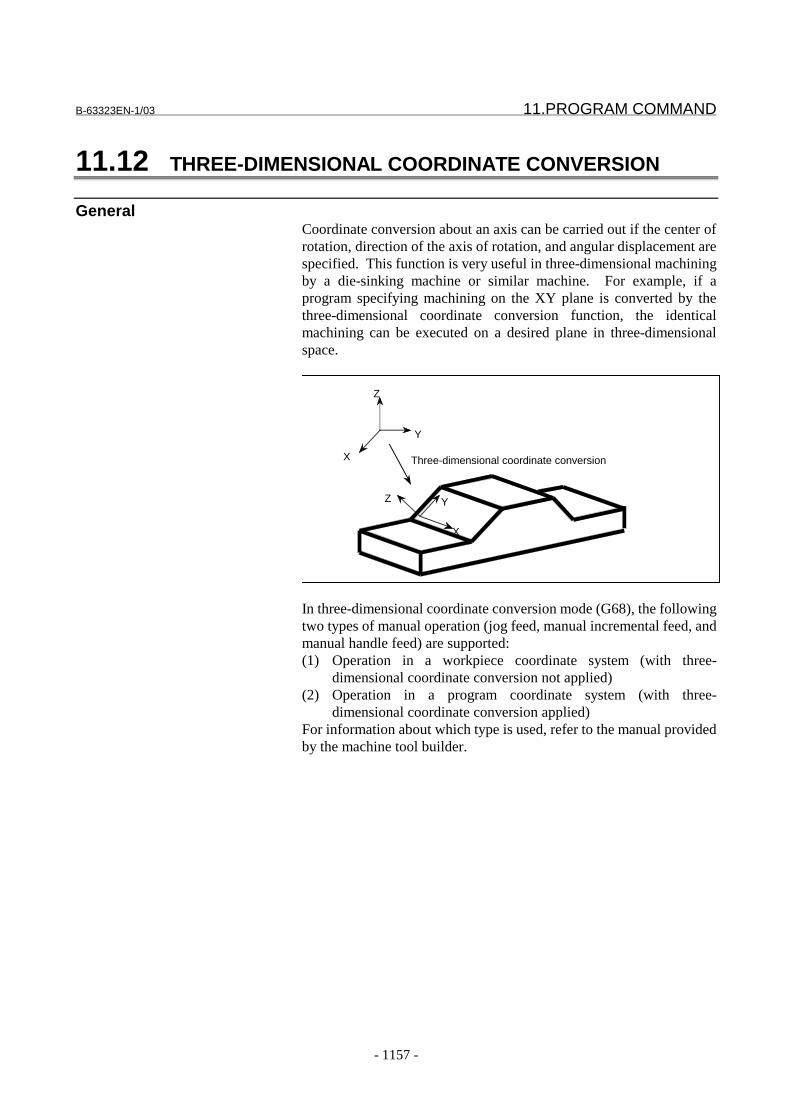
B-63323EN-1/03 11.PROGRAM COMMAND
- 1157 -
11.12 THREE-DIMENSIONAL COORDINATE CONVERSION
GeneralCoordinate conversion about an axis can be carried out if the center ofrotation, direction of the axis of rotation, and angular displacement arespecified. This function is very useful in three-dimensional machiningby a die-sinking machine or similar machine. For example, if aprogram specifying machining on the XY plane is converted by thethree-dimensional coordinate conversion function, the identicalmachining can be executed on a desired plane in three-dimensionalspace.
X
Y
Z
Z Y
X
Three-dimensional coordinate conversion
In three-dimensional coordinate conversion mode (G68), the followingtwo types of manual operation (jog feed, manual incremental feed, andmanual handle feed) are supported:(1) Operation in a workpiece coordinate system (with three-
dimensional coordinate conversion not applied)(2) Operation in a program coordinate system (with three-
dimensional coordinate conversion applied)For information about which type is used, refer to the manual providedby the machine tool builder.

11.PROGRAM COMMAND B-63323EN-1/03
- 1158 -
X, Y ,Z : Coordinate system before conversion (workpiece
coordinate system)
X’, Y’ ,Z’ : Coordinate system after conversion (program
coordinate system)
Z
X
Z’
X’
YY
When manual movement is made along the Z-axis:
(1) A movement is made in the Z direction.
(2) A movement is made in the Z’ direction.
In three-dimensional coordinate conversion mode, three-dimensionalcoordinate conversion manual intervention switch signal NOT3DMcan be used to switch the manual intervention operation between thefollowing two types:(1) Operation in the program coordinate system (Three-dimensional
coordinate conversion is applied.)(2) Operation in the workpiece coordinate system (Three-
dimensional coordinate conversion is not applied.)
Signal
Three-dimensional coordinate conversion manual intervention switch signal M3R<G031#3>[Classification] Input signal
[Function] Specifies whether to perform three-dimensional coordinate conversionfor manual operation (jog feed, manual incremental feed, or manualhandle feed) in three-dimensional coordinate conversion mode.
[Operation] If this signal is set to 0, three-dimensional coordinate conversion is notperformed. (Movement is made in the workpiece coordinate system.)If this signal is set to 1, three-dimensional coordinate conversion isperformed. (Movement is made in the programmed coordinatesystem.)
Three-dimensional coordinate conversion mode signal D3ROT<F159#3>[Classification] Output signal
[Function] Posts whether three-dimensional coordinate conversion mode iscurrently set.
[Operation] If this signal is set to 1, three-dimensional coordinate conversion modeis currently set.
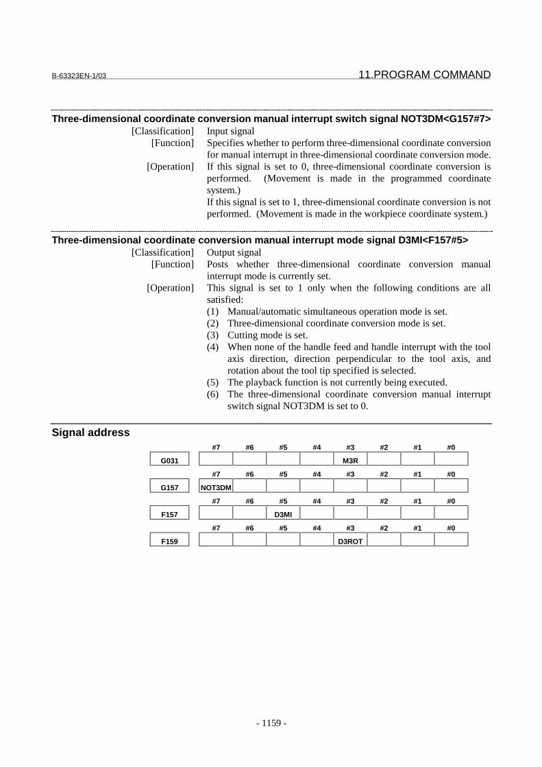
B-63323EN-1/03 11.PROGRAM COMMAND
- 1159 -
Three-dimensional coordinate conversion manual interrupt switch signal NOT3DM<G157#7>[Classification] Input signal
[Function] Specifies whether to perform three-dimensional coordinate conversionfor manual interrupt in three-dimensional coordinate conversion mode.
[Operation] If this signal is set to 0, three-dimensional coordinate conversion isperformed. (Movement is made in the programmed coordinatesystem.)If this signal is set to 1, three-dimensional coordinate conversion is notperformed. (Movement is made in the workpiece coordinate system.)
Three-dimensional coordinate conversion manual interrupt mode signal D3MI<F157#5>[Classification] Output signal
[Function] Posts whether three-dimensional coordinate conversion manualinterrupt mode is currently set.
[Operation] This signal is set to 1 only when the following conditions are allsatisfied:(1) Manual/automatic simultaneous operation mode is set.(2) Three-dimensional coordinate conversion mode is set.(3) Cutting mode is set.(4) When none of the handle feed and handle interrupt with the tool
axis direction, direction perpendicular to the tool axis, androtation about the tool tip specified is selected.
(5) The playback function is not currently being executed.(6) The three-dimensional coordinate conversion manual interrupt
switch signal NOT3DM is set to 0.
Signal address#7 #6 #5 #4 #3 #2 #1 #0
G031 M3R
#7 #6 #5 #4 #3 #2 #1 #0
G157 NOT3DM
#7 #6 #5 #4 #3 #2 #1 #0
F157 D3MI
#7 #6 #5 #4 #3 #2 #1 #0
F159 D3ROT

11.PROGRAM COMMAND B-63323EN-1/03
- 1160 -
Parameter
#7 #6 #5 #4 #3 #2 #1 #0
1200 DSC
���������� %���&��������
��������� ���
� � � � ��* ��� ���������������������� ���������-��� ���������:����� ������������
����� ����� ������&�&���������&�5����-����*"/������*"7"�(;��<%+���
���2 �&������������ ��������5������&� !
0: Coordinates in the coordinate system for which coordinate conversion is not
performed (workpiece coordinate system)
1: Coordinates in the coordinate system for which coordinate conversion has been
performed (program coordinate system)
NOTEWhen the skip signal position is read in a mode other than three-dimensional coordinate conversion mode (G69 mode),coordinates in the coordinate system for which coordinateconversion is not performed (workpiece coordinate system) areread.
For an explanation of system variables #5041 to #5060 (ABSOT),see the explanation of D3M (bit 5 of parameter No. 6400).
#7 #6 #5 #4 #3 #2 #1 #0
1400 LRP
���������� %���&��������
��������� ���
� � � � ��0 �'% ���������&��� ��� ��������������� �()""+!
"# .��2�������������������(���������&�5���� �� ���������������
���5���� ���+
�# �������������������(������������������+
=������� ����2 �&������������ ��������5�����������!

B-63323EN-1/03 11.PROGRAM COMMAND
- 1161 -
#7 #6 #5 #4 #3 #2 #1 #0
1404 D3E
���������� %���&��������
��������� ���
� � � � ��" �9> ��������������������� ����������� ������������5� ���� �������
� ��������������������������������� �������2 �&������������ ����
���5������&� !
"# 4��������� ����������� ������������� ��&���&&�� ��������
�����5!
�# 4��������� ����������� �������������5���������������5!
#7 #6 #5 #4 #3 #2 #1 #0
2005 D3A
���������� %���&��������
��������� ���
� � � � ��0 �9; ������2 �&������������ ��������5������&� �������&�5&����� ����
��#
"# ?��������������� ��&���&&�� �����!
�# ?�����������������������5�!
#7 #6 #5 #4 #3 #2 #1 #0
2202 DCR DTL
���������� %���&��������
��������� ���
� � � � ��8 �4� ���������������������&������� ��-���������������� ������ ���
����'4������ ���� ����������5� �-��������� �����&��������@����
�� �����&���������������������� �������!
"# 4����������������� ���� ����������5� !
�# 4������������ ����������� ���� ����������5� !� � (4�����������
������ �-�������� ��&���� ������ !+
=������� ����2 �&������������ ��������5���������������-�������!
� � � � ��9 ��' ���������������������&������� ��-���������������� ������ ���
����'4������ ���� ����������5� �-����������&��������!
"# 4����������������� ���� ����������5� !
�# 4������������ ����������� ���� ����������5� !� � (4�����������
������ �-�������� ��&���� ������ !+
=������� ����2 �&������������ ��������5���������������-�������!

11.PROGRAM COMMAND B-63323EN-1/03
- 1162 -
#7 #6 #5 #4 #3 #2 #1 #0
2204 DAK
���������� %���&��������
��������� ���
� � � � ��8 �;< ����������������� ����������� ��������������� ��&����� ����
����&�������:�������� ���������&�����-���������� ������������
���2 �&������������ ��������5������&� ������!
"# ������������ ��������������� ��&����� ���������&!
�# ������������ ���������������:�������� ���������&!
#7 #6 #5 #4 #3 #2 #1 #0
2208 D3D DMK
���������� %���&��������
��������� ���
� � � � ��" �,< �����������������&�������5������������� ������ ��������
��� ��&����� ���������&�������:�������� ���������&!
"# %�� ��&����� ���������&�(���� ���������&���������5�����+
�# =��:�������� ���������&�(���� ���������&�-�������5�����+
� � � � ��* �9� �������2 �&������������ ��������5�����������&����� � ���������
�����&����-�&�5 ���� ������
"# ;-���������� ��&����� ���������&!
�# ;-����������:�������� ���������&!
#7 #6 #5 #4 #3 #2 #1 #0
6400 D3M D3R RTR
���������� %���&��������
��������� ���
� � � � ��8 '4' ����������� ��������� ������������ ���������� ���������&
����������� ����2 �&������������ ��������5������()/7+!
"# "!""""��
�# "!""��
B-63323EN-1/03 11.PROGRAM COMMAND
- 1163 -
� � � � ��0 �9' ������������������2 �&������������ ��������5������&� ���
����� !
"# 4�����2 �&������������ ��������5������&� ��������� �-����
)/3���&&�� ���������������>'���>�%�����''=��������� �������&
���%,�!
�# 4�����2 �&������������ ��������5������&� ��������� �����
-�����)/3���&&�� !
� � � � ��* �9, ���������������������� ���������-��� ����������������������������
���������:�������� ���������&������ ����� ������&�&���������&
5����-����*"0������*"/"�(;��?4+�������2 �&������������ ����
���5������&� !
0: Coordinates in the coordinate system for which coordinate conversion is not
performed (workpiece coordinate system)
1: Coordinates in the coordinate system for which coordinate conversion has been
performed (program coordinate system)
NOTEWhen the current tool position is read in a mode other thanthree-dimensional coordinate conversion mode (G69 mode),coordinates in the coordinate system for which coordinateconversion is not performed (workpiece coordinate system) areread.
For system variables #5061 to #5080 (ABSKP), see theexplanation of DSC (bit 5 of parameter No. 1200).
2052 Rapid traverse rate for a drilling cycle in the three-dimensional coordinate
conversion mode
���������� %���&��������
��������� '��
�$������� ��� &&@&��������@&���� �@&���(&����������+
�,���&�&��������� ��� ��� �����������&�������&�����������������
�1��� � ������� '������������� �� �����&�������� ���-��(�+
(=����������&�������&������2���"!"�2�A80""""!"+
Specify the rapid traverse rate for a drilling cycle in the three-dimensional
coordinate conversion mode.
(1) Rapid traverse to point R
(2) Retraction to point R
(3) Rapid traverse to the initial point
When 0 is specified, a dry run feedrate is used. A cutting override is applied to
motions (1) to (3) because cutting-mode operation is performed in the three-
dimensional coordinate conversion mode.
11.PROGRAM COMMAND B-63323EN-1/03
- 1164 -
Alarm And messageNumber Message Contents
PS0625 TOO MANY G68 NESTING 3-dimensional coordinate conversion was specified morethan twice.Cancel 3-dimensional coordinate conversion beforeexecuting new coordinate conversion.
PS0626 G68 FORMAT ERROR There is a format error in the 3-dimensional coordinateconversion block. The alarm occurs in the following cases:(1) When I, J or K is missing from the block in which 3-dimensional coordinate conversion is specified (when thecoordinate rotation option is not available)(2) When I, J and K specified in the block in which 3-dimensional coordinate conversion is specified are all "0"(3) When angle of rotation R is not specified in the block inwhich 3-dimensional coordinate conversion is specified
Reference itemSeries15i/150i-MA Operator’s Manual
(Programming)(B-63324EN)
II-13.9 Three dimensionalcoordinate conversion
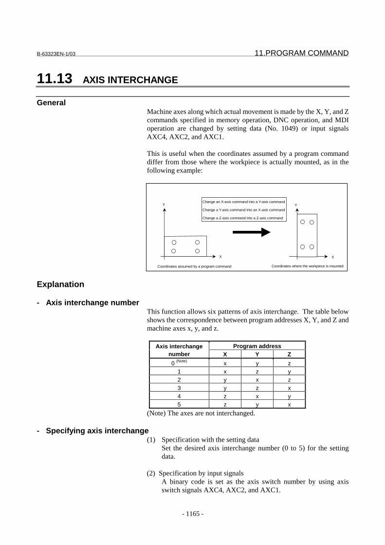
B-63323EN-1/03 11.PROGRAM COMMAND
- 1165 -
11.13 AXIS INTERCHANGE
GeneralMachine axes along which actual movement is made by the X, Y, and Zcommands specified in memory operation, DNC operation, and MDIoperation are changed by setting data (No. 1049) or input signalsAXC4, AXC2, and AXC1.
This is useful when the coordinates assumed by a program commanddiffer from those where the workpiece is actually mounted, as in thefollowing example:
Explanation
- Axis interchange numberThis function allows six patterns of axis interchange. The table belowshows the correspondence between program addresses X, Y, and Z andmachine axes x, y, and z.
Program addressAxis interchangenumber X Y Z
0 (Note) x y z1 x z y2 y x z3 y z x4 z x y5 z y x
(Note) The axes are not interchanged.
- Specifying axis interchange(1) Specification with the setting data
Set the desired axis interchange number (0 to 5) for the settingdata.
(2) Specification by input signalsA binary code is set as the axis switch number by using axisswitch signals AXC4, AXC2, and AXC1.
Y
X
Y
X
Change an X-axis command into a Y-axis command
Change a Y-axis command into an X-axis command
Change a Z-axis command into a Z-axis command
Coordinates assumed by a program command Coordinates where the workpiece is mounted
11.PROGRAM COMMAND B-63323EN-1/03
- 1166 -
The relationships between the specification with the setting dataand that with the switches on the machine operator’s panel are asgiven below.
Setting data(No. 1049)
Switch on machineoperator’s panel
Valid specification
1 0 0 Axis interchange is disabled.
2 1 to 5 0 Specification with the settingdata
3 0 1 to 5 Specification with switches onthe machine operator’s panel
4 1 to 5 1 to 5 Specification with switches onthe machine operator’s panel
When axis interchange need not be performed, set both the setting dataand the switch on the machine operator’s panel to "0."
- Cases in which axis interchange is disabledFor the following commands, axis interchange is disabled.(1) Manual operation commands(2) Move command used to move the tool to a particular machine
position, command related to machine coordinates, andcoordinate system setting command(a) Automatic reference position return
G28 AG30(b) Floating reference position return
G30.1(c) Return from the reference position
G29By setting 1 for parameter RPC (bit 0 of No. 1001), axisinterchange is enabled for the G29 command.
(d) Stored stroke limitG22 AG23
(e) Coordinate system settingG92
(f) Offset settingG10
(g) DwellG04
(h) Machine coordinate positioningG53
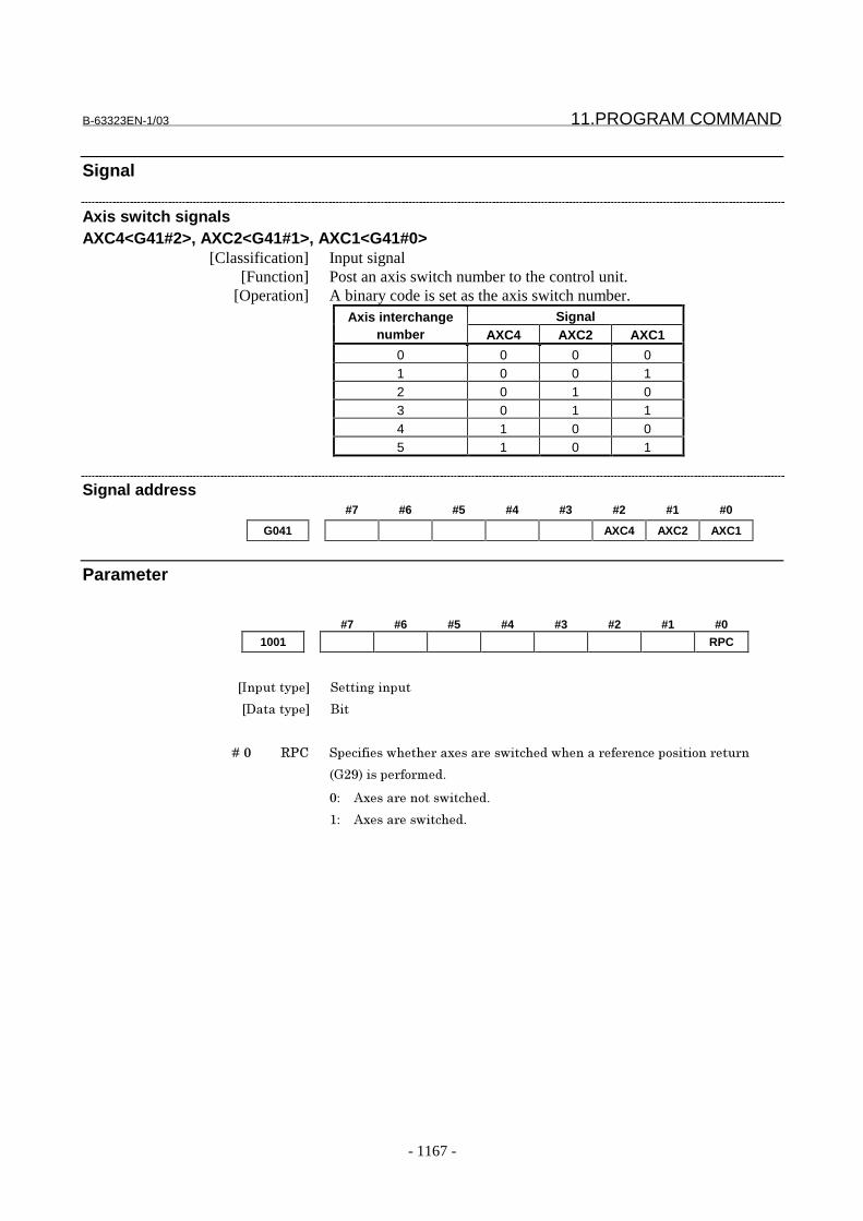
B-63323EN-1/03 11.PROGRAM COMMAND
- 1167 -
Signal
Axis switch signalsAXC4<G41#2>, AXC2<G41#1>, AXC1<G41#0>
[Classification] Input signal[Function] Post an axis switch number to the control unit.
[Operation] A binary code is set as the axis switch number.SignalAxis interchange
number AXC4 AXC2 AXC1
0 0 0 01 0 0 12 0 1 03 0 1 14 1 0 05 1 0 1
Signal address#7 #6 #5 #4 #3 #2 #1 #0
G041 AXC4 AXC2 AXC1
Parameter
#7 #6 #5 #4 #3 #2 #1 #0
1001 RPC
���������� ����� ������
��������� ���
� � � � ��" '%� ��������������������������� ���������������������������
()83+���������& !
"# ;���������������� !
�# ;������������ !

11.PROGRAM COMMAND B-63323EN-1/03
- 1168 -
1049 Axis switching number
���������� ����� ������
��������� ��� �
�1��� � ������� "�2�*
����������������� ���&-�������������5����-�!� � 4�����������&��������
����� ��� �������������� ���&-�!� � 4��&������������������ �B
�������� ������� ��&�� �����6��C���� �D�����������#
Program addressAxis switching
number X Y Z
0 x y z
1 x z y
2 y x z
3 y z x
4 z x y
5 z y x
;������������ ���&-��"�&���������������������� �������������& !
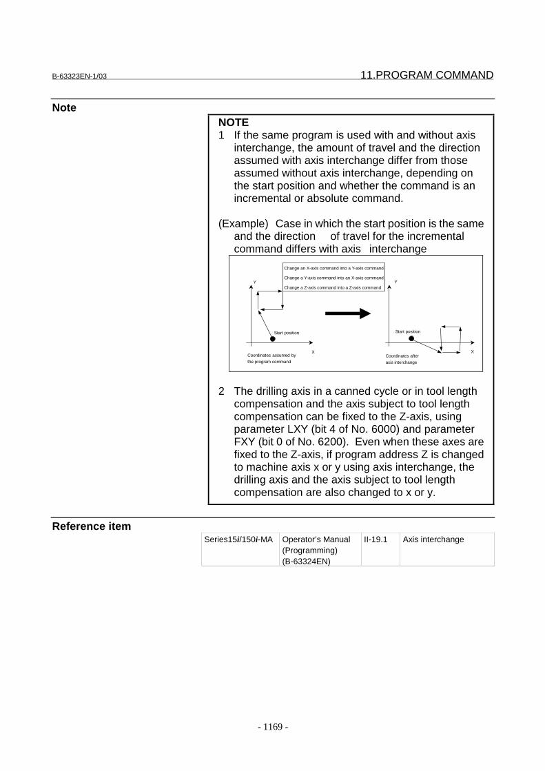
B-63323EN-1/03 11.PROGRAM COMMAND
- 1169 -
NoteNOTE1 If the same program is used with and without axis
interchange, the amount of travel and the directionassumed with axis interchange differ from thoseassumed without axis interchange, depending onthe start position and whether the command is anincremental or absolute command.
(Example) Case in which the start position is the sameand the direction of travel for the incrementalcommand differs with axis interchange
Y
X
Y
X
Change an X-axis command into a Y-axis command
Change a Y-axis command into an X-axis command
Change a Z-axis command into a Z-axis command
Coordinates assumed by
the program commandCoordinates after
axis interchange
Start position Start position
2 The drilling axis in a canned cycle or in tool lengthcompensation and the axis subject to tool lengthcompensation can be fixed to the Z-axis, usingparameter LXY (bit 4 of No. 6000) and parameterFXY (bit 0 of No. 6200). Even when these axes arefixed to the Z-axis, if program address Z is changedto machine axis x or y using axis interchange, thedrilling axis and the axis subject to tool lengthcompensation are also changed to x or y.
Reference itemSeries15i/150i-MA Operator’s Manual
(Programming)(B-63324EN)
II-19.1 Axis interchange
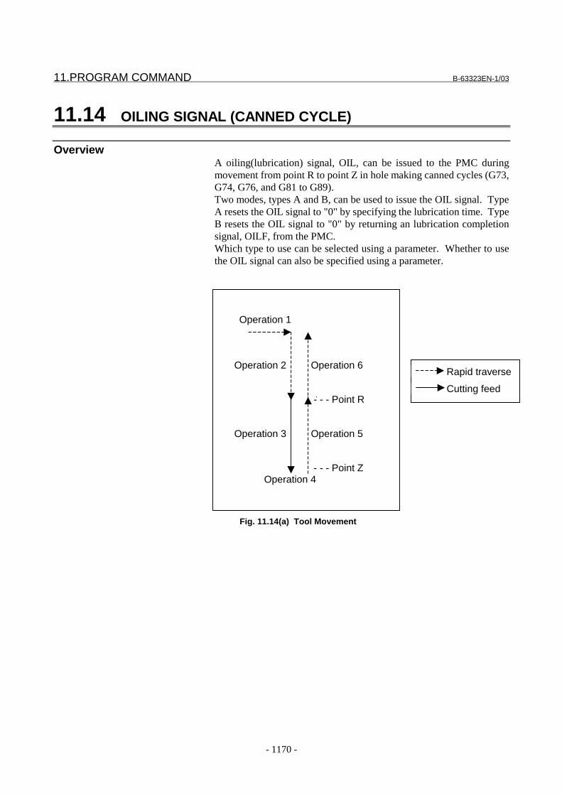
11.PROGRAM COMMAND B-63323EN-1/03
- 1170 -
11.14 OILING SIGNAL (CANNED CYCLE)
OverviewA oiling(lubrication) signal, OIL, can be issued to the PMC duringmovement from point R to point Z in hole making canned cycles (G73,G74, G76, and G81 to G89).Two modes, types A and B, can be used to issue the OIL signal. TypeA resets the OIL signal to "0" by specifying the lubrication time. TypeB resets the OIL signal to "0" by returning an lubrication completionsignal, OILF, from the PMC.Which type to use can be selected using a parameter. Whether to usethe OIL signal can also be specified using a parameter.
Operation 1
Operation 2 Operation 6
- - - Point R
Operation 3 Operation 5
- - - Point Z Operation 4
Fig. 11.14(a) Tool Movement
Rapid traverse
Cutting feed
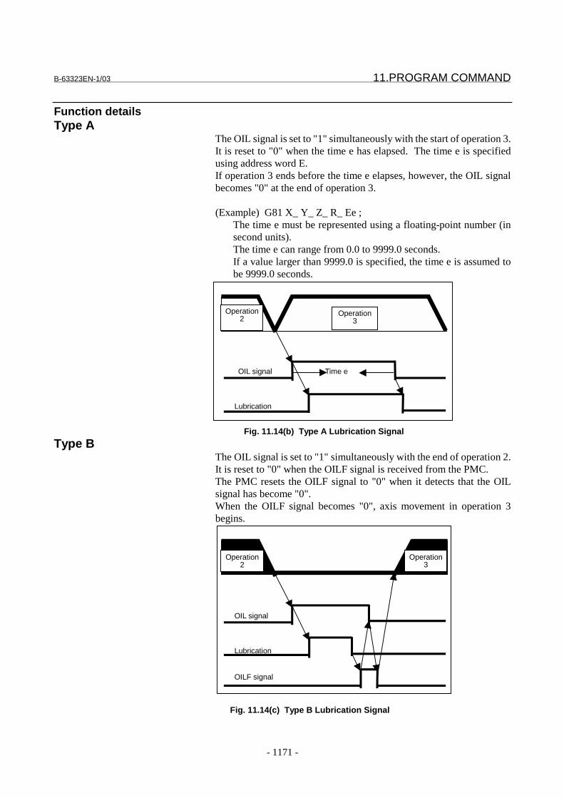
B-63323EN-1/03 11.PROGRAM COMMAND
- 1171 -
Function detailsType A
The OIL signal is set to "1" simultaneously with the start of operation 3.It is reset to "0" when the time e has elapsed. The time e is specifiedusing address word E.If operation 3 ends before the time e elapses, however, the OIL signalbecomes "0" at the end of operation 3.
(Example) G81 X_ Y_ Z_ R_ Ee ;The time e must be represented using a floating-point number (insecond units).The time e can range from 0.0 to 9999.0 seconds.If a value larger than 9999.0 is specified, the time e is assumed tobe 9999.0 seconds.
OIL signal Time e
Lubrication
Operation2
Operation3
Fig. 11.14(b) Type A Lubrication Signal
Type BThe OIL signal is set to "1" simultaneously with the end of operation 2.It is reset to "0" when the OILF signal is received from the PMC.The PMC resets the OILF signal to "0" when it detects that the OILsignal has become "0".When the OILF signal becomes "0", axis movement in operation 3begins.
OIL signal
Lubrication
OILF signal
Operation2
Operation3
Fig. 11.14(c) Type B Lubrication Signal
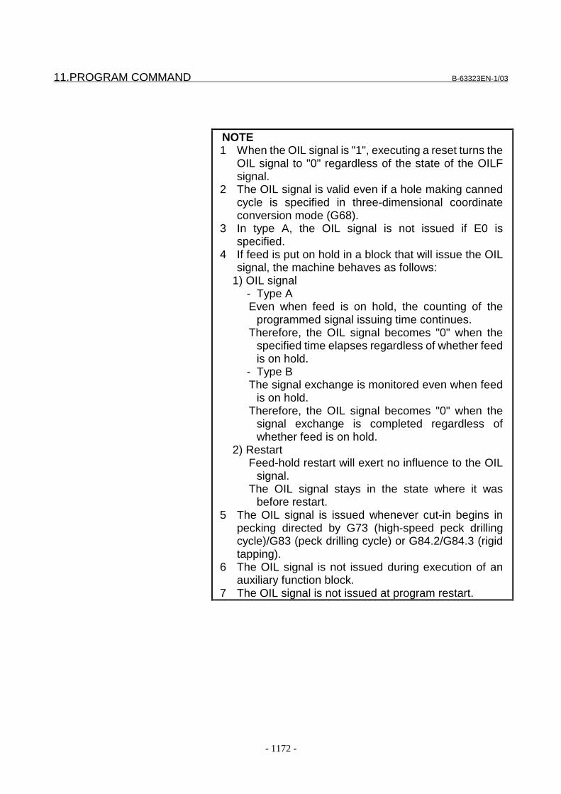
11.PROGRAM COMMAND B-63323EN-1/03
- 1172 -
NOTE 1 When the OIL signal is "1", executing a reset turns the
OIL signal to "0" regardless of the state of the OILFsignal.
2 The OIL signal is valid even if a hole making cannedcycle is specified in three-dimensional coordinateconversion mode (G68).
3 In type A, the OIL signal is not issued if E0 isspecified.
4 If feed is put on hold in a block that will issue the OILsignal, the machine behaves as follows:
1) OIL signal- Type AEven when feed is on hold, the counting of the
programmed signal issuing time continues.Therefore, the OIL signal becomes "0" when the
specified time elapses regardless of whether feedis on hold.
- Type BThe signal exchange is monitored even when feed
is on hold.Therefore, the OIL signal becomes "0" when the
signal exchange is completed regardless ofwhether feed is on hold.
2) RestartFeed-hold restart will exert no influence to the OIL
signal.The OIL signal stays in the state where it was
before restart. 5 The OIL signal is issued whenever cut-in begins in
pecking directed by G73 (high-speed peck drillingcycle)/G83 (peck drilling cycle) or G84.2/G84.3 (rigidtapping).
6 The OIL signal is not issued during execution of anauxiliary function block.
7 The OIL signal is not issued at program restart.

B-63323EN-1/03 11.PROGRAM COMMAND
- 1173 -
Parameters#7 #6 #5 #4 #3 #2 #1 #0
6400 OLT OLN
���������� %���&��������
��������� ���
� � � � ��/ ?�. �������������������������?����� ���!
0: Do not issue.
1: Issue.
NOTE
Once this parameter is re-set, switch the power off and on again.
� � � � ��E ?�4 �����������&� �������������?����� ����������� !
0: Type A
(The OIL signal is reset to "0" by specifying the lubrication time.)
1: Type B
(The OIL signal is reset to "0" by receiving the OILF signal from the PMC.)
SignalsLubrication completion signalOILF<G031#2>
[Classification] Input signal [Function] After lubrication for hole-making canned cycle is directed by program,
this signal indicates when lubrication is completed.The signal is used only in type B.
[Operation] The OIL signal is set to "1" simultaneously with the beginning ofoperation 3. It is reset to "0" when the OILF signal is received from thePMC.The PMC resets the OILF signal to "0" when it detects that the OILsignal has become "0".When the OILF signal becomes "0", axis movement in operation 3begins.
Lubrication signalOIL<F156#3>
[Classification] Output signal[Function] This signal indicates that lubrication during hole making canned cycle
has been directed by program.[Operation] The signal becomes "1" when:
- The program specifies lubrication during hole making cannedcycle.
It becomes "0" when:- A reset occurs, or- Type A: The specified time has elapsed since the output of the
OIL signal.- Type B: The OILF signal becomes "1".

11.PROGRAM COMMAND B-63323EN-1/03
- 1174 -
Signal address#7 #6 #5 #4 #3 #2 #1 #0
G31 OILF
F156 OIL
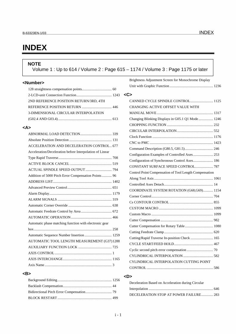
B-63323EN-1/03 INDEX
i - 1
INDEX
<Number>128 straightness compensation points................................. 60
2-LCD-unit Connection Function....................................... 1243
2ND REFERENCE POSITION RETURN/3RD, 4TH
REFERENCE POSITION RETURN ................................. 446
3-DIMENSIONAL CIRCULAR INTERPOLATION
(G02.4 AND G03.4) ........................................................... 613
<A>ABNORMAL LOAD DETECTION................................... 339
Absolute Position Detection ............................................... 131
ACCELERATION AND DECELERATION CONTROL.. 677
Acceleration/Deceleration before Interpolation of Linear
Type Rapid Traverse........................................................... 708
ACTIVE BLOCK CANCEL .............................................. 519
ACTUAL SPINDLE SPEED OUTPUT ............................. 794
Addition of 5000 Pitch Error Compensation Points ........... 96
ADDRESS LIST................................................................. 1402
Advanced Preview Control................................................. 651
Alarm Display..................................................................... 1179
ALARM SIGNALS ............................................................ 319
Automatic Corner Override ................................................ 638
Automatic Feedrate Control by Area .................................. 672
AUTOMATIC OPERATION ............................................. 466
Automatic phase matching function with electronic gear
box...................................................................................... 258
Automatic Sequence Number Insertion .............................. 1259
AUTOMATIC TOOL LENGTH MEASUREMENT (G37)1288
AUXILIARY FUNCTION LOCK ..................................... 725
AXIS CONTROL ............................................................... 1
AXIS INTERCHANGE...................................................... 1165
Axis Name .......................................................................... 3
<B>Background Editing............................................................ 1256
Backlash Compensation...................................................... 44
Bidirectional Pitch Error Compensation............................. 79
BLOCK RESTART ............................................................ 499
Brightness Adjustment Screen for Monochrome Display
Unit with Graphic Function ................................................ 1236
<C>CANNED CYCLE SPINDLE CONTROL......................... 1125
CHANGING ACTIVE OFFSET VALUE WITH
MANUAL MOVE .............................................................. 1317
Changing Blinking Displays in G05.1 Q1 Mode ................ 1246
CHOPPING FUNCTION ................................................... 232
CIRCULAR INTERPOLATION........................................ 552
Clock Function ................................................................... 1176
CNC to PMC ...................................................................... 1423
Command Description (G80.5, G81.5)............................... 246
Configuration Examples of Controlled Axes ...................... 253
Configuration of Synchronous Control Axes...................... 186
CONSTANT SURFACE SPEED CONTROL.................... 787
Control Point Compensation of Tool Length Compensation
Along Tool Axis ................................................................. 1061
Controlled Axes Detach...................................................... 14
COORDINATE SYSTEM ROTATION (G68,G69)........... 1154
Corner Control.................................................................... 704
Cs CONTOUR CONTROL ................................................ 855
CUSTOM MACRO ............................................................ 1099
Custom Macro .................................................................... 1099
Cutter Compensation .......................................................... 982
Cutter Compensation for Rotary Table ............................... 1080
Cutting Feedrate Clamp ...................................................... 620
Cutting/Rapid Traverse In-position Check ......................... 165
CYCLE START/FEED HOLD........................................... 467
Cyclic second pitch error compensation ............................. 70
CYLINDRICAL INTERPOLATION ................................. 582
CYLINDRICAL INTERPOLATION CUTTING POINT
CONTROL ......................................................................... 586
<D>Deceleration Based on Acceleration during Circular
Interpolation ....................................................................... 646
DECELERATION STOP AT POWER FAILURE............. 283
NOTEVolume 1 : Up to 614 / Volume 2 : Page 615 – 1174 / Volume 3 : Page 1175 or later
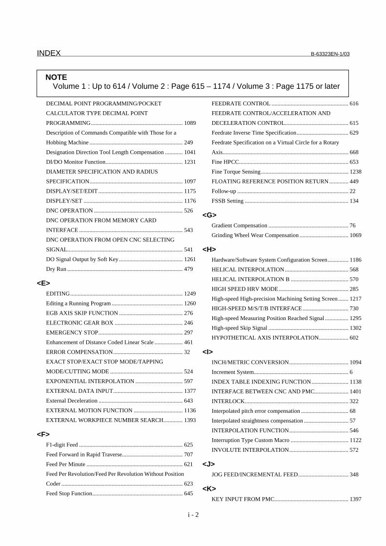
INDEX B-63323EN-1/03
i - 2
DECIMAL POINT PROGRAMMING/POCKET
CALCULATOR TYPE DECIMAL POINT
PROGRAMMING.............................................................. 1089
Description of Commands Compatible with Those for a
Hobbing Machine ............................................................... 249
Designation Direction Tool Length Compensation ............ 1041
DI/DO Monitor Function.................................................... 1231
DIAMETER SPECIFICATION AND RADIUS
SPECIFICATION............................................................... 1097
DISPLAY/SET/EDIT ......................................................... 1175
DISPLEY/SET ................................................................... 1176
DNC OPERATION ............................................................ 526
DNC OPERATION FROM MEMORY CARD
INTERFACE ...................................................................... 543
DNC OPERATION FROM OPEN CNC SELECTING
SIGNAL.............................................................................. 541
DO Signal Output by Soft Key ........................................... 1261
Dry Run .............................................................................. 479
<E>EDITING............................................................................ 1249
Editing a Running Program ................................................ 1260
EGB AXIS SKIP FUNCTION ........................................... 276
ELECTRONIC GEAR BOX .............................................. 246
EMERGENCY STOP......................................................... 297
Enhancement of Distance Coded Linear Scale ................... 461
ERROR COMPENSATION............................................... 32
EXACT STOP/EXACT STOP MODE/TAPPING
MODE/CUTTING MODE ................................................. 524
EXPONENTIAL INTERPOLATION ................................ 597
EXTERNAL DATA INPUT............................................... 1377
External Deceleration ......................................................... 643
EXTERNAL MOTION FUNCTION ................................. 1136
EXTERNAL WORKPIECE NUMBER SEARCH............. 1393
<F>F1-digit Feed ...................................................................... 625
Feed Forward in Rapid Traverse......................................... 707
Feed Per Minute ................................................................. 621
Feed Per Revolution/Feed Per Revolution Without Position
Coder .................................................................................. 623
Feed Stop Function............................................................. 645
FEEDRATE CONTROL .................................................... 616
FEEDRATE CONTROL/ACCELERATION AND
DECELERATION CONTROL........................................... 615
Feedrate Inverse Time Specification................................... 629
Feedrate Specification on a Virtual Circle for a Rotary
Axis..................................................................................... 668
Fine HPCC.......................................................................... 653
Fine Torque Sensing........................................................... 1238
FLOATING REFERENCE POSITION RETURN ............. 449
Follow-up ........................................................................... 22
FSSB Setting ...................................................................... 134
<G>Gradient Compensation ...................................................... 76
Grinding Wheel Wear Compensation ................................. 1069
<H>Hardware/Software System Configuration Screen.............. 1186
HELICAL INTERPOLATION........................................... 568
HELICAL INTERPOLATION B ....................................... 570
HIGH SPEED HRV MODE............................................... 285
High-speed High-precision Machining Setting Screen....... 1217
HIGH-SPEED M/S/T/B INTERFACE............................... 730
High-speed Measuring Position Reached Signal ................ 1295
High-speed Skip Signal ...................................................... 1302
HYPOTHETICAL AXIS INTERPOLATION.................... 602
<I>INCH/METRIC CONVERSION........................................ 1094
Increment System................................................................ 6
INDEX TABLE INDEXING FUNCTION......................... 1138
INTERFACE BETWEEN CNC AND PMC....................... 1401
INTERLOCK...................................................................... 322
Interpolated pitch error compensation ................................ 68
Interpolated straightness compensation .............................. 57
INTERPOLATION FUNCTION........................................ 546
Interruption Type Custom Macro ....................................... 1122
INVOLUTE INTERPOLATION........................................ 572
<J>JOG FEED/INCREMENTAL FEED.................................. 348
<K>KEY INPUT FROM PMC.................................................. 1397
NOTEVolume 1 : Up to 614 / Volume 2 : Page 615 – 1174 / Volume 3 : Page 1175 or later
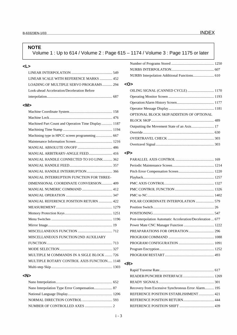
B-63323EN-1/03 INDEX
i - 3
<L>LINEAR INTERPOLATION ............................................. 549
LINEAR SCALE WITH REFERENCE MARKS .............. 452
LOADING OF MULTIPLE SERVO PROGRAMS........... 294
Look-ahead Acceleration/Deceleration Before
interpolation........................................................................ 687
<M>Machine Coordinate System............................................... 158
Machine Lock..................................................................... 476
Machined Part Count and Operation Time Display............ 1187
Machining Time Stamp ...................................................... 1194
Machining type in HPCC screen programming .................. 667
Maintenance Information Screen........................................ 1216
MANUAL ABSOLUTE ON/OFF ...................................... 486
MANUAL ARBITRARY-ANGLE FEED.......................... 416
MANUAL HANDLE CONNECTED TO I/O LINK.......... 362
MANUAL HANDLE FEED............................................... 357
MANUAL HANDLE INTERRUPTION............................ 366
MANUAL INTERRUPTION FUNCTION FOR THREE-
DIMENSIONAL COORDINATE CONVERSION............ 409
MANUAL NUMERIC COMMAND ................................. 412
MANUAL OPERATION ................................................... 347
MANUAL REFERENCE POSITION RETURN ............... 422
MEASUREMENT.............................................................. 1279
Memory Protection Keys .................................................... 1251
Menu Switches ................................................................... 1196
Mirror Image....................................................................... 19
MISCELLANEOUS FUNCTION ...................................... 712
MISCELLANEOUS FUNCTION/2ND AUXILIARY
FUNCTION........................................................................ 713
MODE SELECTION.......................................................... 327
MULTIPLE M COMMANDS IN A SIGLE BLOCK ........ 726
MULTIPLE ROTARY CONTROL AXIS FUNCTION..... 1148
Multi-step Skip ................................................................... 1303
<N>Nano Interpolation.............................................................. 652
Nano Interpolation Type Error Compensation.................... 87
National Language Display................................................. 1206
NORMAL DIRECTION CONTROL ................................. 593
NUMBER OF CONTROLLED AXES .............................. 2
Number of Programs Stored ............................................... 1250
NURBS INTERPOLATION............................................... 607
NURBS Interpolation Additional Functions....................... 610
<O>OILING SIGNAL (CANNED CYCLE) ............................. 1170
Operating Monitor Screen .................................................. 1193
Operation/Alarm History Screen......................................... 1177
Operator Message Display.................................................. 1181
OPTIONAL BLOCK SKIP/ADDITION OF OPTIONAL
BLOCK SKIP ..................................................................... 489
Outputting the Movement State of an Axis......................... 17
Override .............................................................................. 630
OVERTRAVEL CHECK ................................................... 303
Overtravel Signal ................................................................ 303
<P>PARALLEL AXIS CONTROL .......................................... 169
Periodic Maintenance Screen.............................................. 1214
Pitch Error Compensation Screen....................................... 1220
Playback.............................................................................. 1257
PMC AXIS CONTROL...................................................... 1327
PMC CONTROL FUNCTION ........................................... 1326
PMC to NC......................................................................... 1402
POLAR COORDINATE INTERPOLATION .................... 579
Position Switch................................................................... 26
POSITIONING................................................................... 547
Post-interpolation Automatic Acceleration/Deceleration ... 677
Power Mate CNC Manager Function ................................. 1222
PREAPARATIONS FOR OPERATION............................ 296
PROGRAM COMMAND .................................................. 1088
PROGRAM CONFIGURATION ....................................... 1091
Program Encryption............................................................ 1252
PROGRAM RESTART...................................................... 493
<R>Rapid Traverse Rate............................................................ 617
READER/PUNCHER INTERFACE.................................. 1269
READY SIGNALS............................................................. 301
Recovery from Excessive Synchronous Error Alarm.......... 195
REFERENCE POSITION ESTABLISHMENT................. 421
REFERENCE POSITION RETURN.................................. 444
REFERENCE POSITION SHIFT ...................................... 439
NOTEVolume 1 : Up to 614 / Volume 2 : Page 615 – 1174 / Volume 3 : Page 1175 or later

INDEX B-63323EN-1/03
i - 4
REGAINING A MANUAL INTERVENTION AMOUNT
DURING AUTOMATIC OPERATION............................. 528
RESET AND REWIND...................................................... 472
RETRACE.......................................................................... 507
Retraction Function ............................................................ 256
RIGID TAPPING ............................................................... 874
Rigid Tapping Additional Function.................................... 934
Rotary Table Dynamic Fixture Offset................................. 1019
Rotation Axis Roll-over...................................................... 162
Rotation Axis Specification ................................................ 10
<S>SCALING........................................................................... 1150
Screen Clear Function and Automatic Screen Clear
Function.............................................................................. 1207
Self-diagnosis ..................................................................... 1185
SEQUENCE NUMBER COMPARISON AND STOP ...... 492
Servo Adjustment Screen.................................................... 1182
Servo Off (Mechanical handle)........................................... 24
Servo Parameter.................................................................. 119
SETTING EACH AXIS...................................................... 3
SETTING THE REFERENCE POSITION WITHOUT
DOGS ................................................................................. 435
SETTINGS RELATED TO COORDINATE SYSTEMS... 158
SETTINGS RELATED TO SERVO CONTROLLED
AXES.................................................................................. 118
SETUP OF FSSBs IF USING HIGH SPEED HRV
CONTROL ......................................................................... 288
SIGNAL LIST .................................................................... 1444
Signal List (In Order of Address) ....................................... 1516
Signal List (In Order of Symbol) ........................................ 1444
SIMULTANEOUS AUTOMATIC AND MANUAL
OPERATION...................................................................... 534
Single Block ....................................................................... 483
SINGLE DIRECTION POSITIONING.............................. 566
SKIP FUNCTION .............................................................. 1297
Skip Function ..................................................................... 1297
Smooth Backlash Compensation ........................................ 89
SMOOTH INTERPOLATION........................................... 599
Software Operator’s Panel................................................... 1197
Specification of Diameter Entry for Tool Compensation
Value .................................................................................. 956
Spindle Adjustment Screen................................................. 1183
SPINDLE CONTROL ........................................................ 766
SPINDLE FUNCTION....................................................... 734
SPINDLE ORIENTATION ................................................ 937
SPINDLE OUTPUT SWITCHING .................................... 940
SPINDLE POSITIONING.................................................. 796
SPINDLE SERIAL OUTPUT/SPINDLE ANALOG
OUTPUT ............................................................................ 737
SPINDLE SPEED FLUCTUATION DETECTION ........... 941
SPINDLE SPEED FUNCTION (S CODE OUTPUT)........ 735
SPIRAL INTERPOLATION, CONICAL
INTERPOLATION............................................................. 603
SPLINE INTERPOLATION .............................................. 578
STATUS OUTPUT SIGNAL ............................................. 334
Stored Pitch Error Compensation ....................................... 32
Stored Stroke Check 1 ........................................................ 306
Straightness Compensation................................................. 52
Stroke Check 2.................................................................... 310
Stroke Limit Check Prior to Performing Movement........... 316
Synchronization Alignment ................................................ 190
SYNCHRONOUS CONTROL........................................... 185
Synchronous Error Check................................................... 193
Synchronous Error Compensation ...................................... 188
<T>TANDEM CONTROL........................................................ 175
Tape Length for Part Program Storage ............................... 1249
TESTING A PROGRAM ................................................... 476
Thermal Growth Compensation along tool vector .............. 98
THREADING ..................................................................... 558
Threading............................................................................ 558
Threading Based on an Arbitrary Spindle Gear Ratio ........ 561
THREE-DIMENSIONAL COORDINATE
CONVERSION .................................................................. 1157
Three-dimensional Cutter Compensation ........................... 1026
THREE-DIMENSIONAL ERROR COMPENSATION..... 111
THREE-DIMENSIONAL HANDLE FEED....................... 367
Three-dimensional Tool Compensation.............................. 991
Tool Axis Direction Tool Length Compensation................ 1008
Tool Center Point Control .................................................. 1052
TOOL COMPENSATION FUNCTION............................. 975
NOTEVolume 1 : Up to 614 / Volume 2 : Page 615 – 1174 / Volume 3 : Page 1175 or later

B-63323EN-1/03 INDEX
i - 5
TOOL COMPENSATION VALUE/TOOL
COMPENSATION NUMBER/TOOL COMPENSATION
MEMORY .......................................................................... 952
TOOL FUNCTION............................................................. 949
TOOL FUNCTION............................................................. 950
Tool Length Compensation in Tool Axis Direction with
Twin Table Control ............................................................ 224
TOOL LENGTH MANUAL MEASUREMENT................ 1280
Tool Length Offset ............................................................. 975
TOOL LENGTH/WORKPIECE ORIGIN
MEASUREMENT.............................................................. 1282
TOOL LIFE MANAGEMENT FUNCTION...................... 957
Tool Offset.......................................................................... 979
Tool Offsets Based on Tool Numbers................................. 997
Tool Path Drawing and Background Drawing.................... 1191
Torque Difference Alarm Detection for Synchronous
Control................................................................................ 197
Torque Limit Skip .............................................................. 1311
Touch Panel ........................................................................ 1210
TURNING MODE AND COMPENSATION CLAMP OF
DUAL POSITION FEEDBACK ........................................ 280
TWIN-TABLE CONTROL ................................................ 219
<V>Vertical Axis Drop Prevention Function ............................ 30
VRDY OFF ALARM IGNORE SIGNAL .......................... 336
<W>Waveform Diagnosis Display ............................................. 1184
WITHDRAWING AND RETURNING A TOOL .............. 512
Workpiece Coordinate System/Addition of Workpiece
Coordinate System Pair ...................................................... 159
WORKPIECE ORIGIN MANUAL SETTING................... 1281
NOTEVolume 1 : Up to 614 / Volume 2 : Page 615 – 1174 / Volume 3 : Page 1175 or later

Rev
isio
n R
ecor
d
FA
NU
C S
erie
s 15
i/150
i-M
OD
EL
A C
ON
NE
CT
ION
MA
NU
AL
(FU
NC
TIO
N)
(B-6
3323
EN
-1)
03O
ct.,
2000
Fol
low
ing
func
tions
(S
TE
P 4
to 6
) w
ere
adde
d :
Nan
o in
terp
olat
ion
type
err
or c
ompe
nsat
ion,
Sm
ooth
back
lash
com
pens
atio
n, A
dditi
on o
f 500
0 pi
tch
erro
rco
mpe
nsat
ion
poin
ts, T
herm
al g
row
th c
ompe
nsat
ion
alon
g to
ol v
ecto
r, C
uttin
g/ra
pid
trav
erse
in-p
ositi
on c
heck
turn
ing
mod
e an
d co
mpe
nsat
ion
clam
p of
dua
l pos
ition
feed
back
, Dec
eler
atio
n st
op a
t pow
er fa
ilure
, Hig
h sp
eed
HR
V m
ode,
Set
up o
f FS
SB
s if
usin
g hi
gh s
peed
HR
Vco
ntro
l, Lo
adin
g of
mul
tiple
ser
vo p
rogr
ams,
NU
RB
Sin
terp
olat
ion
addi
tiona
l fun
ctio
ns, F
eedr
ate
spec
ifica
tion
on a
virt
ual c
ircle
for
a ro
tary
axi
s, A
utom
atic
feed
rate
cont
rol b
y ar
ea, A
ccel
erat
ion/
dece
lera
tion
befo
rein
terp
olat
ion
of li
near
type
rap
id tr
aver
se, R
igid
tapp
ing
addi
tiona
l fun
ctio
n, S
peci
ficat
ion
of d
iam
eter
ent
ry fo
r to
olco
mpe
nsat
ion
valu
e, T
ool c
ente
r po
int c
ontr
ol, C
ontr
olpo
int c
ompe
nsat
ion
of to
ol le
ngth
com
pens
atio
n al
ong
tool
axi
s, G
rindi
ng w
heel
wea
r co
mpe
nsat
ion,
Cut
ter
com
pens
atio
n fo
r ro
tary
tabl
e, O
iling
sig
nal (
cann
edcy
cle)
, Fin
e to
rque
sen
sing
, 2-L
CD
-uni
t con
nect
ion
func
tion,
Cha
ngin
g bl
inki
ng d
ispl
ays
in G
05.1
Q1
mod
e,D
o si
gnal
out
put b
y so
ft ke
y, a
nd C
hang
ing
activ
e of
fset
valu
e w
ith m
anua
l mov
e
02F
eb.,
2000
Fol
low
ing
func
tions
(S
TE
P 2
and
3)
wer
e ad
ded
:
- P
ower
Mat
e C
NC
man
ager
- 3
-dim
ensi
onal
circ
ular
inte
rpol
atio
n
- S
pind
le s
peed
fluc
tuat
ion
dete
ctio
n
- D
NC
Ope
ratio
n fr
om M
emor
y ca
rd in
terf
ace
- E
nhan
cem
ent o
f Sm
ooth
inte
rpol
atio
n
01F
eb.,
1999
Edi
tion
Dat
eC
onte
nts
Edi
tion
Dat
eC
onte
nts

· No part of this manual may bereproduced in any form.
· All specifications and designsare subject to change withoutnotice.


