306
GE Fanuc Automation Motion Control Products Power Mate 0 Connection Manual GFZ-63443EN/01 February 2000

GE Fanuc Automation
Motion Control Products
Power Mate 0
Connection Manual
GFZ-63443EN/01 February 2000

GFL-001
Warnings, Cautions, and Notesas Used in this Publication
WarningWarning notices are used in this publication to emphasize that hazardous voltages, currents,temperatures, or other conditions that could cause personal injury exist in this equipment or maybe associated with its use.
In situations where inattention could cause either personal injury or damage to equipment, aWarning notice is used.
CautionCaution notices are used where equipment might be damaged if care is not taken.
NoteNotes merely call attention to information that is especially significant to understanding andoperating the equipment.
This document is based on information available at the time of its publication. While effortshave been made to be accurate, the information contained herein does not purport to cover alldetails or variations in hardware or software, nor to provide for every possible contingency inconnection with installation, operation, or maintenance. Features may be described herein whichare not present in all hardware and software systems. GE Fanuc Automation assumes noobligation of notice to holders of this document with respect to changes subsequently made.
GE Fanuc Automation makes no representation or warranty, expressed, implied, or statutorywith respect to, and assumes no responsibility for the accuracy, completeness, sufficiency, orusefulness of the information contained herein. No warranties of merchantability or fitness forpurpose shall apply.
©Copyright 2000 GE Fanuc Automation North America, Inc.
All Rights Reserved.

B–63443EN/01 DEFINITION OF WARNING, CAUTION, AND NOTE
s–1
DEFINITION OF WARNING, CAUTION, AND NOTE
This manual includes safety precautions for protecting the user and preventing damage to themachine. Precautions are classified into Warning and Caution according to their bearing on safety.Also, supplementary information is described as a Note. Read the Warning, Caution, and Notethoroughly before attempting to use the machine.
WARNING
Applied when there is a danger of the user being injured or when there is a danger of both the userbeing injured and the equipment being damaged if the approved procedure is not observed.
CAUTION
Applied when there is a danger of the equipment being damaged, if the approved procedure is notobserved.
NOTE
The Note is used to indicate supplementary information other than Warning and Caution.
Read this manual carefully, and store it in a safe place.
B–63443EN/01 Table of Contents
c–1
DEFINITION OF WARNING, CAUTION, AND NOTE s–1. . . . . . . . . . . . . . . . . .
I HARDWARE
1. PREFACE 3. . . . . . . . . . . . . . . . . . . . . . . . . . . . . . . . . . . . . . . . . . . . . . . . . . . . . . . . . . . . .
2. CONFIGURATION 4. . . . . . . . . . . . . . . . . . . . . . . . . . . . . . . . . . . . . . . . . . . . . . . . . . . . .
3. INSTALLATION 5. . . . . . . . . . . . . . . . . . . . . . . . . . . . . . . . . . . . . . . . . . . . . . . . . . . . . . . . 3.1 ENVIRONMENTAL REQUIREMENTS OF CNC 6. . . . . . . . . . . . . . . . . . . . . . . . . . . . . . . . . . . . . .
3.2 POWER CAPACITY 7. . . . . . . . . . . . . . . . . . . . . . . . . . . . . . . . . . . . . . . . . . . . . . . . . . . . . . . . . . . . .
3.3 DESIGN AND INSTALLATION CONDITIONS OF THE TOOL MAGNETIC CABINET 8. . . . . .
3.4 THERMAL DESIGN OF THE CABINET 10. . . . . . . . . . . . . . . . . . . . . . . . . . . . . . . . . . . . . . . . . . . . 3.4.1 Temperature Rise within the Cabinet 10. . . . . . . . . . . . . . . . . . . . . . . . . . . . . . . . . . . . . . . . . . . . . . . . . . 3.4.2 Cooling by Heat Exchanger 10. . . . . . . . . . . . . . . . . . . . . . . . . . . . . . . . . . . . . . . . . . . . . . . . . . . . . . . . . 3.4.3 Heat Loss of Each Unit 10. . . . . . . . . . . . . . . . . . . . . . . . . . . . . . . . . . . . . . . . . . . . . . . . . . . . . . . . . . . . .
3.5 ACTION AGAINST NOISE 11. . . . . . . . . . . . . . . . . . . . . . . . . . . . . . . . . . . . . . . . . . . . . . . . . . . . . . . 3.5.1 Separating Signal Lines 11. . . . . . . . . . . . . . . . . . . . . . . . . . . . . . . . . . . . . . . . . . . . . . . . . . . . . . . . . . . . 3.5.2 Ground 13. . . . . . . . . . . . . . . . . . . . . . . . . . . . . . . . . . . . . . . . . . . . . . . . . . . . . . . . . . . . . . . . . . . . . . . . . 3.5.3 Connecting the Ground for Signal of the Control Unit 14. . . . . . . . . . . . . . . . . . . . . . . . . . . . . . . . . . . . . 3.5.4 Noise Suppressor 15. . . . . . . . . . . . . . . . . . . . . . . . . . . . . . . . . . . . . . . . . . . . . . . . . . . . . . . . . . . . . . . . . 3.5.5 Cable Clamp and Shield Processing 16. . . . . . . . . . . . . . . . . . . . . . . . . . . . . . . . . . . . . . . . . . . . . . . . . . .
3.6 CONTROL UNIT 19. . . . . . . . . . . . . . . . . . . . . . . . . . . . . . . . . . . . . . . . . . . . . . . . . . . . . . . . . . . . . . . . 3.6.1 Installation of the Control Unit 19. . . . . . . . . . . . . . . . . . . . . . . . . . . . . . . . . . . . . . . . . . . . . . . . . . . . . . . 3.6.2 Battery for Memory Backup 21. . . . . . . . . . . . . . . . . . . . . . . . . . . . . . . . . . . . . . . . . . . . . . . . . . . . . . . . .
3.7 CABLE LEAD–IN DIAGRAM 24. . . . . . . . . . . . . . . . . . . . . . . . . . . . . . . . . . . . . . . . . . . . . . . . . . . . .
3.8 CONNECTOR LAYOUT OF UNIT 25. . . . . . . . . . . . . . . . . . . . . . . . . . . . . . . . . . . . . . . . . . . . . . . . .
4. TOTAL CONNECTION 26. . . . . . . . . . . . . . . . . . . . . . . . . . . . . . . . . . . . . . . . . . . . . . . . . . 4.1 TOTAL CONNECTION DIAGRAM FOR POWER MATE 0 27. . . . . . . . . . . . . . . . . . . . . . . . . . . . .
5. CONNECTION OF INPUT POWER SUPPLY 28. . . . . . . . . . . . . . . . . . . . . . . . . . . . . . 5.1 POWER SUPPLY CAPACITY 29. . . . . . . . . . . . . . . . . . . . . . . . . . . . . . . . . . . . . . . . . . . . . . . . . . . . . .
5.2 POWER CONNECTIONS 31. . . . . . . . . . . . . . . . . . . . . . . . . . . . . . . . . . . . . . . . . . . . . . . . . . . . . . . . .
5.3 POWER–ON SEQUENCE 32. . . . . . . . . . . . . . . . . . . . . . . . . . . . . . . . . . . . . . . . . . . . . . . . . . . . . . . . .
5.4 POWER–OFF SEQUENCE 33. . . . . . . . . . . . . . . . . . . . . . . . . . . . . . . . . . . . . . . . . . . . . . . . . . . . . . . .
5.5 MOMENTARY POWER FAILURE 33. . . . . . . . . . . . . . . . . . . . . . . . . . . . . . . . . . . . . . . . . . . . . . . . .
5.6 PROTECTION GROUND CONNECTION 33. . . . . . . . . . . . . . . . . . . . . . . . . . . . . . . . . . . . . . . . . . . .
6. CONNECTION OF I/O UNITS TO MACHINE INTERFACE 34. . . . . . . . . . . . . . . . . . 6.1 INPUT/OUTPUT SIGNAL SPECIFICATIONS 35. . . . . . . . . . . . . . . . . . . . . . . . . . . . . . . . . . . . . . . .
6.1.1 Input Signal Specifications 35. . . . . . . . . . . . . . . . . . . . . . . . . . . . . . . . . . . . . . . . . . . . . . . . . . . . . . . . . . 6.1.2 Output Signal Specifications 37. . . . . . . . . . . . . . . . . . . . . . . . . . . . . . . . . . . . . . . . . . . . . . . . . . . . . . . . .
6.2 CONNECTION OF BUIL–IN I/O CARD C 40. . . . . . . . . . . . . . . . . . . . . . . . . . . . . . . . . . . . . . . . . . . 6.2.1 Outline 40. . . . . . . . . . . . . . . . . . . . . . . . . . . . . . . . . . . . . . . . . . . . . . . . . . . . . . . . . . . . . . . . . . . . . . . . . 6.2.2 Signals 42. . . . . . . . . . . . . . . . . . . . . . . . . . . . . . . . . . . . . . . . . . . . . . . . . . . . . . . . . . . . . . . . . . . . . . . . . 6.2.3 Machine Interface 43. . . . . . . . . . . . . . . . . . . . . . . . . . . . . . . . . . . . . . . . . . . . . . . . . . . . . . . . . . . . . . . . . 6.2.4 Details of DI Connection 44. . . . . . . . . . . . . . . . . . . . . . . . . . . . . . . . . . . . . . . . . . . . . . . . . . . . . . . . . . . 6.2.5 Details of DO Connection 48. . . . . . . . . . . . . . . . . . . . . . . . . . . . . . . . . . . . . . . . . . . . . . . . . . . . . . . . . . .
6.3 MACHINE INTERFACE CONNECTION EXAMPLES 51. . . . . . . . . . . . . . . . . . . . . . . . . . . . . . . . .
B–63443EN/01Table of Contents
c–2
7. CONNECTION TO CNC PERIPHERALS 53. . . . . . . . . . . . . . . . . . . . . . . . . . . . . . . . . . 7.1 CRT/MDI INTERFACE 54. . . . . . . . . . . . . . . . . . . . . . . . . . . . . . . . . . . . . . . . . . . . . . . . . . . . . . . . . . .
7.1.1 General 54. . . . . . . . . . . . . . . . . . . . . . . . . . . . . . . . . . . . . . . . . . . . . . . . . . . . . . . . . . . . . . . . . . . . . . . . . 7.1.2 CRT Interface 55. . . . . . . . . . . . . . . . . . . . . . . . . . . . . . . . . . . . . . . . . . . . . . . . . . . . . . . . . . . . . . . . . . . . 7.1.3 Power Supply Interface 56. . . . . . . . . . . . . . . . . . . . . . . . . . . . . . . . . . . . . . . . . . . . . . . . . . . . . . . . . . . . . 7.1.4 CRT Terminating Unit 57. . . . . . . . . . . . . . . . . . . . . . . . . . . . . . . . . . . . . . . . . . . . . . . . . . . . . . . . . . . . . 7.1.5 Keyboard 58. . . . . . . . . . . . . . . . . . . . . . . . . . . . . . . . . . . . . . . . . . . . . . . . . . . . . . . . . . . . . . . . . . . . . . .
7.2 CONNECTION WITH THE DPL/MDI 59. . . . . . . . . . . . . . . . . . . . . . . . . . . . . . . . . . . . . . . . . . . . . . . 7.2.1 General 59. . . . . . . . . . . . . . . . . . . . . . . . . . . . . . . . . . . . . . . . . . . . . . . . . . . . . . . . . . . . . . . . . . . . . . . . . 7.2.2 DPL/MDI Interface 60. . . . . . . . . . . . . . . . . . . . . . . . . . . . . . . . . . . . . . . . . . . . . . . . . . . . . . . . . . . . . . . . 7.2.3 Power Supply Interface 61. . . . . . . . . . . . . . . . . . . . . . . . . . . . . . . . . . . . . . . . . . . . . . . . . . . . . . . . . . . . . 7.2.4 Key Sheet 61. . . . . . . . . . . . . . . . . . . . . . . . . . . . . . . . . . . . . . . . . . . . . . . . . . . . . . . . . . . . . . . . . . . . . . .
7.3 I/O DEVICE INTERFACE 62. . . . . . . . . . . . . . . . . . . . . . . . . . . . . . . . . . . . . . . . . . . . . . . . . . . . . . . . . 7.3.1 RS–232–C Interface Specification 62. . . . . . . . . . . . . . . . . . . . . . . . . . . . . . . . . . . . . . . . . . . . . . . . . . . . 7.3.2 RS–232–C Serial Port 70. . . . . . . . . . . . . . . . . . . . . . . . . . . . . . . . . . . . . . . . . . . . . . . . . . . . . . . . . . . . . 7.3.3 FANUC Handy File Connection 71. . . . . . . . . . . . . . . . . . . . . . . . . . . . . . . . . . . . . . . . . . . . . . . . . . . . . . 7.3.4 When External Power Supply is Used 72. . . . . . . . . . . . . . . . . . . . . . . . . . . . . . . . . . . . . . . . . . . . . . . . .
7.4 MANUAL PULSE GENERATOR INTERFACE 73. . . . . . . . . . . . . . . . . . . . . . . . . . . . . . . . . . . . . . . . 7.4.1 Overview 73. . . . . . . . . . . . . . . . . . . . . . . . . . . . . . . . . . . . . . . . . . . . . . . . . . . . . . . . . . . . . . . . . . . . . . . 7.4.2 Interface 73. . . . . . . . . . . . . . . . . . . . . . . . . . . . . . . . . . . . . . . . . . . . . . . . . . . . . . . . . . . . . . . . . . . . . . . . 7.4.3 Cable Connection for the Manual Pulse Generator 74. . . . . . . . . . . . . . . . . . . . . . . . . . . . . . . . . . . . . . . .
7.5 ANALOG SPINDLE INTERFACE 76. . . . . . . . . . . . . . . . . . . . . . . . . . . . . . . . . . . . . . . . . . . . . . . . . . 7.5.1 Analog Spindle Interface 76. . . . . . . . . . . . . . . . . . . . . . . . . . . . . . . . . . . . . . . . . . . . . . . . . . . . . . . . . . . 7.5.2 Position Coder Interface 77. . . . . . . . . . . . . . . . . . . . . . . . . . . . . . . . . . . . . . . . . . . . . . . . . . . . . . . . . . . .
7.6 SERVO INTERFACE 78. . . . . . . . . . . . . . . . . . . . . . . . . . . . . . . . . . . . . . . . . . . . . . . . . . . . . . . . . . . . . 7.6.1 Outline 78. . . . . . . . . . . . . . . . . . . . . . . . . . . . . . . . . . . . . . . . . . . . . . . . . . . . . . . . . . . . . . . . . . . . . . . . . 7.6.2 Servo Amplifier Interface (β Series Servo Amplifier) 79. . . . . . . . . . . . . . . . . . . . . . . . . . . . . . . . . . . . . .
II PMC INTERFACE
1. ADDRESS LIST 83. . . . . . . . . . . . . . . . . . . . . . . . . . . . . . . . . . . . . . . . . . . . . . . . . . . . . . . . 1.1 POWER MATE 0 84. . . . . . . . . . . . . . . . . . . . . . . . . . . . . . . . . . . . . . . . . . . . . . . . . . . . . . . . . . . . . . . .
2. SIGNAL LIST 89. . . . . . . . . . . . . . . . . . . . . . . . . . . . . . . . . . . . . . . . . . . . . . . . . . . . . . . . . . 2.1 I/O SIGNAL LIST (ORDER OF GROUP) 90. . . . . . . . . . . . . . . . . . . . . . . . . . . . . . . . . . . . . . . . . . . .
2.2 I/O SIGNAL LIST (ORDER OF SYMBOL) 93. . . . . . . . . . . . . . . . . . . . . . . . . . . . . . . . . . . . . . . . . . .
3. READY SIGNALS 97. . . . . . . . . . . . . . . . . . . . . . . . . . . . . . . . . . . . . . . . . . . . . . . . . . . . . . 3.1 CNC READY SIGNAL (OUTPUT) MA<F001#7> 98. . . . . . . . . . . . . . . . . . . . . . . . . . . . . . . . . . . . . .
3.2 SERVO READY SIGNAL (OUTPUT) SA <F000#6> 98. . . . . . . . . . . . . . . . . . . . . . . . . . . . . . . . . . .
4. RESET & EMERGENCY STOP 99. . . . . . . . . . . . . . . . . . . . . . . . . . . . . . . . . . . . . . . . . . 4.1 EMERGENCY STOP SIGNAL (INPUT) *ESP <X1000#4, G008#4> 100. . . . . . . . . . . . . . . . . . . . . . .
4.2 EXTERNAL RESET SIGNAL (INPUT) ERS <G008#7> 102. . . . . . . . . . . . . . . . . . . . . . . . . . . . . . . .
4.3 RESET & REWIND SIGNAL (INPUT) RRW <G008#6> 102. . . . . . . . . . . . . . . . . . . . . . . . . . . . . . . .
5. STATUS SIGNALS 103. . . . . . . . . . . . . . . . . . . . . . . . . . . . . . . . . . . . . . . . . . . . . . . . . . . . . 5.1 ALARM SIGNAL (OUTPUT) AL <F001#0> 104. . . . . . . . . . . . . . . . . . . . . . . . . . . . . . . . . . . . . . . . . .
5.2 BATTERY ALARM SIGNAL (OUTPUT) BAL <F001#2> 104. . . . . . . . . . . . . . . . . . . . . . . . . . . . . . .
B–63443EN/01 Table of Contents
c–3
5.3 RESET SIGNAL (OUTPUT) RST <F001#1> 104. . . . . . . . . . . . . . . . . . . . . . . . . . . . . . . . . . . . . . . . . .
5.4 REWINDING SIGNAL (OUTPUT) RWD <F000#0> 105. . . . . . . . . . . . . . . . . . . . . . . . . . . . . . . . . . . .
5.5 MOVING DIRECTION SIGNALS MVDN <F106#0, #1> 105. . . . . . . . . . . . . . . . . . . . . . . . . . . . . . . .
5.6 IN-POSITION SIGNALS INPN <F104#0, #1> 106. . . . . . . . . . . . . . . . . . . . . . . . . . . . . . . . . . . . . . . . .
5.7 THREADING SIGNAL (OUTPUT) THRD <F002#3> 106. . . . . . . . . . . . . . . . . . . . . . . . . . . . . . . . . . .
6. MODE SELECT 107. . . . . . . . . . . . . . . . . . . . . . . . . . . . . . . . . . . . . . . . . . . . . . . . . . . . . . . . 6.1 MODE SELECT SIGNAL (INPUT) MD1, MD2, MD4 <G043#0 TO #2> 108. . . . . . . . . . . . . . . . . . .
6.2 OPERATION BY TAPE READER DNCI (INPUT) <G043#5> 110. . . . . . . . . . . . . . . . . . . . . . . . . . . .
6.3 OPERATION MODE CONFIRMATION SIGNALS (OUTPUT) <F003, F004> 111. . . . . . . . . . . . . . .
7. JOG FEED 112. . . . . . . . . . . . . . . . . . . . . . . . . . . . . . . . . . . . . . . . . . . . . . . . . . . . . . . . . . . . 7.1 FEED AXIS DIRECTION SELECT SIGNAL
(INPUT) +JN, –JN, <G100#0, #1, G102#0, #1> 113. . . . . . . . . . . . . . . . . . . . . . . . . . . . . . . . . . . . . . .
7.2 MANUAL FEEDRATE OVERRIDE (INPUT) *JV0 TO *JV15 <G010,G011> 114. . . . . . . . . . . . . . .
7.3 MANUAL RAPID TRAVERSE SELECT SIGNAL (INPUT) RT<G019#7> 115. . . . . . . . . . . . . . . . . .
7.4 RAPID TRAVERSE OVERRIDE SIGNAL (INPUT) ROV1, ROV2 <G014#0, #1> 115. . . . . . . . . . . .
7.5 MANUAL ABSOLUTE SIGNAL (INPUT) *ABSM <G006#2> 116. . . . . . . . . . . . . . . . . . . . . . . . . . .
8. INTERLOCK 118. . . . . . . . . . . . . . . . . . . . . . . . . . . . . . . . . . . . . . . . . . . . . . . . . . . . . . . . . . 8.1 INTERLOCK SIGNAL (INPUT) *IT<G008#0> 119. . . . . . . . . . . . . . . . . . . . . . . . . . . . . . . . . . . . . . . .
8.2 AXIS INTERLOCK SIGNAL (INPUT) *ITN <G130#0, #1> 120. . . . . . . . . . . . . . . . . . . . . . . . . . . . .
9. MANUAL HANDLE FEED 121. . . . . . . . . . . . . . . . . . . . . . . . . . . . . . . . . . . . . . . . . . . . . . . 9.1 MANUAL HANDLE FEED AXIS SELECT SIGNAL (INPUT)
HS1A, HS1B <G018 #0, #1> 122. . . . . . . . . . . . . . . . . . . . . . . . . . . . . . . . . . . . . . . . . . . . . . . . . . . . . .
9.2 INCREMENTAL FEED SIGNAL (INPUT) MP1, MP2 <G019#4,#5> 123. . . . . . . . . . . . . . . . . . . . . .
10.REFERENCE POSITION RETURN 124. . . . . . . . . . . . . . . . . . . . . . . . . . . . . . . . . . . . . . . 10.1 1ST REFERENCE POSITION RETURN 125. . . . . . . . . . . . . . . . . . . . . . . . . . . . . . . . . . . . . . . . . . . . .
10.2 REFERENCE POSITION ESTABLISHMENT SIGNAL (OUTPUT) ZRFN <F120#0, #1> 130. . . . . .
11.MEMORY PROTECTION KEY (INPUT) KEY1 TO KEY4 <G046#3-#6> 131. . . . . . .
12.AUTOMATIC OPERATION 132. . . . . . . . . . . . . . . . . . . . . . . . . . . . . . . . . . . . . . . . . . . . . . 12.1 CYCLE START SIGNAL (INPUT) ST <G007#2> 133. . . . . . . . . . . . . . . . . . . . . . . . . . . . . . . . . . . . . .
12.2 FEED HOLD SIGNAL (INPUT) *SP <G008#5> 135. . . . . . . . . . . . . . . . . . . . . . . . . . . . . . . . . . . . . . .
12.3 CYCLE START LAMP SIGNAL (OUTPUT) STL <F000#5> 137. . . . . . . . . . . . . . . . . . . . . . . . . . . . .
12.4 FEED HOLD LAMP SIGNAL (OUTPUT) SPL <F000#4> 137. . . . . . . . . . . . . . . . . . . . . . . . . . . . . . .
12.5 AUTOMATIC OPERATION SIGNAL (OUTPUT) OP <F000#7> 138. . . . . . . . . . . . . . . . . . . . . . . . . .
12.6 WORKPIECE NUMBER SEARCH SIGNAL (INPUT) PN0 TO PN3 <G009> 139. . . . . . . . . . . . . . . .
12.7 MACHINE LOCK SIGNAL (INPUT) MLK <G044#1> 141. . . . . . . . . . . . . . . . . . . . . . . . . . . . . . . . . .
12.8 SINGLE BLOCK SIGNAL (INPUT) SBK <G046#1> 142. . . . . . . . . . . . . . . . . . . . . . . . . . . . . . . . . . .
12.9 DRY RUN SIGNAL (INPUT) DRN <G046#7 > 143. . . . . . . . . . . . . . . . . . . . . . . . . . . . . . . . . . . . . . . .
12.10 FEED RATE OVERRIDE SIGNAL (INPUT) *FV0 TO *FV7 <G012> 143. . . . . . . . . . . . . . . . . . . . .
B–63443EN/01Table of Contents
c–4
12.11 OVERRIDE CANCEL SIGNAL (INPUT) OVC <G006#4> 143. . . . . . . . . . . . . . . . . . . . . . . . . . . . . . .
12.12 OPTIONAL BLOCK SKIP SIGNAL (INPUT) BDT <G044#0> 144. . . . . . . . . . . . . . . . . . . . . . . . . . .
12.13 MIRROR IMAGE SIGNAL (INPUT) MIN <G106#0, #1> 145. . . . . . . . . . . . . . . . . . . . . . . . . . . . . . . .
13.SIGNALS IN CUTTING MODE (OUTPUT) CUT <F002#6> 146. . . . . . . . . . . . . . . . . .
14.SCREEN STATE SIGNALS (OUTPUT) DPL0, DPL1, DPL2 <F254 #0 TO #2> 147. . . . . . . . . . . . . . . . . . . . . . . . . . . . . . . . . . . .
15.MISCELLANEOUS FUNCTION 148. . . . . . . . . . . . . . . . . . . . . . . . . . . . . . . . . . . . . . . . . . 15.1 M FUNCTION 149. . . . . . . . . . . . . . . . . . . . . . . . . . . . . . . . . . . . . . . . . . . . . . . . . . . . . . . . . . . . . . . . . .
15.2 DISTRIBUTION END SIGNAL (OUTPUT) DEN <F001#3> 151. . . . . . . . . . . . . . . . . . . . . . . . . . . . .
15.3 AUXILIARY FUNCTION LOCK SIGNAL (INPUT) AFL <G005#6> 151. . . . . . . . . . . . . . . . . . . . . .
16.HIGH-SPEED M/S/T INTERFACE SIGNAL (INPUT) MFIN, SFIN, TFIN <G005#0, #2, #3> 152. . . . . . . . . . . . . . . . . . . . . . . . . . . . . . . . . . . . .
17.PMC KEY DATA REFERENCE FUNCTION (OUTPUT) <F210 TO F218> 153. . . . .
18.SPINDLE FUNCTIONS 155. . . . . . . . . . . . . . . . . . . . . . . . . . . . . . . . . . . . . . . . . . . . . . . . . 18.1 COMMAND FLOW OF SPINDLE SPEED CONTROL 156. . . . . . . . . . . . . . . . . . . . . . . . . . . . . . . . . .
18.2 SPEED ARRIVAL SIGNAL (INPUT) SAR <G029#4> 160. . . . . . . . . . . . . . . . . . . . . . . . . . . . . . . . . .
18.3 SPINDLE STOP SIGNAL (INPUT) *SSTP <G029#6> 161. . . . . . . . . . . . . . . . . . . . . . . . . . . . . . . . . .
18.4 SPINDLE ORIENTATION SIGNAL (INPUT) SOR <G029#5> 162. . . . . . . . . . . . . . . . . . . . . . . . . . . .
18.5 SPINDLE OVERRIDE SIGNAL (INPUT) SOV0 TO SOV7 <G030> 163. . . . . . . . . . . . . . . . . . . . . . .
18.6 CONSTANT SURFACE SPEED CONTROL 164. . . . . . . . . . . . . . . . . . . . . . . . . . . . . . . . . . . . . . . . . .
19.TOOL FUNCTION 168. . . . . . . . . . . . . . . . . . . . . . . . . . . . . . . . . . . . . . . . . . . . . . . . . . . . . . 19.1 TOOL FUNCTION 169. . . . . . . . . . . . . . . . . . . . . . . . . . . . . . . . . . . . . . . . . . . . . . . . . . . . . . . . . . . . . . .
19.2 TOOL COMPENSATION VALUE/TOOL COMPENSATION NUMBER/TOOL COMPENSATION MEMORY 171. . . . . . . . . . . . . . . . . . . . . . .
20.SKIP SIGNALS (INPUT) SKIP <X1000#7> 175. . . . . . . . . . . . . . . . . . . . . . . . . . . . . . . .
21.MECHANICAL HANDLE FEED 177. . . . . . . . . . . . . . . . . . . . . . . . . . . . . . . . . . . . . . . . . . 21.1 SERVO OFF SIGNAL (INPUT) SVFN <G126#0, #1> 178. . . . . . . . . . . . . . . . . . . . . . . . . . . . . . . . . . .
21.2 FOLLOW-UP SIGNAL (INPUT) *FLWU <G007#5> 178. . . . . . . . . . . . . . . . . . . . . . . . . . . . . . . . . . .
22.SOFTWARE OPERATOR’S PANEL 179. . . . . . . . . . . . . . . . . . . . . . . . . . . . . . . . . . . . . . 22.1 SOFTWARE OPERATOR’S PANEL SIGNALS (OUTPUT) <F073 TO F081> 180. . . . . . . . . . . . . . . .
22.2 SOFTWARE OPERATOR’S PANEL GENERAL-PURPOSE SWITCH SIGNALS (OUTPUT) OUT0 TO OUT7 <F072> 181. . . . . . . . . . . . . . . . . . . . . . . . . . . . . . . . . . . . . . . . . . . . . . . . . . . . . . . . . .
23.CUSTOM MACRO 182. . . . . . . . . . . . . . . . . . . . . . . . . . . . . . . . . . . . . . . . . . . . . . . . . . . . . 23.1 CUSTOM MACRO SIGNAL (INPUT) UI0 TO UI15 <G054, G055>, (OUTPUT)
UO0 TO UO131 <F054 TO F059> 183. . . . . . . . . . . . . . . . . . . . . . . . . . . . . . . . . . . . . . . . . . . . . . . . . . .

B–63443EN/01 Table of Contents
c–5
24.SPEED CONTROL SERVO ALARM IGNORE SIGNAL (INPUT) IGNVRY <G066#0> 184. . . . . . . . . . . . . . . . . . . . . . . . . . . . . . . . . . . . . . . . . . . . . . . . . . . . .
APPENDIX
A. EXTERNAL DIMENSIONS OF EACH UNIT 189. . . . . . . . . . . . . . . . . . . . . . . . . . . . . . .
B. EXTERNAL DIMENSIONS OF EACH CONNECTOR 201. . . . . . . . . . . . . . . . . . . . . . .
C. 20–PIN INTERFACE CONNECTORS AND CABLES 212. . . . . . . . . . . . . . . . . . . . . . . C.1 BOARD–MOUNTED CONNECTORS 213. . . . . . . . . . . . . . . . . . . . . . . . . . . . . . . . . . . . . . . . . . . . . . .
C.1.1 Vertical–type Connectors 213. . . . . . . . . . . . . . . . . . . . . . . . . . . . . . . . . . . . . . . . . . . . . . . . . . . . . . . . . . .
C.2 CABLE–SIDE CONNECTORS 214. . . . . . . . . . . . . . . . . . . . . . . . . . . . . . . . . . . . . . . . . . . . . . . . . . . . .
C.3 RECOMMENDED CONNECTORS, APPLICABLE HOUSING, AND CABLES 216. . . . . . . . . . . . .
C.4 PRESS–MOUNT TYPE CONNECTOR ASSEMBLY TOOLS AND JIGS 217. . . . . . . . . . . . . . . . . . .
C.5 MATERIALS FOR CABLE ASSEMBLIES 218. . . . . . . . . . . . . . . . . . . . . . . . . . . . . . . . . . . . . . . . . . .
D. INTERFACE CABLE 227. . . . . . . . . . . . . . . . . . . . . . . . . . . . . . . . . . . . . . . . . . . . . . . . . . .
E. DISPLAYING AND SETTING PARAMETERS 229. . . . . . . . . . . . . . . . . . . . . . . . . . . . . .
F. INPUTTING PARAMETERS 233. . . . . . . . . . . . . . . . . . . . . . . . . . . . . . . . . . . . . . . . . . . . .
G. OUTPUTTING PARAMETERS 235. . . . . . . . . . . . . . . . . . . . . . . . . . . . . . . . . . . . . . . . . . .
H. DESCRIPTION OF PARAMETERS 237. . . . . . . . . . . . . . . . . . . . . . . . . . . . . . . . . . . . . . . H.1 PARAMETERS OF SETTING 239. . . . . . . . . . . . . . . . . . . . . . . . . . . . . . . . . . . . . . . . . . . . . . . . . . . . . .
H.2 PARAMETER OF READER/PUNCH INTERFACE 241. . . . . . . . . . . . . . . . . . . . . . . . . . . . . . . . . . . .
H.3 PARAMETERS OF AXIS CONTROL/INCREMENT SYSTEM 244. . . . . . . . . . . . . . . . . . . . . . . . . . .
H.4 PARAMETERS OF COORDINATES 247. . . . . . . . . . . . . . . . . . . . . . . . . . . . . . . . . . . . . . . . . . . . . . . .
H.5 PARAMETERS OF STROKE LIMIT 251. . . . . . . . . . . . . . . . . . . . . . . . . . . . . . . . . . . . . . . . . . . . . . . .
H.6 PARAMETERS OF FEEDRATE 252. . . . . . . . . . . . . . . . . . . . . . . . . . . . . . . . . . . . . . . . . . . . . . . . . . . .
H.7 PARAMETERS OF ACCELERATION/DECELERATION CONTROL 255. . . . . . . . . . . . . . . . . . . . .
H.8 PARAMETERS OF SERVO 258. . . . . . . . . . . . . . . . . . . . . . . . . . . . . . . . . . . . . . . . . . . . . . . . . . . . . . . .
H.9 PARAMETERS OF DI/DO 266. . . . . . . . . . . . . . . . . . . . . . . . . . . . . . . . . . . . . . . . . . . . . . . . . . . . . . . . .
H.10 PARAMETERS OF CRT/MDI, DISPLAY, AND EDIT 269. . . . . . . . . . . . . . . . . . . . . . . . . . . . . . . . . .
H.11 PARAMETERS OF PROGRAMS 275. . . . . . . . . . . . . . . . . . . . . . . . . . . . . . . . . . . . . . . . . . . . . . . . . . .
H.12 PARAMETERS OF PITCH ERROR COMPENSATION 277. . . . . . . . . . . . . . . . . . . . . . . . . . . . . . . . .
H.13 PARAMETERS OF SPINDLE CONTROL 280. . . . . . . . . . . . . . . . . . . . . . . . . . . . . . . . . . . . . . . . . . . .
H.14 PARAMETERS OF TOOL COMPENSATION 285. . . . . . . . . . . . . . . . . . . . . . . . . . . . . . . . . . . . . . . . .
H.15 PARAMETERS OF CUSTOM MACROS 288. . . . . . . . . . . . . . . . . . . . . . . . . . . . . . . . . . . . . . . . . . . . .
H.16 PARAMETERS OF SKIP FUNCTION 291. . . . . . . . . . . . . . . . . . . . . . . . . . . . . . . . . . . . . . . . . . . . . . .
H.17 PARAMETERS OF MANUAL HANDLE FEED/MANUAL HANDLE INTERRUPTION 292. . . . . .
H.18 PARAMETERS OF SOFTWARE OPERATOR’S PANEL 293. . . . . . . . . . . . . . . . . . . . . . . . . . . . . . . .

I HARDWARE

B–63443EN/01 1. PREFACEHARDWARE
3
1
This manual describes the electrical and structural specifications requiredfor connecting the FANUC Power Mate 0 to a machine. The manualoutlines the components commonly used for FANUC CNC control units,power motion controller as shown in the configuration diagram inChapter 2, and supplies additional information on using thesecomponents with the Power Mate. Refer to individual manuals for thedetailed specifications of each model.The devices should be connected and installed according to thisconnection manual.
The model covered by this manual, and this abbreviation is :
Product Name Abbreviations
FANUC Power Mate 0 Power Mate 0 Power Mate
The table below lists manuals related to the Power Mate 0.In the table, this manual is marked with an asterisk(*).
Table 1 Manuals related to the Power Mate
Manual name SpecificationNumber
FANUC Power Mate 0CONNECTION MANUAL
B–63443EN *
FANUC Power Mate 0OPERATOR’S MANUAL
B–63444EN
FANUC Power Mate 0MAINTENANCE MANUAL
B–63445EN
CAUTIONBack up parameters, programs, ladder programs, and otherSRAM data to a memory card or floppy disk. Make sure thatthe most recent data is backed up.
Related manuals
Backing up data

2. CONFIGURATION B–63443EN/01HARDWARE
4
2
The following figure shows the configuration of the electrical system ofthe machine tool with which the Power Mate is used.This manual describes how to connect the units illustrated in this diagram.The machine tool body, machine operator’s panel, power magneticcircuit, and sensor/actuator are specific to the machine tool and are thebuilder’s responsibility. This manual does not cover the internalconnection of these units to the machine tool. The numbers in parenthesesshown in the diagram are section references for this manual.
Cabinet
Heat exchanger
24–VDC stabilized power supply
Power Mate 0CRT/MDI
DPL/MDI
β Series servo amplifier
CRT link
Analog voltage
DI/DO
TransformerDistributionboard
I/O device suchas Handy File
β Series servo motor
Spindle amplifier Spindle motor
Position coder
Manual pulsegenerator
Built–in I/O cardMachine opera-tor’s panel or pow-er magnetic circuit
Sensor/actuator
NOTERefer to the ”FANUC SERVO MOTOR β series DESCRIPTIONS (B-65232EN)”.

B–63443EN/01 3. INSTALLATIONHARDWARE
5
3
3. INSTALLATION B–63443EN/01HARDWARE
6
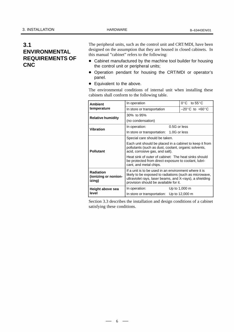
The peripheral units, such as the control unit and CRT/MDI, have beendesigned on the assumption that they are housed in closed cabinets. Inthis manual ”cabinet” refers to the following:
Cabinet manufactured by the machine tool builder for housingthe control unit or peripheral units;
Operation pendant for housing the CRT/MDI or operator’spanel.
Equivalent to the above.The environmental conditions of internal unit when installing thesecabinets shall conform to the following table.
Ambient In operation 0C to 55CAmbient temperature In store or transportation –20C to +60C
Relative humidity30% to 95%
(no condensation)
VibrationIn operation: 0.5G or less
In store or transportation: 1.0G or less
Pollutant
Special care should be taken.
Each unit should be placed in a cabinet to keep it frompollutants (such as dust, coolant, organic solvents,acid, corrosive gas, and salt).
Heat sink of outer of cabinet: The heat sinks shouldbe protected from direct exposure to coolant, lubri-cant, and metal chips.
Radiation (ionizing or nonion-izing)
If a unit is to be used in an environment where it islikely to be exposed to radiations (such as microwave,ultraviolet rays, laser beams, and X–rays), a shieldingprovision should be available for it.
Height above sealevel
In operation: Up to 1,000 m
In store or transportation: Up to 12,000 m
Section 3.3 describes the installation and design conditions of a cabinetsatisfying these conditions.
3.1ENVIRONMENTALREQUIREMENTS OFCNC

B–63443EN/01 3. INSTALLATIONHARDWARE
7
The units listed below require an external regulated supply voltage of 24VDC 10% (including an instantaneous value and a ripple).
Table 3.2 Power supply capacity
Unit Power supply capacity
Power Mate 0 control unit 1.8 A (Another 1A required for the FANUCRS–232–C device is used)
CRT/MDI 1.0 A
DPL/MDI 0.2 A
3.2POWER CAPACITY

3. INSTALLATION B–63443EN/01HARDWARE
8
When a cabinet is designed, it must satisfy the environmental conditionsdescribed in Section 3.1. In addition, the magnetic interference on theCRT screen, noise resistance, and maintenance requirements must beconsidered. The cabinet design must meet the following conditions :
The cabinet must be fully closed.
The cabinet must be designed to prevent the entry of airbornedust,coolant,and organic solvent.
Cabinets that let in air may be designed for the cooling fin unit of servoamplifier and servo transformer provided that they (This applies onlyto cabinets not certified for the CE marking, however.) :
Use an air filter on the air inlet ;
Place the ventilating fan so that it does not blow air directly towardthe unit;
Control the air flow so that no dust or coolant enters the air outlet
Design the cabinet so that the allowable ambient temperature range foreach unit accommodated in it will not be exceeded.See Section 3.4 for the details on thermal design of the cabinet.
A closed cabinet must be equipped with a fan to circulate the airwithin. The fan must be adjusted so that the air moves at 0.5 m/sec along thesurface of each installed unit. CAUTION : If the air blows directly from the fan to the unit, dusteasily adheres to the unit. This may cause the unit to fail.
For the air to move easily, a clearance of 100 mm is required betweeneach unit and the wall of the cabinet.
Packing materials must be used for the cable port and the door in orderto seal the cabinet.Because the CRT unit uses a voltage of approximately 11 kV, airbornedust gathers easily. If the cabinet is insufficiently sealed, dust passesthrough the gap and adheres to the unit. This may cause the insulationof the unit to deteriorate.Acceptable packing materials :
Epton sealer No. 686, NITTO INDUSTRY CO., LTD.
Polyurethane foam (ester) covered with vinyl chloride, FUJIRUBBER CO., LTD.
The setting and display must be installed in a location where coolantcannot be poured directly on it. The unit does have a dust–proof frontpanel.The setting and display unit has a dust–proof front panel. However,do not install the unit in a location where coolant may be poureddirectly on it.
Noise must be minimized.As the machine and the CNC are reduced in size, the parts that generatenoise may be placed near noise–sensitive parts in the magneticscabinet.The CNC is built to protect it from external noise. Cabinet design tominimize noise generation and to prevent it from being transmitted tothe CNC is necessary. See section 3.5 for details of noiseelimination/management.
3.3DESIGN AND INSTALLATION CONDITIONS OF THETOOL MAGNETICCABINET

B–63443EN/01 3. INSTALLATIONHARDWARE
9
The units must be installed or arranged in the cabinet so that they areeasy to inspect and maintain.Allow a space the control unit in order to make it easy to removebuilt–in I/O card cables and DPL/MDI cable.
The CRT screen can be distorted by magnetic interference.Arranging magnetic sources must be done with care.If magnetic sources (such as transformers, fan motors,electromagnetic contactors, solenoids, and relays) are located near theCRT display, they frequently distort the display screen. To preventthis, the CRT display and the magnetic sources generally must be kept300 mm apart. If the CRT display and the magnetic sources are not300 mm apart, the screen distortion may be suppressed by changingthe direction in which the magnetic sources are installed.The magnetic intensity is not constant, and it is often increased bymagnetic interference from multiple magnetic sources interactingwith each other. As a result, simply keeping the CRT and the magneticsources 300 mm apart may not be enough to prevent the distortion.If they cannot be kept apart, or if the CRT screen remains distorteddespite the distance, cover the screen with a magnetic shield.
To ensure conformity to the EMC command, refer to ”Conforming tothe EMC Command (A–72937).”
Check for vibration.The CNC may resonate at an unpredictable frequency. After installingthe CNC on the machine, check carefully for vibration and ensure thatno resonance is produced.
3. INSTALLATION B–63443EN/01HARDWARE
10
The temperature of the air inside a cabinet rises due to heat generated inthe units and parts installed in the cabinet, compared with the outside airtemperature. Since the generated heat is radiated from the surface of thecabinet, the temperature of the air in the cabinet and the outside air balanceat certain heat levels. If the amount of heat generated is constant, thelarger the surface area of the cabinet, the less the internal temperaturerises. The thermal design of the cabinet refers to calculating the heatgenerated in the cabinet, evaluating the surface area of the cabinet, andenlarging that surface area by installing heat exchangers in the cabinet, ifnecessary. Such a design method is described in the followingsubsections.
The cooling capacity of a cabinet made of sheet metal is generally 6 W/°Cper 1m2 surface area, that is, when the 6W heat source is contained in acabinet having a surface area of 1 m2, the temperature of the air in thecabinet rises by 1°C. In this case the surface area of the cabinet refers tothe area useful in cooling , that is, the area obtained by subtracting the areaof the cabinet touching the floor from the total surface area of the cabinet.There are two preconditions : The air in the cabinet must be circuited bythe fun, and the temperature of the air in the cabinet must be almostconstant. The temperature rise inside the cabinet is represented by the expressionbelow, with respect to the outside air temperature. Internal heat loss P [W] 6[W/m2⋅°C] × surface area S[m2]×10[°C] of rise in temperatureFor example, a cabinet having a surface area of 4m2 has a cooling capacityof 24W/°C. To limit the internal temperature increase to 10°C under theseconditions, the internal heat must not exceed 240W. If the actual internalheat is 320W, however, the temperature in the cabinet rises by 13°C ormore. If the allowable ambient temperature conditions for the unitscannot be satisfied, the cooling capacity of the cabinet must be improvedusing the heat exchanger described below.
As discussed above, if the temperature rise cannot be limited to theallowable level by the cooling capacity of the cabinet, a heat exchangermust be added. The heat exchanger forcibly applies the air from both theinside and outside of the cabinet to the cooling fin to obtain effectivecooling. The heat exchanger enlarges the surface area. The customer should prepare the heat exchanger if necessary.
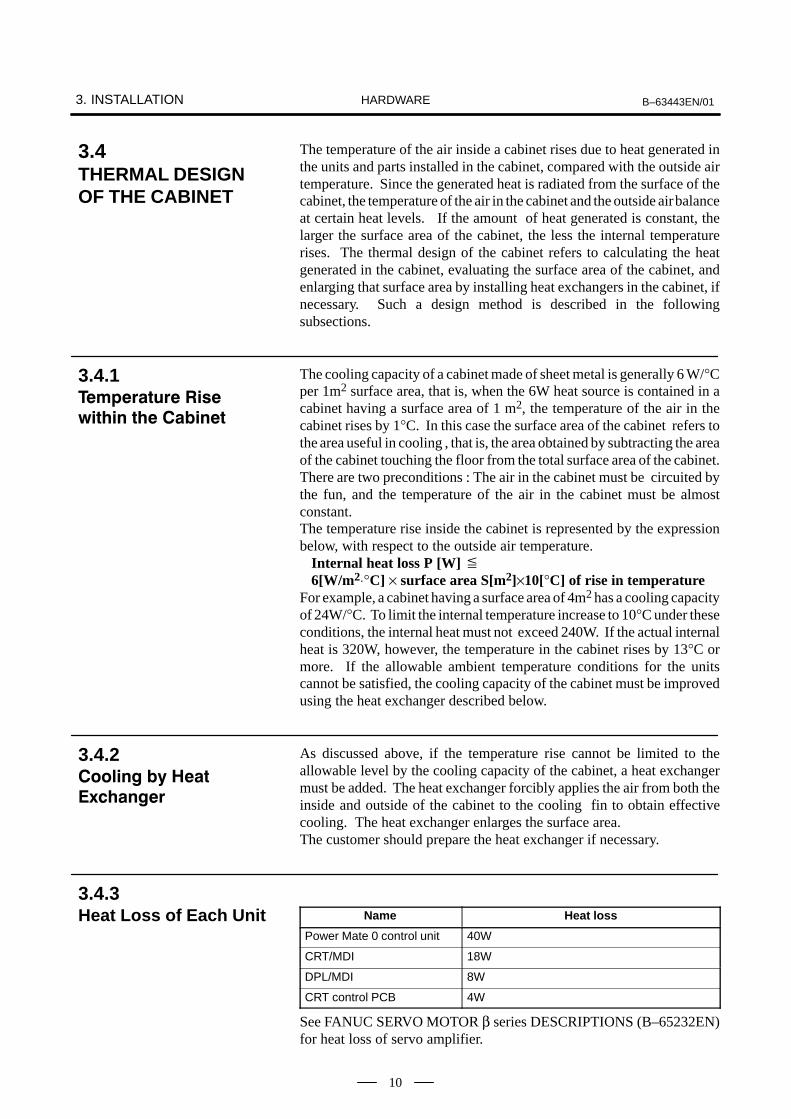
Name Heat loss
Power Mate 0 control unit 40W
CRT/MDI 18W
DPL/MDI 8W
CRT control PCB 4W
See FANUC SERVO MOTOR β series DESCRIPTIONS (B–65232EN)for heat loss of servo amplifier.
3.4THERMAL DESIGNOF THE CABINET
3.4.1
3.4.2
!"
3.4.3Heat Loss of Each Unit

B–63443EN/01 3. INSTALLATIONHARDWARE
11
The CNC unit has been steadily reduced in size using surface–mount andcustom LSI technologies for electronic components. The CNC unit alsois designed to be protected from external noise. However, it is difficultto measure the level and frequency of noise quantitatively, and noise hasmany uncertain factors. It is important to prevent both noise from beinggenerated and generated noise from being introduced into the CNC unit.This precaution improves the stability of the CNC unit machine toolsystem.The CNC unit component units are often installed close to the partsgenerating noise in the power magnetics cabinet. Possible noise sourcesinto the CNC unit are capacitive coupling, electromagnetic induction, andground loops.When designing the power magnetics cabinet, guard against noise in themachine as described in the following section.
The cables used for the machine are classified as listed in the following table:Process the cables in each group as described in the action column.
Group Signal line Action
Primary AC power line Bind the cables in group A separate-
Secondary AC power linely (Note 1) from groups B and C, orcover group A with an electromag-
A AC/DC power lines (containing the power lines for the servo motors and spindle motors)
cover group A with an electromag-netic shield (Note 2).
See Section 3.5.4 and connectAC/DC solenoid
See Section 3.5.4 and connectspark killers or diodes with the sole-
AC/DC relaynoid and relay.
DC solenoid (24VDC) Connect diodes with DC solenoidand relay.
DC relay (24VDC)and relay.
Bind the cables in group B separate-
B DC power linely from group A, or cover group Bwith an electromagnetic shield.
DI/DO cable between the built–in I/O and power magnetics cabinetSeparate group B as far from GroupC as possible.
DI/DO cable between the built–in I/O and machine It is more desirable to cover group Bwith the shield.
Cable between the Power Mate and servo amplifier Bind the cables in group C sepa-
Cable for position and velocity feedbackrately from group A, or cover groupC with an electromagnetic shield.
Cable between the Power Mate and spindle amplifierC with an electromagnetic shield.
Separate group C as far from GroupCable for position coder
Separate group C as far from GroupB as possible.
C Cable for manual pulse generator Be sure to perform shield proces-
Cable between the Power Mate and the CRT/MDIsing in Subsec. 3.5.5.
RS–232–C interface cable
Battery cable
Other cables to be covered with the shield
3.5ACTION AGAINSTNOISE
3.5.1Separating SignalLines
3. INSTALLATION B–63443EN/01HARDWARE
12
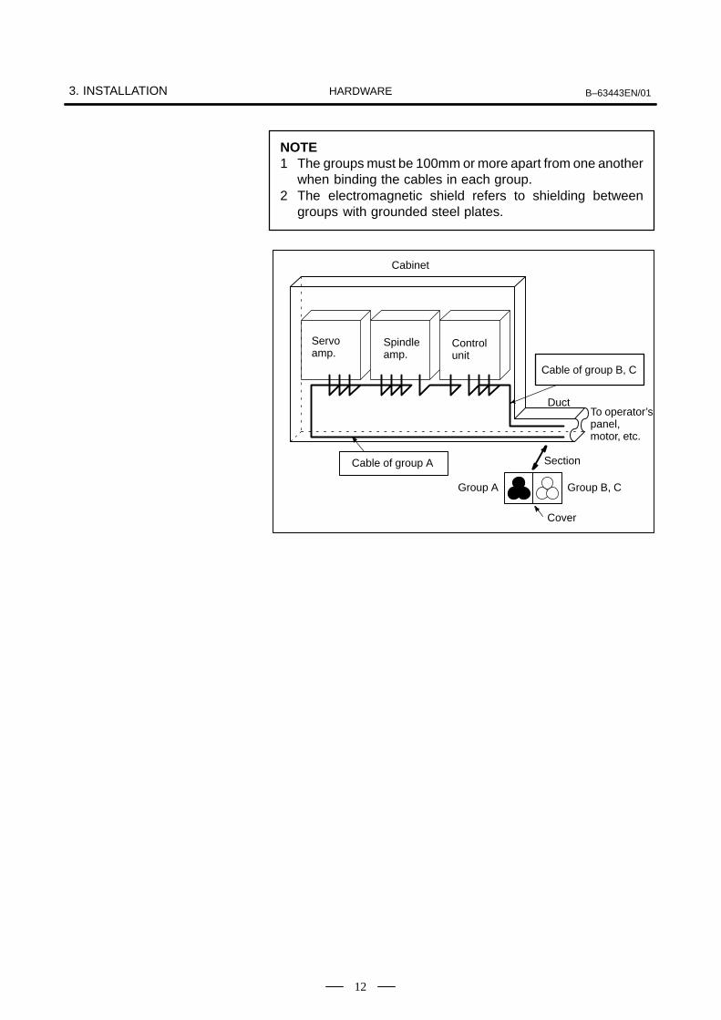
NOTE1 The groups must be 100mm or more apart from one another
when binding the cables in each group.2 The electromagnetic shield refers to shielding between
groups with grounded steel plates.
Cable of group B, C
Cable of group A
Cabinet
Servo amp.
Spindle amp.
Control unit
DuctTo operator’s panel, motor, etc.
Section
Group A Group B, C
Cover

B–63443EN/01 3. INSTALLATIONHARDWARE
13
The following ground systems are provided for the CNC machine tool:
Ground for signalThe signal ground (SG) supplies the reference voltage (0V) of theelectrical signal system.
Ground for protectionThe frame ground system (FG) is used for safety, and suppressingexternal and internal noises. In the frame ground system, the frames,cases of the units, panels, and shields for the interface cables betweenthe units are connected.
Protection ground (PE)The protection ground (PE) is used to connect the ground forprotection connected between devices or units with the ground.
The grounding resistance of the protection ground (PE) shall be 100ohms or less (class D grounding).
The protection ground (PE) cable must have enough cross–sectionalarea to safely carry the accidental current flow into the protectionground (PE) when an accident such as a short circuit occurs.(Generally, it must have the cross–sectional area of the AC power cableor more.)
Use the cable containing the AC power wire and the protection ground(PE) wire so that power is supplied with the ground wire connected.
3.5.2Ground
""
#

3. INSTALLATION B–63443EN/01HARDWARE
14
Connect the signal ground (FG) terminal for the Power Mate to thegrounded plate of the cabinet. The grounded plate must be connected tothe protection ground (PE) as shown below.
Cabinet Air goes out.
FG terminals(Faston terminals atthe controller)
To the other grounded platesDistributionswitchboardin the cabinet
External distributionswitchboard
See the note below.
Class D grounding ormore strict grounding
To the cabinet
Grounded plate Grounded plate
Air comes in.
PE
CAUTIONUse the Faston terminals (A02B–0166–K330) for the frame ground. Also use 100 to 300 mmstranded wire with a cross–section of 2 mm2 or more. Be sure to connect the frame ground ofthe Power Mate to the grounded plates in the cabinet as shown above.
3.5.3Connecting the Groundfor Signal of theControl Unit

B–63443EN/01 3. INSTALLATIONHARDWARE
15
The AC/DC solenoid and relay are used in the power magnetics cabinet.A high pulse voltage is caused by coil inductance when these devices areturned on or off.This pulse voltage induced through the cable causes the electronic circuitsto be disturbed. In general, to reduce this pulse voltage, a spark killer isused in AC circuits, while a diode is used in DC circuits.
Use a spark killer consisting of a resistor and capacitor in series. Thistype of spark killer is called a CR spark killer.(Use it under AC)(A varistor is useful in clamping the peak voltage of the pulse voltage,but cannot suppress the sudden rise of the pulse voltage. FANUCtherefore recommends a CR spark killer.)
The reference capacitance and resistance of the spark killer shallconform to the following based on the current (I (A)) and DCresistance of the stationary coil:
1) Resistance (R) : Equivalent DC resistance of the coil
2) Capacitance (C) :20
I2(µF)
I2
10
I : Current at stationary state of the coil
Equivalent circuit of the spark killerR C
Spark killer
Spark killer
Motor
ACrelay
Mount the noise eliminator near a motor or a relay coil.
NOTEUse a CR–type noise eliminator. Varistor–type noiseeliminators clamp the peak pulse voltage but cannotsuppress a sharp rising edge.
3.5.4Noise Suppressor
$ $
3. INSTALLATION B–63443EN/01HARDWARE
16
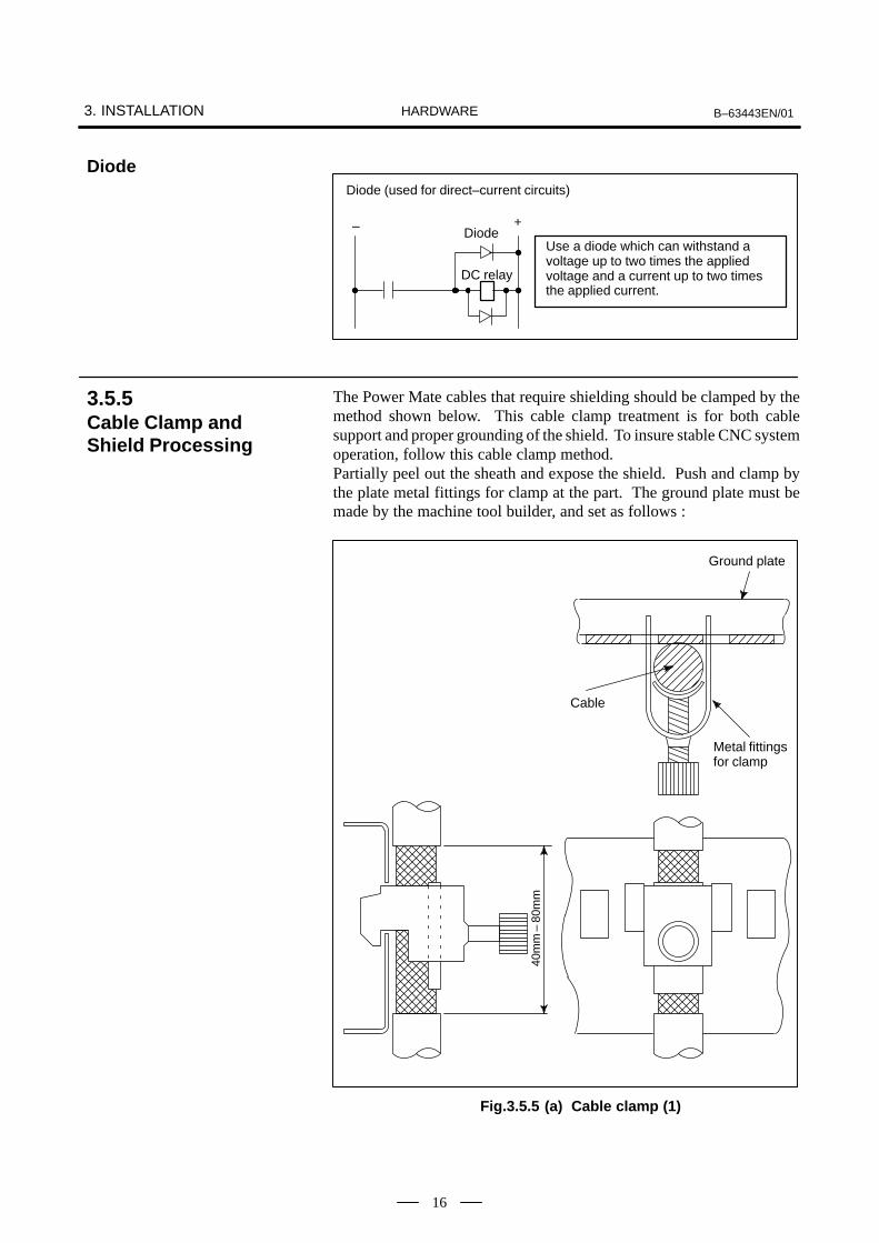
Use a diode which can withstand avoltage up to two times the appliedvoltage and a current up to two timesthe applied current.
Diode
DC relay
Diode (used for direct–current circuits)
– +
The Power Mate cables that require shielding should be clamped by themethod shown below. This cable clamp treatment is for both cablesupport and proper grounding of the shield. To insure stable CNC systemoperation, follow this cable clamp method.Partially peel out the sheath and expose the shield. Push and clamp bythe plate metal fittings for clamp at the part. The ground plate must bemade by the machine tool builder, and set as follows :
Cable
Metal fittings for clamp
Ground plate
40m
m –
80m
m
Fig.3.5.5 (a) Cable clamp (1)
Diode
3.5.5Cable Clamp andShield Processing

B–63443EN/01 3. INSTALLATIONHARDWARE
17
ÇÇÇÇÇÇÇÇÇÇÇÇÇÇÇÇÇÇÇÇÇÇÇÇÇÇÇÇÇÇÇÇ
Control unit
Ground plate
Metal fittings for clamp
Shield cover
Machine sideinstallationboard
Fig.3.5.5 (b) Cable clamp (2)
Prepare ground plate like the following figure.
Mount screw hole
Hole for securing metal fitting clamp
Ground terminal(grounded)
Fig.3.5.5 (c) Ground plate
For the ground plate, use a metal plate of 2 mm or thicker, which surfaceis plated with nickel.

3. INSTALLATION B–63443EN/01HARDWARE
18
12mm
20mm
8mmGroundplate
Fig.3.5.5 (d) Ground plate holes
(Reference) Outer drawings of metal fittings for clamp.
17mm
28mm
6mm
Max. 55mm
Fig.3.5.5 (e) Outer drawings of metal fittings for clamp
Ordering specification for metal fittings for clamp A02B–0124–K001 (8 pieces)
B–63443EN/01 3. INSTALLATIONHARDWARE
19
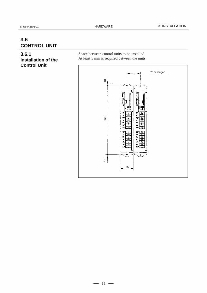
Space between control units to be installedAt least 5 mm is required between the units.
70 or longer
360
10
65
10
3.6CONTROL UNIT
3.6.1Installation of theControl Unit
3. INSTALLATION B–63443EN/01HARDWARE
20
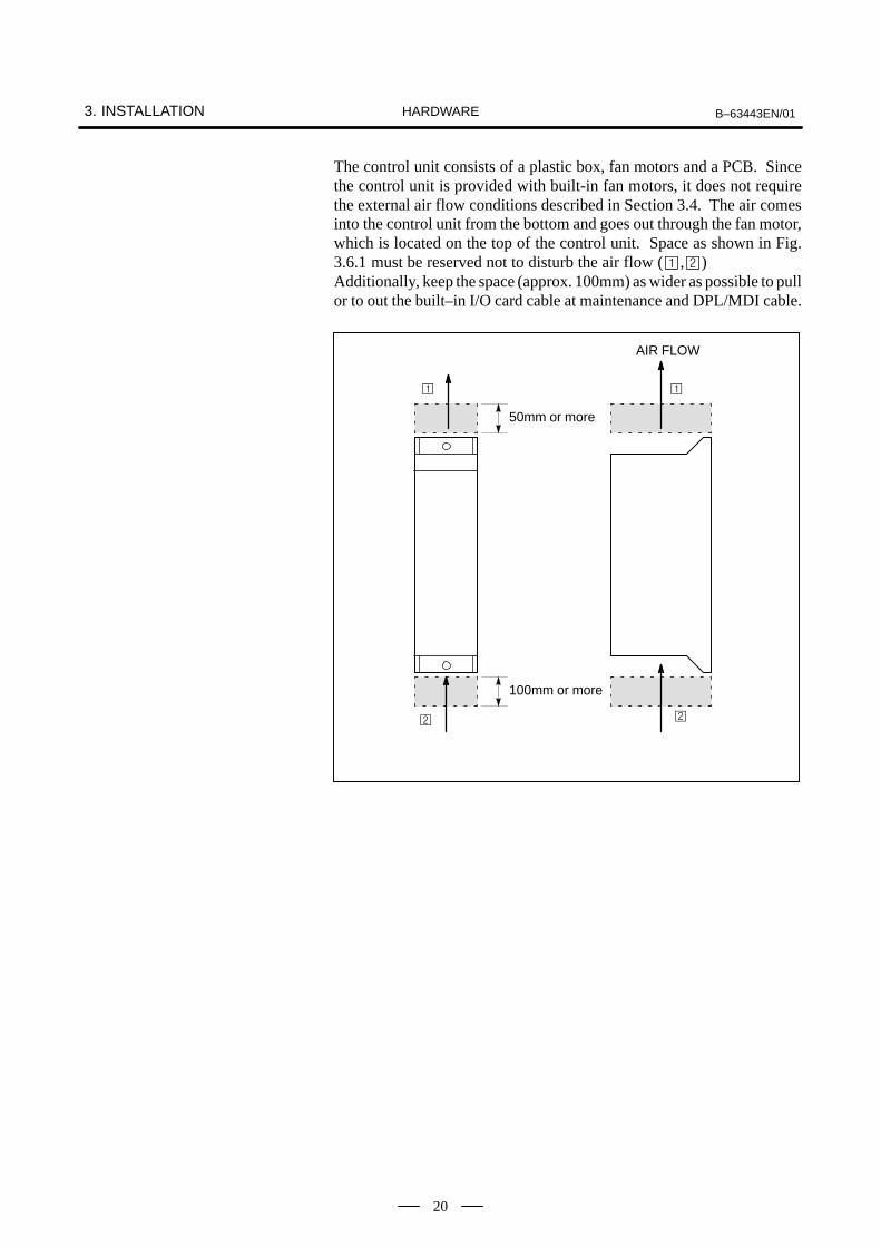
The control unit consists of a plastic box, fan motors and a PCB. Sincethe control unit is provided with built-in fan motors, it does not requirethe external air flow conditions described in Section 3.4. The air comesinto the control unit from the bottom and goes out through the fan motor,which is located on the top of the control unit. Space as shown in Fig.3.6.1 must be reserved not to disturb the air flow (,)Additionally, keep the space (approx. 100mm) as wider as possible to pullor to out the built–in I/O card cable at maintenance and DPL/MDI cable.
100mm or more
50mm or more
AIR FLOW

B–63443EN/01 3. INSTALLATIONHARDWARE
21
Part programs, offset data, system parameters, and ladder are stored inSRAM memory in the control unit. The power to the SRAM memory isbacked up by a lithium battery mounted on the front panel of the controlunit. The above data is not lost even when the main battery goes dead.The backup battery is mounted on the control unit at shipping. Thisbattery can maintain the contents of memory for about a year.When the voltage of the battery becomes low, alarm message ”BAT”blinks on the CRT or MDI display and the battery alarm signal BAL <F001#2> is output to the PMC. When this alarm is displayed, replace thebattery as soon as possible. In general, the battery can be replaced withinone or two weeks, however, this depends on the system configuration.If the voltage of the battery becomes any lower, contents of SRAMmemory can no longer be backed up. Turning on the power to the PowerMate in this state causes system alarm 910 (RAM parity alarm) to occurbecause the contents of SRAM memory are lost. Clear the entire SRAMmemory and reenter data after replacing the battery. To clear and reenter,it is required to save data in the memory card or floppy.
CAUTIONIf the contents of the SRAM memory are not backed up, thedata may not be restored at the time of maintenance.
The power to the Power Mate must be turned on when the battery isreplaced. If the battery is disconnected when the power is turned off, thecontents of memory are lost.Observe the following precautions for lithium batteries:
WARNINGIf an unspecified battery is used, it may explode.Replace the battery only with the specified battery
(A02B–0118–K111).
Dispose of used batteries as follows:
Small quantitiesDischarge the batteries and dispose of them as ordinary nonflammablegarbage.
Large quantitiesConsult FANUC.
3.6.2Battery for MemoryBackup

3. INSTALLATION B–63443EN/01HARDWARE
22
Procedure for replacing the battery
WARNINGWhen replacing the memory backup batteries, keep thepower to the machine (Power Mate) switched on, and holdthe machine at an emergency stop. Because this work mustbe carried out while the power is kept switched on and thecabinet is open, only the personnel who have been trainedfor safety are allowed to engage in the work. Whenreplacing the batteries, be careful not to touch thehigh–voltage circuit section (marked and shielded witha shock hazard prevention cover). If you touch thehigh–voltage circuit section when it is uncovered, you willget an electric shock.
1 Prepare lithium battery (A02B-0118-K111).
2 Turn the power ON.
3 Remove the battery in the battery holder at behind front panel ofcontrol unit.
Â
ÂÂ
(A02B–0118–K111)
Control unit
Battery
Fig.3.6.2 (a) Replacing the battery (1)
Replacing the Battery

B–63443EN/01 3. INSTALLATIONHARDWARE
23
4 Remove the connector of the battery.
BATTERY
Connectorin side ofP.C.B
Connector in side of cable
Battery
Fig.3.6.2 (b) Replacing the battery (2)
5 Replace the battery, and connect the connector carefully not toconnect inversely.
6 Attache the battery holder.
7 Turn power of Power Mate OFF.
3. INSTALLATION B–63443EN/01HARDWARE
24
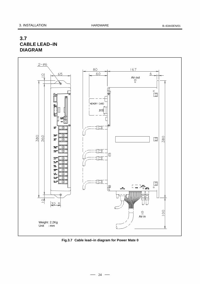
Weight: 2.2KgUnit : mm
Air in
Air out
Fig.3.7 Cable lead–in diagram for Power Mate 0
3.7CABLE LEAD–INDIAGRAM
B–63443EN/01 3. INSTALLATIONHARDWARE
25
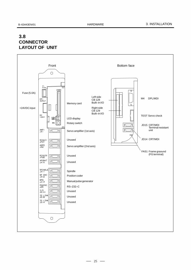
Front
Fuse (5.0A)
+24VDC input
Memory card
LED display
Rotary switch
Servo amplifier (1st axis)
Unused
Unused
Unused
Spindle
Position coder
Manual pulse generator
RS–232–C
Unused
Unused
Unused
Bottom face
Left sideCB 128Built–in I/O
Right sideCB 129Built–in I/O
M4 DPL/MDI
TEST Servo check
JD15 CRT/MDI Terminal resistant unit
FAS1 Frame graound (FG terminal)
JD14 CRT/MDI
Servo amplifier (2nd axis)
3.8CONNECTORLAYOUT OF UNIT

4. TOTAL CONNECTION B–63443EN/01HARDWARE
26
4

B–63443EN/01 4. TOTAL CONNECTIONHARDWARE
27
Note 1 : Connector and terminal symbols
M : Male connectorF : Female connector
AMP3 : AMP Japan connector (3 pins) Y34 : YamaichiD15 : D–sub connector (15 pins) M3 : M3 screw terminalD25 : D–sub connector (25 pins) CH : Varies with the AC motorP20 : Honda Tsushin PCR connector (20 pins)
Note 2 : The +24 VDC power supply (marked #) should be prepared by the customer.
Note 3 : All cables except the SRAM back–up battery cable should be prepared by the customer.
Emergency stop
100VAC, 1φ
200VAC, 3φ
1st axis servo motor(Built–in type serial pulse coder)
2nd axis servo amplifier/2nd axis servo motor/built–in type serial pulse coder
Analog spindlecontroled circuit
Position coder
Relay connector
Manual pulsegenerator
Power magnetic
CRT/MDI
Terminal unit(PCR connec-tor)
Power supply P.C. board
Base P.C. board
Memorycard
+24VDC powersupply
Battery 3V for RAM battery backup
1st axis servo amplifier
Built–in I/Ocard
HANDY FILE
J86
J87
4.1TOTAL CONNECTIONDIAGRAM FOR Power Mate 0

5. CONNECTION OF INPUTPOWER SUPPLY B–63443EN/01HARDWARE
28
5 % &

B–63443EN/015. CONNECTION OF INPUT
POWER SUPPLYHARDWARE
29
External power supply24 VDC 10%(for main unit)
Power Mate controller
Built–in I/O card
J3024 VDC capacity2.0 A(Another 1A required for the FANUC RS–232–C device is used.)
Power Mate CRT/MDI DPL/MDI
J30 CRT/MDI→1.0 A
DPL/MDI→0.2 A
NOTEThe above power supply capacity values only serve asguidelines. They do not include the capacity required forDOs.
5.1POWER SUPPLYCAPACITY

5. CONNECTION OF INPUTPOWER SUPPLY B–63443EN/01HARDWARE
30
For the controller and the setting and display unit of the Power Mate, usea stabilized power supply that satisfies the condition below.24 VDC10% (including instantaneous and ripple voltages)
CAUTIONIf a power supply that falls outside the above voltage rangeis used, the controller and setting and display unit of thePower Mate may not operate normally.
1) Main unit power supplyThe main unit requires a sum of the following currents.
Control power supplyController : 2.0 A
RS–232–C (if it draws power from the Power Mate): 1.0 A,additionally
DOs of the built–in I/O card 2.1 A (maximum), additionally
NOTEDetailed power requirement of the DOs of the built–in I/Ocard: Total maximum load current for the DOs (including aninstantaneous value) plus 10 mA
2) Power supply for the setting and display unitOne of the following values applies.
CRT/MDI : 1.0 A DPL/MDI : 0.3 A
Details of 24 VDC inputpower supply

B–63443EN/015. CONNECTION OF INPUT
POWER SUPPLYHARDWARE
31
AMP Japan1–178288–3 (Housing)1–175218–5 (Contact)
1 +24V2 0V3
External power source
Power Mate CRT/MDI, DPL/MDI
J30+24VDC stabilized power source
CP1, CPD1 (AMP)
24VDC10%
FG
Groud for signalFaston terminal
Â
ÂÂ
CP1
+24V
0V
1 24VDC
2 0V
Cable connection (J30)
StandardA02B–0120–K324
NOTE1 Be sure to connect the signal ground terminal. (See Section
3.5.3.)2 When a momentary power failure occurs, the system is
restored to the same state as the state at power–on.
5.2POWERCONNECTIONS

5. CONNECTION OF INPUTPOWER SUPPLY B–63443EN/01HARDWARE
32
Apply the following power–on sequence.
1 Power to the Entire machine <200 VAC> Power to the servo amplifier <200 VAC>
2 Power to the Power Mate (includes setting and display unit)<24 VDC>
5.3POWER–ONSEQUENCE

B–63443EN/015. CONNECTION OF INPUT
POWER SUPPLYHARDWARE
33
Apply the following power–off sequence.
1 Power to the Power Mate <24 VDC>2 Power to the servo amplifier <200 VAC>3 Power to the entire machine <200 VAC>
Motors cannot be controlled when the power is turned off or momentarilyinterrupted. Take appropriate action on the machine side when necessary.For example, when the tool is moved along a vertical axis, apply brakesto prevent the axis from falling. Apply a brake that clamps the motor whenthe servo is not operating or the motor is not rotating. Release the clamponly when the motor is rotating. When the servo axis cannot be controlledwhen the power is turned off or momentarily interrupted, clamp the servomotor. In this case, the axis may fall before the relay for clamping startsoperating. The designer should make sure if the distance results in trouble.
The Power Mate controller has a circuit for protection against momentarypower failures.
When a momentary power failure is detected, the Power Mate controllerturns off the output signals to the servo system and machine. Uponrecovery from the momentary power failure, the system is automaticallyreset to turn on the output signals to the servo system and machine. Thenthe Power Mate waits for automatic operation to be restarted. (Theoperator restarts operation after checking the status.)
The signal ACT on the PMC is available to check if a momentary powerfailure has occurred.
The stud for the protection ground is located at the rear of the setting anddisplay unit (such as a CRT/MDI) installed in the cabinet. Use a twistedwire that is 2 mm2 or larger and has a length of approximately 100 mmto connect the ground. See Appendix A for the location of the stud.
5.4POWER–OFFSEQUENCE
5.5MOMENTARYPOWER FAILURE
5.6PROTECTIONGROUNDCONNECTION

6. CONNECTION OF I/O UNITS TO MACHINE INTERFACE B–63443EN/01HARDWARE
34
6 ' (
B–63443EN/01
6. CONNECTION OF I/O UNITS TOMACHINE INTERFACEHARDWARE
35
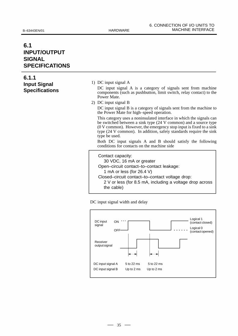
1) DC input signal ADC input signal A is a category of signals sent from machinecomponents (such as pushbutton, limit switch, relay contact) to thePower Mate.
2) DC input signal BDC input signal B is a category of signals sent from the machine tothe Power Mate for high–speed operation.This category uses a noninsulated interface in which the signals canbe switched between a sink type (24 V common) and a source type(0 V common). However, the emergency stop input is fixed to a sinktype (24 V common). In addition, safety standards require the sinktype be used.Both DC input signals A and B should satisfy the followingconditions for contacts on the machine side
Contact capacity: 30 VDC, 16 mA or greater
Open–circuit contact–to–contact leakage: 1 mA or less (for 26.4 V)
Closed–circuit contact–to–contact voltage drop: 2 V or less (for 8.5 mA, including a voltage drop acrossthe cable)
DC input signal width and delay
Up to 2 ms
5 to 22 ms 5 to 22 ms
Up to 2 ms
ON
OFF
DC inputsignal
Logical 1 (contact closed)
Logical 0 (contact opened)
Receiveroutput signal
DC input signal A
DC input signal B
6.1INPUT/OUTPUTSIGNALSPECIFICATIONS
6.1.1Input SignalSpecifications

6. CONNECTION OF I/O UNITS TO MACHINE INTERFACE B–63443EN/01HARDWARE
36
Contact
+24V
Filter and levelconversion circuit
+24V
0V
Sink–type input connection, in compliance with safety standards
Power Mate
Open: Logical 0
Closed: Logical 1
3.3K
Input signal
DIC
Source–type input connection
Contact
+24V
Filter and level conversion circuit
+24V
0V
Power Mate
Open: Logical 1
Closed: Logical 0
3.3K
Input signal
DIC
WARNINGWhen a source interface is used, a ground fault in an inputsignal has the same effect as closing the contacts. From theviewpoint of safety, therefore, FANUC does not recommendthe use of such an interface for input signals.

B–63443EN/01
6. CONNECTION OF I/O UNITS TOMACHINE INTERFACEHARDWARE
37
The Power Mate can use source–type output signals that comply withsafety standards.
The output signals are rated as follows:
Maximum load current with the driver turned on: 200 mA (including an instantaneous value)
Saturation voltage with the driver turned on: 1.0 V (maximum)
Dielectric strength: 24 V +20% (including an instantaneous value)
Leakage current with the driver turned off: 100 µA (maximum)
The output signals require an external power supply rated as follows:
Supply voltage: +24 V +10% (including an instantaneous value)
Supply current: At least the total maximum load current (including aninstantaneous and ripple value) + 100 mA
Turn–on timing: Before the Power Mate power supply is turned on (with amaximum allowable time lag of 500 ms)
Turn–off timing: Same time or after the Power Mate powersupply is turned off
Connect the power supply that meets the above requirements to the outputsignal power supply pins (DOC and 0V) of each DI/DO connector. Notethat the total load current varies with the type of a DI/DO card used. Itis necessary to connect 24 VDC to all DOC pins.
Built–in I/O card C : Maximum load current of 2.1 A (Yamaichi connector (0.7 A) 3)
NOTEUse 30/0.18 (0.75 mm2) or heavier wire as the power cable.
6.1.2Output SignalSpecifications
6. CONNECTION OF I/O UNITS TO MACHINE INTERFACE B–63443EN/01HARDWARE
38
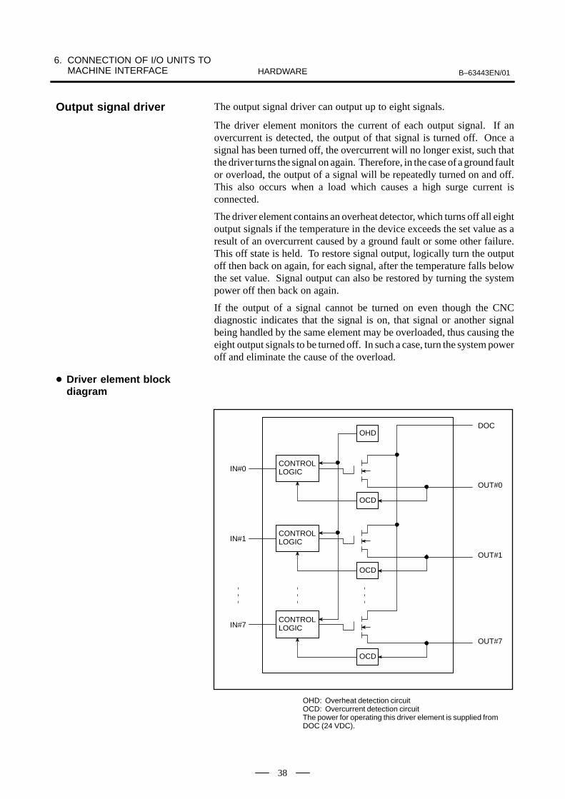
The output signal driver can output up to eight signals.
The driver element monitors the current of each output signal. If anovercurrent is detected, the output of that signal is turned off. Once asignal has been turned off, the overcurrent will no longer exist, such thatthe driver turns the signal on again. Therefore, in the case of a ground faultor overload, the output of a signal will be repeatedly turned on and off.This also occurs when a load which causes a high surge current isconnected.
The driver element contains an overheat detector, which turns off all eightoutput signals if the temperature in the device exceeds the set value as aresult of an overcurrent caused by a ground fault or some other failure.This off state is held. To restore signal output, logically turn the outputoff then back on again, for each signal, after the temperature falls belowthe set value. Signal output can also be restored by turning the systempower off then back on again.
If the output of a signal cannot be turned on even though the CNCdiagnostic indicates that the signal is on, that signal or another signalbeing handled by the same element may be overloaded, thus causing theeight output signals to be turned off. In such a case, turn the system poweroff and eliminate the cause of the overload.
CONTROLLOGIC
OHDDOC
IN#0
OCD
OUT#0
CONTROLLOGICIN#1
OCD
OUT#1
CONTROLLOGICIN#7
OCD
OUT#7
OHD: Overheat detection circuitOCD: Overcurrent detection circuitThe power for operating this driver element is supplied fromDOC (24 VDC).
Output signal driver
Driver element blockdiagram

B–63443EN/01
6. CONNECTION OF I/O UNITS TOMACHINE INTERFACEHARDWARE
39
The following restriction applies to the connection of the output signals.
The following parallel connection of output pins shall not be used.
Source–type driver circuit
DOCRegulatedpower supply+24V 0V
0V
|
Parallel connection inhibited
Power Mate
When using a dark–light resistance, connect a leakage prevention diodeto it.
Source–typedriver circuit
Lamp
Leakage prevention diode
DOC Regulatedpower supply+24V 0V
Dim–light resistance
Power Mate
When a dim–light resistance is used
0V

6. CONNECTION OF I/O UNITS TO MACHINE INTERFACE B–63443EN/01HARDWARE
40
FANUC Power Mate 0 34–pin ribboncable connector
Mother boardBuilt–inI/O card–C
DI 32 pinsDO 24 pins
Machineoperator’spanel
J86, J87
This is built–in I/O card C built in Power Mate 0 unit.
The DO signals are of source type and conform to the safety requirements.
Each I/O card is designed such that a connector panel is used to relay thesignals between the I/O card and terminal block or another connector. Inparticular, to facilitate connection to a connector panel, MIL–standardribbon–cable connectors are employed as the interface connectors.
(1) DI 32 pins and DO 24 pins are available.
(2) Common switches:1 set of 8 common signals, plus twenty four 24V common signals
(3) Maximum DO load current: 2.1 A
(4) Connector specification:Connector conforming to MIL–C–83503 standard, equipped withcenter key for protection against reverse insertionUse the cable connector conforming to the equivalent standard.Recommended connectorA02B–0124–K300(HIROSE HIF3BA–34D–2.54R)
(5) The ribbon cable goes out from the bottom of the cabinet.
6.2CONNECTION OFBUILT–IN I/O CARD C
6.2.1Outline
B–63443EN/01
6. CONNECTION OF I/O UNITS TOMACHINE INTERFACEHARDWARE
41
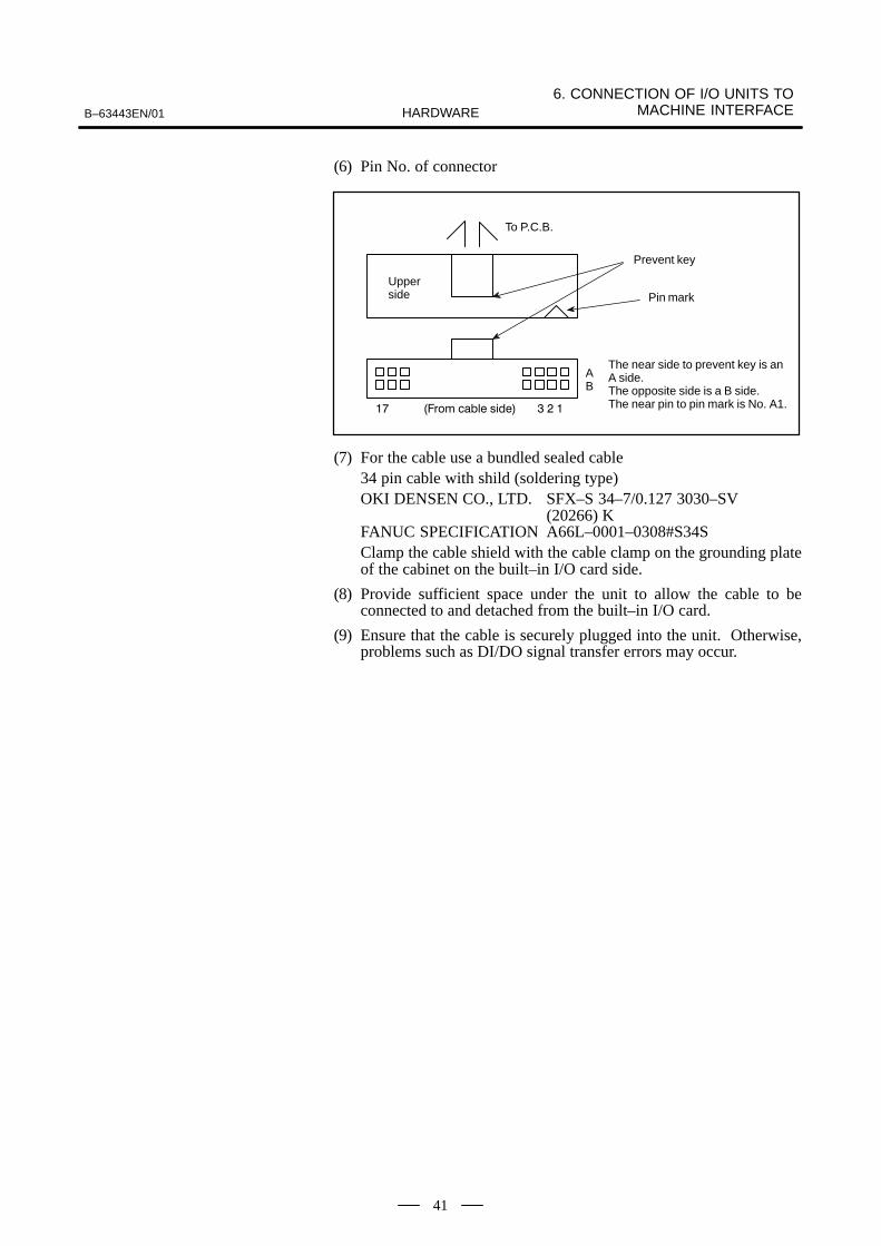
(6) Pin No. of connector
Prevent key
Pin mark
AB
The near side to prevent key is anA side.The opposite side is a B side.The near pin to pin mark is No. A1.
To P.C.B.
Upperside
(7) For the cable use a bundled sealed cable34 pin cable with shild (soldering type)OKI DENSEN CO., LTD. SFX–S 34–7/0.127 3030–SV
(20266) KFANUC SPECIFICATION A66L–0001–0308#S34SClamp the cable shield with the cable clamp on the grounding plateof the cabinet on the built–in I/O card side.
(8) Provide sufficient space under the unit to allow the cable to beconnected to and detached from the built–in I/O card.
(9) Ensure that the cable is securely plugged into the unit. Otherwise,problems such as DI/DO signal transfer errors may occur.

6. CONNECTION OF I/O UNITS TO MACHINE INTERFACE B–63443EN/01HARDWARE
42
(1) DI signals
#7X1000
#6 #5 #4 #3 #2 #1 #0
128–B05 128–A06 128–B04 128–A04 128–B03 128–A03 128–B02 128–A02
PMCADDRESS
#7X1001
#6 #5 #4 #3 #2 #1 #0
128–B10 128–A10 128–B09 128–A09 128–B08 128–A08 128–B07 128–A07
#7X1002
#6 #5 #4 #3 #2 #1 #0
129–B05 129–A05 129–B04 129–A04 129–B03 129–A03 129–B02 129–A02
#7X1003
#6 #5 #4 #3 #2 #1 #0
129–B10 129–A10 129–B09 129–A09 129–B08 129–A08 129–B07 129–A07
DC input signal A DC input signal B
Switchable–common DC input signal B (8 pcs)
(2) DO signals#7
Y1000#6 #5 #4 #3 #2 #1 #0
128–B14 128–A14 128–B13 128–A13 128–B12 128–A12 128–B11 128–A11
#7Y1001
#6 #5 #4 #3 #2 #1 #0
129–B16 129–A16 129–B15 129–A15 128–B16 128–A16 128–B15 128–A15
#7Y1002
#6 #5 #4 #3 #2 #1 #0
129–B14 129–A14 129–B13 129–A13 129–B12 129–A12 129–B11 129–A11
6.2.2Signals

B–63443EN/01
6. CONNECTION OF I/O UNITS TOMACHINE INTERFACEHARDWARE
43
+24E02
A01
X1000.003
05
X1000.204
0706
0809
X1000.4DIC
X1000.6X1001.0X1001.2X1001.4
1110
1213
X1001.6Y1000.0Y1000.2Y1000.4
1514
1617
Y1000.6Y1001.0Y1001.2
0V
+24EB
X1000.1X1000.3X1000.5X1000.7
DOCX1001.1X1001.3X1001.5X1001.7Y1000.1Y1000.3Y1000.5Y1000.7Y1001.1Y1001.3
0V
+24E02
A01
X1002.003
05
X1002.204
0706
0809
X1002.4X1002.6
DOCX1003.0X1003.2X1003.4
1110
1213
X1003.6Y1002.0Y1002.2Y1002.4
1514
1617
Y1002.6Y1001.4Y1001.6
0V
+24EB
X1002.1X1002.3X1002.5X1002.7
DOCX1003.1X1003.3X1003.5X1003.7Y1002.1Y1002.3Y1002.5Y1002.7Y1001.5Y1001.7
0V
Built–in I/O card CCB128 CB129
34–pin flat cable connector
CB128 Male
Female
CB129
J86 J87
Power magnetics cabinet and machine operator’spanel
Male
Female
NOTE1 +24E (output)
A voltage of 24 VDC supplied to the Power Mate main unitis connected through a fuse and used for DI signals. Do notconnect an external 24 VDC output to this pin. Do notconnect it to DOC either.
2 DOC (external 24 VDC input)An external voltage of 24 VDC should be supplied for DOsignals.
6.2.3Machine Interface

6. CONNECTION OF I/O UNITS TO MACHINE INTERFACE B–63443EN/01HARDWARE
44
Filter and level conversion circuit
Power Mate
Example ofconnection
DIC
0V
CB128(A02)
CB128(B02)
CB128(A03)
CB128(A04)
CB128(A06)
CB128(B05)
CB128(A05)
CB128(B03)
CB128(B04)
CB128(A17, B17)
X1000. 0
X1000. 1
X1000. 2
X1000. 3
X1000. 4
X1000. 5
X1000. 6
X1000. 7
Bit number
Address number
Pin number
CB128(A01, B01)
+24E
Fig.6.2.4 (a) Built–in I/O card C machine interface (1)
X1000 is DC input signal B (for high–speed signal input).
X1000.0 to X1000.2 and X1000.7 are switchable–common signals;shown above are examples of sink–type inputs.
DIC serves as a common input for X1001.0 to X1001.2, and X1001.7.
6.2.4Details of DIConnection
B–63443EN/01
6. CONNECTION OF I/O UNITS TOMACHINE INTERFACEHARDWARE
45
Filter and level conversion circuit
Power Mate
Example ofconnection
DIC
0V
CB128(A07)
CB128(B07)
CB128(A08)
CB128(A09)
CB128(A10)
CB128(B10)
CB128(A05)
CB128(B08)
CB128(B09)
CB128(A17, B17)
X1001. 0
X1001. 1
X1001. 2
X1001. 3
X1001. 4
X1001. 5
X1001. 6
X1001. 7
Bit number
Address number
Pin number
CB128(A01, B01)
+24E
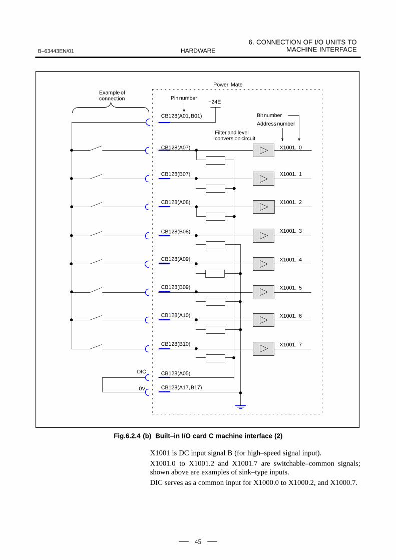
Fig.6.2.4 (b) Built–in I/O card C machine interface (2)
X1001 is DC input signal B (for high–speed signal input).
X1001.0 to X1001.2 and X1001.7 are switchable–common signals;shown above are examples of sink–type inputs.
DIC serves as a common input for X1000.0 to X1000.2, and X1000.7.

6. CONNECTION OF I/O UNITS TO MACHINE INTERFACE B–63443EN/01HARDWARE
46
Filter and level conversion circuit
Power Mate
Example ofconnection
CB129(A02)
CB129(B02)
CB129(A03)
CB129(A04)
CB129(A05)
CB129(B05)
CB129(B03)
CB129(B04)
X1002. 0
X1002. 1
X1002. 2
X1002. 3
X1002. 4
X1002. 5
X1002. 6
X1002. 7
Bit number
Address number
Pin number
CB129(A01, B01)
+24E
Fig.6.2.4 (c) Built–in I/O card C machine interface (3)
X1002 is DC input signal A.

B–63443EN/01
6. CONNECTION OF I/O UNITS TOMACHINE INTERFACEHARDWARE
47
Filter and level conversion circuit
Power Mate
Example ofconnection
CB129(A07)
CB129(B07)
CB129(A08)
CB129(A09)
CB129(A10)
CB129(B10)
CB129(B08)
CB129(B09)
X1003. 0
X1003. 1
X1003. 2
X1003. 3
X1003. 4
X1003. 5
X1003. 6
X1003. 7
Bit number
Address number
Pin number
CB129(A01, B01)
+24E
Fig.6.2.4 (d) Built–in I/O card C machine interface (4)
X1003 is DC input signal A.
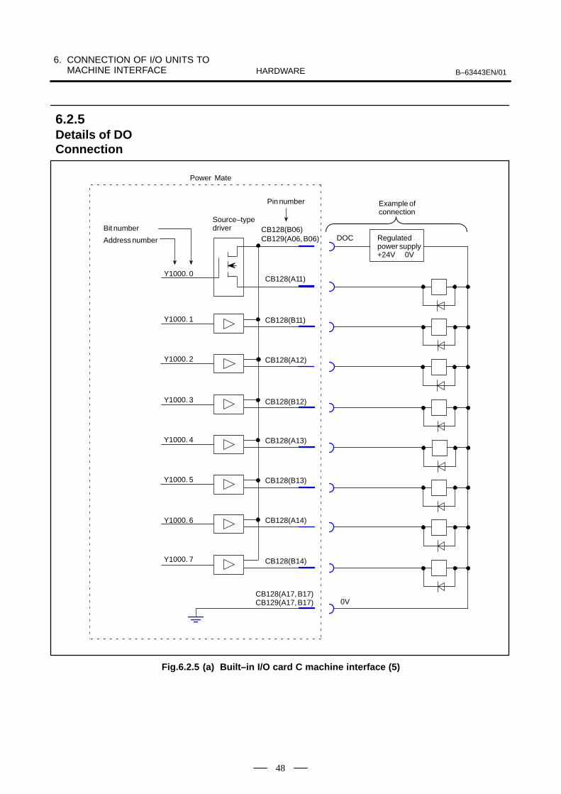
6. CONNECTION OF I/O UNITS TO MACHINE INTERFACE B–63443EN/01HARDWARE
48
CB128(A17, B17)
Power Mate
Example ofconnection
0V
CB128(A11)
CB128(B11)
CB128(A12)
CB128(A13)
CB128(A14)
CB128(B14)
CB128(B12)
CB128(B13)
Y1000. 0
Bit number
Address number
Pin number
Regulatedpower supply+24V 0V
DOCCB128(B06)
Source–typedriver
Y1000. 1
Y1000. 2
Y1000. 3
Y1000. 4
Y1000. 5
Y1000. 6
Y1000. 7
CB129(A06, B06)
CB129(A17, B17)
Fig.6.2.5 (a) Built–in I/O card C machine interface (5)
6.2.5Details of DOConnection
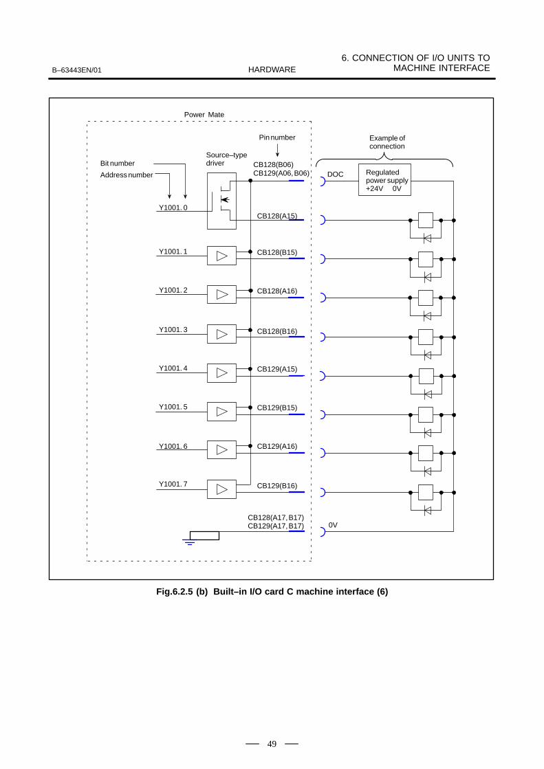
B–63443EN/01
6. CONNECTION OF I/O UNITS TOMACHINE INTERFACEHARDWARE
49
CB129(A17, B17)
Power Mate
Example ofconnection
0V
CB128(A15)
CB128(B15)
CB128(A16)
CB129(A15)
CB129(A16)
CB129(B16)
CB128(B16)
CB129(B15)
Y1001. 0
Bit number
Address number
Pin number
Regulatedpower supply+24V 0V
DOCCB128(B06)
Source–typedriver
Y1001. 1
Y1001. 2
Y1001. 3
Y1001. 4
Y1001. 5
Y1001. 6
Y1001. 7
CB129(A06, B06)
CB128(A17, B17)
Fig.6.2.5 (b) Built–in I/O card C machine interface (6)
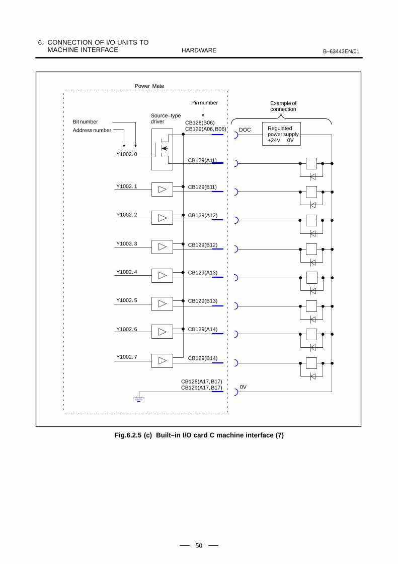
6. CONNECTION OF I/O UNITS TO MACHINE INTERFACE B–63443EN/01HARDWARE
50
CB129(A17, B17)
CB128(B06)
Power Mate
Example ofconnection
0V
CB129(A11)
CB129(B11)
CB129(A12)
CB129(A13)
CB129(A14)
CB129(B14)
CB129(B12)
CB129(B13)
Y1002. 0
Bit number
Address number
Pin number
Regulatedpower supply+24V 0V
DOC
Source–typedriver
Y1002. 1
Y1002. 2
Y1002. 3
Y1002. 4
Y1002. 5
Y1002. 6
Y1002. 7
CB129(A06, B06)
CB128(A17, B17)
Fig.6.2.5 (c) Built–in I/O card C machine interface (7)

B–63443EN/01
6. CONNECTION OF I/O UNITS TOMACHINE INTERFACEHARDWARE
51
This section provides examples of connecting the emergency stop signalinput, skip signal, and reference position return deceleration signal all ofwhich are processed without PMC intervention.See Section 6.2.4 for the connections within the Power Mate 0.
NOTEThe emergency stop signal input is used to stop themachine in the event of an emergency. This signal mustalways be connected to the machine, therefore.
X1000. 2
X1000. 3
X1000. 4
X1000. 5
X1000. 6
X1000. 7
X1000. 1
Filter and level conversion circuit
Power Mate 0
*ESP
Emergencystop signalinput
Skip signal SKIP
DIC
0V
X1000. 0
Bit number
Address number
+24E
*DEC1
Reference positionreturn decelerationsignal input (1st axis)
+24E
Fig.6.3 (a) Example of machine interface (1)
6.3MACHINEINTERFACECONNECTIONEXAMPLES
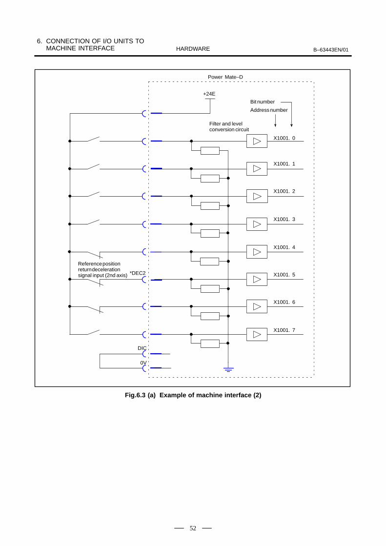
6. CONNECTION OF I/O UNITS TO MACHINE INTERFACE B–63443EN/01HARDWARE
52
X1001. 2
X1001. 3
X1001. 4
X1001. 5
X1001. 6
X1001. 7
X1001. 1
Filter and level conversion circuit
Power Mate–D
DIC
0V
X1001. 0
Bit number
Address number
+24E
*DEC2
Reference positionreturn decelerationsignal input (2nd axis)
Fig.6.3 (a) Example of machine interface (2)

B–63443EN/01 7. CONNECTION TO CNC PERIPHERALSHARDWARE
53
7

7. CONNECTION TO CNC PERIPHERALS B–63443EN/01HARDWARE
54
The Power Mate 0 supports the use of the CRT/MDI.
a) Only one connecting cable is needed between NC and CRT for theCRT interface for Power Mate 0.
b) Maximum total length of the communication cable is 50m.
c) Normally turn on the power for the CRT/MDI before or, at latest,simultaneously when the power for Power Mate control unit is turnedon.
Power source for CRT/MDI
Power source for Power Mate 0 body
ÂÂt t 0.2 sec
If the power for the CRT/MDI is turned on after the power for Power Matebody is turned on, it becomes impossible to execute special operationswhile the power for Power Mate is on such as memory all clear.
d) To enable the use of a CRT/MDI, a CRT control module must beinstalled in the Power Mate.
WARNINGTo have the CRT/MDI approved for the CE marking, it isnecessary to provide a shock hazard prevention cover(A02B–0200–K820). Attaching the cover to the CRT is themachine tool builder’s responsibility.
Power Mate
JD14 JD13
JD15
J45
CRT/MDI
CPD1J30
Terminal unitJN1 FG DC+24V
power source10%1.0A(Stabilized powersource)
NOTE1 Leave rotary switches RSW and MTSW set to 0.2 Connector JN1 of the CRT/MDI is not used.
7.1CRT/MDI INTERFACE
7.1.1General

B–63443EN/01 7. CONNECTION TO CNC PERIPHERALSHARDWARE
55
1 RXD
2 *RXD
3 TXD
4 *TXD
11 0V
12 0V
13
14
5
6
7
8
15
16
17
18
9
10
19
20
Power Mate
JD14
(PCR–EV20MDT)
CRT/MDI
JD13
(PCR–EV20MDT)
Recommended cable:A66L–0001–0284#10P (#28AWG10 ten pairs)
1
2
1
2RXD TXD
3
4
3
4
11
12
11
12
*RXD
TXD
*TXD
0V
0V
*TXD
RXD
*RXD
0V
0V
1 TXD
2 *TXD
3 RXD
4 *RXD
11 0V
12 0V
13
14
5
6
7
8
15
16
17
18
9
10
19
20
J45
JD14 JD13
Recommended connectorPCR–E20FS or PCR–E20FAHousing PCR–V20LA
Shield
NOTELeave unassigned pins open.
7.1.2CRT Interface

7. CONNECTION TO CNC PERIPHERALS B–63443EN/01HARDWARE
56
1 +24V
2 0V
3
CRT/MDI
CPD1
(AMP)
Cable connection (J30)
1
2+24V +24VDC
0V 0V
J30
CPD1
External power source
FG
+24VDCStabilized power source
AMP Japan1–178288–3 (Housing)1–175218–5 (Contact)
Ground for protectionstad (M4)
Recommended cable material 30/0.18 (0.8 mm2) or more
Be sure to connect the protection ground.See Section 5.6.
7.1.3Power Supply Interface

B–63443EN/01 7. CONNECTION TO CNC PERIPHERALSHARDWARE
57
1) The CRT terminating unit (A02B–0124–D001) is designed to enableadjustment of the waveform of a CRT link (RS485). The CRT/MDIunit may operate normally without a CRT terminating unit, providedthe CRT link is short, or if the operating environment is free of noise.For qualitative evaluation, however, always install a CRT terminatingunit prior to shipment. If the CRT terminating unit is not mounted,the CRT screen may not be updated, and the keys may fail to operate.
2) A CRT link is terminated at connector J5 of Power Mate. TheCRT/MDI has a built–in terminating resistor.
CRT/MDIunit
Terminatingresistor
Terminatingunit
PowerMate
CRT link
JD15
3) The CRT/MDI unit terminates the following signals with 200 ohms,1/4 W:
Resistor
Insulating heat–shrinkable tube
NOTEFor A02B–0124–D001, pins other than pin 3 are alsoterminated. This does not affect the Power Mate 0, however.
7.1.4CRT Terminating Unit
7. CONNECTION TO CNC PERIPHERALS B–63443EN/01HARDWARE
58
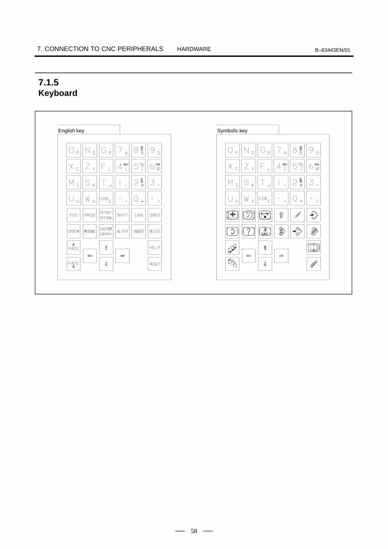
English key Symbolic key
7.1.5Keyboard

B–63443EN/01 7. CONNECTION TO CNC PERIPHERALSHARDWARE
59
To the Power Mate 0, its specific DPL/MDI can be connected. ThisDPL/MDI has a fluorescent character display tube for 2 lines by 16characters. The keys are the same as those of a DPL/MDI for the PowerMate–D, except that they are of a larger design for ease of use.
Power Mate 0
M4
DPL/MDI
CNPR CP1
J181 J30 24–V stabilizedpower supply
NOTE1 Cable J6 can be used as a substitute for cable J181.
The customer can purchase the following cables fromFANUC.A02B–0118–K820 (2m)A02B–0118–K821 (7m)A02B–0118–K822 (14m)
2 When the DPL/MDI and CRT/MDI are connectedsimultaneously, only the DPL/MDI can operate.
3 This DPL/MDI cannot be used as a detachable unit.4 The relative humidity, defined as an installation
environment condition for this DPL/MDI, is 30% to 85%(non–condensing).See Section 3.1 for the other installation environmentconditions.
5 This DPL/MDI differs from a DPL/MDI for the PowerMate–D, long–distance DPL/MDI, or dust–proof DPL/MDI.
7.2CONNECTION WITHTHE DPL/MDI
7.2.1General
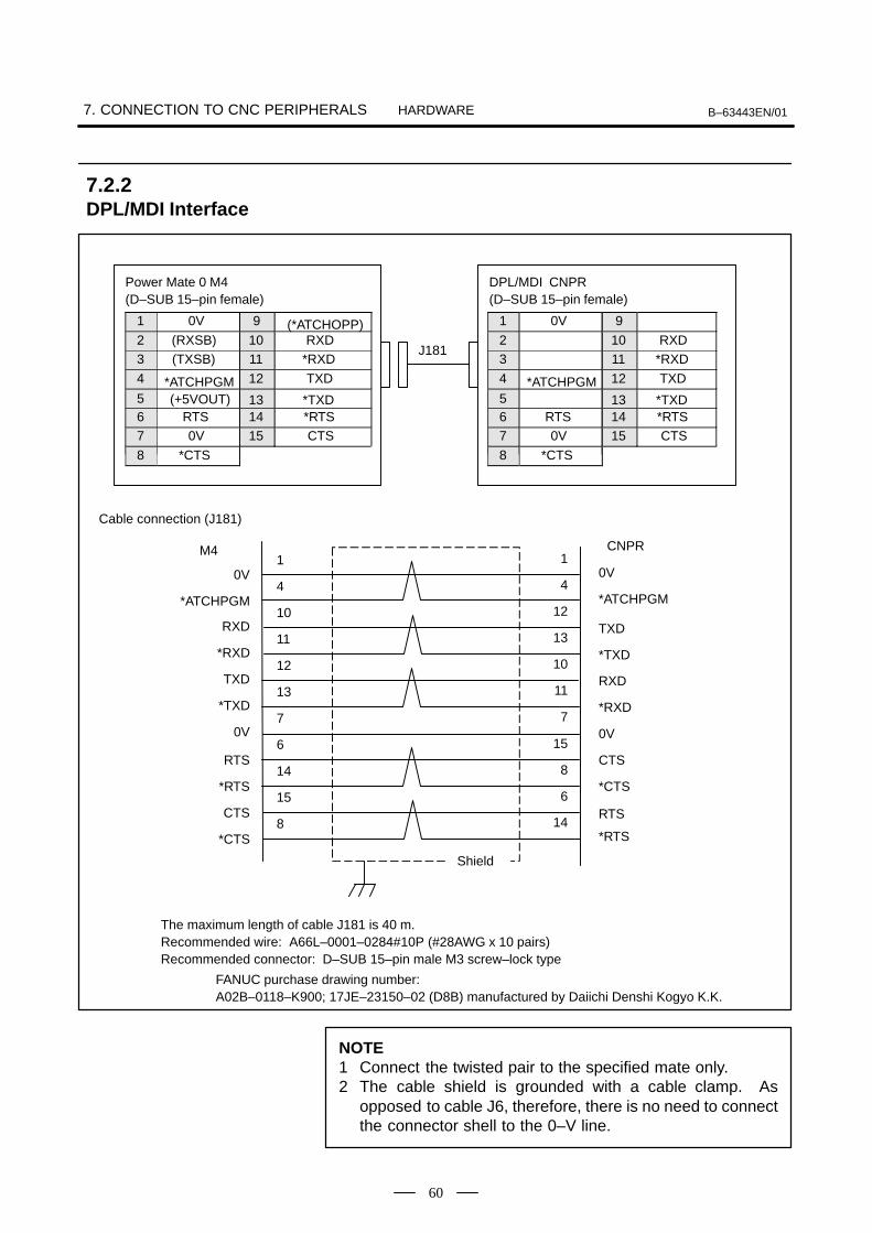
7. CONNECTION TO CNC PERIPHERALS B–63443EN/01HARDWARE
60
The maximum length of cable J181 is 40 m.Recommended wire: A66L–0001–0284#10P (#28AWG x 10 pairs)Recommended connector: D–SUB 15–pin male M3 screw–lock type
J181
Power Mate 0 M4(D–SUB 15–pin female)
1 0V 9 (*ATCHOPP)2 (RXSB) 10 RXD3 (TXSB) 11 *RXD
4 *ATCHPGM 12 TXD
5 (+5VOUT) 13 *TXD6 RTS 14 *RTS7 0V 15 CTS
8 *CTS
DPL/MDI CNPR(D–SUB 15–pin female)
1 0V 9
2 10 RXD3 11 *RXD
4 *ATCHPGM 12 TXD
5 13 *TXD6 RTS 14 *RTS7 0V 15 CTS
8 *CTS
Cable connection (J181)
1
4
10
11
12
13
7
6
14
15
8
M4
0V
*ATCHPGM
RXD
*RXD
TXD
*TXD
0V
RTS
*RTS
CTS
*CTS
Shield
1
4
12
13
10
11
7
15
8
6
14
CNPR
0V
*ATCHPGM
TXD
*TXD
RXD
*RXD
0V
CTS
*CTS
RTS
*RTS
FANUC purchase drawing number: A02B–0118–K900; 17JE–23150–02 (D8B) manufactured by Daiichi Denshi Kogyo K.K.
NOTE1 Connect the twisted pair to the specified mate only.2 The cable shield is grounded with a cable clamp. As
opposed to cable J6, therefore, there is no need to connectthe connector shell to the 0–V line.
7.2.2DPL/MDI Interface

B–63443EN/01 7. CONNECTION TO CNC PERIPHERALSHARDWARE
61
This DPL/MDI operates at an input voltage of 24 VDC. The DPL/MDIand Power Mate use the same power supply cable. (See Section 5.2.)
7.2.3Power Supply Interface
7.2.4Key Sheet

7. CONNECTION TO CNC PERIPHERALS B–63443EN/01HARDWARE
62
The Power Mate 0 has a single–channel RS–232C interface.
(1) RS–232–C interface signal namesGenerally, the RS–232–C interface uses the following signals:
SD (Send data)
RD (Receive data)
RS (Request to send)
CS (Ready for sending)
ER (Equipment ready)
DR (Data set ready)
CD (Signal quality detect)
SG (Signal ground)
FG (Frame ground)
Output
Input
When CS is not used, connect CS to RS.
When DR is not used, connect DR to ER.
Be sure to connect ERwith CD.
Fig.7.3.1(a) RS–232–C interface
7.3I/O DEVICEINTERFACE
7.3.1RS–232–C InterfaceSpecification
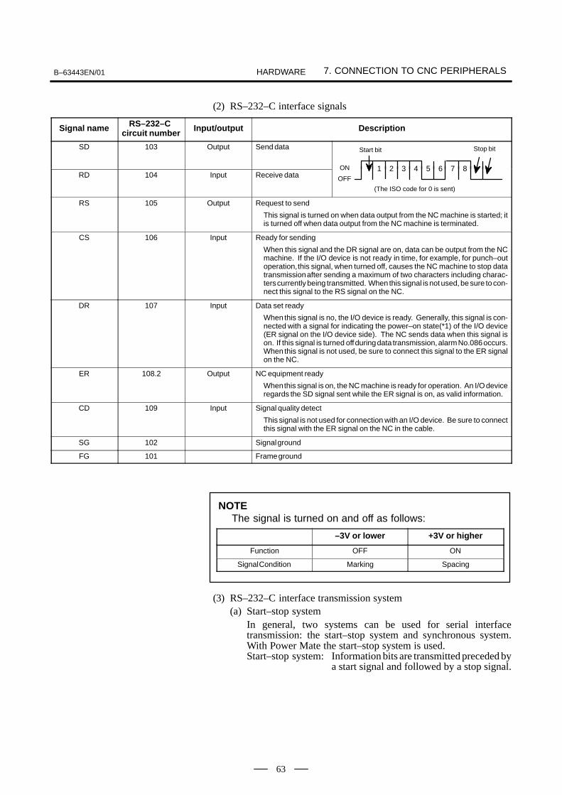
B–63443EN/01 7. CONNECTION TO CNC PERIPHERALSHARDWARE
63
(2) RS–232–C interface signals
Signal name RS–232–C circuit number Input/output Description
SD 103 Output Send data Start bit Stop bit
RD 104 Input Receive data1 2 3 4 5 6 7 8ON
OFF
(The ISO code for 0 is sent)
RS 105 Output Request to send
This signal is turned on when data output from the NC machine is started; itis turned off when data output from the NC machine is terminated.
CS 106 Input Ready for sending
When this signal and the DR signal are on, data can be output from the NCmachine. If the I/O device is not ready in time, for example, for punch–outoperation, this signal, when turned off, causes the NC machine to stop datatransmission after sending a maximum of two characters including charac-ters currently being transmitted. When this signal is not used, be sure to con-nect this signal to the RS signal on the NC.
DR 107 Input Data set ready
When this signal is no, the I/O device is ready. Generally, this signal is con-nected with a signal for indicating the power–on state(*1) of the I/O device(ER signal on the I/O device side). The NC sends data when this signal ison. If this signal is turned off during data transmission, alarm No.086 occurs.When this signal is not used, be sure to connect this signal to the ER signalon the NC.
ER 108.2 Output NC equipment ready
When this signal is on, the NC machine is ready for operation. An I/O deviceregards the SD signal sent while the ER signal is on, as valid information.
CD 109 Input Signal quality detect
This signal is not used for connection with an I/O device. Be sure to connectthis signal with the ER signal on the NC in the cable.
SG 102 Signal ground
FG 101 Frame ground
–3V or lower +3V or higher
Function OFF ON
Signal Condition Marking Spacing
(3) RS–232–C interface transmission system(a) Start–stop system
In general, two systems can be used for serial interfacetransmission: the start–stop system and synchronous system.With Power Mate the start–stop system is used.Start–stop system: Information bits are transmitted preceded by
a start signal and followed by a stop signal.
NOTEThe signal is turned on and off as follows:

7. CONNECTION TO CNC PERIPHERALS B–63443EN/01HARDWARE
64
b1 b2 b3 b4 b5 b6 b7 b8
1 character in the start–stop system
Start bit Information bits(8 bits including a parity bit)
Stop bits(2 bits)
(For bit correspondence information, see the description of the SD andRD signals in ltem 2).
(b) CodesThe following codes are used:i) EIA code + control codes DC1 to DC4ii) ISO code + control codes DC1 to DC4
An I/O device must be able to identify the following controlcodes output from the NC system:
Character 8 7 6 5 4 3 2 1
DC1 Start tape reader °
DC2 Specify tape punch °
DC3 Stop tape reader °
DC4 Release tapepunch
°
NOTEThe control codes above are commonly used regardless ofwhether the EIA code or ISO code is used.
With this interface, control codes DC1 to DC4 are used. Note thefollowing:(a) The NC machine can control an I/O device by sending DC1
to DC4.(b) An I/O device can perform the operations below if it is not
ready to receive data from the NC machine.(i) The I/O device can temporarily stop data transmission
from the NC machine by using the CS signal on the NC.The CS signal, when turned off and sent to the NC machine, causes the NC machine to stop data transmission after sending a maximum of two charactersincluding characters currently being transmitted. Whenthe CS signal is turned on again, data transmission resumes.
(ii) When control code DC3 is sent to the NC machine, theNC machine stops data transmission after sending 10 orless characters. Then, when control code DC1 is sent tothe NC machine, the NC machine resumes data transmission. When an I/O device containing an ISO/EIA converter is used, the device needs to satisfy thespecifications of Table 7.3.1.
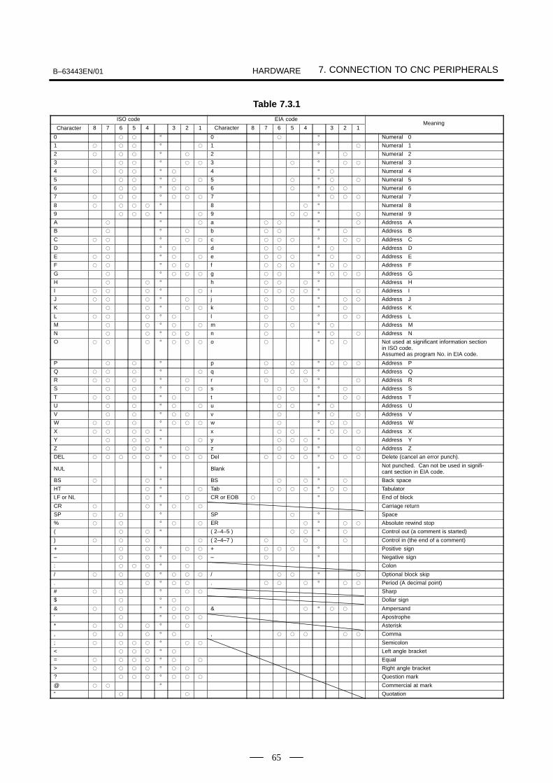
B–63443EN/01 7. CONNECTION TO CNC PERIPHERALSHARDWARE
65
Table 7.3.1
ISO code EIA code
Character 8 7 6 5 4 3 2 1 Character 8 7 6 5 4 3 2 1Meaning
0 ° 0 ° Numeral 0
1 ° 1 ° Numeral 1
2 ° 2 ° Numeral 2
3 ° 3 ° Numeral 3
4 ° 4 ° Numeral 4
5 ° 5 ° Numeral 5
6 ° 6 ° Numeral 6
7 ° 7 ° Numeral 7
8 ° 8 ° Numeral 8
9 ° 9 ° Numeral 9
A ° a ° Address A
B ° b ° Address B
C ° c ° Address C
D ° d ° Address D
E ° e ° Address E
F ° f ° Address F
G ° g ° Address G
H ° h ° Address H
I ° i ° Address I
J ° j ° Address J
K ° k ° Address K
L ° l ° Address L
M ° m ° Address M
N ° n ° Address N
O ° o ° Not used at significant information sectionin ISO code.Assumed as program No. in EIA code.
P ° p ° Address P
Q ° q ° Address Q
R ° r ° Address R
S ° s ° Address S
T ° t ° Address T
U ° u ° Address U
V ° v ° Address V
W ° w ° Address W
X ° x ° Address X
Y ° y ° Address Y
Z ° z ° Address Z
DEL ° Del ° Delete (cancel an error punch).
NUL ° Blank ° Not punched. Can not be used in signifi-cant section in EIA code.
BS ° BS ° Back space
HT ° Tab ° Tabulator
LF or NL ° CR or EOB ° End of block
CR ° Carriage return
SP ° SP ° Space
% ° ER ° Absolute rewind stop
( ° ( 2–4–5 ) ° Control out (a comment is started)
) ( 2–4–7 ) Control in (the end of a comment)
+ ° + ° Positive sign
– ° – ° Negative sign
: ° Colon
/ ° / ° Optional block skip
. ° . ° Period (A decimal point)
# ° Sharp
$ ° Dollar sign
& ° & ° Ampersand
’ ° Apostrophe
* ° Asterisk
, ° , Comma
; ° Semicolon
< ° Left angle bracket
= ° Equal
> ° Right angle bracket
? ° Question mark
@ ° Commercial at mark
” Quotation

7. CONNECTION TO CNC PERIPHERALS B–63443EN/01HARDWARE
66
NOTEWhen an I/O device containing an ISO/EIA converter isused, pay special attention to the following in Table 7.3.1.
EIA code
ISO code
Control–out (start of a comment)
Control–in (end of a comment)
Condition 1
( ............... )
( ............... )
Condition 1 Condition 3
CR
LF
Condition 2
O
: ...............
...............
Condition 1 In the EIA code, a card punched at bits 2, 4, and 5corresponds to the ISO code for the left parenthesis“(.” A card punched at bits 2, 4, and 7 correspondsto the ISO code for the right parenthesis “).”
Condition 2 The EIA code for O is converted to the ISO codefor the colon (:).
Condition 3 The EIA code for CR is converted to the ISO code
for LF .
NOTEControl codes DC1 to DC4 are transmission codes outputfrom the NC machine, and need not be fed as paper tapeinformation.
(iii) Transmission rate (baud rate)The transmission rate (baud rate) indicates the numberof bits sent per second. One of the following baud ratescan be selected by parameter setting:
600, 1200, 2400, 4800, 9600Example: When 4800 baud is used
Assuming that 1 start bit and 2 stop bits are used(11 bits/character).Then,
Number of transmission characters per second=4800/11 characters per second (maximum)
(iv) Cable lengthThe cable length varies from one I/O device to another.For the required cable length, consult with each I/O device supplier.

B–63443EN/01 7. CONNECTION TO CNC PERIPHERALSHARDWARE
67
(1) The NC machine sends a DC1 code.
(2) Upon receipt of the DC1 code, the I/O device starts data transmissionto the NC machine.
(3) While the NC machine is processing, it sends a DC3 code.
(4) Upon receipt of the DC3 code, the I/O device stops data transmissionto the NC machine.When the DC3 code is sent, the I/O device is to stop data transmissionafter sending 10 or less characters. If more than 10 characters are sent,alarm no.087 occurs.
(5) The NC machine sends another DC1 code when its processing iscompleted.
(6) Upon receipt of the DC1 code, the I/O device resumes datatransmission to the NC machine in order to send the remaining data.
(7) Upon completion of data read operation, the NC machine sendsanother DC3 code.
(8) The I/O device stops data transmission.
1ms or more
10ms or more
ER (output)
RS (output)
SD (output)
RD (input)
DR (input)
CS (input)
ÅÅÅÅ
DC1
ÅÅÅÅÅÅ
ÅÅÅÅ
DC3ÅÅÅÅ
DC1
ÅÅÅÅÅÅÅÅÅÅÅÅ
ÅÅÅÅ
DC3
100ms or more
10 or less characters
ER code
Fig.7.3.1(b)
When the NC receivesdata (for reading intomemory)
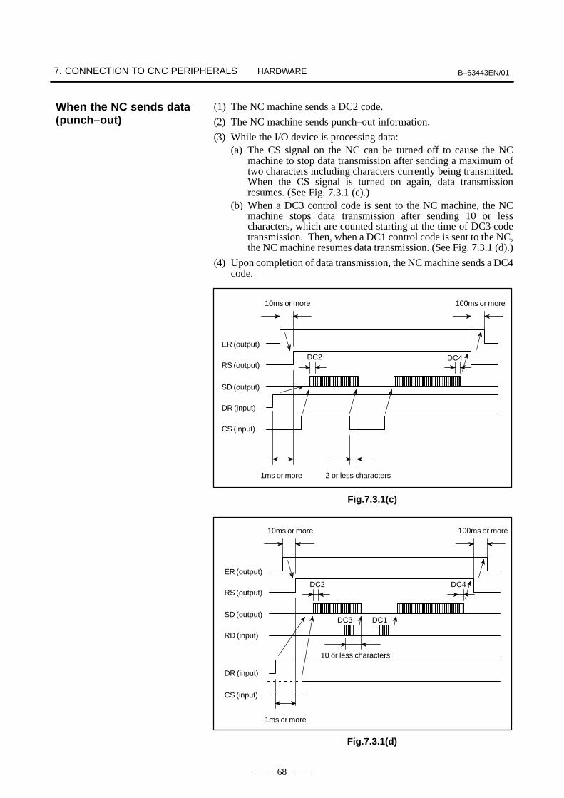
7. CONNECTION TO CNC PERIPHERALS B–63443EN/01HARDWARE
68
(1) The NC machine sends a DC2 code.
(2) The NC machine sends punch–out information.
(3) While the I/O device is processing data:(a) The CS signal on the NC can be turned off to cause the NC
machine to stop data transmission after sending a maximum oftwo characters including characters currently being transmitted.When the CS signal is turned on again, data transmissionresumes. (See Fig. 7.3.1 (c).)
(b) When a DC3 control code is sent to the NC machine, the NCmachine stops data transmission after sending 10 or lesscharacters, which are counted starting at the time of DC3 codetransmission. Then, when a DC1 control code is sent to the NC,the NC machine resumes data transmission. (See Fig. 7.3.1 (d).)
(4) Upon completion of data transmission, the NC machine sends a DC4code.
1ms or more
10ms or more
ER (output)
RS (output)
SD (output)
DR (input)
CS (input)
ÅÅÅÅÅÅÅÅ
DC2
ÅÅÅÅÅÅÅÅÅÅ
DC4
100ms or more
2 or less characters
Fig.7.3.1(c)
1ms or more
10ms or more
ER (output)
RS (output)
SD (output)
RD (input)
DR (input)
CS (input)
ÅÅ
DC1
100ms or more
10 or less characters
ÅÅÅÅÅÅÅÅ
DC2
ÅÅÅÅÅÅÅÅÅÅ
DC4
ÅÅÅÅDC3
Fig.7.3.1(d)
When the NC sends data(punch–out)

B–63443EN/01 7. CONNECTION TO CNC PERIPHERALSHARDWARE
69
(5) Connecting the RS–232–C interface with an I/O device
NCSD
RD
RS
CS
ER
DR
CD
SG
FG
SD
RD
RS
CS
ER
DR
CD
SG
FG
I/O device

7. CONNECTION TO CNC PERIPHERALS B–63443EN/01HARDWARE
70
1 RD
2 0V
3 DR
4 0V
11 SD
12 0V
13 ER
14 0V
5 CS
6 0V
7 CD
8 0V
15 RS
16 0V
17
18
9 19 +24V
Power Mate
(PCR-EV20MDT)
Relay connector
(DBM–25S)
Cable wiring J42
Recommended cable material A66L–0001–0284#10P (#28AWG10–pair) (line length: 15m or less)
10 +24V 20
1 FG
2 SD
3 RD
4 RS
5 CS
6 DR
7 SG
8 CD
9
10
11
12
13
14
15
16
17
18
19
20 ER
21
22
23
24
25 +24V
1
2
3RD
0V
RD
3
4
6DR
0V
DR
5
6
5CS
0V
CS
7
8
8CD
0V
CD
9
10
SD
0V
SD11
12
2
ER
0V
ER13
14
20
RS
0V
RS
SG
15
16
4
7
17
18
24V +24V
+24V
19
20
25
1
Shield
ConnectorPCR–E20FAorPCR–E20FSCase: PCR–V20CA
Power Mate Relay connector
J42
FG
7.3.2RS–232–C Serial Port

B–63443EN/01 7. CONNECTION TO CNC PERIPHERALSHARDWARE
71
1
FG SD RD RS CS DR SG CD
2 3 4 5 6 7 8 9 10 11 12 13
14 15 16 17 18 19 20 21 22 23 24 25
ER +24
1 RD
2 0V
3 DR
4 0V
11 SD
12 0V
13 ER
14 0V
5 CS
6 0V
7
8 0V
15 RS
16 0V
17
18
9 19 +24V
Power Mate
JD5
(PCR-EV20MDT)
10 +24V 20
FG
FANUCFLOPPYCASSETTE/Handy File
Relayingcable
Relaying connectorConnector : DBM-25S
(JAPAN AVIATION ELECTRONIC INDUSTRY., LTD.)
Lock metal : D20418-J2(JAPAN AVIATIONELECTRONIC INDUSTRY., LTD.)
Cable side connectorConnector : DBM-25P
(JAPAN AVIATION ELECTRONIC INDUSTRY., LTD.)Lock metal : DDB–C2–J9
(JAPAN AVIATION ELECTRONIC INDUSTRY., LTD.)
Appendant
Relaying connector signal layout
!
24VDC10%1.0A(Including aninstanta-neous andripple value)
CD
NOTE1 Machine tool builder shall furnish relay connector and relay
cable.2 Use a totally shielded cable for the signal cable.
Recommended cable specification : A66L-0001-0284#10P(Line length : 15m or less)
3 Open all terminals other than illustrated.4 Set a parameter to be able to use reader puncher interface
when connecting FANUC Handy File.5 The Power Mate can be used to route 24 VDC power to the
FANUC Handy File. In this case, additional 24 VDC (1.0 A)power needs to be fed to the Power Mate.
7.3.3FANUC Handy FileConnection

7. CONNECTION TO CNC PERIPHERALS B–63443EN/01HARDWARE
72
1
FG SD RD RS CS DR SG CD
2 3 4 5 6 7 8 9 10 11 12 13
14 15 16 17 18 19 20 21 22 23 24 25
ER +24
1 RD
2 0V
3 DR
4 0V
11 SD
12 0V
13 ER
14 0V
5 CS
6 0V
7
8 0V
15 RS
16 0V
17
18
9 19 (+24V)
Power Mate
JD5
(PCR-EV20MDT)
10 (+24V) 20
FG
FANUCFLOPPYCASSETTE/Handy File
Relayingcable
Relaying connectorConnector : DBM-25S
(JAPAN AVIATION ELECTRONIC INDUSTRY., LTD.)
Lock metal : D20418-J2(JAPAN AVIATIONELECTRONIC INDUSTRY., LTD.)
Cable side connectorConnector : DBM-25P
(JAPAN AVIATION ELECTRONIC INDUSTRY., LTD.)Lock metal : DDB–C2–J9
(JAPAN AVIATION ELECTRONIC INDUSTRY., LTD.)
Appendant
Relaying connector signal layout
!" #
$% &$$'
+24VDC10%1.0A
! ( )*
CD
NOTE1 Machine tool builder shall furnish relay connector, relay
cable and 24VDC.2 Use a totally shielded cable for the signal cable.
Recommended cable specification : A66L-0001-0284#10P(Line length : 15m or less)
3 Open all terminals other than illustrated.4 Set a parameter to be able to use reader puncher interface
when connecting FANUC Handy File.5 If 24 VDC power is supplied to the FANUC Handy File from
another power supply, 24 VDC (1.0 A) power for FANUC I/Odevices need not be fed to the Power Mate.
7.3.4When External PowerSupply is Used

B–63443EN/01 7. CONNECTION TO CNC PERIPHERALSHARDWARE
73
A manual pulse generator interface for one axis is provided. Whether thismanual pulse generator interface is used for the first or second axis canbe selected by the PMC.
CNC
Cable wiring J41
HA1
2 HB1
3
4
1111
1212 0V
1313
1414 0V
5
6
7
8
1515
1616 0V
1717
1818 +5V
9 +5V 1919
JA13
(PCR-EV20MDT)
1010 2020 +5V
MPG
+5V
+5V 0V HA1 HB1
0V A1
MPG unit #1
(M3 screw terminal)
B
1
2
A
BHA1
HB1
HA1
HB19
12
+5V
0V+5V
0V
+5V
0V
Shield
#24AWG
#20AWG
J41
Connector FI40–20I5SCase FI–20–CV
Recommended cable:A66L–0001–0286 (6 pairs of #20AWG wires and 3 pairs of #24AWGwires)
Recommended connector:A02B–0120–K303 (such as the following connector and its housing)(Connector:Soldering–type FI40–2015S, manufactured by HiroseElectric Co., Ltd.)(Housing:FI–20–CV, manufactured by Hirose Electric Co., Ltd.)
7.4MANUAL PULSE GENERATORINTERFACE
7.4.1Overview
7.4.2Interface

L
30.0394
76.75[m]
7. CONNECTION TO CNC PERIPHERALS B–63443EN/01HARDWARE
74
Recommended cables: A02B–0124–K821 (7m) (for connecting one manual pulse generator)(This cable is that used between the JA47 connector and the connectorpanel.)
The manual pulse generator cable can be up to 50 m in length.The power supply to the manual pulse generator is 5 VDC, same as forthe pulse coder. It is therefore necessary to prevent cable resistance fromcausing the supply voltage to drop more than 0.2 V (total for both the 0V and 5 V lines).This is written as:
0.2 0.1 R 2L
m
0.1 : 0.1 A power supply current of the manual pulse generator
R : Resistance per unit length of the wire (Ω/m)
m : Number of wires connected in each 0 V and 5 V line
L : Wire length (m)
This can be converted to the following equation:L
mR
In the case of the A66L–0001–0286 cable, for example, when three pairsof signal wires and six power supply wires (20/0.18, 0.0394 /m) areused (three power supply wires connected to 5 V and the other three to 0V when one manual pulse generator is used), the cable length is:
However, the maximum pulse transmission distance for the manual pulsegenerator is 50 m.
The relationship between the HAn and HBn signals and the Power Matepulses shall be as shown in Fig. 7.4.3 (a).Pulse cycle T1 shall be 200 sec or more. Pulse cycle T1/4 shall be 50 secor more.
t1
HAn
HBn
T14
T1 T14 4
T1
– direction pulse
+ direction pulse
Forward rotation
Click pointReverse direction
Backward rotation
Fig. 7.4.3 (a)
7.4.3Cable Connection forthe Manual PulseGenerator
Pulse width

B–63443EN/01 7. CONNECTION TO CNC PERIPHERALSHARDWARE
75
A circuit configuration shown in Fig. 7.4.3 (b) is recommended for theoutput signals of the manual pulse generator.
Recommended circuit
VCC
to CNC
0V
300
Fig. 7.4.3 (b)
Input signal level change point (threshold)When the voltage is 3.7 V or higher, the input signal level changesfrom low to high.When the voltage is 1.5 V or lower, the input signal level changes fromhigh to low.
[Forward movement command] [Backward movement command]
HA1
HB1
HA1
HB1
HA1
HB1
HA1
HB1
[The following two cases are not assumed as command pulses.]
Recommended outputsignal circuit
Voltage of threshold ofreceiver for Power Mate
Signal logics
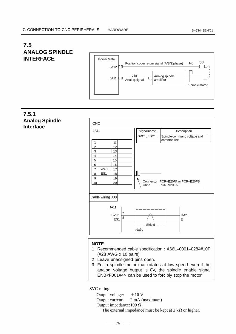
7. CONNECTION TO CNC PERIPHERALS B–63443EN/01HARDWARE
76
+
Analog spindle amplifier
Spindle motor
Position coder return signal (A/B/Z phase)
Analog signal
Power Mate
JA12
JA11J38
J40
Spindle command voltage andcommon line
CNC
JA11
SVC1, ESC1
Cable wiring J38
Signal name Description
1
32
4
65
SVC1
87
ES1
910
11
1312
14
1615
1817
1920 Connector PCR–E20FA or PCR–E20FS
Case PCR–V20LA
78
DA2E
SVC1ES1
Shield
JA11
NOTE1 Recommended cable specification : A66L–0001–0284#10P
(#28 AWG x 10 pairs)2 Leave unassigned pins open.3 For a spindle motor that rotates at low speed even if the
analog voltage output is 0V, the spindle enable signalENB<F001#4> can be used to forcibly stop the motor.
SVC ratingOutput voltage: 10 VOutput current: 2 mA (maximum)Output impedance:100 Ω
The external impedance must be kept at 2 kΩ or higher.
7.5ANALOG SPINDLE INTERFACE
7.5.1Analog SpindleInterface

B–63443EN/01 7. CONNECTION TO CNC PERIPHERALSHARDWARE
77
*SC
1
3
SC2
PA4
65
*PAPB
87
*PB9 +5V10
0V
11
1312
14
16
0V15
0V
1817
+5V
+5V1920
Description
Position coder A–phase signal
Position coder C–phasesignal
CNC
JA12 Name
PA, *PA
SC, *SC
5678129,18,2012,14,1634
A(PA)N(*PA)C(PB)R(*PB)B(PZ)P(*PZ)HK
PA*PAPB
*PBSC
*SC+5V
0VSOUT
*SOUTSHIELD
CNCPOSITION CODER
Recommended cable material
A66L–0001–0286 (#20AWG+6×#24AWG×3 pairs) MAX LENGTH 20m.
Position coder B–phasesignal
PB, *PB
Cable wiring J40
Connector FI40–20I5SCase FI–20–CV
#24AWG
#20AWG
3Pairs
NOTELeave unassigned pins open.
7.5.2Position CoderInterface

7. CONNECTION TO CNC PERIPHERALS B–63443EN/01HARDWARE
78
The servo interface has these features.
Digital control AC servo motor
Motor feedback : Serial pulse coder
n=Axis number
Power Mate
JSn JSnB
JFn
β series servoamplifierJ93
J94
7.6SERVO INTERFACE
7.6.1Outline
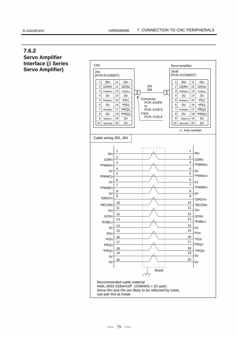
B–63443EN/01 7. CONNECTION TO CNC PERIPHERALSHARDWARE
79
1 IRn2 GDRn3 *PWMAn
4 0V
11 ISn12 GDSn13 *ENBLn
14 0V5 *PWMCn
6 0V7 *PWMEn
8 0V
15 PD116 *PD117 PRQ118 *PRQ1
9 19
JSn(PCR-EV20MDT)
10 *MCONn 20
CNC
n : Axis number
Servo amplifier
JSnB(PCR–EV20MDT)
1
2
1
2IRn
GDRn
IRn
GDRn3
4
3
4*PWMAn
0V
*PWMAn
0V5
6
5
6*PWMCn
0V
*PWMCn
0V7
8
7
8*PWMEn
0V
*PWMEn
0V
10 10*MCONn *MCONn
11
12
11
12ISn
GDSn
ISn
GDSn
Shield
13
14
13
14*ENBLn
0V
*ENBLn
0V15
16
15
16PDn
*PDn
PDn
*PDn17
18
17
18PRQn
0V
PRQn
*PRQn
200V
0V
0V20
Recommended cable materialA66L-0001-0284#10P (#28AWG10–pair)Since IRn and ISn are likely to be reflected by noise,use pair line at inside
1 IRn2 GDRn3 *PWMAn
4 0V
11 ISn12 GDSn13 *ENBLn
14 0V5 *PWMCn
6 0V7 *PWMEn
8 0V
15 PD116 *PD117 PRQ118 *PRQ1
9 19
10 *MCONn 20
*DRDYn*DRDYn 0V0V
0V0V
*DRDYn
*PRQn
9 9
19 19
*DRDYn
Cable wiring J93, J94
ConnectorPCR–E20FAorPCR–E20FS
CasePCR–V20LA
J93J94
7.6.2Servo AmplifierInterface (β SeriesServo Amplifier)

II PMC INTERFACE

B–63443EN/01 1. ADDRESS LISTPMC INTERFACE
83
1 ADDRESS LIST
Address of interface signals between Power Mate and PLC.
Power Mate
G000 orlater PMC
F000 orlater
X1000 orlater MT
Y1000 orlater

1. ADDRESS LIST B–63443EN/01PMC INTERFACE
84
Address Bit No.#7 #6 #5 #4 #3 #2 #1 #0
X1000 SKIP *DEC1 *ESP
X1001 *DEC2
1.1Power Mate 0
MT PMC
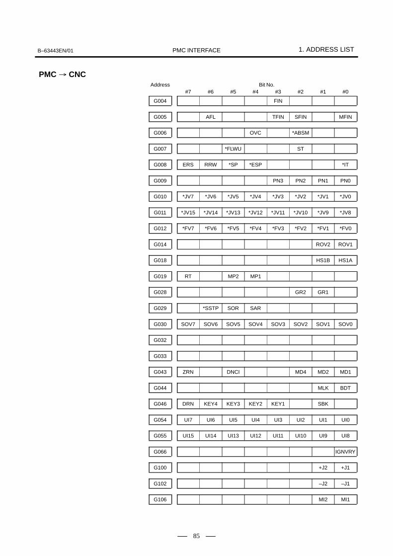
B–63443EN/01 1. ADDRESS LISTPMC INTERFACE
85
Address Bit No.#7 #6 #5 #4 #3 #2 #1 #0
G004 FIN
G005 AFL TFIN SFIN MFIN
G006 OVC *ABSM
G007 *FLWU ST
G008 ERS RRW *SP *ESP *IT
G009 PN3 PN2 PN1 PN0
G010 *JV7 *JV6 *JV5 *JV4 *JV3 *JV2 *JV1 *JV0
G011 *JV15 *JV14 *JV13 *JV12 *JV11 *JV10 *JV9 *JV8
G012 *FV7 *FV6 *FV5 *FV4 *FV3 *FV2 *FV1 *FV0
G014 ROV2 ROV1
G018 HS1B HS1A
G019 RT MP2 MP1
G028 GR2 GR1
G029 *SSTP SOR SAR
G030 SOV7 SOV6 SOV5 SOV4 SOV3 SOV2 SOV1 SOV0
G032
G033
G043 ZRN DNCI MD4 MD2 MD1
G044 MLK BDT
G046 DRN KEY4 KEY3 KEY2 KEY1 SBK
G054 UI7 UI6 UI5 UI4 UI3 UI2 UI1 UI0
G055 UI15 UI14 UI13 UI12 UI11 UI10 UI9 UI8
G066 IGNVRY
G100 +J2 +J1
G102 –J2 –J1
G106 MI2 MI1
PMC CNC

1. ADDRESS LIST B–63443EN/01PMC INTERFACE
86
Address Bit No.#7 #6 #5 #4 #3 #2 #1 #0
G126 SVF2 SVF1
G130 *IT2 *IT1

B–63443EN/01 1. ADDRESS LISTPMC INTERFACE
87
Address Bit No.#7 #6 #5 #4 #3 #2 #1 #0
F000 OP SA STL SPL RWD
F001 MA ENB DEN BAL RST AL
F002 CUT THRD CSS
F003 MEDT MMEM MRMT MMDI MJ MH
F004 MZRN
F007 TF SF MF
F010 M07 M06 M05 M04 M03 M02 M01 M00
F011 M15 M14 M13 M12 M11 M10 M09 M08
F012 M23 M22 M21 M20 M19 M18 M17 M16
F013 M31 M30 M29 M28 M27 M26 M25 M24
F022 S07 S06 S05 S04 S03 S02 S01 S00
F023 S15 S14 S13 S12 S11 S10 S09 S08
F024 S23 S22 S21 S20 S19 S18 S17 S16
F025 S31 S30 S29 S28 S27 S26 S25 S24
F026 T07 T06 T05 T04 T03 T02 T01 T00
F027 T15 T14 T13 T12 T11 T10 T09 T08
F028 T23 T22 T21 T20 T19 T18 T17 T16
F029 T31 T30 T29 T28 T27 T26 T25 T24
F036 R08O R07O R06O R05O R04O R03O R02O R01O
F037 R12O R11O R10O R09O
F054 UO7 UO6 UO5 UO4 UO3 UO2 UO1 UO0
F055 UO15 UO14 UO13 UO12 UO11 UO10 UO9 UO8
F056 UO107 UO106 UO105 UO104 UO103 UO102 UO101 UO100
F057 UO115 UO114 UO113 UO112 UO111 UO110 UO109 UO108
F058 UO123 UO122 UO121 UO120 UO119 UO118 UO117 UO116
F059 UO131 UO130 UO129 UO128 UO127 UO126 UO125 UO124
CNC PMC
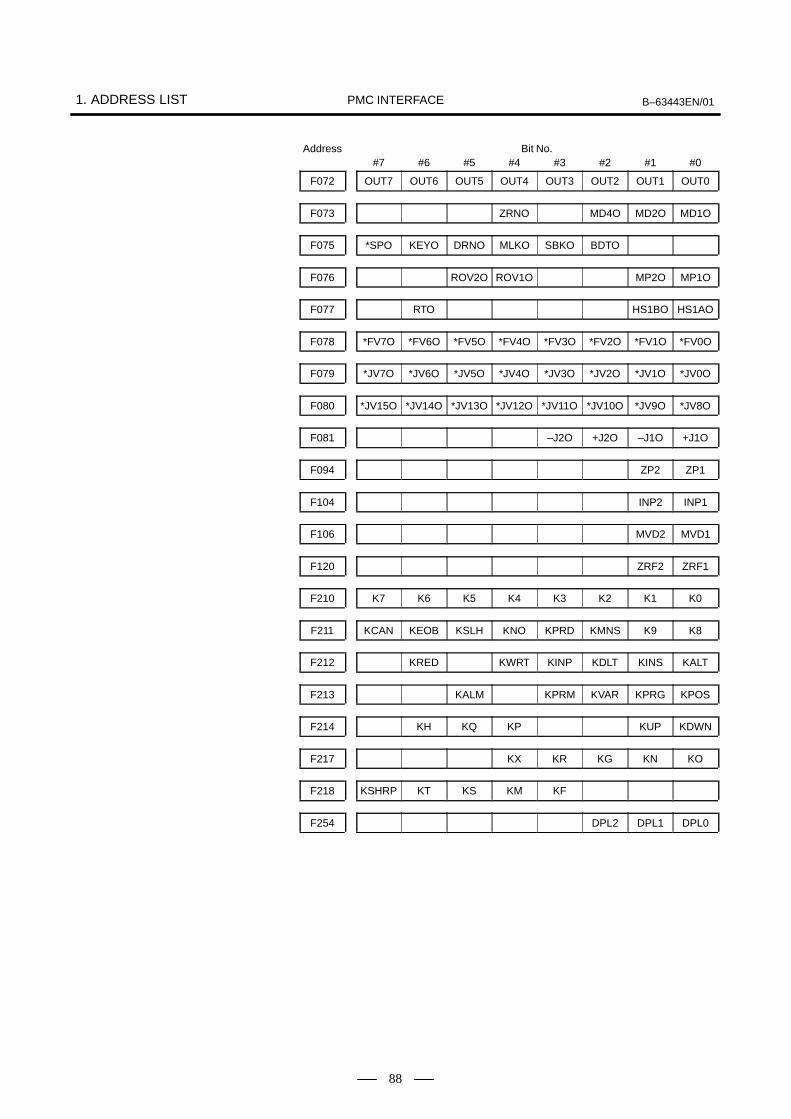
1. ADDRESS LIST B–63443EN/01PMC INTERFACE
88
Address Bit No.#7 #6 #5 #4 #3 #2 #1 #0
F072 OUT7 OUT6 OUT5 OUT4 OUT3 OUT2 OUT1 OUT0
F073 ZRNO MD4O MD2O MD1O
F075 *SPO KEYO DRNO MLKO SBKO BDTO
F076 ROV2O ROV1O MP2O MP1O
F077 RTO HS1BO HS1AO
F078 *FV7O *FV6O *FV5O *FV4O *FV3O *FV2O *FV1O *FV0O
F079 *JV7O *JV6O *JV5O *JV4O *JV3O *JV2O *JV1O *JV0O
F080 *JV15O *JV14O *JV13O *JV12O *JV11O *JV10O *JV9O *JV8O
F081 –J2O +J2O –J1O +J1O
F094 ZP2 ZP1
F104 INP2 INP1
F106 MVD2 MVD1
F120 ZRF2 ZRF1
F210 K7 K6 K5 K4 K3 K2 K1 K0
F211 KCAN KEOB KSLH KNO KPRD KMNS K9 K8
F212 KRED KWRT KINP KDLT KINS KALT
F213 KALM KPRM KVAR KPRG KPOS
F214 KH KQ KP KUP KDWN
F217 KX KR KG KN KO
F218 KSHRP KT KS KM KF
F254 DPL2 DPL1 DPL0

B–63443EN/01 2. SIGNAL LISTPMC INTERFACE
89
2

2. SIGNAL LIST B–63443EN/01PMC INTERFACE
90
NOTEThe following symbols indicate whether each function in thefollowing table is usable with the 1–path Power Mate–D,2–path Power Mate–D, and Power Mate–F. : The function can be used. : The function can be used with an axis of each path of
the Power Mate–D, and with the first axis of the PowerMate–F.
: The function cannot be used.
Signaldirection
Group Signal name Symbol (address) CNC↓
PMC
CNC↑
PMC
Reference
1 CNC ready signal MA (F001#7) 3.1
Servo ready signal SA (F000#6) 3.2
2 Emergency stop signal ESP (G008#4, X1000#4) 4.1
External reset signal ERS (G008#7) 4.2
Reset & rewind signal RRW (G008#6) 4.3
3 Alarm signal AL (F001#0) 5.1
Battery alarm signal BAL (F001#2) 5.2
Reset signal RST (F001#1) 5.3
Rewinding signal RWD (F000#0) 5.4
Moving direction signals MVD1 (F106#0), MVD2 (F106#1) 5.5
In–position signals INP1 (F104#0), INP2 (F104#1) 5.6
Threading signal THRD (F002#3) 5.7
4 Mode select signal MD1 (G043#0), MD2 (G043#1), MD4 (G043#2)
6.1
DNC operation signal DNCI (G043#5) 6.2
Manual data input (MDI) check signal MMDI (F003#3) 6.3
Automatic operation (MEM) check signal M,, (F003#5) 6.3
Tape command (RMT) check signal MRMT (F003#4) 6.3
Memory edit (EDIT) check signal MEDT (F003#6) 6.3
Manual handle step feed (HANDLE/STEP)check signal
MH (F003#1) 6.3
Jog feed (JOG) check signal MJ (F003#2) 6.3
Manual reference position return check sig-nal
M-. (F004#) 6.3
2.1I/O SIGNAL LIST(ORDER OF GROUP)
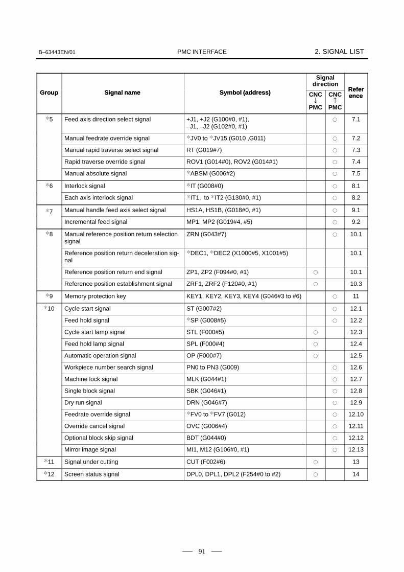
B–63443EN/01 2. SIGNAL LISTPMC INTERFACE
91
Group Reference
Signaldirection
Symbol (address)Signal nameGroup ReferenceCNC
↑PMC
CNC↓
PMC
Symbol (address)Signal name
5 Feed axis direction select signal +J1, +J2 (G100#0, #1), –J1, –J2 (G102#0, #1)
7.1
Manual feedrate override signal JV0 JV15 (G010 ,G011) 7.2
Manual rapid traverse select signal RT (G019#7) 7.3
Rapid traverse override signal ROV1 (G014#0), ROV2 (G014#1) 7.4
Manual absolute signal ABSM (G006#2) 7.5
6 Interlock signal IT (G008#0) 8.1
Each axis interlock signal IT1, IT2 (G130#0, #1) 8.2
7 Manual handle feed axis select signal HS1A, HS1B, (G018#0, #1) 9.1
Incremental feed signal MP1, MP2 (G019#4, #5) 9.2
8 Manual reference position return selectionsignal
ZRN (G043#7) 10.1
Reference position return deceleration sig-nal
DEC1, DEC2 (X1000#5, X1001#5) 10.1
Reference position return end signal ZP1, ZP2 (F094#0, #1) 10.1
Reference position establishment signal ZRF1, ZRF2 (F120#0, #1) 10.3
9 Memory protection key KEY1, KEY2, KEY3, KEY4 (G046#3 #6) 11
10 Cycle start signal ST (G007#2) 12.1
Feed hold signal SP (G008#5) 12.2
Cycle start lamp signal STL (F000#5) 12.3
Feed hold lamp signal SPL (F000#4) 12.4
Automatic operation signal OP (F000#7) 12.5
Workpiece number search signal PN0 PN3 (G009) 12.6
Machine lock signal MLK (G044#1) 12.7
Single block signal SBK (G046#1) 12.8
Dry run signal DRN (G046#7) 12.9
Feedrate override signal FV0 FV7 (G012) 12.10
Override cancel signal OVC (G006#4) 12.11
Optional block skip signal BDT (G044#0) 12.12
Mirror image signal MI1, M12 (G106#0, #1) 12.13
11 Signal under cutting CUT (F02#6) 13
12 Screen status signal DPL0, DPL1, DPL2 (F254#0 #2) 14
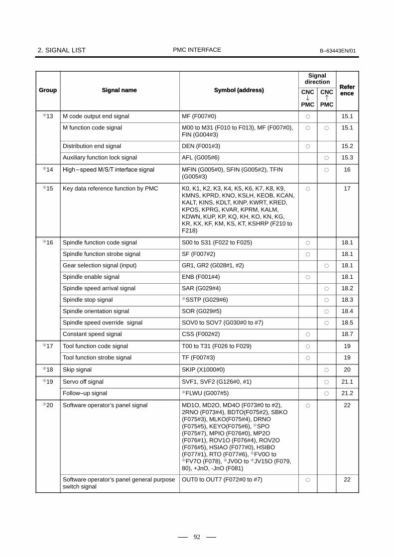
2. SIGNAL LIST B–63443EN/01PMC INTERFACE
92
Group Reference
Signaldirection
Symbol (address)Signal nameGroup ReferenceCNC
↑PMC
CNC↓
PMC
Symbol (address)Signal name
13 M code output end signal MF (F007#0) 15.1
M function code signal M00 M31 (F010 F013), MF (F007#0),FIN (G004#3)
15.1
Distribution end signal DEN (F001#3) 15.2
Auxiliary function lock signal AFL (G005#6) 15.3
14 /01 $ ,++2 3 0 MFIN (G005#0), SFIN (G005#2), TFIN(G005#3)
16
15 Key data reference function by PMC K0, K1, K2, K3, K4, K5, K6, K7, K8, K9,KMNS, KPRD, KNO, KSLH, KEOB, KCAN,KALT, KINS, KDLT, KINP, KWRT, KRED,KPOS, KPRG, KVAR, KPRM, KALM,KDWN, KUP, KP, KQ, KH, KO, KN, KG,KR, KX, KF, KM, KS, KT, KSHRP (F210
F218)
17
16 Spindle function code signal S00 S31 (F022 F025) 18.1
Spindle function strobe signal SF (F007#2) 18.1
Gear selection signal (input) GR1, GR2 (G028#1, #2) 18.1
Spindle enable signal ENB (F001#4) 18.1
Spindle speed arrival signal SAR (G029#4) 18.2
Spindle stop signal SSTP (G029#6) 18.3
Spindle orientation signal SOR (G029#5) 18.4
Spindle speed override signal SOV0 SOV7 (G030#0 #7) 18.5
Constant speed signal CSS (F002#2) 18.7
17 Tool function code signal T00 T31 (F026 F029) 19
Tool function strobe signal TF (F007#3) 19
18 Skip signal SKIP (X1000#0) 20
19 Servo off signal SVF1, SVF2 (G126#0, #1) 21.1
Follow–up signal FLWU (G007#5) 21.2
20 Software operator’s panel signal MD1O, MD2O, MD4O (F073#0 #2),2RNO (F073#4), BDTO(F075#2), SBKO(F075#3), MLKO(F075#4), DRNO(F075#5), KEYO(F075#6), SPO(F075#7), MPIO (F076#0), MP2O(F076#1), ROV1O (F076#4), ROV2O(F076#5), HSIAO (F077#0), HSIBO(F077#1), RTO (F077#6), FV0O FV7O (F078), JV0O JV15O (F079,80), +JnO, -JnO (F081)
22
Software operator’s panel general purposeswitch signal
OUT0 OUT7 (F072#0 #7) 22

B–63443EN/01 2. SIGNAL LISTPMC INTERFACE
93
Group Reference
Signaldirection
Symbol (address)Signal nameGroup ReferenceCNC
↑PMC
CNC↓
PMC
Symbol (address)Signal name
21 Custom macro input signal UI0 UI15 (G054, G055), UO0 UO131(F054 F059)
23.1
22 Speed control servo alarm ignored signal IGNVRY (G66.0) 24
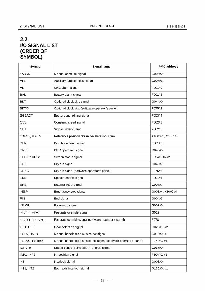
2. SIGNAL LIST B–63443EN/01PMC INTERFACE
94
Symbol Signal name PMC address
ABSM Manual absolute signal G006#2
AFL Auxiliary function lock signal G005#6
AL CNC alarm signal F001#0
BAL Battery alarm signal F001#2
BDT Optional block skip signal G044#0
BDTO Optional block skip (software operator’s panel) F075#2
BGEACT Background editing signal F053#4
CSS Constant speed signal F002#2
CUT Signal under cutting F002#6
DEC1, DEC2 Reference position return deceleration signal X1000#5, X1001#5
DEN Distribution end signal F001#3
DNCI DNC operation signal G043#5
DPL0 to DPL2 Screen status signal F254#0 to #2
DRN Dry run signal G046#7
DRNO Dry run signal (software operator’s panel) F075#5
ENB Spindle enable signal F001#4
ERS External reset signal G008#7
ESP Emergency stop signal G008#4, X1000#4
FIN End signal G004#3
FLWU Follow–up signal G007#5
FV0 to FV7 Feedrate override signal G012
FV0O to FV7O Feedrate override signal (software operator’s panel) F078
GR1, GR2 Gear selection signal G028#1, #2
HS1A, HS1B Manual handle feed axis select signal G018#0, #1
HS1AO, HS1BO Manual handle feed axis select signal (software operator’s panel) F077#0, #1
IGNVRY Speed control servo alarm ignored signal G066#0
INP1, INP2 In–position signal F104#0, #1
IT Interlock signal G008#0
IT1, IT2 Each axis interlock signal G130#0, #1
2.2I/O SIGNAL LIST(ORDER OFSYMBOL)

B–63443EN/01 2. SIGNAL LISTPMC INTERFACE
95
Symbol PMC addressSignal name
+J1, +J2, –J1, –J2 Feed axis direction select signal G100#0, #1,
G102#0, #1
+J1O, –J1O, +J2O,
–J2O
Manual feed F081#0 to #3
JV0 to JV15 Manual feedrate override signal G010, G011
JV0O to JV15O Jog feedrate setting signal F079, F080
K0 to K9, KMNS,
KPRD, KNO, KSLH,
KEOB, KCAN, KALT,
KINS, KDLT, KINP,
KWRT, KRED, KPOS,
KPRG, KVAR, KPRM,
KALM, KDWN, KUP,
KP, KQ, KH, KO, KN,
KG, KR, KX, KF, KM,
KS, KT, KSHRP
Key data reference function by PMC F210 to F218
KEY1, KEY2, KEY3,
KEY4
Memory protection key G046#3 to #6
KEYO Program protect signal (software operator’s panel) F075#6
M00 to M31 M function code signal F010 to F013
MZRN Manual reference position return check F004#5
MA Ready signal F001#7
MMEM Automatic operation (MEM) check signal F003#5
MD1 ,MD2, MD4 Mode select signal G043#0 to #2
MD1O ,MD2O, MD4O Software operator’s panel signal F073#0, F073#1,
F073#2
MEDT Memory edit (EDIT) check signal F003#6
MF M code output end signal F007#0
MFIN M function end signal G005#0
MH Manual handle step feed (HANDLE/STEP) check signal F004#1
MI1, MI2 Mirror image signal G106#0, #1
MJ Jog feed (JOG) check signal F003#2
MLK Machine lock signal G044#1
MLKO Machine lock signal (software operator’s panel) F075#4
MMDI Manual data input (MDI) check signal F003#3
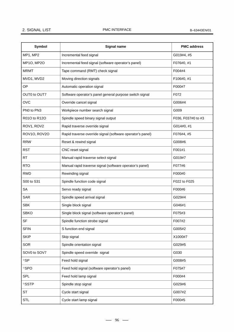
2. SIGNAL LIST B–63443EN/01PMC INTERFACE
96
Symbol PMC addressSignal name
MP1, MP2 Incremental feed signal G019#4, #5
MP1O, MP2O Incremental feed signal (software operator’s panel) F076#0, #1
MRMT Tape command (RMT) check signal F004#4
MVD1, MVD2 Moving direction signals F106#0, #1
OP Automatic operation signal F000#7
OUT0 to OUT7 Software operator’s panel general purpose switch signal F072
OVC Override cancel signal G006#4
PN0 to PN3 Workpiece number search signal G009
R01O to R12O Spindle speed binary signal output F036, F037#0 to #3
ROV1, ROV2 Rapid traverse override signal G014#0, #1
ROV1O, ROV2O Rapid traverse override signal (software operator’s panel) F076#4, #5
RRW Reset & rewind signal G008#6
RST CNC reset signal F001#1
RT Manual rapid traverse select signal G019#7
RTO Manual rapid traverse signal (software operator’s panel) F077#6
RWD Rewinding signal F000#0
S00 to S31 Spindle function code signal F022 to F025
SA Servo ready signal F000#6
SAR Spindle speed arrival signal G029#4
SBK Single block signal G046#1
SBKO Single block signal (software operator’s panel) F075#3
SF Spindle function strobe signal F007#2
SFIN S function end signal G005#2
SKIP Skip signal X1000#7
SOR Spindle orientation signal G029#5
SOV0 to SOV7 Spindle speed override signal G030
SP Feed hold signal G008#5
SPO Feed hold signal (software operator’s panel) F075#7
SPL Feed hold lamp signal F000#4
SSTP Spindle stop signal G029#6
ST Cycle start signal G007#2
STL Cycle start lamp signal F000#5
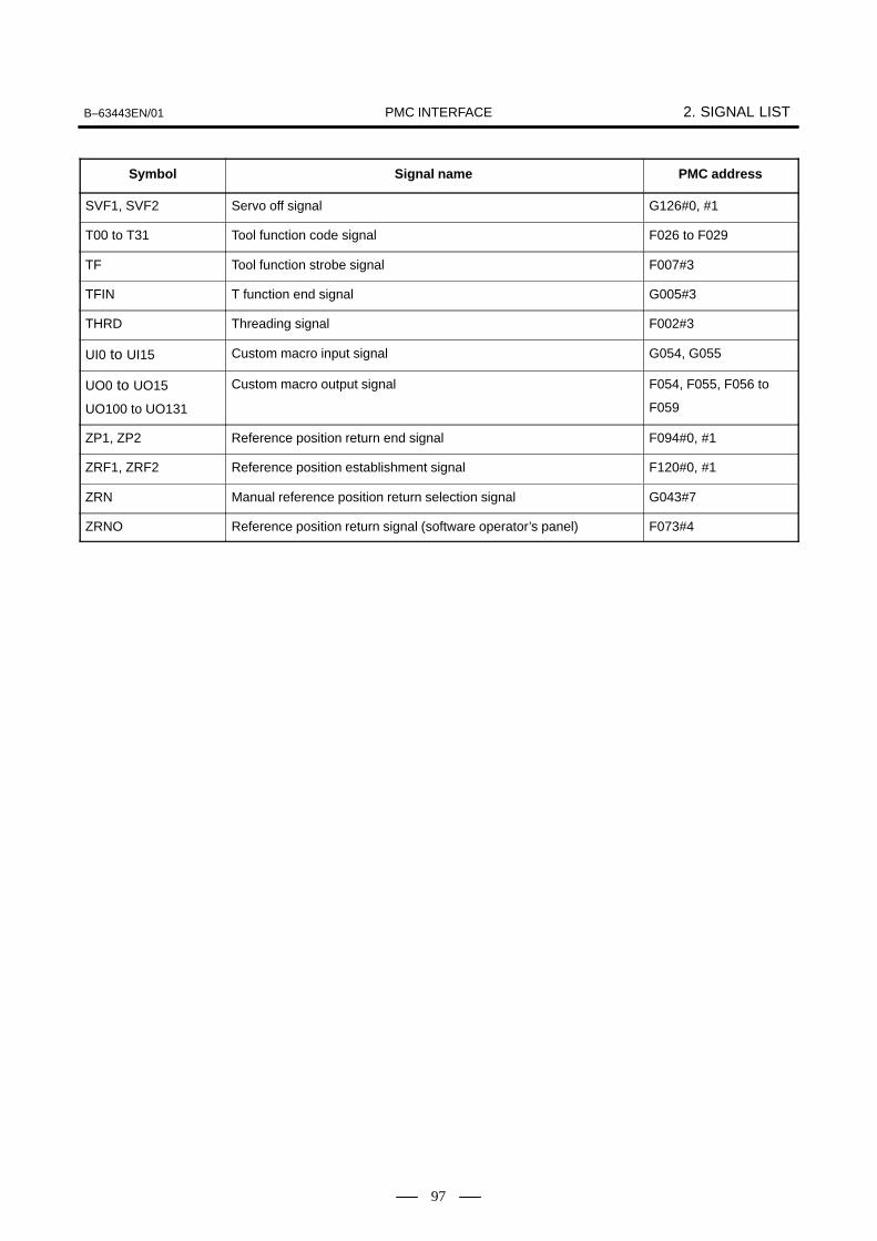
B–63443EN/01 2. SIGNAL LISTPMC INTERFACE
97
Symbol PMC addressSignal name
SVF1, SVF2 Servo off signal G126#0, #1
T00 to T31 Tool function code signal F026 to F029
TF Tool function strobe signal F007#3
TFIN T function end signal G005#3
THRD Threading signal F002#3
UI0 to UI15 Custom macro input signal G054, G055
UO0 to UO15
UO100 to UO131
Custom macro output signal F054, F055, F056 to
F059
ZP1, ZP2 Reference position return end signal F094#0, #1
ZRF1, ZRF2 Reference position establishment signal F120#0, #1
ZRN Manual reference position return selection signal G043#7
ZRNO Reference position return signal (software operator’s panel) F073#4

3. READY SIGNALS B–63443EN/01PMC INTERFACE
98
3 )&

B–63443EN/01 3. READY SIGNALSPMC INTERFACE
99
When power is applied to the Power Mate, this signal MA turns to “1”.
When the servo system becomes operative, the servo ready signal SAturns to “1”. For axes that must be braked on the machine side, the brakeshould not be released until this signal is sent. Fig. 3.2 shows the time chart of this signal.
CNC ready signal MA
Power on
SA60 - 100msec
ResetReset
Approx. 1 secEmergency stop
Power off
1 - 2 sec
Servo readysignal
Brake ON
Servo alarm
(Overload)
Servo alarm
MA
Fig.3.2 Servo Ready Signal Time Chart
3.1CNC READY SIGNAL(OUTPUT)MA<F001#7>
3.2SERVO READYSIGNAL (OUTPUT)SA <F000#6>

4. RESET & EMERGENCY STOP B–63443EN/01PMC INTERFACE
100
4 * (&

B–63443EN/01 4. RESET & EMERGENCY STOPPMC INTERFACE
101
When the emergency stop signal *ESP turns to “0”, the emergency stopis applied to the machine and the Power Mate is reset. This signal iscontrolled by the B contacts of a pushbutton switch. The emergency stopsignal turns the servo ready signal (SA[3.2]) to “0”.
Overtravel detection by this Power Mate is handled by the software limitfunction, and a limit switch for normal overtravel detection is not needed.To prevent the machine from moving beyond the software limit throughservo feedback error, always install a stroke end limit switch (shown inFig. 4.1 below).
*ESP*ESP
24V24V
+X–X+n
Emergency stop limit switch
Emergency stop
Emergency stop temporary release
Power Mate
Fig.4.1 Connection of Emergency Stop Circuit
Refer to AC Servo Motor β series DESCRIPTIONS for the distance
SERVO MOTOR β series DESCRIPTIONS B–65232EN
4.1EMERGENCY STOPSIGNAL (INPUT) *ESP<X1000#4, G008#4>
Reference

4. RESET & EMERGENCY STOP B–63443EN/01PMC INTERFACE
102
WARNINGSoftware limit setting point and operating point of limit switchfor emergency stopThis means that the rapid traverse rate set with parameterNo. 1420 can cause the point at which motion actually stopsto exceed the software limit setting by up to R/7,500 (mm).
R 7,500R : Rapid traverse rate (mm/min)
The actual stopping point may exceed the position set by aparameter(No.1420) by as much as R/7500 (mm). Set thelimit switch for emergency stop including the allowance forthe above value.
The machine stops in this range.
Set the limit switch for emergency stop in this range.
7,500R
Software limit setting point
ÄÄÄÄÄÄÄÄÄÄÄÄÄÄÄÄÄÄÄÄ
Stroke end direction
(mm)

B–63443EN/01 4. RESET & EMERGENCY STOPPMC INTERFACE
103
The Power Mate can be reset by turning the external reset signal ERS to“1”. The reset signal RST[5.3] turns to “1” at the same time. When anM[16.1], S[18.1], or T[19] function is being executed, MF[16.1],SF[18.1], or TF[19] signal is reset within 100 msec after the external resetsignal is input.
Function Resets the Power Mate and rewinds the input device being usedfor the selected automatic operation.
Operation
The Power Mate operates as follows when signal RRW turns to“1”.
i) The moving control axis decelerates to a stop.
ii) After stopping, the CNC is reset and the reset signal RST[5.3] turns to “1”.
iii) While the reset operation takes place, the selected mainprogram is rewound the rewind signal turns to “1” and rewinding begins. (Only at memory operation mode).
iv) Neither automatic nor manual operaitons are conductedwhile the RRW signal is set to “1”.
Usage Normaly, Power Mate is reset by M30 (End of tape). To rewindthe program at the same time, set this signal to l with using M30decode signal.
4.2EXTERNAL RESETSIGNAL (INPUT) ERS<G008#7>
4.3RESET & REWINDSIGNAL (INPUT) RRW<G008#6>

5. STATUS SIGNALS B–63443EN/01PMC INTERFACE
104
5
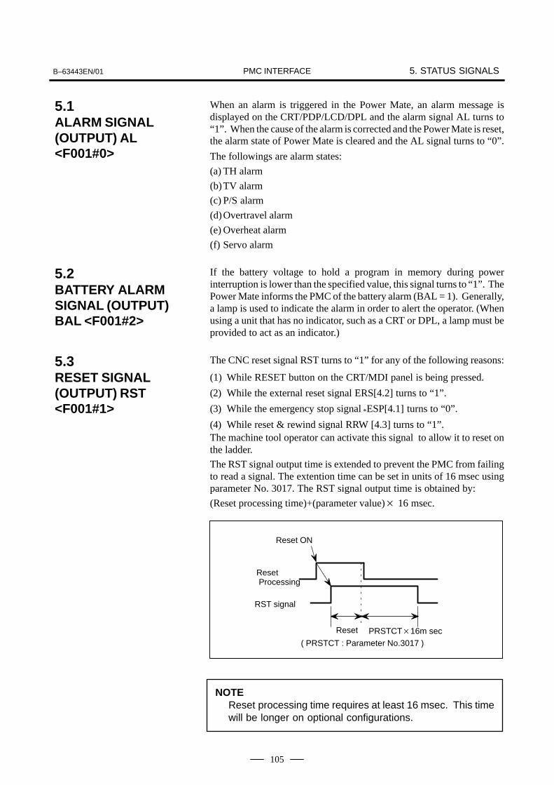
B–63443EN/01 5. STATUS SIGNALSPMC INTERFACE
105
When an alarm is triggered in the Power Mate, an alarm message isdisplayed on the CRT/PDP/LCD/DPL and the alarm signal AL turns to“1”. When the cause of the alarm is corrected and the Power Mate is reset,the alarm state of Power Mate is cleared and the AL signal turns to “0”.
The followings are alarm states:
(a) TH alarm
(b)TV alarm
(c) P/S alarm
(d)Overtravel alarm
(e) Overheat alarm
(f) Servo alarm
If the battery voltage to hold a program in memory during powerinterruption is lower than the specified value, this signal turns to “1”. ThePower Mate informs the PMC of the battery alarm (BAL = 1). Generally,a lamp is used to indicate the alarm in order to alert the operator. (Whenusing a unit that has no indicator, such as a CRT or DPL, a lamp must beprovided to act as an indicator.)
The CNC reset signal RST turns to “1” for any of the following reasons:
(1) While RESET button on the CRT/MDI panel is being pressed.
(2) While the external reset signal ERS[4.2] turns to “1”.
(3) While the emergency stop signal *ESP[4.1] turns to “0”.
(4) While reset & rewind signal RRW [4.3] turns to “1”.The machine tool operator can activate this signal to allow it to reset onthe ladder.
The RST signal output time is extended to prevent the PMC from failingto read a signal. The extention time can be set in units of 16 msec usingparameter No. 3017. The RST signal output time is obtained by:
(Reset processing time)+(parameter value) 16 msec.
PRSTCT16m sec
Reset Processing
Reset
Reset ON
RST signal
( PRSTCT : Parameter No.3017 )
NOTEReset processing time requires at least 16 msec. This timewill be longer on optional configurations.
5.1ALARM SIGNAL(OUTPUT) AL<F001#0>
5.2BATTERY ALARMSIGNAL (OUTPUT)BAL <F001#2>
5.3RESET SIGNAL(OUTPUT) RST<F001#1>
5. STATUS SIGNALS B–63443EN/01PMC INTERFACE
106
Function Indicates that the Power Mate is executing the rewindingoperation.
Output conditions
The signal turns to “1” when the reset & rewind signalRRW[4.3] has turned to “1”.
However, if can be modified by setting parameter RWM (No.3001#2) to “0” so that this signal is not output.
The signal turns to “0” when more than 100 msec has passedafter the signal has turned to “1” in reset & rewind signalRRW[4.3].
NOTEThe rewinding time required for a main program in memoryis nearly zero. Rewinding of the main program has endedwhen the rewinding signal has turned to “0”.
Function These signals indicate the movement direction of control axis.They are provided for each control axis, and the number in thesignal name corresponds to the control axis number.
MVD n The moving direction of the nth axis is minus.(n : 1 or 2)
Output conditions
“1” indicates the corresponding axes are moving in the minusdirection, and “0” indicates they are moving in the plusdirection.
NOTE1 These signals are output in both automatic and manual
operations.2 These signals maintain their existing condition during a
stop, indicating the direction of the axes’ movement beforebeing stopped.
5.4REWINDING SIGNAL(OUTPUT) RWD<F000#0>
5.5MOVING DIRECTIONSIGNALS MVDn<F106#0, #1>

B–63443EN/01 5. STATUS SIGNALSPMC INTERFACE
107
Function These signals indicate that the control axes are set to thein-position condition.They are provided for each control axis, and the number in thesignal name corresponds to the control axis number.
INP n The actual machine position of the n–th axis is placedin the in–position condition.(n : 1 or 2)
Output conditions
These signals turn to “1” in the following case :
The acceleration/deceleration delay of the correspondingcontrol axis is zero and the servo error is within the specifiedallowance.
These signals turn to “0” in the following cases :
The acceleration/deceleration delay of the correspondingcontrol axis is not zero.
The servo error of the corresponding control axis exceeds thespecified allowance.
(2) Staying pulse ofacceleration/deceleration control section
(1) Division pulse
INPn
Axis move command
Fig.5.6 Output Timing of Axis Status Signal
NOTEThe in-position signals may turn to “1” even during themovement if the axis is fed at very low speed.
Relative parameter
No.1801, 1826, 1827
This signal indicates that thread cutting is in progress.
5.6IN-POSITIONSIGNALS INPn<F104#0, #1>
5.7THREADING SIGNAL(OUTPUT) THRD<F002#3>

6. MODE SELECT B–63443EN/01PMC INTERFACE
108
6 ()

B–63443EN/01 6. MODE SELECTPMC INTERFACE
109
The mode select signal is a code signal consisting three bits MD1, MD2,and MD4. The seven modes memory edit (EDIT), automatic operation(MEM), step feed (HANDLE/STEP), manual continuous feed (JOG),manual data input (MDI) mode can be selected by combining these bits.
ModeContact at the machine
sideModeMD1 MD2 MD4
1 Memory edit (EDIT)
2 Automatic operation (MEM)
3 Manual handle/step feed (HANDLE/STEP)
4 Manual continuous feed (JOG)
5 Manual data input (MDI)
: Turns to “1”: Turns to “0”
Cautions about Modes and Mode switching
(1) Switch the mode while the operation is stopped or halt(*SP). (SeeChapter 12.)
(2) The mode cannot be switched during an emergency stop.
(3) In the manual/step feed mode, only step feed is enabled when manualfeed enable signals are 0. Manual feed or step feed is enabled whenthe manual feed enable signal is 1.
(4) If the manual handle/step feed mode is selected during operation inthe automatic operation mode, the operation stops and the signal STL[12.3] turns OFF as well as the signal SPL [12.4] turns ON to assumethe manual handle/step feed mode. Manual handle feed by themanual pulse generator or step feed by the feed axis direction selectsignal +J1, –J1, +J2, –J2 [7.1] is possible in this condition. It is alsopossible to select the automatic operation mode again and to restartthe operation by the automatic operation start signal in this conditionsince the command in the automatic operation mode is held. It isimpossible to restart unless the same mode as before the interruptionis selected, however, if the operation was interrupted by switching tothe manual handle/step feed mode during operation in the automaticoperation mode. (Fig. 6.1(a))
Start signal
Automatic operation
Mode select signal state
Step feed
Step feed enable
STL
SPL
ST
Operation in automaticoperation mode
Fig.6.1 (a)
6.1MODE SELECTSIGNAL (INPUT) MD1,MD2, MD4 <G043#0TO #2>

6. MODE SELECT B–63443EN/01PMC INTERFACE
110
(5) If the manual continuous feed mode is selected during operation inthe automatic operation mode, the operation is interrupted and thesignal STL [12.3] turns OFF as well as the signal SPL [12.4] turns ONto assume the manual continuous feed mode. Manual continuousfeed by the feed axis direction select signal is possible in thiscondition.It is also possible to restart in this condition by returning to theoriginal condition just as in the aforementioned manual handle/stepfeed. Also the manual handle command, step feed command isignored and the manual continuous feed mode is selected if the modeis switched to the manual continuous feed mode during operation bymanual handle or step feed. Any feed axis direction select signalwhich happens to be close before the manual continuous feed modeis selected is ignored, however. Turn all the feed axis direction selectsignals +J1, –J1, +J2, –J2 [7.1] open once and then turn the requiredfeed axis direction select signal close, and that feed axis directionselect signal will be selected. (Figs. 6.1 (b), (c))
Automatic operation
Start signal
Mode select signal state
Jog feed
STL
SPL
ST
Operation in automaticoperation mode
Manual continuous feed enable
Fig.6.1 (b)
Automaticoperation/manualhandle/step feed
100msec min
Feed axis direction select signal
Mode select signal state
Manual continuousfeed disable
Manual continuousfeed enable
Jog feed
Fig.6.1 (c)

B–63443EN/01 6. MODE SELECTPMC INTERFACE
111
It is possible to perform the machining operation while reading theprogram through the reader/puncher interface by connecting the tapereader. If DNC1 turns to ”1” under MEM mode, this function is validated.When using this function, set the parameter concerned withreader/puncher interface in advance.
6.2OPERATION BY TAPEREADER DNCI(INPUT) <G043#5>

6. MODE SELECT B–63443EN/01PMC INTERFACE
112
These signals indicate the current operational mode. The relationshipbetween input and output signals is:
Table 6.2 Relationship between Input and Output Signals
Input signalMode
MD1 MD2 MD4 ZRN DNCIOutput signal
Manaul data input(MDI)
0 0 0 0 0 MMDI<F003#3>
Auto operation (MEM) 1 0 0 0 0 MAUT<F003#5>
Tape command (RMT) 1 0 0 0 1 MAUT<F003#4>
Memory edit (EDIT) 1 1 0 0 0 MEDT<F003#6>
Manual handle/step feed (HANDLE/STEP)
0 0 1 0 0 MH<F003#1>
Jogging (JOG) 1 0 1 0 0 MJ<F003#2>
Manual reference position return
1 0 1 1 1 MZRH<F004#5>
6.3OPERATION MODECONFIRMATIONSIGNALS (OUTPUT)<F003, F004>

B–63443EN/01 7. JOG FEEDPMC INTERFACE
113
7 + )

7. JOG FEED B–63443EN/01PMC INTERFACE
114
These signals are enabled when INC or JOG mode is selected. Theyindicate the feed axis and its feed direction.+/– of signal name indicates the feed direction, the number following “J”corresponds to the number of the controlled axis (see Fig.7.1):
+ J n
n.....Feed nst axis. (n : 1 or 2)
+.....Feed in the + direction.
–.....Feed in the – direction.
Fig.7.1
(1) Incremental feedWhen the feed axis direction select signal of the axis (+Jn, –Jn) to bemoved turns from “0” to “1”, that axis moves one step in the pertinentdirection.
Table 7.1 Feed Amount per Step
Increment system Feed amount per step
Metric sytem 0.001 mm
Inch system 0.0001 inch
The above feed amount per step can be multiplied by 10, 100 or 1000 bythe incremental feed signal MP1, MP2 [9.2].
(2) Jog FeedWhen the feed axis direction select signal (+Jn, –Jn) of the axis to bemoved turns from “0” to “1” after the JOG mode has been selected,that axis moves in the pertinent direction at the feed rate determinedby the override signal or manual rapid traverse select signal. Whenthe feed axis direction select signal turns to “1” and the JOG mode issubsequently selected, or the feed axis direction select signal remains“1” and the RESET button or EMERGENCY STOP button ispressed, the axis does not move until the signal first turns to “0”, thenback to “1”. Simultaneous 2 axes are controled in jog feed.
7.1FEED AXISDIRECTION SELECTSIGNAL (INPUT)+Jn, –Jn, <G100#0,#1, G102#0, #1>

B–63443EN/01 7. JOG FEEDPMC INTERFACE
115
(Function)
A feedrate in jog feed or incremental feed can be overridden.These sixteen binary code signals correspond to the overridevalues as follows:
Override value (%) = 0.01 15
i0
|2i Vi|
where Vi=0 when *JVi is “1”Vi=1 when *JVi is “0”
If *JV0 to *JV15 all are “1” or “0”, the override values are regarded as0. The feed stops. It is possible to select a manual feedrate in 0.01% stepsover a range of 0 to 655.34%.
Table 7.2 shows an example.
Table 7.2 Relationship between *JV0 to *JV15 and
Override Value
*JV0 to *JV15 Override*JV15 *JV12 *JV11 *JV8 *JV7 *JV4 *JV3 *JV0
Overridevalue (%)
1 1 1 1 1 1 1 1 1 1 1 1 1 1 1 1 0
1 1 1 1 1 1 1 1 1 1 1 1 1 1 1 0 0.01
1 1 1 1 1 1 1 1 1 1 1 1 0 1 0 1 0.10
1 1 1 1 1 1 1 1 1 0 0 1 1 0 1 1 1.00
1 1 1 1 1 1 0 0 0 0 0 1 0 1 1 1 10.00
1 1 0 1 1 0 0 0 1 1 1 0 1 1 1 1 100.00
0 1 1 0 0 0 1 1 1 0 1 1 1 1 1 1 400.00
0 0 0 1 0 0 0 0 0 0 0 0 0 0 0 1 655.34
0 0 0 0 0 0 0 0 0 0 0 0 0 0 0 0 0
(Operation)
If rapid traverse selection signal RT[7.3] is “0” during jog feedor incremental feed, the actual feedrate is obtained bymultiplying a jog feedrate set by a parameter (No.1423) by anoverride value selected by these signals.
7.2MANUAL FEEDRATEOVERRIDE (INPUT)*JV0 TO *JV15<G010,G011>
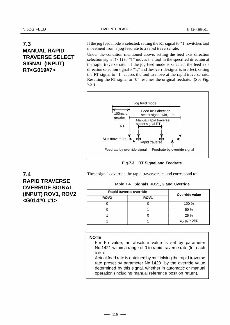
7. JOG FEED B–63443EN/01PMC INTERFACE
116
If the jog feed mode is selected, setting the RT signal to “1” switches toolmovement from a jog feedrate to a rapid traverse rate.
Under the condition mentioned above, setting the feed axis directionselection signal (7.1) to ”1” moves the tool in the specified direction atthe rapid traverse rate. If the jog feed mode is selected, the feed axisdirection selection signal is ”1,” and the override signal is in effect, settingthe RT signal to ”1” causes the tool to move at the rapid traverse rate.Resetting the RT signal to ”0” resumes the original feedrate. (See Fig.7.3.)
100ms or greater
Jog feed mode
Feed axis direction select signal +Jn, –Jn
RT
Axis movement
Feedrate by override signal Feedrate by override signal
Rapid traverse
Manual rapid traverse select signal RT
Fig.7.3 RT Signal and Feedrate
These signals override the rapid traverse rate, and correspond to:
Table 7.4 Signals ROV1, 2 and Override
Rapid traverse override
ROV2 ROV1Override value
0 0 100 %
0 1 50 %
1 0 25 %
1 1 Fo % (NOTE)
NOTEFor Fo value, an absolute value is set by parameterNo.1421 within a range of 0 to rapid traverse rate (for eachaxis).Actual feed rate is obtained by multiplying the rapid traverserate preset by parameter No.1420 by the override valuedetermined by this signal, whether in automatic or manualoperation (including manual reference position return).
7.3MANUAL RAPIDTRAVERSE SELECTSIGNAL (INPUT)RT<G019#7>
7.4RAPID TRAVERSEOVERRIDE SIGNAL(INPUT) ROV1, ROV2<G014#0, #1>
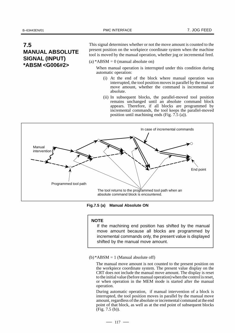
B–63443EN/01 7. JOG FEEDPMC INTERFACE
117
This signal determines whether or not the move amount is counted to thepresent position on the workpiece coordinate system when the machinetool is moved by the manual operation, whether jog or incremental feed.
(a) *ABSM = 0 (manual absolute on)
When manual operation is interrupted under this condition duringautomatic operation:
(i) At the end of the block where manual operation wasinterrupted, the tool position moves in parallel by the manualmove amount, whether the command is incremental orabsolute.
(ii) In subsequent blocks, the parallel-moved tool positionremains unchanged until an absolute command blockappears. Therefore, if all blocks are programmed byincremental commands, the tool keeps the parallel-movedposition until machining ends (Fig. 7.5 (a)).
In case of incremental commands
Manual intervention
Programmed tool path
The tool returns to the programmed tool path when an absolute command block is encountered.
End point
Fig.7.5 (a) Manual Absolute ON
NOTEIf the machining end position has shifted by the manualmove amount because all blocks are programmed byincremental commands only, the present value is displayedshifted by the manual move amount.
(b)*ABSM = 1 (Manual absolute off)
The manual move amount is not counted to the present position onthe workpiece coordinate system. The present value display on theCRT does not include the manual move amount. The display is resetto the initial value (before manual operation) when the control is reset,or when operation in the MEM mode is started after the manualoperation.During automatic operation, if manual intervention of a block isinterrupted, the tool position moves in parallel by the manual moveamount, regardless of the absolute or incremental command at the endpoint of that block, as well as at the end point of subsequent blocks(Fig. 7.5 (b)).
7.5MANUAL ABSOLUTESIGNAL (INPUT)*ABSM <G006#2>
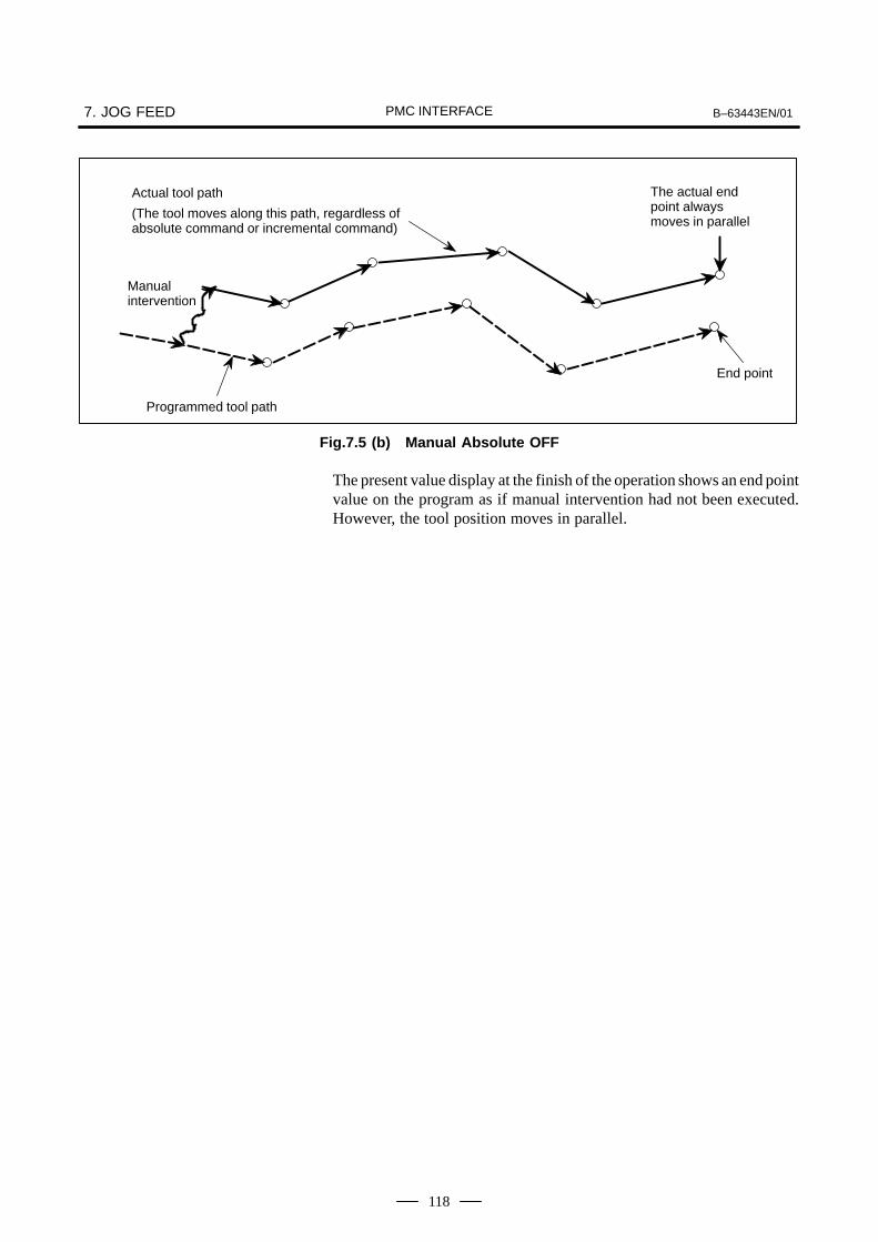
7. JOG FEED B–63443EN/01PMC INTERFACE
118
End point
Programmed tool path
Manual intervention
Actual tool path
(The tool moves along this path, regardless ofabsolute command or incremental command)
The actual end point alwaysmoves in parallel
Fig.7.5 (b) Manual Absolute OFF
The present value display at the finish of the operation shows an end pointvalue on the program as if manual intervention had not been executed.However, the tool position moves in parallel.

B–63443EN/01 8. INTERLOCKPMC INTERFACE
119
8 ,

8. INTERLOCK B–63443EN/01PMC INTERFACE
120
This signal is used to inhibit the machine from moving, and is effectiveregardless of the selected mode. When the *IT signal is “0”, the axismovement is decelerated and stopped.
In automatic operation (cycle start lamp signal STL is “1”, feed hold lampsignal SPL is “0”), blocks containing M, command is executedconsecutively until a block containing an axis move command isencountered; the system then stops and is placed into the automaticoperation mode. When the *IT signal turns to “1”, operation resumes(Figs. 8.1 (a), (b)).
Command read
*IT
Axis move
Fig.8.1 (a) Block Containing Only Axis Move Command
Command read
MF
FIN
*IT
Fig.8.1 (b) Block Containing Auxiliary Functions Only(Automatic)
NOTEThe overtravel amount of the motor after turning *IT to “1”is represented by the following formula.
WhereQmax : Overtravel quantity (mm or inch)Fm : Feedrate (mm/min or inch/min)Tc : Cutting time constant (msec)Ts : Servo time constant (Ts = 33msec normally)A : Processing time of Power Mate
A =30ms
Qmax Fm. 160
(TC
1000
TS
1000
A1000
)
8.1INTERLOCK SIGNAL(INPUT) *IT<G008#0>

B–63443EN/01 8. INTERLOCKPMC INTERFACE
121
The specified axis movement can be prevented independently by signal(*ITn).
Parameter(No.3003#2) selects whether interlock is effective for all axesor each axis. Set the parameter to be effective for each axis.
(a) In manual operation
The movement of an interlocked axis is inhibited, but the other axesare movable. If an axis is interlocked during movement, it stops afterbeing decelerated, and it starts moving again when it is released frominterlock.
(b) In automatic operation (MEM mode)
If an axis is interlocked while its movement is being commanded (themove amount is not 0, inclusive of the tool compensation), all axesmovements are prevented.If a moving axis is interlocked, all axes stop moving after beingdecelerated, and they start moving again when it is released frombeing interlocked.*ITn Interlock signal for the nth axis. (n : 1 or 2)0 : Make it be interlock1 : Not malce it be interlock
This function is effective during dry run.
8.2AXIS INTERLOCKSIGNAL (INPUT) *ITn<G130#0, #1>

9. MANUAL HANDLE FEED B–63443EN/01PMC INTERFACE
122
9 ( ) )
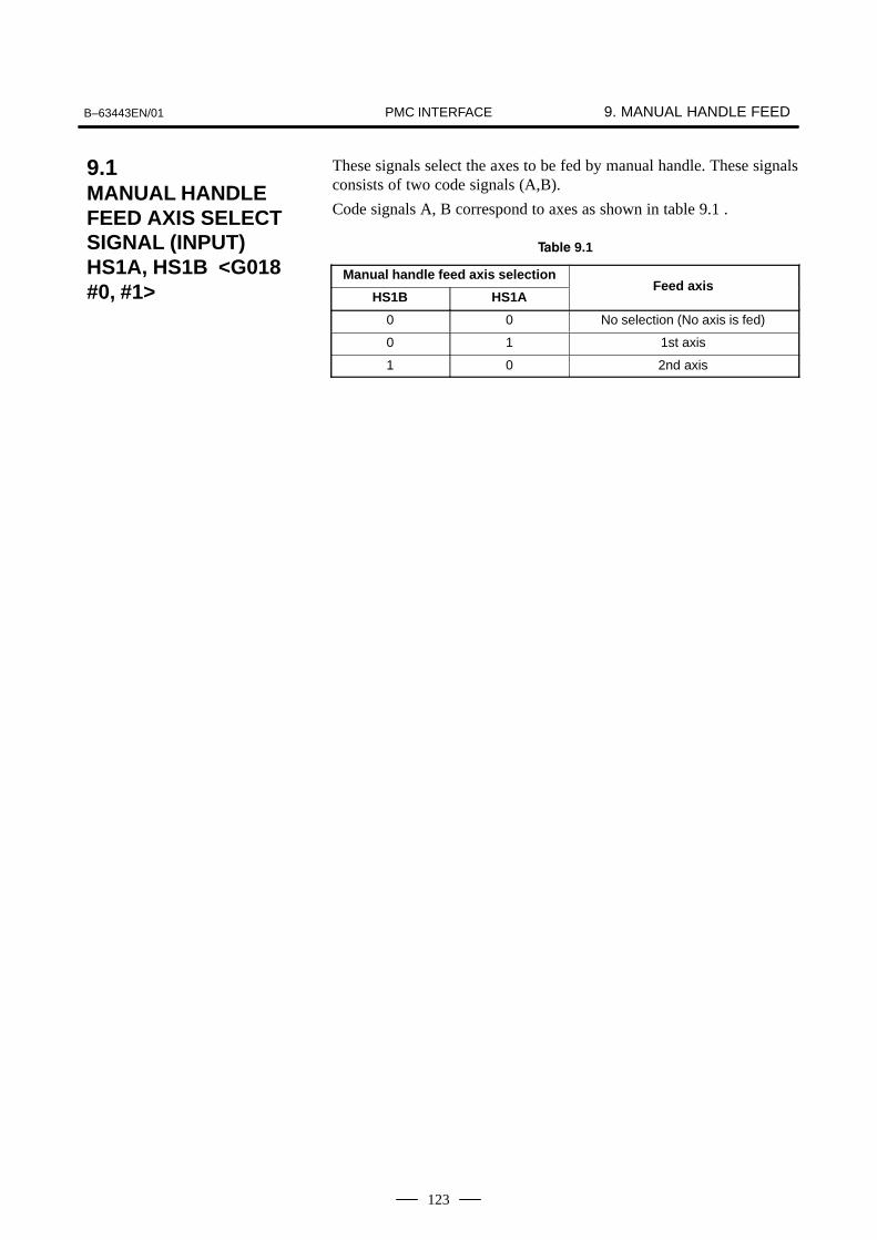
9. MANUAL HANDLE FEEDB–63443EN/01 PMC INTERFACE
123
These signals select the axes to be fed by manual handle. These signalsconsists of two code signals (A,B).
Code signals A, B correspond to axes as shown in table 9.1 .
9.1
Manual handle feed axis selection
HS1B HS1AFeed axis
0 0 No selection (No axis is fed)
0 1 1st axis
1 0 2nd axis
9.1MANUAL HANDLEFEED AXIS SELECTSIGNAL (INPUT) HS1A, HS1B <G018#0, #1>
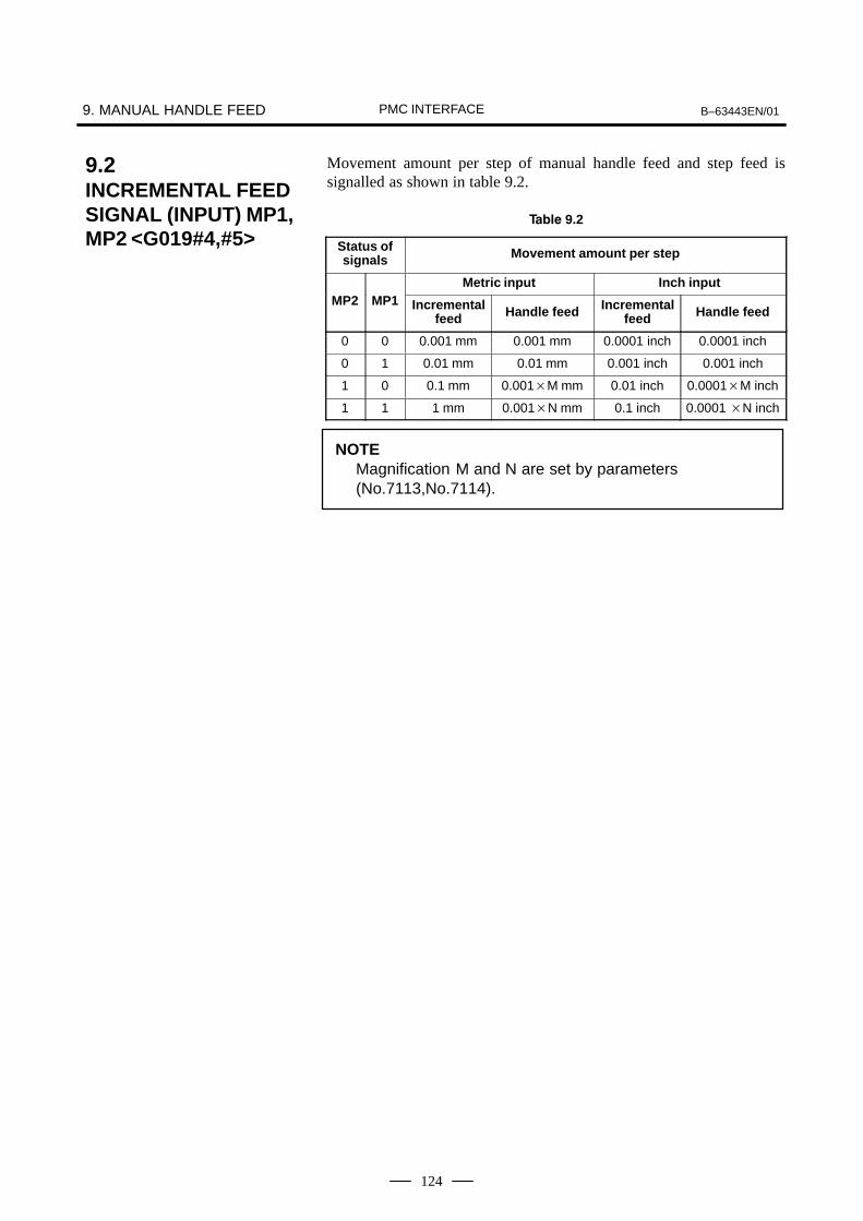
9. MANUAL HANDLE FEED B–63443EN/01PMC INTERFACE
124
Movement amount per step of manual handle feed and step feed issignalled as shown in table 9.2.
9.2
Status ofsignals Movement amount per step
Metric input Inch inputMP2 MP1 Incremental
feed Handle feed Incrementalfeed Handle feed
0 0 0.001 mm 0.001 mm 0.0001 inch 0.0001 inch
0 1 0.01 mm 0.01 mm 0.001 inch 0.001 inch
1 0 0.1 mm 0.001M mm 0.01 inch 0.0001M inch
1 1 1 mm 0.001N mm 0.1 inch 0.0001 N inch
NOTEMagnification M and N are set by parameters (No.7113,No.7114).
9.2INCREMENTAL FEEDSIGNAL (INPUT) MP1,MP2 <G019#4,#5>

B–63443EN/01 10. REFERENCE POSITION RETURNPMC INTERFACE
125
10

10. REFERENCE POSITION RETURN B–63443EN/01PMC INTERFACE
126
(1) Manual reference position return selection signal (input)ZRN<G043#7>
(2) Reference position return deceleration signal (input)*DECn <X1000#5, X1001#5> (n : 1 or 2)
(3) Reference position return end signal (output)ZPn <F094> (n : 1 or 2)
This function manually or automatically returns the moving parts of themachine to the reference position in the direction specified for each axis.The reference position return for this CNC is a grid system. The referenceposition is determined by the electrical grid position shown by the onerevolution signal of the position detector.
(a) Reference position return operation (grid system) When the JOG mode is selected, the ZRN signal is turned to “1”and feed is applied in the reference position direction by pressingthe manual feed button; the moving parts of the machine moveat the rapid traverse. When the reference position returndeceleration signals (*DECn) turn to “0”, the deceleration limitswitch operates, the feedrate decelerates, and the machinecontinues to move at a constant low speed. When thedeceleration limit switch is subsequently released and theelectrical grid position is reached after the reference positionreturn deceleration signal turns to “1“ again, feed stops and thereference position return end signals (ZPn) become “1”. Thereference position return direction can be set for each axis .Once reference position return is complete, JOG feed of the axisat which the signal (ZPn) is turned to “1” is ignored until signalZRN turns to “0”. The time chart in Fig.10.1 (a) shows the above operation.
10.11ST REFERENCEPOSITION RETURN

B–63443EN/01 10. REFERENCE POSITION RETURNPMC INTERFACE
127
V
Jog feed lock state
+J1
ZP1
+J1
ZRN
JOG or TEACH IN JOG mode
Detector 1 revolution signal
Rapid traverse
*DEC1 *DEC1
Grid
(1 revolutionsignal)
(X-axis return direction +)
Fig.10.1 (a) Reference Position Return (Grid System)
When the reference position return operation is done in the reversedirection from the preset return direction, the operation changes directionafter passing through the reference position and the axis reaches thereference position. Fig. 10.1 (b) shows the time chart.
(X-axis return direction –)
JOG mode
ZP1
Grid
*DEC1
Rapidtraverse
+J1
ZRN
Rapid traverse
*DEC1
+V
–V
*DEC1
Fig.10.1 (b) Reference Position Return (from Reverse Direction)
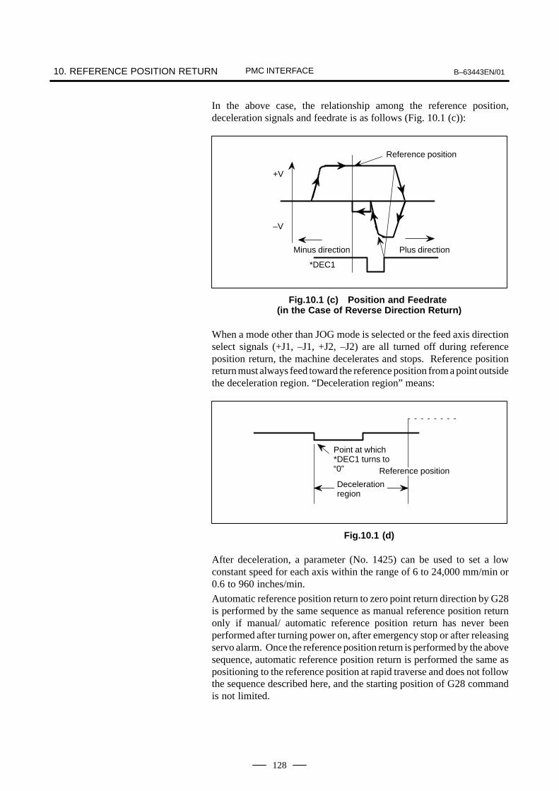
10. REFERENCE POSITION RETURN B–63443EN/01PMC INTERFACE
128
In the above case, the relationship among the reference position,deceleration signals and feedrate is as follows (Fig. 10.1 (c)):
Reference position
Minus direction Plus direction
*DEC1
+V
–V
Fig.10.1 (c) Position and Feedrate (in the Case of Reverse Direction Return)
When a mode other than JOG mode is selected or the feed axis directionselect signals (+J1, –J1, +J2, –J2) are all turned off during referenceposition return, the machine decelerates and stops. Reference positionreturn must always feed toward the reference position from a point outsidethe deceleration region. “Deceleration region” means:
Point at which*DEC1 turns to“0”
Decelerationregion
Reference position
Fig.10.1 (d)
After deceleration, a parameter (No. 1425) can be used to set a lowconstant speed for each axis within the range of 6 to 24,000 mm/min or0.6 to 960 inches/min.
Automatic reference position return to zero point return direction by G28is performed by the same sequence as manual reference position returnonly if manual/ automatic reference position return has never beenperformed after turning power on, after emergency stop or after releasingservo alarm. Once the reference position return is performed by the abovesequence, automatic reference position return is performed the same aspositioning to the reference position at rapid traverse and does not followthe sequence described here, and the starting position of G28 commandis not limited.

B–63443EN/01 10. REFERENCE POSITION RETURNPMC INTERFACE
129
(b) Deceleration limit switch installation conditionsInstallation of the deceleration limit switch for reference positionreturn must meet the following conditions (Fig. 10.1 (e))
V L
Feedrate
Return direction
Deceleration limit switch operation point
Deceleration limit switch released point
L DAL DW
Reference position
V R
Fig.10.1 (e)
(1) LDW : Deceleration dog width (mm or inch)
LDW
VR(TR
2 30 TS) 4VL.TS
6000
VR : Rapid traverse (mm/min or inch/min)TR : Rapid traverse time constant (msec)
TS : Servo time constant (msec)VL : Speed after deceleration (mm/min or inch/min)
(2) LDA : Distance between deceleration limit switch released point and reference position
LDA : Move amount of 1/2 revolution of motorSince the above conditions do not include the limit switchoperation variations, this point must also be considered atinstallation.
(c) ReferenceFor the reference position return described above, it is necessaryto move the machine at a feedrate with the servo positiondeviation value more than 128 before the first return is done afterturning power on or releasing the emergency stop or servo alarmstate. Here, the servo position deviation value is calculated by thefeedrate and the servo loop gain as follows :
E FG
1U
E : Servo position deviation value(µm)F : Feedrate(µm/sec)U: Detection unit (µm)
G: Servo loop gainGenerally, the detection unit is 1µm.For example, if the machine is moved at a feedrate of 6 m/min and servo loop gain is 30 at the time, servo positiondeviation is

10. REFERENCE POSITION RETURN B–63443EN/01PMC INTERFACE
130
E
6,0001,00060
11
30 3, 333
Conversely, when detection unit is 1µm and servo loop gain is 30, thefeedrate with the servo position deviation of 128 is
F = 1283060 (mm) = 230,400 (µm/min) = 230 (mm/min)
By the above result, the machine should be moved toward the referenceposition at a feedrate of more than 230 mm/min before the first referenceposition return is performed.
The servo position error that occurs during actual feeding can be detectedusing diagnose 300.

B–63443EN/01 10. REFERENCE POSITION RETURNPMC INTERFACE
131
(a) Function
This signal indicates that the Power Mate has established thereference position by the reference position return. For the machinewhose reference position is established by the absolute pulse coder,this signal turns to “1” at the time of power on.
(b)Output condition
This signal turns to “1” when the Power Mate has established thereference position by the reference position return operation. Itremains “1” until the Power Mate releases the reference position.
10.2REFERENCEPOSITIONESTABLISHMENTSIGNAL (OUTPUT)ZRFn <F120#0, #1>

11. MEMORY PROTECTION KEY (INPUT)KEY1 TO KEY4 <G046#3-#6> B–63443EN/01PMC INTERFACE
132
11((& ,& -. ,&/ ,&0
1203456437
(a) FunctionEnables the changing of the memory contents from the MDI panel.Four signals are provided. The operations that can be performed onthe contents of memory by each signal vary depending on the settingof bit 7 (KEY) of parameter No. 3290.When KEY = 0
KEY1: Enables the input of tool compensation values. KEY2: Enables the input of setting data and macro variables. KEY3: Enables program loading and editing. KEY4: (Reserved)
When KEY = 1 KEY1: Enables program loading and editing, as well as the
input of PMC parameters. KEY2 to KEY4: Not used
(b) OperationWhen a signal is set to 0, the associated operations are disabled.When a signal is set to 1, the associated operations are enabled.
(c) Signal address
#7 #6 #5 #4 #3 #2 #1 #0
G046 KEY4 KEY3 KEY2 KEY1
(d) Parameter
#7 #6 #5 #4 #3 #2 #1 #0
3290 KEY
KEY For memory protection keys:0 : The KEY1, KEY2, KEY3, and KEY4 signals are used.1 : Only the KEY1 signal is used.
NOTEThe functions of the signals depend on whether KEY = 0 orKEY = 1.

B–63443EN/01 12. AUTOMATIC OPERATIONPMC INTERFACE
133
12 (
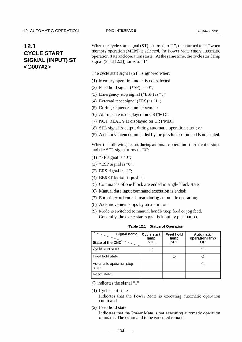
12. AUTOMATIC OPERATION B–63443EN/01PMC INTERFACE
134
When the cycle start signal (ST) is turned to “1”, then turned to “0” whenmemory operation (MEM) is selected, the Power Mate enters automaticoperation state and operation starts. At the same time, the cycle start lampsignal (STL[12.3]) turns to “1”.
The cycle start signal (ST) is ignored when:
(1) Memory operation mode is not selected;
(2) Feed hold signal (*SP) is “0”;
(3) Emergency stop signal (*ESP) is “0”;
(4) External reset signal (ERS) is “1”;
(5) During sequence number search;
(6) Alarm state is displayed on CRT/MDI;
(7) NOT READY is displayed on CRT/MDI;
(8) STL signal is output during automatic operation start ; or
(9) Axis movement commanded by the previous command is not ended.
When the following occurs during automatic operation, the machine stopsand the STL signal turns to “0”:
(1) *SP signal is “0”;
(2) *ESP signal is “0”;
(3) ERS signal is “1”;
(4) RESET button is pushed;
(5) Commands of one block are ended in single block state;
(6) Manual data input command execution is ended;
(7) End of record code is read during automatic operation;
(8) Axis movement stops by an alarm; or
(9) Mode is switched to manual handle/step feed or jog feed.Generally, the cycle start signal is input by pushbutton.
Table 12.1 Status of Operation
Signal name Cycle start Feed hold Automatic
State of the CNClampSTL
lampSPL
operation lampOP
Cycle start state
Feed hold state
Automatic operation stopstate
Reset state
indicates the signal “1”
(1) Cycle start stateIndicates that the Power Mate is executing automatic operationcommand.
(2) Feed hold stateIndicates that the Power Mate is not executing automatic operationommand. The command to be executed remain.
12.1CYCLE STARTSIGNAL (INPUT) ST<G007#2>

B–63443EN/01 12. AUTOMATIC OPERATIONPMC INTERFACE
135
(3) Automatic operation stop stateIndicates that automatic operation has been completed and stopped.
(4) Reset stateIndicates that the automatic operation has been forcibly terminated.
NOTEIf the sequence number search is performed through MDIpanel during memory operation, the OP signal turns to “1”.

12. AUTOMATIC OPERATION B–63443EN/01PMC INTERFACE
136
When the feed hold signal (*SP) is turned to “0” during automaticoperation or manual data input, the Power Mate enters the feed hold stateand stops. At the same time, the cycle start lamp signal (STL[12.3]) turnsto “0” and the feed hold lamp signal (SPL[12.4]) turns to “1”.The CNC does not enter automatic operation again even if the *SP signalis “1”. Operation can be restarted by turning the *SP signal to “1”followed by turning the cycle start signal (ST[12.1]) to “1”, then turningthe ST signal to “0”.
STL
ST
SPL
ST
STL
*SP *SP
This signal is invalid because the feed hold signal(*SP) is opened.
ST
Fig.12.2 Time Chart for Automatic Operation
If the *SP signal is “0” during the execution of a block where onlyM[16.1], S[18.1], or T[19], function code is programmed, the STL signalturns to “0” immediately, the SPL signal turns to “1” and the automaticoperation is stopped (feed hold state). When the FIN signal is returned,the corresponding operation is executed. The Power Mate operates untilthe execution of the block is completed, then the SPL signal turns to “0”(the STL signal remains “0”) and the Power Mate switches to the feedhold state (the same state as the stop state after the execution of one blockin the single block mode).
See Section 12.1 for an explanation of the feed hold state.
12.2FEED HOLD SIGNAL(INPUT) *SP<G008#5>
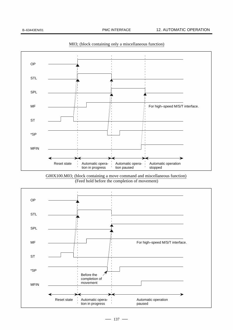
B–63443EN/01 12. AUTOMATIC OPERATIONPMC INTERFACE
137
M03; (block containing only a miscellaneous function)
Automatic operationstopped
OP
For high–speed M/S/T interface.
*SP
Reset state Automatic opera-tion in progress
Automatic opera-tion paused
STL
SPL
MF
ST
MFIN
G00X100.M03; (block containing a move command and miscellaneous function) (Feed hold before the completion of movement)
OP
For high–speed M/S/T interface.
*SP
Reset state Automatic opera-tion in progress
Automatic operationpaused
Before thecompletion ofmovement
STL
SPL
MF
ST
MFIN

12. AUTOMATIC OPERATION B–63443EN/01PMC INTERFACE
138
G00X100.M03; (block containing a move command and miscellaneous function)(Feed hold after the completion of movement)
Automatic operationstopped
OP
For high–speed M/S/T interface.
*SP
Reset state Automatic opera-tion in progress
Automatic opera-tion paused
After the comple-tion of movement
STL
SPL
MF
ST
MFIN
This signal indicates that the system is operating automatically. Refer toSection 12.1, cycle start signal ST, for a detailed description.
This signal indicates that automatic operation is temporarily stopped.Refer to Section 12.2, feed hold signal *SP, for a detailed description.
12.3CYCLE START LAMPSIGNAL (OUTPUT)STL <F000#5>
12.4FEED HOLD LAMPSIGNAL (OUTPUT)SPL <F000#4>

B–63443EN/01 12. AUTOMATIC OPERATIONPMC INTERFACE
139
The following output signals indicate the status of the Power Mate:
(1) Cycle start lamp STL
(2) Feed hold lamp SPL
(3) Automatic operation OPThe following table shows the relationship between the state of the PowerMate and the signals.
See Section 12.1 for an explanation of the operation statuses.
12.5AUTOMATICOPERATION SIGNAL(OUTPUT) OP<F000#7>

12. AUTOMATIC OPERATION B–63443EN/01PMC INTERFACE
140
When several part programs are stored in program storage memorybeforehand, a workpiece number can be searched with the workpiecenumber search signals PN0 to PN3 from the machine side. First, a number from O001 to O015 is given to each part program as thework piece number using address 0. Input the PN0 to PN3 signals fromthe machine side in accordance with the table 12.6.
Table 12.6
Workpiece No. PN3 PN2 PN1 PN0
Not searched
0001
0002
0003
::
::
::
::
::
0014
0015
: Contacts closed : Contacts opened
When the cycle start signal ST[12.1] is input in the reset state, a programwith program number specified with PN0 to PN3 is searched and theprogram is executed from the beginning.
+24V
Power Mate
PN0
PN1
PN2
PN3
12.6WORKPIECENUMBER SEARCHSIGNAL (INPUT) PN0TO PN3 <G009>
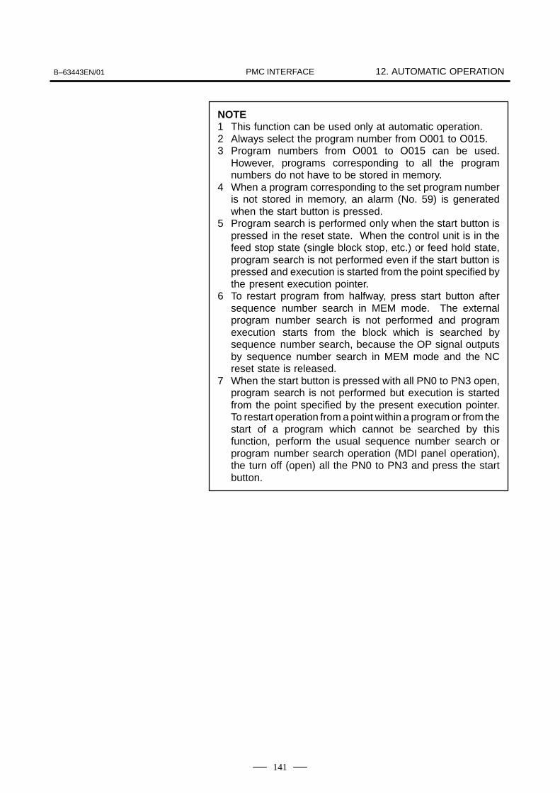
B–63443EN/01 12. AUTOMATIC OPERATIONPMC INTERFACE
141
NOTE1 This function can be used only at automatic operation.2 Always select the program number from O001 to O015.3 Program numbers from O001 to O015 can be used.
However, programs corresponding to all the programnumbers do not have to be stored in memory.
4 When a program corresponding to the set program numberis not stored in memory, an alarm (No. 59) is generatedwhen the start button is pressed.
5 Program search is performed only when the start button ispressed in the reset state. When the control unit is in thefeed stop state (single block stop, etc.) or feed hold state,program search is not performed even if the start button ispressed and execution is started from the point specified bythe present execution pointer.
6 To restart program from halfway, press start button aftersequence number search in MEM mode. The externalprogram number search is not performed and programexecution starts from the block which is searched bysequence number search, because the OP signal outputsby sequence number search in MEM mode and the NCreset state is released.
7 When the start button is pressed with all PN0 to PN3 open,program search is not performed but execution is startedfrom the point specified by the present execution pointer.To restart operation from a point within a program or from thestart of a program which cannot be searched by thisfunction, perform the usual sequence number search orprogram number search operation (MDI panel operation),the turn off (open) all the PN0 to PN3 and press the startbutton.
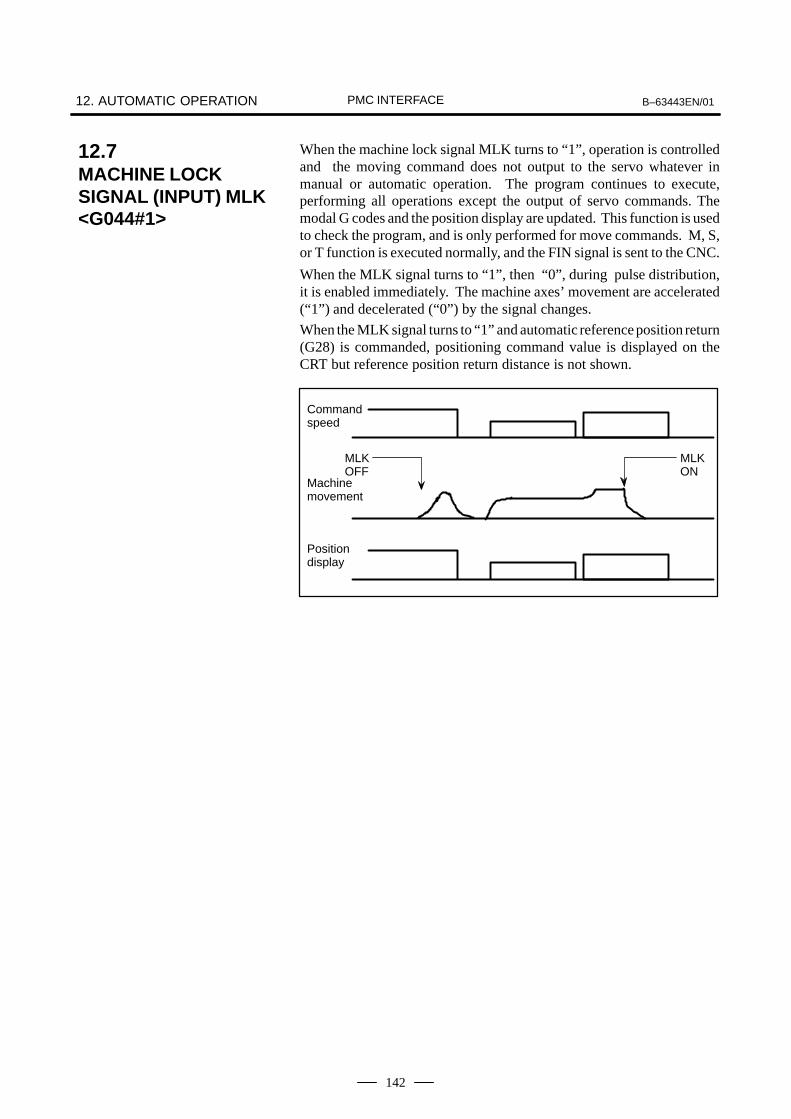
12. AUTOMATIC OPERATION B–63443EN/01PMC INTERFACE
142
When the machine lock signal MLK turns to “1”, operation is controlledand the moving command does not output to the servo whatever inmanual or automatic operation. The program continues to execute,performing all operations except the output of servo commands. Themodal G codes and the position display are updated. This function is usedto check the program, and is only performed for move commands. M, S,or T function is executed normally, and the FIN signal is sent to the CNC.
When the MLK signal turns to “1”, then “0”, during pulse distribution,it is enabled immediately. The machine axes’ movement are accelerated(“1”) and decelerated (“0”) by the signal changes.
When the MLK signal turns to “1” and automatic reference position return(G28) is commanded, positioning command value is displayed on theCRT but reference position return distance is not shown.
Commandspeed
Positiondisplay
MLKOFF
Machinemovement
MLKON
12.7MACHINE LOCKSIGNAL (INPUT) MLK<G044#1>

B–63443EN/01 12. AUTOMATIC OPERATIONPMC INTERFACE
143
This signal is enabled in the MEM mode.
When the single block signal SBK turns to “1” during automaticoperation, operation stops at the end of the executing block and the cyclestart lamp signal STL [12.3] turns to “0”, but the feed hold lamp signalSPL [12.4] does not turn to “1”. Each time the cycle start signal ST[12.1]is input thereafter, the program for one block is read from memory and itscommands are executed. Operation can be switched to INC or JOG bythe mode select signal under single block stop state.
When the SBK signal turns to “0”, normal automatic operation isperformed.
12.8SINGLE BLOCKSIGNAL (INPUT) SBK<G046#1>
12. AUTOMATIC OPERATION B–63443EN/01PMC INTERFACE
144
(Function)This signal selects the dry run to set the feedrate of automaticoperation to the dry run speed set by a parameter (No.1410)instead of a command value .
(Operation)When this signal turns to “1”:
(1) In a dry run of automatic operation, rather than using a cuttingfeedrate specified by a program, the CNC uses the value obtained byapplying the manual feedrate override to the dry speed set byparameter No. 1410. The acceleration/deceleration time constantremains that for the cutting feed. If rapid traverse selection signalRT[7.3] remains “1”, the tool is fed at the maximum cutting feedrate.
(2) The rapid traverse in automatic operation is also set to the dry runspeed by parameter RDR (No.1401#6). If rapid traverse selectionsignal RT is also “1”, the axis is fed at rapid traverse as before.When RT is low, the time constant for manual continuous feed isemployed as the acceleration/deceleration time constant during thedry run The time constant for rapid traverse is used when RT is high.
(3) If this signal changed during the travel, the axis decelerates to a stopbefore accelerating to the specified feed rate.
(Function)These signals override the cutting feedrate. Eight binary codesignals correspond to override values as follows:
Override value 7
i0(2i
Vi)
Vi=0 when *FVi is “1” and Vi=1 when *FVi is “0”These signals have the following weight.
*FV0 : 1%, *FV1 : 2%, *FV2 : 4%, *FV3 : 8%*FV4 : 16%, *FV5 : 32%, *FV6 : 64%, *FV7 : 128 %
When all signals are “0”, they are regarded as overriding 0% in the sameway as when all signals are “1”.Thus, the override is selectable in steps over a range of 0 to 254%.
(Operation)Actual feedrate is obtained by multiplying the speed specifiedin cutting feed in automatic operation mode by the overridevalue selected by this signal.The override is regarded as 100%, regardless of this signal, inthe following cases:
Override cancel signal OVC[12.11] is ”1”. Threading
Feedrate override is fixed to 100% while this signal is “1” (Refer toSec.12.10). This signal does not effect rapid traverse override or spindleoverride. The feedrate override is effective when this signal is “0”.
12.9DRY RUN SIGNAL(INPUT) DRN<G046#7 >
12.10FEED RATEOVERRIDE SIGNAL(INPUT) *FV0 TO *FV7<G012>
12.11OVERRIDE CANCELSIGNAL (INPUT) OVC<G006#4>

B–63443EN/01 12. AUTOMATIC OPERATIONPMC INTERFACE
145
This signal is effective during automatic operation. Setting the BDT to“1” ignores information read after the appropriate code is sent, until theend of block code (EOB code). The code for each signal is shown below,and Figs.12.12 (a) - (b) show examples
Input signal Heading code ignored
BDT /a letter or /1
EOB code Slash
; / N 1 2 3 X 5 6 , N 7 8 ;
EOB code
Ignored
Fig.12.12 (a) An Optional Block Skip Signal and IgnoredData
NOTESetting the BDT to “1” when a block including a slash codeis already being read does not ignore that block, becausethe BDT signal only becomes “1” after the slash code isread.
; / N 1 2 3 X 5 6 ; N 7 8
OFF
ON
Not ignored
BDT
; / N 9 0 1 Z 1 2 ;
Ignored
Fig.12.12 (b) An Optional Block Skip Signal and Ignored Data
12.12OPTIONAL BLOCKSKIP SIGNAL (INPUT)BDT <G044#0>

12. AUTOMATIC OPERATION B–63443EN/01PMC INTERFACE
146
When the MIn (n:1 or 2) signal turns to “1”, the algebraical sign of the axiscommand value in MEM mode is inverted. This function is not availablein JOG mode or for the movement between intermediate position andreference position given by the G28 automatic reference position return.The mirror image signal can be turned to “1” in the following cases:
(1) During offset cancel;
(2) When the CNC is in the automatic operation stop state and not in thefeed hold state (Refer to Sec.12.1).
X
0
A
When MI1 signal turned to “1” at point A
B
Z
B’
Fig.12.13 Mirror Image
12.13MIRROR IMAGESIGNAL (INPUT) MIn<G106#0, #1>

B–63443EN/0113. SIGNALS IN CUTTING MODE
(OUTPUT) CUT <F002#6>PMC INTERFACE
147
13 () -.
1228437
Signal displayed during movement in cutting mode is output to PMC.
[Signal] CUT
[Function]Signal in cutting mode
1 : Signal is output during movement in cutting mode.0 : Signal is output when stopped, during movement in rapid
traverse mode, and during manual mode.
NOTEIf interlock *IT or *RILK is applied during movement incutting mode, the signal becomes 1.

14. SCREEN STATE SIGNALS (OUTPUT) DPL0, DPL1, DPL2 <F254 #0 TO #2> B–63443EN/01PMC INTERFACE
148
14 -. )29 )/9 )8
18:0 42 487
The DPL/MDI screen state is output to the PMC in a code signalconsisting of 3 bits.
DPL2 DPL1 DPL0 Screen State
0 0 0 Position display
0 0 1 Program
0 1 0 Offset/Macro variables/Setting
0 1 1 Parameter/Diagnose/Pitch error
1 0 0 Alarm/Message

B–63443EN/01 15. MISCELLANEOUS FUNCTIONPMC INTERFACE
149
15 (
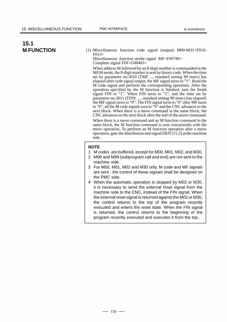
15. MISCELLANEOUS FUNCTION B–63443EN/01PMC INTERFACE
150
(1) Miscellaneous function code signal (output) M00-M31<F010-F013>Miscellaneous function strobe signal MF<F007#0> Complete signal FIN<G004#3>When address M followed by an 8-digit number is commanded in theMEM mode, the 8-digit number is sent by binary code. When the timeset by parameter no.3010 (TMF .... standard setting 80 msec) haselapsed after code signal output, the MF signal turns to ”1”. Read theM code signal and perform the corresponding operation. After theoperation specified by the M function is finished, turn the finishsignal FIN to ”1”. When FIN turns to ”1”, and the time set byparameter no.3011 (TFIN ..... standard setting 80 msec) has elapsed,the MF signal turns to ”0”. The FIN signal turns to ”0” after MF turnsto ”0”, all the M code signals turn to ”0” and the CNC advances to thenext block. When there is a move command in the same block, theCNC advances to the next block after the end of the move command.When there is a move command and an M function command in thesame block, the M function command is sent concurrently with themove operation. To perform an M function operation after a moveoperation, gate the distribution end signal DEN [15.2] at the machineside.
NOTE1 M codes are buffered, except for M00, M01, M02, and M30.2 M98 and M99 (subprogram call and end) are not sent to the
machine side.3 For M00, M01, M02 and M30 only, M code and MF signals
are sent ; the control of these signals shall be designed onthe PMC side.
4 When the automatic operation is stopped by M02 or M30,it is necessary to send the external reset signal from themachine side to the CNC, instead of the FIN signal, Whenthe external reset signal is returned against the M02 or M30,the control returns to the top of the program recentlyexecuted and enters the reset state. When the FIN signalis returned, the control returns to the beginning of theprogram recently executed and executes it from the top..
15.1M FUNCTION

B–63443EN/01 15. MISCELLANEOUS FUNCTIONPMC INTERFACE
151
The code signal, read signal, and finish signal timing is shown below:
TMF, TFIN are set by parameter.TMF (no. 3010) : 16 to 256msec (16msec steps)TFIN (no. 3011) : 16 to 256msec (16msec steps)
M command read
M code signalM00 to M31
Next command read
TMFTFIN
MF
FIN
DEN
Fig.15.1 (a) When There Is No Move Command
Move operation
M command read
MF
FIN
DEN
Next command read
TFINTMF
M code signalM00 to M31
Fig.15.1 (b) When There is a Move Command in the Same Block

15. MISCELLANEOUS FUNCTION B–63443EN/01PMC INTERFACE
152
When an M, S, or T function is commanded in the MEM or MDI mode,and axial movement ends but the FIN signal for the M, S, or T commandis not issued, the distribution end signal DEN turns to “1”. The DEN turnsto “1” until the FIN signal for the M, S, or T command is issued even inthe block in which no axial movement exists. When the operation endsby arrival of the FIN signal for the M, S, or T function, the DEN signalturns to “0”. Use this signal to discriminate between simultaneousexecution of an auxiliary (M, S, or T) function with the start of movement,and execution after the end of movement when an auxiliary function andmove command are specified in the same block.Fig. 15.2 shows the time chart of this signal.
Axismove
Auxiliary function is not included
Commad
MF
FIN
Feedrate
DEN
Auxiliary function isincluded
Auxiliary function is included
Not output because FIN already returnedOutput because FIN is not
yet returned at this pointDEN is not output
Fig.15.2 Distribution End Signal and Other Signals
If this signal is turned ”1”, binary code signals and M read commandsignal is not output, even when executing M, S, or T function block.
NOTE1 Internal processing of M98 and M99 is done, regardless of
the AFL signal.2 M00, M01, M02, and M03 are output even if the AFL signal
is “1”.3 An analog voltage for the spindle is output even when the
AFL signal is ”1.”
15.2DISTRIBUTION ENDSIGNAL (OUTPUT)DEN <F001#3>
15.3AUXILIARYFUNCTION LOCKSIGNAL (INPUT) AFL<G005#6>
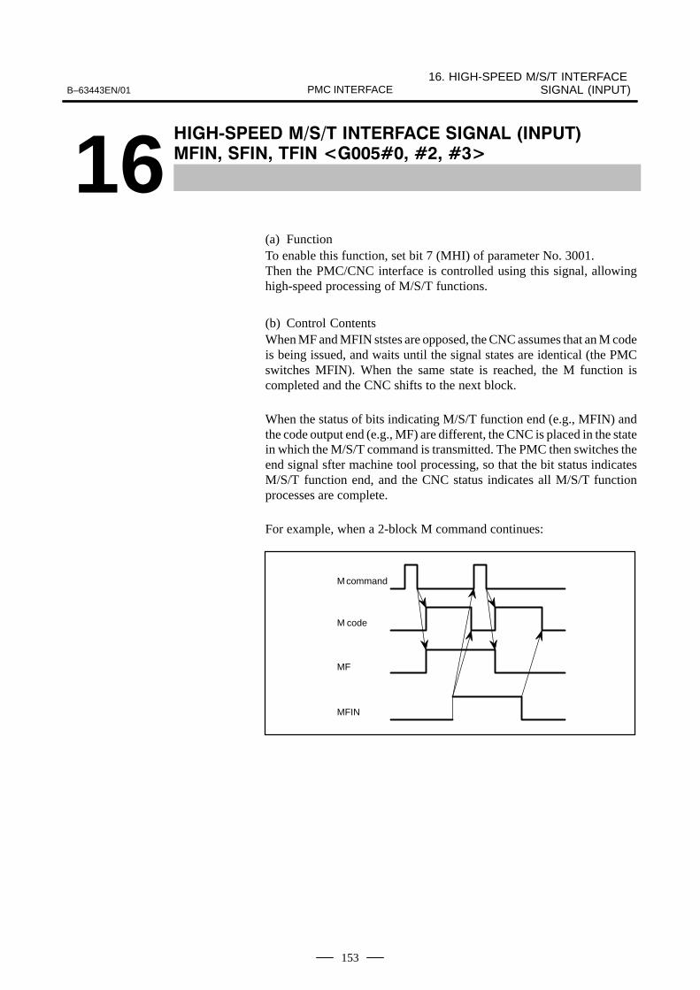
B–63443EN/0116. HIGH-SPEED M/S/T INTERFACE
SIGNAL (INPUT)PMC INTERFACE
153
16 6 ) (' ' -.
(9 9 122:429 489 457
(a) FunctionTo enable this function, set bit 7 (MHI) of parameter No. 3001.Then the PMC/CNC interface is controlled using this signal, allowinghigh-speed processing of M/S/T functions.
(b) Control ContentsWhen MF and MFIN ststes are opposed, the CNC assumes that an M codeis being issued, and waits until the signal states are identical (the PMCswitches MFIN). When the same state is reached, the M function iscompleted and the CNC shifts to the next block.
When the status of bits indicating M/S/T function end (e.g., MFIN) andthe code output end (e.g., MF) are different, the CNC is placed in the statein which the M/S/T command is transmitted. The PMC then switches theend signal sfter machine tool processing, so that the bit status indicatesM/S/T function end, and the CNC status indicates all M/S/T functionprocesses are complete.
For example, when a 2-block M command continues:
M command
M code
MF
MFIN

17. PMC KEY DATA REFERENCE FUNCTION (OUTPUT) <F210 TO F218> B–63443EN/01PMC INTERFACE
154
17( ,& ) -.
18/2 8/;7

B–63443EN/01
17. PMC KEY DATA REFERENCE FUNCTION (OUTPUT)
<F210 TO F218>PMC INTERFACE
155
The DPL/MDI key input status is output to the PMC.
NOTEWhen three keys or more are pushed at the same time, thekey data cannot be connectly read.
Key KeyKeyKey
K1 ········
Signal name
1
K0 ········0
K3 ········3
K2 ········2
K5 ········5
K4 ········4
K7 ········7
K6 ········6
K8 ········8
KMNS ·· –/+
K9 ········9
KNO ····· & @ No.
KPRD ···
KEOB ··· EOB
STK
KSLH ··· /
KALT ···ALTER
KCAN ··CAN
KDLT ···DELET
KINS ····INSRT
KINP ····INPUT
KRED ··· READ
KWRT ··WRITE
KPRG ···PRGRM
KPOS ···POS
KPRM ·· DGNOSPARAM
KVAR ··· MENU VAR
KDWN ·
KALM ·· OPRALARM
KP ········ P
I
KUP ·····
KQ ········ Q
J
KO ········ O
KH ········ H
KN ·······N
KR ········R
K
KG ········ G
KX ········ X
AXIS
KM ······· M
KF ········ F
KS ········ S
KT ········ T
KSHRP #
[Function] 1 : The key is pressed.0 : The key is not pressed.
<F210#0>
<F210#1>
<F210#2>
<F210#3>
<F210#4>
<F210#5>
<F211#3>
<F211#4>
<F211#5>
<F211#6>
<F211#7>
<F212#0>
<F213#0>
<F213#1>
<F213#2>
<F213#3>
<F213#5>
<F214#0>
<F217#1>
<F217#2>
<F217#3>
<F217#4>
<F210#6>
<F210#7>
<F211#0>
<F211#1>
<F211#2>
<F212#1>
<F212#2>
<F212#3>
<F212#4>
<F212#6> <F217#0>
<F214#1>
<F214#4>
<F214#5>
<F214#6>
<F218#3>
<F218#4>
<F218#5>
<F218#6>
<F218#7>
Signal name Signal name Signal name

18. SPINDLE FUNCTIONS B–63443EN/01PMC INTERFACE
156
18 )

B–63443EN/01 18. SPINDLE FUNCTIONSPMC INTERFACE
157
The following chart summarizes spindle speed control.
Output to the PMC(used for ladders)
Switching in the machine
←From the PMC
Machining program, etc.↓
⋅ Processing for gear change(S command → spindle motor speed con-version)Clamp the speed according to parameters.
⋅ Command output to thespindle, spindle enable sig-nal output, gain, and offset
⋅Spindle stop signal/spindle orientation signal
⋅Spindle override signal (*SSTP/SOR, SOV0 to SOV7)
Input the gear selectsignal (GR1, GR2).
CNC output specification (result of speed conversion)S12 bit code output (R12O to R01O)
Specify output polarity in the CNC.(M03/M04 and parameter No. 3706 = TCW, CWM)
Thread cutting,feed per revolu-tion, etc.
⋅ Position coderfeedback signal
SensorsInput the spindle amplifiercontrol signal from thePMC, etc.
⋅ S command
⋅S code/SF signal output .
⋅ Control over thestart of cuttingfeed.
Input the spindlespeed arrivalsignal (SAR).
Monitor the arrivalspindle speed
Spindleamplifier
Spindlemotor
Positioncoder
Gear changemechanism
Spindle
Mechanical section of the machine
CNC PMC and machine
Output to the PMC (to be used for ladders).
←
18.1COMMAND FLOW OFSPINDLE SPEEDCONTROL
18. SPINDLE FUNCTIONS B–63443EN/01PMC INTERFACE
158
The S command specifies the spindle speed entered from machiningprograms, etc. for the CNC.
For constant surface speed control (during G96 mode), the CNC convertsthe specified surface speed to the spindle speed.
With the spindle analog module, the spindle control function in the CNCconverts the S command value to the output value for the spindle motor.For correspondence to gear change and constant surface speed control, theS code/SF signals output is different as follows in case of the spindleanalog module is not used.
Outputs neither S code nor SF signal.(This is because the S code is not always the spindle speed when theconstant surface speed control option is used.)
If you use the S code for processing in the PMC ladder, you must specifyparameters related to parameter No. 3705.
This signal sets the S command value in the CNC to 0. This signal setsthe speed command for the spindle to 0.
Even if the function of the spindle stop signal is not used, the signal mustbe set to logical 1 for the CNC to perform spindle speed control.
If the spindle orientation signal is logical 1 and the spindle stop signal islogical 0, the spindle rotates in the direction specified by bit 5 (ORM) ofparameter No. 3706 at a constant speed specified by parameter No. 3732.
Because the spindle rotates at a constant speed regardless of the gearstage, this signal can be used to rotate the spindle to drive the stopper orpin during mechanical spindle positioning.
This signal specifies an override of 0% to 254% for the specified S valuefor spindle control.
However, the spindle speed override function is disabled when the CNCis in the thread cutting (G32)
When the spindle speed control is performed but the spindle speedoverride is not used, set the override value to 100%.
Although the S command contains the spindle speed, the object that isactually controlled is the spindle motor. Therefore, the CNC must havesome provision to detect the gear stage between the speed and spindlemotor.
The gear stage (one of the four gear stages ) being currently used by themachine is input in response to the gear select signal inputs (GR1, GR2).
The machine determines which gear to use.
The CNC outputs the spindle speed that corresponds to the gear stageinput.
S command
S code/SF signal output
Spindle stop signal (*SSTP)
Spindle orientation signal (SOR)
Spindle speed override signal (SOV00 to SOV07)
Processing for gearchanging

B–63443EN/01 18. SPINDLE FUNCTIONSPMC INTERFACE
159
To perform the gear changing, the maximum spindle speed for each gearselect signal issued from the PMC side must be set by parameter No.3741-3744. The gear select signal is a 2 bit code signal (GR1, GR2). The relationshipbetween the signal and gear number is :
GR1 GR2 Gear No. Parameter No. for max.spindle speed
0 0 1 No. 3741
1 0 2 No. 3742
0 1 3 No. 3743
1 1 4 No. 3744
Assume that gear switching is two stage switching. If the spindle speedwith the output voltage 10 V is 1000 rpm for the low speed gear (G1) and2000 rpm for the high speed gear (G2), set these speeds by the parameterNo. 3741, 3742. In this case, the analog voltage has the linear relationshipshown below.
When gear2 selected
When gear1 selected
Volt0 V2 V1 10
600rpm
1000rpm
2000rpmN
When spindle speed S=600 is given, V1 (for G1) or V2 (for G2) iscalculated inside the CNC and output to the machine side.
V1: 6(V)V2: 3(V)
The value of output voltage V is calculated automatically from thefollowing equations:
V=10N
R
R: Spindle speed at 10V output voltage
N: Spindle speed given by S5-digits
This is equivalent to the G97 mode for constant surface speed control.
See Section 18.6 for operations during the constant surface speed controlmode (G96).
In addition, parameter No. 3772 (upper limit to the spindle speed) canspecify speed clamping for all gear positions.
Details of gear selectionmethod (Input of GR1,GR2)

18. SPINDLE FUNCTIONS B–63443EN/01PMC INTERFACE
160
Reference→ Block Diagram for Analog Voltage Output
rpm/10V
X–axis pres-ent value
Power magnetics cabinet
Gear change command
Speedcontrol
D-Aconverter
Constant surfacespeed control
Motor speed conversion
Full scale conversion
Gear change
r
[Surface speed]
S(m/min)M code
CNC
GR1, GR2
Gear select signal
(Contact)
Spindle motor
SF signal is not sent.
Parameter
SVC
G96G97
S (rpm)
Spindle speedcommand

B–63443EN/01 18. SPINDLE FUNCTIONSPMC INTERFACE
161
The speed arrival signal SAR informs the CNC that the spindle speed hasreached the commanded speed. The CNC uses this signal as the cuttingstart condition. The PMC side should turn this signal to ”1” when theactual speed reaches the commanded speed. When the SAR signal is notused, parameter SAR No. 3708#0 should be set to 0.
The SAR is checked under the following conditions:
(1) Before starting distribution of the first feed (move command) blockafter shifting from the rapid traverse to the cutting feed. This checkingis performed after the time set by parameter no. 3740 has elapsed afterthe feed block is read.
(2) Before starting distribution of the first feed command block after anS code is commanded. The wait time for checking is the same as initem (1).
(3) When an S code and feed are programmed in the same block, the Scode (or analog voltage) is output, and the SAR signal is checked aftera fixed time elapses. If the SAR signal is set to ”1”, feed begins.
NOTEAccording to the conditions of item (3) above, note that if thecircuit is so designed that SAR is turned to ”0”simultaneously with the output of an S code and the changeof spindle speed is gated with DEN signal, the operation willstop. That is, the spindle speed does not reach thecommanded speed because the CNC is waiting for the DENsignal and distribution is not started because the CNC iswaiting for the SAR signal.
18.2SPEED ARRIVALSIGNAL (INPUT) SAR<G029#4>

18. SPINDLE FUNCTIONS B–63443EN/01PMC INTERFACE
162
When the spindle stop signal turns to ”0”, the output voltage becomes 0Vand the spindle enable signal ENB[18.1] turns to ”0” (M05 is not output).When this signal turns to ”1”, the analog voltage returns to its originalvalue and the signal ENB turns to ”1”. The time chart shown in Fig.18.3is an example. The signal conforms with the time chart that satisfies thespindle amplifier specifications.
Input command
S or S
M03 M05 M04 S0
Miscellaneous functionprocessing
Spindle stop signal *SSTP
ON
OFF
Spindle enable signal ENB
Analog voltage 0V
Fig.18.3
NOTE1 When this signal is not used, let the signal be ”1”.2 M03, M04, M05 are not processed inside the CNC.
18.3SPINDLE STOPSIGNAL (INPUT)*SSTP <G029#6>

B–63443EN/01 18. SPINDLE FUNCTIONSPMC INTERFACE
163
When the spindle orientation signal turns to ”1” and the spindle stopsignal *SSTP[18.3] turns to ”0”, an analog voltage which lets the spindlerotate at the constant speed set by parameter No. 3732 is output. Thespindle enable signal ENB[18.1] also turns to ”1”. This signal is disabledwhen the spindle stop signal *SSTP[18.3] is ”1”.
When the spindle motor speed is set, it is used for gear shift (see Fig.18.4).
Max. 70ms
M19Input command
Miscellaneous functionprocessing
Spindle stop signal *SSTP
Spindle enable signal ENB
Analog voltage 0V
Stop command Orientation detection
M03
Spindle orientation signalSOR
Max. 70ms
RL : Constant speed set by parameter
Spindle speed
0 rpm
Fig.18.4
18.4SPINDLEORIENTATIONSIGNAL (INPUT) SOR<G029#5>

18. SPINDLE FUNCTIONS B–63443EN/01PMC INTERFACE
164
In spindle control, an override of 0 to 254%, in 1% units, is possible forthe S command using the SOV0 to SOV7 8th-bit signal. The serial spindlecontrol option is needed to use this function. The spindle override isinvalidated in the following cases :
During threading (G32)
When all of SOV0 to SOV7 are ”1”, an override of 0% is set.
When this function is not used, set an override of 100%. (An override of0% is applied and the spindle cannot be rotated.)
18.5SPINDLE OVERRIDESIGNAL (INPUT)SOV0 TO SOV7<G030>

B–63443EN/01 18. SPINDLE FUNCTIONSPMC INTERFACE
165
With the analog spindle module, specifying the surface speed (m/min orfeet/min) directly in an S command makes it possible to change thespindle output continuously so as to maintain a constant surface speed ata programmed point. (For the rapid traverse command, however, thesurface speed for the end point is output at the beginning of rapidtraverse.)
Spindle speed N
r
Surface speed S=2πr·N
Whether or not constant surface speed control is performed is selected byG code.
G96: Constant surface speed control performed. S in the G96 mode ism/min or feet/min.
G97: Constant surface speed control not performed. S in the G97 modeis rev/min.
To perform constant surface speed control, the maximum spindle speedfor each gear select signal issued from the PMC side must be set byparameter No. 3741-3744. The gear select signal is a 2 bit code signal (GR1, GR2). The relationshipbetween the signal and gear number is :
GR1 GR2 Gear number
0 0 1
1 0 2
0 1 3
1 1 4
Assume that gear switching is two stage switching. If the spindle speedwith the output 10 V is 1000 rpm for the low speed gear (G1) and 2000rpm for the high speed gear (G2), set these speeds to the parameter No.3741, 3742, respectively. In this case, the spindle output has the linearrelationship shown below:
18.6CONSTANTSURFACE SPEEDCONTROL
General
Example of SpindleAnalog Output

18. SPINDLE FUNCTIONS B–63443EN/01PMC INTERFACE
166
When gear2 selected
When gear1 selected
(Volt)0 V2 V1 10
600rpm
1000rpm
2000rpmN
G2
G1
Spindle output
Here, S = 60 m/min is given as the surface speed; if the position of thepresent X-axis cutter is 16 mm from the center, the spindle speed Nbecomes 600 rpm (S = 2πr N). Therefore, V1 (for G1) or V2 (for G2) iscalculated inside the CNC and output to the machine side.
V1: 6(V)V2: 3(V)
The value of output voltage V is calculated automatically from thefollowing equations:
(i) G96
V=10S
2πrR
R: Spindle speed (rpm) at 10V output voltage (that is , spindle speed setby parameter No. 3741 to No. 3744)
S: Surface speed (m/min) specified by S command
r: Radius value in the X-axis direction (m)
(ii)G97
V=10N
R
R: Spindle speed at 10V output voltage (rpm)
N: Spindle speed given by S command (rpm)

B–63443EN/01 18. SPINDLE FUNCTIONSPMC INTERFACE
167
Refer to section 18.1 “Spindle Speed Control”.
[Classification] Output signal
[Function] This signal indicates that constant surface speed control is in progress.
[Output condition] “1” indicates that constant surface speed control mode (G96) is inprogress, while “0” indicates it is not.
#7 #6 #5 #4 #3 #2 #1 #0F002 CSS
3741 Maximum spindle speed for gear 1
3742 Maximum spindle speed for gear 2
3743 Maximum spindle speed for gear 3
3744 Maximum spindle speed for gear 4
[Data type] Word
[Unit of data] rpm
3770 Axis as the calculation reference in constant surface speed contorol
[Data type] Byte
[Valid data range] 0, 1, 2set the axis as the calculation reference in constant surface speed contorol.
NOTEWhen 0 is set, constant surface speed control is alwaysapplied to the X–axis. In this case, specifying P in a G96block has no effect on the constant surface speed control.
Signal
Gear selection signal (Input)GR2, GR1 <G028#2, #1>
Constant surface speed signal CSS <F002#2>
Signal address
Parameter

18. SPINDLE FUNCTIONS B–63443EN/01PMC INTERFACE
168
3771 Minimum spindle speed in constant surface speed control mode (G96)
[Data type] Word
[Unit of data] rpm
[Valid data range] 0 to 32767
Set the minimum spindle speed in the constant surface speed controlmode (G96). The spindle speed in constant surface speed control is clamped to thespeed given by parameter 3771.
3772 Maximum spindle speed
[Data type] Word
[Unit of data] rpm
[Valid data range] 0 to 32767
This parameter sets the maximum spindle speed. When a command specifying a speed exceeding the maximum spindlespeed is specified, or the spindle speed exceeds the maximum speedbecause of the spindle speed override function, the spindle speed isclamped at the maximum speed set in the parameter.
Message Description
190 ILLEGAL AXIS SELECT In the constant surface speed control,the axis specification is wrong. (See pa-rameter No. 3770.) The specified axiscommand (P) contains an illegal value.Correct the program.
CAUTIONIf the spindle speed corresponding to the calculated surfacespeed exceeds the speed specified in the spindle speedclamp command (G50S_) during the G96 mode, the actualspindle speed is clamped at the value specified in thespindle speed clamp command.If the specified spindle speed is lower than the valuespecified in parameter No. 3771, the actual spindle speedis clamped at the specified speed.
Alarm and message
Caution

B–63443EN/01 19. TOOL FUNCTIONPMC INTERFACE
169
19
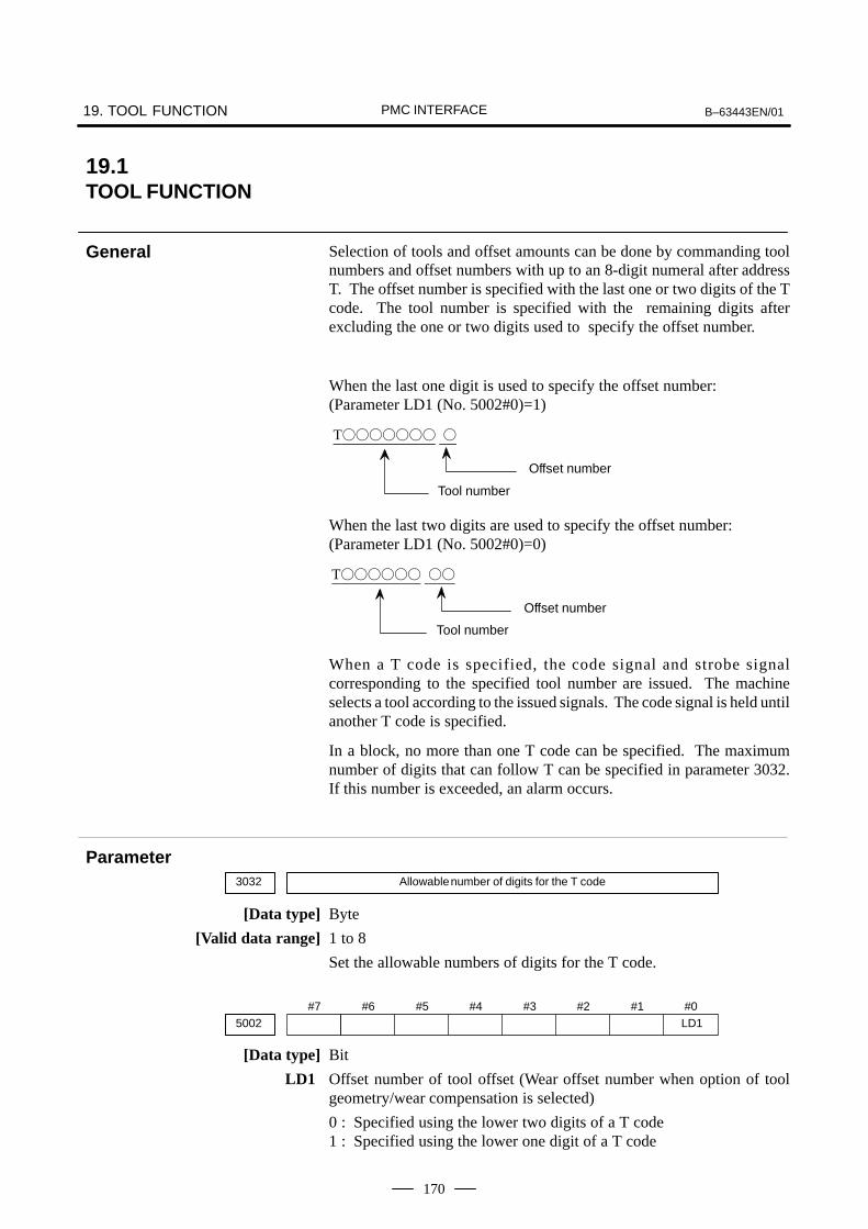
19. TOOL FUNCTION B–63443EN/01PMC INTERFACE
170
Selection of tools and offset amounts can be done by commanding toolnumbers and offset numbers with up to an 8-digit numeral after addressT. The offset number is specified with the last one or two digits of the Tcode. The tool number is specified with the remaining digits afterexcluding the one or two digits used to specify the offset number.
When the last one digit is used to specify the offset number: (Parameter LD1 (No. 5002#0)=1)
T
Offset number
Tool number
When the last two digits are used to specify the offset number: (Parameter LD1 (No. 5002#0)=0)
T
Offset number
Tool number
When a T code is specified, the code signal and strobe signalcorresponding to the specified tool number are issued. The machineselects a tool according to the issued signals. The code signal is held untilanother T code is specified.
In a block, no more than one T code can be specified. The maximumnumber of digits that can follow T can be specified in parameter 3032.If this number is exceeded, an alarm occurs.
3032 Allowable number of digits for the T code
[Data type] Byte
[Valid data range] 1 to 8
Set the allowable numbers of digits for the T code.
#7 #6 #5 #4 #3 #2 #1 #05002 LD1
[Data type] Bit
LD1 Offset number of tool offset (Wear offset number when option of toolgeometry/wear compensation is selected)
0 : Specified using the lower two digits of a T code1 : Specified using the lower one digit of a T code
19.1TOOL FUNCTION
General
Parameter

B–63443EN/01 19. TOOL FUNCTIONPMC INTERFACE
171
#7 #6 #5 #4 #3 #2 #1 #05006 TGC
[Data type] Bit
TGC When a T code is specified in a block containing G50, G04, or G10:
0 : No alarm occurs.1 : P/S alarm No. 254 occurs.
Message Description
030 ILLEGAL OFFSET NUM-BER
The offset number in T function speci-fied for tool offset is too large.Modify the program.
245 T–CODE NOT ALOWEDIN THIS BLOCK
One of the G codes, G50, G10, andG04, which cannot be specified in thesame block as a T code, was specifiedwith a T code.
NOTEWhen a move command and a tool function are specified inthe same block, the commands are executed in one of thefollowing two ways:(i) Simultaneous execution of the move command and tool
function commands.(ii) Executing tool function commands upon completion of
move command execution.The selection of either (i) or (ii) depends on the sequenceprogram of PMC.
OPERATOR’S MANUAL(B–63444EN)
II.10.1 TOOL SELECTION FUNCTION
Power Mate 0CONNECTION MANUAL (This manual)
15 AUXILIARY FUNCTION
Alarm and message
Note
Reference item

19. TOOL FUNCTION B–63443EN/01PMC INTERFACE
172
19.2TOOL COMPENSATION VALUE/TOOL COMPENSATION NUMBER/TOOL COMPENSATION MEMORY
Point on the program
Offsetvalue onX axis
Offsetvalue onZ axis
Tool compensation values can be entered into CNC memory from theCRT/MDI panel or from a program.A tool compensation value is selected from the CNC memory when thecorresponding code is specified after address T in a program. The value is used for tool offset or tool nose radius compensation.
Tool offset amount range which can be set is as follows:
Tool compensationIncrement system
Metric input Inch input
IS-B 999.999 mm 99.9999 inch
The memory can hold 16 sets of tool compensation values.
Range of toolcompensation value
Tool compensationnumber
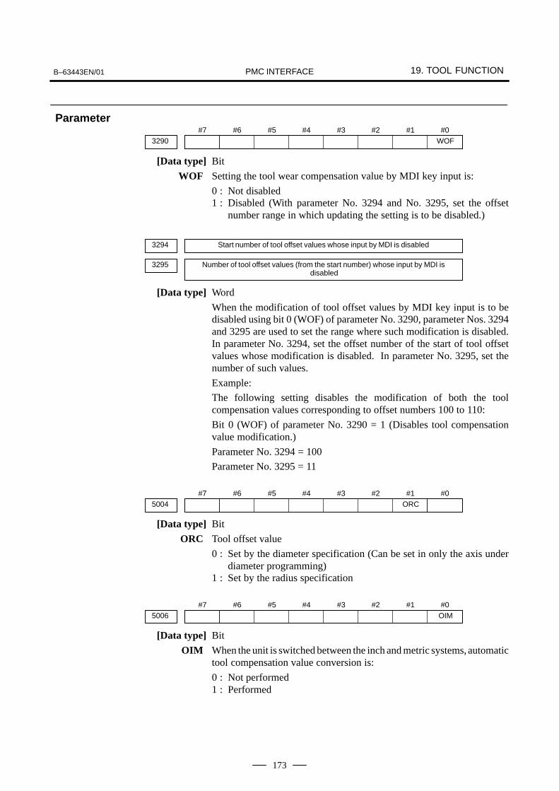
B–63443EN/01 19. TOOL FUNCTIONPMC INTERFACE
173
#7 #6 #5 #4 #3 #2 #1 #03290 WOF
[Data type] Bit
WOF Setting the tool wear compensation value by MDI key input is:
0 : Not disabled1 : Disabled (With parameter No. 3294 and No. 3295, set the offset
number range in which updating the setting is to be disabled.)
3294 Start number of tool offset values whose input by MDI is disabled
3295 Number of tool offset values (from the start number) whose input by MDI is disabled
[Data type] Word
When the modification of tool offset values by MDI key input is to bedisabled using bit 0 (WOF) of parameter No. 3290, parameter Nos. 3294and 3295 are used to set the range where such modification is disabled.In parameter No. 3294, set the offset number of the start of tool offsetvalues whose modification is disabled. In parameter No. 3295, set thenumber of such values.
Example:
The following setting disables the modification of both the toolcompensation values corresponding to offset numbers 100 to 110:
Bit 0 (WOF) of parameter No. 3290 = 1 (Disables tool compensationvalue modification.)
Parameter No. 3294 = 100
Parameter No. 3295 = 11
#7 #6 #5 #4 #3 #2 #1 #05004 ORC
[Data type] Bit
ORC Tool offset value
0 : Set by the diameter specification (Can be set in only the axis underdiameter programming)
1 : Set by the radius specification
#7 #6 #5 #4 #3 #2 #1 #05006 OIM
[Data type] Bit
OIM When the unit is switched between the inch and metric systems, automatictool compensation value conversion is:
0 : Not performed1 : Performed
Parameter

19. TOOL FUNCTION B–63443EN/01PMC INTERFACE
174
5013 Maximum value of tool compensation
[Data type] Two–word
Increment system IS–B Unit
Metric input 0.001 mm
Inch input 0.0001 inch
Increment system IS–B
Metric input 0 to 999999
Inch input 0 to 999999
This parameter sets the maximum value of tool compensation. Thefollowing alarm or warning will be informed when the tool compensation(absolute value) exceeding this setting value is set.
Input from MDI Warning : Too many digits
Input by G10 P/S 32 offset value is out of range by G10
5014 Maximum value of incremental input for tool compensation
[Data type] Two–word
Increment system IS–B Unit
Metric input 0.001 mm
Inch input 0.0001 inch
Increment system IS–B
Metric input 0 to 999999
Inch input 0 to 999999
This parameter sets the maximum value of tool compensation at anincremental input. If the incremental value exceeds the set value, thefollowing alarm or warning message is indicated:
Input from MDI Warning : Data is out of range
Input by G10 P/S 32 offset value is out of range by G10
Message Description
032 ILLEGAL OFFSET VALUEIN G10
In setting an offset amount by G10 orin writing an offset amount by systemvariables, the offset amount was ex-cessive.
Warning message Content
DATA IS OUT OF RANGE The value searched exceeds the permittedrange.
TOO MANY DIGITS The input value exceeds the permitted numberof digits.
[Unit of data]
[Valid data range]
[Unit of data]
[Valid data range]
Alarm and message

B–63443EN/01 19. TOOL FUNCTIONPMC INTERFACE
175
Power Mate 0 OPERATOR’S MANUAL(B–63444EN)
II 13.4 TOOL COMPENSATION VAL-UES, NUMBER OF COM-PENSATION VALUES, AND EN-TERING VALUES FROM THEPROGRAM (G10)
Reference item
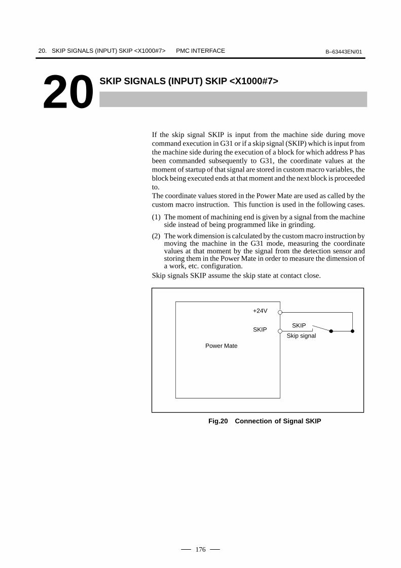
20. SKIP SIGNALS (INPUT) SKIP <X1000#7> B–63443EN/01PMC INTERFACE
176
20 SKIP SIGNALS (INPUT) SKIP <X1000#7>
If the skip signal SKIP is input from the machine side during movecommand execution in G31 or if a skip signal (SKIP) which is input fromthe machine side during the execution of a block for which address P hasbeen commanded subsequently to G31, the coordinate values at themoment of startup of that signal are stored in custom macro variables, theblock being executed ends at that moment and the next block is proceededto.The coordinate values stored in the Power Mate are used as called by thecustom macro instruction. This function is used in the following cases.
(1) The moment of machining end is given by a signal from the machineside instead of being programmed like in grinding.
(2) The work dimension is calculated by the custom macro instruction bymoving the machine in the G31 mode, measuring the coordinatevalues at that moment by the signal from the detection sensor andstoring them in the Power Mate in order to measure the dimension ofa work, etc. configuration.
Skip signals SKIP assume the skip state at contact close.
Power Mate
Skip signal
SKIP
+24V
SKIP
Fig.20 Connection of Signal SKIP

B–63443EN/01 20. SKIP SIGNALS (INPUT) SKIP <X1000#7>PMC INTERFACE
177
NOTE1 The G31 block unconditionally assumes the G01 mode.
The feed rate becomes the value specified by the F code.2 If measuring using signal SKIP, the feed rate must be
programmed to be constant. Measuring errors becomelange if the feed rate is different. The measuring error whenthe feed rate is constant is shown below.
ERRmax : Measuring error [mm or inch]Fm : Measuring feedrate [mm/min or inch/min]
3 The surpassing amount after signal SKIP rises is shownbelow.
Qmax : Surpassing amount [mm or inch]Fm : Measuring rate [mm/min or inch/min]Tc : Cutting time constant [msec]Ts : Servo time constant, normally Ts=33 msec
4 The signal width of signal SKIP must be a minimum of 10msec.
5 SKIP is read directly by the Power Mate from the machineside.
6 If not using the skip function (G31), the signal terminalcorresponding to SKIP is available in the PMC as thegeneral-purpose input signal.
ERRmax Fm 160
4
1000
Qmax Fm 160
( 121000
TC1000
TS1000
)

21. MECHANICAL HANDLE FEED B–63443EN/01PMC INTERFACE
178
21 ( ) )
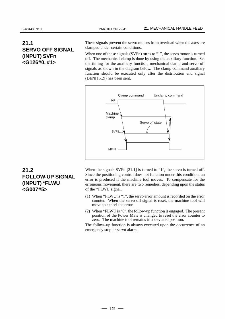
B–63443EN/01 21. MECHANICAL HANDLE FEEDPMC INTERFACE
179
These signals prevent the servo motors from overload when the axes areclamped under certain conditions.
When one of these signals (SVFn) turns to “1”, the servo motor is turnedoff. The mechanical clamp is done by using the auxiliary function. Setthe timing for the auxiliary function, mechanical clamp and servo offsignals as shown in the diagram below. The clamp command auxiliaryfunction should be executed only after the distribution end signal(DEN[15.2]) has been sent.
MF
Clamp command
Machineclamp
SVF1,…
Unclamp command
Servo off state
MFIN
When the signals SVFn [21.1] is turned to “1”, the servo is turned off.Since the positioning control does not function under this condition, anerror is produced if the machine tool moves. To compensate for theerroneous movement, there are two remedies, depending upon the statusof the *FLWU signal.
(1) When *FLWU is “1”, the servo error amount is recorded on the errorcounter. When the servo off signal is reset, the machine tool willmove to cancel the error.
(2) When *FLWU is “0”, the follow-up function is engaged. The presentposition of the Power Mate is changed to reset the error counter tozero. The machine tool remains in a deviated position.
The follow–up function is always executed upon the occurrence of anemergency stop or servo alarm.
21.1SERVO OFF SIGNAL(INPUT) SVFn<G126#0, #1>
21.2FOLLOW-UP SIGNAL(INPUT) *FLWU<G007#5>

22. SOFTWARE OPERATOR’S PANEL B–63443EN/01PMC INTERFACE
180
22 % <
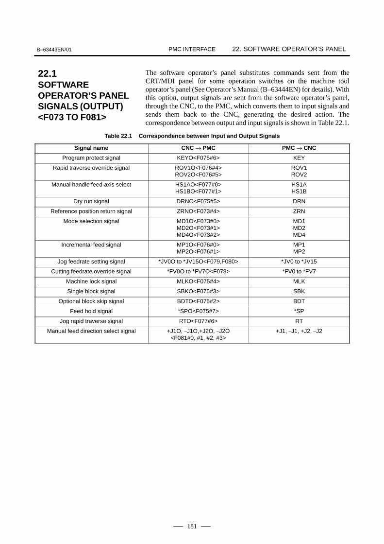
B–63443EN/01 22. SOFTWARE OPERATOR’S PANELPMC INTERFACE
181
The software operator’s panel substitutes commands sent from theCRT/MDI panel for some operation switches on the machine tooloperator’s panel (See Operator’s Manual (B–63444EN) for details). Withthis option, output signals are sent from the software operator’s panel,through the CNC, to the PMC, which converts them to input signals andsends them back to the CNC, generating the desired action. Thecorrespondence between output and input signals is shown in Table 22.1.
Table 22.1 Correspondence between Input and Output Signals
Signal name CNC → PMC PMC → CNC
Program protect signal KEYO<F075#6> KEY
Rapid traverse override signal ROV1O<F076#4>ROV2O<F076#5>
ROV1ROV2
Manual handle feed axis select HS1AO<F077#0>HS1BO<F077#1>
HS1AHS1B
Dry run signal DRNO<F075#5> DRN
Reference position return signal ZRNO<F073#4> ZRN
Mode selection signal MD1O<F073#0>MD2O<F073#1>MD4O<F073#2>
MD1MD2MD4
Incremental feed signal MP1O<F076#0>MP2O<F076#1>
MP1MP2
Jog feedrate setting signal *JV0O to *JV15O<F079,F080> *JV0 to *JV15
Cutting feedrate override signal *FV0O to *FV7O<F078> *FV0 to *FV7
Machine lock signal MLKO<F075#4> MLK
Single block signal SBKO<F075#3> SBK
Optional block skip signal BDTO<F075#2> BDT
Feed hold signal *SPO<F075#7> *SP
Jog rapid traverse signal RTO<F077#6> RT
Manual feed direction select signal +J1O, –J1O,+J2O, –J2O<F081#0, #1, #2, #3>
+J1, –J1, +J2, –J2
22.1SOFTWAREOPERATOR’S PANELSIGNALS (OUTPUT)<F073 TO F081>

22. SOFTWARE OPERATOR’S PANEL B–63443EN/01PMC INTERFACE
182
These signals work from the optional software operator’s panel in thesame way as the predefined signals. Machine tool builders may assigntheir own functions to the signals.
OUT0 Signal corresponds to the switch described on 1st line of CRT display
OUT1 Signal corresponds to the switch described on 2nd line of CRT display
OUT7 Signal corresponds to the switch described on 8th line of CRT display
The cursor position (ON/OFF) on the CRT display and correspondingsignal conditions are specified below :
ON
OFF
1
0
Cursor position on the CRT display Corresponding signal condition
22.2SOFTWAREOPERATOR’S PANELGENERAL-PURPOSESWITCH SIGNALS(OUTPUT) OUT0 TOOUT7 <F072>

B–63443EN/01 23. CUSTOM MACROPMC INTERFACE
183
23 ( (

23. CUSTOM MACRO B–63443EN/01PMC INTERFACE
184
Custom macro signals are interface signals used for custom macro andPMC programs. Input/output is controlled by system variables from thecustom macro side, by specifying both addresses and bits from the PMC(just as for DI/DO signals). (See Fig. 23.1 (a).)
Output by system variable#1100 to #1115
Output by addresses G054(0-7bit) and G055 (0-7bit)
Ready by addresses F054(0-7bit) and F055 (0-7bit)
Read by system variable#1000 to #1015
Custom macro
Power Mateside
PMC side
UO0 toUO15,
UI0toUI15
Fig.23.1 (a)
The relationship among system variables, I/O signals, addresses, and bitsis shown in Tables 23.1 (a) and (b).
Table 23.1 (a) Custom Macro Input Signals Table 23.1 (b) Custom Macro Output Signals
Systemvariable
Interface inputsignal
PMC address(bit)
Systemvariable
Interface outputsignal
PMC address(bit)
#1000#1001#1002#1003#1004#1005#1006#1007#1008#1009#1010#1011#1012#1013#1014#1015
UI0UI1UI2UI3UI4UI5UI6UI7UI8UI9UI10UI11UI12UI13UI14UI15
G054 (0)G054 (1)G054 (2)G054 (3)G054 (4)G054 (5)G054 (6)G054 (7)G055 (0)G055 (1)G055 (2)G055 (3)G055 (4)G055 (5)G055 (6)G055 (7)
#1100#1101#1102#1103#1104#1105#1106#1107#1108#1109#1110#1111#1112#1113#1114#1115#1133
UO0UO1UO2UO3UO4UO5UO6UO7UO8UO9
UO10UO11UO12UO13UO14UO15
UO100 to UO131
F054(0)F054 (1)F054 (2)F054 (3)F054 (4)F054 (5)F054 (6)F054 (7)F055 (0)F055 (1)F055 (2)F055 (3)F055 (4)F055 (5)F055 (6)F055 (7)
F056 to F059
23.1CUSTOM MACROSIGNAL (INPUT) UI0 TO UI15<G054, G055>,(OUTPUT) UO0 TOUO131 <F054 TOF059>

B–63443EN/01
24. SPEED CONTROL SERVO ALARM IGNORE SIGNAL (INPUT)
IGNVRY <G066#0>PMC INTERFACE
185
24 ) = (
-. =& 1233427
If the speed control servo alarm is issued and this signal is high, thecontrol unit ignores the alarm, thus preventing the alarm state from beingset.
While this signal is “1”, the control unit ignores the speed control servoalarm (alarm 401: VRDY OFF); consequently, the alarm state is not set.The alarm state is set if an alarm other than the speed control servo alarmis issued, however. If IGNVRY makes a “0” to “1” transition after thespeed control servo alarm has been issued, the alarm state is not canceled.Only the speed control servo alarm issued while this signal is “1” isignored.
Application: Suppose an application exists which has a safety provisionto switch off the magnetic contactor (MCC) of the servo unitwhen the limit switch on at the door of the splash guard isactivated when the splash guard is opened. This signal canbe used in such an application. When the MCC of the servounit is switched off, the speed control servo alarm is issued.By making the IGNVRY signal “1” beforehand, however,the alarm can be ignored.When making IGNVRY “1”, be sure to make the feed holdsignal *SP [12.2] “0” at the same time to prevent automaticoperation from being activated.
t
IGNVRY
*SP
The MCC of the servo unitON/OFF
t
t : more than 100 ms
ON OFF

24. SPEED CONTROL SERVO ALARM IGNORE SIGNAL (INPUT) IGNVRY <G066#0> B–63443EN/01PMC INTERFACE
186
NOTE1 While the VRDY OFF alarm ignore signal is set to 1, and a
servo alarm other than alarm No. 401 occurs, the controlunit detects the alarm.
2 When the control enters NOT READY status due toemergency stop or a servo alarm and then the control isreset, reset processing is not terminated until the VRDYOFF alarm ignore signal is set to 0.
3 When the VRDY OFF alarm ignore signal is set to 1 and theservo amplifier ready signal is set to off, the motor is freedfrom the drive, but follow up is not performed. To performfollow up, set the servo off signal to 1.

APPENDIX

B–63443EN/01 A. EXTERNAL DIMENSIONS OF EACH UNITAPPENDIX
189
A > )(
Classification NameNumber
ofFigure
Control unit CONTROL UNIT Fig. 1
Setting and CRT/MDI Fig. 2display unit
DPL/MDI Fig. 3
External device α POSITION CODER Fig. 4
MANUAL PULSE GENERATOR Fig. 5
MANUAL PULSE GENERATOR (PENDANT TYPE) Fig. 6
PUNCH PANEL (NARROW WIDTH TYPE) Cable J42 Fig. 7
PUNCH PANEL (WITH 24V TERMINAL BOARD) Fig. 8
FANUC Handy File Fig. 9
CRT LINK TERMINAL UNIT, TOUCH PANEL TERMINAL Fig. 10

A. EXTERNAL DIMENSIONS OF EACH UNIT B–63443EN/01APPENDIX
190
Fig. 1 CONTROL UNIT
Specification : A02B–0166–B591
Air in
Air out
Weight: 2.2kgUnit : mm

B–63443EN/01 A. EXTERNAL DIMENSIONS OF EACH UNITAPPENDIX
191

A. EXTERNAL DIMENSIONS OF EACH UNIT B–63443EN/01APPENDIX
192
Fig. 2 CRT/MDI
Specification : A02B–0166–C201#TR (English key)A02B–0166–C201#TS (Symbolic key)
The unit is installed from the outside of the cabinet.
Pan
el c
ut d
raw
ing
Stu
d (M
4) fo
r gro
undi
ng
Stu
d (M
4) fo
r gro
undi
ng fo
r pro
tect
ion
Weight: 5.8kgUnit : mm
for p
rote
ctio
n

B–63443EN/01 A. EXTERNAL DIMENSIONS OF EACH UNITAPPENDIX
193
Fig. 3 DPL/MDI
Specification : A02B–0166–C301#R (English key)
Weight: 1.5kgUnit : mm
Stud for ground forprotection (M4)

A. EXTERNAL DIMENSIONS OF EACH UNIT B–63443EN/01APPENDIX
194
Fig. 4 α POSITION CODER
Specification : A860–0309–T302 (Max. 10000 rpm)
MS connector : MS3102A–20–29P
Weight: 1kg or lessUnit : mm

B–63443EN/01 A. EXTERNAL DIMENSIONS OF EACH UNITAPPENDIX
195
Fig. 5 MANUAL PULSE GENERATOR
Specification : A860–0202–T001
83.580.055.0
60.0
50.0
30.0
M4X
8.0
A B
11.0PULSE GENERATOR
FANUC LTD
120.0°M3 screw terminal
3 holes equally spaced on a 72 dia
5V 0V
Weight: 0.35kgUnit : 5mm
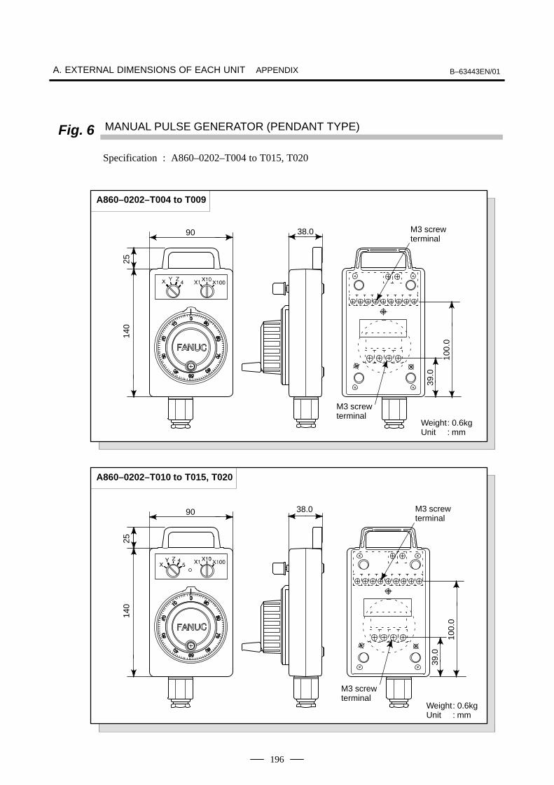
A. EXTERNAL DIMENSIONS OF EACH UNIT B–63443EN/01APPENDIX
196
Fig. 6 MANUAL PULSE GENERATOR (PENDANT TYPE)
Specification : A860–0202–T004 to T015, T020
140
25
90 38.0
39.0
100.
0
A860–0202–T004 to T009
M3 screw terminal
M3 screw terminal
Weight: 0.6kgUnit : mm
140
25
90 38.0
39.0
100.
0
A860–0202–T010 to T015, T020
M3 screw terminal
M3 screw terminal
Weight: 0.6kgUnit : mm

B–63443EN/01 A. EXTERNAL DIMENSIONS OF EACH UNITAPPENDIX
197
Fig. 7 PUNCH PANEL (NARROW WIDTH TYPE) Cable J42
Specification : A02B–0120–C191 (Cable length : 1m)A02B–0120–C192 (Cable length : 2m)A02B–0120–C193 (Cable length : 5m)
401320
100 115
20
2M3
125
55
Panel cut drawing
Unit : mm
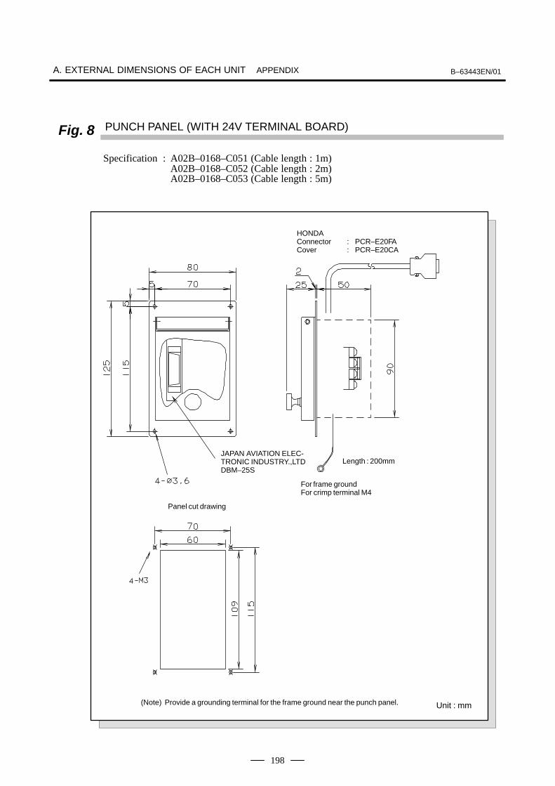
A. EXTERNAL DIMENSIONS OF EACH UNIT B–63443EN/01APPENDIX
198
Fig. 8 PUNCH PANEL (WITH 24V TERMINAL BOARD)
Specification : A02B–0168–C051 (Cable length : 1m)A02B–0168–C052 (Cable length : 2m)A02B–0168–C053 (Cable length : 5m)
For frame groundFor crimp terminal M4
Panel cut drawing
(Note) Provide a grounding terminal for the frame ground near the punch panel.
HONDAConnector : PCR–E20FACover : PCR–E20CA
Length : 200mmJAPAN AVIATION ELEC-TRONIC INDUSTRY.,LTDDBM–25S
Unit : mm
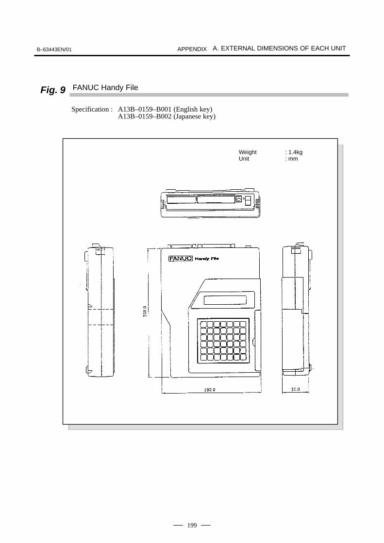
B–63443EN/01 A. EXTERNAL DIMENSIONS OF EACH UNITAPPENDIX
199
Fig. 9 FANUC Handy File
Specification : A13B–0159–B001 (English key)A13B–0159–B002 (Japanese key)
Weight : 1.4kgUnit : mm

A. EXTERNAL DIMENSIONS OF EACH UNIT B–63443EN/01APPENDIX
200
Fig. 10 CRT LINK TERMINAL UNIT
Specification : A02B–0124–D001
9.5
HONDA
21
30
37
11.4
Weight: Approx. 30gUnit : mm

B–63443EN/01
B. EXTERNAL DIMENSIONS OFEACH CONNECTORAPPENDIX
201
B > )(
NameNumber
of Figure
PCR CONNECTOR Fig. 1
FI40 CONNECTOR Fig. 2
CONNECTOR CASE (HONDA PCR TYPE) Fig. 3
CONNECTOR CASE (HIROSE FI TYPE) Fig. 4
CONNECTOR CASE (FUJITSU FCN TYPE) Fig. 5
AMP CONNECTOR (1) TYPE X Fig. 6
CONTACT FOR AMP CONNECTOR Fig. 7
READER PUNCHER PANEL CONNECTOR Fig. 8
READER PUNCHER CONNECTOR METAL FITTING FOR LOCK Fig. 9
FASTON TERMINAL Fig. 10
CONNECTOR FOR HIROSE PLAT CABLE Fig. 11
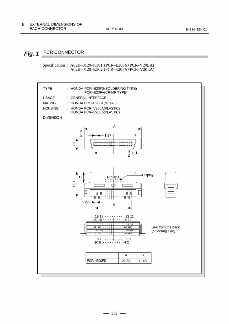
B. EXTERNAL DIMENSIONS OF EACH CONNECTOR B–63443EN/01APPENDIX
202
Fig. 1 PCR CONNECTOR
Specification : A02B–0120–K301 (PCR–E20FS+PCR–V20LA)A02B–0120–K302 (PCR–E20FA+PCR–V20LA)
19 17 13 1120 18 14 12
9 7 3 110 8 4 2
HONDA
1.27
A
1
7.3
n n2 1
7
15.1
B1.27
Display
n2
21.65
4
11.43
TYPE : HONDA PCR–E20FS(SOLDERING TYPE)PCR–E20FA(CRIMP TYPE)
USAGE : GENERAL INTERFACE
MATING : HONDA PCS–E20LA(METAL)
HOUSING : HONDA PCR–V20LA(PLASTIC)HONDA PCR–V20LB(PLASTIC)
DIMENSION
See from the back (soldering side)

B–63443EN/01
B. EXTERNAL DIMENSIONS OFEACH CONNECTORAPPENDIX
203
Fig. 2 FI40 CONNECTOR
Specification : A02B–0120–K303 (FI40–2015S+FI–20–CV)
16.2511.43
1.27
13.35
19.2
15°
5.5
2.2
1.7
9.2
12345678910
11121314151617181920
S
1
2
3
4
5
6
7
8
9
10
1214161820
1.8
3
5
8.5
4.3
7
A A2.4 2.4
Section AA
NOTEThis connector does nothave contacts for positions11,13,15,17, and 19.
Tab forshieldconnection
TYPE : HIROSE FI40–2015S
USAGE : PULSE CODER INTERFACE
LINEAR SCALE INTERFACE
MPG INTERFACE
MATING/HOUSING : HIROSE FI–20–CV
DIMENSION
(Standard 1/10)See from the back (soldering side)

B. EXTERNAL DIMENSIONS OF EACH CONNECTOR B–63443EN/01APPENDIX
204
Fig. 3 CONNECTOR CASE (HONDA PCR TYPE)
9.5
HONDA
21
30
37
11.4
TYPE : HONDA PCR–V20LA (for 6 dia. cable)PCR–V20LB (for 8 dia. cable)
USAGE : GENERAL INTERFACE
DIMENSION
Case Cable clamp Lock bracket Lock lever Set screw for cable clamp
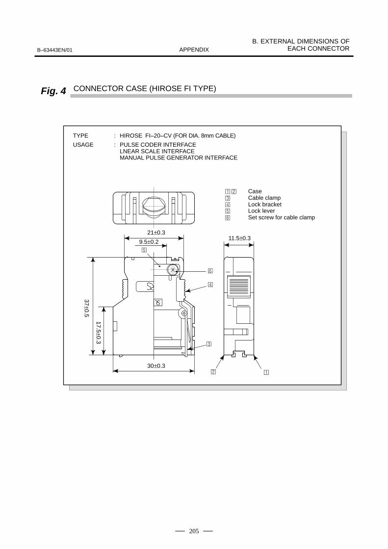
B–63443EN/01
B. EXTERNAL DIMENSIONS OFEACH CONNECTORAPPENDIX
205
Fig. 4 CONNECTOR CASE (HIROSE FI TYPE)
21±0.3
9.5±0.2
30±0.3
11.5±0.3
Case Cable clamp Lock bracket Lock lever Set screw for cable clamp
TYPE : HIROSE FI–20–CV (FOR DIA. 8mm CABLE)
USAGE : PULSE CODER INTERFACELNEAR SCALE INTERFACEMANUAL PULSE GENERATOR INTERFACE
17.5±0.3
37±0.5

B. EXTERNAL DIMENSIONS OF EACH CONNECTOR B–63443EN/01APPENDIX
206
Fig. 5 CONNECTOR CASE (FUJITSU FCN TYPE)
21
30
37
11.4
FC020–02
$
%
56 7
TYPE : FUJITSU FCN–240C20–Y/S (FOR DIA. 5.8mm CABLE)
USAGE : GENERAL
9.5

B–63443EN/01
B. EXTERNAL DIMENSIONS OFEACH CONNECTORAPPENDIX
207
Fig. 6 AMP CONNECTOR (1) TYPE X
Specification : A02B–0120–K324 (WITH CONTACT AMP1–175218–5)
3 12D–3AMP
(22.96)
16.7
16.3 22
.8X
7.623.81
4.05
3.1
123
0.6
6.55
7.15
0V
+24E
Circuit No.
TYPE : AMP2–178288–3 (HOUSING)
USAGE : CONTROL UNIT POWER SUPPLY INPUT
CRT/MDI POWER SUPPLY INPUTDPL/MDI POWER SUPPLY INPUT
DIMENSION
Circuit No.
CP1
CPD1

B. EXTERNAL DIMENSIONS OF EACH CONNECTOR B–63443EN/01APPENDIX
208
Fig. 7 CONTACT FOR AMP CONNECTOR
SEPARATE : AMP1–175218–2 (GOLD COATED)AMP1–175218–5 (TIN COATED)
REEL : AMP1–175196–2 (GOLD COATED)AMP1–175196–5 (TIN COATED)
WIRE : AWG 16, 18, 20
*8
9 3
±0.4
*
*
±0.4*8
±0.5
:* *
(φ2.6)
–AMP
*:
* *
*
±0.2
PLATING ID–MARK
PRESSER ID–MARK
±0.2
±0.2
±0.5
*:
±0.5
*:
44
4
4

B–63443EN/01
B. EXTERNAL DIMENSIONS OFEACH CONNECTORAPPENDIX
209
Fig. 8 READER PUNCHER PANEL CONNECTOR
Specification : A02B–0118–K895 (male, with cover)A02B–0061–K201 (female. with metal fitting for lock)
F
G
10
HJ
A * " *8 ) *4 8* *; / * * * *8
A
2–3.05
D
A–Across sectionA
A
CB
E
10
106.1
10.8
Fig. 9 READER PUNCHER CONNECTOR METAL FITTING FOR LOCK
Interlock screwM2.6×P0.45 screwSmall round head screw
1.2 groove
Spring washer
6.1
1.26.2
*
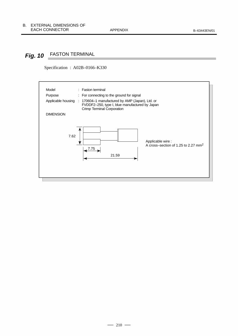
B. EXTERNAL DIMENSIONS OF EACH CONNECTOR B–63443EN/01APPENDIX
210
Fig. 10 FASTON TERMINAL
Specification : A02B–0166–K330
7.62
7.75
21.59
Model : Faston terminal
Purpose : For connecting to the ground for signal
Applicable housing : 170604–1 manufactured by AMP (Japan), Ltd. or FVDDF2–250, type I, blue manufactured by Japan Crimp Terminal Corporation
DIMENSION
Applicable wire :A cross–section of 1.25 to 2.27 mm2

B–63443EN/01
B. EXTERNAL DIMENSIONS OFEACH CONNECTORAPPENDIX
211
Fig. 11 CONNECTOR FOR HIROSE FLAT CABLE
Specification HIROSE ELEC. CO.HIF3BA–34D–2.54R (34contacts)
Section B–B’
1.271.27
1.27
1.09
15.6
14.4
ASS’Y DIAGRAMSection A–A’
C
3.8
2.7
7.0
A
A A’ B
B’2.54
3.811.27
2.54
6.0
A
6.0
D
3.5
10.5
7.0
0.3
0.95
1.05
3.5
4.5
2.3
A
D
3.6
6.0
2.33.5
8.5
MAIN BODY PROTECTOR CRAMP
B
5.1
HIF3BA–34D–2.54R
Description A B C D
47.75 40.64 41.91 43.28
No.ofcontact
34
Dimensions
FLAT CABLE CONNECTOR CONTACT NUMBER (HIROSE)
HIF3BA
AOI MARK (side)
0102
0304
0506
0708
0910
1112
1314
1516
17
34PINS
ROW A
ROW B
OUTVIEW FROM CONNECTOR SIDE
POLARITY GUIDANCE

C. 20–PIN INTERFACE CONNECTORS AND CABLES B–63443EN/01APPENDIX
212
C 82? ) @

B–63443EN/01
C. 20–PIN INTERFACE CONNECTORSAND CABLESAPPENDIX
213
Models: PCR–EV20MDT (Honda Tsushin)52618–2011 (Molex Japan)
These board–mounted connectors have been specially developed toachieve the high packing density required for FANUC products. Asexplained in the following subsection, Honda PCR series connectors canbe used as cable connectors because the mating mechanism of the newlydeveloped connectors is compatible with that of the Honda PCR seriesconnectors. To support this specification extensively, many connectormanufacturers are now developing custom–tailored cable connectors.(Note that these cables cannot be used with screw–fixing cable connectorhousings.)
C.1BOARD–MOUNTEDCONNECTORS
C.1.1Vertical–typeConnectors
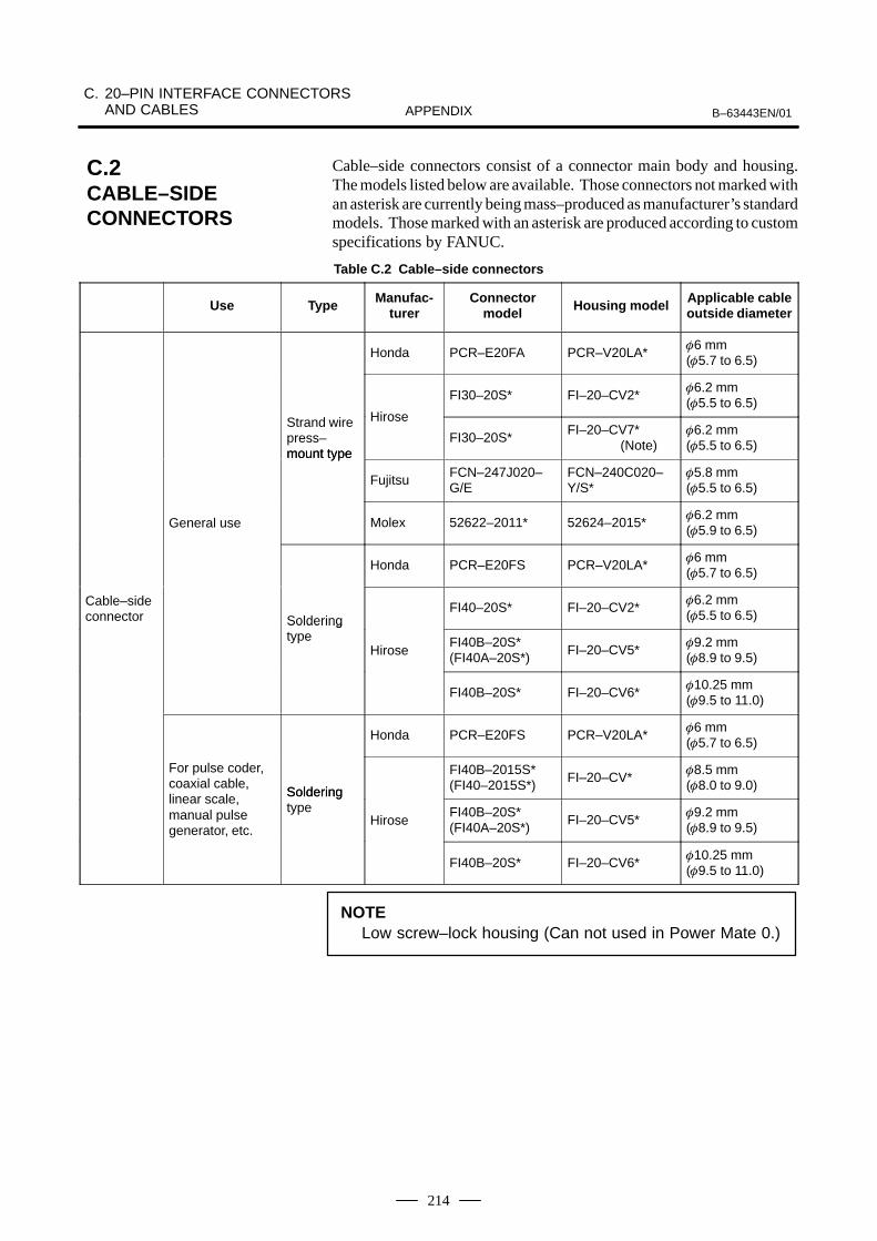
C. 20–PIN INTERFACE CONNECTORS AND CABLES B–63443EN/01APPENDIX
214
Cable–side connectors consist of a connector main body and housing.The models listed below are available. Those connectors not marked withan asterisk are currently being mass–produced as manufacturer’s standardmodels. Those marked with an asterisk are produced according to customspecifications by FANUC.
Table C.2 Cable–side connectors
Use Type Manufac-turer
Connectormodel Housing model Applicable cable
outside diameter
Honda PCR–E20FA PCR–V20LA*6 mm (5.7 to 6.5)
FI30–20S* FI–20–CV2*6.2 mm (5.5 to 6.5)
Strand wirepress–mount type
Hirose
FI30–20S*FI–20–CV7*
(Note)6.2 mm (5.5 to 6.5)
mount type
FujitsuFCN–247J020–G/E
FCN–240C020–Y/S*
5.8 mm (5.5 to 6.5)
General use Molex 52622–2011* 52624–2015*6.2 mm (5.9 to 6.5)
Honda PCR–E20FS PCR–V20LA*6 mm (5.7 to 6.5)
Cable–sideconnector Soldering
FI40–20S* FI–20–CV2*6.2 mm (5.5 to 6.5)Soldering
typeHirose
FI40B–20S*(FI40A–20S*)
FI–20–CV5*9.2 mm (8.9 to 9.5)
FI40B–20S* FI–20–CV6*10.25 mm (9.5 to 11.0)
Honda PCR–E20FS PCR–V20LA*6 mm (5.7 to 6.5)
For pulse coder,coaxial cable,
Soldering
FI40B–2015S*(FI40–2015S*)
FI–20–CV*8.5 mm (8.0 to 9.0)
linear scale, manual pulse generator, etc.
Solderingtype
HiroseFI40B–20S*(FI40A–20S*)
FI–20–CV5*9.2 mm (8.9 to 9.5)
FI40B–20S* FI–20–CV6*10.25 mm (9.5 to 11.0)
NOTELow screw–lock housing (Can not used in Power Mate 0.)
C.2CABLE–SIDECONNECTORS
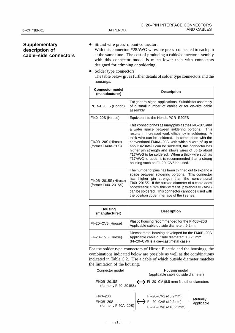
B–63443EN/01
C. 20–PIN INTERFACE CONNECTORSAND CABLESAPPENDIX
215
Strand wire press–mount connector: With this connector, #28AWG wires are press–connected to each pinat the same time. The cost of producing a cable/connector assemblywith this connector model is much lower than with connectorsdesigned for crimping or soldering.
Solder type connectorsThe table below gives further details of solder type connectors and thehousings.
Connector model(manufacturer) Description
PCR–E20FS (Honda)For general signal applications. Suitable for assemblyof a small number of cables or for on–site cableassembly
FI40–20S (Hirose) Equivalent to the Honda PCR–E20FS
FI40B–20S (Hirose) (former FI40A–20S)
This connector has as many pins as the FI40–20S anda wider space between soldering portions. Thisresults in increased work efficiency in soldering. Athick wire can be soldered. In comparison with theconventional FI40A–20S, with which a wire of up toabout #20AWG can be soldered, this connector hashigher pin strength and allows wires of up to about#17AWG to be soldered. When a thick wire such as#17AWG is used, it is recommended that a stronghousing such as FI–20–CV6 be used.
FI40B–2015S (Hirose)(former FI40–2015S)
The number of pins has been thinned out to expand aspace between soldering portions. This connectorhas higher pin strength than the conventionalFI40–2015S. If the outside diameter of a cable doesnot exceed 8.5 mm, thick wires of up to about #17AWGcan be soldered. This connector cannot be used withthe position coder interface of the i series.
Housing(manufacturer) Description
FI–20–CV5 (Hirose)Plastic housing recommended for the FI40B–20SApplicable cable outside diameter: 9.2 mm
FI–20–CV6 (Hirose)Diecast metal housing developed for the FI40B–20SApplicable cable outside diameter: 10.25 mm(FI–20–CV6 is a die–cast metal case.)
For the solder type connectors of Hirose Electric and the housings, thecombinations indicated below are possible as well as the combinationsindicated in Table C.2. Use a cable of which outside diameter matchesthe limitation of the housing.
Connector model
FI40B–2015S (formerly FI40–2015S)
FI40–20S
FI40B–20S (formerly FI40A–20S)
Housing model (applicable cable outside diameter)
FI–20–CV (8.5 mm) No other diameters
FI–20–CV2 (6.2mm)
FI–20–CV5 (9.2mm)
FI–20–CV6 (10.25mm)
Mutuallyapplicable
Supplementarydescription ofcable–side connectors

C. 20–PIN INTERFACE CONNECTORS AND CABLES B–63443EN/01APPENDIX
216
Table C.3 Recommended connectors, applicable housings, and cables
Connector namereferenced in the
Connection Manual
FANUC–approvedconnector
(manufacturer)
FANUC–approvedhousing
(manufacturer)
Compatible cable (cablediameter) FANUC devel-opment FANUC specifi-
cation number
Remark
PCR–E20FA Strand press–mount
PCR–E20FA(Honda Tsushin)
PCR–E20LA(Honda Tsushin)
A66L–0001–0284#10P(6.2 mm in diameter)
Plastic housing
typeFI30–20S(Hirose Electric)
FI–20–CV2(Hirose Electric)
Plastic housing
FI–20–CV7(Hirose Electric)
Plastic housing
FCN–247J020–G/E(Fujitsu Takamizawa)
FCN–240C020–Y/S(Fujitsu Takamizawa)
Plastic housing
52622–2011(Molex)
52624–2015(Molex)
Plastic housing
PCR–E20FS Soldering type
PCR–E20FS(Honda Tsushin)
PCR–V20LA(Honda Tsushin)
Plastic housing
FI40–20S(Hirose Electric)
FI–20–CV2(Hirose Electric)
Plastic housing
FI40B–2015S (formerlyFI40–2015S) 15–pinsoldering type
F140B–2015S(formerlyFI40–2015S) (HiroseElectric)
FI–20–CV(Hirose Electric)
A66L–0001–0286 (Note)A66L–0001–0402 (Note)(8.5 mm in diameter)
Plastic housing
FI40B–20S (formerly FI40A–20S)Soldering type
FI40B–20S(formerly FI40A–20S)(Hirose Electric)
FI–20–CV5(Hirose Electric)
A66L–0001–0367A66L–0001–0368 (9.2 mm in diameter)
Plastic housing
FI40B–20S(Hirose Electric)
FI–20–CV6(Hirose Electric)
A66L–0001–0403 (Note)(9.8 mm in diameter)
Metal housing
NOTECable A66L–0001–0286 has been recommended for use as a pulse coder cable. It can be upto 20 m long. Two cables, A66L–0001–0402 and A66L–0001–0403, have recently beendeveloped. A66L–0001–0402 and A66L–0001–0403 can be as long as 30 m and 50 m,respectively. (See the Section on the cable materials for detailed specifications.)
C.3RECOMMENDEDCONNECTORS,APPLICABLEHOUSING, ANDCABLES
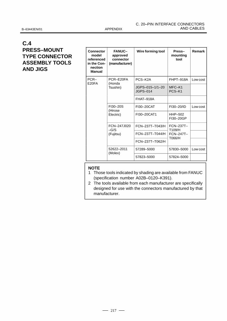
B–63443EN/01
C. 20–PIN INTERFACE CONNECTORSAND CABLESAPPENDIX
217
Connectormodel
referencedin the Con-
nectionManual
FANUC–approved connector
(manufacturer)
Wire forming tool Press–mounting
tool
Remark
PCR– PCR–E20FA PCS–K2A FHPT–918A Low costE20FA (Honda
Tsushin) JGPS–015–1/1–20JGPS–014
MFC–K1PCS–K1
FHAT–918A
FI30–20S FI30–20CAT FI30–20/ID Low cost(Hirose Electric) FI30–20CAT1 HHP–502
FI30–20GP
FCN–247J020 FCN–237T–T043/H FCN–237T––G/S(Fujitsu) FCN–237T–T044/H
T109/HFCN–247T–
FCN–237T–T062/HT066/H
52622–2011 57289–5000 57830–5000 Low cost(Molex)
57823–5000 57824–5000
NOTE1 Those tools indicated by shading are available from FANUC
(specification number A02B–0120–K391).2 The tools available from each manufacturer are specifically
designed for use with the connectors manufactured by thatmanufacturer.
C.4PRESS–MOUNTTYPE CONNECTORASSEMBLY TOOLSAND JIGS

C. 20–PIN INTERFACE CONNECTORS AND CABLES B–63443EN/01APPENDIX
218
Machine tool builders are required to manufacture or procure thematerials for the cable assemblies to be used with their products. FANUCrecommends the following materials as being suitable for interfaceconnectors. Individual machine tool builders are encouraged to contacteach cable manufacturer for themselves, as required.
Table C.5 Recommended materials for cable assemblies
Material Use Constitution FANUC specificationnumber
Manufacturer Remark
10–pair cable General use 0.08 mm2 10 pairs A66L–0001–0284#10P Hitachi Cable, Ltd.Oki Electric Cable Co., Ltd.
5–conductorcoaxial cable
CRT interface (long–distance)
5–conductor coaxial A66L–0001–0371 Hitachi Cable, Ltd. 50 m or less
12–conductorcompositecable (Note)
Pulse coder 0.5 mm2 6 conductors0.18 mm2 3 pairs
A66L–0001–0286 Hitachi Cable, Ltd.Oki Electric CableCo., Ltd.
20 m or less
Linear scale 0.75 mm2 6 conductors0.18 mm2 3 pairs
A66L–0001–0402 Oki Electric Cable Co., Ltd.
30 m or lessUsable on movableparts
Manual pulse generator
1.25 mm2 6 conductors0.18 mm2 3 pairs
A66L–0001–0403 Oki Electric Cable Co., Ltd.
50 m or less Usable on movableparts
NOTEFor a pulse coder, scale, manual pulse generator, or otherunit using +5 V power, select cable wires considering thevoltage drop due to the cable resistance.
C.5MATERIALS FORCABLE ASSEMBLIES
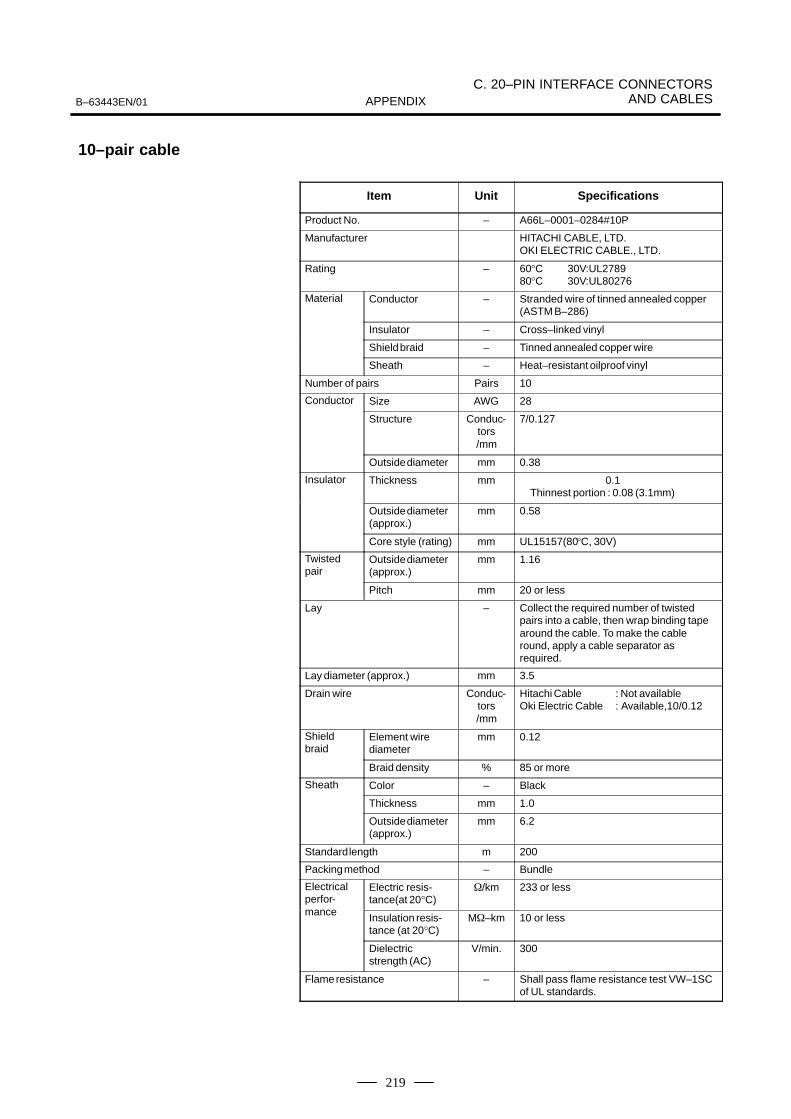
B–63443EN/01
C. 20–PIN INTERFACE CONNECTORSAND CABLESAPPENDIX
219
Item Unit Specifications
Product No. – A66L–0001–0284#10P
Manufacturer HITACHI CABLE, LTD.OKI ELECTRIC CABLE., LTD.
Rating – 60°C 30V:UL278980°C 30V:UL80276
Material Conductor – Stranded wire of tinned annealed copper(ASTM B–286)
Insulator – Cross–linked vinyl
Shield braid – Tinned annealed copper wire
Sheath – Heat–resistant oilproof vinyl
Number of pairs Pairs 10
Conductor Size AWG 28
Structure Conduc-tors/mm
7/0.127
Outside diameter mm 0.38
Insulator Thickness mm 0.1Thinnest portion : 0.08 (3.1mm)
Outside diameter(approx.)
mm 0.58
Core style (rating) mm UL15157(80°C, 30V)
Twistedpair
Outside diameter(approx.)
mm 1.16
Pitch mm 20 or less
Lay – Collect the required number of twistedpairs into a cable, then wrap binding tapearound the cable. To make the cableround, apply a cable separator as required.
Lay diameter (approx.) mm 3.5
Drain wire Conduc-tors/mm
Hitachi Cable : Not availableOki Electric Cable : Available,10/0.12
Shieldbraid
Element wire diameter
mm 0.12
Braid density % 85 or more
Sheath Color – Black
Thickness mm 1.0
Outside diameter(approx.)
mm 6.2
Standard length m 200
Packing method – Bundle
Electricalperfor-
Electric resis-tance(at 20°C)
/km 233 or less
mance Insulation resis-tance (at 20°C)
M–km 10 or less
Dielectricstrength (AC)
V/min. 300
Flame resistance – Shall pass flame resistance test VW–1SCof UL standards.
10–pair cable
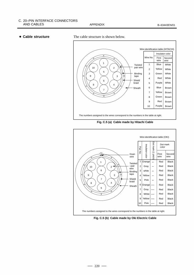
C. 20–PIN INTERFACE CONNECTORS AND CABLES B–63443EN/01APPENDIX
220
The cable structure is shown below.
1
2
3
4
5
6
7
8
9
10
Wire identification table (HITACHI)
Wire No.
Insulator color
First wire
Secondwire
1
2
3
4
5
6
7
8
10
9
Blue
Yellow
Green
Red
Purple
Blue
Yellow
Green
Red
Purple
White
Brown
Twistedpair wire
Bindingtape
Shieldbraid
Sheath
The numbers assigned to the wires correspond to the numbers in the table at right.
White
White
White
White
Brown
Brown
Brown
Brown
Fig. C.5 (a) Cable made by Hitachi Cable
Wire identification table (OKI)
1
2
3
4
5
6
7
8
10
9
Orange
Gray
white
Yellow
Pink
Orange
Gray
White
Yellow
Pink
Red
Firstwire
Secondwire
Dot markcolor
Black–
–
–
–
–
––
––
––
––
––
Drain wire
Twisted–pairwireBinding tape
Shield braid
Sheath
The numbers assigned to the wires correspond to the numbers in the table at right.
1
2
3
4
5
6
7
8
9
10 Red
Red
Red
Red
Red
Red
Red
Red
Red
Black
Black
Black
Black
Black
Black
Black
Black
Black
Insulator color
Pair N
o.
Dot m
ark (1 pitch)
Fig. C.5 (b) Cable made by Oki Electric Cable
Cable structure
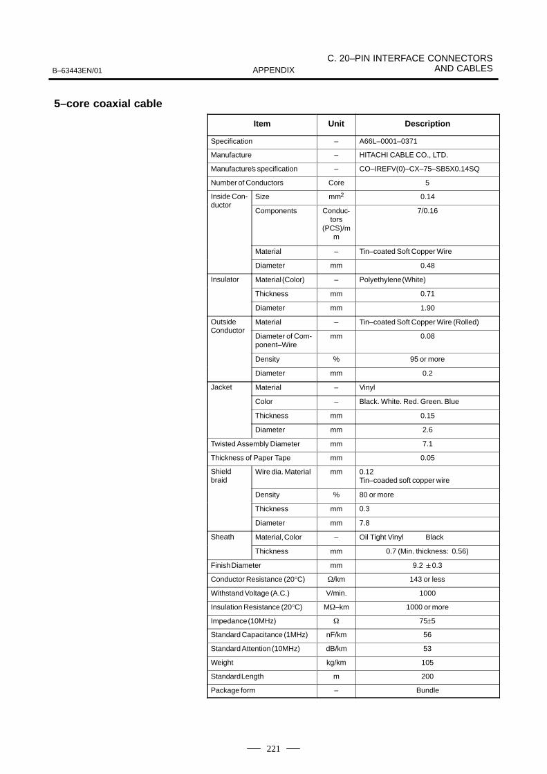
B–63443EN/01
C. 20–PIN INTERFACE CONNECTORSAND CABLESAPPENDIX
221
Item Unit Description
Specification – A66L–0001–0371
Manufacture – HITACHI CABLE CO., LTD.
Manufacture’s specification – CO–IREFV(0)–CX–75–SB 5X0.14SQ
Number of Conductors Core 5
Inside Con- Size mm2 0.14ductor
Components Conduc-tors
(PCS)/mm
7/0.16
Material – Tin–coated Soft Copper Wire
Diameter mm 0.48
Insulator Material (Color) – Polyethylene (White)
Thickness mm 0.71
Diameter mm 1.90
Outside Material – Tin–coated Soft Copper Wire (Rolled)Conductor
Diameter of Com-ponent–Wire
mm 0.08
Density % 95 or more
Diameter mm 0.2
Jacket Material – Vinyl
Color – Black. White. Red. Green. Blue
Thickness mm 0.15
Diameter mm 2.6
Twisted Assembly Diameter mm 7.1
Thickness of Paper Tape mm 0.05
Shieldbraid
Wire dia. Material mm 0.12 Tin–coaded soft copper wire
Density % 80 or more
Thickness mm 0.3
Diameter mm 7.8
Sheath Material, Color – Oil Tight Vinyl Black
Thickness mm 0.7 (Min. thickness: 0.56)
Finish Diameter mm 9.2 0.3
Conductor Resistance (20°C) /km 143 or less
Withstand Voltage (A.C.) V/min. 1000
Insulation Resistance (20°C) M–km 1000 or more
Impedance (10MHz) 75±5
Standard Capacitance (1MHz) nF/km 56
Standard Attention (10MHz) dB/km 53
Weight kg/km 105
Standard Length m 200
Package form – Bundle
5–core coaxial cable
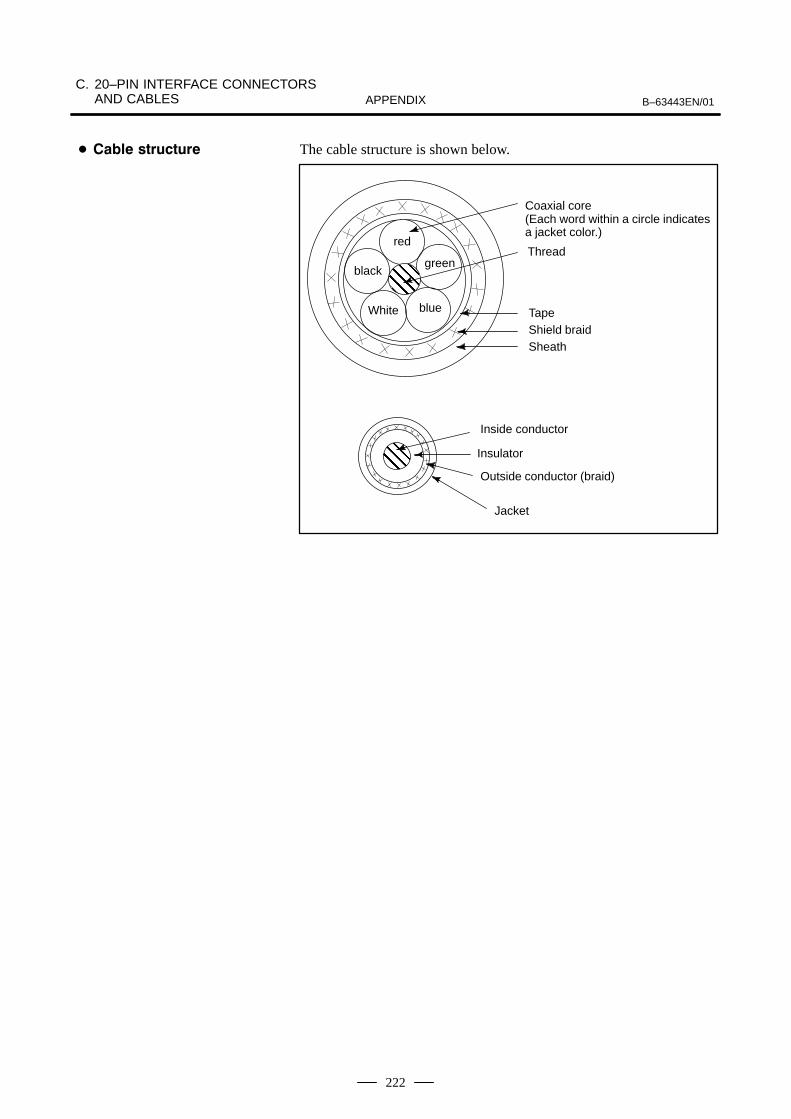
C. 20–PIN INTERFACE CONNECTORS AND CABLES B–63443EN/01APPENDIX
222
The cable structure is shown below.
red
ÊÊÊÊÊÊ
White blue
greenblack
ÊÊÊÊÊÊÊÊÊ
Coaxial core(Each word within a circle indicatesa jacket color.)
Thread
Tape
Sheath
Inside conductor
Insulator
Outside conductor (braid)
Jacket
Shield braid
"

B–63443EN/01
C. 20–PIN INTERFACE CONNECTORSAND CABLESAPPENDIX
223
Item Unit SpecificationsProduct No. – A66L–0001–0286
Manufacturer – HITACHI CABLE, LTD.OKI ELECTRIC CABLE., LTD.
Rating – 80C, 30VMaterial Conductor,braid–shielded
wire,drain wire– Strand wire of tinned annealed
copper (JIS C3152)Insulator – Heat–resistant flame–retardant vinylSheath – Oilproof, heat–resistant, flame–re-
tardant vinyl
Number of wires (wire ons.) Cores 6 (1 to 6) 6 (three pairs)(7 to 9)
Con- Size mm2 0.5 0.18ductor Structure Conduc-
tors/mm
20/0.18 7/0.18
Outside diameter mm 0.94 0.54
Insula-tor
Standard thickness (The minimum thickness isat least 80% of the stan-dard thickness.)
mm 0.25 0.2
Outside diameter mm 1.50 0.94
Twisted Outside diameter mm 1.88pair Direction of lay – Left
Pitch mm 20 or lessLay – Twist the wires at an appropriate
pitch so the outermost layer is right–twisted, and wrap tape around theoutermost layer. Apply a cable separator as required.
Lay diameter mm 5.7
Drain Size mm2 0.3wire Structure Wires/
mm12/0.18
Outside diameter mm 0.72
Shield Element wire diameter mm 0.12braid Thickness mm 0.3
Braid density % 70Outside diameter mm 6.3
Sheath Color – BlackStandard thickness (The minimum thickness isat least 85% of the stan-dard thickness.)
mm 1.1
Outside diameter mm 8.5Max. 9.0(1)Standard length m 100
Packing method – Bundle
Electri-cal per-
Electric resistance (at 20C) (wire nos.)
/km 39.4(1 to 6) 113(7 to 9)
for-mance
Insulation resistance (at 20C)
M–km 15
Dielectric strength (AC) V/min. 500
Flame resistance – Shall pass flame resistance testVW–1SC of UL standards,
NOTEThe maximum outside diameter applies to portions otherthan the drain wire.
12–core cable Specifications
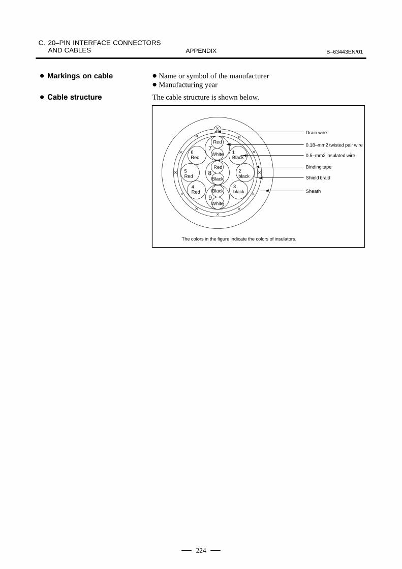
C. 20–PIN INTERFACE CONNECTORS AND CABLES B–63443EN/01APPENDIX
224
Name or symbol of the manufacturer Manufacturing year
The cable structure is shown below.
The colors in the figure indicate the colors of insulators.
Drain wire
0.18–mm2 twisted pair wire
0.5–mm2 insulated wire
Binding tape
Shield braid
Sheath
Red
White
Black
1Black
2black
3black
4Red
5Red
6Red
7
8
9
Red
Black
White
Markings on cable
"

B–63443EN/01
C. 20–PIN INTERFACE CONNECTORSAND CABLESAPPENDIX
225
Item Specification
FANUC specification number A66L–0001–0402 A66L–0001–0403
Manufacturer Oki Electric Cable Co., Ltd.
A–conductor B–conductor A–conductor B–conductor
Conductor Constitution Number of conductors/mm
16/0.12(0.18mm2)
3/22/0.12(0.75mm2)
16/0.12(0.18mm2)
7/16/0.12(1.25mm2)
Typical outside diameter(mm)
0.55 1.20 0.55 1.70
Insulation Color White, red, black Red, black White, red, black Red, black(polyester)
Typical thickness (mm) 0.16 0.23 0.16 0.25
Typical outside diameter(mm)
0.87 1.66 0.87 2.20
Pair twisting Constitution White–red, white–black, andblack–red
White–red, white–black, andblack–red
Direction of twisting LeftTypical pitch: 20 mm
LeftTypical pitch: 20 mm
Assembling by twisting
Number of strands or conductors
3 6 3 6
Direction of twisting Left Left
Taping Twisting is wrapped with washi, or Japanese paper, tape.
Twisting is wrapped with washi, or Japanese paper, tape.
Typical outside diameter(mm)
5.7 6.9
Braided shielding
Typical strand diameter(mm)
0.14
Typical density (mm) 80
Drain A 12/0.18 mm wire is roughly wrapped under braided shielding.
Typical outside diameter(mm)
6.4 7.6
Sheath Color Black (matted)(polyurethane)
Typical thickness (mm) 1.05 1.1
Vertical taping Vertically taped with washi under sheathing.
Outside diameter (mm) 8.50.3 9.80.3
Finished Typical length (m) 100assembly
Short size Basically not approved.
Specifications
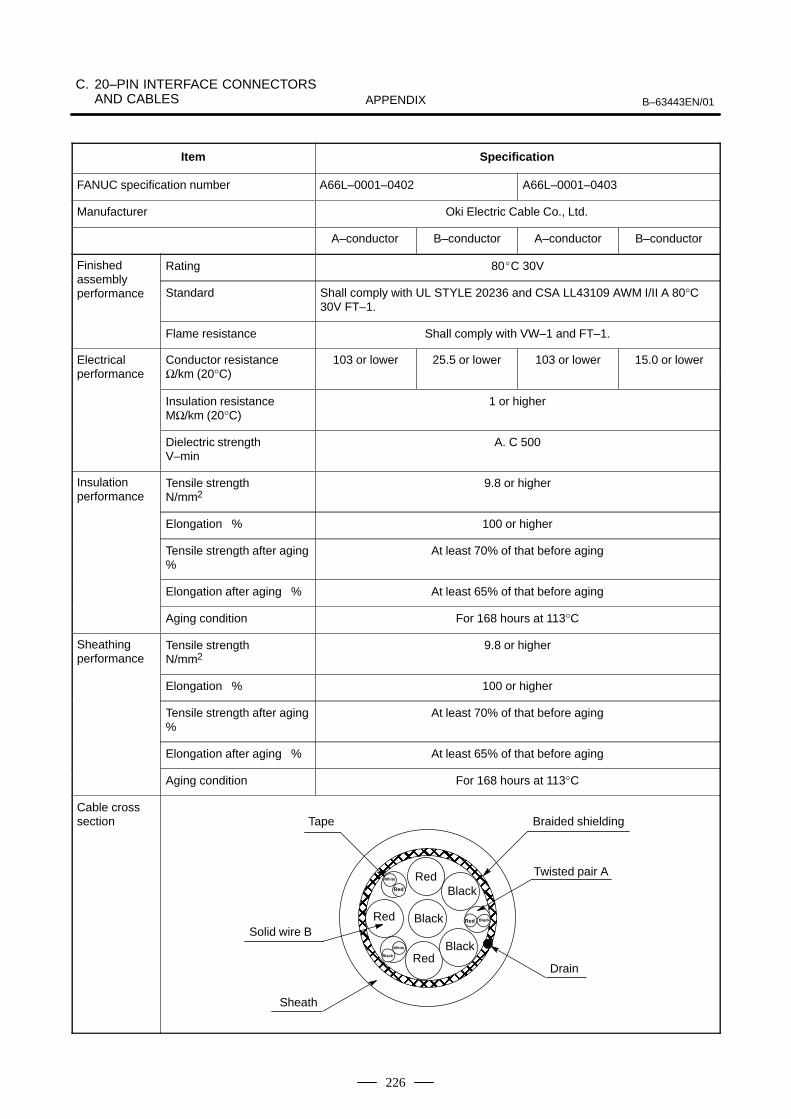
C. 20–PIN INTERFACE CONNECTORS AND CABLES B–63443EN/01APPENDIX
226
Item Specification
FANUC specification number A66L–0001–0403A66L–0001–0402
Manufacturer Oki Electric Cable Co., Ltd.
B–conductorA–conductorB–conductorA–conductor
Finished Rating 80C 30Vassembly performance Standard Shall comply with UL STYLE 20236 and CSA LL43109 AWM I/II A 80°C
30V FT–1.
Flame resistance Shall comply with VW–1 and FT–1.
Electrical Conductor resistance 103 or lower 25.5 or lower 103 or lower 15.0 or lowerperformance Ω/km (20°C)
Insulation resistanceMΩ/km (20°C)
1 or higher
Dielectric strengthV–min
A. C 500
Insulation performance
Tensile strengthN/mm2
9.8 or higher
Elongation % 100 or higher
Tensile strength after aging%
At least 70% of that before aging
Elongation after aging % At least 65% of that before aging
Aging condition For 168 hours at 113°C
Sheathing performance
Tensile strength N/mm2
9.8 or higher
Elongation % 100 or higher
Tensile strength after aging%
At least 70% of that before aging
Elongation after aging % At least 65% of that before aging
Aging condition For 168 hours at 113°C
Cable cross section
ÅÅÅÅÅÅÅÅÅÅÅÅÅÅÅÅÅÅÅÅÅÅÅÅÅÅÅÅÅÅÅÅÅÅÅÅÅÅÅÅÅÅÅÅÅÅÅÅÅÅÅÅÅÅÅÅÅÅÅÅÅÅÅÅ
RedRed
White
Red
Black
BlackBlack
BlackRed
White
Black
Red
Tape Braided shielding
Twisted pair A
Solid wire B
Sheath
Drain

B–63443EN/01 D. INTERFACE CABLEAPPENDIX
227
D INTERFACE CABLE
Cables
Cable No. Name and connection Maximum length (m)
J6 DPL/MDI cable between the M4 and DPL/MDI unit 40
J30 Power cable between the 24 V power supply and Power Mate, CRT/MDI, DPL/MDI
J40 Position coder cable between the JA12 and position coder 50
J41 Manual pulse cable between the JA13 and manual pulse generator 50
J42 Punch panel cable between the JD5 and an I/O unit relay connector 50
J45 CRT/MDI cable between the JD14 and JD13 50
J86, J87 Built–in I/O cable (34pins) between CB128, or CB129 and power magnetics cabinet 50
J93 1st axis servo cable (type B interface) between JS1 and servo amplifier 50
J94 2nd axis servo cable (type B interface) between JS2 and servo amplifier 50
NOTEEach maximum allowable cable length relates to the use of the cable for an interface signal.For some cables (such as that for a pulse coder) that contain a power cable, however, anadditional limit, based on a drop in the supply voltage, is imposed.
The following interface cables are provided.
Name Application Specifications Code Length
Cable for DPL/MDI
DPL/MDI EMI–immune molded interface cable (by Oki Densen)
A02B–0118–K820
2m
J6A02B–0118–K821
7m
Power Mate
D–SUB15 (male) A02B–0118–K822
14m
J30
+24V power cable forthe CRT/MDI, CNC,or DPL/MDI Crimp terminal
T3–2 AMP JAPAN, LTD2–178288–3
A02B–0124–K830
5m

D. INTERFACE CABLE B–63443EN/01APPENDIX
228
Name LengthCodeSpecificationsApplication
J40
Position coder cable F140–2015S
MS3106B20–29S
10-pair whole shielded cable(cable A)
A02B–0124–K823
7m
J41
Manual pulse generatorcable F140–2015S
M3 crimp style terminal
A02B–0120–K821(for1unit)
7m
CRT link cablePCR–E20F
A02B–0124–K813
0.5m
J45A02B–0124–K814
5m
10–pair cable shielded with one sleeveA66L–0001–0284#10P
A02B–0124–K815
10
Built–in I/O cable
HIROSE H2F3BB–34D–2.54R
A02B–0124–K840
0.3m
J86,J87
A02B–0124–K841
0.5m
To flat cableA02B–0124–K841
1m

B–63443EN/01E. DISPLAYING AND SETTING
PARAMETERSAPPENDIX
229
E DISPLAYING AND SETTING PARAMETERS

E. DISPLAYING AND SETTING PARAMETERS B–63443EN/01APPENDIX
230
Procedure for displaying and setting parameters
1 Set 1 for PARAMETER WRITE to enable writing. See the procedurefor enabling/disabling parameter writing described below.
2 Press function key SYSTEM .
3 Press chapter selection soft key [PARAM] to display the parameterscreen.
PARAMETER (SETTING) O0010 N00002 0000 SEQ INI ISO TVC 0 0 0 0 0 0 0 0 0001 0 0 0 0 0 0 0 0 0012 MIR X 0 0 0 0 0 0 0 0 Y 0 0 0 0 0 0 0 0 0020 I/O CHANNEL
> _MDI **** *** *** [ PARAM ][ DGNOS ][ PMC ][ SYSTEM ][ (OPRT) ]
4 Move the cursor to the parameter number to be set or displayed ineither of the following ways:
⋅ Enter the parameter number and press soft key [NO.SRH] .
⋅ Move the cursor to the parameter number using the page keys,
PAGE and PAGE , and cursor keys, , , , and .
5 To set the parameter, enter a new value with numeric keys and presssoft key [INPUT]. The parameter is set to the entered value and thevalue is displayed.
6 Set 0 for PARAMETER WRITE to disable writing.
Press the <DGNOS/PARAM> key to toggle between the parameterscreen and diagnostic screen.
>&0001 01010101&0002 01010101
Parameter screen Diagnostic screen
>@0800 0@0801 0
Display of PMC data
>D0000 00000000D0001 00000000
Key operation
Procedure for CRT/MDI
Procedure for DPL/MDI

B–63443EN/01E. DISPLAYING AND SETTING
PARAMETERSAPPENDIX
231
Procedure for enabling/displaying parameter writing
1 Select the MDI mode or enter state emergency stop.
2 Press function key OFFSETSETTING .
3 Press soft key [SETING] to display the setting screen.
SETTING (HANDY) O0001N00000
> _ MDI **** *** *** ALM[ OFFSET ][ SETING ][ ][ ][ (OPRT) ]
PARAMETER WRITE = 1 (0:DISABLE 1:ENABLE)TV CHECK = 0 (0:OFF 1:ON)PUNCH CODE = 1 (0:EIA 1:ISO)INPUT UNIT = 0 (0:MM 1:INCH)I/O CHANNEL = 0 (0–1:CHANNEL NO.)SEQUENCE NO. = 0 (0:OFF 1:ON)
4 Move the cursor to PARAMETER WRITE using cursor keys.
5 Press soft key [(OPRT)], then press [1: ON] to enable parameterwriting.At this time, the CNC enters the P/S alarm state (No. 100).
6 After setting parameters, return to the setting screen. Move the cursorto PARAMETER WRITE and press soft key [(OPRT)] , then press [0: OFF].
7 Depress the RESET key to release the alarm condition. If alarm No. 000
has occurred, however, turn off the power supply and then turn it on,otherwise the alarm is not released.
Procedure for CRT/MDI

E. DISPLAYING AND SETTING PARAMETERS B–63443EN/01APPENDIX
232
1 Press the <VAR> key to display the settings screen.
2 Use the cursor keys to position the cursor at PWE.
3 Press the <1> key and the <INPUT> key, in that order, to enableparameters to be written. The CNC unit will generate P/S alarm 100.
4 Press the <DGNOS/PARAM> key to display the parameter screen.
>&0001 00000000&0002 00000000
5 Move the cursor to the number of the parameter to change.Method 1Use the cursor keys. The cursor will continue to move while a cursorkey is being pressed.Method 2Press the following keys and enter data in the order shown:<No.><(parameter No.)><INPUT>
6 Enter a parameter value with the data input keys.
7 Press the <INPUT> key. The parameter value is input and displayed.
8 After all parameters have been set and confirmed, return to thesettings screen and set PWE to 0.
9 Normally, in order to release the alarm state, press the <CAN> key.However, in order to release alarm No. 000, the power needs to beturned off and then on again.
Some parameters are not effective until the power is turned off and onagain after they are set. Setting such parameters causes alarm 000. In thiscase, turn off the power, then turn it on again.
Some parameters can be set on the setting screen if the parameter listindicates ”Setting entry is acceptable”. Setting 1 for PARAMETERWRITE is not necessary when these parameters are set on the settingscreen.
Procedure for DPL/MDI
Explanations
Parameters that requireturning off the power
#

B–63443EN/01 F. INPUTTING PARAMETERSAPPENDIX
233
F INPUTTING PARAMETERS
Parameters are loaded into the memory of the controller unit from a floppyor Handy File. The input format is the same as the output format. Whena parameter is loaded which has the same data number as a parameteralready registered in the memory, the loaded parameter replaces theexisting parameter.

F. INPUTTING PARAMETERS B–63443EN/01APPENDIX
234
Inputting parameters
1 Make sure the input device is ready for reading.
2 Press the EMERGENCY STOP button on the machine operator’spanel.
3 Press function key OFFSETSETTING .
4 Press the soft key[SETING]for chapter selection.
5 Enter 1 in response to the prompt for writing parameters (PWE).Alarm P/S100 (indicating that parameters can be written) appears.
6 Press soft key SYSTEM .
7 Press chapter selection soft key[PARAM].
8 Press soft key[(OPRT)].
9 Press the rightmost soft key (next–menu key).
10 Press soft keys[READ]and[EXEC].Parameters are read into memory. Upon completion of input, the”INPUT” indicator at the lower–right corner of the screen disappears.
11 Press function key OFFSETSETTING .
12 Press soft key[SETING] for chapter selection.
13 Enter 0 in response to the prompt for writing parameters.
14 Turn the power to the Power Mate back on.
15 Release the EMERGENCY STOP button on the machine operator’spanel.
1 Press the EMERGENCY STOP button on the machine side.
2 The parameter screen is selected by pressing the <PARAM> key.
3 Set PWE on the setting screen to 1. Alarm P/S100 is displayed atthis time.
4 Perform the same operation as for program input.
5 NC parameters are input to the memory by this operation. Normally,alarm P/S000 will activate after completion of parameter reading.Normally, P/S alarm 000 is generated after parameters have finishedbeing read in.
6 Set PWE on the setting parameter to 0.
7 Turn on the Power Mate power again if PS alarm activates.
8 Release the emergency stop button of machine side.
"# -'().
"# -)'().

B–63443EN/01 G. OUTPUTTING PARAMETERSAPPENDIX
235
GOUTPUTTING PARAMETERS
All parameters are output in the defined format from the memory of thecontroller to Handy File.
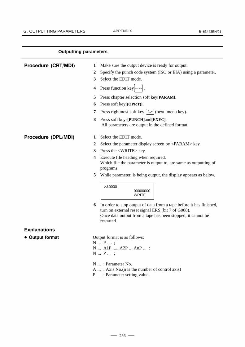
G. OUTPUTTING PARAMETERS B–63443EN/01APPENDIX
236
Outputting parameters
1 Make sure the output device is ready for output.
2 Specify the punch code system (ISO or EIA) using a parameter.
3 Select the EDIT mode.
4 Press function key SYSTEM .
5 Press chapter selection soft key[PARAM].
6 Press soft key[(OPRT)].
7 Press rightmost soft key (next–menu key).
8 Press soft keys[PUNCH]and[EXEC]. All parameters are output in the defined format.
1 Select the EDIT mode.
2 Select the parameter display screen by <PARAM> key.
3 Press the <WRITE> key.
4 Execute file heading when required.Which file the parameter is output to, are same as outputting ofprograms.
5 While parameter, is being output, the display appears as below.
>&000000000000WRITE
6 In order to stop output of data from a tape before it has finished,turn on external reset signal ERS (bit 7 of G008).Once data output from a tape has been stopped, it cannot berestarted.
Output format is as follows:N ... P .... ;N ... A1P ..... A2P ... AnP ... ;N ... P ... ;
N ... : Parameter No.A ... : Axis No.(n is the number of control axis)P ... : Parameter setting value .
"# -'().
"# -)'().
Explanations
A

B–63443EN/01 H. DESCRIPTION OF PARAMETERSAPPENDIX
237
H DESCRIPTION OF PARAMETERS
Parameters are classified by data type as follows:
Table H Data Types and Valid Data Ranges of Parameters
Data type Valid data range Remarks
Bit
Bit axis0 or 1
Byte 0 to127 In some parameters, signs
Byte axis 0 to255 are ignored.
Word
Word axis0 to32767
2-word
2-word axis0 to99999999
NOTE1 For the bit type and bit axis type parameters, a single data
number is assigned to 8 bits. Each bit has a differentmeaning.
2 The axis type allows data to be set separately for eachcontrol axis.
3 The valid data range for each data type indicates a generalrange. The range varies according to the parameters. Forthe valid data range of a specific parameter, see theexplanation of the parameter.
(1) Notation of bit type and bit axis type parameters[Example]
0000 SEQ INI ISO TVC
(Bit)
Data No. Data #0 to #7 are bit positions.
#7 #6 #5 #4 #3 #2 #1 #0
(2) Notation of parameters other than bit type and bit axis type
1023 Servo axis number of a specific axis
Data No. Data

H. DESCRIPTION OF PARAMETERS B–63443EN/01APPENDIX
238
Parameters of Power Mate-H are classified in order as follows.
H.1 Parameters of setting (from data number 0000)H.2 Parameter of reader/punch interface (from data number 0100)H.3 Parameters of axis control/increment system (from data number
1000)H.4 Parameters of coordinates (from data number 1200)H.5 Parameters of stroke limit (from data number 1300)H.6 Parameters of feedrate (from data number 1400)H.7 Parameters of acceleration/deceleration control (from data number
1600)H.8 Parameters of servo (from data number 1800)H.9 Parameters of DI/DO (from data number 3000)H.10 Parameters of CRT/MDI, display, and edit (from data number
3100)H.11 Parameters of programs (from data number 3400)H.12 Parameters of pitch error compensation (from data number 3600)H.13 Parameters of spindle control (from data number 3700)H.14 Parameters of tool compensation (from data number 5000)H.15 Parameters of custom macros (from data number 6000)H.16 Parameters of skip function, picture display, and ITP synchronous
(from data number 6200)H.17 Parameters of manual handle feed/manual handle interruption
(from data number 7100)H.18 Parameters of software operator’s panel (from data number 7200)
WARNINGParameters not described in this document may appear onthe Power Mate screen.Such parameters are invalid. Do not set data for them, orotherwise an unexpected operation may result.To check the functions that can be used with each model,refer to the specifications in ”FANUC Power Mate 0Descriptions (B–63442EN).”
classification ofparameters

B–63443EN/01 H. DESCRIPTION OF PARAMETERSAPPENDIX
239
0000 SEQ INI ISO TVC
(Bit)#7 #6 #5 #4 #3 #2 #1 #0
Setting entry is acceptable.Data type: BitTVC TV check
0: Not performed1: Performed
ISO Code used for data output0: EIA code1: ISO code
INI Unit of input0: In mm1: In inches
SEQ Automatic insertion of sequence numbers0: Not performed1: Performed
NOTEWhen a program is prepared by using MDI keys in the partprogram storage and edit mode, a sequence number canautomatically be assigned to each block in set increments.Set the increment to parameter 3216.
0012 MIRx
(Bit)#7 #6 #5 #4 #3 #2 #1 #0
Setting entry is acceptable.Data type: Bit axisMIRx Mirror image about each axis
0: Mirror image is off.1: Mirror image is on.
H.1PARAMETERS OFSETTING

H. DESCRIPTION OF PARAMETERS B–63443EN/01APPENDIX
240
0020 I/O CHANNEL: Selection of an input/output device
Setting entry is acceptable.Data type: ByteValid data range: 0 to 1
I/O CHANNEL An input/output device used is selected.0: The device on channel 1 is selected.
(Input/output device connected to JD5 on themain body of Power Mate)
1: The device on channel 1 is selected. (Input/output device connected to JD5 on themain body of Power Mate)
Power Mate
Channel 1
JD5
RS-232-C
Reader/puncher
I/O CHANNEL=0 orI/O CHANNEL=1
Fig.H.1 I/O Unit Selection
NOTE1 The input/output device used can be selected (parameter
0020) also on the setting screen. Using the setting screenis a more common method for selecting the device.
2 The specified data, such as a baud rate and the number ofstop bits, of an input/output device connected to a specificchannel must be set in parameters for that channel inadvance. See Section H.2 “Parameters of Reader/PuncherInterface.”I/O CHANNEL=0 and I/O CHANNEL=1 both refer tochannel 1. For each, parameters to set the baud rate, thenumber of stop bits, and other data are provided separately.
3 JD5 is number of connector on the printed circuit boards.

B–63443EN/01 H. DESCRIPTION OF PARAMETERSAPPENDIX
241
Two combinations of parameters to specify the input/output device dataare provided.
The following shows the interrelation between the reader/punch interfaceparameters for the channels.
0020 I/O CHANNEL
Input/output channel number (parameter 0020)
I/O CHANNEL=0
(channel 1)
0101 Stop bit and other data
0102 Number specified for the input/output device
0103 Baud rate
0111 Stop bit and other data
0112 Number specified for the input/output device
0113 Baud rate
I/O CHANNEL=1
(channel 1)
Specify a channel foran input/output device.
I/O CHANNEL
=0 : Channel 1 =1 : Channel 1
Fig.H.2 I/O Channel Number Settings
(1) Parameters common to all channels0100 ENS NCR CTV
(Bit)#7 #6 #5 #4 #3 #2 #1 #0
Setting entry is acceptable.Data type: BitCTV Character counting for TV check in control-out state (or
comment part).0: Performed1: Not performed
NCR Output of the end of block (EOB) in ISO code0: LF, CR, CR are output.1: Only LF is output.
ENS Action taken when a NULL code is found during read ofEIAcode0: An alarm is generated.1: The NULL code is ignored.
(2) Parameters for channel 1 (I/O CHANNEL=0)0101 NFD ASI SB2
(Bit)#7 #6 #5 #4 #3 #2 #1 #0
Data type: BitSB2 The number of stop bits
0: 11: 2
ASI Code used at data input0: EIA or ISO code (automatically distinguished)1: ASCII code
H.2PARAMETER OFREADER/PUNCHINTERFACE

H. DESCRIPTION OF PARAMETERS B–63443EN/01APPENDIX
242
NFD Feed before and after the data at data output0: Output1: Not output
NOTESet NFD to 1 at normal usually.
0102 Number specified for the input/output device (when the I/O CHANNEL is set to 0)
Data type: ByteSet the number specified for the input/output device used when theI/O CHANNEL is set to 0, with one of the set values listed in TableH.2 (a).
Table H.2 (a) Set Value and Specified Number of Input/Output Device
Set value Number specified for input/output device
0 RS232C (For other than the following for example connect topersonal computer etc. , set 0.)
1 Not used
2 Not used
3 FANUC Handy File
4 Not used
5 Not used
6 Not used
0103 Baud rate (when the I/O CHANNEL is set to 0)
Data type: ByteSet the baud rate of the input/output device used when the I/OCHANNEL is set to 0, with a set value in Table H.2 (b).
Table H.2 (b) Baud Rate Settings
Set value Baud rate
7 600
8 1200
9 2400
10 4800
11 9600
12 19200

B–63443EN/01 H. DESCRIPTION OF PARAMETERSAPPENDIX
243
(3) Parameters for channel 1 (I/O CHANNEL=1)0111 NFD ASI SB2
(Bit)#7 #6 #5 #4 #3 #2 #1 #0
Data type: BitThese parameters are used when I/O CHANNEL is set to 1. Themeanings of the bits are the same as for parameter 0101.
0112 Number specified for the input/output device (when I/O CHANNEL is set to 1)
Data type: ByteSet the number specified for the input/output device used when theI/O CHANNEL is set to 1, with one of the set values listed in TableH.2 (a).
0113 Baud rate (when I/O CHANNEL is set to 1)
Data type: ByteSet the baud rate of the input/output device used when I/OCHANNEL is set to 1, with a value in Table H.2 (b).

H. DESCRIPTION OF PARAMETERS B–63443EN/01APPENDIX
244
1001 INM
(Bit)#7 #6 #5 #4 #3 #2 #1 #0
NOTEWhen this parameter is set, the power must be turned offbefore operation is continued.
Data type: Bit
INM Least command increment on the linear axis0: In mm (millimeter machine)1: In inches (inch machine)
1002 JAX
(Bit)#7 #6 #5 #4 #3 #2 #1 #0
Data type: Bit
JAX Number of axes controlled simultaneously in manualoperation0: 1 axis1: 2 axes
1004 IPR
(Bit)#7 #6 #5 #4 #3 #2 #1 #0
Data type: Bit
IPR Whether the least input increment for each axis is set to a value10 times as large as the least command increment is specified.0: The least input increment is not set to a value 10 times as
large as the least command increment.1: The least input increment is set to a value 10 times as large
as the least command increment.
1005 ZRNx
(Bit)#7 #6 #5 #4 #3 #2 #1 #0
Data type: Bit axis
ZRNx When a command specifying the movement except for G28is issued in automatic operation (MEM or MDI) when a returnof axis to the reference position has not been performed sincethe power was turned on0: An alarm is generated. (PS224 : return to the reference
position)1: An alarm is not generated.
H.3PARAMETERS OFAXIS CONTROL/INCREMENT SYSTEM

B–63443EN/01 H. DESCRIPTION OF PARAMETERSAPPENDIX
245
1006 ZMIx DIAx
(Bit)#7 #6 #5 #4 #3 #2 #1 #0
NOTEWhen this parameter is changed, turn off the power beforecontinuing operation.
Data type: Bit axisZMIx The direction of reference position return and the direction of
initial backlash at power-on0: Positive direction1: Negative direction
DIAx Either a diameter or radius is set to be used for specifying theamount of travel on each axis.0 : Radius1 : Diameter
1020 Name of the axis used for programming for each axis
Data type: Byte axisSet the name of the program axis for each control axis, with one ofthe values listed in the following table:
Axis name Set value Axis name Set value Axis name Set value
X 88 U 85 A 65
Y 89 V 86 B 66
Z 90 W 87 C 67
NOTEThe same axis name cannot be assigned to more than oneaxis.Be sure to set X (88) for the first axis, and Z (90) for the second axis.
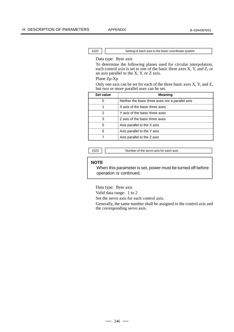
H. DESCRIPTION OF PARAMETERS B–63443EN/01APPENDIX
246
1022 Setting of each axis in the basic coordinate system
Data type: Byte axisTo determine the following planes used for circular interpolation,each control axis is set to one of the basic three axes X, Y, and Z, oran axis parallel to the X, Y, or Z axis.Plane Zp-XpOnly one axis can be set for each of the three basic axes X, Y, and Z,but two or more parallel axes can be set.Set value Meaning
0 Neither the basic three axes nor a parallel axis
1 X axis of the basic three axes
2 Y axis of the basic three axes
3 Z axis of the basic three axes
5 Axis parallel to the X axis
6 Axis parallel to the Y axis
7 Axis parallel to the Z axis
1023 Number of the servo axis for each axis
NOTEWhen this parameter is set, power must be turned off beforeoperation is continued.
Data type: Byte axisValid data range: 1 to 2Set the servo axis for each control axis.Generally, the same number shall be assigned to the control axis andthe corresponding servo axis.

B–63443EN/01 H. DESCRIPTION OF PARAMETERSAPPENDIX
247
1201 WZR AWK ZPI ZPR
(Bit)#7 #6 #5 #4 #3 #2 #1 #0
Data type: BitZPR Automatic setting of a coordinate system when manual return
to the reference position is performed0: Not set automatically1: Set automatically
NOTEZPR is enabled when a workpiece coordinate system is notselected (bit 0 (WKC) of parameter No. 1204 is 0). Whena workpiece coordinate system is selected, it is alwaysestablished according to the workpiece origin offset(parameter Nos. 1220 to 1226) upon manual return to thereference position, regardless of the setting of thisparameter.
ZPI Coordinates at the reference position when a coordinatesystem is set automatically0: Value set in parameter 1250 is used.1: For input in mm, the value set in parameter 1250 is used,
or for input in inches, the value set in parameter 1251 isused.
This bit is ineffective, when a workpiece coordinate systemoption is provided, however.
AWK When the workpiece zero point offset value is changed0: The absolute position display changed when the next
bufforing block is performed.1: The absolute position display is changed immediately.
Changed value is valid ofter baffering the next block.WZR Upon reset, the workpiece coordinate system is:
0: Not returned to that specified with G541: Returned to that specified with G54
1202 G50
(Bit)#7 #6 #5 #4 #3 #2 #1 #0
Data type: BitG50 When the workpiece coordinate systems is enabled, if the G50
command for setting a coordinate system (or the G92command in G command system B or C) is specified,0 : G50 is executed and no alarm is issued.1 : G50 is not executed and a P/S alarm (No. 010) is issued.
H.4PARAMETERS OFCOORDINATES

H. DESCRIPTION OF PARAMETERS B–63443EN/01APPENDIX
248
1204 WKC
(Bit)#7 #6 #5 #4 #3 #2 #1 #0
Data type: BitWKC Determines whether to enable the workpiece coordinate
system.0: Disabled1: Enabled
1220 External workpiece zero point offset value
Data type: 2-word axisUnit of data
Increment system Least inputincrement Unit
Linear axis (input in mm) 0.001 mm
Linear axis (input in inches) 0.0001 inch
Valid data range: –99999999 to +99999999This is one of the parameters that give the position of the origin ofworkpiece coordinate system (G54 to G59). It gives an offset of theworkpiece origin common to all workpiece coordinate systems. Ingeneral, the offset varies depending on the workpiece coordinatesystems.
1221 Workpiece zero point offset value in workpiece coordinate system 1 (G54)
1222 Workpiece zero point offset value in workpiece coordinate system 2 (G55)
1223 Workpiece zero point offset value in workpiece coordinate system 3 (G56)
1224 Workpiece zero point offset value in workpiece coordinate system 4 (G57)
1225 Workpiece zero point offset value in workpiece coordinate system 5 (G58)
1226 Workpiece zero point offset value in workpiece coordinate system 6 (G59)
Data type: 2-word axisUnit of data
Increment system Least inputincrement Unit
Linear axis (input in mm) 0.001 mm
Linear axis (input in inches) 0.0001 inch
Valid data range: –99999999 to +99999999The workpiece zero point offset values in workpiece coordinatesystems 1 to 6 (G54 to G59) are set.

B–63443EN/01 H. DESCRIPTION OF PARAMETERSAPPENDIX
249
Workpiece coordinate system 1 (G54)
Workpiece zero point offset
Origin of machine coordinate system
Workpiece coordinate system 2 (G55)
NOTEThe workpiece origin offset can also be set using theworkpiece coordinate system screen.
1240Coordinate value of the first reference position on each axis in the machinecoordinate system
Data type: 2-word axisUnit of data
Increment system Least inputincrement Unit
Milimeter machine 0.001 mm
Inch machine 0.0001 inch
Valid data range: 0 to99999999Set the coordinate values of the first reference positions in themachine coordinate system.
1250Coordinate value of the reference position used when automatic coordinatesystem setting is performed
Data type: 2-word axisUnit of data
Increment system Least inputincrement Unit
Linear axis (input in mm) 0.001 mm
Linear axis (input in inches) 0.0001 inch
Valid data range: 0 to99999999Set the coordinate value of the reference position on each axis to beused for setting a coordinate system automatically.
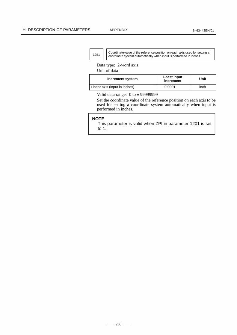
H. DESCRIPTION OF PARAMETERS B–63443EN/01APPENDIX
250
1251Coordinate value of the reference position on each axis used for setting acoordinate system automatically when input is performed in inches
Data type: 2-word axisUnit of data
Increment system Least inputincrement Unit
Linear axis (input in inches) 0.0001 inch
Valid data range: 0 to99999999Set the coordinate value of the reference position on each axis to beused for setting a coordinate system automatically when input isperformed in inches.
NOTEThis parameter is valid when ZPI in parameter 1201 is setto 1.

B–63443EN/01 H. DESCRIPTION OF PARAMETERSAPPENDIX
251
1300 BFA LZR
(Bit)#7 #6 #5 #4 #3 #2 #1 #0
Data type: BitBFA When a command that exceeds a stored stroke limit is issued
0: An alarm is generated after the stroke limit exceeded.1: An alarm is generated before the stroke limit exceeded.
Software stroke limit alarmsAlarm 500: The positive stored stroke limit is
exceeded.Alarm 501: The negative stored stroke limit is
exceeded.LZR Checking of stored stroke limits during the time from
power-on to manual return to the reference position0: The stroke limits are checked.1: The stroke limits are not checked.
1320Coordinate value 1 of stored stroke limit 1 in the positive direction on each axis
1321Coordinate value 1 of stored stroke limit 1 in the negative direction on eachaxis
Data type: 2-word axisUnit of data:
Increment system Least inputincrement Unit
Milimeter machine 0.001 mm
Inch machine 0.0001 inch
Valid data range:999999999 to +99999999The coordinate values of stored stroke limits 1 in the positive andnegative directions are set for each axis in the machine coordinatesystem. The outside area of the two limits set in the parameters isinhibited.
NOTEWhen the parameters are set as follows, the strokebecomes infinite: parameter 1320 < parameter 1321For movement along the axis for which infinite stroke is set,only incremental commands are available. If an absolutecommand is issued for this axis, the absolute register mayoverflow, and normal movement will not result.
H.5PARAMETERS OFSTROKE LIMIT

H. DESCRIPTION OF PARAMETERS B–63443EN/01APPENDIX
252
1401 RDR RFO RPD
(Bit)#7 #6 #5 #4 #3 #2 #1 #0
Data type: BitRPD Manual rapid traverse during the period from power-on time
to the completion of return to the reference position0: Disabled (Manual continuous feed is performed.)1: Enabled
RFO When cutting feedrate override is 0% during rapid traverse,0: The machine tool does not stop moving.1: The machine tool stops moving.
RDR Dry run for rapid traverse command0: Disabled1: Enabled
1410 Dry run rate
Data type: WordUnit of data:Valid data range:
Increment system Unit of data Valid data range
Milimeter input 1 mm/min 6 to 15000
Inch input 0.1 inch/min 6 to 6000
Set the dry run rate when the jog feedrate is overridden by 100%.
1411 Cutting feedrate in the automatic mode at power–on
Setting entry is acceptable.Data type: WordUnit of data:Valid data range:
Increment system Unit of data Valid data range
Milimeter machine 1 mm/min 6 to 15000
Inch machine 0.1 inch/min 6 to 6000
When the machine requires little change in cutting feedrate duringcutting, a cutting feedrate can be specified in the parameter. Thiseliminates the need to specify a cutting feedrate in the NC commanddata.
H.6PARAMETERS OFFEEDRATE
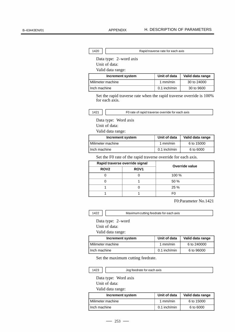
B–63443EN/01 H. DESCRIPTION OF PARAMETERSAPPENDIX
253
1420 Rapid traverse rate for each axis
Data type: 2–word axisUnit of data:Valid data range:
Increment system Unit of data Valid data range
Milimeter machine 1 mm/min 30 to 24000
Inch machine 0.1 inch/min 30 to 9600
Set the rapid traverse rate when the rapid traverse override is 100%for each axis.
1421 F0 rate of rapid traverse override for each axis
Data type: Word axisUnit of data:Valid data range:
Increment system Unit of data Valid data range
Milimeter machine 1 mm/min 6 to 15000
Inch machine 0.1 inch/min 6 to 6000
Set the F0 rate of the rapid traverse override for each axis.Rapid traverse override signal
ROV2 ROV1Override value
0 0 100 %
0 1 50 %
1 0 25 %
1 1 F0
F0:Parameter No.1421
1422 Maximum cutting feedrate for each axis
Data type: 2–wordUnit of data:Valid data range:
Increment system Unit of data Valid data range
Milimeter machine 1 mm/min 6 to 240000
Inch machine 0.1 inch/min 6 to 96000
Set the maximum cutting feedrate.
1423 Jog feedrate for each axis
Data type: Word axisUnit of data:Valid data range:
Increment system Unit of data Valid data range
Milimeter machine 1 mm/min 6 to 15000
Inch machine 0.1 inch/min 6 to 6000

H. DESCRIPTION OF PARAMETERS B–63443EN/01APPENDIX
254
Set the continuous manual feedrate when the override of the jogfeedrate is 100%.
1424 Manual rapid traverse rate for each axis
Data type: 2–word axisUnit of data:Valid data range:
Increment system Unit of data Valid data range
Milimeter machine 1 mm/min 30 to 24000
Inch machine 0.1 inch/min 30 to 9600
Set the rate of manual rapid traverse when the rapid traverse overrideis 100% for each axis.
NOTEIf 0 is set, the rate set in parameter 1420 is assumed.
1425 FL rate of return to the reference position for each axis
Data type: Word axisUnit of data:Valid data range:
Increment system Unit of data Valid data range
Milimeter machine 1 mm/min 6 to 15000
Inch machine 0.1 inch/min 6 to 6000
Set a feedrate (FL rate) after deceleration when return to the referenceposition is performed for each axis.
1430 Maximum cutting feedrate for each axis
Data type: 2–word axisUnit of data:Valid data range:
Increment system Unit of data Valid data range
Milimeter machine 1 mm/min 6 to 240000
Inch machine 0.1 inch/min 6 to 96000
Set a maximum allowable cutting feedrate for each axis.In cutting feed, the feedrate along each axis is clamped to themaximum allowable cutting feedrate for each axis.
NOTEWhen 0 is set for all axes, the feedrate is clamped to themaximum allowable cutting feedrate specified in parameterNo. 1422.

B–63443EN/01 H. DESCRIPTION OF PARAMETERSAPPENDIX
255
1601 NCI
(Bit)#7 #6 #5 #4 #3 #2 #1 #0
Data type: BitNCI Imposition check at deceleration
0: Performed1: Not performed (Exact stop check dose not performed too.)
1610 JGLx CTLx
(Bit)#7 #6 #5 #4 #3 #2 #1 #0
Data type: Bit axisCTLx Acceleration/deceleration (in each axis) in cutting feed
including feed in dry run0: Exponential acceleration/deceleration is applied.1: Linear acceleration/deceleration after interpolation is
applied.JGLx Acceleration/deceleration in manual continuous feed (jog
feed).0: Exponential acceleration/deceleration is applied.1: Linear acceleration/deceleration after interpolation is
applied (depending on which is used in cutting feed).
1620Time constant T used in linear acceleration/deceleration in rapid traversefor each axis
Data type: Word axisUnit of data: msecValid data range: 0 to 4000Specify a time constant used in acceleration/deceleration in rapidtraverse.
Feedrate
TimeTT
0
<Linear acceleration/deceleration during rapid traverse>
Rapid traverse rate
T: Time constant for linear acceleration/deceleration
Set the value when the rapid traverse rate is 100%. If it is under 100%, the total time is reduced. (Constant accelerationmethod)
H.7PARAMETERS OFACCELERATION/DECELERATIONCONTROL

H. DESCRIPTION OF PARAMETERS B–63443EN/01APPENDIX
256
1622Time constant for exponential acceleration/deceleration, or linear accelera-tion/deceleration after interpolation in cutting feed for each axis.
Data type: Word axisUnit of data: msValid data range : 0 to 4000
(Cutting feed exponential acceleration/deceleration)0 to 512 (Linear acceleration/deceleration after cuttingfeed interpolation)
Set the time constant used for exponential function acceleration/deceleration or linear acceleration/deceleration after interpolation incutting feed for each axis. Except for special applications, the sametime constant must be set for all axes in this parameter. If the timeconstants set for the axes differ from each other, proper straight linesor arcs cannot be obtained.
1623FL rate of exponential function acceleration/deceleration in cutting feed foreach axis
Data type: Word axisUnit of data:Valid data range:
Increment system Unit of data Valid data range
Milimeter machine 1 mm/min 6 to 15000
Inch machine 0.1 inch/min 6 to 6000
Set the lower limit (FL rate) of exponential functionacceleration/deceleration in cutting feed for each axis. Except forspecial applications, this parameter must be set to 0 for all axes. Ifa value other than 0 is specified, proper straight lines or arcs cannotbe obtained.
1624Time constant of exponential function acceleration/deceleration or linearacceleration/deceleration after interpolation in jog feed for each axis.
Data type: Word axisUnit of data: msValid data range : 0 to 4000
(Jog feed exponential acceleration/deceleration)0 to 512 (Linear acceleration/deceleration after jog feedcompensation)
Set the time constant used for exponential functionacceleration/deceleration or linear acceleration/deceleration afterinterpolation in continuous manual feed for each axis.

B–63443EN/01 H. DESCRIPTION OF PARAMETERSAPPENDIX
257
1625FL rate of exponential function acceleration/deceleration in manual continu-ous feed for each axis.
Data type: Word axisUnit of data:Valid data range:
Increment system Unit of data Valid data range
Milimeter machine 1 mm/min 6 to 15000
Inch machine 0.1 inch/min 6 to 6000
Set the lower limit (FL rate) of exponential functionacceleration/deceleration in continuous manual feed for each axis.

H. DESCRIPTION OF PARAMETERS B–63443EN/01APPENDIX
258
1800 CVR
(Bit)#7 #6 #5 #4 #3 #2 #1 #0
Data type: BitCVR When velocity control ready signal VRDY is set ON before
position control ready signal PRDY comes ON0: A servo alarm is generated. (SV404)1: A servo alarm is not generated.
1801 CNI CCI
(Bit)#7 #6 #5 #4 #3 #2 #1 #0
Data type: BitCCI Specifies whether to use the effective area in cutting feed
specified by parameter No. 1826 or by bit 5 (CNI) ofparameter No. 1801.0: The setting of parameter No. 1826 is used. (This also
applies to rapid traverse.)1: The setting of bit 5 (CNI) of parameter No. 1801 is used.
CNI Specifies how the effective area in cutting feed is to bedetermined when bit 4 (CCI) of parameter No. 1801 is set to1.0: When the next block also specifies cutting feed, the setting
of parameter No. 1827 is used. When the next block doesnot specify cutting feed, the setting of parameter No. 1826is used.
1: The setting of parameter No. 1827 is used, regardless ofhow the next block specifies feed operation. (In rapidtraverse, the setting of parameter No. 1826 is used. Incutting feed, the setting of parameter No. 1827 is used.)
1816 DM3x DM2x DM1x
(Bit)#7 #6 #5 #4 #3 #2 #1 #0
NOTEWhen this parameter has been set, the power must beturned off before operation is continued.
Data type: Bit axisDM1x to DM3x Setting of detection multiply
H.8PARAMETERS OFSERVO

B–63443EN/01 H. DESCRIPTION OF PARAMETERSAPPENDIX
259
Set value
DM3x DM2x DM1xDetection mulyiply
00001111
00110011
01010101
1/21
3/22
5/23
7/24
NOTEWhen the flexibly feed gear is used, do not use theseparameters. Set the numerator and denominator of DMRto an appropriate values in parameters 2084 and 2085respectively.
1820 Command multiply for each axis (CMR)
NOTEWhen this parameter has been set, the power must beturned off before operation is continued.
Data type: Byte axisSet a command multiply indicating the ratio of the least commandincrement to the detection unit for each axis.Least command increment = detection unit command multiplyRelationship between the increment system and the least commandincrement
Increment system Least inputincrement Unit
Milimeter machine 0.001 mm
Inch machine 0.0001 inch
Setting command multiply (CMR), detection multiply (DMR), andthe capacity of the reference counter
Detection unit
Least command increment
CMR Error counter DA converter
To velocity control
DMR
Feedback pulse
Position detector
+
Reference counter
Fig.H.8 CMR, DMR, and the Capacity of the Reference Counter
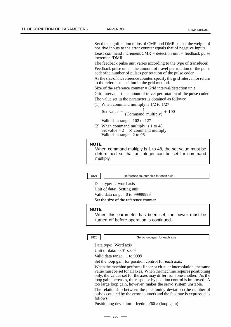
H. DESCRIPTION OF PARAMETERS B–63443EN/01APPENDIX
260
Set the magnification ratios of CMR and DMR so that the weight ofpositive inputs to the error counter equals that of negative inputs.Least command increment/CMR = detection unit = feedback pulseincrement/DMRThe feedback pulse unit varies according to the type of transducer.Feedback pulse unit = the amount of travel per rotation of the pulsecoder/the number of pulses per rotation of the pulse coderAs the size of the reference counter, specify the grid interval for returnto the reference position in the grid method.Size of the reference counter = Grid interval/detection unitGrid interval = the amount of travel per rotation of the pulse coderThe value set in the parameter is obtained as follows:(1) When command multiply is 1/2 to 1/27
Set value 1
(Command multiply) 100
Valid data range: 102 to 127(2) When command multiply is 1 to 48
Set value = 2 command multiplyValid data range: 2 to 96
NOTEWhen command multiply is 1 to 48, the set value must bedetermined so that an integer can be set for commandmultiply.
1821 Reference counter size for each axis
Data type: 2-word axisUnit of data: Setting unitValid data range: 0 to 99999999Set the size of the reference counter.
NOTEWhen this parameter has been set, the power must beturned off before operation is continued.
1825 Servo loop gain for each axis
Data type: Word axisUnit of data: 0.01 sec–1
Valid data range: 1 to 9999Set the loop gain for position control for each axis.When the machine performs linear or circular interpolation, the samevalue must be set for all axes. When the machine requires positioningonly, the values set for the axes may differ from one another. As theloop gain increases, the response by position control is improved. Atoo large loop gain, however, makes the servo system unstable.The relationship between the positioning deviation (the number ofpulses counted by the error counter) and the feedrate is expressed asfollows:Positioning deviation = feedrate/60(loop gain)

B–63443EN/01 H. DESCRIPTION OF PARAMETERSAPPENDIX
261
Unit: Positioning deviation mm, inches, or degFeedrate mm/min, inches/min, or deg/minLoop gain s-1
1826 Inposition width for each axis
Data type: Word axisUnit of data: Detection unitValid data range: 0 to 32767The inposition width is set for each axis.When the deviation of the machine position from the specifiedposition (the absolute value of the positioning deviation) is smallerthan the inposition width, the machine is assumed to have reached thespecified position. (The machine is in the inposition state.)
1827 Effective area for each axis in cutting feed
Data type: Word axisUnit of data: Detection unitValid data range: 0 to 32767An effective area in cutting feed is set for each axis. This parameterfunctions when bit 4 (CCI) of parameter No. 1801 is set to 1.
1828 Positioning deviation limit for each axis in movement
Data type: 2-word axisUnit of data: Detection unitValid data range: 0 to 99999999Set the positioning deviation limit in movement for each axis.If the positioning deviation exceeds the positioning deviation limitduring movement, a servo alarm is generated, and operation isstopped immediately (as in emergency stop).Generally, set the positioning deviation for rapid traverse plus somemargin in this parameter.
1829 Positioning deviation limit for each axis in the stopped state
Data type: Word axisUnit of data: Detection unitValid data range: 0 to 32767Set the positioning deviation limit in the stopped state for each axis.If, in the stopped state, the positioning deviation exceeds thepositioning deviation limit set for movement, a servo alarm isgenerated, and operation is stopped immediately (as in emergencystop).
1850 Grid shift for each axis
Data type: 2-word axisUnit of data: Detection unitValid data range: 0 to99999999A grid shift is set for each axis.To shift the reference position, the grid can be shifted by the amountset in this parameter. Up to the maximum value counted by thereference counter can be specified as the grid shift.
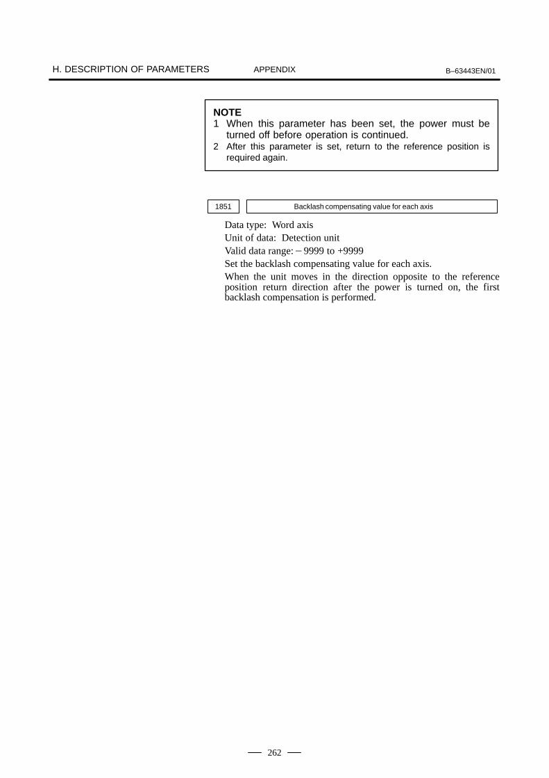
H. DESCRIPTION OF PARAMETERS B–63443EN/01APPENDIX
262
NOTE1 When this parameter has been set, the power must be
turned off before operation is continued.2 After this parameter is set, return to the reference position is
required again.
1851 Backlash compensating value for each axis
Data type: Word axisUnit of data: Detection unitValid data range:9999 to +9999Set the backlash compensating value for each axis.When the unit moves in the direction opposite to the referenceposition return direction after the power is turned on, the firstbacklash compensation is performed.

B–63443EN/01 H. DESCRIPTION OF PARAMETERSAPPENDIX
263
The following parameters are not explained in this manual, therefore seeparameter manual of servo for details;
No. Data type Contents
2000 Bit axis PGEXPD DGPRM
2001 Bit axis AMR7 AMR6 AMR5 AMR4 AMR3 AMR2 AMR1 AMR0
2002 Bit axis
2003 Bit axis VOFST OVSCMP BLENBL IPSPRS PIENBL OBENBL TGALRM
2004 Bit axis DLY1 DLY0 TRW1 TRW0 TIB0 TIA0
2005 Bit axis BRKCTL FEEDFD
2006 Bit axis DCBEMF ACCFB PKVER
2007 Bit axis
2008 Bit axis
2009 Bit axis BLSTP BLCUT ADBLSH SERDMY
2010 Bit axis BLTEN
2011 Bit axis
2012 Bit axis VCMD2 VCMD1
2013 Bit axis (Reserve)
2014 Bit axis (Reserve)
2015 Bit axis TDOUT SSG1 PGTWN
2016 Bit axis
2017 Bit axis (Reserve)
2018 Bit axis (Reserve)
2019 Bit axis
2020 Word axis Motor type
2021 Word axis Load intertia ratio (LDINT)
2022 Word axis Direction of motor rotation (DIRCTL)
2023 Word axis Number of velocity detection feedback pulses (PULCO)
2024 Word axis Number of position detection feedback pulses (PPLS)
2025 Word axis
2026 Word axis
2027 Word axis
2028 Word axis Position gain change effective speed(TWNSP)
2029 Word axis Acceleration effective speed for integral function at low speed (INTSP1)
2030 Word axis Deceleration effective speed for integral function at low speed (INTSP2)
2031 Word axis (Reserve)
2032 Word axis (Reserve)
2033 Word axis (Reserve)
2034 Word axis (Reserve)
2035 Word axis (Reserve)
2036 Word axis (Reserve)
2037 Word axis (Reserve)
2038 Word axis (Reserve)
2039 Word axis (Reserve)
2040 Word axis Current loop gain (PK1)

H. DESCRIPTION OF PARAMETERS B–63443EN/01APPENDIX
264
No. ContentsData type
2041 Word axis Current loop gain (PK2)
2042 Word axis Current loop gain (PK3)
2043 Word axis Velocity loop gain (PK1V)
2044 Word axis Velocity loop gain (PK2V)
2045 Word axis Incomplete integral coefficient (PK3V)
2046 Word axis Velocity loop gain (PK4V)
2047 Word axis Velocity control observer parameter (POA1)
2048 Word axis Improvement of velocity control backlash compensation (BLCMP)
2049 Word axis Not used
2050 Word axis Velocity control observer parameter (POK1)
2051 Word axis Velocity control observer parameter (POK2)
2052 Word axis Not used
2053 Word axis Compensation for current non–operating area (PRMAX)
2054 Word axis Compensation for current non–operating area (PDDP)
2055 Word axis Compensation for current non–operating area (PHYST)
2056 Word axis Back electromotive force compensation (EMFCMP)
2057 Word axis Current phase control (PVPA)
2058 Word axis Current phase control (PALPH)
2059 Word axis Back electromotive force compensation (EMFBAS)
2060 Word axis Torque limit (TQLIM)
2061 Word axis Back electromotive force compensation (EMFLMT)
2062 Word axis Overload protection coefficient (OVC1)
2063 Word axis Overload protection coefficient (OVC2)
2064 Word axis TG alarm level (TGALMLV)
2065 Word axis Overload protection coefficient (OVCLMT)
2066 Word axis PK2VAUX
2067 Word axis Torque command filter (TCFIL)
2068 Word axis Feed–forward coefficient (FALPH)
2069 Word axis Feed–forward filter coefficient (VFFLT)
2070 Word axis Backlash compensation acceleration parameter (ERBLN)
2071 Word axis Backlash compensation acceleration parameter (PBLCT)
2072 Word axis
2073 Word axis
2074 Word axis Velocity–dependent current loop gain (AALPH)
2075 Word axis
2076 Word axis
2077 Word axis Overshoot preventive counter (OSCTP)
2078 Word axis
2079 Word axis
2080 Word axis
2081 Word axis
2082 Word axis Backlash acceleration end amount (BLEND)
2083 Word axis Brake control hold time (MOFCT)

B–63443EN/01 H. DESCRIPTION OF PARAMETERSAPPENDIX
265
No. ContentsData type
2084 Word axis Numerator of DMR when the flexibly feed gear is used
2085 Word axis Denominator of DMR when the flexibly feed gear is used
2086 Word axis Rated current parameter (RTCURR)
2087 Word axis Torque offset (TCPRLD)
2088 Word axis
2089 Word axis Base pulse in backslash acceleration (BLBSL)
2090 Word axis
2091 Word axis Non–linear control input (ACCSPL)
2092 Word axis
2093 Word axis
2094 Word axis
2095 Word axis
2096 Word axis
2097 Word axis
2098 Word axis Phase progress compensation coefficient in deceleration (DEPVPL)
2099 Word axis 1 pulse suppress level (ONEPSL)
2100 Word axis
2101 Word axis
2102 Word axis
2103 Word axis
2104 Word axis
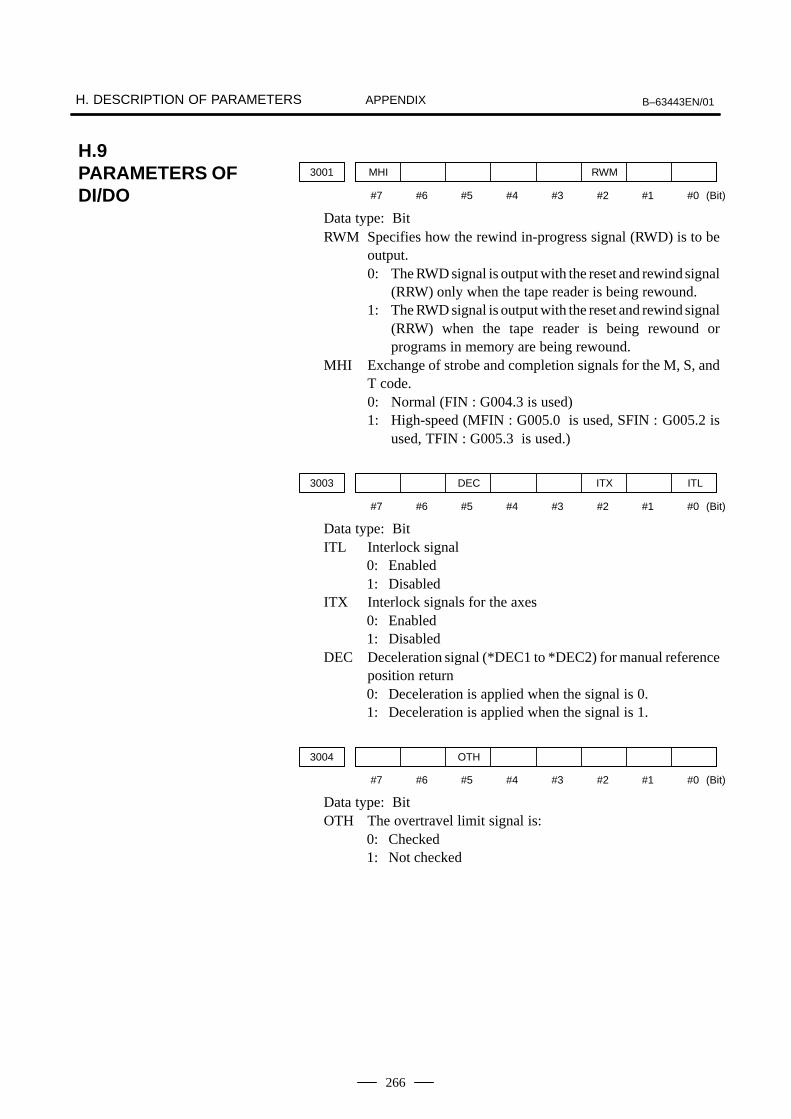
H. DESCRIPTION OF PARAMETERS B–63443EN/01APPENDIX
266
3001 MHI RWM
(Bit)#7 #6 #5 #4 #3 #2 #1 #0
Data type: BitRWM Specifies how the rewind in-progress signal (RWD) is to be
output.0: The RWD signal is output with the reset and rewind signal
(RRW) only when the tape reader is being rewound.1: The RWD signal is output with the reset and rewind signal
(RRW) when the tape reader is being rewound orprograms in memory are being rewound.
MHI Exchange of strobe and completion signals for the M, S, andT code.0: Normal (FIN : G004.3 is used)1: High-speed (MFIN : G005.0 is used, SFIN : G005.2 is
used, TFIN : G005.3 is used.)
3003 DEC ITX ITL
(Bit)#7 #6 #5 #4 #3 #2 #1 #0
Data type: BitITL Interlock signal
0: Enabled1: Disabled
ITX Interlock signals for the axes0: Enabled1: Disabled
DEC Deceleration signal (*DEC1 to *DEC2) for manual referenceposition return0: Deceleration is applied when the signal is 0.1: Deceleration is applied when the signal is 1.
3004 OTH
(Bit)#7 #6 #5 #4 #3 #2 #1 #0
Data type: BitOTH The overtravel limit signal is:
0: Checked1: Not checked
H.9PARAMETERS OFDI/DO
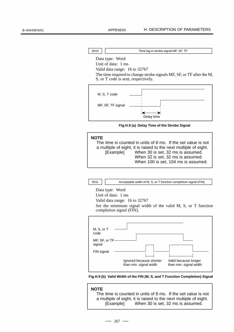
B–63443EN/01 H. DESCRIPTION OF PARAMETERSAPPENDIX
267
3010 Time lag in strobe signal MF, SF, TF
Data type: WordUnit of data: 1 msValid data range: 16 to 32767The time required to change strobe signals MF, SF, or TF after the M,S, or T code is sent, respectively.
Delay time
M, S, T code
MF, SF, TF signal
Fig.H.9 (a) Delay Time of the Strobe Signal
NOTEThe time is counted in units of 8 ms. If the set value is nota multiple of eight, it is raised to the next multiple of eight.
[Example] When 30 is set, 32 ms is assumed.When 32 is set, 32 ms is assumed.When 100 is set, 104 ms is assumed.
3011 Acceptable width of M, S, or T function completion signal (FIN)
Data type: WordUnit of data: 1 msValid data range: 16 to 32767Set the minimum signal width of the valid M, S, or T functioncompletion signal (FIN).
M, S, or Tcode
MF, SF, or TFsignal
FIN signal
Ignored because shorter than min. signal width
Valid because longer than min. signal width
Fig.H.9 (b) Valid Width of the FIN (M, S, and T Function Completion) Signal
NOTEThe time is counted in units of 8 ms. If the set value is nota multiple of eight, it is raised to the next multiple of eight.
[Example] When 30 is set, 32 ms is assumed.

H. DESCRIPTION OF PARAMETERS B–63443EN/01APPENDIX
268
3016 Clamped value for manual feedrate override
Data type: 2–wordUnit of data: 0.01%Valid data range: 0 to 65534This parameter specifies the clamped value for manual feedrateoverride. When the entered manual feedrate override is greater thanthe value specified by this parameter, it is clamped to this value.
NOTEManual feedrate override is input using the manual feedrateoverride signal (*JV0 to *JV15).
3017 Output time of reset signal RST
Data type: ByteUnit of data: 16 msValid data range: 0 to 255To extend the output time of reset signal RST, the time to be addedis specified in this parameter.RST signal output time = time required for reset + parameter value 16 ms
3030 Allowable number of digits for the M code
3031 Allowable number of digits for the S code
3032 Allowable number of digits for the T code
Data type: ByteValid data range: 1 to 8Set the allowable numbers of digits for the M, S, or T code.

B–63443EN/01 H. DESCRIPTION OF PARAMETERSAPPENDIX
269
3102 CHI
(Bit)#7 #6 #5 #4 #3 #2 #1 #0
Data type: Bit
NOTE1 When this parameter is set, turn off the power once. Then
turn it on for machining. 2 Chinese can be used only when the corresponding option
is specified.
CHI Determines whether to use Chinese.0: Not used1: Used
3104 DAL DRL PPD MCN
(Bit)#7 #6 #5 #4 #3 #2 #1 #0
Data type: Bit
MCN Machine position0: Not displayed according to the unit of input.
(Regardless of whether input is made in mm or inches, themachine position is displayed in mm for millimetermachines, or in inches for inch machines.)
1: Displayed according to the unit of input.(When input is made in mm, the machine position isdisplayed in mm, and when input is made in inches, themachine position is displayed in inches accordingly.)
PPD Relative position display when a coordinate system is set0: Not preset1: Preset
NOTEWhen PPD is set to 1 and the absolute position display ispreset by one of the following, the relative position displayis also preset to the same value as the absolute positiondisplay:1 Manual return to the reference position2 Setting of a coordinate system by G92
(G50 when G code system A is used.)
DRL Relative position0: The actual position displayed takes into account tool
compensation.1: The programmed position displayed does not take into
account tool compensation.
H.10PARAMETERS OFCRT/MDI, DISPLAY,AND EDIT
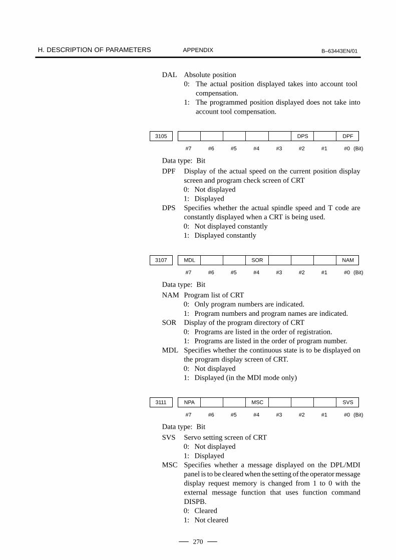
H. DESCRIPTION OF PARAMETERS B–63443EN/01APPENDIX
270
DAL Absolute position0: The actual position displayed takes into account tool
compensation.1: The programmed position displayed does not take into
account tool compensation.
3105 DPS DPF
(Bit)#7 #6 #5 #4 #3 #2 #1 #0
Data type: Bit
DPF Display of the actual speed on the current position displayscreen and program check screen of CRT0: Not displayed1: Displayed
DPS Specifies whether the actual spindle speed and T code areconstantly displayed when a CRT is being used.0: Not displayed constantly1: Displayed constantly
3107 MDL SOR NAM
(Bit)#7 #6 #5 #4 #3 #2 #1 #0
Data type: Bit
NAM Program list of CRT0: Only program numbers are indicated.1: Program numbers and program names are indicated.
SOR Display of the program directory of CRT0: Programs are listed in the order of registration.1: Programs are listed in the order of program number.
MDL Specifies whether the continuous state is to be displayed onthe program display screen of CRT.0: Not displayed1: Displayed (in the MDI mode only)
3111 NPA MSC SVS
(Bit)#7 #6 #5 #4 #3 #2 #1 #0
Data type: Bit
SVS Servo setting screen of CRT0: Not displayed1: Displayed
MSC Specifies whether a message displayed on the DPL/MDIpanel is to be cleared when the setting of the operator messagedisplay request memory is changed from 1 to 0 with theexternal message function that uses function commandDISPB.0: Cleared1: Not cleared

B–63443EN/01 H. DESCRIPTION OF PARAMETERSAPPENDIX
271
NOTEWhen MSCL is set to 1, message data must end with@03@.
NPA Action taken when an alarm is generated or when an operatormessage is entered0: The display shifts to the alarm or message screen.1: The display does not shift to the alarm or message screen.
3201 NPE REP RAL
(Bit)#7 #6 #5 #4 #3 #2 #1 #0
Data type: Bit
RAL Program registration by the reader/puncher interface0: All programs are registered.1: Only one program is registered.
REP Action in response to an attempt to register a program whosenumber is the same as that of an existing program0: An alarm is generated.1: The existing program is deleted, then the new program is
registered. Note that if the existing program is protectedfrom being edited, it is not deleted, and an alarm isgenerated.
NPE M02, M30, and M99 at program registration0: Completion of registration is assumed.1: Completion of registration is not assumed.
3202 PSR NE9 NE8
(Bit)#7 #6 #5 #4 #3 #2 #1 #0
Data type: Bit
NE8 Editing of subprograms with program numbers 8000 to 89990: Not inhibited1: Inhibited
The following edit operations are disabled:1 Program deletion (Even when deletion of all
programs is specified, programs with programnumbers 8000 to 8999 are not deleted.)
2 Program punching (Even when punching of allprograms is specified, programs with programnumbers 8000 to 8999 are not punched.)
3 Program number search4 Program editing after registration5 Program registration6 Program collation7 Displaying programs

H. DESCRIPTION OF PARAMETERS B–63443EN/01APPENDIX
272
NE9 Editing of subprograms with program numbers 9000 to 99990: Not inhibited1: Inhibited
The following edit operations are disabled:1 Program deletion (Even when deletion of all
programs is specified, programs with programnumbers 9000 to 9999 are not deleted.)
2 Program punching (Even when punching of allprograms is specified, programs with programnumbers 9000 to 9999 are not punched.)
3 Program number search4 Program editing after registration5 Program registration6 Program collation7 Displaying programs
PSR Search for the program number of a protected program0: Disabled1: Enabled
3203 MCL
(Bit)#7 #6 #5 #4 #3 #2 #1 #0
Data type: BitMCL Specifies whether a program created in the MDI mode is to be
cleared upon system reset.0: Not cleared1: Cleared
3204 CEX
(Bit)#7 #6 #5 #4 #3 #2 #1 #0
Data type: BitCEX Input character expansion function of CRT (”@”, ”(”, and ”)”
can be entered using soft keys.)0: Disabled1: Enabled
3216 Increment in sequence numbers inserted automatically
Setting entry is acceptable.Data type: WordValid data range: 0 to 9999Set the increment for sequence numbers for automatic sequencenumber insertion (when SEQ, #5 of parameter 0000, is set to 1.)

B–63443EN/01 H. DESCRIPTION OF PARAMETERSAPPENDIX
273
3290 KEY MCM IWZ WZO MCV WOF
(Bit)#7 #6 #5 #4 #3 #2 #1 #0
Data type: BitWOF Setting the tool offset value by MDI key input is:
0 : Not disabled1 : Disabled (With parameter No.3294 and No.3295, set the
offset number range in which updating the setting is to bedisabled.)
MCV Macro variable setting by MDI key input is:0 : Not disabled1 : Disabled
WZO Setting a workpiece zero point offset value by MDI key inputis:0 : Not disabled1 : Disabled
IWZ Setting a workpiece zero point offset value by MDI key inputin the automatic operation activation or halt state is:0 : Not disabled1 : Disabled
MCM The setting of custom macros by MDI key operation is:0 : Enabled regardless of the mode.1 : Enabled only in the MDI mode.
KEY For memory protection keys:0 : The KEY1, KEY2, KEY3, and KEY4 signals are used.1 : Only the KEY1 signal is used.
NOTEThe functions of the signals depend on whether KEY=0or KEY=1.
When KEY = 0:– KEY1: Enables a tool offset value and a workpiece zero
point offset value to be input.– KEY2: Enables setting data and macro variables to be
input.– KEY3: Enables program registration and editing.– KEY4: Enables PMC data (counter and data table) to be
input.When KEY = 1:
– KEY1: Enables program registration and editing, and enables PMC parameter input.
– KEY2 to KEY4: Not used

H. DESCRIPTION OF PARAMETERS B–63443EN/01APPENDIX
274
3294 Start number of tool offset values whose input by MDI is disabled
3295Number of tool offset values (from the start number) whose input by MDI isdisabled
Data type: WordWhen the modification of tool offset values by MDI key input is tobe disabled using bit 0 (WOF) of parameter No.3290 , parameter Nos.3294 and 3295 are used to set the range where such modification isdisabled. In parameter No.3294, set the offset number of the start oftool offset values whose modification is disabled. In parameterNo.3295, set the number of such values.When 0 or a negative value is set in parameter No.3294 or parameterNo.3295, no modification of the tool offset values is allowed.When the value set with parameter No.3294 is greater than themaximum tool offset count, no modification is allowed.[Example]The following setting disables the modification of the toolcompensation values corresponding to offset numbers 51 to 60:Bit 0 (WOF) of parameter No.3290=1 (Disables tool wearcompensation value modification.)Parameter No.3294 = 51Parameter No.3295 = 10

B–63443EN/01 H. DESCRIPTION OF PARAMETERSAPPENDIX
275
3401 GSC GSB DPI
(Bit)#7 #6 #5 #4 #3 #2 #1 #0
Data type: Bit
DPI When a decimal point is omitted in an address that can includea decimal point0: The least input increment is assumed.1: The unit of mm, inches, or s is assumed. (Pocket
calculator type decimal point input)GSB, GSC The G code system is set.
GSC GSB G code0 0 G code system A
0 1 G code system B
1 0 G code system C
3402 CLR G91 G01
(Bit)#7 #6 #5 #4 #3 #2 #1 #0
Data type: Bit
G01 Mode entered when the power is turned on or when the controlis cleared0: G00 mode (positioning)1: G01 mode (linear interpolation)
G91 When the power is turned on or when the control is cleared0: G90 mode (absolute command)1: G91 mode (incremental command)
CLR Reset button on the CRT/MDI panel, external reset signal,reset and rewind signal, and emergency stop0: Cause reset state.1: Cause clear state.
3404 EOR M02
(Bit)#7 #6 #5 #4 #3 #2 #1 #0
Data type: Bit
M02 When M02 is specified in memory operation
0: M02 is sent to the machine, and the program is positionedat its beginning automatically. As completion signal FINis returned without resetting or without resetting andrewinding, the program is restarted from the beginning.
1: M02 is only sent to the machine. The program ispositioned at its beginning by the reset and rewind signal.
EOR 0: An alarm is issued (PS5010, program end) when an EOR(%, or end of record) is read during program execution.
1: An alarm is not issued (automatic operation stops and a reset occurs) when an EOR (%, or end of record) is read during program execution.
H.11PARAMETERS OFPROGRAMS
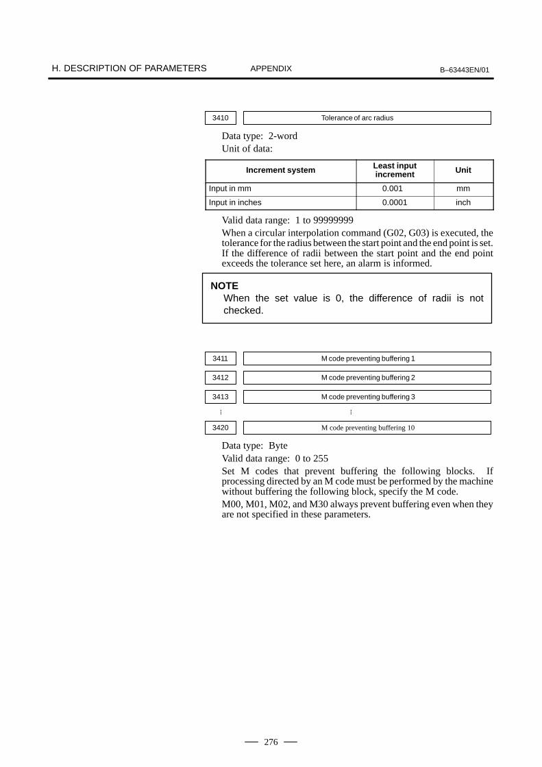
H. DESCRIPTION OF PARAMETERS B–63443EN/01APPENDIX
276
3410 Tolerance of arc radius
Data type: 2-wordUnit of data:
Increment system Least inputincrement Unit
Input in mm 0.001 mm
Input in inches 0.0001 inch
Valid data range: 1 to 99999999When a circular interpolation command (G02, G03) is executed, thetolerance for the radius between the start point and the end point is set.If the difference of radii between the start point and the end pointexceeds the tolerance set here, an alarm is informed.
NOTEWhen the set value is 0, the difference of radii is notchecked.
3411 M code preventing buffering 1
3412 M code preventing buffering 2
3413 M code preventing buffering 3
3420 M code preventing buffering 10
Data type: ByteValid data range: 0 to 255Set M codes that prevent buffering the following blocks. Ifprocessing directed by an M code must be performed by the machinewithout buffering the following block, specify the M code.M00, M01, M02, and M30 always prevent buffering even when theyare not specified in these parameters.
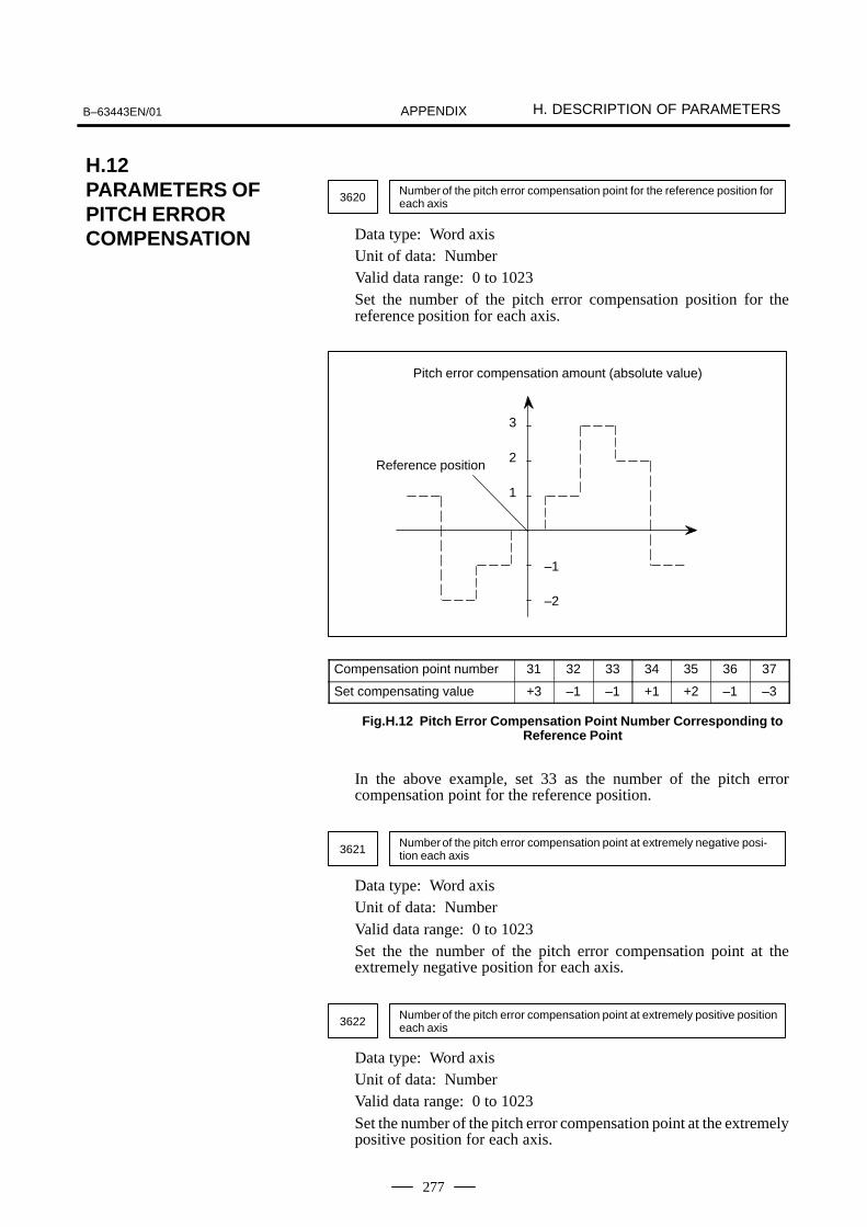
B–63443EN/01 H. DESCRIPTION OF PARAMETERSAPPENDIX
277
3620 Number of the pitch error compensation point for the reference position foreach axis
Data type: Word axisUnit of data: NumberValid data range: 0 to 1023Set the number of the pitch error compensation position for thereference position for each axis.
Pitch error compensation amount (absolute value)
3
2
1
–1
–2
Reference position
Compensation point number 31 32 33 34 35 36 37
Set compensating value +3 –1 –1 +1 +2 –1 –3
Fig.H.12 Pitch Error Compensation Point Number Corresponding toReference Point
In the above example, set 33 as the number of the pitch errorcompensation point for the reference position.
3621 Number of the pitch error compensation point at extremely negative posi-tion each axis
Data type: Word axisUnit of data: NumberValid data range: 0 to 1023Set the the number of the pitch error compensation point at theextremely negative position for each axis.
3622 Number of the pitch error compensation point at extremely positive positioneach axis
Data type: Word axisUnit of data: NumberValid data range: 0 to 1023Set the number of the pitch error compensation point at the extremelypositive position for each axis.
H.12PARAMETERS OFPITCH ERRORCOMPENSATION

H. DESCRIPTION OF PARAMETERS B–63443EN/01APPENDIX
278
3623 Magnification for pitch error compensation for each axis
Data type: Byte axisUnit of data: 1Valid data range: 0 to 100Set the magnification for pitch error compensation for each axis.If the magnification is set to 1, the same unit as the detection unit isused for the compensation data.
3624 Magnification for pitch error compensation for each axis
Data type: 2-word axisUnit of data:
Increment system Least inputincrement Unit
Input in mm 0.001 mm
Input in inches 0.0001 inch
Valid data range: 0 to 99999999The pitch error compensation points are arranged with equallyspaced. Set the space between two adjacent points for each axis.The minimum interval between pitch error compensation points islimited and obtained from the following equation:Minimum interval of pitch error compensation points = maximumfeedrate (rapid traverse rate)/7500Unit: mm, inches, deg, or mm/min, inches/min, deg/min[Example]When the maximum rapid traverse rate is 15000 mm/min, theminimum interval between pitch error compensation points is 2 mm.Examples of parameters
Machine stroke: –400 mm to +800 mm Interval between the pitch error compensation points: 50 mm No. of the compensation point of the reference position: 40
If the above is specified, the No. of the farthest compensation pointin the negative direction is as follows:
No. of the compensation point of the reference position –(Machine stroke length in the negative direction/Interval betweenthe compensation points) + 1= 40 – 400/50 + 1= 33
No. of the farthest compensation point in the positive direction is asfollows:
No. of the compensation point of the reference position +(Machine stroke length in the positive direction/Interval betweenthe compensation points)= 40 + 800/50= 56
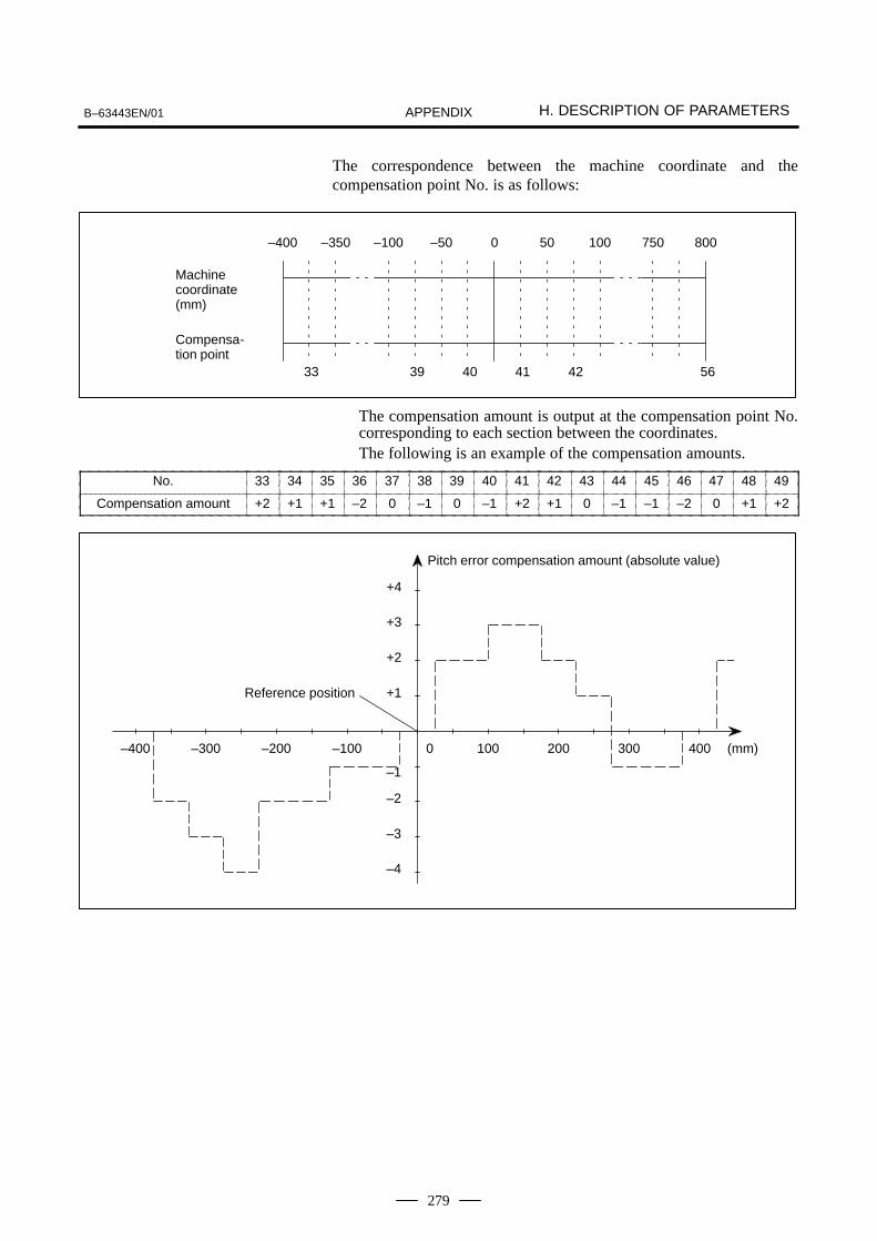
B–63443EN/01 H. DESCRIPTION OF PARAMETERSAPPENDIX
279
The correspondence between the machine coordinate and thecompensation point No. is as follows:
Machine coordinate(mm)
–400
Compensa-tion point
33
–350 –100
39
–50
40
0
41
50
42
100 750 800
56
The compensation amount is output at the compensation point No.corresponding to each section between the coordinates.The following is an example of the compensation amounts.
No. 33 34 35 36 37 38 39 40 41 42 43 44 45 46 47 48 49
Compensation amount +2 +1 +1 –2 0 –1 0 –1 +2 +1 0 –1 –1 –2 0 +1 +2
–1
Pitch error compensation amount (absolute value)
Reference position +1
–400 –300 –200 –100 100 200 300 400 (mm)0
+2
+3
+4
–4
–3
–2

H. DESCRIPTION OF PARAMETERS B–63443EN/01APPENDIX
280
3705 EVS ESF
(Bit)#7 #6 #5 #4 #3 #2 #1 #0
Data type: BitESF: When the spindle control function (S analog module) is used:
0 : S codes and SF are output for all S commands.1 : S codes and SF are not output for an S command in
constant surface speed control mode (G96 mode) ormaximum spindle speed clamp command (G50 when Gcode system A is used).
NOTEThis bit (ESF) is enabled, when bit 5 (NSF) of parameterNo.3705 is set to 1
EVS When the spindle control function (Spindle analog output orSpindle serial output) is used, S codes and SF are:0 : Not output for an S command.1 : Output for an S command.
NOTEThe output of S codes and SF for an S command in constantsurface speed control mode (G96), or for an S commandused to specify maximum spindle speed clamping(G50S–––;) depends on the setting of bit 0 (ESF) ofparameter No.3705.
3706 TCW CWM ORM PG2 PG1
(Bit)#7 #6 #5 #4 #3 #2 #1 #0
Data type: BitPG2 and PG1: Gear ratio of spindle to position coder
Magnification PG2 PG1
1 0 0
2 0 1
4 1 0
8 1 1
Number of spindle revolutions
Number of position coder revolutionsMagnification
ORM: Voltage polarity during spindle orientation0: Positive1: Negative
H.13PARAMETERS OFSPINDLE CONTROL

B–63443EN/01 H. DESCRIPTION OF PARAMETERSAPPENDIX
281
TCW and CWM: Voltage polarity when the spindle speed voltage isoutput
TCW CWM Voltage polarity
0 0 Both M03 and M04 positive
0 1 Both M03 and M04 negative
1 0 M03 positive, M04 negative
1 1 M03 negative, M04 positive
3708 SAT SAR
(Bit)#7 #6 #5 #4 #3 #2 #1 #0
Data type: BitSAR: The spindle speed arrival signal is:
0: Not checked1: Checked
SAT Check of the spindle speed arrival signal at the start ofexecuting the thread cutting block0 : The signal is checked only when SAR, #0 of parameter
3708, is set.1 : The signal is always checked irrespective of whether SAR
is set.
NOTEWhen thread cutting blocks are consecutive, the spindlespeed arrival signal is not checked for the second andsubsequent thread cutting blocks.
3730 Data used for adjusting the gain of the analog output of spindle speed
Data type: WordUnit of data: 0.1 %Valid data range: 700 to 1250Set data used for adjusting the gain of the analog output of spindlespeed.(Adjustment method)
(1) Assign standard value 1000 to the parameter.
(2) Specify the spindle speed so that the analog output of thespindle speed is the maximum voltage (10 V).
(3) Measure the output voltage.
(4) Assign the value obtained by the following equation toparameter No. 3730.
(5) After setting the parameter, specify the spindle speed so thatthe analog output of the spindle speed is the maximumvoltage. Confirm that the output voltage is 10 V

H. DESCRIPTION OF PARAMETERS B–63443EN/01APPENDIX
282
3731 Compensation value for the offset voltage of the analog output of thespindle speed
Data type: WordUnit of data: VeloValid data range: –1024 to +1024Set compesation value for the offset voltage of the analog output ofthe spindle speed.
!"
#
(Adjustment method)
(1) Assign standard value 0 to the parameter.
(2) Specify the spindle speed so that the analog output of thespindle speed is 0.
(3) Measure the output voltage.
(4) Assign the value obtained by the following equation toparameter No. 3731.
!"
#
(5) After setting the parameter, specify the spindle speed so thatthe analog output of the spindle speed is 0. Confirm that theoutput voltage is 0 V.
3732 The number of spindle revolutions during spindle orientation
Data type: 2 wordsUnit of data: rpmValid data range: 0 to 20000Set the spindle speed during spindle orientation.
3740 Time elapsed prior to checking the spindle speed arrival signal
Data type: ByteUnit of data: msValid data range: 0 to 255Set the time elapsed from the execution of the S function up to thechecking of the spindle speed arrival signal.
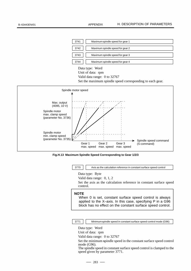
B–63443EN/01 H. DESCRIPTION OF PARAMETERSAPPENDIX
283
3741 Maximum spindle speed for gear 1
3742 Maximum spindle speed for gear 2
3743 Maximum spindle speed for gear 3
3744 Maximum spindle speed for gear 4
Data type: WordUnit of data: rpmValid data range: 0 to 32767Set the maximum spindle speed corresponding to each gear.
Spindle speed command(S command)
Spindle motor min. clamp speed(parameter No. 3735)
Spindle motor speed
Gear 1max. speed
Max. output (4095, 10 V)
Spindle motormax. clamp speed(parameter No. 3736)
Gear 2max. speed
Gear 3max. speed
Fig.H.13 Maximum Spindle Speed Corresponding to Gear 1/2/3
3770 Axis as the calculation reference in constant surface speed control
Data type: ByteValid data range: 0, 1, 2Set the axis as the calculation reference in constant surface speedcontrol.
NOTEWhen 0 is set, constant surface speed control is alwaysapplied to the X–axis. In this case, specifying P in a G96block has no effect on the constant surface speed control.
3771 Minimum spindle speed in constant surface speed control mode (G96)
Data type: WordUnit of data: rpmValid data range: 0 to 32767Set the minimum spindle speed in the constant surface speed controlmode (G96).The spindle speed in constant surface speed control is clamped to thespeed given by parameter 3771.

H. DESCRIPTION OF PARAMETERS B–63443EN/01APPENDIX
284
3772 Maximum spindle speed
Data type: WordUnit of data: rpmValid data range: 0 to 32767This parameter sets the maximum spindle speed. When a command specifying a speed exceeding the maximum speedof the spindle is specified , or the speed of the spindle exceeds themaximum speed because of the spindle speed override function, thespindle speed is clamped at the maximum speed set in the parameter.
NOTE1 Spindle speed is clamped at the maximum speed,
regardless of whether the G96 mode or G97 mode isspecified.
2 When 0 is set in this parameter, the speed of the spindleis not clamped.
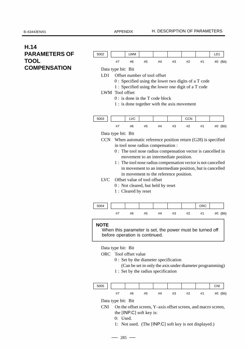
B–63443EN/01 H. DESCRIPTION OF PARAMETERSAPPENDIX
285
5002 LWM LD1
(Bit)#7 #6 #5 #4 #3 #2 #1 #0
Data type bit: BitLD1 Offset number of tool offset
0 : Specified using the lower two digits of a T code1 : Specified using the lower one digit of a T code
LWM Tool offset0 : is done in the T code block1 : is done together with the axis movement
5003 LVC CCN
(Bit)#7 #6 #5 #4 #3 #2 #1 #0
Data type bit: BitCCN When automatic reference position return (G28) is specified
in tool nose radius compensation :0 : The tool nose radius compensation vector is cancelled in
movement to an intermediate position.1 : The tool nose radius compensation vector is not cancelled
in movement to an intermediate position, but is cancelledin movement to the reference position.
LVC Offset value of tool offset0 : Not cleared, but held by reset1 : Cleared by reset
5004 ORC
(Bit)#7 #6 #5 #4 #3 #2 #1 #0
NOTEWhen this parameter is set, the power must be turned offbefore operation is continued.
Data type bit: BitORC Tool offset value
0 : Set by the diameter specification (Can be set in only the axis under diameter programming)
1 : Set by the radius specification
5005 CNI
(Bit)#7 #6 #5 #4 #3 #2 #1 #0
Data type bit: BitCNI On the offset screen, Y–axis offset screen, and macro screen,
the [INP.C] soft key is:0: Used.1: Not used. (The [INP.C] soft key is not displayed.)
H.14PARAMETERS OFTOOLCOMPENSATION

H. DESCRIPTION OF PARAMETERS B–63443EN/01APPENDIX
286
5006 TGC OIM
(Bit)#7 #6 #5 #4 #3 #2 #1 #0
Data type bit: BitOIM When the unit is switched between the inch and metric
systems, automatic tool offset value conversion is:0 : Not performed1 : Performed
TGC When a T code is specified in a block containing G50, G04,or G10:0 : No alarm occurs.1 : P/S alarm No.245 occurs.
5008 CNC CNI
(Bit)#7 #6 #5 #4 #3 #2 #1 #0
Data type bit: BitCNI Interference check for tool nose radius compensation is:
0 : Performed1 : Not performed
CNC During interference check for tool nose radius compensation,when the direction of movement after application of the offsetdiffers from the programmed direction by between 90 and270:0 : An alarm is issued.1 : No alarm is issued.
5010 Limit value that ignores the vector when a tool moves on the outside of acorner during tool nose radius compensation
Data type: WordUnit of data:
Increment system Least input increment Unit
Input in mm 0.001 mm
Input in inches 0.0001 inch
Valid data range: 0 to 16383This parameter sets the limit value that ignores a slight movementoccurring when a tool moves on the outside of the corner during toolnose radius compensation.

B–63443EN/01 H. DESCRIPTION OF PARAMETERSAPPENDIX
287
Very small amount of travel tobe ignored
Programmed path
Actual tool path Very small amountof travel to be ig-nored
5013 Maximum value of tool wear compensation
Data type: 2–wordUnit of data:
Increment system Least input increment Unit
Input in mm 0.001 mm
Input in inches 0.0001 inch
Valid data rande:
Increment system Valid data range
Millimeter machine 0 to 999999
Inch machine 0 to 999999
This parameter sets the maximum allowable tool wear compensationvalue. If an attempt is made to set a tool wear compensation value,the absolute value of which exceeds the value set in this parameter,the following alarm or warning is output:Input from MDI Warning: Too many digitsInput by G10 P/S alarm No.032: Offset value is out of range by
G10.
5014 Maximum value of incremental input for tool wear compensation
Data type: 2–wordUnit of data:
Increment system Least input increment Unit
Input in mm 0.001 mm
Input in inches 0.0001 inch
Valid data range:
Increment system Valid data range
Millimeter machine 0 to 999999
Inch machine 0 to 999999
Set the maximum allowable value for the tool compensation value, inputas an incremental value. If the incremental input value (absolute value)exceeds the set value, the following alarm or warning message is output:Input from MDI Warning: Setting value out of range.Input using G10 P/S alarm No.032: Offset value is out of range by
G10.

H. DESCRIPTION OF PARAMETERS B–63443EN/01APPENDIX
288
6000 SBM
(Bit)#7 #6 #5 #4 #3 #2 #1 #0
Data type: Bit
SBM Custom macro statement0: Not stop the single block1: Stops the single block
6001 CLV CCV TCS CRO VFP PRT
(Bit)#7 #6 #5 #4 #3 #2 #1 #0
Data type: Bit
PRT Reading zero when data is output using a DPRINT command0: Outputs a space1: Outputs no data
CRO ISO code in the B/D PRINT mode0: Outputs only LF after data is output1: Outputs LF and CR after data is output
TCS Custom macro (subprogram)0 : Not called using a T code1 : Called using a T code
CCV Custom macroGs common variables Nos. 100 to 1490: Cleared to <vacant> by reset1: Not cleared by reset
CLV Custom macroGs local variables Nos. 1 to 330: Cleared to <vacant> by reset1: Not cleared by reset
6010 *7 *6 *5 *4 *3 *2 *1 *0
6011 =7 =6 =5 =4 =3 =2 =1 =0
6012 #7 #6 #5 #4 #3 #2 #1 #0
6013 [ 7 [ 6 [ 5 [ 4 [ 3 [ 2 [ 1 [ 0
6014 ] 7 ] 6 ] 5 ] 4 ] 3 ] 2 ] 1 ] 0
(Bit)#7 #6 #5 #4 #3 #2 #1 #0
Data type: Bit
*0 to *7 : Set the pattern of an EIA code indicating *.=0 to =7 : Set the pattern of an EIA code indicating =.
#0 to #7 : Set the pattern of an EIA code indicating #.[ 0 to [ 7 : Set the pattern of an EIA code indicating [.
] 0 to ] 7 : Set the pattern of an EIA code indicating ].
NOTEThe numeral of a suffix indicates the bit position in a code.
H.15PARAMETERS OFCUSTOM MACROS
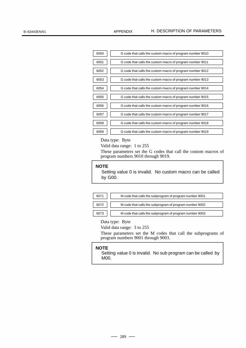
B–63443EN/01 H. DESCRIPTION OF PARAMETERSAPPENDIX
289
6050 G code that calls the custom macro of program number 9010
6051 G code that calls the custom macro of program number 9011
6052 G code that calls the custom macro of program number 9012
6053 G code that calls the custom macro of program number 9013
6054 G code that calls the custom macro of program number 9014
6055 G code that calls the custom macro of program number 9015
6056 G code that calls the custom macro of program number 9016
6057 G code that calls the custom macro of program number 9017
6058 G code that calls the custom macro of program number 9018
6059 G code that calls the custom macro of program number 9019
Data type: ByteValid data range: 1 to 255These parameters set the G codes that call the custom macros ofprogram numbers 9010 through 9019.
NOTESetting value 0 is invalid. No custom macro can be calledby G00.
6071 M code that calls the subprogram of program number 9001
6072 M code that calls the subprogram of program number 9002
6073 M code that calls the subprogram of program number 9003
Data type: ByteValid data range: 3 to 255These parameters set the M codes that call the subprograms ofprogram numbers 9001 through 9003.
NOTESetting value 0 is invalid. No sub program can be called byM00.
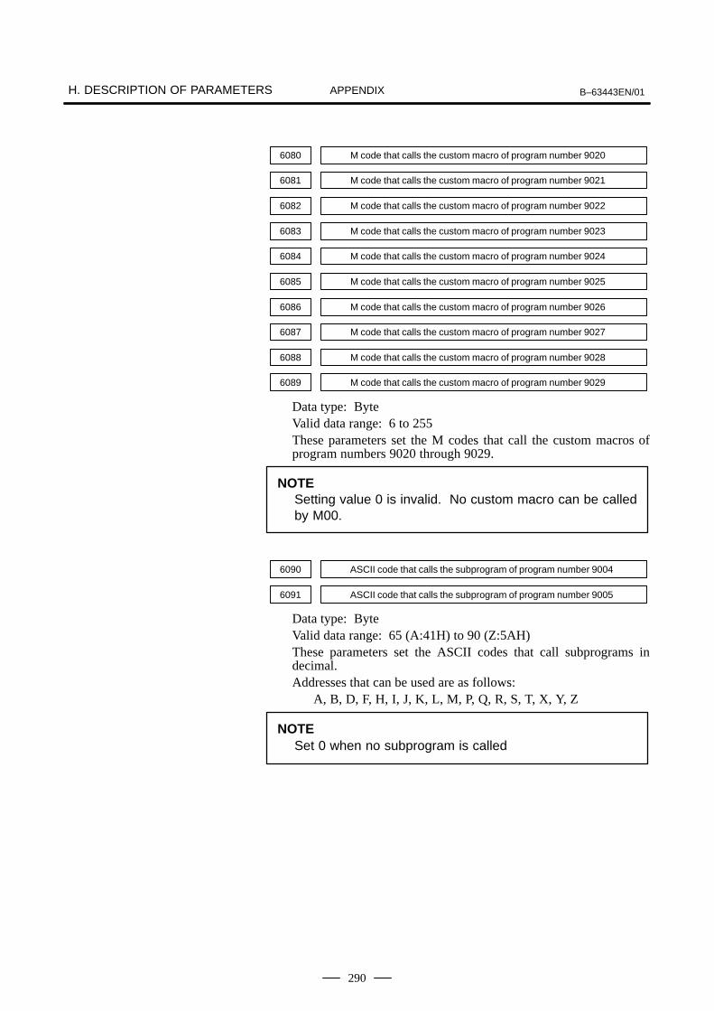
H. DESCRIPTION OF PARAMETERS B–63443EN/01APPENDIX
290
6080 M code that calls the custom macro of program number 9020
6081 M code that calls the custom macro of program number 9021
6082 M code that calls the custom macro of program number 9022
6083 M code that calls the custom macro of program number 9023
6084 M code that calls the custom macro of program number 9024
6085 M code that calls the custom macro of program number 9025
6086 M code that calls the custom macro of program number 9026
6087 M code that calls the custom macro of program number 9027
6088 M code that calls the custom macro of program number 9028
6089 M code that calls the custom macro of program number 9029
Data type: ByteValid data range: 6 to 255These parameters set the M codes that call the custom macros ofprogram numbers 9020 through 9029.
NOTESetting value 0 is invalid. No custom macro can be calledby M00.
6090 ASCII code that calls the subprogram of program number 9004
6091 ASCII code that calls the subprogram of program number 9005
Data type: ByteValid data range: 65 (A:41H) to 90 (Z:5AH)These parameters set the ASCII codes that call subprograms indecimal.Addresses that can be used are as follows:
A, B, D, F, H, I, J, K, L, M, P, Q, R, S, T, X, Y, Z
NOTESet 0 when no subprogram is called

B–63443EN/01 H. DESCRIPTION OF PARAMETERSAPPENDIX
291
6200 SKF
(Bit)#7 #6 #5 #4 #3 #2 #1 #0
Data type: BitSKF Dry run, override, and automatic acceleration/deceleration for
G31 skip command0: Disabled1: Enabled
H.16PARAMETERS OFSKIP FUNCTION

H. DESCRIPTION OF PARAMETERS B–63443EN/01APPENDIX
292
7100 HDLPM
(Bit)#7 #6 #5 #4 #3 #2 #1 #0
Data type: BitHDLPM 0: When the handle of the manual pulse generator is
turned rapidly, the number of input pulses may not match the amount of movement.
1: When the handle of the manual pulse generator is turned rapidly, the number of input pulses matches theamount of movement.
7110 Number of manual pulse generators used
Data type: ByteValid data range: 1This parameter sets the number of manual pulse generators.
7113 Magnification m of manual handle feed
Data type: ByteUnit of data: One timeValid data range: 1 to 127This parameter sets a magnification when manual handle feedmovement selection signal MP1 is off, and external pulse inputmovement selection signal MP2 is on.
7114 Magnification n of manual handle feed
Data type: WordUnit of data: One timeValid data range: 0 to 1000This parameter sets the magnification when manual handle feedmovement selection signals MP1 and MP2 are on.
Movement selection signal
MP2 MP1Movement (Manual handle feed)
0 0 Least input increment 1
0 1 Least input increment 10
1 0 Least input increment m
1 1 Least input increment n
H.17PARAMETERS OFMANUAL HANDLEFEED/MANUALHANDLEINTERRUPTION

B–63443EN/01 H. DESCRIPTION OF PARAMETERSAPPENDIX
293
7200 OP7 OP6 OP5 OP4 OP3 OP2 OP1
(Bit)#7 #6 #5 #4 #3 #2 #1 #0
Data type: BitOP1 Mode selection on software operator’s panel
0: Not performed1: Performed
OP2 JOG feed axis select and JOG rapid traverse buttons onsoftware operator’s panel0: Not performed1: Performed
OP3 Manual pulse generator’s axis select and manual pulsegenerator’s magnification switches on software operator’spanel0: Not performed1: Performed
OP4 JOG speed override and rapid traverse override switches onsoftware operator’s panel0: Not performed1: Performed
OP5 Optional block skip, single block, machine lock, and dry runswitches on software operator’s panel0: Not performed1: Performed
OP6 Protect key on software operator’s panel0: Not performed1: Performed
OP7 Feed hold on software operator’s panel0: Not performed1: Performed
NOTETo use the software operator’s panel function, a CRT/MDIis required.
7210 PLSKYX
Data type: ByteValid data range: 1, 2, 3, 4, 5, 6, 7, 8, 9This parameter specifies the value to use for the positive direction keyon the software operator’s panel during jogging of the first axis.
7211 MNSKYX
Data type: ByteValid data range: 1, 2, 3, 4, 5, 6, 7, 8, 9This parameter specifies the value to use for the negative directionkey on the software operator’s panel during jogging of the first axis.
H.18PARAMETERS OFSOFTWAREOPERATOR’S PANEL

H. DESCRIPTION OF PARAMETERS B–63443EN/01APPENDIX
294
7212 PLSKYY
Data type: ByteValid data range: 1, 2, 3, 4, 5, 6, 7, 8, 9This parameter specifies the value to use for the posinega directionkey on the software operator’s panel during jogging of the secondaxis.
7213 MNSKYY
Data type: ByteValid data range: 1, 2, 3, 4, 5, 6, 7, 8, 9This parameter specifies the value to use for the negative directionkey on the software operator’s panel during jogging of the secondaxis.
7214 Unused
7217 Unused
Data type: ByteValid data range:
7220 Name of general-purpose switch on software operator’s panel
7283 Name of general-purpose switch on software operator’s panel
Data type: Byte

B–63443EN/01 H. DESCRIPTION OF PARAMETERSAPPENDIX
295
OPERATOR’S PANEL O1234 N5678
SIGNAL 1 : OFF ONSIGNAL 2 : OFF ONSIGNAL 3 : OFF ONSIGNAL 4 : OFF ONSIGNAL 5 : OFF ONSIGNAL 6 : OFF ONSIGNAL 7 : OFF ONSIGNAL 8 : OFF ON
These names are set using character codes that are displayed in parameterNos. 7220 to 7283.
Parameter No. 7220:Sets the character code (083) corresponding to S of SIGNAL 1.
Parameter No. 7221:Sets the character code (073) corresponding to I of SIGNAL 1.
Parameter No. 7222:Sets the character code (071) corresponding to G of SIGNAL 1.
Parameter No. 7223:Sets the character code (078) corresponding to N of SIGNAL 1.
Parameter No. 7224:Sets the character code (065) corresponding to A of SIGNAL 1.
Parameter No. 7225:Sets the character code (076) corresponding to L of SIGNAL 1.
Parameter No. 7226:Sets the character code (032) corresponding to space of SIGNAL 1.
Parameter No. 7227:Sets the character code (049) corresponding to 1 of SIGNAL 1.
Parameter Nos. 7228 to 7235:Set the character codes of SIGNAL 2 shown in the figure above.
Parameter Nos. 7236 to 7243:Set the character codes of SIGNAL 3 shown in the figure above.
Parameter Nos. 7244 to 7251:Set the character codes of SIGNAL 4 shown in the figure above.
Parameter Nos. 7252 to 7259:Set the character codes of SIGNAL 5 shown in the figure above.
Parameter Nos. 7260 to 7267:Set the character codes of SIGNAL 6 shown in the figure above.
Parameter Nos. 7268 to 7275:Set the character codes of SIGNAL 7 shown in the figure above.
Parameter Nos. 7276 to 7283:Set the character codes of SIGNAL 8 shown in the figure above.
The character codes are shown in Table 4.31, character code list, on thenext page.

H. DESCRIPTION OF PARAMETERS B–63443EN/01APPENDIX
296
Table H.18 Character Code List
NOTEThe “dakuten” and “han dakuten” in Katakana alsocorrespond to one character.

B–63443EN/01 H. DESCRIPTION OF PARAMETERSAPPENDIX
297
The kanji and hiragana take up the equivalent of two alphanumericcharacters.
Example) #501 R point R : 082, point : 002 0232, space : 032 N3G65 H93 P501 Qo82 002 R232 032 ;

IndexB–63443EN/01
i–1
[Numbers]1st Reference Position Return, 125
20–pin Interface Connectors and Cables, 212
[A]Action Against Noise, 11
Address List, 83
Alarm Signal (Output) AL <F001#0>, 104
Analog Spindle Interface, 76
Analog spindle interface, 76
Automatic Operation, 132
Automatic Operation Signal (Output) OP <F000#7>,138
Auxiliary Function Lock Signal (Input) AFL<G005#6>, 151
Axis Interlock Signal (Input) *ITn <G130#0, #1>, 120
[B]Battery Alarm Signal (Output) BAL <F001#2>, 104
Battery for Memory Backup, 21
Board–mounted connectors, 213
[C]Cable Clamp and Shield Processing, 16
Cable Connection for the Manual Pulse Generator, 74
Cable Lead–in Diagram, 24
Cable–side connectors, 214
CNC Ready Signal (Output) MA<F001#7>, 98
Command Flow of Spindle Speed Control, 156
Configuration, 4
Connecting the Ground for Signal of the Control Unit,14
Connection of Buil–in I/O Card–C, 40
Connection of I/O Units to Machine Interface, 34
Connection of Input Power Supply, 28
Connection to CNC Peripherals, 53
Connection with the DPL/MDI, 59
Connector Layout of Unit, 25
Constant Surface Speed Control, 164
Control Unit, 19
Cooling by Heat Exchanger, 10
CRT Interface, 55
CRT Terminating Unit, 57
CRT/MDI Interface, 54
Custom Macro, 182
Custom Macro Signal (Input) UI0 to UI15 <G054,G055>, (Output) UO0 to UO131 <F054 to F059>,183
Cycle Start Lamp Signal (Output) STL <F000#5>,137
Cycle Start Signal (Input) ST <G007#2>, 133
[D]Definition of Warning, Caution, and Note, s–1
Description of Parameters, 237
Design and Installation Conditions of the Tool Mag-netic Cabinet, 8
Details of DI Connection, 44
Details of DO Connection, 48
Displaying and Setting Parameters, 229
Distribution end Signal (Output) DEN <F001#3>, 151
DPL/MDI Interface, 60
Dry Run Signal (Input) DRN <G046#7 > , 143
[E]Emergency Stop Signal (Input) *ESP <X1000#4,
G008#4>, 100
Environmental Requirements of CNC, 6
External Dimensions of Each Connector, 201
External Dimensions of Each Unit, 189
External Reset Signal (Input) ERS <G008#7>, 102
[F]FANUC Handy File Connection, 71
Feed Axis Direction Select Signal (Input) +Jn, –jn,<G100#0, #1, G102#0, #1>, 113
Feed Hold Lamp Signal (Output) SPL <F000#4>, 137
Feed Hold Signal (Input) *SP <G008#5>, 135
Feed Rate Override Signal (Input) *FV0 to *FV7<G012>, 143
Follow-up Signal (Input) *FLWU <G007#5>, 178
[G]Ground, 13
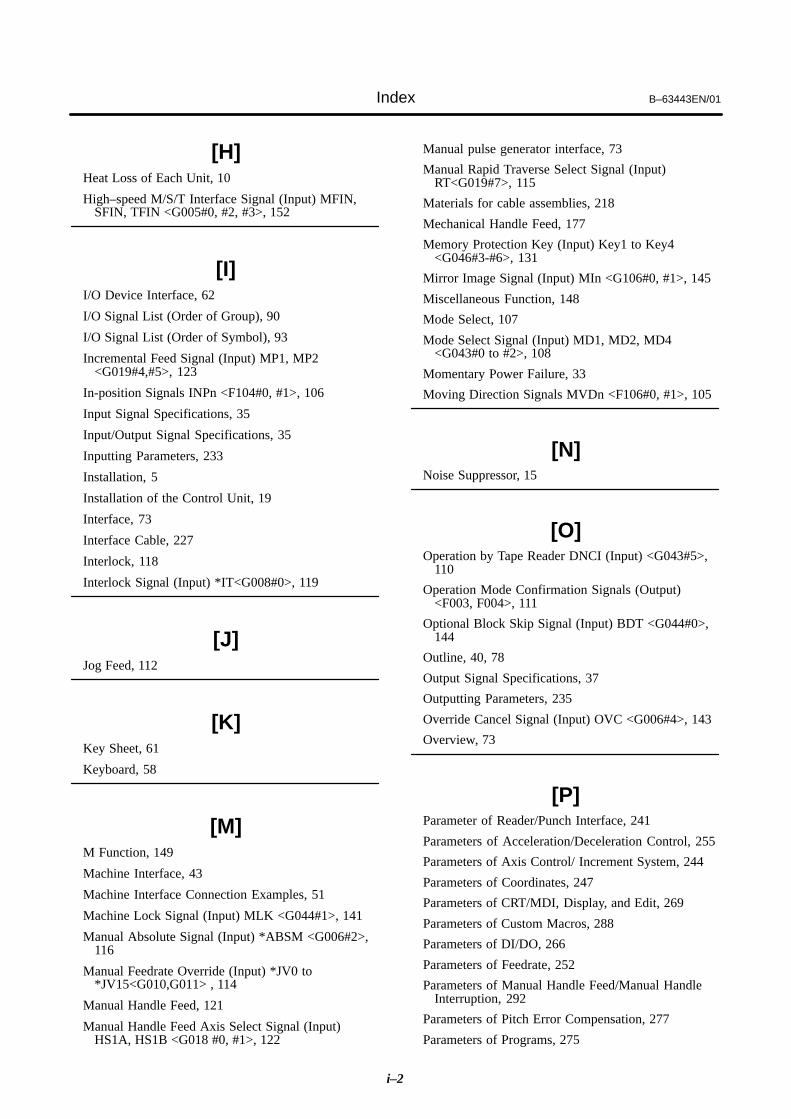
Index B–63443EN/01
i–2
[H]Heat Loss of Each Unit, 10
High–speed M/S/T Interface Signal (Input) MFIN,SFIN, TFIN <G005#0, #2, #3>, 152
[I]I/O Device Interface, 62
I/O Signal List (Order of Group), 90
I/O Signal List (Order of Symbol), 93
Incremental Feed Signal (Input) MP1, MP2<G019#4,#5>, 123
In-position Signals INPn <F104#0, #1>, 106
Input Signal Specifications, 35
Input/Output Signal Specifications, 35
Inputting Parameters, 233
Installation, 5
Installation of the Control Unit, 19
Interface, 73
Interface Cable, 227
Interlock, 118
Interlock Signal (Input) *IT<G008#0>, 119
[J]Jog Feed, 112
[K]Key Sheet, 61
Keyboard, 58
[M]M Function, 149
Machine Interface, 43
Machine Interface Connection Examples, 51
Machine Lock Signal (Input) MLK <G044#1>, 141
Manual Absolute Signal (Input) *ABSM <G006#2>,116
Manual Feedrate Override (Input) *JV0 to*JV15<G010,G011> , 114
Manual Handle Feed, 121
Manual Handle Feed Axis Select Signal (Input)HS1A, HS1B <G018 #0, #1>, 122
Manual pulse generator interface, 73
Manual Rapid Traverse Select Signal (Input)RT<G019#7>, 115
Materials for cable assemblies, 218
Mechanical Handle Feed, 177
Memory Protection Key (Input) Key1 to Key4<G046#3-#6>, 131
Mirror Image Signal (Input) MIn <G106#0, #1>, 145
Miscellaneous Function, 148
Mode Select, 107
Mode Select Signal (Input) MD1, MD2, MD4<G043#0 to #2>, 108
Momentary Power Failure, 33
Moving Direction Signals MVDn <F106#0, #1>, 105
[N]Noise Suppressor, 15
[O]Operation by Tape Reader DNCI (Input) <G043#5>,
110
Operation Mode Confirmation Signals (Output)<F003, F004>, 111
Optional Block Skip Signal (Input) BDT <G044#0>,144
Outline, 40, 78
Output Signal Specifications, 37
Outputting Parameters, 235
Override Cancel Signal (Input) OVC <G006#4>, 143
Overview, 73
[P]Parameter of Reader/Punch Interface, 241
Parameters of Acceleration/Deceleration Control, 255
Parameters of Axis Control/ Increment System, 244
Parameters of Coordinates, 247
Parameters of CRT/MDI, Display, and Edit, 269
Parameters of Custom Macros, 288
Parameters of DI/DO, 266
Parameters of Feedrate, 252
Parameters of Manual Handle Feed/Manual HandleInterruption, 292
Parameters of Pitch Error Compensation, 277
Parameters of Programs, 275

B–63443EN/01 Index
i–3
Parameters of Servo, 258
Parameters of Setting, 239
Parameters of Skip Function, Picture Display, and ITPSynchronous, 291
Parameters of Software Operator’s Panel, 293
Parameters of Spindle Control, 280
Parameters of Stroke Limit, 251
Parameters of Tool Compensation, 285
PMC Key Data Reference Function (Output), 153
Position coder interface, 77
Power Capacity, 7
Power Connections, 31
Power Mate 0, 84
Power Supply Capacity, 29
Power Supply Interface, 56, 61
Power–off Sequence, 33
Power–on Sequence, 32
Press–mount type connector assembly tools and jigs,217
Protection Ground Connection, 33
[R]Rapid Traverse Override Signal (Input) ROV1, ROV2
<G014#0, #1>, 115
Ready Signals, 97
Recommended connectors, applicable housings, andcables, 216
Reference Position Establishment Signal (Output)ZRFn <F120#0, #1>, 130
Reference Position Return, 124
Reset & Emergency Stop, 99
Reset & Rewind Signal (Input) RRW <G008#6>, 102
Reset Signal (Output) RST <F001#1>, 104
Rewinding Signal (Output) RWD <F000#0>, 105
RS–232–C Interface Specification, 62
RS–232–C Serial Port, 70
[S]Screen State Signals (Output) DPL0, DPL1, DPL2
<F254 #0 to #2>, 147
Separating Signal Lines, 11
Servo Amplifier Interface (β Series Servo Amplifier),79
Servo Interface, 78
Servo Off Signal (Input) SVFn <G126#0, #1>, 178
Servo Ready Signal (Output) SA <F000#6>, 98
Signal List, 89
Signals, 42
Signals In Cutting Mode (Output) Cut <F002#6>, 146
Single Block Signal (Input) SBK <G046#1>, 142
Skip Signals (Input) Skip <X1000#7>, 175
Software Operator’s Panel, 179
Software Operator’s Panel General–purpose SwitchSignals (Output) OUT0 to OUT7 <F072>, 181
Software Operator’s Panel Signals (Output) <F073 toF081>, 180
Speed Arrival Signal (Input) SAR <G029#4>, 160
Speed Control Servo Alarm Ignore Signal (Input)Ignvry <G066#0>, 184
Spindle Functions, 155
Spindle Orientation Signal (Input) SOR <G029#5>,162
Spindle Override Signal (Input) SOV0 to SOV7<G030>, 163
Spindle Stop Signal (Input) *SSTP <G029#6>, 161
Status Signals, 103
[T]Temperature Rise within the Cabinet, 10
Thermal Design of the Cabinet, 10
Threading Signal (Output) Thrd <F002#3>, 106
Tool compensation value/tool compensation number/tool compensation memory, 171
Tool Function, 168, 169
Total Connection, 26
Total Connection Diagram for Power Mate 0, 27
[V]Vertical–type connectors, 213
[W]When External Power Supply is Used, 72
Workpiece Number Search Signal (Input) PN0 to PN3<G009>, 139

Rev
isio
n R
eco
rd
FAN
UC
Po
wer
Mat
e 0
CO
NN
EC
TIO
N M
AN
UA
L (
B–6
3443
EN
)
01F
eb.,
’00
Rev
isio
nD
ate
Con
tent
sR
evis
ion
Dat
eC
onte
nts

· No part of this manual may bereproduced in any form.
· All specifications and designsare subject to change withoutnotice.


