712
GE Fanuc Automation Computer Numerical Control Products Series 0i-Model B Series 0i-Mate Model B Maintenance Manual GFZ-63835EN/03 July 2003
GE Fanuc Automation
Computer Numerical Control Products Series 0i-Model B Series 0i-Mate Model B Maintenance Manual GFZ-63835EN/03 July 2003

GFL-001
Warnings, Cautions, and Notesas Used in this Publication
Warning
Warning notices are used in this publication to emphasize that hazardous voltages, currents,temperatures, or other conditions that could cause personal injury exist in this equipment ormay be associated with its use.
In situations where inattention could cause either personal injury or damage to equipment, aWarning notice is used.
Caution
Caution notices are used where equipment might be damaged if care is not taken.
NoteNotes merely call attention to information that is especially significant to understanding andoperating the equipment.
This document is based on information available at the time of its publication. While effortshave been made to be accurate, the information contained herein does not purport to cover alldetails or variations in hardware or software, nor to provide for every possible contingency inconnection with installation, operation, or maintenance. Features may be described hereinwhich are not present in all hardware and software systems. GE Fanuc Automation assumesno obligation of notice to holders of this document with respect to changes subsequently made.
GE Fanuc Automation makes no representation or warranty, expressed, implied, or statutorywith respect to, and assumes no responsibility for the accuracy, completeness, sufficiency, orusefulness of the information contained herein. No warranties of merchantability or fitness forpurpose shall apply.
©Copyright 2003 GE Fanuc Automation North America, Inc.
All Rights Reserved.

s–1
SAFETY PRECAUTIONS
This section describes the safety precautions related to the use of CNC units. It is essential that these precautionsbe observed by users to ensure the safe operation of machines equipped with a CNC unit (all descriptions in thissection assume this configuration). CNC maintenance involves various dangers. CNC maintenance must be undertaken only by a qualifiedtechnician.Users must also observe the safety precautions related to the machine, as described in the relevant manual suppliedby the machine tool builder. Before checking the operation of the machine, take time to become familiar with the manuals provided by themachine tool builder and FANUC.
Contents
1. DEFINITION OF WARNING, CAUTION, AND NOTE s–2. . . . . . . . . . . . . . . . . . . . . . .
2. WARNINGS RELATED TO CHECK OPERATION s–3. . . . . . . . . . . . . . . . . . . . . . . . .
3. WARNINGS RELATED TO REPLACEMENT s–5. . . . . . . . . . . . . . . . . . . . . . . . . . . . . .
4. WARNINGS RELATED TO PARAMETERS s–6. . . . . . . . . . . . . . . . . . . . . . . . . . . . . . .
5. WARNINGS AND NOTES RELATED TO DAILY MAINTENANCE s–7. . . . . . . . . . . .

SAFETY PRECAUTIONS B–63835EN/03
s–2
1 DEFINITION OF WARNING, CAUTION, AND NOTE
This manual includes safety precautions for protecting the maintenance personnel (herein referredto as the user) and preventing damage to the machine. Precautions are classified into Warnings andCautions according to their bearing on safety. Also, supplementary information is described as aNote. Read the Warning, Caution, and Note thoroughly before attempting to use the machine.
WARNING
Applied when there is a danger of the user being injured or when there is a danger of both the userbeing injured and the equipment being damaged if the approved procedure is not observed.
CAUTION
Applied when there is a danger of the equipment being damaged, if the approved procedure is notobserved.
NOTE
The Note is used to indicate supplementary information other than Warning and Caution.
� Read this manual carefully, and store it in a safe place.

B–63835EN/03 SAFETY PRECAUTIONS
s–3
2 WARNINGS RELATED TO CHECK OPERATION
WARNING
1. When checking the operation of the machine with the cover removed
(1) The user’s clothing could become caught in the spindle or other components, thuspresenting a danger of injury. When checking the operation, stand away from the machineto ensure that your clothing does not become tangled in the spindle or other components.
(2) When checking the operation, perform idle operation without workpiece. When aworkpiece is mounted in the machine, a malfunction could cause the workpiece to bedropped or destroy the tool tip, possibly scattering fragments throughout the area. Thispresents a serious danger of injury. Therefore, stand in a safe location when checking theoperation.
2. When checking the machine operation with the power magnetics cabinet door opened
(1) The power magnetics cabinet has a high–voltage section (carrying a mark). Nevertouch the high–voltage section. The high–voltage section presents a severe risk of electricshock. Before starting any check of the operation, confirm that the cover is mounted onthe high–voltage section. When the high–voltage section itself must be checked, note thattouching a terminal presents a severe danger of electric shock.
(2) Within the power magnetics cabinet, internal units present potentially injurious corners andprojections. Be careful when working inside the power magnetics cabinet.
3. Never attempt to machine a workpiece without first checking the operation of the machine.Before starting a production run, ensure that the machine is operating correctly by performinga trial run using, for example, the single block, feedrate override, or machine lock function orby operating the machine with neither a tool nor workpiece mounted. Failure to confirm thecorrect operation of the machine may result in the machine behaving unexpectedly, possiblycausing damage to the workpiece and/or machine itself, or injury to the user.
4. Before operating the machine, thoroughly check the entered data.Operating the machine with incorrectly specified data may result in the machine behavingunexpectedly, possibly causing damage to the workpiece and/or machine itself, or injury to theuser.

SAFETY PRECAUTIONS B–63835EN/03
s–4
WARNING
5. Ensure that the specified feedrate is appropriate for the intended operation. Generally, for eachmachine, there is a maximum allowable feedrate. The appropriate feedrate varies with theintended operation. Refer to the manual provided with the machine to determine the maximumallowable feedrate. If a machine is run at other than the correct speed, it may behaveunexpectedly, possibly causing damage to the workpiece and/or machine itself, or injury to theuser.
6. When using a tool compensation function, thoroughly check the direction and amount ofcompensation. Operating the machine with incorrectly specified data may result in the machine behavingunexpectedly, possibly causing damage to the workpiece and/or machine itself, or injury to theuser.

B–63835EN/03 SAFETY PRECAUTIONS
s–5
3 WARNINGS RELATED TO REPLACEMENT
WARNING
1. Always turn off the power to the CNC and the main power to the power magnetics cabinet. Ifonly the power to the CNC is turned off, power may continue to be supplied to the serve section.In such a case, replacing a unit may damage the unit, while also presenting a danger of electricshock.
2. When a heavy unit is to be replaced, the task must be undertaken by two persons or more. Ifthe replacement is attempted by only one person, the replacement unit could slip and fall,possibly causing injury.
3. After the power is turned off, the servo amplifier and spindle amplifier may retain voltages fora while, such that there is a danger of electric shock even while the amplifier is turned off. Allowat least twenty minutes after turning off the power for these residual voltages to dissipate.
4. When replacing a unit, ensure that the new unit has the same parameter and other settings as theold unit. (For details, refer to the manual provided with the machine.) Otherwise, unpredictablemachine movement could damage the workpiece or the machine itself, and present a danger ofinjury.

SAFETY PRECAUTIONS B–63835EN/03
s–6
4 WARNINGS RELATED TO PARAMETERS
WARNING
1. When machining a workpiece for the first time after modifying a parameter, close the machinecover. Never use the automatic operation function immediately after such a modification.Instead, confirm normal machine operation by using functions such as the single block function,feedrate override function, and machine lock function, or by operating the machine withoutmounting a tool and workpiece. If the machine is used before confirming that it operatesnormally, the machine may move unpredictably, possibly damaging the machine or workpiece,and presenting a risk of injury.
2. The CNC and PMC parameters are set to their optimal values, so that those parameters usuallyneed not be modified. When a parameter must be modified for some reason, ensure that youfully understand the function of that parameter before attempting to modify it. If a parameteris set incorrectly, the machine may move unpredictably, possibly damaging the machine orworkpiece, and presenting a risk of injury.
B–63835EN/03 SAFETY PRECAUTIONS
s–7
5 WARNINGS AND NOTES RELATED TO DAILYMAINTENANCE
WARNING
1. Memory backup battery replacement
When replacing the memory backup batteries, keep the power to the machine (CNC) turned on,and apply an emergency stop to the machine. Because this work is performed with the poweron and the cabinet open, only those personnel who have received approved safety andmaintenance training may perform this work.When replacing the batteries, be careful not to touch the high–voltage circuits (marked andfitted with an insulating cover).Touching the uncovered high–voltage circuits presents an extremely dangerous electric shockhazard.
NOTE
The CNC uses batteries to preserve the contents of its memory, because it must retain data such asprograms, offsets, and parameters even while external power is not applied.If the battery voltage drops, a low battery voltage alarm is displayed on the machine operator’s panelor CRT screen.When a low battery voltage alarm is displayed, replace the batteries within a week. Otherwise, thecontents of the CNC’s memory will be lost.To replace the battery, see the procedure described in Section 2.10 of this manual.

SAFETY PRECAUTIONS B–63835EN/03
s–8
WARNING
2. Absolute pulse coder battery replacement
When replacing the memory backup batteries, keep the power to the machine (CNC) turned on,and apply an emergency stop to the machine. Because this work is performed with the poweron and the cabinet open, only those personnel who have received approved safety andmaintenance training may perform this work.When replacing the batteries, be careful not to touch the high–voltage circuits (marked andfitted with an insulating cover).Touching the uncovered high–voltage circuits presents an extremely dangerous electric shockhazard.
NOTE
The absolute pulse coder uses batteries to preserve its absolute position.If the battery voltage drops, a low battery voltage alarm is displayed on the machine operator’s panelor CRT screen.When a low battery voltage alarm is displayed, replace the batteries within a week. Otherwise, theabsolute position data held by the pulse coder will be lost.To replace the battery, see the procedure described in Servo Motor αi series Maintenance Manual(B–65285EN)

B–63835EN/03 SAFETY PRECAUTIONS
s–9
WARNING
3. Fuse replacement
Before replacing a blown fuse, however, it is necessary to locate and remove the cause of theblown fuse.For this reason, only those personnel who have received approved safety and maintenancetraining may perform this work.When replacing a fuse with the cabinet open, be careful not to touch the high–voltage circuits(marked and fitted with an insulating cover).Touching an uncovered high–voltage circuit presents an extremely dangerous electric shockhazard.

B–63835EN/03 PREFACE
p–1
PREFACE
1.Display and operation
This chapter covers those items, displayed on the screen, that are relatedto maintenance. A list of all supported operations is also provided at theend of this chapter.
2.Hardware
This chapter describes the configuration of the hardware, lists thehardware units, and explains how to replace printed–circuit boards.
3.Data input/output
This chapter describes the input/output of data, including programs,parameters, and tool compensation data, aswell as the input/outputprocedures for conversational data.
4.Interface between the CNC and PMC
This chapter describes the PMC specifications, the system configuration,and the signals used by the PMC.
5.Digital servo
This chapter describes the servo tuning screen and how to adjust thereference position return position.
6.AC spindles
These chapters describe the spindle amplifier checkpoints, as well as thespindle tuning screen.
7.Trouble shooting
This chapter describes the procedures to be followed in the event ofcertain problems occurring.
Appendix
A. Alarm listB. List of maintenance partsC. Boot systemD. LED display and maintenance of stand–alone type unitE. Maintenance of open CNC (boot–up and IPL)F. FSSB start–up procedure/materialsG. Notation of MDI keys
This manual does not provide a parameter list. If necessary, refer to theseparate PARAMETER MANUAL.
Description of this manual

B–63835EN/03PREFACE
p–2
The models covered by this manual, and their abbreviations are:
Product name Abbreviation
FANUC Series 0i–TB 0i–TB
FANUC Series 0i–MB 0i–MB Series 0i
FANUC Series 0i–PB 0i–PB
FANUC Series 0i Mate–TB 0i–Mate TB
FANUC Series 0i Mate–MB 0i–Mate TBSeries 0i Mate
NOTESome function described in this manual may not be appliedto some products.For details, refer to the DESCRIPTIONS manual (B–63832EN)
The following table lists the manuals related to Series 0i–B, Series 0iMate–B. This manual is indicated by an asterisk(*).
Manual name Specificationnumber
FANUC Series 0i–MODEL B/0i Mate–MODEL B DESCRIPTIONS
B–63832EN
FANUC Series 0i–PB DESCRIPTIONS B–63972EN
FANUC Series 0i–MODEL B/0i Mate–MODEL B CONNECTION MANUAL (HARDWARE)
B–63833EN
FANUC Series 0i–MODEL B/0i Mate–MODEL B CONNECTION MANUAL (FUNCTION)
B–63833EN–1
FANUC Series 0i–PB CONNECTION MANUAL (FUNCTION)
B–63973EN
FANUC Series 0i–TB OPERATOR’S MANUAL B–63834EN
FANUC Series 0i–MB OPERATOR’S MANUAL B–63844EN
FANUC Series 0i Mate–TB OPERATOR’S MANUAL B–63854EN
FANUC Series 0i Mate–MB OPERATOR’S MANUAL B–63864EN
FANUC Series 0i–PB OPERATOR’S MANUAL B–63974EN
FANUC Series 0i–MODEL B/0i Mate–MODEL B MAINTENANCE MANUAL
B–63835EN *
FANUC Series 0i–MODEL B/0i Mate–MODEL B PARAMETER MANUAL
B–63840EN
FANUC Series 0i–PB PARAMETER MANUAL B–63980EN
Applicable models
Related manuals ofSeries 0i–B/0i Mate–B

B–63835EN/03 PREFACE
p–3
Manual nameSpecification
number
PROGRAMMING MANUAL
Macro Compiler/Macro Executor PROGRAMMING MANUAL
B–61803E–1
FANUC MACRO COMPILER (For Personal Computer)PROGRAMMING MANUAL
B–66102E
PMC
PMC Ladder Language PROGRAMMING MANUAL B–61863E
PMC C Language PROGRAMMING MANUA B–61863E–1
Network
PROFIBUS–DP Board OPERATOR’S MANUAL B–62924EN
Ethernet Board/DATA SERVER BoardOPERATOR’S MANUAL
B–63354EN
AST Ethernet Board/FAST DATA SERVER OPERATOR’S MANUAL
B–63644EN
DeviceNet Board OPERATOR’S MANUAL B–63404EN
OPEN CNC
FANUC OPEN CNC OPERATOR’S MANUALBasic Operation Package 1 (For Windows 95/NT)
B–62994EN
FANUC OPEN CNC OPERATOR’S MANUAL(DNC Operation Management Package)
B–63214EN
The following table lists the manuals related to SERVO MOTOR αi series
Manual name Specificationnumber
FANUC AC SERVO MOTOR αi series DESCRIPTIONS B–65262EN
FANUC AC SERVO MOTOR αi series PARAMETER MANUAL
B–65270EN
FANUC AC SPINDLE MOTOR αi series DESCRIPTIONS B–65272EN
FANUC AC SPINDLE MOTOR αi series PARAMETER MANUAL
B–65280EN
FANUC SERVO AMPLIFIER αi series DESCRIPTIONS B–65282EN
FANUC SERVO MOTOR αi series MAINTENANCE MANUAL
B–65285EN
Related manuals ofSERVO MOTOR �i series

B–63835EN/03PREFACE
p–4
The following table lists the manuals related to SERVO MOTOR β series
Manual name Specificationnumber
FANUC SERVO MOTOR β series DESCRIPTIONS B–65232EN
FANUC SERVO MOTOR β series MAINTENANCEMANUAL
B–65235EN
FANUC SERVO MOTOR β series (I/O Link Option)MAINTENANCE MANUAL
B–65245EN
Related manuals ofSERVO MOTOR β series
B–63835EN/03 Table of Contents
c–1
SAFETY PRECAUTIONS s–1. . . . . . . . . . . . . . . . . . . . . . . . . . . . . . . . . . . . . . . . . . . . . . . . . .
PREFACE p–1. . . . . . . . . . . . . . . . . . . . . . . . . . . . . . . . . . . . . . . . . . . . . . . . . . . . . . . . . . . . . . . .
1. DISPLAY AND OPERATION 1. . . . . . . . . . . . . . . . . . . . . . . . . . . . . . . . . . . . . . . . . . . . . 1.1 FUNCTION KEYS AND SOFT KEYS 2. . . . . . . . . . . . . . . . . . . . . . . . . . . . . . . . . . . . . . . . . . . . . . .
1.1.1 Soft Keys 2. . . . . . . . . . . . . . . . . . . . . . . . . . . . . . . . . . . . . . . . . . . . . . . . . . . . . . . . . . . . . . . . . . . . . . .
1.2 SCREEN DISPLAYED IMMEDIATELY AFTER POWER IS TURNED ON 23. . . . . . . . . . . . . . . . . 1.2.1 Slot Status Display 23. . . . . . . . . . . . . . . . . . . . . . . . . . . . . . . . . . . . . . . . . . . . . . . . . . . . . . . . . . . . . . . . 1.2.2 Setting Module Screen 24. . . . . . . . . . . . . . . . . . . . . . . . . . . . . . . . . . . . . . . . . . . . . . . . . . . . . . . . . . . . . 1.2.3 Configuration Display of Software 24. . . . . . . . . . . . . . . . . . . . . . . . . . . . . . . . . . . . . . . . . . . . . . . . . . . .
1.3 SYSTEM CONFIGURATION SCREEN 25. . . . . . . . . . . . . . . . . . . . . . . . . . . . . . . . . . . . . . . . . . . . . . 1.3.1 Display Method 25. . . . . . . . . . . . . . . . . . . . . . . . . . . . . . . . . . . . . . . . . . . . . . . . . . . . . . . . . . . . . . . . . . 1.3.2 Configuration of PCBs 25. . . . . . . . . . . . . . . . . . . . . . . . . . . . . . . . . . . . . . . . . . . . . . . . . . . . . . . . . . . . . 1.3.3 Software Configuration Screen 26. . . . . . . . . . . . . . . . . . . . . . . . . . . . . . . . . . . . . . . . . . . . . . . . . . . . . . . 1.3.4 Module Configuration Screen 26. . . . . . . . . . . . . . . . . . . . . . . . . . . . . . . . . . . . . . . . . . . . . . . . . . . . . . . . 1.3.5 ID Information Screen (αi Servo Information Screen/αi Spindle Information Screen) 27. . . . . . . . . . . . .
1.4 ALARM HISTORY SCREEN 28. . . . . . . . . . . . . . . . . . . . . . . . . . . . . . . . . . . . . . . . . . . . . . . . . . . . . . 1.4.1 Alarm History Screen 28. . . . . . . . . . . . . . . . . . . . . . . . . . . . . . . . . . . . . . . . . . . . . . . . . . . . . . . . . . . . . .
1.4.1.1 General 28. . . . . . . . . . . . . . . . . . . . . . . . . . . . . . . . . . . . . . . . . . . . . . . . . . . . . . . . . . . . . . . . . . .
1.4.1.2 Screen display 28. . . . . . . . . . . . . . . . . . . . . . . . . . . . . . . . . . . . . . . . . . . . . . . . . . . . . . . . . . . . .
1.4.1.3 Clearing alarm history 28. . . . . . . . . . . . . . . . . . . . . . . . . . . . . . . . . . . . . . . . . . . . . . . . . . . . . . .
1.4.1.4 Alarm display 28. . . . . . . . . . . . . . . . . . . . . . . . . . . . . . . . . . . . . . . . . . . . . . . . . . . . . . . . . . . . . .
1.4.2 System Alarm History 29. . . . . . . . . . . . . . . . . . . . . . . . . . . . . . . . . . . . . . . . . . . . . . . . . . . . . . . . . . . . .
1.4.2.1 General 29. . . . . . . . . . . . . . . . . . . . . . . . . . . . . . . . . . . . . . . . . . . . . . . . . . . . . . . . . . . . . . . . . . .
1.4.2.2 System alarm history screen (history list screen) 29. . . . . . . . . . . . . . . . . . . . . . . . . . . . . . . . . . . .
1.4.2.3 System alarm history screen (detail screen) 31. . . . . . . . . . . . . . . . . . . . . . . . . . . . . . . . . . . . . . .
1.4.2.4 Parameter 34. . . . . . . . . . . . . . . . . . . . . . . . . . . . . . . . . . . . . . . . . . . . . . . . . . . . . . . . . . . . . . . . .
1.5 EXTERNAL OPERATOR MESSAGES RECORD 35. . . . . . . . . . . . . . . . . . . . . . . . . . . . . . . . . . . . . . 1.5.1 Screen Display 35. . . . . . . . . . . . . . . . . . . . . . . . . . . . . . . . . . . . . . . . . . . . . . . . . . . . . . . . . . . . . . . . . . . 1.5.2 Deletion of External Operator Messages Record 35. . . . . . . . . . . . . . . . . . . . . . . . . . . . . . . . . . . . . . . . . . 1.5.3 Parameter 36. . . . . . . . . . . . . . . . . . . . . . . . . . . . . . . . . . . . . . . . . . . . . . . . . . . . . . . . . . . . . . . . . . . . . . . 1.5.4 Notes 36. . . . . . . . . . . . . . . . . . . . . . . . . . . . . . . . . . . . . . . . . . . . . . . . . . . . . . . . . . . . . . . . . . . . . . . . . .
1.6 OPERATION HISTORY 37. . . . . . . . . . . . . . . . . . . . . . . . . . . . . . . . . . . . . . . . . . . . . . . . . . . . . . . . . . . 1.6.1 Parameter Setting 37. . . . . . . . . . . . . . . . . . . . . . . . . . . . . . . . . . . . . . . . . . . . . . . . . . . . . . . . . . . . . . . . . 1.6.2 Screen Display 42. . . . . . . . . . . . . . . . . . . . . . . . . . . . . . . . . . . . . . . . . . . . . . . . . . . . . . . . . . . . . . . . . . . 1.6.3 Setting the Input Signal or Output Signal to be Recorded in the Operation History 46. . . . . . . . . . . . . . . 1.6.4 Inputting and Outputting the Operation History Data 50. . . . . . . . . . . . . . . . . . . . . . . . . . . . . . . . . . . . . . 1.6.5 Notes 55. . . . . . . . . . . . . . . . . . . . . . . . . . . . . . . . . . . . . . . . . . . . . . . . . . . . . . . . . . . . . . . . . . . . . . . . . .
1.7 HELP FUNCTION 56. . . . . . . . . . . . . . . . . . . . . . . . . . . . . . . . . . . . . . . . . . . . . . . . . . . . . . . . . . . . . . . 1.7.1 General 56. . . . . . . . . . . . . . . . . . . . . . . . . . . . . . . . . . . . . . . . . . . . . . . . . . . . . . . . . . . . . . . . . . . . . . . . . 1.7.2 Display Method 56. . . . . . . . . . . . . . . . . . . . . . . . . . . . . . . . . . . . . . . . . . . . . . . . . . . . . . . . . . . . . . . . . .
1.8 DISPLAYING DIAGNOSTIC PAGE 59. . . . . . . . . . . . . . . . . . . . . . . . . . . . . . . . . . . . . . . . . . . . . . . . . 1.8.1 Displaying Diagnostic Page 59. . . . . . . . . . . . . . . . . . . . . . . . . . . . . . . . . . . . . . . . . . . . . . . . . . . . . . . . . 1.8.2 Contents Displayed 59. . . . . . . . . . . . . . . . . . . . . . . . . . . . . . . . . . . . . . . . . . . . . . . . . . . . . . . . . . . . . . . .
1.9 CNC STATE DISPLAY 82. . . . . . . . . . . . . . . . . . . . . . . . . . . . . . . . . . . . . . . . . . . . . . . . . . . . . . . . . . .
1.10 WAVEFORM DIAGNOSTIC FUNCTION 84. . . . . . . . . . . . . . . . . . . . . . . . . . . . . . . . . . . . . . . . . . . . 1.10.1 Setting Parameters 84. . . . . . . . . . . . . . . . . . . . . . . . . . . . . . . . . . . . . . . . . . . . . . . . . . . . . . . . . . . . . . . . 1.10.2 Waveform Diagnostic Parameter Screen 85. . . . . . . . . . . . . . . . . . . . . . . . . . . . . . . . . . . . . . . . . . . . . . . . 1.10.3 Graphic of Wave Diagnosis Data 88. . . . . . . . . . . . . . . . . . . . . . . . . . . . . . . . . . . . . . . . . . . . . . . . . . . . . 1.10.4 Data Sampling for Storage Type Waveform Diagnosis 90. . . . . . . . . . . . . . . . . . . . . . . . . . . . . . . . . . . . .
B–63835EN/03Table of Contents
c–2
1.10.5 Outputting Waveform Diagnosis Data (Storage Type) 92. . . . . . . . . . . . . . . . . . . . . . . . . . . . . . . . . . . . . 1.10.6 Notes 95. . . . . . . . . . . . . . . . . . . . . . . . . . . . . . . . . . . . . . . . . . . . . . . . . . . . . . . . . . . . . . . . . . . . . . . . . .
1.11 OPERATING MONITOR 96. . . . . . . . . . . . . . . . . . . . . . . . . . . . . . . . . . . . . . . . . . . . . . . . . . . . . . . . . . 1.11.1 Display Method 96. . . . . . . . . . . . . . . . . . . . . . . . . . . . . . . . . . . . . . . . . . . . . . . . . . . . . . . . . . . . . . . . . . 1.11.2 Parameters 97. . . . . . . . . . . . . . . . . . . . . . . . . . . . . . . . . . . . . . . . . . . . . . . . . . . . . . . . . . . . . . . . . . . . . .
1.12 LIST OF OPERATIONS 98. . . . . . . . . . . . . . . . . . . . . . . . . . . . . . . . . . . . . . . . . . . . . . . . . . . . . . . . . . .
1.13 WARNING SCREEN DISPLAYED WHEN AN OPTION IS CHANGED 108. . . . . . . . . . . . . . . . . . .
1.14 WARNING SCREEN DISPLAYED WHEN SYSTEM SOFTWARE IS REPLACED(SYSTEM LABEL CHECK ERROR) 110. . . . . . . . . . . . . . . . . . . . . . . . . . . . . . . . . . . . . . . . . . . . . . . .
1.15 MAINTENANCE INFORMATION SCREEN 111. . . . . . . . . . . . . . . . . . . . . . . . . . . . . . . . . . . . . . . . . . 1.15.1 Screen Display and Operation 111. . . . . . . . . . . . . . . . . . . . . . . . . . . . . . . . . . . . . . . . . . . . . . . . . . . . . . . . 1.15.2 Maintenance Information Input/Output 114. . . . . . . . . . . . . . . . . . . . . . . . . . . . . . . . . . . . . . . . . . . . . . . .
1.16 COLOR SETTING SCREEN (10.4″ COLOR LCD) 115. . . . . . . . . . . . . . . . . . . . . . . . . . . . . . . . . . . . . 1.16.1 Screen Display 115. . . . . . . . . . . . . . . . . . . . . . . . . . . . . . . . . . . . . . . . . . . . . . . . . . . . . . . . . . . . . . . . . . . 1.16.2 Color Setting 115. . . . . . . . . . . . . . . . . . . . . . . . . . . . . . . . . . . . . . . . . . . . . . . . . . . . . . . . . . . . . . . . . . . . 1.16.3 Parameters 117. . . . . . . . . . . . . . . . . . . . . . . . . . . . . . . . . . . . . . . . . . . . . . . . . . . . . . . . . . . . . . . . . . . . . . 1.16.4 Notes 118. . . . . . . . . . . . . . . . . . . . . . . . . . . . . . . . . . . . . . . . . . . . . . . . . . . . . . . . . . . . . . . . . . . . . . . . . .
1.17 CONTRAST ADJUSTMENT 119. . . . . . . . . . . . . . . . . . . . . . . . . . . . . . . . . . . . . . . . . . . . . . . . . . . . . . .
1.18 POWER MATE CNC MANAGER 120. . . . . . . . . . . . . . . . . . . . . . . . . . . . . . . . . . . . . . . . . . . . . . . . . . 1.18.1 Parameter 120. . . . . . . . . . . . . . . . . . . . . . . . . . . . . . . . . . . . . . . . . . . . . . . . . . . . . . . . . . . . . . . . . . . . . . . 1.18.2 Screen Display 121. . . . . . . . . . . . . . . . . . . . . . . . . . . . . . . . . . . . . . . . . . . . . . . . . . . . . . . . . . . . . . . . . . . 1.18.3 Parameter Input/Output 127. . . . . . . . . . . . . . . . . . . . . . . . . . . . . . . . . . . . . . . . . . . . . . . . . . . . . . . . . . . . 1.18.4 Notes 129. . . . . . . . . . . . . . . . . . . . . . . . . . . . . . . . . . . . . . . . . . . . . . . . . . . . . . . . . . . . . . . . . . . . . . . . . .
1.19 PERIODIC MAINTENANCE SCREENS 130. . . . . . . . . . . . . . . . . . . . . . . . . . . . . . . . . . . . . . . . . . . . . 1.19.1 Overview 130. . . . . . . . . . . . . . . . . . . . . . . . . . . . . . . . . . . . . . . . . . . . . . . . . . . . . . . . . . . . . . . . . . . . . . . 1.19.2 Screen Display and Setting 130. . . . . . . . . . . . . . . . . . . . . . . . . . . . . . . . . . . . . . . . . . . . . . . . . . . . . . . . . . 1.19.3 Status Screen Display and Setting 131. . . . . . . . . . . . . . . . . . . . . . . . . . . . . . . . . . . . . . . . . . . . . . . . . . . . . 1.19.4 Setting Screen Display and Setting 136. . . . . . . . . . . . . . . . . . . . . . . . . . . . . . . . . . . . . . . . . . . . . . . . . . . . 1.19.5 Registered Data Input/Output 138. . . . . . . . . . . . . . . . . . . . . . . . . . . . . . . . . . . . . . . . . . . . . . . . . . . . . . . . 1.19.6 FANUC Two–Byte Character Code Table 140. . . . . . . . . . . . . . . . . . . . . . . . . . . . . . . . . . . . . . . . . . . . . .
2. HARDWARE 146. . . . . . . . . . . . . . . . . . . . . . . . . . . . . . . . . . . . . . . . . . . . . . . . . . . . . . . . . . 2.1 HARDWARE CONFIGURATION 147. . . . . . . . . . . . . . . . . . . . . . . . . . . . . . . . . . . . . . . . . . . . . . . . . . .
2.2 HARDWARE OVERVIEW 148. . . . . . . . . . . . . . . . . . . . . . . . . . . . . . . . . . . . . . . . . . . . . . . . . . . . . . . .
2.3 TOTAL CONNECTION DIAGRAMS 149. . . . . . . . . . . . . . . . . . . . . . . . . . . . . . . . . . . . . . . . . . . . . . . .
2.4 CONNECTOR AND CARD CONFIGURATIONS OF PRINTED CIRCUIT BOARDS 152. . . . . . . . . 2.4.1 Main CPU Board 152. . . . . . . . . . . . . . . . . . . . . . . . . . . . . . . . . . . . . . . . . . . . . . . . . . . . . . . . . . . . . . . . . 2.4.2 Built–in I/O Board 158. . . . . . . . . . . . . . . . . . . . . . . . . . . . . . . . . . . . . . . . . . . . . . . . . . . . . . . . . . . . . . . . 2.4.3 Serial Communication Board 161. . . . . . . . . . . . . . . . . . . . . . . . . . . . . . . . . . . . . . . . . . . . . . . . . . . . . . . . 2.4.4 HSSB Interface Board 162. . . . . . . . . . . . . . . . . . . . . . . . . . . . . . . . . . . . . . . . . . . . . . . . . . . . . . . . . . . . . 2.4.5 Fast Ethernet Board 166. . . . . . . . . . . . . . . . . . . . . . . . . . . . . . . . . . . . . . . . . . . . . . . . . . . . . . . . . . . . . . . 2.4.6 DeviceNet Board 168. . . . . . . . . . . . . . . . . . . . . . . . . . . . . . . . . . . . . . . . . . . . . . . . . . . . . . . . . . . . . . . . . 2.4.7 PROFIBUS Master Board 169. . . . . . . . . . . . . . . . . . . . . . . . . . . . . . . . . . . . . . . . . . . . . . . . . . . . . . . . . . 2.4.8 PROFIBUS Slave Board 170. . . . . . . . . . . . . . . . . . . . . . . . . . . . . . . . . . . . . . . . . . . . . . . . . . . . . . . . . . . 2.4.9 FL–net Board 171. . . . . . . . . . . . . . . . . . . . . . . . . . . . . . . . . . . . . . . . . . . . . . . . . . . . . . . . . . . . . . . . . . . . 2.4.10 Main CPU Board of CNC Display Unit with PC Functions and PANEL i 172. . . . . . . . . . . . . . . . . . . . . .
2.5 UNITS AND PRINTED CIRCUIT BOARDS 175. . . . . . . . . . . . . . . . . . . . . . . . . . . . . . . . . . . . . . . . . . 2.5.1 Basic Units 175. . . . . . . . . . . . . . . . . . . . . . . . . . . . . . . . . . . . . . . . . . . . . . . . . . . . . . . . . . . . . . . . . . . . . . 2.5.2 Printed Circuit Boards of Control Unit 175. . . . . . . . . . . . . . . . . . . . . . . . . . . . . . . . . . . . . . . . . . . . . . . . . 2.5.3 LCD/MDI Unit 178. . . . . . . . . . . . . . . . . . . . . . . . . . . . . . . . . . . . . . . . . . . . . . . . . . . . . . . . . . . . . . . . . . . 2.5.4 Other Units 180. . . . . . . . . . . . . . . . . . . . . . . . . . . . . . . . . . . . . . . . . . . . . . . . . . . . . . . . . . . . . . . . . . . . . . 2.5.5 CNC Display Unit with PC Functions and PANEL i 181. . . . . . . . . . . . . . . . . . . . . . . . . . . . . . . . . . . . . .

B–63835EN/03 ����� �� ����
c–3
2.6 MOUNTING AND REMOVING AN OPTION BOARD 184. . . . . . . . . . . . . . . . . . . . . . . . . . . . . . . . . 2.6.1 Mounting and Removing the Main CPU Board and a Full–Size Option Board 184. . . . . . . . . . . . . . . . . .
2.6.1.1 Removing the board 184. . . . . . . . . . . . . . . . . . . . . . . . . . . . . . . . . . . . . . . . . . . . . . . . . . . . . . . . .
2.6.1.2 Mounting the board 185. . . . . . . . . . . . . . . . . . . . . . . . . . . . . . . . . . . . . . . . . . . . . . . . . . . . . . . . .
2.6.2 Mounting and Removing a Mini–Slot Option Board (Except DeviceNet Board) 186. . . . . . . . . . . . . . . . .
2.6.2.1 Removing the board 186. . . . . . . . . . . . . . . . . . . . . . . . . . . . . . . . . . . . . . . . . . . . . . . . . . . . . . . . .
2.6.2.2 Mounting the board 186. . . . . . . . . . . . . . . . . . . . . . . . . . . . . . . . . . . . . . . . . . . . . . . . . . . . . . . . .
2.6.3 Mounting and Removing the DeviceNet Board 187. . . . . . . . . . . . . . . . . . . . . . . . . . . . . . . . . . . . . . . . . .
2.6.3.1 Removing the board 187. . . . . . . . . . . . . . . . . . . . . . . . . . . . . . . . . . . . . . . . . . . . . . . . . . . . . . . . .
2.6.3.2 Mounting the board 187. . . . . . . . . . . . . . . . . . . . . . . . . . . . . . . . . . . . . . . . . . . . . . . . . . . . . . . . .
2.7 MOUNTING AND DEMOUNTING CARD PCBS 189. . . . . . . . . . . . . . . . . . . . . . . . . . . . . . . . . . . . . . 2.7.1 Demounting a Card PCB 190. . . . . . . . . . . . . . . . . . . . . . . . . . . . . . . . . . . . . . . . . . . . . . . . . . . . . . . . . . . 2.7.2 Mounting a Card PCB 191. . . . . . . . . . . . . . . . . . . . . . . . . . . . . . . . . . . . . . . . . . . . . . . . . . . . . . . . . . . . .
2.8 MOUNTING AND DEMOUNTING DIMM MODULES 192. . . . . . . . . . . . . . . . . . . . . . . . . . . . . . . . . 2.8.1 Demounting a DIMM Module 193. . . . . . . . . . . . . . . . . . . . . . . . . . . . . . . . . . . . . . . . . . . . . . . . . . . . . . . 2.8.2 Mounting a DIMM Module 193. . . . . . . . . . . . . . . . . . . . . . . . . . . . . . . . . . . . . . . . . . . . . . . . . . . . . . . . .
2.9 MOUNTING AND REMOVING THE BACK PANEL 194. . . . . . . . . . . . . . . . . . . . . . . . . . . . . . . . . . . 2.9.1 Removing the Panel 194. . . . . . . . . . . . . . . . . . . . . . . . . . . . . . . . . . . . . . . . . . . . . . . . . . . . . . . . . . . . . . . 2.9.2 Mounting the Back Panel 194. . . . . . . . . . . . . . . . . . . . . . . . . . . . . . . . . . . . . . . . . . . . . . . . . . . . . . . . . . .
2.10 REPLACING THE FUSE OF THE CONTROL UNIT 196. . . . . . . . . . . . . . . . . . . . . . . . . . . . . . . . . . .
2.11 REPLACING THE BATTERY 197. . . . . . . . . . . . . . . . . . . . . . . . . . . . . . . . . . . . . . . . . . . . . . . . . . . . . . 2.11.1 Battery for Memory Backup (3VDC) 197. . . . . . . . . . . . . . . . . . . . . . . . . . . . . . . . . . . . . . . . . . . . . . . . . . 2.11.2 Batteries for CNC Display Unit with PC Functions (3VDC) 201. . . . . . . . . . . . . . . . . . . . . . . . . . . . . . . . 2.11.3 Battery for Separate Absolute Pulse Coders (6VDC) 202. . . . . . . . . . . . . . . . . . . . . . . . . . . . . . . . . . . . . . 2.11.4 Battery for Absolute Pulse Coder Built into the Motor (6VDC) 203. . . . . . . . . . . . . . . . . . . . . . . . . . . . . .
2.12 REPLACING A FAN UNIT 204. . . . . . . . . . . . . . . . . . . . . . . . . . . . . . . . . . . . . . . . . . . . . . . . . . . . . . . .
2.13 REPLACING THE FUSE OF THE LCD UNIT 205. . . . . . . . . . . . . . . . . . . . . . . . . . . . . . . . . . . . . . . .
2.14 REPLACING THE LCD BACKLIGHT 206. . . . . . . . . . . . . . . . . . . . . . . . . . . . . . . . . . . . . . . . . . . . . .
2.15 HEAT LOSS OF EACH UNIT 211. . . . . . . . . . . . . . . . . . . . . . . . . . . . . . . . . . . . . . . . . . . . . . . . . . . . . .
2.16 DISTRIBUTED I/O SETTING (SERIES 0i–B ONLY) 212. . . . . . . . . . . . . . . . . . . . . . . . . . . . . . . . . . .
2.17 REPLACING FUSES ON VARIOUS UNITS 215. . . . . . . . . . . . . . . . . . . . . . . . . . . . . . . . . . . . . . . . . .
2.18 ENVIRONMENTAL REQUIREMENTS OUTSIDE THE CONTROL UNIT 218. . . . . . . . . . . . . . . . .
2.19 ACTION AGAINST NOISE 219. . . . . . . . . . . . . . . . . . . . . . . . . . . . . . . . . . . . . . . . . . . . . . . . . . . . . . . 2.19.1 Separating Signal Lines 219. . . . . . . . . . . . . . . . . . . . . . . . . . . . . . . . . . . . . . . . . . . . . . . . . . . . . . . . . . . . 2.19.2 Ground 221. . . . . . . . . . . . . . . . . . . . . . . . . . . . . . . . . . . . . . . . . . . . . . . . . . . . . . . . . . . . . . . . . . . . . . . . . 2.19.3 Connecting the Signal Ground (SG) of the Control Unit 222. . . . . . . . . . . . . . . . . . . . . . . . . . . . . . . . . . . 2.19.4 Noise Suppressor 226. . . . . . . . . . . . . . . . . . . . . . . . . . . . . . . . . . . . . . . . . . . . . . . . . . . . . . . . . . . . . . . . . 2.19.5 Cable Clamp and Shield Processing 227. . . . . . . . . . . . . . . . . . . . . . . . . . . . . . . . . . . . . . . . . . . . . . . . . . .
2.20 REPLACING THE MAINTENANCE PARTS OF CNC DISPLAY UNIT FOR PC FUNCTIONS AND PANEL i 230. . . . . . . . . . . . . . . . . . . . . . . . . . . . . . . . . . . . . . . . . . . . . . . . . . . . . . . . . . . . . . . . . .
2.20.1 Replacing the Battery 230. . . . . . . . . . . . . . . . . . . . . . . . . . . . . . . . . . . . . . . . . . . . . . . . . . . . . . . . . . . . . . 2.20.2 Replacing the Fuse 232. . . . . . . . . . . . . . . . . . . . . . . . . . . . . . . . . . . . . . . . . . . . . . . . . . . . . . . . . . . . . . . . 2.20.3 Replacing the Fan 233. . . . . . . . . . . . . . . . . . . . . . . . . . . . . . . . . . . . . . . . . . . . . . . . . . . . . . . . . . . . . . . . . 2.20.4 Replacing the LCD Back–Light 236. . . . . . . . . . . . . . . . . . . . . . . . . . . . . . . . . . . . . . . . . . . . . . . . . . . . . . 2.20.5 Replacing the Touch Panel Protection Sheet 237. . . . . . . . . . . . . . . . . . . . . . . . . . . . . . . . . . . . . . . . . . . . .
3. INPUT AND OUTPUT OF DATA 242. . . . . . . . . . . . . . . . . . . . . . . . . . . . . . . . . . . . . . . . . 3.1 SETTING PARAMETERS FOR INPUT/OUTPUT 243. . . . . . . . . . . . . . . . . . . . . . . . . . . . . . . . . . . . . .
3.2 INPUTTING/OUTPUTTING DATA 245. . . . . . . . . . . . . . . . . . . . . . . . . . . . . . . . . . . . . . . . . . . . . . . . . 3.2.1 Confirming the Parameters Required for Data Output 245. . . . . . . . . . . . . . . . . . . . . . . . . . . . . . . . . . . . .

B–63835EN/03Table of Contents
c–4
3.2.2 Outputting CNC Parameters 246. . . . . . . . . . . . . . . . . . . . . . . . . . . . . . . . . . . . . . . . . . . . . . . . . . . . . . . . . 3.2.3 Outputting PMC Parameters 247. . . . . . . . . . . . . . . . . . . . . . . . . . . . . . . . . . . . . . . . . . . . . . . . . . . . . . . . . 3.2.4 Outputting Pitch Error Compensation Amount 247. . . . . . . . . . . . . . . . . . . . . . . . . . . . . . . . . . . . . . . . . . . 3.2.5 Outputting Custom Macro Variable Values 248. . . . . . . . . . . . . . . . . . . . . . . . . . . . . . . . . . . . . . . . . . . . . . 3.2.6 Outputting Tool Compensation Amount 248. . . . . . . . . . . . . . . . . . . . . . . . . . . . . . . . . . . . . . . . . . . . . . . . 3.2.7 Outputting Part Program 248. . . . . . . . . . . . . . . . . . . . . . . . . . . . . . . . . . . . . . . . . . . . . . . . . . . . . . . . . . . . 3.2.8 Inputting CNC Parameters 249. . . . . . . . . . . . . . . . . . . . . . . . . . . . . . . . . . . . . . . . . . . . . . . . . . . . . . . . . . 3.2.9 Inputting PMC Parameters 250. . . . . . . . . . . . . . . . . . . . . . . . . . . . . . . . . . . . . . . . . . . . . . . . . . . . . . . . . . 3.2.10 Inputting Pitch Error Compensation Amount 251. . . . . . . . . . . . . . . . . . . . . . . . . . . . . . . . . . . . . . . . . . . . 3.2.11 Inputting Custom Macro Variable Values 251. . . . . . . . . . . . . . . . . . . . . . . . . . . . . . . . . . . . . . . . . . . . . . . 3.2.12 Inputting Tool Compensation Amount 252. . . . . . . . . . . . . . . . . . . . . . . . . . . . . . . . . . . . . . . . . . . . . . . . . 3.2.13 Inputting Part Programs 252. . . . . . . . . . . . . . . . . . . . . . . . . . . . . . . . . . . . . . . . . . . . . . . . . . . . . . . . . . . .
3.3 DATA INPUT/OUTPUT ON THE ALL IO SCREEN 254. . . . . . . . . . . . . . . . . . . . . . . . . . . . . . . . . . . . 3.3.1 Setting Input/Output–Related Parameters 255. . . . . . . . . . . . . . . . . . . . . . . . . . . . . . . . . . . . . . . . . . . . . . . 3.3.2 Inputting and Outputting Programs 257. . . . . . . . . . . . . . . . . . . . . . . . . . . . . . . . . . . . . . . . . . . . . . . . . . . 3.3.3 Inputting and Outputting Parameters 261. . . . . . . . . . . . . . . . . . . . . . . . . . . . . . . . . . . . . . . . . . . . . . . . . . 3.3.4 Inputting and Outputting Offset Data 262. . . . . . . . . . . . . . . . . . . . . . . . . . . . . . . . . . . . . . . . . . . . . . . . . . 3.3.5 Outputting Custom Macro Common Variables 263. . . . . . . . . . . . . . . . . . . . . . . . . . . . . . . . . . . . . . . . . . . 3.3.6 Inputting and Outputting Floppy Files 264. . . . . . . . . . . . . . . . . . . . . . . . . . . . . . . . . . . . . . . . . . . . . . . . .
3.4 DATA INPUT/OUTPUT USING A MEMORY CARD 269. . . . . . . . . . . . . . . . . . . . . . . . . . . . . . . . . . .
4. INTERFACE BETWEEN CNC AND PMC 279. . . . . . . . . . . . . . . . . . . . . . . . . . . . . . . . . . 4.1 GENERAL OF INTERFACE 280. . . . . . . . . . . . . . . . . . . . . . . . . . . . . . . . . . . . . . . . . . . . . . . . . . . . . . .
4.2 SPECIFICATION OF PMC 281. . . . . . . . . . . . . . . . . . . . . . . . . . . . . . . . . . . . . . . . . . . . . . . . . . . . . . . . 4.2.1 Specification 281. . . . . . . . . . . . . . . . . . . . . . . . . . . . . . . . . . . . . . . . . . . . . . . . . . . . . . . . . . . . . . . . . . . . . 4.2.2 Address 282. . . . . . . . . . . . . . . . . . . . . . . . . . . . . . . . . . . . . . . . . . . . . . . . . . . . . . . . . . . . . . . . . . . . . . . . . 4.2.3 System Reserve Area of Internal Relay 283. . . . . . . . . . . . . . . . . . . . . . . . . . . . . . . . . . . . . . . . . . . . . . . . . 4.2.4 Execution Period of PMC 286. . . . . . . . . . . . . . . . . . . . . . . . . . . . . . . . . . . . . . . . . . . . . . . . . . . . . . . . . . . 4.2.5 I/O Module Assignment Name List 288. . . . . . . . . . . . . . . . . . . . . . . . . . . . . . . . . . . . . . . . . . . . . . . . . . .
4.3 PMC SCREEN (PMC–SA1) 291. . . . . . . . . . . . . . . . . . . . . . . . . . . . . . . . . . . . . . . . . . . . . . . . . . . . . . . . 4.3.1 PMC Menu Selection Procedure Using Soft Keys 291. . . . . . . . . . . . . . . . . . . . . . . . . . . . . . . . . . . . . . . . 4.3.2 Dynamic Display of Sequence Program 292. . . . . . . . . . . . . . . . . . . . . . . . . . . . . . . . . . . . . . . . . . . . . . . . 4.3.3 Display of PMC Diagnosis Screen 297. . . . . . . . . . . . . . . . . . . . . . . . . . . . . . . . . . . . . . . . . . . . . . . . . . . .
4.3.3.1 Title screen (TITLE) 297. . . . . . . . . . . . . . . . . . . . . . . . . . . . . . . . . . . . . . . . . . . . . . . . . . . . . . . . .
4.3.3.2 Status screen (STATUS) 298. . . . . . . . . . . . . . . . . . . . . . . . . . . . . . . . . . . . . . . . . . . . . . . . . . . . . .
4.3.3.3 Alarm screen (ALARM) 299. . . . . . . . . . . . . . . . . . . . . . . . . . . . . . . . . . . . . . . . . . . . . . . . . . . . . .
4.3.3.4 Trace screen (TRACE) 299. . . . . . . . . . . . . . . . . . . . . . . . . . . . . . . . . . . . . . . . . . . . . . . . . . . . . . .
4.3.4 PMC Parameter 301. . . . . . . . . . . . . . . . . . . . . . . . . . . . . . . . . . . . . . . . . . . . . . . . . . . . . . . . . . . . . . . . . .
4.3.4.1 Input of PMC parameter from MDI 301. . . . . . . . . . . . . . . . . . . . . . . . . . . . . . . . . . . . . . . . . . . . .
4.3.4.2 Timer screen (TIMER) 301. . . . . . . . . . . . . . . . . . . . . . . . . . . . . . . . . . . . . . . . . . . . . . . . . . . . . . .
4.3.4.3 Counter screen (COUNTER) 302. . . . . . . . . . . . . . . . . . . . . . . . . . . . . . . . . . . . . . . . . . . . . . . . . .
4.3.4.4 Keep relay screen (KEEPRL) 302. . . . . . . . . . . . . . . . . . . . . . . . . . . . . . . . . . . . . . . . . . . . . . . . . .
4.3.4.5 Data table screen (DATA) 305. . . . . . . . . . . . . . . . . . . . . . . . . . . . . . . . . . . . . . . . . . . . . . . . . . . . .
4.3.4.6 Setting screen 306. . . . . . . . . . . . . . . . . . . . . . . . . . . . . . . . . . . . . . . . . . . . . . . . . . . . . . . . . . . . . .
4.3.5 Input/Output of PMC Data 307. . . . . . . . . . . . . . . . . . . . . . . . . . . . . . . . . . . . . . . . . . . . . . . . . . . . . . . . . .
4.3.5.1 Start of the built-in type PMC programmer 307. . . . . . . . . . . . . . . . . . . . . . . . . . . . . . . . . . . . . . .
4.3.5.2 Input/output method 307. . . . . . . . . . . . . . . . . . . . . . . . . . . . . . . . . . . . . . . . . . . . . . . . . . . . . . . . .
4.3.5.3 Copy function (COPY) 308. . . . . . . . . . . . . . . . . . . . . . . . . . . . . . . . . . . . . . . . . . . . . . . . . . . . . .
4.3.6 System Parameters 309. . . . . . . . . . . . . . . . . . . . . . . . . . . . . . . . . . . . . . . . . . . . . . . . . . . . . . . . . . . . . . . . 4.3.7 Online Monitor Setting Screen 310. . . . . . . . . . . . . . . . . . . . . . . . . . . . . . . . . . . . . . . . . . . . . . . . . . . . . . .
4.4 PMC SCREEN (PMC–SB7) 313. . . . . . . . . . . . . . . . . . . . . . . . . . . . . . . . . . . . . . . . . . . . . . . . . . . . . . . . 4.4.1 PMC Menu Selection Procedure Using Soft Keys 313. . . . . . . . . . . . . . . . . . . . . . . . . . . . . . . . . . . . . . . .

B–63835EN/03 ����� �� ����
c–5
4.4.2 Dynamic Display of Sequence Programs 314. . . . . . . . . . . . . . . . . . . . . . . . . . . . . . . . . . . . . . . . . . . . . . .
4.4.2.1 Ladder diagram display screen 315. . . . . . . . . . . . . . . . . . . . . . . . . . . . . . . . . . . . . . . . . . . . . . . . .
4.4.2.2 Selection monitor screen 317. . . . . . . . . . . . . . . . . . . . . . . . . . . . . . . . . . . . . . . . . . . . . . . . . . . . .
4.4.2.3 Ladder diagram editing screen 318. . . . . . . . . . . . . . . . . . . . . . . . . . . . . . . . . . . . . . . . . . . . . . . . .
4.4.2.4 Net editing screen 320. . . . . . . . . . . . . . . . . . . . . . . . . . . . . . . . . . . . . . . . . . . . . . . . . . . . . . . . . . .
4.4.3 Display of the PMC Diagnosis Screen 323. . . . . . . . . . . . . . . . . . . . . . . . . . . . . . . . . . . . . . . . . . . . . . . . .
4.4.3.1 Title screen 323. . . . . . . . . . . . . . . . . . . . . . . . . . . . . . . . . . . . . . . . . . . . . . . . . . . . . . . . . . . . . . . .
4.4.3.2 Status screen 324. . . . . . . . . . . . . . . . . . . . . . . . . . . . . . . . . . . . . . . . . . . . . . . . . . . . . . . . . . . . . . .
4.4.3.3 Alarm screen 324. . . . . . . . . . . . . . . . . . . . . . . . . . . . . . . . . . . . . . . . . . . . . . . . . . . . . . . . . . . . . .
4.4.3.4 Trace function 325. . . . . . . . . . . . . . . . . . . . . . . . . . . . . . . . . . . . . . . . . . . . . . . . . . . . . . . . . . . . .
4.4.3.5 I/O Link connection check screen 329. . . . . . . . . . . . . . . . . . . . . . . . . . . . . . . . . . . . . . . . . . . . . .
4.4.4 PMC Parameters 329. . . . . . . . . . . . . . . . . . . . . . . . . . . . . . . . . . . . . . . . . . . . . . . . . . . . . . . . . . . . . . . . . .
4.4.4.1 Parameter input/output method 329. . . . . . . . . . . . . . . . . . . . . . . . . . . . . . . . . . . . . . . . . . . . . . . .
4.4.4.2 TIMER screen 330. . . . . . . . . . . . . . . . . . . . . . . . . . . . . . . . . . . . . . . . . . . . . . . . . . . . . . . . . . . . .
4.4.4.3 COUNTER screen 331. . . . . . . . . . . . . . . . . . . . . . . . . . . . . . . . . . . . . . . . . . . . . . . . . . . . . . . . . .
4.4.4.4 KEEP RELAY screen 332. . . . . . . . . . . . . . . . . . . . . . . . . . . . . . . . . . . . . . . . . . . . . . . . . . . . . . .
4.4.4.5 Data table screen 335. . . . . . . . . . . . . . . . . . . . . . . . . . . . . . . . . . . . . . . . . . . . . . . . . . . . . . . . . . .
4.4.4.6 Setting screens 336. . . . . . . . . . . . . . . . . . . . . . . . . . . . . . . . . . . . . . . . . . . . . . . . . . . . . . . . . . . . .
4.4.5 PMC Data Input/Output 339. . . . . . . . . . . . . . . . . . . . . . . . . . . . . . . . . . . . . . . . . . . . . . . . . . . . . . . . . . . .
4.4.5.1 Starting the built–in programmer 339. . . . . . . . . . . . . . . . . . . . . . . . . . . . . . . . . . . . . . . . . . . . . . .
4.4.5.2 Input/output method 340. . . . . . . . . . . . . . . . . . . . . . . . . . . . . . . . . . . . . . . . . . . . . . . . . . . . . . . . .
4.4.6 System Parameters 341. . . . . . . . . . . . . . . . . . . . . . . . . . . . . . . . . . . . . . . . . . . . . . . . . . . . . . . . . . . . . . . . 4.4.7 Online Monitor Setting Screen 343. . . . . . . . . . . . . . . . . . . . . . . . . . . . . . . . . . . . . . . . . . . . . . . . . . . . . . .
4.5 LIST OF SIGNALS BY EACH MODE 345. . . . . . . . . . . . . . . . . . . . . . . . . . . . . . . . . . . . . . . . . . . . . . .
4.6 LIST OF INPUT/OUTPUT SIGNALS 347. . . . . . . . . . . . . . . . . . . . . . . . . . . . . . . . . . . . . . . . . . . . . . . .
4.7 LIST OF ADDRESSES 362. . . . . . . . . . . . . . . . . . . . . . . . . . . . . . . . . . . . . . . . . . . . . . . . . . . . . . . . . . .
5. FOCAS1/ETHERNET PARAMETER SETTING 389. . . . . . . . . . . . . . . . . . . . . . . . . . . .
6. DIGITAL SERVO 393. . . . . . . . . . . . . . . . . . . . . . . . . . . . . . . . . . . . . . . . . . . . . . . . . . . . . . . 6.1 INITIAL SETTING SERVO PARAMETERS 394. . . . . . . . . . . . . . . . . . . . . . . . . . . . . . . . . . . . . . . . . .
6.2 SERVO TUNING SCREEN 405. . . . . . . . . . . . . . . . . . . . . . . . . . . . . . . . . . . . . . . . . . . . . . . . . . . . . . . . 6.2.1 Parameter Setting 405. . . . . . . . . . . . . . . . . . . . . . . . . . . . . . . . . . . . . . . . . . . . . . . . . . . . . . . . . . . . . . . . . 6.2.2 Displaying Servo Tuning Screen 405. . . . . . . . . . . . . . . . . . . . . . . . . . . . . . . . . . . . . . . . . . . . . . . . . . . . .
6.3 ADJUSTING REFERENCE POSITION (DOG METHOD) 408. . . . . . . . . . . . . . . . . . . . . . . . . . . . . . . 6.3.1 General 408. . . . . . . . . . . . . . . . . . . . . . . . . . . . . . . . . . . . . . . . . . . . . . . . . . . . . . . . . . . . . . . . . . . . . . . . .
6.4 DOGLESS REFERENCE POSITION SETTING 411. . . . . . . . . . . . . . . . . . . . . . . . . . . . . . . . . . . . . . . 6.4.1 General 411. . . . . . . . . . . . . . . . . . . . . . . . . . . . . . . . . . . . . . . . . . . . . . . . . . . . . . . . . . . . . . . . . . . . . . . . . 6.4.2 Operation 411. . . . . . . . . . . . . . . . . . . . . . . . . . . . . . . . . . . . . . . . . . . . . . . . . . . . . . . . . . . . . . . . . . . . . . . 6.4.3 Associated Parameters 412. . . . . . . . . . . . . . . . . . . . . . . . . . . . . . . . . . . . . . . . . . . . . . . . . . . . . . . . . . . . .
6.5 αi SERVO WARNING INTERFACE 413. . . . . . . . . . . . . . . . . . . . . . . . . . . . . . . . . . . . . . . . . . . . . . . . .
6.6 αi SERVO INFORMATION SCREEN 415. . . . . . . . . . . . . . . . . . . . . . . . . . . . . . . . . . . . . . . . . . . . . . .
7. AC SPINDLE (SERIAL INTERFACE) 419. . . . . . . . . . . . . . . . . . . . . . . . . . . . . . . . . . . . . 7.1 AC SPINDLE (SERIAL INTERFACE) 420. . . . . . . . . . . . . . . . . . . . . . . . . . . . . . . . . . . . . . . . . . . . . . .
7.1.1 Outline of Spindle Control 420. . . . . . . . . . . . . . . . . . . . . . . . . . . . . . . . . . . . . . . . . . . . . . . . . . . . . . . . . .
7.1.1.1 Method A of gear change for machining center 422. . . . . . . . . . . . . . . . . . . . . . . . . . . . . . . . . . . .
7.1.1.2 Method B of gear change for machining center (PRM 3705#2=1) 422. . . . . . . . . . . . . . . . . . . . . .

B–63835EN/03Table of Contents
c–6
7.1.1.3 T series 422. . . . . . . . . . . . . . . . . . . . . . . . . . . . . . . . . . . . . . . . . . . . . . . . . . . . . . . . . . . . . . . . . . .
7.1.2 Spindle Setting and Tuning Screen 423. . . . . . . . . . . . . . . . . . . . . . . . . . . . . . . . . . . . . . . . . . . . . . . . . . . .
7.1.2.1 Display method 423. . . . . . . . . . . . . . . . . . . . . . . . . . . . . . . . . . . . . . . . . . . . . . . . . . . . . . . . . . . .
7.1.2.2 Spindle setting screen 423. . . . . . . . . . . . . . . . . . . . . . . . . . . . . . . . . . . . . . . . . . . . . . . . . . . . . . . .
7.1.2.3 Spindle tuning screen 424. . . . . . . . . . . . . . . . . . . . . . . . . . . . . . . . . . . . . . . . . . . . . . . . . . . . . . . .
7.1.2.4 Spindle monitor screen 426. . . . . . . . . . . . . . . . . . . . . . . . . . . . . . . . . . . . . . . . . . . . . . . . . . . . . . .
7.1.2.5 Correspondence between operation mode and parameters on spindle tuning screen 428. . . . . . . . .
7.1.3 Automatic Setting of Standard Parameters 431. . . . . . . . . . . . . . . . . . . . . . . . . . . . . . . . . . . . . . . . . . . . . . 7.1.4 Warning Interface for the αi Spindle 432. . . . . . . . . . . . . . . . . . . . . . . . . . . . . . . . . . . . . . . . . . . . . . . . . . . 7.1.5 αi Spindle Information Screen 434. . . . . . . . . . . . . . . . . . . . . . . . . . . . . . . . . . . . . . . . . . . . . . . . . . . . . . .
7.2 AC SPINDLE (ANALOG INTERFACE) 438. . . . . . . . . . . . . . . . . . . . . . . . . . . . . . . . . . . . . . . . . . . . . . 7.2.1 Outline of Spindle Control 438. . . . . . . . . . . . . . . . . . . . . . . . . . . . . . . . . . . . . . . . . . . . . . . . . . . . . . . . . .
7.2.1.1 Block diagram 439. . . . . . . . . . . . . . . . . . . . . . . . . . . . . . . . . . . . . . . . . . . . . . . . . . . . . . . . . . . . .
7.2.1.2 Calculation of S analog voltage and related parameters 440. . . . . . . . . . . . . . . . . . . . . . . . . . . . . .
7.2.1.3 Tuning S analog voltage (D/A converter) 442. . . . . . . . . . . . . . . . . . . . . . . . . . . . . . . . . . . . . . . . .
8. TROUBLESHOOTING 444. . . . . . . . . . . . . . . . . . . . . . . . . . . . . . . . . . . . . . . . . . . . . . . . . . 8.1 CORRECTIVE ACTION FOR FAILURES 446. . . . . . . . . . . . . . . . . . . . . . . . . . . . . . . . . . . . . . . . . . . .
8.1.1 Investigating the Conditions Under which Failure Occurred 446. . . . . . . . . . . . . . . . . . . . . . . . . . . . . . . . .
8.2 NO MANUAL OPERATION NOR AUTOMATIC OPERATION CAN BE EXECUTED 448. . . . . . . .
8.3 JOG OPERATION CANNOT BE DONE 452. . . . . . . . . . . . . . . . . . . . . . . . . . . . . . . . . . . . . . . . . . . . .
8.4 HANDLE OPERATION CANNOT BE DONE 456. . . . . . . . . . . . . . . . . . . . . . . . . . . . . . . . . . . . . . . . .
8.5 AUTOMATIC OPERATION CANNOT BE DONE 461. . . . . . . . . . . . . . . . . . . . . . . . . . . . . . . . . . . . .
8.6 CYCLE START LED SIGNAL HAS TURNED OFF 469. . . . . . . . . . . . . . . . . . . . . . . . . . . . . . . . . . . .
8.7 NOTHING IS DISPLAYED ON THE SCREEN WHEN THE POWER IS TURNED ON 471. . . . . . .
8.8 THE DISPLAY ON THE LCD UNIT FLASHES 474. . . . . . . . . . . . . . . . . . . . . . . . . . . . . . . . . . . . . . .
8.9 INPUT FROM AND OUTPUT TO I/O DEVICES CANNOT BE PERFORMED INPUT/OUTPUT CANNOT BE PERFORMED PROPERLY 475. . . . . . . . . . . . . . . . . . . . . . . . . . . . .
8.10 IN A CONNECTOR PANEL I/O UNIT, DATA IS INPUT TO AN UNEXPECTED ADDRESS (FOR SERIES 0i–B) 477. . . . . . . . . . . . . . . . . . . . . . . . . . . . . . . . . . . . . . . . . . . . . . . . . . . . . . . . . . . . . .
8.11 IN A CONNECTOR PANEL I/O UNIT, NO DATA IS OUTPUT TO AN EXPANSION UNIT (FOR SERIES 0i–B) 478. . . . . . . . . . . . . . . . . . . . . . . . . . . . . . . . . . . . . . . . . . . . . . . . . . . . . . . . . . . . . .
8.12 ALARM 85 TO 87 (READER/PUNCHER INTERFACE ALARM) 479. . . . . . . . . . . . . . . . . . . . . . . .
8.13 ALARM 90 (REFERENCE POSITION RETURN IS ABNORMAL) 483. . . . . . . . . . . . . . . . . . . . . . .
8.14 ALARM 300 (REQUEST FOR REFERENCE POSITION RETURN) 485. . . . . . . . . . . . . . . . . . . . . . .
8.15 ALARM 401 (V READY OFF) 486. . . . . . . . . . . . . . . . . . . . . . . . . . . . . . . . . . . . . . . . . . . . . . . . . . . . .
8.16 ALARM 404 (V READY ON) 488. . . . . . . . . . . . . . . . . . . . . . . . . . . . . . . . . . . . . . . . . . . . . . . . . . . . . .
8.17 ALARM 462 (SEND CNC DATA FAILED) ALARM 463 (SEND SLAVE DATA FAILED) 490. . . . . . . . . . . . . . . . . . . . . . . . . . . . . . . . . . . . . . . . .
8.18 ALARM 417 (DIGITAL SERVO SYSTEM IS ABNORMAL) 491. . . . . . . . . . . . . . . . . . . . . . . . . . . . .
8.19 ALARM 700 (OVERHEAT: CONTROL UNIT) 492. . . . . . . . . . . . . . . . . . . . . . . . . . . . . . . . . . . . . . .
8.20 ALARM 701 (OVERHEAT: FAN MOTOR) 493. . . . . . . . . . . . . . . . . . . . . . . . . . . . . . . . . . . . . . . . . . .
8.21 ALARM 704 (SPINDLE SPEED FLUCTUATION DETECTION ALARM) 494. . . . . . . . . . . . . . . . . .
8.22 ALARM 749 (SERIAL SPINDLE COMMUNICATION ERROR) 495. . . . . . . . . . . . . . . . . . . . . . . . . .
8.23 ALARM 750 (SPINDLE SERIAL LINK STARTUP FAILURE) 496. . . . . . . . . . . . . . . . . . . . . . . . . . .
B–63835EN/03 ����� �� ����
c–7
8.24 ALARM 5134 (FSSB: OPEN READY TIME OUT)ALARM 5135 (FSSB: ERROR MODE)ALARM 5137 (FSSB: CONFIGURATION ERROR)ALARM 5197 (FSSB: OPEN TIME OUT)ALARM 5198 (FSSB: ID DATA NOT READ) 498. . . . . . . . . . . . . . . . . . . . . . . . . . . . . . . . . . . . . . . .
8.25 ALARM 5136 (FSSB: NUMBER OF AMPS IS SMALL) 500. . . . . . . . . . . . . . . . . . . . . . . . . . . . . . . .
8.26 ALARM 900 (ROM PARITY) 501. . . . . . . . . . . . . . . . . . . . . . . . . . . . . . . . . . . . . . . . . . . . . . . . . . . . . .
8.27 ALARMS 912 TO 919 (DRAM PARITY) 502. . . . . . . . . . . . . . . . . . . . . . . . . . . . . . . . . . . . . . . . . . . . .
8.28 ALARM 920 (SERVO ALARMS) 503. . . . . . . . . . . . . . . . . . . . . . . . . . . . . . . . . . . . . . . . . . . . . . . . . . .
8.29 ALARM 926 (FSSB ALARM) 504. . . . . . . . . . . . . . . . . . . . . . . . . . . . . . . . . . . . . . . . . . . . . . . . . . . . . .
8.30 ALARM 930 (CPU INTERRUPT) 508. . . . . . . . . . . . . . . . . . . . . . . . . . . . . . . . . . . . . . . . . . . . . . . . . . .
8.31 ALARM 935 (SRAM ECC ERROR) 509. . . . . . . . . . . . . . . . . . . . . . . . . . . . . . . . . . . . . . . . . . . . . . . . .
8.32 ALARM 950 (PMC SYSTEM ALARM) 511. . . . . . . . . . . . . . . . . . . . . . . . . . . . . . . . . . . . . . . . . . . . . .
8.33 ALARM 951 (PMC WATCHDOG ALARM) 514. . . . . . . . . . . . . . . . . . . . . . . . . . . . . . . . . . . . . . . . . .
8.34 ALARM 972 (NMI ALARM ON AN OPTION BOARD) (SERIES 0i–B ONLY) 515. . . . . . . . . . . . . .
8.35 ALARM 973 (NMI ALARM WITH AN UNKNOWN CAUSE) 516. . . . . . . . . . . . . . . . . . . . . . . . . . .
8.36 ALARM 974 (F–BUS ERROR) 517. . . . . . . . . . . . . . . . . . . . . . . . . . . . . . . . . . . . . . . . . . . . . . . . . . . . .
8.37 ALARM 975 (BUS ERROR) 518. . . . . . . . . . . . . . . . . . . . . . . . . . . . . . . . . . . . . . . . . . . . . . . . . . . . . . .
8.38 ALARM 976 (LOCAL BUS ERROR) 519. . . . . . . . . . . . . . . . . . . . . . . . . . . . . . . . . . . . . . . . . . . . . . . .
8.39 SERVO ALARMS 520. . . . . . . . . . . . . . . . . . . . . . . . . . . . . . . . . . . . . . . . . . . . . . . . . . . . . . . . . . . . . . .
8.40 SPC ALARMS 524. . . . . . . . . . . . . . . . . . . . . . . . . . . . . . . . . . . . . . . . . . . . . . . . . . . . . . . . . . . . . . . . . .
8.41 SPINDLE ALARMS 525. . . . . . . . . . . . . . . . . . . . . . . . . . . . . . . . . . . . . . . . . . . . . . . . . . . . . . . . . . . . . .
APPENDIX
A. ALARM LIST 529. . . . . . . . . . . . . . . . . . . . . . . . . . . . . . . . . . . . . . . . . . . . . . . . . . . . . . . . . . A.1 LIST OF ALARM CODES (CNC) 530. . . . . . . . . . . . . . . . . . . . . . . . . . . . . . . . . . . . . . . . . . . . . . . . . . .
A.2 LIST OF ALARMS (PMC) 567. . . . . . . . . . . . . . . . . . . . . . . . . . . . . . . . . . . . . . . . . . . . . . . . . . . . . . . .
A.3 ALARM LIST (SERIAL SPINDLE) 592. . . . . . . . . . . . . . . . . . . . . . . . . . . . . . . . . . . . . . . . . . . . . . . . .
A.4 ERROR CODES (SERIAL SPINDLE) 604. . . . . . . . . . . . . . . . . . . . . . . . . . . . . . . . . . . . . . . . . . . . . . .
B. LIST OF MAINTENANCE PARTS 606. . . . . . . . . . . . . . . . . . . . . . . . . . . . . . . . . . . . . . . .
C. BOOT SYSTEM 607. . . . . . . . . . . . . . . . . . . . . . . . . . . . . . . . . . . . . . . . . . . . . . . . . . . . . . . . C.1 OVERVIEW 608. . . . . . . . . . . . . . . . . . . . . . . . . . . . . . . . . . . . . . . . . . . . . . . . . . . . . . . . . . . . . . . . . . . .
C.1.1 Starting the Boot System 608. . . . . . . . . . . . . . . . . . . . . . . . . . . . . . . . . . . . . . . . . . . . . . . . . . . . . . . . . . . C.1.2 System Files and User Files 609. . . . . . . . . . . . . . . . . . . . . . . . . . . . . . . . . . . . . . . . . . . . . . . . . . . . . . . . .
C.2 SCREEN CONFIGURATION AND OPERATING PROCEDURE 610. . . . . . . . . . . . . . . . . . . . . . . . . . C.2.1 System Data Loading Screen 611. . . . . . . . . . . . . . . . . . . . . . . . . . . . . . . . . . . . . . . . . . . . . . . . . . . . . . . . C.2.2 System Data Check Screen 613. . . . . . . . . . . . . . . . . . . . . . . . . . . . . . . . . . . . . . . . . . . . . . . . . . . . . . . . . . C.2.3 System Data Delete Screen 615. . . . . . . . . . . . . . . . . . . . . . . . . . . . . . . . . . . . . . . . . . . . . . . . . . . . . . . . . . C.2.4 System Data Save Screen 616. . . . . . . . . . . . . . . . . . . . . . . . . . . . . . . . . . . . . . . . . . . . . . . . . . . . . . . . . . . C.2.5 SRAM Data Backup Screen 618. . . . . . . . . . . . . . . . . . . . . . . . . . . . . . . . . . . . . . . . . . . . . . . . . . . . . . . . . C.2.6 Memory Card File Delete Screen 621. . . . . . . . . . . . . . . . . . . . . . . . . . . . . . . . . . . . . . . . . . . . . . . . . . . . . C.2.7 Memory Card Format Function 622. . . . . . . . . . . . . . . . . . . . . . . . . . . . . . . . . . . . . . . . . . . . . . . . . . . . . . C.2.8 Load Basic System Function 623. . . . . . . . . . . . . . . . . . . . . . . . . . . . . . . . . . . . . . . . . . . . . . . . . . . . . . . .
C.3 ERROR MESSAGES AND REQUIRED ACTIONS 625. . . . . . . . . . . . . . . . . . . . . . . . . . . . . . . . . . . .

B–63835EN/03Table of Contents
c–8
D. LED DISPLAY AND MAINTENANCE OF CONTROL UNIT 628. . . . . . . . . . . . . . . . . . D.1 OVERVIEW 629. . . . . . . . . . . . . . . . . . . . . . . . . . . . . . . . . . . . . . . . . . . . . . . . . . . . . . . . . . . . . . . . . . . .
D.2 LAYOUT OF THE 7–SEGMENT LED AND SWITCHES 630. . . . . . . . . . . . . . . . . . . . . . . . . . . . . . .
D.3 OPERATION 631. . . . . . . . . . . . . . . . . . . . . . . . . . . . . . . . . . . . . . . . . . . . . . . . . . . . . . . . . . . . . . . . . . . . D.3.1 Operation Before Power–On 631. . . . . . . . . . . . . . . . . . . . . . . . . . . . . . . . . . . . . . . . . . . . . . . . . . . . . . . . D.3.2 Function Number 631. . . . . . . . . . . . . . . . . . . . . . . . . . . . . . . . . . . . . . . . . . . . . . . . . . . . . . . . . . . . . . . . . D.3.3 Seven–Segment LED Display 632. . . . . . . . . . . . . . . . . . . . . . . . . . . . . . . . . . . . . . . . . . . . . . . . . . . . . . .
D.3.3.1 NC status display 632. . . . . . . . . . . . . . . . . . . . . . . . . . . . . . . . . . . . . . . . . . . . . . . . . . . . . . . . . . .
D.3.3.2 LED display during automatic operation 632. . . . . . . . . . . . . . . . . . . . . . . . . . . . . . . . . . . . . . . . .
D.3.3.3 LED display when the push switch is pressed 632. . . . . . . . . . . . . . . . . . . . . . . . . . . . . . . . . . . . .
D.3.3.4 LED display when a system alarm is issued 633. . . . . . . . . . . . . . . . . . . . . . . . . . . . . . . . . . . . . . .
D.3.3.5 Display on the 7–segment LED at power–on 634. . . . . . . . . . . . . . . . . . . . . . . . . . . . . . . . . . . . . .
D.3.4 Operation of Each Function 635. . . . . . . . . . . . . . . . . . . . . . . . . . . . . . . . . . . . . . . . . . . . . . . . . . . . . . . . .
E. MAINTENANCE OF OPEN CNC (BOOT–UP AND IPL) 637. . . . . . . . . . . . . . . . . . . . . E.1 OVERVIEW 638. . . . . . . . . . . . . . . . . . . . . . . . . . . . . . . . . . . . . . . . . . . . . . . . . . . . . . . . . . . . . . . . . . . .
E.2 CHANGING START SEQUENCES (NOT APPLICABLE TO THE SERIES 0i MATE) 639. . . . . . . .
E.3 EXPLANATION OF SCREENS 640. . . . . . . . . . . . . . . . . . . . . . . . . . . . . . . . . . . . . . . . . . . . . . . . . . . . E.3.1 Boot Screen 640. . . . . . . . . . . . . . . . . . . . . . . . . . . . . . . . . . . . . . . . . . . . . . . . . . . . . . . . . . . . . . . . . . . . .
E.3.1.1 System data manipulation 641. . . . . . . . . . . . . . . . . . . . . . . . . . . . . . . . . . . . . . . . . . . . . . . . . . . .
E.3.1.2 SRAM operation 642. . . . . . . . . . . . . . . . . . . . . . . . . . . . . . . . . . . . . . . . . . . . . . . . . . . . . . . . . . .
E.3.1.3 File operation 643. . . . . . . . . . . . . . . . . . . . . . . . . . . . . . . . . . . . . . . . . . . . . . . . . . . . . . . . . . . . . .
E.3.2 IPL Screen 644. . . . . . . . . . . . . . . . . . . . . . . . . . . . . . . . . . . . . . . . . . . . . . . . . . . . . . . . . . . . . . . . . . . . . .
E.3.2.1 Functions on the IPL screen 645. . . . . . . . . . . . . . . . . . . . . . . . . . . . . . . . . . . . . . . . . . . . . . . . . . .
E.4 OTHER SCREENS 647. . . . . . . . . . . . . . . . . . . . . . . . . . . . . . . . . . . . . . . . . . . . . . . . . . . . . . . . . . . . . . . E.4.1 CNC Alarm Screen 647. . . . . . . . . . . . . . . . . . . . . . . . . . . . . . . . . . . . . . . . . . . . . . . . . . . . . . . . . . . . . . . . E.4.2 Status Screen 648. . . . . . . . . . . . . . . . . . . . . . . . . . . . . . . . . . . . . . . . . . . . . . . . . . . . . . . . . . . . . . . . . . . . E.4.3 Option Setting Screen 649. . . . . . . . . . . . . . . . . . . . . . . . . . . . . . . . . . . . . . . . . . . . . . . . . . . . . . . . . . . . . .
F. FSSB START–UP PROCEDURE/MATERIALS 650. . . . . . . . . . . . . . . . . . . . . . . . . . . . . F.1 OVERVIEW 651. . . . . . . . . . . . . . . . . . . . . . . . . . . . . . . . . . . . . . . . . . . . . . . . . . . . . . . . . . . . . . . . . . . .
F.2 SLAVE 652. . . . . . . . . . . . . . . . . . . . . . . . . . . . . . . . . . . . . . . . . . . . . . . . . . . . . . . . . . . . . . . . . . . . . . . .
F.3 AUTOMATIC SETTING 653. . . . . . . . . . . . . . . . . . . . . . . . . . . . . . . . . . . . . . . . . . . . . . . . . . . . . . . . . . F.3.1 [Sample Setting 1] General Configuration (Semi–Closed Loop) 655. . . . . . . . . . . . . . . . . . . . . . . . . . . . . F.3.2 [Sample Setting 2] General Configuration (Closed Loop) 656. . . . . . . . . . . . . . . . . . . . . . . . . . . . . . . . . . F.3.3 [Sample Setting 3] When the C–Axis is a Cs Axis 658. . . . . . . . . . . . . . . . . . . . . . . . . . . . . . . . . . . . . . . .
F.4 MANUAL SETTING 2 660. . . . . . . . . . . . . . . . . . . . . . . . . . . . . . . . . . . . . . . . . . . . . . . . . . . . . . . . . . . .
F.5 MANUAL SETTING 1 666. . . . . . . . . . . . . . . . . . . . . . . . . . . . . . . . . . . . . . . . . . . . . . . . . . . . . . . . . . . .
F.6 ALARMS 667. . . . . . . . . . . . . . . . . . . . . . . . . . . . . . . . . . . . . . . . . . . . . . . . . . . . . . . . . . . . . . . . . . . . . .
F.7 ACTIONS FOR TROUBLE ENCOUNTERED AT START–UP TIME 672. . . . . . . . . . . . . . . . . . . . . .
F.8 FSSB DATA DISPLAY 674. . . . . . . . . . . . . . . . . . . . . . . . . . . . . . . . . . . . . . . . . . . . . . . . . . . . . . . . . . . . F.8.1 Amplifier Setting Screen 674. . . . . . . . . . . . . . . . . . . . . . . . . . . . . . . . . . . . . . . . . . . . . . . . . . . . . . . . . . . . F.8.2 Axis Setting Screen 675. . . . . . . . . . . . . . . . . . . . . . . . . . . . . . . . . . . . . . . . . . . . . . . . . . . . . . . . . . . . . . . F.8.3 Amplifier Maintenance Screen 676. . . . . . . . . . . . . . . . . . . . . . . . . . . . . . . . . . . . . . . . . . . . . . . . . . . . . . .
G. NOTATION OF MDI KEYS 678. . . . . . . . . . . . . . . . . . . . . . . . . . . . . . . . . . . . . . . . . . . . . .

B–63835EN/03 1. DISPLAY AND OPERATION
1
1 DISPLAY AND OPERATION
This chapter describes how to display various screens by the functionkeys. The screens used for maintenance are respectively displayed.
1.1 FUNCTION KEYS AND SOFT KEYS 2. . . . . . . . . . . . 1.2 SCREEN DISPLAYED IMMEDIATELY AFTER
POWER IS TURNED ON 23. . . . . . . . . . . . . . . . . . . . . . 1.3 SYSTEM CONFIGURATION SCREEN 25. . . . . . . . . . 1.4 ALARM HISTORY SCREEN 28. . . . . . . . . . . . . . . . . . . 1.5 EXTERNAL OPERATOR MESSAGES
RECORD 35. . . . . . . . . . . . . . . . . . . . . . . . . . . . . . . . . . . 1.6 OPERATION HISTORY 37. . . . . . . . . . . . . . . . . . . . . . . 1.7 HELP FUNCTION 56. . . . . . . . . . . . . . . . . . . . . . . . . . . . 1.8 DISPLAYING DIAGNOSTIC PAGE 59. . . . . . . . . . . . . 1.9 CNC STATE DISPLAY 82. . . . . . . . . . . . . . . . . . . . . . . . 1.10 WAVEFORM DIAGNOSTIC FUNCTION 84. . . . . . . . . 1.11 OPERATING MONITOR 96. . . . . . . . . . . . . . . . . . . . . . 1.12 LIST OF OPERATIONS 98. . . . . . . . . . . . . . . . . . . . . . . 1.13 WARNING SCREEN DISPLAYED WHEN
AN OPTION IS CHANGED 108. . . . . . . . . . . . . . . . . . . 1.14 WARNING SCREEN DISPLAYED
WHEN SYSTEM SOFTWARE IS REPLACED(SYSTEM LABEL CHECK ERROR) 110. . . . . . . . . . . . .
1.15 MAINTENANCE INFORMATION SCREEN 111. . . . . . 1.16 COLOR SETTING SCREEN
(10.4″ COLOR LCD) 115. . . . . . . . . . . . . . . . . . . . . . . . . . 1.17 CONTRAST ADJUSTMENT 119. . . . . . . . . . . . . . . . . . . 1.18 POWER MATE CNC MANAGER 120. . . . . . . . . . . . . . 1.19 PERIODIC MAINTENANCE SCREENS 130. . . . . . . . .

1. DISPLAY AND OPERATION B–63835EN/03
2
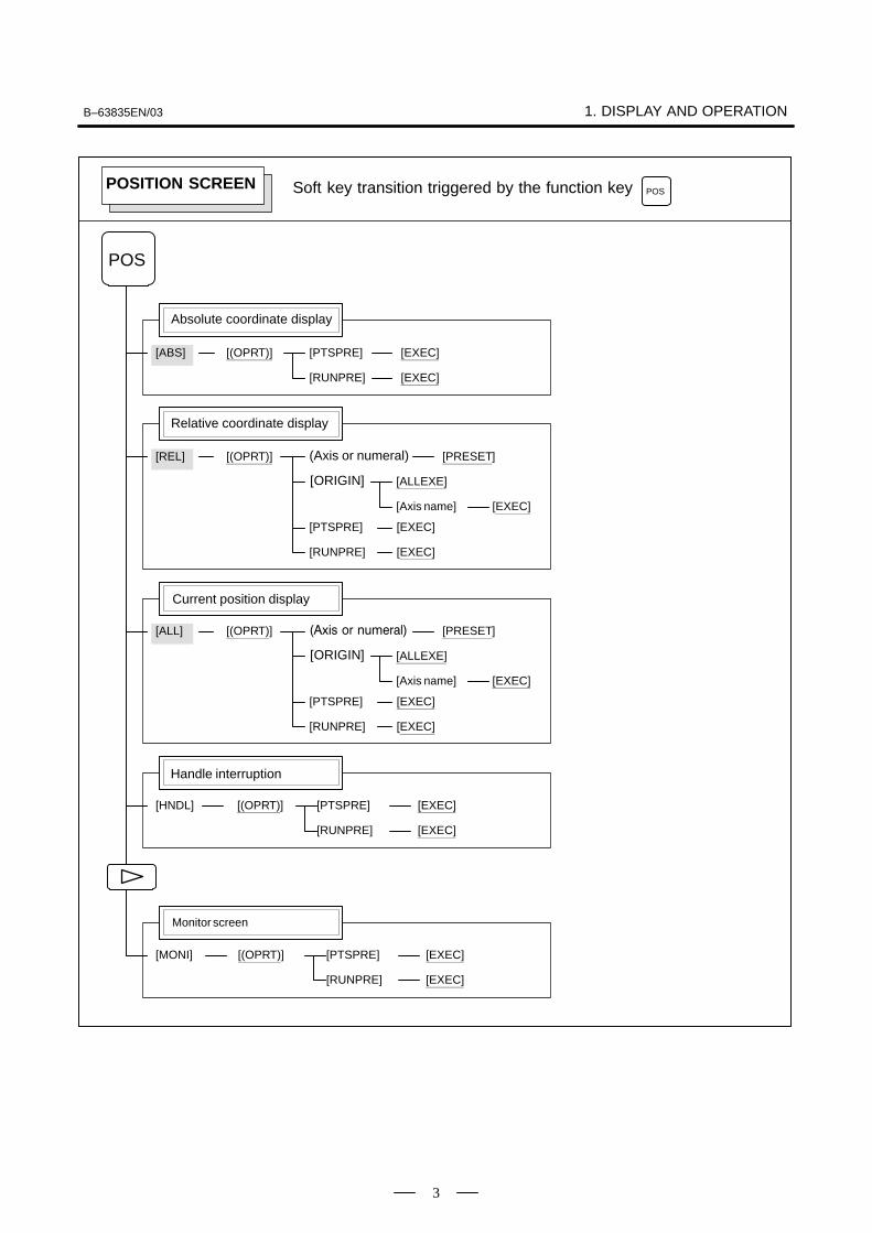
Operations and soft key display staturs for each function key are describedbelow:
To display a more detailed screen, press a function key followed by a softkey. Soft keys are also used for actual operations.The following illustrates how soft key displays are changed by pressingeach function key.
: Indicates a screen that can be displayed by pressing afunction key(*1)
: Indicates a soft key(*2)
: Indicates input from the MDI panel.
: Indicates a soft key displayed in green (or highlighted).
: Indicates the continuous menu key (rightmost soft key)(*3).
� �
� �
� �
The symbols in the following figures mean as shown below :
: Indicates screens
*1 Press function keys to switch between screens that are used frequently.
*2 Some soft keys are not displayed depending on the option configuration.
*3 In some cases, the continuous menu key is omitted when the 12 soft keystype is used.
1.1FUNCTION KEYS AND SOFT KEYS
1.1.1Soft Keys
B–63835EN/03 1. DISPLAY AND OPERATION
3
Monitor screen
[(OPRT)] [PTSPRE] [EXEC]
[RUNPRE] [EXEC]
[ABS]
Absolute coordinate display
POS
[(OPRT)][REL] (Axis or numeral)
�ORIGIN�
[PRESET]
[ALLEXE]
[Axis name] [EXEC]
[PTSPRE] [EXEC]
[RUNPRE] [EXEC]
[ALL]
[(OPRT)] [PTSPRE] [EXEC]
[RUNPRE] [EXEC]
[HNDL]
[(OPRT)] [PTSPRE] [EXEC]
[RUNPRE] [EXEC]
[MONI]
Soft key transition triggered by the function key POSPOSITION SCREEN
Relative coordinate display
Current position display
Handle interruption
[(OPRT)] ����� �� ����
�ORIGIN�
[PRESET]
[ALLEXE]
[Axis name] [EXEC]
[PTSPRE] [EXEC]
[RUNPRE] [EXEC]

1. DISPLAY AND OPERATION B–63835EN/03
4
[ABS]
[(OPRT)] [BG–EDT][O SRH]
[PRGRM]
Program display screen
PROG
Soft key transition triggered by the function keyin the MEM mode
PROG
[N SRH][REWIND]
See “When the soft key [BG–EDT] is pressed”
[(OPRT)][CHECK]
Program check display screen
[REL]
Current block display screen
[(OPRT)] [BG–EDT][CURRNT]
Next block display screen
[(OPRT)] [BG–EDT][NEXT]
Program restart display screen
[(OPRT)] [BG–EDT][RSTR]
���
[O number][N number]
PROGRAM SCREEN
See “When the soft key [BG–EDT] is pressed”
See “When the soft key [BG–EDT] is pressed”
See “When the soft key [BG–EDT] is pressed”
[F SRH]
[P TYPE][Q TYPE]
[CAN](N number)
[BG–EDT][O SRH][N SRH]
[REWIND]
See “When the soft key [BG–EDT] is pressed”[O number][N number]
[F SRH]
[P TYPE][Q TYPE]
[CAN](N number)
(2)(Continued on the next page)
1/2
[EXEC]
[EXEC]
B–63835EN/03 1. DISPLAY AND OPERATION
5
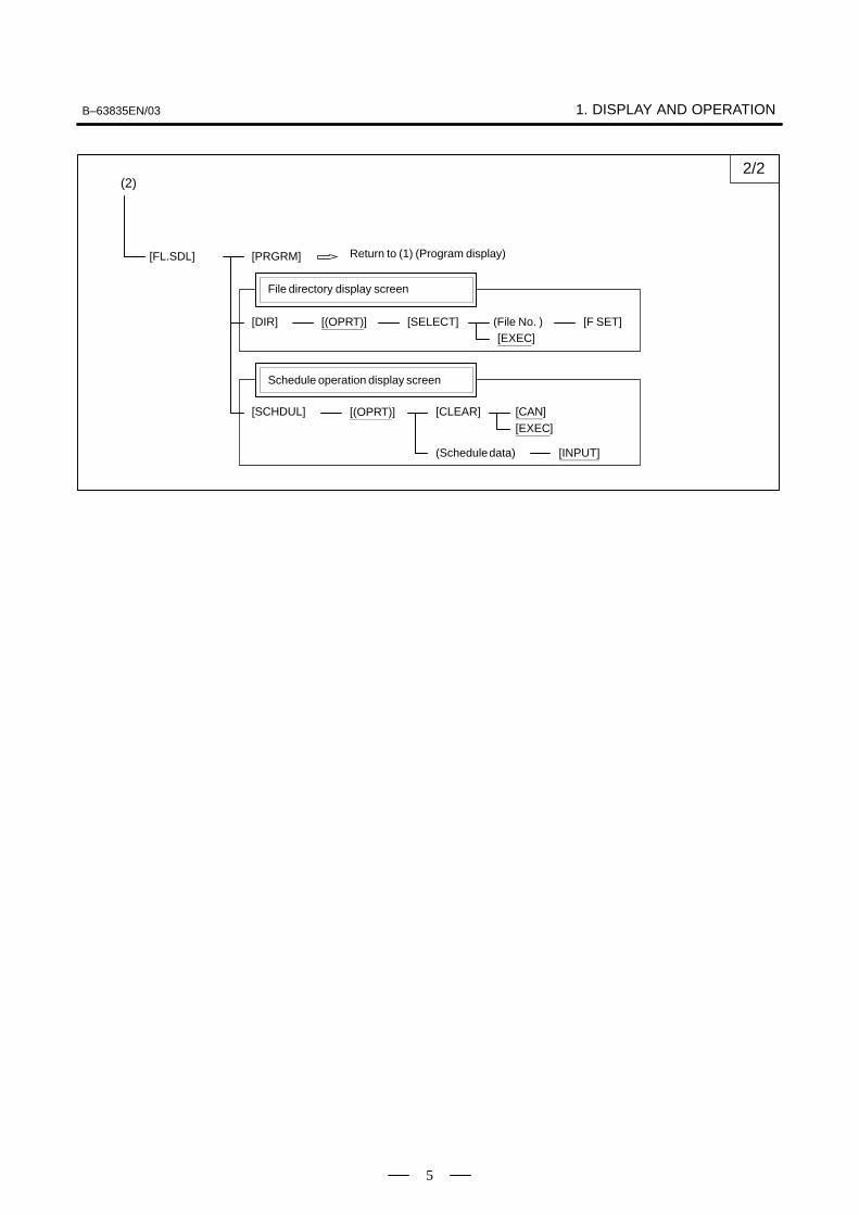
[FL.SDL] [PRGRM]
File directory display screen
[(OPRT)][DIR] [SELECT][EXEC]
(File No. ) [F SET]
Schedule operation display screen
[(OPRT)][SCHDUL] [CLEAR]
(Schedule data)
[CAN][EXEC]
[INPUT]
Return to (1) (Program display)
(2)2/2

1. DISPLAY AND OPERATION B–63835EN/03
6
1/2
[(OPRT)] [BG–EDT](O number) [O SRH]
[PRGRM]
Program display
PROG
(Address) [SRH↓]
[REWIND](Address) [SRH↑]
[F SRH] [CAN](N number) [EXEC]
[READ] [CHAIN][STOP][CAN]
[EXEC][PUNCH] [STOP]
[CAN][EXEC]
[DELETE] [CAN][EXEC]
[EX–EDT] [COPY] [CRSR∼][∼CRSR][∼BTTM][ALL]
[MOVE] [CRSR∼][∼CRSR][∼BTTM][ALL]
[MERGE] [∼CRSR][∼BTTM]
[CHANGE] (Address) [BEFORE]
(Address) [AFTER] [SKIP][1–EXEC][EXEC]
(1)(Continued on the next page)
(The cursor moves to the end of a program.)
(O number)
(O number)
(N number)
Soft key transition triggered by the function keyin the EDIT mode
PROGPROGRAM SCREEN
(O number) [EXEC]
(O number) [EXEC]
(O number) [EXEC]
See “When the soft key [BG–EDT] is pressed”

B–63835EN/03 1. DISPLAY AND OPERATION
7
(1)
[C.A.P.]
Graphic Conversational Programming (M series)
[PRGRM][G.MENU](G number) [BLOCK] (Data) [INPUT] INSERT
When a G number is omitted, the standard screen appears.
[(OPRT)] [INPUT]
2/2
Return to the program
[(OPRT)] [BG–EDT](O number) [O SRH]
[LIB]
Program directory display
[READ] [CHAIN][STOP][CAN]
[EXEC][PUNCH] [STOP]
[CAN][EXEC]
(O number)
(O number)
Return to the programSee “When the soft key [BG–EDT] is pressed”
[F SRH][CAN][EXEC]
[READ]
[STOP][CAN]
[PUNCH]
[F SET]
[F SET]
[EXEC]
[O SET]
[STOP][CAN]
[F SET]
[EXEC]
[O SET]
[DELETE][CAN]
[F SET]
[EXEC]
Floppy directory display
[FLOPPY][DIR] (Numeral)
(Numeral)(Numeral)
(Numeral)(Numeral)
(Numeral)
[PRGRM][(OPRT)]
����� � ��� ���
[C.A.P.]
Graphic Conversational Programming (T series)
[PRGRM][G.MENU](G number) [BLOCK] (Data)
When a G number is omitted, the standard screen appears.
����� � ��� ���
[LINE][CHAMF][CNR.R][INPUT]

1. DISPLAY AND OPERATION B–63835EN/03
8
[(OPRT)] [BG–EDT][PRGRM]
Program display
PROG
Soft key transition triggered by the function keyin the MDI mode
PROGPROGRAM SCREEN
[(OPRT)] [BG–EDT][MDI]
Program input screen
[START]
(Address)(Address)
[SRH↓][SRH↑]
[CAN][EXEC]
Current block display screen
[(OPRT)] [BG–EDT][CURRNT]
Next block display screen
[(OPRT)] [BG–EDT][NEXT]
Program restart display screen
[(OPRT)] [BG–EDT][RSTR]
��� ����� ��� ��� ��� ���� !"� �� �����#$
See “When the soft key [BG–EDT] is pressed”
See “When the soft key [BG–EDT] is pressed”
See “When the soft key [BG–EDT] is pressed”
See “When the soft key [BG–EDT] is pressed”
[REWIND]

B–63835EN/03 1. DISPLAY AND OPERATION
9
[(OPRT)] [BG–EDT][PRGRM]
Program display
PROG
Soft key transition triggered by the function keyin the HNDL, JOG, or REF mode
PROGPROGRAM SCREEN
Current block display screen
[(OPRT)] [BG–EDT][CURRNT]
Next block display screen
[(OPRT)] [BG–EDT][NEXT]
Program restart display screen
[(OPRT)] [BG–EDT][RSTR]
See “When the soft key [BG–EDT] is pressed”
See “When the soft key [BG–EDT] is pressed”
See “When the soft key [BG–EDT] is pressed”
See “When the soft key [BG–EDT] is pressed”

1. DISPLAY AND OPERATION B–63835EN/03
10
[PRGRM]
PROG
Soft key transition triggered by the function keyin the TJOG or THDL mode
PROGPROGRAM SCREEN
[(OPRT)] [BG–EDT]
Program input screen
(Address)(Address)
[SRH↓][SRH↑]
(O number)
[REWIND]
[(OPRT)] [BG–EDT](O number) [O SRH]
[LIB]
Program directory display
Return to the program
See “When the soft key [BG–EDT] is pressed”
See “When the soft key [BG–EDT] is pressed”
[O SRH] Return to the program

B–63835EN/03 1. DISPLAY AND OPERATION
11
1/2
[(OPRT)] [BG–END](O number) [O SRH]
[PRGRM]
Program display
PROG
(Address) [SRH↓]
[REWIND](Address) [SRH↑]
[F SRH] [CAN](N number) [EXEC]
[READ] [CHAIN][STOP][CAN]
[EXEC][PUNCH] [STOP]
[CAN][EXEC]
[DELETE] [CAN][EXEC]
[EX–EDT] [COPY] [CRSR∼][∼CRSR][∼BTTM][ALL]
[MOVE] [CRSR∼][∼CRSR][∼BTTM][ALL]
[MERGE] [∼CRSR][∼BTTM]
[CHANGE] (Address) [BEFORE]
(Address) [AFTER] [SKIP][1–EXEC][EXEC]
(1)(Continued on the next page)
(The cursor moves to the end of a program.)
(O number)
(O number)
(N number)
Soft key transition triggered by the function key(When the soft key [BG–EDT] is pressed in all modes)
PROG
PROGRAM SCREEN
(O number) [EXEC]
(O number) [EXEC]
(O number) [EXEC]

1. DISPLAY AND OPERATION B–63835EN/03
12
[(OPRT)] [BG–EDT](O number) [O SRH]
[LIB]
Program directory display
[READ] [CHAIN][STOP][CAN]
[EXEC][PUNCH] [STOP]
[CAN][EXEC]
(1)
(O number)
(O number)
[C.A.P.]
Graphic Conversational Programming
[PRGRM][G.MENU](G number) [BLOCK] (Data)
When a G number is omitted, the standard screen appears.
[F SRH][CAN][EXEC]
[READ]
[STOP][CAN]
[PUNCH]
[F SET]
[F SET]
[EXEC]
[O SET]
[STOP][CAN]
[F SET]
[EXEC]
[O SET]
[DELETE][CAN]
[F SET]
[EXEC]
Floppy directory display
[FLOPPY][DIR]
2/2
Return to the program
Return to the program
(Numeral)
(Numeral)(Numeral)
(Numeral)(Numeral)
(Numeral)
[PRGRM][(OPRT)]
Return to the program
[LINE][CHAMF][CNR.R][INPUT]
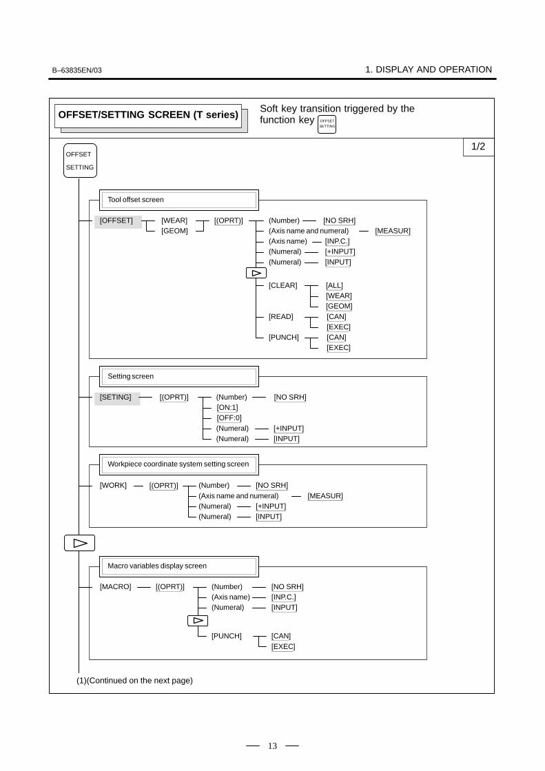
B–63835EN/03 1. DISPLAY AND OPERATION
13
[(OPRT)][OFFSET]
Tool offset screen
Soft key transition triggered by the function key
OFFSET
SETTING
(Number)
(Axis name)(Numeral)(Numeral)
[NO SRH]
[INP.C.][+INPUT][INPUT]
[(OPRT)][SETING]
Setting screen
(Numeral)(Numeral)
[NO SRH]
[+INPUT][INPUT]
[ON:1][OFF:0]
[(OPRT)][WORK]
Workpiece coordinate system setting screen
(Numeral)(Numeral)
[NO SRH]
[+INPUT][INPUT]
(Number)
(Number)
[(OPRT)][MACRO]
Macro variables display screen
(Numeral)
[NO SRH]
[INPUT]
(Number)(Axis name) [INP.C.]
[PUNCH]
OFFSETSETTING
OFFSET/SETTING SCREEN (T series)
[WEAR][GEOM] (Axis name and numeral) [MEASUR]
[CLEAR] [ALL][WEAR][GEOM]
[READ] [CAN][EXEC]
[PUNCH] [CAN][EXEC]
(Axis name and numeral) [MEASUR]
1/2
(1)(Continued on the next page)
[CAN][EXEC]

1. DISPLAY AND OPERATION B–63835EN/03
14
[OPR]
Software operator’s panel screen
[(OPRT)][TOOLLF]
Tool life management setting screen
(Numeral)
[NO SRH]
[INPUT]
(Number)[CAN][EXEC]
[CLEAR]
(1)2/2
[(OPRT)][OFST.2]
Y–axis tool offset screen
(Number)
(Axis name)(Numeral)(Numeral)
[NO SRH]
[INP.C.][+INPUT][INPUT]
[WEAR][GEOM] (Axis name and numeral) [MEASUR]
[CLEAR] [ALL][WEAR][GEOM]
[READ] [CAN][EXEC]
[PUNCH] [CAN][EXEC]
[(OPRT)][WK.SHFT]
Workpiece shift screen
(Numeral)(Numeral)
[+INPUT][INPUT]
[(OPRT)][MENU]
Pattern data input screen
[SELECT](Number)
[(OPRT)][BARRIER]
Chuck/tailstock barrier setting screen
(Numeral)(Numeral)
[INPUT][+INPUT]
[SET]

B–63835EN/03 1. DISPLAY AND OPERATION
15
[(OPRT)][OFFSET]
Tool offset screen
Soft key transition triggered by the function key
OFFSET
SETTING
(Number)(Axis name)(Numeral)(Numeral)
[NO SRH][INP.C.][+INPUT][INPUT]
[(OPRT)][SETING]
Setting screen
(Numeral)(Numeral)
[NO SRH]
[+INPUT][INPUT]
[ON:1][OFF:0]
[(OPRT)][WORK]
Workpiece coordinate system setting screen
(Numeral)(Numeral)
[NO SRH]
[+INPUT][INPUT]
(Number)
(Number)
[(OPRT)][MACRO]
Macro variables display screen
(Numeral)
[NO SRH]
[INPUT]
(Number)(Axis name) [INP.C.]
[PUNCH]
OFFSETSETTING
OFFSET/SETTING SCREEN (M series)
[CAN][EXEC]
1/2
(1)(Continued on the next page)
[CLEAR] [ALL][WEAR][GEOM]
[READ] [CAN][EXEC]
[PUNCH] [CAN][EXEC]
(Axis name and numeral) [MEASUR]

1. DISPLAY AND OPERATION B–63835EN/03
16
[(OPRT)][MENU]
Patten data input screen
[SELECT](Number)
[OPR]
Software operator’s panel screen
[(OPRT)][TOOLLF]
Tool life management setting screen
(Numeral)
[NO SRH]
[INPUT]
(Number)[CAN][EXEC]
[CLEAR]
(1)2/2

B–63835EN/03 1. DISPLAY AND OPERATION
17
Soft key transition triggered by the function key
[(OPRT)][PARAM]
Parameter screen
(Numeral)(Numeral)
[NO SRH]
[+INPUT][INPUT]
[ON:1][OFF:0]
(Number)
SYSTEM
SYSTEM
[READ] [CAN][EXEC]
[PUNCH] [CAN][EXEC]
[(OPRT)][DGNOS]
Diagnosis screen
[NO SRH](Number)
[PMCLAD][PMC]
PMC screen
(1) (Continued on the next page)
(2)
1/3
SYSTEM SCREEN
[TOP][BOTTOM][SRCH][W–SRCH][N–SRCH]
[F–SRCH][ADRESS]/[SYMBOL]
[SEARCH]
[TRGON][TRIGER][TRGOFF][START]
[SEARCH][DUMP]
[BYTE][WORD][D.WORD]
[DPARA]/[NDPARA][TRGSRC][INIT][DIVIDE][WINDOW][CANCEL][DELETE][SELECT][WIDTH]
(3)

1. DISPLAY AND OPERATION B–63835EN/03
18
[SYSTEM]
System configuration screen
(1)
(4) (Continued on the next page)
2/3[SEARCH]
[BYTE][WORD][D.WORD]
[DRARA]/[NDPARA]
[DUMP]
(2) (3)
[PMCDGN] [TITLE][STATUS][ALARM]
[SEARCH]
[TRACE] [T.DISP]/[TRCPRM][EXEC]
[PMCPRM] [TIMER][COUNTR][KEEPRL][DATA]
[STOP]/[RUN][I/O] [EXEC]
[CANCEL](No.)
[G.DATA][G.CONT]
[INIT][NO.SRH]
[C.DATA][G–SRCH][SEARCH]
[SETTING] [YES]/[MANUAL]/[ROM][NO]/[AUTO]/[RAM]
[SPEED] [INPUT][INIT]
[MDI]/[ROM]
[M.SRCH] [SEARCH][INPUT]
[ANALYS] [SCOPE][DELETE][INIT]
[ADRESS]/[SYMBOL]
[SGNPRM][START]/[STOP][T–SRCH][ADRESS]/[SYMBOL][EXCHG] [SELECT]
[CANCEL][TO] [EXEC]
WithPMC–RConly
[SYSTEM]
ID information screen: αi servo information screen
[SYSTEM]
ID information screen: αi spindle information screen
[SV–INF]
[SP–INF]
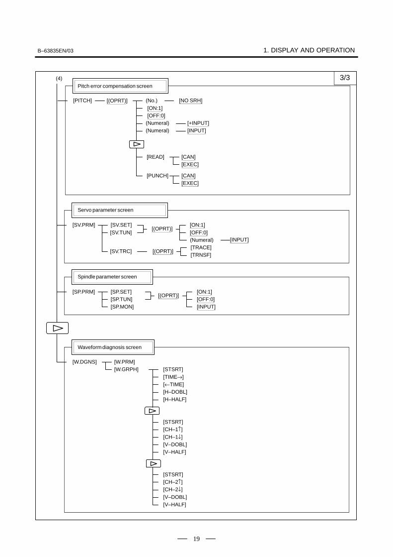
B–63835EN/03 1. DISPLAY AND OPERATION
19
[W.DGNS]
Waveform diagnosis screen
(4)
[W.PRM][W.GRPH] [STSRT]
[TIME→][←TIME][H–DOBL][H–HALF]
[STSRT][CH–1↑]
[V–DOBL][V–HALF]
[CH–1↓]
[STSRT][CH–2↑]
[V–DOBL][V–HALF]
[CH–2↓]
3/3
[(OPRT)][SV.PRM]
Servo parameter screen
[ON:1][OFF:0]
[SV.SET][SV.TUN]
Spindle parameter screen
[(OPRT)][SP.PRM]
[INPUT]
[ON:1][OFF:0]
[SP.SET][SP.TUN][SP.MON]
(Numeral) [INPUT]
[SV.TRC] [(OPRT)][TRACE][TRNSF]
[(OPRT)][PITCH]
Pitch error compensation screen
(Numeral)(Numeral)
[NO SRH]
[+INPUT][INPUT]
[ON:1][OFF:0]
(No.)
[READ] [CAN][EXEC]
[PUNCH] [CAN][EXEC]
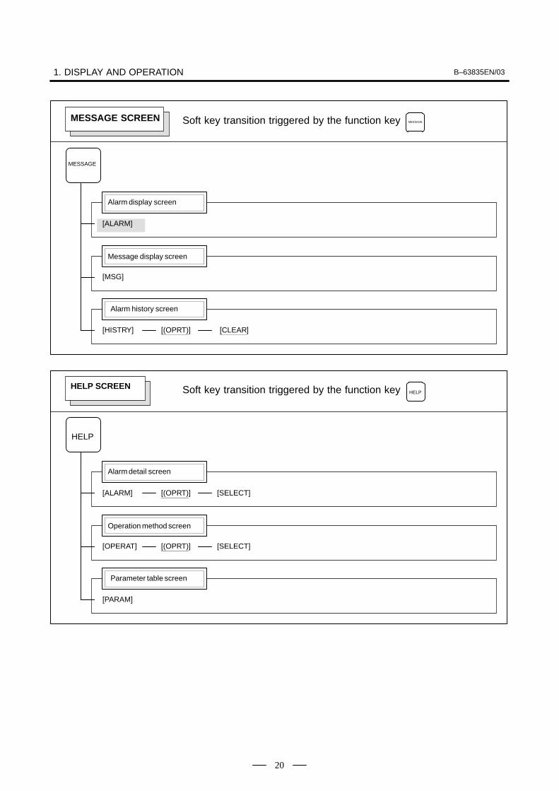
1. DISPLAY AND OPERATION B–63835EN/03
20
Soft key transition triggered by the function key
[ALARM]
Alarm display screen
MESSAGE
MESSAGE
[MSG]
Message display screen
[HISTRY]
Alarm history screen
[(OPRT)] [CLEAR]
MESSAGE SCREEN
[ALARM]
Soft key transition triggered by the function key
Alarm detail screen
HELP
HELP
[OPERAT]
Operation method screen
[PARAM]
Parameter table screen
[(OPRT)] [SELECT]
HELP SCREEN
[(OPRT)] [SELECT]

B–63835EN/03 1. DISPLAY AND OPERATION
21
Soft key transition triggered by the function key GRAPHGRAPHIC SCREEN (T series)
Tool path graphics
[(OPRT)]
[G.PRM]
Tool path graphics
GRAPH
[GRAPH] [ZOOM]
[(OPRT)][ZOOM]
[(OPRT)] [NORMAL]
[ACT][HI/LO]
Mode 0
[HEAD][ERASE][PROCES][EXEC][STOP]
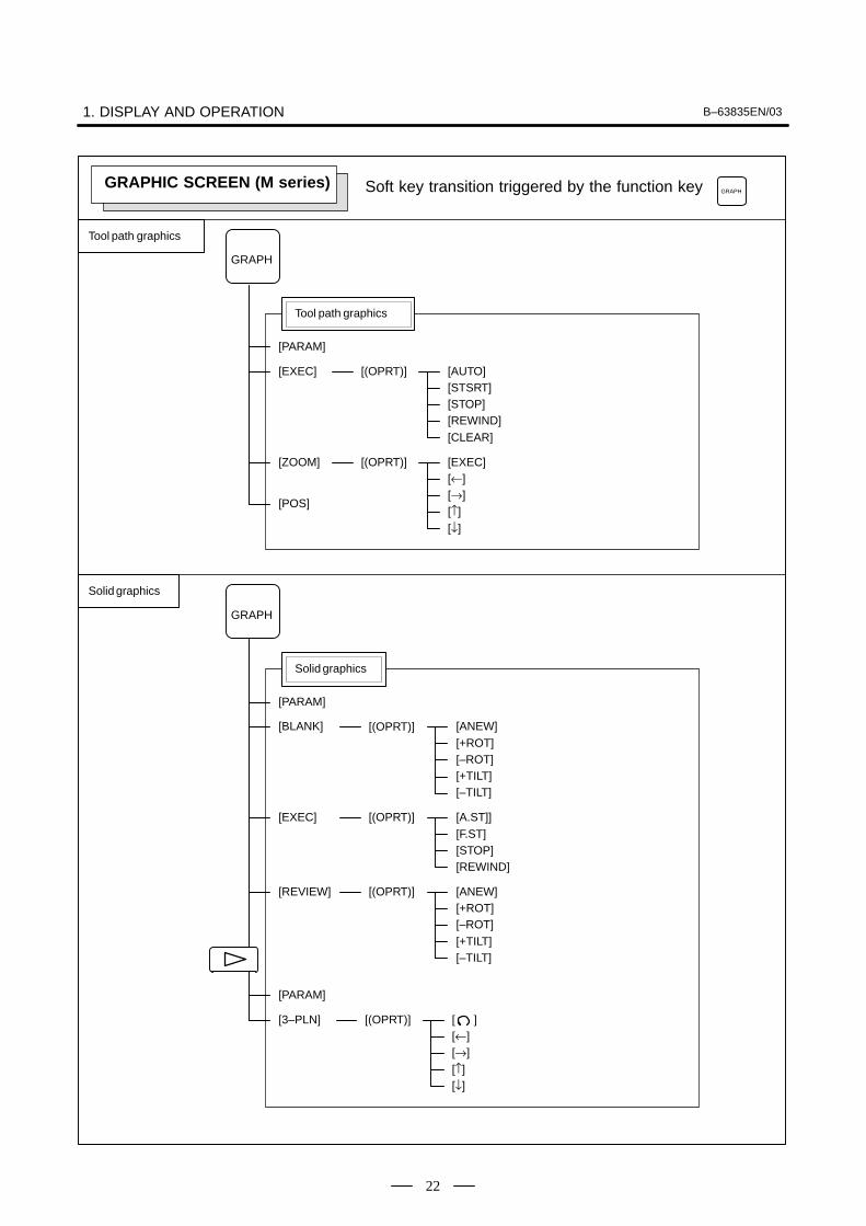
1. DISPLAY AND OPERATION B–63835EN/03
22
Soft key transition triggered by the function key
[(OPRT)]
[PARAM]
Solid graphics
GRAPH
GRAPH
[BLANK] [ANEW]
[(OPRT)][3–PLN] [ ][←][→][↑][↓]
[(OPRT)][EXEC] [A.ST]][F.ST][STOP][REWIND]
[+ROT][–ROT][+TILT][–TILT]
[(OPRT)][REVIEW] [ANEW][+ROT][–ROT][+TILT][–TILT]
[PARAM]
GRAPHIC SCREEN (M series)
Tool path graphics
Solid graphics
[(OPRT)]
[PARAM]
Tool path graphics
GRAPH
[EXEC] [AUTO][STSRT][STOP][REWIND][CLEAR]
[(OPRT)][ZOOM] [EXEC][←][→][↑][↓]
[POS]
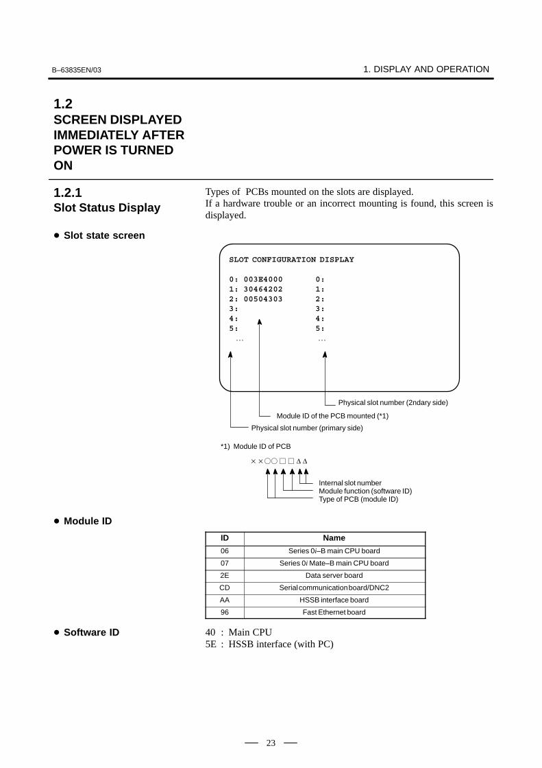
B–63835EN/03 1. DISPLAY AND OPERATION
23
Types of PCBs mounted on the slots are displayed.If a hardware trouble or an incorrect mounting is found, this screen isdisplayed.
SLOT CONFIGURATION DISPLAY
0: 003E4000 0:1: 30464202 1:2: 00504303 2:3: 3:4: 4:5: 5: … …
Physical slot number (2ndary side)
Module ID of the PCB mounted (*1)
Physical slot number (primary side)
*1) Module ID of PCB
Internal slot numberModule function (software ID)Type of PCB (module ID)
���� � � ∆ ∆
ID Name
06 Series 0i–B main CPU board
07 Series 0i Mate–B main CPU board
2E Data server board
CD Serial communication board/DNC2
AA HSSB interface board
96 Fast Ethernet board
40 : Main CPU5E : HSSB interface (with PC)
1.2SCREEN DISPLAYEDIMMEDIATELY AFTERPOWER IS TURNEDON
1.2.1Slot Status Display
� Slot state screen
� Module ID
� Software ID
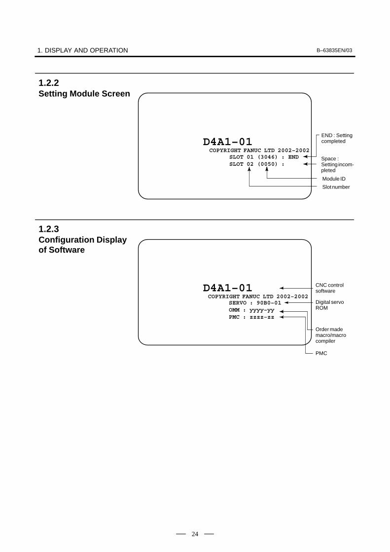
1. DISPLAY AND OPERATION B–63835EN/03
24
SLOT 01 (3046) : ENDSLOT 02 (0050) :
END : Settingcompleted
Module ID
Slot number
Space : Setting incom-pleted
D4A1–01COPYRIGHT FANUC LTD 2002–2002
D4A1–01SERVO : 90B0–01OMM : yyyy–yyPMC : zzzz–zz
PMC
CNC controlsoftware
Digital servoROM
Order mademacro/macrocompiler
COPYRIGHT FANUC LTD 2002–2002
1.2.2Setting Module Screen
1.2.3Configuration Displayof Software

B–63835EN/03 1. DISPLAY AND OPERATION
25
After the system has been installed correctly, you can find the PCBsinstalled and the softwares integrated on the system configuration screen.
(1)Press SYSTEM key.
(2)Press soft key [SYSTEM], then the system configuration screen isdisplayed.
(3)The system configuration screen is composed of three screens and
each of them can be selected by the page keyPAGE
PAGE
.
SYSTEM CONFIG (SLOT) PAGE01
SLOT MODULE ID SERIES VERSION 00 3008 : 40 D4A1 0001 01 00CF : 66 B435 0001
Software series of mod-ule with CPU
Module IDSlot No.(80 to 8F is 2nd side)
Software versionof module withCPU
Software ID (type)
ID Name
06 Series 0i–B main CPU board
07 Series 0i Mate–B main CPU board
CD Serial communication board/DNC2
2E Data server board
AA HSSB interface board
96 Fast Ethernet board
40 : Main CPU5E : HSSB interface (with PC)
1.3SYSTEMCONFIGURATIONSCREEN
1.3.1Display Method
1.3.2Configuration of PCBs
� Screen
� Module ID
� Software ID

1. DISPLAY AND OPERATION B–63835EN/03
26
SYSTEM CONFIG (SOFTWARE) 01234 N12345PAGE:02
SYSTEM D4A1 0001BASIC+OPTION–A1
SERVO 90B0 0001PMC(SYS) 406G 0001
406G 0001PMC(LAD) FS16 0001MACRO LIB BZG1 0001MACRO APL AAAA BBBBBOOT 60M5 0001GRAPHIC–1 60V5 0001GRAPHIC–2 60V6 0001EMBED ETH 656A 0001MEM **** *** *** 12:14:59[ PARMA ][ DGNOS ][ PMC ][ SYSTEM ][(OPRT)]
Kind of softwareSoftware series
Software version
Software configuration
Character writtenon PMC title screen
Character writtenon macro compileror on CAP.
Configuration of the modules displayed on PCB.
SYSTEM CONFIG (MODULE) 01234 N12345PAGE:03
SLOT 00 MOTHER BOARD
AXIS CTRL CARD : 08DISPLAY CTRL CARD : 0ECPU CARD : 11FROM DIMM : C7SRAM DIMM : 05DRAM DIMM : A9PMC CPU : 01
MEM **** *** *** 12:14:59[ PARMA ][ DGNOS ][ PMC ][ SYSTEM ][(OPRT)]
(2)
(4)
(3)
(1)
Contents of display
(1)Slot number (The number is corresponding to PCB configurationscreen)
(2)Type of PCB mounted
(3)Name of card PCB or DIMM module
(4)Hardware ID of mounted card PCB or DIMM moduleRefer to “2.5.4 Printed Circuit Boards of the Control Unit” forcorrespondence with each hardware ID and drawing number.
Pressing the PAGE key PAGE
PAGE
displays the system configuration
screen of other PCBs.
1.3.3Software ConfigurationScreen
1.3.4Module ConfigurationScreen

B–63835EN/03 1. DISPLAY AND OPERATION
27
� αi series servo and αi series spindleWhen the αi servo/αi spindle system is connected, ID informationowned by connected units (motor, amplifier, module, etc.) for αiservo/αi spindle can be displayed on the CNC screen.See below for details.
� αi servo information screen (Chapter 5 Digital Servo)
� αi spindle information screen (Chapter 6 AC Spindle (SerialSpindle))
1.3.5ID Information Screen(αi Servo InformationScreen/αi SpindleInformation Screen)

1. DISPLAY AND OPERATION B–63835EN/03
28
Alarms generated in the NC are recorded. The latest 25 alarms generatedare recorded. The 26th and former alarms are deleted.
(1)Press MESSAGE key .
(2)Press soft key [HISTRY] and an alarm history screen is displayed.
(3)Other pages are displayed by PAGE
or PAGE
key.
ALARM HISTORY O1234 N12345
02/04/18 20:56:26506 OVERTRAVEL : +X02/04/18 19:58:11000 TURN OFF POWER02/04/18 19:52:45000 TURN OFF POWER02/04/18 19:48:43300 APC ALARM : X–AXIS ZERO RETURN REQUEST02/04/18 18:10:10507 OVERTRAVEL : +B
[ ALARM ][ MSG ][ HISTRY ][ ][(OPRT)]
(1)Press soft key [(OPRT)].
(2)Press soft key [(CLEAR], then the alarm history is cleared.
When an external alarm (No. 1000 to 1999) or a macro alarm (No. 3000to 3999) is output, the alarm history function can record both the alarmnumber and message if so specified in the following parameter. Ifrecording of the message is not set or if no message is input, only anexternal alarm or macro alarm is displayed.
1.4ALARM HISTORYSCREEN
1.4.1Alarm History Screen
1.4.1.1General
1.4.1.2Screen display
1.4.1.3Clearing alarm history
1.4.1.4Alarm display

B–63835EN/03 1. DISPLAY AND OPERATION
29
#73112
#6 #5 #4 #3EAH
#2 #1 #0
[Data type] Bit
#3 (EAH) The alarm history function:
0 : Does not record the messages output with external alarms or macroalarms.
1 : Records the messages output with external alarms or macro alarms.
Up to three system alarms issued in the past are stored, and informationabout those alarms can be displayed on the system alarm history screen.
SYSTEM ALARM HISTORY O1234 N12345
1 2002–03–13 12:13:19 930 CPU INTERRUPT
2 2002–03–11 07:23:07 900 ROM PARITY
3 2002–02–27 973 NON MASK INTERRUPT
EDIT **** *** *** 08:20:52[ ][ ][ NMIHIS ][ ][ ]
By setting bit 2 (NMH) of parameter No. 3103 to 1, information about upto three system alarms including the latest system alarm can be displayed.The latest system alarm information is displayed at the top of the list, anda lower item in the list indicates older system alarm information.
1 Set bit 2 (NMH) of parameter No. 3103 to 1.
2 Press the function key <MESSAGE>.
3 Press the [NMIHIS] chapter selection soft key.
The following information is displayed:
1. System alarm occurrence date and time
2. System alarm number
3. System alarm message (No message is displayed for somesystem alarms.)
1.4.2System Alarm History
1.4.2.1General
1.4.2.2System alarm historyscreen (history listscreen)
���������

1. DISPLAY AND OPERATION B–63835EN/03
30
[ SELECT ][ RETURN ][ CLEAR ][ ][ ]
SYSTEM ALARM HISTORY O1234 N12345
1 2002–03–13 12:13:19 930 CPU INTERRUPT
2 2002–03–11 07:23:07 900 ROM PARITY
3 2002–02–27 973 NON MASK INTERRUPT
EDIT **** *** *** 08:20:52[ ][ ][ NMIHIS ][ ][ ]
This soft key displays the details of a system alarm.
Procedure
1 Press the [(OPRT)] soft key on the system configuration screen.
2 By using the cursor keys PAGE
PAGE
, move the cursor to the system
alarm number whose details are to be displayed.
3 Press the [SELECT] soft key.
4 The details of the selected system alarm are displayed.
This soft key clears all system alarm information stored.
When bit 4 (OPC) of parameter No. 3110 is set to 1, this soft key isdisplayed. When bit 4 (OPC) of parameter No. 3110 is set to 0, this softkey is not displayed.
Procedure
1 Set bit 4 (OPC) of parameter No. 3110 to 1.
2 Press the [(OPRT)] soft key on the system configuration screen.
3 Press the [CLEAR] soft key.
4 Information about all of the three system alarms stored is cleared.
Pressing the [RETURN] soft key while system alarm history screen(detail screen) is displayed returns the screen display to the system alarmlist screen.
[SELECT] soft key
[CLEAR] soft key
[RETURN] soft key

B–63835EN/03 1. DISPLAY AND OPERATION
31
The system alarm history screen (detail screen) displays informationitems such as registers and stacks involved when a system alarm is issued.
The following items are displayed:
1. System alarm occurrence date and time
2. System alarm number
3. System alarm message (No message is displayed for some systemalarms.)
4. System alarm occurrence series and edition
5. Number of display pages
6. General–purpose resistor, pointer index register, segment register,task register, LDT register, flag register, interrupt source, errorcode, error address
7. Contents of stacks (up to 32 stacks)
8. Contents of stacks of privilege level 3 (up to 48 stacks)
9. NMI information
You can switch among the information items 6 to 9 by the page keys PAGE
PAGE
.
Pressing the [RETURN] soft key returns the screen display to the statealarm history list screen.
SYSTEM ALARM HISTORY O1234 N12345
2 2002–03–11 07:23:07 BDH1–01(1/4)973 NON MASK INTERRUPT
EAX EBX ECX EDX00000000 00930063 000003E0 00000040ESI EDI EBP ESP00000010 009404E0 0000FFB4 0000FFDCSS DS ES FS GS TR LDTR06D8 0338 0248 0440 0338 0628 0028EFLAGS VECT ERRC ERROR–ADDRESS00003046 FFFF 0000 03E0:000009BC
EDIT **** *** *** 08:20:52[ SELECT ][ RETURN ][ CLEAR ][ ][ ]
(Detail display screen 1)
1.4.2.3System alarm historyscreen (detail screen)

1. DISPLAY AND OPERATION B–63835EN/03
32
SYSTEM ALARM HISTORY O1234 N12345
2 2002–03–11 07:23:07 BDH1–01(2/4)973 NON MASK INTERRUPT
STACK (PL0)3646 0338 7CBA 0001 0958 FFF8 0068 00630346 0000 0000 02BC 08F8 52F1 2438 03380580 0440 0580 001F 03C0 0214 0780 0FFF0000 0000 0000 0000 0000 0000 0000 0000
EDIT **** *** *** 08:20:52[ SELECT ][ RETURN ][ CLEAR ][ ][ ]
(Detail display screen 2)
SYSTEM ALARM HISTORY O1234 N12345
2 2002–03–11 07:23:07 BDH1–01(3/4)973 NON MASK INTERRUPT
STACK!(PL3)SS:ESP3 =0804:00007C50CS:EIP =1350:000012341008 1408 0001 0002 0003 0004 1008 FFE41008 3678 00FA 0024 0000 0000 0000 00000000 0000 0000 0000 0000 0000 0000 00000000 0000 0000 0000 0000 0000 0000 00000000 0000 0000 0000 0000 0000 0000 00000000 0000 0000 0000 0000 0000 0000 0000
EDIT **** *** *** 08:20:52[ SELECT ][ RETURN ][ CLEAR ][ ][ ]
(Detail display screen 3)
SYSTEM ALARM HISTORY O1234 N12345
2 2002–03–11 07:23:07 BDH1–01(4/4)973 NON MASK INTERRUPT
NMIC00000000 00000000 00000000 00000000SVL11111111 11111111SVR11111111 11111111 11111111 1111111111111111 11111111 11111111 11111111ADRS007F0000
EDIT **** *** *** 08:20:52[ SELECT ][ RETURN ][ CLEAR ][ ][ ]
(Detail display screen 4)

B–63835EN/03 1. DISPLAY AND OPERATION
33
CAUTION1 In the case of an NMI on other than the main board, the
registers of detail display screen 1, and the contents of detaildisplay screen 2 and detail display screen 3 are displayed.
SYSTEM ALARM HISTORY O1234 N12345
2 2002–03–11 07:23:07 BDH1–01(1/1)972 NMI OCUURRED IN OTHER MODULE
SLOT> 02 0080415F<1> <2>
EDIT **** *** *** 08:20:52[ SELECT ][ RETURN ][ CLEAR ][ ][ ]
(Detail display screen 5)
<1> NMI occurrence slot number
<2> Message address set with the NMI occurrence slot (string address)
SYSTEM ALARM HISTORY O1234 N12345
2 2002–03–11 07:23:07 BDH1–01(1/1)900 ROM PARITY
00000000 00000000<1>
EDIT **** *** *** 08:20:52[ SELECT ][ RETURN ][ CLEAR ][ ][ ]
(Detail display screen 6)
<1> ROM parity causeBasic ROM 2F(h). . . . . . . . . . . . . . . . . . . . . . . .
(800000 to 97FFFF)
Additional ROM 40(h). . . . . . . . . . . . . . . . . . . .
(A00000 to A3FFFF)
OMM ROM 80(h). . . . . . . . . . . . . . . . . . . . . . .
Servo ROM 100(h). . . . . . . . . . . . . . . . . . . . . . . .
Built in MMC ROM 200(h). . . . . . . . . . . . . . . . .
Online Custom Screen 400(h). . . . . . . . . . . . . . . .

1. DISPLAY AND OPERATION B–63835EN/03
34
#7
3103#6 #5 #4 #3 #2
NMH#1 #0
[Data type] Bit
NMH The system alarm history screen is:
0 : Not displayed.1 : Displayed.
#7
3110#6 #5 #4
OPC#3 #2 #1 #0
[Data type] Bit
OPC On the operation history screen, the [CLEAR] soft key is:
0 : Not enabled.1 : Enabled.
1.4.2.4Parameter

B–63835EN/03 1. DISPLAY AND OPERATION
35
This function enables the saving of external operator messages as arecord.The record can be viewed on the external operator message history screen.
(1)Press the MESSAGE function key.
(2)Press the rightmost soft key .
(3)Press the [MSGHIS] soft key.
(4)To display the previous or subsequent screen, press the PAGE
or PAGE
key.
MESSAGE HISTORY O1234 N1234502/04/01 17:25:00 PAGE : 1 No. ****
Up to 255 characters
MEM STRT MTN FIN ALM 17:25:00[ ][ MSGHIS ][ ][ ][ ]
→ Date, time, andpage
→ MessageNo.
Displayrange
(1)The recorded external operator message can be deleted by setting theMMC bit (bit 0 of parameter 3113) to 1.Pressing the [CLEAR] soft key erases all the records of the externaloperator message.
(2)The MS1 and MS0 bits (bits 7 and 6 of parameter 3113) specify thenumber of records to be displayed on the external operator messagehistory screen. When the bits are changed, all external operatormessage records retained up to that point are erased.
1.5EXTERNALOPERATORMESSAGES RECORD
1.5.1Screen Display
1.5.2Deletion of ExternalOperator MessagesRecord

1. DISPLAY AND OPERATION B–63835EN/03
36
#7MS13113
#6MS0
#5 #4 #3 #2 #1 #0MHC
#0 (MHC) The records of an external operator message:
0 : Cannot be erased.1 : Can be erased.
#6, #7 (MS0,MS1) These bits set the number of characters to be retained in each record of anexternal operator message, as well as the number of records, as shown inthe following table:
MS1 MS0 Number of charac-ters in each record
Number of records
0 0 255 8
0 1 200 10
1 0 100 18
1 1 50 32
* An external operator message of up to 255 characters can be specified.Combining the MS1 bit and MS0 bit (bits 7 and 6 of parameter No.3113) selects the number of records by limiting the number ofcharacters to be retained as the record of an external operator message.
#73112
#6 #5 #4 #3 #2OMH
#1 #0
#2 (OMH) The external operator message history screen is:
0 : Not displayed.1 : Displayed.
NOTEAfter setting this parameter, briefly turn the power off, thenon again.
When the number of an external operator message is specified, the systemstarts updating the records of the specified message. The systemcontinues to perform update until another external operator message isspecified or until an instruction to delete the records of the externaloperator message is specified.
1.5.3Parameter
1.5.4Notes

B–63835EN/03 1. DISPLAY AND OPERATION
37
This function displays the key and signal operations performed by theoperator upon the occurrence of a fault or the output of an alarm, togetherwith the corresponding alarms.This function records the following data:
(1)MDI key operations performed by the operator
(2)Status changes (ON/OFF) of input and output signals (selected signalsonly)
(3)Details of alarms
(4)Time stamp (date and time)
#7OHS3106
#6 #5 #4OPH
#3 #2 #1 #0
[Data type] Bit
OPH The operation history screen is:
0 : Not displayed.
1 : Displayed.
OHS The operation history is:
0 : Sampled.1 : Not sampled.
3122 Interval at which the clock time is recorded in the operation history
[Data type] Word
[Units of data] Minutes
[Valid data range] 0 to 1439
The clock time is recorded to the operation history at specified intervals.If zero is set as the interval, ten minutes is assumed. The time is recordedonly when data is recorded within the corresponding interval.
#73206
#6 #5 #4PHS
#3 #2 #1 #0
[Data type] Bit
PHS Setting and display on the operation history signal selection screen andthe parameters (No. 12801 through No. 128900) are:
0 : Not linked.1 : Linked.
1.6OPERATIONHISTORY
1.6.1Parameter Setting

1. DISPLAY AND OPERATION B–63835EN/03
38
12801 Number of a signal symbol table for selecting an operation history signal (01)
12802 Number of a signal symbol table for selecting an operation history signal (02)
12803 Number of a signal symbol table for selecting an operation history signal (03)
12804 Number of a signal symbol table for selecting an operation history signal (04)
12805 Number of a signal symbol table for selecting an operation history signal (05)
12806 Number of a signal symbol table for selecting an operation history signal (06)
12807 Number of a signal symbol table for selecting an operation history signal (07)
12808 Number of a signal symbol table for selecting an operation history signal (08)
12809 Number of a signal symbol table for selecting an operation history signal (09)
12810 Number of a signal symbol table for selecting an operation history signal (10)
12811 Number of a signal symbol table for selecting an operation history signal (11)
12812 Number of a signal symbol table for selecting an operation history signal (12)
12813 Number of a signal symbol table for selecting an operation history signal (13)
12814 Number of a signal symbol table for selecting an operation history signal (14)
12815 Number of a signal symbol table for selecting an operation history signal (15)
12816 Number of a signal symbol table for selecting an operation history signal (16)
12817 Number of a signal symbol table for selecting an operation history signal (17)
12818 Number of a signal symbol table for selecting an operation history signal (18)
12819 Number of a signal symbol table for selecting an operation history signal (19)
12820 Number of a signal symbol table for selecting an operation history signal (20)
[Data type] Byte
[Valid data range] 1 to 10
Set the number of a symbol table including a signal of which operationhistory is to be recorded for operation history channel (01) to (20) asfollows:
1 : G0 to G2552 : G1000 to G12553 : F0 to F2554 : F1000 to F12555 : Y0 to Y1276 : X0 to X1279 : G2000 to G225510 : F2000 to F2255

B–63835EN/03 1. DISPLAY AND OPERATION
39
12841 Number of a signal selected as an operation history signal (01)
12842 Number of a signal selected as an operation history signal (02)
12843 Number of a signal selected as an operation history signal (03)
12844 Number of a signal selected as an operation history signal (04)
12845 Number of a signal selected as an operation history signal (05)
12846 Number of a signal selected as an operation history signal (06)
12847 Number of a signal selected as an operation history signal (07)
12848 Number of a signal selected as an operation history signal (08)
12849 Number of a signal selected as an operation history signal (09)
12850 Number of a signal selected as an operation history signal (10)
12851 Number of a signal selected as an operation history signal (11)
12852 Number of a signal selected as an operation history signal (12)
12853 Number of a signal selected as an operation history signal (13)
12854 Number of a signal selected as an operation history signal (14)
12855 Number of a signal selected as an operation history signal (15)
12856 Number of a signal selected as an operation history signal (16)
12857 Number of a signal selected as an operation history signal (17)
12858 Number of a signal selected as an operation history signal (18)
12859 Number of a signal selected as an operation history signal (19)
12860 Number of a signal selected as an operation history signal (20)
[Data type] Word
[Valid data range] 0 to 255
Set the number of a signal of which operation history is to be recorded foroperation history channel (01) to (20) with a value between 0 and 255.

1. DISPLAY AND OPERATION B–63835EN/03
40
#7RB712881
#6RB6
#5RB5
#4RB4
#3RB3
#2RB2
#1RB1
#0RB0
History record bit settings for an operation history signal (01)
#7RB712882
#6RB6
#5RB5
#4RB4
#3RB3
#2RB2
#1RB1
#0RB0
History record bit settings for an operation history signal (02)
#7RB712883
#6RB6
#5RB5
#4RB4
#3RB3
#2RB2
#1RB1
#0RB0
History record bit settings for an operation history signal (03)
#7RB712884
#6RB6
#5RB5
#4RB4
#3RB3
#2RB2
#1RB1
#0RB0
History record bit settings for an operation history signal (04)
#7RB712885
#6RB6
#5RB5
#4RB4
#3RB3
#2RB2
#1RB1
#0RB0
History record bit settings for an operation history signal (05)
#7RB712886
#6RB6
#5RB5
#4RB4
#3RB3
#2RB2
#1RB1
#0RB0
History record bit settings for an operation history signal (06)
#7RB712887
#6RB6
#5RB5
#4RB4
#3RB3
#2RB2
#1RB1
#0RB0
History record bit settings for an operation history signal (07)
#7RB712888
#6RB6
#5RB5
#4RB4
#3RB3
#2RB2
#1RB1
#0RB0
History record bit settings for an operation history signal (08)
#7RB712889
#6RB6
#5RB5
#4RB4
#3RB3
#2RB2
#1RB1
#0RB0
History record bit settings for an operation history signal (09)
#7RB712890
#6RB6
#5RB5
#4RB4
#3RB3
#2RB2
#1RB1
#0RB0
History record bit settings for an operation history signal (10)
#7RB712891
#6RB6
#5RB5
#4RB4
#3RB3
#2RB2
#1RB1
#0RB0
History record bit settings for an operation history signal (11)
#7RB712892
#6RB6
#5RB5
#4RB4
#3RB3
#2RB2
#1RB1
#0RB0
History record bit settings for an operation history signal (12)
#7RB712893
#6RB6
#5RB5
#4RB4
#3RB3
#2RB2
#1RB1
#0RB0
History record bit settings for an operation history signal (13)
#7RB712894
#6RB6
#5RB5
#4RB4
#3RB3
#2RB2
#1RB1
#0RB0
History record bit settings for an operation history signal (14)
#7RB712895
#6RB6
#5RB5
#4RB4
#3RB3
#2RB2
#1RB1
#0RB0
History record bit settings for an operation history signal (15)
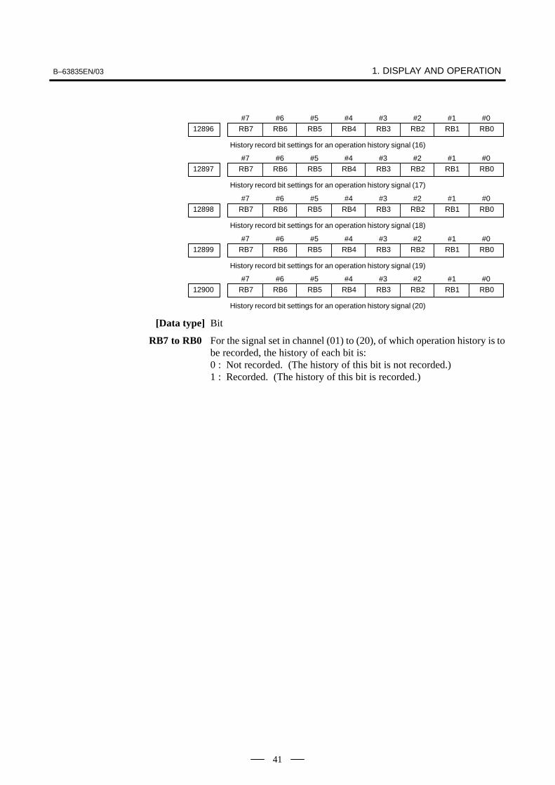
B–63835EN/03 1. DISPLAY AND OPERATION
41
#7RB712896
#6RB6
#5RB5
#4RB4
#3RB3
#2RB2
#1RB1
#0RB0
History record bit settings for an operation history signal (16)
#7RB712897
#6RB6
#5RB5
#4RB4
#3RB3
#2RB2
#1RB1
#0RB0
History record bit settings for an operation history signal (17)
#7RB712898
#6RB6
#5RB5
#4RB4
#3RB3
#2RB2
#1RB1
#0RB0
History record bit settings for an operation history signal (18)
#7RB712899
#6RB6
#5RB5
#4RB4
#3RB3
#2RB2
#1RB1
#0RB0
History record bit settings for an operation history signal (19)
#7RB712900
#6RB6
#5RB5
#4RB4
#3RB3
#2RB2
#1RB1
#0RB0
History record bit settings for an operation history signal (20)
[Data type] Bit
RB7 to RB0 For the signal set in channel (01) to (20), of which operation history is tobe recorded, the history of each bit is:0 : Not recorded. (The history of this bit is not recorded.)1 : Recorded. (The history of this bit is recorded.)

1. DISPLAY AND OPERATION B–63835EN/03
42
(1) Press the SYSTEM function key.
(2)Press the continue menu key [ ]. The [OPEHIS] (OPERATIONHISTORY) soft key are displayed.
(3)Press the [OPEHIS] soft key twice. The operation history screen isdisplayed.
OPERATION HISTORY O1234 N12345Page : 123
No.DATA No.DATA No.DATA01 01/06/03 11 F0000.7↑ 21 F0001.0↓02 08:40:00 12 F0000.5↑ 22 <POS>03 <DELETE> 13 F0001.0↑ 23 <PROG>04 F0000.6↑ 14 F0000.5↓ 24 <RESET>05 MEM 15 P/S0010 25 EDIT06 G0009.0↑ 16 02/06/03 26 O07 G0009.1↑ 17 09:27:49 27 108 G0009.2↑ 18 <PROG> 28 209 ST↑ 19 <RESET> 29 310 ST↓ 20 F0000.7↓ 30 4
EDIT **** *** *** 08:20:52[ TOP ][ BOTTOM ][ ][ ][PG.SRH]
On the operation history screen, the soft keys are configured as shownbelow:
⇒ [ ] [ PARAM ] [DGNOS] [PMC] [SYSTEM] [(OPE)] [ ]�push
[ ] [W.DGNS] [ ] [ ] [OPEHIS] [(OPE)] [ ]� push
[ ] [ OPEHIS ] [SG–SEL] [ ] [ ] [(OPE)] [ ]�push
[ ] [ TOP ] [BOTTOM] [ ] [ ] [PG.SRH] [ ]
(4)To display the next part of the operation history, press the page down
key PAGE
. The next page is displayed.
To display the interface between two pages, press cursor key or
. The screen is scrolled by one row. On a 14–inch CRT screen,
pressing the cursor key scrolls the screen by half a page.
These soft keys can also be used:1) Pressing the [TOP] soft key displays the first page (oldest data).
2) Pressing the [BOTTOM] soft key displays the last page (latestdata).
3) Pressing the [PG.SRH] soft key displays a specified page.
Example) By entering 50 then pressing the [PG.SRH] key, page 50 isdisplayed.
1.6.2Screen Display� Displaying the operation
history

B–63835EN/03 1. DISPLAY AND OPERATION
43
Data displayed on the operation history screen
(1)MDI keys
Address and numeric keys are displayed after a single space.Soft keys are displayed in square brackets ([]).Other keys (RESET/INPUT, for example) are displayed in anglebrackets (<>).A key pressed at power–on is displayed in reverse video.For two–path control, the operations of path 2 are displayed in thesame way, but preceded by S_.
1) Function key: <POS>, <PROG>, <OFFSET>, etc.
2) Address/numeric key: A to Z, 0 to 9, ; (EOB), +, –, (, etc.
3) Page/cursor key: <PAGE↑>, <CUR↓>, <CUR←>
4) Soft key: [SF1], [SF2], etc.
5) Other key: <RESET>, <CAN>, etc.
6) Key pressed at power–on: <RESET>
(2) Input and output signals
Indicates the bit.
General signals are displayed in the following format:G 0 0 0 0 . 7 ↑
The ↑ mark indicates that the signal isturned on.The ↓ mark indicates that the signal isturned off.
Indicates the address.
Some signals are indicated by their symbol names.
SBK ↑ (Indicates that the single block switch is turned on.)

1. DISPLAY AND OPERATION B–63835EN/03
44
Mode selection signals and rapid traverse override signalsare displayed as indicated below:
Input signal
MD1 ND2 MD4 REF DNC1Name displayed
0 0 0 0 0 MDI
1 0 0 0 0 MEM
1 0 0 0 1 RMT
0 1 0 0 0 NOMODE
1 1 0 0 0 EDT
0 0 1 0 0 H/INC
1 0 1 0 0 JOG
1 0 1 1 0 REF
0 1 1 0 0 TJOG
1 1 1 0 0 THND
Input signal
ROV1 ROV2Name displayed
0 0 R100%
1 0 R50%
0 1 R25%
1 1 RF0%
(3)NC alarms
NC alarms are displayed in reverse video.P/S alarms, system alarms, and external alarms are displayed togetherwith their numbers. For other types of alarms, only the alarm type is displayed. (No detailsare displayed.)For two–path control, the operations of path 2 are displayed in thesame way, but preceded by S_.
Example) P/S0050, SV_ALM, S_APC_ALM
(4)Time stamp (date and time)
The following time data (date and time) is recorded:
1) Date and time of power–on
2) Date and time of power–off
3) Date and time when an NC alarm occurs
4) The clock time is recorded at predetermined intervals, togetherwith each new calendar day.

B–63835EN/03 1. DISPLAY AND OPERATION
45
1) The power–on time is displayed as shown below:
02/01/20 ==== Year/Month/Day09:15:30 ==== Hour:Minute:Second
2) The power–off time and the time when an NC alarm occurred aredisplayed in reverse video.
02/01/20 ==== Year/Month/Day09:15:30 ==== Hour:Minute:Second
If a system alarm occurs, the date and time are not recorded.
3) At predetermined intervals, the clock time is displayed in reversevideo. Set the interval in minutes in parameter No. 3122. If zerois set, the time is stamped at ten–minute intervals.
09:15:30 ==== Hour:Minute:SecondEach new calendar day is displayed in reverse video.02/01/20 ==== Year/Month/Day
CAUTION1 The clock time is recorded for a specified interval only when
data is stored within that interval.2 If a system alarm is issued, the system alarm occurrence
time is used for power–off display.
(1)P ress the SYSTEM function key.
(2)Press the continuous menu key [ ]. The [OPEHIS] (operationhistory) soft key is displayed.
(3)Press the [OPEHIS] soft key, then press the [SG–SEL] soft key. Theoperation history signal selection screen is displayed.
OP_HIS SIGNAL SELECT O1000 N02000
No. ADDRES SIGNAL No. ADDRES SIGNAL01 X0000 00001000 11 G0000 0000000102 X0004 10000000 12 G0004 0000001103 X0008 00001100 13 G0008 0000011104 X0009 00111000 14 G0003 0000111105 X0012 00001111 15 G0043 0110000006 Y0000 01000000 16 ********07 Y0004 00110000 17 ********08 Y0007 00011100 18 ********09 Y0008 00011100 19 ********10 Y0010 00011100 20 ********>EDIT **** *** * * * 00:00:00
[OPEHIS] [SG–SEL] [ ] [ ] [ (OPE) ]
� Input signal or outputsignal to be recorded inthe operation history

1. DISPLAY AND OPERATION B–63835EN/03
46
(1)On the operation history signal selection screen, press the [(OPE)] softkey.
OP_HIS SIGNAL SELECT O1000 N02000
No. ADDRESSIGNAL No. ADDRES SIGNAL01 G0004 00000010 11 ********02 ******** 12 ********03 ******** 13 ********04 ******** 14 ********05 ******** 15 ********06 ******** 16 ********07 ******** 17 ********08 ******** 18 ********09 ******** 19 ********10 ******** 20 ********> EDIT **** *** *** *** 00:00:00
[ ALLDEL ][ DELETE ][ ON:1 ][ OFF:0 ][ ]
(2)Press the cursor key or to position the cursor to a desired
position.
(3)Key in a signal type (X, G, F, or Y) and an address, then press the INPUT
key.
Example) G0004 INPUT
Signal address G0004 is set in the ADDRES column. The correspondingposition in the SIGNAL column is initialized to 000000000.
(4)Select the bit to be recorded.To select all bits of the specified signal address, press the [ON:1] softkey while the cursor is positioned to 00000000 .
To select a particular bit, position the cursor to that bit by pressing the
cursor key or , then press the [ON:1] soft key. To cancel
a selection made by pressing the [ON:1] soft key or to cancel apreviously selected signal, press the [OFF:0] soft key.
(5)Up to 20 addresses can be specified by means of this signal selection.These addresses need not always be specified at consecutive positions,starting from No.1.
(6)Pressing the [ALLDEL] and [EXEC] soft keys deletes all data. If the[ALLDEL] key is pressed by mistake, it can be cancelled by pressingthe [CAN] key.
(7)To delete a selected signal address, position the cursor to thecorresponding position then press the [DELETE] and [EXEC] softkeys. In the SIGNAL column, asterisks ******** are displayed inplace of the deleted data. In the ADDRES column, the correspondingposition is cleared.If the [DELET] key is pressed by mistake, it can be cancelled bypressing the [CAN] key.
(8)Pressing the return menu key [ ] causes the [OPEHIS] (OPE) softkey to be displayed again.
1.6.3Setting the Input Signalor Output Signal to beRecorded in theOperation History

B–63835EN/03 1. DISPLAY AND OPERATION
47
By setting bit 4 (PHS) of parameter No. 3206, setting and display on theoperation history signal selection screen can be linked with parameter No.12801 through No. 12900. By this linking, setting information related toinput and output signals subject to operation history processing can beinput and output in the same way as ordinary parameters.
NOTE1 A cross (×) indicates that a signal will not be recorded. Also,
any signal for which an address is not specified will not berecorded, either.
2 A circle (�) indicates that a signal can be recorded.3 A signal indicated by its symbol name will also be displayed
by its symbol name.
1. M/T addresses
MT→PMC#7�X000
#6�
#5�
#4�
#3�
#2�
#1�
#0�
�X127 � � � � � � �
to
PMC→CNC#7�G000
#6�
#5�
#4�
#3�
#2�
#1�
#0�
�G003 � � � � � � �
�G004 � � � FIN � � �
�G005 � � � TFIN SFIN � MFIN
to
�G006 � � � � *ABS � SRN
RLSOTG007 EXLM *FLUP � � ST STLK �
ERSG008 RRW *SP *ESP � � � *IT
�G009 � � � � � � �
�G013 � � � � � � �
�G014 � � � � � � �
�G015 � � � � � � �
�G018 � � � � � � �
RTG019 � � � � � � �
to
to
� Parameter–based setting
� Input signals and outputsignals to be recorded inthe history
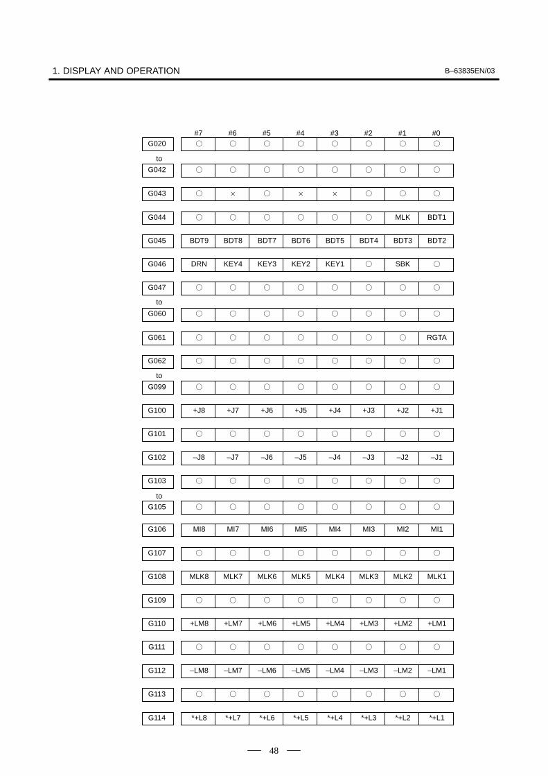
1. DISPLAY AND OPERATION B–63835EN/03
48
#7 #6 #5 #4 #3 #2 #1 #0�G020 � � � � � � �
�G042 � � � � � � �
�G043 × � × × � � �
�G044 � � � � � MLK BDT1
BDT9G045 BDT8 BDT7 BDT6 BDT5 BDT4 BDT3 BDT2
DRNG046 KEY4 KEY3 KEY2 KEY1 � SBK �
�G047 � � � � � � �
�G060 � � � � � � �
�G061 � � � � � � RGTA
�G062 � � � � � � �
�G099 � � � � � � �
+J8G100 +J7 +J6 +J5 +J4 +J3 +J2 +J1
�G101 � � � � � � �
–J8G102 –J7 –J6 –J5 –J4 –J3 –J2 –J1
�G103 � � � � � � �
�G105 � � � � � � �
to
to
to
to
MI8G106 MI7 MI6 MI5 MI4 MI3 MI2 MI1
�G107 � � � � � � �
MLK8G108 MLK7 MLK6 MLK5 MLK4 MLK3 MLK2 MLK1
�G109 � � � � � � �
+LM8G110 +LM7 +LM6 +LM5 +LM4 +LM3 +LM2 +LM1
�G111 � � � � � � �
–LM8G112 –LM7 –LM6 –LM5 –LM4 –LM3 –LM2 –LM1
�G113 � � � � � � �
*+L8G114 *+L7 *+L6 *+L5 *+L4 *+L3 *+L2 *+L1

B–63835EN/03 1. DISPLAY AND OPERATION
49
#7 #6 #5 #4 #3 #2 #1 #0
�G115 � � � � � � �
*–L8G116 *–L7 *–L6 *–L5 *–L4 *–L3 *–L2 *–L1
�G117 � � � � � �
*+ED8G118 *+ED7 *+ED6 *+ED5 *+ED4 *+ED3 *+ED2 *+ED1
�G119 � � � � � � �
*–ED8G120 *–ED7 *–ED6 *–ED5 *–ED4 *–ED3 *–ED2 *–ED1
�G121 � � � � � � �
�G125 � � � � � � �
SVF8G126 SVF7 SVF6 SVF5 SVF4 SVF3 SVF2 SVF1
�G127 � � � � � � �
�G129 � � � � � � �
*IT8G130 *IT7 *IT6 *IT5 *IT4 *IT3 *IT2 *IT1
�G131 � � � � � � �
�G132 � � � +MIT4 +MIT3 +MIT2 +MIT1
�G133 � � � � � � �
�G134 � � � –MIT4 –MIT3 –MIT2 –MIT1
�
to
to
�G135 � � � � � � �
�G255 � � � � � � �
to
PMC→MT#7�Y000
#6�
#5�
#4�
#3�
#2�
#1�
#0�
�Y127 � � � � � � �
to
CNC→PMC#7�F000
#6�
#5�
#4�
#3�
#2�
#1�
#0�
�F255 � � � � � � �
to

1. DISPLAY AND OPERATION B–63835EN/03
50
Recorded data can be output to an input/output unit connected via areader/punch interface. An output record can be input from theinput/output unit.Set the input/output unit to be used in setting parameters No. 0020 and0100 to 0135.To output the data, set a code in the ISO bit of a setting parameter (bit 1of parameter No. 0020).
(1)Select EDIT mode.
(2)Press the SYSTEM key, then select the operation history display screen.
(3)Press the soft keys [(OPRT)], , [PUNCH], and [EXEC] in this
order.
The data output to the FANUC Floppy Cassette or FANUC FA Card isstored under file name OPERATION HISTORY.
(1)Select EDIT mode.
(2)Press the SYSTEM key, then select the operation history display screen.
(3)Press the soft keys [(OPRT)], , [READ], and [EXEC] in thisorder.
1. MDI/soft key
2. Signal
3. Alarm
4. For extension (date or time)
5. MDI/soft key of path 2
6. Signal of path 2
7. Alarm of path 2
The header and recorded operation data are output, in this order. Theoperation history data is divided into four parts by identifier words. Dataother than the identifier words depends on the type.
T0 : HeaderT50 : MDI/soft keyT51 : SignalT52 : AlarmT53 : For extension (date or time)T54 : MDI/soft key of path 2T55 : Signal of path 2T56 : Alarm of path 2
T(identifier word)
1.6.4Inputting andOutputting theOperation History Data
� Output
� Input
� Output data format

B–63835EN/03 1. DISPLAY AND OPERATION
51
1) Header
T 0 C O P E R A T I O N
H I S T O R Y ;
C: Data word
2) MDI/soft key
T 5 0 P 0 to 1 H * * ;
P0: Usually
P1: At power–on
H **: Key code (See the following table.)
3) Signal
0 to 2550 to 6T 5 1 P H * * ,N * * ;
New data Old dataP0: X0000 and above
P2: G0000 and above
P4: Y0000 and above
P6: F0000 and above
N***: DI/DO number
H **: Signal information data (hexadecimal)

1. DISPLAY AND OPERATION B–63835EN/03
52
4) Alarm
0 to 10T 5 2 P * *N * * ;
P0: P/S No. 100
P1: P/S No. 000
P2: P/S No. 101
P3: P/S No. 0001 to 254
P4: Overtravel alarm
P5: Overheat alarm
P6: Servo alarm
P7: System alarm
P8: APC alarm
P9: Spindle alarm
P10: P/S alarm No. 5000 to 5999
P15: External alarm
N****: Alarm number (for P/S alarm, system alarm, and external alarm only)
5) For extension (date or time)
0 to 1
0 to 1T 5 3 P 0 *E * * ;D * * * * *Date
T 5 3 P 1 *E * * ;D * * *Time
P0: Usually
P1: At power–on
E0: Date
E1: Time
D*..*: Data Example) June 29, 2002
D 2 0 0 0 62 2 9

B–63835EN/03 1. DISPLAY AND OPERATION
53
Key codes (MDI/soft key)(00H to 7FH)
0 1 2 3 4 5 6 7
0 Space 0 @ P
1 ! 1 A Q
2 ” 2 B R
3 # 3 C S
4 $ 4 D T
5 % 5 E U
6 & 6 F V
7 ’ 7 G W
8 ( 8 H X
9 ) 9 I Y
A ;(EOB)
* : J Z
B + K [
C ’ < L ¥
D – = M ]
E . > N
F / ? O –

1. DISPLAY AND OPERATION B–63835EN/03
54
(80H to FFH)
8 9 A B C D E F
0 Reset*
F0*
1 MMC*
F1*
2 CNC*
F2*
3 F3*
4 Shift Insert*
F4*
5 Delete*
F5*
6 CAN Alter*
F6*
7 F7*
8 Cur→*
Input*
POS*
F8*
9 Cur←*
PROG*
F9*
A Cur↓*
Help*
OFFSETSETTING
*
B Cur↑*
SYSTEM*
C MESSAGE*
D CUSTOMGRAPH
*1*
E Page↓*
CUSTOM*
FR*
F Page↑*
Fapt*
FL*
*1:On the small–sized keyboard, ED corresponds to the CUSTOMGRAPH key. On
a standard keyboard, ED corresponds to the GRAPH key and EE to the
CUSTOM key.
* : Command key

B–63835EN/03 1. DISPLAY AND OPERATION
55
(1)While the operation history screen is displayed, no information can berecorded to the history.
(2)An input signal having an on/off width of up to 16 msec is not recordedin the history. Some signals are not recorded in the history.
(3)Once the storage becomes full, old data is deleted, starting from theoldest record. Up to about 8000 key information items can berecorded.
(4)The recorded data is retained even after the power is turned off. Amemory all clear operation, however, erases the recorded data.
(5)The operation history function cannot execute sampling when theOHS bit (bit 7 of parameter No. 3106) is set to 1.
(6)Set the date and time on the setting screen.
(7)The time needed to input and output 6000 operation records at a rateof 4800 baud is as follows:
Output:About 5 minutesInput: About 2 minutes and 30 seconds
This file corresponds to a paper tape of about 180 m in length.
1.6.5Notes

1. DISPLAY AND OPERATION B–63835EN/03
56
The help function displays alarm information, operation method and atable of contents for parameters. This function is used as a handbook.
Press HELP key on any screen other than PMC screen, then a help screen
appears.(However, it is not available when PMC screen/CUSTOM screen isdisplaying)
HELP (INITIAL MENU) O1234 N12345
***** HELP *****1. ALARM DETAIL2. OPERATION METHOD3. PARAMETER TABLE
[ALARM] [OPERAT] [PARAM] [ ] [ ]
(1)When an alarm is generated, press soft key [ALARM], then a helpmessage of the alarm is displayed.
HELP (INITIAL MENU) O1234 N12345
NUMBER : 010M’SAGE : IMPROPER G CODEFUNCTION :ALARM :A G CODE NOT LISTED IN G–CODE TABLEIS BEING COMMANDEDALSO G–CODE FOR FUNCTION NOT ADDEDIS BEING COMMANDED
[ALARM] [OPERAT] [PARAM] [ ] [ (OPRT) ]
(2)Pressing soft key [OPERAT],(alarm No.), and soft key [SELECT]in this order, a help message corresponding to the input alarm numberis displayed.
1.7HELP FUNCTION
1.7.1General
1.7.2Display Method
� Display of help screen
� Help for alarm

B–63835EN/03 1. DISPLAY AND OPERATION
57
(1)Press [OPERAT], then a menu for operation method is displayed.
HELP (OPERATION METHOD) O1234 N12345
1. PROGRAM EDIT2. SEARCH3. RESET4. DATA INPUT WITH MDI5. DATA INPUT WITH TAPE6. OUTPUT7. INPUT WITH FANUC CASSETTE8. OUTPUT WITH FANUC CASSETTE9. MEMORY CLEAR
[ALARM] [OPRERAT] [PARAM] [ ] [(OPRT)]
(2)Press [OPERAT], (an item number) and soft key [SELECT], then anoperation method of the item is displayed.
Pressing PAGE key PAGE
or PAGE
displays another pages.
HELP (OPERATION METHOD) O1234 N12345<<1.PROGRAM EDIT>> 1/4DELETE ALL PROGRAMSMODE :EDITSCREEN :PROGRAMOPR :(0–9999) – (DELETE)
DELETE ONE PROGRAMMODE : EDITSCREEN : PROGRAMOPR :(0+PROGRAM NUMBER) – <DELETE>
[ ] [ ] [ ] [ ] [SELECT]
Currentpage/ Totalpage
� Help for operation
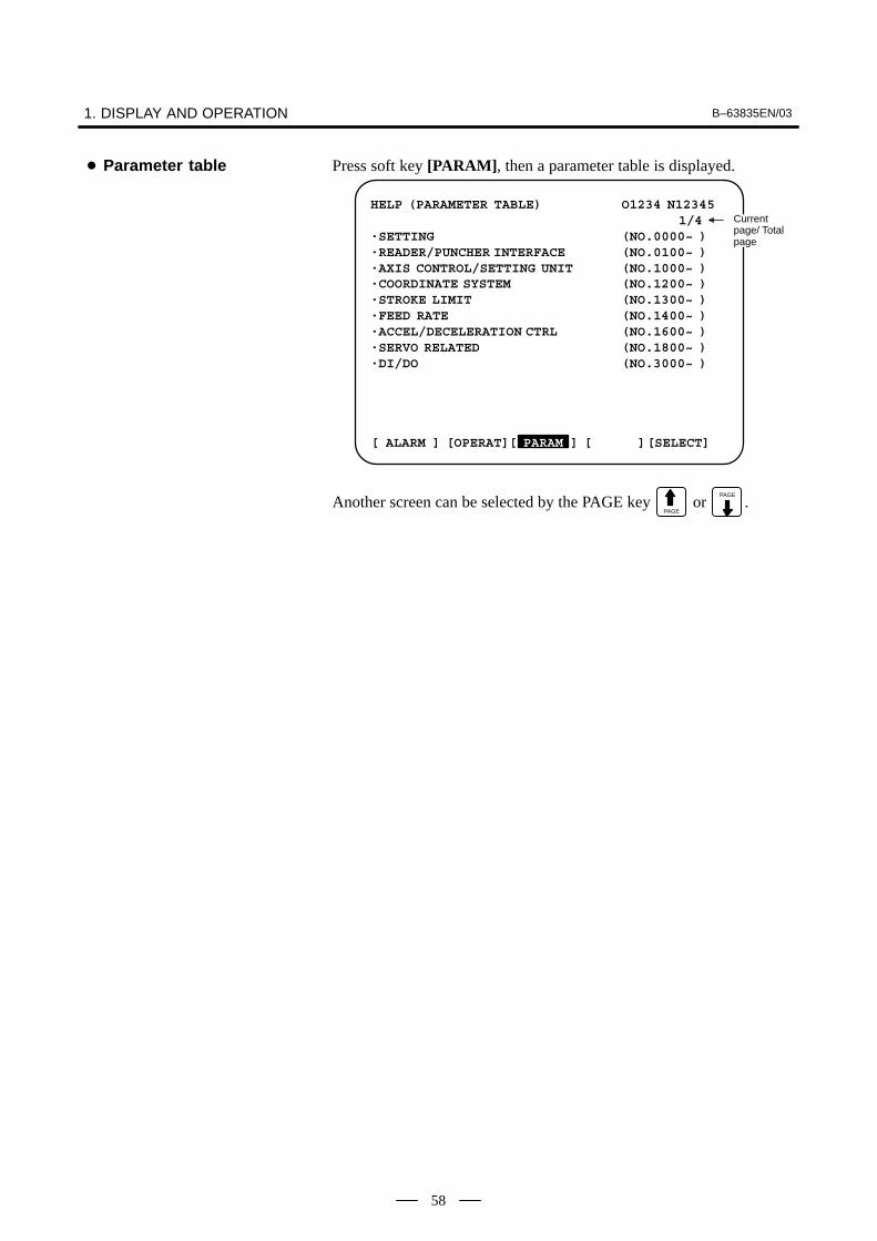
1. DISPLAY AND OPERATION B–63835EN/03
58
Press soft key [PARAM], then a parameter table is displayed.
HELP (PARAMETER TABLE) O1234 N12345 1/4
·SETTING (NO.0000~ )·READER/PUNCHER INTERFACE (NO.0100~ )·AXIS CONTROL/SETTING UNIT (NO.1000~ )·COORDINATE SYSTEM (NO.1200~ )·STROKE LIMIT (NO.1300~ )·FEED RATE (NO.1400~ )·ACCEL/DECELERATION CTRL (NO.1600~ )·SERVO RELATED (NO.1800~ )·DI/DO (NO.3000~ )
[ ALARM ] [OPERAT][ PARAM ] [ ][SELECT]
Current page/ Totalpage
Another screen can be selected by the PAGE key PAGE
or PAGE
.
� Parameter table
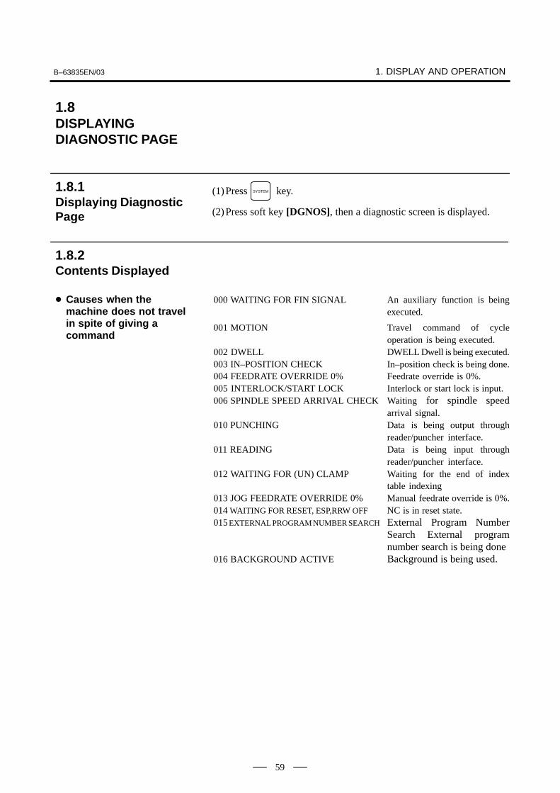
B–63835EN/03 1. DISPLAY AND OPERATION
59
(1)Press SYSTEM key.
(2)Press soft key [DGNOS], then a diagnostic screen is displayed.
000 WAITING FOR FIN SIGNAL An auxiliary function is beingexecuted.
001 MOTION Travel command of cycleoperation is being executed.
002 DWELL DWELL Dwell is being executed.003 IN–POSITION CHECK In–position check is being done.004 FEEDRATE OVERRIDE 0% Feedrate override is 0%.005 INTERLOCK/START LOCK Interlock or start lock is input.006 SPINDLE SPEED ARRIVAL CHECK Waiting for spindle speed
arrival signal.010 PUNCHING Data is being output through
reader/puncher interface.011 READING Data is being input through
reader/puncher interface.012 WAITING FOR (UN) CLAMP Waiting for the end of index
table indexing013 JOG FEEDRATE OVERRIDE 0% Manual feedrate override is 0%.014 WAITING FOR RESET, ESP,RRW OFF NC is in reset state.015 EXTERNAL PROGRAM NUMBER SEARCH External Program Number
Search External programnumber search is being done
016 BACKGROUND ACTIVE Background is being used.
1.8DISPLAYINGDIAGNOSTIC PAGE
1.8.1Displaying DiagnosticPage
1.8.2Contents Displayed
� Causes when themachine does not travelin spite of giving acommand

1. DISPLAY AND OPERATION B–63835EN/03
60
1 0 0 0 1 0 0
0 0 1 0 0 0 0
0 0 0 1 0 0 0
1 0 0 0 0 0 0
1 1 1 1 0 0 0
1 1 1 1 1 1 0
020 CUT SPEED UP/DOWN
021 RESET BUTTON ON
022 RESET AND REWIND ON
023 EMERGENCY STOP ON
024 RESET ON
025 STOP MOTION OR DWELL
Input of emergency stop signal
Input of external reset signal
Reset button On of MDI
Input of reset & rewind
Servo alarm generation
Switching to other mode, Feed hold
Single block stop
030 CHARACTER NUMBER TH ALARM Position of the character thatcaused TH alarm. The positionis counted from the head.
031 TH DATA Data of the character that causedTH alarm.
#7OVL200
#6LV
#5OVC
#4HCA
#3HVA
#2DCA
#1FBA
#0OFADGN
#7(OVL): Overload alarm
#6(LV): Insufficient voltage alarm
#5(OVC): Over current alarm
#4(HCA): Abnormal current alarm
#3(HVA): Overvoltage alarm
#2(DCA): Discharge alarm
#1(FBA): Disconnection alarm
#0(OFA): Overflow alarm
� Cause of the cycle startLED turned off
� State of TH alarm
� Details of serial pulsecoder

B–63835EN/03 1. DISPLAY AND OPERATION
61
#7ALD201
#6 #5 #4EXP
#3 #2 #1 #0
DGN
Overload 0 – – – Motor overheatalarm 1 – – – Amplifier overheat
Disconnec- 1 – – 0 Built–in pulse coder (hand)tion alarm 1 – – 1 Disconnection of separated type pulse
coder (hard)
0 – – 0 Disconnection of pulse coder (software)
#7202
#6CSA
#5BLA
#4PHA
#3RCA
#2BZA
#1CKA
#0SPHDGN
#6(CSA): Hardware of serial pulse coder is abnormal
#5(BLA): Battery voltage is low (warning)
#4(PHA): Serial pulse coder or feedback cable is erroneous.Counting of feedback cable is erroneous.
#3(RCA): Serial pulse coder is faulty.Counting of feedback cable is erroneous.
#2(BZA): Battery voltage became 0.Replace the battery and set the reference position.
#1(CKA): Serial pulse coder is faulty.Internal block stopped.
#0(SPH): Serial pulse coder or feedback cable is faulty.Counting of feedback cable is erroneous.
#7DTE203
#6CRC
#5STB
#4PRM
#3 #2 #1 #0
DGN
#7(DTE): Communication failure of serial pulse coder.There is no response for communication.
#6(CRC): Communication failure of serial pulse coder.Transferred data is erroneous.
#5(STB): Communication failure of serial pulse coder.Transferred data is erroneous.
#4(PRM): The alarm is detected by the servo, the values specified in the parameter isnot correct.
#7204
#6OFS
#5MCC
#4LDA
#3PMS
#2 #1 #0
DGN
#6(OFS): Abnormal current value result of A/D conversion of digital
#5(MCC): Contacts of MCC of servo amplifier is melted.
#4(LDA): Serial pulse coder LED is abnormal
#3(PMS): Feedback is not correct due to faulty serial pulse coder C or feedbackcable.

1. DISPLAY AND OPERATION B–63835EN/03
62
#7OHA205
#6LDA
#5BLA
#4PHA
#3CMA
#2BZA
#1PMA
#0SPHDGN
#7(OHA): Overheat occurred in the separate pulse coder.
#6(LDA): An LED error occurred in the separate pulse coder.
#5(BLA): A low battery voltage occurred in the separate pulse coder.
#4(PHA): A phase data error occurred in the separate linear scale.
#3(CMA): A count error occurred in the separate pulse coder.
#2(BZA): The battery voltage for the separate pulse coder is zero.
#1(PMA): A pulse error occurred in the separate pulse coder.
#0(SPH): A soft phase data error occurred in the separate pulse coder.#7
DTE206#6
CRC#5
STB#4 #3 #2 #1 #0
DGN
#7(DTE): A data error occurred in the separate pulse coder.
#6(CRC): A CRC error occurred in the separate pulse coder.
#5(STB): A stop bit error occurred in the separate pulse coder.
This data indicates the cause of servo alarm No. 417, detected by the NC.If the alarm is detected by the servo, the PRM bit (bit 4 of DGN No. 0203)is set to 1.
#7280
#6AXS
#5 #4DIR
#3PLS
#2PLC
#1 #0MOTDGN
#0(MOT): The motor type specified in parameter No. 2020 falls outside thepredetermined range.
#2(PLC): The number of velocity feedback pulses per motor revolution, specified inparameter No. 2023, is zero or less. The value is invalid.
#3(PLS): The number of position feedback pulses per motor revolution, specified inparameter No. 2024, is zero or less. The value is invalid.
#4(DIR): The wrong direction of rotation for the motor is specified in parameter No.2022 (the value is other than 111 or –111).
#6(AXS): In parameter No. 1023 (servo axis number), a value that falls outside therange of 1 to the number of controlled axes is specified. (For example, 4 isspecified instead of 3.) Alternatively, the values specified in theparameter are not consecutive.
300 Position error of an axis in detection unitDGN
Position error= Feed rate [mm/min]
60�servo loop gain [1/sec]
1
Detection unit×
301 Distance from reference position of an axis in detection unitDGN
� Details of separate serialpulse coder alarms
� Details of invalid servoparameter alarms (on theCNC side)
� Position error amount
� Machine position

B–63835EN/03 1. DISPLAY AND OPERATION
63
302 Distance from the end of the deceleration dog to the first grid pointDGN
[Data type] Two–word axis
[Units of data] 0.001 mm (metric output), 0.0001 inch (inch output)
[Valid data range] –99999999 to 99999999
303 Position deviation with fine acceleration/deceleration enabledDGN
[Data type] Two–word axis
[Unit of data] Detection unit
[Valid data range] –99999999 to 99999999
304 Reference counter for individual axesDGN
[Data type] Two–word axis
[Unit of data] Detection unit
[Valid data range] –99999999 to 99999999
305 Position feedback data between Z phases of individual axesDGN
[Data type] Two–word axis
[Unit of data] Detection unit
[Valid data range] –99999999 to 99999999
If displacement detection is enabled, the feedback data between the Zphases of different axes is represented in the detection unit.
� Reference position shiftfunction
� Position deviation withfine acceleration/deceleration enabled
� Reference counter
� Displacement detection

1. DISPLAY AND OPERATION B–63835EN/03
64
306 Machine coordinates of a slant axis in the Cartesian coordinate systemDGN
307 Machine coordinates of an orthogonal axis in the Cartesian coordinate systemDGN
[Data type] Two–word
[Unit of data]
Increment system IS–A IS–B IS–C Unit
Metric input 0.01 0.01 0.01 mm
Inch input 0.001 0.001 0.001 inch
Rotation axis 0.01 0.01 0.01 deg
[Valid data range] –99999999 to 99999999
These parameters are updated only when bit 0 (AAC) of parameter No.8200 is set to 1, and any of the parameters below is set to 1:
� Bit 0 (AOT) of parameter No. 8201
� Bit 1 (AO2) of parameter No. 8201
� Bit 2 (AO3) of parameter No. 8201
� Bit 3 (QSA) of parameter No. 5009 (T series only)
� The interference check option is selected.
308 Servo motor temperatureDGN
[Data type] Byte axis
[Unit of data] �C
[Valid data range] 0 to 255
The αi servo motor coil temperature is indicated.When the temperature reaches 140�C, an alarm about motor overheat isissued.
309 Pulse coder temperatureDGN
[Data type] Byte axis
[Unit of data] �C
[Valid data range] 0 to 255
The temperature of the pulse coder printed circuit board is indicated.When the temperature reaches 100�C (85�C for the atmospheretemperature in the pulse coder), an alarm about motor overheat is issued.
� Machine coordinates ofangular axis/orthogonalaxis
� Motor temperatureinformation
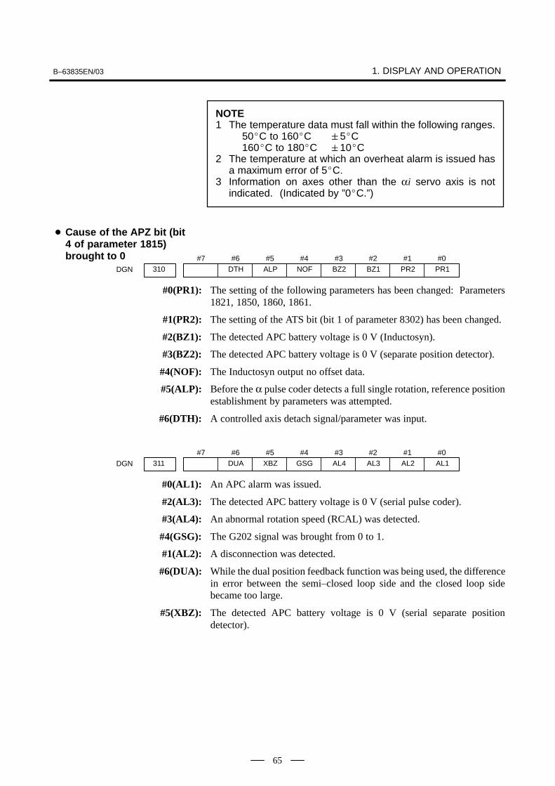
B–63835EN/03 1. DISPLAY AND OPERATION
65
NOTE1 The temperature data must fall within the following ranges.
50�C to 160�C �5�C160�C to 180�C �10�C
2 The temperature at which an overheat alarm is issued hasa maximum error of 5�C.
3 Information on axes other than the αi servo axis is notindicated. (Indicated by ”0�C.”)
#7310
#6DTH
#5ALP
#4NOF
#3BZ2
#2BZ1
#1PR2
#0PR1DGN
#0(PR1): The setting of the following parameters has been changed: Parameters1821, 1850, 1860, 1861.
#1(PR2): The setting of the ATS bit (bit 1 of parameter 8302) has been changed.
#2(BZ1): The detected APC battery voltage is 0 V (Inductosyn).
#3(BZ2): The detected APC battery voltage is 0 V (separate position detector).
#4(NOF): The Inductosyn output no offset data.
#5(ALP): Before the α pulse coder detects a full single rotation, reference positionestablishment by parameters was attempted.
#6(DTH): A controlled axis detach signal/parameter was input.
#7311
#6DUA
#5XBZ
#4GSG
#3AL4
#2AL3
#1AL2
#0AL1DGN
#0(AL1): An APC alarm was issued.
#2(AL3): The detected APC battery voltage is 0 V (serial pulse coder).
#3(AL4): An abnormal rotation speed (RCAL) was detected.
#4(GSG): The G202 signal was brought from 0 to 1.
#1(AL2): A disconnection was detected.
#6(DUA): While the dual position feedback function was being used, the differencein error between the semi–closed loop side and the closed loop sidebecame too large.
#5(XBZ): The detected APC battery voltage is 0 V (serial separate positiondetector).
� Cause of the APZ bit (bit4 of parameter 1815)brought to 0

1. DISPLAY AND OPERATION B–63835EN/03
66
#7CFE320
#6 #5 #4ERP
#3OPN
#2RDY
#1OPP
#0CLSDGN
Indicates the internal status of the FSSBC.
#0(CLS): Closed.
#1(OPP): Running OPEN protocol.
#2(RDY): Open and ready.
#3(OPN): Open.
#4(ERP): Running ERROR protocol.
#7(CFE): Encountered configuration error.(The actual slave type does not match the one specified in the conversiontable.)
#7XE3321
#6XE2
#5XE1
#4XE0
#3ER3
#2ER2
#1ER1
#0ER0DGN
Indicates the cause of an FSSBC error.
#0(ER0): INFORMED ERROR
#1(ER1): (RESERVE)
#2(ER2): Master port disconnection
#3(ER3): External EMG input
Indicates the cause of an FSSBC error resulting from a request from a slave.
#4(XE0): (RESERVE)
#5(XE1): Slave port disconnection
#6(XE2): Master port disconnection
#7(XE3): External EMG input
#7330
#6 #5 #4 #3EXT
#2DUA
#1ST1
#0ST0DGN
#7332
#6 #5 #4 #3EXT
#2DUA
#1ST1
#0ST0DGN
#7348
#6 #5 #4 #3EXT
#2DUA
#1ST1
#0ST0DGN
to
#0, #1(ST0, ST1): Indicates the type code for an actually connected slave.
ST1 ST0 Type Address
0 0 A Servo amplifier
0 1 (B: RESERVE) (Currently nonexistent)
1 0 C Stand–alone type detector inter-face unit
1 1 (RESERVE) (Currently nonexistent)
� FSSB status

B–63835EN/03 1. DISPLAY AND OPERATION
67
#2(DUA): 0 : The slave of interest is not on the first axis of the two–axis amplifier.
1 : The slave of interest is on the first axis of the two–axis amplifier.
#3(EXT): 0 : The slave of interest does not exist.
1 : The slave of interest exists.
#7331
#6 #5DMA
#4TP1
#3TP0
#2HA2
#1HA1
#0HA0DGN
#7333
#6 #5DMA
#4TP1
#3TP0
#2HA2
#1HA1
#0HA0DGN
to#7
349#6 #5
DMA#4
TP1#3
TP0#2
HA2#1
HA1#0
HA0DGN
#0, #1, #2(HA0, HA1, HA2): Indicates the host LSI address specified as a DMA destination.
#3, #4 (TP0, TP1): Indicates the type code of a specified slave.(See the above descriptions about ST0 and ST1.)
#5(DMA): Indicates a value determining whether to allow DMA to occur.
NOTEA combination of parameter Nos. 330 and 331 correspondsto one FSSB slave unit. Up to ten slave units are available.
Slave units and the associated diagnosis numbers
Slave unit 00Slave unit 01Slave unit 02Slave unit 03Slave unit 04Slave unit 05Slave unit 06Slave unit 07Slave unit 08Slave unit 09
�
�
�
�
�
�
�
�
�
�
Diagnosis No. 330, No. 331Diagnosis No. 332, No. 333Diagnosis No. 334, No. 335Diagnosis No. 336, No. 337Diagnosis No. 338, No. 339Diagnosis No. 340, No. 341Diagnosis No. 342, No. 343Diagnosis No. 344, No. 345Diagnosis No. 346, No. 347Diagnosis No. 348, No. 349

1. DISPLAY AND OPERATION B–63835EN/03
68
352 Detail number for invalid servo parameter setting alarmDGN
Indicates information that can be used to identify the location (parameter)and cause of an invalid servo parameter setting alarm (servo alarm No.417).This diagnosis information is valid when the following conditions aresatisfied.
� Servo alarm No. 417 has occurred.
� Bit 4 of diagnosis No. 203 (PRM) = 1
See the following table for the displayed detail numbers and thecorresponding causes. For further detail information that could be usedto take measures, refer to FANUC AC Servo Motor αi series ParameterManual (B–65270EN).
Detailnumber
Parameternumber Cause Measure
0233 2023 A value specified as the number of veloc-ity pulses is greater than 13100 when ini-tialization bit 0 = 1.
Decrease the value specified as the num-ber of velocity pulses to within 13100.
0243 2024 A value specified as the number of posi-tion pulses is greater than 13100 wheninitialization bit 0 = 1.
Decrease the value specified as the num-ber of position pulses to within 13100.
04340435
2043 The internal value of the velocity loop in-tegration gain has overflowed.
Decrease the value specified in the veloc-ity loop integration gain parameter.
04440445
2044 The internal value of the velocity loop pro-portional gain has overflowed.
Use a function for changing the internal for-mat of the velocity loop proportional gain.
04740475
2047 The internal value of the observer param-eter (POA1) has overflowed.
Change the setting to: (–1) × (desiredsetting)/10
05340535
2053 The internal value of the dead zone com-pensation parameter has overflowed.
Decrease the setting until the invalid pa-rameter setting alarm will not occur anylonger.
05440545
2054 The internal value of the dead zone com-pensation parameter has overflowed.
Decrease the setting until the invalid param-eter setting alarm will not occur any longer.
068606870688
2068 The internal value of the feedforward co-efficient has overflowed.
Use the position gain magnification func-tion.
0694069506960699
2069 The interval value of the velocity feedfor-ward coefficient has overflowed.
Decrease the velocity feedforward coeffi-cient.
� Details of invalid servoparameter setting alarms(on the servo side)
� Detailed descriptionsabout invalid servoparameter setting alarms

B–63835EN/03 1. DISPLAY AND OPERATION
69
Detailnumber MeasureCause
Parameternumber
07540755
2075 The setting of the parameter listed at theleft has overflowed.
This parameter is presently not in use.Specify 0 in it.
07640765
2076 The setting of the parameter listed at theleft has overflowed.
This parameter is presently not in use.Specify 0 in it.
0783 2078 The conversion coefficient parameterlisted at the left has not been set up for afull–closed loop linear motor (for the Se-ries 9080 only).
Set a value in this parameter.
0793 2079 The conversion coefficient parameterlisted at the left has not been set up for afull–closed loop linear motor (for the Se-ries 9080 only).
Set a value in this parameter.
0843 2084 No positive value has been set for theflexible feed gear numerator.Alternatively, the following condition ex-ists: Feed gear numerator > denominator
Specify a positive value as the flexiblefeed gear numerator.Alternatively, satisfy the following condi-tion: Feed gear numerator � denomina-tor (except for phase A–/B–specificstand–alone type detector).
0853 2085 No positive value has been set as theflexible feed gear denominator.
Specify a positive value as the flexiblefeed gear denominator.
088408850886
2088 The internal value of the machine velocityfeedback coefficient has overflowed.
Decrease the machine velocity feedbackcoefficient.Alternatively, use the damping controlfunction, which has an equivalent effect.
0883 2088 A value of 100 or greater was specified inthe machine velocity feedback coefficientfor an axis with a serial stand–alone typedetector.
The maximum allowable value for the ma-chine velocity feedback coefficient for axeswith a serial stand–alone type detector is100. Decrease the setting to within 100.
092609270928
2092 The interval value of the advance feedfor-ward coefficient has overflowed.
Use the position gain magnification func-tion.
0996 2099 The internal value for suppressing Npulses has overflowed.
Decrease the setting of the parameterlisted at the left.
1123 2112 No value has been entered for the AMRconversion coefficient parameter when alinear motor is in use.
Specify the AMR conversion coefficient.
1183 2118 No value has been specified in the semi–/full–closed loop error threshold parameterfor a full–closed loop linear motor (for theSeries 9080 only).
Specify a semi–/full–closed loop errorthreshold value for the parameter listed atthe left.
12841285
2128 If the value specified as the number of ve-locity pulses is small, the internal value ofthe current control parameter overflows.
Decrease the value for the parameterlisted at the left to within a range where noalarm will occur any longer.
12941295
2129 If the value specified as the number of ve-locity pulses is large, the internal value ofthe current control parameter overflows.
Re–set “a” to a smaller value when thesetting of the parameter listed at the left isbroken up into: a × 256 + b

1. DISPLAY AND OPERATION B–63835EN/03
70
Detailnumber MeasureCause
Parameternumber
1393 2139 The setting of the linear motor AMR offsethas exceeded ±45.
Decrease the setting of the parameterlisted at the left to within ±45.
144614471448
2144 The cutting feedforward coefficient for thecutting–/rapid traverse–specific FAD func-tion has overflowed.
Use the position gain magnification func-tion.
1454145514561459
2145 The cutting velocity feedforward coeffi-cient for the cutting–/rapid traverse–spe-cific FAD function has overflowed.
Decrease the velocity feedforward coeffi-cient.
8213 1821 No positive value has been set in the ref-erence counter capacity parameter.
Specify a positive value in the parameterlisted at the left.
825482558256
1825 The internal value of the position gain hasoverflowed.
Use the position gain magnification func-tion.
1001610019
2200 bit 0 The internal value of a parameter used todetect runaway has overflowed.
Do not use the runaway detection func-tion (specify bit 0 = 1).
10043 1815#12010#2
A full–closed loop has been set up for alinear motor (except for the Series 9080).
A full–closed loop cannot be specified forlinear motors.
10053 2018#0 The scale reverse connection bit hasbeen set up for a linear motor.
The scale reverse connection bit cannotbe used for linear motors.
10062 2209#4 The amplifier in use does not support theHC alarm avoidance function.
If you want to use this amplifier, reset thefunction bit listed at the left to 0.If you want to use the HC alarm avoidancefunction, use an amplifier that supports it.
360 Cumulative command pulse count (NC)DGN
[Data type] Two–word axis
[Unit of data] Detection unit
[Valid data range] –99999999 to 99999999
Indicates the cumulative count of movement commands distributed fromthe CNC since the power was switched on.
361 Cumulative compensation pulse count (NC)DGN
[Data type] Word axis
[Unit of data] Detection unit
[Valid data range] –32767 to 32767
Indicates the cumulative count of compensation pulses (backlashcompensation, pitch error compensation, etc.) distributed from the CNCsince the power was switched on.
� Error detection

B–63835EN/03 1. DISPLAY AND OPERATION
71
362 Cumulative command pulse count (SV)DGN
[Data type] Two–word axis
[Unit of data] Detection unit
[Valid data range] –99999999 to 99999999
Indicates the cumulative count of movement command and compensationpulses received at the servo section since the power was switched on.
363 Cumulative feedback pulse count (SV)DGN
[Data type] Two–word axis
[Unit of data] Detection unit
[Valid data range] –99999999 to 99999999
Indicates the cumulative count of position feedback pulses received fromthe pulse coder by the servo section.
380 Difference between the absolute position of the motor and offset dataDGN
[Data type] Two–word axis
[Units of data] Detection units
M (absolute position of the motor) – S (offset data)λ(pitch interval)
The remainder resulting from the division is displayed.
381 Offset data from the InductosynDGN
[Data type] Two–word axis
[Units of data] Detection units
Off set data is displayed when CNC calculates the machine position.
� Diagnostic data relatedto the Inductosynabsolute position detector

1. DISPLAY AND OPERATION B–63835EN/03
72
#7400
#6 #5 #4SAI
#3SS2
#2SSR
#1POS
#0SICDGN
#4(SAI) 0 : Spindle analog control is not used.
1 : Spindle analog control is used.
#3(SS2) 0 : Spindle serial doesn’t control 2nd spindle.
1 : Spindle serial control 2nd spindle.
#2(SSR) 0 : Spindle serial control is not performed.
1 : Spindle serial control is performed.
#1 (POS) A module required for spindle analog control is
0 : not mounted
1 : mounted
#0 (SIC) A module required for spindle serial control is
0 : not mounted
1 : mounted
401 Serial spindle alarm state of First spindleDGN
402 Serial spindle alarm state of Second spindleDGN
403 First spindle motor temperatureDGN
404 Second spindle motor temperatureDGN
[Data type] Byte
[Unit of data] �C
[Valid data range] 0 to 255
The αi spindle motor coil temperature is indicated.This temperature is used as a guideline for occurrence of the spindleoverheat alarm.(However, the temperature at which overhear occurs varies with themotor.)
NOTE1 The temperature data must fall within the following ranges.
� 50�C to 160�C �5�C� 160�C to 180�C �10�C
2 The indicated temperature and the temperature at whichoverhear occurs have the following errors.� 160�C or less Up to 5�C� 160�C to 180�C Up to 10�C
3 For spindles older than the αi spindle, this function is invalid.4 When the system configuration of the spindle (even another
spindle) includes an additional spindle older than the αispindle, this function is invalid.
� Serial spindle

B–63835EN/03 1. DISPLAY AND OPERATION
73
#7SSA408
#6 #5SCA
#4CME
#3CER
#2SNE
#1FRE
#0CREDGN
#0 (CRE): A CRC error occurred. (Warning)
#1 (FRE): A framing error occurred. (Warning)
#2 (SNE): The transmission/reception target is invalid.
#3 (CER): An error occurred during reception.
#4 (CME): No response was returned during automatic scanning.
#5 (SCA): A communication alarm occurred on the spindle amplifier side.
#7 (SSA): A system alarm occurred on the spindle amplifier side.(These problems cause spindle alarm 749. Such problems are mainlycaused by noise, disconnection, or instantaneous power–off).
#7409
#6 #5 #4 #3SPE
#2S2E
#1S1E
#0SHEDGN
Refer to this diagnosis when alarm 750 has generated.
#3 (SPE) In spindle serial control serial spindle parameters
0 : Satisfy start condition of spindle unit1 : Do not satisfy start condition of spindle unit
#2 (S2E) 0 : 2nd spindle started normally in spindle serial control.
1 : 2nd spindle did not start normally in spindle serial control.
#1 (S1E) 0 : 1st spindle started normally in spindle serial control.
1 : 1st spindle did not start normally in spindle serial control.
#0 (SHE) 0 : Serial communication module is correct on CNC side.
1 : An error occurred in serial communication module on CNC side

1. DISPLAY AND OPERATION B–63835EN/03
74
410 Load meter of 1st spindle [%]DGN
411 Speed meter of 1st spindle [min–1]DGN
412 Load meter of 2nd spindle [%]DGN
413 Speed meter of 2nd spindle [min–1]DGN
414 Position error in 1st spindle synchronous control modeDGN
415 Position error in 2nd spindle synchronous control modeDGN
416 Absolute value of synchronization error between 1st and 2nd spindlesDGN
417 Feedback information of 1st spindle position coderDGN
418 Position error of 1st spindle position loop modeDGN
419 Feedback information of 2nd spindle position coderDGN
420 Feedback information of 2nd spindle position coderDGN
425 First–spindle synchronization errorDGN
426 Second–spindle synchronization errorDGN
No. 425 to 428: Indicates the absolute value of a synchronization error in synchronizationmode where each spindle is treated as a slave axis.
NOTE1 The temperature data must fall within the following ranges.
� 50�C to 160�C �5�C� 160�C to 180�C �10�C
2 The indicated temperature and the temperature at whichoverhear occurs have the following errors.� 160�C or less Up to 5�C� 160�C to 180�C Up to 10�C
3 For spindles older than the αi spindle, this function is invalid.4 When the system configuration of the spindle (even another
spindle) includes an additional spindle older than the αispindle, this function is invalid.
445 First–spindle position dataDGN
446 Second–spindle position dataDGN
[Data type] Word
[Unit of data] Pulse
[Valid data range] 0 to 4095
This parameter is valid when bit 1 of parameter No. 3117 = 1.To display the position data of a spindle, execute spindle orientation.

B–63835EN/03 1. DISPLAY AND OPERATION
75
450 Spindle position error during rigid tappingDGN
[Data type] Word
[Unit of data] Detection units
451 Spindle distribution during rigid tappingDGN
[Data type] Word
[Unit of data] Detection units
454 Accumulated spindle distribution during rigid tappingDGN
[Data type] Two–word
[Unit of data] Detection units
455 Instantaneous difference for the move command, calculated in terms of the spindle,during rigid tapping (signed, accumulated value)
DGN
[Data type] Two–word
[Unit of data] Detection units
456 Instantaneous difference for the travel error, calculated in terms of the spindle, during rigid tapping (signed)
DGN
[Data type] Word
[Unit of data] Detection units
457 Width of synchronization error during rigid tapping (maximum value)DGN
[Data type] Word
[Unit of data] Detection units
#7510
#6 #5 #4 #3 #2 #1 #0
DGN
This data indicates the internal Open CNC information (not available togeneral users).
#7511
#6 #5 #4 #3 #2 #1 #0
DGN
This data indicates the internal Open CNC information (not available togeneral users).
� Diagnostic data relatedto rigid tapping
� Open CNC

1. DISPLAY AND OPERATION B–63835EN/03
76
#7512
#6 #5 #4 #3THH
#2THL
#1 #0PRADGN
This data indicates the cause of a system alarm that has occurred in OpenCNC.
#0(PRA) 1 : A RAM parity error occurred in shared RAM.
#3, #2(THL, THH):
THL THH Status
0 0 A battery alarm has occurred in the PANEL i or CNC dis-play unit with PC functions.
1 0 A high–temperature condition has occurred in the PANEL ior CNC display unit with PC functions.
0 1 A low–temperature condition has occurred in the PANEL ior CNC display unit with PC functions.
1 1 Normal (connected to the PC)
#4 0 : Normal
1 : An NMI has occurred in HSSB.
#7513
#6 #5 #4 #3 #2 #1 #0
DGN
Indicates the internal information about the HSSB (open CNC). (Hiddenfunction)
#7515
#6 #5 #4 #3 #2 #1 #0
DGN
Indicates the internal information about the HSSB (channel 2). (Hiddenfunction)
#7516
#6 #5 #4 #3 #2 #1 #0
DGN
Indicates the internal information about the HSSB (channel 2). (Hiddenfunction)

B–63835EN/03 1. DISPLAY AND OPERATION
77
#7517
#6 #5 #4 #3THH
#2THL
#1 #0PRADGN
Indicates the internal information about the HSSB (channel 2) as follows.
#0(PRA): 0 : Normal
1 : A RAM parity error has occurred in shared RAM.
#3, #2(THL, THH):
THL THH Status
0 0 A battery alarm has occurred in the PANEL i or CNC dis-play unit with PC functions.
1 0 A high–temperature condition has occurred in the PANEL ior CNC display unit with PC functions.
0 1 A low–temperature condition has occurred in the PANEL ior CNC display unit with PC functions.
1 1 Normal (connected to the PC)
#4: 0 : Normal
1 : An NMI has occurred in the HSSB.
#7518
#6 #5 #4 #3 #2 #1 #0
DGN
Indicates the internal information about the HSSB (channel 2). (Hiddenfunction)
520 Total number of retractions during cutting after G83 is specifiedDGN
Executing the G83 command clears the value to zero.
Total number of retractions made by receiving the overload signal during cuttingafter G83 is specified
521DGN
Executing the G83 command clears the value to zero.
522 Position on the drill axis from which retraction is startedDGN
The units are the same as the minimum input increment.
Difference between the position on the drill axis from which the previous retractionwas started and the position from which the current retraction is started
523DGN
The units are the same as the minimum input increment.
� Diagnostic data relatedto a small–diameter peckdrilling cycle (M seriesonly)

1. DISPLAY AND OPERATION B–63835EN/03
78
Difference in the position error between the master and slave axes in simple synchro-nas control
540DGN
Difference in the position error between the master and slave axes in simple synchro-nas control
541DGN
DGN 540 indicates the difference in the position error between the masterand slave axes when a single axis pair is subjected to simple synchronouscontrol. DGN 541 is used when two or more pairs are subjected to simplesynchronous control. The position error is indicated for the master axis.
DGN 540 and 541 indicate values in detection units. They are displayedonly with the M series.
560 Status after execution of manual tool compensationDGN
0 : Manual tool compensation ended normally.1 : The data of the T code command is out of the allowable range.
2 : The offset value is out of the allowable range.
3 : The offset number is out of the allowable range.
4 : The CNC is running automatically or moving the axes.
5 : The CNC is in tool tip radius compensation mode.
6 : The CNC is not in JOG or HNDL (INCR) mode.
7 : The setting of a CNC parameter is invalid.
#7CFE620
#6 #5ERR
#4ERP
#3OPN
#2RDY
#1OPP
#0CLSDGN
Indicates the internal status of the FSSBC2.
#0(CLS): Closed.
#1(OPP): Running OPEN protocol.
#2(RDY): Open and ready.
#3(OPN): Open.
#4(ERP): Running ERROR protocol.
#7(CFE): Encountered configuration error.(The actual slave type does not match the one specified in the conversiontable.)
� Diagnostic data relatedto simple synchronouscontrol
� Status after execution ofmanual toolcompensation (for the Tseries only)
� FSSB2 status
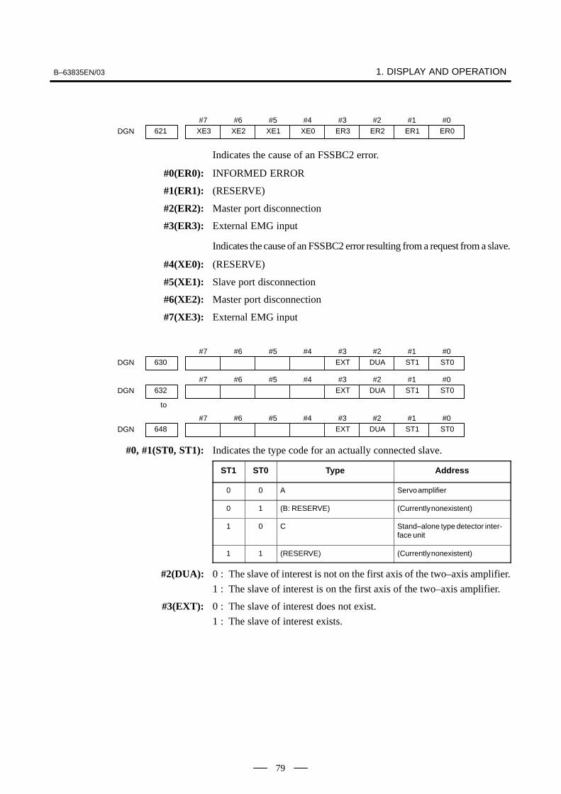
B–63835EN/03 1. DISPLAY AND OPERATION
79
#7XE3621
#6XE2
#5XE1
#4XE0
#3ER3
#2ER2
#1ER1
#0ER0DGN
Indicates the cause of an FSSBC2 error.
#0(ER0): INFORMED ERROR
#1(ER1): (RESERVE)
#2(ER2): Master port disconnection
#3(ER3): External EMG input
Indicates the cause of an FSSBC2 error resulting from a request from a slave.
#4(XE0): (RESERVE)
#5(XE1): Slave port disconnection
#6(XE2): Master port disconnection
#7(XE3): External EMG input
#7630
#6 #5 #4 #3EXT
#2DUA
#1ST1
#0ST0DGN
#7632
#6 #5 #4 #3EXT
#2DUA
#1ST1
#0ST0DGN
to
#7648
#6 #5 #4 #3EXT
#2DUA
#1ST1
#0ST0DGN
#0, #1(ST0, ST1): Indicates the type code for an actually connected slave.
ST1 ST0 Type Address
0 0 A Servo amplifier
0 1 (B: RESERVE) (Currently nonexistent)
1 0 C Stand–alone type detector inter-face unit
1 1 (RESERVE) (Currently nonexistent)
#2(DUA): 0 : The slave of interest is not on the first axis of the two–axis amplifier.
1 : The slave of interest is on the first axis of the two–axis amplifier.
#3(EXT): 0 : The slave of interest does not exist.
1 : The slave of interest exists.

1. DISPLAY AND OPERATION B–63835EN/03
80
#7631
#6 #5DMA
#4TP1
#3TP0
#2HA2
#1HA1
#0HA0DGN
#7633
#6 #5DMA
#4TP1
#3TP0
#2HA2
#1HA1
#0HA0DGN
#7649
#6 #5DMA
#4TP1
#3TP0
#2HA2
#1HA1
#0HA0DGN
to
#0, #1, #2(HA0, HA1, HA2): Indicates the host LSI address specified as a DMA destination.
#3, #4 (TP0, TP1): Indicates the type code of a specified slave.(See the above descriptions about ST0 and ST1.)
#5(DMA): Indicates a value determining whether to allow DMA to occur.
NOTEA combination of parameter Nos. 630 and 631 correspondsto one FSSB2 slave unit. Up to ten slave units are available.
Slave units and the associated diagnosis numbers
Slave unit 00Slave unit 01Slave unit 02Slave unit 03Slave unit 04Slave unit 05Slave unit 06Slave unit 07Slave unit 08Slave unit 09
�
�
�
�
�
�
�
�
�
�
Diagnosis No. 630, No. 631Diagnosis No. 632, No. 633Diagnosis No. 634, No. 635Diagnosis No. 636, No. 637Diagnosis No. 638, No. 639Diagnosis No. 640, No. 641Diagnosis No. 642, No. 643Diagnosis No. 644, No. 645Diagnosis No. 646, No. 647Diagnosis No. 648, No. 649
#7700
#6 #5 #4 #3 #2 #1HOK
#0HONDGN
[Data type] Bit axis
The state of high–speed HRV current control is displayed.
HON: The motor is controlled in the high–speed HRV current control mode.
HOK: This bit is set to 1 when high–speed HRV current control is enabled.
High–speed HRV current control is enabled when the followingconditions are satisfied:
– Bit 0 (HR3) of parameter No. 2013 is set to 1.
– Servo software, servo modules, and servo amplifiers suitable forhigh–speed HRV current control are used.
– When a separate detector interface unit is used, the separate detectorinterface unit is suitable for high–speed HRV current control.
� State of high–speed HRVcurrent control

B–63835EN/03 1. DISPLAY AND OPERATION
81
710 Error status of first spindleDGN
711 Error status of second spindleDGN
[Data type] Word
712 Warning status of first spindleDGN
713 Warning status of second spindleDGN
[Data type] Word
If an error (the yellow LED flashes and the error number appears) orwarning occurred in the αi spindle amplifier module (SPM), the numberis displayed on the diagnostic screen.When there is no error or warning, ”0” is indicated.
NOTE1 For spindles older than the αi spindle, this function is invalid.2 When the system configuration of the spindle (even another
spindle) includes an additional spindle older than the αispindle, this function is invalid.
Refer to the FANUC SERVO MOTOR αi series Maintenance Manual(B–65285EN) for errors on the αi spindle.See Subsection 10.1.4, ”Warning Interface for the αi Spindle” in thismanual for warnings.
� Error and warningstatuses of the αi spindle

1. DISPLAY AND OPERATION B–63835EN/03
82
ACTUAL POSITION (ABSOLUTE) O1000 N00010
X 217.940Y 363.233Z 0.000
PART COUNT 5RUN TIME 0H15M CYCLE TIME 0H 0M38SACT.F 3000MM/M S 0 T0000
MEM STRT MTN *** 09:06:35
[ ABS ] [ REL ] [ ALL ] [ HNDL ] [ OPRT ]
· Indicates the current status of the CNC.· Display example and explanation
MEM STRT MTN *** 09:06:35
(1) (2) (3) (4) (7) (8)
(5)
(1) Mode selection statusMEM: Automatic operation (memory operation)MDI: Manual data input/MDI operationEDIT: Program editingRMT: Remote operationJOG: Jog feedREF: Reference position returnINC: Incremental feed mode = step feed (if no manual pulse
generator is available)HND: Manual handle feed modeTJOG: Teaching in jog feed modeTHND:Teaching in handle feed mode
(2) Automatic operation statusSTRT: Automatic operation has started (and program execution is
under way).HOLD:Automatic operation has been suspended (execution of a
block has been discontinued, and automatic operation hasstopped).
STOP: Automatic operation has stopped (a block has been finished,and automatic operation has stopped).
MSTR:The tool is returning or being repositioned when the toolretract and return function is executed.
****: Other status (when the power is switched on, or automaticoperation has ended)
1.9CNC STATE DISPLAY
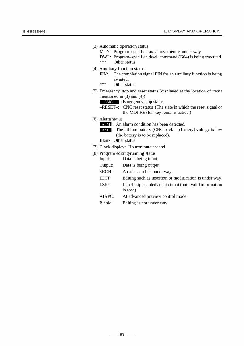
B–63835EN/03 1. DISPLAY AND OPERATION
83
(3) Automatic operation statusMTN: Program–specified axis movement is under way.DWL: Program–specified dwell command (G04) is being executed.***: Other status
(4) Auxiliary function statusFIN: The completion signal FIN for an auxiliary function is being
awaited.***: Other status
(5) Emergency stop and reset status (displayed at the location of itemsmentioned in (3) and (4))––EMG–– : Emergency stop status
–RESET–: CNC reset status (The state in which the reset signal orthe MDI RESET key remains active.)
(6) Alarm statusALM : An alarm condition has been detected.BAT : The lithium battery (CNC back–up battery) voltage is low
(the battery is to be replaced).Blank: Other status
(7) Clock display: Hour:minute:second
(8) Program editing/running statusInput: Data is being input.
Output: Data is being output.
SRCH: A data search is under way.
EDIT: Editing such as insertion or modification is under way.
LSK: Label skip enabled at data input (until valid informationis read).
AIAPC: AI advanced preview control mode
Blank: Editing is not under way.

1. DISPLAY AND OPERATION B–63835EN/03
84
Tuning becomes easier by graphically displaying servo error amount andtorque command, etc. (Graphic option is required).
The following two types of waveform diagnosis functions are supported:
(1)One–shot type
The one–shot type waveform diagnosis function can graphicallydisplay, as a waveform, any variation in those data items listed below.The start of data sampling can be triggered by the rising or falling edgeof a machine signal. This function facilitates the adjustment of theservo and spindle motors.
a. Error, pulse distribution amount, torque, speed, current, andthermal simulation data for the servo motor of each axis
b. Composite speed for the first, second, and third axes
c. Spindle motor speed and load meter value
d. On/off state of a machine signal specified with a signal address
(2)Storage type
The storage type waveform diagnosis function enables the storingof any variation in the data items listed below and, if a servo alarmoccurs, the graphical display (as a waveform) of the stored data. Theend of data sampling can be triggered by the rising or falling edgeof a machine signal. This function facilitates the estimation oferroneous locations. Stored data can be output via the reader/punchinterface.
a. Error, pulse distribution amount, torque, speed, current, andthermal simulation data for the servo motor for each axis
NOTE1 To output stored waveform data, the optional reader/punch
interface must have been installed.2 The waveform diagnosis function is enabled when bit 0
(SGD) of parameter No. 3112 is set to 1. Note, however, thata graphics card is necessary to display waveforms.
#73112
#6 #5 #4 #3 #2 #1 #0SGDDGN
#0(SGD) 0 : Do not display servo waveform (usual graphic display).
1 : Displays servo waveform (usual graphic display function cannot beused).
3120 Time between servo alarm and sampling stop (storage type)DGN
[Data type] Word
[Unit of data] ms
[Valid data range] 1 to 32760
1.10WAVEFORMDIAGNOSTICFUNCTION
1.10.1Setting Parameters

B–63835EN/03 1. DISPLAY AND OPERATION
85
3121 Selection of data of waveform diagnosis storage typeDGN
[Data type] Byte
The sixth–type sampling data of storage type of the waveform diagnosisfunction is:
0 : Thermal simulation data1 : Spindle load meter data of the first spindle
1.Press the SYSTEM key to display a system screen such as aparameter.
2. Press the continuous menu key several times, and the soft key[W.DGNS] is displayed.
3. Press [W.DGNS], then the parameter screen for the waveformdiagnosis is displayed.
Set the necessary data items. Position the cursor to the item to be set,
enter the corresponding data, then press INPUT . Data items for which
***** is displayed cannot be set. To assist in data setting, the frame onthe right side of the screen displays help information for that data to whichthe cursor is positioned. Help information which cannot fit into a singleframe is split into several pages, which the user can scroll through using
the page keys PAGE
and PAGE
.
WAVE DIAGNOSE (PARAMETER) O1234 N12345
GRP CONDITION 100
SAMPLING TIME *****MS
TRIGGER *******
(CH–1) (CH–2)
DATA NO. 11 22UNIT 1000 10SIGNAL ******* *******> S 0 T0000EDIT **** *** *** 08:20:52[W.PRM] [W.GRPH] [ W.MEM ] [ ] [ ]
GRP CONDITION
(ONE–S TYPE)0:START1:START&TRG ↑2:START&TRG ↓(MEMORY TYPE)
100: DATA OF MEMORY
1/3
(1)Display start condition
0 : Starts data sampling upon the [START] key being pressed,samples data for the specified period, then draws a waveform.
1 : Starts data sampling upon the detection of the first rising edge ofthe trigger signal after the [START] key is pressed, samples datafor the specified period, then draws a waveform.
2 : Starts data sampling upon the detection of the first falling edge ofthe trigger signal after the [START] key is pressed, samples datafor the specified period, then draws a waveform.
1.10.2Waveform DiagnosticParameter Screen
� Waveform diagnosisparameters (one–shottype)

1. DISPLAY AND OPERATION B–63835EN/03
86
(2)Sampling period: Set the period during which data will be sampled.
Valid data range: 10 to 32760Units: ms
(3)Trigger: Set the PMC address and bit for the signal used to trigger thestart of data sampling, when 1 or 2 is set for the start condition.
Example) G0007.2: ST signal
(4)Data number: The table below lists the numbers of the data items forwhich a waveform can be displayed (n = 1 to 8).
Data No. Description Units
00 Does not display a waveform. –
0n Servo error (8 ms) for the n–th axis (positional devi-ation)
Pulses (detection units)
1n Pulse distribution for the n–th axis (move command)
Pulses (input increments)
2n Torque for the n–th axis (actual current) % (relative to maxi-mum current)
3n Servo error (2 ms) for the n–th axis (positional devi-ation)
Pulses (detection units)
5n Actual speed for the n–th axis min–1
6n Command current for the n–th axis % (relative to maxi-mum current)
7n Thermal simulation data for the n–th axis % (OVC alarm ratio)
90 Composite speed for the first, second, and third axes Pulses (input increments)
99 On/off state of a machine signal specified with a sig-nal address
None
10n Actual spindle speed for the n–th axis % (relative to maxi-mum rotationspeed)
11n Load meter for the n–th spindle % (relative to maxi-mum output)
161 Difference in position error calculated on the spindlebasis
Pulses (detectionunit)
(5)Data units: Weight of data when 1 is specified. The data units areautomatically specified for each data item and need not be set unlessthe units must be changed for some reason.
[Valid data range] 1 to 1000
[Unit] 0.001
(6)Signal address: PMC address and bit number. Set in the same way asthat for trigger, when the data number is 99.

B–63835EN/03 1. DISPLAY AND OPERATION
87
(1)Display start condition
100 : Draws a waveform for the stored data.
(2)Sampling period: Invalid
(3)Trigger: Invalid
(4)Data number: The table below lists the numbers of the data items forwhich a waveform can be displayed (n = 1 to 8). Numbers for whichno data is stored cannot be specified.
Data No. Description Units
00 Does not display a waveform. –
0n Servo error (8 ms) for the n–th axis (positional devi-ation)
Pulses (detection units)
1n Pulse distribution for the n–th axis (move command) Pulses (input increments)
2n Torque for the n–th axis (actual current) % (relative to maxi-mum current)
5n Actual speed for the n–th axis min–1
6n Command current for the n–th axis % (relative to maxi-mum current)
7n Thermal simulation data for the n–th axis(when the parameter No.3121 is set to 0.)
% (OVC alarm ratio)
111 Load meter for the n–th spindle(when the parameter No.3121 is set to 1.)
% (relative to maxi-mum output)
(5)Data units: Weight of data when 1 is specified. The data units areautomatically specified for each data item and need not be set unlessthe units must be changed for some reason.
[Valid data range] 1 to 1000
[Unit] 0.001
(6)Signal address: Invalid
� Waveform diagnosisparameters (storagetype)

1. DISPLAY AND OPERATION B–63835EN/03
88
1. Press soft key [W.GRPH], then graph of waveform diagnosis isdisplayed.
WAVE DIAGNOSE (GRAPHIC)
CH1 CH2
1.0
0.5
0
–0 .5
–1 .0
1.0
0.5
0
–0 .5
–1 .0[START] [TIME�] [�TIME] [H–DOBL] [H–HALF]
2. Press soft key [(OPRT)], then the following soft keys are displayed.The following three sets of soft keys are displayed by the key.
[START] [TIME�] [�TIME] [H–DOBL] [H–DOBL]
[START] [CH–1�] [CH–1�] [V–DOBL] [V–HALF]
[START] [CH–2�] [CH–2�] [V–DOBL] [V–HALF]
1) [START ] : Starts Graphic data
2) [TIME→] : Shift the waveform of channel 1 and 2 rightward
3) [←TIME] : Shift the waveform of channel and 2 leftward
4) [H–DOBL] : Double the time scale of the waveform of channel 1and 2
5) [H–HALF] : Half the time scale of the waveform of channel 1 and 2
6) [H–DOBL] : Double the height of waveform of channel 1 and 2
7) [V–HALF] : Half the height of waveform of channel 1 and 2
8) [CH–1↑] : Shift the zero point of channel 1 upward
9) [CH–1↓] : Shift the zero point of channel 1 downward
10) [CH–2↑] : Shift the zero point of channel 2 upward
11) [CH–2↓] : Shift the zero point of channel 2 downward
The one–shot type waveform diagnosis function draws a waveform for aspecified data item in real time as the data is sampled. The sampled data,however, is not stored and thus cannot be output later.
To sample data for one–shot type waveform diagnosis, press the[START] key on the WAVE DIAGNOS. (GRAPHIC) screen. Then, datais sampled when the specified start condition is satisfied. Data samplingcontinues for the specified period.
1.10.3Graphic of WaveDiagnosis Data
� Drawing a waveform forone–shot type waveformdiagnosis

B–63835EN/03 1. DISPLAY AND OPERATION
89
Pressing the [SATART] soft key starts data sampling. While samplingis being performed, SAMPLING blinks at the top of the screen. Once datasampling has been completed, a waveform is automatically displayed.
WAVE DIAGNOS. (GRAPHIC) O1234 N12345
CH1 CH2
[START] [TIME�] [�TIME] [H–DOBL] [H–HALF]
EDIT **** ******
To use storage type waveform diagnosis, set 100 for the display startcondition. The maximum data width for storage type waveform diagnosisis 32760 ms. Data must be sampled before starting drawing. The nextpage explains sampling in detail.
Pressing the [START] soft key loads stored data. While the data is beingloaded, SAMPLING blinks at the top of the screen. Once the data hasbeen loaded, a waveform is displayed. The date on which the data wasstored is displayed at the top left of the screen. If the [START] soft keyis pressed while data is being stored, storage is stopped and the waveformfor the data stored up to that point is displayed. The WAVE DIAGNOS.(MEMORY) screen indicates whether data is being stored.
[START] [TIME�] [�TIME] [H–DOBL] [H–HALF]
WAVE DIAGNOS. (GRAPHIC) O1234 N12345
CH197/01/13 12:15:00 CH2
EDIT **** ******
� Drawing a waveform forstorage type waveformdiagnosis

1. DISPLAY AND OPERATION B–63835EN/03
90
(1)Press the SYSTEM function key. Pressing the menu continuation key [ ]
displays the [W.DGNS] soft key. Press this soft key to display theWAVE DIAGNOS. (PARAMETER) screen.
(2)Press the [W.MEM] soft key to display the WAVE DIAGNOS.(MEMORY) screen. The operation selection soft keys appear.The configuration of the operation selection soft keys is as follows:
WAVE DIAGNOS. (MEMORY) O1234 N12345
CONDITION: 100 TRIGGER: G0123.4
DATA KINDS SAMPLING AXISPOS ERROR XYZABCUVMOTION CMD XYZABCUVCURRENT (%) XYZABCUVSPEED (RPM) NONETORQUE CMD NONEHEAT SIMLT XYZABCUV
SMPL TIME : 2. 0SECDATE : MEMORY
[SELECT] [ ] [ ] [ ] [START]
EDIT **** *** *** 08:20:52
(3)The configuration of the operation selection soft keys is asfollows:
Press
[W.PRM] [W.GRPH] [ W.MEM ] [ ] [ ]
[SELECT] [ ] [ ] [ ] [START]
[ ] [ ] [PUNCH] [ ] [ ]
Fig. 1.10.4 Soft keys
(4)Using the cursor, set the necessary data items. To set the samplingaxes, position the cursor to the data item to be set, enter the names ofthe axes for which data will be sampled for that data item, then press
[SELECT] or INPUT . The axis names are displayed to the right of the
data items.
Example) XYZ + [SELECT] or INPUT
(5)Once the sampling axes have been selected, the sampling period foreach axis is displayed. Subsequently pressing the [START] soft keystarts data sampling.
1.10.4Data Sampling forStorage TypeWaveform Diagnosis

B–63835EN/03 1. DISPLAY AND OPERATION
91
CAUTION1 Data items for which ***** is displayed cannot be set.2 To change the sampling axes, enter new axis names then
press the [SELECT] soft key. Pressing the [SLELCT] softkey without entering an axis name results in no samplingaxis being set.
3 If the sampling axes are changed during data sampling,data sampling is stopped. In this case, press the [START]soft key to restart data sampling for the new sampling axes.
4 Initially, no sampling axis is set.5 When the sixth–type sampling data is spindle load meter
data (parameter No. 3121 = 1), set the axis name S.
(1)Storage stop condition
100: Stops data storage upon the issue of a servo alarm.
101: Stops data storage upon the issue of a servo alarm or thedetection of the rising edge of the trigger signal.
102: Stops data storage upon the issue of a servo alarm or thedetection of the falling edge of the trigger signal.
The maximum stored data width is 32760 ms. If the storage stopcondition is not satisfied within 32760 ms, data is overwritten, startingwith the oldest data.
Parameter No. 3120 can be used to delay data storage being stoppedby a specified period (ms), after the issue of a servo alarm.
(2)Trigger: Set the PMC address and bit for the signal used to trigger thestopping of data storage, when 101 or 102 is set for the stop condition.
Example) G0007.2: ST signal
(3)Data type: The following table lists the types of data for which awaveform can be displayed.
Data type Description Units
POS ERROR Servo error (8 ms) for the n–th axis Pulses (detection units)
MOTION CMD Pulse distribution for the n–th axis Pulses (input increments)
CURRENT (%) Torque for the n–th axis % (relative to maxi-mum current)
SPEED (RPM) Actual speed for the n–th axis min–1
TORQUE CMD Command current for the n–th axis % (relative to maxi-mum current)
HEAT SIMLT Thermal simulation data for the n–th axis(when the parameter No.3121 is set to 0.)
% (OVC alarm ratio)
LOAD METER Load meter for the n–th spindle(when the parameter No.3121 is set to 1.)
% (relative to maxi-mum output)
� Storage data parameters

1. DISPLAY AND OPERATION B–63835EN/03
92
NOTEWith parameter No. 3121, choose whether the sixth–typesampling data is thermal simulation data or spindle loadmeter data. When spindle load meter is selected, thespindle data of the first axis is stored with each path.
(4)Sampling axis: The axes along which data will be sampled aredisplayed.
(5)Sampling period: The sampling period for each axis is displayed.
(6)Date of storage: While data is being sampled, MEMORY blinks in thisfield. When data sampling stops, the date at that point appears in thisfield.
Waveform diagnosis data of servo alarm format can be output to an I/Odevice, as follows:
1) Select EDIT mode.
2) Press the SYSTEM key, then display the WAVE DIAGNOS. (MEMORY)
screen.
3) Press the [W.MEM], , [PUNCH], and [EXEC] soft keys, in thisorder.
For details of input/output to/from the FANUC Floppy Cassette or FACard, see “Output to FANUC Floppy Cassette or FA Card,” below.
WAVE DIAGNOSE (MEMORY) O1234 N12345
CONDIGION: 100 TRIGGER: G0123.4
DATA KINDS SAMPLING AXISPOS ERROR XYZABCUVMOTION CMD XYZABCUVCURRENT (%) XYZABCUVSPEED (RPM) NONETORQUE CMD NONEHEAT SIMLT XYZABCUV
SMPL TIME : 2.0SECDATE : 01/01/13 12:15:00
[SELECT] [ ] [ ] [ ] [START]
EDIT **** *** *** 12:15:52
Press
[ ] [ ] [PUNCH] [ ] [ ]
[ ] [ ] [ ] [ CAN ] [ EXEC ]
Press
1.10.5Outputting WaveformDiagnosis Data(Storage Type)

B–63835EN/03 1. DISPLAY AND OPERATION
93
1) Select EDIT mode.
2) Press the SYSTEM key, then display the WAVE DIAGNOS. (MEMORY)
screen.
3) Open the write protect tab on the floppy disk or card.
4) Press the [W.MEM], , [PUNCH], and [EXEC] soft keys, in thisorder.
The waveform diagnosis data is output to a file named WAVEDIAGNOS, to which the number of the last file is assigned.
If a file named WAVE DIAGNOS already exists in the floppy disk or onthe card, P/S alarm 86 is issued. A floppy disk or card can contain onlyone file for waveform diagnosis data. If the existing WAVE DIAGNOSfile contains unnecessary waveform diagnosis data of servo alarm format,delete that file before attempting to output new data. The procedure fordeleting a file is described later.
The directory in the cassette or card is displayed by means of thefollowing procedure:
1) Select EDIT mode.
2) Press the PROG function key to select the program screen.
3) Press the continuous menu key , then press [FLOPPY].
4) Press page key PAGE
.
The directory is displayed.
A file stored on a cassette or card is deleted by means of the followingprocedure:
1) Select EDIT mode.
2) Press the PROG function key to select the program screen.
3) Set the write protect switch on the cassette or card to enable writing.
4) Press [FLOPPY].
5) Press [DELETE].
6) Enter the file number, then press [F SET].
7) Press [EXEC].The file corresponding to the specified file number is deleted. Thenumber of each file subsequent to the deleted file is decremented byone.
� Output to FANUC FloppyCassette or FA Card
� Directory display
� Deleting a file

1. DISPLAY AND OPERATION B–63835EN/03
94
In the servo alarm format, the header, date and time, selected axes, andwaveform diagnosis data are output in this order. Data items are identifiedby ten identifier words. Output data other than the identifier words varieswith the data type.
T0 : HeaderT60 : Positional deviationT61 : Move commandT62 : Actual currentT63 : Actual speedT64 : Command currentT65 : Thermal simulationT66 : Load meter for the spindleT68 : Selected axesT69 : Date and time
T(identifier word)
1) Header
T 0 C W A V E D I A G N O S ;
C: Data word
2) Data word
T 6 9 D * * * * * * , * * * * * * ;
T 6 9 D 2 0 0 2 0 6 2 3 , 1 2 1 4 5 9 ;
D *..*: Data Example: 12:14 59 seconds on June 23, 2002
3) Selected axes
T 6 8 P * * D * * , * * , to * * ,
P0: Positional deviation
P1: Actual speed
P2: Move command
P3: Command current
P4: Actual current
P5: Thermal simulation
D*.. *: Axis number (1 to 8)
� Output format

B–63835EN/03 1. DISPLAY AND OPERATION
95
4) Waveform diagnosis data
T 6 0 D * * , * * , * * , to * * ,
T 6 1 D * * , * * , * * , to * * ,
T 6 2 D * * , * * , * * , to * * ,
T 6 3 D * * , * * , * * , to * * ,
T 6 4 D * * , * * , * * , to * * ,
T 6 5 D * * , * * , * * , to * * ,
D *..*: Waveform diagnosis data x number of axes
T 6 6 D * * , * * , * * , to * * ,
NOTE1 Records are classified into header records and data
records.2 “%” is used as an end–of–record code.3 Each record starts with an identifier and ends with an
end–of–block code.4 Either the ISO or EIA code system is used.5 The output code type is specified with parameter ISO (bit 1
of No. 0100). For ISO code, parameter NCR (bit 3 of No.0100) is used to specify whether the end–of–block code is<LF> only, or a sequence of <LF> <CR> <CR>.
6 Parameter NFD (bit 7 of No. 01X1, where X is the channelnumber) is used to specify whether a feed code is outputbefore and after the data.
7 No identifier word is output for a data item for which no axisis selected.
8 The above file corresponds to a paper tape of about 200 min length.
(1)Once the storage is full, the oldest data is overwritten.
(2)Stored–type waveform diagnostic data is not lost, even when thepower is turned off.
(3)The waveform diagnostic function is disabled when parameter SGD(bit 0 of No. 3112) is set to 0.
(4)Set the correct date and time using the setting screen.
1.10.6Notes

1. DISPLAY AND OPERATION B–63835EN/03
96
Load meter of the servo axis and the serial spindle and the speed metercan be displayed.
1. Set a parameter to display operating monitor. (Bit 5 (OPM) ofparameter No.3111)
2. Press the POS key to display the position display screen.
3. Press continuous menu key , then soft key [MONI] is displayed.
4. Press the soft key [MONI], then the operating monitor screen isdisplayed.
X : * * * 80% S1: 201%
Y : * * * * * 0% (SPEED METER RPM)
Z : * * * * * 0% S1: * * * 1500
PART COUNT 5RUN TIME 0H15M CYCLE TIME 0H 0M38SACT.F 3000 MM/M S 0 T 0000
OPERATING MONITOR O0001 N00001 (LOAD METER)
[
MEM STRT MTN *** 09:06:35[ ABS ] [ REL ] [ ALL ] [ HNDL ] [ OPRT ]
CAUTION1 The bar graph for the load meter shows load up to 200%.2 The bar graph for the speed meter shows the ratio of the
current spindle speed to the maximum spindle speed(100%). Although the speed meter normally indicates thespeed of the spindle motor, it can also be used to indicatethe speed of the spindle by setting bit 6. (OPS) of parameter3111 to 1.
3 The servo axes for their load meters are displayed are setto parameter No. 3151 to 3. If parameters 3151 to 3153 areall zero, the load meter of the basic axes are displayed.
4 For color display, the bar of the load meter that exceed100% shows purple color.
1.11OPERATINGMONITOR
1.11.1Display Method

B–63835EN/03 1. DISPLAY AND OPERATION
97
#73111
#6OPS
#5OPM
#4 #3 #2 #1 #0
DGN
[Data type] Bit
OPM Operating monitor display is:
0 : Disabled1 : Enabled
OPS The speed meter on the operating monitor screen displays:
0 : Spindle motor speed1 : Spindle speed
3151 Axis number for which the first servo motor load meter is displayedDGN
3152 Axis number for which the second servo motor load meter is displayedDGN
3153 Axis number for which the third servo motor load meter is displayedDGN
3154 Axis number for which the fourth servo motor load meter is displayedDGN
[Data type] Byte
[Valid data range] 0, 1, ... number of controlled axesThese parameters specify the numbers of the axes for which load metersfor servo motors are to be displayed. Up to four load meters can bedisplayed. Set 0 for those axes for which no load meter is to be displayed.
1.11.2Parameters
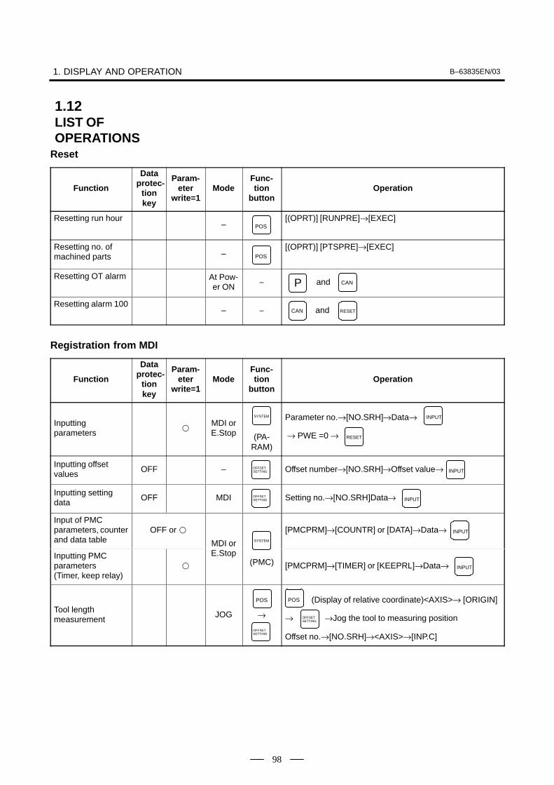
1. DISPLAY AND OPERATION B–63835EN/03
98
Reset
Function
Dataprotec-
tionkey
Param-eter
write=1Mode
Func-tion
buttonOperation
Resetting run hour– POS
[(OPRT)] [RUNPRE]→[EXEC]
Resetting no. of machined parts – POS
[(OPRT)] [PTSPRE]→[EXEC]
Resetting OT alarm At Pow-er ON
– andP CAN
Resetting alarm 100– – CAN and RESET
Registration from MDI
Function
Dataprotec-
tionkey
Param-eter
write=1Mode
Func-tion
buttonOperation
Inputting parameters
MDI orE.Stop (PA-
RAM)
SYSTEM Parameter no.→[NO.SRH]→Data→
→ PWE =0 →
INPUT
RESET
Inputting offset values
OFF – OFFSETSETTING Offset number→[NO.SRH]→Offset value→ INPUT
Inputting setting data
OFF MDI OFFSETSETTING Setting no.→[NO.SRH]Data→ INPUT
Input of PMC parameters, counterand data table
OFF or
MDI or SYSTEM
[PMCPRM]→[COUNTR] or [DATA]→Data→ INPUT
Inputting PMC parameters (Timer, keep relay)
MDI orE.Stop
(PMC) [PMCPRM]→[TIMER] or [KEEPRL]→Data→ INPUT
Tool length measurement
JOG →
POS
OFFSETSETTING
(Display of relative coordinate)<AXIS>→ [ORIGIN]
→ →Jog the tool to measuring position
Offset no.→[NO.SRH]→<AXIS>→[INP.C]
POS
OFFSETSETTING
1.12LIST OFOPERATIONS

B–63835EN/03 1. DISPLAY AND OPERATION
99
Input/Output with FANUC Cassette
Function
Dataprotec-
tionkey
Param-eter
write=1Mode
Func-tion
buttonOperation
Heading a file EDITPROG →File no.→[ � ]→[F SRH]→[EXEC]N
Deleting a file OFF EDITPROG →File no.→[ � ]→[DELETE→[EXEC]N
Collating a program EDITPROG Heading a file→ →Program number→[(OPRT)]
→[ � ]→[READ]→[EXEC]
O
Inputting From FANUC Cassette
Function
Dataprotec-
tionkey
Param-eter
write=1Mode
Func-tion
buttonOperation
Inputting parameters
EDIT orE.Stop
(PA-RAM)
SYSTEM[(OPRT)]→[ � ]→[READ]→[EXEC]
Inputting PMC parameters
E.Stop
(PMC)
SYSTEM [ � ]→[I/O]→(CANNEL NO) →
(DEVICE NAME) [FDCAS]→(KIND OF DATA) [PA-
RAM]→[READ]→(FILE NO) File no. →[EXEC]
1 INPUT
INPUT
Inputting offset values
OFF EDITOFFSETSETTING
(Heading a file no.)→[(OPRT)]→[ � ]→[READ]→[EXEC]
Registering a program
OFF EDITPROG →File no.→ →[ � ]→[READ]→[EXEC]N INPUT
Inputting macrovariables
OFF EDITPROG →File no.→ →[ � ]→ →
Program no. → [READ]→[EXEC]
N INPUT O
MEMORY PROG
<START>
(Note) After loading into the program by assigning an ap-propriate program number, this function performsexecution in MEM mode. Then, it deletes the pro-gram.

1. DISPLAY AND OPERATION B–63835EN/03
100
Output to FANUC Cassette
Function
Dataprotec-
tionkey
Param-eter
write=1Mode
Func-tion
buttonOperation
Output of parameter
EDITor
Emer-gencyStop
(PA-RAM)
SYSTEM
[(OPRT)]→[ � ]→[PUNCH]→[EXEC]
Output of PMC parameter
EDIT (PMC)
SYSTEM
[ � ]→[I/O]→(CANNEL NO) →(DEVICE
NAME) [FDCAS] →(KIND OF DATA) [PARAM] → [WRITE]
→ (FILE NO) →[EXEC]
1 INPUT
1 INPUT
Output of offset EDIT OFFSETSETTING
[(OPRT)]→[ � ]→[PUNCH]→[EXEC]
Output of all programs
EDIT PROG →–9999→[ � ]→[PUNCH]→[EXEC]O
Output of one program
EDIT PROG →Program no.→[ � ]→[PUNCH]→[EXEC]O
Output of macrovariables
EDIT OFFSETSETTING
[ � ]→[MACRO]→[(OPRT)]→[ � ]→[PUNCH]→[EXEC]
Search
Function
Dataprotec-
tionkey
Param-eter
write=1Mode
Func-tion
buttonOperation
Searching a program number
MEMORY
or EDITPROG →Program no.→[O SRH]O
Searching a sequence number
MEMORY
PROG Program no. search→ →Sequence number→[NSRH]N
Searching an address word EDIT PROG
Data to be searched→[SRH↑] or[SRH↓] or
(cursor key)
Searching an address only EDIT PROG
Address to be searched [SRH↑] or[SRH↓] or
(Cursor key)
Searching an offsetnumber – OFFSET
SETTING
Offset no.→[NO.SRH]
Searching a diagnostic number –
(DGNOS)
SYSTEMDiagnostic number→[NO.SRH]
Searching a parameter number
– (PA-RAM)
SYSTEM
Parameter no.→[NO.SRH]

B–63835EN/03 1. DISPLAY AND OPERATION
101
Edit
Function
Dataprotec-
tionkey
Param-eter
write=1Mode
Func-tion
buttonOperation
Display of memorycapacity used
EDIT PROG[LIB]
Deleting all programs
OFFEDIT PROG →–9999→O DELETE
Deleting a programOFF
EDIT PROG →Program no.→O DELETE
Deleting severalblocks
OFF EDIT PROG→Sequence no.→
(Deleted up to a block with a specified sequence no.)
N DELETE
Deleting a blockOFF
EDIT PROG →EOB DELETE
Deleting a wordOFF
EDIT PROG Searching a word to be deleted→ DELETE
Changing a wordOFF
EDIT PROG Searching a word to be changed→New Data→ ALTER
Inserting a word
OFF
EDIT PROG
Searching a word immediately before a word to be
searched→New Data→ INSERT
Collation
Function
Dataprotec-
tionkey
Param-eter
write=1Mode
Func-tion
buttonOperation
Collating memoryON
EDIT PROG[(OPRT)]→[ � ]→[READ]→[EXEC]
Playback
Function
Dataprotec-
tionkey
Param-eter
write=1Mode
Func-tion
buttonOperation
Input of NC data
TEACH–IN
JOG/HAN-DLE
PROG
Jog the machine→ , or →
→ NC data → → →
X Y Z INSERT
INSERT INSERTEOB

1. DISPLAY AND OPERATION B–63835EN/03
102
Clear
Function
Dataprote-ctionkey
Param-eter
write=1Mode
Func-tionkey
Operation
Memory all clearM/T : AND
On 2path are controlled
RESET DELETE
Atpower
ON
On 2path are controlled
Path1 : AND
Path2 : AND
CAN
CAN
1
2
Loader is controlled : ANDCAN 5
Parameter/offsetclear M/T : RESET
�
AtPower
ON
On 2path are controlled
Path1 : AND
Path2 : AND
RESET
RESET
1
2
Loader is controlled : AND (Parameter
only)
RESET 5
Clearing a programM/T : DELETE
�
AtPower
ON
On 2path are controlled
Path1 : AND
Path2 : AND
DELETE
DELETE
1
2
Loader is controlled : AND 5RESET
Program under edition at poweroff(PS101)
– ANDPROG RESET
PMC RAM *At Main CPU : AND (O)0X
PowerON Loader is controlled : ANDX 5
Additional SRAMarea clear M/T : (O) ANDO DELETE
AtPower
ON
On 2path are controlled
Path1 : (O) AND
Path2 : (O) AND
O
O
1
2
* PMC ladder program is not cleard in FROM.

B–63835EN/03 1. DISPLAY AND OPERATION
103
Manual operation
Function KEYSW
PWE=1 Mode Func-
tion key Operation
Manual refer-ence pointreturn
JOGTurn on Reference point return switch � Turn on +X, –X, +Z, or –Z �Reference point return switch LED lit.
Jog feed JOGTurn on +X, –X, +Z, or –Z � Use JOG FEEDRATE to set jog feedrate� Press Rapid traverse button, if required.
Incrementalfeed
INCUse Move distance selection switch to select move distance � Turn on+X, –X, +Z, or –Z � Press Rapid traverse button, if required.
Manualhandle feed
HNDUse Axis selection switch to select axis to be operated � Use Handlemagnification selection to select magnification � Turn manual pulsegenerator.
Display
Function KEYSW
PWE=1 Mode Func-
tion key Operation
Amount ofprogrammemory inuse
EDIT PROG [ DIR ]
Command Command value being executed, and previously specified modal valuevalue display
[CURRNT]
Command value being executed, and next command value to beexecuted
[ NEXT ]
MEMor PROG
Command value entered from MDI, and previously specified modalvalue
MDI[ MDI ]
Program in memory being executed
[PRGRM]
Executable blocks in memory and current position
[CHECK]
Current– Representation of the position in the workpiece coordinate systempositiondisplay [ ABS ]
Representation of the position in the relative coordinate systemPOS
[ REL ]
General position indication
[ ALL ]
Alarm display— MESSAGE [ALARM ] when an alarm condition has occurred.

1. DISPLAY AND OPERATION B–63835EN/03
104
FunctionOperation
Func-tion keyMode
PWE=1
KEYSW
Alarm historydisplay MESSAGE [HISTRY]
Screen erase— — Press the and function keys simultaneously. The function key
causes re–display.
CAN
Screenswitchingbetween NCand loader
SHIFT and HELP
Graphics functions (T series)
Function KEYSW
PWE=1 Mode Func-
tion key Operation
Parametersetting
GRAPH [G.PRM]
Select a graphics drawing screen.
[GRAPH]
Begins and ends drawing.
Tool pathDuring automatic operation or manual operation
Tool pathdrawing GRAPH
Erase a drawing screen.
[(OPRT)] � [ERASE ]
Enlarge graphics.
[ ZOOM ]
NOTEFor the small–size MDI, read the function key in this
table as the function key.
GRAPH
CUSTOMGRAPH
Graphics function (M series)
Function KEYSW
PWE=1 Mode Func-
tion key Operation
Parametersetting GRAPH [PARAM]
Tool path Select a graphics drawing screen.drawing
[GRAPH]GRAPH
Begin and end drawing.
During automatic operation or manual operation
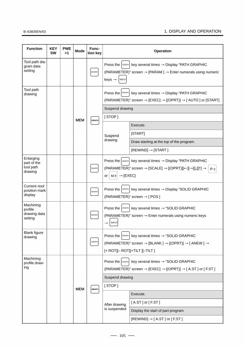
B–63835EN/03 1. DISPLAY AND OPERATION
105
FunctionOperation
Func-tion keyMode
PWE=1
KEYSW
Tool path dia-gram datasetting GRAPH
Press the key several times � Display “PATH GRAPHIC
(PARAMETER)” screen � [PARAM ] � Enter numerals using numeric
keys �
GRAPH
INPUT
Tool pathdrawing Press the key several times � Display “PATH GRAPHIC
(PARAMETER)” screen � [EXEC] � [(OPRT)] � [ AUTO ] or [START]
GRAPH
Suspend drawing
MEM GRAPH
[ STOP ]MEM GRAPH
Execute.
Suspend[START]
Suspenddrawing Draw starting at the top of the program.
[REWIND] � [START ]
Enlargingpart of thetool pathdrawing
GRAPH
Press the key several times � Display “PATH GRAPHIC
(PARAMETER)” screen � [SCALE] � [(OPRT)][�][�][�][�] �
or � [EXEC]
GRAPH
P c
M #
Current–toolposition markdisplay
GRAPHPress the key several times � Display “SOLID GRAPHIC
(PARAMETER)” screen � [ POS ]
GRAPH
Machiningprofiledrawing datasetting
GRAPH
Press the key several times � “SOLID GRAPHIC
(PARAMETER)” screen � Enter numerals using numeric keys
�
GRAPH
INPUT
Blank figuredrawing
GRAPH
Press the key several times � “SOLID GRAPHIC
(PARAMETER)” screen � [BLANK ] � [(OPRT)] � [ ANEW ] �
[+ ROT][– ROT][+TILT ][–TILT ]
GRAPH
Machiningprofile draw-ing
Press the key several times � “SOLID GRAPHIC
(PARAMETER)” screen � [EXEC] � [(OPRT)] � [ A.ST ] or [ F.ST ]
GRAPH
Suspend drawing
MEM GRAPH
[ STOP ]MEM GRAPH
Execute.
After drawing[ A.ST ] or [ F.ST ]
After drawingis suspended Display the start of part program.
[REWIND] � [ A.ST ] or [ F.ST ]

1. DISPLAY AND OPERATION B–63835EN/03
106
FunctionOperation
Func-tion keyMode
PWE=1
KEYSW
Re–drawingof “SOLIDGRAPHIC(PARAME-TER)” in adifferentorientation
GRAPH
Press the key several times � “SOLID GRAPHIC
(PARAMETER)” screen � [REVIEW] � [(OPRT)] � [ ANEW ] �
[+ ROT ][– ROT ][+TILT ][–TILT ]
GRAPH
3–planedrawing
GRAPH
Press the key several times � “SOLID GRAPHIC
(PARAMETER)” screen � [ �] � [3–PLN ] � [(OPRT)] � [ ]
[�][�][�][�]
GRAPH
NOTEFor the small–size MDI, read the function key in this
table as the function key.
GRAPH
CUSTOMGRAPH
Help function
Function KEYSW
PWE=1 Mode Func-
tion key Operation
Initial menuscreen dis-play
HELP HELP
Alarm detailscreen dis-play
HELP [ALARM ] � Alarm No. � [SELECT]
Operationmethodscreen dis-play
HELP [OPERAT] � Operation method item No. � [SELECT]
Parametertable–of–con-tents screendisplay
HELP [PARAM]
Self–diagnosis function
Function KEYSW
PWE=1 Mode Func-
tion key Operation
Self–diagno-sis screendisplay
SYSTEM
[DGNOS ]�
1. page switch keys
2. Diagnosis data No. � [NO.SRH]
PAGE
PAGE

B–63835EN/03 1. DISPLAY AND OPERATION
107
Boot
Function KEYSW
PWE=1 Mode Func-
tion key Operation
System mon-itor screendisplay
Pow-er–ontime
— and a soft key at its left
Reading filefrom memorycard
Place the cursor at 1. SYSTEM DATA LOADING on the system monitorscreen � [SELECT] � Place the cursor at the target file � [SELECT]� [YES]
Listing files inflash ROMand display-ing detailscreen
Place the cursor at 2. SYSTEM DATA CHECK on the system monitorscreen � [SELECT] � Place the cursor at the target item � [SELECT]
Deleting filefrom flashROM
Place the cursor at 3. SYSTEM DATA DELETE on the system monitorscreen � [SELECT] � Place the cursor at the target file � [SELECT]� [YES]
Outputtingfile from flashROM tomemory card
Place the cursor at 4. SYSTEM DATA SAVE on the system monitorscreen � [SELECT] � Place the cursor at the target file � [SELECT]� [YES]
Transferringcontents be-tween SRAMand memorycard in batch
Place the cursor at 5. SRAM DATA BACKUP on the system monitorscreen � [SELECT]– Batch output to memory card
Place the cursor at 1. SRAM BACK UP � [SELECT] � [YES]– Batch input from memory card
Place the cursor at 2. RESTORE SRAM � [SELECT] � [YES]
Deleting filefrom memorycard
Place the cursor at 6. MEMORY CARD FILE DELETE on the systemmonitor screen � [SELECT] � Place the cursor at the target file �[SELECT] � [YES]
Memory cardformatting
Place the cursor at 7. MEMORY CARD FORMAT on the system moni-tor screen � [SELECT] � [YES]
Exiting sys-tem monitor
Place the cursor at 10. END on the system monitor screen � [SELECT] � [YES]
ReferenceIf no soft key is available as with a touch panel, use the numeric keys onthe MDI keypad.
�
1
�
2
�
3
�
4
�
5
�
6
�
7
: 12–soft key type
: 7–soft key type

1. DISPLAY AND OPERATION B–63835EN/03
108
This CNC displays a warning screen when the configuration of theoptions using the SRAM area is changed. The data for the functionindicated on the screen is cleared the next time the system is turned on.
WARNING
YOU SET THE PARAMETER NO.����#�
THE FOLLOWING DATA WILL BE CLEARED.
* PART PROGRAM MEMORY
PLEASE PRESS <DELETE> OR <CAN> KEY.<DELETE> : CLEAR ALL DATA<CAN> : CANCEL
NOTEMark* varies with the parameter settings. Two or morefunction names may be displayed.
1.13WARNING SCREENDISPLAYED WHENAN OPTION ISCHANGED� Warning screen

B–63835EN/03 1. DISPLAY AND OPERATION
109
When an option which uses the SRAM area is added, the system softwaremay require more SRAM than is currently installed in the system. In thiscase, an allocation error screen appears the first time the system is turnedon after the addition of the option, thus restoring the state existing beforethe addition.
FILE ALLOCATION ERROR
S–RAM CAPACITY IS NOT SUFFICIENT.ADDITIONAL S–RAM IS NECESSARY.
PLEASE PRESS <CAN> KEY :RETURN TO THE STATE BEFOREOPTION PARAMETER IS CHANGED.
NOTEWhen replacing SRAM, perform all memory clear.
( + )RESET DELETE
� Allocation error screen

1. DISPLAY AND OPERATION B–63835EN/03
110
When an attempt is made to turn on the power to the CNC after replacingthe system software, the screen shown below is displayed, and the systemis not started if the replacing new system software is not compatible withthe replaced system software.
D6A1–01
SYSTEM LABEL CHECK ERROR:CLEAR ALL SRAM MODULE
NOT READY
In this case, perform memory all clear (by holding down the RESET and
DELETE MDI keys then turning on the power) or reinstall the original system
software.
1.14WARNING SCREENDISPLAYED WHENSYSTEM SOFTWAREIS REPLACED(SYSTEM LABELCHECK ERROR)

B–63835EN/03 1. DISPLAY AND OPERATION
111
The maintenance information screen is provided to record the history ofmaintenance performed by a service person of FANUC or machine toolbuilder.The screen has the following features:
� MDI alphabetical input is allowed.
� The recording screen can be scrolled in units of lines.
� Edited maintenance information can be read and punched.
� The screen can be saved in flash ROM.
1. Press the SYSTEM function key.
2. Press the continuous menu key several times. [M–INFO] softkey appears.
3. Press the [M–INFO] soft key. The maintenance information screenappears.
When selected, the maintenance screen shows the latest information.
The recording screen has an input area of 40 characters by 11 lines.
The status (mode, number of empty character spaces, cursor line, columnnumber) is displayed at the bottom of the screen.
MAINTENANCE INFORMaaabbbcccdddeeefff...
nnn
|OVER|EDIT|spaces:2078 33:1
%& '���'���
�� �����
1.15MAINTENANCEINFORMATIONSCREEN
1.15.1Screen Display andOperation
� Screen display

1. DISPLAY AND OPERATION B–63835EN/03
112
Status display
⋅ OVER/INSERT : OVER : Overwrite mode ; INSERT: Insertmode
⋅ EDIT/VIEW : EDIT : Editing allowed ; VIEW : Editing inhibited
⋅ Number of empty character spaces
⋅ Current cursor line
⋅ Current cursor column
The maintenance information screen has view mode and edit mode, whichare selected by pressing the [END] or [EDIT] soft key.Initially, view mode is selected. To start editing, select edit mode bypressing the [(OPRT)] and [EDIT] keys. When the editing is completed,press the [END] key. Then, select [STORE] or [IGNORE]. Unless[STORE] is selected, the edited data will be lost at next power–up.To scroll the screen showing the recorded information, press a cursor keyor page key on the MDI panel.The following keys are used for editing (character input) and viewing:
Operation table
Mode Key Description
View Soft keys[EDIT][JUMP]
Allows editing.Displays the beginning or the end.
Cursor key Scrolls the screen up or down.
Page key Scrolls the screen up or down in units of whole screens.
Edit Soft keys
[END]
[ALLDEL]
[I/O]
[JUMP]
Ends editing. Select whether to store the edited data.
Clears all maintenance information. (This key is enabled when the MDC bit (bit 3 of parameter 3118) isset to 1.)
Reads or punches the maintenance information.
Moves the cursor to the beginning or end.
Cursor key Moves the cursor position up or down.
Page key Scrolls the screen up or down in units of whole screens.
Alphanumeric/spe-cial character keys
Allows alphabetical, numeric, or special character input.
keyINSERT
Selects either insert mode or overwrite mode.
keyDELETE
Deletes a single character.
keyCAN
Deletes a single character before the cursor position.
keyINPUT
Starts a new line.
� Screen operation

B–63835EN/03 1. DISPLAY AND OPERATION
113
Operation of the soft keys
(1) View mode
Edit Jump
(5)
(2) Edit mode
END I/O ALLDEL Jump
(5)
(3) Edit saving
MAINTE-NANCE IGNORE CANCEL
(4) I/O
READ PUNCH CANCEL
(5) Jump
BEGIN-ING END CANCEL
(6) Execution
EXEC CANCEL
(6)(4)(3)
(2)
(1) (1)(2)
(6) (6) (2)
(1) (2) (1) (2) (1) (2)
(2)(2)

1. DISPLAY AND OPERATION B–63835EN/03
114
The maintenance information can be read and punched.When the maintenance information is input from or output to a memorycard, a file name MAINTINF.DAT is used.
(1)Format%%
Data
(2)Reading
When a MAINTINF.DAT file generated in the format shown above isread, the data is added at the end of the existing maintenanceinformation.
NOTE1 A TAB code is converted to one to four blanks, depending
on the input position.2 80h to 90h and E0h to EBh are assumed as prefix codes of
double–byte characters. Reading these codes alone isinhibited.
3 Control codes (00H to 1FH) except TAB and LF arediscarded in reading.
4 %% cannot be input.
(3)Punching
All maintenance information is output in the format shown above.
1.15.2MaintenanceInformationInput/Output

B–63835EN/03 1. DISPLAY AND OPERATION
115
When VGA screen display is selected (NVG bit (bit 7 of parameter 3119)is set to 0), the color scheme of the VGA screen can be set on the colorsetting screen.
1. Press the SYSTEM function key.
2. Press the continuous menu key several times. The [COLOR]soft key appears.
3. Press the [COLOR] soft key. The color setting screen appears.
[ 1 ]�
2 �
3 �
4 �
5 �
6 �
7 �
⋅ A LARM
⋅ TITLE ⋅ SOFT KEY 1
⋅ INPUT KEY ⋅ O/N NO.⋅ STATUS⋅ CURSOR
⋅ RESTART NO.⋅ ABSOLUTE ORDER⋅ SUB TITLE ⋅ SOFT KEY 2
⋅ DATA ⋅ TIME
8 �
9 �
10 �
11 �
12 �
13 �
14 �
15 �
⋅ SELECT WINDOW BAR
⋅ NONE
⋅ TITLE BAR ⋅ INPUT BAR
⋅ WINDOW BACKGROUND
⋅ LIGHT
⋅ ALTER POSSIBLE DATA
⋅ SHADOW
⋅ BACKGROUND
RED 08 GREEN 00 BLUE 00
COLOR SELECT NO.
[ MEM **** *** *** | *** | 12:34:56 | ]
COLORING O 0 0 0 0 N 0 0 0 0 0
+COLOR (OPRT)
1(PARAMETER)
MAINTE MAINTE
1. Press the [(OPRT)] soft key. The following operation soft keys appear.
+RED DARKBLUEGREEN BRIGHT
2. Move the cursor to the color number corresponding to the color palettevalue to be changed.
The current color palette values of individual color elements aredisplayed.
3. Select a desired color element by pressing the [RED], [GREEN], or[BLUE] operation soft key.
Two or more color elements can be simultaneously selected.
Each time the [RED], [GREEN], or [BLUE] operation soft key ispressed, the selection is made or canceled.
1.16COLOR SETTINGSCREEN (10.4″COLOR LCD)
1.16.1Screen Display
1.16.2Color Setting� Changing a color
(color palette value)
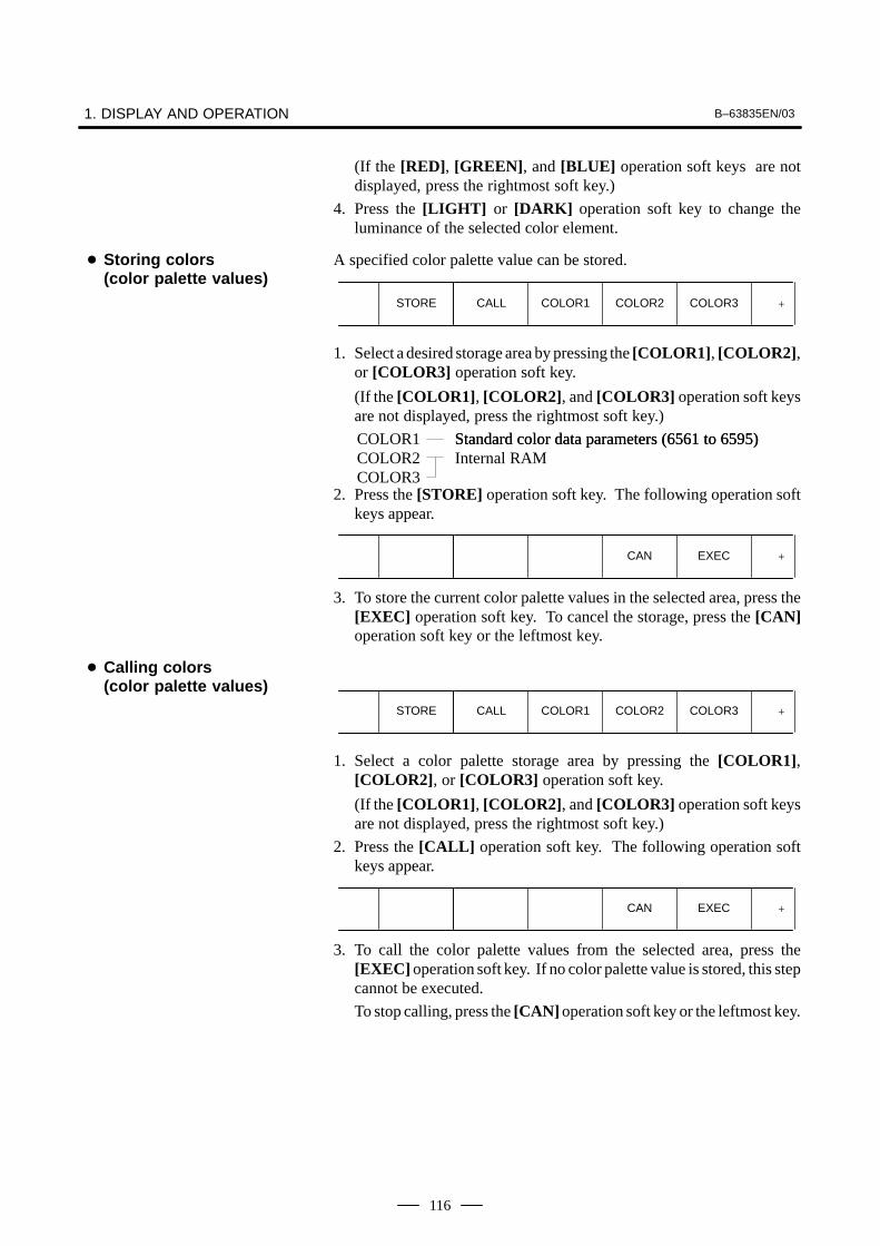
1. DISPLAY AND OPERATION B–63835EN/03
116
(If the [RED], [GREEN], and [BLUE] operation soft keys are notdisplayed, press the rightmost soft key.)
4. Press the [LIGHT] or [DARK] operation soft key to change theluminance of the selected color element.
A specified color palette value can be stored.
+STORE COLOR3COLOR1CALL COLOR2
1. Select a desired storage area by pressing the [COLOR1], [COLOR2],or [COLOR3] operation soft key.
(If the [COLOR1], [COLOR2], and [COLOR3] operation soft keysare not displayed, press the rightmost soft key.)
COLOR1COLOR2COLOR3
Standard color data parameters (6561 to 6595)Standard color data parameters (6561 to 6595)Internal RAM
2. Press the [STORE] operation soft key. The following operation softkeys appear.
+EXECCAN
3. To store the current color palette values in the selected area, press the[EXEC] operation soft key. To cancel the storage, press the [CAN]operation soft key or the leftmost key.
+STORE COLOR3COLOR1CALL COLOR2
1. Select a color palette storage area by pressing the [COLOR1],[COLOR2], or [COLOR3] operation soft key.
(If the [COLOR1], [COLOR2], and [COLOR3] operation soft keysare not displayed, press the rightmost soft key.)
2. Press the [CALL] operation soft key. The following operation softkeys appear.
+EXECCAN
3. To call the color palette values from the selected area, press the[EXEC] operation soft key. If no color palette value is stored, this stepcannot be executed.
To stop calling, press the [CAN] operation soft key or the leftmost key.
� Storing colors (color palette values)
� Calling colors (color palette values)
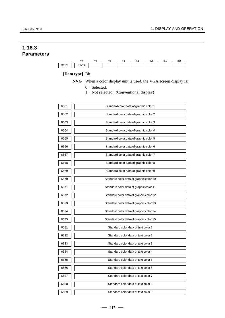
B–63835EN/03 1. DISPLAY AND OPERATION
117
#7NVG3119
#6 #5 #4 #3 #2 #1 #0
[Data type] Bit
NVG When a color display unit is used, the VGA screen display is:
0 : Selected.1 : Not selected. (Conventional display)
6561 Standard color data of graphic color 1
6562 Standard color data of graphic color 2
6563 Standard color data of graphic color 3
6564 Standard color data of graphic color 4
6565 Standard color data of graphic color 5
6566 Standard color data of graphic color 6
6567 Standard color data of graphic color 7
6568 Standard color data of graphic color 8
6569 Standard color data of graphic color 9
6570 Standard color data of graphic color 10
6571 Standard color data of graphic color 11
6572 Standard color data of graphic color 12
6573 Standard color data of graphic color 13
6574 Standard color data of graphic color 14
6575 Standard color data of graphic color 15
6581 Standard color data of text color 1
6582 Standard color data of text color 2
6583 Standard color data of text color 3
6584 Standard color data of text color 4
6585 Standard color data of text color 5
6586 Standard color data of text color 6
6587 Standard color data of text color 7
6588 Standard color data of text color 8
6589 Standard color data of text color 9
1.16.3Parameters

1. DISPLAY AND OPERATION B–63835EN/03
118
6590 Standard color data of text color 10
6591 Standard color data of text color 11
6592 Standard color data of text color 12
6593 Standard color data of text color 13
6594 Standard color data of text color 14
6595 Standard color data of text color 15
[Data type] Two–word
[Unit of data] Six–digit number rrggbb (rr: Red component value, gg: Green componentvalue, bb: Blue component value)When five digits or less are specified, the missing high–order digits areassumed as zeros.
[Valid data range] Each color component value: 00 to 15 (Equivalent to the color level onthe color setting screen)When 16 or a higher value is specified, 15 is assumed.
(Example) When specifying a color having red component value 1, greencomponent value 2, and blue component value 3, set theparameter value as 10203.
(1)At power–up, the color scheme of the screen is determined by thesetting in the COLOR1 area (parameters). If no data is stored in theCOLOR1 area, the last color scheme before power–down is applied.
(2)The standard color data specified in parameters must not be changedby direct MDI key input. When changing the parameter data, set andstore the new data on the color setting screen.
(3)When a wrong value is specified in a standard color data parameter,the screen may not be displayed. If this occurs, turn the power on
again, while pressing the DELETE and RESET keys. This clears the whole
stored color scheme and restores the FANUC standard color schemeinstead.Be very careful when performing this operation, as all memorycontents such as parameters and programs are lost.
(4)The VGA–support screen is enabled only for the 10.4–inch color LCDof the Series 0i–B.
1.16.4Notes
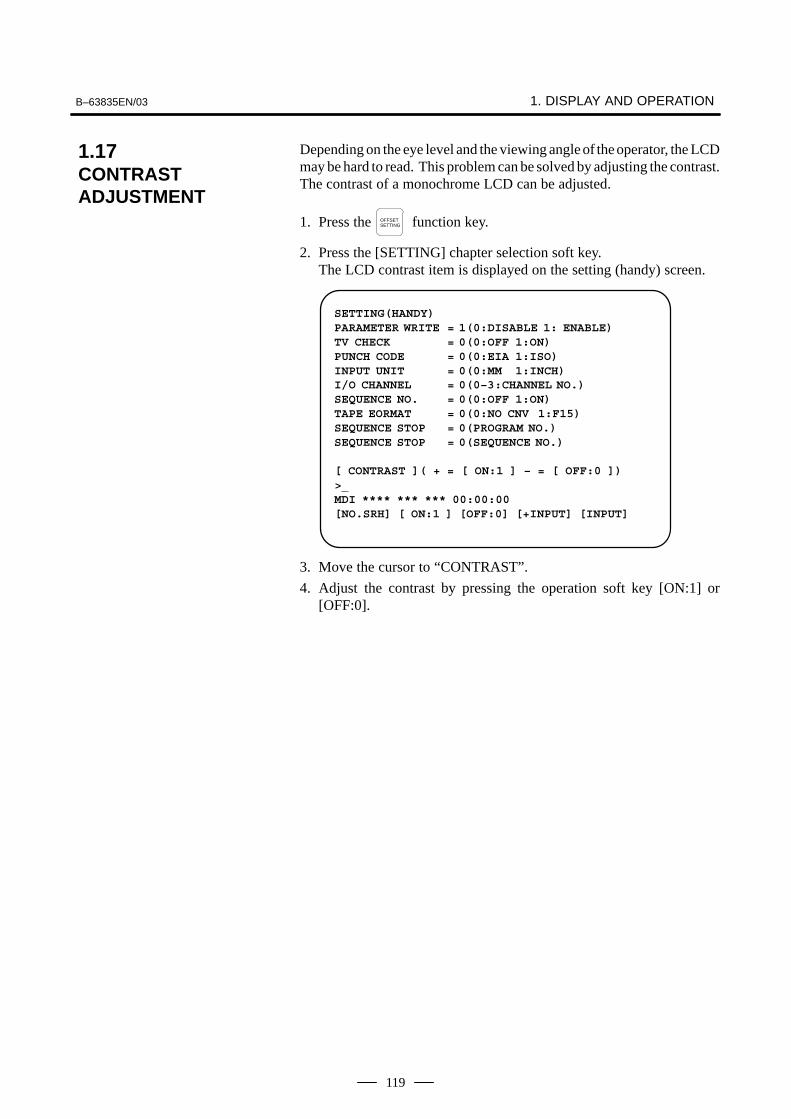
B–63835EN/03 1. DISPLAY AND OPERATION
119
Depending on the eye level and the viewing angle of the operator, the LCDmay be hard to read. This problem can be solved by adjusting the contrast.The contrast of a monochrome LCD can be adjusted.
1. Press the OFFSETSETTING function key.
2. Press the [SETTING] chapter selection soft key.The LCD contrast item is displayed on the setting (handy) screen.
SETTING(HANDY)PARAMETER WRITE = 1(0:DISABLE 1: ENABLE)TV CHECK = 0(0:OFF 1:ON)PUNCH CODE = 0(0:EIA 1:ISO)INPUT UNIT = 0(0:MM 1:INCH)I/O CHANNEL = 0(0–3:CHANNEL NO.)SEQUENCE NO. = 0(0:OFF 1:ON)TAPE EORMAT = 0(0:NO CNV 1:F15)SEQUENCE STOP = 0(PROGRAM NO.)SEQUENCE STOP = 0(SEQUENCE NO.)
[ CONTRAST ]( + = [ ON:1 ] – = [ OFF:0 ])>_MDI **** *** *** 00:00:00[NO.SRH] [ ON:1 ] [OFF:0] [+INPUT] [INPUT]
3. Move the cursor to “CONTRAST”.
4. Adjust the contrast by pressing the operation soft key [ON:1] or[OFF:0].
1.17CONTRASTADJUSTMENT

1. DISPLAY AND OPERATION B–63835EN/03
120
When the Power Mate CNC series is used as an additional axis (slave) ofthe CNC, the Power Mate CNC manager allows the slave data to bedisplayed and set by the CNC.The Power Mate CNC manager enables the following display and setting:
(1)Current position display (absolute/machine coordinates)
(2)Parameter display and setting
(3)Diagnosis display
(4)System configuration screen display
(5)Alarm display
The Power Mate CNC series that can be used as the slave is a β amplifierwith I/O Link.
#7960
#62CH
#5ASG
#4SLPWE
#3PMN
#2MD2
#1MD1
#0SLV
[Data type] Bit
SLV When the Power Mate CNC manager is selected, the screen shows thedata of:
0 : A single slave.1 : Up to four slaves by dividing the screen into four segments.
MD1, MD2 The slave parameters are input from and output to the following devices:
MD2 MD1 I/O device
0 0 Part program storage
0 1 Memory card
The parameters are input or output in the program format, no matter whichI/O device is selected.
PMN The Power Mate CNC manager function is:
0 : Enabled.1 : Disabled. (Communication with the slave is not performed.)
SLPWE The settings of slave parameters:
0 : Can be made by Power mate CNC manager regardless of the PWEsetting.
1 : Are made according to the PWE setting.
ASG Whether or not the number of bytes allocated to the input/outputdestination of the β amplifier with I/O links is 16:
0 : Is checked.1 : Is not checked.
2CH Power mate CNC manager:
0 : Communicates with channel 2.1 : Communicates with channel 1.
1.18POWER MATE CNCMANAGER
1.18.1Parameter

B–63835EN/03 1. DISPLAY AND OPERATION
121
NOTE1 The parameters are valid only when I/O link count extension
is supported (two channels are supported).2 Even when 0 is set, Power Mate CNC Manager
communicates with channel 1 if the β amplifier with I/O linksis not connected to channel 2.
3 When 1 is set, Power Mate CNC Manager does notcommunicate with channel 2 if the β amplifier with I/O linksis not connected to channel 1.
1. Press the SYSTEM function key.
2. Press the continuous menu key several times. The [PMM] softkey appears.
3. Press the [PMM] soft key. The system configuration screen, which isthe initial screen of the Power Mate CNC manager, appears. Thescreen has the following soft keys (function selection soft keys).
[ POS ][ ][ ][SYSTEM][ MSG ]
The currently active soft key is displayed in reverse video. Pressing a softkey enables the corresponding function, as indicated below:
POS: Current position displaySYSTEM: System informationMSG: Alarm list
To select another function after one of the functions listed above isselected, press the return menu key several times until the soft keysare displayed as shown above. Then, select the desired function.
4. To terminate the Power Mate CNC manager, repeatedly press thereturn menu key until the function selection keys are displayedas shown above. Then, press the return menu key once more. Thesoft keys of the CNC system appear, and the Power Mate CNCmanager terminates. The system configuration screen of this functionis displayed as the termination screen.
Alternative termination method is to select another function while this
function is enabled. To do this, press an MDI function key ( POS , PROG ,
MESSAGE , etc.).
NOTEAfter another screen is displayed by pressing a function key,
pressing the function key, restores the initial statusof this function. That is, the soft keys shown above arerestored. The data that was being input is canceled.
SYSTEM
1.18.2Screen Display
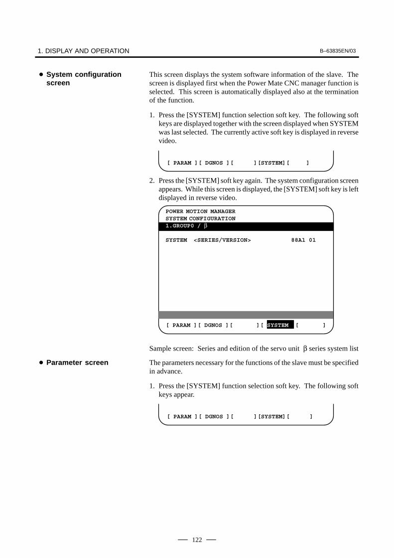
1. DISPLAY AND OPERATION B–63835EN/03
122
This screen displays the system software information of the slave. Thescreen is displayed first when the Power Mate CNC manager function isselected. This screen is automatically displayed also at the terminationof the function.
1. Press the [SYSTEM] function selection soft key. The following softkeys are displayed together with the screen displayed when SYSTEMwas last selected. The currently active soft key is displayed in reversevideo.
[ PARAM ][ DGNOS ][ ][SYSTEM][ ]
2. Press the [SYSTEM] soft key again. The system configuration screenappears. While this screen is displayed, the [SYSTEM] soft key is leftdisplayed in reverse video.
POWER MOTION MANAGERSYSTEM CONFIGURATION1.GROUP0 / β
SYSTEM <SERIES/VERSION> 88A1 01
[ PARAM ][ DGNOS ][ ][ SYSTEM ][ ]
Sample screen: Series and edition of the servo unit β series system list
The parameters necessary for the functions of the slave must be specifiedin advance.
1. Press the [SYSTEM] function selection soft key. The following softkeys appear.
[ PARAM ][ DGNOS ][ ][SYSTEM][ ]
� System configurationscreen
� Parameter screen

B–63835EN/03 1. DISPLAY AND OPERATION
123
2. Press the [PARAM] soft key. The parameter screen appears.
POWER MOTION MANAGERPARAMETER1.GROUP0 / β0000 00001000 0010 111100000001 00010101 0011 010100000002 11111011 0012 000000000003 00000000 0013 000000000004 00000000 0014 101100010005 10100001 0015 000000000006 00000000 0016 000000000007 10000000 0017 100000100008 00000000 0018 000000000009 00000000 0019 00000000
[ PARAM ][ DGNOS ][ ][ SYSTEM ][ ]
The screen displays just the bit and decimal data. For details of theparameters, refer to the connection manual of the corresponding PowerMate CNC unit.
�Searching for a parameter
A search can be made for the parameter to be displayed.
1. Select the active slave.
2. Press the [(OPRT)] soft key. The following soft keys appear.
[ NO.SRC ][ ][ ][ ][ INPUT ]
3. Enter a desired number in the key–in field by using MDI numeric keys.Then, press the [NO.SRC] soft key. The search starts.
�Setting a parameter
A parameter of a slave Power Mate CNC unit can be directly set from theCNC.
1. Select the active slave.
2. Press the [(OPRT)] soft key. The following soft keys appear:
[ NO.SRC ][ ][ ][ ][ INPUT ]
3. Move the cursor to the parameter to be set.
4. Enter desired data in the key–in buffer by using MDI numeric keys.Then, press the [INPUT] soft key. Alternatively, press the MDIINPUT key.
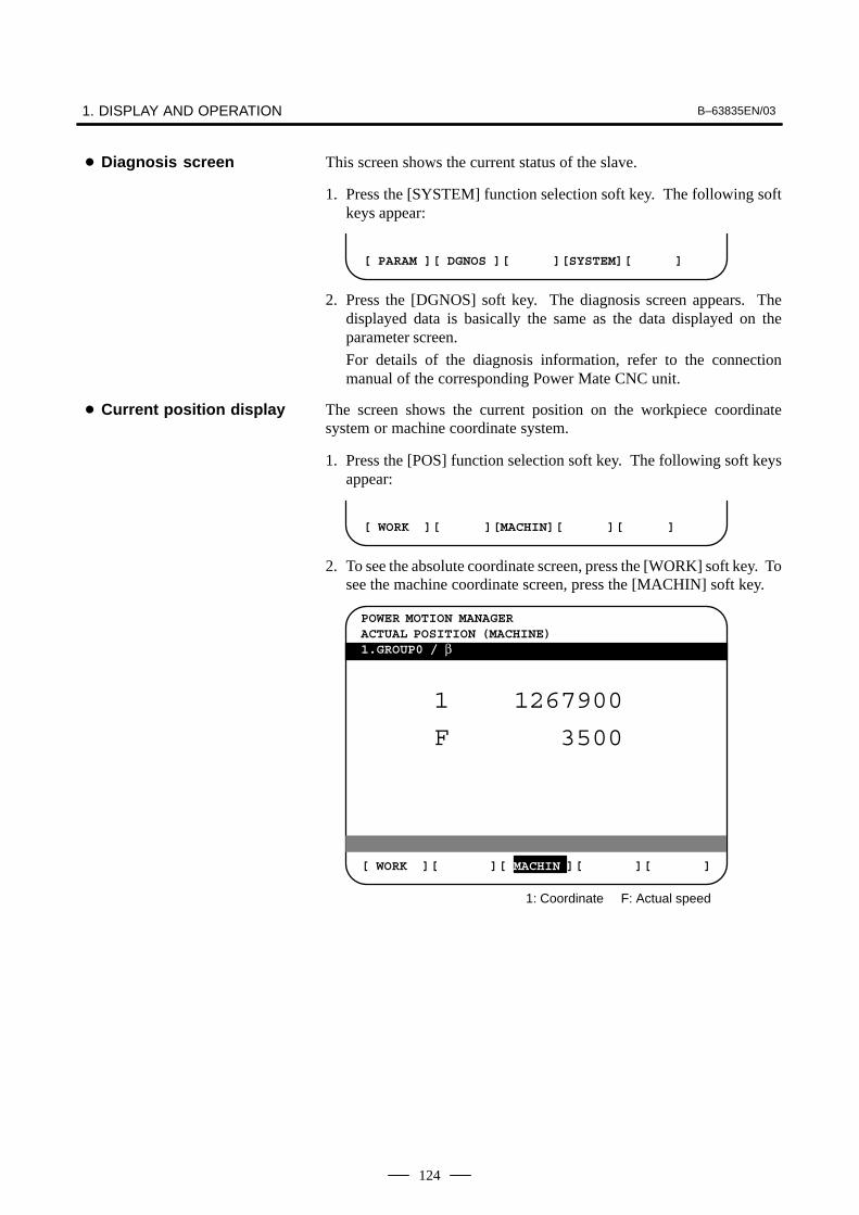
1. DISPLAY AND OPERATION B–63835EN/03
124
This screen shows the current status of the slave.
1. Press the [SYSTEM] function selection soft key. The following softkeys appear:
[ PARAM ][ DGNOS ][ ][SYSTEM][ ]
2. Press the [DGNOS] soft key. The diagnosis screen appears. Thedisplayed data is basically the same as the data displayed on theparameter screen.
For details of the diagnosis information, refer to the connectionmanual of the corresponding Power Mate CNC unit.
The screen shows the current position on the workpiece coordinatesystem or machine coordinate system.
1. Press the [POS] function selection soft key. The following soft keysappear:
[ WORK ][ ][MACHIN][ ][ ]
2. To see the absolute coordinate screen, press the [WORK] soft key. Tosee the machine coordinate screen, press the [MACHIN] soft key.
POWER MOTION MANAGERACTUAL POSITION (MACHINE)1.GROUP0 / β
[ WORK ][ ][ MACHIN ][ ][ ]
1 1267900
F 3500
1: Coordinate F: Actual speed
� Diagnosis screen
� Current position display

B–63835EN/03 1. DISPLAY AND OPERATION
125
If an alarm is issued during operation, the group number of the slavecausing the alarm is indicated at the right end of the message field on thescreen. Check the details on the alarm screen. For example, (13) meansthat the first and third Power Mate CNC units are in the alarm state.
1. Press the [MSG] function selection soft key. Just the error code isdisplayed on the screen.
POWER MOTION MANAGERALARM1.GROUP0 / β
442 210 232
[ POS ][ ][ ][SYSTEM ][ MSG ]
Up to forty codes can be displayed on the screen.
For details of the alarm, refer to the connection manual of thecorresponding Power Mate CNC unit.
The active slave is subjected to the ZOOM function, which will bedescribed later, and parameter overwrite. The title of the active slave isdisplayed in a color different from the display color of the other slavetitles.
The active slave can be selected by pressing the [�NEXT] or [�BACK]soft key, which is displayed after the continuous menu key ispressed several times.
[�NEXT]: Displays the screen of the Power Mate CNC unit connectedafter the currently active slave. The equipment other than thePower Mate CNC unit is ignored.
[�BACK]: Displays the screen of the Power Mate CNC unit connectedbefore the currently active slave.
Whether the screen displays the data of just a single unit or of four unitsin four segments is specified in the SLV bit (bit 0 of parameter 960).
To switch the four–slave display to the single–slave display, press the[ZOOM] soft key, which is displayed after the continuous menu key is pressed several times. The single–slave display shows the data of theactive slave. To switch the single–slave display to the four–slave displayshowing the data of four slaves including the active slave, press the[ZOOM] key.
� Alarm screen
� Operating the activeslave
� Single–slave display/Four–slave display

1. DISPLAY AND OPERATION B–63835EN/03
126
When five or more slaves are connected, the four–slave display has twoor more pages. To see the slave data that is not displayed on the currentpage, press soft key [�NEXT].
4.GROUP3 / β
SYSTEM ****##SERVO ****##
1.GROUP0 / β O12345678 N12345
SYSTEM ****##
2.GROUP1 / β
SYSTEM 88A101
POWER MOTION MANAGER/ SYSTEM CONFIGURATION O12345678 N12345
3.GROUP2 / β
SYSTEM 88A101
PARAM DGNOS SYSTEM (OPRT)
The figure above shows a sample four–slave display screen on a displayunit with twelve soft keys. A unit with seven soft keys can also displaythe four–slave display screen.
POWER MOTION MANAGER O12345678 N12345SYSTEM CONFIGURATION1.GROUP0 / β
SYSTEM <SERIES/VERSION> 88A101
[ POS ][ DGNOS ][ ][ SYSTEM ][ MSG ]
The figure above shows a sample single–slave display screen on a displayunit with seven soft keys. A unit with twelve soft keys can also displaythe single–slave display screen.

B–63835EN/03 1. DISPLAY AND OPERATION
127
While the following soft keys are being displayed, a guidance messageis displayed in the message field.
[ POS ][ ][ ][SYSTEM][ MSG ]
[ WORK ][ ][MACHIN ][ ][ ]
[ PARAM ][ DGNOS ][ ][SYSTEM][(OPRT) ]
When the soft keys are displayed as shown above, “SELECT ACTIVESLAVE [>]” is displayed.
[ �NEXT ][ �BACK ][ ZOOM ][ ][ ]
When the soft keys are displayed as shown above, “SELECT ACTIVESLAVE [↓] [↑]” is displayed.
When the [(OPRT)] soft key is pressed, the message line may turn into akey–in field as required. The numeric data input by using MDI keys isdisplayed after the prompt (>).
On the parameter and diagnosis screens, the key–in field appears whenjust a numeric value is input. The soft key [(OPRT)] need not be pressed.
Parameters can be saved in CNC memory or a memory card as a data fileof program format. Specify the first digit of the registration programnumber in parameter 8760. Programs with predetermined numbers arecreated for individual slaves. When the parameters are saved in CNCmemory, a program having the specified program number is created.When the parameters are saved in a memory card, a file is created, towhich the file name consists of the specified program number and anextension PMM.
Example: When parameter 8760 is set to 8000
The program number for group n is 8000 + n*10.
The group number n is indicated in the title area of each slave.
CAUTIONIn case that the parameters are saved in a memory card, Ifthe specified program number already exists on memorycard, the corresponding program is overwritten with newdata.
� Guidance message
� Key–in field
1.18.3Parameter Input/Output� Saving parameters

1. DISPLAY AND OPERATION B–63835EN/03
128
Specify a desired input device in the MD1 and MD2 bits (bits 1 and 2 ofparameter 960). Connect a memory card. Alternatively, check the freearea of CNC memory. Then, follow the steps given below:
1. Select the active slave.
2. Press the [(OPRT)] soft key. The following soft keys appear:
[ NO.SRC ][ ][ ][ ][ INPUT ]
3. Press the continuous menu key . The following soft keys appear:
[ ][ READ ][ PUNCH ][ ][ ]
4. Press the [READ] soft key. The following soft keys appear:
[ ][ ][ ][CANCEL ][ EXEC ]
5. Press the [EXEC] soft key.
During input, “INPUT” blinks in the message field.
The data file of parameters saved in CNC memory or a memory card asa program is written into the slave determined by the program number.The program number and memory device are determined as described in“Saving parameters.”
1. Select the active slave.
2. Press the [(OPRT)] soft key. The following soft keys appear:
[ NO.SRC ][ ][ ][ ][ INPUT ]
3. Press the next–menu key. The following soft keys appear:
[ ][ READ ][ PUNCH ][ ][ ]
4. Press the [PUNCH] soft key. The following soft keys appear:
[ ][ ][ ][CANCEL ][ EXEC ]
5. Press the [EXEC] soft key.
During output, “INPUT” blinks in the message field.
The screen cannot be changed to another screen during parameterinput/output.
When the RESET key is pressed, or when an alarm status is detected incommunication, the input/output stops.
� Writing parameters

B–63835EN/03 1. DISPLAY AND OPERATION
129
When the Power Mate CNC series is used as a slave of an I/O Link, theCNC assigns I/O addresses. The salve data is input and output in unitsof 16 bytes. Therefore, 128 input/output points are necessary. Up to eightslaves can be connected.
The module name is OC021 (16–byte input) or OC020 (16–byte output).BASE is always 0, and SLOT is always 1.
After the data necessary for each slave connected is set and checked, thecommunication of the Power Mate CNC manager (PMM) can be stoppedto send a command from the CNC ladder to the slave.
When the PMN bit (bit 3 of parameter 960) is set to 1, all communicationbetween CNC and the slave via the I/O Link is open to the ladder.
While the bit is held 1, the screen shows just the title, function name, andother items that are independent of the communication. The followingmessage appears to indicate that communication has stopped.
COMMUNICATION PROHIBITED BY P960#3
When the Power Mate CNC manager is used, the function for datainput/output by I/O Link cannot be used.
(1)CNC
When a CNC alarm status is detected, the screen is automaticallyswitched to the CNC alarm screen. Check the details of the alarm. Ifnecessary, display and select the Power Mate CNC manager screen
again by pressing function key SYSTEM .
(2)Slave
A guidance message is usually displayed in the message field. If aslave alarm is detected, the corresponding slave group number isdisplayed at the right end.
Display the alarm screen to check the details.
When the data protection key of the CNC is turned on, parameters cannotbe input to CNC memory.
1.18.4Notes� Connecting an I/O Link
� Ignoring the Power MateCNC manager function
� Data input/output by I/OLink
� Alarm
� Data protection key

1. DISPLAY AND OPERATION B–63835EN/03
130
Using the periodic maintenance screens makes it easy to manageconsumables (such as LCD unit backlight and backup battery) that are tobe replaced periodically.
Setting the name and service life of consumables, and the countdownmethod to be used for them enables counting of the remaining service timeaccording to the specified countdown method and displaying of the result.
The following periodic maintenance screens are available:
(1) Status screen: Displays item names, remaining service time,countdown status, and lets you specify item names.
(2) Setting screen: Lets you specify service life, remaining service time,and count type (countdown method).
(3) Machine system menu screen: Enables registering the names ofconsumables used in the machine.
(4) NC system menu screen: Displays the names of registeredconsumables used in the NC.
To use this function, follow the steps below:
(1) Select a number for registration (using the cursor key on the statusscreen).
(2) Specify an item name.The following two methods are available.
– Selecting a name from a menu screen (machine or NC system menuscreen).
– Entering a name to the status screen directly from the MDI.
Using the machine system menu screen requires that item names beregistered previously.
(3) Specify the service life, remaining service time, and count type for atarget item.Once they are specified, the remaining service time can be checkedon the status screen.
1 Press the SYSTEM function key.
2 Press the continuous menu key several times. Soft key[MAINTE] appears.
3 Press soft key [MAINTE]. A periodic maintenance screen appears.
There are two periodic maintenance screens, status and setting screens.Either screen can be selected using soft key [CHANGE].
1.19PERIODICMAINTENANCESCREENS
1.19.1Overview
� Screen configuration
� Procedure
1.19.2Screen Display andSetting

B–63835EN/03 1. DISPLAY AND OPERATION
131
Up to 10 consumable items can be registered for management. Theirremaining service time and count status are displayed on the status screen.
PERIODICAL MAINTENANCE O0001 N12345(STATUS)
ITEM NAME REMAIN*01 BATTERY FOR CONTROLLER 0H@02 BATTERY FOR PULSECODER 5000H 03 FAN MOTOR 10000H@04 LCD BACK LIGHT 720H 05 06 07 08 09 10
>_EDIT *** ***** *** **** 19:27:05[ ][ MAINTE ][ ][ ][ (OPRT) ]
[ CHANGE ][ ENTRY ][ CLEAR ][ +INPUT ][ INPUT ]
[ ][ ][ ][ CAN ][ EXEC ]
(1) Item nameThe name of an item to be subjected to periodic maintenance isspecified under “Item name.”Two methods can be used to specify item names. The first method usesthe menu screen, and the second, the MDI keypad.
(1)Method of using the menu screen
1 Place the cursor on the target item name, and press soft key[ENTRY]. A menu screen appears. The menu screen is eitherthe machine or NC system menu screen.
2 Press soft key [MACHIN] or [NC]. A machine system menuappears. It holds the names of consumables typical to themachine system or NC system.
3 Place the cursor on a registered item name, and press soft key[SELECT], then soft key [EXEC]. The status screen appearsagain, enabling the selected item to be set up.
4 Press soft key [CAN]. The previous soft key displays appearagain.
5 Press soft key [MAINTE]. The status screen appears again.
Using the machine system menu screen requires that item namesbe registered on the screen previously.This can be done using two methods, (a) and (b).
(a) Program–based registrationExecuting a program in the following format enables itemnames to be registered on the machine system menu screen.
1.19.3Status Screen Displayand Setting

1. DISPLAY AND OPERATION B–63835EN/03
132
G10 L61 Px [n]
x… Registration number
n… Item name[Alphanumeric characters*two–byte characters*alphanumeric characters]
(b)MDI keypad–based registrationAn item name can be registered on the machine system menuscreen by first entering it in the following format, then pressing
soft key [INPUT] (or INPUT function key).
Pressing soft key [+INPUT] adds the item name to the list ofpreviously registered item names.
Alphanumeric characters*two–byte characters*alphanumeric characters
The two–byte characters shall comply with the FANUC code.(See Section 1.19.6.)When entering a two–byte character, sandwich it with an “*”pair.
The item name can consist of up to 24 alphanumeric characters(if no two–byte character is included) or 12 two–byte characters(if no alphanumeric character is included).
Example) To register “LCD backlight,” enter:>LCD*110E10F410CC114010B610FE_
NOTE1 “*” cannot be used in item names, because it is used as
control code. “[”, “]”, “(“, or “)” also cannot be used in itemnames.
2 When both alphanumeric and two–byte characters areused in an item name to be registered, the warningmessage “DATA IS OUT OF RANGE” may appear even ifthe maximum allowable number of characters has not beenexceeded.
3 If a blank item name is selected from the machine systemscreen, the warning message “EDIT REJECTED” appears.If a blank item name is selected from the NC system screen,a blank is set up.
Format
Format

B–63835EN/03 1. DISPLAY AND OPERATION
133
To erase the registered data for an item, place the cursor on thetarget item name, and press soft key [CLEAR], then soft key[EXEC].
[Machine system] menu screen
PERIODICAL MAINTENANCE O0001 N12345(MACHINE)
ITEM NAME 01 02 03 04 05 06 07 08 09 10
>_EDIT *** ***** *** **** 19:27:05[ ][ STATUS ][ MACHIN ][ NC ][ (OPRT) ]
[ SELECT ][ ][ CLEAR ][ +INPUT ][ INPUT ]
[ ][ ][ ][ CAN ][ EXEC ]
[ ][ READ ][ PUNCH ][ ][ ]
[ ][ ][ ][ CAN ][ EXEC ]

1. DISPLAY AND OPERATION B–63835EN/03
134
[NC system] menu screen
PERIODICAL MAINTENANCE O0001 N12345(NC)
ITEM NAME 01 BATTERY FOR CONTROLLER 02 BATTERY FOR PULSECODER 03 FAN MOTOR 04 LCD BACK LIGHT 05 06 07 08 09 10
>_EDIT *** ***** *** **** 19:27:05[ ][ STATUS ][ MACHIN ][ NC ][ (OPRT) ]
[ SELECT ][ ][ ][ ][ ]
[ ][ ][ ][ CAN ][ EXEC ]
NOTEOn the NC system screen, no item name can be registered,erased, input, or output.
(2)MDI keypad–based settingAn item name can be registered on the status screen by first enteringit in the following format using keys, then pressing soft key
[INPUT] (or the INPUT key).
Pressing soft key [+INPUT] adds the item name to the list ofpreviously registered item names.
Alphanumeric characters*two–byte characters*alphanumeric characters
The two–byte characters shall comply with the FANUC code. (SeeSection 1.19.6.)When entering a two–byte character using keys, sandwich it withan “*” pair.
The item name can consist of up to 24 alphanumeric characters (ifno two–byte character is included) or 12 two–byte characters (if noalphanumeric character is included).
Example) To register “LCD backlight,” enter:>LCD*110E10F410CC114010B610FE_
Format

B–63835EN/03 1. DISPLAY AND OPERATION
135
NOTE1 “*” cannot be used in item names, because it is used as
control code. “[”, “]”, “(“, or “)” also cannot be used in itemnames.
2 When both alphanumeric and two–byte characters areused in an item name to be registered, the warningmessage “DATA IS OUT OF RANGE” may appear even ifthe maximum allowable number of characters has not beenexceeded.
To erase the registered data for an item, place the cursor on thetarget item name, press soft key [CLEAR], then [EXEC].
When an item name is deleted, the related service life, remainingservice time, and count type are also deleted.
(2)Remaining service timeThe remaining service time of an item (the time allowed before theitem is replaced) is obtained by count–down and displayed under“Remaining service time.” When the remaining service timedecreases to a specified percentage (specified in parameter No. 8911)of the service life or lower, it is displayed in red.
Count–down continues even after the service life has expired.
NOTESetting is impossible on the status screen.It should be done on the setting screen.
(3)Count statusThe count status is displayed at the left of the corresponding itemnumber, as listed below:
Display Count status
Blank Count suspended
@ Count under way
* The service life has expired.

1. DISPLAY AND OPERATION B–63835EN/03
136
The setting screen lets you specify the service life, the remaining servicetime, and count type for a registered item name.It also displays the same count status information as displayed on thestatus screen.
PERIODICAL MAINTENANCE O0001 N12345(SETTING)
LIFE REMAIN COUNT TYPE*01 10000H 0H ALL TIME@02 20000H 5000H LIV TIME 03 32767H 10000H ––––––––@04 1500H 720H RUN TIME 05 06 07 08 09 10
>_EDIT *** ***** *** **** 19:27:05[ CHANGE ][ TYPE ][ CLEAR ][ +INPUT ][ INPUT ]
[ EFFECT ][ ALL ][ LIV ][ RUN ][ CUT ]
[ ][ READ ][ PUNCH ][ ][ ]
(1)Service lifeThe service life of a consumable item is to be specified under “Servicelife.”First place the cursor on the service life of a target registration number,enter a desired service life value using numeric keys, then press soft
key [INPUT] (or the INPUT key). The specified service life is set up,
and the same value is set up also under “Remaining service time.”In addition, the count type for the item changes to: “––––––”Pressing soft key [+INPUT] adds the newly specified service life valueto the previously specified life value. The added service life value isreflected to the remaining service time.
The valid data range for the service life is: 0 to 65535 (hours)
NOTE1 An attempt to set up the service life for a non–registered
item results in the warning message “EDIT REJECTED”.2 An attempt to enter a value that is out of the valid data range
results in the warning message “DATA IS OUT OF RANGE”.3 An attempt to enter a value that would make the service life
or remaining service time 0 or lower, it is clamped at 0.4 Pressing soft keys [CLEAR] and [TYPE] results in the
warning message “EDIT REJECTED”.
1.19.4Setting Screen Displayand Setting

B–63835EN/03 1. DISPLAY AND OPERATION
137
(2)Remaining service timeThe remaining service time of an item (the time allowed before theitem is replaced) is determined by count–down and displayed under“Remaining service time.” When the remaining service timedecreases to a specified percentage (specified in parameter No. 8911)of the service life or lower, it is displayed in red.Count–down continues even after the service life has expired.First place the cursor on the remaining service time of a targetregistration number, enter a desired remaining service time value
using numeric keys, then press soft key [INPUT] (or the INPUT key).
Pressing soft key [+INPUT] adds the newly specified remainingservice time to the previously specified remaining service time.The valid data range for the remaining service time is: 0 to (servicelife)After soft key [CLEAR] is pressed, pressing soft key [EXEC] sets theremaining service time with the same value as for the service life.
NOTE1 An attempt to set up the remaining service time for a non–
registered item or an item for which the service life has notbeen set up results in the warning message “EDITREJECTED”.
2 An attempt to enter a value that is out of the valid data rangeresults in the warning message “DATA IS OUT OF RANGE”.
3 An attempt to enter a value that would make the remainingservice time 0 or lower, it is clamped at 0.
4. Pressing soft key [TYPE] results in the warning message“EDIT REJECTED”.
(3)Count typeThe type of a selected count method is specified under “Count type.”After the cursor is placed on the count type of a target registrationnumber, pressing soft key [TYPE] displays the next count type as asoft key. Select it and press soft key [EXEC].
Soft key Meaning Display
[NO CNT] Not counting (suspended). —
[ ALL ] Always count. All times
[PWR ON] Count while the power is supplied. Power–on time
[ RUN ] Count while operation is under way. Operating
[ CUT ] Count while cutting is under way. Cutting
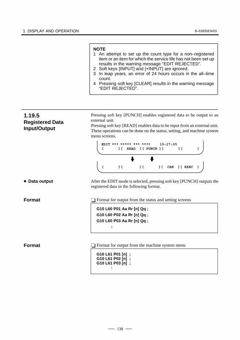
1. DISPLAY AND OPERATION B–63835EN/03
138
NOTE1 An attempt to set up the count type for a non–registered
item or an item for which the service life has not been set upresults in the warning message “EDIT REJECTED”.
2 Soft keys [INPUT] and [+INPUT] are ignored.3 In leap years, an error of 24 hours occurs in the all–time
count.4 Pressing soft key [CLEAR] results in the warning message
“EDIT REJECTED”.
Pressing soft key [PUNCH] enables registered data to be output to anexternal unit.Pressing soft key [READ] enables data to be input from an external unit.These operations can be done on the status, setting, and machine systemmenu screens.
EDIT *** ***** *** **** 19:27:05[ ][ READ ][ PUNCH ][ ][ ]
[ ][ ][ ][ CAN ][ EXEC ]
After the EDIT mode is selected, pressing soft key [PUNCH] outputs theregistered data in the following format.
� Format for output from the status and setting screens
G10 L60 P01 Aa Rr [n] Qq ;
G10 L60 P02 Aa Rr [n] Qq ;
G10 L60 P03 Aa Rr [n] Qq ;
:
� Format for output from the machine system menu
G10 L61 P01 [n] ; G10 L61 P02 [n] ; G10 L61 P03 [n] ;
:
1.19.5Registered DataInput/Output
� Data output
Format
Format
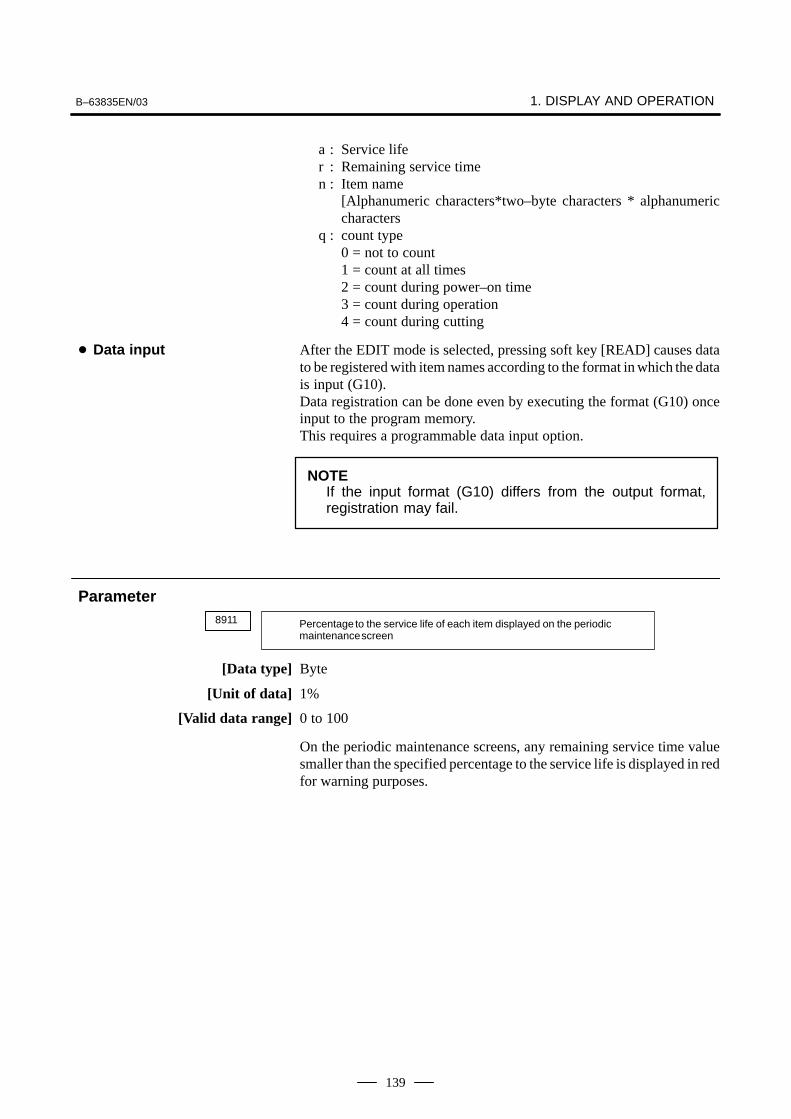
B–63835EN/03 1. DISPLAY AND OPERATION
139
a : Service lifer : Remaining service timen : Item name
[Alphanumeric characters*two–byte characters * alphanumericcharacters
q : count type0 = not to count1 = count at all times2 = count during power–on time3 = count during operation4 = count during cutting
After the EDIT mode is selected, pressing soft key [READ] causes datato be registered with item names according to the format in which the datais input (G10).Data registration can be done even by executing the format (G10) onceinput to the program memory.This requires a programmable data input option.
NOTEIf the input format (G10) differs from the output format,registration may fail.
8911 Percentage to the service life of each item displayed on the periodic maintenance screen
[Data type] Byte
[Unit of data] 1%
[Valid data range] 0 to 100
On the periodic maintenance screens, any remaining service time valuesmaller than the specified percentage to the service life is displayed in redfor warning purposes.
� Data input
Parameter

1. DISPLAY AND OPERATION B–63835EN/03
140
1.19.6FANUC Two–ByteCharacter Code Table

B–63835EN/03 1. DISPLAY AND OPERATION
141
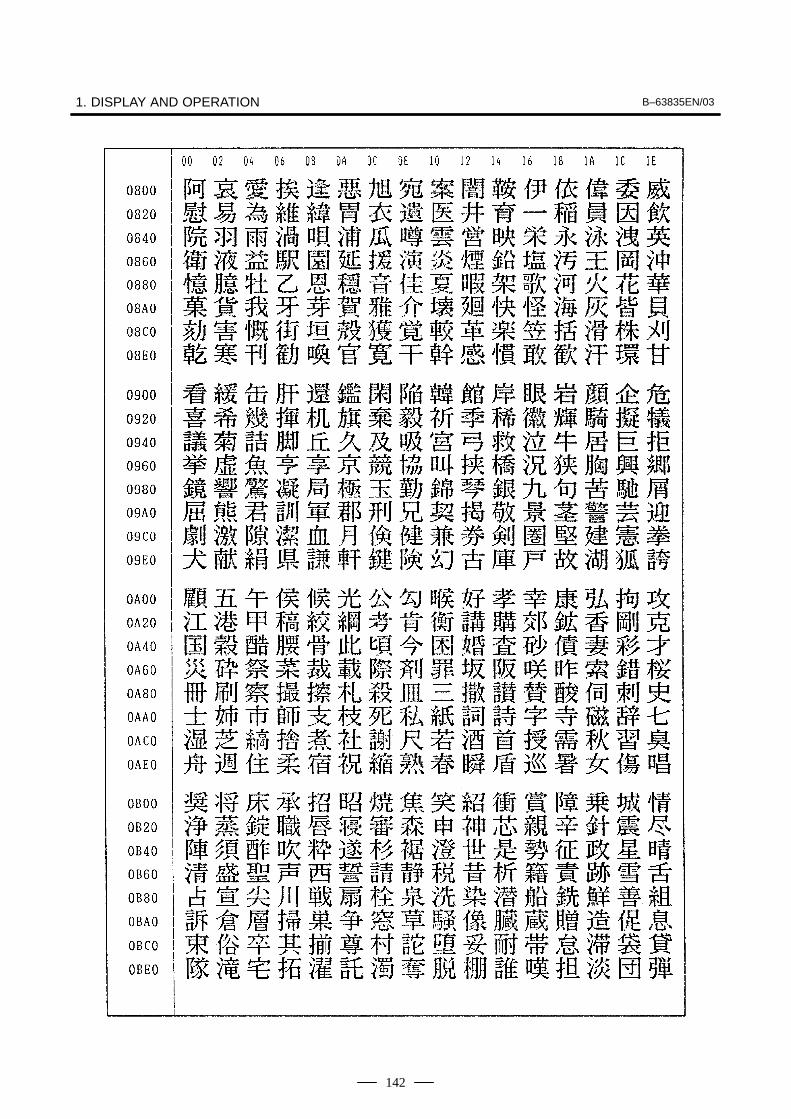
1. DISPLAY AND OPERATION B–63835EN/03
142
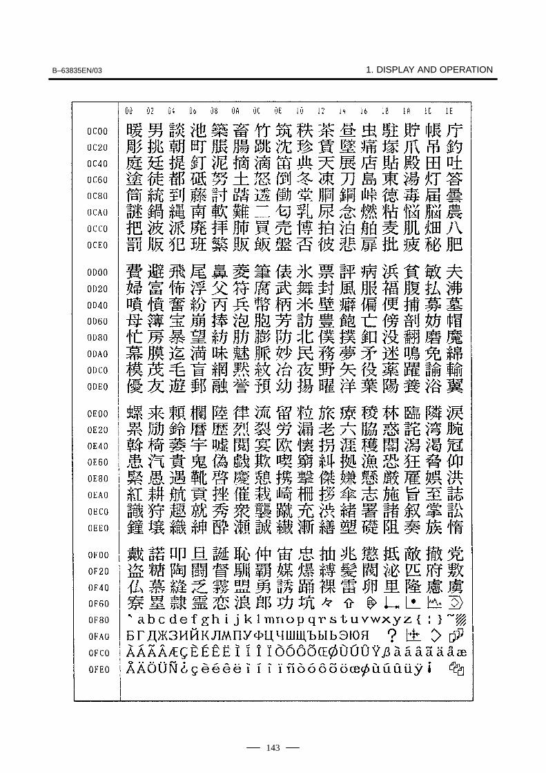
B–63835EN/03 1. DISPLAY AND OPERATION
143
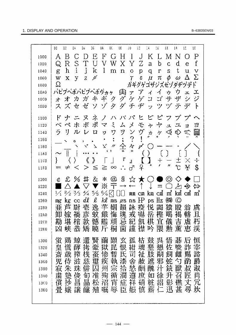
1. DISPLAY AND OPERATION B–63835EN/03
144

B–63835EN/03 1. DISPLAY AND OPERATION
145
2. HARDWARE B–63835EN/03
146
2 HARDWARE
This chapter describes the printed circuit boards of the CNC control unitand card PCB functions on the printed circuit boards. The chapter alsodescribes procedures for replacing consumable items.
2.1 HARDWARE CONFIGURATION 147. . . . . . . . . . . . . . 2.2 HARDWARE OVERVIEW 148. . . . . . . . . . . . . . . . . . . . 2.3 TOTAL CONNECTION DIAGRAMS 149. . . . . . . . . . . 2.4 CONNECTOR AND CARD
CONFIGURATIONS OF PRINTED CIRCUIT BOARDS 152. . . . . . . . . . . . . . . . . . . . . . . . . .
2.5 UNITS AND PRINTED CIRCUIT BOARDS 175. . . . . 2.6 MOUNTING AND REMOVING
AN OPTION BOARD 184. . . . . . . . . . . . . . . . . . . . . . . . 2.7 MOUNTING AND DEMOUNTING CARD PCBS 189. 2.8 MOUNTING AND DEMOUNTING DIMM
MODULES 192. . . . . . . . . . . . . . . . . . . . . . . . . . . . . . . . . 2.9 MOUNTING AND REMOVING
THE BACK PANEL 194. . . . . . . . . . . . . . . . . . . . . . . . . . 2.10 REPLACING THE FUSE OF THE
CONTROL UNIT 196. . . . . . . . . . . . . . . . . . . . . . . . . . . . 2.11 REPLACING THE BATTERY 197. . . . . . . . . . . . . . . . . 2.12 REPLACING A FAN UNIT 204. . . . . . . . . . . . . . . . . . . 2.13 REPLACING THE FUSE OF THE LCD UNIT 205. . . . 2.14 REPLACING THE LCD BACKLIGHT 206. . . . . . . . . . 2.15 HEAT LOSS OF EACH UNIT 211. . . . . . . . . . . . . . . . . . 2.16 DISTRIBUTED I/O SETTING
(Series 0i–B ONLY) 212. . . . . . . . . . . . . . . . . . . . . . . . . . 2.17 REPLACING FUSES ON VARIOUS UNITS 215. . . . . . 2.18 ENVIRONMENTAL REQUIREMENTS
OUTSIDE THE CONTROL UNIT 218. . . . . . . . . . . . . . 2.19 ACTION AGAINST NOISE 219. . . . . . . . . . . . . . . . . . . 2.20 REPLACING THE MAINTENANCE PARTS OF
CNC DISPLAY UNIT FOR PC FUNCTIONS AND PANEL i 230. . . . . . . . . . . . . . . . . . . . . . . . . . . . . .
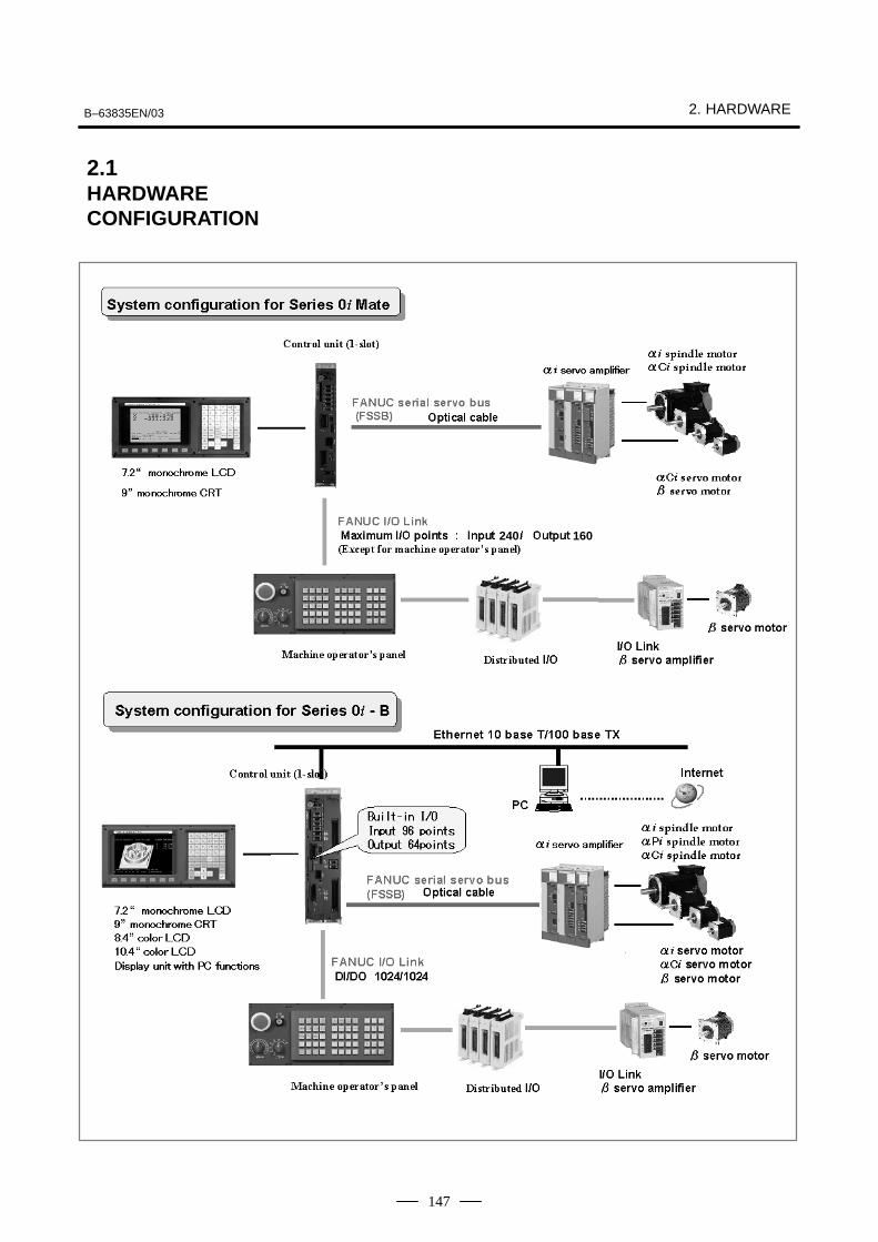
B–63835EN/03 2. HARDWARE
147
240 160
2.1HARDWARECONFIGURATION
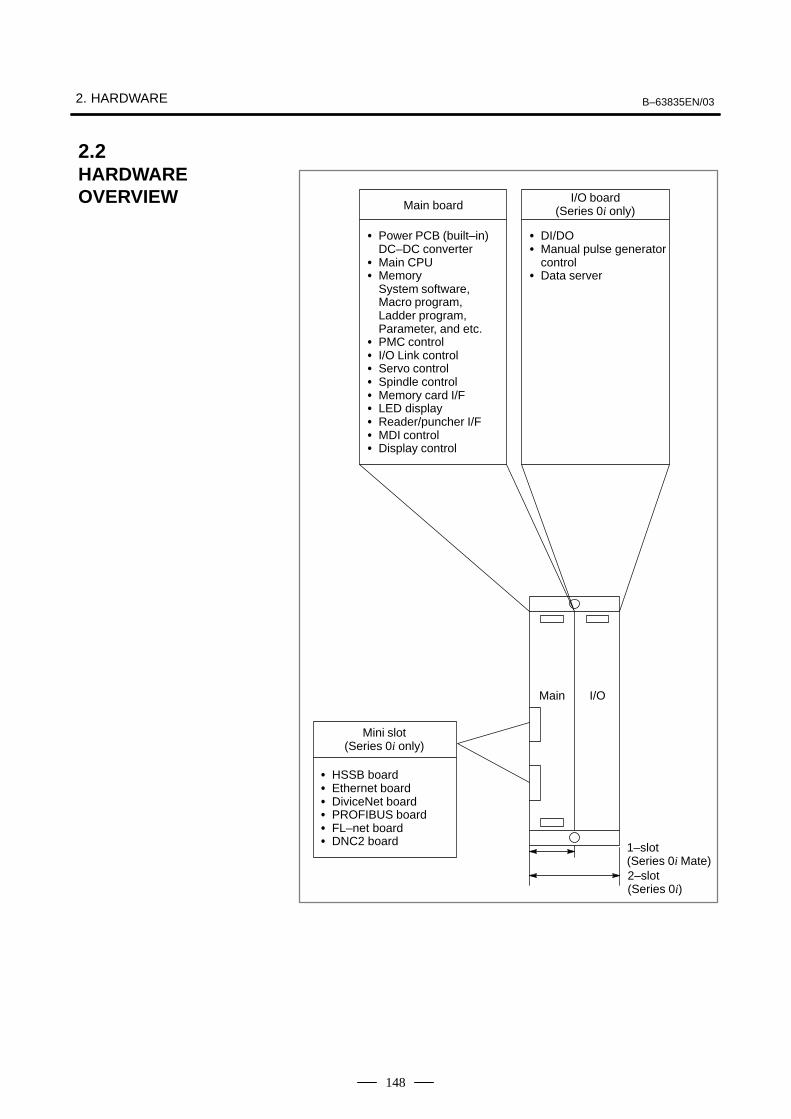
2. HARDWARE B–63835EN/03
148
� Power PCB (built–in)DC–DC converter
� Main CPU� Memory
System software,Macro program,Ladder program,Parameter, and etc.
� PMC control� I/O Link control� Servo control� Spindle control� Memory card I/F� LED display� Reader/puncher I/F� MDI control� Display control
Main board
� DI/DO� Manual pulse generator
control� Data server
I/O board(Series 0i only)
2–slot(Series 0i)
Main I/O
Mini slot(Series 0i only)
� HSSB board� Ethernet board� DiviceNet board� PROFIBUS board� FL–net board� DNC2 board 1–slot
(Series 0i Mate)
2.2HARDWAREOVERVIEW
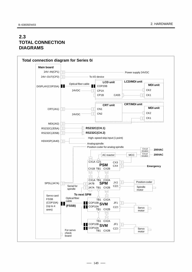
B–63835EN/03 2. HARDWARE
149
Main board
24V–IN(CP1)
24V–OUT(CP2)
DISPLAY(COP20A)
CRT(JA1)
MDI(JA2)
RS232C(JD5A)
RS232C(JD5B)
HDI/ASP(JA40)
SPDL(JA7A)
Servo cardFSSB(COP10A)(Up to 4axes)
Power supply 24VDC
To I/O device
Optical fiber cable
24VDC
24VDC
LCD unitCOP20B
CP1A
CP1B CA55
MDI unit
CK2
CK1
LCD/MDI unit
CRT unitCN1
CN2
MDI unit
CK2
CK1
CRT/MDI unit
RS232C(CH.1)
RS232C(CH.2)
High–speed skip input (1 point)
Analog spindlePosition coder for analog spindle
Circuitbreaker
Circuitbreaker
200VAC
200VACMCCAC reactor
Emergency
CX1A CZ1 CX3PSM CX4
CX1B TB1 CX2B
CX1A TB1SPM
CZ2JA7A TB1 CX2B
CX2AJY2 Position coder
Spindlemotor
Serial for spindle
To next SPM
COP10BTB1
SVMCZ2
TB1 CX2B
CX2AJF1
COP10A Servomotor
Servomotor
COP10BTB1
SVMCZ2
TB1 CX2B
CX2AJF1
COP10A
Optical fibercable
(FSSB)
For servocheckboard
Total connection diagram for Series 0i
JA7B
2.3TOTAL CONNECTIONDIAGRAMS

2. HARDWARE B–63835EN/03
150
Main board
HSSB boardETHERNET boardPROFIBUS boardDeviceNet boardFL–net boardDNC2 board
To other device
To other device
Built–in I/OI/O Link
I/O for operator’s panelJD1B
JD1A
I/O Link β
JD1B
JD1A
IOLINK(JD1A)
DI/DO–1
(CB104)
DI/DO–2
(CB105)
DI/DO–3
(CB106)
DI/DO–4
(CB107)
MPG(JA3) Manual pulse generator (up to 3 units)
ETHERNET
Dataserver
ETHERNET
(CD38T)
DI:96 pointsDO:64 points
Min
i slo
tM
ini s
lot

B–63835EN/03 2. HARDWARE
151
Main board
24V–IN(CP1)
24V–OUT(CP2)
DISPLAY(COP20A)
CRT(JA1)
MDI(JA2)
RS232C(JD5A)
RS232C(JD5B)
HDI/ASP(JA40)
SPDL(JA7A)
Servo cardFSSB(COP10A)(Up to 3axes)
Power supply 24VDC
To I/O device
Optical fiber cable
24VDC
24VDC
LCD unitCOP20B
CP1A
CP1B CA55
MDI unit
CK2
CK1
LCD/MDI unit
CRT unitCN1
CN2
MDI unit
CK2
CK1
CRT/MDI unit
RS232C(CH.1)
RS232C(CH.2)
High–speed skip input (1 point)
Analog spindlePosition coder for analog spindle
Circuitbreaker 200VAC
200VACMCCAC reactor
Emergency stop
CX1A CZ1 CX3PSM CX4
CX1B TB1 CX2B
CX1A TB1SPM
CZ2JA7A TB1 CX2B
CX2AJY2 Position coder
Spindlemotor
Serial for spindle
COP10BTB1
SVMCZ2
TB1 CX2B
CX2AJF1
COP10A Servomotor
Servomotor
COP10BTB1
SVMCZ2
TB1 CX2B
CX2AJF1
COP10A
Optical fibercable
(FSSB)
For servocheckboard
Total connection diagram for Series 0i Mate
JA7B
Manual pulse generator(up to 3 units)
IOLINK(JD1A)
I/O for operator’s panel(with MPG)I/O Link
JD1B
JD1A
I/O for operator’s panel(without MPG)
JD1B
JD1A
JA3
Circuitbreaker

2. HARDWARE B–63835EN/03
152
Item Code
Main CPU board of Series 0i–B (for PMC–SA1) A16B–3200–0490
Main CPU board of Series 0i–B (for PMC–SB7) A16B–3200–0491
Main CPU board of Series 0i–Mate B A16B–3200–0495
JD5A: RS232C serial port
JD5B: RS232C serial port
JA1: CRT video output
JA40: Analog output/high–speed DI
JA41: Serial spindle/position coder
JA2: MDI
LEDs
CP1(right): 24VDC INCP2(left): 24VDC OUT
STATUS: 7–Segment LED
MTSW: Rotary switch
COP20A : Connection to LCD unit
COP10A–1:FSSB
CA69A: Servo check
Battery case
CNM1B: Memory card
PSW: Push switch
FUSE: Fuse burn–out detection LED
BAT1: Battery
MAIN
JD1A: I/O Link (for Series 0i Mate–B only)
2.4CONNECTOR ANDCARDCONFIGURATIONSOF PRINTED CIRCUITBOARDS
2.4.1Main CPU Board� Specifications
� Mounting positions ofconnectors, LEDs, etc.

B–63835EN/03 2. HARDWARE
153
STATUS 7–segment LED: Used for setting and maintenance operations, in combination with theMTSW rotary switch and PSW push switch described below.
MTSW rotary switch: This rotary switch is used for setting and maintenance operations, incombination with the STATUS 7–segment LED and the PSW pushswitch.
PSW push switch: This push switch is used for setting and maintenance operations, incombination with the STATUS 7–segment LED and the MTSW rotaryswitch.
(3) Axis control card
(6) FROM/SRAM module
(5) Analog spindle module
(4) Power supply unit
(1) CPU card
(2) Display control card
� Mounting positions ofcards and DIMM modules
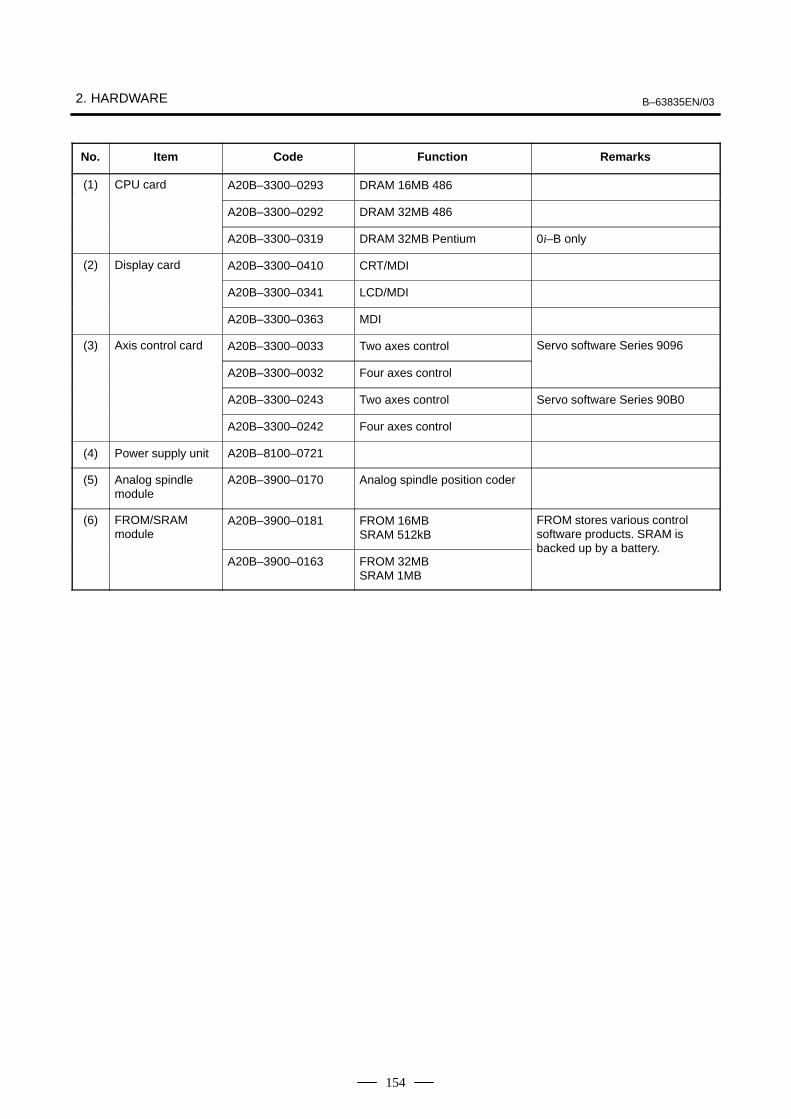
2. HARDWARE B–63835EN/03
154
No. Item Code Function Remarks
(1) CPU card A20B–3300–0293 DRAM 16MB 486
A20B–3300–0292 DRAM 32MB 486
A20B–3300–0319 DRAM 32MB Pentium 0i–B only
(2) Display card A20B–3300–0410 CRT/MDI
A20B–3300–0341 LCD/MDI
A20B–3300–0363 MDI
(3) Axis control card A20B–3300–0033 Two axes control Servo software Series 9096
A20B–3300–0032 Four axes control
A20B–3300–0243 Two axes control Servo software Series 90B0
A20B–3300–0242 Four axes control
(4) Power supply unit A20B–8100–0721
(5) Analog spindlemodule
A20B–3900–0170 Analog spindle position coder
(6) FROM/SRAMmodule
A20B–3900–0181 FROM 16MBSRAM 512kB
FROM stores various controlsoftware products. SRAM is
A20B–3900–0163 FROM 32MBSRAM 1MB
backed up by a battery.

B–63835EN/03 2. HARDWARE
155
� Fuse burn–out detection LED
FUSE (Red) Lit if the fuse is blown.
� LED status transition at power–up �: Off �: On
7–segmentLED STATUS Status
Not lit ���� Power off
8 ���� CPU not activated after power–up
F NC system loading started by boot system
9 ���� NC system started–up and RAM initialization completed
8 ���� Waiting for system processor ID setting
7 ���� System processor ID setting completedDisplay circuit initialization completed
6 ���� FANUC bus initialization completed
5 ���� Loading from flash memory completedPMC initialization completedSeries and edition screen displayed
4 ���� Hardware configuration information setting completedfor each printed circuit board of the system
3 ���� PMC ladder initialization completed
2 ���� Waiting for digital servo and spindle initialization
1 ���� Digital servo and spindle initialization completed
0 ���� Initialization completed, normal operation state
� LED display during automatic operation start–upWhile automatic operation start–up in progress signal STL (F0.5) isheld to 1, the 7–segment LED cyclically displays the followingpatterns:
� LED display when a battery alarm occurs
ALARM ��� SRAM backup battery is weak.
� LED display
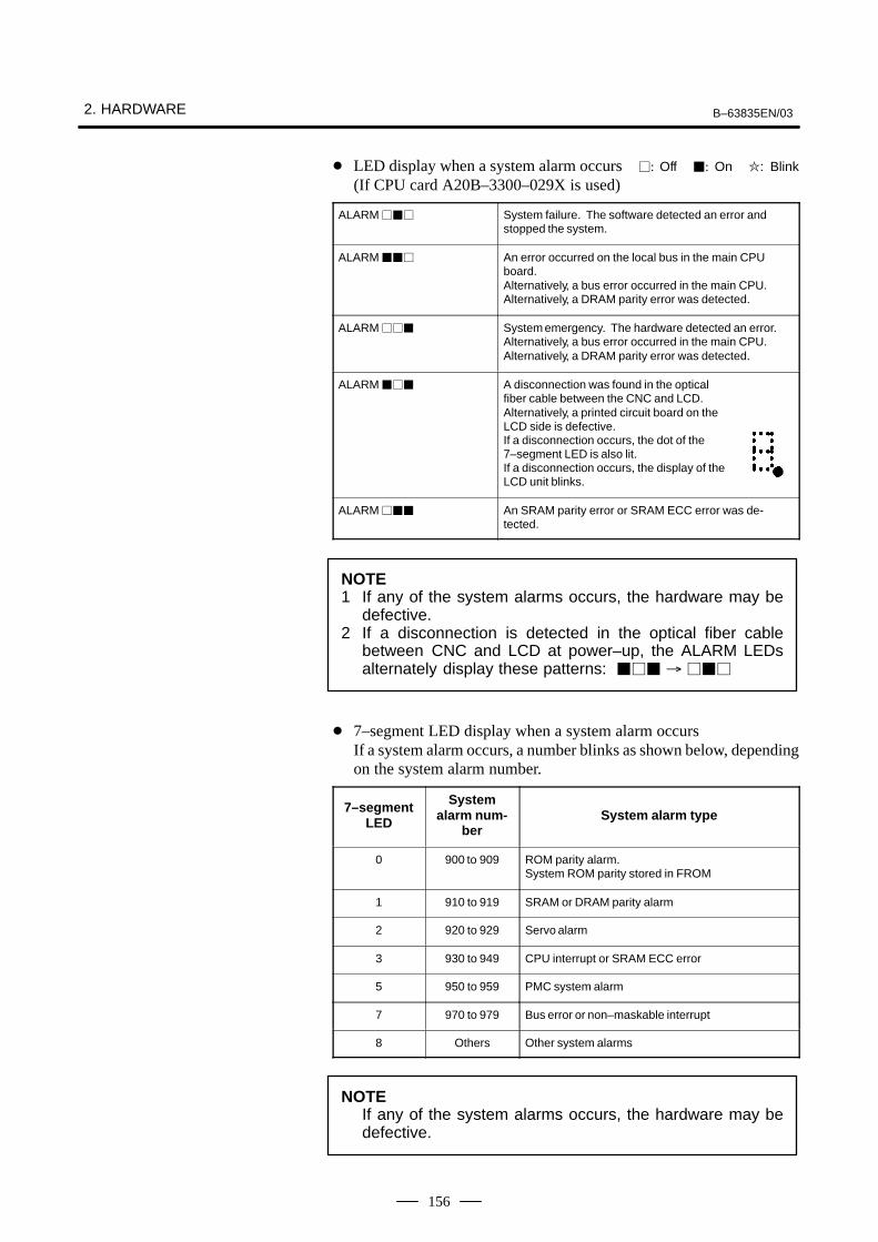
2. HARDWARE B–63835EN/03
156
� LED display when a system alarm occurs �: Off �: On �: Blink(If CPU card A20B–3300–029X is used)
ALARM ��� System failure. The software detected an error andstopped the system.
ALARM ��� An error occurred on the local bus in the main CPUboard.Alternatively, a bus error occurred in the main CPU.Alternatively, a DRAM parity error was detected.
ALARM ��� System emergency. The hardware detected an error.Alternatively, a bus error occurred in the main CPU.Alternatively, a DRAM parity error was detected.
ALARM ��� A disconnection was found in the opticalfiber cable between the CNC and LCD.Alternatively, a printed circuit board on theLCD side is defective.If a disconnection occurs, the dot of the7–segment LED is also lit.If a disconnection occurs, the display of theLCD unit blinks.
ALARM ��� An SRAM parity error or SRAM ECC error was de-tected.
NOTE1 If any of the system alarms occurs, the hardware may be
defective.2 If a disconnection is detected in the optical fiber cable
between CNC and LCD at power–up, the ALARM LEDsalternately display these patterns: ��� � ���
� 7–segment LED display when a system alarm occursIf a system alarm occurs, a number blinks as shown below, dependingon the system alarm number.
7–segmentLED
Systemalarm num-
berSystem alarm type
0 900 to 909 ROM parity alarm. System ROM parity stored in FROM
1 910 to 919 SRAM or DRAM parity alarm
2 920 to 929 Servo alarm
3 930 to 949 CPU interrupt or SRAM ECC error
5 950 to 959 PMC system alarm
7 970 to 979 Bus error or non–maskable interrupt
8 Others Other system alarms
NOTEIf any of the system alarms occurs, the hardware may bedefective.

B–63835EN/03 2. HARDWARE
157
DR
AM
FR
OM
SR
AM
Ana
log
outp
utP
ositi
onco
der
I/O L
INK
(0 M
ate–
B o
nly)
Vid
eo o
utpu
tM
DI i
nput
I/O L
ink
(To
I/O b
oaud
)(0
–B
onl
y)i
i
G/A
grap
hic
cont
rol
G/A
Dis
play
link
cont
rol
� Block diagram

2. HARDWARE B–63835EN/03
158
The built–in I/O function and data server function are implemented on aprinted circuit board. When only the built–in I/O function is required, usethe printed circuit board on which only the built–in I/O function isimplemented. When the built–in I/O function and data server function arerequired, use the printed circuit board on which both functions areimplemented. There is no printed circuit board on which only the dataserver function is implemented.
To use the data server function, install the ATA card adapter on a printedcircuit board. Connect the card adapter to the printed circuit board witha flat cable.
Name Code
Built–in I/O board A16B–3200–0500
Built–in I/O board with data server A16B–3200–0501
ATA card adapter A20B–2002–0960
STATUSALARM
LED display(For the data server function. There are no LEDs for the built–in I/O function.)
CD38T : Ethernet (100BASE–TX)(For data server functions.)
Right CB104 : DI/DO–1
Left CB105 : DI/DO–2
JA3 : Manual pulse generator
JD1A : I/O Link
Right CB106 : DI/DO–3
Left CB107 : DI/DO–4
2.4.2Built–in I/O Board
Built–in I/O Board withData Server
� Specifications
� Mounting positions ofconnectors, LEDs, etc.

B–63835EN/03 2. HARDWARE
159
Setting pin TM1Setting pin TM2
(1) ATA card adapter
No. Item Code Function
(1) ATA card adapter A20B–2002–0960 ATA card interface
The setting pins (TM1 and TM2) are provided on the printed circuit board.Insert a short plug into the A position (factory default). If the short plugis removed or the setting is changed, the board does not function properly.
� Components layout
� Setting pin

2. HARDWARE B–63835EN/03
160
There are no LEDs on a printed circuit board on which only the built–inI/O function is implemented.The LEDs on this printed circuit board indicate the state and error relatedto the data server function.
� LED lighting sequence at power on �: Off �: On �: Blink
NO. STATUS 1234 Status
1 STATUS ���� Power off
2 STATUS ���� Initial state after power on
3 STATUS ���� MPU initialized.
4 STATUS ���� Firmware downloaded.
5 STATUS ���� Control migration to OS
6 STATUS ���� OS PHASE 1
7 STATUS ���� OS PHASE 2
8 STATUS ���� OS PHASE 3
9 STATUS ���� OS PHASE 4
10 STATUS ���� Startup completed.
When the board is successfully started, the LEDs light as shown in No.10. This state is held until an error occurs.
� STATUS LED indications if an error occursIf an error occurs, the LEDs repeatedly flash ”LONG” then ”SHORT.”(For ”LONG,” the LED lights for a long time. For ”SHORT,” the LEDlights for a short time.)
STATUS
No.LONG1 2 3 4
SHORT1 2 3 4
Board state
1 ���� ���� SDRAM paruty alarm
2 ���� ����
Failure caused bythis board
General invalid instruction
3 ���� ����
this board
Invalid slot instruction
4 ���� ����
Failure caused byanother board
NMI of another module
� ALARM LED indications if an error occurs
NO. ALARM 123 Fast Ethernet board state
1 ALARM ��� Parity error occurred in main memory.
� LED indications related to communication status
NO. ALARM 123 Communication state
1 ALARM ��� Lights when a data collision occurs.This LED lights frequently when Ethernet communicationtraffic (amount of communication) is heavy or the ambientnoise level is high.
� LED display
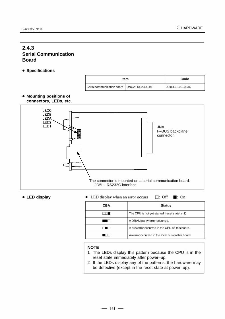
B–63835EN/03 2. HARDWARE
161
Item Code
Serial communication board DNC2: RS232C I/F A20B–8100–0334
JNAF–BUS backplaneconnector
The connector is mounted on a serial communication board.JD5L: RS232C interface
� LED display when an error occurs �: Off �: On
CBA Status
��� The CPU is not yet started (reset state).(*1)
��� A DRAM parity error occurred.
��� A bus error occurred in the CPU on this board.
��� An error occurred in the local bus on this board.
NOTE1 The LEDs display this pattern because the CPU is in the
reset state immediately after power–up.2 If the LEDs display any of the patterns, the hardware may
be defective (except in the reset state at power–up).
2.4.3Serial CommunicationBoard
� Specifications
� Mounting positions ofconnectors, LEDs, etc.
� LED display

2. HARDWARE B–63835EN/03
162
(1) DRAM module
No. Item Code Function Remarks
(1) DRAM module A20B–3900–0042 System RAM 4MB
Item Code
HSSB interface board A20B–8001–0730
SW1(Up to the PWB03 version)
JNAF–BUS backplaneconnector
COP7: High–speed serial bus (HSSB) interfaceSW1(PWB04 version and later)
� Mounting positions ofcard and DIMM module
2.4.4HSSB Interface Board
� Specifications
� Mounting positions ofconnectors, LEDs, etc.

B–63835EN/03 2. HARDWARE
163
LEDB Red HSSB communication has been interrupted.
LEDA Red A RAM parity alarm occurred in the common RAM on theboard.The common RAM is mounted on this board. The RAMis used to exchange information between the CNC andpersonal computer and is not battery–backed.
Status display of the green LEDs �: Off �: On
4 3 2 1 Status
���� Immediately after power–up
���� HSSB board initialization in progress
���� Waiting for the booting of the PC side
���� CNC screen displayed on the PC
���� Activation normally terminated, normal operation in progress
���� Thermal error detected by the CNC display unit with PC functions or PANEL i
���� HSSB communication interrupted
���� Parity alarm in the common RAM
���� Communication error
���� Battery alarm in the CNC display unit with PC functions or PANEL i
NOTEThe PC used in the above table includes PANEL i and CNCdisplay unit with PC functions.
� LED display

2. HARDWARE B–63835EN/03
164
1) Setting of ROTARY SWITCH in case of connecting to PC or PANELi
The power–on start sequence can be modified using rotary switch onthe board.
setting of rotaryswitch
Description
0 Setting for maintenance.The start menu is displayed. It is possible to start boot and IPLfrom the PC or PANEL i.
1 Setting for usual operation.The start menu is not displayed.It is impossible to start boot or IPL from the PC or PANEL i.
2 The CNC and PC or PANEL i are started independently of eachother without handshake.
* CNCCNC is available if PC is not turned on or not connected.(Display for CNC and MDI or Operation panel etc. are neededto operate.)The start menu is not displayed if PC or PANEL i is connectedand turned on.
* PC or PANEL iThe start menu is not displayed and it is impossible to startboot or IPL from the PC or PANEL i if CNC is connected andturned on.
This setting makes PC or PANEL i or CNC be able to be turnedon/off the power individually if HSSB device driver for Windows95/98, NT4.0 or 2000 is installed. In case of Multi–connection (connecting some CNCs to one PCor PANEL i), please set to this setting usually.
NOTEPANEL i used here represents hardware that can operateon a stand–alone basis (provide a stand–alone option).
� Rotary switch
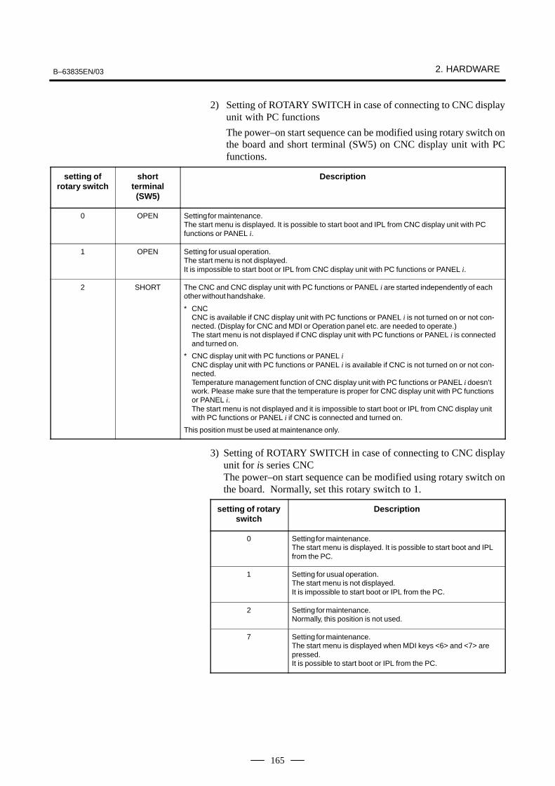
B–63835EN/03 2. HARDWARE
165
2) Setting of ROTARY SWITCH in case of connecting to CNC displayunit with PC functions
The power–on start sequence can be modified using rotary switch onthe board and short terminal (SW5) on CNC display unit with PCfunctions.
setting ofrotary switch
shortterminal(SW5)
Description
0 OPEN Setting for maintenance.The start menu is displayed. It is possible to start boot and IPL from CNC display unit with PCfunctions or PANEL i.
1 OPEN Setting for usual operation.The start menu is not displayed.It is impossible to start boot or IPL from CNC display unit with PC functions or PANEL i.
2 SHORT The CNC and CNC display unit with PC functions or PANEL i are started independently of eachother without handshake.
* CNCCNC is available if CNC display unit with PC functions or PANEL i is not turned on or not con-nected. (Display for CNC and MDI or Operation panel etc. are needed to operate.)The start menu is not displayed if CNC display unit with PC functions or PANEL i is connectedand turned on.
* CNC display unit with PC functions or PANEL iCNC display unit with PC functions or PANEL i is available if CNC is not turned on or not con-nected.Temperature management function of CNC display unit with PC functions or PANEL i doesn’twork. Please make sure that the temperature is proper for CNC display unit with PC functionsor PANEL i.The start menu is not displayed and it is impossible to start boot or IPL from CNC display unitwith PC functions or PANEL i if CNC is connected and turned on.
This position must be used at maintenance only.
3) Setting of ROTARY SWITCH in case of connecting to CNC displayunit for is series CNCThe power–on start sequence can be modified using rotary switch onthe board. Normally, set this rotary switch to 1.
setting of rotaryswitch
Description
0 Setting for maintenance.The start menu is displayed. It is possible to start boot and IPLfrom the PC.
1 Setting for usual operation.The start menu is not displayed.It is impossible to start boot or IPL from the PC.
2 Setting for maintenance.Normally, this position is not used.
7 Setting for maintenance.The start menu is displayed when MDI keys <6> and <7> arepressed. It is possible to start boot or IPL from the PC.

2. HARDWARE B–63835EN/03
166
Item Code
Fast Ethernet board A20B–8100–0670
JNAF–BUS backplaneconnector
CD38R: Ethernet interface
ALM (red)COM (green)LED4 (green)LED3 (green)LED2 (green)LED1 (green)
LIL (green)COL (red)
BTX (green)
TM
5T
M4
� Status transition at power–up, displayed by the green LEDs
No. 4 3 2 1 Ethernet board status
1 ���� Power off
2 ���� Initial state immediately after power–up
3 ���� MPU initialization completed
4 ���� Firmware downloading completed
5 ���� Control transferred to OS
6 ���� OS PHASE 1
7 ���� OS PHASE 2
8 ���� OS PHASE 3
9 ���� OS PHASE 4
10 ���� Start–up completed
If the board has normally started up, the LEDs display the pattern ofNo.10. The LEDs keep this pattern until an error occurs.
2.4.5Fast Ethernet Board
� Specifications
� Mounting positions ofconnectors, LEDs, etc.
� LED display

B–63835EN/03 2. HARDWARE
167
� STATUS LED indications if an error occursIf an error occurs, the LEDs repeatedly flash ”LONG” then ”SHORT.”(For ”LONG,” the LED lights for a long time. For ”SHORT,” the LEDlights for a short time.)
STATUS LEDindication
No.LONG4321
SHORT4321
Fast Ethernet/Fast data server state
1 ���� ���� Failure caused by SDRAM paruty alarm
2 ���� ����
this boardGeneral invalid instruction
3 ���� ���� Invalid slot instruction
4 ���� ���� Failure caused byanother board
NMI of another module
NOTEIf an error, indicated by repeatedly flashing a LONG andSHORT combination other than the above, occurs, contactFANUC.
� ALARM LED indications if an error occurs
No. LED indication Fast Ethernet board state
1 ALM � Parity error occurred in main memory.
� LED indications related to communication status
No. LED indication Fast Ethernet communications status
1 COM � Lights when data is sent.
3 LIL � Lights when a connection is made correctly with the hub.
4 COL � Lights if a data collision occurs.
5 BTX � Lights when a connection is made with 100BASE–TX.
NOTELIL : Communication is not performed while this LED is
not lit. A probable reason for this is that the FastEthernet/Fast data server is not properlyconnected to the hub, or that the hub is off. ThisLED should be lit at all times while the FastEthernet is properly connected to the hub.
COL : This LED lights frequently if there is excessivetraffic on the communication line or if there isexcessive peripheral electrical noise.
On the board, the setting pins (TM4, TM5) are installed. Connect eachjumper plug to side A (factory–set state). Do not remove a jumper plug,and do not change the setting of a jumper plug. Otherwise, the board doesnot operate normally.
� Setting Pins
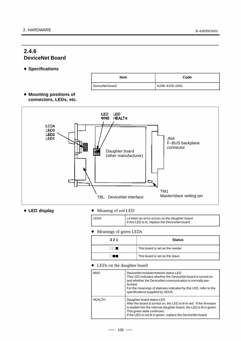
2. HARDWARE B–63835EN/03
168
Item Code
DeviceNet board A20B–8100–0491
Daughter board(other manufacturer)
JNAF–BUS backplaneconnector
TM1Master/slave setting pinTBL: DeviceNet interface
� Meaning of red LED
LEDA Lit when an error occurs on the daughter board.If this LED is lit, replace the DeviceNet board.
� Meanings of green LEDs
3 2 1 Status
��� This board is set as the master.
��� This board is set as the slave.
� LEDs on the daughter board
MNS DeviceNet module/network status LEDThis LED indicates whether the DeviceNet board is turned onand whether the DeviceNet communication is normally per-formed.For the meanings of statuses indicated by this LED, refer to thespecifications supplied by ODVA.
HEALTH Daughter board status LEDAfter the board is turned on, the LED is lit in red. If the firmwareis loaded into the internal daughter board, the LED is lit in green.This green state continues.If the LED is not lit in green, replace the DeviceNet board.
2.4.6DeviceNet Board
� Specifications
� Mounting positions ofconnectors, LEDs, etc.
� LED display

B–63835EN/03 2. HARDWARE
169
This setting pin is used to switch around the master function and slavefunction of DeviceNet.
This DeviceNet board can be removed after the main CPU board isremoved. For the procedure, see “Mounting and Removing an OptionBoard.”A daughter board of a different manufacturer is mounted on theDeviceNet board. The daughter board alone cannot be replaced.
Item Code
PROFIBUS master board A20B–8100–0470
JNAF–BUS backplaneconnector
CN1: PROFIBUS interface
� Status LED display (green)
State
LED1 Lit when this board is released from the reset state and startsoperating.This LED is not lit at power–up.
LED2 Lit when the communication is normally performed.This LED is not lit at power–up.
� Master/slave setting pin
� Precautions
2.4.7PROFIBUS MasterBoard
� Specifications
� Mounting positions ofconnectors, LEDs, etc.
� LED display

2. HARDWARE B–63835EN/03
170
Item Code
PROFIBUS slave board A20B–8100–0440
JNAF–BUS backplaneconnector
CN2: PROFIBUS interface
� Status LED display (green)
State
LED1 Lit when this board is released from the reset state and startsoperating.This LED is not lit at power–up.
LED2 Lit when the communication starts.The LED is not lit at power–up. The LED is not lit also in thefollowing cases:· When no parameter configuration data is received· When illegal parameter configuration data is received
LED3 Lit when the communication is normally performed.This LED is not lit at power–up.
LEDB Lit when a RAM parity alarm occurs on this board.
2.4.8PROFIBUS SlaveBoard
� Specifications
� Mounting positions ofconnectors, LEDs, etc.
� LED display

B–63835EN/03 2. HARDWARE
171
Item Code
FL–net board A20B–8100–0530
JNAF–BUS backplaneconnector
CD38N: FL–net interface
Setting pin TM1(fixed to B)
� Meanings of red LEDs
HER Lit when a parity alarm occurs in the DRAM on the FL–netboard.The board may be defective.
COL Lit if a data collision occurs on the line.
� Meanings of green LEDs
COM Lit during data transmission or reception.
POK Lit when the parameters are normally set.
LNK This LED indicates the link state and is lit if the board partici-pates in the FA link.
RES Reserved. This LED is normally lit.
ROS Lit while the OS is running on the FL–net board.
LIL Lit when a hub is normally connected.
This setting pin is always set to position B. The setting should not bechanged.
2.4.9FL–net Board
� Specifications
� Mounting positions ofconnectors, LEDs, etc.
� LED display
� Setting pin TM1

2. HARDWARE B–63835EN/03
172
Item Code
Main CPU board For Windows95 For 10.4”/12.1” LCD A20B–2100–0690(For basic unit A08B–0082–B001 to –B004, –B011 to–B014, –B021 to –B024) For 15.0” LCD A20B–2100–0691
For other OS than Windows95 For 10.4”/12.1” LCD A20B–2100–0692
For 15.0” LCD A20B–2100–0693
CP
5F
US
E–1
(7.5
A)
FU
SE
–2(1
0A)
(Uni
t Fan
JD46
(RS
232–
2, U
SB
)
JD9
(CE
NT
RO
)
JD33
(RS
232–
1)
Pow
er)
TM
10
CN
6
CN
7
CN
2
CN
2B
TH
ER
MA
L
CN
P1
(PC
I)
CN
P2
(PC
I)
CN
5 (P
CM
CIA
)
CN
1B (L
CD
)
CN
1 (L
CD
)
TH
ER
MA
L(HD
D F
an P
ower
)
(Inverter)
CN3
BAT1BATTERY
COP7(HSSB)
LED
CN4(PC Card)
CD32BMOUSE
CD32AKeyboard
(FDD Power)
(HDD Power)
CNH3 (HDD signal)
CD34 (FDD signal)
SW5
SW7
*4
*4
*4
Mounting positions of the parts in the location indicated by *4
LCD Unit Type(Code of PC board)
Parts
10.4”/12.1”LCD(A20B–2100–0690, –0692)
15.0”LCD(A20B–2100–0691, –0693) Fuse for maintenance
FUSE–1 Provided None A02B–0236–K101
FUSE–2 None Provided A08B–0082–K001
CN1B None Provided —
2.4.10Main CPU Board of CNCDisplay Unit with PCFunctions and PANEL i
� Specifications
� Mounting positions ofconnectors, LEDs, etc.

B–63835EN/03 2. HARDWARE
173
Item Code
Main CPU board For Windows95 For 10.4” LCD A20B–2100–0780(For basic unit A08B–0082–B031 to –B038, –B041 to–B048, –B051 to –B057) For 12.1” LCD A20B–2100–0781(For basic unit A13B–0193– B031 to –B038, –B041 to–B048, –B051 to –B057) For 15.0” LCD A20B–2100–0782
For other OS than Windows95 For 10.4” LCD A20B–2100–0783
For 12.1” LCD A20B–2100–0784
For 15.0”LCD A20B–2100–0785
CP
5F
US
E–1
(7.5
A)
FU
SE
–2(1
0A)
*5
*5
(Uni
t Fan
Pow
er)
CN
6
(Inverter) *5
CN3 CN3B
JD46
(RS
232–
2, U
SB
)
JD9
(CE
NT
RO
)
JD33
(RS
232–
1)
TM
10
BAT1BATTERY
COP7(HSSB)
LED
CN4(PC Card)
CD32BMOUSE
CD32AKeyboard
CN
2
CN
2B (FDD Power)
(HDD Power)
CNH3 (HDD signal)
CD34 (FDD signal) CN
7
TH
ER
MA
LC
NP
1 (P
CI)
CN
P2
(PC
I)
TH
ER
MA
L
(HD
D F
an P
ower
)
CN
5 (P
CM
CIA
)
CN
1B (L
CD
)
CN
1 (L
CD
)
*5
SW5
SW7
Mounting positions of the parts in the location indicated by *5
LCD Unit Type(Code of PC board)
Parts
10.4”LCD(A20B–2100–0780,
–0783)
12.1”LCD(A20B–2100–0781,
–0784)
15.0”LCD(A20B–2100–0782,
–0785)
Fuse formaintenance
FUSE–1 Provided None None A02B–0236–K101
FUSE–2 None Provided Provided A08B–0082–K001
CN3 Provided Provided Provided —
CN3B None None Provided —
CN1B None None Provided —
� Specifications
� Mounting positions ofconnectors, LEDs, etc.

2. HARDWARE B–63835EN/03
174
GR1(Green) +5V(Green)GR2(Green) HDD(Green)GR3(Green) CNC(Green)GR4(Green) CRD(Green)RE1(Red) BUS(Red)RE2(Red) BAT (Red)RE3(Red) FAN(Red)RE4(Red) TRM(Red)
or*6
CNH3 (HDD Signal)
CD34 (FDD Signal)
COP7
Name 1(*6) Name 2(*6) Color Status
GR1 +5V Green Lights when +5 V is supplied.
GR2 HDD Green Lights when the HDD is accessed.
GR3 CNC Green Lights when the CNC operates normally.
GR4 CRD Green Lights when PCMCIA is accessed.
RE1 BUS Red Lights when transfer over the HSSB is interrupted. Possible causes areshown below.
� The CNC unit is not powered.� The optical fiber cable is not connected.� The interface on the CNC side failed.� The CNC display unit with PC functions or the PANEL i failed.
RE2 BAT Red Indicates a battery alarm. Replace the battery installed in the CNC displayunit with PC functions or in the PANEL i.
RE3 FAN Red Lights when the basic unit fan or HDD fan stops. Replace the failed fan.
RE4 TRM Red Indicates a temperature alarm. This LED lights when the CPU detects ahigh temperature that falls outside the use range. (This decreases theoperating speed of the CPU.)
*6:These labels may vary with the drawing number or version number ofthe main board.
Short plug Settings Location
SW5SW7(A20B–2100–0690 to –0693)
Reserved Do not change the factory–setdefaults.
SW5
SW7
: Open: Short
: Short (PANEL i)
SW5TM7(A20B–2100–0780 to –0785)
Reserved Do not change the factory–setdefaults.
SW5
TM7
: Short (PANEL i)Open (CNC displayunit with PC functions)
TM10 Reserved This short plug is provided fortesting purpose.Be sure to insert this plug. T
M10 : Short
� LED display
� Short plug settings

B–63835EN/03 2. HARDWARE
175
Type Item Drawing No. Remarks
0i Mate–B Basic unit with 1 slot A02B–0301–B801
0i–B Basic unit with 2 slots A02B–0299–B802
Type Item Drawing No. ID Remarks
Master Main CPU board A16B–3200–0490 0X06 0i–B (for PMC–SA1)PCB
A16B–3200–0491 1X06 0i–B (for PMC–SB7)
A16B–3200–0495 1X07 0i Mate–B
Card PCB CPU card DRAM 16MB 486 A20B–3300–0293 CPU: 09DRAM: 89
DRAM 32MB 486 A20B–3300–0292 CPU: 09DRAM: 84
0i–B only
DRAM 32MB Pentium A20B–3300–0319 CPU: 11DRAM: 84
0i–B only
Card PCB Display control card LCD/MDI A20B–3300–0341 –
CRT/MDI A20B–3300–0410 –
MDI only A20B–3300–0363 –
Axis control card 2 axes A20B–3300–0033 00 Servo software
4 axes A20B–3300–0032 01Series 9096
2 axes A20B–3300–0243 08 Servo software
4 axes A20B–3300–0242 08Series 90B0
Display control card 10.4″ color/8.4″ color A20B–3300–0280 – Graphic(LCD unit side)
7.2″ monochrome A20B–3300–0283 – Graphic
7.2″ monochrome A20B–3300–0303 – Character only
Powersupply unit
Power supply unit A02B–8100–0721 –
2.5UNITS AND PRINTEDCIRCUIT BOARDS
2.5.1Basic Units
2.5.2Printed Circuit Boardsof Control Unit

2. HARDWARE B–63835EN/03
176
Type RemarksIDDrawing No.Item
DIMMmodule
FROM/SRAM module A20B–3900–0163 FROM: C2SRAM: 03
FROM 32MB, SRAM 1MB
A20B–3900–0181 FROM: C1SRAM: 02
FROM 16MB, SRAM 512kB
Analog spindle module A20B–3900–0170
Option I/O board (with data server)+data server board A16B–3200–0501 0x2EPCB
I/O board (without data server) A16B–3200–0500 –
ATA card adapter A20B–2002–0960 – For data server
Serial communication board
(DNC2, RS232C I/F)
A20B–8100–0334 1xE0
HSSB interface board A20B–8001–0730 xxAA
Fast Ethernet board A20B–8100–0670 xx96
DeviceNet board A20B–8100–0491 xxEF
DeviceNet board C A20B–8100–0650 xxBF
PROFIBUS Master board A20B–8100–0470 xxFC
PROFIBUS Slave board A20B–8100–0440 xxE3
FL–net board A20B–8100–0530 xx59
Back Back panel A20B–2003–0271 – 1 slotpanel
A20B–2003–0490 – 2 slots
DistributedI/O
Operator’s panel I/O module A20B–2002–0470 – Matrix DI supported
With MPG interface
A20B–2002–0520 – General–purpose
DI input
With MPG interface
A20B–2002–0521 – General–purpose
DI input
Without MPG inter–face
Connector panel I/O module Basic A20B–2100–0150 –
Expansion A20B–2100–0410 – With MPG interface
A20B–2100–0411 – Without MPG inter-face
A20B–2100–0320 – DO only
A20B–2100–0190 – Analog input

B–63835EN/03 2. HARDWARE
177
Type RemarksIDDrawing No.Item
Others LCD control printed circuit board A20B–8100–0821 –
Inverter A20B–8001–0920 – 10.4″ color LCD
A20B–8001–0922 – 8.4″ color LCD
A20B–8100–0710 – 7.2″ monochromeLCD
PCB for separate detector interface unit A20B–2100–0270 –
HSSB board on the personal computer side A20B–8001–0583 – For 1 channel, corre-sponding to ISA–bus
A20B–8001–0582 – For 2 channels, cor-responding to ISA–bus
A20B–8001–0960 – For 2 channels, cor-responding to PCI–bus
A20B–8001–0961 – For 1 channel, corre-sponding to PCI–bus

2. HARDWARE B–63835EN/03
178
Item Drawing No. Remarks
9″ monochrome CRT/MDI Graphic display T series A02B–0299–C041#T English key type MDIunit supported
A02B–0299–C041#TS Symbolic key type MDI
M series A02B–0299–C041#M English key type MDI
A02B–0299–C041#MS Symbolic key type MDI
7.2″ monochrome LCD/MDI Graphic display T series A02B–0299–C071#T English key type MDIunit supported
A02B–0299–C071#TS Symbolic key type MDI
M series A02B–0299–C071#M English key type MDI
A02B–0299–C071#MS Symbolic key type MDI
Only character dis- T series A02B–0299–C076#T English key type MDIplay supported
A02B–0299–C076#TS Symbolic key type MDI
M series A02B–0299–C076#M English key type MDI
A02B–0299–C076#MS Symbolic key type MDI
7.2″ monochrome LCD unit Graphic displaysupported
T/M series A02B–0299–C070
Only character display supported
T/M series A02B–0299–C075
8.4″ color LCD/MDI unit Graphic display T series A02B–0299–C081#T English key type MDIsupported
A02B–0299–C081#TS Symbolic key type MDI
M series A02B–0299–C081#M English key type MDI
A02B–0299–C081#MS Symbolic key type MDI
8.4″ color LCD unit Graphic displaysupported
T/M series A02B–0299–C080
10.4″ color LCD unit Graphic displaysupported
T/M series A02B–0299–C060
Small MDI unit For 8.4″ color LCD T series A02B–0279–C120#TA English key type MDI
A02B–0279–C120#TAS Symbolic key type MDI
M series A02B–0279–C120#MA English key type MDI
A02B–0279–C120#MAS Symbolic key type MDI
2.5.3LCD/MDI Unit

B–63835EN/03 2. HARDWARE
179
Item RemarksDrawing No.
Fullkey type MDI unit Vertical type for″
T series A02B–0279–C122#TA English key type MDI10.4″ color LCD
A02B–0279–C122#TAS Symbolic key type MDI
T series A02B–0279–C122#MA English key type MDI
A02B–0279–C122#MAS Symbolic key type MDI
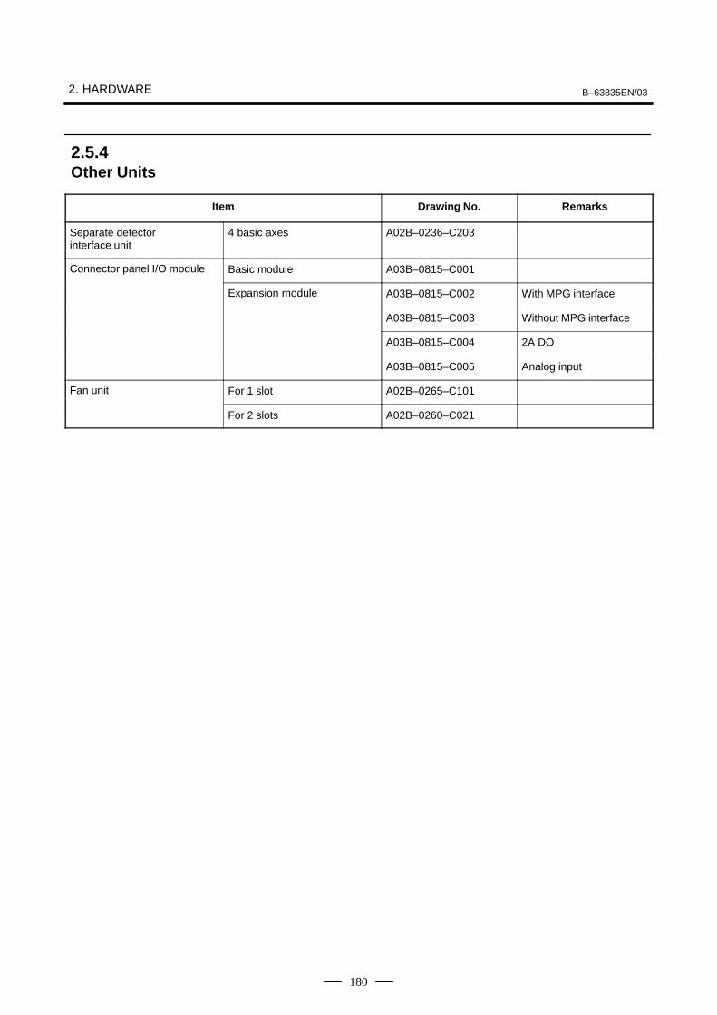
2. HARDWARE B–63835EN/03
180
Item Drawing No. Remarks
Separate detector interface unit
4 basic axes A02B–0236–C203
Connector panel I/O module Basic module A03B–0815–C001
Expansion module A03B–0815–C002 With MPG interface
A03B–0815–C003 Without MPG interface
A03B–0815–C004 2A DO
A03B–0815–C005 Analog input
Fan unit For 1 slot A02B–0265–C101
For 2 slots A02B–0260–C021
2.5.4Other Units

B–63835EN/03 2. HARDWARE
181
Type Item Drawing No.
Printed circuit board Main printed circuit board For Windows95 For 10.4”/12.1” LCD A20B–2100–0690for CNC display unitwith PC functions and
(For basic unit A08B–0082–B001 to –B004,–B011 to –B014, –B021 to –B024) For 15.0” LCD A20B–2100–0691
PANEL iFor OS except for For 10.4”/12.1” LCD A20B–2100–0692Windows95
For 15.0” LCD A20B–2100–0693
Main printed circuit board For OS except for For 10.4”LCD A20B–2100–0780(For basic unit A08B–0082–B031 to –B038,–B041 to –B048, –B051 to –B057)
Windows95For 12.1”LCD A20B–2100–0781
(For basic unit A13B–0193– B031 to –B038,–B041 to –B048, –B051 to –B057) For 15.0”LCD A20B–2100–0782
For Windows95 For 10.4”LCD A20B–2100–0783
For 12.1”LCD A20B–2100–0784
For 15.0”LCD A20B–2100–0785
Inverter printed circuit board For 10.4” LCD A14L–0132–0001(For basic unit A08B–0082–B001 to –B004,–B011 to –B014, –B021 to –B024) For 12.1” LCD A20B–2002–0890
For 15.0” LCD A14L–0143–0002
Inverter printed circuit board For 10.4” LCD A14L–0132–0001 #B(For basic unit A08B–0082– B031 to –B038,–B041 to –B048, –B051 to –B057) For 12.1” LCD A14L–0143–0001 #B(For basic unit A13B–0193– B031 to –B038,–B041 to –B048, –B051 to –B057) For 15.0” LCD A14L–0143–0002 #B
Soft key printed circuit board For 10.4” LCD A86L–0001–0261
For 12.1” LCD A20B–1007–0760
Printed circuit board for touch panel controller
A20B–8001–0620
2.5.5CNC Display Unit withPC Functions andPANEL i

2. HARDWARE B–63835EN/03
182
Type ItemDrawing number
of unit formaintenance
Main drawingnumber
(Basic unit)
Printed circuit board Base unit LCD Soft key Touch panelfor CNC display unitwith PC functions and 10.4” LCD � � A08B–0082–D001 A08B–0082–B001with PC functions andPANEL i � � A08B–0082–D002 A08B–0082–B002
� � A08B–0082–D003 A08B–0082–B003
� � A08B–0082–D004 A08B–0082–B004
12.1”LCD � � A08B–0082–D011 A08B–0082–B011
� � A08B–0082–D012 A08B–0082–B012
� � A08B–0082–D013 A08B–0082–B013
� � A08B–0082–D014 A08B–0082–B014
15.0”LCD � � A08B–0082–D021 A08B–0082–B021
� � A08B–0082–D023 A08B–0082–B023
10.4”LCD � � A08B–0082–D031 A08B–0082–B031A08B–0082–B035A13B–0193–B031A13B–0193–B035
� � A08B–0082–D032 A08B–0082–B032A08B–0082–B036A13B–0193–B032A13B–0193–B036
� � A08B–0082–D033 A08B–0082–B033A08B–0082–B037A13B–0193–B033A13B–0193–B037
� � A08B–0082–D034 A08B–0082–B034A08B–0082–B038A13B–0193–B034A13B–0193–B038
12.1”LCD � � A08B–0082–D041 A08B–0082–B041A08B–0082–B045A13B–0193–B041A13B–0193–B045
� � A08B–0082–D042 A08B–0082–B042A08B–0082–B046A13B–0193–B042A13B–0193–B046
� � A08B–0082–D043 A08B–0082–B043A08B–0082–B047A13B–0193–B043A13B–0193–B047
� � A08B–0082–D044 A08B–0082–B044A08B–0082–B048A13B–0193–B044A13B–0193–B048
15.0”LCD � � A08B–0082–D051 A08B–0082–B051A08B–0082–B055A13B–0193–B051A13B–0193–B055
� � A08B–0082–D053 A08B–0082–B053A08B–0082–B057A13B–0193–B053A13B–0193–B057
3.5” HDD unit (including the FAN for HDD) A08B–0082–C100 A08B–0082–H100

B–63835EN/03 2. HARDWARE
183
�: Provided �: None
NOTEThe base unit for maintenance consists of the componentsof the basic unit from which the main printed circuit boardand its retaining screws are excluded.
Type Item Drawing numberfor maintenance
Main drawingnumber
Printed circuit board PC card MMX– For 10.4” LCD A08B–0082–H500#6141 A08B–0082–H010for PC function ofCNC display unit with
Pentium 233MHzFor 12.1” LCD A08B–0082–H500#6142 A08B–0082–H011
PC functions andPANEL i For 15.0” LCD A08B–0082–H500#6143 A08B–0082–H012
PentiumII For 10.4” LCD A08B–0082–H511#6138 A08B–0082–H020333MHz
For 12.1” LCD A08B–0082–H511#6139 A08B–0082–H021
For 15.0” LCD A08B–0082–H511#6140 A08B–0082–H022
Celeron For 10.4” LCD A08B–0082–H512#613D A08B–0082–H040400MHz
For 12.1” LCD A08B–0082–H512#613E A08B–0082–H041
For 15.0” LCD A08B–0082–H512#613F A08B–0082–H042
PentiumIII For 10.4” LCD A08B–0082–H520#613G A08B–0082–H050500MHz
For 12.1” LCD A08B–0082–H520#613H A08B–0082–H051
For 15.0” LCD A08B–0082–H520#613J A08B–0082–H052
Memory Main memory(For MMX–Pentium 233MHz and PentiumII 333MHz)
DRAM 32MB (*) A76L–0500–0013(Specification:TOSHIBATHL64V4075BTG–5S)
A08B–0082–H001
DRAM 64MB A76L–0500–0014(Specification: TOSHIBATHL64V8015BTG–5S)
A08B–0082–H002
DRAM 128MB A76L–0500–0017(Specification: PFUPD–2261ADS)
A08B–0082–H003
Main memory(For Celeron 400MHz and PentiumIII500MHz)
SDRAM 64M A76L–0500–0018(Specification: PFUPD–2261ACS)
A08B–0082–H004
SDRAM 128M A76L–0500–0019(Specification: PFUPD–2261ADSA)
A08B–0082–H005
*: DRAM 32 MB can be used only for the MMX–Pentium 233MHz.

2. HARDWARE B–63835EN/03
184
WARNINGThe replacement described here should be performed by aperson fully trained in maintenance and safety. If thecabinet is opened to replace the option board, take extremecare not to touch any high–voltage area (marked with and covered by a shock prevention cover). If the area isuncovered, direct contact with this area will result in anelectric shock.
NOTEBefore starting the replacement, take a back–up copy of thecontents (parameters, programs, etc.) of the SRAMmemory of the CNC. The backup copy can be used in casethe contents of the SRAM memory are lost during thereplacement.
(1)Remove cables other than the battery cable. (The battery cable isconnected only to the main CPU board.)
(2)Hold handles A and B.
(3)Pushing down the hook of handle A and pushing up the hook of handleB, pull out the printed circuit board.
NOTE1 The battery is mounted on the face place of the main CPU
board. The battery is pulled out together with the main CPUboard.
2 The main CPU board or a full–size option board can beremoved without removing mini–slot option boards. (If acable connected to a mini–slot option board obstructs theremoval, the cable must be removed.)
2.6MOUNTING ANDREMOVING ANOPTION BOARD
2.6.1Mounting andRemoving the MainCPU Board and aFull–Size Option Board
2.6.1.1Removing the board

B–63835EN/03 2. HARDWARE
185
(1)Holding handles A and B, insert the board into the cabinet until theconnector on the back panel is connected.
(2)Connect the removed cables to correct positions.
Handle AWith a hook onthe top side
Handle BWith a hook onthe bottom side
0i–B 0i Mate–B
2.6.1.2Mounting the board
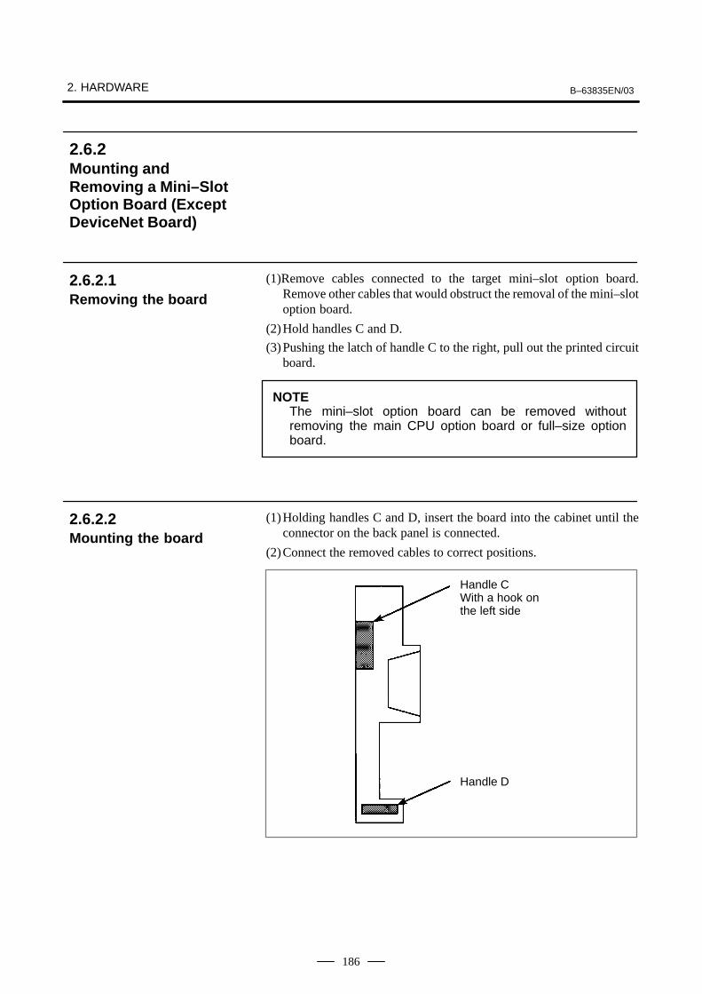
2. HARDWARE B–63835EN/03
186
(1)Remove cables connected to the target mini–slot option board.Remove other cables that would obstruct the removal of the mini–slotoption board.
(2)Hold handles C and D.
(3)Pushing the latch of handle C to the right, pull out the printed circuitboard.
NOTEThe mini–slot option board can be removed withoutremoving the main CPU option board or full–size optionboard.
(1)Holding handles C and D, insert the board into the cabinet until theconnector on the back panel is connected.
(2)Connect the removed cables to correct positions.
Handle CWith a hook onthe left side
Handle D
2.6.2Mounting andRemoving a Mini–SlotOption Board (ExceptDeviceNet Board)
2.6.2.1Removing the board
2.6.2.2Mounting the board
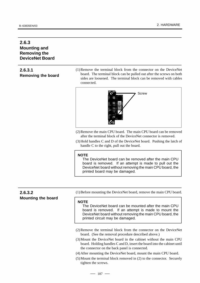
B–63835EN/03 2. HARDWARE
187
(1)Remove the terminal block from the connector on the DeviceNetboard. The terminal block can be pulled out after the screws on bothsides are loosened. The terminal block can be removed with cablesconnected.
Screw
(2)Remove the main CPU board. The main CPU board can be removedafter the terminal block of the DeviceNet connector is removed.
(3)Hold handles C and D of the DeviceNet board. Pushing the latch ofhandle C to the right, pull out the board.
NOTEThe DeviceNet board can be removed after the main CPUboard is removed. If an attempt is made to pull out theDeviceNet board without removing the main CPU board, theprinted board may be damaged.
(1)Before mounting the DeviceNet board, remove the main CPU board.
NOTEThe DeviceNet board can be mounted after the main CPUboard is removed. If an attempt is made to mount theDeviceNet board without removing the main CPU board, theprinted circuit may be damaged.
(2)Remove the terminal block from the connector on the DeviceNetboard. (See the removal procedure described above.)
(3)Mount the DeviceNet board in the cabinet without the main CPUboard. Holding handles C and D, insert the board into the cabinet untilthe connector on the back panel is connected.
(4)After mounting the DeviceNet board, mount the main CPU board.
(5)Mount the terminal block removed in (2) to the connector. Securelytighten the screws.
2.6.3Mounting andRemoving theDeviceNet Board
2.6.3.1Removing the board
2.6.3.2Mounting the board

2. HARDWARE B–63835EN/03
188
Handle CWith a hook on theleft side
Handle D
B–63835EN/03 2. HARDWARE
189
WARNINGOnly those personnel who have received approved safetyand maintenance training may perform this replacementwork.When opening the cabinet and replacing a card PCB, becareful not to touch the high–voltage circuits (marked andfitted with an insulating cover). Touching the uncoveredhigh–voltage circuits presents an extremely dangerouselectric shock hazard.
CAUTION1 Before starting replacement work, back up the contents
(such as parameters and programs) of the SRAM memoryof the CNC. Otherwise, the contents of the SRAM memorymay be lost during replacement work.
2 If the SRMA data check method (parity check or ECC check)has been changed after the replacement, a parity or ECCalarm may occur at power–on, possibly causing damage tothe SRAM data. Back up the SRAM data before startingreplacement, and restore the data after completing thereplacement.
2.7MOUNTING ANDDEMOUNTING CARDPCBS

2. HARDWARE B–63835EN/03
190
1) Pull outward the claw of each of the four spacers used to secure the cardPCB, then release each latch. (See Fig. a.)
2) Extract the card PCB upward. (See Fig. b.)
Card PCB Card PCB
Card PCB
Card PCB
Fig. a Spacer
Spacer
Connector
Connector
Fig. b
2.7.1Demounting a CardPCB
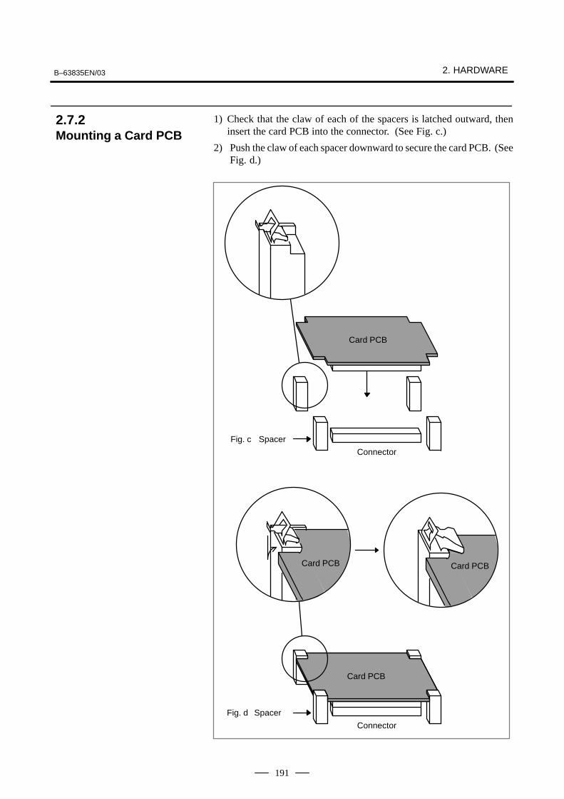
B–63835EN/03 2. HARDWARE
191
1) Check that the claw of each of the spacers is latched outward, theninsert the card PCB into the connector. (See Fig. c.)
2) Push the claw of each spacer downward to secure the card PCB. (SeeFig. d.)
Card PCB
Card PCBCard PCB
Card PCB
Fig. c Spacer
Spacer
Connector
Connector
Fig. d
2.7.2Mounting a Card PCB
2. HARDWARE B–63835EN/03
192
WARNINGOnly those personnel who have received approved safetyand maintenance training may perform this replacementwork.When opening the cabinet and replacing a module, becareful not to touch the high–voltage circuits (marked andfitted with an insulating cover). Touching the uncoveredhigh–voltage circuits presents an extremely dangerouselectric shock hazard.
CAUTIONBefore starting replacement work, back up the contents(such as parameters and programs) of the SRAM memoryof the CNC. Otherwise, the contents of the SRAM memorymay be lost during replacement work.Before replacing an SRAM module, be sure to back up thecontents of the SRAM module.
2.8MOUNTING ANDDEMOUNTING DIMMMODULES
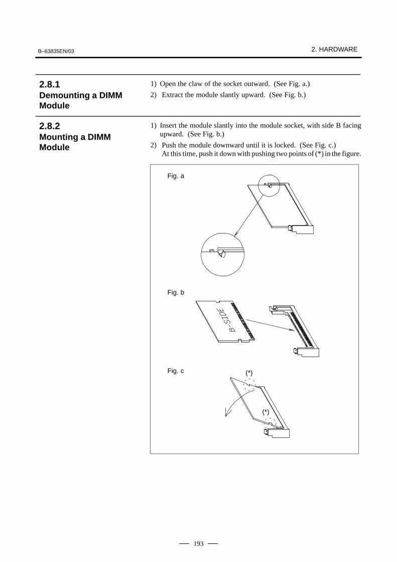
B–63835EN/03 2. HARDWARE
193
1) Open the claw of the socket outward. (See Fig. a.)
2) Extract the module slantly upward. (See Fig. b.)
1) Insert the module slantly into the module socket, with side B facingupward. (See Fig. b.)
2) Push the module downward until it is locked. (See Fig. c.)At this time, push it down with pushing two points of (*) in the figure.
Fig. c
Fig. b
Fig. a
(*)
(*)
2.8.1Demounting a DIMMModule
2.8.2Mounting a DIMMModule
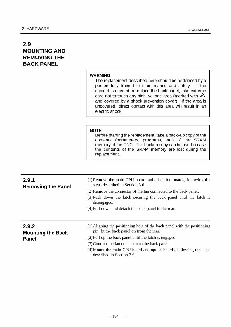
2. HARDWARE B–63835EN/03
194
WARNINGThe replacement described here should be performed by aperson fully trained in maintenance and safety. If thecabinet is opened to replace the back panel, take extremecare not to touch any high–voltage area (marked with and covered by a shock prevention cover). If the area isuncovered, direct contact with this area will result in anelectric shock.
NOTEBefore starting the replacement, take a back–up copy of thecontents (parameters, programs, etc.) of the SRAMmemory of the CNC. The backup copy can be used in casethe contents of the SRAM memory are lost during thereplacement.
(1)Remove the main CPU board and all option boards, following thesteps described in Section 3.6.
(2)Remove the connector of the fan connected to the back panel.
(3)Push down the latch securing the back panel until the latch isdisengaged.
(4)Pull down and detach the back panel to the rear.
(1)Aligning the positioning hole of the back panel with the positioningpin, fit the back panel on from the rear.
(2)Pull up the back panel until the latch is engaged.
(3)Connect the fan connector to the back panel.
(4)Mount the main CPU board and option boards, following the stepsdescribed in Section 3.6.
2.9MOUNTING ANDREMOVING THEBACK PANEL
2.9.1Removing the Panel
2.9.2Mounting the BackPanel

B–63835EN/03 2. HARDWARE
195
Back panel
Fanconnector
Latch
Back panel
0i–B 0i Mate–B

2. HARDWARE B–63835EN/03
196
WARNINGBefore starting the replacement of a fuse, remove the causeof the fuse burn–out.Accordingly, the replacement should be performed by aperson fully trained in maintenance and safety. If thecabinet is opened to replace the fuse, take extreme care notto touch any high–voltage area (marked with andcovered by a shock prevention cover). If the area isuncovered, direct contact with this area will result in anelectric shock.
The fuse of the control unit is mounted on the main CPU board.
Axis control card
Fuse
CP1, CP2
Main CPU board
Display control card
Ordering information Rating Individual information
A02B–0265–K100 7.5A A60L–0001–0046#7.5
2.10REPLACING THEFUSE OF THECONTROL UNIT
� Mounting position of thefuse of the control unit
� Ordering information ofthe fuse

B–63835EN/03 2. HARDWARE
197
Part programs, offset data, and system parameters are stored in CMOSmemory in the control unit. The power to the CMOS memory is backedup by a lithium battery mounted on the front panel of the control unit. Theabove data is not lost even when the main battery goes dead. The backupbattery is mounted on the control unit at shipping. This battery canmaintain the contents of memory for about a year.When the voltage of the battery becomes low, alarm message “BAT”blinks on the CNC display and the battery alarm signal is output to thePMC. When this alarm is displayed, replace the battery as soon aspossible. In general, the battery can be replaced within two or threeweeks, however, this depends on the system configuration.If the voltage of the battery becomes any lower, memory can no longerbe backed up. Turning on the power to the control unit in this state causessystem alarm 935 (ECC error) to occur because the contents of memoryare lost. Clear the entire memory and reenter data after replacing thebattery.The power to the control unit must be turned on when the batteryis replaced. If the battery is disconnected when the power is turned off,the contents of memory are lost.Observe the following precautions for lithium batteries:
WARNINGIf an unspecified battery is used, it may explode.Replace the battery only with the specified battery(A02B–0200–K102.)
Dispose of batteries used in accordance with the applicable laws of yourcountry or the applicable laws or regulations of your local self–governingbody. Before disposal, insulate the terminals with tape or somethingsimilar to prevent them from being short–circuited.
1 Use a litium battery (ordering drawing number :A02B–0200–K102)
2 Turn on the Series 0i/0i Mate for about 30 seconds and then turn it offagain.
3 Turn off the Series 0i/0i Mate.
2.11REPLACING THEBATTERY
2.11.1Battery for MemoryBackup (3VDC)
Replacing the battery

2. HARDWARE B–63835EN/03
198
Claw holding the battery
Lithium battery
Battery connector
4 Remove the battery from the front panel of the control unit.First detach the connector, then remove the battery from the batterycase.
5 Replace the battery and then reconnect the connector.
CAUTIONSteps 3 to 5 must performed within 10 minutes. Note thatall data in memory is lost when the battery is kept removedfor extended time.

B–63835EN/03 2. HARDWARE
199
Commercial D–size alkaline dry cells can be used by mounting the batterycase externally.
Use the connector connected to the lithium battery for an external battery.Following the battery replacement procedure described above, replace thestandard lithium battery with an external battery in a battery case(A02B–0236–C281).
CAUTION1 Place the battery case (A02B–0236–C281) in such a
position that the battery can be replaced even while thecontrol unit is active.
2 The connector of the battery cable uses a simple locksystem. Fix the cable within an area of 50 cm from theconnector, removing tension on the cable. This is requiredto prevent the connector from coming off because of theweight of the cable or tension on the cable.
When using commercialD–size alkaline dry cells
� Connection method
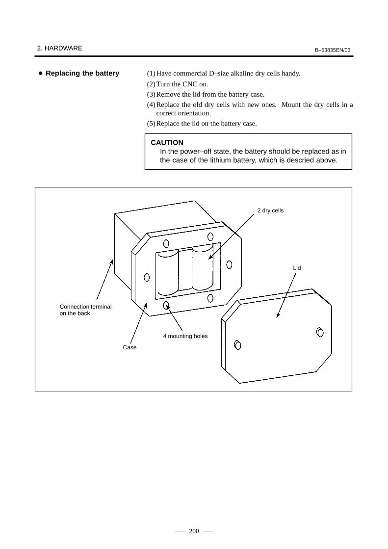
2. HARDWARE B–63835EN/03
200
(1)Have commercial D–size alkaline dry cells handy.
(2)Turn the CNC on.
(3)Remove the lid from the battery case.
(4)Replace the old dry cells with new ones. Mount the dry cells in acorrect orientation.
(5)Replace the lid on the battery case.
CAUTIONIn the power–off state, the battery should be replaced as inthe case of the lithium battery, which is descried above.
Connection terminalon the back
Case
4 mounting holes
2 dry cells
Lid
� Replacing the battery

B–63835EN/03 2. HARDWARE
201
If the voltage of a battery drops, the screen on the LCD flashes. (If a fanalarm is issued, the screen on the LCD also flashes.) If this status occurs,replace the battery as soon as possible (within 1 week). FANUCrecommends that each battery be replaced periodically (once a year)regardless of whether a battery alarm is issued.
The BIOS settings are usually preserved as long as the battery is replacedaccording to the following procedure. If they are lost, the followingmessage is displayed when the power is turned on:
251: System CMOS checksum bad – Default configuration used.After this, the default BIOS settings are loaded, and the unit restartsautomatically. Before starting machining, check that the current BIOSsettings of the CNC display unit with PC functions in use have beenchanged from the default BIOS settings, and resume your settings asrequired.
(1)After keeping the CNC display unit with PC functions powered for atleast 5 seconds, turn it off, and enable work to be done from the rear,for example, by removing the battery section from the panel.
(2)Remove the connector from the lithium battery, and take the batteryout from the battery holder.
(3)Attach the connector (BAT1) to a new battery within 5 minutes, andput the battery in the battery holder.
(4)Put the CNC display unit with PC functions back into the previousplace.
(5)Turn the power on, and check that no BIOS parameter is lost (no erroris detected at start–up).
NOTEBe sure to install a new battery within 5 minutes after the oldone is removed from the connector.
2.11.2Batteries for CNCDisplay Unit with PCFunctions (3VDC)

2. HARDWARE B–63835EN/03
202
Lithium batteryA02B–0200–K102
Connector(BAT1)
Battery holder
Fig. 2.11.2 Battery replacement
One battery unit can maintain current position data for six absolute pulsecoders for a year.When the voltage of the battery becomes low, APC alarms 3n6 to 3n8 (n:axis number) are displayed on the LCD display. When APC alarm 3n7is displayed, replace the battery as soon as possible. In general, the batteryshould be replaced within one or two weeks, however, this depends on thenumber of pulse coders used.If the voltage of the battery becomes any lower, the current positions forthe pulse coders can no longer be maintained. Turning on the power tothe control unit in this state causes APC alarm 3n0 (reference positionreturn request alarm) to occur. Return the tool to the reference positionafter replacing the battery. Therefore, FANUC recommends that the battery be replaced once a yearregardless of whether APC alarms are generated.See Connection Manual (Hardware) (B–63833EN) for details ofconnecting the battery to separate absolute pulse coders.
2.11.3Battery for SeparateAbsolute Pulse Coders(6VDC)

B–63835EN/03 2. HARDWARE
203
Obtain four commercially available alkaline batteries (size D).
(1)Turn on the power to the machine (Series 0i/0i Mate).
(2)Loosen the screws of the battery case, and remove the cover.
(3)Replace the dry batteries in the case.Note the polarity of the batteries as shown in the figure below (orienttwo batteries one way and the other two in the opposite direction).
ŸŸ
ŸŸŸ
Ÿ
Ÿ
ÇÇ
ÇÇÇÇŸ
Ÿ Ÿ
Screws
Cover
(4)After installing the new batteries, replace the cover.
(5)Turn off the power to the machine (Series 0i/0i Mate).
WARNINGIf the batteries are installed incorrectly, an explosion mayoccur. Never use batteries other than the specified type(Size D alkaline batteries).
CAUTIONReplace batteries while the power to the i Series CNC is on.Note that, if batteries are replaced while no power issupplied to the CNC, the recorded absolute position is lost.
The battery for the absolute pulse coder built into the motor is installedin the servo amplifier. For how to connect and replace the battery, referto the following manuals:
� FANUC SERVO MOTOR αi series Maintenance Manual
� FANUC SERVO MOTOR β series Maintenance Manual
� FANUC SERVO MOTOR β series (I/O Link Option) MaintenanceManual
Replacing batteries
2.11.4Battery for AbsolutePulse Coder Built intothe Motor (6VDC)

2. HARDWARE B–63835EN/03
204
WARNINGIf the cabinet is opened to replace a fan unit, take extremecare not to touch any high–voltage area (marked with and covered by a shock prevention cover). If the area isuncovered, direct contact with this area will result in anelectric shock.
Ordering information Quantity
For 1–slot cabinet (0i Mate–B) A02B–0265–C101 1
For 2–slot cabinet (0i–B) A02B–0260–C021 1
(1)Before starting the replacement of a fan unit, turn the CNC off.
(2)Pull the fan unit to be replaced.
(3)Lift the pulled fan unit until the fan unit is detached from the cabinet.
(4)Place a new fan unit on the cabinet.
(5)Push the new unit as far as it goes. When a click is heard, the unit isconnected to the fan connector.
Fan unit
Cabinet
(3), (4)
(2), (5)
2.12REPLACING A FANUNIT
� Ordering information offan units
� Replacing a fan unit

B–63835EN/03 2. HARDWARE
205
WARNINGBefore starting the replacement of the fuse, remove thecause of the fuse burn–out.Accordingly, the replacement should be performed by aperson fully trained in maintenance and safety. If thecabinet is opened to replace the fuse, take extreme care notto touch any high–voltage area (marked with andcovered by a shock prevention cover). If the area isuncovered, direct contact with this area will result in anelectric shock.
LCD unit (rear face)
Fuse
� Information of the fuseOrdering information: A02B–0265–K101Rating: 2.0 AIndividual information: A60L–0001–0290#LM20C
2.13REPLACING THEFUSE OF THE LCDUNIT
� Mounting position of thefuse

2. HARDWARE B–63835EN/03
206
WARNINGThe replacement described here should be performed by aperson fully trained in maintenance and safety. If thecabinet is opened to replace the unit, take extreme care notto touch any high–voltage area (marked with andcovered by a shock prevention cover). If the area isuncovered, direct contact with this area will result in anelectric shock.
The contrast of the LCD is reduced at a low ambient temperature. (Inparticular, immediately after power–up, the contrast of the LCD screenbecomes lower.) This is due to the characteristics of the LCD rather thana LCD failure. The LCD screen becomes bright as the ambienttemperature rises.The monochrome LCD has a function for adjusting the contrast.For instructions on adjusting the contrast, see Section 1.16,”CONTRAST ADJUSTMENT.”
Backlight Ordering information Individual information
For 7.2″ LCD A02B–0236–K112 A61L–0001–0142/BL (for Hitachi products)A61L–0001–0142/BL (for Sharp products)
For 8.4″ LCD A02B–0236–K119 A61L–0001–0176/BL
For 10.4″ LCD A02B–0236–K116 A61L–0001–0168/BL
2.14REPLACING THELCD BACKLIGHT
Contrast of themonochrome LCD
� Ordering information ofbacklights

B–63835EN/03 2. HARDWARE
207
For the 7.2–inch LCD
(1)Remove the inverter cable and video signal cable and then removeLCD control unit.
LCD unit (rear view)
(2)From the front of the LCD, remove the screws for the inverter coverand then replace the inverter.
LCD unit (front view)
Backlight
(3)After replacing the inverter, assemble the unit in the reverse order inwhich it was disassembled.At this time, take care to prevent dust or dirt from entering the unit.
� Replacement procedure

2. HARDWARE B–63835EN/03
208
For the 8.4–inch LCD
(1)Remove the inverter cable and video signal cable and then remove theLCD control unit.
LCD unit (rear view)
(2)From the rear of the LCD, remove the screws for the inverter cover andthen replace the inverter.
LCD panel
Backlight
(3)After replacing the inverter, assemble the unit in the reverse order inwhich it was disassembled.At this time, take care to prevent dust or dirt from entering the unit.

B–63835EN/03 2. HARDWARE
209
For the 10.4–inch LCD
(1)Remove the inverter cable and video signal cable and then remove theLCD control unit.
LCD unit (rear view)
(2)Remove the LCD unit from the sheet metal.
LCD panel
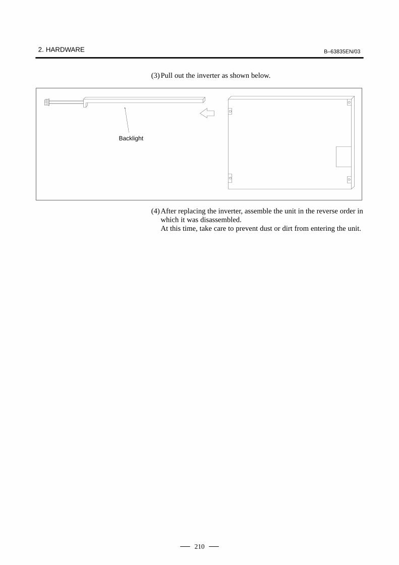
2. HARDWARE B–63835EN/03
210
(3)Pull out the inverter as shown below.
Backlight
(4)After replacing the inverter, assemble the unit in the reverse order inwhich it was disassembled.At this time, take care to prevent dust or dirt from entering the unit.

B–63835EN/03 2. HARDWARE
211
� indicates ”Applicable.”
Unit Series0i
Series0i Mate
Heatloss
Control unit 1–slot — � 30W
2–slot (without data server) � — 50W
2–slot (with data server) � — 60W
Option card Ethernet card � — 10Wfor mini slot
HSSB card � — 3W
DNC2 card � — 6W
FL–Net card � — 6W
DeviceNet card � — 5W
PROFIBUS card � — 6W
9”CRT/MDI unit � � 14W
7.2”LCD/MDI unit � � 20W
8.4”LCD/MDI unit � — 10W
8.4”LCD unit � — 10W
10.4”LCD unit � — 18W
MDI unit (small) � — 0W
MDI unit (full key) � — 0W
I/O module for operator’s panel (with MPG interface)
� � 12W
I/O module for operator’s panel (without MPG interface)
� � 12W
I/O module for connector panel (basic) � — 8W
I/O module for connector panel (addition) � — 5W
Machine operator’s panel unit � � 10W
Separate detector interface unit � � 9W
Heat from the MDI unit is negligible.
2.15HEAT LOSS OF EACHUNIT

2. HARDWARE B–63835EN/03
212
By changing the setting (rotary switch) on an expansion module, aconnection can be made to skip an expansion module or expansionmodules as shown below.
Bas
ic m
odul
e
Bas
ic m
odul
e
Bas
ic m
odul
e
Bas
ic m
odul
e 1
Bas
ic m
odul
e 2
Bas
ic m
odul
e 3
Bas
ic m
odul
e 1
Bas
ic m
odul
e 1
Bas
ic m
odul
e 2
Bas
ic m
odul
e 2
Bas
ic m
odul
e 3
Bas
ic m
odul
e 3
When expansion module 1 isskipped
When expansion module 2 isskipped
When expansion modules 1 and2 are skipped
Method of setting (control and setting method)
A control (rotary switch) is provided on the location shown below of eachexpansion module. When changing the setting, turn the rotary switchwith a flat–blade screwdriver with a tip diameter of about 2.5 mm.
Each setting position of the rotary switch has the meaning as indicatedbelow.
Settingposition
Indication Meaning of setting
0 0 Standard setting. The rotary switch is set to thisposition at the time of shipment from FANUC.This setting is not skipped an expansion module.
1 – Set the rotary switch of an expansion module to thisposition when the one preceding expansion moduleis skipped.
2.16DISTRIBUTED I/OSETTING (Series 0i–B ONLY)

B–63835EN/03 2. HARDWARE
213
Settingposition
Meaning of settingIndication
2 2 Set the rotary switch of an expansion module to thisposition when the two preceding expansion mod-ules are skipped.
3 – Setting prohibited
4 to F 4, –, 6, –, 8, –, A, –, C, –, E, –,
4, 8, or C has the effect of 0.5, 9, or D has the effect of 1.6, A, or E has the effect of 2.7, B, or F has the effect of 3. (← setting prohibited)
Examples of settingB
asic
mod
ule
Bas
ic m
odul
e 1
Bas
ic m
odul
e 2
Bas
ic m
odul
e 3
Bas
ic m
odul
e
Bas
ic m
odul
e 1
Bas
ic m
odul
e 2
Bas
ic m
odul
e 3
Bas
ic m
odul
e
Bas
ic m
odul
e 1
Bas
ic m
odul
e 2
Bas
ic m
odul
e 3
(When expansion module 1 is skipped)Set the rotary switch of expansion module 2to setting position = 1. Do not change thesetting (setting position = 0) of expansionmodule 3.
(When expansion module 1 and expansionmodule 2 are skipped)Set the rotary switch of expansion module 3to setting position = 2.
(When expansion module 2 is skipped)Set the rotary switch of expansion module 3to setting position = 1. Do not change thesetting (setting position = 0) of expansionmodule 1.
This function was not available initially, but was recently added. Thisfunction became available, depending on the type of module, as indicatedbelow.
Expansion module B (DI/DO =24/16, without a manual pulsegenerator interface)
A03B–0815–C003 Available starting with shipmentin June 1998 and later
Expansion module C (DO = 16,24A output)
A03B–0815–C004 Available starting with shipmentin August 1998 and later
Expansion module D (analoginput)
A03B–0815–C005 Available starting with shipmentin August 1998 and later

2. HARDWARE B–63835EN/03
214
NOTETo expansion module A (DI/DO = 24/16, with a manual pulsegenerator interface) (A03B–0815–C002), a rotary switch isadded as the other modules are modified. However,expansion module A is always installed at the location ofexpansion module 1, so that the setting of expansionmodule A need not be changed.

B–63835EN/03 2. HARDWARE
215
WARNINGBefore replacement of a blown fuse, the cause of the blownfuse must be corrected. So, fuse replacement work must bedone only by a person who is trained in the relatedmaintenance and safety requirements. When opening thecabinet and replacing a fuse inside, be careful not to touchthe high–voltage circuits (marked with and fitted with aninsulating cover). Touching the uncovered high–voltagecircuits presents an extremely dangerous electric shockhazard.
For the specification of the fuse of each unit, see the list of consumablesin Appendix B.
2.17REPLACING FUSESON VARIOUS UNITS

2. HARDWARE B–63835EN/03
216
Fuse
Cable for the I/O Link
Cable for a manual pulse generator
Basic module(A03B–0815–C001)
Expansion module 1
Expansion module 2
Expansion module 3
NOTENo fuse is provided on the expansion modules. A fuse isprovided on the basic module only.
� Fuse mounting locationon the connector panelI/O modules

B–63835EN/03 2. HARDWARE
217
JD1A
JD1B
JA3
I/O connector
Power supply connectorFuse
This drawing is for A20B–2002–0470, A20B–2002–0520, andA20B–2002–0521.
Powerconnector
FuseOpticalconnector
� Fuse mounting locationon the operator’s panelI/O modules
� Fuse mounting locationon the separate detectorinterface unit
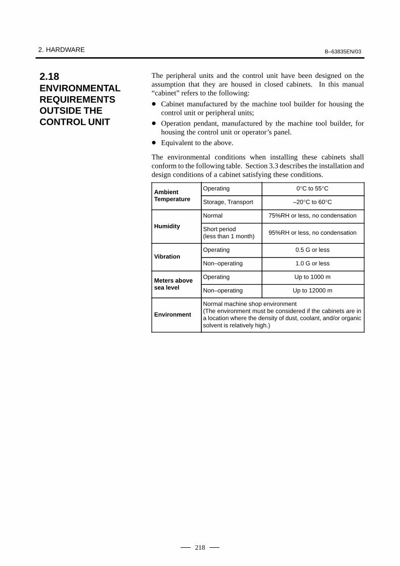
2. HARDWARE B–63835EN/03
218
The peripheral units and the control unit have been designed on theassumption that they are housed in closed cabinets. In this manual“cabinet” refers to the following:
� Cabinet manufactured by the machine tool builder for housing thecontrol unit or peripheral units;
� Operation pendant, manufactured by the machine tool builder, forhousing the control unit or operator’s panel.
� Equivalent to the above.
The environmental conditions when installing these cabinets shallconform to the following table. Section 3.3 describes the installation anddesign conditions of a cabinet satisfying these conditions.
Ambient Operating 0°C to 55°CAmbient Temperature Storage, Transport –20°C to 60°C
Normal 75%RH or less, no condensation
Humidity Short period (less than 1 month)
95%RH or less, no condensation
Operating 0.5 G or lessVibration
Non–operating 1.0 G or less
Meters above Operating Up to 1000 mMeters abovesea level Non–operating Up to 12000 m
Environment
Normal machine shop environment(The environment must be considered if the cabinets are ina location where the density of dust, coolant, and/or organicsolvent is relatively high.)
2.18ENVIRONMENTALREQUIREMENTSOUTSIDE THECONTROL UNIT

B–63835EN/03 2. HARDWARE
219
The CNC has been steadily reduced in size using surface–mount andcustom LSI technologies for electronic components. The CNC also isdesigned to be protected from external noise. However, it is difficult tomeasure the level and frequency of noise quantitatively, and noise hasmany uncertain factors. It is important to prevent both noise from beinggenerated and generated noise from being introduced into the CNC. Thisprecaution improves the stability of the CNC machine tool system.
The CNC component units are often installed close to the parts generatingnoise in the power magnetics cabinet. Possible noise sources into theCNC are capacitive coupling, electromagnetic induction, and groundloops.
When designing the power magnetics cabinet, guard against noise in themachine as described in the following section.
The cables used for the CNC machine tool are classified as listed in thefollowing table:
Process the cables in each group as described in the action column.
Group Signal line Action
Primary AC power line Bind the cables in group A sepa-
Secondary AC power linerately (Note 1) from groups Band C, or cover group A with an
AAC/DC power lines (containing thepower lines for the servo andspindle motors)
electromagnetic shield (Note 2).
See Subsec. 2.19.4 and con-nect spark killers or diodes withthe solenoid and relay.
AC/DC solenoid
the solenoid and relay.
AC/DC relay
DC solenoid (24VDC) Connect diodes with DC sole-noid and relay.
DC relay (24VDC) Bind the cables in group B sepa-rately from group A, or cover
B DI/DO cable between the CNCand power magnetics cabinet
group B with an electromagneticshield.
Separate group B as far from
DI/DO cable between the CNCand machine
Group C as possible.
It is more desirable to covergroup B with the shield.
2.19ACTION AGAINST NOISE
2.19.1Separating SignalLines

2. HARDWARE B–63835EN/03
220
Group ActionSignal line
Cable for position and velocityfeedback
Bind the cables in group C sepa-rately from group A, or cover
Cable between the CNC andspindle amplifier
group C with an electromagnet-ic shield.
Separate group C as far from
Cable for the position coder Group B as possible.
Cable for the manual pulse gener-ator
Be sure to perfrom shield pro-cessing in Subsec. 2.19.5.
CCable between the CNC and theCRT/MDI
RS–232–C and RS–422 interfacecable
Cable for the battery
Other cables to be covered with theshield
NOTE1 The groups must be 10 cm or more apart from one another
when binding the cables in each group.2 The electromagnetic shield refers to shielding between
groups with grounded steel plates.
Cable of group B, C
Cable of group A
Cabinet
Spindle amp.
Servo amp.
Control unit
DuctTo operator’s panel, motor, etc.
Section
Group A Group B, C
Cover

B–63835EN/03 2. HARDWARE
221
The following ground systems are provided for the CNC machine tool:
(1)Signal ground system (SG)
The signal ground (SG) supplies the reference voltage (0 V) of theelectrical signal system.
(2)Frame ground system (FG)
The frame ground system (FG) is used for safety, and suppressingexternal and internal noises. In the frame ground system, the frames,cases of the units, panels, and shields for the interface cables betweenthe units are connected.
(3)System ground system
The system ground system is used to connect the frame groundsystems connected between devices or units with the ground.
Power magnet-ics unit
Servoamplifier
CNCcontrol unit
Powermagneticscabinet
Distribution board
Operator’spanel
Machinetool
System ground systemFrame ground sysytemSignal ground system
� Connect the signal ground with the frame ground (FG) at only oneplace in the CNC control unit.
� The grounding resistance of the system ground shall be 100 ohms orless (class 3 grounding).
� The system ground cable must have enough cross–sectional area tosafely carry the accidental current flow into the system ground whenan accident such as a short circuit occurs.(Generally, it must have the cross–sectional area of the AC power cableor more.)
� Use the cable containing the AC power wire and the system groundwire so that power is supplied with the ground wire connected.
2.19.2Ground
Notes on connecting theground systems

2. HARDWARE B–63835EN/03
222
PE
M3 (screw hole)M4 (screw hole)
Ground plate ofthe cabinet
Ground cable (upper 2mm2)
Series 0i control unit
Connect the 0 V line of the electronic circuit in the control unit with theground plate of the cabinet via the signal ground (SG) terminal.The SG terminal is located below the main board of the control unit.
2.19.3Connecting the SignalGround (SG) of theControl Unit
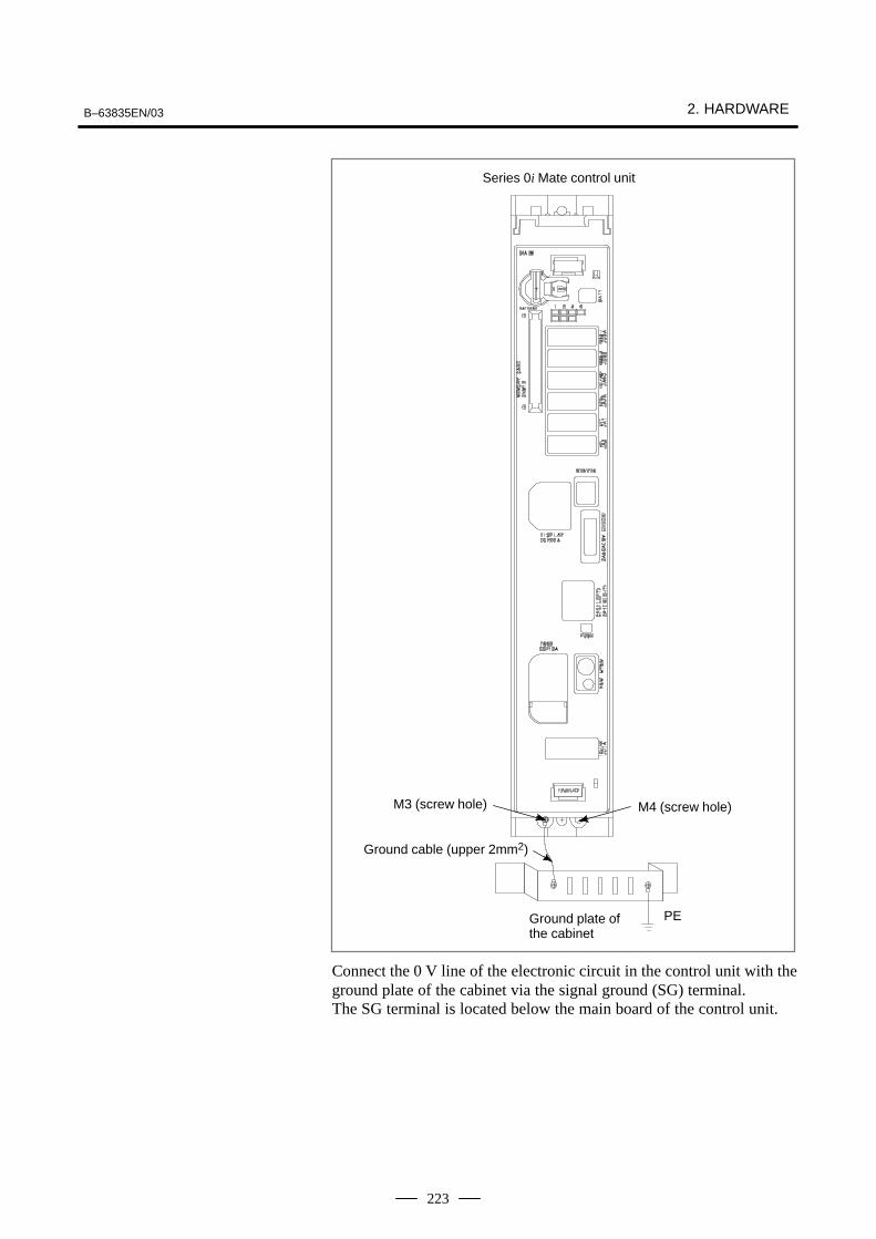
B–63835EN/03 2. HARDWARE
223
M3 (screw hole) M4 (screw hole)
Ground plate ofthe cabinet
Ground cable (upper 2mm2)
Series 0i Mate control unit
PE
Connect the 0 V line of the electronic circuit in the control unit with theground plate of the cabinet via the signal ground (SG) terminal.The SG terminal is located below the main board of the control unit.

2. HARDWARE B–63835EN/03
224
M4 stud
M4 stud
MDI CRT
9″ CRT/MDI unit8.4″ LCD/MDI unit
Approx. 20 mm (for 9″ CRT/MDI unit)Approx. 150 mm (for 8.4″ LCD/MDI unit)
App
rox.
15m
m
LCDMDI
7.2″ LCD/MDI unitApprox. 151mm
LCD
10.4″ LCD unit
App
rox.
17m
m
M4 stud
App
rox.
20m
m
Approx. 50mm
M4 stud
Approx. 37mm
App
rox.
17m
m
LCD
7.2″ LCD unit
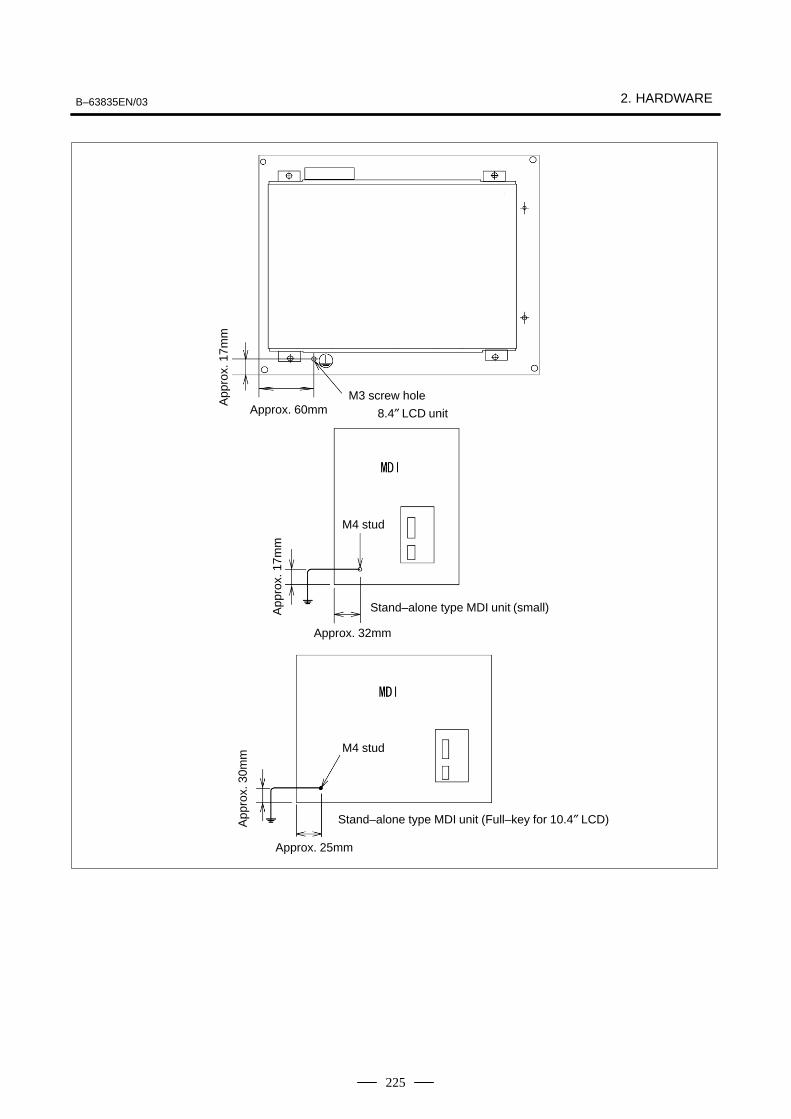
B–63835EN/03 2. HARDWARE
225
Stand–alone type MDI unit (small)
8.4″ LCD unit
App
rox.
17m
m
App
rox.
17m
m
M4 stud
Approx. 60mm
Approx. 32mm
Approx. 25mm
M3 screw hole
Stand–alone type MDI unit (Full–key for 10.4″ LCD)App
rox.
30m
m
M4 stud
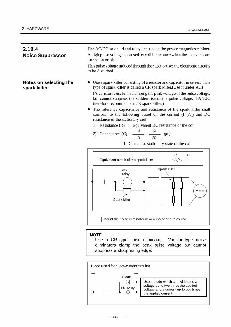
2. HARDWARE B–63835EN/03
226
The AC/DC solenoid and relay are used in the power magnetics cabinet.
A high pulse voltage is caused by coil inductance when these devices areturned on or off.
This pulse voltage induced through the cable causes the electronic circuitsto be disturbed.
� Use a spark killer consisting of a resistor and capacitor in series. Thistype of spark killer is called a CR spark killer.(Use it under AC)
(A varistor is useful in clamping the peak voltage of the pulse voltage,but cannot suppress the sudden rise of the pulse voltage. FANUCtherefore recommends a CR spark killer.)
� The reference capacitance and resistance of the spark killer shallconform to the following based on the current (I (A)) and DCresistance of the stationary coil:1) Resistance (R) : Equivalent DC resistance of the coil
2) Capacitance (C) :20
I2(µF)to
I2
10
I : Current at stationary state of the coil
Equivalent circuit of the spark killerR C
Spark killer
Spark killer
Motor
ACrelay
Mount the noise eliminator near a motor or a relay coil.
NOTEUse a CR–type noise eliminator. Varistor–type noiseeliminators clamp the peak pulse voltage but cannotsuppress a sharp rising edge.
Use a diode which can withstand avoltage up to two times the appliedvoltage and a current up to two timesthe applied current.
Diode
DC relay
Diode (used for direct–current circuits)
2.19.4Noise Suppressor
Notes on selecting thespark killer

B–63835EN/03 2. HARDWARE
227
The CNC cables that require shielding should be clamped by the methodshown below. This cable clamp treatment is for both cable support andproper grounding of the shield. To insure stable CNC system operation,follow this cable clamp method.
Partially peel out the sheath and expose the shield. Push and clamp bythe plate metal fittings for clamp at the part. The ground plate must bemade by the machine tool builder, and set as follows :
Cable
Metal fittings for clamp
Ground plate
40m
m –
80m
m
Fig.2.19.5(a) Cable clamp (1)
2.19.5Cable Clamp andShield Processing

2. HARDWARE B–63835EN/03
228
ÇÇÇÇÇÇÇÇÇÇÇÇÇÇÇÇÇÇÇÇÇÇÇÇÇÇÇÇÇÇÇÇÇÇ
Control unit
Ground plate
Metal fittings for clamp
Shield cover
Machine sideinstallationboard
Fig.2.19.5(b) Cable clamp (2)
Prepare ground plate like the following figure.
Mount screw hole
Hole for securing metal fitting clamp
Ground terminal(grounded)
Fig.2.19.5(c) Ground plate
For the ground plate, use a metal plate of 2 mm or thicker, which surfaceis plated with nickel.

B–63835EN/03 2. HARDWARE
229
12mm
20mm
8mmGroundplate
Fig.2.19.5(d) Ground plate holes
(Reference) Outer drawings of metal fittings for clamp.
17mm
28mm
6mm
Max. 55mm
Fig.2.19.5(e) Outer drawings of metal fittings for clamp
Ordering specification for metal fittings for clampA02B–0124–K001 (8 pieces)

2. HARDWARE B–63835EN/03
230
Item Ordering number
Lithium battery A02B–0200–K102
2.20REPLACING THEMAINTENANCEPARTS OF CNCDISPLAY UNIT FORPC FUNCTIONS ANDPANEL i
2.20.1Replacing the Battery
� Ordering number

B–63835EN/03 2. HARDWARE
231
(1)After a lapse of five minutes from power up, power off the CNCdisplay unit with PC functions or the PANEL i. Then remove the CNCdisplay unit with PC functions or the PANEL i from the panel so thatit can be accessed from the back.
(2)Remove the connector for the lithium battery, then remove the batteryfrom the battery holder.
(3)Within five minutes, plug the connector (BAT1) for a new battery andinsert a new battery.
(4)Reinstall the CNC display unit with PC functions or the PANEL i.
(5)Turn on the power and make sure the BIOS parameter is not cleared(no error occurs during startup).
Battery holder
Lithium batteryA02B–0200–K102
Connector(BAT1)
Fig. 2.20.1 Replacing the battery
NOTEIt must not take more than five minutes from the time the oldbattery is removed until the connector for the new battery isplugged into the connector.
� Replacing method

2. HARDWARE B–63835EN/03
232
When this procedure is used to replace the battery, normally the BIOSsettings are not cleared. However, in case the settings are cleared, thefollowing message appears during power up, the default BIOS settingsare loaded, and the unit automatically reboots.
251: System CMOS checksum bad – Default configuration used.
Therefore, check whether the default settings of the CNC display unitwith PC functions or the PANEL i are changed before maintenance. If thesettings are cleared to the defaults, restore the BIOS settings.
WARNINGBefore replacing the fuse, eliminate the cause by which thefuse blew.Therefore, only those personnel who were well trained formaintenance and safety can perform the replacement.When replacing the fuse with the cabinet open, be carefulnot to touch the part containing high–voltage circuits.Otherwise, you receive an electric shock.
A fuse blows when there is a short circuit in the CNC display unit withPC functions or the PANEL i. When the fuse blows, check the followingpoints.
� A conductive part touches the main printed circuit board.
� A PCI extension board failed or is incorrectly inserted.
� A cable is incorrectly connected.
When the fuse blows, the system may suffer damage. Before turning onthe power again, make visual and smell inspection to check the system foran abnormality and replace the failed parts if any.
Item Ordering number
Fuse For A08B–0082–B001 to –B004, –B011 to –B014,–B031 to –B038, A13B–0193–B031 to –B038
A02B–0236–K101
A08B–0082–B021 to –B024, –B041 to –B048,–B051 to –B058, A13B–0193–B041 to –B048,–B051 to –B058
A08B–0082–K001
2.20.2Replacing the Fuse
� Ordering number

B–63835EN/03 2. HARDWARE
233
(1)Make sure the CNC display unit with PC functions or the PANEL i ispowered off.
(2)Remove the CNC display unit with PC functions or the PANEL i fromthe panel so that it can be accessed from the back.
(3)Remove the old fuse from the socket, then securely insert a new oneinto it.
(4)Reinstall the CNC display unit with PC functions or the PANEL i.
(5)Turn on the power and verify that the CNC display unit with PCfunctions or the PANEL i starts up normally.
Fuse : A02B–0236–K101
For A08B–0082–B001to –B004, –B011 to –B014, –B031 to B–038,A13B–0193–B031 toB–038
A08B–0082–B021 to –B024,–B041 to –B048, –B051 to–B058, A13B–0193–B041 to–B048, –B051 to –B058
Fuse : A08B–0082–K001
Item Ordering number
Fan for main body A08B–0082–K010
Fan for HDD A13B–0178–K001
� Replacing method
2.20.3Replacing the Fan� Ordering number

2. HARDWARE B–63835EN/03
234
(1)Make sure the CNC display unit with PC functions or the PANEL i ispowered off.
(2)Loosen the two screws (A), then remove the fan retaining metal sheet.
(3)Remove the fan connector (CN6). Since the connector is fixed witha latch, pull out the connector while opening the latch with a flatbladescrewdriver, as shown below.
(4)Loosen the two screws (B), then replace the fan.
(5) Install a new fan in the unit by reversing the removal procedure. Atthis time, be sure to install the fan in the correct direction.
CN6 FANFanA08B–0082–K010Be sure to installthe fan in the cor-rect direction.
For A08B–0082–B001 to –B004, –B011 to –B014,–B021 to –B024
Two screws (A)
Fan retaining metal sheet
� Replacing the fan formain body
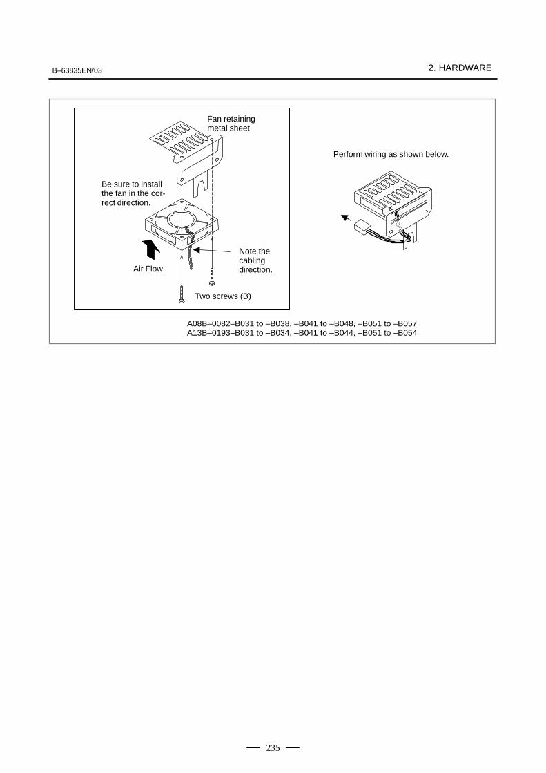
B–63835EN/03 2. HARDWARE
235
Perform wiring as shown below.
Note thecablingdirection.
Two screws (B)
Fan retainingmetal sheet
Be sure to installthe fan in the cor-rect direction.
Air Flow
A08B–0082–B031 to –B038, –B041 to –B048, –B051 to –B057A13B–0193–B031 to –B034, –B041 to –B044, –B051 to –B054

2. HARDWARE B–63835EN/03
236
(1)Make sure the CNC display unit with PC functions or the PANEL i ispowered off.
(2)Remove the fan connector (CN7) on the main board. Since theconnector is fixed with a latch, pull out the connector while lifting theconnector lightly to open the latch.
(3)Loosen the two screws that retain the fan, then remove it.
(4)Retain a new fan with the two screws, then connect the cable to theconnector (CN7).
Two screws
Fan
CN7
Fig. 2.20.3 Replacing the FAN for HDD
LCD back–light can not be replaced for CNC display unit with PCfunctions or PANEL i.
� Replacing the fan forHDD
2.20.4Replacing the LCDBack–Light
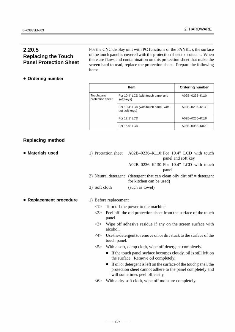
B–63835EN/03 2. HARDWARE
237
For the CNC display unit with PC functions or the PANEL i, the surfaceof the touch panel is covered with the protection sheet to protect it. Whenthere are flaws and contamination on this protection sheet that make thescreen hard to read, replace the protection sheet. Prepare the followingitems.
Item Ordering number
Touch panelprotection sheet
For 10.4” LCD (with touch panel andsoft keys)
A02B–0236–K110
For 10.4” LCD (with touch panel, with-out soft keys)
A02B–0236–K130
For 12.1” LCD A02B–0236–K118
For 15.0” LCD A08B–0082–K020
1) Protection sheet A02B–0236–K110: For 10.4” LCD with touchpanel and soft key
A02B–0236–K130:For 10.4” LCD with touchpanel
2) Neutral detergent (detergent that can clean oily dirt off = detergentfor kitchen can be used)
3) Soft cloth (such as towel)
1) Before replacement
<1> Turn off the power to the machine.
<2> Peel off the old protection sheet from the surface of the touchpanel.
<3> Wipe off adhesive residue if any on the screen surface withalcohol.
<4> Use the detergent to remove oil or dirt stuck to the surface of thetouch panel.
<5> With a soft, damp cloth, wipe off detergent completely.
� If the touch panel surface becomes cloudy, oil is still left onthe surface. Remove oil completely.
� If oil or detergent is left on the surface of the touch panel, theprotection sheet cannot adhere to the panel completely andwill sometimes peel off easily.
<6> With a dry soft cloth, wipe off moisture completely.
2.20.5Replacing the TouchPanel Protection Sheet
� Ordering number
Replacing method
� Materials used
� Replacement procedure

2. HARDWARE B–63835EN/03
238
2) Applying the protection sheet
2–1) For A02B–0236–K110
<1> Fold the tab over the front side (the side opposite to thebacking sheet).
Fold
<2> Peel off the backing sheet.
<3> Position the sheet, then attach the upper and lower sidesof the sheet first. Check that the sides of the protectionsheet do not touch the escutcheon.
NGOK
<4> Attach the right and left sides of the protection sheetwhile pushing out air between the touch panel andprotection sheet.
� With part of the protection sheet kept stuck to thetouch panel, do not attempt to correct the position ofthe protection sheet by pulling the sheet.
<5> Press the adhesive parts of the four sides, and attach theentire sheet completely.
� Check that the four corners and four sides of theprotection sheet do not float.
2–2) For A02B–0236–K130
<1> Peel off the white film attached on the back (facing theLCD) of the new protection sheet.
<2> Attach the protection sheet so that it is to the lower–leftof the replacement tab. At this time, align the overhangedge at bottom of the escutcheon with the correspondingpart of the protection sheet. In addition, prevent dustfrom entering between the LCD and the protection sheet.

B–63835EN/03 2. HARDWARE
239
Guide position
<3> Attach the four sides while pushing out air between thetouch panel and the protection sheet.
� Do not pull the protection sheet to correct its positionwith the part of the sheet kept stuck to the touch panel.
<4> Press the adhesive parts of the four sides, and attach thesheet completely.
� Check that the four corners and four sides of theprotection sheet do not float.
3) Checks after replacement
<1> Check that there is no wrinkle on the surface of the protectionsheet.
<2> After power–on, check that there is no touch panel portion keptpressed.
<3> Press the touch panel, and check that correct operation takesplace.

2. HARDWARE B–63835EN/03
240
Touch panel compensation is required:
1 When the LCD unit is replaced
2 When the touch panel is replaced
3 When the touch panel control printed circuit board is replaced
4 Memory is all cleared.
#73113
#6 #5DTPCL
#4 #3 #2 #1 #0
[Data type] Bit
#5 (DTPCL) The compensation function for the touch panel on the display is:
0 : Disabled
1 : Enabled
1 Set bit 5 (DTPCL) of parameter No. 3113 to 1.
2 Press function key <SYSTEM>.
3 Pressing the continuous menu key several times displays soft key [TPCAL].
4 Pressing soft key [TP CAL] displays the touch panel compensationscreen.
CALIBRATION OF TOUCH PANEL
PLEASE PUSH CALIBRATED POINTS.IF CALIBRATION IS ENDED, PLEASE PUSH <INPUT> KEY.IF CALIBRATION IS CANCELED, PLEASE PUSH <CAN> KEY.IF OPERATION IS ENDED, PLEASE PUSH FUNCTION KEY.
5 Press the nine compensation points (marked with +) with touch panelpen. You may press the nine points in any order. When you press a+ mark correctly, the + mark blinks. When you press a + pointincorrectly, the message “CALIBRATED POINT DOES NOTMATCH, PLEASE PUSH AGAIN.” appears.
Touch panelcompensation
� Condition that requirescompensation
� Parameter setting
� Method of compensation

B–63835EN/03 2. HARDWARE
241
6 After pressing all of the nine compensation points, press the<INPUT> key to terminate compensation. To cancel compensationor start all over again, press the <CAN> key.
7 Upon normal termination, the message “CALIBRATION WASENDED.” appears.
8 Pressing the function key exits from the touch panel compensationscreen, and terminates or stops compensation operation.
9 Upon termination of compensation operation, set bit 5 (DTPCL) ofparameter No. 3113 to 0.
NOTETouch panel of the CNC display unit with PC functions iscompensated by the exclusive program.When compensating the touch panel for the is series, select[Start] → [Settings] → [Control Panel] → [Adjusting Stylus],instead of using the above method.
3. INPUT AND OUTPUT OF DATA B–63835EN/03
242
3 INPUT AND OUTPUT OF DATA
After you change a SRAM module, you must set various data again. This chapter describes the procedures to input and output the parameters,the part programs and the tool offset values.
3.1 SETTING PARAMETERS FOR INPUT/OUTPUT 243. . . . . . . . . . . . . . . . . . . . . . . . . . . .
3.2 INPUTTING/OUTPUTTING DATA 245. . . . . . . . . . . . . 3.3 DATA INPUT/OUTPUT ON THE
ALL IO SCREEN 254. . . . . . . . . . . . . . . . . . . . . . . . . . . . 3.4 DATA INPUT/OUTPUT USING A
MEMORY CARD 269. . . . . . . . . . . . . . . . . . . . . . . . . . .

B–63835EN/03 3. INPUT AND OUTPUT OF DATA
243
Parameter writing is enabled with following steps 1 to 3.
1. Set to MDI mode or emergency stop state.
2. Press OFFSETSETTING key several times or press soft key [SETING] to display
SETTING (HANDY) screen.
3. Set the cursor to PARAMETER WRITE and, press 1 and INPUT
keys in this order. Here alarm 100 will be displayed.
4. Press SYSTEM key several times to display the following screen.
PARAMETER (SETTING) O1234N123450000 SEQ INI ISO TVC
0 0 0 0 0 0 0 00001 FCV
0 0 0 0 0 0 0 00012 RMV MIR
X 0 0 0 0 0 0 0 0Y 0 0 0 0 0 0 0 0Z 0 0 0 0 0 0 0 0B 0 0 0 0 0 0 0 0
0020 I/O CHANNELS 0 T0000
REF **** *** *** 10:15:30[ F SRH ][ READ ][ PUNCH ][DELETE ][ ]
To make the cursor display in bit unit, press the cursor key or .
5. Press soft key[(OPRT)] and the following operation menu isdisplayed.
1) Soft key [NO. SRH] : Searched by number. Examination) Parameter number → [NO. SRH].
2) Soft key [ON : 1] : Item with cursor position is set to 1 (bit parameter)
3) Soft key [OFF : 0] : Item with cursor position is set to 0 (bit parameter)
4) Soft key [+INPUT] : Input value is added to the value at cursor(word type)
5) Soft key [INPUT] : Input value is replaced with the value at cursor (word type)
6) Soft key [READ] : Parameters are input from reader/puncherinterface.
7) Soft key [PUNCH] : Parameters are output to reader/puncher interface.
3.1SETTINGPARAMETERS FOR INPUT/OUTPUT
� Setting procedure ofparameters

3. INPUT AND OUTPUT OF DATA B–63835EN/03
244
6. After the parameters have been input, set PARAMETER WRITE on
the SETTING screen to 0. Press RESET to release alram 100.
7. Convenient method
1) To change parameters in bit unit, press cursor key or ,
then the cursor becomes bit length and you can set parameters bitby bit (Bit parameter only).
2) To set data consecutively, use EOB key.
(Ex.1) 1 2 3 4 EOB 4 5 6 7 EOB 9
9 9 9 INPUT
This key sequence sets data as follows:0 1234 0 ⇒ 4567 0 9999
0 0
(Ex.2) 1 2 3 4 EOB EOB 9 9 9 9 INPUT
This key sequence sets data as follows:0 1234 0 ⇒ 0 0 9999
0 0
3) To set the same data sequentially, press = .
(Ex.) 1 2 3 4 EOB a EOB a INPUT
This key sequence sets data as follows:0 1234 0 ⇒ 1234 0 1234
0 0
4) Bit parameters can be set as follows:
(Ex.) 1 1 EOB a EOB a INPUT
This key sequence sets data as follows: 0 0 0 0 0 0 0 0 0 0 0 1 1 0 0 0 0 0 0 0 0 0 0 0 ⇒ 0 0 0 1 1 0 0 0 0 0 0 0 0 0 0 0 0 0 0 1 1 0 0 0 0 0 0 0 0 0 0 0 0 0 0 0 0 0 0 0
8. After the required parameters are set, set PARAMETER WRITE to0.
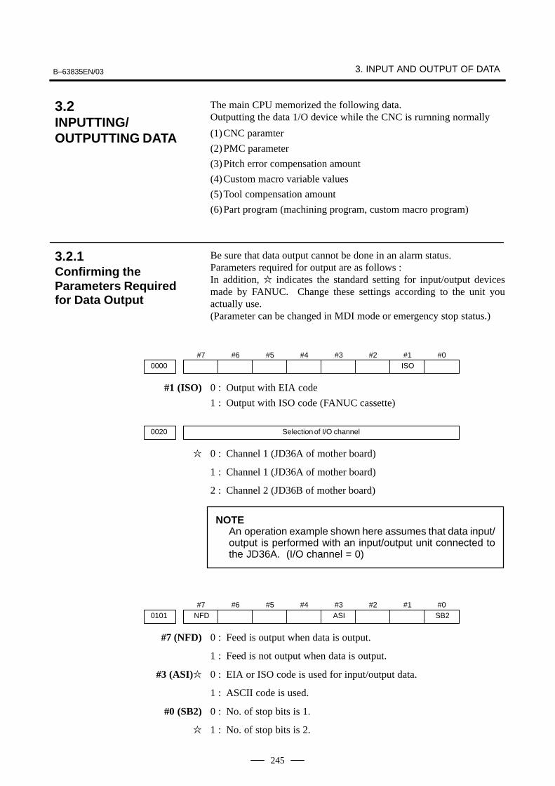
B–63835EN/03 3. INPUT AND OUTPUT OF DATA
245
The main CPU memorized the following data. Outputting the data 1/O device while the CNC is rurnning normally
(1)CNC paramter
(2)PMC parameter
(3)Pitch error compensation amount
(4)Custom macro variable values
(5)Tool compensation amount
(6)Part program (machining program, custom macro program)
Be sure that data output cannot be done in an alarm status.Parameters required for output are as follows :In addition, � indicates the standard setting for input/output devicesmade by FANUC. Change these settings according to the unit youactually use.(Parameter can be changed in MDI mode or emergency stop status.)
#70000
#6 #5 #4 #3 #2 #1ISO
#0
#1 (ISO) 0 : Output with EIA code
1 : Output with ISO code (FANUC cassette)
0020 Selection of I/O channel
� 0 : Channel 1 (JD36A of mother board)
1 : Channel 1 (JD36A of mother board)
2 : Channel 2 (JD36B of mother board)
NOTEAn operation example shown here assumes that data input/output is performed with an input/output unit connected tothe JD36A. (I/O channel = 0)
#7NFD0101
#6 #5 #4 #3ASI
#2 #1 #0SB2
#7 (NFD) 0 : Feed is output when data is output.
1 : Feed is not output when data is output.
#3 (ASI)� 0 : EIA or ISO code is used for input/output data.
1 : ASCII code is used.
#0 (SB2) 0 : No. of stop bits is 1.
� 1 : No. of stop bits is 2.
3.2INPUTTING/OUTPUTTING DATA
3.2.1Confirming theParameters Requiredfor Data Output

3. INPUT AND OUTPUT OF DATA B–63835EN/03
246
0102 pecification number of input/output device
Set value Input/output device
0 RS–232–C (Used control codes DC1 to DC4)1 FANUC CASSETTE ADAPTOR 1 (FANUC CASSETTE B1/ B2)2 FANUC CASSETTE ADAPTOR 3 (FANUC CASSETTE F1)3 FANUC PROGRAM FILE Mate, FANUC FA Card Adaptor
FANUC FLOPPY CASSETTE ADAPTOR, FANUC Handy FileFANUC SYSTEM P-MODEL H
4 RS–232–C (Not used control codes DC1 to DC4)5 Portable tape reader6 FANUC PPR
FANUC SYSTEM P-MODEL G, FANUC SYSTEM P-MODEL H
0103 Baud Rate
1: 50 5: 200 9: 2400
2: 100 6: 300 �10: 4800
3: 110 7: 600 11: 9600
4: 150 8: 1200 12: 19200 [BPS]
In case of PPR, steps 2 and 3 are not required.
1. Enter EDIT mode or the emergency stop condition.
2. PROG Press PROG key and soft key PRGRM to select a program text.
3. Press soft key [(OPRT)] and soft key .
And then, put out the head of file by pressing [FSRH] 0 [EXEC].
4. Press SYSTEM key and soft key [PARAM] to display parameter screen.
5. Press soft key [(OPRT)] ,and soft key .
6. Press soft key [PUNCH] and [EXEC],and the parameters are startedto be output.
3.2.2Outputting CNCParameters

B–63835EN/03 3. INPUT AND OUTPUT OF DATA
247
1. Select MDI mode.
2. Press OFFSETSETTING key then soft key [SETTING] to select a setting screen.
3. Set the cursor to PARAMETER WRITE and input 1 and INPUT .
At this time, alarm 100 will be generated.
4. Press SYSTEM key and soft key [PMC].
5. Press soft key [PMCPRM] and soft key [KEEPRL]6. Set the cursor to K17 and set the first bit to 1.
X X X X X X 1 X INPUT
Where, mark x is a former value
Thus, data input/output screen has been selected.
7. Select EDIT mode.
8. Press soft key then key .
9. Press soft key [I/O] and set the parameters on I/O.Item selection cursor moves to the following item after data of an itemis set.
10.In CHANNEL NO item, input 1 INPUT to select I/O channel 1.
11.In DEVICE item, press soft key [FDCAS] to select the floppy cassette.
12.In KIND DATA item, press soft key [PARAM].13.In FUNCTION item, press soft key [WRITE].14.In FILE No item, specify a file name. In this example input as follows:
@ P M C INPUT
15.Press soft key [EXEC]. Then PMC parameters are started to be output.
16.After the PMC parameters have been output, set PARAMETERWRITE to 0.
17.Press RESET to release alarm 100.
1. Select EDIT mode.
2. Press SYSTEM key several times, press soft key [PARAM], and
[PITCH] to select the SETTING screen for pitch error amount.
3. Press soft key [(OPRT)] and .
4. Press soft key [PUNCH] and [EXEC], then pitch error compensationamount is started to be output.
3.2.3Outputting PMCParameters
3.2.4Outputting Pitch ErrorCompensation Amount

3. INPUT AND OUTPUT OF DATA B–63835EN/03
248
When custom macro function is equipped, values of variable no. 500 andlater are output.
1. Press OFFSETSETTING key.
2. Press key and soft key [MACRO] to select custom macro
variable screen.
3. Press soft key [(OPRT)] and then key .
4. Press soft key [PUNCH] and [EXEC], then custom macro variablevalues are output.
1. Select EDIT mode.
2. Press OFFSETSETTING key and soft key [OFFSET] to display the tool
compensation amount screen.
3. Press [(OPRT)] key and soft key .
4. Press soft key [PUNCH] an [EXEC] key, and the tool compensationamount is started to be output.
1. Confirm the following parameters. If this parameter is set to 1, ratherthan the value indicated by �, change to MDI mode and then reset to 0.However, if you changed the parameter setting, restore the originalvalue after finishing this work.
#73202
#6 #5 #4NE9
#3 #2 #1 #0NE8
#4 (NE9) � 0 : Programs of 9000s are edited.
1 : Programs of 9000s can be protected.
#0 (NE8) � 0 : Programs of 8000s are edited.
1 : Programs of 8000s can be protected.
2. Select EDIT mode.
3. Press PROG key and press soft key [PRGRM] to display program text.
4. Press [(OPRT)] key and press soft key .
5. Input a program number to be output. To output all programs input as:
O – 9 9 9 9
6. Press [PUNCH] and [EXEC] key, then program output is started.
3.2.5Outputting CustomMacro Variable Values
3.2.6Outputting ToolCompensation Amount
3.2.7Outputting PartProgram
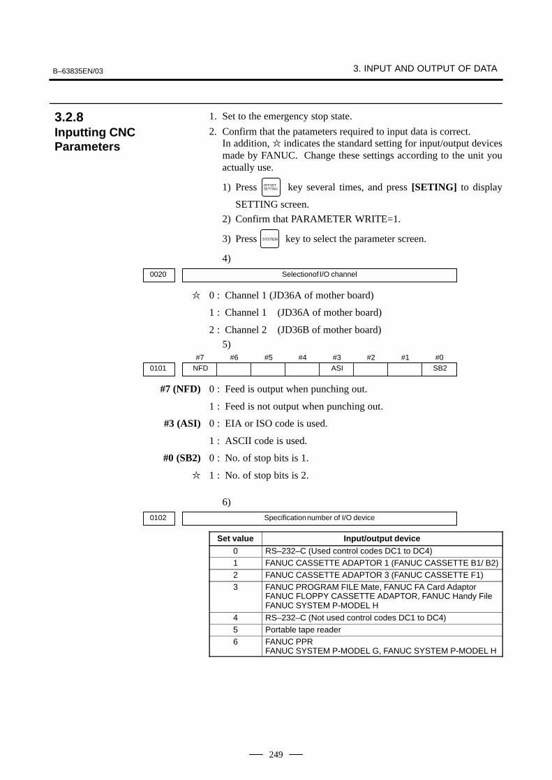
B–63835EN/03 3. INPUT AND OUTPUT OF DATA
249
1. Set to the emergency stop state.
2. Confirm that the patameters required to input data is correct.In addition, � indicates the standard setting for input/output devicesmade by FANUC. Change these settings according to the unit youactually use.
1) Press OFFSETSETTING key several times, and press [SETING] to display
SETTING screen.
2) Confirm that PARAMETER WRITE=1.
3) Press SYSTEM key to select the parameter screen.
4)
0020 Selectionof I/O channel
� 0 : Channel 1 (JD36A of mother board)
1 : Channel 1 (JD36A of mother board)
2 : Channel 2 (JD36B of mother board)
5)#7
NFD0101#6 #5 #4 #3
ASI#2 #1 #0
SB2
#7 (NFD) 0 : Feed is output when punching out.
1 : Feed is not output when punching out.
#3 (ASI) 0 : EIA or ISO code is used.
1 : ASCII code is used.
#0 (SB2) 0 : No. of stop bits is 1.
� 1 : No. of stop bits is 2.
6)
0102 Specification number of I/O device
Set value Input/output device
0 RS–232–C (Used control codes DC1 to DC4)1 FANUC CASSETTE ADAPTOR 1 (FANUC CASSETTE B1/ B2)2 FANUC CASSETTE ADAPTOR 3 (FANUC CASSETTE F1)3 FANUC PROGRAM FILE Mate, FANUC FA Card Adaptor
FANUC FLOPPY CASSETTE ADAPTOR, FANUC Handy FileFANUC SYSTEM P-MODEL H
4 RS–232–C (Not used control codes DC1 to DC4)5 Portable tape reader6 FANUC PPR
FANUC SYSTEM P-MODEL G, FANUC SYSTEM P-MODEL H
3.2.8Inputting CNCParameters
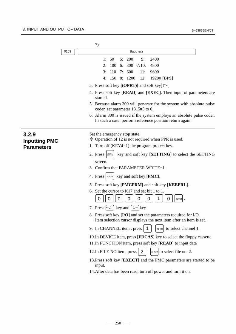
3. INPUT AND OUTPUT OF DATA B–63835EN/03
250
7)
0103 Baud rate
1: 50 5: 200 9: 2400
2: 100 6: 300 �10: 4800
3: 110 7: 600 11: 9600
4: 150 8: 1200 12: 19200 [BPS]
3. Press soft key [(OPRT)] and soft key
4. Press soft key [READ] and [EXEC]. Then input of parameters arestarted.
5. Because alarm 300 will generate for the system with absolute pulsecoder, set parameter 1815#5 to 0.
6. Alarm 300 is issued if the system employs an absolute pulse coder.In such a case, perform reference position return again.
Set the emergency stop state.� Operation of 12 is not required when PPR is used.
1. Turn off (KEY4=1) the program protect key.
2. Press OFFSETSETTING key and soft key [SETTING] to select the SETTING
screen.
3. Confirm that PARAMETER WRITE=1.
4. Press SYSTEM key and soft key [PMC].
5. Press soft key [PMCPRM] and soft key [KEEPRL].6. Set the cursor to K17 and set bit 1 to 1.
0 0 0 0 0 0 1 0 INPUT .
7. Press key and key.
8. Press soft key [I/O] and set the parameters required for I/O.Item selection cursor displays the next item after an item is set.
9. In CHANNEL item , press 1 INPUT to select channel 1.
10.In DEVICE item, press [FDCAS] key to select the floppy cassette.
11.In FUNCTION item, press soft key [READ] to input data
12.In FILE NO item, press 2 INPUT to select file no. 2.
13.Press soft key [EXECT] and the PMC parameters are started to beinput.
14.After data has been read, turn off power and turn it on.
3.2.9Inputting PMCParameters

B–63835EN/03 3. INPUT AND OUTPUT OF DATA
251
1. Release the emergency stop and select EDIT mode.
2. Confirm that PARAMETER WRITE=1 on the setting screen.
3. Press PROG key and soft key [PRGRM] to display program contents.
4. Press soft key [(OPRT)], , [F SRH], and 3 [EXEC] to select
the pitch error compensation file.
5. Press SYSTEM key several times, soft key [PARAM], and
[PITCH] to select the screen for pitch error compensation amount.
6. Press soft key [(OPRT)] and key.
7. Press soft key [READ] and [EXEC], then the pitch errorcompensation amount is started to be input.
8. After data has been input, press OFFSETSETTING key twice to display the
SETTING screen and return the PARAMETER WRITE to 0.
� If the system is equipped with the custom macro fucntion, input thevariable values.
� For PPR, item 4 is not required.
1. Confirm that EDIT mode is selected.
2. Turn off the program protect key (KEY2=1).
3. Press PROG key then soft key [PRGRM] to display program contents.
4. Press soft key [(OPRT)], , [F SRH], and 4 [EXEC] to select
a file.
5. Press soft key [(OPRT)] and key .
6. Press address O , a program number (0001 for example), soft key
[READ] and [EXEC] key, then custom macro variable values arestarted to be input.Input a program number that is not used.
7. Select MEMORY mode on the machine operator’s panel and presscycle start button.When the program is executed, macro variables are set.
8. Press OFFSETSETTING key, key and soft key [MACRO] to select the custom
macro variable screen.
9. Press 500 and soft key [NO SRH] to display variable number 500 andconfirm the custom macro variables are set correctly.
� Of the data displayed, 0 and vacant differ in meaning.Vacant is an undefined variable. To set vacant, press soft key[INPUT].
10.Select EDIT mode again.
11.Press PROG key to select the program display screen.
3.2.10Inputting Pitch ErrorCompensation Amount
3.2.11Inputting CustomMacro Variable Values
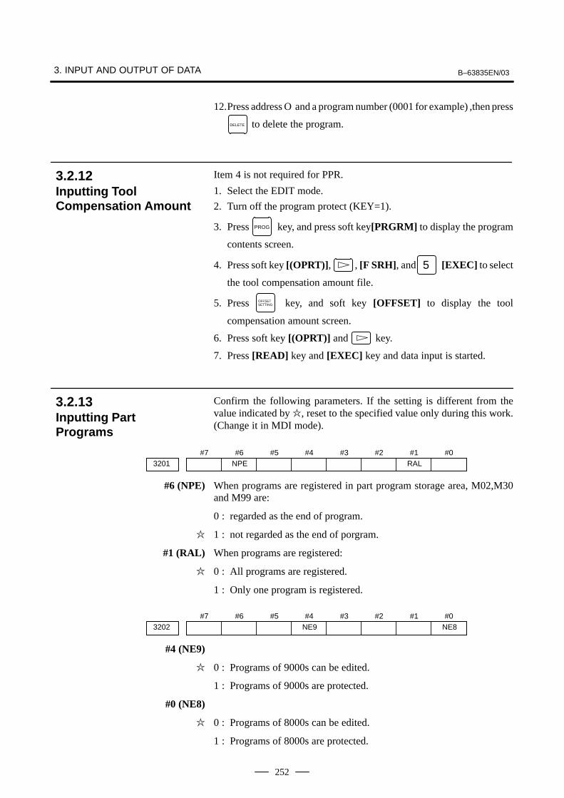
3. INPUT AND OUTPUT OF DATA B–63835EN/03
252
12.Press address O and a program number (0001 for example) ,then press
DELETE to delete the program.
Item 4 is not required for PPR.
1. Select the EDIT mode.
2. Turn off the program protect (KEY=1).
3. Press PROG key, and press soft key[PRGRM] to display the program
contents screen.
4. Press soft key [(OPRT)], , [F SRH], and 5 [EXEC] to select
the tool compensation amount file.
5. Press OFFSETSETTING key, and soft key [OFFSET] to display the tool
compensation amount screen.
6. Press soft key [(OPRT)] and key.
7. Press [READ] key and [EXEC] key and data input is started.
Confirm the following parameters. If the setting is different from thevalue indicated by �, reset to the specified value only during this work.(Change it in MDI mode).
#73201
#6NPE
#5 #4 #3 #2 #1RAL
#0
#6 (NPE) When programs are registered in part program storage area, M02,M30and M99 are:
0 : regarded as the end of program.
� 1 : not regarded as the end of porgram.
#1 (RAL) When programs are registered:
� 0 : All programs are registered.
1 : Only one program is registered.
#73202
#6 #5 #4NE9
#3 #2 #1 #0NE8
#4 (NE9)
� 0 : Programs of 9000s can be edited.
1 : Programs of 9000s are protected.
#0 (NE8)
� 0 : Programs of 8000s can be edited.
1 : Programs of 8000s are protected.
3.2.12Inputting ToolCompensation Amount
3.2.13Inputting PartPrograms
B–63835EN/03 3. INPUT AND OUTPUT OF DATA
253
� For PPR, item 4 is not required.
1. Confirm that mode is EDIT mode.
2. Turn off the program protect (KEY3=1).
3. Press PROG key and press soft key [PRGRM] to select a part program
file.
4. Press soft key [(OPRT)], [F SRH], and 6 [EXEC] to select
a part program file.
5. Press soft key ,[(OPRT)] and key.
6. Press soft key [READ] and [EXEC], then data input is started.

3. INPUT AND OUTPUT OF DATA B–63835EN/03
254
To input/output a particular type of data, the corresponding screen isusually selected. For example, the parameter screen is used for parameterinput from or output to an external input/output unit, while the programscreen is used for program input or output. However, programs,parameters, offset data, and macro variables can all be input and outputusing a single common screen, that is, the ALL IO screen.
READ/PUNCH (PROGRAM) O1234 N12345
MDI
* * * * * * * * * * * * * 12:34:56
PRGRM PARAM OFFSET (OPRT)
I/O CHANNEL 1 TV CHECK OFFDEVICE NUM. 0 PUNCH CODE ISOBAUDRATE 4800 INPUT CODE ASCIISTOP BIT 2 FEED OUTPUT FEEDNULL INPUT (EIA) NO EOB OUTPUT (ISO) CRTV CHECK (NOTES) ON
(0:EIA 1:ISO)>1_
MACRO
Fig. 3.3 ALL IO screen (when channel 1 is being used for input/output)
3.3DATA INPUT/OUTPUTON THE ALL IOSCREEN
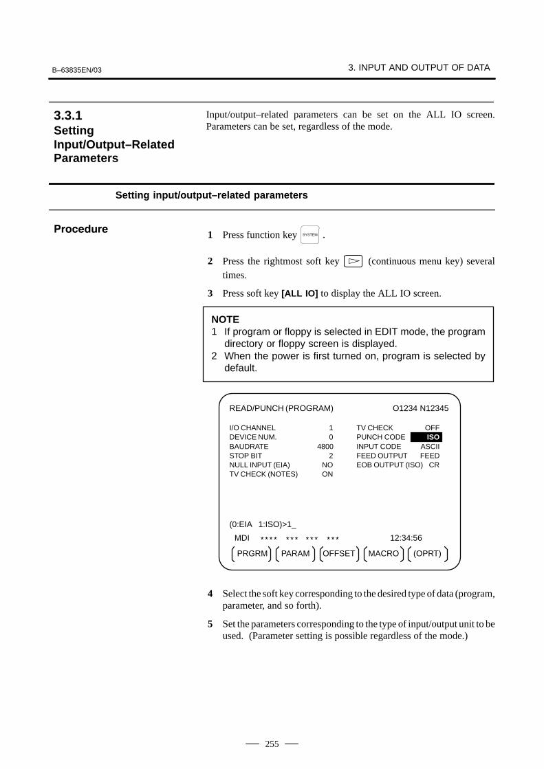
B–63835EN/03 3. INPUT AND OUTPUT OF DATA
255
Input/output–related parameters can be set on the ALL IO screen.Parameters can be set, regardless of the mode.
Setting input/output–related parameters
1 Press function key SYSTEM .
2 Press the rightmost soft key (continuous menu key) several
times.
3 Press soft key [ALL IO] to display the ALL IO screen.
NOTE1 If program or floppy is selected in EDIT mode, the program
directory or floppy screen is displayed.2 When the power is first turned on, program is selected by
default.
READ/PUNCH (PROGRAM) O1234 N12345
MDI * * * * * * * * * * * * * 12:34:56
PRGRM PARAM OFFSET (OPRT)
I/O CHANNEL 1 TV CHECK OFFDEVICE NUM. 0 PUNCH CODE ISOBAUDRATE 4800 INPUT CODE ASCIISTOP BIT 2 FEED OUTPUT FEEDNULL INPUT (EIA) NO EOB OUTPUT (ISO) CRTV CHECK (NOTES) ON
(0:EIA 1:ISO)>1_
MACRO
4 Select the soft key corresponding to the desired type of data (program,parameter, and so forth).
5 Set the parameters corresponding to the type of input/output unit to beused. (Parameter setting is possible regardless of the mode.)
3.3.1SettingInput/Output–RelatedParameters
���������

3. INPUT AND OUTPUT OF DATA B–63835EN/03
256
Tip
First, set an I/O channel. The parameters on this screen change to thosecorresponding to a specified I/O channel.
� I/O channel (0 to 2)
Setting Corresponding parameter
0 No. 101 to 103
1 No. 111 to 113
2 No. 121 to 123
� Device number
Setting Input/output device
0 RS–232–C (The control codes DC1 through DC4 are used.)
1 FANUC CASSETTE ADAPTOR 1 (FANUC CASSETTE B1/B2)
2 FANUC CASSETTE ADAPTOR 3 (FANUC CASSETTE F1)
3 FANUC PROGRAM FILE MATE, FANUC FA Card AdaptorFANUC FLOPPY CASSETTE ADAPTOR, FANUC Handy FileFANUC SYSTEM P–MODEL H
4 RS–232–C (The control codes DC1 through DC4 are not used.)
5 Portable tape reader
6 FANUC PPRFANUC SYSTEM P–MODEL G, FANUC SYSTEM P–MODEL H
� Baud rate (bps)
Set a desired baud rate value indicated below.
Baud rate (bps)
50
100
110
150
200
300
600
1200
2400
4800
9600
19200
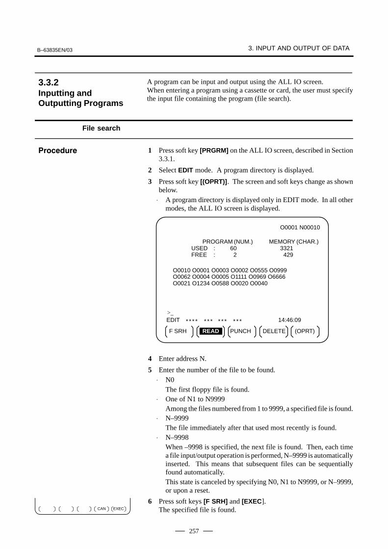
B–63835EN/03 3. INPUT AND OUTPUT OF DATA
257
A program can be input and output using the ALL IO screen.When entering a program using a cassette or card, the user must specifythe input file containing the program (file search).
File search
1 Press soft key [PRGRM] on the ALL IO screen, described in Section3.3.1.
2 Select EDIT mode. A program directory is displayed.
3 Press soft key [(OPRT)]. The screen and soft keys change as shownbelow.
⋅ A program directory is displayed only in EDIT mode. In all othermodes, the ALL IO screen is displayed.
O0001 N00010
EDIT * * * * * * * * * * * * * 14:46:09
F SRH READ PUNCH (OPRT)
>_
PROGRAM (NUM.) MEMORY (CHAR.)USED : 60 3321FREE : 2 429
O0010 O0001 O0003 O0002 O0555 O0999O0062 O0004 O0005 O1111 O0969 O6666O0021 O1234 O0588 O0020 O0040
DELETE
4 Enter address N.
5 Enter the number of the file to be found.⋅ N0
The first floppy file is found.⋅ One of N1 to N9999
Among the files numbered from 1 to 9999, a specified file is found.⋅ N–9999
The file immediately after that used most recently is found.⋅ N–9998
When –9998 is specified, the next file is found. Then, each timea file input/output operation is performed, N–9999 is automaticallyinserted. This means that subsequent files can be sequentiallyfound automatically.This state is canceled by specifying N0, N1 to N9999, or N–9999,or upon a reset.
6 Press soft keys [F SRH] and [EXEC]. The specified file is found.
3.3.2Inputting andOutputting Programs
���������
EXECCAN

3. INPUT AND OUTPUT OF DATA B–63835EN/03
258
Inputting a program
1 Press soft key [PRGRM] on the ALL IO screen, described in Section3.3.1.
2 Select EDIT mode. A program directory is displayed.
3 Press soft key [(OPRT)]. The screen and soft keys change as shownbelow.
⋅ A program directory is displayed only in EDIT mode. In all othermodes, the ALL IO screen is displayed.
O0001 N00010
EDIT * * * * * * * * * * * * * 14:46:09
F SRH READ PUNCH (OPRT)
>_
PROGRAM (NUM.) MEMORY (CHAR.)USED : 60 3321FREE : 2 429
O0010 O0001 O0003 O0002 O0555 O0999O0062 O0004 O0005 O1111 O0969 O6666O0021 O1234 O0588 O0020 O0040
DELETE
4 To specify a program number to be assigned to an input program,enter address O, followed by the desired program number.If no program number is specified, the program number in the file oron the NC tape is assigned as is.
5 Press soft key [READ], then [EXEC].The program is input with the program number specified in step 4assigned.To cancel input, press soft key [CAN].To stop input prior to its completion, press soft key [STOP].
���������
EXECCANSTOP

B–63835EN/03 3. INPUT AND OUTPUT OF DATA
259
Outputting programs
1 Press soft key [PRGRM] on the ALL IO screen, described in Section3.3.1.
2 Select EDIT mode. A program directory is displayed.
3 Press soft key [(OPRT)]. The screen and soft keys change as shownbelow.
⋅ A program directory is displayed only in EDIT mode. In all othermodes, the ALL IO screen is displayed.
O0001 N00010
EDIT * * * * * * * * * * * * * 14:46:09
F SRH READ (OPRT)
>_
PROGRAM (NUM.) MEMORY (CHAR.)USED : 60 3321FREE : 2 429
O0010 O0001 O0003 O0002 O0555 O0999O0062 O0004 O0005 O1111 O0969 O6666O0021 O1234 O0588 O0020 O0040
DELETEPUNCH
4 Enter address O.
5 Enter a desired program number.If –9999 is entered, all programs in memory are output.To output a range of programs, enter O∆∆∆∆, O����.. Theprograms numbered from ∆∆∆∆ to ���� are output.When bit 4 (SOR) of parameter No. 3107 for sorted display is set to 1on the program library screen, programs are output in order, startingfrom those having the smallest program numbers.
6 Press soft key [PUNCH], then [EXEC].The specified program or programs are output. If steps 4 and 5 areomitted, the currently selected program is output.To cancel output, press soft key [CAN].To stop output prior to its completion, press soft key [STOP].
���������
EXECCANSTOP

3. INPUT AND OUTPUT OF DATA B–63835EN/03
260
Deleting files
1 Press soft key [PRGRM] on the ALL IO screen, described in Section3.3.1.
2 Select EDIT mode. A program directory is displayed.
3 Press soft key [(OPRT)]. The screen and soft keys change as shownbelow.
⋅ A program directory is displayed only in EDIT mode. In all othermodes, the ALL IO screen is displayed.
O0001 N00010
EDIT * * * * * * * * * * * * * 14:46:09
F SRH READ PUNCH (OPRT)
>_
PROGRAM (NUM.) MEMORY (CHAR.)USED : 60 3321FREE : 2 429
O0010 O0001 O0003 O0002 O0555 O0999O0062 O0004 O0005 O1111 O0969 O6666O0021 O1234 O0588 O0020 O0040
DELETE
4 Press soft key [DELETE].
5 Enter a file number, from 1 to 9999, to indicate the file to be deleted.
6 Press soft key [EXEC].The k–th file, specified in step 5, is deleted.
���������
EXECCAN
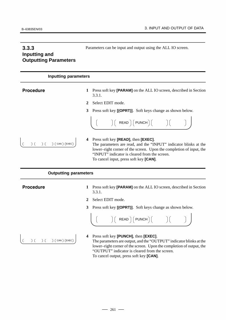
B–63835EN/03 3. INPUT AND OUTPUT OF DATA
261
Parameters can be input and output using the ALL IO screen.
Inputting parameters
1 Press soft key [PARAM] on the ALL IO screen, described in Section3.3.1.
2 Select EDIT mode.
3 Press soft key [(OPRT)]. Soft keys change as shown below.
READ PUNCH
4 Press soft key [READ], then [EXEC].The parameters are read, and the “INPUT” indicator blinks at thelower–right corner of the screen. Upon the completion of input, the“INPUT” indicator is cleared from the screen.To cancel input, press soft key [CAN].
Outputting parameters
1 Press soft key [PARAM] on the ALL IO screen, described in Section3.3.1.
2 Select EDIT mode.
3 Press soft key [(OPRT)]. Soft keys change as shown below.
READ PUNCH
4 Press soft key [PUNCH], then [EXEC].The parameters are output, and the “OUTPUT” indicator blinks at thelower–right corner of the screen. Upon the completion of output, the“OUTPUT” indicator is cleared from the screen.To cancel output, press soft key [CAN].
3.3.3Inputting andOutputting Parameters
���������
EXECCAN
���������
EXECCAN

3. INPUT AND OUTPUT OF DATA B–63835EN/03
262
Offset data can be input and output using the ALL IO screen.
Inputting offset data
1 Press soft key [OFFSET] on the ALL IO screen, described in Section3.3.1.
2 Select EDIT mode.
3 Press soft key [(OPRT)]. Soft keys change as shown below.
READ PUNCH
4 Press soft key [READ], then [EXEC].The offset data is read, and the “INPUT” indicator blinks at thelower–right corner of the screen. Upon the completion of input, the “INPUT” indicator is cleared fromthe screen.To cancel input, press soft key [CAN].
Outputting offset data
1 Press soft key [OFFSET] on the ALL IO screen, described in Section3.3.1.
2 Select EDIT mode.
3 Press soft key [(OPRT)]. Soft keys change as shown below.
READ PUNCH
4 Press soft key [PUNCH], then [EXEC].The offset data is output, and the “OUTPUT” indicator blinks at thelower–right corner of the screen. Upon the completion of output, the“OUTPUT” indicator is cleared from the screen.To cancel output, press soft key [CAN].
3.3.4Inputting andOutputting Offset Data
���������
EXECCAN
���������
EXECCAN

B–63835EN/03 3. INPUT AND OUTPUT OF DATA
263
Custom macro common variables can be output using the ALL IO screen.
Outputting custom macro common variables
1 Press soft key [MACRO] on the ALL IO screen, described in Section3.3.1.
2 Select EDIT mode.
3 Press soft key [(OPRT)]. Soft keys change as shown below.
READ PUNCH
4 Press soft key [PUNCH], then [EXEC].The custom macro common variables are output, and the “OUTPUT”indicator blinks at the lower–right corner of the screen. Upon thecompletion of output, the “OUTPUT” indicator is cleared from thescreen.To cancel output, press soft key [CAN].
NOTETo input a macro variable, read the desired custom macrostatement as a program, then execute the program.
3.3.5Outputting CustomMacro CommonVariables
���������
EXECCAN

3. INPUT AND OUTPUT OF DATA B–63835EN/03
264
The ALL IO screen supports the display of a directory of floppy files, aswell as the input and output of floppy files.
Displaying a file directory
1 Press the rightmost soft key (continuous menu key) on the ALLIO screen, described in Section 3.3.1.
2 Press soft key [FLOPPY].
3 Select EDIT mode. The floppy screen is displayed.
4 Press soft key [(OPRT)]. The screen and soft keys change as shownbelow.
⋅ The floppy screen is displayed only in EDIT mode. In all othermodes, the ALL IO screen is displayed.
READ/PUNCH (FLOPPY) O1234 N12345
MDI
* * * * * * * * * * * * * 12:34:56
F SRH READ PUNCH
>
DELETE
5 Press soft key [F SRH].
6 Enter the number of the desired file, then press soft key [F SET].
7 Press soft key [EXEC]. A directory is displayed, with the specifiedfile uppermost. Subsequent files in the directory can be displayed bypressing the page key.
3.3.6Inputting andOutputting FloppyFiles
���������
EXECCANF SET
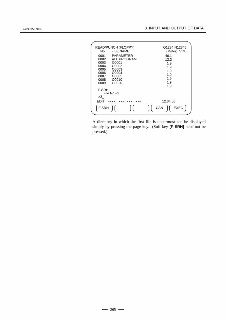
B–63835EN/03 3. INPUT AND OUTPUT OF DATA
265
READ/PUNCH (FLOPPY) No. FILE NAME
O1234 N12345(Meter) VOL
EDIT
* * * * * * * * * * * * * 12:34:56
F SRH EXEC
0001 PARAMETER0002 ALL.PROGRAM0003 O00010004 O00020005 O00030006 O00040007 O00050008 O00100009 O0020
F SRHFile No.=2
>2_
CAN
46.112.311.911.911.911.911.911.911.9
A directory in which the first file is uppermost can be displayedsimply by pressing the page key. (Soft key [F SRH] need not bepressed.)
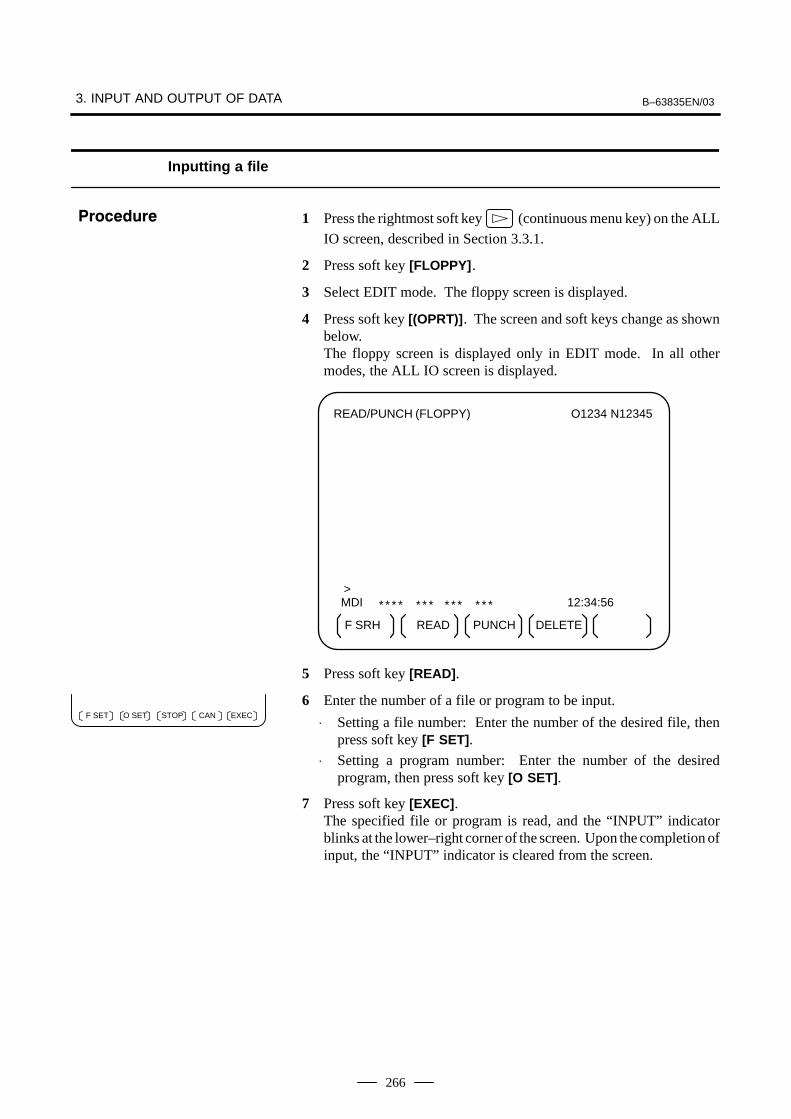
3. INPUT AND OUTPUT OF DATA B–63835EN/03
266
Inputting a file
1 Press the rightmost soft key (continuous menu key) on the ALL
IO screen, described in Section 3.3.1.
2 Press soft key [FLOPPY].
3 Select EDIT mode. The floppy screen is displayed.
4 Press soft key [(OPRT)]. The screen and soft keys change as shownbelow.The floppy screen is displayed only in EDIT mode. In all othermodes, the ALL IO screen is displayed.
READ/PUNCH (FLOPPY) O1234 N12345
MDI
* * * * * * * * * * * * * 12:34:56
F SRH READ PUNCH
>
DELETE
5 Press soft key [READ].
6 Enter the number of a file or program to be input.
⋅ Setting a file number: Enter the number of the desired file, thenpress soft key [F SET].
⋅ Setting a program number: Enter the number of the desiredprogram, then press soft key [O SET].
7 Press soft key [EXEC]. The specified file or program is read, and the “INPUT” indicatorblinks at the lower–right corner of the screen. Upon the completion ofinput, the “INPUT” indicator is cleared from the screen.
���������
EXECCANF SET O SET STOP
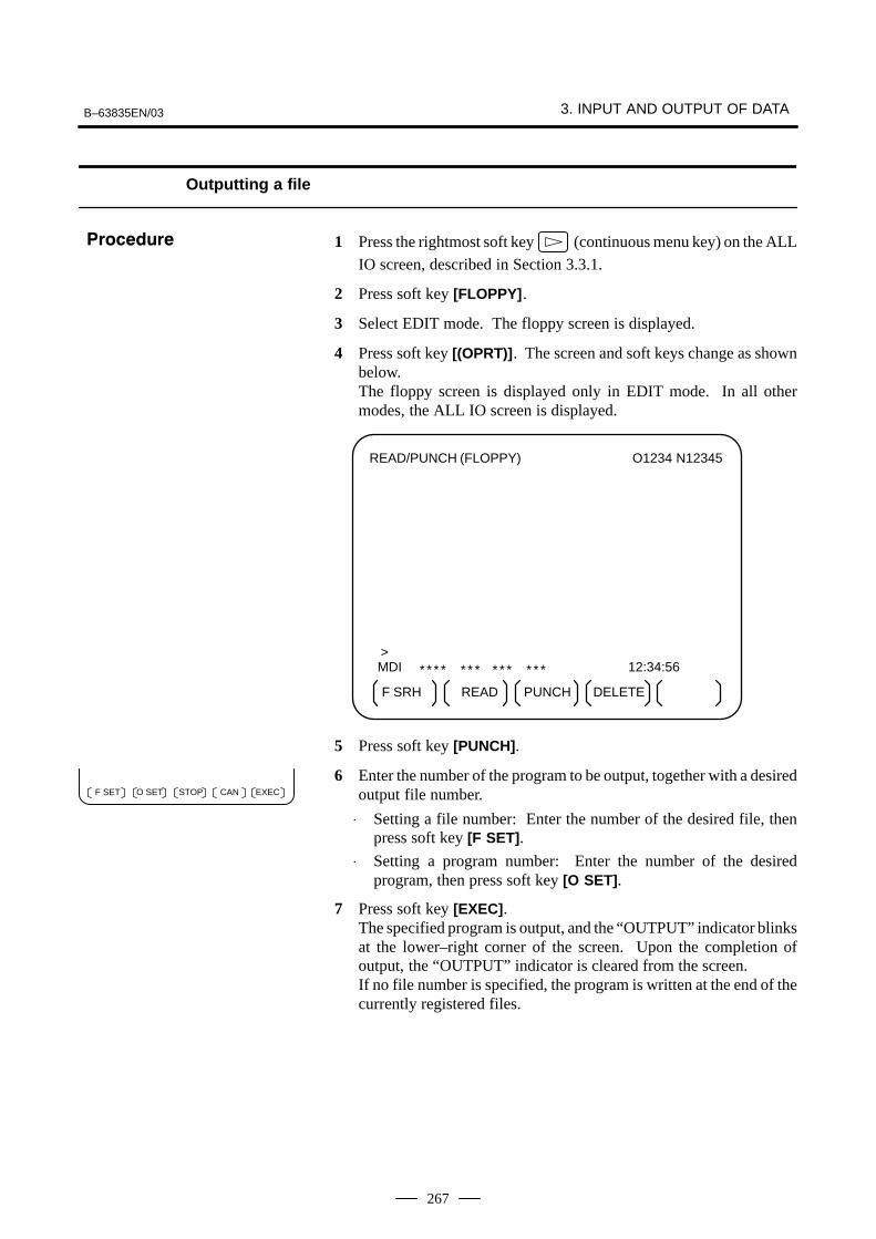
B–63835EN/03 3. INPUT AND OUTPUT OF DATA
267
Outputting a file
1 Press the rightmost soft key (continuous menu key) on the ALL
IO screen, described in Section 3.3.1.
2 Press soft key [FLOPPY].
3 Select EDIT mode. The floppy screen is displayed.
4 Press soft key [(OPRT)]. The screen and soft keys change as shownbelow.The floppy screen is displayed only in EDIT mode. In all othermodes, the ALL IO screen is displayed.
READ/PUNCH (FLOPPY) O1234 N12345
MDI
* * * * * * * * * * * * * 12:34:56
F SRH READ PUNCH
>
DELETE
5 Press soft key [PUNCH].
6 Enter the number of the program to be output, together with a desiredoutput file number.
⋅ Setting a file number: Enter the number of the desired file, thenpress soft key [F SET].
⋅ Setting a program number: Enter the number of the desiredprogram, then press soft key [O SET].
7 Press soft key [EXEC].The specified program is output, and the “OUTPUT” indicator blinksat the lower–right corner of the screen. Upon the completion ofoutput, the “OUTPUT” indicator is cleared from the screen.If no file number is specified, the program is written at the end of thecurrently registered files.
���������
EXECCANF SET O SET STOP

3. INPUT AND OUTPUT OF DATA B–63835EN/03
268
Deleting a file
1 Press the rightmost soft key (continuous menu key) on the ALL
IO screen, described in Section 3.3.1.
2 Press soft key [FLOPPY].
3 Select EDIT mode. The floppy screen is displayed.
4 Press soft key [(OPRT)]. The screen and soft keys change as shownbelow.The floppy screen is displayed only in EDIT mode. In all othermodes, the ALL IO screen is displayed.
READ/PUNCH (FLOPPY) O1234 N12345
MDI
* * * * * * * * * * * * * 12:34:56
F SRH READ PUNCH
>
DELETE
5 Press soft key [DELETE].
6 Enter the number of the desired file, then press soft key [F SET].
7 Press soft key [EXEC]. The specified file is deleted. After the file hasbeen deleted, the subsequent files are shifted up.
���������
EXECCANF SET

B–63835EN/03 3. INPUT AND OUTPUT OF DATA
269
If the I/O channel (parameter No. 20) is set to 4, files on the memory cardcan be referenced and various types of data such as part programs,parameters, and offset data can be input and output in text file format byusing the memory card interface of the control unit.The major functions are listed below.
⋅ Displaying a directory of stored files
The files stored on a memory card can be displayed on the directoryscreen.
⋅ Searching for a file
A search is made for a file on a memory card and, if found, it isdisplayed on the directory screen.
⋅ Reading a file
Text–format files can be read from a memory card.
⋅ Writing a file
Data such as part programs can be stored to a memory card in text fileformat.
⋅ Deleting a file
A file can be selected and deleted from a memory card.
���
Writing a file
Reading a file
Displaying a directory
Searching for a file
Deleting a file
Memory card
NOTE1 For the Series 0i–B/0i Mate–B, a program stored on the
memory card cannot be used to make a subprogram call forRTM mode operation (DNC operation) or the M198command.
2 Data I/O by the Series 0i–B/0i Mate–B memory card can beused only for maintenance.
3.4DATA INPUT/OUTPUTUSING A MEMORYCARD

3. INPUT AND OUTPUT OF DATA B–63835EN/03
270
Displaying a directory of stored files
1 Press the EDIT switch on the machine operator’s panel.
2 Press function key PROG .
3 Press the rightmost soft key (continuous menu key).
4 Press soft key [CARD]. The screen shown below is displayed. Using
page keys and , the screen can be scrolled.
PROG (OPRT)DIR +
DIRECTORY (M–CARD) No. FILE NAME SIZE DATE
O0034 N00045
0001 O1000 123456 01/07/100002 O1001 118458 01/07/300003 O0002 113250 01/07/300004 O2000 173456 01/07/310005 O2001 113444 01/07/310006 O3001 118483 01/08/020007 O3300 111406 01/08/050008 O3400 112420 01/07/310009 O3500 117460 01/07/31
~ ~
5 Comments relating to each file can be displayed by pressing soft key[DIR+].
PROG (OPRT)DIR +
DIRECTORY (M–CARD) No. FILE NAME COMMENT
O0034 N00045
0001 O1000 (COMMENT )0002 O1001 (SUB PROGRAM )0003 O0002 (12345678 )0004 O2000 ( )0005 O2001 ( )0006 O3001 (SKIP–K )0007 O3300 (HI–SPEED )0008 O3400 ( )0009 O3500 (TEST PROGRAM)
~ ~
6 Repeatedly pressing soft key [DIR+] toggles the screen between thedisplay of comments and the display of sizes and dates.Any comment described after the O number in the file is displayed.Up to 18 characters can be displayed on the screen.
���������

B–63835EN/03 3. INPUT AND OUTPUT OF DATA
271
Searching for a file
1 Press the EDIT switch on the machine operator’s panel.
2 Press function key PROG .
3 Press the rightmost soft key (continuous menu key).
4 Press soft key [CARD]. The screen shown below is displayed.
PROG (OPRT)DIR +
DIRECTORY (M–CARD) No. FILE NAME SIZE DATE
O0034 N00045
0001 O1000 123456 01/07/100002 O1001 118458 01/07/300003 O0002 113250 01/07/300004 O2000 173456 01/07/310005 O2001 113444 01/07/310006 O3001 118483 01/08/020007 O3300 111406 01/08/050008 O3400 112420 01/07/310009 O3500 117460 01/07/31
~ ~
5 Press soft key [(OPRT)].
6 Set the number of the desired file number with soft key [F SRH].Then, start the search by pressing soft key [EXEC]. If found, the file isdisplayed at the top of the directory screen.
DIRECTORY (M–CARD) No. FILE NAME COMMENT
O0034 N00045
0019 O1000 (MAIN PROGRAM)0020 O1010 (SUBPROGRAM–1)0021 O1020 (COMMENT )0022 O1030 (COMMENT )
~ ~
When a search is made for file number 19
���������
DELETEPUNCHF SRH F READ N READ

3. INPUT AND OUTPUT OF DATA B–63835EN/03
272
Reading a file
1 Press the EDIT switch on the machine operator’s panel.
2 Press function key PROG .
3 Press the rightmost soft key (continuous menu key).
4 Press soft key [CARD]. Then, the screen shown below is displayed.
PROG (OPRT)DIR +
DIRECTORY (M–CARD) No. FILE NAME SIZE DATE
O0034 N00045
0001 O1000 123456 01/07/100002 O1001 118458 01/07/300003 O0002 113250 01/07/300004 O2000 173456 01/07/310005 O2001 113444 01/07/310006 O3001 118483 01/08/020007 O3300 111406 01/08/050008 O3400 112420 01/07/310009 O3500 117460 01/07/31
~ ~
5 Press soft key [(OPRT)].
6 To specify a file number, press soft key [F READ]. The screen shownbelow is displayed.
F NAME EXECSTOPO SET CAN
DIRECTORY (M–CARD) No. FILE NAME COMMENT
O0001 N00010
0019 O1000 (MAIN PROGRAM)0020 O1010 (SUBPROGRAM–1)0021 O1030 (COMMENT )
~ ~
READFILE NAME=20 PROGRAM No.=120
>
EDIT 15:40:21* * * * * * * * * * * * * *
7 Enter file number 20 from the MDI panel, then set the file number bypressing soft key [F SET]. Next, enter program number 120, then setthe program number by pressing soft key [O SET]. Then, press softkey [EXEC].
⋅ File number 20 is registered as O0120 in the CNC.
⋅ Set a program number to register a read file with a separate Onumber. If no program number is set, the O number in the file namecolumn is registered.
���������
DELETEPUNCHF SRH F READ N READ

B–63835EN/03 3. INPUT AND OUTPUT OF DATA
273
8 To specify a file with its file name, press soft key [N READ] in step 6above. The screen shown below is displayed.
F NAME EXECSTOPO SET CAN
DIRECTORY (M–CARD) No. FILE NAME COMMENT
O0001 N00010
0012 O0050 (MAIN PROGRAM)0013 TESTPRO (SUB PROGRAM–1)0014 O0060 (MACRO PROGRAM)
~ ~
READ FILE NAME =TESTPROPROGRAM No. =1230
>
EDIT 15:40:21* * * * * * * * * * * * * *
9 To register file name TESTPRO as O1230, enter file name TESTPROfrom the MDI panel, then set the file name with soft key [F NAME].Next, enter program number 1230, then set the program number withsoft key [O SET]. Then, press soft key [EXEC].

3. INPUT AND OUTPUT OF DATA B–63835EN/03
274
Writing a file
1 Press the EDIT switch on the machine operator’s panel.
2 Press function key PROG .
3 Press the rightmost soft key (continuous menu key).
4 Press soft key [CARD]. The screen shown below is displayed.
PROG (OPRT)DIR +
DIRECTORY (M–CARD) No. FILE NAME SIZE DATE
O0034 N00045
0001 O1000 123456 01/07/100002 O1001 118458 01/07/300003 O0002 113250 01/07/300004 O2000 173456 01/07/310005 O2001 113444 01/07/310006 O3001 118483 01/08/020007 O3300 111406 01/08/050008 O3400 112420 01/07/310009 O3500 117460 01/07/31
~ ~
5 Press soft key [(OPRT)].
6 Press soft key [PUNCH].
7 Enter a desired O number from the MDI panel, then set the programnumber with soft key [O SET]. When soft key [EXEC] is pressed after the setting shown below hasbeen made, for example, the file is written under program numberO1230.
F NAME EXECSTOPO SET CAN
EDIT
* * * * * * * * * * * * * * 15:40:21
PUNCH FILE NAME =PROGRAM No. =1230
>
~ ~
8 In the same way as for O number setting, enter a desired file namefrom the MDI panel, then set the file name with soft key [F SET].When soft key [EXEC] is pressed after the setting shown below hasbeen made, for example, the file is written under program numberO1230 and file name ABCD12.
F NAME EXECSTOPO SET CAN
EDIT
* * * * * * * * * * * * * * 15:40:21
PUNCH FILE NAME =ABCD12PROGRAM No. =1230
>
~ ~
���������
DELETEPUNCHF SRH F READ N READ
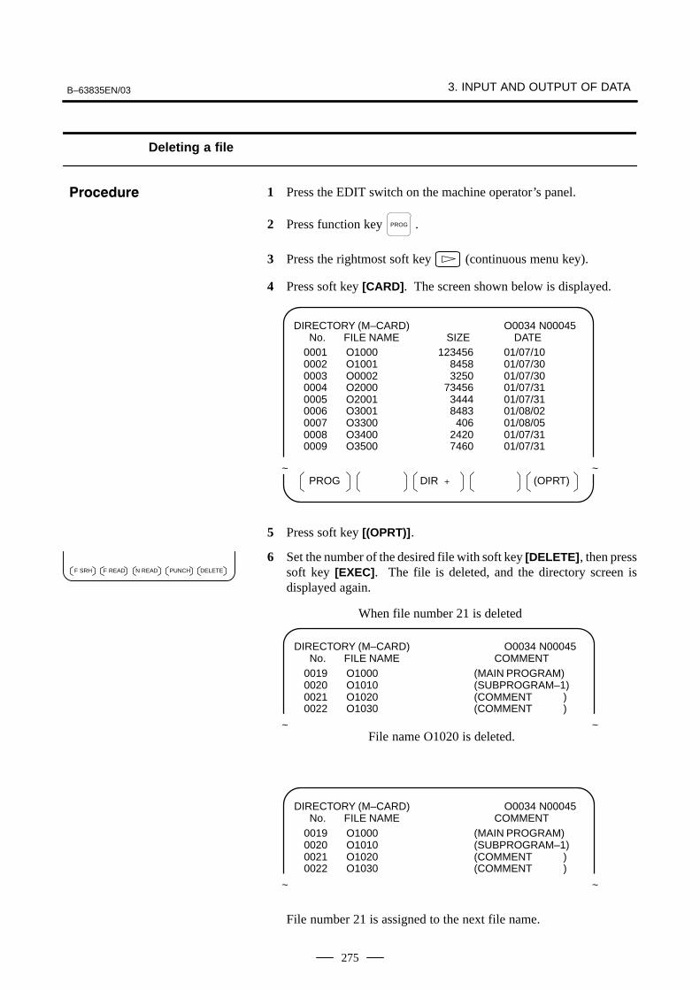
B–63835EN/03 3. INPUT AND OUTPUT OF DATA
275
Deleting a file
1 Press the EDIT switch on the machine operator’s panel.
2 Press function key PROG .
3 Press the rightmost soft key (continuous menu key).
4 Press soft key [CARD]. The screen shown below is displayed.
PROG (OPRT)DIR +
DIRECTORY (M–CARD) No. FILE NAME SIZE DATE
O0034 N00045
0001 O1000 123456 01/07/100002 O1001 118458 01/07/300003 O0002 113250 01/07/300004 O2000 173456 01/07/310005 O2001 113444 01/07/310006 O3001 118483 01/08/020007 O3300 111406 01/08/050008 O3400 112420 01/07/310009 O3500 117460 01/07/31
~ ~
5 Press soft key [(OPRT)].
6 Set the number of the desired file with soft key [DELETE], then presssoft key [EXEC]. The file is deleted, and the directory screen isdisplayed again.
DIRECTORY (M–CARD) No. FILE NAME COMMENT
O0034 N00045
0019 O1000 (MAIN PROGRAM)0020 O1010 (SUBPROGRAM–1)0021 O1020 (COMMENT )0022 O1030 (COMMENT )
~ ~File name O1020 is deleted.
When file number 21 is deleted
DIRECTORY (M–CARD) No. FILE NAME COMMENT
O0034 N00045
0019 O1000 (MAIN PROGRAM)0020 O1010 (SUBPROGRAM–1)0021 O1020 (COMMENT )0022 O1030 (COMMENT )
~ ~
File number 21 is assigned to the next file name.
���������
DELETEPUNCHF SRH F READ N READ

3. INPUT AND OUTPUT OF DATA B–63835EN/03
276
Batch input/output with a memory card
On the ALL IO screen, different types of data including part programs,parameters, offset data, pitch error data, custom macros, and workpiececoordinate system data can be input and output using a memory card; thescreen for each type of data need not be displayed for input/output.
Memory card ALL IO screen�
�
Data item name
Part programParameter Offset data Pitch error data Custom macroWorkpiece coordinate systemdata (additional coordinate systems)
1 Press the EDIT switch on the machine operator’s panel.
2 Press function key SYSTEM .
3 Press the rightmost soft key (continuous menu key) severaltimes.
4 Press soft key [ALL IO]. The screen shown below is displayed.
PROG (OPRT)OFFSETPARAM
READ/PUNCH (PROGRAM) No. FILE NAME SIZE DATE
O0001 N00001
* 0001 O0222 332010 01–04–060002 O1003 334450 01–05–040003 MACROVAR.DAT 653400 01–05–120004 O0002 341205 01–05–13
[PROGRAM]O0001 O0002 O0003 O0005 O0100 O0020O0006 O0004 O0110 O0200 O2200 O0441O0330
>EDIT 10:07:37* * * * * * * * * * * * * *
Upper part : Directory of files on the memory card Lower part : Directory of registered programs
5 With cursor keys and , the user can choose between upper
part scrolling and lower part scrolling. (An asterisk (*) displayed atthe left edge indicates the part for which scrolling is possible.)
: Used for memory card file directory scrolling.
: Used for program directory scrolling.
���������

B–63835EN/03 3. INPUT AND OUTPUT OF DATA
277
6 With page keys PAGE
and PAGE
, scroll through the file directory or
program directory.
7 When this screen is displayed, the program data item is selected. Thesoft keys for other screens are displayed by pressing the rightmost softkey (continuous menu key).
(OPRT)PITCH WORK
When a data item other than program is selected, the screen displays onlya file directory.A data item is indicated, in parentheses, on the title line.
READ/PUNCH (PARAMETER) No. FILE NAME SIZE DATE
O0001 N00001
0001 O0222 332010 96/04/060002 O1003 334450 96/05/040003 MACROVAR.DAT 653400 96/05/120004 O0003 334610 96/05/040005 O0001 334254 96/06/040006 O0002 333750 96/06/040007 CNCPARAM.DAT 334453 96/06/04
~ ~
8 Display the following soft keys with soft key [(OPRT)].
F SRH DELETEN READF READ PUNCH
The operation of each function is the same as on the directory (memorycard) screen. Soft key [O SET], used for program number setting, and the“PROGRAM NUMBER =” indication are not displayed for data itemsother than program.
[F SRH] : Finds a specified file number.[F READ] : Reads a specified file number.[PUNCH] : Writes a file.[N READ] : Reads a file under a specified file name.[DELETE] : Deletes a specified file number.

3. INPUT AND OUTPUT OF DATA B–63835EN/03
278
Error codes
Memory card error codes
Code Meaning
007 The memory card is protected.
030 The memory card is not inserted into its slot.
032 The memory card’s battery is exhausted.
102 The memory card does not have sufficient free space.
105 No memory card is mounted.
106 A memory card is already mounted.
110 The specified directory cannot be found.
111 There are too many files under the root directory to allow a di-rectory to be added.
114 The specified file cannot be found.
115 The specified file is protected.
117 The file has not yet been opened.
118 The file is already open.
119 The file is locked.
121 A file end was detected.
122 The specified file name is invalid.
124 The extension of the specified file is invalid.
129 A non–corresponding function was specified.
130 The specification of a device is invalid.
131 The specification of a pathname is invalid.
133 Multiple files are open at the same time.
135 The device is not formatted.
140 The file has the read/write disabled attribute.
B–63835EN/03 4.INTERFACE BETWEEN CNC AND PMC
279
4 INTERFACE BETWEEN CNC AND PMC
This chapter describes the signals between the machine operator’s panel,magnetics cabinet and the PMC, connection of the signals between PMCand CNC, and confirmation method of on/off state of these signals.It also describes system configuration of PMC, parameters of PMC,ladder and how to display time chart of the signals on the screen.It also describes a method of inputting/outputting PMC parameters to anexternal device.
4.1 GENERAL OF INTERFACE 280. . . . . . . . . . . . . . . . . . 4.2 SPECIFICATION OF PMC 281. . . . . . . . . . . . . . . . . . . . 4.3 PMC SCREEN (PMC–SA1) 291. . . . . . . . . . . . . . . . . . . 4.4 PMC SCREEN (PMC–SB7) 313. . . . . . . . . . . . . . . . . . . 4.5 LIST OF SIGNALS BY EACH MODE 345. . . . . . . . . . 4.6 LIST OF INPUT/OUTPUT SIGNALS 347. . . . . . . . . . . 4.7 LIST OF ADDRESSES 362. . . . . . . . . . . . . . . . . . . . . . .

4. INTERFACE BETWEEN CNC AND PMC B–63835EN/03
280
+ –
0V 0V0V
ST
1
ST
2
MT
(Mac
hine
Too
l bui
lder
)
RV
DI/D
O
+24
E
PM
CD
GN
*
X Y
PM
CD
GN
*
ST
1D
OO
R
X0.
1X
0.0
ST
2
X5.
7
ST
L
F0.
5
ST
G00
7.2
ST
L
Y0.
1
PM
CD
GN
G
NC
F
PM
CD
GN
Load
MT
B d
ecid
esad
dres
ses
and
sign
als
Inte
rnal
rela
y V
aria
ble
timer
Cou
nter
Dat
a ta
ble
Mes
sage
dis
play
Kee
p re
lay
Sys
tem
rese
rve
area
PM
C a
ddre
ssFA
NU
C d
ecid
es
addr
esse
san
d si
gnal
s co
rres
pond
ence
PM
CD
GN
T
r
Out
put
L
oad
[0]
. .
. .
. .
Off
2
4V
O
ff[1
] .
. .
. .
. O
n
0V
O
n
PM
CD
GN
In
put
Con
tact
s[0
]
.
. 0V
O
pen
[1]
. . 2
4V
Clo
se
Hig
h–sp
eed
proc
essi
ng s
igna
l*D
EC
*D
EC
Pow
ersu
pply
�*E
SP,
SK
IP, E
SK
IP, X
AE
, YA
E, Z
AE
(M s
erie
s)�
*ES
P, S
KIP
, ES
KIP
, XA
E, Z
AE
, +M
IT �
(T s
erie
s)
PM
C–S
A/S
B
4.1GENERAL OFINTERFACE
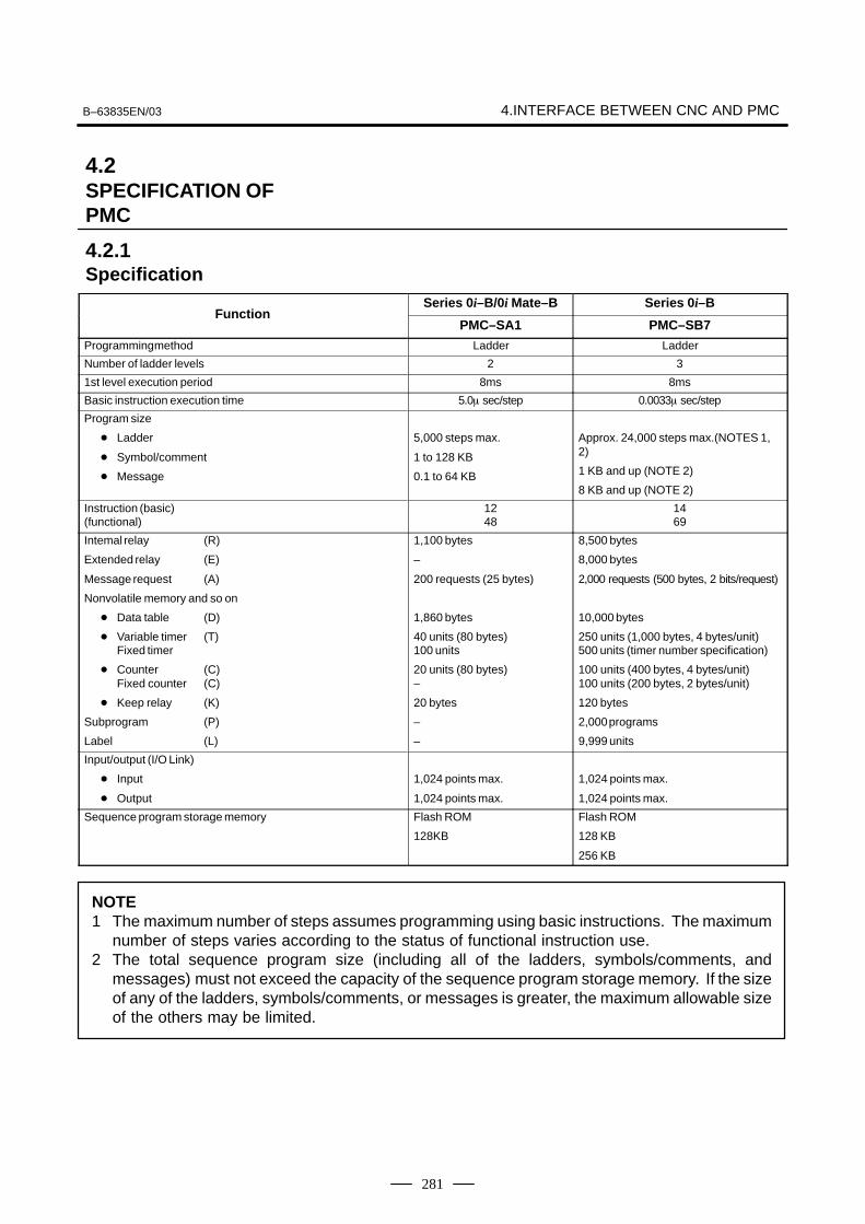
B–63835EN/03 4.INTERFACE BETWEEN CNC AND PMC
281
Series 0i–B/0i Mate–B Series 0i–BFunction
PMC–SA1 PMC–SB7
Programming method Ladder Ladder
Number of ladder levels 2 3
1st level execution period 8ms 8ms
Basic instruction execution time 5.0� sec/step 0.0033� sec/step
Program size
� Ladder
� Symbol/comment
� Message
5,000 steps max.
1 to 128 KB
0.1 to 64 KB
Approx. 24,000 steps max.(NOTES 1,2)
1 KB and up (NOTE 2)
8 KB and up (NOTE 2)
Instruction (basic)(functional)
1248
1469
Intemal relay (R)
Extended relay (E)
Message request (A)
Nonvolatile memory and so on
� Data table (D)
� Variable timer (T)Fixed timer
� Counter (C)Fixed counter (C)
� Keep relay (K)
Subprogram (P)
Label (L)
1,100 bytes
–
200 requests (25 bytes)
1,860 bytes
40 units (80 bytes)100 units
20 units (80 bytes)–
20 bytes
–
–
8,500 bytes
8,000 bytes
2,000 requests (500 bytes, 2 bits/request)
10,000 bytes
250 units (1,000 bytes, 4 bytes/unit)500 units (timer number specification)
100 units (400 bytes, 4 bytes/unit)100 units (200 bytes, 2 bytes/unit)
120 bytes
2,000 programs
9,999 units
Input/output (I/O Link)
� Input
� Output
1,024 points max.
1,024 points max.
1,024 points max.
1,024 points max.
Sequence program storage memory Flash ROM
128KB
Flash ROM
128 KB
256 KB
NOTE1 The maximum number of steps assumes programming using basic instructions. The maximum
number of steps varies according to the status of functional instruction use.2 The total sequence program size (including all of the ladders, symbols/comments, and
messages) must not exceed the capacity of the sequence program storage memory. If the sizeof any of the ladders, symbols/comments, or messages is greater, the maximum allowable sizeof the others may be limited.
4.2SPECIFICATION OFPMC
4.2.1Specification

4. INTERFACE BETWEEN CNC AND PMC B–63835EN/03
282
ModelChar-acter
Signal type Series 0i–B/0i Mate–Bacter
PMC–SA1 PMC–SB7
X Input signal from the machine to the PMC (MT to PMC)
X0 to X127 X0 to X127X200 to X327(NOTE 1)
X1000 to X1127(NOTE 1)
Y Output signal from the PMC to the machine (PMC to MT)
Y0 to Y127 Y0 to Y127Y200 to Y327(NOTE 1)
Y1000 to Y1127 (NOTE 1)
F Input signal from the NC to the PMC(NC to PMC)
F0 to F255 F0 to F767(NOTE 2)F1000 to F1767(NOTE 3)F2000 to F2767(NOTE 3)F3000 to F3767(NOTE 3)
G Output signal from the PMC to the NC (PMC to NC) G0 to G255 G0 to G767(NOTE 2)G1000 to G1767(NOTE 3)G2000 to G2767(NOTE 3)G3000 to G3767(NOTE 3)
R Internal relay R0 to R999R9000 to R9099
R0 to R7999R9000 to R9499(NOTE 4)
E Extended relay – E0 to E7999(NOTE 5)
A Message display request signal A0 to A24 A0 to A249
Message display state signal – A9000 to A9249(NOTE 6)
C Counter C0 to C79 C0 to C399C5000 to C5199(NOTE 7)
K Keep relay K0 to K19 K0 to K99K900 to K919(NOTE 8)
T Variable timer T0 to T79 T0 to T499T9000 to T9499(NOTE 9)
D Data table D0 to D1859 D0 to D9999
L Label number – L1 to L9999
P Subprogram number – P1 to P2000
4.2.2Address
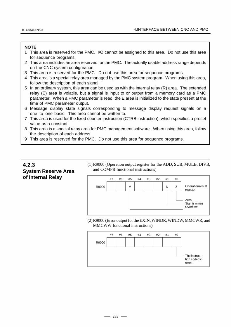
B–63835EN/03 4.INTERFACE BETWEEN CNC AND PMC
283
NOTE1 This area is reserved for the PMC. I/O cannot be assigned to this area. Do not use this area
for sequence programs.2 This area includes an area reserved for the PMC. The actually usable address range depends
on the CNC system configuration.3 This area is reserved for the PMC. Do not use this area for sequence programs.4 This area is a special relay area managed by the PMC system program. When using this area,
follow the description of each signal.5 In an ordinary system, this area can be used as with the internal relay (R) area. The extended
relay (E) area is volatile, but a signal is input to or output from a memory card as a PMCparameter. When a PMC parameter is read, the E area is initialized to the state present at thetime of PMC parameter output.
6 Message display state signals corresponding to message display request signals on aone–to–one basis. This area cannot be written to.
7 This area is used for the fixed counter instruction (CTRB instruction), which specifies a presetvalue as a constant.
8 This area is a special relay area for PMC management software. When using this area, followthe description of each address.
9 This area is reserved for the PMC. Do not use this area for sequence programs.
(1)R9000 (Operation output register for the ADD, SUB, MULB, DIVB,and COMPB functional instructions)
#7
Operation resultregister
#6 #5 #4 #3 #2 #1 #0
ZeroSign is minusOverflow
V N ZR9000
(2)R9000 (Error output for the EXIN, WINDR, WINDW, MMCWR, andMMCWW functional instructions)
#7 #6 #5 #4 #3 #2 #1 #0
The instruc-tion ended inerror.
R9000
4.2.3System Reserve Areaof Internal Relay

4. INTERFACE BETWEEN CNC AND PMC B–63835EN/03
284
(3)R9002 to R9005 (Operation output registers for the DIVB functionalinstruction)The data remaining after the DIVB functional instruction is executedin output.
Register for remainder(used by DIVBinstruction)
#7 #6 #5 #4 #3 #2 #1 #0
R9002
R9003
R9004
R9005
(4) R9091 (System timer) 4 signals can be used as system timer. The specifications of every signal are as following.
R9091
#7 #6 #5 #4 #3 #2 #1 #0
always OFF
always ON
Cyclic signal of 200ms (104 ms ON, 96ms OFF)
Cyclic signal of 1 se-cond. (504 ms ON,496 ms OFF)
CAUTIONEach signal is initially off. R9091.0 and R9091.1 are setcyclically at the beginning of the first ladder level. Each signal (ON–OFF signal) has an accuracy of �8 ms.

B–63835EN/03 4.INTERFACE BETWEEN CNC AND PMC
285
200ms
104ms 96msR9091.5
R9091.6
1s
504ms 496ms
(5)Ladder execution start signal, ladder stop signal, ladder executionstate signal (PMC–SB7)
1 Ladder execution start signal and latter stop signal
With the ladder execution start signal or the ladder stop signal, thestart or stop of a ladder program can be known in the ladderprogram.
R9015
#7 #6 #5 #4 #3 #2 #1 #0
R9015.0: Ladderexecution start sig-nal (reference onlyfrom the ladder pro-gram)
R9015.1: Ladderexecution start sig-nal (reference onlyfrom the ladder pro-gram)
2 Ladder execution state signal
The state of ladder program execution or PMCC language programexecution can be known by referencing the ladder execution statesignal from an external system or program such as the networkboard, C executor program, FOCAS1 Ethernet, and HSSB library.

4. INTERFACE BETWEEN CNC AND PMC B–63835EN/03
286
R9015
#7 #6 #5 #4 #3 #2 #1 #0
R9091.2: Ladder executionstate signal0: Ladder stopped1: Ladder being executed
For PMC–SA1
END1
1st level(High–speed se-quence)
From NC
Synchronizedbuffer
Sequence program
2nd level(Normal sequence)
Head of 2nd level
END2
(1)
(2)–n
(2)–1
(2)–2
From MT
Period
1st level
8msec
(1) (1) (1) (1)
(2)–12nd level
(2)–2 (2)–n (2)–1
4.2.4Execution Period ofPMC

B–63835EN/03 4.INTERFACE BETWEEN CNC AND PMC
287
For PMC–SB7
1st level
END1
2nd level
END23rd level
END3
Synchronizedbuffer
CNC (F)
Machine (X)
END2
From NC
Division 1 Division 2 Division n
8ms 8ms 8ms
Ladder execution time
1st level
2nd level
3rd level
The ratio of the 1st level execution time to the 2nd level execution timeis set in a system parameter for ladder execution time.
� For a ladder that uses the 1st level and the 2nd level only, set the upperlimit (150).
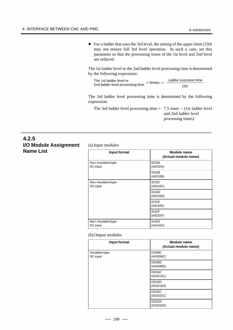
4. INTERFACE BETWEEN CNC AND PMC B–63835EN/03
288
� For a ladder that uses the 3rd level, the setting of the upper limit (150)may not ensure full 3rd level operation. In such a case, set thisparameter so that the processing times of the 1st level and 2nd levelare reduced.
The 1st ladder level or the 2nd ladder level processing time is determinedby the following expression:
The 1st ladder level or 2nd ladder level processing time
Ladder execution time = 5msec �
100
The 3rd ladder level processing time is determined by the followingexpression:
The 3rd ladder level processing time = 7.5 msec – (1st ladder leveland 2nd ladder level processing times)
(a) Input modules
Input format Module name(Actual module name)
Non–insulation typeDC input
ID32A(AID32A)
ID32B(AID32B)
Non–insulation typeDC input
ID16C(AID16C)
ID16D(AID16D)
ID32E(AID32E)
ID32F(AID32F)
Non–insulation typeDC input
IA16G(AIA16G)
(b)Output modules
Input format Module name(Actual module name)
Insulation typeDC input
OD08C(AOD08C)
OD08D(AOD08D)
OD16C(AOD16C)
OD16D(AOD16D)
OD32C(AOD32C)
OD32D(AOD32D)
4.2.5I/O Module AssignmentName List

B–63835EN/03 4.INTERFACE BETWEEN CNC AND PMC
289
Input format Module name(Actual module name)
AC output OA05E(AOA05E)
OA08E(AOA08E)
OA12E(AOA12E)
Relay output OA08G(AOA08G)
OA16G(AOA16G)
(c) Other modules
Name Module name Occupiedaddress
FANUC CNC SYSTEMFANUC Power Mate
FS04A Input 4 bytesOutput 4 bytes
FS08A Input 8 bytesOutput 8 bytes
OC02I Input 16 bytes
OC02O Output 16 bytes
OC03I Input 32 bytes
OC03O Output 32 bytes
Analog input module AD04A(AAD04A)
Input 8 bytes
Analog output module DA02A(ADA02A)
Output 4 bytes
Connection unit (1 unit) CN01I Input 12 bytes
Connection unit (1 unit) CN01O Output 8 bytes
Connection unit (2 units) CN02I Input 24 bytes
Connection unit (2 units) CN02O Output 16 bytes
Operator’s panel connection unit OC01I Input 12 bytesI/O card E OC01O Output 8 bytes
Operator’s panel connection unit /8 Input 8 bytesI/O card D /4 Output 4 bytes
Machine operator’s panel interface unit OC02I Input 16 bytes
OC02O Output 16 bytes
OC03I Input 32 bytes
OC03O Output 32 bytes
I/O Link connection unit /� Input � bytesOutput � bytes
OC02I Input 16 bytes
OC02O Output 16 bytes
OC03I Input 32 bytes
OC03O Output 32 bytes
For I/O Unit MODEL B #� Input � bytesOutput � bytes
## Input 4 bytes
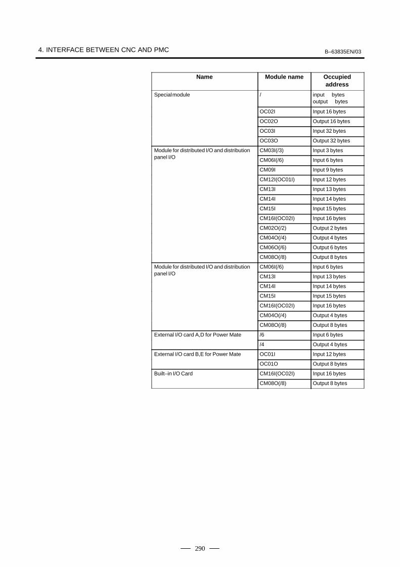
4. INTERFACE BETWEEN CNC AND PMC B–63835EN/03
290
Name Occupiedaddress
Module name
Special module /� input � bytesoutput � bytes
OC02I Input 16 bytes
OC02O Output 16 bytes
OC03I Input 32 bytes
OC03O Output 32 bytes
Module for distributed I/O and distribution CM03I(/3) Input 3 bytespanel I/O CM06I(/6) Input 6 bytes
CM09I Input 9 bytes
CM12I(OC01I) Input 12 bytes
CM13I Input 13 bytes
CM14I Input 14 bytes
CM15I Input 15 bytes
CM16I(OC02I) Input 16 bytes
CM02O(/2) Output 2 bytes
CM04O(/4) Output 4 bytes
CM06O(/6) Output 6 bytes
CM08O(/8) Output 8 bytes
Module for distributed I/O and distribution CM06I(/6) Input 6 bytespanel I/O CM13I Input 13 bytes
CM14I Input 14 bytes
CM15I Input 15 bytes
CM16I(OC02I) Input 16 bytes
CM04O(/4) Output 4 bytes
CM08O(/8) Output 8 bytes
External I/O card A,D for Power Mate /6 Input 6 bytes
/4 Output 4 bytes
External I/O card B,E for Power Mate OC01I Input 12 bytes
OC01O Output 8 bytes
Built–in I/O Card CM16I(OC02I) Input 16 bytes
CM08O(/8) Output 8 bytes

B–63835EN/03 4.INTERFACE BETWEEN CNC AND PMC
291
PMC–SA1 screen menu selection procedure
[PMC] [PMCLAD] Ladder diagram display screen
[PMCDGN] [TITLE] Title screen
[STATUS] Signal status screen
[ALARM] Alarm screen
[TRACE] Trace function
[IOCHK] I/O check screen
[PMCPRM] [TIMER] Timer screen
[COUNTR] Counter screen
[KEEPRL] Keep relay screen
[DATA] [G.DATA] Data table screen
[SETING] Setting screen
[RUN]/[STOP] Ladder start/stop
[EDIT] [TITLE] Title editing screen
[LADDER] Ladder diagram editing screen
[SYMBOL] Symbol/comment editing screen
[MESAGE] Message editing screen
[MODULE] I/O unit address setting screen
[CROSS] Cross reference screen
[CLEAR] Clear screen
[I/O] Program/parameter input/output screen
[SYSPRM] System parameter screen
[MONIT] [ONLINE] Online setting screen
4.3PMC SCREEN(PMC–SA1)
4.3.1PMC Menu SelectionProcedure Using SoftKeys

4. INTERFACE BETWEEN CNC AND PMC B–63835EN/03
292
(1)Display method
1 Press the SYSTEM key, then press the soft key [PMC].
2 Dynamic display of sequence program by pressing [PMCLAD]soft key.
(2)Display information
[ ]WINDOWSEARCH[ ] [ ] [ ] [ ]ADRESS TRIGER
LADDER NET 0001–0004 MONIT RUN
END1
LOG1
X008.4
LOG1ALWAYS1
EMERGENCYSTOP
POWER ON RESET
LOG1
*ESP
PORPORD
Greencolor(dark) :Signal isturnedON
White color(bright) :Signal isturned ON
Display of current net numberRUN/STOP status
Comment
� Soft key
NEXT
SEARCH ADRESS TRIGER WINDOW
DUMP DPARA
(3)Searching for the signal (SEARCH)
1 Press the [SEARCH] soft key.
2 Using the following keys as described below, search for desiredsignal.
� The signals being displayed can be changed by using the PAGE
,
PAGE, , and keys.
� [TOP]: Locates the top of the ladder program.
� [BOTTOM] : Locates the end of the ladder program.
� Address.bit [SRCH] or Single name [SRCH] :Search a specified address unconditionally.
� Address.bit [W-SRCH] or Single name or [W-SRCH] :Searches for a specified address, for the write coils.
� Net number [N-SRCH]:Displays the ladder program from the specified net address.
4.3.2Dynamic Display ofSequence Program

B–63835EN/03 4.INTERFACE BETWEEN CNC AND PMC
293
� Function instruction number [F-SRCH] orFunction instruction name [F-SRCH]: Searches for the specified
function instruction.
� [ADRESS]:Displays the address and bit number of the specified signal.
� [SYMBOL]:Displays the symbol of the specified signal. (The address of thespecified signal is displayed if a symbol was not specified whenthe program was created.)
(4)Turning off the monitor display when the trigger signal changes(TRIGER)When the preset trigger signal changes, the system turns off themonitor display. By using this function, the states of all signals canbe accurately read when the trigger signal changes.
1 Press the [TRIGER] soft key.
SEARCH ADRESS TRIGER WINDOW
NEXT
TRGON TRGOFF START
DUMP DPARA TRGSRC INIT
RET
2 Press the [INIT] soft key to initialize the trigger parameters.
3 Specify the trigger conditions.
� To turn off the monitor display at the signal’s rising edge (as thesignal changes from 0 to 1), enter the desired data and press therequired keys in the order shown below.
Signal name/address EOB Trigger checkpoint EOB
Count [TRGON]
� Trigger checkpoint:
0: Before the first level of the ladder program is executed
1: After the first level of the ladder program is executed
2: After the second level of the ladder program is executed
3: After the third level of the ladder program is executed
Example) To set the system so that it turns off the monitor displaywhen the external reset signal (ERS) is input three times, enter therequired data and press the required keys in the order shown below:
ERS EOB [TRGON]2 EOB 3
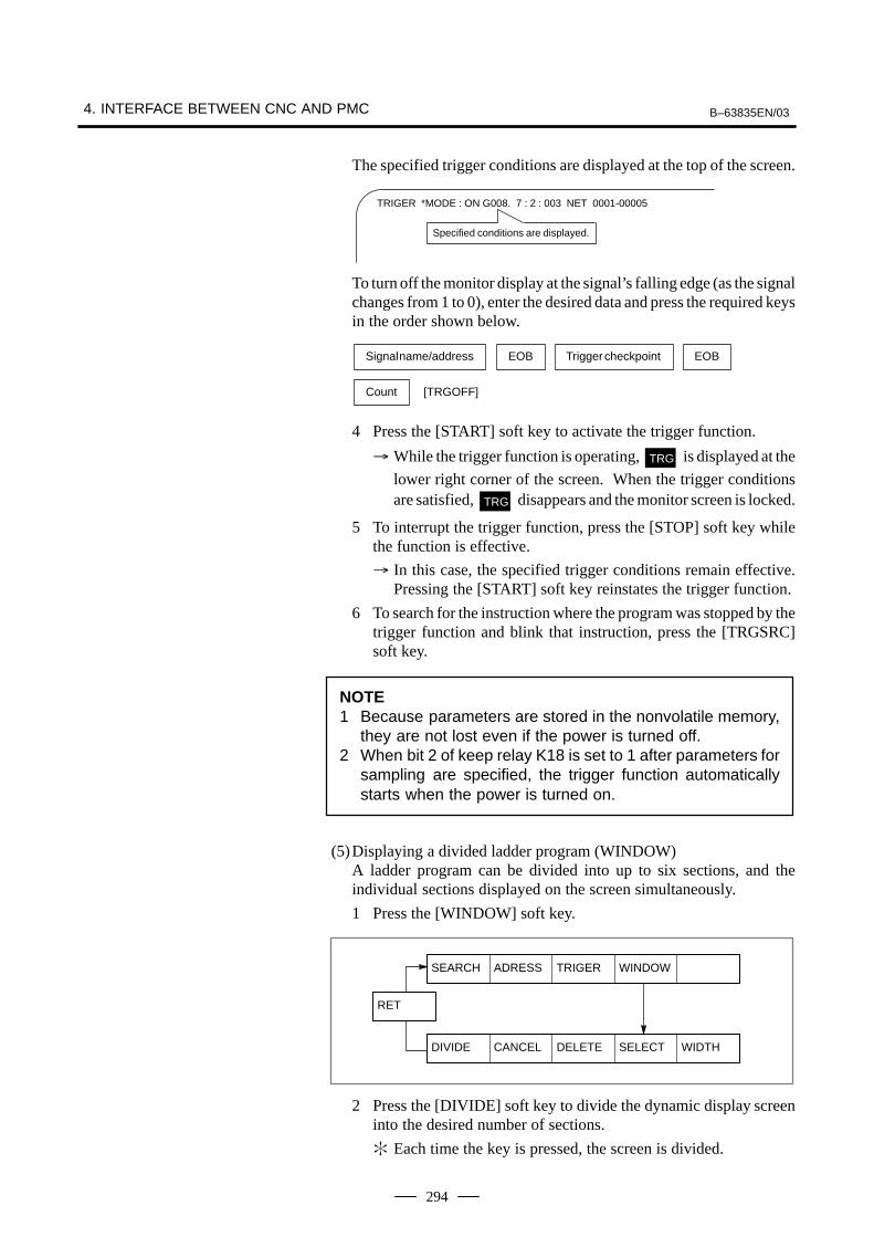
4. INTERFACE BETWEEN CNC AND PMC B–63835EN/03
294
The specified trigger conditions are displayed at the top of the screen.
TRIGER *MODE : ON G008. 7 : 2 : 003 NET 0001-00005
Specified conditions are displayed.
To turn off the monitor display at the signal’s falling edge (as the signalchanges from 1 to 0), enter the desired data and press the required keysin the order shown below.
Signal name/address EOB Trigger checkpoint EOB
Count [TRGOFF]
4 Press the [START] soft key to activate the trigger function.
� While the trigger function is operating, TRG is displayed at the
lower right corner of the screen. When the trigger conditionsare satisfied, TRG disappears and the monitor screen is locked.
5 To interrupt the trigger function, press the [STOP] soft key whilethe function is effective.
� In this case, the specified trigger conditions remain effective.Pressing the [START] soft key reinstates the trigger function.
6 To search for the instruction where the program was stopped by thetrigger function and blink that instruction, press the [TRGSRC]soft key.
NOTE1 Because parameters are stored in the nonvolatile memory,
they are not lost even if the power is turned off.2 When bit 2 of keep relay K18 is set to 1 after parameters for
sampling are specified, the trigger function automaticallystarts when the power is turned on.
(5)Displaying a divided ladder program (WINDOW)A ladder program can be divided into up to six sections, and theindividual sections displayed on the screen simultaneously.
1 Press the [WINDOW] soft key.
SEARCH ADRESS TRIGER WINDOW
DIVIDE CANCEL DELETE SELECT WIDTH
RET
2 Press the [DIVIDE] soft key to divide the dynamic display screeninto the desired number of sections.
� Each time the key is pressed, the screen is divided.
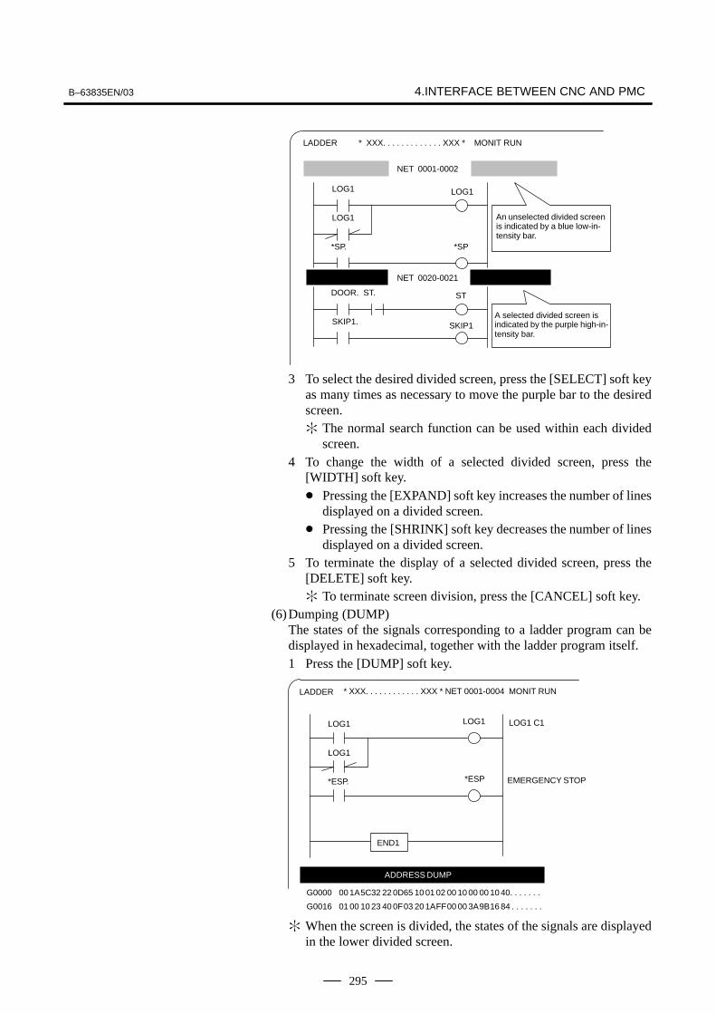
B–63835EN/03 4.INTERFACE BETWEEN CNC AND PMC
295
An unselected divided screenis indicated by a blue low-in-tensity bar.
LOG1
*SP
ST
A selected divided screen isindicated by the purple high-in-tensity bar.
LADDER
LOG1
DOOR. ST.
* XXX. . . . . . . . . . . . . XXX * MONIT RUN
LOG1
*SP.
NET 0001-0002
SKIP1. SKIP1
NET 0020-0021
3 To select the desired divided screen, press the [SELECT] soft keyas many times as necessary to move the purple bar to the desiredscreen.� The normal search function can be used within each divided
screen.4 To change the width of a selected divided screen, press the
[WIDTH] soft key.� Pressing the [EXPAND] soft key increases the number of lines
displayed on a divided screen.� Pressing the [SHRINK] soft key decreases the number of lines
displayed on a divided screen.5 To terminate the display of a selected divided screen, press the
[DELETE] soft key.� To terminate screen division, press the [CANCEL] soft key.
(6)Dumping (DUMP)The states of the signals corresponding to a ladder program can bedisplayed in hexadecimal, together with the ladder program itself.1 Press the [DUMP] soft key.
LOG1 LOG1
LOG1
*ESP. *ESP
LOG1 C1
EMERGENCY STOP
END1
G0000 00 1A5C32 22 0D65 10 01 02 00 10 00 00 10 40. . . . . . .
G0016 01 00 10 23 40 0F03 20 1AFF00 00 3A9B16 84 . . . . . . .
* XXX. . . . . . . . . . . . XXX * NET 0001-0004 MONIT RUNLADDER
ADDRESS DUMP
� When the screen is divided, the states of the signals are displayedin the lower divided screen.

4. INTERFACE BETWEEN CNC AND PMC B–63835EN/03
296
� To change the data notation
[BYTE] : Data is displayed in units of bytes. Example) G0000 00 16 84 00 ...
[WORD] : Data is displayed in units of two bytes.Example) G0000 1600 0084 ...
[D.WORD] : Data is displayed in units of two words, or fourbytes.Example) G0000 00841600 ...
� When WORD or D.WORD is specified, data is displayedwith the high-order byte placed first.
� To search for an address
Use the PAGE
, PAGE
, and [SRCH] keys, as in the normal search
function.
(7)Displaying the function-instruction parameters (DPARA/NDPARA)The states of the control parameters used in function instructions aredisplayed together with the ladder program.
1 Press the [DPARA] soft key.
* XXX. . . . . . . . . . . . XXX * NET 0001-0004 MONIT RUNLADDER
RST ERR1
JOG
JOG FEEDRATE
SUB 27CODEB
2
6
R002
[ 4]
G014
[ 800]
The current value of a control parameter is displayed below the pa-rameter.
� The data notation (binary or BCD) varies with the functioninstructions.
2 To terminate the display of parameters, press the [NDPARA] softkey.
(8)Editing the program being executed (ONLEDT: on-line editing)A sequence program can be edited while a program is being executed,without stopping its execution.
� This function is available only while the edit function is enabled.
1 Press the [ONLEDT] soft key to start the on-line editing function.The cursor appears on the screen.
2 Modify the program, following the usual editing procedure.The following changes can be made by means of on-line editing.
� Changing the type of contacts ( , )
� Changing the addresses of contacts and coils
� Changing the addresses of control parameters used in functioninstructions

B–63835EN/03 4.INTERFACE BETWEEN CNC AND PMC
297
� The operations that can be performed in on-line editing arerestricted to those that do not change the memory size of theprogram. To perform other operations, such as addition,insertion, and deletion, use the ordinary editing function.
3 To terminate on-line editing, press the key.
� Changes made in on-line editing are temporary. To save achanged program, set K18.3 to 1 or transfer the program to theDRAM by using the COPY function from the I/O screen. Toenable the use of the program when the system is next turned on,write it to the FROM from the I/O screen.
#7K018
#6 #5 #4
ÇÇÇÇÇÇ
#3 #2 #1 #0PMCPRM
#3 0 : The ladder program is not transferred to the RAM after on-lineediting.
� To transfer the program, press the following keys in the ordershown, using the COPY function from the I/O screen:[COPY], [EXELAD], [EXEC]
1: A ladder program is automatically transferred to the RAM afteron-line editing.
(1)Display method
1 Press the SYSTEM key.
2 Press the [PMC] soft key.
3 Display of PMC diagnosis screen by pressing [PMC/DGN] softkey.
Display of the title data which is wrote at the ladder programming time.
PMC TITLE DATA #1
PMC PROGRAM NO. :
EDITION NO. :
PMC CONTROL PROGRAM
SERIES : 4067 EDITION : 01
(SERIES : EDITION : )
PMC TYPE CONTROL : RB5 PROGRAM : RB5
MEMORY USED : KB
LADDER : KB
SYMBOL : KB
MESSAGE : KB
SCAN TIME : MS
SCAN MAX : MS MIN : MS
MONIT RUN
TITLE[ ] [ ] [ ] [ ] [ ]STATUS ANALYS TRACE
4.3.3Display of PMCDiagnosis Screen
4.3.3.1Title screen (TITLE)

4. INTERFACE BETWEEN CNC AND PMC B–63835EN/03
298
1) 1st page
PMC PROGRAM NO. :
EDITION NO. :
PMC CONTROL PROGRAM
SERIES : EDITION :
(SERIES: EDITION : )
PMC TYPE CONTROL : PROGRAM :
MEMORY USED : KB
LADDER : KB
SYMBOL : KB
MESSAGE : KB
SCAN TIME : MS
SCAN MAX : MS MIN : MS
Display of a serialnumber and versionnumber of PMCcontrol software, usedmemory area andscan time.
Set at LADDER programming time.
2) 2nd page
MACHINE TOOL BUILDER NAME :
MACHINE TOOL NAME :
CNC & PMC TYPE NAME :
PROGRAM DRAWING NO. :
3) 3rd page
DATE OF PRGRAMMING :
PROGRAM DESIGNED BY :
ROM WRITTEN BY :
REMARKS :
Set at LADDER diagram programmingtime.
Display of ON/OFF condition for I/O signals, internal relays, etc.
SEARCH[ ] [ ] [ ] [ ] [ ]
PMC SIGNAL STATUS MONIT RUN
ADDRESS 7 6 5 4 3 2 1 0ED7 ED6 ED5 ED4 ED3 ED2 ED1 ED0
G0000 0 0 0 0 1 0 1 0ED15 ED14 ED13 ED12 ED11 ED10 ED9 ED8
G0001 0 0 0 0 0 0 0 0ESTB EA6 EA5 EA4 EA3 EA2 EA1 EA0
G0002 0 0 0 0 0 0 0 0
G0003 0 0 0 0 0 0 0 0FIN
G0003 0 0 0 0 0 0 0 0
Signalname
Status of signal
0 : OFF1 : ON
1 Search the diagnosis number by pressing PAGE PAGE keys.
2 Searching the specified address or signal name by pressing[SEARCH] soft key when inputted of Address and number orSingle name
4.3.3.2Status screen (STATUS)

B–63835EN/03 4.INTERFACE BETWEEN CNC AND PMC
299
Display of an alarm when an alarm occurred in PMC program.
TITLE[ ] [ ] [ ] [ ] [ ]STATUS ALARM TRACE
PMC ALARM MESSAGEALARM NOTHING
MONIT RUN
See Appendix A.2 for details of the alarms.
Record the signal status to the trace memory when the specified signal ischanged.
(1)Trace parameter screen (TRCPRM)
T.DISP[ ] [ ] [ ] [ ] [ ]EXEC
PMC SIGNAL TRACE MONIT RUN
TRACE MODE :(0:1BYTE/1:2BYTE/2:WORD)
1ST TRACE ADDRESS CONDITIONADDRESS TYPE : (0:PMC/1:PHY)ADDRESS :MASK DATA
2ND TRACE ADDRESS CONDITIONADDRESS TYPE : (0:PMC/1:PHY)ADDRESS :MASK DATA :
(a) TRACE MODE: Select the trace mode.
0= 1 byte address signal trace
1= Independent 2 byte address signal trace
2= Continuous 2 byte address signal trace
(b)ADDRESS TYPE: 0= Set the trace address by PMC address
1= Set the trace address by physical address(Using mainly by C language)
(c) ADDRESS : Set the trace address
(d)MASK DATA : Specify the trace bit by hexadecimal code.For example, set the “E1” when trace the bit7, 6, 5 and 0. Not execute the tracing when thebit 4, 3, 2 and 1 is changed, but, the signalstatus should recorded at tracing time.
(e.g) #7 #6 #5 #4 #3 #2 #1 #0
1 1 1 0 0 0 0 1:E1
4.3.3.3Alarm screen (ALARM)
4.3.3.4Trace screen (TRACE)

4. INTERFACE BETWEEN CNC AND PMC B–63835EN/03
300
� Correspond table between binary and hexadecimal code �
00002 : 016 00012 : 116 00102 : 216 00112 : 316
01002 : 416 01012 : 516 01102 : 616 01112 : 716
10002 : 816 10012 : 916 10102 : A16 10112 : B16
11002 : C16 11012 : D16 11102 : E16 11112 : F16
(e) [EXEC] soft key :
Start of tracing.Clear the trace memory and trace memory contents are updatewhen the specified signal are changed from previous ones.The trace memory are always maintained up to the previous resultsfor 256 bytes from the latest ones regardless of the time lapse.(2 byte tracing = 128 times.)
(f) [T.DISP] soft key : Display of trace memory contents.
(2)Trace memory screen (T.DISP)
PMC SIGNAL TRACE
1ST ADDRESS=X008(E1) 2ND ADDRESS=G000(FF)NO. 7 6 5 4 3 2 1 0 7 6 5 4 3 2 1 00000 . . . . . . . . . . . . . . . .0001 1 0 0 0 0 0 1 1 0 0 0 0 0 0 0 00002 1 1 0 0 0 0 0 0 0 0 0 0 0 0 0 00003 0 1 0 0 0 0 0 0 0 0 0 0 0 0 0 00004 . . . . . . . . . . . . . . . .0005 . . . . . . . . . . . . . . . .0006 . . . . . . . . . . . . . . . .0007 . . . . . . . . . . . . . . . .0008 . . . . . . . . . . . . . . . .
Trace address andmask data in ( )
Newest status⋅(Period):off1/I:on
TRCPRM[ ] [ ] [ ] [ ] [ ]STOP
MONIT RUN
[TRCPRM] soft key : Return to trace parameter setting screen
[STOP] soft key : Stop the trace operation.
[EXEC] soft key : Re-start of tracing (Clear the memory).
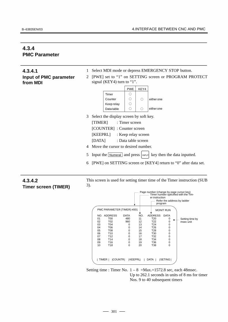
B–63835EN/03 4.INTERFACE BETWEEN CNC AND PMC
301
1 Select MDI mode or depress EMERGENCY STOP button.
2 [PWE] set to “1” on SETTING screen or PROGRAM PROTECTsignal (KEY4) turn to “1”.
PWE KEY4
�
�
�
�
� either one
Timer
Counter
Keep relay
Data table � either one
3 Select the display screen by soft key.
[TIMER] : Timer screen
[COUNTER] : Counter screen
[KEEPRL] : Keep relay screen
[DATA] : Data table screen
4 Move the cursor to desired number.
5 Input the Numeral and press INPUT key then the data inputted.
6 [PWE] on SETTING screen or [KEY4] return to “0” after data set.
This screen is used for setting timer time of the Timer instruction (SUB3).
TIMER[ ] [ ] [ ] [ ] [ ]COUNTR KEEPRL DATA SETING
PMC PARAMETER (TIMER) #001
NO. ADDRESS DATA NO. ADDRESS DATA01 T00 480 11 T20 002 T02 960 12 T22 003 T04 0 13 T24 004 T06 0 14 T26 005 T08 0 15 T28 006 T10 0 16 T30 007 T12 0 17 T32 008 T14 0 18 T34 009 T16 0 19 T36 010 T18 0 20 T38 0
MONIT RUN
Setting time bymsec unit
Refer the address by ladder program
Timer number specified with the Tim-er instruction
Page number (change by page cursor key)
Setting time : Timer No. 1 – 8 =Max.=1572.8 sec, each 48msec.Up to 262.1 seconds in units of 8 ms for timerNos. 9 to 40 subsequent timers
4.3.4PMC Parameter
4.3.4.1Input of PMC parameterfrom MDI
4.3.4.2Timer screen (TIMER)

4. INTERFACE BETWEEN CNC AND PMC B–63835EN/03
302
Set and display the preset values and integrated values of the counterinstruction (SUB 5).
Page number (change by page cursor key)
TIMER[ ] [ ] [ ] [ ] [ ]COUNTR KEEPRL DATA SETING
PMC PARAMETER (COUNTER) #001
NO. ADDRESS PRESET CURRENT01 C00 100 102 C04 50 203 C08 0 004 C12 0 005 C16 0 006 C20 0 007 C24 0 008 C28 0 009 C32 0 010 C36 0 0
MONIT RUN
Preset value (MAX. value)(The min. value specified in theprogram)
Refer the address by ladder programSpecified counter number by program
Integrated value
Up to 32767can be set forPRESET andCURRENT forcounter Nos. 1to 20
PMC PARAMETER (KEEP RELAY) MONIT STOP
NO. ADDRESS DATA01 K00 0000000002 K01 0000000003 K02 0000000004 K03 0000000005 K04 0000000006 K05 0000000007 K06 0000000008 K07 0000000009 K08 0000000010 K09 00000000
[KEEPRL] [DATA][COUNTR][TIMER] [SETING]
Refer the address by ladder program
NO. ADDRESS DATA11 K10 0000000012 K11 0000000013 K12 0000000014 K13 0000000015 K14 0000000016 K15 0000000017 K16 0000000018 K17 0000000019 K18 0000000020 K19 00000000
i) Control of battery-powered memory
#7MWRTF2K16
#6MWRTF1
#5 #4 #3 #2 #1 #0
#7 MWRTF2: This operation is performed for checking the writing status of thenonvolatile memory.
#6 MWRTF1: Write status for battery-powered memory
4.3.4.3Counter screen(COUNTER)
4.3.4.4Keep relay screen(KEEPRL)

B–63835EN/03 4.INTERFACE BETWEEN CNC AND PMC
303
ii) PMC system parameterSince the system uses keep relays K17 to K19, they cannot be used bya sequence program.
#7DTBLDSPK17
#6ANASTAT
#5TRCSTAT
#4MEMINP
#3 #2AUTORUN
#1PRGRAM
#0LADMASK
#0 (LADMASK): 0: The ladder programs are displayed dynamically (PCLAD).
1: The ladder programs are not displayed dynamically (PCLAD).
#1 (PRGRAM): 0: The built-in programmer function does not operate. (Also, theprogrammer menu is not displayed.)
1: The built-in programmer function operates. (The programmer menuis displayed.)
#2 (AUTORUN): 0: The sequence program automatically starts at power on.
1: Pressing the soft key to sequence program execution starts thesequence program.
#4 (MEMINP): 0: The forcing function is disabled.
1: The forcing function is enabled.
#5 (TRCSTAT): 0: Pressing the [EXEC] soft key starts tracing by the signal tracefunction.
1: The signal trace function automatically starts tracing at power on.
#6 (ANASTAT): 0: Pressing the soft key to execution starts sampling by the signalwaveform display function.
1: The signal waveform display function automatically starts samplingat power on.
� This bit is only effective for those models for which the signalwaveform display function is applicable.
#7 (DTBLDSP): 0: The PMC parameter data table control screen is displayed.
1: The PMC parameter data table control screen is not displayed.
#7IGNDINTK018
#6EDITLAD
#5CHKPRTY
#4CALCPRTY
#3TRNSRAM
#2TRGSTAT
#1DBGSTAT
#0IGNKEY
#0 (IGNKEY): 0: Function keys are enabled for a user program on the user screen.
1: Function keys are disabled for a user program on the user screen.
� This flag is useful when a user program is used. When this bit is setto 1, the user screen cannot be switched to the NC screen by using thefunction keys. A program which invariably sets this bit to 0, or whichswitches the user screen to the NC screen, must be prepared.
#1 (DBGSTAT): 0: The C language debug function does not start automatic breakprocessing at power on.
1: The C language debug function starts automatic break processing atpower on.
� This flag is useful when a user program is used.
#2 (TRGSTAT): 0: The trigger stop function does not automatically start at power on.
1: The trigger stop function starts automatically at power on.

4. INTERFACE BETWEEN CNC AND PMC B–63835EN/03
304
#3 (TRNSRAM): 0: After on-line editing, the ladder program is not automaticallytransferred to the backup RAM.
1: After on-line editing, the ladder program is automatically transferredto the backup RAM.
#4 (CALCPRTY): 0: The built-in programmer function calculates the RAM parity.
1: The built-in programmer function does not calculate the RAM parity.
#5 (CHKPRTY): 0: The system performs parity check for the system ROM, programROM and program RAM.
1: The system does not perform parity check for the system ROM,program ROM, or program RAM.
#6 (EDITLAD): 0: The editing of a sequence program is disabled.
1: The editing of a sequence program is enabled.
#7 (IGNDINT): 0: The system initializes the LCD when the screen is switched to thePMCMDI screen.
1: The system does not initialize the LCD when the screen is switched tothe PMCMDI screen.
� This flag is useful when a user program is used. When the screen isswitched to the PMCMDI screen, PMC control software determineswhether the system initialize the LCD, by checking this flag. Whenthis flag is on, an application program must initialize the LCD.
#7PTCTPRMK019
#6HIDEPRM
#5 #4 #3 #2ALWSTP
#1C–REJECT
#0FROM–WRT
#0 (FROM_WRT): 0: After editing a ladder or C program, does not automatically write it toF–ROM.
1: After editing a ladder or C program, automatically writes it toF–ROM.
#1 (C-REJECT): 0: The system activates a C program.
1: The system does not activate a C program.
#2 (ALWSTP): 0: The execution/stop operation of a sequence program is disabled.
1: The execution/stop operation of a sequence program is enabled.
#6 (HIDEPRM): 0: The display of PMC parameters and the output of PMC parameters tothe outside are enabled.
1: The display of PMC parameters and the output of PMC parameters tothe outside are disabled.
#7 (PTCTPRM): 0: The modification and reading of PMC parameters are enabled.
1: The modification and reading of PMC parameters are disabled.
CAUTIONSet all unused bits to 0.

B–63835EN/03 4.INTERFACE BETWEEN CNC AND PMC
305
1) DATA TABLE SETTING screen (C. DATA)
INITNO.SRHG.CONTG.DATA[ ]
NO. ADDRESS PARAMETER TYPE NO.OF DATA
001 D0000 00000000 0 10
002 D0020 00000011 1 20
003
004
005
006
007
008
PMC DATA TBL CONTROL #001
GROUP TABLE COUNT = 2
[ ] [ ] [ ] [ ]
MONIT RUN Number ofdata tablegroup
Number ofdata ofeach datatable
Data length
Table parameter
Head address ofdata table
(a) [G.DATA] soft key : Select the data display screen of data table.
(b) No. of group [G.CONT] : Set the number of group for data table.
(c) No. of group [NO.SRH] : Move the cursor to specified group.
(d) [INIT] soft key : Initialize of data table setting.No. of group is 1, ADDRESS is D0000,PARAMETER is 00000000, TYPE is 0, NO. OFDATA is 1860.
�Table parameter�
0 : Binary format 1 : BCD format
Protection of input data,0 : not provided.
1 : provided.
0 : Displayed in binary or BCD (bit 0 is enabled)1 : Displayed in hexadecimal (bit 0 is disabled)
#7 #6 #5 #4 #3
ÇÇÇÇÇÇÇÇ
#2
ÇÇÇÇÇÇ
#1
ÇÇÇÇÇÇÇÇ
#0
�TYPE�
0 : 1byte1 : 2bytes2 : 4bytes
4.3.4.5Data table screen (DATA)

4. INTERFACE BETWEEN CNC AND PMC B–63835EN/03
306
2) Data setting screen (G. DATA)
C.DATA[ ] [ ] [ ] [ ] [ ]G–SRCH SEARCH
PMC PRM (DATA) 001/001
NO. ADDRESS DATA000 D0000 0001 D0001 0002 D0002 0003 D0003 0004 D0004 0005 D0005 0006 D0006 0007 D0007 0008 D0008 0009 D0009 0
MONIT RUN
Group number
Number of page
(a) [C.DATA] soft key : Return to data table setting screen.
(b) Group No. [G-SRCH] : Move the cursor to head of specified group.
(c) Address [SEARCH] : Searching the specified address incurrentup group.
Some PMC system parameters can be set on this screen.
(K17.5)(K18.2)(K18.6)(K19.0)(K17.4)(K17.7)(K19.6)(K19.7)(K17.0)
(K17.2)(K19.2)(K17.1)
NOTEThe parenthesized values to the right of the screen indicatekeep relay addresses.
4.3.4.6Setting screen

B–63835EN/03 4.INTERFACE BETWEEN CNC AND PMC
307
When the PMC data are input/output with I/O device unit viareader/puncher interface, the built-in type PMC programmer should startsby as following operation.
� As following operation is not required when the data set from MDI.
1 Select the PMC screen
Press SYSTEM key and press [PMC] soft key.
2 Confirm to the built-in type PMC programmer is running.
PMC CONTROL SYSTEM MENU
SELECT ONE OF FOLLOWING SOFT KEYS
PMCLAD : DYNAMIC LADDER DISPLAYPMCDGN : DIAGNOSIS FUNCTIONPMCPRM : PARAMETER (T/C/K/D)RUN/STOP : RUN/STOP SEQUENCE PROGRAMEDIT : EDIT SEQUENCE PROGRAMI/O : I/O SEQUENCE PROGRAMSYSPRM : SYSTEM PARAMETERMONIT : PMC MONITOR
PMCLAD[ ] [ ] [ ] [ ] [ ]PMCDGN PMCPRM
MONIT RUN
parts are displayed, starts of the built-in type PMC programmer.
3 Keep relay K17.1 should set to “1” if the built-in type PMCprogrammer is not start yet.
4 Press key to return to initial menu screen.
1 Press key in the initial menu screen, then display to [I/O] softkey.
2 Display next screen
EXEC[ ] [ ] [ ] [ ] [ ]CANCEL (NO.)
MONIT RUNPMC I/O PROGRAM
CHANNEL = 1
DEVICE = HOST
FUNCTION =
DATA KIND =
4.3.5Input/Output of PMCData
4.3.5.1Start of the built-in typePMC programmer
4.3.5.2Input/output method

4. INTERFACE BETWEEN CNC AND PMC B–63835EN/03
308
3 Enter the desired channel number, then press the INPUT key to set the
number for CHANNEL.
1 : JD5A of the main CPU board
2 : JD5B of the main CPU board
4 Specify the I/O unit to be used for DEVICE.
HOST: I/O operation with FAPT LADDER (on the P-G, P-GMate, or personal computer)
FDCAS: I/O operation with a Floppy Cassette Adaptor
F-ROM: I/O operation with a flash EEPROM
M-CARD: I/O operation with a memory card
OTHERS: I/O operation with other I/O units
5 Specify the desired function with FUNCTION.
WRITE: Outputting data
READ: Inputting data
COMPARE:Comparing data in memory with that in an externaldevice
DELETE: Deleting files on a floppy disk or memory card
LIST: Listing the files on a floppy disk or memory card
BLANK: Checking whether the flash EEPROM is empty
ERASE: Clearing the data in the flash EEPROM
FORMAT: Formatting a memory card (all data on the memory cardis deleted.)
6 Specify the desired type of data to be output at KIND DATA.
LADDER: Ladder programs
PARAM: PMC parameters
7 When FDCAS or M-CARD is specified for the device, a file can bespecified for FILE NO. by either its file number or file name.
8 Specify the RS-232C conditions for each device with SPEED.
9 Check that the settings are correct. Then, press the [EXEC] soft key.
Changes made during on-line editing are transferred to the correspondingediting ladder program.
4.3.5.3Copy function (COPY)
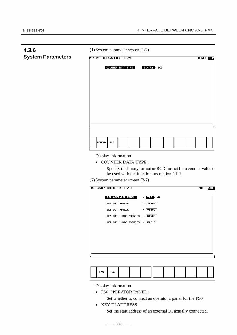
B–63835EN/03 4.INTERFACE BETWEEN CNC AND PMC
309
(1)System parameter screen (1/2)
Display information
• COUNTER DATA TYPE :
Specify the binary format or BCD format for a counter value tobe used with the function instruction CTR.
(2)System parameter screen (2/2)
Display information
• FS0 OPERATOR PANEL :
Set whether to connect an operator’s panel for the FS0.
• KEY DI ADDRESS :
Set the start address of an external DI actually connected.
4.3.6System Parameters

4. INTERFACE BETWEEN CNC AND PMC B–63835EN/03
310
• LED DO ADDRESS :
Set the start address of an external DO actually connected.
• KEY BIT IMAGE ADDRESS :
Set the start address of a key image referenced by a userprogram. Usually, set an arbitrary internal relay (R) area.
• LED BIT IMAGE ADDRESS :
Set the start address of an LED image generated by a userprogram. Usually, set an arbitrary internal relay (R) area.
(a) Soft key
• [EMG ST] : Terminates communication forcibly. Use this key ifcommunication becomes abnormal and theconnection cannot be terminated normally.
• [INIT] : Initializes the parameters to their default values.
(b)Setting
• CPU ID : Displays a CPU ID value. However, do notmodify this item.
• RS–232C : Enables communication setting in the case ofconnection via RS–232C. However, do notmodify the items of TIMER 1, TIMER 2,TIMER 3, and MAX PACKET SIZE.
• HIGH SPEED I/F : Enables setting for connection via ahigh–speed interface (HSSB, Ethernet).
4.3.7Online Monitor SettingScreen
B–63835EN/03 4.INTERFACE BETWEEN CNC AND PMC
311
NOTE1 When both ”RS–232C = USE” and ”HIGH SPEED I/F =
USE” are selected, the PMC system will communicate withthe application which is connected at first. If PMC system isalready connecting with an application, it can not connectwith other applications.
2 When you use the online function by Ethernet, the settingof Ethernet parameters at CNC is necessary in advance.
(c) Communication status
• USE TIME : The maximum time in the communicationprocessing is displayed.
• RS–232C : The communication condition of RS–232C isdisplayed.
• HIGH SPEED I/F : The communication condition of HIGHSPEED I/F is displayed.
• ETHER_BOARD : Displayed during the communication withEthernet board. The IP address of thecommunication partner is displayed.
• EMB_ETHERNET: Displayed during the communication withembedded Ethernet. The IP address of thecommunication partner is displayed.
• HSSB : Displayed during the communication withHSSB.

4. INTERFACE BETWEEN CNC AND PMC B–63835EN/03
312
Display messages and the meanings
Displaymessages
Meanings
INACTIVE The communication is inactive.
STOPPING The communication is being stopped. (Wait for the termination of communication)
STARTING The communication is being started.(Wait for the termination of communication over anoth-er communication path)
STAND–BY The communication is active and in standby mode.
CONNECTED The communication is active and being connected.
NO OPTION The port can be not opened because there is not op-tion of RS–232C.
BAD PARAMETER Invalid open parameters are specified.
TIMEOUT ERROR A time–out has occurred and communication isaborted.
TIMEOUT(K)ERROR
A time–out has occurred and communication isaborted.
BCC ERROR A Block Check Code (packet parity) error has occurred.
PARITY ERROR A parity error has occurred.
OVER–RUNERROR
A reception overrun has occurred and the communica-tion can not recover.
SEQUENCEERROR
Packets are out of sequence. (Incorrect procedure)
DATA ERROR Incorrect packets have been received through retryprocess.
QUEUEOVERFLOW
The transmit/receive queue has overflowed.
DISCONNECTED Communication has been terminated successfully.
NO CONNECTION The cable is disconnected.

B–63835EN/03 4.INTERFACE BETWEEN CNC AND PMC
313
PMC–SB7 screen menu selection procedure
[PMC] [PMCLAD] [EDIT] Ladder diagram display screen
Selection monitor function
Ladder diagram editing screen
[PMCDGN] [TITLE] Title screen
[STATUS] Signal status screen
[ALARM] Alarm screen
[TRACE] Signal trace screen
[IOCHK] I/O check screen
[PMCPRM] [TIMER] Timer screen
[COUNTR] Counter screen
[KEEPRL] Keep relay screen
[DATA] [G.DATA] Data table screen
[SETING] Setting screen
[RUN]/[STOP] Ladder start/stop
[EDIT] [TITLE] Title editing screen
[SYMBOL] Symbol/comment editing screen
[MESAGE] Message editing screen
[MODULE] I/O unit address setting screen
[CROSS] Cross reference screen
[CLEAR] Clear screen
[I/O] Program/parameter input/output screen
[SYSPRM] System parameter screen
[MONIT] [ONLINE] Online setting screen
4.4PMC SCREEN(PMC–SB7)
4.4.1PMC Menu SelectionProcedure Using SoftKeys

4. INTERFACE BETWEEN CNC AND PMC B–63835EN/03
314
(1)Display method
<1> Press the system key, then press the [PMC] soft key.
<2> Press the [PMCLAD] soft key to enable dynamic display ofsequence programs.
(2)Display information
The ladder diagram display/editing function consists of the followingscreens:a) Ladder diagram display screen
b) Selection monitor screen
c) Ladder diagram editing screen
d) Net editing screen
e) Program list display screen
f) Program list editing screen
Display
Display function(monitor)
PMC main menu
[PMCLAD][<]
[EDIT]
Ladder diagramediting screen
Program listediting screen
[LIST]
[ZOOM], [<]
Net editing screen
[MODIFY], [ADD]
[<]
Editing function
Ladder diagramdisplay screen
Program list display screen
Selection monitorscreen[SWITCH]
[ZOOM][LIST][ZOOM][LIST]
[<]
[SWITCH]
4.4.2Dynamic Display ofSequence Programs
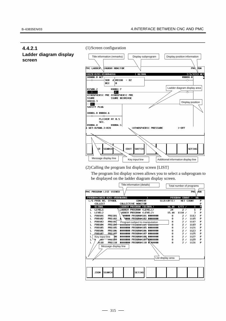
B–63835EN/03 4.INTERFACE BETWEEN CNC AND PMC
315
(1)Screen configuration
Title information (remarks) Display position information
Ladder diagram display area
Additional information display lineMessage display line
Display subprogram
Key input line
Display position
(2)Calling the program list display screen [LIST]
The program list display screen allows you to select a subprogram tobe displayed on the ladder diagram display screen.
Title information (details) Total number of programs
Program subject to manipulation
Key input line
Message display line
List display area
4.4.2.1Ladder diagram displayscreen

4. INTERFACE BETWEEN CNC AND PMC B–63835EN/03
316
(3)Searching for a signal [SEARCH]
<1> Press the [SEARCH] soft key.
<2> Search for a signal by using the keys indicated below.
� With PAGE
PAGE
, the display area can be changed.
� [TOPBTM] : The start/end of a ladder diagram is searched for.
� “Address” + [SEARCH] or “Signal name” + [SEARCH]:A specified address or signal name is searched for.
� “net–number” + [SEARCH]:A ladder is displayed from a specified net number.
� “Address” + [W–SRCH] or “Signal name” + [W–SRCH]:The write coil is searched for a specified address or signal name.
� “function–instruction–number” + [F–SRCH] or “function–instruction–name” + [F–SRCH]:A specified function instruction is searched for.
� [PREV] : The previous search operation performed successfully is repeated towards the start.
� [NEXT] : The previous search operation performed successfully is repeated towards the end.
� [GLOBAL]/[LOCAL] : The search range is switched.
(4)Calling the function instruction data table display screen [TABLE]
The data table of a function instruction with a data table such as theCOD instruction (SUB7) and the CODB instruction (SUB27) can bedisplayed.
(5)Setting the screen [SETING]
The setting screen for the ladder diagram display screen can be called.Various settings for ladder diagram display can be modified.

B–63835EN/03 4.INTERFACE BETWEEN CNC AND PMC
317
On the selection monitor screen, only a ladder net including a coil to bemonitored can be specified for ladder net monitoring.
(1)Display method
(a) Calling the screen from the program list display screen<1> Display the program list screen.
<2> Move the cursor to the “COLLECT”.<3> Press the [ZOOM] soft key.
(b)Calling the screen from the ladder diagram display screen
<1> Display the ladder diagram display screen.<2> Press the [SWITCH] soft key.
(2)Display information
(3)Specifying a ladder net to be monitored [PICKUP]By using the method described below, a ladder net to be monitored onthe selection monitor screen can be read for display.(a) Specifying a desired ladder net on the selection monitor screen
� Typing the address used with the coil to read the net
<1> Enter the address to be monitored.<2> Press the [PICKUP] soft key.
<3> The net that uses the address specified by <1> with a coilis read to the top of the screen.
� Specifying the ladder net on the selection monitor screen<1> Move the cursor to the relay in the ladder net that uses an
address to be monitored.
<2> Press the [PICKUP] soft key.<3> The net that uses the address specified by <1> with a coil
is read to the top of the screen, and the cursor moves to thecoil position.
(b)Specifying a desired ladder net on the ladder diagram displayscreen
4.4.2.2Selection monitor screen
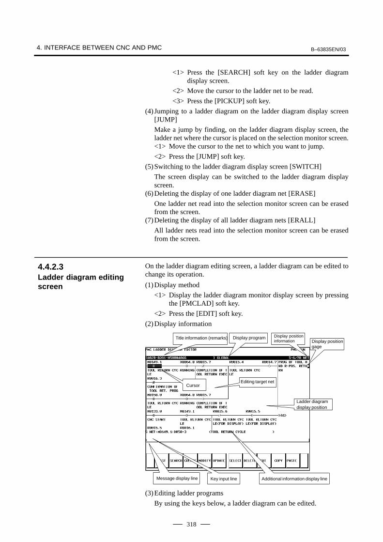
4. INTERFACE BETWEEN CNC AND PMC B–63835EN/03
318
<1> Press the [SEARCH] soft key on the ladder diagramdisplay screen.
<2> Move the cursor to the ladder net to be read.
<3> Press the [PICKUP] soft key.
(4) Jumping to a ladder diagram on the ladder diagram display screen[JUMP]
Make a jump by finding, on the ladder diagram display screen, theladder net where the cursor is placed on the selection monitor screen.<1> Move the cursor to the net to which you want to jump.
<2> Press the [JUMP] soft key.
(5)Switching to the ladder diagram display screen [SWITCH]
The screen display can be switched to the ladder diagram displayscreen.
(6)Deleting the display of one ladder diagram net [ERASE]
One ladder net read into the selection monitor screen can be erasedfrom the screen.
(7)Deleting the display of all ladder diagram nets [ERALL]
All ladder nets read into the selection monitor screen can be erasedfrom the screen.
On the ladder diagram editing screen, a ladder diagram can be edited tochange its operation.
(1)Display method
<1> Display the ladder diagram monitor display screen by pressingthe [PMCLAD] soft key.
<2> Press the [EDIT] soft key.
(2)Display information
Title information (remarks) Display program Display position information Display position
gage
Cursor
Ladder diagram display position
Editing target net
Message display line Key input line Additional information display line
(3)Editing ladder programs
By using the keys below, a ladder diagram can be edited.
4.4.2.3Ladder diagram editingscreen

B–63835EN/03 4.INTERFACE BETWEEN CNC AND PMC
319
� Selecting a subprogram to be edited
<1> Display the program list editing screen by pressing the [LIST]soft key.
<2> Move the cursor to a subprogram to be edited.
� Searching for a specified address or function instruction
<1> Press the [SEARCH] soft key.
<2> Switch to the soft key display for search.
For the search function, see “(3) Searching for a signal [SEARCH]”in Subsection 4.4.2.1, “Ladder diagram display screen”.
� Adding a new net
<1> Move the cursor to the position where a new net is to be added.
<2> Press the [ADD] soft key to call the net editing screen.Perform creation and addition operations to build a new net.
� Modifying the structure of a selected net
<1> Move the cursor to a net to be modified.
<2> Call the net editing screen by pressing the [MODIFY] softkey.
� Changing the bit address of a relay
<1> Move the cursor to a relay to be modified.
<2> Enter a desired bit address then press the ENTER key. Thebit address of the relay where the cursor is placed is changed.
� Modifying the parameter of a function instruction
<1> Move the cursor to the parameter of a function instruction tobe modified.
<2> Enter a desired number or byte address then press the ENTERkey. The parameter of the function instruction where thecursor is placed is modified.
� Reflecting modifications
<1> On the ladder diagram editing screen, modify a ladderprogram.
<2> Press the [UPDATE] soft key. The results of editingperformed so far are reflected in the ladder being executed.When the modifications have been reflected normally, theladder after editing is executed.
� Deleting a net
<1> Move the cursor to a net to be deleted.
<2> Press the [DELETE] soft key.
� Moving a net
<1> Move the cursor to a net to be moved.
<2> By pressing the [CUT] soft key, cut the net.
<3> Move the cursor to the position to which the selected net is tobe moved.
<4> Press the [PASTE] soft key.
� Copying a net
<1> Move the cursor to a net to be copied.
<2> Press the [COPY] soft key.
4. INTERFACE BETWEEN CNC AND PMC B–63835EN/03
320
<3> Move the cursor to the position to which the selected net is tobe copied.
<4> Press the [PASTE] soft key.
� Selecting multiple nets to be deleted/copied/moved
<1> Move the cursor to the start point of a desired net selectionrange.
<2> Press the [SELECT] soft key.
<3> Move the cursor to the end point of the desired net selectionrange.
<4> Press the [DELETE], [CUT], or [COPY] soft key to delete,move, or copy the selected nets.
� Discarding changes
Press the [RESTOR] soft key.
The results of editing performed so far are discarded to return to theladder present when you moved to the ladder diagram editingscreen or when you performed the last [UPDATE] processing.
� Modifying the setting of the ladder diagram editing screen
Press the [SETING] soft key.
The setting screen of the ladder diagram editing screen is called.
� Starting/stopping a ladder
Press the [START] or [STOP] soft key.
The execution of a ladder program is controlled. The [START] softkey starts the execution of a ladder program, and the [STOP] softkey stops the execution of a ladder program.
� Ending the editing
Press the [<] key.
On the net editing screen, net editing operations such as the creation ofa new net and the modification of an existing net can be performed.
� Modification to an existing netIf the net editing screen is displayed with the [MODIFY] soft key,the mode (modification mode) for modifying the net indicated bythe cursor is set.
� Addition of a new netIf the net editing screen is displayed with the [CREATE] soft key,the mode (creation mode) for creating a new net from a free stateis set.
(1)Display method
<1> Display the ladder diagram editing screen.
<2> Press the [ADD] or [MODIFY] soft key.
4.4.2.4Net editing screen
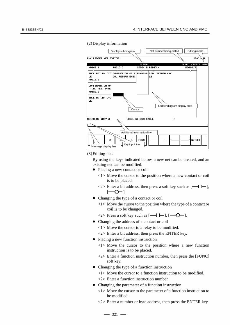
B–63835EN/03 4.INTERFACE BETWEEN CNC AND PMC
321
(2)Display information
Editing mode
Additional information line
Net number being editedDisplay subprogram
Message display lineKey input line
CursorLadder diagram display area
(3)Editing nets
By using the keys indicated below, a new net can be created, and anexisting net can be modified.� Placing a new contact or coil
<1> Move the cursor to the position where a new contact or coilis to be placed.
<2> Enter a bit address, then press a soft key such as [ ],[ ].
� Changing the type of a contact or coil
<1> Move the cursor to the position where the type of a contact orcoil is to be changed.
<2> Press a soft key such as [ ], [ ].
� Changing the address of a contact or coil
<1> Move the cursor to a relay to be modified.<2> Enter a bit address, then press the ENTER key.
� Placing a new function instruction
<1> Move the cursor to the position where a new functioninstruction is to be placed.
<2> Enter a function instruction number, then press the [FUNC]soft key.
� Changing the type of a function instruction
<1> Move the cursor to a function instruction to be modified.
<2> Enter a function instruction number.
� Changing the parameter of a function instruction
<1> Move the cursor to the parameter of a function instruction tobe modified.
<2> Enter a number or byte address, then press the ENTER key.
4. INTERFACE BETWEEN CNC AND PMC B–63835EN/03
322
� Adding/deleting a connection line
<1> Move the cursor to the position where a connection line is tobe added or deleted.
<2> Press a soft key such as [ ], [ ], [ ] foraddition.
<3> When deleting an existing connection line, press a soft keysuch as [ ], [ ], [ ].
� Deleting a contact, coil, or function instruction
<1> Move the cursor to the position where a contact, coil, orfunction instruction to be deleted is located.
<2> Press the [ ] soft key.
� Editing the next net
Press the [NXTNET] soft key. The editing operation of the netcurrently being edited ends, and processing proceeds to the editingof the next net.
� Editing a function instruction data table
<1> Move the cursor to the function instruction that has a datatable to be edited.
<2> Press the [TABLE] soft key. The function instruction datatable editing screen appears.
<3> Move the cursor to the data table to be edited.
<4> Modify the selected data.
� Inserting a line/column
<1> Move the cursor to the position where a line/column is to beinserted.
<2> Press the [INSLIN], [INSCLM], or [APPCLM] soft key.
� Discarding the results of editing
Press the [RESTOR] soft key.

B–63835EN/03 4.INTERFACE BETWEEN CNC AND PMC
323
Display method
<1> Press the system key, then press the [PMC] soft key.
<2> Press the [PMCDGN] soft key. The PMC diagnosis screen appears.
The title data registered at the time of ladder program creation isdisplayed.
2002.7.21
008008
406L
008
01
Title data is the title of a sequence program, and consists of ten items:
� MACHINE TOOL BUILDER NAME (32 characters)
� MACHINE TOOL NAME (32 characters)
� CNC & PMC TYPE NAME (32 characters)
� PMC PROGRAM NO. (4 characters)
� EDITION NO. (2 characters)
� PROGRAM DRAWING NO. (32 characters)
� DATE OF PROGRAMMING (16 characters)
� PROGRAM DESIGNED BY (32 characters)
� ROM WRITTEN BY (32 characters)
� REMARKS (32 characters)
In addition, the following data is displayed:
� Series and edition of the PMC basic software
� Memory use status of each sequence data item
� Type of the PMC basic software and the PMC type of the sequenceprogram
� Current execution time, maximum execution time, and minimumexecution time of the ladder program
4.4.3Display of the PMCDiagnosis Screen
4.4.3.1Title screen

4. INTERFACE BETWEEN CNC AND PMC B–63835EN/03
324
The on/off state of I/O signals and the internal relay is displayed.
Signal name
Signal state.(period): OffI: On
� The diagnosis number can be increased or decreased by using PAGE
PAGE.
� Enter an address and number or signal name, then press the[SEARCH] soft key. Then, the specified address or signal name issearched for.
An alarm issued from the PMC is displayed.
4.4.3.2Status screen
4.4.3.3Alarm screen

B–63835EN/03 4.INTERFACE BETWEEN CNC AND PMC
325
(1)Trace parameter screen (first page)
<1> Press the system key, then press the [PMC] soft key.
<2> Press the [PMCDGN] soft key.
<3> Press the [TRACE] soft key.
<4> Press the [SETING] soft key on the signal trace screen.
a) SAMPLING/MODESet a sampling mode.
� TIME CYCLE : Sampling based on a period oftime
� SIGNAL TRANSITION : Sampling based on signaltransitions
b) SAMPLING/RESOLUTIONSet the resolution of sampling.
c) SAMPLING/TIMEThis item is displayed when “TIME CYCLE” is selected as thesampling mode. Set a time interval for sampling.
d) SAMPLING/FRAMEThis item is displayed when “SIGNAL TRANSITION” isselected as the sampling mode. Set the number of samplingtimes.
e) STOP CONDITIONSet a trace stop condition.
� NONE : Does not stop trace operationautomatically.
� BUFFER FULL : Stops trace operation automaticallywhen the sampling buffer becomes full.
� TRIGGER : Stops trace operation automatically bya trigger.
4.4.3.4Trace function

4. INTERFACE BETWEEN CNC AND PMC B–63835EN/03
326
f) STOP CONDITION/TRIGGER/ADDRESSThis item becomes settable when “TRIGGER” is set as the tracestop condition. Set a trigger address for stopping traceoperation.
g) STOP CONDITION/TRIGGER/MODEThis item becomes settable when “TRIGGER” is set as the tracestop condition. Set a trigger mode for stopping trace operation.
� RISING EDGE : Stops trace operation automaticallyon the rising edge of the trigger signal.
� FALLING EDGE : Stops trace operation automaticallyon the falling edge of the trigger signal.
� BOTH EDGE : Stops trace operationautomaticallyon a transition of thetrigger signal.
h) STOP CONDITION/TRIGGER/POSITIONThis item becomes settable when “TRIGGER” is set as the tracestop condition. By using a ratio to the sampling time (or count),set where to place a stop trigger occurrence position in the entiresampling time (or count).
i) SAMPLING CONDITIONThis item becomes settable when “SIGNAL TRANSITION” isset as the sampling mode. Set a sampling condition.
� TRIGGER : Performs sampling when thesampling trigger condition issatisfied.
� ANY CHANGE : Perform sampling when a samplingaddress signal transition occurs.
j) SAMPLING CONDITION/TRIGGER/ADDRESSThis item becomes settable when “SIGNAL TRANSITION” isset as the sampling mode and “Trigger” is set as the samplingcondition. Set an address used to trigger sampling.
k) SAMPLING CONDITION/TRIGGER/MODEThis item becomes settable when “SIGNAL TRANSITION” isset as the sampling mode and “Trigger” is set as the samplingcondition. Set a trigger condition mode.
� RISING EDGE : Performs sampling on the rising edgeof the trigger signal.
� FALLING EDGE : Performs sampling on the fallingedge of the trigger signal.
� BOTH EDGE : Performs sampling on a signaltransition.
� ON : Performs sampling when the triggersignal is on.
� OFF : Performs sampling when the triggersignal is off.

B–63835EN/03 4.INTERFACE BETWEEN CNC AND PMC
327
(2)Trace parameter screen (second page)
On the trace parameter screen (first page), press PAGE
PAGE
.
a) Address settingSet a signal address as a bit address. If you enter a byte address,bits 0 to 7 of the entered address are input. Up to 32 signaladdresses can be set.
b) Soft keys
� [DELETE] : Deletes the set address where thecursor is placed.
� [SYMBOL]/[ADRESS] : Switches the setting addressbetween symbol display andaddress display.
� [MV.UP] : Replaces the set address with theupper line.
� [MV.DWN] : Replaces the set address with thelower line.
� [DELALL] : Deletes all set addresses.
c) Trigger settingWhen “SIGNAL TRANSITION” is set as the trace sampling modeand “BOTH EDGE” is set as the sampling condition, you canchoose whether to use a set address as a trigger signal for sampling.To the right of a signal address set as a trigger, a “�” mark isindicated.
� [TRGON] : Turns on a trigger setting.
� [TRGOFF] : Turns off a trigger setting.

4. INTERFACE BETWEEN CNC AND PMC B–63835EN/03
328
(3)Trace screen
<1> Press the system key, then press the [PMC] soft key.
<2> Press the [PMCDGN] soft key.
<3> Press the [TRACE] soft key.
(a) Executing trace operation
[START] : Executes trace operation.
(b)Stopping trace operation
[STOP] : Stops trace operation. Trace operationends also when the trace stopcondition set on the trace parametersetting screen is satisfied.
(c) Checking trace results
Upon completion of trace execution, the results of traceoperation can be checked.
� Scrolling display
Cursor up/down key, page switch key:Scrolls the set sampling signaladdresses up and down.
[<<PREV], [NEXT>>] Soft key, current right/left key:Scrolls the graphical display of traceresults right and left.
� Performing automatic calculation and display of a selectedrange
[MARK] : Marks the current cursor position, anddisplays the mark cursor. To cancelthe range selection, press the [MARK]soft key again.
� Enlarging/reducing display of trace results
[Z.IN]/[Z.OUT] : Enlarges/reduces graphical display.

B–63835EN/03 4.INTERFACE BETWEEN CNC AND PMC
329
� Replacing display data
[MV.UP] : Replaces the address where the cursoris placed and the trace result of theaddress with the upper line.
[MV.DWN] : Replaces the display data with thelower line.
The type and ID code of an I/O device connected to the I/O Link aredisplayed for each group. No data is displayed when no I/O device isconnected.
Channel enable mark
Channel enable mark : When a channel is usable, an “*” mark isindicated. On the sample screen above, channel2 is unusable.
<1> Place the NC in the MDI mode or in the emergency stop state.
<2> Set PWE of the NC setting screen to 1.
PWE KEY4
�
�
�
�
� either one
Timer
Counter
Keep relay
Data table � either one
<3> Alternatively, set the program protect signal (KEY4) to 1 only withthe counter and data table.
4.4.3.5I/O Link connectioncheck screen
4.4.4PMC Parameters
4.4.4.1Parameter input/outputmethod
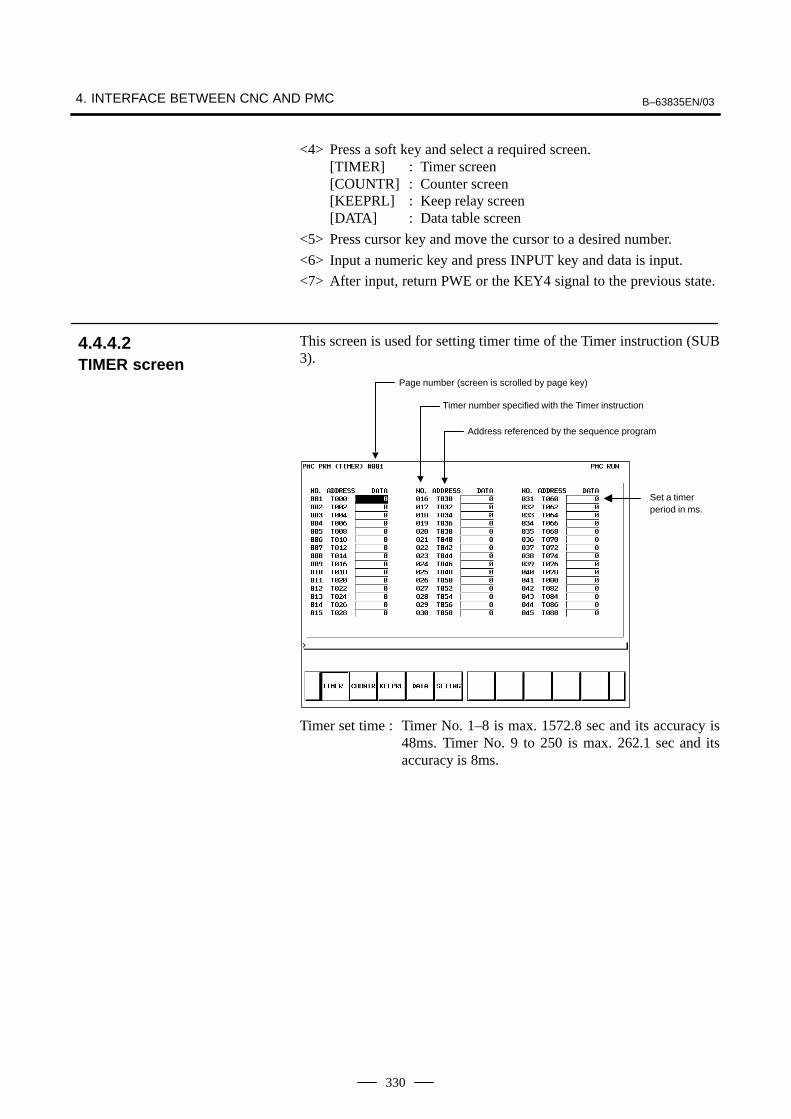
4. INTERFACE BETWEEN CNC AND PMC B–63835EN/03
330
<4> Press a soft key and select a required screen.[TIMER] : Timer screen[COUNTR] : Counter screen[KEEPRL] : Keep relay screen[DATA] : Data table screen
<5> Press cursor key and move the cursor to a desired number.
<6> Input a numeric key and press INPUT key and data is input.
<7> After input, return PWE or the KEY4 signal to the previous state.
This screen is used for setting timer time of the Timer instruction (SUB3).
Page number (screen is scrolled by page key)
Timer number specified with the Timer instruction
Address referenced by the sequence program
Set a timerperiod in ms.
Timer set time : Timer No. 1–8 is max. 1572.8 sec and its accuracy is48ms. Timer No. 9 to 250 is max. 262.1 sec and itsaccuracy is 8ms.
4.4.4.2TIMER screen

B–63835EN/03 4.INTERFACE BETWEEN CNC AND PMC
331
This screen sets and displays max. value of counter and current value ofthe counter instruction (SUB 5).
Page No. (screen is scrolled by page key)
Max. value of counter (Minimum value is specifiedby counter)
Current value of counter
Counternumbersfrom 1 to 100
Address referenced by the sequence program
Counter number specified by the counter instruction
Counter formats and maximum values
Counter format Setting Current value
BINARY 32767 32767
BCD 9999 9999
4.4.4.3COUNTER screen

4. INTERFACE BETWEEN CNC AND PMC B–63835EN/03
332
Address used by the sequence program
(i) Nonvolatile memory control
#7MWRTF2K16
#6MWRTF1
#5 #4 #3 #2 #1 #0
#7 MWRTF2 This operation is performed for checking the writing status of thenonvolatile memory.
#6 MWRTF1 Writing status in nonvolatile memory
(ii)PMC system parameters
The keep relays below are used by the system, so that the keep relayscannot be used by the sequence program.
#7DTBLDSPK900
#6 #5 #4MEMINP
#3 #2AUTORUN
#1PRGRAM
#0LADMASK
#0 LADMASK 0 : Access by the sequence program is enabled.
1 : Access by the sequence program is disabled.
#1 PRGRAM 0 : The built–in programmer function does not operate.(Also, the programmer menu is not displayed.)
1 : The built–in programmer function operates.(The programmer menu is displayed.)
#2 AUTORUN 0 : The sequence program automatically starts at power on.
1 : Pressing the soft key to sequence program execution starts thesequence program.
#4 MEMINP 0 : The forcing function and override function are disabled.
1 : The forcing function and override function are enabled.
4.4.4.4KEEP RELAY screen

B–63835EN/03 4.INTERFACE BETWEEN CNC AND PMC
333
#7 DTBLDSP 0 : The PMC parameter data table control screen is displayed.
1 : The PMC parameter data table control screen is not displayed.
#7IGNDINTK901
#6EDITLAD
#5CHKPRTY
#4CALCPRTY
#3TRNSRAM
#2TRGSTAT
#1DBGSTAT
#0IGNKEY
#0 IGNKEY 0 : Function keys are enabled for a user program on the user screen.
1 : Function keys are disabled for a user program on the user screen.
* This flag is useful when a user program is used. When this bit is setto 1, the user screen cannot be switched to the NC screen by using thefunction keys. Program which invariably sets this bit to 0, or whichswitches the user screen to the NC screen, must be prepared.
#1 DBGSTAT 0 : The C language debug function does not start automatic breakprocessing at power on.
1 : The C language debug function starts automatic break processing atpower on.
* This flag is useful when a user program is used.
#2 TRGSTAT 0 : The trigger stop function does not automatically start at power on.
1 : The trigger stop function starts automatically at power on.
#3 TRNSRAM 0 : After on–line editing, the ladder program is not automaticallytransferred to the backup RAM.
1 : After on–line editing, the ladder program is automatically transferredto the backup RAM.
#4 CALCPRTY 0 : A RAM parity calculation is made with the built–in programmerfunction.
1 : No RAM parity calculation is made with the built–in programmerfunction.
#5 CHKPRTY 0 : The system ROM and program ROM/RAM are checked for parityerrors.
1 : The system ROM and program ROM/RAM are not checked for parityerrors.
#6 EDITLAD 0 : The editing of a sequence program is disabled.
1 : The editing of a sequence program is enabled.
#7 IGNDINT 0 : The system initializes the LCD when the screen is switched to thePMCMDI screen.
1 : The system does not initialize the LCD when the screen is switched tothe PMCMDI screen.
* This flag is useful when a user program is used. When the screen isswitched to the PMCMDI screen, PMC control software determineswhether the system initialize the LCD, by checking this flag. Whenthis flag is on, an application program must initialize the LCD.

4. INTERFACE BETWEEN CNC AND PMC B–63835EN/03
334
#7PTCTPRMK902
#6HIDEPRM
#5 #4 #3 #2ALWSTP
#1C–REJECT
#0FROM–WRT
#0 FROM–WRT 0 : After editing a ladder program, does not automatically write it toF–ROM.
1 : After editing a ladder program, automatically writes it to F–ROM.
#1 C–REJECT 0 : The system activates a C program.
1 : The system does not activate a C program.
#2 ALWSTP 0 : The execution/stop operation of a sequence program is disabled.
1 : The execution/stop operation of a sequence program is enabled.
#6 HIDEPRM 0 : The display of PMC parameters and the output of PMC parameters tothe outside are enabled.
1 : The display of PMC parameters and the output of PMC parameters tothe outside are disabled.
#7 PTCTPRM 0 : The modification and reading of PMC parameters are enabled.
1 : The modification and reading of PMC parameters are disabled.
#7K906
#6 #5TRCSTAT
#4 #3 #2IOCHK
#1IOSELSCN
#0OVRRIDE
#0 OVRRIDE 0 : Disables the override function.
1 : Enables the override function.
#1 IOSELSCN 0 : Does not display the I/O assignment selection function setting screen.
1 : Displays the I/O assignment selection function setting screen.
#2 IOCHK 0 : Enables the I/O Link connection check function. (Initial value).
1 : Disables the I/O Link connection check function.
#5 TRCSTAT 0 : Starts trace operation with the trace function when the execution softkey is pressed.
1 : Starts trace operation with the trace function automatically after thepower is turned on.
CAUTIONBe sure to set any unused areas to 0.
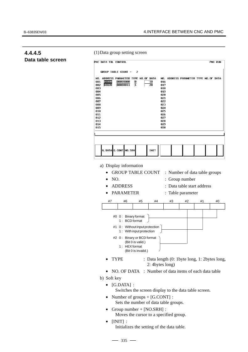
B–63835EN/03 4.INTERFACE BETWEEN CNC AND PMC
335
(1)Data group setting screen
a) Display information
• GROUP TABLE COUNT : Number of data table groups
• NO. : Group number
• ADDRESS : Data table start address
• PARAMETER : Table parameter
#0 0 : Binary format1 : BCD format
#1 0 : Without input protection1 : With input protection
#2 0 : Binary or BCD format(Bit 0 is valid.)
1 : HEX format(Bit 0 is invalid.)
#7 #6 #5 #4 #3 #2 #1 #0
• TYPE : Data length (0: 1byte long, 1: 2bytes long,2: 4bytes long)
• NO. OF DATA : Number of data items of each data table
b) Soft key
• [G.DATA] :Switches the screen display to the data table screen.
• Number of groups + [G.CONT] :Sets the number of data table groups.
• Group number + [NO.SRH] :Moves the cursor to a specified group.
• [INIT] :Initializes the setting of the data table.
4.4.4.5Data table screen
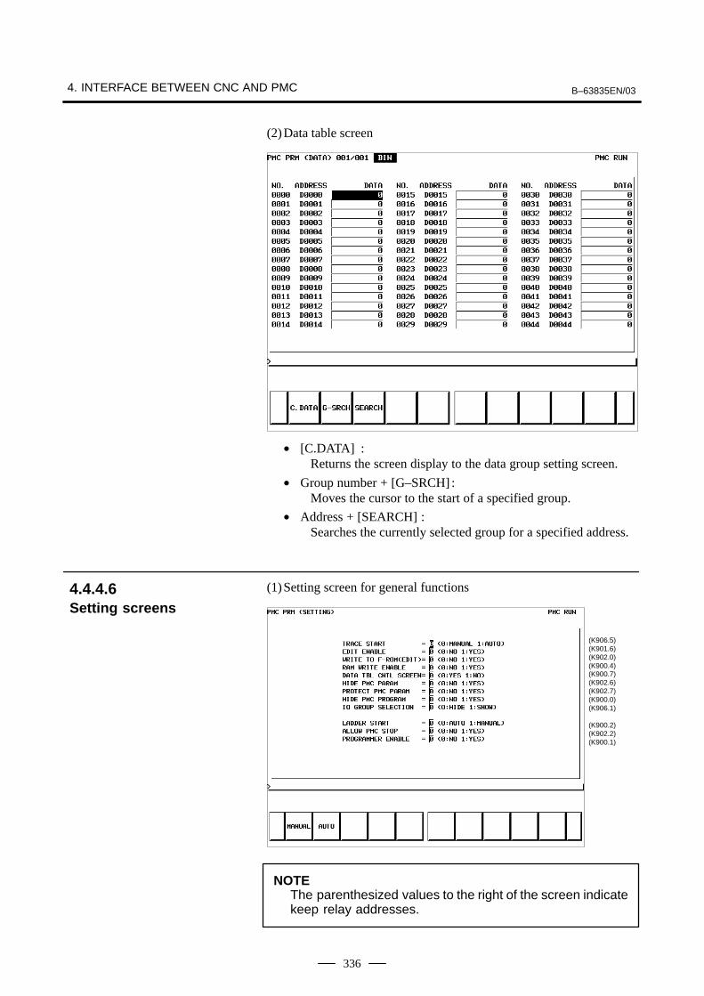
4. INTERFACE BETWEEN CNC AND PMC B–63835EN/03
336
(2)Data table screen
• [C.DATA] :Returns the screen display to the data group setting screen.
• Group number + [G–SRCH] :Moves the cursor to the start of a specified group.
• Address + [SEARCH] :Searches the currently selected group for a specified address.
(1)Setting screen for general functions
(K906.5)(K901.6)(K902.0)(K900.4)(K900.7)(K902.6)(K902.7)(K900.0)(K906.1)
(K900.2)(K902.2)(K900.1)
NOTEThe parenthesized values to the right of the screen indicatekeep relay addresses.
4.4.4.6Setting screens

B–63835EN/03 4.INTERFACE BETWEEN CNC AND PMC
337
(2)Message function screen for each language
Display information• MESSAGE SHIFT VALUE :
Enter a shift amount for a message display request. A valuefrom 0 to 1999 can be specified. Even when the power is turnedoff, entered data is preserved.
• MESSAGE SHIFT START ADDRESS :Enter the start bit address of a shifted message display requestbit area. An address in the A address area can be specified. Evenwhen the power is turned off, entered data is preserved.
(3)Override mode screen of the forced input/output function
(K906.0)
Display information• OVERRIDE ENABLE
0: Disables overriding.1: Enables overriding.

4. INTERFACE BETWEEN CNC AND PMC B–63835EN/03
338
(4) I/O Link assignment data selection function setting screen
(K910.0 to K910.7)
(K911.0 to K911.7)
(K912.0 to K912.7)
(K913.0 to K913.7)
In this setting parameter, set the group of an I/O device connected toeach machine.
EFFECTIVE GROUP SELECTION (CH1: K910 to K911):Select a group in which I/O Link assignment data is valid.
0: Disables assignment.
1: Enables assignment.
The basic group section set in “BASIC GROUP COUNT” on thesystem parameter screen is marked with *, and disables this setting.
NOTEChannel 2 can not be used.

B–63835EN/03 4.INTERFACE BETWEEN CNC AND PMC
339
NOTEWhen data is input through the MDI keys, the operationsbelow need not be performed:
(1)Select the PMC screen. Press the [SYSTEM] soft key, then press the[PMC] soft key.
(2)When the built–in programmer is started, the items below aredisplayed. When the items of RUN/STOP, EDIT, I/O, SYSPRM, andMONIT are displayed, the built–in programmer is already started.
(3)When the built–in programmer is not started, set the keep relay K900.1to 1.
4.4.5PMC Data Input/Output
4.4.5.1Starting the built–inprogrammer

4. INTERFACE BETWEEN CNC AND PMC B–63835EN/03
340
(1)Press the [I/O] soft key.
(2)The screen shown below appears.
(3)Select an I/O device in “DEVICE”.
[FDCAS] : Input to, and output from, a floppy cassette adapter[F–ROM] : Input to, and output from, a flash EEPROM[M–CARD] : Input to, and output from, a memory card[OTHERS] : Input to, and output from, other I/O devices
(4)Set a channel number in “CHANNEL”.
When [F–ROM] or [OTHERS] is selected in “DEVICE”, set this item.Enter a channel number, then press the INPUT key or [(NO.)].Main CPU board JD5A=1
JD5B=2(5)Select a function in “FUNCTION”.
[WRITE] : Outputs data.[READ] : Inputs data.[COMPAR] : Compares the data in an external device with the data
in memory.[DELETE] : Deletes the files from the floppy disk or memory card.[LIST] : Displays the directory of files in the floppy disk or
memory card.[FORMAT] : Initializes the memory card. (All data in the memory
card is erased.)(6)Select a type of output data in “DATA KIND”.
[LADDER] : Ladder[PARAM] : PMC parameter
(7)When [FDCAS] or [M–CARD] is selected, a file can be specified in“FILE NO.”. A file can be specified by file number or by file name.When specifying a file name, prefix @ or # to the file name.
(8)Select an RS–232C setting condition. [SPEED]For each “DEVICE”, set a condition.
4.4.5.2Input/output method
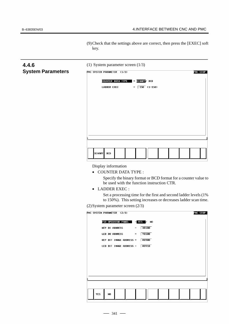
B–63835EN/03 4.INTERFACE BETWEEN CNC AND PMC
341
(9)Check that the settings above are correct, then press the [EXEC] softkey.
(1) System parameter screen (1/3)
Display information
• COUNTER DATA TYPE :
Specify the binary format or BCD format for a counter value tobe used with the function instruction CTR.
• LADDER EXEC :
Set a processing time for the first and second ladder levels (1%to 150%). This setting increases or decreases ladder scan time.
(2)System parameter screen (2/3)
4.4.6System Parameters
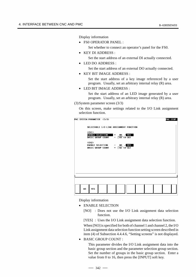
4. INTERFACE BETWEEN CNC AND PMC B–63835EN/03
342
Display information
• FS0 OPERATOR PANEL :
Set whether to connect an operator’s panel for the FS0.
• KEY DI ADDRESS :
Set the start address of an external DI actually connected.
• LED DO ADDRESS :
Set the start address of an external DO actually connected.
• KEY BIT IMAGE ADDRESS :
Set the start address of a key image referenced by a userprogram. Usually, set an arbitrary internal relay (R) area.
• LED BIT IMAGE ADDRESS :
Set the start address of an LED image generated by a userprogram. Usually, set an arbitrary internal relay (R) area.
(3)System parameter screen (3/3)
On this screen, make settings related to the I/O Link assignmentselection function.
Display information
• ENABLE SELECTION
[NO] : Does not use the I/O Link assignment data selectionfunction.
[YES] : Uses the I/O Link assignment data selection function.
When [NO] is specified for both of channel 1 and channel 2, the I/OLink assignment data selection function setting screen described initem (4) of Subsection 4.4.4.6, “Setting screens” is not displayed.
• BASIC GROUP COUNT :
This parameter divides the I/O Link assignment data into thebasic group section and the parameter selection group section.Set the number of groups in the basic group section. Enter avalue from 0 to 16, then press the [INPUT] soft key.

B–63835EN/03 4.INTERFACE BETWEEN CNC AND PMC
343
Example
3 : BASIC GROUP COUNT 0 to 2 groupsParameter selection group section 3 to 15 groups
(a) Soft key
• [EMG ST] : Terminates communication forcibly. Use this keyif communication becomes abnormal and theconnection cannot be terminated normally.
• [INIT] : Initializes the parameters to their default values.
(b)Setting
• CPU ID : Displays a CPU ID value. However, do notmodify this item.
• RS–232C : Enables communication setting in the caseof connection via RS–232C. However, donot modify the items of timer 1, timer 2,timer 3, and maximum packet size.
• HIGH SPEED I/F : Enables setting for connection via ahigh–speed interface (HSSB, Ethernet).
(c) Communication status
• USE TIME : The maximum time in the communicationprocessing is displayed.
• RS–232C : The communication condition of RS–232Cis displayed.
• HIGH SPEED I/F : The communication condition of HIGHSPEED I/F is displayed.
• ETHER_BOARD : Displayed during the communication withEthernet board. The IP address of thecommunication partner is displayed.
4.4.7Online Monitor SettingScreen

4. INTERFACE BETWEEN CNC AND PMC B–63835EN/03
344
• EMB_ETHERNET: Displayed during the communication withembedded Ethernet. The IP address of thecommunication partner is displayed.
• HSSB : Displayed during the communication withHSSB.
Display messages and the meanings
Displaymessages
Meanings
INACTIVE The communication is inactive.
STOPPING The communication is being stopped.(Wait for the termination of communication)
STARTING The communication is being started.(Wait for the termination of communication overanother communication path)
STAND–BY The communication is active and in standby mode.
CONNECTED The communication is active and being connected.
NO OPTION The port can be not opened because there is notoption of RS–232C.
BAD PARAMETER Invalid open parameters are specified.
TIMEOUT ERROR A time–out has occurred and communication isaborted.
TIMEOUT(K) ERROR
A time–out has occurred and communication isaborted.
BCC ERROR A Block Check Code (packet parity) error has occurred.
PARITY ERROR A parity error has occurred.
OVER–RUN ERROR
A reception overrun has occurred and thecommunication can not recover.
SEQUENCE ERROR
Packets are out of sequence.(Incorrect procedure)
DATA ERROR Incorrect packets have been received through retry process.
QUEUE OVERFLOW
The transmit/receive queue has overflowed.
DISCONNECTED Communication has been terminated successfully.
NO CONNECTION The cable is disconnected.

B–63835EN/03 4.INTERFACE BETWEEN CNC AND PMC
345
CAUTIONThe signal list also contains a description of the signals forthe functions that are invalid for the Series 0i–B and Series0i Mate–B.
MODE INPUT/OUTPUT SIGNAL FEED RATE,ETC
EDIT [PMC ⇒ CNC]KEY3(Program protect key)
AUTOMATIC
OPERATI
MEM
MDI
RMT
[PMC ⇒ CNC)ST (Cycle start)*SP (Feed hold)SBK (Single block)DRN (Dry run)BDT1 to 9 (Block delete)MIα (Mirror image)STLK (Start lock: T series)CDZ (Chamfering: T series)SMZ (In–position check: T series)PN1 to 8 (External program no. search)MINP (External program input)DNCI (DNC input mode)DMMC (C direct operation)HSα1A to D (Handle interrupt axis select)AFL (Auxiliary function neglect)FIN, MFIN2, MFIN3
(Auxiliary function complete)MFIN, SFIN, TFIN, BFIN
(High speed M/S/T function complete)GR1, 2 (Gear input: T series)*SSTP (Spindle stop)SAR (Spindle speed arrival)SOR (Spindle orientation)
[PMC ⇒ CNC]*FV0 to 7(Feed rate over-ride)*AFV0 to 7(2nd feed rateoverride)
OVC(Override can-cel)
ROV1,ROV2,HROV,*HROV0 to 6(Rapid traverseoverride)
SOV0 to 7(Spindle speedoverride)
ON [CNC ⇒ PMC]
STL (Cycle start LED)SPL (Feed hold LED)MF, M00 to M31MF2, M200 to M215 (Miscellaneous MF3, M300 to M315 function)SF, S00 to S31 (Spindle speed function)TF, T00 to T31 (Tool function)BF, B00 to B31 (2nd miscellaneous func.)DEN (Distribution end)OP (automatic operating)GR1O to GR3O(Gear selection: M series)
4.5LIST OF SIGNALS BYEACH MODE
� Automatic operation

4. INTERFACE BETWEEN CNC AND PMC B–63835EN/03
346
MODE INPUT/OUTPUT SIGNAL FEED RATE,ETC
MA
Handle/ incremental
[PMC ⇒ CNC]HSnA to D (Axis selection) n:1 to 3(No. of MPGs)+α, –α (Jog feed)
[PMC ⇒ CNC]MP1, MP2(Multiplier)
NUAL
JOG [PMC ⇒ CNC]RT (Rapid traverse)
[PMC ⇒ CNC]*JV0 to 15(Manual fee-L
OPER Z
R
[PMC ⇒ CNC]ZRN(Reference position return mode)
[MT ⇒ CNC]*DECα (Reference position deceleration)
(Manual fee-drate override)
+α, –α (Manual feed movecommand)
ATION
RN [CNC ⇒ PMC]
ZPαZP2α, ZP3α, ZP4α(Reference position return completion)
ROV1, ROV2HROV*HROV0 to 6(Rapid traverseoverride)
Others
[PMC ⇒ CNC]MD1 to 4 (Mode selection)*ESP (Emergency stop)KEY1 to 4 (Memory protection key)MLK,MLKα (All axes/ each axis machine lock)*IT,*ITα (All axes/ each axis machine lock)*�MITα (interlock per axis and direction:M series)STLK (Start lock:T series)*ABSM (Manual absolute)SVFα (Servo off)*FLWP (Follow up)ERS (External reset)RRW (Reset & Rewind)EXLM (Stored stroke limit external switching)�LMα, RLSOT (Software limit external setting M series)*�Lα (Overtravel limit)*�EDα (External deceleration of each axis)
[CMC ⇒ PMC]MA (NC ready)SA (Servo ready)AL (NC alarm)RST (Resetting)BAL (Battery alarm)INPα (In–position)MVα (Axis moving)TAP (Tapping)
� Manual operation
� Others

B–63835EN/03 4.INTERFACE BETWEEN CNC AND PMC
347
The relationship of the addresses of the interface signals transferredbetween the CNC and PMC are shown below.
G000–
F000–
X000–
Y000–
CNC PMC MT
4.6LIST OF INPUT/OUTPUT SIGNALS
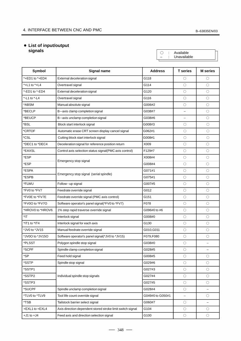
4. INTERFACE BETWEEN CNC AND PMC B–63835EN/03
348
� : Available– : Unavailable
Symbol Signal name Address T series M series
*+ED1 to *+ED4 External decelerationsignal G118 � �
*+L1 to *+L4 Overtravel signal G114 � �
*-ED1 to *-ED4 External decelerationsignal G120 � �
*-L1 to *-L4 Overtravel signal G116 � �
*ABSM Manual absolute signal G006#2 � �
*BECLP B�axis clamp completion signal G038#7 – �
*BEUCP B�axis unclamp completion signal G038#6 – �
*BSL Block start interlock signal G008#3 � �
*CRTOF Automatic erase CRT screen display cancel signal G062#1 � �
*CSL Cutting block start interlock signal G008#1 � �
*DEC1 to *DEC4 Deceleration signal for reference position return X009 � �
*EAXSL Control axis selection status signal(PMC axis control) F129#7 � �
*ESP X008#4 � �
*ESPEmergency stop signal
G008#4 � �
*ESPA G071#1 � �
*ESPBEmergency stop signal (serial spindle)
G075#1 � �
*FLWU Follow�up signal G007#5 � �
*FV0 to *FV7 Feedrate override signal G012 � �
*FV0E to *FV7E Feedrate override signal (PMC axis control) G151 � �
*FV0O to *FV7O Software operator�s panel signal(*FV0 to *FV7) F078 � �
*HROV0 to *HROV6 1% step rapid traverse override signal G096#0 to #6 � �
*IT Interlock signal G008#0 � �
*IT1 to *IT4 Interlock signal for each axis G130 � �
*JV0 to *JV15 Manual feedrate override signal G010,G011 � �
*JV0O to *JV15O Software operator�s panel signal(*JV0 to *JV15) F079,F080 � �
*PLSST Polygon spindle stop signal G038#0 � –
*SCPF Spindle clamp completion signal G028#5 � –
*SP Feed hold signal G008#5 � �
*SSTP Spindle stop signal G029#6 � �
*SSTP1 G027#3 � �
*SSTP2 Individual spindle stop signals G027#4 � �
*SSTP3 G027#5 � �
*SUCPF Spindle unclamp completion signal G028#4 � –
*TLV0 to *TLV9 Tool life count override signal G049#0 to G050#1 – �
*TSB Tailstock barrier select signal G060#7 � –
+EXL1 to +EXL4 Axis direction dependent stored stroke limit switch signal G104 � �
+J1 to +J4 Feed axis and direction selection signal G100 � �
� List of input/outputsignals
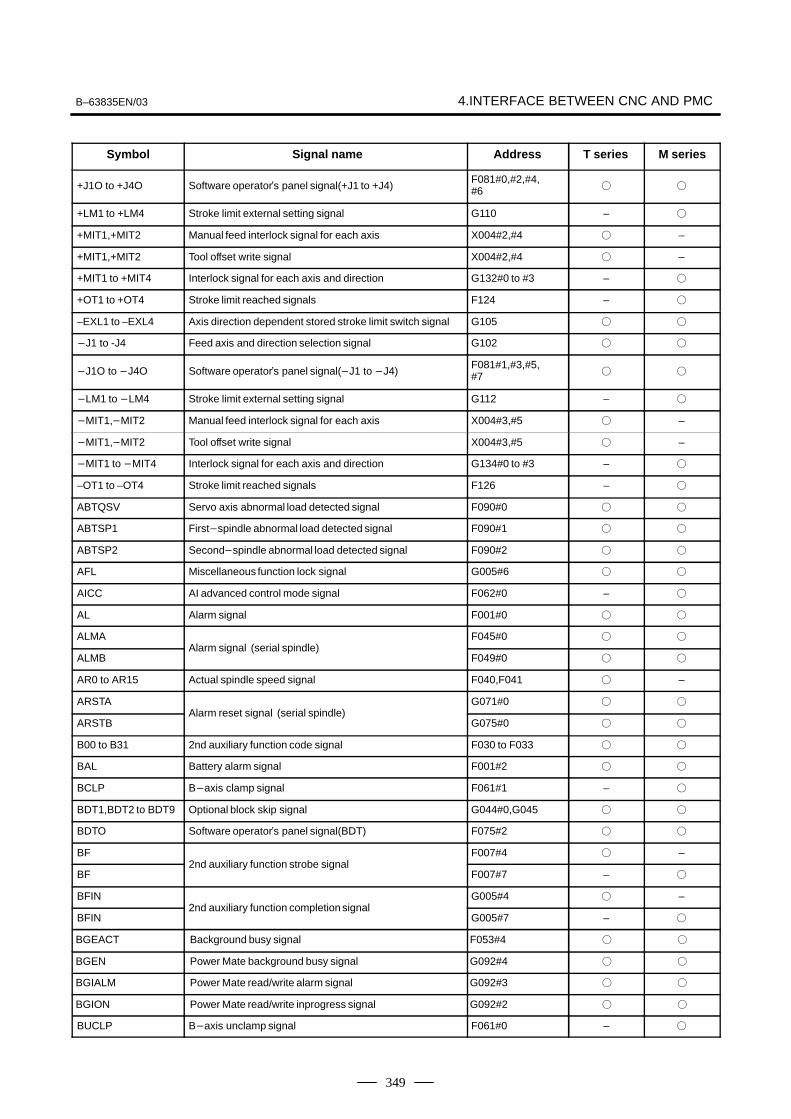
B–63835EN/03 4.INTERFACE BETWEEN CNC AND PMC
349
Symbol M seriesT seriesAddress Signal name
+J1O to +J4O Software operator�s panel signal(+J1 to +J4)F081#0,#2,#4,#6 � �
+LM1 to +LM4 Stroke limit external setting signal G110 – �
+MIT1,+MIT2 Manual feed interlock signal for each axis X004#2,#4 � –
+MIT1,+MIT2 Tool offset write signal X004#2,#4 � –
+MIT1 to +MIT4 Interlock signal for each axis and direction G132#0 to #3 – �
+OT1 to +OT4 Stroke limit reached signals F124 – �
–EXL1 to –EXL4 Axis direction dependent stored stroke limit switch signal G105 � �
�J1 to -J4 Feed axis and direction selection signal G102 � �
�J1O to �J4O Software operator�s panel signal(�J1 to �J4)F081#1,#3,#5,#7 � �
�LM1 to �LM4 Stroke limit external setting signal G112 – �
�MIT1,�MIT2 Manual feed interlock signal for each axis X004#3,#5 � –
�MIT1,�MIT2 Tool offset write signal X004#3,#5 � –
�MIT1 to �MIT4 Interlock signal for each axis and direction G134#0 to #3 – �
–OT1 to –OT4 Stroke limit reached signals F126 – �
ABTQSV Servo axis abnormal load detected signal F090#0 � �
ABTSP1 First�spindle abnormal load detected signal F090#1 � �
ABTSP2 Second�spindle abnormal load detected signal F090#2 � �
AFL Miscellaneous function lock signal G005#6 � �
AICC AI advanced control mode signal F062#0 – �
AL Alarm signal F001#0 � �
ALMA F045#0 � �
ALMBAlarm signal (serial spindle)
F049#0 � �
AR0 to AR15 Actual spindle speed signal F040,F041 � –
ARSTA G071#0 � �
ARSTBAlarm reset signal (serial spindle)
G075#0 � �
B00 to B31 2nd auxiliary function code signal F030 to F033 � �
BAL Battery alarm signal F001#2 � �
BCLP B�axis clamp signal F061#1 – �
BDT1,BDT2 to BDT9 Optional block skip signal G044#0,G045 � �
BDTO Software operator�s panel signal(BDT) F075#2 � �
BF F007#4 � –
BF2nd auxiliary function strobe signal
F007#7 – �
BFIN G005#4 � –
BFIN2nd auxiliary function completion signal
G005#7 – �
BGEACT Background busy signal F053#4 � �
BGEN Power Mate background busy signal G092#4 � �
BGIALM Power Mate read/write alarm signal G092#3 � �
BGION Power Mate read/write inprogress signal G092#2 � �
BUCLP B�axis unclamp signal F061#0 – �
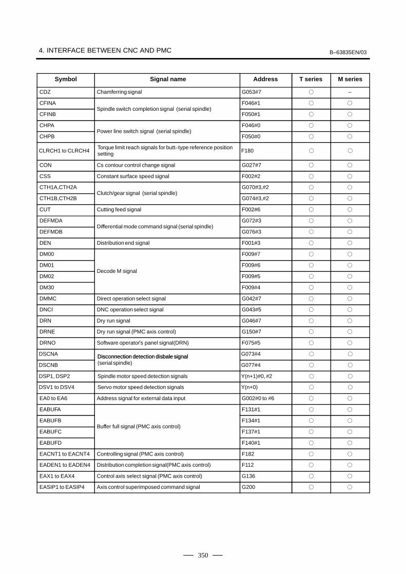
4. INTERFACE BETWEEN CNC AND PMC B–63835EN/03
350
Symbol M seriesT seriesAddress Signal name
CDZ Chamferringsignal G053#7 � –
CFINA F046#1 � �
CFINBSpindle switch completion signal (serial spindle)
F050#1 � �
CHPA F046#0 � �
CHPBPower line switch signal (serial spindle)
F050#0 � �
CLRCH1 to CLRCH4Torque limit reach signals for butt–type reference positionsetting F180 � �
CON Cs contour control change signal G027#7 � �
CSS Constant surface speed signal F002#2 � �
CTH1A,CTH2A G070#3,#2 � �
CTH1B,CTH2BClutch/gear signal (serial spindle)
G074#3,#2 � �
CUT Cutting feed signal F002#6 � �
DEFMDA G072#3 � �
DEFMDBDifferential mode command signal (serial spindle)
G076#3 � �
DEN Distribution end signal F001#3 � �
DM00 F009#7 � �
DM01 F009#6 � �
DM02Decode M signal
F009#5 � �
DM30 F009#4 � �
DMMC Direct operation select signal G042#7 � �
DNCI DNC operation select signal G043#5 � �
DRN Dry run signal G046#7 � �
DRNE Dry run signal (PMC axis control) G150#7 � �
DRNO Software operator�s panel signal(DRN) F075#5 � �
DSCNA Disconnection detection disbale signal G073#4 � �
DSCNB
Disconnection detection disbale signal(serial spindle) G077#4 � �
DSP1, DSP2 Spindle motor speed detection signals Y(n+1)#0, #2 � �
DSV1 to DSV4 Servo motor speed detection signals Y(n+0) � �
EA0 to EA6 Address signal for external data input G002#0 to #6 � �
EABUFA F131#1 � �
EABUFB F134#1 � �
EABUFCBuffer full signal (PMC axis control)
F137#1 � �
EABUFD F140#1 � �
EACNT1 to EACNT4 Controlling signal (PMC axis control) F182 � �
EADEN1 to EADEN4 Distribution completion signal(PMC axis control) F112 � �
EAX1 to EAX4 Control axis select signal (PMC axis control) G136 � �
EASIP1 to EASIP4 Axis control superimposed command signal G200 � �

B–63835EN/03 4.INTERFACE BETWEEN CNC AND PMC
351
Symbol M seriesT seriesAddress Signal name
EBSYA F130#7 � �
EBSYB Axis control command read completion signal (PMC axis F133#7 � �
EBSYC
Axis control command read completion signal (PMC axiscontrol) F136#7 � �
EBSYD F139#7 � �
EBUFA G142#7 � �
EBUFB G154#7 � �
EBUFCAxis control command read signal(PMC axis control)
G166#7 � �
EBUFD G178#7 � �
EC0A to EC6A G143#0 to #6 � �
EC0B to EC6B G155#0 to #6 � �
EC0C to EC6CAxis control command signal (PMC axis control)
G167#0 to #6 � �
EC0D to EC6D G179#0 to #6 � �
ECKZA F130#1 � �
ECKZB F133#1 � �
ECKZCFollowing zero checking signal (PMC axis control)
F136#1 � �
ECKZD F139#1 � �
ECLRA G142#6 � �
ECLRB G154#6 � �
ECLRCReset signal (PMC axis control)
G166#6 � �
ECLRD G178#6 � �
ED0 to ED15 Data signal for external data input G000,G001 � �
EDENA F130#3 � �
EDENB F133#3 � �
EDENCAuxiliary function executing signal (PMC axis control)
F136#3 � �
EDEND F139#3 � �
EDGN Slave diagnosis selection signal F177#7 � �
EF External operation signal F008#0 – �
EFD External operation signal for high�speed interface F007#1 – �
EFIN External operation function completion signal G005#1 – �
EFINA G142#0 � �
EFINB G154#0 � �
EFINCAuxiliary function completion signal (PMC axis control)
G166#0 � �
EFIND G178#0 � �
EGENA F130#4 � �
EGENB F133#4 � �
EGENCAxis moving signal (PMC axis control)
F136#4 � �
EGEND F139#4 � �

4. INTERFACE BETWEEN CNC AND PMC B–63835EN/03
352
Symbol M seriesT seriesAddress Signal name
EIALA F130#2 � �
EIALB F133#2 � �
EIALCAlarm signal (PMC axis control)
F136#2 � �
EIALD F139#2 � �
EID0A to EID31A G146 to G149 � �
EID0B to EID31B G158 to G161 � �
EID0C to EID31CAxis control data signal (PMC axis control)
G170 to G173 � �
EID0D to EID31D G182 to G185 � �
EIF0A to EIF15A G144,G145 � �
EIF0B to EIF15B G156,G157 � �
EIF0C to EIF15CAxis control feedrate signal (PMC axis control)
G168,G169 � �
EIF0D to EIF15D G180,G181 � �
EINPA F130#0 � �
EINPB�
F133#0 � �
EINPCIn�position signal (PMC axis control)
F136#0 � �
EINPD F139#0 � �
EKC0 to EKC7 Key code signal G098 � �
EKENB Key code read completion signal F053#7 � �
EKSET key code read signal G066#7 � �
ELCKZA G142#1 � �
ELCKZB G154#1 � �
ELCKZCAccumulated zero check signal
G166#1 � �
ELCKZD G178#1 � �
EM11A to EM48A F132,F142 � �
EM11B to EM48B F135,F145 � �
EM11C to EM48CAuxiliary function code signal (PMC axis control)
F138,F148 � �
EM11D to EM48D F141,F151 � �
EMBUFA G142#2 � �
EMBUFB Buffering disable signal G154#2 � �
EMBUFC
Buffering disable signal(PMC axis control) G166#2 � �
EMBUFD G178#2 � �
EMFA F131#0 � �
EMFB F134#0 � �
EMFCAuxiliary function strobe signal (PMC axis control)
F137#0 � �
EMFD F140#0 � �
EMSBKA G143#7 � �
EMSBKB Block stop disable signal G155#7 � �
EMSBKC
Block stop disable signal(PMC axis control) G167#7 � �
EMSBKD G179#7 � �

B–63835EN/03 4.INTERFACE BETWEEN CNC AND PMC
353
Symbol M seriesT seriesAddress Signal name
ENB F001#4 � �
ENB2 Spindle enable signal F038#2 � –
ENB3 F038#3 � –
ENBKY External key input mode selection signal G066#1 � �
EOTNA F130#6 � �
EOTNB�
F133#6 � �
EOTNCNegative�direction overtravel signal (PMC axis control)
F136#6 � �
EOTND F139#6 � �
EOTPA F130#5 � �
EOTPB�
F133#5 � �
EOTPCPositive�direction overtravel signal (PMC axis control)
F136#5 � �
EOTPD F139#5 � �
EOV0 Override 0% signal (PMC axis control) F129#5 � �
EPARM Slave parameter selection signal F177#6 � �
EPN0 to EPN13 Expanded workpiece number search signals G024#0 to G025#5 � �
EPNS Expanded workpiece number search start signal G025#7 � �
EPRG Slave program selection signal F177#4 � �
ERDIO Slave external read start signal F177#1 � �
EREND Read completion signal for external data input F060#0 � �
ERS External reset signal G008#7 � �
ESBKA G142#3 � �
ESBKB G154#3 � �
ESBKCBlock stop signal (PMC axis control)
G166#3 � �
ESBKD G178#3 � �
ESEND Search completion signal for external data input F060#1 � �
ESKIP Skip signal (PMC axis control) X004#6 � �
ESOFA G142#4 � �
ESOFB G154#4 � �
ESOFCServo off signal (PMC axis control)
G166#4 � �
ESOFD G178#4 � �
ESTB Read signal for external data input G002#7 � �
ESCAN Search cancel signal for external data input F060#2 � �
ESTPA G142#5 � �
ESTPB G154#5 � �
ESTPCAxis control temporary stop signal (PMC axis control)
G166#5 � �
ESTPD G178#5 � �
ESTPIO Slave read/write stop signal F177#2 � �
EVAR Slave macro variable selection signal F177#5 � �
EWTIO Slave external write start signal F177#3 � �
EXLM Stored stroke limit select signal G007#6 � �

4. INTERFACE BETWEEN CNC AND PMC B–63835EN/03
354
Symbol M seriesT seriesAddress Signal name
EXOFA Motor activation off status signal F047#4 � �
EXOFB
Motor activation off status signal(serial spindle) F051#4 � �
EXRD External read start signal G058#1 � �
EXSTP External read/punch stop signal G058#2 � �
EXWT External punch start signal G058#3 � �
F1D F1�digit feed select signal G016#7 – �
FIN Completionsignal G004#3 � �
FSCSL Cs contour control change completion signal F044#1 � �
FSPPH Spindle phase synchronous control completion signal F044#3 � �
FSPSY Spindle synchronous speed control completion signal F044#2 � �
G08MD ������� ��� control mode signal F066#0 – �
GOQSM Tool offset value write mode select signal G039#7 � –
GR1,GR2 Gear selection signal (input) G028#1,#2 � �
GR1O,GR2O,GR3O Gear selection signal (output ) F034#0 to #2 – �
GR21 Gear selection signal (input) G029#0 � �
HDO0 High�speed skip status signal F122#0 � �
HROV 1% step rapid traverse override select signal G096#7 � �
HS1A to HS1D Manual handle feed axis selection signal G018#0 to #3 � �
HS1AO Software operator�s panel signal(HS1A) F077#0 � �
HS1BO Software operator�s panel signal(HS1B) F077#1 � �
HS1CO Software operator�s panel signal(HS1C) F077#2 � �
HS1DO Software operator�s panel signal(HS1D) F077#3 � �
HS1IA to HS1ID Manual handle interruptionaxis select signal G041#0 to #3 � �
HS2A to HS2D Manual handle feed axis selection signal G018#4 to #7 � �
HS2IA to HS2ID Manual handle interruptionaxis select signal G041#4 to #7 � �
HS3A to HS3D Manual handle feed axis selection signal G019#0 to #3 � �
HS3IA to HS3ID Manual handle interruptionaxis select signal G042#0 to #3 � �
IGNVRY All�axis VRDY OFF alarm ignore signal G066#0 � �
IGVRY1 to IGVRY4 Each�axis VRDY OFF alarm ignore signal G192 � �
INCH Inch input signal F002#0 � �
INCMDA Incremental command external setting type orientation G072#5 � �
INCMDB
Incremental command external setting type orientationsignal (serial spindle) G076#5 � �
INCSTA F047#1 � �
INCSTBIncremental method orientationsignal (serial spindle)
F051#1 � �
INDXA G072#0 � �
INDXBOrientation stop position change signal (serial spindle)
G076#0 � �
INHKY Key input disable signal F053#0 � �
INP1 to INP4 In�position signal F104 � �
INTGA G071#5 � �
INTGBSignal for controlling velocity integration (serial spindle)
G075#5 � �
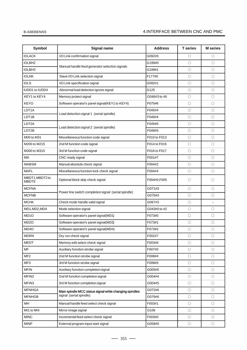
B–63835EN/03 4.INTERFACE BETWEEN CNC AND PMC
355
Symbol M seriesT seriesAddress Signal name
IOLACK I/O Link confirmation signal G092#0 � �
IOLBH2 G199#0 � �
IOLBH3Manual handle feed generator selection signals
G199#1 � �
IOLNK Slave I/O Link selection signal F177#0 � �
IOLS I/O Link specification signal G092#1 � �
IUDD1 to IUDD4 Abnormal load detection ignore signal G125 � �
KEY1 to KEY4 Memory protect signal G046#3 to #6 � �
KEYO Software operator�s panel signal(KEY1 to KEY4) F075#6 � �
LDT1A F045#4 � �
LDT1BLoad detection signal 1 (serial spindle)
F049#4 � �
LDT2A F045#5 � �
LDT2BLoad detection signal 2 (serial spindle)
F049#5 � �
M00 to M31 Miscellaneous function code signal F010 to F013 � �
M200 to M215 2nd M function code signal F014 to F015 � �
M300 to M315 3rd M function code signal F016 to F017 � �
MA CNC ready signal F001#7 � �
MABSM Manual absolute check signal F004#2 � �
MAFL Miscellaneous function lock check signal F004#4 � �
MBDT1,MBDT2 toMBDT9 Optional block skip check signal F004#0,F005 � �
MCFNA G071#3 � �
MCFNBPower line switch completion signal (serial spindle)
G075#3 � �
MCHK Check mode handle valid signal G067#3 � –
MD1,MD2,MD4 Mode selection signal G043#0 to #2 � �
MD1O Software operator�s panel signal(MD1� F073#0 � �
MD2O Software operator�s panel signal(MD2� F073#1 � �
MD4O Software operator�s panel signal(MD4) F073#2 � �
MDRN Dry run check signal F002#7 � �
MEDT Memory edit select check signal F003#6 � �
MF Auxiliary function strobe signal F007#0 � �
MF2 2nd M function strobe signal F008#4 � �
MF3 3rd M function strobe signal F008#5 � �
MFIN Auxiliary function completion signal G005#0 � �
MFIN2 2nd M function completion signal G004#4 � �
MFIN3 3rd M function completion signal G004#5 � �
MFNHGA Main spindle MCC status signal while changing spindles G072#6 � �
MFNHGB
Main spindle MCC status signal while changing spindlessignal (serial spindle) G076#6 � �
MH Manual handle feed select check signal F003#1 � �
MI1 to MI4 Mirror image signal G106 � �
MINC Incremental feed select check signal F003#0 � �
MINP External program input start signal G058#0 � �

4. INTERFACE BETWEEN CNC AND PMC B–63835EN/03
356
Symbol M seriesT seriesAddress Signal name
MJ JOG feed select check signal F003#2 � �
MLK All�axis machine lock signal G044#1 � �
MLK1 to MLK4 Each�axis machine lock signal G108 � �
MLKO Software operator�s panel signal(MLK) F075#4 � �
MMDI Manual data input select check signal F003#3 � �
MMEM Automatic operation select check signal F003#5 � �
MMI1 to MMI4 Mirror image check signal F108 � �
MMLK All�axis machine lock check signal F004#1 � �
MMOD Check mode signal G067#2 � –
MNCHG Inversion inhibition signal F091#1 � –
MORA1A Signal for completion of spindle orientationwith a magnetic F046#6 � �
MORA1B
Signal for completion of spindle orientationwith a magneticsensor (serial spindle) F050#6 � �
MORA2A Signal for approximatespindle orientationwith a magnetic F046#7 � �
MORA2B
Signal for approximatespindle orientationwith a magneticsensor (serial spindle) F050#7 � �
MORCMA Command for spindle orientaion with a magnetic sensor G073#0 � �
MORCMB
Command for spindle orientaion with a magnetic sensor(serial spindle) G077#0 � �
MP1,MP2Manual handle feed amount selection signal (incrementalfeed signal) G019#4,#5 � �
MP1O Software operator�s panel signal(MP1) F076#0 � �
MP2O Software operator�s panel signal(MP2) F076#1 � �
MPOFA G073#2 � �
MPOFBMotor power stop signal (serial spindle)
G077#2 � �
MRDYA G070#7 � �
MRDYBMachine ready signal (serial spindle)
G074#7 � �
MREF Manual reference position return selection check signal F004#5 � �
MRMT DNC operation select check signal F003#4 � �
MRVM Check mode backward movement inhibition signal G067#1 � –
MRVMD Check mode backward movement signal F091#0 � –
MRVSP Backward movement inhibition signal F091#2 � –
MSBK Single block check signal F004#3 � �
MSDFON Motor speed detection function enable signal G016#0 � �
MTCHIN TEACH IN select check signal F003#7 � �
MV1 to MV4 Axis moving signal F102 � �
MVD1 to MVD4 Axis moving direction signal F106 � �
NOZAGC Perpendicular/angular axis control disable signal G063#5 � �
NPOS1 to NPOS4 Position display neglect signal G198 � �
NRROA Short–distant movement command while changing the G072#2 � �
NRROB
Short–distant movement command while changing theorientation stop position signal (serial spindle) G076#2 � �
OFN0 to OFN5,OFN6 Tool offset number select signalG039#0 to#5,G040#0 � –
OP Automatic operation signal F000#7 � �
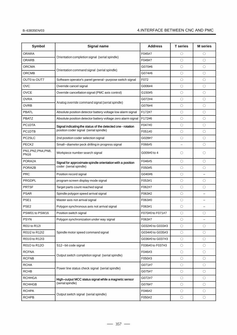
B–63835EN/03 4.INTERFACE BETWEEN CNC AND PMC
357
Symbol M seriesT seriesAddress Signal name
ORARA F045#7 � �
ORARBOrientation completion signal (serial spindle)
F049#7 � �
ORCMA G070#6 � �
ORCMBOrientation command signal (serial spindle)
G074#6 � �
OUT0 to OUT7 Software operator�s panel general�purpose switch signal F072 � �
OVC Override cancel signal G006#4 � �
OVCE Override cancellation signal (PMC axis control) G150#5 � �
OVRA G072#4 � �
OVRBAnalog override command signal (serial spindle)
G076#4 � �
PBATL Absolute position detector battery voltage low alarm signal F172#7 � �
PBATZ Absolute position detector battery voltage zero alarm signal F172#6 � �
PC1DTA Signal indicating the status of the detected one�rotation F047#0 � �
PC1DTB
Signal indicating the status of the detected one rotationposition coder signal (serial spindle) F051#0 � �
PC2SLC 2nd position coder selection signal G028#7 � �
PECK2 Small�diameter peck drilling in progress signal F066#5 – �
PN1,PN2,PN4,PN8,PN16 Workpiece number search signal G009#0 to 4 � �
PORA2A Signal for approximatespindle orientationwith a position F046#5 � �
PORA2B
Signal for approximatespindle orientationwith a positioncoder (serial spindle) F050#5 � �
PRC Position record signal G040#6 � –
PRGDPL program screen display mode signal F053#1 � �
PRTSF Target parts count reached signal F062#7 � �
PSAR Spindle polygon speed arrival signal F063#2 � –
PSE1 Master axis not arrival signal F063#0 � –
PSE2 Polygon synchronous axis not arrival signal F063#1 � –
PSW01 to PSW16 Position switch signal F070#0 to F071#7 � �
PSYN Polygon synchronization under way signal F063#7 � –
R01I to R12I G032#0 to G033#3 � �
R01I2 to R12I2 Spindle motor speed command signal G034#0 to G035#3 � �
R01I3 to R12I3 G036#0 to G037#3 � �
R01O to R12O S12�bit code signal F036#0 to F037#3 � �
RCFNA F046#3 � �
RCFNBOutput switch completion signal (serial spindle)
F050#3 � �
RCHA G071#7 � �
RCHBPower line status check signal (serial spindle)
G075#7 � �
RCHHGA High–output MCC status signal while a magnetic sensor G072#7 � �
RCHHGB
High–output MCC status signal while a magnetic sensor(serial spindle) G076#7 � �
RCHPA F046#2 � �
RCHPBOutput switch signal (serial spindle)
F050#2 � �

4. INTERFACE BETWEEN CNC AND PMC B–63835EN/03
358
Symbol M seriesT seriesAddress Signal name
RGSPM F065#1 – �
RGSPPSpindle rotation direction signal
F065#0 – �
RGTAP Rigid tapping signal G061#0 � �
RGTSP1,RGTSP2 Rigid tapping spindle selection signal G061#4,#5 � –
RLSOT Stroke check release signal G007#7 – �
RLSOT3 Stroke check 3 release signal G007#4 � �
ROTAA Rotation direction command while changing the orientation G072#1 � �
ROTAB
Rotation direction command while changing the orientationstop position signal (serial spindle) G076#1 � �
ROV1,ROV2 Rapid traverse override signal G014#0,#1 � �
ROV1E,ROV2E Rapid traverse override signal(PMC axis control) G150#0,#1 � �
ROV1O Software operator�s panel signal(ROV1) F076#4 � �
ROV2O Software operator�s panel signal(ROV2) F076#5 � �
RPALM Read/punch alarm signal F053#3 � �
RPBSY Read/punch in–progress signal F053#2 � �
RPDO Rapid traversing signal F002#1 � �
RRW Reset&rewind signal G008#6 � �
RSLA G071#6 � �
RSLBOutput switch request signal (serial spindle)
G075#6 � �
RST Reset signal F001#1 � �
RT Manual rapid traverse selection signal G019#7 � �
RTAP Rigid tapping in�progress signal F076#3 � �
RTE Manual rapid traverse selection signal (PMC axis control) G150#6 � �
RTO Software operator�s panel signal(RT) F077#6 � �
RTNT Rigid tapping retraction start signal G062#6 – �
RTPT Rigid tapping retraction completiont signal F066#1 – �
RVS Retrace signal G007#0 – �
RVSL Retrace�in�progress signal F082#2 – �
RWD Rewinding signal F000#0 � �
S00 to S31 Spindle speed code signal F022 to F025 � �
S1MES Spindle 1 under measurement signal F062#3 � –
S2MES Spindle 2 under measurement signal F062#4 � –
S2TLS Spindle measurement select signal G040#5 � –
SA Servo ready signal F000#6 � �
SAR Spindle speed arrival signal G029#4 � �
SARA F045#3 � �
SARBSpeed arrival signal (serial spindle)
F049#3 � �
SBK Single block signal G046#1 � �
SBKO Software operator�s panel signal(SBK) F075#3 � �
SCLP Spindle clamp signal F038#0 � –

B–63835EN/03 4.INTERFACE BETWEEN CNC AND PMC
359
Symbol M seriesT seriesAddress Signal name
SDTA F045#2 � �
SDTBSpeed detection signal (serial spindle)
F049#2 � �
SF Spindle speed strobe signal F007#2 � �
SFIN Spindle function completion signal G005#2 � �
SFRA G070#5 � �
SFRBCW command signal (serial spindle)
G074#5 � �
SGN G033#5 � �
SGN2 Spindle motor command polarity select signal G035#5 � �
SGN3 G037#5 � �
SHA00 to SHA11 G078#0 to G079#3 � �
SHB00 to SHB11Spindle orientationexternal stop position command signal
G080#0 to G081#3 � �
SIND G033#7 � �
SIND2 Spindle motor speed command select signal G035#7 � �
SIND3 G037#7 � �
Skip signal X004#7 � �
SKIPOverload torque signal X004#7 – �
SKIP2 to SKIP6,SKIP7,SKIP8 Skip signal
X004#2 to #6,#0,#1 � �
SKIPP Skip signal G006#6 � –
SLVA G073#1 � �
SLVBSlave operation command signal (serial spindle)
G077#1 � �
SLVSA F046#4 � �
SLVSBSlave operation status signal (serial spindle)
F050#4 � �
SMZ Error detect signal G053#6 � –
SOCNA�
G071#4 � �
SOCNBSoft start�stop cancel signal (serial spindle)
G075#4 � �
SOR Spindle orientationsignal G029#5 � �
SOV0 to SOV7 Spindle speed override signal G030 � �
SPAL Spindle fluctuation detection alarm signal F035#0 � �
SPL Feed hold lamp signal F000#4 � �
SPO Software operator�s panel signal(*SP) F075#7 � �
SPPHS Spindle phase synchronous control signal G038#3 � �
SPSLA G071#2 � �
SPSLBSpindle select signal (serial spindle)
G075#2 � �
SPSTP Spindle stop complete signal G028#6 � –
SPSYC Spindle synchronous control signal G038#2 � �
SRLNI0 to SRLNI3 Group number specification signals G091#0 to #3 � �
SRLNO0 to SRLNO3 Group number output signals F178#0 to #3 � �
SRN Program restart signal G006#0 � �
SRNMV Program restart under way signal F002#4 � �
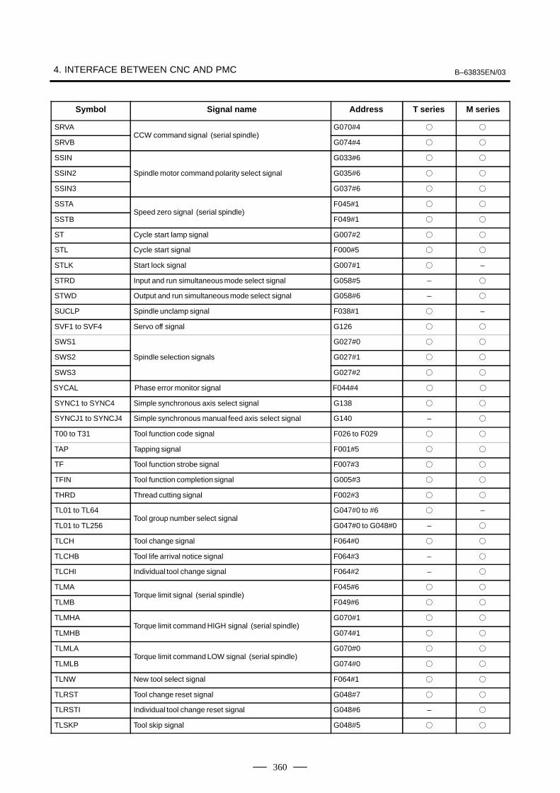
4. INTERFACE BETWEEN CNC AND PMC B–63835EN/03
360
Symbol M seriesT seriesAddress Signal name
SRVA G070#4 � �
SRVBCCW command signal (serial spindle)
G074#4 � �
SSIN G033#6 � �
SSIN2 Spindle motor command polarity select signal G035#6 � �
SSIN3 G037#6 � �
SSTA F045#1 � �
SSTBSpeed zero signal (serial spindle)
F049#1 � �
ST Cycle start lamp signal G007#2 � �
STL Cycle start signal F000#5 � �
STLK Start lock signal G007#1 � –
STRD Input and run simultaneousmode select signal G058#5 – �
STWD Output and run simultaneousmode select signal G058#6 – �
SUCLP Spindle unclamp signal F038#1 � –
SVF1 to SVF4 Servo off signal G126 � �
SWS1 G027#0 � �
SWS2 Spindle selection signals G027#1 � �
SWS3 G027#2 � �
SYCAL Phase error monitor signal F044#4 � �
SYNC1 to SYNC4 Simple synchronous axis select signal G138 � �
SYNCJ1 to SYNCJ4 Simple synchronous manual feed axis select signal G140 – �
T00 to T31 Tool function code signal F026 to F029 � �
TAP Tapping signal F001#5 � �
TF Tool function strobe signal F007#3 � �
TFIN Tool function completion signal G005#3 � �
THRD Thread cutting signal F002#3 � �
TL01 to TL64 G047#0 to #6 � –
TL01 to TL256Tool group number select signal
G047#0 to G048#0 – �
TLCH Tool change signal F064#0 � �
TLCHB Tool life arrival notice signal F064#3 – �
TLCHI Individual tool change signal F064#2 – �
TLMA F045#6 � �
TLMBTorque limit signal (serial spindle)
F049#6 � �
TLMHA G070#1 � �
TLMHBTorque limit command HIGH signal (serial spindle)
G074#1 � �
TLMLA G070#0 � �
TLMLBTorque limit command LOW signal (serial spindle)
G074#0 � �
TLNW New tool select signal F064#1 � �
TLRST Tool change reset signal G048#7 � �
TLRSTI Individual tool change reset signal G048#6 – �
TLSKP Tool skip signal G048#5 � �

B–63835EN/03 4.INTERFACE BETWEEN CNC AND PMC
361
Symbol M seriesT seriesAddress Signal name
TMRON General�purpose integratingmeter start signal G053#0 � �
TRQL1 to TRQL4 Torque limit reached signal F114 � –
UI000 to UI015 Input signal for custom macro G054,G055 � �
UINT Interrupt signal for custom macro G053#3 � �
UO000 to UO015 F054,F055 � �
UO100 to UO131Output signal for custom macro
F056 to F059 � �
WOQSMWorkpiece coordinate system shift value write mode selectsignal G039#6 � –
WOSET Workpiece coordinate system shift value write signal G040#7 � –
XAE X004#0 � �
YAE X004#1 – �
ZAEMeasuring position reached signal
X004#1 � –
ZAE X004#2 – �
ZP1 to ZP4 Reference position return end signal F094 � �
ZP21 to ZP24 2nd reference position return end signal F096 � �
ZP31 to ZP34 3rd reference position return end signal F098 � �
ZP41 to ZP44 4th reference position return end signal F100 � �
ZRF1 to ZRF4 Reference position establishmentsignal F120 � �
ZRN Manual reference position return selection signal G043#7 � �
ZRNO Software operator�s panel signal(ZRN) F073#4 � �

4. INTERFACE BETWEEN CNC AND PMC B–63835EN/03
362
For a signal that is common to the M series and T series, and is usable foronly one of the two series, hatching is provided on the upper part (the Tseries) or lower part (M series) for which the signal is not usable, as shownbelow.
[Example 1] EXLM and ST are signals common to the T series and M series. STLKis a signal usable only for the T series. RLSOT and RVS are signals usableonly for the M series.
#7RLSOTG007
#6EXLM
#2ST
#1STLK
#0RVS T series
M series
Address Bit number#7
X000#6 #5 #4 #3 #2 #1 #0
X001
X002
ESKIP
X003
–MIT2 +MIT2 –MIT1 +MIT1 ZAE XAESKIPSKIP6 SKIP5 SKIP4 SKIP3 SKIP2 SKIP8 SKIP7
SKIP
(T series)
(M series)X004
X005
X006
X007
*ESPX008
*DEC4 *DEC3 *DEC2 *DEC1X009
X010
X011
X012
ZAE XAEYAEESKIP
4.7LIST OF ADDRESSES
� Address list
MT → PMC
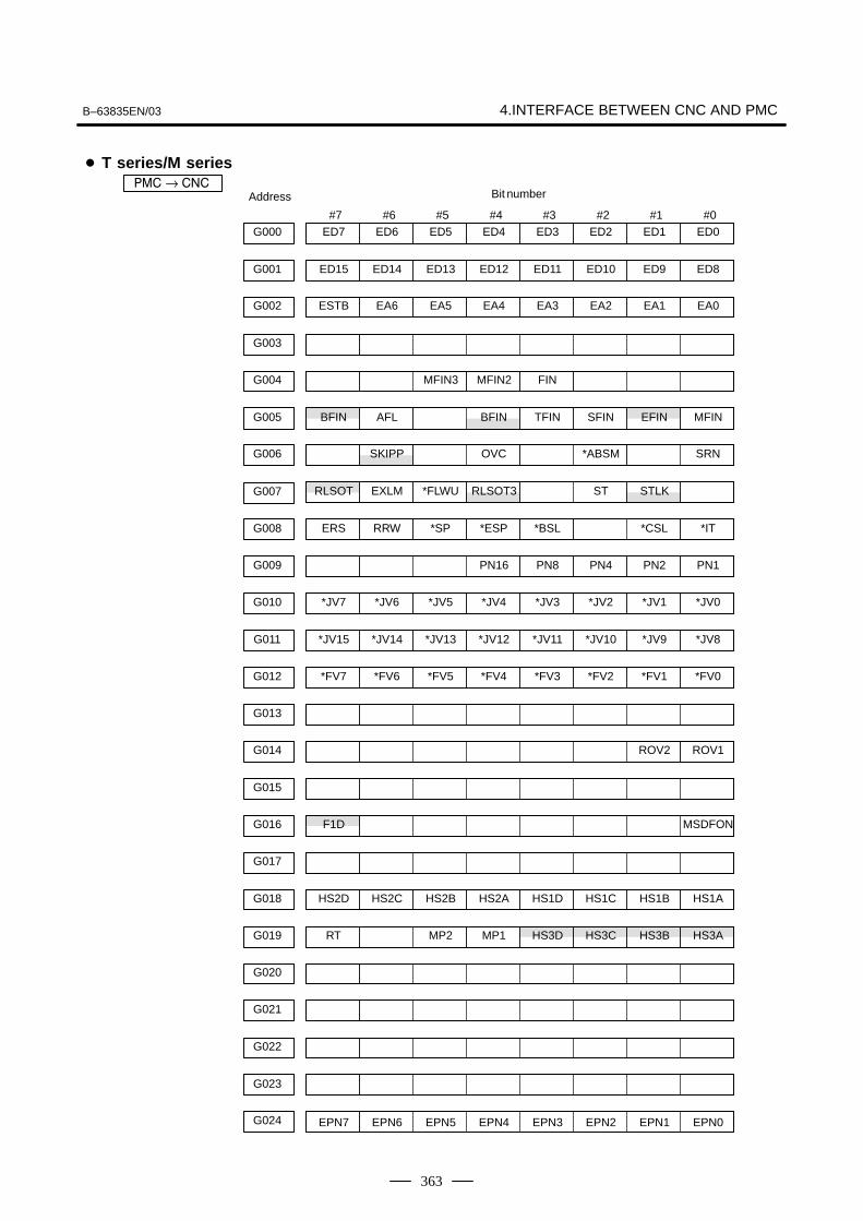
B–63835EN/03 4.INTERFACE BETWEEN CNC AND PMC
363
G000
G001
ESTBG002 EA6 EA5 EA4 EA3 EA2 EA1 EA0
G003
G004 MFIN3 MFIN2 FIN
BFING005 AFL BFIN TFIN SFIN EFIN MFIN
G006 SKIPP OVC *ABSM SRN
G007
ERSG008 RRW *SP *ESP *BSL *CSL *IT
G009 PN16 PN8 PN4 PN2 PN1
G010
ED7 ED6 ED5 ED4 ED3 ED2 ED1 ED0
ED15 ED14 ED13 ED12 ED11 ED10 ED9 ED8
RLSOT EXLM *FLWU RLSOT3 ST STLK
*JV7 *JV6 *JV5 *JV4 *JV3 *JV2 *JV1 *JV0
*JV15G011 *JV14 *JV13 *JV12 *JV11 *JV10 *JV9 *JV8
*FV7G012 *FV6 *FV5 *FV4 *FV3 *FV2 *FV1 *FV0
G013
G014 ROV2 ROV1
G015
F1DG016 MSDFON
G017
HS2DG018 HS2C HS2B HS2A HS1D HS1C HS1B HS1A
RTG019 MP2 MP1 HS3D HS3C HS3B HS3A
G020
G021
G022
G023
G024 EPN7 EPN6 EPN5 EPN3 EPN2 EPN1 EPN0EPN4
#7 #6 #5 #4 #3 #2 #1 #0
� T series/M series��� → ���
Address Bit number

4. INTERFACE BETWEEN CNC AND PMC B–63835EN/03
364
#7 #6 #5 #4 #3 #2 #1 #0EPNSG025 EPN13 EPN12 EPN11 EPN10 EPN9 EPN8
G026
CONG027 *SSTP3 *SSTP2 *SSTP1 SWS3 SWS2 SWS1
PC2SLCG028 SPSTP *SCPF *SUCPF GR2 GR1
G029 *SSTP SOR SAR GR21
SOV7G030 SOV6 SOV5 SOV4 SOV3 SOV2 SOV1 SOV0
G031
R08IG032 R07I R06I R05I R04I R03I R02I R01I
SINDG033 SSIN SGN R12I R11I R10I R09I
R08I2G034 R07I2 R06I2 R05I2 R04I2 R03I2 R02I2 R01I2
SIND2G035 SSIN2 SGN2 R12I2 R11I2 R10I2 R09I2
G036
G037
*BECLPG038 *BEUCP SPPHS SPSYC
GOQSMG039 WOQSM OFN5 OFN4 OFN3 OFN2 OFN1 OFN0
WOSETG040 PRC S2TLS
HS2IDG041 HS2IC HS2IB HS2IA HS1ID HS1IC HS1IB HS1IA
DMMCG042 HS3ID HS3IC HS3IB HS3IA
ZRNG043 DNCI MD4 MD2 MD1
G044 MLK BDT1
BDT9G045 BDT8 BDT7 BDT6 BDT5 BDT4 BDT3 BDT2
DRNG046 KEY4 KEY3 KEY2 KEY1 SBK
TL128G047 TL64 TL32 TL16 TL08 TL04 TL02 TL01
TLRSTG048 TLRSTI TLSKP TL256
*TLV7G049 *TLV6 *TLV5 *TLV4 *TLV3 *TLV2 *TLV1 *TLV0
SIND3 SSIN3 SGN3 R12I3 R11I3 R10I3 R09I3
R08I3 R07I3 R06I3 R05I3 R04I3 R03I3 R02I3 R01I3

B–63835EN/03 4.INTERFACE BETWEEN CNC AND PMC
365
#7 #6 #5 #4 #3 #2 #1 #0G050 *TLV9 *TLV8
G051
G052
CDZG053 SMZ UINT TMRON
UI007G054 UI006 UI005 UI004 UI003 UI002 UI001 UI000
UI015G055 UI014 UI013 UI012 UI011 UI010 UI009 UI008
G056
G057
G058 EXWT EXSTP EXRD MINP
G059
*TSBG060
G061 RGTSP2 RGTSP1 RGTAP
G062 RTNT *CRTOF
G063 NOZAGC
G064
G065
EKSETG066 ENBKY IGNVRY
G067
G068
G069
MRDYAG070 ORCMA SFRA SRVA CTH1A CTH2A TLMHA TLMLA
RCHAG071 RSLA INTGA SOCNA MCFNA SPSLA *ESPA ARSTA
RCHHGAG072 MFNHGA INCMDA OVRA DEFMDA NRROA ROTAA INDXA
G073 DSCNA MPOFA SLVA MORCMA
MRDYBG074 ORCMB SFRB SRVB CTH1B CTH2B TLMHB TLMLB
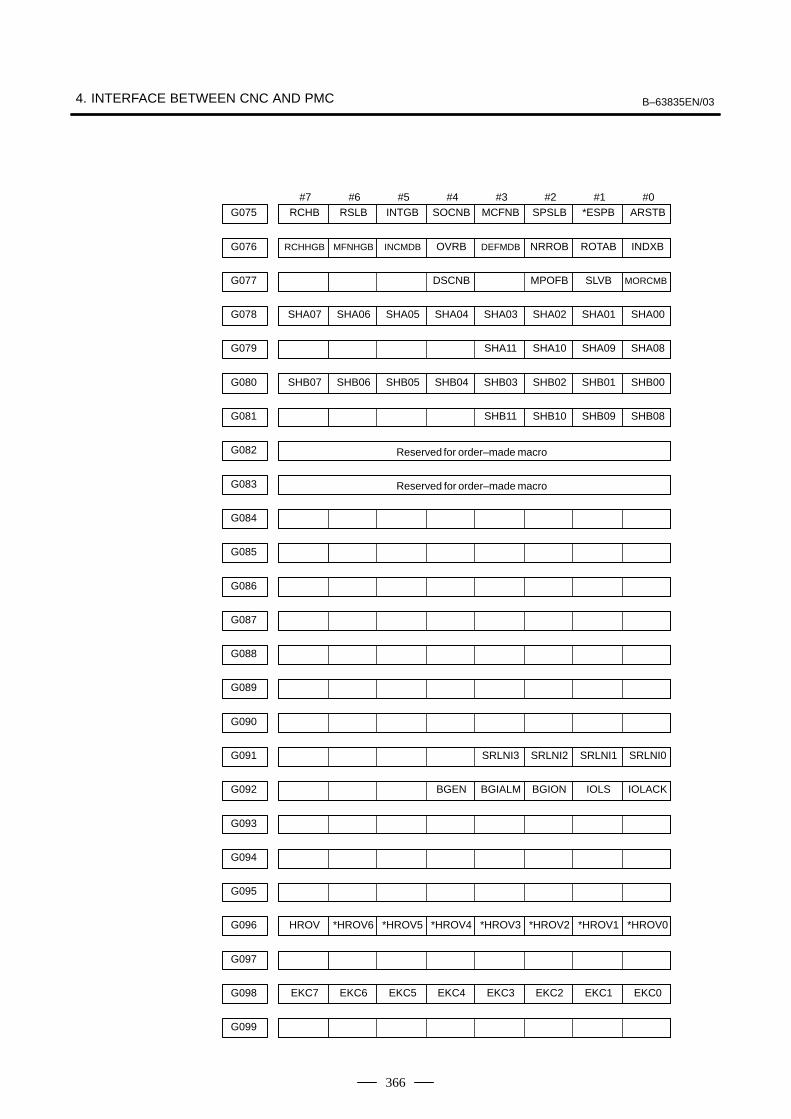
4. INTERFACE BETWEEN CNC AND PMC B–63835EN/03
366
#7 #6 #5 #4 #3 #2 #1 #0
Reserved for order–made macro
Reserved for order–made macro
RCHBG075 RSLB INTGB SOCNB MCFNB SPSLB *ESPB ARSTB
RCHHGBG076 MFNHGB INCMDB OVRB DEFMDB NRROB ROTAB INDXB
G077 DSCNB MPOFB SLVB MORCMB
SHA07G078 SHA06 SHA05 SHA04 SHA03 SHA02 SHA01 SHA00
G079 SHA11 SHA10 SHA09 SHA08
SHB07G080 SHB06 SHB05 SHB04 SHB03 SHB02 SHB01 SHB00
G081 SHB11 SHB10 SHB09 SHB08
G082
G083
G084
G085
G086
G087
G088
G089
G090
G091
G092
G093
G094
G095
HROVG096 *HROV6 *HROV5 *HROV4 *HROV3 *HROV2 *HROV1 *HROV0
G097
EKC7G098 EKC6 EKC5 EKC4 EKC3 EKC2 EKC1 EKC0
G099
SRLNI3 SRLNI2 SRLNI1 SRLNI0
BGEN BGIALM BGION IOLS IOLACK

B–63835EN/03 4.INTERFACE BETWEEN CNC AND PMC
367
#7 #6 #5 #4 #3 #2 #1 #0
–LM1
G100 +J4 +J3 +J2 +J1
G101
G102 –J4 –J3 –J2 –J1
G103
G104 +EXL4 +EXL3 +EXL2 +EXL1
G105 –EXL4 –EXL3 –EXL2 –EXL1
G106 MI4 MI3 MI2 MI1
G107
G108 MLK4 MLK3 MLK2 MLK1
G109
G110 +LM4 +LM3 +LM2 +LM1
G111
G112 –LM4 –LM3 –LM2
G113
G114 *+L4 *+L3 *+L2 *+L1
G115
G116 *–L4 *–L3 *–L2 *–L1
G117
G118 *+ED4 *+ED3 *+ED2 *+ED1
G119
G120 *–ED4 *–ED3 *–ED2 *–ED1
G121
G122
G123

4. INTERFACE BETWEEN CNC AND PMC B–63835EN/03
368
#7 #6 #5 #4 #3 #2 #1 #0G124
IUDD4 IUDD3 IUDD2 IUDD1G125
SVF4 SVF3 SVF2 SVF1G126
G127
G128
G129
*IT4 *IT3 *IT2 *IT1G130
G131
+MIT4 +MIT3 +MIT2 +MIT1G132
G133
–MIT4 –MIT3 –MIT2 –MIT1G134
G135
EAX4 EAX3 EAX2 EAX1G136
G137
SYNC4 SYNC3 SYNC2 SYNC1G138
G139
SYNCJ4 SYNCJ3 SYNCJ2 SYNCJ1G140
EBUFA
G141
ECLRA ESTPA ESOFA ESBKA EMBUFA ELCKZA EFINA
EMSBKA
G142
EC6A EC5A EC4A EC3A EC2A EC1A EC0A
EIF7A
G143
EIF6A EIF5A EIF4A EIF3A EIF2A EIF1A EIF0A
EIF15A
G144
EIF14A EIF13A EIF12A EIF11A EIF10A EIF9A EIF8A
EID7A
G145
EID6A EID5A EID4A EID3A EID2A EID1A EID0A
EID15A
G146
EID14A EID13A EID12A EID11A EID10A EID9A EID8A
EID23A
G147
EID22A EID21A EID20A EID19A EID18A EID17A EID16AG148

B–63835EN/03 4.INTERFACE BETWEEN CNC AND PMC
369
#7 #6 #5 #4 #3 #2 #1 #0
DRNE
G149
RTE OVCE ROV2E ROV1E
*FV7E
G150
*FV6E *FV5E *FV4E *FV3E *FV2E *FV1E *FV0EG151
G152
EBUFB
G153
ECLRB ESTPB ESOFB ESBKB EMBUFB ELCKZB EFINB
EMSBKB
G154
EC6B EC5B EC4B EC3B EC2B EC1B EC0B
EIF7B
G155
EIF6B EIF5B EIF4B EIF3B EIF2B EIF1B EIF0B
EIF15B
G156
EIF14B EIF13B EIF12B EIF11B EIF10B EIF9B EIF8B
EID7B
G157
EID6B EID5B EID4B EID3B EID2B EID1B EID0B
EID15B
G158
EID14B EID13B EID12B EID11B EID10B EID9B EID8B
EID23B
G159
EID22B EID21B EID20B EID19B EID18B EID17B EID16B
EID31B
G160
EID30B EID29B EID28B EID27B EID26B EID25B EID24BG161
G162
G163
G164
EBUFC
G165
ECLRC ESTPC ESOFC ESBKC EMBUFC ELCKZC EFINC
EMSBKC
G166
EC6C EC5C EC4C EC3C EC2C EC1C EC0C
EIF7C
G167
EIF6C EIF5C EIF4C EIF3C EIF2C EIF1C EIF0C
EIF15C
G168
EIF14C EIF13C EIF12C EIF11C EIF10C EIF9C EIF8C
EID7C
G169
EID6C EID5C EID4C EID3C EID2C EID1C EID0C
EID15C
G170
EID14C EID13C EID12C EID11C EID10C EID9C EID8C
EID23C
G171
EID22C EID21C EID20C EID19C EID18C EID17C EID16C
EID31C
G172
EID30C EID29C EID28C EID27C EID26C EID25C EID24CG173
EID31A EID30A EID29A EID28A EID27A EID26A EID25A EID24A
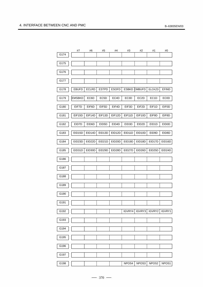
4. INTERFACE BETWEEN CNC AND PMC B–63835EN/03
370
#7 #6 #5 #4 #3 #2 #1 #0G174
G175
G176
EBUFD
G177
ECLRD ESTPD ESOFD ESBKD EMBUFD ELCKZD EFIND
EMSBKD
G178
EC6D EC5D EC4D EC3D EC2D EC1D EC0D
EIF7D
G179
EIF6D EIF5D EIF4D EIF3D EIF2D EIF1D EIF0D
EIF15D
G180
EIF14D EIF13D EIF12D EIF11D EIF10D EIF9D EIF8D
EID7D
G181
EID6D EID5D EID4D EID3D EID2D EID1D EID0D
EID15D
G182
EID14D EID13D EID12D EID11D EID10D EID9D EID8D
EID23D
G183
EID22D EID21D EID20D EID19D EID18D EID17D EID16D
EID31D
G184
EID30D EID29D EID28D EID27D EID26D EID25D EID24DG185
G186
G187
G188
G189
G190
G191
IGVRY4 IGVRY3 IGVRY2 IGVRY1G192
G193
G194
G195
G196
G197
NPOS4 NPOS3 NPOS2 NPOS1G198

B–63835EN/03 4.INTERFACE BETWEEN CNC AND PMC
371
#7 #6 #5 #4 #3 #2 #1 #0G199
G200 EASIP4 EASIP3 EASIP2 EASIP1
G201
G202
G203
G204
G205
G206
G207
G208
G209
G210
G211
G212
G213
G214
G215
G216
G217
G218
G219
G220
G221
G222
G223

4. INTERFACE BETWEEN CNC AND PMC B–63835EN/03
372
#7 #6 #5 #4 #3 #2 #1 #0G224
G225
G226
G227
G228
G229
G230
G231
G232
G233
G234
G235
G236
G237
G238
G239
G240
G241
G242
G243
G244
G245
G246
G247
G248

B–63835EN/03 4.INTERFACE BETWEEN CNC AND PMC
373
#7 #6 #5 #4 #3 #2 #1 #0G249
G250
G251
G252
G253
G254
G255
G256
G257
G258
G259
G260
G261
G262
G263
G264
G265
G266
G267
G268
G269
G270
G271
G272
G273

4. INTERFACE BETWEEN CNC AND PMC B–63835EN/03
374
#7 #6 #5 #4 #3 #2 #1 #0G274
G275
G276
G277
G278
G279
G280
G281
G282
G283
G284
G285
G286
G287
G288
G289
G290
G291
G292
G293
G294
G295
G296
G297
G298
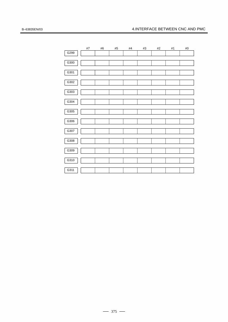
B–63835EN/03 4.INTERFACE BETWEEN CNC AND PMC
375
#7 #6 #5 #4 #3 #2 #1 #0G299
G300
G301
G302
G303
G304
G305
G306
G307
G308
G309
G310
G311

4. INTERFACE BETWEEN CNC AND PMC B–63835EN/03
376
Address Bit number
#7 #6 #5 #4 #3 #2 #1 #0F000
F001
MDRNF002 CUT SRNMV THRD CSS RPDO INCH
MTCHINF003 MEDT MMEM MRMT MMDI MJ MH MINC
OP SA STL SPL RWD
MA TAP ENB DEN BAL RST AL
F004
MBDT9F005 MBDT8 MBDT7 MBDT6 MBDT5 MBDT4 MBDT3 MBDT2
F006
MREF MAFL MSBK MABSM MMLK MBDT1
F007
F008 MF3 MF2 EF
DM00F009 DM01 DM02 DM30
BF BF TF SF EFD MF
F010
M15F011 M14 M13 M12 M11 M10 M09 M08
M23F012 M22 M21 M20 M19 M18 M17 M16
M07 M06 M05 M04 M03 M02 M01 M00
M31F013 M30 M29 M28 M27 M26 M25 M24
M207F014 M206 M205 M204 M203 M202 M201 M200
F015
M307F016 M306 M305 M304 M303 M302 M301 M300
M315F017 M314 M313 M312 M311 M310 M309 M308
M215 M214 M213 M212 M211 M210 M209 M208
F018
F019
F020
F021
S07F022 S06 S05 S04 S03 S02 S01 S00
S15F023 S14 S13 S12 S11 S10 S09 S08
S23F024 S22 S21 S20 S19 S18 S17 S16
CNC → ���

B–63835EN/03 4.INTERFACE BETWEEN CNC AND PMC
377
#7 #6 #5 #4 #3 #2 #1 #0F025
T07 T06 T05 T04 T03 T02 T01 T00
T15 T14 T13 T12 T11 T10 T09 T08
S31 S30 S29 S28 S27 S26 S25 S24
T31 T30 T29 T28 T27 T26 T25 T24
B07 B06 B05 B04 B03 B02 B01 B00
T23 T22 T21 T20 T19 T18 T17 T16
B23 B22 B21 B20 B19 B18 B17 B16
B31 B30 B29 B28 B27 B26 B25 B24
B15 B14 B13 B12 B11 B10 B09 B08
SPAL
R08O R07O R06O R05O R04O R03O R02O R01O
GR3O GR2O GR1O
R12O R11O R10O R09O
ENB3 ENB2 SUCLP SCLP
AR7 AR6 AR5 AR4 AR3 AR2 AR1 AR0
AR15 AR14 AR13 AR12 AR11 AR10 AR09 AR08
SYCAL FSPPH FSPSY FSCSL
MORA2A MORA1A PORA2A SLVSA RCFNA RCHPA CFINA CHPA
EXOFA INCSTA PC1DTA
ORARA TLMA LDT2A LDT1A SARA SDTA SSTA ALMA
ORARB TLMB LDT2B LDT1B SARB SDTB SSTB ALMB
F026
F027
F028
F029
F030
F031
F032
F033
F034
F035
F036
F037
F038
F039
F040
F041
F042
F043
F044
F045
F046
F047
F048
F049
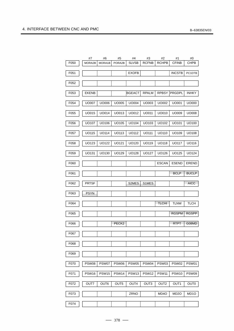
4. INTERFACE BETWEEN CNC AND PMC B–63835EN/03
378
#7 #6 #5 #4 #3 #2 #1 #0F050
EXOFB INCSTB PC1DTB
MORA2B MORA1B PORA2B SLVSB RCFNB RCHPB CFINB CHPB
UO007 UO006 UO005 UO004 UO003 UO002 UO001 UO000
UO015 UO014 UO013 UO012 UO011 UO010 UO009 UO008
EKENB BGEACT RPALM RPBSY PRGDPL INHKY
UO115 UO114 UO113 UO112 UO111 UO110 UO109 UO108
UO123 UO122 UO121 UO120 UO119 UO118 UO117 UO116
UO107 UO106 UO105 UO104 UO103 UO102 UO101 UO100
ESCAN ESEND EREND
BCLP BUCLP
UO131 UO130 UO129 UO128 UO127 UO126 UO125 UO124
PRTSF S2MES S1MES AICC
PSYN
RGSPM RGSPP
PECK2 RTPT G08MD
TLCHI TLNW TLCH
PSW16 PSW15 PSW14 PSW13 PSW12 PSW11 PSW10 PSW09
OUT7 OUT6 OUT5 OUT4 OUT3 OUT2 OUT1 OUT0
PSW08 PSW07 PSW06 PSW05 PSW04 PSW03 PSW02 PSW01
ZRNO MD4O MD2O MD1O
F051
F052
F053
F054
F055
F056
F057
F058
F059
F060
F061
F062
F063
F064
F065
F066
F067
F068
F069
F070
F071
F072
F073
F074
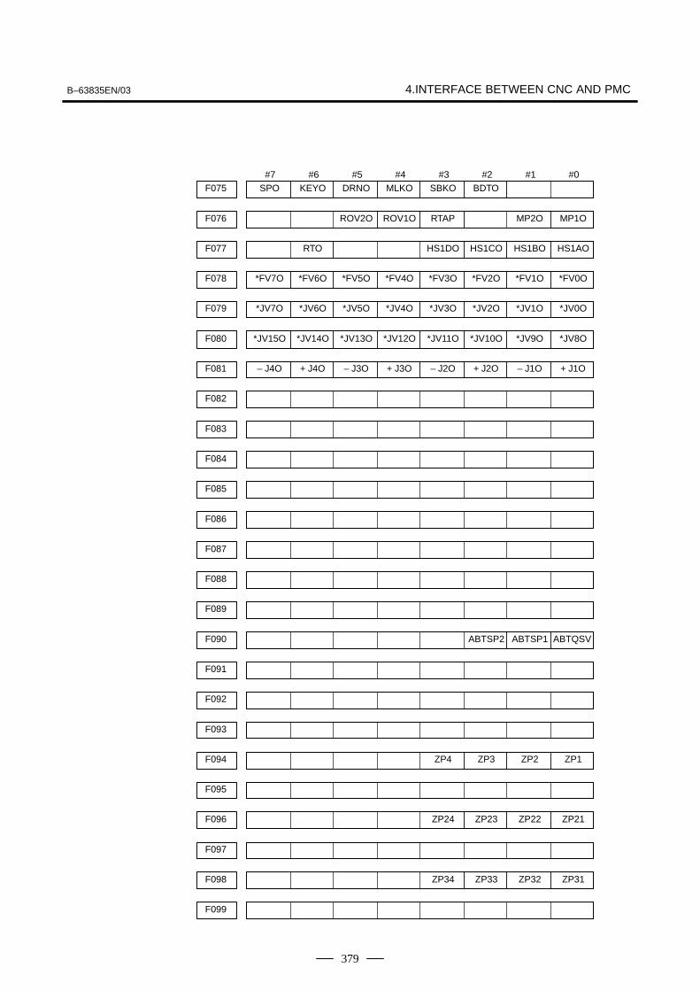
B–63835EN/03 4.INTERFACE BETWEEN CNC AND PMC
379
#7 #6 #5 #4 #3 #2 #1 #0F075
ROV2O ROV1O RTAP MP2O MP1O
RTO HS1DO HS1CO HS1BO HS1AO
SPO KEYO DRNO MLKO SBKO BDTO
*JV7O *JV6O *JV5O *JV4O *JV3O *JV2O *JV1O *JV0O
*JV15O *JV14O *JV13O *JV12O *JV11O *JV10O *JV9O *JV8O
*FV7O *FV6O *FV5O *FV4O *FV3O *FV2O *FV1O *FV0O
– J4O + J4O – J3O + J3O – J2O + J2O – J1O + J1O
ABTSP2 ABTSP1 ABTQSV
ZP4 ZP3 ZP2 ZP1
ZP24 ZP23 ZP22 ZP21
ZP34 ZP33 ZP32 ZP31
F076
F077
F078
F079
F080
F081
F082
F083
F084
F085
F086
F087
F088
F089
F090
F091
F092
F093
F094
F095
F096
F097
F098
F099

4. INTERFACE BETWEEN CNC AND PMC B–63835EN/03
380
#7 #6 #5 #4 #3 #2 #1 #0F100
MV4 MV3 MV2 MV1
ZP44 ZP43 ZP42 ZP41
INP4 INP3 INP2 INP1
MMI4 MMI3 MMI2 MMI1
MVD4 MVD3 MVD2 MVD1
EADEN4 EADEN3 EADEN2 EADEN1
TRQL4 TRQL3 TRQL2 TRQL1
HDO0
ZRF4 ZRF3 ZRF2 ZRF1
+OT4 +OT3 +OT2 +OT1
F101
F102
F103
F104
F105
F106
F107
F108
F109
F110
F111
F112
F113
F114
F115
F116
F117
F118
F119
F120
F121
F122
F123
F124

B–63835EN/03 4.INTERFACE BETWEEN CNC AND PMC
381
#7 #6 #5 #4 #3 #2 #1 #0F125
*EAXSL EOV0
EBSYA EOTNA EOTPA EGENA EDENA EIALA ECKZA EINPA
EM28A EM24A EM22A EM21A EM18A EM14A EM12A EM11A
EBSYB EOTNB EOTPB EGENB EDENB EIALB ECKZB EINPB
EABUFA EMFA
EM28B EM24B EM22B EM21B EM18B EM14B EM12B EM11B
EBSYC EOTNC EOTPC EGENC EDENC EIALC ECKZC EINPC
EABUFB EMFB
EABUFC EMFC
EM28C EM24C EM22C EM21C EM18C EM14C EM12C EM11C
EABUFD EMFD
EM28D EM24D EM22D EM21D EM18D EM14D EM12D EM11D
EBSYD EOTND EOTPD EGEND EDEND EIALD ECKZD EINPD
EM48A EM44A EM42A EM41A EM38A EM34A EM32A EM31A
EM48B EM44B EM42B EM41B EM38B EM34B EM32B EM31B
EM48C EM44C EM42C EM41C EM38C EM34C EM32C EM31C
F126
F127
F128
F129
F130
F131
F132
F133
F134
F135
F136
F137
F138
F139
F140
F141
F142
F143
F144
F145
F146
F147
F148
F149
–OT4 –OT3 –OT2 –OT1
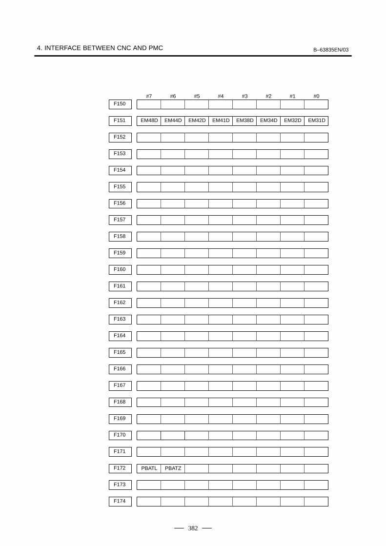
4. INTERFACE BETWEEN CNC AND PMC B–63835EN/03
382
#7 #6 #5 #4 #3 #2 #1 #0F150
EM48D EM44D EM42D EM41D EM38D EM34D EM32D EM31DF151
F152
F153
F154
F155
F156
F157
F158
F159
F160
F161
F162
F163
F164
F165
F166
F167
F168
F169
F170
F171
F172
F173
F174
PBATL PBATZ

B–63835EN/03 4.INTERFACE BETWEEN CNC AND PMC
383
#7 #6 #5 #4 #3 #2 #1 #0F175
EACNT4 EACNT3 EACNT2 EACNT1
F176
F177
F178
F179
F180
F181
F182
F183
F184
F185
F186
F187
F188
F189
F190
F191
F192
F193
F194
F195
EDGN EPARM EVAR EPRG EWTIO ESTPIO ERDIO IOLNK
SRLNO3 SRLNO2 SRLNO1 SRLNO0
CLRCH4 CLRCH3 CLRCH2 CLRCH1
F196
F197
F198
F199

4. INTERFACE BETWEEN CNC AND PMC B–63835EN/03
384
#7 #6 #5 #4 #3 #2 #1 #0F200
F201
F202
F203
F204
F205
F206
F207
F208
F209
F210
F211
F212
F213
F214
F215
F216
F217
F218
F219
F220
F221
F222
F223
F224

B–63835EN/03 4.INTERFACE BETWEEN CNC AND PMC
385
#7 #6 #5 #4 #3 #2 #1 #0F225
F226
F227
F228
F229
F230
F231
F232
F233
F234
F235
F236
F237
F238
F239
F240
F241
F242
F243
F244
F245
F246
F247
F248
F249
4. INTERFACE BETWEEN CNC AND PMC B–63835EN/03
386
#7 #6 #5 #4 #3 #2 #1 #0F250
F251
F252
F253
F254
F255
F256
F257
F258
F259
F260
F261
F262
F263
F264
F265
F266
F267
F268
F269
F270
F271
F272
F273
F274

B–63835EN/03 4.INTERFACE BETWEEN CNC AND PMC
387
#7 #6 #5 #4 #3 #2 #1 #0F275
F276
F277
F278
F279
F280
F281
F282
F283
F284
F285
F286
F287
F288
F289
F290
F291
F292
F293
F294
F295
F296
F297
F298
F299

4. INTERFACE BETWEEN CNC AND PMC B–63835EN/03
388
#7 #6 #5 #4 #3 #2 #1 #0F300
F301
F302
F303
F304
F305
F306
F307
F308
F309
F310
F311
F312
F313
F314
F315

B–63835EN/03 5. FOCAS1/ETHERNET PARAMETER SETTING
389
5 FOCAS1/ETHERNET PARAMETER SETTING
On the Ethernet parameter setting screen, set the PCMCIA LAN cardparameters required for the SERVO GUIDE and FANUC LADDER–IIIto operate.
NOTEBe sure to use the PCMCIA LAN card specified by FANUC.

5. FOCAS1/ETHERNET PARAMETER SETTING B–63835EN/03
390
Display
1 Place the CNC in the MDI mode.
2 Press the function key SYSTEM .
3 Press the continuous menu key at the right end of the soft key display.
4 Press the [ETHPRM] soft key. The Ethernet parameter setting screenappears.
5 By pressing the [PCMCIA] soft key, the parameters for the PCMCIALAN card can be set.
6 By using the MDI keys and soft keys, enter and update data.
7 Switch the screen display with the page keys PAGE
PAGE
.
If data is already registered, the data is displayed.
Procedure
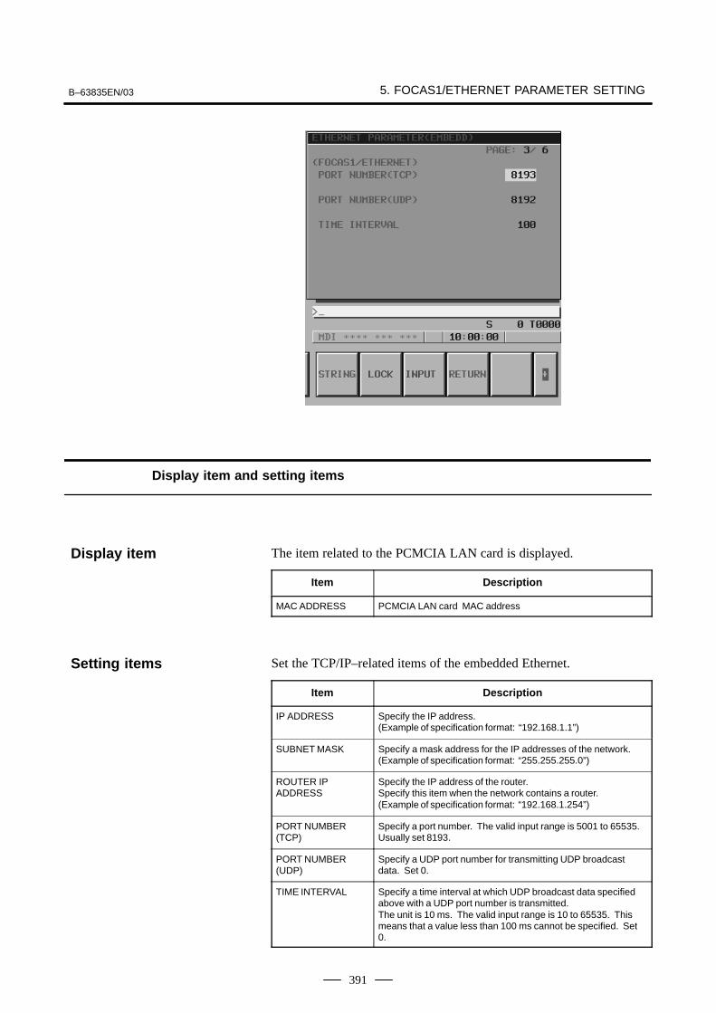
B–63835EN/03 5. FOCAS1/ETHERNET PARAMETER SETTING
391
Display item and setting items
The item related to the PCMCIA LAN card is displayed.
Item Description
MAC ADDRESS PCMCIA LAN card MAC address
Set the TCP/IP–related items of the embedded Ethernet.
Item Description
IP ADDRESS Specify the IP address.(Example of specification format: “192.168.1.1”)
SUBNET MASK Specify a mask address for the IP addresses of the network.(Example of specification format: “255.255.255.0”)
ROUTER IP ADDRESS
Specify the IP address of the router.Specify this item when the network contains a router.(Example of specification format: “192.168.1.254”)
PORT NUMBER(TCP)
Specify a port number. The valid input range is 5001 to 65535.Usually set 8193.
PORT NUMBER(UDP)
Specify a UDP port number for transmitting UDP broadcastdata. Set 0.
TIME INTERVAL Specify a time interval at which UDP broadcast data specifiedabove with a UDP port number is transmitted. The unit is 10 ms. The valid input range is 10 to 65535. Thismeans that a value less than 100 ms cannot be specified. Set0.
Display item
Setting items
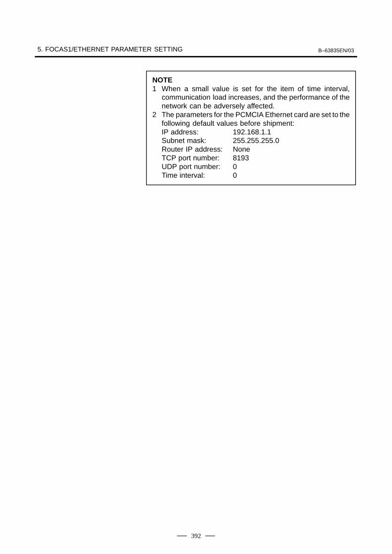
5. FOCAS1/ETHERNET PARAMETER SETTING B–63835EN/03
392
NOTE1 When a small value is set for the item of time interval,
communication load increases, and the performance of thenetwork can be adversely affected.
2 The parameters for the PCMCIA Ethernet card are set to thefollowing default values before shipment:IP address: 192.168.1.1Subnet mask: 255.255.255.0Router IP address: NoneTCP port number: 8193UDP port number: 0Time interval: 0

B–63835EN/03 6. DIGITAL SERVO
393
6 DIGITAL SERVO
This chapter describes servo tuning screen required for maintenance ofdigital servo and adjustment of reference position.
6.1 INITIAL SETTING SERVO PARAMETERS 394. . . . . . 6.2 SERVO TUNING SCREEN 405. . . . . . . . . . . . . . . . . . . . 6.3 ADJUSTING REFERENCE POSITION
(DOG METHOD) 408. . . . . . . . . . . . . . . . . . . . . . . . . . . . 6.4 DOGLESS REFERENCE POSITION SETTING 411. . . . 6.5 αi SERVO WARNING INTERFACE 413. . . . . . . . . . . . 6.6 αi SERVO INFORMATION SCREEN 415. . . . . . . . . . .
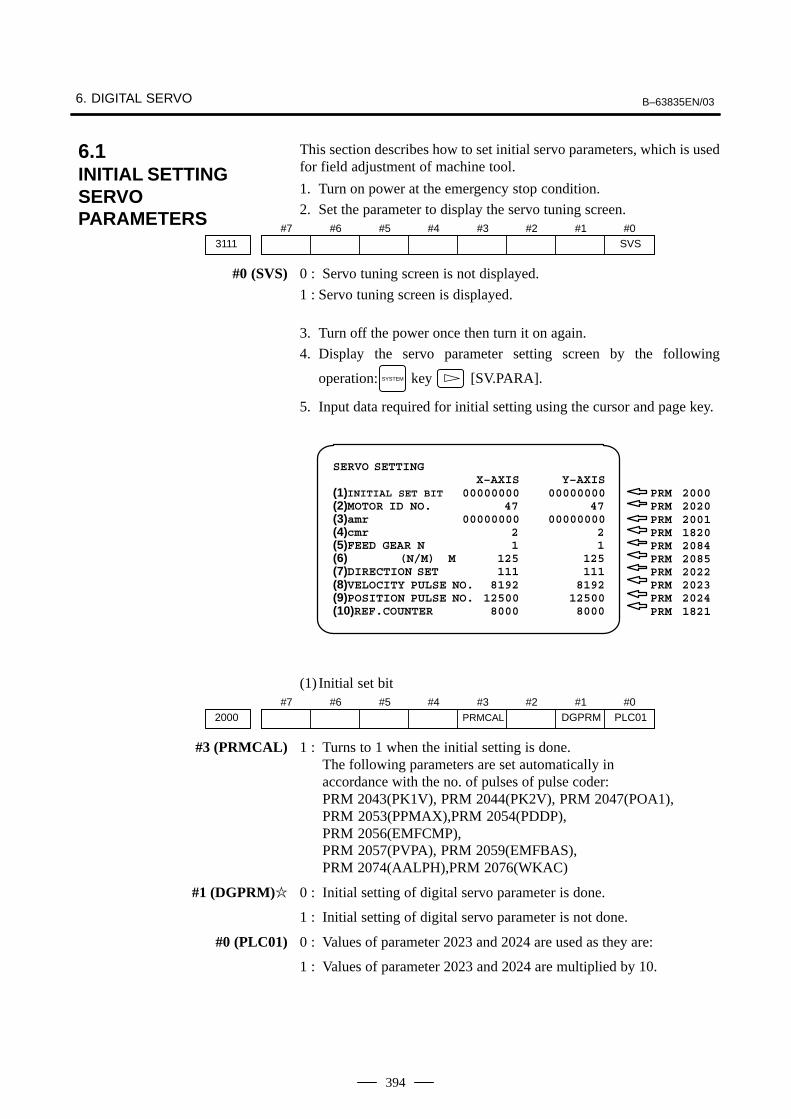
6. DIGITAL SERVO B–63835EN/03
394
This section describes how to set initial servo parameters, which is usedfor field adjustment of machine tool.
1. Turn on power at the emergency stop condition.
2. Set the parameter to display the servo tuning screen.#7
3111#6 #5 #4 #3 #2 #1 #0
SVS
#0 (SVS) 0 : Servo tuning screen is not displayed.
1 : Servo tuning screen is displayed.
3. Turn off the power once then turn it on again.
4. Display the servo parameter setting screen by the following
operation: SYSTEM key [SV.PARA].
5. Input data required for initial setting using the cursor and page key.
SERVO SETTINGX–AXIS Y–AXIS
(1)INITIAL SET BIT 00000000 00000000(2)MOTOR ID NO. 47 47(3)amr 00000000 00000000(4)cmr 2 2(5)FEED GEAR N 1 1(6) (N/M) M 125 125(7)DIRECTION SET 111 111(8)VELOCITY PULSE NO. 8192 8192(9)POSITION PULSE NO. 12500 12500(10)REF.COUNTER 8000 8000
PRM 2000PRM 2020PRM 2001PRM 1820PRM 2084PRM 2085PRM 2022PRM 2023PRM 2024PRM 1821
(1) Initial set bit#7
2000#6 #5 #4 #3
PRMCAL
#2 #1DGPRM
#0PLC01
#3 (PRMCAL) 1 : Turns to 1 when the initial setting is done.The following parameters are set automatically inaccordance with the no. of pulses of pulse coder:PRM 2043(PK1V), PRM 2044(PK2V), PRM 2047(POA1),PRM 2053(PPMAX),PRM 2054(PDDP),PRM 2056(EMFCMP), PRM 2057(PVPA), PRM 2059(EMFBAS), PRM 2074(AALPH),PRM 2076(WKAC)
#1 (DGPRM)� 0 : Initial setting of digital servo parameter is done.
1 : Initial setting of digital servo parameter is not done.
#0 (PLC01) 0 : Values of parameter 2023 and 2024 are used as they are:
1 : Values of parameter 2023 and 2024 are multiplied by 10.
6.1INITIAL SETTINGSERVOPARAMETERS
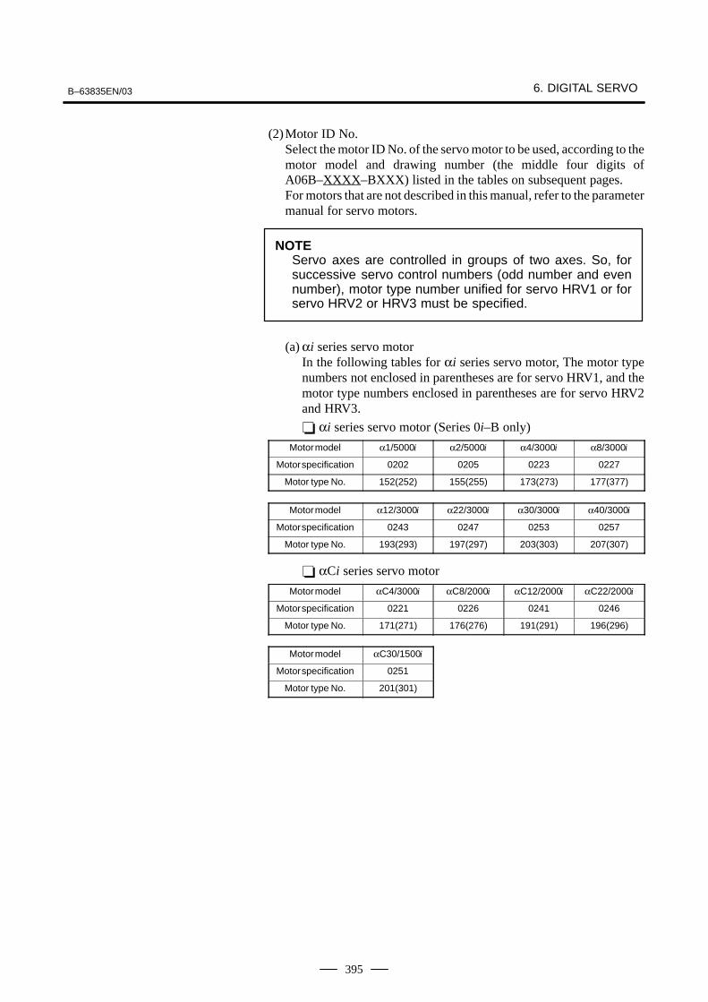
B–63835EN/03 6. DIGITAL SERVO
395
(2)Motor ID No.Select the motor ID No. of the servo motor to be used, according to themotor model and drawing number (the middle four digits ofA06B–XXXX–BXXX) listed in the tables on subsequent pages.For motors that are not described in this manual, refer to the parametermanual for servo motors.
NOTEServo axes are controlled in groups of two axes. So, forsuccessive servo control numbers (odd number and evennumber), motor type number unified for servo HRV1 or forservo HRV2 or HRV3 must be specified.
(a) αi series servo motorIn the following tables for αi series servo motor, The motor typenumbers not enclosed in parentheses are for servo HRV1, and themotor type numbers enclosed in parentheses are for servo HRV2and HRV3.
� αi series servo motor (Series 0i–B only)
Motor model α1/5000i α2/5000i α4/3000i α8/3000i
Motor specification 0202 0205 0223 0227
Motor type No. 152(252) 155(255) 173(273) 177(377)
Motor model α12/3000i α22/3000i α30/3000i α40/3000i
Motor specification 0243 0247 0253 0257
Motor type No. 193(293) 197(297) 203(303) 207(307)
� αCi series servo motor
Motor model αC4/3000i αC8/2000i αC12/2000i αC22/2000i
Motor specification 0221 0226 0241 0246
Motor type No. 171(271) 176(276) 191(291) 196(296)
Motor model αC30/1500i
Motor specification 0251
Motor type No. 201(301)

6. DIGITAL SERVO B–63835EN/03
396
These motor type Nos. may not be supported depending on the servosoftware being used.The following lists the motor type Nos. together with the applicable servosoftware series and editions (A or later).
� αi series servo motor (Series 0i–B only)
Servo software series
Motormodel and motor type number
9060 90B0
α1/5000i 152(252) A H
α2/5000i 155(255) A H
α4/4000i 173(273) A H
α8/3000i 177(277) A H
α12/3000i 193(293) A H
α22/3000i 197(297) A H
α30/3000i 203(303) A H
α40/3000i 207(307) A H
� αCi series servo motor
Servo software series
Motormodel and motor type number
9060 90B0
αC4/3000i 171(271) A H
αC8/2000i 176(276) A H
αC12/2000i 191(291) A H
αC22/2000i 196(296) A H
αC30/1500i 201(301) A H
For � series servo motor
Model name � 0.5 � 1/3000 � 2/3000 � 3/3000 � 6/2000
Drawing number 0113 0101 0102 0105 0106
Format number 13 35 36 33 34
(3)Arbitrary AMR function#7
AMR72001#6
AMR6#5
AMR5#4
AMR4#3
AMR4#2
AMR3#1
AMR2#0
AMR1PRM For each axis
NOTESet “00000000”.

B–63835EN/03 6. DIGITAL SERVO
397
(4)CMR
1820 Command multiply ratioPRM
1) When CMR is 1/2 to 1/27
2) When CMR is 0.5 to 48
(5)Turn off the power then back on.
(6)N/M of feed gear (F⋅FG)
2084 n for flexible feed gearPRM
2085 m for flexible feed gearPRM
Setting for the α pulse coder in the semi–closed mode
Necessary position feedback pulsesper motor revolution
(Note 1)F⋅FG numerator (� 32767)
(as irreducible fraction)1,000,000 (Note 2)F⋅FG denominator (� 32767)
=
NOTE1 For both F⋅FG number and denominator, the maximum
setting value (after reduced) is 32767.2 αi pulse coders assume one million pulses per motor
revolution, irrespective of resolution, for the flexible feedgear setting.
3 If the calculation of the number of pulses required per motorrevolution involves π, such as when a rack and pinion areused, assume π to be approximately 355/113.
[Example]For detection in 1 µm units, specify as follows:
Ball screw lead(mm/rev)
Number of necessaryposition pulses
(pulses/rev)
F⋅FG
102030
100002000030000
1/1002/100 or 1/503/100
[Example]If the machine is set to detection in 1,000 degree units with a gearreduction ratio of 10:1 for the rotation axis, the table rotates by 360/10degrees each time the motor makes one turn.1000 position pulses are necessary for the table to rotate through onedegree.The number of position pulses necessary for the motor to make one turnis:
360/10 � 1000 = 36000 with reference counter = 36000
Set value= 1CMR
+100
Set value=2×CMR
F⋅FG numerator
F⋅FG denominator=
36000
1,000,000=
36
1000

6. DIGITAL SERVO B–63835EN/03
398
Setting for use of a separate detector (full–closed)
Number of position pulses correspondingto a predetermined amount of travelF⋅FG numerator (� 32767)
(as irreducible fraction)Number of position pulses correspondingto a predetermined amount of travel from
a separate detector
F⋅FG denominator (� 32767)=
[Example]To detect a distance of 1–µm using a 0.5–µm scale, set the following:
<<Examples of calculation>>
1/1000 mm 1/10000 mm
One revolution 8mmof motor 10mm
12mm
n=1/m=125n=1/m=100n=3/m=250
n=2/m=25n=1/m=10n=3/m=25
(7)Direction of travel2022 Rotational direction of motorPRM
111 : Normal (clockwise) –111 : Reverse (counterclockwise)(8)Number of velocity pulses and position pulses
1) For serial αi pulse coder, or serial � pulse coder
Increment system : 1/1000mm Increment system : 1/10000mmParamter No.
Closed loop Semi–closed loop Closed loop Semi–closed loop
High resolution setting 2000 xxxx xxx 0 xxxx xxx 1
Separate detector 1815 0010 0010 0010 0000 0010 0010 0010 0000
No. of velocity feedback pulses 2023 8192 819
No. of position feedback pulses 2024 NS 12500 NS/10 1250
NOTE1 NS is the number of position feedback pulses per one
revolution of the motor (multiplied by four)2 Even if the system employs a closed loop, bit 3 of parameter
2002 is 1 and bit 4 is 0.
(9)Reference counter1821 Reference counter capacity for each axis (0 – 99999999)PRM
6. Turn off the power then back on.(10) FSSB display and setting screen
Connecting the CNC control unit to servo amplifiers via ahigh–speed serial bus (FANUC Serial Servo Bus, or FSSB), whichuses only one fiber optics cable, can significantly reduce the amountof cabling in machine tool electrical sections. Axis settings are calculated automatically according to theinterrelationships between axes and amplifiers entered on the FSSBsetting screen. Parameter Nos. 1023, 1905, 1910 to 1919, 1936, and1937 are specified automatically according to the results of thecalculation.
Numerator of F⋅FG
Denominator of F⋅FG=
L/1
L/0.5=
1
2

B–63835EN/03 6. DIGITAL SERVO
399
The FSSB setting screen displays FSSB–based amplifier and axisinformation. This information can also be specified by the operator.
1. Press function key SYSTEM .
2. To display [FSSB], press continuous menu key several times.
3. Pressing soft key [FSSB] causes the AMP SET screen (or thepreviously selected FSSB setting screen) to appear, with the followingsoft keys displayed.
AMP (OPRT)MAINTEAXIS
The FSSB setting screens include: AMP SET, AXIS SET, and AMPMAINTENANCE.
Pressing soft key [AMP] causes the AMP SET screen to appear.Pressing soft key [AXIS] causes the AXIS SET screen to appear.Pressing soft key [MAINTE] causes the AMP MAINTENANCEscreen to appear.
1) Amplifier setting screenThe amplifier setting screen consists of two sections: the first sectiondisplays information about the slave, while the second sectiondisplays information about the pulse modules.
AMPLIFIER SETTING O1000 N00001NO. AMP SERIES UNIT CUR. AXIS NAME1 A1–L α SVM–HV 40AL 1 X2 A1–M α SVM 12A 2 Y3 A2–L β SVM 40A 3 Z4 A3–L α SVM 20A 4 A
NO. EXTRA TYPE PCB ID5 M1 A 0000 DETECTOR(8AXES)6 M2 B 12AB
>_MDI **** *** *** 13:11:56[ AMP ][ AXIS ][ MAINTE ][ ][(OPRT)]
The amplifier setting screen consists of the following items:
� NO. (slave number)
The numbers of up to ten slaves (up to eight amplifiers and up to twopulse modules) connected via the FSSB are displayed sequentially,with the one nearest to the CNC being number 1.
� AMP (amplifier type)
The amplifier type display consists of the letter A, which stands for“amplifier,” a number that indicates the placing of the amplifier, ascounted from that nearest to the CNC, and a letter such as L (first axis)or M (second axis) indicating the placing of the axis in the amplifier.
� Display

6. DIGITAL SERVO B–63835EN/03
400
� AXIS NO. (controlled axis number)
The axis number of each controlled axis specified in parameters (Nos.1920 to 1929) is displayed. If a number specified in these parametersfalls outside the range of between 1 and the maximum number ofcontrolled axes, 0 is displayed.
� NAME (controlled axis name)
The axis name assigned to a parameter (No. 1020) corresponding toa particular controlled axis number is displayed. If the controlled axisnumber is 0, – is displayed.
� The following items are displayed as amplifier information:
⋅ UNIT (servo amplifier unit type)
⋅ SERIES (servo amplifier name)
⋅ CURRENT (maximum rating)
� The following items are displayed as pulse module information:
⋅ SEPARATE
This display consists of the letter M, which stands for “pulsemodule” and a number indicating the placing of the pulse module,as counted from that nearest to the CNC.
⋅ TYPE
This display is a letter indicating the type of the pulse module.
⋅ PCB ID
This display consists of four digits indicating the pulse module ID(hexadecimal). The pulse module ID is followed by DETECTOR(8–AXES) for the eight–axis separate detector module orDETECTOR (4–AXES) for the four–axis separate detector module.
2) Axis setting screen
The axis setting screen displays the information shown below:
AXIS SETTING O1000 N00001AXIS NAME AMP M1 M2 1–DSF Cs TNDM1 X A1–L 0 0 0 0 02 Y A1–M 1 0 1 0 03 Z A2–L 0 0 0 1 04 A A3–L 0 0 0 0 0
>_MDI **** *** *** 13:11:56[ AMP ][ AXIS ][ MAINTE ][ ][(OPRT)]
This axis setting screen displays the following items:
� AXIS (controlled axis number)
This item is the placing of the NC controlled axis.
� NAME (controlled axis name)
� AMP (type of the amplifier connected to each axis)

B–63835EN/03 6. DIGITAL SERVO
401
� M1 (connector number for pulse module 1)
This item is the number of the connector for pulse module 1, specifiedin parameter No. 1931.
� M2 (connector number for pulse module 2)
This item is the number of the connector for pulse module 2, specifiedin parameter No. 1932.
� 1–DSF
This item is the value specified in bit 0 (parameter 1 DSP) of parameterNo. 1904. It is 1 for an axis (such as a high–speed current loop axis,or high–speed interface axis) that exclusively uses a DSP, which isusually shared by two–axes.
� Cs: Cs contour controlled axis
This item is the value specified in parameter No. 1933. It is 1 for theCs contour controlled axis.
3) Amplifier maintenance screen
The amplifier maintenance screen displays maintenance informationfor servo amplifiers. This screen consists of the following two pages,
either of which can be selected by pressing the or key.
AMPLIFIER MAINTENANCE O1000 N00001AXIS NAME AMP SERIES UNIT AXES CUR.1 X A1–L α SVM–HV 2 40AL2 Y A1–M α SVM 2 12A3 Z A2–L β SVM 1 40A4 A A3–L α SVM 1 20A
MDI **** *** *** 13:11:56[ AMP ][ AXIS ][ MAINTE ][ ][ ]
AMPLIFIER MAINTENANCE O1000 N00001AXIS NAME EDITION TEST MAINTE–NO.1 X 01A 020123 012 Y 01A 020123 013 Z 01A 020123 014 A 02B 020123 01
MDI **** *** *** 13:11:56[ AMP ][ AXIS ][ MAINTE ][ ][ ]

6. DIGITAL SERVO B–63835EN/03
402
The amplifier maintenance screen displays the following items:
� AXIS (controlled axis number)
� NAME (controlled axis name)
� AMP (type of amplifier connected to each axis)
� SERIES (servo amplifier series of an amplifier connected to each axis)
� UNIT (unit type of a servo amplifier connected to each axis)
� AXES (maximum number of axes controlled by an amplifierconnected to each axis)
� CUR. (maximum rating for amplifiers connected to each axis)
� EDITION (unit version number of an amplifier connected to each axis)
� TEST (date of test performed on an amplifier connected to each axis)
Example) 010123 = January 23, 2001
� MAINTE–NO. (engineering change number for an amplifierconnected to each axis)
On an FSSB setting screen (other than the amplifier maintenance screen),pressing soft key [(OPRT)] displays the following soft keys:
SET INPUTREAD
To enter data, place the machine in MDI mode or the emergency stop state,position the cursor to the point where a desired item is to be input, then
enter the desired data and press soft key [INPUT] (or the INPUT key on the
MDI panel).When soft key [SET] is pressed after data has been entered, a warningmessage is displayed if the entered data contains an error. When the datais satisfactory, the corresponding parameter is set up.To restore the previous value of a parameter if, for example, an enteredvalue is incorrect, press soft key [READ].When the power is turned on, values are read from the parameters anddisplayed on the screen.
CAUTION1 For the parameters to be specified on the FSSB setting
screen, do not attempt to enter values on the parameterscreen using the MDI or a G10 command. Use only theFSSB screen to enter values for these parameters.
2 If pressing soft key [SET] results in a warning messagebeing displayed, retry data entry, or press soft key [READ]to clear the warning message. Note that pressing the resetkey does not clear the warning message.
� Setting

B–63835EN/03 6. DIGITAL SERVO
403
1) Amplifier setting screen
AMPLIFIER SETTING O1000 N00001NO. AMP SERIES UNIT CUR. AXIS NAME1 A1–L α SVM–HV 40AL 1 X2 A1–M α SVM 12A 2 Y3 A2–L β SVM 40A 3 Z4 A3–L α SVM 20A 4 A
NO. EXTRA TYPE PCB ID5 M1 A 0000 DETECTOR(8AXES)6 M2 B 12AB
>_MDI **** *** *** 13:11:56[SETTING][ ][ READ ][ ][ INPUT ]
The amplifier setting screen displays the following items:
� NO. (controlled axis number)
For this item, enter a value of between 1 and the maximum number ofcontrolled axes. If a number that falls outside this range is entered, thewarning message “INVALID FORMAT” appears. If the enteredcontrolled axis number is duplicate or 0, the warning message“SPECIFIED DATA IS OUT OF RANGE” appears when soft key[SET] is pressed to assert the entered value. In this case, no value canbe entered for the parameter.
2) Axis setting screen
AXIS SETTING O1000 N00001AXIS NAME AMP M1 M2 1–DSF Cs TNDM1 X A1–L 0 0 0 0 02 Y A1–M 1 0 1 0 03 Z A2–L 0 0 0 1 04 A A3–L 0 0 0 0 0
>_MDI **** *** *** 13:11:56[SETTING][ ][ READ ][ ][ INPUT ]
On the axis setting screen, the following items can be specified:
� M1 (connector number for pulse module 1)
For an axis that uses pulse module 1, enter a connector number usinga number in the range of between 1 and the maximum number of axesfor pulse module 1. When pulse module 1 need not be used, enter 0.If a number that falls outside the valid range is entered, the warningmessage “INVALID FORMAT” is displayed.

6. DIGITAL SERVO B–63835EN/03
404
� M2 (connector number for pulse module 2)
For an axis that uses pulse module 2, enter a connector number usinga number in the range of between 1 and the maximum number of axesfor pulse module 2. When pulse module 2 need not be used, enter 0.If a number that falls outside the valid range is entered, the warningmessage “INVALID FORMAT” is displayed.
� 1–DSF
Enter 1 for the following axes, each of which exclusively uses a DSP,which is usually shared by two–axes. If a number other than 0 or 1 isentered, the warning message “INVALID FORMAT” is displayed.
⋅ Learning control axis
⋅ High–speed current loop axis
⋅ High–speed interface axis
� Cs (Cs contour controlled axis)
Enter 1 for the Cs contour controlled axis. If a number other than 0or 1 is entered, the warning message “INVALID FORMAT” isdisplayed.
When soft key [SET] is pressed on the axis setting screen after data entry,the warning message “SPECIFIED DATA IS OUT OF RANGE” isdisplayed if any of the following conditions is satisfied.
� Both M1 and M2 are nonzero for an axis.
� Any two of TWO–AXES, Cs, and TANDEM are nonzero for an axis.
� A duplicate value is specified for M1.
� A duplicate value is specified for M2.
� A duplicate value is specified for Cs.
� A duplicate value is specified for TANDEM.
� An invalid master/slave axis pair is specified for TANDEM.
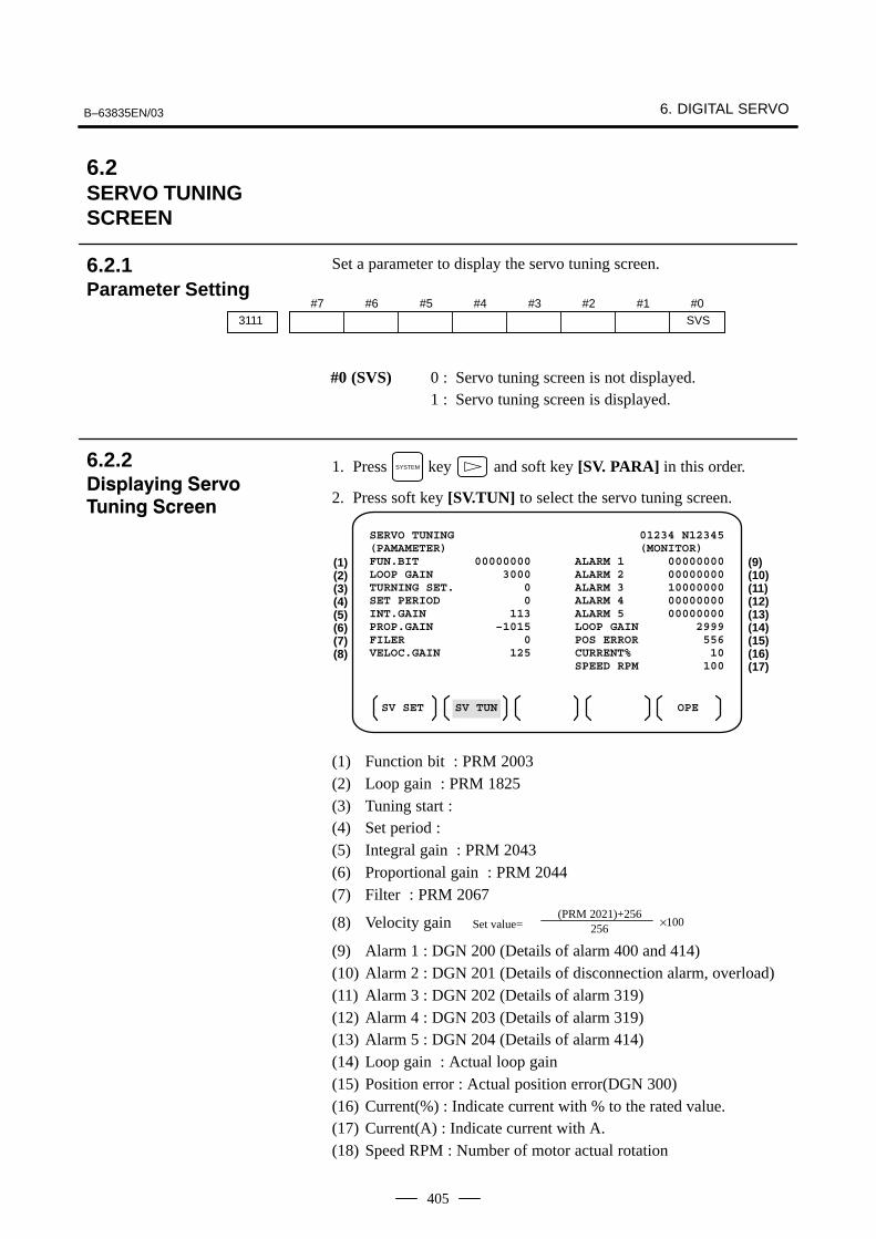
B–63835EN/03 6. DIGITAL SERVO
405
Set a parameter to display the servo tuning screen.
#73111
#6 #5 #4 #3 #2 #1 #0SVS
#0 (SVS) 0 : Servo tuning screen is not displayed.1 : Servo tuning screen is displayed.
1. Press SYSTEM key and soft key [SV. PARA] in this order.
2. Press soft key [SV.TUN] to select the servo tuning screen.
SERVO TUNING 01234 N12345(PAMAMETER) (MONITOR) FUN.BIT 00000000 ALARM 1 00000000LOOP GAIN 3000 ALARM 2 00000000TURNING SET. 0 ALARM 3 10000000SET PERIOD 0 ALARM 4 00000000INT.GAIN 113 ALARM 5 00000000PROP.GAIN –1015 LOOP GAIN 2999FILER 0 POS ERROR 556VELOC.GAIN 125 CURRENT% 10
SPEED RPM 100
SV SET SV TUN OPE
(1)(2)(3)(4)(5)(6)(7)(8)
(9)(10)(11)(12)(13)(14)(15)(16)(17)
(1) Function bit : PRM 2003(2) Loop gain : PRM 1825(3) Tuning start :(4) Set period :(5) Integral gain : PRM 2043(6) Proportional gain : PRM 2044(7) Filter : PRM 2067
(8) Velocity gain (PRM 2021)+256
256Set value= ×100
(9) Alarm 1 : DGN 200 (Details of alarm 400 and 414)(10) Alarm 2 : DGN 201 (Details of disconnection alarm, overload)(11) Alarm 3 : DGN 202 (Details of alarm 319)(12) Alarm 4 : DGN 203 (Details of alarm 319)(13) Alarm 5 : DGN 204 (Details of alarm 414)(14) Loop gain : Actual loop gain(15) Position error : Actual position error(DGN 300)(16) Current(%) : Indicate current with % to the rated value.(17) Current(A) : Indicate current with A.(18) Speed RPM : Number of motor actual rotation
6.2SERVO TUNINGSCREEN
6.2.1Parameter Setting
6.2.2��������� �� ������ �����

6. DIGITAL SERVO B–63835EN/03
406
#7OVLAlarm1
#6LV
#5OVC
#4HCA
#3HVA
#2DCA
#1FBA
#0OFA
DGN (200) :
#7 (OVL) : Overload alarm
#6 (LV) : Insufficient voltage alarm
#5 (OVC) : Overcurrent alarm
#4 (HCA) : Abnormal current alarm
#3 (HVA) : Excessive voltage alarm
#2 (DCA) : Discharge alarm
#1 (FBA) : Disconnection alarm
#0 (OFA) : Overflow alarm#7
ALDAlarm2#6 #5 #4
EXP#3 #2 #1 #0
DGN (201) ⇓
Over- 0 — — — Amplifier overheatloadalarm 1 — — — Motor overheat
Discon-nection
1 — — 1 Separate type pulse coder disconnec-tion (Hardware)
alarm0 — — 0 Pulse coder disconnection (software)
#7Alarm3
#6CSA
#5BLA
#4PHA
#3RCA
#2BZA
#1CKA
#0SPH
DGN (202) :
#6 (CSA) : Hardware of serial pulse coder is abnormal.
#5 (BLA) : Battery voltage is in low (warning).
#4 (PHA) : Serial pulse coder or feedback cable is abnormal.Counting the feedback signal is in error.
#3 (RCA) : Serial pulse coder is faulty.Counting is in error.If the RCA bit is set to 1 when both the FBA bit (bit 1 of alarm 1) andALD bit of alarm 2 are set to 1 and the EXP bit of alarm 2 (internalhardware disconnection) is set to 1, a count miss alarm (CMAL)occurs in the α pulse coder.
#2 (BZA) : Battery voltage becomes 0.Replace batteries and set the reference position.
#1 (CKA) : Serial pulse coder is faulty.Internal clock has stopped.
#0 (SPH) : Serial pulse coder or feedback cable is faulty.Counting the feedback signal is in error.

B–63835EN/03 6. DIGITAL SERVO
407
#7DTEAlarm4
#6CRC
#5STB
#4PRM
#3 #2 #1 #0
DGN (203) :
#7 (DTE) : Communication error of serial pulse coder.There is no response.Generally, a leading cause is a break in a wire.
#6 (CRC) : Communication error of serial pulse coder.Transmitted data is in error.
#5 (STB) : Communication error of serial pulse coder.Transmitted data is in error.
#4 (PRM) : The alarm is detected by the digital servo, the values specified in the parameter is not correct.
#7Alarm5
#6OFS
#5MCC
#4LDM
#3PMS
#2 #1 #0
DGN (204) :
#6 (OFS) : A/D conversion of current value of digital servo is abnormal.
#5 (MCC) : Contacts of electro–magnetic contactor of servo amplifier is blown
#4 (LDM) : LED of α pulse coder is abnormal.
#3 (PMS) : No. of feedback pulses are in error because α pulse coder or feedbackcable is faulty.
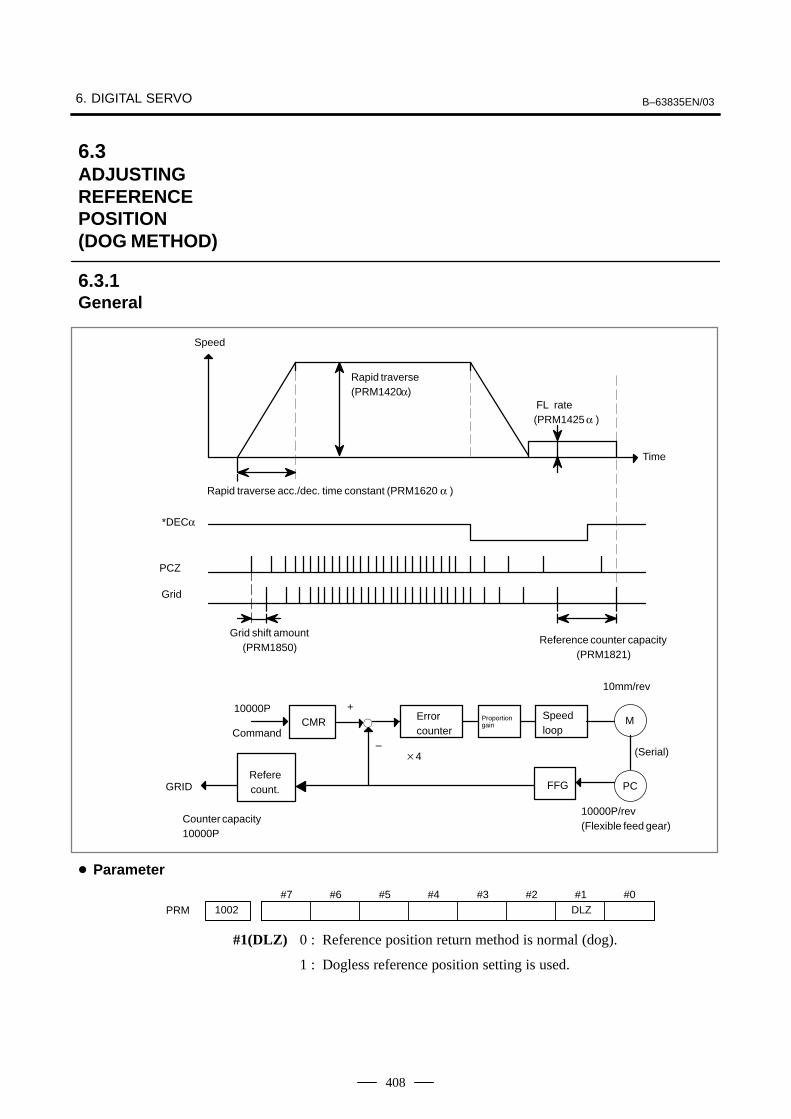
6. DIGITAL SERVO B–63835EN/03
408
Speed
Rapid traverse(PRM1420α)
FL rate(PRM1425 α )
Time
Rapid traverse acc./dec. time constant (PRM1620 α )
*DECα
PCZ
Grid
Referecount.
Counter capacity10000P
+10000PCMR �
Error counter
Proportiongain
Speedloop
M
–
GRID PC
10mm/rev
Grid shift amount(PRM1850)
Reference counter capacity(PRM1821)
FFG
�4
10000P/rev (Flexible feed gear)
Command
(Serial)
#71002
#6 #5 #4 #3 #2 #1DLZ
#0
PRM
#1(DLZ) 0 : Reference position return method is normal (dog).
1 : Dogless reference position setting is used.
6.3ADJUSTINGREFERENCEPOSITION (DOG METHOD)
6.3.1General
� Parameter

B–63835EN/03 6. DIGITAL SERVO
409
#71005
#6 #5 #4 #3 #2 #1DLZ
#0
PRM
#1(DLZ) 0 : The normal method (dog) is used for reference position return.
1 : Reference position setting without dogs is used (axis by axis).
NOTEA reference position can be set axis by axis by setting bit 1of parameter No. 1002 to 0 and setting bit 1 of parameterNo. 1005. Reference position setting without dogs cannotbe used for a spindle positioning axis and Cs contour axis.When these axes are involved, use bit 1 of parameter No.1005.
1821 Reference counter capacity [P]PRM
No. of feedback pulses or its division by an integer is set.
1850 Grid shift amount per axis [P]PRM
When the resolution is 0.0001mm, set the value in the unit ten times
the detection unit.
#71815
#6 #5APC
#4APZ
#3 #2 #1OPT
#0
PRM
#5(APC) 0 : Position detector is other than absolute pulse coder.
1 : Position detector is absolute pulse coder.
#4(APZ) Zero position of absolute pulse coder is :
0 : Not established
1 : Established(Turns to 1 after establishment)To manually change the value of the APZ bit from 0 to 1 without firstreturning to the reference positionwhen using serial pulse coder α , follow this procedure: Back up thedata with the battery and give the motor one or more turns. Turn the power off then on again, then change the APZ bit settingfrom 0 to 1.
#1(OPT) 0 : Position detection is performed by the pulse coder built in the motor.
1 : Separate type pulse coder or linear scale is used.
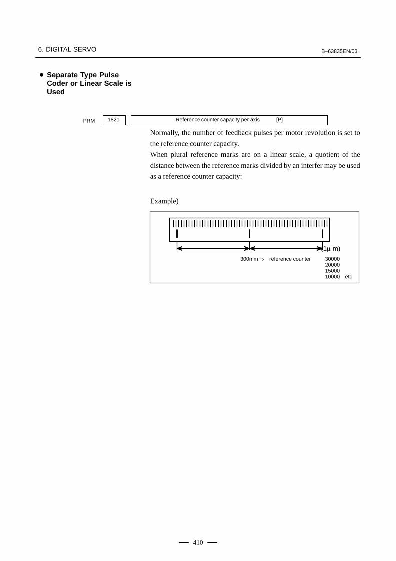
6. DIGITAL SERVO B–63835EN/03
410
1821 Reference counter capacity per axis [P]PRM
Normally, the number of feedback pulses per motor revolution is set to
the reference counter capacity.
When plural reference marks are on a linear scale, a quotient of the
distance between the reference marks divided by an interfer may be used
as a reference counter capacity:
Example)
(1µ m)
300mm ⇒ reference counter 30000200001500010000 etc
� Separate Type PulseCoder or Linear Scale isUsed

B–63835EN/03 6. DIGITAL SERVO
411
When there are no dog nor limit switch for reference position return, thisfunction enables the tool to return the reference position that is set byMTB.When the absolute position detector is used, the reference position onceset remains also during power off. When the absolute detector is replacedor absolute position is lost, perform this setting.
Time
JOG
ZRN
+Jα
Speed
Reference position returnFL rate (PRM 1425)
GRID . . . . . . . . . . . . . . . . . . . . . . . . .
ZP α
1 Move the tool near the reference position using a manual operation.
2 Select the reference position return mode or switch.
3 Press a button for an axis–and–direction–select–signal + or –, and themachine moves to the next grid, then stops.(This position is set as the reference position).
� After the reference position has been set, select the reference positionreturn mode(ZRN signal is 1) and turn on an axis–and–direction–select signal, then the tool returns to the reference position.
6.4DOGLESSREFERENCEPOSITION SETTING
6.4.1General
6.4.2Operation

6. DIGITAL SERVO B–63835EN/03
412
#71002
#6 #5 #4 #3 #2 #1DLZ
#0
PRM
#1(DLZ) 0 : Dog is used for reference position return
1 : Dogless reference position setting (all axes)
#71005
#6 #5 #4 #3 #2 #1DLZ
#0
PRM
#1(DLZ) 0 : The normal method (dog) is used for reference position return.
1 : Reference position setting without dogs is used (axis by axis).
NOTEA reference position can be set axis by axis by setting bit 1of parameter No. 1002 to 0 and setting bit 1 of parameterNo. 1005. Reference position setting without dogs cannotbe used for a spindle positioning axis and Cs contour axis.When these axes are involved, use bit 1 of parameter No.1005.
#71006
#6 #5ZMI
#4 #3 #2 #1 #0
PRM
#5(ZMI) 0 : Reference position return and backlash initial direction is +.
1 : Reference position return and backlash initial direction is –.
� After ZRN signal becomes 1, manual feed direction is always thedirection set by this parameter irrespective of an axis selection signal.
6.4.3Associated Parameters

B–63835EN/03 6. DIGITAL SERVO
413
The αi servo system can report the warning status before one of thefollowing target alarms occurs.When the warning status is entered, a report to the PMC is issued.For example, this signal can be used by the machine for retracting toolsfrom the time a warning occurs by the time a servo alarm occurs.
[Classification] Output signal
[Function] Reports the warning signal corresponding to the state of the servoamplifier.
[Output condition] The following table shows the warning statuses of the servo amplifier andtheir corresponding warning signals.
Corresponding alarm messages Warning status signals (F93) Time from when a
SVWRN4(#7)
SVWRN3(#6)
SVWRN2(#5)
SVWRN1(#4)
warning state signal isissued to until an alarm
occurs
444 n AXIS: INV. COOLING FAN FAILURE 1 0 0 0 One minute
601 n AXIS: INV. RADIATOR FAN FAILURE 1 0 0 1 Until overheat occurs(inconstant)
443 n AXIS: CNV. COOLING FAN FAILURE 1 1 0 0 One minute
606 n AXIS: CNV. RADIATOR FAN FAILURE 1 1 0 1 Until overheat occurs(inconstant)
431 n AXIS: CNV. OVERLOAD 1 1 1 0 One minute
607 n AXIS: CNV. SINGLE PHASE FAILURE 1 1 1 1 PSMR: Five seconds,PSM: One minute
6.5αi SERVO WARNINGINTERFACE
General
Signal
Servo warning detailsignalsSVWRN1 to 4<F093#4 to #7>

6. DIGITAL SERVO B–63835EN/03
414
A timing chart for handling a warning is shown below.
Servo amplifier
SVWRN1–4(Warning)
Occurrence of a warning
Activation
Perform deceleration stop or block stopduring this time period with the PMC tostop the machine without damage. Thetime period varies with the warning type.
Occurrence and stop of thealarm corresponding to awarning
#7SVWRN4F903
#6SVWRN3
#5SVWRN2
#4SVWRN1
#3 #2 #1 #0
Signal address

B–63835EN/03 6. DIGITAL SERVO
415
In the αi servo system, ID information output from each of the connectedunits is obtained and output to the CNC screen.
The units that have ID information are shown below.(Remark: Some instances of these units do not have ID information.)
� Servo motor
� Pulse coder
� Servo amplifier module
� Power supply module
ID information is automatically read from each of the connected unitsduring first startup of the CNC and then recorded. During the second orlater startup, the ID information recorded during first startup can becompared with the ID information read this time on the screen to checkwhether the configuration of the connected units is changed. (If there isa difference between them, the alarm mark (*) appears.)
The recorded ID information can be edited. Therefore, the ID informationof an unit that does not have ID information can be displayed. (However,the alarm mark (*) indicating a difference between these IDs appears.)
#713112
#6 #5 #4 #3 #2 #1SVI
#0IDW
[Data type] Bit
IDW The edit of the servo information screen or the spindle information screenis:
0 : Prohibited1 : Allowed
SVI The servo information screen is:
0 : Displayed1 : Not displayed
6.6αi SERVOINFORMATIONSCREEN
General
Parameter

6. DIGITAL SERVO B–63835EN/03
416
Displaying the servo ID screen
1 Press the SYSTEM function key, then press the [System] soft key.
2 Press the [SV Information] soft key to display the screen as shownbelow.
NOTEServo information is stored in flash ROM. If there is adifference between the servo information in flash ROM andthe actual servo information, the corresponding items arepreceded by *, as shown below.
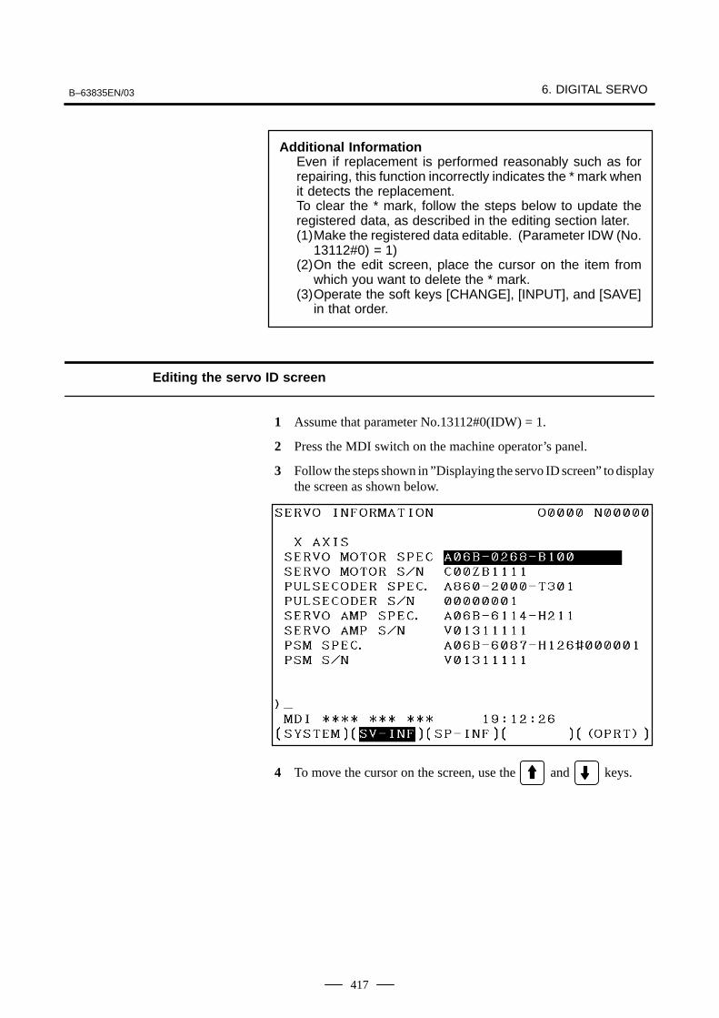
B–63835EN/03 6. DIGITAL SERVO
417
Additional InformationEven if replacement is performed reasonably such as forrepairing, this function incorrectly indicates the * mark whenit detects the replacement.To clear the * mark, follow the steps below to update theregistered data, as described in the editing section later.(1)Make the registered data editable. (Parameter IDW (No.
13112#0) = 1)(2)On the edit screen, place the cursor on the item from
which you want to delete the * mark.(3)Operate the soft keys [CHANGE], [INPUT], and [SAVE]
in that order.
Editing the servo ID screen
1 Assume that parameter No.13112#0(IDW) = 1.
2 Press the MDI switch on the machine operator’s panel.
3 Follow the steps shown in ”Displaying the servo ID screen” to displaythe screen as shown below.
4 To move the cursor on the screen, use the and keys.

6. DIGITAL SERVO B–63835EN/03
418
Screen operation
Mode Key operation Use
Viewing(*1)
Page key Scrolls up or down on a screen–by–screen basis.
Editing(*2)
Soft key[INPUT]
[CANCEL]
[CHANGE]
[SAVE]
[RELOAD]
Replace the selected ID information at the cursor posi-tion with the character string in key–in buffer.
Deletes the character string in key–in buffer.
Transfers the selected ID information at the cursor posi-tion that was sent by the servo, to key–in buffer. Onlythe items preceded by * (*3) are valid.
Saves the ID information that has been changed on theservo information screen in flash ROM.
Cancels the ID information that has been changed onthe servo information screen and loads ID informationfrom flash ROM.
Page key Scrolls up or down on a screen–by–screen basis.
Cursor key Scrolls up or down the selection of ID information.
*1 Viewing mode: when parameter No.13112#0 = 0
*2 Editing mode: when parameter No.13112#0 = 1
*3 Servo information is stored in flash ROM. If there is a differencebetween the servo information in flash ROM and the actual servoinformation, the corresponding items are preceded by *.
For axes that are not used by the αi servo system, ID information ofconnected units cannot be obtained.
Note

B–63835EN/03 6. AC SPINDLE (SERIAL INTERFACE)
419
7 AC SPINDLE (SERIAL INTERFACE)
This chapter outlines the serial interface and analog interface spindleamplifiers and explains related parameters.
7.1 AC SPINDLE (SERIAL INTERFACE) 420. . . . . . . . . . . 7.1.1 Outline of Spindle Control 420. . . . . . . . . . . . . . . . . . 7.1.2 Spindle Setting and Tuning Screen 423. . . . . . . . . . . . 7.1.3 Automatic Setting of Standard Parameters 431. . . . . . 7.1.4 Warning Interface for the αi Spindle 432. . . . . . . . . . . 7.1.5 αi Spindle Information Screen 434. . . . . . . . . . . . . . .
7.2 AC SPINDLE (ANALOG INTERFACE) 438. . . . . . . . . 7.2.1 Outline of Spindle Control 438. . . . . . . . . . . . . . . . . .

6. AC SPINDLE (SERIAL INTERFACE) B–63835EN/03
420
7.1AC SPINDLE (SERIALINTERFACE)
7.1.1Outline of SpindleControl
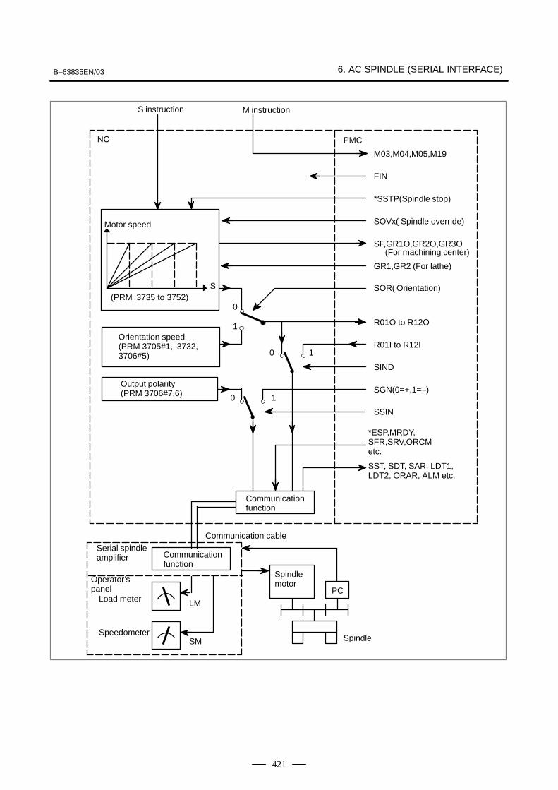
B–63835EN/03 6. AC SPINDLE (SERIAL INTERFACE)
421
S instruction
NC
Load meter
Orientation speed(PRM 3705#1, 3732,3706#5)
Serial spindleamplifier
Spindle
PMC
Communication cable
Spindle motor
LM
M03,M04,M05,M19
FIN
*SSTP(Spindle stop)
Motor speed SOVx( Spindle override)
SF,GR1O,GR2O,GR3O(For machining center)
GR1,GR2 (For lathe)
S SOR( Orientation)(PRM 3735 to 3752)
R01O to R12O
R01I to R12I1
SIND
Output polarity(PRM 3706#7,6) SGN(0=+,1=–)
1
SSIN
*ESP,MRDY,SFR,SRV,ORCMetc.
SST, SDT, SAR, LDT1,LDT2, ORAR, ALM etc.
Communicationfunction
PC
SM
M instruction
0
0
0
1
Operator’spanel
Speedometer
Communicationfunction

6. AC SPINDLE (SERIAL INTERFACE) B–63835EN/03
422
Motor speed
4095 Max
S code
Output
PRM 3735
PRM 3736
0
0 PRM 3741 PRM 3742 PRM 3743
Gear 1
Gear 2 Gear 3
(min–1)
Motor speed
4095 Max
S code
Output
PRM 3735
PRM 3736
0
Gear 1 Gear 2 Gear 3
0 PRM 3741 PRM 3742 PRM 3743
PRM 3752PRM 3751
(min–1)
Motor speed
4095 Max
S code
Output
Gear 1 Gear 2 Gear 3
Gear 4
00 PRM 3741 PRM 3742 PRM 3743 PRM 3744
7.1.1.1 Method A of gear changefor machining center
7.1.1.2 Method B of gear changefor machining center(PRM 3705#2=1)
7.1.1.3 T series
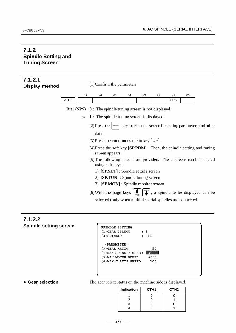
B–63835EN/03 6. AC SPINDLE (SERIAL INTERFACE)
423
(1)Confirm the parameters
#73111
#6 #5 #4 #3 #2 #1SPS
#0
Bit1 (SPS) 0 : The spindle tuning screen is not displayed.
� 1 : The spindle tuning screen is displayed.
(2)Press the SYSTEM key to select the screen for setting parameters and other
data.
(3)Press the continuous menu key .
(4)Press the soft key [SP.PRM]. Then, the spindle setting and tuningscreen appears.
(5)The following screens are provided. These screens can be selectedusing soft keys.
1) [SP.SET] : Spindle setting screen
2) [SP.TUN] : Spindle tuning screen
3) [SP.MON] : Spindle monitor screen
(6)With the page keys PAGE
PAGE
, a spindle to be displayed can be
selected (only when multiple serial spindles are connected).
SPINDLE SETTING(1)GEAR SELECT : 1(2)SPINDLE : S11
(PARAMETER)(3)GEAR RATIO 50(4)MAX SPINDLE SPEED 3000(5)MAX MOTOR SPEED 6000(6)MAX C AXIS SPEED 100
The gear select status on the machine side is displayed.
Indication CTH1 CTH2
1234
0011
0101
7.1.2Spindle Setting andTuning Screen
7.1.2.1 Display method
7.1.2.2 Spindle setting screen
� Gear selection
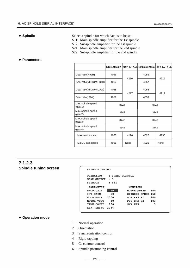
6. AC SPINDLE (SERIAL INTERFACE) B–63835EN/03
424
Select a spindle for which data is to be set.S11: Main spindle amplifier for the 1st spindle S12: Subspindle amplifier for the 1st spindle S21: Main spindle amplifier for the 2nd spindle S22: Subspindle amplifier for the 2nd spindle
4216 4216
4217 4217
S11:1st Main S12:1st Sub S21:2nd Main S22:2nd Sub
Gear ratio(HIGH) 4056 4056
Gear ratio(MIDIUM HIGH) 4057 4057
Gear ratio(MIDIUM LOW) 4058 4058
Gear ratio(LOW) 4059 4059
Max. spindle speed(gear1)
3741
3742 3742
3743 3743
3744 3744
Max. motor speed 4020 4196 4020 4196
Max. C axis speed 4021 None 4021 None
3741
Max. spindle speed(gear2)
Max. spindle speed(gear3)
Max. spindle speed(gear4)
OPERATION : SPEED CONTROLGEAR SELECT : 1SPINDLE : S11
(MONITOR)MOTOR SPEED 100SPINDLE SPEED 150POS ERR S1 100POS ERR S2 103SYN.ERR 3
SPINDLE TUNING
(PARAMETER)PROP.GAIN 20INT.GAIN 50LOOP GAIN 3000MOTOR VOLT 30TIME CONST 100REF. SHIFT 2046
1 : Normal operation
2 : Orientation
3 : Synchronization control
4 : Rigid tapping
5 : Cs contour control
6 : Spindle positioning control
� Spindle
� Parameters
7.1.2.3 Spindle tuning screen
� Operation mode
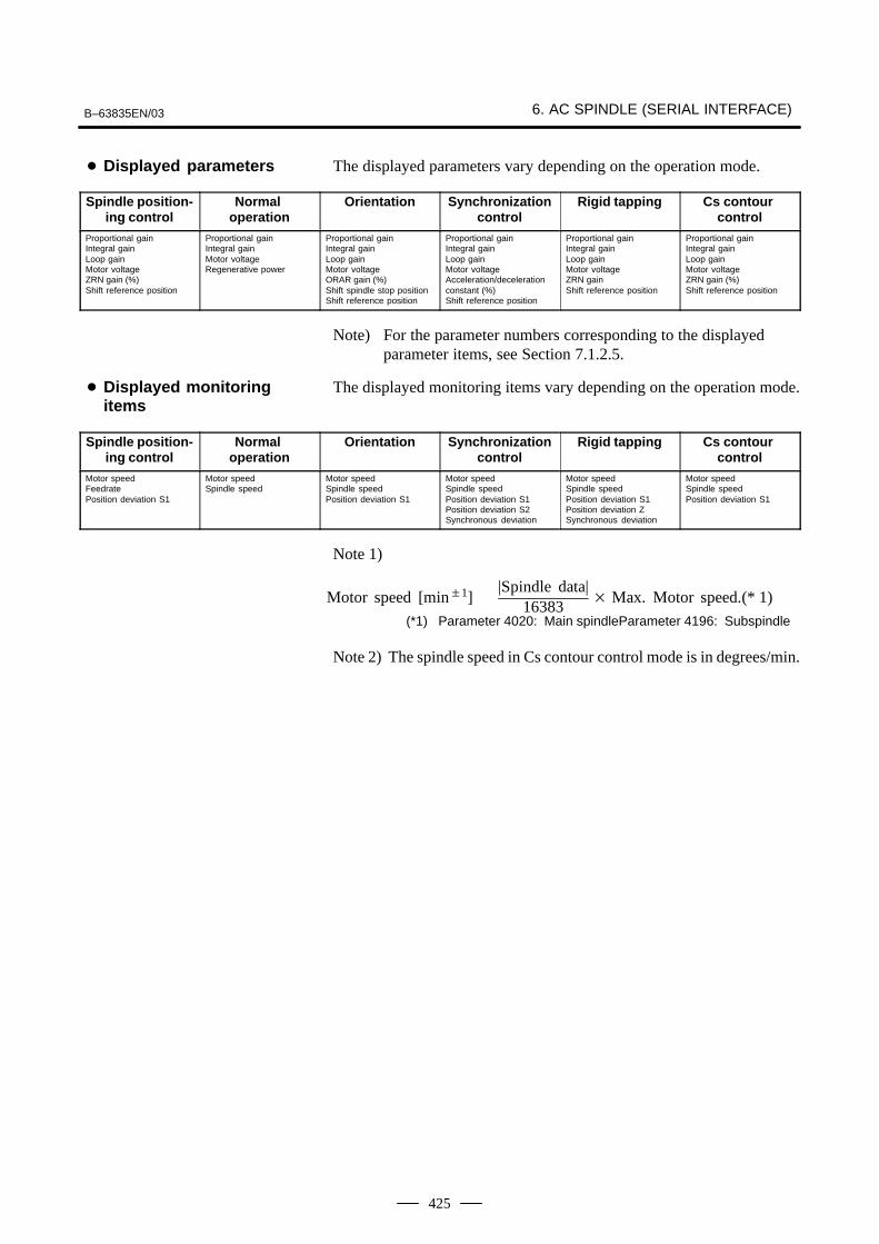
B–63835EN/03 6. AC SPINDLE (SERIAL INTERFACE)
425
The displayed parameters vary depending on the operation mode.
Spindle position-ing control
Normal operation
Orientation Synchronizationcontrol
Rigid tapping Cs contour control
Proportional gainIntegral gainLoop gainMotor voltageZRN gain (%)Shift reference position
Proportional gainIntegral gainMotor voltageRegenerative power
Proportional gainIntegral gainLoop gainMotor voltageORAR gain (%)Shift spindle stop positionShift reference position
Proportional gainIntegral gainLoop gainMotor voltageAcceleration/decelerationconstant (%)Shift reference position
Proportional gainIntegral gainLoop gainMotor voltageZRN gain Shift reference position
Proportional gainIntegral gainLoop gainMotor voltageZRN gain (%)Shift reference position
Note) For the parameter numbers corresponding to the displayed parameter items, see Section 7.1.2.5.
The displayed monitoring items vary depending on the operation mode.
Spindle position-ing control
Normal operation
Orientation Synchronizationcontrol
Rigid tapping Cs contour control
Motor speedFeedratePosition deviation S1
Motor speedSpindle speed
Motor speedSpindle speedPosition deviation S1
Motor speedSpindle speedPosition deviation S1Position deviation S2Synchronous deviation
Motor speedSpindle speedPosition deviation S1Position deviation ZSynchronous deviation
Motor speedSpindle speedPosition deviation S1
Note 1)
Motor speed [min�1] �|Spindle data|
16383� Max. Motor speed.(* 1)
(*1) Parameter 4020: Main spindleParameter 4196: Subspindle
Note 2) The spindle speed in Cs contour control mode is in degrees/min.
� Displayed parameters
� Displayed monitoringitems

6. AC SPINDLE (SERIAL INTERFACE) B–63835EN/03
426
SPINDLE MONITOR SCREEN ALARM : AL–27(POSITION CODER DIS.) OPERATION : Cs AXIS OONTROL SPINDLE SPEED : 100 DEG/MIN MOTOR SPEED : 150 RPM
LOAD METER (%)
CONTROL INPUT : ORCM MRDY *ESPCONTROL OUTPUT : SST SDT ORAR
0 50 100 150 200
�����
1: Motor overheated2: Speed deviation excessive3: Fuse blow of DC link4: Fuse blow of AC inputline5: Fuse blow of DC voltage7: Excessive speed9: Heat sink overheat10: Low voltage of AC input11: Excess voltage in DC link12: Excess current in DC link13: CPU internal data memory error18: ROM SUM check error19: U phase current offset excessive20: V phase current offset excessive24: Serial data transmission abnormal25: Serial data transmission stop26: Cs axis speed detecting signal failure27: Position coder signal disconnection28: Cs pos.detect signal disconnection29: Short time overload30: Input circuit excess current31: Speed detecting signal disconnection32: SLC LSI internal RAM abnormal33: DC link charging insufficient34: Parameter abnormal setting35: Gear ratio data excessive36: Error counter overflow37: Speed detecting unit error setting38: Magnetic sensor signal abnormal39: Alarm of one revolution signal for Cs axis control is detected40: Alarm of one revolution signal for Cs axis control is not detected41: Erroneous detection of the position coder one revolution signal42: Undetection of the position coder one revolution signal46: Erroneous detection of the position coder one revolution signal on threading47: Abnormal position coder signal48: Erroneous detection of position coder one revolution signal
7.1.2.4 Spindle monitor screen
� Spindle alarm

B–63835EN/03 6. AC SPINDLE (SERIAL INTERFACE)
427
Following 6 modes are available:
a. Normal operation
b. Orientation
c. Synchronous operation
d. Rigid tapping
e. Cs contour cotrol
f. Spindle positioning control
The load meter displays spindle load in a unit of 10%.
1) Load meter[%] � Load meter data32767
� Max.output value
(*) PRM 4127: Main PRM 4274: Sub.
of load meter (*)
Max.10 signals those are ON are displayed from the following signals:
TLML : Torque limit command (low)
TLMH : Torque limit command (high)
CTH1 : Gear signal 1
CTH2 : Gear signal 2
SRV : Spindle reverse rotation
SFR : Spindle forward rotation
ORCM : Spindle orientation
MEDY : Machine ready
ARST : Alarm reset signal
*ESP : Emergency stop
SPSL : Spindle selection signalMCFN : Power line switchingSOCN : Soft start/stop cancelRSL : Output switching requestRCH : Power line state confirmINDX : Orientation stop pos.
changeROTA : Rotation direction of
ORCMNRRO : Shor–cut of ORCMINTG : Speed integral control
signalDEFM : Referencial mode
command
Max. 10 signals those are ON are displayed from the following signals:
ALM : Alarm signalSST : Speed zero signalSDT : Speed detecting signalSAR : Speed arrival signalLDT1 : Load detecting signal 1LDT2 : Load detecting signal 2
TML5 : Torque limitationORAR : Orientation end signalCHP : Power line switched signalCFIN : Spindle switch completeRCHP : Output switch signalRCFN : Output switch complete
signal
� Operation
� Load meter
� Control input signal
� Control output signals

6. AC SPINDLE (SERIAL INTERFACE) B–63835EN/03
428
S11:1st Main
S12:1st Sub
S21:2nd Main
S22:2nd Sub
Proportional gain(HIGH) 4040 4206 4040 4206
Proportional gain (LOW) 4041 4207 4041 4207
Integral gain(HIGH) 4048 4048
Integral gain(LOW) 40494212
40494212
Motor voltage 4083 4236 4083 4236
Regenerative power 4080 4231 4080 4231
S11:1st Main
S12:1st Sub
S21:2nd Main
S22:2nd Sub
Proportional gain(HIGH) 4042 4208 4042 4208
Proportional gain (LOW) 4043 4209 4043 4209
Integral gain(HIGH) 4050 4050
Integral gain(LOW) 40514213
40514213
Loop gain (HIGH) 4060 4060
Loop gain (MID, HIGH) 40614218
40614218
Loop gain (MID, LOW) 4062 4062
Loop gain (LOW) 40634219
40634219
Motor voltage 4084 4237 4084 4237
Gain change upon completionof orientation
4064 4220 4064 4220
Stop position shift 4077 4228 4077 4228
PC–type orientation stop posi-tion
4031 4204 4031 4204
7.1.2.5 Correspondencebetween operation modeand parameters onspindle tuning screen
� Normal operation mode
� Orientation mode

B–63835EN/03 6. AC SPINDLE (SERIAL INTERFACE)
429
Numerals are parameter numbers :
S11:1st Main
S12:1st Sub
S21:2nd Main
S22:2nd Sub
Proportional gain(HIGH) 4044 4210 4044 4210
Proportional gain(LOW) 4045 4211 4045 4211
Integral gain(HIGH) 4052 4052
Integral gain(LOW) 40534214
40534214
Position loop gain(HIGH) 4065 4221 4065 4221
Position loop gain(MID,HIGH) 4066 4066
Position loop gain(MID,LOW) 4067 4222 4067 4222
Position loop gain(LOW) 4068 4068
Motor voltage 4085 4238 4085 4238
Acc./Dec. time constant 4032 4032
Shift amount 4034 4034
Numerals are parameter numbers :
S11:1st Main
S12:1st Sub
S21:2nd Main
S22:2nd Sub
Proportional gain(HIGH) 4044 4210 4044 4210
Proportional gain(LOW) 4045 4211 4045 4211
Integral gain(HIGH) 4052 4052
Integral gain(LOW) 40534214
40534214
Position loop gain(HIGH) 4065 4221 4065 4221
Position loop gain(MID,HIGH) 4066 4066
Position loop gain(MID,LOW) 4067 4222 4067 4222
Position loop gain(LOW) 4068 4068
Motor voltage 4085 4238 4085 4238
ZRN gain % 4091 4239 4091 4239
Grid shift amount 4073 4223 4073 4223
� Synchronization controlmode
� Rigid tapping mode

6. AC SPINDLE (SERIAL INTERFACE) B–63835EN/03
430
Numerals are parameter numbers :
S11:1st Main
S12:1st Sub
S21:2nd Main
S22:2nd Sub
Proportional gain(HIGH) 4046 4046
Proportional gain (LOW) 4047 4047
Integral gain(HIGH) 4054 4054
Integral gain(LOW) 4055 4055
Position loop gain(HIGH) 4069 4069
Position loop gain(MID,HIGH) 4070 4070
Position loop gain(MID,LOW) 4071 4071
Position loop gain(LOW) 4072 4072
Motor voltage 4086 4086
ZRN gain % 4092 4092
Reference position shift 4135 4135
S11:1st Main
S12:1st Sub
S21:2nd Main
S22:2nd Sub
Proportional gain(HIGH) 4044 4210 4044 4210
Proportional gain (LOW) 4045 4211 4045 4211
Integral gain(HIGH) 4052 4052
Integral gain(LOW) 40534214
40534214
Position loop gain(HIGH) 4065 4065
Position loop gain(MID,HIGH) 40664221
40664221
Position loop gain(MID,LOW) 4067 4067
Position loop gain(LOW) 40684222
40684222
Motor voltage 4085 4238 4085 4238
ZRN gain % 4091 4239 4091 4239
Reference position shift 4073 4223 4073 4223
� Spindle contouringcontrol mode (Cs axis control)
� Spindle positioningcontrol mode
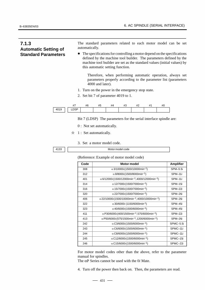
B–63835EN/03 6. AC SPINDLE (SERIAL INTERFACE)
431
The standard parameters related to each motor model can be setautomatically.
� The specifications for controlling a motor depend on the specificationsdefined by the machine tool builder. The parameters defined by themachine tool builder are set as the standard values (initial values) bythis automatic setting function.
Therefore, when performing automatic operation, always setparameters properly according to the parameter list (parameters4000 and later).
1. Turn on the power in the emergency stop state.
2. Set bit 7 of parameter 4019 to 1.
#7LDSP4019
#6 #5 #4 #3 #2 #1 #0
Bit 7 (LDSP) The parameters for the serial interface spindle are:
0 : Not set automatically.
� 1 : Set automatically.
3. Set a motor model code.
4133 Motor model code
(Reference: Example of motor model code)
Code Motor model Amplifier
308 � 3/10000i (1500/10000min–1) SPM–5.5i
312 � 8/8000i (1500/8000min–1) SPM–11i
401 � 6/12000i (1500/12000min–1, 4000/12000min–1) SPM–11i
314 � 12/7000i (1500/7000min–1) SPM–15i
316 � 15/7000i (1500/7000min–1) SPM–22i
320 � 22/7000i (1500/7000min–1) SPM–26i
406 � 22/10000i (1500/10000min–1, 4000/10000min–1) SPM–26i
322 � 30/6000i (1150/6000min–1) SPM–45i
323 � 40/6000i (1500/6000min–1) SPM–45i
411 � P30/6000i (400/1500min–1, 575/6000min–1) SPM–22i
413 � P50/6000i (575/1500min–1, 1200/6000min–1) SPM–26i
242 � C3/6000i (1500/6000min–1) SPMC–5.5i
243 � C6/6000i (1500/6000min–1) SPMC–11i
244 � C8/6000i (1500/6000min–1) SPMC–11i
245 � C12/6000i (1500/6000min–1) SPMC–15i
246 � C15/6000i (1500/6000min–1) SPMC–22i
For motor model codes other than the above, refer to the parametermanual for spindles.The αP Series cannot be used with the 0i Mate.
4. Turn off the power then back on. Then, the parameters are read.
7.1.3Automatic Setting ofStandard Parameters

6. AC SPINDLE (SERIAL INTERFACE) B–63835EN/03
432
For the αi spindle, the warning state can be reported before an alarm isissued. When the warning state is entered, a report to the PMC is sent.For example, this signal can be used for retracting tools or reducingcutting load from the time a warning occurs by the time an overheat alarmoccurs. In addition, diagnostic information also contains warningnumbers.
[Classification] Output
[Function] Reports the warning number corresponding to the state of the αi spindleamplifier.
[Output condition] When the αi spindle is in the warning state, a warning number consistingof SPWRN1 to SPWRN9 is output as nine–bit binary data.If warnings occurred on multiple αi spindle amplifiers, the warningnumber of the αi spindle having the smallest axis number is output.However, when there is no αi spindle or the system configuration of thespindle includes an additional spindle that is older than the αi spindle, thisfunction is invalid for all spindles.The warning numbers and their descriptions are shown below.
Warningnumber
Contents Details
56 Internal fanstopped
If the internal fan stops, the warning signal is output.Since the spindle continues to operate at this time,use the PMC to perform processing as needed.About one minute after the warning signal is output,an alarm occurs.
88 Radiator coolingfan stopped
If the radiator cooling fan stops, the warning signal isoutput. Since the spindle continues to operate at thistime, use the PMC to perform processing as needed.If the main circuit overheats, an alarm occurs.
04 Open–phase de-tected in the con-verter main pow-er supply
If an open–phase is detected in the main power sup-ply, the warning signal is output. Since the spindlecontinues to operate at this time, use the PMC to per-form processing as needed.About one minute (for the PSM) or about five se-conds (for the PSMR) after the warning signal is out-put, an alarm occurs.
7.1.4Warning Interface forthe αi Spindle
Overview
Signal
Spindle warning detailedsignalsSPWRN1 to 9<F264#0 to #7, F265#0>
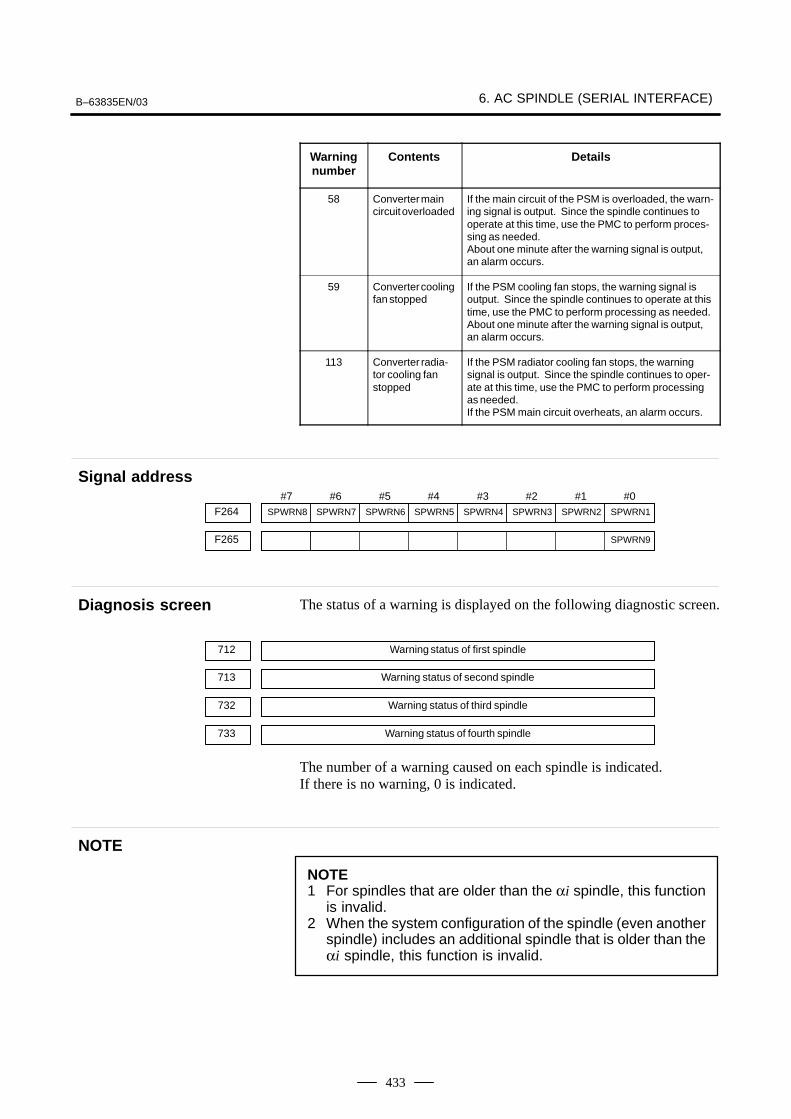
B–63835EN/03 6. AC SPINDLE (SERIAL INTERFACE)
433
Warningnumber
DetailsContents
58 Converter maincircuit overloaded
If the main circuit of the PSM is overloaded, the warn-ing signal is output. Since the spindle continues tooperate at this time, use the PMC to perform proces-sing as needed.About one minute after the warning signal is output,an alarm occurs.
59 Converter coolingfan stopped
If the PSM cooling fan stops, the warning signal isoutput. Since the spindle continues to operate at thistime, use the PMC to perform processing as needed.About one minute after the warning signal is output,an alarm occurs.
113 Converter radia-tor cooling fanstopped
If the PSM radiator cooling fan stops, the warningsignal is output. Since the spindle continues to oper-ate at this time, use the PMC to perform processingas needed.If the PSM main circuit overheats, an alarm occurs.
#7SPWRN8F264
#6SPWRN7
#5SPWRN6
#4SPWRN5
#3SPWRN4
#2SPWRN3
#1SPWRN2
#0SPWRN1
F265 SPWRN9
The status of a warning is displayed on the following diagnostic screen.
712 Warning status of first spindle
713 Warning status of second spindle
732 Warning status of third spindle
733 Warning status of fourth spindle
The number of a warning caused on each spindle is indicated.If there is no warning, 0 is indicated.
NOTE1 For spindles that are older than the αi spindle, this function
is invalid.2 When the system configuration of the spindle (even another
spindle) includes an additional spindle that is older than theαi spindle, this function is invalid.
Signal address
Diagnosis screen
NOTE
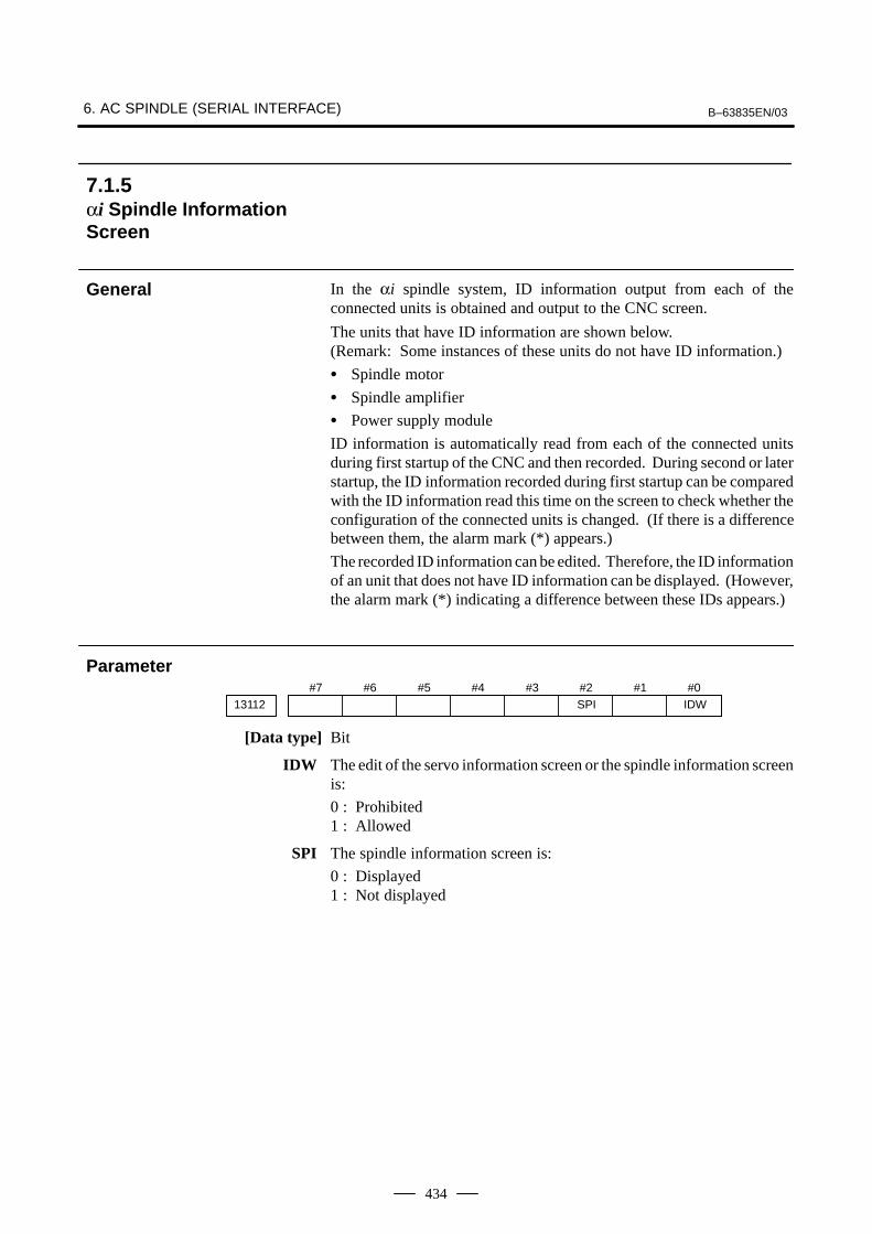
6. AC SPINDLE (SERIAL INTERFACE) B–63835EN/03
434
In the αi spindle system, ID information output from each of theconnected units is obtained and output to the CNC screen.
The units that have ID information are shown below.(Remark: Some instances of these units do not have ID information.)
� Spindle motor
� Spindle amplifier
� Power supply module
ID information is automatically read from each of the connected unitsduring first startup of the CNC and then recorded. During second or laterstartup, the ID information recorded during first startup can be comparedwith the ID information read this time on the screen to check whether theconfiguration of the connected units is changed. (If there is a differencebetween them, the alarm mark (*) appears.)
The recorded ID information can be edited. Therefore, the ID informationof an unit that does not have ID information can be displayed. (However,the alarm mark (*) indicating a difference between these IDs appears.)
#713112
#6 #5 #4 #3 #2SPI
#1 #0IDW
[Data type] Bit
IDW The edit of the servo information screen or the spindle information screenis:
0 : Prohibited1 : Allowed
SPI The spindle information screen is:
0 : Displayed1 : Not displayed
7.1.5αi Spindle InformationScreen
General
Parameter

B–63835EN/03 6. AC SPINDLE (SERIAL INTERFACE)
435
Displaying the spindle information screen
1 Press the SYSTEM function key, then press the [SYSTEM] soft key.
2 Press the [SP–INF] soft key to display the screen as shown below.
NOTESpindle information is stored in flash ROM. If there is adifference between the spindle information in flash ROMand the actual spindle information, the corresponding itemsare preceded by *, as shown below.

6. AC SPINDLE (SERIAL INTERFACE) B–63835EN/03
436
Additional InformationEven if replacement is performed reasonably such as forrepairing, this function incorrectly indicates the * mark whenit detects the replacement.To clear the * mark, follow the steps below to update theregistered data, as described in the editing section later.(1)Make the registered data editable. (Parameter IDW (No.
13112#0) = 1)(2)On the edit screen, place the cursor on the item from
which you want to delete the * mark.(3)Operate the soft keys [CHANGE], [INPUT], and [SAVE]
in that order.
Editing the spindle information screen
1 Assume that parameter No.13112#0(IDW) = 1.
2 Press the MDI switch on the machine operator’s panel.
3 Follow the steps shown in ”Displaying the spindle ID screen” todisplay the screen as shown below.
4 To move key–in buffer on the screen, use the and keys.

B–63835EN/03 6. AC SPINDLE (SERIAL INTERFACE)
437
Screen operation on the editing screen
Mode Key operation Use
Viewing(*1)
Page key Scrolls up or down on a screen–by–screen basis.
Editing(*2)
Soft key[INPUT]
[CANCEL]
[CHANGE]
[SAVE]
[RELOAD]
Replace the selected ID information at the cursor posi-tion with the character string in key–in buffer.
Deletes the character string in key–in buffer.
Transfers the selected ID information at the cursor posi-tion that was sent by the servo, to key–in buffer. Onlythe items preceded by * (*3) are valid.
Saves the ID information that has been changed on thespindle information screen in flash ROM.
Cancels the ID information that has been changed onthe spindle information screen and loads ID informationfrom flash ROM.
Page key Scrolls up or down on a screen–by–screen basis.
Cursor key Scrolls up or down the selection of ID information.
*1 Viewing mode: when parameter No.13112#0 = 0
*2 Editing mode: when parameter No.13112#0 = 1
*3 Spindle information is stored in flash ROM. If there is a differencebetween the spindle information in flash ROM and the actual spindleinformation, the corresponding items are preceded by *.
CAUTIONFor mixed connection of an αi spindle and a spindle thatdoes not belong to the αi spindle system, ID information ofconnected units for serial spindle including ai spindlescannot be obtained.

6. AC SPINDLE (SERIAL INTERFACE) B–63835EN/03
438
7.2AC SPINDLE(ANALOGINTERFACE)
7.2.1Outline of SpindleControl

B–63835EN/03 6. AC SPINDLE (SERIAL INTERFACE)
439
CW/CCW command,orientation, etc.
Motor speed
Spindle speedconversion
PMC
SAR, LDTSST, ORARSDT, ALM
NC
GR1, GR2
FIN
SVC
LM
GR1O, GR2O, GR3O
S
DV
RV
PC
SM
M03 to M05, M06, M19
*SSTP
*ESP, MRDYSFR, SRVORCM, TLM
S command M command
Gear 1 Gear 2
Maximum spindle speed and otherparameters
PRM 3714 to 3743, 3735, 3736,3751 and 3752 (M series)
PRM 3741 to 3744 (T series)
Position coder interface D/A converter
PRM 3730 (gain)PRM 3731 (offset)
Miscellaneous function end
Spindle stop
Gear selection (16M/18M)
Gear information (16T/18T)
Spindle amplifier
Spindlemotor
Spindle
I/O card or I/O unit
Operator’s panel
Load meter
Speed meter
7.2.1.1 Block diagram

6. AC SPINDLE (SERIAL INTERFACE) B–63835EN/03
440
[M series]
1 Gear change method A (bit 2 of parameter 3705 = 0)
SVC
(4095) 10VPRM 3736
Max
PRM 3735 0V
Motor speed
Gear 1 Gear 2 Gear 3
S code0 PRM 3741 PRM 3742 PRM 3743 (min–1)
2 Gear change method B (bit 2 of parameter 3705 = 1)
(4095) 10VPRM 3736
Max
PRM 3735 0V
PRM 3752
PRM 3751
SVC Motor speed
Gear 1 Gear 2 Gear 3
S code0 PRM 3741 PRM 3742 PRM 3743 (min–1)
[T series]
Constant surface speed control
(4095) 10V Max
0V
SVC Motor speed
Gear 1 Gear 2 Gear 3
S code0 PRM 3741 PRM 3742 PRM 3743 (min–1)
Gear 4
PRM 3744
7.2.1.2 Calculation of S analogvoltage and relatedparameters

B–63835EN/03 6. AC SPINDLE (SERIAL INTERFACE)
441
#7TCW3706
#6CWM
#5 #4 #3 #2 #1 #0
TCW CWM Sign of output voltage
0 0 Analog voltage (+) with both M03 and M04
0 1 Analog voltage (–) with both M03 and M04
1 0 (+) with M03, (–) with M04
1 1 (–) with M03, (+) with M04
[M series]
#73705
#6 #5 #4 #3 #2SGB
#1 #0
SGB Spindle speed set when gear change is performed is:
0 : Maximum speed for each gear.1 : Set by respective parameters. (Parameters 3751, 3752)
3741 Max. spindle speed of gear 1 (1 to 9999) [min–1]
3742 Max. spindle speed of gear 2 (1 to 9999) [min–1]
3743 Max. spindle speed of gear 3 (1 to 9999) [min–1]
3751 Spindle motor speed at the switch point between gear 1 and gear 2
3752 Spindle motor speed at the switch point between gear 2 and gear 3
[Data type] Word
[Valid data range] 0 to 4095
Set a spindle motor speed at each gear switch point when gear switchmethod B is used (when bit 2 (SGB) of parameter No. 3705 is set to 1).
Setting �Spindle motor speed at gear switch point
Maximum spindle motor speed� 4095
3736 Upper limit of the output to the spindle motor
3735 Lower limit of the output to the spindle motor
Setting �Spindle speed (upper limit�lower limit)
Max. spindle speed� 4095
[T series]
3741 Max. spindle speed of gear 1 (1 to 9999) [min–1]
3742 Max. spindle speed of gear 2 (1 to 9999) [min–1]
3743 Max. spindle speed of gear 3 (1 to 9999) [min–1]
3744 Max. spindle speed of gear 4 (1 to 9999) [min–1]

6. AC SPINDLE (SERIAL INTERFACE) B–63835EN/03
442
(1)For M series, change the upper and lower limits as follows:
⋅ When gear change method A is used: Parameter 3736 = 4095, parameter 3735 = 0
⋅ When gear change method B is used: Parameter 3751 = 4095, parameter 3735 = 0
� For T series, these changes are not required.
(2)Tuning the D/A converter offset
Specify zero as the spindle speed. Then, by using a digital multimeter,adjust the following parameter so that the voltage at the test pin DA2on the spindle amplifier printed circuit board is 0 mV.
1 For M series
S0; (Specify the command by MDI operation, then press the cycle start button.)
2 For T series (in case of G–code system A)
G97 S0; (Specify the command by MDI in the same manner as for M series.)
3731 Spindle speed (D/A converter) offset compensation value
(3)Tuning the D/A converter gain
Specify the maximum spindle speed of gear 1. Then, by using a digitalmultimeter, adjust the following parameter so that the voltage at thetest pin DA2 on the spindle amplifier printed circuit board is 10.0 V.
1 For M series
Sxxxx ; (xxxx is the value set in parameter 3741.)
(Specify the command by MDI operation, then press the cycle start button.)
3741 Max. spindle speed of gear 1 (1 to 9999) [min–1]
2 For T series (in case of G–code system A)
G97 Sxxxx ; (xxxx is the value set in parameter 3741.)(Specify the command by MDI operation, then press the cycle start button.)
3741 Max. spindle speed of gear 1 (1 to 9999) [min–1]
� Usually a voltage is output from the D/A converter by onlyexecuting an S command. However, the clockwise rotationcommand (M03) may be required on some machines.
7.2.1.3 Tuning S analog voltage(D/A converter)

B–63835EN/03 6. AC SPINDLE (SERIAL INTERFACE)
443
(4) If the output voltage is not correct, perform the following calculation,and change the value of parameter 3730 to adjust the gain of the D/Aconverter:
Setting �10V
Measured voltage� (Current value of PRM 3730)
(5)Execute an S command again and confirm that the output voltage iscorrect.
�Restore the original parameter values.

8. TROUBLESHOOTING B–63835EN/03
444
8 TROUBLESHOOTING
This chapter describes troubleshooting procedure.
8.1 CORRECTIVE ACTION FOR FAILURES 446. . . . . . 8.2 NO MANUAL OPERATION NOR AUTOMATIC
OPERATION CAN BE EXECUTED 448. . . . . . . . . . . 8.3 JOG OPERATION CANNOT BE DONE 452. . . . . . . . 8.4 HANDLE OPERATION CANNOT BE DONE 456. . . . 8.5 AUTOMATIC OPERATION CANNOT BE DONE 4618.6 CYCLE START LED SIGNAL HAS
TURNED OFF 469. . . . . . . . . . . . . . . . . . . . . . . . . . . . . 8.7 NOTHING IS DISPLAYED ON THE SCREEN
WHEN THE POWER IS TURNED ON 471. . . . . . . . . 8.8 THE DISPLAY ON THE LCD UNIT FLASHES 474. . 8.9 INPUT FROM AND OUTPUT TO I/O DEVICES
CANNOT BE PERFORMED INPUT/ OUTPUT CANNOT BE PERFORMED PROPERLY 475. . . . . . .
8.10 IN A CONNECTOR PANEL I/O UNIT, DATA IS INPUT TO AN UNEXPECTED ADDRESS (FOR Series 0i–B) 477. . . . . . . . . . . . . . . . . . . . . . . . . .
8.11 IN A CONNECTOR PANEL I/O UNIT, NO DATA IS OUTPUT TO AN EXPANSION UNIT (FOR Series 0i–B) 478. . . . . . . . . . . . . . . . . . . . . . . . . .
8.12 ALARM 85 TO 87 (READER/PUNCHER INTERFACE ALARM) 479. . . . . . . . . . . . . . . . . . . . . .
8.13 ALARM 90 (REFERENCE POSITION RETURN IS ABNORMAL) 483. . . . . . . . . . . . . . . . . .
8.14 ALARM 300 (REQUEST FOR REFERENCE POSITION RETURN) 485. . . . . . . . . . . . . . . . . . . . . . .
8.15 ALARM 401 (V READY OFF) 486. . . . . . . . . . . . . . . . 8.16 ALARM 404 (V READY ON) 488. . . . . . . . . . . . . . . . 8.17 ALARM 462 (SEND CNC DATA FAILED)
ALARM 463 (SEND SLAVE DATA FAILED) 490. . . . 8.18 ALARM 417 (DIGITAL SERVO SYSTEM IS
ABNORMAL) 491. . . . . . . . . . . . . . . . . . . . . . . . . . . . . 8.19 ALARM 700 (OVERHEAT: CONTROL UNIT) 492. . 8.20 ALARM 701 (OVERHEAT: FAN MOTOR) 493. . . . . 8.21 ALARM 704 (SPINDLE SPEED
FLUCTUATION DETECTION ALARM) 494. . . . . . . 8.22 ALARM 749 (SERIAL SPINDLE
COMMUNICATION ERROR) 495. . . . . . . . . . . . . . . . 8.23 ALARM 750 (SPINDLE SERIAL LINK
STARTUP FAILURE) 496. . . . . . . . . . . . . . . . . . . . . . .

B–63835EN/03 8.TROUBLESHOOTING
445
8.24 ALARM 5134 (FSSB: OPEN READY TIME OUT)ALARM 5135 (FSSB: ERROR MODE)ALARM 5137 (FSSB: CONFIGURATION ERROR)ALARM 5197 (FSSB: OPEN TIME OUT)ALARM 5198 (FSSB: ID DATA NOT READ) 498. . .
8.25 ALARM 5136 (FSSB: NUMBER OF AMPS IS SMALL) 500. . . . . . . . . . . . . . . . . . . . . . . . . . . . . . . .
8.26 ALARM 900 (ROM PARITY) 501. . . . . . . . . . . . . . . . . 8.27 ALARMS 912 TO 919 (DRAM PARITY) 502. . . . . . . 8.28 ALARM 920 (SERVO ALARMS) 503. . . . . . . . . . . . . 8.29 ALARM 926 (FSSB ALARM) 504. . . . . . . . . . . . . . . . 8.30 ALARM 930 (CPU INTERRUPT) 508. . . . . . . . . . . . . 8.31 ALARM 935 (SRAM ECC ERROR) 509. . . . . . . . . . . 8.32 ALARM 950 (PMC SYSTEM ALARM) 511. . . . . . . . . 8.33 ALARM 951 (PMC WATCHDOG ALARM) 514. . . . . 8.34 ALARM 972 (NMI ALARM ON AN OPTION
BOARD) (Series 0i–B ONLY) 515. . . . . . . . . . . . . . . . . 8.35 ALARM 973 (NMI ALARM WITH AN
UNKNOWN CAUSE) 516. . . . . . . . . . . . . . . . . . . . . . . 8.36 ALARM 974 (F–BUS ERROR) 517. . . . . . . . . . . . . . . 8.37 ALARM 975 (BUS ERROR) 518. . . . . . . . . . . . . . . . . . 8.38 ALARM 976 (LOCAL BUS ERROR) 519. . . . . . . . . . 8.39 SERVO ALARMS 520. . . . . . . . . . . . . . . . . . . . . . . . . . 8.40 SPC ALARMS 524. . . . . . . . . . . . . . . . . . . . . . . . . . . . . 8.41 SPINDLE ALARMS 525. . . . . . . . . . . . . . . . . . . . . . . .

8. TROUBLESHOOTING B–63835EN/03
446
When a failure occurs, it is important to correctly grasp what kind offailure occured and take appropriate action, to promptly recover themachine.Check for the failure according to the following procedure :
Recovery
With whatoperation?
What failure?
Appropriate action
When?
Grasp the kind of failure
↓
↓
(1) When and how many times (frequency of occurrences)(2) With what operation(3) What failure occurred
1 When did the failure occur?
⋅ Date and time?
⋅ Occurred during operation? (how long was the operation?)
⋅ Occurred when the power was turned on?
⋅ Was there any lightening surge, power failure, or other disturbancesto the power supply?
How many times has it occurred
⋅ Only once?
⋅ Occurred many times ? (How many times per hour, per day, or permonth?)
2 With what operation did it occur ?
⋅ What was the NC mode when the failure occurred?Jog mode/memory operation mode /MDI mode /reference positionreturn mode
⋅ If during program operation,
1) Where in the program ?2) Which program No. and sequence No. ?3) What program ?4) Occurred during axial movement ?5) Occurred during the execution of an M/S/T code ?6) Failure specific to the program ?
⋅ Does the same operation cause the same failure ?(Check the repeatability of the failure.)
⋅ Occurred during data input/output ?
<Feed axes and spindles>
⋅ For a failure related to feed axis servo
1) Occurred at both low feedrate and high feedrate ?2) Ocurred only for a certain axis ?
8.1CORRECTIVEACTION FORFAILURES
8.1.1Investigating theConditions Underwhich Failure Occurred

B–63835EN/03 8.TROUBLESHOOTING
447
⋅ For a failure related to spindlesWhen did the failure occur ? (during power–on, acceleration,deceleration, or constant rotation)
3 What failure occurred ?
⋅ Which alarm was displayed on the alarm display screen?(Check the axis along which an alarm has occurred for alarms 300to 599.)
⋅ Is the screen correct ?
⋅ If machining dimensions are incorrect
1) How large is the error ?
2) Is the position display on the CRT correct ?
3) Are the offsets correct ?
4 Other information
⋅ Is there noise origin around machine?If the failure has not occurred frequently, the cause may be externalnoise to the power supply or inductive noise on machinery cables.Operate other machines connected to the same power line and seeif noise come from the relays or compressors.
⋅ Is it taken any countermeasure for noise in machine side?
⋅ Check the following for the input power supply voltage :
1) Is there variation in the voltage ?
2) Are the voltages different depending on the phase ?
3) Is the standard voltage supplied ?
⋅ How high is the ambient temperature of the control unit?Refer to manual about noise.
⋅ Has excessive vibration been applied to the control unit?
5 When you contact our service center, specify the following items :
1) Name of the NC unit
2) Name of the machine tool builder and type of machine
3) Software series/version of the NC
4) Specifications of the servo amplifier and motor
(for a failure related to the servo)
5) Specifications of the spindle amplifier and spindle motor
(for a failure related to a spindle)
⋅ See the drawing issued by the machine tool builder for the locationsof the NC unit and servo/spindle amplifiers.
⋅ We use the following specification codes : Servo /spindle amplifier : A06B–����–H���
Servo/spindle amplifier : A06B–����–B���
NOTEThe mark ‘�’ represents a number.

8. TROUBLESHOOTING B–63835EN/03
448
(1)Execute the following procedure when no manual nor automaticoperation is done
(2)Check whether position display shows correct position
(3)Check CNC status display
(4)Check CNC internal status using diagnostic function
(1)Check CNC status display (Refer to Section 1.9 CNC STATUSDISPLAY for detail.)
(a) Emergency stop status (Emergency stop signal is turned on)
If status display shows EMG the emergency stop signal is input.
Check the following signal using the PMC’s diagnostic function(PMCDGN).
#7X1008
#6 #5 #4*ESP
#3 #2 #1 #0
G0008 *ESP
ESP=0 indicates that emergency stop signal is input.
(b) It is a reset status
When RESET is displayed, any of a reset is functioned. Check thefollowing signal using the PMC’s diagnostic funciton(PMCDGN).
1) An input signal from the PMC functions#7
ERSG0008#6
RRW#5 #4 #3 #2 #1 #0
When ERS is 1, external reset signal is input.When RRW is 1, reset & rewing signal is input.
2) RESET key on the MDI keyboard functions
When the signals in 1) are 0, RESET key may be functioning.
Check the contact of RESET key using a tester.
When it is abnormal, change the keyboard.
8.2NO MANUAL OPERA-TION NOR AUTOMAT-IC OPERATION CANBE EXECUTED
Points
Causes andCountermeasures
1. Position display(relative, absolute,machine coordinate)does not change

B–63835EN/03 8.TROUBLESHOOTING
449
(c) Confirm the status of modes
Operation mode status is displayed on the lower part of CRT asfollows :If nothing is displayed, mode select signal is not input. Check modeselect signal using PMC’s diagnostic function (PMCDGN).For details, refer to section 1.9 CNC STATUS DISPLAY.
(Example of display)
JOG : Manual operation (JOG) mode
HND : Manual handle (MPG) mode
MDI : Manual data input (MDI) mode
MEM : Automatic operation (Memory) mode
EDIT: EDIT (Memory edit) mode
<Mode select signal>#7
G0043#6 #5 #4 #3 #2
MD4#1
MD2#0
MD1
Manual operation (JOG) mode 1 0 1
Manual handle (MPG) mode 1 0 0
Manual data input (MDI) mode 0 0 0
Automatic operation (Memory) mode 0 0 1
EDIT (Memory edit) mode 0 1 1
↓ ↓ ↓
(2)Check diagnostic data 000 to 025 of the CNC Check an item for which1 is displayed
No. Message Display
000 WAITING FOR FIN SIGNAL : 0
001 MOTION : 0
002 DWELL : 0
a.003 IN–POSITION CHECK : 0
004 FEEDRATE OVERRIDE 0% : 0
b.005 INTERLOCK / START LOCK : 1 (Example)
006 SPINDLE SPEED ARRIVAL CHECK : 0
010 PUNCHING : 0
011 READING : 0
012 WAITING FOR (UN) CLAMP : 0
c.013 JOG FEEDRATE OVERRIDE 0% : 0
d.014 WAITING FOR RESET, ESP, RRW OFF : 0
015 EXTERNAL PROGRAM NUMBER SEARCH : 0
Items with a to d relate with manual and automatic operation and itsdetail is shown below.
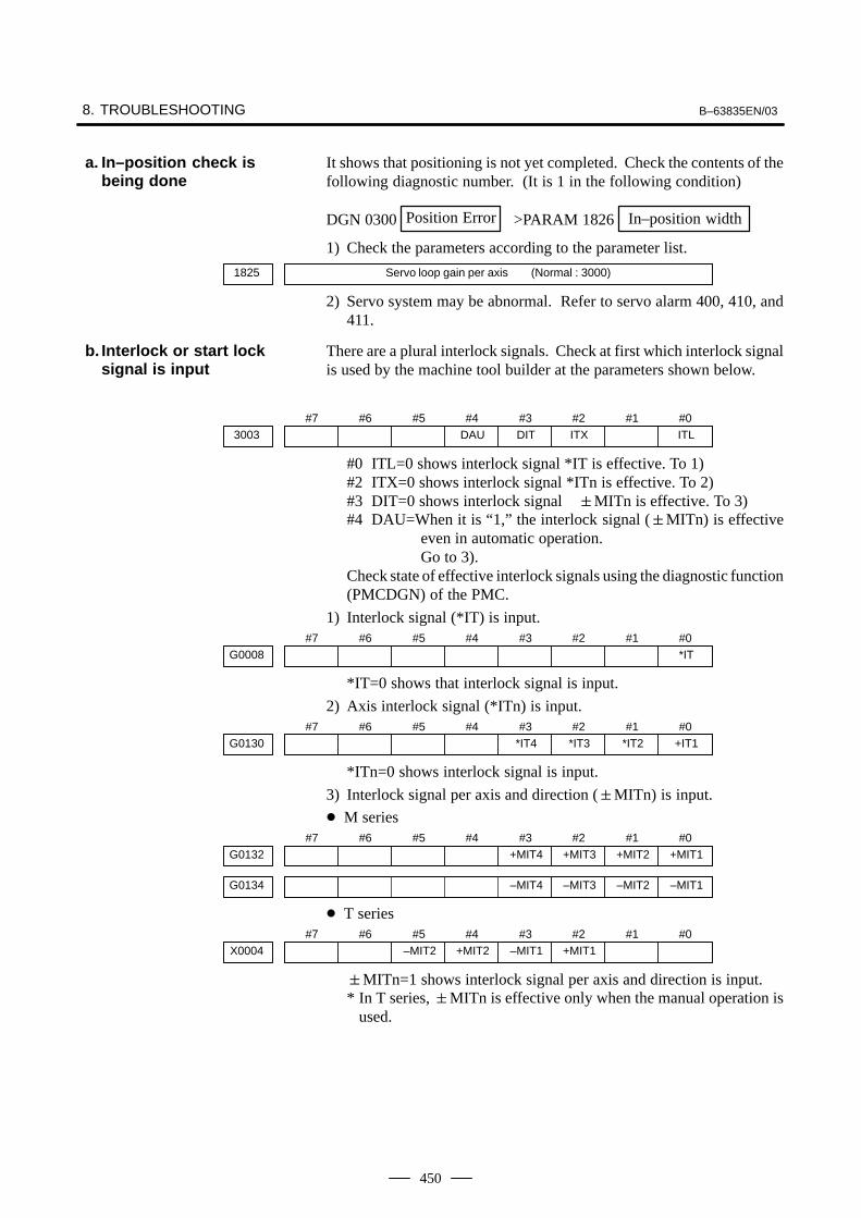
8. TROUBLESHOOTING B–63835EN/03
450
It shows that positioning is not yet completed. Check the contents of thefollowing diagnostic number. (It is 1 in the following condition)
DGN 0300 Position Error >PARAM 1826 In–position width
1) Check the parameters according to the parameter list.
1825 Servo loop gain per axis (Normal : 3000)
2) Servo system may be abnormal. Refer to servo alarm 400, 410, and411.
There are a plural interlock signals. Check at first which interlock signalis used by the machine tool builder at the parameters shown below.
#73003
#6 #5 #4DAU
#3DIT
#2ITX
#1 #0ITL
#0 ITL=0 shows interlock signal *IT is effective. To 1)#2 ITX=0 shows interlock signal *ITn is effective. To 2)#3 DIT=0 shows interlock signal �MITn is effective. To 3)#4 DAU=When it is “1,” the interlock signal (�MITn) is effective
even in automatic operation.Go to 3).
Check state of effective interlock signals using the diagnostic function(PMCDGN) of the PMC.
1) Interlock signal (*IT) is input.#7
G0008#6 #5 #4 #3 #2 #1 #0
*IT
*IT=0 shows that interlock signal is input.
2) Axis interlock signal (*ITn) is input.#7
G0130#6 #5 #4 #3
*IT4#2
*IT3#1
*IT2#0
+IT1
*ITn=0 shows interlock signal is input.
3) Interlock signal per axis and direction (�MITn) is input.
� M series#7
G0132#6 #5 #4 #3
+MIT4#2
+MIT3#1
+MIT2#0
+MIT1
G0134 –MIT4 –MIT3 –MIT2 –MIT1
� T series#7
X0004#6 #5
–MIT2#4
+MIT2#3
–MIT1#2
+MIT1#1 #0
�MITn=1 shows interlock signal per axis and direction is input.* In T series, �MITn is effective only when the manual operation is
used.
a. In–position check isbeing done
b. Interlock or start locksignal is input
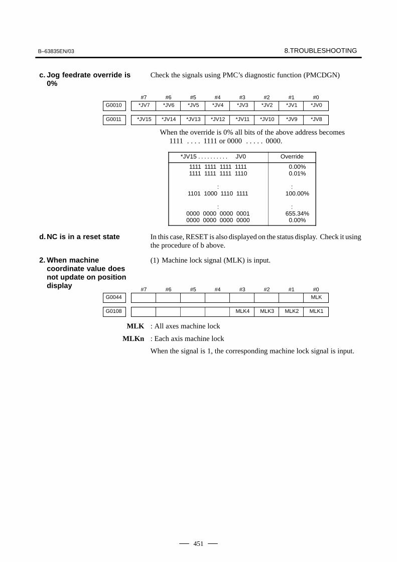
B–63835EN/03 8.TROUBLESHOOTING
451
Check the signals using PMC’s diagnostic function (PMCDGN)
#7*JV7G0010
#6*JV6
#5*JV5
#4*JV4
#3*JV3
#2*JV2
#1*JV1
#0*JV0
*JV15G0011 *JV14 *JV13 *JV12 *JV11 *JV10 *JV9 *JV8
When the override is 0% all bits of the above address becomes 1111 1111 or 0000 0000.. . . . . . . . .
*JV15 JV0. . . . . . . . . . Override
1111 1111 1111 11111111 1111 1111 1110
:1101 1000 1110 1111
:0000 0000 0000 00010000 0000 0000 0000
0.00%0.01%
:100.00%
:655.34%
0.00%
In this case, RESET is also displayed on the status display. Check it usingthe procedure of b above.
(1) Machine lock signal (MLK) is input.
#7G0044
#6 #5 #4 #3 #2 #1 #0MLK
G0108 MLK4 MLK3 MLK2 MLK1
MLK : All axes machine lock
MLKn : Each axis machine lock
When the signal is 1, the corresponding machine lock signal is input.
c. Jog feedrate override is0%
d.NC is in a reset state
2. When machinecoordinate value doesnot update on positiondisplay

8. TROUBLESHOOTING B–63835EN/03
452
(1)Check whether position display is operating.
(2)Check CNC status display.
(3)Check internal status using Diagnostic funciton.
(1)Check mode selection status (JOG mode is not selected).
When status display shows JOG, it is normal.When status display does not show JOG, mode select signal is notselected correctly. Confirm the mode select signal using PMC’sdiagnostic function (PMCDGN).
<Mode select signal>#7
G0043#6 #5 #4 #3 #2
MD4#1
MD2#0
MD1
Manual operation (JOG) mode 1 0 1
↓ ↓ ↓
(2)Feed axis and direction select signal is not input Check the signal usingPMC’s diagnostic function (PMCDGN).
#7G0100
#6 #5 #4 #3+J4
#2+J3
#1+J2
#0+J1
G0102 –J4 –J3 –J2 –J1
G0086 –Ja +Ja –Jg +Jg
When a bit is “1”, the corresponding feed axis directionselection signal has been entered.
�
g : Both X– and Y–axes simultaneously (feed along a straight line or circle)
a : Both X– and Y–axes simultaneously (feed in the normal direction)
J
� : Feed in the � direction
� : Feed in the � direction
Example)In the normal state, pressing the “+X” button on the operator’s panelcauses the signal +Jn to be displayed as “1”.
* This signal becomes effective when the rise of the signal isdetected. If, therefore, the direction selection signal has beenentered before jog mode selection, axis movement is notperformed; set the bit “0” and then re–check the signal.
8.3JOG OPERATIONCANNOT BE DONE
Points
Causes and Remedies
1. Position display(relative, absolute,machine cooordinate)does not change
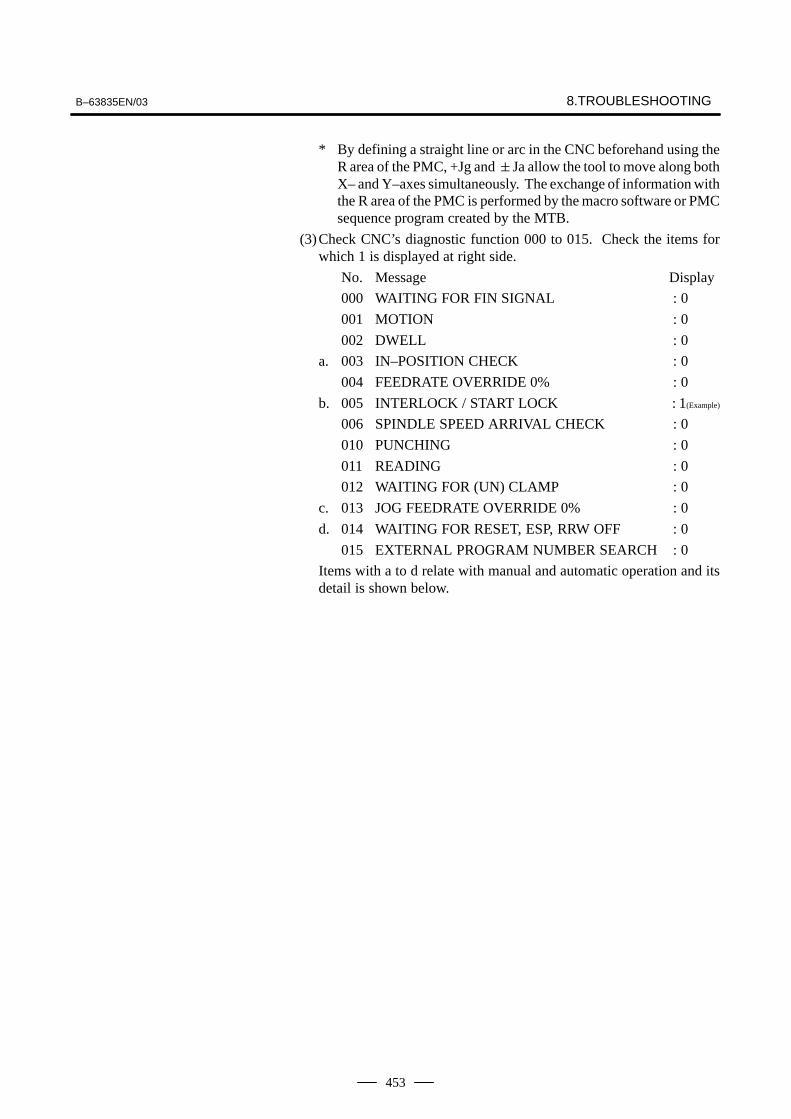
B–63835EN/03 8.TROUBLESHOOTING
453
* By defining a straight line or arc in the CNC beforehand using theR area of the PMC, +Jg and �Ja allow the tool to move along bothX– and Y–axes simultaneously. The exchange of information withthe R area of the PMC is performed by the macro software or PMCsequence program created by the MTB.
(3)Check CNC’s diagnostic function 000 to 015. Check the items forwhich 1 is displayed at right side.
No. Message Display
000 WAITING FOR FIN SIGNAL : 0
001 MOTION : 0
002 DWELL : 0
a. 003 IN–POSITION CHECK : 0
004 FEEDRATE OVERRIDE 0% : 0
b. 005 INTERLOCK / START LOCK : 1(Example)
006 SPINDLE SPEED ARRIVAL CHECK : 0
010 PUNCHING : 0
011 READING : 0
012 WAITING FOR (UN) CLAMP : 0
c. 013 JOG FEEDRATE OVERRIDE 0% : 0
d. 014 WAITING FOR RESET, ESP, RRW OFF : 0
015 EXTERNAL PROGRAM NUMBER SEARCH : 0
Items with a to d relate with manual and automatic operation and itsdetail is shown below.

8. TROUBLESHOOTING B–63835EN/03
454
It shows that positioning is not yet completed. Check the contents of thefollowing diagnostic number. (It is 1 in the following condition)
DGN 0300 Position Error >PARAM 1826 In–positio width
1) Check the parameters according to the parameter list.
1825 Servo loop gain per axis (Normal : 3000)
2) Servo system may be abnormal. Refer to servo alarm 400, 410, and411.
There are a plural interlock signals. Check at first which interlock signalis used by the machine tool builder at the parameters shown below.
#73003
#6 #5 #4 #3DIT
#2ITX
#1 #0ITLPARAM
#0 ITL=0 shows interlock signal *IT is effective. To 1)#2 ITX=0 shows interlock signal *ITn is effective. To 2)#3 DIT=0 shows interlock signal �MITn is effective. To 3)Check state of effective interlock signals using the diagnostic function(PMCDGN) of the PMC.
1) Interlock signal (*IT) is input.#7
G0008#6 #5 #4 #3 #2 #1 #0
*IT
*IT=0 shows that interlock signal is input.
2) Axis interlock signal (*ITn) is input.#7
G0130#6 #5 #4 #3
*IT4#2
*IT3#1
*IT2#0
+IT1
*ITn=0 shows interlock signal is input.
3) Interlock signal per axis and direction (+/– MITn) is input
⋅ M series#7
G0132#6 #5 #4 #3
+MIT4#2
+MIT3#1
+MIT2#0
+MIT1
G0134 –MIT4 –MIT3 –MIT2 –MIT1
⋅ T series#7
X0004#6 #5
–MIT2#4
+MIT2#3
–MIT1#2
+MIT1#1 #0
�MITn=1 shows interlock signal per axis and direction is input.
* For the T series, �MITn is valid only for manual operation.
a. In–position check isbeing done
b. Interlock or start locksignal is input
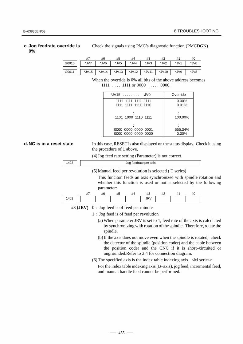
B–63835EN/03 8.TROUBLESHOOTING
455
Check the signals using PMC’s diagnostic function (PMCDGN)
#7*JV7G0010
#6*JV6
#5*JV5
#4*JV4
#3*JV3
#2*JV2
#1*JV1
#0*JV0
*JV15G0011 *JV14 *JV13 *JV12 *JV11 *JV10 *JV9 *JV8
When the override is 0% all bits of the above address becomes 1111 1111 or 0000 0000.. . . . . . . . .
*JV15 JV0. . . . . . . . . . Override
1111 1111 1111 11111111 1111 1111 1110
:1101 1000 1110 1111
:0000 0000 0000 00010000 0000 0000 0000
0.00%0.01%
:100.00%
:655.34%
0.00%
In this case, RESET is also displayed on the status display. Check it usingthe procedure of 1 above.
(4) Jog feed rate setting (Parameter) is not correct.
1423 Jog feedrate per axis
(5)Manual feed per revolution is selected ( T series)
This funciton feeds an axis synchronized with spindle rotation andwhether this function is used or not is selected by the followingparameter:
#71402
#6 #5 #4 #3JRV
#2 #1 #0
#3 (JRV) 0 : Jog feed is of feed per minute
1 : Jog feed is of feed per revolution
(a) When parameter JRV is set to 1, feed rate of the axis is calculatedby synchronizing with rotation of the spindle. Therefore, rotate thespindle.
(b) If the axis does not move even when the spindle is rotated, checkthe detector of the spindle (position coder) and the cable betweenthe position coder and the CNC if it is short–circuited orungrounded.Refer to 2.4 for connection diagram.
(6)The specified axis is the index table indexing axis. <M series>
For the index table indexing axis (B–axis), jog feed, incremental feed,and manual handle feed cannot be performed.
c. Jog feedrate override is0%
d.NC is in a reset state
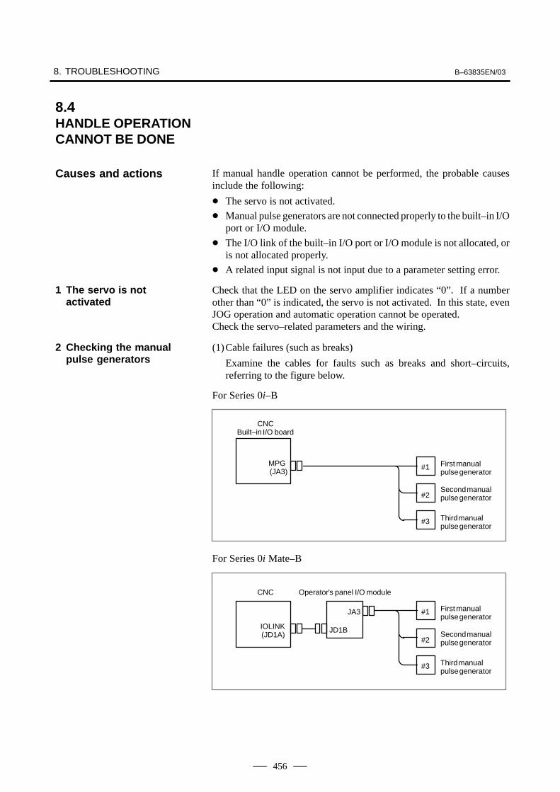
8. TROUBLESHOOTING B–63835EN/03
456
If manual handle operation cannot be performed, the probable causesinclude the following:
� The servo is not activated.
� Manual pulse generators are not connected properly to the built–in I/Oport or I/O module.
� The I/O link of the built–in I/O port or I/O module is not allocated, oris not allocated properly.
� A related input signal is not input due to a parameter setting error.
Check that the LED on the servo amplifier indicates “0”. If a numberother than “0” is indicated, the servo is not activated. In this state, evenJOG operation and automatic operation cannot be operated.Check the servo–related parameters and the wiring.
(1)Cable failures (such as breaks)
Examine the cables for faults such as breaks and short–circuits,referring to the figure below.
For Series 0i–B
#1
#2
#3
MPG(JA3)
CNCBuilt–in I/O board
First manualpulse generator
Second manualpulse generator
Third manualpulse generator
For Series 0i Mate–B
#1
#2
#3
JA3
IOLINK JD1B(JD1A)
CNC Operator’s panel I/O module
First manualpulse generator
Second manualpulse generator
Third manualpulse generator
8.4HANDLE OPERATIONCANNOT BE DONE
Causes and actions
1 The servo is notactivated
2 Checking the manualpulse generators
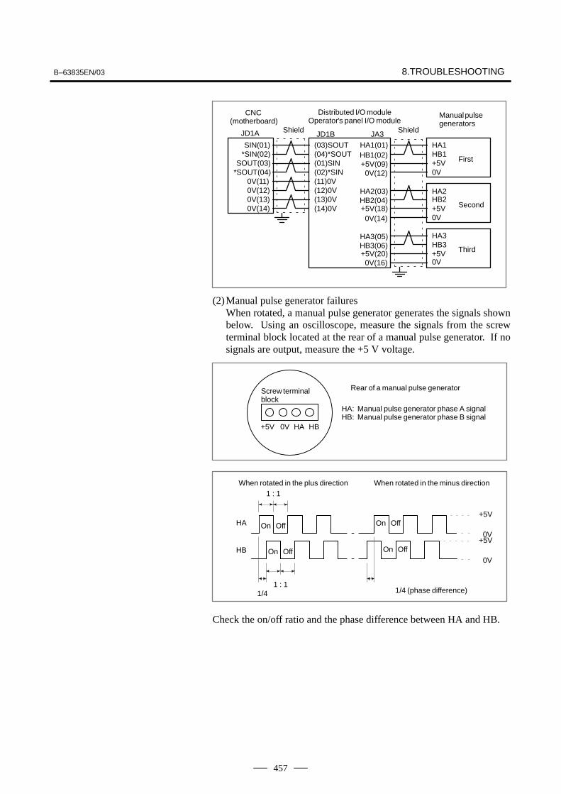
B–63835EN/03 8.TROUBLESHOOTING
457
JA3JD1BJD1A
SIN(01) (03)SOUT HA1HB1(02)HA1(01)
SOUT(03)*SIN(02) (04)*SOUT
(01)SINHB1
+5V(09)
0V(11)*SOUT(04) (02)*SIN 0V
+5V0V(12)
0V(12) HA2HA2(03)
0V(14)0V(13)
(11)0V
HB2HB2(04)
0V+5V
0V(14)+5V(18)
(12)0V
HA3HA3(05)HB3
+5V(20)HB3(06)
(14)0V(13)0V
0V+5V
0V(16)
Manual pulsegenerators
CNC(motherboard)
Shield Shield
Distributed I/O moduleOperator’s panel I/O module
First
Second
Third
(2)Manual pulse generator failuresWhen rotated, a manual pulse generator generates the signals shownbelow. Using an oscilloscope, measure the signals from the screwterminal block located at the rear of a manual pulse generator. If nosignals are output, measure the +5 V voltage.
+5V 0V HA HB
Screw terminalblock
Rear of a manual pulse generator
HA: Manual pulse generator phase A signalHB: Manual pulse generator phase B signal
+5V
0V+5V
0V
HA
HB
1/41 : 1
1 : 1When rotated in the plus direction When rotated in the minus direction
On Off
On Off
On Off
On Off
1/4 (phase difference)
Check the on/off ratio and the phase difference between HA and HB.
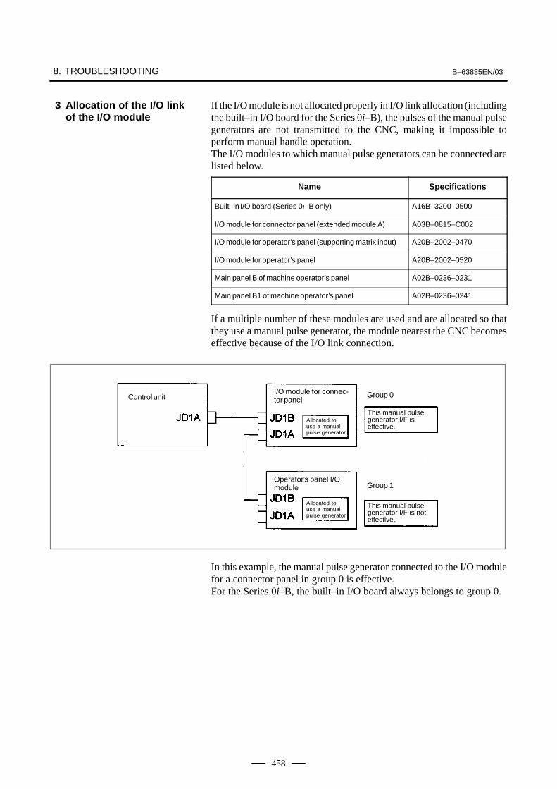
8. TROUBLESHOOTING B–63835EN/03
458
If the I/O module is not allocated properly in I/O link allocation (includingthe built–in I/O board for the Series 0i–B), the pulses of the manual pulsegenerators are not transmitted to the CNC, making it impossible toperform manual handle operation.The I/O modules to which manual pulse generators can be connected arelisted below.
Name Specifications
Built–in I/O board (Series 0i–B only) A16B–3200–0500
I/O module for connector panel (extended module A) A03B–0815–C002
I/O module for operator’s panel (supporting matrix input) A20B–2002–0470
I/O module for operator’s panel A20B–2002–0520
Main panel B of machine operator’s panel A02B–0236–0231
Main panel B1 of machine operator’s panel A02B–0236–0241
If a multiple number of these modules are used and are allocated so thatthey use a manual pulse generator, the module nearest the CNC becomeseffective because of the I/O link connection.
Control unitI/O module for connec-tor panel
Allocated touse a manualpulse generator
Allocated touse a manualpulse generator
Group 0
Group 1
This manual pulsegenerator I/F is effective.
This manual pulsegenerator I/F is noteffective.
Operator’s panel I/Omodule
In this example, the manual pulse generator connected to the I/O modulefor a connector panel in group 0 is effective.For the Series 0i–B, the built–in I/O board always belongs to group 0.
3 Allocation of the I/O linkof the I/O module

B–63835EN/03 8.TROUBLESHOOTING
459
Control unit I/O module for connec-tor panel
Allocated so as notto use a manualpulse generator
Allocated touse a manualpulse generator
Group 0
Group 1
This manual pulsegenerator I/F is effective.
This manual pulsegenerator I/F is noteffective.
Operator’s panel I/Omodule
If the I/O module for a connector panel in group 0 is allocated so as notto use a manual pulse generator, as in this example, the manual pulsegenerator interface of the operator’s panel I/O module in group 1 iseffective.The allocation can be confirmed on the allocation edit screen. Selecting[EDIT] and then [MODULE] from the PMC screen causes the allocationedit screen to be displayed.After editing allocation, write the changes to the FROM on the [I/O]screen. Otherwise, the changes will be lost when the power is turned off.If allocation is performed properly, when a manual pulse generator isrotated, the bits count up/down in the area of the corresponding inputsignal (X). Select [PMCDGN] and then [STATUS] from the PMC screento display the corresponding address, and rotate the manual pulsegenerator to check that the bits count up/down.
(1)Check CNC status display at lower left corner of the CRT. (See Section 1.9.)
When the status display shows HND, mode selection is correct.If it is not HND, mode select signal is not input correctly. Check themode select signal using the PMC’s diagnostic function(PMCDGN).
#7G0043
#6 #5 #4 #3 #2MD4
#1MD2
#0MD1
1 0 0
↓ ↓ ↓
Manuale handle mode
4 Checking the parametersand input signals

8. TROUBLESHOOTING B–63835EN/03
460
(2)Manual handle feed axis select signal is not input.
Check the signals using PMC’s diagnostic function (PMCDGN).#7
HS2DG0018#6
HS2C#5
HS2B#4
HS2A#3
HS1D#2
HS1C#1
HS1B#0
HS1A
G0019 HS3D HS3C HS3B HS3A
When axis select switch for manual handle feed is selected on themachine operator’s panel, if the signals are input as follows, it isnormal.
Selected axis HSnD HSnC HSnB HSnA
no selection1st axis2nd axis3rd axis4th axis
00000
00001
00110
01010
NOTEIn the above table, n is the number of the manual pulsegenerator(MPG) and up to 3 MPGs can be used.A feed axis is selected by 4–bit code of A to D.
(3)Manual handle feed multiplication is not correct
Check the following signals using PMC’s PCDGN. Also confirm thefollowing parameters based on the parameter list.
#7G0019
#6 #5MP2
#4MP1
#3 #2 #1 #0
In handle mode, the travel distance per step can be changed.
MP2 MP1 Step feed Handle feed
0011
0101
� 1� 10� 100�1000
� 1� 10� Mn� Nn
#77102
#6 #5 #4 #3 #2 #1 #0HNGxPARAM
#0(HNGx) The direction of rotation of the manual pulse generator and the directionof the travel of the machine are:
0 : Same1 : Opposite
7110 Number of manual pulse generators used (1 to 3).PARAM
(4)The specified axis is the index table indexing axis. <M series>
For the index table indexing axis (B–axis), jog feed, incremental feed,and manual handle feed cannot be performed.

B–63835EN/03 8.TROUBLESHOOTING
461
(1)Check manual operation is possible.
(2)Check the status of cycle start LED on machine operator’s manual.
(3)Check status of CNC.
When manual operation is either impossible, perform countermeasure,based on the previous item “Jog operation cannot be done”.Confirm that a correct mode is selected according to the mode select statusof CNC status display. Also, by confirming the automatic operationstatus it is possible to identify cycle operation, feed hold and cycle stopstate.
“****” is displayed at status display on CRT.
(1)Mode select signal is not correct.
When the mode select signal is input correctly, following statusdisplay is done.MDI :Manual data input mode (MDI)MEM :Memory operation modeRMT :Remote operation mode
If status display does not show a correct status, check the mode signalwith following diagnosis function of PMC side (PMCDGN).
#7G0043
#6 #5DNCI
#4 #3 #2MD4
#1MD2
#0MD1
DNCI MD4 MD2 MD1 Mode select
– 0 0 0 Manual data input mode
0 0 0 1 Memory operation mode
1 0 0 1 Remote operation mode
(2)Cycle start signal is not input
This signal turns 1 when cycle start button is pressed and turns 0 whenit is released. The cycle start actuates when it changes from 1 to 0.Check the state of the signal using PMC’s diagnosticfunction(PMCDGN).
#7G0007
#6 #5 #4 #3 #2ST
#1 #0
#2 (ST) : Cycle start signal
(3)Feed hold signal is input
Under normal state, the feed hold signal is 1 when the feed hold buttonis not pressed.Check the state of this signal using the PMC’s diagnostic function(PMCDGN) .
#7G0008
#6 #5*SP
#4 #3 #2 #1 #0
#5 (*SP) : Feed hold signal
8.5AUTOMATICOPERATION CANNOTBE DONE
Points
Causes and Remedies
1. When cycle operation isnot started (Cycle startLED does not light)

8. TROUBLESHOOTING B–63835EN/03
462
CNC’s status display shows “STRT” on the CRT.
(1)Check the contents of diagnostic nos. 000 to 015.
No. Message Display
a. 000 WAITING FOR FIN SIGNAL : 1(Example)
b. 001 MOTION : 0
c. 002 DWELL : 0
d. 003 IN–POSITION CHECK : 0
e. 004 FEEDRATE OVERRIDE 0% : 0
f. 005 INTERLOCK / START LOCK : 0
g. 006 SPINDLE SPEED ARRIVAL CHECK : 0
010 PUNCHING : 0
011 READING : 0
012 WAITING FOR (UN) CLAMP : 0
h. 013 JOG FEEDRATE OVERRIDE 0% : 0
i. 014 WAITING FOR RESET, ESP, RRW OFF : 0
015 EXTERNAL PROGRAM NUMBER SEARCH : 0
Items with a to i relate with an automatic operation and their detailsare as follows :
An auxiliary function (M/S/T/B) specified in a program is not ended.Check according to the following procedure.First, check the parameter setting to confirm the type of the interface ofthe auxiliary function.
#7HSIF3001
#6 #5 #4 #3 #2 #1 #0
#7(HSIF) 0 : M/S/T/B is of normal interface.
1 : M/S/T/B is of high–speed interface.
1) Normal interface
When the auxiliary function finish signal turns from 1 to 0, theauxiliary function is supposed to be ended and the next block is readfor operation. Confirm the status of this signal using PMC’sdiagnostic function(PMCDGN).
#7G0004
#6 #5 #4 #3FIN
#2 #1 #0
#3 (FIN) : Auxiliary function finish signal
2) High–speed interface
The auxiliary function is supposed to be ended when the signals arein the following state. Confirm it using PMC’s diagnostic function(PMCDGN).
2. When an automaticoperation is in progress(Cycle start LED is lit)
a. An auxiliary function isbeing executed (waitingfor FIN signal)

B–63835EN/03 8.TROUBLESHOOTING
463
<M series>#7
BFING0005#6 #5 #4 #3
TFIN#2
SFIN#1 #0
MFIN
#0(MFIN) : M function finish signal
#2(SFIN) : S function finish signal
#3(TFIN) : T function finish signal
#4(BFIN) : 2nd auxiliary function finish signal
#7BFF0007
#6 #5 #4 #3TF
#2SF
#1 #0MF
#0(MF) : M function strobe signal
#2(SF) : S function strobe signal
#3(TF) : T function strobe signal
#7(BF) : 2nd auxiliary function strobe signal
<T series>#7
G0005#6 #5 #4
BFIN#3
TFIN#2
SFIN#1 #0
MFIN
#0(MFIN) : M function completion signal
#2(SFIN) : S function completion signal
#3(TFIN) : T function completion signal
#4(BFIN) : Second auxiliary function completion signal
#7F0007
#6 #5 #4BF
#3TF
#2SF
#1 #0MF
#0(MF) : M function strobe signal
#2(SF) : S function strobe signal
#3(TF) : T function strobe signal
#4(BF) : Second auxiliary function strobe signal
<M/T series>#7
G0004#6 #5
MFIN3#4
MFIN2#3 #2 #1 #0
#4(MFIN2) : Second M function completion signal
#5(MFIN3) : Third M function completion signal
#7F0008
#6 #5MF3
#4MF2
#3 #2 #1 #0
#4(MF2) : Second M function strobe signal
#5(MF3) : Third M function strobe signal
* The second and third M functions are enabled only when bit 7 (M3B)of parameter No. 3404 is set to 1.

8. TROUBLESHOOTING B–63835EN/03
464
Signal End state
Finish signal 0 1
store signal 0 1
CNC is reading an axis command (X,Y,Z,...) in a program and giving thecommand to the axis.
CNC is reading a dwell command (G04) in a program and is executingthe dwell command.
Positioning (G00) to a specified position of a specified axis is notcompleted.Whether positioning is completed or not is checked as the servo positionerror amount. Check it CNC’s diagnostic function as follows:
DGN no.300 Position Error > PARAM 1826 In–position width
Position error amount almost becomes 0, when positioning of an axiscompletes and when the amount becomes within the in–posiiton width,it is assumed that positioning completes and the next block is exected.If position error amount does not become within the in–position width,refer to servo alarm 400, 4n0 and 4n1.
Actual feedrate is overridden by the override signals to a programmedfeedrate. Check the override signals using the PMC’s diagnostic function(PMCDGN).
<Normal override signal>#7
*FV7G0012#6
*FV6#5
*FV5#4
*FV4#3
*FV3#2
*FV2#1
*FV1#0
*FV0
*FVn :Feedrate override
<2nd override signal (option)>Feed rate is overridden more finely using the signals below:See MTB’s manual whether this feature is equipped.
#7*AFV7G0013
#6*AFV6
#5*AFV5
#4*AFV4
#3*AFV3
#2*AFV2
#1*AFV1
#0*AFV0
*AFVn :2nd feed rate override
<State of override signal>
*FV7�������*FV0
1 1 1 1 1 1 1 11 1 1 1 1 1 1 0
:1 0 0 1 1 0 1 1
:0 0 0 0 0 0 0 10 0 0 0 0 0 0 0
0%1%
:100%
:254%
0%
*AFV7������*AFV0
1 1 1 1 1 1 1 11 1 1 1 1 1 1 0
:1 0 0 1 1 0 1 1
:0 0 0 0 0 0 0 10 0 0 0 0 0 0 0
0%1%
:100%
:254%
0%
b.Travel command is beingexecuted
c. A dwell command isbeing executed
d. In–position check(confirming positioning)is being done
e. Feedrate override is at0%

B–63835EN/03 8.TROUBLESHOOTING
465
<T series only>
Start lock signal is input#7
G0007#6 #5 #4 #3 #2 #1
STLK#0
#1 (STLK) With this signal being 1, start lock signal is input.
<Common to T series and M series>There are a plural number of interlock functions. Parameters are set bymachine tool builders for which interlock function is used.Therefore, confirm the following parameters at first:
#73003
#6 #5 #4DAU
#3DIT
#2ITX
#1 #0ITL
#0 (ITL) 0 : Interlock signal(*IT) is valid.#2 (ITX) 0 : Interlock signal (*ITn) is valid.#3 (DIT) 0 : Interlock signal (�MITn) is valid.#4 (DAU) 1 : Interlock signal (�MITn) is valid in both manual operation and
automatic operation.
Confirm which interlock signal is activated by the PMC’s diagnosticfunction (PMCDGN) .
1) Interlock signal (*IT) is input#7
G0008#6 #5 #4 #3 #2 #1 #0
*IT
#0 (*IT) : When this bit is 0, interlock signal is input.
2) Interlock signal per each axis (*ITn) is input#7
G0130#6 #5 #4 #3
*IT4#2
*IT3#1
*IT2#0*IT1
*ITn When the bit is 0, the corresponding axis’s interlock signal is input.
3) Interlock signal per axis and direction(�MITn) is input
⋅ M series#7
G0132#6 #5 #4 #3
+MIT4#2
+MIT3#1
+MIT2#0
+MIT1
G0134 –MIT4 –MIT3 –MIT2 –MIT1
⋅ T series#7
X0004#6 #5
–MIT2#4
+MIT2#3
–MIT1#2
+MIT1#1 #0
�MITn=1 shows interlock signal per axis and direction is input.
* For the T series, �MITn is valid only for manual operation.
4) Controlled axis detach function is running. A detached axis isspecified for travelling.
*This function is valid when CNC parameter No.1005#7=1. Forwhether this function is running or not, confirm the following signalusing PMC’s diagnostic function (PMCDGN). Check the axisconcerned.
f. Interlock signal or startlock signal is input
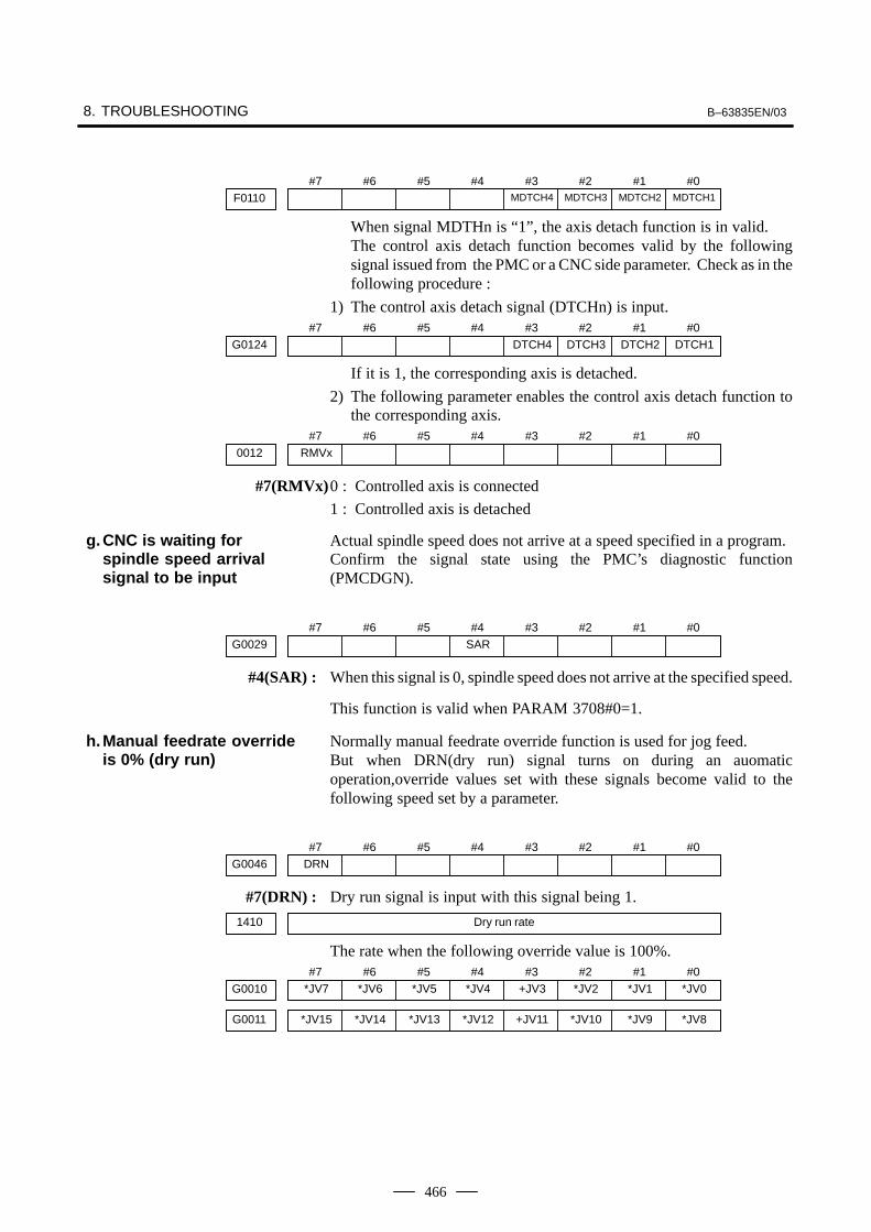
8. TROUBLESHOOTING B–63835EN/03
466
#7F0110
#6 #5 #4 #3MDTCH4
#2MDTCH3
#1MDTCH2
#0MDTCH1
When signal MDTHn is “1”, the axis detach function is in valid.The control axis detach function becomes valid by the followingsignal issued from the PMC or a CNC side parameter. Check as in thefollowing procedure :
1) The control axis detach signal (DTCHn) is input.#7
G0124#6 #5 #4 #3
DTCH4#2
DTCH3#1
DTCH2#0
DTCH1
If it is 1, the corresponding axis is detached.
2) The following parameter enables the control axis detach function tothe corresponding axis.
#7RMVx0012
#6 #5 #4 #3 #2 #1 #0
#7(RMVx)0 : Controlled axis is connected
1 : Controlled axis is detached
Actual spindle speed does not arrive at a speed specified in a program.Confirm the signal state using the PMC’s diagnostic function(PMCDGN).
#7G0029
#6 #5 #4SAR
#3 #2 #1 #0
#4(SAR) : When this signal is 0, spindle speed does not arrive at the specified speed.
This function is valid when PARAM 3708#0=1.
Normally manual feedrate override function is used for jog feed.But when DRN(dry run) signal turns on during an auomaticoperation,override values set with these signals become valid to thefollowing speed set by a parameter.
#7DRNG0046
#6 #5 #4 #3 #2 #1 #0
#7(DRN) : Dry run signal is input with this signal being 1.
1410 Dry run rate
The rate when the following override value is 100%.#7
*JV7G0010#6
*JV6#5
*JV5#4
*JV4#3
+JV3#2
*JV2#1
*JV1#0
*JV0
*JV15G0011 *JV14 *JV13 *JV12 +JV11 *JV10 *JV9 *JV8
g.CNC is waiting forspindle speed arrivalsignal to be input
h.Manual feedrate overrideis 0% (dry run)

B–63835EN/03 8.TROUBLESHOOTING
467
When override value is 0%, all bits of the above address is[1111 1111] or [0000 0000].. . . . . .
*JV15 JV0. . . . . . . . . . . . . . Override
1111 1111 1111 11111111 1111 1111 1110
1101 1000 1110 1111
0000 0000 0000 00010000 0000 0000 0000
0.00%0.01%
:100.00%
:655.34%
0.00%
In this case, the CNC’s status display shows RESET. Refer to item 1.
(2)Only rapid traverse in positioning (G00) does not function Confirmthe following parameter and signals from the PMC.
(a) Setting value of rapid traverse rate
1420 Rapid traverse rate per axis
(b)Rapid traverse override signals#7
G0014#6 #5 #4 #3 #2 #1
ROV2#0
ROV1
HROVG0096 *HROV6 *HROV5 *HROV4 *HROV3 *HROV2 *HROV1 *HROV0
(HROV–0) (HROV=1)
ROV1 ROV2 Override
0 01 10 11 1
100%50%25%
Fo
*HROV6 *HROV0 Override
1 1 1 1 1 1 11 1 1 1 1 1 0
:0 0 1 1 0 1 1
0%1%
:100%
1421 Rapid traverse override F0 rate
(3)Only feed (other than G00) does not function
(a) Maximum feedrate set by parameter is incorrect.
1422 Maximum feedrate
Feedrate is clamped at this upper feedrate.
(b)Feedrate is specified by feed per revolution (mm/rev)
1) Position coder does not rotate
Check the connection between spindle and position coderThe following failure is considered:
⋅ T iming belt is broken
⋅ Key is removed
⋅ Coupling is loose
⋅ Connector of signal cable is loosened
2) Position coder is faulty
i. NC is in a reset state

8. TROUBLESHOOTING B–63835EN/03
468
(c) Thread cutting does not operate
1) Position coder does not rotate
Check the connection between spindle and position coderThe following failure is considered:
⋅ Timing belt is broken
⋅ Key is removed
⋅ Coupling is loose
⋅ Connector of signal cable is loosened
2) Position coder is faulty
Position coder is connected to the spindle amplifier when serialinterface spindle is used or connected to the CNC when analoginterface spindle is used.For details of connection, refer to the following.
<T series>Whether A/B phase signals from the position coder are readcorrectly, can be judged also by the spindle speed display on theCRT screen (position screen). (However, it is not displayedwhen PARAM 3105#2=0).
<αi series spindle amplifier>
CNC
JA41SPM
Spindlemotor
Positioncoder
JA7A
JA7B
SPMJA7A
JA7B
JYA3
Spindlemotor
Positioncoder
JYA3
<Analog interface spindle amplifier>
Spindlemotor
Positioncoder
CNC
JA41
Analog spindleamplifierJA40
(d)A cutting feed block containing a feedrate command (F command)with a feedrate of 0 is specified.If FCO (bit 7 of parameter No. 1404) is set to 1, P/S alarm 11 is notissued even if a feedrate command (F command) with a feedrate of0 is issued.

B–63835EN/03 8.TROUBLESHOOTING
469
(1)After cycle operation is started, then stopped, check as follows:
(2)Confirm cycle start LED on machine operator’s panel.
(3)Confirm CNC’s diagnostic function.
The reason why cycle start LED signal (STL) has turned off are displayedon CNC’s diagnostic numbers 020 to 025 as follows:
020 CUT SPEED UP/DOWN 1 0 0 0 1 0 0
021 RESET BUTTON ON 0 0 1 0 0 0 0
022 RESET AND REWIND ON 0 0 0 1 0 0 0
023 EMERGENCY STOP ON 1 0 0 0 0 0 0
024 RESET ON 1 1 1 1 0 0 0
025 STOP MOTION OR DWELL 1 1 1 1 1 1 0
a. Emergency stop signal
b. External reset signal
c. Reset button on MDI
d. Reset & rewind signal
e. Servo alarm
f. Feed hold by switching mode
g. Single block stop
Details of signals a to g are as follows:Confirm the signals concerned using diagnostic function (PMCDGN).
#7X1008
#6 #5 #4*ESP
#3 #2 #1 #0
#7G0008
#6 #5 #4*ESP
#3 #2 #1 #0
*ESP=0 : Emergency stop signal is input :
8.6CYCLE START LEDSIGNAL HASTURNED OFF
Points
Causes and Remedies
a. Emergency stop is input

8. TROUBLESHOOTING B–63835EN/03
470
#7G0008
#6 #5 #4ERS
#3 #2 #1 #0
#7(ERS) : When the bit is 1, external reset signal is input.
This signal is usually used for a confirmation signal of M02 when an M02is specified in a program as the end of a program.Therefore, when M02 is executed, this signal is input.
An automatic operation is put into a reset status when RESET key on theMDI panel is pressed.
#7G0008
#6RRW
#5 #4 #3 #2 #1 #0
#6(RRW) : When this signal is 1, the reset & rewind signal is input.
This signal is usually used for a confirmation signal of M30 when an M30is specified in a program as the end of a program.Therefore, when M30 is executed, this signal is input.
When any servo alarm has generated, cycle operation is put into the resetstate and operation stop.
The cycle operation becomes feed hold state in the following cases:
1) Modes are switched from an automatic operation mode to a manualoperation mode.
2) Feed hold signal is input.
<Mode select signal>#7
G0043#6 #5 #4 #3 #2
MD4#1
MD2#0
MD1
memory edit(EDIT) 0 1 1
Automaticoperation
Automatic operation(AUTO)
0 0 1
Manual data input (MDI) 0 0 0
Jog feed (JOG) 1 0 0Manual Handle/step 1 0 1
operationTEACH IN HANDLE 1 1 1
TEACH IN JOG 1 1 0
<Feed hold signal>#7
G0008#6 #5
*SP#4 #3 #2 #1 #0
#5(*SP) : When this signal is 0, the feed hold signal is input.
#7G0046
#6 #5 #4 #3 #2 #1SBK
#0
#1(SBK) When this signal is 1, the single block signal is input.
b.External reset signal isinput
c. Reset button on the MDIis pressed
d.Reset & rewind signal isinput
e. Servo alarm hasgenerated
f. Cycle operation is in afeed hold state
g. It become single blockstop during automaticoperation

B–63835EN/03 8.TROUBLESHOOTING
471
If nothing is displayed on the screen at power–up or if the LCD is lockedwith “GRAPHIC IS READY.” or the slot status screen displayed, theprobable causes include the following:
� The display unit is not connected to the power supply.
� The CRT video cable, LCD optical cable, or backlight cable is notconnected.
� The LCD unit is not connected to the CNC with the optical cable orthe cable is broken.
� The necessary software is not installed.
� The main CPU board, display control card, or LCD unit printed circuitboard is defective.
� The CRT unit or LCD unit backlight is defective.
If “GRAPHIC IS READY.BOOT START”. is displayed, this indicatesthat the display control circuit has started up normally but that the CNChas not started up.
Make sure the power cable is connected to connector CN2 for the CRTunit or to connector CPIA for the LCD unit. The power voltage is 24V.
Connector for connecting the backlight cable
Inverter printedcircuit board
Connector forconnecting theLCD cable
LCD control printedcircuit board
Optical cableCOP20B
24 V inputCP1A
For 24 V branchCP1B
8.7NOTHING ISDISPLAYED ON THESCREEN WHEN THEPOWER IS TURNEDON
Causes and actions
� Power supply of thedisplay unit

8. TROUBLESHOOTING B–63835EN/03
472
Referring to the hardware chapter, check the LED on/off status of the mainCPU board.If the main CPU board has started up normally and the LED displayindicates normal operation, a probable cause is a fault of the displaysystem, such as the cable of the LCD unit not connected or a defectiveinverter board.If the LED display is locked in the middle of the startup process, theprobable causes include defective hardware (or installation failure) andthe necessary software not installed.
Check that the connection cable (video cable for CRT or optical cable forLCD) is free from excessive force and that it is not excessively bent.Check that the connection cable is connected firmly.If no problems are found with the connection of the connection cable,replace the connection cable.
Check that the backlight and LCD cables are connected firmly to thecorresponding connectors.These cables are connected before shipment from FANUC. This checkis, however, required because the cables may be disconnected duringmaintenance.
Check that the display control card installed on the main CPU board isengaged with the connector. If it is engaged properly, replace this card.
Replace the LCD unit or the control printed circuit board located at therear of the LCD unit.
For the LCD unit, make sure the backlight is turned on. If it is not turnedon, replace it with a new one. See Section 2.14 for details.
If any of the above actions does not solve the problem, replace the mainCPU board and the CPU card.
� LED display
� Connection cable
� Connection on the LCDunit
� Display control card
� LCD unit
� Backlight
� Main CPU board

B–63835EN/03 8.TROUBLESHOOTING
473
CPU card
Display controlcard
� Installation positions ofthe display control cardand the CPU card

8. TROUBLESHOOTING B–63835EN/03
474
If a break is detected in the optical cable (HSSB) that connects the LCDunit to the main CPU board, the display on the LCD unit flashes.The same situation occurs if the main CPU board is turned off while thepower is on.
The display on the LCD unit flashes if the main CPU board is turned off,with the LCD kept on, while the power is on.
Check that the optical cable is free from excessive force and that it is notexcessively bent.If no problems are found with the connection of the cable, replace theoptical cable.
Replace the display control card installed on the main CPU board.
Replace the LCD unit or the control printed circuit board located at therear of the LCD unit
Display controlcard
8.8THE DISPLAY ONTHE LCD UNITFLASHESCauses and actions
� Power supply of themain CPU board
� Break of the opticalcable
� Display control card
� LCD unit
� Installation position ofthe display control card
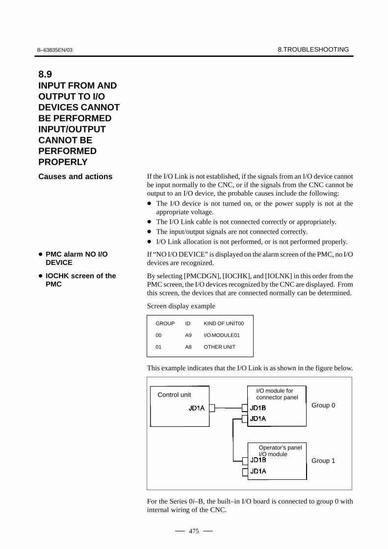
B–63835EN/03 8.TROUBLESHOOTING
475
If the I/O Link is not established, if the signals from an I/O device cannotbe input normally to the CNC, or if the signals from the CNC cannot beoutput to an I/O device, the probable causes include the following:
� The I/O device is not turned on, or the power supply is not at theappropriate voltage.
� The I/O Link cable is not connected correctly or appropriately.� The input/output signals are not connected correctly.
� I/O Link allocation is not performed, or is not performed properly.
If “NO I/O DEVICE” is displayed on the alarm screen of the PMC, no I/Odevices are recognized.
By selecting [PMCDGN], [IOCHK], and [IOLNK] in this order from thePMC screen, the I/O devices recognized by the CNC are displayed. Fromthis screen, the devices that are connected normally can be determined.
Screen display example
GROUP ID KIND OF UNIT00
00 A9 I/O MODULE01
01 A8 OTHER UNIT
This example indicates that the I/O Link is as shown in the figure below.
Control unitI/O module forconnector panel
Operator’s panel I/O module
Group 0
Group 1
For the Series 0i–B, the built–in I/O board is connected to group 0 withinternal wiring of the CNC.
8.9INPUT FROM ANDOUTPUT TO I/ODEVICES CANNOTBE PERFORMEDINPUT/OUTPUTCANNOT BEPERFORMEDPROPERLY
Causes and actions
� PMC alarm NO I/ODEVICE
� IOCHK screen of thePMC
8. TROUBLESHOOTING B–63835EN/03
476
Check that the connected I/O devices are connected properly to the powersupplies and that the voltages are as prescribed.Check that the power–on sequence is correct.
Time at which an I/O device is to be turned onBefore the CNC is turned on or within 500 ms after the CNC isturned on
When the CNC is turned off, the I/O devices must also be turned off.(Otherwise, the I/O Link may not be established the next time the CNCis turned on.)
As in the example shown on the previous page, I/O Link cables are usedto connect JD1As and JD1Bs.JD1A represents an upper unit while JD1B represents a lower unit.Check that the cables are connected correctly.
Check that the input/output signals to be connected to each I/O device areconnected correctly.For operator’s panel I/O modules and for connector panel I/O modules,also check that the 0 V or +24 V input signal is connected to the commonpin and that the +24 V output signal is connected to the DO common pin.
Check that I/O Link allocation has been performed correctly. Selecting [EDIT] and then [MODULE] from the PMC screen causes theallocation edit screen to be displayed.After editing allocation, write the changes to the FROM on the [I/O]screen. Otherwise, the changes will be lost when the power is turned off.The checking of allocation requires a Ladder editing card.
� Checking the powersupplies of the I/Odevices
� Connection of cables
� Connection of I/O signals
� I/O Link allocation
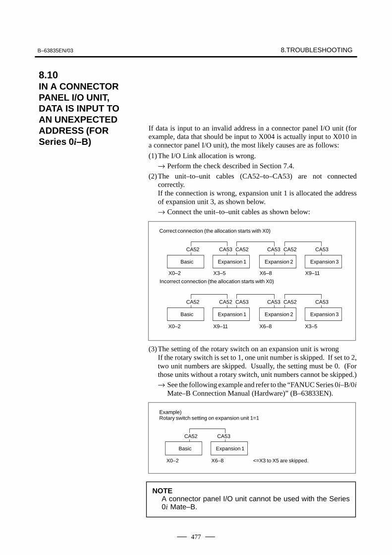
B–63835EN/03 8.TROUBLESHOOTING
477
If data is input to an invalid address in a connector panel I/O unit (forexample, data that should be input to X004 is actually input to X010 ina connector panel I/O unit), the most likely causes are as follows:
(1)The I/O Link allocation is wrong.
→ Perform the check described in Section 7.4.
(2)The unit–to–unit cables (CA52–to–CA53) are not connectedcorrectly.If the connection is wrong, expansion unit 1 is allocated the addressof expansion unit 3, as shown below.
→ Connect the unit–to–unit cables as shown below:
Correct connection (the allocation starts with X0)
Incorrect connection (the allocation starts with X0)
Basic Expansion 1
Basic Expansion 1
Expansion 2
Expansion 2
Expansion 3
Expansion 3
CA52 CA53 CA52 CA53 CA52 CA53
CA52 CA52 CA53 CA53 CA52 CA53
X0–2 X3–5 X6–8 X9–11
X0–2 X9–11 X6–8 X3–5
(3)The setting of the rotary switch on an expansion unit is wrongIf the rotary switch is set to 1, one unit number is skipped. If set to 2,two unit numbers are skipped. Usually, the setting must be 0. (Forthose units without a rotary switch, unit numbers cannot be skipped.)
→ See the following example and refer to the “FANUC Series 0i–B/0iMate–B Connection Manual (Hardware)” (B–63833EN).
Example)Rotary switch setting on expansion unit 1=1
Basic Expansion 1
CA52 CA53
X0–2 X6–8 <=X3 to X5 are skipped.
NOTEA connector panel I/O unit cannot be used with the Series0i Mate–B.
8.10IN A CONNECTORPANEL I/O UNIT,DATA IS INPUT TOAN UNEXPECTEDADDRESS (FORSeries 0i–B)
8. TROUBLESHOOTING B–63835EN/03
478
The most likely cause is that power is not being supplied to the expansionunit.
→ Check whether 24–V power is supplied to 18P and 50P of theexpansion unit, DI and DO signals are not input and output.
→ Check whether 24–V power is supplied to 1P and 3P of the expansionunit, when DI signals are input and DO signals are not output.
NOTEA connector panel I/O unit cannot be used with the Series0i Mate–B.
8.11IN A CONNECTORPANEL I/O UNIT, NODATA IS OUTPUT TOAN EXPANSION UNIT(FOR Series 0i–B)

B–63835EN/03 8.TROUBLESHOOTING
479
NO
Alarm 85?
Alarm 86?
· Check baud rateand other I/O parameters
· I/O device is faulty
YES
NO
YES
�������
Is I/O parametercorrect?
YES
NO
Set correct parameters
Is power of I/O ?
ON
OFF
Turn on I/O device
Is cable connection right?
YES
NO
Connect the cable
· I/O device is faulty· Main CPU board
is faultyAlarm 87?
· I/O device is faulty· Main CPU board
is faulty
(a) Parameters on reader/puncher interface are not correct.
Check the following setting data and parameters.
(b)External I/O device or host computer is faulty.
(c) Main CPU board or serial communication board is faulty.
(d)Cable between NC and I/O device is faulty.
(a) Parameters on reader/puncher interface are not correct.
Check the following setting data and parameters:<Setting>PUNCH CODE=0 OR 1 (0: EIA,1:ISO)Select ISO or EIA according to the type of I/O device.If punch code does not match, alarm 86 will generate.
8.12ALARM 85 TO 87(READER/PUNCHERINTERFACE ALARM)
Causes
Countermeasures

8. TROUBLESHOOTING B–63835EN/03
480
<Parameter>
Function
Value of parame-ter 0020 0 1 2
Feed 0101#7 0111#7 0121#7
Data input code 0101#3 0111#3 0121#3
Stop bit 0101#0 0111#0 0121#0
Type of I/O device 102 112 122
Baud rate 103 113 123
Commu- 0135#3 – – –nicationmethod RS–232C
MAIN CPU BOARDConnector
JD5A JD5B
NOTENumbers in the table indicate parameters and bit numbers.Example) 101#7: bit7 of parameter 101.
#7NFD0101
#6 #5 #4 #3ASI
#2 #1 #0SB2
0111
0121
0131
#7(NFD) 0 : Feed is output before and after data in data output (FANUC PPR)
1 : Feed is not output (standard).
#3(ASI) 0 : Data input code is EIA or ISO (automatic recognition)
1 : Data input code is ASCII.
#0(SB2) 0 : No. of stop bits is 1.
1 : No. of stop bits is 2.
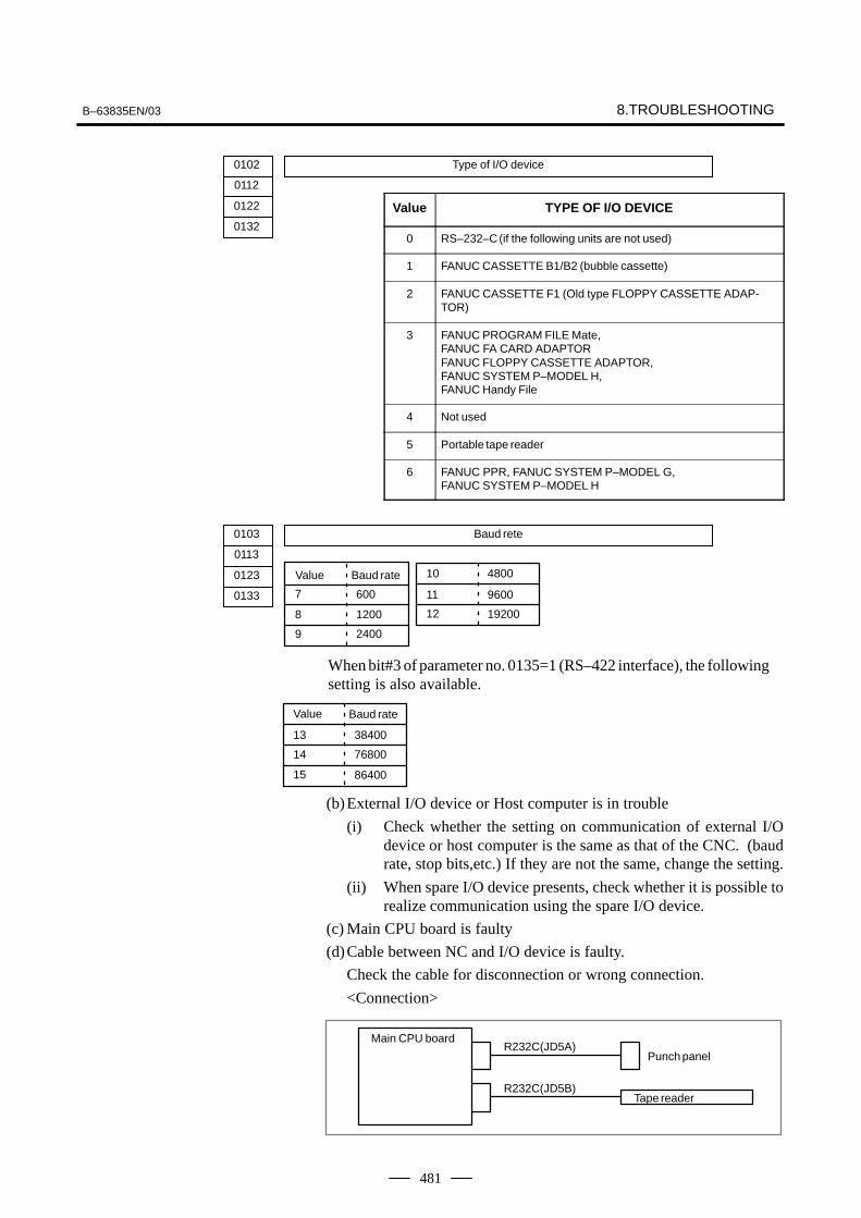
B–63835EN/03 8.TROUBLESHOOTING
481
Value TYPE OF I/O DEVICE
0 RS–232–C (if the following units are not used)
1 FANUC CASSETTE B1/B2 (bubble cassette)
2 FANUC CASSETTE F1 (Old type FLOPPY CASSETTE ADAP-TOR)
3 FANUC PROGRAM FILE Mate,FANUC FA CARD ADAPTORFANUC FLOPPY CASSETTE ADAPTOR,FANUC SYSTEM P–MODEL H,FANUC Handy File
4 Not used
5 Portable tape reader
6 FANUC PPR, FANUC SYSTEM P–MODEL G, FANUC SYSTEM P–MODEL H
0103 Baud rete
0113
0123
0133
When bit#3 of parameter no. 0135=1 (RS–422 interface), the followingsetting is also available.
7
8
600
1200
Value
13
14
15
Baud rate
38400
76800
86400
9 2400
10
11
12
4800
9600
19200
Value Baud rate
(b)External I/O device or Host computer is in trouble
(i) Check whether the setting on communication of external I/Odevice or host computer is the same as that of the CNC. (baudrate, stop bits,etc.) If they are not the same, change the setting.
(ii) When spare I/O device presents, check whether it is possible torealize communication using the spare I/O device.
(c) Main CPU board is faulty
(d)Cable between NC and I/O device is faulty.
Check the cable for disconnection or wrong connection.
<Connection>
Tape reader
Main CPU boardR232C(JD5A)
Punch panel
R232C(JD5B)
0102 Type of I/O device
0112
0122
0132
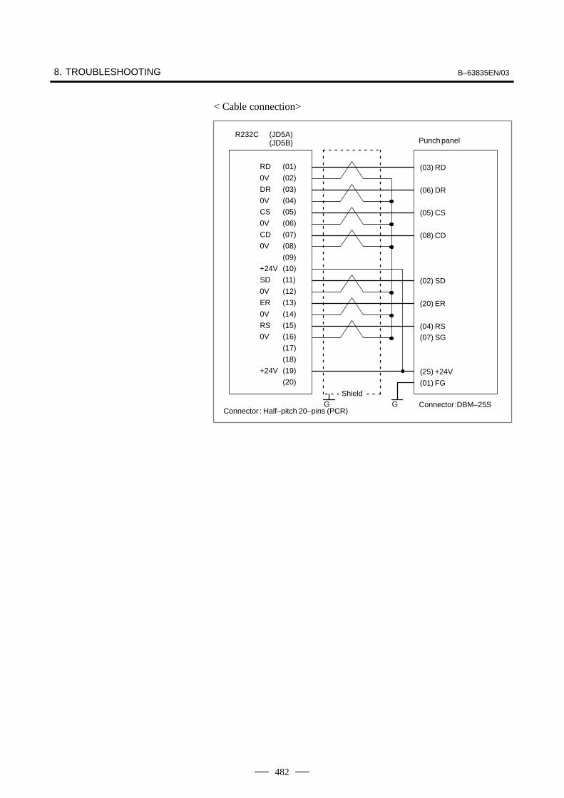
8. TROUBLESHOOTING B–63835EN/03
482
< Cable connection>
RD (01)
0V (02)
DR (03)
0V (04)
CS (05)
0V (06)
CD (07)
0V (08)
(09)
+24V (10)
SD (11)
0V (12)
ER (13)
0V (14)
RS (15)
0V (16)
(17)
(18)
+24V (19)
(20)
(03) RD
(06) DR
(05) CS
(08) CD
(02) SD
(20) ER
(04) RS
(07) SG
(25) +24V
(01) FG
GGConnector : Half–pitch 20–pins (PCR)
Connector :DBM–25S
Shield
R232C (JD5A)(JD5B) Punch panel

B–63835EN/03 8.TROUBLESHOOTING
483
Reference position return was executed when the following condition isnot satisfied:The CNC received one rotation signal at least one time when the axis ismoving to the reference position at a speed higher than a speed equivalentto 128 pulses of position error amount(DGN300).
(START)
Check whether position gain is greater than 128 pulses(DGN 300) before or during reference position return.
128 or more
Position erroramount : DGN 300
Check feed rate command:PRM 1420 F : Rapid traverse rate (mm/min)PRM 1424 Manual rapid traverse rate (mm/min)PRM 1825 G : Servo loop gain (0.01sec–1)
F�5000/3Position error=
G�detection unit[µm/PLUSE]
Detection unit : Move amount to a command pulse (usually 1µm)In metric machine, if the no. of digits below decimal point is 4 on the positiondisplay screen, detection unit is 0.1 µm.
Check rapid traverse override signals :ROV1 DGN 014.0
1014.0 (For two–path control)
ROV2 DGN 014.11014.1 (For two–
path control)PRM 1421 Fo rate
Check reference position return deceleration signalDEC1 to DEC8 DGN 009.0 to 009.7When reference position return is started from deceleration signal 0, feed ratebecomes FL rate.PRM 1425 FL rate
ROV1 ROV2
0 00 11 01 1
YES
NO
(1) Next page
Override
100%50%25%
Fo rate
Raise the speed
8.13ALARM 90(REFERENCEPOSITION RETURNIS ABNORMAL)
Contents
Countermeasures

8. TROUBLESHOOTING B–63835EN/03
484
(1)
Check whether the motor ratated more than one rota-tion (one rotation signal is issued ) at faster than 128pulses of position error amount.
Rotated ?Return start position is too close
· Chagne the return start position.· Move the machine at faster that 128
pulses for more than one rotation towards RP.
Check that voltage of pulse coder is higher than 4.75 V.To measure pulse coder voltage, remove the motor cover and measure onpulse coder PCB at across + and – or +5V and 0V terminals.
More than 4.75V
Hardware failure
· Pulse coder is faultyChange pulse coder or motor
Pulse coder power voltage is low
YES
NO
NO
YES
CAUTIONAfter the pulse coder or motor is exchanged, referenceposition or machine’s standard point may be different fromformer one. Please set it correctly.
A speed more than 128 pulses is required because if speed is lower thatthis, one–rotation signal does not function stably, causing improperposition detection.If bit 0 of parameter No. 2000 is set to 1, a speed corresponding to apositional deviation of 1280 pulses or more is required.Parameter No. 1836 can be set to 128 or less, as the minimum positionaldeviation with which reference position return is possible. (If theparameter is set to 0, 128 is assumed as the minimum positional deviation.If bit 0 of parameter No. 2000 is set to 1, a value equal to ten times theset value is used for checking.)
� Reference

B–63835EN/03 8.TROUBLESHOOTING
485
Absolute position data in the serial pulse coder was lost. (This alarm will be generated when serial pulse coder is exchanged orposition feedback signal cable of the serial pulse coder is disconnected).
Machine position must be memorized using the following method:
(1)Execute manual reference position return only for an axis for whichthis alarm was generated.When manual reference position returncannot be executed because of an another alarm, set parameter 1815#5to 0 and release the alarm and perform manual operation.
(2)Press RESET key at the end of reference position return to release the
alarm.
Execute dogless reference position setting to memorize the referenceposition.
Since the reference position is different from the former one, change thegrid shift value (PRM 1850) to correct the position.
#71815
#6 #5APC x
#4APZx
#3 #2 #1 #0
#5(APCx) 0 : Position detector is incremental pulse coder.
1 : Position detector is absolute pulse coder.
#4(APZx) Reference position of absolute pulse coder is :
0 : not established1 : established
8.14ALARM 300(REQUEST FORREFERENCEPOSITION RETURN)
Remedies
� When reference positionreturn function ispresent
� When reference positionreturn function is notpresent
� When serial pulse coderis changed
Related parameters
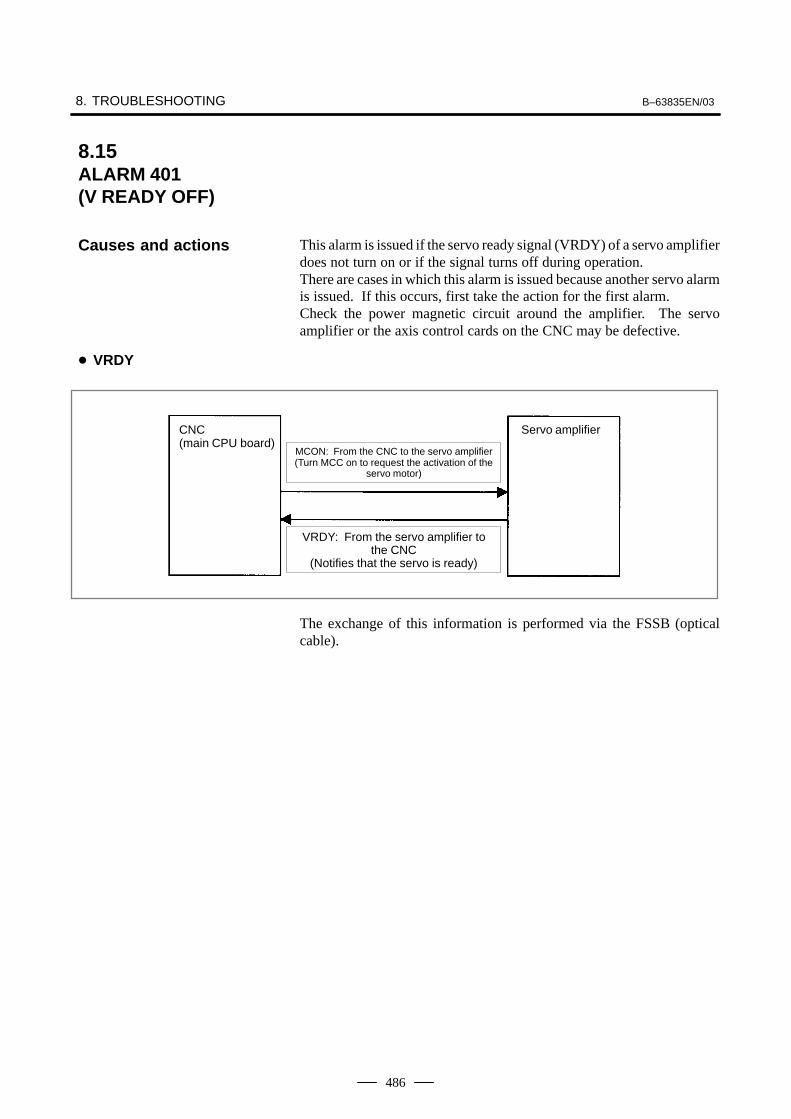
8. TROUBLESHOOTING B–63835EN/03
486
This alarm is issued if the servo ready signal (VRDY) of a servo amplifierdoes not turn on or if the signal turns off during operation.There are cases in which this alarm is issued because another servo alarmis issued. If this occurs, first take the action for the first alarm.Check the power magnetic circuit around the amplifier. The servoamplifier or the axis control cards on the CNC may be defective.
CNC(main CPU board)
Servo amplifier
MCON: From the CNC to the servo amplifier(Turn MCC on to request the activation of the
servo motor)
VRDY: From the servo amplifier tothe CNC
(Notifies that the servo is ready)
The exchange of this information is performed via the FSSB (opticalcable).
8.15ALARM 401 (V READY OFF)
Causes and actions
� VRDY

B–63835EN/03 8.TROUBLESHOOTING
487
Serial spindle
(servoamplifier)
(servoamplifier) Control
powersupply
Emergency stopcircuit
Servomotor
Servomotor
Spindlemotor
Breaker
Breaker
ACreactor
3–phase
Single–phase
Check items
� Is the PSM control power supply on?
� Has an emergency stop been canceled?
� Is a terminating connector connected to the JX1B connector of theterminating amplifier?
� Is MCC on? If there is an external MCC sequence in addition to theMCC contact of the PSM, check that sequence also.
� Is the power for driving MCC supplied?
� Is the breaker on?
� Has some alarm been issued in the PSM or SPM?
If no problem is found in the power magnetic circuit around the amplifier,replace the servo amplifier.
If the above action does not solve the problem, replace the axis controlcards.
� Example of connectionaround the amplifier(Typical example)
� Replacing the servoamplifier
� Replacing the axiscontrol cards
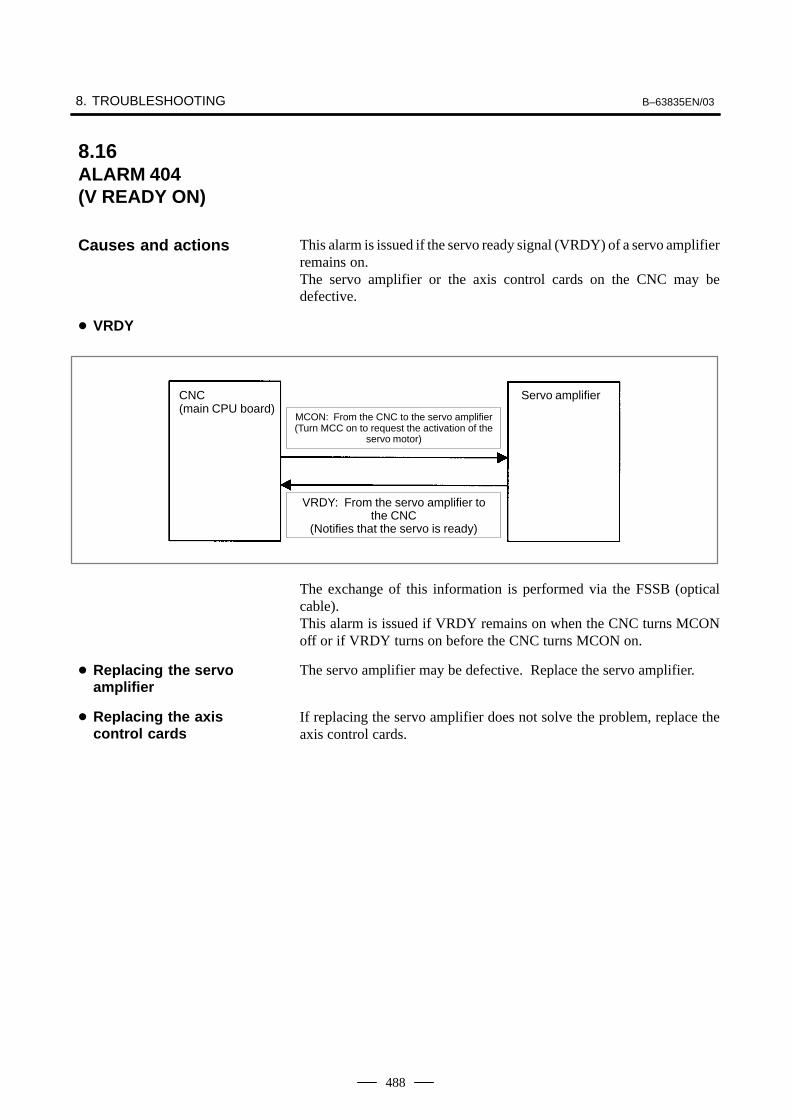
8. TROUBLESHOOTING B–63835EN/03
488
This alarm is issued if the servo ready signal (VRDY) of a servo amplifierremains on.The servo amplifier or the axis control cards on the CNC may bedefective.
CNC(main CPU board)
Servo amplifier
MCON: From the CNC to the servo amplifier(Turn MCC on to request the activation of the
servo motor)
VRDY: From the servo amplifier tothe CNC
(Notifies that the servo is ready)
The exchange of this information is performed via the FSSB (opticalcable).This alarm is issued if VRDY remains on when the CNC turns MCONoff or if VRDY turns on before the CNC turns MCON on.
The servo amplifier may be defective. Replace the servo amplifier.
If replacing the servo amplifier does not solve the problem, replace theaxis control cards.
8.16ALARM 404 (V READY ON)
Causes and actions
� VRDY
� Replacing the servoamplifier
� Replacing the axiscontrol cards
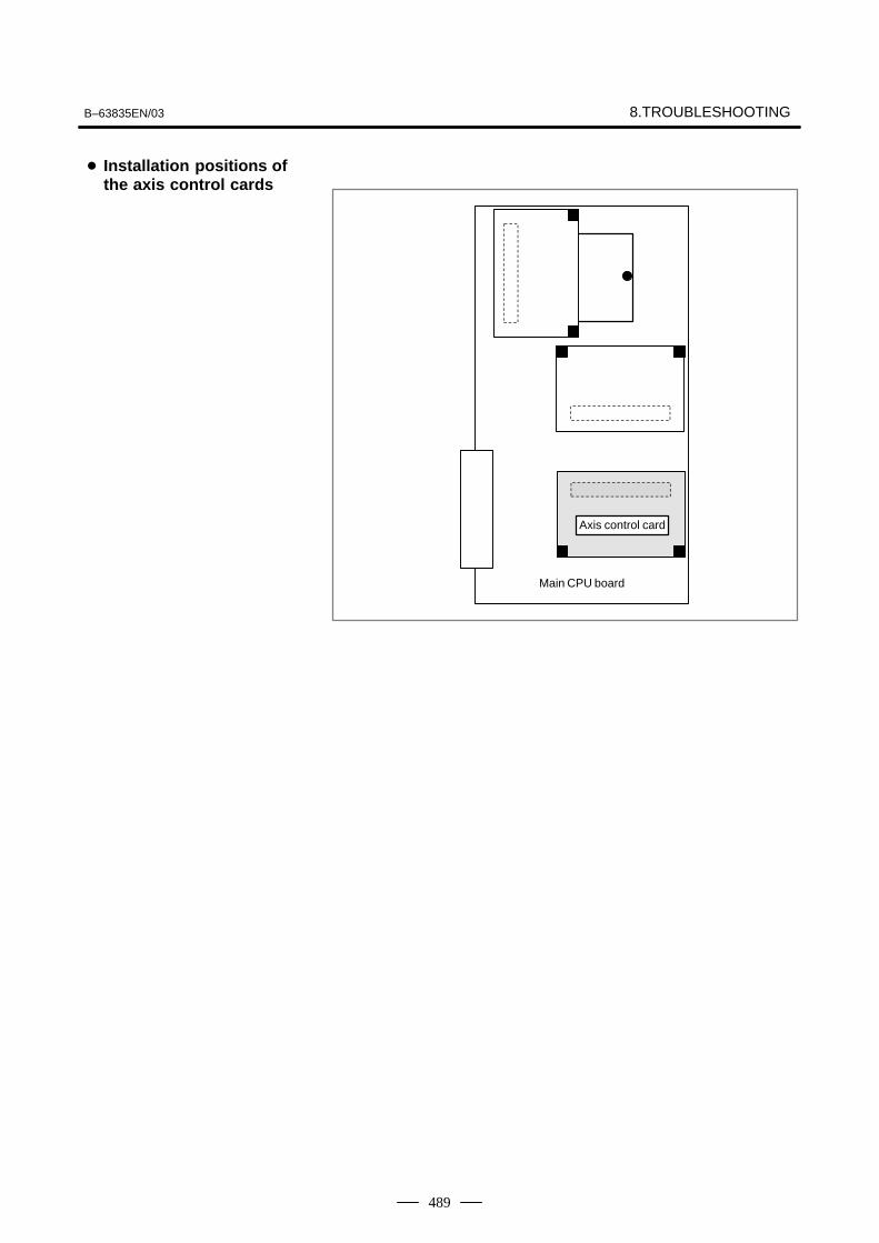
B–63835EN/03 8.TROUBLESHOOTING
489
Axis control card
Main CPU board
� Installation positions ofthe axis control cards

8. TROUBLESHOOTING B–63835EN/03
490
Alarm 462 is issued if a slave (servo amplifier) cannot receive correct datadue to an FSSB communication error.Alarm 463 is issued if the CNC cannot receive correct data due to an FSSBcommunication error.If these alarms are issued, the alarm message indicates the number of thedefective axis (axis name).
Any of the optical cables between the CNC control unit and the amplifiercorresponding to the axis number indicated in the alarm message may bedefective.Or, any of the first amplifier to the amplifier corresponding to that axisnumber may be defective.
The axis control cards installed on the CNC may be defective.
Axis control card
Main CPU board
8.17ALARM 462 (SEND CNC DATAFAILED) ALARM 463 (SEND SLAVE DATAFAILED)Causes and actions
� Servo amplifier or opticalcable
� Axis control cards
� Installation positions ofthe axis control cards

B–63835EN/03 8.TROUBLESHOOTING
491
Digital servo parameters are abnormal.(Digital servo parameters are set incorrectly.)
1 Confirm the setting value of the following parameters:
PRM 2020 : Motor format number
PRM 2022 : Motor rotation direction
PRM 2023 : Number of pulses of velocity feedbacks
PRM 2024 : Number of pulses of position feedback
PRM 1023 : Servo axis number
PRM 2084 : Flexible feed gear ratio
PRM 2085 : Flexible feed gear ratio
Confirm the details with diagnosis function of CNC side.
2 Change the setting of this parameter to 0.
PRM 2047 : Observer parameter
3 Perform initial setting of digital servo parameters.
Refer to setcion 6.1 “Initial Setting of Servo Parameters” .
This data indicates the cause of servo alarm No. 417, detected by the NC.If the alarm is detected by the servo, the PRM bit (bit 4 of DGN No. 0203)is set to 1.
#70280
#6AXS
#5 #4DIR
#3PLS
#2PLC
#1 #0MOT
#0(MOT) : The motor type specified in parameter No. 2020 falls outside thepredetermined range.
#2(PLC) : The number of velocity feedback pulses per motor revolution, specified inparameter No. 2023, is zero or less. The value is invalid.
#3(PLS) : The number of position feedback pulses per motor revolution, specified inparameter No. 2024, is zero or less. The value is invalid.
#4(DIR) : The wrong direction of rotation for the motor is specified in parameter No.2022 (the value is other than 111 or –111).
#6(AXS) : In parameter No. 1023 (servo axis number), a value that falls outside therange of 1 to the number of controlled axes is specified. (For example, 4 isspecified instead of 3.) Alternatively, the values specified in theparameter are not consecutive.
8.18ALARM 417 (DIGITALSERVO SYSTEM ISABNORMAL)
� Causes

8. TROUBLESHOOTING B–63835EN/03
492
This alarm is issued if the ambient temperature of the CNC control unitis abnormally high. As an installation condition, the ambient temperatureof the CNC must not exceed 55°C.
A temperature monitoring circuit is installed on the main CPU board, andcauses this alarm to be issued if the ambient temperature is abnormallyhigh.Take appropriate action to the cabinet that houses the CNC control unitso that the temperature falls within the proper temperature range 0 to55°C.If it is obvious that the ambient temperature is not abnormal, themotherboard (main CPU board) may be defective.
8.19ALARM 700(OVERHEAT:CONTROL UNIT)
Causes and actions
� Ambient temperature

B–63835EN/03 8.TROUBLESHOOTING
493
This alarm is issued if a fault occurs in any of the fan motors, such as thestoppage of a fan motor during the operation of the CNC.
Fan motors are installed in the uppermost portion of the CNC control unit.Each fan motor is attached with an alarm detector circuit, which notifiesthe CNC of a fault such as the stoppage of the fan motor, thereby issuingthis alarm.If this alarm is issued, replace the fan motor.
A fan can be replaced together with its case.
Fan motor for2–slot track Fan motor for
1–slot track
Specifications of fan motors
Ordering information
For 1–slot track (for Series 0i Mate–B) A02B–0265–C101
For 2–slot track (for Series 0i–B) A02B–0260–C021
8.20ALARM 701(OVERHEAT: FANMOTOR)
Causes and actions
� Fan motors

8. TROUBLESHOOTING B–63835EN/03
494
Spindle speed changes abnormally due to load.
Confirm the follow-ing parameter :
Check whether spindle speed is constant by viewof the speed meter on CRT.
Constant ?
Heavy cutting?
Is a heavy cutting being per-formed ? Confirm spindle loadon CRT.
Reduce cutting condition
PRM 4911PRM 4912PRM 4913PRM 4914
Doesn’t the cutting tool worn ?
Worn ?
Spindle servo unit is faultySpindle motor is faulty
Replace tool
YES
NO
YES
NO
YES
NO
PRM 4911 : A ratio of spindle speed at which actual spindle speed isregarded as arrived at a command spindle speed.
PRM 4912 : Spindle speed fluctuation ratio up to which the spindlespeed fluctuation detection alarm is not issued.
PRM 4913 : Spindle speed fluctuation that is not regarded as the spindlespeed fluctuation alarm.
PRM 4914 : Time when a spindle speed changed to when spindle speedfluctuation detection is started.
8.21ALARM 704(SPINDLE SPEEDFLUCTUATIONDETECTION ALARM)
Remedies
Remedies
B–63835EN/03 8.TROUBLESHOOTING
495
An error occurred in the communication between the serial spindleamplifier (SPM) and the CNC. The probable causes include:
� Contact failure of the connection cable
� Defective printed circuit board on the CNC
� Defective spindle amplifier
� Noise
Check that the cable connecting the serial spindle amplifier (SPM) to theCNC is in contact.Check that the cable is inserted firmly into the connectors and that it doesnot have any conductors likely to be cut off.Check that the cable used is a twisted–pair cable and that it is connectedas described in the connection manual.
A spindle control circuit for the CNC is installed on the main CPU board.If this alarm is issued, replace the main CPU board.
When an error occurred on the spindle amplifier module (SPM) side, acode of A, A1, or A2 is indicated on the SPM depending on the nature ofthe error.In this case, take appropriate actions in FANUC SERVO MOTOR αiseries Maintenance Manual (B–65285EN).
If any of the above actions does not solve the problem, examine the noiseenvironment of the connection cable.See the section on the measures against noise, take appropriate actionssuch as the reinforcement of the cable shield and the separation of thecable from the power line.
8.22ALARM 749 (SERIAL SPINDLECOMMUNICATIONERROR)
Causes and actions
� Connection cable
� Printed circuit boards onthe CNC
� Spindle amplifier module(SPM)
� Noise environment

8. TROUBLESHOOTING B–63835EN/03
496
This alarm is issued if a serial spindle amplifier (SPM) does not enter thenormal startup state when the CNC is turned on.This alarm is not issued once the CNC system including the spindleamplifiers has started up normally. It is issued if a fault occurs in thepower–on process.The probable causes include the following:
� Contact failure, wiring error, or connection error of the connectioncable
� The CNC is turned on when a spindle amplifier is in the alarm state.
� Parameter setting error
� Defective printed circuit board on the CNC
� Detective spindle amplifier
Up to two serial spindle amplifiers (SPMs) can be connected per path.Note, however, the number of amplifiers that can be connected differsdepending on the model, number of paths, and configuration. Refer to theConnection Manual (Hardware).
Main CPU board
SPM (first)
SPM (second)
JA7A
Check that the cables are connected as shown in the figure above. Checkthat JA7Bs and JA7As are connected correctly.Check that the cables are latched firmly and are not loose.Refer to the Connection Manual (Hardware) to check that the cables areconnected correctly.
This alarm is issued if the CNC is turned on when the LED of a spindleamplifier indicates a number other than “24”.On the spindle amplifier, remove the cause of the alarm. Turn off thespindle amplifier and the CNC, then turn on the system again.
If this alarm is issued, its details can be checked with diagnosis numbers409 and 439.
8.23ALARM 750(SPINDLE SERIALLINK STARTUPFAILURE)Causes and actions
� Connection
� States of the spindleamplifiers
� Details of the alarm

B–63835EN/03 8.TROUBLESHOOTING
497
#70409
#6 #5 #4 #3SPE
#2S2E
#1S1E
#0SHE
SPE: 0 : In the spindle serial control, the serial spindle parameters fulfill thespindle unit startup conditions.
1 : In the spindle serial control, the serial spindle parameters do not fulfillthe spindle unit startup conditions.
S2E: 0 : The second spindle is normal during the spindle serial control startup.1 : The second spindle was detected to have a fault during the spindle
serial control startup.S1E: 0 : The first spindle is normal during the spindle serial control startup.
1 : The first spindle was detected to have a fault during the spindle axisserial control startup.
SHE: 0 : The serial communications circuit in the CNC is normal.1 : The serial communications circuit in the CNC was detected to have a
fault.
� 1st and 2nd spindles

8. TROUBLESHOOTING B–63835EN/03
498
These alarms are issued if any of the axis control cards and the slaves(such as servo amplifiers) and optical cables connected to the FSSB isdefective.
No. Message Description
5134 FSSB: OPEN READY TIMEOUT
The FSSB did not become ready toopen during initialization.
5135 FSSB: ERROR MODE The FSSB entered an error mode.
5137 FSSB: CONFIGURATIONERROR
The FSSB detected a configuration er-ror.
5197 FSSB: OPEN TIME OUT The FSSB did not open when the CNChad allowed the FSSB to open.
5198 FSSB: ID DATA NOT READ The initial ID information for the amplifi-er cannot be read because of a failurein the temporary assignment.
The processing of the FSSB at power on is as described below:
1 The CNC initializes the FSSB and the servo.
2 The servo returns the first ready signal.
3 The first ITP interrupt is generated.
4 The CNC waits for the FSSB to become ready to open.
5 The CNC checks that the FSSB did not detect a configuration error.
6 The CNC allows the FSSB to open.
7 The CNC checks that the FSSB has opened.
8 The servo returns the second ready signal.
9 Normal operation
8.24ALARM 5134 (FSSB: OPENREADY TIME OUT)
ALARM 5135 (FSSB:ERROR MODE)
ALARM 5137 (FSSB:CONFIGURATIONERROR)
ALARM 5197 (FSSB:OPEN TIME OUT)
ALARM 5198 (FSSB:ID DATA NOT READ)
Causes and actions
� Processing of the FSSBat power on

B–63835EN/03 8.TROUBLESHOOTING
499
If the FSSB does not become ready to open in 4, alarm 5134 is issued.If an error is detected in 5, alarm 5137 is issued.If the FSSB does not open within a fixed period of time, alarm 5197 isissued.If the ready signal is not returned within a fixed period of time, alarm 5198is issued.
Check that the FSSB–related parameters are set correctly.
Check the power supplies of the servo amplifiers connected to the FSSB.
Replace the axis control cards on the CNC.Replace the optical cables and servo amplifiers connected to the FSSB,one at a time, to identify the defective item.
Axis control card
Main CPU board
� Checking the parametersettings
� Power supplies of theservo amplifiers
� Replacing the axiscontrol cards, opticalcables, and servoamplifiers
� Installation positions ofthe axis control cards

8. TROUBLESHOOTING B–63835EN/03
500
The number of servo amplifiers recognized by the FSSB is insufficient,compared with the number of controlled axes.
If this alarm is issued, display the amplifier setting screen from the FSSBsetting screen. Only the servo amplifiers recognized on the FSSB aredisplayed.
The optical cable that connects together the last recognized amplifier andthe next one may be defective.Or, either of the amplifiers connected together with that optical cable maybe defective. Check the power supplies of the amplifiers.
This alarm may be issued if a power fault occurs in a servo amplifier. Apower fault occurs if the amplifier control power supply voltage drops,if the +5 V conductor of the pulse coder cable is ground, or for otherreasons.
The axis control cards installed on the CNC may be defective.
Axis control card
Main CPU board
8.25ALARM 5136 (FSSB: NUMBER OFAMPS IS SMALL)
Causes and actions
� FSSB setting screen
� Optical cable or servoamplifier
� Power fault of a servoamplifier
� Axis control cards
� Installation positions ofthe axis control cards
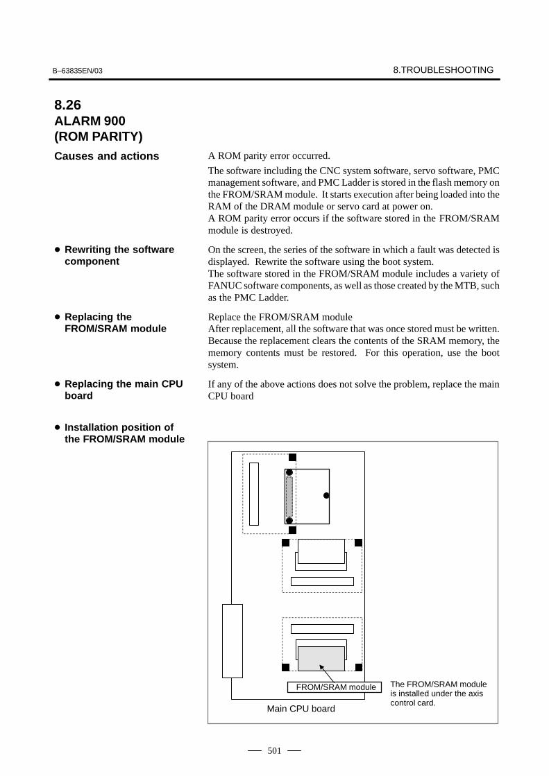
B–63835EN/03 8.TROUBLESHOOTING
501
A ROM parity error occurred.
The software including the CNC system software, servo software, PMCmanagement software, and PMC Ladder is stored in the flash memory onthe FROM/SRAM module. It starts execution after being loaded into theRAM of the DRAM module or servo card at power on.A ROM parity error occurs if the software stored in the FROM/SRAMmodule is destroyed.
On the screen, the series of the software in which a fault was detected isdisplayed. Rewrite the software using the boot system.The software stored in the FROM/SRAM module includes a variety ofFANUC software components, as well as those created by the MTB, suchas the PMC Ladder.
Replace the FROM/SRAM moduleAfter replacement, all the software that was once stored must be written.Because the replacement clears the contents of the SRAM memory, thememory contents must be restored. For this operation, use the bootsystem.
If any of the above actions does not solve the problem, replace the mainCPU board
Main CPU board
FROM/SRAM module The FROM/SRAM moduleis installed under the axiscontrol card.
8.26ALARM 900 (ROM PARITY)Causes and actions
� Rewriting the softwarecomponent
� Replacing theFROM/SRAM module
� Replacing the main CPUboard
� Installation position ofthe FROM/SRAM module

8. TROUBLESHOOTING B–63835EN/03
502
The management software for the CNC is loaded from the FROM to theDRAM at power on, so that it is executed on the DRAM.
A parity error occurred on this DRAM.These alarms occur if the data on the DRAM is destroyed due to someexternal cause or if the CPU card is defective.
Replace the CPU card.
Main CPU board
CPU card
8.27ALARMS 912 TO 919(DRAM PARITY)
Causes and actions
� Replacing the CPU card.
� Installation position ofthe CPU card
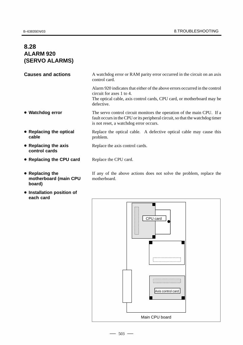
B–63835EN/03 8.TROUBLESHOOTING
503
A watchdog error or RAM parity error occurred in the circuit on an axiscontrol card.
Alarm 920 indicates that either of the above errors occurred in the controlcircuit for axes 1 to 4.The optical cable, axis control cards, CPU card, or motherboard may bedefective.
The servo control circuit monitors the operation of the main CPU. If afault occurs in the CPU or its peripheral circuit, so that the watchdog timeris not reset, a watchdog error occurs.
Replace the optical cable. A defective optical cable may cause thisproblem.
Replace the axis control cards.
Replace the CPU card.
If any of the above actions does not solve the problem, replace themotherboard.
Main CPU board
Axis control card
CPU card
8.28ALARM 920 (SERVO ALARMS)
Causes and actions
� Watchdog error
� Replacing the opticalcable
� Replacing the axiscontrol cards
� Replacing the CPU card
� Replacing themotherboard (main CPUboard)
� Installation position ofeach card

8. TROUBLESHOOTING B–63835EN/03
504
A fault occurred on the FSSB (serial servo bus) that connects servoamplifiers to the CNC.
This alarm is issued if a fault occurs in any of the axis control cardsmaking up the FSSB, optical cables, and servo amplifiers.
Use the LEDs on the servo amplifiers.Using the 7–segment LEDs installed on the servo amplifiers, thedefective location can be identified.
Amplifier0
Amplifier1
Amplifier2
Amplifier3
Amplifier4
Amplifier5
CNC
B A
If portion A, indicated by dotted line, contains the defective location, theLEDs on the servo amplifiers will be as shown in the table below.
AmplifierNo.
Amplifier0
Amplifier1
Amplifier2
Amplifier3
Amplifier4
Amplifier5
LEDdisplay “–” “–”
“L”or“–”
“U” “U” “U”
In this case, any of the following locations may be defective:
(1)Optical cable connecting together the servo amplifier whose LED is“L” or “–” and that whose LED is “U”. In the above figure, the opticalcable in portion A may be defective.
(2)Either of the servo amplifier whose LED is “L” or “–” and that whoseLED is “U”. In the above figure, either amplifier 2 or 3 may be defective.
If portion B, indicated by dotted line, contains the defective location, theLEDs on the servo amplifiers will be as follows:
AmplifierNo.
Amplifier0
Amplifier1
Amplifier2
Amplifier3
Amplifier4
Amplifier5
LEDdisplay “–” or “U”
In this case, any of the following locations may be defective:
(1)Optical cable connected to the CNC. In the above figure, the opticalcable in portion B may be defective.
(2)Any of the axis control cards in the CNC
(3)First servo amplifier connected. In the above figure, amplifier 0 maybe defective.
8.29ALARM 926 (FSSB ALARM)Causes and actions
� Identifying the defectivelocation
FSSB connectionexample

B–63835EN/03 8.TROUBLESHOOTING
505
Use the display on the CNC screenIf alarm 926 is issued, information such as the following is displayed atthe bottom of the CNC screen. It can be used to identify the defectivelocation.
MODEinformation
STATUS information
Bits Bits
Bits 12 to 15 of the MODE information indicate the number of the slavein which the alarm occurred. The unit nearest the CNC (such as a servoamplifier) is assigned a slave number of “0”. For a 2–axis amplifier, forexample, one number is assigned for the first axis, and the next numberis assigned for the second.
Details of the MODE information
Bit 15 14 13 12 11 0
De-scrip-tion
Number of the slave inwhich the alarm oc-curred
No meaning
0000: Indicates that the alarm occurred in slave 0.0001: Indicates that the alarm occurred in slave 1.
::
1001: Indicates that the alarm occurred in slave 9.
Using the bits of the STATUS information, the fault can be estimated.
Details of the STATUS information
Bit 15 12 11 10 9 87 6 5 4 3 0
Description
No m
eaning
External alarm
Broken m
aster port
Broken slave port
No m
eaning
Broken m
aster port
No m
eaning
Error on slave
No m
eaning
A xxxx 0 0 0 xxx 1 x 0 xxxx
A xxxx 0 1 0 xxx 0 x 1 xxxx
B xxxx 0 0 1 xxx 0 x 1 xxxx
C xxxx 1 0 0 xxx 0 x 1 xxxx
The STATUS information matches any of the patterns A, B, and C.(x indicates a bit that may be either 0 or 1.)
� Identifying the defectivelocation
8. TROUBLESHOOTING B–63835EN/03
506
If the pattern of the STATUS information is A
(1)The optical cable that connects together the slave corresponding to bits12 to 15 of the MODE information and the preceding slave may bedefective. Or, either of the slaves connected together with that opticalcable may be defective.
(2)The voltage of the power supplied to the slave amplifier dropped, ora power fault occurred in the amplifier.
(3)Any of the axis control cards in the CNC may be defective.
If the pattern of the STATUS information is B
(1)The optical cable that connects together the slave corresponding to bits12 to 15 of the MODE information and the preceding slave may bedefective. Or, either of the slaves connected together with that opticalcable may be defective.
(2)The voltage of the power supplied to the slave amplifier dropped, ora power fault occurred in the amplifier.
If the pattern of the STATUS information is C
(1)The slave corresponding to bits 12 to 15 of the MODE informationmay be defective.
(2)The voltage of the power supplied to the slave amplifier dropped, ora power fault occurred in the amplifier.
If a power fault occurs in a servo amplifier, the FSSB alarm is issued. Apower fault occurs, causing the FSSB alarm to be issued, if the amplifiercontrol power supply voltage drops, if the +5 V conductor of the pulsecoder cable is ground, or for other reasons.
If any of the axis control cards are found defective because of the abovediagnosis, replace the axis control card on the main CPU board.
� Power fault in a servoamplifier
� Replacing the axiscontrol card

B–63835EN/03 8.TROUBLESHOOTING
507
Main CPU board
Axis control card
� Installation position ofthe axis control card
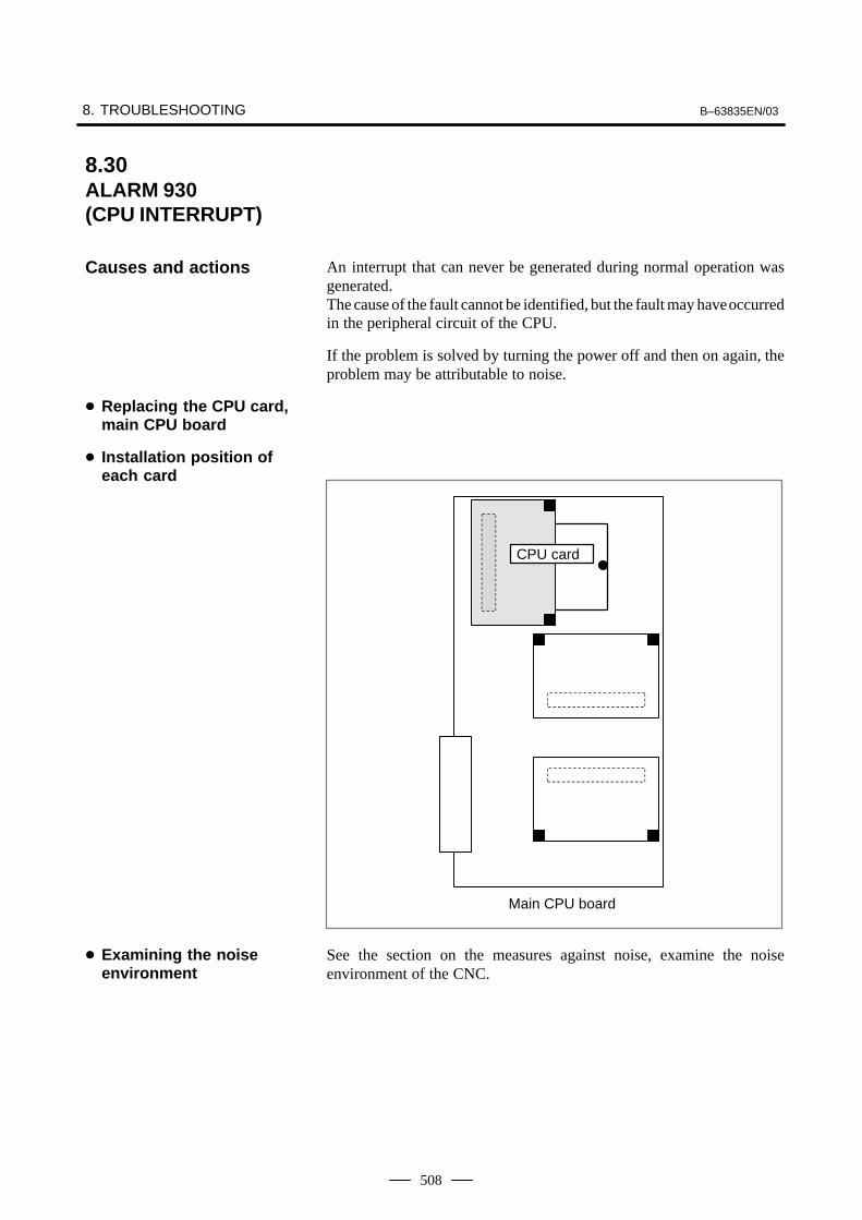
8. TROUBLESHOOTING B–63835EN/03
508
An interrupt that can never be generated during normal operation wasgenerated.The cause of the fault cannot be identified, but the fault may have occurredin the peripheral circuit of the CPU.
If the problem is solved by turning the power off and then on again, theproblem may be attributable to noise.
Main CPU board
CPU card
See the section on the measures against noise, examine the noiseenvironment of the CNC.
8.30ALARM 930 (CPU INTERRUPT)
Causes and actions
� Replacing the CPU card,main CPU board
� Installation position ofeach card
� Examining the noiseenvironment

B–63835EN/03 8.TROUBLESHOOTING
509
An ECC error occurred in the SRAM used to store data such as parametersand machining programs.
This alarm is issued if the battery has run down or if the data in the SRAMis destroyed due to some external cause. Or, the FROM/SRAM moduleor motherboard may be defective.
This is the method of checking the data stored in the SRAM. It has beenemployed instead of the conventional parity check.With the ECC check method, 8–bit correction data is provided for 16–bitdata, so that if a data error occurs in one of these 16 bits, the error isautomatically corrected with the correction data, allowing the CNC tocontinue operation. This alarm is issued if a data error occurs in two ormore bits.With the conventional parity check method, a system alarm is issued if adata error occurs even in one bit.
The battery is rated 3 V. A battery alarm is issued and “BAT” flashes onthe screen if the voltage of the battery drops to 2.6 V.If a battery alarm is issued, replace the battery with a new one promptly.
Perform a memory all clear operation, then start up the CNC.Alternatively, if a backup of the data in the SRAM has been made, use thebackup to restore the data. To back up and restore the data in the SRAM,use the boot system.
If memory all clear or the restoration of the data with a backup does notsolve the problem, replace the FROM/SRAM module. Take a backupcopy in advance. All the software must be restored after the replacement.After replacing the FROM/SRAM module, perform a memory all clearoperation and start up the CNC. All the data must be re–loaded.If a backup is available, restore the data using the backup, then start upthe CNC.
If any of the above actions does not solve the problem, replace the mainCPU board.
8.31ALARM 935 (SRAM ECC ERROR)
Causes and actions
� ECC check
� Checking the battery
� Performing memory allclear
� Replacing theFROM/SRAM module
� Main CPU board
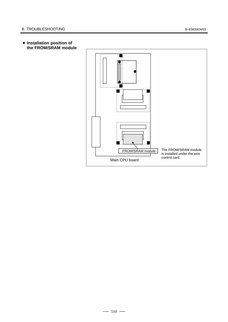
8. TROUBLESHOOTING B–63835EN/03
510
Main CPU board
FROM/SRAM module The FROM/SRAM moduleis installed under the axiscontrol card.
� Installation position ofthe FROM/SRAM module

B–63835EN/03 8.TROUBLESHOOTING
511
This alarm is issued if a fault is detected in the PMC.
The probable causes include an I/O link communication error and adefective PMC control circuit
The I/O Link is a serial interface that connects the CNC to various I/Odevices and allows transfers of I/O signals between devices at high speed.When multiple devices are connected using the I/O Link, there forms arelationship that a certain device is a master and the other devices areslaves. The states of the input signals from the slaves are transferred tothe master at fixed intervals. The output signals from the master aretransferred to the slaves at fixed intervals. In a CNC system, the masteris the CNC (main CPU board).The I/O signals transferred via the I/O link can be used with the PMCLadder.
Master station (CNC) Slave station #0
Slave station #1
Group 0
Group 1
Up to 16 groupsThe I/O card for the Series 0i–B is also used asI/O link slave station #0.
If alarm 950 is issued, displaying “PC050” on the screen, an I/O linkcommunication error may have occurred.
Screen display example
SYSTEM ALARM
950 PMC SYSTEM ALARMPC050 I/OLINK(CH1) xx:yy–aa:bborPC050 I/OLINK(CH2) aa:bb–xx:yyorPC050 IOLINK CH1 aabb–xxyy:aabborPC050 IOLINK CH2 aabb:aabb–xxyy
In this screen display example, the cause of the alarm can be estimatedusing xx:yy. xx and yy are hexadecimal representations. CH1 and CH2are channels on which communication failed.
8.32ALARM 950 (PMC SYSTEMALARM)
Causes and actions
� Connecting the I/O Link
� I/O Link communicationerror PC050

8. TROUBLESHOOTING B–63835EN/03
512
1) If bit 0 of the binary representation of xx is “1”, this indicates that themaster station (CNC) received invalid communication data. Forexample, assume that the following is displayed on the screen:
SYSTEM ALARM
950 PMC SYSTEM ALARMPC050 IOLINK CH1 aabb–4142:aabb
xx is equal to 41, or “01000001” in binary notation. Bit 0, which isthe lowest (rightmost) bit, is “1”.In this case, check the following:
(1)Noise environment of the I/O Link cableNoise may disturb the data on the I/O Link and may result in aproblem.
(2)Contact of the I/O Link cableCheck that the I/O link cable is in contact. Check that the cable isnot loose and is latched firmly.
(3)Cable failureCheck that the I/O Link cable is connected properly.
(4)Device failureThe motherboard or any of the I/O devices connected to the I/OLink may be defective. Replace the devices, one at a time, toidentify the defective device.
Refer to 2) if bit 1 (second bit from the right) is also “1”.
2) If bit 1 of the binary representation of xx is “1”, this indicates that anerror was detected on a slave station (I/O device). For example,assume that the following is displayed on the screen:
SYSTEM ALARM
950 PMC SYSTEM ALARMPC050 IOLINK CH1 aabb–4382:aabb
xx is equal to 43, or “01000011” in binary notation. Bit 1 (second bitfrom the right) is “1”.In this case, yy indicates the following:
Number equal to the number indicated by bits 0 to 4 of yy minus 1:Group number of the slave station on which an error was detected
Bit 5 of yy:Invalid communication data was detected on the slave.
Bit 6 of yy:Another error was detected on the slave.
Bit 7 of yy:A watchdog or parity error was detected on the slave.
In the example shown in the figure above, yy is equal to 82, or“10000010” in binary notation. Bits 0 to 4 are “00010” (2 in decimalnotation). The number “1”, which is equal to that number minus 1, isthe group number of the slave station on which an error was detected.Bit 7 is “1”. Thus, a watchdog or parity error was detected on the slavestation in group 1.
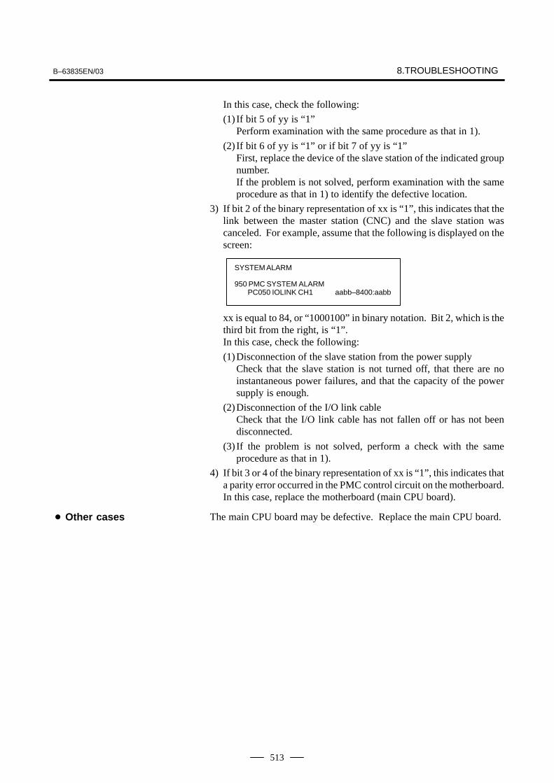
B–63835EN/03 8.TROUBLESHOOTING
513
In this case, check the following:
(1) If bit 5 of yy is “1”Perform examination with the same procedure as that in 1).
(2) If bit 6 of yy is “1” or if bit 7 of yy is “1”First, replace the device of the slave station of the indicated groupnumber.If the problem is not solved, perform examination with the sameprocedure as that in 1) to identify the defective location.
3) If bit 2 of the binary representation of xx is “1”, this indicates that thelink between the master station (CNC) and the slave station wascanceled. For example, assume that the following is displayed on thescreen:
SYSTEM ALARM
950 PMC SYSTEM ALARMPC050 IOLINK CH1 aabb–8400:aabb
xx is equal to 84, or “1000100” in binary notation. Bit 2, which is thethird bit from the right, is “1”.In this case, check the following:
(1)Disconnection of the slave station from the power supplyCheck that the slave station is not turned off, that there are noinstantaneous power failures, and that the capacity of the powersupply is enough.
(2)Disconnection of the I/O link cableCheck that the I/O link cable has not fallen off or has not beendisconnected.
(3) If the problem is not solved, perform a check with the sameprocedure as that in 1).
4) If bit 3 or 4 of the binary representation of xx is “1”, this indicates thata parity error occurred in the PMC control circuit on the motherboard.In this case, replace the motherboard (main CPU board).
The main CPU board may be defective. Replace the main CPU board.� Other cases
8. TROUBLESHOOTING B–63835EN/03
514
This alarm is issued if a fault (watchdog alarm) is detected in the PMC.A probable cause is that the MC control circuit is defective.
The PMC control circuit is installed on the main CPU board. Replace themain CPU board.
8.33ALARM 951 (PMC WATCHDOGALARM)
Causes and actions
� Replacing the main CPUboard

B–63835EN/03 8.TROUBLESHOOTING
515
This alarm indicates that an error was detected on an option board, not onthe main CPU board.
If alarm 972 is issued, the following is displayed on the screen:
Screen display example
SYSTEM ALARM
972 NMI OCCURRED IN OTHER MODULE
SLOT 0�
“SLOT” indicates the number of the slot into which the option board isinserted. Alternatively, it may indicate the number of the alarm thatoccurred on the option board. Take the action related to that alarm to theoption board.
The slot number of each option slot is as shown in the figure below.
SLOT 10
SLOT 9
SLOT 1
Replace the option board inserted into the slot with the indicated slotnumber.
8.34ALARM 972 (NMI ALARM ON ANOPTION BOARD)(Series 0i–B ONLY)
Causes and actions
� Screen display
� Slot number
� Replacing the optionboard

8. TROUBLESHOOTING B–63835EN/03
516
An error that can never occur during normal operation occurred. Thecause of the error cannot be identified.
Replace all the printed circuit boards installed (including cards, modules,and the back panel), one at a time, to identify the defective printed circuitboard.Replace the CPU card, motherboard, and other printed circuit boards, oneat a time.
8.35ALARM 973 (NMI ALARM WITHAN UNKNOWNCAUSE)
Causes and actions
� Replacing printed circuitboards

B–63835EN/03 8.TROUBLESHOOTING
517
A bus error occurred on the FANUC–BUS connecting each option board.
This alarm indicates that a fault occurred during the exchange of databetween the main CPU and an option board.
Replace the CPU card on the main CPU board.
Replace the main CPU board.
Replace the installed option boards, one at a time.
Replace the back panel.
Main CPU board
CPU card
8.36ALARM 974 (F–BUS ERROR)
Causes and actions
� Replacing the CPU card
� Replacing themotherboard
� Replacing the optionboards
� Replacing the back panel
� Installation position ofthe CPU card
8. TROUBLESHOOTING B–63835EN/03
518
A bus error occurred on the main CPU board. This alarm indicates thatan error occurred during the exchange of data within the main CPU board.
Replace the CPU card on the main CPU board.
Replace the display control card, axis control cards, and FROM/SRAMmodule, one at time.
Replace the main CPU board.
8.37ALARM 975 (BUS ERROR)
Causes and actions
� Replacing the CPU card
� Replacing other cardsand modules
� Replacing the main CPUboard

B–63835EN/03 8.TROUBLESHOOTING
519
A bus error occurred on the local bus on the main CPU board.
This alarm indicates that an error occurred during the exchange of datawithin the main CPU board.
Replace the CPU card on the main CPU board (main CPU board).
Replace the display control card, axis control cards, and FROM/SRAMmodule, one at a time.
Replace the main CPU board.
8.38ALARM 976 (LOCAL BUS ERROR)
Causes and actions
� Replacing the CPU card
� Replacing other cardsand modules
� Replacing the main CPUboard

8. TROUBLESHOOTING B–63835EN/03
520
For an explanation of the following servo alarms, refer to the FANUCSERVO MOTOR αi series Maintenance Manual (B–65285EN).
Number Message Contents
417 SERVO ALARM: n–TH AXIS – PA-RAMETER INCORRECT
This alarm occurs when the n–th axis (axis 1–8) is in one of the condi-tions listed below. (Digital servo system alarm)
1) The value set in Parameter No. 2020 (motor form) is out of the speci-fied limit.
2) A proper value (111 or –111) is not set in parameter No.2022 (motorrevolution direction).
3) Illegal data (a value below 0, etc.) was set in parameter No. 2023(number of speed feedback pulses per motor revolution).
4) Illegal data (a value below 0, etc.) was set in parameter No. 2024(number of position feedback pulses per motor revolution).
5) Parameters No. 2084 and No. 2085 (flexible field gear rate) have notbeen set.
6) A value outside the limit of {1 to the number of control axes} or a non–continuous value (Parameter 1023 (servo axis number) contains avalue out of the range from 1 to the number of axes, or an isolatedvalue (for example, 4 not prceded by 3).was set in parameter No.1023 (servo axisnumber).
420 SERVO ALARM: n AXIS SYNCTORQUE
During simple synchronous control, the difference between the torquecommands for the master and slave axes exceeded the value set in pa-rameter No. 2031.
421 SERVO ALARM: n AXIS EXCESSER (D)
The difference between the errors in the semi–closed loop and closedloop has become excessive during dual position feedback. Check thevalues of the dual position conversion coefficients in parameters No.2078 and 2079.
422 SERVO ALARM: n AXIS In torque control of PMC axis control, a specified allowable speedhas been exceeded.
423 SERVO ALARM: n AXIS In torque control of PMC axis control, the parameter–set allowablecumulative travel distance has been exceeded.
430 n AXIS : SV. MOTOR OVERHEAT A servo motor overheat occurred.
431 n AXIS : CNV. OVERLOAD 1) PSM: Overheat occurred.
2) β series SVU: Overheat occurred.
432 n AXIS : CNV. LOWVOLT CON. 1) PSM: The control power supply voltage has dropped.
2) PSMR: The control power supply voltage has dropped.
3) β series SVU: The control power supply voltage has dropped.
433 n AXIS : CNV. LOWVOLT DC LINK 1) PSM: The DC link voltage has dropped.
2) PSMR: The DC link voltage has dropped.
3) α series SVU: The DC link voltage has dropped.
4) β series SVU: The DC link voltage has dropped.
434 n AXIS : INV. LOWVOLT CONTROL SVM: The control power supply voltage has dropped.
435 n AXIS : INV. LOWVOLT DC LINK SVM: The DC link voltage has dropped.
436 n AXIS : SOFTTHERMAL (OVC) The digital servo software detected the soft thermal state (OVC).
437 n AXIS : CNV. OVERCURRENTPOWER
PSM: Overcurrent flowed into the input circuit.
438 n AXIS : INV. ABNORMAL CUR-RENT
1) SVM: The motor current is too high.
2) α series SVU: The motor current is too high.
3) β series SVU: The motor current is too high.
8.39SERVO ALARMS

B–63835EN/03 8.TROUBLESHOOTING
521
Number ContentsMessage
439 n AXIS : CNV. OVERVOLT POWER 1) PSM: The DC link voltage is too high.
2) PSMR: The DC link voltage is too high.
3) α series SVU: The C link voltage is too high.
4) β series SVU: The link voltage is too high.
440 n AXIS : CNV. EX DECELERATIONPOW.
1) PSMR: The regenerative discharge amount is too large.
2) α series SVU: The regenerative discharge amount is too large. Al-ternatively, the regenerative discharge circuit is abnormal.
441 n AXIS : ABNORMAL CURRENTOFFSET
The digital servo software detected an abnormality in the motor cur-rent detection circuit.
442 n AXIS : CNV. CHARGE FAULT 1) PSM: The spare discharge circuit of the DC link is abnormal.
2) PSMR: The spare discharge circuit of the DC link is abnormal.
443 n AXIS : CNV. COOLING FAN FAIL-URE
1) PSM: The internal stirring fan failed.
2) PSMR: The internal stirring fan failed.
3) β series SVU: The internal stirring fan failed.
444 n AXIS : INV. COOLING FAN FAIL-URE
SVM: The internal stirring fan failed.
445 n AXIS : SOFT DISCONNECTALARM
The digital servo software detected a broken wire in the pulse coder.
446 n AXIS : HARD DISCONNECTALARM
A broken wire in the built–in pulse coder was detected by hardware.
447 n AXIS : HARD DISCONNECT (EXT) A broken wire in the separate detector was detected by hardware.
448 n AXIS : UNMATCHED FEEDBACKALARM
The sign of feedback data from the built–in pulse coder differs fromthat of feedback data from the separate detector.
449 n AXIS : INV. IPM ALARM 1) SVM: IPM (intelligent power module) detected an alarm.
2) α series SVU: IPM (intelligent power module) detected an alarm.
453 n AXIS : SPC SOFT DISCONNECTALARM
Software disconnection alarm of the α pulse coder.Turn off the power to the CNC, then remove and insert the pulse cod-er cable. If this alarm is issued again, replace the pulse coder.
456 ILLEGAL CURRENT LOOP The current control cycle settings (parameter No. 2004, bit 0 of pa-rameter No. 2003, and bit 0 of parameter No. 2013) are incorrect.Possible problems are as follows.
– For the two axes whose servo axis numbers (settings of parameterNo. 1023) are an odd number followed by an even number (a pairof axes 1 and 2 or axes 5 and 6, for example), a different current con-trol cycle is set for each of the axes.
– The requirements for slaves needed for the set current control cycle,including the number, type, and connection method of them, are notsatisfied.
457 ILLEGAL HI HRV (250US) Use of high–speed HRV is specified although the current controlcycle is 200 �s.
458 CURRENT LOOP ERROR The current control cycle setting does not match the actual currentcontrol cycle.
459 HI HRV SETTING ERROR For the two axes whose servo axis numbers (settings of parameterNo. 1023) are an odd number followed by an even number (a pair ofaxes 1 and 2 or axes 5 and 6, for example), the SVM for one of theaxes supports high–speed HRV control but the SVM for the otherdoes not. Refer to the SVM specification.

8. TROUBLESHOOTING B–63835EN/03
522
Number ContentsMessage
460 n AXIS : FSSB DISCONNECT FSSB communication was disconnected suddenly. The possiblecauses are as follows:
1) The FSSB communication cable was disconnected or broken.
2) The power to the amplifier was turned off suddenly.
3) A low–voltage alarm was issued by the amplifier.
461 n AXIS : ILLEGAL AMP INTERFACE The axes of the 2–axis amplifier were assigned to the fast type inter-face.
462 n AXIS : SEND CNC DATA FAILED Because of an FSSB communication error, a slave could not receivecorrect data.
463 n AXIS : SEND SLAVE DATAFAILED
Because of an FSSB communication error, the servo system couldnot receive correct data.
464 n AXIS : WRITE ID DATA FAILED An attempt was made to write maintenance information on the ampli-fier maintenance screen, but it failed.
465 n AXIS : READ ID DATA FAILED At power–up, amplifier initial ID information could not be read.
466 n AXIS : MOTOR/AMP COMBINA-TION
The maximum current rating for the amplifier does not match that forthe motor.
467 n AXIS : ILLEGAL SETTING OFAXIS
The servo function for the following has not been enabled when anaxis occupying a single DSP (corresponding to two ordinary axes) isspecified on the axis setting screen.
1. Learning control (bit 5 of parameter No. 2008 = 1)
2. High–speed current loop (bit 0 of parameter No. 2004 = 1)
3. High–speed interface axis (bit 4 of parameter No. 2005 = 1)
468 HI HRV SETTING ERROR (AMP) Use of high–speed HRV is specified for a controlled axis of an ampli-fier which does not support high–speed HRV.
600 n AXIS : INV. DC LINK OVER CUR-RENT
DC link current is too large.
601 n AXIS : INV. RADIATOR FAN FAIL-URE
The external dissipator stirring fan failed.
602 n AXIS : INV. OVERHEAT The servo amplifier was overheated.
603 n AXIS : INV. IPM ALARM (OH) The IPM (intelligent power module) detected an overheat alarm.
604 n AXIS : AMP. COMMUNICATIONERROR
Communication between the SVM and the PSM failed.
605 n AXIS : CNV. EX. DISCHARGEPOW.
PSMR: Regenerative power is too large.
606 n AXIS : CNV. RADIATOR FAN FAIL-URE
PSM: The external dissipator stirring fan failed.
PSMR: The external dissipator stirring fan failed.
607 n AXIS : CNV. SINGLE PHASE FAIL-URE
PSM: Input voltage is in the open–phase condition.
PSMR: Input voltage is in the open–phase condition.
If the hardware on the CNC is suspected to be defective as a result ofexamination, replace the axis control cards.
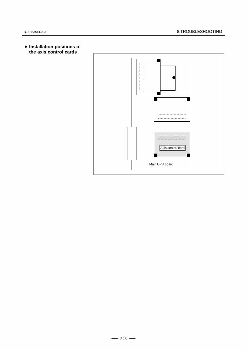
B–63835EN/03 8.TROUBLESHOOTING
523
Axis control card
Main CPU board
� Installation positions ofthe axis control cards
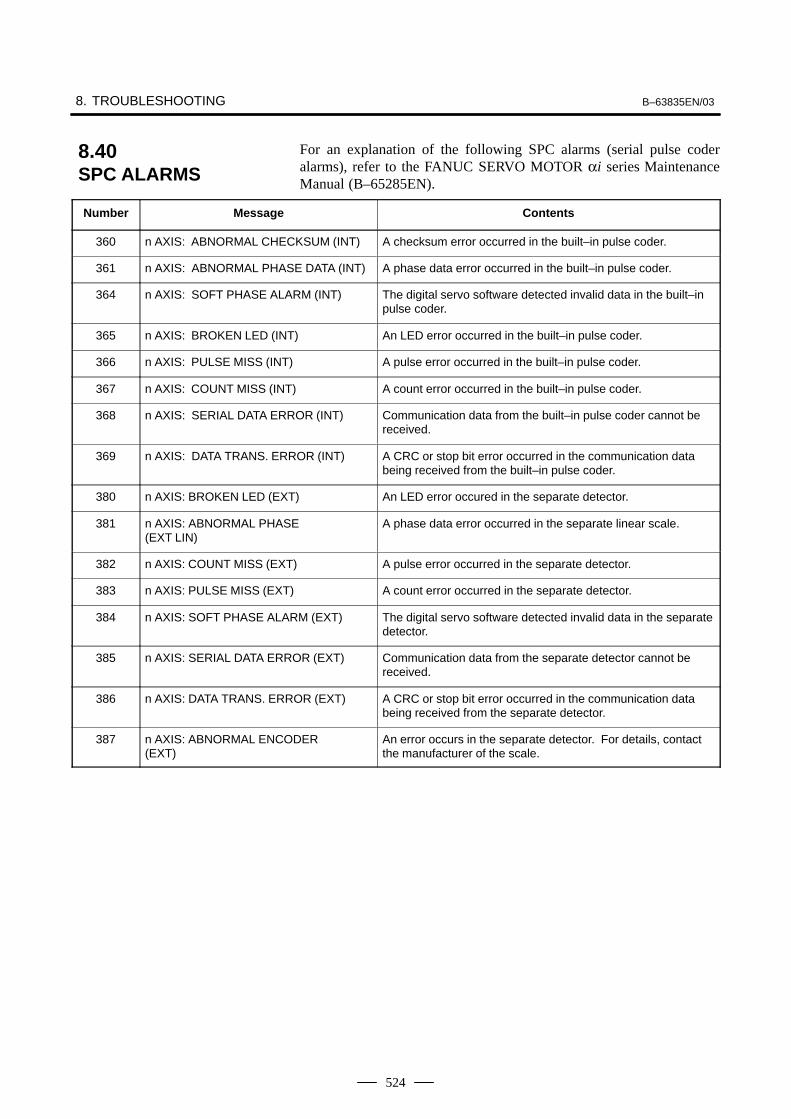
8. TROUBLESHOOTING B–63835EN/03
524
For an explanation of the following SPC alarms (serial pulse coderalarms), refer to the FANUC SERVO MOTOR αi series MaintenanceManual (B–65285EN).
Number Message Contents
360 n AXIS: ABNORMAL CHECKSUM (INT) A checksum error occurred in the built–in pulse coder.
361 n AXIS: ABNORMAL PHASE DATA (INT) A phase data error occurred in the built–in pulse coder.
364 n AXIS: SOFT PHASE ALARM (INT) The digital servo software detected invalid data in the built–inpulse coder.
365 n AXIS: BROKEN LED (INT) An LED error occurred in the built–in pulse coder.
366 n AXIS: PULSE MISS (INT) A pulse error occurred in the built–in pulse coder.
367 n AXIS: COUNT MISS (INT) A count error occurred in the built–in pulse coder.
368 n AXIS: SERIAL DATA ERROR (INT) Communication data from the built–in pulse coder cannot bereceived.
369 n AXIS: DATA TRANS. ERROR (INT) A CRC or stop bit error occurred in the communication databeing received from the built–in pulse coder.
380 n AXIS: BROKEN LED (EXT) An LED error occured in the separate detector.
381 n AXIS: ABNORMAL PHASE (EXT LIN)
A phase data error occurred in the separate linear scale.
382 n AXIS: COUNT MISS (EXT) A pulse error occurred in the separate detector.
383 n AXIS: PULSE MISS (EXT) A count error occurred in the separate detector.
384 n AXIS: SOFT PHASE ALARM (EXT) The digital servo software detected invalid data in the separatedetector.
385 n AXIS: SERIAL DATA ERROR (EXT) Communication data from the separate detector cannot bereceived.
386 n AXIS: DATA TRANS. ERROR (EXT) A CRC or stop bit error occurred in the communication databeing received from the separate detector.
387 n AXIS: ABNORMAL ENCODER(EXT)
An error occurs in the separate detector. For details, contactthe manufacturer of the scale.
8.40SPC ALARMS

B–63835EN/03 8.TROUBLESHOOTING
525
For an explanation of the following spindle alarms, refer to the FANUCSERVO MOTOR αi series Maintenance Manual (B–65285EN).
Number Contents
7101 to 7199 Spindle 1 alarm (SPM display 01 to 99)
7201 to 7299 Spindle 2 alarm (SPM display 01 to 99)
7301 to 7399 Spindle 3 alarm (SPM display 01 to 99)
7401 to 7499 Spindle 4 alarm (SPM display 01 to 99)
Number Contents
9001 to later: Spindle_n n–th spindle alarm (SPM display 01 or larger)
8.41SPINDLE ALARMS


APPENDIX


APPENDIXB–63835EN/03 A. ALARM LIST
529
A ALARM LIST
A.1 LIST OF ALARM CODES (CNC) 530. . . . . . . . . . . . . . A.2 LIST OF ALARMS (PMC) 567. . . . . . . . . . . . . . . . . . . . A.3 ALARM LIST (SERIAL SPINDLE) 592. . . . . . . . . . . . . A.4 ERROR CODES (SERIAL SPINDLE) 604. . . . . . . . . . .
CAUTIONThe alarm list also contains a description of the alarms forthe functions that are invalid for the Series 0i–B and Series0i Mate–B.

APPENDIXA. ALARM LIST B–63835EN/03
530
(1) Program errors /Alarms on program and operation (P/S alarm)
Number Message Contents
000 PLEASE TURN OFF POWER A parameter which requires the power off was input, turn off power.
001 TH PARITY ALARM TH alarm (A character with incorrect parity was input). Correct the tape.
002 TV PARITY ALARM TV alarm (The number of characters in a block is odd). This alarm willbe generated only when the TV check is effective.
003 TOO MANY DIGITS Data exceeding the maximum allowable number of digits was input.(Refer to the item of max. programmable dimensions.)
004 ADDRESS NOT FOUND A numeral or the sign “ – ” was input without an address at the beginningof a block. Modify the program .
005 NO DATA AFTER ADDRESS The address was not followed by the appropriate data but was followedby another address or EOB code. Modify the program.
006 ILLEGAL USE OF NEGATIVE SIGN Sign “ – ” input error (Sign “ – ” was input after an address with which itcannot be used. Or two or more “ – ” signs were input.) Modify the program.
007 ILLEGAL USE OF DECIMAL POINT Decimal point “ . ” input error (A decimal point was input after an addresswith which it can not be used. Or two decimal points were input.)Modify the program.
009 ILLEGAL ADDRESS INPUT Unusable character was input in significant area.Modify the program.
010 IMPROPER G–CODE An unusable G code or G code corresponding to the function not pro-vided is specified. Modify the program.
011 NO FEEDRATE COMMANDED Feedrate was not commanded to a cutting feed or the feedrate was in-adequate. Modify the program.
014 CAN NOT COMMAND G95(M series)
A synchronous feed is specified without the option for threading / syn-chronous feed.
ILLEGAL LEAD COMMAND(T series)
In variable lead threading, the lead incremental and decremental out-putted by address K exceed the maximum command value or a com-mand such that the lead becomes a negative value is given.Modify the program.
015 TOO MANY AXES COMMANDED(M series)
An attempt was made to move the machine along the axes, but the num-ber of the axes exceeded the specified number of axes controlled simul-taneously. Modify the program.
TOO MANY AXES COMMANDED(T series)
An attempt has been made to move the tool along more than the maxi-mum number of simultaneously controlled axes. Alternatively, no axismovement command or an axis movement command for two or moreaxes has been specified in the block containing the command for skipusing the torque limit signal (G31 P99/98). The command must be ac-companied with an axis movement command for a single axis, in thesame block.
020 OVER TOLERANCE OF RADIUS In circular interpolation (G02 or G03), difference of the distance betweenthe start point and the center of an arc and that between the end pointand the center of the arc exceeded the value specified in parameter No.3410.
021 ILLEGAL PLANE AXIS COMMAN-DED
An axis not included in the selected plane (by using G17, G18, G19) wascommanded in circular interpolation. Modify the program.
022 NO CIRCLE RADIUS The command for circular interpolation lacks arc radius R or coordinateI, J, or K of the distance between the start point to the center of the arc.
A.1LIST OF ALARMCODES (CNC)
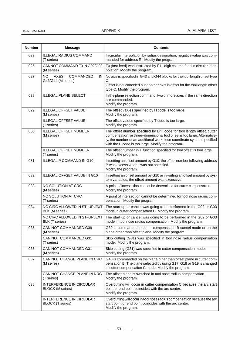
APPENDIXB–63835EN/03 A. ALARM LIST
531
Number ContentsMessage
023 ILLEGAL RADIUS COMMAND(T series)
In circular interpolation by radius designation, negative value was com-manded for address R. Modify the program.
025 CANNOT COMMAND F0 IN G02/G03(M series)
F0 (fast feed) was instructed by F1 –digit column feed in circular inter-polation. Modify the program.
027 NO AXES COMMANDED ING43/G44 (M series)
No axis is specified in G43 and G44 blocks for the tool length offset typeC.Offset is not canceled but another axis is offset for the tool length offsettype C. Modify the program.
028 ILLEGAL PLANE SELECT In the plane selection command, two or more axes in the same directionare commanded.Modify the program.
029 ILLEGAL OFFSET VALUE(M series)
The offset values specified by H code is too large.Modify the program.
ILLEGAL OFFSET VALUE(T series)
The offset values specified by T code is too large.Modify the program.
030 ILLEGAL OFFSET NUMBER(M series)
The offset number specified by D/H code for tool length offset, cuttercompensation, or three–dimensional tool offset is too large. Alternative-ly, the number of an additional workpiece coordinate system specifiedwith the P code is too large. Modify the program.
ILLEGAL OFFSET NUMBER(T series)
The offset number in T function specified for tool offset is tool large.Modify the program.
031 ILLEGAL P COMMAND IN G10 In setting an offset amount by G10, the offset number following addressP was excessive or it was not specified.Modify the program.
032 ILLEGAL OFFSET VALUE IN G10 In setting an offset amount by G10 or in writing an offset amount by sys-tem variables, the offset amount was excessive.
033 NO SOLUTION AT CRC(M series)
A point of intersection cannot be determined for cutter compensation. Modify the program.
NO SOLUTION AT CRC(T series)
A point of intersection cannot be determined for tool nose radius com-pensation. Modify the program.
034 NO CIRC ALLOWED IN ST–UP /EXTBLK (M series)
The start up or cancel was going to be performed in the G02 or G03mode in cutter compensation C. Modify the program.
NO CIRC ALLOWED IN ST–UP /EXTBLK (T series)
The start up or cancel was going to be performed in the G02 or G03mode in tool nose radius compensation. Modify the program.
035 CAN NOT COMMANDED G39(M series)
G39 is commanded in cutter compensation B cancel mode or on theplane other than offset plane. Modify the program.
CAN NOT COMMANDED G31(T series)
Skip cutting (G31) was specified in tool nose radius compensationmode. Modify the program.
036 CAN NOT COMMANDED G31(M series)
Skip cutting (G31) was specified in cutter compensation mode.Modify the program.
037 CAN NOT CHANGE PLANE IN CRC(M seires)
G40 is commanded on the plane other than offset plane in cutter com-pensation B. The plane selected by using G17, G18 or G19 is changedin cutter compensation C mode. Modify the program.
CAN NOT CHANGE PLANE IN NRC(T seires)
The offset plane is switched in tool nose radius compensation.Modify the program.
038 INTERFERENCE IN CIRCULAR BLOCK (M seires)
Overcutting will occur in cutter compensation C because the arc startpoint or end point coincides with the arc center. Modify the program.
INTERFERENCE IN CIRCULAR BLOCK (T series)
Overcutting will occur in tool nose radius compensation because the arcstart point or end point coincides with the arc center. Modify the program.

APPENDIXA. ALARM LIST B–63835EN/03
532
Number ContentsMessage
039 CHF/CNR NOT ALLOWED IN NRC(T series)
Chamfering or corner R was specified with a start–up, a cancel, orswitching between G41 and G42 in tool nose radius compensation. Theprogram may cause overcutting to occur in chamfering or corner R.Modify the program.
040 INTERFERENCE IN G90/G94BLOCK (T series)
Overcutting will occur in tool nose radius compensation in canned cycleG90 or G94. Modify the program.
041 INTERFERENCE IN CRC(M seires)
Overcutting will occur in cutter compensation C. Two or more blocks areconsecutively specified in which functions such as the auxiliary functionand dwell functions are performed without movement in the cutter com-pensation mode. Modify the program.
INTERFERENCE IN NRC(T seires)
Overcutting will occur in tool nose radius compensation.Modify the program.
042 G45/G48 NOT ALLOWED IN CRC(M series)
Tool offset (G45 to G48) is commanded in cutter compensation. Modifythe program.
044 G27–G30 NOT ALLOWED IN FIXEDCYC (M series)
One of G27 to G30 is commanded in canned cycle mode. Modify the program.
045 ADDRESS Q NOT FOUND(G73/G83) (M series)
In canned cycle G73/G83, the depth of each cut (Q) is not specified. Al-ternatively, Q0 is specified. Correct the program.
046 ILLEGAL REFERENCE RETURN COMMAND
Other than P2, P3 and P4 are commanded for 2nd, 3rd and 4th refer-ence position return command.
047 ILLEGAL AXIS SELECT Two or more parallel axes (in parallel with a basic axis) have been speci-fied upon start–up of three–dimensional tool compensation or three–di-mensional coordinate conversion.
048 BASIC 3 AXIS NOT FOUND Start–up of three–dimensional tool compensation or three–dimensionalcoordinate conversion has been attempted, but the three basic axesused when Xp, Yp, or Zp is omitted are not set in parameter No. 1022.
049 ILLEGAL OPERATION (G68/G69) (M series)
The commands for three–dimensional coordinate conversion (G68,G69) and tool length compensation (G43, G44, G45) are not nested. Modify the program.
050 CHF/CNR NOT ALLOWED IN THRDBLK (M series)
Optional chamfering or corner R is commanded in the thread cuttingblock.Modify the program.
CHF/CNR NOT ALLOWED IN THRDBLK(T series)
Chamfering or corner R is commanded in the thread cutting block.Modify the program.
051 MISSING MOVE AFTER CHF/CNR(M series)
Improper movement or the move distance was specified in the blocknext to the optional chamfering or corner R block.Modify the program.
MISSING MOVE AFTER CHF/CNR(T series)
Improper movement or the move distance was specified in the blocknext to the chamfering or corner R block.Modify the program.
052 CODE IS NOT G01 AFTER CHF/CNR(M series)
The block next to the chamfering or corner R block is not G01,G02 orG03.Modify the program.
CODE IS NOT G01 AFTER CHF/CNR(T series)
The block next to the chamfering or corner R block is not G01.Modify the program.
053 TOO MANY ADDRESS COMMANDS(M series)
For systems without the arbitary angle chamfering or corner R cutting,a comma was specified. For systems with this feature, a comma was fol-lowed by something other than R or C Correct the program.
TOO MANY ADDRESS COMMANDS(T seires)
In the chamfering and corner R commands, two or more of I, K and Rare specified. Otherwise, the character after a comma(“,”) is not C or Rin direct drawing dimensions programming. Modify the program.
054 NO TAPER ALLOWED AFTER CHF/CNR (T series)
A block in which chamfering in the specified angle or the corner R wasspecified includes a taper command. Modify the program.

APPENDIXB–63835EN/03 A. ALARM LIST
533
Number ContentsMessage
055 MISSING MOVE VALUE IN CHF/CNR(M series)
In the arbitrary angle chamfering or corner R block, the move distanceis less than chamfer or corner R amount.
MISSING MOVE VALUE IN CHF/CNR(T series)
In chamfering or corner R block, the move distance is less than chamferor corner R amount.
056 NO END POINT & ANGLE IN CHF/CNR (T series)
Neither the end point nor angle is specified in the command for the blocknext to that for which only the angle is specified (A). In the chamferingcomman, I(K) is commanded for the X(Z) axis.
057 NO SOLUTION OF BLOCK END(T series)
Block end point is not calculated correctly in direct dimension drawingprogramming.
058 END POINT NOT FOUND(M series)
In a arbitrary angle chamfering or corner R cutting block, a specified axisis not in the selected plane. Correct the program.
END POINT NOT FOUND(T series)
Block end point is not found in direct dimension drawing programming.
059 PROGRAM NUMBER NOT FOUND In an external program number search, a specified program numberwas not found. Otherwise, a program specified for searching is beingedited in background processing. Alternatively, the program with theprogram number specified in a one–touch macro call is not found inmemory. Check the program number and external signal. Or discontin-ue the background eiting.
060 SEQUENCE NUMBER NOT FOUND Commanded sequence number was not found in the sequence numbersearch. Check the sequence number.
061 ADDRESS P/Q NOT FOUND ING70–G73 (T series)
Address P or Q is not specified in G70, G71, G72, or G73 command.Modify the program.
062 ILLEGAL COMMAND IN G71–G76(T series)
1. The depth of cut in G71 or G72 is zero or negative value.
2. The repetitive count in G73 is zero or negative value.
3. the negative value is specified to ∆i or ∆k is zero in G74 or G75.
4. A value other than zero is specified to address U or W though ∆i or∆k is zero in G74 or G75.
5. A negative value is specified to ∆d, thoughthe relief direction in G74or G75 is determined.
6. Zero or a negative value is specified to the height of thread or depthof cut of first time in G76.
7. The specified minimum depth of cut in G76 is greater than the heightof thread.
8. An unusable angle of tool tip is specified in G76.
Modify the program.
063 SEQUENCE NUMBER NOT FOUND(T series)
The sequence number specified by address P in G70, G71, G72, or G73command cannot be searched. Modify the program.
064 SHAPE PROGRAM NOT MONOTO-NOUSLY (T series)
A target shape which cannot be made by monotonic machining wasspecified in a repetitive canned cycle (G71 or G72).
065 ILLEGAL COMMAND IN G71–G73(T series)
1. G00 or G01 is not commanded at the block with the sequence num-ber which is specified by address P in G71, G72, or G73 command.
2. Address Z(W) or X(U) was commanded in the block with a sequencenumber which is specified by address P in G71 or G72, respectively.
Modify the program.
066 IMPROPER G–CODE IN G71–G73(T series)
An unallowable G code was commanded beween two blocks specifiedby address P in G71, G72, or G73. Modify the program.
067 CAN NOT ERROR IN MDI MODE(T series)
G70, G71, G72, or G73 command with address P and Q.Modify the program.
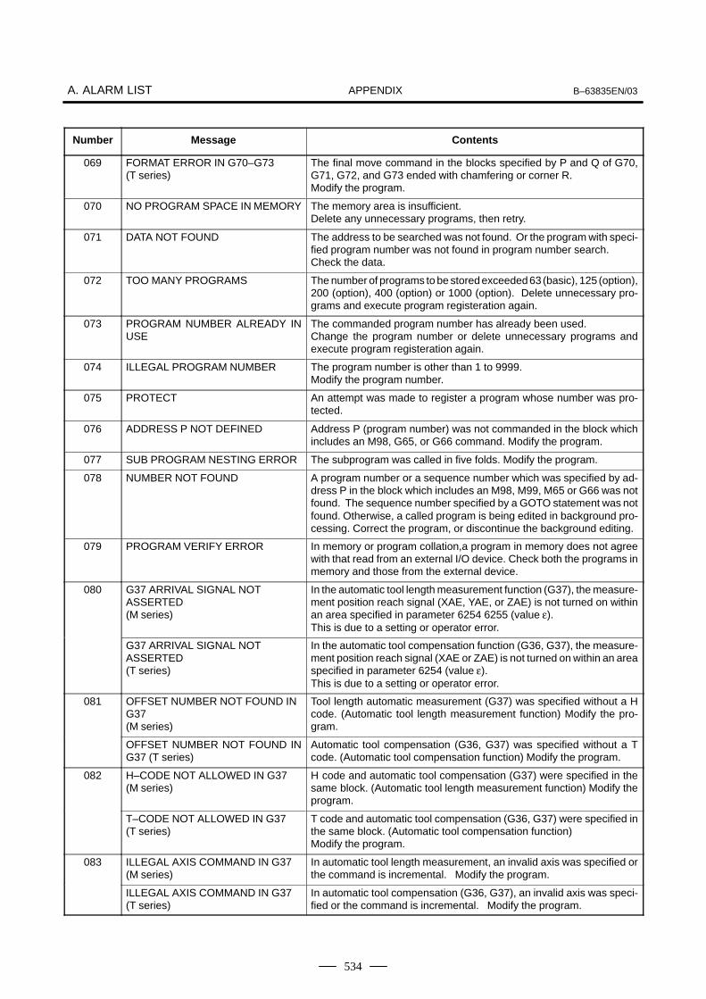
APPENDIXA. ALARM LIST B–63835EN/03
534
Number ContentsMessage
069 FORMAT ERROR IN G70–G73(T series)
The final move command in the blocks specified by P and Q of G70,G71, G72, and G73 ended with chamfering or corner R.Modify the program.
070 NO PROGRAM SPACE IN MEMORY The memory area is insufficient.Delete any unnecessary programs, then retry.
071 DATA NOT FOUND The address to be searched was not found. Or the program with speci-fied program number was not found in program number search.Check the data.
072 TOO MANY PROGRAMS The number of programs to be stored exceeded 63 (basic), 125 (option),200 (option), 400 (option) or 1000 (option). Delete unnecessary pro-grams and execute program registeration again.
073 PROGRAM NUMBER ALREADY INUSE
The commanded program number has already been used.Change the program number or delete unnecessary programs andexecute program registeration again.
074 ILLEGAL PROGRAM NUMBER The program number is other than 1 to 9999.Modify the program number.
075 PROTECT An attempt was made to register a program whose number was pro-tected.
076 ADDRESS P NOT DEFINED Address P (program number) was not commanded in the block whichincludes an M98, G65, or G66 command. Modify the program.
077 SUB PROGRAM NESTING ERROR The subprogram was called in five folds. Modify the program.
078 NUMBER NOT FOUND A program number or a sequence number which was specified by ad-dress P in the block which includes an M98, M99, M65 or G66 was notfound. The sequence number specified by a GOTO statement was notfound. Otherwise, a called program is being edited in background pro-cessing. Correct the program, or discontinue the background editing.
079 PROGRAM VERIFY ERROR In memory or program collation,a program in memory does not agreewith that read from an external I/O device. Check both the programs inmemory and those from the external device.
080 G37 ARRIVAL SIGNAL NOT ASSERTED (M series)
In the automatic tool length measurement function (G37), the measure-ment position reach signal (XAE, YAE, or ZAE) is not turned on withinan area specified in parameter 6254 6255 (value ε). This is due to a setting or operator error.
G37 ARRIVAL SIGNAL NOT ASSERTED(T series)
In the automatic tool compensation function (G36, G37), the measure-ment position reach signal (XAE or ZAE) is not turned on within an areaspecified in parameter 6254 (value ε). This is due to a setting or operator error.
081 OFFSET NUMBER NOT FOUND IN G37(M series)
Tool length automatic measurement (G37) was specified without a Hcode. (Automatic tool length measurement function) Modify the pro-gram.
OFFSET NUMBER NOT FOUND ING37 (T series)
Automatic tool compensation (G36, G37) was specified without a Tcode. (Automatic tool compensation function) Modify the program.
082 H–CODE NOT ALLOWED IN G37(M series)
H code and automatic tool compensation (G37) were specified in thesame block. (Automatic tool length measurement function) Modify theprogram.
T–CODE NOT ALLOWED IN G37(T series)
T code and automatic tool compensation (G36, G37) were specified inthe same block. (Automatic tool compensation function) Modify the program.
083 ILLEGAL AXIS COMMAND IN G37(M series)
In automatic tool length measurement, an invalid axis was specified orthe command is incremental. Modify the program.
ILLEGAL AXIS COMMAND IN G37(T series)
In automatic tool compensation (G36, G37), an invalid axis was speci-fied or the command is incremental. Modify the program.
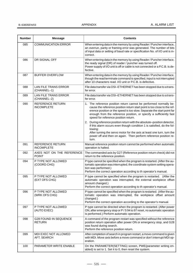
APPENDIXB–63835EN/03 A. ALARM LIST
535
Number ContentsMessage
085 COMMUNICATION ERROR When entering data in the memory by using Reader / Puncher interface,an overrun, parity or framing error was generated. The number of bitsof input data or setting of baud rate or specification No. of I/O unit is in-correct.
086 DR SIGNAL OFF When entering data in the memory by using Reader / Puncher interface,the ready signal (DR) of reader / puncher was turned off.Power supply of I/O unit is off or cable is not connected or a P.C.B. is de-fective.
087 BUFFER OVERFLOW When entering data in the memory by using Reader / Puncher interface,though the read terminate command is specified, input is not interruptedafter 10 characters read. I/O unit or P.C.B. is defective.
088 LAN FILE TRANS ERROR(CHANNEL–1)
File data transfer via OSI–ETHERNET has been stopped due to a trans-fer error.
089 LAN FILE TRANS ERROR(CHANNEL–2)
File data transfer via OSI–ETHERNET has been stopped due to a trans-fer error.
090 REFERENCE RETURN INCOMPLETE
1. The reference position return cannot be performed normally be-cause the reference position return start point is too close to the ref-erence position or the speed is too slow. Separate the start point farenough from the reference position, or specify a sufficiently fastspeed for reference position return.
2. During reference position return with the absolute–position detector,if this alarm occurs even though condition 1 is satisfied, do the fol-lowing:After turning the servo motor for the axis at least one turn, turn thepower off and then on again. Then perform reference position re-turn.
091 REFERENCE RETURN INCOMPLETE
Manual reference position return cannot be performed when automaticoperation is halted.
092 AXES NOT ON THE REFERENCEPOINT
The commanded axis by G27 (Reference position return check) did notreturn to the reference position.
094 P TYPE NOT ALLOWED (COORD CHG)
P type cannot be specified when the program is restarted. (After the au-tomatic operation was interrupted, the coordinate system setting opera-tion was performed.)Perform the correct operation according to th operator’s manual.
095 P TYPE NOT ALLOWED (EXT OFS CHG)
P type cannot be specified when the program is restarted. (After theautomatic operation was interrupted, the external workpiece offsetamount changed.)Perform the correct operation according to th operator’s manual.
096 P TYPE NOT ALLOWED (WRK OFS CHG)
P type cannot be specified when the program is restarted. (After the au-tomatic operation was interrupted, the workpiece offset amountchanged.)Perform the correct operation according to the operator’s manual.
097 P TYPE NOT ALLOWED (AUTO EXEC)
P type cannot be directed when the program is restarted. (After powerON, after emergency stop or P / S 94 to 97 reset, no automatic operationis performed.) Perform automatic operation.
098 G28 FOUND IN SEQUENCE RETURN
A command of the program restart was specified without the referenceposition return operation after power ON or emergency stop, and G28was found during search.Perform the reference position return.
099 MDI EXEC NOT ALLOWED AFT. SEARCH
After completion of search in program restart, a move command is givenwith MDI. Move axis before a move command or don’t interrupt MDI op-eration.
100 PARAMETER WRITE ENABLE On the PARAMETER(SETTING) screen, PWE(parameter writing en-abled) is set to 1. Set it to 0, then reset the system.

APPENDIXA. ALARM LIST B–63835EN/03
536
Number ContentsMessage
101 PLEASE CLEAR MEMORY The power turned off while rewriting the memory by program edit opera-tion. If this alarm has occurred, press <RESET> while pressing<PROG>, and only the program being edited will be deleted.Register the deleted program.
109 FORMAT ERROR IN G08 A value other than 0 or 1 was specified after P in the G08 code, or novalue was specified.
110 DATA OVERFLOW The absolute value of fixed decimal point display data exceeds the al-lowable range. Modify the program.
111 CALCULATED DATA OVERFLOW The result of calculation turns out to be invalid, an alarm No.111 is is-sued.–1047 to –10–29, 0, 10–29 to 1047
Modify the program.
112 DIVIDED BY ZERO Division by zero was specified. (including tan 90°)Modify the program.
113 IMPROPER COMMAND A function which cannot be used in custom macro is commanded.Modify the program.
114 FORMAT ERROR IN MACRO There is an error in other formats than <Formula>.Modify the program.
115 ILLEGAL VARIABLE NUMBER A value not defined as a variable number is designated in the custommacro or in high–speed cycle machining.The header contents are improper. This alarm is given in the followingcases:
High speed cycle machining
1. The header corresponding to the specified machining cycle numbercalled is not found.
2. The cycle connection data value is out of the allowable range (0 – 999).
3. The number of data in the header is out of the allowable range (0 – 32767).
4. The start data variable number of executable format data is out ofthe allowable range (#20000 – #85535).
5. The last storing data variable number of executable format data isout of the allowable range (#85535).
6. The storing start data variable number of executable format data isoverlapped with the variable number used in the header.
Modify the program.
116 WRITE PROTECTED VARIABLE The left side of substitution statement is a variable whose substitutionis inhibited. Modify the program.
118 PARENTHESIS NESTING ERROR The nesting of bracket exceeds the upper limit (quintuple).Modify the program.
119 ILLEGAL ARGUMENT The SQRT argument is negative. Or BCD argument is negative, andother values than 0 to 9 are present on each line of BIN argument.Modify the program.
122 FOUR FOLD MACRO MODAL–CALL The macro modal call is specified four fold.Modify the program.
123 CAN NOT USE MACRO COMMANDIN DNC
Macro control command is used during DNC operation.Modify the program.
124 MISSING END STATEMENT DO – END does not correspond to 1 : 1. Modify the program.
125 FORMAT ERROR IN MACRO <Formula> format is erroneous. Modify the program.
126 ILLEGAL LOOP NUMBER In DOn, 1� n �3 is not established. Modify the program.
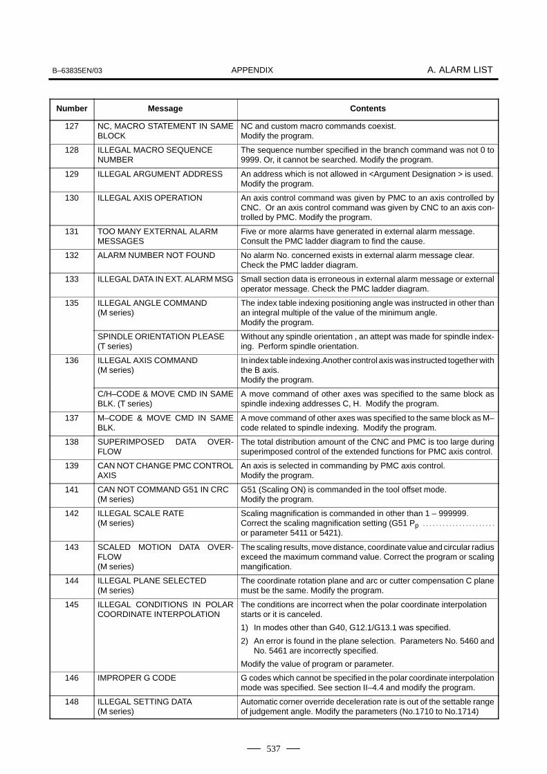
APPENDIXB–63835EN/03 A. ALARM LIST
537
Number ContentsMessage
127 NC, MACRO STATEMENT IN SAMEBLOCK
NC and custom macro commands coexist.Modify the program.
128 ILLEGAL MACRO SEQUENCE NUMBER
The sequence number specified in the branch command was not 0 to9999. Or, it cannot be searched. Modify the program.
129 ILLEGAL ARGUMENT ADDRESS An address which is not allowed in <Argument Designation > is used.Modify the program.
130 ILLEGAL AXIS OPERATION An axis control command was given by PMC to an axis controlled byCNC. Or an axis control command was given by CNC to an axis con-trolled by PMC. Modify the program.
131 TOO MANY EXTERNAL ALARM MESSAGES
Five or more alarms have generated in external alarm message.Consult the PMC ladder diagram to find the cause.
132 ALARM NUMBER NOT FOUND No alarm No. concerned exists in external alarm message clear.Check the PMC ladder diagram.
133 ILLEGAL DATA IN EXT. ALARM MSG Small section data is erroneous in external alarm message or externaloperator message. Check the PMC ladder diagram.
135 ILLEGAL ANGLE COMMAND(M series)
The index table indexing positioning angle was instructed in other thanan integral multiple of the value of the minimum angle.Modify the program.
SPINDLE ORIENTATION PLEASE(T series)
Without any spindle orientation , an attept was made for spindle index-ing. Perform spindle orientation.
136 ILLEGAL AXIS COMMAND(M series)
In index table indexing.Another control axis was instructed together withthe B axis.Modify the program.
C/H–CODE & MOVE CMD IN SAMEBLK. (T series)
A move command of other axes was specified to the same block asspindle indexing addresses C, H. Modify the program.
137 M–CODE & MOVE CMD IN SAMEBLK.
A move command of other axes was specified to the same block as M–code related to spindle indexing. Modify the program.
138 SUPERIMPOSED DATA OVER-FLOW
The total distribution amount of the CNC and PMC is too large duringsuperimposed control of the extended functions for PMC axis control.
139 CAN NOT CHANGE PMC CONTROLAXIS
An axis is selected in commanding by PMC axis control.Modify the program.
141 CAN NOT COMMAND G51 IN CRC(M series)
G51 (Scaling ON) is commanded in the tool offset mode.Modify the program.
142 ILLEGAL SCALE RATE(M series)
Scaling magnification is commanded in other than 1 – 999999.Correct the scaling magnification setting (G51 Pp . . . . . . . . . . . . . . . . . . . . . .
or parameter 5411 or 5421).
143 SCALED MOTION DATA OVER-FLOW(M series)
The scaling results, move distance, coordinate value and circular radiusexceed the maximum command value. Correct the program or scalingmangification.
144 ILLEGAL PLANE SELECTED(M series)
The coordinate rotation plane and arc or cutter compensation C planemust be the same. Modify the program.
145 ILLEGAL CONDITIONS IN POLARCOORDINATE INTERPOLATION
The conditions are incorrect when the polar coordinate interpolationstarts or it is canceled.
1) In modes other than G40, G12.1/G13.1 was specified.
2) An error is found in the plane selection. Parameters No. 5460 andNo. 5461 are incorrectly specified.
Modify the value of program or parameter.
146 IMPROPER G CODE G codes which cannot be specified in the polar coordinate interpolationmode was specified. See section II–4.4 and modify the program.
148 ILLEGAL SETTING DATA(M series)
Automatic corner override deceleration rate is out of the settable rangeof judgement angle. Modify the parameters (No.1710 to No.1714)

APPENDIXA. ALARM LIST B–63835EN/03
538
Number ContentsMessage
150 ILLEGAL TOOL GROUP NUMBER Tool Group No. exceeds the maximum allowable value.Modify the program.
151 TOOL GROUP NUMBER NOTFOUND
The tool group commanded in the machining program is not set.Modify the value of program or parameter.
152 NO SPACE FOR TOOL ENTRY The number of tools within one group exceeds the maximum value re-gisterable. Modify the number of tools.
153 T–CODE NOT FOUND In tool life data registration, a T code was not specified where one shouldbe. Correct the program.
154 NOT USING TOOL IN LIFE GROUP(M series)
When the group is not commanded, H99 or D99 was commanded.Correct the program.
155 ILLEGAL T–CODE IN M06(M series)
In the machining program, M06 and T code in the same block do not cor-respond to the group in use. Correct the program.
ILLEGAL T–CODE IN M06(T series)
Group No.∆∆ which is specified with T∆∆ 88 of the machining programdo not included in the tool group in use. Correct the program.
156 P/L COMMAND NOT FOUND P and L commands are missing at the head of program in which the toolgroup is set. Correct the program.
157 TOO MANY TOOL GROUPS The number of tool groups to be set exceeds the maximum allowablevalue. (See parameter No. 6800 bit 0 and 1) Modify the program.
158 ILLEGAL TOOL LIFE DATA The tool life to be set is too excessive. Modify the setting value.
159 TOOL DATA SETTING INCOMPLETE
During executing a life data setting program, power was turned off. Set again.
160 MISMATCH WAITING M–CODE(T series (At two–path))
Diffrent M code is commanded in heads 1 and 2 as waiting M code.Modify the program.
MISMATCH WAITING M–CODE(T series (At three–path))
1) Although the same P command is specified, the waiting M codes donot match.
2) Although the waiting M codes match, the P commands do not match.
3) Two–path wait and three–path wait are specified simultaneously.
Modify the program.
G72.1 NESTING ERROR(M series)
A subprogram which performs rotational copy with G72.1 containsanother G72.1 command.
161 ILLEGAL P OF WAITING M–CODE (T series (three–path control)
1) The value of address P is a negative value, 1, 2, 4, or a value notsmaller than 8.
2) The value specified in P is not consistent with the system configura-tion.
Modify the program.
G72.1 NESTING ERROR(M series)
A subprogram which performs parallel copy with G72.2 contains anoth-er G72.2 command.
163 COMMAND G68/G69 INDEPEN-DENTLY (T series (At two–path))
G68 and G69 are not independently commanded in balance cut.Modify the program.
169 ILLEGAL TOOL GEOMETRY DATA(At two–path)
Incorrect tool figure data in interference check.Set correct data, or select correct tool figure data.
175 ILLEGAL G107 COMMAND Conditions when performing circular interpolation start or cancel notcorrect. To change the mode to the cylindrical interpolation mode, spec-ify the command in a format of “G07.1 rotation–axis name radius of cylin-der.”

APPENDIXB–63835EN/03 A. ALARM LIST
539
Number ContentsMessage
176 IMPROPER G–CODE IN G107(M series)
Any of the following G codes which cannot be specified in the cylindricalinterpolation mode was specified.1) G codes for positioning: G28,, G73, G74, G76, G81 – G89,
including the codes specifying the rapid traverse cycle2) G codes for setting a coordinate system: G52,G92, 3) G code for selecting coordinate system: G53 G54–G59Modify the program.
IMPROPER G–CODE IN G107(T series)
Any of the following G codes which cannot be specified in the cylindricalinterpolation mode was specified.1) G codes for positioning: G28, G76, G81 – G89, including the
codes specifying the rapid traverse cycle2) G codes for setting a coordinate system: G50, G523) G code for selecting coordinate system: G53 G54–G59Modify the program.
181 FORMAT ERROR IN G81 BLOCK(Hobbing machine, EGB) (M series)
G81 block format error (hobbing machine)
1) T (number of teeth) has not been instructed.
2) Data outside the command range was instructed by either T, L, Q orP.
3) An overflow occurred in synchronization coefficient calculation.
Modify the program.
182 G81 NOT COMMANDED(Hobbing machine) (M series)
G83 (C axis servo lag quantity offset) was instructed though synchro-nization by G81 has not been instructed. Correct the program. (hobbingmachine)
183 DUPLICATE G83 (COMMANDS)(Hobbing machine) (M series)
G83 was instructed before canceled by G82 after compensating for theC axis servo lag quantity by G83. (hobbing machine)
184 ILLEGAL COMMAND IN G81(Hobbing machine, EGB) (M series)
A command not to be instructed during synchronization by G81 wasinstructed. (hobbing machine)
1) A C axis command by G00, G27, G28, G29, G30, etc. wasinstructed.
2) Inch/Metric switching by G20, G21 was instructed.
185 RETURN TO REFERENCE POINT(Hobbing machine) (M series)
G81 was instructed without performing reference position return afterpower on or emergency stop. (hobbing machine) Perform referenceposition return.
186 PARAMETER SETTING ERROR(Hobbing machine, EGB) (M series)
Parameter error regarding G81 (hobbing machine)
1) The C axis has not been set to be a rotary axis.
2) A hob axis and position coder gear ratio setting error
Modify the parameter.
187 HOB COMMAND IS NOT ALLOWED Error in the modal state when G81.4 or G81 is specified
1. The canned cycle mode (G81 to G89) is set.
2. The thread cutting mode is set.
3. The C–axis is under synchronous, composite, or superimposedcontrol.
190 ILLEGAL AXIS SELECT In the constant surface speed control, the axis specification is wrong.(See parameter No. 3770.) The specified axis command (P) contains anillegal value.Correct the program.
194 SPINDLE COMMAND IN SYNCHRO–MODE
A contour control mode, spindle positioning (Cs–axis control) mode, orrigid tapping mode was specified during the serial spindle synchronouscontrol mode. Correct the program so that the serial spindle synchro-nous control mode is released in advance.

APPENDIXA. ALARM LIST B–63835EN/03
540
Number ContentsMessage
197 C–AXIS COMMANDED IN SPINDLEMODE
The program specified a movement along the Cs–axis when the signalCON(DGN=G027#7) was off. Correct the program, or consult the PMCladder diagram to find the reason the signal is not turned on.
199 MACRO WORD UNDEFINED Undefined macro word was used. Modify the custom macro.
200 ILLEGAL S CODE COMMAND In the rigid tap, an S value is out of the range or is not specified.Modify the program.
201 FEEDRATE NOT FOUND IN RIGIDTAP
In the rigid tap, no F value is specified.Correct the program.
202 POSITION LSI OVERFLOW In the rigid tap, spindle distribution value is too large. (System error)
203 PROGRAM MISS AT RIGID TAPPING In the rigid tap, position for a rigid M code (M29) or an S command is in-correct. Modify the program.
204 ILLEGAL AXIS OPERATION In the rigid tap, an axis movement is specified between the rigid M code(M29) block and G84 or G74 for M series (G84 or G88 for T series) block.Modify the program.
205 RIGID MODE DI SIGNAL OFF 1.Although a rigid M code (M29) is specified in rigid tapping, the rigidmode DI signal (DGN G061.0) is not ON during execution of the G84(G88) block.
2. In a system with the multi–spindle option, the spindle used for rigidtapping is not selected (by DI signal G27#0 and #1, or G61#4 and #5).
Check the PMC ladder diagram to find the reason why the DI signalis not turned on.
206 CAN NOT CHANGE PLANE (M series)
Plane changeover was instructed in the rigid mode.Correct the program.
207 RIGID DATA MISMATCH The specified distance was too short or too long in rigid tapping.
210 CAN NOT COMAND M198/M199 M98 and M99 are executed in the schedule operation. M198 isexecuted in the DNC operation. Modify the program.
1) The execution of an M198 or M99 command was attempted duringscheduled operation. Alternatively, the execution of an M198 com-mand was attempted during DNC operation. Correct the program.The execution of an M99 command was attempted by an interruptmacro during pocket machining in a multiple repetitive cannedcycle.
211 G31 (HIGH) NOT ALLOWED IN G99(T series)
G31 is commanded in the per revolution command when the high–speed skip option is provided. Modify the program.
212 ILLEGAL PLANE SELECT(M series)
The arbitrary angle chamfering or a corner R is commanded or the planeincluding an additional axis. Correct the program.
ILLEGAL PLANE SELECT(T series)
The direct drawing dimensions programming is commanded for theplane other than the Z–X plane. Correct the program.
213 ILLEGAL COMMAND IN SYNCHRO–MODE(M series)
Movement is commanded for the axis to be synchronously controlled.Any of the following alarms occurred in the operation with the simplesynchronization control.
1) The program issued the move command to the slave axis.
2) The program issued the manual continuous feed/manual handlefeed/incremental feed command to the slave axis.
3) The program issued the automatic reference position return com-mand without specifying the manual reference position return afterthe power was turned on.
4) The difference between the position error amount of the master andslave axes exceeded the value specified in parameter NO.8313.
ILLEGAL COMMAND IN SYNCHRO–MODE (T series)
A move command has been specified for an axis subject to synchro-nous control.

APPENDIXB–63835EN/03 A. ALARM LIST
541
Number ContentsMessage
214 ILLEGAL COMMAND IN SYNCHRO–MODE
Coordinate system is set or tool compensation of the shift type isexecuted in the synchronous control. Correct the program.
217 DUPLICATE G51.2 (COMMANDS)(T series)
G51.2/G251 is further commanded in the G51.2/G251 mode. Modifythe program.
218 NOT FOUND P/Q COMMAND ING251 (T series)
P or Q is not commanded in the G251 block, or the command value isout of the range. Modify the program.
219 COMMAND G250/G251 INDEPENDENTLY (T series)
G251 and G250 are not independent blocks.
220 ILLEGAL COMMAND IN SYNCHR–MODE (T series)
In the synchronous operation, movement is commanded by the NC pro-gram or PMC axis control interface for the synchronous axis.
221 ILLEGAL COMMAND IN SYNCHR–MODE (T series)
Polygon machining synchronous operation and axis control or balancecutting are executed at a time. Modify the program.
222 DNC OP. NOT ALLOWED IN BG.–EDIT (M series)
Input and output are executed at a time in the background edition.Execute a correct operation.
224 RETURN TO REFERENCE POINT(M series)
Reference position return has not been performed before the automaticoperation starts. Perform reference position return only when bit 0 of pa-rameter 1005 is 0.
TURN TO REFERENCE POINT(T series)
Reference position return is necessary before cycle start.
225 SYNCHRONOUS/MIXED CONTROLERROR(T series (At two–path))
This alarm is generated in the following circumstances. (Searched forduring synchronous and mixed control command.
1 When there is a mistake in axis number parameter (No. 1023) set-ting.
2 When there is a mistake in control commanded.
During hobbing synchronization, a command to bring the C–axis undersynchronous, composite, or superimposed control is made.
Modify the program or the parameter.
226 ILLEGAL COMMAND IN SYNCHRO–MODE (T series (At two–path))
A travel command has been sent to the axis being synchronized in syn-chronous mode. Modify the program or the parameter.
229 CAN NOT KEEP SYNCHRO–STATE(T series)
This alarm is generated in the following circumstances.
1 When the synchro/mixed state could not be kept due to system over-load.
2 The above condition occurred in CMC devices (hardware) and syn-chro–state could not be kept.
(This alarm is not generated in normal use conditions.)
230 R CODE NOT FOUND(Grinding machine) (M series)
The infeed quantity R has not been instructed for the G161 block. Orthe R command value is negative. Correct the program.
231 ILLEGAL FORMAT IN G10 OR L50 Any of the following errors occurred in the specified format at the pro-grammable–parameter input.
1 Address N or R was not entered.
2 A number not specified for a parameter was entered.
3 The axis number was too large.
4 An axis number was not specified in the axis–type parameter.
5 An axis number was specified in the parameter which is not an axistype. Correct the program.
6 In the locked state set by the password function, an attempt wasmade to set bit 4 (NE9) of parameter No. 3204 to 0 or change the con-tents of parameter No. 3210.
7 An attempt was made to change a program encryption parameter(parameter No. 3220 to 3223).
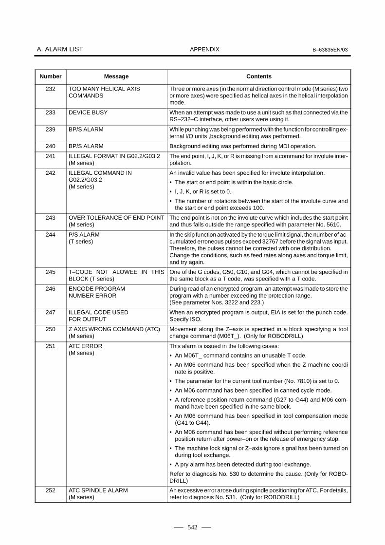
APPENDIXA. ALARM LIST B–63835EN/03
542
Number ContentsMessage
232 TOO MANY HELICAL AXIS COMMANDS
Three or more axes (in the normal direction control mode (M series) twoor more axes) were specified as helical axes in the helical interpolationmode.
233 DEVICE BUSY When an attempt was made to use a unit such as that connected via theRS–232–C interface, other users were using it.
239 BP/S ALARM While punching was being performed with the function for controlling ex-ternal I/O units ,background editing was performed.
240 BP/S ALARM Background editing was performed during MDI operation.
241 ILLEGAL FORMAT IN G02.2/G03.2(M series)
The end point, I, J, K, or R is missing from a command for involute inter-polation.
242 ILLEGAL COMMAND IN G02.2/G03.2(M series)
An invalid value has been specified for involute interpolation.
� The start or end point is within the basic circle.
� I, J, K, or R is set to 0.
� The number of rotations between the start of the involute curve andthe start or end point exceeds 100.
243 OVER TOLERANCE OF END POINT(M series)
The end point is not on the involute curve which includes the start pointand thus falls outside the range specified with parameter No. 5610.
244 P/S ALARM(T series)
In the skip function activated by the torque limit signal, the number of ac-cumulated erroneous pulses exceed 32767 before the signal was input.Therefore, the pulses cannot be corrected with one distribution.Change the conditions, such as feed rates along axes and torque limit,and try again.
245 T–CODE NOT ALOWEE IN THISBLOCK (T series)
One of the G codes, G50, G10, and G04, which cannot be specified inthe same block as a T code, was specified with a T code.
246 ENCODE PROGRAM NUMBER ERROR
During read of an encrypted program, an attempt was made to store theprogram with a number exceeding the protection range.(See parameter Nos. 3222 and 223.)
247 ILLEGAL CODE USED FOR OUTPUT
When an encrypted program is output, EIA is set for the punch code.Specify ISO.
250 Z AXIS WRONG COMMAND (ATC)(M series)
Movement along the Z–axis is specified in a block specifying a toolchange command (M06T_). (Only for ROBODRILL)
251 ATC ERROR(M series)
This alarm is issued in the following cases:
� An M06T_ command contains an unusable T code.
� An M06 command has been specified when the Z machine coordinate is positive.
� The parameter for the current tool number (No. 7810) is set to 0.
� An M06 command has been specified in canned cycle mode.
� A reference position return command (G27 to G44) and M06 com-mand have been specified in the same block.
� An M06 command has been specified in tool compensation mode(G41 to G44).
� An M06 command has been specified without performing referenceposition return after power–on or the release of emergency stop.
� The machine lock signal or Z–axis ignore signal has been turned onduring tool exchange.
� A pry alarm has been detected during tool exchange.
Refer to diagnosis No. 530 to determine the cause. (Only for ROBO-DRILL)
252 ATC SPINDLE ALARM(M series)
An excessive error arose during spindle positioning for ATC. For details,refer to diagnosis No. 531. (Only for ROBODRILL)

APPENDIXB–63835EN/03 A. ALARM LIST
543
Number ContentsMessage
253 G05 IS NOT AVAILABLE(M series)
Alarm detailsBinary input operation using high–speed remote buffer (G05) or high–speed cycle machining (G05) has been specified in advance controlmode (G08P1). Execute G08P0; to cancel advance control mode, be-fore executing these G05 commands.
5010 END OF RECORD The end of record (%) was specified. I/O is incorrect. modify the program.
5011 PARAMETER ZERO(CUT MAX)(M series)
The maximum cutting feedrate (parameter No. 1422, No. 1430, No.1431, No. 1432) is 0 in the HPCC mode.
5014 TRACE DATA NOT FOUND Transfer cannot be performed because no trace data exists.
5015 NO ROTATION AXIS(M series)
The specified rotation axis does not exist for tool axis direction handlefeed.
5016 ILLEGAL COMBINATION OF MCODE
M codes which belonged to the same group were specified in a block.Alternatively,an M code which must be specified without other M codesin the block was specified in a block with other M codes.
5018 POLYGON SPINDLE SPEED ER-ROR(T series)
Function category:Polygon turningAlarm details:In G51.2 mode, the speed of the spindle or polygon synchronous axiseither exceeds the clamp value or is too small. The specified rotationspeed ratio thus cannot be maintained.
5020 PARAMETER OF RESTART ERROR An erroneous parameter was specified for restarting a program.A parameter for program restart is invalid.
5043 TOO MANY G68 NESTING(M series)
Three–dimensional coordinate conversion G68 has been specifiedthree or more times.
TOO MANY G68 NESTING(T series)
Three–dimensional coordinate conversion G68.1 has been specifiedthree or more times.
5044 G68 FORMAT ERROR(M series)
A G68 command block contains a format error. This alarm is issued inthe following cases:
1. I, J, or K is missing from a G68 command block (missing coordinaterotation option).
2. I, J, and K are 0 in a G68 command block.
3. R is missing from a G68 command block.
G68 FORMAT ERROR(T series)
A G68.1 command block contains a format error. This alarm is issuedin the following cases:
1. I, J, or K is missing from a G68.1 command block (missing coordi-nate rotation option).
2. I, J, and K are 0 in a G68.1 command block.
3. R is missing from a G68.1 command block.

APPENDIXA. ALARM LIST B–63835EN/03
544
Number ContentsMessage
5046 ILLEGAL PARAMETER (ST.COMP) The parameter settings for straightness compensation contain an error.Possible causes are as follows:
1. A parameter for a movement axis or compensation axis contains anaxis number which is not used.
2. More than 128 pitch error compensation points exist between thenegative and positive end points.
3. Compensation point numbers for straightness compensation arenot assigned in the correct order.
4. No straightness compensation point exists between the pitch errorcompensation points at the negative and positive ends.
5. The compensation value for each compensation point is too largeor too small.
6 The settings of parameters Nos. 13881 to 13886 are illegal (in theinterpolation type straightness compensation).
5050 ILL–COMMAND IN CHOPPING MODE(M series)
A command for switching the major axis has been specified for circularthreading. Alternatively, a command for setting the length of the majoraxis to 0 has been specified for circular threading.
5051 M–NET CODE ERROR Abnormal character received (other than code used for transmission)
5052 M–NET ETX ERROR Abnormal ETX code
5053 M–NET CONNECT ERROR Connection time monitoring error (parameter No. 175)
5054 M–NET RECEIVE ERROR Polling time monitoring error (parameter No. 176)
5055 M–NET PRT/FRT ERROR Vertical parity or framing error
5057 M–NET BOARD SYSTEM DOWN Transmission timeout error (parameter No. 177)ROM parity errorCPU interrupt other than the above
5058 G35/G36 FORMAT ERROR(T series)
A command for switching the major axis has been specified for circularthreading. Alternatively, a command for setting the length of the majoraxis to 0 has been specified for circular threading.
5059 RADIUS IS OUT OF RANGE A radius exceeding nine digits has been specified for circular interpola-tion with the center of the arc specified with I, J, and K.
5060 ILLEGAL PARAMETER ING02.3/G03.3(M series)
There is a parameter setting error.Parameter No. 5641 (setting of the linear axis) is not set.The axis set in parameter No. 5641 is not a linear axis.Parameter No. 5642 (setting of a rotation axis) is not set.The axis set in parameter No. 5642 is not a rotation axis.The linear and rotation axes cannot be controlled by the CNC. (The val-ue set in parameter No. 1010 is exceeded.)
5061 ILLEGAL FORMAT IN G02.3/G03.3(M series)
The exponential interpolation command (G02.3/G03.3) has a format er-ror.Address I, J, or K is not specified.The value of address I, J, or K is 0.
5062 ILLEGAL COMMAND ING02.3/G03.3
The value specified in an exponential interpolation command(G02.3/03.3) is illegal. A value that does not allow exponential interpola-tion is specified. (For example, a negative value is specified in In.)

APPENDIXB–63835EN/03 A. ALARM LIST
545
Number ContentsMessage
5063 IS NOT PRESET AFTER REF.(M series)
Function category:Workpiece thickness measurement Alarm detailsThe position counter was not preset before the start of workpiece thick-ness measurement. This alarm is issued in the following cases:
(1) An attempt has been made to start measurement without first estab-lishing the origin.
(2) An attempt has been made to start measurement without first pre-setting the position counter after manual return to the origin.
5064 DIFFERRENT AXIS UNIT (IS–B,IS–C)(M series)
Circular interpolation has been specified on a plane consisting of axeshaving different increment systems.
5065 DIFFERENT AXIS UNIT (PMC AXIS)(M series)
Axes having different increment systems have been specified in thesame DI/DO group for PMC axis control. Modify the setting of parameterNo. 8010.
5067 G05 PO COMMANDED IN G68/G51MODE (HPCC) (M series)
HPCC mode cannot be canceled during G51 (scaling) or G68 (coordi-nate system rotation).Correct the program.
5068 G31 FORMAT ERROR(M series)
The continuous high–speed skip command (G31 P90) has one of thefollowing errors:
1. The axis along which the tool is moved is not specified.
2. More than one axis is specified as the axis along which the tool ismoved.
Alternatively, the EGB skip command (G31.8) or continuous high–speed skip command (G31.9) has one of the following errors:
1. A move command is specified for the EGB axis (workpiece axis).
2. More than one axis is specified.
3. P is not specified.
4. The specified Q value exceeds the allowable range.
Correct the program.
5069 WHL–C:ILLEGAP–DATA(M series)
The P data in selection of the grinding–wheel wear compensation cen-ter is illegal.
5073 NO DECIMAL POINT No decimal point has been specified for an address requiring a decimalpoint.
5074 ADDRESS DUPLICATION ERROR The same address has been specified two or more times in a singleblock. Alternatively, two or more G codes in the same group have beenspecified in a single block.
5082 DATA SERVER ERROR This alarm is detailed on the data server message screen.
5085 SMOOTH IPL ERROR 1 A block for specifying smooth interpolation contains a syntax error.
5096 MISMATCH WAITING M–CODE(M series)
Different wait codes (M codes) were specified in HEAD1 and HEAD2.Correct the program.
5110 NOT STOP POSITION(G05.1 G1)(M series)
An illegal G code was specified in AI contour control mode.A command was specified for the index table indexing axis in AI controlmode.
NOT STOP POSITION(G05.1 G1)(21i–M)
An illegal G code was specified in AI look–ahead control mode.A command was specified for the index table indexing axis in AI look–ahead control mode.

APPENDIXA. ALARM LIST B–63835EN/03
546
Number ContentsMessage
5111 IMPROPER MODEL G–CODE(G05.1 G1)(M series)
An illegal G code is left modal when AI contour control mode was speci-fied.
IMPROPER MODEL G–CODE(G05.1 G1)(21i–M)
An illegal G code is left modal when AI look–ahead control mode wasspecified.
5112 G08 CAN NOT BE COMMANDED(G05.1 G1)(M series)
Look–ahead control (G08) was specified in AI contour control mode.
G08 CAN NOT BE COMMANDED(G05.1 G1)(21i–M)
Look–ahead control (G08) was specified in AI look–ahead controlmode.
5114 NOT STOP POSITION(G05.1 Q1)(M series)
At the time of restart after manual intervention, the coordinates at whichthe manual intervention occurred have not been restored.
CAN NOT ERROR IN MDI MODE(G05.1)(21i–M)
AI contour control (G05.1) was specified in MDI mode.
5115 SPL : ERROR There is an error in the specification of the rank.(M series) No knot is specified.
The knot specification has an error.
The number of axes exceeds the limits.
Other program errors
5116 SPL : ERROR There is a program error in a block under look–ahead control.(M series) Monotone increasing of knots is not observed.
In NURBS interpolation mode, a mode that cannot be used together isspecified.
5117 SPL : ERROR(M series)
The first control point of NURBS is incorrect.
5118 SPL : ERROR(M series)
After manual intervention with manual absolute mode set to on, NURBSinterpolation was restarted.
5122 ILLEGAL COMMAND IN SPIRAL(M series)
A spiral interpolation or conical interpolation command has an error.Specifically, this error is caused by one of the following:
1) L = 0 is specified.2) Q = 0 is specified.3) R/, R/, C is specified.4) Zero is specified as height increment.5) Three or more axes are specified as the height axes.6) A height increment is specified when there are two height axes.7) Conical interpolation is specified when the helical interpolation
function is not selected.8) Q < 0 is specified when radius difference > 0.9) Q > 0 is specified when radius difference < 0.10) A height increment is specified when no height axis is specified.
5123 OVER TOLERANCE OF END POINT(M series)
The difference between a specified end point and the calculated endpoint exceeds the allowable range (parameter 3471).

APPENDIXB–63835EN/03 A. ALARM LIST
547
Number ContentsMessage
5124 CAN NOT COMMAND SPIRAL(M series)
A spiral interpolation or conical interpolation was specified in any of thefollowing modes:
1) Scaling2) Programmable mirror image3) Polar coordinate interpolation
In cutter compensation C mode, the center is set as the start point orend point.
5134 FSSB : OPEN READY TIME OUT Initialization did not place FSSB in the open ready state.
5135 FSSB : ERROR MODE FSSB has entered error mode.
5136 FSSB : NUMBER OF AMPS IS SMALL In comparison with the number of controlled axes, the number of amplifi-ers recognized by FSSB is not enough.
5137 FSSB : CONFIGURATION ERROR FSSB detected a configuration error.
5138 FSSB : AXIS SETTING NOT COM-PLETE
In automatic setting mode, axis setting has not been made yet.Perform axis setting on the FSSB setting screen.
5139 FSSB : ERROR Servo initialization did not terminate normally.The optical cable may be defective, or there may be an error in connec-tion to the amplifier or another module.Check the optical cable and the connection status.
5155 NOT RESTART PROGRAM BY G05 During servo leaning control by G05, an attempt was made to performrestart operation after feed hold or interlock. This restart operation can-not be performed. (G05 leaning control terminates at the same time.)
5156 ILLEGAL AXIS OPERATION(AICC)(M series)
In AI contour control mode, the controlled axis selection signal (PMCaxis control) changes.In AI contour control mode, the simple synchonous axis selection signalchanges.
ILLEGAL AXIS OPERATION(AICC)(21i–M)
In AI look–ahead control mode, the controlled axis selection signal(PMC axis control) changes.In AI look–ahead control mode, the simple synchonous axis selectionsignal changes.
5157 PARAMETER ZERO (AICC)(M series)
Zero is set in the parameter for the maximum cutting feedrate (parame-ter No. 1422 or 1432).Zero is set in the parameter for the acceleration/deceleration before in-terpolation (parameter No. 1770 or 1771).Set the parameter correctly.
5195 DIRECTION CAN NOT BE JUDGED(T series)
When the touch sensor with a single contact signal input is used in thedirect input B function for tool offset measurement values, the storedpulse direction is not constant. One of the following conditions exists:
· The stop state exists in offset write mode.
· Servo off state
· The direction varies.
· Movement takes place simultaneously along two axes.
5196 ILLEGAL OPERATION (HPCC)(M series)
Detach operation was performed in HPCC mode. (If detach operationis performed in HPCC mode, this alarm is issued after the currentlyexecuted block terminates.)
5197 FSSB : OPEN TIME OUT The CNC permitted FSSB to open, but FSSB was not opened.
5198 FSSB : ID DATA NOT READ Temporary assignment failed, so amplifier initial ID information could notbe read.
5199 FINE TORQUE SENSING PARAME-TER
A parameter related to the fine torque sensing function is illegal.
· The storage interval is invalid.
· An invalid axis number is set as the target axis.
Correct the parameter.

APPENDIXA. ALARM LIST B–63835EN/03
548
Number ContentsMessage
5218 ILLEGAL PARAMETER (INCL.COMP)
There is an inclination compensation parameter setting error.Cause:
1. The number of pitch error compensation points between the nega-tive (–) end and positive (+) end exceeds 128.
2. The relationship in magnitude among the inclination compensationpoint numbers is incorrect.
3. An inclination compensation point is not located between the nega-tive (–) end and positive (+) end of the pitch error compensationpoints.
4. The amount of compensation per compensation point is too large ortoo small.
Correct the parameter.
5219 CAN NOT RETURN Manual intervention or return is not allowed during three–dimensionalcoordinate conversion.
5220 REFERENCE POINT ADJUSTMENTMODE
A parameter for automatically set a reference position is set. (Bit 2 ofparameter No. 1819 = 1)Perform automatic setting.(Position the machine at the reference position manually, then performmanual reference position return.)Supplementary: Automatic setting sets bit 2 of parameter No. 1819 to0.
5222 SRAM CORRECTABLE ERROR The SRAM correctable error cannot be corrected.Cause:A memory problem occurred during memory initialization.Action:Replace the master printed circuit board (SRAM module).
5227 FILE NOT FOUND A specified file is not found during communication with the built–inHandy File.
5228 SAME NAME USED There are duplicate file names in the built–in Handy File.
5229 WRITE PROTECTED A floppy disk in the built–in Handy File is write protected.
5231 TOO MANY FILES The number of files exceeds the limit during communication with thebuilt–in Handy File.
5232 DATA OVER–FLOW There is not enough floppy disk space in the built–in Handy File.
5235 COMMUNICATION ERROR A communication error occurred during communication with the built–inHandy File.
5237 READ ERROR A floppy disk in the built–in Handy File cannot be read from. The floppydisk may be defective, or the head may be dirty. Alternatively, the HandyFile is defective.
5238 WRITE ERROR A floppy disk in the built–in Handy File cannot be written to. The floppydisk may be defective, or the head may be dirty. Alternatively, the HandyFile is defective.
5242 ILLEGAL AXIS NUMBER(M series)
The axis number of the synchronous master axis or slave axis is incor-rect. (This alarm is issued when flexible synchronization is turned on.)Alternatively, the axis number of the slave axis is smaller than that of themaster axis.
5243 DATA OUT OF RANGE(M series)
The gear ratio is not set correctly. (This alarm is issued when flexiblesynchronization is turned on.)
5244 TOO MANY DI ON(M series)
Even when an M code was encountered in automatic operation mode,the flexible synchronization mode signal was not driven on or off.Check the ladder and M codes.

APPENDIXB–63835EN/03 A. ALARM LIST
549
Number ContentsMessage
5245 OTHER AXIS ARE COMMANDED(M series)
One of the following command conditions was present during flexiblesynchronization or when flexible synchronization was turned on:
1. The synchronous master axis or slave axis is the EGB axis.
2. The synchronous master axis or slave axis is the chopping axis.
3. In reference position return mode
5251 ILLEGAL PARAMETER IN G54.2(M series)
A fixture offset parameter (No. 7580 to 7588) is illegal. Correct the pa-rameter.
5252 ILLEGAL P COMMAND IN G54.2(M series)
The P value specifying the offset number of a fixture offset is too large.Correct the program.
5257 G41/G42 NOT ALLOWED IN MDIMODE(M series)
G41/G42 (cutter compensation C: M series) was specified in MDImode. (Depending on the setting of bit 4 of parameter No. 5008)
G41/G42 NOT ALLOWED IN MDIMODE(T series)
G41/G42 (tool–nose radius compensation: T series) was specified inMDI mode. (Depending on the setting of bit 4 of parameter No. 5008)
5300 SET ALL OFFSET DATAS AGAIN After the inch/metric automatic conversion function (OIM: Bit 0 of pa-rameter No. 5006) for tool offset data is enabled or disabled, all the tooloffset data must be reset. This message reminds the operator to resetthe data.If this alarm is issued, reset all the tool offset data. Operating the ma-chine without resetting the data will result in a malfunction.
5302 ILLEGAL COMMAND IN G68 MODE A command to set the coordinate system is specified in the coordinatesystem rotation mode.
5303 TOUCH PANEL ERROR A touch panel error occurred.Cause:
1. The touch panel is kept pressed.
2. The touch panel was pressed when power was turned on.
Remove the above causes, and turn on the power again.
5306 MODE CHANGE ERROR In a one–touch macro call, mode switching at the time of activation is notperformed correctly.
5307 INTERNAL DATA OVER FLOW (M series)
In the following function, internal data exceeds the allowable range.
1) Improvement of the rotation axis feedrate
5311 FSSB:ILLEGAL CONNECTION A connection related to FSSB is illegal.This alarm is issued when either of the following is found:
1. Two axes having adjacent servo axis numbers (parameter No.1023), odd number and even number, are assigned to amplifiers towhich different FSSB systems are connected.
2. The system does not satisfy the requirements for performing HRVcontrol, and use of two pulse modules connected to different FSSBsystems having different FSSB current control cycles is specified.
5321 S–COMP. VALUE OVERFLOW The straightness compensation value has exceeded the maximum val-ue of 32767.After this alarm is issued, make a manual reference positionreturn.
5400 SPL:ILLEGAL AXIS COMMAND (M series)
An axis specified for spline interpolation or smooth interpolation is incor-rect.If an axis that is not the spline axis is specified in spline interpolationmode, this alarm is issued. The spline axis is the axis specified in a blockcontaining G06.1 or the next block. For smooth interpolation, the axisspecified in G5.1Q2 is incorrect.
5401 SPL:ILLEGAL COMMAND (M series) In a G code mode in which specification of G06.1 is not permitted, G06.1is specified.
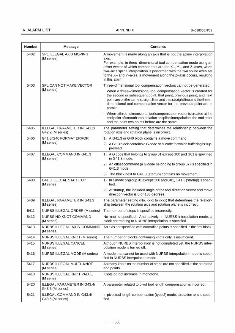
APPENDIXA. ALARM LIST B–63835EN/03
550
Number ContentsMessage
5402 SPL:ILLEGAL AXIS MOVING (M series)
A movement is made along an axis that is not the spline interpolationaxis.For example, in three–dimensional tool compensation mode using anoffset vector of which components are the X–, Y–, and Z–axes, whentwo–axis spline interpolation is performed with the two spline axes setto the X– and Y–axes, a movement along the Z–axis occurs, resultingin this alarm.
5403 SPL:CAN NOT MAKE VECTOR (M series)
Three–dimensional tool compensation vectors cannot be generated.
· When a three–dimensional tool compensation vector is created forthe second or subsequent point, that point, previous point, and nextpoint are on the same straight line, and that straight line and the three–dimensional tool compensation vector for the previous point are inparallel.
· When a three–dimensional tool compensation vector is created at theend point of smooth interpolation or spline interpolation, the end pointand the point two points before are the same.
5405 ILLEGAL PARAMETER IN G41.2/G42.2 (M series)
The parameter setting that determines the relationship between therotation axis and rotation plane is incorrect.
5406 G41.3/G40 FORMAT ERROR (M series)
1) A G41.3 or G40 block contains a move command.
2) A G1.3 block contains a G code or M code for which buffering is sup-pressed.
5407 ILLEGAL COMMAND IN G41.3 (M series)
1) A G code that belongs to group 01 except G00 and G01 is specifiedin G41.3 mode.
2) An offset command (a G code belonging to group 07) is specified inG41.3 mode.
3) The block next to G41.3 (startup) contains no movement.
5408 G41.3 ILLEGAL START_UP (M series)
1) In a mode of group 01 except G00 and G01, G41.3 (startup) is speci-fied.
2) At startup, the included angle of the tool direction vector and movedirection vector is 0 or 180 degrees.
5409 ILLEGAL PARAMETER IN G41.3 (M series)
The parameter setting (No. xxxx to xxxx) that determines the relation-ship between the rotation axis and rotation plane is incorrect.
5411 NURBS:ILLEGAL ORDER (M series) The number of steps is specified incorrectly.
5412 NURBS:NO KNOT COMMAND (M series)
No knot is specified. Alternatively, in NURBS interpolation mode, ablock not relating to NURBS interpolation is specified.
5413 NURBS:ILLEGAL AXIS COMMAND(M series)
An axis not specified with controlled points is specified in the first block.
5414 NURBS:ILLEGAL KNOT (M series) The number of blocks containing knots only is insufficient.
5415 NURBS:ILLEGAL CANCEL (M series)
Although NURBS interpolation is not completed yet, the NURBS inter-polation mode is turned off.
5416 NURBS:ILLEGAL MODE (M series) A mode that cannot be used with NURBS interpolation mode is speci-fied in NURBS interpolation mode.
5417 NURBS:ILLEGAL MULTI–KNOT (M series)
As many knots as the number of steps are not specified at the start andend points.
5418 NURBS:ILLEGAL KNOT VALUE (M series)
Knots do not increase in monotone.
5420 ILLEGAL PARAMETER IN G43.4/G43.5 (M series)
A parameter related to pivot tool length compensation is incorrect.
5421 ILLEGAL COMMAND IN G43.4/G43.5 (M series)
In pivot tool length compensation (type 2) mode, a rotation axis is speci-fied.

APPENDIXB–63835EN/03 A. ALARM LIST
551
Number ContentsMessage
5422 EXCESS VELOCITY IN G43.4/G43.5(M series)
As a result of pivot tool length compensation, an attempt was made tomove the tool along an axis at a feedrate exceeding the maximum cut-ting feedrate.
5425 ILLEGAL OFFSET VALUE (M series) The offset number is incorrect.
5430 ILLEGAL COMMAND IN 3–D CIR (M series)
In a modal state in which three–dimensional circular interpolation can-not be specified, a three–dimensional circular interpolation(G02.4/G03.4) is specified. Alternatively, in three–dimensional circularinterpolation mode, a code that cannot be specified is specified.
5432 G02.4/G03.4 FORMAT ERROR (M series)
A three–dimensional circular interpolation command (G02.4/G03.4) isincorrect.
5433 MANUAL INTERVENTION IN 3–DCIR (M series)
In three–dimensional circular interpolation mode (G02.4/G03.4), manu-al intervention was made when the manual absolute switch was on.
5435 PARAMETER OUT OF RANGE(TLAC) (M series)
Incorrect parameter setting (set value range)
5436 PARAMETER SETTING ERROR 1(TLAC) (M series)
Incorrect parameter setting (setting of the rotation axis)
5437 PARAMETER SETTING ERROR 2(TLAC) (M series)
Incorrect parameter setting (setting of the tool axis)
5440 ILLEGAL DRILLING AXIS SELECTED (M series)
The drilling axis specified for the drilling canned cycle is incorrect.The G code command block of the canned cycle does not specify theZ point of the drilling axis. When there is a parallel axis with the drillingaxis, the parallel axis is also specified at the same time.
5445 CRC:MOTION IN G39 (M series) Corner circular interpolation (G39) of cutter compensation is not speci-fied alone but is specified with a move command.
5446 CRC:NO AVOIDANCE (M series) Because there is no interference evade vector, the interference checkevade function of cutter compensation cannot evade interference.
5447 CRC:DANGEROUS AVOIDANCE (M series)
The interference check evade function of cutter compensation deter-mines that an evade operation will lead to danger.
5448 CRC:INTERFERENCE TO AVD. (M series)
In the interference check evade function of cutter compensation, a fur-ther interference occurs for an already created interference evade vec-tor.
5452 IMPROPER G–CODE (5AXIS MODE)(M series)
A G code that cannot be specified is found. (5–axis mode)This alarm is issued when:
1) Three–dimensional cutter compensation (side–face offset and lead-ing–edge offset) is applied during cutter compensation, or cuttercompensation is applied during three–dimensional cutter com-pensation (side–face offset and leading–edge offset).
2) A leading–edge offset of three–dimensional cutter compensation isapplied during side–face offsetting of three–dimensional cutter com-pensation, or a side–face offset of three–dimensional cutter com-pensation is applied during leading–edge offsetting of three–dimen-sional cutter compensation.
3) Tool axis direction tool length compensation is applied during toollength compensation, or tool length compensation is applied duringtool axis direction tool length compensation.
4) Tool center point control is provided during tool length compensa-tion, or tool length compensation is applied during tool center pointcontrol.
5) Tool center point control is provided during tool axis direction toollength compensation, or tool axis direction tool length compensationis applied during tool center point control.If this alarm is issued, cancel the relevant mode, then specify a differ-ent mode.

APPENDIXA. ALARM LIST B–63835EN/03
552
Number ContentsMessage
5453 NOTE: G68 IS CANCELED (HPCC)(M series)
When bit 2 of parameter No. 5400 is set to 1, and a reset does not cancelG68, this alarm is issued at the time of program restart.To release this alarm, press <RESET> and <CAN>. Once this operationis performed, the alarm will not be issued at the next restart.
5455 ILLEGAL ACC. PARAMETER (M series)
A permissible acceleration parameter for optimum torque acceleration/deceleration is incorrect. The cause is one of the following:
1) The ratio of the deceleration rate to the acceleration rate is below thelimit.
2) The time required for deceleration to a speed of 0 exceeds the maxi-mum value.
NOTEAICC designates AI Contour Control.
(2) Background edit alarm
Number Message Contents
??? BP/S alarm BP/S alarm occurs in the same number as the P/S alarm that occurs inordinary program edit. (070, 071, 072, 073, 074 085,086,087 etc.)
140 BP/S alarm It was attempted to select or delete in the background a program beingselected in the foreground. (Note) Use background editing correctly.
NOTEAlarm in background edit is displayed in the key input line of the background edit screen insteadof the ordinary alarm screen and is resettable by any of the MDI key operation.
(3) Absolute pulse coder (APC) alarm
Number Message Contents
300 APC alarm: nth–axis origin return Manual reference position return is required for the nth–axis (n=1 – 8).
301 APC alarm: nth–axis communication nth–axis (n=1 – 8) APC communication error. Failure in data transmis-sion Possible causes include a faulty APC, cable, or servo interface module.
302 APC alarm: nth–axis over time nth–axis (n=1 – 8) APC overtime error.Failure in data transmission.Possible causes include a faulty APC, cable, or servo interface module.
303 APC alarm: nth–axis framing nth–axis (n=1 – 8) APC framing error. Failure in data transmission.Possible causes include a faulty APC, cable, or servo interface module.
304 APC alarm: nth–axis parity nth–axis (n=1 – 8) APC parity error.Failure in data transmission.Possible causes include a faulty APC, cable, or servo interface module.
305 APC alarm: nth–axis pulse error nth–axis (n=1 – 8) APC pulse error alarm. APC alarm.APC or cable may be faulty.
306 APC alarm: nth–axis battery voltage 0
nth–axis (n=1 – 8) APC battery voltage has decreased to a low level sothat the data cannot be held. APC alarm. Battery or cable may be faulty.
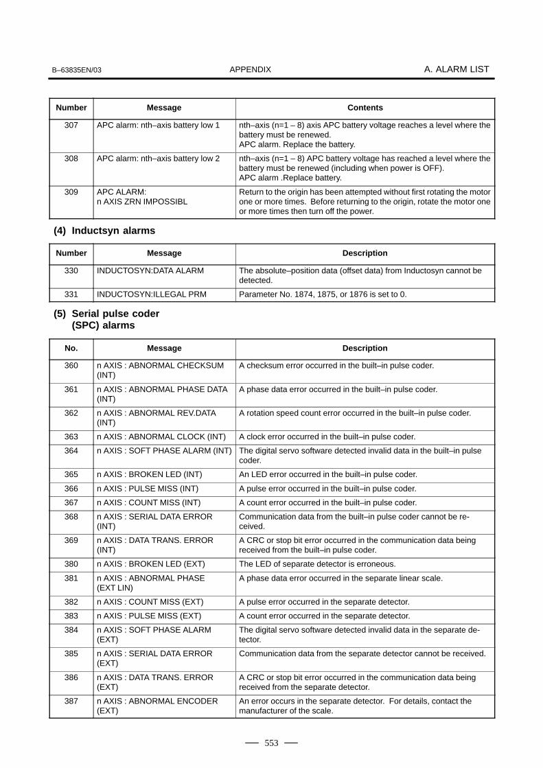
APPENDIXB–63835EN/03 A. ALARM LIST
553
Number ContentsMessage
307 APC alarm: nth–axis battery low 1 nth–axis (n=1 – 8) axis APC battery voltage reaches a level where thebattery must be renewed.APC alarm. Replace the battery.
308 APC alarm: nth–axis battery low 2 nth–axis (n=1 – 8) APC battery voltage has reached a level where thebattery must be renewed (including when power is OFF).APC alarm .Replace battery.
309 APC ALARM: n AXIS ZRN IMPOSSIBL
Return to the origin has been attempted without first rotating the motorone or more times. Before returning to the origin, rotate the motor oneor more times then turn off the power.
Number Message Description
330 INDUCTOSYN:DATA ALARM The absolute–position data (offset data) from Inductosyn cannot bedetected.
331 INDUCTOSYN:ILLEGAL PRM Parameter No. 1874, 1875, or 1876 is set to 0.
No. Message Description
360 n AXIS : ABNORMAL CHECKSUM(INT)
A checksum error occurred in the built–in pulse coder.
361 n AXIS : ABNORMAL PHASE DATA(INT)
A phase data error occurred in the built–in pulse coder.
362 n AXIS : ABNORMAL REV.DATA(INT)
A rotation speed count error occurred in the built–in pulse coder.
363 n AXIS : ABNORMAL CLOCK (INT) A clock error occurred in the built–in pulse coder.
364 n AXIS : SOFT PHASE ALARM (INT) The digital servo software detected invalid data in the built–in pulsecoder.
365 n AXIS : BROKEN LED (INT) An LED error occurred in the built–in pulse coder.
366 n AXIS : PULSE MISS (INT) A pulse error occurred in the built–in pulse coder.
367 n AXIS : COUNT MISS (INT) A count error occurred in the built–in pulse coder.
368 n AXIS : SERIAL DATA ERROR(INT)
Communication data from the built–in pulse coder cannot be re-ceived.
369 n AXIS : DATA TRANS. ERROR(INT)
A CRC or stop bit error occurred in the communication data beingreceived from the built–in pulse coder.
380 n AXIS : BROKEN LED (EXT) The LED of separate detector is erroneous.
381 n AXIS : ABNORMAL PHASE (EXT LIN)
A phase data error occurred in the separate linear scale.
382 n AXIS : COUNT MISS (EXT) A pulse error occurred in the separate detector.
383 n AXIS : PULSE MISS (EXT) A count error occurred in the separate detector.
384 n AXIS : SOFT PHASE ALARM(EXT)
The digital servo software detected invalid data in the separate de-tector.
385 n AXIS : SERIAL DATA ERROR(EXT)
Communication data from the separate detector cannot be received.
386 n AXIS : DATA TRANS. ERROR(EXT)
A CRC or stop bit error occurred in the communication data beingreceived from the separate detector.
387 n AXIS : ABNORMAL ENCODER(EXT)
An error occurs in the separate detector. For details, contact themanufacturer of the scale.
(4) Inductsyn alarms
(5) Serial pulse coder(SPC) alarms

APPENDIXA. ALARM LIST B–63835EN/03
554
The details of serial pulse coder alarm are displayed in the diagnosisdisplay (No. 202 and No.203) as shown below.
#7202
#6CSA
#5BLA
#4PHA
#3PCA
#2BZA
#1CKA
#0SPH
#6 (CSA) : The serial pulse coder is defective. Replace it.
#5 (BLA) : The battery voltage is low. Replace the batteries.
#4 (PHA) : The serial pulse coder or feedback cable is defective. Replace the serialpulse coder or cable.
#3 (PCA) : The serial pulse coder is defective. Replace it.
#2 (BZA) : The pulse coder was supplied with power for the first time.Make sure that the batteries are connected.Turn the power off, then turn it on again and perform a reference positionreturn.
#1 (CKA) : The serial pulse coder is defective. Replace it.
#0 (SPH) : The serial pulse coder or feedback cable is defective. Replace the serialpulse coder or cable.
#7DTE203
#6CRC
#5STB
#4PRM
#3 #2 #1 #0
#7 (DTE) : The serial pulse coder encountered a communication error.The pulse coder, feedbak cable, or feedback receiver circuit is defective.Replace the pulse coder, feedback cable, or NC–axis board
#6 (CRC) : The serial pulse coder encountered a communication error.The pulse coder, feedback cable, or feedback receiver circuit is defective.Replace the pulse coder, feedback cable, or NC–axis board.
#5 (STB) : The serial pulse coder encountered a communication error.The pulse coder, feedback cable, or feedback receiver circuit is defective.Replace the pulse coder, feedback cable, or NC–axis board.
#4 (PRM) : An invalid parameter was found. Alarm No. 417 (invalid servoparameter) is also issued.
(6) Servo alarms(1/2)
Number Message Contents
401 SERVO ALARM: n–TH AXIS VRDYOFF
The n–th axis (axis 1–8) servo amplifier READY signal (DRDY) went off.Refer to procedure of trouble shooting.
402 SERVO ALARM: SV CARD NOT EX-IST
The axis control card is not provided.
403 SERVO ALARM: CARD/SOFT MIS-MATCH
The combination of the axis control card and servo software is illegal.The possible causes are as follows:
· A correct axis control card is not provided.
· Correct servo software is not installed on flash memory.
404 SERVO ALARM: n–TH AXIS VRDYON
Even though the n–th axis (axis 1–8) READY signal (MCON) went off,the servo amplifier READY signal (DRDY) is still on. Or, when the powerwas turned on, DRDY went on even though MCON was off.Check that the servo interface module and servo amp are connected.
405 SERVO ALARM: (ZERO POINT RE-TURN FAULT)
Position control system fault. Due to an NC or servo system fault in thereference position return, there is the possibility that reference positionreturn could not be executed correctly. Try again from the manual refer-ence position return.
� The details of serialpulse coder alarm

APPENDIXB–63835EN/03 A. ALARM LIST
555
Number ContentsMessage
407 SERVO ALARM: EXCESS ERROR The following error occurred during simple synchronous control:The difference in machine coordinates between the synchronized axesexceeds the value set in parameter No. 8314.
409 SERVO ALARM: n AXIS TORQUEALM
Abnormal servo motor load has been detected. Alternatively, abnormalspindle motor load has been detected in Cs mode.
410 SERVO ALARM: n–TH AXIS – EX-CESS ERROR
One of the following errors occurred:
1) The positional deviation value when the n–th axis stops exceeds thevalue set in parameter No. 1829.
2) In simple synchronous control, the compensation amount for syn-chronization exceeds the value set in parameter No. 8325.
This alarm is issued only for the slave axis.
411 SERVO ALARM: n–TH AXIS – EX-CESS ERROR
The position deviation value when the n–th axis (axis 1–8) moves islarger than the set value.Refer to procedure of trouble shooting.
413 SERVO ALARM: n–th AXIS – LSIOVERFLOW
The contents of the error register for the n–th axis (axis 1–8) exceeded�231 power. This error usually occurs as the result of an improperly setparameters.
415 SERVO ALARM: n–TH AXIS – EX-CESS SHIFT
A speed higher than 524288000 units/s was attempted to be set in then–th axis (axis 1–8). This error occurs as the result of improperly setCMR.
417 SERVO ALARM: n–TH AXIS – PA-RAMETER INCORRECT
This alarm occurs when the n–th axis (axis 1–8) is in one of the condi-tions listed below. (Digital servo system alarm)
1) The value set in Parameter No. 2020 (motor form) is out of the speci-fied limit.
2) A proper value (111 or –111) is not set in parameter No.2022 (motorrevolution direction).
3) Illegal data (a value below 0, etc.) was set in parameter No. 2023(number of speed feedback pulses per motor revolution).
4) Illegal data (a value below 0, etc.) was set in parameter No. 2024(number of position feedback pulses per motor revolution).
5) Parameters No. 2084 and No. 2085 (flexible field gear rate) have notbeen set.
6) A value outside the limit of {1 to the number of control axes} or a non–continuous value (Parameter 1023 (servo axis number) contains avalue out of the range from 1 to the number of axes, or an isolatedvalue (for example, 4 not prceded by 3).was set in parameter No.1023 (servo axisnumber).
7) A torque control parameter is set incorrectly in PMC axis control.(The torque constant parameter is set to 0.)
420 SERVO ALARM: n AXIS SYNCTORQUE(M series)
During simple synchronous control, the difference between the torquecommands for the master and slave axes exceeded the value set in pa-rameter No. 2031.
421 SERVO ALARM: n AXIS EXCESSER (D)
The difference between the errors in the semi–closed loop and closedloop has become excessive during dual position feedback. Check thevalues of the dual position conversion coefficients in parameters No.2078 and 2079.
422 SERVO ALARM: n AXIS In torque control of PMC axis control, a specified allowable speedhas been exceeded.
423 SERVO ALARM: n AXIS In torque control of PMC axis control, the parameter–set allowablecumulative travel distance has been exceeded.
430 n AXIS : SV. MOTOR OVERHEAT A servo motor overheat occurred.

APPENDIXA. ALARM LIST B–63835EN/03
556
Number ContentsMessage
431 n AXIS : CNV. OVERLOAD 1) PSM: Overheat occurred.
2) β series SVU: Overheat occurred.
432 n AXIS : CNV. LOW VOLT CON-TROL
1) PSM: Control power voltage has dropped.
2) PSMR: The control power supply voltage has dropped.
3) β series SVU: The control power supply voltage has dropped.
433 n AXIS : CNV. LOW VOLT DC LINK 1) PSM: The DC link voltage has dropped.
2) PSMR: The DC link voltage has dropped.
3) α series SVU: The DC link voltage has dropped.
4) β series SVU: The DC link voltage has dropped.
434 n AXIS : INV. LOW VOLT CONTROL SVM: The control power supply voltage has dropped.
435 n AXIS : INV. LOW VOLT DC LINK SVM: The DC link voltage has dropped.
436 n AXIS : SOFTTHERMAL (OVC) The digital servo software detected the soft thermal state (OVC).
437 n AXIS : CNV. OVERCURRENTPOWER
PSM: Overcurrent flowed into the input circuit.
438 n AXIS : INV. ABNORMAL CUR-RENT
1) SVM: The motor current is too high.
2) α series SVU: The motor current is too high.
3) β series SVU: The motor current is too high.
439 n AXIS : CNV. OVERVOLT POWER 1) PSM: The DC link voltage is too high.
2) PSMR: The DC link voltage is too high.
3) α series SVU: The C link voltage is too high.
4) β series SVU: The link voltage is too high.
440 n AXIS : CNV. EX DECELERATIONPOW.
1) PSMR: The regenerative discharge amount is too large.
2) α series SVU: The regenerative discharge amount is too large. Al-ternatively, the regenerative discharge circuit is abnormal.
441 n AXIS : ABNORMAL CURRENTOFFSET
The digital servo software detected an abnormality in the motor cur-rent detection circuit.
442 n AXIS : CNV. CHARGE FAILURE 1) PSM: The spare discharge circuit of the DC link is abnormal.
2) PSMR: The spare discharge circuit of the DC link is abnormal.
443 n AXIS : CNV. COOLING FAN FAIL-URE
1) PSM: The internal stirring fan failed.
2) PSMR: The internal stirring fan failed.
3) β series SVU: The internal stirring fan failed.
444 n AXIS : INV. COOLING FAN FAIL-URE
SVM: The internal stirring fan failed.
445 n AXIS : SOFT DISCONNECTALARM
The digital servo software detected a broken wire in the pulse coder.
446 n AXIS : HARD DISCONNECTALARM
A broken wire in the built–in pulse coder was detected by hardware.
447 n AXIS : HARD DISCONNECT (EXT) A broken wire in the separate detector was detected by hardware.
448 n AXIS : UNMATCHED FEEDBACKALARM
The sign of feedback data from the built–in pulse coder differs fromthat of feedback data from the separate detector.
449 n AXIS : INV. IPM ALARM 1) SVM: IPM (intelligent power module) detected an alarm.
2) α series SVU: IPM (intelligent power module) detected an alarm.
453 n AXIS : SPC SOFT DISCONNECTALARM
Software disconnection alarm of the α pulse coder.Turn off the power to the CNC, then remove and insert the pulse cod-er cable. If this alarm is issued again, replace the pulse coder.
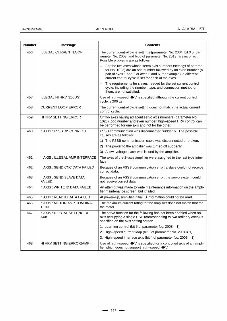
APPENDIXB–63835EN/03 A. ALARM LIST
557
Number ContentsMessage
456 ILLEGAL CURRENT LOOP The current control cycle settings (parameter No. 2004, bit 0 of pa-rameter No. 2003, and bit 0 of parameter No. 2013) are incorrect.Possible problems are as follows.
– For the two axes whose servo axis numbers (settings of parame-ter No. 1023) are an odd number followed by an even number (apair of axes 1 and 2 or axes 5 and 6, for example), a differentcurrent control cycle is set for each of the axes.
– The requirements for slaves needed for the set current controlcycle, including the number, type, and connection method ofthem, are not satisfied.
457 ILLEGAL HI HRV (250US) Use of high–speed HRV is specified although the current controlcycle is 200 µs.
458 CURRENT LOOP ERROR The current control cycle setting does not match the actual currentcontrol cycle.
459 HI HRV SETTING ERROR Of two axes having adjacent servo axis numbers (parameter No.1023), odd number and even number, high–speed HRV control canbe performed for one axis and not for the other.
460 n AXIS : FSSB DISCONNECT FSSB communication was disconnected suddenly. The possiblecauses are as follows:
1) The FSSB communication cable was disconnected or broken.
2) The power to the amplifier was turned off suddenly.
3) A low–voltage alarm was issued by the amplifier.
461 n AXIS : ILLEGAL AMP INTERFACE The axes of the 2–axis amplifier were assigned to the fast type inter-face.
462 n AXIS : SEND CNC DATA FAILED Because of an FSSB communication error, a slave could not receivecorrect data.
463 n AXIS : SEND SLAVE DATAFAILED
Because of an FSSB communication error, the servo system couldnot receive correct data.
464 n AXIS : WRITE ID DATA FAILED An attempt was made to write maintenance information on the ampli-fier maintenance screen, but it failed.
465 n AXIS : READ ID DATA FAILED At power–up, amplifier initial ID information could not be read.
466 n AXIS : MOTOR/AMP COMBINA-TION
The maximum current rating for the amplifier does not match that forthe motor.
467 n AXIS : ILLEGAL SETTING OFAXIS
The servo function for the following has not been enabled when anaxis occupying a single DSP (corresponding to two ordinary axes) isspecified on the axis setting screen.
1. Learning control (bit 5 of parameter No. 2008 = 1)
2. High–speed current loop (bit 0 of parameter No. 2004 = 1)
3. High–speed interface axis (bit 4 of parameter No. 2005 = 1)
468 HI HRV SETTING ERROR(AMP) Use of high–speed HRV is specified for a controlled axis of an ampli-fier which does not support high–speed HRV.
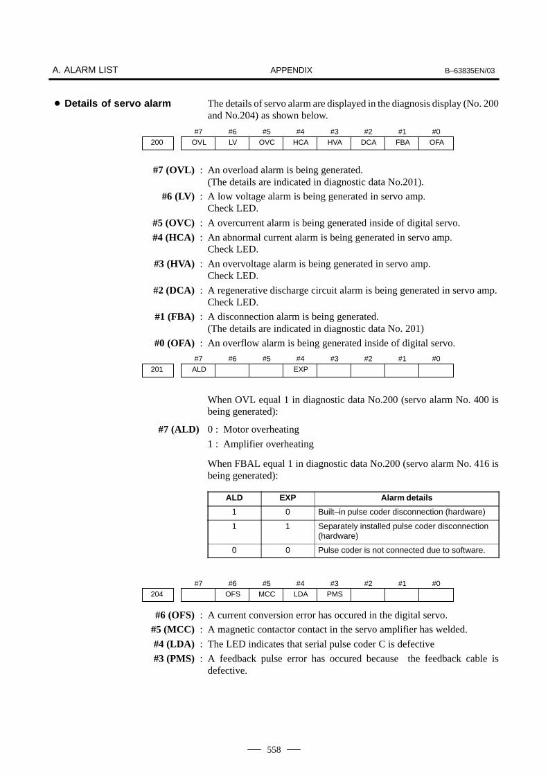
APPENDIXA. ALARM LIST B–63835EN/03
558
The details of servo alarm are displayed in the diagnosis display (No. 200and No.204) as shown below.
#7OVL200
#6LV
#5OVC
#4HCA
#3HVA
#2DCA
#1FBA
#0OFA
#7 (OVL) : An overload alarm is being generated. (The details are indicated in diagnostic data No.201).
#6 (LV) : A low voltage alarm is being generated in servo amp. Check LED.
#5 (OVC) : A overcurrent alarm is being generated inside of digital servo.
#4 (HCA) : An abnormal current alarm is being generated in servo amp.Check LED.
#3 (HVA) : An overvoltage alarm is being generated in servo amp. Check LED.
#2 (DCA) : A regenerative discharge circuit alarm is being generated in servo amp.Check LED.
#1 (FBA) : A disconnection alarm is being generated.(The details are indicated in diagnostic data No. 201)
#0 (OFA) : An overflow alarm is being generated inside of digital servo.
#7ALD201
#6 #5 #4EXP
#3 #2 #1 #0
When OVL equal 1 in diagnostic data No.200 (servo alarm No. 400 isbeing generated):
#7 (ALD) 0 : Motor overheating
1 : Amplifier overheating
When FBAL equal 1 in diagnostic data No.200 (servo alarm No. 416 isbeing generated):
ALD EXP Alarm details
1 0 Built–in pulse coder disconnection (hardware)
1 1 Separately installed pulse coder disconnection(hardware)
0 0 Pulse coder is not connected due to software.
#7204
#6OFS
#5MCC
#4LDA
#3PMS
#2 #1 #0
#6 (OFS) : A current conversion error has occured in the digital servo.
#5 (MCC) : A magnetic contactor contact in the servo amplifier has welded.
#4 (LDA) : The LED indicates that serial pulse coder C is defective
#3 (PMS) : A feedback pulse error has occured because the feedback cable isdefective.
� Details of servo alarm

APPENDIXB–63835EN/03 A. ALARM LIST
559
(7) Over travel alarms
Number Message Contents
500 OVER TRAVEL : +n Exceeded the n–th axis (axis 1–8) + side stored stroke check I.(Parameter No.1320 or 1326 NOTE)
501 OVER TRAVEL : –n Exceeded the n–th axis (axis 1–8) – side stored stroke check I.(Parameter No.1321 or 1327 NOTE)
502 OVER TRAVEL : +n Exceeded the n–th axis (axis 1–8) + side stored stroke check II.(Parameter No.1322 )
503 OVER TRAVEL : –n Exceeded the n–th axis (axis 1–8) – side stored stroke check II.(Parameter No.1323)
504 OVER TRAVEL : +n Exceeded the n–th axis (axis 1–8) + side stored stroke check III.(Parameter No.1324 )
505 OVER TRAVEL : –n Exceeded the n–th axis (axis 1–8) – side stored stroke check III.(Parameter No.1325 )
506 OVER TRAVEL : +n Exceeded the n–th axis (axis 1–8) + side hardware OT.
507 OVER TRAVEL : –n Exceeded the n–th axis (axis 1–8) – side hardware OT.
508 INTERFERENCE: +n(T series (two–path control))
A tool moving in the positive direction along the n axis has fouled anoth-er tool post.
509 INTERFERENCE: –n(T series (two–path control))
A tool moving in the negative direction along the n axis has fouled anoth-er tool post.
510 OVER TRAVEL: +n Alarm for stroke check prior to movement. The end point specified in ablock falls within the forbidden area defined with the stroke check in thepositive direction along the N axis. Correct the program.
511 OVER TRAVEL: –n Alarm for stroke check prior to movement. The end point specified in ablock falls within the forbidden area defined with the stroke check in thenegative direction along the N axis. Correct the program.
514 INTERFERENCE : +n The rotation area interference check function found interference on theplus side of the n axis.
515 INTERFERENCE : –n The rotation area interference check function found interference on theminus side of the n axis.
NOTEParameters 1326 and 1327 are effective when EXLM(stroke check switch signal) is on.

APPENDIXA. ALARM LIST B–63835EN/03
560
(8) Servo alarms (2/2)
Number Message Contents
600 n AXIS: INV. DC LINK OVER CUR-RENT
DC link current is too large.
601 n AXIS: INV. RADIATOR FAN FAIL-URE
The external dissipator stirring fan failed.
602 n AXIS: INV. OVERHEAT The servo amplifier was overheated.
603 n AXIS: INV. IPM ALARM(OH) The IPM (intelligent power module) detected an overheat alarm.
604 n AXIS: AMP. COMMUNICATIONERROR
Communication between the SVM and the PSM failed.
605 n AXIS: CNV. EX. DISCHARGEPOW.
PSMR: Regenerative power is too large.
606 n AXIS: CNV. RADIATOR FAN FAIL-URE
PSM: The external dissipator stirring fan failed.PSMR: The external dissipator stirring fan failed.
607 n AXIS: CNV. SINGLE PHASE FAIL-URE
PSM: Input voltage is in the open–phase condition.PSMR: Input voltage is in the open–phase condition.
(9) Overheat alarms
Number Message Contents
700 OVERHEAT: CONTROL UNIT Control unit overheatCheck that the fan motor operates normally, and clean the air filter.
701 OVERHEAT: FAN MOTOR The fan motor on the top of the cabinet for the contorl unit is overheated.Check the operation of the fan motor and replace the motor if necessary.
704 OVERHEAT: SPINDLE Spindle overheat in the spindle fluctuation detection
(1) If the cutting load is heavy, relieve the cutting condition.
(2) Check whether the cutting tool is share.
(3) Another possible cause is a faulty spindle amp.
(10)Rigid tapping alarms
Number Message Contents
740 RIGID TAP ALARM: EXCESS ER-ROR
The positional deviation of the stopped spindle has exceeded the setvalue during rigid tapping.
741 RIGID TAP ALARM: EXCESS ER-ROR
The positional deviation of the moving spindle has exceeded the set val-ue during rigid tapping.
742 RIGID TAP ALARM: LSI OVER-FLOW
An LSI overflow has occurred for the spindle during rigid tapping.

APPENDIXB–63835EN/03 A. ALARM LIST
561
(11)Serial spindle alarms
Number Message Contents
749 S–SPINDLE LSI ERROR It is serial communication error while system is executing after powersupply on. Following reasons can be considered.
1) Optical cable connection is fault or cable is not connected or cableis cut.
2) MAIN CPU board or option 2 board is fault.
3) Spindle amp. printed board is fault.
4) The spindle amplifier is under an abnormal condition. (The SPM in-dication is A, A1, A2, or the like, depending on the type of the ab-normality.)
If this alarm occurs when CNC power supply is turned on or when thisalarm can not be cleared even if CNC is reset, turn off the power supplyalso turn off the power supply in spindle side.If the spindle amplifier is under an abnormal condition, check the SPMindication (A, A1, A2, or the like). Then, refer to the FANUC SERVO MO-TOR �i series MAINTENANCE MANUAL (B–65285EN) or FANUCSERVO MOTOR � series MAINTENANCE MANUAL (B–65165E) tosolve the problem.
750 SPINDLE SERIAL LINK STARTFAULT
This alarm is generated when the spindle control unit is not ready forstarting correctly when the power is turned on in the system with theserial spindle.The four reasons can be considered as follows:1) An improperly connected optic cable, or the spindle control unit’s
power is OFF.2) When the NC power was turned on under alarm conditions other
than SU–01 or AL–24 which are shown on the LED display of thespindle control unit.In this case, turn the spindle amplifier power off once and performstartup again.
3) Other reasons (improper combination of hardware)This alarm does not occur after the system including the spindle con-trol unit is activated.
4) The second spindle (when SP2, bit 4 of parameter No. 3701, is 1)is in one of the above conditions 1) to 3).
See diagnostic display No. 409 for details.
752 FIRST SPINDLE MODE CHANGEFAULT
This alarm is generated if the system does not properly terminate amode change. The modes include the Cs contouring, spindle position-ing, rigid tapping, and spindle control modes. The alarm is activated ifthe spindle control unit does not respond correctly to the mode changecommand issued by the NC.
754 SPINDLE–1 ABNORMAL TORQUEALM
Abnormal first spindle motor load has been detected.
762 SECOND SPINDLE MODECHANGE FAULT
Refer to alarm No. 752.(For 2nd axis)
764 SPINDLE–2 ABNORMAL TORQUEALM
Same as alarm No. 754 (for the second spindle)
772 SPINDLE–3 MODE CHANGE ER-ROR
Same as alarm No. 752 (for the third spindle)
774 SPINDLE–3 ABNORMAL TORQUEALM
Same as alarm No. 754 (for the third spindle)
782 SPINDLE–4 MODE CHANGE ER-ROR
Same as alarm number 752 (for the fourth spindle)
784 SPINDLE–4 ABNORMAL TORQUEALM
Same as alarm number 754 (for the fourth spindle)

APPENDIXA. ALARM LIST B–63835EN/03
562
#7409
#6 #5 #4 #3SPE
#2S2E
#1S1E
#0SHE
#3 (SPE) 0 : In the spindle serial control, the serial spindle parameters fulfill thespindle unit startup conditions.
1 : In the spindle serial control, the serial spindle parameters do not fulfillthe spindle unit startup conditions.
#2 (S2E) 0 : The second spindle is normal during the spindle serial control startup.
1 : The second spindle was detected to have a fault during the spindleserial control startup.
#1 (S1E) 0 : The first spindle is normal during the spindle serial control startup.
1 : The first spindle was detected to have a fault during the spindle axisserial control startup.
#0 (SHE) 0 : The serial communications module in the CNC is normal.
1 : The serial communications module in the CNC was detected to have afault.
The details of spindle alarm No. 750 are displayed in the diagnosis display(No. 409) as shown below.
#7409
#6 #5 #4 #3SPE
#2S4E
#1S3E
#0SHE
#3 (SPE) 0 : In the spindle serial control, the serial spindle parameters fulfill thespindle unit startup conditions.
1 : In the spindle serial control, the serial spindle parameters do not fulfillthe spindle unit startup conditions.
#2 (S2E) 0 : The fourth spindle is normal during the spindle serial control startup.
1 : The fourth spindle was detected to have a fault during the spindleserial control startup.
#1 (S1E) 0 : The third spindle is normal during the spindle serial control startup.
1 : The third spindle was detected to have a fault during the spindle axisserial control startup.
#0 (SHE) 0 : The serial communications module in the CNC is normal.
1 : The serial communications module in the CNC was detected to have afault.
� The details of spindle alarm No.750
� 1st and 2nd spindles
� 3rd and 4th spindles
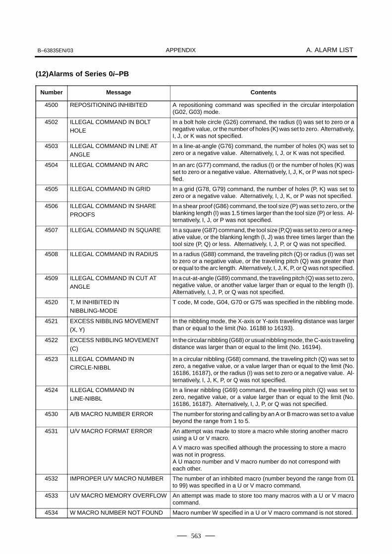
APPENDIXB–63835EN/03 A. ALARM LIST
563
(12)Alarms of Series 0i–PB
Number Message Contents
4500 REPOSITIONING INHIBITED A repositioning command was specified in the circular interpolation(G02, G03) mode.
4502 ILLEGAL COMMAND IN BOLTHOLE
In a bolt hole circle (G26) command, the radius (I) was set to zero or anegative value, or the number of holes (K) was set to zero. Alternatively,I, J, or K was not specified.
4503 ILLEGAL COMMAND IN LINE ATANGLE
In a line-at-angle (G76) command, the number of holes (K) was set tozero or a negative value. Alternatively, I, J, or K was not specified.
4504 ILLEGAL COMMAND IN ARC In an arc (G77) command, the radius (I) or the number of holes (K) wasset to zero or a negative value. Alternatively, I, J, K, or P was not speci-fied.
4505 ILLEGAL COMMAND IN GRID In a grid (G78, G79) command, the number of holes (P, K) was set tozero or a negative value. Alternatively, I, J, K, or P was not specified.
4506 ILLEGAL COMMAND IN SHAREPROOFS
In a shear proof (G86) command, the tool size (P) was set to zero, or theblanking length (I) was 1.5 times larger than the tool size (P) or less. Al-ternatively, I, J, or P was not specified.
4507 ILLEGAL COMMAND IN SQUARE In a square (G87) command, the tool size (P,Q) was set to zero or a neg-ative value, or the blanking length (I, J) was three times larger than thetool size (P, Q) or less. Alternatively, I, J, P, or Q was not specified.
4508 ILLEGAL COMMAND IN RADIUS In a radius (G88) command, the traveling pitch (Q) or radius (I) was setto zero or a negative value, or the traveling pitch (Q) was greater thanor equal to the arc length. Alternatively, I, J, K, P, or Q was not specified.
4509 ILLEGAL COMMAND IN CUT ATANGLE
In a cut-at-angle (G89) command, the traveling pitch (Q) was set to zero,negative value, or another value larger than or equal to the length (I).Alternatively, I, J, P, or Q was not specified.
4520 T, M INHIBITED INNIBBLING-MODE
T code, M code, G04, G70 or G75 was specified in the nibbling mode.
4521 EXCESS NIBBLING MOVEMENT(X, Y)
In the nibbling mode, the X-axis or Y-axis traveling distance was largerthan or equal to the limit (No. 16188 to 16193).
4522 EXCESS NIBBLING MOVEMENT(C)
In the circular nibbling (G68) or usual nibbling mode, the C-axis travelingdistance was larger than or equal to the limit (No. 16194).
4523 ILLEGAL COMMAND INCIRCLE-NIBBL
In a circular nibbling (G68) command, the traveling pitch (Q) was set tozero, a negative value, or a value larger than or equal to the limit (No.16186, 16187), or the radius (I) was set to zero or a negative value. Al-ternatively, I, J, K, P, or Q was not specified.
4524 ILLEGAL COMMAND INLINE-NIBBL
In a linear nibbling (G69) command, the traveling pitch (Q) was set tozero, negative value, or a value larger than or equal to the limit (No.16186, 16187). Alternatively, I, J, P, or Q was not specified.
4530 A/B MACRO NUMBER ERROR The number for storing and calling by an A or B macro was set to a valuebeyond the range from 1 to 5.
4531 U/V MACRO FORMAT ERROR An attempt was made to store a macro while storing another macrousing a U or V macro.
A V macro was specified although the processing to store a macrowas not in progress.A U macro number and V macro number do not correspond witheach other.
4532 IMPROPER U/V MACRO NUMBER The number of an inhibited macro (number beyond the range from 01to 99) was specified in a U or V macro command.
4533 U/V MACRO MEMORY OVERFLOW An attempt was made to store too many macros with a U or V macrocommand.
4534 W MACRO NUMBER NOT FOUND Macro number W specified in a U or V macro command is not stored.

APPENDIXA. ALARM LIST B–63835EN/03
564
Number ContentsMessage
4535 U/V MACRO NESTING ERROR An attempt was made to call a macro which is defined three times ormore using a U or V macro command.
An attempt was made to store 15 or more macros in the storage areafor macros of number 90 to 99.
4536 NO W, Q COMMAND INMULTI-PIECE
W or Q was not specified in the command for taking multiple workpieces(G73, G74).
4537 ILLEGAL Q VALUE IN MULTI-PIECE In the command for taking multiple workpieces (G73, G74), Q is set toa value beyond the range from 1 to 4.
4538 W NO. NOT FOUND INMULTI-PIECE
Macro number W specified in the command for taking multiple work-pieces (G73, G74) is not stored.
4539 MULTI-PIECE SETTING IS ZERO The command for taking multiple workpieces (G73, G74) was specifiedalthough zero is specified for the function to take multiple workpieces(No. 16206 or signals MLP1 and MLP2 (PMC address G231, #0 and#1)).
4540 MULTI-PIECE COMMAND WITHINMACRO
The command for taking multiple workpieces (G73, G74) was specifiedwhen a U or V macro was being stored.
4542 MULTI-PIECE COMMAND ERROR Although G98P0 was specified, the G73 command was issued.
Although G98K0 was specified, the G74 command was issued.
4543 MULTI-PIECE Q COMMANDERROR
Although G98P0 was specified, the Q value for the G74 command wasnot 1 or 3.Although G98K0 was specified, the Q value for the G73 command wasnot 1 or 2.
4544 MULTI-PIECE RESTART ERROR In the command for resuming taking multiple workpieces, the resumeposition (P) is set to a value beyond the range from 1 to total number ofworkpieces to be machined.
4600 T, C COMMAND ININTERPOLATION
In the linear interpolation (G01) mode or circular interpolation (G02,G03) mode, a T command or C-axis command was specified.
4601 INHIBITED T, M COMMAND In the block of G52, G72, G73, or G74, a T or M command was specified.
4602 ILLEGAL T-CODE The specified T command is not cataloged on the tool register screen.
4606 A T COMMAND WAS ISSUED A T command was issued during normal–line control.
4650 IMPROPER G-CODE IN OFFSETMODE
In the cutter compensation mode, an inhibited G code (pattern com-mand, G73, G74, G75, etc.) was specified.
4700 PROGRAM ERROR (OT +) The value specified in the X-axis move command exceeded the positivevalue of stored stroke limit 1. (Advance check)
4701 PROGRAM ERROR (OT –) The value specified in the X-axis move command exceeded the nega-tive value of stored stroke limit 1. (Advance check)
4702 PROGRAM ERROR (OT +) The value specified in the Y-axis move command exceeded the positivevalue of stored stroke limit 1. (Advance check)
4703 PROGRAM ERROR (OT –) The value specified in the Y-axis move command exceeded the nega-tive value of stored stroke limit 1. (Advance check)
4800 ZONE : PUNCHING INHIBITED 1 When a safety zone check was executed, a punch command wasspecified in area 1 where punching is inhibited.
4801 ZONE : PUNCHING INHIBITED 2 When a safety zone check was executed, a punch command wasspecified in area 2 where punching is inhibited.
4802 ZONE : PUNCHING INHIBITED 3 When a safety zone check was executed, a punch command wasspecified in area 3 where punching is inhibited.
4803 ZONE : PUNCHING INHIBITED 4 When a safety zone check was executed, a punch command wasspecified in area 4 where punching is inhibited.

APPENDIXB–63835EN/03 A. ALARM LIST
565
Number ContentsMessage
4810 ZONE : ENTERING INHIBITED 1 +X When a safety zone check was executed, the machine moving in thepositive X direction entered area 1 into which entry is inhibited.
4811 ZONE : ENTERING INHIBITED 1 –X
When a safety zone check was executed, the machine moving in thenegative X direction entered area 1 into which entry is inhibited.
4812 ZONE : ENTERING INHIBITED 2 +X When a safety zone check was executed, the machine moving in thepositive X direction entered area 2 into which entry is inhibited.
4813 ZONE : ENTERING INHIBITED 2 –X
When a safety zone check was executed, the machine moving in thenegative X direction entered area 2 into which entry is inhibited.
4814 ZONE : ENTERING INHIBITED 3 +X When a safety zone check was executed, the machine moving in thepositive X direction entered area 3 into which entry is inhibited.
4815 ZONE : ENTERING INHIBITED 3 –X
When a safety zone check was executed, the machine moving in thenegative X direction entered area 3 into which entry is inhibited.
4816 ZONE : ENTERING INHIBITED 4 +X When a safety zone check was executed, the machine moving in thepositive X direction entered area 4 into which entry is inhibited.
4817 ZONE : ENTERING INHIBITED 4 –X
When a safety zone check was executed, the machine moving in thenegative X direction entered area 4 into which entry is inhibited.
4830 ZONE : ENTERING INHIBITED 1 +Y When a safety zone check was executed, the machine moving in thepositive X direction entered area 1 into which entry is inhibited.
4831 ZONE : ENTERING INHIBITED 1 –Y
When a safety zone check was executed, the machine moving in thenegative Y direction entered area 1 into which entry is inhibited.
4832 ZONE : ENTERING INHIBITED 2 +Y When a safety zone check was executed, the machine moving in thepositive Y direction entered area 2 into which entry is inhibited.
4833 ZONE : ENTERING INHIBITED 2 –Y
When a safety zone check was executed, the machine moving in thenegative Y direction entered area 2 into which entry is inhibited.
4834 ZONE : ENTERING INHIBITED 3 +Y When a safety zone check was executed, the machine moving in thepositive Y direction entered area 3 into which entry is inhibited.
4835 ZONE : ENTERING INHIBITED 3 –Y
When a safety zone check was executed, the machine moving in thenegative Y direction entered area 3 into which entry is inhibited.
4836 ZONE : ENTERING INHIBITED 4 +Y When a safety zone check was executed, the machine moving in thepositive Y direction entered area 4 into which entry is inhibited.
4837 ZONE : ENTERING INHIBITED 4 –Y
When a safety zone check was executed, the machine moving in thenegative Y direction entered area 4 into which entry is inhibited.
4870 AUTO SETTING FEED ERROR The feed rate of safety zone auto setting is other than the parametervalue (No. 16538, No. 16539).
4871 AUTO SETTING PIECES ERROR In safety zone auto setting, the safety zone pieces are not correct. Orthe position detector has gone wrong, please tell your machine toolbuilder.
4872 AUTO SETTING COMMANDERROR
M code, S code or T code is specified with safety zone auto settingcommand (G32).G32 is specified in the nibbling mode, in the cutter compensation, inthe rotation mode or the scaling mode.
(These alarms cannot be reset with reset key.)(13) System alarms

APPENDIXA. ALARM LIST B–63835EN/03
566
Number Message Description
900 ROM PARITY A parity error occurred in the CNC, macro, or servo ROM. Correctthe contents of the flash ROM having the displayed number.
910 SRAM PARITY : (BYTE 0) A RAM parity error occurred in the part program storage RAM. Clear
911 SRAM PARITY : (BYTE 1)the RAM, or replace the SRAM module or motherboard. Subse-quently, re–set the parameters and all other data.
912 DRAM PARITY : (BYTE 0) A RAM parity error occurred in the DRAM module. Replace the
913 DRAM PARITY : (BYTE 1) DRAM module.
914 DRAM PARITY : (BYTE 2)
915 DRAM PARITY : (BYTE 3)
916 DRAM PARITY : (BYTE 4)
917 DRAM PARITY : (BYTE 5)
918 DRAM PARITY : (BYTE 6)
919 DRAM PARITY : (BYTE 7)
920 SERVO ALARM (1–4 AXIS) Servo alarm (first to fourth axis). A watchdog alarm condition oc-curred, or a RAM parity error occurred in the axis control card.
Replace the axis control card.
921 SERVO ALARM (5–8 AXIS) Servo alarm (fifth to eighth axis). A watchdog alarm condition oc-curred, or a RAM parity error occurred in the axis control card.
Replace the axis control card.
926 FSSB ALARM FSSB alarm.Replace the axis control card.
930 CPU INTERRUPT CPU error (abnormal interrupt).The motherboard or CPU card may be faulty.
935 SRAM ECC ERROR An error occurred in RAM for part program storage.Action:Replace the master printed circuit board (SRAM module), performall–clear operation, and set all parameter and other data again.
950 PMC SYSTEM ALARMPCxxx YYYYYYYYYYYYYY
An error occurred in the PMC.For details of PCxxx, see the list of system alarm messages in Sec-tion A.2, ”LIST OF ALARMS (PMC)” in this manual.
951 PMC WATCH DOG ALARM An error occurred in the PMC.(Watchdog alarm)The motherboard may be faulty.
970 NMI OCCURRED IN PMCLSI With the PMC–SA1, an error occurred in the PMC control LSI deviceon the motherboard. (I/O RAM parity)Replace the motherboard.
971 NMI OCCURRED IN SLC With the PMC–SA1, an I/O Link disconnection was detected.Check the I/O Link.
972 NMI OCCURRED IN OTHER MOD-ULE
An NMI occurred on a board other than the motherboard.The option board may be faulty.
973 NON MASK INTERRUPT An NMI occurred as a result of an unknown cause.
974 F–BUS ERROR A bus error occurred on the FANUC bus.The motherboard or option board may be faulty.
975 BUS ERROR A bus error occurred on the motherboard.The motherboard may be faulty.
976 L–BUS ERROR A bus error occurred on the local bus.The motherboard may be faulty.
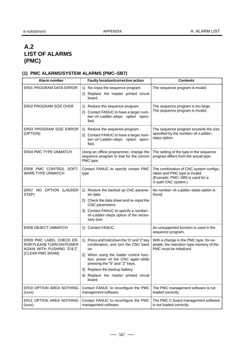
APPENDIXB–63835EN/03 A. ALARM LIST
567
(1) PMC ALARMS/SYSTEM ALARMS (PMC–SB7)
Alarm number Faulty location/corrective action Contents
ER01 PROGRAM DATA ERROR 1) Re–input the sequence program.
2) Replace the master printed circuitboard.
The sequence program is invalid.
ER02 PROGRAM SIZE OVER 1) Reduce the sequence program.
2) Contact FANUC to have a larger num-ber–of–Ladder–steps option speci-fied.
The sequence program is too large.The sequence program is invalid.
ER03 PROGRAM SIZE ERROR(OPTION)
1) Reduce the sequence program.
2) Contact FANUC to have a larger num-ber–of–Ladder–steps option speci-fied.
The sequence program exceeds the sizespecified by the number–of–Ladder–steps option.
ER04 PMC TYPE UNMATCH Using an offline programmer, change thesequence program to that for the correctPMC type.
The setting of the type in the sequenceprogram differs from the actual type.
ER06 PMC CONTROL SOFT-WARE TYPE UNMATCH
Contact FANUC to specify certain PMCtype
The combination of CNC system configu-ration and PMC type is invalid.(Example: PMC–SB5 is used for a3–path CNC system.)
ER07 NO OPTION (LADDERSTEP)
1) Restore the backed up CNC parame-ter data.
2) Check the data sheet and re–input theCNC parameters.
3) Contact FANUC to specify a number–of–Ladder–steps option of the neces-sary size.
No number–of–Ladder–steps option isfound.
ER08 OBJECT UNMATCH 1) Contact FANUC. An unsupported function is used in thesequence program.
ER09 PMC LABEL CHECK ER-ROR PLEASE TURN ON POWERAGAIN WITH PUSHING ’O’&’Z’.(CLEAR PMC SRAM)
1) Press and hold down the ’O’ and ’Z’ keycombination, and turn the CNC backon.
2) When using the loader control func-tion, power on the CNC again whilepressing the ”5” and ”Z” keys.
3) Replace the backup battery.
4) Replace the master printed circuitboard.
With a change in the PMC type, for ex-ample, the retention–type memory of thePMC must be initialized.
ER10 OPTION AREA NOTHING(xxxx)
Contact FANUC to reconfigure the PMCmanagement software.
The PMC management software is notloaded correctly.
ER11 OPTION AREA NOTHING(xxxx)
Contact FANUC to reconfigure the PMCmanagement software.
The PMC C board management softwareis not loaded correctly.
A.2LIST OF ALARMS(PMC)

APPENDIXA. ALARM LIST B–63835EN/03
568
Alarm number ContentsFaulty location/corrective action
ER12 OPTION AREA ERROR(xxxx)
Contact FANUC to reconfigure the PMCmanagement software.
The PMC management software is inval-id.(The series of BASIC and OPTION donot match.)
ER13 OPTION AREA ERROR(xxxx)
Contact FANUC to reconfigure the PMCmanagement software.
The PMC C board management softwareis invalid.(The series of BASIC and OPTION donot match.)
ER14 OPTION AREA VERSIONERROR (xxxx)
Contact FANUC to reconfigure the PMCmanagement software.
The PMC management software is inval-id.(The editions of BASIC and OPTION donot match.)
ER15 OPTION AREA VERSIONERROR (xxxx)
Contact FANUC to reconfigure the PMCmanagement software
The PMC C board management softwareis invalid.(The editions of BASIC and OPTION donot match.)
ER16 RAM CHECK ERROR(PROGRAM RAM)
Replace the master printed circuit board. The initialization of the memory used tostore the sequence program failed.
ER17 PROGRAM PARITY 1) Re–input the sequence program.
2) Replace the master printed circuitboard.
The parity of the sequence program isinvalid.
ER18 PROGRAM DATA ERRORBY I/O
Re–input the sequence program. While the sequence program was beingread, an interrupt command was gener-ated.
ER19 LADDER DATA ERROR Display the Ladder edit screen again andexit from editing by using the [<<] key.
During Ladder editing, the system wasforcibly switched to the CNC screen witha function key.
ER20 SYMBOL/COMMENTDATA ERROR
Display the symbol/comment edit screenagain and exit from editing by using the[<<] key.
During symbol/comment editing, the sys-tem was forcibly switched to the CNCscreen with a function key.
ER21 MESSAGE DATA ERROR Display the message data edit screenagain and exit from editing by using the[<<] key.
During message data editing, the systemwas forcibly switched to the CNC screenwith a function key.
ER22 PROGRAM NOTHING 1) Re–input the sequence program.
2) Replace the master printed circuitboard.
The sequence program is empty.
ER23 PLEASE TURN OFF POW-ER
Turn the CNC off and then back on. With a change in the PMC type, for ex-ample, the power must be turned off andthen back on.
ER25 SOFTWARE VERSION ER-ROR (PMCAOPT)
Contact FANUC to reconfigure the PMCmanagement software.
The PMC management software is inval-id.(The edition of PMCAOPT does notmatch.)
ER26 PMC CONTROL MODULEERROR (PMCAOPT)
1) Contact FANUC to reconfigure thePMC management software.
2) 2) Replace the master printed circuitboard.
The initialization of the PMC manage-ment software failed.

APPENDIXB–63835EN/03 A. ALARM LIST
569
Alarm number ContentsFaulty location/corrective action
ER27 LADDER FUNC. PRM ISOUT OF RANGE
Modify the sequence program. Changethe parameter number of the functioninstruction to a value within the valid range.
An out–of–range parameter number isspecified with function instruction TMR,TMRB, CTR, DIFU, or DIFD.
ER32 NO I/O DEVICE 1) Check that the I/O device is on.
2) Check that the I/O device was turnedon before the CNC was turned on.
3) Check the connection of the cable.
An I/O device such as the I/O Link, con-nection unit, and Power Mate is not con-nected.
ER33 I/O LINK ERROR Replace the master printed circuit board. The LSI of the I/O Link is defective.
ER34 I/O LINK ERROR (xx) 1) Check the connection of the cableleading to a device in group xx.
2) Check that the I/O device was turnedon before the CNC.
3) Replace that device in group xx inwhich the PMC control module isinstalled.
In a slave in group xx, an error occurredin communication with an I/O device.
ER35 TOO MUCH OUTPUTDATA IN GROUP (xx)
Reduce the amount of output data in groupxx.
The amount of output data in I/O Linkgroup xx exceeds the limit (33 bytes).The excess data is nullified.
ER36 TOO MUCH INPUT DATAIN GROUP (xx)
Reduce the amount of input data in groupxx
The amount of input data in I/O Linkgroup xx exceeds the limit (33 bytes).The excess data is nullified.
ER38 MAX SETTING OUTPUTDATA OVER (xx)
Modify the total amount of output data ineach group to 128 bytes or less.
The I/O Link I/O area is insufficient.(The allocation of any group after groupxx on the output side is nullified.)
ER39 MAX SETTING INPUTDATA OVER (xx)
Modify the total amount of input data ineach group to 128 bytes or less.
The I/O Link I/O area is insufficient.(The allocation of any group after groupxx on the input side is nullified.)
ER40 I/O LINK–II SETTING ER-ROR (CHx)
Reconfigure the I/O Link–II. The I/O Link–II setting is invalid.(CH1: Primary board, CH2: Secondaryboard)
ER41 I/O LINK–II MODE ERROR(CHx)
Reconfigure the I/O Link–II. The I/O Link–II mode setting is invalid.(CH1: Primary board, CH2: Secondaryboard)
ER42 I/O LINK–II STATIONNO.ERROR (CHx)
Reconfigure the I/O Link–II. The I/O Link–II station number setting isinvalid.(CH1: Primary board, CH2: Secondaryboard)
ER97 I/O LINK(CHxyyGROUP)
1) Check whether the cables of I/Odevices in group yy are connectedproperly.
2) Check the power to each I/O device.
3) Check the parameter setting of the I/Olink assignment data selection function.
The number of assigned I/O modules ingroup yy differs from that of I/O devicesactually connected.
Note)This alarm can control how thecheck function operates throughthe use of keep relay K906.2.K906.2 = 0: Connection check isperformed (initial value).K906.2 = 1: Connection check isnot performed.
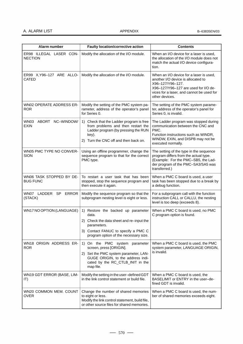
APPENDIXA. ALARM LIST B–63835EN/03
570
Alarm number ContentsFaulty location/corrective action
ER98 ILLEGAL LASER CON-NECTION
Modify the allocation of the I/O module. When an I/O device for a laser is used,the allocation of the I/O module does notmatch the actual I/O device configura-tion.
ER99 X,Y96–127 ARE ALLO-CATED
Modify the allocation of the I/O module. When an I/O device for a laser is used,another I/O device is allocated toX96–127/Y96–127.X96–127/Y96–127 are used for I/O de-vices for a laser, and cannot be used forother devices.
WN02 OPERATE ADDRESS ER-ROR
Modify the setting of the PMC system pa-rameter, address of the operator’s panelfor Series 0.
The setting of the PMC system parame-ter, address of the operator’s panel forSeries 0, is invalid.
WN03 ABORT NC–WINDOW/EXIN
1) Check that the Ladder program is freefrom problems and then restart theLadder program (by pressing the RUNkey).
2) Turn the CNC off and then back on.
The Ladder program was stopped duringcommunication between the CNC andPMC.Function instructions such as WINDR,WINDW, EXIN, and DISPB may not beexecuted normally.
WN05 PMC TYPE NO CONVER-SION
Using an offline programmer, change thesequence program to that for the correctPMC type.
The setting of the type in the sequenceprogram differs from the actual type.(Example: For the PMC–SB5, the Lad-der program of the PMC–SA3/SA5 wastransferred.)
WN06 TASK STOPPED BY DE-BUG FUNC
To restart a user task that has beenstopped, stop the sequence program andthen execute it again.
When a PMC C board is used, a usertask has been stopped due to a break bya debug function.
WN07 LADDER SP ERROR(STACK)
Modify the sequence program so that thesubprogram nesting level is eight or less.
For a subprogram call with the functioninstruction CALL or CALLU, the nestinglevel is too deep (exceeds 8).
WN17 NO OPTION (LANGUAGE) 1) Restore the backed up parameterdata.
2) Check the data sheet and re–input theparameters.
3) Contact FANUC to specify a PMC Cprogram option of the necessary size.
When a PMC C board is used, no PMCC program option is found.
WN18 ORIGIN ADDRESS ER-ROR
1) On the PMC system parameterscreen, press [ORIGIN].
2) Set the PMC system parameter, LAN-GUGE ORIGIN, to the address indi-cated by the RC_CTLB_INIT in themap file.
When a PMC C board is used, the PMCsystem parameter, LANGUAGE ORIGIN,is invalid.
WN19 GDT ERROR (BASE, LIM-IT)
Modify the setting in the user–defined GDTin the link control statement or build file.
When a PMC C board is used, theBASELIMIT or ENTRY in the user–de-fined GDT is invalid.
WN20 COMMON MEM. COUNTOVER
Change the number of shared memoriesto eight or less.Modify the link control statement, build file,or other source files for shared memories.
When a PMC C board is used, the num-ber of shared memories exceeds eight.

APPENDIXB–63835EN/03 A. ALARM LIST
571
Alarm number ContentsFaulty location/corrective action
WN21 COMMON MEM. ENTRYERROR
Modify the ENTRY in the shared memoryGDT in the link control statement.
When a PMC C board is used, theENTRY in the shared memory GDT isout of range.
WN22 LADDER 3 PRIORITY ER-ROR
Change the value of the TASK LEVEL(LADDER LEVEL 3) in the link controlstatement to 0, 10 to 99, or –1.
When a PMC C board is used, the prior-ity of LADDER LEVEL 3 is out of range.
WN23 TASK COUNT OVER Change the TASK COUNT in the link con-trol statement to 16 or less. (To change thetask count, modify the link control state-ment, build file, and the configuration of thefiles to be linked.)
When a PMC C board is used, the num-ber of user tasks exceeds 16.
WN24 TASK ENTRY ADDR ER-ROR
Change the GDT table in the build file to 32(20H) to 95 (5FH).
When a PMC C board is used, the usertask entry address selector is out ofrange.
WN25 DATA SEG ENTRY ER-ROR
Change the DATA SEGMENT GDTENTRY value in the link control statementand the GDT table in the build file to 32(20H) to 95 (5FH).
When a PMC C board is used, the datasegment entry address is out of range.
WN26 USER TASK PRIORITYERROR
Change the TASK LEVEL of each task inthe link control statement to a value from10 to 99 or –1. (Note that –1 can be speci-fied for the TASK LEVEL of only one task,including the third Ladder level).
When a PMC C board is used, the prior-ity of the user task is out of range.
WN27 CODE SEG TYPE ERROR Change the value of the code segment ac-cording to the segment setting in the linkcontrol statement and build file.
When a PMC C board is used, the codesegment type is invalid. The setting ofthe RENA–MESEG code segment in thebind control file is wrong.
WN28 DATA SEG TYPE ERROR Change the value of the data segment ac-cording to the segment setting in the linkcontrol statement and build file.
When a PMC C board is used, the datasegment type is invalid. The setting ofthe RENA–MESEG data segment in thebind control file is wrong.
WN29 COMMON MEM SEGTYPE ERROR
Change the value according to the seg-ment setting in the link control statementand build file.
When a PMC C board is used, theshared memory segment type is invalid.The setting of the RENAMESEG seg-ment in the shared memory bind controlfile is wrong.
WN30 IMPOSSIBLE ALLOCATEMEM.
1) Check that the USER GDT ADDRESSin the link control statement and thestart address of the code segment inthe build file are correct.
2) Change the PMC system parameter,MAX LADDER AREA SIZE, to a mini-mum.
3) Change the stack size in the link con-trol state to a minimum.
When a PMC C board is used, thememory area for data, stacks, and otherscannot be reserved.
WN31 IMPOSSIBLE EXECUTELIBRARY
1) Check the types supported by the li-brary.
2) Reconfigure the PMC managementsoftware and contact FANUC.
When a PMC C board is used, libraryfunctions cannot be executed.

APPENDIXA. ALARM LIST B–63835EN/03
572
Alarm number ContentsFaulty location/corrective action
WN32 LNK CONTROL DATA ER-ROR
1) Check that the address ofRC_CTLNB_INIT is set for the PMCsystem parameter, LANGUAGE ORI-GIN.
2) Create the link control statementagain.
When a PMC C board is used, link con-trol statement (program control) data isinvalid.
WN33 LNK CONTROL VER.ER-ROR
Modify the link control statement in thePMC C program.
When a PMC C board is used, a link con-trol statement data edition error has oc-curred.
WN34 LOAD MODULE COUNTOVER
Change the number of independent loadmodules to eight or less.
When a PMC C board is used, the num-ber of independent load modules ex-ceeds eight.
WN35 CODE AREA OUT OFRANGE
Check the link map and allocate segmentswithin the range of RAM.
When a PMC C board is used, the codesegment area is out of the range of theRAM.
WN36 LANGUAGE SIZE ERROR(OPTION)
1) Reduce the PMC C program.
2) Contact FANUC to specify a PMC Cprogram option of a larger size.
When a PMC C board is used, the PMCC program exceeds the size specified forthe PMC C program option.
WN37 PROGRAM DATA ERROR(LANG.)
Initialize the PMC C program memory.([EDIT] → [CLEAR] → [CLRLNG] →[EXEC])
The PMC C program memory must beinitialized.
WN38 RAM CHECK ERROR(LANG.)
Replace the master printed circuit board. The initialization of the PMC C programmemory failed.
WN39 PROGRAM PARITY(LANG.)
1) Re–input the PMC C program.
2) Replace the master printed circuitboard.
The parity of the PMC C program parityis invalid.
WN40 PROGRAM DATA ERRORBY I/O (LANG.)
Re–input the language program. While the PMC C program was beingread, an interrupt command was gener-ated.
WN41 LANGUAGE TYPE UN-MATCH
1) Re–input the PMC C program.
2) Replace the master printed circuitboard.
When a PMC C board is used, an unus-able C program is input.
WN42 UNDEFINE LANGUAGEORIGIN ADDRESS
1) On the PMC system parameterscreen, click [ORIGIN].
2) Set the PMC system parameter, LAN-GUGE ORIGIN, to the address indi-cated by the RC_CTLB_INIT in themap file.
When a PMC C board is used, the PMCparameter, LANGUAGE ORIGIN, is notset.
WN48 UNAVAIL LANGUAGE BYCNC UNMATCH
Remove the PMC C board. A PMC C board is installed in a CNC inwhich a PMC C board cannot be used.

APPENDIXB–63835EN/03 A. ALARM LIST
573
(2) Alarm messages (PMC–SA1)
Message Contents and solution
ALARM NOTHING Normal status
ER00 PROGRAM DATA ERROR(ROM)
The sequence program in the ROM is not written correctly.(solution) Please exchange ROM for the sequence program.
ER01 PROGRAM DATA ERROR(RAM)
The sequence program in the debugging RAM is defective. (solution) Please clear the debugging RAM and input LADDER again.
The debugging RAM is not installed though the RAM is selected.(solution) Please install the debugging RAM or install ROM for sequence program
and select ROM with K17#3=0.
ER02 PROGRAM SIZE OVER The size of sequence program exceeds the maximum size of LADDER(PMC–SConly).(solution) Please change MAX LADDER AREA SIZE at the SYSPRM screen and
restart the system.
ER03 PROGRAM SIZE ERROR(OPTION)
The size of sequence program exceeds the option specification size.(solution) Please increase the option specification size.
Or, reduce the size of sequence program.
ER04 PMC TYPE UNMATCH The PMC model setting of the sequence program is not corresponding to an actualmodel.(solution) Please change the PMC model setting by the offline programmer.
ER05 PMC MODULE TYPE ERROR
The module type of the PMC engine is not correct.
(solution) Please exchange the module of PMC engine for a correct one.
ER07 NO OPTION (LADDER STEP)
There is no step number option of LADDER.
ER10 OPTION AREA NOTHING (series name)
The management software for the PMC–SB has not been transferred.(solution) The software installation is not consistent with the order. Contact FANUC.
ER11 OPTION AREA NOTHING (series name)
The management software for the PMC C board has not been transferred.(solution) The software installation is not consistent with the order. Contact FANUC.
ER12 OPTION AREA ERROR (series name)
The series of the management software for the PMC–RB differs between BASIC andOPTION.(solution) Contact FANUC.
ER13 OPTION AREA ERROR (series name)
The series of the management software for the PMC C board differs between BASICand OPTION.(solution) Contact FANUC.
ER14 OPTION AREA VERSIIONERROR (series name)
The edition of the management software for the PMC–RB differs between BASICand OPTION.(solution) Contact FANUC.
ER15 OPTION AREA VERSIIONERROR (series name)
The edition of the management software for the PMC C board differs between BASICand OPTION.(solution) Contact FANUC.
ER16 RAM CHECK ERROR(PROGRAM RAM)
The debugging RAM cannot be read/written normally.(solution) Please exchange the debugging RAM.
ER17 PROGRAM PARITY The parity error occurred on ROM for sequence program or the debugging RAM.(solution) ROM: The deterioration of ROM may be deteriorated
Please exchange ROM for the sequence program RAM: Please edit the sequence program once on PMC
Still the error occurs, exchange the debugging RAM.

APPENDIXA. ALARM LIST B–63835EN/03
574
Message Contents and solution
ER18 PROGRAM DATA ERRORBY I/O
Transferring the sequence program from offline programmer was interrupted by thepower off etc.(solution) Please clear the sequence program and transfer the sequence program
again.
ER19 LADDER DATA ERROR Editing the LADDER was interrupted by the power off or by the switch to the CNCscreen by the function key etc. (solution) Please edit LADDER once on PMC.
Or, please input LADDER again.
ER20 SYMBOL/COMMENT DATA ERROR
Editing the symbol and comment was interrupted by the power off or by the switch tothe CNC screen by the function key etc.(solution) Please edit symbol and comment once on PMC.
Or, please input symbol and comment again.
ER21 MESSAGE DATA ERROR Editing the message data was interrupted by the power off or the switch to the CNCscreen by the function key etc. (solution) Please edit message data once on PMC.
Or, please input message data again.
ER22 PROGRAM NOTHING There is no sequence program
ER23 PLEASE TURN OFF POW-ER
There is a change in setting LADDER MAX AREA SIZE etc.(solution) Please restart the system to make the change effective.
ER24 LADDER, LANGUAGE AREA OVERLAP
The C program area overlaps the ladder program area.(solution) Adjust the address range assigned to C programs.
ER25 SOFTWARE VERSION ERROR (PMCAOPT)
The PMC–SB management software editions are inconsistent.(solution) Contact FANUC.
ER26 SOFTWARE VERSION ERROR (PMCAOPT)
The PMC–SB management software cannot be initialized.(solution) Contact FANUC.
ER27 LADDER FUNC. PRM ISOUT OF RANGE
The parameter number for function instruction TMR, TMRB, CTR, DIFU, or DIFD isnot in the range.(solution) Correct the number so that it is within the range.
*When ER00 to ER27 occur, sequence program is not available.
Message Contents and solution
ER32 NO I/O DEVICE Any DI/DO unit of I/O Unit or the connection unit etc. is not connected. When built–inI/O card is connected, this message is not displayed.(solution) When built–in I/O card is used:
Please confirm whether the built–in I/O card is certainly connected with.When I/O Link is used:Please confirm whether the DI/DO units turning on. Or please confirmthe connection of the cable.
ER33 SLC ERROR The LSI for I/O Link is defective.(solution) Please exchange the module of PMC engine.
ER34 SLC ERROR(xx) The communication with the DI/DO units of the xx group failed.(solution) Please confirm the connection of the cable connected to the DI/DO
units of the xx group.Please confirm whether the DI/DO units turned on earlier than CNC andPMC. Or, please exchange the module of PMC engine on the DI/DOunits of the xx group
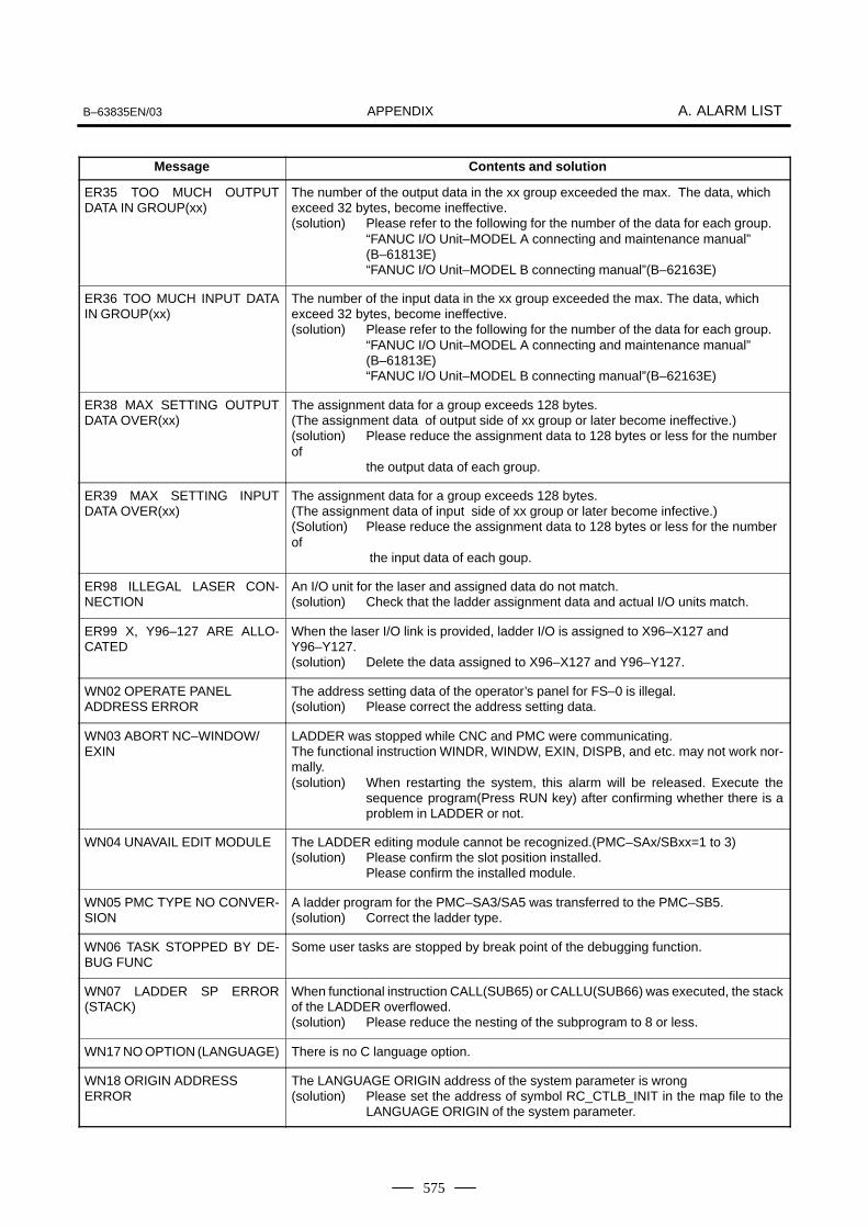
APPENDIXB–63835EN/03 A. ALARM LIST
575
Message Contents and solution
ER35 TOO MUCH OUTPUTDATA IN GROUP(xx)
The number of the output data in the xx group exceeded the max. The data, whichexceed 32 bytes, become ineffective.(solution) Please refer to the following for the number of the data for each group.
“FANUC I/O Unit–MODEL A connecting and maintenance manual” (B–61813E) “FANUC I/O Unit–MODEL B connecting manual”(B–62163E)
ER36 TOO MUCH INPUT DATAIN GROUP(xx)
The number of the input data in the xx group exceeded the max. The data, whichexceed 32 bytes, become ineffective.(solution) Please refer to the following for the number of the data for each group.
“FANUC I/O Unit–MODEL A connecting and maintenance manual” (B–61813E) “FANUC I/O Unit–MODEL B connecting manual”(B–62163E)
ER38 MAX SETTING OUTPUTDATA OVER(xx)
The assignment data for a group exceeds 128 bytes.(The assignment data of output side of xx group or later become ineffective.)(solution) Please reduce the assignment data to 128 bytes or less for the numberof the output data of each group.
ER39 MAX SETTING INPUTDATA OVER(xx)
The assignment data for a group exceeds 128 bytes.(The assignment data of input side of xx group or later become infective.)(Solution) Please reduce the assignment data to 128 bytes or less for the numberof
the input data of each goup.
ER98 ILLEGAL LASER CON-NECTION
An I/O unit for the laser and assigned data do not match.(solution) Check that the ladder assignment data and actual I/O units match.
ER99 X, Y96–127 ARE ALLO-CATED
When the laser I/O link is provided, ladder I/O is assigned to X96–X127 andY96–Y127.(solution) Delete the data assigned to X96–X127 and Y96–Y127.
WN02 OPERATE PANEL ADDRESS ERROR
The address setting data of the operator’s panel for FS–0 is illegal.(solution) Please correct the address setting data.
WN03 ABORT NC–WINDOW/EXIN
LADDER was stopped while CNC and PMC were communicating.The functional instruction WINDR, WINDW, EXIN, DISPB, and etc. may not work nor-mally.(solution) When restarting the system, this alarm will be released. Execute the
sequence program(Press RUN key) after confirming whether there is aproblem in LADDER or not.
WN04 UNAVAIL EDIT MODULE The LADDER editing module cannot be recognized.(PMC–SAx/SBxx=1 to 3)(solution) Please confirm the slot position installed.
Please confirm the installed module.
WN05 PMC TYPE NO CONVER-SION
A ladder program for the PMC–SA3/SA5 was transferred to the PMC–SB5.(solution) Correct the ladder type.
WN06 TASK STOPPED BY DE-BUG FUNC
Some user tasks are stopped by break point of the debugging function.
WN07 LADDER SP ERROR(STACK)
When functional instruction CALL(SUB65) or CALLU(SUB66) was executed, the stackof the LADDER overflowed.(solution) Please reduce the nesting of the subprogram to 8 or less.
WN17 NO OPTION (LANGUAGE) There is no C language option.
WN18 ORIGIN ADDRESS ERROR
The LANGUAGE ORIGIN address of the system parameter is wrong(solution) Please set the address of symbol RC_CTLB_INIT in the map file to the
LANGUAGE ORIGIN of the system parameter.

APPENDIXA. ALARM LIST B–63835EN/03
576
Message Contents and solution
WN19 GDT ERROR(BASE,LIMIT)
The value of BASE, LIMIT or ENTRY of user defined GDT is illegal.(solution) Please correct the address in link control statement and build file.
WN20 COMMON MEM. COUNTOVER
The number of common memories exceeds 8.(solution) Please reduce the number of common memories to 8 or less. It is
necessary to correct a link control statement,build file and the source filefor the common memory.
WN21 COMMON MEM. ENTRYERROR
GDT ENTRY of the common memory is out of range.(solution) Please correct the address of GDT ENTRY of the common memory in the link control statement.
WN22 LADDER 3 PRIORITY ERROR
The priority of LADDER LEVEL 3 is out of range.(solution) Please correct the value of LADDER LEVEL 3 in the link control statement
within the range of 0 or 10–99 or –1.
WN23 TASK COUNT OVER The number of user tasks exceeds 16.(solution) Please confirm TASK COUNT in the link control statement. When the
number of tasks is changed, it is necessary to correct the link controlstatement, build file and the composition of the files to be linked.
WN24 TASK ENTRY ADDR ERROR
The selector of the entry address to the user task is out of range.(solution) Please correct the table of GDT in build file to the value within
32(20H)–95(5FH).
WN25 DATA SEG ENTRY ERROR
The entry address of the data segment is out of range.(solution) Please correct DATA SEGMENT GDT ENTRY in the link control statement
and the table of GDT in build file within 32(20H)–95(5FH).
WN26 USER TASK PRIORITYERROR
The priority of the user task is out of range.(solution) Please correct the TASK LEVEL in link control statement within the
range of 10–99 or –1.Note: Only one task can have TASK LEVEL –1 (including LADDER
LEVEL 3).
WN27 CODE SEG TYPE ERROR The code segment type is illegal. The code segment of RENAMESEG in the bindingcontrol file is wrong.(solution) Please correct the entry of the code segment in the link control statement
to correspond to the entry in the build file.
WN28 DATA SEG TYPE ERROR The data segment type is illegal. The data segment of RENAMESEG in the binding con-trol file is wrong.(solution) Please correct the entry of the code segment in the link control statement
to correspond to the entry in the build file.
WN29 COMMON MEM SEGTYPE ERROR
The segment type of common memory is illegal. The segment of RENAMESEG in thebuilding control file of the common memory is wrong.(solution) Please correct the entry of common memory in the link control statement to correspond to the entry in the build file.
WN30 IMPOSSIBLE ALLOCATEMEM.
The memories for the data and stack etc. cannot be allocated.(solution) Please confirm whether the value of code segment in build file and USER
GDT ADDRESS in link control statement is correct or not.Or please reduce the value of MAX LADDER AREA SIZE of the systemparameter and the size of the stack in link control statement at the least
WN31 IMPOSSIBLE EXECUTELIBRARY
The library function cannot be executed.(solution) Please confirm the object model of the library.
Or, system ROM of PMC must be replaced with one of later version.

APPENDIXB–63835EN/03 A. ALARM LIST
577
Message Contents and solution
WN32 LNK CONTROL DATA ER-ROR
Link control statement data is illegal.(solution) Please confirm whether the address of symbol RC_ CTLB_INIT in map file
is set to LANGUAGE ORIGIN of the system parameter. Or, please makethe link control statement again.
WN33 LNK CONTROL VER. ER-ROR
A link control statement data version error occurred.(Solution) Correct the link control statement in the C program.
WN34 LOAD MODULE COUNTOVER
The number of independent load modules exceeds eight.(solution) Decrease the number of independent load modules to eight or small
er.
WN35 CODE AREA OUT OFRANGE
The specified code area is beyond the address range.(solution) Correct the C program.
WN36 LANGUAGE SIZE ERROR(OPTION)
The size of a C program exceeds the option size.(solution) Decrease the size of the C program.
WN37 PROGRAM DATA ERROR(LANG.)
A C program is destroyed.(solution) Transfer the C program again.
WN38 RAM CHECK ERROR (LANG.)
A C program is destroyed.(solution) Transfer the C program again.
WN39 PROGRAM PARITY (LANG.)
A parity mismatch occurred in a C program.(solution) Transfer the C program again.
WN40 PROGRAM DATA ERRORBY I/O (LANG.)
Transfer of a C program was interrupted by, for example, a power failure.(solution) Clear the C program, then transfer the C program again.
WN41 LANGUAGE TYPE UNMATCH
A C program type mismatch occurred.(solution) Correct the C program.
WN42 UNDEFINE LANGUAGE ORIGIN ADDRESS
No language origin address is set.(solution) Set the language origin address.
NOTEAlarms WN17 to WN42 indicate errors related to PMC userC programs.

APPENDIXA. ALARM LIST B–63835EN/03
578
(3) System alarm messages (PMC–SB7)
Message Contents and solution
1 PC004 CPU ERR xxxxxxxx:yyyyyyyy
PC006 CPU ERR xxxxxxxx:yyyyyyyy
PC009 CPU ERR xxxxxxxx:yyyyyyyy
PC010 CPU ERR xxxxxxxx:yyyyyyyy
A CPU error occurred in the PMC.xxxxxxxx and yyyyyyyy indicate internal error code.
If this error occurs, the motherboard may be faulty.
Replace the motherboard, then check whether the error recurs. If the error stilloccurs even after the replacement of the motherboard, report the conditions un-der which the error occurred (system configuration, operation, time and frequen-cy of error occurrences, etc.) to FANUC.
2 PC030 RAM PARITY aa:bb A RAM parity error occurred in the PMC.aa and bb indicate internal error code.
If this error occurs, the motherboard may be faulty.
Solution) Replace the motherboard, then check whether the error recurs. If the error stilloccurs even after the replacement of the motherboard, report the conditions un-der which the error occurred (system configuration, operation, time and frequen-cy of error occurrences, etc.) and the indicated internal error code to FANUC.
3 PC050 I/OLINK(CHx)aa:bb–aa:bb
orPC050 IOLINK CHx
aabb– aabb:aabb
A communication error occurred in the I/O Link.CHx is channel number.aa and bb indicate internal error code.
If this error occurs, the possible causes are as follows:
(1) Although the base expansion is assigned when the I/O Unit A is used, thebase is not connected.
(2) A cable is not connected securely.
(3) Cabling is faulty.
(4) I/O equipment (I/O unit, Power Mate, etc.) is faulty.
(5) The power to the master or slave unit of the I/O Link is disconnected.
(6) A DO–pin short–circuit occurred in an I/O device.
(7) The motherboard is faulty.
Solution)
(1) Check whether the I/O assignment data and the actual I/O equipment con-nection match.
(2) Check whether the cables are connected correctly.
(3) According to “FANUC I/O Unit–MODEL A Connection and MaintenanceManual” (B–61813E) or “FANUC I/O Unit–MODEL B Connection manual”(B–62163E), check for an error in the cable specifications.
(4) Replace the I/O unit interface module, cable, or motherboard. Then, checkwhether the error still occurs.
4 PC060 FBUSxxxxxxxx:yyyyyyyy
PC061 FL–Rxxxxxxxx:yyyyyyyy
PC062 FL–Waa: xxxxxxxx:yyyyyyyy
A bus error occurred in the PMC.aa, xxxxxxxx, and yyyyyyyy indicate internal error code.
If this error occurs, the hardware may be faulty.
Solution) Report the conditions under which the error occurred (system configuration, op-eration, time and frequency of error occurrences, tc.), the indicated internal errorcode, and the LED status on each board to FANUC.

APPENDIXB–63835EN/03 A. ALARM LIST
579
Contents and solutionMessage
5 PC070 SUB65 CALL (STACK) A stack error occurred during execution of ladder function instruction CALL/CALLU.
Solution) Check the correspondence between the CALL/CALLU instruction and SPEinstruction. If the error cannot be located, report the conditions under which theerror occurred and the ladder program to FANUC.
6 PC080 SYS EMGxxxxxxxx:yyyyyyyy
PC081 FL EMGxxxxxxxx:yyyyyyyy
A system alarm was caused by another software.
Solution)Report the conditions under which the error occurred (system configuration, op-eration, time and frequency of error occurrences, etc.), the indicated internal er-ror code, and the LED status on each board to FANUC.
7 PC097 PARITY ERR (LADDER)
PC098 PARITY ERR (DRAM)
A parity error occurred in the PMC system.
If this error occurred, the motherboard may be faulty.
Solution) Replace the motherboard, then check whether the error recurs. If the error stilloccurs even after the replacement of the motherboard, report the conditions un-der which the error occurred (system configuration, operation, time and frequen-cy of error occurrences, etc.) to FANUC.

APPENDIXA. ALARM LIST B–63835EN/03
580
(4) System alarm messages (for the C language board)
Message Contents and solution
1 PC1nn CPU INTERRT xxxxyyyyyy
STATUS LED ��
CPU error (abnormal interrupt)
nn : Exception codeException code of the i80486. For details, refer to the relevantmanual that describes the CPU.
00 Division error. For example, the divisor in a division instruction is 0.12 Stack exception caused by, for example, stack segment limit viola
tion13 General protection exception generated when, for example, a seg
ment limit is exceeded
xxxx : Segment selector where the system error occurredA value 0103 to 02FB indicates the C execution area.
yyyyyy : Offset address at which the system error occurred
(Solution) If a C program is not used, or if the cause of the error cannot be determinedeven by checking the C program, contact FANUC.
2 PC130 RAM PRTY aa xxxxyyyyyy
STATUS LED ��
A parity error occurred in user RAM or DRAM on the C language board.
aa : RAM parity error occurrence information
xxxx : Segment selector where the system error occurred
yyyyyy : Offset address at which the system error occurred
5 PC160 F–BUS ERROR xxxxyyyyyyPC161 F–BUS ERROR xxxxyyyyyyPC162 F–BUS ERROR xxxxyyyyyySTATUS LED ��
A bus error occurred on the C language board.
xxxx : Segment selector where the system error occurred
yyyyyy : Offset address at which the system error occurred
6 PC170 F–BUS ERROR xxxxyyyyyyPC171 F–BUS ERROR xxxxyyyyyyPC172 F–BUS ERROR xxxxyyyyyySTATUS LED ��
A bus error occurred on the C language board.
xxxx : Segment selector where the system error occurred
yyyyyy : Offset address at which the system error occurred
7 PC199 ROM PARITY eeeeeeeeSTATUS LED ��
A parity error occurred in system ROM on the C language board.
eeeeeeee : ROM parity error information
STATUS LED (green)� : Off � : On �� : Blink

APPENDIXB–63835EN/03 A. ALARM LIST
581
(5) Alarm messages (For EDIT: PMC–SB7)
Messages displayed during update of the PMC ladder diagram editing
Alarm number Faulty location/corrective action Contents
OVERLAPPED COM If COME is missing, add it in proper posi-tion. If the COM is unnecessary, remove it.
There is no COME that corresponds tothis COM.
END IN COMEND1 IN COMEND2 IN COM
If COME is missing, add it in proper posi-tion. If COM is unnecessary, remove it.
END,END1,END2, or END3 is found be-tween COM and COME.
JMPE IN COM JMPE and corresponding JMP must havesame COM/COME status. Review JMPrange and COM range, to adjust not tooverlap with each other: it is possible thatone range includes the other completely.
JMPE is found between COM andCOME, and JMP and correspondingJMPE have different COM/COME status.
SP/SPE IN COM If COME is missing, add it in proper posi-tion. If the COM is unnecessary, remove it.
SP or SPE is found between COM andCOME.
COME WITHOUT COM If COM is missing, add it in proper position.If the COME is unnecessary, remove it.
There is no COM that corresponds to thisCOME.
DUPLICATE CTR NUMBER(WARNING)
If some of them are unnecessary, removethem. If all of them are necessary, assignother number to parameter of them tomake them unique. (If two or more instruc-tions with same parameter number willnever be active simultaneously at onetime, the Ladder program has a possibilityto work correctly, however, it is recom-mended from safety and maintenancepoints of view, that all these instructionsshould have different parameter numberwith each other.)
Plural CTRs have the same number astheir parameter. (This is warning.)
ILLEGAL CTR NUMBER If unnecessary, remove it. Assign correctnumber not to exceed the maximum num-ber defined by each PMC model.
CTR has parameter number that is out ofrange.
DUPLICATE DIFU/DIFD NUM-BER (WARNING)
If some of them are unnecessary, removethem. If all of them are necessary, assignother number to parameter of them tomake them unique. (If two or more instruc-tions with same parameter number willnever be active simultaneously at onetime, the Ladder program has a possibilityto work correctly, however, it is recom-mended from safety and maintenancepoints of view, that all these instructionsshould have different parameter numberwith each other.)
Plural DIFUs or DIFDs have the samenumber as their parameter. (This is warning.)
ILLEGAL DIFU/DIFD NUMBER If unnecessary, remove it. Assign correctnumber not to exceed the maximum num-ber defined by each PMC model.
DIFU or DIFD has parameter numberthat is out of range.
NO ENDNO END1NO END2NO END3
Add END, END1, END2 or END3 in properposition.
END, END1, END2 or END3 is notfound.

APPENDIXA. ALARM LIST B–63835EN/03
582
Alarm number ContentsFaulty location/corrective action
DUPLICATE END1DUPLICATE END2DUPLICATE END3
Remove extra END1, END2 or END3. Multiple END1, END2 or END3 arefound.
GARBAGE AFTER ENDGARBAGE AFTER END2GARBAGE AFTER END3
Remove unnecessary nets, and movenecessary nets to proper position so thatthey will be executed.
There are some nets after END, END2 orEND3, which will not be executed.
OVERLAPPED JMP If JMPE is missing, add it in proper posi-tion. If the JMP is unnecessary, remove it.
There is no JMPE that corresponds tothis JMP.
JMP/JMPE TO BAD COM LEVEL JMP and corresponding JMPE must havesame COM/COME status. Review JMPrange and COM range, to adjust not tooverlap with each other: it is possible thatone range includes the other completely.
JMP and corresponding JMPE have dif-ferent COM/COME status.
COME IN JMP COME and corresponding COM musthave same JMP/JMPE status. ReviewCOM range and JMP range, to adjust notto overlap with each other: it is possiblethat one range includes the other com-pletely.
COME is found between JMP and JMPE,and COM and corresponding COMEhave different JMP/JMPE status.
END IN JMPEND1 IN JMPEND2 IN JMPEND3 IN JMP
If JMPE is missing, add it in proper posi-tion. If JMP is unnecessary, remove it.
END,END1,END2, or END3 is found be-tween JMP and JMPE.
SP/SPE IN JMP If JMPE is missing, add it in proper posi-tion. If the JMP is unnecessary, remove it.
SP or SPE is found between JMP andJMPE.
JMPB OVER COM BORDER JMPB and its destination must have sameCOM/COME status. Review range ofJMPB and COM range, to adjust not tooverlap with each other: it is possible thatone range includes the other completely.
JMPB and its destination differ in COM/COME status.
JMPB OVER LEVEL JMPB can only jump to the same programlevel, or within a subprogram. If the JMPBis unnecessary, remove it. If LBL for theJMPB is missing, add it in proper position.If it should be JMPC, correct it.
JMPB jumps to different program level.
LBL FOR JMPB NOT FOUND If JMPB is unnecessary, remove it. If LBLis missing, add it in proper position.
Can not find proper LBL for JMPB.
JMPC IN BAD LEVEL JMPC is used to jump from a subprogramto level 2. If the JMPC is unnecessary, re-move it. If it should be JMPB or JMP, cor-rect it.
JMPC is used in other than subprogram.
LBL FOR JMPC NOT FOUND If JMPC is unnecessary, remove it. If LBLis missing, add it in proper position: JMPCjumps into level 2. If it should be JMPB orJMP, correct it.
Can not find proper LBL for JMPC.
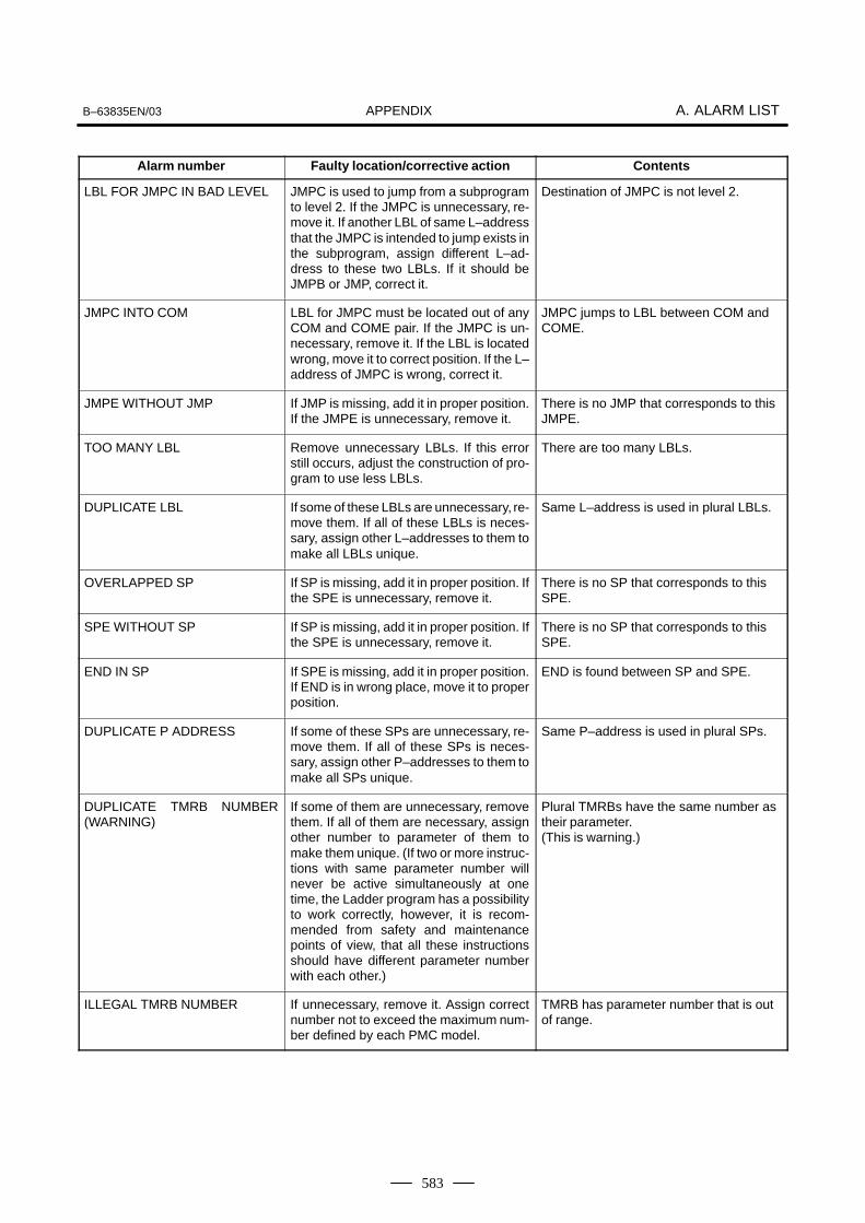
APPENDIXB–63835EN/03 A. ALARM LIST
583
Alarm number ContentsFaulty location/corrective action
LBL FOR JMPC IN BAD LEVEL JMPC is used to jump from a subprogramto level 2. If the JMPC is unnecessary, re-move it. If another LBL of same L–addressthat the JMPC is intended to jump exists inthe subprogram, assign different L–ad-dress to these two LBLs. If it should beJMPB or JMP, correct it.
Destination of JMPC is not level 2.
JMPC INTO COM LBL for JMPC must be located out of anyCOM and COME pair. If the JMPC is un-necessary, remove it. If the LBL is locatedwrong, move it to correct position. If the L–address of JMPC is wrong, correct it.
JMPC jumps to LBL between COM andCOME.
JMPE WITHOUT JMP If JMP is missing, add it in proper position.If the JMPE is unnecessary, remove it.
There is no JMP that corresponds to thisJMPE.
TOO MANY LBL Remove unnecessary LBLs. If this errorstill occurs, adjust the construction of pro-gram to use less LBLs.
There are too many LBLs.
DUPLICATE LBL If some of these LBLs are unnecessary, re-move them. If all of these LBLs is neces-sary, assign other L–addresses to them tomake all LBLs unique.
Same L–address is used in plural LBLs.
OVERLAPPED SP If SP is missing, add it in proper position. Ifthe SPE is unnecessary, remove it.
There is no SP that corresponds to thisSPE.
SPE WITHOUT SP If SP is missing, add it in proper position. Ifthe SPE is unnecessary, remove it.
There is no SP that corresponds to thisSPE.
END IN SP If SPE is missing, add it in proper position.If END is in wrong place, move it to properposition.
END is found between SP and SPE.
DUPLICATE P ADDRESS If some of these SPs are unnecessary, re-move them. If all of these SPs is neces-sary, assign other P–addresses to them tomake all SPs unique.
Same P–address is used in plural SPs.
DUPLICATE TMRB NUMBER(WARNING)
If some of them are unnecessary, removethem. If all of them are necessary, assignother number to parameter of them tomake them unique. (If two or more instruc-tions with same parameter number willnever be active simultaneously at onetime, the Ladder program has a possibilityto work correctly, however, it is recom-mended from safety and maintenancepoints of view, that all these instructionsshould have different parameter numberwith each other.)
Plural TMRBs have the same number astheir parameter. (This is warning.)
ILLEGAL TMRB NUMBER If unnecessary, remove it. Assign correctnumber not to exceed the maximum num-ber defined by each PMC model.
TMRB has parameter number that is outof range.

APPENDIXA. ALARM LIST B–63835EN/03
584
Alarm number ContentsFaulty location/corrective action
DUPLICATE TMR NUMBER(WARNING)
If some of them are unnecessary, removethem. If all of them are necessary, assignother number to parameter of them tomake them unique. (If two or more instruc-tions with same parameter number willnever be active simultaneously at onetime, the Ladder program has a possibilityto work correctly, however, it is recom-mended from safety and maintenancepoints of view, that all these instructionsshould have different parameter numberwith each other.)
Plural TMRs have the same number astheir parameter. (This is warning.)
ILLEGAL TMR NUMBER If unnecessary, remove it. Assign correctnumber not to exceed the maximum num-ber defined by each PMC model.
TMR has parameter number that is out ofrange.
NO SUCH SUBPROGRAM If it calls wrong subprogram, correct it. If thesubprogram is missing, create it.
Subprogram that is called by CALL/CAL-LU is not found.
UNAVAILABLE INSTRUCTION Confirm that this ladder program is correctone. If this program is correct one, all theseunsupported instructions have to be re-moved.
Unsupported instruction for this PMCmodel is found.
SP IN BAD LEVEL SP can be used at top of a subprogram.Correct it so that no SP exists in otherplace.
SP is found in wrong place.
LADDER PROGRAM IS BROKEN This ladder program must be all clearedonce, and remake ladder program.
Ladder program may be broken by somereason.
NO WRITE COIL Add proper write coil. Write coil is necessary, but is not found.
CALL/CALLU IN BAD LEVEL CALL/CALLU must be used in Level 2 or insubprograms. Do not use any otherplaces.
CALL/CALLU is used in wrong place.
SP IN LEVEL3 If END3 is located wrong, move it to correctposition. If the SP is unnecessary, removeit.
SP is found in level 3.
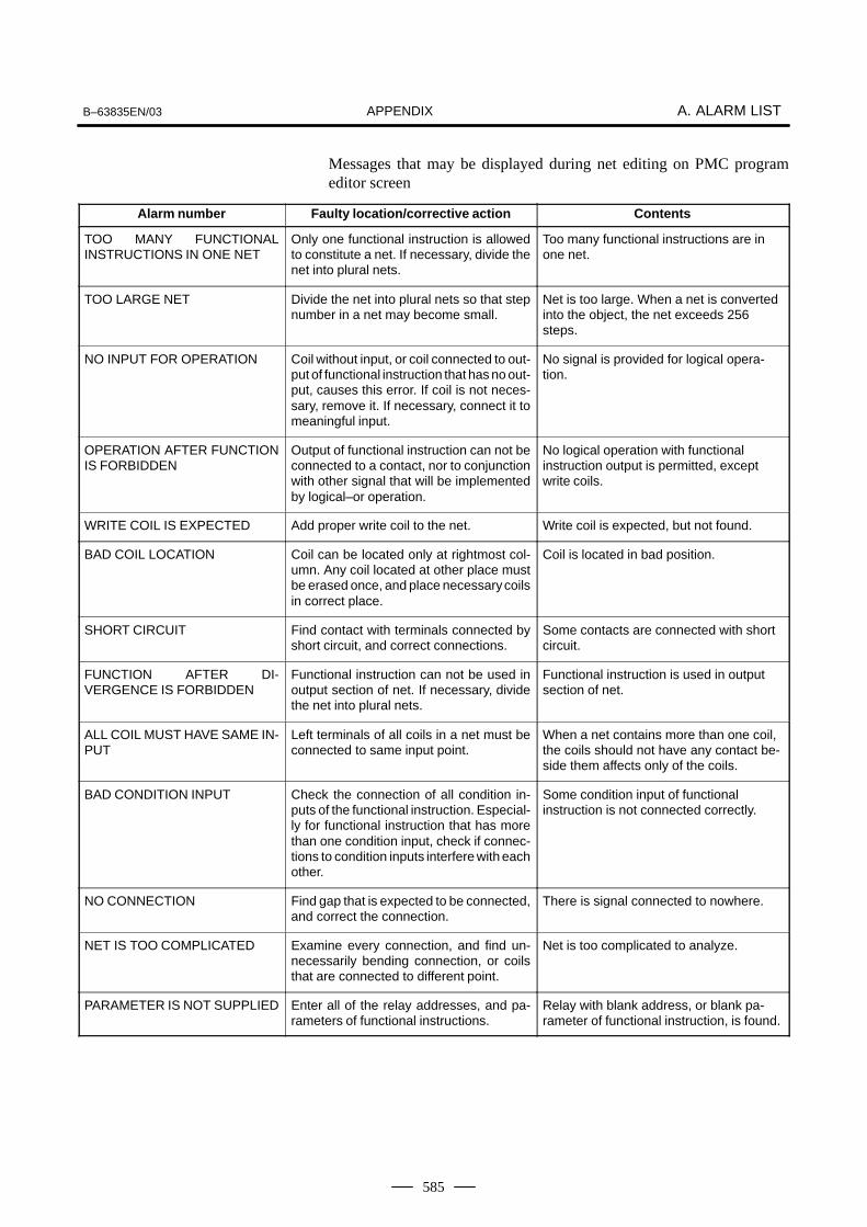
APPENDIXB–63835EN/03 A. ALARM LIST
585
Messages that may be displayed during net editing on PMC programeditor screen
Alarm number Faulty location/corrective action Contents
TOO MANY FUNCTIONALINSTRUCTIONS IN ONE NET
Only one functional instruction is allowedto constitute a net. If necessary, divide thenet into plural nets.
Too many functional instructions are inone net.
TOO LARGE NET Divide the net into plural nets so that stepnumber in a net may become small.
Net is too large. When a net is convertedinto the object, the net exceeds 256steps.
NO INPUT FOR OPERATION Coil without input, or coil connected to out-put of functional instruction that has no out-put, causes this error. If coil is not neces-sary, remove it. If necessary, connect it tomeaningful input.
No signal is provided for logical opera-tion.
OPERATION AFTER FUNCTIONIS FORBIDDEN
Output of functional instruction can not beconnected to a contact, nor to conjunctionwith other signal that will be implementedby logical–or operation.
No logical operation with functionalinstruction output is permitted, exceptwrite coils.
WRITE COIL IS EXPECTED Add proper write coil to the net. Write coil is expected, but not found.
BAD COIL LOCATION Coil can be located only at rightmost col-umn. Any coil located at other place mustbe erased once, and place necessary coilsin correct place.
Coil is located in bad position.
SHORT CIRCUIT Find contact with terminals connected byshort circuit, and correct connections.
Some contacts are connected with shortcircuit.
FUNCTION AFTER DI-VERGENCE IS FORBIDDEN
Functional instruction can not be used inoutput section of net. If necessary, dividethe net into plural nets.
Functional instruction is used in outputsection of net.
ALL COIL MUST HAVE SAME IN-PUT
Left terminals of all coils in a net must beconnected to same input point.
When a net contains more than one coil,the coils should not have any contact be-side them affects only of the coils.
BAD CONDITION INPUT Check the connection of all condition in-puts of the functional instruction. Especial-ly for functional instruction that has morethan one condition input, check if connec-tions to condition inputs interfere with eachother.
Some condition input of functionalinstruction is not connected correctly.
NO CONNECTION Find gap that is expected to be connected,and correct the connection.
There is signal connected to nowhere.
NET IS TOO COMPLICATED Examine every connection, and find un-necessarily bending connection, or coilsthat are connected to different point.
Net is too complicated to analyze.
PARAMETER IS NOT SUPPLIED Enter all of the relay addresses, and pa-rameters of functional instructions.
Relay with blank address, or blank pa-rameter of functional instruction, is found.
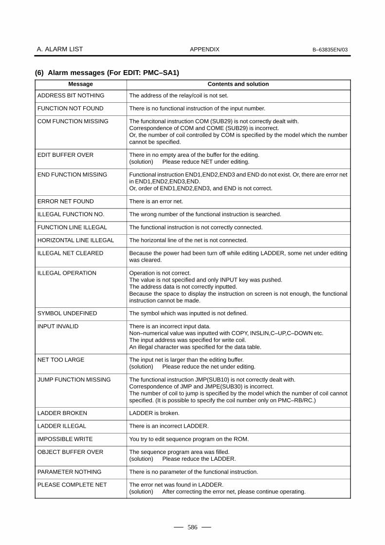
APPENDIXA. ALARM LIST B–63835EN/03
586
(6) Alarm messages (For EDIT: PMC–SA1)
Message Contents and solution
ADDRESS BIT NOTHING The address of the relay/coil is not set.
FUNCTION NOT FOUND There is no functional instruction of the input number.
COM FUNCTION MISSING The funcitonal instruction COM (SUB29) is not correctly dealt with.Correspondence of COM and COME (SUB29) is incorrect.Or, the number of coil controlled by COM is specified by the model which the numbercannot be specified.
EDIT BUFFER OVER There in no empty area of the buffer for the editing.(solution) Please reduce NET under editing.
END FUNCTION MISSING Functional instruction END1,END2,END3 and END do not exist. Or, there are error netin END1,END2,END3,END.Or, order of END1,END2,END3, and END is not correct.
ERROR NET FOUND There is an error net.
ILLEGAL FUNCTION NO. The wrong number of the functional instruction is searched.
FUNCTION LINE ILLEGAL The functional instruction is not correctly connected.
HORIZONTAL LINE ILLEGAL The horizontal line of the net is not connected.
ILLEGAL NET CLEARED Because the power had been turn off while editing LADDER, some net under editingwas cleared.
ILLEGAL OPERATION Operation is not correct.The value is not specified and only INPUT key was pushed.The address data is not correctly inputted.Because the space to display the instruction on screen is not enough, the functionalinstruction cannot be made.
SYMBOL UNDEFINED The symbol which was inputted is not defined.
INPUT INVALID There is an incorrect input data.Non–numerical value was inputted with COPY, INSLIN,C–UP,C–DOWN etc.The input address was specified for write coil.An illegal character was specified for the data table.
NET TOO LARGE The input net is larger than the editing buffer.(solution) Please reduce the net under editing.
JUMP FUNCTION MISSING The functional instruction JMP(SUB10) is not correctly dealt with.Correspondence of JMP and JMPE(SUB30) is incorrect.The number of coil to jump is specified by the model which the number of coil cannotspecified. (It is possible to specify the coil number only on PMC–RB/RC.)
LADDER BROKEN LADDER is broken.
LADDER ILLEGAL There is an incorrect LADDER.
IMPOSSIBLE WRITE You try to edit sequence program on the ROM.
OBJECT BUFFER OVER The sequence program area was filled.(solution) Please reduce the LADDER.
PARAMETER NOTHING There is no parameter of the functional instruction.
PLEASE COMPLETE NET The error net was found in LADDER.(solution) After correcting the error net, please continue operating.

APPENDIXB–63835EN/03 A. ALARM LIST
587
Message Contents and solution
PLEASE KEY IN SUB NO. Please input the number of the functional instruction.(solution) If you do not input the functional instruction, please push soft key “FUNC”
again.
PROGRAM MODULE NOTHING You tried to edit though there was neither RAM for debugging nor ROM for sequenceprogram.
RELAY COIL FORBIT There is an unnecessary relay or coil.
RELAY OR COIL NOTHING The relay or the coil does not suffice.
PLEASE CLEAR ALL It is impossible to recover the sequence program.(solution) Please clear the all data.
SYMBOL DATA DUPLICATE The same symbol name is defined in other place.
COMMENT DATA OVERFLOW The comment data area was filled.(solution) Please reduce the number of the commnet.
SYMBOL DATA OVERFLOW The symbol data area was filled.(solution) Please reduce the number of the symbol.
VERTICAL LINE ILLEGAL There is an incorrect vertical line of the net.
MESSAGE DATA OVERFLOW The message data area was filled.(solution) Please reduce the number of the message.
1ST LEVEL EXECUTE TIMEOVER
The 1st level of LADDER is too large to complete execution in time.(solution) Please reduce the 1st level of LADDER.
PARA NO. RANGE ERR: The parameter number for a function instruction is not in the range.(solution) Correct the number so that it is within the range.
PARA NO. DUPLICATE: The parameter number for a function instruction is used more than once.(solution) If the duplicate numbers pose the problem of simultaneous operation,
change the parameter number to an unused number.

APPENDIXA. ALARM LIST B–63835EN/03
588
(7) Error Messages (at Automatic Write to Flash ROM after Ladder Editing)
Error message Contents and solution
PROGRAM ALREADY EXISTS A program already exists on flash ROM. (At BLANK)
PROGRAM ALREADY EXISTS(EXEC?)
A program already exists on flash ROM.(Remedy) When the message is displayed, pressing the EXEC key again causes
write or erasure operation. (At write or erasure)
PROGRAM NOTHING There is no program on flash ROM.
ERASE ERRORF–ROM WRITE ERROR 13F–ROM WRITE ERROR 28
Flash ROM is abnormal. Replacement is required. Ask FANUC Service Representative for replacement.
WRITE ERRORF–ROM WRITE ERROR 12F–ROM WRITE ERROR 29
READ ERROR
ANOTHER USEDF–ROM WRITE ERROR 9F–ROM WRITE ERROR 36
Flash ROM is used by other than PMC.
MUST BE IN EMG STOPNOT EMG STOPF–ROM WRITE ERROR 10F–ROM WRITE ERROR 37
The CNC is not in the emergency stop state.
NO OPTION There is no ROM cassette option.
SIZE ERRORIMPOSSIBLE WRITE (SIZEOVER)NO SPACEF–ROM WRITE ERROR 1F–ROM WRITE ERROR 15F–ROM WRITE ERROR 35
The sequence program is larger than the flash ROM size. (At write)(Remedy) Try the condense function. (EDIT/CLEAR screen) If the same phenome-
non is still observed, the flash ROM size must be enlarged.The sequence program to be read is larger than the RAM size. (At read)(Remedy) RAM must be enlarged.

APPENDIXB–63835EN/03 A. ALARM LIST
589
(8) Error Messages (at Assignment Data Editing)
Message Contents and solution
ERR: GROUP NO. (0—15) The group number must be 0 to 15.
ERR: BASE NO. (0—1) The base number must be 0 or 1.
WARN: BASE NO. MUST BE 0 For I/O Unit–B, the base number must be 0. The base number was set to 0 forcibly.
ERR: SLOT NO. (1—10) For I/O Unit–A, the slot number must be 1 to 10.
ERR: SLOT NO. (0, 1—30) For I/O Unit–B, the slot number must be 0 or a number 1 to 30.
ERR: SLOT NO. MUST BE 0 When power on/off information for I/O Unit–B is set, the slot number must be 0.
ERR: ILLEGAL NAME The input assignment name is illegal or not supported. Enter a correct name.
INPUT INVALID The input character string is illegal. Enter a character string in a correct input formatagain.
IMPOSSIBLE WRITE An attempt was made to edit ROM data. ROM data cannot be edited.
ERR: ADDRESS ALREADY ASSIGNED
The specified address is already assigned. Assign another address. Alternatively, de-lete the existing data, then set the address again.
ERR: ADDRESS OVER A set address exceeds the maximum value (X127, Y127). Check the addresses dedi-cated to the unit to be set.
ERR: SLOT ALREADY DEFINED The specified slot is already assigned. Check the existing data.
WARN: SLOT ALREADYDEFINED
The specified slot is already assigned. Check the existing data.
ERR: UNIT TYPE MISMATCH (IN OR OUT)
An output module cannot be allocated to an X address, or an input module cannot beallocated to a Y address.
WARN: UNIT TYPE MISMATCH(MODEL)
I/O Unit–A and I/O Unit–B are assigned to the same group. These units cannot existtogether within the same group.
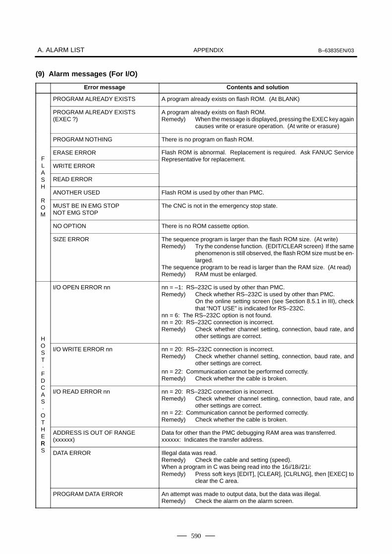
APPENDIXA. ALARM LIST B–63835EN/03
590
(9) Alarm messages (For I/O)
Error message Contents and solution
PROGRAM ALREADY EXISTS A program already exists on flash ROM. (At BLANK)
PROGRAM ALREADY EXISTS(EXEC ?)
A program already exists on flash ROM.Remedy) When the message is displayed, pressing the EXEC key again
causes write or erasure operation. (At write or erasure)
PROGRAM NOTHING There is no program on flash ROM.
ERASE ERROR Flash ROM is abnormal. Replacement is required. Ask FANUC ServiceFL WRITE ERROR
Representative for replacement.
AS READ ERRORH
ANOTHER USED Flash ROM is used by other than PMC.ROM
MUST BE IN EMG STOPNOT EMG STOP
The CNC is not in the emergency stop state.
NO OPTION There is no ROM cassette option.
SIZE ERROR The sequence program is larger than the flash ROM size. (At write)Remedy) Try the condense function. (EDIT/CLEAR screen) If the same
phenomenon is still observed, the flash ROM size must be en-larged.
The sequence program to be read is larger than the RAM size. (At read)Remedy) RAM must be enlarged.
H
I/O OPEN ERROR nn nn = –1: RS–232C is used by other than PMC.Remedy) Check whether RS–232C is used by other than PMC.
On the online setting screen (see Section 8.5.1 in III), checkthat “NOT USE” is indicated for RS–232C.
nn = 6: The RS–232C option is not found.nn = 20: RS–232C connection is incorrect.Remedy) Check whether channel setting, connection, baud rate, and
other settings are correct.
OST·FD
I/O WRITE ERROR nn nn = 20: RS–232C connection is incorrect.Remedy) Check whether channel setting, connection, baud rate, and
other settings are correct.nn = 22: Communication cannot be performed correctly.Remedy) Check whether the cable is broken.
CAS·OT
I/O READ ERROR nn nn = 20: RS–232C connection is incorrect.Remedy) Check whether channel setting, connection, baud rate, and
other settings are correct.nn = 22: Communication cannot be performed correctly.Remedy) Check whether the cable is broken.
HER
ADDRESS IS OUT OF RANGE(xxxxxx)
Data for other than the PMC debugging RAM area was transferred.xxxxxx: Indicates the transfer address.
RS DATA ERROR Illegal data was read.
Remedy) Check the cable and setting (speed).When a program in C was being read into the 16i/18i/21i:Remedy) Press soft keys [EDIT], [CLEAR], [CLRLNG], then [EXEC] to
clear the C area.
PROGRAM DATA ERROR An attempt was made to output data, but the data was illegal.Remedy) Check the alarm on the alarm screen.
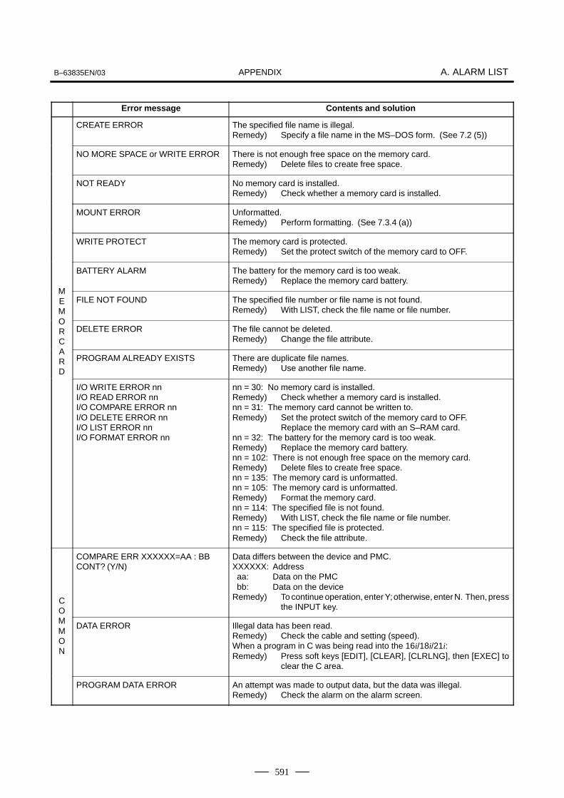
APPENDIXB–63835EN/03 A. ALARM LIST
591
Contents and solutionError message
CREATE ERROR The specified file name is illegal.Remedy) Specify a file name in the MS–DOS form. (See 7.2 (5))
NO MORE SPACE or WRITE ERROR There is not enough free space on the memory card.Remedy) Delete files to create free space.
NOT READY No memory card is installed.Remedy) Check whether a memory card is installed.
MOUNT ERROR Unformatted.Remedy) Perform formatting. (See 7.3.4 (a))
WRITE PROTECT The memory card is protected.Remedy) Set the protect switch of the memory card to OFF.
BATTERY ALARM The battery for the memory card is too weak.Remedy) Replace the memory card battery.
MEM
FILE NOT FOUND The specified file number or file name is not found.Remedy) With LIST, check the file name or file number.
ORC
DELETE ERROR The file cannot be deleted.Remedy) Change the file attribute.
ARD
PROGRAM ALREADY EXISTS There are duplicate file names.Remedy) Use another file name.
I/O WRITE ERROR nnI/O READ ERROR nnI/O COMPARE ERROR nnI/O DELETE ERROR nnI/O LIST ERROR nnI/O FORMAT ERROR nn
nn = 30: No memory card is installed.Remedy) Check whether a memory card is installed.nn = 31: The memory card cannot be written to.Remedy) Set the protect switch of the memory card to OFF.
Replace the memory card with an S–RAM card.nn = 32: The battery for the memory card is too weak.Remedy) Replace the memory card battery.nn = 102: There is not enough free space on the memory card.Remedy) Delete files to create free space.nn = 135: The memory card is unformatted.nn = 105: The memory card is unformatted.Remedy) Format the memory card.nn = 114: The specified file is not found.Remedy) With LIST, check the file name or file number.nn = 115: The specified file is protected.Remedy) Check the file attribute.
CO
COMPARE ERR XXXXXX=AA : BB CONT? (Y/N)
Data differs between the device and PMC.XXXXXX: Address aa: Data on the PMC bb: Data on the deviceRemedy) To continue operation, enter Y; otherwise, enter N. Then, press
the INPUT key.
MMON
DATA ERROR Illegal data has been read.Remedy) Check the cable and setting (speed).When a program in C was being read into the 16i/18i/21i:Remedy) Press soft keys [EDIT], [CLEAR], [CLRLNG], then [EXEC] to
clear the C area.
PROGRAM DATA ERROR An attempt was made to output data, but the data was illegal.Remedy) Check the alarm on the alarm screen.

APPENDIXA. ALARM LIST B–63835EN/03
592
When a serial spindle alarm occurs, the following number is displayed onthe CNC. n is a number corresponding to the spindle on which an alarmoccurs. (n = 1: First spindle; n = 2: Second spindle; etc.)
NOTE*1Note that the meanings of the SPM indications differdepending on which LED, the red or yellow LED, is on.When the red LED is on, the SPM indicates a 2–digit alarmnumber. When the yellow LED is on, the SPM indicates anerror number that designates a sequence problem (forexample, when a rotation command is entered with theemergency stop state not released).� See Appendix A.4, “Error Codes (Serial Spindle).”
Alarm Numbers and Alarms Displayed on the α Series Spindle Amplifier
No. MessageSPM in-
dica-tion(*1)
Faulty location and remedy Description
(750) SPINDLE SERIAL LINKERROR
A0A
1 Replace the ROM on the SPMcontrol printed circuit board.
2 Replace the SPM control printedcircuit board.
The program does not start normally.ROM series error or hardware ab-normality on the SPM control printedcircuit board
(749) S–SPINDLE LSI ERROR A1 Replace the SPM control printed cir-cuit board.
An abnormality was detected in theCPU peripheral circuit of the SPMcontrol circuit.
7n01 SPN_n_ : MOTOR OVER-HEAT
01 1 Check and correct the peripheraltemperature and load status.
2 If the cooling fan stops, replace it.
The thermostat embedded in the mo-tor winding operated.The internal temperature of the motorexceeds the specified level.The motor is used in excess of thecontinuous rating, or the cooling com-ponent is abnormal.
7n02 SPN_n_ : EX SPEED ER-ROR
02 1 Check and correct the cuttingconditions to decrease the load.
2 Correct parameter No. 4082.
The motor speed cannot follow a spe-cified speed.An excessive motor load torque is de-tected.The acceleration/deceleration time inparameter No. 4082 is insufficient.
7n03 SPN_n_ : FUSE ON DC LINK BLOWN
03 1 Replace the SPM unit.2 Check the motor insulation status.3 Replace the interface cable.
The PSM becomes ready (00 is indi-cated), but the DC link voltage is toolow in the SPM.The fuse in the DC link section in theSPM is blown. (The power device isdamaged or the motor is ground–fault.)The JX1A/JX1B connection cable isabnormal.
7n04 SPN_n_ : INPUT FUSE/POWER FAULT
04 Check the state of the input powersupply to the PSM.
The PSM found a missing power sup-ply phase. (PSM alarm 5)
A.3ALARM LIST (SERIAL SPINDLE)

APPENDIXB–63835EN/03 A. ALARM LIST
593
No. DescriptionFaulty location and remedySPM in-
dica-tion(*1)
Message
7n06 SPN_n_ : THERMALSENSOR DIS-CONNECT
06 1 Check and correct the parameter.2 Replace the feedback cable.
The temperature sensor of the motoris disconnected.
7n07 SPN_n_ : OVERSPEED 07 Check for a sequence error. (For ex-ample, check whether spindle syn-chronization was specified when thespindle could not be turned.)
The motor speed has exceeded115% of its rated speed.When the spindle axis was in positioncontrol mode, positional deviationswere accumulated excessively (SFRand SRV were turned off duringspindle synchronization.)
7n09 SPN_n_ : OVERHEATMAIN CIRCUIT
09 1 Improve the heat sink cooling sta-tus.
2 If the heat sink cooling fan stops,replace the SPM unit.
Abnormal temperature rise of thepower transistor radiator
7n11 SPN_n_ : OVERVOLTPOW CIRCUIT
11 1 Check the selected PSM.2 Check the input power voltage and
change in power during motor de-celeration. If the voltage exceeds253 VAC (for the 200–V system) or530 VAC (for the 400–V system),improve the power supply imped-ance.
Overvoltage of the DC link section ofthe PSM was detected. (PSM alarmindication: 7)PSM selection error. (The maximumoutput specification of the PSM is ex-ceeded.)
7n12 SPN_n_ : OVERCUR-RENT POW CIRCUIT
12 1 Check the motor insulation status.2 Check the spindle parameters.3 Replace the SPM unit.
The motor output current is abnormal-ly high.A motor–specific parameter does notmatch the motor model.Poor motor insulation
7n15 SPN_n_ : SP SWITCH CONTROLALARM
15 1 Check and correct the ladder se-quence.
2 Replace the switching MC.
The switch sequence in spindleswitch/output switch operation is ab-normal.The switching MC contact statuscheck signal and command do notmatch.
7n16 SPN_n_ : RAM FAULT 16 Replace the SPM control printed cir-cuit board.
Abnormality in an SPM control circuitcomponent is detected. (RAM for ex-ternal data is abnormal.)
7n18 SPN_n_ : SUMCHECKERROR PGM DATA
18 Replace the SPM control printed cir-cuit board.
Abnormality in an SPM control circuitcomponent is detected. (ProgramROM data is abnormal.)
7n19 SPN_n_ : EX OFFSET CURRENT U
19 Replace the SPM unit. Abnormality in an SPM component isdetected. (The initial value for the Uphase current detection circuit is ab-normal.)
7n20 SPN_n_ : EX OFFSET CURRENT V
20 Replace the SPM unit. Abnormality in an SPM component isdetected. (The initial value of the Vphase current detection circuit is ab-normal.)
7n21 SPN_n_ : POS SENSORPOLARITY ER-ROR
21 Check and correct the parameters.(No. 4000#0, 4001#4)
The polarity parameter setting of theposition sensor is wrong.

APPENDIXA. ALARM LIST B–63835EN/03
594
No. DescriptionFaulty location and remedySPM in-
dica-tion(*1)
Message
7n24 SPN_n_ : SERIALTRANSFERERROR
24 1 Place the CNC–to–spindle cableaway from the power cable.
2 Replace the cable.
The CNC power is turned off (normalpower–off or broken cable).An error is detected in communica-tion data transferred to the CNC.
7n26 SPN_n_ : DISCONNECTC–VELO DE-TECT
26 1 Replace the cable.2 Re–adjust the pre–amplifier.
The signal amplitude of the detectionsignal (connector JY2) on the Cs con-tour control motor side is abnormal.(Unconnected cable, adjustment er-ror, etc.)
7n27 SPN_n_ : DISCONNECTPOS–CODER
27 1 Replace the cable.2 Re–adjust the BZ sensor signal.
1 The spindle position coder (con-nector JY4) signal is abnormal.
2 The signal amplitude (connectorJY2) of the MZ or BZ sensor is ab-normal.(Unconnected cable, adjustmenterror, etc.)
7n28 SPN_n_ : DISCONNECTC–POS DE-TECT
28 1 Replace the cable2 Re–adjust the pre–amplifier.
The position detection signal (con-nector JY5) for Cs contour control isabnormal.(Unconnected cable, adjustment er-ror, etc.)
7n29 SPN_n_ : SHORTTIMEOVERLOAD
29 Check and correct the load status. Excessive load has been appliedcontinuously for a certain period oftime. (This alarm is issued also whenthe motor shaft has been locked in theexcitation state.)
7n30 SPN_n_ : OVERCUR-RENT POW CIRCUIT
30 Check and correct the power supplyvoltage.
Overcurrent is detected in PSM maincircuit input. (PSM alarm indication:1)Unbalanced power supply.PSM selection error (The maximumPSM output specification is exceed-ed.)
7n31 SPN_n_ : MOTOR LOCKOR V–SIG LOS
31 1 Check and correct the load status.2 Replace the motor sensor cable
(JY2 or JY5).
The motor cannot rotate at a specifiedspeed. (A level not exceeding theSST level for the rotation commandhas existed continuously.)Abnormality in the speed detectionsignal.
7n32 SPN_n_ : RAM FAULT SERIAL LSI
32 Replace the SPM control printed cir-cuit board.
Abnormality in an SPM control circuitcomponent is detected. (The LSI de-vice for serial transfer is abnormal.)
7n33 SPN_n_ : SHORTAGEPOWERCHARGE
33 1 Check and correct the power sup-ply voltage.
2 Replace the PSM unit.
Charging of direct current power sup-ply voltage in the power circuit sectionis insufficient when the magnetic con-tractor in the amplifier is turned on(such as open phase and defectivecharging resistor).

APPENDIXB–63835EN/03 A. ALARM LIST
595
No. DescriptionFaulty location and remedySPM in-
dica-tion(*1)
Message
7n34 SPN_n_ : PARAMETERSETTING ER-ROR
34 Correct a parameter value accordingto the manual.If the parameter number is unknown,connect the spindle check board, andcheck the indicated parameter.
Parameter data exceeding the allow-able limit is set.
7n35 SPN_n_ : EX SETTING GEAR RATIO
35 Correct the value according to the pa-rameter manual.
Gear ratio data exceeding the allow-able limit is set.
7n36 SPN_n_ : OVERFLOWERRORCOUNTER
36 Check whether the position gain val-ue is too large, and correct the value.
An error counter overflow occurred.
7n37 SPN_n_ : SPEED DE-TECT PAR. ER-ROR
37 Correct the value according to the pa-rameter manual.
The setting of the parameter for thenumber of pulses in the speed detec-tor is incorrect.
7n39 SPN_n_ : 1–ROT Cs SIG-NAL ERROR
39 1 Adjust the 1–rotation signal in thepre–amplifier.
2 Check the cable shield status.3 Replace the cable.
An incorrect relationship between the1–rotation signal and the number ofAB phase pulses was detected dur-ing Cs contour control.
7n40 SPN_n_ : NO 1–ROT CsSIGNAL DE-TECT
40 1 Adjust the 1–rotation signal in thepre–amplifier.
2 Check the cable shield status.3 Replace the cable.
The 1–rotation signal is not gener-ated during Cs contour control.
7n41 SPN_n_ : 1–ROT POS–CODER ER-ROR
41 1 Check and correct the parameter.2 Replace the cable.3 Re–adjust the BZ sensor signal.
1 The 1–rotation signal of thespindle position coder (connectorJY4) is abnormal.
2 The 1–rotation signal (connectorJY2) of the MZ or BZ sensor is ab-normal.
3 Parameter setting error
7n42 SPN_n_ : NO 1–ROT.POS–CODERDETECT
42 1 Replace the cable.2 Re–adjust the BZ sensor signal.
1 The 1–rotation signal of thespindle position coder (connectorJY4) is disconnected.
2 The 1–rotation signal (connectorJY2) of the MZ or BZ sensor is dis-connected.
7n43 SPN_n_ : DISCON. PCFOR DIF. SP.MODE
43 Replace the cable. The differential speed position codersignal (connector JY8) in SPM type 3is abnormal.
7n44 SPN_n_ : CONTROLCIRCUIT(AD)ERROR
44 Replace the SPM control printed cir-cuit board.
Abnormality in an SPM control circuitcomponent was detected (A/D con-verter abnormality).
7n46 SPN_n_ : SCREW1–ROT POS–COD. ALARM
46 1 Check and correct the parameter.2 Replace the cable.3 Re–adjust the BZ sensor signal.
An abnormality equivalent to alarm41 was detected during thread cuttingoperation.

APPENDIXA. ALARM LIST B–63835EN/03
596
No. DescriptionFaulty location and remedySPM in-
dica-tion(*1)
Message
7n47 SPN_n_ : POS–CODERSIGNAL AB-NORMAL
47 1 Replace the cable.2 Re–adjust the BZ sensor signal.3 Correct the cable layout (vicinity of
the power line).
1 The A/B phase signal of thespindle position coder (connectorJY4) is abnormal.
2 The A/B phase signal (connectorJY2) of the MZ or BZ sensor is ab-normal.
The relationship between the A/Bphase and 1–rotation signal is incor-rect (Pulse interval mismatch).
7n49 SPN_n_ : HIGH CONV.DIF. SPEED
49 Check whether the calculated differ-ential speed value exceeds the maxi-mum motor speed.
In differential speed mode, the speedof the other spindle converted to thespeed of the local spindle has ex-ceeded the allowable limit (the differ-ential speed is calculated by multiply-ing the speed of the other spindle bythe gear ratio).
7n50 SPN_n_ : SPNDL CON-TROL OVER-SPEED
50 Check whether the calculated valueexceeds the maximum motor speed.
In spindle synchronization, the speedcommand calculation value exceed-ed the allowable limit (the motorspeed is calculated by multiplying thespecified spindle speed by the gearratio).
7n51 SPN_n_ : LOW VOLT DCLINK
51 1 Check and correct the power sup-ply voltage.
2 Replace the MC.
Input voltage drop was detected.(PSM alarm indication: 4) (Momen-tary power failure or poor MC contact)
7n52 SPN_n_ : ITP SIGNALABNORMAL I
52 1 Replace the SPM control printedcircuit board.
2 Replace the spindle interfaceprinted circuit board in the CNC.
NC interface abnormality was de-tected (the ITP signal stopped).
7n53 SPN_n_ : ITP SIGNALABNORMAL II
53 1 Replace the SPM control printedcircuit board.
2 Replace the spindle interfaceprinted circuit board in the CNC.
NC interface abnormality was de-tected (the ITP signal stopped).
7n54 SPN_n_ : OVERLOADCURRENT
54 Review the load state. An overload current was detected.
7n55 SPN_n_ : POWER LINESWITCH ER-ROR
55 1 Replace the magnetic contactor.2 Check and correct the sequence.
The power line state signal of themagnetic contactor for selecting aspindle or output is abnormal.
7n56 SPN_n_ : INNER COOL-ING FAN STOP
56 Replace the SPM unit. The cooling fan in the SPM control cir-cuit stopped.
7n57 SPN_n_ : EX DECEL-ERATIONPOWER
57 1 Decrease the acceleration/decel-eration duty.
2 Check the cooling condition (pe-ripheral temperature).
3 If the cooling fan stops, replace theresistor.
4 If the resistance is abnormal, re-place the resistor.
An overload was detected in the re-generative resistance. (PSMR alarmindication: 8)Thermostat operation or short–timeoverload was detected.The regenerative resistor was dis-connected, or an abnormal resis-tance was detected.
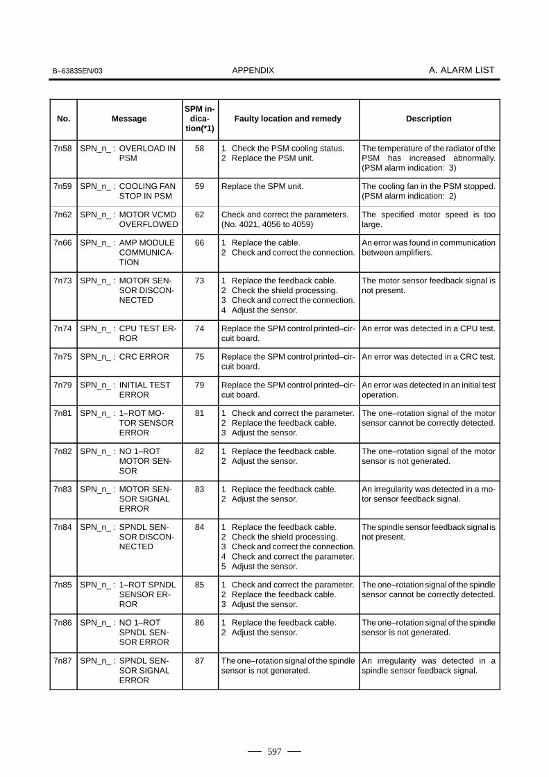
APPENDIXB–63835EN/03 A. ALARM LIST
597
No. DescriptionFaulty location and remedySPM in-
dica-tion(*1)
Message
7n58 SPN_n_ : OVERLOAD INPSM
58 1 Check the PSM cooling status.2 Replace the PSM unit.
The temperature of the radiator of thePSM has increased abnormally.(PSM alarm indication: 3)
7n59 SPN_n_ : COOLING FANSTOP IN PSM
59 Replace the SPM unit. The cooling fan in the PSM stopped.(PSM alarm indication: 2)
7n62 SPN_n_ : MOTOR VCMDOVERFLOWED
62 Check and correct the parameters.(No. 4021, 4056 to 4059)
The specified motor speed is toolarge.
7n66 SPN_n_ : AMP MODULECOMMUNICA-TION
66 1 Replace the cable.2 Check and correct the connection.
An error was found in communicationbetween amplifiers.
7n73 SPN_n_ : MOTOR SEN-SOR DISCON-NECTED
73 1 Replace the feedback cable.2 Check the shield processing.3 Check and correct the connection.4 Adjust the sensor.
The motor sensor feedback signal isnot present.
7n74 SPN_n_ : CPU TEST ER-ROR
74 Replace the SPM control printed–cir-cuit board.
An error was detected in a CPU test.
7n75 SPN_n_ : CRC ERROR 75 Replace the SPM control printed–cir-cuit board.
An error was detected in a CRC test.
7n79 SPN_n_ : INITIAL TESTERROR
79 Replace the SPM control printed–cir-cuit board.
An error was detected in an initial testoperation.
7n81 SPN_n_ : 1–ROT MO-TOR SENSORERROR
81 1 Check and correct the parameter.2 Replace the feedback cable.3 Adjust the sensor.
The one–rotation signal of the motorsensor cannot be correctly detected.
7n82 SPN_n_ : NO 1–ROTMOTOR SEN-SOR
82 1 Replace the feedback cable.2 Adjust the sensor.
The one–rotation signal of the motorsensor is not generated.
7n83 SPN_n_ : MOTOR SEN-SOR SIGNALERROR
83 1 Replace the feedback cable.2 Adjust the sensor.
An irregularity was detected in a mo-tor sensor feedback signal.
7n84 SPN_n_ : SPNDL SEN-SOR DISCON-NECTED
84 1 Replace the feedback cable.2 Check the shield processing.3 Check and correct the connection.4 Check and correct the parameter.5 Adjust the sensor.
The spindle sensor feedback signal isnot present.
7n85 SPN_n_ : 1–ROT SPNDLSENSOR ER-ROR
85 1 Check and correct the parameter.2 Replace the feedback cable.3 Adjust the sensor.
The one–rotation signal of the spindlesensor cannot be correctly detected.
7n86 SPN_n_ : NO 1–ROTSPNDL SEN-SOR ERROR
86 1 Replace the feedback cable.2 Adjust the sensor.
The one–rotation signal of the spindlesensor is not generated.
7n87 SPN_n_ : SPNDL SEN-SOR SIGNALERROR
87 The one–rotation signal of the spindlesensor is not generated.
An irregularity was detected in aspindle sensor feedback signal.

APPENDIXA. ALARM LIST B–63835EN/03
598
No. DescriptionFaulty location and remedySPM in-
dica-tion(*1)
Message
7n88 SPN_n_ : COOLING RA-DIFAN FAIL-URE
88 Replace the SPM external coolingfan.
The external cooling fan stopped.
7n97 SPN_n_ : OTHERSPINDLEALARM
97 Replace the SPM. Another irregularity was detected.
7n98 SPN_n_ : OTHER CON-VERTERALARM
98 Check the PSM alarm display. A PSM alarm was detected.
No. MessageSPM in-
dica-tion(*1)
Faulty location and remedy Description
9001 SPN_n_ : MOTOR OVER-HEAT
01 1 Check and correct the peripheraltemperature and load status.
2 If the cooling fan stops, replace it.
The thermostat embedded in the mo-tor winding operated.The internal temperature of the motorexceeds the specified level.The motor is used in excess of thecontinuous rating, or the cooling com-ponent is abnormal.
9002 SPN_n_ : EX SPEED ER-ROR
02 1 Check and correct the cuttingconditions to decrease the load.
2 Correct parameter No. 4082.
The motor speed cannot follow a spe-cified speed.An excessive motor load torque is de-tected.The acceleration/deceleration time inparameter No. 4082 is insufficient.
9003 SPN_n_ : FUSE ON DC LINK BLOWN
03 1 Replace the SPM unit.2 Check the motor insulation status.3 Replace the interface cable.
The PSM becomes ready (00 is indi-cated), but the DC link voltage is toolow in the SPM.The fuse in the DC link section in theSPM is blown. (The power device isdamaged or the motor is ground–fault.)The JX1A/JX1B connection cable isabnormal.
9006 SPN_n_ : THERMALSENSOR DIS-CONNECT
06 1 Check and correct the parameter.2 Replace the feedback cable.
The temperature sensor of the motoris disconnected.
9007 SPN_n_ : OVERSPEED 07 Check for a sequence error. (For ex-ample, check whether spindle syn-chronization was specified when thespindle could not be turned.)
The motor speed has exceeded115% of its rated speed.When the spindle axis was in positioncontrol mode, positional deviationswere accumulated excessively (SFRand SRV were turned off duringspindle synchronization.)
9009 SPN_n_ : OVERHEATMAIN CIRCUIT
09 1 Improve the heat sink cooling sta-tus.
2 If the heat sink cooling fan stops,replace the SPM unit.
Abnormal temperature rise of thepower transistor radiator
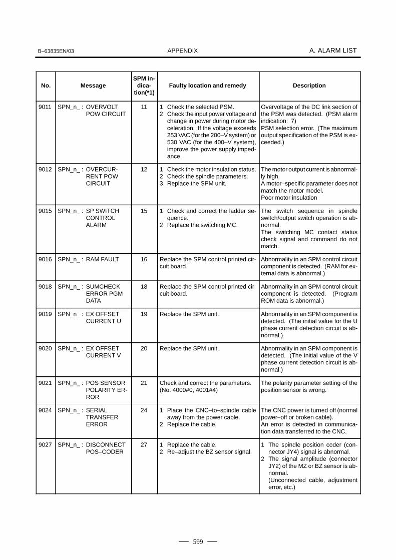
APPENDIXB–63835EN/03 A. ALARM LIST
599
No. DescriptionFaulty location and remedySPM in-
dica-tion(*1)
Message
9011 SPN_n_ : OVERVOLTPOW CIRCUIT
11 1 Check the selected PSM.2 Check the input power voltage and
change in power during motor de-celeration. If the voltage exceeds253 VAC (for the 200–V system) or530 VAC (for the 400–V system),improve the power supply imped-ance.
Overvoltage of the DC link section ofthe PSM was detected. (PSM alarmindication: 7)PSM selection error. (The maximumoutput specification of the PSM is ex-ceeded.)
9012 SPN_n_ : OVERCUR-RENT POW CIRCUIT
12 1 Check the motor insulation status.2 Check the spindle parameters.3 Replace the SPM unit.
The motor output current is abnormal-ly high.A motor–specific parameter does notmatch the motor model.Poor motor insulation
9015 SPN_n_ : SP SWITCH CONTROLALARM
15 1 Check and correct the ladder se-quence.
2 Replace the switching MC.
The switch sequence in spindleswitch/output switch operation is ab-normal.The switching MC contact statuscheck signal and command do notmatch.
9016 SPN_n_ : RAM FAULT 16 Replace the SPM control printed cir-cuit board.
Abnormality in an SPM control circuitcomponent is detected. (RAM for ex-ternal data is abnormal.)
9018 SPN_n_ : SUMCHECKERROR PGM DATA
18 Replace the SPM control printed cir-cuit board.
Abnormality in an SPM control circuitcomponent is detected. (ProgramROM data is abnormal.)
9019 SPN_n_ : EX OFFSET CURRENT U
19 Replace the SPM unit. Abnormality in an SPM component isdetected. (The initial value for the Uphase current detection circuit is ab-normal.)
9020 SPN_n_ : EX OFFSET CURRENT V
20 Replace the SPM unit. Abnormality in an SPM component isdetected. (The initial value of the Vphase current detection circuit is ab-normal.)
9021 SPN_n_ : POS SENSORPOLARITY ER-ROR
21 Check and correct the parameters.(No. 4000#0, 4001#4)
The polarity parameter setting of theposition sensor is wrong.
9024 SPN_n_ : SERIALTRANSFERERROR
24 1 Place the CNC–to–spindle cableaway from the power cable.
2 Replace the cable.
The CNC power is turned off (normalpower–off or broken cable).An error is detected in communica-tion data transferred to the CNC.
9027 SPN_n_ : DISCONNECTPOS–CODER
27 1 Replace the cable.2 Re–adjust the BZ sensor signal.
1 The spindle position coder (con-nector JY4) signal is abnormal.
2 The signal amplitude (connectorJY2) of the MZ or BZ sensor is ab-normal.(Unconnected cable, adjustmenterror, etc.)
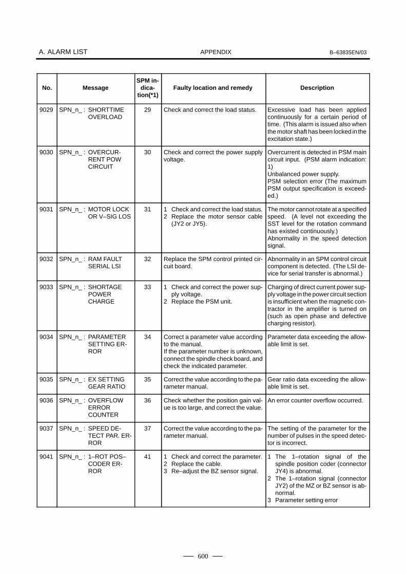
APPENDIXA. ALARM LIST B–63835EN/03
600
No. DescriptionFaulty location and remedySPM in-
dica-tion(*1)
Message
9029 SPN_n_ : SHORTTIMEOVERLOAD
29 Check and correct the load status. Excessive load has been appliedcontinuously for a certain period oftime. (This alarm is issued also whenthe motor shaft has been locked in theexcitation state.)
9030 SPN_n_ : OVERCUR-RENT POW CIRCUIT
30 Check and correct the power supplyvoltage.
Overcurrent is detected in PSM maincircuit input. (PSM alarm indication:1)Unbalanced power supply.PSM selection error (The maximumPSM output specification is exceed-ed.)
9031 SPN_n_ : MOTOR LOCKOR V–SIG LOS
31 1 Check and correct the load status.2 Replace the motor sensor cable
(JY2 or JY5).
The motor cannot rotate at a specifiedspeed. (A level not exceeding theSST level for the rotation commandhas existed continuously.)Abnormality in the speed detectionsignal.
9032 SPN_n_ : RAM FAULT SERIAL LSI
32 Replace the SPM control printed cir-cuit board.
Abnormality in an SPM control circuitcomponent is detected. (The LSI de-vice for serial transfer is abnormal.)
9033 SPN_n_ : SHORTAGEPOWERCHARGE
33 1 Check and correct the power sup-ply voltage.
2 Replace the PSM unit.
Charging of direct current power sup-ply voltage in the power circuit sectionis insufficient when the magnetic con-tractor in the amplifier is turned on(such as open phase and defectivecharging resistor).
9034 SPN_n_ : PARAMETERSETTING ER-ROR
34 Correct a parameter value accordingto the manual.If the parameter number is unknown,connect the spindle check board, andcheck the indicated parameter.
Parameter data exceeding the allow-able limit is set.
9035 SPN_n_ : EX SETTING GEAR RATIO
35 Correct the value according to the pa-rameter manual.
Gear ratio data exceeding the allow-able limit is set.
9036 SPN_n_ : OVERFLOWERRORCOUNTER
36 Check whether the position gain val-ue is too large, and correct the value.
An error counter overflow occurred.
9037 SPN_n_ : SPEED DE-TECT PAR. ER-ROR
37 Correct the value according to the pa-rameter manual.
The setting of the parameter for thenumber of pulses in the speed detec-tor is incorrect.
9041 SPN_n_ : 1–ROT POS–CODER ER-ROR
41 1 Check and correct the parameter.2 Replace the cable.3 Re–adjust the BZ sensor signal.
1 The 1–rotation signal of thespindle position coder (connectorJY4) is abnormal.
2 The 1–rotation signal (connectorJY2) of the MZ or BZ sensor is ab-normal.
3 Parameter setting error

APPENDIXB–63835EN/03 A. ALARM LIST
601
No. DescriptionFaulty location and remedySPM in-
dica-tion(*1)
Message
9042 SPN_n_ : NO 1–ROT.POS–CODERDETECT
42 1 Replace the cable.2 Re–adjust the BZ sensor signal.
1 The 1–rotation signal of thespindle position coder (connectorJY4) is disconnected.
2 The 1–rotation signal (connectorJY2) of the MZ or BZ sensor is dis-connected.
9043 SPN_n_ : DISCON. PCFOR DIF. SP.MODE
43 Replace the cable. The differential speed position codersignal (connector JY8) in SPM type 3is abnormal.
9046 SPN_n_ : SCREW1–ROT POS–COD. ALARM
46 1 Check and correct the parameter.2 Replace the cable.3 Re–adjust the BZ sensor signal.
An abnormality equivalent to alarm41 was detected during thread cuttingoperation.
9047 SPN_n_ : POS–CODERSIGNAL AB-NORMAL
47 1 Replace the cable.2 Re–adjust the BZ sensor signal.3 Correct the cable layout (vicinity of
the power line).
1 The A/B phase signal of thespindle position coder (connectorJY4) is abnormal.
2 The A/B phase signal (connectorJY2) of the MZ or BZ sensor is ab-normal.
The relationship between the A/Bphase and 1–rotation signal is incor-rect (Pulse interval mismatch).
9049 SPN_n_ : HIGH CONV.DIF. SPEED
49 Check whether the calculated differ-ential speed value exceeds the maxi-mum motor speed.
In differential speed mode, the speedof the other spindle converted to thespeed of the local spindle has ex-ceeded the allowable limit (the differ-ential speed is calculated by multiply-ing the speed of the other spindle bythe gear ratio).
9050 SPN_n_ : SPNDL CON-TROL OVER-SPEED
50 Check whether the calculated valueexceeds the maximum motor speed.
In spindle synchronization, the speedcommand calculation value exceed-ed the allowable limit (the motorspeed is calculated by multiplying thespecified spindle speed by the gearratio).
9051 SPN_n_ : LOW VOLT DCLINK
51 1 Check and correct the power sup-ply voltage.
2 Replace the MC.
Input voltage drop was detected.(PSM alarm indication: 4) (Momen-tary power failure or poor MC contact)
9052 SPN_n_ : ITP SIGNALABNORMAL I
52 1 Replace the SPM control printedcircuit board.
2 Replace the spindle interfaceprinted circuit board in the CNC.
NC interface abnormality was de-tected (the ITP signal stopped).
9053 SPN_n_ : ITP SIGNALABNORMAL II
53 1 Replace the SPM control printedcircuit board.
2 Replace the spindle interfaceprinted circuit board in the CNC.
NC interface abnormality was de-tected (the ITP signal stopped).
9054 SPN_n_ : OVERLOADCURRENT
54 Review the load state. An overload current was detected.
9055 SPN_n_ : POWER LINESWITCH ER-ROR
55 1 Replace the magnetic contactor.2 Check and correct the sequence.
The power line state signal of themagnetic contactor for selecting aspindle or output is abnormal.

APPENDIXA. ALARM LIST B–63835EN/03
602
No. DescriptionFaulty location and remedySPM in-
dica-tion(*1)
Message
9056 SPN_n_ : INNER COOL-ING FAN STOP
56 Replace the SPM unit. The cooling fan in the SPM control cir-cuit stopped.
9057 SPN_n_ : EX DECEL-ERATIONPOWER
57 1 Decrease the acceleration/decel-eration duty.
2 Check the cooling condition (pe-ripheral temperature).
3 If the cooling fan stops, replace theresistor.
4 If the resistance is abnormal, re-place the resistor.
An overload was detected in the re-generative resistance. (PSMR alarmindication: 8)Thermostat operation or short–timeoverload was detected.The regenerative resistor was dis-connected, or an abnormal resis-tance was detected.
9058 SPN_n_ : OVERLOAD INPSM
58 1 Check the PSM cooling status.2 Replace the PSM unit.
The temperature of the radiator of thePSM has increased abnormally.(PSM alarm indication: 3)
9059 SPN_n_ : COOLING FANSTOP IN PSM
59 Replace the SPM unit. The cooling fan in the PSM stopped.(PSM alarm indication: 2)
9066 SPN_n_ : AMP MODULECOMMUNICA-TION
66 1 Replace the cable.2 Check and correct the connection.
An error was found in communicationbetween amplifiers.
9073 SPN_n_ : MOTOR SEN-SOR DISCON-NECTED
73 1 Replace the feedback cable.2 Check the shield processing.3 Check and correct the connection.4 Adjust the sensor.
The motor sensor feedback signal isnot present.
9074 SPN_n_ : CPU TEST ER-ROR
74 Replace the SPM control printed–cir-cuit board.
An error was detected in a CPU test.
9075 SPN_n_ : CRC ERROR 75 Replace the SPM control printed–cir-cuit board.
An error was detected in a CRC test.
9079 SPN_n_ : INITIAL TESTERROR
79 Replace the SPM control printed–cir-cuit board.
An error was detected in an initial testoperation.
9081 SPN_n_ : 1–ROT MO-TOR SENSORERROR
81 1 Check and correct the parameter.2 Replace the feedback cable.3 Adjust the sensor.
The one–rotation signal of the motorsensor cannot be correctly detected.
9082 SPN_n_ : NO 1–ROTMOTOR SEN-SOR
82 1 Replace the feedback cable.2 Adjust the sensor.
The one–rotation signal of the motorsensor is not generated.
9083 SPN_n_ : MOTOR SEN-SOR SIGNALERROR
83 1 Replace the feedback cable.2 Adjust the sensor.
An irregularity was detected in a mo-tor sensor feedback signal.
9084 SPN_n_ : SPNDL SEN-SOR DISCON-NECTED
84 1 Replace the feedback cable.2 Check the shield processing.3 Check and correct the connection.4 Check and correct the parameter.5 Adjust the sensor.
The spindle sensor feedback signal isnot present.
9085 SPN_n_ : 1–ROT SPNDLSENSOR ER-ROR
85 1 Check and correct the parameter.2 Replace the feedback cable.3 Adjust the sensor.
The one–rotation signal of the spindlesensor cannot be correctly detected.

APPENDIXB–63835EN/03 A. ALARM LIST
603
No. DescriptionFaulty location and remedySPM in-
dica-tion(*1)
Message
9086 SPN_n_ : NO 1–ROTSPNDL SEN-SOR ERROR
86 1 Replace the feedback cable.2 Adjust the sensor.
The one–rotation signal of the spindlesensor cannot be correctly detected.
9087 SPN_n_ : SPNDL SEN-SOR SIGNALERROR
87 The one–rotation signal of the spindlesensor is not generated.
An irregularity was detected in aspindle sensor feedback signal.
9088 SPN_n_ : COOLING RA-DIFAN FAIL-URE
88 Replace the SPM external coolingfan.
The external cooling fan stopped.
9097 SPN_n_ : OTHERSPINDLEALARM
Check the SPM alarm display. Other spindle alarm
9098 SPN_n_ : OTHER CON-VERTERALARM
Check the PSM alarm display. Other converter alarm
9110 SPN_n_ : AMP COMMU-NICATION ER-ROR
b0 1 Replace the communication cablebetween amplifier and module.
2 Replace the SPM or PSM controlprinted circuit board.
Communication error between am-plifier and module
9111 SPN_n_ : CONV.LOWVOLT CON-TROL
b1 Replace the PSM control printed cir-cuit board.
Low converter control power supplyvoltage (PSM indication = 6)
9112 SPN_n_ : CONV.EXDIS-CHARGE POW.
b2 1 Check the regenerative resis-tance.
2 Check the motor selection.3 Replace the PSM
Excessive converter regenerativepower (PSM indication = 8)
9113 SPN_n_ : CONV.COOL-ING FAN FAIL-URE
b3 Replace the cooling fan. Stopped cooling fan of the converterradiator (PSM indication = A)
9120 SPN_n_ : COMMUNICA-TION DATA ER-ROR
C0 1 Replace the communication cablebetween CNC and SPM.
2 Replace the SPM control printedcircuit board.
3 Replace the CNC side spindle in-terface printed circuit board.
Communication data alarm
9121 SPN_n_ : COMMUNICA-TION DATA ER-ROR
C1 1 Replace the communication cablebetween CNC and SPM.
2 Replace the SPM control printedcircuit board.
3 Replace the CNC side spindle in-terface printed circuit board.
Communication data alarm
9122 SPN_n_ : COMMUNICA-TION DATA ER-ROR
C2 1 Replace the communication cablebetween CNC and SPM.
2 Replace the SPM control printedcircuit board.
3 Replace the CNC side spindle in-terface printed circuit board.
Communication data alarm
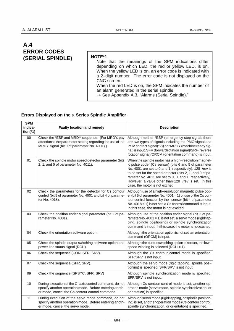
APPENDIXA. ALARM LIST B–63835EN/03
604
NOTE*1Note that the meanings of the SPM indications differdepending on which LED, the red or yellow LED, is on.When the yellow LED is on, an error code is indicated witha 2–digit number. The error code is not displayed on theCNC screen.When the red LED is on, the SPM indicates the number ofan alarm generated in the serial spindle.� See Appendix A.3, “Alarms (Serial Spindle).”
Errors Displayed on the α Series Spindle Amplifier
SPMindica-tion(*1)
Faulty location and remedy Description
00 Check the *ESP and MRDY sequence. (For MRDY, payattention to the parameter setting regarding the use of theMRDY signal (bit 0 of parameter No. 4001).)
Although neither *ESP (emergency stop signal; thereare two types of signals including the PMC signal andPSM contact signal(*2)) nor MRDY (machine ready sig-nal) is input, SFR (forward rotation signal)/SRF (reverserotation signal)/ORCM (orientation command) is input.
01 Check the spindle motor speed detector parameter (bits2, 1, and 0 of parameter No. 4011).
When the spindle motor has a high–resolution magnet-ic pulse coder (Cs sensor) (bits 6 and 5 of parameterNo. 4001 are set to 0 and 1, respectively), 128 /rev isto be set for the speed detector (bits 2, 1, and 0 of pa-rameter No. 4011 are set to 0, 0, and 1, respectively).However, a value other than 128 /rev is set. In thiscase, the motor is not excited.
02 Check the parameters for the detector for Cs contourcontrol (bit 5 of parameter No. 4001 and bit 4 of parame-ter No. 4018).
Although use of a high–resolution magnetic pulse cod-er (bit 5 of parameter No. 4001 = 1) or use of the Cs con-tour control function by the sensor (bit 4 of parameterNo. 4018 = 1) is not set, a Cs control command is input.In this case, the motor is not excited.
03 Check the position coder signal parameter (bit 2 of pa-rameter No. 4001).
Although use of the position coder signal (bit 2 of pa-rameter No. 4001 = 1) is not set, a servo mode (rigid tap-ping, spindle positioning) or spindle synchronizationcommand is input. In this case, the motor is not excited.
04 Check the orientation software option. Although the orientation option is not set, an orientationcommand (ORCM) is input.
05 Check the spindle output switching software option andpower line status signal (RCH).
Although the output switching option is not set, the low–speed winding is selected (RCH = 1).
06 Check the sequence (CON, SFR, SRV). Although the Cs contour control mode is specified,SFR/SRV is not input.
07 Check the sequence (SFR, SRV). Although the servo mode (rigid tapping, spindle posi-tioning) is specified, SFR/SRV is not input.
09 Check the sequence (SPSYC, SFR, SRV) Although spindle synchronization mode is specified,SFR/SRV is not input.
10 During execution of the C–axis control command, do notspecify another operation mode. Before entering anoth-er mode, cancel the Cs contour control command.
Although Cs contour control mode is set, another op-eration mode (servo mode, spindle synchronization, ororientation) is specified.
11 During execution of the servo mode command, do notspecify another operation mode. Before entering anoth-er mode, cancel the servo mode.
Although servo mode (rigid tapping, or spindle position-ing) is set, another operation mode (Cs contour control,spindle synchronization, or orientation) is specified.
A.4ERROR CODES(SERIAL SPINDLE)
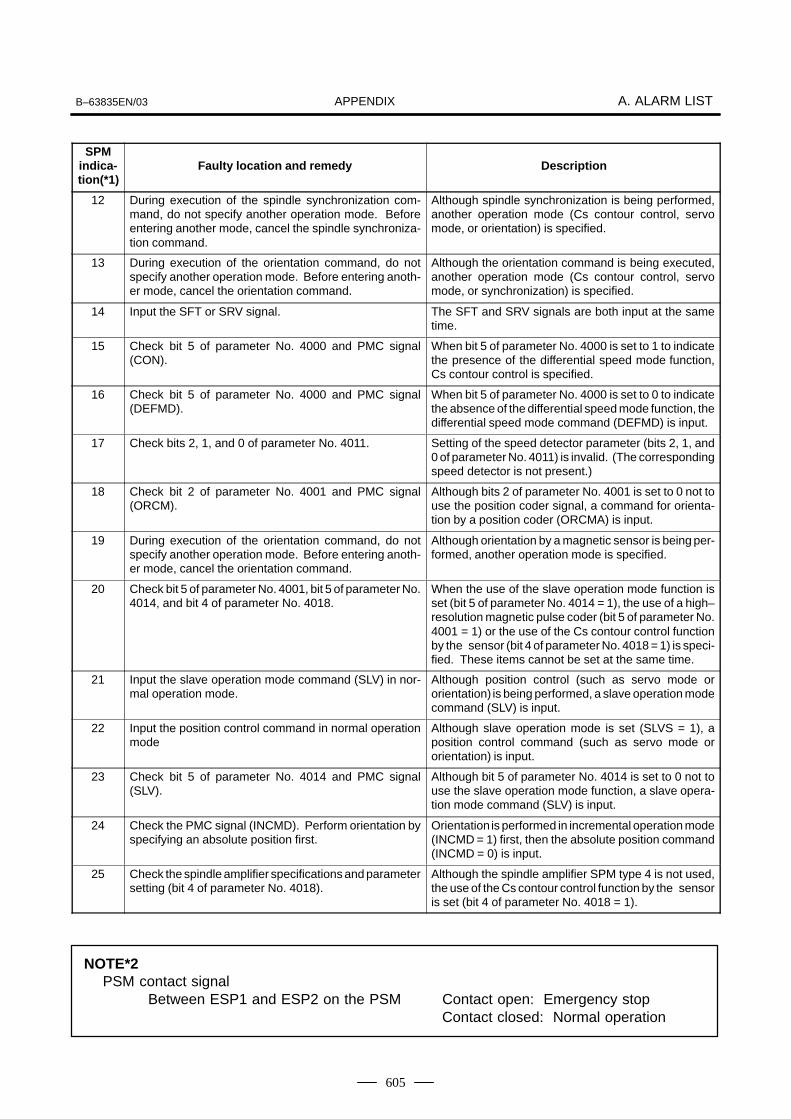
APPENDIXB–63835EN/03 A. ALARM LIST
605
SPMindica-tion(*1)
DescriptionFaulty location and remedy
12 During execution of the spindle synchronization com-mand, do not specify another operation mode. Beforeentering another mode, cancel the spindle synchroniza-tion command.
Although spindle synchronization is being performed,another operation mode (Cs contour control, servomode, or orientation) is specified.
13 During execution of the orientation command, do notspecify another operation mode. Before entering anoth-er mode, cancel the orientation command.
Although the orientation command is being executed,another operation mode (Cs contour control, servomode, or synchronization) is specified.
14 Input the SFT or SRV signal. The SFT and SRV signals are both input at the sametime.
15 Check bit 5 of parameter No. 4000 and PMC signal(CON).
When bit 5 of parameter No. 4000 is set to 1 to indicatethe presence of the differential speed mode function,Cs contour control is specified.
16 Check bit 5 of parameter No. 4000 and PMC signal(DEFMD).
When bit 5 of parameter No. 4000 is set to 0 to indicatethe absence of the differential speed mode function, thedifferential speed mode command (DEFMD) is input.
17 Check bits 2, 1, and 0 of parameter No. 4011. Setting of the speed detector parameter (bits 2, 1, and0 of parameter No. 4011) is invalid. (The correspondingspeed detector is not present.)
18 Check bit 2 of parameter No. 4001 and PMC signal(ORCM).
Although bits 2 of parameter No. 4001 is set to 0 not touse the position coder signal, a command for orienta-tion by a position coder (ORCMA) is input.
19 During execution of the orientation command, do notspecify another operation mode. Before entering anoth-er mode, cancel the orientation command.
Although orientation by a magnetic sensor is being per-formed, another operation mode is specified.
20 Check bit 5 of parameter No. 4001, bit 5 of parameter No.4014, and bit 4 of parameter No. 4018.
When the use of the slave operation mode function isset (bit 5 of parameter No. 4014 = 1), the use of a high–resolution magnetic pulse coder (bit 5 of parameter No.4001 = 1) or the use of the Cs contour control functionby the sensor (bit 4 of parameter No. 4018 = 1) is speci-fied. These items cannot be set at the same time.
21 Input the slave operation mode command (SLV) in nor-mal operation mode.
Although position control (such as servo mode ororientation) is being performed, a slave operation modecommand (SLV) is input.
22 Input the position control command in normal operationmode
Although slave operation mode is set (SLVS = 1), aposition control command (such as servo mode ororientation) is input.
23 Check bit 5 of parameter No. 4014 and PMC signal(SLV).
Although bit 5 of parameter No. 4014 is set to 0 not touse the slave operation mode function, a slave opera-tion mode command (SLV) is input.
24 Check the PMC signal (INCMD). Perform orientation byspecifying an absolute position first.
Orientation is performed in incremental operation mode(INCMD = 1) first, then the absolute position command(INCMD = 0) is input.
25 Check the spindle amplifier specifications and parametersetting (bit 4 of parameter No. 4018).
Although the spindle amplifier SPM type 4 is not used,the use of the Cs contour control function by the sensoris set (bit 4 of parameter No. 4018 = 1).
NOTE*2PSM contact signal
Between ESP1 and ESP2 on the PSM Contact open: Emergency stopContact closed: Normal operation

APPENDIXB. LIST OF MAINTENANCE PARTS B–63835EN/03
606
B LIST OF MAINTENANCE PARTS
Item Ordering information Remarks
Fuse Control unit A02B–0265–K100
LCD unit A02B–0265–K101
Separate detector interface unit A60L–0001–0290#LM20 Rated at 2 A
I/O module for operator’s panel A03B–0815–K001
Connector panel I/O module A03B–0815–K002
Distributed I/O machine operator’s panel A60L–0001–0290#LM10
Battery For control unit memory backupFor CNC display unit with PC functions and PANEL i
A02B–0200–K102
Fan unit for stand– For 1–slot case A02B–0265–C101alone type CNC
For 2–slot case A02B–0260–C021
Fan for CNC display For main body A08B–0082–K010unit with PC functionsand PANEL i For HDD A13B–0178–K001
Backlight For 7.2″ LCD A02B–0236–K112
For 8.4″ LCD A02B–0236–K119
For 10.4″ LCD A02B–0281–K116
APPENDIXB–63835EN/03 C. BOOT SYSTEM
607
C BOOT SYSTEM
C.1 OVERVIEW 608. . . . . . . . . . . . . . . . . . . . . . . . . . . . . . . . C.2 SCREEN CONFIGURATION AND OPERATING
PROCEDURE 610. . . . . . . . . . . . . . . . . . . . . . . . . . . . . . C.3 ERROR MESSAGES AND REQUIRED
ACTIONS 625. . . . . . . . . . . . . . . . . . . . . . . . . . . . . . . . . .

APPENDIXC. BOOT SYSTEM B–63835EN/03
608
The boot system load the CNC system software (flash RAM→DRAM),then starts it so that software can be executed.The boot system provides the following maintenance functions for theCNC:
(1)Registering a file in flash ROM
⋅ Reads a file from a memory card, in FAT format, into flash ROM.
(2)Checking a file (series and edition) in flash ROM
(3)Deleting a file from flash ROM
(4)Batch saving and restoration of files of parameters and programsbacked up by battery (SRAM area), to and from a memory card
(5)Saving a file in flash ROM to a memory card
(6)Formatting of a memory card
(7)Deleting a file from a memory card
This manual describes the activation of the boot system, as well as thescreen displays and operation for the functions listed above.
CAUTIONThis control unit supports the use of a memory card as aninput/output device. When a flash card is used, however,data can be written to a FANUC–recommended card only.Data can be read in the same way as with an ordinary SRAMcard, provided the data has been saved in FAT format. Notethat, when a flash card is used, the card capacity is reducedby 128KB.See the order list for details of the supported memory cardtypes.
In ordinary system activation, the boot system automatically transfersfiles from flash ROM to DRAM in the background.The user is not aware of this operation. However, the boot system mustbe operated manually, from menu screen, when maintenance is to becarried out or when the flash ROM does not contain a required file.
1 In system maintenance, for example, to replace a file in ROMOperation : Turn the power on by simultaneously pressing the two softkeys at the right end.
Hold down the two keys until the boot system screen appears.
If soft keys are not provided (for example, when a touch pad is being
used), use the MDI numeric keys. Hold down the 6 and 7
keys until the boot system screen appears.
�
1.�
2.�
3.�
4.�
5.�
6.�
7.
C.1OVERVIEW
C.1.1Starting the BootSystem

APPENDIXB–63835EN/03 C. BOOT SYSTEM
609
2 When the flash memory does not contain a file required to start theCNC
Immediately after the CNC is turned on, the boot system startstransferring files from flash ROM to DRAM. If, for some reason, afile required to start the CNC (NC basic) is not in flash ROM or hasbeen destroyed, the boot system is automatically started.
The boot system organizes files in flash ROM into two main groups :system files and user files. These two file types have the followingcharacteristics :
CNC and servo control software provided by FANUC
PMC sequence program (ladder), P–CODE macro program, and otheruser–created files
C.1.2System Files and UserFiles
� System files
� User files

APPENDIXC. BOOT SYSTEM B–63835EN/03
610
When the boot system is first started, the MAIN MENU screen isdisplayed. This screen is described below :
SYSTEM MONITOR MAIN MENU 60M5-01
1. SYSTEM DATA LOADING2. SYSTEM DATA CHECK3. SYSTEM DATA DELETE4. SYSTEM DATA SAVE5. SRAM DATA BACKUP6. MEMORY CARD FILE DELETE7. MEMORY CARD FORMAT
10.END
*** MESSAGE ***SELECT MENU AND HIT SELECT KEY.[ SELECT ][ YES ][ NO ][ UP ][ DOWN ]
(1)
(2)(3)(4)(5)(6)(7)(8)
(9)
(10)
(1) : Screen title. The series and edition of the boot system appear atthe right end.
(2) : Function for writing data to flash ROM.
(3) : Function for checing the edition of a file in ROM.
(4) : Function for deleting a file from flash ROM.
(5) : Function for making a backup copy of the data stored on the memorycard.
(6) : Function for making a backup copy of the data in SRAM.
(7) : Function for deleting a file from a memory card.
(8) : Function for formatting a memory card.
(9) : Function for terminating the boot system and starting the CNC.(10) : Condensed guidance or error message
Press the [UP] or [DOWN] soft key to select the desired function. Afterpositioning the cursor to the desired function, press the [SELECT] softkey. Before executing a function, the system my request confirmationfrom the operator by having him/her press the [YES] or [NO] soft key.
Position the cursor.
[UP][DOWN]
→
Select a function[SELECT] →
Check the selection
[YES][NO]
→Executethefunction
→ Select END
→ Return to original state
C.2SCREENCONFIGURATIONAND OPERATINGPROCEDURE
� ���� ���� ���
� Operating procedure
� Basic operation

APPENDIXB–63835EN/03 C. BOOT SYSTEM
611
This screen is used to read a system or user file from a memory card intoflash ROM.
SYSTEM DATA LOADING 1/1
FILE DIRECTORYB1H1A_B1.MEMB1H1A_AI.MEMEND
*** MESSAGE ***SELECT FILE AND HIT SELECT KEY.[ SELECT ][ YES ][ NO ][ UP ][ DOWN ]
(1)
(2)
(3)
(4)
(1) : Screen title. The page number (n) and total number of pages (m)are displayed, in n/m format, at the right end.
(2) : Files on the memory card
(3) : Option for returning to previous menu Message
(4) : Message
1 Position the cursor to the file to be read from the memory card andwritten to flash ROM. Then, press the [SELECT] soft key.
A single page can list up to eight file names. If the memory cardcontains nine or more files, the remaining files are displayed onanother page.
To display the next page, press the soft key.
To display the previous page, press the soft key. The END optionis displayed on the last page.
The END option is displayed on the last page.
2 After a file has been slected, the system asks whether that file is to beloaded.
*** MESSAGE ***LOADING OK ? HIT YES OR NO.
C.2.1System Data LoadingScreen
� Description
� Screen configuration
� Operating procedure

APPENDIXC. BOOT SYSTEM B–63835EN/03
612
3 To start loading, press the [YES] soft key. To cancel, press the [NO]key.
*** MESSAGE ***LOADING FROM MEMORY CARD.
4 When loading terminates normally, the system displays the followingmessage. Press the [SELECT] soft key. If an error occurs, see C.3
*** MESSAGE ***LOADING COMPELETE. HIT SELECT KEY.
1 Counter display while a file is being loaded
While a file is being loaded, the address of the data currently beingaccessed is displayed.
*** MESSAGE ***LOADING FROM MEMORY CARD.ADDRESS 001: � The counter appears under the
message fild.(1)
(1) : Number of 128–KB management unit in flash ROM
2 File name in flash ROM
The boot system identifies a file in flash ROM by the first fourcharacters of the ID in the header. If flash ROM has a file of the sametype as a file to be read from the memory card, the file in flash ROMis deleted before the file on the memory card is read. The followingtable lists the IDs in the header and the contents. Note that these IDsare subject to change without prior notice.
File name Contents File type
NC BASICNC 2BSICDGB0SRVOGRAPHICNC� OPTNPS�****ETH2 EMBPCD ****CEX ****PMC - ****PMC@****
Basic 1Basic 2ServoGraphicOptional�PMC control software, etc.Embedded ethernetP–CODE macro file/ OMMC–language executorLadder softwareLadder software for the loader
System fileSystem fileSystem fileSystem fileSystem fileSystem fileSystem fileUser fileUser fileUser fileUser file
� : A numeric character, * : An alphabetic character
� Others

APPENDIXB–63835EN/03 C. BOOT SYSTEM
613
This screen is used to list files in flash ROM, together with thecorresponding numbers of 128–KB management units in each file and theseries and edition of the software.
SYSTEM DATA CHECK 1/1[BOARD:MAIN]FILE DIRECTORY (FLASH ROM : 16MB)1 NC BASIC ( 10)2 NC2 BSIC ( 8)3 DGB0SRVO ( 2)4 PS0B406G ( 8)5 PS1B406G ( 4)6 PS2B406G ( 4)7 ETH2 EMB ( 8)END
*** MESSAGE ***SELECT FILE AND HIT SELECT KEY.[ SELECT ][ YES ][ NO ][ UP ][ DOWN ]
(1)(2)
(3)
(4)
(5)
(1) : Screen title
(2) : Names of accessing board
(3) : Names of files in flash ROM The number of management unitsconstituting each file appears in parentheses to the right of the filename.
(4) : Returning to the previous menuIf flash ROM contains many files, END is sometimes not displayed.In this case, press the continuous menu key ( ) of the soft keydisplay several times. Then, END appears at the end of files.
(5) : Message
C.2.2System Data CheckScreen
� Description
� Screen configuration

APPENDIXC. BOOT SYSTEM B–63835EN/03
614
1 Select the file whose details are required. For example, select “1 NCBASIC (10).”
2 The numbers of management units in the selected file are listed,together with the series and edition of the software in eachmanagement unit. After checking the listed data, select the[SELECT] soft key to return to the file selection screen.
ROM FILE CHECKNC BASIC
0 D6A1 801A 0001 D6A1 821A 0012 D6A1 841A 0023 D6A1 861A 0034 D6A1 881A 0045 D6A1 8A1A 0056 D6A1 8C1A 0067 D6A1 8E1A 007
*** MESSAGE ***HIT SELECT KEY.
ÁÁÁÁÁÁÁÁÁÁÁÁÁÁÁÁÁÁÁÁÁÁÁÁÁÁÁ
Internal management–unitnumberROM number and editionSeries
0 D6A1 801A 000
Parity information for the system file and user file The NC BASIC, DGB0SRVO, and other system files in flash ROMcontain parity information in each management unit. If the file name fieldor parity field on the check screen contains a non–ASC II character or an“@”, the flash ROM may have been destroyed or a damaged file may havebeen read. Re–read the data from the memory card.The PMC–SB, PCD 0.5M, and other user files do not contain parityinformation in each management unit. A non–ASCII character or an “@”may appear in the series/edition information. In this case, it does notindicate that the file has been damaged.
� Operating procedure
� Others
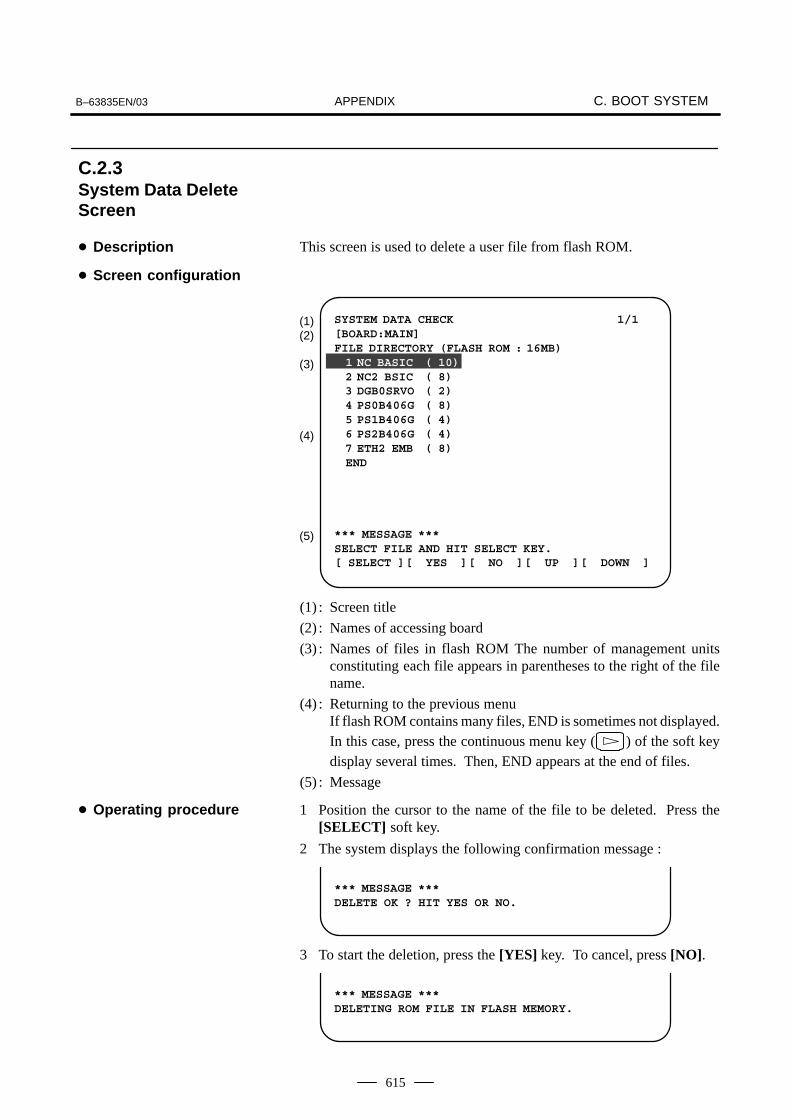
APPENDIXB–63835EN/03 C. BOOT SYSTEM
615
This screen is used to delete a user file from flash ROM.
SYSTEM DATA CHECK 1/1[BOARD:MAIN]FILE DIRECTORY (FLASH ROM : 16MB)1 NC BASIC ( 10)2 NC2 BSIC ( 8)3 DGB0SRVO ( 2)4 PS0B406G ( 8)5 PS1B406G ( 4)6 PS2B406G ( 4)7 ETH2 EMB ( 8)END
*** MESSAGE ***SELECT FILE AND HIT SELECT KEY.[ SELECT ][ YES ][ NO ][ UP ][ DOWN ]
(1)(2)
(3)
(4)
(5)
(1) : Screen title
(2) : Names of accessing board
(3) : Names of files in flash ROM The number of management unitsconstituting each file appears in parentheses to the right of the filename.
(4) : Returning to the previous menuIf flash ROM contains many files, END is sometimes not displayed.In this case, press the continuous menu key ( ) of the soft keydisplay several times. Then, END appears at the end of files.
(5) : Message
1 Position the cursor to the name of the file to be deleted. Press the[SELECT] soft key.
2 The system displays the following confirmation message :
*** MESSAGE ***DELETE OK ? HIT YES OR NO.
3 To start the deletion, press the [YES] key. To cancel, press [NO].
*** MESSAGE ***DELETING ROM FILE IN FLASH MEMORY.
C.2.3System Data DeleteScreen
� Description
� Screen configuration
� Operating procedure

APPENDIXC. BOOT SYSTEM B–63835EN/03
616
4 When deletion terminates normally, the system displays the followingmessage. Press the [SELECT] key.
*** MESSAGE ***DELETING COMPLETE. HIT SELECT KEY.
1 System files and user files on SYSTEM DATA DELETE screen The system files are protected from accidental deletion. User files,however, are not protected. Protected system files can beoverwritten from the SYSTEM DATA LOADING screen.
This screen is used to write a user file in flash ROM to a memory card.Only user files can be saved from flash ROM to a memory card. Systemfiles cannot be saved.
SYSTEM DATA SAVE[BOARD:MAIN]FILE DIRECTORY (FLASH ROM : 16MB)1 NC BASIC ( 10)2 NC2 BSIC ( 8)3 DGB0SRVO ( 2)4 PS0B406G ( 8)5 PS1B406G ( 4)6 PS2B406G ( 4)7 ETH2 EMB ( 8)END
*** MESSAGE ***SELECT FILE AND HIT SELECT KEY.[ SELECT ][ YES ][ NO ][ UP ][ DOWN ]
(1)(2)
(3)
(4)
(5)
(1) : Screen title
(2) : Names of accessing board
(3) : Names of files in flash memory The number of management unitsconstituting each file appears in parentheses to the right of the filename.
(4) : Returning to the previous menuIf flash ROM contains many files, END is sometimes not displayed.In this case, press the continuous menu key ( ) of the soft keydisplay several times. Then, END appears at the end of files.
(5) : Message
� Others
C.2.4System Data SaveScreen
� Description
� Screen configuration

APPENDIXB–63835EN/03 C. BOOT SYSTEM
617
1 Position the cursor to the name of the file to be deleted. Press the[SELECT] soft key.
2 The system displays the following confirmation message :
*** MESSAGE ***SAVE OK ? HIT YES OR NO.
3 To start saving, press the [YES] key. To cancel, press [NO].
*** MESSAGE ***WRITING FLASH ROM FILE TO MEMORY CARD.SAVE FILE NAME : PMC_RB.000
4 When saving terminates normally, the system displays thefollowing message. Press the [SELECT] key. The names of fileswritten to the memory card are listed. Check the file names by, forexample, making a note of the list.
*** MESSAGE ***FILE SAVE COMPELETE. HIT SELECT KEY.SAVE FILE NAME : PMC_RB.000
1 System files and user files on SYSTEM DATA SAVE screen
The SYSTEM DATA SAVE function provides a safeguard against freecopying of the system files.
User files, however, are not protected.
2 Names of saved files
Files saved from flash ROM to a memory card have the followingnames :
Flash ROM File name inMemory card
PMC–SBPMC 0.5MPMC 1.0MPMC 1.5MCEX1.0MCEX 2.0M
�
�
�
�
�
�
PMC_SB. XXXPCD_0.5M.XXXPCD_10M.XXXPCD_15M.XXXCEX_10M.XXXCEX_20M.XXX
XXX corresponds to the file extension of MS–DOS format files. Anumber from 000 to 031 is specified for XXX. For example, if thePMC–RB file in flash ROM is saved to a memory card that does not yetcontain a file whose name begins with “PMC–RB”, the saved file isnamed PMC–RB.000. If, however, that file is saved to a memory card thatalready contains a file named PMC–RB.000, the saved file is namedPMC–RB.001. As files are added, the extension is incremented up to amaximum of PMC–RB.031. Any no–longer used numbers in thesequence of the extension numbers are used in as cending order. If twoor more files having identical names but different extension numbers arenormally saved to the memory card, check the file names displayedsubsequently.
� Operating procedure
� Others

APPENDIXC. BOOT SYSTEM B–63835EN/03
618
This screen is used to collectively save and restore parameters, programs,and other data, retained after the CNC power in SRAM is turned off, toand from a memory card.
Select “4 SRAM DATA BACKUP” on the SYSTEM MONITOR MAINMENU screen. The following screen is displayed.
SRAM DATA BACKUP[BOARD:MAIN]1. SRAM BACKUP (CNC � MEMORY CARD)2. RESTORE SRAM (MEMORY CARD � CNC)END
SRAM SIZE : 256K (BASIC)FILE NAME : SRAM256A. FDB
*** MESSAGE ***SELECT MENU AND HIT SELECT KEY.[ SELECT ][ YES ][ NO ][ UP ][ DOWN ]
(1)(2)(3)
(4)
(5)(6)
(7)
(1) : Screen title
(2) : Names of accessing board
(3) : Menu
(4) : Returning to the previous menu
(5) : Size of SRAM mounted on the CNC
(6) : File name
(7) : Message
C.2.5SRAM Data BackupScreen
� Description
� Screen configuration

APPENDIXB–63835EN/03 C. BOOT SYSTEM
619
1 Select “1. SRAM BACKUP.” The following confirmation message isdisplayed. The backup file name may be displayed according to theSRAM capacity.
2 Press [YES] to start backup.
*** MESSAGE ***BACKUP SRAM DATA OK ? HIT YES OR NO.
3 If a backup file is already on the memory card, you will be promptedto confirm whether to permit overwriting.
4 The name of the file being written to the memory card is displayed inthe FILE NAME: field.
SRAM SIZE : 0.5MB (BASIC)FILE NAME : SRAM0_5A.FDB � MEMORY CARD
*** MESSAGE ***SRAM DATA WRITING TO MEMORY CARD.
Name of the file beingsaved
5 Upon terminating normally, the system displays the followingmessage. Press the [SELECT] soft key.
*** MESSAGE ***SRAM BACKUP COMPLETE. HIT SELECT KEY.
1 Select “2. RESTORE SRAM.” The system displays the followingmessage. Press the [YES] key.
*** MESSAGE ***RESTORE SRAM DATA OK ? HIT YES OR NO.
2 The system displays the following message during restoration.
*** MESSAGE ***RESTORE SRAM DATA FROM MEMORY CARD.
3 Upon terminating normally, the system displays the followingmessage. Press the [SELECT] soft key.
*** MESSAGE ***RESTORE COMPLETE. HIT SELECT KEY.
� Operating procedure
[Backing up data]
[Restoring the data]

of filesSRAM
size
Number
APPENDIXC. BOOT SYSTEM B–63835EN/03
620
1 Name of backup file
The name of the backup file written to the memory card by the SRAMbackup function depends on the size of the SRAM installed in theCNC.
When the size of SRAM is 1MB or larger, backup files are created inunits of 512 KB.
1 2 3 4 5 6
256KB SRAM256A.FDB
0.5MB SRAM0_5A.FDB
1.0MB SRAM1_0A.FDB SRAM1_0B.FDB
2.0MB SRAM2_0A.FDB SRAM2_0B.FDB SRAM2_0C.FDB SRAM2_0D.FDB
3.0MB SRAM3_0A.FDB SRAM3_0B.FDB SRAM3_0C.FDB SRAM3_0D.FDB SRAM3_0E.FDB SRAM3_0F.FDB
CAUTIONIf data such as parameters was restored from a memorycard to SRAM in a system using an absolute pulse coder,set bit 4 (APZ) of parameter No. 1815 to 0, and set thereference point again.
� Others
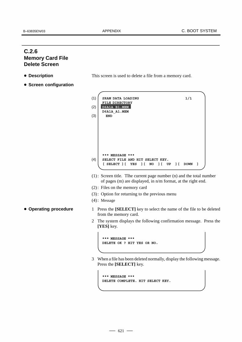
APPENDIXB–63835EN/03 C. BOOT SYSTEM
621
This screen is used to delete a file from a memory card.
SRAM DATA LOADING 1/1FILE DIRECTORYD6A1A_B1.MEMD6A1A_A1.MEMEND
*** MESSAGE ***SELECT FILE AND HIT SELECT KEY.[ SELECT ][ YES ][ NO ][ UP ][ DOWN ]
(1)
(2)
(3)
(4)
(1) : Screen title. Tlhe current page number (n) and the total numberof pages (m) are displayed, in n/m format, at the right end.
(2) : Files on the memory card
(3) : Option for returning to the previous menu
(4) : Message
1 Press the [SELECT] key to select the name of the file to be deletedfrom the memory card.
2 The system displays the following confirmation message. Press the[YES] key.
*** MESSAGE ***DELETE OK ? HIT YES OR NO.
3 When a file has been deleted normally, display the following message.Press the [SELECT] key.
*** MESSAGE ***DELETE COMPLETE. HIT SELECT KEY.
C.2.6Memory Card FileDelete Screen
� Description
� Screen configuration
� Operating procedure
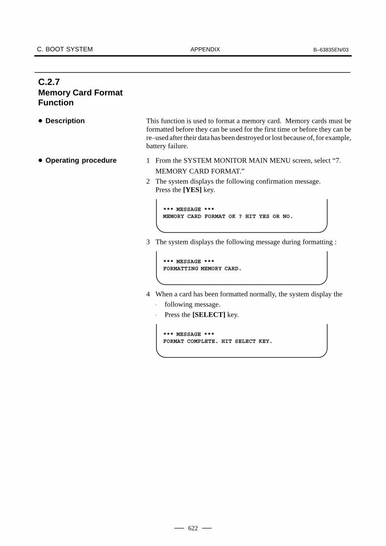
APPENDIXC. BOOT SYSTEM B–63835EN/03
622
This function is used to format a memory card. Memory cards must beformatted before they can be used for the first time or before they can bere–used after their data has been destroyed or lost because of, for example,battery failure.
1 From the SYSTEM MONITOR MAIN MENU screen, select “7.
MEMORY CARD FORMAT.”
2 The system displays the following confirmation message.Press the [YES] key.
*** MESSAGE ***MEMORY CARD FORMAT OK ? HIT YES OR NO.
3 The system displays the following message during formatting :
*** MESSAGE ***FORMATTING MEMORY CARD.
4 When a card has been formatted normally, the system display the
⋅ following message.
⋅ Press the [SELECT] key.
*** MESSAGE ***FORMAT COMPLETE. HIT SELECT KEY.
C.2.7Memory Card FormatFunction
� Description
� Operating procedure

APPENDIXB–63835EN/03 C. BOOT SYSTEM
623
The function is used to terminate the boot system and activate the CNC.
From the MAIN MENU screen, select “9. END.” The system displaysthe “ARE YOU SURE? HIT YES OR NO” message. To terminate theboot system and activate the CNC, press the [YES] soft key. Press the[NO] soft key, and you will be brought back to the main menu.
*** MESSAGE ***ARE YOU SURE ? HIT YES OR NO.
[ SELECT ][ YES ][ NO ][ UP ][ DOWN ]
1 After pressing the [YES] soft key
The system checks the NC BASIC system file in the flash ROM. Thesystem displays the following message :
*** MESSAGE ***CHECK CNC BASIC SYSTEM.
[ SELECT ][ YES ][ NO ][ UP ][ DOWN ]
When the NC BASIC system file is found to be normal, the systemsends the system file to DRAM and starts the NC basic system. Duringloading, the system blinks the following message.
*** MESSAGE ***LOADING BASIC TO DRAM
[ SELECT ][ YES ][ NO ][ UP ][ DOWN ]
If the contents of the NC BASIC SYSTEM file are found to have beendamaged or destroyed, the system returns to the processing selectionstate, in exactly the same way as when the [NO] soft key is pressed.
C.2.8Load Basic SystemFunction
� Description
� Operating procedure

APPENDIXC. BOOT SYSTEM B–63835EN/03
624
2 If the [NO] soft key is pressed, the system returns to the processingselection state as shown below :
SYSTEM MONITOR MAIN MENU 60M5-01
1. SYSTEM DATA LOADING2. SYSTEM DATA CHECK3. SYSTEM DATA DELETE4. SYSTEM DATA SAVE5. SRAM DATA BACKUP6. MEMORY CARD FILE DELETE7. MEMORY CARD FORMAT
10.END
*** MESSAGE ***SELECT MENU AND HIT SELECT KEY.[ SELECT ][ YES ][ NO ][ UP ][ DOWN ]
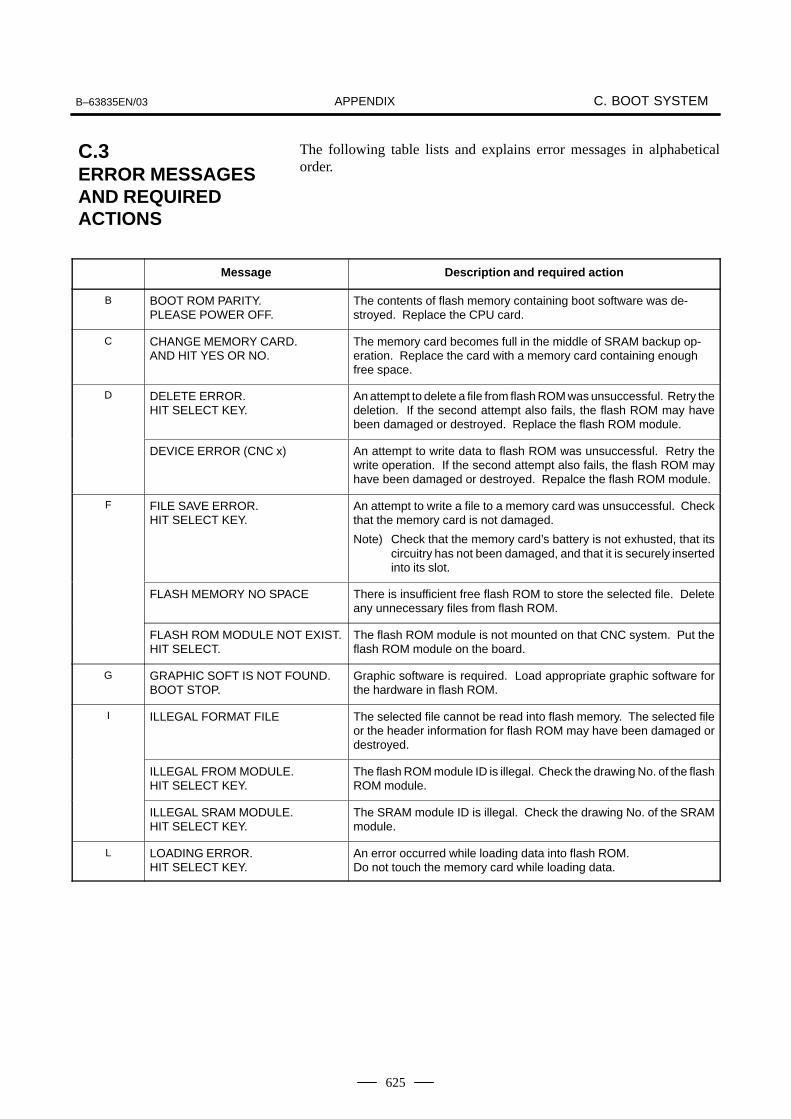
APPENDIXB–63835EN/03 C. BOOT SYSTEM
625
The following table lists and explains error messages in alphabeticalorder.
Message Description and required action
B BOOT ROM PARITY.PLEASE POWER OFF.
The contents of flash memory containing boot software was de-stroyed. Replace the CPU card.
C CHANGE MEMORY CARD.AND HIT YES OR NO.
The memory card becomes full in the middle of SRAM backup op-eration. Replace the card with a memory card containing enoughfree space.
D DELETE ERROR.HIT SELECT KEY.
An attempt to delete a file from flash ROM was unsuccessful. Retry thedeletion. If the second attempt also fails, the flash ROM may havebeen damaged or destroyed. Replace the flash ROM module.
DEVICE ERROR (CNC x) An attempt to write data to flash ROM was unsuccessful. Retry thewrite operation. If the second attempt also fails, the flash ROM mayhave been damaged or destroyed. Repalce the flash ROM module.
F FILE SAVE ERROR.HIT SELECT KEY.
An attempt to write a file to a memory card was unsuccessful. Checkthat the memory card is not damaged.
Note) Check that the memory card’s battery is not exhusted, that itscircuitry has not been damaged, and that it is securely insertedinto its slot.
FLASH MEMORY NO SPACE There is insufficient free flash ROM to store the selected file. Deleteany unnecessary files from flash ROM.
FLASH ROM MODULE NOT EXIST.HIT SELECT.
The flash ROM module is not mounted on that CNC system. Put theflash ROM module on the board.
G GRAPHIC SOFT IS NOT FOUND.BOOT STOP.
Graphic software is required. Load appropriate graphic software forthe hardware in flash ROM.
I ILLEGAL FORMAT FILE The selected file cannot be read into flash memory. The selected fileor the header information for flash ROM may have been damaged ordestroyed.
ILLEGAL FROM MODULE.HIT SELECT KEY.
The flash ROM module ID is illegal. Check the drawing No. of the flashROM module.
ILLEGAL SRAM MODULE.HIT SELECT KEY.
The SRAM module ID is illegal. Check the drawing No. of the SRAMmodule.
L LOADING ERROR.HIT SELECT KEY.
An error occurred while loading data into flash ROM.Do not touch the memory card while loading data.
C.3ERROR MESSAGESAND REQUIREDACTIONS

APPENDIXC. BOOT SYSTEM B–63835EN/03
626
Description and required actionMessage
M MAX EXTENSION OVER.HIT SELECT KEY.
The extension number added to a file name exceeds 031. Delete anyunnecessary backup files from the memory card.
MEMORY CARD BATTERY ALARM.HIT SELECT.
The memory card’s battery is exhausted. Replace the battery.
MEMORY CARD FULL.HIT SELECT KEY.
The memory card is full. Delete any unnecessary files from thememory card. Alternatively, replace the memory card with anothercard having sufficient free space.
MEMORY CARD IS NOTAVAILABLE. HIT SEL.
The use of this memory card is not supported. Use only FANUC–recommended memory cards, as described in the order list.
MEMORY CARD MOUNT ERROR.HIT SELECT KEY
The memory card could not be accessed. Check that the memory cardis normal.
MEMORY CARD NOT EXIST.HIT SELECT KEY.
The memory card is not inserted into its slot. Check that the memorycard is pushed fully home.
MEMORY CARD PROTECTED.HITSELECT KEY.
Although writing to the memory card was selected, the write inhibitswitch is set. Disable the write inhibit switch.
Note) Check that the memory card’s battery is not exhusted, that itscircuitry has not been damaged, and that it is securely insertedinto its slot.
MEMORY CARD TYPE IS NOTAVAILABLE.
Write has been attempted to an incompatible flash memory card. Useonly the flash ROM cards recommended by FANUC. Recommendedflash ROM cards are listed in the ordering list.
MEMORY CARD RESET ERROR.HIT SELECT KEY.
Access to a memory card failed. The memory card’s battery may havegone dead, the memory card may have been damaged electrically, orthe memory card may not be inserted in the slot securely.
MEMORY CARD WRITE ERROR.HIT SELECT KEY.
Access to the memory card has failed. Check whether the memorycard is defective.
Note) Check that the memory card’s battery is not exhusted, that itscircuitry has not been damaged, and that it is securely insertedinto its slot.
N NMI OCCURRED.PLEASE POWER OFF.
A hardware or software error occurred. Determine the procedurewhich causes the error, and report it to FANUC together with the seriesand edition of the boot software.
P PLEASE FORMAT FLASH TYPECARD.HIT SEL.
It is not possible to delete only specific files from a flash ROM card, dueto the characteristics of the memory used. To delete a file it is neces-sary to delete all files on the card, by using the FORMAT function.
R ROM PARITY ERROR:NC BASIC. HIT SELECT.
The NC BASIC is parity error. Check whether NC BASIC is in flashROM, using SYSTEM DATA CHECK.
S SRAM DATA BACKUP ERROR.HIT SELECT KEY.
An attempt to write a backup file to a memory card failed. Check that the memory card is normal.
Note) Check that the memory card’s battery is not exhusted, that itscircuitry has not been damaged, and that it is securely insertedinto its slot.
SRAM PARITY OCCURRED.PLEASE POWER OFF.
A parity error was detected during backup operation of SRAM (Cau-tion).

APPENDIXB–63835EN/03 C. BOOT SYSTEM
627
CAUTION1 Action to be taken when an SRAM parity error is detected during backup of SRAM in the boot
systemThe SRAM area of each CNC shipped from the factory is cleared and is free of parity errors.However, shock applied to the CNC during transportation may cause a parity error in the SRAMarea. A parity error may also occur in the SRAM area when the CNC was kept switched off forone year or longer, and the battery has been exhausted. If a parity error occurs in the SRAMarea, the data held in the SRAM area is not guaranteed. However, the CNC does not alwaysuse the entire SRAM area. A parity error is not detected by hardware unless the part containingthe error is read. Therefore, if a parity error occurs in an area not accessed by the CNC, theCNC may operate normally. The SRAM backup function of the boot system reads the entireSRAM area. So, a parity error may occur in the middle of backup operation even when the CNChas operated normally. In this case, the SRAM data of the CNC is not guaranteed, and the datacannot be backed up using the SRAM backup function of the boot system. Nevertheless, theCNC may operate normally. So, it is recommended that necessary data be backed up usingthe Floppy Cassette or Handy File, data all clear operation be performed, then the backed updata be restored in the CNC. Once all clear operation is performed, the parity error can beremoved. Then, the SRAM backup function of the boot system can be used.
D. LED DISPLAY AND MAINTENANCE OF CONTROL UNIT B–63835EN/03APPENDIX
628
D LED DISPLAY AND MAINTENANCE OF CONTROL UNIT
D.1 OVERVIEW 629. . . . . . . . . . . . . . . . . . . . . . . . . . . . . . . . D.2 LAYOUT OF THE 7–SEGMENT LED AND
SWITCHES 630. . . . . . . . . . . . . . . . . . . . . . . . . . . . . . . . D.3 OPERATION 631. . . . . . . . . . . . . . . . . . . . . . . . . . . . . . .

B–63835EN/03D. LED DISPLAY AND MAINTENANCE
OF CONTROL UNITAPPENDIX
629
Control unit is equipped with a 7–segment LED, rotary switch, and pushswitch.
When no MDI is included in the system configuration or when the MDIbecomes defective and cannot be used, battery backed–up data can besaved and restored by using the rotary switch and push switch.
When the MDI can be used, use these switches for maintenance of theboot function.
D.1OVERVIEW

D. LED DISPLAY AND MAINTENANCE OF CONTROL UNIT B–63835EN/03APPENDIX
630
The 7–segment LED, rotary switch, and push switch are located as shownbelow.
7–segment LED (STATUS)
Rotary switch (MTSW)
Push switch (PSW)
D.2LAYOUT OF THE7–SEGMENT LEDAND SWITCHES

B–63835EN/03D. LED DISPLAY AND MAINTENANCE
OF CONTROL UNITAPPENDIX
631
Before turning on the power, select a function number by using the rotaryswitch. When the power is turned on after the selection with the rotaryswitch, the number corresponding to the selected function number isindicated on the LED. The indication blinks at intervals of about onesecond.
Each function is assigned a number. This number is called a functionnumber hereinafter in this manual. The function numbers that can beselected with the rotary switch are listed below. Do not set the reservedfunction numbers. (If a reserved function number is set, the systemoperates as if function number 0 were selected.)
Functionnumber Explanation Remarks
0 Normal state. After terminating maintenance operation,always set this number.
1 Reserved
2 Sets a device number for the display link function.
3 Reserved
4 Maintenance switch
5 Memory all clear
6 Reserved
7 Reserved
8 Saves battery backed–up main board data in a memorycard at a time.
9 Reserved
A Restores battery backed–up main board data from amemory card at a time.
B Reserved
C Reserved
D Reserved
E Reserved
F Reserved
D.3OPERATION
D.3.1Operation BeforePower–On
D.3.2Function Number

D. LED DISPLAY AND MAINTENANCE OF CONTROL UNIT B–63835EN/03APPENDIX
632
Number displayed on LED Blink/not blink Description
Not blink Automatic operation ispaused, stopped, or reset.
(Rotation of character ) Not blink Automatic operation startsignalWhen STL <F000#5> = 1
Number ( to ) Blink System alarm status
Number ( to ) Not blink Status change at power–on
LED indication Description
Automatic operation start signalWhen STL <F000#5> = 1
Number displayed on LED Blink/not blink Description
Not blink The push switch has beenpressed normally.
D.3.3Seven–Segment LEDDisplay
D.3.3.1 NC status display
D.3.3.2 LED display duringautomatic operation
D.3.3.3 LED display when thepush switch is pressed

B–63835EN/03D. LED DISPLAY AND MAINTENANCE
OF CONTROL UNITAPPENDIX
633
When a system alarm is issued, a number blinks on the 7–segment LED.
Number on LED (blinking)
System alarmnumber Type of system alarm
In the 900’s ROM PARITY
In the 910’s SRAM PARITY,DRAM PARITY
In the 920’s SERVO ALARM
In the 930’s CPU INTERRUPT,SRAM ECC ERROR
In the 950’s PMC SYSTEM ALARM
In the 970’s NON MASK INTERRUPT,BUS ERROR
Others Other system alarms
D.3.3.4 LED display when asystem alarm is issued
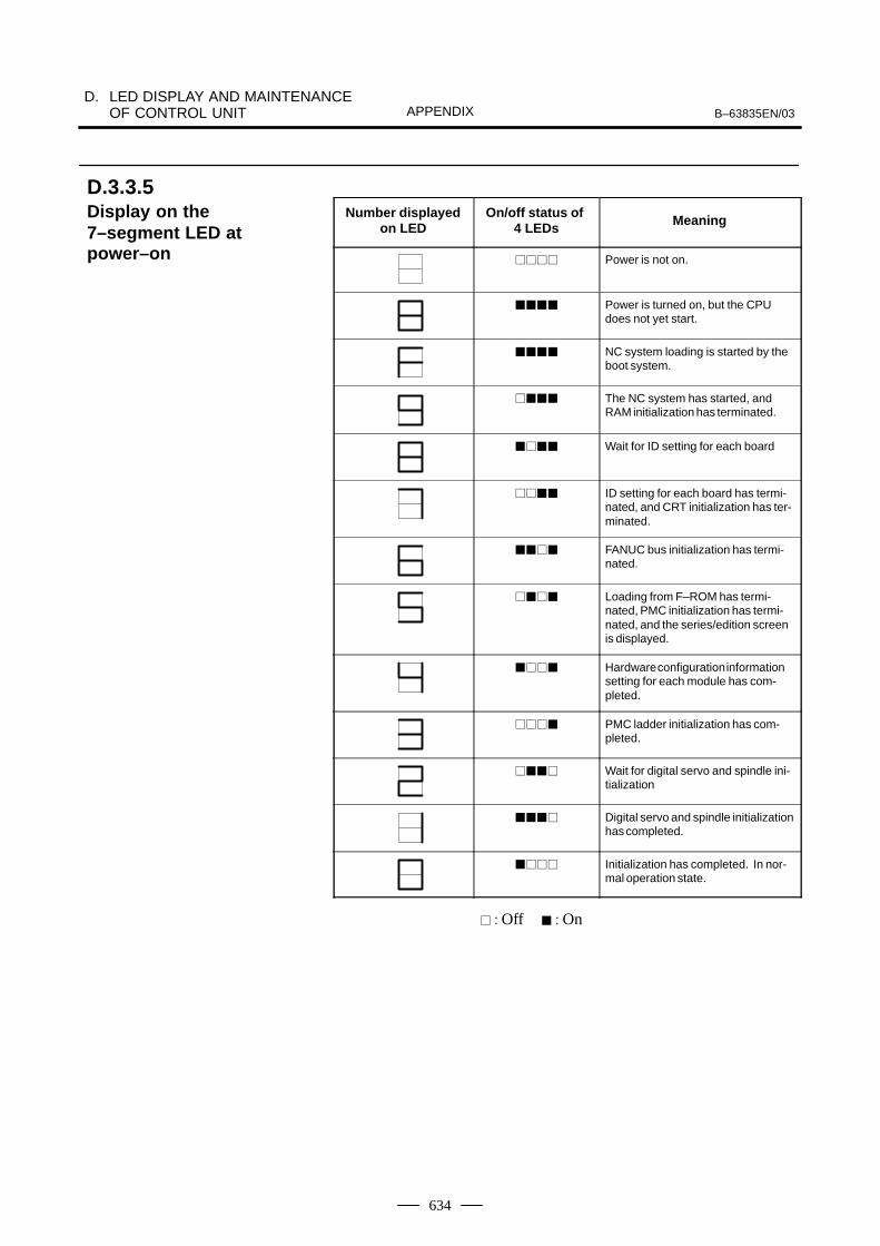
D. LED DISPLAY AND MAINTENANCE OF CONTROL UNIT B–63835EN/03APPENDIX
634
Number displayedon LED
On/off status of 4 LEDs Meaning
���� Power is not on.
���� Power is turned on, but the CPUdoes not yet start.
���� NC system loading is started by theboot system.
���� The NC system has started, andRAM initialization has terminated.
���� Wait for ID setting for each board
���� ID setting for each board has termi-nated, and CRT initialization has ter-minated.
���� FANUC bus initialization has termi-nated.
���� Loading from F–ROM has termi-nated, PMC initialization has termi-nated, and the series/edition screenis displayed.
���� Hardware configuration informationsetting for each module has com-pleted.
���� PMC ladder initialization has com-pleted.
���� Wait for digital servo and spindle ini-tialization
���� Digital servo and spindle initializationhas completed.
���� Initialization has completed. In nor-mal operation state.
� : Off � : On
D.3.3.5 Display on the7–segment LED atpower–on

B–63835EN/03D. LED DISPLAY AND MAINTENANCE
OF CONTROL UNITAPPENDIX
635
This function allows the maintenance switches to be used to display datawithout using any display unit.
(1)Check that number 4 blinks on the LED. Press the push switch.(2)Number 4 is displayed on the LED. Press the push switch.(3)Number 0 is displayed on the LED. Press the push switch.(4)Numbers 0 and 2 are displayed alternately on the LED at intervals of
about one second. When 2 is displayed, press the push switch.
(5)The device number used for the display link function is displayed onthe LED.
This function clears all the battery backed–up SRAM data. The devicenumber for the display link function is also cleared. Once the devicenumber has been cleared, the device number is set to 0.
(1)Check that number 5 blinks on the LED. Press the push switch.
(2)Number 5 is displayed on the LED. Press the push switch.(3)The display on the LED changes from – to F to 9 to 8 to 7 to 6 to 5 to
4 to 3 to 2 to 1 to 0 in this order.(4)After all–clear operation terminates normally, the LED display stops
changing at number 0.(5)Turn off the power, set the rotary switch to 0 (normal state), then turn
on the power again.
This function saves battery backed–up main board data in a memory cardat a time. The data saved using this function can be restored at a time byperforming the operation for function number A or by using theSRAMDATABACKUP function of the boot function.
(1) In the memory card slot (MEMORY CARD CNM1B) of the controlunit, insert a formatted memory card having at least 512 KB ofavailable space.
(2)Check that number 8 blinks on the LED, and press the push switch.(3)While data is being saved in the memory card, the LED indication
turns clockwise.(4) If the data cannot fit in one memory card, number 3 blinks. Replace
the memory card with another one, and press the push switch.(5) If the protect switch of the memory card is not released or if the battery
capacity of the memory card is insufficient, number 2 blinks on theLED. Replace the memory card with another one, and press the pushswitch.
(6)When the data has been saved normally, number 0 is displayed on theLED. If the data cannot be saved normally, number 1 is displayed onthe LED.
(7) If SRAM PARITY occurs during data save operation, number 1 blinkson the LED. In this case, it is impossible to save the data at a time.Back up individual data items one by one, then perform all–clearoperation.
D.3.4Operation of EachFunction
� Function number 4
� Function number 5
� Function number 8

D. LED DISPLAY AND MAINTENANCE OF CONTROL UNIT B–63835EN/03APPENDIX
636
This function restores battery backed–up main board data from a memorycard at a time.
(1) Insert the memory card in the memory card slot (MEMORY CARDCNM1B) of the control unit.
(2)Check that A blinks on the LED, and press the push switch.
(3)While data is being restored from the memory card, the LEDindication turns counterclockwise.
(4) If the entire data cannot be restored from the single memory card,number 3 blinks. Replace the memory card with the next memorycard, and press the push switch.
(5) If the memory card cannot be recognized correctly, number 2 blinkson the LED. Check the memory card status, and press the push switch.
(6)When the data has been restored normally, number 0 is displayed onthe LED. If the data cannot be restored normally, number 1 isdisplayed on the LED.
� Function number A

B–63835EN/03E. MAINTENANCE OF OPEN CNC
(BOOT–UP AND IPL)APPENDIX
637
E MAINTENANCE OF OPEN CNC (BOOT–UP AND IPL)
E.1 OVERVIEW 638. . . . . . . . . . . . . . . . . . . . . . . . . . . . . . . . E.2 CHANGING START SEQUENCES
(NOT APPLICABLE TO THE Series 0i Mate) 639. . . . . E.3 EXPLANATION OF SCREENS 640. . . . . . . . . . . . . . . .
E.3.1 Boot Screen 640. . . . . . . . . . . . . . . . . . . . . . . . . . . . . E.3.2 IPL Screen 644. . . . . . . . . . . . . . . . . . . . . . . . . . . . . .
E.4 OTHER SCREENS 647. . . . . . . . . . . . . . . . . . . . . . . . . . E.4.1 CNC Alarm Screen 647. . . . . . . . . . . . . . . . . . . . . . . . E.4.2 Status Screen 648. . . . . . . . . . . . . . . . . . . . . . . . . . . . E.4.3 Option Setting Screen 649. . . . . . . . . . . . . . . . . . . . . .

E. MAINTENANCE OF OPEN CNC(BOOT–UP AND IPL) B–63835EN/03APPENDIX
638
When the CNC is connected to the PC over HSSB, Ncboot32.exe can beused for the maintenance of the CNC.Ncboot32.exe provides the following functions:
� BOOT screen (for CNC system data maintenance, SRAM backup, andso forth)
� IPL screen (for clearing SRAM, and so forth)
� Display of the CNC power–on screen
� Display of CNC alarm screen
� Re–connection in case of the occurrence of a communication error
� Start of a registered application program
Ncboot32.exe is copied in the System folder of Windows (System32folder in Windows NT) at driver installation. At the start of Windows,Ncboot32.exe starts automatically, and resides in the system tray.
(Icon at the center)
Supplementary 1: Multi–connection
Ncboot32.exe supports HSSB multi–connection. The CNCs connectedby HSSB are managed as nodes. The boot, IPL, and system alarm screensare displayed in windows that are opened independently for each node.
Supplementary 2: Termination method
Normally, Ncboot32.exe need not be terminated. However, to terminateNcboot32.exe, right–click the icon in the system tray, and click End in thepopup menu. When the Ncboot32.exe window is open, End cannot beselected.
NOTEWhen the CNC is connected to the PC over Ethernet, usethe standard LCD/MDI for the maintenance of the CNC.
E.1OVERVIEW

B–63835EN/03E. MAINTENANCE OF OPEN CNC
(BOOT–UP AND IPL)APPENDIX
639
With the rotary switch on the HSSB board on the CNC side (when theCNC does not have the PC function) or on the motherboard of the CNC(when the CNC has the PC function), the start sequence can be changed.
Position 0 can be selected as required to perform maintenance using theboot and IPL screens.
Position 0 (maintenance)
1. Wait until communication with the CNC is established.
2. Display the boot screen.
3. Display the IPL screen.
4. Display the CNC power–on screen.
5. Initialize the work area for the data window library.
6. Start a registered application program.
7. Perform monitoring for communication errors and CNC systemalarms.
Position 1 (normal operation)
1. Wait until communication with the CNC is established.
2. Initialize the work area for the data window library.
3. Start a registered application program.
4. Perform monitoring for communication errors and CNC systemalarms.
Position 2 (asynchronous start)
1. The CNC starts without waiting for communication to be established.
2. After communication is established, the PC performs initializationdescribed below.
3. Initialize the work area for the data window library.
4. Start a registered application program.
5. Perform monitoring for communication errors and CNC systemalarms.
� HSSB interface board
Rotary switch
E.2CHANGING STARTSEQUENCES (NOT APPLICABLETO THE Series 0iMate)
� Rotary switch location

E. MAINTENANCE OF OPEN CNC(BOOT–UP AND IPL) B–63835EN/03APPENDIX
640
NOTEA mouse is required to display Ncboot32.exe screens.
When the sub–board is provided, select a board in the [Board] list.
The area where the file is to be placed can be changed by using the[Setting...] button.
Select the memory card on the CNC or a PC folder. The file location maybe changed at any time.
E.3EXPLANATION OFSCREENS
E.3.1Boot Screen

B–63835EN/03E. MAINTENANCE OF OPEN CNC
(BOOT–UP AND IPL)APPENDIX
641
The following screen is used for manipulating system data (includingcontrol software and ladder programs) on the NC.
[Load...] opens the file selection screen. Specify a file to be loaded.
[Save] saves the selected NC system data in a file.
[Check] checks the selected NC system data.
[Delete] deletes the selected NC system data.
E.3.1.1 System datamanipulation

E. MAINTENANCE OF OPEN CNC(BOOT–UP AND IPL) B–63835EN/03APPENDIX
642
This screen is used to store and restore NC SRAM data.
[Backup] stores SRAM data, and [Restore] restores SRAM data. In thecenter of the screen, the progress status is displayed. As with the NC, thebackup file name is determined automatically from the SRAM size, andcannot be renamed.
E.3.1.2 SRAM operation

B–63835EN/03E. MAINTENANCE OF OPEN CNC
(BOOT–UP AND IPL)APPENDIX
643
The following screen is used for operating files on a memory card in theCNC or in a folder of the PC.
[Delete] deletes a selected file.
[Format] formats the memory card. This button is valid when the memorycard is selected by [Setting...]
[Refresh] updates the file list to the latest state. After changing memorycards or floppy disks, click this button.
E.3.1.3 File operation

E. MAINTENANCE OF OPEN CNC(BOOT–UP AND IPL) B–63835EN/03APPENDIX
644
NOTEThe contents of the IPL screen vary depending on the CNCmodel. Follow the instructions displayed in the menu.
The CNC allows functions to be performed according to the key status setat power–on.
The open CNC does not allow this operation. On the IPL screen, however,equivalent functions can be executed.
For details of the menu on the IPL screen and supported functions, see thetable given in Section E.3.2.1.
E.3.2IPL Screen
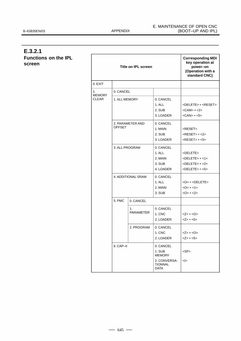
B–63835EN/03E. MAINTENANCE OF OPEN CNC
(BOOT–UP AND IPL)APPENDIX
645
Title on IPL screen
Corresponding MDIkey operation at
power–on(Operation with a
standard CNC)
0. EXIT
1. 0. CANCELMEMORYCLEAR 1. ALL MEMORY 0. CANCEL
1. ALL
2. SUB
3. LOADER
<DELETE> + <RESET>
<CAM> + <2>
<CAN> + <5>
2. PARAMETER ANDOFFSET
0. CANCEL
1. MAIN
2. SUB
3. LOADER
<RESET>
<RESET> + <2>
<RESET> + <5>
3. ALL PROGRAM 0. CANCEL
1. ALL
2. MAIN
3. SUB
4. LOADER
<DELETE>
<DELETE> + <1>
<DELETE> + <2>
<DELETE> + <5>
4. ADDITIONAL SRAM 0. CANCEL
1. ALL
2. MAIN
3. SUB
<O> + <DELETE>
<O> + <1>
<O> + <2>
5. PMC 0. CANCEL
1.PARAMETER
0. CANCEL
1. CNC
2. LOADER
<Z> + <O>
<Z> + <5>
2. PROGRAM 0. CANCEL
1. CNC
2. LOADER
<Z> + <O>
<Z> + <5>
6. CAP–II 0. CANCEL
1. SUBMEMORY
2. CONVERSA-TIONNAL DATA
<SP>
<I>
E.3.2.1 Functions on the IPLscreen
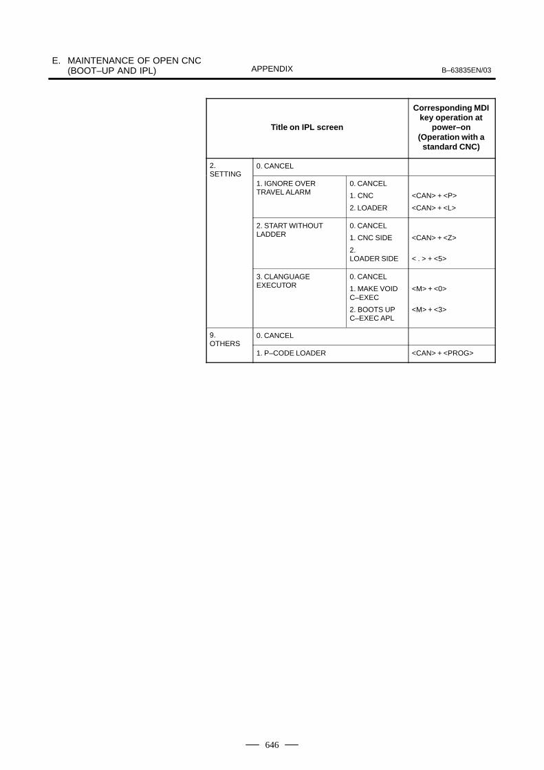
E. MAINTENANCE OF OPEN CNC(BOOT–UP AND IPL) B–63835EN/03APPENDIX
646
Title on IPL screen
Corresponding MDIkey operation at
power–on(Operation with a
standard CNC)
2. 0. CANCELSETTING
1. IGNORE OVERTRAVEL ALARM
0. CANCEL
1. CNC
2. LOADER
<CAN> + <P>
<CAN> + <L>
2. START WITHOUTLADDER
0. CANCEL
1. CNC SIDE
2. LOADER SIDE
<CAN> + <Z>
< . > + <5>
3. CLANGUAGEEXECUTOR
0. CANCEL
1. MAKE VOIDC–EXEC
2. BOOTS UPC–EXEC APL
<M> + <0>
<M> + <3>
9. 0. CANCELOTHERS
1. P–CODE LOADER <CAN> + <PROG>
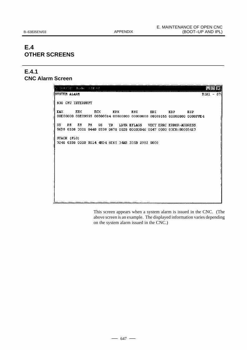
B–63835EN/03E. MAINTENANCE OF OPEN CNC
(BOOT–UP AND IPL)APPENDIX
647
This screen appears when a system alarm is issued in the CNC. (Theabove screen is an example. The displayed information varies dependingon the system alarm issued in the CNC.)
E.4OTHER SCREENS
E.4.1CNC Alarm Screen

E. MAINTENANCE OF OPEN CNC(BOOT–UP AND IPL) B–63835EN/03APPENDIX
648
To open the status screen, double–click the icon in the system tray.Alternatively, in the menu popped up by right–clicking, click OPEN.
Node: Node number
Name: Node name. (Define the node name in advance by using thedevice manager in Windows 95/98 or the HSSB applet on thecontrol panel in Windows NT.)
Bus: Hardware communication status (0: Communication error, 1:Communication established)
Status: Status (in hexadecimal)
Bit 1: Rotary switch position 1Bit 2: End of boot processing Bit 3: End of IPL processingBit 4: Rotary switch position 2Bit 8: CNC system alarm
Pop up this window on communication error: By checking this item,this screen is opened automatically when a communication erroroccurs.
Clicking the [Close] button closes the screen.
Clicking the [Setting...] button opens the option setting screen.
Clicking the [About...] button opens the version information screen.
E.4.2Status Screen
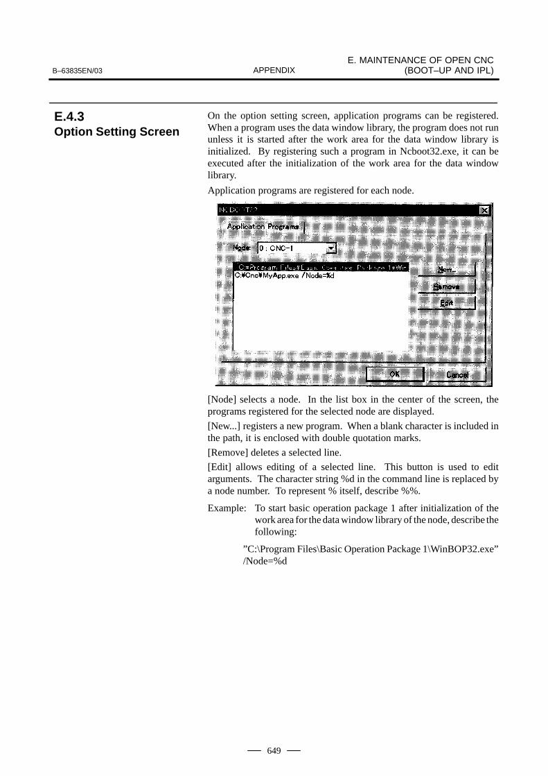
B–63835EN/03E. MAINTENANCE OF OPEN CNC
(BOOT–UP AND IPL)APPENDIX
649
On the option setting screen, application programs can be registered.When a program uses the data window library, the program does not rununless it is started after the work area for the data window library isinitialized. By registering such a program in Ncboot32.exe, it can beexecuted after the initialization of the work area for the data windowlibrary.
Application programs are registered for each node.
[Node] selects a node. In the list box in the center of the screen, theprograms registered for the selected node are displayed.
[New...] registers a new program. When a blank character is included inthe path, it is enclosed with double quotation marks.
[Remove] deletes a selected line.
[Edit] allows editing of a selected line. This button is used to editarguments. The character string %d in the command line is replaced bya node number. To represent % itself, describe %%.
Example: To start basic operation package 1 after initialization of thework area for the data window library of the node, describe thefollowing:
”C:\Program Files\Basic Operation Package 1\WinBOP32.exe”/Node=%d
E.4.3Option Setting Screen

F. FSSB START–UP PROCEDURE/MATERIALS B–63835EN/03APPENDIX
650
F FSSB START–UP PROCEDURE/MATERIALS
F.1 OVERVIEW 651. . . . . . . . . . . . . . . . . . . . . . . . . . . . . . . . F.2 SLAVE 652. . . . . . . . . . . . . . . . . . . . . . . . . . . . . . . . . . . . F.3 AUTOMATIC SETTING 653. . . . . . . . . . . . . . . . . . . . . .
F.3.1 [Sample Setting 1] General Configuration (Semi–Closed Loop) 655. . . . . . . . . .
F.3.2 [Sample Setting 2] General Configuration (Closed Loop) 656. . . . . . . . . . . . . . .
F.3.3 [Sample Setting 3] When the C–axis is a Cs Axis 658. . . . . . . . . . . . . . . . . . . .
F.4 MANUAL SETTING 2 660. . . . . . . . . . . . . . . . . . . . . . . F.5 MANUAL SETTING 1 666. . . . . . . . . . . . . . . . . . . . . . . F.6 ALARMS 667. . . . . . . . . . . . . . . . . . . . . . . . . . . . . . . . . . F.7 ACTIONS FOR TROUBLE ENCOUNTERED
AT START–UP TIME 672. . . . . . . . . . . . . . . . . . . . . . . . F.8 FSSB DATA DISPLAY 674. . . . . . . . . . . . . . . . . . . . . . .
F.8.1 Amplifier Setting Screen 674. . . . . . . . . . . . . . . . . . . F.8.2 Axis Setting Screen 675. . . . . . . . . . . . . . . . . . . . . . . F.8.3 Amplifier Maintenance Screen 676. . . . . . . . . . . . . .

B–63835EN/03F. FSSB START–UP PROCEDURE/
MATERIALSAPPENDIX
651
With a system that uses the FSSB, the parameters below need to be set foraxis setting. (Set other parameters as usually done.)
� No. 1023
� No. 1905
� No. 1910 to 1919
� No. 1936, 1937
For setting of these parameters, three methods are available.
1. Automatic setting
By entering data including the relationship between axes andamplifiers on the FSSB setting screen, a calculation for axis setting ismade automatically, and parameter Nos. 1023, 1905, 1910 through1919, 1936, and 1937 are automatically set.
2. Manual setting 2
Enter desired values directly in all of parameter Nos. 1023, 1905, 1910through 1919, 1936, and 1937.
Before setting the parameters, fully understand the functions of theparameters.
3. Manual setting 1(NOTE)
Based on the setting of No. 1023, default axis setting is performed.Parameter Nos. 1905, 1910 through 1919, 1936, and 1937 need not beset. Automatic setting is not performed.
NOTEWith manual setting 1, usable functions are limited. So,when starting up the FSSB, use automatic setting or manualsetting 2 whenever possible.
F.1OVERVIEW
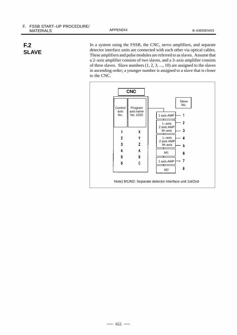
F. FSSB START–UP PROCEDURE/MATERIALS B–63835EN/03APPENDIX
652
In a system using the FSSB, the CNC, servo amplifiers, and separatedetector interface units are connected with each other via optical cables.These amplifiers and pulse modules are referred to as slaves. Assume thata 2–axis amplifier consists of two slaves, and a 3–axis amplifier consistsof three slaves. Slave numbers (1, 2, 3, ..., 10) are assigned to the slavesin ascending order; a younger number is assigned to a slave that is closerto the CNC.
SlaveNo.
ControlaxisNo.
Programaxis nameNo. 1020 1 axis AMP
L–axis2 axis AMP
M–axis
L–axis2 axis AMP
M–axis
M1
1 axis AMP
M2
Note) M1/M2: Separate detector interface unit 1st/2nd
F.2SLAVE

B–63835EN/03F. FSSB START–UP PROCEDURE/
MATERIALSAPPENDIX
653
When the following parameters are set, automatic setting can beperformed using the FSSB setting screen:
Bit 0 of No. 1902 = 0Bit 1 of No. 1902 = 0
For automatic setting on the FSSB setting screen, use the procedurebelow.
1 Set a servo axis number in No. 1023.
Be sure to match an axis number set in No. 1023 with the total numberof axes of the servo amplifiers connected via optical cables.
2 On the servo initialization screen, initialize the servo parameters.
3 Turn off then on the power to the CNC.
4 Press function key SYSTEM .
5 Pressing the continuous menu key several times displays[FSSB].
6 Pressing soft key [FSSB] switches the screen display to the amplifiersetting screen (or the FSSB setting screen selected previously), anddisplays the following soft keys:
[ ][ ][ ][ ][ ]
7 Press soft key [AMP].
8 On the amplifier setting screen, set a controlled axis number connectedto each amplifier.
The amplifier setting screen lists the slaves in ascending order of slavenumbers from top to bottom. So, when setting controlled axisnumbers, consider which amplifier axis is to be connected to whichCNC axis, sequentially, starting with the amplifier axis closest to theNC. On this setting screen, 0 and duplicate numbers cannot be entered.
No. AMP SERIES UNIT CUR. [AXIS] NAME1 A1–L α SVM 40AL [ 1 ] X2 A1–M α SVM 12A [ 2 ] Y3 A2–L β SVU 20A [ 3 ] Z4 A3–L α SVM 40A [ 4 ] A5 A3–M α SVM 80A [ 5 ] B7 A4–L α SVM 40AS [ 6 ] C
NO. EXTRA PCB ID6 M1 A 0008 DETECTOR(4AXES)8 M2 A 0008 DETECTOR(4AXES)
>MDI **** *** *** 13:11:56[ AMP ][ AXIS ][ MAINT ][ ][ (OPRT) ]
9 Press soft key [SETING]. (This soft key appears when a value isentered.)
10 Press function key SYSTEM .
F.3AUTOMATICSETTING
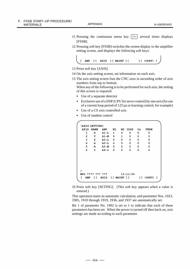
F. FSSB START–UP PROCEDURE/MATERIALS B–63835EN/03APPENDIX
654
11 Pressing the continuous menu key several times displays[FSSB].
12 Pressing soft key [FSSB] switches the screen display to the amplifiersetting screen, and displays the following soft keys:
[ AMP ][ AXIS ][ MAINT ][ ][ (OPRT) ]
13 Press soft key [AXIS].
14 On the axis setting screen, set information on each axis.
15 The axis setting screen lists the CNC axes in ascending order of axisnumbers from top to bottom.When any of the following is to be performed for each axis, the settingof this screen is required:
� Use of a separate detector
� Exclusive use of a DSP (CPU for servo control) by one axis (for useof a current loop period of 125 µs or learning control, for example)
� Use of a CS axis controlled axis
� Use of tandem control
(AXIS SETTING) AXIS NAME AMP M1 M2 IDSP Cs TNDM
1 X A1–L 1 0 0 0 02 Y A1–M 0 1 0 0 03 Z A2–L 0 0 0 0 04 A A3–L 2 0 0 0 05 B A3–M 0 2 0 0 06 C A4–L 0 0 0 0 0
>MDI **** *** *** 13:11:56[ AMP ][ AXIS ][ MAINT ][ ][ (OPRT) ]
16 Press soft key [SETING]. (This soft key appears when a value isentered.)
This operation starts an automatic calculation, and parameter Nos. 1023,1905, 1910 through 1919, 1936, and 1937 are automatically set.
Bit 1 of parameter No. 1902 is set to 1 to indicate that each of theseparameters has been set. When the power is turned off then back on, axissettings are made according to each parameter.

B–63835EN/03F. FSSB START–UP PROCEDURE/
MATERIALSAPPENDIX
655
Z–axis
A–axis
X–axis
Y–axis
Step 1 Set the following with parameter No. 1023:X : 1Y : 2Z : 3A : 4
Step 2 Initialize the servo parameters for each axis.Step 3 Turn on then off the power to the CNC.Step 4 Enter the axis numbers on the amplifier setting screen.
(AMPLIFIER SETTING) No. AMP SERIES UNIT CUR. [AXIS] NAME
1 A1–L α SVM 40A [ 2 ] Y2 A2–L α SVM 40A [ 1 ] X3 A3–L α SVM 40A [ 4 ] A4 A3–M α SVM 80A [ 3 ] Z
NO. EXTRA TYPE PCB ID
>MDI **** *** *** 13:11:56[ AMP ][ AXIS ][ MAINT ][ ][ (OPRT) ]
Step 5 Press soft key [SETING]. (This soft key appears when a valueis entered.)
Step 6 Press function key SYSTEM .
F.3.1[Sample Setting 1]General Configuration(Semi–Closed Loop)

F. FSSB START–UP PROCEDURE/MATERIALS B–63835EN/03APPENDIX
656
Step 7 Pressing the continuous menu key several times displays[FSSB].
Step 8 Pressing soft key [FSSB] switches the screen display to theamplifier setting screen, and displays the following soft keys:
[ AMP ][ AXIS ][ MAINT ][ ][ (OPRT) ]
Step 9 Press soft key [AXIS].
Step 10 Press soft key [(OPRT)] without entering any data, then press softkey [SETING].
Step 11 Turn off then on the power to the CNC. This completes thesetting.
Connector 1 (CN1)
Connector 2 (CN2)
Z–axis
scale
Machine side
A–axis
X–axis
Y–axisscale
Separate detector interface unit
Step 1 Set the following with parameter No. 1023:
X : 1
Y : 2
Z : 3
A : 4
Step 2 Initialize the servo parameters for each axis.
Step 3 Turn on then off the power to the CNC.
Step 4 Enter the axis numbers on the amplifier setting screen.
F.3.2[Sample Setting 2]General Configuration(Closed Loop)
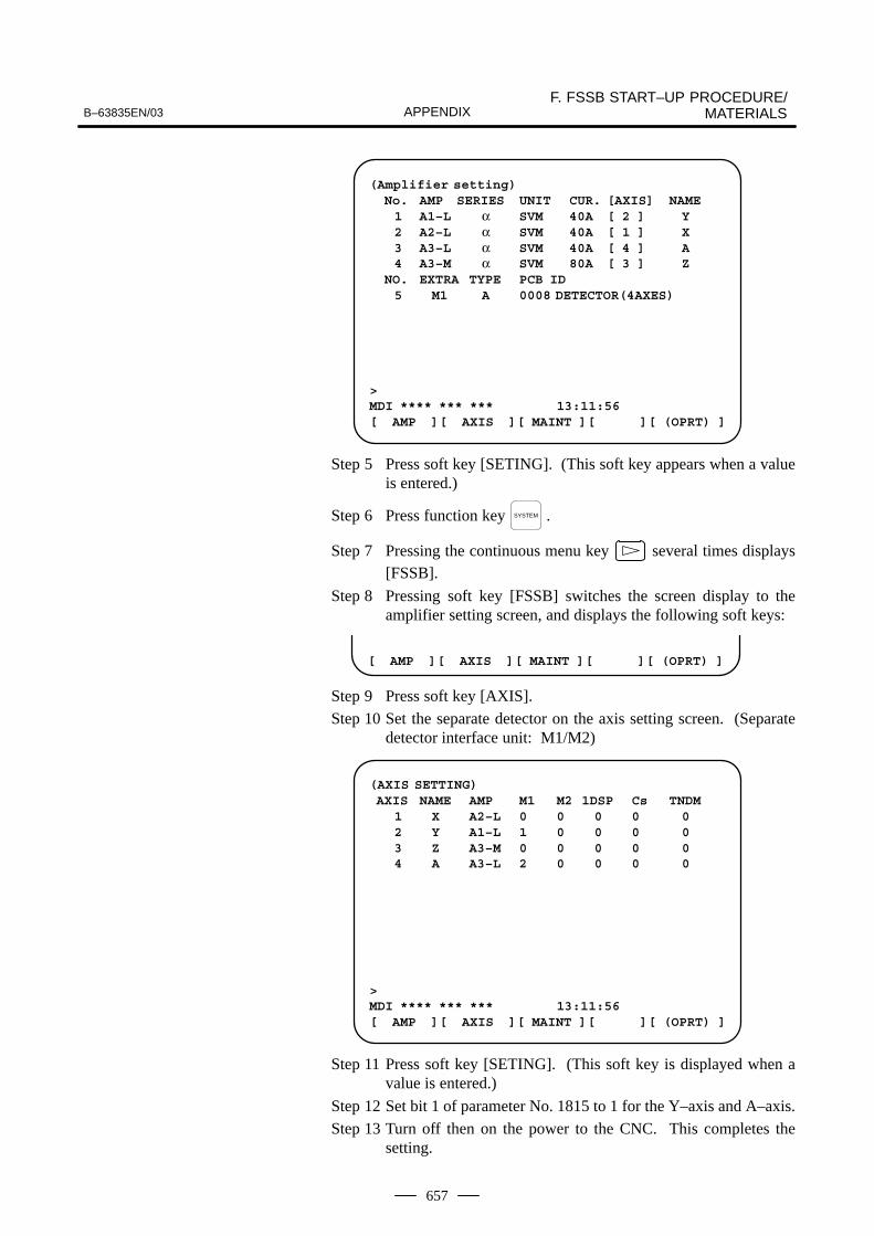
B–63835EN/03F. FSSB START–UP PROCEDURE/
MATERIALSAPPENDIX
657
(Amplifier setting) No. AMP SERIES UNIT CUR. [AXIS] NAME
1 A1–L α SVM 40A [ 2 ] Y2 A2–L α SVM 40A [ 1 ] X3 A3–L α SVM 40A [ 4 ] A4 A3–M α SVM 80A [ 3 ] Z
NO. EXTRA TYPE PCB ID5 M1 A 0008 DETECTOR(4AXES)
>MDI **** *** *** 13:11:56[ AMP ][ AXIS ][ MAINT ][ ][ (OPRT) ]
Step 5 Press soft key [SETING]. (This soft key appears when a valueis entered.)
Step 6 Press function key SYSTEM .
Step 7 Pressing the continuous menu key several times displays[FSSB].
Step 8 Pressing soft key [FSSB] switches the screen display to theamplifier setting screen, and displays the following soft keys:
[ AMP ][ AXIS ][ MAINT ][ ][ (OPRT) ]
Step 9 Press soft key [AXIS].
Step 10 Set the separate detector on the axis setting screen. (Separatedetector interface unit: M1/M2)
(AXIS SETTING) AXIS NAME AMP M1 M2 1DSP Cs TNDM
1 X A2–L 0 0 0 0 02 Y A1–L 1 0 0 0 03 Z A3–M 0 0 0 0 04 A A3–L 2 0 0 0 0
>MDI **** *** *** 13:11:56[ AMP ][ AXIS ][ MAINT ][ ][ (OPRT) ]
Step 11 Press soft key [SETING]. (This soft key is displayed when avalue is entered.)
Step 12 Set bit 1 of parameter No. 1815 to 1 for the Y–axis and A–axis.
Step 13 Turn off then on the power to the CNC. This completes thesetting.

F. FSSB START–UP PROCEDURE/MATERIALS B–63835EN/03APPENDIX
658
Cs contour control axis
Z–axis
1 Spindle Amplifiers
A–axis
X–axis
Y–axis
C–axis
Step 1 Set the following with parameter No. 1023:
X : 1
Z : 2
C : –1
Y : 3
A : 4
Step 2 Initialize the servo parameters for each axis.
Step 3 Initialize the spindle parameters for the spindle.
Step 4 Turn on then off the power to the CNC.
F.3.3[Sample Setting 3]When the C–Axis is aCs Axis
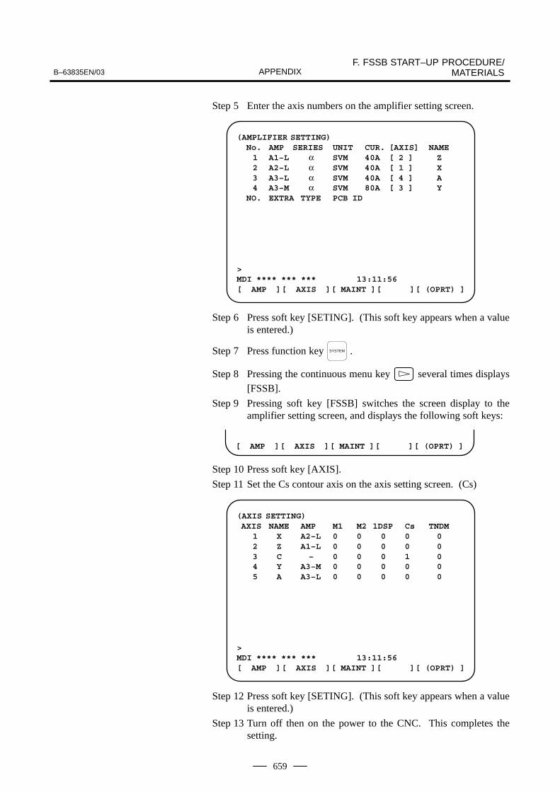
B–63835EN/03F. FSSB START–UP PROCEDURE/
MATERIALSAPPENDIX
659
Step 5 Enter the axis numbers on the amplifier setting screen.
(AMPLIFIER SETTING) No. AMP SERIES UNIT CUR. [AXIS] NAME
1 A1–L α SVM 40A [ 2 ] Z2 A2–L α SVM 40A [ 1 ] X3 A3–L α SVM 40A [ 4 ] A4 A3–M α SVM 80A [ 3 ] Y
NO. EXTRA TYPE PCB ID
>MDI **** *** *** 13:11:56[ AMP ][ AXIS ][ MAINT ][ ][ (OPRT) ]
Step 6 Press soft key [SETING]. (This soft key appears when a valueis entered.)
Step 7 Press function key SYSTEM .
Step 8 Pressing the continuous menu key several times displays
[FSSB].
Step 9 Pressing soft key [FSSB] switches the screen display to theamplifier setting screen, and displays the following soft keys:
[ AMP ][ AXIS ][ MAINT ][ ][ (OPRT) ]
Step 10 Press soft key [AXIS].
Step 11 Set the Cs contour axis on the axis setting screen. (Cs)
(AXIS SETTING) AXIS NAME AMP M1 M2 1DSP Cs TNDM
1 X A2–L 0 0 0 0 02 Z A1–L 0 0 0 0 03 C – 0 0 0 1 04 Y A3–M 0 0 0 0 05 A A3–L 0 0 0 0 0
>MDI **** *** *** 13:11:56[ AMP ][ AXIS ][ MAINT ][ ][ (OPRT) ]
Step 12 Press soft key [SETING]. (This soft key appears when a valueis entered.)
Step 13 Turn off then on the power to the CNC. This completes thesetting.

F. FSSB START–UP PROCEDURE/MATERIALS B–63835EN/03APPENDIX
660
When the following parameters are set, each axis can be set manually:
No.1902#0=1No.1902#1=0
When performing manual setting, set parameter Nos. 1023, 1905, 1910through 1919, 1936, and 1937, fully understanding their functions.
#71902
#6 #5 #4 #3 #2 #1ASE
#0FMD
[Data type] Bit
#0 (FMD) The FSSB setting mode is:
0 : Automatic setting mode. (When data including the relationshipbetween axes and amplifiers is set on the FSSB setting screen,parameter Nos. 1023, 1905, 1910 through 1919, 1936, and 1937 areautomatically set.)
1 : Manual setting 2 mode. (Parameter Nos. 1023, 1905, 1910 through1919, 1936, and 1937 are set manually.)
#1 (ASE) When the FSSB setting mode is the automatic setting mode (when bit 0 ofparameter No. 1902 = 0), automatic setting is:
0 : Not completed.1 : Completed.
(This bit is automatically set to 1 when automatic setting iscompleted.)
#7PM21905
#6PM1
#5 #4 #3 #2 #1 #0FSL
[Data type] Bit axis
#0 (FSL) The type of interface between servo amplifiers and servo software is:
0 : Fast type.1 : Slow type.
Two servo data transfer interface types are available: the fast type andslow type.
Set this bit so that the following conditions are satisfied:
� When a 1–axis amplifier is used, both of the fast and slow types canbe used.
� When a 2–axis amplifier is used, the fast type must not be used forboth axes. The slow type can be used for both axes.
� When a 3–axis amplifier is used, the first and second axes mustsatisfy the condition for a 2–axis amplifier, and the third axis mustsatisfy the condition for a one–axis amplifier.
� With an axis for which an odd number is set in parameter No. 1023,the fast type must be used. The slow type can also be used,however, for an EGB workpiece axis, learning–control axis,high–speed current loop axis, and high–speed interface axis.
� Only the slow type can be used with an axis for which an evennumber is set in parameter No. 1023. (Be sure to set this bit to 1).
F.4MANUAL SETTING 2

B–63835EN/03F. FSSB START–UP PROCEDURE/
MATERIALSAPPENDIX
661
Con-trolled
axis No.
Programaxis nameNo.1020
Servoaxis No.No.1023
Interfacetype
Fast/Slow
2–axis AMP
1–axis AMP
2–axis AMP
1–axis AMP
#6 (PM1) The first separate detector interface unit is:0 : Not used.1 : Used.
#7 (PM2) The second separate detector interface unit is:0 : Not used.1 : Used.
This parameter is automatically set by data input on the FSSB settingscreen when the FSSB setting mode is the automatic setting mode (whenbit 0 of parameter No. 1902 = 0). When the manual setting 2 mode is used(when bit 0 of parameter No. 1902 = 1), be sure to enter necessary datadirectly.
When a separate detector interface unit is used, connector numbers(parameter Nos. 1936 and 1937) need to be set.
1910 Address conversion table value for slave 1 (ATR)PRM
1911 Address conversion table value for slave 2 (ATR)PRM
1912 Address conversion table value for slave 3 (ATR)PRM
1913 Address conversion table value for slave 4 (ATR)PRM
1914 Address conversion table value for slave 5 (ATR)PRM
1915 Address conversion table value for slave 6 (ATR)PRM
1916 Address conversion table value for slave 7 (ATR)PRM
1917 Address conversion table value for slave 8 (ATR)PRM
1918 Address conversion table value for slave 9 (ATR)PRM
1919 Address conversion table value for slave 10 (ATR)PRM
[Data type] Byte
[Valid data range] 0 to 7, 16, 40, 48
Set an address conversion table value for each of slave 1 through 10.

F. FSSB START–UP PROCEDURE/MATERIALS B–63835EN/03APPENDIX
662
The slave is the generic name of a servo amplifier or separate detectorinterface unit connected to the CNC via an FSSB optical cable. Thenumbers from 1 to 10 are assigned to the slaves in ascending order; ayounger number is assigned to a slave that is closer to the CNC. A 2–axisamplifier consists of two slaves, and a 3–axis amplifier consists of threeslaves. Set each of the parameters as described below according to whichof the three cases is applicable: the slave is an amplifier, the slave is aseparate detector interface unit, or there is no slave.
� When the slave is an amplifier:
Set a value obtained by subtracting 1 from the setting of parameter No.1023 for the axis to which the amplifier is assigned.
� When the slave is a separate detector interface unit:
� For the first separate detector interface unit (closest to the CNC),set 16.
� For the second separate detector interface unit (farthest from theCNC), set 48.
� When there is no slave:
Set 40.
These parameters are automatically set by data input on the FSSB settingscreen when the FSSB setting mode is the automatic setting mode (whenbit 0 of parameter No. 1902 = 0). When the manual setting 2 mode is used(when bit 0 of parameter No. 1902 = 1), be sure to enter necessary datadirectly.

B–63835EN/03F. FSSB START–UP PROCEDURE/
MATERIALSAPPENDIX
663
� Axis configuration and example of parameter setting
ControlNo.
Axis NameNo.1020
ServoAxis No.No.1023
SlaveNo.
ATRNo.1910to 1919
AXIS
1 axis AMP
L–axis2 axis AMP
M–axis
L–axis2 axis AMP
M–axis
1 axis AMP
M2
M1
ControlNo.
Axis NameNo.1020
ServoAxis No.No.1023 1 axis AMP
L–axis2 axis AMP
M–axis
L–axis2 axis AMP
M–axis
1 axis AMP
M2
M1
SlaveNo.
ATRNo.1910to 1919
AXIS
M1/M2 : Separate detector interfaceunit 1st/2nd
M1/M2 : Separate detector interfaceunit 1st/2nd

F. FSSB START–UP PROCEDURE/MATERIALS B–63835EN/03APPENDIX
664
1936 Connector number for the first separate detector interface unitPRM
1937 Connector number for the second separate detector interface unitPRM
[Data type] Byte axis
[Valid data range] 0 to 7
When using a pulse module, set a value obtained by subtracting 1 fromthe pulse module connector number for each axis. That is, for connectornumbers 1 to 8, set the values 0 to 7. Moreover, set bits 6 and 7 ofparameter No. 1905. Set 0 for an axis for which no pulse module is used.
The user can freely determine which connector to use for which axis. Useconnector numbers, starting with younger numbers. For example,connector number 4 cannot be used without using connector number 3.
Example:
Con-trolledaxis
First con-nector
number
Secondconnector
number
No.1936 No.1937 No.1905(#7,#6)
X 1 Not used 0 0 0,1
Y Not used 2 0 1 1,0
Z Not used 1 0 0 1,0
A Not used Not used 0 0 0,0
B 2 Not used 1 0 0,1
C Not used 3 0 2 1,0
These parameters are automatically set by data input on the FSSB settingscreen when the FSSB setting mode is the automatic setting mode (whenbit 0 of parameter No. 1902 = 0). When the manual setting 2 mode is used(when bit 0 of parameter No. 1902 = 1), be sure to enter necessary datadirectly.

B–63835EN/03F. FSSB START–UP PROCEDURE/
MATERIALSAPPENDIX
665
� Axis configuration and example of parameter setting in the manualsetting 2 mode
ControlAxis No.
Axis NameNo.1020
Pulse ModuleConnector
AXIS
1 axis AMP
L–axis2 axis AMP
M–axis
L–axis2 axis AMP
M–axis
M1
1 axis AMP
M2
M1/M2 : Separate detector interfaceunit 1st/2nd
No. 1902#0FSBMD
1
No. 1910 1911 1912 1913 1914 1915 1916 1917 1918 1919
0 1 2 3 4 16 5 48 40 40
No. 1023 1905#0FSBSL
1905#6FSBM1
1905#7FSBM2
1936 1937
X 1 0 1 0 0 0
Y 3 0 0 1 0 1
Z 4 1 0 1 0 0
A 2 1 0 0 0 0
B 5 0 1 0 1 0
C 6 1 0 1 0 2

F. FSSB START–UP PROCEDURE/MATERIALS B–63835EN/03APPENDIX
666
When the following parameters are set, manual setting 1 is enabled:
Bit 0 of No. 1092 = 0Bit 1 of No. 1902 = 0Nos. 1910 through 1919 = 0 (all set to 0)
In manual setting 1, a setting is made at power–on so that the value set inparameter No. 1023 is assumed to be a slave number. That is, an axis forwhich the value of parameter No. 1023 is 1 is connected to the amplifierclosest to the CNC. An axis for which the value of parameter No. 1023is 2 is connected to the amplifier next closest to the CNC.
Note) M1/M2 : Separate detector interface unit 1 st/2 nd
ControlAxis No.
ProgramAxis NameNo.1020
ServoAxis
NameNo.1023
Note that some functions and settings cannot be used in manual setting1 as described below.
� No separate detector interface unit can be used.
This means that no separate position detector can be used.
� Set sequential numbers in parameter No. 1023.
For example, 3 cannot be set for an axis without setting 2 for any axis.
� The following servo functions cannot be used:
� High–speed current loop
F.5MANUAL SETTING 1

B–63835EN/03F. FSSB START–UP PROCEDURE/
MATERIALSAPPENDIX
667
Alarms related to pulse coders
NCalarmNo.
Message Description
360 n AXIS : ABNORMALCHECKSUM (INT)
A checksum error occurred in the built–inpulse coder.
361 n AXIS : ABNORMAL PHASEDATA (INT)
A phase data error occurred in the built–inpulse coder.
362 n AXIS : ABNORMALREV.DATA (INT)
A rotation speed count error occurred in thebuilt–in pulse coder.
363 n AXIS : ABNORMAL CLOCK(INT)
A clock error occurred in the built–in pulsecoder.
364 n AXIS : SOFT PHASEALARM (INT)
The digital servo software detected invaliddata in the built–in pulse coder.
365 n AXIS : BROKEN LED (INT) An LED error occurred in the built–in pulsecoder.
366 n AXIS : PULSE MISS (INT) A pulse error occurred in the built–in pulsecoder.
367 n AXIS : COUNT MISS (INT) A count error occurred in the built–in pulsecoder.
368 n AXIS : SERIAL DATA ER-ROR (INT)
Communication data from the built–in pulsecoder cannot be received.
369 n AXIS : DATA TRANS. ER-ROR (INT)
A CRC or stop bit error occurred in the com-munication data being received from thebuilt–in pulse coder.
380 n AXIS : BROKEN LED (EXT) The LED of separate detector is erroneous.
381 n AXIS : ABNORMAL PHASE
(EXT LIN)
A phase data error occurred in the separatelinear scale.
382 n AXIS : COUNT MISS (EXT) A pulse error occurred in the separate de-tector.
383 n AXIS : PULSE MISS (EXT) A count error occurred in the separate de-tector.
384 n AXIS : SOFT PHASEALARM (EXT)
The digital servo software detected invaliddata in the separate detector.
385 n AXIS : SERIAL DATA ER-ROR (EXT)
Communication data from the separate de-tector cannot be received.
386 n AXIS : DATA TRANS. ER-ROR (EXT)
A CRC or stop bit error occurred in the com-munication data being received from theseparate detector.
F.6ALARMS
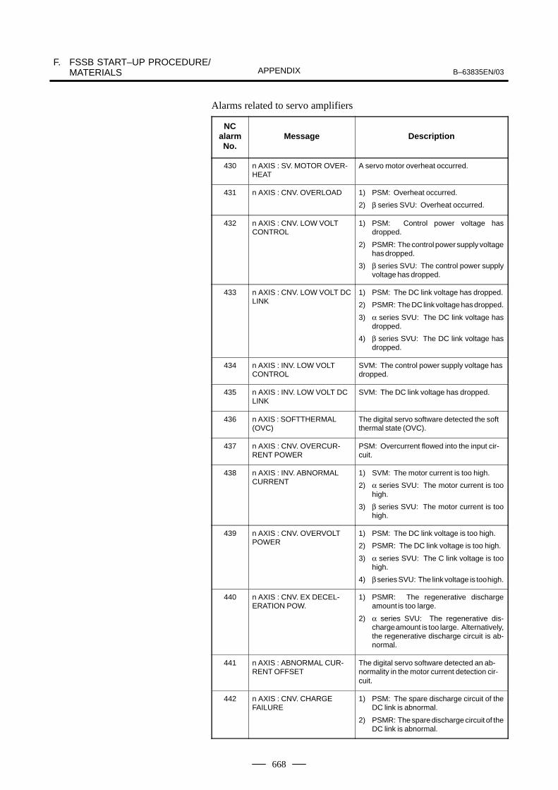
F. FSSB START–UP PROCEDURE/MATERIALS B–63835EN/03APPENDIX
668
Alarms related to servo amplifiers
NCalarmNo.
Message Description
430 n AXIS : SV. MOTOR OVER-HEAT
A servo motor overheat occurred.
431 n AXIS : CNV. OVERLOAD 1) PSM: Overheat occurred.
2) β series SVU: Overheat occurred.
432 n AXIS : CNV. LOW VOLTCONTROL
1) PSM: Control power voltage hasdropped.
2) PSMR: The control power supply voltagehas dropped.
3) β series SVU: The control power supplyvoltage has dropped.
433 n AXIS : CNV. LOW VOLT DCLINK
1) PSM: The DC link voltage has dropped.
2) PSMR: The DC link voltage has dropped.
3) α series SVU: The DC link voltage hasdropped.
4) β series SVU: The DC link voltage hasdropped.
434 n AXIS : INV. LOW VOLTCONTROL
SVM: The control power supply voltage hasdropped.
435 n AXIS : INV. LOW VOLT DCLINK
SVM: The DC link voltage has dropped.
436 n AXIS : SOFTTHERMAL(OVC)
The digital servo software detected the softthermal state (OVC).
437 n AXIS : CNV. OVERCUR-RENT POWER
PSM: Overcurrent flowed into the input cir-cuit.
438 n AXIS : INV. ABNORMALCURRENT
1) SVM: The motor current is too high.
2) α series SVU: The motor current is toohigh.
3) β series SVU: The motor current is toohigh.
439 n AXIS : CNV. OVERVOLTPOWER
1) PSM: The DC link voltage is too high.
2) PSMR: The DC link voltage is too high.
3) α series SVU: The C link voltage is toohigh.
4) β series SVU: The link voltage is too high.
440 n AXIS : CNV. EX DECEL-ERATION POW.
1) PSMR: The regenerative dischargeamount is too large.
2) α series SVU: The regenerative dis-charge amount is too large. Alternatively,the regenerative discharge circuit is ab-normal.
441 n AXIS : ABNORMAL CUR-RENT OFFSET
The digital servo software detected an ab-normality in the motor current detection cir-cuit.
442 n AXIS : CNV. CHARGEFAILURE
1) PSM: The spare discharge circuit of theDC link is abnormal.
2) PSMR: The spare discharge circuit of theDC link is abnormal.
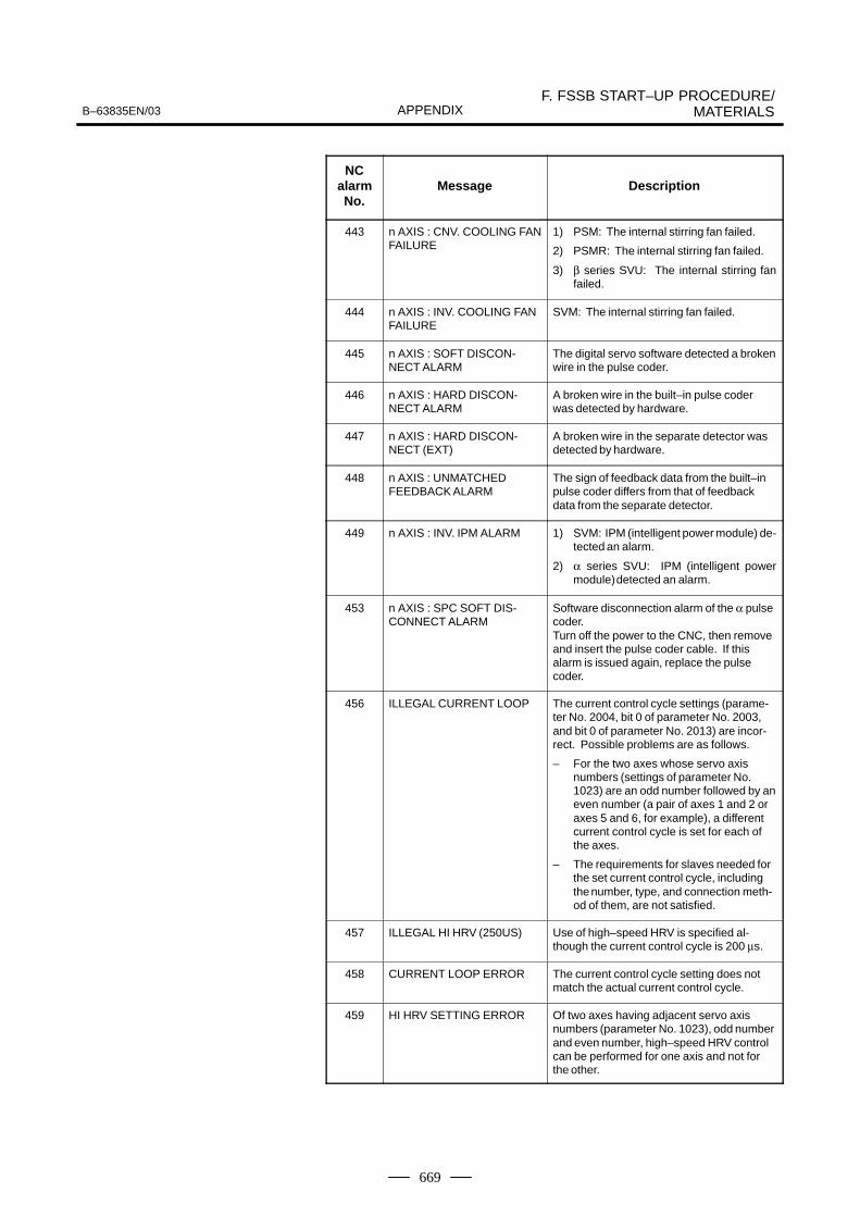
B–63835EN/03F. FSSB START–UP PROCEDURE/
MATERIALSAPPENDIX
669
NCalarmNo.
DescriptionMessage
443 n AXIS : CNV. COOLING FANFAILURE
1) PSM: The internal stirring fan failed.
2) PSMR: The internal stirring fan failed.
3) β series SVU: The internal stirring fanfailed.
444 n AXIS : INV. COOLING FANFAILURE
SVM: The internal stirring fan failed.
445 n AXIS : SOFT DISCON-NECT ALARM
The digital servo software detected a brokenwire in the pulse coder.
446 n AXIS : HARD DISCON-NECT ALARM
A broken wire in the built–in pulse coderwas detected by hardware.
447 n AXIS : HARD DISCON-NECT (EXT)
A broken wire in the separate detector wasdetected by hardware.
448 n AXIS : UNMATCHEDFEEDBACK ALARM
The sign of feedback data from the built–inpulse coder differs from that of feedbackdata from the separate detector.
449 n AXIS : INV. IPM ALARM 1) SVM: IPM (intelligent power module) de-tected an alarm.
2) α series SVU: IPM (intelligent powermodule) detected an alarm.
453 n AXIS : SPC SOFT DIS-CONNECT ALARM
Software disconnection alarm of the α pulsecoder.Turn off the power to the CNC, then removeand insert the pulse coder cable. If thisalarm is issued again, replace the pulsecoder.
456 ILLEGAL CURRENT LOOP The current control cycle settings (parame-ter No. 2004, bit 0 of parameter No. 2003,and bit 0 of parameter No. 2013) are incor-rect. Possible problems are as follows.
– For the two axes whose servo axisnumbers (settings of parameter No.1023) are an odd number followed by aneven number (a pair of axes 1 and 2 oraxes 5 and 6, for example), a differentcurrent control cycle is set for each ofthe axes.
– The requirements for slaves needed forthe set current control cycle, includingthe number, type, and connection meth-od of them, are not satisfied.
457 ILLEGAL HI HRV (250US) Use of high–speed HRV is specified al-though the current control cycle is 200 µs.
458 CURRENT LOOP ERROR The current control cycle setting does notmatch the actual current control cycle.
459 HI HRV SETTING ERROR Of two axes having adjacent servo axisnumbers (parameter No. 1023), odd numberand even number, high–speed HRV controlcan be performed for one axis and not forthe other.
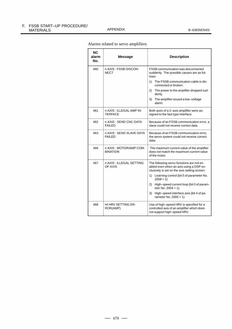
F. FSSB START–UP PROCEDURE/MATERIALS B–63835EN/03APPENDIX
670
Alarms related to servo amplifiers
NCalarmNo.
Message Description
460 n AXIS : FSSB DISCON-NECT
FSSB communication was disconnectedsuddenly. The possible causes are as fol-lows:
1) The FSSB communication cable is dis-connected or broken.
2) The power to the amplifier dropped sud-denly.
3) The amplifier issued a low–voltagealarm.
461 n AXIS : ILLEGAL AMP IN-TERFACE
Both axes of a 2–axis amplifier were as-signed to the fast type interface.
462 n AXIS : SEND CNC DATAFAILED
Because of an FSSB communication error, aslave could not receive correct data.
463 n AXIS : SEND SLAVE DATAFAILED
Because of an FSSB communication error,the servo system could not receive correctdata.
466 n AXIS : MOTOR/AMP COM-BINATION
The maximum current value of the amplifierdoes not match the maximum current valueof the motor.
467 n AXIS : ILLEGAL SETTINGOF AXIS
The following servo functions are not en-abled even when an axis using a DSP ex-clusively is set on the axis setting screen:
1) Learning control (bit 5 of parameter No.2008 = 1)
2) High–speed current loop (bit 0 of param-eter No. 2004 = 1)
3) High–speed interface axis (bit 4 of pa-rameter No. 2005 = 1)
468 HI HRV SETTING ER-ROR(AMP)
Use of high–speed HRV is specified for acontrolled axis of an amplifier which doesnot support high–speed HRV.
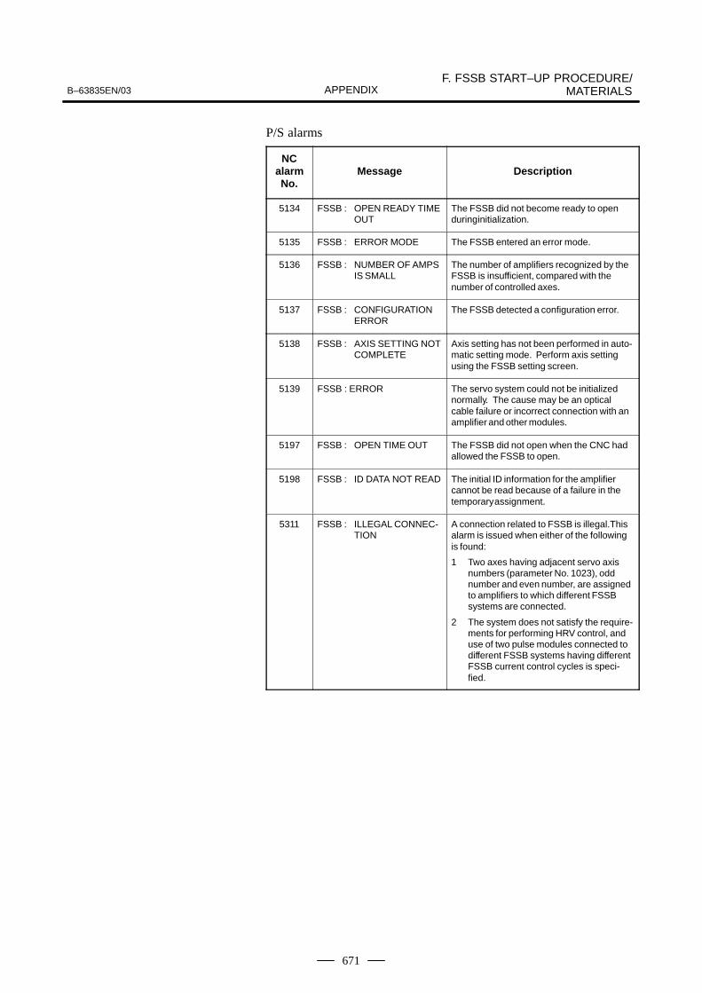
B–63835EN/03F. FSSB START–UP PROCEDURE/
MATERIALSAPPENDIX
671
P/S alarms
NCalarmNo.
Message Description
5134 FSSB : OPEN READY TIMEOUT
The FSSB did not become ready to openduring initialization.
5135 FSSB : ERROR MODE The FSSB entered an error mode.
5136 FSSB : NUMBER OF AMPSIS SMALL
The number of amplifiers recognized by theFSSB is insufficient, compared with thenumber of controlled axes.
5137 FSSB : CONFIGURATIONERROR
The FSSB detected a configuration error.
5138 FSSB : AXIS SETTING NOTCOMPLETE
Axis setting has not been performed in auto-matic setting mode. Perform axis settingusing the FSSB setting screen.
5139 FSSB : ERROR The servo system could not be initializednormally. The cause may be an opticalcable failure or incorrect connection with anamplifier and other modules.
5197 FSSB : OPEN TIME OUT The FSSB did not open when the CNC hadallowed the FSSB to open.
5198 FSSB : ID DATA NOT READ The initial ID information for the amplifiercannot be read because of a failure in thetemporary assignment.
5311 FSSB : ILLEGAL CONNEC-TION
A connection related to FSSB is illegal.Thisalarm is issued when either of the followingis found:
1 Two axes having adjacent servo axisnumbers (parameter No. 1023), oddnumber and even number, are assignedto amplifiers to which different FSSBsystems are connected.
2 The system does not satisfy the require-ments for performing HRV control, anduse of two pulse modules connected todifferent FSSB systems having differentFSSB current control cycles is speci-fied.

F. FSSB START–UP PROCEDURE/MATERIALS B–63835EN/03APPENDIX
672
� MDI input is abnormal (each time data is entered, the power needs tobe turned off).
First, disconnect the optical cable of the NC, then turn off then on thepower. Next, check the items below.
(A) Check parameter No. 1902.
Action: hen parameterNo. 1902 = 00000000, set the following:No. 1905 = 00000000Nos. 1910 through 1919 = 0
Action: hen parameter No. 1902 = 00000001 or 00000010, set the following:No. 1905 = Appropriate valueNos. 1910 through 1919 = Appropriate value
(B) When bit 1 of parameter No. 1815 = 1, check parameter Nos.1910 through 1919 to see if 16 or 48 is set.
Action: If neither 16 nor 48 is set, set bit 1 of No. 1815 to 1.
(C) Check if communication is open (the green LED is on).
Action: If communication is not open, check the power supplyfor the amplifier and optical cable connection.
� The separate detector can be recognized, but feedback pulses from theseparate detector are abnormal.
(A) Check parameter No. 1902.
Action: The setting of parameter No. 1902 = 00000000 is incorrect. When parameterNo. 1902 = 00000001, set the following:No. 1905 = 01000000 or 10000000Nos. 1910 through 1919 = Appropriate valueNos. 1936 and 1937 = Appropriate value
Action: When parameter No. 1902 = 00000010, set connectornumbers for M0 and M1 in axis setting on the FSSBscreen.
� In axis setting on the FSSB screen, connector numbers for M1 and M2cannot be set.
Action: Check the FSSB screen to see if separate detector interfaceunit IDs are read correctly. If pulse module IDs are not readcorrectly, check the separate detector interface unitconnections.
� The settings on the FSSB screen are canceled when the power is turnedoff then back on.
Action: After setting desired values, press soft key [SETING] on theamplifier setting screen and axis setting screen.
� P/S alarm 5138 “AXIS SETTING NOT COMPLETE” is issued.
Action: Automatic setting on the FSSB screen is not terminatednormally. Make settings correctly on the FSSB amplifiersetting screen and axis setting screen, and press soft key[SETING] on both screens. At this time, be sure to makesettings on the amplifier setting screen and the axis settingscreen in this order.
F.7ACTIONS FORTROUBLEENCOUNTERED ATSTART–UP TIME

B–63835EN/03F. FSSB START–UP PROCEDURE/
MATERIALSAPPENDIX
673
Action: When automatic setting on the FSSB screen is notperformed, set all of parameter Nos. 1902, 1905, 1910through 1919, 1936, and 1937 to 0 before starting manualsetting.
� The invalid amplifier/motor combination alarm (466) is issued.
Action: Check if the maximum current value of the amplifier read onthe ID screen matches the setting of parameter No. 2165.Recheck the amplifier/motor combination.
Action: Initialize the servo parameters of each axis.
� When the power is turned off then back on after modifying parameterNo. 1902, the system alarm (920) is issued.
Action: Disconnect the optical cable of the CNC, then turn off thenon the power.Set all of parameter Nos. 1902, 1905, 1910 through 1919,1936, and 1937 to 0, then turn off then on the power, thenmake an FSSB setting all over again.

F. FSSB START–UP PROCEDURE/MATERIALS B–63835EN/03APPENDIX
674
The FSSB setting screen displays FSSB–based amplifier and axisinformation, and allows amplifier and axis information to be set.
1 Press function key SYSTEM .
2 Pressing the continuous menu key several times displays[FSSB].
3 Pressing soft key [FSSB] switches the screen display to the amplifiersetting screen (or the FSSB setting screen selected previously), anddisplays the following soft keys:
[ AMP ][ AXIS ][ MAINT ][ ][ (OPRT) ]
There are three types of FSSB setting screens: the amplifier setting screen,axis setting screen, and amplifier maintenance screen.
Pressing soft key [AMP] switches the screen display to the amplifiersetting screen.Pressing soft key [AXIS] switches the screen display to the axis settingscreen.Pressing soft key [MAINT] switches the screen display to theamplifier maintenance screen.
The amplifier setting screen displays slave information divided intoamplifier information and separate detector interface unit information.
(AMPLIFIER SETTING) O1000 N00001 NO.
1 A1–L α SVM–HV 40AL 1 X2 A1–M α SVM 12A 2 Y3 A2–L β SVM 40A 3 Z4 A3–L α SVM 20A 4 A5 A3–M α SVM 40A 5 B7 A4–L α SVU 240A 6 C
NO. PCB ID6 M1 A 0000 DETECTOR(8AXES)8 M2 B 12AB
>_MDI **** *** *** 13:11:56[ AMP ][ AXIS ][ MAINT ][ ][ (OPRT) ]
The amplifier setting screen displays the items below.� NO.: Slave number
The serial numbers for to up to ten slaves (up to eight amplifiers andup to two pulse modules) connected via the FSSB are displayedsequentially. A younger number is assigned to a slave closer to theCNC.
� AMP: Amplifier typeAmplifier type information starts with the character A, which standsfor “amplifier.” The character A is followed by the ordinal number ofan amplifier counted from the amplifier closest to the CNC, then isfollowed by a letter indicating which axis of the amplifier is used (Lfor the first axis, and M for the second axis).
F.8FSSB DATA DISPLAY
F.8.1Amplifier SettingScreen
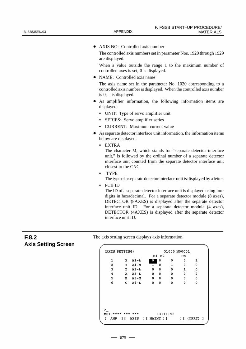
B–63835EN/03F. FSSB START–UP PROCEDURE/
MATERIALSAPPENDIX
675
� AXIS NO: Controlled axis number
The controlled axis numbers set in parameter Nos. 1920 through 1929are displayed.
When a value outside the range 1 to the maximum number ofcontrolled axes is set, 0 is displayed.
� NAME: Controlled axis name
The axis name set in the parameter No. 1020 corresponding to acontrolled axis number is displayed. When the controlled axis numberis 0, – is displayed.
� As amplifier information, the following information items aredisplayed:
� UNIT: Type of servo amplifier unit
� SERIES: Servo amplifier series
� CURRENT: Maximum current value
� As separate detector interface unit information, the information itemsbelow are displayed.
� EXTRAThe character M, which stands for “separate detector interfaceunit,” is followed by the ordinal number of a separate detectorinterface unit counted from the separate detector interface unitclosest to the CNC.
� TYPEThe type of a separate detector interface unit is displayed by a letter.
� PCB IDThe ID of a separate detector interface unit is displayed using fourdigits in hexadecimal. For a separate detector module (8 axes),DETECTOR (8AXES) is displayed after the separate detectorinterface unit ID. For a separate detector module (4 axes),DETECTOR (4AXES) is displayed after the separate detectorinterface unit ID.
The axis setting screen displays axis information.
(AXIS SETTING) O1000 N00001M1 M2 Cs
1 X A1–L 0 0 0 0 12 Y A1–M 1 0 1 0 03 Z A2–L 0 0 0 1 04 A A3–L 0 0 0 0 25 B A3–M 0 0 0 0 06 C A4–L 0 0 0 0 0
>_MDI **** *** *** 13:11:56[ AMP ][ AXIS ][ MAINT ][ ][ (OPRT) ]
F.8.2Axis Setting Screen
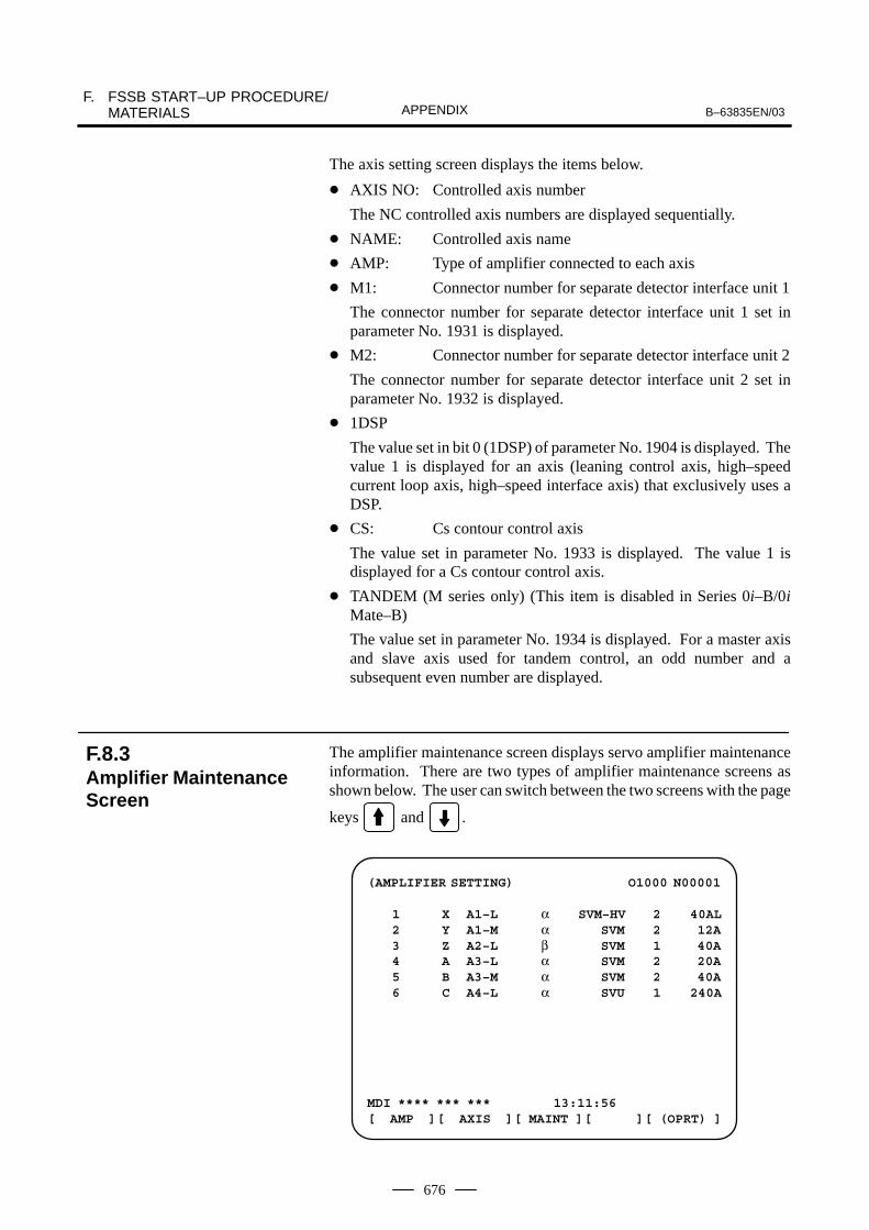
F. FSSB START–UP PROCEDURE/MATERIALS B–63835EN/03APPENDIX
676
The axis setting screen displays the items below.
� AXIS NO: Controlled axis number
The NC controlled axis numbers are displayed sequentially.
� NAME: Controlled axis name
� AMP: Type of amplifier connected to each axis
� M1: Connector number for separate detector interface unit 1
The connector number for separate detector interface unit 1 set inparameter No. 1931 is displayed.
� M2: Connector number for separate detector interface unit 2
The connector number for separate detector interface unit 2 set inparameter No. 1932 is displayed.
� 1DSP
The value set in bit 0 (1DSP) of parameter No. 1904 is displayed. Thevalue 1 is displayed for an axis (leaning control axis, high–speedcurrent loop axis, high–speed interface axis) that exclusively uses aDSP.
� CS: Cs contour control axis
The value set in parameter No. 1933 is displayed. The value 1 isdisplayed for a Cs contour control axis.
� TANDEM (M series only) (This item is disabled in Series 0i–B/0iMate–B)
The value set in parameter No. 1934 is displayed. For a master axisand slave axis used for tandem control, an odd number and asubsequent even number are displayed.
The amplifier maintenance screen displays servo amplifier maintenanceinformation. There are two types of amplifier maintenance screens asshown below. The user can switch between the two screens with the page
keys and .
(AMPLIFIER SETTING) O1000 N00001
1 X A1–L α SVM–HV 2 40AL2 Y A1–M α SVM 2 12A3 Z A2–L β SVM 1 40A4 A A3–L α SVM 2 20A5 B A3–M α SVM 2 40A6 C A4–L α SVU 1 240A
MDI **** *** *** 13:11:56[ AMP ][ AXIS ][ MAINT ][ ][ (OPRT) ]
F.8.3Amplifier MaintenanceScreen

B–63835EN/03F. FSSB START–UP PROCEDURE/
MATERIALSAPPENDIX
677
(AMPLIFIER MAINTENANCE) O1000 N00001NO.
1 X 01A 020123 012 Y 01A 020123 013 Z 01A 020123 014 A 02B 020123 015 B 02B 020123 016 C 02B 020123 01
MDI **** *** *** 13:11:56[ AMP ][ AXIS ][ MAINT ][ ][ (OPRT) ]
The amplifier maintenance screens display the following items:
� AXIS NO: Controlled axis number
� NAME: Controlled axis name
� AMP: Type of an amplifier connected to each axis
� SERIES: Series of a servo amplifier connected to each axis
� UNIT: Unit type of a servo amplifier connected to eachaxis
� NO. OF AXES: Maximum number of axes of an amplifierconnected to each axis
� CURRENT: Maximum current value of an amplifier connectedto each axis
� VERSION: Version of an amplifier unit connected to each axis
� TEST: Test date of an amplifier connected to each axis
Example) 010123: January 23, 2002
� MAINTENANCE:Engineering change drawing number of anamplifier connected to each axis

G. NOTATION OF MDI KEYS B–63835EN/03APPENDIX
678
G�������� �� ��� ��
i series CNC have two types of MDI keypads : English type and Symbolic type.The table below shows correspondence between English keys and Symbolic keys.This manual uses English type in the text.Therefore when a user uses Symbolic type MDI keypads and encounters an English key in the text, please referto the correspondence table shown below.
Name English key Symbolic key
CANCEL key CAN
POSITION key POS
PROGRAM key PROG
OFFSET/SETTING key SETTING
OFFSET
CUSTOM key CUSTOM
SYSTEM key SYSTEM
MESSAGE key MESSAGE
GRAPH key GRAPH
SHIFT key SHIFT
INPUT key INPUT

B–63835EN/03 G. NOTATION OF MDI KEYSAPPENDIX
679
Name Symbolic keyEnglish key
ALTER key ALTER
INSERT key INSERT
DELETE key DELETE
PAGE UP keyPAGE
PAGE DOWN key PAGE
HELP key HELP
RESET key RESET
CUSTOM/GRAPH key CUSTOM
GRAPH


IndexB–63835EN/03
i–1
[Symbols][Sample Setting 1] General Configuration (Semi–
Closed Loop), 655
[Sample Setting 2] General Configuration (ClosedLoop), 656
[Sample Setting 3] When the C–Axis is a Cs Axis,658
αi Servo Information Screen, 415
αi Servo Warning Interface, 413
αi Spindle Information Screen, 434
[A]AC Spindle (Analog Interface), 438
AC Spindle (Serial Interface), 419, 420
Action Against Noise, 219
Actions for Trouble Encountered at Start–Up Time,672
Address, 282
Adjusting Reference Position (DOG Method), 408
Alarm 300 (Request for Reference Position Return),485
Alarm 401 (V Ready Off), 486
Alarm 404 (V Ready On), 488
Alarm 417 (Digital Servo System is Abnormal), 491
Alarm 462 (Send CNC Data Failed), 490
Alarm 463 (Send Slave Data Failed), 490
Alarm 5134 (FSSB: Open Ready Time Out), 498
Alarm 5135 (FSSB: Error Mode), 498
Alarm 5136 (FSSB: Number of Amps is Small), 500
Alarm 5137 (FSSB: Configuration Error), 498
Alarm 5197 (FSSB: Open Time Out), 498
Alarm 5198 (FSSB: ID Data Not Read), 498
Alarm 700 (Overheat: Control Unit), 492
Alarm 701 (Overheat: Fan Motor), 493
Alarm 704 (Spindle Speed Fluctuation DetectionAlarm), 494
Alarm 749 (Serial Spindle Communication Error), 495
Alarm 750 (Spindle Serial Link Startup Failure), 496
Alarm 85 to 87 (Reader/Puncher Interface Alarm),479
Alarm 90 (Reference Position Return is Abnormal),483
Alarm 900 (ROM Parity), 501
Alarm 920 (Servo Alarms), 503
Alarm 926 (FSSB Alarm), 504
Alarm 930 (CPU Interrupt), 508
Alarm 935 (SRAM ECC Error), 509
Alarm 950 (PMC System Alarm), 511
Alarm 951 (PMC Watchdog Alarm), 514
Alarm 972 (NMI Alarm on an Option Board) (Series0i–B Only), 515
Alarm 973 (NMI Alarm with an Unknown Cause),516
Alarm 974 (F–BUS Error), 517
Alarm 975 (BUS Error), 518
Alarm 976 (Local BUS Error), 519
Alarm display, 28
Alarm History Screen, 28
Alarm List, 529
Alarm List (Serial Spindle), 592
Alarm screen, 324
Alarm screen (ALARM), 299
Alarms, 667
Alarms 912 to 919 (Dram Parity), 502
Amplifier Maintenance Screen, 676
Amplifier Setting Screen, 674
Associated Parameters, 412
Automatic Operation Cannot be Done, 461
Automatic Setting, 653
Automatic Setting of Standard Parameters, 431
Axis Setting Screen, 675
[B]Basic Units, 175
Batteries for CNC Display Unit with PC Functions(3VDC), 201
Battery for Absolute Pulse Coder Built into the Motor(6VDC), 203
Battery for Memory Backup (3VDC), 197
Battery for Separate Absolute Pulse Coders (6VDC),202
Block diagram, 439
Boot Screen, 640
Boot System, 607
Built–in I/O Board, 158
[C]Cable Clamp and Shield Processing, 227
Calculation of S analog voltage and related parame-ters, 440
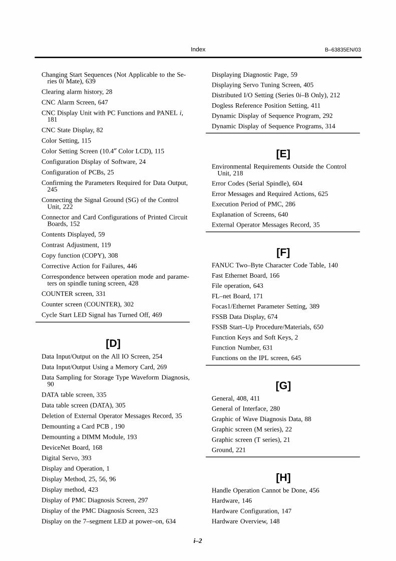
Index B–63835EN/03
i–2
Changing Start Sequences (Not Applicable to the Se-ries 0i Mate), 639
Clearing alarm history, 28
CNC Alarm Screen, 647
CNC Display Unit with PC Functions and PANEL i,181
CNC State Display, 82
Color Setting, 115
Color Setting Screen (10.4″ Color LCD), 115
Configuration Display of Software, 24
Configuration of PCBs, 25
Confirming the Parameters Required for Data Output,245
Connecting the Signal Ground (SG) of the ControlUnit, 222
Connector and Card Configurations of Printed CircuitBoards, 152
Contents Displayed, 59
Contrast Adjustment, 119
Copy function (COPY), 308
Corrective Action for Failures, 446
Correspondence between operation mode and parame-ters on spindle tuning screen, 428
COUNTER screen, 331
Counter screen (COUNTER), 302
Cycle Start LED Signal has Turned Off, 469
[D]Data Input/Output on the All IO Screen, 254
Data Input/Output Using a Memory Card, 269
Data Sampling for Storage Type Waveform Diagnosis,90
DATA table screen, 335
Data table screen (DATA), 305
Deletion of External Operator Messages Record, 35
Demounting a Card PCB , 190
Demounting a DIMM Module, 193
DeviceNet Board, 168
Digital Servo, 393
Display and Operation, 1
Display Method, 25, 56, 96
Display method, 423
Display of PMC Diagnosis Screen, 297
Display of the PMC Diagnosis Screen, 323
Display on the 7–segment LED at power–on, 634
Displaying Diagnostic Page, 59
Displaying Servo Tuning Screen, 405
Distributed I/O Setting (Series 0i–B Only), 212
Dogless Reference Position Setting, 411
Dynamic Display of Sequence Program, 292
Dynamic Display of Sequence Programs, 314
[E]Environmental Requirements Outside the Control
Unit, 218
Error Codes (Serial Spindle), 604
Error Messages and Required Actions, 625
Execution Period of PMC, 286
Explanation of Screens, 640
External Operator Messages Record, 35
[F]FANUC Two–Byte Character Code Table, 140
Fast Ethernet Board, 166
File operation, 643
FL–net Board, 171
Focas1/Ethernet Parameter Setting, 389
FSSB Data Display, 674
FSSB Start–Up Procedure/Materials, 650
Function Keys and Soft Keys, 2
Function Number, 631
Functions on the IPL screen, 645
[G]General, 408, 411
General of Interface, 280
Graphic of Wave Diagnosis Data, 88
Graphic screen (M series), 22
Graphic screen (T series), 21
Ground, 221
[H]Handle Operation Cannot be Done, 456
Hardware, 146
Hardware Configuration, 147
Hardware Overview, 148
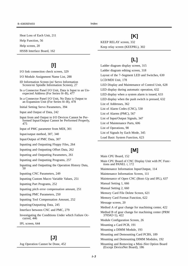
B–63835EN/03 Index
i–3
Heat Loss of Each Unit, 211
Help Function, 56
Help screen, 20
HSSB Interface Board, 162
[I]I/O link connection check screen, 329
I/O Module Assignment Name List, 288
ID Information Screen (αi Servo InformationScreen/αi Spindle Information Screen), 27
In a Connector Panel I/O Unit, Data is Input to an Un-expected Address (For Series 0i–B), 477
In a Connector Panel I/O Unit, No Data is Output toan Expansion Unit (For Series 0i–B), 478
Initial Setting Servo Parameters, 394
Input and Output of Data, 242
Input from and Output to I/O Devices Cannot be Per-formed Input/Output Cannot be Performed Properly,475
Input of PMC parameter from MDI, 301
Input/output method, 307, 340
Input/Output of PMC Data, 307
Inputting and Outputting Floppy Files, 264
Inputting and Outputting Offset Data, 262
Inputting and Outputting Parameters, 261
Inputting and Outputting Programs, 257
Inputting and Outputting the Operation History Data,50
Inputting CNC Parameters, 249
Inputting Custom Macro Variable Values, 251
Inputting Part Programs, 252
Inputting pitch error compensation amount, 251
Inputting PMC Parameters, 250
Inputting Tool Compensation Amount, 252
Inputting/Outputting Data, 245
Interface between CNC and PMC, 279
Investigating the Conditions Under which Failure Oc-curred, 446
IPL screen, 644
[J]Jog Operation Cannot be Done, 452
[K]KEEP RELAY screen, 332
Keep relay screen (KEEPRL), 302
[L]Ladder diagram display screen, 315
Ladder diagram editing screen, 318
Layout of the 7–Segment LED and Switches, 630
LCD/MDI Unit, 178
LED Display and Maintenance of Control Unit, 628
LED display during automatic operation, 632
LED display when a system alarm is issued, 633
LED display when the push switch is pressed, 632
List of Addresses, 362
List of Alarm Codes (CNC), 530
List of Alarms (PMC), 567
List of Input/Output Signals, 347
List of Maintenance Parts, 606
List of Operations, 98
List of Signals by Each Mode, 345
Load Basic System Function, 623
[M]Main CPU Board, 152
Main CPU Board of CNC Display Unit with PC Func-tions and PANEL i, 172
Maintenance Information Input/Output, 114
Maintenance Information Screen, 111
Maintenance of Open CNC (Boot–Up and IPL), 637
Manual Setting 1, 666
Manual Setting 2, 660
Memory Card File Delete Screen, 621
Memory Card Format Function, 622
Message screen, 20
Method A of gear change for machining center, 422
Method B of gear change for machining center (PRM3705#2=1), 422
Module Configuration Screen, 26
Mounting a Card PCB, 191
Mounting a DIMM Module, 193
Mounting and Demounting Card PCBS, 189
Mounting and Demounting DIMM Modules, 192
Mounting and Removing a Mini–Slot Option Board(Except DeviceNet Board), 186

Index B–63835EN/03
i–4
Mounting and Removing an Option Board, 184
Mounting and Removing the Back Panel, 194
Mounting and Removing the DeviceNet Board, 187
Mounting and Removing the Main CPU Board and aFull–Size Option Board, 184
Mounting the Back Panel, 194
Mounting the board, 185, 186, 187
[N]NC status display, 632
Net editing screen, 320
No Manual Operation Nor Automatic Operation Canbe Executed, 448
Noise Suppressor, 226
Notation of MDI Keys, 678
Notes, 36, 55, 95, 118, 129
Nothing is Displayed on the Screen when the Power isTurned On, 471
[O]Offset/setting screen (M series), 15
Offset/setting screen (T series), 13
Online Monitor Setting Screen, 310, 343
Operating Monitor, 96
Operation, 411, 631
Operation Before Power–On, 631
Operation History, 37
Operation of Each Function, 635
Option Setting Screen, 649
Other Screens, 647
Other Units, 180
Outline of Spindle Control, 420, 438
Outputting CNC Parameters, 246
Outputting Custom Macro Common Variables, 263
Outputting Custom Macro Variable Values, 248
Outputting Part Program, 248
Outputting Pitch Error Compensation Amount, 247
Outputting PMC Parameters, 247
Outputting Tool Compensation Amount, 248
Outputting Waveform Diagnosis Data (Storage Type),92
Overview, 130
[P]Parameter, 34, 36, 120
Parameter Input/Output, 127
Parameter input/output method, 329
Parameter Setting, 37, 405
Parameters, 97, 117
Periodic Maintenance Screens, 130
PMC Data Input/Output, 339
PMC Menu Selection Procedure Using Soft Keys,291, 313
PMC Parameter, 301
PMC Parameters, 329
PMC Screen (PMC–SA1), 291
PMC Screen (PMC–SB7), 313
Position screen, 3
Power Mate CNC Manager, 120
Printed Circuit Boards of Control Unit, 175
PROFIBUS Master Board, 169
PROFIBUS Slave Board, 170
Program screen, 4, 6, 8, 9, 10, 11
[R]Registered Data Input/Output, 138
Removing the board, 184, 186, 187
Removing the Panel, 194
Replacing a Fan Unit, 204
Replacing Fuses on Various Units, 215
Replacing the Battery, 197, 230
Replacing the Fan, 233
Replacing the Fuse, 232
Replacing the Fuse of the Control Unit, 196
Replacing the Fuse of the LCD Unit, 205
Replacing the LCD Back–Light, 236
Replacing the LCD Backlight, 206
Replacing the Maintenance Parts of CNC DisplayUnit for PC Functions and PANEL i, 230
Replacing the Touch Panel Protection Sheet, 237
[S]Screen Configuration and Operating Procedure, 610
Screen Display, 35, 42, 115, 121
Screen display, 28
Screen Display and Operation, 111

B–63835EN/03 Index
i–5
Screen Display and Setting, 130
Screen Displayed Immediately After Power is TurnedOn, 23
Selection monitor screen, 317
Separating Signal Lines, 219
Serial Communication Board, 161
Servo Alarms, 520
Servo Tuning Screen, 405
Setting Input/Output–Related Parameters, 255
Setting Module Screen, 24
Setting Parameters, 84
Setting Parameters for Input/Output, 243
Setting screen, 306
Setting Screen Display and Setting, 136
Setting screens, 336
Setting the Input Signal or Output Signal to be Re-corded in the Operation History, 46
Seven–Segment LED Display, 632
Slave, 652
Slot Status Display, 23
Soft key transition triggered by the function key
GRAPH , 21, 22
Soft key transition triggered by the function key
HELP , 20
Soft key transition triggered by the function key
MESSAGE , 20
Soft key transition triggered by the function keyOFFSETSETTING , 13, 15
Soft key transition triggered by the function key
POS , 3
Soft key transition triggered by the function key
PROG (When the soft key [BG–EDT] is pressed in
all modes), 11
Soft key transition triggered by the function key
PROG in the EDIT mode, 6
Soft key transition triggered by the function key
PROG in the HNDL, JOG, or REF mode, 9
Soft key transition triggered by the function key
PROG in the MDI mode, 8
Soft key transition triggered by the function key
PROG in the MEM mode, 4
Soft key transition triggered by the function key
PROG in the TJOG or THDL mode, 10
Soft key transition triggered by the function key
SYSTEM , 17
Soft Keys, 2
Software Configuration Screen, 26
SPC Alarms, 524
Specification, 281
Specification of PMC, 281
Spindle Alarms, 525
Spindle monitor screen, 426
Spindle Setting and Tuning Screen, 423
Spindle setting screen, 423
Spindle tuning screen, 424
SRAM Data Backup Screen, 618
SRAM operation, 642
Start of the built–in type PMC programmer, 307
Starting the Boot System, 608
Starting the built–in programmer, 339
Status Screen, 648
Status screen, 324
Status screen (STATUS), 298
Status Screen Display and Setting, 131
System Alarm History, 29
System alarm history screen (detail screen), 31
System alarm history screen (history list screen), 29
System Configuration Screen, 25
System Data Check Screen, 613
System Data Delete Screen, 615
System Data Loading Screen, 611
System data manipulation, 641
System Data Save Screen, 616
System Files and User Files, 609
System Parameters, 309, 341
System Reserve Area of Internal Relay, 283
System screen, 17
[T]T series, 422
The Display on the LCD Unit Flashes, 474
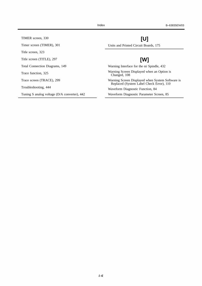
Index B–63835EN/03
i–6
TIMER screen, 330
Timer screen (TIMER), 301
Title screen, 323
Title screen (TITLE), 297
Total Connection Diagrams, 149
Trace function, 325
Trace screen (TRACE), 299
Troubleshooting, 444
Tuning S analog voltage (D/A converter), 442
[U]Units and Printed Circuit Boards, 175
[W]Warning Interface for the αi Spindle, 432
Warning Screen Displayed when an Option isChanged, 108
Warning Screen Displayed when System Software isReplaced (System Label Check Error), 110
Waveform Diagnostic Function, 84
Waveform Diagnostic Parameter Screen, 85

Rev
isio
n R
eco
rd
FAN
UC��������
i��� ���
i������ �
MA
INT
EN
AN
CE
MA
NU
AL
(B
–638
35E
N)
03Ju
n., 2
003
�A
dditi
on o
f ala
rms
for
Ser
ies
0i–P
B
02A
pr.,
2003
�C
orre
ctio
n of
err
ors
01S
ep.,
2002
Edi
tion
Dat
eC
onte
nts
Edi
tion
Dat
eC
onte
nts

• No part of this manual may bereproduced in any form.
• All specifications and designsare subject to change withoutnotice.


![Fanuc 0i Installation, Spanish (MAN-0164 a)[1]](https://static.documents.pub/doc/80x56/563db9e1550346aa9aa0c4e0/fanuc-0i-installation-spanish-man-0164-a1.jpg)


