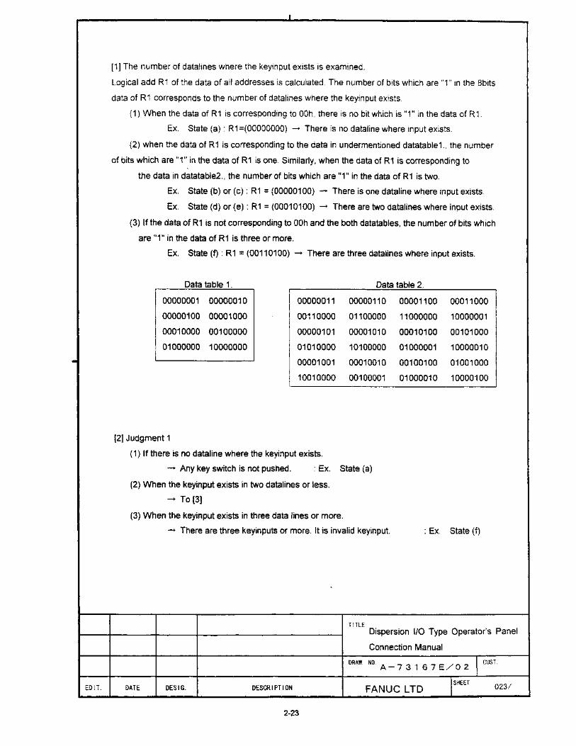
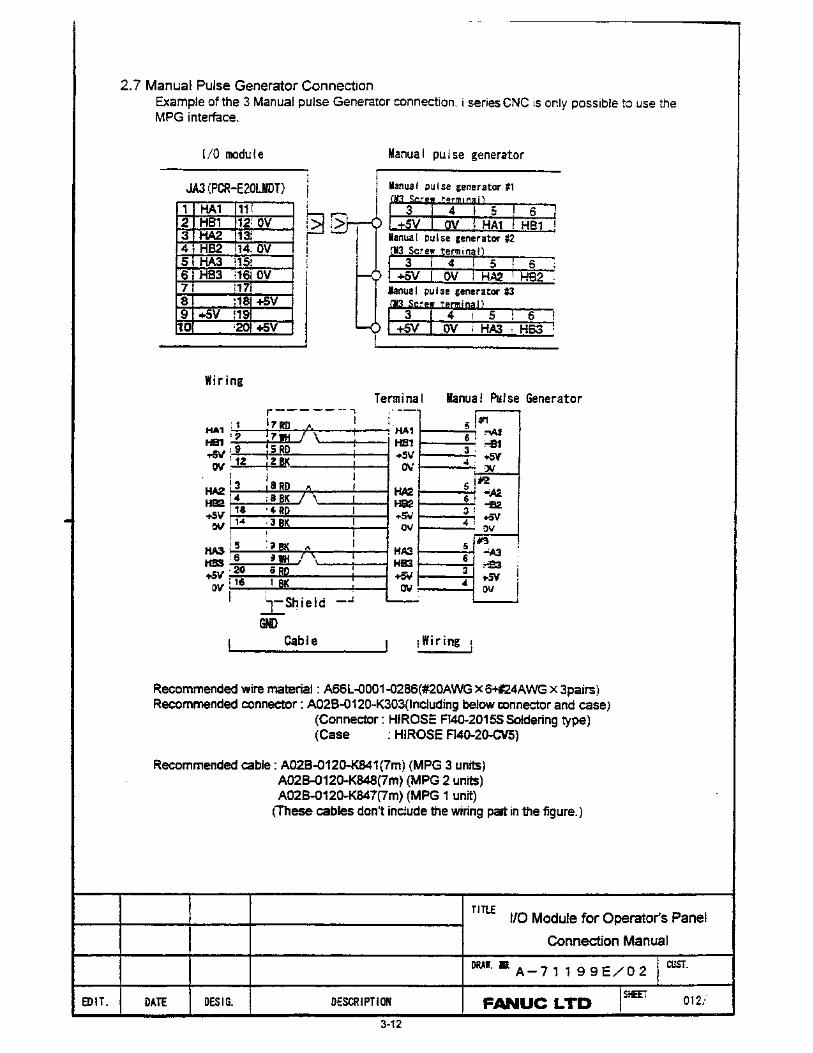
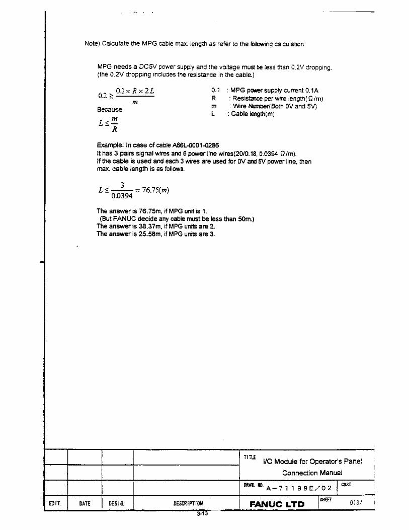
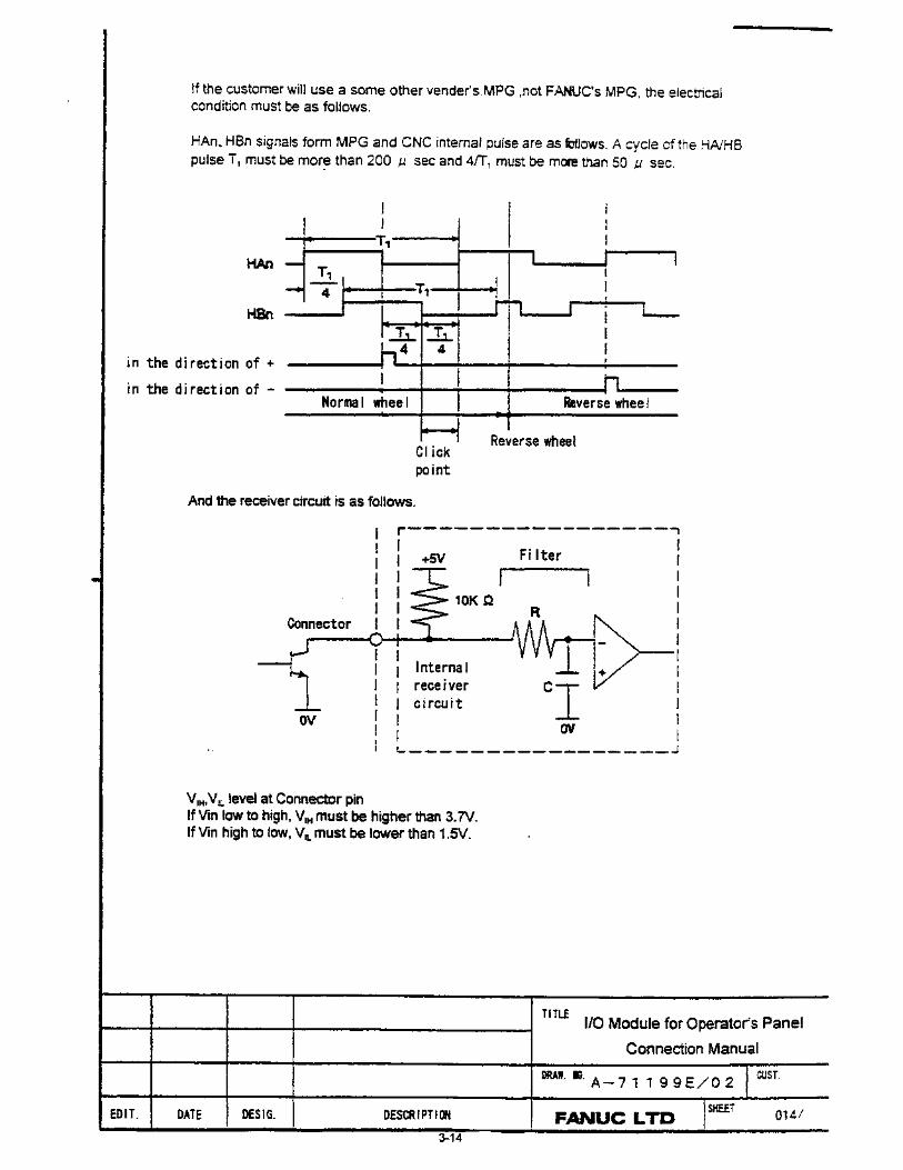
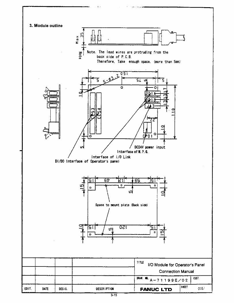
118
GE Fanuc Automation Computer Numerical Control Products Operator Panels for i Series Controls User's Manual GFK-1478E August 2004
GE Fanuc Automation
Computer Numerical Control Products Operator Panels for i Series Controls User's Manual GFK-1478E August 2004
GFL-001
Warnings, Cautions, and Notesas Used in this Publication
Warning
Warning notices are used in this publication to emphasize that hazardous voltages, currents,temperatures, or other conditions that could cause personal injury exist in this equipment ormay be associated with its use.
In situations where inattention could cause either personal injury or damage to equipment, aWarning notice is used.
Caution
Caution notices are used where equipment might be damaged if care is not taken.
NoteNotes merely call attention to information that is especially significant to understanding andoperating the equipment.
This document is based on information available at the time of its publication. While effortshave been made to be accurate, the information contained herein does not purport to cover alldetails or variations in hardware or software, nor to provide for every possible contingency inconnection with installation, operation, or maintenance. Features may be described hereinwhich are not present in all hardware and software systems. GE Fanuc Automation assumesno obligation of notice to holders of this document with respect to changes subsequently made.
GE Fanuc Automation makes no representation or warranty, expressed, implied, or statutorywith respect to, and assumes no responsibility for the accuracy, completeness, sufficiency, orusefulness of the information contained herein. No warranties of merchantability or fitness forpurpose shall apply.
©Copyright 2004 GE Fanuc Automation North America, Inc.
All Rights Reserved.
Preface
GFK-1478E iii
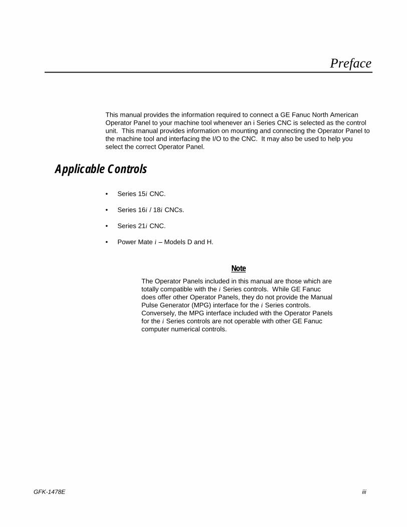
This manual provides the information required to connect a GE Fanuc North American Operator Panel to your machine tool whenever an i Series CNC is selected as the control unit. This manual provides information on mounting and connecting the Operator Panel to the machine tool and interfacing the I/O to the CNC. It may also be used to help you select the correct Operator Panel.
Applicable Controls
• Series 15i CNC.
• Series 16i / 18i CNCs.
• Series 21i CNC.
• Power Mate i – Models D and H.
Note The Operator Panels included in this manual are those which are totally compatible with the i Series controls. While GE Fanuc does offer other Operator Panels, they do not provide the Manual Pulse Generator (MPG) interface for the i Series controls. Conversely, the MPG interface included with the Operator Panels for the i Series controls are not operable with other GE Fanuc computer numerical controls.

Preface
iv Operator Panels for i Series Controls User's Manual – August 2004 GFK-1478E
Operator Panels The following Operator Panels are available. All units communicate with i Series CNCs via the I/O Link communication bus.
North American Operator Panel
• 520mm x 180mm x 90mm (or 50mm if the Connection Unit is not mounted).
• 400mm x 180mm x 90mm (or 50mm if the Connection Unit is not mounted).
Features
Features of the North American Operator Panel include:
• UL listed.
• Convenient Control ON / OFF pushbuttons, which may be used to cycle 24VDC power to the CNC and other elements of the machine tool.
• Bracket for mounting the Connection Unit A20B-2002-0470 (supports up to three MPGs).
• Optional 1 meter signal cable set for alternative mounting of the Connection Unit.
• Lighted pushbuttons with user-definable lens cap inserts.
• Choice of high-intensity LED or incandescent lamp for backlight.
• Optional configurations such as addition of MPG (see page 1-1)
Specification Part Numbers
See List of Covered Products on Page 1-1
Preface
GFK-1478E Preface v
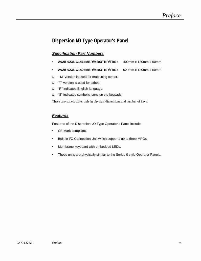
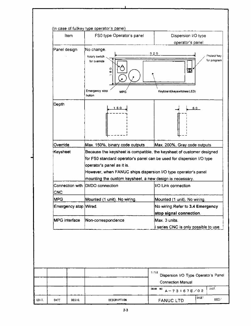
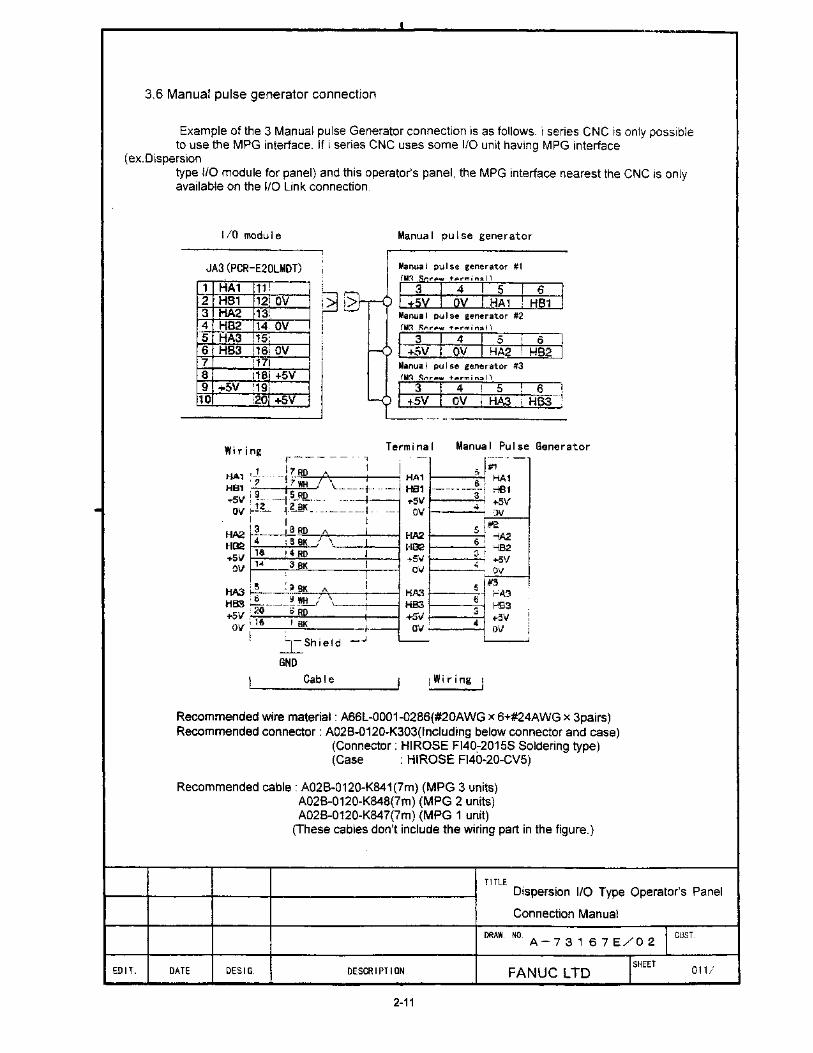
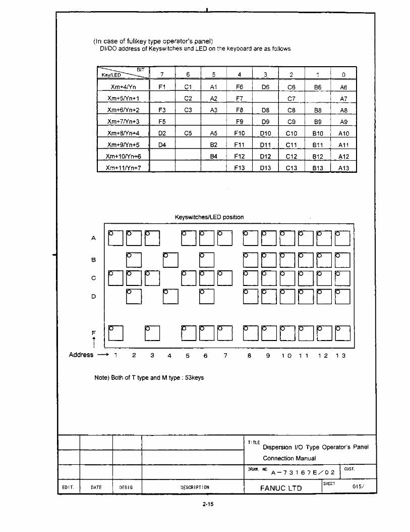
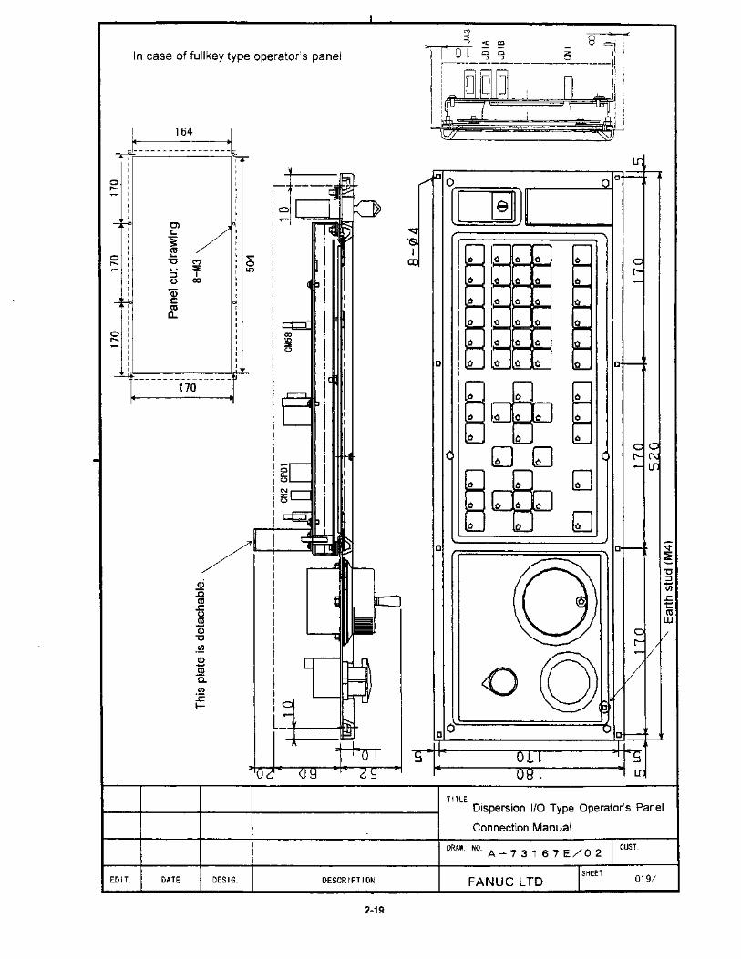
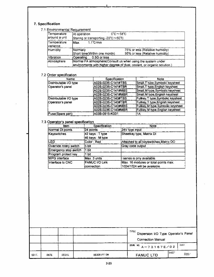
Dispersion I/O Type Operator’s Panel
Specification Part Numbers
• A02B-0236-C141#MBR/MBS/TBR/TBS : 400mm x 180mm x 60mm.
• A02B-0236-C140#MBR/MBS/TBR/TBS : 520mm x 180mm x 60mm.
� “M” version is used for machining center.
� “T” version is used for lathes.
� “R” indicates English language.
� “S” indicates symbolic icons on the keypads.
These two panels differ only in physical dimensions and number of keys.
Features
Features of the Dispersion I/O Type Operator’s Panel include :
• CE Mark compliant.
• Built-in I/O Connection Unit which supports up to three MPGs.
• Membrane keyboard with embedded LEDs.
• These units are physically similar to the Series 0 style Operator Panels.
Preface
vi Operator Panels for i Series Controls User's Manual – August 2004 GFK-1478E
If you decide to interface your own Operator Panel to an i Series Control, you will probably need to use one of the Connection Units listed below. If you do not use either of the first two units, you will need to interface the MPG via an approved method. For more information, refer to the appropriate Hardware Connection Manual for your control.
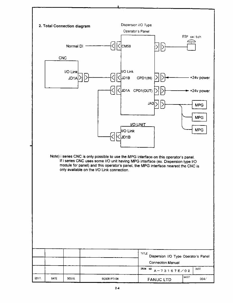
Connection Units The following Connection Units are available for the i Series CNCs. All units communicate with the i Series CNC via the I/O Link communication bus. (Refer to the appropriate Hardware Connection Manual for details.) Note that the MPG interface is operational only with i Series CNCs.
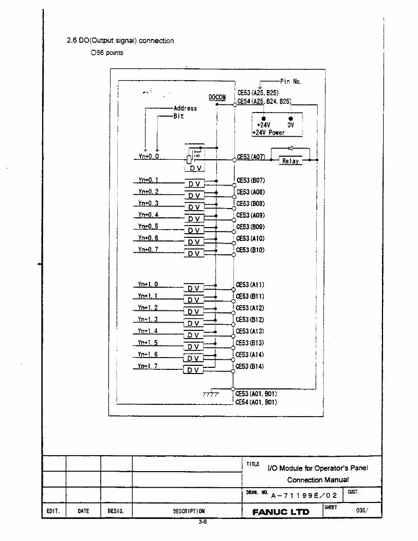
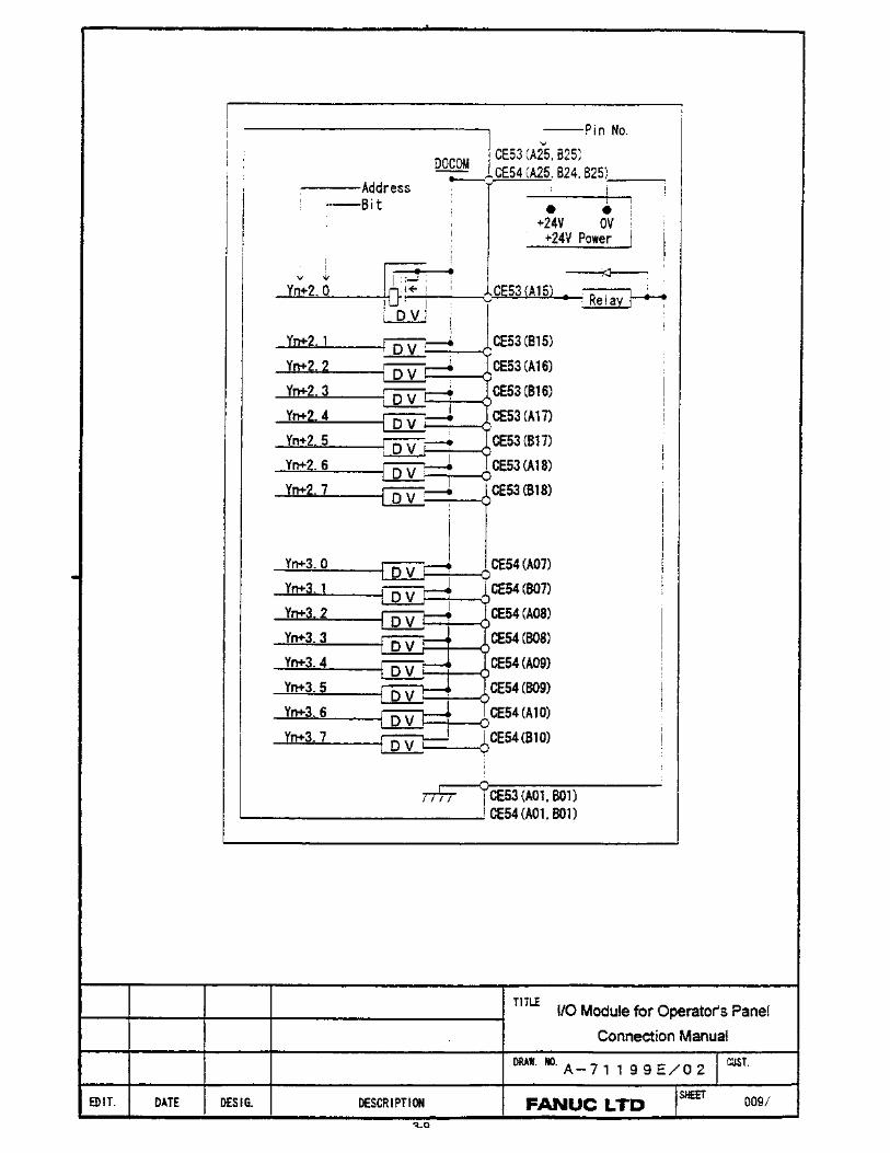
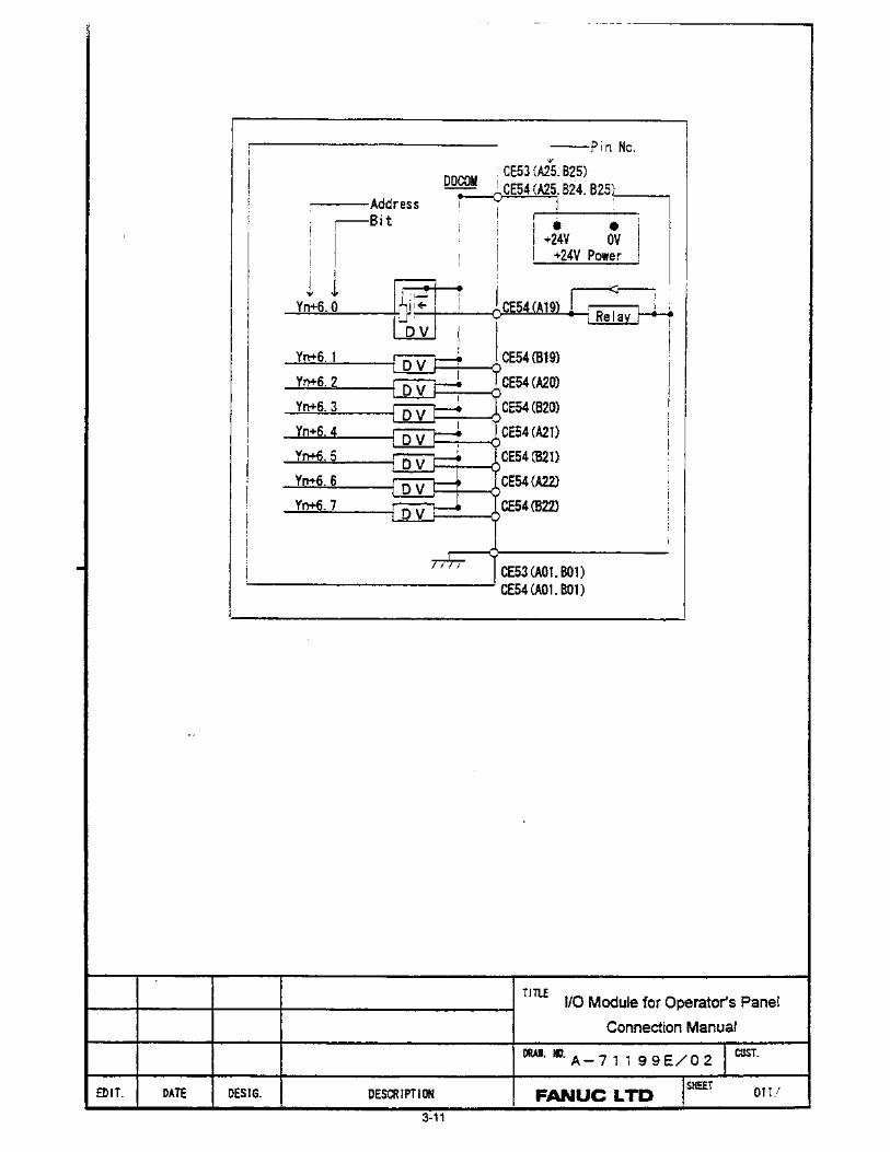
• 72/56 I/O
� 56 of the inputs are matrixed.
� Outputs are sourced outputs, electronically fused.
� Supports up to three MPGs.
� Specification Number: A20B-2002-0470
• 48/32 I/O
� All inputs are non-matrixed.
� Outputs are sourced outputs, electronically fused.
� Supports up to three MPGs.
� Specification Number: A20B-2002-0520
• 48/32 I/O
� All inputs are non-matrixed.
� Outputs are sourced outputs, electronically fused.
� Does not provide any MPG interface.
� Specification Number: A20B-2002-0521
Preface
GFK-1478E Preface vii
Related Publications • Series 15i-Model A
GFZ-63322EN Descriptions Manual GFZ-63323EN Connection Manual (Hardware) GFZ-63323EN-1 Connection Manual (Function) GFZ-63324EN Operator's Manual (Programming) GFZ-63324EN-1 Operator's Manual (Operation) GFZ-63325EN Maintenance Manual GFZ-63330EN Parameter Manual
• Series 16i/18i-Model A GFZ-63002EN Descriptions Manual GFZ-63003EN Connection Manual (Hardware) GFZ-63003EN-1 Connection Manual (Function) GFZ-63004EN Operator's Manual (for Lathe) GFZ-63005EN Maintenance Manual GFZ-63007EN Operation & Maintenance Handbook GFZ-63010EN Parameter Manual GFZ-63014EN Operator's Manual (for Machining Center)
• Series 21i-Model A GFZ-63002EN Descriptions Manual GFZ-63003EN Connection Manual (Hardware) GFZ-63003EN-1 Connection Manual (Function) GFZ-63084EN Operator's Manual (for Lathe) GFZ-63085EN Maintenance Manual GFZ-63090EN Parameter Manual GFZ-63094EN Operator's Manual (for Machining Center)
• Power Mate i-Models D and H GFZ-63172EN Descriptions Manual GFZ-63173EN Connection Manual (Hardware) GFZ-63173EN-1 Connection Manual (Function) GFZ-63174EN Operator's Manual GFZ-63175EN Maintenance Manual GFZ-63180EN Parameter Manual

CONTENTS
The Operator Panels for i Series Controls User's Manual, GFK-1478E, contains the following sections:
Page
• Section 1: North American Operator Panel 1-1
• Section 2: Dispersion I/O Type Operator Panel 2-1
• Section 3: 72 In / 56 Out Connection Unit 3-1
• Section 4: 48 / 32 Points I/O Module 4-1

SECTION 1:
NORTH AMERICAN OPERATOR PANEL FOR I SERIES CNCS
This section contains: Page
• Features and Benefits 1-1
• Outline Drawing 44C715714 1-3
• Outline Drawing 44C745908 1-4
• Variations 1-5
• Optional Cables and Connectors 1-7
• Power Connection Considerations 1-10
� Series 16i/18i and 21i CNCs 1-11
� Power Mate i Motion Controllers 1-11
� Series 15i CNC 1-16
• Series 15i Power Supply Connection Installation 1-19
• Sample Operator Panel Ladder Logic 1-21
• Renewal Parts 1-22
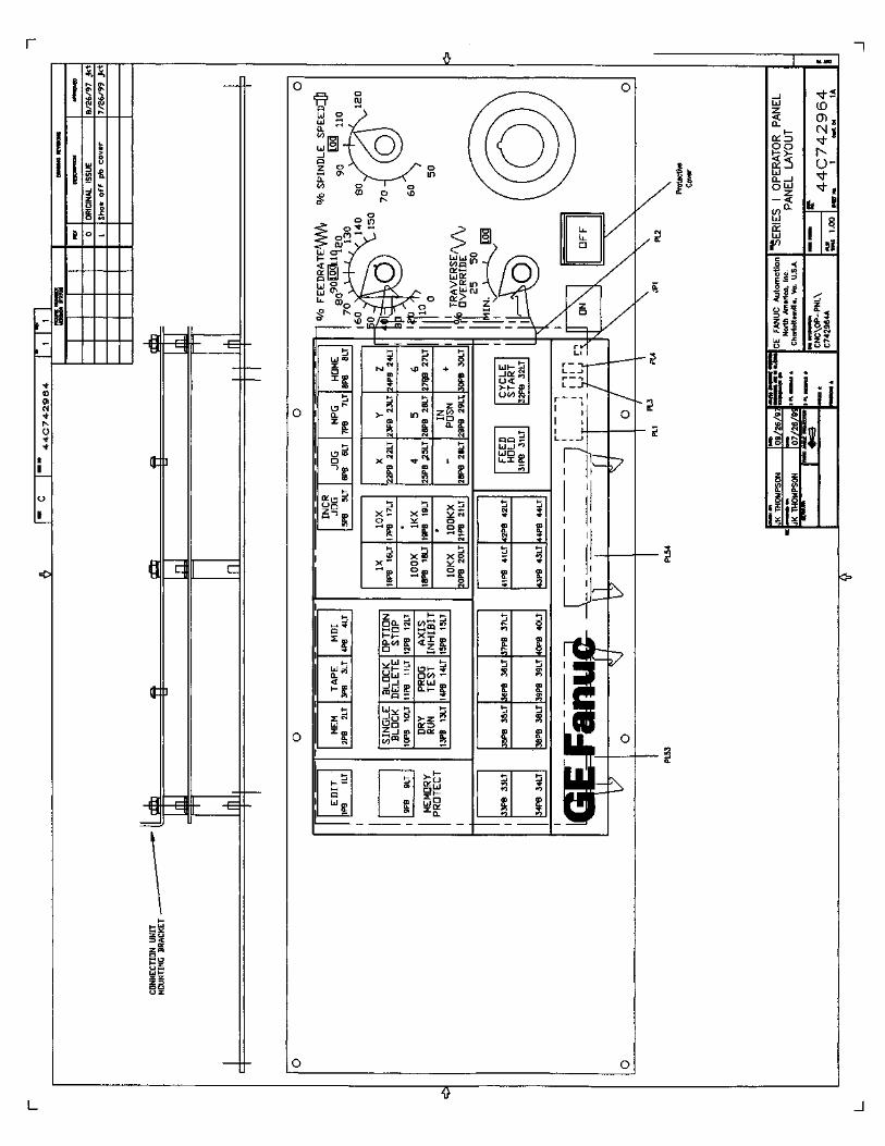
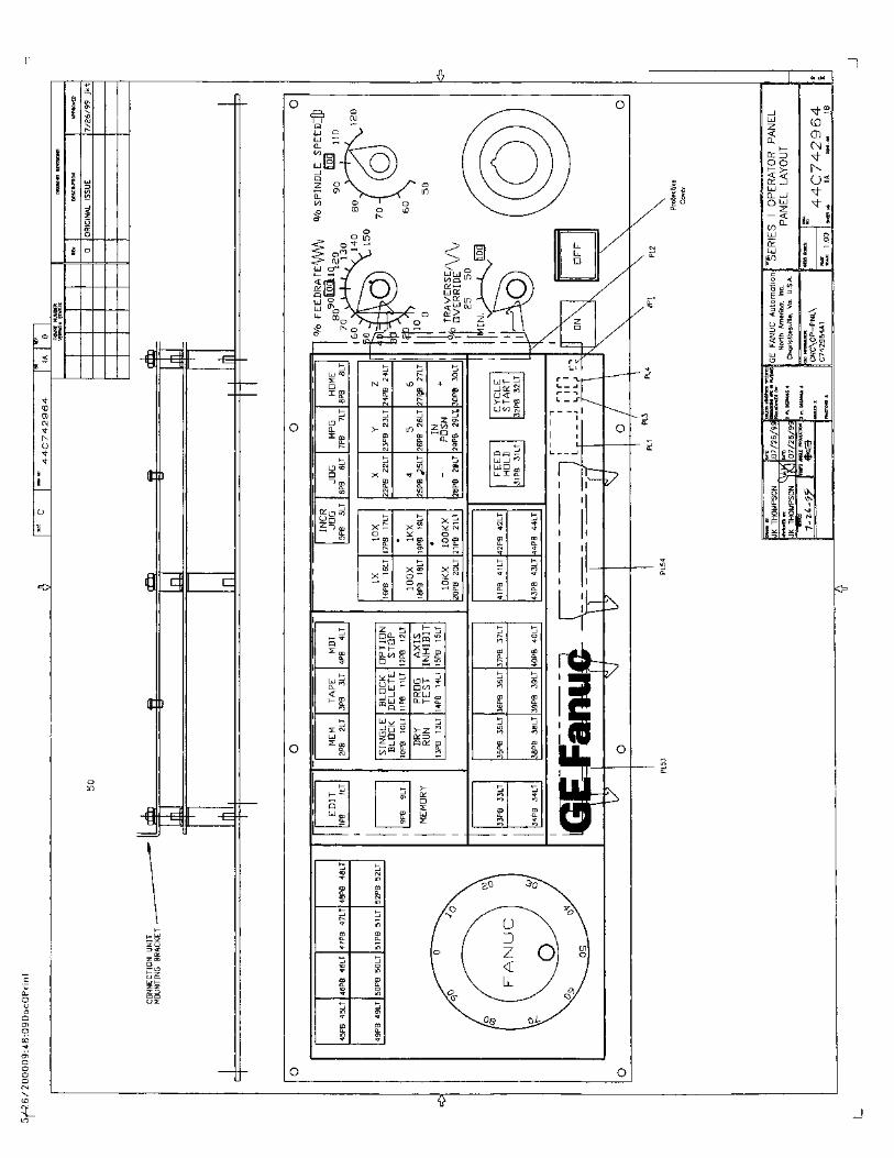
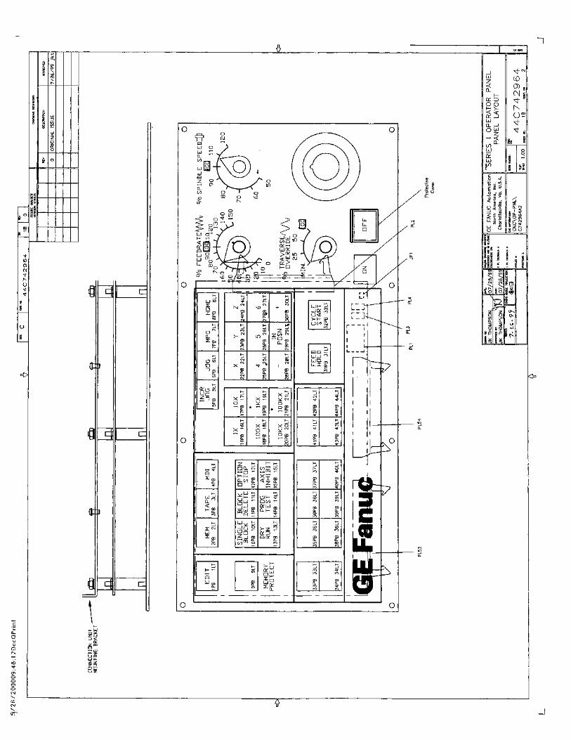
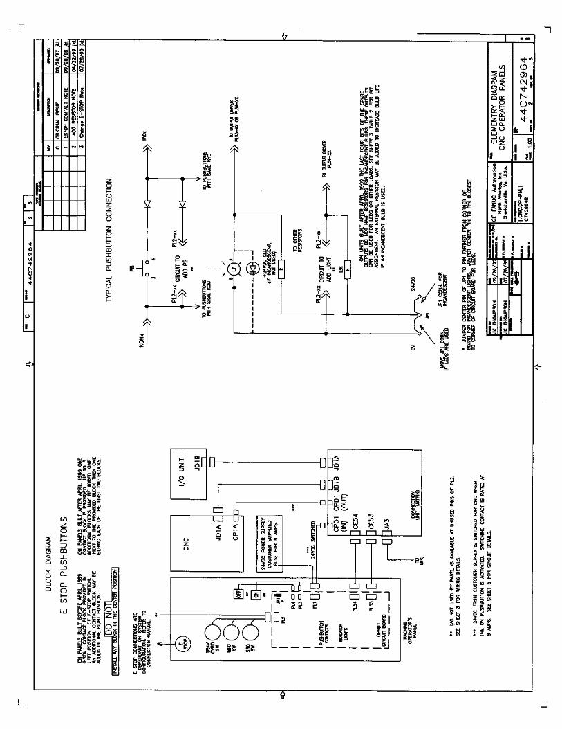
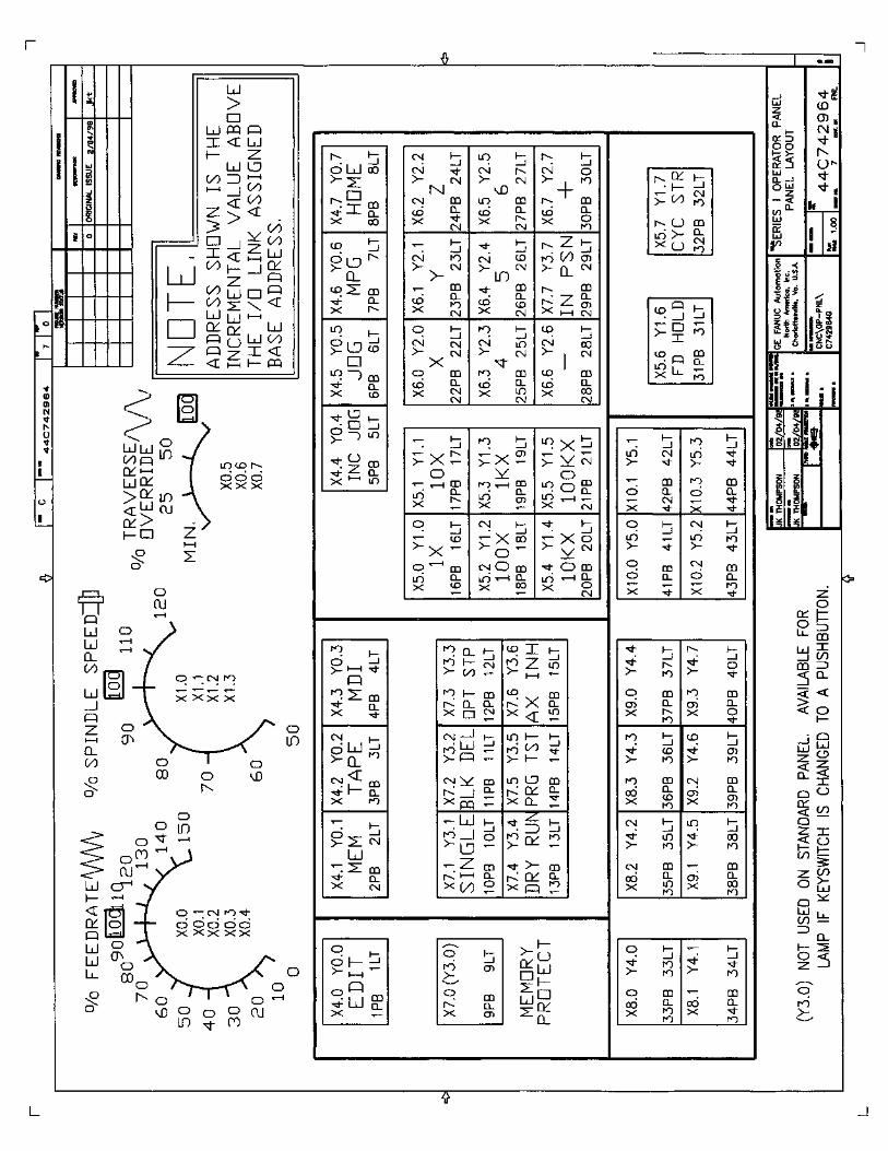
• Elementary Diagrams 44C742964 1-26

1-1
North American Operator Panels for Machine Tools using i Series CNCs or Power Mate i
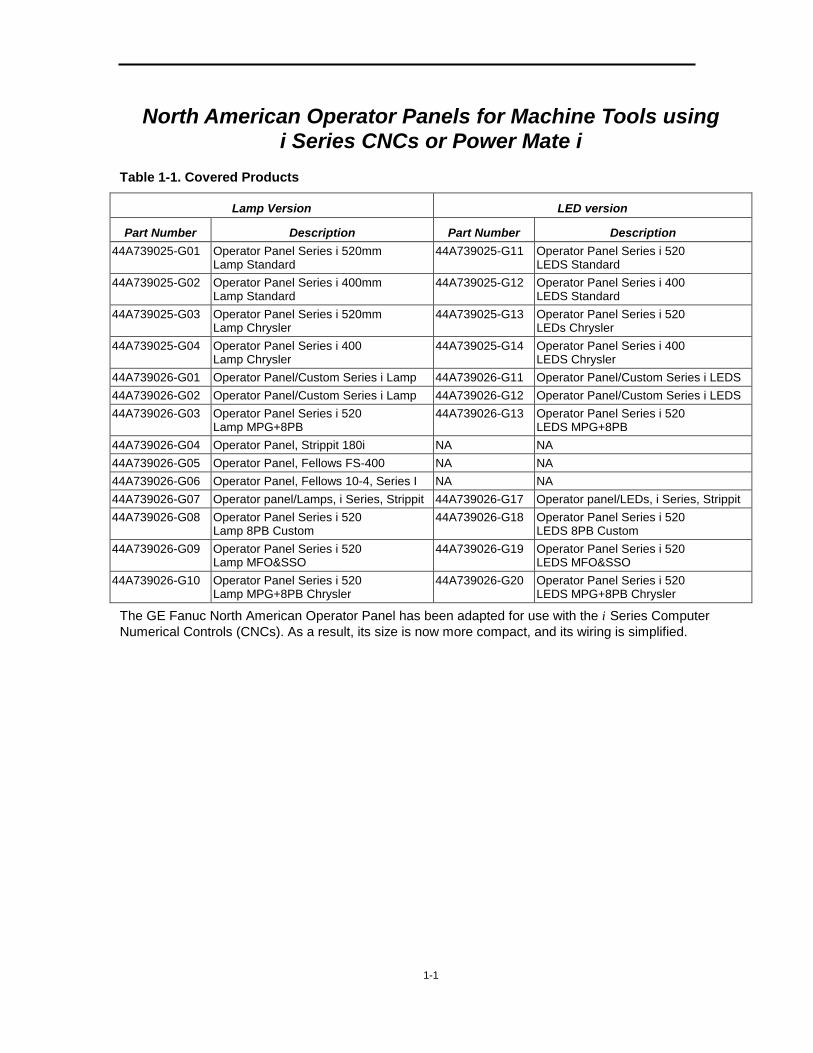
Table 1-1. Covered Products
Lamp Version LED version
Part Number Description Part Number Description 44A739025-G01 Operator Panel Series i 520mm
Lamp Standard 44A739025-G11 Operator Panel Series i 520
LEDS Standard 44A739025-G02 Operator Panel Series i 400mm
Lamp Standard 44A739025-G12 Operator Panel Series i 400
LEDS Standard 44A739025-G03 Operator Panel Series i 520mm
Lamp Chrysler 44A739025-G13 Operator Panel Series i 520
LEDs Chrysler 44A739025-G04 Operator Panel Series i 400
Lamp Chrysler 44A739025-G14 Operator Panel Series i 400
LEDS Chrysler 44A739026-G01 Operator Panel/Custom Series i Lamp 44A739026-G11 Operator Panel/Custom Series i LEDS 44A739026-G02 Operator Panel/Custom Series i Lamp 44A739026-G12 Operator Panel/Custom Series i LEDS 44A739026-G03 Operator Panel Series i 520
Lamp MPG+8PB 44A739026-G13 Operator Panel Series i 520
LEDS MPG+8PB 44A739026-G04 Operator Panel, Strippit 180i NA NA 44A739026-G05 Operator Panel, Fellows FS-400 NA NA 44A739026-G06 Operator Panel, Fellows 10-4, Series I NA NA 44A739026-G07 Operator panel/Lamps, i Series, Strippit 44A739026-G17 Operator panel/LEDs, i Series, Strippit 44A739026-G08 Operator Panel Series i 520
Lamp 8PB Custom 44A739026-G18 Operator Panel Series i 520
LEDS 8PB Custom 44A739026-G09 Operator Panel Series i 520
Lamp MFO&SSO 44A739026-G19 Operator Panel Series i 520
LEDS MFO&SSO 44A739026-G10 Operator Panel Series i 520
Lamp MPG+8PB Chrysler 44A739026-G20 Operator Panel Series i 520
LEDS MPG+8PB Chrysler
The GE Fanuc North American Operator Panel has been adapted for use with the i Series Computer Numerical Controls (CNCs). As a result, its size is now more compact, and its wiring is simplified.
1-2
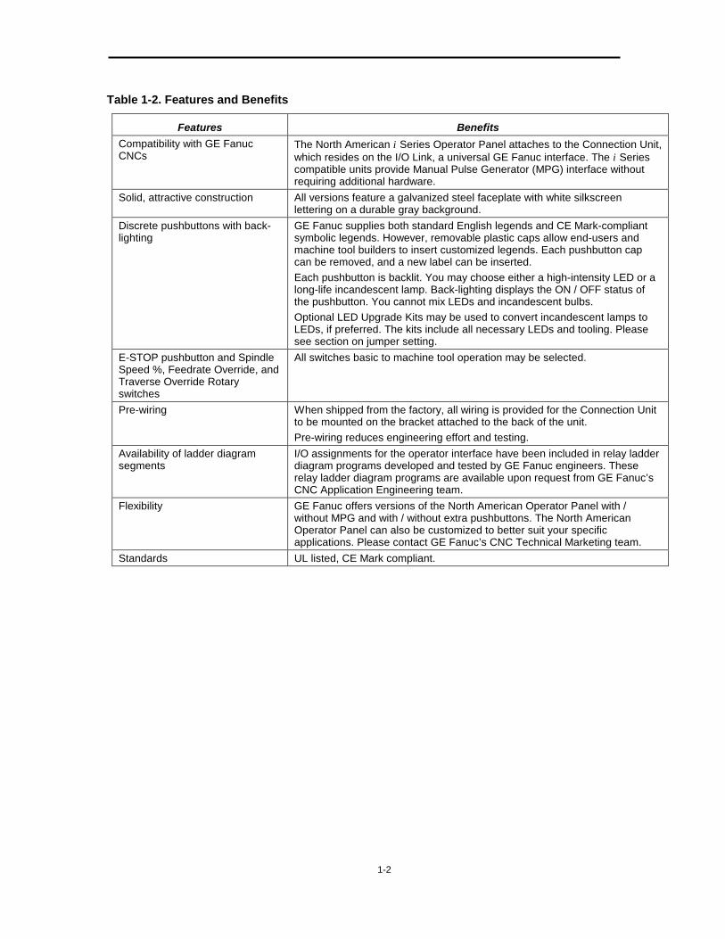
Table 1-2. Features and Benefits
Features Benefits Compatibility with GE Fanuc CNCs
The North American i Series Operator Panel attaches to the Connection Unit, which resides on the I/O Link, a universal GE Fanuc interface. The i Series compatible units provide Manual Pulse Generator (MPG) interface without requiring additional hardware.
Solid, attractive construction All versions feature a galvanized steel faceplate with white silkscreen lettering on a durable gray background.
Discrete pushbuttons with back-lighting
GE Fanuc supplies both standard English legends and CE Mark-compliant symbolic legends. However, removable plastic caps allow end-users and machine tool builders to insert customized legends. Each pushbutton cap can be removed, and a new label can be inserted. Each pushbutton is backlit. You may choose either a high-intensity LED or a long-life incandescent lamp. Back-lighting displays the ON / OFF status of the pushbutton. You cannot mix LEDs and incandescent bulbs. Optional LED Upgrade Kits may be used to convert incandescent lamps to LEDs, if preferred. The kits include all necessary LEDs and tooling. Please see section on jumper setting.
E-STOP pushbutton and Spindle Speed %, Feedrate Override, and Traverse Override Rotary switches
All switches basic to machine tool operation may be selected.
Pre-wiring When shipped from the factory, all wiring is provided for the Connection Unit to be mounted on the bracket attached to the back of the unit. Pre-wiring reduces engineering effort and testing.
Availability of ladder diagram segments
I/O assignments for the operator interface have been included in relay ladder diagram programs developed and tested by GE Fanuc engineers. These relay ladder diagram programs are available upon request from GE Fanuc’s CNC Application Engineering team.
Flexibility GE Fanuc offers versions of the North American Operator Panel with / without MPG and with / without extra pushbuttons. The North American Operator Panel can also be customized to better suit your specific applications. Please contact GE Fanuc’s CNC Technical Marketing team.
Standards UL listed, CE Mark compliant.

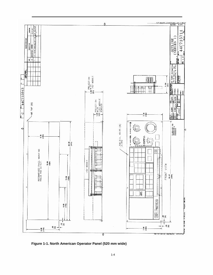
1-3
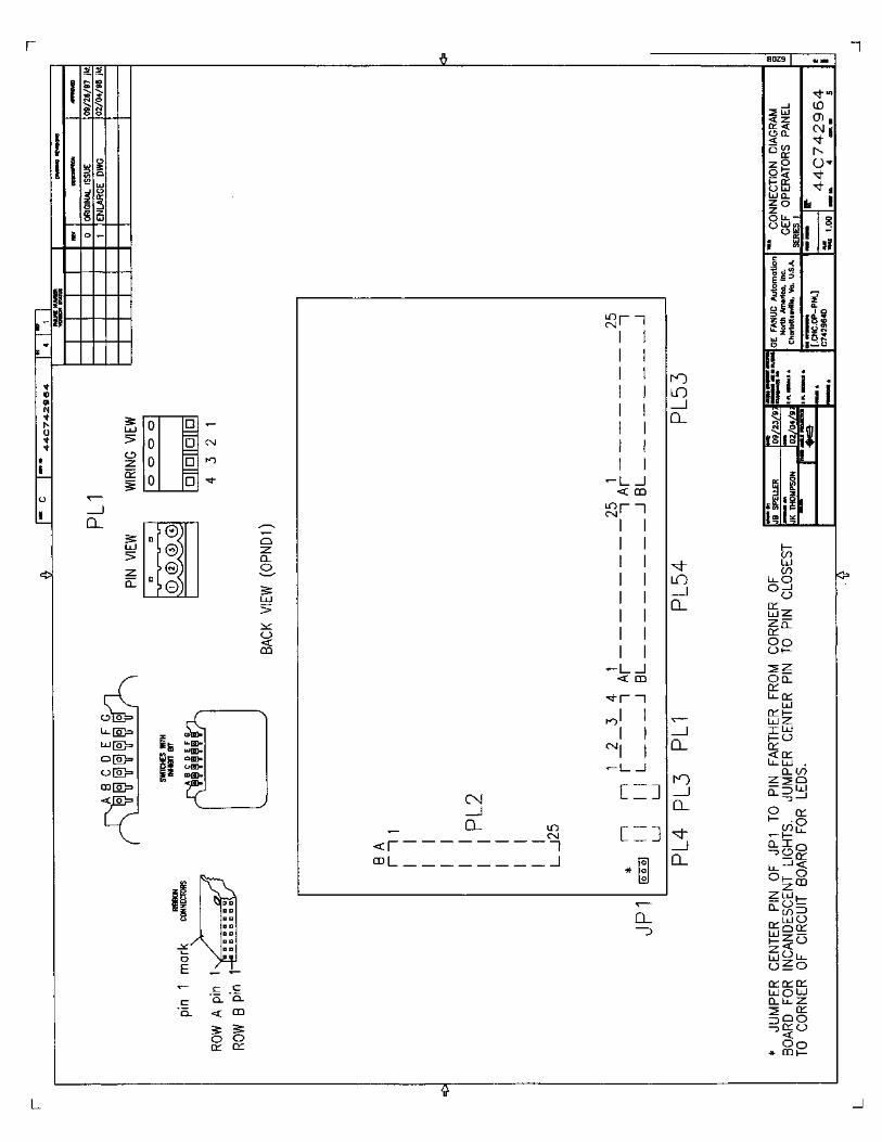
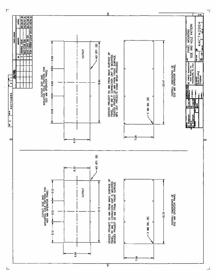
The dimensions of the North American i Series Operator Panel are either 520 mm or 400 mm wide by 180 mm high by 90 mm deep. If the Connection Unit bracket is removed, the depth is 50 mm. Panel devices project up to 25 mm from the front of the panel.
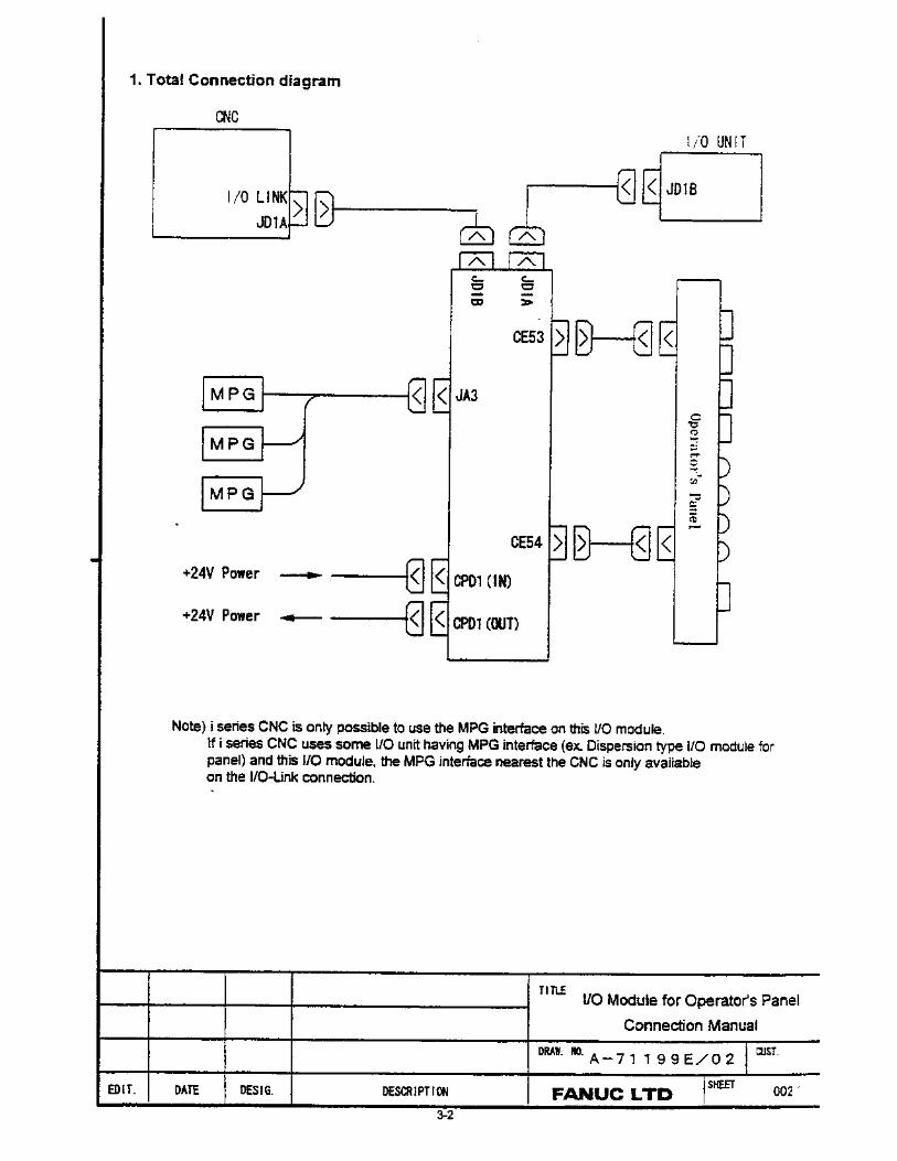
The Operator Panel is designed to be used with the 72 Data Input / 56 Data Output Connection Unit (see Section 3 of this manual). A convenient mounting bracket for the Connection Unit is provided on the back of the Operator Panel. The Connection Unit (A02B-2002-0470) is ordered separately. It attaches to the CNC via the high-speed I/O Link and provides a convenient attachment for up to three Manual Pulse Generators.
Note For i Series controls, it may be possible to connect the MPGs to multiple locations within the machine tool. Select the location on the I/O Link closest to the CNC, and connect all MPGs to that unit. This will be the only active MPG circuit.
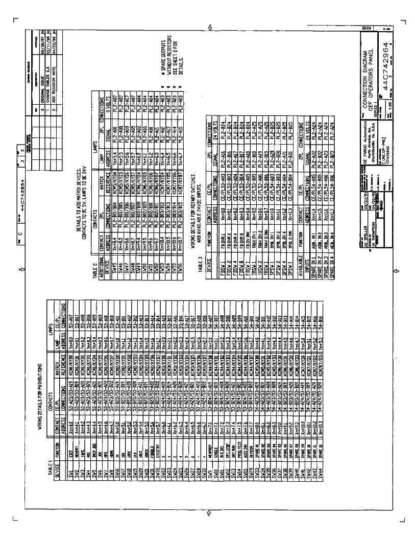
The pushbuttons on the Operator Panel use 44 of the 56 matrix-type inputs. The rotary switches use 12 of the 16 discrete-type 24V inputs. The remaining 12 outputs, 12 matrix inputs, and 4 discrete 24VDC inputs are available on connector PL2 for customer use.
Note The Memory Protect Key Switch is included with the North American i Series Operator Panel, however, the protection must be defined in the ladder logic.
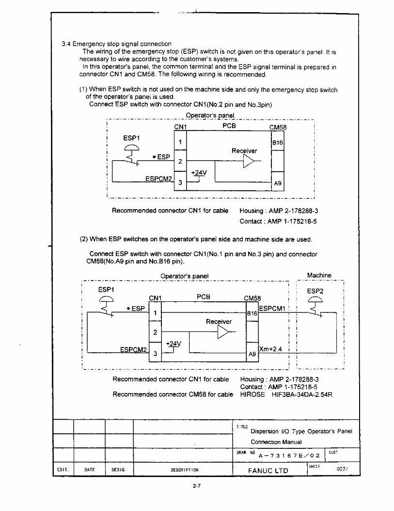
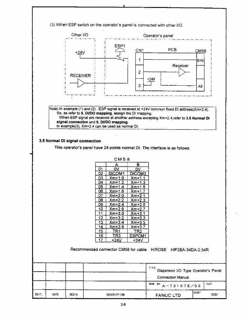
All supplied panel devices are wired, except for the Emergency Stop (E-STOP) pushbutton. It is the machine tool builder’s responsibility to wire the E-STOP pushbutton in order to satisfy safety requirements for each application and location. For more information on E-STOP wiring and signals, refer to the Hardware and Function Connection Manuals for the CNC control to be used. The E-STOP pushbutton contacts are equipped with screw terminals to provide for easy termination of wiring by the machine tool builder. Use of crimp-on terminals or ferrules is recommended to protect stranded wire from being damaged by over-tightening the screw terminals.
The Operator Panel is connected to a 24VDC power supply fused for a maximum of 8 Amps. A Power Cable Set 44C742962-G01 may be ordered to connect the system. The Power Cable Set provides one meter of wire between the panel and the power supply, 250 mm from the panel to the Connection Unit (the length required when a mounting bracket is used), and one meter from the Connection Unit to the i Series Control. ON and OFF pushbuttons are provided to switch the 24VDC output for the CNC and other machine devices. (Refer to the wiring diagrams on Pages 1-13, 1-14, 1-15, and 1-18.)
CAUTION The North American Operator Panel may be used with controls other than the i Series CNCs; however, the ON/OFF pushbuttons may require a different configuration.
In addition, the MPG interface circuits on the Connection Unit will not be functional with CNCs other than the i Series CNCs.
Ribbon cables are included to connect the Operator Panel to the Connection Unit when a mounting bracket is used. If the mounting bracket is not used, a one-meter set of Ribbon Cables 44C739032-G01 can be ordered.
1-4
Figure 1-1. North American Operator Panel (520 mm wide)
1-5
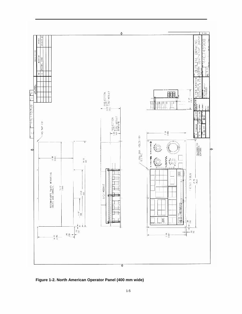
Figure 1-2. North American Operator Panel (400 mm wide)
1-6
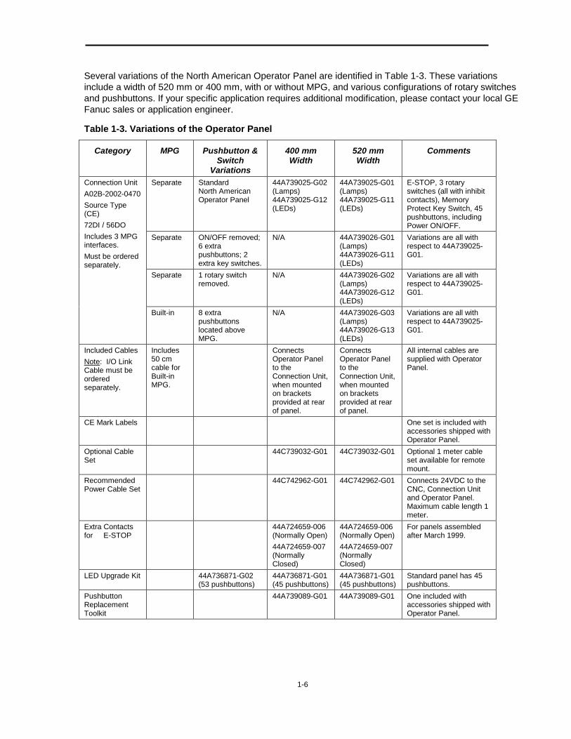
Several variations of the North American Operator Panel are identified in Table 1-3. These variations include a width of 520 mm or 400 mm, with or without MPG, and various configurations of rotary switches and pushbuttons. If your specific application requires additional modification, please contact your local GE Fanuc sales or application engineer.
Table 1-3. Variations of the Operator Panel
Category MPG Pushbutton & Switch
Variations
400 mm Width
520 mm Width
Comments
Separate Standard North American Operator Panel
44A739025-G02 (Lamps) 44A739025-G12 (LEDs)
44A739025-G01 (Lamps) 44A739025-G11 (LEDs)
E-STOP, 3 rotary switches (all with inhibit contacts), Memory Protect Key Switch, 45 pushbuttons, including Power ON/OFF.
Separate ON/OFF removed; 6 extra pushbuttons; 2 extra key switches.
N/A 44A739026-G01 (Lamps) 44A739026-G11 (LEDs)
Variations are all with respect to 44A739025-G01.
Separate 1 rotary switch removed.
N/A 44A739026-G02 (Lamps) 44A739026-G12 (LEDs)
Variations are all with respect to 44A739025-G01.
Connection Unit A02B-2002-0470 Source Type (CE) 72DI / 56DO Includes 3 MPG interfaces. Must be ordered separately.
Built-in 8 extra pushbuttons located above MPG.
N/A 44A739026-G03 (Lamps) 44A739026-G13 (LEDs)
Variations are all with respect to 44A739025-G01.
Included Cables Note: I/O Link Cable must be ordered separately.
Includes 50 cm cable for Built-in MPG.
Connects Operator Panel to the Connection Unit, when mounted on brackets provided at rear of panel.
Connects Operator Panel to the Connection Unit, when mounted on brackets provided at rear of panel.
All internal cables are supplied with Operator Panel.
CE Mark Labels One set is included with accessories shipped with Operator Panel.
Optional Cable Set
44C739032-G01 44C739032-G01 Optional 1 meter cable set available for remote mount.
Recommended Power Cable Set
44C742962-G01 44C742962-G01 Connects 24VDC to the CNC, Connection Unit and Operator Panel. Maximum cable length 1 meter.
Extra Contacts for E-STOP
44A724659-006 (Normally Open) 44A724659-007 (Normally Closed)
44A724659-006 (Normally Open) 44A724659-007 (Normally Closed)
For panels assembled after March 1999.
LED Upgrade Kit 44A736871-G02 (53 pushbuttons)
44A736871-G01 (45 pushbuttons)
44A736871-G01 (45 pushbuttons)
Standard panel has 45 pushbuttons.
Pushbutton Replacement Toolkit
44A739089-G01 44A739089-G01 One included with accessories shipped with Operator Panel.
1-7
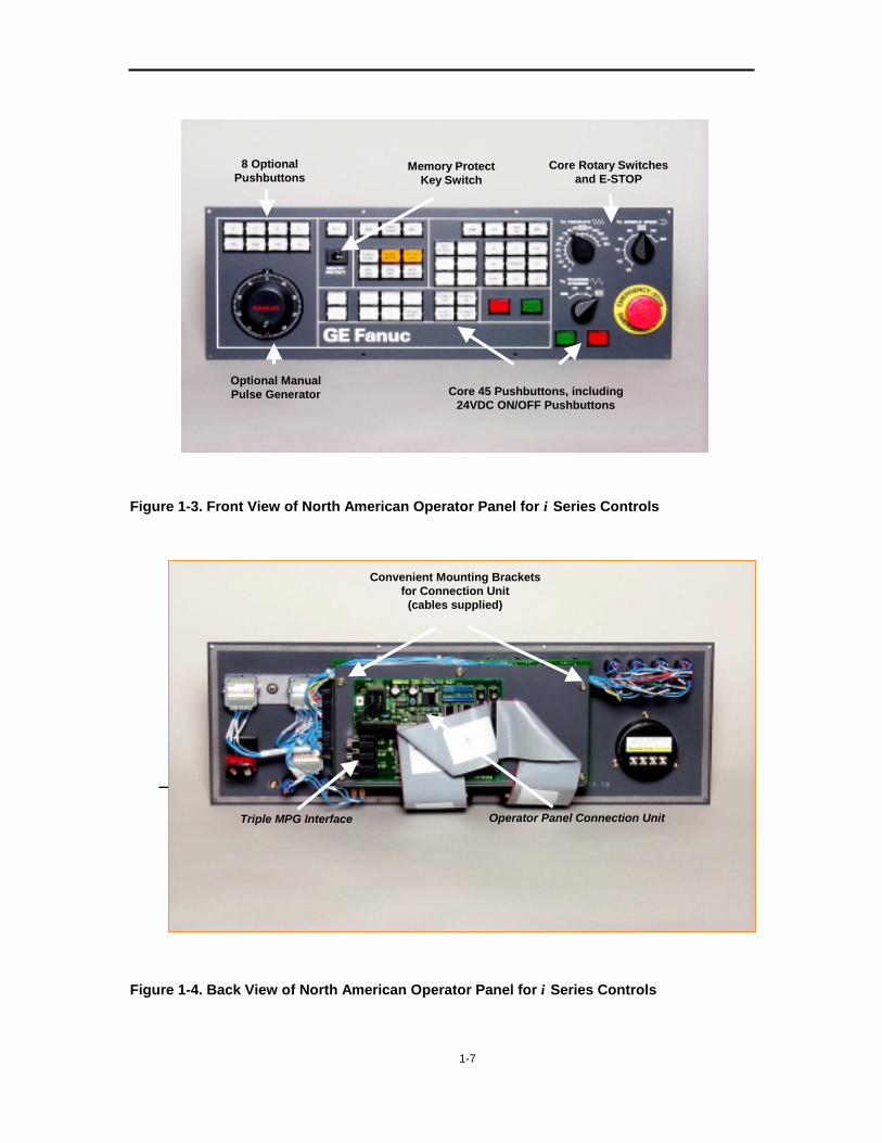
Figure 1-3. Front View of North American Operator Panel for i Series Controls
Figure 1-4. Back View of North American Operator Panel for i Series Controls
8 Optional Pushbuttons
Optional Manual Pulse Generator Core 45 Pushbuttons, including
24VDC ON/OFF Pushbuttons
Memory Protect Key Switch
Core Rotary Switches and E-STOP
T i l
T i l Operator Panel
Convenient Mounting Bracketsfor Connection Unit
(cables supplied)
Triple MPG Interface Operator Panel Connection Unit
1-8
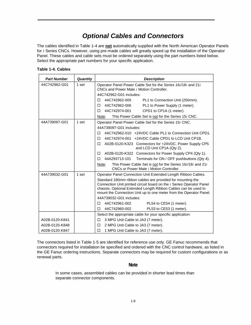
Optional Cables and Connectors The cables identified in Table 1-4 are not automatically supplied with the North American Operator Panels for i Series CNCs. However, using pre-made cables will greatly speed up the installation of the Operator Panel. These cables and cable sets must be ordered separately using the part numbers listed below. Select the appropriate part numbers for your specific application.
Table 1-4. Cables
Part Number Quantity Description 44C742962-G01 1 set Operator Panel Power Cable Set for the Series 16i/18i and 21i
CNCs and Power Mate i Motion Controller. 44C742962-G01 includes: � 44C742962-005 PL1 to Connection Unit (250mm). � 44C742962-006 PL1 to Power Supply (1 meter). � 44C742974-001 CPD1 to CP1A (1 meter). Note: This Power Cable Set is not for the Series 15i CNC.
44A739097-G01 1 set Operator Panel Power Cable Set for the Series 15i CNC. 44A739097-G01 includes: � 44C742962-010 +24VDC Cable PL1 to Connection Unit CPD1. � 44C742974-001 +24VDC Cable CPD1 to LCD Unit CP1B. � A02B-0120-K323 Connectors for +24VDC. Power Supply CP5
and LCD Unit CP1A (Qty 2). � A02B-0120-K322 Connectors for Power Supply CP4 (Qty 1). � 44A293713-101 Terminals for ON / OFF pushbuttons (Qty 4). Note: This Power Cable Set is not for the Series 16i/18i and 21i CNCs or Power Mate i Motion Controller.
44A739032-G01 1 set Operator Panel Connection Unit Extended Length Ribbon Cables. Standard 180mm ribbon cables are provided for mounting the Connection Unit printed circuit board on the i Series Operator Panel chassis. Optional Extended Length Ribbon Cables can be used to mount the Connection Unit up to one meter from the Operator Panel. 44A739032-G01 includes: � 44C742961-002 PL54 to CE54 (1 meter). � 44C742960-002 PL53 to CE53 (1 meter).
A02B-0120-K841 A02B-0120-K848 A02B-0120-K847
Select the appropriate cable for your specific application: � 3 MPG Unit Cable to JA3 (7 meter). � 2 MPG Unit Cable to JA3 (7 meter). � 1 MPG Unit Cable to JA3 (7 meter).
The connectors listed in Table 1-5 are identified for reference use only. GE Fanuc recommends that connectors required for installation be specified and ordered with the CNC control hardware, as listed in the GE Fanuc ordering instructions. Separate connectors may be required for custom configurations or as renewal parts.
Note In some cases, assembled cables can be provided in shorter lead times than separate connector components.
1-9
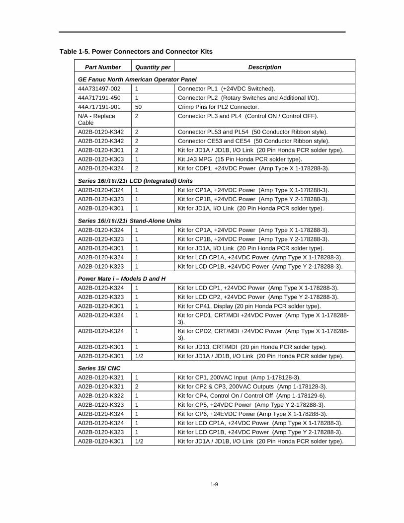
Table 1-5. Power Connectors and Connector Kits
Part Number Quantity per Description
GE Fanuc North American Operator Panel 44A731497-002 1 Connector PL1 (+24VDC Switched). 44A717191-450 1 Connector PL2 (Rotary Switches and Additional I/O). 44A717191-901 50 Crimp Pins for PL2 Connector. N/A - Replace Cable
2 Connector PL3 and PL4 (Control ON / Control OFF).
A02B-0120-K342 2 Connector PL53 and PL54 (50 Conductor Ribbon style). A02B-0120-K342 2 Connector CE53 and CE54 (50 Conductor Ribbon style). A02B-0120-K301 2 Kit for JD1A / JD1B, I/O Link (20 Pin Honda PCR solder type). A02B-0120-K303 1 Kit JA3 MPG (15 Pin Honda PCR solder type). A02B-0120-K324 2 Kit for CDP1, +24VDC Power (Amp Type X 1-178288-3).
Series 16i/18i/21i LCD (Integrated) Units A02B-0120-K324 1 Kit for CP1A, +24VDC Power (Amp Type X 1-178288-3). A02B-0120-K323 1 Kit for CP1B, +24VDC Power (Amp Type Y 2-178288-3). A02B-0120-K301 1 Kit for JD1A, I/O Link (20 Pin Honda PCR solder type).
Series 16i/18i/21i Stand-Alone Units A02B-0120-K324 1 Kit for CP1A, +24VDC Power (Amp Type X 1-178288-3). A02B-0120-K323 1 Kit for CP1B, +24VDC Power (Amp Type Y 2-178288-3). A02B-0120-K301 1 Kit for JD1A, I/O Link (20 Pin Honda PCR solder type). A02B-0120-K324 1 Kit for LCD CP1A, +24VDC Power (Amp Type X 1-178288-3). A02B-0120-K323 1 Kit for LCD CP1B, +24VDC Power (Amp Type Y 2-178288-3).
Power Mate i – Models D and H A02B-0120-K324 1 Kit for LCD CP1, +24VDC Power (Amp Type X 1-178288-3). A02B-0120-K323 1 Kit for LCD CP2, +24VDC Power (Amp Type Y 2-178288-3). A02B-0120-K301 1 Kit for CP41, Display (20 pin Honda PCR solder type). A02B-0120-K324 1 Kit for CPD1, CRT/MDI +24VDC Power (Amp Type X 1-178288-
3). A02B-0120-K324 1 Kit for CPD2, CRT/MDI +24VDC Power (Amp Type X 1-178288-
3). A02B-0120-K301 1 Kit for JD13, CRT/MDI (20 pin Honda PCR solder type). A02B-0120-K301 1/2 Kit for JD1A / JD1B, I/O Link (20 Pin Honda PCR solder type).
Series 15i CNC A02B-0120-K321 1 Kit for CP1, 200VAC Input (Amp 1-178128-3). A02B-0120-K321 2 Kit for CP2 & CP3, 200VAC Outputs (Amp 1-178128-3). A02B-0120-K322 1 Kit for CP4, Control On / Control Off (Amp 1-178129-6). A02B-0120-K323 1 Kit for CP5, +24VDC Power (Amp Type Y 2-178288-3). A02B-0120-K324 1 Kit for CP6, +24EVDC Power (Amp Type X 1-178288-3). A02B-0120-K324 1 Kit for LCD CP1A, +24VDC Power (Amp Type X 1-178288-3). A02B-0120-K323 1 Kit for LCD CP1B, +24VDC Power (Amp Type Y 2-178288-3). A02B-0120-K301 1/2 Kit for JD1A / JD1B, I/O Link (20 Pin Honda PCR solder type).
1-10
Power Connection Considerations The following questions and explanations will help you determine how to supply 24VDC power to the North American Operator Panel.
1. Is the CNC an “Open CNC System? That is, is it a system containing an integrated personal computer (PC) or an external PC with High-Speed Serial Bus (HSSB) hardware?
If your answer is yes, the power-down sequence must include the time required to shut down the computer’s Operating System before physically disconnecting power from the PC. A timing sequence run from the PMC ladder diagram can be used to accomplish this. Use the OFF pushbutton to start the sequence. For more information, refer to your Open System documentation.
2. Which CNC or motion control product is involved – Series 15i, Series 16i/18i, Series 21i CNC, or Power Mate i Models D and H?
For Series 16i/18i and 21i power connections, refer to Pages 1-13 and 1-14. For Power Mate i Models D and H power connections, refer to Page 1-15. For Series 15i power connections, refer to Page 1-18.
3. Is the Series 16i/18i/21i CNC an LCD-Mount or Stand-Alone system?
Separate wiring diagrams are provided on Pages 1-13 and 1-14 for these different configurations.
4. Is it desirable to isolate the 24VDC power supplied to the CNC from the 24VDC power supplied to the Machine I/O, including the North American Operator Panel?
Due to resistive or inductive loading by 24VDC external machine devices, it may be beneficial to use a separate power supply to drive such loads. The machine tool builder must determine this and implement the appropriate wiring diagram to suit each application.
1-11
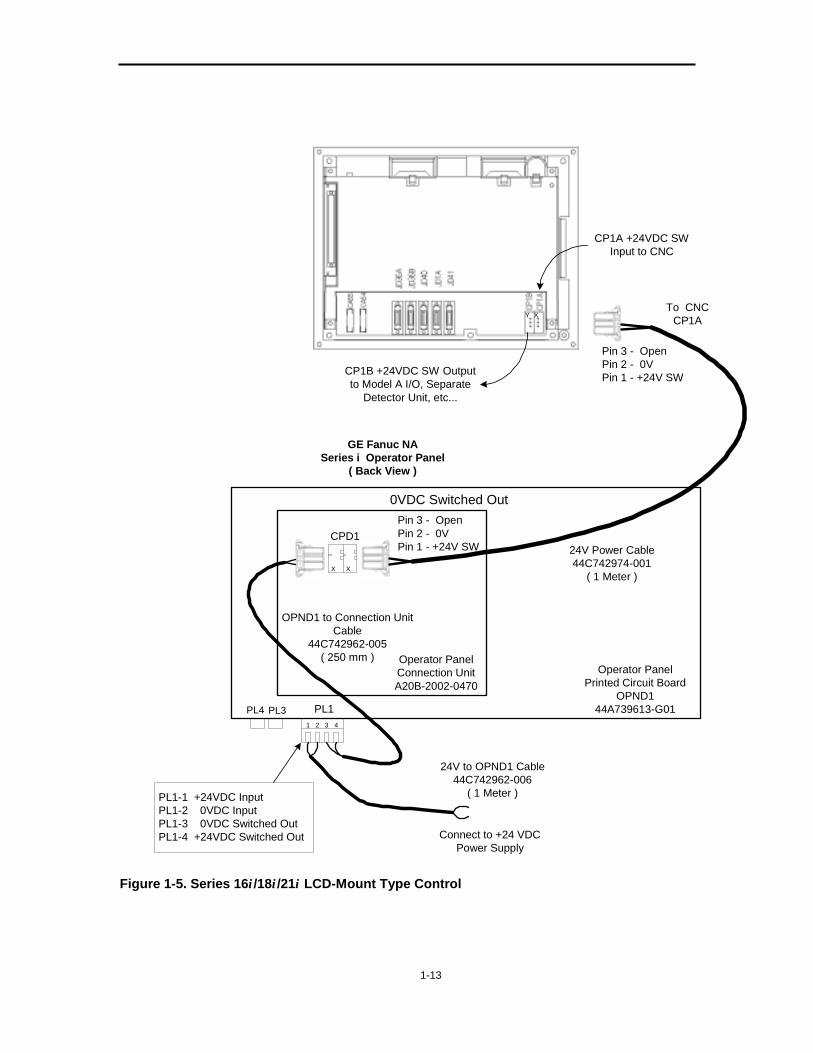
+24VDC Power Connections for Series 16i/18i/21i CNCs and Power Mate i Motion Controllers
Note This information applies only to the Series 16i/18i and 21i CNCs and Power Mate i Motion Controllers. It does not apply to the Series 15i CNC. For information on the Series 15i CNC, please refer to Page 1-16.
The Series 16i/18i and 21i CNCs and Power Mate i Motion Controllers do not contain built-in power supplies. They must be powered by an external +24VDC power supply.
Most machine tools use an external +24VDC power supply for machine I/O devices. To save space and reduce electrical hardware, the same power supply could be sized to include the CNC hardware requirements. In other applications, it may be desirable to provide a separate +24VDC power supply to the CNC-related hardware. The separate +24VDC power supply would be isolated from the +24VDC power supply used for machine I/O devices.
CAUTION Regardless of the method used to supply power, proper device mounting and grounding, good wiring practices, and recognized methods of noise suppression must always be observed. Failure to do so could result in incorrect operation or machine failures.
The North American Operator Panel for i Series CNCs contains built-in hardware to provide for switching the external +24VDC power supply. This will simplify installation for the machine tool builder. The switched +24VDC output is controlled by the Control ON and OFF pushbuttons provided on the Operator Panel. The switched +24VDC power supply should be used for all GE Fanuc devices required to be turned on in synchronization with the CNC control. This includes I/O Model A racks, I/O Link Connection Units, and Separate Feedback Detectors. Connector PL1 on OPND1 (the circuit board behind the pushbutton assembly) provides screw clamp terminal block type connections for the incoming +24VDC power supply, and +24VDC @ 8 Amps Maximum switched output (see 44C742964).
When used with the Series 16i/18i/21i controls, the Operator Panel may be ordered with Cable Kit 44C742962-G01. All cables in the kit are fully assembled. This kit contains the following items:
Table 1-6. Cable Kit 44C742962-G01
Item Description 44C742962-006 +24VDC power supply to OPND1 Connector PL-1 for incoming
+24VDC. 44C742962-005 Switched +24VDC from OPND1 PL-1 to the Connection Unit. 44C742974-001 Connection Unit to CNC or LCD Unit.
Note The cables in the Cable Kit are sized for typical installations. Custom cable lengths may be required for special applications and would be provided by the machine tool builder.
1-12
Figures 1-5, 1-6, and 1-7 on Pages 1-13, 1-14, and 1-15, respectively, illustrate how to apply the +24VDC Cable Kit with either the LCD-Mount (Integrated) type or the Stand-Alone type i Series hardware. Power Mate Motion Controllers are only available in a Stand-Alone configuration.
The installation of Stand-Alone type i Series hardware will require a +24VDC cable from the LCD display to the CNC or PM logic rack. This cable length is determined by the machine tool design and cannot be included in a standard cable kit. Connectors required for custom cable lengths or for custom installations must be specified and ordered with the CNC control hardware.
The flexibility of Power Mate i-D & i-H motion controllers as used in their wide variety of applications makes it difficult to apply a “standardized” power cable kit. A “standard” cable kit may not best fit the specific requirements of cable types and lengths, required by specific hardware configurations and mounting distances. The machine tool builder must analyze the power cable requirements based on the application and installation dimensions. The i-Series Cable Kit 44C742962-G01 may be ordered separately for use in Power Mate i applications. However, it may not be suitable for the target application. In this case, please use the connectors supplied with the Operator Panel to create a custom cable set.
Notes: 1. Refer to the appropriate documentation for the +24VDC fusing requirements for your control.
2. Reversing +24VDC polarity to the CNC will damage the Inverter printed circuit board in the CNC. Check wiring and polarities before applying initial power.
3. North American Operator Panels are rated for 8 Amps maximum on the switched 24VDC circuit.
1-13
PL12
PL3PL4
CPD1
To CNCCP1A
Operator PanelConnection UnitA20B-2002-0470
Operator PanelPrinted Circuit Board
OPND144A739613-G01
OPND1 to Connection UnitCable
44C742962-005( 250 mm )
24V Power Cable44C742974-001
( 1 Meter )
GE Fanuc NASeries i Operator Panel
( Back View )
Connect to +24 VDCPower Supply
Pin 3 - OpenPin 2 - 0VPin 1 - +24V SW
24V to OPND1 Cable44C742962-006
( 1 Meter )
Pin 3 - OpenPin 2 - 0VPin 1 - +24V SW
1 3 4
CP1B +24VDC SW Outputto Model A I/O, Separate
Detector Unit, etc...
CP1A +24VDC SWInput to CNC
XX
XY
PL1-1 +24VDC InputPL1-2 0VDC InputPL1-3 0VDC Switched OutPL1-4 +24VDC Switched Out
0VDC Switched Out
Figure 1-5. Series 16i/18i/21i LCD-Mount Type Control
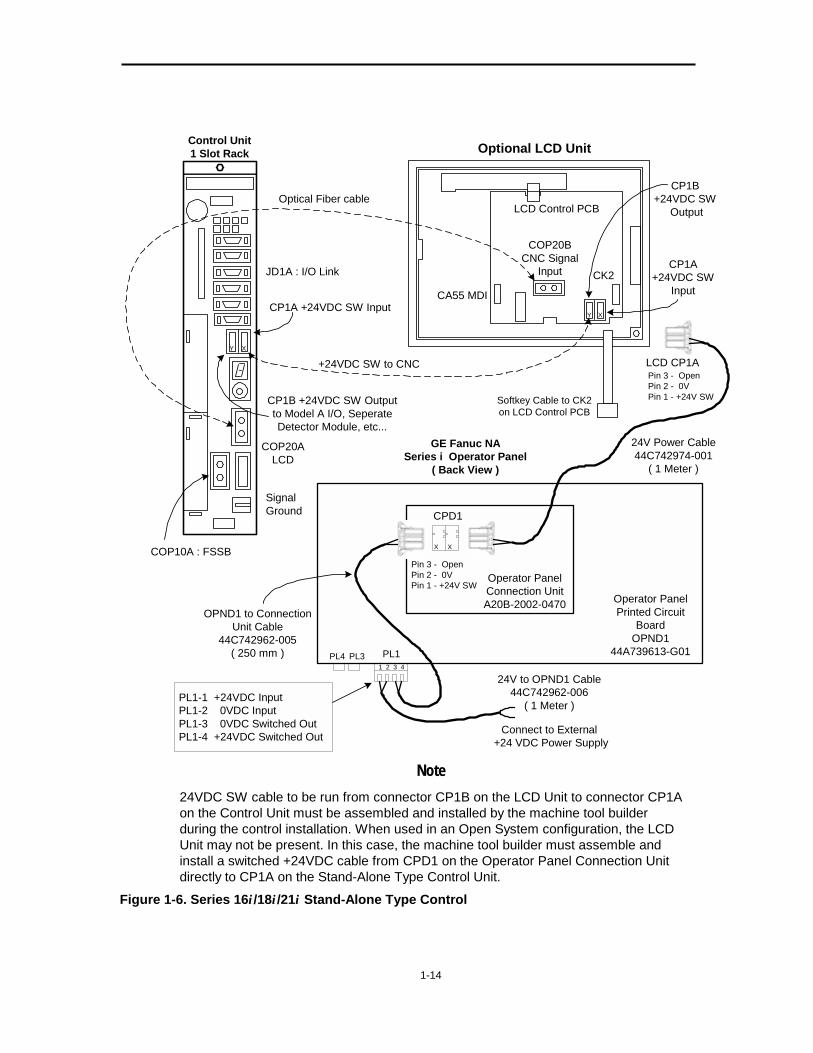
1-14
CA55 MDI
LCD Control PCB
COP20BCNC Signal
Input CP1A+24VDC SW
InputCK2
Softkey Cable to CK2on LCD Control PCB
JD1A : I/O Link
COP20ALCD
SignalGround
COP10A : FSSB
CP1A +24VDC SW Input
CP1B +24VDC SW Outputto Model A I/O, SeperateDetector Module, etc...
Control Unit1 Slot Rack
PL1PL3PL4
CPD1
LCD CP1A
Operator PanelConnection UnitA20B-2002-0470 Operator Panel
Printed CircuitBoard
OPND144A739613-G01
OPND1 to ConnectionUnit Cable
44C742962-005( 250 mm )
24V Power Cable44C742974-001
( 1 Meter )
GE Fanuc NASeries i Operator Panel
( Back View )
Connect to External +24 VDC Power Supply
Pin 3 - OpenPin 2 - 0VPin 1 - +24V SW
24V to OPND1 Cable44C742962-006
( 1 Meter )
Pin 3 - OpenPin 2 - 0VPin 1 - +24V SW
1 2 3 4
Optional LCD Unit
Optical Fiber cableCP1B
+24VDC SW Output
+24VDC SW to CNC
XX
XY
Y X
PL1-1 +24VDC InputPL1-2 0VDC InputPL1-3 0VDC Switched OutPL1-4 +24VDC Switched Out
Note
24VDC SW cable to be run from connector CP1B on the LCD Unit to connector CP1A on the Control Unit must be assembled and installed by the machine tool builder during the control installation. When used in an Open System configuration, the LCD Unit may not be present. In this case, the machine tool builder must assemble and install a switched +24VDC cable from CPD1 on the Operator Panel Connection Unit directly to CP1A on the Stand-Alone Type Control Unit.
Figure 1-6. Series 16i/18i/21i Stand-Alone Type Control
1-15
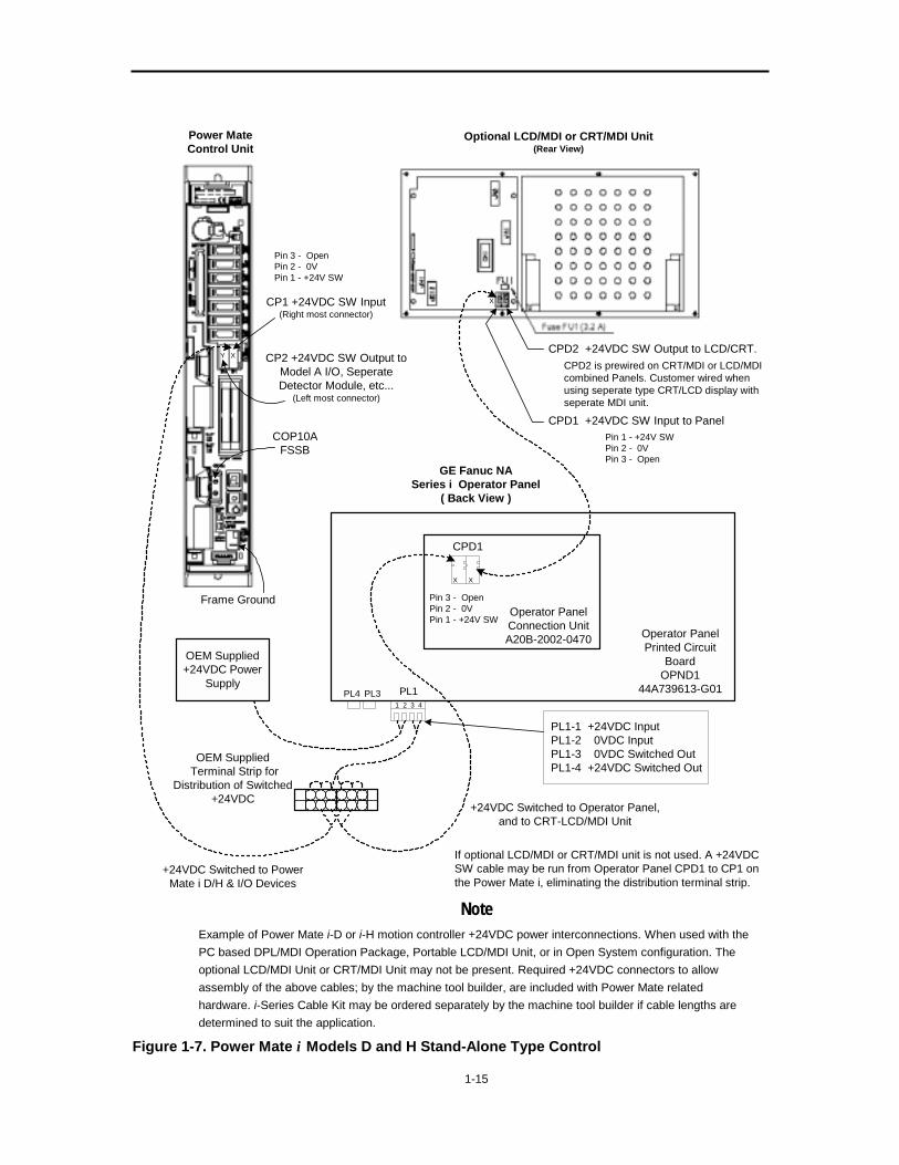
CPD1 +24VDC SW Input to Panel
CP1 +24VDC SW Input(Right most connector)
CP2 +24VDC SW Output toModel A I/O, SeperateDetector Module, etc...
(Left most connector)
Power MateControl Unit
PL1PL3PL4
CPD1
Operator PanelConnection UnitA20B-2002-0470 Operator Panel
Printed CircuitBoard
OPND144A739613-G01
GE Fanuc NASeries i Operator Panel
( Back View )
Pin 3 - OpenPin 2 - 0VPin 1 - +24V SW
1 2 3 4
PL1-1 +24VDC Input PL1-2 0VDC Input PL1-3 0VDC Switched Out PL1-4 +24VDC Switched Out
Optional LCD/MDI or CRT/MDI Unit(Rear View)
COP10AFSSB
Frame Ground
X X
XY
Pin 3 - OpenPin 2 - 0VPin 1 - +24V SW
CPD2 +24VDC SW Output to LCD/CRT.CPD2 is prewired on CRT/MDI or LCD/MDIcombined Panels. Customer wired whenusing seperate type CRT/LCD display withseperate MDI unit.
X
OEM Supplied+24VDC Power
Supply
OEM Supplied Terminal Strip for
Distribution of Switched+24VDC
+24VDC Switched to Operator Panel,and to CRT-LCD/MDI Unit
+24VDC Switched to PowerMate i D/H & I/O Devices
If optional LCD/MDI or CRT/MDI unit is not used. A +24VDCSW cable may be run from Operator Panel CPD1 to CP1 onthe Power Mate i, eliminating the distribution terminal strip.
Pin 1 - +24V SWPin 2 - 0VPin 3 - Open
Note
Example of Power Mate i-D or i-H motion controller +24VDC power interconnections. When used with the PC based DPL/MDI Operation Package, Portable LCD/MDI Unit, or in Open System configuration. The optional LCD/MDI Unit or CRT/MDI Unit may not be present. Required +24VDC connectors to allow assembly of the above cables; by the machine tool builder, are included with Power Mate related hardware. i-Series Cable Kit may be ordered separately by the machine tool builder if cable lengths are determined to suit the application.
Figure 1-7. Power Mate i Models D and H Stand-Alone Type Control
1-16
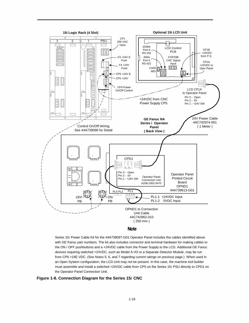
+24VDC Power Connections for Series 15i Control Note
This information applies only to the Series 15i CNC. It does not apply to the Series 16i/18i and 21i CNCs or Power Mate i Motion Controllers. For information on the Series 16i/18i and 21i CNCs or Power Mate i Motion Controllers, please refer to Pages 1-11 through 1-15.
The Series 15i CNC uses its own power supply, which operates from 200 volts ac. The power supply is similar in style to previous generations of Series 15 controls. The power supply mounts in the CNC logic rack and provides power to the Series 15i circuit boards mounted in the rack. The power supply also provides a switched +24VDC that can be used to power the LCD unit, Operator Panel, and other GE Fanuc devices requiring a switched +24VDC. The power supply contains connections to be wired directly to the Control ON and OFF pushbuttons mounted on the Operator Panel.
The North American Operator Panel includes circuitry to provide a switched +24VDC to be used with the Series 16i/18i and 21i CNCs. This circuitry does not apply when the Operator Panel is used with the Series 15i control. Instead, the Operator Panel mounted Control ON and OFF pushbuttons will be wired directly to the Series 15i power supply. The +24VDC required by the Operator Panel may be sourced from the Series 15i power supply.
When used with the Series 15i control, the Operator Panel may be ordered with Cable Kit 44A739097-G01. This kit contains the following items:
Table 1-7. Cable Kit 44A739097-G01
Item Description 44C742962-010 +24VDC Cable PL1 to Connection Unit CPD1. 44C742974-001 +24VDC Cable CPD1 to LCD Unit CP1B. A02B-0120-K323 Connectors for +24VDC. Power Supply CP5 and LCD Unit CP1A
(Qty 2). A02B-0120-K322 Connectors for Power Supply CP4 (Qty 1). 44A293713-101 Terminals for ON and OFF pushbuttons (Qty 4).
Note Materials in the Cable Kit are sized for typical installations. Other cabling configurations are possible to accommodate specific machine requirements and would be provided by the machine tool builder.
Figure 1-8 illustrates the recommended cabling using this Cable Kit for +24VDC power and wiring diagrams for Control ON and OFF pushbuttons.
1-17
The installation of the Series 15i control requires a +24VDC cable from the Series 15i power supply to the LCD unit and a Control ON/OFF pushbutton cable to the control’s power supply. As these cable lengths are determined by the machine design, they cannot be included in a standard cable kit. Required connectors are provided to allow the machine tool builder to construct cables to the required length.
Notes: 1. Refer to the appropriate documentation for the +24VDC fusing requirements for your control.
2. Check all wiring and polarities before applying initial power.
3. External devices and machine I/O requiring +24VDC power may require the use of an external +24VDC power supply.
4. +24E on Power Supply Connector CP6 may be used for external devices. Do not exceed the 2 Amp rating. (Please refer to the following notes regarding the use of 24E from CP6.)
5. When using CP5 as +24VDC source for the Series 15i LCD Unit and North American Operator Panel, as illustrated, current draw of the two devices during normal operation will total approximately 1.5 Amps. Assignment of spare outputs from the Operator Panel to OEM devices, or use of the Operator Panel in special applications requiring the simultaneous illumination of most available pushbuttons, will increase current draw. Current draw from CP5 up to 2 Amps is permitted. However, when driving loads larger than 1 Amp from CP5, the load capacity of CP6 should be de-rated so that the combined 24VDC load supported by CP5 and CP6 does not exceed 3 Amps in total.
6. In certain applications, an alternative method would be to supply 24VDC to the LCD Unit exclusively from connector CP5. CP6 (24E) could then be used for the Operator Panel and external Operator Panel devices, not to exceed 2 Amps.
7. Many applications will generally require an external +24VDC power supply to be used for Machine I/O. It may often be more convenient to supply 24VDC to the Operator Panel and associated Operator Panel devices from the external 24VDC supply.
1-18
CPD1
Operator PanelConnection UnitA20B-2002-0470
Pin 3 - OpenPin 2 - 0VPin 1 - +24V SW
CA55MDI
LCD ControlPCB
COP20BCNC Signal
Input CP1A+24VDC toOper Panel
CP1B +24VDCfrom P.S.
JD36APort 6
RS-232JD6APort 5
RS-422
Optional 15i LCD Unit
Pin 3 - OpenPin 2 - 0VPin 1 - +24V SW
CP1200 VAC
Input
F3 +24V EFuse
F4 +24V Fuse
CP5 +24V
CP6 +24V E
CP4 PowerOn/Off Control
15i Logic Rack (4 Slot)
LCD CP1Ato Operator Panel
PL1-1 +24VDC InputPL1-2 0VDC Input
PL1PL3PL4
Operator PanelPrinted Circuit
BoardOPND1
44A739613-G01
OPND1 to ConnectionUnit Cable
44C742962-010( 250 mm )
24V Power Cable44C742974-001
( 1 Meter )
GE Fanuc NASeries i Operator
Panel( Back View )
1 2 3 4
OFF PB
ONPB
+24VDC from CNCPower Supply CP5
Control On/Off WiringSee 44A739096 for Detail
3
1
2
4
3 2
41
X X
XYXY
Note Series 15i Power Cable Kit for the 44A739097-G01 Operator Panel includes the cables identified above with GE Fanuc part numbers. The kit also includes connector and terminal hardware for making cables to the ON / OFF pushbuttons and a +24VDC cable from the Power Supply to the LCD. Additional GE Fanuc devices requiring switched +24VDC, such as Model A I/O or a Separate Detector Module, may be run from CP6 +24E VDC. (See Notes 5, 6, and 7 regarding current ratings on previous page.) When used in an Open System configuration, the LCD Unit may not be present. In this case, the machine tool builder must assemble and install a switched +24VDC cable from CP5 on the Series 15i PSU directly to CPD1 on the Operator Panel Connection Unit.
Figure 1-8. Connection Diagram for the Series 15i CNC

1-19
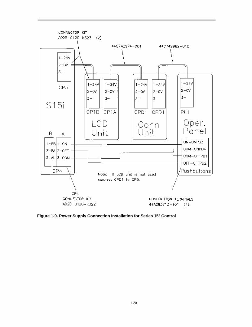
Series 15i Power Supply Connection Installation The North American Operator Panel includes circuitry for switching 24VDC power for a CNC using the Control ON and OFF pushbuttons on that panel. By following the steps listed below, you can modify the Operator Panel for use with the Series 15i CNC, which uses 200VAC power and includes its own switching logic.
1. Remove the cable from the OFF pushbutton to Connector PL4 on the back of the Operator Panel. Also, remove the cable from the ON pushbutton to Connector PL3. You can dispose of these cables. They are not used with the Series 15i control.
2. Using the stab-on terminals provided, construct an ON/OFF cable of the proper length from Connector CP4 on the Series 15i CNC to the ON and OFF pushbuttons on the Operator Panel. For more detailed wiring information, refer to Figure 1-9 below and the Hardware Connection Manual for the Series 15i CNC.
3. Remove any power cable from PL1, Pins 3 and 4, to CPD1 on the Operator Panel Connection Unit. Install the power cable provided, 44C742962-010, from CPD1 to PL1, Pins 1 and 2.
Note If your system includes an LCD, install Cable 44C742962-010 from CPD1 on the Operator Panel Connection to CP1 on the LCD.
4. Construct a power cable of the proper length from CP5 on the Series 15i to CP1 on the LCD or to CPD1 on the Operator Panel Connection Unit, if an LCD is not being used.
The recommended cabling for the 24VDC power and for the ON/OFF circuitry is illustrated in Figure 1-9 on the following page. However, other configurations are possible. For help with other configurations, please contact your local GE Fanuc sales or applications engineer.
1-20
Figure 1-9. Power Supply Connection Installation for Series 15i Control

1-21
Sample Operator Panel Ladder Logic To integrate the North American Operator Panel with the i Series CNC, Programmable Machine Control (PMC) ladder logic must be developed. GE Fanuc Automation can provide examples of the ladder logic to the machine tool builder or system integrator to assist in this development effort.
Examples are available to illustrate common ladder interface methodology and help reduce the overall design effort. GE Fanuc Automation makes no representation that these examples will provide full functionality for every application. It is the machine tool builder’s responsibility to properly develop and test the machine tool's ladder interface for the desired application.
For more information, please contact your local GE Fanuc Automation sales or application engineer.
1-22
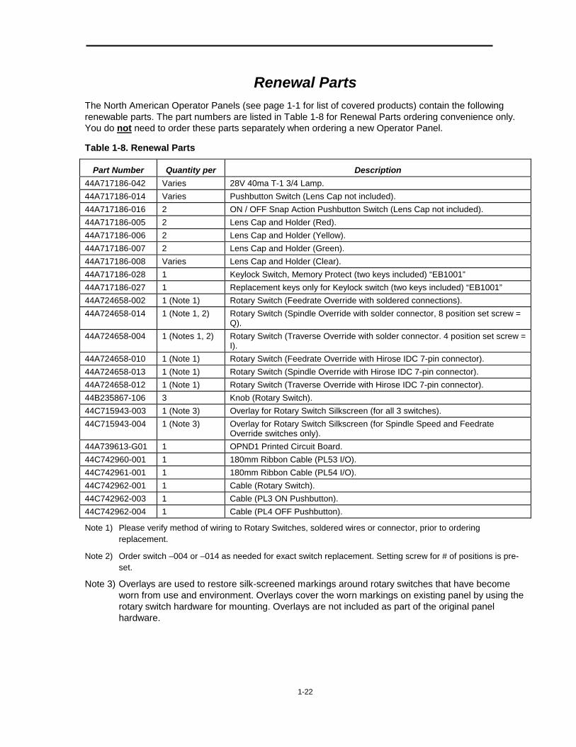
Renewal Parts The North American Operator Panels (see page 1-1 for list of covered products) contain the following renewable parts. The part numbers are listed in Table 1-8 for Renewal Parts ordering convenience only. You do not need to order these parts separately when ordering a new Operator Panel.
Table 1-8. Renewal Parts
Part Number Quantity per Description 44A717186-042 Varies 28V 40ma T-1 3/4 Lamp. 44A717186-014 Varies Pushbutton Switch (Lens Cap not included). 44A717186-016 2 ON / OFF Snap Action Pushbutton Switch (Lens Cap not included). 44A717186-005 2 Lens Cap and Holder (Red). 44A717186-006 2 Lens Cap and Holder (Yellow). 44A717186-007 2 Lens Cap and Holder (Green). 44A717186-008 Varies Lens Cap and Holder (Clear). 44A717186-028 1 Keylock Switch, Memory Protect (two keys included) “EB1001” 44A717186-027 1 Replacement keys only for Keylock switch (two keys included) “EB1001” 44A724658-002 1 (Note 1) Rotary Switch (Feedrate Override with soldered connections). 44A724658-014 1 (Note 1, 2) Rotary Switch (Spindle Override with solder connector, 8 position set screw =
Q). 44A724658-004 1 (Notes 1, 2) Rotary Switch (Traverse Override with solder connector. 4 position set screw =
I). 44A724658-010 1 (Note 1) Rotary Switch (Feedrate Override with Hirose IDC 7-pin connector). 44A724658-013 1 (Note 1) Rotary Switch (Spindle Override with Hirose IDC 7-pin connector). 44A724658-012 1 (Note 1) Rotary Switch (Traverse Override with Hirose IDC 7-pin connector). 44B235867-106 3 Knob (Rotary Switch). 44C715943-003 1 (Note 3) Overlay for Rotary Switch Silkscreen (for all 3 switches). 44C715943-004 1 (Note 3) Overlay for Rotary Switch Silkscreen (for Spindle Speed and Feedrate
Override switches only). 44A739613-G01 1 OPND1 Printed Circuit Board. 44C742960-001 1 180mm Ribbon Cable (PL53 I/O). 44C742961-001 1 180mm Ribbon Cable (PL54 I/O). 44C742962-001 1 Cable (Rotary Switch). 44C742962-003 1 Cable (PL3 ON Pushbutton). 44C742962-004 1 Cable (PL4 OFF Pushbutton).
Note 1) Please verify method of wiring to Rotary Switches, soldered wires or connector, prior to ordering replacement.
Note 2) Order switch –004 or –014 as needed for exact switch replacement. Setting screw for # of positions is pre-set.
Note 3) Overlays are used to restore silk-screened markings around rotary switches that have become worn from use and environment. Overlays cover the worn markings on existing panel by using the rotary switch hardware for mounting. Overlays are not included as part of the original panel hardware.
1-23
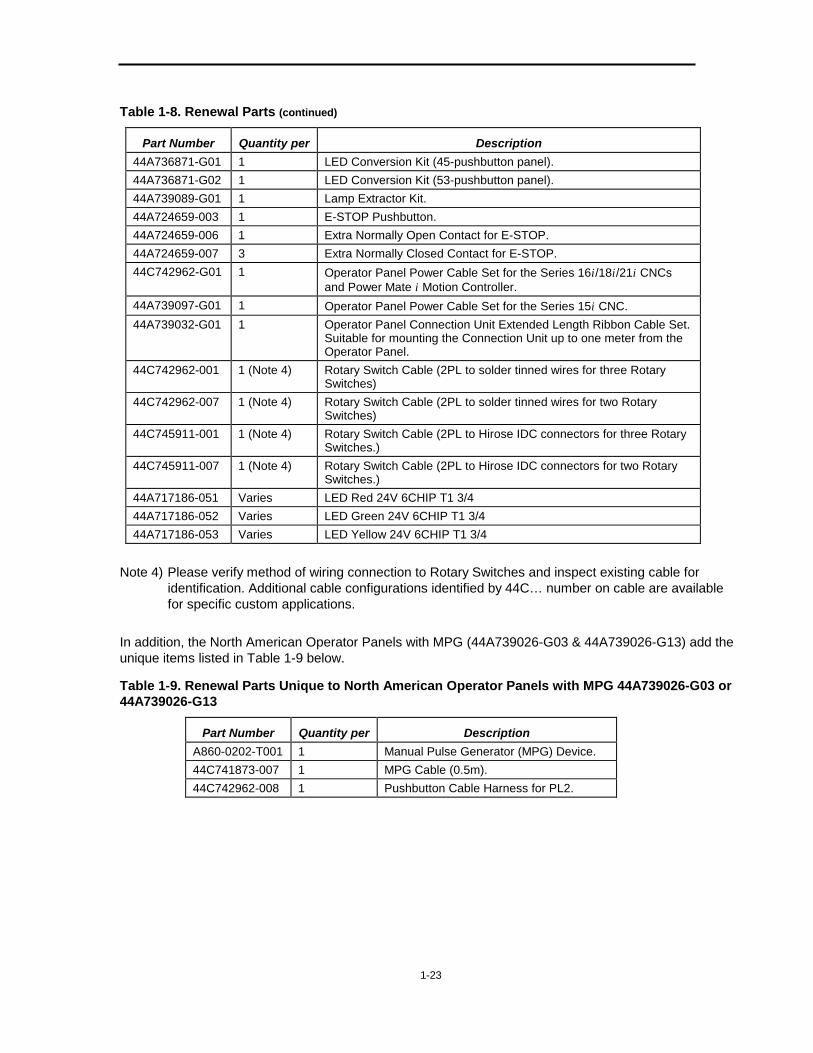
Table 1-8. Renewal Parts (continued)
Part Number Quantity per Description 44A736871-G01 1 LED Conversion Kit (45-pushbutton panel). 44A736871-G02 1 LED Conversion Kit (53-pushbutton panel). 44A739089-G01 1 Lamp Extractor Kit. 44A724659-003 1 E-STOP Pushbutton. 44A724659-006 1 Extra Normally Open Contact for E-STOP. 44A724659-007 3 Extra Normally Closed Contact for E-STOP. 44C742962-G01 1 Operator Panel Power Cable Set for the Series 16i/18i/21i CNCs
and Power Mate i Motion Controller. 44A739097-G01 1 Operator Panel Power Cable Set for the Series 15i CNC. 44A739032-G01 1 Operator Panel Connection Unit Extended Length Ribbon Cable Set.
Suitable for mounting the Connection Unit up to one meter from the Operator Panel.
44C742962-001 1 (Note 4) Rotary Switch Cable (2PL to solder tinned wires for three Rotary Switches)
44C742962-007 1 (Note 4) Rotary Switch Cable (2PL to solder tinned wires for two Rotary Switches)
44C745911-001 1 (Note 4) Rotary Switch Cable (2PL to Hirose IDC connectors for three Rotary Switches.)
44C745911-007 1 (Note 4) Rotary Switch Cable (2PL to Hirose IDC connectors for two Rotary Switches.)
44A717186-051 Varies LED Red 24V 6CHIP T1 3/4 44A717186-052 Varies LED Green 24V 6CHIP T1 3/4 44A717186-053 Varies LED Yellow 24V 6CHIP T1 3/4
Note 4) Please verify method of wiring connection to Rotary Switches and inspect existing cable for
identification. Additional cable configurations identified by 44C… number on cable are available for specific custom applications.
In addition, the North American Operator Panels with MPG (44A739026-G03 & 44A739026-G13) add the unique items listed in Table 1-9 below.
Table 1-9. Renewal Parts Unique to North American Operator Panels with MPG 44A739026-G03 or 44A739026-G13
Part Number Quantity per Description A860-0202-T001 1 Manual Pulse Generator (MPG) Device. 44C741873-007 1 MPG Cable (0.5m). 44C742962-008 1 Pushbutton Cable Harness for PL2.
1-24
Instructions for Using Incandescent Lamps or LEDs All North American Operator Panels may be operated with either incandescent lamps or with LEDs. Table 1-8 lists LED conversion kits for Operator Panels that have incandescent lamps.
Notes: � Jumper JP1 must be in the standard position if lamps are installed, and in the
alternate position if LEDs are installed. (See “JP1 Setting”, below.)
� Do not mix lamps and LEDs.
� Each LED should be mounted behind a lens cap of the same color, otherwise the emitted light may not pass through.
JP1 Setting All North American Operators Panels have a jumper (JP1) that must be set up differently depending on whether incandescent lamps are used, or LEDs are used. On the Series i compatible units, JP1 is located on circuit board OPND1, behind and below the Cycle Start Pushbutton.
� For use with incandescent lamps, place the jumper JP1inside the silk-screened rectangle marking. This will result in the jumper being located across the two pins furthest from the nearby corner of the circuit board OPND1. When the jumper is set this way, the lamp filaments are pre-heated when off, and will result in longer lamp life.
� For use with LEDs, place the jumper JP1 in its alternate setting (i.e. not inside the rectangle). This will result in the jumper being located across the two pins closest to the nearby corner of the circuit board OPND1.
Verifying Correct Setting of JP1 There are simple tests that can be performed to verify that the jumper JP1 is set correctly.
� If incandescent lamps are installed, remove the lens cap of a couple of the unlit pushbuttons. A dim glow will be visible in the filament of each unlit lamp when the jumper JP1 is correctly positioned. If the ambient light is low, this effect is visible even with the lens caps in place, so this effect can also be used to check for blown lamps. If none of the "off" lamps is glowing dimly, it is likely that JP1 is in the wrong position.
� If LEDs are installed, they will glow dimly if the jumper JP1 is positioned incorrectly. And, as additional pushbuttons are activated, the LEDs that are supposed to be off will glow a little more brightly each time. No damage will result to the LEDs, but the operator could become confused. So, if LEDs that are supposed to be off are in fact glowing, the setting of jumper JP1 should be changed. It is possible to remove a few lens caps to get a better view of the LEDs underneath while conducting this test.
WARNING! The +24VDC power supplied to the Operator Panel is typically NOT removed from the operator panel by CNC's Control Off logic. Please refer to the electrical schematics provided by the Machine Tool Builder for specifics.
CAUTION When removing the incandescent lamps, take care to use the extractor tool 44A739089-G01. If the specified extractor tool is not available, use only a non-metallic/non-conductive device to remove the incandescent lamps. Damage to circuitry may result when attempting to remove lamps with conductive tooling such as needle-nose pliers while +24VDC is applied to the operator panel. Even if no circuit damage results, shorting out the lamp circuit will lead to an I/O error which will disrupt operation of the machine tool.


SECTION 2:
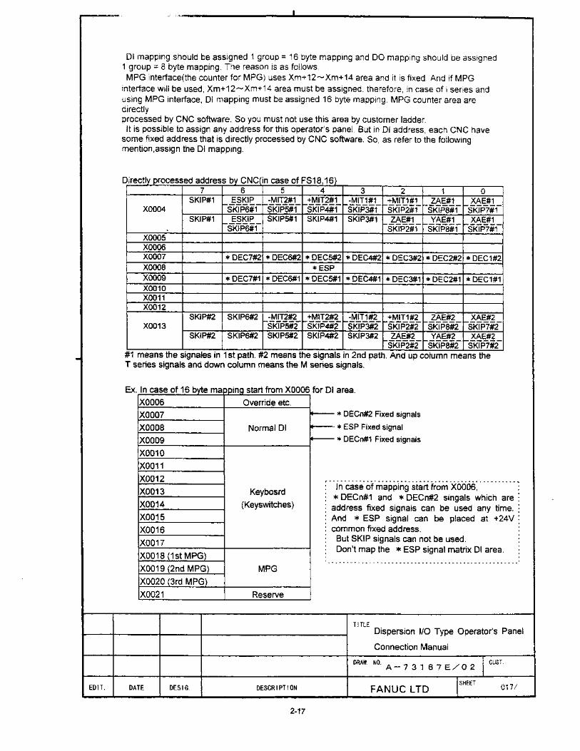
DISPERSION I/O TYPE OPERATOR PANEL
This section contains:
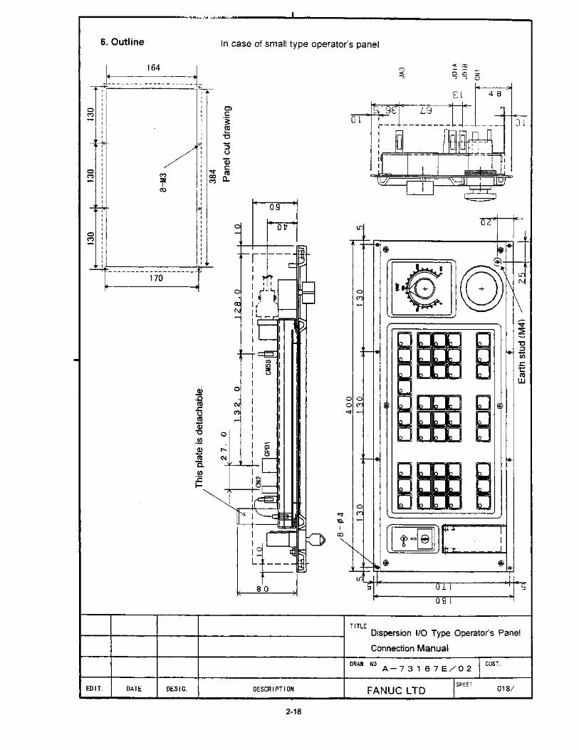
• Drawing No. A-73167E/02 for Dispersion I/O Type Operator Panels:
� A02B-0236-C140 (Full Keyboard).
� A02B-0236-C141 (Small Keyboard).


SECTION 3:
72 IN / 56 OUT CONNECTION UNIT
This section contains:
• Drawing A-71199E/03 for Operator Panel Connection Unit A20B-2002-0470.
Note
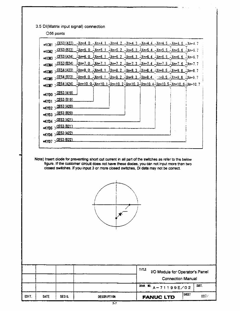
Inputs are multiplexed.
This panel must be ordered separately for use with all GE Fanuc North American i Series Operator Panels.


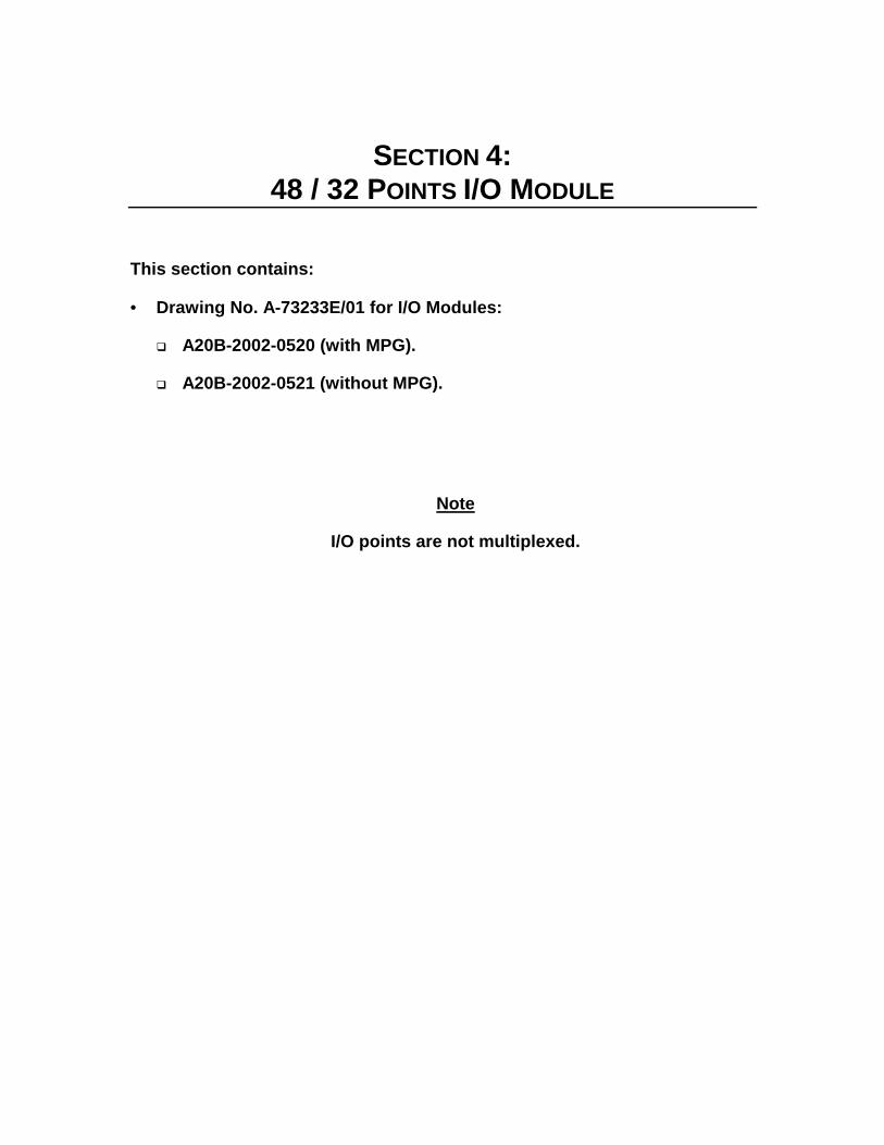
SECTION 4:
48 / 32 POINTS I/O MODULE
This section contains:
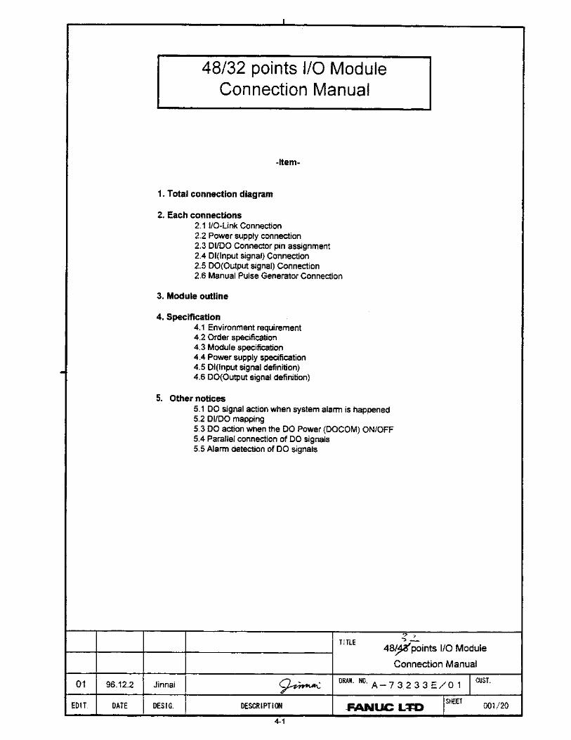
• Drawing No. A-73233E/01 for I/O Modules:
� A20B-2002-0520 (with MPG).
� A20B-2002-0521 (without MPG).
Note
I/O points are not multiplexed.


• No part of this manual may bereproduced in any form.
• All specifications and designsare subject to change withoutnotice.


