97
GE Fanuc Automation Computer Numerical Control Products Series 16-LB Descriptions Manual GFZ-62592EN/01 July 1995
| Date post: | 08-Mar-2018 |
| Category: |
Documents |
| Upload: | truongduong |
| View: | 219 times |
| Download: | 3 times |

GE Fanuc Automation
Computer Numerical Control Products
Series 16-LB
Descriptions Manual
GFZ-62592EN/01 July 1995

GFL-001
Warnings, Cautions, and Notesas Used in this Publication
Warning
Warning notices are used in this publication to emphasize that hazardous voltages, currents,temperatures, or other conditions that could cause personal injury exist in this equipment ormay be associated with its use.
In situations where inattention could cause either personal injury or damage to equipment, aWarning notice is used.
Caution
Caution notices are used where equipment might be damaged if care is not taken.
NoteNotes merely call attention to information that is especially significant to understanding andoperating the equipment.
This document is based on information available at the time of its publication. While effortshave been made to be accurate, the information contained herein does not purport to cover alldetails or variations in hardware or software, nor to provide for every possible contingency inconnection with installation, operation, or maintenance. Features may be described hereinwhich are not present in all hardware and software systems. GE Fanuc Automation assumesno obligation of notice to holders of this document with respect to changes subsequently made.
GE Fanuc Automation makes no representation or warranty, expressed, implied, or statutorywith respect to, and assumes no responsibility for the accuracy, completeness, sufficiency, orusefulness of the information contained herein. No warranties of merchantability or fitness forpurpose shall apply.
©Copyright 1995 GE Fanuc Automation North America, Inc.All Rights Reserved.

Table of ContentsB–62592EN/01
c–1
1. GENERAL 1. . . . . . . . . . . . . . . . . . . . . . . . . . . . . . . . . . . . . . . . . . . . . . . . . . . . . . . . . . . . . . . . . .
2. SPECIFICATIONS 2. . . . . . . . . . . . . . . . . . . . . . . . . . . . . . . . . . . . . . . . . . . . . . . . . . . . . . . . . . .
3. FUNCTIONS DIFFERENT FROM THOSE OF THE M SERIES CNC 13. . . . . . . . . . . . . . .
3.1 EMERGENCY STOP 14. . . . . . . . . . . . . . . . . . . . . . . . . . . . . . . . . . . . . . . . . . . . . . . . . . . . . . . . . . . . . .
3.2 FEED HOLD 14. . . . . . . . . . . . . . . . . . . . . . . . . . . . . . . . . . . . . . . . . . . . . . . . . . . . . . . . . . . . . . . . . . . . .
3.3 MACHINE LOCK 14. . . . . . . . . . . . . . . . . . . . . . . . . . . . . . . . . . . . . . . . . . . . . . . . . . . . . . . . . . . . . . . . .
3.4 DRY RUN 14. . . . . . . . . . . . . . . . . . . . . . . . . . . . . . . . . . . . . . . . . . . . . . . . . . . . . . . . . . . . . . . . . . . . . . .
3.5 SINGLE BLOCK 14. . . . . . . . . . . . . . . . . . . . . . . . . . . . . . . . . . . . . . . . . . . . . . . . . . . . . . . . . . . . . . . . . .
3.6 PROGRAM RESTART (0–L SPECIFICATION) 14. . . . . . . . . . . . . . . . . . . . . . . . . . . . . . . . . . . . . . . . .
4. LASER FUNCTIONS 15. . . . . . . . . . . . . . . . . . . . . . . . . . . . . . . . . . . . . . . . . . . . . . . . . . . . . . . .
4.1 LASER INTERFACE 16. . . . . . . . . . . . . . . . . . . . . . . . . . . . . . . . . . . . . . . . . . . . . . . . . . . . . . . . . . . . . .
4.2 CONNECTABLE OSCILLATORS 17. . . . . . . . . . . . . . . . . . . . . . . . . . . . . . . . . . . . . . . . . . . . . . . . . . . .
4.3 LASER FUNCTIONS 18. . . . . . . . . . . . . . . . . . . . . . . . . . . . . . . . . . . . . . . . . . . . . . . . . . . . . . . . . . . . . .
5. LASER SEQUENCE CONTROL 19. . . . . . . . . . . . . . . . . . . . . . . . . . . . . . . . . . . . . . . . . . . . . .
5.1 SEQUENCE CONTROL OF THE C AND Y SERIES LASER OSCILLATORS 20. . . . . . . . . . . . . . . .
5.2 SEQUENCE CONTROL OF THE YP SERIES LASER OSCILLATOR 21. . . . . . . . . . . . . . . . . . . . . .
6. ASSIST GAS CONTROL 22. . . . . . . . . . . . . . . . . . . . . . . . . . . . . . . . . . . . . . . . . . . . . . . . . . . .
6.1 ASSIST GAS CONTROL 23. . . . . . . . . . . . . . . . . . . . . . . . . . . . . . . . . . . . . . . . . . . . . . . . . . . . . . . . . . .
6.2 ASSIST GAS PRESSURE ANALOG OUTPUT 25. . . . . . . . . . . . . . . . . . . . . . . . . . . . . . . . . . . . . . . . .
6.3 ASSIST GAS PRESSURE OVERRIDE 26. . . . . . . . . . . . . . . . . . . . . . . . . . . . . . . . . . . . . . . . . . . . . . . .
7. SHUTTER OPEN/CLOSE CONTROL 27. . . . . . . . . . . . . . . . . . . . . . . . . . . . . . . . . . . . . . . . .
8. LASER OUTPUT CONTROL 28. . . . . . . . . . . . . . . . . . . . . . . . . . . . . . . . . . . . . . . . . . . . . . . . .
8.1 C AND Y SERIES LASER CONTROL 29. . . . . . . . . . . . . . . . . . . . . . . . . . . . . . . . . . . . . . . . . . . . . . . .
8.1.1 Power Value Command and Power Override 30. . . . . . . . . . . . . . . . . . . . . . . . . . . . . . . . . . . . . . . .
8.1.2 Pulse Frequency Command and Frequency Override 31. . . . . . . . . . . . . . . . . . . . . . . . . . . . . . . . .
8.1.3 Pulse Duty Cycle Command and Duty Cycle Override 32. . . . . . . . . . . . . . . . . . . . . . . . . . . . . . . .
8.1.4 Piercing Command 33. . . . . . . . . . . . . . . . . . . . . . . . . . . . . . . . . . . . . . . . . . . . . . . . . . . . . . . . . . . .
8.1.5 External Alteration of the Piercing Time 33. . . . . . . . . . . . . . . . . . . . . . . . . . . . . . . . . . . . . . . . . . .
8.1.6 Power Control 34. . . . . . . . . . . . . . . . . . . . . . . . . . . . . . . . . . . . . . . . . . . . . . . . . . . . . . . . . . . . . . . .
8.1.7 Laser Machining Program Example 35. . . . . . . . . . . . . . . . . . . . . . . . . . . . . . . . . . . . . . . . . . . . . . .
8.2 YP SERIES LASER CONTROL 36. . . . . . . . . . . . . . . . . . . . . . . . . . . . . . . . . . . . . . . . . . . . . . . . . . . . . .
8.2.1 Waveform Data Setting Function 36. . . . . . . . . . . . . . . . . . . . . . . . . . . . . . . . . . . . . . . . . . . . . . . . .
8.2.2 Waveform Data Registration Function 36. . . . . . . . . . . . . . . . . . . . . . . . . . . . . . . . . . . . . . . . . . . . .
8.2.3 Execution Sequence Data Registration Function 37. . . . . . . . . . . . . . . . . . . . . . . . . . . . . . . . . . . . .
8.2.4 Output Command 38. . . . . . . . . . . . . . . . . . . . . . . . . . . . . . . . . . . . . . . . . . . . . . . . . . . . . . . . . . . . .
8.2.5 Override 38. . . . . . . . . . . . . . . . . . . . . . . . . . . . . . . . . . . . . . . . . . . . . . . . . . . . . . . . . . . . . . . . . . . .
8.2.6 Display and Setting 39. . . . . . . . . . . . . . . . . . . . . . . . . . . . . . . . . . . . . . . . . . . . . . . . . . . . . . . . . . . .

����� � ������ B–62592EN/01
c–2
8.2.7 Alarms 39. . . . . . . . . . . . . . . . . . . . . . . . . . . . . . . . . . . . . . . . . . . . . . . . . . . . . . . . . . . . . . . . . . . . . .
8.2.8 Program example 40. . . . . . . . . . . . . . . . . . . . . . . . . . . . . . . . . . . . . . . . . . . . . . . . . . . . . . . . . . . . .
8.3 CUTTING CONDITION SETTING FUNCTION 41. . . . . . . . . . . . . . . . . . . . . . . . . . . . . . . . . . . . . . . .
8.3.1 Data Area 41. . . . . . . . . . . . . . . . . . . . . . . . . . . . . . . . . . . . . . . . . . . . . . . . . . . . . . . . . . . . . . . . . . .
8.3.2 Displaying the Data 43. . . . . . . . . . . . . . . . . . . . . . . . . . . . . . . . . . . . . . . . . . . . . . . . . . . . . . . . . . . .
8.3.3 Updating the Data 43. . . . . . . . . . . . . . . . . . . . . . . . . . . . . . . . . . . . . . . . . . . . . . . . . . . . . . . . . . . . .
8.3.4 Executing the Data 44. . . . . . . . . . . . . . . . . . . . . . . . . . . . . . . . . . . . . . . . . . . . . . . . . . . . . . . . . . . .
8.3.5 Program Example 45. . . . . . . . . . . . . . . . . . . . . . . . . . . . . . . . . . . . . . . . . . . . . . . . . . . . . . . . . . . . .
8.3.6 Sending the Data 46. . . . . . . . . . . . . . . . . . . . . . . . . . . . . . . . . . . . . . . . . . . . . . . . . . . . . . . . . . . . . .
8.4 HIGH–SPEED PIERCING FUNCTION 47. . . . . . . . . . . . . . . . . . . . . . . . . . . . . . . . . . . . . . . . . . . . . . . .
8.4.1 Power Control 47. . . . . . . . . . . . . . . . . . . . . . . . . . . . . . . . . . . . . . . . . . . . . . . . . . . . . . . . . . . . . . . .
8.4.2 Command 47. . . . . . . . . . . . . . . . . . . . . . . . . . . . . . . . . . . . . . . . . . . . . . . . . . . . . . . . . . . . . . . . . . .
8.5 EDGE MACHINING FUNCTION 48. . . . . . . . . . . . . . . . . . . . . . . . . . . . . . . . . . . . . . . . . . . . . . . . . . . .
8.5.1 Detecting the Edge 48. . . . . . . . . . . . . . . . . . . . . . . . . . . . . . . . . . . . . . . . . . . . . . . . . . . . . . . . . . . .
8.5.2 Feedrate and Power Control 49. . . . . . . . . . . . . . . . . . . . . . . . . . . . . . . . . . . . . . . . . . . . . . . . . . . . .
8.5.3 Data Setting 50. . . . . . . . . . . . . . . . . . . . . . . . . . . . . . . . . . . . . . . . . . . . . . . . . . . . . . . . . . . . . . . . . .
8.5.4 Command 50. . . . . . . . . . . . . . . . . . . . . . . . . . . . . . . . . . . . . . . . . . . . . . . . . . . . . . . . . . . . . . . . . . .
8.6 START–UP FUNCTION 51. . . . . . . . . . . . . . . . . . . . . . . . . . . . . . . . . . . . . . . . . . . . . . . . . . . . . . . . . . . .
8.6.1 Feedrate and Power Control 51. . . . . . . . . . . . . . . . . . . . . . . . . . . . . . . . . . . . . . . . . . . . . . . . . . . . .
8.6.2 Setting the Data 51. . . . . . . . . . . . . . . . . . . . . . . . . . . . . . . . . . . . . . . . . . . . . . . . . . . . . . . . . . . . . . .
8.6.3 Command 51. . . . . . . . . . . . . . . . . . . . . . . . . . . . . . . . . . . . . . . . . . . . . . . . . . . . . . . . . . . . . . . . . . .
8.7 GUIDE LIGHT ON SIGNAL 52. . . . . . . . . . . . . . . . . . . . . . . . . . . . . . . . . . . . . . . . . . . . . . . . . . . . . . . .
8.8 STATUS OUTPUT SIGNAL 53. . . . . . . . . . . . . . . . . . . . . . . . . . . . . . . . . . . . . . . . . . . . . . . . . . . . . . . . .
8.8.1 Piercing Signal 53. . . . . . . . . . . . . . . . . . . . . . . . . . . . . . . . . . . . . . . . . . . . . . . . . . . . . . . . . . . . . . .
8.8.2 Laser Processing Signal 53. . . . . . . . . . . . . . . . . . . . . . . . . . . . . . . . . . . . . . . . . . . . . . . . . . . . . . . .
8.8.3 Output Drop Alarm Signal 53. . . . . . . . . . . . . . . . . . . . . . . . . . . . . . . . . . . . . . . . . . . . . . . . . . . . . .
8.8.4 Laser Alarm Signal 53. . . . . . . . . . . . . . . . . . . . . . . . . . . . . . . . . . . . . . . . . . . . . . . . . . . . . . . . . . . .
8.8.5 Status Output Signals 54. . . . . . . . . . . . . . . . . . . . . . . . . . . . . . . . . . . . . . . . . . . . . . . . . . . . . . . . . .
9. TRACING CONTROL 55. . . . . . . . . . . . . . . . . . . . . . . . . . . . . . . . . . . . . . . . . . . . . . . . . . . . . . .
9.1 TRACING FUNCTION 56. . . . . . . . . . . . . . . . . . . . . . . . . . . . . . . . . . . . . . . . . . . . . . . . . . . . . . . . . . . . .
9.1.1 Interface 56. . . . . . . . . . . . . . . . . . . . . . . . . . . . . . . . . . . . . . . . . . . . . . . . . . . . . . . . . . . . . . . . . . . .
9.1.2 Reference Deviation 56. . . . . . . . . . . . . . . . . . . . . . . . . . . . . . . . . . . . . . . . . . . . . . . . . . . . . . . . . . .
9.1.3 Tracing Speed 57. . . . . . . . . . . . . . . . . . . . . . . . . . . . . . . . . . . . . . . . . . . . . . . . . . . . . . . . . . . . . . . .
9.1.4 Tracing Gain Override 57. . . . . . . . . . . . . . . . . . . . . . . . . . . . . . . . . . . . . . . . . . . . . . . . . . . . . . . . .
9.1.5 Command 57. . . . . . . . . . . . . . . . . . . . . . . . . . . . . . . . . . . . . . . . . . . . . . . . . . . . . . . . . . . . . . . . . . .
9.1.6 Tracing Adjustment Function 57. . . . . . . . . . . . . . . . . . . . . . . . . . . . . . . . . . . . . . . . . . . . . . . . . . . .
9.1.7 Tracing Alarms 58. . . . . . . . . . . . . . . . . . . . . . . . . . . . . . . . . . . . . . . . . . . . . . . . . . . . . . . . . . . . . . .
9.2 TRACING INTERLOCK FUNCTION 59. . . . . . . . . . . . . . . . . . . . . . . . . . . . . . . . . . . . . . . . . . . . . . . . .
9.3 TRACING AXIS SELECTION FUNCTION 60. . . . . . . . . . . . . . . . . . . . . . . . . . . . . . . . . . . . . . . . . . . .
10. FUNCTION FOR THREE–DIMENSIONAL PROCESSING SYSTEM 61. . . . . . . . . . . . .
10.1 ATTITUDE CONTROL 62. . . . . . . . . . . . . . . . . . . . . . . . . . . . . . . . . . . . . . . . . . . . . . . . . . . . . . . . . . . .
10.1.1 Attitude Control A (Zero Offset Type Nozzle) 63. . . . . . . . . . . . . . . . . . . . . . . . . . . . . . . . . . . . . . .
10.1.2 Attitude Control B (Offset Type Nozzle) 64. . . . . . . . . . . . . . . . . . . . . . . . . . . . . . . . . . . . . . . . . . .
10.1.3 Interaction Control 66. . . . . . . . . . . . . . . . . . . . . . . . . . . . . . . . . . . . . . . . . . . . . . . . . . . . . . . . . . . .
10.2 TEACHING BOX INTERFACE 67. . . . . . . . . . . . . . . . . . . . . . . . . . . . . . . . . . . . . . . . . . . . . . . . . . . . . .
����� � ������B–62592EN/01
c–3
10.3 THREE–DIMENSIONAL CONTROL FUNCTION 69. . . . . . . . . . . . . . . . . . . . . . . . . . . . . . . . . . . . . .
10.3.1 W Axis Tracing Control 69. . . . . . . . . . . . . . . . . . . . . . . . . . . . . . . . . . . . . . . . . . . . . . . . . . . . . . . .
10.3.2 Spatial Circular Interpolation 70. . . . . . . . . . . . . . . . . . . . . . . . . . . . . . . . . . . . . . . . . . . . . . . . . . . .
10.3.3 Three–Dimensional Coordinate Conversion 71. . . . . . . . . . . . . . . . . . . . . . . . . . . . . . . . . . . . . . . . .
10.3.4 Spatial Corner–R Insertion 72. . . . . . . . . . . . . . . . . . . . . . . . . . . . . . . . . . . . . . . . . . . . . . . . . . . . . .
10.3.5 Three–Dimensional Conversion Function 73. . . . . . . . . . . . . . . . . . . . . . . . . . . . . . . . . . . . . . . . . .
10.3.6 Proximity Point Search 75. . . . . . . . . . . . . . . . . . . . . . . . . . . . . . . . . . . . . . . . . . . . . . . . . . . . . . . . .
10.3.7 Manual Operation Using a Hand Coordinate System 76. . . . . . . . . . . . . . . . . . . . . . . . . . . . . . . . . .
11. CONTROL FUNCTIONS 77. . . . . . . . . . . . . . . . . . . . . . . . . . . . . . . . . . . . . . . . . . . . . . . . . . . .
11.1 OPTICAL PATH LENGTH COMPENSATION 78. . . . . . . . . . . . . . . . . . . . . . . . . . . . . . . . . . . . . . . . . .
11.2 MACHINING RESTART FUNCTION 80. . . . . . . . . . . . . . . . . . . . . . . . . . . . . . . . . . . . . . . . . . . . . . . . .
APPENDIX
A. LASER SETTING SCREEN 85. . . . . . . . . . . . . . . . . . . . . . . . . . . . . . . . . . . . . . . . . . . . . . . . . .
B. CUTTING CONDITION SETTING SCREENS 87. . . . . . . . . . . . . . . . . . . . . . . . . . . . . . . . . .
C. YP SERIES LASER CONTROL SCREENS 89. . . . . . . . . . . . . . . . . . . . . . . . . . . . . . . . . . . .

B–62592EN/01 1. GENERAL
1
1 GENERAL
The FANUC Series 16–LB is a CNC dedicated for use in a laser machinetool and developed based on the FANUC Series 16–MODEL B. Whencombined with a FANUC laser, it can be configured into a laser machinetool.
This manual supplements “FANUC Series 16/18/160/180–MODEL BDescriptions” (B–62442E) by adding descriptions of laser functions.
This manual handles the model listed below.The model name is abbreviated herein as listed in the following table.
Product name Abbreviations
FANUC Series 16–LB 16–LB M series
The table below lists manuals related to the FANUC Series 16–LB. In thetable, this manual is marked with an asterisk (*).
Manuals Related to the Series 16–LB
Manual name Specificationnumber
FANUC Series 16–LB DESCRIPTIONS B–62592EN *
FANUC Series 16–LB CONNECTION MANUAL B–62593EN
FANUC Series 16–LB OPERATOR’S MANUAL B–62594EN
FANUC Series 16–LB MAINTENANCE MANUAL B–62595EN
FANUC Series 16–LB PARAMETER MANUAL B–62600EN
FANUC Series 16/18/160/180–MODEL B DESCRIPTIONS
B–62442E
FANUC Series 16/18/160/180–MODEL B CONNECTION MANUAL (Hardware)
B–62443E
FANUC Series 16/18/160/180–MODEL B CONNECTION NANUAL (Function)
B–62443E–1
FANUC Series 16/18/160/180–MODEL B OPERATOR’S MANUAL (For Machining Center)
B–62454E
FANUC Series 16/18/160/180–MODEL B MAINTENANCE MANUAL
B–62445E
FANUC Series 16/18/160/180–MODEL B PARAMETER MANUAL
B–62450E
FANUC Series 16/18/20 PROGRAMMING MANUAL(Macro Compiler/Macro Executer)
B–61803E–1
FAPT MACRO COMPILER PROGRAMMING MANUAL B–66102E
Manuals related toSeries 16–LB

B–62592EN/012. SPECIFICATIONS
2
2 SPECIFICATIONS
For functions other than the laser functions, refer to “FANUC Series16/18/160/180–MODEL B Descriptions” (B–62442E).
Some functions described in manual B–62442E may not be supported bythe 16–LB or may differ from those of this model.
The following table lists the functions supported by the 16–LB. Anyfunctions not listed below are not supported by the 16–LB.
The meanings of the symbols used in the table are:� : Standard functions of the 16–LB� : Optional functions of the 16–LB
: Functions different in part
ReferencesRefer to:
A: FANUC Series 16/18/160/180–MODEL B Descriptions(B–62442E)
B: This manual
Axis control
Item Specifications Usable Referencemanual
Max. controlled axes Machine 8 axes × 1–path � A
Controlled path 1–path � A
Controlled axes 3 axes � A
Machine controlled
Simultaneous controllable axes 3 axes � Acontrolled axes Controllable axes expansion (total) 8 axes � A
Simultaneous controllable axes expansion (total) 6 axes � A
Axis control by PMC Max. simultaneous 4 axes per path � A
Axis name Optional from X, Y, Z, U, V, W, A, B, C � A
Simple synchronous control � A
Tandem control � A
Controlled axis detach � A
Least input increment 0.001mm, 0.001deg, 0.0001inch � A
Flexible feed gear Optional DMR � A
Dual position feedback � A

B–62592EN/01 2. SPECIFICATIONS
3
ItemReference
manualUsableSpecifications
Inch/metric conversion � A
Interlock All axes / each axis / cutting block start � A
Machine lock All axes / each axis � A/B
Emergency stop � A/B
Overtravel signal � A
Stored stroke check 1 � A
Stroke limit external setting � A
Stored stroke check 2 � A
Mirror image Each axis � A
Follow–up � A
Servo–off / mechanical handle feed � A
Backlash compensation � A
Backlash compensation for each rapid traverse and cutting feed � A
Stored pitch error compensation � A
Position switch � A
Operation
Item Specifications Usable Referencemanual
Automatic operation (memory) � A
DNC operation Reader/puncher interface is required. � A
MDI operation � A
Program number search � A
Sequence number search � A
Sequence number comparison and stop � A
Program restart � A/B
Manual interruption & recover � A
Buffer register � A
Dry run � A/B
Single block � A/B
Manual continuous feed (JOG) � A
Manual reference position return � A
Reference position setting without DOG � A
Manual handle feed 1 unit / 2 units / 3 units � A

B–62592EN/012. SPECIFICATIONS
4
Item Specifications Usable Referencemanual
Manual handle feed rate � A
Manual handle interruption � A
Incremental feed ×1, ×10, ×100, ×1000 � A
Jog and handle simultaneous mode � A
Interpolation
Item Specifications Usable Referencemanual
PositioningG00 (Linear interpolation type positioningis possible) � A
Single direction positioning G60 � A
Exact stop mode G61 � A
Exact stop G09 � A
Linear interpolation G01 � A
Circular interpolation G02, G03 Multi–quadrant is possible � A
Dwell Dwell in seconds � A
Polar coordinate interpolation � A
Cylindrical interpolation � A
Helical interpolationCircular interpolation plus max. 2 axes lin-ear interpolation � A
Skip function G31 � A
Reference position return G28 � A
Reference position return check G27 � A
2nd reference position return � A
3rd/4th reference position return � A
Floating reference position return � A
Normal direction control � A

B–62592EN/01 2. SPECIFICATIONS
5
Feed function
Item Specifications Usable Referencemanual
Rapid traverse Max. 240m/min (1µm) � A
Rapid traverse override F0, 25, 50, 100% � A
Feed per minute mm/min � A
Tangential speed constant control � A
Cutting feedrate clamp � A
Automatic acceleration/decelerationRapid traverse : linearCutting feed : linear
� A
Rapid traverse bell–shaped acceleration / deceleration � A
Linear acceleration/deceleration after cutting feed interpolation � A
Bell–shaped acceleration/deceleration after cutting feed � A
Linear acceleration/deceleration before cutting feed interpolation � A
Feedrate override 0 to 254% � A
2nd feedrate override 0 to 254% � A
Jog override 0 to 655.34% � A
Override cancel � A
External deceleration � A
Feed stop � A
Look–ahead control � A
Program input
Item Specifications Usable Referencemanual
Tape code EIA RS244/ISO840 automatic recognition � A
Label skip � A
Parity check Horizontal and vertical parity � A
Control in/out � A
Optional block skip1 � A
O tional block ski9 � A
Max. programmable dimension ±8–digit � A
Program number O4–digit � A
Sequence number N5–digit � A
Absolute/incremental programming Combined use in the same block � A
Decimal point input/pocket calculator type decimal point input � A
Input unit 10 time multiply � A

B–62592EN/012. SPECIFICATIONS
6
ItemReference
manualUsableSpecifications
Plane selection G17, G18, G19 � A
Rotary axis designation � A
Rotary axis roll over � A
Polar coordinate command � A
Coordinate system setting � A
Automatic coordinate system setting � A
Workpiece coordinate system G52–G59 � A
Workpiece coordinate system preset � A
Addition of workpiece coordinate system pair48 pairs � A
Addition of work iece coordinate system air300 pairs � A
Manual absolute on/off � A
Optional chamfering/corner R � A
Programmable data input G10 � A
Sub program call 4 folds nested � A
Custom macro B � A
Addition of custom macro common variables #100 to #199, #500 to #999 � A
Pattern data input � A
Interruption type custom macro � A
Radius designation on arc � A
Automatic corner override � A
Automatic corner deceleration � A
Feedrate clamp by circular radius � A
Scaling � A
Coordinate system rotation � A
Programmable mirror image � A
Figure copying � A
Retrace function � A
Tape format for FS15 � A
Conversional programming with graphic function � A
Macro executer Max. 4MB � A
C language executer Max. 4MB � A
MMC–III � A
MMC–IV � A

B–62592EN/01 2. SPECIFICATIONS
7
Auxiliary / Spindle function
Item Specifications Usable Referencemanual
Auxiliary function M8–digit � A
2nd auxiliary function B8–digit � A
Auxiliary function lock � A
High speed M, S, T, B interface � A
Multiple command of auxiliary function 3 � A
M code group check � A
Tool function / Tool compensation
Item Specifications Usable Referencemanual
Tool function T8 digits � A
±6 digits 32 � A
±6 digits 64 � A
±6 digits 99 � A
Tool offset ±6 digits 200 � A
±6 digits 400 � A
±6 digits 499 � A
±6 digits 999 � A
Tool offset memory B Geometry/wear memory � A
Tool offset memory CDistinction between geometry and wear, orbetween cutter and tool length compensa-tion
� A
Tool length compensation � A
Tool offset � A
Cutter compensation C � A

B–62592EN/012. SPECIFICATIONS
8
Editing operation
Item Specifications Usable Referencemanual
160m � A
Part program storage length320m � A
Part rogram storage length640m � A
1280m � A
Part program editing � A
Program protect � A
Password function � A
Background editing � A
Extended part program editing � A
Playback � A
Machining time stamp function � A
Setting and display
Item Specifications Usable Referencemanual
Status display � A
Clock function � A
Program display Program name 16 characters � A
Self–diagnosis function � A
Alarm display � A
Alarm history displayDisplay of PMC alarm message, macroalarm message � A
Operator message history display � A
Operation history display � A
Help function � A
Run hour and parts count display � A
Actual cutting speed display � A
T code display � A
Directory display of floppy cassette � A
Graphic display � A
Dynamic graphic display � A
Servo setting screen � A
Servo waveform display Graphic display circuit is required � A
Display of hardware and software configuration � A

B–62592EN/01 2. SPECIFICATIONS
9
ItemReference
manualUsableSpecifications
Software operator’s panel � A
Software operator’s panel general purpose switch � A
English � A
Japanese (Chinese character) � A
Multi–language display German / French � A
Italian � A
Spanish � A
Data protection key 3 types � A
Data input/output
Item Specifications Usable Referencemanual
Reader/puncher interfaceReader/puncher(Ch.1) interface � A
Reader/ uncher interfaceReader/puncher(Ch.2) interface � A
Input/output simultaneous operation � A
Remote buffer � A
High–speed remote buffer A � A
High–speed remote buffer B � A
External I/O device control � A
DNC1 controlUploading/downloading a part program,Reading/writing CNC data, Transfer ofPMC data, Memory operation control, etc.
� A
DNC2 controlUploading/downloading a part program,Reading/writing CNC data, Transfer ofPMC data, Memory operation control, etc.
� A
External tool offset � A
External message � A
External machine zero point shift � A
External data input Including above 3 items � A
External workpiece number search 15 � A
External program input 1 to 9999 � A
External program number search � A
FANUC Handy File � A
FANUC FLOPPY CASSETTE � A

B–62592EN/012. SPECIFICATIONS
10
ItemReference
manualUsableSpecifications
FANUC PROGRAM File Mate � A
Memory card interface For data backup and user program loading � A
Others
Item Specifications Usable Referencemanual
Abnormal load detection � A
Status output signal
NC ready, servo ready, automatic opera-tion, automatic operation start lamp, feedhold, reset, NC alarm, distribution end, re-winding, inch input, cutting, imposition,thread cutting, tapping, etc.
� A
9” monochrome CRT/MDI (small size) � A
9” monochrome CRT/MDI (standard size) � A
9” color CRT/MDI (small size) � A
9” color CRT/MDI (standard size) � A
9” monochrome PDP/MDI (standard size) � A
14” color CRT/MDI (horizontal type) � A
14” color CRT/MDI (vertical type) � A
Setting and display unit 9” monochrome CRT (separate type) � A
9” color CRT (separate type) � A
9” monochrome PDP (separate type) � A
8.4” color LCD (separate type) � A
9.5” color LCD/MDI (horizontal type) � A
9.5” color CRT/MDI (vertical type) � A
Separate MDI (small size) � A
Separate MDI (standard size) � A
Basic instruction : 0.1µs/stepMax. step number ladder : 24000 � A
PMC system PMC–RC3
C language : Max. 2MB � Asystem
Nonvolatile memory expansion � A
Signal waveform display � A
Machine interface (I/O Card)
Sink type outputMax. DI/DO points : 156/120 � A
( )(Available 1 or 2 card)
Sink type output Max. DI/DO points : 104/72 � A

B–62592EN/01 2. SPECIFICATIONS
11
ItemReference
manualUsableSpecifications
I/O Unit MODEL A � A
Machine interface (I/O Link)I/O Unit MODEL B � A
Machine interface (I/O Link)Max. DI/DO points : 1024/1024 points Operator’s panel connection unit
Max. DI/DO points : 96/64 � A
Machine operator’s panel interface unit � A
Connectable servo motorFANUC AC servo motor α series (with se-rial interface pulse coder) � A
Connectable servo ampFANUC control motor amplifier α series � A
Connectable servo am .FANUC AC servo amp. (digital servo) � A
Connectable position detector (for full–closed control)Pulse coder / optical scale (2–phase pulseinterface) � A
2 slots 172(W)×380(H)×172(D) mm � A
Control unit4 slots 224(W)×380(H)×172(D) mm � A
dimensions6 slots 336(W)×380(H)×172(D) mm � A
8 slots 448(W)×380(H)×172(D) mm � A
Input power supply200 to 240 VAC +10%, –15% 50 to 60Hz±3Hz � A
Laser function
Item Specifications Usable Referencemanual
Laser sequence controlC series / Y series oscillator control � B
Laser sequence controlYP series oscillator control � B
Assist gas control � B
Analog output for assist gas pressure � B
Assist gas pressure override � B
Shutter open/close control � B
Laser beam on/off control � B
Power override � B
Pulse frequency override � B
Duty override � B
Current override For YP series oscillator control only � B
External alteration of piercing time � B
Guide light on signal � B
Status output signalsPiercing in progress, Laser machining inprogress, low–output alarm, laser alarm � B
Tracing control function � B

B–62592EN/012. SPECIFICATIONS
12
ItemReference
manualUsableSpecifications
Tracing interlock function � B
Tracing axis selection function � B
Attitude control A � B
Attitude control B � B
Teaching box interface � B
W axis tracing control � B
Tracing feed function � B
Approach feed function � B
Proximity point search function � B
Manual operation using the hand coordinate system � B
Optical path length compensation � B
Cutting condition setting function � B
High speed piercing � B
Edge machining function � B
Start–up function � B
Machining restart function � B
Power control function � B
Waveform control function YP series oscillator only � B

B–62592EN/013. FUNCTIONS DIFFERENT FROM
THOSE OF THE M SERIES CNC
13
3 FUNCTIONS DIFFERENT FROM THOSE OFTHE M SERIES CNC
Some functions described in “FANUC Series 16/18/160/180–MODEL BDescriptions” (B–62442E) are supported by the 16–LB, but may bedifferent in specification from those of the 16–LB. This chapter describesthe differences.

B–62592EN/013. FUNCTIONS DIFFERENT FROM
THOSE OF THE M SERIES CNC
14
If an emergency stop occurs when the oscillator is operating, the oscillatorshutter is closed, the laser beam is turned off, the high–frequency powersupply is turned off to stop discharge, and the assist gas selection signalsquit selection, all at the same time the machine stops.After the machine is released from the emergency stop state, turning onthe discharge start signal causes the oscillator to operate.
If the feed hold command is issued when the machine is running with thelaser beam turned on, the machine is decelerated to stop, the laser beamis turned off, the shutter is closed, and the assist gas supply is stopped. Pressing the cycle start button starts supplying the assist gas, opens theshutter, turns on the laser beam, and causes the machine to run again.
Even if laser beam output has been programmed, the machine lockfunction causes the laser beam output commands to be ignored and allowsonly the machine move commands to be calculated. As a result, themachine does not move, but the current position display is updated. If thepierce command G24 is executed, it works as a dwell command withoutoutputting a laser beam.
Even if laser beam output has been programmed, the dry run functioncauses the laser beam output commands to be ignored. As a result, themachine dry–runs with the laser beam turned off. If the pierce commandG24 is executed, it works as a dwell command, because a laser beam isnot output.
When a block in which machining is carried out with the laser beamturned on ends, feeding stops, the laser beam is turned off, the shutter isclosed, and the assist gas supply stops. Pressing the cycle start buttonstarts the next block. If this block requests to perform machining with thelaser beam turned on, the assist gas is supplied, the shutter is opened, thelaser beam is turned on, and machining is restarted.
Machining can be restarted at a specified block. After specifying a blockwhere you want to restart by placing the cursor on it in EDIT mode, selectthe memory operation mode and run the program from the beginning, andthe block immediately preceding the specified block is searched for.When that block is found, and its end is located, the search is completed.When the block search is completed, pressing the cycle start buttonrestarts machining at the end of the found block. The laser beam has beenturned off. When the program restarts, the beam is turned on or off asdirected. All M code output signals are output to the PMC during the search. Sothe PMC must respond to them.
3.1EMERGENCY STOP
3.2FEED HOLD
3.3MACHINE LOCK
3.4DRY RUN
3.5SINGLE BLOCK
3.6PROGRAM RESTART(0–L SPECIFICATION)

B–62592EN/01 4. LASER FUNCTIONS
15
4 LASER FUNCTIONS

B–62592EN/014. LASER FUNCTIONS
16
Because the 16–LB can be connected to a laser oscillator via a dedicatedinterface, it can be used to configure a high–performance laser machineeasily.
(1)Connection via a serial interface
The I/O link interface can be used to connect the 16–LB to anoscillator.
(*) When an optical fiber cable is used
Metal/optical fiber cable
FS16–LB
FANUC LASERseriesOptical I/O
link adapterI/O link
(*)
(2)Oscillator control
The following control is performed on the oscillator.
1 Oscillator start/stop sequence control
2 Automatic laser output compensation
3 Laser output feedback
4 Laser gas pressure control
5 Leakage check
6 Electric shutter control
7 Return light detection
8 Parameter management for uniform oscillator output
(3)Output control in synchronization with interpolation calculation
Output control in synchronization with interpolation calculation usedin this model makes it possible to:
1 Change an output command in each block separately.
2 Control the output quickly without wasting time.
3 Change the output without causing discontinuance between movecommands.
4 Control the output control according to the command type.
(4)Automated functions
The CNC supports the following functions.
1 Assist gas control
2 Saving and restoring machining condition data
3 High–speed piercing control
4 Optical path length compensation based on coordinates
5 Machining restart function based on the retrace function
4.1LASER INTERFACE

B–62592EN/01 4. LASER FUNCTIONS
17
The following oscillators can be connected to the 16–LB.
1 CO2 laser oscillator : FANUC LASER C series
2 Continuous–output YAG laser oscillator : FANUC LASER Y series
3 Pulse–output YAG laser oscillator : FANUC LASER YP series
4.2CONNECTABLEOSCILLATORS

B–62592EN/014. LASER FUNCTIONS
18
The 16–LB can support the following laser control functions.Note that the functions actually supported vary with the laser oscillatormodel used. In the following table a circle means that the correspondingfunction is supported, while an X means that the corresponding functionis not supported.
Item C series Y series YP series
Laser sequence control (C and Y series) � � �
Laser sequence control (YP series) � � �
Assist gas control � � �
Shutter open/close control � � �
Power command � � �
Pulse frequency command � � �
Pulse duty cycle command � � �
Output override � � �
Laser data update command � � �
Power control � � �
Piercing command � � �
External alteration of piercing time � � �
Guide light on/off control � � �
Status output signal � � �
Tracing control � � �
Cutting condition setting function � � �
High–speed piercing function � � �
Edge machining function � � �
Start–up function � � �
Machining restart function � � �
Optical path length compensation � � �
Pulse waveform control � � �
Three–dimensional machining system � � �
4.3LASER FUNCTIONS

B–62592EN/01 5. LASER SEQUENCE CONTROL
19
5 LASER SEQUENCE CONTROL
The 16–LB supports laser sequence control for automatically starting andstopping the FANUC laser oscillator. Input/output signals provided between the CNC and PMC make itpossible to program the start/stop operation of the laser oscillator usingthe ladder language.

B–62592EN/015. LASER SEQUENCE CONTROL
20
The sequence control of the C series CO2 laser oscillator and the Y seriescontinuous–output YAG laser oscillator is shown below.
Power on
Oscillator not suppliedwith power
: CNC internal processing : Input signal : Signal to be sent to the outside
Power off
(Note :)
Initial state Purge completed Purge processingcompleted
Start oscillator
Start gas pressurecontrol Getting oscillator ready Vacuuming
Start purge processing
Confirm chiller operation Request to start chiller
Chiller ready to run
Gas pressure controlcompleted
Ready to start discharge
Stop reference discharge
Start discharge
Turn RF power on
Start reference discharge
Reference discharge inprogress
Calculate output compensation factor
Reference dischargestarted Oscillating
Ready to run
Stop oscillator
Stop discharge
Stop oscillator
Emergency stop
RUN=ON
RUN=OFF
HVON=ON
HVON=OFF
RUN=OFF
ERS=ON
5.1SEQUENCECONTROL OF THE CAND Y SERIES LASEROSCILLATORS

B–62592EN/01 5. LASER SEQUENCE CONTROL
21
The sequence control of the YP series pulse–output YAG laser oscillatoris shown below.
Power on
Oscillator not suppliedwith power
: CNC internal processing : Input signal : Signal to be sent to the outside
Power off
(Note :)
Initial state Purge completed Stop oscillator
Start oscillator
Start pure water circulator Getting oscillator ready Oscillator stop
processing
Confirm chiller operation Request to start chiller
Chiller ready to run
Oscillator ready to operate
Ready to start discharge
Stop reference discharge
Start discharge
Calculate output compensation factor
Reference discharge inprogress
Reference dischargecompleted Oscillating
Ready to run
Stop oscillator
Stop discharge
Stop oscillator
Emergency stop
RUN=ON
RUN=OFF
HVON=ON
HVON=OFF
RUN=OFF
ERS=ON
Transfer data
5.2SEQUENCECONTROL OF THE YPSERIES LASER OSCILLATOR

B–62592EN/016. ASSIST GAS CONTROL
22
6 ASSIST GAS CONTROL

B–62592EN/01 6. ASSIST GAS CONTROL
23
Assist gas control is performed using a direct gas pressure controlcommand or a flow pattern command.
(1)Direct gas pressure command
The type and pressure of an assist gas to be used and the settling timeof the assist gas pressure can be controlled directly using the P, T, andR addresses.
G32 with P�0 opens the shutter, and sends out the assist gas selectionsignals and the assist gas pressure analog signal.G32 with P=0 closes the shutter, and turns off the assist gas selectionsignals and the assist gas pressure analog signal.
G32P–(T–R–) ; The parameters enclosed in parentheses are omissible.
P=gas type : Specifies the assist gas type.0 : The shutter is closed, and no assist gas is
selected.1 to 7 : The shutter is opened, and an assist gas
is selected.
T=gas pressure : Specifies the assist gas pressure.The specified gas pressure is output in form of analog voltage.
R=settling time : Specifies the time required before the pressure of assist gas reaches the specified value.
(2)Control using the cutting condition setting function
The type and pressure of an assist gas to be used and the settling timeof the assist gas pressure can be controlled using the registered cuttingcondition data.
G32 with L�0 opens the shutter, and sends out the assist gas selectionsignals and the assist gas pressure analog signal.G32 with L=0 closes the shutter, and turns off the assist gas selectionsignals and the assist gas pressure analog signal.
G32L– ;
L=0 : The shutter is closed, and the assist gas supply is stopped.L=1 : The shutter is opened, and the assist gas supply is started
according to cutting condition data.L=2 : The shutter is opened, and the assist gas supply is started
according to piercing condition data.
This command uses the gas type, pressure, and settling time specifiedas cutting condition data in E code format.(See the description of the cutting condition setting function.)
(3)Flow pattern command
The following pattern of data such as pre–stage pressure and time,cutting pressure, and post–stage pressure and time is previouslyregistered as a flow pattern. It can be specified using the Q address.
6.1ASSIST GASCONTROL
Format
Format

B–62592EN/016. ASSIST GAS CONTROL
24
Cutting pressure
Time
Pre–stage time Post–stage time
Post–stage pressure
Pre–stage pressure
Specifying P�0 and Q�0 in the G32 flow pattern command opensthe shutter, outputs the assist gas selection signals, then outputs theassist gas pressure analog signal according to the flow pattern.
Specifying P=0 or Q=0 in G32 closes the shutter, and causes the assistgas selection signals to quit selecting an assist gas, then turns off theassist gas pressure analog signal after the post–stage is generated forthe specified post–stage time.
G32P–(Q–) ; The parameters enclosed in parentheses is omissible.
P=gas type : Specifies the assist gas type.0 : The shutter is closed, and no assist gas is
selected.1 to 7 : The shutter is opened, and an assist gas
is selected.
Q=pattern selection : Specifies a flow pattern number.
Format

B–62592EN/01 6. ASSIST GAS CONTROL
25
Specifying assist gas control causes the analog voltage signal to begenerated according to the specified assist gas pressure. Operating thecontrol valve according to this signal received at the outside enablesautomatic adjustment of the assist gas pressure.
CNC
Assist gaspressure analog output
Amplifier
Assist gas Controlvalve
Machininghead
The analog output signal represents a pressure range between 0 andAGPST kg/cm2 using a voltage range between 0 and 10 V.AGPST is a parameter. It can range between 0 and 25.5 kg/cm2.
10V
0
AGPST kg/cm2Pressure command
Output voltage
Valid data range : 0 � AGPST � 25.5kg/cm2
Least input increment : 0.1kg/cm2
6.2ASSIST GASPRESSURE ANALOGOUTPUT

B–62592EN/016. ASSIST GAS CONTROL
26
The assist gas analog output can be overridden with a percentage from 0to 200% in 1% steps.
6.3ASSIST GASPRESSUREOVERRIDE

B–62592EN/01 7. SHUTTER OPEN/CLOSE CONTROL
27
7 SHUTTER OPEN/CLOSE CONTROL
The oscillator output section has a safety provision. It is a shuttermechanism that can mechanically shut off the laser beam output asrequired. To output the laser beam, it is necessary to open the shutterpreviously.
There are two methods for opening the shutter automatically, as describedbelow. Which method to use can be selected using parameters.
(1)Command using the G code
In automatic operation mode, specifying G32P–; or G32L–; opens orcloses the shutter.
� If P�0 or L�0, the shutter is opened.
� If P=0 or L=0, the shutter is closed.
(2)Command using the PMC signal
The shutter open signal from the PMC can be used to open or close theshutter. This method may be selected when you want to control theshutter using the M code or from the outside.
� Turning on the shutter open signal opens the shutter.
� Turning off the shutter open signal closes the shutter.
Another safety provision is available. It is a shutter lock signal used todisable the shutter from opening. When the shutter lock signal is on, itnullifies the shutter open command, thereby keeping the shutter closed.

B–62592EN/018. LASER OUTPUT CONTROL
28
8 LASER OUTPUT CONTROL

B–62592EN/01 8. LASER OUTPUT CONTROL
29
The 16–LB supports laser output control functions for the CO2 laser (Cseries) and continuous–output YAG laser (Y series). When the shutter isopen, and the piercing command (G24) or a cutting feed command (G01,G02, G03, or G12) is executed, the laser beam is turned on. When thecommand execution ends, the laser beam is turned off. G01, G02, G03,G12, and G24 are generically called laser output commands hereinafter.
8.1C AND Y SERIESLASER CONTROL

B–62592EN/018. LASER OUTPUT CONTROL
30
The laser power is specified with a value that follows the S address in alaser output command.
G01 X_Y_F_Sxxxx ;
(*1) The maximum and minimum values vary with the model of the oscillator.
S : Specifies the power value.Valid data range : 0 to 6000 W(*1)
Minimum increment : 1W
When a laser output command is fetched from the program, if the Saddress has a specified value, it updates the power value in the laser dataarea. The laser data area holds specified values. When a laser outputcommand is executed, data is read from the laser data area and sent to thelaser oscillator.The laser data is also displayed on the laser setting screen, and can beupdated using key entries. There are two types of power value laser dataareas: one type for contouring and the other type for piercing.Power values specified in G01, G02, G03, and G12 are stored in the laserdata area for contouring. A power value specified in G24 is stored in thelaser data area for piercing.The PMC can override the power value during command execution. Theoverride value can range between 0 and 200% (in 1% steps).
Contouringcommand
G01 Sxxxx;
Key entrieson the screen
Powervalues forcontouring
Piercing command
G24 Sxxxx; Powervalues forpiercing
Override Outputclamp
Key entrieson the screen
Power override
Output command
Laser data
8.1.1Power Value Commandand Power Override

B–62592EN/01 8. LASER OUTPUT CONTROL
31
The frequency of the output pulse is specified by a value that follows theP address in the laser output command.
G01 X_Y_F_S_Pxxxx ;
P : Specifies the pulse frequency.Valid data range : 5 to 2000Minimum increment : 1 Hz
When a laser output command is fetched from the program, if the Paddress has a specified value, it updates the pulse frequency value in thelaser data area. The laser data area holds specified values. When a laseroutput command is executed, data is read from the laser data area andused, in conjunction with the pulse duty cycle described later, to calculatethe on/off time of the pulse, which is then sent to the laser oscillator.The laser data is also displayed on the laser setting screen, and can beupdated by key entries. There are two types of pulse frequency laser dataareas : one type for contouring and the other type for piercing.Pulse frequency values specified in G01, G02, G03, and G12 are storedin the laser data area for contouring. A pulse frequency value specifiedin G24 is stored in the laser data area for piercing.The PMC can override the pulse frequency value during commandexecution. The override value can range between 0 and 200% (in 1%steps).
Contouringcommand
G01 Pxxxx;
Key entrieson the screen
Pulse fre-quency forcontouring
Piercing command
G24 Pxxxx; Pulse fre-quency forpiercing
Override Frequencyclamp
Key entrieson the screen
Frequency override
Outputcommand
Laser data
8.1.2Pulse FrequencyCommand andFrequency Override

B–62592EN/018. LASER OUTPUT CONTROL
32
The duty cycle of the output pulse is specified by a value that follows theQ address in the laser output command.
G01 X_Y_F_S_P_Qxxx ;
Q : Specifies the pulse duty cycle.Valid data range : 0 to 100Minimum increment : 1%
When a laser output command is fetched from the program, if the Qaddress has a specified value, it updates the pulse duty cycle in the laserdata area. The laser data area holds specified values. When a laser outputcommand is executed, data is read from the laser data area and used, inconjunction with the pulse frequency described earlier, to calculate theon/off time of the pulse, which is then sent to the laser oscillator.The laser data is also displayed on the laser setting screen, and can beupdated using key entries. There are two types of pulse frequency laserdata areas: one type for contouring and the other type for piercing.Pulse duty cycle values specified in G01, G02, G03, and G12 are storedin the laser data area for contouring. A pulse duty cycle value specifiedin G24 is stored in the laser data area for piercing.The minimum increment of the pulse duty cycle is 1%, but the resolutionis 0.01 ms. Therefore, the actual minimum increment is rounded up to thisresolution.If the duty cycle is specified as 100%, the output command is placed inthe continuous mode (CW).The PMC can override the pulse duty cycle value during commandexecution. The override value can range between 0 and 150% (in 10%steps).
Contouringcommand
G01 Qxxx;
Key entrieson the screen
Pulse frequencyfor contouring
Piercing com-mand
G24 Qxxx; Pulse frequency forpiercing
Override
Key entrieson the screen
Duty cycle override
Outputcommand
Laser data
8.1.3Pulse Duty CycleCommand and DutyCycle Override

B–62592EN/01 8. LASER OUTPUT CONTROL
33
The laser beam can be radiated for a specified period of time withoutinvolving machine movement. This function is called a piercingcommand. It can be used for the laser beam to pierce the workpiece aspreprocessing for cutting.
G24 S_P_Q_Rxxxxxxxx ;
R : Specifies the piercing timeValid data range : 0 to 9999.999 sMinimum increment : 1ms
S : Power valueP : Pulse frequencyQ : Pulse duty cycle
G24 is a one–shot command. So, it must be issued every time thecorresponding function is required. Values specified after the S, P, Q andR in G24 cause the corresponding operations. If the S, P, Q, or R isomitted from G24, the corresponding value is supplied from the laser dataarea.
The piercing time specified in G24 can be changed using an externalsignal.
(1)Extending the piercing time
If the “extension” signal is turned on during piercing, piercingcontinues as long as the signal remains on. When it is turned off,piercing ends, and the next block is executed.
Preset time
External “extension” signal
(2)Reducing the piercing time
If the “reduction” signal is turned on during piercing, piercingdiscontinues when the signal rises, and the next block is executed.
Preset time
External “reduction” signal
(3)Updating the piercing time
When an external “extension” or “reduction” signal is used, thecorresponding value in the laser data area can be updated. If theprogram contains G24; , it can run with the updated time.
8.1.4Piercing Command
8.1.5External Alteration ofthe Piercing Time

B–62592EN/018. LASER OUTPUT CONTROL
34
This function controls laser output according to changes in the actual feedspeed. It is put in effect by enabling power control in the laser setting dataand specifying both the S and F address in G01, G02, G03, or G12.During acceleration/deceleration, this function varies the pulse duty cycleaccording to the feedrate, based on the feedrate and pulse duty cycle,specified with address S and F.
Dutycycle
Dc
Fc Feedrate
0
Dm
Fc : Feedrate specified in the program
Dc : Pulse duty cycle specified at thesame time with the feedrate in theprogram
Dm :Lower limit to the duty cycle speci-fied in the laser data area
8.1.6Power Control

B–62592EN/01 8. LASER OUTPUT CONTROL
35
S
a1
a2
a3
a5 b1
E
b3
b2a4
G00X_ Y_ ; : Positioning at a1 from S
G00Z_ ; : Positioning at a2
G13Pxxxx ; : Start tracing control. Approach a3. Whenapproach is completed, thenext block is executed.
G32Px Txxx Rxxx ; : Open the shutter, and activatethe assist gas.
G24SxxxxPxxxxQxxxRxxxxx ; : Piercing
G03X_ Y_ R_ SxxxxPxxxxQxxx ; : Cut the workpiece up to a4.
G14 ; : Stop tracing control.
G00Z_ ; : Positioning at a5
G00X_ Y_ ; : Positioning at b1
G13 ; : Start tracing control. Approach b2.
G24Rxxxxx ; : Piercing
G02X_ Y_ R_ F_ SxxxxPxxxxQxxx ; : Cut the workpiece up to b3.
G32P0 ; : Close the shutter, and stop theassist gas.
G14 ; : Stop tracing control.
G00Z_ ; M02 ; : Positioning at E
8.1.7Laser MachiningProgram Example

B–62592EN/018. LASER OUTPUT CONTROL
36
The 16–LB supports laser output control functions for the pulse–outputYAG laser (Y series).
CNC memory has a data area to hold waveform data. This data area canaccommodated 16 sets of waveform data, each set consisting of 20 steps.
G26 P_K_I_ ;
P=waveform number : Number (1 to 16) assigned to each of the 16sets of waveform data
K=step number : Number (1 to 20) assigned to each of the 20steps of waveform data in a specific set
I=current : Current (0 to 1000 A) corresponding to eachstep number
An example of a waveform data set follows:
1 2 3 4 20 Step number. . . . . . . . . . . . . . . . . . . . . . . .
0.1 msec
Current (A)
This function is used to register each set of waveform data from the CNCdata area with the oscillator. It is implemented as the following command.
G26 L50 P_ ;
P= waveform number: Number (1 to 16) assigned to a waveformdata set
8.2YP SERIES LASER CONTROL
8.2.1Waveform Data SettingFunction
8.2.2Waveform DataRegistration Function

B–62592EN/01 8. LASER OUTPUT CONTROL
37
Before machining begins, data specifying the sequence of machining canbe registered with the oscillator. Specifying the register number for theexecution sequence data during machining can control the output of theoscillator. The execution sequence data consists of a waveform number,waveform scale factor, frequency, and output count as listed below. Thereare 8 registers, each of which can hold three sets of execution sequencedata.
Registernumber
Executionsequence
Waveformnumber
Waveformscale factor
Frequency Outputcount
1 * *** *** ***
1 2 * *** *** ***
3 * *** *** ***
.
.
1 * *** *** ***
8 2 * *** *** ***
3 * *** *** ***
G25 L_J_P_K_R_S_ ;
L=register number : Number (1 to 8) assigned to the registerfor holding execution sequence data.
J=execution sequence : Specifies the sequence of execution (1 to 3)
P=waveform number : Number (1 to 16) assigned to waveformdata
K=waveform scale factor : Scale factor (30 to 100%, changed in 1%units) to multiply the current specified inwaveform data
R=frequency : Frequency (1 to 200 Hz, changed in 1 Hzunits) at which the specified waveform isoutput
S= output count : The number (–1, 0 to 999, changed inone–count unit) of times that the specifiedwaveform is output
If the output count is a positive number, the command is executed inascending order with respect to the execution sequence data, that is 1 �
2 � 3, then the laser beam is turned off. When another command isissued, execution begins with execution sequence 1. If the output countis 0, the laser beam is turned off without executing the corresponding data.When another command is issued, execution begins with executionsequence 1 without executing the remaining data. If the output count is–1, it is not used for laser beam on/off control. This control will be basedon whether a cutting feed command is active, instead. (This is used forcutting operation.)
8.2.3Execution SequenceData RegistrationFunction

B–62592EN/018. LASER OUTPUT CONTROL
38
1 Piercing output command
G24; specifies piercing. Data is read sequentially from a registerspecified by the E code to output a laser beam.The E code can be specified independently.
G24 E_ ;
E=register number (1 to 8)
Data is read sequentially from a specified execution sequence register,starting at sequence 1 to output a laser beam. When output iscompleted for the specified output count, data at sequence 2 is read toperform the same control. Output control ends when the output countis 0, or when data at sequence 3 is executed.
2 Cutting output command
When a cutting command (G01, G02, G03, or G12) with a registernumber specified with the E code is executed, the laser beam is turnedon according to the contents of the register. When the cutting feedcommand ends, the laser beam is turned off. The output count mustbe –1 for cutting operation.
The E code can be specified independently.
G01 X_Y_F_E_ ;
E=register number (1 to 8)
A signal from the PMC can be used to override programmed outputconditions. Overriding is effective for the current and frequency over arange of 30 to 100% (in 5% steps). The override value becomes effectiveat the same time the data is read from the execution sequence register.
8.2.4Output Command
8.2.5Override

B–62592EN/01 8. LASER OUTPUT CONTROL
39
The following display and setting screens are available.This function requires either the 14–inch color CRT or 10–inch colorLCD unit.
1 Waveform data display and setting
This screen displays the input waveform data. It can be updated eitherby program commands or with key entries.
2 Execution sequence data display and setting
This screen displays the input execution sequence data. It can beupdated either by program commands or with key entries.
3 Laser status display
The screen displays the output status of:
� Execution sequence register number
� Execution sequence
� Waveform number
� Waveform scale factor
� Frequency
� Output count
The following alarm conditions may be detected.
1 Data reception error
When the CNC sends data to the oscillator, if the oscillator does notrespond to the data within a specified time, an alarm is generated.
2 Overcurrent
When waveform data is sent to the oscillator, a check is made to seeif it exceeds the capacity of the oscillator.If it does, it is assumed to be abnormal, and an alarm is raised.
3 Overpower
When execution sequence data is sent to the oscillator, a check is madeto see if it exceeds the capacity of the oscillator. If it does, it is assumedto be abnormal, and an alarm is raised.
8.2.6Display and Setting
8.2.7Alarms

B–62592EN/018. LASER OUTPUT CONTROL
40
The following example shows a program for piercing operation.
G26 P1 K1 I– ;··
G26 P1 K20 I– ;G26 L50 P1 ;
··
G26 P8 K1 I– ;··
G26 P8 K20 I– ;G26 L50 P8 ;
G25 L1 J1P5 K80 R8 S5 ;G25 L1 J2 P3 K100R6 S5 ;G25 L1 J3 P1 K50 R8 S4 ;
G25 L2 J1 P5 K80 R8 S5 ;G25 L2 J2 P4 K100R6 S5 ;G25 L2 J3 P3 K50 R8 S4 ;
G32 P1 ;
G00 X–Y– ;G00 Z– ;G24 E1 ;
··
G00 X–Y– ;G00 Z– ;G24 E2 ;
G32 P0 ;··
M30 ;
Input waveform data at waveformnumber 1.
Input waveform data at waveformnumber 8.
Register waveform data at wave-form number 1.
Register waveform data at wave-form number 8.
Register theexecution sequence(register 1)
Open the shutter, and start assistgas supply.
Sequence of waveformnumber 5 � 3 � 1Sequence of waveformscale factor 80 � 100� 50%Sequence of frequency8 � 6 � 8 HzSequence of outputcount 5 � 5 � 4
Positioning.
Output command, according toexecution sequence register 1
Positioning.
Output command, according toexecution sequence register 2Stops assist gas supply, andclose the shutter.
Register theexecutionsequence(register 2)
Sequence of waveformnumber 5 � 4 � 3Sequence of waveformscale factor 80 � 100� 50%Sequence of frequency8 � 6 � 8 HzSequence of outputcount 5 � 5 � 4
8.2.8Program example

B–62592EN/01 8. LASER OUTPUT CONTROL
41
This function saves laser machining data (otherwise specified using theS, P, and Q addresses separately) all together in memory and enablesmachining according to the saved data read out by specifying thecorresponding data number at the E address.This function is provided for controlling the C and Y series lasers. Itrequires the 14–inch color CRT or 10–inch color LCD unit.
Data necessary for machining can be grouped and saved in a data areaunder a data number. It can be read as cutting condition data by specifyingthe corresponding data number with the E code. The data is grouped intothree: piercing data, cutting data, and edge machining data.
101 to 103
3 sets
Piercing data group
1 to 10
10 sets
201 to 205
5 sets
Cutting data group
Edge machining data group
Exxx ; where xxx = data number
(1)Piercing data group
The piercing data group consists of three sets of the data listed below.Its data numbers are 101 to 103 and specified with the E code.
[Item] [Valid data range] [Minimum increment]Peak value :0 to 9999 :WInitial frequency value :0 to 9999 :HzInitial duty cycle value :0 to 100 :%Frequency increment :0 to 9999 :HzDuty cycle increment :0 to 99 :%Step time :0 to 9.999 :0.001sStep count :0 to 99 :QuantityPiercing time :0.001 to 999.999 :0.001sAssist gas pressure :0 to 25.5 :0.1kg/cm2
Assist gas type :1 to 7 :TypeAssist gas settling time :0 to 9.9 :0.1sReference deviation :–9.999 to 9.999 :0.001mm
8.3CUTTING CONDITIONSETTING FUNCTION
8.3.1Data Area

B–62592EN/018. LASER OUTPUT CONTROL
42
(2)Cutting data group
The cutting data group consists of ten sets of the data listed below. Itsdata numbers are 1 to 10 and specified with the E code.
[Item] [Valid data range] [Minimum increment]Feedrate :0 to 99999 :mm/minPeak value for contouring :0 to 9999 :WFrequency for contouring :0 to 9999 :HzDuty cycle for contouring :0 to 100 :%Assist gas pressure :0 to 25.5 :0.1kg/cm2
Assist gas type :1 to 7 :TypeAssist gas settling time :0 to 9.9 :0.1sReference deviation :–9.999 to 9.999 :0.001mmBeam diameter compensation value :9.999 to 9.999 :0.001mmEdge machining selection :Not to select=0. To select=edge machining set
number (201 to 205)Start–up selection :Not to select=0. To select=edge machining set
number (201 to 205)
(3)Edge machining data group
The edge machining data group consists of five sets of the data listedbelow. Its data numbers are 201 to 205 and specified with the E code.It is specified by selecting edge machining from the cutting data group,and approach machining.
[Item] [Valid data range] [Minimum increment]Edge machining angle :0 to 180 :DegreePeak value for piercing :0 to 9999 :WFrequency for piercing :0 to 9999 :HzDuty cycle for piercing :0 to 100 :%Time for piercing :0 to 999.999 :0.001sAssist gas pressure for piercing :0 to 25.5 :0.1kg/cm2
Assist gas type for piercing :0 to 99 :TypeReturn distance :0 to 99.999 :0.001mmReturn speed :0 to 9999 :mm/minReturn frequency :5 to 2000 :HzReturn duty cycle :0 to 100 :%

B–62592EN/01 8. LASER OUTPUT CONTROL
43
The cutting data, piercing data, and edge machining data screens areavailable for displaying cutting condition data.
Pressing the OFFSETSETTING function key causes the [CUT], [PIERCE], and
[EDGE] soft keys to appear.Selecting one of these soft keys displays the corresponding machiningcondition data.Another type of screen is available which displays the followingcommand data.
� Feedrate
� Peak value
� Pulse frequency
� Pulse duty cycle
� Assist gas type
� Reference deviation
� Cutter compensation value
(1)Correction function based on data screen operation
Select and display a target screen, and press the [OPRT] soft key.Correction will be enabled. Place the cursor on the target item, andtake the necessary action. When data at the currently active numberis corrected, all items including active data but excluding“compensation” will be corrected. The “compensation” data becomeseffective after a block involving rewriting the buffer is executed.
(2)Override
Override applies to the following command values.
� Feedrate
� Peak value
� Duty cycle
� Frequency
8.3.2Displaying the Data
8.3.3Updating the Data

B–62592EN/018. LASER OUTPUT CONTROL
44
(1)Piercing command
When G24 is executed, a data group specified with the E code is readfrom the data area to carry out piercing. The E code can be specifiedindependently.
G24 Exxx ;
Piercing data number (101 to 103)
(2)Reading the cutting data
When a cutting feed command is executed, a data group specified withthe E code is read from the data area to carry out piercing. The E codecan be specified independently.
G01 Exxx ;G02G03G12
Cutting data number (1 to 10)
Cutting feed command
(3)Switching the assist gas
G32 specifies to switch on/off the assist gas supply and selects eitherthe piercing assist gas or cutting assist gas. The shutter can beopened/closed at the same time the assist gas is turned on/off. Aparameter can be used to disable shutter open/close control.
G32 L x ;
0=stop assist gas supply.1=select cutting assist gas.2=select piercing assist gas.
(4)Using the E code together with the conventional commands
If the S, P, Q, R, F, or D address is used to specify laser output, feedrate,cutter compensation, or other items during execution based on the Ecode, data updating based on the E code is discontinued, and operationis carried on with the values specified at these addresses. To resumeoperation with the data area, specify the E code again.
8.3.4Executing the Data
B–62592EN/01 8. LASER OUTPUT CONTROL
45
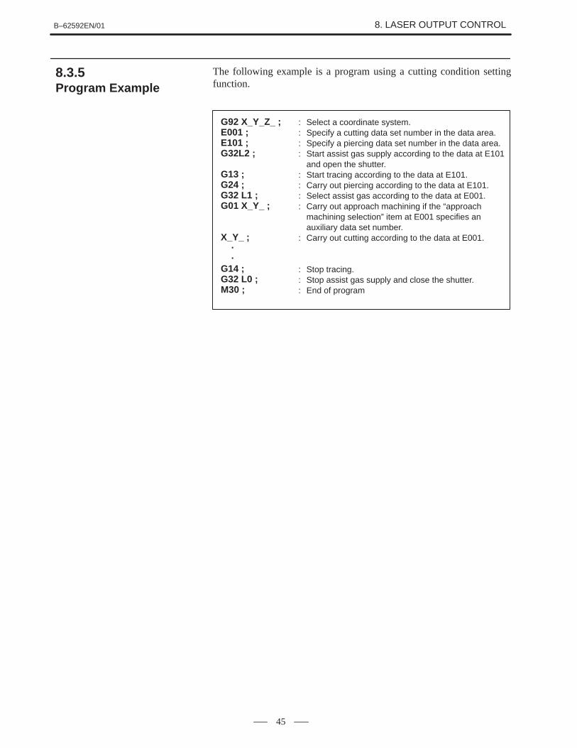
The following example is a program using a cutting condition settingfunction.
G92 X_Y_Z_ ;E001 ;E101 ;G32L2 ;
G13 ;G24 ;G32 L1 ;G01 X_Y_ ;
X_Y_ ;··
G14 ;G32 L0 ;M30 ;
: Select a coordinate system.: Specify a cutting data set number in the data area.: Specify a piercing data set number in the data area.: Start assist gas supply according to the data at E101
and open the shutter.: Start tracing according to the data at E101.: Carry out piercing according to the data at E101.: Select assist gas according to the data at E001.: Carry out approach machining if the “approach
machining selection” item at E001 specifies an auxiliary data set number.
: Carry out cutting according to the data at E001.
: Stop tracing.: Stop assist gas supply and close the shutter.: End of program
8.3.5Program Example

B–62592EN/018. LASER OUTPUT CONTROL
46
The data area is limited in capacity. To store more data, it is necessary toexpand the data area using a macro variable or battery–poweredexpansion memory, and send the necessary data from the expansion areato the data area as required. This function is supported by a means of datatransfer between a macro and the PMC, as shown below.
PMC–RC application software writtenin C
Program
Dataexecution
Window
[File]
Battery–poweredexpansionmemory
Window
Data areaOscillatoroutput control
E code
Note: Portion supported by the cuttingcondition setting function
Expandable portion
Data reading
(1)Data transfer through the PMC–CNC window
Data can be transferred between the data area and battery–poweredexpansion memory through the PMC–CNC window.
(2)Reading a comment through the PMC–CNC window
If a comment is specified with the M code, the PMC can read it throughthe PMC–CNC window. The comment can be used to specify datasuch as material and plate thickness.
8.3.6Sending the Data

B–62592EN/01 8. LASER OUTPUT CONTROL
47
Stable piercing with the minimum processing time is enabled by changingthe piercing laser output in a staircase fashion to radiate the optimalpower. Use of the high–speed piercing function requires the cuttingcondition setting function.
The average output is controlled by increasing the pulse frequency andduty cycle at every unit time with the output peak value fixed.
Frequencyduty cycle
Piercing time
Step count
Frequency increment
Step time
Time0
Duty cycle increment
(1)Direct command
The following command specifies high–speed piercing. Theaddresses enclosed in parentheses are omissible. The H addressshould always be specified.
G24 (S_P_Q_I_J_K_) H_ (R_) ;Piercing end timeStep countStep timeDuty cycle incrementFrequency incrementInitial duty cycle valueInitial frequency valueOutput peak value
(2) Indirect command
If the cutting condition setting function (option) is available,specifying a piercing data number at the E address enables high–speedpiercing. In this case, the “step count” item at the specified numbermust be set with a positive number. If it is set with 0, normal–speedpiercing takes place, instead of high–speed piercing.
(3)Override
During high–speed piercing, override does not apply to the outputpeak value, frequency, or duty cycle.
8.4HIGH–SPEEDPIERCING FUNCTION
8.4.1Power Control
8.4.2Command

B–62592EN/018. LASER OUTPUT CONTROL
48
The edge machining function detects edges, controls deceleration–to–stop, performs piercing, and controls the feedrate and power during a shiftfrom piercing to cutting.It is intended to produce sharp edges. Using this function requires thecutting condition setting function.
During G64 mode (cutting feed), if an angle (θ) formed by two cuttingfeed blocks A and B is smaller than a specified angle, it is assumed to bea corner, and the machine decelerates to stop at the end of block A so thatthe feedrate and power can be controlled.
Block A
Block B
θ
8.5EDGE MACHININGFUNCTION
8.5.1Detecting the Edge

B–62592EN/01 8. LASER OUTPUT CONTROL
49
Machining at a shift from block A to block B is carried out as shownbelow.
Feedrate/power
Sb, Pb, Qb
Fb
Time
Fr
Sb, Pr, Qr
Fa : Feedrate in block ASa : Output peak value in block APa : Pulse frequency in block AQa : Pulse duty cycle in block ASe : Output peak value for piercingPe : Pulse frequency for piercingQe : Pulse duty cycle for piercingTe : Piercing timeLr : Return distanceFr : Return speedPr : Return frequencyQr : Return duty cycleFb : Feedrate in block BSb : Output peak value in block BPb : Pulse frequency in block BQb : Pulse duty cycle in block B
Block B
Block A Te Lr
Sa, Pa, Qa
Fa
Se, Pe, Qe
Data for block A
Data for edgemachining
Data for block B
1 Decelerates to stop at the end of block A.
2 Retains the output power until the machine stops.
3 Carries out piercing according to the specified values after anin–posithion check.
4 Starts movement specified in block B after piercing is completed.
5 Before shifting to machining specified in block B, sets the feedrate toa return speed and keeps it until the return distance is traveled, then setsthe output power to the output peak value for cutting specified in blockB. Also sets the return frequency and duty cycle to restart.
6 After traveling the return distance, selects the cutting conditions forblock B and resumes cutting.
8.5.2Feedrate and PowerControl

B–62592EN/018. LASER OUTPUT CONTROL
50
See the description of the cutting condition setting function for the edgemachining data item.
The edge machining function is enabled by specifying an edge datanumber at “edge selection” in the machining data specified with the Ecode. To disable the edge machining function, set 0 at the “edgeselection” item.
8.5.3Data Setting
8.5.4Command

B–62592EN/01 8. LASER OUTPUT CONTROL
51
When a shift occurs from piercing to cutting, cutting may not be stableif it is started with the cutting data. The start–up function controls thefeedrate and power at a shift from piercing to cutting in the same manneras with the end of edge machining, thereby achieving stable cutting.
Cutting is started as shown below.
Feedrate/power
Sb, Pb, Qb
Fb
Time
Fr
Sb, Pr, Qr
Lr : Return distanceFr : Return speedPr : Return frequencyQr : Return duty cycleFb : Programmed feedrateSb : Programmed output peak valuePb : Programmed pulse frequencyQb : Programmed pulse duty cycle
Lr
1 Stable cutting starts with the return frequency Pr, return duty cycle Qr,and return speed Fr, instead of the programmed values.
2 After the return distance Lr is traveled, the programmed feedrate, pulsefrequency, and duty cycle become effective again, resuming normalmachining.
The following edge machining data specified using the cutting conditionsetting function becomes effective.
[Item] [Valid data range] [Minimum increment]Return distance :0 to 99.999 :0.001mmReturn speed :0 to 9999 :mm/minReturn frequency :5 to 2000 :HzReturn duty cycle :0 to 100 :%
The start–up function is enabled by specifying an edge machining datanumber at the “start–up selection” item in the machining data specifiedwith the E code. To disable the start–up function, set 0 at the “start–upselection” item.
8.6START–UPFUNCTION
8.6.1Feedrate and PowerControl
8.6.2Setting the Data
8.6.3Command

B–62592EN/018. LASER OUTPUT CONTROL
52
If the laser oscillator is equipped with the guide light option(semiconductor laser or He–Ne laser unit), the laser beam from the guidelight laser unit can be switched on and off using an external signal. If theoscillator shutter is closed, when this signal is on, the oscillator emitsguide light. When the shutter is opened, CO2 gas laser beam is radiated,instead of the guide light.
8.7GUIDE LIGHT ON SIGNAL
B–62592EN/01 8. LASER OUTPUT CONTROL
53
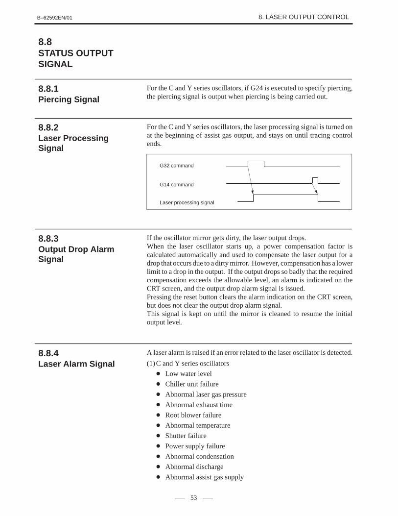
For the C and Y series oscillators, if G24 is executed to specify piercing,the piercing signal is output when piercing is being carried out.
For the C and Y series oscillators, the laser processing signal is turned onat the beginning of assist gas output, and stays on until tracing controlends.
G32 command
G14 command
Laser processing signal
If the oscillator mirror gets dirty, the laser output drops.When the laser oscillator starts up, a power compensation factor iscalculated automatically and used to compensate the laser output for adrop that occurs due to a dirty mirror. However, compensation has a lowerlimit to a drop in the output. If the output drops so badly that the requiredcompensation exceeds the allowable level, an alarm is indicated on theCRT screen, and the output drop alarm signal is issued.Pressing the reset button clears the alarm indication on the CRT screen,but does not clear the output drop alarm signal.This signal is kept on until the mirror is cleaned to resume the initialoutput level.
A laser alarm is raised if an error related to the laser oscillator is detected.
(1)C and Y series oscillators
� Low water level
� Chiller unit failure
� Abnormal laser gas pressure
� Abnormal exhaust time
� Root blower failure
� Abnormal temperature
� Shutter failure
� Power supply failure
� Abnormal condensation
� Abnormal discharge
� Abnormal assist gas supply
8.8STATUS OUTPUTSIGNAL
8.8.1Piercing Signal
8.8.2Laser ProcessingSignal
8.8.3Output Drop AlarmSignal
8.8.4Laser Alarm Signal

B–62592EN/018. LASER OUTPUT CONTROL
54
(2)YP series oscillator
� A/D converter–2 failure
� Interface unit power supply failure
� Water supply not started� Oscillator not ready
� Abnormal initial loading
� Data reception error
� Data transmission error
� Laser oscillator/power supply failure� Abnormal shutter operation
� Emergency stop button pressed
� Abnormal laser beam reflection
� Assist gas not specified
� Laser not radiated
(1)Purge completion signal
This signal is issued, when the unit is switched on, and the CNC startsoperating. When this signal is issued, the RUN signal becomesacceptable. When the RUN signal is turned off, purge processingoccurs to purge the gas from the discharge tube. When purgeprocessing is completed, the purge completion signal is sent out. Afterit is sent out, it becomes possible to switch off the power.
(2)Oscillator ready signalThis signal is issued when laser gas pressure control begins in responseto the RUN signal. When the RUN signal is turned off, purgeprocessing begins. It is kept on until purge processing is completed.
(3)Discharge start ready signal
This signal is issued when gas pressure control ends.(4)Reference discharge start signal
This signal is issued when reference discharge control begins inresponse to the HVON signal.
(5)Oscillator signal
This signal is issued when reference discharge begins.Laser machining is possible while this signal is on.
(6)Mode output signal
This signal indicates whether the laser output is continuous orpulsating.
(7)Beam output signal
This signal is issued, when the shutter is open, and the laser beam isradiated to the outside.
(8)Tracing motion signalThis signal is issued, when the tracing function starts, and the nozzlehas approached the workpiece, then an approach completed state isdetected. When the tracing function is disabled, the signal is turnedoff.
8.8.5Status Output Signals

B–62592EN/01 9. TRACING CONTROL
55
9 TRACING CONTROL

B–62592EN/019. TRACING CONTROL
56
The machine is equipped with a detector to measure the distance to thesurface of the workpiece. An analog signal generated in this detector issent to the CNC through a specified interface. This signal enables gapcontrol in which the Z–axis is controlled.
The detector produces 0 V for the reference distance. The detector outputis proportional to a deviation from the reference distance. The amplifiershould be adjusted so that the analog signal becomes �10 V for adeviation of �2mm from the reference distance.
Detector
Amplifier
Reference distance L0
Workpiece
To the CNC
+10V
–2mm
+2mm
Voltage
Deviation
–10V
The deviation for a voltage of �10 V is typically set to �2mm. But itcan be set to �4, �6, �8, or �10mm using a parameter. The resolutionis 1µm for �2mm. The resolution decreases as the deviation range isincreased. It becomes 5 µm for �10mm.
The tracing function controls the Z–axis so that it balances when thedetector produces 0 V. At this point, to change the gap between the nozzleand workpiece, specify the reference deviation E0.
Detector
Nozzle
E0 = 0
Detector
Nozzle
L0–0.50.5mm
L0
Workpiece
E0 = 0.5mm�
9.1TRACING FUNCTION
9.1.1Interface
9.1.2Reference Deviation

B–62592EN/01 9. TRACING CONTROL
57
On receiving an analog signal from the detector, the CNC subtracts thereference deviation E0 from it and multiplies the difference by loop gainK to calculate the speed command for the Z–axis. The loop gain can bespecified using a parameter.
Vz = 60&K (E–E0)
where Vz = Z–axis speed (mm/min)K = tracing loop gain (typically 30 s–1)E = input deviation (mm)E0 = reference deviation (mm)
The normal gap deviation (�E = E–E0) for tracing control is calculatedas follows:
where � E = normal deviation (mm)Vxy = X–Y plane feed command (mm/min)Q = tilt from the X–Y plane (°)K = tracing loop gain (typically 30 s–1)
�E=Vxy& tan θ
60&K
Override can be applied to the tracing loop gain over a range between12.5% and 100% in 12.5% steps.
(1)Programmed start and stop
The tracing function can be turned on and off using the G CODE.
G13 P_ ;
P = reference deviation (in 0.001mm increments)
Tracing start command
G14 _ ; Tracing end command
(2)Start and stop controlled by an external signal
The tracing function can be turned on and off using a signal from thePMC.
The tracing adjustment function enables zero–point and detection gainfactor adjustments necessary to normalize the input signal to the specifieddeviation. This is done using soft keys displayed on the CRT screen.
9.1.3Tracing Speed
9.1.4Tracing Gain Override
9.1.5Command
9.1.6Tracing AdjustmentFunction

B–62592EN/019. TRACING CONTROL
58
(1)Overdeviation alarm
If the nozzle gets too close to the workpiece, an overdeviation alarmis issued, and the machine is brought to a stop, and an alarm signal issent to the PMC.
(2)Tracing–out of–range alarm
If the absolute value of the deviation exceeds a specified value, thisstate is reported to the PMC.
9.1.7Tracing Alarms

B–62592EN/01 9. TRACING CONTROL
59
If the machine receives a tracing interlock signal from the PMC duringtracing operation specified by G13; , it suspends the operation of thetracing axis as long as the signal is on. When the tracing interlock signalis turned off, the machine resumes tracing.
9.2TRACINGINTERLOCKFUNCTION

B–62592EN/019. TRACING CONTROL
60
When a tracing control axis direction is selected according to an externalsignal, control is enabled for the selected axis direction. The surface ofa three–dimensional workpiece can be traced for laser machining byswitching the tracing controlled axis and by rotating the nozzle to thetarget plane. The relationships between the selected tracing axis directionand nozzle attitude are shown below.
Receding
Approaching
Workpiece
Approaching
Receding
Receding
Controlled axis–Z(–TRZ)
Controlled axis–Y (–TRY)
Controlled axis–X(–TRX)
Controlledaxis�X(�TRX)
Controlledaxis�Y(�TRY)
Controlled axis�Z(�TRZ)
+Z+Y
+X
Approaching
Receding
RecedingApproachingReceding
Approaching
Approaching
9.3TRACING AXISSELECTIONFUNCTION

B–62592EN/0110. FUNCTION FOR THREE–DIMENSIONAL
PROCESSING SYSTEM
61
10 FUNCTION FOR THREE–DIMENSIONALPROCESSING SYSTEM

B–62592EN/0110. FUNCTION FOR THREE–DIMENSIONAL
PROCESSING SYSTEM
62
If the fifth and sixth axes are specified as a controlled axis, and attitudecontrol is specified, the nozzle attitude can be controlled around the twoaxes, thus enabling configuring of a three–dimensional machine tool.Either of the following two attitude control types is supported accordingto the axis configuration of the nozzle head section.
1 Attitude control A (zero–offset nozzle)
2 Attitude control B (offset nozzle)
10.1ATTITUDE CONTROL

B–62592EN/0110. FUNCTION FOR THREE–DIMENSIONAL
PROCESSING SYSTEM
63
The nozzle tip position fixed type (zero offset type) mechanism isconfigured with the α axis (no.4 axis) to rotate around Z axis, and therotational axis β axis (no.5 axis) recorded in this α axis. It possesses thestructure that the tip of the nozzle is arranged at the point where therotational center line of the α axis crosses the rotational center line of theβ axis.This type has the following characteristics:
1 Movement of the nozzle tip position is performed by X, Y, Z axes, andthe attitude control of the nozzle is performed by α, β axes. Therefore,movement of the position and attitude control can be controlledindependently.
2 Contour precision is good because control is easy.
3 Operability is good.
4 The structure of the nozzle head section is complicated and easilyinterferes with the workpiece.
5 The number of mirrors becomes great.
180� 0�
270�
90�
Base
Nozzle
+X
Arm
Rotation around the β axis
Rotation around the α axis
Base+Z
Arm
α axisβ axis
Nozzle
+Y
+X
10.1.1Attitude Control A (ZeroOffset Type Nozzle)

B–62592EN/0110. FUNCTION FOR THREE–DIMENSIONAL
PROCESSING SYSTEM
64
The offset type mechanism is configured with the α axis (no.4 axis) torotate around Z axis, and the rotational axis β axis (no.5 axis) recorded inthis α axis. It possesses the structure of being arranged such that therotational center line of the α axis is perpendicular to the rotational centerline of the β axis, and that the rotational center line of the α axis does notcross the center line of the nozzle.This type has the following characteristics:
1 When controlling the attitude of the nozzle by α and β axes, it isnecessary to command the moved amount to the X, Y, Z axes, and tocontrol to return to the original tip position of the nozzle, because thetip position of the nozzle moves.
2 Because there is interference between axes, control is complicated andcontour precision is decreased.
3 The structure of the nozzle head section is simplified, and it is easy toavoid interference with the workpiece.
4 The number of mirrors is decreased.
180� 0�
270�
90�
+Y
+X
Rotation around the α axis
+Z
+X
α axis
β axisSecond arm
L2
Program coordinates(X, Y, Z)
First armL1Machine
coordinates(x, y, z)
270� 90�
180�
0�Rotation around the β axis
+Y
+Z
10.1.2Attitude Control B(Offset Type Nozzle)

B–62592EN/0110. FUNCTION FOR THREE–DIMENSIONAL
PROCESSING SYSTEM
65
(1)Mode selection
In automatic operation, the nozzle tip fixed mode automaticallyoccurs; in manual operation, nozzle tip fixed mode and independentaxis mode can be switched by DI.
(2) Independent axis mode
This is the mode that the commanded axis performs only the rotationoperation if α axis or β axis is commanded.According to the command, if α axis or β axis rotates, because the tipposition of the nozzle changes, change the coordinate values of therelative coordinate system and workpiece coordinate system by thechanged X, Y, Z coordinate value amounts, and match the nozzle tipposition and the coordinate system.
(3)Nozzle tip fixed mode
This is the mode that the nozzle tip position becomes the rotationalcenter, and the commanded axis performs the rotation operation bymeans of simultaneously moving the linear axes X, Y, Z after rotatingthe commanded axis if α axis or β axis is commanded.According to the command, if α axis or β axis rotates, because the tipposition of the nozzle changes, move each X, Y, Z axis by the changedX, Y, Z coordinate value amounts, and return the nozzle tip positionto its original position.At this time, the relative coordinate system of X, Y, Z axes and theworkpiece coordinate system are not affected, but the machinecoordinate system X, Y, Z axes are affected.
+Z +Z
When α axis rotation command When β axis rotation command
Operation when nozzle tip fixed mode

B–62592EN/0110. FUNCTION FOR THREE–DIMENSIONAL
PROCESSING SYSTEM
66
In nozzle attitude control, as shown in the diagram of the axisconfiguration of the nozzle head, the β axis motor is arranged around theZ axis. In the case of a structure which transmits by gear, if the α axis iscommanded, the housing rotates and the nozzle rotates around the Z axis.
However, simultaneously at this time gear B must rotate around gear A.This movement results in the nozzle being rotated by the β axis.Namely, if the α axis rotates by an α axis command, a rotational operationsimultaneously occurs at the β axis.Interaction control is the function to automatically generate commands inthe β axis of the same amount as the α axis commands in order to cancelthe rotational operation of the β axis for a nozzle head of axisconfiguration such that the β axis rotates by the α axis commands. Thecommand polarity can be selected by parameter.
α axis
ÅÅÅÅÅ
Gear A
Housing
β axis
ÅÅÅÅÅÅÅÅÅÅÅÅ
Gear
Gear
Gear B
10.1.3Interaction Control
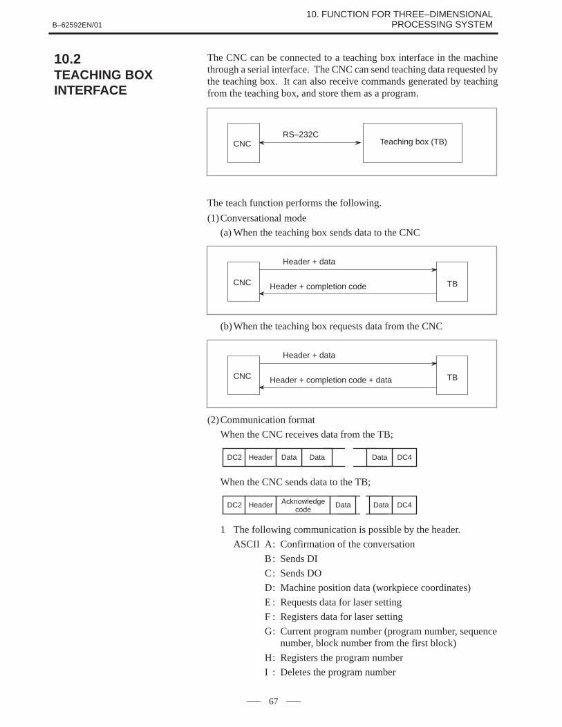
B–62592EN/0110. FUNCTION FOR THREE–DIMENSIONAL
PROCESSING SYSTEM
67
The CNC can be connected to a teaching box interface in the machinethrough a serial interface. The CNC can send teaching data requested bythe teaching box. It can also receive commands generated by teachingfrom the teaching box, and store them as a program.
RS–232CCNC Teaching box (TB)
The teach function performs the following.
(1)Conversational mode
(a) When the teaching box sends data to the CNC
Header + data
Header + completion codeCNC TB
(b)When the teaching box requests data from the CNC
Header + data
Header + completion code + dataCNC TB
(2)Communication format
When the CNC receives data from the TB;
DC2 Header Data DC4Data Data
When the CNC sends data to the TB;
DC2 Header Acknowledgecode
Data Data DC4
1 The following communication is possible by the header.
ASCII A: Confirmation of the conversation
B: Sends DI
C: Sends DO
D: Machine position data (workpiece coordinates)
E : Requests data for laser setting
F : Registers data for laser setting
G: Current program number (program number, sequencenumber, block number from the first block)
H: Registers the program number
I : Deletes the program number
10.2TEACHING BOXINTERFACE

B–62592EN/0110. FUNCTION FOR THREE–DIMENSIONAL
PROCESSING SYSTEM
68
J : Reads the specified block
K: Writes the specified block (insertion)
L : Deletes the specified block
M : Sequence number search
N: Command of the MDI operation
O: Nozzle tip machine position data
P : Request three–dimensional conversion data.
Q: Register three–dimensional conversion data.
R: Read from battery–powered expansion memory.
S : Write to battery–powered expansion memory.
2 DATA
ASCII code (hexadecimal number; NC data is the external code)
3 Acknowledge code
After receiving demand or data from the TB, the CNC adds theacknowledge code to demand or data when the CNC transmits theheader or data as its reply to the TB.

B–62592EN/0110. FUNCTION FOR THREE–DIMENSIONAL
PROCESSING SYSTEM
69
The W axis is arranged such that linear operation of the nozzle tip sectioncan be performed, and the gap sensor is connected at the prescribedinterface. If this function is specified, gap control can be performed bythe W axis. However, when using this function, the tracing controlfunction should be specified at the same time.This function can be used unrelated to the attitude control of the nozzle.
For attitude control A For attitude control B
W
W
(1)Tracing feed
If the machine supports W–axis tracing control, Z–axis tracing isenabled by switching the tracing controlled axis to the Z–axis, usinga selection switch.
� Switching by an external signal
� Switching by a program
G13L0 ; Selects the W–axis.G13L2 ; Selects the Z–axis.
(2)Approach feed
If W axis tracing control is included, and the selection signal is set toON, the machine enters approach feed mode.In approach feed mode, the gap sensor signal is monitored, and if thesignal becomes zero or above (when approach to the work is thestandard distance or greater), jog feed in the direction stops. When youwant to release the stop status, set the jog feed switch to OFF then ONto instruct feed in the direction away from the work.
10.3THREE–DIMENSIONALCONTROL FUNCTION
10.3.1W Axis Tracing Control

B–62592EN/0110. FUNCTION FOR THREE–DIMENSIONAL
PROCESSING SYSTEM
70
G12 Xx1 Yy1 Zz1 Aa1 Bb1 Ss Pp Qq ;G12 Xx2 Yy2 Zz2 Aa2 Bb2 S ;
The first block represents the intermediate point on an arc, and the secondblock represents the end point of the arc.If the intermediate and end points are specified in succession, an arc isdrawn to the end point. This command is modal and remains effectiveuntil G00, G01, G02, or G03 is specified. To specify laser output, includeS, P, Q, and E in the first block.
End point(x2, y2, z2, a2, b2)
Start point(x0, y0, z0, a0, b0)
Intermediate point(x1, y1, z1, a1, b1)
10.3.2Spatial CircularInterpolation
Command method:

B–62592EN/0110. FUNCTION FOR THREE–DIMENSIONAL
PROCESSING SYSTEM
71
G68 Xx Yy Zz Aa Bb Ii Jj Kk ;
G69 ;
Program to be converted
The program put in between the commands G68 and G69 is coordinate–converted.
(1)The program to be converted is regarded as that having programmingspecifying the figure to be drawn on the XY–plane and the directionof Z axis as the nozzle direction.
(2)The G68 block specifies data for conversion.
1 Origin of coordinate–conversion by x, y, and z (using absolutevalues)
2 Nozzle axis tilt angle at the origin by a and b (normal line to theworkpiece)
3 The vector of the axis corresponding to the positive direction of theX–axis of the program to be converted, by i, j, and k (with theincremental value from the origin of the coordinate–conversion)
Z’ Z
X’
X
Y
Y’i, j, k
P
Origin (x, y, z)
(3)The coordinate–conversion is executed based on the coordinatesystem described below.The coordinate system is determined by first defining the plane, wherethe axis direction given by a and b is regarded as the normal directionof the workpiece based on the origin having the X–, Y–, and Z–axiscoordinate values. Next, the workpiece plane is rotated at the normalaxis regarded as the rotational axis, and then the +X axis in theprogram to be converted is directed in the direction given by i, j, andk.
10.3.3Three–DimensionalCoordinate Conversion
Specifying method

B–62592EN/0110. FUNCTION FOR THREE–DIMENSIONAL
PROCESSING SYSTEM
72
(4)The format can be taught easily by the teaching box.The values of x, y, z, a, and b are defined by reading the current positionafter positioning of the nozzle to the origin is executed by teaching,and adjusting the attitude of the nozzle in the normal direction of theworkpiece. Then the nozzle is moved to the point p to define thedirection of the +X axis and the current position of x1, y1, and z1 isread. Finally, the values of i, j, and k are defined by calculating theformulas i=x1–x, j=y1–y, and k=z1–z.
G33 Rr ;
G34 ;
Program to be converted
(1)The arc having the specified radius is automatically inserted to eachcorner obtained by the spatial dot–strings put in between commandsG33 and G34.
(2)Radius of arc to be inserted is commanded by address R that followscommand G33.
(x2, y2, z2)
r
Start point
(x1, y1, z1)
10.3.4Spatial Corner–RInsertion
Specifying method
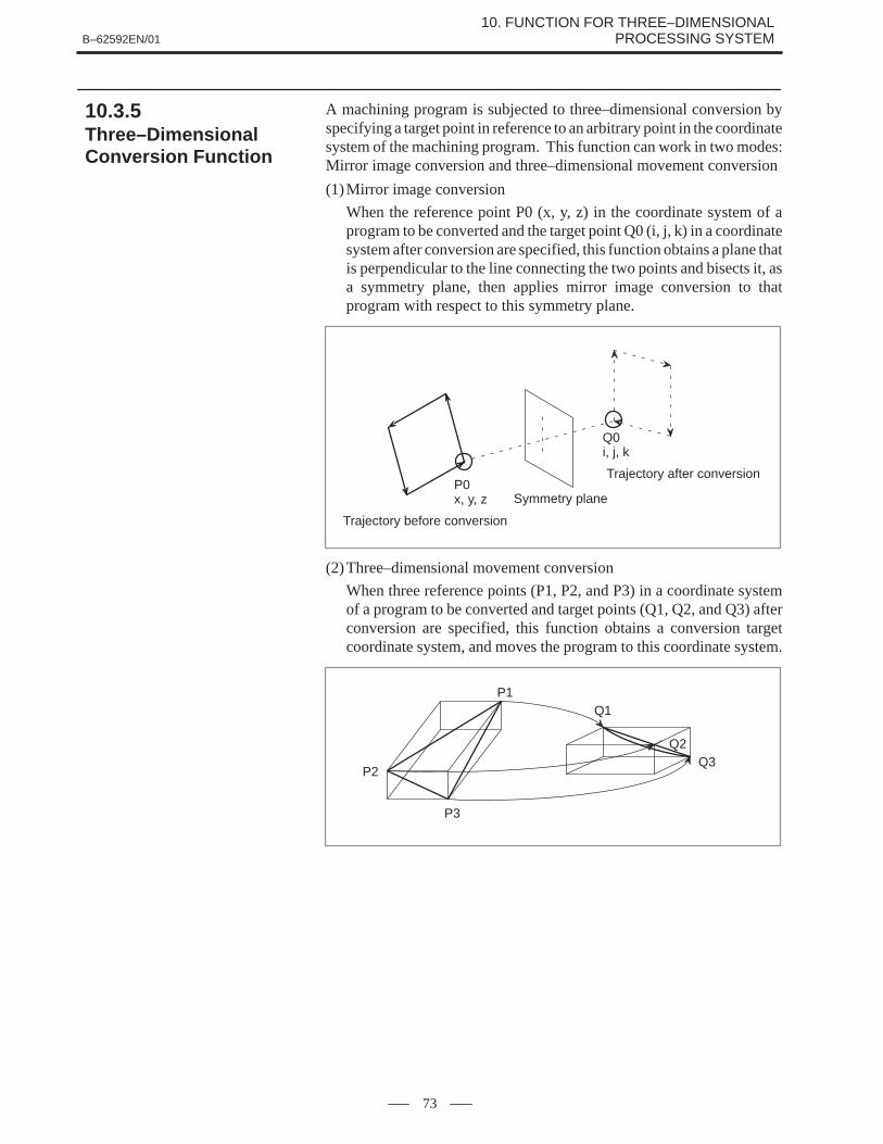
B–62592EN/0110. FUNCTION FOR THREE–DIMENSIONAL
PROCESSING SYSTEM
73
A machining program is subjected to three–dimensional conversion byspecifying a target point in reference to an arbitrary point in the coordinatesystem of the machining program. This function can work in two modes:Mirror image conversion and three–dimensional movement conversion
(1)Mirror image conversion
When the reference point P0 (x, y, z) in the coordinate system of aprogram to be converted and the target point Q0 (i, j, k) in a coordinatesystem after conversion are specified, this function obtains a plane thatis perpendicular to the line connecting the two points and bisects it, asa symmetry plane, then applies mirror image conversion to thatprogram with respect to this symmetry plane.
P0x, y, z
Trajectory before conversion
Symmetry plane
Trajectory after conversion
Q0i, j, k
(2)Three–dimensional movement conversion
When three reference points (P1, P2, and P3) in a coordinate systemof a program to be converted and target points (Q1, Q2, and Q3) afterconversion are specified, this function obtains a conversion targetcoordinate system, and moves the program to this coordinate system.
P2
P1
P3
Q1
Q2Q3
10.3.5Three–DimensionalConversion Function

B–62592EN/0110. FUNCTION FOR THREE–DIMENSIONAL
PROCESSING SYSTEM
74
(3)Command
The three–dimensional conversion function is specified using thefollowing G codes.
G98 : StartG99 : End
The commands listed below are added before a program to beconverted. When the program is executed, the coordinates of thereference and target points are written as the setting data. When Q0or Q3 is read, conversion begins with the setting data.
(a) Mirror image conversion
G98 P0 X_Y_Z_ ; Reference pointG98 Q0 X_Y_Z_ ; Target point
(b)Three–dimensional movement conversion
G98 P1 X_Y_Z_ ; Reference pointG98 P2 X_Y_Z_ ; Reference pointG98 P3 X_Y_Z_ ; Reference pointG98 Q1 X_Y_Z_ ; Target pointG98 Q2 X_Y_Z_ ; Target pointG98 Q3 X_Y_Z_ ; Target point
(4)Operation mode
G98 can be executed in either memory of MDI mode.
(5)Discontinuing movement and laser beam status
Suppose the program shown below is to be executed. The machinestops and the laser beam is turned off, at a shift from move commandgroup (a) to move command group (b) and at a shift from movecommand group (b) to move command group (c).
G98 Q0 ; or Q3 ;
Move command group (a)
G99 ;
Move command group (b)
Move command group (c)
Three–dimensional conversionfunction enabled
(6)Compound command
Mirror image conversion and movement conversion can be specifiedsimultaneously. For example, when mirror image conversion isspecified after movement conversion, both conversion types areenabled provided that the former type has not been canceled.
The cancel command G99 cancels all conversion commands. If it isnecessary to cancel one type of conversion in a compound command,first cancel the whole compound command using the G99, thenspecify the necessary conversion type again.
When the proximity point search signal is turned off, and a cycle startis requested, machining begins at that point.

B–62592EN/0110. FUNCTION FOR THREE–DIMENSIONAL
PROCESSING SYSTEM
75
In the memory operation mode, if the proximity point search (DI) isturned on and the cycle start is carried out, the block in the nearest positionto the current position of the nozzle is searched as described below, andthe nozzle is positioned at the start point of this block and becomes feedhold state.
L
E (Xe, Ye, Ze)Le
Ls
P (Xp, Yp, Zp)
S (Xs, Ys, Zs)
Point P: Current position of the nozzle (Xp, Yp, and Zp)
Point S: Start point (Xs, Ys, and Zs)
Point E: End point (Xe, Ye, and Ze)
DecisionIf the distance Ls between the block start point (Xs, Ys, Zs) and the currentnozzle position (Xp, Yp, Zp) does not exceed the specified distance L, andthe distance Le between the block end point (Xe, Ye, Ze) and the currentnozzle position is longer than Ls, the start point S is judged to be theproximity point.
10.3.6Proximity Point Search

B–62592EN/0110. FUNCTION FOR THREE–DIMENSIONAL
PROCESSING SYSTEM
76
A hand coordinate system can be generated in which the origin is at thetip of the nozzle, +Zh coincides with the line normal to the nozzle, +Xhcoincides with the arm direction, and the Yh–axis is orthogonal to bothXh–and Zh–axes. This hand coordinate system can be used for job andhandle feed.
Machine coordinates (x, y, z)
X
α
L1 +ZhY
Z
β+Xh
Hand coordinate system
+YhL2
(1)Turning on the hand coordinate system selection signal selects handcoordinate system mode.
(2)For jog feed in hand coordinate system mode, turning on the jog feedaxis direction signal �X causes the machine to move in the�Xh–axis direction. Similarly, turning on the signal for �Y or �Zcauses the machine to move in the �Yh–axis or �Zh–axis direction,respectively. To change the hand coordinate system, turn off the handcoordinate system mode selection signal, and operate on the α– andβ–axes.
(3)For handle feed in hand coordinate system mode, rotating the manualpulse generator with the X–axis selected as the handle axis causes themachine to move in the �Xh–axis direction. Similarly, rotating thepulse generator with the Y–axis or Z–axis selected as the handle axiscauses the machine to move in the �Yh–axis or �Zh–axis,respectively. To change the hand coordinate system, turn off the handcoordinate system mode selection signal, and operate on the α– andβ–axes.
10.3.7Manual OperationUsing a HandCoordinate System

B–62592EN/01 11. CONTROL FUNCTIONS
77
11 CONTROL FUNCTIONS

B–62592EN/0111. CONTROL FUNCTIONS
78
If there is a movable reflector, the propagation distance between theoscillator and condensing lens varies as the reflector moves.
Generally, stable machining characteristics are obtained within a limitedpropagation distance range. In a large machine tool in which the reflectorhas to move through a long distance because of its mechanical structure,the required propagation distance may exceed its limit, hampering stablemachining over the stroke of reflector movement. To solve this problem,the 16–LB is provided with an optical path adjustment axis and an opticalpath length compensation function. When a command is issued whichrequests that the reflector be moved, the optical path length compensationfunction automatically adjusts the optical path adjustment axis tomaintain a constant optical path length.
Optical path length compensation uses the following mechanism.1 An axis (called the U–axis) must be available along which a beam
reflecting mirror block (shown below) moves linearly to vary thepropagation distance.
2 The U–axis should be configured to change the propagationdistance α times (1 to 511) as much as the movement of the mirrorblock.
3 The maximum speed of the U–axis should be higher than or equalto 1/α the total rapid traverse rate of the axes that can change theoptical path length.
4 All axes including the U–axis should have reference point. Theoptical path length is calculated based on the reference point.
5 An interference protection provision should be installed for all axesthat may otherwise interfere with the U–axis.
Oscillator
U–axis
Mirror block
Nozzle head
(1)Detectors on the controlled axes can be incremental and/or absolutepulse coders (APC). The two types can be intermixed.
(2)Any axis from the fourth axis to the eight axis can be assigned as theU–axis.
(3)A U–axis move command is generated based on the movementdistance of an axis that can change the optical path length. So, it isnecessary to specify controlled axes (except the U–axis) that canchange the optical path length, using parameters.
11.1OPTICAL PATH LENGTHCOMPENSATION

B–62592EN/01 11. CONTROL FUNCTIONS
79
(4) If the movement direction of an axis that can change the optical pathlength does not match the polarity of a change in the optical pathlength, the polarity may be inverted for calculation purposes.
(5)A parameter can specify whether to reflect the amount of movementof an axis under tracing control into the U–axis move command.
(6)Optical path length compensation is possible.When all axes (including the U–axis) are at their reference points, theoptical path length is defined as the reference optical path length,which can be subjected to compensation.When optical path length compensation is enabled, the referenceoptical path length can be set up regardless of the position of thereference point.If a parameter specifies a mirror position compensation value, turningon the constant–optical path length control start signal (LRCS) withall axes set at their reference points causes the U–axis to moveautomatically through the specified distance away from its referencepoint and to begin optical path length compensation.For an APC axis, if its reference point has been set up, theconstant–optical path length control start signal is accepted even if theaxis is not at the reference point.
(7)The distance through which the U–axis should move is calculated asfollows:
� U=64
Parameter 15705 (��X��Y��Z. . .)
where �U, �X, �Y, �Z ... : Move command value for each axis

B–62592EN/0111. CONTROL FUNCTIONS
80
Burning may occur during laser machining, preventing machining fromcontinuing. In such a case, machining may be resumed by putting themachine back in the state in which it was before burning. This is done bya machining restart function.If a machining error is detected, the machining restart function moves themachine back to a specified position through the same path it had takenbefore the error occurred, while the laser beam is kept turned off. Whenthe machine gets back to the specified position, the machining restartfunction again places the machine in an operable state and causes it tomove forward to the position where it started going back. At this point,the machine restarts machining according to the programmed commands.This function cannot be used together with the three–dimensionalmachining function. This function is based on the retrace function of the16–MB. So, it is necessary to specify the retrace function also. Themachining restart function conforms to the specifications of the retracefunction.The machining restart function behaves as described below.A PMC ladder program can be created to restart machining automatically.
Z
Restart completion distance
Retract distance
Retrace signal = offAutomatic operation start signal = on
Retrace distance
Retry processing Skip processing
Automatic operation pause signal = onRetrace signal = onAutomatic operation start signal = on
XY
13
1
24 5 6 7
89
10 11
12
3
1 When the program is running with the machining restart mode signalselected, if a machining error is detected on the machine side,automatic operation should be made to pause.
2 When automatic operation starts with the retrace signal selected, thepoint where automatic operation starts is recorded as a retrace startpoint, and the machine retracts in the +Z direction through a specifieddistance.
3 When retracting is completed, the machine retraces the specifieddistance, then stops. After confirming the retrace completed signaland turning off the retrace signal, triggering automatic operationcauses the nozzle to approach the surface of the workpiece.
4 After the nozzle approaches the workpiece surface, the assist gas isturned on.
11.2MACHININGRESTART FUNCTION

B–62592EN/01 11. CONTROL FUNCTIONS
81
5 A move command that will end at the retrace start point is generatedautomatically, the laser beam is turned on, and the machine startsmoving forward again. When it reaches the retrace start point, a blockthat was executed at 1 is called to resume programmed operation.
6 After restart, it is checked whether the restart completion distance hasbeen passed through.
7 If no machining error is detected during movement through the restartcompletion distance, machining is continued.
8 If a machining error is detected before the restart completion distanceis passed through, steps 2 to 4 are retried.
9 If retry is repeated a specified number of times, it is assumed thatmachining restart is impossible, and skip operation is carried out.
10 The machine begins positioning at the end of the block executed at step1 . When it gets to the end of the block, it stops there in single blockstop mode.
11 After confirming that the skip completed signal is on and turning offthe retrace signal, triggering automatic operation causes the nozzle toapproach the workpiece.
12 After the nozzle approaches the workpiece surface, the assist gas isturned on, and piercing is carried out under the machining conditionused most recently. When piercing is completed, the cutting assist gasis selected.
13 The laser beam is turned on, and the next block begins execution.

APPENDIX

B–62592EN/01 A. LASER SETTING SCREEN
85
A LASER SETTING SCREEN
(1)Laser power display
The laser output display screen displays the following data.
LASER POWER O0000 N00000
P C 1000 W
P A 1000 W
F R 2000 Hz
D U 100 %
E 0.000 MM
S 0 T0000MDI **** *** *** 21:20:07[ POWER ][ SET ][ ][ ][ ]
(2)Laser setting
The laser setting screen consists of three pages shown below.
LASER SETTING O0000 N00000
CONTOURING POWER = 1000 WFREQUENCY = 2000 HzDUTY = 100 %
PIERCING POW4R = 800 WFREQUENCY = 1000 HzDUTY = 50 %
POWER SELECT = 0 (0:ALL,1:HLF)POWER CONTROL = 0 (0:OFF,1:ON)
MIN. DUTY = 10 %ASSIST GAS SELECT = 0GAS FLOW SELECT = 1>_ S 0 T0000MDI **** *** *** 21:12:20[ POWER ][ SET ][ ][ ][ ]

B–62592EN/01A. LASER SETTING SCREEN
86
LASER SETTING O0000 N00000
GAS FLOW 1 PRE–TIME = 1.00 SPRE–PRES. = 100WORK–PRES. = 200AFTER–TIME = 1.00 SAFTER–PRES. = 100
GAS FLOW 2 PRE–TIME = 1.00 SPRE–PRES. = 100WORK–PRE = 200AFTER–TIME = 1.00 SAFTER–PRE = 100
>_ S 0 T0000MDI **** *** *** 21:12:59[ POWER ][ SET ][ ][ ][ ]
LASER SETTING O0000 N00000
GAS FLOW 3 PRE–TIME = 1.00 SPRE–PRES. = 100WORK–PRES. = 200AFTER–TIME = 1.00 SAFTER–PRES. = 100
>_ S 0 T0000MDI **** *** *** 21:14:54[ POWER ][ SET ][ ][ ][ ]
(3)Edge machining data screen
This screen displays the following edge machining data.
TRACE SETTING O0000 N00000
Z–DEFLECTION POSITION= 1.000 (RELATIVE)
ZERO ADJUST X 7.213E 0.143 Y 9.596
GAIN COEFFICIENT Z –14.559 START POINT
Z –14.059E 0.048
END POINTZ –14.559 DEFLECTIONE 0.520 E 0.520
>_ S 0 T0000MDI **** *** *** 21:14:54[ POWER ][ SET ][ ZERO ][ START ][ END ]

B–62592EN/01 B. CUTTING CONDITION SETTING SCREENS
87
B CUTTING CONDITION SETTING SCREENS
(1)Cutting data screen
This screen displays the following cutting data.
[CUTTING] ACTIVE DATA NO.[CUTTING=5 PIRCING=103]
GAS GAS GASNo. FEED PWR FREQ. DUTY PRES. KIND TIME DEF EDGE APPR.
1 ***** **** **** *** **.* ** *.* –*.*** *** *** 2 ***** **** **** *** **.* ** *.* –*.*** *** *** 3 ***** **** **** *** **.* ** *.* –*.*** *** *** 4 ***** **** **** *** **.* ** *.* –*.*** *** *** 5 ***** **** **** *** **.* ** *.* –*.*** *** ***
6 ***** **** **** *** **.* ** *.* –*.*** *** *** 7 ***** **** **** *** **.* ** *.* –*.*** *** *** 8 ***** **** **** *** **.* ** *.* –*.*** *** *** 9 ***** **** **** *** **.* ** *.* –*.*** *** ***10 ***** **** **** *** **.* ** *.* –*.*** *** ***
CUT PIERCE EDGE [OPRT]
(2)Piercing data screen
This screen displays the following piercing data.
[PIERCING] ACTIVE DATA NO.[CUTTING=5 PIRCING=103]
[INITIAL] [INCREM.] [STEP] PIRC [ASSIST GAS]No. PWR FREQ. DUTY FREQ. DUTY TIME CNT TIME PRESS. KIND TIME DEF
101 **** **** *** *** **.* *.*** ** ***.*** **.* ** *.* –*.***102 **** **** *** *** **.* *.*** ** ***.*** **.* ** *.* –*.***103 **** **** *** *** **.* *.*** ** ***.*** **.* ** *.* –*.***
CUT PIERCE EDGE [OPRT]

B–62592EN/01B. CUTTING CONDITION SETTING SCREENS
88
(3)Edge machining data screen
This screen displays the following edge machining data.
[EDGE] ACTIVE DATA NO.[CUTTING=5 PIRCING=103]
PIRC GAS GAS STRT STRT STRT STRT
No. ANGL PWR. FREQ. DUTY TIME PRSS. KIND DIST FEED FREQ. DUTY
201 *** **** **** *** ***.*** **.* ** **.*** **** **** ***202 *** **** **** *** ***.*** **.* ** **.*** **** **** ***203 *** **** **** *** ***.*** **.* ** **.*** **** **** ***204 *** **** **** *** ***.*** **.* ** **.*** **** **** ***205 *** **** **** *** ***.*** **.* ** **.*** **** **** ***
CUT PIERCE EDGE [OPRT]
(4)Command data display screen
This screen display the following command data.
MAT. ***********E CODE CUTTING *** PIERCING ***
F FEED ***** mm/min
PC POWER **** W
FR FREQUENCY **** Hz
DU DUTY *** %
GK GAS SELECT *
GP GAS PRESSURE **.* kg/cm2
ER DEFLECTION –*.*** mm
D OFFSET *.*** mm
STATUS
O ***** N *****
FA FEED ***** mm/min
PA POWER **** W
X –*****.***Y –*****.***Z –*****.***4 –*****.***5 –*****.***6 –*****.***7 –*****.***8 –*****.***

B–62592EN/01 C. YP SERIES LASER CONTROL SCREENS
89
C YP SERIES LASER CONTROL SCREENS
(1)Waveform data display
WAVE DATA (1/1)
STEP NO. WAVE NO.1 NO.2 NO.3 NO.4 NO.5 NO.6 NO.7 NO.8 1 **** **** **** **** **** **** **** **** 2 **** **** **** **** **** **** **** **** 3 **** **** **** **** **** **** **** **** 4 **** **** **** **** **** **** **** **** 5 **** **** **** **** **** **** **** **** 6 **** **** **** **** **** **** **** **** 7 **** **** **** **** **** **** **** **** 8 **** **** **** **** **** **** **** **** 9 **** **** **** **** **** **** **** ****10 **** **** **** **** **** **** **** ****11 **** **** **** **** **** **** **** ****12 **** **** **** **** **** **** **** ****13 **** **** **** **** **** **** **** ****14 **** **** **** **** **** **** **** ****15 **** **** **** **** **** **** **** ****16 **** **** **** **** **** **** **** ****17 **** **** **** **** **** **** **** ****
LEFT C RIGHT DOWN C UP CUR [OPRT]
(2)Execution sequence data display
EXEC. ORDER
ORDR ITEM NO.1 NO.2 NO.3 NO.4 NO.5 NO.6 NO.7 NO.8 1 WAVE NO. * * * * * * * * WAVE COE *** *** *** *** *** *** *** *** FREQ. *** *** *** *** *** *** *** *** OUT CNT. *** *** *** *** *** *** *** ***
2 WAVE NO. * * * * * * * * WAVE COE *** *** *** *** *** *** *** *** FREQ. *** *** *** *** *** *** *** *** OUT CNT. *** *** *** *** *** *** *** ***
3 WAVE NO. * * * * * * * * WAVE COE *** *** *** *** *** *** *** *** FREQ. *** *** *** *** *** *** *** *** OUT CNT. *** *** *** *** *** *** *** ***
[OPRT]

B–62592EN/01C. YP SERIES LASER CONTROL SCREENS
90
(3)Status display
STATUS
RG REGISTER NO. 5
SQ ORDER 1
WN WAVE NO. 12
MP WAVE COE 100 %
FR FREQ. 150 HZ
SN OUT CNT. 200
WR WARNING NO. 1
(OPRT)
O 00001 N 00001
X –*****.***Y –*****.***Z –*****.***4 –*****.***5 –*****.***6 –*****.***7 –*****.***8 –*****.***
FA SPEED 1000 MM/MIN
PA AVE. PWR 500 W

IndexB–62592EN/01
i–1
�A�
Alarms, 39
Assist gas control, 22, 23
Assist gas pressure analog output, 25
Assist gas pressure override, 26
Attitude control, 62
Attitude control A (Zero offset type nozzle), 63
Attitude control B (Offset type nozzle), 64
Auxiliary function, 7
Axis control, 2
�C�
C and Y series laser control, 29
Command, 47, 50, 51, 57
Connectable oscillators, 17
Control functions, 77
Cutting condition setting function, 41
Cutting condition setting screens, 87
�D�
Data area, 41
Data input/output, 9
Data setting, 50
Detecting the edge, 48
Display and setting, 39
Displaying the data, 43
Dry run, 14
�E�Edge machining function, 48
Editing operation, 8
Emergency stop, 14
Executing the data, 44
Execution sequence data registration function, 37
External alteration of the piercing time, 33
�F�Feed function, 5
Feed hold, 14
Feedrate and power control, 49, 51
Function for three–dimensional processing system, 61
Functions different from those of the M series CNC, 13
�G�
Guide light on signal, 52
�H�
High–speed piercing function, 47
�I�Interaction control, 66
Interface, 56
Interpolation, 4
�L�Laser alarm signal, 53
Laser functions, 15, 18
Laser interface, 16
Laser machining program example, 35
Laser output control, 28
Laser processing signal, 53
Laser sequence control, 19
Laser setting screen, 85
�M�
Machine lock, 14
Machining restart function, 80
Manual operation using a hand coordinate system, 76
�O�
Operation, 3
Optical path length compensation, 78
Others, 10
Output command, 38
Output drop alarm signal, 53
Override, 38
�P�Piercing command, 33
Piercing signal, 53
Power control, 34, 47
Power value command and power override, 30
Program example, 40, 45
Program input, 5
Program restart (0–L specification), 14
Proximity point search, 75

INDEX B–62592EN/01
i–2
Pulse duty cycle command and duty cycle override, 32
Pulse frequency command and frequency override, 31
�R�
Reference deviation, 56
�S�Sending the data, 46
Sequence control of the C and Y series laser oscillators, 20
Sequence control of the YP series laser oscillator, 21
Setting and display, 8
Setting the data, 51
Shutter open/close control, 27
Single block, 14
Spatial circular interpolation, 70
Spatial corner–R insertion, 72
Specifications, 2
Spindle function, 7
Start–up function, 51
Status output signal, 53
Status output signals, 54
�T�Teaching box interface, 67
Three–dimensional control function, 69
Three–dimensional conversion function, 73
Three–dimensional coordinate conversion, 71
Tool compensation, 7
Tool function, 7
Tracing adjustment function, 57
Tracing alarms, 58
Tracing axis selection function, 60
Tracing control, 55
Tracing function, 56
Tracing gain override, 57
Tracing interlock function, 59
Tracing speed, 57
�U�
Updating the data, 43
�W�
W axis tracing control, 69
Waveform data registration function, 36
Waveform data setting function, 36
�Y�YP series laser control, 36
YP series laser control scree, 89

Rev
isio
n R
ecor
d
FAN
UC�S
erie
s���������� ��
��
(B
–625
92E
N)
01Ju
l., ’9
5
Edi
tion
Dat
eC
onte
nts
Edi
tion
Dat
eC
onte
nts

· No part of this manual may bereproduced in any form.
· All specifications and designsare subject to change withoutnotice.


