52
GE Fanuc Automation Programmable Control Products Series 90 -30 I/O Processor Module User’s Manual GFK-1028 June 1994
ÎÎ
GE Fanuc Automation
Programmable Control Products
Series 90�-30I/O Processor Module
User’s Manual
GFK-1028 June 1994
GFL-002
Warnings, Cautions, and Notesas Used in this Publication
Warning
Warning notices are used in this publication to emphasize that hazardous voltages,currents, temperatures, or other conditions that could cause personal injury exist in thisequipment or may be associated with its use.
In situations where inattention could cause either personal injury or damage toequipment, a Warning notice is used.
Caution
Caution notices are used where equipment might be damaged if care is not taken.
Note
Notes merely call attention to information that is especially significant to understandingand operating the equipment.
This document is based on information available at the time of its publication. Whileefforts have been made to be accurate, the information contained herein does notpurport to cover all details or variations in hardware or software, nor to provide forevery possible contingency in connection with installation, operation, or maintenance.Features may be described herein which are not present in all hardware and softwaresystems. GE Fanuc Automation assumes no obligation of notice to holders of thisdocument with respect to changes subsequently made.
GE Fanuc Automation makes no representation or warranty, expressed, implied, orstatutory with respect to, and assumes no responsibility for the accuracy, completeness,sufficiency, or usefulness of the information contained herein. No warranties ofmerchantability or fitness for purpose shall apply.
The following are trademarks of GE Fanuc Automation North America, Inc.
Alarm Master CIMSTAR Helpmate PROMACRO Series SixCIMPLICITY GEnet Logicmaster Series One Series 90CIMPLICITY 90-ADS Genius Modelmaster Series Three VuMasterCIMPLICITY PowerTRAC Genius PowerTRAC ProLoop Series Five Workmaster
Copyright 1994 GE Fanuc Automation North America, Inc.All Rights Reserved
iii GFK-1028
Preface
This manual provides the specifications, hardware interface requirements, andprogramming information needed to install and use the Series 90-30 I/O Processormodule. The Series 90-30 Programmable Controller Installation Manual, GFK-0356, shouldbe your primary reference for information about the Series 90-30 Programmable LogicController. It describes types of systems, system planning, installation procedures, andsystem components for the Series 90-30 PLC.
Content of this ManualThis manual contains the following information:
Chapter 1. Introduction: provides an overview of I/O Processor features.
Chapter 2. Installation and Wiring: explains installation and field wiring for themodule.
Chapter 3. Configuring the I/O Processor Module: provides information forconfiguring the module using a Hand-held Programmer or the Logicmaster 90Configurator Software
Chapter 4. Automatic Data Transfers: . describes data transferred automaticallybetween the CPU and the I/O Processor during each sweep
Appendix A. I/O Processor Error Codes: lists error codes reported in the module statuscode
Appendix B. I/O Processor Specifications: summarizes module operatingcharacteristics, and provides a detailed listing of module inputs and outputs
Related Publications:� GFK-0356: Series 90�-30 Programmable Controller Installation Manual. This manual is
the primary reference for information about the Series 90-30 PLC.
� GFK-0402: Hand-Held Programmer, Series 90�-30 and 90-20 Programmable ControllersUser’s Manual. Describes the Hand-held Programmer displays, and explainsoperator procedures for module configuration, programming, and data monitoring.
We Welcome Your Comments and SuggestionsAt GE Fanuc Automation, we strive to produce quality documentation. After you haveused this manual, please take a few moments to complete and return the Reader’sComment Card located on the next page.
Libby AllenSenior Technical Writer
Contents
ivGFK–1028 Series 90–30 I/O Processor User’s Manual – June 1994
Chapter 1 Introduction 1-1 . . . . . . . . . . . . . . . . . . . . . . . . . . . . . . . . . . . . . . . . . . . . . . .
I/O Processor Module Description 1-1 . . . . . . . . . . . . . . . . . . . . . . . . . . . . . . . . . . .
Module Features 1-3 . . . . . . . . . . . . . . . . . . . . . . . . . . . . . . . . . . . . . . . . . . . . . . . . . .
Module Functions 1-4 . . . . . . . . . . . . . . . . . . . . . . . . . . . . . . . . . . . . . . . . . . . . . . . .
Encoder Input Function 1-4 . . . . . . . . . . . . . . . . . . . . . . . . . . . . . . . . . . . . . . . . .
Range Comparator Function 1-6 . . . . . . . . . . . . . . . . . . . . . . . . . . . . . . . . . . . .
Latched Strobe Input Function 1-9 . . . . . . . . . . . . . . . . . . . . . . . . . . . . . . . . . . .
Time Measurement Function 1-9 . . . . . . . . . . . . . . . . . . . . . . . . . . . . . . . . . . . .
Chapter 2 Installation and Wiring 2-1 . . . . . . . . . . . . . . . . . . . . . . . . . . . . . . . . . . . . .
Installation and Removal of I/O Modules 2-1 . . . . . . . . . . . . . . . . . . . . . . . . . .
Wiring to I/O Modules 2-3 . . . . . . . . . . . . . . . . . . . . . . . . . . . . . . . . . . . . . . . . . .
Field Wiring Considerations 2-5 . . . . . . . . . . . . . . . . . . . . . . . . . . . . . . . . . . . . .
Chapter 3 Configuring the I/O Processor Module 3-1 . . . . . . . . . . . . . . . . . . . . . . . .
Configuration Using the Hand-held Programmer 3-1 . . . . . . . . . . . . . . . . . .
Hand-held Programmer Configuration Screens 3-1 . . . . . . . . . . . . . . . . . . . .
Configuration Using the LM90 Configurator 3-10 . . . . . . . . . . . . . . . . . . . . . . .
Chapter 4 Automatic Data Transfers 4-1 . . . . . . . . . . . . . . . . . . . . . . . . . . . . . . . . . . .
Input Status Data (From IOP to CPU) 4-1 . . . . . . . . . . . . . . . . . . . . . . . . . . . . .
Output Command Data (From CPU to IOP) 4-1 . . . . . . . . . . . . . . . . . . . . . . .
%I Status Bits 4-1 . . . . . . . . . . . . . . . . . . . . . . . . . . . . . . . . . . . . . . . . . . . . . . . . .
%I Status Bit Descriptions 4-2 . . . . . . . . . . . . . . . . . . . . . . . . . . . . . . . . . . . . . . .
%AI Data Words 4-3 . . . . . . . . . . . . . . . . . . . . . . . . . . . . . . . . . . . . . . . . . . . . . . .
%AI Data Word Descriptions 4-3 . . . . . . . . . . . . . . . . . . . . . . . . . . . . . . . . . . . .
%Q Control Bits 4-5 . . . . . . . . . . . . . . . . . . . . . . . . . . . . . . . . . . . . . . . . . . . . . . .
%Q Control Bit Descriptions 4-5 . . . . . . . . . . . . . . . . . . . . . . . . . . . . . . . . . . . .
%AQ Immediate Commands 4-6 . . . . . . . . . . . . . . . . . . . . . . . . . . . . . . . . . . . .
%AQ Immediate Command Descriptions 4-7 . . . . . . . . . . . . . . . . . . . . . . . . .
Appendix A I/O Processor Error Codes A-1 . . . . . . . . . . . . . . . . . . . . . . . . . . . . . . . . . . .
Appendix B I/O Processor Module Specifications B-1 . . . . . . . . . . . . . . . . . . . . . . . . .
Module Specifications B-1 . . . . . . . . . . . . . . . . . . . . . . . . . . . . . . . . . . . . . . . . . .
I/O Processor Module Inputs/Outputs B-2 . . . . . . . . . . . . . . . . . . . . . . . . . . . .
Content of this Manual iii . . . . . . . . . . . . . . . . . . . . . . . . . . . . . . . . . . . . . . . . . . . .
Related Publications: iii . . . . . . . . . . . . . . . . . . . . . . . . . . . . . . . . . . . . . . . . . . .
We Welcome Your Comments and Suggestions iii . . . . . . . . . . . . . . . . . . . . . . .
Contents
vGFK–1028 Series 90–30 I/O Processor User’s Manual – June 1994
Figure 1-1. Series 90-30 I/O Processor Module 1-2 . . . . . . . . . . . . . . . . . . . . . . . . . . . . . . . . . . . . . . . . . . . . . .
Figure 1-2. Range Comparator Block Diagram 1-6 . . . . . . . . . . . . . . . . . . . . . . . . . . . . . . . . . . . . . . . . . . . . . .
Figure 1-3. Pulse Latching and Timing Functions 1-10 . . . . . . . . . . . . . . . . . . . . . . . . . . . . . . . . . . . . . . . . . . .
Figure 2-1. Inserting a Series 90-30 Module 2-1 . . . . . . . . . . . . . . . . . . . . . . . . . . . . . . . . . . . . . . . . . . . . . . . .
Figure 2-2. Removing a Series 90-30 Module 2-2 . . . . . . . . . . . . . . . . . . . . . . . . . . . . . . . . . . . . . . . . . . . . . . .
Figure 2-3. Installing a Terminal Board 2-3 . . . . . . . . . . . . . . . . . . . . . . . . . . . . . . . . . . . . . . . . . . . . . . . . . . . .
Figure 2-4. Releasing the Terminal Block 2-4 . . . . . . . . . . . . . . . . . . . . . . . . . . . . . . . . . . . . . . . . . . . . . . . . . . .
Figure 2-5. Removing a Terminal Board 2-4 . . . . . . . . . . . . . . . . . . . . . . . . . . . . . . . . . . . . . . . . . . . . . . . . . . .
Figure 2-6. Terminal Board Pin Assignments 2-6 . . . . . . . . . . . . . . . . . . . . . . . . . . . . . . . . . . . . . . . . . . . . . . .
Figure 2-7. Field Wiring Connections 2-7 . . . . . . . . . . . . . . . . . . . . . . . . . . . . . . . . . . . . . . . . . . . . . . . . . . . . . .
Figure 2-8. Typical I/O Processor Module Faceplate Wiring 2-8 . . . . . . . . . . . . . . . . . . . . . . . . . . . . . . . . . . .
Figure 3-1. IOP Configuration Screen 1 (Function = ABS Encoder) 3-10 . . . . . . . . . . . . . . . . . . . . . . . . . . . .
Figure 3-2. IOP Configuration Screen 1 (Function = AQUADB Encoder) 3-13 . . . . . . . . . . . . . . . . . . . . . . .
Figure 3-3. IOP Configuration Screen 2 (Function = ABS or AQUADB Encoder) 3-14 . . . . . . . . . . . . . . . . .
Figure 3-4. IOP Configuration Screen 4 (Function = ABS or AQUADB Encoder) 3-15 . . . . . . . . . . . . . . . .
Figure B-1. Simplified Input Circuit Diagram (Inputs 1–8) B-2 . . . . . . . . . . . . . . . . . . . . . . . . . . . . . . . . . . .
Figure B-2. Simplified Output Circuit Diagram (Outputs 1–4) B-3 . . . . . . . . . . . . . . . . . . . . . . . . . . . . . . . .
Figure B-3. Simplified I/O Circuit Diagram (Inputs 9 – 12/Outputs 5–8) B-4 . . . . . . . . . . . . . . . . . . . . . . .
1Chapter
1-1GFK-1028
Introduction
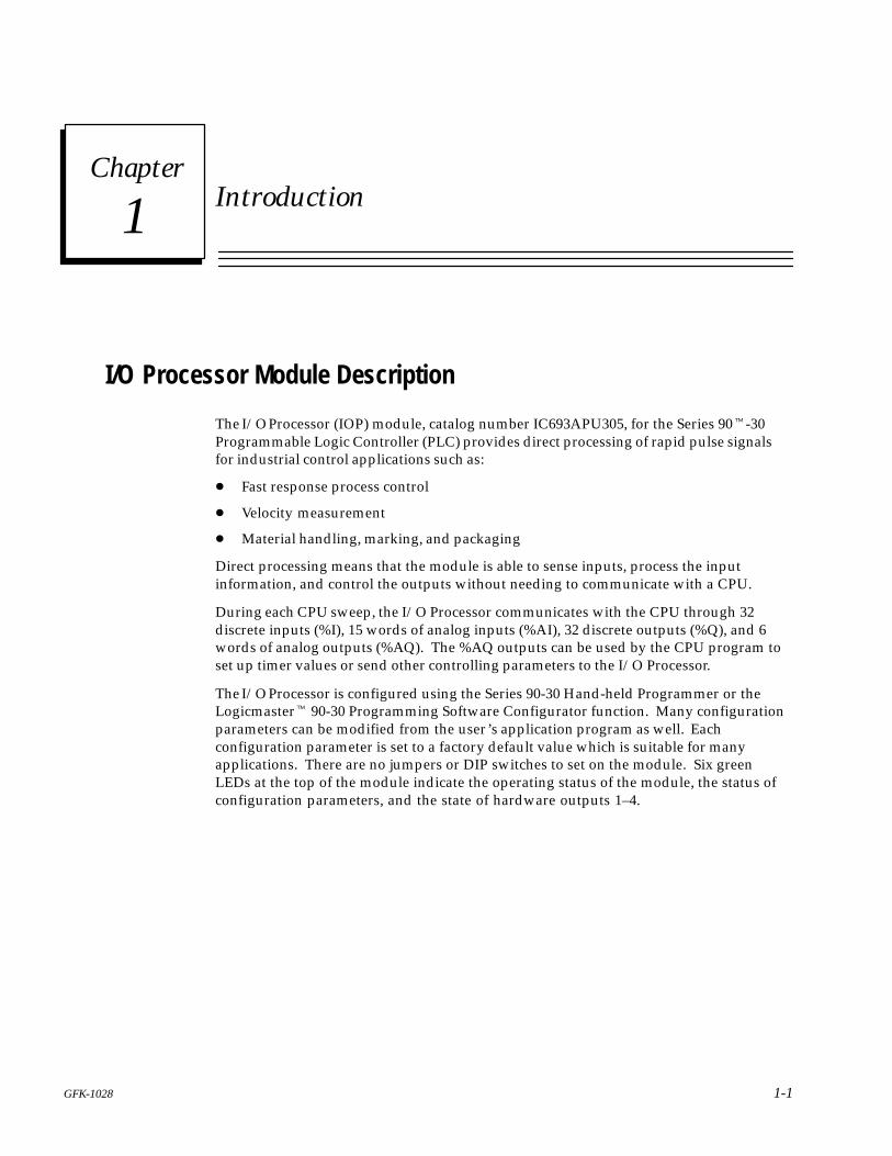
I/O Processor Module Description
The I/O Processor (IOP) module, catalog number IC693APU305, for the Series 90�-30Programmable Logic Controller (PLC) provides direct processing of rapid pulse signalsfor industrial control applications such as:
� Fast response process control
� Velocity measurement
� Material handling, marking, and packaging
Direct processing means that the module is able to sense inputs, process the inputinformation, and control the outputs without needing to communicate with a CPU.
During each CPU sweep, the I/O Processor communicates with the CPU through 32discrete inputs (%I), 15 words of analog inputs (%AI), 32 discrete outputs (%Q), and 6words of analog outputs (%AQ). The %AQ outputs can be used by the CPU program toset up timer values or send other controlling parameters to the I/O Processor.
The I/O Processor is configured using the Series 90-30 Hand-held Programmer or theLogicmaster� 90-30 Programming Software Configurator function. Many configurationparameters can be modified from the user’s application program as well. Eachconfiguration parameter is set to a factory default value which is suitable for manyapplications. There are no jumpers or DIP switches to set on the module. Six greenLEDs at the top of the module indicate the operating status of the module, the status ofconfiguration parameters, and the state of hardware outputs 1–4.
1
1-2 GFK-1028Series 90-30 I/O Processor User’s Manual - June 1994
IN12/OUT8
1–4: 1.0A @ 12/24 VDC
5/12/24 VDC
2
4
OK
I/OPROCMODULE
1
3
CFG
a45380
I/O PROCESSOR
2
4
OK
I/OPROCMODULE
5/12/24 VDCI/O PROCESSOR
1
3
7
2
5
6
8
9
10
11
12
13
14
15
16
17
18
19
20
4
OUT1
SHIELD
IN2
IN1
IN4
IN3
IN6
IN5
IN8
IN7
IN9/OUT5
44A729182–070R01FOR USE WITHIC693APU305
IN10/OUT6
IN11/OUT7
INCOM
OUTCOM
OUT2
OUT3
OUT4
INTERNAL
V
V
1
3
CFG
IN1
IN2
IN3
IN4
IN5
IN6
IN7
IN8I9/05
OUT1
OUT2
OUT3
OUT4
I10/06I11/07I12/08
OUT 1–8: 0.02A @ 5 VDC
OUTOUT 5–8: 0.5A @ 12/24 VDC
4.0A/MODULE
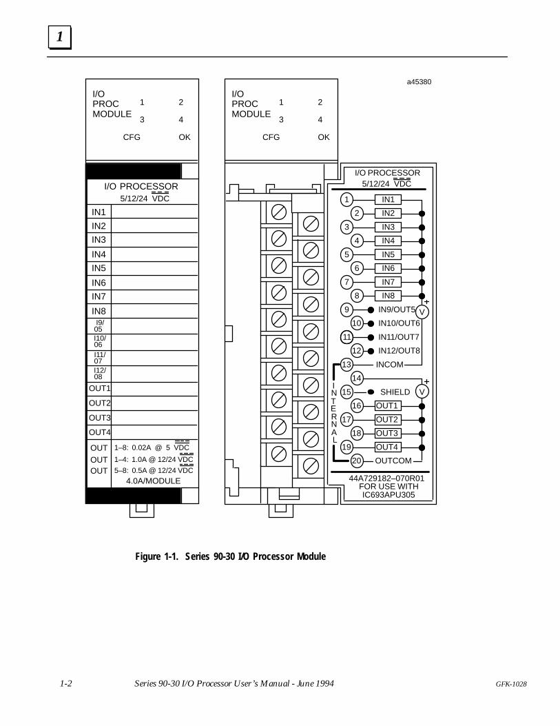
Figure 1-1. Series 90-30 I/O Processor Module
1
1-3GFK-1028 Chapter 1 Introduction
Module Features
Module features include:
� Up to 12 positive logic (source) inputs with input voltage range selection of either 5VDC (TTL) or 10 to 30 VDC (non-TTL).
� Up to eight positive logic (source) outputs (four outputs with 1 amp rating, fourconfigurable outputs with 0.5 amp rating)
� Outputs protected by replaceable fuse (one fuse common to all outputs)
� Dedicated processor provides 500 µs I/O update
� Counts per Timebase register for input rate measurement
� Total Counts register (32-bit) accumulates total counts received by module
� Four Strobe data registers for input position capture
� Two Timer data registers for indicating input pulse length or input spacing inmilliseconds
� Thirty-two range comparators (outputs returned in %I and %AI data)
� Software configuration
� Internal module diagnostics
� Individual LEDs that indicate Module OK and Configured OK status
� Individual LEDs that indicate state of Outputs 1–4
� A removable terminal board for connection of field wiring
Inputs can be used as count signals or edge-sensitive strobe signals. Outputs can beused to drive indicating lights, solenoids, relays, and other devices.
Power to operate the module’s logic circuitry is obtained from the baseplate backplane’s5 VDC bus. Power sources for the input and output devices must be supplied by theuser or by the +24 VDC isolated output of the Model 30 power supply. The I/OProcessor module provides a selectable threshold voltage to allow the inputs to respondto either a 5 VDC signal level or a 10 to 30 VDC signal level. The threshold is selected byconfiguration.
All configuration parameters for the module are downloaded from the PLC to the I/OProcessor after it passes its internal diagnostics. Once the module has been successfullyconfigured, the CONFIG OK LED will turn on. Configuration parameters can bechanged using Logicmaster configuration software or the Hand-held Programmer.
Operation of the IOP module is monitored by a watchdog timer circuit. If the watchdogtimer detects a module failure, it will force all outputs off and turn off the MODULE OKLED.
1
1-4 GFK-1028Series 90-30 I/O Processor User’s Manual - June 1994
Module Functions
The I/O Processor module provides the following functions:
� ENCODER INPUT – Reads an absolute or AQUADB encoder; reports encoderposition and velocity to the PLC.
� RANGE COMPARATORS – Updates 32 range comparators based on the latestencoder reading and reports range comparator outputs to the PLC. The first 8 rangecomparators also can control IOP digital outputs.
� STROBE INPUTS – Up to four strobe input channels trigger the IOP to capture thelatest encoder readings and report them to the PLC.
� STROBE TIMERS – Two input timers allow strobe pulse widths or time betweentwo different strobe channels to be measured and reported to the PLC.
The following sections explain these functions in more detail.
Encoder Input FunctionThe IOP module reads a parallel output Gray Code Encoder or an AQUADB Encoderevery 500 µs. Encoder Gray Code data , Encoder Binary Code data, Encoder TotalCounts and Counts per Timebase (encoder velocity) are reported to the PLC on each I/Oscan using %AI data.
Absolute Gray Code Encoders must provide 256, 360, 512, or 1024 counts per revolution.IOP Configuration allows the direction of encoder rotation to be electrically reversed.IOP Configuration and %AQ immediate commands also allow a position offset to beintroduced. This offset value can eliminate the need to mechanically align the encoderzero position.
Absolute Encoders always use IOP inputs 1–8. Nine bit encoders require IOP input 9;Ten bit encoders require IOP inputs 9 and 10.
AQUADB Encoders with an optional marker channel can also be used. The encodermaximum (rollover) Binary Count value is configurable between 10 and 64999 counts.Normally the maximum count value should be set to 1 less than the encoder counts perrevolution. However this is not a requirement and some applications may benefit fromthe use of other rollover values.
Position initialization of AQUADB encoders can be accomplished in three ways:
1. The PLC can send a %AQ immediate command to initialize the encoder BinaryCount value.
2. The PLC can initiate a Find Home operation which causes Binary Count data to beset to the configured Home Position when the Home Switch input is ON and anencoder marker rising edge transition occurs.
3. The encoder marker channel can be connected to the IOP faceplate Preload input. Ifthe %Q Reset Preload Latch bit is set ON, each marker rising edge transition will setEncoder Binary Count data to the configured Preload value. This techniqueprovides a pseudo-absolute encoder function because Binary Count data isre-initialized once per encoder revolution. For systems which can allow the encoderto rotate at least one revolution before initializing position, operation will be similarto an absolute encoder of equal resolution.
1
1-5GFK-1028 Chapter 1 Introduction
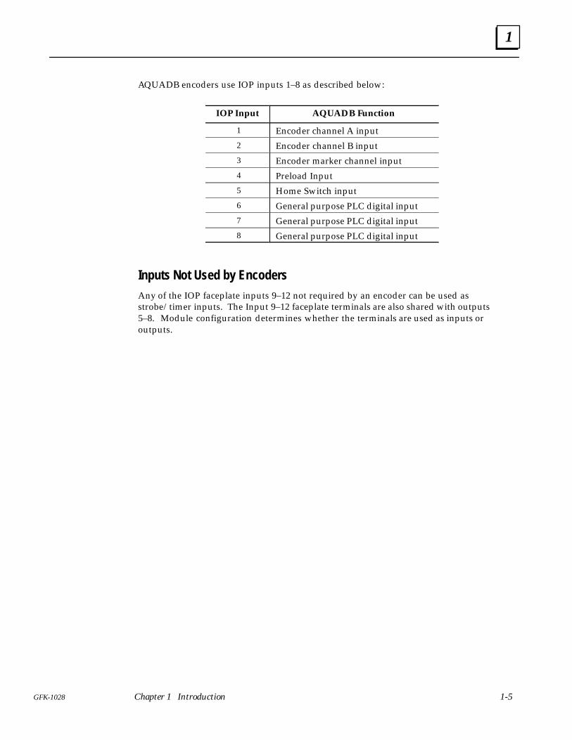
AQUADB encoders use IOP inputs 1–8 as described below:
IOP Input AQUADB Function
1 Encoder channel A input2 Encoder channel B input3 Encoder marker channel input4 Preload Input5 Home Switch input6 General purpose PLC digital input7 General purpose PLC digital input8 General purpose PLC digital input
Inputs Not Used by EncodersAny of the IOP faceplate inputs 9–12 not required by an encoder can be used asstrobe/timer inputs. The Input 9–12 faceplate terminals are also shared with outputs5–8. Module configuration determines whether the terminals are used as inputs oroutputs.
1
1-6 GFK-1028Series 90-30 I/O Processor User’s Manual - June 1994
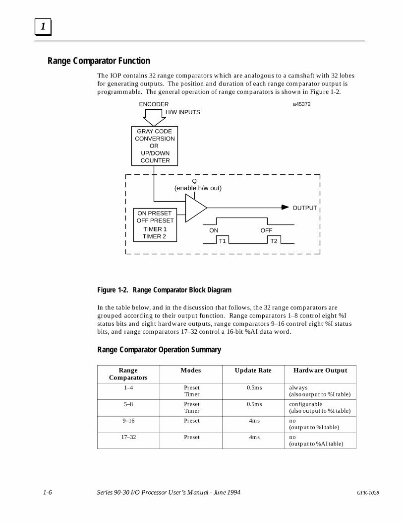
Range Comparator Function
The IOP contains 32 range comparators which are analogous to a camshaft with 32 lobesfor generating outputs. The position and duration of each range comparator output isprogrammable. The general operation of range comparators is shown in Figure 1-2.
T1
ON OFF
T2
OUTPUTON PRESETOFF PRESET
TIMER 1TIMER 2
Q(enable h/w out)
a45372
GRAY CODECONVERSION
ORUP/DOWNCOUNTER
ENCODERH/W INPUTS
Figure 1-2. Range Comparator Block Diagram
In the table below, and in the discussion that follows, the 32 range comparators aregrouped according to their output function. Range comparators 1–8 control eight %Istatus bits and eight hardware outputs, range comparators 9–16 control eight %I statusbits, and range comparators 17–32 control a 16-bit %AI data word.
Range Comparator Operation Summary
RangeComparators
Modes Update Rate Hardware Output
1–4 PresetTimer
0.5ms always(also output to %I table)
5–8 PresetTimer
0.5ms configurable(also output to %I table)
9–16 Preset 4ms no(output to %I table)
17–32 Preset 4ms no(output to %AI table)
1
1-7GFK-1028 Chapter 1 Introduction
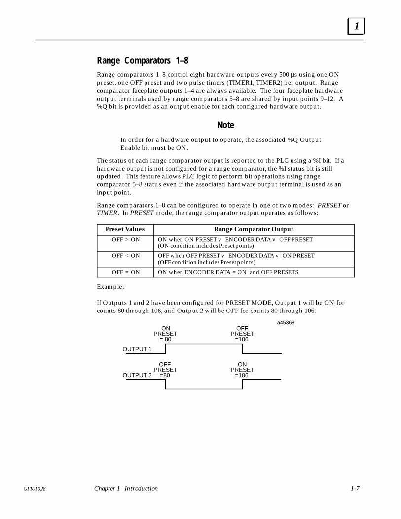
Range Comparators 1–8Range comparators 1–8 control eight hardware outputs every 500 µs using one ONpreset, one OFF preset and two pulse timers (TIMER1, TIMER2) per output. Rangecomparator faceplate outputs 1–4 are always available. The four faceplate hardwareoutput terminals used by range comparators 5–8 are shared by input points 9–12. A%Q bit is provided as an output enable for each configured hardware output.
Note
In order for a hardware output to operate, the associated %Q OutputEnable bit must be ON.
The status of each range comparator output is reported to the PLC using a %I bit. If ahardware output is not configured for a range comparator, the %I status bit is stillupdated. This feature allows PLC logic to perform bit operations using rangecomparator 5–8 status even if the associated hardware output terminal is used as aninput point.
Range comparators 1–8 can be configured to operate in one of two modes: PRESET orTIMER. In PRESET mode, the range comparator output operates as follows:
Preset Values Range Comparator Output
OFF > ON ON when ON PRESET v ENCODER DATA v OFF PRESET(ON condition includes Preset points)
OFF < ON OFF when OFF PRESET v ENCODER DATA v ON PRESET(OFF condition includes Preset points)
OFF = ON ON when ENCODER DATA = ON and OFF PRESETS
Example:
If Outputs 1 and 2 have been configured for PRESET MODE, Output 1 will be ON forcounts 80 through 106, and Output 2 will be OFF for counts 80 through 106.
OFFPRESET
=80
ONPRESET
= 80
OUTPUT 2
OUTPUT 1
a45368
ONPRESET
=106
OFFPRESET
=106
1
1-8 GFK-1028Series 90-30 I/O Processor User’s Manual - June 1994
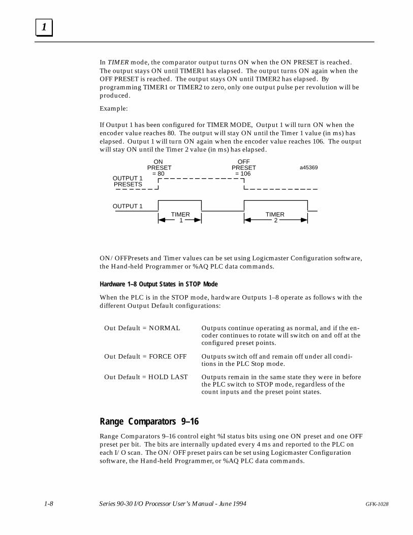
In TIMER mode, the comparator output turns ON when the ON PRESET is reached.The output stays ON until TIMER1 has elapsed. The output turns ON again when theOFF PRESET is reached. The output stays ON until TIMER2 has elapsed. Byprogramming TIMER1 or TIMER2 to zero, only one output pulse per revolution will beproduced.
Example:
If Output 1 has been configured for TIMER MODE, Output 1 will turn ON when theencoder value reaches 80. The output will stay ON until the Timer 1 value (in ms) haselapsed. Output 1 will turn ON again when the encoder value reaches 106. The outputwill stay ON until the Timer 2 value (in ms) has elapsed.
ONPRESET
= 80
OUTPUT 1
OUTPUT 1PRESETS
a45369OFF
PRESET= 106
TIMER1
TIMER2
ON/OFF Presets and Timer values can be set using Logicmaster Configuration software,the Hand-held Programmer or %AQ PLC data commands.
Hardware 1–8 Output States in STOP Mode
When the PLC is in the STOP mode, hardware Outputs 1–8 operate as follows with thedifferent Output Default configurations:
Out Default = NORMAL Outputs continue operating as normal, and if the en-coder continues to rotate will switch on and off at theconfigured preset points.
Out Default = FORCE OFF Outputs switch off and remain off under all condi-tions in the PLC Stop mode.
Out Default = HOLD LAST Outputs remain in the same state they were in beforethe PLC switch to STOP mode, regardless of thecount inputs and the preset point states.
Range Comparators 9–16Range Comparators 9–16 control eight %I status bits using one ON preset and one OFFpreset per bit. The bits are internally updated every 4 ms and reported to the PLC oneach I/O scan. The ON/OFF preset pairs can be set using Logicmaster Configurationsoftware, the Hand-held Programmer, or %AQ PLC data commands.
1
1-9GFK-1028 Chapter 1 Introduction
Range Comparators 17–32Range Comparators 17–32 control 16 additional status bits using one ON preset and oneOFF preset per bit. The bits are internally updated every 4 ms. The ON/OFF presetpairs can be set using Logicmaster Configuration software, the Hand-held Programmer,or %AQ PLC data commands.
Range Comparator outputs 17–32 are reported to the PLC on each I/O scan using a %AIdata word. Within the PLC, the %AI word can be copied directly to %Q memory tocontrol a discrete output module. The %AI word can also be copied to %T or %Mmemory to facilitate additional bit oriented operations.
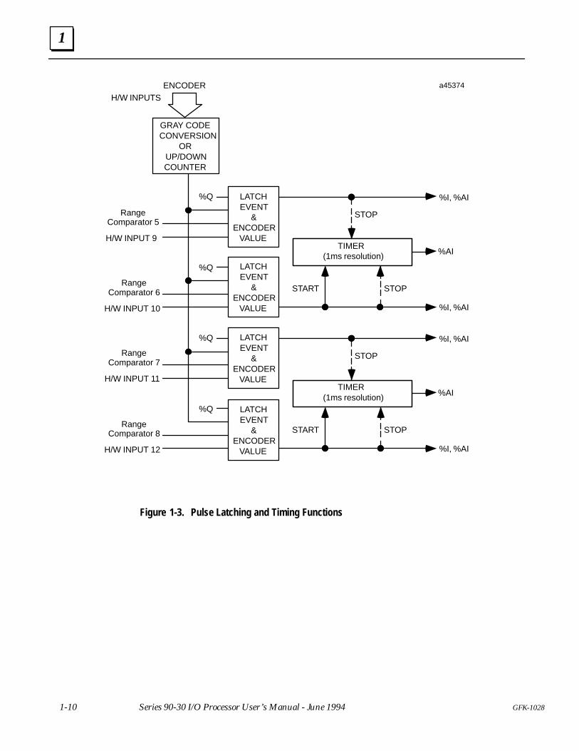
Latched Strobe Input Function
Any of the four hardware inputs (9–12) not used by an Encoder provides a latchedstrobe input function (Figure 1-3). These inputs are shared with the four configurablehardware outputs controlled by range comparators 5–8. In addition to the functionsdescribed below, the status of each input 9–12 is reported as a %I bit.
The rising or falling edge (configurable) of each input latches the latest encoder positionas a strobe value (reported via %AI data) and sets a %I strobe status bit. The strobe latch%I bit is reset by a corresponding %Q bit controlled by the PLC. Once the strobe data islatched, another strobe input will not change the data until the %I strobe status bit isreset. A configuration option allows range comparator 5–8 outputs to be used asadditional enable bits for the latched strobe functions. Range comparator 5 can beconfigured to enable the input 9 strobe latch. Range comparator 6 can be configured toenable the input 10 strobe latch, etc.
Time Measurement Function
The input time measurement function (Figure 1-3) provides two timers using input pairs9–10 and 11–12. Each timer can be configured to operate in two modes:
Single Input Timer Operation (default mode)
One edge of the second input (10 or 12) of each pair starts a timer with 1 ms resolution.The opposite edge of the same input halts the timer. The timer value is reported to thePLC using one word of %AI data for each timer. The input edge configured to set thestrobe latch for inputs 10 or 12 is also used to start the associated timer.
Dual Input Timer Operation
The second input (10 or 12) of each pair starts a timer with 1 ms resolution. The firstinput (9 or 11) of each pair halts the timer. The timer value is reported to the PLC usingone word of %AI data for each timer. The input edge configured to set the strobe latchfor each input is also used to start/stop the associated timer.
1
1-10 GFK-1028Series 90-30 I/O Processor User’s Manual - June 1994
LATCHEVENT
&ENCODER
VALUE
RangeComparator 7
H/W INPUT 11
%AI
LATCHEVENT
&ENCODER
VALUE
%Q
TIMER(1ms resolution)
%I, %AI
RangeComparator 6
%Q
H/W INPUT 10
START STOP
%I, %AI
STOP
a45374
%AI
%Q
TIMER(1ms resolution)
%I, %AI
%Q
START STOP
%I, %AI
STOP
RangeComparator 8
H/W INPUT 12
RangeComparator 5
H/W INPUT 9
GRAY CODECONVERSION
ORUP/DOWNCOUNTER
ENCODERH/W INPUTS
LATCHEVENT
&ENCODER
VALUE
LATCHEVENT
&ENCODER
VALUE
Figure 1-3. Pulse Latching and Timing Functions

2Chapter
2-1GFK-1028
Installation and Wiring
This section contains information on installing the I/O Processor module andinformation relevant to field wiring to and from the module.
Warning
Do not insert or remove modules with power applied. This couldcause damage to the module, or result in personal injury. Removingmodule with power applied could cause the PLC to Stop.
Installation and Removal of I/O Modules The following procedures and recommendations should be followed when installingand removing Series 90-30 I/O modules.
Inserting a ModuleUse the following instructions as a guide when inserting a module into its slot in abaseplate.
1. Make sure that power to the PLC is turned off.
2. Select the slot into which the module is to be inserted. Grasp the module firmlywith terminal board toward you and with rear hook facing away from you.
3. Align module with desired base slot and connector. Tilt module upward so that toprear hook of module engages slot on baseplate (Figure 2-1).
4. Swing module downward until connectors mate and lock-lever on bottom ofmodule snaps into place engaging the baseplate notch.
5. Visually inspect the module to be sure that it is properly seated.
ÎÎ
ÎÎ
a43055ÎÎÎÎÎÎÎÎÎÎÎÎÎÎÎÎÎÎÎÎÎÎÎÎÎÎÎÎÎÎÎÎÎÎÎÎÎÎÎÎÎÎÎÎÎÎÎÎÎÎÎÎÎÎÎÎÎÎÎÎÎÎÎÎÎÎÎÎÎÎÎÎÎÎÎÎÎÎÎÎÎÎÎÎÎÎÎÎÎÎ
ÎÎÎÎÎÎÎÎÎÎ
ÎÎÎÎÎÎ
Figure 2-1. Inserting a Series 90-30 Module
2
2-2 GFK-1028Series 90-30 I/O Processor Module User’s Manual - June 1994
Warning
Voltages from user devices can be present on a module’s screwterminals even though power to the rack is turned off. Care must betaken any time you are handling the module’s removable terminalboard or any wires connected to it.
Removing a Module
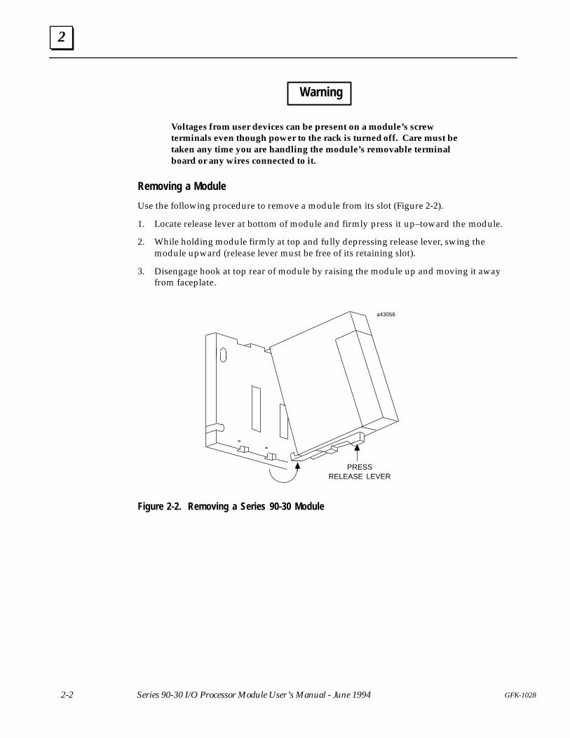
Use the following procedure to remove a module from its slot (Figure 2-2).
1. Locate release lever at bottom of module and firmly press it up–toward the module.
2. While holding module firmly at top and fully depressing release lever, swing themodule upward (release lever must be free of its retaining slot).
3. Disengage hook at top rear of module by raising the module up and moving it awayfrom faceplate.
Î
ÎÎ
a43056
PRESSRELEASE LEVER
Figure 2-2. Removing a Series 90-30 Module
2
2-3GFK-1028 Chapter 2 Installation and Wiring
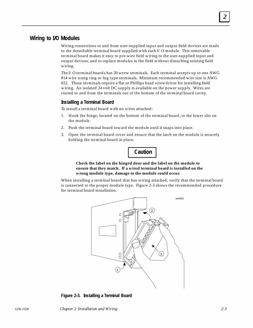
Wiring to I/O ModulesWiring connections to and from user-supplied input and output field devices are madeto the detachable terminal board supplied with each I/O module. This removableterminal board makes it easy to pre-wire field wiring to the user-supplied input andoutput devices, and to replace modules in the field without disturbing existing fieldwiring.
The I/O terminal boards has 20 screw terminals. Each terminal accepts up to one AWG#14 wire using ring or lug type terminals. Minimum recommended wire size is AWG#22. These terminals require a flat or Phillips head screwdriver for installing fieldwiring. An isolated 24 volt DC supply is available on the power supply. Wires arerouted to and from the terminals out of the bottom of the terminal board cavity.
Installing a Terminal BoardTo install a terminal board with no wires attached:
1. Hook the hinge, located on the bottom of the terminal board, to the lower slot onthe module.
2. Push the terminal board toward the module until it snaps into place.
3. Open the terminal board cover and ensure that the latch on the module is securelyholding the terminal board in place.
Caution
Check the label on the hinged door and the label on the module toensure that they match. If a wired terminal board is installed on thewrong module type, damage to the module could occur.
When installing a terminal board that has wiring attached, verify that the terminal boardis connected to the proper module type. Figure 2-3 shows the recommended procedurefor terminal board installation.
a43062
ÎÎÎÎÎÎÎÎÎÎÎÎ
ÎÎÎÎÎÎÎÎÎ
ÎÎÎÎ
ÎÎÎÎÎÎÎÎÎÎÎÎÎÎÎÎÎÎÎÎÎÎÎÎÎÎÎÎÎÎÎÎÎÎÎÎÎÎÎÎÎÎÎÎÎÎÎÎÎÎÎÎÎÎÎÎÎÎÎÎÎÎÎÎÎÎÎÎÎÎÎÎÎÎÎÎÎÎÎÎÎÎÎÎÎÎÎÎÎÎÎÎÎÎÎÎÎÎÎÎÎÎÎÎÎÎÎÎ
ÎÎÎÎÎÎÎÎÎ
2
3
1
Figure 2-3. Installing a Terminal Board
2
2-4 GFK-1028Series 90-30 I/O Processor Module User’s Manual - June 1994
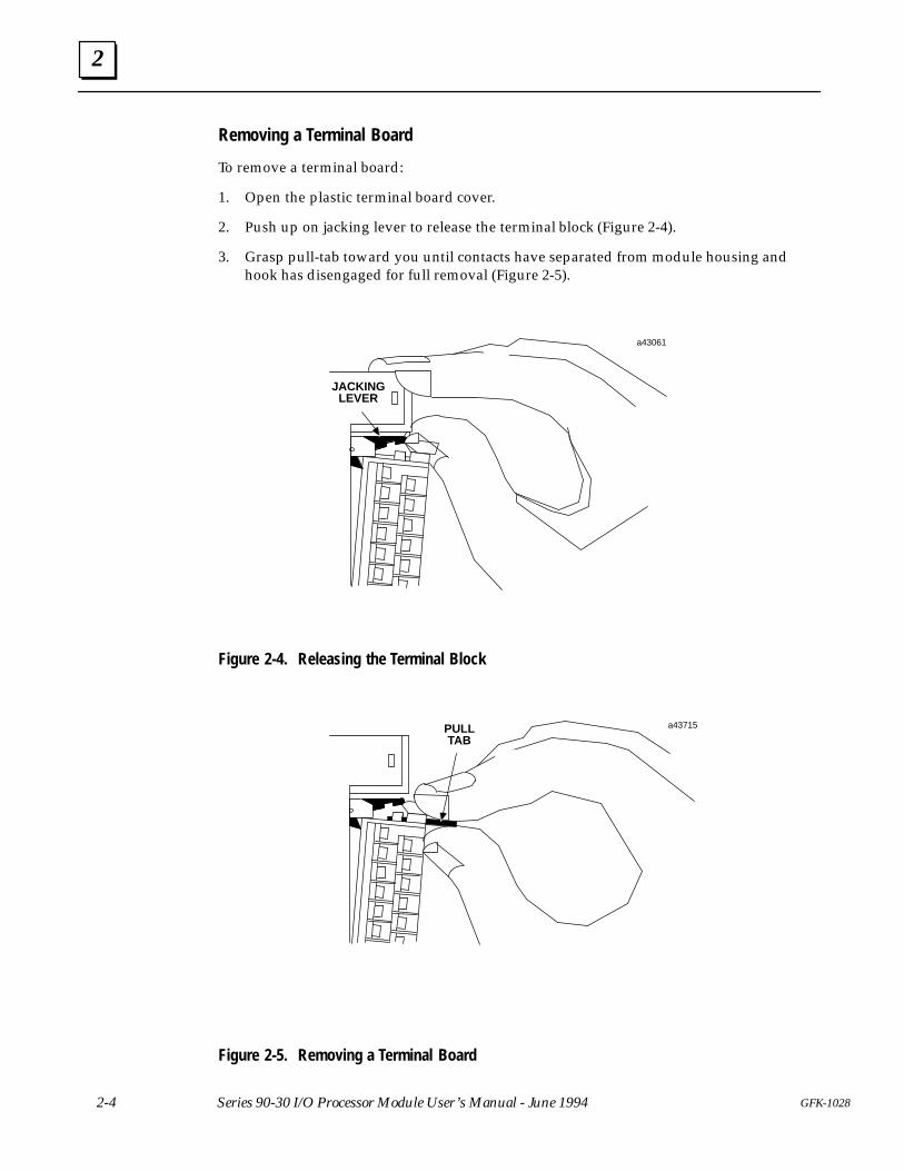
Removing a Terminal Board
To remove a terminal board:
1. Open the plastic terminal board cover.
2. Push up on jacking lever to release the terminal block (Figure 2-4).
3. Grasp pull-tab toward you until contacts have separated from module housing andhook has disengaged for full removal (Figure 2-5).
ÎÎ
ÎÎÎÎ
ÎÎÎÎÎÎ
ÎÎÎÎÎÎ
ÎÎ
ÎÎ
ÎÎÎÎÎÎÎÎÎÎÎÎÎÎÎÎÎÎÎÎÎÎÎÎÎÎÎÎÎÎÎÎÎÎÎÎÎÎÎÎÎÎÎÎÎÎÎÎÎ
JACKINGLEVER
a43061
Figure 2-4. Releasing the Terminal Block
ÎÎÎÎÎÎÎÎÎ
ÎÎÎÎÎÎÎÎ
ÎÎÎÎ
PULLTAB
a43715
Figure 2-5. Removing a Terminal Board
2
2-5GFK-1028 Chapter 2 Installation and Wiring
Field Wiring Considerations
Warning
You should calculate the maximum current for each wire and observeproper wiring practices. Failure to do so could cause injury topersonnel or damage to equipment.
It is recommended that the following procedures be followed when routing andconnecting field wiring from user devices to the PLC or to output devices to becontrolled by the PLC.
� All low level signal wires should be run separately from other field wiring.
� AC power wiring should be run separately from DC field wiring.
� Field wiring should not be routed close to any device that could be a potential sourceof electrical interference.
� If severe noise problems are present, additional power supply filtering or anisolation transformer may be required.
� Ensure that proper grounding procedures are followed to minimize potential safetyhazards to personnel.
� Label all wires to and from I/O devices. Record circuit identification numbers orother pertinent data on the inserts for the module’s faceplate door).
2
2-6 GFK-1028Series 90-30 I/O Processor Module User’s Manual - June 1994
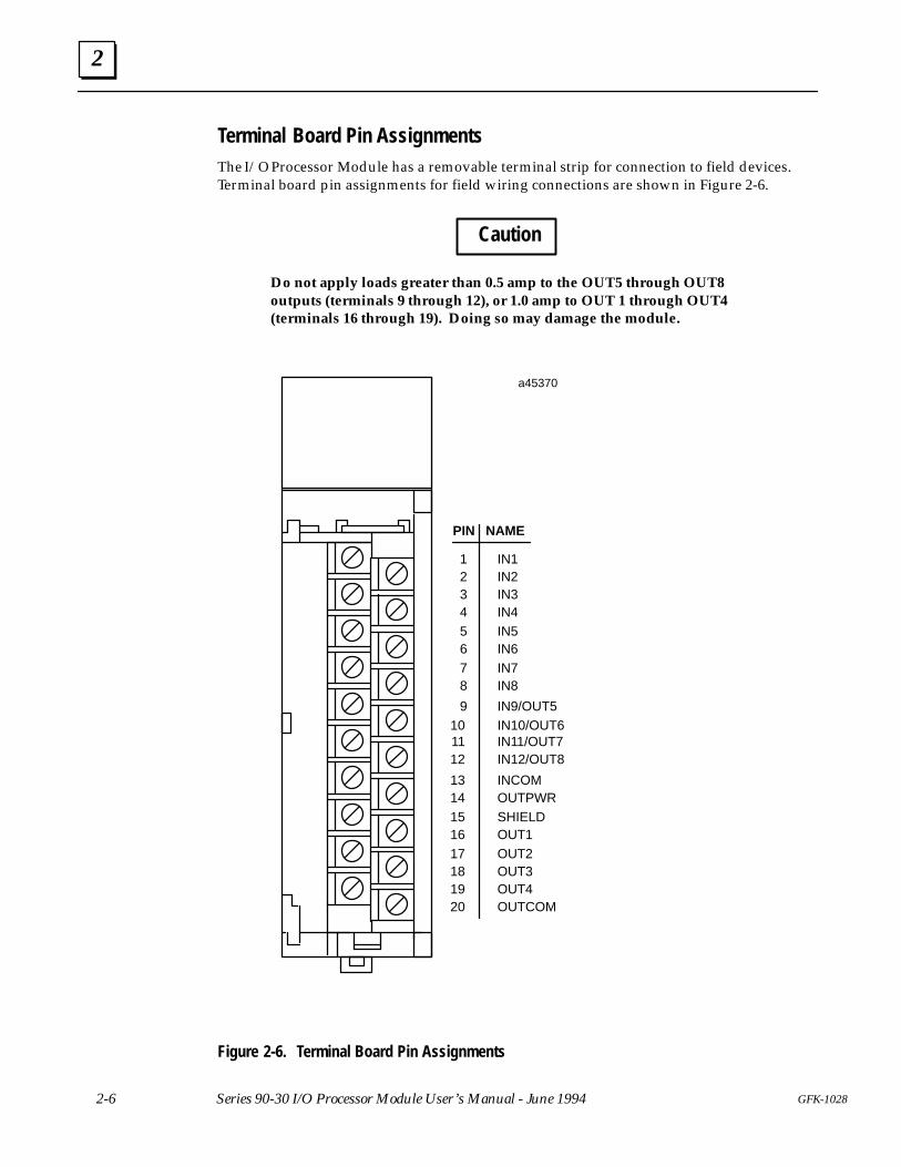
Terminal Board Pin AssignmentsThe I/O Processor Module has a removable terminal strip for connection to field devices.Terminal board pin assignments for field wiring connections are shown in Figure 2-6.
Caution
Do not apply loads greater than 0.5 amp to the OUT5 through OUT8outputs (terminals 9 through 12), or 1.0 amp to OUT 1 through OUT4(terminals 16 through 19). Doing so may damage the module.
14
a45370
ÎÎÎÎÎÎÎÎÎÎÎÎÎÎ
A1 2 3 4 5 6 7 8
ÎÎÎÎÎÎÎA1 2 3 4 5 6 7 8ÎÎÎÎ
F
ÎÎÎÎÎÎÎÎÎÎÎÎÎÎÎÎÎÎÎÎÎÎÎÎÎÎÎÎÎÎÎÎÎÎÎÎÎÎÎÎÎÎÎÎÎÎÎÎ
2
4
6
8
10
12
16
20
18
IN2
IN4
IN6
IN8
IN10/OUT6
IN12/OUT8
OUTPWR
OUT1
OUTCOM
OUT3
PIN NAME
INCOM
1
3
5
7
9
11
13
15
17
19
IN1
IN3
IN5
IN7
IN9/OUT5
IN11/OUT7
SHIELD
OUT2
OUT4
Figure 2-6. Terminal Board Pin Assignments
2
2-7GFK-1028 Chapter 2 Installation and Wiring
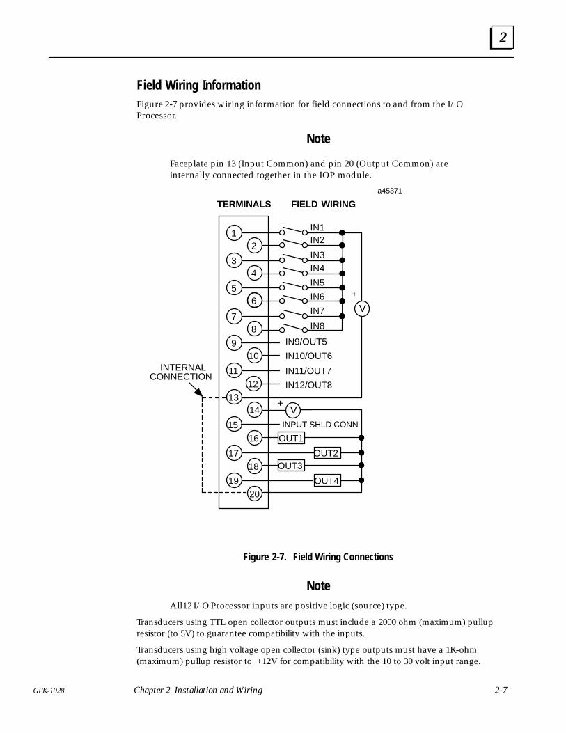
Field Wiring Information Figure 2-7 provides wiring information for field connections to and from the I/OProcessor.
Note
Faceplate pin 13 (Input Common) and pin 20 (Output Common) areinternally connected together in the IOP module.
TERMINALS FIELD WIRING
1
3
5
7
9
11
13
15
17
19
4
8
10
14
16
18
20
12
2
6
IN3ÎÎÎÎÎÎÎÎÎÎÎÎÎÎÎÎÎÎÎÎ
ÎÎÎÎ
ÎÎÎ
IN2
IN4
IN5
IN6
IN7ÎÎÎÎÎ
IN8
a45371
ÎÎÎIN1
OUT2OUT3
OUT4
OUT1
INTERNALCONNECTION
IN9/OUT5
IN10/OUT6
IN11/OUT7
IN12/OUT8
INPUT SHLD CONN
V
+
V+
Figure 2-7. Field Wiring Connections
NoteAll 12 I/O Processor inputs are positive logic (source) type.
Transducers using TTL open collector outputs must include a 2000 ohm (maximum) pullupresistor (to 5V) to guarantee compatibility with the inputs.
Transducers using high voltage open collector (sink) type outputs must have a 1K-ohm(maximum) pullup resistor to +12V for compatibility with the 10 to 30 volt input range.
2
2-8 GFK-1028Series 90-30 I/O Processor Module User’s Manual - June 1994
ÎÎÎÎ
d010 BIT
GRAY CODEABSOLUTEENCODER
d1
d2
d3
d4
d5
d6
d7
d8
d9
a45375TERMINALS FIELD WIRING
1
3
5
7
9
11
13
15
17
19
4
8
10
14
16
18
20
12
2
6
IN3
IN2
IN4
IN5
IN6
IN7
IN8
IN1
LOAD
LOAD
LOAD
LOAD
INTERNALCONNECTION
IN9/OUT5
IN10/OUT6
IN11/OUT7
IN12/OUT8
INCOMOUTPWR
SHIELD
OUT1
OUT2
OUT3
OUT4
OUTCOM
LOAD
LOAD
24V
0V
EXTERNALPOWERSUPPLY
PWR
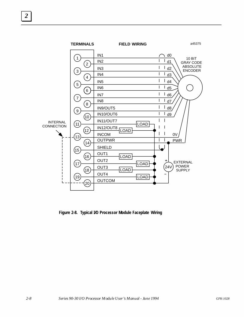
Figure 2-8. Typical I/O Processor Module Faceplate Wiring
3Chapter
3-1GFK-1028
Configuring the I/O Processor Module
There are two methods for configuring the I/O Processor:
� When the I/O Processor module is installed in its selected slot in a Series 90-30 PLCbaseplate, the Hand-held Programmer can be used for on-line configuration.
� Off-Line configuration can be accomplished using the Logicmaster 90 Configuratorsoftware and then downloading the new configuration to the PLC when on-line.
Configuration Using the Hand-held Programmer
When the I/O Processor Module is installed, configuration data entered by the user, inresponse to the Hand-held Programmer screens, is stored in the configuration memoryarea of the PLC. When configuration is complete, the PLC sends this configuration datato the I/O Processor Module.
Hand-held Programmer Configuration Screens
The screens encountered when configuring the I/O Processor are described below. If thevalue input by the user is not an acceptable value for that configuration parameter, the I/OProcessor will reject the data and respond with an error message. Error messages are describedin the Hand-held Programmer User’s Manual.
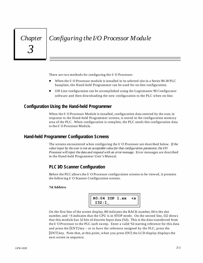
PLC I/O Scanner Configuration Before the PLC allows the I/O Processor configuration screens to be viewed, it presentsthe following I/O Scanner Configuration screens.
%I Address
R0:04 IOP 1.xx <s I32:I_
On the first line of the screen display, R0 indicates the RACK number, 04 is the slotnumber, and <S indicates that the CPU is in STOP mode. On the second line, I32 showsthat this module has 32 bits of discrete Input data (%I). This is the data transferred fromthe I/O Processor to the PLC each sweep. Enter a valid %I starting reference for this dataand press the [ENT] key – or to have the reference assigned by the PLC, press the[ENT] key. Note that, at this point, when you press ENT, the LCD display displays thenext screen in sequence.
3
3-2 GFK-1028Series 90-30 I/O Processor User’s Manual - June 1994
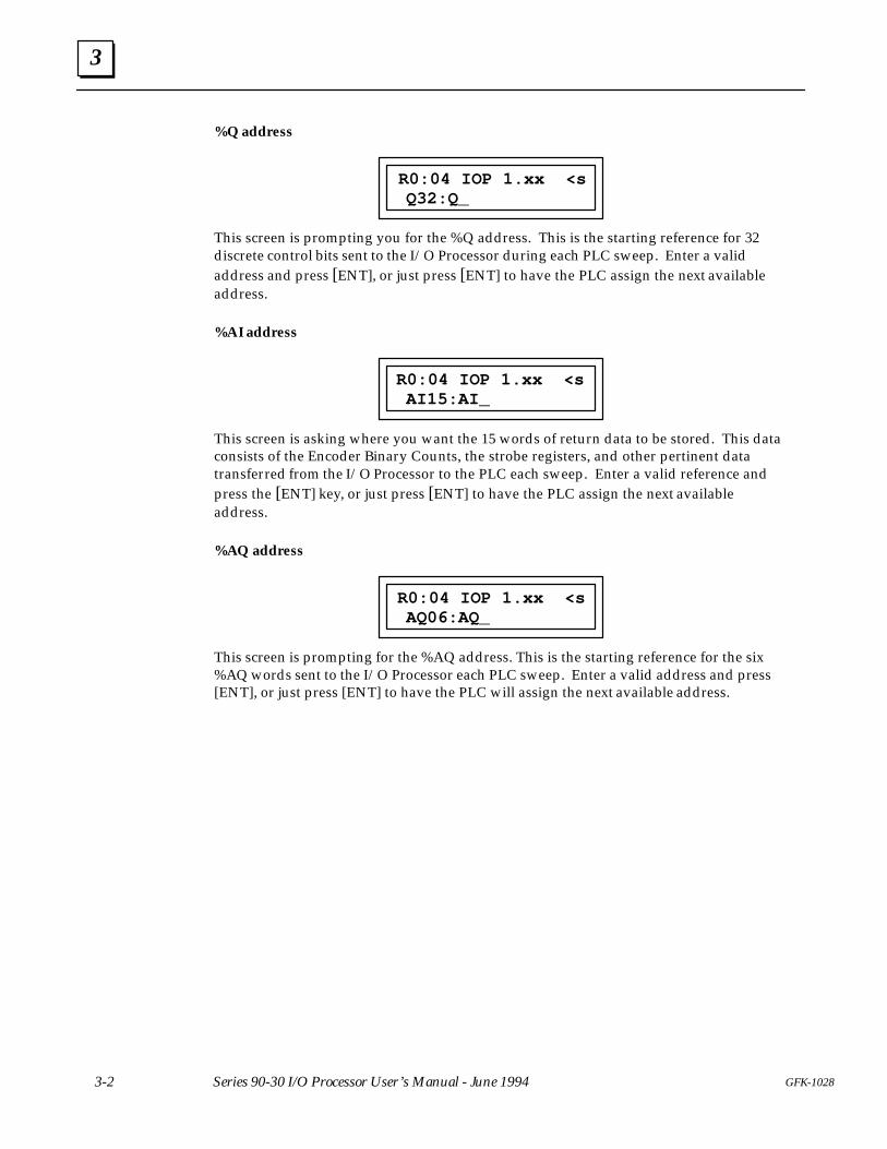
%Q address
Q32:Q_R0:04 IOP 1.xx <s
This screen is prompting you for the %Q address. This is the starting reference for 32discrete control bits sent to the I/O Processor during each PLC sweep. Enter a validaddress and press [ENT], or just press [ENT] to have the PLC assign the next availableaddress.
%AI address
AI15:AI_R0:04 IOP 1.xx <s
This screen is asking where you want the 15 words of return data to be stored. This dataconsists of the Encoder Binary Counts, the strobe registers, and other pertinent datatransferred from the I/O Processor to the PLC each sweep. Enter a valid reference andpress the [ENT] key, or just press [ENT] to have the PLC assign the next availableaddress.
%AQ address
AQ06:AQ_R0:04 IOP 1.xx <s
This screen is prompting for the %AQ address. This is the starting reference for the six%AQ words sent to the I/O Processor each PLC sweep. Enter a valid address and press[ENT], or just press [ENT] to have the PLC will assign the next available address.
3
3-3GFK-1028 Chapter 3 Configuration
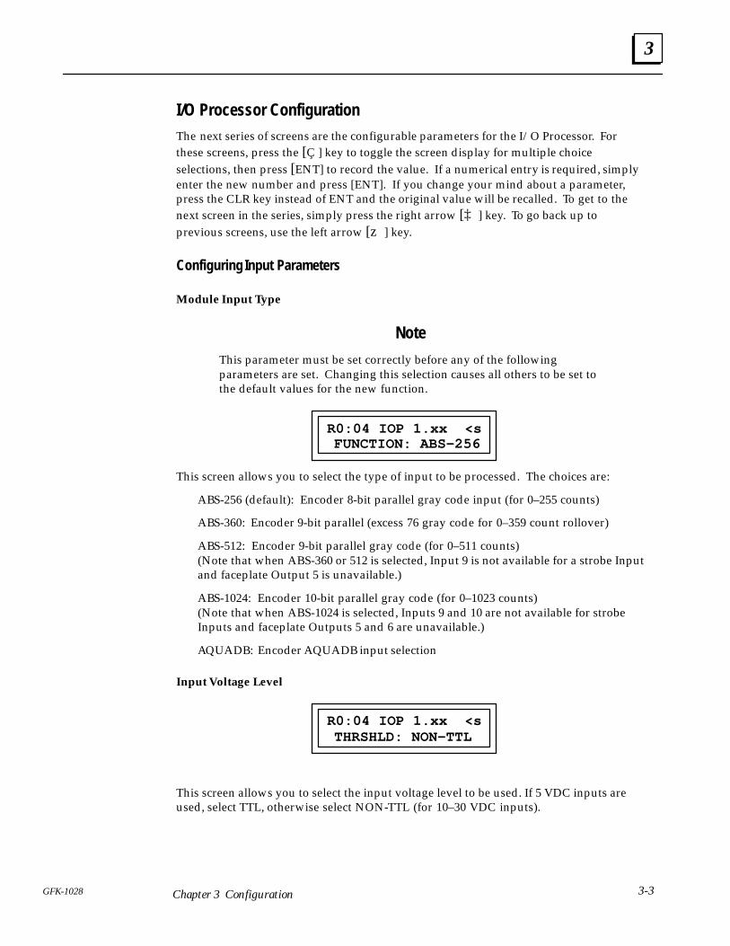
I/O Processor ConfigurationThe next series of screens are the configurable parameters for the I/O Processor. Forthese screens, press the [Ç ] key to toggle the screen display for multiple choiceselections, then press [ENT] to record the value. If a numerical entry is required, simplyenter the new number and press [ENT]. If you change your mind about a parameter,press the CLR key instead of ENT and the original value will be recalled. To get to thenext screen in the series, simply press the right arrow [‡ ] key. To go back up toprevious screens, use the left arrow [z ] key.
Configuring Input Parameters
Module Input Type
Note
This parameter must be set correctly before any of the followingparameters are set. Changing this selection causes all others to be set tothe default values for the new function.
FUNCTION: ABS–256R0:04 IOP 1.xx <s
This screen allows you to select the type of input to be processed. The choices are:
ABS-256 (default): Encoder 8-bit parallel gray code input (for 0–255 counts)
ABS-360: Encoder 9-bit parallel (excess 76 gray code for 0–359 count rollover)
ABS-512: Encoder 9-bit parallel gray code (for 0–511 counts)(Note that when ABS-360 or 512 is selected, Input 9 is not available for a strobe Inputand faceplate Output 5 is unavailable.)
ABS-1024: Encoder 10-bit parallel gray code (for 0–1023 counts)(Note that when ABS-1024 is selected, Inputs 9 and 10 are not available for strobeInputs and faceplate Outputs 5 and 6 are unavailable.)
AQUADB: Encoder AQUADB input selection
Input Voltage Level
THRSHLD: NON–TTLR0:04 IOP 1.xx <s
This screen allows you to select the input voltage level to be used. If 5 VDC inputs areused, select TTL, otherwise select NON-TTL (for 10–30 VDC inputs).
3
3-4 GFK-1028Series 90-30 I/O Processor User’s Manual - June 1994
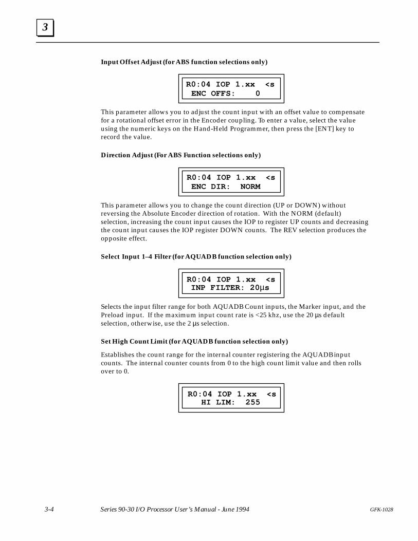
Input Offset Adjust (for ABS function selections only)
ENC OFFS: 0R0:04 IOP 1.xx <s
This parameter allows you to adjust the count input with an offset value to compensatefor a rotational offset error in the Encoder coupling. To enter a value, select the valueusing the numeric keys on the Hand-Held Programmer, then press the [ENT] key torecord the value.
Direction Adjust (For ABS Function selections only)
ENC DIR: NORMR0:04 IOP 1.xx <s
This parameter allows you to change the count direction (UP or DOWN) withoutreversing the Absolute Encoder direction of rotation. With the NORM (default)selection, increasing the count input causes the IOP to register UP counts and decreasingthe count input causes the IOP register DOWN counts. The REV selection produces theopposite effect.
Select Input 1–4 Filter (for AQUADB function selection only)
INP FILTER: 20 µsR0:04 IOP 1.xx <s
Selects the input filter range for both AQUADB Count inputs, the Marker input, and thePreload input. If the maximum input count rate is <25 khz, use the 20 µs defaultselection, otherwise, use the 2 µs selection.
Set High Count Limit (for AQUADB function selection only)
Establishes the count range for the internal counter registering the AQUADB inputcounts. The internal counter counts from 0 to the high count limit value and then rollsover to 0.
HI LIM: 255R0:04 IOP 1.xx <s
3
3-5GFK-1028 Chapter 3 Configuration
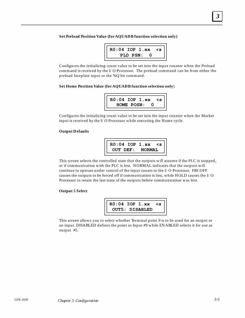
Set Preload Position Value (for AQUADB function selection only)
PLD PSN: 0R0:04 IOP 1.xx <s
Configures the initializing count value to be set into the input counter when the Preloadcommand is received by the I/O Processor. The preload command can be from either thepreload faceplate input or the %Q bit command.
Set Home Position Value (for AQUADB function selection only)
HOME POSN: 0R0:04 IOP 1.xx <s
Configures the initializing count value to be set into the input counter when the Markerinput is received by the I/O Processor while executing the Home cycle.
Output Defaults
OUT DEF: NORMALR0:04 IOP 1.xx <s
This screen selects the controlled state that the outputs will assume if the PLC is stopped,or if communication with the PLC is lost. NORMAL indicates that the outputs willcontinue to operate under control of the input counts to the I/O Processor. FRCOFFcauses the outputs to be forced off if communication is lost, while HOLD causes the I/OProcessor to retain the last state of the outputs before communication was lost.
Output 5 Select
OUT5: DISABLEDR0:04 IOP 1.xx <s
This screen allows you to select whether Terminal point 9 is to be used for an output oran input. DISABLED defines the point as Input #9 while ENABLED selects it for use asoutput #5.
3
3-6 GFK-1028Series 90-30 I/O Processor User’s Manual - June 1994
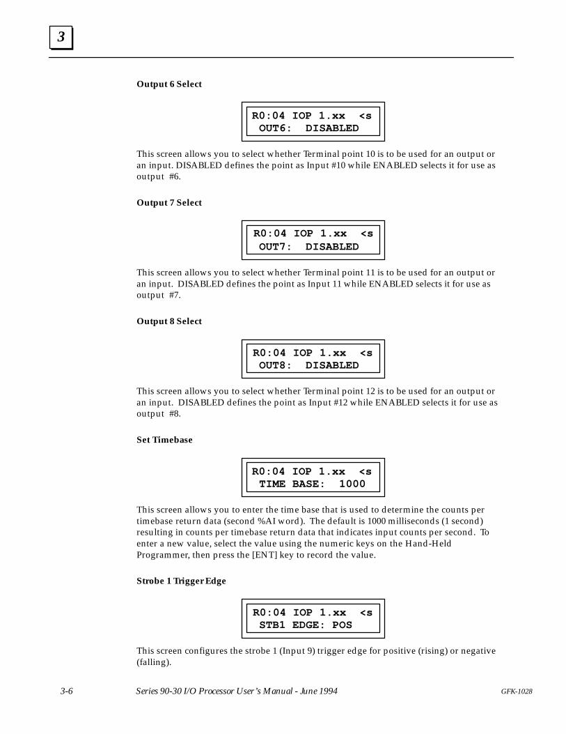
Output 6 Select
OUT6: DISABLEDR0:04 IOP 1.xx <s
This screen allows you to select whether Terminal point 10 is to be used for an output oran input. DISABLED defines the point as Input #10 while ENABLED selects it for use asoutput #6.
Output 7 Select
OUT7: DISABLEDR0:04 IOP 1.xx <s
This screen allows you to select whether Terminal point 11 is to be used for an output oran input. DISABLED defines the point as Input 11 while ENABLED selects it for use asoutput #7.
Output 8 Select
OUT8: DISABLEDR0:04 IOP 1.xx <s
This screen allows you to select whether Terminal point 12 is to be used for an output oran input. DISABLED defines the point as Input #12 while ENABLED selects it for use asoutput #8.
Set Timebase
TIME BASE: 1000R0:04 IOP 1.xx <s
This screen allows you to enter the time base that is used to determine the counts pertimebase return data (second %AI word). The default is 1000 milliseconds (1 second)resulting in counts per timebase return data that indicates input counts per second. Toenter a new value, select the value using the numeric keys on the Hand-HeldProgrammer, then press the [ENT] key to record the value.
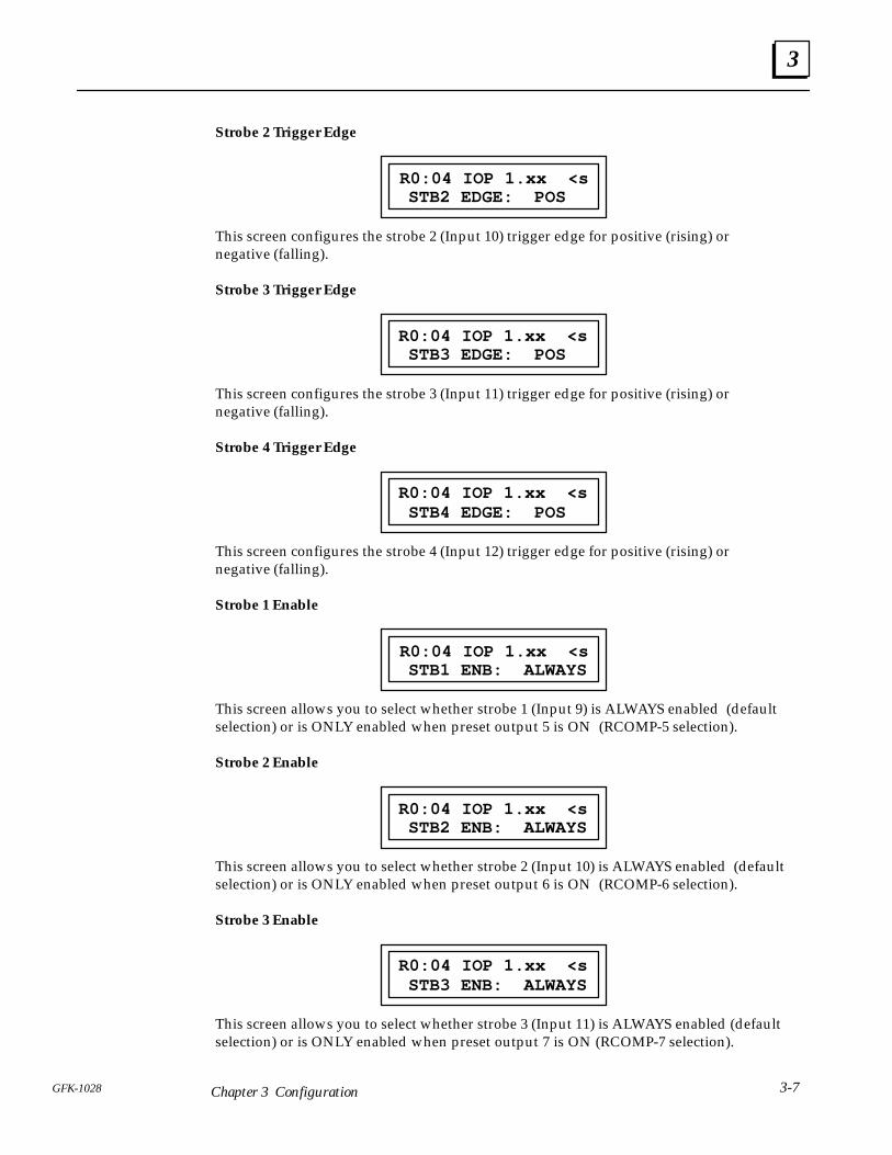
Strobe 1 Trigger Edge
STB1 EDGE: POSR0:04 IOP 1.xx <s
This screen configures the strobe 1 (Input 9) trigger edge for positive (rising) or negative(falling).
3
3-7GFK-1028 Chapter 3 Configuration
Strobe 2 Trigger Edge
STB2 EDGE: POSR0:04 IOP 1.xx <s
This screen configures the strobe 2 (Input 10) trigger edge for positive (rising) ornegative (falling).
Strobe 3 Trigger Edge
STB3 EDGE: POSR0:04 IOP 1.xx <s
This screen configures the strobe 3 (Input 11) trigger edge for positive (rising) ornegative (falling).
Strobe 4 Trigger Edge
STB4 EDGE: POSR0:04 IOP 1.xx <s
This screen configures the strobe 4 (Input 12) trigger edge for positive (rising) ornegative (falling).
Strobe 1 Enable
STB1 ENB: ALWAYSR0:04 IOP 1.xx <s
This screen allows you to select whether strobe 1 (Input 9) is ALWAYS enabled (defaultselection) or is ONLY enabled when preset output 5 is ON (RCOMP-5 selection).
Strobe 2 Enable
STB2 ENB: ALWAYSR0:04 IOP 1.xx <s
This screen allows you to select whether strobe 2 (Input 10) is ALWAYS enabled (defaultselection) or is ONLY enabled when preset output 6 is ON (RCOMP-6 selection).
Strobe 3 Enable
STB3 ENB: ALWAYSR0:04 IOP 1.xx <s
This screen allows you to select whether strobe 3 (Input 11) is ALWAYS enabled (defaultselection) or is ONLY enabled when preset output 7 is ON (RCOMP-7 selection).
3
3-8 GFK-1028Series 90-30 I/O Processor User’s Manual - June 1994
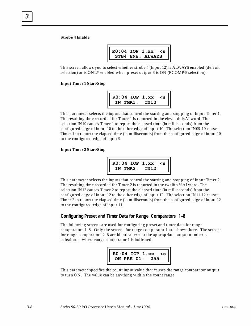
Strobe 4 Enable
STB4 ENB: ALWAYSR0:04 IOP 1.xx <s
This screen allows you to select whether strobe 4 (Input 12) is ALWAYS enabled (defaultselection) or is ONLY enabled when preset output 8 is ON (RCOMP-8 selection).
Input Timer 1 Start/Stop
IN TMR1: IN10R0:04 IOP 1.xx <s
This parameter selects the inputs that control the starting and stopping of Input Timer 1.The resulting time recorded for Timer 1 is reported in the eleventh %AI word. Theselection IN10 causes Timer 1 to report the elapsed time (in milliseconds) from theconfigured edge of input 10 to the other edge of input 10. The selection IN09-10 causesTimer 1 to report the elapsed time (in milliseconds) from the configured edge of input 10to the configured edge of input 9.
Input Timer 2 Start/Stop
IN TMR2: IN12R0:04 IOP 1.xx <s
This parameter selects the inputs that control the starting and stopping of Input Timer 2.The resulting time recorded for Timer 2 is reported in the twelfth %AI word. Theselection IN12 causes Timer 2 to report the elapsed time (in milliseconds) from theconfigured edge of input 12 to the other edge of input 12. The selection IN11-12 causesTimer 2 to report the elapsed time (in milliseconds) from the configured edge of input 12to the configured edge of input 11.
Configuring Preset and Timer Data for Range Comparators 1–8
The following screens are used for configuring preset and timer data for rangecomparators 1–8. Only the screens for range comparator 1 are shown here. The screensfor range comparators 2–8 are identical except the appropriate output number issubstituted where range comparator 1 is indicated.
ON PRE 01: 255R0:04 IOP 1.xx <s
This parameter specifies the count input value that causes the range comparator outputto turn ON. The value can be anything within the count range.
3
3-9GFK-1028 Chapter 3 Configuration
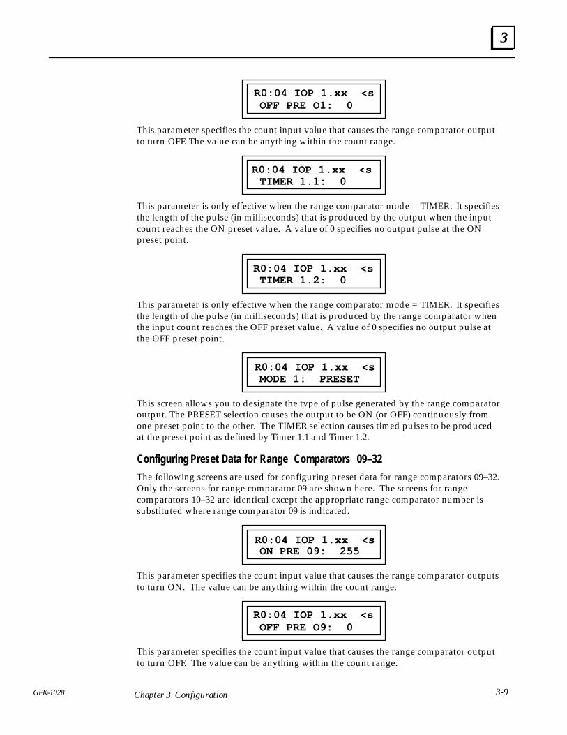
OFF PRE O1: 0R0:04 IOP 1.xx <s
This parameter specifies the count input value that causes the range comparator outputto turn OFF. The value can be anything within the count range.
TIMER 1.1: 0R0:04 IOP 1.xx <s
This parameter is only effective when the range comparator mode = TIMER. It specifiesthe length of the pulse (in milliseconds) that is produced by the output when the inputcount reaches the ON preset value. A value of 0 specifies no output pulse at the ONpreset point.
TIMER 1.2: 0R0:04 IOP 1.xx <s
This parameter is only effective when the range comparator mode = TIMER. It specifiesthe length of the pulse (in milliseconds) that is produced by the range comparator whenthe input count reaches the OFF preset value. A value of 0 specifies no output pulse atthe OFF preset point.
MODE 1: PRESETR0:04 IOP 1.xx <s
This screen allows you to designate the type of pulse generated by the range comparatoroutput. The PRESET selection causes the output to be ON (or OFF) continuously fromone preset point to the other. The TIMER selection causes timed pulses to be producedat the preset point as defined by Timer 1.1 and Timer 1.2.
Configuring Preset Data for Range Comparators 09–32
The following screens are used for configuring preset data for range comparators 09–32.Only the screens for range comparator 09 are shown here. The screens for rangecomparators 10–32 are identical except the appropriate range comparator number issubstituted where range comparator 09 is indicated.
ON PRE 09: 255R0:04 IOP 1.xx <s
This parameter specifies the count input value that causes the range comparator outputsto turn ON. The value can be anything within the count range.
OFF PRE O9: 0R0:04 IOP 1.xx <s
This parameter specifies the count input value that causes the range comparator outputto turn OFF. The value can be anything within the count range.
3
3-10 GFK-1028Series 90-30 I/O Processor User’s Manual - June 1994
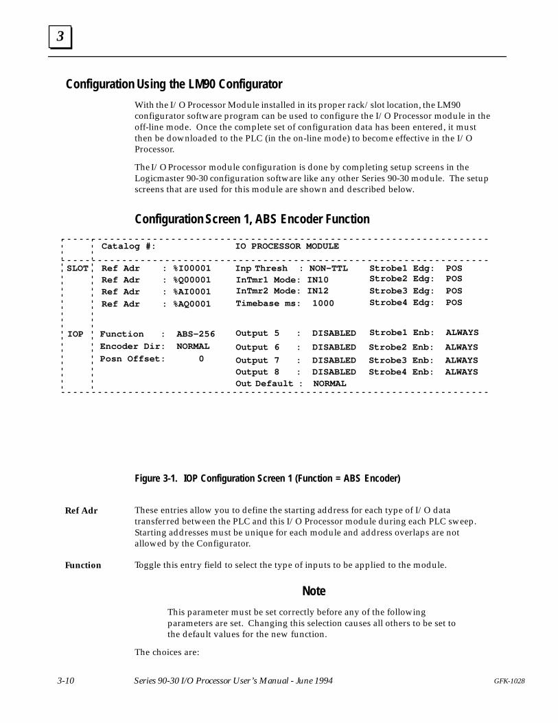
Configuration Using the LM90 Configurator
With the I/O Processor Module installed in its proper rack/slot location, the LM90configurator software program can be used to configure the I/O Processor module in theoff-line mode. Once the complete set of configuration data has been entered, it mustthen be downloaded to the PLC (in the on-line mode) to become effective in the I/OProcessor.
The I/O Processor module configuration is done by completing setup screens in theLogicmaster 90-30 configuration software like any other Series 90-30 module. The setupscreens that are used for this module are shown and described below.
Configuration Screen 1, ABS Encoder Function
Catalog #: IO PROCESSOR MODULE
SLOT
IOP
Ref Adr : %I00001Ref Adr : %Q00001Ref Adr : %AI0001
Ref Adr : %AQ0001
Function : ABS–256
Encoder Dir: NORMAL
Posn Offset: 0
Inp Thresh : NON–TTL Strobe1 Edg: POSInTmr1 Mode: IN10InTmr2 Mode: IN12
Timebase ms: 1000
Output 5 : DISABLED
Output 6 : DISABLED
Output 7 : DISABLEDOutput 8 : DISABLEDOut Default : NORMAL
Strobe2 Edg: POS
Strobe3 Edg: POSStrobe4 Edg: POS
Strobe1 Enb: ALWAYS
Strobe2 Enb: ALWAYS
Strobe3 Enb: ALWAYSStrobe4 Enb: ALWAYS
Figure 3-1. IOP Configuration Screen 1 (Function = ABS Encoder)
These entries allow you to define the starting address for each type of I/O datatransferred between the PLC and this I/O Processor module during each PLC sweep.Starting addresses must be unique for each module and address overlaps are notallowed by the Configurator.
Toggle this entry field to select the type of inputs to be applied to the module.
Note
This parameter must be set correctly before any of the followingparameters are set. Changing this selection causes all others to be set tothe default values for the new function.
The choices are:
Ref Adr
Function
3
3-11GFK-1028 Chapter 3 Configuration
ABS-256 (default) Encoder 8-bit parallel gray code input (for 0–255 counts)
ABS-360 Encoder 9-bit parallel excess 76 gray code (for 0–359 count rollover)
ABS-512 Encoder 9-bit parallel gray code (for 0–511 counts) (Note that whenABS-360 or 512 is selected, Input 9 is not available for a strobe Input andfaceplate Output 5 is unavailable.)
ABS-1024 Encoder 10-bit parallel gray code for 0–1023 counts. (Note that whenABS-1024 is selected, Inputs 9 and 10 are not available for strobe Inputs andfaceplate Outputs 5 and 6 are unavailable.)
AQUADB Encoder AQUADB input selection (Note that when AQUADB is selected, theremaining selections in this column change. See the next screen for thesedescriptions.)
This parameter allows you to change the count direction (UP or DOWN) withoutreversing the Absolute Encoder direction of rotation. If the NORM (default) is selected,increasing the count input causes the IOP to register UP counts and decreasing the countinput causes the IOP to register DOWN counts. The REV selection produces theopposite effect. Default: NORMAL
This parameter allows you to adjust the count input with an offset value to compensatefor a rotational offset error in the Encoder coupling. Enter any required count valuewithin the count range. Default: 0
Selects the Input voltage level to be used. If 5 VDC inputs are used, select TTL,otherwise select NON-TTL (for 10–30 VDC inputs). Default: NON-TTL
This parameter selects the inputs that control the starting and stopping of Timer 1. Theresulting time recorded for Timer 1 is reported in the eleventh %AI word. The selectionIN10 causes Timer 1 to report the elapsed time (in milliseconds) from the configurededge of input 10 to the other edge of input 10. The selection IN09-10 causes Timer 1 toreport the elapsed time (in milliseconds) from the configured edge of input 10 to theconfigured edge of input 9. Default: IN10
This parameter selects the inputs that control the starting and stopping of Timer 2. Theresulting time recorded for Timer 2 is reported in the twelfth %AI word. The selectionIN12 causes Timer 2 to report the elapsed time (in milliseconds) from the configurededge of input 12 to the other edge of input 12. The selection IN11-12 causes Timer 2 toreport the elapsed time (in milliseconds) from the configured edge of input 12 to theconfigured edge of input 11. Default: IN12
This parameter allows you to enter the time base that is used to determine the Countsper Timebase return data (second %AI word). The default is 1000 milliseconds (1second) resulting in Counts per Timebase return data that indicates input counts persecond. Default: 1000
This parameter allows you to select whether Terminal point 9 is to be used for an outputor an input. DISABLED defines the point as Input #9 while ENABLED selects it for useas output #5. Default: DISABLED
This parameter allows you to select whether Terminal point 10 is to be used for anoutput or an input. DISABLED defines the point as Input #10 while ENABLED selects itfor use as output #6. Default: DISABLED
Encoder Dir
Posn Offset
Inp Thresh
InTmr1 Mode
InTmr2 Mode
Timebase ms
Output 5
Output 6
3
3-12 GFK-1028Series 90-30 I/O Processor User’s Manual - June 1994
This parameter allows you to select whether Terminal point 11 is to be used for anoutput or an input. DISABLED defines the point as Input 11 while ENABLED selects itfor use as output #7. Default: DISABLED
This parameter allows you to select whether Terminal point 12 is to be used for anoutput or an input. DISABLED defines the point as Input #12 while ENABLED selects itfor use as output #8. Default: DISABLED
This parameter selects the state the hardware outputs will assume if the PLC is stopped.NORMAL indicates that the outputs continue to operate under control of the inputcounts to the I/O Processor. FRCOFF causes the outputs to be forced off if the PLC stops.HOLD causes the I/O Processor to retain the last state of the outputs before the PLCstopped. Default: NORMAL
This parameter configures the strobe 1 (Input 9) trigger edge for positive (rising) ornegative (falling). Default: POS
This parameter configures the strobe 2 (Input 10) trigger edge for positive (rising) ornegative (falling). Default: POS
This parameter configures the strobe 3 (Input 11) trigger edge for positive (rising) ornegative (falling). Default: POS
This parameter configures the strobe 4 (Input 12) trigger edge for positive (rising) ornegative (falling). Default: POS
This parameter allows you to select whether strobe 1 (Input 9) is ALWAYS enabled(default selection) or is ONLY enabled when preset output 5 is ON (RCOMP-5selection). Default: ALWAYS
This parameter allows you to select whether strobe 2 (Input 10) is ALWAYS enabled(default selection) or is ONLY enabled when preset output 6 is ON (RCOMP-6selection). Default: ALWAYS
This parameter allows you to select whether strobe 3 (Input 11) is ALWAYS enabled(default selection) or is ONLY enabled when preset output 7 is ON (RCOMP-7selection). Default: ALWAYS
This parameter allows you to select whether strobe 4 (Input 12) is ALWAYS enabled(default selection) or is ONLY enabled when preset output 8 is ON (RCOMP-8selection). Default: ALWAYS
Output 7
Output 8
Out Default
Strobe1 Edg
Strobe2 Edg
Strobe3 Edg
Strobe4 Edg
Strobe1 Enb
Strobe2 Enb
Strobe3 Enb
Strobe4 Enb

3
3-13GFK-1028 Chapter 3 Configuration
Configuration Screen 1, AQUADB Encoder Function
Catalog #: IO PROCESSOR MODULE
SLOT
IOP
Ref Adr : %I00001Ref Adr : %Q00001Ref Adr : %AI0001
Ref Adr : %AQ0001
Function : AQUADB
Inp Filter : 20 µs
Max Counts : 0
Inp Thresh : NON–TTL Strobe1 Edg: POSInTmr1 Mode: IN10InTmr2 Mode: IN12
Timebase ms: 1000
Output 5 : DISABLED
Output 6 : DISABLED
Output 7 : DISABLEDOutput 8 : DISABLEDOut Default : NORMAL
Strobe2 Edg: POS
Strobe3 Edg: POSStrobe4 Edg: POS
Strobe1 Enb: ALWAYS
Strobe2 Enb: ALWAYS
Strobe3 Enb: ALWAYSStrobe4 Enb: ALWAYSPreld Posn : 0
Home Posn : 0
Figure 3-2. IOP Configuration Screen 1 (Function = AQUADB Encoder)
Note
All screen entries not described here are identical to those described forthe ABS Encoder (Figure 3-1)
Selects the Input filter range for both AQUADB Count inputs , the Marker input, and thePreload input. If the maximum count input rate is < 25 khz, use the 20 µs defaultselection, otherwise use the 2 µs selection. Default: 20 µs
This entry establishes the count range for the internal counter registering the AQUADBinput counts. It counts from 0 to this maximum value and then rolls over to 0. Therange for this parameter is 10 to 64,999 counts. Default: 255
This configures the initializing count value to be set into the input counter when thepreload command is received by the I/O Processor. The preload command can be fromeither the preload faceplate input or the %Q bit command. Range: 0 to maximum counts
This configures the initializing count value to be set into the input counter when theMarker input is received by the I/O Processor when executing the Home cycle. Range: 0to maximum counts
Inp Filter
Max Counts
Preld Posn
Home Posn
3
3-14 GFK-1028Series 90-30 I/O Processor User’s Manual - June 1994
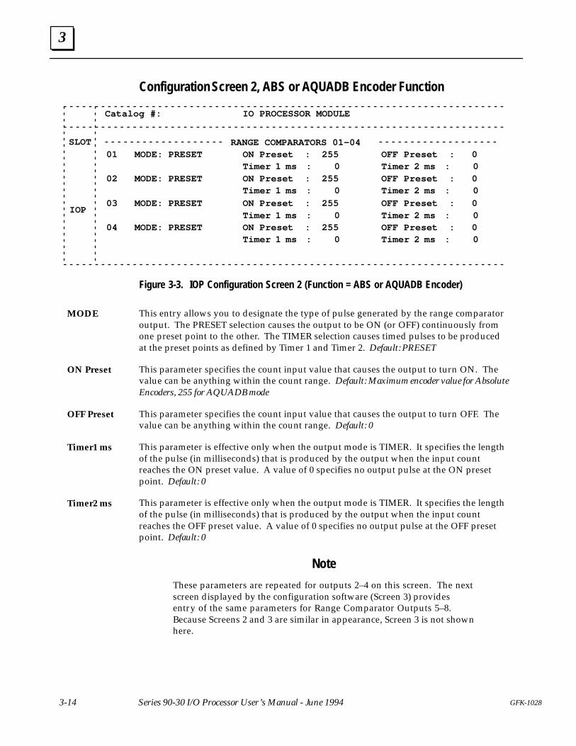
Configuration Screen 2, ABS or AQUADB Encoder Function
Catalog #: IO PROCESSOR MODULE
SLOT
IOP
ON Preset : 255 OFF Preset : 0RANGE COMPARATORS 01–04
Timer 1 ms : 001 MODE: PRESET
ON Preset : 255 OFF Preset : 0Timer 1 ms : 0
02 MODE: PRESET
ON Preset : 255 OFF Preset : 0Timer 1 ms : 0
03 MODE: PRESET
ON Preset : 255 OFF Preset : 0Timer 1 ms : 0
04 MODE: PRESET
Timer 2 ms : 0
Timer 2 ms : 0
Timer 2 ms : 0
Timer 2 ms : 0
Figure 3-3. IOP Configuration Screen 2 (Function = ABS or AQUADB Encoder)
This entry allows you to designate the type of pulse generated by the range comparatoroutput. The PRESET selection causes the output to be ON (or OFF) continuously fromone preset point to the other. The TIMER selection causes timed pulses to be producedat the preset points as defined by Timer 1 and Timer 2. Default: PRESET
This parameter specifies the count input value that causes the output to turn ON. Thevalue can be anything within the count range. Default: Maximum encoder value for AbsoluteEncoders, 255 for AQUADB mode
This parameter specifies the count input value that causes the output to turn OFF. Thevalue can be anything within the count range. Default: 0
This parameter is effective only when the output mode is TIMER. It specifies the lengthof the pulse (in milliseconds) that is produced by the output when the input countreaches the ON preset value. A value of 0 specifies no output pulse at the ON presetpoint. Default: 0
This parameter is effective only when the output mode is TIMER. It specifies the lengthof the pulse (in milliseconds) that is produced by the output when the input countreaches the OFF preset value. A value of 0 specifies no output pulse at the OFF presetpoint. Default: 0
Note
These parameters are repeated for outputs 2–4 on this screen. The nextscreen displayed by the configuration software (Screen 3) providesentry of the same parameters for Range Comparator Outputs 5–8.Because Screens 2 and 3 are similar in appearance, Screen 3 is not shownhere.
MODE
ON Preset
OFF Preset
Timer1 ms
Timer2 ms
3
3-15GFK-1028 Chapter 3 Configuration
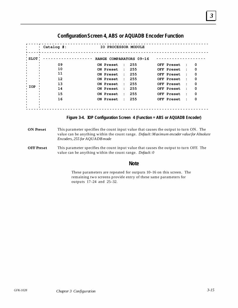
Configuration Screen 4, ABS or AQUADB Encoder Function
Catalog #: IO PROCESSOR MODULE
SLOT
IOP
ON Preset : 255 OFF Preset : 0
RANGE COMPARATORS 09–16
09ON Preset : 255 OFF Preset : 0ON Preset : 255 OFF Preset : 0ON Preset : 255 OFF Preset : 012ON Preset : 255 OFF Preset : 013ON Preset : 255 OFF Preset : 014
ON Preset : 255 OFF Preset : 015
ON Preset : 255 OFF Preset : 016
1011
Figure 3-4. IOP Configuration Screen 4 (Function = ABS or AQUADB Encoder)
This parameter specifies the count input value that causes the output to turn ON. Thevalue can be anything within the count range. Default: Maximum encoder value for AbsoluteEncoders, 255 for AQUADB mode
This parameter specifies the count input value that causes the output to turn OFF. Thevalue can be anything within the count range. Default: 0
Note
These parameters are repeated for outputs 10–16 on this screen. Theremaining two screens provide entry of these same parameters foroutputs 17–24 and 25–32.
ON Preset
OFF Preset
4Chapter
4-1GFK-1028
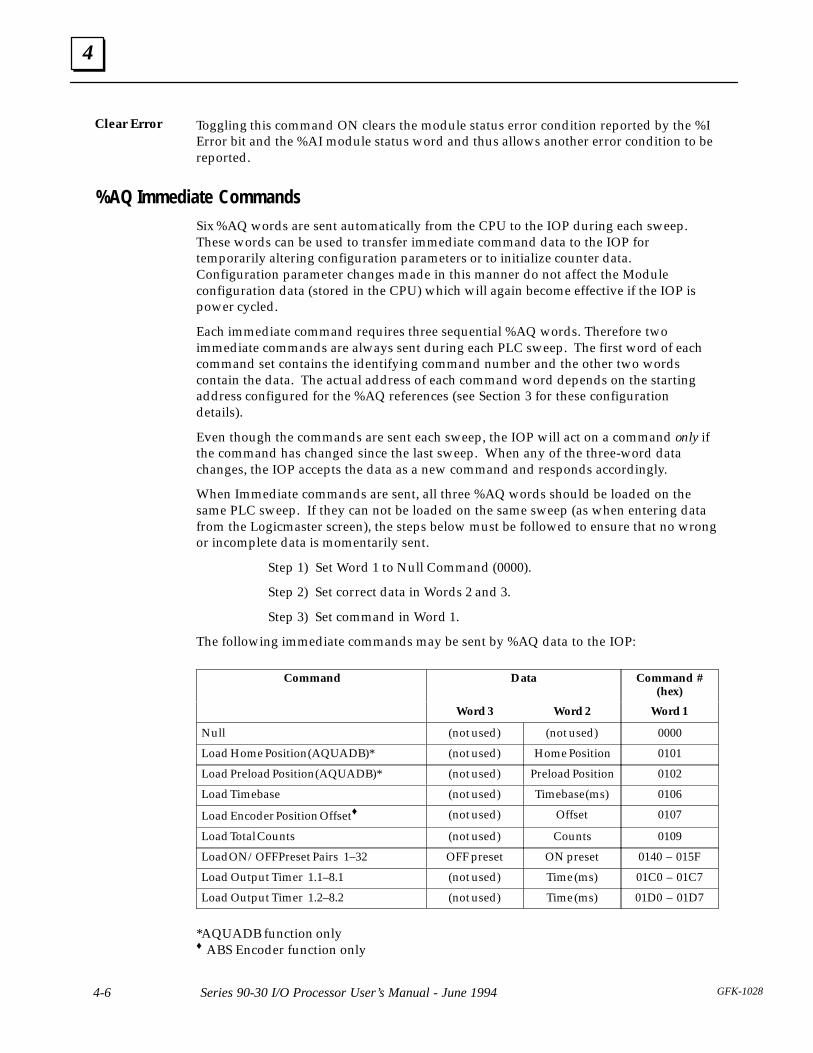
Automatic Data Transfers
Data transferred automatically during each sweep between the CPU and IOP, withoutuser programming, consists of discrete status bits (%I), status data words (%AI), discretecommand bits (%Q), and immediate command data (%AQ). The size and direction flowof this data is listed below.
Input Status Data (From IOP to CPU)� Status Bits: 32 bits of %I data
� Status Words: 15 words of %AI data
Output Command Data (From CPU to IOP)� Discrete Commands: 32 bits of %Q data
� Immediate Command Data: 6 words of %AQ data
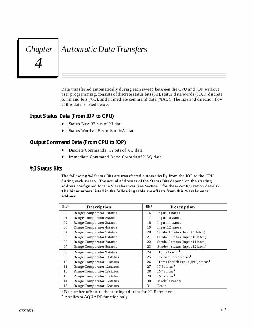
%I Status BitsThe following %I Status Bits are transferred automatically from the IOP to the CPUduring each sweep. The actual addresses of the Status Bits depend on the startingaddress configured for the %I references (see Section 3 for these configuration details).The bit numbers listed in the following table are offsets from this %I referenceaddress.
ÁÁÁÁÁÁBit*
ÁÁÁÁÁÁÁÁÁÁÁÁÁÁÁÁÁÁÁÁÁÁÁÁ Description
ÁÁÁÁÁÁBit*
ÁÁÁÁÁÁÁÁÁÁÁÁÁÁÁÁÁÁÁÁÁÁÁÁ DescriptionÁÁÁ
ÁÁÁ00ÁÁÁÁÁÁÁÁÁÁÁÁÁÁÁÁÁÁÁÁÁÁÁÁRange Comparator 1 status
ÁÁÁÁÁÁ16
ÁÁÁÁÁÁÁÁÁÁÁÁÁÁÁÁÁÁÁÁÁÁÁÁInput 9 statusÁÁÁ
ÁÁÁ01 ÁÁÁÁÁÁÁÁÁÁÁÁÁÁÁÁÁÁÁÁÁÁÁÁ
Range Comparator 2 status ÁÁÁÁÁÁ
17 ÁÁÁÁÁÁÁÁÁÁÁÁÁÁÁÁÁÁÁÁÁÁÁÁ
Input 10 statusÁÁÁÁÁÁ
02 ÁÁÁÁÁÁÁÁÁÁÁÁÁÁÁÁÁÁÁÁÁÁÁÁ
Range Comparator 3 status ÁÁÁÁÁÁ
18 ÁÁÁÁÁÁÁÁÁÁÁÁÁÁÁÁÁÁÁÁÁÁÁÁ
Input 11 status
ÁÁÁÁÁÁ
03 ÁÁÁÁÁÁÁÁÁÁÁÁÁÁÁÁÁÁÁÁÁÁÁÁ
Range Comparator 4 status ÁÁÁÁÁÁ
19 ÁÁÁÁÁÁÁÁÁÁÁÁÁÁÁÁÁÁÁÁÁÁÁÁ
Input 12 status
ÁÁÁ04 ÁÁÁÁÁÁÁÁÁÁÁÁRange Comparator 5 status ÁÁÁ20 ÁÁÁÁÁÁÁÁÁÁÁÁStrobe 1 status (Input 9 latch)ÁÁÁÁÁÁ
05 ÁÁÁÁÁÁÁÁÁÁÁÁÁÁÁÁÁÁÁÁÁÁÁÁ
Range Comparator 6 status ÁÁÁÁÁÁ
21 ÁÁÁÁÁÁÁÁÁÁÁÁÁÁÁÁÁÁÁÁÁÁÁÁ
Strobe 2 status (Input 10 latch)ÁÁÁÁÁÁ
06 ÁÁÁÁÁÁÁÁÁÁÁÁÁÁÁÁÁÁÁÁÁÁÁÁ
Range Comparator 7 status ÁÁÁÁÁÁ
22 ÁÁÁÁÁÁÁÁÁÁÁÁÁÁÁÁÁÁÁÁÁÁÁÁ
Strobe 3 status (Input 11 latch)
ÁÁÁÁÁÁ
07 ÁÁÁÁÁÁÁÁÁÁÁÁÁÁÁÁÁÁÁÁÁÁÁÁ
Range Comparator 8 status ÁÁÁÁÁÁ
23 ÁÁÁÁÁÁÁÁÁÁÁÁÁÁÁÁÁÁÁÁÁÁÁÁ
Strobe 4 status (Input 12 latch)
ÁÁÁ08 ÁÁÁÁÁÁÁÁÁÁÁÁRange Comparator 9 status ÁÁÁ24 ÁÁÁÁÁÁÁÁÁÁÁÁHome Found♦ÁÁÁÁÁÁ
09ÁÁÁÁÁÁÁÁÁÁÁÁÁÁÁÁÁÁÁÁÁÁÁÁ
Range Comparator 10 statusÁÁÁÁÁÁ
25ÁÁÁÁÁÁÁÁÁÁÁÁÁÁÁÁÁÁÁÁÁÁÁÁ
Preload Latch status♦ÁÁÁÁÁÁ
10 ÁÁÁÁÁÁÁÁÁÁÁÁÁÁÁÁÁÁÁÁÁÁÁÁ
Range Comparator 11 status ÁÁÁÁÁÁ
26 ÁÁÁÁÁÁÁÁÁÁÁÁÁÁÁÁÁÁÁÁÁÁÁÁ
Home Switch Input (IN5) status♦
ÁÁÁÁÁÁ
11 ÁÁÁÁÁÁÁÁÁÁÁÁÁÁÁÁÁÁÁÁÁÁÁÁ
Range Comparator 12 status ÁÁÁÁÁÁ
27 ÁÁÁÁÁÁÁÁÁÁÁÁÁÁÁÁÁÁÁÁÁÁÁÁ
IN6 status♦
ÁÁÁ12 ÁÁÁÁÁÁÁÁÁÁÁÁRange Comparator 13 status ÁÁÁ28 ÁÁÁÁÁÁÁÁÁÁÁÁIN7 status♦ÁÁÁÁÁÁ
13ÁÁÁÁÁÁÁÁÁÁÁÁÁÁÁÁÁÁÁÁÁÁÁÁ
Range Comparator 14 statusÁÁÁÁÁÁ
29ÁÁÁÁÁÁÁÁÁÁÁÁÁÁÁÁÁÁÁÁÁÁÁÁ
IN8 status♦ÁÁÁÁÁÁ
14 ÁÁÁÁÁÁÁÁÁÁÁÁÁÁÁÁÁÁÁÁÁÁÁÁ
Range Comparator 15 status ÁÁÁÁÁÁ
30 ÁÁÁÁÁÁÁÁÁÁÁÁÁÁÁÁÁÁÁÁÁÁÁÁ
Module ReadyÁÁÁÁÁÁ
15 ÁÁÁÁÁÁÁÁÁÁÁÁÁÁÁÁÁÁÁÁÁÁÁÁ
Range Comparator 16 status ÁÁÁÁÁÁ
31 ÁÁÁÁÁÁÁÁÁÁÁÁÁÁÁÁÁÁÁÁÁÁÁÁ
Error
* Bit number offsets to the starting address for %I References.♦ Applies to AQUADB function only
4
Series 90-30 I/O Processor User’s Manual - June 1994 GFK-10284-2
%I Status Bit Descriptions
Indicates the ON/OFF state for range comparator outputs 1–8. If the Output Mode =Preset, the state of the status bit is defined by the ON/OFF presets. If the Output Mode= Timer, the status bit will be on after each preset point is passed for the length of timedesignated by Timer 1 or Timer 2. These bits always indicate the output state for rangecomparators 1–8, even if the corresponding hardware output is disabled (and TerminalPoints 9–12 are used as Inputs).
Indicates the ON/OFF state for range comparator outputs 9–16 based solely on the ON& OFF presets defined for each output.
Indicates the present on/off input status for Inputs 9–12. State changes in these inputsproduce strobe inputs 1–4 according to the configured strobe edge (input 9 = strobe 1,input 10 = strobe 2, etc.).
Indicates strobe data has been captured by Inputs 9–12, respectively. Onceacknowledged by the PLC ladder program, the corresponding %Q command (ResetStrobe) should be sent to clear the strobe status for future strobe captures. Followingstrobes will be locked out until this flag is cleared.
Indicates the Home marker, after a Home command sequence, has been recognized andthe AQUADB Input Counter has been set to the Home preload value.
This status flag indicates to the PLC that the AQUADB input counter has been preloadedby the faceplate Preload Input. When acknowledged, this status indication should becleared (by the Reset Preload Latch %Q bit) in order to recognize the occurrence offuture preloads. This latch locks out the effect of the faceplate Preload Input, it will not beeffective again until this flag is cleared. This latch does not apply to the %Q preload command bit.
This %I bit reports the status of the faceplate Home switch input. When this switch isclosed during the Home cycle, the next encoder marker encountered will preload thecounter with the configured Home value and set the Home Found %I indication. If aHome Switch is not used, this %I bit can be used as a general purpose PLC inputreporting the status of faceplate Input 5.
These three %I bits indicate the on/off status of Inputs 6, 7, & 8 thus making these inputsavailable to the PLC ladder for general purpose control functions.
Indicates the module power-up tests have all passed and the IOP module is ready foroperation.
Indicates an error condition has been detected by the IOP and the error code is reportedin the module status code word of the first %AI word. If the error was caused by a baddata command (such as a %AQ data command), the data has been ignored. Onceacknowledged by the PLC ladder program, the %Q command (Clear error) must betoggled to clear the error status.
RangeComparator1–8 Status
RangeComparator9–16 Status
Input 9–12Status
Strobe 1–4status (Input9–12 latch)
Home Found(AQUADBonly)
Preload LatchStatus(AQUADBonly)
Home SwitchInput(AQUADBonly)
IN6, IN7, IN8(AQUADBonly)
Module Ready
Error
4
4-3GFK-1028 Chapter 4 Automatic Data Transfers
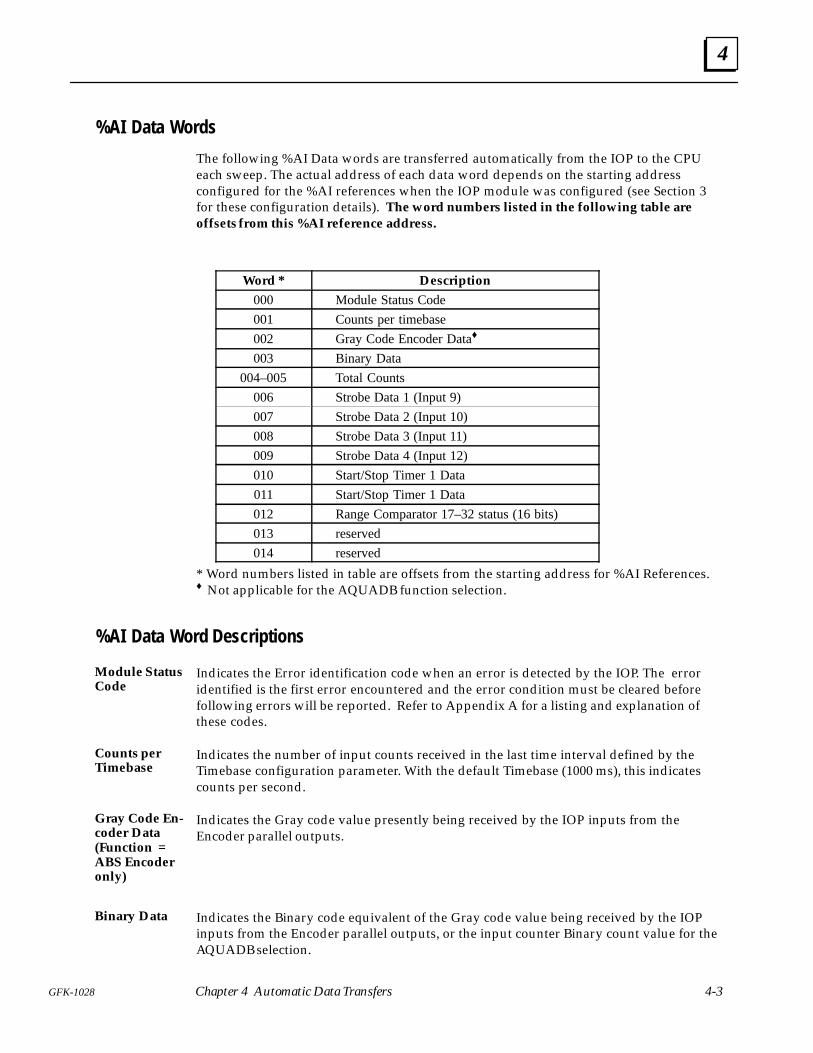
%AI Data Words
The following %AI Data words are transferred automatically from the IOP to the CPUeach sweep. The actual address of each data word depends on the starting addressconfigured for the %AI references when the IOP module was configured (see Section 3for these configuration details). The word numbers listed in the following table areoffsets from this %AI reference address.
ÁÁÁÁÁÁÁÁÁÁÁÁ
Word * ÁÁÁÁÁÁÁÁÁÁÁÁÁÁÁÁÁÁÁÁÁÁÁÁÁÁÁÁÁÁ
Description
ÁÁÁÁÁÁÁÁÁÁÁÁ
000 ÁÁÁÁÁÁÁÁÁÁÁÁÁÁÁÁÁÁÁÁÁÁÁÁÁÁÁÁÁÁ
Module Status Code
ÁÁÁÁÁÁÁÁÁÁÁÁ
001 ÁÁÁÁÁÁÁÁÁÁÁÁÁÁÁÁÁÁÁÁÁÁÁÁÁÁÁÁÁÁ
Counts per timebase
ÁÁÁÁÁÁÁÁÁÁÁÁ
002 ÁÁÁÁÁÁÁÁÁÁÁÁÁÁÁÁÁÁÁÁÁÁÁÁÁÁÁÁÁÁ
Gray Code Encoder Data♦ÁÁÁÁÁÁÁÁÁÁÁÁÁÁÁÁÁÁ
003ÁÁÁÁÁÁÁÁÁÁÁÁÁÁÁÁÁÁÁÁÁÁÁÁÁÁÁÁÁÁÁÁÁÁÁÁÁÁÁÁÁÁÁÁÁ
Binary DataÁÁÁÁÁÁÁÁÁÁÁÁ004–005
ÁÁÁÁÁÁÁÁÁÁÁÁÁÁÁÁÁÁÁÁÁÁÁÁÁÁÁÁÁÁTotal CountsÁÁÁÁÁÁ
ÁÁÁÁÁÁ006ÁÁÁÁÁÁÁÁÁÁÁÁÁÁÁÁÁÁÁÁÁÁÁÁÁÁÁÁÁÁStrobe Data 1 (Input 9)ÁÁÁÁÁÁ
ÁÁÁÁÁÁ007ÁÁÁÁÁÁÁÁÁÁÁÁÁÁÁÁÁÁÁÁÁÁÁÁÁÁÁÁÁÁStrobe Data 2 (Input 10)ÁÁÁÁÁÁ
ÁÁÁÁÁÁ008ÁÁÁÁÁÁÁÁÁÁÁÁÁÁÁÁÁÁÁÁÁÁÁÁÁÁÁÁÁÁStrobe Data 3 (Input 11)ÁÁÁÁÁÁ
ÁÁÁÁÁÁ009ÁÁÁÁÁÁÁÁÁÁÁÁÁÁÁÁÁÁÁÁÁÁÁÁÁÁÁÁÁÁStrobe Data 4 (Input 12)ÁÁÁÁÁÁ
ÁÁÁÁÁÁ010
ÁÁÁÁÁÁÁÁÁÁÁÁÁÁÁÁÁÁÁÁÁÁÁÁÁÁÁÁÁÁ
Start/Stop Timer 1 DataÁÁÁÁÁÁÁÁÁÁÁÁ
011ÁÁÁÁÁÁÁÁÁÁÁÁÁÁÁÁÁÁÁÁÁÁÁÁÁÁÁÁÁÁ
Start/Stop Timer 1 DataÁÁÁÁÁÁÁÁÁÁÁÁ
012ÁÁÁÁÁÁÁÁÁÁÁÁÁÁÁÁÁÁÁÁÁÁÁÁÁÁÁÁÁÁ
Range Comparator 17–32 status (16 bits)ÁÁÁÁÁÁÁÁÁÁÁÁ
013 ÁÁÁÁÁÁÁÁÁÁÁÁÁÁÁÁÁÁÁÁÁÁÁÁÁÁÁÁÁÁ
reservedÁÁÁÁÁÁÁÁÁÁÁÁ
014 ÁÁÁÁÁÁÁÁÁÁÁÁÁÁÁÁÁÁÁÁÁÁÁÁÁÁÁÁÁÁ
reserved
* Word numbers listed in table are offsets from the starting address for %AI References.♦ Not applicable for the AQUADB function selection.
%AI Data Word Descriptions
Indicates the Error identification code when an error is detected by the IOP. The erroridentified is the first error encountered and the error condition must be cleared beforefollowing errors will be reported. Refer to Appendix A for a listing and explanation ofthese codes.
Indicates the number of input counts received in the last time interval defined by theTimebase configuration parameter. With the default Timebase (1000 ms), this indicatescounts per second.
Indicates the Gray code value presently being received by the IOP inputs from theEncoder parallel outputs.
Indicates the Binary code equivalent of the Gray code value being received by the IOPinputs from the Encoder parallel outputs, or the input counter Binary count value for theAQUADB selection.
Module StatusCode
Counts perTimebase
Gray Code En-coder Data(Function =ABS Encoderonly)
Binary Data
4
Series 90-30 I/O Processor User’s Manual - June 1994 GFK-10284-4
Indicates the total input counts received by the IOP. This total counts register can beinitialized (preloaded) by a %AQ data command from the PLC. It is initialized to 0 atpower-up. For AQUADB selection, it is also initialized to 0 at the Home position marker.In AQUADB mode, the Preload Input does not affect Total Counts.
Returns the captured input Binary data value recorded when the strobe input occurred.Inputs 9–12 correspond to Strobe inputs 1–4, respectively. Either input edge may beconfigured to trigger the strobe data capture.
Indicates the time (in ms) between the input edges of Input 10 (default configuration) orthe input edges of Inputs 9–10 depending upon the configuration. To start the captureof this timing data, the strobe latch for Input 10 must be cleared, and if the strobe 2enable configuration is RCOMP-6, the output range comparator 6 must be on when theInput 10 strobe occurs. If Input 9 is used to stop the time measurement and the strobe 1enable configuration is RCOMP-5, output range comparator 5 must be on (when strobeinput occurs) before the timing will stop.
Indicates the time (in ms) between the input edges of Input 12 (default configuration) orthe input edges of Inputs 11–12 depending upon the configuration. To start the captureof this timing data the strobe latch for Input 12 must be cleared, and if the strobe 4enable configuration is RCOMP-8, output range comparator 8 must be on when theInput 12 strobe occurs.
If Input 11 is used to stop the time measurement and the strobe 3 enable configuration isRCOMP-7, output range comparator 7 must be on (when strobe input occurs) before thetiming will stop.
Indicates the ON/OFF state for range comparator outputs 17–32 based solely on the ONand OFF presets defined for each output.
Total Counts
Strobe Data1–4
Start/StopTimer 1 Data
Start/StopTimer 2 Data
RangeComparator17–32 status(16 bits)
4
4-5GFK-1028 Chapter 4 Automatic Data Transfers
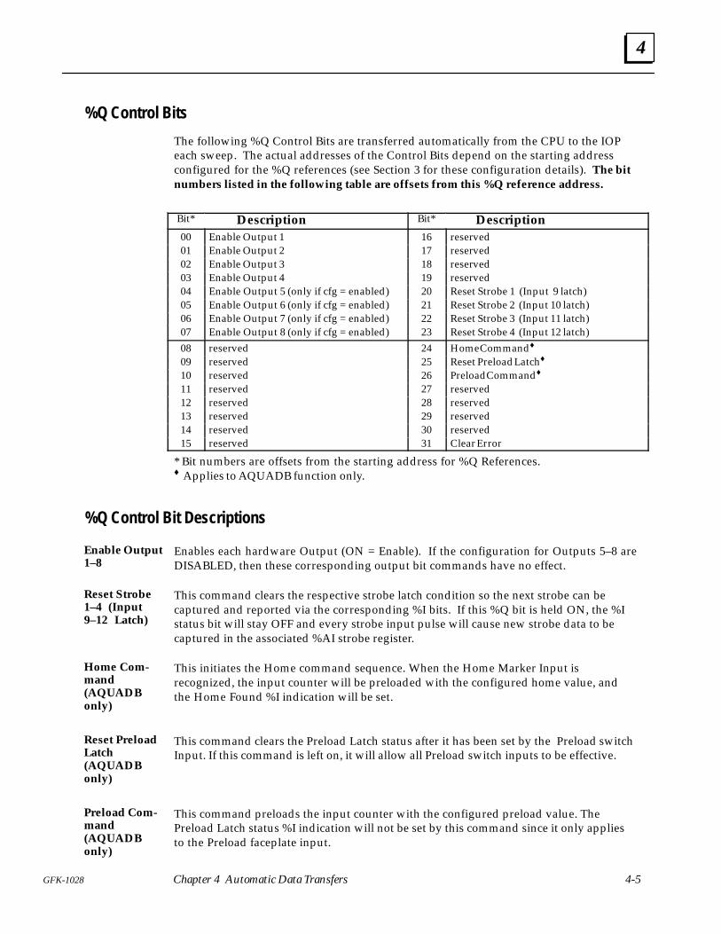
%Q Control Bits
The following %Q Control Bits are transferred automatically from the CPU to the IOPeach sweep. The actual addresses of the Control Bits depend on the starting addressconfigured for the %Q references (see Section 3 for these configuration details). The bitnumbers listed in the following table are offsets from this %Q reference address.
ÁÁÁÁÁÁ
Bit* ÁÁÁÁÁÁÁÁÁÁÁÁÁÁÁÁÁÁÁÁÁÁÁÁ
Description ÁÁÁÁÁÁ
Bit*ÁÁÁÁÁÁÁÁÁÁÁÁÁÁÁÁÁÁÁÁÁÁÁÁ
DescriptionÁÁÁÁÁÁ
00 ÁÁÁÁÁÁÁÁÁÁÁÁÁÁÁÁÁÁÁÁÁÁÁÁ
Enable Output 1 ÁÁÁÁÁÁ
16ÁÁÁÁÁÁÁÁÁÁÁÁÁÁÁÁÁÁÁÁÁÁÁÁ
reservedÁÁÁÁÁÁ
01 ÁÁÁÁÁÁÁÁÁÁÁÁÁÁÁÁÁÁÁÁÁÁÁÁ
Enable Output 2 ÁÁÁÁÁÁ
17ÁÁÁÁÁÁÁÁÁÁÁÁÁÁÁÁÁÁÁÁÁÁÁÁ
reserved
ÁÁÁÁÁÁ
02 ÁÁÁÁÁÁÁÁÁÁÁÁÁÁÁÁÁÁÁÁÁÁÁÁ
Enable Output 3 ÁÁÁÁÁÁ
18ÁÁÁÁÁÁÁÁÁÁÁÁÁÁÁÁÁÁÁÁÁÁÁÁ
reservedÁÁÁÁÁÁ03
ÁÁÁÁÁÁÁÁÁÁÁÁÁÁÁÁÁÁÁÁÁÁÁÁEnable Output 4
ÁÁÁÁÁÁ19
ÁÁÁÁÁÁÁÁÁÁÁÁÁÁÁÁÁÁÁÁÁÁÁÁreservedÁÁÁ
ÁÁÁ04 ÁÁÁÁÁÁÁÁÁÁÁÁÁÁÁÁÁÁÁÁÁÁÁÁ
Enable Output 5 (only if cfg = enabled) ÁÁÁÁÁÁ
20ÁÁÁÁÁÁÁÁÁÁÁÁÁÁÁÁÁÁÁÁÁÁÁÁ
Reset Strobe 1 (Input 9 latch)ÁÁÁÁÁÁ
05 ÁÁÁÁÁÁÁÁÁÁÁÁÁÁÁÁÁÁÁÁÁÁÁÁ
Enable Output 6 (only if cfg = enabled) ÁÁÁÁÁÁ
21ÁÁÁÁÁÁÁÁÁÁÁÁÁÁÁÁÁÁÁÁÁÁÁÁ
Reset Strobe 2 (Input 10 latch)
ÁÁÁÁÁÁ
06 ÁÁÁÁÁÁÁÁÁÁÁÁÁÁÁÁÁÁÁÁÁÁÁÁ
Enable Output 7 (only if cfg = enabled) ÁÁÁÁÁÁ
22ÁÁÁÁÁÁÁÁÁÁÁÁÁÁÁÁÁÁÁÁÁÁÁÁ
Reset Strobe 3 (Input 11 latch)ÁÁÁÁÁÁ07
ÁÁÁÁÁÁÁÁÁÁÁÁÁÁÁÁÁÁÁÁÁÁÁÁEnable Output 8 (only if cfg = enabled)
ÁÁÁÁÁÁ23
ÁÁÁÁÁÁÁÁÁÁÁÁÁÁÁÁÁÁÁÁÁÁÁÁReset Strobe 4 (Input 12 latch)ÁÁÁ
ÁÁÁ08ÁÁÁÁÁÁÁÁÁÁÁÁÁÁÁÁÁÁÁÁÁÁÁÁ
reservedÁÁÁÁÁÁ
24ÁÁÁÁÁÁÁÁÁÁÁÁÁÁÁÁÁÁÁÁÁÁÁÁ
Home Command♦
ÁÁÁÁÁÁ
09 ÁÁÁÁÁÁÁÁÁÁÁÁÁÁÁÁÁÁÁÁÁÁÁÁ
reserved ÁÁÁÁÁÁ
25ÁÁÁÁÁÁÁÁÁÁÁÁÁÁÁÁÁÁÁÁÁÁÁÁ
Reset Preload Latch♦
ÁÁÁÁÁÁ
10 ÁÁÁÁÁÁÁÁÁÁÁÁÁÁÁÁÁÁÁÁÁÁÁÁ
reserved ÁÁÁÁÁÁ
26ÁÁÁÁÁÁÁÁÁÁÁÁÁÁÁÁÁÁÁÁÁÁÁÁ
Preload Command♦
ÁÁÁ11 ÁÁÁÁÁÁÁÁÁÁÁÁreserved ÁÁÁ27ÁÁÁÁÁÁÁÁÁÁÁÁreservedÁÁÁÁÁÁ
12ÁÁÁÁÁÁÁÁÁÁÁÁÁÁÁÁÁÁÁÁÁÁÁÁ
reservedÁÁÁÁÁÁ
28ÁÁÁÁÁÁÁÁÁÁÁÁÁÁÁÁÁÁÁÁÁÁÁÁ
reservedÁÁÁÁÁÁ
13 ÁÁÁÁÁÁÁÁÁÁÁÁÁÁÁÁÁÁÁÁÁÁÁÁ
reserved ÁÁÁÁÁÁ
29ÁÁÁÁÁÁÁÁÁÁÁÁÁÁÁÁÁÁÁÁÁÁÁÁ
reservedÁÁÁÁÁÁ
14 ÁÁÁÁÁÁÁÁÁÁÁÁÁÁÁÁÁÁÁÁÁÁÁÁ
reserved ÁÁÁÁÁÁ
30ÁÁÁÁÁÁÁÁÁÁÁÁÁÁÁÁÁÁÁÁÁÁÁÁ
reserved
ÁÁÁ15 ÁÁÁÁÁÁÁÁÁÁÁÁreserved ÁÁÁ31ÁÁÁÁÁÁÁÁÁÁÁÁClear Error
* Bit numbers are offsets from the starting address for %Q References.♦ Applies to AQUADB function only.
%Q Control Bit Descriptions
Enables each hardware Output (ON = Enable). If the configuration for Outputs 5–8 areDISABLED, then these corresponding output bit commands have no effect.
This command clears the respective strobe latch condition so the next strobe can becaptured and reported via the corresponding %I bits. If this %Q bit is held ON, the %Istatus bit will stay OFF and every strobe input pulse will cause new strobe data to becaptured in the associated %AI strobe register.
This initiates the Home command sequence. When the Home Marker Input isrecognized, the input counter will be preloaded with the configured home value, andthe Home Found %I indication will be set.
This command clears the Preload Latch status after it has been set by the Preload switchInput. If this command is left on, it will allow all Preload switch inputs to be effective.
This command preloads the input counter with the configured preload value. ThePreload Latch status %I indication will not be set by this command since it only appliesto the Preload faceplate input.
Enable Output1–8
Reset Strobe1–4 (Input9–12 Latch)
Home Com-mand(AQUADBonly)
Reset PreloadLatch(AQUADBonly)
Preload Com-mand(AQUADBonly)
4
Series 90-30 I/O Processor User’s Manual - June 1994 GFK-10284-6
Toggling this command ON clears the module status error condition reported by the %IError bit and the %AI module status word and thus allows another error condition to bereported.
%AQ Immediate CommandsSix %AQ words are sent automatically from the CPU to the IOP during each sweep.These words can be used to transfer immediate command data to the IOP fortemporarily altering configuration parameters or to initialize counter data.Configuration parameter changes made in this manner do not affect the Moduleconfiguration data (stored in the CPU) which will again become effective if the IOP ispower cycled.
Each immediate command requires three sequential %AQ words. Therefore twoimmediate commands are always sent during each PLC sweep. The first word of eachcommand set contains the identifying command number and the other two wordscontain the data. The actual address of each command word depends on the startingaddress configured for the %AQ references (see Section 3 for these configurationdetails).
Even though the commands are sent each sweep, the IOP will act on a command only ifthe command has changed since the last sweep. When any of the three-word datachanges, the IOP accepts the data as a new command and responds accordingly.
When Immediate commands are sent, all three %AQ words should be loaded on thesame PLC sweep. If they can not be loaded on the same sweep (as when entering datafrom the Logicmaster screen), the steps below must be followed to ensure that no wrongor incomplete data is momentarily sent.
Step 1) Set Word 1 to Null Command (0000).
Step 2) Set correct data in Words 2 and 3.
Step 3) Set command in Word 1.
The following immediate commands may be sent by %AQ data to the IOP:
Command Data Command #(hex)
Word 3 Word 2 Word 1
Null (not used) (not used) 0000
Load Home Position (AQUADB)* (not used) Home Position 0101
Load Preload Position (AQUADB)* (not used) Preload Position 0102
Load Timebase (not used) Timebase (ms) 0106
Load Encoder Position Offset♦ (not used) Offset 0107
Load Total Counts (not used) Counts 0109
Load ON/OFF Preset Pairs 1–32 OFF preset ON preset 0140 – 015F
Load Output Timer 1.1–8.1 (not used) Time (ms) 01C0 – 01C7
Load Output Timer 1.2–8.2 (not used) Time (ms) 01D0 – 01D7
*AQUADB function only♦ ABS Encoder function only
Clear Error
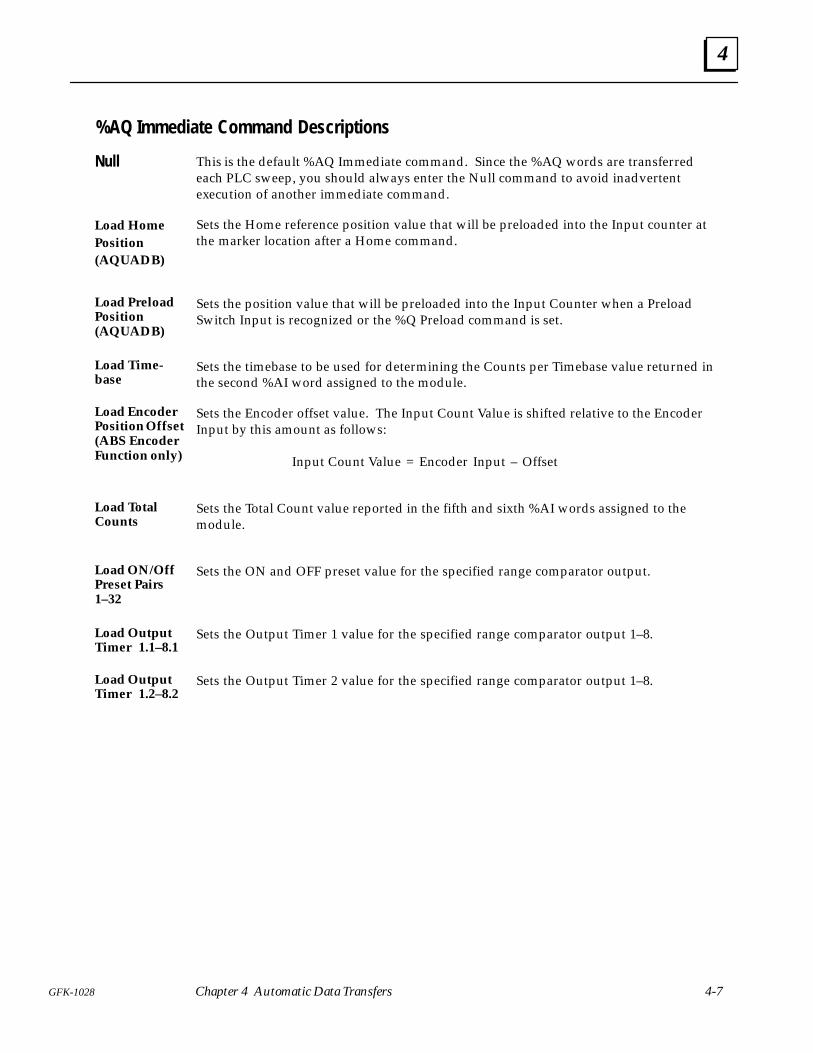
4
4-7GFK-1028 Chapter 4 Automatic Data Transfers
%AQ Immediate Command Descriptions
This is the default %AQ Immediate command. Since the %AQ words are transferredeach PLC sweep, you should always enter the Null command to avoid inadvertentexecution of another immediate command.
Sets the Home reference position value that will be preloaded into the Input counter atthe marker location after a Home command.
Sets the position value that will be preloaded into the Input Counter when a PreloadSwitch Input is recognized or the %Q Preload command is set.
Sets the timebase to be used for determining the Counts per Timebase value returned inthe second %AI word assigned to the module.
Sets the Encoder offset value. The Input Count Value is shifted relative to the EncoderInput by this amount as follows:
Input Count Value = Encoder Input – Offset
Sets the Total Count value reported in the fifth and sixth %AI words assigned to themodule.
Sets the ON and OFF preset value for the specified range comparator output.
Sets the Output Timer 1 value for the specified range comparator output 1–8.
Sets the Output Timer 2 value for the specified range comparator output 1–8.
Null
Load HomePosition(AQUADB)
Load PreloadPosition(AQUADB)
Load Time-base
Load EncoderPosition Offset(ABS EncoderFunction only)
Load TotalCounts
Load ON/OffPreset Pairs1–32
Load OutputTimer 1.1–8.1
Load OutputTimer 1.2–8.2
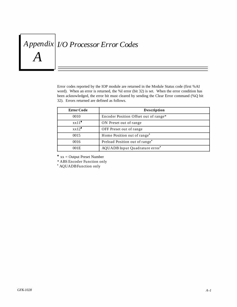
AAppendix
A-1GFK-1028
I/O Processor Error Codes
Error codes reported by the IOP module are returned in the Module Status code (first %AIword). When an error is returned, the %I error (bit 32) is set. When the error condition hasbeen acknowledged, the error bit must cleared by sending the Clear Error command (%Q bit32). Errors returned are defined as follows.
Error Code Description
0010 Encoder Position Offset out of range*
xx11♦ ON Preset out of range
xx12♦ OFF Preset out of range
0015 Home Position out of range•
0016 Preload Position out of range•
001E AQUADB Input Quadrature error•
♦ xx = Output Preset Number* ABS Encoder Function only• AQUADB Function only
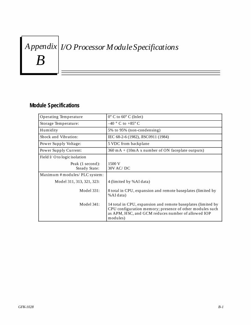
BAppendix
B-1GFK-1028
I/O Processor Module Specifications
Module Specifications
Operating Temperature 0° C to 60° C (Inlet)
Storage Temperature: –40 ° C to +85° C
Humidity 5% to 95% (non-condensing)
Shock and Vibration: IEC 68-2-6 (1982), JISC0911 (1984)
Power Supply Voltage: 5 VDC from backplane
Power Supply Current: 360 mA + (10mA x number of ON faceplate outputs)
Field I/O to logic isolation
Peak (1 second): Steady State:
1500 V30V AC/DC
Maximum # modules/PLC system:
Model 311, 313, 321, 323:
Model 331:
Model 341:
4 (limited by %AI data)
8 total in CPU, expansion and remote baseplates (limited by%AI data)
14 total in CPU, expansion and remote baseplates (limited byCPU configuration memory; presence of other modules suchas APM, HSC, and GCM reduces number of allowed IOPmodules)
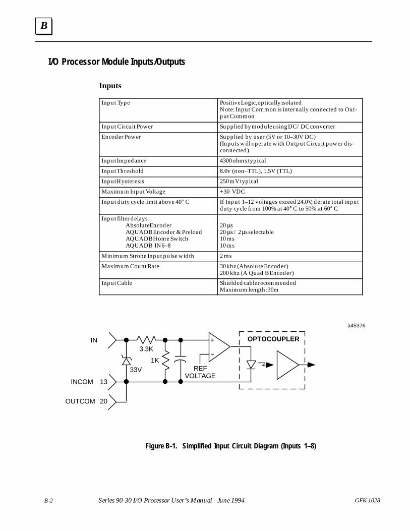
B
B-2 GFK-1028Series 90-30 I/O Processor User’s Manual - June 1994
I/O Processor Module Inputs/Outputs
Inputs
Input Type Positive Logic, optically isolatedNote: Input Common is internally connected to Out-put Common
Input Circuit Power Supplied by module using DC/DC converter
Encoder Power Supplied by user (5V or 10–30V DC)(Inputs will operate with Output Circuit power dis-connected)
Input Impedance 4300 ohms typical
Input Threshold 8.0v (non–TTL), 1.5V (TTL)
Input Hysteresis 250 mV typical
Maximum Input Voltage +30 VDC
Input duty cycle limit above 40° C If Input 1–12 voltages exceed 24.0V, derate total inputduty cycle from 100% at 40° C to 50% at 60° C
Input filter delaysAbsolute EncoderAQUADB Encoder & PreloadAQUADB Home SwitchAQUADB IN6–8
20 µs20 µs / 2 µs selectable10 ms10 ms
Minimum Strobe Input pulse width 2 ms
Maximum Count Rate 30 khz (Absolute Encoder)200 khz (A Quad B Encoder)
Input Cable Shielded cable recommendedMaximum length: 30m
OPTOCOUPLER
a45376
13
OUTCOM
INCOM
20
REFVOLTAGE
3.3K
1K33V
IN
Figure B-1. Simplified Input Circuit Diagram (Inputs 1–8)
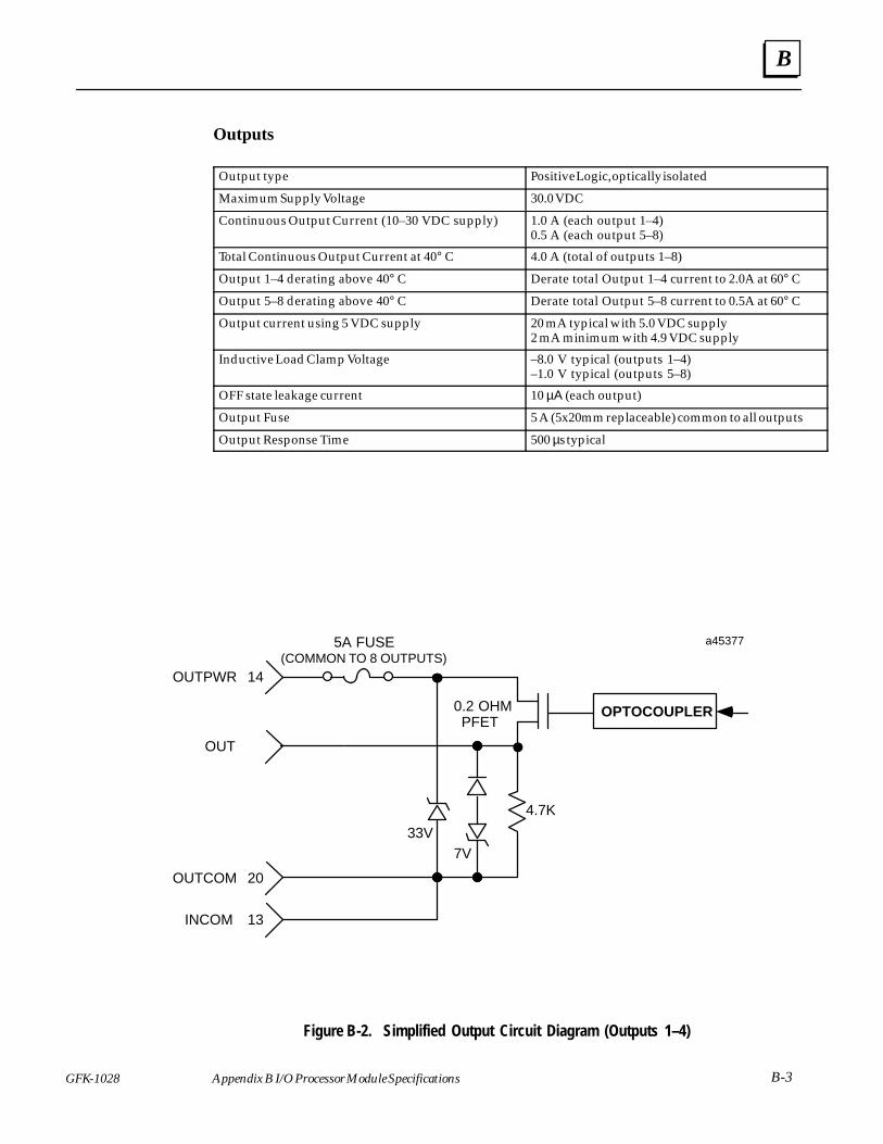
B
GFK-1028 B-3Appendix B I/O Processor Module Specifications
Outputs
Output type Positive Logic, optically isolated
Maximum Supply Voltage 30.0 VDC
Continuous Output Current (10–30 VDC supply) 1.0 A (each output 1–4)0.5 A (each output 5–8)
Total Continuous Output Current at 40° C 4.0 A (total of outputs 1–8)
Output 1–4 derating above 40° C Derate total Output 1–4 current to 2.0A at 60° C
Output 5–8 derating above 40° C Derate total Output 5–8 current to 0.5A at 60° C
Output current using 5 VDC supply 20 mA typical with 5.0 VDC supply2 mA minimum with 4.9 VDC supply
Inductive Load Clamp Voltage –8.0 V typical (outputs 1–4)–1.0 V typical (outputs 5–8)
OFF state leakage current 10 µΑ (each output)
Output Fuse 5 A (5x20mm replaceable) common to all outputs
Output Response Time 500 µs typical
OUTCOM 20
ÏÏÏÏÏÏÏÏÏÏÏÏÏÏ
OPTOCOUPLER
a45377
4.7K
7V33V
13INCOM
Ï Ï0.2 OHMPFET
5A FUSE(COMMON TO 8 OUTPUTS)
OUTPWR 14
OUT
Figure B-2. Simplified Output Circuit Diagram (Outputs 1–4)
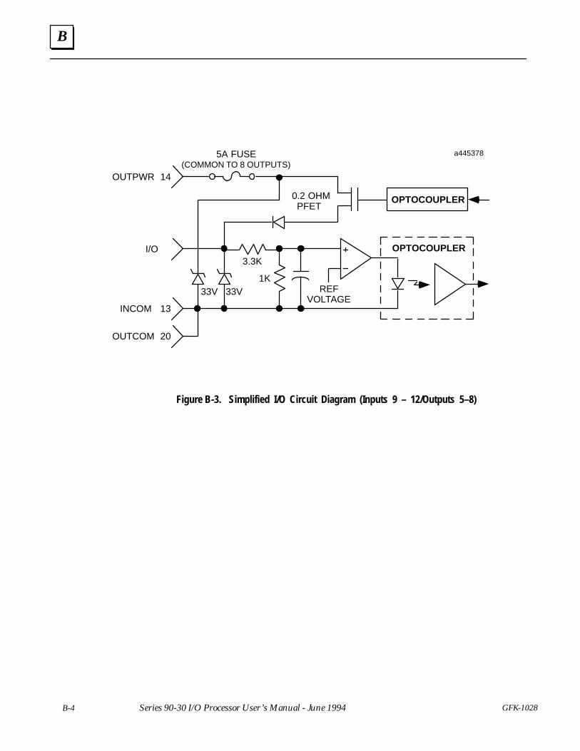
B
B-4 GFK-1028Series 90-30 I/O Processor User’s Manual - June 1994
OPTOCOUPLER
a445378
OPTOCOUPLER
13
REFVOLTAGE
OUTCOM
INCOM
20
3.3K
1K33V33V
0.2 OHMPFET
OUTPWR 14
I/O
ÏÏ
ÏÏ
5A FUSE(COMMON TO 8 OUTPUTS)
Figure B-3. Simplified I/O Circuit Diagram (Inputs 9 – 12/Outputs 5–8)
Index
Index-1GFK-1028
AABS Encoder function, 3-10
Applications, typical, 1-1
CCatalog number, 1-1
Clear Error command, A-1
Commands, %AQ, 4-6
Configuration, 1-3 %I, %Q, %AI, %AQ addresses, 3-1–3-3 ,
3-10–3-12 ABS Encoder function, 3-10 ABS or A-quad-B Encoder function, 3-14
, 3-15 AQUADB Encoder function, 3-13–3-15 I/O Processor, 3-1 , 3-3 , 3-10 I/O Scanner, 3-1 input parameters, 3-3 , 3-10 output default, 1-8 , 3-12 Preset data, 3-9 , 3-15 range comparators, 3-8–3-9 using the Hand-held Programmer, 1-1 ,
3-1 using the LM90 Configurator, 1-1 , 3-10
Control bits, %Q, 4-5–4-7
Count range, 3-13
DData
Input status, 4-1 Output command, 4-1
Data words, %AI, 4-3–4-5
Description, 1-1
Direct processing, definition, 1-1
Direction adjust, 3-4
Dual input timer operation, 1-9
EError codes, A-1
FFaceplate wiring, 2-8
Features, 1-3
Field wiring, 2-7
HHand-held Programmer, 3-1–3-10
High count limit, 3-4
Home position value, 3-5 , 3-13
II/O Processor
configuring, 3-1 I/O circuit diagram, B-4 input circuit diagram, B-2 inputs, B-2 installation, 2-1 output circuit diagram, B-3 outputs, B-3 removal, 2-2
I/O scanner configuration, 3-1
Immediate command data, %AQ, 4-6–4-8
Input counter, initializing count value, 3-5
Input filter range, 3-4 , 3-13
Input offset adjust, 3-4
Input specifications, B-2
Input status data, 4-1
Input voltage level, 1-3 configuring, 3-3 , 3-11
Inputs 1–8, circuit diagram, B-2
Inputs 9–12, circuit diagram, B-4
Installing a terminal board, 2-3
IOP. See I/O Processor
LLatched strobe inputs, 1-9
LED indicators, 1-3
MModule functions, 1-4
Index
Index-2 GFK-1028
Module input type, configuring, 3-3 , 3-10
Module specifications, B-1
Modules/system, maximum, B-1
NNumber of modules per system, B-1
OOff Preset, 3-14 , 3-15
Offset error, 3-4 , 3-11
On Preset, 3-14 , 3-15
Operating conditions, B-1
Output circuit diagram, B-3
Output command data, 4-1
Output default configurations, 1-8
Output defaults, 3-5 , 3-12
Output Preset number, A-1
Output Timer mode, 1-8
Outputs 5–8circuit diagram, B-4 selecting, 3-5–3-6 , 3-11
PPin assignments, terminal board, 2-6
PLCI/O Scanner configuration, 3-1 module output states when stopped,
1-8 , 3-5
Position initialization, 1-4
Power requirements, B-1
Preload position value, 3-5 , 3-13
Preset, configuring, 3-8
Preset mode, 1-7 , 3-9
Preset value, 3-14 , 3-15
Pulse timing and latching functions, 1-10
RRange comparator, status bits, 4-1–4-3
Range comparators, configuration,3-8–3-9
Removing a module, 2-2
Removing a terminal board, 2-4
SSingle input timer operation, 1-9
Specifications, B-1
Status bits, 4-1
Status code, A-1
STOP mode, output states, 1-8 , 3-12
Strobeenable, 3-7–3-8 , 3-12 trigger edge, 3-6–3-7 , 3-12
System overview, 1-1
TTerminal board
field wiring recommendations, 2-5 installing, 2-3 pin assignments, 2-6 removing, 2-4
Threshold voltage, 1-3
Time measurement, 1-9
Timebase, 3-6 , 3-11
Timerconfiguring, 3-8 , 3-11 , 3-14 Input, 3-8 Start/Stop, 3-8
Timer mode, 1-8 , 3-9 , 3-14
Timing functions, 1-10
Typical applications, 1-1
WWatchdog timer circuit, 1-3
Wiringfaceplate, 2-8 field, 2-5 , 2-7 to I/O modules, 2-3


