124
Computer Numerical Control Products GE Fanuc Automation ß-Series Servo Motor Maintenance Manual B-65235EN/02 October 1997

Computer Numerical Control Products
GE Fanuc Automation
ß-Series Servo Motor
Maintenance Manual
B-65235EN/02 October 1997
In this manual we have tried as much as possible to describe allthe various matters.However, we cannot describe all the matters which must not bedone, or which cannot be done, because there are so manypossibilities.Therefore, matters which are not especially described as possiblein this manual should be regarded as ’’impossible’
The export of this product is subject to the authorization of thegovernment of the country from where the product is exported.
Warnings and notices forthis publication
GFLE-003
Warning
In this manual we have tried as much as possible to describe all the variousmatters. However, we cannot describe all the matters which must not be done,or which cannot be done, because there are so many possibilities.
Therefore, matters which are not especially described as possible in thismanual should be regarded as “impossible”.
NoticeThis document is based on information available at the time of its publication. While efforts havebeen made to be accurate, the information contained herein does not purport to cover all details orvariations in hardware or software, nor to provide every contingency in connection withinstallation, operation, or maintenance. Features may be described herein which are not present inall hardware and software systems. GE Fanuc Automation assumes no obligation of notice toholders of this document with respect to changes subsequently made.
GE Fanuc Automation makes no representation or warranty, expressed, implied, or statutory withrespect to, and assumes no responsibility for accuracy, completeness, sufficiency, or usefulness ofthe information contained herein. No warranties of merchantability or fitness for purpose shallapply.
The following are Registered Trademarks of GE Fanuc Automation
CIMPLICITY® Genius®
The following are Trademarks of GE Fanuc Automation
Alarm MasterCIMSTARField ControlGenetHelpmateLogicMasterModelmasterPowerMotionProLoop
PROMACROSeries FiveSeries 90Series OneSeries SixSeries ThreeVuMasterWorkmaster
© Copyright 1998 FANUC Ltd.Authorized Reproduction GE Fanuc Automation Europe S.A.
All Rights ReservedNo part of this manual may be reproduced in any form.
All specifications and designs are subject to change without notice.
3
SAFETY PRECAUTIONS
FANUC SERVO MOTOR seriesFANUC SERVO MOTOR AMPLIFIER series
This ”Safety Precautions” section describes the precautions which must be observed to ensure safety when usingFANUC servo motors (including spindle motors) and servo amplifiers (including spindle amplifiers). Users ofany servo motor or amplifier model are requested to read the ”Safety Precautions” carefully before using the servomotor or amplifier.The users are also requested to read an applicable specification manual carefully and understand each functionof the motor or amplifier for correct use.The users are basically forbidden to do any behavior or action not mentioned in the ”Safety Precautions.” Theyare invited to ask FANUC previously about what behavior or action is prohibited.
SAFETY PRECAUTIONS
Contents
DEFINITION OF WARNING, CAUTION, AND NOTE 4. . . . . . . . . . . . . . . . . . . . . . . . . . . . .
I. FANUC SERVO MOTOR series 5. . . . . . . . . . . . . . . . . . . . . . . . . . . . . . . . . . . . . . . . .
1. WARNING 6. . . . . . . . . . . . . . . . . . . . . . . . . . . . . . . . . . . . . . . . . . . . . . . . . . . . . . . . . . . . . . .
2. CAUTION 8. . . . . . . . . . . . . . . . . . . . . . . . . . . . . . . . . . . . . . . . . . . . . . . . . . . . . . . . . . . . . . .
3. NOTE 9. . . . . . . . . . . . . . . . . . . . . . . . . . . . . . . . . . . . . . . . . . . . . . . . . . . . . . . . . . . . . . . . . . .
II. FANUC SERVO MOTOR AMPLIFIER series 12. . . . . . . . . . . . . . . . . . . . . . . . . . . . .
1. WARNINGS AND CAUTIONS RELATING TO MOUNTING 13. . . . . . . . . . . . . . . . . .
2. WARNINGS AND CAUTIONS RELATING TO A PILOT RUN 18. . . . . . . . . . . . . . . . .
3. WARNINGS AND CAUTIONS RELATING TO MAINTENANCE 20. . . . . . . . . . . . . . .
SAFETY PRECAUTIONS B–65235EN/02
4
DEFINITION OF WARNING, CAUTION, AND NOTE
This manual includes safety precautions for protecting the user and preventing damage to themachine. Precautions are classified into Warning and Caution according to their bearing on safety.Also, supplementary information is described as a Note. Read the Warning, Caution, and Notethoroughly before attempting to use the machine.
WARNING
Applied when there is a danger of the user being injured or when there is a danger of both the userbeing injured and the equipment being damaged if the approved procedure is not observed.
CAUTION
Applied when there is a danger of the equipment being damaged, if the approved procedure is notobserved.
NOTE
The Note is used to indicate supplementary information other than Warning and Caution.
Read this manual carefully, and store it in a safe place.
5
I. FANUC SERVO MOTOR series
B–65235EN/02SAFETY PRECAUTIONS (FANUC AC SERVO MOTOR series)
6
1 WARNING
WARNING
Be safely dressed when handling a motor.
Wear safety shoes or gloves when handling a motor as you may get hurt on any edge or protrusionon it or electric shocks.
Use a crane or lift to move a motor from one place to another.
Motors are heavy. When moving them, use a crane or lift as required. (For the weight of motors,refer to their respective specification manuals.)When moving a motor using a crane or lift, use a hanging bolt if the motor has a correspondingtapped hole, or textile rope if it has no tapped hole. If a motor is attached with a machine or anyother heavy stuff, do not use a hanging bolt to move the motor as the hanging bolt and/or motormay get broken. When moving a motor, be careful not to apply excessive force to its windingsas the windings may break and/or their insulation may deteriorate.
Do not touch a motor with a wet hand.
A failure to observe this caution is vary dangerous because you may get electric shocks.
Before starting to connect a motor to electric wires, make sure they areisolated from an electric power source.
A failure to observe this caution is vary dangerous because you may get electric shocks.
Do not bring any dangerous stuff near a motor.
Motors are connected to a power line, and may get hot. If a flammable is placed near a motor,it may be ignited, catch fire, or explode.
Be sure to ground a motor frame.
To avoid electric shocks, be sure to connect the grounding terminal in the terminal box to thegrounding terminal of the machine.
Do not ground a motor power wire terminal or short–circuit it to anotherpower wire terminal.
A failure to observe this caution may cause electric shocks or a burned wiring.
Some motors require a special connection such as a winding changeover. Refer to theirrespective motor specification manuals for details.
B–65235EN/02 SAFETY PRECAUTIONS (FANUC AC SERVO MOTOR series)
7
WARNING
Connect power wires securely so that they will not get loose.
A failure to observe this caution may cause a wire to be disconnected, resulting in a ground fault,short circuit, or electric shock.
Do not supply the power to the motor while any terminal is exposed.
A failure to observe this caution is very dangerous because you may get electric shocks if yourbody or any conductive stuff touches an exposed terminal.
Do not get close to a rotary section of a motor when it is rotating.
A rotating part may catch your cloths or fingers. Before starting a motor, ensure that there is nostuff that can fly away (such as a key) on the motor.
Before touching a motor, shut off the power to it.
Even if a motor is not rotating, there may be a voltage across the terminals of the motor. Especially before touching a power supply connection, take sufficient precautions. Otherwiseyou may get electric shocks.
Do not touch any terminal of a motor for a while (at least 5 minutes) afterthe power to the motor is shut off.
High voltage remains across power line terminals of a motor for a while after the power to themotor is shut off. So, do not touch any terminal or connect it to any other equipment. Otherwise,you may get electric shocks or the motor and/or equipment may get damaged.
To drive a motor, use a specified amplifier and parameters.
An incorrect combination of a motor, amplifier, and parameters may cause the motor to behaveunexpectedly. This is dangerous, and the motor may get damaged.
Do not touch a motor when it is running or immediately after it stops.
A motor may get hot when it is running. Do not touch the motor before it gets cool enough.Otherwise, you may get burned.
Be careful not get your hair or cloths caught in a fan.
Be careful especially for a fan used to generate an inward air flow.Be careful also for a fan even when the motor is stopped, because it continues to rotate while theamplifier is turned on.
Ensure that motors and related components are mounted securely.
If a motor or its component slips out of place or comes off when the motor is running, it is verydangerous.
B–65235EN/02SAFETY PRECAUTIONS (FANUC AC SERVO MOTOR series)
8
2 CAUTION
CAUTION
FANUC motors are designed for use with machines. Do not use them forany other purpose.
If a FANUC motor is used for an unintended purpose, it may cause an unexpected symptom ortrouble. If you want to use a motor for an unintended purpose, previously consult with FANUC.
Ensure that a base or frame on which a motor is mounted is strongenough.
Motors are heavy. If a base or frame on which a motor is mounted is not strong enough, it isimpossible to achieve the required precision.
Be sure to connect motor cables correctly.
An incorrect connection of a cable cause abnormal heat generation, equipment malfunction, orfailure. Always use a cable with an appropriate current carrying capacity (or thickness). For howto connect cables to motors, refer to their respective specification manuals.
Ensure that motors are cooled if they are those that require forciblecooling.
If a motor that requires forcible cooling is not cooled normally, it may cause a failure or trouble.For a fan–cooled motor, ensure that it is not clogged or blocked with dust and dirt. For aliquid–cooled motor, ensure that the amount of the liquid is appropriate and that the liquid pipingis not clogged. For both types, perform regular cleaning and inspection.
When attaching a component having inertia, such as a pulley, to a motor,ensure that any imbalance between the motor and component isminimized.
If there is a large imbalance, the motor may vibrates abnormally, resulting in the motor beingbroken.
Be sure to attach a key to a motor with a keyed shaft.
If a motor with a keyed shaft runs with no key attached, it may impair torque transmission orcause imbalance, resulting in the motor being broken.
B–65235EN/02 SAFETY PRECAUTIONS (FANUC AC SERVO MOTOR series)
9
3 NOTE
NOTE
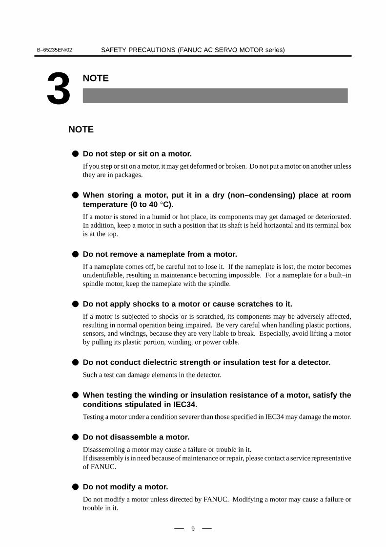
Do not step or sit on a motor.
If you step or sit on a motor, it may get deformed or broken. Do not put a motor on another unlessthey are in packages.
When storing a motor, put it in a dry (non–condensing) place at roomtemperature (0 to 40 °C).
If a motor is stored in a humid or hot place, its components may get damaged or deteriorated.In addition, keep a motor in such a position that its shaft is held horizontal and its terminal boxis at the top.
Do not remove a nameplate from a motor.
If a nameplate comes off, be careful not to lose it. If the nameplate is lost, the motor becomesunidentifiable, resulting in maintenance becoming impossible. For a nameplate for a built–inspindle motor, keep the nameplate with the spindle.
Do not apply shocks to a motor or cause scratches to it.
If a motor is subjected to shocks or is scratched, its components may be adversely affected,resulting in normal operation being impaired. Be very careful when handling plastic portions,sensors, and windings, because they are very liable to break. Especially, avoid lifting a motorby pulling its plastic portion, winding, or power cable.
Do not conduct dielectric strength or insulation test for a detector.
Such a test can damage elements in the detector.
When testing the winding or insulation resistance of a motor, satisfy theconditions stipulated in IEC34.
Testing a motor under a condition severer than those specified in IEC34 may damage the motor.
Do not disassemble a motor.
Disassembling a motor may cause a failure or trouble in it. If disassembly is in need because of maintenance or repair, please contact a service representativeof FANUC.
Do not modify a motor.
Do not modify a motor unless directed by FANUC. Modifying a motor may cause a failure ortrouble in it.
B–65235EN/02SAFETY PRECAUTIONS (FANUC AC SERVO MOTOR series)
10
NOTE
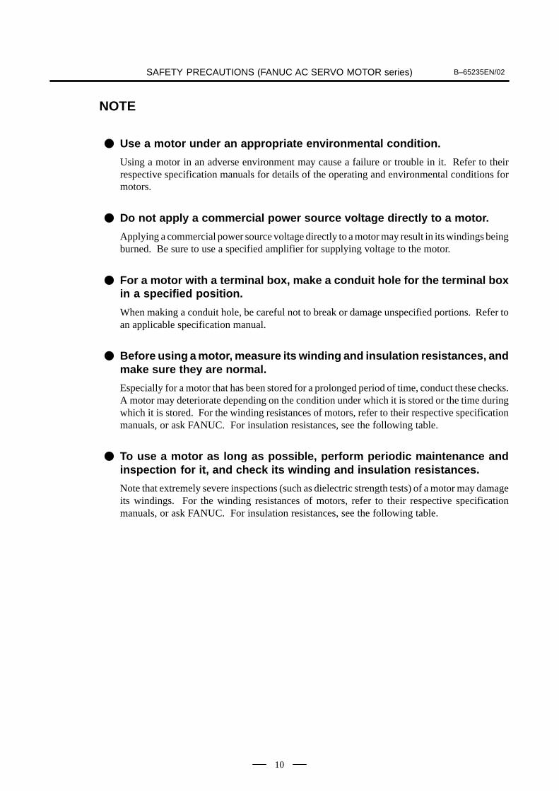
Use a motor under an appropriate environmental condition.
Using a motor in an adverse environment may cause a failure or trouble in it. Refer to theirrespective specification manuals for details of the operating and environmental conditions formotors.
Do not apply a commercial power source voltage directly to a motor.
Applying a commercial power source voltage directly to a motor may result in its windings beingburned. Be sure to use a specified amplifier for supplying voltage to the motor.
For a motor with a terminal box, make a conduit hole for the terminal boxin a specified position.
When making a conduit hole, be careful not to break or damage unspecified portions. Refer toan applicable specification manual.
Before using a motor, measure its winding and insulation resistances, andmake sure they are normal.
Especially for a motor that has been stored for a prolonged period of time, conduct these checks.A motor may deteriorate depending on the condition under which it is stored or the time duringwhich it is stored. For the winding resistances of motors, refer to their respective specificationmanuals, or ask FANUC. For insulation resistances, see the following table.
To use a motor as long as possible, perform periodic maintenance andinspection for it, and check its winding and insulation resistances.
Note that extremely severe inspections (such as dielectric strength tests) of a motor may damageits windings. For the winding resistances of motors, refer to their respective specificationmanuals, or ask FANUC. For insulation resistances, see the following table.
B–65235EN/02 SAFETY PRECAUTIONS (FANUC AC SERVO MOTOR series)
11
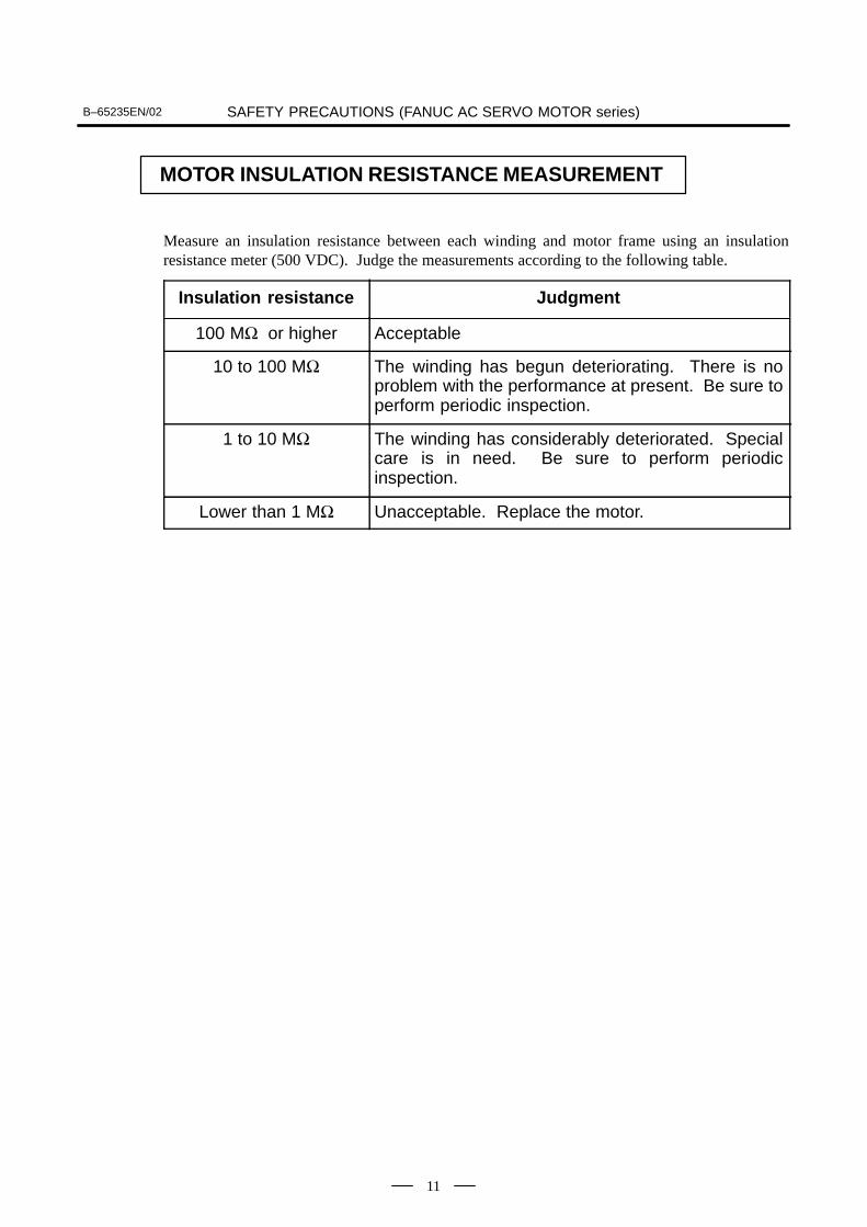
MOTOR INSULATION RESISTANCE MEASUREMENT
Measure an insulation resistance between each winding and motor frame using an insulationresistance meter (500 VDC). Judge the measurements according to the following table.
Insulation resistance Judgment
100 MΩ or higher Acceptable
10 to 100 MΩ The winding has begun deteriorating. There is noproblem with the performance at present. Be sure toperform periodic inspection.
1 to 10 MΩ The winding has considerably deteriorated. Specialcare is in need. Be sure to perform periodicinspection.
Lower than 1 MΩ Unacceptable. Replace the motor.

12
II. FANUC SERVO MOTOR AMPLIFIER series
SAFETY PRECAUTIONS (FANUC SERVO MOTOR AMPLIFIER series)B–65235EN/02
13
1 WARNINGS AND CAUTIONS RELATING TO MOUNTING
WARNING
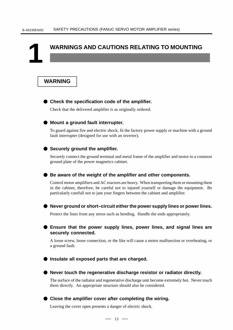
Check the specification code of the amplifier.
Check that the delivered amplifier is as originally ordered.
Mount a ground fault interrupter.
To guard against fire and electric shock, fit the factory power supply or machine with a groundfault interrupter (designed for use with an inverter).
Securely ground the amplifier.
Securely connect the ground terminal and metal frame of the amplifier and motor to a commonground plate of the power magnetics cabinet.
Be aware of the weight of the amplifier and other components.
Control motor amplifiers and AC reactors are heavy. When transporting them or mounting themin the cabinet, therefore, be careful not to injured yourself or damage the equipment. Beparticularly carefull not to jam your fingers between the cabinet and amplifier.
Never ground or short–circuit either the power supply lines or power lines.
Protect the lines from any stress such as bending. Handle the ends appropriately.
Ensure that the power supply lines, power lines, and signal lines aresecurely connected.
A loose screw, loose connection, or the like will cause a motor malfunction or overheating, ora ground fault.
Insulate all exposed parts that are charged.
Never touch the regenerative discharge resistor or radiator directly.
The surface of the radiator and regenerative discharge unit become extremely hot. Never touchthem directly. An appropriate structure should also be considered.
Close the amplifier cover after completing the wiring.
Leaving the cover open presents a danger of electric shock.
SAFETY PRECAUTIONS (FANUC SERVO MOTOR AMPLIFIER series) B–65235EN/02
14
WARNING
Do not disassemble the amplifier.
Ensure that the cables used for the power supply lines and power lines areof the appropriate diameter and temperature ratings.
Do not apply an excessively large force to plastic parts.
If a plastic section breaks, it may cause internal damage, thus interfering with normal operation.The edge of a broken section is likely to be sharp and, therefore, presents a risk of injury.
SAFETY PRECAUTIONS (FANUC SERVO MOTOR AMPLIFIER series)B–65235EN/02
15
CAUTION
Do not step or sit on the amplifier.
Also, do not stack unpacked amplifiers on top of each other.
Use the amplifier in an appropriate environment.
See the allowable ambient temperatures and other requirements, given in the correspondingdescriptions.
Protect the amplifier from corrosive or conductive mist or drops of water.
Use a filter if necessary.
Protect the amplifier from impact.
Do not place anything on the amplifier.
Do not block the air inlet to the radiator.
A deposit of coolant, oil mist, or chips on the air inlet will result in a reduction in the coolingefficiency. In some cases, the required efficiency cannot be achieved. The deposit may also leadto a reduction in the useful life of the semiconductors. Especially, when outside air is drawn in,mount filters on both the air inlet and outlet. These filters must be replaced regularly. So, aneasy–to–replace type of filter should be used.
Before connecting the power supply wiring, check the supply voltage.
Check that the supply voltage is within the range specified in this manual, then connect the powersupply lines.
Ensure that the combination of motor and amplifier is appropriate.
Ensure that valid parameters are specified.
Specifying an invalid parameter for the combination of motor and amplifier may not onlyprevent normal operation of the motor but also result in damage to the amplifier.
Ensure that the amplifier and peripheral equipment are securelyconnected.
Check that the magnetic contactor, circuit breaker, and other devices mounted outside theamplifier are securely connected to each other and that those devices are securely connected tothe amplifier.
Check that the amplifier is securely mounted in the power magneticscabinet.
If any clearance is left between the power magnetics cabinet and the surface on which theamplifier is mounted, dust entering the gap may build up and prevent the normal operation ofthe amplifier.
SAFETY PRECAUTIONS (FANUC SERVO MOTOR AMPLIFIER series) B–65235EN/02
16
CAUTION
Apply appropriate countermeasures against noise.
Adequate countermeasures against noise are required to maintain normal operation of theamplifier. For example, signal lines must be routed away from power supply lines and powerlines.
SAFETY PRECAUTIONS (FANUC SERVO MOTOR AMPLIFIER series)B–65235EN/02
17
NOTE
Keep the nameplate clearly visible.
Keep the legend on the nameplate clearly visible.
After unpacking the amplifier, carefully check for any damage.
Mount the amplifier in a location where it can be easily accessed to allowperiodic inspection and daily maintenance.
Leave sufficient space around the machine to enable maintenance to beperformed easily.
Do not place any heavy objects such that they would interfere with the opening of the doors.
Keep the parameter table and spare parts at hand.
Also, keep the specifications at hand. These items must be stored in a location where they canbe retrieved immediately.
Provide adequate shielding.
A cable to be shielded must be securely connected to the ground plate, using a cable clamp orthe like.
SAFETY PRECAUTIONS (FANUC SERVO MOTOR AMPLIFIER series) B–65235EN/02
18
2 WARNINGS AND CAUTIONS RELATING TO A PILOT RUN
WARNING
Before turning on the power, check that the cables connected to the powermagnetics cabinet and amplifier, as well as the power lines and powersupply lines, are securely connected. Also, check that no lines are slack.
Before turning on the power, ensure that the power magnetics cabinet issecurely grounded.
Before turning on the power, check that the door of the power magneticscabinet and all other doors are closed.
Ensure that the door of the power magnetics cabinet containing the amplifier, and all other doors,are securely closed. During operation, all doors must be closed and locked.
Apply extreme caution if the door of the power magnetics cabinet oranother door must be opened.
Only a person trained in the maintenance of the corresponding machine or equipment shouldopen the door, and only after shutting off the power supply to the power magnetics cabinet (byopening both the input circuit breaker of the power magnetics cabinet and the factory switch usedto supply power to the cabinet). If the machine must be operated with the door open to enableadjustment or for some other purpose, the operator must keep his or her hands and tools wellaway from any dangerous voltages. Such work must be done only by a person trained in themaintenance of the machine or equipment.
When operating the machine for the first time, check that the machineoperates as instructed.
To check whether the machine operates as instructed, first specify a small value for the motor,then increase the value gradually. If the motor operates abnormally, perform an emergency stopimmediately.
After turning on the power, check the operation of the emergency stopcircuit.
Press the emergency stop button to check that the motor stops immediately, and that the powerbeing supplied to the amplifier is shut off by the magnetic contactor.
Before opening a door or protective cover of a machine to enableadjustment of the machine, first place the machine in the emergency stopstate and check that the motor has stopped.
SAFETY PRECAUTIONS (FANUC SERVO MOTOR AMPLIFIER series)B–65235EN/02
19
CAUTION
Note whether an alarm status relative to the amplifier is displayed atpower–up or during operation.
If an alarm is displayed, take appropriate action as explained in the maintenance manual. If thework to be done requires that the door of the power magnetics cabinet be left open, the work mustbe carried out by a person trained in the maintenance of the machine or equipment. Note thatif some alarms are forcibly reset to enable operation to continue, the amplifier may be damaged.Take appropriate action according to the contents of the alarm.
Before operating the motor for the first time, mount and adjust the positionand speed detectors.
Following the instructions given in the maintenance manual, adjust the position and speeddetectors for the spindle so that an appropriate waveform is obtained. If the detectors are notproperly adjusted, the motor may not rotate normally or the spindle may fail to stop as desired.
If the motor makes any abnormal noise or vibration while operating, stopit immediately.
Note that if operation is continued in spite of there being some abnormal noise or vibration, theamplifier may be damaged. Take appropriate corrective action, then resume operation.
Observe the ambient temperature and output rating requirements.
The continuous output rating or continuous operation period of some amplifiers may fall as theambient temperature increases. If the amplifier is used continuously with an excessive loadapplied, the amplifier may be damaged.
SAFETY PRECAUTIONS (FANUC SERVO MOTOR AMPLIFIER series) B–65235EN/02
20
3 WARNINGS AND CAUTIONS RELATING TO MAINTENANCE
WARNING
Read the maintenance manual carefully and ensure that you are totallyfamiliar with its contents.This manual describes daily maintenance and the procedures to be followed in the event of analarm being issued. The operator must be familiar with these descriptions.
Notes on replacing a fuse or PC board
1) Before starting the replacement work, ensure that the circuit breaker protecting the powermagnetics cabinet is open.
2) Check that the red LED that indicates that charging is in progress is not lit. The positionof the charging LED on each model of amplifier is given in specification manual. Whilethe LED is lit, hazardous voltages are present inside the unit, and thus there is a danger ofelectric shock.
3) Some PC board components become extremely hot. Be careful not to touch thesecomponents.
4) Ensure that a fuse having an appropriate rating is used.
5) Check the specification code of a PC board to be replaced. If a modification drawing numberis indicated, contact FANUC before replacing the PC board. Also, before and after replacinga PC board, check its pin settings.
6) After replacing the fuse, ensure that the screws are firmly tightened. For a socket–type fuse,ensure that the fuse is inserted correctly.
7) After replacing the PC board, ensure that it is securely connected.
8) Ensure that all power lines, power supply lines, and connectors are securely connected.
Take care not to lose any screws.When removing the case or PC board, take care not to lose any screws. If a screw is lost insidethe nit and the power is turned on, the machine may be damaged.
Notes on replacing the battery of the absolute pulse coderReplace the battery only while the power is on. If the battery is replaced while the power is turnedoff, the stored absolute positioning data will be lost. Some series servo amplifier modules havebatteries in their servo amplifiers. To replace the battery of any of those models, observe thefollowing procedure: Open the door of the power magnetics cabinet; Leave the control powerof the power supply module on; Place the machine in the emergency stop state so that the powerbeing input to the amplifier is shut off; Then, replace the battery. Replacement work should bedone only by a person who is trained in the related maintenance and safety requirements. Thepower magnetics cabinet in which the servo amplifier is mounted has a high–voltage section.This section presents a severe risk of electric shock.
SAFETY PRECAUTIONS (FANUC SERVO MOTOR AMPLIFIER series)B–65235EN/02
21
WARNING
Check the number of any alarm.
If the machine stops upon an alarm being issued, check the alarm number. Some alarms indicatethat a component must be replaced. If the power is reconnected without first replacing the failedcomponent, another component may be damaged, making it difficult to locate the original causeof the alarm.
Before resetting an alarm, ensure that the original cause of the alarm hasbeen removed.
Contact FANUC whenever a question relating to maintenance arises.
Notes on removing the amplifier
Before removing the amplifier, first ensure that the power is shut off. Be careful not to jam yourfingers between the power magnetics cabinet and amplifier.
SAFETY PRECAUTIONS (FANUC SERVO MOTOR AMPLIFIER series) B–65235EN/02
22
CAUTION
Ensure that all required components are mounted.
When replacing a component or PC board, check that all components, including the snubbercapacitor, are correctly mounted. If the snubber capacitor is not mounted, for example, the IPMwill be damaged.
Tighten all screws firmly.
Check the specification code of the fuse, PC board, and othercomponents.
When replacing a fuse or PC board, first check the specification code of the fuse or PC board,then mount it in the correct position. The machine will not operate normally if a fuse or PC boardhaving other than the correct specification code is mounted, or if a fuse or PC board is mountedin the wrong position.
Mount the correct cover.
The cover on the front of the amplifier carries a label indicating a specification code. Whenmounting a previously removed front cover, take care to mount it on the unit from which it wasremoved.
Notes on cleaning the heat sink and fan
1) A dirty heat sink or fan results in reduced semiconductor cooling efficiency, which degradesreliability. Periodic cleaning is necessary.
2) Using compressed air for cleaning scatters the dust. A deposit of conductive dust on theamplifier or peripheral equipment will result in a failure.
3) To clean the heat sink, do so only after turning the power off and ensuring that the heat sinkhas cooled to room temperature. The heat sink becomes extremely hot, such that touchingit during operation or immediately after power–off is likely to cause a burn. Be extremelycareful when touching the heat sink.
SAFETY PRECAUTIONS (FANUC SERVO MOTOR AMPLIFIER series)B–65235EN/02
23
NOTE
Ensure that the battery connector is correctly inserted.
If the power is shut off while the battery connector is not connected correctly, the absoluteposition data for the machine will be lost.
Store the manuals in a safe place.
The manuals should be stored in a location where they can be accessed immediately it so requiredduring maintenance work.
Notes on contacting FANUC
Inform FANUC of the details of an alarm and the specification code of the amplifier so that anycomponents required for maintenance can be quickly secured, and any other necessary actioncan be taken without delay.
PREFACE B-65235EN/02
- 24 -
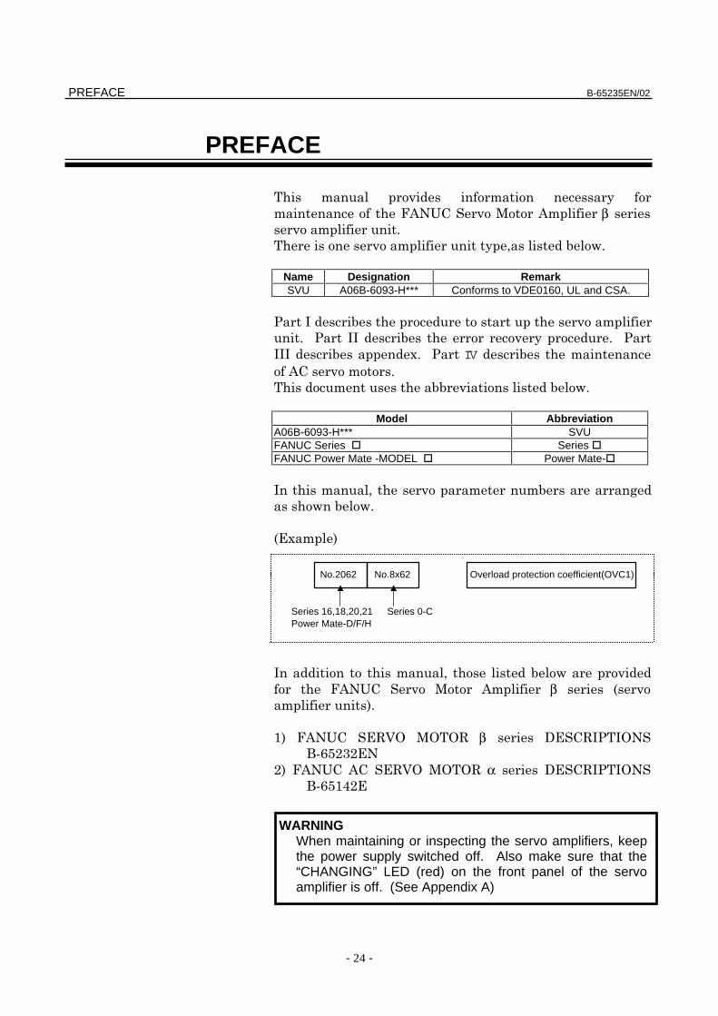
PREFACE
β
Name Designation RemarkSVU A06B-6093-H*** Conforms to VDE0160, UL and CSA.
!
!!
!!!" IV
Model AbbreviationA06B-6093-H*** SVUFANUC Series Series FANUC Power Mate -MODEL Power Mate-
! #
$%"&
!
β $ &
'& %()* **( β +%(! !*,-./010%
0& %()***(α +%(! !*,-./'20%
Series 0-CSeries 16,18,20,21Power Mate-D/F/H
Overload protection coefficient(OVC1)No.8x62No.2062
WARNINGWhen maintaining or inspecting the servo amplifiers, keepthe power supply switched off. Also make sure that the“CHANGING” LED (red) on the front panel of the servoamplifier is off. (See Appendix A)
B-65235EN/02
- 25 -
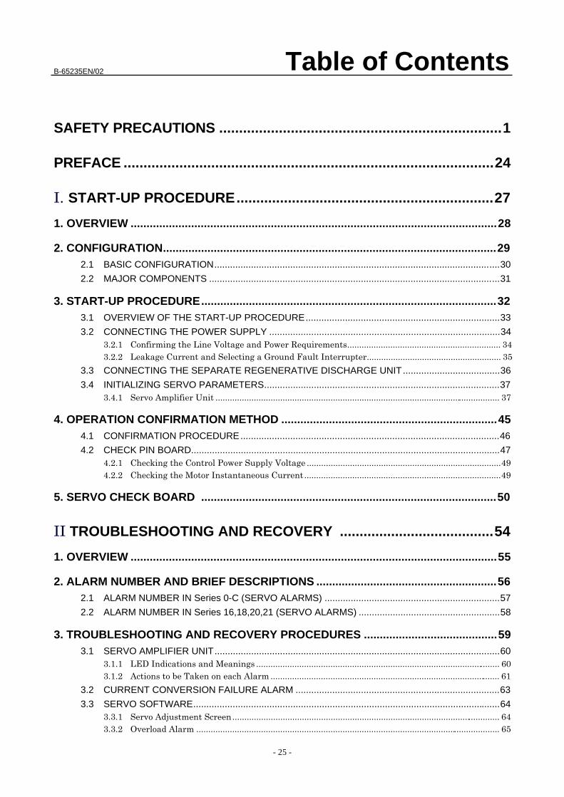
Table of Contents
SAFETY PRECAUTIONS .......................................................................1
PREFACE .............................................................................................24
START-UP PROCEDURE.................................................................27
1. OVERVIEW ...................................................................................................................28
2. CONFIGURATION.........................................................................................................292.1 BASIC CONFIGURATION.............................................................................................................30
2.2 MAJOR COMPONENTS ...............................................................................................................31
3. START-UP PROCEDURE.............................................................................................323.1 OVERVIEW OF THE START-UP PROCEDURE..........................................................................33
3.2 CONNECTING THE POWER SUPPLY ........................................................................................34
! "# $
3.3 CONNECTING THE SEPARATE REGENERATIVE DISCHARGE UNIT.....................................36
3.4 INITIALIZING SERVO PARAMETERS..........................................................................................37 % &# ' (
4. OPERATION CONFIRMATION METHOD ....................................................................454.1 CONFIRMATION PROCEDURE...................................................................................................46
4.2 CHECK PIN BOARD......................................................................................................................47 ##) *
+ " *
5. SERVO CHECK BOARD .............................................................................................50
TROUBLESHOOTING AND RECOVERY .......................................54
1. OVERVIEW ...................................................................................................................55
2. ALARM NUMBER AND BRIEF DESCRIPTIONS .........................................................562.1 ALARM NUMBER IN Series 0-C (SERVO ALARMS) ...................................................................57
2.2 ALARM NUMBER IN Series 16,18,20,21 (SERVO ALARMS) ......................................................58
3. TROUBLESHOOTING AND RECOVERY PROCEDURES ..........................................593.1 SERVO AMPLIFIER UNIT.............................................................................................................60
,- " + ./
& 0 1 & .
3.2 CURRENT CONVERSION FAILURE ALARM ..............................................................................63
3.3 SERVO SOFTWARE.....................................................................................................................64 % &2 .
3% & .$
Table of Contents B-65235EN/02
- 26 -
!0 - & .$
+ 3% & ..
$ "% % .(
. , & (
( # - , & ($
4 , &($
4. REPLACING THE FUSE ...............................................................................................76
5. CONNECTING THE BATTERY FOR AN ABSOLUTE PULSE CODER.......................77
III. MOTOR MAINTENANCE................................................................78
1. AC SERVO MOTOR MAINTENANCE...........................................................................791.1 RECEIVING AND KEEPING AC SERVO MOTORS.....................................................................80
1.2 DAILY INSPECTION OF AC SERVO MOTORS...........................................................................81
1.3 PERIODIC INSPECTION OF β SERIES MOTOR.........................................................................84
1.4 REPLACING THE PULSE CODER ...............................................................................................86
1.5 REPLACEMENT PARTS SPECIFICATION ..................................................................................87
APPENDIX............................................................................................88
A. SERVO AMPLIFIER UNIT FRONT PANEL..................................................................89
B. MOTOR PARAMETER LIST.........................................................................................90
C. FSSB.............................................................................................................................94C.1 GENERAL......................................................................................................................................95
C.2 CONFIGURATION.........................................................................................................................96
C.3 OPERATION CONFIRMATION METHOD....................................................................................97 5 *(
% # *4
C.4 SERVO CHECK BOARD...............................................................................................................99
C.5 TROUBLESHOOTING AND RECOVERY...................................................................................100
C.6 i SERIES INITIAL SETTING OF PARAMETER ..........................................................................104. 3 /
. % /$
. + /.
. & /(
.$ +

- 27 -
I. START-UP PROCEDURE
2. CONFIGURATION START-UP PROCEDURE B-65235EN/02
- 28 -
1 OVERVIEW
B-65235EN/02 START-UP PROCEDURE 2. CONFIGURATION
- 29 -
2 CONFIGURATION
2. CONFIGURATION START-UP PROCEDURE B-65235EN/02
- 30 -
2.1 BASIC CONFIGURATION
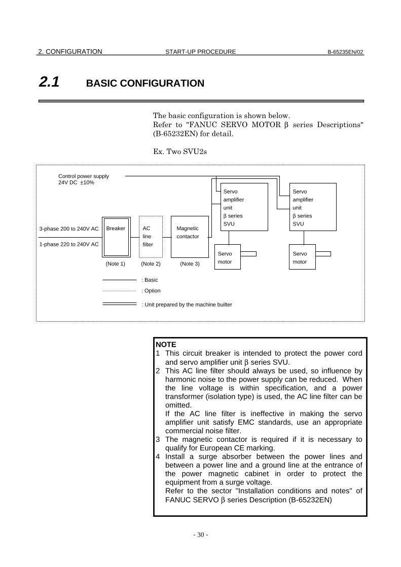
! !"
# $%&'( )#* +# β , $-./)' "
)0"!*(
NOTE1 This circuit breaker is intended to protect the power cord
and servo amplifier unit β series SVU.2 This AC line filter should always be used, so influence by
harmonic noise to the power supply can be reduced. Whenthe line voltage is within specification, and a powertransformer (isolation type) is used, the AC line filter can beomitted.If the AC line filter is ineffective in making the servoamplifier unit satisfy EMC standards, use an appropriatecommercial noise filter.
3 The magnetic contactor is required if it is necessary toqualify for European CE marking.
4 Install a surge absorber between the power lines andbetween a power line and a ground line at the entrance ofthe power magnetic cabinet in order to protect theequipment from a surge voltage.Refer to the sector "Installation conditions and notes" ofFANUC SERVO β series Description (B-65232EN)
Servo
motor
: Basic
: Option
(Note 2)(Note 1)
: Unit prepared by the machine builter
(Note 3)
AC
line
filter
Magnetic
contactor
Breaker
Servo
amplifier
unit
β series
SVU
1-phase 220 to 240V AC
3-phase 200 to 240V AC
Control power supply24V DC ±10%
Servo
motor
Servo
amplifier
unit
β series
SVU
B-65235EN/02 START-UP PROCEDURE 2. CONFIGURATION
- 31 -
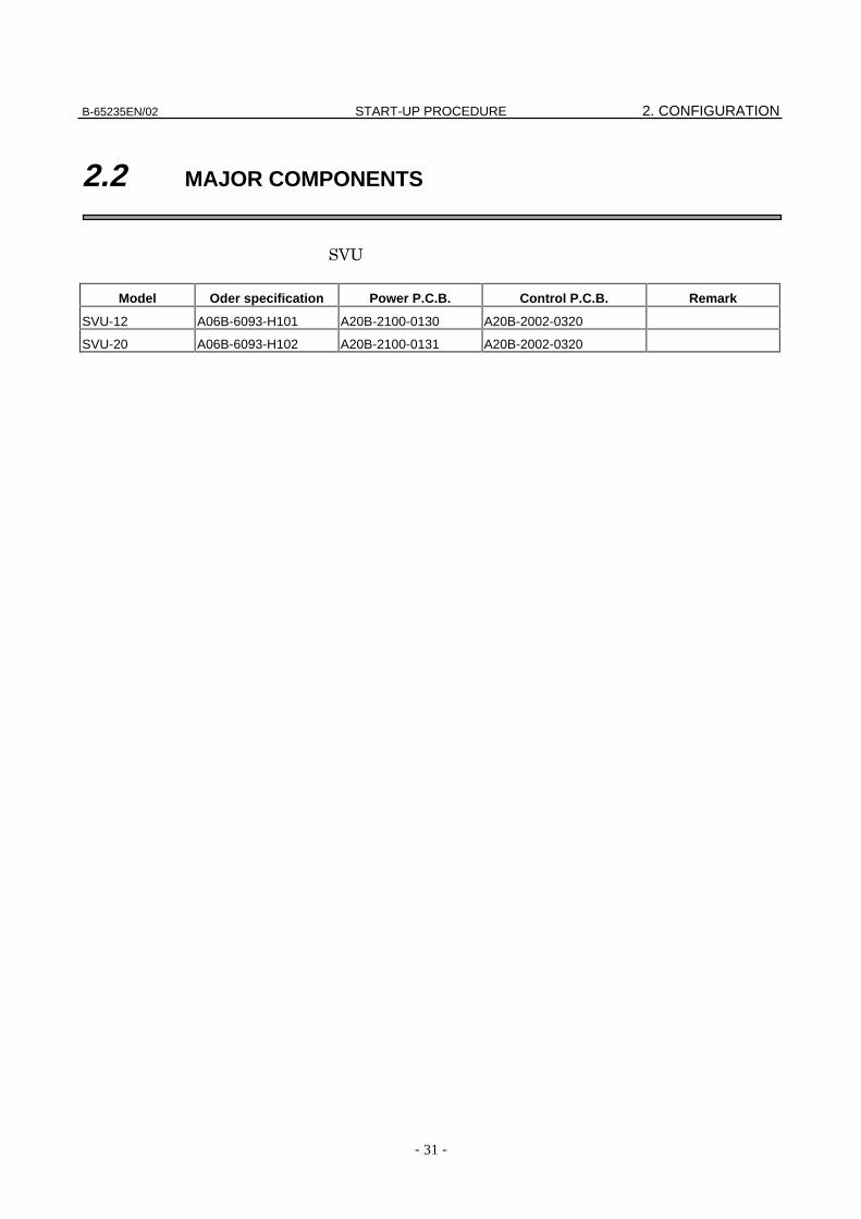
2.2 MAJOR COMPONENTS
*(
Model Oder specification Power P.C.B. Control P.C.B. Remark
SVU-12 A06B-6093-H101 A20B-2100-0130 A20B-2002-0320
SVU-20 A06B-6093-H102 A20B-2100-0131 A20B-2002-0320
3. START-UP PROCEDURE START-UP PROCEDURE B-65235EN/02
- 32 -
3 START-UP PROCEDURE
B-65235EN/02 START-UP PROCEDURE 3. START-UP PROCEDURE
- 33 -
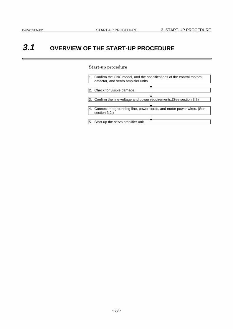
3.1 OVERVIEW OF THE START-UP PROCEDURE
1. Confirm the CNC model, and the specifications of the control motors,detector, and servo amplifier units.
2. Check for visible damage.
3. Confirm the line voltage and power requirements.(See section 3.2)
4. Connect the grounding line, power cords, and motor power wires. (Seesection 3.2.)
5. Start-up the servo amplifier unit.
3. START-UP PROCEDURE START-UP PROCEDURE B-65235EN/02
- 34 -
3.2 CONNECTING THE POWER SUPPLY
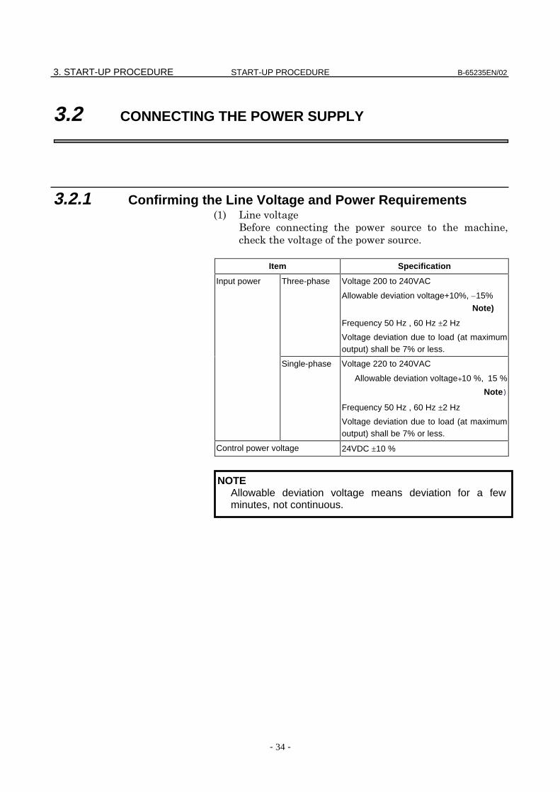
3.2.1 Confirming the Line Voltage and Power Requirements 1
- ! 2
3 ! "
Item Specification
Input power Three-phase Voltage 200 to 240VAC
Allowable deviation voltage+10%, –15%
Note)
Frequency 50 Hz , 60 Hz ±2 Hz
Voltage deviation due to load (at maximumoutput) shall be 7% or less.
Single-phase Voltage 220 to 240VAC
Allowable deviation voltage+10 %, 15 %
Note)
Frequency 50 Hz , 60 Hz ±2 Hz
Voltage deviation due to load (at maximumoutput) shall be 7% or less.
Control power voltage 24VDC ±10 %
NOTEAllowable deviation voltage means deviation for a fewminutes, not continuous.
B-65235EN/02 START-UP PROCEDURE 3. START-UP PROCEDURE
- 35 -
4! 5
• ! 5
! 5
"
• 6
2 5 ! !
" 3
5 !
2
3 78*&
97*&
"
• # /4:::;%&'()#*
+)# β , < -./)' ! 5 "
3.2.2 Leakage Current and Selecting a Ground Fault Interrupter
-
!
:=-2 5 3 !
! !
" 3
3
! ! "
3
"
1 3
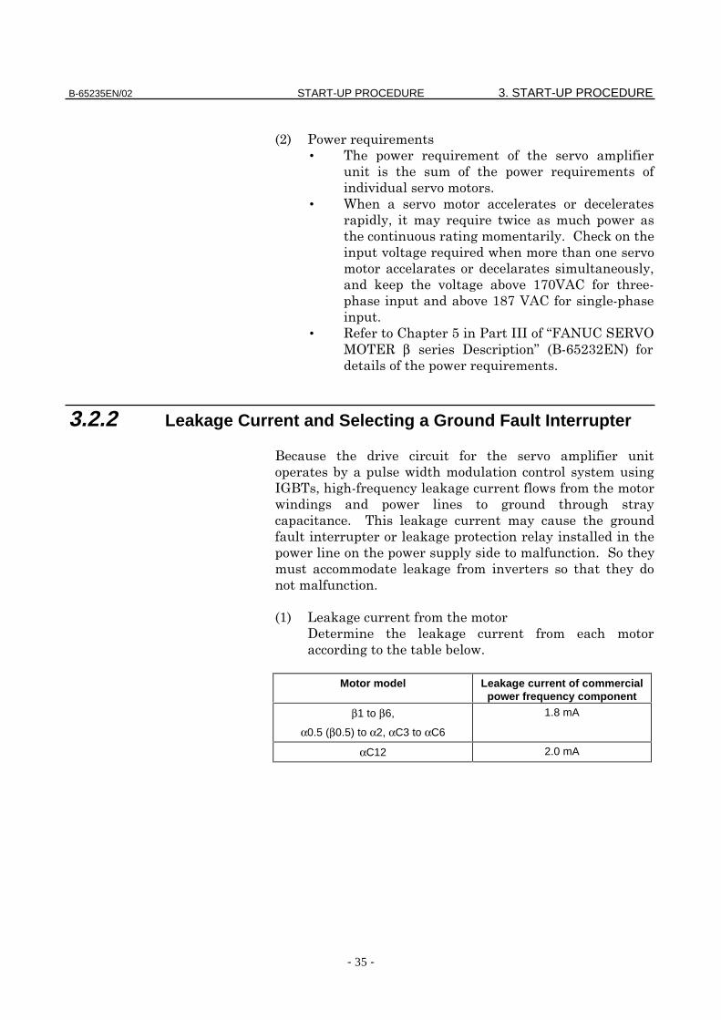
, 3
!"
Motor model Leakage current of commercialpower frequency component
β1 to β6,
α0.5 (β0.5) to α2, αC3 to αC6
1.8 mA
αC12 2.0 mA
3. START-UP PROCEDURE START-UP PROCEDURE B-65235EN/02
- 36 -
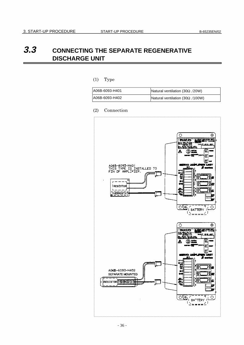
3.3 CONNECTING THE SEPARATE REGENERATIVEDISCHARGE UNIT
A06B-6093-H401 Natural ventilation (30Ω /20W)
A06B-6093-H402 Natural ventilation (30Ω /100W)
B-65235EN/02 START-UP PROCEDURE 3. START-UP PROCEDURE
- 37 -
3.4 INITIALIZING SERVO PARAMETERS
3.4.1 Servo Amplifier Unit
- >
- > 2
!
' )0 .
)0 β.?888 4
)0 β @ 6
)0 '
/ ,
)0 8
. + )0 8"88
7 ' )0 8"88
>
! ' "
) !46)A
:>
"
2 !
!2 3 '"
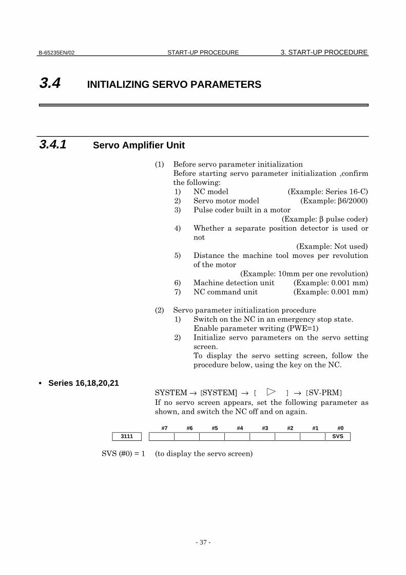
• Series 16,18,20,21B)+→ [B)+C → [ ] → [*4#+]: 2 !
!2! '"
#7 #6 #5 #4 #3 #2 #1 #03111 SVS
*D8A
3. START-UP PROCEDURE START-UP PROCEDURE B-65235EN/02
- 38 -
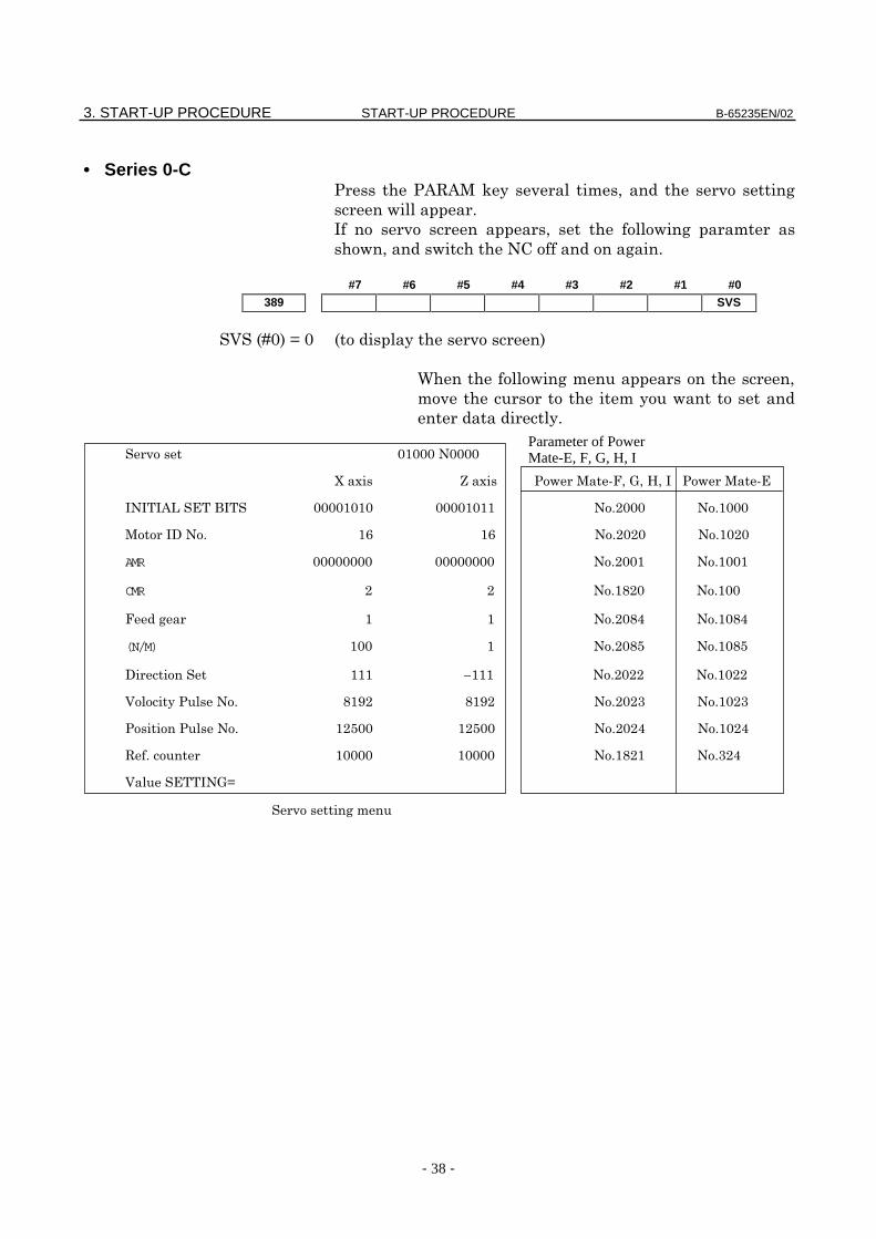
• Series 0-C4 4&#&+3 2
! "
: 2 !
!2! '"
#7 #6 #5 #4 #3 #2 #1 #0389 SVS
*D8A8
6 ! 2
!
"
! " "
AMR
CMR #
$% #&#&
(N/M) #'#'
!() –
*+(,-+ #. #. / /
)-+ ' ' & &
01(-) # / &
* +-2
)%3)-
Parameter of PowerMate-E, F, G, H, I
B-65235EN/02 START-UP PROCEDURE 3. START-UP PROCEDURE
- 39 -
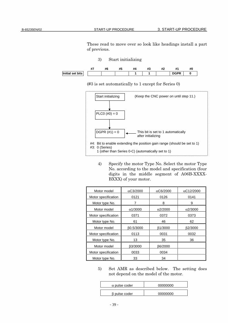
33
"
>
#7 #6 #5 #4 #3 #2 #1 #0Initial set bits 1 1 DGPR 0
D 0 8
@ '"
'"
&8.-EEEE
-EEE"
Motor model αC3/2000 αC6/2000 αC12/2000
Motor specification 0121 0126 0141
Motor type No. 7 8 9
Motor model α1/3000 α2/2000 α2/3000
Motor specification 0371 0372 0373
Motor type No. 61 46 62
Motor model β0.5/3000 β1/3000 β2/3000
Motor specification 0113 0031 0032
Motor type No. 13 35 36
Motor model β3/3000 β6/2000
Motor specification 0033 0034
Motor type No. 33 34
/ &+# !"
"
α pulse coder 00000000
β pulse coder 00000000
#4: Bit to enable extending the position gain range (should be set to 1)#3: 0 (Series) 1 (other than Series 0-C) (automatically set to 1)
(Keep the CNC power on until step 11.)
This bit is set to 1 automaticallyafter initializing
PLC0 (#0) = 0
DGPR (#1) = 0
Start initializing
3. START-UP PROCEDURE START-UP PROCEDURE B-65235EN/02
- 40 -
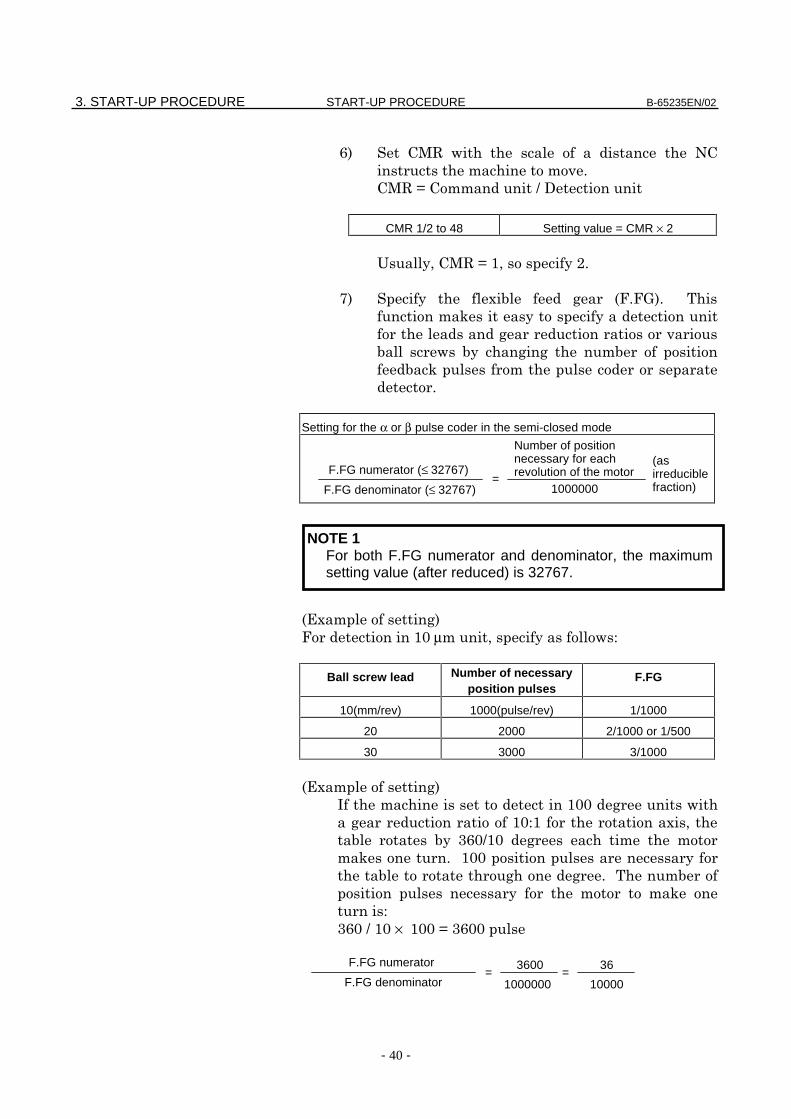
. +# ! '
"
+#A?,
CMR 1/2 to 48 Setting value = CMR × 2
(2+#A2 "
7 0 %"%="
3
!
3
"
Setting for the α or β pulse coder in the semi-closed mode
)0
% 8µ2 !
Ball screw lead Number of necessaryposition pulses
F.FG
10(mm/rev) 1000(pulse/rev) 1/1000
20 2000 2/1000 or 1/500
30 3000 3/1000
)0
: 88 !
8 02
.8?8
3 "88
"
3
.8?8× 88A.88
=F.FG numerator (≤ 32767)
1000000F.FG denominator (≤ 32767)
Number of positionnecessary for eachrevolution of the motor
(asirreduciblefraction)
NOTE 1For both F.FG numerator and denominator, the maximumsetting value (after reduced) is 32767.
=F.FG numerator
1000000F.FG denominator
3600=
10000
36
B-65235EN/02 START-UP PROCEDURE 3. START-UP PROCEDURE
- 41 -
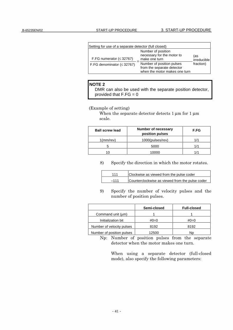
Setting for use of a separate detector (full closed)
)0
6 µµ "
Ball screw lead Number of necessaryposition pulses
F.FG
1(mm/rev) 1000(pulses/rev) 1/1
5 5000 1/1
10 10000 1/1
9 ! "
111 Clockwise as viewed from the pulse coder
–111 Counterclockwise as viewed from the pulse coder
F
"
Semi-closed Full-closed
Command unit (µm) 1 1
Initialization bit #0=0 #0=0
Number of velocity pulses 8192 8192
Number of position pulses 12500 Np
' '
! 3 "
6
2 !
=F.FG numerator (≤ 32767)
F.FG denominator (≤ 32767)
Number of positionnecessary for the motor tomake one turnNumber of position pulsesfrom the separate detectorwhen the motor makes one turn
(asirreduciblefraction)
NOTE 2DMR can also be used with the separate position detector,provided that F.FG = 0
3. START-UP PROCEDURE START-UP PROCEDURE B-65235EN/02
- 42 -
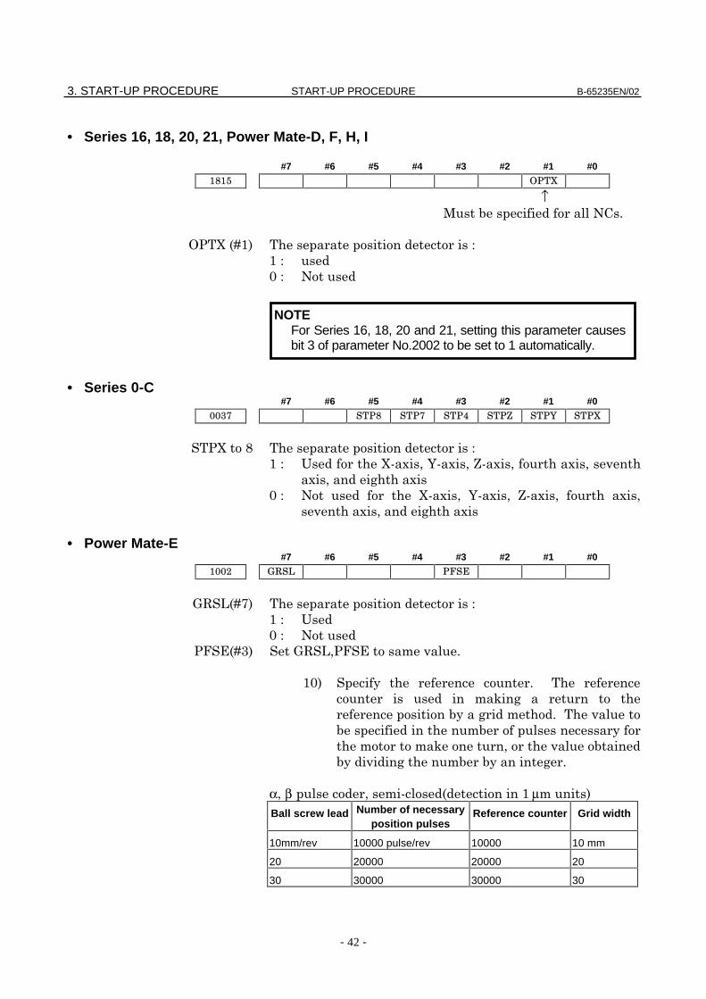
• Series 16, 18, 20, 21, Power Mate-D, F, H, I
#7 #6 #5 #4 #3 #2 #1 #0
↑+ '"
4ED
8 '
• Series 0-C#7 #6 #5 #4 #3 #2 #1 #0
4E9
( E02B02G0202
02 0
8 ' E02 B02 G02 02
02 0
• Power Mate-E#7 #6 #5 #4 #3 #2 #1 #0
=#1D7
(
8 '
4%)D =#124%) "
8 "
3
"
3 2
"
α2β 2 µ
Ball screw lead Number of necessaryposition pulses
Reference counter Grid width
10mm/rev 10000 pulse/rev 10000 10 mm
20 20000 20000 20
30 30000 30000 30
NOTEFor Series 16, 18, 20 and 21, setting this parameter causesbit 3 of parameter No.2002 to be set to 1 automatically.
B-65235EN/02 START-UP PROCEDURE 3. START-UP PROCEDURE
- 43 -
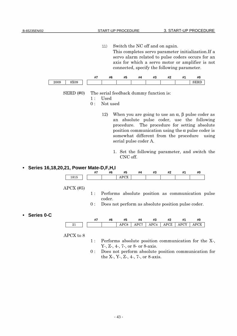
11) ! '"
>":
0 !
2 ! "
#7 #6 #5 #4 #3 #2 #1 #0
)#,D8 3
(
8 '
6 α2β 2 !
"
α !
&"
" ! 2 !
'"
• Series 16,18,20,21, Power Mate-D,F,H,I#7 #6 #5 #4 #3 #2 #1 #0
&4ED/
4
"
8 , "
• Series 0-C#7 #6 #5 #4 #3 #2 #1 #0
&4E9
4 E2
B2G2@272990"
8 ,
E2B2G2@27290"
3. START-UP PROCEDURE START-UP PROCEDURE B-65235EN/02
- 44 -
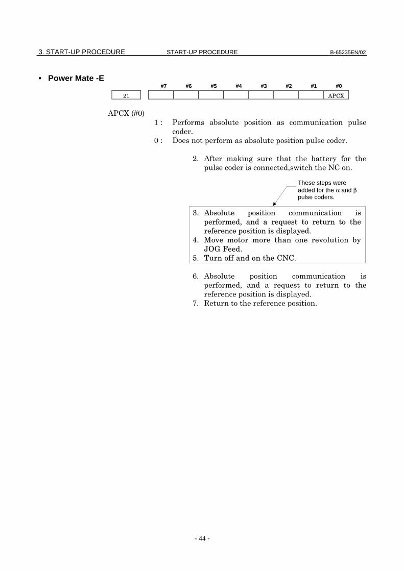
• Power Mate -E#7 #6 #5 #4 #3 #2 #1 #0
&4ED8
4
"
8 , "
" & 3
2! '"
!"#"
." &
2 5
"
7" # "
These steps wereadded for the α and βpulse coders.
B-65235EN/02 START-UP PROCEDURE 4. OPERATION CONFIRMATION METHOD
- 45 -
4 OPERATION CONFIRMATION METHOD
4. OPERATION CONFIRMATION METHOD START-UP PROCEDURE B-65235EN/02
- 46 -
4.1 CONFIRMATION PROCEDURE
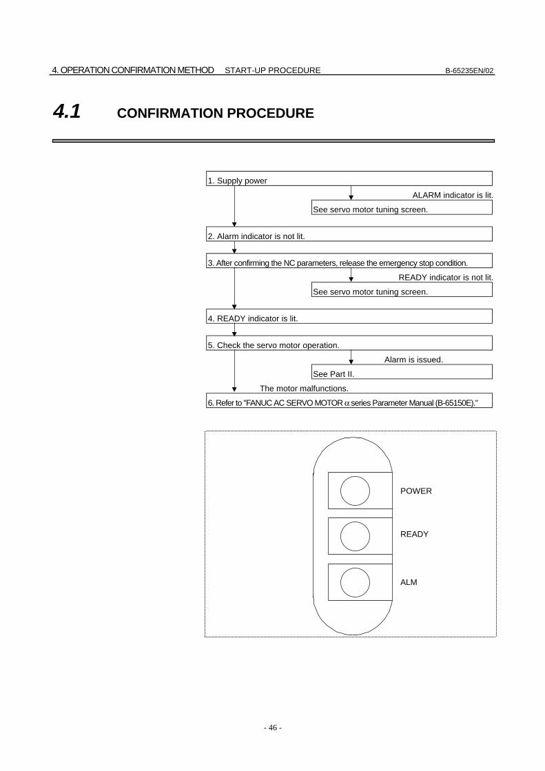
1. Supply power
ALARM indicator is lit.
See servo motor tuning screen.
2. Alarm indicator is not lit.
3. After confirming the NC parameters, release the emergency stop condition.
READY indicator is not lit.
See servo motor tuning screen.
4. READY indicator is lit.
5. Check the servo motor operation.
Alarm is issued.
See Part II.
The motor malfunctions.
6. Refer to "FANUC AC SERVO MOTOR α series Parameter Manual (B-65150E)."
ALM
READY
POWER
B-65235EN/02 START-UP PROCEDURE 4. OPERATION CONFIRMATION METHOD
- 47 -
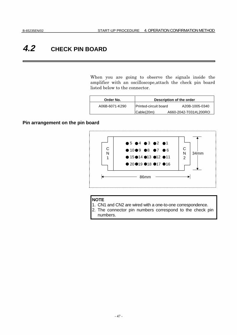
4.2 CHECK PIN BOARD
6
! 2 3
! "
Order No. Description of the order
A06B-6071-K290 Printed-circuit board A20B-1005-0340
Cable(20m) A660-2042-T031#L200RO
Pin arrangement on the pin board
NOTE1. CN1 and CN2 are wired with a one-to-one correspondence.2. The connector pin numbers correspond to the check pin
numbers.
CN2
34mm
86mm
16171819
11121314
678
4
9
123
15
20
10
5CN1
4. OPERATION CONFIRMATION METHOD START-UP PROCEDURE B-65235EN/02
- 48 -
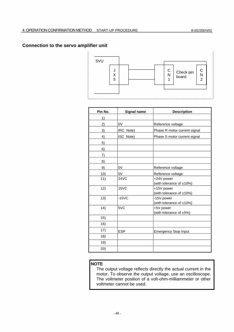
Connection to the servo amplifier unit
Pin No. Signal name Description
1)
2) 0V Reference voltage
3) IRC Note) Phase R motor current signal
4) ISC Note) Phase S motor current signal
5)
6)
7)
8)
9) 0V Reference voltage
10) 0V Reference voltage11) 24VC +24V power
(with tolerance of ±10%)12) 15VC +15V power
(with tolerance of ±10%)13) -15VC -15V power
(with tolerance of ±10%)14) 5VC +5V power
(with tolerance of ±5%)15)
16)
17) ESP Emergency Stop Input18)
19)
20)
NOTEThe output voltage reflects directly the actual current in themotor. To observe the output voltage, use an oscilloscope.The voltmeter position of a volt-ohm-milliammeter or othervoltmeter cannot be used.
CN2
CN1
JX5
SVU
Check pinboard
B-65235EN/02 START-UP PROCEDURE 4. OPERATION CONFIRMATION METHOD
- 49 -
4.2.1 Checking the Control Power Supply Voltage
Check pin Ratings
24V - 0V 24V ±10%
5V - 0V 5V ±5%
15V - 0V 15V ±10%
-15V - 0V -15V ±10%
4.2.2 Checking the Motor Instantaneous Current
8*:#: 3
"
! "
!
!"
0 $$"
":
!
2 ± @*" 2
!"
3"
% 0 *(8
*(
1+
Limit to Motorinstantaneous current (A)
Coefficient to caliculatethe motor current (A/V)
12 3
20 5
Limit to Motorinstantaneous current [AV]
Coefficient to calculate the motor current =
Coefficient to calculatethe motor current
4V=
20A5 [A/V]
4V
5. SERVO CHECK BOARD START-UP PROCEDURE B-65235EN/02
- 50 -
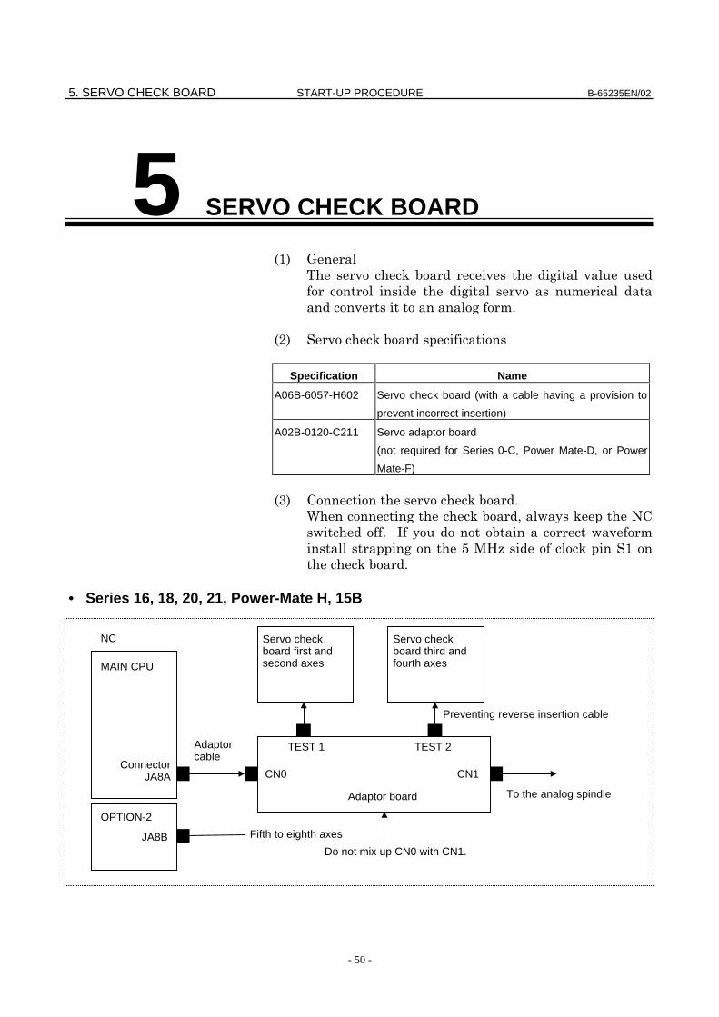
5 SERVO CHECK BOARD
=
3
"
3
Specification Name
A06B-6057-H602 Servo check board (with a cable having a provision to
prevent incorrect insertion)
A02B-0120-C211 Servo adaptor board
(not required for Series 0-C, Power Mate-D, or Power
Mate-F)
3 "
6 3 2!3 '
! " : !
/+H> 3
3 "
• Series 16, 18, 20, 21, Power-Mate H, 15B
Fifth to eighth axes
Do not mix up CN0 with CN1.
Adaptor board
Adaptorcable
NC
MAIN CPU
OPTION-2
ConnectorJA8A
JA8B
CN0 CN1
TEST 2TEST 1
To the analog spindle
Servo checkboard third andfourth axes
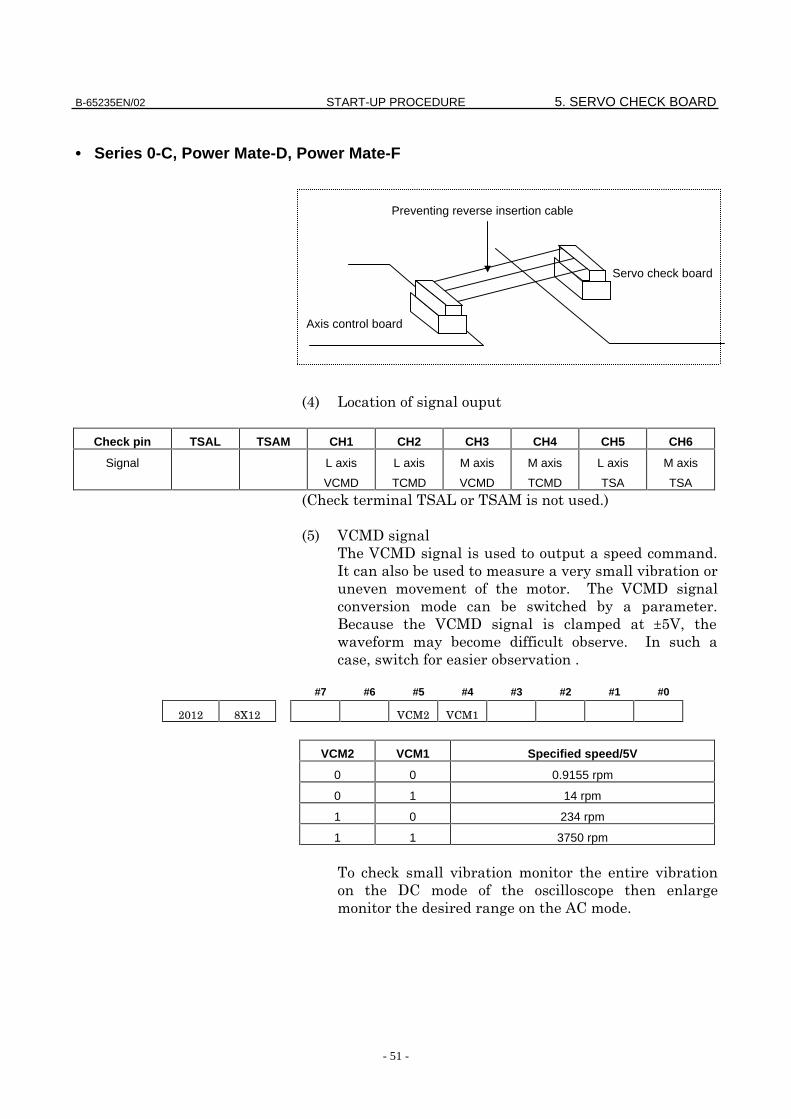
Preventing reverse insertion cable
Servo checkboard first andsecond axes
B-65235EN/02 START-UP PROCEDURE 5. SERVO CHECK BOARD
- 51 -
• Series 0-C, Power Mate-D, Power Mate-F
@ 1
Check pin TSAL TSAM CH1 CH2 CH3 CH4 CH5 CH6
Signal L axis
VCMD
L axis
TCMD
M axis
VCMD
M axis
TCMD
L axis
TSA
M axis
TSA
3 &1&+ "
/ *+,
*+, "
:
" *+,
! "
- *+, ±/*2 ! " :
2! "
#7 #6 #5 #4 #3 #2 #1 #0
VCM2 VCM1 Specified speed/5V
0 0 0.9155 rpm
0 1 14 rpm
1 0 234 rpm
1 1 3750 rpm
3
,
& "
Axis control board
Preventing reverse insertion cable
Servo check board

5. SERVO CHECK BOARD START-UP PROCEDURE B-65235EN/02
- 52 -
6 *+,
! 6?/*2
)0 & 4 A 8-12
3 ?
A 888 2
*+,! A@?/*!
µ?
( 2
)A88*2?A8*+A2*+A8
*
A.@*?
2 A88×?.@A@".µ2
! /8H>
. +,
+,5 ":
:#2:
2
3 "
Maximum
current
Signal output for
maximum current
Ap/V Applicable servo motor
12Ap 4.44V 2.7 β 1/3000, β 2/3000
β 0.5/3000, α 1/3000
α 2/2000, α 2/3000
20Ap 4.44V 4.5 β 3/3000, β 6/2000
α C3/2000, α C6/2000,
α C12/2000,
Root mean square value(RMS) =+,&× 8"7
Number of positional feedback pulses/motor revolution × W
300 × position gain (S–1)=Voltage (V) per positional deviation pulse
1/f
E
GND
VCMD
GND
AC modeDC mode
Enlarged
B-65235EN/02 START-UP PROCEDURE 5. SERVO CHECK BOARD
- 53 -
7 &
& "
Signal conversion 3750 rpm / 5V
: & /*2 3!
! "
2115 Not used
- 8"
- 54 -
II. TROUBLESHOOTINGAND RECOVERY
B-65235EN/02 TROUBLESHOOTING AND RECOVERY 1. OVERVIEW
- 55 -
1 OVERVIEW
!
"
#
2. ALARM NUMBER AND BRIEF DESCRIPTIONS TROUBLESHOOTING AND RECOVERY B-65235EN/02
- 56 -
2 ALARM NUMBER AND BRIEFDESCRIPTIONS
2. ALARM NUMBER AND BRIEFB-65235EN/02 TROUBLESHOOTING AND RECOVERY DESCRIPTIONS
- 57 -
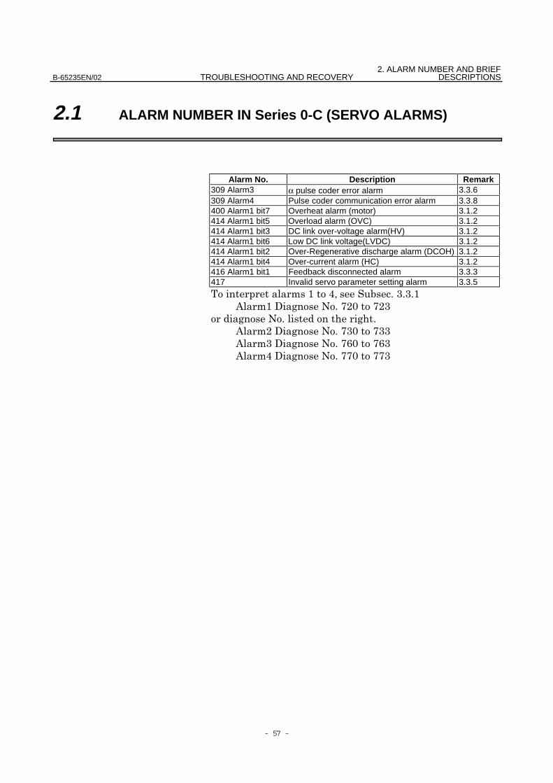
2.1 ALARM NUMBER IN Series 0-C (SERVO ALARMS)
Alarm No. Description Remark309 Alarm3 α pulse coder error alarm 3.3.6309 Alarm4 Pulse coder communication error alarm 3.3.8400 Alarm1 bit7 Overheat alarm (motor) 3.1.2414 Alarm1 bit5 Overload alarm (OVC) 3.1.2414 Alarm1 bit3 DC link over-voltage alarm(HV) 3.1.2414 Alarm1 bit6 Low DC link voltage(LVDC) 3.1.2414 Alarm1 bit2 Over-Regenerative discharge alarm (DCOH) 3.1.2414 Alarm1 bit4 Over-current alarm (HC) 3.1.2416 Alarm1 bit1 Feedback disconnected alarm 3.3.3417 Invalid servo parameter setting alarm 3.3.5
$% ##$
&$'(")("#
&"'(#)(##
&#'(*)(*#
&%'(()((#

2. ALARM NUMBER AND BRIEF DESCRIPTIONS TROUBLESHOOTING AND RECOVERY B-65235EN/02
- 58 -
2.2 ALARM NUMBER IN Series 16,18,20,21 (SERVO ALARMS)
Alarm No. Description Remark350 Alarm3 α pulse coder error alarm 3.3.6350 Alarm3 bit3 Rotation speed data error alarm 3.3.7351 Alarm4 Pulse coder communication error alarm 3.3.8400 Alarm1 bit7 Overheat alarm (motor) 3.3.4414 Alarm5 bit6 Current conversion error alarm 3.2414 Alarm1 bit5 Overload alarm (OVC) 3.3.2414 Alarm1 bit3 DC link over-voltage alarm (HV) 3.1.2414 Alarm1 bit6 Low DC link voltage(LVDC) 3.1.2414 Alarm5 bit2 FAN stop alarm(FAL) 3.1.2416 Alarm1 bit2 Over-Regenerative discharge alarm(DCOH) 3.1.2414 Alarm1 bit4 Over-current alarm(HC) 3.1.2416 Alarm1 bit1 Feedback disconnected alarm 3.3.3417 Invalid servo parameter setting alarm 3.3.5
$+ ##$
&$'"))
&#'")"
&%'")#
&+'")%

3. TROUBLESHOOTING ANDB-65235EN/02 TROUBLESHOOTING AND RECOVERY RECOVERY PROCEDURES
- 59 -
3 TROUBLESHOOTING ANDRECOVERY PROCEDURES
3.TROUBLESHOOTING ANDRECOVERY PROCEDURES TROUBLESHOOTING AND RECOVERY B-65235EN/02
- 60 -
3.1 SERVO AMPLIFIER UNIT
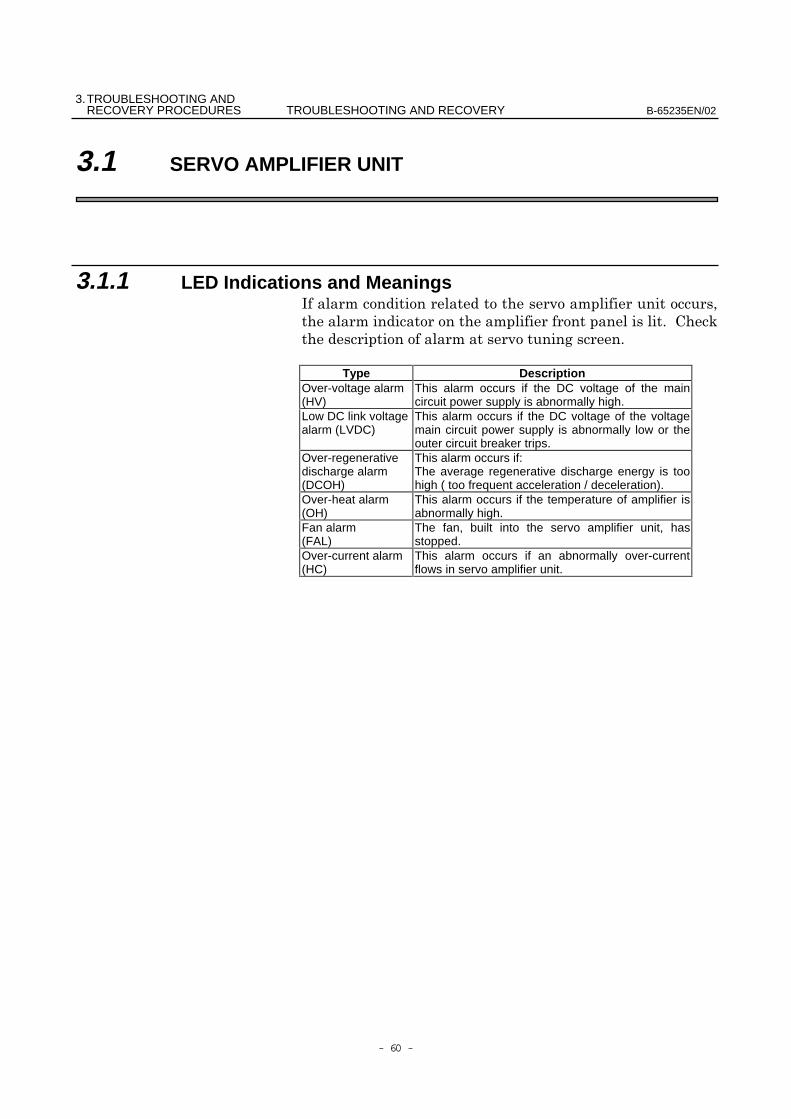
3.1.1 LED Indications and Meanings,
Type DescriptionOver-voltage alarm(HV)
This alarm occurs if the DC voltage of the maincircuit power supply is abnormally high.
Low DC link voltagealarm (LVDC)
This alarm occurs if the DC voltage of the voltagemain circuit power supply is abnormally low or theouter circuit breaker trips.
Over-regenerativedischarge alarm(DCOH)
This alarm occurs if:The average regenerative discharge energy is toohigh ( too frequent acceleration / deceleration).
Over-heat alarm(OH)
This alarm occurs if the temperature of amplifier isabnormally high.
Fan alarm(FAL)
The fan, built into the servo amplifier unit, hasstopped.
Over-current alarm(HC)
This alarm occurs if an abnormally over-currentflows in servo amplifier unit.
3. TROUBLESHOOTING ANDB-65235EN/02 TROUBLESHOOTING AND RECOVERY RECOVERY PROCEDURES
- 61 -
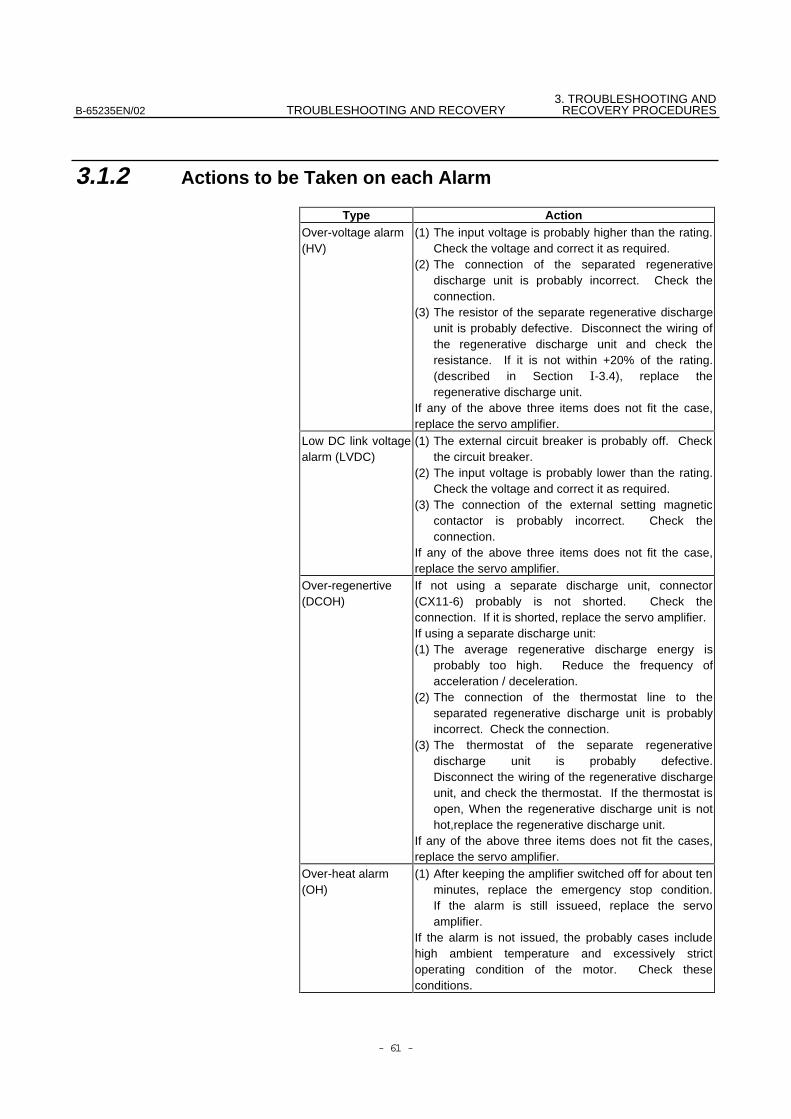
3.1.2 Actions to be Taken on each Alarm
Type ActionOver-voltage alarm(HV)
(1) The input voltage is probably higher than the rating.Check the voltage and correct it as required.
(2) The connection of the separated regenerativedischarge unit is probably incorrect. Check theconnection.
(3) The resistor of the separate regenerative dischargeunit is probably defective. Disconnect the wiring ofthe regenerative discharge unit and check theresistance. If it is not within +20% of the rating.(described in Section -3.4), replace theregenerative discharge unit.
If any of the above three items does not fit the case,replace the servo amplifier.
Low DC link voltagealarm (LVDC)
(1) The external circuit breaker is probably off. Checkthe circuit breaker.
(2) The input voltage is probably lower than the rating.Check the voltage and correct it as required.
(3) The connection of the external setting magneticcontactor is probably incorrect. Check theconnection.
If any of the above three items does not fit the case,replace the servo amplifier.
Over-regenertive(DCOH)
If not using a separate discharge unit, connector(CX11-6) probably is not shorted. Check theconnection. If it is shorted, replace the servo amplifier.If using a separate discharge unit:(1) The average regenerative discharge energy is
probably too high. Reduce the frequency ofacceleration / deceleration.
(2) The connection of the thermostat line to theseparated regenerative discharge unit is probablyincorrect. Check the connection.
(3) The thermostat of the separate regenerativedischarge unit is probably defective.Disconnect the wiring of the regenerative dischargeunit, and check the thermostat. If the thermostat isopen, When the regenerative discharge unit is nothot,replace the regenerative discharge unit.
If any of the above three items does not fit the cases,replace the servo amplifier.
Over-heat alarm(OH)
(1) After keeping the amplifier switched off for about tenminutes, replace the emergency stop condition.If the alarm is still issueed, replace the servoamplifier.
If the alarm is not issued, the probably cases includehigh ambient temperature and excessively strictoperating condition of the motor. Check theseconditions.
3.TROUBLESHOOTING ANDRECOVERY PROCEDURES TROUBLESHOOTING AND RECOVERY B-65235EN/02
- 62 -
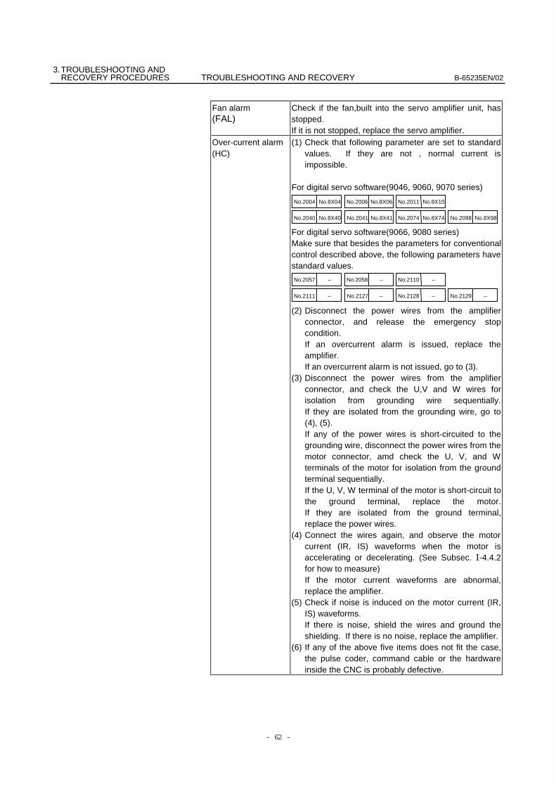
Fan alarm(FAL)
Check if the fan,built into the servo amplifier unit, hasstopped.If it is not stopped, replace the servo amplifier.
Over-current alarm(HC)
(1) Check that following parameter are set to standardvalues. If they are not , normal current isimpossible.
For digital servo software(9046, 9060, 9070 series)
For digital servo software(9066, 9080 series)Make sure that besides the parameters for conventionalcontrol described above, the following parameters havestandard values.
(2) Disconnect the power wires from the amplifierconnector, and release the emergency stopcondition.If an overcurrent alarm is issued, replace theamplifier.If an overcurrent alarm is not issued, go to (3).
(3) Disconnect the power wires from the amplifierconnector, and check the U,V and W wires forisolation from grounding wire sequentially.If they are isolated from the grounding wire, go to(4), (5).If any of the power wires is short-circuited to thegrounding wire, disconnect the power wires from themotor connector, amd check the U, V, and Wterminals of the motor for isolation from the groundterminal sequentially.If the U, V, W terminal of the motor is short-circuit tothe ground terminal, replace the motor.If they are isolated from the ground terminal,replace the power wires.
(4) Connect the wires again, and observe the motorcurrent (IR, IS) waveforms when the motor isaccelerating or decelerating. (See Subsec. -4.4.2for how to measure)If the motor current waveforms are abnormal,replace the amplifier.
(5) Check if noise is induced on the motor current (IR,IS) waveforms.If there is noise, shield the wires and ground theshielding. If there is no noise, replace the amplifier.
(6) If any of the above five items does not fit the case,the pulse coder, command cable or the hardwareinside the CNC is probably defective.
No.8X04No.2004
No.8X40No.2040
No.8X06No.2006
No.8X41No.2041
No.8X10No.2011
No.8X74No.2074 No.8X98No.2098
–
–No.2057
No.2111
No.2058
No.2127
No.2110
No.2128 No.2129–
–
––
–
3. TROUBLESHOOTING ANDB-65235EN/02 TROUBLESHOOTING AND RECOVERY RECOVERY PROCEDURES
- 63 -
3.2 CURRENT CONVERSION FAILURE ALARM
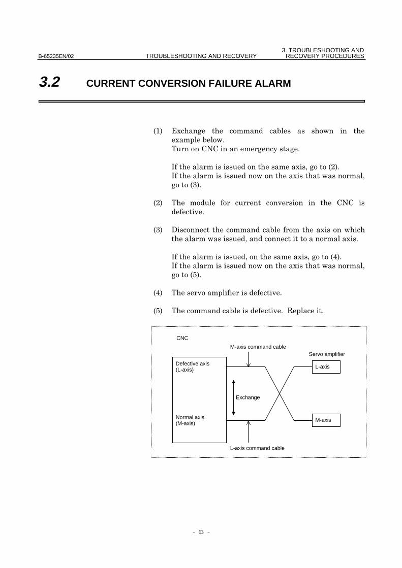
$! -
-
,-"!
,-
#!
"!
#! ' -
-
,-%!
,-
+!
%!
+! .
Normal axis(M-axis)
L-axis
L-axis command cable
CNC
M-axis command cableServo amplifier
Exchange
Defective axis(L-axis)
M-axis
3.TROUBLESHOOTING ANDRECOVERY PROCEDURES TROUBLESHOOTING AND RECOVERY B-65235EN/02
- 64 -
3.3 SERVO SOFTWARE
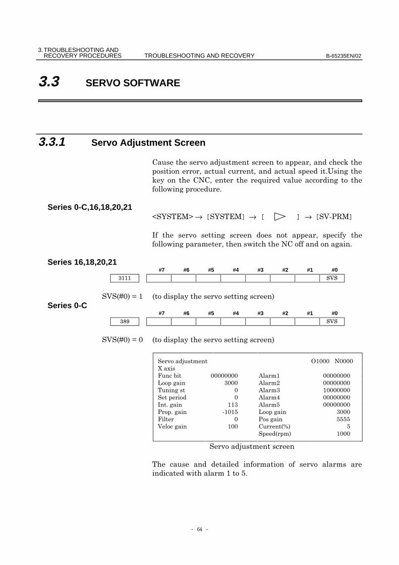
3.3.1 Servo Adjustment Screen
/
0
1
Series 0-C,16,18,20,212345→ [34] → [ ] → [678.4]
,
Series 16,18,20,21#7 #6 #5 #4 #3 #2 #1 #0
69)!:$ !
Series 0-C#7 #6 #5 #4 #3 #2 #1 #0
69)!:) !
!
"
# $
%# &$
% $$$$
' ( )*+ $
)+
/
$+

3. TROUBLESHOOTING ANDB-65235EN/02 TROUBLESHOOTING AND RECOVERY RECOVERY PROCEDURES
- 65 -
3.3.2 Overload Alarm$! 4
,
"! 4
,
#! 4
&
;
2062 8X62 Overload protection coefficient (OVC1)
2063 8X63 Overload protection coefficient (OVC2)
2065 8X65 Overload protection coefficient (OVCLMT)
%! & &)*;7*)($7<"=)!
>?+,.
,!
,.,!
– ,-$%
@
– ,-$%
3.3.3 Feedback Disconnected Alarm $ "
/ ##$!Alarm 1 Alarm 2
#7 #2 Alarm details #7 #40 1 CM alarm (α pulse coder) 1 10 1 Pulse coder disconnected (soft ware) 0 00 1 Separate pulse coder disconnected
(hard ware)1 1
4 ##(
$!
#!
3.TROUBLESHOOTING ANDRECOVERY PROCEDURES TROUBLESHOOTING AND RECOVERY B-65235EN/02
- 66 -
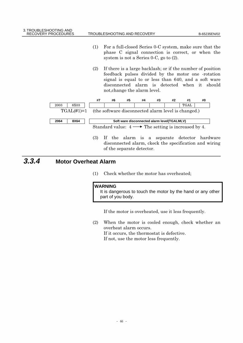
$! 7)7
)7 "!
"! , A
7
1 *%)
#7 #6 #5 #4 #3 #2 #1 #0
B&C9$!:$ !
2064 8X64 Soft ware disconnected alarm level(TGALMLV)
D% %
#! ,
3.3.4 Motor Overheat Alarm
$! A
,1
"! E
,
,1
WARNINGIt is dangerous to touch the motor by the hand or any otherpart of you body.
3. TROUBLESHOOTING ANDB-65235EN/02 TROUBLESHOOTING AND RECOVERY RECOVERY PROCEDURES
- 67 -
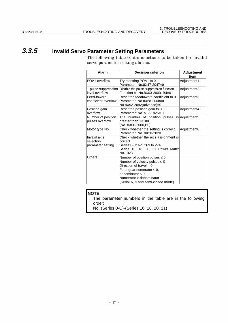
3.3.5 Invalid Servo Parameter Setting Parameters
Alarm Decision criterion Adjustmentitem
POA1 overflow Try resetting POA1 to 0Parameter: No.8X47-2047=0
Adjustment1
1 pulse suppressionlevel overflow
Disable the pulse suppression function.Function bit:No.8X03-2003, B4=0
Adjustment2
Feed-fowardcoefficient overflow
Reset the feedfoward coefficient to 0Parameter: No.8X68-2068=0No.8X92-2092(advance)=0
Adjustment3
Position gainoverflow
Reset the position gain to 0Parameter: No. 517-1825= 0
Adjustment4
Number of positionpulses overflow
The number of position pulses isgreater than 13100(No. 8X00-2000,B0)
Adjustment5
Motor type No. Check whether the setting is correct.Parameter: No. 8X20-2020
Adjustment6
Invalid axisselectionparameter setting
Check whether the axis assignment iscorrect.Series 0-C: No. 269 to 274Series 16, 18, 20, 21 Power Mate:No.1023
Others Number of position pulses ≤ 0Number of velocity pulses ≤ 0Direction of travel = 0Feed gear numerator ≤ 0,denominator ≤ 0Numerator > denominator(Serial A, α and semi-closed mode)
NOTEThe parameter numbers in the table are in the followingorder:No. (Series 0-C)-(Series 16, 18, 20, 21)
3.TROUBLESHOOTING ANDRECOVERY PROCEDURES TROUBLESHOOTING AND RECOVERY B-65235EN/02
- 68 -
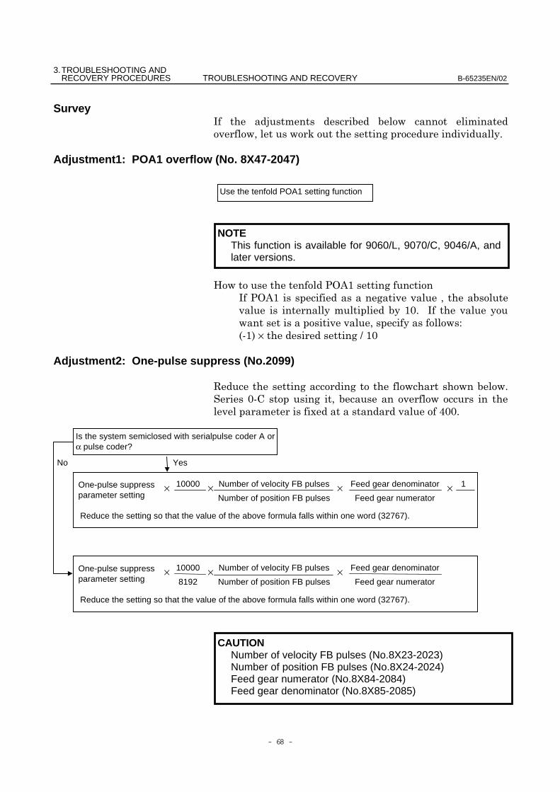
Survey, /
Adjustment1: POA1 overflow (No. 8X47-2047)
F8G&$
,8G&$
$) ,
D
7$!×@$)
Adjustment2: One-pulse suppress (No.2099)
.
)7
-%))
NOTEThis function is available for 9060/L, 9070/C, 9046/A, andlater versions.
× ×××
No Yes
Is the system semiclosed with serialpulse coder A orα pulse coder?
Use the tenfold POA1 setting function
Number of velocity FB pulses
Number of position FB pulses
1Feed gear denominator
Feed gear numerator
10000
Reduce the setting so that the value of the above formula falls within one word (32767).
One-pulse suppressparameter setting
××× Number of velocity FB pulses
Number of position FB pulses
Feed gear denominator
Feed gear numerator
10000
8192
Reduce the setting so that the value of the above formula falls within one word (32767).
One-pulse suppressparameter setting
CAUTIONNumber of velocity FB pulses (No.8X23-2023)Number of position FB pulses (No.8X24-2024)Feed gear numerator (No.8X84-2084)Feed gear denominator (No.8X85-2085)
3. TROUBLESHOOTING ANDB-65235EN/02 TROUBLESHOOTING AND RECOVERY RECOVERY PROCEDURES
- 69 -
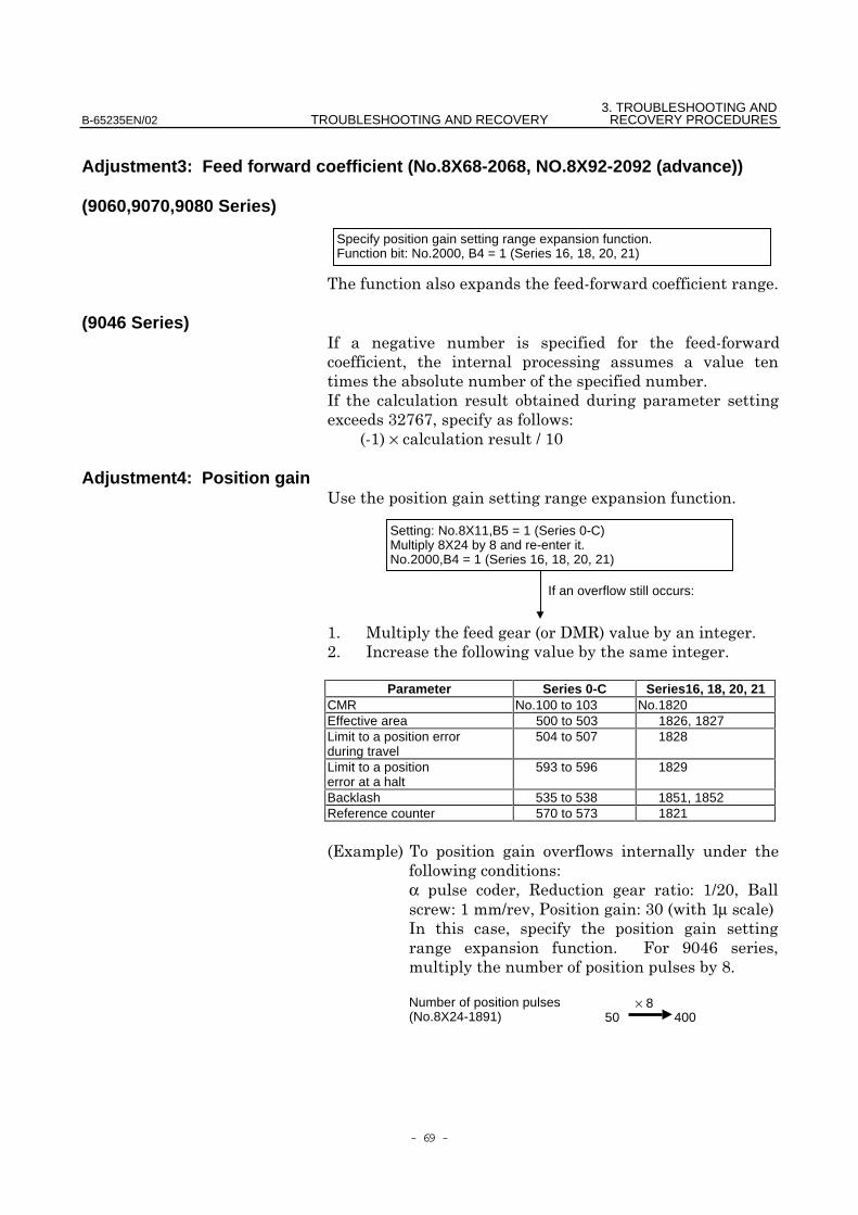
Adjustment3: Feed forward coefficient (No.8X68-2068, NO.8X92-2092 (advance))
(9060,9070,9080 Series)
-7
(9046 Series), 7
,
-#"(*(D
7$!×@$)
Adjustment4: Position gain0-
$ 4'4.!
" ,
Parameter Series 0-C Series16, 18, 20, 21CMR No.100 to 103 No.1820Effective area 500 to 503 1826, 1827Limit to a position errorduring travel
504 to 507 1828
Limit to a positionerror at a halt
593 to 596 1829
Backlash 535 to 538 1851, 1852Reference counter 570 to 573 1821
-!
D
α . D $@") ;D$@8D#)$µ !,
- =)%*
H
If an overflow still occurs:
Setting: No.8X11,B5 = 1 (Series 0-C)Multiply 8X24 by 8 and re-enter it.No.2000,B4 = 1 (Series 16, 18, 20, 21)
× 840050
Number of position pulses(No.8X24-1891)
Specify position gain setting range expansion function.Function bit: No.2000, B4 = 1 (Series 16, 18, 20, 21)
3.TROUBLESHOOTING ANDRECOVERY PROCEDURES TROUBLESHOOTING AND RECOVERY B-65235EN/02
- 70 -
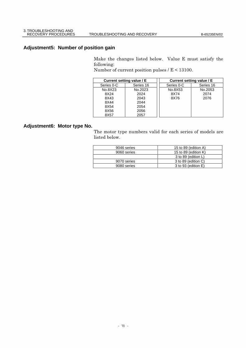
Adjustment5: Number of position gain
4 6
D
@2$#$))
Current setting value / E Current setting value / ESeries 0-C Series 16 Series 0-C Series 16No.8X23
8X248X438X448X548X568X57
No.2023202420432044205420562057
No.8X538X748X76
No.205320742076
Adjustment6: Motor type No.
9046 series 15 to 89 (edition A)9060 series 15 to 89 (edition K)
3 to 89 (edition L)9070 series 3 to 89 (edition C)9080 series 3 to 93 (edition E)
3. TROUBLESHOOTING ANDB-65235EN/02 TROUBLESHOOTING AND RECOVERY RECOVERY PROCEDURES
- 71 -
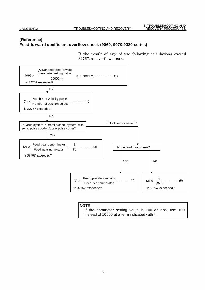
[Reference]Feed-forward coefficient overflow check (9060, 9070,9080 series)
, -
#"(*(
NOTEIf the parameter setting value is 100 or less, use 100instead of 10000 at a term indicated with *.
(Advanced) feed-forwardparameter setting value
Is your system a semi-closed system withserial pulses coder A or α pulse coder?
is 32767 exceeded?is 32767 exceeded?
Is the feed gear in use?
No
Full closed or serial C
Yes
is 32767 exceeded?
is 32767 exceeded?
is 32767 exceeded?10000(*)
×(2) ×
(1) ×
(1)(× 4 serial A)4096 ×
Number of position pulses
Number of velocity pulses
(3)
(2)
Feed gear numerator
Feed gear denominator
80
1
(2) ×(2) × (4)Feed gear numerator
Feed gear denominator(5)
DMR
4
No
Yes
No
3.TROUBLESHOOTING ANDRECOVERY PROCEDURES TROUBLESHOOTING AND RECOVERY B-65235EN/02
- 72 -
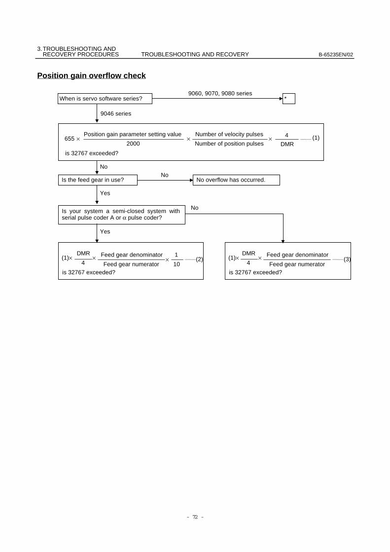
Position gain overflow check
is 32767 exceeded?
× ×655 ×Number of position pulses
Number of velocity pulses(1)
*
No
Yes
No
9060, 9070, 9080 series
9046 series
When is servo software series?
DMR
42000
Position gain parameter setting value
No overflow has occurred. Is the feed gear in use?
Is your system a semi-closed system withserial pulse coder A or α pulse coder?
Yes
is 32767 exceeded?
×(1)×4
DMR× (2)
Feed gear numerator
Feed gear denominator
10
1
is 32767 exceeded?
×(1)×4
DMR(3)
Feed gear numerator
Feed gear denominator
No
3. TROUBLESHOOTING ANDB-65235EN/02 TROUBLESHOOTING AND RECOVERY RECOVERY PROCEDURES
- 73 -
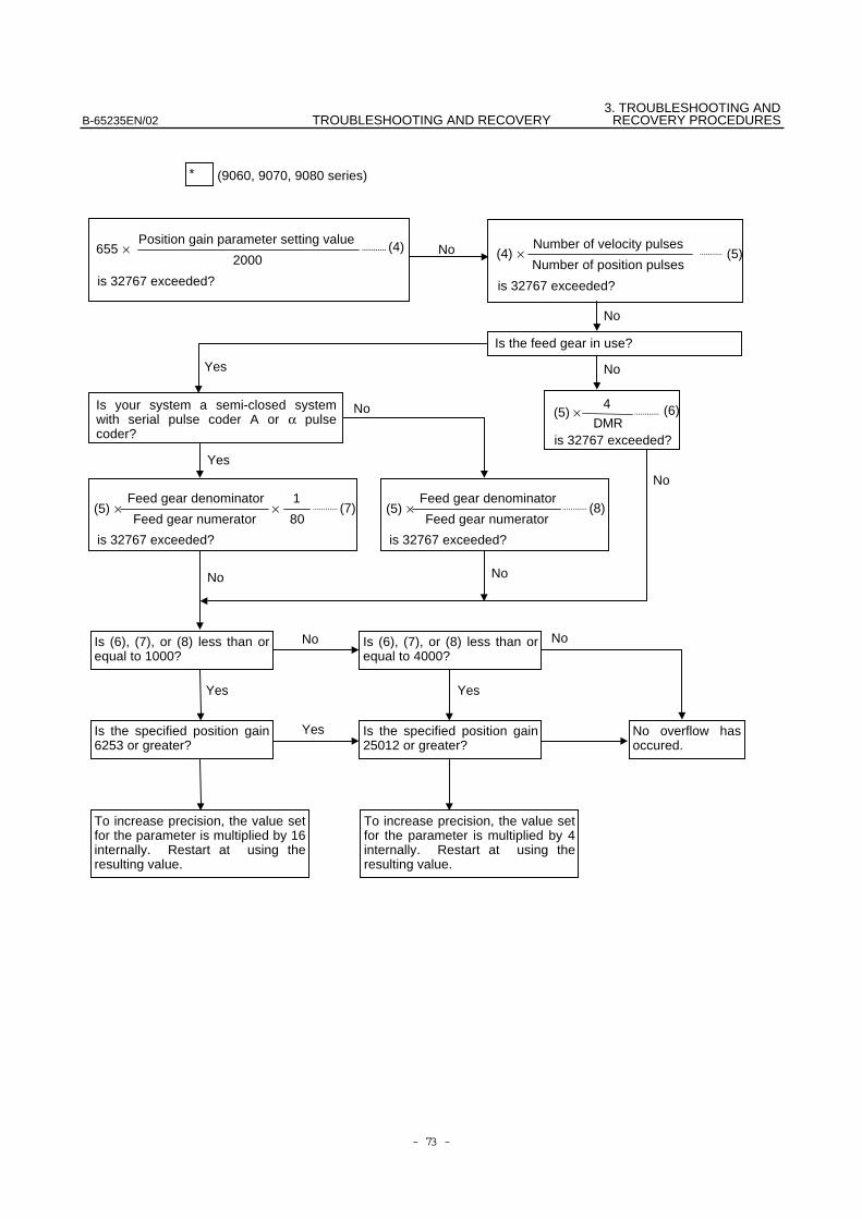
* (9060, 9070, 9080 series)
is 32767 exceeded?
655 × (4)2000
Position gain parameter setting value
is 32767 exceeded?
(4) ×Number of position pulses
Number of velocity pulses(5)
Is the feed gear in use?
No
Is your system a semi-closed systemwith serial pulse coder A or α pulsecoder?
Yes
Yes
is 32767 exceeded?
(5) × (6)DMR
4
No
is 32767 exceeded?
×(5) × (7)Feed gear numerator
Feed gear denominator
80
1
is 32767 exceeded?
(5) × (8)Feed gear numerator
Feed gear denominator
No
No
No
No
No
Is (6), (7), or (8) less than orequal to 4000?
Is (6), (7), or (8) less than orequal to 1000?
YesYes
No
No overflow hasoccured.
Is the specified position gain25012 or greater?
To increase precision, the value setfor the parameter is multiplied by 4internally. Restart at using theresulting value.
To increase precision, the value setfor the parameter is multiplied by 16internally. Restart at using theresulting value.
Is the specified position gain6253 or greater?
Yes
No
3.TROUBLESHOOTING ANDRECOVERY PROCEDURES TROUBLESHOOTING AND RECOVERY B-65235EN/02
- 74 -
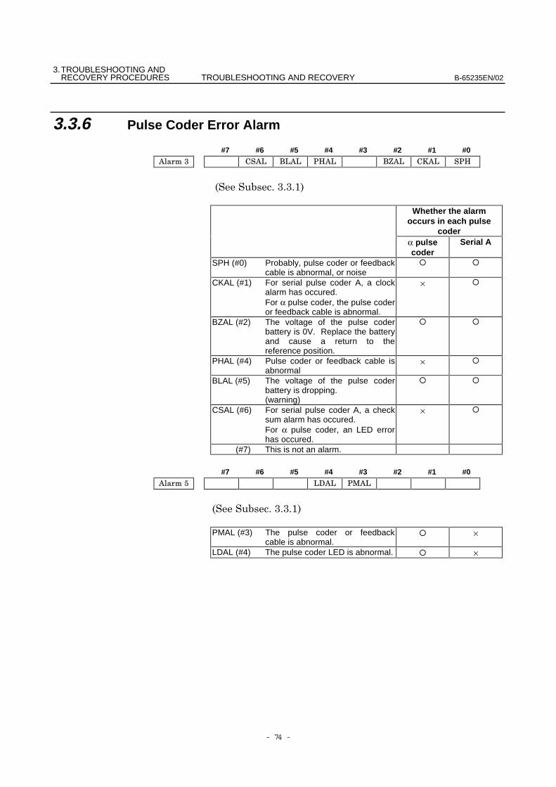
3.3.6 Pulse Coder Error Alarm
#7 #6 #5 #4 #3 #2 #1 #0
##$!
Whether the alarmoccurs in each pulse
coderα pulsecoder
Serial A
SPH (#0) Probably, pulse coder or feedbackcable is abnormal, or noise
CKAL (#1) For serial pulse coder A, a clockalarm has occured.For α pulse coder, the pulse coderor feedback cable is abnormal.
×
BZAL (#2) The voltage of the pulse coderbattery is 0V. Replace the batteryand cause a return to thereference position.
PHAL (#4) Pulse coder or feedback cable isabnormal
×
BLAL (#5) The voltage of the pulse coderbattery is dropping.(warning)
CSAL (#6) For serial pulse coder A, a checksum alarm has occured.For α pulse coder, an LED errorhas occured.
×
(#7) This is not an alarm.
#7 #6 #5 #4 #3 #2 #1 #0
##$!
PMAL (#3) The pulse coder or feedbackcable is abnormal.
×
LDAL (#4) The pulse coder LED is abnormal. ×
3. TROUBLESHOOTING ANDB-65235EN/02 TROUBLESHOOTING AND RECOVERY RECOVERY PROCEDURES
- 75 -
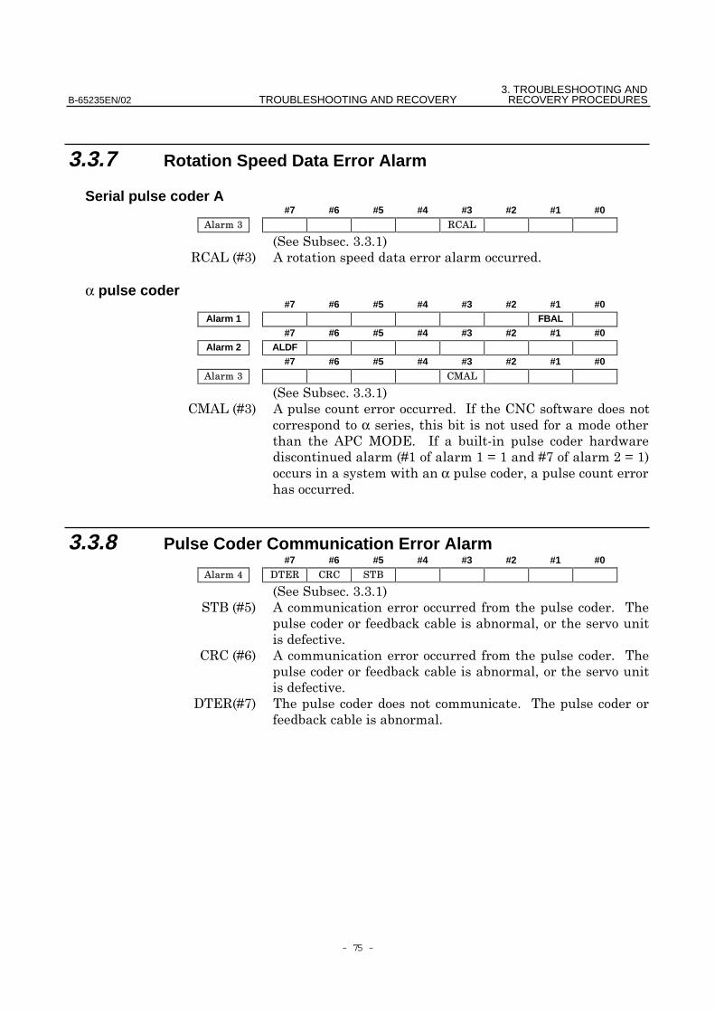
3.3.7 Rotation Speed Data Error Alarm
Serial pulse coder A#7 #6 #5 #4 #3 #2 #1 #0
##$!
. &C9#! &
α pulse coder#7 #6 #5 #4 #3 #2 #1 #0
Alarm 1 FBAL#7 #6 #5 #4 #3 #2 #1 #0
Alarm 2 ALDF#7 #6 #5 #4 #3 #2 #1 #0
##$!
4&C9#! &,
α &8 4G' , 7
9$$:$9(":$!
α
3.3.8 Pulse Coder Communication Error Alarm#7 #6 #5 #4 #3 #2 #1 #0
##$!
;9+! &
. 9*! &
'.9(!
4. REPLACING THE FUSE TROUBLESHOOTING AND RECOVERY B-65235EN/02
- 76 -
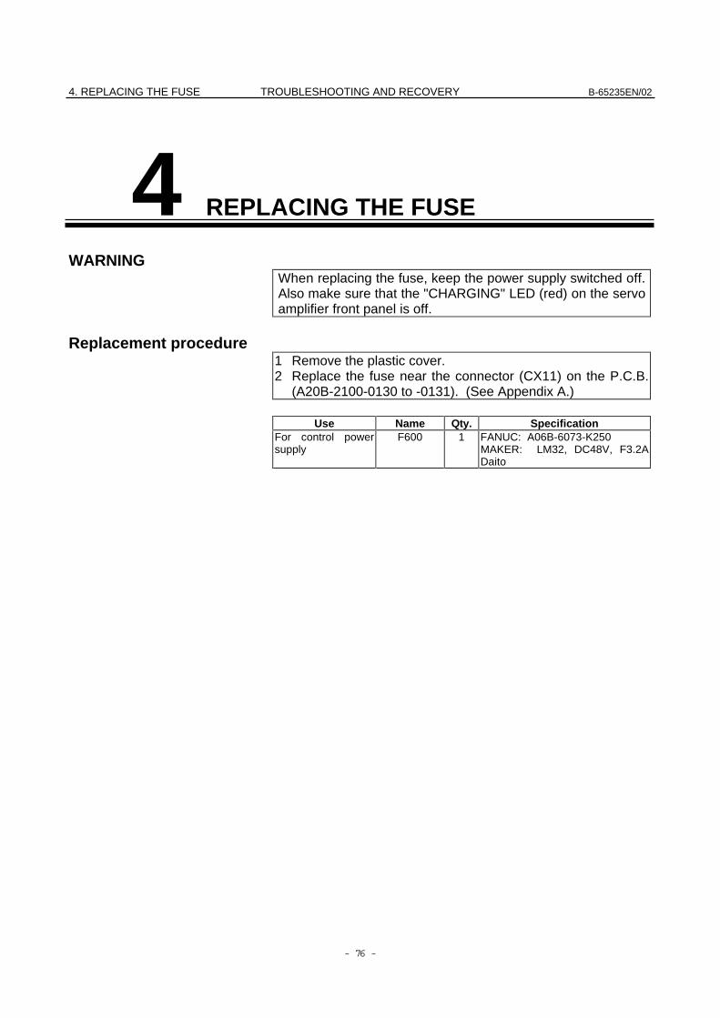
4 REPLACING THE FUSE
WARNINGWhen replacing the fuse, keep the power supply switched off.Also make sure that the "CHARGING" LED (red) on the servoamplifier front panel is off.
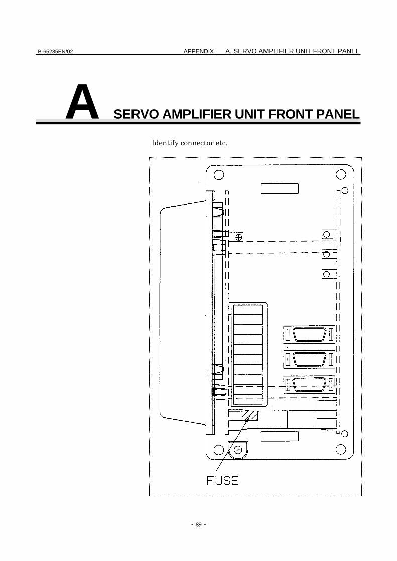
Replacement procedure1 Remove the plastic cover.2 Replace the fuse near the connector (CX11) on the P.C.B.
(A20B-2100-0130 to -0131). (See Appendix A.)
Use Name Qty. SpecificationFor control powersupply
F600 1 FANUC: A06B-6073-K250MAKER: LM32, DC48V, F3.2ADaito
5. CONNECTING THE BATTERY FORB-65235EN/02 TROUBLESHOOTING AND RECOVERY AN ABSOLUTE PULSE CODER
- 77 -
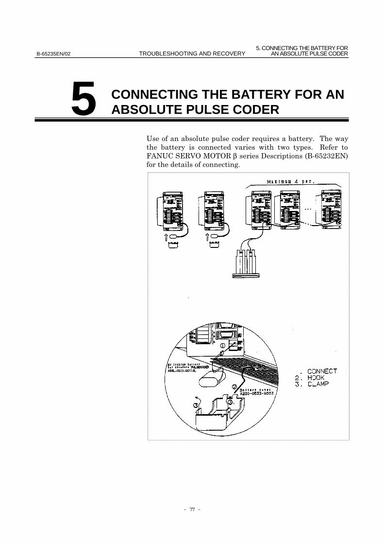
5
!"!!β# $%&'()*)+,
CONNECTING THE BATTERY FOR ANABSOLUTE PULSE CODER

- 78 -
III. MOTOR MAINTENANCE
B-65235EN/02 MOTOR MAINTENANCE 1. AC SERVO MOTOR MAINTENANCE
- 79 -
1 AC SERVO MOTOR MAINTENANCE
β
1. AC SERVO MOTOR MAINTENANCE MOTOR MAINTENANCE B-65235EN/02
- 80 -
1.1 RECEIVING AND KEEPING AC SERVO MOTORS
β
! "
! #
!
!
!
!$% &'%°C
β
! ("
!
!
! "
) *+#,
B-65235EN/02 MOTOR MAINTENANCE 1. AC SERVO MOTOR MAINTENANCE
- 81 -
1.2 DAILY INSPECTION OF AC SERVO MOTORS
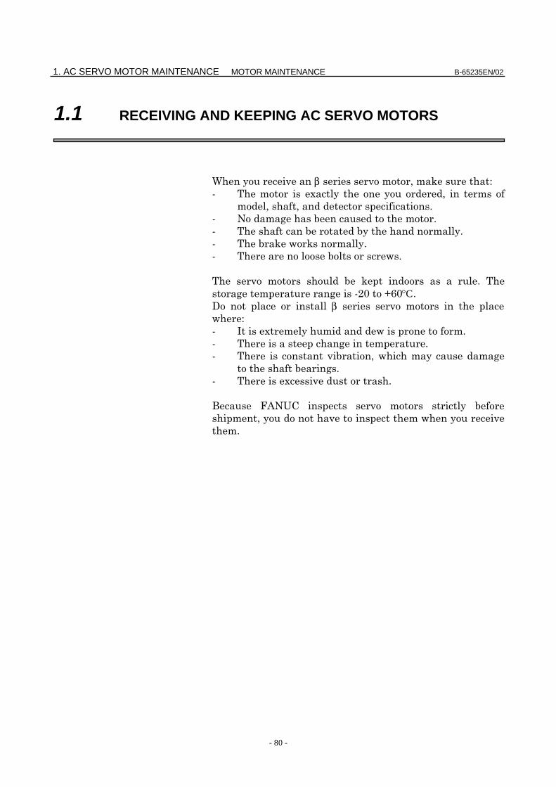
) -
. β
-/. 0
– #
– 1
– +
( *+#,
-$.
- .
- .
(
(
*+#,
1. AC SERVO MOTOR MAINTENANCE MOTOR MAINTENANCE B-65235EN/02
- 82 -
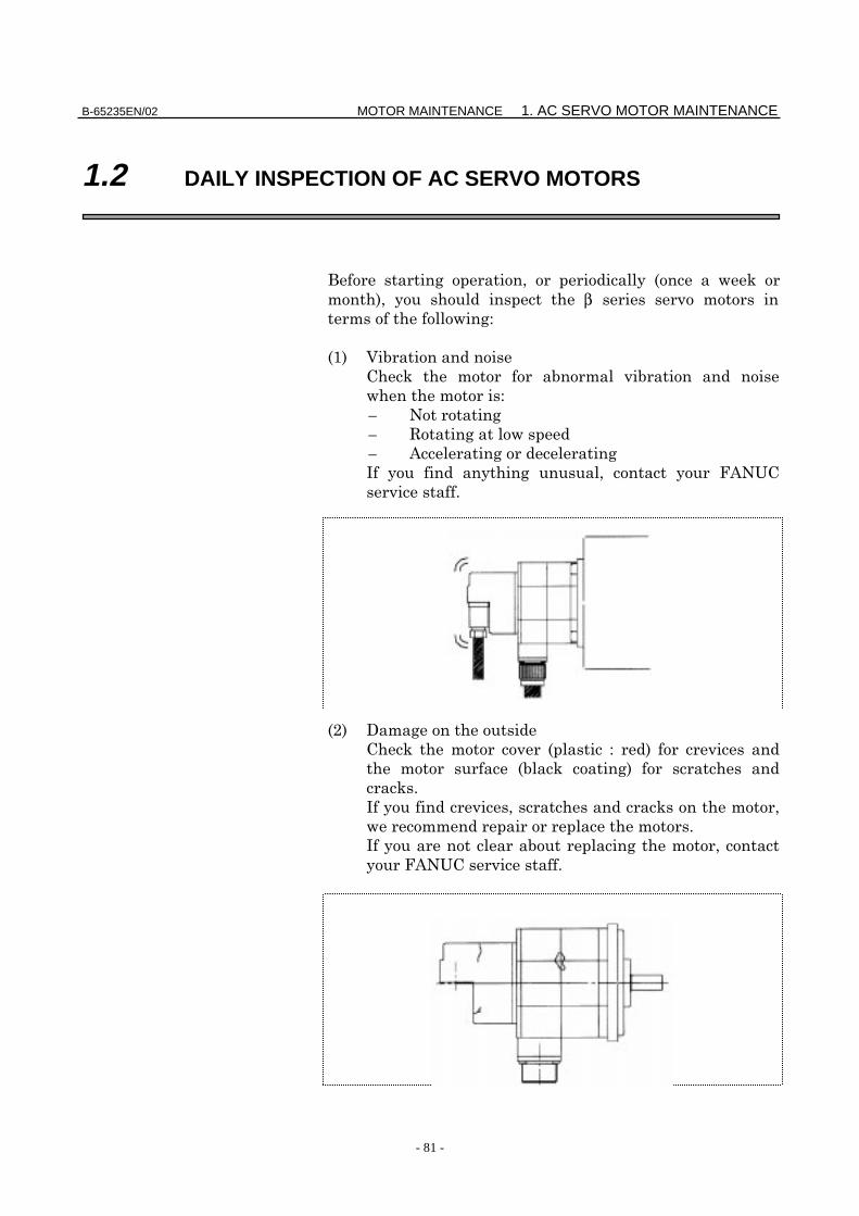
-2. 3
4
( 5
5
- .
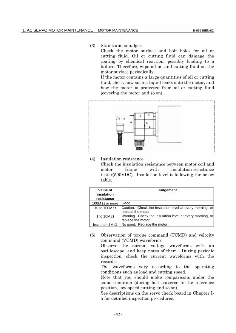
-6. (
!
-7%%0.(
Value ofinsulationresistance
Judgement
100M Ω or more Good.10 to 100M Ω Caution. Check the insulation level at every morning, or
replace the motor.1 to 10M Ω Warning. Check the insulation level at every morning, or
replace the motor.less than 1M Ω No good. Replace the motor.
-7. 4 5 -8.
-08.
4
#
-
! .
3 (!
7
B-65235EN/02 MOTOR MAINTENANCE 1. AC SERVO MOTOR MAINTENANCE
- 83 -
-'. 4
+
WARNINGTemperature on the motor surface can exceed 80°C undersome conditions. Therefore, never touch the motor duringoperation.
1. AC SERVO MOTOR MAINTENANCE MOTOR MAINTENANCE B-65235EN/02
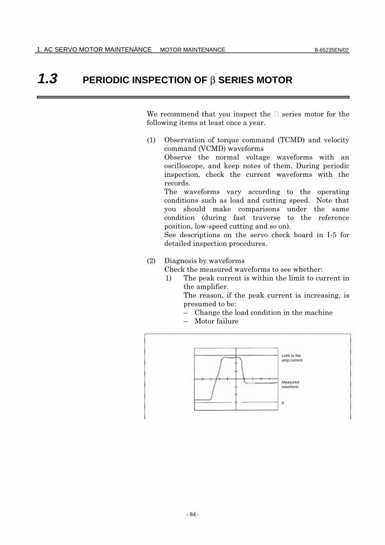
- 84 -
1.3 PERIODIC INSPECTION OF β SERIES MOTOR
9
-/. 4 5 -8.
-08.
4
#
-
! .
3 (!7
-$.
/.
:
: 8
0
Measuredwaveform
Limit to theamp.current
B-65235EN/02 MOTOR MAINTENANCE 1. AC SERVO MOTOR MAINTENANCE
- 85 -
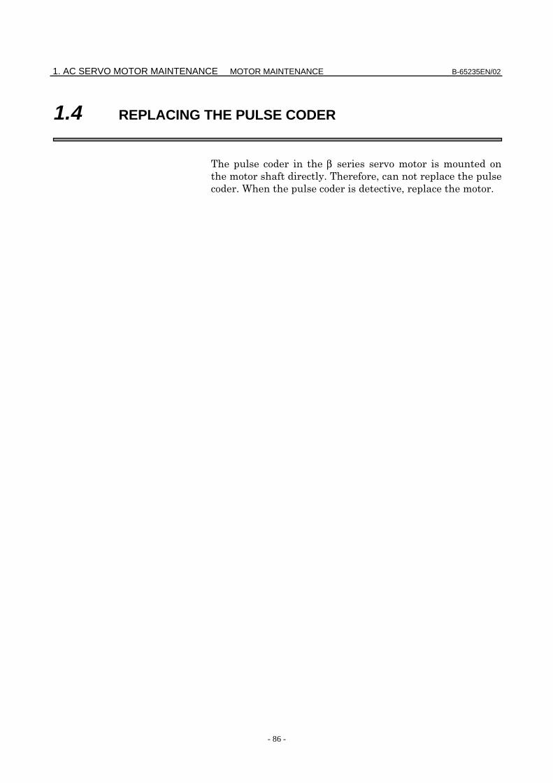
:
: 1
β1/3000, β2/3000, β0.5/3000, α1/3000, α2/2000,α2/3000
12Apeak
β3/3000, β6/2000, αC3/2000, αC6/2000, αC12/2000 20Apeak
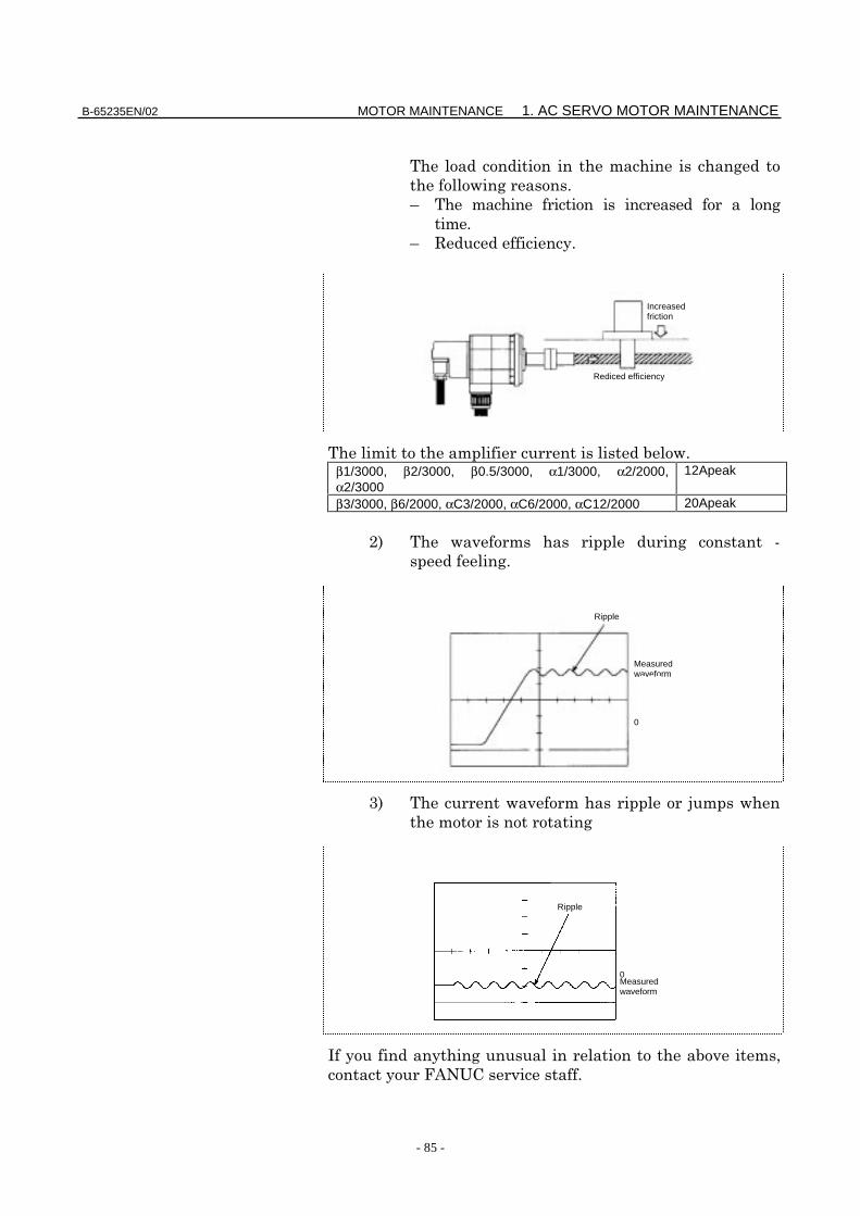
$. !
2. ;
(
*+#,
Rediced efficiency
Increasedfriction
0
Measuredwaveform
Ripple
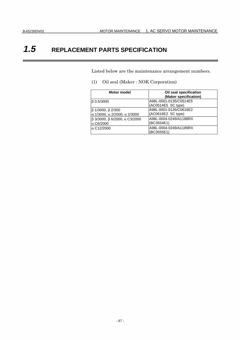
0Measuredwaveform
Ripple
1. AC SERVO MOTOR MAINTENANCE MOTOR MAINTENANCE B-65235EN/02
- 86 -
1.4 REPLACING THE PULSE CODER
β
B-65235EN/02 MOTOR MAINTENANCE 1. AC SERVO MOTOR MAINTENANCE
- 87 -
1.5 REPLACEMENT PARTS SPECIFICATION
<
-/. 4-8 #4= .
Motor model Oil seal specification(Maker specification)
β 0.5/3000 A98L-0001-0135/C0514E5(AC0514E5 SC type)
β 1/3000, β 2/300α 1/3000, α 2/2000, α 2/3000
A98L-0001-0135/C0616E2(AC0616E2 SC type)
β 3/3000, β 6/2000, α C3/2000α C6/2000
A98L-0004-0249/A1188RX(BC3554E1)
α C12/2000 A98L-0004-0249/A1189RX(BC3555E1)

- 88 -
APPENDIX
B-65235EN/02 APPENDIX A. SERVO AMPLIFIER UNIT FRONT PANEL
- 89 -
A SERVO AMPLIFIER UNIT FRONT PANEL

B. MOTOR PARAMETER LIST APPENDIX B-65235EN/02
- 90 -
B MOTOR PARAMETER LIST

B-65235EN/02 APPENDIX B. MOTOR PARAMETER LIST
- 91 -
9041, 9046 series
Motor model 2-0SP/3 1-0SP 1-0SP/3 α 0.5 α E1/3 α E2/3 α E3/2 α E6/2Motor specification 371 372 373 0113 0101 0102 0105 0106Motor model α C3 α C6 α C12 α 1/3 α 2/2 α 2/3 β 0.5 β 1/3 β 2/3 β 3/3 β 6/2Motorspecification
0121 0126 0141 0371 0372 0373 0113 0031 0032 0033 0034
Motor type 7 8 9 61 46 62 13 35 36 33 34Symbol Parameter No.
FS0-C8¨03 00001000 00001000 00001000 00001000 00000000 00001000 00001000 00001100 00001100 00001100 000011008¨04 00000110 00000110 00000110 01000110 01000110 01000110 00000110 00000110 00000110 00000110 010001108¨05 00000000 00000000 00000000 00000000 00000000 00000000 00000000 00000100 00000100 00000100 000001008¨06 01000100 01000100 01000000 01000100 00000000 01000100 01000100 01000000 01000000 01000000 010000008¨10 00000010 00000010 00000010 00000000 00000000 00000000 00000010 00000000 00000010 00000010 00000010
PK1 8¨40 1600 1800 3000 390 1170 450 220 359 704 275 990PK2 8¨41 –5059 –6105 –9750 –1053 –2289 –900 –540 –1129 –2401 –1006 –3544PK3 8¨42 –2608 –2641 –2687 –2480 –2485 –2503 –2556 –2564 –2596 –2622 –2632PK1V 8¨43 107 127 251 111 91 128 9 102 62 144 144PK2V 8¨44 –955 –1140 –2245 –997 –812 –1146 –79 –916 –1111 –2587 –2587PK3V 8¨45 0 0 0 0 0 0 0 0 0 0 0PK4V 8¨46 –8235 –8235 –8235 –8235 –8235 –8235 –8235 –8235 –8235 –8235 –8235POA1 8¨47 3974 3329 1690 3806 4674 3311 –4789 4141 3415 1467 1467BLCMP 8¨48 0 0 0 0 0 0 0 0 0 0 0RESERV 8¨49 0 0 0 0 0 0 0 0 0 0 0POK1 8¨50 956 956 956 956 956 956 956 956 956 956 956POK2 8¨51 510 510 510 510 510 510 510 510 510 510 510RESERV 8¨52 3843 3844 3842 0 0 0 3844 0 3072 3840 3072PPMAX 8¨53 21 21 21 21 21 21 21 21 21 21 21PDDP 8¨54 1894 1894 1894 3787 3787 3787 1894 1894 1894 1894 3787PHYST 8¨55 319 319 319 319 319 319 319 319 319 319 319EMFCMP 8¨56 3046 4381 4000 2800 2147 2520 1200 2500 3300 3000 3200PVPA 8¨57 2100 1800 2400 2330 1864 2330 2000 2100 2700 3200 2000PALPH 8¨58 42 48 42 57 46 57 77 71 78 80 57PPBAS 8¨59 5 5 5 5 0 5 5 5 5 5 5TQLIM 8¨60 7282 7282 7282 7282 7282 7282 7282 7282 7282 7282 7282EMFLMT 8¨61 120 120 120 120 120 120 120 120 120 120 120POVC1 8¨62 32686 32637 32412 32623 32627 32519 32585 32617 32540 32456 32456POVC2 8¨63 1030 1636 4446 1811 1766 3112 2288 1884 2850 3897 3897TGALMLV 8¨64 4 4 4 4 4 4 4 4 4 4 4POVCLMT 8¨65 3056 4858 13245 5377 5245 9256 6797 5594 8474 11600 11600PK2VAUX 8¨66 0 0 0 0 0 0 0 0 0 0 0FILTER 8¨67 0 0 0 0 0 0 0 0 0 0 0FALPH 8¨68 0 0 0 0 0 0 0 0 0 0 0VFFLT 8¨69 0 0 0 0 0 0 0 0 0 0 0ERBLM 8¨70 0 0 0 0 0 0 0 0 0 0 0PBLCT 8¨71 0 0 0 0 0 0 0 0 0 0 0RESERV 8¨72 0 0 0 0 0 0 0 0 0 0 0RESERV 8¨73 0 0 0 0 0 0 0 0 0 0 0AALPH 8¨74 4000 4000 0 1680 0 2940 1000 0 0 0 0MODEL 8¨75 0 0 0 0 0 0 0 0 0 0 0WKAC 8¨76 0 0 0 0 0 0 0 0 0 0 0OSCTPL 8¨77 0 0 0 0 0 0 0 0 0 0 0RESERV 8¨78 0 0 0 0 0 0 0 0 0 0 0RESERV 8¨79 0 0 0 0 0 0 0 0 0 0 0RESERV 8¨80 0 0 0 0 0 0 0 0 0 0 0RESERV 8¨81 0 0 0 0 0 0 0 0 0 0 0BLENDL 8¨82 0 0 0 0 0 0 0 0 0 0 0MOFCTL 8¨83 0 0 0 0 0 0 0 0 0 0 0SDMR1 8¨84 0 0 0 0 0 0 0 0 0 0 0SDMR2 8¨85 0 0 0 0 0 0 0 0 0 0 0RTCURR 8¨86 1286 1622 2678 1706 1685 2239 1918 1740 2142 2506 2506TDPLD 8¨87 0 0 0 0 0 0 0 0 0 0 0MCNFB 8¨88 0 0 0 0 0 0 0 0 0 0 0BLBSL 8¨89 0 0 0 0 0 0 0 0 0 0 0ROBSTL 8¨90 0 0 0 0 0 0 0 0 0 0 0ACCSPL 8¨91 0 0 0 0 0 0 0 0 0 0 0ADFF1 8¨92 0 0 0 0 0 0 0 0 0 0 0VMPK3V 8¨93 0 0 0 0 0 0 0 12923 14203 12923 12923BLCMP2 8¨94 0 0 0 0 0 0 0 0 0 0 0AHDRTL 8¨95 0 0 0 0 0 0 0 0 0 0 0RADUSL 8¨96 0 0 0 0 0 0 0 0 0 0 0RESERV 8¨97 0 0 0 0 0 0 0 0 0 0 0DEPVPL 8¨98 12800 17920 17920 50 0 0 5160 80 –2786 –1476 30ONEPSL 8¨99 400 400 400 400 400 400 400 400 400 400 400

B. MOTOR PARAMETER LIST APPENDIX B-65235EN/02
- 92 -
9060, 9064, 9070 series
Motor model 2-0SP/3 1-0SP 1-0SP/3 α 0.5 α E1/3 α E2/3 α E3/2 α E6/2Motor specification 371 372 373 0113 0101 0102 0105 0106Motor model α C3 α C6 α C12 α 1/3 α 2/2 α 2/3 β 0.5 β 1/3 β 2/3 β 3/3 β 6/2Motorspecification
0121 0126 0141 0371 0372 0373 0113 0031 0032 0033 0034
Motor type 7 8 9 61 46 62 13 35 36 33 34Symbol Parameter No.
FS16,PM,etc
2003 00001000 00001000 00001000 00001000 00000000 00001000 00001000 00001100 00001100 00001100 00001100
2004 00000110 00000110 00000110 01000110 01000110 01000110 00000110 00000110 00000110 00000110 01000110
2005 00000000 00000000 00000000 00000000 00000000 00000000 00000000 00000100 00000100 00000100 00000100
2006 01000100 01000100 01000000 01000100 00000000 01000100 01000100 01000000 01000000 01000000 01000000
2011 00100000 00100000 00100000 00000000 00000000 00000000 00100000 00000000 00100000 00100000 00100000
PK1 2040 1600 1800 3000 390 1170 450 220 359 704 275 990
PK2 2041 –5059 –6105 –9750 –1053 –2289 –900 –540 –1129 –2401 –1006 –3544PK3 2042 –2608 –2641 –2687 –2480 –2485 -2503 –2556 –2564 –2596 –2622 –2632PK1V 2043 107 127 251 111 91 128 9 102 62 144 144
PK2V 2044 –955 –1140 –2245 –997 –812 –1146 –79 –916 –1111 –2587 –2587PK3V 2045 0 0 0 0 0 0 0 0 0 0 0
PK4V 2046 –8235 –8235 –8235 –8235 –8235 –8235 –8235 –8235 –8235 –8235 –8235POA1 2047 3974 3329 1690 3806 4674 3311 -4789 4141 3415 1467 1467
BLCMP 2048 0 0 0 0 0 0 0 0 0 0 0
RESERV 2049 0 0 0 0 0 0 0 0 0 0 0
POK1 2050 956 956 956 956 956 956 956 956 956 956 956
POK2 2051 510 510 510 510 510 510 510 510 510 510 510
RESERV 2052 0 0 0 0 0 0 0 0 0 0 0
PPMAX 2053 21 21 21 21 21 21 21 21 21 21 21
PDDP 2054 1894 1894 1894 3787 3787 3787 1894 1894 1894 1894 3787
PHYST 2055 319 319 319 319 319 319 319 319 319 319 319
EMFCMP 2056 3046 4381 4000 2800 2147 2520 1200 2500 3300 3000 3200
PVPA 2057 2100 1800 2400 2330 1864 2330 2000 2100 2700 3200 2000
PALPH 2058 42 48 42 57 46 57 77 71 78 80 57
PPBAS 2059 5 5 5 5 0 5 5 5 5 5 5
TQLIM 2060 7282 7282 7282 7282 7282 7282 7282 7282 7282 7282 7282
EMFLMT 2061 120 120 120 120 120 120 120 120 120 120 120
POVC1 2062 32686 32637 32412 32623 32627 32519 32585 32617 32540 32456 32456
POVC2 2063 1030 1636 4446 1811 1766 3112 2288 1884 2850 3897 3897
TGALMLV 2064 4 4 4 4 4 4 4 4 4 4 4
POVCLMT 2065 3056 4858 13245 5377 5245 9256 6797 5594 8474 11600 11600
PK2VAUX 2066 0 0 0 0 0 0 0 0 0 0 0
FILTER 2067 0 0 0 0 0 0 0 0 0 0 0
FALPH 2068 0 0 0 0 0 0 0 0 0 0 0
VFFLT 2069 0 0 0 0 0 0 0 0 0 0 0
ERBLM 2070 0 0 0 0 0 0 0 0 0 0 0
PBLCT 2071 0 0 0 0 0 0 0 0 0 0 0
RESERV 2072 0 0 0 0 0 0 0 0 0 0 0
RESERV 2073 0 0 0 0 0 0 0 0 0 0 0
AALPH 2074 16288 20384 8192 1680 0 2940 17384 0 0 0 0
MODEL 2075 0 0 0 0 0 0 0 0 0 0 0
WKAC 2076 0 0 0 0 0 0 0 0 0 0 0
OSCTPL 2077 0 0 0 0 0 0 0 0 0 0 0
RESERV 2078 0 0 0 0 0 0 0 0 0 0 0
RESERV 2079 0 0 0 0 0 0 0 0 0 0 0
RESERV 2080 0 0 0 0 0 0 0 0 0 0 0
RESERV 2081 0 0 0 0 0 0 0 0 0 0 0
BLENDL 2082 0 0 0 0 0 0 0 0 0 0 0
MOFCTL 2083 0 0 0 0 0 0 0 0 0 0 0
SDMR1 2084 0 0 0 0 0 0 0 0 0 0 0
SDMR2 2085 0 0 0 0 0 0 0 0 0 0 0
RTCURR 2086 1286 1622 2678 1706 1685 2239 1918 1740 2142 2506 2506
TDPLD 2087 0 0 0 0 0 0 0 0 0 0 0
MCNFB 2088 0 0 0 0 0 0 0 0 0 0 0
BLBSL 2089 0 0 0 0 0 0 0 0 0 0 0
ROBSTL 2090 0 0 0 0 0 0 0 0 0 0 0
ACCSPL 2091 0 0 0 0 0 0 0 0 0 0 0
ADFF1 2092 0 0 0 0 0 0 0 0 0 0 0
VMPK3V 2093 0 0 0 0 0 0 0 0 0 0 0
BLCMP2 2094 0 0 0 0 0 0 0 0 0 0 0
AHDRTL 2095 0 0 0 0 0 0 0 0 0 0 0
RADUSL 2096 0 0 0 0 0 0 0 0 0 0 0
RESERV 2097 0 0 0 0 0 0 0 0 0 0 0
DEPVPL 2098 12800 17920 17920 50 0 0 5160 80 –2786 –1476 30
ONEPSL 2099 400 400 400 400 400 400 400 400 400 400 400
INPA1 2100 0 0 0 0 0 0 0 0 0 0 0
INPA2 2101 0 0 0 0 0 0 0 0 0 0 0
DBLIM 2102 15000 15000 15000 0 0 0 15000 0 12000 15000 12000
ABVOF 2103 0 0 0 0 0 0 0 0 0 0 0
ABTSH 2104 0 0 0 0 0 0 0 0 0 0 0
TRQCST 2105 205 326 395 51 104 74 29 51 83 107 215LP24PA 2106 0 0 0 0 0 0 0 12923 14203 12923 12923
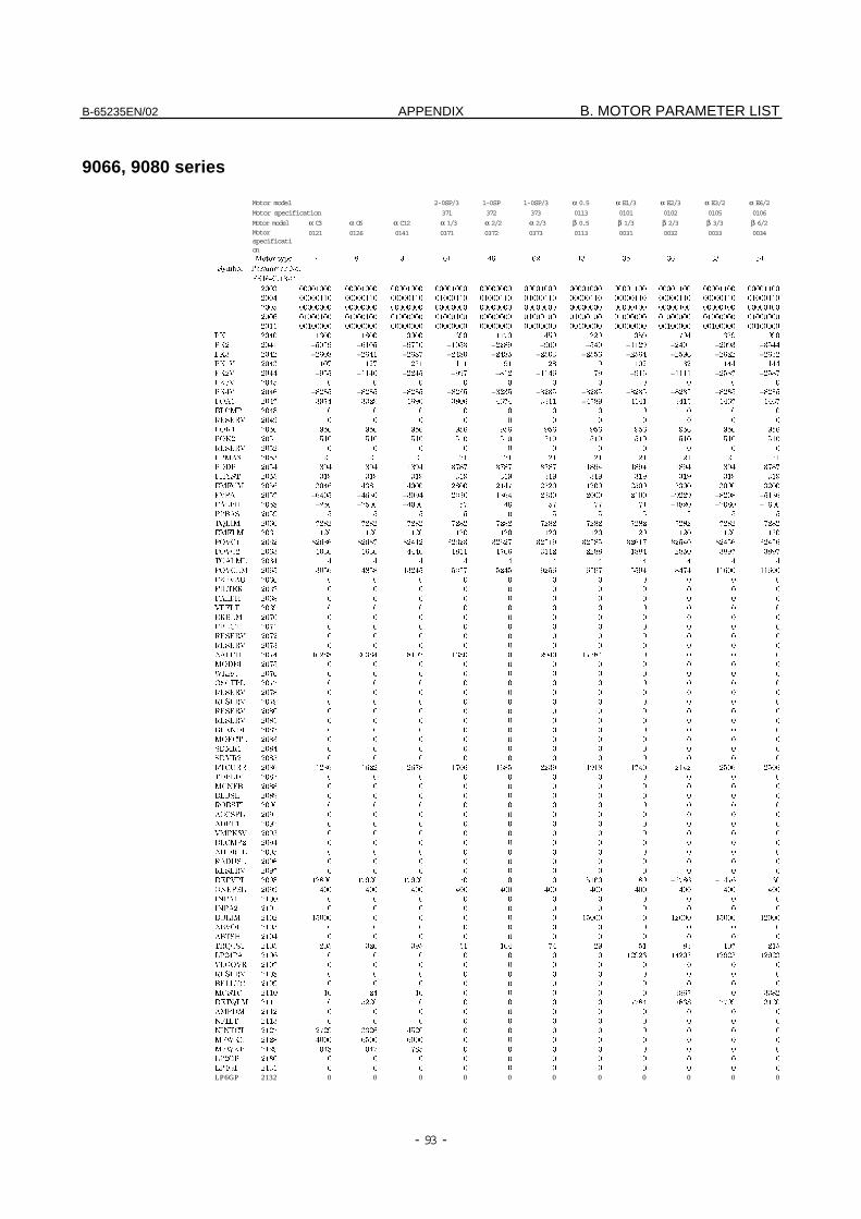
B-65235EN/02 APPENDIX B. MOTOR PARAMETER LIST
- 93 -
9066, 9080 series
Motor model 2-0SP/3 1-0SP 1-0SP/3 α 0.5 α E1/3 α E2/3 α E3/2 α E6/2Motor specification 371 372 373 0113 0101 0102 0105 0106
Motor model α C3 α C6 α C12 α 1/3 α 2/2 α 2/3 β 0.5 β 1/3 β 2/3 β 3/3 β 6/2Motorspecification
0121 0126 0141 0371 0372 0373 0113 0031 0032 0033 0034
Motor type 7 8 9 61 46 62 13 35 36 33 34
Symbol Parameter No.
FS16-C,18-C
2003 00001000 00001000 00001000 00001000 00000000 00001000 00001000 00001100 00001100 00001100 00001100
2004 00000110 00000110 00000110 01000110 01000110 01000110 00000110 00000110 00000110 00000110 01000110
2005 00000000 00000000 00000000 00000000 00000000 00000000 00000000 00000100 00000100 00000100 00000100
2006 01000100 01000100 01000000 01000100 00000000 01000100 01000100 01000000 01000000 01000000 01000000
2011 00100000 00000000 00000000 00000000 00000000 00000000 00100000 00000000 00100000 00100000 00100000
PK1 2040 1600 1800 3000 390 1170 450 220 359 704 629 990
PK2 2041 –5059 –6105 –9750 –1053 –2289 –900 –540 –1129 –2401 –2093 –3544PK3 2042 –2608 –2641 –2687 –2480 –2485 –2503 –2556 –2564 –2596 –2622 –2632PK1V 2043 107 127 251 111 91 128 9 102 62 144 144
PK2V 2044 –955 –1140 –2245 –997 –812 –1146 -79 –916 –1111 –2587 –2587PK3V 2045 0 0 0 0 0 0 0 0 0 0 0
PK4V 2046 –8235 –8235 –8235 –8235 –8235 –8235 –8235 –8235 –8235 –8235 –8235POA1 2047 3974 3329 1690 3806 4674 3311 –4789 4141 3415 1467 1467
BLCMP 2048 0 0 0 0 0 0 0 0 0 0 0
RESERV 2049 0 0 0 0 0 0 0 0 0 0 0
POK1 2050 956 956 956 956 956 956 956 956 956 956 956
POK2 2051 510 510 510 510 510 510 510 510 510 510 510
RESERV 2052 0 0 0 0 0 0 0 0 0 0 0
PPMAX 2053 21 21 21 21 21 21 21 21 21 21 21
PDDP 2054 1894 1894 1894 3787 3787 3787 1894 1894 1894 1894 3787
PHYST 2055 319 319 319 319 319 319 319 319 319 319 319
EMFCM 2056 3046 4381 4000 2800 2147 2520 1200 2500 3300 3000 3200
PVPA 2057 –6405 –4630 –3094 2330 1864 2330 2000 2100 –9229 –8208 –5136PALPH 2058 –250 –2500 –4000 57 46 57 77 71 –1820 –2080 –1600PPBAS 2059 5 5 5 5 0 5 5 5 5 5 5
TQLIM 2060 7282 7282 7282 7282 7282 7282 7282 7282 7282 7282 7282
EMFLM 2061 120 120 120 120 120 120 120 120 120 120 120
POVC1 2062 32686 32637 32412 32623 32627 32519 32585 32617 32540 32456 32456
POVC2 2063 1030 1636 4446 1811 1766 3112 2288 1884 2850 3897 3897
TGALML 2064 4 4 4 4 4 4 4 4 4 4 4
POVCLM 2065 3056 4858 13245 5377 5245 9256 6797 5594 8474 11600 11600
PK2VAU 2066 0 0 0 0 0 0 0 0 0 0 0
FILTER 2067 0 0 0 0 0 0 0 0 0 0 0
FALPH 2068 0 0 0 0 0 0 0 0 0 0 0
VFFLT 2069 0 0 0 0 0 0 0 0 0 0 0
ERBLM 2070 0 0 0 0 0 0 0 0 0 0 0
PBLCT 2071 0 0 0 0 0 0 0 0 0 0 0
RESERV 2072 0 0 0 0 0 0 0 0 0 0 0
RESERV 2073 0 0 0 0 0 0 0 0 0 0 0
AALPH 2074 16288 20384 8192 1680 0 2940 17384 0 0 0 0
MODEL 2075 0 0 0 0 0 0 0 0 0 0 0
WKAC 2076 0 0 0 0 0 0 0 0 0 0 0
OSCTPL 2077 0 0 0 0 0 0 0 0 0 0 0
RESERV 2078 0 0 0 0 0 0 0 0 0 0 0
RESERV 2079 0 0 0 0 0 0 0 0 0 0 0
RESERV 2080 0 0 0 0 0 0 0 0 0 0 0
RESERV 2081 0 0 0 0 0 0 0 0 0 0 0
BLENDL 2082 0 0 0 0 0 0 0 0 0 0 0
MOFCTL 2083 0 0 0 0 0 0 0 0 0 0 0
SDMR1 2084 0 0 0 0 0 0 0 0 0 0 0
SDMR2 2085 0 0 0 0 0 0 0 0 0 0 0
RTCURR 2086 1286 1622 2678 1706 1685 2239 1918 1740 2142 2506 2506
TDPLD 2087 0 0 0 0 0 0 0 0 0 0 0
MCNFB 2088 0 0 0 0 0 0 0 0 0 0 0
BLBSL 2089 0 0 0 0 0 0 0 0 0 0 0
ROBSTL 2090 0 0 0 0 0 0 0 0 0 0 0
ACCSPL 2091 0 0 0 0 0 0 0 0 0 0 0
ADFF1 2092 0 0 0 0 0 0 0 0 0 0 0
VMPK3V 2093 0 0 0 0 0 0 0 0 0 0 0
BLCMP2 2094 0 0 0 0 0 0 0 0 0 0 0
AHDRTL 2095 0 0 0 0 0 0 0 0 0 0 0
RADUSL 2096 0 0 0 0 0 0 0 0 0 0 0
RESERV 2097 0 0 0 0 0 0 0 0 0 0 0
DEPVPL 2098 12800 17920 17920 50 0 0 5160 80 –2786 –1476 30
ONEPSL 2099 400 400 400 400 400 400 400 400 400 400 400
INPA1 2100 0 0 0 0 0 0 0 0 0 0 0
INPA2 2101 0 0 0 0 0 0 0 0 0 0 0
DBLIM 2102 15000 0 0 0 0 0 15000 0 12000 15000 12000
ABVOF 2103 0 0 0 0 0 0 0 0 0 0 0
ABTSH 2104 0 0 0 0 0 0 0 0 0 0 0
TRQCST 2105 205 326 395 51 104 74 29 51 83 107 215
LP24PA 2106 0 0 0 0 0 0 0 12923 14203 12923 12923
VLGOVR 2107 0 0 0 0 0 0 0 0 0 0 0
RESERV 2108 0 0 0 0 0 0 0 0 0 0 0
BELLTC 2109 0 0 0 0 0 0 0 0 0 0 0
MGSTC 2110 16 24 16 0 0 0 0 0 3867 0 3382
DETQLM 2111 0 5220 0 0 0 0 0 7784 7868 7799 3120
AMRDM 2112 0 0 0 0 0 0 0 0 0 0 0
NFILT 2113 0 0 0 0 0 0 0 0 0 0 0
NINTCT 2127 2729 3326 4520 0 0 0 0 0 0 0 0
MFWKC 2128 4000 6500 6000 0 0 0 0 0 0 0 0
MFWKB 2129 1048 1047 785 0 0 0 0 0 0 0 0
LP2GP 2130 0 0 0 0 0 0 0 0 0 0 0
LP4GP 2131 0 0 0 0 0 0 0 0 0 0 0
LP6GP 2132 0 0 0 0 0 0 0 0 0 0 0
C. FSSB APPENDIX B-65235EN/02
- 94 -
C FSSB
B-65235EN/02 APPENDIX C. FSSB
- 95 -
C.1 GENERAL
β
!
β " "
# !
$ β "
"$!
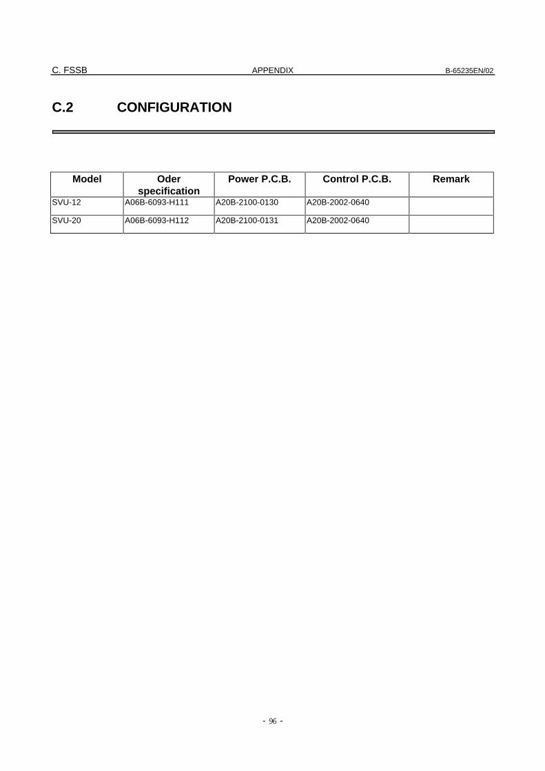
C. FSSB APPENDIX B-65235EN/02
- 96 -
C.2 CONFIGURATION
Model Oderspecification
Power P.C.B. Control P.C.B. Remark
SVU-12 A06B-6093-H111 A20B-2100-0130 A20B-2002-0640
SVU-20 A06B-6093-H112 A20B-2100-0131 A20B-2002-0640
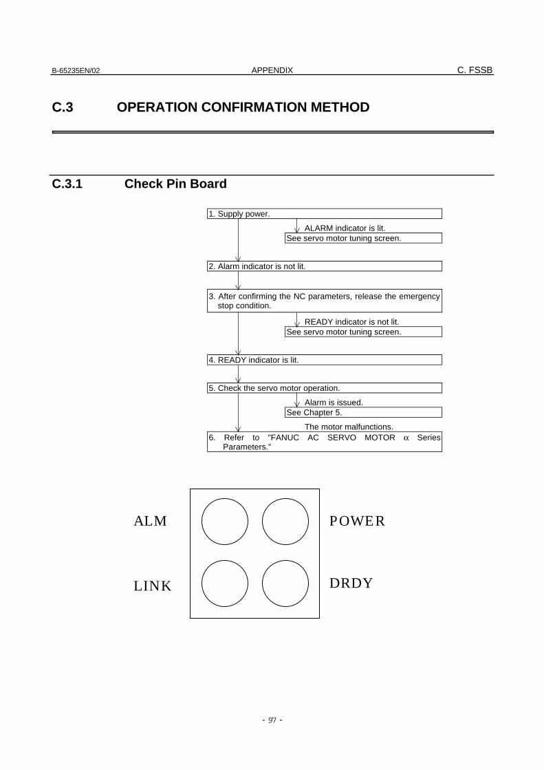
B-65235EN/02 APPENDIX C. FSSB
- 97 -
C.3 OPERATION CONFIRMATION METHOD
C.3.1 Check Pin Board
1. Supply power.
ALARM indicator is lit.See servo motor tuning screen.
2. Alarm indicator is not lit.
3. After confirming the NC parameters, release the emergencystop condition.
READY indicator is not lit.See servo motor tuning screen.
4. READY indicator is lit.
5. Check the servo motor operation.
Alarm is issued.See Chapter 5.
The motor malfunctions.6. Refer to "FANUC AC SERVO MOTOR α Series
Parameters."
DRDYLINK
ALM POWER
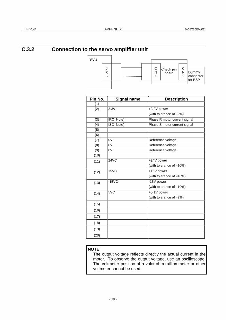
C. FSSB APPENDIX B-65235EN/02
- 98 -
C.3.2 Connection to the servo amplifier unit
Pin No. Signal name Description(1)
(2) 3.3V +3.3V power
(with tolerance of –2%)
(3) IRC Note) Phase R motor current signal
(4) ISC Note) Phase S motor current signal
(5)
(6)
(7) 0V Reference voltage
(8) 0V Reference voltage
(9) 0V Reference voltage
(10)
(11) 24VC +24V power
(with tolerance of –10%)
(12) 15VC +15V power
(with tolerance of –10%)
(13) -15VC -15V power
(with tolerance of –10%)
(14) 5VC +5.1V power
(with tolerance of –2%)
(15)
(16)
(17)
(18)
(19)
(20)
NOTEThe output voltage reflects directly the actual current in themotor. To observe the output voltage, use an oscilloscope.The voltmeter position of a volot-ohm-milliammeter or othervoltmeter cannot be used.
Dummyconnectorfor ESP
CN2
CN1
JX5
Check pinboard
SVU
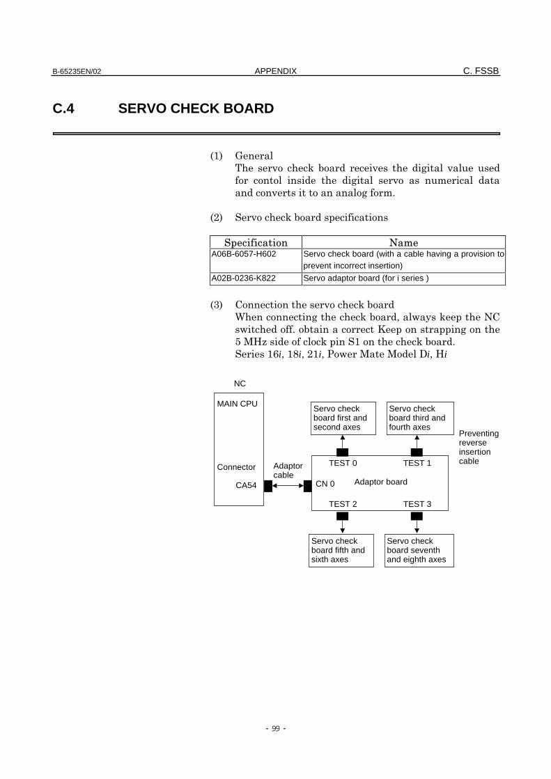
B-65235EN/02 APPENDIX C. FSSB
- 99 -
C.4 SERVO CHECK BOARD
%&' (
) * $ ) + )
+ ) "
)+ "!
%,' )*$
A06B-6057-H602 Servo check board (with a cable having a provision to
prevent incorrect insertion)
A02B-0236-K822 Servo adaptor board (for i series )
%-' .)*$
/+*$01*.
!$2+
345 *&*$!
&6i0&7i0,&i08i04i
Adaptor board
TEST 1
CN 0
TEST 0
NC
MAIN CPU
Connector
CA54
Adaptorcable
Preventingreverseinsertioncable
Servo checkboard third andfourth axes
Servo checkboard first andsecond axes
Servo checkboard seventhand eighth axes
Servo checkboard fifth andsixth axes
TEST 3TEST 2
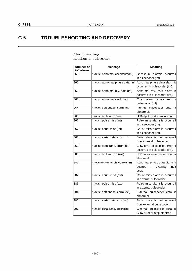
C. FSSB APPENDIX B-65235EN/02
- 100 -
C.5 TROUBLESHOOTING AND RECOVERY
""+
Number ofNC alarms
Message Meaning
360 n axis : abnormal checksum(int) Checksum alarmis occurredin pulsecoder (int).
361 n axis : abnormal phase data (int) Abnormal phase data alarm isoccurred in pulsecoder (int).
362 n axis : abnormal rev. data (int) Abnormal rev. data alarm isoccurred in pulsecoder (int).
363 n axis : abnormal clock (int) Clock alarm is occurred inpulsecoder (int).
364 n axis : soft phase alarm (int) Internal pulsecoder data isabnormal.
365 n axis : broken LED(int) LED of pulsecoder is abnormal.
366 n axis : pulse miss (int) Pulse miss alarm is occurredin pulsecoder (int).
367 n axis : count miss (int) Count miss alarm is occurredin pulsecoder (int).
368 n axis : serial data error (int) Serial data is not receivedfrom internal pulsecoder.
369 n axis : data trans. error (int) CRC error or stop bit error isoccurred in pulsecoder (int).
380 n axis : broken LED (ext) LED in external pulsecoder isabnormal.
381 n axis abnormal phase (ext lin) Abnormal phase data alarm isoccrred in external lineascale.
382 n axis : count miss (ext) Count miss alarm is occurredin external pulsecoder.
383 n axis : pulse miss (ext) Pulse miss alarm is occurredin external pulsecoder.
384 n axis : soft phase alarm (ext) External pulsecoder data isabnormal.
385 n axis : serial data error(ext) Serial data is not receivedfrom external pulsecoder.
386 n axis : data trans. error(ext) External pulsecoder data isCRC error or stop bit error.
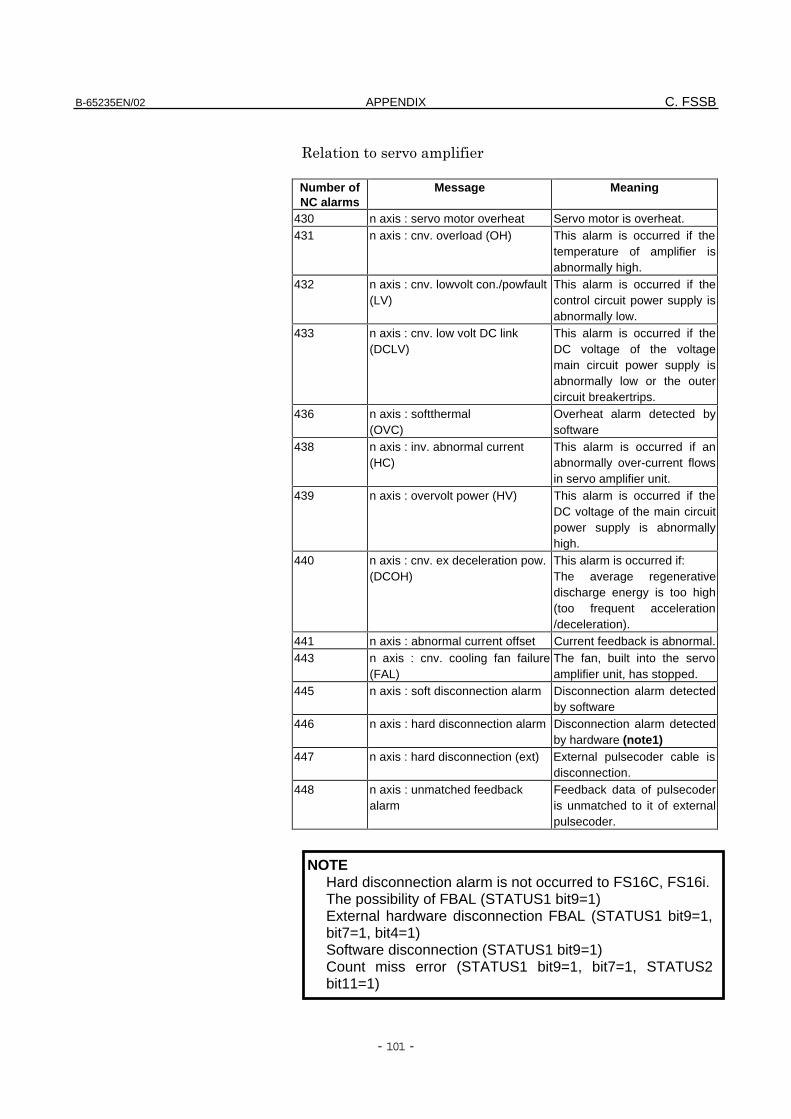
B-65235EN/02 APPENDIX C. FSSB
- 101 -
)"
Number ofNC alarms
Message Meaning
430 n axis : servo motor overheat Servo motor is overheat.431 n axis : cnv. overload (OH) This alarm is occurred if the
temperature of amplifier isabnormally high.
432 n axis : cnv. lowvolt con./powfault(LV)
This alarm is occurred if thecontrol circuit power supply isabnormally low.
433 n axis : cnv. low volt DC link(DCLV)
This alarm is occurred if theDC voltage of the voltagemain circuit power supply isabnormally low or the outercircuit breakertrips.
436 n axis : softthermal(OVC)
Overheat alarm detected bysoftware
438 n axis : inv. abnormal current(HC)
This alarm is occurred if anabnormally over-current flowsin servo amplifier unit.
439 n axis : overvolt power (HV) This alarm is occurred if theDC voltage of the main circuitpower supply is abnormallyhigh.
440 n axis : cnv. ex deceleration pow.(DCOH)
This alarm is occurred if:The average regenerativedischarge energy is too high(too frequent acceleration/deceleration).
441 n axis : abnormal current offset Current feedback is abnormal.443 n axis : cnv. cooling fan failure
(FAL)The fan, built into the servoamplifier unit, has stopped.
445 n axis : soft disconnection alarm Disconnection alarm detectedby software
446 n axis : hard disconnection alarm Disconnection alarm detectedby hardware (note1)
447 n axis : hard disconnection (ext) External pulsecoder cable isdisconnection.
448 n axis : unmatched feedbackalarm
Feedback data of pulsecoderis unmatched to it of externalpulsecoder.
NOTEHard disconnection alarm is not occurred to FS16C, FS16i.The possibility of FBAL (STATUS1 bit9=1)External hardware disconnection FBAL (STATUS1 bit9=1,bit7=1, bit4=1)Software disconnection (STATUS1 bit9=1)Count miss error (STATUS1 bit9=1, bit7=1, STATUS2bit11=1)
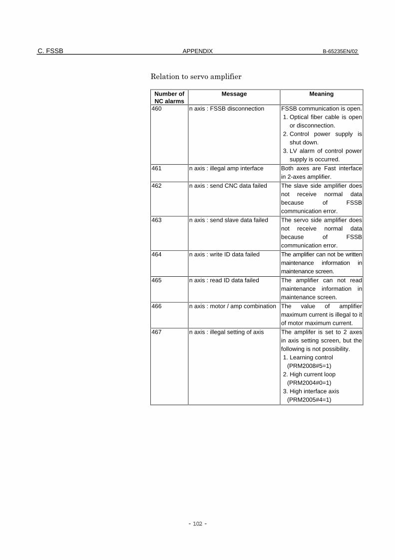
C. FSSB APPENDIX B-65235EN/02
- 102 -
)"
Number ofNC alarms
Message Meaning
460 n axis : FSSB disconnection FSSB communication is open.1. Optical fiber cable is open
or disconnection.2. Control power supply is
shut down.3. LV alarm of control power
supply is occurred.
461 n axis : illegal amp interface Both axes are Fast interfacein 2-axes amplifier.
462 n axis : send CNC data failed The slave side amplifier doesnot receive normal databecause of FSSBcommunication error.
463 n axis : send slave data failed The servo side amplifier doesnot receive normal databecause of FSSBcommunication error.
464 n axis : write ID data failed The amplifier can not be writtenmaintenance information inmaintenance screen.
465 n axis : read ID data failed The amplifier can not readmaintenance information inmaintenance screen.
466 n axis : motor / amp combination The value of amplifiermaximum current is illegal to itof motor maximum current.
467 n axis : illegal setting of axis The amplifer is set to 2 axesin axis setting screen, but thefollowing is not possibility.1. Learning control
(PRM2008#5=1)2. High current loop
(PRM2004#0=1)3. High interface axis
(PRM2005#4=1)
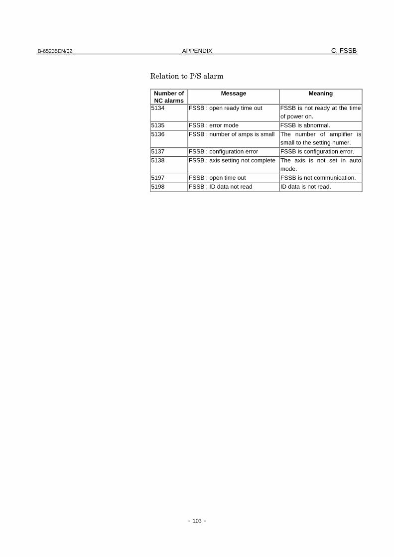
B-65235EN/02 APPENDIX C. FSSB
- 103 -
9"
Number ofNC alarms
Message Meaning
5134 FSSB : open ready time out FSSB is not ready at the timeof power on.
5135 FSSB : error mode FSSB is abnormal.
5136 FSSB : number of amps is small The number of amplifier issmall to the setting numer.
5137 FSSB : configuration error FSSB is configuration error.
5138 FSSB : axis setting not complete The axis is not set in automode.
5197 FSSB : open time out FSSB is not communication.
5198 FSSB : ID data not read ID data is not read.
C. FSSB APPENDIX B-65235EN/02
- 104 -
C.6 i SERIES INITIAL SETTING OF PARAMETER
C.6.1 Outline
1" + 0 ) +
" #+"!
% " # +
'
!&:,-
!&;:3
!&;&: &;&;
!&;-60&;-<
"0-1 !
&! +&
1 + " !&:,-0 #
+" +!=
)"!&;:30&;&:~&;&;0&;-60&;-<!"
1!
,! "+
1 + + 0 1
" # "0 ..
" !&;:30 &;&: &;&;0 &;-60 &;-<
"1!
-! +,
" !&;:30 &;&: &;&;0
&;-60&;-<$1 1"+
"!

B-65235EN/02 APPENDIX C. FSSB
- 105 -
C.6.2 Slave
1" + 0 ) "
..$1 $!/
) " >)?!
# " ) #
" )!
)"&0,0-!!!0&: " ..
..!
X
Y
Z
A
B
C
1
2
3
4
5
6
NOTE) M1/M2: Pulse Module 1st/2nd
8
7
6
5
4
3
2
1
Programaxis nameNo. 1020
CNC
SlaveNo.
Controlaxis No.
2 axes
2 axes
M2
M1
1 axis AMP
1 axis AMP
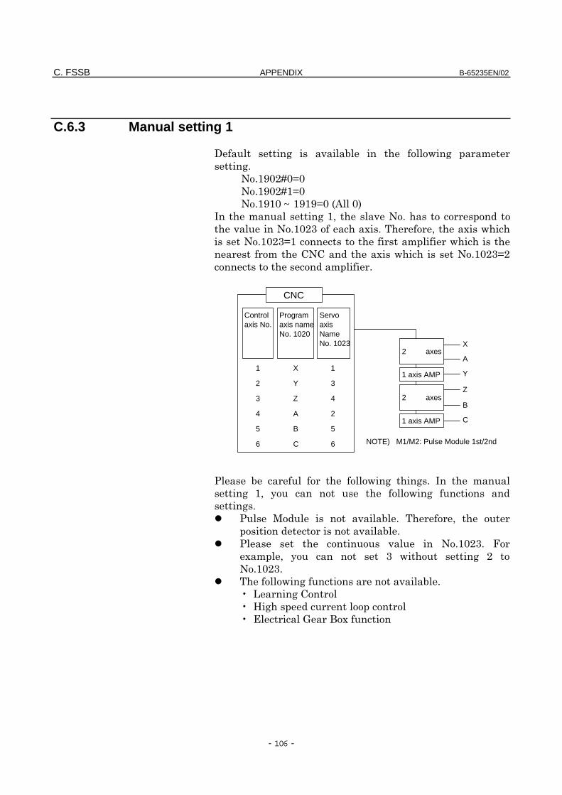
C. FSSB APPENDIX B-65235EN/02
- 106 -
C.6.3 Manual setting 1
8 + )$ + "
+!
!&;:,@:A:
!&;:,@&A:
!&;&:~ &;&;A:% :'
"+&0)!
)!&:,- #! 0#
!&:,-A& "
"..# !&:,-A,
" !
$ + +! "
+ &0 1 +
+!
)$! 0
)$!
) !&:,-!
#"0 1 - + ,
!&:,-!
+ )$!
B+.
B4+
B(#
X
Y
Z
A
B
C
1
3
4
2
5
6
1
2
3
4
5
6 NOTE) M1/M2: Pulse Module 1st/2nd
C
B
Z
Y
A
X
Programaxis nameNo. 1020
CNC
Controlaxis No.
2 axes
2 axes
1 axis AMP
1 axis AMP
ServoaxisNameNo. 1023
B-65235EN/02 APPENDIX C. FSSB
- 107 -
C.6.4 Automatic setting
+ 0 1 "
"1+!
!&;:,@:A:
!&;:,@&A:
" + $1 +
+!
&! )#!!&:,-!
"$ # !&:,-
"$ " #!
,! 5 ) "
(!
-! C..D!
E! *1=!
3! FG +)"!
6! /1 *1FG0+
" +%$ '
+ *1!
F GF H GF GF GF%'G
<! #"$
" (!
( 0 "
) $1 " $"!
0 # "
" :)!
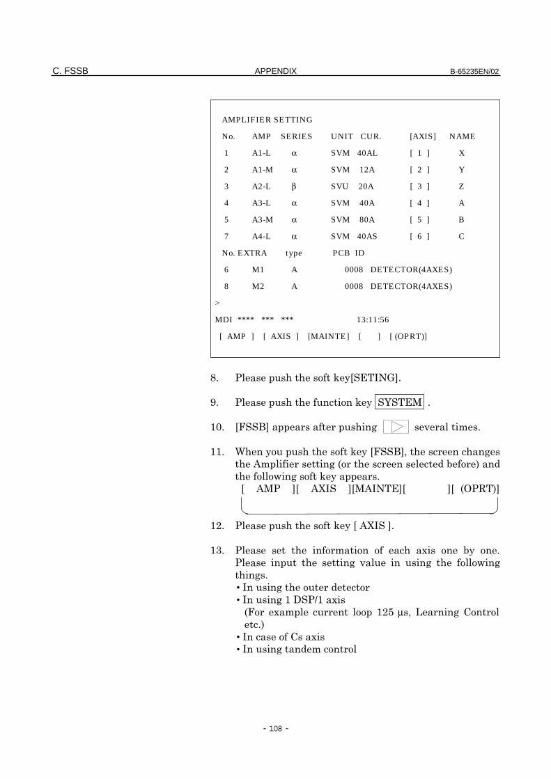
C. FSSB APPENDIX B-65235EN/02
- 108 -
7! *1F(G!
;! *1=!
&:! FG +)"!
&&! /1 *1FG0+
" +%$ '
+ *1!
F GF H GF GF GF %'G
&,! *1F HG!
&-! " # $1 !
+ ) + +
+!
•+
•+&89&#
% #" &,3µ0 +.
!'
• .#
•+"
AMPLIFIER SETTING
No. AMP SERIES UNIT CUR. [AXIS] NAME
1 A1-L α SVM 40AL [ 1 ] X
2 A1-M α SVM 12A [ 2 ] Y
3 A2-L β SVU 20A [ 3 ] Z
4 A3-L α SVM 40A [ 4 ] A
5 A3-M α SVM 80A [ 5 ] B
7 A4-L α SVM 40AS [ 6 ] C
No. EXTRA type PCB ID
6 M1 A 0008 DETECTOR(4AXES)
8 M2 A 0008 DETECTOR(4AXES)
>
MDI **** *** *** 13:11:56
[ AMP ] [ AXIS ] [MAINTE] [ ] [ (OPRT)]
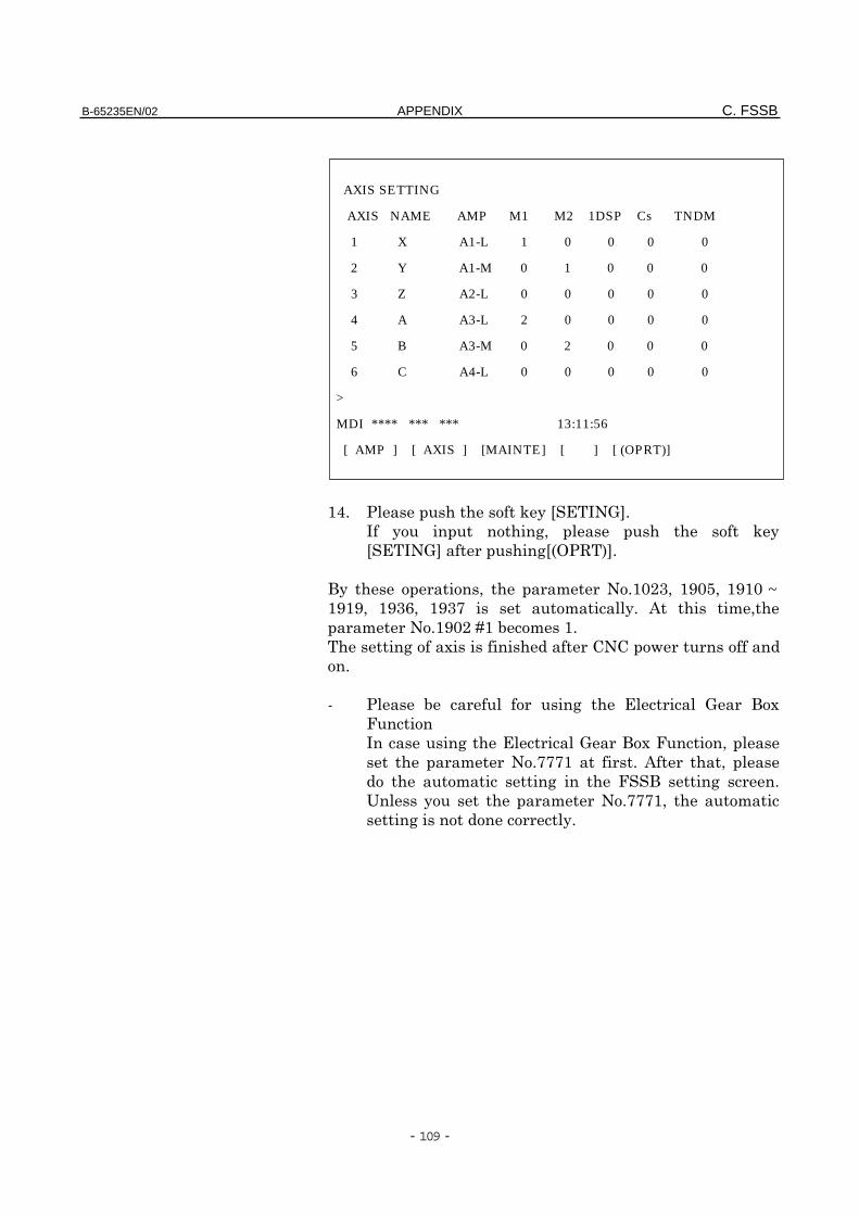
B-65235EN/02 APPENDIX C. FSSB
- 109 -
&E! *1F(G!
1 +0 *1
F(G +F%'G!
1 0 "!&:,-0 &;:30 &;&:~&;&;0 &;-60 &;-< "1! "0
"!&;:,@&$"&!
+ # ..
!
I $ + ( #
+(#0
"!<<<& ! 0
" + + !
1 "!<<<&0 "
+1!
AXIS SETTING
AXIS NAME AMP M1 M2 1DSP Cs TNDM
1 X A1-L 1 0 0 0 0
2 Y A1-M 0 1 0 0 0
3 Z A2-L 0 0 0 0 0
4 A A3-L 2 0 0 0 0
5 B A3-M 0 2 0 0 0
6 C A4-L 0 0 0 0 0
>
MDI **** *** *** 13:11:56
[ AMP ] [ AXIS ] [MAINTE] [ ] [ (OPRT)]
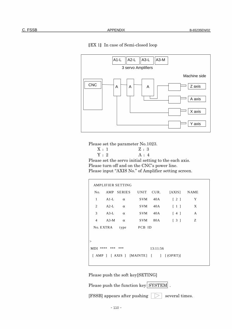
C. FSSB APPENDIX B-65235EN/02
- 110 -
[H&] "I
"!&:,-!
H: & J: -
=: , : E
)+#!
..D!
> H!? " +!
*1F(G
*1=!
FG +)"!
AMPLIFIER SETTING
No. AMP SERIES UNIT CUR. [AXIS] NAME
1 A1-L α SVM 40A [ 2 ] Y
2 A2-L α SVM 40A [ 1 ] X
3 A3-L α SVM 40A [ 4 ] A
4 A3-M α SVM 80A [ 3 ] Z
No. EXTRA type PCB ID
>
MDI **** *** *** 13:11:56
[ AMP ] [ AXIS ] [MAINTE] [ ] [ (OPRT)]
A2-L
AAA Z axisCNC
Machine side
3 servo Amplifiers
A1-L A3-MA3-L
A axis
X axis
Y axis
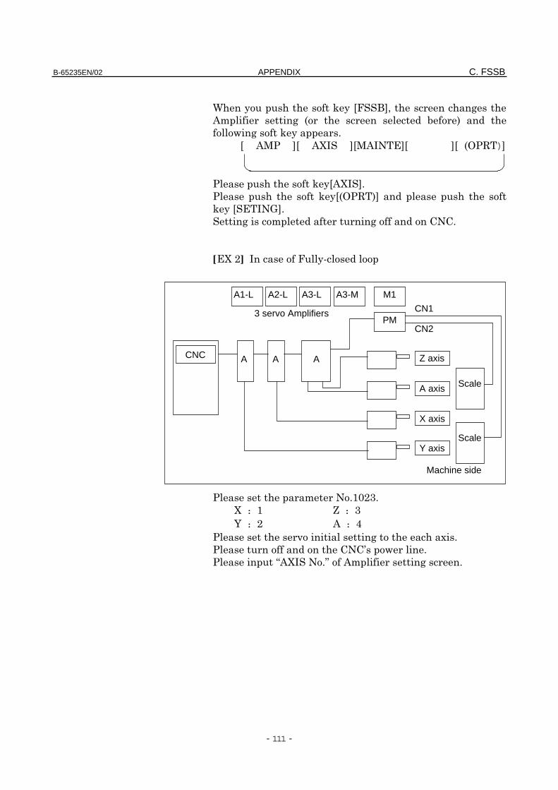
B-65235EN/02 APPENDIX C. FSSB
- 111 -
/1 *1FG0+
" + % $ '
+ *1!
F GF H GF GF GF %)G
*1F HG!
*1F%'G
*1F(G!
+" + ..!
[H,] 1I
"!&:,-!
H : & J : -
= : , : E
)+#!
..D!
> H!? " +!
A2-L
AAA Z axisCNC
CN2
CN13 servo Amplifiers
A1-L
PM
M1A3-MA3-L
Machine side
Scale
ScaleA axis
X axis
Y axis

C. FSSB APPENDIX B-65235EN/02
- 112 -
*1F(G
*1=!
FG +)"!
/1 *1FG0+
" + % $ '
+ *1!
F GF H GF GF GF %'G
AMPLIFIER SETTING
No. AMP SERIES UNIT CUR. [AXIS] NAME
1 A1-L α SVM 40A [ 2 ] Y
2 A2-L α SVM 40A [ 1 ] X
3 A3-L α SVM 40A [ 4 ] A
4 A3-M α SVM 80A [ 3 ] Z
No. EXTRA TYPE PCB ID
5 M1 A 0008 DETECTOR (AXES)
>
MDI **** *** *** 13:11:56
[ AMP ] [ AXIS ] [MAINTE] [ ] [ (OPRT)]
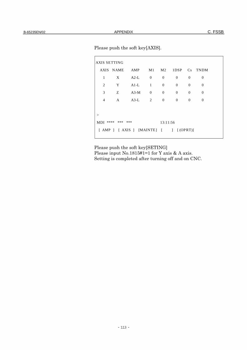
B-65235EN/02 APPENDIX C. FSSB
- 113 -
*1F HG!
*1F(G
!&7&3@&A& =#C #!
+" + ..!
AXIS SETTING
AXIS NAME AMP M1 M2 1DSP Cs TNDM
1 X A2-L 0 0 0 0 0
2 Y A1-L 1 0 0 0 0
3 Z A3-M 0 0 0 0 0
4 A A3-L 2 0 0 0 0
>
MDI **** *** *** 13:11:56
[ AMP ] [ AXIS ] [MAINTE] [ ] [ (OPRT)]
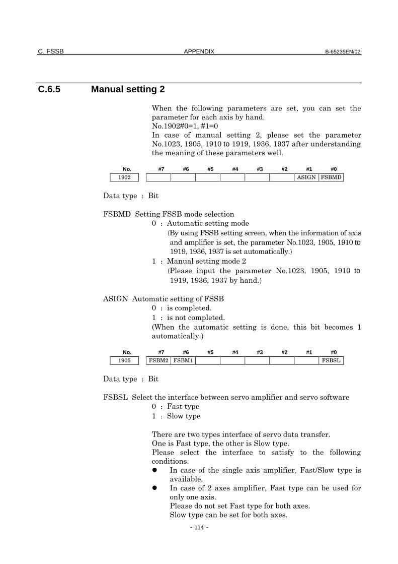
C. FSSB APPENDIX B-65235EN/02
- 114 -
C.6.5 Manual setting 2
/ + " 0 1
" #$1!
!&;:,@:A&0@&A:
" + ,0 "
!&:,-0&;:30&;&: to &;&;0&;-60&;-< +
"+ "!
No. #7 #6 #5 #4 #3 #2 #1 #0
81 :
8+"
: : "+"
(1++0 " #
" 0"!&:,-0&;:30&;&: to&;&;0&;-60&;-<"1!)
& : +",
( " !&:,-0 &;:30 &;&: to&;&;0&;-60&;-<$1!)
( "+
: : "!
& : "!
%/ " + 0 $ $" &
"1!'
No. #7 #6 #5 #4 #3 #2 #1 #0
81 :
$)" )
: : 1
& : 1
1 ) !
101!
1 +
!
+ # " 0 9 1
)$!
, # " 0 1 $
1#!
1 $#!
1$ $#!
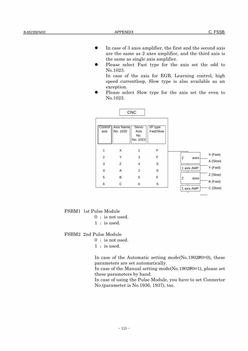
B-65235EN/02 APPENDIX C. FSSB
- 115 -
-#" 0 #
",#" 0#
"+#" !
1 #
!&:,-!
# (0 + 0 +
0 1 )$
#!
1 # )
!&:,-!
&&
: : !
& : !
,,
: : !
& : !
" +"%!&;:,@:A:'0
""1!
+"%!&;:,@:A&'0
"$1!
+01).
!%"!&;-60&;-<'0!
X
Y
Z
A
B
C
F
F
S
S
F
S
1
3
4
2
5
6
1
2
3
4
5
6C (Slow)
B (Fast)
Z (Slow)
Y (Fast)
A (Slow)
X (Fast)
Axis NameNo. 1020
CNC
Controlaxis
2 axes
2 axes
1 axis AMP
1 axis AMP
ServoAxisNo.
No. 1023
I/F typeFast/Slow
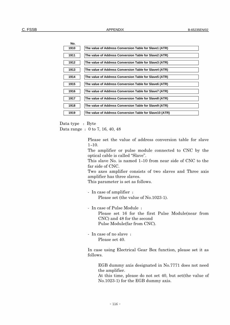
C. FSSB APPENDIX B-65235EN/02
- 116 -
No.1910 The value of Address Conversion Table for Slave1 (ATR)
1911 The value of Address Conversion Table for Slave2 (ATR)
1912 The value of Address Conversion Table for Slave3 (ATR)
1913 The value of Address Conversion Table for Slave4 (ATR)
1914 The value of Address Conversion Table for Slave5 (ATR)
1915 The value of Address Conversion Table for Slave6 (ATR)
1916 The value of Address Conversion Table for Slave7 (ATR)
1917 The value of Address Conversion Table for Slave8 (ATR)
1918 The value of Address Conversion Table for Slave9 (ATR)
1919 The value of Address Conversion Table for Slave10 (ATR)
81 : 1
8+ : :<0&60E:0E7
) ) $ )
&~&:!
" " .. $1
$>)?!
)!"&~&: " ..
..!
# " ) #
" )!
" !
I " :%) !&:,-I&'!
I : &6 % "
..'E7
% "..'!
I ) :E:!
+(# 0
!
(""1#+!<<<&
" !
"0E:0$%)
!&:,-I&' (""1#!
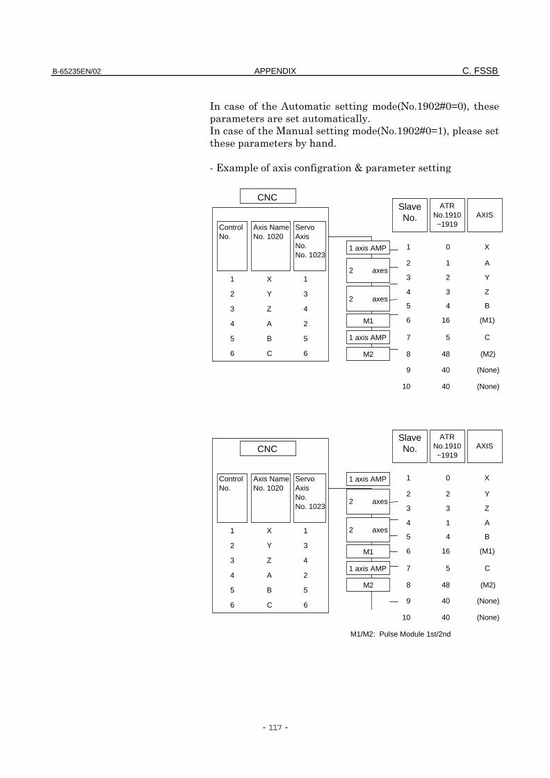
B-65235EN/02 APPENDIX C. FSSB
- 117 -
" +"%!&;:,@:A:'0
""1!
+"%!&;:,@:A&'0
"$1!
I#" # +C"+
X
Y
Z
A
B
C
1
3
4
2
5
6
1
2
3
4
5
6
10
9
8
7
6
5
4
3
2
1
Axis NameNo. 1020
CNC
ControlNo.
2 axes
2 axes
AXISATR
No.1910~1919
SlaveNo.
1 axis AMP
ServoAxisNo.No. 1023
M2
M1
1 axis AMP
40
40
48
5
16
4
3
2
1
0
(None)
(None)
(M2)
C
(M1)
B
Z
Y
A
X
X
Y
Z
A
B
C
1
3
4
2
5
6
1
2
3
4
5
6
10
9
8
7
6
5
4
3
2
1Axis NameNo. 1020
CNC
ControlNo.
2 axes
2 axes
AXISATR
No.1910~1919
SlaveNo.
1 axis AMPServoAxisNo.No. 1023
M2
M1
1 axis AMP
40
40
48
5
16
4
1
3
2
0
M1/M2: Pulse Module 1st/2nd
(None)
(None)
(M2)
C
(M1)
B
A
Z
Y
X
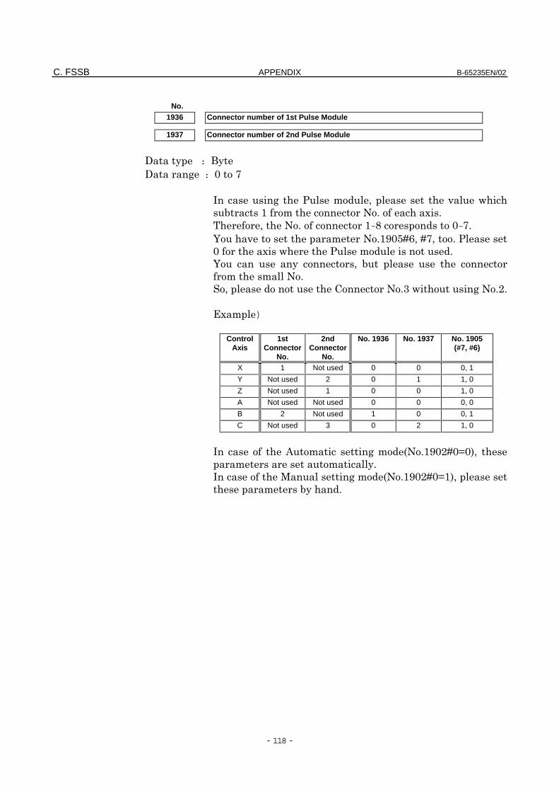
C. FSSB APPENDIX B-65235EN/02
- 118 -
No.1936 Connector number of 1st Pulse Module
1937 Connector number of 2nd Pulse Module
81 : 1
8+ : :<
+ "0 )
$& "! #!
0! &-7:-<!
=)"!&;:3@60@<0!
: #"!
= 1 0 $
""!
0.!-+!,!
#")
ControlAxis
1stConnector
No.
2ndConnector
No.
No. 1936 No. 1937 No. 1905(#7, #6)
X 1 Not used 0 0 0, 1
Y Not used 2 0 1 1, 0
Z Not used 1 0 0 1, 0
A Not used Not used 0 0 0, 0
B 2 Not used 1 0 0, 1
C Not used 3 0 2 1, 0
" +"%!&;:,@:A:'0
""1!
+"%!&;:,@:A&'0
"$1!
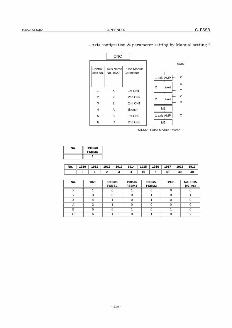
B-65235EN/02 APPENDIX C. FSSB
- 119 -
I # +C"+$1+,
No. 1902#0FSBMD
1
No. 1910 1911 1912 1913 1914 1915 1916 1917 1918 1919
0 1 2 3 4 16 5 48 40 40
No. 1023 1905#0FSBSL
1905#6FSBM1
1905#7FSBM2
1936 No. 1905(#7, #6)
X 1 0 1 0 0 0
Y 3 0 0 1 0 1
Z 4 1 0 1 0 0
A 2 1 0 0 0 0
B 5 0 1 0 1 0
C 6 1 0 1 0 2
X
Y
Z
A
B
C
1st CN1
2nd CN2
2nd CN1
(None)
1st CN2
2nd CN3
1
2
3
4
5
6
Axis NameNo. 1020
CNC
Controlaxis No.
2 axes
2 axes
AXIS
1 axis AMP
Pulse ModuleConnector
M2
M1
1 axis AMP C
B
Z
Y
A
X
M1/M2: Pulse Module 1st/2nd
B-65235EN/02
- 120 -
Index
<A>
AC servo motor maintenance, 79
Actions to be taken on each alarm, 61
Alarm number brief descriptions, 56
Alarm number in Series 0-C (SERVOALARMS), 57
Alarm number in Series 16,18,20,21(SERVO ALARMS), 58
Automatic setting, 107
<B>
Basic configuration, 30
<C>
Check pin board, 47, 97
Checking the control power supplyvoltage, 49
Checking the motor instantaneouscurrent, 49
Configuration, 29, 96
Confirmation procedure, 46
Confirming the line voltage and powerrequirements, 34
Connecting the battery for an absolutepulse coder, 77
Connecting the power supply, 34
Connecting the separate regenerativedischarge unit, 36
Connection to the servo amplifier unit,98
Current conversion failure alarm, 63
<D>
Daily inspection of AC servo motors, 81
<F>
Feedback disconnected alarm, 65
FSSB, 94
<I>
iseries initial setting of parameter, 104
Initializing servo parameters, 37
Invalid servo parameter settingparameters, 67
<L>
Leakage current and selecting a groundfault interrupter, 35
LED indications and meanings, 60
<M>
Major components, 31
Manual setting 1, 106
Manual setting 2, 114
Motor overheat alarm, 66
Motor parameter list, 90
<O>
Operation confirmation method, 45, 97
Overload alarm, 65
Overview of the start-up procedure,33
B-65235EN/02 INDEX
- 121 -
<P>
Periodic inspection of β series motor,84
Pulse coder communication erroralarm, 75
Pulse coder error alarm, 74
<R>
Receiving and keeping AC servomotors, 80
Replacement parts specification, 87
Replacing the fuse, 76
Replacing the pulse coder, 86
Rotation speed data error alarm, 75
<S>
Servo adjustment screen, 64
Servo amplifier unit, 37, 60
Servo amplifier unit front panel, 89
Servo check board , 50, 99
Servo software, 64
Slave, 105
Start-up procedure, 32
<T>
Troubleshooting and recovery, 100
Troubleshooting and recoveryprocedures, 59
200
Revision Record
FANUC SERVO MOTOR β series MAINTENANCE MANUAL (B–65235EN)
Edition Date Contents
01 Nov., ’96
03 Oct., ’97
– SAFETY PRECAUTIONS (FANUC AC SERVO MOTOR series) is modified.– SAFETY PRECAUTIONS (FANUC AC SERVO AMPLIFIER series) is modified.– FANUC SERVO MOTOR AMPLIFIER β series with FSSB MAINTENANCE
MANUAL (B–65235EN/01–02 is added.

No part of this manual may bereproduced in any form.
All specifications and designs aresubject to change without notice.


