175
GE Fanuc Automation Programmable Control Products PANELWARE™ MMI Application Manual for GE Fanuc Genius™ Protocol User's Manual GFK - 1115 June 1995 GE FANUC Spares
GE Fanuc Automation
Programmable Control Products
PANELWARE™ MMI Application Manualfor GE Fanuc Genius™ Protocol
User's Manual
GFK - 1115 June 1995
GE FANUC Spares
GFL-002
Warnings, Cautions, and Notesas Used in this Publication
Warning
Warning notices are used in this publication to emphasize that hazardous voltages, currents,temperatures, or other conditions that could cause personal injury exist in this equipment ormay be associated with its use.
In situations where inattention could cause either personal injury or damage to equipment, aWarning notice is used.
Caution
Caution notices are used where equipment might be damaged if care is not taken.
NoteNotes merely call attention to information that is especially significant to understanding andoperating the equipment.
This document is based on information available at the time of its publication. While efforts have beenmade to be accurate, the information contained herein does not purport to cover all details or variations inhardware or software, nor to provide or every possible contingency in connection with installation,operation, or maintenance. Features may be described herein which are not present in all hardware andsoftware systems. GE Fanuc Automation assumes no obligation of notice to holders of this document withrespect to changes subsequently made.
GE Fanuc Automation makes no representation or warranty, expressed, implied, or statutory with respectto, and assumes no responsibility for the accuracy, completeness, sufficiency, or usefulness of theinformation contained herein. No warranties of merchantability or fitness for purpose shall apply.
The following are trademarks of GE Fanuc Automation North America, Inc.
Alarm Master Field Control Modelmaster Series OneCIMPLICITY GEnet ProLoop Series SixCIMPLICITY Genius PROMACRO Series ThreePowerTRAC Genius PowerTRAC Series Five VuMasterCIMPLICITY 90–ADS Helpmate Series 90 WorkmasterCIMSTAR Logicmaster
©Copyright 1995 GE Fanuc Automation North America, Inc.All Rights Reserved.

Preface
GFK-1115 iii
This manual provides a quick guide to installing and operating PANELWARE™ Panels,describes configuration techniques, and outlines general use of the PANELWARE ConfigurationSoftware (PCS) with GE Fanuc Genius Protocol.
Some of the products mentioned or illustrated in this manual may not be released when thisdocument is published. Please do not rely on any references made to these units. Your localGE Fanuc distributor will inform you of any new product releases.
Content of This Manual
Chapter 1. Overview provides a short description of the PCS and outlines the prerequisites forPCS operation with the PC and the PLC.
Chapter 2. C400 Panel Controller Hardware provides specifications, descriptions ofconnections and operational elements, and operating instructions for the C400 Controller.
Chapter 3. Quick Start provides installation instructions and introduces the operation andfunctionality of the PCS by means of several easy-to-follow examples.
Chapter 4. Configuring Communication with the PLC contains information on PanelController and PLC interface configurations and describes how to make the connection betweenthe Panel and PLC.
Chapter 5. Connection Editor describes the PCS function that performs the organization ofvariables in the Panel (symbolic names) and addresses in the PLC.
Chapter 6. Demo Project briefly explains how to run the demo projects that are delivered withthe software.
Appendix A. Cabling Information describes the required PCS to PLC and PC interface cablesand provides several cabling diagrams.
Appendix B. Errors / Troubleshooting provides an overview of possible system errors andexplains their causes and possible solutions.
GE FANUC Spares

Preface
iv PANELWARE MMI Application Manual for GE Fanuc Genius Protocol - June 1995 GFK-1115
Related Publications
PANELWARE Manuals
GFK-0848 PANELWARE™ Hardware Installation User's ManualDescribes the PANELWARE Operator Panels and contains technical data, hardware installationinstructions, and the general information required for putting the Panels into operation.
GFK-0849 PANELWARE™ Configuration Software Reference ManualDescribes the PANELWARE Configuration Software and provides the program setups for Panelsthat are equipped with a programmable controller.
GFK-0850 PANELWARE™ MMI Application Manual for GE Fanuc Series 90™Protocol (SNP)
Contains specific information on the configuration of PANELWARE Panels that communicate bymeans of GE Fanuc Series 90 Protocol.
GFK-1112 PANELWARE™ Application Manual for Siemens SINEC L1 DriverContains specific information on the configuration of PANELWARE Panels that communicatewith Siemens controllers by means of the SINEC L1 protocol.
GFK-1113 PANELWARE™ Application Manual for the Modicon MODBUS(RTU/ASCII) Driver
Contains specific information on the configuration of PANELWARE Panels that communicatewith MODICON controllers by means of the MODBUS protocol.
GFK-1142 PANELWARE™ Configuration Software Quick Start GuideThis guide, a companion to the PANELWARE Configuration Software Reference Manual (GFK-0849), provides basic information for configuring and using PCS.
Other Documents
GEK-90486-1 Genius™ I/O System and Communications User’s ManualReference manual for systems designers, programmers, and others involved in integrating GeniusI/O products in a PLC or host computer environment. This book provides a system overview, anddescribes the types of systems that can be created using Genius products. Datagrams, global data,and data formats are defined.
GFK-0398 Series 90™-70 Genius™- Bus Controller User’s ManualDescribes the features and operation of the Series 90-70 Genius Bus Controller. Providesconfiguration and programming information needed to complete the interface between a Series90-30 PLC and a Genius I/O Bus.
GFK-0585 Series 90 PLC SNP Communications Driver User’s ManualDescribes the software installation, operation, and programming of the GE Fanuc Series 90Protocol Driver. The SNP is used to retrieve/store data or issue commands to a given Series 90PLC via the serial port.

Preface
GFK-1115 Preface v
GFK-0852 Series 90™ PLC Serial Communications User's ManualThis manual describes serial communications products for the Series 90 Programmable LogicController. Information is provided to implement a serial communications link between the Series90 PLC, a host computer, peripheral device, or another PLC.
GFK-0898 Series 90-30 Programmable Controller I/O Module SpecificationsDescribes the discrete and analog I/O modules for the GE Fanuc Series 90-30 PLC. Containsdescriptions of each I/O module and provides specifications and wiring information for eachmodule.
GFK-1034 Series 90™-30 Genius™ Bus Controller User’s ManualDescribes the features and operation of the Series 90-30 Genius Bus Controller. Providesconfiguration and programming information needed to complete the interface between a Series90-30 PLC and a Genius I/O Bus.
We Welcome Your Comments and Suggestions
At GE Fanuc Automation, we strive to produce quality technical documentation. After you haveused this manual, please take a few moments to complete and return the Reader's Comment Cardlocated on the next page.
Libby AllenSenior Technical Writer
GE FANUC Spares
Contents
GFK-1115 vii
Chapter 1 Overview............................................................................................................... 1-1
PANELWARE Configuration Software..............................................................................1-2Hardware and Software Requirements................................................................................1-3PLC Requirements.............................................................................................................1-4Document Conventions.......................................................................................................1-5
Key Symbols...............................................................................................................1-5Menu Functions...........................................................................................................1-5
Chapter 2 C400 Panel Controller Hardware......................................................................... 2-1
General Information...........................................................................................................2-2Power Requirement......................................................................................................2-2Connecting Power to the Controller..............................................................................2-2Setting Number Switches.............................................................................................2-2
Genius Panel Controller (C400)..........................................................................................2-3Specifications..............................................................................................................2-3Overview of Connections and Operational Elements.....................................................2-5
Operating the C400 Controller...........................................................................................2-9FlashPROM................................................................................................................2-9RESET Modes.............................................................................................................2-9Loading and Starting Panel Programs.........................................................................2-10Update Mode/Reloading the Operating System...........................................................2-10
Chapter 3 Quick Start............................................................................................................ 3-1
Section 1 Software Installation............................................................................ 3-2Calling the Setup Program..................................................................................................3-2Language Selection............................................................................................................3-2Installation Menu...............................................................................................................3-3
Changing the Destination Path.....................................................................................3-3Start Installation..........................................................................................................3-3Screen Configuration...................................................................................................3-4Exiting the Installation.................................................................................................3-4
Section 2 Starting PCS......................................................................................... 3-5
Section 3 General Operation............................................................................... 3-6Pull-Down Menus (Main Menu).........................................................................................3-6Window Name...................................................................................................................3-6Selection Windows.............................................................................................................3-7Context-Sensitive Help Screens..........................................................................................3-7Screen Elements.................................................................................................................3-8
Section 4 PCS Configuration............................................................................... 3-9
Contents
viii PANELWARE MMI Application Manual for GE Fanuc Genius Protocol - June 1995 GFK-1115
Section 5 Creating a New Project.......................................................................3-10
Section 6 Defining Connections..........................................................................3-13Connection to a GE Fanuc PLC via Genius......................................................................3-14Internal Connection..........................................................................................................3-17Genius Internal Connection..............................................................................................3-18
Section 7 Key Assignments.................................................................................3-19
Section 8 Creating Pictures................................................................................3-21Picture 1..........................................................................................................................3-21Picture 2..........................................................................................................................3-25Picture 3..........................................................................................................................3-27
Section 9 Defining the Project Variables............................................................3-28Genius Device Connection................................................................................................3-29Genius Internal Connection..............................................................................................3-30Internal Connection.......................................................................................................... 3-31
Section 10 Binding Pictures in the Project.........................................................3-32Picture for a Communications Error.................................................................................3-33Picture Binding Overview.................................................................................................3-34
Error Picture..............................................................................................................3-35Start-up Picture .........................................................................................................3-36Pict_1........................................................................................................................3-37
Picture List Organization.................................................................................................3-38
Section 11 Compiling the Project .......................................................................3-39
Section 12 Downloading the Project to the Panel ..............................................3-40
Section 13 Connecting the PLC and the Panel ..................................................3-42
Section 14 Starting the Project...........................................................................3-43
Section 15 Exiting PCS .......................................................................................3-44
Chapter 4 Configuring Communication with the PLC......................................................... 4-1
Genius Protocol Parameters (Definition in PCS).................................................................4-2PLC Types..................................................................................................................4-3PLC Node Parameter Definitions.................................................................................4-5PLC Network Parameter Definitions............................................................................4-7
SNP 90 Protocol Parameters (Definition in PCS)................................................................4-9Settings on the Panel........................................................................................................4-10Panel Interface.................................................................................................................4-10Configuration of the PLC Interface...................................................................................4-10
Chapter 5 PCS Connection Editor ........................................................................................ 5-1
General Information...........................................................................................................5-2Accessing the Connection List............................................................................................5-2
GE FANUC Spares
Contents
GFK-1115 Table of Contents ix
Elements of the Connection List.........................................................................................5-3Using Function Keys in the Connection List........................................................................5-3
Overview.....................................................................................................................5-3Editing/Inserting Connections.......................................................................................5-4Defining/Changing an ID.............................................................................................5-4Defining/Changing a Connection..................................................................................5-4Deleting Connections...................................................................................................5-5Editing PLC Node Parameters of a Connection.............................................................5-5
Editing the Variable Assignment Table...............................................................................5-6Elements of the VAT...................................................................................................5-6Function Keys of the VAT...........................................................................................5-7Editing/Inserting Variable Assignments........................................................................5-8Entering/Changing the Tagname...................................................................................5-8Entering/Changing PLC Addresses...............................................................................5-8Entering/Changing PLC Variable Types.......................................................................5-9Deleting Variable Assignments...................................................................................5-10Marking Unused Variables.........................................................................................5-10
Global Data Format.........................................................................................................5-11Data Type Conversions....................................................................................................5-12
Chapter 6 Demo Project......................................................................................................... 6-1
Section 1 General Information............................................................................ 6-2
Section 2 Required Hardware............................................................................. 6-3
Section 3 Downloading the Demo Project ........................................................... 6-4Defining the User Path.......................................................................................................6-4Loading the Project............................................................................................................6-5Downloading and Starting the Project.................................................................................6-6
Section 4 Description of the Demo Project.......................................................... 6-7General Information...........................................................................................................6-7Main Menu........................................................................................................................6-8Value Entries.....................................................................................................................6-9
INPUT VALUES Picture.............................................................................................6-9CLOCK Picture.........................................................................................................6-10
Entering a Password.........................................................................................................6-11INPUT PASSWORD Picture.....................................................................................6-11LOCKED INPUT Picture..........................................................................................6-12
Key Functions..................................................................................................................6-13Alarm List .......................................................................................................................6-14Error Picture....................................................................................................................6-15
Section 5 Creating the Demo Project .................................................................6-16General Information.........................................................................................................6-16

Contents
x PANELWARE MMI Application Manual for GE Fanuc Genius Protocol - June 1995 GFK-1115
Creating a Project............................................................................................................6-16Preparing a Concept...................................................................................................6-17Creating a New Project..............................................................................................6-18Selecting the Connections...........................................................................................6-19Defining Key Assignments.........................................................................................6-22Creating the Pictures..................................................................................................6-23Defining the Text Groups...........................................................................................6-51Binding Pictures to the Project...................................................................................6-52Editing the Alarm System...........................................................................................6-58Activating the Alarm System......................................................................................6-60Editing the Connections..............................................................................................6-61
Compiling the Project.......................................................................................................6-64Errors ..............................................................................................................................6-64
Appendix A Cabling Information ............................................................................................A-1
Genius Communications.................................................................................................... A-2Selecting a Cable Type............................................................................................... A-2Using Other Cable Types............................................................................................ A-2Bus Length................................................................................................................. A-4Baud Rate Selection.................................................................................................... A-4Connecting Devices to the Bus.................................................................................... A-5
SNP Communications....................................................................................................... A-5Cable Diagrams................................................................................................................ A-6
Appendix B Errors/Troubleshooting .......................................................................................B-1
Errors During Installation.................................................................................................. B-2Errors During Program Start ............................................................................................. B-3Errors While Working in PCS........................................................................................... B-4Error Numbers in Internal USER Variable......................................................................... B-6
GE FANUC Spares

GFK-1115 1 - 1
Chapter Overview
This chapter provides a short overview/description of the PANELWARE Configuration Software(PCS) and outlines the requirements for PCS operation with the PC and PLC. It includes thefollowing information:
■ PANELWARE Configuration Software (PCS)............................................................1-2
■ Hardware and Software Requirements........................................................................1-3
■ PLC Requirements......................................................................................................1-4
■ Document Conventions...............................................................................................1-5
1
1 - 2 PANELWARE MMI Application Manual for GE Fanuc Genius Protocol - June 1995 GFK-1115
1
PANELWARE Configuration Software
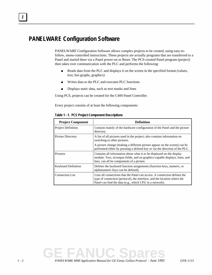
PANELWARE Configuration Software allows complex projects to be created, using easy-to-follow, menu-controlled instructions. These projects are actually programs that are transferred to aPanel and started there via a Panel power-on or Reset. The PCS-created Panel program (project)then takes over communication with the PLC and performs the following:
■ Reads data from the PLC and displays it on the screen in the specified format (values,text, bar-graphs, graphics)
■ Writes data to the PLC and executes PLC functions
■ Displays static data, such as text masks and lines
Using PCS, projects can be created for the C400 Panel Controller.
Every project consists of at least the following components:
Table 1 - 1. PCS Project Component Descriptions
Project Component Definition
Project Definition Consists mainly of the hardware configuration of the Panel and the picturedirectory.
Picture Directory A list of all pictures used in the project; also contains information onswitching to other pictures.
A picture change (making a different picture appear on the screen) can beperformed either by pressing a defined key or via the direction of the PLC.
Pictures Contains all information about what is to be displayed on the displaymodule. Text, in/output fields, and on graphics-capable displays, lines, andbars, can all be components of a picture.
Keyboard Definition Defines the keyboard function assignments (function keys, numeric, oralphanumeric keys can be defined).
Connection List Lists all connections that the Panel can access. A connection defines thetype of connection (protocol), the interface, and the location where thePanel can find the data (e.g., which CPU in a network).
GE FANUC Spares

GFK-1115 Chapter 1 Overview 1 - 3
1
Hardware and Software Requirements
PCS is delivered on two 3½-inch disks in 2DD (720K) format and on one 5¼-inch disk in 2S/HD(1.2M) format. The diskette(s) you use to install the PCS depends on your PC configuration.
Description CatalogNumber
PANELWARE Configuration Software(includes cable assembly)
IC641SWP950
Before starting the software installation, make sure the following requirements are met:
■ Complete IBM PC compatibility (processor types: 80286 and higher)
■ IBM compatible monochrome or color adapter
■ One 3½ inch (720 Kbyte) or 5¼ inch (1.2 Mbyte) floppy disk drive
■ For the installation, approximately 3 Mbytes must be free on the hard disk.
■ 640 KB RAM, of which at least 512 KB must be available. Memory-resident programsshould be removed if necessary to free up the RAM.
■ Minimum 1 serial interface (COM1 or COM2)
■ MS-DOS version 3.30 or higher
■ The CONFIG.SYS file settings for FILES and BUFFERS must be set to a minimum of:FILES=40; BUFFERS=10.
Note
PCS can be executed in a DOS box under Windows 3.1 only in offline mode. Toeither download or upload a project to/from a Panel, you must exit Windows andrun PCS from the DOS prompt.
1 - 4 PANELWARE MMI Application Manual for GE Fanuc Genius Protocol - June 1995 GFK-1115
1
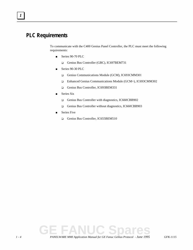
PLC Requirements
To communicate with the C400 Genius Panel Controller, the PLC must meet the followingrequirements:
■ Series 90-70 PLC
❏ Genius Bus Controller (GBC), IC697BEM731
■ Series 90-30 PLC
❏ Genius Communications Module (GCM), IC693CMM301
❏ Enhanced Genius Communications Module (GCM+), IC693CMM302
❏ Genius Bus Controller, IC693BEM331
■ Series Six
❏ Genius Bus Controller with diagnostics, IC660CBB902
❏ Genius Bus Controller without diagnostics, IC660CBB903
■ Series Five
❏ Genius Bus Controller, IC655BEM510
GE FANUC Spares
GFK-1115 Chapter 1 Overview 1 - 5
1
Document Conventions
Key Symbols
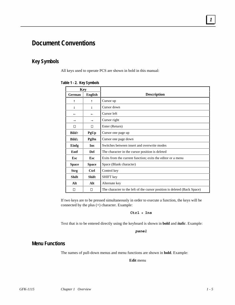
All keys used to operate PCS are shown in bold in this manual:
Table 1 - 2. Key Symbols
KeyGerman English Description
↑↑ ↑↑ Cursor up
↓↓ ↓↓ Cursor down
←← ←← Cursor left
→→ →→ Cursor right
↵↵ ↵↵ Enter (Return)
Bild ↑↑ PgUp Cursor one page up
Bild ↓↓ PgDn Cursor one page down
Einfg Ins Switches between insert and overwrite modes
Entf Del The character in the cursor position is deleted
Esc Esc Exits from the current function; exits the editor or a menu
Space Space Space (Blank character)
Strg Ctrl Control key
Shift Shift SHIFT key
Alt Alt Alternate key
⇐⇐ ⇐⇐ The character to the left of the cursor position is deleted (Back Space)
If two keys are to be pressed simultaneously in order to execute a function, the keys will beconnected by the plus (+) character. Example:
Ctrl + Ins
Text that is to be entered directly using the keyboard is shown in bold and italic. Example:
panel
Menu Functions
The names of pull-down menus and menu functions are shown in bold. Example:
Edit menu

GFK-1115 2 - 1
Chapter C400 Panel Controller Hardware
This chapter describes the C400 PANELWARE Panel Controller (IC750CTR400), its connections(interfaces) and all operational elements for which hardware must be configured on the modularPanel. The following sections of information are included:
■ General Information ...................................................................................................2-2
❏ Power Requirement..............................................................................................2-2
❏ Connecting Power to the Controller .....................................................................2-2
❏ Setting Number Switches.....................................................................................2-2
■ Genius Panel Controller (C400)..................................................................................2-3
❏ Specifications......................................................................................................2-3
❏ Overview of Connections and Operational Elements............................................2-5
■ Operating the C400 Controller ...................................................................................2-7
❏ FlashPROM.........................................................................................................2-9
❏ RESET Modes.....................................................................................................2-9
❏ Loading and Starting Panel Programs................................................................2-10
❏ Update Mode/Reloading the Operating System..................................................2-10
2
GE FANUC Spares

2 - 2 PANELWARE MMI Application Manual for Genius Protocol - June 1995 GFK-1115
2
General Information
Power Requirement
24 VDC power must be supplied to the PANELWARE Controller unit. The Controller, in turn,supplies the Keyblock and Display modules with power.
When estimating the total 24 VDC power consumption for a system, add up the 24 VDC powersupply requirements for all of the PANELWARE components being used, then add an additional30% to allow for power on surge currents. Refer to the PANELWARE™ Hardware InstallationUser’s Guide (GFK-0848) for details on displays and Keyblocks.
Connecting Power to the Controller
The 24 VDC power connector on the Controller is located on the top left corner of the unit. Themating connector is supplied with each Controller.
Caution
Do not try to run PANELWARE off a Series 90-30 power supply revision Mor earlier. Although some configurations might function under this setup, itis not recommended. Damage to the 90-30 power supply could result.
The suitability of a Series 90-30, revision N or later power supply dependson the +24VDC isolated load requirements of the modules in your PLC.Refer to the Series 90-30 Programmable Controller I/O ModuleSpecifications (GFK-0898) to determine additional load requirements ofyour system.
All components of a PLC and the devices it is controlling must be properly grounded. This isparticularly important for the reasons listed below:
■ A low-resistance path from all parts of a system to ground minimizes exposure to shockin the event of short circuits or equipment malfunction.
■ PANELWARE Operator Panels require proper grounding for correct operation.
The importance of grounding can not be over emphasized.
Setting Number Switches
Number switch settings on the Panel Controller can be set using a small flathead screwdriver toturn the switch dial to the desired setting (so that the arrow points at the desired setting).
The assembled Panel configuration provides minimal space to reach the number switches once thePanel is installed. If possible, these settings should be made before the Controller is installed.
GFK-1115 Chapter 2 C400 Panel Controller Hardware 2 - 3
2
Genius Panel Controller (C400)
Specifications
a45517
2.165"(55mm)
7.165"(182mm)
7.165"(182mm)
GE
NIU
S
SHLD OUT
SHLD IN
X2
X1
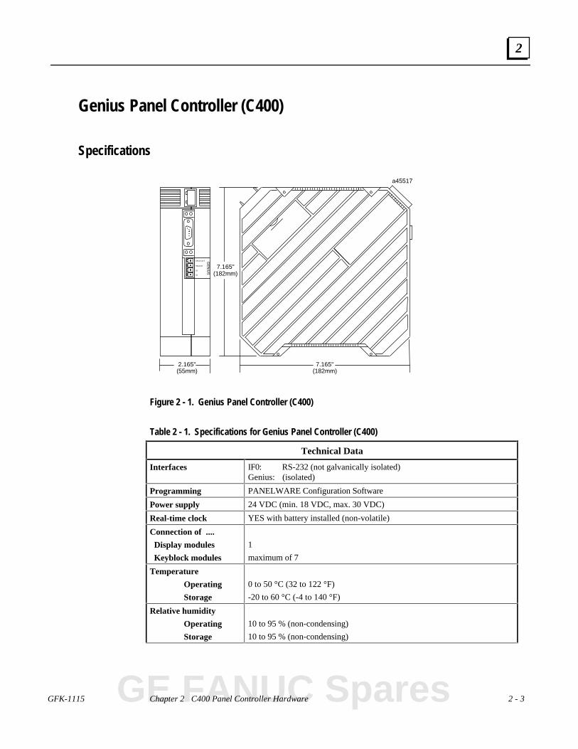
Figure 2 - 1. Genius Panel Controller (C400)
Table 2 - 1. Specifications for Genius Panel Controller (C400)
Technical Data
Interfaces IF0: RS-232 (not galvanically isolated)Genius: (isolated)
Programming PANELWARE Configuration Software
Power supply 24 VDC (min. 18 VDC, max. 30 VDC)
Real-time clock YES with battery installed (non-volatile)
Connection of ....
Display modules
Keyblock modules
1
maximum of 7
Temperature
Operating
Storage
0 to 50 °C (32 to 122 °F)
-20 to 60 °C (-4 to 140 °F)
Relative humidity
Operating
Storage
10 to 95 % (non-condensing)
10 to 95 % (non-condensing)
GE FANUC Spares

2 - 4 PANELWARE MMI Application Manual for Genius Protocol - June 1995 GFK-1115
2
Table 2 - 1. - Continued
Shock conforms to IEC 68-2-2715g equivalent, 150 m/sec2, 11 msec, 3 axes (positive and
negative)
Vibration conforms to IEC 68-2-6 1g equivalent, 10-58 Hz; 0.075 mm
58-150 Hz; 9.8m/sec2
20 cycles per axis
Processor Motorola 68302 @ 16 MHz
24 VDC powerrequirements(typical)
185 mA, 24 VDC
260 mA, 18 VDC (minimum power voltage)
150 mA, 30 VDC (maximum power voltage)
Sealing NEMA 12 and IP54 when properly mounted in a Panel
Noise immunity conforms to IEC 801.2; IEC 801.3; IEC 801.4

GFK-1115 Chapter 2 C400 Panel Controller Hardware 2 - 5
2
Overview of Connections and Operational Elements
a455161
38
2
5
6
9
7
4
Figure 2 - 2. Genius Panel Controller (C400) Elements/Connections
1. Display Module Connector (ribboncable)
2. 24 VDC Power Supply Connector
3. IF0: RS-232 (to PC), labeled 0
4. Genius Bus Connector
5. Keyblock Module Connector
6. Mode Switch - Operating Mode
7. Cover for Lithium Battery
8. Device Number Switches
9. Reset Button
GE FANUC Spares

2 - 6 PANELWARE MMI Application Manual for Genius Protocol - June 1995 GFK-1115
2
24 VDC Power Supply (item 2, Figure 2-2)
Pin Description
+ +24 V
- 0 V
Ground
Ground
The pins are to be connected using as short a cable as is possible. If the Panel is mounted in acabinet, the connecting cable should be as short as possible.
IF0 - RS-232, Non-isolated (item 3, Figure 2-2)
9 pin D-Type (M)
LED Meaning
TxD Send data over interface
RxD Receive data over interface
Pin Description
1 NC
2 RxD Receive Data (Input)
3 TxD Transmit Data (Output)
4 + 5 V Power Supply(200 mA available to user)
5 GND Signal Ground
6 NC
7 RTS Request To Send (Input)
8 CTS Clear To Send (Output)
9 NC

GFK-1115 Chapter 2 C400 Panel Controller Hardware 2 - 7
2
Genius Bus Connector, Isolated (item 4, Figure 2-2)
GENIUS
a45318
SHLD OUT
SHLD IN
X2
X1
Pin Description
SHLD OUT Shield Out (to next physicaldevice on bus)
SHLD IN Shield In (from previousphysical device on bus)
X2 Serial 2
X1 Serial 1
Mode Switch (item 6, Figure 2-2)The mode of operation for the Panel Controller isselected by setting the Operating Mode switch (seeTable 2-2 for operating modes).
Device Number Switches (item 8,Figure 2-2)The Genius bus address for the C400 Controller is set using the Device Number switches. Validdevice numbers are 00 to 31, inclusive.
Lithium Battery (item 7, Figure 2-2)The lithium battery is stored in its own compartment inthe Controller and covered for its own and the user'sprotection. It should be replaced every two years, orwhenever the software indicates that the battery is low.
Warning
Lithium batteries are considered harmful waste. Dispose of them inaccordance with the instructions in the Material Safety Data Sheet (MSDS)that accompany the battery, and in accordance with local regulations.
GE FANUC Spares

2 - 8 PANELWARE MMI Application Manual for Genius Protocol - June 1995 GFK-1115
2
Reset Button (item 9, Figure 2-2)A hardware reset can be executed by pressing this button.Depending on the setting of the mode selection switch,different functions can be executed. These functions areexplained in the descriptions of the connections andoperational elements that follow.
GFK-1115 Chapter 2 C400 Panel Controller Hardware 2 - 9
2
Operating the C400 Controller
FlashPROM
The Panel Controller has non-volatile memory called FlashPROM, which is split into two separateareas (banks) as follows:
System Bank contains the operating system, which is necessary for the Panel program created bythe user to be processed. The system bank can not be deleted by the user.
Routine operating system updates to a higher revision level are performed with PCS in Update-Mode.
User Bank contains the Panel program that controls and is used by the display and Keyblockmodules. The Panel program is created with PCS on a standard PC and downloaded in Teach-Mode.
RESET Modes
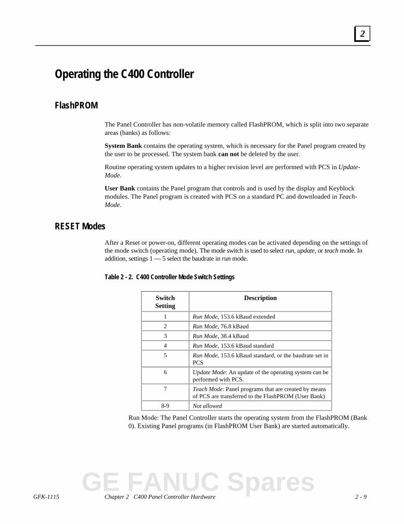
After a Reset or power-on, different operating modes can be activated depending on the settings ofthe mode switch (operating mode). The mode switch is used to select run, update, or teach mode. Inaddition, settings 1 — 5 select the baudrate in run mode.
Table 2 - 2. C400 Controller Mode Switch Settings
SwitchSetting
Description
1 Run Mode, 153.6 kBaud extended
2 Run Mode, 76.8 kBaud
3 Run Mode, 38.4 kBaud
4 Run Mode, 153.6 kBaud standard
5 Run Mode, 153.6 kBaud standard, or the baudrate set inPCS
6 Update Mode: An update of the operating system can beperformed with PCS.
7 Teach Mode: Panel programs that are created by meansof PCS are transferred to the FlashPROM (User Bank)
8-9 Not allowed
Run Mode: The Panel Controller starts the operating system from the FlashPROM (Bank0). Existing Panel programs (in FlashPROM User Bank) are started automatically.
GE FANUC Spares
2 - 10 PANELWARE MMI Application Manual for Genius Protocol - June 1995 GFK-1115
2
Loading and Starting Panel Programs
A Panel program is created using PCS and then transferred (loaded) to the Panel through theserial interface when Teach Mode is selected. To start an application, RUN Mode must beselected. The following sections outline how to load, start, and reload the operating system.
Loading the Panel Program1. Connect the PC (COM1 or COM2) to the Panel Controller (always IF0) using the
appropriate serial cable (see Appendix A).
Note
If you are using a printer with the C400, the printer must be disconnected whilethe Panel program is loaded.
2. Select Teach Mode (position 7).
3. Press the Reset button.
4. Wait until Teach-Mode is displayed.
5. Start the transfer from PCS.
6. Wait until PCS acknowledges that the entire Panel program has been transferred.
Starting the Panel Program1. Select Run Mode (position 5, or 1 — 4, as appropriate).
2. Connect the PLC to the Panel Controller.
3. Press the Reset button.
Update Mode/Reloading the Operating System
The Panel Controller's operating system can be reloaded from PCS. The steps for accomplishingthis transfer are identical to those in the section, “Loading the Panel Program,” except thatUpdate Mode (position 6) is selected. The Update Mode is only required to support futureoperating system upgrades.
To update in this mode, proceed as follows:
1. Select Update Mode (position 6).
2. Press the Reset button.
3. Begin the update operation with PCS.
4. Wait until PCS acknowledges that the update is complete.
5. Select Run Mode (position 5, or 1 — 4, as appropriate).
6. Press the Reset button to start the existing Panel program.

GFK-1115 3 - 1
Chapter Quick Start
This chapter provides a quick guide to installing and using PCS and, using step-by-stepinstructions, explains how to create a project. It includes the following information:
■ Software Installation........................3-2
❏ Calling the Setup Program........3-2
❏ Language Selection...................3-2
❏ Installation Menu .....................3-3
■ Starting PCS ...................................3-5
■ General Operation ...........................3-6
❏ Pull-down Menus...............3-6
❏ Window Name...................3-6
❏ Selection Windows............3-7
❏ Context-Sensitive Help......3-7
❏ Screen Elements................3-8
■ PCS Configuration ..........................3-9
■ Creating a New Project..................3-10
■ Defining Connections....................3-14
❏ PLC ↔ Panel Connection.......3-15
❏ Connection to a GE Fanuc PLCvia Genius..............................3-15
❏ Internal Connection ...............3-18
❏ Genius Internal Connection....3-19
■ Key Assignments..........................3-20
■ Creating Pictures ..........................3-22
■ Defining the Project Variables......3-29
■ Binding Pictures in the Project......3-33
❏ Communications Error Picture3-34
❏ Picture Binding Overview......3-35
❏ Picture List Organization .......3-39
■ Compiling the Project...................3-40
■ Downloading the Project...............3-41
■ Starting the Project .......................3-44
■ Exiting the PCS ............................3-45
3
GE FANUC Spares

3 - 2 PANELWARE MMI Application Manual for GE Fanuc Genius Protocol - June 1995 GFK-1115
3
Section 1 Software Installation
The Genius protocol driver is copied to your computer as part of the standard PCS installation(PCS version 1.8 or later). The PCS should be installed according to the instructions in thefollowing sections.
Calling the Setup Program
Insert the PCS distribution diskette into the appropriate floppy disk drive. If you are using the two3 1/2” diskettes, install the #1 disk first (the system will prompt you when it is time to insert disk#2).
Depending on the floppy drive designation (a or b), type one of the following commands at theDOS prompt, then press the ↵↵ (Enter) key:
C:\> a:setup
or
C:\> b:setup
After you press ↵↵ , the setup program is called and the menu for language selection appears on thescreen.
Language Selection
The Language Selection menu is used to select the language (English or German/Deutsch) inwhich you wish to configure the PCS during the installation procedure. This language is used asthe default selection for the PCS.
Press the function key that corresponds to the desired language. When it has been selected, theInstall Program menu is displayed on the screen.
GFK-1115 Chapter 3 Quick Start 3 - 3
3
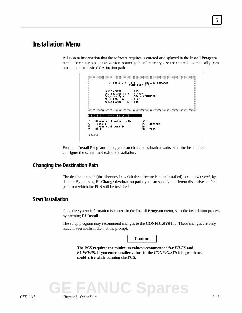
Installation Menu
All system information that the software requires is entered or displayed in the Install Programmenu. Computer type, DOS version, source path and memory size are entered automatically. Youmust enter the desired destination path.
From the Install Program menu, you can change destination paths, start the installation,configure the screen, and exit the installation.
Changing the Destination Path
The destination path (the directory in which the software is to be installed) is set to C:\PW\ bydefault. By pressing F1 Change destination path, you can specify a different disk drive and/orpath into which the PCS will be installed.
Start Installation
Once the system information is correct in the Install Program menu, start the installation processby pressing F3 Install.
The setup program may recommend changes to the CONFIG.SYS file. These changes are onlymade if you confirm them at the prompt.
Caution
The PCS requires the minimum values recommended for FILES andBUFFERS. If you enter smaller values in the CONFIG.SYS file, problemscould arise while running the PCS.
GE FANUC Spares

3 - 4 PANELWARE MMI Application Manual for GE Fanuc Genius Protocol - June 1995 GFK-1115
3
Screen Configuration
The Screen Configuration menu is displayed once the CONFIG.SYS file changes are made.
This screen allows you to set up the appropriate PCS screen type by pressing the function key thatcorresponds to your computer's display. When you select a display type, the system begins copyingthe PCS files to the destination directory you selected.
After all PCS installation files are copied to the destination directory, the following message isdisplayed:
Installation completed. Press any key to continue _
The Install Program menu reappears on the screen when any key is pressed.
Note
If the screen type that was selected during installation must be changed afterinstallation, you can access the Screen Configuration menu again by pressingF5 Screen configuration from the Install Program menu and selecting thedesired screen type.
Exiting the Installation
The setup (installation) program is exited when you press F8 EXIT from any of the menus. Beforeexiting, the following message will appear on the screen if changes were made to theCONFIG.SYS file:
System file modified: RE-BOOT (Y/N)?
To start the PCS properly, it is necessary to reboot the computer after installation when changeshave been made to the CONFIG.SYS file.
Remove the distribution diskette from the floppy drive and press Y to reboot the computer in orderto put the changes to the CONFIG.SYS file into immediate effect. If you do not remove thediskette from the floppy drive, the system will reboot from the floppy drive rather than the harddrive.
Caution
During the installation process, a batch file called PANEL.BAT is createdin the root directory of your hard disk. This file should never be deleted,because it is used to access the PCS.

GFK-1115 Chapter 3 Quick Start 3 - 5
3
Section 2 Starting PCS
To start PCS, type the following command at the C: prompt, then press ↵↵ (if you installed thesoftware on a drive other than C, substitute the correct drive ID for C:):
C:\> panel
The PCS is called up and the following copyright information is displayed on the screen:
After a delay, the Main menu, with its pull-down menu line and messages, is displayed:
GE FANUC Spares

3 - 6 PANELWARE MMI Application Manual for GE Fanuc Genius Protocol - June 1995 GFK-1115
3
Section 3 General Operation
Pull-Down Menus (Main Menu)
The pull-down menus of the Main menu can be opened at any time using two different methods:
■ By pressing the alternate (Alt ) key simultaneously with the desired function key (F1 toF5)
■ By pressing the Alt key simultaneously with the first letter of the desired menu name
For example, the F1 File menu can be opened by pressing either Alt + F1 or Alt + F.
Once a menu is open, select the desired option by highlighting it using the cursor keys andpressing ↵↵. Any resulting window that the option calls up will be displayed in the blank windowof the Main menu, with its associated function key line displayed below.
Key shortcuts (hot keys) for specific menu entries are displayed on the menu next to the associatedentry.
Window Name
Every window that can be displayed within the Main menu has a name that is centered inside thetop line margin of the window. For example:
■ Window name New Project
■ Window name Edit Project
GFK-1115 Chapter 3 Quick Start 3 - 7
3
Selection Windows
If the ↵↵ character is displayed in the bottom line of a screen, a selection window can be opened bypressing the enter (↵↵) key. A selection can be made from these windows by moving through thelist using the cursor keys until the desired entry is highlighted, then pressing ↵↵.
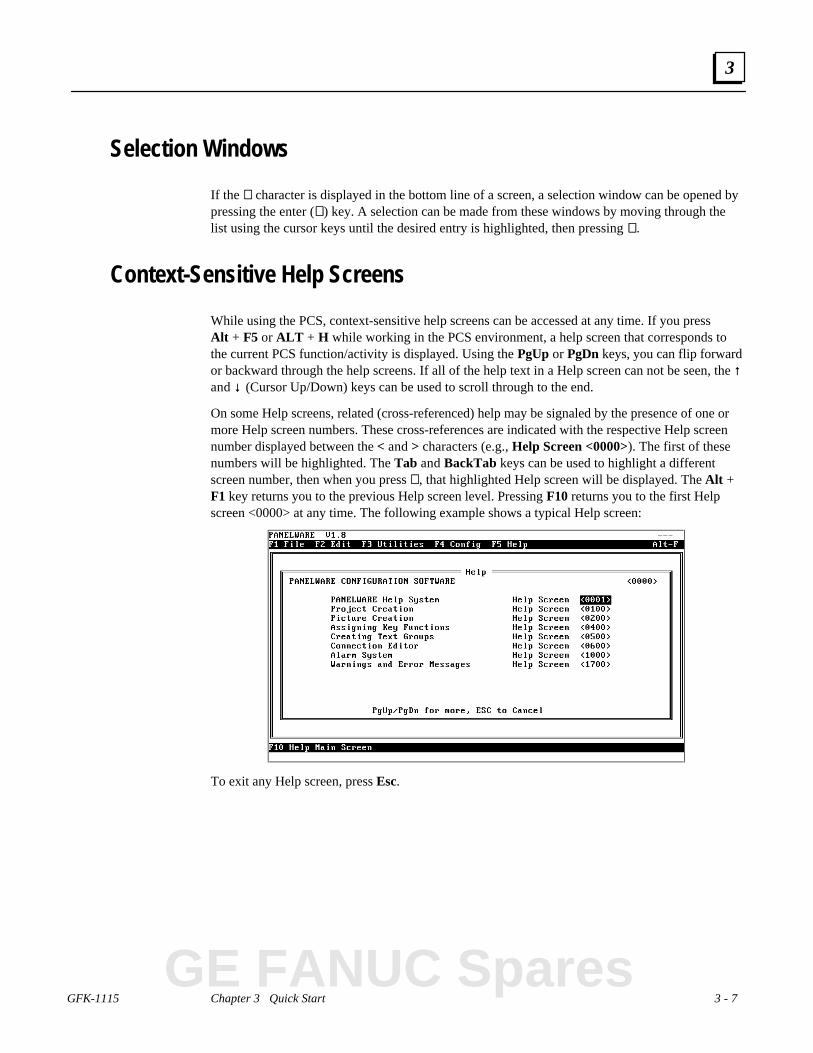
Context-Sensitive Help Screens
While using the PCS, context-sensitive help screens can be accessed at any time. If you pressAlt + F5 or ALT + H while working in the PCS environment, a help screen that corresponds tothe current PCS function/activity is displayed. Using the PgUp or PgDn keys, you can flip forwardor backward through the help screens. If all of the help text in a Help screen can not be seen, the ↑↑and ↓↓ (Cursor Up/Down) keys can be used to scroll through to the end.
On some Help screens, related (cross-referenced) help may be signaled by the presence of one ormore Help screen numbers. These cross-references are indicated with the respective Help screennumber displayed between the < and > characters (e.g., Help Screen <0000>). The first of thesenumbers will be highlighted. The Tab and BackTab keys can be used to highlight a differentscreen number, then when you press ↵↵, that highlighted Help screen will be displayed. The Alt +F1 key returns you to the previous Help screen level. Pressing F10 returns you to the first Helpscreen <0000> at any time. The following example shows a typical Help screen:
To exit any Help screen, press Esc.
GE FANUC Spares

3 - 8 PANELWARE MMI Application Manual for GE Fanuc Genius Protocol - June 1995 GFK-1115
3
Screen Elements
The PCS display contains a few basic elements that are displayed at all times:
Figure 3 - 1. Basic PCS Screen Elements
■ In the top line (title line) of the screen, the software version number is displayed at the left,the name of the current project is in the middle, and the Panel Controller description (typeand operating system version) is on the right.
■ The next line down (menu line) contains the headings of the pull-down menus.
■ The second to the last line (function line) of the screen displays the current function keyassignments.
■ The bottom line (message line) contains any error messages, important notices that relate tothe project, or the character ↵↵, which indicates that a selection window can be accessed.
GFK-1115 Chapter 3 Quick Start 3 - 9
3
Section 4 PCS Configuration
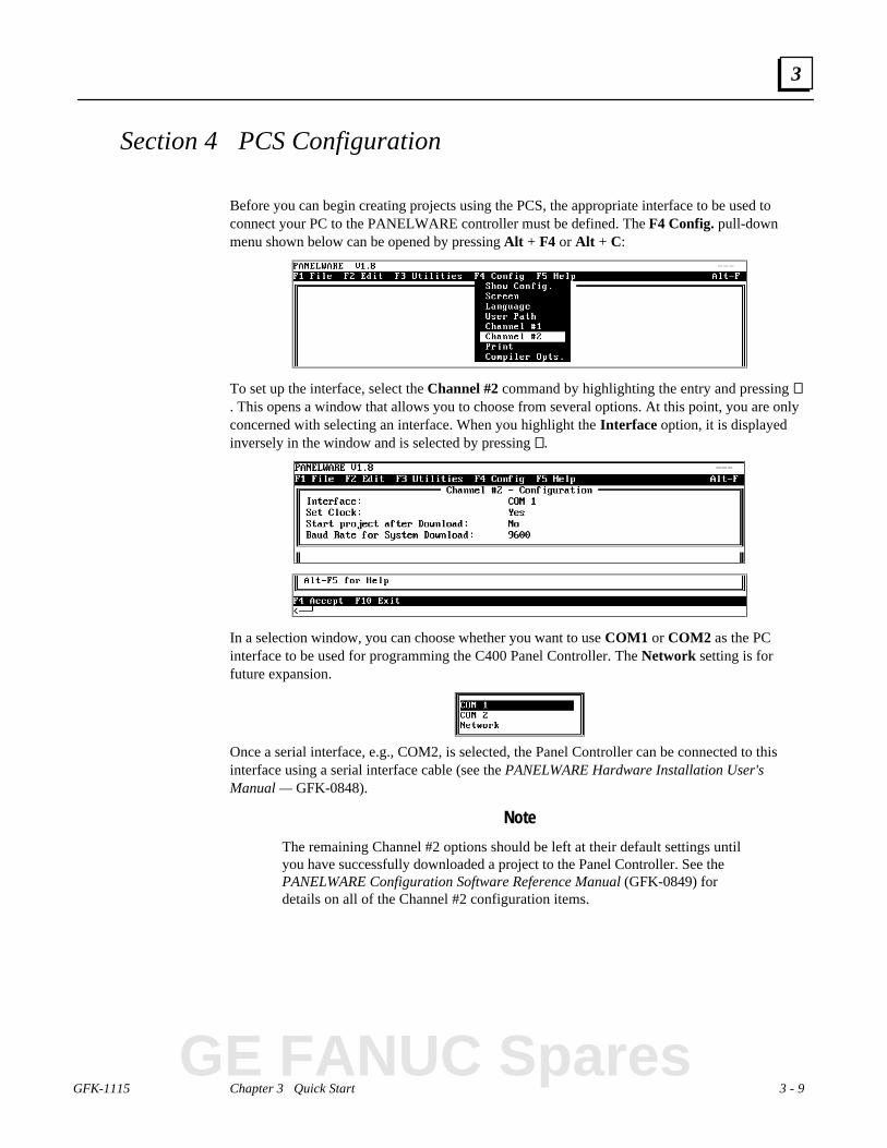
Before you can begin creating projects using the PCS, the appropriate interface to be used toconnect your PC to the PANELWARE controller must be defined. The F4 Config. pull-downmenu shown below can be opened by pressing Alt + F4 or Alt + C:
To set up the interface, select the Channel #2 command by highlighting the entry and pressing ↵↵. This opens a window that allows you to choose from several options. At this point, you are onlyconcerned with selecting an interface. When you highlight the Interface option, it is displayedinversely in the window and is selected by pressing ↵↵.
In a selection window, you can choose whether you want to use COM1 or COM2 as the PCinterface to be used for programming the C400 Panel Controller. The Network setting is forfuture expansion.
Once a serial interface, e.g., COM2, is selected, the Panel Controller can be connected to thisinterface using a serial interface cable (see the PANELWARE Hardware Installation User'sManual — GFK-0848).
Note
The remaining Channel #2 options should be left at their default settings untilyou have successfully downloaded a project to the Panel Controller. See thePANELWARE Configuration Software Reference Manual (GFK-0849) fordetails on all of the Channel #2 configuration items.
GE FANUC Spares

3 - 10 PANELWARE MMI Application Manual for GE Fanuc Genius Protocol - June 1995 GFK-1115
3
Section 5 Creating a New Project
Throughout the remainder of this chapter, you will create an example project (named QUICKST )by following the steps that are outlined in the text. This sample project is designed to provide anoverview of how the PCS works.
The following minimum hardware setup is required to execute the sample project you will create:
❏ one C400 Panel Controller
❏ one 4 x 20 LCD display module
❏ one 16-key Keyblock module
❏ one numeric (12+4) Keyblock module
❏ one PLC capable of Genius communications
Assemble the modules according to the instructions in the PANELWARE™ Hardware InstallationUser's Manual (GFK-0848) so that the numeric Keyblock module is the one to be connected to thePanel Controller.
Note
Although your hardware configuration may be different than that specifiedabove, creating the example project is still recommended as it will introduce youto the basic techniques you will need to use for any hardware configuration.
To create a new project, access the F1 File menu by pressing either the Alt + F1 or Alt + F keycombination. Select the New Project menu option using the cursor keys:
When the New Project option is highlighted inversely within the menu, press ↵↵ to open the NewProject window, in which the project name and the type of Panel Controller to be used areentered.
Use the keyboard to type the desired name of the project (QUICKST) in the current cursorposition. Press ↵↵ to accept the name and the cursor moves to the next line, where the type ofcontroller can be defined.

GFK-1115 Chapter 3 Quick Start 3 - 11
3
Press ↵↵ again to open a selection window that contains a list of the available Controllers.
Note
The available Controllers are listed in the form <type>.#<OS version>, where<type> is the basic controller model (e.g., C400) and <OS version> is theoperating system version number (e.g., V1.8).
When you press ↵↵, the controller selection (C400-GEN.#18 in the example above) is confirmed.Another window appears on the screen from which the display and Keyblock module types can beconfigured.
Caution
Both the controller and the display type must be defined when creating anew project. Once selected, you CAN NOT change them. You should knowwhich controller and display type will be used before the project creationprocess is started.
GE FANUC Spares
3 - 12 PANELWARE MMI Application Manual for GE Fanuc Genius Protocol - June 1995 GFK-1115
3
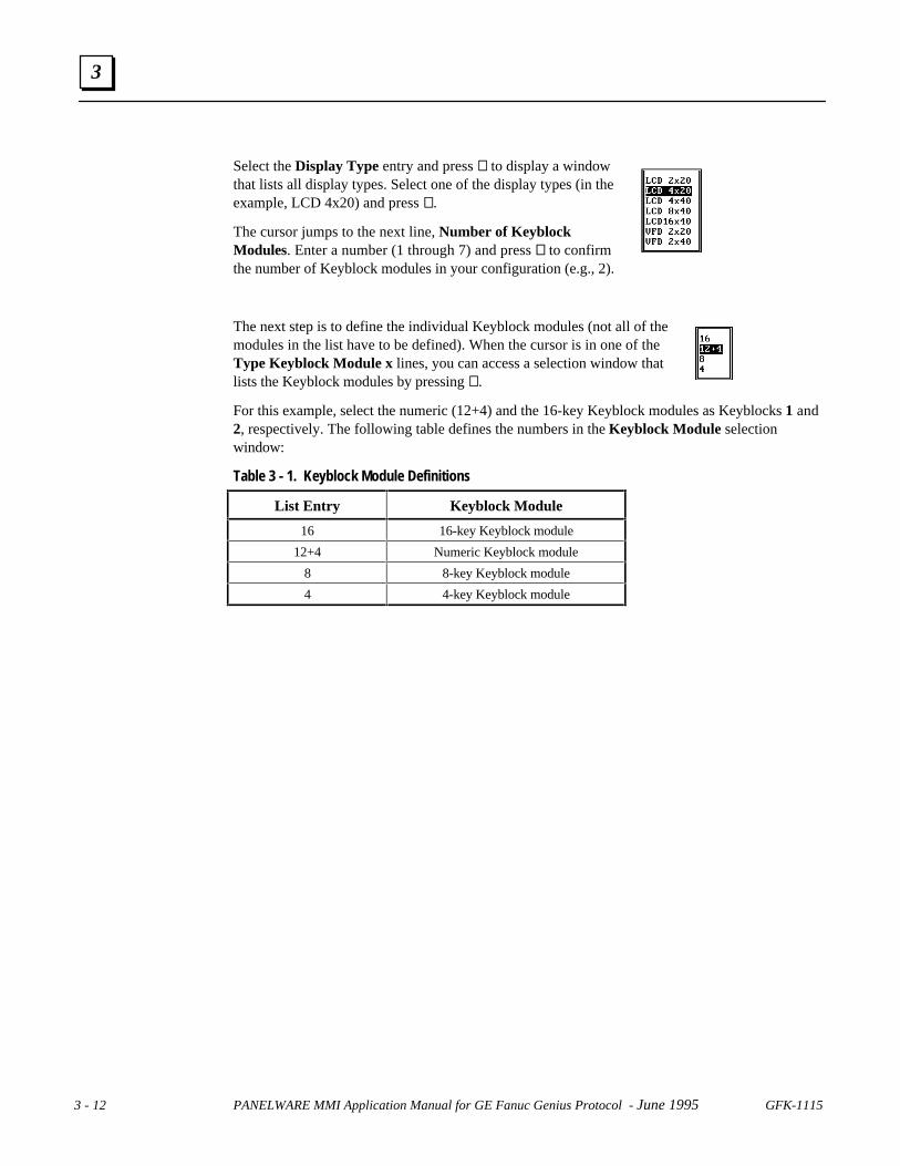
Select the Display Type entry and press ↵↵ to display a windowthat lists all display types. Select one of the display types (in theexample, LCD 4x20) and press ↵↵.
The cursor jumps to the next line, Number of KeyblockModules. Enter a number (1 through 7) and press ↵↵ to confirmthe number of Keyblock modules in your configuration (e.g., 2).
The next step is to define the individual Keyblock modules (not all of themodules in the list have to be defined). When the cursor is in one of theType Keyblock Module x lines, you can access a selection window thatlists the Keyblock modules by pressing ↵↵.
For this example, select the numeric (12+4) and the 16-key Keyblock modules as Keyblocks 1 and2, respectively. The following table defines the numbers in the Keyblock Module selectionwindow:
Table 3 - 1. Keyblock Module Definitions
List Entry Keyblock Module
16 16-key Keyblock module
12+4 Numeric Keyblock module
8 8-key Keyblock module
4 4-key Keyblock module
GFK-1115 Chapter 3 Quick Start 3 - 13
3
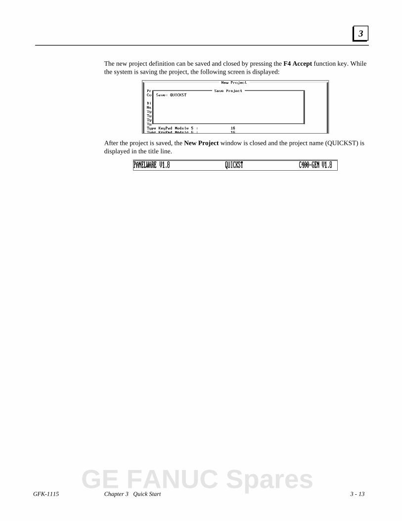
The new project definition can be saved and closed by pressing the F4 Accept function key. Whilethe system is saving the project, the following screen is displayed:
After the project is saved, the New Project window is closed and the project name (QUICKST) isdisplayed in the title line.
GE FANUC Spares

3 - 14 PANELWARE MMI Application Manual for GE Fanuc Genius Protocol - June 1995 GFK-1115
3
Section 6 Defining Connections
The next step after creating a new project is to define the connections. All PLCs and other devicesthat are to communicate with the Panel must be entered in the connection editor. To change orinsert connections, select the Connection option from the Edit menu.
The following window, Connection List displays all entered connections:
When creating a new project for the C400-Genius Controller, a default entry with the ID, DD, ismade automatically (connection to a GE Fanuc PLC via the Genius bus). However, the associatedPLC type is not defaulted and must be specified.

GFK-1115 Chapter 3 Quick Start 3 - 15
3
Connection to a GE Fanuc PLC via Genius
Press F1 Edit to edit the connection DD Genius:
Move the cursor to the PLC Type line using the →→ or ↵↵ key:
The PLC type to communicate with can be chosen from this selection window. For this example,use the cursor keys to highlight the entry GBC Series 90-70 and press the ↵↵ key, closing theselection window.
GE FANUC Spares

3 - 16 PANELWARE MMI Application Manual for GE Fanuc Genius Protocol - June 1995 GFK-1115
3
The Connection Definition window containing the new connection is displayed.
By pressing F4 Accept, the change is confirmed and shown in the Connection List window:
To configure the Genius bus aspects of the connection, press the F4 PLC Node Parameters Key.

GFK-1115 Chapter 3 Quick Start 3 - 17
3
Here, the Target device number, or Genius bus address, of the connection is specified. Enter thebus address of your GBC (typically bus address 31) in the Target device number field.
No other data needs to be entered into the PLC Node Parameter Definition screen for thisexample. Pressing F4 Accept completes the entry
GE FANUC Spares
3 - 18 PANELWARE MMI Application Manual for GE Fanuc Genius Protocol - June 1995 GFK-1115
3
Internal Connection
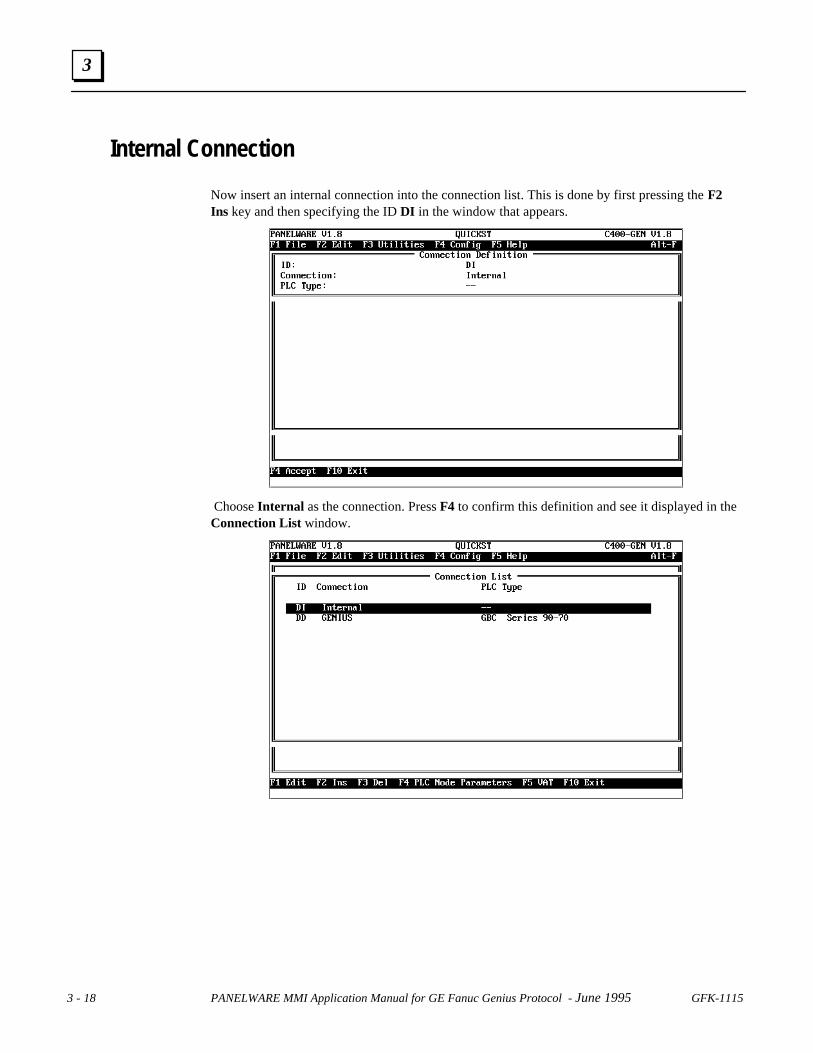
Now insert an internal connection into the connection list. This is done by first pressing the F2Ins key and then specifying the ID DI in the window that appears.
Choose Internal as the connection. Press F4 to confirm this definition and see it displayed in theConnection List window.

GFK-1115 Chapter 3 Quick Start 3 - 19
3
Genius Internal Connection
As a final connection, insert a Genius internal connection into the connection list. this is done byfirst pressing the F2 Ins key and then specifying the ID GI in the window that appears. ChooseGenius as the Connection and Genius Internal as the PLC Type. This definition is nowconfirmed and the new connection displayed in the connection list upon pressing the F4 Acceptkey.
GE FANUC Spares
3 - 20 PANELWARE MMI Application Manual for GE Fanuc Genius Protocol - June 1995 GFK-1115
3
Section 7 Key Assignments
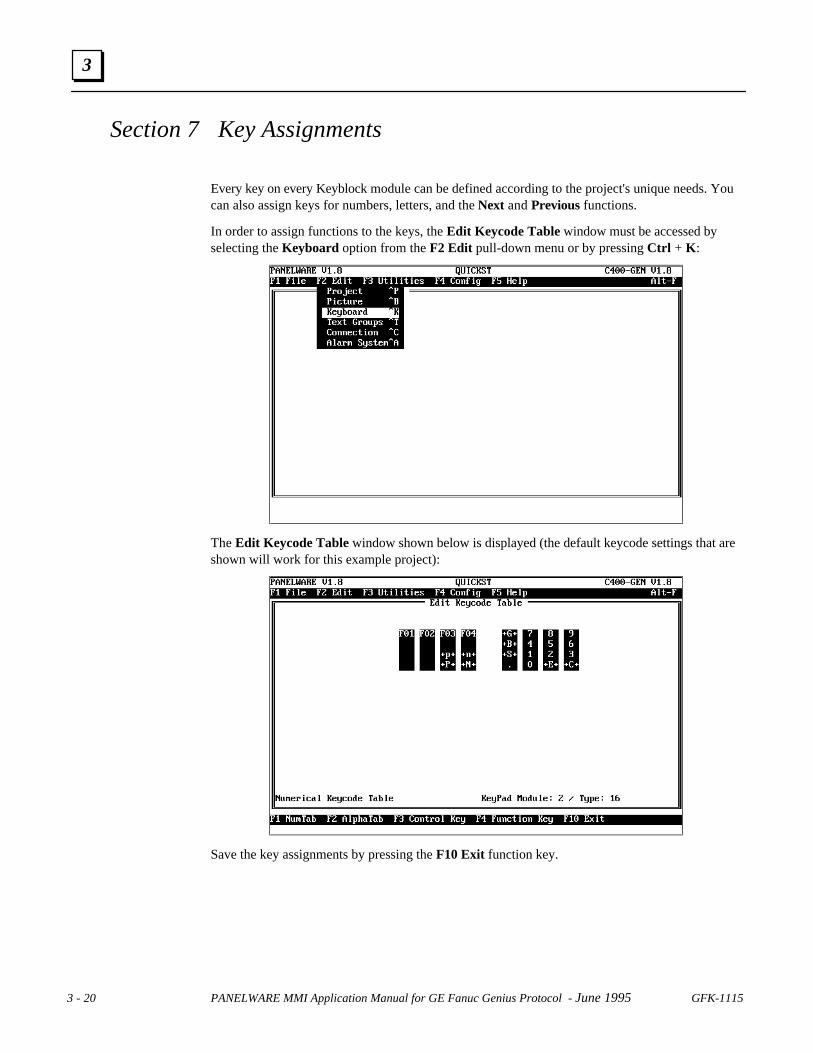
Every key on every Keyblock module can be defined according to the project's unique needs. Youcan also assign keys for numbers, letters, and the Next and Previous functions.
In order to assign functions to the keys, the Edit Keycode Table window must be accessed byselecting the Keyboard option from the F2 Edit pull-down menu or by pressing Ctrl + K :
The Edit Keycode Table window shown below is displayed (the default keycode settings that areshown will work for this example project):
Save the key assignments by pressing the F10 Exit function key.

GFK-1115 Chapter 3 Quick Start 3 - 21
3
The abbreviations on the Keyblock module keys have the following meanings:
Table 3 - 2. Keyblock Abbreviation Definitions
Abbr. Description
F1 ... F4 Function keys 1 through 4 (used for commands and picture changes)
+p+ Moves cursor to the previous INPUT field
+n+ Moves cursor to the next INPUT field
+P+ Changes to the previous picture
+N+ Changes to the next picture
+G+ Global alarm acknowledgment
+B+ Backspace; deletes the character before the cursor in an INPUT field
+S+ Changes the sign in a numerical INPUT field
+E+ Enter key; transmits the value entered in an INPUT field; labeled as ↵↵ onactual Keyblock
+C+ Cancels (deletes) an INPUT field; labeled as ← on actual Keyblock
. Decimal point
0 ... 9 Numbers 0 - 9 for the entry of numbers
GE FANUC Spares
3 - 22 PANELWARE MMI Application Manual for GE Fanuc Genius Protocol - June 1995 GFK-1115
3
Section 8 Creating Pictures
Pictures make up the basic elements of every Panel project. They include static elements such astext and lines1, and/or dynamic elements like input and output fields. Output fields allowinformation, such as temperature, RPM, etc., to be updated and displayed for the user. Input fieldscan be used to display entries given to the process that you enter using the keyboard.
A project must contain at least two pictures—one picture that displays when the Panel powers up,and another that displays in the event of a communications failure. This example project willcontain three pictures, as follows:
1. Picture 1 is the picture where values will be entered using the keyboard, transmitted to thePLC and output in another field.
2. Picture 2 is the start-up picture that is to be displayed when the Panel and PLC are switchedon. Only the Panel’s date and time, and the scan rate of the Genius bus will be displayed.
3. Picture 3 is displayed if there is a communications failure between the PLC and the Panel.Only text providing notice of a communications error will be displayed in this picture.
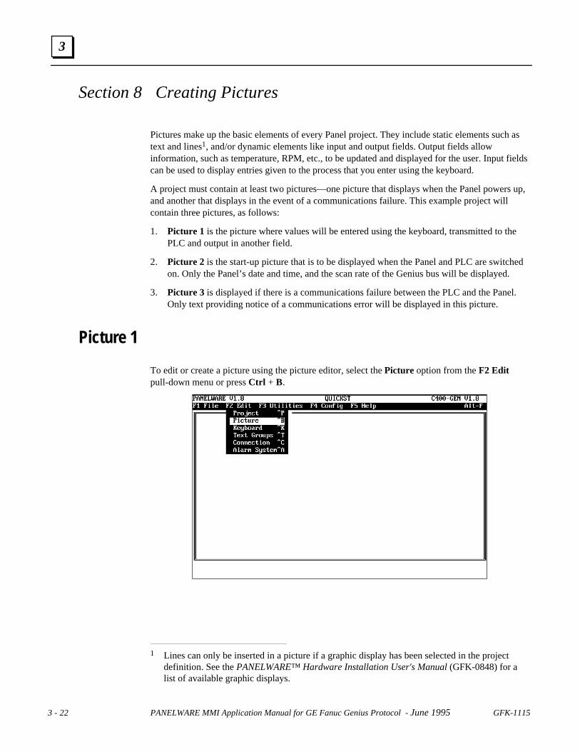
Picture 1
To edit or create a picture using the picture editor, select the Picture option from the F2 Editpull-down menu or press Ctrl + B.
1 Lines can only be inserted in a picture if a graphic display has been selected in the project
definition. See the PANELWARE™ Hardware Installation User's Manual (GFK-0848) for alist of available graphic displays.

GFK-1115 Chapter 3 Quick Start 3 - 23
3
The blank Edit Picture window shown below is displayed:
The size of the dark rectangle (picture) at the bottom of the screen corresponds to the selecteddisplay type (display type LCD 4x20 is shown above, i.e., the rectangle consists of 4 lines and 20characters per line). Text or fields can now be entered into this rectangle.
In the first line, enter the text Input / Output as follows:
Move the cursor to position (3,0) (the current cursor position is indicated in the lower right-handcorner of the screen as Column/Row). A text field can now be created simply by typing in thedesired text (Input / Output ). It is also possible to start a text field by pressing the F1 Textfunction key and then entering the desired text.
As long as the cursor is within this text field, the field is displayed inversely (on color monitors ithas a red background). Press ↵↵ to complete the text field. The inverse display is switched off andthe text is displayed normally.
Move down to lines 2 and 3, and enter the following text:
Next to the Output: text, begin creating an output field by moving the cursor to the followingposition (8,2):
GE FANUC Spares
3 - 24 PANELWARE MMI Application Manual for GE Fanuc Genius Protocol - June 1995 GFK-1115
3
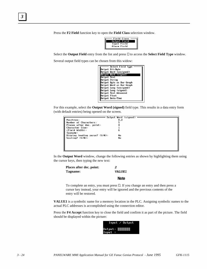
Press the F2 Field function key to open the Field Class selection window.
Select the Output Field entry from the list and press ↵↵ to access the Select Field Type window.
Several output field types can be chosen from this widow:
For this example, select the Output Word (signed) field type. This results in a data entry form(with default entries) being opened on the screen.
In the Output Word window, change the following entries as shown by highlighting them usingthe cursor keys, then typing the new text:
Places after dec. point: 2Tagname: VALUE1
Note
To complete an entry, you must press ↵↵. If you change an entry and then press acursor key instead, your entry will be ignored and the previous contents of theentry will be restored.
VALUE1 is a symbolic name for a memory location in the PLC. Assigning symbolic names to theactual PLC addresses is accomplished using the connection editor.
Press the F4 Accept function key to close the field and confirm it as part of the picture. The fieldshould be displayed within the picture:

GFK-1115 Chapter 3 Quick Start 3 - 25
3
Move the cursor to the Input: text line and press the F2 Field function key. Select the Inputfield option from the Field Class window that is displayed:
The Select Field Type window containing all of the input field types is displayed.
For this example, select the Input Word (signed) field type:
In the Input Word window that is displayed, change the following entries as shown byhighlighting them using the cursor keys, then typing the new text:
Places after dec. point: 2Tagname: VALUE1
Press the F4 Accept function key to close the field and confirm it as part of the picture. The fieldshould be displayed within the picture as shown below:
GE FANUC Spares
3 - 26 PANELWARE MMI Application Manual for GE Fanuc Genius Protocol - June 1995 GFK-1115
3
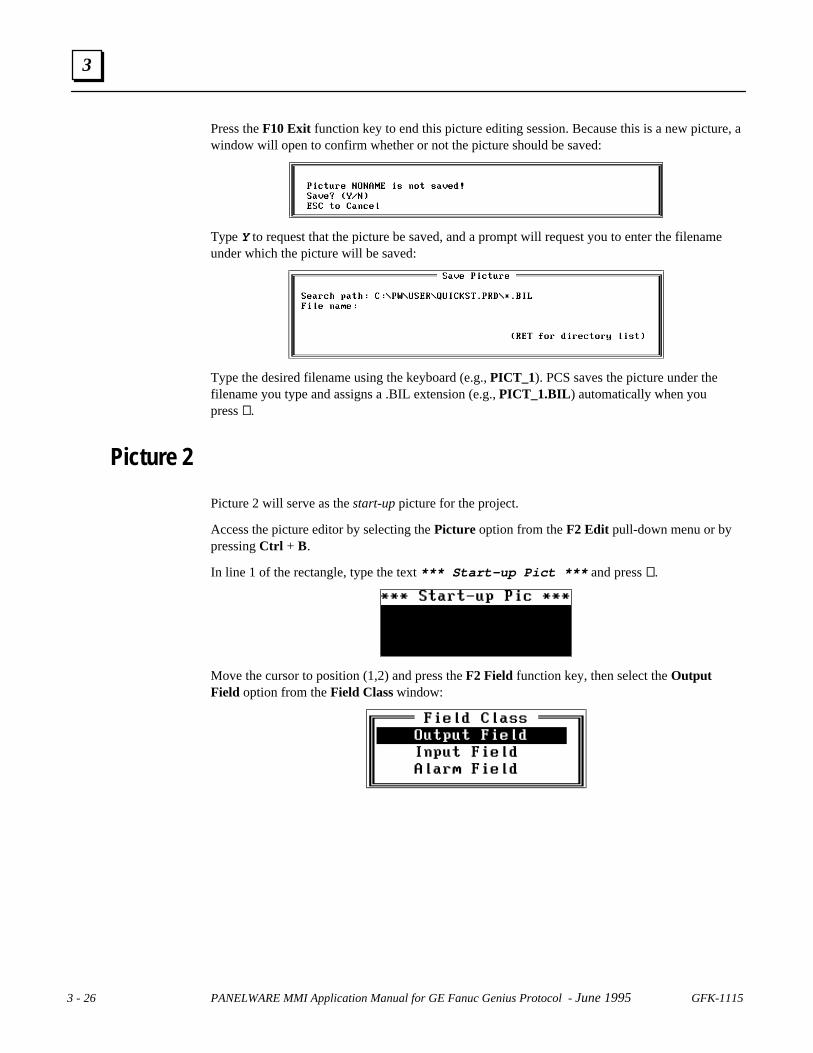
Press the F10 Exit function key to end this picture editing session. Because this is a new picture, awindow will open to confirm whether or not the picture should be saved:
Type Y to request that the picture be saved, and a prompt will request you to enter the filenameunder which the picture will be saved:
Type the desired filename using the keyboard (e.g., PICT_1). PCS saves the picture under thefilename you type and assigns a .BIL extension (e.g., PICT_1.BIL ) automatically when youpress ↵↵.
Picture 2
Picture 2 will serve as the start-up picture for the project.
Access the picture editor by selecting the Picture option from the F2 Edit pull-down menu or bypressing Ctrl + B.
In line 1 of the rectangle, type the text *** Start-up Pict *** and press ↵↵.
Move the cursor to position (1,2) and press the F2 Field function key, then select the OutputField option from the Field Class window:

GFK-1115 Chapter 3 Quick Start 3 - 27
3
From the Select field type window that is displayed, select the Output Date/Time option:
The output format for the date and time is selected from the following window that is displayed:
Do not make any changes in this window and press the F4 Accept function key. The Date/Timefield will be displayed in the start-up picture:
Move the cursor to position (1,3), type the text Bus Scan: , and press ↵↵. Next, move the cursorto position (16,3), type the text ms, and again press ↵↵.
Using the same process detailed above for creating the Output Date/Time field, position the cursorat (11,3), and create an Output Word (unsigned) field with the following definition:
GE FANUC Spares
3 - 28 PANELWARE MMI Application Manual for GE Fanuc Genius Protocol - June 1995 GFK-1115
3
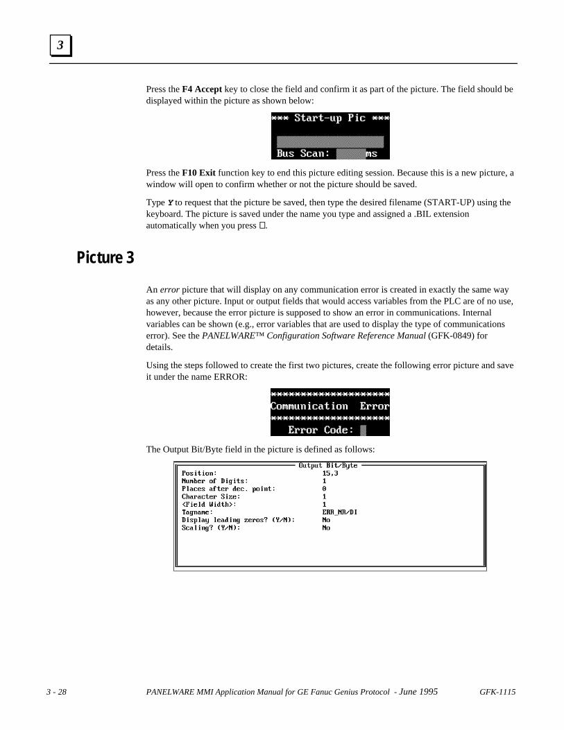
Press the F4 Accept key to close the field and confirm it as part of the picture. The field should bedisplayed within the picture as shown below:
Press the F10 Exit function key to end this picture editing session. Because this is a new picture, awindow will open to confirm whether or not the picture should be saved.
Type Y to request that the picture be saved, then type the desired filename (START-UP) using thekeyboard. The picture is saved under the name you type and assigned a .BIL extensionautomatically when you press ↵↵.
Picture 3
An error picture that will display on any communication error is created in exactly the same wayas any other picture. Input or output fields that would access variables from the PLC are of no use,however, because the error picture is supposed to show an error in communications. Internalvariables can be shown (e.g., error variables that are used to display the type of communicationserror). See the PANELWARE™ Configuration Software Reference Manual (GFK-0849) fordetails.
Using the steps followed to create the first two pictures, create the following error picture and saveit under the name ERROR:
The Output Bit/Byte field in the picture is defined as follows:
GFK-1115 Chapter 3 Quick Start 3 - 29
3
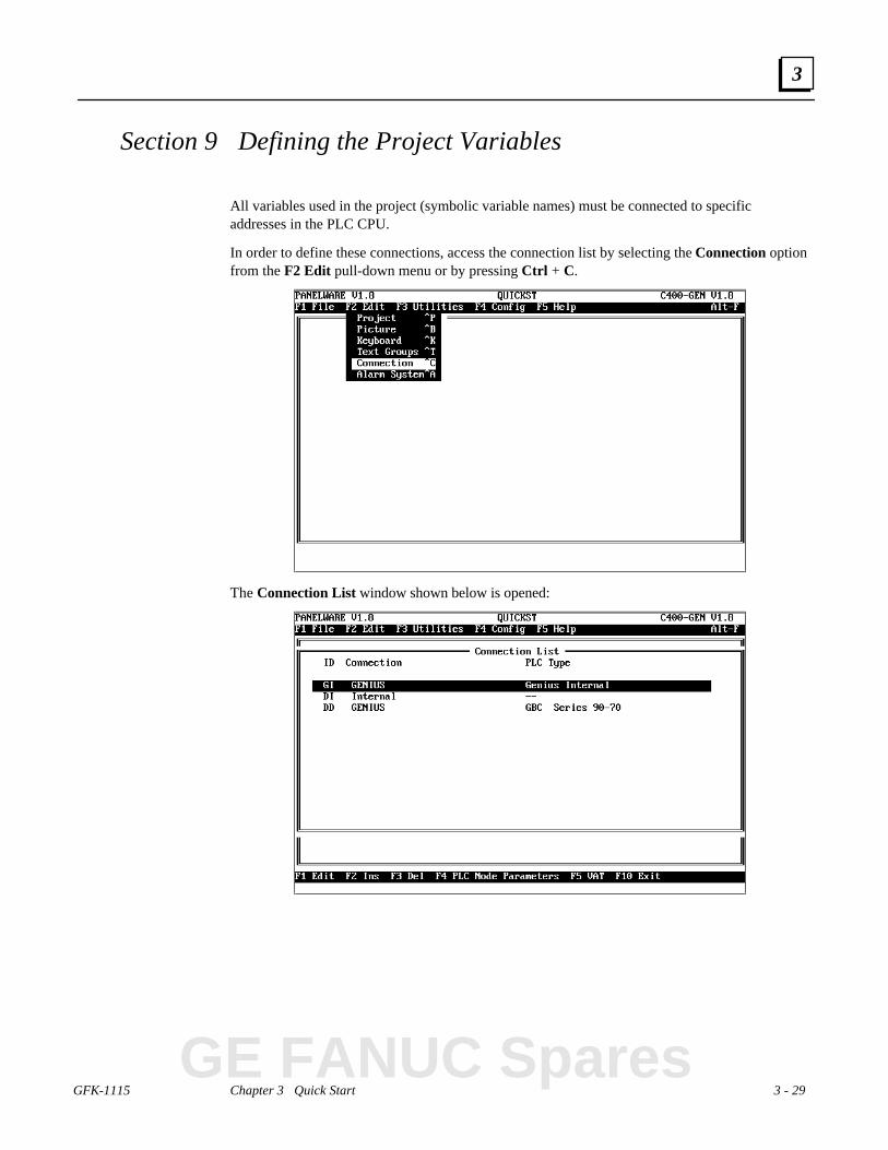
Section 9 Defining the Project Variables
All variables used in the project (symbolic variable names) must be connected to specificaddresses in the PLC CPU.
In order to define these connections, access the connection list by selecting the Connection optionfrom the F2 Edit pull-down menu or by pressing Ctrl + C.
The Connection List window shown below is opened:
GE FANUC Spares

3 - 30 PANELWARE MMI Application Manual for GE Fanuc Genius Protocol - June 1995 GFK-1115
3
Genius Device Connection
Use the cursor keys to highlight connection DD Genius, and then press the F5 VAT function keyto display the associated variable assignment table (VAT) on the screen.
All variables that have been used in a picture's input or output fields in the project are listed in theVariable Assignment Table window. In this example project, only one name, VALUE1 , isdisplayed:
To assign an address in the PLC CPU to the VALUE1 variable, press the F1 Edit function key.The VAT Definition window shown below is opened:
The PLC address can be entered directly at the PLC Address line using the keyboard (e.g.,%R0100).
If the cursor is in the PLC Variable Type line, a variable type selectionwindow that shows all valid variable types can be opened by pressing ↵↵.Select DINT from the selection window.

GFK-1115 Chapter 3 Quick Start 3 - 31
3
The definition that is entered can be saved by pressing the F4 Accept function key. Once saved,the newly selected variable is shown in the VAT.
Pressing the F10 Exit function key causes the connection list to appear on the screen again.
Genius Internal Connection
Select the GE Genius Internal connection from the connection list and press either F5 VAT or ↵↵to display the connection in the Variable Assignment Table:
Press the F1 Edit function key to open the VAT Definition window for the GENIUS_BUStagname. Edit the definition for GENIUS_BUS as shown below (Follow the same procedure thatwas used for editing the tagname VALUE1 in the DD connection — see page 30):
After accepting the entry (by pressing F4), press F10 Exit to return to the Connection Listwindow.
GE FANUC Spares

3 - 32 PANELWARE MMI Application Manual for GE Fanuc Genius Protocol - June 1995 GFK-1115
3
Internal Connection
Select the DI Internal connection from the connection list and press F5 or ↵↵ to view its VAT:
This is the variable that will be output in the error picture. The internal variables cannot be edited.You can close the VAT by pressing F10 Exit, which calls the connection list once again. Press theF10 Exit key again to close the connection list and return to the main menu.

GFK-1115 Chapter 3 Quick Start 3 - 33
3
Section 10 Binding Pictures in the Project
The pictures that you have created for this project still have to be bound into the project definition.To begin the binding process, select the Project option from the F2 Edit pull-down menu or pressCtrl + P.
The Edit Project window shown below is opened:
The picture binding process for this project consists of the following three steps:
1. Entering the filename of the ERROR picture
2. Binding the three project pictures
3. Organizing the picture directory
These processes are explained in the sections that follow.
GE FANUC Spares

3 - 34 PANELWARE MMI Application Manual for GE Fanuc Genius Protocol - June 1995 GFK-1115
3
Picture for a Communications Error
From the Edit Project window, press the F1 Project Def. function key to move the cursor to thePicture for Communications Error line in the window. The function line options are changed asshown below:
The file name of the error picture can be entered directly using the keyboard or the followingselection window can be accessed by pressing the F5 Pictures function key.
Highlight the desired filename (ERROR.BIL) and press ↵↵, then confirm the project definition bypressing the F4 Accept function key.

GFK-1115 Chapter 3 Quick Start 3 - 35
3
Picture Binding Overview
Binding a picture into the project means that all possible branches (picture changes) that thepicture can have are defined. A picture change can be made using the Next, Previous or optionalfunction keys2.
When you press the F2 Bind Picture function key from the Edit Project window, the BindPicture window appears on the screen:
When the cursor is located in one of the boxes in the window, a picture name can be entereddirectly by using the keyboard or a selection window containing picture names can be accessed bypressing the F5 Pictures function key.
In the first box (left-hand side of the screen), enter the name of the picture to be bound into theproject. When you press ↵↵, the picture is accepted and the cursor moves to the upper right-handbox. You can switch between the upper and lower right-hand boxes using the cursor keys. Whenthe cursor is in one of the boxes on the right-hand side, the function line at the bottom of thescreen changes as shown below:
Press the F1 Picture name function key to move the cursor back to the box on the left-hand sideof the screen. Use these cursor location controls to bind this project's pictures as described in thefollowing sections. 2 The user can define keys to be used for Next, Previous or function keys (see “Key
Assignments” in this chapter).
GE FANUC Spares

3 - 36 PANELWARE MMI Application Manual for GE Fanuc Genius Protocol - June 1995 GFK-1115
3
Error Picture
Bind the ERROR picture into the example project as follows:
Caution
You should not branch from the ERROR picture to a picture that has fieldsdisplaying data from the PLC in it because the fields will not be updated orprocessed if a communications error occurs.
Save the configuration by pressing the F4 Accept function key.
GFK-1115 Chapter 3 Quick Start 3 - 37
3
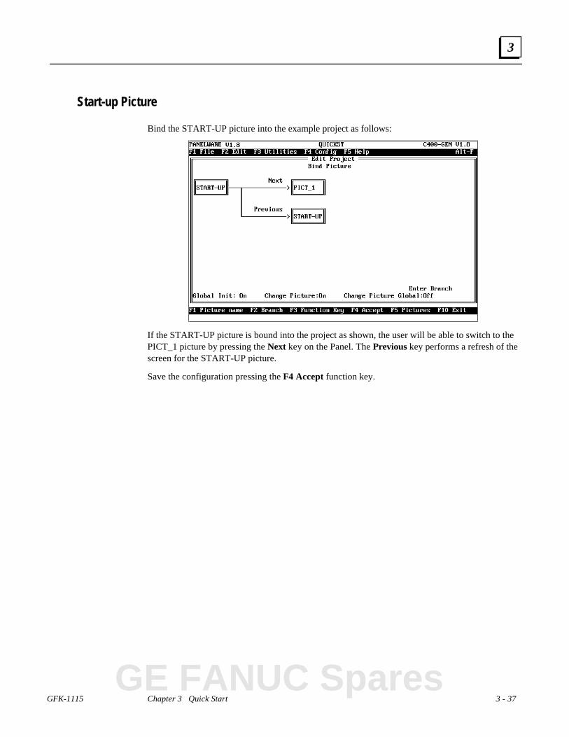
Start-up Picture
Bind the START-UP picture into the example project as follows:
If the START-UP picture is bound into the project as shown, the user will be able to switch to thePICT_1 picture by pressing the Next key on the Panel. The Previous key performs a refresh of thescreen for the START-UP picture.
Save the configuration pressing the F4 Accept function key.
GE FANUC Spares

3 - 38 PANELWARE MMI Application Manual for GE Fanuc Genius Protocol - June 1995 GFK-1115
3
Pict_1
Bind the PICT_1 picture into the example project as follows:
If the PICT_1 picture is bound into the project as shown, the operator will be able to switch backto the START-UP picture using the Previous key on the Panel. Pressing the Next key causes arefresh of the screen for the PICT_1 picture. Save the configuration by pressing the F4 Acceptfunction key.

GFK-1115 Chapter 3 Quick Start 3 - 39
3
Picture List Organization
When you press the F3 Picture List function key from the Edit Project window, a list of all ofthe pictures that are bound to the project is displayed:
The picture defined as the ERROR picture is not allowed to be placed in the top position in thepicture list; the picture in the top position must be the one initially displayed when the Panel ispower cycled (start-up picture).
Accordingly, in this example, the ERROR picture must be moved down from its top position inthe list using the F7 Back function key. This will move the item in the current cursor positiondown one line in the list, and move the next item one line up as shown below:
The START-UP picture should now be in the correct position (000).
Press the F10 Exit function key to save the changes and redisplay the Edit Project window. PressF10 Exit again to return to the Main menu.
GE FANUC Spares

3 - 40 PANELWARE MMI Application Manual for GE Fanuc Genius Protocol - June 1995 GFK-1115
3
Section 11 Compiling the Project
In order to create, transfer and run your project on the Panel, it must be compiled (translated).
To compile the example project, select the Compile option from the F3 Utilities pull-down menuor press Ctrl + Q:
The compilation procedure status messages are displayed in the Project Compiler window that isdisplayed. If the project is compiled successfully, the following message is displayed:
The amount of memory the project will occupy in the user memory (user Flash) in the Panel isalso displayed.
Press Esc to close the Project Compiler window and return to the Main menu.
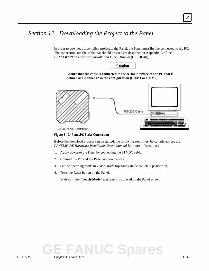
GFK-1115 Chapter 3 Quick Start 3 - 41
3
Section 12 Downloading the Project to the Panel
In order to download a compiled project to the Panel, the Panel must first be connected to the PC.The connection and the cable that should be used are described in Appendix A of thePANELWARE™ Hardware Installation User's Manual (GFK-0848).
Caution
Ensure that the cable is connected to the serial interface of the PC that isdefined as Channel #2 in the configuration (COM1 or COM2).
Figure 3 - 2. Panel/PC Serial Connection
Before the download process can be started, the following steps must be completed (see thePANELWARE Hardware Installation User's Manual for more information):
1. Apply power to the Panel by connecting the 24 VDC cable.
2. Connect the PC and the Panel as shown above.
3. Set the operating mode to Teach-Mode (operating mode switch to position 7).
4. Press the Reset button on the Panel.
Wait until the “Teach-Mode” message is displayed on the Panel screen.
GE FANUC Spares

3 - 42 PANELWARE MMI Application Manual for GE Fanuc Genius Protocol - June 1995 GFK-1115
3
Once these steps have been performed, the download process can be started by selecting theDownload option from the F3 Utilities pull-down menu or by pressing Ctrl + X:
The Download Project title and the number of the channel (Channel #2) are centered in the topmargin of the window that appears on the screen to prompt you to begin the process.
Start the download process by typing Y.
In order to begin the download, the PCS tries to make a connection with the Panel. If theconnection is successful, the following messages are displayed on the screen:
When the compiled project has been loaded to the Panel successfully, the message Downloadcomplete! is displayed.
Press Esc to close the Download Project window and return to the Main menu.
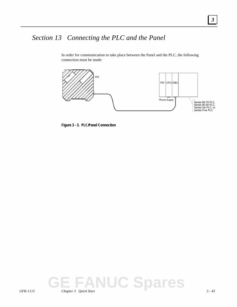
GFK-1115 Chapter 3 Quick Start 3 - 43
3
Section 13 Connecting the PLC and the Panel
In order for communication to take place between the Panel and the PLC, the followingconnection must be made:
Figure 3 - 3. PLC/Panel Connection
GE FANUC Spares
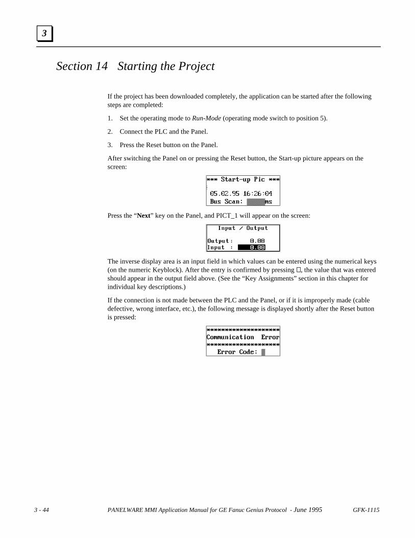
3 - 44 PANELWARE MMI Application Manual for GE Fanuc Genius Protocol - June 1995 GFK-1115
3
Section 14 Starting the Project
If the project has been downloaded completely, the application can be started after the followingsteps are completed:
1. Set the operating mode to Run-Mode (operating mode switch to position 5).
2. Connect the PLC and the Panel.
3. Press the Reset button on the Panel.
After switching the Panel on or pressing the Reset button, the Start-up picture appears on thescreen:
Press the “Next” key on the Panel, and PICT_1 will appear on the screen:
The inverse display area is an input field in which values can be entered using the numerical keys(on the numeric Keyblock). After the entry is confirmed by pressing ↵↵, the value that was enteredshould appear in the output field above. (See the “Key Assignments” section in this chapter forindividual key descriptions.)
If the connection is not made between the PLC and the Panel, or if it is improperly made (cabledefective, wrong interface, etc.), the following message is displayed shortly after the Reset buttonis pressed:
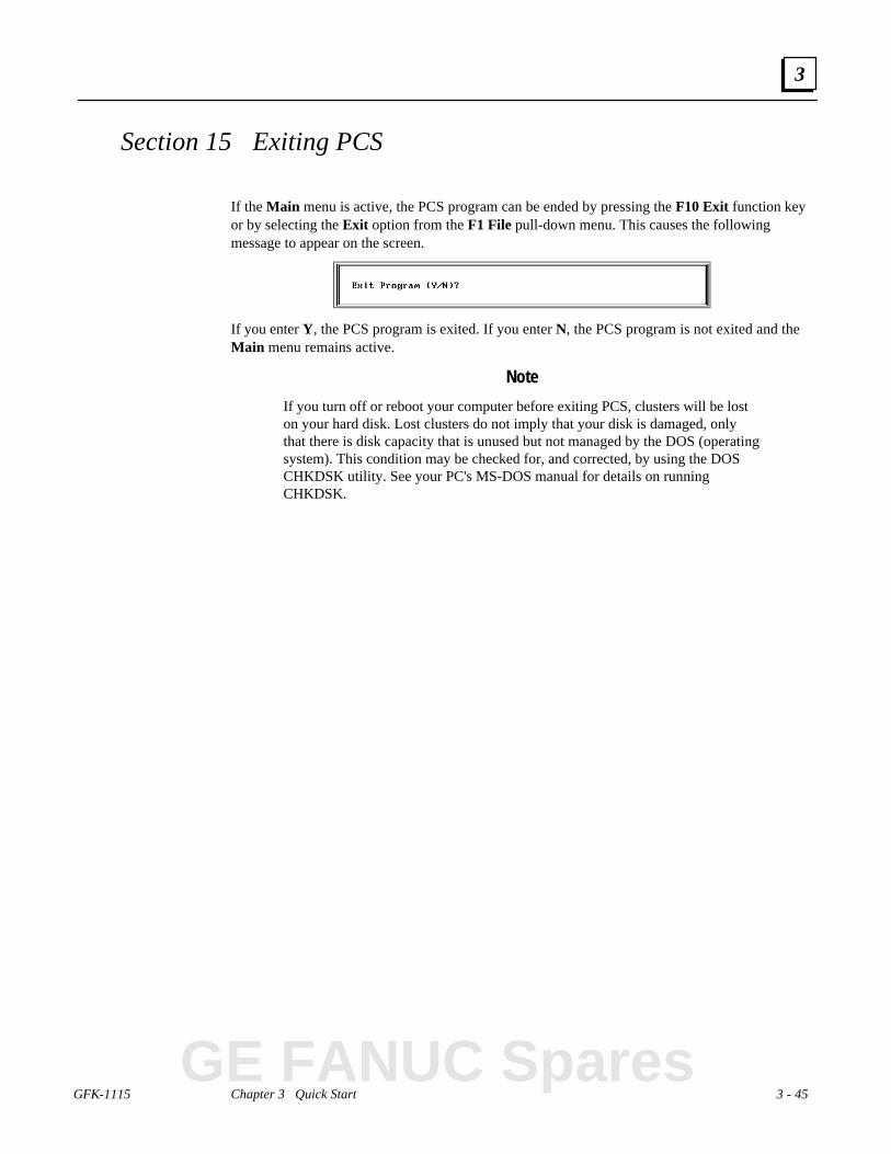
GFK-1115 Chapter 3 Quick Start 3 - 45
3
Section 15 Exiting PCS
If the Main menu is active, the PCS program can be ended by pressing the F10 Exit function keyor by selecting the Exit option from the F1 File pull-down menu. This causes the followingmessage to appear on the screen.
If you enter Y, the PCS program is exited. If you enter N, the PCS program is not exited and theMain menu remains active.
Note
If you turn off or reboot your computer before exiting PCS, clusters will be loston your hard disk. Lost clusters do not imply that your disk is damaged, onlythat there is disk capacity that is unused but not managed by the DOS (operatingsystem). This condition may be checked for, and corrected, by using the DOSCHKDSK utility. See your PC's MS-DOS manual for details on runningCHKDSK.
GE FANUC Spares
GFK-1115 4 - 1
Chapter Configuring Communication with the PLC
This chapter provides information on how to configure the interfaces of the Panel Controller andthe PLC to make the connection between them. The following information is included:
■ Genius Protocol Parameters (Definition in PCS).........................................................4-2
❏ PLC Types...........................................................................................................4-3
❏ PLC Node Parameter Definitions.........................................................................4-5
❏ PLC Network Parameter Definitions....................................................................4-7
■ SNP 90 Protocol Parameters (Definition in PCS)........................................................4-9
■ Settings on the Panel ................................................................................................4-10
■ Panel Interface..........................................................................................................4-10
■ Configuration of the PLC Interface...........................................................................4-10
❏ Genius...............................................................................................................4-11
❏ SNP...................................................................................................................4-11
4
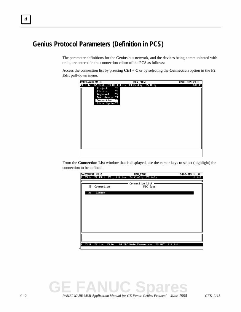
4 - 2 PANELWARE MMI Application Manual for GE Fanuc Genius Protocol - June 1995 GFK-1115
4
Genius Protocol Parameters (Definition in PCS)
The parameter definitions for the Genius bus network, and the devices being communicated withon it, are entered in the connection editor of the PCS as follows:
Access the connection list by pressing Ctrl + C or by selecting the Connection option in the F2Edit pull-down menu.
From the Connection List window that is displayed, use the cursor keys to select (highlight) theconnection to be defined.
-
GE FANUC Spares

GFK-1115 Chapter 4 Configuring Communication with the PLC 4 - 3
4
PLC Types
Every Genius connection must be configured to specify a PLC Type. Except for the case of thePCS-created DD GENIUS default connection, this PLC type must be provided when inserting anew connection. For the DD GENIUS default connection, the PLC type must be provided before asuccessful project compilation can occur.
In either case, a PLC Type selection window is accessed when editing the Connection Definition.
Table 4-1 summarizes the types of data that can be accessed for each PLC type.
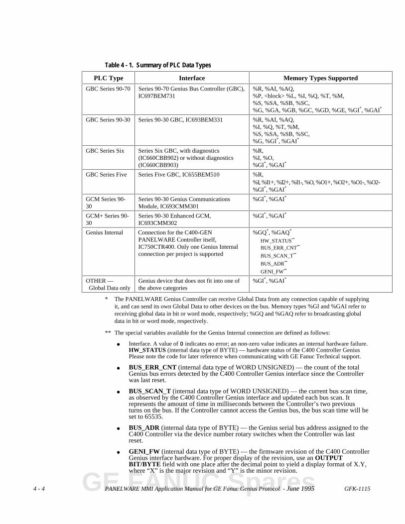
4 - 4 PANELWARE MMI Application Manual for GE Fanuc Genius Protocol - June 1995 GFK-1115
Table 4 - 1. Summary of PLC Data Types
PLC Type Interface Memory Types Supported
GBC Series 90-70 Series 90-70 Genius Bus Controller (GBC),IC697BEM731
%R, %AI, %AQ,%P, <block> %L, %I, %Q, %T, %M,%S, %SA, %SB, %SC,%G, %GA, %GB, %GC, %GD, %GE, %GI*, %GAI*
GBC Series 90-30 Series 90-30 GBC, IC693BEM331 %R, %AI, %AQ,%I, %Q, %T, %M,%S, %SA, %SB, %SC,%G, %GI*, %GAI*
GBC Series Six Series Six GBC, with diagnostics(IC660CBB902) or without diagnostics(IC660CBB903)
%R,%I, %O,%GI*, %GAI*
GBC Series Five Series Five GBC, IC655BEM510 %R,%I, %I1+, %I2+, %I1-, %O, %O1+, %O2+, %O1-, %O2-%GI*, %GAI*
GCM Series 90-30
Series 90-30 Genius CommunicationsModule, IC693CMM301
%GI*, %GAI*
GCM+ Series 90-30
Series 90-30 Enhanced GCM,IC693CMM302
%GI*, %GAI*
Genius Internal Connection for the C400-GENPANELWARE Controller itself,IC750CTR400. Only one Genius Internalconnection per project is supported
%GQ*, %GAQ*
HW_STATUS**
BUS_ERR_CNT**
BUS_SCAN_T**
BUS_ADR**
GENI_FW**
OTHER — Global Data only
Genius device that does not fit into one ofthe above categories
%GI*, %GAI*
* The PANELWARE Genius Controller can receive Global Data from any connection capable of supplyingit, and can send its own Global Data to other devices on the bus. Memory types %GI and %GAI refer toreceiving global data in bit or word mode, respectively; %GQ and %GAQ refer to broadcasting globaldata in bit or word mode, respectively.
** The special variables available for the Genius Internal connection are defined as follows:
● Interface. A value of 0 indicates no error; an non-zero value indicates an internal hardware failure.HW_STATUS (internal data type of BYTE) — hardware status of the C400 Controller GeniusPlease note the code for later reference when communicating with GE Fanuc Technical support.
● BUS_ERR_CNT (internal data type of WORD UNSIGNED) — the count of the totalGenius bus errors detected by the C400 Controller Genius interface since the Controllerwas last reset.
● BUS_SCAN_T (internal data type of WORD UNSIGNED) — the current bus scan time,as observed by the C400 Controller Genius interface and updated each bus scan. Itrepresents the amount of time in milliseconds between the Controller’s two previousturns on the bus. If the Controller cannot access the Genius bus, the bus scan time will beset to 65535.
● BUS_ADR (internal data type of BYTE) — the Genius serial bus address assigned to theC400 Controller via the device number rotary switches when the Controller was lastreset.
● GENI_FW (internal data type of BYTE) — the firmware revision of the C400 ControllerGenius interface hardware. For proper display of the revision, use an OUTPUTBIT/BYTE field with one place after the decimal point to yield a display format of X.Y,where “X” is the major revision and “Y” is the minor revision.
GE FANUC Spares
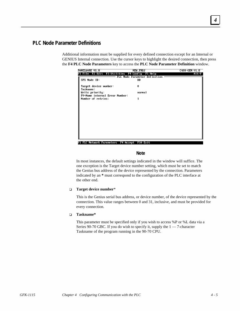
GFK-1115 Chapter 4 Configuring Communication with the PLC 4 - 5
4
PLC Node Parameter Definitions
Additional information must be supplied for every defined connection except for an Internal orGENIUS Internal connection. Use the cursor keys to highlight the desired connection, then pressthe F4 PLC Node Parameters key to access the PLC Node Parameter Definition window.
Note
In most instances, the default settings indicated in the window will suffice. Theone exception is the Target device number setting, which must be set to matchthe Genius bus address of the device represented by the connection. Parametersindicated by an * must correspond to the configuration of the PLC interface atthe other end.
❏ Target device number*
This is the Genius serial bus address, or device number, of the device represented by theconnection. This value ranges between 0 and 31, inclusive, and must be provided forevery connection.
❏ Taskname*
This parameter must be specified only if you wish to access %P or %L data via aSeries 90-70 GBC. If you do wish to specify it, supply the 1 — 7-characterTaskname of the program running in the 90-70 CPU.

4 - 6 PANELWARE MMI Application Manual for GE Fanuc Genius Protocol - June 1995 GFK-1115
4
❏ Write priority
Data can be written to another device on the Genius bus in one of two ways: via globaldata, or via datagrams. Only the %GQ and %GAQ data types are handled by global datawrites; all other memory types are handled by datagrams.
Datagrams can be sent with either normal or high priority. Normal priority means thatthe C400 Controller will send the datagram only if no other datagram or similarbackground message has been sent by any other device on the Genius bus during thecurrent bus scan. High priority means that the datagram will be sent when the C400Controller has its turn on the bus, regardless of the number of datagrams and otherbackground messages that have already been sent during the current bus scan.
Sending datagrams with high priority could adversely affect bus scan time. Also,excessive numbers of datagrams sent to a device during a single bus scan could result insome of the datagrams being ignored. Refer to the Genius™ I/O System andCommunications User’s Manual (GEK-90486-1) for details.
❏ PV-Name internal Error Number
The Genius driver maintains specific error information for each of the possibledevices on the Genius bus. A word variable from the PANELWARE InternalConnection, USERWORDnn, can optionally be specified here to obtain thespecific error information for this connection. The referenced internal variableshould be unique (not used in the parameter definitions of another connection)and is specified without the internal connection identifier (e.g., USERWORD01instead of USERWORD01/DI). Refer to Appendix B for a list of error codesthat could be encountered here.
❏ Number of retries
Defines the number of times a read device datagram will be sent to a devicefollowing a transmission failure before the user-defined communications errorpicture is displayed.
GE FANUC Spares

GFK-1115 Chapter 4 Configuring Communication with the PLC 4 - 7
4
PLC Network Parameter Definitions
In addition to the unique information that must be supplied for each defined connection,information must be provided concerning the Genius bus itself. From any PLC Node ParameterDefinition window, you can access the PLC Network Parameter Definition window by pressingthe F1 function key.
Note
In many instances, the default settings indicated in the window will suffice.Those parameters indicated with an * must correspond to the configuration ofthe PLC interface at the other end.
❏ Baud Rate*
The baud rate of the Genius bus can be specified via PCS whenever mode switch setting5 or 7 is selected. The following can be selected to specify the baud rate for mode switchsettings 5 and 7.
----------------------------- use system default (153.6 kBaud standard)153.6 kBaud standard153.6 kBaud extended 76.8 kBaud 38.4 kBaud
If mode switch settings 1 — 4 are used, this parameter is ignored.
❏ Broadcast control data length
Defines the number of bytes that are to be broadcast as global data. This parameter canrange between 0 and 128, inclusive. Note that other devices on the Genius bus must beconfigured as to how much global data they will accept from any other device, includinga PANELWARE C400 Controller. Data can be lost if they are configured to accept lessthan is being transmitted. To minimize the impact on the scan time of the Genius bus,this value should be set no higher than the actual amount of global data you need tobroadcast.

4 - 8 PANELWARE MMI Application Manual for GE Fanuc Genius Protocol - June 1995 GFK-1115
4
❏ Command timer (10 ms)
Specifies the time, in increments of 10 ms, allotted for the C400 Controller to executeeach command on the Genius bus. The default is 1 second (100 x 10 ms). Note that thistimer controls only the execution of the command; it does not govern the response of thetarget device. If needed, this timer can be adjusted within the range of 50 — 500 ms,inclusive.
❏ Timeout (10 ms)
Specifies the time, in increments of 10 ms, allotted for a target device to respond to arequest from the C400 Controller. The default time is 2 seconds (200 x 10 ms). If needed,this timer can be adjusted within the range of 50 — 500 ms, inclusive.
❏ Blocking distance
This parameter controls the maximum byte length of datagrams used in requesting datafrom a GBC. Increasing this value can decrease the number of datagrams that must besent, but at the expense of a longer bus scan. If needed, this value can be adjusted withinthe range of 16 — 128, inclusive (default is 32).
❏ Data interface service
Variables can either be accessed individually from the PLC or as a group via a staticvariable list. For example, specifying static-VL for the data interface service allows youto retrieve %R1, %R6, and %R8 in a single datagram request, whereas the read-writeservice requires three (albeit shorter) requests. You will almost always want to specify thestatic-VL service, because it yields faster data response times. The one exception to thiswould be an application that contains a high proportion of key commands in relationshipto the amount of data displayed on any one picture or the amount of data gathered forgenerating alarms. Because key commands are processed only between requests,shortening the processing time of all requests can yield faster key response. If your keycommands appear to execute too slowly, you can try setting the data interface service toread-write and compare the performance.
GE FANUC Spares

GFK-1115 Chapter 4 Configuring Communication with the PLC 4 - 9
4
❏ Global data starting reference*
This parameter must be set only if you will be communicating with a Series Six or SeriesFive PLC. It specifies the offset within the Series Six/Five register memory where globaldata broadcast by the C400 Controller is to be placed. Note that this parameter affects allSeries Six and Series Five PLCs on the Genius bus. You should set this offset within therange of 1 — 16384, inclusive, to specify a fixed register offset. If you wish the offset tobe calculated by the C400 Controller based on its own bus device address, leave the offsetspecified as 0. In this case, the actual offset will be calculated according to the formula
(BusAdr * 64) + 1
where BusAdr is the serial bus device address of the C400 Controller when it powers upon the Genius bus. This calculation will yield offsets as seen in the table below:
C400 Bus Address Global Data StartingReference
0 1
1 65
2 129
. .
. .
. .
31 1985
SNP 90 Protocol Parameters (Definition in PCS)
For details on using SNP90 communications with the C400 Controller, refer to the PANELWAREMMI Application Manual for GE Fanuc Series 90 Protocol (SNP) — GFK-0850.

4 - 10 PANELWARE MMI Application Manual for GE Fanuc Genius Protocol - June 1995 GFK-1115
4
Settings on the Panel
A Panel with a C400 Panel Controller can read from and write to a PLC, either through a Geniusinterface or an RS-232 interface. In order to make this possible, the following must take place:
1. A project compiled with PCS is downloaded to the Panel (see “Downloading the Projectto a Panel” in chapter 3).
2. The Panel is operated in Run-Mode (see “Starting a Project” in chapter 3).
Panel Interface
The Genius interface connector is always used for the Genius connection to the Series 90, SeriesSix, and/or Series Five PLC. The IF0 connector normally used by PCS to download projects to aPanel and optionally as an alarm printer interface, can also be used as an SNP connection to aSeries 90 PLC.
Figure 4 - 1. Panel to PLC Connections
Configuration of the PLC Interface
Caution
If a CMM interface is used for communication with a PANELWARE Panel,it must be operated with the SNP90 protocol.
A PANELWARE Panel can be connected to the following interfaces of GE Fanuc Series 90-30and 90-70 PLCs using Series 90 Protocol (table 4-2) or Genius Protocol (table 4-3).
GE FANUC Spares
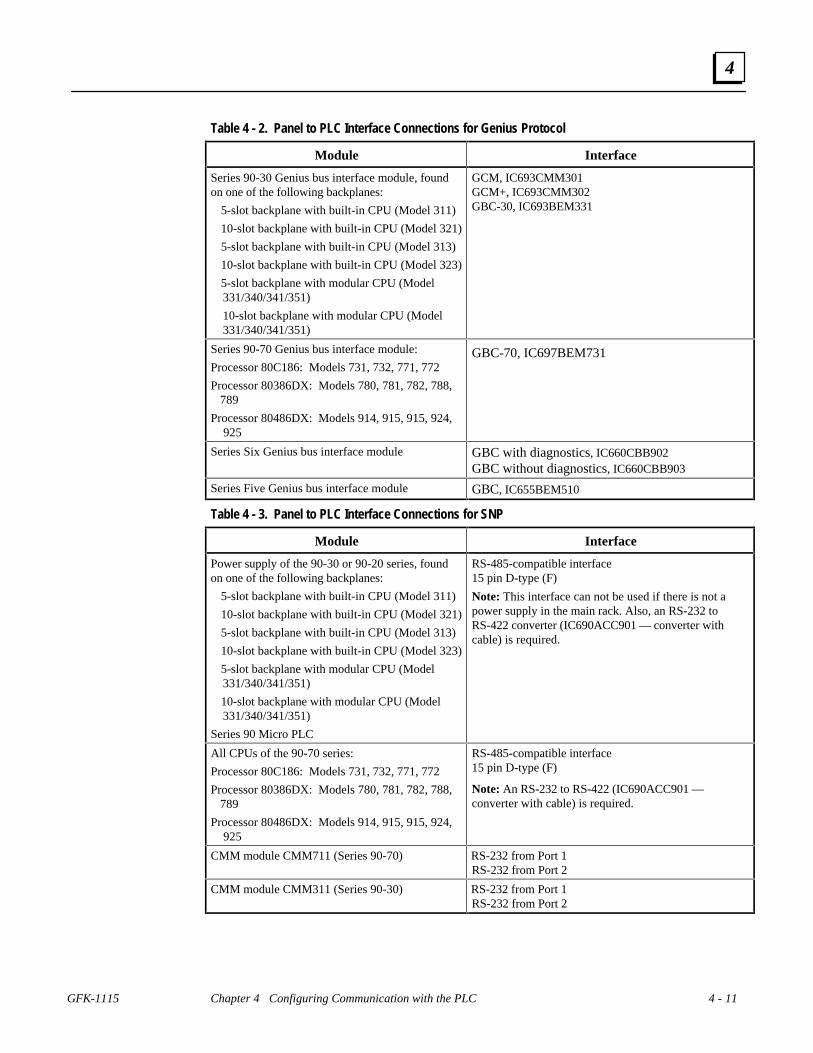
GFK-1115 Chapter 4 Configuring Communication with the PLC 4 - 11
4
Table 4 - 2. Panel to PLC Interface Connections for Genius Protocol
Module Interface
Series 90-30 Genius bus interface module, foundon one of the following backplanes:
5-slot backplane with built-in CPU (Model 311)
10-slot backplane with built-in CPU (Model 321)
5-slot backplane with built-in CPU (Model 313)
10-slot backplane with built-in CPU (Model 323)
5-slot backplane with modular CPU (Model331/340/341/351)
10-slot backplane with modular CPU (Model331/340/341/351)
GCM, IC693CMM301GCM+, IC693CMM302GBC-30, IC693BEM331
Series 90-70 Genius bus interface module:
Processor 80C186: Models 731, 732, 771, 772
Processor 80386DX: Models 780, 781, 782, 788, 789
Processor 80486DX: Models 914, 915, 915, 924, 925
GBC-70, IC697BEM731
Series Six Genius bus interface module GBC with diagnostics, IC660CBB902GBC without diagnostics, IC660CBB903
Series Five Genius bus interface module GBC, IC655BEM510
Table 4 - 3. Panel to PLC Interface Connections for SNP
Module Interface
Power supply of the 90-30 or 90-20 series, foundon one of the following backplanes:
5-slot backplane with built-in CPU (Model 311)
10-slot backplane with built-in CPU (Model 321)
5-slot backplane with built-in CPU (Model 313)
10-slot backplane with built-in CPU (Model 323)
5-slot backplane with modular CPU (Model331/340/341/351)
10-slot backplane with modular CPU (Model331/340/341/351)
Series 90 Micro PLC
RS-485-compatible interface15 pin D-type (F)
Note: This interface can not be used if there is not apower supply in the main rack. Also, an RS-232 toRS-422 converter (IC690ACC901 — converter withcable) is required.
All CPUs of the 90-70 series:
Processor 80C186: Models 731, 732, 771, 772
Processor 80386DX: Models 780, 781, 782, 788, 789
Processor 80486DX: Models 914, 915, 915, 924, 925
RS-485-compatible interface15 pin D-type (F)
Note: An RS-232 to RS-422 (IC690ACC901 —converter with cable) is required.
CMM module CMM711 (Series 90-70) RS-232 from Port 1RS-232 from Port 2
CMM module CMM311 (Series 90-30) RS-232 from Port 1RS-232 from Port 2
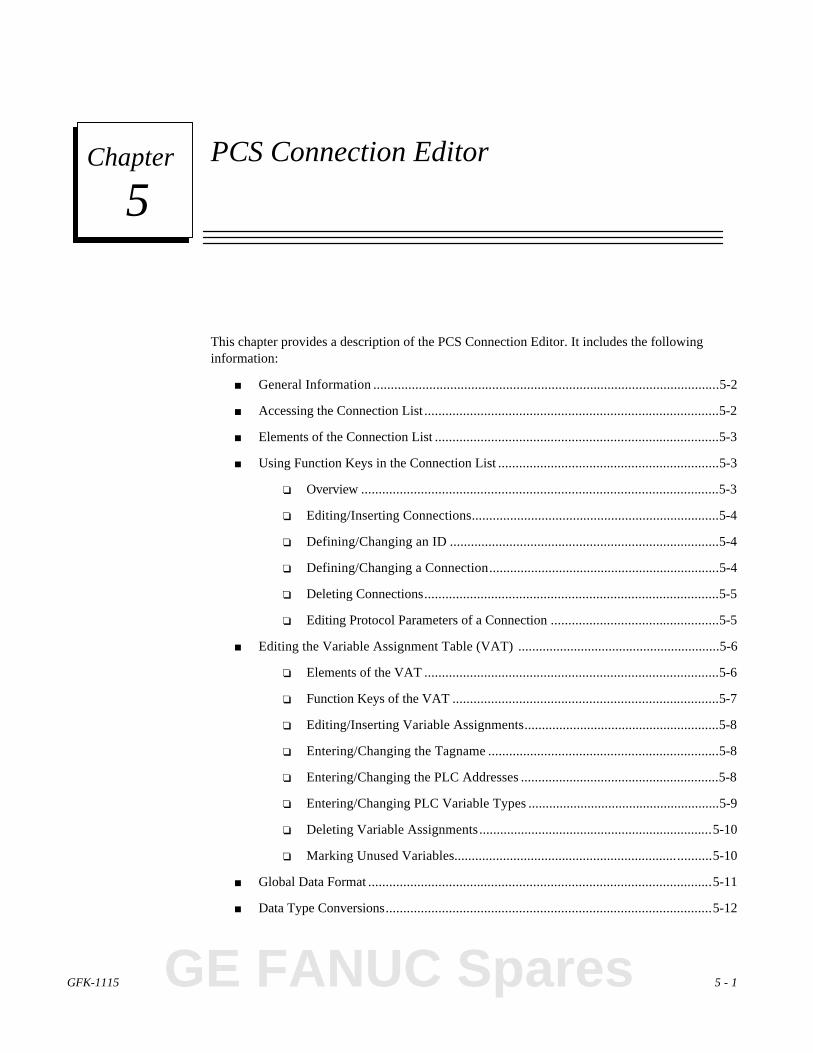
GFK-1115 5 - 1
Chapter PCS Connection Editor
This chapter provides a description of the PCS Connection Editor. It includes the followinginformation:
■ General Information ...................................................................................................5-2
■ Accessing the Connection List....................................................................................5-2
■ Elements of the Connection List.................................................................................5-3
■ Using Function Keys in the Connection List...............................................................5-3
❏ Overview......................................................................................................5-3
❏ Editing/Inserting Connections.......................................................................5-4
❏ Defining/Changing an ID .............................................................................5-4
❏ Defining/Changing a Connection..................................................................5-4
❏ Deleting Connections....................................................................................5-5
❏ Editing Protocol Parameters of a Connection................................................5-5
■ Editing the Variable Assignment Table (VAT) ..........................................................5-6
❏ Elements of the VAT....................................................................................5-6
❏ Function Keys of the VAT............................................................................5-7
❏ Editing/Inserting Variable Assignments........................................................5-8
❏ Entering/Changing the Tagname ..................................................................5-8
❏ Entering/Changing the PLC Addresses .........................................................5-8
❏ Entering/Changing PLC Variable Types .......................................................5-9
❏ Deleting Variable Assignments...................................................................5-10
❏ Marking Unused Variables..........................................................................5-10
■ Global Data Format..................................................................................................5-11
■ Data Type Conversions.............................................................................................5-12
5
GE FANUC Spares

5 - 2 PANELWARE MMI Application Manual for GE Fanuc Genius Protocol - June 1995 GFK-1115
5
General Information
All of the variables (symbolic variable names) that are to be used in a project must be assigned anaddress in the PLC CPU.
Every PLC connected to the Panel must be entered in the project's connection list. Each of theseentries accesses an additional list called the variable assignment table (VAT), in which allvariables of a connection are assigned a PLC address (tagname).
Accessing the Connection List
To edit or insert connections, the Connection List, must be opened from the Main menu. (TheConnection List can only be accessed if a project is loaded.) Select the Connections option fromthe F2 Edit pull-down menu, or press Ctrl + C.
The Connection List window is displayed:

GFK-1115 Chapter 5 PCS Connection Editor 5 - 3
5
Elements of the Connection List
A single entry in the connection list consists of the following three segments:
■ ID: Identification for a connection (PLC station). The assignment of variables to certainconnections is accomplished through the ID. If input or output fields are defined as partof a picture, the PLC address (tagname) must be entered with the ID (e.g., VALUE1/ID ).Variable names without an ID are automatically assigned the default connection DD. AnID consists of one to two alphanumeric characters of your choosing.
■ Connection: Type of connection, either Genius, SNP90 or Internal :
Genius: The connection to the PLC is accomplished over the Genius bus.
SNP90: The connection to the PLC is accomplished over the RS-232 interface (IF0) onthe Panel. The GE Fanuc SNP90 protocol is used for the transmission.
Internal: Internal variables are located within the Panel. A list of these internalvariables is provided in the PANELWARE Configuration Software Reference Manual(GFK-0849).
■ PLC Type: Further description of the PLC.
Using Function Keys in the Connection List
Whenever a connection list is displayed, six function keys are active to allow editing, inserting,and deleting of connections, protocol parameters, and the VAT.
Overview
F1 Edit ..........................................Editing ConnectionsAllows the selected connection to be edited (changed).
F2 Ins ...........................................Inserting ConnectionsInserts a new connection into the list.
F3 Del ...........................................Deleting ConnectionsDeletes the selected connection.
F4 PLC Node Parameters ...............Editing PLC Node ParametersAllows the PLC node parameters (protocol parameters) of theselected connection to be edited.
F5 VAT .........................................Editing Variable Assignment Table (VAT)Displays the variable assignment table of the selectedconnection so that it can be edited.
F10 Exit ........................................Closing the Connection ListCloses the Connection List window and redisplays the Mainmenu.
GE FANUC Spares

5 - 4 PANELWARE MMI Application Manual for GE Fanuc Genius Protocol - June 1995 GFK-1115
5
Editing/Inserting Connections
Pressing F1 Edit or F2 Ins in the Connection List window opens the Connection Definitionwindow, in which a connection can be entered or modified:
F4 Accept .............Saves and then closes the connection definition.
F10 Exit ................Closes the connection definition without saving.
Defining/Changing an ID
If the cursor is in the ID line, the identification code can be changed to any one to two letter-number combination.
Defining/Changing a Connection
If the cursor is in the Connection line, a selection window can be accessed by pressing ↵↵. Use thecursor up (↑↑) or down (↓↓) keys to choose the type of connection required (Genius, SNP90 orInternal) and press ↵↵ to insert it in the Connection Definition window.
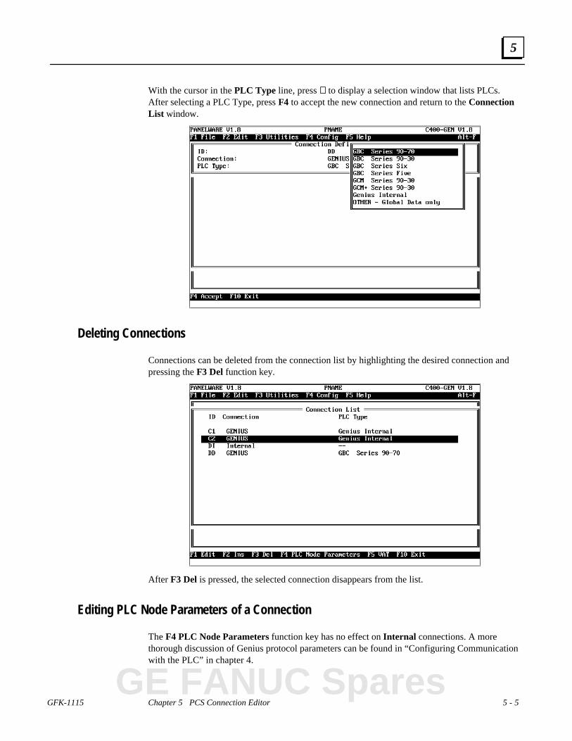
GFK-1115 Chapter 5 PCS Connection Editor 5 - 5
5
With the cursor in the PLC Type line, press ↵↵ to display a selection window that lists PLCs.After selecting a PLC Type, press F4 to accept the new connection and return to the ConnectionList window.
Deleting Connections
Connections can be deleted from the connection list by highlighting the desired connection andpressing the F3 Del function key.
After F3 Del is pressed, the selected connection disappears from the list.
Editing PLC Node Parameters of a Connection
The F4 PLC Node Parameters function key has no effect on Internal connections. A morethorough discussion of Genius protocol parameters can be found in “Configuring Communicationwith the PLC” in chapter 4.
GE FANUC Spares

5 - 6 PANELWARE MMI Application Manual for GE Fanuc Genius Protocol - June 1995 GFK-1115
5
Editing the Variable Assignment Table
The VAT is used to assign absolute PLC addresses to symbolic variables. All connection variablesthat are entered as PLC addresses during the project creation are listed in the VariableAssignment Table.
When you press the F5 VAT key from the connection list, the VAT screen for the selectedconnection is displayed. The following screen is an example:
Elements of the VAT
The VAT for any connection consists of the following elements:
■ Tagname: Symbolic name as follows:
- Entered for an input or output field as the PLC address with the ID for this connection.
- Entered for PLC addresses of the alarm system with the ID for this connection (PLCaddress for the alarm bit field, global alarm or bypass image).
- Entered for a key command or LED function with the ID for this connection.
- Entered in the project definition screen with the ID for this connection.
■ Panel Data Type: Indicates (automatically) the data type of the field that the variableuses (e.g., for Output Byte, Byte unsigned). Every field type is assigned a certain Paneldata type that cannot be changed by the user.

GFK-1115 Chapter 5 PCS Connection Editor 5 - 7
5
■ PLC Address: The PLC address can only be defined for Genius and SNP90 connections.You must enter the PLC address using the syntax and format that the connected PLC willunderstand.
For a series 90-30 or 90-70 PLC, an address is constructed as shown below:
Example: %Yxxxxx
% Y xxxxx
Offset
The address code indicates the type of memory location. In thePCS, this can be entered in upper or lower case letters.
The percentage character is optional for the entry in the PCS.
The address %R0010 could also be entered using the following formats:
%R10, %r10, r010, R00010, ...
■ PLC Variable Type: The PLC variable type can only be entered for Genius and SNP90connections. You must enter the variable data type in the PLC (in most cases, it isidentical to the Panel data type). For different data types, a data conversion must beperformed (automatically). PCS only makes those data types available that the Panel candisplay or convert for the PLC address (see “Data Type Conversions” in this chapter).
Function Keys of the VAT
F1 Edit ..........................................Editing a variable assignmentAllows the selected variable assignment to be changed.
F2 Ins ...........................................Inserting a variable assignmentInserts a new variable assignment.
F3 Del ...........................................Deleting a variable assignmentDeletes the selected variable assignment.
F6 Used ........................................Marking an unused variableAll variables that are displayed in the VAT but not used in theproject can be marked with a * character using this functionand then deleted later using the F3 Del function.
F10 Exit ...................................Closing the VATCloses the Variable Assignment Table window andredisplays the Connection list window on the screen.
GE FANUC Spares

5 - 8 PANELWARE MMI Application Manual for GE Fanuc Genius Protocol - June 1995 GFK-1115
5
Editing/Inserting Variable Assignments
Pressing the F1 Edit or F2 Ins key from the VAT window opens the VAT Definition window,which allows a variable assignment to be entered or modified:
Note
Only the Tagname and PLC Address fields may be defined prior to the tagnamebeing referenced somewhere in the project.
F4 Accept .............Saves and closes the VAT definition.
F10 Exit ................Closes the VAT definition without saving.
Entering/Changing the Tagname
If the cursor is in the Tagname line, the symbolic variable name can be changed or entered.Names that are already used in the VAT cannot be used twice and are rejected with the followingerror message:
Variable name already exists!
Entering/Changing PLC Addresses
If the cursor is in the PLC Address line, the PLC address can be entered or changed using thesyntax and format that the connected PLC requires.

GFK-1115 Chapter 5 PCS Connection Editor 5 - 9
5
Entering/Changing PLC Variable Types
If the cursor is in the PLC Variable Type line, a selection window can be opened by pressing the↵↵ (Enter) key. This window lists the data types that are permitted for this PLC address.
Table 5-1 provides a list of the data types allowed for PLC addresses, depending on the Panel datatypes and the address codes of the PLC address. Table 5-2 lists the address codes that make upGroups 1 and 2.
Table 5 - 1. Allowable PLC Address Data Types
PLC Variable Type
Panel Data Type (PDT) Group 1 Group 2
Bit WORD BIT
Byte unsigned INT, WORD BIT, INT, WORD
Word unsigned INT, WORD, DWORD BIT, INT, WORD
Word signed INT, WORD, DINT INT, WORD
Long unsigned DWORD, DINT ----
Long signed DWORD, DINT ----
Float FLOAT ----
String STRING ----
GE FANUC Spares
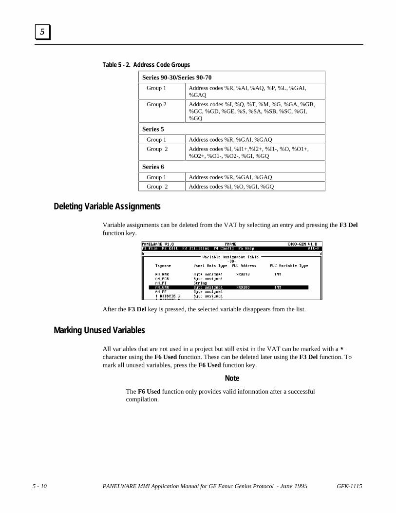
5 - 10 PANELWARE MMI Application Manual for GE Fanuc Genius Protocol - June 1995 GFK-1115
5
Table 5 - 2. Address Code Groups
Series 90-30/Series 90-70
Group 1 Address codes %R, %AI, %AQ, %P, %L, %GAI,%GAQ
Group 2 Address codes %I, %Q, %T, %M, %G, %GA, %GB,%GC, %GD, %GE, %S, %SA, %SB, %SC, %GI,%GQ
Series 5
Group 1 Address codes %R, %GAI, %GAQ
Group 2 Address codes %I, %I1+,%I2+, %I1-, %O, %O1+,%O2+, %O1-, %O2-, %GI, %GQ
Series 6
Group 1 Address codes %R, %GAI, %GAQ
Group 2 Address codes %I, %O, %GI, %GQ
Deleting Variable Assignments
Variable assignments can be deleted from the VAT by selecting an entry and pressing the F3 Delfunction key.
After the F3 Del key is pressed, the selected variable disappears from the list.
Marking Unused Variables
All variables that are not used in a project but still exist in the VAT can be marked with a *character using the F6 Used function. These can be deleted later using the F3 Del function. Tomark all unused variables, press the F6 Used function key.
Note
The F6 Used function only provides valid information after a successfulcompilation.

GFK-1115 Chapter 5 PCS Connection Editor 5 - 11
5
Global Data Format
Global Data is used to automatically broadcast up to 128 bytes of data from one host to all otherson the Genius bus. Typically, this data is a collection of both discrete and analog values. Tofacilitate transmitting/receiving global data as either discrete or analog values, a double mappingscheme is used. Two separate reference structures, one discrete and the other analog, are used toaccess a single memory area. This double mapping is described in the table below (substitute I forinput data, and Q for output data where the # symbol appears).
byte 2 byte 1GA#01 G#
0016G#0015
G#0014
G#0013
G#0012
G#0011
G#0000
G#0009
G#0008
G#0007
G#0006
G#0005
G#0004
G#0003
G#0002
G#0001
byte 4 byte 3GA#02 G#
0032G#0031
G#0030
G#0029
G#0028
G#0027
G#0026
G#0025
G#0024
G#0023
G#0022
G#0021
G#0020
G#0019
G#0018
G#0017
AAAAAAAA
AAAAAAAA
AAAAAA
AAAAAAAA
byte 128 byte 127GA#64 G#
1024G#1023
G#1022
G#1021
G#1020
G#1019
G#1018
G#1017
G#1016
G#1015
G#1014
G#1013
G#1012
G#1011
G#1010
G#1009
Global data output references, %GQnnnn and %GAQnn, can appear only in a Genius Internalconnection, because they pertain only to the C400 Controller itself. The input references,%GInnnn and %GAInn, can appear in any Genius connections except the Genius internalconnection.
GE FANUC Spares
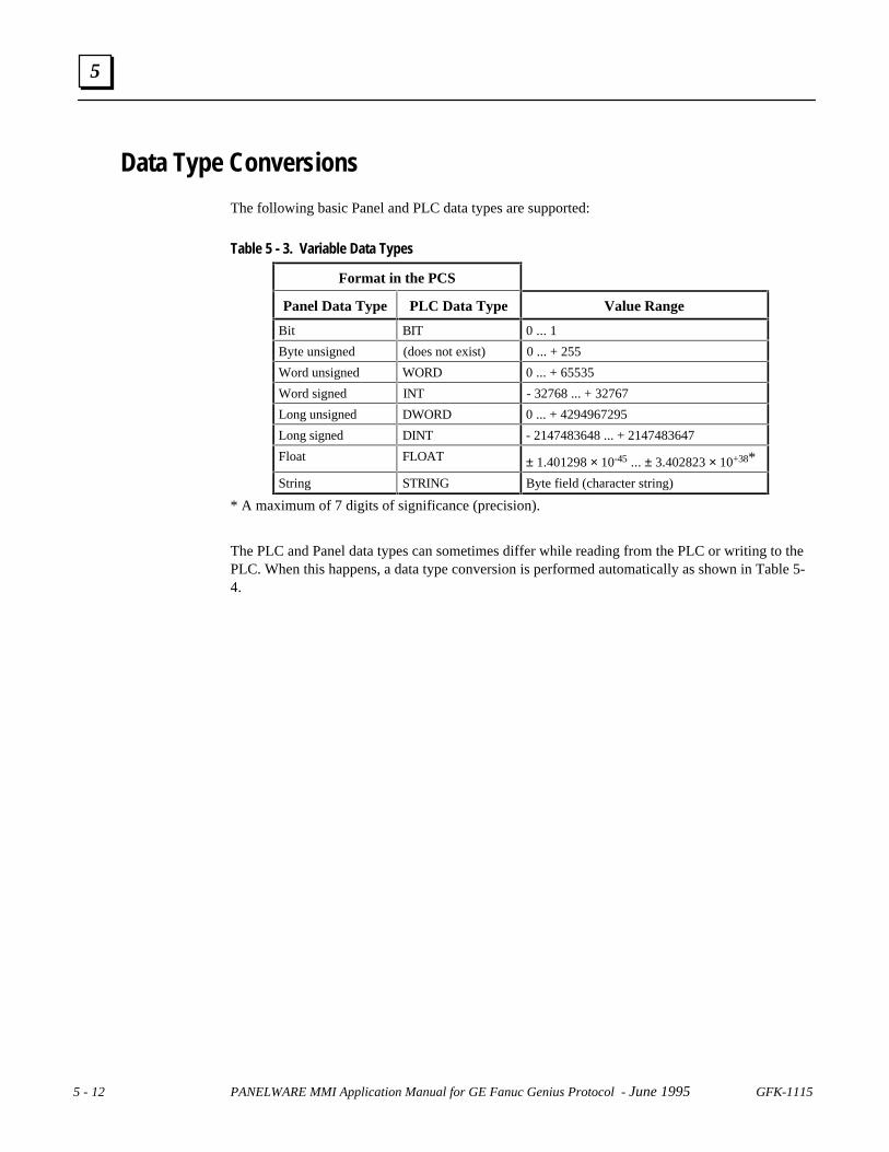
5 - 12 PANELWARE MMI Application Manual for GE Fanuc Genius Protocol - June 1995 GFK-1115
5
Data Type Conversions
The following basic Panel and PLC data types are supported:
Table 5 - 3. Variable Data Types
Format in the PCS
Panel Data Type PLC Data Type Value Range
Bit BIT 0 ... 1
Byte unsigned (does not exist) 0 ... + 255
Word unsigned WORD 0 ... + 65535
Word signed INT - 32768 ... + 32767
Long unsigned DWORD 0 ... + 4294967295
Long signed DINT - 2147483648 ... + 2147483647
Float FLOAT ± 1.401298 × 10-45 ... ± 3.402823 × 10+38*
String STRING Byte field (character string)
* A maximum of 7 digits of significance (precision).
The PLC and Panel data types can sometimes differ while reading from the PLC or writing to thePLC. When this happens, a data type conversion is performed automatically as shown in Table 5-4.

GFK-1115 Chapter 5 PCS Connection Editor 5 - 13
5
Table 5 - 4. Data Type Conversions (Panel Data Type/PLC)
Legend:
Byte u...................Byte unsigned
Word u. ................Word unsigned
Word s..................Word signed
Long u..................Long unsigned
LSB......................Least Significant Bit
(Lower Bit)
MSB .................... Most Significant Bit
(Upper Bit)
LOB..................... Low Order Byte
(Lower Byte)
HOB .................... High Order Byte
(Upper Byte)
PDT..................... Panel Data Type
PDT Data Type Conversion PLC
Bit → No conversion. → BIT
← No conversion. ←Bit → The value of Bit is copied to the LSB of WORD. The rest of the
bits of WORD are set to 0.→ WORD *
← Values higher than 1 are limited to 1. ←
Byte u. → The LSB of Byte u. is copied to BIT. → BIT
← The value of BIT is copied to the LSB of Byte u. The rest of thebits of Byte u. are set to 0.
←
Byte u. → Byte u. is copied to the LOB of WORD. The HOB of WORD is setto 00.
→ WORD *
← Values higher than 255 are limited to 255. ←Byte u. → Byte u. is copied to the LOB of INT. The HOB of INT is set to 0. → INT *
← Values higher than 255 are limited to 255. Negative values arelimited to 0.
←
PDT Data Type Conversion PLC
Word u. → The LSB of Word u. is copied to BIT. → BIT
← The value of Bit is copied to the LSB of Word u. The rest of thebits of Word u. are set to 0.
←
Word u. → No conversion. → WORD *
← No conversion. ←Word u. → Values higher than 32767 are limited to 32767. → INT *
← Negative values are limited to 0. ←Word u. → Word u. is copied to the lower word of DWORD. The upper word
is set to 0.→ DWORD
← Values higher than 65535 are limited to 65535. ←
GE FANUC Spares
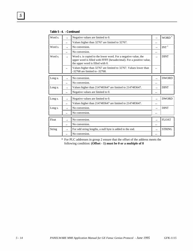
5 - 14 PANELWARE MMI Application Manual for GE Fanuc Genius Protocol - June 1995 GFK-1115
5
Table 5 - 4. - Continued
Word s. → Negative values are limited to 0. → WORD *
← Values higher than 32767 are limited to 32767. ←Word s. → No conversion. → INT *
← No conversion. ←Word s. → Word s. is copied to the lower word. For a negative value, the
upper word is filled with FFFF (hexadecimal). For a positive value,the upper word is filled with 0.
→ DINT
← Values higher than 32767 are limited to 32767. Values lower than-32768 are limited to -32768.
←
Long u. → No conversion. → DWORD
← No conversion. ←Long u. → Values higher than 2147483647 are limited to 2147483647. → DINT
← Negative values are limited to 0. ←
Long s. → Negative values are limited to 0. → DWORD
← Values higher than 2147483647 are limited to 2147483647. ←Long s. → No conversion. → DINT
← No conversion. ←
Float → No conversion. → FLOAT
← No conversion. ←
String → For odd string lengths, a null byte is added to the end. → STRING
← No conversion. ←
* For PLC addresses in group 2 ensure that the offset of the address meets thefollowing condition: (Offset - 1) must be 0 or a multiple of 8

GFK-1115 Chapter 5 PCS Connection Editor 5 - 15
5
Tables 5-5 and 5-6 provides another overview of the permitted combinations of Panel and PLCdata types. In addition, the address codes and possible limitations on the offset are listed for thePLC data types.
Note
The statement (offset - 1)%8 calculates the modulo (remainder) of the divisionfrom (offset - 1)/8. This calculation ensures that the address is on a byteboundary (address -1 is a multiple of 8).
Table 5 - 5. Possible Data Type Conversions for Series 90
Panel Data PLC Data Types
Types BIT WORD INT DWORD DINT FLOAT STRING
Bit I, Q, M, T, S, SA,SB, SC, G, GA,GB, GC, GD, GE,GI, GQ
(offset-1)%8=0
R, AI, AQ, I, Q,M, T,P, L, GAI,GAQ,S, SA, SB, SC,G, GA, GB,GC, GD, GE,GI, GQ(offset-1)%8=0
Byte u. I, Q, M, T, S, SA,SB, SC, G, GA,GB, GC,GD, GE,GI, GQ
R, AI, AQ,I, Q, M, T,P, L, GAI,GAQ,S, SA, SB, SC,G, GA, GB,GC, GD, GE,GI, GQ(offset-1)%8=0
R, AI, AQ,I, Q, M, T,P, L, GAI, GAQ,S, SA, SB, SC,G, GA, GB, GC,GD, GE,GI, GQ(offset-1)%8=0
Word u. I, Q, M, T, S, SA,SB, SC, G, GA,GB, GC, GD, GE,GI, GQ
R, AI, AQ,I, Q, M, T,P, L, GAI,GAQ,S, SA, SB, SC,G, GA, GB,GC, GD, GE,GI, GQ(offset-1)%8=0
R, AI, AQ,I, Q, M, T,P, L, GAI, GAQ,S, SA, SB, SC,G, GA, GB, GC,GD, GE,GI, GQ(offset-1)%8=0
R, AI, AQ, P,L, GAI, GAQ
Word s. R, AI, AQ,I, Q, M, T,P, L, GAI,GAQ,S, SA, SB, SC,G, GA, GB,GC, GD, GE,GI, GQ(offset-1)%8=0
R, AI, AQ,I, Q, M, T,P, L, GAI, GAQ,S, SA, SB, SC,G, GA, GB, GC,GD, GE, GI, GQ(offset-1)%8=0
R, AI, AQ, P,L, GAI, GAQ
Long u. R, AI, AQ, P,L, GAI, GAQ
R, AI, AQ, P,L, GAI, GAQ
Long s. R, AI, AQ, P,L, GAI, GAQ
R, AI, AQ, P,L, GAI, GAQ
Float R, AI, AQ, P,L, GAI, GAQ
String R, AI, AQ, P,L, GAI, GAQ
GE FANUC Spares

5 - 16 PANELWARE MMI Application Manual for GE Fanuc Genius Protocol - June 1995 GFK-1115
5
Table 5 - 6. Possible Data Type Conversions for Series Five/Series Six
Panel Data PLC Data Types
Types BIT WORD INT DWORD DINT FLOAT STRING
Bit I, I1+,I2+, I1-,O, O1+, O2+,O1-, O2-, GI,GQ
I, O, GI, GQ(offset-1)%8=0
R, GAI, GAQ
(offset-1)%8=0
Byte u. I, I1+,I2+, I1-,O, O1+, O2+,O1-, O2-, GI,GQ
I, O, GI, GQ
R, GAI, GAQ
(offset-1)%8=0
R, GAI, GAQ
(offset-1)%8=0
Word u. I, I1+,I2+, I1-,O, O1+, O2+,O1-, O2-, GI,GQ
I, O, GI, GQ
R, GAI, GAQ
(offset-1)%8=0
R, GAI, GAQ
(offset-1)%8=0
R, GAI, GAQ
Word s. R, GAI, GAQ
(offset-1)%8=0
R, GAI, GAQ
(offset-1)%8=0
R, GAI, GAQ
Long u. R, GAI, GAQ R, GAI, GAQ
Long s. R, GAI, GAQ R, GAI, GAQ
Float R, GAI, GAQ
String R, GAI, GAQ

GFK-1115 6 - 1
Chapter Demo Project
■ General Information ........................6-2
■ Required Hardware..........................6-3
■ Downloading the Demo Project.......6-4
❏ Defining the User Path .............6-4
❏ Loading the Project...................6-5
❏ Downloading/Starting the Project...6-6
■ Description of the Demo Project......6-4
❏ General Information .................6-7
❏ Main Menu...............................6-8
❏ Value Entries............................6-9
❏ Entering a Password ...............6-11
❏ Key Functions.........................6-13
❏ Alarm List ..............................6-14
❏ Error Picture...........................6-15
■ Creating the Demo Project.............6-16
❏ General Information ...............6-16
❏ Creating a Project...................6-16
● Preparing a Concept ........6-17
● Creating a New Project....6-18
● Selecting the Connections ....6-19
● Defining Key Assignments...6-22
● Creating the Pictures .......6-23
● Defining the Text Groups.....6-51
● Binding Pictures.................6-52
● Editing the Alarm System....6-58
● Activating the Alarm System 6-60
● Editing the Connections.......6-61
❏ Compiling the Project.............6-64
❏ Errors.....................................6-64
6
GE FANUC Spares

6 - 2 PANELWARE MMI Application Manual for GE Fanuc Genius Protocol - June 1995 GFK-1115
6
Section 1 General Information
A demo project, which is copied to the hard disk during the installation, is delivered in the samepackage as PCS. Project DEMO_400 is for use with a C400 Controller. The demo provides anoverview of PANELWARE features.
Even if you do not have the PANELWARE hardware needed to execute the demo project, it willstill be useful to examine the demo to learn more about how to take advantage of PANELWARE’smany features.
Project Name Directory Required Hardware
DEMO_400 Dest.path\USER\DEMO_400.PRD
The demo project is stored in thisdirectory after the installation.
PLC Hardware:
A GE Fanuc PLC
PANELWARE Hardware:
PANELWARE Panel with C400Controller
See chapter 1 for an explanation of which GE Fanuc PLCs can be connected to a PANELWAREPanel, using the C400 Controller.
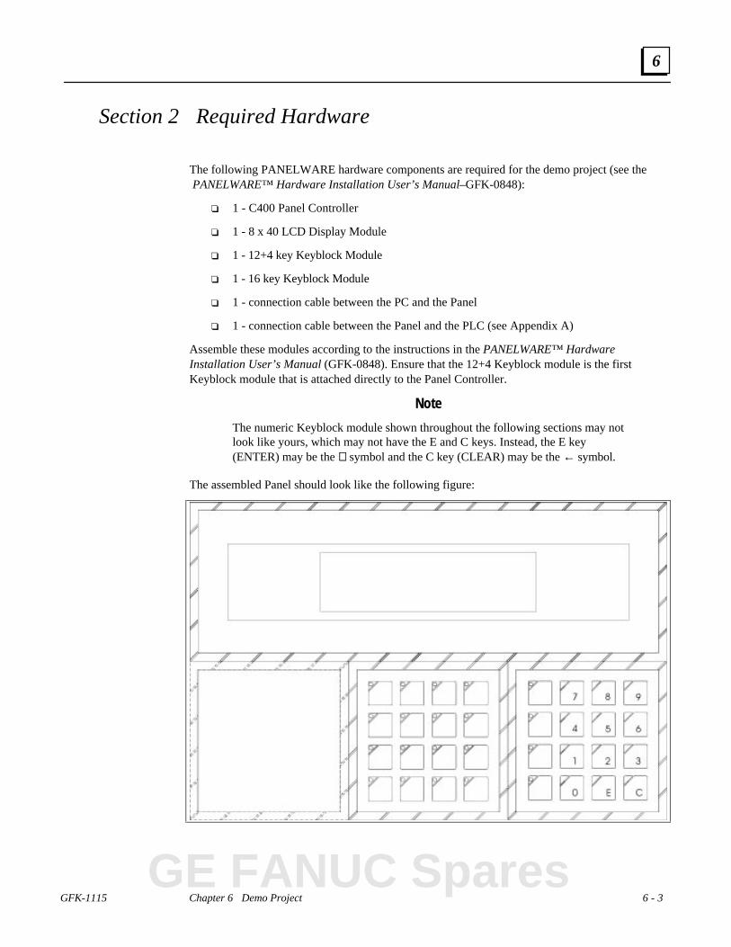
GFK-1115 Chapter 6 Demo Project 6 - 3
6
Section 2 Required Hardware
The following PANELWARE hardware components are required for the demo project (see the PANELWARE™ Hardware Installation User’s Manual–GFK-0848):
❏ 1 - C400 Panel Controller
❏ 1 - 8 x 40 LCD Display Module
❏ 1 - 12+4 key Keyblock Module
❏ 1 - 16 key Keyblock Module
❏ 1 - connection cable between the PC and the Panel
❏ 1 - connection cable between the Panel and the PLC (see Appendix A)
Assemble these modules according to the instructions in the PANELWARE™ HardwareInstallation User’s Manual (GFK-0848). Ensure that the 12+4 Keyblock module is the firstKeyblock module that is attached directly to the Panel Controller.
Note
The numeric Keyblock module shown throughout the following sections may notlook like yours, which may not have the E and C keys. Instead, the E key(ENTER) may be the ↵↵ symbol and the C key (CLEAR) may be the ← symbol.
The assembled Panel should look like the following figure:
GE FANUC Spares
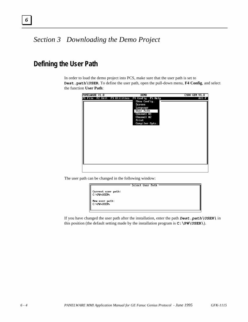
6 - 4 PANELWARE MMI Application Manual for GE Fanuc Genius Protocol - June 1995 GFK-1115
6
Section 3 Downloading the Demo Project
Defining the User Path
In order to load the demo project into PCS, make sure that the user path is set toDest.path\USER . To define the user path, open the pull-down menu, F4 Config, and selectthe function User Path:
The user path can be changed in the following window:
If you have changed the user path after the installation, enter the path Dest.path\USER\ inthis position (the default setting made by the installation program is C:\PW\USER\ ).
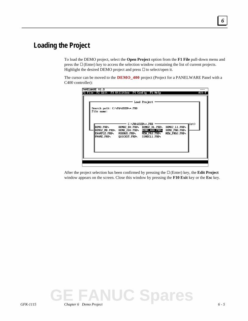
GFK-1115 Chapter 6 Demo Project 6 - 5
6
Loading the Project
To load the DEMO project, select the Open Project option from the F1 File pull-down menu andpress the ↵↵ (Enter) key to access the selection window containing the list of current projects.Highlight the desired DEMO project and press ↵↵ to select/open it.
The cursor can be moved to the DEMO_400 project (Project for a PANELWARE Panel with aC400 controller):
After the project selection has been confirmed by pressing the ↵↵ (Enter) key, the Edit Projectwindow appears on the screen. Close this window by pressing the F10 Exit key or the Esc key.
GE FANUC Spares

6 - 6 PANELWARE MMI Application Manual for GE Fanuc Genius Protocol - June 1995 GFK-1115
6
Downloading and Starting the Project
Download the project to the Panel by following these steps:
■ Panel:
❏ Supply the Panel with power by connecting the 24 VDC power.
❏ Select Teach Mode (operating mode switch in position 7).
❏ Press the RESET button on the Panel.
❏ Wait until Teach Mode is seen on the Panel display.
❏ Make the connection between the PC and the Panel
■ PCS:
❏ Press the Ctrl + X keys simultaneously, or select the Download function from theUtilities pulldown menu.
❏ The question Download Project? (Y/N) is displayed
❏ Start the download by pressing Y.
❏ Wait until the message Download Complete! appears
■ Panel:
❏ Make the connection between the Panel and the PLC
❏ Switch to Run-Mode (operating mode switch to position 5)
❏ Press the RESET button on the Panel
❏ The following picture will appear on the Panel display:

GFK-1115 Chapter 6 Demo Project 6 - 7
6
Section 4 Description of the Demo Project
General InformationThe following symbols and representations will be used in the project description:
Keys:
F1 ... F4 Function 1 to 4 (Function depends on the current picture)+p+/+n+ Cursor to previous/next input field+P+/+N+ Change to previous/next picture+G+ Group acknowledgment for alarms0 ... 9 Numbers 0 to 9. Decimal point←← If the cursor is in an input field, this key deletes the last entered character.±± Sign change in numerical input fieldsE Confirmation of the entry in an input fieldC Deletes the entry in an input field
Key LEDs:
Function keys with specific functions are defined for every picture. The LEDs for keys that haveassigned functions are either lit or blinking.
Note
The numeric Keyblock module shown throughout the following sections may bedifferent from yours, which may not have the E and C keys. Instead, the E(Enter) key may be the ↵↵ symbol and the C key (CLEAR) may be the ←←symbol.
GE FANUC Spares

6 - 8 PANELWARE MMI Application Manual for GE Fanuc Genius Protocol - June 1995 GFK-1115
6
Main Menu
If the demo project has been successfully downloaded to the Panel and if you have started thePanel in Run-Mode, the main menu appears (This is the same as the Startup Picture):
The date and time are displayed in the top right-hand corner of the menu. The F1 to F4 entriesprovide information about the functions assignedto keys F1 to F4. These key LEDs (F1 throughF4) are illuminated on the Keyblock module, aswell, as shown below:
Use function keys F1 – F4 to change to another picture:
F1 Changes to the INPUT VALUES picture.In this picture, you can enter or change two values of different types, which arethen displayed in two output fields.
F2 Changes to the INPUT PASSWORD picture.You can use this picture to enter a password and its function.
F3 Changes to the KEY FUNCTIONS picture.The keys can be assigned with certain functions so that locations in the PLCmemory can be influenced immediately.
F4 Changes to the ACTIVE ALARM LIST picture.Displays a list of all active alarms.

GFK-1115 Chapter 6 Demo Project 6 - 9
6
Value Entries
INPUT VALUES Picture
If you have pressed the F1 key in the main menu, the following picture appears on the screen:
Key LEDs:
987
4 5
1
6
2
0
3
E C
F1 F2 F3
+P+
+p+
F4
+N+
+n+
+G+
.
F5 F6 F7 F8
By pressing key F1/F2, the content of PLC address %R0001 is increased/decreased in steps:
F1 Increases the value by 1 initially, then at greater increments the longer the key is pressed
F2 Decreases the value by 1 initially, then at greater increments the longer the key is pressed
The contents of PLC address %R0002 can be changed by directly entering a value through thekeyboard numeric keys. Keys +p+ and +n+ switch between the two input fields.
The contents of the two PLC variables are displayed again in two output fields. The display isdefined with preceding zeros. Keys F3 and F4 are used to switch to one of the following pictures:
F3 Changes to the CLOCK pictureThe date and time of the Panel can be entered/changed in this picture.
F4 Picture changes back to the main menu.
GE FANUC Spares

6 - 10 PANELWARE MMI Application Manual for GE Fanuc Genius Protocol - June 1995 GFK-1115
6
CLOCK Picture
If you press the F3 function key while the INPUT VALUES picture is on the screen, the CLOCKpicture appears on the Panel display:
Key LEDs:
To change the date and time, enter the desired data in the input fields, using the +p+ and +n+keys to switch between the fields. Two function keys are used to set the internal time or date:
F1 The Panel internal time is set according to the entered values for HH (Hours) , MM(Minutes) and SS (Seconds).
F2 The Panel internal date is set according to the entered values for MM (Month), DD (Day), and YYYY (Year).
Pressing the F4 function key returns you to the main menu.

GFK-1115 Chapter 6 Demo Project 6 - 11
6
Entering a Password
The following sections describe how to use the pictures that have to do with passwords and lockedinput.
INPUT PASSWORD Picture
If you press the F2 function key while in the main menu, the Input Password picture appears onthe Panel display:
Key LEDs:
This picture allows you to enter the password(s) that will allow you to change locked input fields.Entering a password switches you to a different password level that changes the access rights ofdifferent functions.
With keys F1 and F4 you can switch into the following pictures:
F1 Switches to the LOCKED INPUT picture.Depending on the password level, certain values can be changed in this picture.
F4 Picture change back to the main menu.
GE FANUC Spares

6 - 12 PANELWARE MMI Application Manual for GE Fanuc Genius Protocol - June 1995 GFK-1115
6
LOCKED INPUT Picture
If you press the F1 function key while in the INPUT PASSWORD picture, the LOCKED INPUTpicture appears on the Panel display:
Key LEDs:
If an invalid password has been entered, you cannot change the value for INPUT #1. The value forINPUT #2 can only be changed if the proper password for password level 3 is entered.
With keys +p+ and +n+, you can switch to the other input field if allowed (depends on yourpassword level).
Keys F1 and F4 are used to switch to one of the following pictures:
F1 Switches back to the INPUT PASSWORD pictureThe entry of a password and its function is performed in this picture.
F4 Changes picture back to the main menu.

GFK-1115 Chapter 6 Demo Project 6 - 13
6
Key Functions
If you press the F3 function key while in the main menu, the KEY FUNCTIONS picture appearson the Panel screen:
Key LEDs:
Keys F1 – F3 are assigned with key functions, i.e., specific variables in the PLC are changed whenthey are pressed.
F1 A value of 10000 is written to PLC address %R0005.
F2 PLC address %R0006 is toggled between values 0 and 20000. This key always switchesfrom one of two values to the other.
F3 A value of 1 is output as global data bit b0 (%GQ001) as long as the key is held down; avalue of 0 is output as long as the key is released.
Pressing the F4 key returns you to the main menu.
GE FANUC Spares

6 - 14 PANELWARE MMI Application Manual for GE Fanuc Genius Protocol - June 1995 GFK-1115
6
Alarm List
Pressing the F4 key while in the main menucauses the ACTIVE ALARM LIST to appear onthe Panel display:
Key LEDs:
Alarms are displayed according to an alarm bit field that is found in memory location %M001through %M016 in the PLC. For example, if %M008 is changed from 0 to 1 in the PLC, alarm 8is entered in the alarm list. (More information about the alarm bit field structure in the PLC can be found inchapter 4.) Also, see the PANELWARE™ Configuration Software Reference Manual (GFK-0849)for a more detailed description of alarms.
An entry in the list contains the following information:
Alarm time When the alarm occurred
Alarm number Number of the alarm (corresponds to the bit number in the alarm bit field)
Alarm text Short description of the alarm
Information Information about the type of alarm
Priority Priority of the alarm
The following functions are assigned to keys F1 – F3:
F1 Acknowledgment for the selected alarm.
F2/F3 Scroll through the alarms in the alarm list (F2=Up; F3=Down). Scrollingthrough the list selects an alarm (inverse display), which can be acknowledgedby pressing the F1 key.
Pressing the F4 key returns you to the main menu.
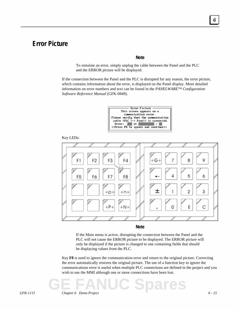
GFK-1115 Chapter 6 Demo Project 6 - 15
6
Error Picture
Note
To simulate an error, simply unplug the cable between the Panel and the PLCand the ERROR picture will be displayed.
If the connection between the Panel and the PLC is disrupted for any reason, the error picture,which contains information about the error, is displayed on the Panel display. More detailedinformation on error numbers and text can be found in the PANELWARE™ ConfigurationSoftware Reference Manual (GFK-0849).
Key LEDs:
Note
If the Main menu is active, disrupting the connection between the Panel and thePLC will not cause the ERROR picture to be displayed. The ERROR picture willonly be displayed if the picture is changed to one containing fields that shouldbe displaying values from the PLC.
Key F8 is used to ignore the communication error and return to the original picture. Correctingthe error automatically restores the original picture. The use of a function key to ignore thecommunications error is useful when multiple PLC connections are defined in the project and youwish to use the MMI although one or more connections have been lost.
GE FANUC Spares

6 - 16 PANELWARE MMI Application Manual for GE Fanuc Genius Protocol - June 1995 GFK-1115
6
Section 5 Creating the Demo Project
General Information
This section presents a step by step description explaining how to create a demo project. Thesection also contains useful information for creating your own projects in the future.
More information on using PCS can be found in the PANELWARE™ Software ConfigurationReference Manual (GFK-0849). This section is based on chapter 10, “Editing a Project”, in thatmanual.
Creating a Project
The list below shows the steps to be taken in creating a new project:
1. Prepare a basic concept before you start.
2. Create the new project.
3. Define hardware setup (choose all connections).
4. Define key assignments.
5. Create the required pictures.
6. Create connection list.
7. Define your text groups.
8. Bind pictures to the project.
9. Check for errors, particularly in keycode table.
10. Compile your project.
11. Download the project to the Panel.
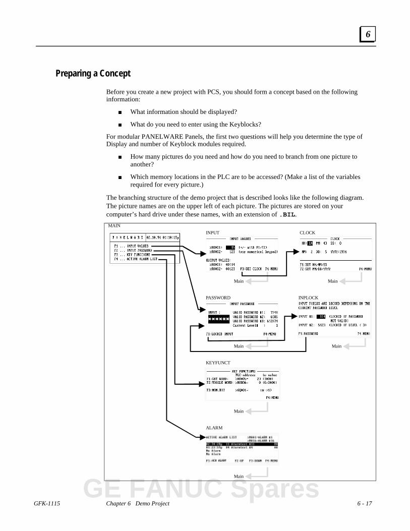
GFK-1115 Chapter 6 Demo Project 6 - 17
6
Preparing a Concept
Before you create a new project with PCS, you should form a concept based on the followinginformation:
■ What information should be displayed?
■ What do you need to enter using the Keyblocks?
For modular PANELWARE Panels, the first two questions will help you determine the type ofDisplay and number of Keyblock modules required.
■ How many pictures do you need and how do you need to branch from one picture toanother?
■ Which memory locations in the PLC are to be accessed? (Make a list of the variablesrequired for every picture.)
The branching structure of the demo project that is described looks like the following diagram.The picture names are on the upper left of each picture. The pictures are stored on yourcomputer’s hard drive under these names, with an extension of .BIL .
Main
Main
Main
Main
Main
Main
INPUT
PASSWORD
KEYFUNCT
ALARM
CLOCK
INPLOCK
MAIN
GE FANUC Spares
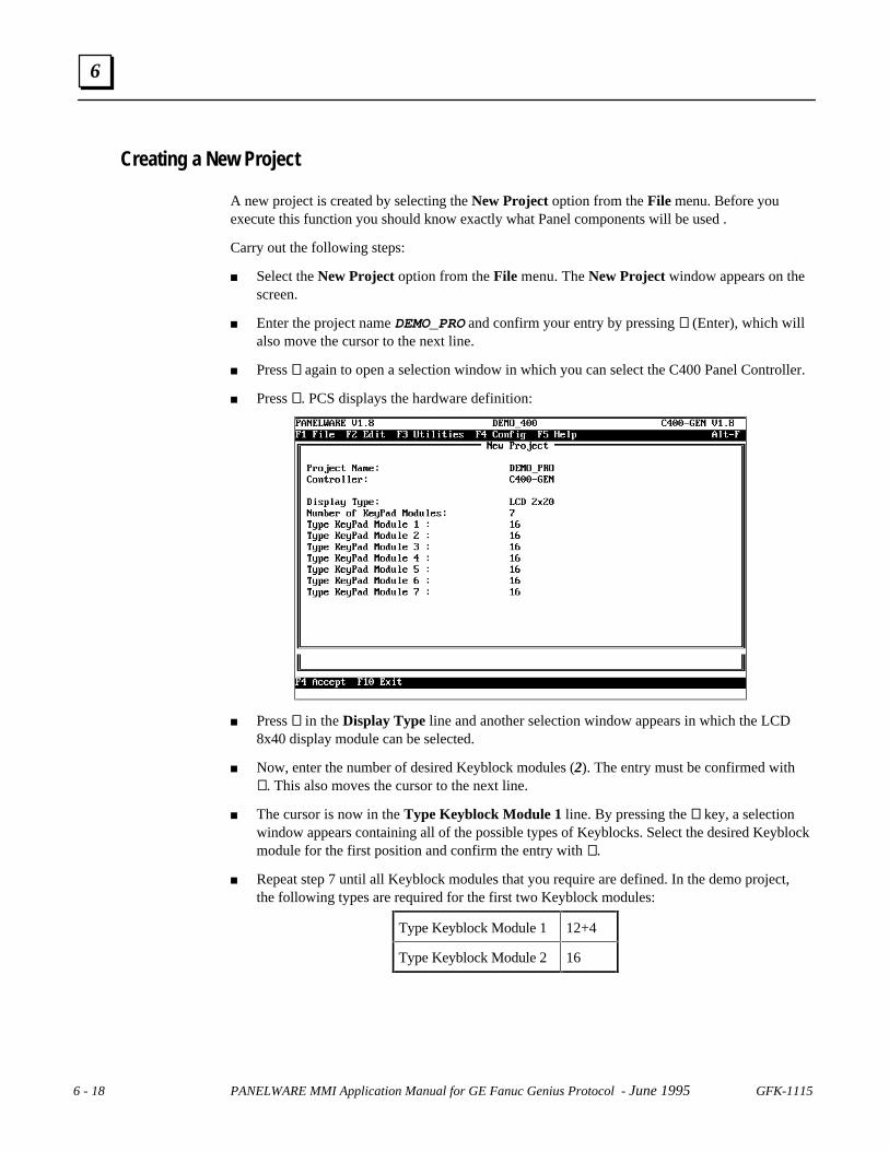
6 - 18 PANELWARE MMI Application Manual for GE Fanuc Genius Protocol - June 1995 GFK-1115
6
Creating a New Project
A new project is created by selecting the New Project option from the File menu. Before youexecute this function you should know exactly what Panel components will be used .
Carry out the following steps:
■ Select the New Project option from the File menu. The New Project window appears on thescreen.
■ Enter the project name DEMO_PRO and confirm your entry by pressing ↵↵ (Enter), which willalso move the cursor to the next line.
■ Press ↵↵ again to open a selection window in which you can select the C400 Panel Controller.
■ Press ↵↵. PCS displays the hardware definition:
■ Press ↵↵ in the Display Type line and another selection window appears in which the LCD8x40 display module can be selected.
■ Now, enter the number of desired Keyblock modules (2). The entry must be confirmed with↵↵. This also moves the cursor to the next line.
■ The cursor is now in the Type Keyblock Module 1 line. By pressing the ↵↵ key, a selectionwindow appears containing all of the possible types of Keyblocks. Select the desired Keyblockmodule for the first position and confirm the entry with ↵↵.
■ Repeat step 7 until all Keyblock modules that you require are defined. In the demo project,the following types are required for the first two Keyblock modules:
Type Keyblock Module 1 12+4
Type Keyblock Module 2 16

GFK-1115 Chapter 6 Demo Project 6 - 19
6
■ If all of the entries that are required have been defined, you can confirm the whole definitionby pressing the F4 Accept key, which closes and saves the hardware definition. The windowis closed and the main menu appears. At the top of the screen, the project nameDEMO_PRO is displayed. If, instead of F4, either the Esc or F10 Exit key is pressed, allentries are disregarded and none are saved.
Note
Further information on the use of the project editor can be found in chapter 4 ofthe PANELWARE™ Software Configuration Reference Manual.
Selecting the Connections
Every PLC that is connected with a modular PANELWARE Panel must be defined in theconnection list. Each connection has a separate list, called the Variable Assignment Table (VAT).The VAT contains all variables that are used in the project and their assignments to physical PLCaddresses.
Execute the following steps to define the connections used in the demo:
1. Select the Connection function from the Edit menu. The Connection List windowappears. The connections that are already defined are shown in this list. The connectionwith the ID DD is automatically inserted when a new project is created.
GE FANUC Spares

6 - 20 PANELWARE MMI Application Manual for GE Fanuc Genius Protocol - June 1995 GFK-1115
6
2. Edit the default connection DD Genius.
• Press F1 Edit .
• Specify the GBC type corresponding to your PLC (90-70 in this example).
• Press F4 Accept, to confirm your changes. The connection list is displayed with thechanged default connection.
3. Insert the additional connections that are required for your project (define ID andconnection).
• Press F2 Ins and insert a Genius Internal connection with the ID, GI .
• Press F4 Accept to confirm the entry.
• Press F2 Ins and insert an Internal connection with the ID, DI .
• Press F4 Accept to confirm the entry. The connection list is displayed with the connectionsthat you have added:
4. Select the connection DD Genius from the connection list with the cursor keys and thenpress F4 PLC Node Parameters. The standard protocol parameters can be seen in thefollowing screen:
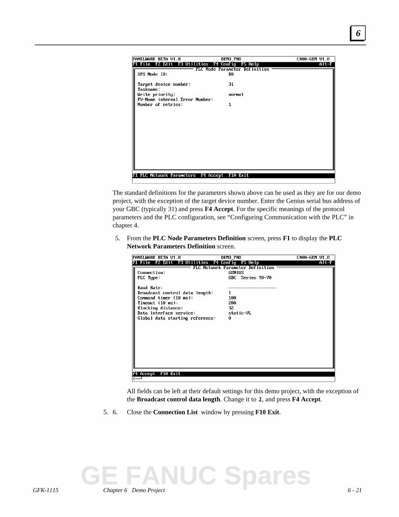
GFK-1115 Chapter 6 Demo Project 6 - 21
6
The standard definitions for the parameters shown above can be used as they are for our demoproject, with the exception of the target device number. Enter the Genius serial bus address ofyour GBC (typically 31) and press F4 Accept. For the specific meanings of the protocolparameters and the PLC configuration, see “Configuring Communication with the PLC” inchapter 4.
5. From the PLC Node Parameters Definition screen, press F1 to display the PLCNetwork Parameters Definition screen.
All fields can be left at their default settings for this demo project, with the exception ofthe Broadcast control data length. Change it to 1, and press F4 Accept.
5. 6. Close the Connection List window by pressing F10 Exit .
GE FANUC Spares

6 - 22 PANELWARE MMI Application Manual for GE Fanuc Genius Protocol - June 1995 GFK-1115
6
Defining Key Assignments
1. Select the Keyboard function from the Edit menu.
2. Define function keys F5–F8 now. This is started by moving the cursor to the respective key.
3. Press F4. A small window appears in the lower right-hand corner of the screen, in which thefunction number of the key can be entered (e.g.: 5).
4. Confirm the entry by pressing ↵↵. The respective key assignment is then indicated by F05. Thekey assignments should now look like this:
5. It is not necessary to define control keys for this demo project the default definitions will beused.
6. Leave the Edit Keyboard Table window by pressing F10 Exit .

GFK-1115 Chapter 6 Demo Project 6 - 23
6
Creating the Pictures
The picture is the basis of a Panel project. Pictures consist of text, lines, fields, key functions andLED functions. These elements can be divided into two groups. There are static elements such astext and lines or dynamic elements like input and output fields. (Lines can only be inserted in apicture if a graphic display has been selected in the project definition.)
■ Text and lines make up the Mask.
■ Fields are defined for user entries and for displaying values from the PLC. Output fieldscan be used to display information such as temperature and RPM. Input fields can beused to enter values to be sent to the PLC.
The number of fields, keys and LED functions that can be used in a picture depends on the Panelused (see Appendix A in the PANELWARE™ Configuration Software Reference Manual – GFK-0849).
If the main menu is active, you can use the Picture option from the Edit menu or use the keycombination Ctrl + B to access the picture editor.
The size of the rectangle corresponds to the selected display type (in this case, display type LCD8x40 is shown); i.e., the rectangle consists of 8 lines and 40 columns (characters per line). Text orfields can be inserted into the rectangle.
Press F10 Exit or the Esc key can be used to close the picture editor. If the picture is not yetsaved, (in this case having the name, NONAME) or the picture has been changed, PCS askswhether the picture should be saved or not.
More information about the picture editor can be found in chapter 5 of the PANELWARE™Configuration Software Reference Manual (GFK-0849).
GE FANUC Spares

6 - 24 PANELWARE MMI Application Manual for GE Fanuc Genius Protocol - June 1995 GFK-1115
6
MAIN Picture (Main Menu)No data from the PLC is shown in this picture.The date and time are taken from the internalreal-time clock in the Panel.
Text is also displayed informing the user of thefunction keys that can be used for switching to thenext pictures. Assigning the function keys to theiractual functions is done in the project editor.
To create this picture follow these steps:
1. Open the picture editor from the main menu with key combination Ctrl + B (see “Creating thePictures”).
2. Insert all lines and text in the rectangle so that it looks like the one below:
3. Move the cursor to position (21,0). The cursor position is indicated in the lower right-handcorner of the window, as (column, row).
4. Insert a field for displaying the date and time:
● Press F2 Field.
● Select the entry Output Field from the Field Class selection window and then press the ↵key.
● Select the Output Date/Time output field from the Select Field Type selection window.The following window will appear:

GFK-1115 Chapter 6 Demo Project 6 - 25
6
● Press ↵↵ to open a selection window where you can define the output format. Select thedesired format from the window:
● Confirm the selection with ↵↵.
● Confirm the entered field parameters with F4 Accept.
● The output field Date/Time is inserted in the picture:
GE FANUC Spares

6 - 26 PANELWARE MMI Application Manual for GE Fanuc Genius Protocol - June 1995 GFK-1115
6
5. The next step is to define the LED functions. The key LEDs of function keys F1 to F4 shouldlight up if the main menu is on the display.
● Press F5 Key. All Keyblock modules that are defined in the project are displayed:

GFK-1115 Chapter 6 Demo Project 6 - 27
6
The top four keys of the left-hand Keyblock module are defined as function keys F1 to F4(see “Defining Key Assignments”).
● Move the cursor to the upper left-most key ofKeyblock module (left-most module). Press F2LED Function. All LED functions are offeredin the next window.
● Select the function Key LED switched on and press ↵↵. A window appears in which theselected LED function is displayed again. Confirm your selection now with the F4Accept function key. The LED function is inserted and indicated with a * character.
● Move the cursor to the next key to be assigned with an LED function. Execute these stepsagain for function keys F2 to F4. The following picture should be seen on the screen:
● Now press the F4 Accept key to confirm your entries. The picture editor appears again.
6. The picture that you have created is not saved yet. Pressing the Esc key or the F10 Exitfunction key calls the following message:
● If the N key is pressed the entire picture is discarded and not saved. When you pressEsc, the picture is not saved. The definition is not lost however. You can return to editingthe picture. Pressing the Y key opens a window in which you can enter a name for thepicture:
● Give the picture the file name MAIN and confirm your entry with ↵↵. The picture is thensaved together with the LED functions and the main menu appears on your screen again.
GE FANUC Spares

6 - 28 PANELWARE MMI Application Manual for GE Fanuc Genius Protocol - June 1995 GFK-1115
6
7. If you want to call up the same picture again for further editing, follow these steps:
● While the main menu is on the screen, press key combination Ctrl + B or select thePicture function from the Edit pulldown menu. The picture editor is called.
● Now press Ctrl + L or select the Load function from the File pulldown menu to load apicture into the picture editor.
● Enter the name MAIN in the Load Picture window that appears now and press the ↵↵ keyto load the picture.
● Instead of entering the picture name directly with the keyboard, you can also call up aselection window with a list of all pictures in the project by pressing the ↵↵ key when youwould normally type in the picture name. By moving the cursor to the desired picturename and pressing the ↵↵ key twice, the respective picture is loaded into the pictureeditor.
● As soon as the picture has been loaded, it can be edited.
INPUT Picture (Value Entries)Input and output fields are demonstrated in this picture.By pressing the F1 and F2 keys, the value changes insteps in the first input field. The active input field isdisplayed inversely in a running project. You can switchbetween the two input fields by pressing +p+ and +n+(see “Defining Key Assignments”).
Follow these steps to create the picture:
1. Call the picture editor from the main menu with key combination Ctrl + B (see above“Creating the Pictures”).
2. Insert all lines and text so that your picture looks like this:

GFK-1115 Chapter 6 Demo Project 6 - 29
6
3. Insert an input field that increments/decrements using keys F1 and F2, respectively. Followthese steps:
● Position the cursor at (11,2).
● Press F2 Field.
● Select Input Field from the Field Class selection window and press the ↵↵ key.
● Select the input field Input Word (unsigned) from the Select Field Type, which willbring a parameter definition window onto the screen for entering or changing theparameters of the input field:
● Enter INP_WORD as the Destination Tagname and confirm the entry with ↵↵. Thedeclaration of this address is done collectively in the connection editor.
● Move the cursor to the Up/Down Input line. press the Y and then ↵↵, to define the field asan up/down input.
● Now, press F1 Up/Down Input. The following window appears:
● In the window shown above, the F1 function key is defined as the key for incrementingthe value (F key +) and F2 for decrementing (F key -).
● Press F4 Accept to confirm the definition and to close the Up/Down Input window.
● Now, press the F4 key again to confirm your entries and to close the Input Word(unsigned) window. The input field is shown on the screen:
GE FANUC Spares
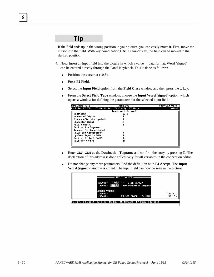
6 - 30 PANELWARE MMI Application Manual for GE Fanuc Genius Protocol - June 1995 GFK-1115
6
T ipIf the field ends up in the wrong position in your picture, you can easily move it. First, move thecursor into the field. With key combination Ctrl + Cursor key, the field can be moved to thedesired position.
4. Now, insert an input field into the picture in which a value — data format: Word (signed) —can be entered directly through the Panel Keyblock. This is done as follows:
● Position the cursor at (10,3).
● Press F2 Field.
● Select the Input Field option from the Field Class window and then press the ↵↵ key.
● From the Select Field Type window, choose the Input Word (signed) option, whichopens a window for defining the parameters for the selected input field:
● Enter INP_INT as the Destination Tagname and confirm the entry by pressing ↵↵. Thedeclaration of this address is done collectively for all variables in the connection editor.
● Do not change any more parameters. End the definition with F4 Accept. The InputWord (signed) window is closed. The input field can now be seen in the picture:

GFK-1115 Chapter 6 Demo Project 6 - 31
6
5. Insert an output field that will display the value that is entered in the first input field, into thepicture. This is done as follows:
● Position the cursor at (11,6).
● Press F2 Field.
● Select the Output Field from the Field Class window and press the ↵↵ key.
● Select the Output Word (unsigned) from Select Field Type, which opens the window inwhich the parameters for the selected input field can be entered/changed:
● Enter OUT_WORD as the Destination Tagname and confirm the entry by pressing ↵↵. Thedeclaration of this address is done collectively for all variables in the connection editor(see “Editing the Connections” in this chapter).
● To display preceding zeros, move the cursor to the Display leading zeros line and enterY followed by ↵↵ to activate the leading zeros display.
● End the definition with F4 Accept. The Output Word (unsigned) window is closed. Theoutput field is displayed again:
GE FANUC Spares

6 - 32 PANELWARE MMI Application Manual for GE Fanuc Genius Protocol - June 1995 GFK-1115
6
6. Insert an output field into the picture. The value that is entered in the second input field willbe displayed in this output field. This is done as follows:
● Position the cursor at (10,7).
● Press F2 Field.
● Select the Output Field entry from the Field class window and press the ↵↵ key.
● Select the entry Output Word (signed) from Select field type window. This opens awindow in which you can enter or change the parameters for the selected input field:
● Now, enter OUT_INT as the Destination Tagname and confirm your entry with ↵↵.Thedeclaration of this address is done along with all other variables in the connection editor(see “Connections” in this chapter).
● In order to display preceding zeros, move the cursor to the Display leading zeros line.Enter Y and then ↵↵ to activate the preceding zero display.
● End the entry with F4 Accept. The window Output Word (signed) is closed. The outputfield is then seen in the picture:

GFK-1115 Chapter 6 Demo Project 6 - 33
6
7. Next, the LED functions must be defined.
● Function keys F1 and F2 should be assigned LED function Key LED blinking slow. Thevalue in the first input field (see step 3) can be changed in steps with these keys.
● Function keys F3 and F4 should be assigned LED function Key LED switched on. Thesekeys switch to other pictures.
● For the description of how to assign an LED function to a key, see step 5 under “MainPicture” on page 6-26.
8. Save this picture under the name INPUT:
● Press Esc or F10 Exit .
● PCS warns you that the picture is not yet saved.
● Enter Y to save the picture.
Enter picture name INPUT in the Save Picture window and press the ↵↵ key. The picture is thensaved and the main menu appears again.
CLOCK Picture (Setting the Real Time Clock)The date and time of the internal real timeclock can be set in this picture. By pressingkeys on the Panel, the date and the time areentered in input fields on the Panel display.The real time clock however, is only setwhen function key F1 (SET HH/MM/SS) orF2 (SET MM/DD/YYYY) is pressed.
To set the real time clock on the PANELWARE Panel, internal variables are used. The followingtable lists these variables and their functions:
Variable name Data type Description
DATE_YY_S Word unsigned Year (Format 19xx)
DATE_MM_S Byte unsigned Month
DATE_DD_S Byte unsigned Day
TIME_HH_S Byte unsigned Hours
TIME_MM_S Byte unsigned Minutes
TIME_SS_S Byte unsigned Seconds
DATE_SET Byte unsigned By writing a non-zero value to this variable, the date of thereal time clock is overwritten with the values of variablesDATE_YY_S, DATE_MM_S and DATE_DD_S.
TIME_SET Byte unsigned By writing a non-zero value to this variable, the real timeclock is overwritten with the values of variablesTIME_HH_S, TIME_MM_S and TIME_SS_S.
The input fields are scaled, limiting the entry to a valid range for time and date values. Date andtime are set through key functions.
GE FANUC Spares

6 - 34 PANELWARE MMI Application Manual for GE Fanuc Genius Protocol - June 1995 GFK-1115
6
Follow these steps to create this picture:
1. Open the picture editor from the main menu with key combination Ctrl + B.
2. Insert all lines and text so that your picture looks like this:
3. Insert a scaled input field for the Hours (HH) entry in the picture. Follow these steps:
● Position the cursor at (4,1).
● Press F2 Field.
● Select the entry Input Field from the Field class selection window and then press the ↵↵key.
● Select the Input Bit/Byte input field from the Select field type. Bit/Byte must beselected because the internal variable TIME_HH_S is of data type Byte unsigned (datatypes of the field and the internal variable must be the same). The window in which theparameters for the selected input field can be entered or changed is displayed:
● Enter 2 in the Number of Digits line and press the ↵↵ key.
● Enter TIME_HH_S/DI as the Destination Tagname and confirm the entry with ↵↵. Inorder to inform PCS that the entered variable is an internal variable, the connection ID,DI must be supplied, separated by a / character. Any lower case characters areautomatically converted to upper case.
● Move the cursor into the Scaling line. Enter Y and then press ↵↵, to activate the scalingfor this field.
● Now press F3 Scaling. The following window appears:
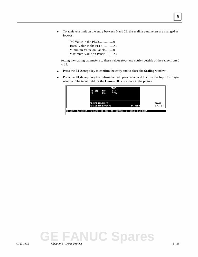
GFK-1115 Chapter 6 Demo Project 6 - 35
6
● To achieve a limit on the entry between 0 and 23, the scaling parameters are changed asfollows:
0% Value in the PLC:................ 0100% Value in the PLC: ............ 23Minimum Value on Panel: ......... 0Maximum Value on Panel:........ 23
Setting the scaling parameters to these values stops any entries outside of the range from 0to 23.
● Press the F4 Accept key to confirm the entry and to close the Scaling window.
● Press the F4 Accept key to confirm the field parameters and to close the Input Bit/Bytewindow. The input field for the Hours (HH) is shown in the picture:
GE FANUC Spares
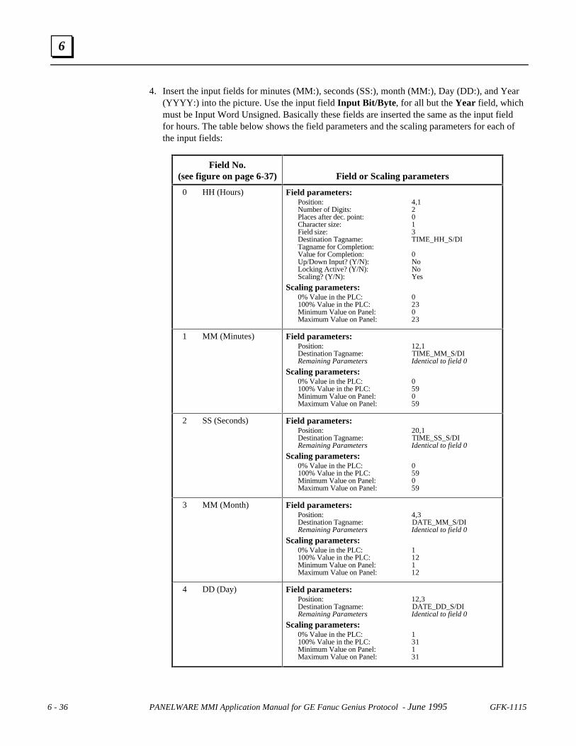
6 - 36 PANELWARE MMI Application Manual for GE Fanuc Genius Protocol - June 1995 GFK-1115
6
4. Insert the input fields for minutes (MM:), seconds (SS:), month (MM:), Day (DD:), and Year(YYYY:) into the picture. Use the input field Input Bit/Byte , for all but the Year field, whichmust be Input Word Unsigned. Basically these fields are inserted the same as the input fieldfor hours. The table below shows the field parameters and the scaling parameters for each ofthe input fields:
Field No.(see figure on page 6-37) Field or Scaling parameters
0 HH (Hours) Field parameters:Position: 4,1Number of Digits: 2Places after dec. point: 0Character size: 1Field size: 3Destination Tagname: TIME_HH_S/DITagname for Completion:Value for Completion: 0Up/Down Input? (Y/N): NoLocking Active? (Y/N): NoScaling? (Y/N): Yes
Scaling parameters:0% Value in the PLC: 0100% Value in the PLC: 23Minimum Value on Panel: 0Maximum Value on Panel: 23
1 MM (Minutes) Field parameters:Position: 12,1Destination Tagname: TIME_MM_S/DIRemaining Parameters Identical to field 0
Scaling parameters:0% Value in the PLC: 0100% Value in the PLC: 59Minimum Value on Panel: 0Maximum Value on Panel: 59
2 SS (Seconds) Field parameters:Position: 20,1Destination Tagname: TIME_SS_S/DIRemaining Parameters Identical to field 0
Scaling parameters:0% Value in the PLC: 0100% Value in the PLC: 59Minimum Value on Panel: 0Maximum Value on Panel: 59
3 MM (Month) Field parameters:Position: 4,3Destination Tagname: DATE_MM_S/DIRemaining Parameters Identical to field 0
Scaling parameters:0% Value in the PLC: 1100% Value in the PLC: 12Minimum Value on Panel: 1Maximum Value on Panel: 12
4 DD (Day) Field parameters:Position: 12,3Destination Tagname: DATE_DD_S/DIRemaining Parameters Identical to field 0
Scaling parameters:0% Value in the PLC: 1100% Value in the PLC: 31Minimum Value on Panel: 1Maximum Value on Panel: 31

GFK-1115 Chapter 6 Demo Project 6 - 37
6
After all fields have been entered, the screen will look as follows (the field numbers in thepicture correspond to the numbers in the table on page 6-36):
When the project is running, you can switch to the previous picture or the next picture bypressing the +p+ key or the +n+ key respectively (see “Defining Key Assignments”). Thenumbering shown in the picture above represents the sequence that the pictures are in.
T ipThis sequence can be changed. Move the cursor into an input field. With function keys F6Forward and F7 Back you can change the number of the selected picture in the sequence.
5. Insert the input field for the year (YYYY:) into the picture.
● Move the cursor to the position in which the field should be inserted and press F2 Field.
● Select the Input Field entry from selection window Field class and then press the ↵↵ key.
● Select the Input Word (unsigned) input field from the Select field type selectionwindow. You must select this field because the internal variable DATE_YY_S has datatype Word unsigned (data type of the field and the internal variable must be the same).The window in which the parameters for the selected input field can be entered/changedappears:
● Enter 4 in the Number of Digits line and then press ↵↵.
● Enter DATE_YY_S/DI as the Destination Tagname and confirm the entry with the ↵↵key. In order to inform PCS that the entered variable is an internal variable, theconnection ID , DI is separated from the rest by a / character. Any lower case charactersare automatically converted into upper case characters.
GE FANUC Spares

6 - 38 PANELWARE MMI Application Manual for GE Fanuc Genius Protocol - June 1995 GFK-1115
6
● Press F4 to confirm the field parameters and to close the Input Word (unsigned). Theinput field for the Year (YYYY) is displayed in the picture:
6. Next, the key functions must be defined. By pressing F1 or F2, the internal variableTIME_SET or DATE_SET is written to with value 1 to set the time or date of the real timeclock with the entered values.
While a project is running, pressing a key that has an assigned function writes a predefinedvalue to a certain memory location (in the PLC or Panel).
● Press the F5 Key function key. All Keyblock modules in the project are shown:
The four upper keys of the left-hand Keyblock module are defined as function keys F1 toF4 (see page 6-22).
● Move the cursor to the top left-hand key ofKeyblock module 2 (Left module). PressF1 Key Function. All key functions can beseen in the following window:
● Select the function Set Bit/Byte (the internal variable has data type Byte unsigned) andpress ↵↵. The PLC address and the value that is to be transmitted to the PLC should beentered in the window that appears.
● Enter TIME_SET/DI for the Tagname and press the ↵↵ key. Enter 1 in the Value 1 lineand press ↵↵.

GFK-1115 Chapter 6 Demo Project 6 - 39
6
● Confirm your entry with F4 Accept. The key function is inserted and indicated by thecharacter T:
● Move the cursor to key F2 now. Perform those steps described again. EnterDATE_SET/DI for the Tagname and a 1 again for the Value 1.
● Press F4 Accept to confirm and save this entry and then press F10 to close the LED/KeyFunctions window. The main PCS menu appears again.
7. Now, the LED functions have to be defined.
● Function keys F1, F2 and F4 are all assigned LED function Key-LED switched on.
● A description of LED function assignments for the individual keys can be found in step 5under “Main Picture” (see page 6-26)
8. Save the picture under the name CLOCK:
● Press Esc or F10 Exit .
● PCS warns you that the picture is not yet saved.
● To save the picture, enter Y.
● Enter the name CLOCK in the Save Picture window and press the ↵↵ key. The picture issaved and the main menu appears again.
GE FANUC Spares

6 - 40 PANELWARE MMI Application Manual for GE Fanuc Genius Protocol - June 1995 GFK-1115
6
PASSWORD Picture (Password Entry)A password can be entered in this picture. Theinput will be compared with three validpasswords, each of which each corresponds to adifferent level of access. The current passwordlevel is also displayed. If an invalid password isentered, the user only has access to passwordlevel 0. The method of password level evaluation is shown by means of the next picture(INPLOCK).
Execute the following steps to create this picture:
1. Call the picture editor from the main menu with key combination Ctrl + B (see page 6-23).
2. Insert all lines and text into the rectangle so that your picture looks like this:
3. Now enter an input field for the password entry into the picture. Follow these steps:
● Position the cursor at (1,4).
● Press F2 Field.
● Select the Input Field entry from the Field class selection window and then press the ↵↵key.
● Select the Input Password input field from the Select field type selection window. Thewindow in which the parameters for the selected input field can be entered or changed isdisplayed:

GFK-1115 Chapter 6 Demo Project 6 - 41
6
● Enter the following parameters for the password input field:
Character Size:...................................2Number of Digits:..............................6Destination Tagname: ........................PASSWORDTagname for Completion:..................COMPLETEValue for Completion:........................100Echo Character: .................................*Number of Password Levels:..............4Password for Level #1:.......................7748Password for Level #2:.......................6586Password for Level #3:.......................612674
For Number of Password Levels, 0 also counts as a level. (0= no/wrong password.)
T ipInstead of defining a number combination, as was used in the demo project, you can define apassword from any combination of letters, numbers and/or other characters.
● Press F4 Accept after the parameters have been entered. The input field for the passwordis inserted into the picture:
4. Insert the output field for the active password level in cursor position (37,5). Output fieldOutput Bit/Byte
Position:.............................................37,5Number of Digits:..............................3Places after dec. point:.......................0Character Size:...................................1Field Width:.......................................3Tagname:...........................................PASSWORDDisplay leading zeros? (Y/N):............NoScaling? (Y/N):..................................No
5. The next step is to define the LED functions.
● Function keys F1 and F4 will be assigned LED function Key LED Switched on. Thesekeys are used to switch to another picture.
● The method used in assigning LED functions to certain keys is described in step 5 underthe “Main Picture” on page 6-26.
6. Save the picture under the name PASSWORD.
GE FANUC Spares

6 - 42 PANELWARE MMI Application Manual for GE Fanuc Genius Protocol - June 1995 GFK-1115
6
INPLOCK Picture (password protected entry of values)This picture is a demonstration of passwordprotected value entries. The picture contains twoinput fields:
● The first input field is locked (i.e., noentry is possible), if the entered passwordis invalid (active password level = 0).
● In the second input field, entries can only be made if the password for level #3 has beengiven.
Execute the following steps for the creation of this picture:
1. Call the picture editor from the main menu by pressing key combination Ctrl + B (see page6-23).
2. Insert all lines and text into the rectangle so that your picture looks like this:
3. Insert the first input field into the picture. To do this follow the steps below:
● Position the cursor at (10,3).
● Press F2 Field.
● Select the Input Field entry from the Field Class window and then press the ↵↵ key.
● Select the input field Input Word (unsigned) from the Select field type. The window inwhich the parameters for the selected input field can be entered/changed is displayed:

GFK-1115 Chapter 6 Demo Project 6 - 43
6
● Change the field parameters as follows:
Position:.............................................10,3Number of Digits:..............................5Places after the dec. point:..................0Character Size:...................................1Field Width:.......................................5Destination Tagname: ........................INPUT#1Tagname for Completion:Value for Completion:........................0Up/Down Input? (Y/N): .....................NoLocking Active? (Y/N):......................YesScaling ? (Y/N) ..................................No
● Press F2 Locking. The following window appears on the screen:
● For the first parameter Tagname for Locking Value, enter the address of the input fieldfor the password (PASSWORD).
● The second parameter Input Locked if determines the value at which the input field islocked or enabled for entries. Move the cursor to this line and press the ↵↵ key. This callsa selection window. Select the entry Locking Value == 0. This causes the input field tobe locked if the locking value is 0 (an invalid password is entered).
● The third parameter is not evaluated if the locking condition Locking Value == 0 isselected.
● Press F4 Accept to close the Input Locking Configuration window.
● Now press F4 Accept to close the Input Word (unsigned) window. The field is thenshown in the actual cursor position.
GE FANUC Spares

6 - 44 PANELWARE MMI Application Manual for GE Fanuc Genius Protocol - June 1995 GFK-1115
6
4. Insert the second input field into the picture.
● Insert the input field Input Word (unsigned) into the picture (at cursor position 10,5)with the following parameters:
Field parameters
Position:.............................................10,5Number of Digits:..............................5Places after the dec. point:..................0Character Size:...................................1Field Width:.......................................5Destination Tagname: ........................INPUT#2Tagname for Completion:Value for Completion:........................0Up/Down Input? (Y/N): .....................NoLocking Active? (Y/N):......................YesScaling ? (Y/N) ..................................No
Press F2 Locking and enter the following parameters for the input locking configuration:
Tagname for Locking Value:..............PASSWORDInput Locked if:..................................Locking Value < Password LevelPassword Level:.................................3
− For the first parameter Tagname for Locking Value enter the address that you haveentered in the input field for the password (PASSWORD).
− Locking Conditions Locking Value< Password Level causes the input field to belocked if the locking value is less than the password level.
− A password level of value 3 ensures that only one entry is possible in this field if thepassword for level #3 has already been given.
5. The next step is to define the LED functions.
● Function keys F1 and F4 will be assigned LED functions Key LED switched on. Thesekeys are used to switch to another picture.
● The method used in assigning LED functions to specific keys is described in step 5 under“Main Picture” (see page 6-26).
6. Now save the picture under the name INPLOCK .
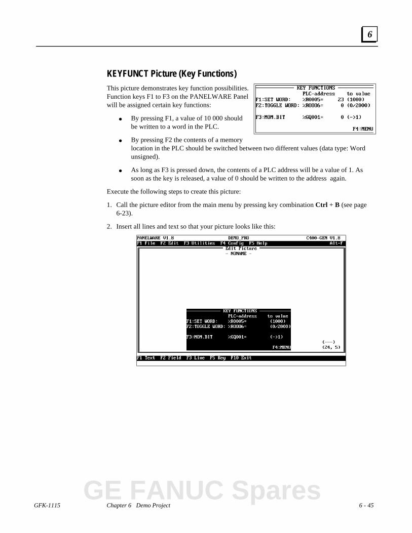
GFK-1115 Chapter 6 Demo Project 6 - 45
6
KEYFUNCT Picture (Key Functions)This picture demonstrates key function possibilities.Function keys F1 to F3 on the PANELWARE Panelwill be assigned certain key functions:
● By pressing F1, a value of 10 000 shouldbe written to a word in the PLC.
● By pressing F2 the contents of a memorylocation in the PLC should be switched between two different values (data type: Wordunsigned).
● As long as F3 is pressed down, the contents of a PLC address will be a value of 1. Assoon as the key is released, a value of 0 should be written to the address again.
Execute the following steps to create this picture:
1. Call the picture editor from the main menu by pressing key combination Ctrl + B (see page6-23).
2. Insert all lines and text so that your picture looks like this:
GE FANUC Spares

6 - 46 PANELWARE MMI Application Manual for GE Fanuc Genius Protocol - June 1995 GFK-1115
6
3. Insert the first output field and the respective key functions into the picture:
● Insert an output field type, Output Word (unsigned), with the following parameters:
Position:.............................................24,3Number of Digits:..............................5Places after the dec. point:..................0Character Size:...................................1Field Width:.......................................5Tagname:...........................................SETWORDDisplay leading zeros? (Y/N):............NScaling ? (Y/N) ..................................No
● In order to write to memory location SETWORD by pressing F1, a function must beassigned to a function key. Assign the key that will be defined as function key F1 (see“Defining Key Assignments”), using the key function Set Word with the followingparameters:
Tagname:...........................................SETWORDValue 1: .............................................10000
It is not necessary to define the parameters Tagname for Completion and Value forCompletion.
Press F5 Key to display the LED/Key function menu. Step 6 under “Clock Picture” (seepage 6-38) describes how to assign a function to a single key.
4. Insert the second output field and its key function into the picture:
● Insert an output field of type Output Word (unsigned) with the following parameters:
Position:.............................................24,4Number of Digits:..............................5Places after the dec. point:..................0Character Size:...................................1Field Width:.......................................5Tagname:...........................................TOGGWORDDisplay leading zeros? (Y/N):............NoScaling ? (Y/N) ..................................No
● To switch the memory location TOGGWORD between two different values by pressingF2, a key function must be assigned to this function key. Assign the key function ToggleWord to the key that will be defined as function key F2 (see “Defining KeyAssignments”), with the following parameters.
Tagname:...........................................TOGGWORDValue 1: .............................................0Value 2: .............................................20000
There is no need to define parameters Tagname for Completion and Value forCompletion. Step 6 of section “Clock Picture” describes how to assign a key function to asingle key (see page 6-38).

GFK-1115 Chapter 6 Demo Project 6 - 47
6
5. Insert the third output field and its key functions into the picture:
● Insert an output field of type Output Bit/Byte with the following parameters:
Position:.............................................24,5Number of Digits:..............................1Places after the dec. point:..................0Character Size:...................................1Field Width:.......................................1Tagname:...........................................GLB_BIT _01/GIDisplay leading zeros? (Y/N):............NoScaling? (Y/N):..................................No
● To transfer the status of the F3 function key to the memory location GLB_BIT_01/GI,assign the key function Momentary Bit/Byte to the key that will be defined as functionkey F3 (see “Defining Key Assignments”) with the following parameters.
Tagname:...........................................GLB_BIT _01/GIValue 1: .............................................1
There is no need to define parameters Destination Tagname and Destination Value. Aslong as the F3 key is held down, the value 111 will be written to memory locationGLB_BIT_01/GI. Only when the key is released, will value 0 be written to the memorylocation again.
Step 6 of section “Clock Picture” describes how to assign a key function to a single key (seepage 6-38).
6. Assign the LED function Key LED switched on to function keys F1 to F4 . Step 5 in “MainPicture” explains how to assign LED functions to individual keys (see page 6-26).
7. Save this picture under the name KEYFUNCT.
GE FANUC Spares

6 - 48 PANELWARE MMI Application Manual for GE Fanuc Genius Protocol - June 1995 GFK-1115
6
ALARM Picture (Alarm List)This picture shows a list of active alarms. Thealarm bit field (16 bits in the demo project) isread from the PLC. Every bit represents an alarm.If an alarm occurs (bit changes from 0 to 1), itwill appear in the alarm list. This alarm list canbe displayed with the alarm field Active Alarm .To display a list of four active alarms (as shown in the picture above), insert four fields into thepicture.
Execute the following steps to create this picture:
1. Call the picture editor from the main menu with key combination Ctrl + B (see page 6-23).
2. Insert all lines and text into the rectangle so that your picture looks like the one below:
3. Now insert the first alarm field Active Alarm in cursor position 0,2 with the followingparameters:
Position:.............................................0,2Field Width:.......................................40F key for Acknowledge:......................F1Function Key for Up:..........................F2Function Key for Down:.....................F3
4. The next three fields are inserted with the same parameters, each field a line lower in thepicture. The picture should then look like this:

GFK-1115 Chapter 6 Demo Project 6 - 49
6
5. Assign function keys F1 to F4 with LED function Key LED switched on. Step 5 in “MainPicture” explains how to assign LED functions to individual keys (see page 6-26).
6. Save this picture now under the name ALARM.
GE FANUC Spares

6 - 50 PANELWARE MMI Application Manual for GE Fanuc Genius Protocol - June 1995 GFK-1115
6
ERR_PIC Picture (Error Picture)The error picture is displayed if an error occurs in thecommunication with the PLC. Three internal variablescontaining notes on the cause of the error are displayedin the picture (for more information on these variablessee Appendix D “Internal Variables” in thePANELWARE™ Configuration Software ReferenceManual – GFK-0849).
To create this picture, complete the following steps:
1. Call the picture editor from the main menu with key combination Ctrl + B (see page 6-23).
2. Insert all lines and text into the rectangle so that it looks like the one in the screen shownbelow:
3. In cursor position 12,5 insert an output field Output Bit/Byte with the following parameters:
Position:.............................................12,5Number of Digits:..............................3Places after the dec. point:..................0Character size: ...................................1Field width:........................................3Tagname:...........................................ERR_NR/DIDisplay leading zeros? (Y/N):............NoScaling? (Y/N):..................................No
4. Insert an output field Output String in cursor position 19,5 with the following parameters:
Position:.............................................19,5String length:.....................................10Character size: ...................................1Tagname:...........................................ERR_NAME/DI
5. Insert an output field Output String in cursor position 32,5 with the following parameters:
Position:.............................................32,5String length:.....................................2Character size: ...................................1Tagname:...........................................ERR_NODE/DI
6. Assign function key F8 with LED function Key LED blinking slow. This is explained in step5 under “Main Picture” on page 6-26.
7. Save the picture under the name ERR_PIC.

GFK-1115 Chapter 6 Demo Project 6 - 51
6
Defining the Text Groups
A text group named GLOBAL exists for every project. This text group cannot be deleted. Text #0of this text group contains commands for clearing the display and the key LEDs. These commandsare always executed after every picture change.
In the demo project, no text is used from a text group except text #0 from the group GLOBAL .This text group is automatically created during the creation of a new project.
GE FANUC Spares

6 - 52 PANELWARE MMI Application Manual for GE Fanuc Genius Protocol - June 1995 GFK-1115
6
Binding Pictures to the Project
Every picture used must be bound into the project. Binding the pictures is done in the projecteditor (see Chapter 4, “Project Editor” in the PANELWARE™ Configuration Software ReferenceManual — GFK-0849).
Error PictureThe name of the error picture is entered in the main menu of the project editor. The project editoris selected via the Project menu option from the Edit menu, or by using key combination Ctrl +P. The Edit Project window appears on the screen:
1. Press the F1 Project Def. function key and enter the name of the error picture (Note: Thefunction line at the bottom of the screen changes when you do this). Pressing the F5 Picturefunction key displays a selection window with a list of all of the pictures created for thisproject. Select the ERR_PIC picture with the cursor keys. Confirm the selection by pressingthe ↵↵ key.
2. Enter 8 to specify function key F8 for the F-Key for Error confirmation .
3. Now press F4 Accept to close the project definition. This saves the definition so that it can beused in the future.
4. Next, the error picture must be bound to the project (described in “Binding Process Pictures”),so that no picture change is possible.

GFK-1115 Chapter 6 Demo Project 6 - 53
6
Binding Process PicturesThe pictures that will be used to display process information or to enter process data (commands)with the Keyblocks must be bound into the project. Press F2 Bind Picture in the project editor.The screen appears:
The name of the picture to be bound into the project (the Base picture) is entered in the rectangleon the left-hand side of the window. Enter the names of the pictures that will be branched to in theother rectangles.
Binding the MAIN Picture:
1. You should be able to switch to all four other pictures from the MAIN picture. The picturechanges should be done through function keys F1 – F4. The Next and Previous keys shouldnot cause a picture change; i.e., they must point to the MAIN picture.
2. Binding the MAIN picture should be done according to the structure shown below:
GE FANUC Spares
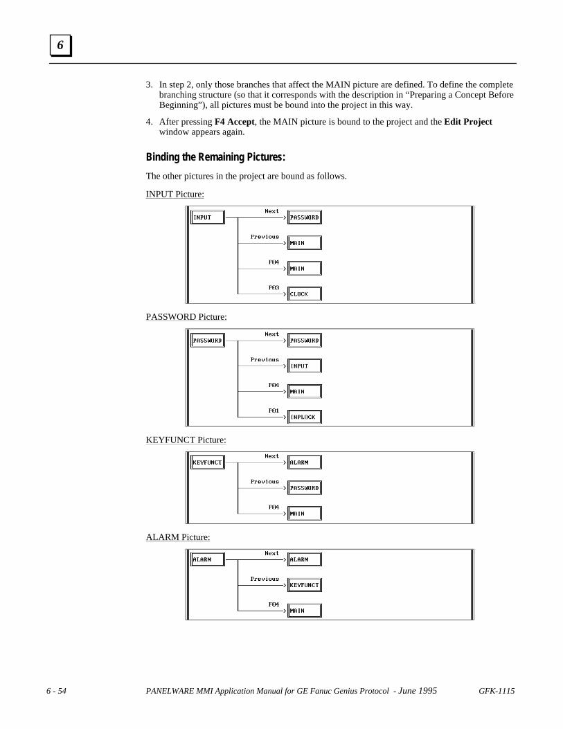
6 - 54 PANELWARE MMI Application Manual for GE Fanuc Genius Protocol - June 1995 GFK-1115
6
3. In step 2, only those branches that affect the MAIN picture are defined. To define the completebranching structure (so that it corresponds with the description in “Preparing a Concept BeforeBeginning”), all pictures must be bound into the project in this way.
4. After pressing F4 Accept, the MAIN picture is bound to the project and the Edit Projectwindow appears again.
Binding the Remaining Pictures:
The other pictures in the project are bound as follows.
INPUT Picture:
PASSWORD Picture:
KEYFUNCT Picture:
ALARM Picture:

GFK-1115 Chapter 6 Demo Project 6 - 55
6
CLOCK Picture:
INPLOCK Picture:
ERR_PIC Picture:
GE FANUC Spares
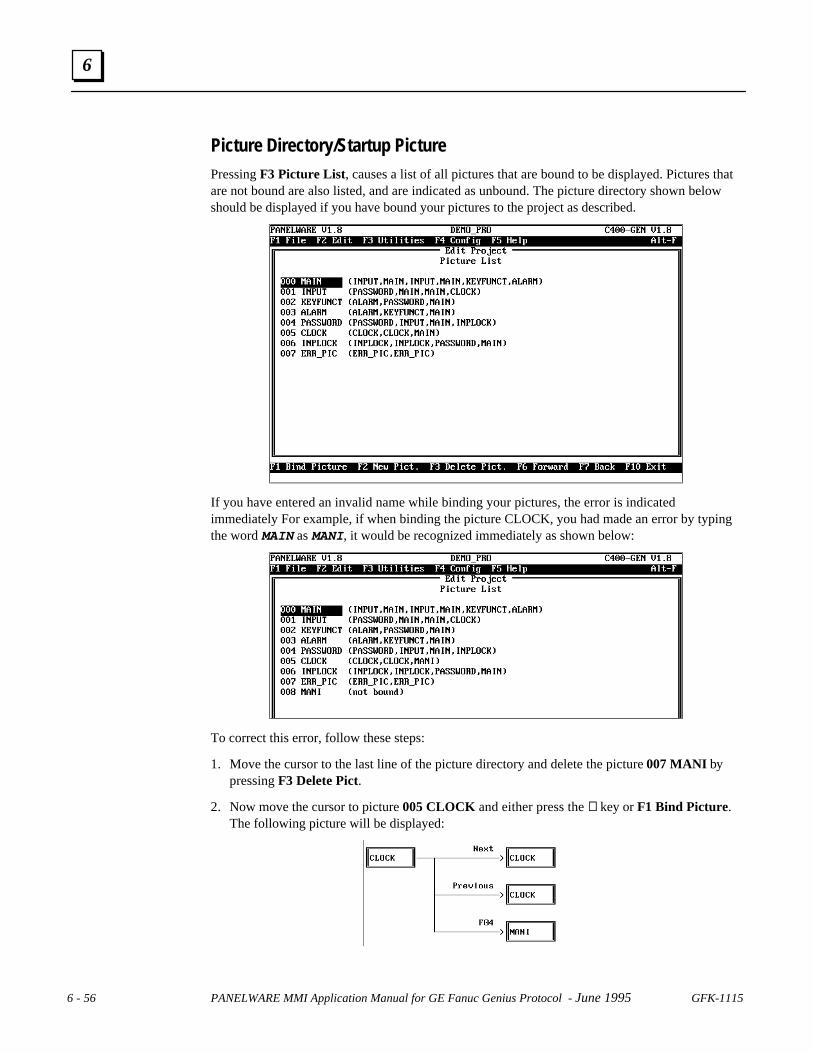
6 - 56 PANELWARE MMI Application Manual for GE Fanuc Genius Protocol - June 1995 GFK-1115
6
Picture Directory/Startup PicturePressing F3 Picture List, causes a list of all pictures that are bound to be displayed. Pictures thatare not bound are also listed, and are indicated as unbound. The picture directory shown belowshould be displayed if you have bound your pictures to the project as described.
If you have entered an invalid name while binding your pictures, the error is indicatedimmediately For example, if when binding the picture CLOCK, you had made an error by typingthe word MAIN as MANI, it would be recognized immediately as shown below:
To correct this error, follow these steps:
1. Move the cursor to the last line of the picture directory and delete the picture 007 MANI bypressing F3 Delete Pict.
2. Now move the cursor to picture 005 CLOCK and either press the ↵↵ key or F1 Bind Picture.The following picture will be displayed:

GFK-1115 Chapter 6 Demo Project 6 - 57
6
3. Move the cursor to the rectangle with the misspelled word MANI and change the name toMAIN. Press the F4 Accept key to confirm the change.
4. The corrected picture directory should now be displayed.
5. The Startup picture is the picture that is displayed on the screen as soon as the Panel isswitched on in Run Mode or after a reset. The picture that is in position 0 of the picturedirectory is always used as the startup picture. If the MAIN picture is not in this position, youshould move it to the first position in the list:
• To do this move the cursor to the MAIN picture.
• Press F7 Back to push the MAIN picture up to the top of the list.
• Press F10 to return to the Main menu when you have finished editing the Picture List.
Caution
Make sure that the picture in the first position is never the same as thepicture defined as the communication error picture in the project editor.
Further information on the use and the operation of the project editor can be found in thePANELWARE™ Configuration Software Reference Manual (GFK-0849).
GE FANUC Spares
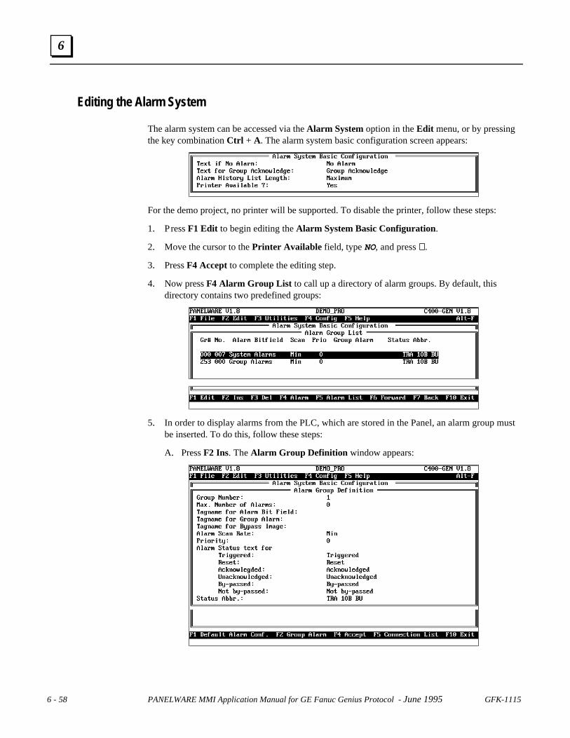
6 - 58 PANELWARE MMI Application Manual for GE Fanuc Genius Protocol - June 1995 GFK-1115
6
Editing the Alarm System
The alarm system can be accessed via the Alarm System option in the Edit menu, or by pressingthe key combination Ctrl + A. The alarm system basic configuration screen appears:
For the demo project, no printer will be supported. To disable the printer, follow these steps:
1. Press F1 Edit to begin editing the Alarm System Basic Configuration.
2. Move the cursor to the Printer Available field, type NO, and press ↵↵.
3. Press F4 Accept to complete the editing step.
4. Now press F4 Alarm Group List to call up a directory of alarm groups. By default, thisdirectory contains two predefined groups:
5. In order to display alarms from the PLC, which are stored in the Panel, an alarm group mustbe inserted. To do this, follow these steps:
A. Press F2 Ins. The Alarm Group Definition window appears:
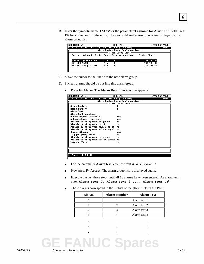
GFK-1115 Chapter 6 Demo Project 6 - 59
6
B. Enter the symbolic name ALARM for the parameter Tagname for Alarm Bit Field. PressF4 Accept to confirm the entry. The newly defined alarm groups are displayed in thealarm group list:
C. Move the cursor to the line with the new alarm group.
D. Sixteen alarms should be put into this alarm group:
● Press F4 Alarm . The Alarm Definition window appears:
● For the parameter Alarm text , enter the text Alarm text 1 .
● Now press F4 Accept. The alarm group list is displayed again.
● Execute the last three steps until all 16 alarms have been entered. As alarm text,enter Alarm text 2, Alarm text 3 .... Alarm text 16 .
● These alarms correspond to the 16 bits of the alarm field in the PLC.
Bit No. Alarm Number Alarm Text
0 1 Alarm text 1
1 2 Alarm text 2
2 3 Alarm text 3
3 4 Alarm text 4
. . .
. . .
. . .
GE FANUC Spares

6 - 60 PANELWARE MMI Application Manual for GE Fanuc Genius Protocol - June 1995 GFK-1115
6
E. Now you can display a list of all alarms in this group by pressing the F5 Alarm List keywhile in the Alarm Group List window. (Press PgeDn to view the remainder of theAlarm List window.)
F. You can change the sequence of the alarms and the definition of each individual alarm inthis list by pressing F1 Edit .
G. Press F10 Exit repeatedly until the main menu appears again.
Activating the Alarm System
The alarm system still has to be activated in the project definition. To change the projectdefinition, follow these steps:
1. Access the project definition using option Project in the Edit menu, or by using keycombination Ctrl + P:
2. Press function key F1 Project Def.
3. Move the cursor to the line Enable Alarm System.
4. Enter Y and confirm it by pressing ↵↵.
5. End the project definition with F4 Accept.
6. Close the project editor with F10 Exit . The main menu appears again.

GFK-1115 Chapter 6 Demo Project 6 - 61
6
Editing the Connections
All of the variables used in the project must be assigned to a certain PLC address in theconnection editor. General information on operating the connection editor can be found in thePANELWARE™ Configuration Software Reference Manual (GFK-0849).
Access the connection list from the main menu, either by selecting the Connection option in theEdit menu, or by using key combination Ctrl + C:
Internal ConnectionYou can display all of the internal variables used in your project. Move the cursor in theconnection list to the connection DI Internal and press F5 VAT or ↵↵:
If you have made all entries correctly, your screen should look like the screen shown above.Compare the variable names and the corresponding Panel data types. If the variable assignmenttable is different from the one above, make the required changes. Possible errors and theircorrections are:
• Wrong Name: Change the address in the respective picture/field.
• Wrong Panel Data Type: You have used a field with the incorrect data type in a picture.Delete the field and its entry in the VAT and then insert the desired field.
Pressing F10 Exit or Esc closes the variable assignment table for the DI Internal connection.
GE FANUC Spares

6 - 62 PANELWARE MMI Application Manual for GE Fanuc Genius Protocol - June 1995 GFK-1115
6
Genius Internal ConnectionTo display the Genius Internal variables used in your project, move the cursor in the connectionlist to the connection GI — GENIUS — Genius Internal and press F5 VAT or ↵↵:
If you have made all entries correctly If you have made all entries correctly, your screen shouldlook like the screen shown above. Compare the variable names and the corresponding Panel datatypes. If the variable assignment table is different from the one above, make the required changes.Possible errors and their corrections are:
• Wrong Name:Change the address in the respective picture/field.
• Wrong Panel Data Type:You have used a field with the incorrect data type in a picture. Delete the field and its entry inthe VAT and then insert the desired field.
Every variable must be assigned to a PLC address and a PLC variable type now. A detailedexplanation is provided in chapter 5. Assign following PLC addresses to the symbolic names:
Symbolic Name Panel Data Type PLC Address PLC Variable Type
GLB_BIT_01 Byte unsigned GQ0001 BIT
By pressing the F10 Exit function key, or the Esc key, the VAT is closed for the Genius Internalconnection.

GFK-1115 Chapter 6 Demo Project 6 - 63
6
Genius GBC Series 90-70 ConnectionAll variables used in your project and having the connection DD Genius can be displayed. To dothis move the cursor to the GENIUS connection in the connection editor and press the functionkey F5 VAT or the ↵↵ key:
If you have made all entries correctly, your screen should look like the screen shown above.Compare the variable names and the corresponding Panel data types. If the variable assignmenttable is different from the one above, make the required changes. Possible errors and theircorrections are:
• Wrong Name:Change the address in the respective picture/field.
• Wrong Panel Data Type:You have used a field with another data type in a picture. Delete the field and its entry in theVAT and then insert the desired field.
Every variable must be assigned to a PLC address and a PLC variable type now. A detailedexplanation is provided in chapter 5. Assign the symbolic names to the following PLC addresses:
Symbolic Name Panel Data Type PLC AddressPLC Variable Type
ALARM Bit %M001 BIT
COMPLETE Byte unsigned %R0101 INT
INPUT#1 Word unsigned %R0010 WORD
INPUT#2 Word unsigned %R0011 WORD
INP_INT Word signed %R0002 INT
INP_WORD Word unsigned %R0001 WORD
OUT_INT Word signed %R0002 INT
OUT_WORD Word unsigned %R0001 WORD
PASSWORD Byte unsigned %R0100 INT
SETWORD Word unsigned %R0005 WORD
TOGGWORD Word unsigned %R0006 WORD
By pressing the F10 Exit function key or the Esc key, the variable assignment table is closed forthe Genius GBC Series 90-70 connection.
GE FANUC Spares

6 - 64 PANELWARE MMI Application Manual for GE Fanuc Genius Protocol - June 1995 GFK-1115
6
Compiling the Project
To download a project to the Panel, it must first be compiled. Only a project that is loaded (projectname in the title bar) can be compiled. Start the compilation by accessing the project compiler,either via the Compile menu option in the Utilities menu, or by pressing the key combinationCtrl + Q.
The progress of the compilation procedure is shown in the Project Compiler window. If theproject is successfully compiled (translated), the following message appears:
The amount of memory used in the user bank (FlashPROM in the Panel) is also shown after asuccessful compilation. See the PANELWARE™ Hardware Installation User’s Manual (GFK-0848) for more information.
Pressing Esc closes the window and returns you to the main menu.
Errors
During the compilation, error messages can appear in the Project Compiler window.
If you receive an error message, refer to Appendix C of the PANELWARE™ ConfigurationSoftware Reference Manual (GFK-0849).

GFK-1115 Appendix A Cabling Information A - 1
Appendix Cabling Information
This appendix describes the required PCS to PLC/PC interface cabling. It includes the followinginformation:
■ Genius Communications............................................................................................A-2
❏ Selecting a Cable Type........................................................................................A-2
❏ Using Other Cable Types....................................................................................A-2
❏ Bus Length.........................................................................................................A-4
❏ Baud Rate Selection............................................................................................A-4
❏ Connecting Devices to the Bus............................................................................A-5
■ SNP Communications................................................................................................A-5
■ Cable Diagrams.........................................................................................................A-6
A
GE FANUC Spares

A - 2 PANELWARE MMI Application Manual for GE Fanuc Genius Protocol - June 1995 GFK-1115
A
Genius Communications
Selecting a Cable Type
The Genius bus is a shielded twisted-pair wire, daisy-chained from block to block and terminatedat both ends. Proper cable selection is critical to successful operation of the system. Each bus inthe system can be any cable type listed in table A-1. The 89182, 89207, 4794, 9696, and 89855types are high temperature cables for use in severe environments, and are qualified for use in airplenums. The 9815 type is water resistant, and can be used where direct burial is required. Similarcables of equivalent terminating resistance such as 9207, 89207, and 9815 can be mixed. Do notmix cables of different impedance, regardless of cable run length. The maximum run for mixedcable type equals the shortest length recommended for any of the types used. Other, small-sizetwisted pair shielded wire of unspecified impedance can be used for short runs of 50 feet or less,using 75 ohm terminations.
The excellent noise reduction of these cable types, and of the Genius communications system,allow the communications bus to be mixed with other signaling systems and 120 volt AC controlcircuits without added shielding or conduits. Conservative wiring practices, and national and localcodes, require physical separation between control circuits and power distribution or motor power.Refer to sections 430 and 725 of the National Electric Code.
Using Other Cable Types
If the cables listed in table A-1 are not available, the cable selected must meet the following guidelines:
1. High quality construction. Most important is uniformity of cross section along the length ofthe cable. Poor quality cable can cause signal distortion, and increase the possibility ofdamage during installation.
2. Precision-twisted shielded wire of type EIA RS-422, having a uniform number of twists per unit oflength. In a catalog, this type of cable may be listed as twinaxial cable, data cable, or computercable.
3. Relatively high characteristic impedance; 100 to 150 ohms is best; 75 ohms is the minimumrecommended.
4. Low capacitance between wires, typically less than 20pF/foot (60pF/meter). This can beaccomplished by inner dielectrics of foamed type, usually polypropylene or polyethylene,having a low dielectric constant. Alternatively, the conductors can be spaced relatively farapart. Lower impedance types have smaller cross-sections, and provide easier wiring forshorter total transmission distances.
5. Shield coverage of 95% or more. Solid foil with an overlapped folded seam and drain wire isbest. Braided copper is less desirable; spiral wound foil is least desirable.
6. An outer jacket that provides appropriate protection, such as water, oil, or chemicalresistance. While PVC materials can be used in many installations, Teflon, polyethylene, orpolypropylene are usually more durable.
7. Electrical characteristics: cable manufacturers' information about pulse rise time and NRZdata rate is useful for comparing cable types. The Genius bit consists of three AC pulses; theequivalent NRZ bit rate is about three times as great. For assistance in selecting a specificcable type, please consult your local GE Fanuc application engineer.
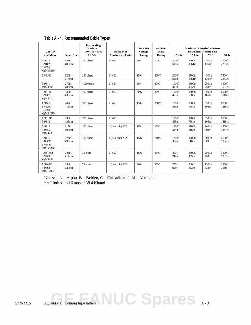
GFK-1115 Appendix A Cabling Information A - 3
Table A - 1. Recommended Cable Types
Cable #
TerminatingResistor*
-10% to +20% Number ofDielectricVoltage
AmbientTemp.
Maximum Length Cable Runfeet/meters at baud rate
and Make Outer Dia. 1/2 Watt Conductors/AWG Rating Rating 153.6s 153.6e 76.8 38.4•
(A)9823(B)9182(C)4596(M)M39240
350in8.89mm
150 ohms 2 / #22 30v 60°C 2000ft606m
3500ft1061m
4500ft1364m
7500ft2283m
(B)89182 .322in8.18mm
150 ohms 2 / #22 150v 200°C 2000ft606m
3500ft1061m
4500ft1364m
7500ft2283m
(B)9841(M)M3993
.270in6.86mm
*120 ohms 2 / #24 30v 80°C 1000ft303m
1500ft455m
2500ft758m
3500ft1061m
(A)9818C(B)9207(M)M4270
.330in8.38mm
100 ohms 2 / #20 300v 80°C 1500ft455m
2500ft758m
3500ft1061m
6000ft1818m
(A)9109(B)89207(C)4798(M)M44270
.282in7.16mm
100 ohms 2 / #20 150v 200°C 1500ft455m
2500ft758m
3500ft1061m
6000ft1818m
(A)9818D(B)9815
.330in8.38mm
100 ohms 2 / #20 1500ft455m
2500ft758m
3500ft1061m
6000ft1818m
(A)9818(B)9855(M)M4230
.315in8.00mm
100 ohms 4 (two pair) #22 150v 60°C 1200ft364m
1700ft516m
3000ft909m
4500ft1364m
(A)9110(B)89696(B)89855(M)M64230
.274in6.96mm
100 ohms 4 (two pair) #22 150v 200°C 1200ft364m
1700ft516m
3000ft909m
4500ft1364m
(A)9814C)(B)9463(M)M4154
.243in6.17mm
75 ohms 2 / #20 150v 60°C 800ft242m
1500ft455m
2500ft758m
3500ft1061m
(A)5902C(B)9302(M)M17002
.244in6.20mm
75 ohms 4 (two pair) #22 300v 80°C 200ft60m
500ft152m
1200ft333m
2500ft758m
Notes: A = Alpha, B = Belden, C = Consolidated, M = Manhattan• = Limited to 16 taps at 38.4 Kbaud
GE FANUC Spares

A - 4 PANELWARE MMI Application Manual for GE Fanuc Genius Protocol - June 1995 GFK-1115
A
Bus Length
The maximum bus length for shielded, twisted-pair cable is 7500 feet. Some cable types arerestricted to shorter bus lengths. For example, for buses with a total cable length of 100 feet to2000 feet Belden 9182 or Alpha 9823 or Belden 89182 can be used. In turn, the bus lengthdetermines which baud rate can be selected. If the application requires greater bus length, fiberoptics cable and modems can be used, as explained later in this chapter.
If the application requires greater bus length, fiber optics cable and modems can be used; refer tothe Genius I/O System and Communications User’s Manual (GEK-90486-1).
Baud Rate Selection
A Genius I/O or communications bus can operate at one of four baud rates: 153.6 Kbaud standard,153.6 Kbaud extended, 76.8 Kbaud, or 38.4 Kbaud. Follow these guidelines when selecting thebaud rate for a bus:
1. All devices on a bus must operate at the same baud rate (other busses in the system canoperate at different baud rates).
2. If there are any older Genius products on the bus (catalog numbers IC660CBDnnn,IC660CBSnnn, IC660CBAnnn, IC660HHM500, or IC660CBB900/901), the bus must be setup to use 153.6 Kbaud standard.
3. If the cable length is between 4500 and 7500 feet, you must select 38.4 Kbaud. This data rateonly supports a maximum of 16 device on the bus.
4. If the cable length is between 3500 and 4500 feet, select 76.8 Kbaud.
5. If cable length is between 2000 and 3500 feet, select 153.6 Kbaud extended.
6. If the cable length is less than 2000 feet, either 153.6 Kbaud standard or 153.6 Kbaudextended can be used. The products are set to operate at 153.6 Kbaud standard when shippedfrom the factory. The use of 153.6 Kbaud extended is recommended, especially if the systemwill include a dual bus with Bus Switching Modules.
In noisy environments, 153.6 Kbaud extended provides improved noise immunity with little effecton bus scan time. If a system is experiencing excessive blinking of the bus controller's COMM OKlight, or if the I/O blocks’ I/O Enabled LEDs go off frequently, 153.6 Kbaud extended should beused. The baud rate selected should be indicated on all blocks, especially if different busses in thefacility use different baud rates. Before connecting a Hand-held Monitor (HHM) to a functioningbus, check that it has been configured to the correct baud rate. If not, change the HHM baud rateselection, turn off the HHM, connect it to the bus, then turn the HHM on.
Bus Length and Baud Rate for Busses with Phase A DevicesIf a bus has any Phase A Genius products (catalog numbers IC660CBDnnn, IC660CBSnnn,IC660CBAnnn, IC660HHM500, or IC660CBB900/901), the bus must use 153.6 Kbaud“standard” and the maximum bus length is 2000 feet. Therefore, only the cable lengths listedunder “153.6s" are permitted (“153.6e" refers to 153.6 Kbaud extended, which is not compatiblewith 153.6 Kbaud standard).
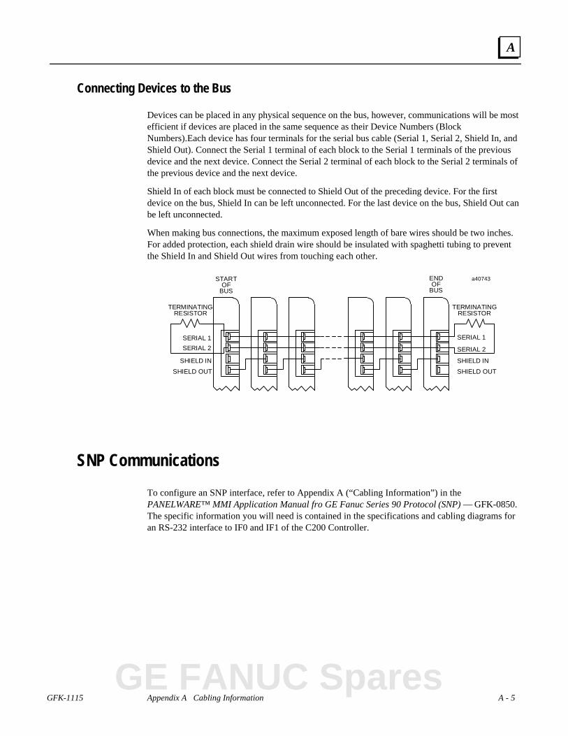
GFK-1115 Appendix A Cabling Information A - 5
A
Connecting Devices to the Bus
Devices can be placed in any physical sequence on the bus, however, communications will be mostefficient if devices are placed in the same sequence as their Device Numbers (BlockNumbers).Each device has four terminals for the serial bus cable (Serial 1, Serial 2, Shield In, andShield Out). Connect the Serial 1 terminal of each block to the Serial 1 terminals of the previousdevice and the next device. Connect the Serial 2 terminal of each block to the Serial 2 terminals ofthe previous device and the next device.
Shield In of each block must be connected to Shield Out of the preceding device. For the firstdevice on the bus, Shield In can be left unconnected. For the last device on the bus, Shield Out canbe left unconnected.
When making bus connections, the maximum exposed length of bare wires should be two inches.For added protection, each shield drain wire should be insulated with spaghetti tubing to preventthe Shield In and Shield Out wires from touching each other.
STARTOF
BUS
SERIAL 1
SERIAL 2
SHIELD IN
SHIELD OUT
TERMINATINGRESISTOR
a40743
SERIAL 1
SERIAL 2
SHIELD IN
SHIELD OUT
TERMINATINGRESISTOR
ENDOF
BUS
SNP Communications
To configure an SNP interface, refer to Appendix A (“Cabling Information”) in thePANELWARE™ MMI Application Manual fro GE Fanuc Series 90 Protocol (SNP) — GFK-0850.The specific information you will need is contained in the specifications and cabling diagrams foran RS-232 interface to IF0 and IF1 of the C200 Controller.
GE FANUC Spares
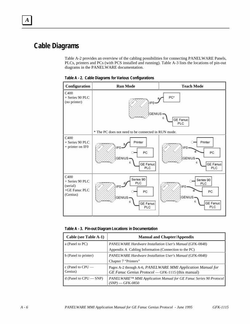
A - 6 PANELWARE MMI Application Manual for GE Fanuc Genius Protocol - June 1995 GFK-1115
A
Cable Diagrams
Table A-2 provides an overview of the cabling possibilities for connecting PANELWARE Panels,PLCs, printers and PCs (with PCS installed and running). Table A-3 lists the locations of pin-outdiagrams in the PANELWARE documentation.
Table A - 2. Cable Diagrams for Various Configurations
Configuration Run Mode Teach Mode
C400+ Series 90 PLC(no printer)
* The PC does not need to be connected in RUN mode.
C400+ Series 90 PLC+ printer on IF0
C400+ Series 90 PLC(serial)+GE Fanuc PLC(Genius)
Table A - 3. Pin-out Diagram Locations in Documentation
Cable (see Table A-1) Manual and Chapter/Appendix
a (Panel to PC) PANELWARE Hardware Installation User's Manual (GFK-0848)
Appendix A Cabling Information (Connection to the PC)
b (Panel to printer) PANELWARE Hardware Installation User's Manual (GFK-0848)
Chapter 7 “Printers”
c (Panel to CPU —Genius)
Pages A-2 through A-6, PANELWARE MMI Application Manual forGE Fanuc Genius Protocol — GFK-1115 (this manual)
d (Panel to CPU — SNP) PANELWARE™ MMI Application Manual for GE Fanuc Series 90 Protocol(SNP) — GFK-0850

GFK-1115 B - 1
Appendix Errors/Troubleshooting
This appendix provides an overview of possible system errors, their causes, and how to handlethem. Actual error messages are displayed, followed by possible causes and corrective actions. Thefollowing sections of information are included:
■ Errors During Installation.......................................................................................... B-2
■ Errors During Program Start ..................................................................................... B-3
■ Errors While Working in PCS ................................................................................... B-4
■ Error Numbers in Internal USER Variable................................................................. B-6
B
GE FANUC Spares

B - 2 PANELWARE MMI Application Manual for GE Fanuc Genius Protocol - June 1995 GFK-1115
B
Errors During Installation
Installation could not be ended properly!Setup program cannot be called!
Check that the following conditions are met:
■ PC must contain an 80286 or higher type processor.
■ To install the PCS, the PC must have at least 2 MB hard disk space available.
■ PC must have at least 640 KB RAM (500 KB must be available). If enough RAM is notavailable, remove the necessary memory-resident programs.
GFK-1115 Appendix B Errors/Troubleshooting B - 3
B
Errors During Program Start
PCS cannot be started!
Check that the following conditions are met:
■ PC must contain an 80286 or higher type processor.
■ PC must have at least 640 KB RAM (500 KB must be available). If enough RAM is notavailable, remove the necessary memory-resident programs.
PCS Error Message Fatal Error, PANELWARE requires 1 MB on drive c:
Check that the following condition is met:
■ To start the PCS, the PC must have at least 1 MB hard disk space available.
GE FANUC Spares

B - 4 PANELWARE MMI Application Manual for GE Fanuc Genius Protocol - June 1995 GFK-1115
B
Errors While Working in PCS
When the PCS is running, error messages are either displayed in the bottom line of the screen (thefunction key line) or in the current window.
Faults running PCS!
Check that the following condition is met:
■ FILES and BUFFERS in the CONFIG.SYS file should be set to at least the followingvalues:
BUFFERS = 10FILES = 40
■ During installation, the SETUP program makes these settings automatically, but only ifyou responded positively by pressing Y during the installation process. If the BUFFERSand FILES values in the CONFIG.SYS file are smaller, change them to the above valuesbefore trying to run the PCS again.
Invalid Project Name
This error message appears in the last line if a new project is assigned a name that already exists.Either change the new project's name or delete the existing project with the same name.
<File name> cannot be written
When entering project names or saving pictures, text groups, or key definitions, filenames mustmeet the following conditions:
■ Maximum length of the filename: 8 characters
■ Only standard MS-DOS characters are allowed. Characters such as ".*?,;.:" or thespace character are not permitted.
<File name> cannot be read
This error message appears if a non-existent filename is entered while trying to load a project orpicture.
If no filename is entered and [ENTER] is pressed, all existing project or picture names are listedin a selection window. By using the cursor keys to highlight a filename, the desired project/picturecan be selected and loaded.
GFK-1115 Appendix B Errors/Troubleshooting B - 5
B
Error! Error picture and first picture cannot be the same!
The compilation of a project is interrupted with this error message if the error picture is defined inthe first position of the picture directory. The start-up picture must be listed in the first position ofthe directory (see the Chapter 2, “Quick Start” section entitled “Binding Pictures in a Project”).
Cannot make connection with panel!Please check cable and installation!
After calling the Download function, this message appears if the connection to the panel cannot bemade. Check that the following conditions are met:
■ Is the PC connected to the panel?
■ Is the panel properly supplied with power?
■ Are all cables connected to the proper interfaces?
-IF0 on the panel
-COM1 or COM2 on the PC, depending on the PCS configuration (see "PCSConfiguration" in chapter 3)
■ Is the panel in Teach Mode?
■ Is the download cable in good shape and properly connected?
GE FANUC Spares
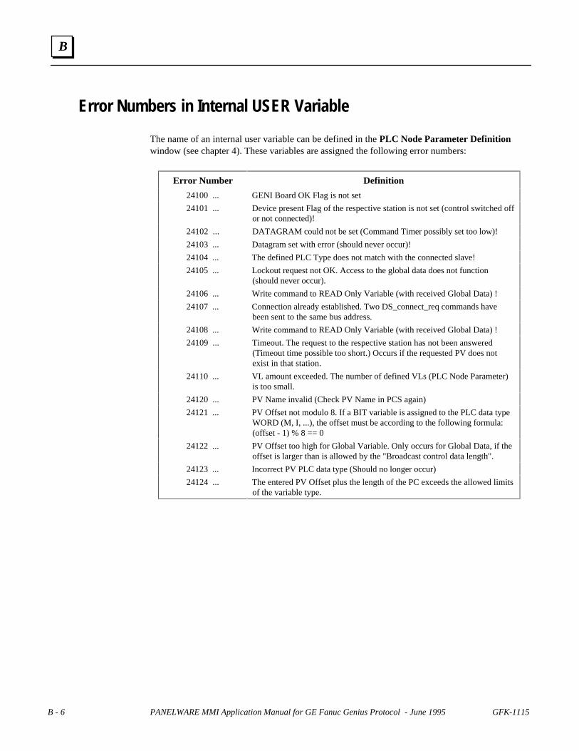
B - 6 PANELWARE MMI Application Manual for GE Fanuc Genius Protocol - June 1995 GFK-1115
B
Error Numbers in Internal USER Variable
The name of an internal user variable can be defined in the PLC Node Parameter Definitionwindow (see chapter 4). These variables are assigned the following error numbers:
Error Number Definition
24100 ... GENI Board OK Flag is not set
24101 ... Device present Flag of the respective station is not set (control switched offor not connected)!
24102 ... DATAGRAM could not be set (Command Timer possibly set too low)!
24103 ... Datagram set with error (should never occur)!
24104 ... The defined PLC Type does not match with the connected slave!
24105 ... Lockout request not OK. Access to the global data does not function(should never occur).
24106 ... Write command to READ Only Variable (with received Global Data) !
24107 ... Connection already established. Two DS_connect_req commands havebeen sent to the same bus address.
24108 ... Write command to READ Only Variable (with received Global Data) !
24109 ... Timeout. The request to the respective station has not been answered(Timeout time possible too short.) Occurs if the requested PV does notexist in that station.
24110 ... VL amount exceeded. The number of defined VLs (PLC Node Parameter)is too small.
24120 ... PV Name invalid (Check PV Name in PCS again)
24121 ... PV Offset not modulo 8. If a BIT variable is assigned to the PLC data typeWORD (M, I, ...), the offset must be according to the following formula:(offset - 1) % 8 == 0
24122 ... PV Offset too high for Global Variable. Only occurs for Global Data, if theoffset is larger than is allowed by the "Broadcast control data length".
24123 ... Incorrect PV PLC data type (Should no longer occur)
24124 ... The entered PV Offset plus the length of the PC exceeds the allowed limitsof the variable type.

Index
GFK-1115 Index-1
AAccessing the Connection List, 5-2Alarm field, 6-48Alarm group definition, 6-58Alarm list, 6-48Alarm system
activation, 6-60editing, 6-58
BBase picture, 6-53Baud Rate, 4-7Baud rate selection, A-4Binding pictures
error picture, 3-35overview, 3-32Pict_1 picture, 3-37picture for a communications error, 3-33picture list directory organization, 3-38process, 3-34start-up picture, 3-36to the project, 6-52
Blocking distance, 4-8Broadcast control data length, 4-7Bus address
assigned to C400 Controller, 4-4Bus connections, A-5Bus error count, 4-4Bus length, A-4Bus scan time, 4-4
CCabling
cable types, A-2diagrams, A-6Genius communications, A-2recommended cable types, A-3
Calling the setup program, 3-2Catalog numbers
C400 Controller, 2-1Genius products, 1-4, A-4PCS, 1-3PLCs, 4-4RS-232 to RS-422 converter, 4-11
Command timer, 4-8Communication error
picture for, 6-50, 6-52Compiling a project, 3-39, 6-64Configuration of the PLC interface, 4-10Connecting power to Panel Controller, 2-2Connecting the PLC and the Panel, 3-42Connection editor, 4-2Connection List, 1-2
accessing, 5-2data type conversions, 5-12deleting connections, 5-5editing protocol parameters, 5-5editing the Variable Assignment Table, 5-6Editing/inserting connections, 5-4elements, 5-3function keys, 5-3selecting the connection, 6-19
Connections, 6-61selection, 6-19to C400, 2-5
Context-sensitive Help screens, 3-7Creating, 3-10Creating a project, 6-16Creating pictures, 3-21
DData interface service, 4-8Data response times, 4-8Data type conversions, 5-12Defining alarms, 6-59Deleting connections, 5-5Deleting variable assignments, 5-10Demo project
creating, 6-16, 6-18creating pictures, 6-23defining key assignments, 6-22description, 6-7downloading, 6-4general information, 6-2required hardware, 6-3selecting the connection, 6-19
Device number switch, 2-7Document conventions, 1-5DOS box
executing PCS in, 1-3Downloading the project to the Panel, 3-40
EEditing protocol parameters for a connection, 5-
5Editing the Variable Assignment Table, 5-6Editing/inserting connections, 5-4Editing/inserting variable assignments, 5-8Elements of the VAT, 5-6Error picture, 6-50, 6-52Errors, 6-64Errors/troubleshooting
errors during installation, B-2errors during program start, B-3errors while working in PCS, B-4
Exiting PCS, 3-44
GE FANUC Spares

Index
Index-2 GFK-1115
FFirmware revision, 4-4Flash memory, 3-39FlashPROM, 2-9, 6-64Function keys of the VAT, 5-7
GGeneral information
connection editor, 5-2Controllers, 2-2
General operationPCS, 3-6PCS screen elements, 3-8
Genius (Definition in PCS), 4-2Genius bus connector, 2-7Genius communications, A-2
baud rate, A-4bus length, A-4connecting devices to the bus, A-5
Genius Internal connection, 4-4Genius Panel Controller
24 VDC power supply, 2-6connections and operational elements, 2-5device number switch, 2-7FlashPROM, 2-9IF0 - RS-232, 2-6IF1 - RS-232, 2-7lithium battery, 2-8mode switch, 2-7Operation, 2-9Reset button, 2-8RESET modes, 2-9specifications, 2-3
Genius protocol parameters, 4-2Global data, 4-4, 5-11Global data starting reference, 4-9
HHardware requirements, 1-3Hardware status, 4-4
IIF0 - RS-232
C400, 2-6IF1 - RS-232
C400, 2-7Installation menu, 3-3Interface connections
Genius, 4-11SNP, 4-11
Internal connection, 6-61
KKey assignments, 3-19
defining, 6-22Key functions, 6-45Key LEDs, 6-26Keyboard Definition, 1-2
LLanguage selection, 3-2LED functions, 6-26Lithium battery
C400, 2-8Locking conditions, 6-43, 6-44Locking value, 6-43, 6-44
MMarking unused variables, 5-10Mode switch
C400, 2-7
NNode parameters
definitions, 4-5NRZ bit rate, A-2Number of retries, 4-6
OOffset, 5-15
in Series Six/Five register memory, 4-9limitations, 5-15
Operating systemreloading, 2-10
Operational elementsC400, 2-5
PPanel Controllers
24 VDC power, 2-2connecting power, 2-2loading Panel program, 2-10loading/starting Panel programs, 2-10reloading the operating system, 2-10setting number switches, 2-2starting panel program, 2-10update mode, 2-10
Panel interface, 4-10Panel programs
loading, 2-10overview, 2-10starting, 2-10

Index
GFK-1115 Index-3
Password, 6-40, 6-42, 6-44PCS
configuration, 3-9General operation, 3-6installation, 3-2Overview, 1-2starting, 3-5
Phase A devicesbus length and baud rate, A-4
Picture 1, 3-21Picture 2, 3-25Picture 3, 3-27Picture Directory, 1-2, 6-56Picture for communication error, 6-50, 6-52Picture list directory organization, 3-38Pictures, 1-2
binding, 6-52creating, 6-23editing, 6-30saving, 6-27
PLC data types, 4-4PLC Network Parameter Definitions, 4-7PLC Node Parameter Definitions, 4-5PLC requirements, 1-4PLC types
configuring, 4-3Power connection
24 VDC, 2-2Power requirement
Panel Controller24 VDC, 2-2
Power supply24 VDC, 2-6
Projectcompiling, 6-64creating pictures, 6-23creation, 6-16defining key assignments, 6-22errors, 6-64
Project components, 1-2Project Definition, 1-2Project variables
defining, 3-28Protocol parameters, 5-3Pull-down menus (main menu), 3-6PV-Name internal Error Number, 4-6
RReal-time clock
reading/displaying, 6-24setting, 6-33
Recommended cable types, A-3Reloading the operating system, 2-10Requirements
hardware, 1-3PLC, 1-4
software, 1-3Reset button, 2-8RESET modes, 2-9
SScreen elements, 3-8Selection windows, 3-7Setting number switches, 2-2Settings on the Panel, 4-10SNP communications, A-5Software installation, 3-2
changing the destination path, 3-3exiting the installation, 3-4installation menu, 3-3language selection, 3-2screen configuration, 3-4setup program, 3-2start installation, 3-3
Starting PCS, 3-5Starting the project, 3-43Startup picture, 6-56
TTarget device number, 4-5Taskname, 4-5Text groups, 6-51
defining, 6-51Timeout, 4-8
UUpdate mode, 2-10User memory, 3-39
VVAT
deleting variable assignments, 5-10editing, 5-6Editing/inserting variable assignments, 5-8elements, 5-6entering/changing PLC addresses, 5-8entering/changing PLC variable types, 5-9entering/changing the tagname, 5-8function keys, 5-7marking unused variables, 5-10
WWindow name, 3-6Write priority, 4-6
GE FANUC Spares


