.- SPECIAL REPORT ON VHF SSB Presenting a 2 -part series on VHF Sideband Equipment PART I ... In This Issue: A COMPLETE 20 -WATT, 144 -MC. SSB EXCITER By David W. Bray, K2LMG PART II - In the September -October, 1962 Issue: A 144 -MC. DIRECT SSB GENERATOR & HETERODYNING SSB SIGNALS TO 144 MC. By James V. O'Hern, W2WZR Interest in SSB on the VHF amateurs bands - principally 50 and 144 megacycles - is growing rapidly. This two-part series in G -E HAM NEWS has been prepared by two long-time experimenters with VHF SSB techniques - and proven in hundreds of tests over a rugged 40 -odd mile path between their stations. There's a wealth of good ideas in their circuits, choices of frequency conversion, and construction techniques. You'll find it's easy to modify or add to your present equipment and try VHF Single Sideband! INTRODUCTION - It is not necessary to extol the advantages of single or double sideband on the high frequency amateur radio bands, but on the VHF bands where there is no QRM, just steady receiver noise, many people do not real- ize the advantages of single or double sideband. These advantages can largely be summed up as follows: 1. In order to achieve high power out- put with an amplitude modulated signal, a large audio amplifier of at least one-half the total input power to the transmitter is re- quired. For one kilowatt trans- mitter this audio power output is extremely difficult and costly to achieve. However, a single side - band exciter of only 6 watts out- put is capable of driving a pair of 250 -watt class beam pentode tubes in a linear amplifier to full 1200 watt peak effective input. If this same amplifier was used to am- plify an amplitude modulated sig- nal one finds that its efficiency is so poor that an amplifier which is capable of putting out 800 watts of SSB RF power delivers approx- imately 200 watts. Thus single and double sideband provide a simple means of producing a high power RF signal. 2. By theory and experimentation it has been shown that CW has a 17 db. advantage over amplitude mod- ulation. That is; a transmitter capable of transmitting one kilo- watt input fully amplitude modu- lated has the same transmitting range as a 20 -watt transmitter which is operated on CW. This is all well and good if you want to IN THIS ISSUE use CW. However, it has also been shown that a single sideband emis- sion is nearly as effective as CW. Actual tests on the 144 -megacycle band have shown that, even though not exactly predicted by theory, a single sideband signal can be copied with the same ease as CW when the distance between stations is such that the signal strength of the received signal is very weak. Under these same conditions an amplitude modulated signal is in- distinguishable. Therefore, single or double sideband do provide two very obvious advantages in the VHF bands: (1) equipment sim- plicity, and (2) talking power. This article describes a 144 -megacycle exciter which is capable of operating single sideband, double sideband, ampli- tude modulation and CW. It has a power output of approximately 6 watts which is adequate for local use or to drive a pentode -type kilowatt linear amplifier to full rated output. It also includes a tun- able crystal oscillator with good stabil- ity and a voice operated control system. The exciter is a phasing type single sideband generator which provides good carrier suppression and unwanted side - band rejection. CIRCUIT DESCRIPTION - The Exciter con- sists of four basic circuits: (1) A phas- ing type single sideband generator oper- ating on 25 megacycles; (2) a tunable crystal oscillator as the VFO; (3) a RF mixer and amplifier; and (4) a voice operated control circuit. Each of the separate circuits which make up the Exciter are discussed in detail, and all references are made to the schematic diagram, Figure 1. NAM NEWS JULY -AUGUST, 1962 o >07 i K21MG DISPLAYS his 20 -watt, 14 -tube, 144 -mega- cycle SSB exciter. Dave is a consulting engineer in the Advanced Radar and ECM Engineering group at General Electric's Advanced Electronics Center at Cornell University, Ithaca, New York. He has been with General Electric for 13 years and has participated in developing a number of advanced electronics, radar and weapons control systems. He is the author of articles in QST on measuring VHF station performance, and meas- uring antenna patterns using the sun. K2LMG since 1957, Dave is a senior member of IRE. arm IWO WW1 ROM R. - et.. .... 1.0 O . MOW : O. FRONT -PANEL VIEW of the complete exciter con- structed in an 8x121/2x8-inch steel cabinet. All controls used during normal operation are on the front panel. The National MCN dial tunes the VXO over 100 -kilocycle segments. o N.
Transcript
.-
SPECIAL REPORT ON VHF SSB Presenting a 2 -part series on VHF Sideband Equipment
PART I ... In This Issue:
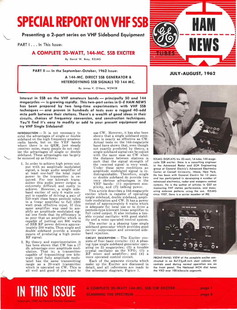
A COMPLETE 20 -WATT, 144 -MC. SSB EXCITER By David W. Bray, K2LMG
PART II - In the September -October, 1962 Issue:
A 144 -MC. DIRECT SSB GENERATOR &
HETERODYNING SSB SIGNALS TO 144 MC.
By James V. O'Hern, W2WZR
Interest in SSB on the VHF amateurs bands - principally 50 and 144 megacycles - is growing rapidly. This two-part series in G -E HAM NEWS has been prepared by two long-time experimenters with VHF SSB techniques - and proven in hundreds of tests over a rugged 40 -odd mile path between their stations. There's a wealth of good ideas in their circuits, choices of frequency conversion, and construction techniques. You'll find it's easy to modify or add to your present equipment and try VHF Single Sideband!
INTRODUCTION - It is not necessary to extol the advantages of single or double sideband on the high frequency amateur radio bands, but on the VHF bands where there is no QRM, just steady receiver noise, many people do not real- ize the advantages of single or double sideband. These advantages can largely be summed up as follows:
1. In order to achieve high power out- put with an amplitude modulated signal, a large audio amplifier of at least one-half the total input power to the transmitter is re- quired. For one kilowatt trans- mitter this audio power output is extremely difficult and costly to achieve. However, a single side - band exciter of only 6 watts out- put is capable of driving a pair of 250 -watt class beam pentode tubes in a linear amplifier to full 1200 watt peak effective input. If this same amplifier was used to am- plify an amplitude modulated sig- nal one finds that its efficiency is so poor that an amplifier which is capable of putting out 800 watts of SSB RF power delivers approx- imately 200 watts. Thus single and double sideband provide a simple means of producing a high power RF signal.
2. By theory and experimentation it has been shown that CW has a 17 db. advantage over amplitude mod- ulation. That is; a transmitter capable of transmitting one kilo- watt input fully amplitude modu- lated has the same transmitting range as a 20 -watt transmitter which is operated on CW. This is all well and good if you want to
IN THIS ISSUE
use CW. However, it has also been shown that a single sideband emis- sion is nearly as effective as CW. Actual tests on the 144 -megacycle band have shown that, even though not exactly predicted by theory, a single sideband signal can be copied with the same ease as CW when the distance between stations is such that the signal strength of the received signal is very weak. Under these same conditions an amplitude modulated signal is in- distinguishable. Therefore, single or double sideband do provide two very obvious advantages in the VHF bands: (1) equipment sim- plicity, and (2) talking power.
This article describes a 144 -megacycle exciter which is capable of operating single sideband, double sideband, ampli- tude modulation and CW. It has a power output of approximately 6 watts which is adequate for local use or to drive a pentode -type kilowatt linear amplifier to full rated output. It also includes a tun- able crystal oscillator with good stabil- ity and a voice operated control system.
The exciter is a phasing type single sideband generator which provides good carrier suppression and unwanted side - band rejection. CIRCUIT DESCRIPTION - The Exciter con- sists of four basic circuits: (1) A phas- ing type single sideband generator oper- ating on 25 megacycles; (2) a tunable crystal oscillator as the VFO; (3) a RF mixer and amplifier; and (4) a voice operated control circuit.
Each of the separate circuits which make up the Exciter are discussed in detail, and all references are made to the schematic diagram, Figure 1.
NAM
NEWS
JULY -AUGUST, 1962
o
>07
i
K21MG DISPLAYS his 20 -watt, 14 -tube, 144 -mega- cycle SSB exciter. Dave is a consulting engineer in the Advanced Radar and ECM Engineering group at General Electric's Advanced Electronics Center at Cornell University, Ithaca, New York. He has been with General Electric for 13 years and has participated in developing a number of advanced electronics, radar and weapons control systems. He is the author of articles in QST on measuring VHF station performance, and meas- uring antenna patterns using the sun. K2LMG since 1957, Dave is a senior member of IRE.
arm
IWO WW1 ROM
R.
- et.. ....
1.0 O .
MOW : O.
FRONT -PANEL VIEW of the complete exciter con- structed in an 8x121/2x8-inch steel cabinet. All controls used during normal operation are on the front panel. The National MCN dial tunes the VXO over 100 -kilocycle segments.
o
N.
I
N
_CA
RR
IER
G
EN
ER
AT
OR
V,-
6AS
6 v2
-6C
66 -
A
f2 2
5MC
))
PF
7
LI
I
700
!.ºK
P
C
ºe
A1C
c
7-5
SE
RIE
S
SO
NA
NT
X
I P
i
CV
/ A
-B+
5-6
C-0
+1
-9
r sC
I
A-B
)-
I
AY
A
-6-7
-f
IL D
+I
2
WIC
IN
PU
T R
100
VO
X
GA
IN
L__
_
R7
CV
/SE
T
AY
SE
T
RA
LA
IiC
E
W1R
I ff
R
Re
r
Qi
1207
7
2D 0
1/
1/10
r4
1000
P
F
, 50
0 A
UD
IO
g
TA
PE
R
IK
- - ---
-VO
X
600
WIN
DIM
G
SR
O P
F
70K
PH
AS
ING
R
2
ISO
K
PH
AS
E S
HIF
T
NE
TW
OR
KS
0.01
U
F
(
0.01
LW
10
00
I(-
=0.
10 U
F
veB
i -
IZA
TT
TW
O
ME
TE
R
EX
CIT
ER
DO
UB
LE
BA
LAN
CE
D
M00
ULA
TO
R
r RF
MIX
ER
- r-
DRIV
ER
-a
. V
6 -6
Aí6
+
ISO
470P
í 47
0PF
RF
C2
TO
UR
y 68
0 P
i 1[
OK
IK
{-70
W
INpN
6 'I
I V
INID
ING
60
0 6O
0 I
WIN
DIN
G
WIN
DIN
G
6 v,
0-I2
AT
7
FE
ED
TO
RO
F
RO
M
TO
P C
HA
SIS
RF
C,
- -
SO
UR
LS
D
1-2-
4-A
-º
.-20
fl
!--C
-D
2.20
0.2
K
-01.
5 V
OU
TP
UT
II -0
-1I
Cs
100
RF
C,
Cr
ON
N-O
EC
TO
RU
TP
UT
T
EE
>
Tu
4IS
O V
« ̂
CA
PA
CIT
OR
15
00
D
UB
B
2 -I
-4/A
-B
!--C
-D
2-1-
4/A
-9
:-i-D
I2W
SK
250 A
UD
IO B
ALA
NC
E
¡VO
N' A
N.
5p
[Iif
CL
=i4
3319
71
J
SPO
TT
ING
I I
TW
ITC
H
TO
A
LL
200V
130
0V
ISO
1061
L 15
I
VI2
-6C
R6-
A
1500
1 10
0PF
p
1F-
LIi
VO
ID ..
-DO
UB
L -4
-DO
UB
LER
F
EE
OT
IIRU
lN
EE
DE
D
m V
,-fC
l6-A
I/LA
TE
R
CIR
CU
IT
UP
PE
R
GR
AT
IS
RF
C! j
!NE
ED
ED
{
.. º
v {B
5
! V
, {
1500
P
F
TT
D
ISC
. C
AP
. ?,
! N
EE
OE
D
5
6.V
C.
I uV
.A.0
.
-?
RF
CB
U
- L
1500
P
I
5 N
EE
DE
D
SO
CK
ET
T
Pi
J2 -P
OW
ER
SO
CK
ET
FE
ED
T
6 M
[ED
CD
I
FIL
TE
R
CO
MP
AR
TM
EN
T
I
L---
--
----
- 15
00 P
F
FE
CP
TM
RU
f N
EE
DE
D
TO
T
O
+)0
0 +
200
vac
V. ac
-150
0 P
F
HE
AT
ER
C
IRC
UIT
LO
WE
R
GR
AT
IS
I O
MIT
F
OR
100
O
HM
/ VO
LT
ME
TE
R
S SW
ITC
M
2 m
3000
0-1
YA
SH
OW
N
IN LE
FT
P
OS
ITIO
N
RE
AD
ING
1.
1 S
CR
B
D
RIV
ER
CU
RR
EN
T
WO
MA
F
s 2.
1 P
LAT
E C
UR
RE
NT
X70
MA
F5
3.1
RF
PO
WE
R^
SW
{ S
CA
LE.º
W F
5
{1+
150
3OO
VF
S
5.1
1200
30
0 V
FS
0.
1.50
0 50
0V F
S
PIL
OT
LI
GH
T
TA
BLE
I -
PA
RT
S L
IST
C1
8 -1
00 -p
f va
riabl
e,
doub
le
bear
ings
(H
amm
arlu
nd M
C -1
00-S
).
C2
4.5
-25
-pf
cera
mic
trim
mer
, N
PO
(C
entr
alab
82
2 -A
Z).
C
3, C
4 7
-45
-pf
cera
mic
trim
mer
, N
-650
(C
entr
alab
822
-BN
).
C. C
6-..-
__2.
7-10
.8-p
f pe
r se
ctio
n m
inia
ture
bu
tterf
ly v
aria
ble,
0.
013
-inch
ai
r ga
p (E
. F
. Jo
hnso
n 16
0-21
1,
type
11
MB
11).
C
7 3.
7 -52
-pf
mid
get
air
varia
ble
(Ham
mar
lund
H
F-5
0 or
eq
ual).
JI
,J2
--_-
2-ci
rcui
t m
idge
t cl
osed
ci
rcui
t ph
one
jack
.
J3
chas
sis
type
coa
xial
ca
ble
conn
ecto
r.
K
3 -p
ole,
dou
ble
thro
w m
idge
t re
lay,
115
-vol
t A
C co
il.
K2
Sin
gle
pole
, si
ngle
thr
ow m
idge
t re
lay,
1,0
00 -o
hm,
8 -m
illi-
ampe
re D
C c
oil
(P&
B t
ype
RS
5D
or e
qual
).
L S
ingl
e la
yer
coils
; S
ee
TA
BLE
I-
CO
IL
DA
TA
, fo
r de
tails
. M
I ._
0-
1 D
C
mill
iam
eter
, 11
/2 -i
nch
diam
eter
cas
e (G
-E
type
Q
N1)
. R
I.....
-500
,000
-ohm
mid
get
pote
ntio
met
er,
audi
o ta
per.
FIG
. 1.
M
AIN
S
CH
EM
AT
IC
DIA
GR
AM
fo
r th
e ex
cite
r.
The
pa
nel
cont
rols
ar
e id
entif
ied
with
re
ctan
gula
r bo
xes
arou
nd
thei
r na
mes
. R
esis
tanc
es
are
in
ohm
s,
1/2
-wat
t ra
ting
unle
ss
othe
rwis
e m
arke
d.
Cap
acita
nces
are
in
pico
fara
ds (
pf),
or
mic
rofa
rads
(m
fd),
as
mar
ked.
P
arts
ne
edin
g fu
rthe
r id
entif
icat
ion
are
desc
ribed
in
T
AB
LE
I -
PA
RT
S
LIS
T,
or T
AB
LE
II - C
OIL
D
AT
A.
Circ
uits
with
in
dash
ed
lines
ar
e in
the
up
per
sub
-cha
ssis
sec
tion
of t
he ex
cite
r.
ó
E 0 v
i ú= E iú ¿,-12 E; ó c c a) c E -oú u=
g 3 ª á v i,_É 3 - .
ó- É 3 E
o 12 "m c, Ñw -:
wººÑp1 v Zvó0CCCo.`
. aEX2OvOvEoó E_u 303 c
.c ;úOv ° a .c °7.c., Evci ó
ñ ñ0 n ` w d1Z«C°d4i úv
Ñ O,¡-dvN; Ñ 0-E-12,,,,,, \ d
d `7 s Z 2 GC Cr 7vdC 3Z3pO'óia`Z 2 Zo a ó 7.
á v
Yrmc O
c7 y c c ó) Ir -o c á ° j _.d 2520.115,4,1:08=m
E EhE `L ° v 'cc64d.). ó.r 00 mvNvhv n3vZN; a.. i- U- u- Li-
_7 _7 _7 cccccc
E
º
d a) -C -C
ó
v
.2 C- á ú c g' J C 1,-,o 7,
o O)o
1
`- c c O'c E o , c - o
c , a) Ñ m C Ó C o p É 3 ó ` : m 3 o d u 0 3
_:3_w:o .1110.': .1"..11/ N
C O °. V a). N N d
N Z mN pp p3 p -Ñ NZ Zi
Z Z Z ú .° _° Z
,., C ^ u:12,1-11 2 E.- E.= ,c ;_Z1 0 0
co
3 u o á
w w E
d
E o
c
ó c °
.0; a) N U- a
= p. dt
o C o
d o >m
o a)
:12.: O ar o
d c
7.1 y O u u :_ C `1 YY
. 1h d Ñ h
.
-61'1 d` Eó.c ai -`o c rnóv d- E o o c ó ó v a c E w á e u u r g a) O. Qi O E -°O w 0
`r ° E` O o rírd>j
: a wáa cr)r >> .N N ;C)Ñáu)NIJu) DE ó oMZ Pero
á > vf O - -N
OC °COC K I/) ON 001-. >XX Cr Cr
THE CARRIER GENERATOR is a transitron oscillator (Vi) operating on 25 mega- cycles. This ocsillator is very stable. It uses the screen grid of a 6AS6 dual - control RF pentode as the plate of the oscillator, and the suppressor grid as the control grid.' The suppressor grid electrically follows the screen grid as the electron stream flows but yet con- trols the flow of electrons, material - ally contributing to the stability of the oscillator. The stability is also improved by forcing the crystal to run in a series resonant mode. Since this is a low im- pedance mode an L matching network transforms the low impedance crystal to a higher impedance to develop more voltage at the screen and control grids.
The power output is very low; there- fore, it is necessary to follow the oscil- lator with a 6CB6 pentode (V2) RF amplifier. Its control grid is coupled very loosely to the transitron oscillator by a 4.7 -pf capacitor. The 4.7 -pf capac- itor and the interelectrode capacitance of the 6CB6 is a capacity divider there- by keeping the load on the oscillator small. The output of the buffer is coupled to the double balanced modu- lator by a four turn link (L5) tightly coupled to the plate tank circuit (L3 & 3.3 -pf) of the buffer, providing a low impedance output to drive the rf phase shift network.
THE DOUBLED BALANCED MODULATOR con- sists of a pair of 5670 twin triodes (V3 & V4). Each of the balanced modu- lators suppresses the carrier and pro- duces a double sideband suppressed carrier signal centered around the carrier frequency.
In order that the balanced modulator can suppress the carrier, the carrier signal is fed to the grids in parallel, and a push-pull audio signal to the grids.
The plates are also in push-pull, to provide cancellation of the audio and RF input signals.
One of the 5670 tubes connected as a balanced modulator is fed from an RF phase shift network which produces a 45 degree leading phase of the carrier. The other balanced modulator is fed from a phase shift network that pro- duces a lag of 45 degrees from the carrier generator. Thus the net result is that the phase of one of the balanced modulators differs from the other bal- anced modulator by 90 degrees.
In addition, each balanced modulator is fed by two audio signals having a relative phase difference of 90 degrees. The output of the balanced modulators (V3 & V4) are fed to a common tank circuit (CG -L4) which combines the sig- nals. This addition and cancellation in the output of the two balanced modu- lators whose carrier is phase shifted by 90° as well as a 90° phase shift of the audio input, produces a single sideband signal in the tank circuit.
AUDIO AMPLIFIER AND PHASE SHIFTER - The major problem with the phasing type single sideband generator is to provide a precise 90 degrees relative phase shift between the two push-pull audio signals required for each balanced modulator. This 90 degree phase shift must be precise across the voice range audio spectrum. In order to provide this phase shift a complicated network must be built. Usually this network is made up of resistance and capacitance values
that are not readily available. However, a special phase shift network was de- veloped that could be built out of stand- ard resistor and capacitor values. Note that only the 16,000 -ohm resistor has a 5 percent tolerance. All other values have 10 percent tolerance. The sideband suppression provided by this network is at least 30 db. To insure that the sup- pression is as good as possible, the actual components used should be close to the specified values.
The audio amplifier itself is straight forward. It consists of three twin triode tubes; a 12AX7 and two 12AT7's. The 12AX7 (VE) functions as a normal two - stage triode amplifier. The output of the second section feeds the first sec- tion of the 12AT7 (V9A) which is trans- former coupled (by T1) to both the audio phase shift network and the VOX ampli- fier. The 600 -ohm winding of T1 feeds the phase shift network and the 5200 - ohm winding drives the VOX amplifier.
The output of the phase shift net- work is a push-pull signal and is fed to an amplifier consisting of a 12AT7 (V10) connected in push-pull with a balancing potentiometer (R3) in the cathodes, and the plate of each con- nected to a separate output transformer (T2 and T3). The 600 -ohm windings of each drive the 5670 double balanced modulator tubes.
In order to choose the desired side - band, the output of T2 and T3 is con- nected to a 4 -pole, 3 -position tap switch (S2) as shown in Fig. 1. The lower side - band is chosen if transformer leads 1 and 2 from T2 are connected to modu- lator grids A and B, respectively, and transformer leads Nos. 3 and 4 from T3 are connected to modular grids C and D, respectively. To obtain lower sideband leads numbered 1 and 2 are inter- changed. To obtain double sideband the modulator grids C and D are connected together in parallel and T3 lead No. 3 is opened.
VARIABLE CRYSTAL OSCILLATOR -A stable but yet tunable oscillator can be achieved by using a quartz crystal which is "pulled" from its normal operating frequency by a series inductor (L1.5). As the value of the inductor is changed, the frequency of oscillation will change proportionally.2 However, since variable inductors are difficult to tune - and particularly in a linear manner - the actual value of the inductance is changed by placing a variable capacitor (C1) in series with the inductor. A modified Pierce oscillator is achieved by placing the crystal and inductor, and a tempera- ture compensating capacitor, between the screen and control grid of the 6AU6 pentode (V12). The feedback circuit is then provided by the variable capacitor (Co) and a zero temperature coefficient trimmer capacitor (C3) .
An ideal crystal frequency for 144 - megacycle band operation is 5955 kilo- cycles, since no harmonics fall in the 144 -megacycle amateur band and the crystal will pull very nicely at least 100 kilocycles. The 20th harmonic of this crystal is 119.10 megacycles. Mixing this frequency with 25 megacycles then produces a frequency of 144.1 mega- cycles.3 To achieve the 20th harmonic the tank circuit in the plate of the oscillator is tuned to the 5th harmonic (29.775 Mc.). This frequency is doubled
Audio
& Vox
Upper Chassis-
I
Jo SIde Band
Ggn.ia tor - I
Side Band
Generator XTAI
vxo CryNols
a --
RF Miner
Miner
RF
Amplifier S
RF Output
RF Detector
REAR VIEW of the complete exciter showing the upper sub-chossis ossembled on the main chassis. Upper chassis contains the audio section, phase -shift networks, voice -controlled unit, and the VXO section. Main chassis cantains the carrier oscillator, the RF SSB balanced modulator, and VHF mixers and amplifiers, plus control relays.
(59.550 Mc.) in the following 6CB6 pentode (V13) stage and again doubled in the second 6CB6 pentode (V14). The 119.1 -megacycle output signal drives the control grid of the r -f mixer stage (V5) .
RF MIXER - Very often in single sideband equipment RF mixing is accomplished at a high level in order to avoid a large amount of straight through amplifica- tion on the output frequency. However, high level mixing is difficult to accom- plish with good mixer stability, and in addition requires the use of relatively high power vacuum tubes in order to obtain the necessary signal level. In order to avoid the difficulties of high level mixing a low level mixer, which seems to have been overlooked in the VHF art, was used. This tube, a 6AS6 (Vr,), has the same VHF capabilities as the 6AK5 pentode but yet has a suppressor grid which has sufficient control to act as a good signal grid. Therefore, the 119.1 -megacycle signal can be fed directly into the control grid of V5, and the single sideband signal at 25 megacycles can be fed to the sup- pressor grid. Using this arrangement
Mode
Seleuor`p 3r R4 `_
v,o
Rl
Vttl
v,_
°C--./1) X7
XTAL2
,2 Spare VXO
xrayil - 9 1r
Ni a' Y 1ÍwSM 4 AM st RF
Detector 1 -
\V7
Ve
vs
,(Under Bracket)
. ' 1 I t` '., V4
l l U
2 r:
_ern£ Balance
Feed Thrus
TOP VIEW, showing the locations of the tubes and other major components on the chassis. Power wiring runs between units in cobles, and through feedthrough insulators in chassis. The crystals for the VXO are in the insulated metal container behind the center of the panel. Carrier crystal is in right rear corner of main chassis.
the mixer is stable since the cathode is grounded. Bias is provided by self -bias operation of the control grid, and the single sideband signal is fed to a com- pletely separate element of the tube. By tuning the plate of the tube to 144 mega- cycles and coupling it through a double tuned circuit into the following amplifier stage, a very clean 144 -megacycle out- put signal is produced from this mixer. RF AMPLIFIER - The first amplifier stage is a 5686 VHF pentode (V6) operated as a class A amplifier. Double -tuned circuits are used from the mixer into its control grid, and into the following stage. The 5686, even though operated in class A, provides ample drive for the 6360 twin pentode (V7) output stage, operated class AB1 with a fixed bias of -21.5 volts. The 6360 is operated push- pull and requires no neutralization be- cause of its internal neutralized con- struction. The output of the push-pull tank is link coupled to the RF output connector. The 6360 operating in class AB1 provides about 6 watts CW output.
To measure the RF output of the exciter, the diode CR3 and RF choke
FOLD DOWN
12
I6IFEED THRU TERMINALS
PARTITION- Wo
iREAR
o ii
FOLD DOWN
3 2
FOLD 90 -1
1 6 1
2
FOLD DOWN 15 L6--- 3 PHASING y 161 n8
u 16
FOLD DOWN
F
16
SPARE -A
VOX GAIN
TOP DECK
1-FOLD 90
I 116 116 / / \ / F 1 1= .e. /
FRONT
NCR DIAL .. .e \RIVE
z --- -
6z
SZ
90 I / FOLD DOWN R, 0,-.,____,,
Z a 1 3 I
11 2
2
FIG. 2. LAYOUT DIAGRAM for the upper sub -chassis unit, showing the overall size of sheet aluminum required. Location of the shield partition across the center of the chassis is indicated by the dashed line. The metal is folded at the dashed lines before drilling holes, sizes of which are given in TABLE III - HOLE SIZE CHART.
RFC1 are mounted in a coaxial cable RF connector, and then plugged into a "Tee" connector in the output cable line, as shown in the rear and top views. A DC connection then runs to the meter control switch, S4. VOICE OPERATED CONTROL CIRCUITS - No single sideband transmitter is complete without the voice control circuitry. In this excites' a familial' type voice con- trol circuit is used. The output of the audio amplifier from the 5200 ohm tap of the audio transformer is fed to one- half of the 12AT7 triode (VisA). The output from the 500 ohm tap or loud speaker of the receiver is fed to the other half of the 12AT7 triode (V11n). The output of VisA from the audio channel is then rectified by diode CR1 and used to charge a 0.3 mfd. capacitor with an adjustable discharge resistor of 2.5 megohms. This operates a control
7 -pin miniature tube socket. socket punch -3/4 -inch diameter for 9 -pin miniature tube socket. socket punch -1116 -inch diameter for small octal tube socket. socket punch - 1 t/4 -inch diameter for large receiving tube socket.
FOOTNOTES 5A technical discussion of the principles of operation of the 6AS6 transitron crystal controlled oscillator will ap pear in the next issue of G -E HAM NEWS, September - October, 1962 (Val. 17, No. 51. 'Following is a reference listing of articles on the variable crystal oscillator:
"VXO-A Variable Crystol Oscillator," by Herman Shall, W3BWK, OST, January, 1958, page 11;
"VXO-II Variable Frequency Crystal Exciter," by Herman Shall, W3BWK, OSl, July, 1959, page 37;
"A V.H.F. Variable Frequency Crystal Exciter," by H. J. Saborsky, W3KXI, OST, November, 1960, page 27.
'To corer 144-148 megacycles with the exciter, crystal frequencies between 5950 and 6150 kilocycles may be used in the VXO. The 24th harmonic of crystals between 6000 and 6150 kilocycles falls within the 144-148 megacycle band, but does not crass the exciter output frequency.
15 GROMMET
relay tube, also one half of a 12AT7 (V9s) with a 1,000 -ohm, 8 ma. plate relay. To provide anti -trip, the output of the receiver amplifier (Vila) is rectified by a negatively connected diode (CR2) and also charges a long time constant circuit. This circuit back - biases the audio amplifier (V11A) chan- nel so that any output from the loud- speaker cancels the signal from the audio amplifier channel by not allowing diode CR1 to conduct.
In addition to the choice of lower, upper and double sidebands on S2, by adding a mode selector switch (Si), the exciter can be placed in an AM or CW mode of operation. To provide AM, one of the double balanced modulators is simply unbalanced. This increases the carrier from its normal cancellation amplitude to any desired value. So that specific carrier level can be set, Si transfers one of the balanced modulator carrier balance potentiometers (R7) to a new potentiometer (R10) which is set at the desired AM carrier amplitude. In practice, only a small amount of carrier is required to make speech very intelligible. Therefore, if a high -power linear amplifier is used to follow this exciter most of the benefits of single sideband can be achieved by inserting a small amount of carrier so that the output modulation is 400 to 500 percent. The carrier output is then small enough to cause little increase in plate dissipa- tion in the linear amplifier tubes, but will be very readible on those 144 - megacycle receivers which cannot re- ceive single sideband due to the lack of a B.F.O.
In the AM mode the use of only one sideband - upper or lower - is not detrimental to reception. Normal AM can be accomplished by throwing the exciter into the double sideband mode.
For CW, unbalancing one of the balanced modulators through R9 to an extent which drives the linear applifier to full output provides a CW carrier. Keying is accomplished in the cathode of the RF mixer (V:,) through J2. In addition to unbalancing the carrier, it is also desirable in the CW mode to
T2
TI
Ls.
FRONT- MAIN CHASSIS
RUBBER
GROMMET
rAREA FOR VOX
I' I RELAY I
F
__-- SHIELD
7 I I6 H
2 16
9
EDGE OF-- UPPER CHASMi
SHIELD PARTITIONS
FEED
41 FEED
E
disconnect the output of the audio am- plifier. This eliminates the possibility of transmitting inadvertently modulated CW. The mode switch (Si) performs these functions. POWER SUPPLY - Power requirements of the complete 144 -megacycle SSB exciter are:
6.3 volts at 5 amperes for heaters; plus 150 volts DC at 35 to 115 ma.; plus 200 volts DC at 25 ma.; plus 300 volts DC at 70 ma.; minus 22 volts for grid bias. To assure optimum and stable per-
formance of the exciter, the plus 150, 200 and 300 -volt DC supplies should be regulated. A suitable power supply con- structed by the author for his exciter will be described in the following issue, September -October, 1962 (Vol.17, No. 5) .
CONSTRUCTION DETAILS - Most of the con- struction of the exciter is self-explana- tory through the pictures and mechan- ical layouts. However, some details may not be obvious and are explained in detail.
The upper chassis was fabricated with open sides from 18 -gauge (0.040 - inch thick) sheet aluminum 111/2x61/2 inches. It is trimmed and folded as shown in the upper chassis layout draw- ing, Fig. 2. Drill holes for the tube sockets and other parts at the locations marked. Make two end plates 3x61/2 inches from the same sheet stock and fasten them to the flanges on the ends with No. 8 sheet metal screws. Also make a shield partition and fasten it in place as shown in Fig. 2.
The main chassis is a standard 7x9x 2 -inch type (Bud AC -406, or equiva- lent). Drill and punch holes as shown in the layout diagram for it, Fig. 3. Make shield partitions from 18 -gauge aluminum at the locations shown by the dashed lines in Fig. 3, and the bot- tom view photo. Fit the shields in place and fasten them with No. 8 sheet metal screws.
Fasten the upper chassis down with No. 8 sheet metal screws driven up from the bottom side into the flanges on the bottom of the upper chassis.
H
E
I\ J B1 `./
3g
GROMMET
) S IS
SHIELD CS PARTITIONS
I 1
4
7
FIG. 3. MAIN CHASSIS layout drawing. Locations for shield partitions under chassis are shown by dashed lines. Upper chassis is fastened over the area indicated. Hole sizes are given in TABLE III - HOLE SIZE CHART.
54
3
16
.5
Also, punch the holes for the power sockets at the left rear corner.
The panel comes with the 8x121/2x 8 -inch deep cabinet (Bud C-1746, or equivalent) and is 8x10 inches in size. Drill and punch the panel as shown in the layout diagram of Fig. 4. The upper and lower chassis, the National MCN dial, and shields should all be assembled temporarily to check on proper align- ment before beginning the mounting of parts and wiring.
UPPER CHASSIS - The upper chassis is divided into two sections. On the right hand side facing the front panel is the audio section separated by a shield from the variable crystal oscillator sec- tion. The audio section is constructed on Vector socket assemblies, with the exception of the phase shift networks. In the right side detail view on page 7, note that these networks were con- structed on a Vector circuit board and suspended under the tube socket for V10. This was convenient, since this tube feeds the audio transformers and the, phase shift network. Behind the audio transformers is the plate relay (K2) for the VOX. The entire VOX was built on a Vector socket assembly with a small terminal board attached to the base of the post on the socket for V11 to hold those components which would not fit on the post.
The sideband selector switch (S2) is mounted through the front of the audio section chassis and passes through the, front panel. The mode selector switch (S2) is mounted directly on the front panel just above the top chassis. In the variable crystal oscillator section of the top chassis, the tuning capacitor (C1) is mounted directly on the underside as seen in the left side detail view.
The National MCN dial is mounted inside the upper chassis with only the shaft going through the front panel. A small bracket to the left of the top chassis holds three potentiometers for adjustment of receiver gain for the anti -trip circuit (R,,), the CW ampli- tude (R9), and the AM amplitude (R10)
3
DRILL THESE HOLES BO
116
3
FRONT PANEL
IS
CUTOUT FOR
I
9 DIA.
I- UPPER CHASSIS
I4
S2
1
MAIN CHASSIS
IN PANEL & CHASSIS _ rt -
I Z.,11_I+L0_ B 6 B_
F T1~
5 J2 RI
JI I
i
cab IL INV gI 7 23
4 PILOT LAMP
10'
FIG. 4. FRONT PANEL layout diagram. Location of the main and upper sub -chassis are shown by dashed lines. Hole for the meter should be bored to fit the case of the particular meter used in construction.
LAYOUT OF RF MIXER a AMPLIFIERS FIQl1
. C6 Tuning CTLoadlnq Oft Pilot '-Pmt CW Cap Cap On Toggle6
FEED THRU SHIELD SJ\\` TO KEY JACK WITH +B \\ + (SHIELDED WIRE)
FRONT PANEL
SHIELD
6AS6-RF MIXER
PIN7 / V5
/ FT TO
1-O SECOND DOUBLER
SSE, SIGNAL OUTPUT
SHIELD
BOTTOM VIEW of the exciter showing the locations of small parts and FIG.5. VHF SECTION parts location diagram, for the mixer and ampli- wiring. Sheet aluminum shields are fitted around the sideband generator fiers. This drawing is printed half actual size so that dimensions can be and VHF RF sections of the exciter. Note the group of feedthrough capac- determined by measuring the diagram and multiplying by 2. All capacitors itors and small RF chokes in the power lead filter compartment at the should have shortest possible leads. Connect 1500 -pf. disc capacitors lower left, between all cathode and screen grid pins and chassis.
MAIN CHASSIS - The main chassis has four shielded areas. These consist of the single sideband generator, the RF assembly, the control section and the power plug section. Construction of the single sideband generator is seen in the bottom view. The output from the single sideband double balanced modulators (V3 and V4) passes through a feed - through terminal in the shield directly to the suppressor grid pin of the RF mixer tube (V5). The assembly of the 144 -megacycle amplifier stages (V11 and V7) is detailed in the sketch of Fig. 5, in addition to the bottom view.
The control section in the middle of the main chassis contains the two relays, K1 and K2, plus the pilot light, control switches, key jack, and audio transformers. The power plug section compartment is filled with small RF chokes (RFC3) and 1500 -pf. ceramic feedthrough bypass capacitors mounted in the partition. These filters keep RF energy from leaking out of the exciter through the power leads.
The variable crystal oscillator will only be as stable as the frequency of the crystals. Because the crystal is operated in a parallel mode in which it is pulled from its normal operating frequency, it is more temperature sensi- tive than a normal crystal. Therefore, in order to insure good frequency sta- bility as the exciter warms up two things must be done. The crystals must be mounted in an assembly as shown in the top view and preferably con- nected to the front panel by a metal strap in contact with the crystals to keep them at the temperature of the front panel.
This assembly is a simple aluminum frame which mounts on top of the crystal holders thereby providing ther- mal insulation from the upper chassis, and the aluminum frame reflects the radiant heat from the nearby tubes. Insulation around the crystal prevents
additional heating. A metal strap which touches the metal portion of the crystal holder also helps keep the crystal at nearly constant temperature.
An alternate solution is to purchase a crystal oven and operate the crystal in this oven in place of the crystal sockets shown. Two crystal sockets are shown, but only one of the sockets, the one to the right facing the front panel, is connected. The other socket is a dummy in which to store the space crystal at the same temperature. To change to the second crystal, simply reverse them in their sockets.
OPERATION AND ADJUSTMENT - Before applying power to the exciter, all tubes should be pulled out of their sockets. Since some stages are only biased by grid current, if the oscillator or ampli- fiers are not operating properly some of the stages could be drawing excess current. Place the tubes in their sockets one at a time as the adjustment pro- ceeds.
First adjust the transitron oscillator by removing the 3,900 -ohm resistor across the inductor (Li), removing the crystal and shorting out the socket. Set the variable capacitor (C4) to approxi- mately one-half of maximum capacity; and, with a grid dip meter tune the inductance to the 25 -megacycle crystal frequency. Reconnect the 3,900 -ohm resistor and place the crystal in its socket. Connect a vacuum tube volt meter (VTVM) on the control grid of the 6CB6 buffer and tune the variable capacitor (C4) for maximum output voltage.
The next step is to adjust the plate coil (L') of the 6CB6 buffer by setting it to 25 megacycles with the grid -dip meter; it can then be repeaked later. The double balance modulator tank cir- cuit (L4 -C5), also should be tuned to 25 megacycles. The final SSB generator peaking can then be finished after the variable crystal oscillator and other RF stages have been adjusted. The
final single sideband adjustments are made after 144 -megacycle output is obtained by listening to the signal on a receiver covering the 144 -megacycle band.
RF ADJUSTMENTS - Adjustment starts with the variable crystal oscillator (V12). Insert the oscillator tube and the first doubler (V13), then connect a high impedance volt meter - preferably a vacuum tube volt meter - on the grid of the first doubler. Switch the oscillator to crystal position, turn the tuning capacitor (C1) to minimum capacitance and adjust the feedback capacitor (C2) for maximum negative voltage on the first doubler grid. Then switch the VXO into the variable position. Tune the inductance (L16) to minimum value and the negative temperature coefficient capacitor (Ca) to approximately one- half its maximum value. With the VTVM on the grid of the first doubler, tune C1 across the band and determine if the oscillator is operating over its whole range. If not, adjust either L1(1 or C3 or both, until the oscillator delivers equal voltage at the grid of V13 nearly to that in the crystal position across the band. Adjustment of the oscillator's tuning range is made by listening on the 144 megacycle receiver after the remainder of the rf section is operating.
Next, switch the VXO to crystal posi- tion, turn C1 to minimum capacitance, and place the second doubler tube (Vi4) in its socket. Connect the VTVM to the grid of the mixer stage (V5) and adjust L13 for maximum negative voltage. If no signal voltage is read, adjust L14 and L15 until a signal is obtained on the mixer grid, then peak L13, L14 and L11. The VTVM on the grid of the mixer stage will probably affect the settings of L14 and L15, but this will be peaked again later.
Next, remove the grid bias, screen and plate voltages to the 6360 (V7) out- put tube. Connect the VTVM to the grid bias supply of the 6360. Then
insert carrier by turning the carrier balance controls off center (they prob- ably will be off balance anyway) and with an insulated tool, adjust L,1 by spreading or compressing the coil for maximum negative voltage on the grid of the 6360. Since the other inductors must also be adjusted the signal at Ls may be low. If so, tentative adjust- ments of L7, L8 and L9 can be made. After the inductors have been peaked try adjusting the coupling between L;; and L7, and Ls and then L9, for a maxi- mum DC voltage of 18 to 25 volts at the grid of the 6360.
Then apply the screen, plate and bias voltages to the 6360 and connect a 50 ohm dummy load to the output con- nector, J2. Then dip the plate current of the 6360 with G; and develop maxi- mum RF signal out by adjusting the series loading capacitor (C7). This is best accomplished by alternately switch- ing the meter from plate current to RF voltage. The bias adjustment of the 6360 should be set to a no signal plate current of 20 Ma. (CW Key Open), and with a maximum unbalance of the signal sideband generator a plate cur- rent of 50 to 60 ma. will be drawn by the 6360. VXO FREQUENCY ADJUSTMENT- Most 5955 - kilocycle crystals will have a pulling range of 200 to 300 kilocycles at 144 megacycles. However, if L11 is set for maximum pulling, the frequency will not be very stable. Therefore, it is recommended that a pulling range of about 100 kilocycles be used. To make this adjustment, set the VXO to crystal position and (C_) to minimum capac- itance. This will result in the highest frequency that can be obtained. Next switch the oscillator to VXO position and usually the frequency will shift slightly lower. Now tune C1 toward its maximum value and check the amount of frequency change. If it is too great, reduce the value of L10, or if it is too small increase the value of L16.
Upon setting the frequency range to the desired value a check of the output voltage of the oscillator should then be made by placing a VTVM on the grid of the 6AS6 mixer stage and tuning across the band. If the variation is greater than 2 to 1 it will be nécessary to adjust the feedback capacitor, C.. This adjustment will also change the tuning range, so it will be necessary to make several checks to set both the tuning range and keep the mixer grid voltage variation to' a minimum. SIDEBAND GENERATOR ADJUSTMENTS - To insure that all of the circuits are peaked correctly, the entire RF adjustment procedure should be repeated with the tuning capacitor (C1) set to the center of the tuning band. The drive at the grid of the 6360 is best checked with the screen,' plate and bias voltages removed.
Tune the exciter to a convenient frequency on the receiver (set for CW reception) and adjust the carrier bal- ance potentiometers (R5 and R6) for minimum output after placing the mode switch in the suppressed carrier posi- tion. After adjusting the carrier bal- ance and noting the frequency, set the sideband selector (S2) to either upper or lower sideband, depending on which may be used the most. Assuming S. on upper sideband, insert a 1000 -cycle audio tone into the audio input (J1) from an audio signal generator. With the re-
ceiver still set for CW and maximum selectivity, carefully tune to both sides of the carrier. Both sidebands will appear as a tone 1,000 cycles on either side of the carrier frequency before it was suppressed.
Then adjusting for upper sideband, tune the receiver to the lowest frequency sideband, being careful to choose the first signal encountered on the low side of the carrier frequency. Other signals will appear which are second, third and fourth order harmonics of the injected 1,000 -cycle signal. These will be sup- pressed by adjusting potentiometers R7 and Rs until the signal on the lower sideband is at minimum. Potentiometer 122, the phasing adjustment, will not be centered, but will be near one end of the adjustment range.
Now switch the receiver to AM, leav- ing the selectivity in its sharpest posi- tion and note the S meter reading. Carefully tune past the carrier toward the upper sideband and note its value on the S meter. If the receiver S meter is correctly calibrated the amount of suppression can be noted by comparing the relative readings of the upper and lower sidebands. Further adjustments are then made until the difference be- tween upper and lower sideband is ap- proximately 30 db, or 5 S units.
Now switch the sideband mode to lower sideband and tune the receiver - still in the AM position - from the lower to the upper sidebands. The lower sideband is now maximum and the upper sideband is suppressed. How- ever, sideband suppression may not be as great in this position. This is not a fault of construction or design - it is simply characteristic of a phasing type sideband rig. Next, switch the sideband selector to double sideband and both sidebands should be approximately equal. VOICE OPERATED CONTROL ADJUSTMENTS - By talking into the microphone at a normal level after making the previous adjustments on the sideband generator, increase potentiometer R4 until the voice control relay picks up at a suitable level. Then with the microphone placed in the normal operating position, and re- ceiver gain adjusted for normal speaker volume, adjust the anti -trip potenti- ometer (R5) , so that the receiver output does not operate the voice controlled relay. The hold -in time constant of the relay can then be adjusted as desired from the front panel adjustment marked VOX HOLD (R3). AM AND CW MODE ADJUSTMENT - Adjust- ment of the exciter in the CW and AM modes is best accomplished by determin- ing the maximum CW input power of the linear amplifier if one is to be used. Simply place the mode selector switch on CW, close the key and increase the CW set potentiometer (R9) until the linear amplifier is drawing full rated power input. This completes adjust- ment of the CW mode.
The amplitude modulated mode may then be adjusted by first switching to suppressed carrier and adjusting the audio gain control so that the linear amplifier is being driven to its normal output. Then switch to amplitude modu- lated mode and, without speaking, adjust the AM SET potentiometer (Rio) until the plate current drawn by the amplifier is approximately one-half of its rated value. The carrier is then set at one- fourth the maximum CW power output.
. 1 . r
.1117V .,
k S. , , ?.
l . . , t, ,
CLOSEUP VIEW of the audio phase -shift net- works on terminal boord inside right end of upper chassis unit. Terminals on T1, T2 and T3
extend up from beneath the moin chassis. When wiring sub -chassis, leave leads for making these connections after mounting upper unit.
Upon speaking into the microphone the input amplitude will then go up to its normal value or in other words 3/4 of the power will then be transmitted bearing the speech. This adjustment is approximately 400 percent over modu- lation but as previously mentioned is very readable by almost any receiver. If normal AM is desired then the car- rier should be increased by adjustment of potentiometer R10 until the final amplifier is drawing a plate current of two-thirds its maximum value. This pro- vides 100 percent modulation. OPERATION - After completing the pre- vious adjustments the power output is controlled by the audio gain control.
It may be found that for some crystals that the VXO will not oscillate if power is applied when the VXO is on variable tuning and the tuning capacitor (C1) is near the low end of the range. There- fore, if this occurs it is recommended that the VXO be switched to crystal position and then returned to variable. This will start the oscillator.
The spotting switch (S5) on the front panel applies power to exciter, with the exception of the RF amplifiers, there- fore allowing the station receiver to hear the transmitter for zero -beat purposes.
Part II of this special report on VHF SSB will be published in the September - October 1962 issue of G -E HAM NEWS. It will contain circuit and construction details on a phasing type SSB generator which operates directly on 144 mega- cycles; circuit ideas for heterodyning SSB signals to 144 megacycles; a de- tailed discussion of the function of the transition oscillator; and the circuit and construction data for the voltage - regulated power supply for the exciter in this issue.
DETAIL VIEW of the VXO compartment in the upper chassis. The VXO-CRYSTAL switch (53) is
below the coupling on the rear of the MCN tuning dial. Note the loose coupling between coils L14 and 115 in the second doubler -VHF mixer circuit.
1
l.ei + +,
iiiIIII ;,q<< p ,,
1 1"2: 1 0 t q :
...dq`&
.
A
PEG
NEW G -E COMPACTRONS SIMPLIFY TV
Radio amateurs have a dramatic demonstration of how General Electric's new line of compactron receiving tubes can simplify electronic equipment in the industry trend toward "compactron- ized" television receivers.
Tube complements in these new TV sets is reduced about one third through substituting multifunction compactrons for conventional receiving tubes in most circuits. Amateurs can expect the same degree of simplification in amateur radio equipment using compactrons.
In the latest line of General Electric television receivers, an average of 7
or 8 compactrons per chassis replaces 11 to 13 conventional tubes used in pre-
I - 11.
fa
in
HAM
.111~
NEWS
JULY -AUGUST, 1962 Vol. 17, No. 4
.'..
. '
G -E COMPACTRONS IN HAM GEAR General Electric's new compactron
multi -function receiving tubes are ap- pearing in the latest amateur radio equipment now coming on the market. One of the first such equipments is the new Hammarlund HX-50 sideband transmitter. In it, a 6C10 triple -triode compactron (each section is similar to those in a 12AX7-A miniature twin triode) is used as the input audio ampli- fier, audio modulator for the balanced modulator, and the carrier oscillator. One triode section performs each of these three functions.
This is a good example of how G -E's new compactrons can simplify electronic equipment through combining functions usually performed by two or three con- ventional tubes into one compact en- velope. A list of compactron types was published on page 8 of the January - February, 1962 issue (Vol. 17 No. 1) of G -E HAM NEWS. A supplement to
ceding models. A total of 19 compac- trons replaces 30 tubes in the three basic chassis which go into all 23 -inch table and console TV's: in the 19 -inch "Designer" series, the 19 -inch portable "Century" and "Celebrity" models; and the new lightweight, 22 -pound 16 -inch "Escort" model.
The photo below shows 8 compac- tions and 1 standard tube (left) taking over the complement of the basic chassis of the 16 -inch "Escort" portable TV. At the right are the 18 conventional tubes which comprised the tube complement in a typical TV basic chassis of several years ago.
Making the comparison is Christopher D. McCool, Home Convenience Products Design Engineering Manager of G -E's Receiving, Tube Department, who spear- headed the compaction development program. Neither the power rectifier or tuner tubes are included in the examp!es.
The multi -function compaction types have many applications in equipment having a number of circuit functions- like the TV receivers described above. Amateur receivers sideband exciters and transceivers can be simplified with multi -function compactrons in the small signal circuits. And, horizontal sweep type power compactrons are available
-=IIÍI/Í'ii' ' f
6C10 TRIPLE TRIODE compoctron in the new Hammarlund HX-50 Sidebond transmitter.
this list containing a number of new types will be published in the September - October, 1962 issue.
The HX-50 transmitter, incidentally, covers several 1 -megacycle segments which include the 3.5, 7, 14, 21 and 28 -megacycle amateur bands. It will run up to 130 watts P.E.P. input, and has all of the latest features.
G -E VHF FM GEAR AT K7USA The VHF FM stations on the 50 and
144 -megacycle bands at K7USA the amateur radio station at the Century 21 exhibition in Seattle have been fur- nished by General Electric's Communi- cation Products Department located in Lynchburg Va.
The 80 -watt deck -type base stations, the same as supplied to hundreds of commercial VHF communications users, operate on the national amateur FM calling frequencies of 52.525 and 146- 146.940 megacycles. In addition, fre- quencies of 146.580, 146.760 and 147.330 megacycles are available for casual operating to keep the calling frequen- cies clear.
If you are planning to attend the Century 21 exhibition in Seattle this summer, and have VHF FM mobile equipment in your car, be sure to take along crystals which cover the above channels so that you can contact K7USA.
to perform the tasks to which conven- tional sweep tubes are usually assigned in amateur radio gear.
G -E HAM NEWS plans to publish articles on "compactronized" equipment for the home constructor in coming issues. Watch for them!