L90 Line Differential Relay UR Series Instruction Manual L90 Revision: 2.9X Manual P/N: 1601-0081-B8 (GEK-106382) Copyright ' 2004 GE Multilin g GE Industrial Systems GE Multilin 215 Anderson Avenue, Markham, Ontario Canada L6E 1B3 Tel: (905) 294-6222 Fax: (905) 201-2098 Internet: http://www.GEindustrial.com/multilin Manufactured under an ISO9000 Registered system. R E G I S T E R E D LISTED 36GN MEASURING EQUIP. E200431 www . ElectricalPartManuals . com
Transcript
L90 Line Differential RelayUR Series Instruction Manual
Internet: http://www.GEindustrial.com/multilinManufactured under an
ISO9000 Registered system.
R
EG
IS T E R E
D
LISTED
36GN
MEASURING EQUIP.
E200431
www . El
ectric
alPar
tMan
uals
. com
www . El
ectric
alPar
tMan
uals
. com
gGE Industrial Systems
ADDENDUMThis Addendum contains information that relates to the L90 relay, version 2.9X. This addendum lists a number ofinformation items that appear in the instruction manual GEK-106382 (1601-0081-B8) but are not included in the cur-rent L90 operations.
The following functions/items are not yet available with the current version of the L90 relay:
Signal Sources SRC 3 to SRC 6 (availability is pending for this release)
NOTE:
The UCA2 specifications are not yet finalized. There will be changes to the object models described in AppendixC: UCA/MMS.
GE Multilin
215 Anderson Avenue, Markham, Ontario
Canada L6E 1B3
Tel: (905) 294-6222 Fax: (905) 201-2098
Internet: http://www.GEindustrial.com/multilin
www . El
ectric
alPar
tMan
uals
. com
www . El
ectric
alPar
tMan
uals
. com
GE Multilin L90 Line Differential Relay i
TABLE OF CONTENTS
1. GETTING STARTED 1.1 IMPORTANT PROCEDURES1.1.1 CAUTIONS AND WARNINGS ........................................................................... 1-11.1.2 INSPECTION CHECKLIST ................................................................................ 1-1
1.2 UR OVERVIEW1.2.1 INTRODUCTION TO THE UR RELAY .............................................................. 1-21.2.2 UR HARDWARE ARCHITECTURE................................................................... 1-31.2.3 UR SOFTWARE ARCHITECTURE ................................................................... 1-41.2.4 IMPORTANT UR CONCEPTS........................................................................... 1-4
1.3 URPC SOFTWARE1.3.1 PC REQUIREMENTS ........................................................................................ 1-51.3.2 SOFTWARE INSTALLATION ............................................................................ 1-51.3.3 CONNECTING URPC® WITH THE L90............................................................ 1-6
1.4 UR HARDWARE1.4.1 MOUNTING AND WIRING................................................................................. 1-81.4.2 COMMUNICATIONS.......................................................................................... 1-81.4.3 FACEPLATE DISPLAY ...................................................................................... 1-8
1.5 USING THE RELAY1.5.1 FACEPLATE KEYPAD....................................................................................... 1-91.5.2 MENU NAVIGATION ......................................................................................... 1-91.5.3 MENU HIERARCHY .......................................................................................... 1-91.5.4 RELAY ACTIVATION....................................................................................... 1-101.5.5 BATTERY TAB................................................................................................. 1-101.5.6 RELAY PASSWORDS ..................................................................................... 1-101.5.7 FLEXLOGIC CUSTOMIZATION................................................................... 1-101.5.8 COMMISSIONING ........................................................................................... 1-10
2.2 PILOT CHANNEL2.2.1 INTER-RELAY COMMUNICATIONS................................................................. 2-72.2.2 CHANNEL MONITOR ........................................................................................ 2-82.2.3 LOOPBACK TEST ............................................................................................. 2-82.2.4 DIRECT TRANSFER TRIPPING ....................................................................... 2-8
2.3 PROTECTION & CONTROL FUNCTIONS2.3.1 CURRENT DIFFERENTIAL PROTECTION ...................................................... 2-92.3.2 BACKUP PROTECTION.................................................................................... 2-92.3.3 MULTIPLE SETTINGS GROUPS ...................................................................... 2-92.3.4 USER PROGRAMMABLE LOGIC ..................................................................... 2-92.3.5 CONFIGURABLE INPUTS AND OUTPUTS...................................................... 2-9
2.5 OTHER FUNCTIONS2.5.1 ALARMS .......................................................................................................... 2-112.5.2 LOCAL USER INTERFACE ............................................................................. 2-112.5.3 TIME SYNCHRONIZATION............................................................................. 2-112.5.4 FUNCTION DIAGRAMS .................................................................................. 2-11
2.6 TECHNICAL SPECIFICATIONS2.6.1 PROTECTION ELEMENTS ............................................................................. 2-132.6.2 USER PROGRAMMABLE ELEMENTS ........................................................... 2-162.6.3 MONITORING.................................................................................................. 2-162.6.4 METERING ...................................................................................................... 2-17
www . El
ectric
alPar
tMan
uals
. com
ii L90 Line Differential Relay GE Multilin
TABLE OF CONTENTS
2.6.5 INPUTS.............................................................................................................2-172.6.6 POWER SUPPLY .............................................................................................2-182.6.7 OUTPUTS.........................................................................................................2-182.6.8 COMMUNICATIONS ........................................................................................2-182.6.9 INTER-RELAY COMMUNICATIONS................................................................2-192.6.10 ENVIRONMENTAL...........................................................................................2-192.6.11 TYPE TESTS....................................................................................................2-202.6.12 PRODUCTION TESTS .....................................................................................2-202.6.13 APPROVALS ....................................................................................................2-202.6.14 MAINTENANCE................................................................................................2-20
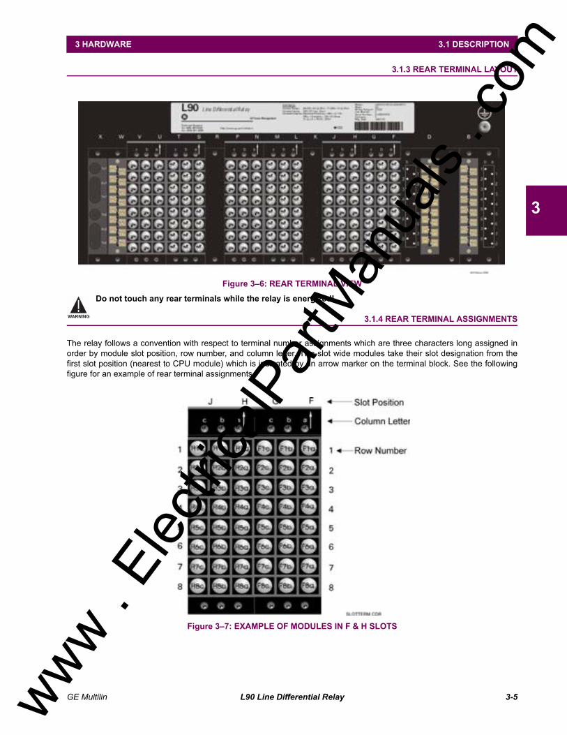
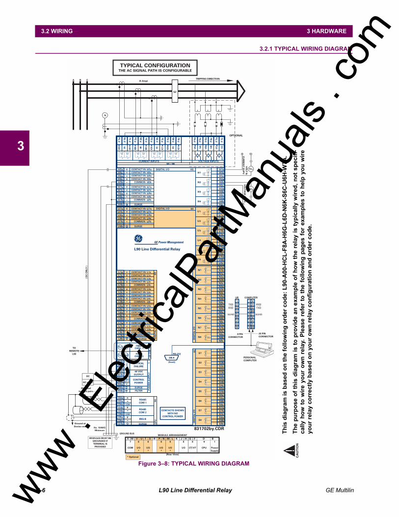
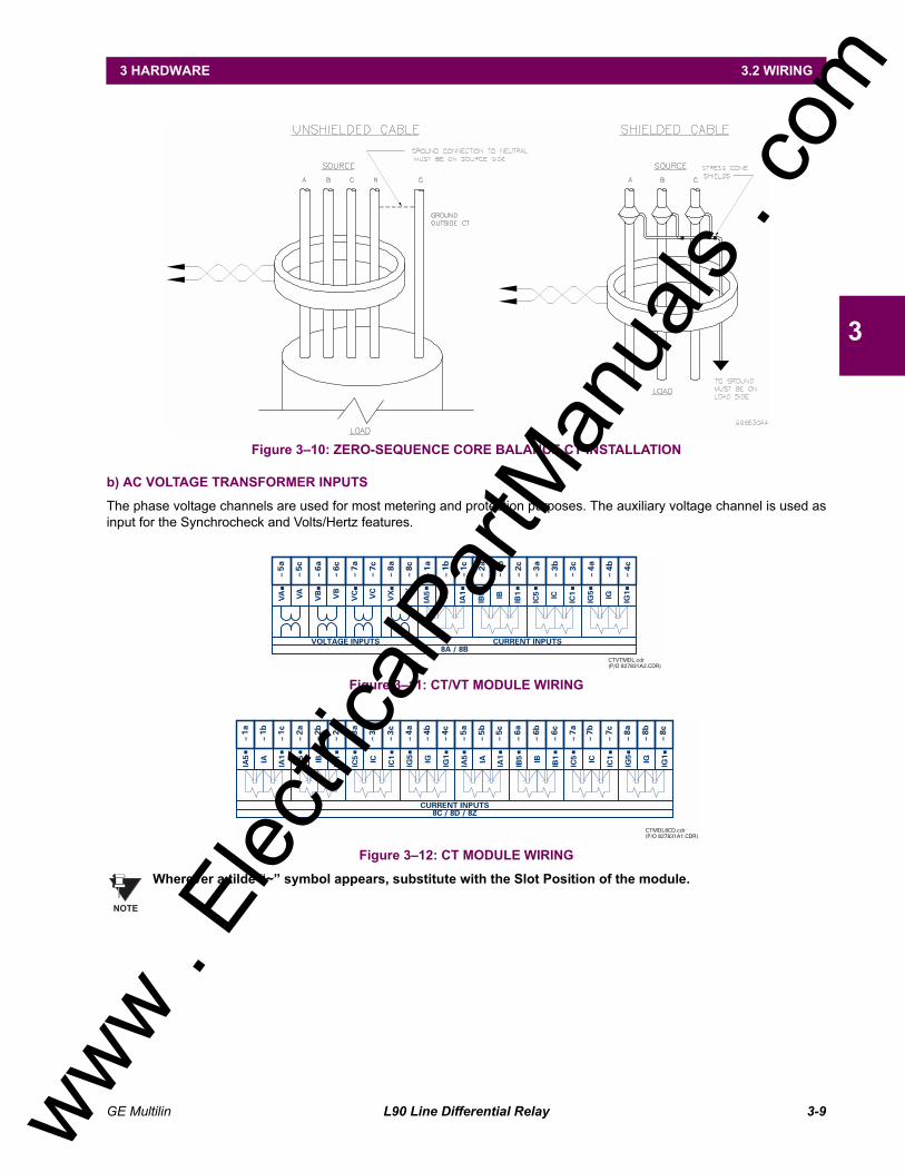
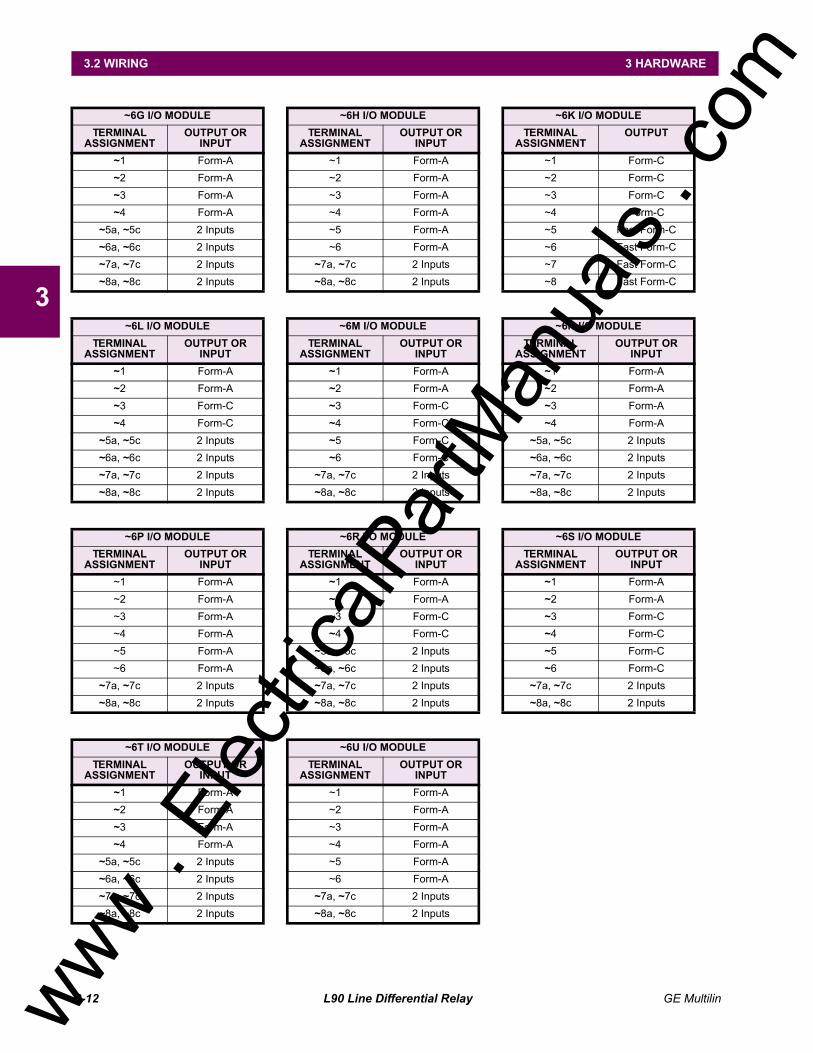
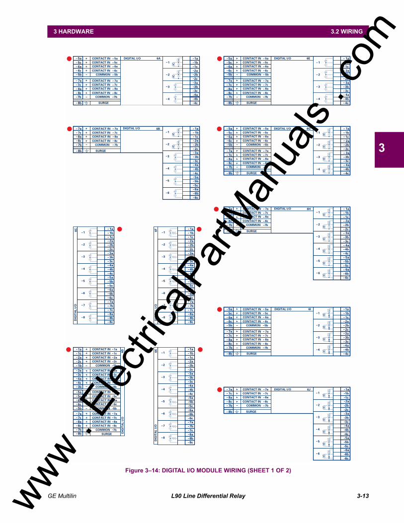
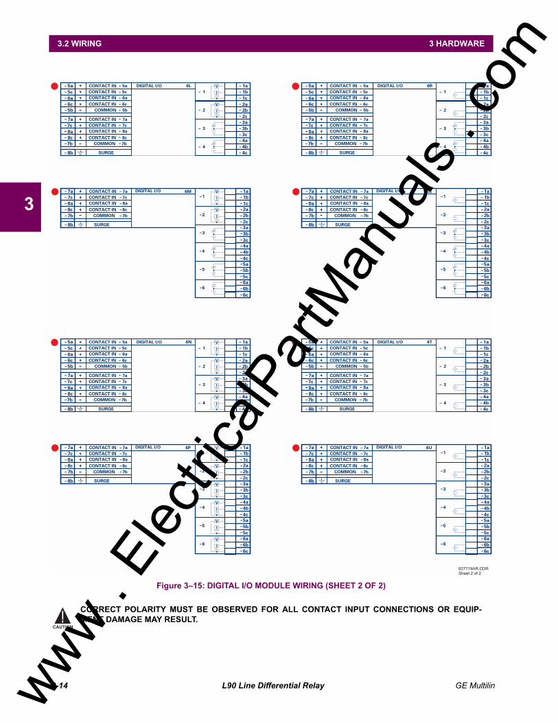
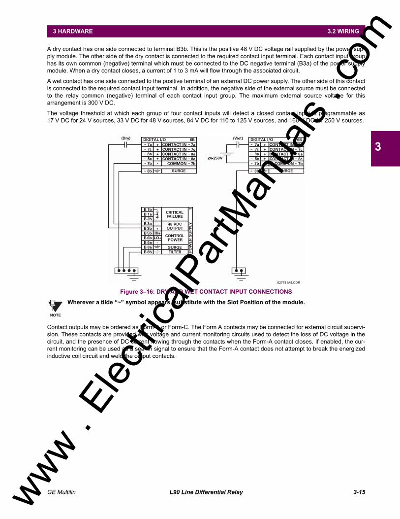
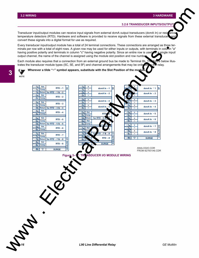
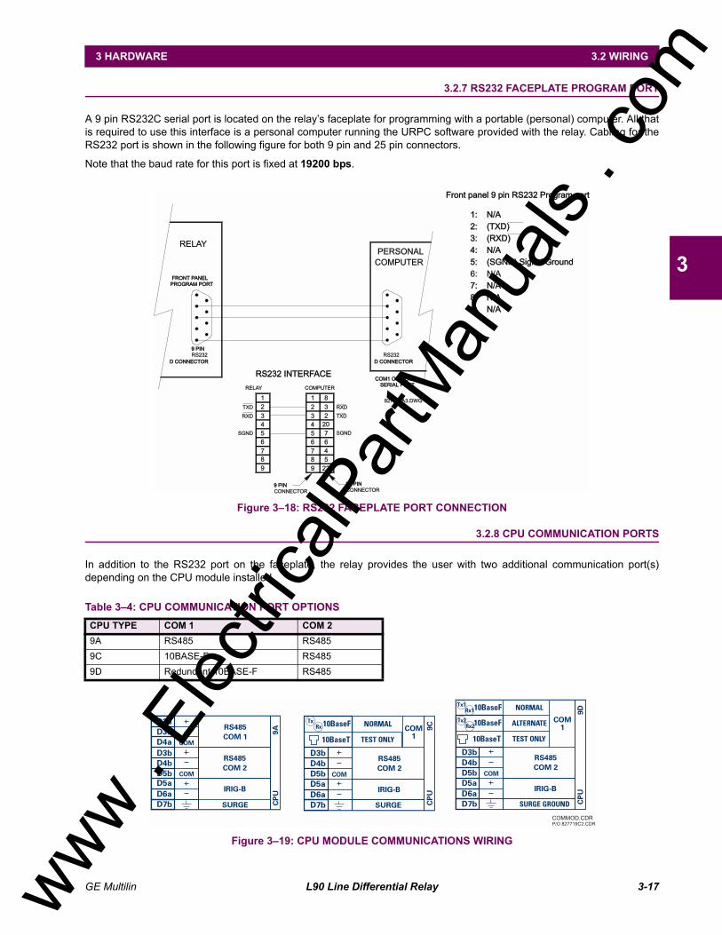
3.2 WIRING3.2.1 TYPICAL WIRING DIAGRAM.............................................................................3-63.2.2 DIELECTRIC STRENGTH RATINGS AND TESTING........................................3-73.2.3 CONTROL POWER............................................................................................3-73.2.4 CT/VT MODULES...............................................................................................3-83.2.5 CONTACT INPUTS/OUTPUTS ........................................................................3-103.2.6 TRANSDUCER INPUTS/OUTPUTS.................................................................3-163.2.7 RS232 FACEPLATE PROGRAM PORT ..........................................................3-173.2.8 CPU COMMUNICATION PORTS.....................................................................3-173.2.9 IRIG-B...............................................................................................................3-19
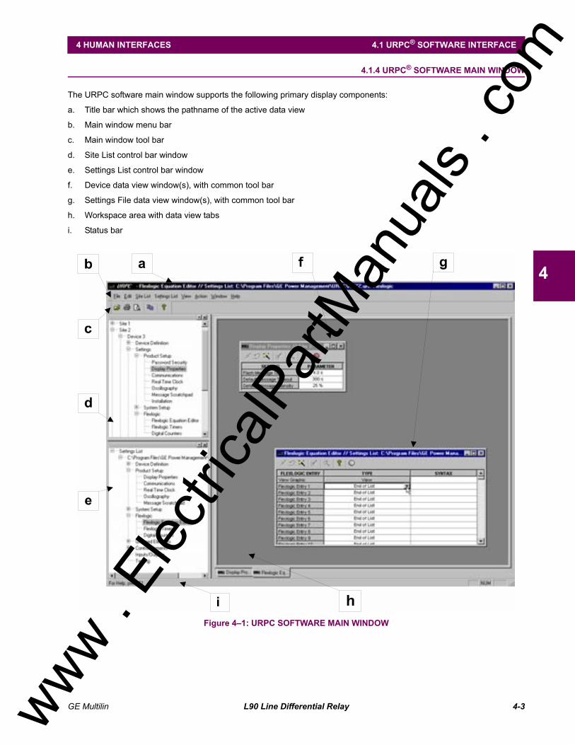
4. HUMAN INTERFACES 4.1 URPC® SOFTWARE INTERFACE4.1.1 GRAPHICAL USER INTERFACE.......................................................................4-14.1.2 CREATING A SITE LIST ....................................................................................4-14.1.3 URPC® SOFTWARE OVERVIEW......................................................................4-14.1.4 URPC® SOFTWARE MAIN WINDOW ...............................................................4-3
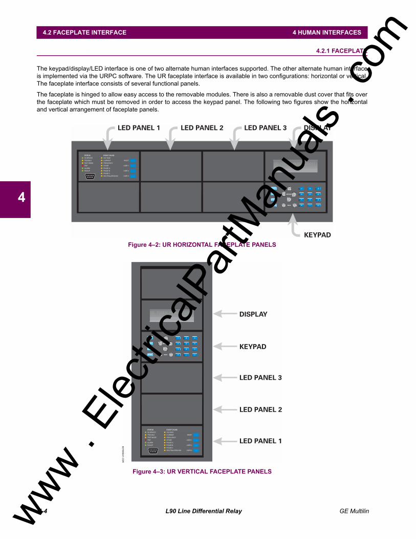
4.2 FACEPLATE INTERFACE4.2.1 FACEPLATE.......................................................................................................4-44.2.2 LED INDICATORS..............................................................................................4-54.2.3 CUSTOM LABELING OF LEDs..........................................................................4-74.2.4 CUSTOMIZING THE DISPLAY MODULE..........................................................4-74.2.5 DISPLAY.............................................................................................................4-84.2.6 KEYPAD .............................................................................................................4-84.2.7 BREAKER CONTROL ........................................................................................4-94.2.8 MENUS.............................................................................................................4-104.2.9 CHANGING SETTINGS ...................................................................................4-11
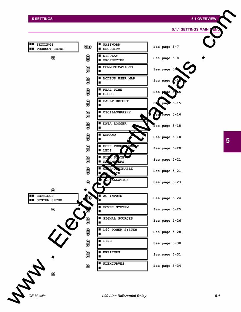
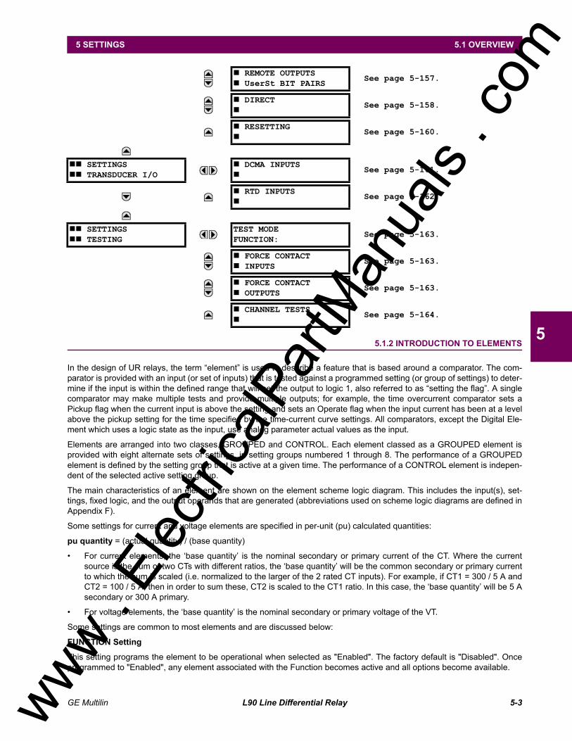
5. SETTINGS 5.1 OVERVIEW5.1.1 SETTINGS MAIN MENU ....................................................................................5-15.1.2 INTRODUCTION TO ELEMENTS......................................................................5-35.1.3 INTRODUCTION TO AC SOURCES..................................................................5-4
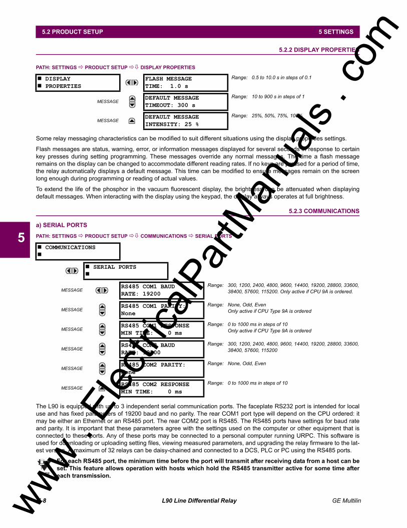
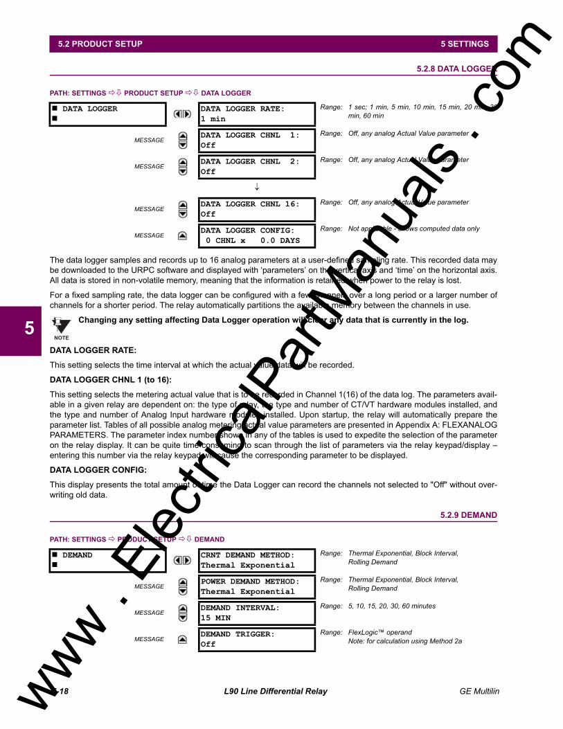
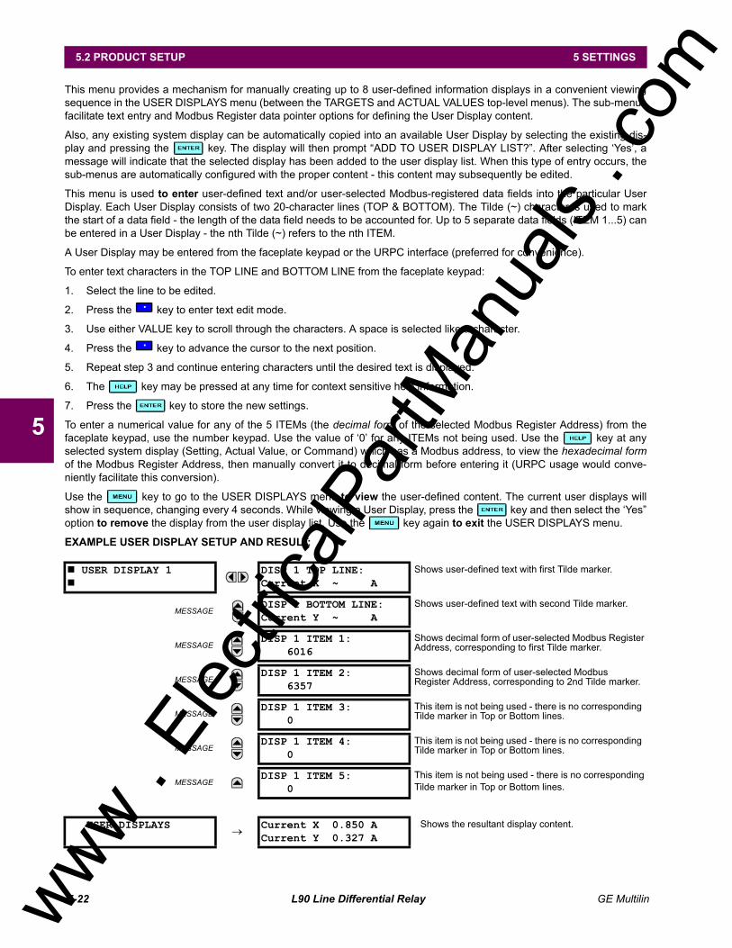
5.2.2 DISPLAY PROPERTIES.................................................................................... 5-85.2.3 COMMUNICATIONS.......................................................................................... 5-85.2.4 MODBUS® USER MAP.................................................................................... 5-155.2.5 REAL TIME CLOCK......................................................................................... 5-155.2.6 FAULT REPORT.............................................................................................. 5-155.2.7 OSCILLOGRAPHY .......................................................................................... 5-165.2.8 DATA LOGGER ............................................................................................... 5-185.2.9 DEMAND.......................................................................................................... 5-185.2.10 USER-PROGRAMMABLE LEDS..................................................................... 5-205.2.11 FLEX STATE PARAMETERS.......................................................................... 5-215.2.12 USER-DEFINABLE DISPLAYS ....................................................................... 5-215.2.13 INSTALLATION................................................................................................ 5-23
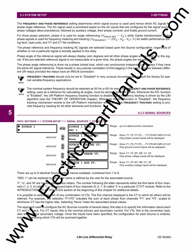
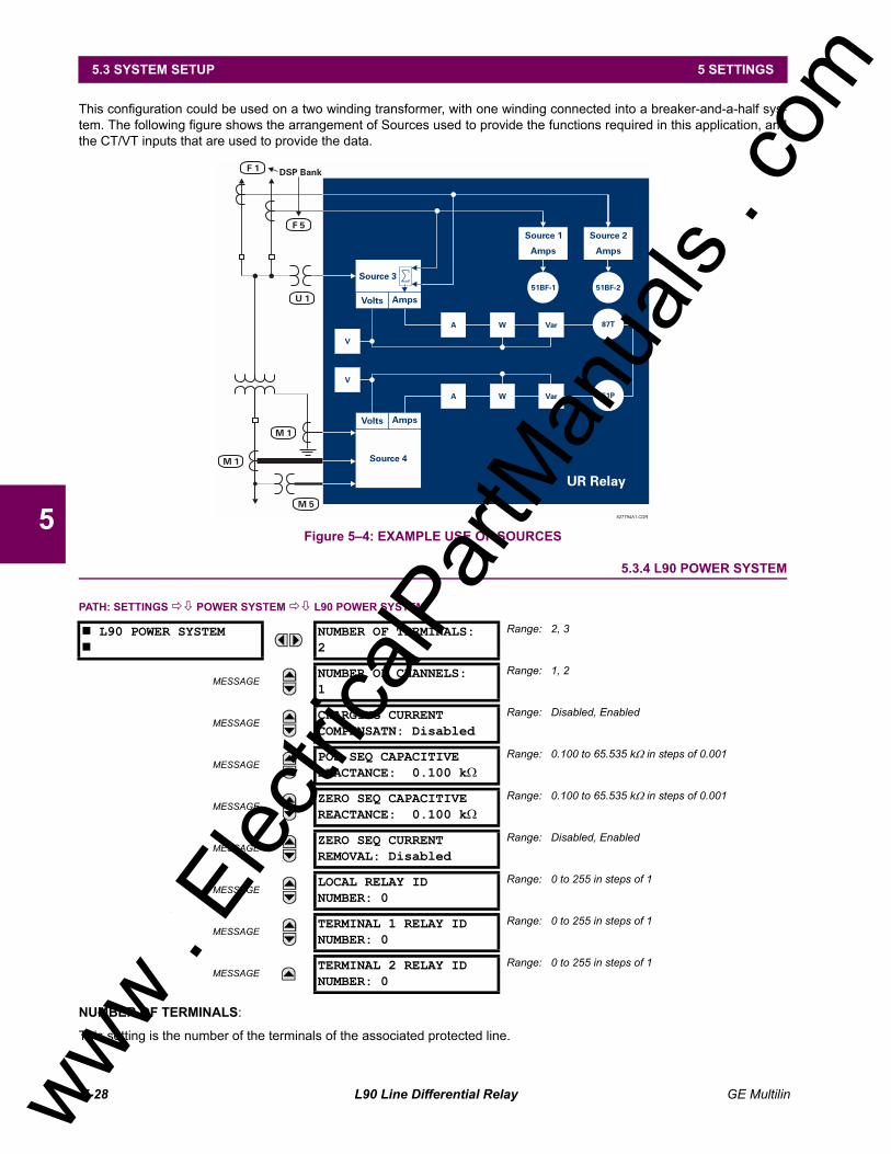
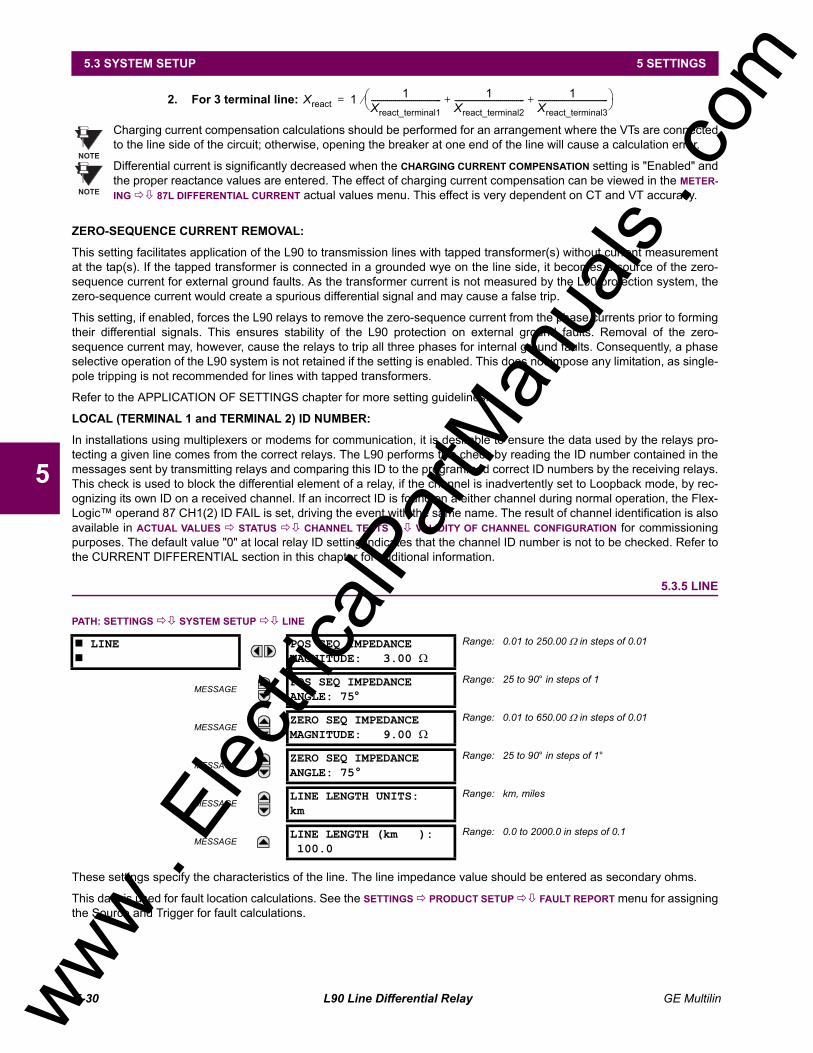
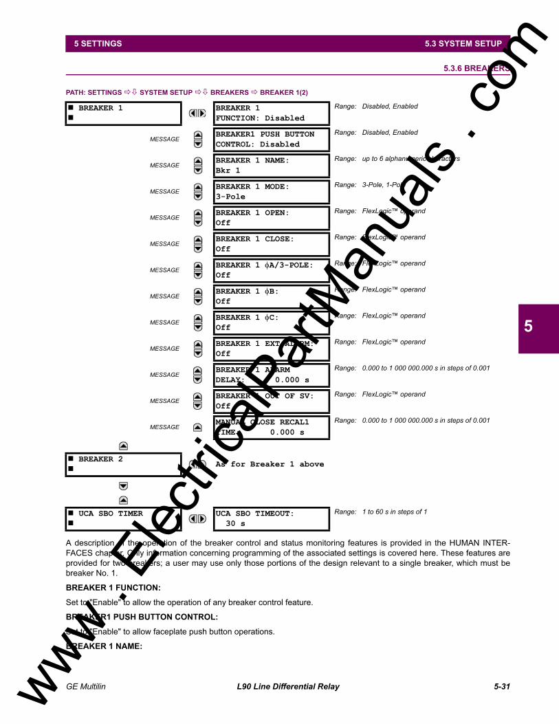
5.3 SYSTEM SETUP5.3.1 AC INPUTS ...................................................................................................... 5-245.3.2 POWER SYSTEM............................................................................................ 5-255.3.3 SIGNAL SOURCES ......................................................................................... 5-265.3.4 L90 POWER SYSTEM..................................................................................... 5-285.3.5 LINE ................................................................................................................. 5-305.3.6 BREAKERS...................................................................................................... 5-315.3.7 FLEXCURVES.............................................................................................. 5-34
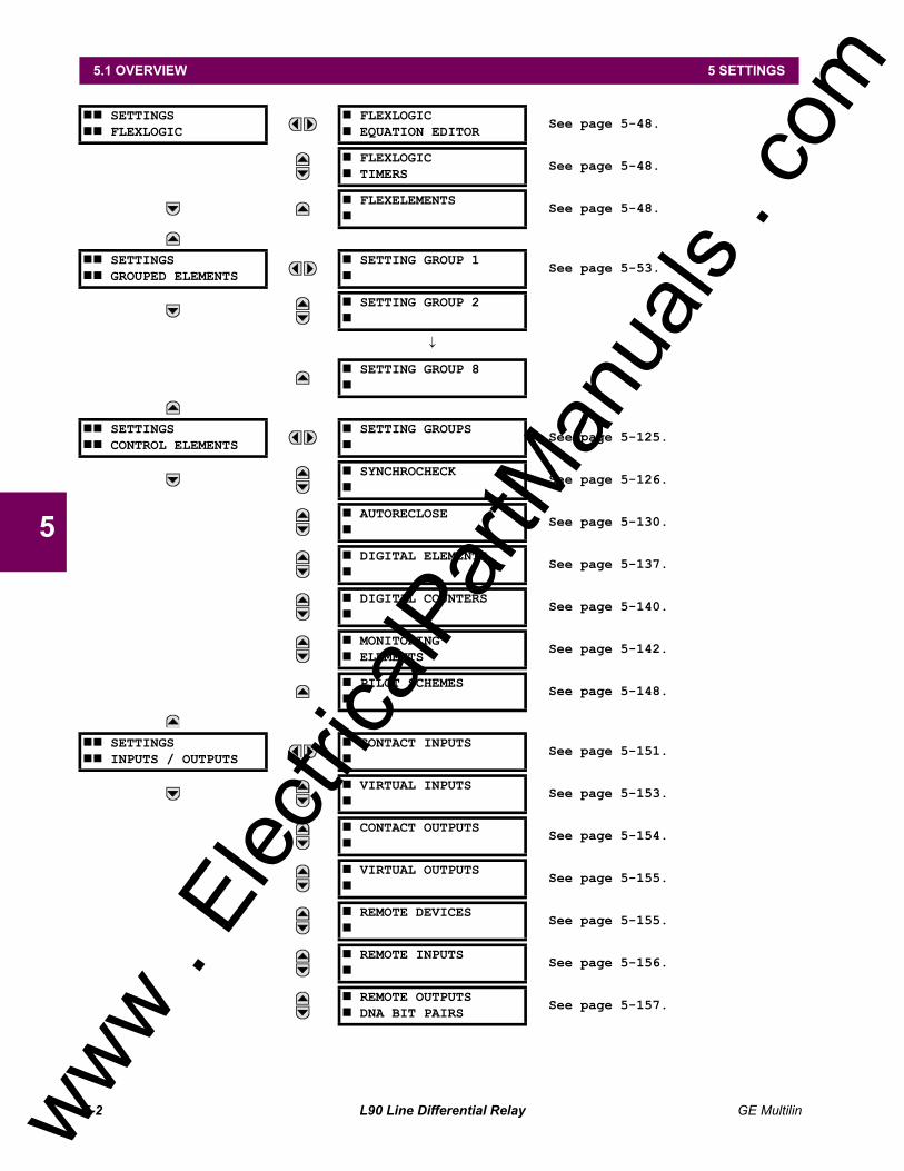
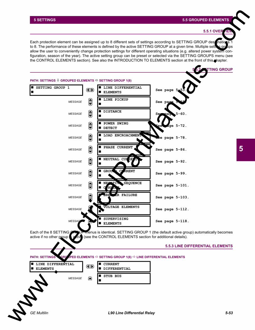
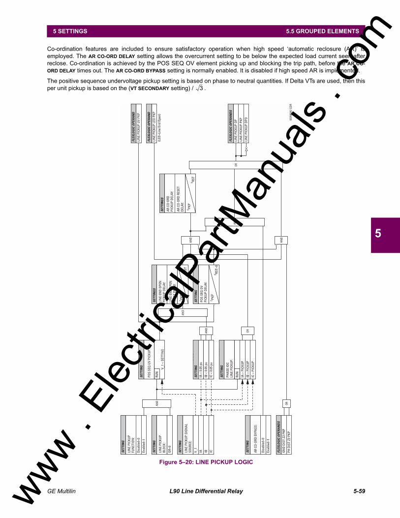
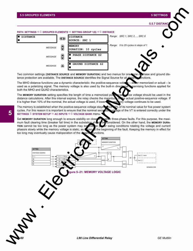
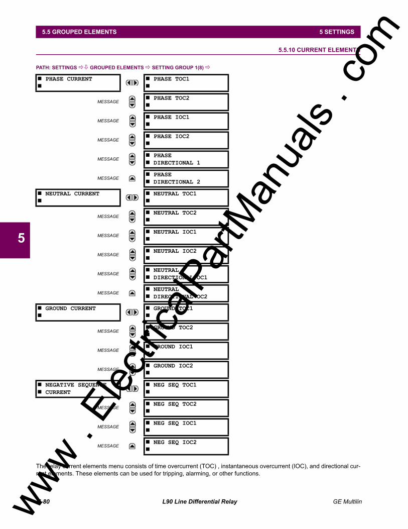
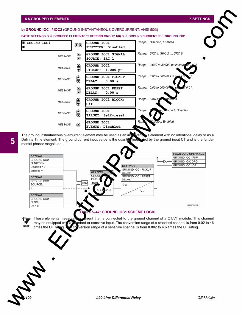
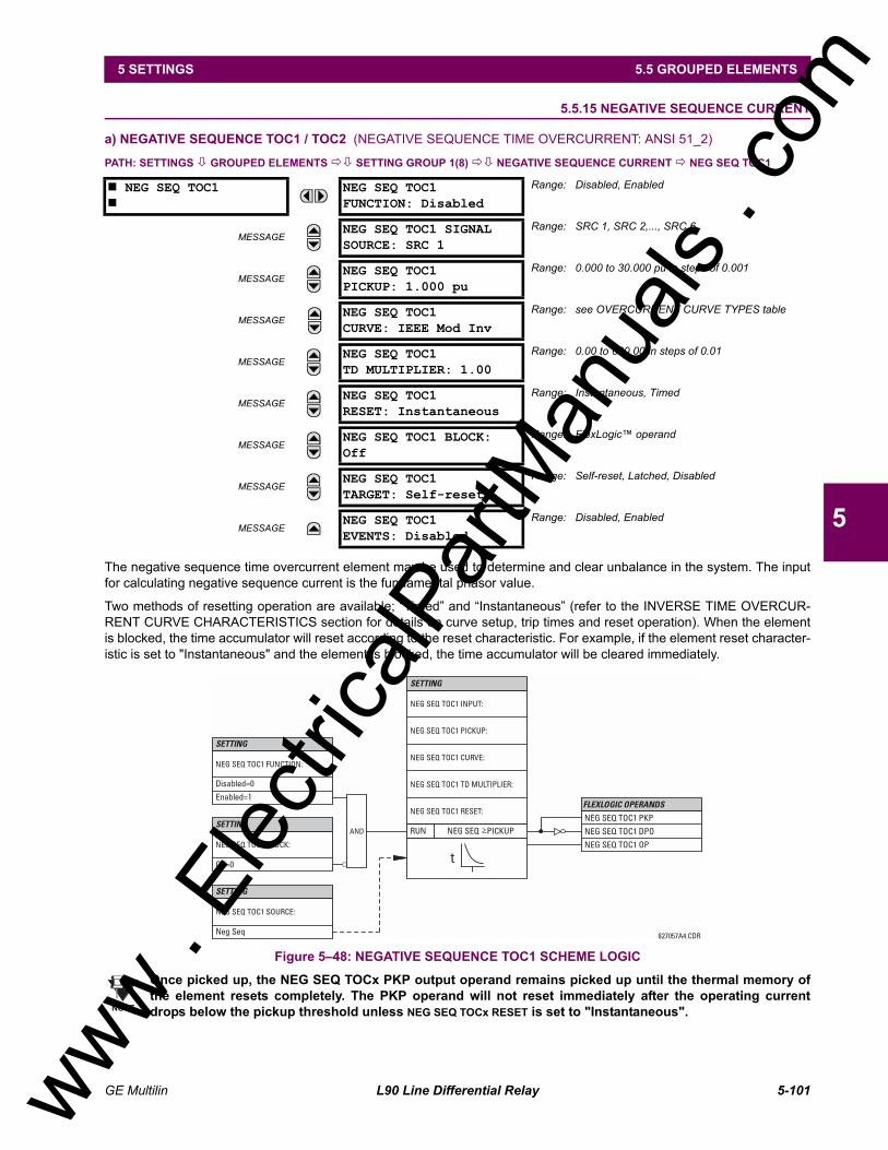
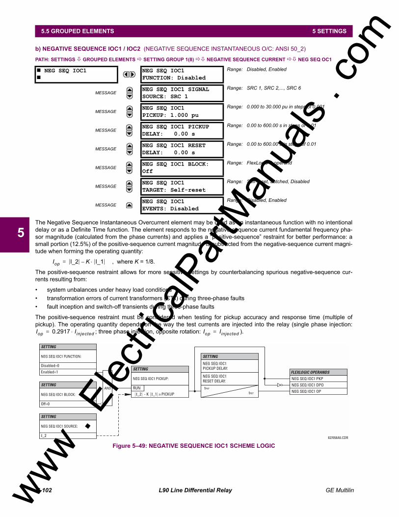
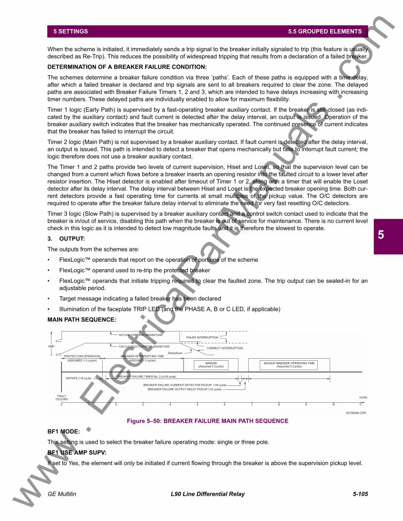
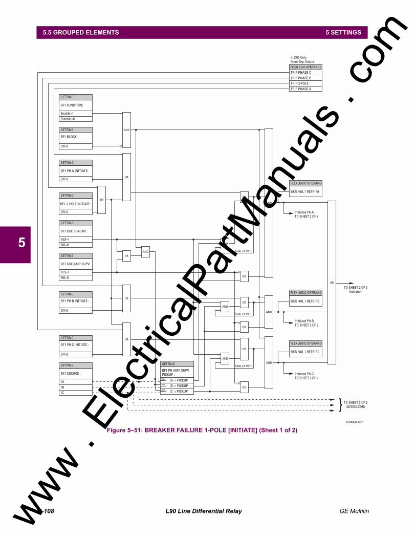
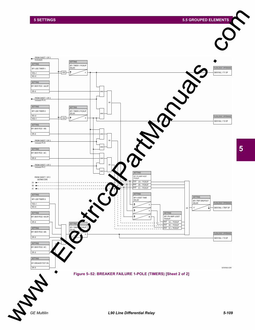
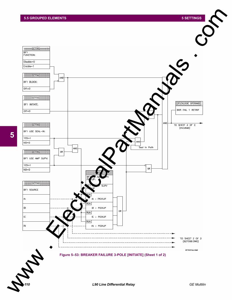
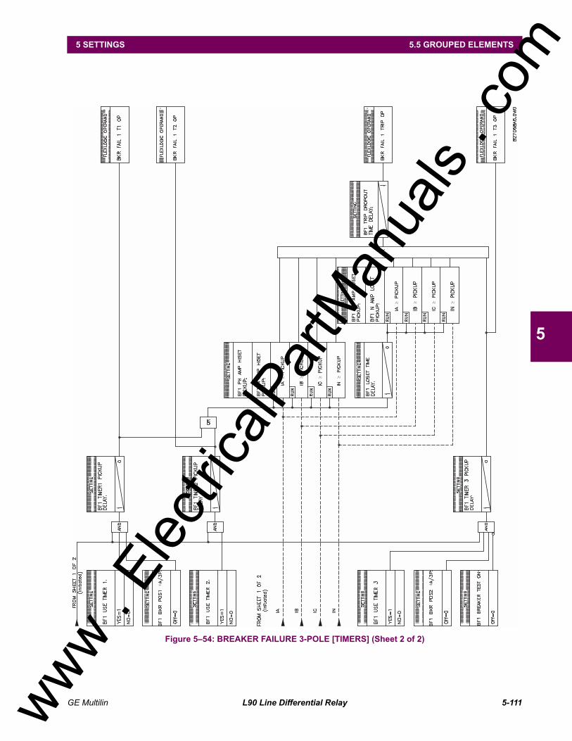
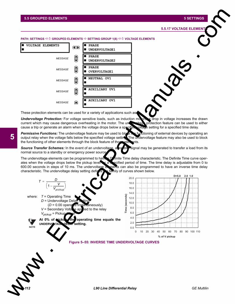
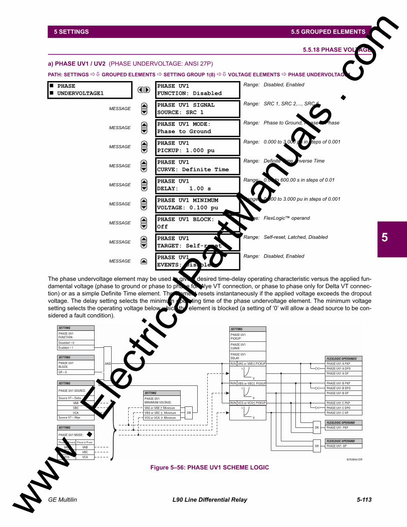
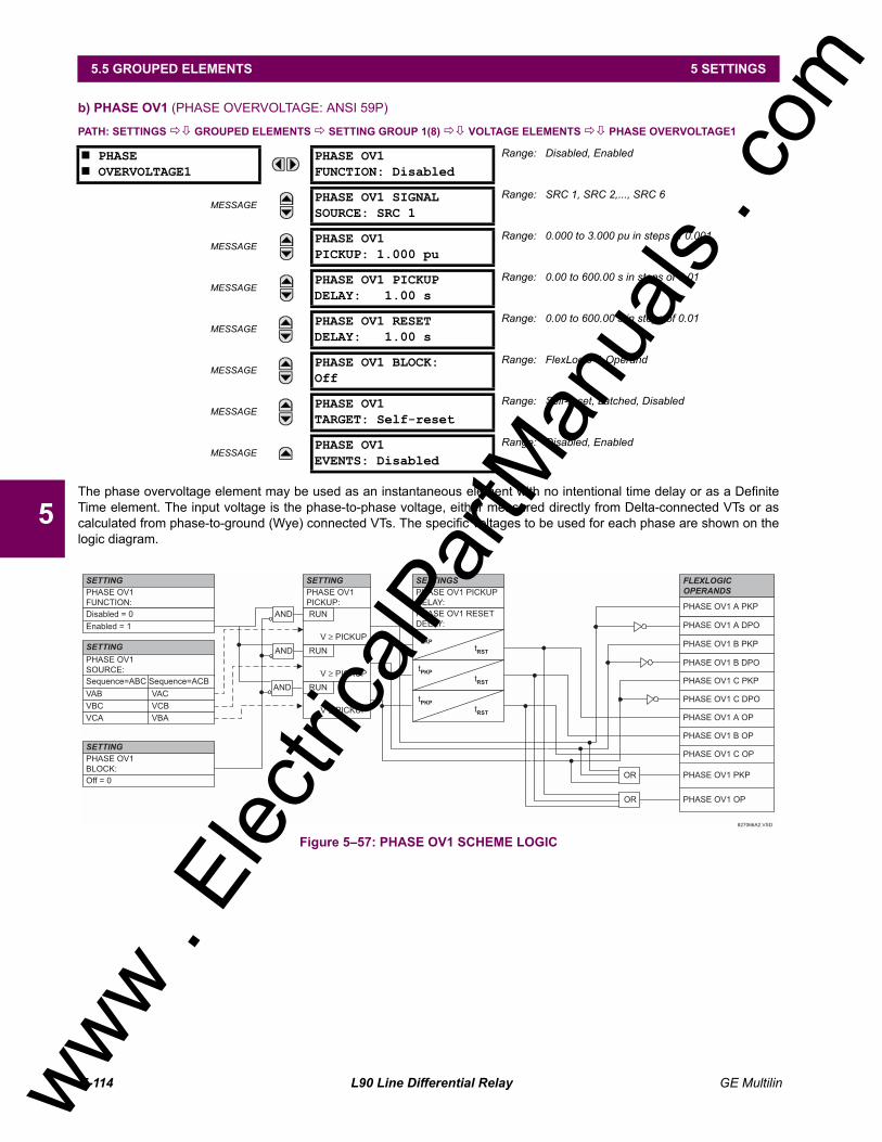
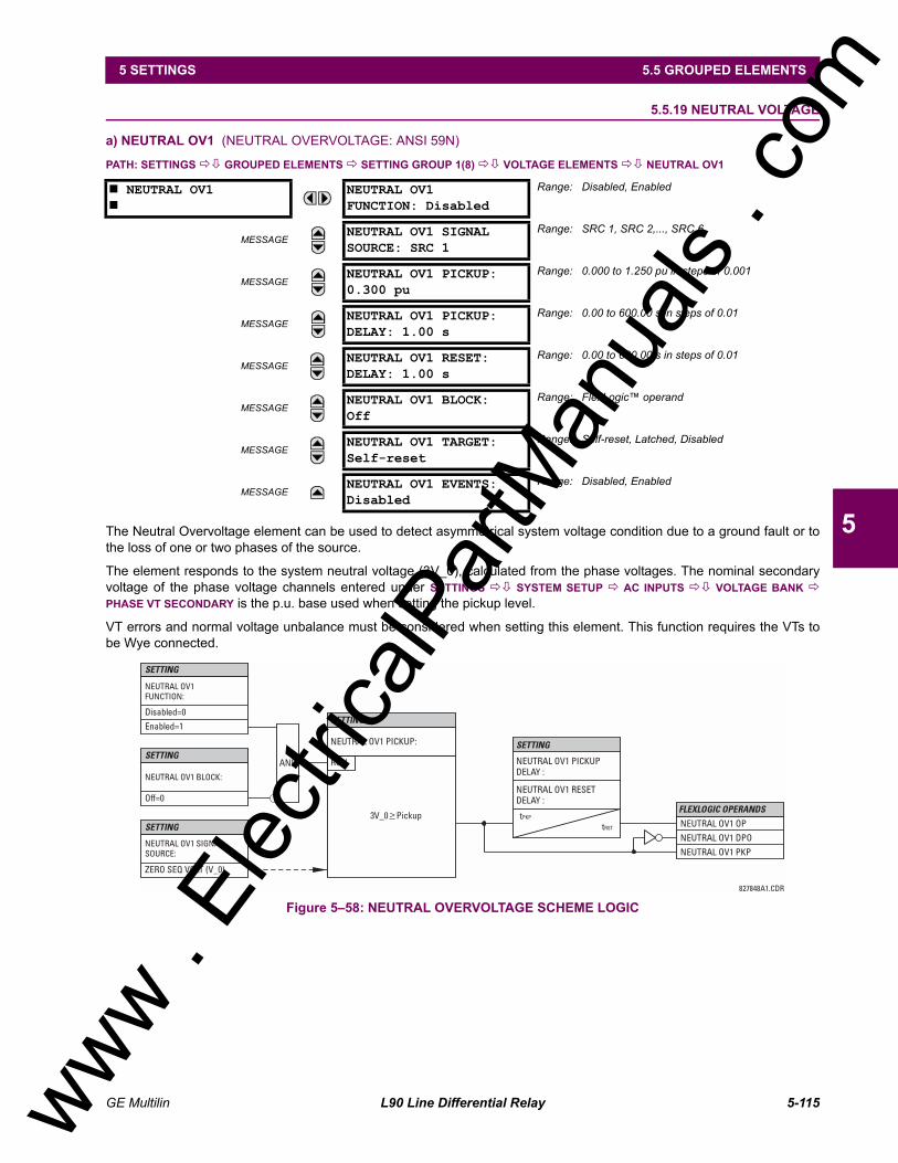
5.5 GROUPED ELEMENTS5.5.1 OVERVIEW...................................................................................................... 5-535.5.2 SETTING GROUP ........................................................................................... 5-535.5.3 LINE DIFFERENTIAL ELEMENTS .................................................................. 5-535.5.4 CURRENT DIFFERENTIAL ............................................................................. 5-545.5.5 STUB BUS ....................................................................................................... 5-575.5.6 LINE PICKUP................................................................................................... 5-585.5.7 DISTANCE ....................................................................................................... 5-605.5.8 POWER SWING DETECT ............................................................................... 5-725.5.9 LOAD ENCROACHMENT................................................................................ 5-785.5.10 CURRENT ELEMENTS ................................................................................... 5-805.5.11 INVERSE TIME OVERCURRENT CURVE CHARACTERISTICS .................. 5-815.5.12 PHASE CURRENT .......................................................................................... 5-865.5.13 NEUTRAL CURRENT...................................................................................... 5-925.5.14 GROUND CURRENT....................................................................................... 5-995.5.15 NEGATIVE SEQUENCE CURRENT ............................................................. 5-1015.5.16 BREAKER FAILURE...................................................................................... 5-1035.5.17 VOLTAGE ELEMENTS.................................................................................. 5-1125.5.18 PHASE VOLTAGE ......................................................................................... 5-1135.5.19 NEUTRAL VOLTAGE .................................................................................... 5-1155.5.20 AUXILIARY VOLTAGE .................................................................................. 5-1165.5.21 SUPERVISING ELEMENTS .......................................................................... 5-118
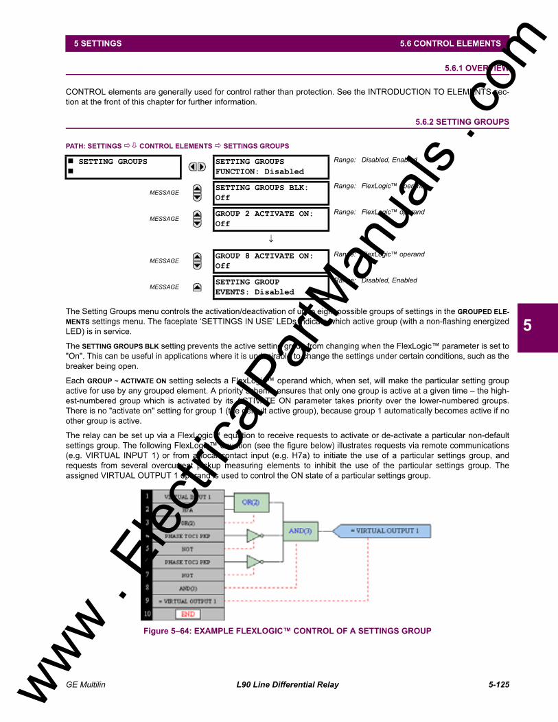
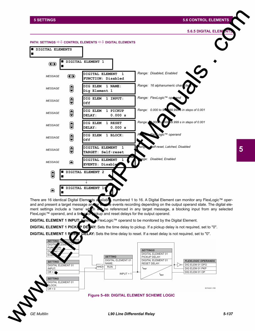
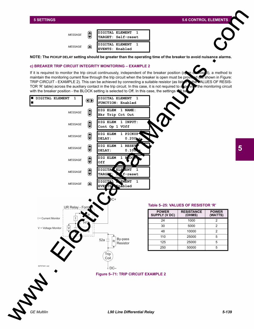
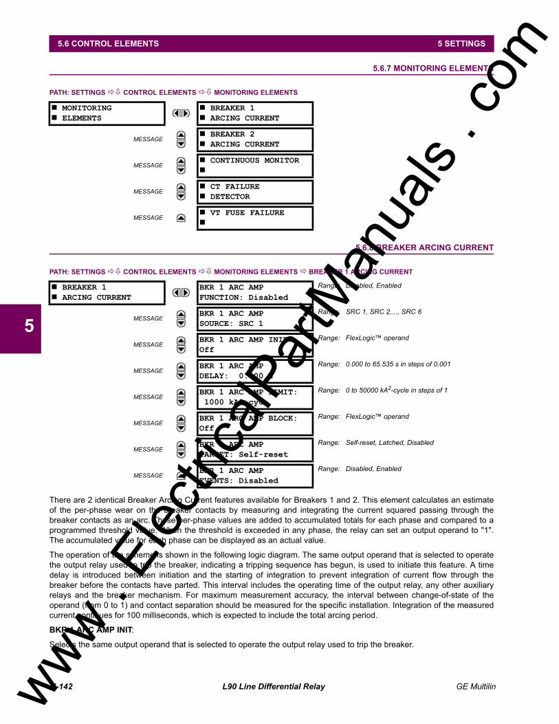
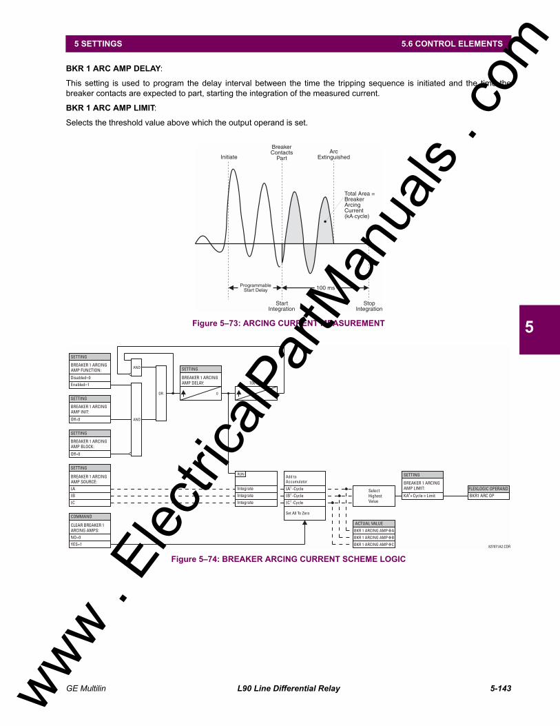
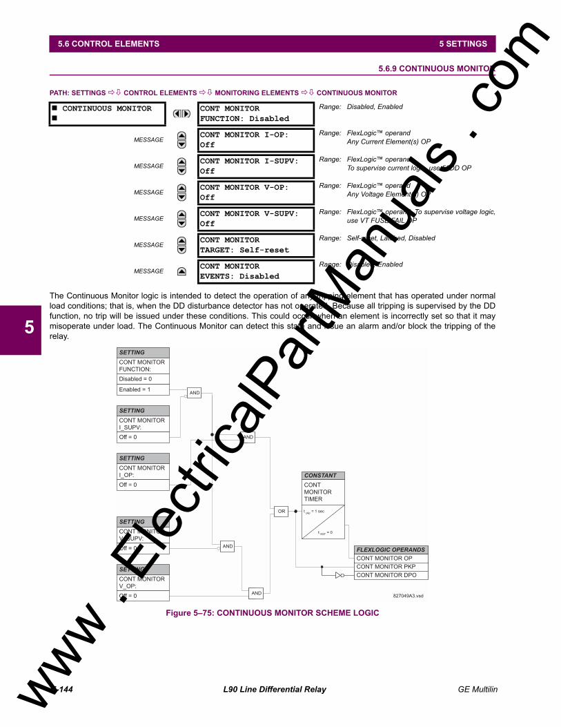
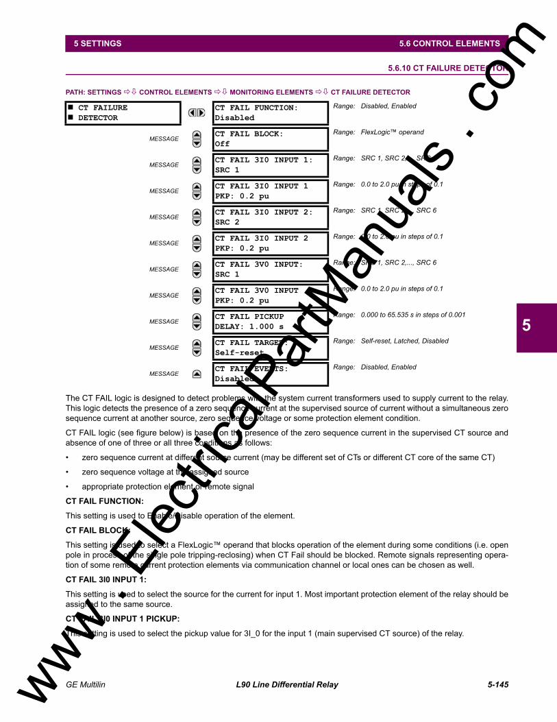
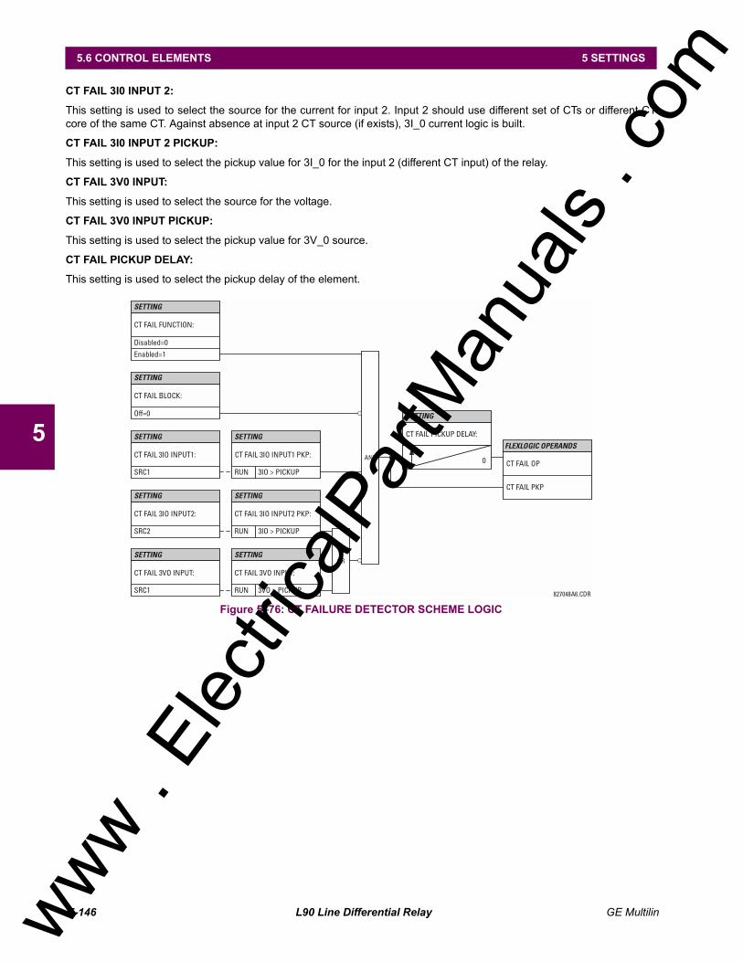
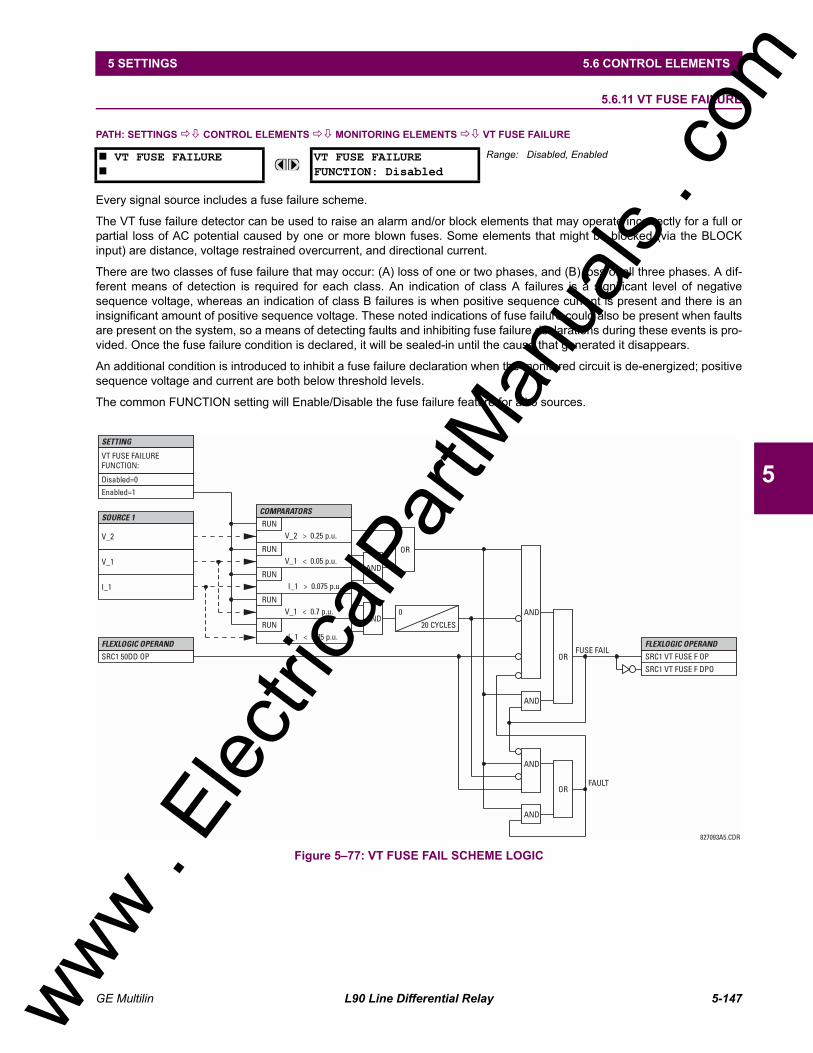
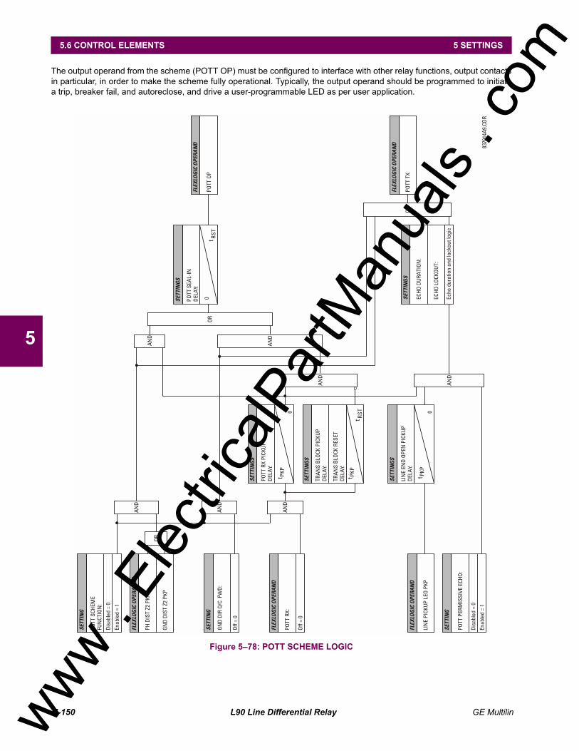
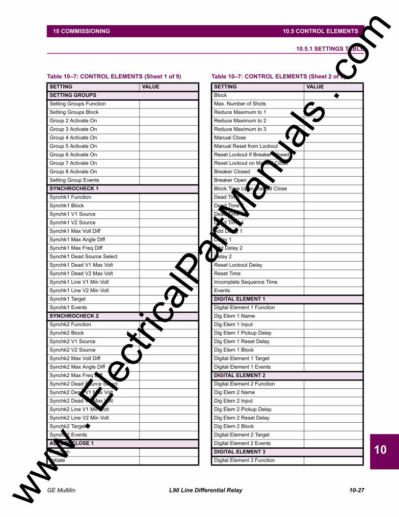
5.6 CONTROL ELEMENTS5.6.1 OVERVIEW.................................................................................................... 5-1255.6.2 SETTING GROUPS ....................................................................................... 5-1255.6.3 SYNCHROCHECK......................................................................................... 5-1265.6.4 AUTORECLOSE ............................................................................................ 5-1305.6.5 DIGITAL ELEMENTS..................................................................................... 5-1375.6.6 DIGITAL COUNTERS .................................................................................... 5-1405.6.7 MONITORING ELEMENTS ........................................................................... 5-1425.6.8 BREAKER ARCING CURRENT .................................................................... 5-1425.6.9 CONTINUOUS MONITOR ............................................................................. 5-1445.6.10 CT FAILURE DETECTOR ............................................................................. 5-1455.6.11 VT FUSE FAILURE........................................................................................ 5-1475.6.12 PILOT SCHEMES .......................................................................................... 5-148
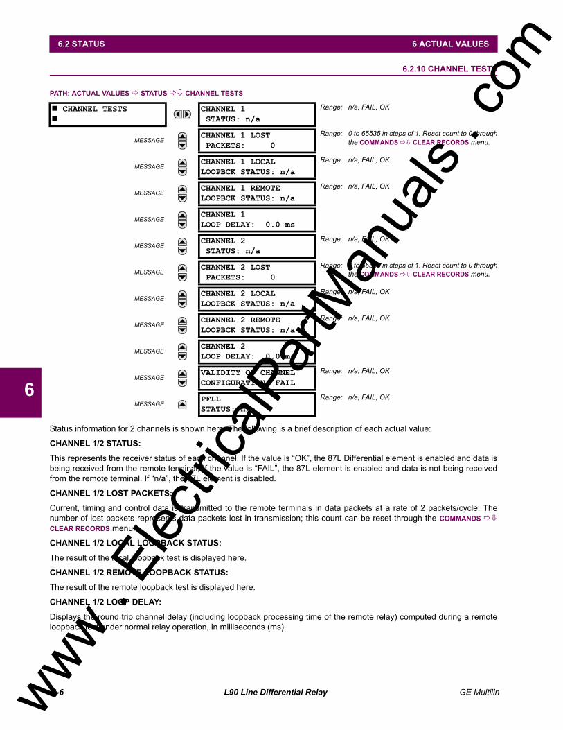
5.9 TESTING5.9.1 TEST MODE...................................................................................................5-1635.9.2 FORCE CONTACT INPUTS...........................................................................5-1635.9.3 FORCE CONTACT OUTPUTS.......................................................................5-1635.9.4 CHANNEL TESTS ..........................................................................................5-164
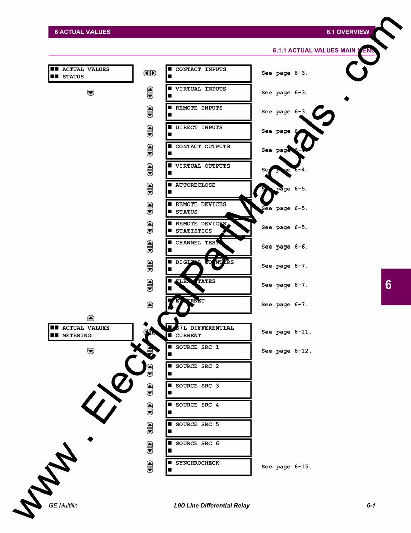
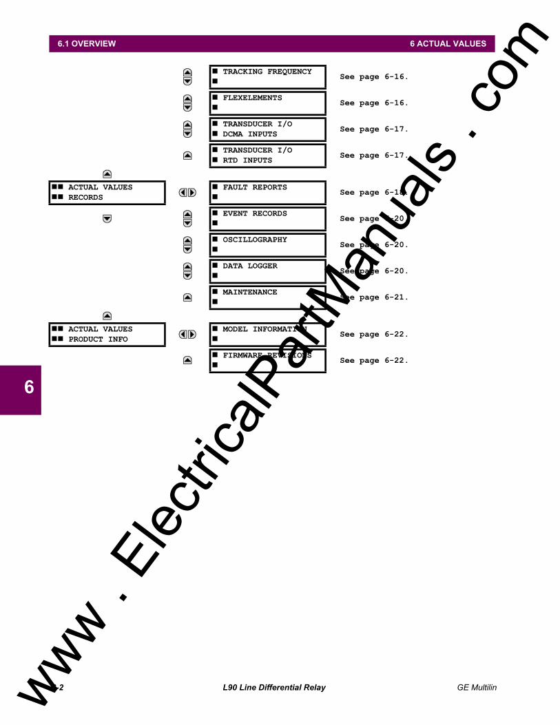
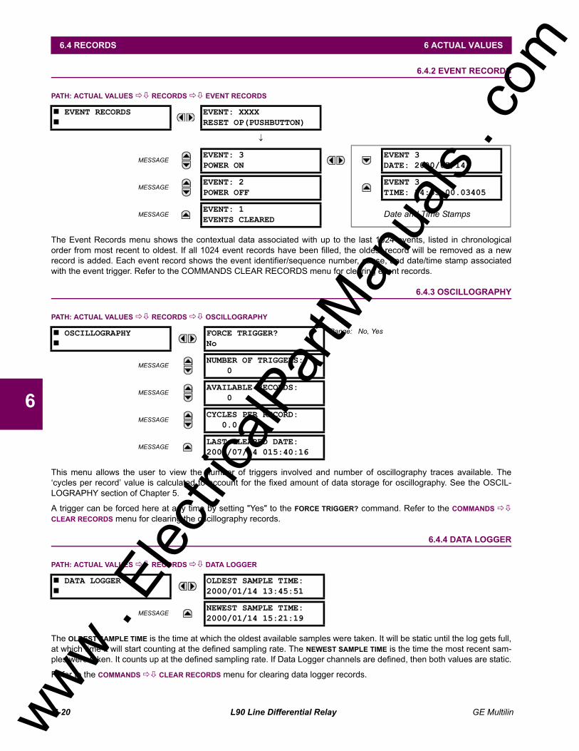
6. ACTUAL VALUES 6.1 OVERVIEW6.1.1 ACTUAL VALUES MAIN MENU.........................................................................6-1
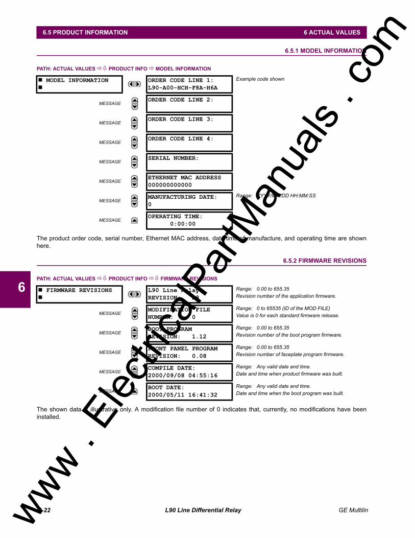
6.5 PRODUCT INFORMATION6.5.1 MODEL INFORMATION...................................................................................6-226.5.2 FIRMWARE REVISIONS..................................................................................6-22
7. COMMANDS AND TARGETS
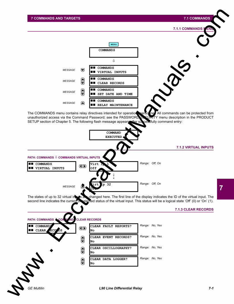
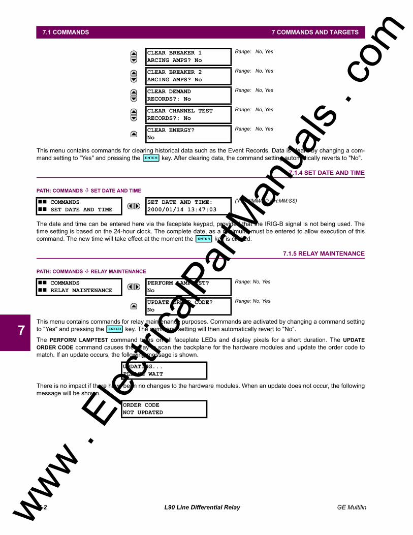
7.1 COMMANDS7.1.1 COMMANDS MENU...........................................................................................7-17.1.2 VIRTUAL INPUTS ..............................................................................................7-17.1.3 CLEAR RECORDS.............................................................................................7-17.1.4 SET DATE AND TIME ........................................................................................7-27.1.5 RELAY MAINTENANCE.....................................................................................7-2
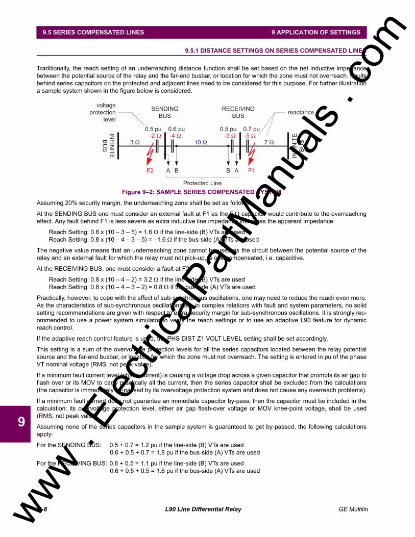
9.5 SERIES COMPENSATED LINES9.5.1 DISTANCE SETTINGS ON SERIES COMPENSATED LINES ......................... 9-8
9.6 LINES WITH TAPPED TRANSFORMERS9.6.1 DESCRIPTION................................................................................................... 9-99.6.2 TRANSFORMER LOAD CURRENTS................................................................ 9-99.6.3 FAULTS AT THE LV SIDE OF THE TRANSFORMER(S) ............................... 9-109.6.4 EXTERNAL GROUND FAULTS ...................................................................... 9-10
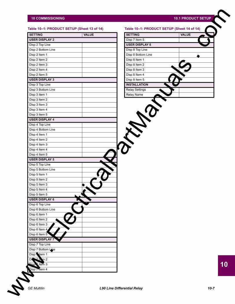
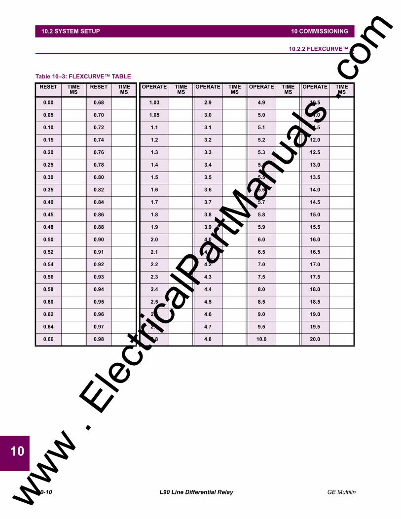
10.2 SYSTEM SETUP10.2.1 SYSTEM SETUP ..............................................................................................10-810.2.2 FLEXCURVE A ...........................................................................................10-1010.2.3 FLEXCURVE B ...........................................................................................10-11
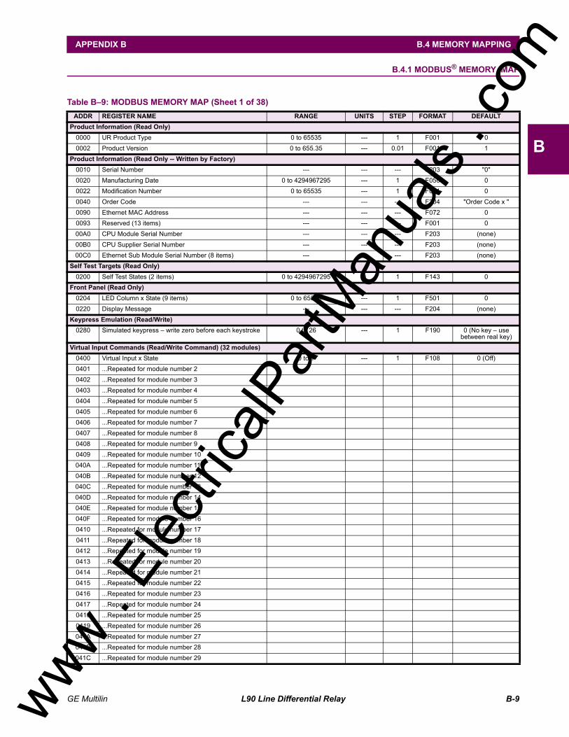
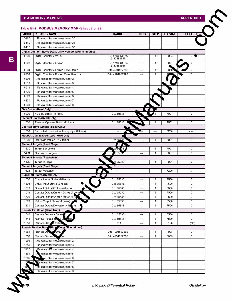
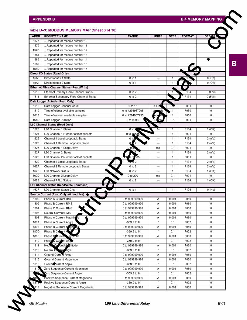
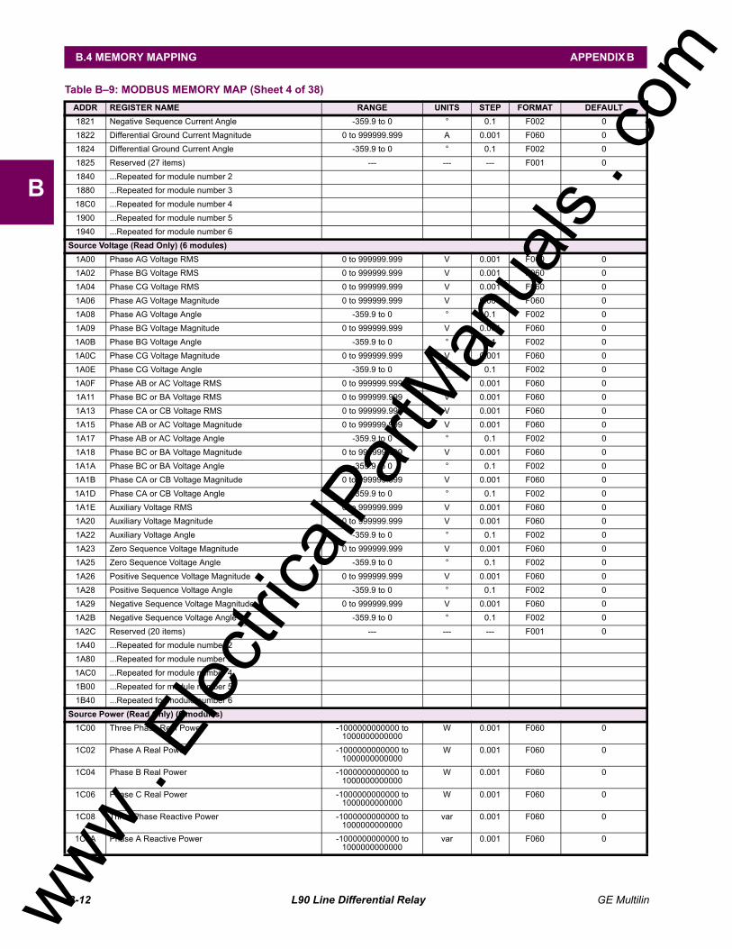
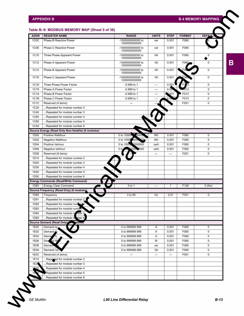
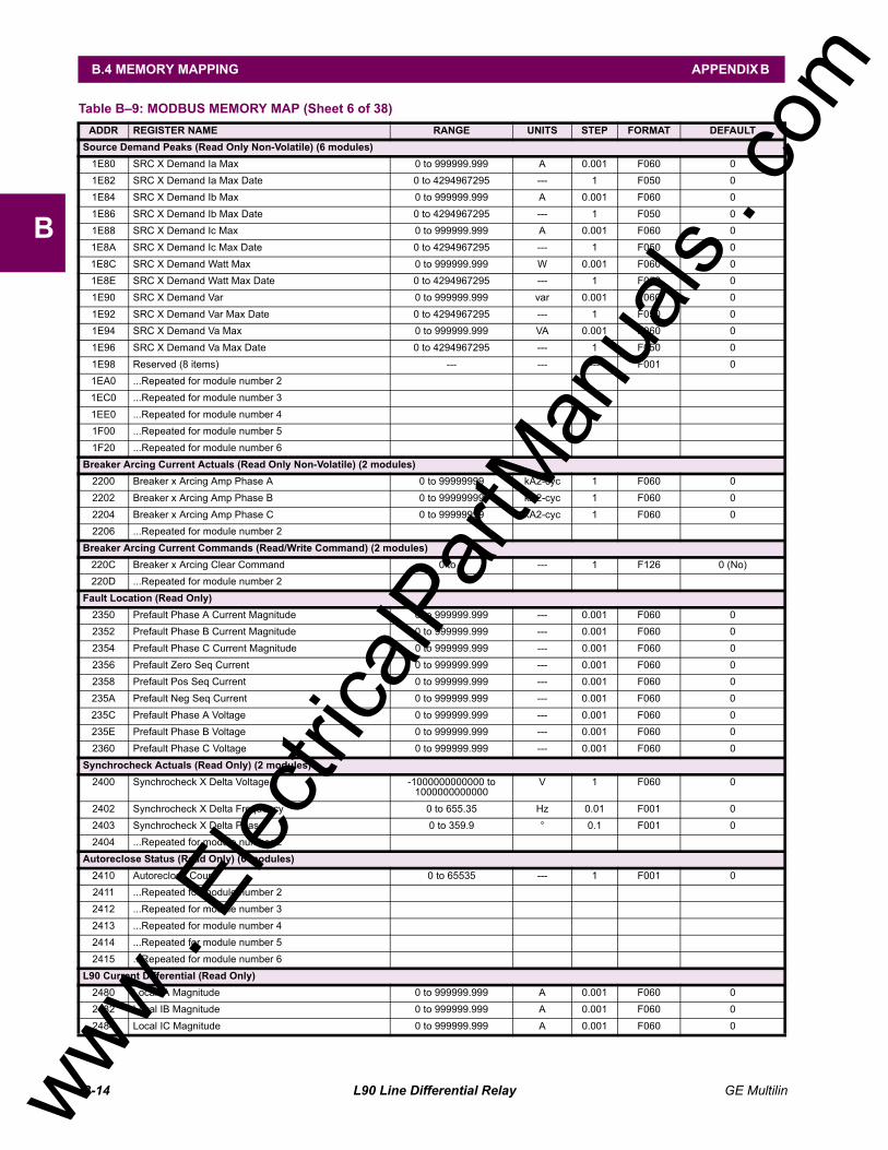
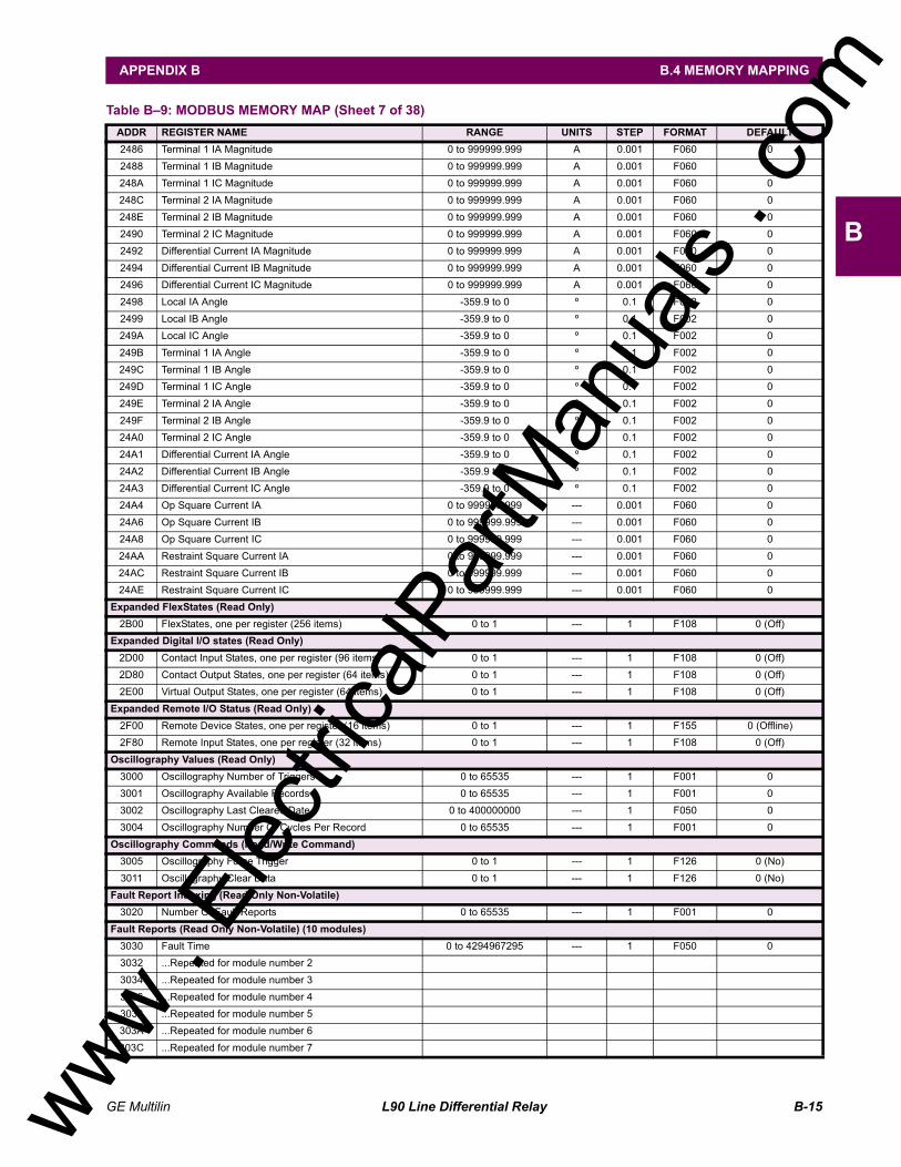
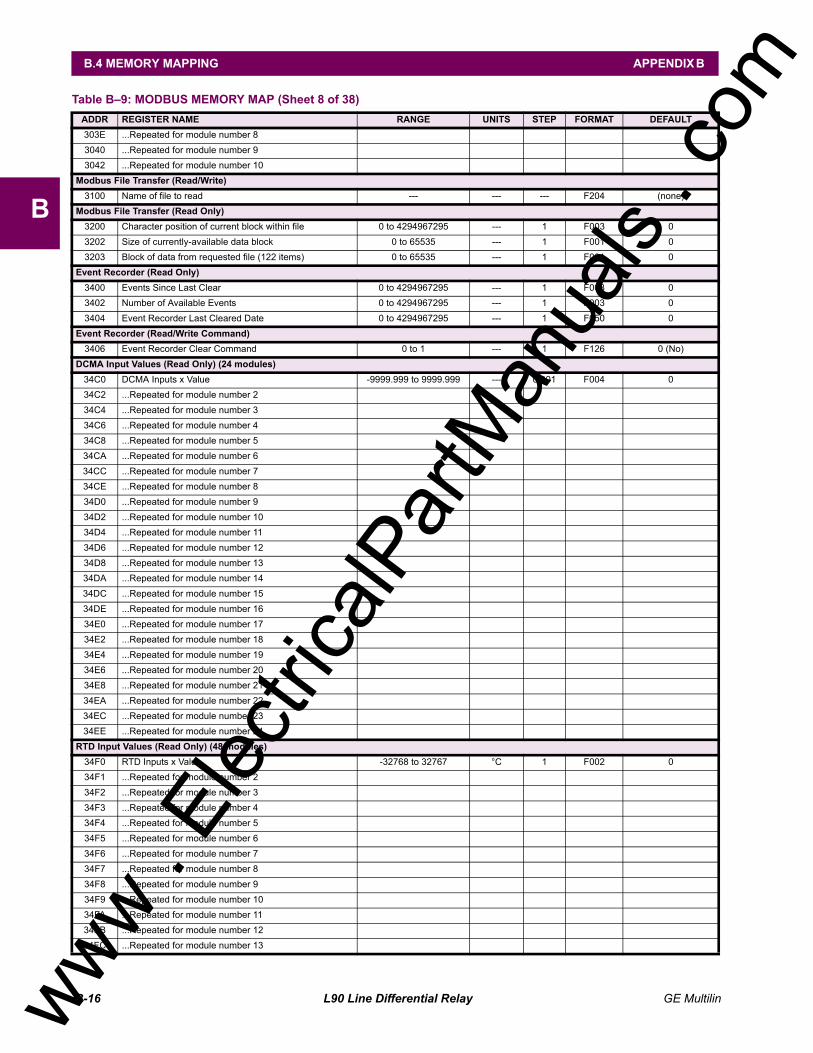
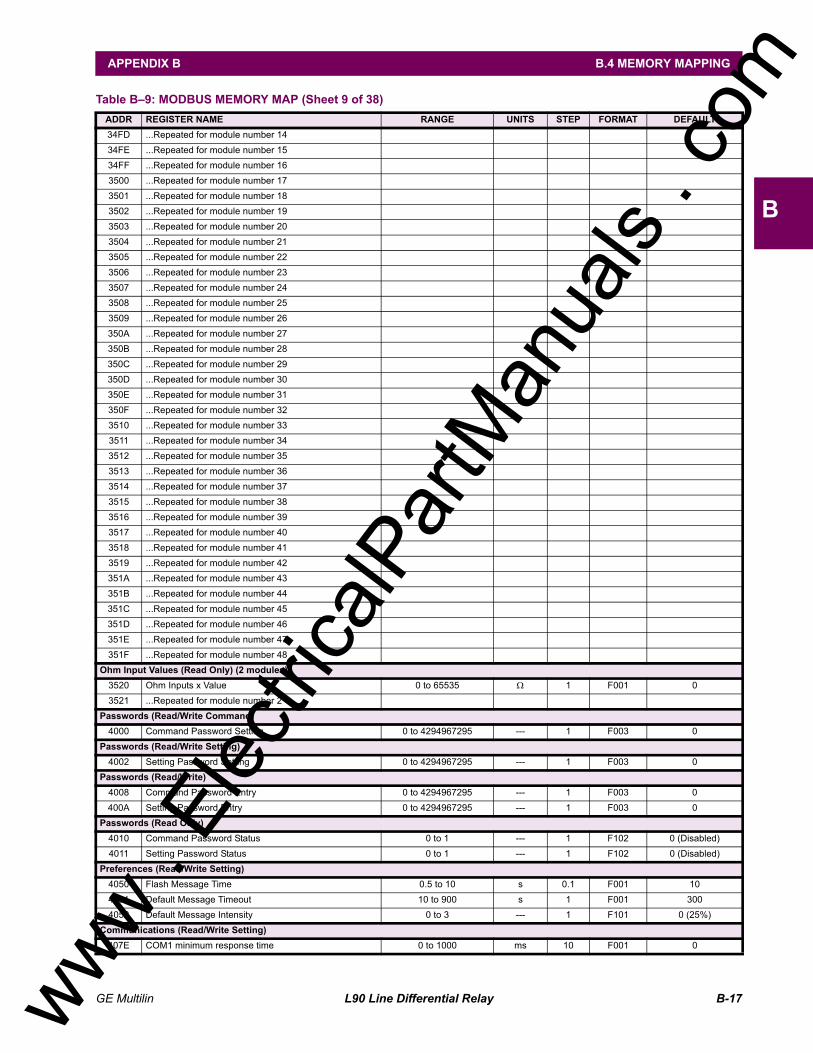
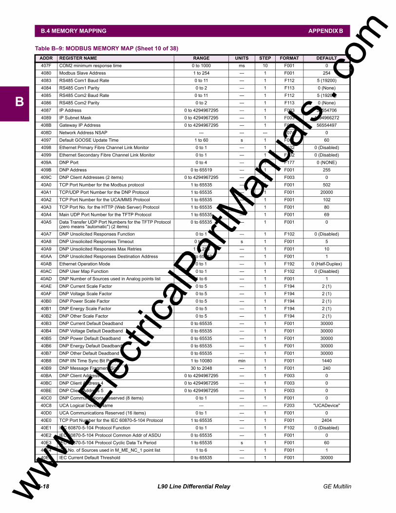
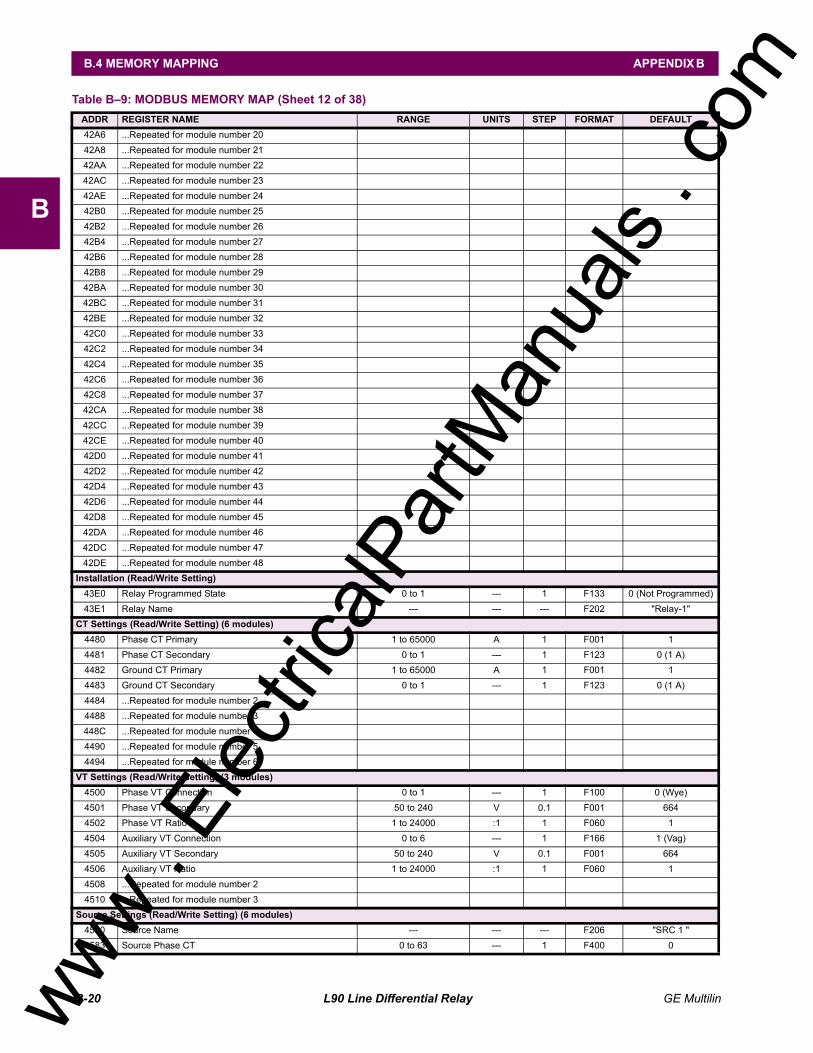
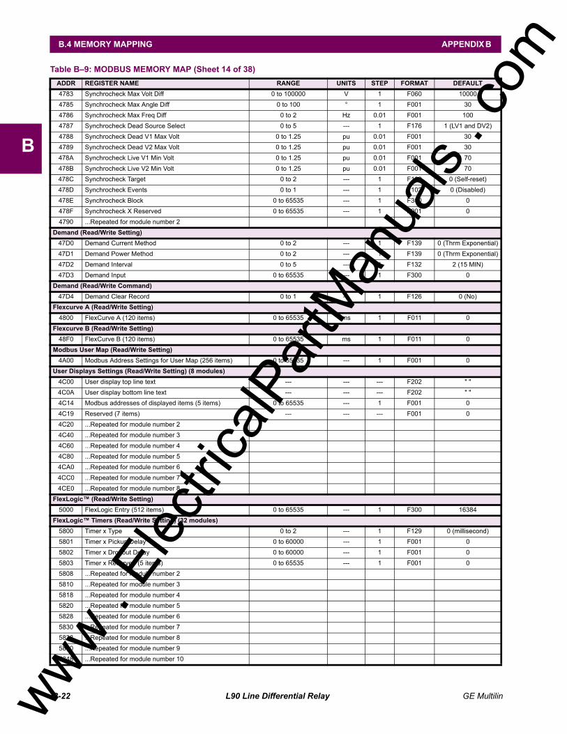
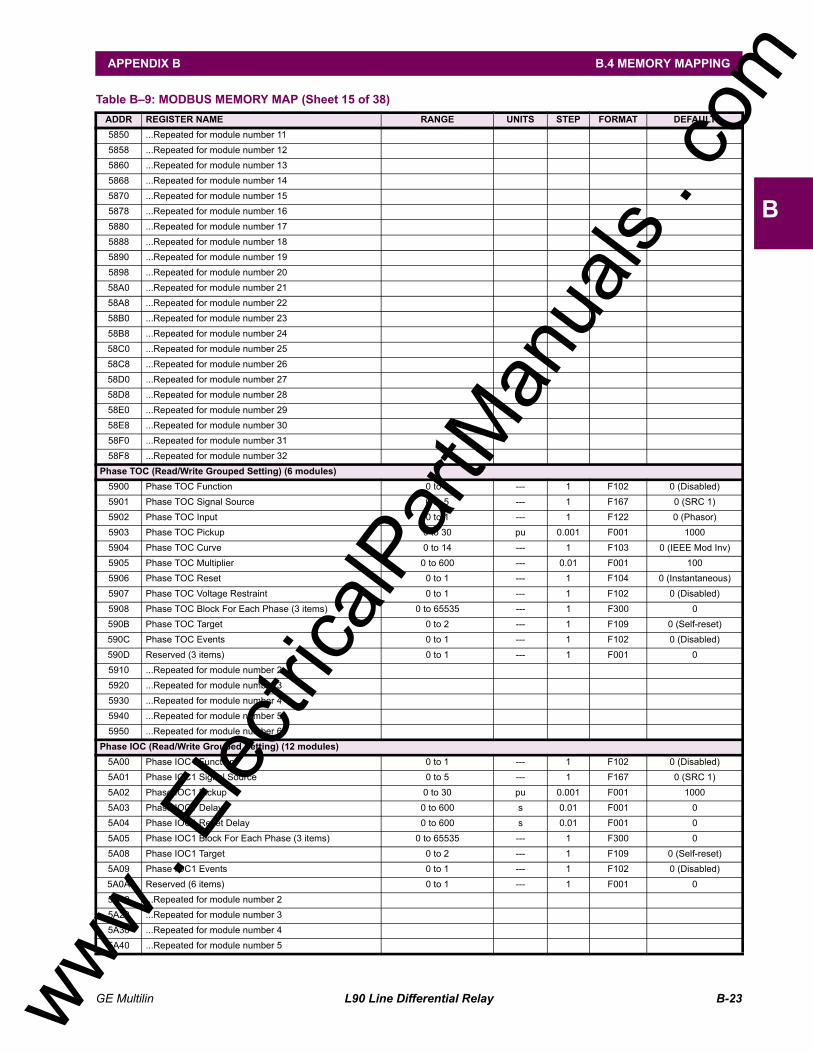
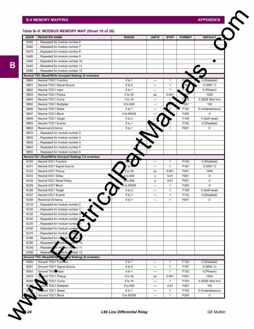
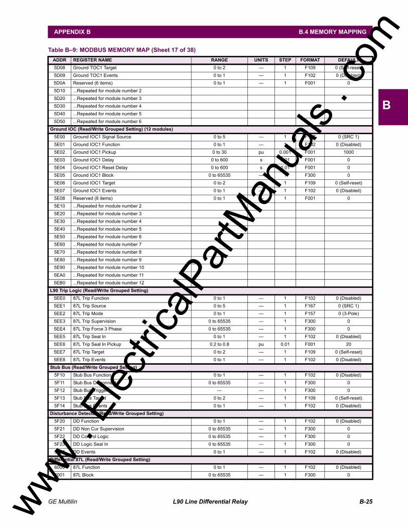
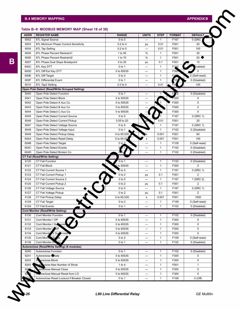
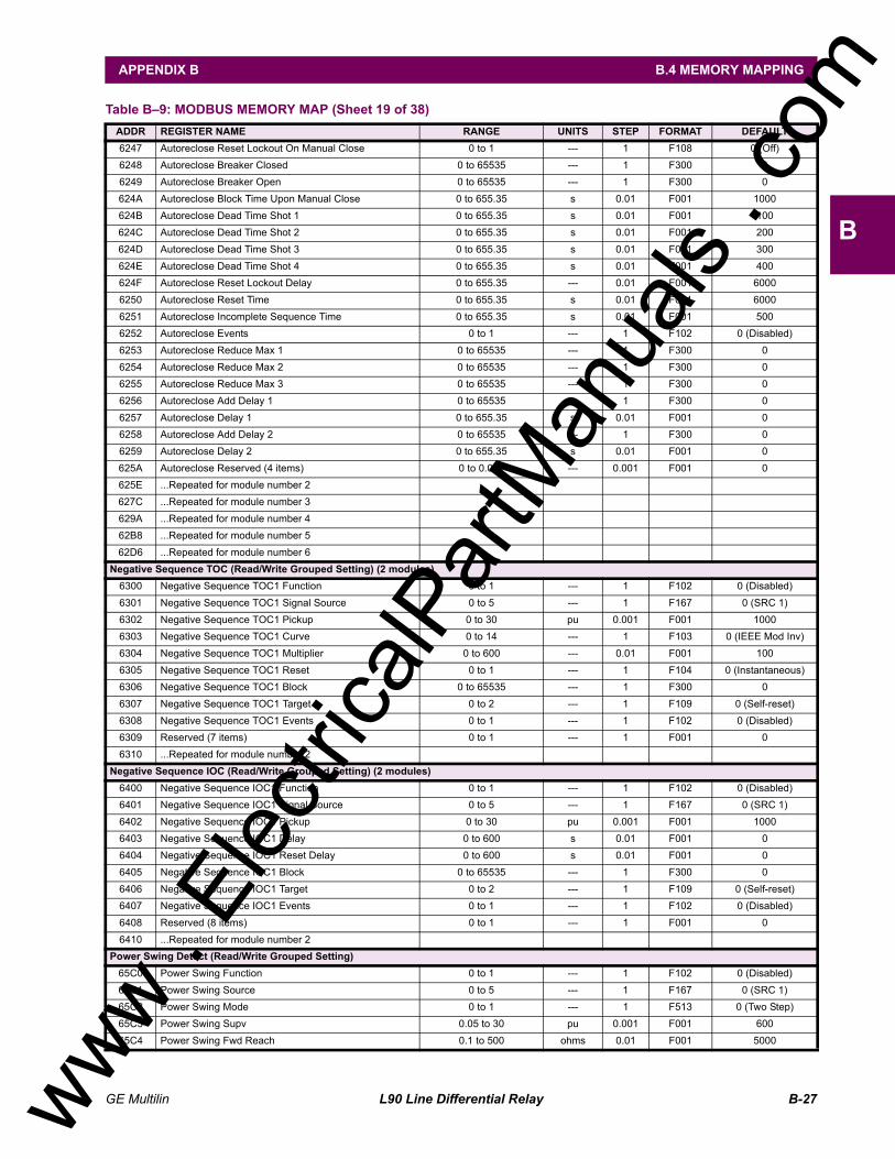
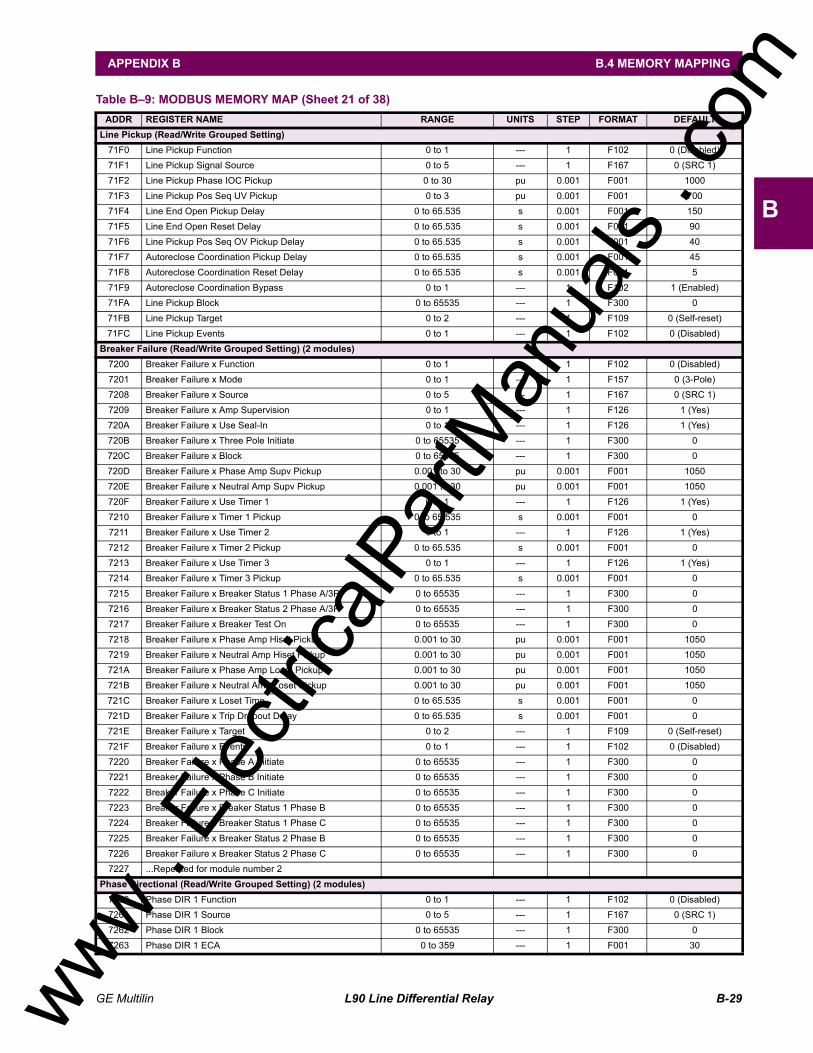
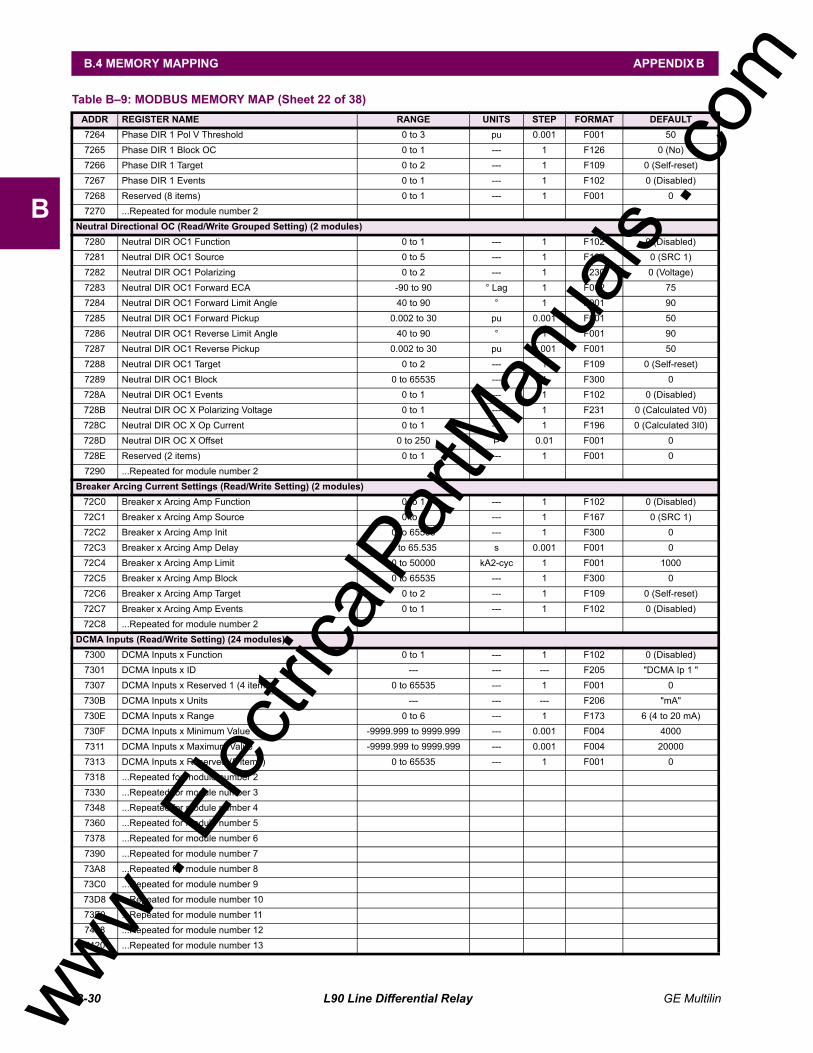
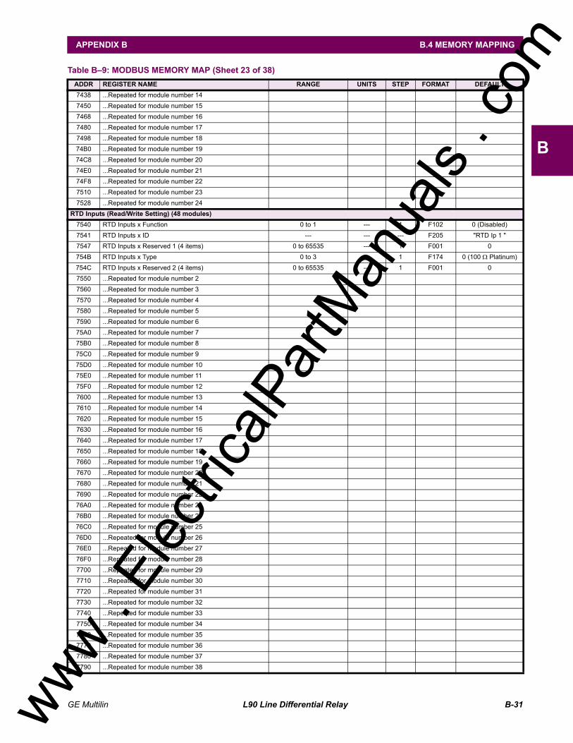
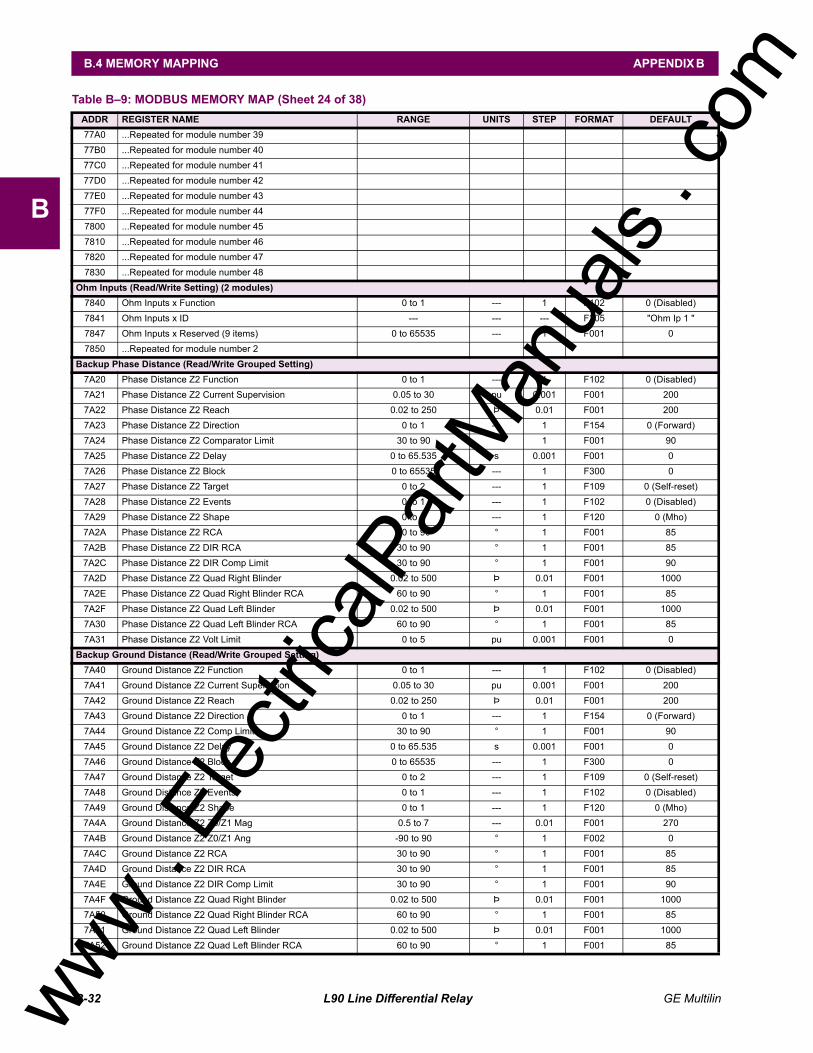
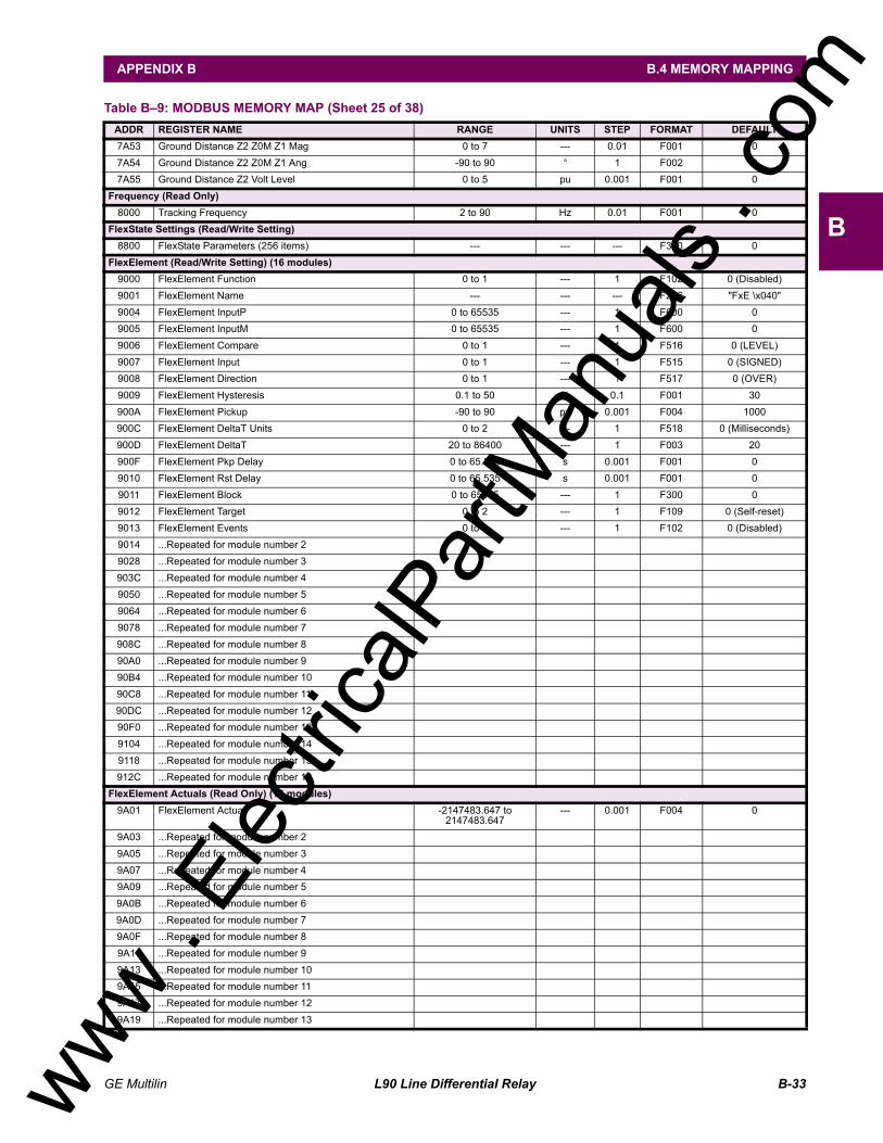
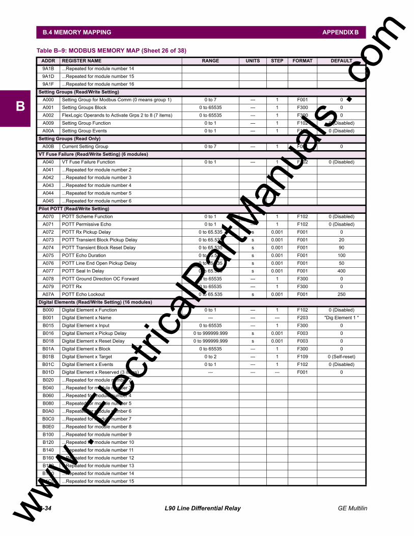
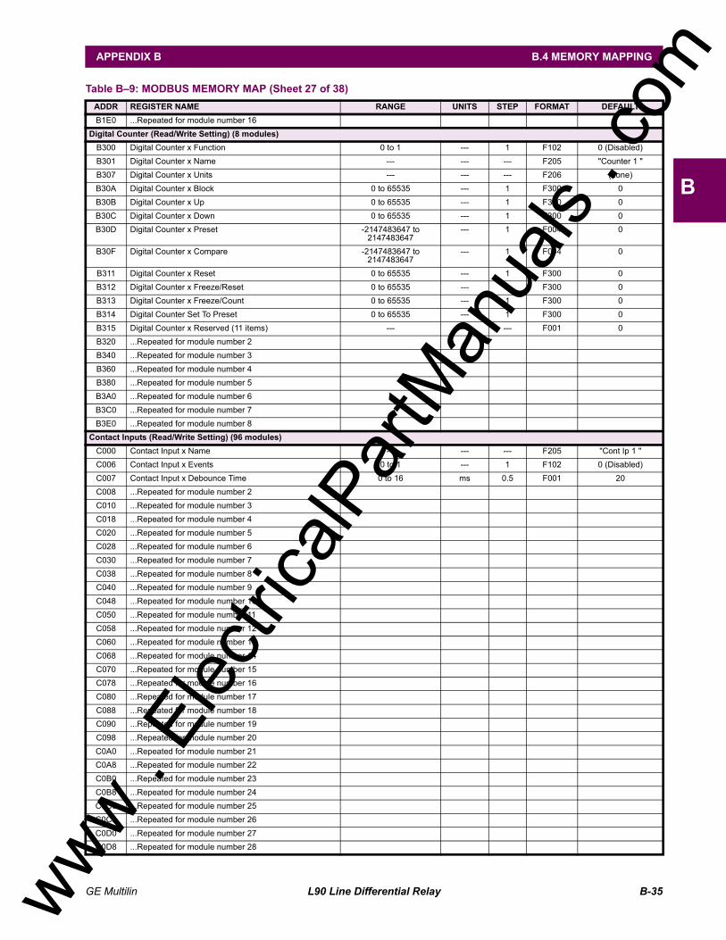
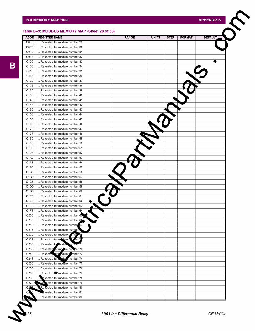
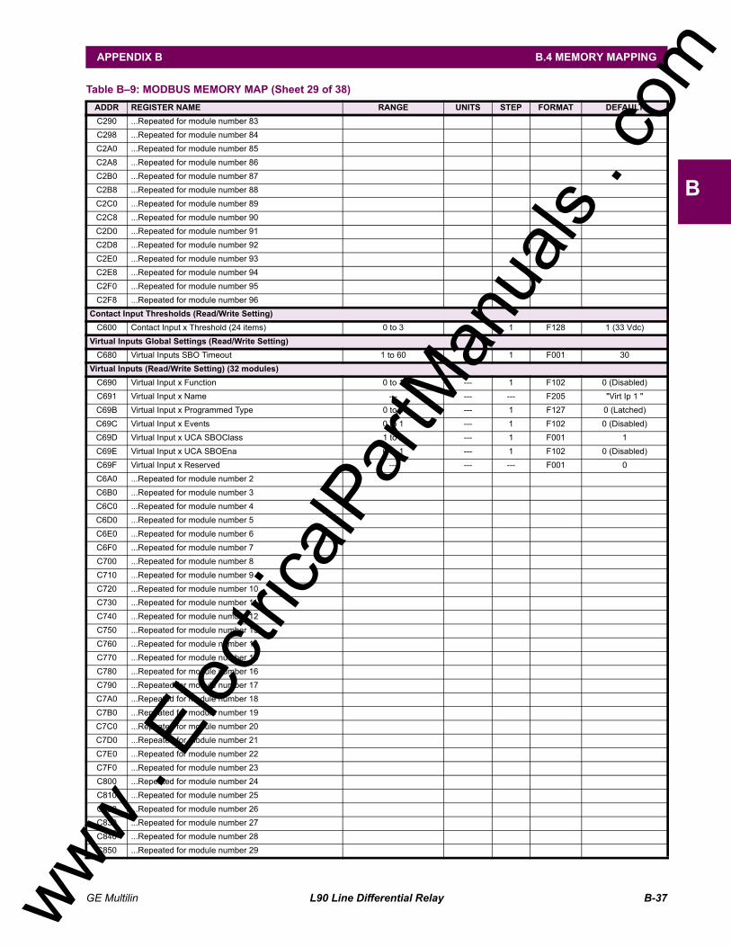
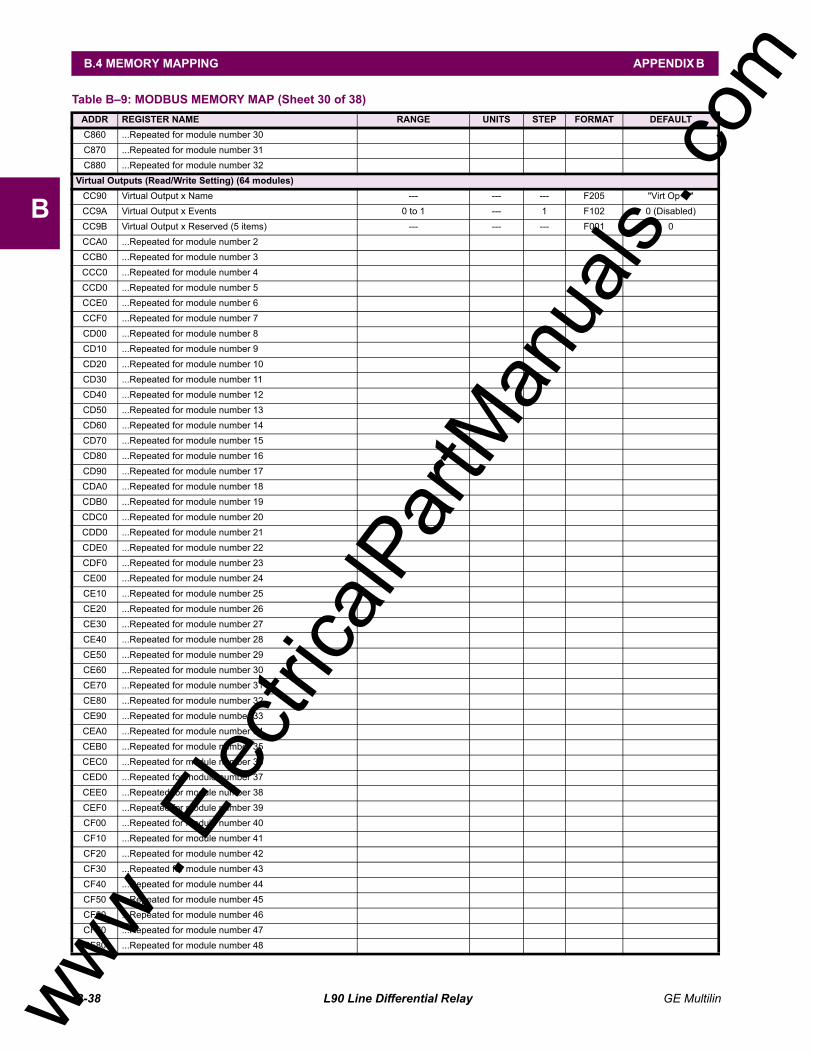
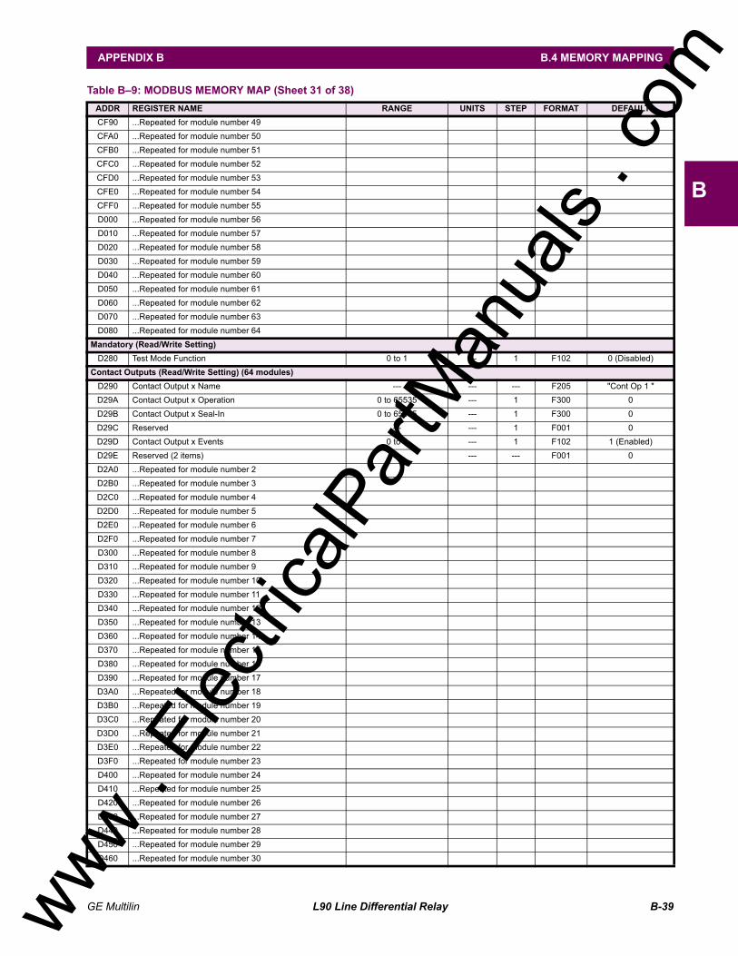
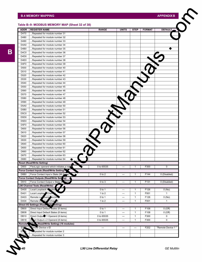
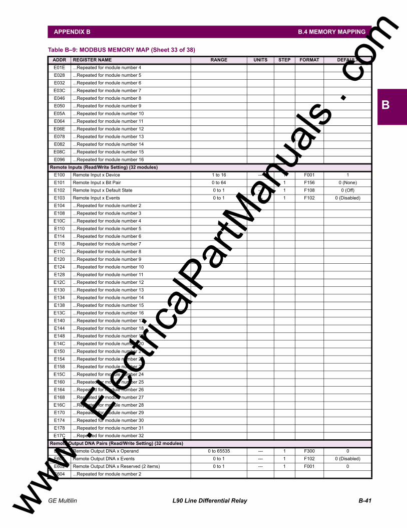
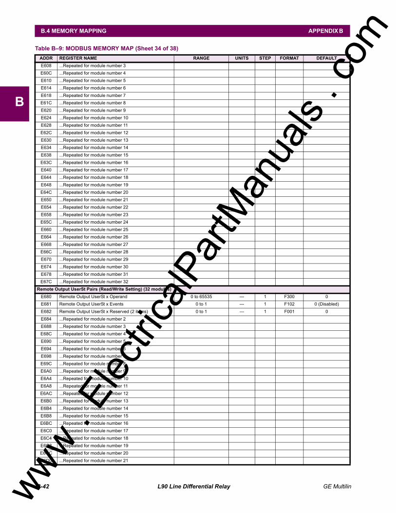
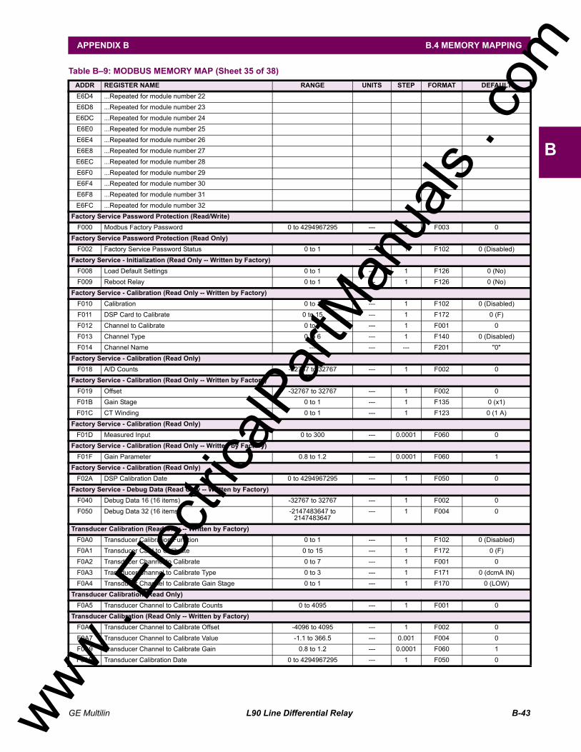
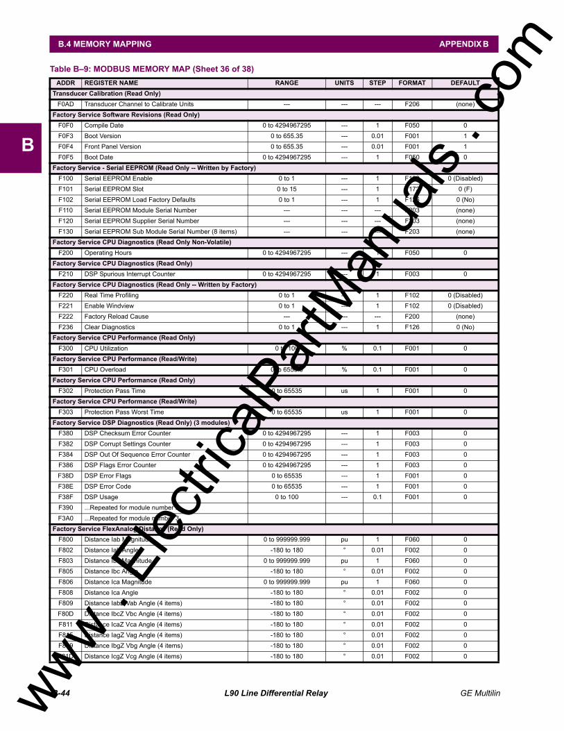
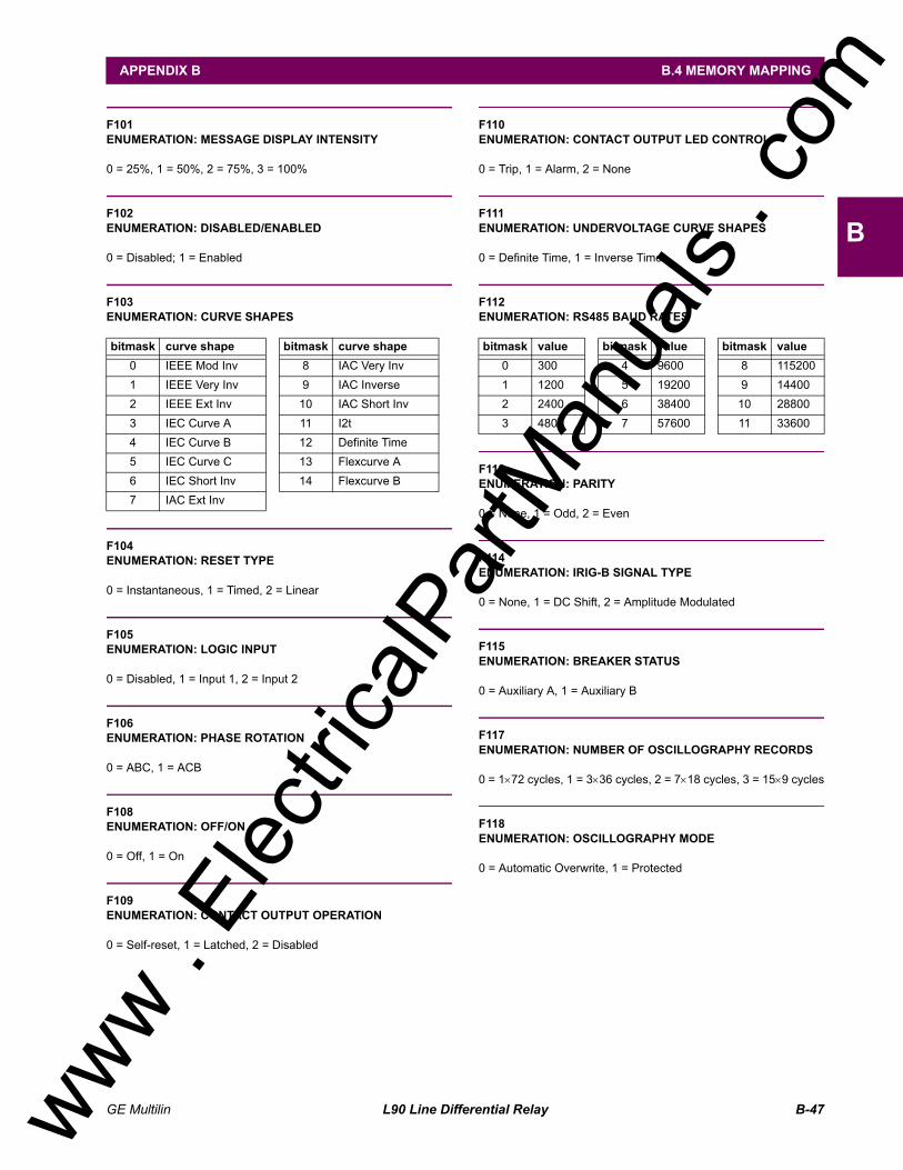
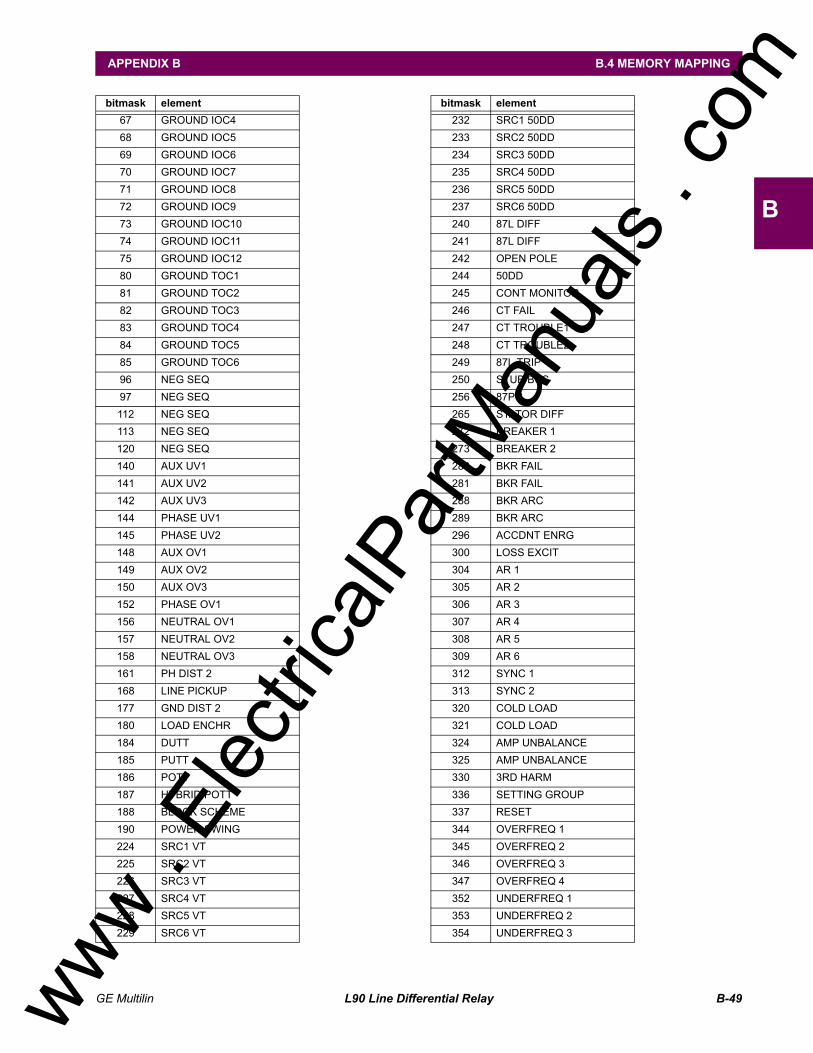
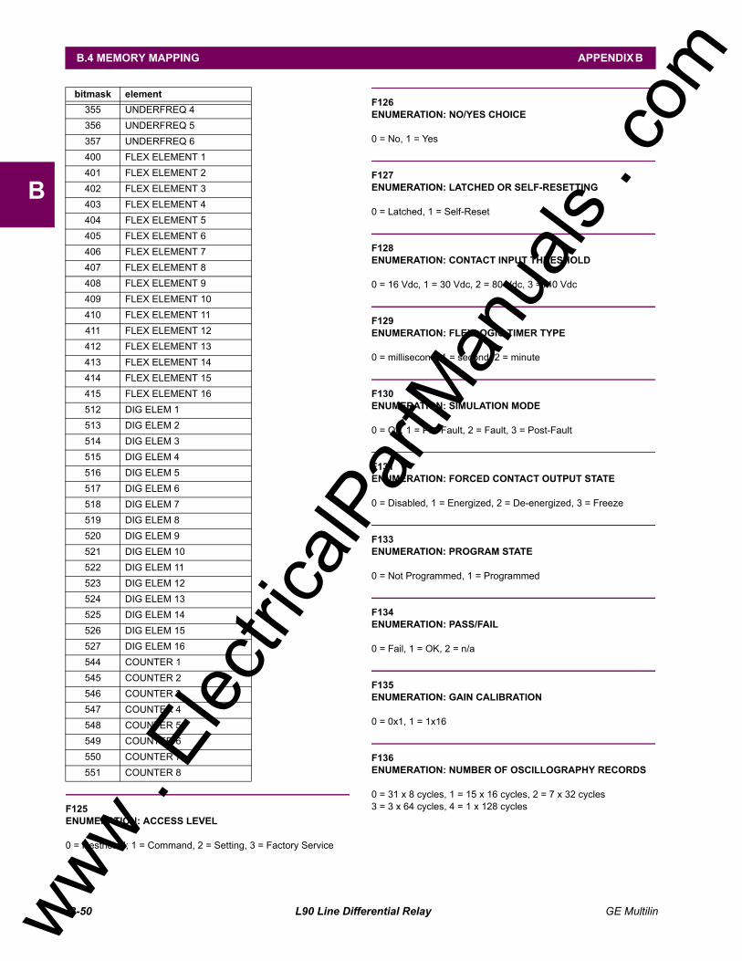
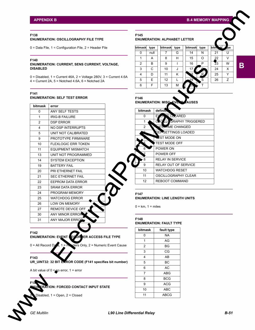
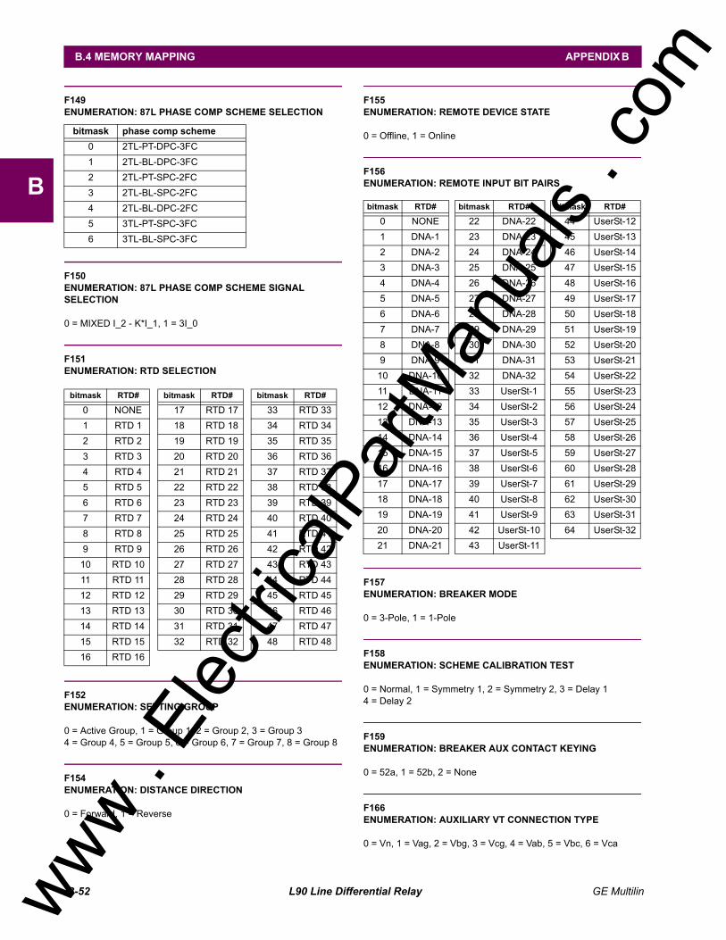
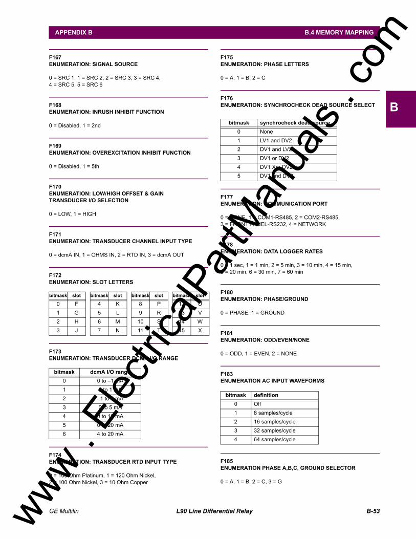
B.4.2 MODBUS® MEMORY MAP DATA FORMATS ................................................B-46
C. UCA/MMS C.1 UCA/MMS OVERVIEWC.1.1 UCA....................................................................................................................C-1C.1.2 MMS...................................................................................................................C-1C.1.3 UCA REPORTING .............................................................................................C-6
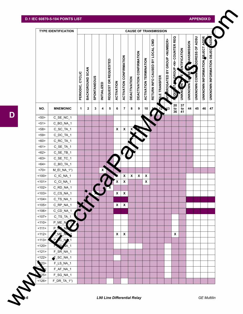
D. IEC 60870-5-104 D.1 IEC 60870-5-104 POINTS LISTD.1.1 INTEROPERABILTY DOCUMENT ....................................................................D-1D.1.2 POINTS LIST ...................................................................................................D-10
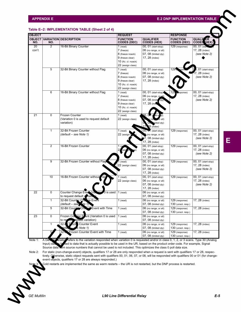
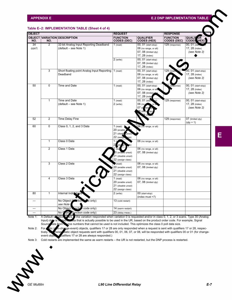
E.3 DNP POINT LISTSE.3.1 BINARY INPUT POINTS....................................................................................E-8E.3.2 BINARY OUTPUT AND CONTROL RELAY OUTPUT ....................................E-13E.3.3 COUNTERS .....................................................................................................E-14E.3.4 ANALOG INPUTS ............................................................................................E-15
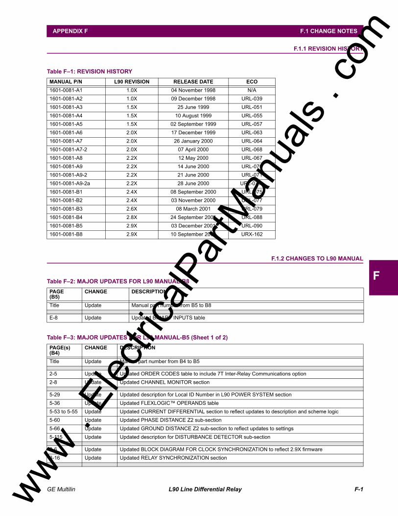
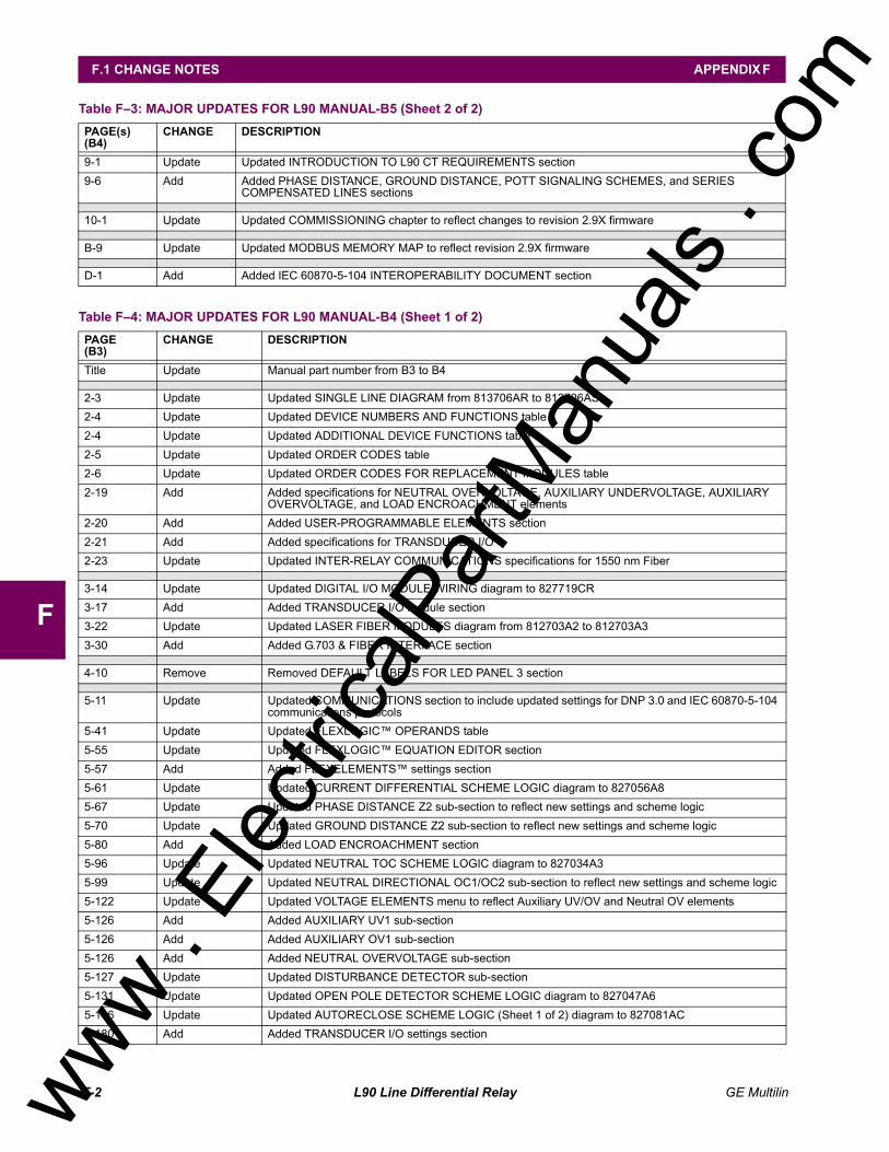
F. MISCELLANEOUS F.1 CHANGE NOTESF.1.1 REVISION HISTORY ......................................................................................... F-1F.1.2 CHANGES TO L90 MANUAL ............................................................................ F-1
F.2 STANDARD ABBREVIATIONSF.2.1 ABBREVIATIONS .............................................................................................. F-4
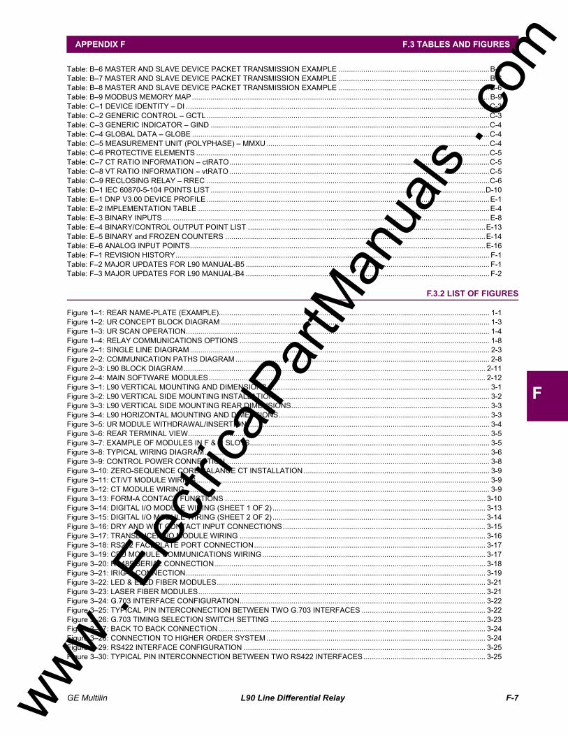
F.3 TABLES AND FIGURESF.3.1 LIST OF TABLES............................................................................................... F-6F.3.2 LIST OF FIGURES............................................................................................. F-7
F.4 WARRANTYF.4.1 GE POWER MANAGEMENT WARRANTY ..................................................... F-10
www . El
ectric
alPar
tMan
uals
. com
viii L90 Line Differential Relay GE Multilin
TABLE OF CONTENTS www .
Elec
tricalP
artM
anua
ls . c
om
GE Multilin L90 Line Differential Relay 1-1
1 GETTING STARTED 1.1 IMPORTANT PROCEDURES
11 GETTING STARTED 1.1 IMPORTANT PROCEDURES
Please read this chapter to help guide you through the initial setup of your new relay.
1.1.1 CAUTIONS AND WARNINGS
Before attempting to install or use the relay, it is imperative that all WARNINGS and CAU-TIONS in this manual are reviewed to help prevent personal injury, equipment damage, and/or downtime.
1.1.2 INSPECTION CHECKLIST
Open the relay packaging and inspect the unit for physical damage.
Check that the battery tab is intact on the power supply module (for more details, see the section BATTERY TAB in thischapter).
View the rear name-plate and verify that the correct model has been ordered.
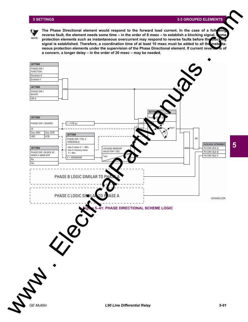
Figure 11: REAR NAME-PLATE (EXAMPLE)
Ensure that the following items are included:
Instruction Manual Products CD (includes URPC software and manuals in PDF format) mounting screws registration card (attached as the last page of the manual)
Fill out the registration form and mail it back to GE Multilin (include the serial number located on the rear nameplate).
For product information, instruction manual updates, and the latest software updates, please visit the GE Multilin HomePage at http://www.GEindustrial.com/multilin.
If there is any noticeable physical damage, or any of the contents listed are missing, please contact GEMultilin immediately.
GE MULTILIN CONTACT INFORMATION AND CALL CENTER FOR PRODUCT SUPPORT:
GE Multilin215 Anderson AvenueMarkham, OntarioCanada L6E 1B3
TELEPHONE: (905) 294-6222, 1-800-547-8629 (North America only)FAX: (905) 201-2098E-MAIL: [email protected] PAGE: http://www.GEindustrial.com/multilin
WARNING CAUTION
NOTE
www . El
ectric
alPar
tMan
uals
. com
1-2 L90 Line Differential Relay GE Multilin
1.2 UR OVERVIEW 1 GETTING STARTED
11.2 UR OVERVIEW 1.2.1 INTRODUCTION TO THE UR RELAY
Historically, substation protection, control, and metering functions were performed with electromechanical equipment. Thisfirst generation of equipment was gradually replaced by analog electronic equipment, most of which emulated the single-function approach of their electromechanical precursors. Both of these technologies required expensive cabling and auxil-iary equipment to produce functioning systems.
Recently, digital electronic equipment has begun to provide protection, control, and metering functions. Initially, this equip-ment was either single function or had very limited multi-function capability, and did not significantly reduce the cabling andauxiliary equipment required. However, recent digital relays have become quite multi-functional, reducing cabling and aux-iliaries significantly. These devices also transfer data to central control facilities and Human Machine Interfaces using elec-tronic communications. The functions performed by these products have become so broad that many users now prefer theterm IED (Intelligent Electronic Device).
It is obvious to station designers that the amount of cabling and auxiliary equipment installed in stations can be even furtherreduced, to 20% to 70% of the levels common in 1990, to achieve large cost reductions. This requires placing even morefunctions within the IEDs.
Users of power equipment are also interested in reducing cost by improving power quality and personnel productivity, andas always, in increasing system reliability and efficiency. These objectives are realized through software which is used toperform functions at both the station and supervisory levels. The use of these systems is growing rapidly.
High speed communications are required to meet the data transfer rates required by modern automatic control and moni-toring systems. In the near future, very high speed communications will be required to perform protection signaling with aperformance target response time for a command signal between two IEDs, from transmission to reception, of less than 5milliseconds. This has been established by the Electric Power Research Institute, a collective body of many American andCanadian power utilities, in their Utilities Communications Architecture 2 (MMS/UCA2) project. In late 1998, some Euro-pean utilities began to show an interest in this ongoing initiative.
IEDs with the capabilities outlined above will also provide significantly more power system data than is presently available,enhance operations and maintenance, and permit the use of adaptive system configuration for protection and control sys-tems. This new generation of equipment must also be easily incorporated into automation systems, at both the station andenterprise levels. The GE Multilin Universal Relay (UR) has been developed to meet these goals.
www . El
ectric
alPar
tMan
uals
. com
GE Multilin L90 Line Differential Relay 1-3
1 GETTING STARTED 1.2 UR OVERVIEW
11.2.2 UR HARDWARE ARCHITECTURE
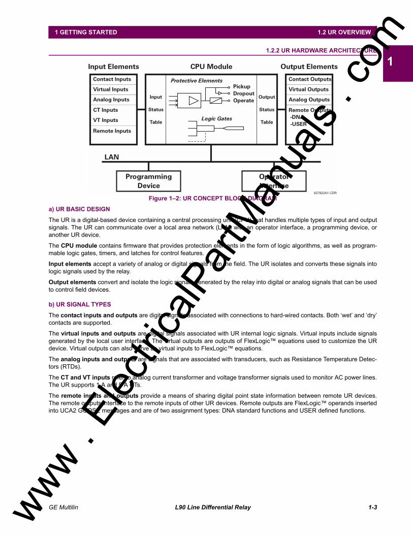
Figure 12: UR CONCEPT BLOCK DIAGRAM
a) UR BASIC DESIGN
The UR is a digital-based device containing a central processing unit (CPU) that handles multiple types of input and outputsignals. The UR can communicate over a local area network (LAN) with an operator interface, a programming device, oranother UR device.
The CPU module contains firmware that provides protection elements in the form of logic algorithms, as well as program-mable logic gates, timers, and latches for control features.
Input elements accept a variety of analog or digital signals from the field. The UR isolates and converts these signals intologic signals used by the relay.
Output elements convert and isolate the logic signals generated by the relay into digital or analog signals that can be usedto control field devices.
b) UR SIGNAL TYPES
The contact inputs and outputs are digital signals associated with connections to hard-wired contacts. Both wet and drycontacts are supported.
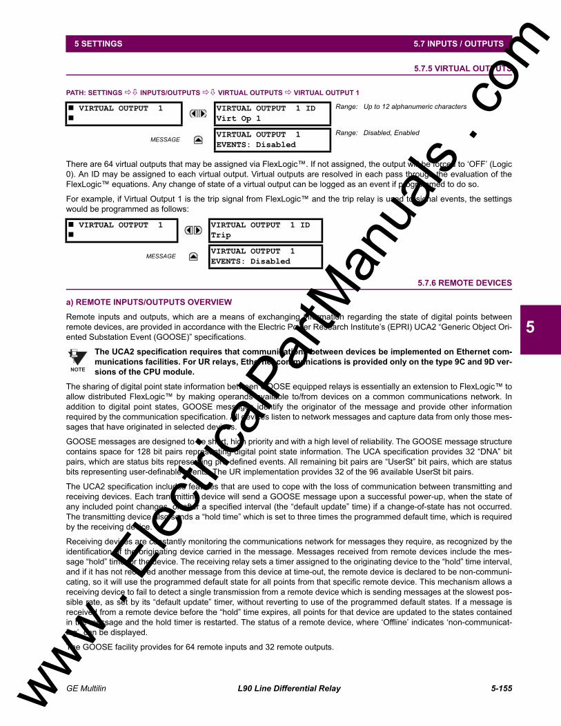
The virtual inputs and outputs are digital signals associated with UR internal logic signals. Virtual inputs include signalsgenerated by the local user interface. The virtual outputs are outputs of FlexLogic equations used to customize the URdevice. Virtual outputs can also serve as virtual inputs to FlexLogic equations.
The analog inputs and outputs are signals that are associated with transducers, such as Resistance Temperature Detec-tors (RTDs).
The CT and VT inputs refer to analog current transformer and voltage transformer signals used to monitor AC power lines.The UR supports 1 A and 5 A CTs.
The remote inputs and outputs provide a means of sharing digital point state information between remote UR devices.The remote outputs interface to the remote inputs of other UR devices. Remote outputs are FlexLogic operands insertedinto UCA2 GOOSE messages and are of two assignment types: DNA standard functions and USER defined functions.
827822A1.CDR
Input Elements
LAN
ProgrammingDevice
OperatorInterface
Contact Inputs Contact Outputs
Virtual Inputs Virtual Outputs
Analog Inputs Analog Outputs
CT Inputs
VT Inputs
Input
Status
Table
Output
Status
Table
PickupDropoutOperate
Protective Elements
Logic Gates
Remote Inputs
Remote Outputs-DNA-USER
CPU Module Output Elements
www . El
ectric
alPar
tMan
uals
. com
1-4 L90 Line Differential Relay GE Multilin
1.2 UR OVERVIEW 1 GETTING STARTED
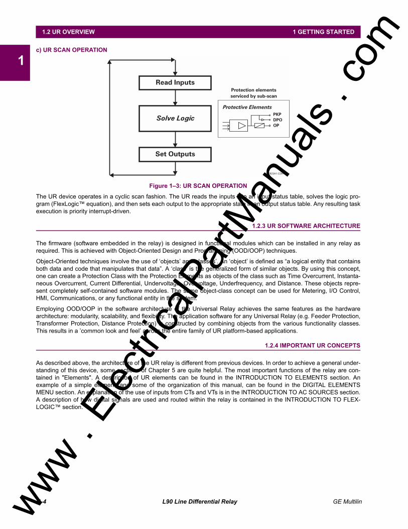
1c) UR SCAN OPERATION
Figure 13: UR SCAN OPERATION
The UR device operates in a cyclic scan fashion. The UR reads the inputs into an input status table, solves the logic pro-gram (FlexLogic equation), and then sets each output to the appropriate state in an output status table. Any resulting taskexecution is priority interrupt-driven.
1.2.3 UR SOFTWARE ARCHITECTURE
The firmware (software embedded in the relay) is designed in functional modules which can be installed in any relay asrequired. This is achieved with Object-Oriented Design and Programming (OOD/OOP) techniques.
Object-Oriented techniques involve the use of objects and classes. An object is defined as a logical entity that containsboth data and code that manipulates that data. A class is the generalized form of similar objects. By using this concept,one can create a Protection Class with the Protection Elements as objects of the class such as Time Overcurrent, Instanta-neous Overcurrent, Current Differential, Undervoltage, Overvoltage, Underfrequency, and Distance. These objects repre-sent completely self-contained software modules. The same object-class concept can be used for Metering, I/O Control,HMI, Communications, or any functional entity in the system.
Employing OOD/OOP in the software architecture of the Universal Relay achieves the same features as the hardwarearchitecture: modularity, scalability, and flexibility. The application software for any Universal Relay (e.g. Feeder Protection,Transformer Protection, Distance Protection) is constructed by combining objects from the various functionality classes.This results in a common look and feel across the entire family of UR platform-based applications.
1.2.4 IMPORTANT UR CONCEPTS
As described above, the architecture of the UR relay is different from previous devices. In order to achieve a general under-standing of this device, some sections of Chapter 5 are quite helpful. The most important functions of the relay are con-tained in "Elements". A description of UR elements can be found in the INTRODUCTION TO ELEMENTS section. Anexample of a simple element, and some of the organization of this manual, can be found in the DIGITAL ELEMENTSMENU section. An explanation of the use of inputs from CTs and VTs is in the INTRODUCTION TO AC SOURCES section.A description of how digital signals are used and routed within the relay is contained in the INTRODUCTION TO FLEX-LOGIC section.
827823A1.CDR
PKPDPOOP
Protective Elements
Protection elementsserviced by sub-scan
Read Inputs
Solve Logic
Set Outputs
www . El
ectric
alPar
tMan
uals
. com
GE Multilin L90 Line Differential Relay 1-5
1 GETTING STARTED 1.3 URPC SOFTWARE
11.3 URPC SOFTWARE 1.3.1 PC REQUIREMENTS
The Faceplate keypad and display or the URPC software interface can be used to communicate with the relay.
The URPC software interface is the preferred method to edit settings and view actual values because the PC monitor candisplay more information in a simple comprehensible format.
The following minimum requirements must be met for the URPC software to properly operate on a PC.
Processor: Intel® Pentium 300 or higher
RAM Memory: 64 MB minimum (128 MB recommended)
Hard Disk: 50 MB free space required before installation of URPC software
O/S: Windows® NT 4.x or Windows® 9x/2000
Device: CD-ROM drive
Port: COM1(2) / Ethernet
1.3.2 SOFTWARE INSTALLATION
Refer to the following procedure to install the URPC software:
1. Start the Windows® operating system.
2. Insert the URPC software CD into the CD-ROM drive.
3. If the installation program does not start automatically, choose Run from the Windows® Start menu and typeD:\SETUP.EXE. Press Enter to start the installation.
4. Follow the on-screen instructions to install the URPC software. When the Welcome window appears, click on Next tocontinue with the installation procedure.
5. When the Choose Destination Location window appears and if the software is not to be located in the default direc-tory, click Browse and type in the complete path name including the new directory name.
6. Click Next to continue with the installation procedure.
7. The default program group where the application will be added to is shown in the Select Program Folder window. If itis desired that the application be added to an already existing program group, choose the group name from the listshown.
8. Click Next to begin the installation process.
9. To launch the URPC application, click Finish in the Setup Complete window.
10. Subsequently, double click on the URPC software icon to activate the application.
Refer to the HUMAN INTERFACES chapter in this manual and the URPC Software Help program for moreinformation about the URPC software interface.
NOTE
www . El
ectric
alPar
tMan
uals
. com
1-6 L90 Line Differential Relay GE Multilin
1.3 URPC SOFTWARE 1 GETTING STARTED
11.3.3 CONNECTING URPC® WITH THE L90
This section is intended as a quick start guide to using the URPC software. Please refer to the URPC Help File and theHUMAN INTERFACES chapter for more information.
a) CONFIGURING AN ETHERNET CONNECTION
Before starting, verify that the Ethernet network cable is properly connected to the Ethernet port on the back of the relay.
1. Start the URPC software. Enter the password "URPC" at the login password box.
2. Select the Help > Connection Wizard menu item to open the Connection Wizard. Click "Next" to continue.
3. Click the "New Interface" button to open the Edit New Interface window.
Enter the desired interface name in the Enter Interface Name field.
Select the "Ethernet" interface from the drop down list and press "Next" to continue.
4. Click the "New Device" button to open the Edit New Device Window.
Enter the desired name in the Enter Interface Name field.
Enter the Modbus address of the relay (from SETTINGS ! PRODUCT SETUP !" COMMUNICATIONS !" MODBUSPROTOCOL ! MODBUS SLAVE ADDRESS) in the Enter Modbus Address field.
Enter the IP address (from SETTINGS ! PRODUCT SETUP !" COMMUNICATIONS !" NETWORK ! IP ADDRESS) inthe Enter TCPIP Address field.
5. Click the "4.1 Read Device Information" button then "OK" when the relay information has been received. Click "Next" tocontinue.
6. Click the "New Site" button to open the Edit Site Name window.
Enter the desired site name in the Enter Site Name field.
7. Click the "OK" button then click "Finish". The new Site List tree will be added to the Site List window (or Online window)located in the top left corner of the main URPC window.
The Site Device has now been configured for Ethernet communications. Proceed to Section c) CONNECTING TO THERELAY below to begin communications.
b) CONFIGURING AN RS232 CONNECTION
Before starting, verify that the RS232 serial cable is properly connected to the RS232 port on the front panel of the relay.
1. Start the URPC software. Enter the password "URPC" at the login password box.
2. Select the Help > Connection Wizard menu item to open the Connection Wizard. Click "Next" to continue.
3. Click the "New Interface" button to open the Edit New Interface window.
Enter the desired interface name in the Enter Interface Name field.
Select the "RS232" interface from the drop down list and press "Next" to continue.
4. Click the "New Device" button to open the Edit New Device Window.
Enter the desired name in the Enter Interface Name field.
Enter the PC COM port number in the COM Port field.
5. Click "OK" then click "Next" to continue.
6. Click the "New Site" button to open the Edit Site Name window.
Enter the desired site name in the Enter Site Name field.
7. Click the "OK" button then click "Finish". The new Site List tree will be added to the Site List window (or Online window)located in the top left corner of the main URPC window.
The Site Device has now been configured for RS232 communications. Proceed to Section c) CONNECTING TO THERELAY below to begin communications.
www . El
ectric
alPar
tMan
uals
. com
GE Multilin L90 Line Differential Relay 1-7
1 GETTING STARTED 1.3 URPC SOFTWARE
1c) CONNECTING TO THE RELAY
1. Select the Display Properties window through the Site List tree as shown below:
2. The Display Properties window will open with a flashing status indicator.
If the indicator is red, click the Connect button (lightning bolt) in the menu bar of the Displayed Properties window.
3. In a few moments, the flashing light should turn green, indicating that URPC is communicating with the relay.
Refer to the HUMAN INTERFACES chapter in this manual and the URPC Software Help program for moreinformation about the URPC software interface.
NOTE
www . El
ectric
alPar
tMan
uals
. com
1-8 L90 Line Differential Relay GE Multilin
1.4 UR HARDWARE 1 GETTING STARTED
11.4 UR HARDWARE 1.4.1 MOUNTING AND WIRING
Please refer to the HARDWARE chapter for detailed relay mounting and wiring instructions. Review all WARNINGS andCAUTIONS.
1.4.2 COMMUNICATIONS
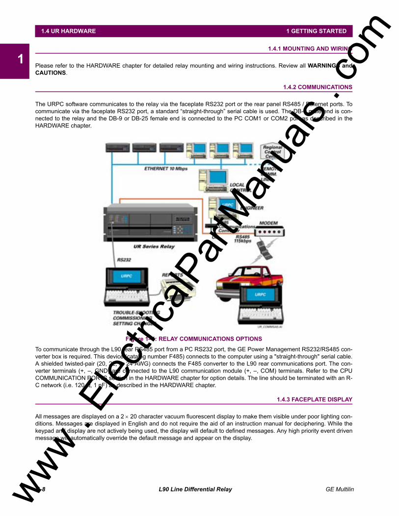
The URPC software communicates to the relay via the faceplate RS232 port or the rear panel RS485 / Ethernet ports. Tocommunicate via the faceplate RS232 port, a standard straight-through serial cable is used. The DB-9 male end is con-nected to the relay and the DB-9 or DB-25 female end is connected to the PC COM1 or COM2 port as described in theHARDWARE chapter.
Figure 14: RELAY COMMUNICATIONS OPTIONS
To communicate through the L90 rear RS485 port from a PC RS232 port, the GE Power Management RS232/RS485 con-verter box is required. This device (catalog number F485) connects to the computer using a "straight-through" serial cable.A shielded twisted-pair (20, 22, or 24 AWG) connects the F485 converter to the L90 rear communications port. The con-verter terminals (+, , GND) are connected to the L90 communication module (+, , COM) terminals. Refer to the CPUCOMMUNICATION PORTS section in the HARDWARE chapter for option details. The line should be terminated with an R-C network (i.e. 120 Ω, 1 nF) as described in the HARDWARE chapter.
1.4.3 FACEPLATE DISPLAY
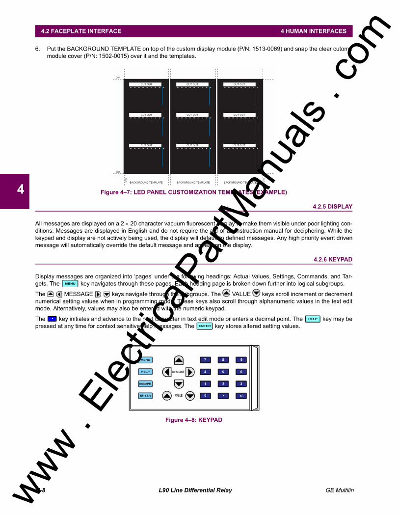
All messages are displayed on a 2 × 20 character vacuum fluorescent display to make them visible under poor lighting con-ditions. Messages are displayed in English and do not require the aid of an instruction manual for deciphering. While thekeypad and display are not actively being used, the display will default to defined messages. Any high priority event drivenmessage will automatically override the default message and appear on the display.
www . El
ectric
alPar
tMan
uals
. com
GE Multilin L90 Line Differential Relay 1-9
1 GETTING STARTED 1.5 USING THE RELAY
11.5 USING THE RELAY 1.5.1 FACEPLATE KEYPAD
Display messages are organized into pages under the following headings: Actual Values, Settings, Commands, and Tar-gets. The key navigates through these pages. Each heading page is broken down further into logical subgroups.
The MESSAGE keys navigate through the subgroups. The VALUE keys scroll increment or decrementnumerical setting values when in programming mode. These keys also scroll through alphanumeric values in the text editmode. Alternatively, values may also be entered with the numeric keypad.
The key initiates and advance to the next character in text edit mode or enters a decimal point. The key may bepressed at any time for context sensitive help messages. The key stores altered setting values.
1.5.2 MENU NAVIGATION
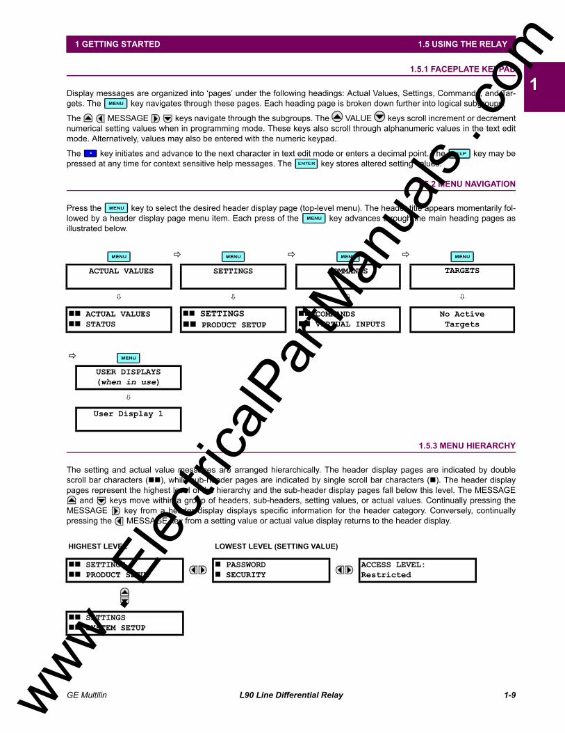
Press the key to select the desired header display page (top-level menu). The header title appears momentarily fol-lowed by a header display page menu item. Each press of the key advances through the main heading pages asillustrated below.
1.5.3 MENU HIERARCHY
The setting and actual value messages are arranged hierarchically. The header display pages are indicated by doublescroll bar characters (##), while sub-header pages are indicated by single scroll bar characters (#). The header displaypages represent the highest level of the hierarchy and the sub-header display pages fall below this level. The MESSAGE
and keys move within a group of headers, sub-headers, setting values, or actual values. Continually pressing theMESSAGE key from a header display displays specific information for the header category. Conversely, continuallypressing the MESSAGE key from a setting value or actual value display returns to the header display.
! ! !
ACTUAL VALUES SETTINGS COMMANDS TARGETS
" " " "
## ACTUAL VALUES## STATUS
## SETTINGS## PRODUCT SETUP
## COMMANDS## VIRTUAL INPUTS
No ActiveTargets
!
USER DISPLAYS(when in use)
"
User Display 1
HIGHEST LEVEL LOWEST LEVEL (SETTING VALUE)
## SETTINGS## PRODUCT SETUP
# PASSWORD# SECURITY
ACCESS LEVEL:Restricted
## SETTINGS## SYSTEM SETUP
www . El
ectric
alPar
tMan
uals
. com
1-10 L90 Line Differential Relay GE Multilin
1.5 USING THE RELAY 1 GETTING STARTED
11.5.4 RELAY ACTIVATION
The relay is defaulted to the "Not Programmed" state when it leaves the factory. This safeguards against the installation ofa relay whose settings have not been entered. When powered up successfully, the TROUBLE indicator will be on and theIN SERVICE indicator off. The relay in the "Not Programmed" state will block signaling of any output relay. These condi-tions will remain until the relay is explicitly put in the "Programmed" state.
Select the menu message SETTINGS ! PRODUCT SETUP !" INSTALLATION ! RELAY SETTINGS
To put the relay in the "Programmed" state, press either of the VALUE keys once and then press . The face-plate TROUBLE indicator will turn off and the IN SERVICE indicator will turn on. The settings for the relay can be pro-grammed manually (refer to the SETTINGS chapter) via the faceplate keypad or remotely (refer to the URPC Help file) viathe URPC software interface.
1.5.5 BATTERY TAB
The battery tab is installed in the power supply module before the L90 shipped from the factory. The battery tab prolongsbattery life in the event the relay is powered down for long periods of time before installation. The battery is responsible forbacking up event records, oscillography, data logger, and real-time clock information when the relay is powered off. Thebattery failure self-test error generated by the relay is a minor and should not affect the relay functionality. When the relay isinstalled and ready for commissioning, the tab should be removed. The battery tab should be re-inserted if the relay is pow-ered off for an extended period of time. If required, contact the factory for a replacement battery or battery tab.
1.5.6 RELAY PASSWORDS
It is recommended that passwords be set up for each security level and assigned to specific personnel. There are two userpassword SECURITY access levels:
1. COMMAND
The COMMAND access level restricts the user from making any settings changes, but allows the user to perform the fol-lowing operations: operate breakers via faceplate keypad change state of virtual inputs clear event records clear oscillography records
2. SETTING
The SETTING access level allows the user to make any changes to any of the setting values.
Refer to the CHANGING SETTINGS section (in the HUMAN INTERFACES chapter) for complete instructionson setting up security level passwords.
1.5.7 FLEXLOGIC CUSTOMIZATION
FlexLogic equation editing is required for setting up user-defined logic for customizing the relay operations. See sectionFLEXLOGIC in the SETTINGS chapter.
1.5.8 COMMISSIONING
Templated tables for charting all the required settings before entering them via the keypad are available in the COMMIS-SIONING chapter, which also includes instructions for commissioning tests.
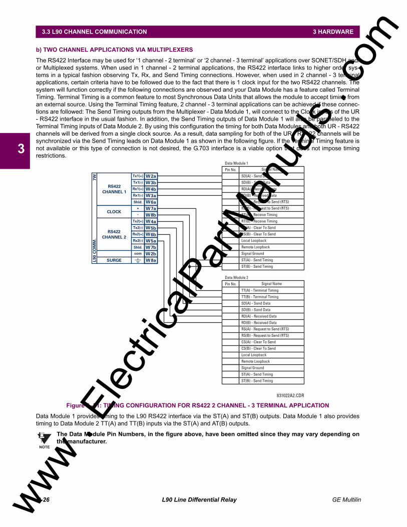
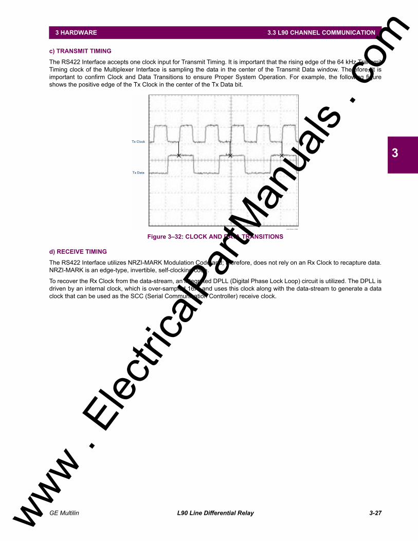
The L90 relay is a digital current differential relay system with an integral communications channel interface.
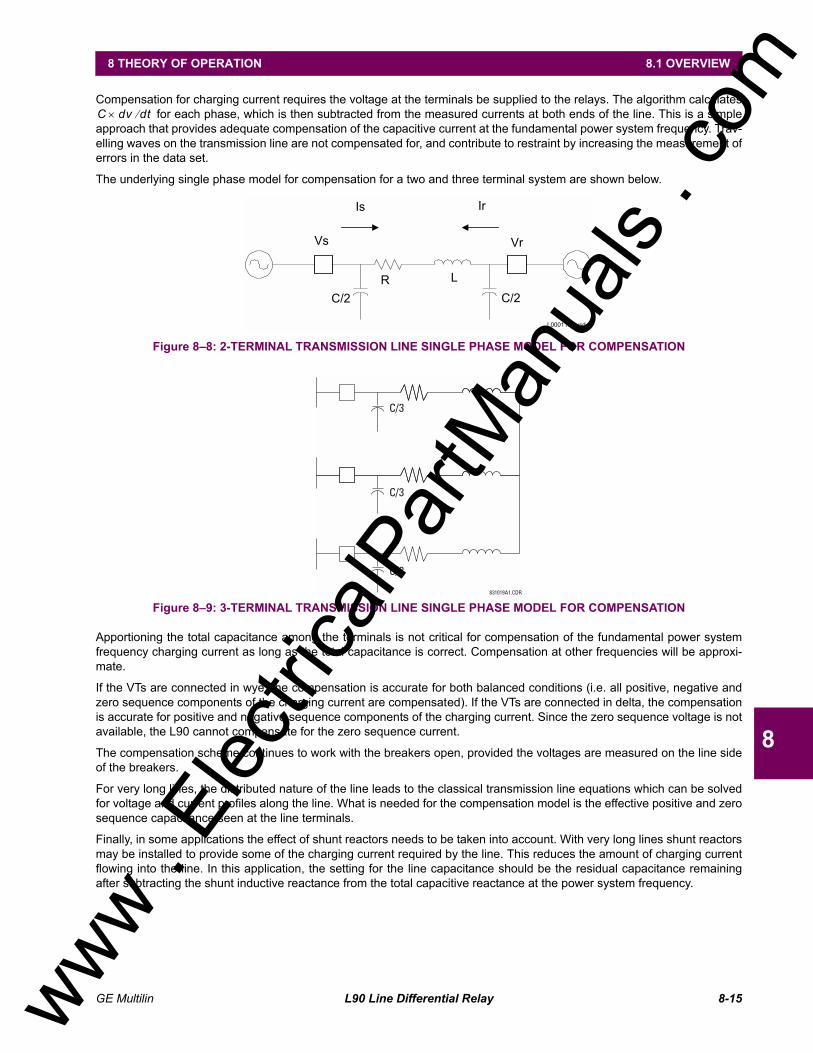
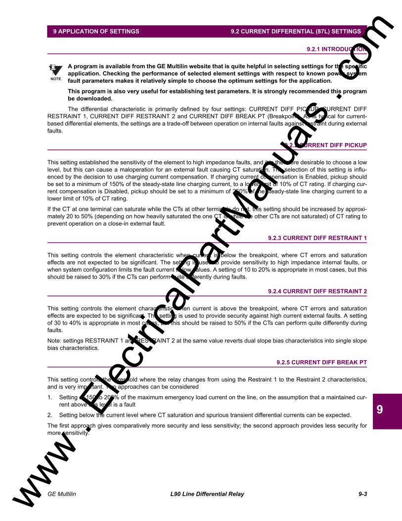
The L90 is intended to provide complete protection for transmission lines of any voltage level. Both three phase and singlephase tripping schemes are available. Models of the L90 are available for application on both two and three terminal lines.The L90 uses per phase differential at 64 kbps transmitting 2 phaselets per cycle. The current differential scheme is basedon innovative patented techniques developed by GE. The L90 algorithms are based on the Fourier transformphaseletapproach and an adaptive statistical restraint. The restraint is similar to a traditional percentage differential scheme, but isadaptive based on relay measurements. When used with a 64 kbps channel, the innovative phaselets approach yields anoperating time of 1.0 to 1.5 cycles typical. The adaptive statistical restraint approach provides both more sensitive andmore accurate fault sensing. This allows the L90 to detect relatively higher impedance single line to ground faults that exist-ing systems may not. The basic current differential element operates on current input only. Long lines with significantcapacitance can benefit from charging current compensation if terminal voltage measurements are applied to the relay. Thevoltage input is also used for some protection and monitoring features such as directional elements, fault locator, metering,and distance backup.
The L90 is designed to operate over different communications links with various degrees of noise encountered in powersystems and communications environments. Since correct operation of the relay is completely dependent on data receivedfrom the remote end, special attention must be paid to information validation. The L90 incorporates a high degree of secu-rity by using a 32-bit CRC (cyclic redundancy code) inter-relay communications packet.
In addition to current differential protection, the relay provides multiple backup protection for phase and ground faults. Forovercurrent protection, the time overcurrent curves may be selected from a selection of standard curve shapes or a customFlexCurve for optimum co-ordination. Additionally, one zone of phase and ground distance protection with power swingblocking, out-of-step tripping, line pickup, load encroachment, and POTT features is included.
The L90 incorporates charging current compensation for applications on very long transmission lines without loss of sensi-tivity. The line capacitive current is removed from the terminal phasors.
The relay uses a sampling rate of 64 samples per cycle to provide metering values and flexible oscillography.
Voltage and current metering is included as a standard feature. Additionally, currents are available as total RMS values.Power, power factor and frequency measurements are also provided.
Diagnostic features include a sequence of records of 1024 time-tagged events. The internal clock used for time-tagging canbe synchronized with an IRIG-B signal. This precise time stamping allows the sequence of events to be determinedthroughout the system. Events can also be programmed (via FlexLogic equations) to trigger oscillography data capturewhich may be set to record the measured parameters before and after the event for viewing on a portable computer (PC).These tools will significantly reduce troubleshooting time and simplify report generation in the event of system faults.
A faceplate RS232 port may be used to connect a PC for programming settings and for monitoring actual values. A varietyof communications modules are available. Two rear RS485 ports are standard to allow independent access by operatingand engineering staff. All serial ports use the Modbus® RTU protocol. The RS485 ports may be connected to system com-puters with baud rates up to 115.2 kbps. The RS232 port has a fixed baud rate of 19.2 kbps. Optional communicationsmodules include a 10BaseF Ethernet interface which can be used to provide fast, reliable communications in noisy environ-ments. Another option provides two 10BaseF fiber optic ports for redundancy. The Ethernet port supports MMS/UCA2 pro-tocol.
The relay uses flash memory technology which allows field upgrading as new features are added.
The testing features can be used to verify and test settings and operations.
www . El
ectric
alPar
tMan
uals
. com
2-2 L90 Line Differential Relay GE Multilin
2.1 INTRODUCTION 2 PRODUCT DESCRIPTION
2
2.1.2 FEATURES
LINE CURRENT DIFFERENTIAL:
Phase segregated, high-speed digital current differential system
Overhead and underground AC transmission lines, series compensated lines
Two and three terminal line applications
Zero-sequence removal for application on lines with tapped transformers connected in a grounded Wye on the lineside
GE phaselets approach based on Discrete Fourier Transform with 64 samples per cycle and transmitting 2 time-stamped phaselets per cycle
Adaptive restraint approach improving sensitivity and accuracy of fault sensing
Increased security for trip decision using Disturbance Detector and Trip Output logic
Continuous clock synchronization via the distributed synchronization technique
Increased transient stability through DC decaying offset removal
Accommodates up to 5 times CT ratio differences
Peer-to-Peer (Master-Master) architecture changing to Master-Slave via DTT (if channel fails) at 64 kbps
Charging current compensation
Interfaces direct fiber, multiplexed RS422 and G.703 connections with relay ID check
Per phase line differential protection Direct Transfer Trip plus 8 user-assigned pilot signals via the communicationschannel
Secure 32-bit CRC protection against communications errors
BACKUP PROTECTION:
DTT provision for pilot schemes
1 zone distance protection with POTT scheme, power swing blocking/out-of-step tripping, line pickup, and loadencroachment
2-element TOC and 2-element IOC directional phase overcurrent protection
2-element TOC and 2-element IOC directional zero sequence overcurrent protection
2-element TOC and 2-element IOC negative sequence overcurrent protection
Undervoltage and overvoltage protection
ADDITIONAL PROTECTION:
Breaker failure protection
Stub bus protection
VT and CT supervision
GE "Sources" approach allowing grouping of different CTs and VTs from multiple input channels
Open pole detection
Breaker trip coil supervision and "seal-in" of trip command
FlexLogic allowing creation of user-defined distributed protection and control logic
CONTROL:
1 and 2 breakers configuration for 1½ and ring bus schemes, pushbutton control from the relay
Auto-reclosing and synchrochecking
Breaker arcing current
www . El
ectric
alPar
tMan
uals
. com
GE Multilin L90 Line Differential Relay 2-3
2 PRODUCT DESCRIPTION 2.1 INTRODUCTION
2
MONITORING:
Oscillography of current, voltage, FlexLogic operands, and digital signals (1 × 128 cycles to 31 × 8 cycles config-urable)
Events recorder - 1024 events
Fault locator
METERING:
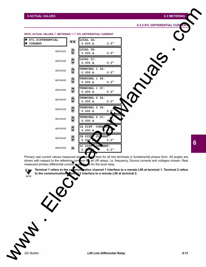
Actual 87L remote phasors, differential current and channel delay at all line terminals of line current differential protec-tion
Line current, voltage, real power, reactive power, apparent power, power factor, and frequency
COMMUNICATIONS:
RS232 front port - 19.2 kbps
1 or 2 RS485 rear ports - up to 115 kbps
10BaseF Ethernet port supporting MMS/UCA2.0 protocol
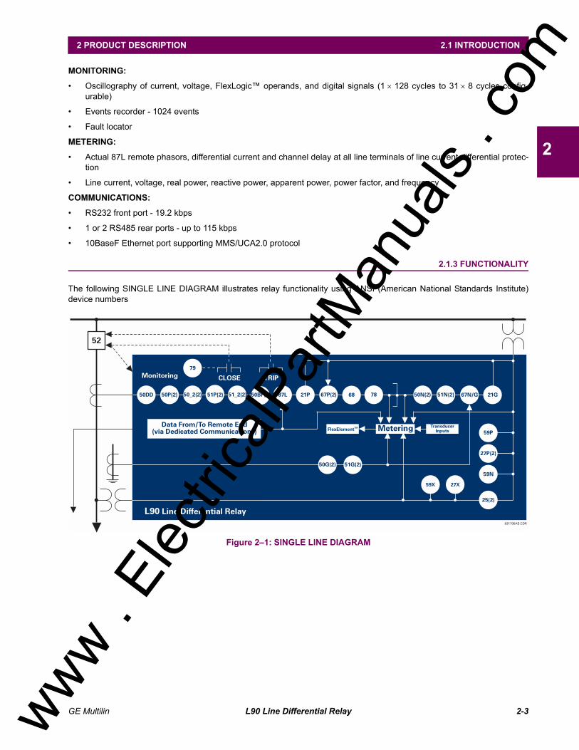
2.1.3 FUNCTIONALITY
The following SINGLE LINE DIAGRAM illustrates relay functionality using ANSI (American National Standards Institute)device numbers
Figure 21: SINGLE LINE DIAGRAM
831706AS.CDR
L90 Line Differential Relay
52
Monitoring CLOSE TRIP
Data From/To Remote End(via Dedicated Communications) MeteringFlexElementTM Transducer
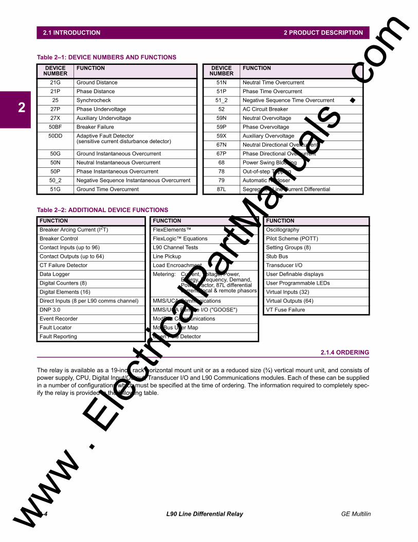
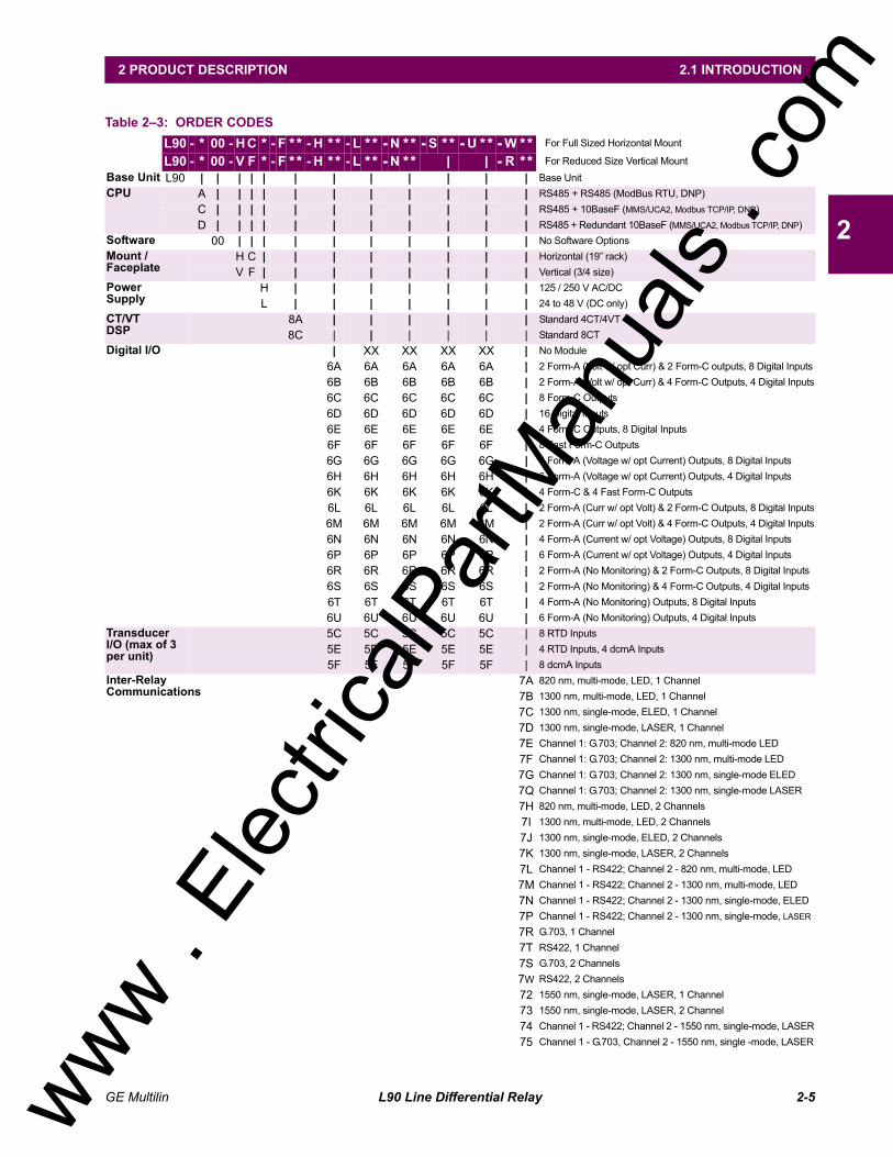
The relay is available as a 19-inch rack horizontal mount unit or as a reduced size (¾) vertical mount unit, and consists ofpower supply, CPU, Digital Input/Output, Transducer I/O and L90 Communications modules. Each of these can be suppliedin a number of configurations which must be specified at the time of ordering. The information required to completely spec-ify the relay is provided in the following table.
Table 21: DEVICE NUMBERS AND FUNCTIONS DEVICE
NUMBERFUNCTION DEVICE
NUMBERFUNCTION
21G Ground Distance 51N Neutral Time Overcurrent21P Phase Distance 51P Phase Time Overcurrent25 Synchrocheck 51_2 Negative Sequence Time Overcurrent
The order codes for replacement modules to be ordered separately are shown in the following table. When ordering areplacement CPU module or Faceplate, please provide the serial number of your existing unit.
Table 24: ORDER CODES FOR REPLACEMENT MODULES UR - ** -
POWER SUPPLY | 1H | 125 / 250 V AC/DC| 1L | 24 - 48 V (DC only)
2.2 PILOT CHANNEL 2.2.1 INTER-RELAY COMMUNICATIONS
Dedicated inter-relay communications may operate over 64 kbps digital channels or dedicated fiber optic channels. Avail-able interfaces include:
RS422 at 64 kbps
G.703 at 64 kbps
Dedicated fiber optics at 64 kbps. The fiber optic options include:
820 nm multi-mode fiber with an LED transmitter 1300 nm multi-mode fiber with an LED transmitter 1300 nm single-mode fiber with an ELED transmitter 1300 nm single-mode fiber with a LASER transmitter 1550 nm single-mode fiber with a LASER transmitter
All fiber optic options use an ST connector. L90 models are available for use on two or three terminal lines. A two terminalline application requires one bi-directional channel. However, in two terminal line applications, it is also possible to use anL90 relay with two bi-directional channels. The second bi-directional channel will provide a redundant backup channel withautomatic switchover if the first channel fails.
The L90 current differential relay is designed to function in a Peer to Peer or MasterMaster architecture. In the Peer toPeer architecture, all relays in the system are identical and perform identical functions in the current differential scheme. Inorder for every relay on the line to be a Peer, each relay must be able to communicate with all of the other relays. If there isa failure in communications among the relays, the relays will revert to a Master - Slave architecture, with the Master as therelay that has current phasors from all terminals. The use of two different operational modes is intended to increase thedependability of the current differential scheme by reducing reliance on the communications.
The main difference between a Master and a Slave L90 is that only a Master relay performs the actual current differentialcalculation, and only a Master relay communicates with the relays at all other terminals of the protected line.
At least one Master L90 relay must have live communications to all other terminals in the current differential scheme; theother L90 relays on that line may operate as Slave relays. All Master relays in the scheme will be equal, and each will per-form all functions. Each L90 relay in the scheme will determine if it is a Master by comparing the number of terminals on theline to the number of active communication channels.
The Slave terminals only communicate with the Master; there is no Slave to Slave communications path. As a result, aSlave L90 relay cannot calculate the differential current. When a Master L90 relay issues a local trip signal, it also sends aDirect Transfer Trip signal to all of the other L90 relays on the protected line.
If a Slave L90 relay issues a trip from one of its backup functions, it can send a transfer trip signal to its Master and otherSlave relays if such option is designated. Because a Slave cannot communicate with all the relays in the differentialscheme, the Master will then broadcast the Direct Transfer Trip signal to all other terminals.
The Slave L90 Relay performs the following functions: Samples currents and voltages Removes DC offset from the current via the mimic algorithm Creates phaselets Calculates sum of squares data Transmits current data to all Master L90 relays Performs all local relaying functions Receives Current Differential DTT and Direct Input signals from all other L90 relays Transmits Direct Output signals to all communicating relays Sends synchronization information of local clock to all other L90 clocks
The Master L90 Relay performs the following functions: Performs all functions of a Slave L90 Receives current phasor information from all relays Performs the Current Differential algorithm Sends a Current Differential DTT signal to all L90 relays on the protected line
www . El
ectric
alPar
tMan
uals
. com
2-8 L90 Line Differential Relay GE Multilin
2.2 PILOT CHANNEL 2 PRODUCT DESCRIPTION
2
In the Peer to Peer mode, all L90 relays act as Masters.
Figure 22: COMMUNICATION PATHS DIAGRAM
2.2.2 CHANNEL MONITOR
The L90 has logic to detect that the communications channel is deteriorating or has failed completely. This can provide analarm indication and disable the current differential protection. Note that a failure of the communications from the Master toa Slave does not prevent the Master from performing the current differential algorithm; failure of the communications from aSlave to the Master will prevent the Master from performing the correct current differential logic. Channel propagation delayis being continuously measured and adjusted according to changes in the communications path. Every relay on the protec-tion system can assigned an unique ID to prevent advertent loopbacks at multiplexed channels.
2.2.3 LOOPBACK TEST
This option allows the user to test the relay at one terminal of the line by looping the transmitter output to the receiverinput; at the same time, the signal sent to the remote will not change. A local loopback feature is included in the relay tosimplify single ended testing.
2.2.4 DIRECT TRANSFER TRIPPING
The L90 includes provision for sending and receiving a single-pole Direct Transfer Trip (DTT) signal from current differentialprotection between the L90 relays at the terminals of the line using the pilot communications channel. The user may alsoinitiate an additional 8 pilot signals with an L90 communications channel to create trip/block/signaling logic. A FlexLogicoperand, an external contact closure, or a signal over the LAN communication channels can be assigned for that logic.
L90 - 1
L90 - 1
L90 - 2
L90 - 2
L90 - 3
CHn
CHn
CHn
CHn
CHn
CHn
CHn
CHn
CHn
CHn
Rx
Rx
OPTIONAL REDUNDANT CHANNEL
TYPICAL 2-TERMINAL APPLICATION
TYPICAL 3-TERMINAL APPLICATION
Rx
Rx
Rx
Rx
Rx
Rx
Rx
Rx
Tx
Tx
Tx
Tx
Tx
Tx
Tx
Tx
Tx
Tx
831009A4.CDR
www . El
ectric
alPar
tMan
uals
. com
GE Multilin L90 Line Differential Relay 2-9
2 PRODUCT DESCRIPTION 2.3 PROTECTION & CONTROL FUNCTIONS
2
2.3 PROTECTION & CONTROL FUNCTIONS 2.3.1 CURRENT DIFFERENTIAL PROTECTION
The current differential algorithms used in the L90 Line Differential Relay are based on the Fourier transform phaseletapproach and an adaptive statistical restraint. The L90 uses per phase differential at 64 kbps with 2 phaselets per cycle. Adetailed description of the current differential algorithms is found in the THEORY OF OPERATION chapter. The current dif-ferential protection can be set in a percentage differential scheme with a single or dual slope.
2.3.2 BACKUP PROTECTION
In addition to the primary current differential protection, the L90 Line Differential Relay incorporates backup functions thatoperate on the local relay current only, such as directional phase overcurrent, directional neutral overcurrent, negativesequence overcurrent, undervoltage, overvoltage, and distance protection.
2.3.3 MULTIPLE SETTINGS GROUPS
The relay can store 8 sets of settings. They may be selected by user command, a configurable contact input or a Flex-Logic equation to allow the relay to respond to changing conditions.
2.3.4 USER PROGRAMMABLE LOGIC
In addition to the built-in protection logic, the relay may be programmed by the user via FlexLogic equations.
2.3.5 CONFIGURABLE INPUTS AND OUTPUTS
All of the contact converter inputs (Digital Inputs) to the relay may be assigned by the user to directly block a protection ele-ment, operate an output relay or serve as an input to FlexLogic equations. All of the outputs, except for the self test criti-cal alarm contacts, may also be assigned by the user.
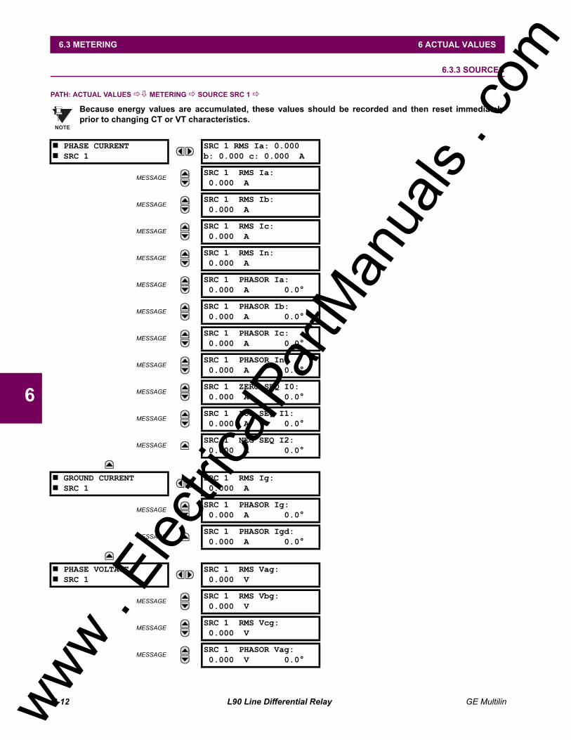
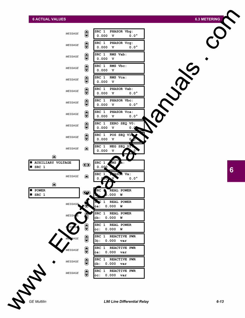
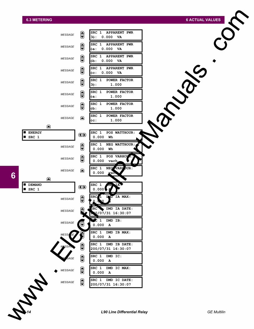
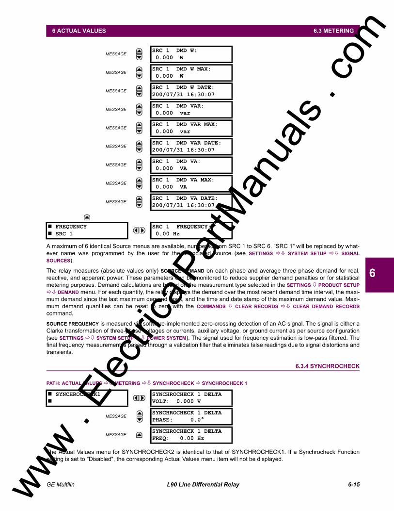
The relay measures all input currents and calculates both phasors and symmetrical components. When AC potential isapplied to the relay via the optional voltage inputs, metering data includes phase and neutral current, phase voltage, threephase and per phase W, VA, and var, and power factor. Frequency is measured on either current or voltage inputs. Theymay be called onto the local display or accessed via a computer. All terminal current phasors and differential currents arealso displayed at all relays, allowing the user opportunity to analyze correct polarization of currents at all terminals.
2.4.2 EVENT RECORDS
The relay has a sequence of events recorder which combines the recording of snapshot data and oscillography data.Events consist of a broad range of change of state occurrences, including input contact changes, measuring-elementpickup and operation, FlexLogic equation changes, and self-test status. The relay stores up to 1024 events with the dateand time stamped to the nearest microsecond. This provides the information needed to determine a sequence of events,which can reduce troubleshooting time and simplify report generation after system events.
2.4.3 OSCILLOGRAPHY
The relay stores oscillography data at a sampling rate of 64 times per cycle. The relay can store from 1 to 64 records. Eachoscillography file includes a sampled data report consisting of: Instantaneous sample of the selected currents and voltages (if AC potential is used), The status of each selected contact input, The status of each selected contact output, The status of each selected measuring function, The status of various selected logic signals, including virtual inputs and outputs.
The captured oscillography data files can be accessed via the remote communications ports on the relay.
2.4.4 CT FAILURE / CURRENT UNBALANCE ALARM
The relay has current unbalance alarm logic. The unbalance alarm may be supervised by a zero sequence voltage detec-tor. The user may block the relay from tripping when the current unbalance alarm operates.
2.4.5 TRIP CIRCUIT MONITOR
On those outputs designed for trip duty, a trip voltage monitor will continuously measure the DC voltage across output con-tacts to determine if the associated trip circuit is intact. If the voltage dips below the minimum voltage or the breaker fails toopen or close after a trip command, an alarm can be activated.
2.4.6 SELF TEST
The most comprehensive self testing of the relay is performed during a power-up. Because the system is not performingany protection activities at power-up, tests that would be disruptive to protection processing may be performed.
The processors in the CPU and all DSP modules participate in startup self-testing. Self-testing checks approximately 85-90% of the hardware, and CRC/check-sum verification of all PROMs is performed. The processors communicate theirresults to each other so that if any failures are detected, they can be reported to the user. Each processor must successfullycomplete its self tests before the relay begins protection activities.
During both startup and normal operation, the CPU polls all plug-in modules and checks that every one answers the poll.The CPU compares the module types that identify themselves to the relay order code stored in memory and declares analarm if a module is either non-responding or the wrong type for the specific slot.
When running under normal power system conditions, the relay processors will have idle time. During this time, each pro-cessor performs background self-tests that are not disruptive to the foreground processing.
www . El
ectric
alPar
tMan
uals
. com
GE Multilin L90 Line Differential Relay 2-11
2 PRODUCT DESCRIPTION 2.5 OTHER FUNCTIONS
2
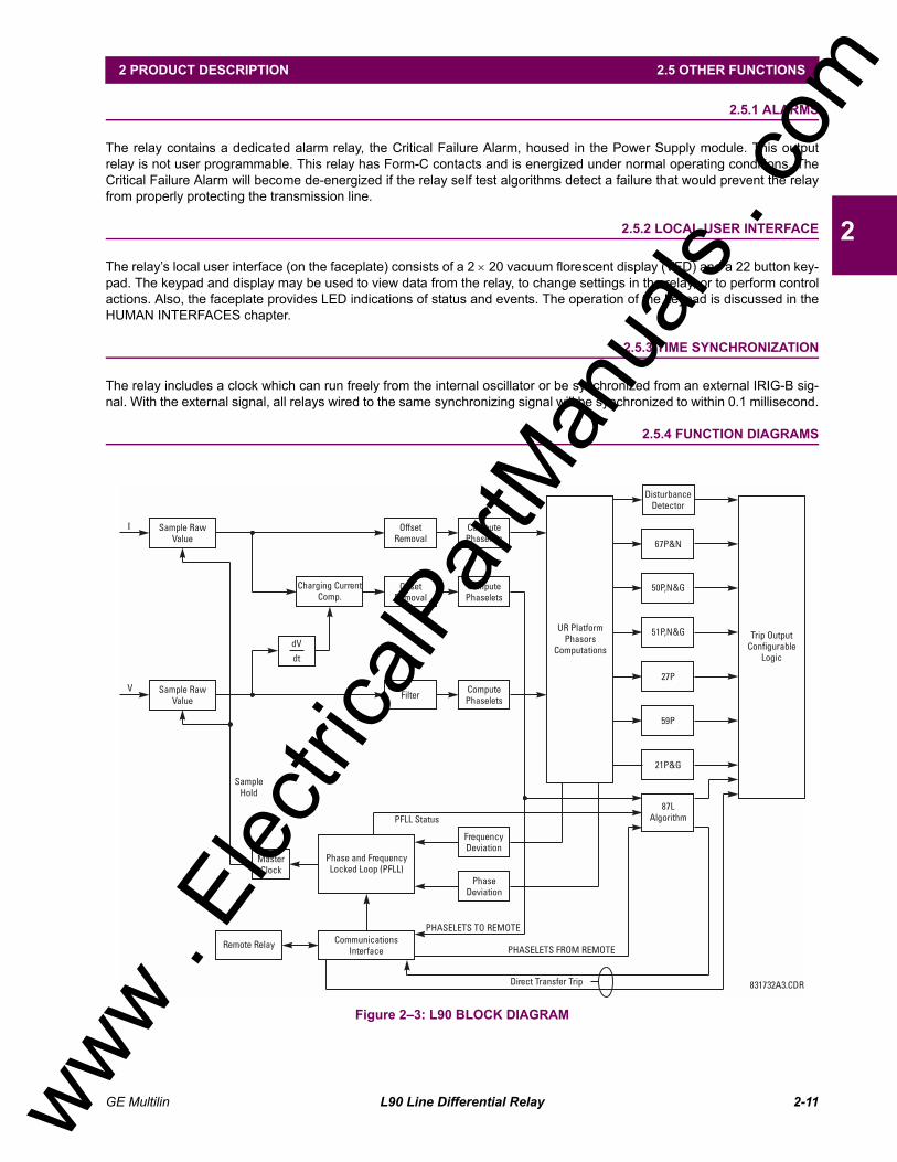
2.5 OTHER FUNCTIONS 2.5.1 ALARMS
The relay contains a dedicated alarm relay, the Critical Failure Alarm, housed in the Power Supply module. This outputrelay is not user programmable. This relay has Form-C contacts and is energized under normal operating conditions. TheCritical Failure Alarm will become de-energized if the relay self test algorithms detect a failure that would prevent the relayfrom properly protecting the transmission line.
2.5.2 LOCAL USER INTERFACE
The relays local user interface (on the faceplate) consists of a 2 × 20 vacuum florescent display (VFD) and a 22 button key-pad. The keypad and display may be used to view data from the relay, to change settings in the relay, or to perform controlactions. Also, the faceplate provides LED indications of status and events. The operation of the keypad is discussed in theHUMAN INTERFACES chapter.
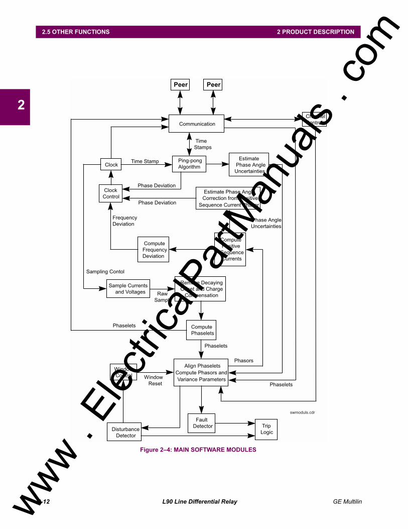
2.5.3 TIME SYNCHRONIZATION
The relay includes a clock which can run freely from the internal oscillator or be synchronized from an external IRIG-B sig-nal. With the external signal, all relays wired to the same synchronizing signal will be synchronized to within 0.1 millisecond.
SPECIFICATIONS ARE SUBJECT TO CHANGE WITHOUT NOTICE
2.6.1 PROTECTION ELEMENTS
The operating times below include the activation time of a trip rated Form-A output contact unless otherwise indi-cated. FlexLogic operands of a given element are 4 ms faster. This should be taken into account when usingFlexLogic to interconnect with other protection or control elements of the relay, building FlexLogic equations, orinterfacing with other IEDs or power system devices via communications or different output contacts.
LINE CURRENT DIFFERENTIAL (87L)Application: 2 or 3 terminal line, series compensated
line, tapped line, with charging current compensation
Pickup Current Level: 0.20 to 4.00 pu in steps of 0.01CT Tap (CT mismatch factor): 0.20 to 5.00 in steps of 0.01Slope # 1: 1 to 50%Slope # 2: 1 to 70%Breakpoint between Slopes: 0.0 to 20.0 pu in steps of 0.1DTT: Direct Transfer Trip (1 and 3 pole) to
remote L90Operating Time: 1.0 to 1.5 power cycles duration
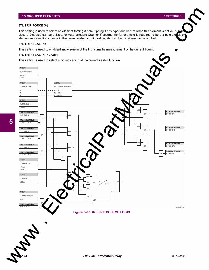
LINE CURRENT DIFFERENTIAL TRIP LOGIC87L Trip: Adds security for trip decision; creates 1
& 3 pole trip logicDTT: Engaged Direct Transfer Trip (1 and 3
pole) from remote L90DD: Sensitive Disturbance Detector to detect
fault occurrenceStub Bus Protection: Security for ring bus and 1½ breaker
configurationsOpen Pole Detector: Security for sequential and evolving
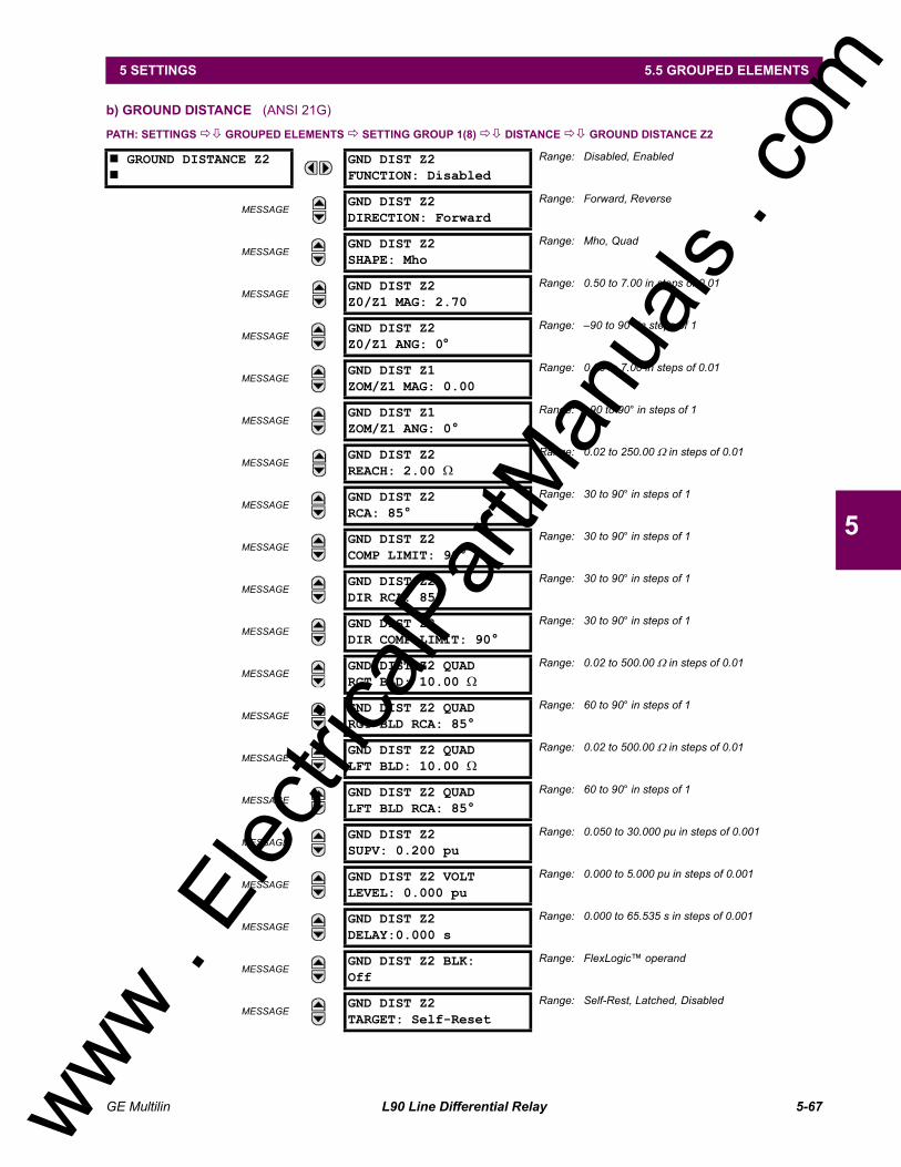
MHO or QUADNumber of Zones: 1Directionality: reversibleReach (secondary Ω): 0.02 to 250.00 Ω in steps of 0.01Reach Accuracy: ±5% including the effect of CVT tran-
sients up to an SIR of 30Distance Characteristic Angle: 30 to 90° in steps of 1Distance Comparator Limit Angle: 30 to 90° in steps of 1Directional Supervision:
Characteristic Angle: 30 to 90° in steps of 1Limit Angle: 30 to 90° in steps of 1
Right Blinder (QUAD only):Reach: 0.02 to 250 Ω in steps of 0.01Characteristic Angle: 60 to 90° in steps of 1
Left Blinder (QUAD only):Reach: 0.02 to 250 Ω in steps of 0.01Characteristic Angle: 60 to 90° in steps of 1
Time Delay: 0.000 to 65.535 s in steps of 0.001Timing Accuracy: ±3% or 4 ms, whichever is greater
Current Supervision:Level: line-to-line currentPickup: 0.050 to 30.000 pu in steps of 0.001Dropout: 97 to 98%
Memory Duration: 5 to 25 cycles in steps of 1Voltage Supervision Pickup (series compensation applications):
0 to 5.000 pu in steps of 0.001Operation Time: 1 to 1.5 cycles (typical)Reset Time: 1 power cycle (typical)
MHO, or QUADNumber of Zones: 1Directionality: reversibleReach (secondary Ω): 0.02 to 250.00 Ω in steps of 0.01Reach Accuracy: ±5% including the effect of CVT tran-
sients up to an SIR of 30Distance Characteristic Angle: 30 to 90° in steps of 1Distance Comparator Limit Angle: 30 to 90° in steps of 1Directional Supervision:
Characteristic Angle: 30 to 90° in steps of 1Limit Angle: 30 to 90° in steps of 1
Zero-Sequence CompensationZ0/Z1 magnitude: 0.50 to 7.00 in steps of 0.01Z0/Z1 angle: 90 to 90° in steps of 1
Zero-Sequence Mutual CompensationZ0M/Z1 magnitude: 0.00 to 7.00 in steps of 0.01Z0M/Z1 angle: 90 to 90° in steps of 1
Right Blinder (QUAD only):Reach: 0.02 to 250 Ω in steps of 0.01Characteristic Angle: 60 to 90° in steps of 1
Left Blinder (QUAD only):Reach: 0.02 to 250 Ω in steps of 0.01Characteristic Angle: 60 to 90° in steps of 1
Time Delay: 0.000 to 65.535 s in steps of 0.001Timing Accuracy: ±3% or 4 ms, whichever is greaterCurrent Supervision:
Level: neutral current (3I_0)Pickup: 0.050 to 30.000 pu in steps of 0.001Dropout: 97 to 98%
Memory Duration: 5 to 25 cycles in steps of 1Voltage Supervision Pickup (series compensation applications):
0 to 5.000 pu in steps of 0.001Operation Time: 1 to 1.5 cycles (typical)Reset Time: 1 power cycle (typical)
PHASE/NEUTRAL/GROUND TOCCurrent: Phasor or RMSPickup Level: 0.000 to 30.000 pu in steps of 0.001Dropout Level: 97% to 98% of PickupLevel Accuracy:for 0.1 to 2.0 × CT: ±0.5% of reading or ±1% of rated
(whichever is greater)for > 2.0 × CT: ±1.5% of reading > 2.0 × CT rating
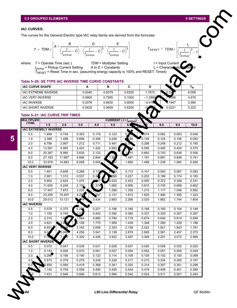
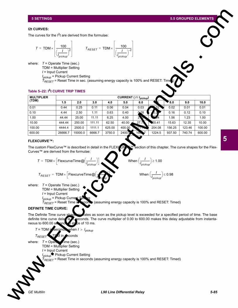
Curve Shapes: IEEE Moderately/Very/Extremely Inverse; IEC (and BS) A/B/C and Short Inverse; GE IAC Inverse, Short/Very/ Extremely Inverse; I2t; FlexCurve (pro-grammable); Definite Time (0.01 s base curve)
Curve Multiplier: Time Dial = 0.00 to 600.00 in steps of 0.01
Reset Type: Instantaneous/Timed (per IEEE)Timing Accuracy: Operate at > 1.03 × Actual Pickup
±3.5% of operate time or ±½ cycle (whichever is greater)
PHASE/NEUTRAL/GROUND IOCPickup Level: 0.000 to 30.000 pu in steps of 0.001Dropout Level: 97 to 98% of PickupLevel Accuracy:0.1 to 2.0 × CT rating: ±0.5% of reading or ±1% of rated
(whichever is greater)> 2.0 × CT rating ±1.5% of reading
Overreach: <2%Pickup Delay: 0.00 to 600.00 s in steps of 0.01Reset Delay: 0.00 to 600.00 s in steps of 0.01Operate Time: <20 ms at 3 × Pickup at 60 HzTiming Accuracy: Operate at 1.5 × Pickup
±3% or ±4 ms (whichever is greater)
NEGATIVE SEQUENCE TOCCurrent: PhasorPickup Level: 0.000 to 30.000 pu in steps of 0.001Dropout Level: 97% to 98% of PickupLevel Accuracy: ±0.5% of reading or ±1% of rated (which-
ever is greater)from 0.1 to 2.0 x CT rating±1.5% of reading > 2.0 x CT rating
Curve Shapes: IEEE Moderately/Very/Extremely Inverse; IEC (and BS) A/B/C and Short Inverse; GE IAC Inverse, Short/Very/ Extremely Inverse; I2t; FlexCurve (pro-grammable); Definite Time (0.01 s base curve)
Curve Multiplier (Time Dial): 0.00 to 600.00 in steps of 0.01Reset Type: Instantaneous/Timed (per IEEE) and Lin-
earTiming Accuracy: Operate at > 1.03 × Actual Pickup
±3.5% of operate time or ±½ cycle (whichever is greater)
NEGATIVE SEQUENCE IOCPickup Level: 0.000 to 30.000 pu in steps of 0.001Dropout Level: 97 to 98% of PickupLevel Accuracy:
0.1 to 2.0 × CT rating: ±0.5% of reading or ±1% of rated(whichever is greater)
> 2.0 × CT rating: ±1.5% of readingOverreach: < 2 %Pickup Delay: 0.00 to 600.00 s in steps of 0.01Reset Delay: 0.00 to 600.00 s in steps of 0.01Operate Time: < 20 ms at 3 × Pickup at 60 HzTiming Accuracy: Operate at 1.5 × Pickup
±3% or ± 4 ms (whichever is greater)
PHASE DIRECTIONAL OVERCURRENTRelay Connection: 90° (quadrature)Quadrature Voltage:ABC Phase Seq.: phase A (VBC), phase B (VCA), phase C (VAB)ACB Phase Seq.: phase A (VCB), phase B (VAC), phase C (VBA)
Polarizing Voltage Threshold: 0.000 to 3.000 pu in steps of 0.001Current Sensitivity Threshold: 0.05 puCharacteristic Angle: 0 to 359° in steps of 1Angle Accuracy: ±2°Operation Time (FlexLogic Operands):Tripping (reverse load, forward fault):< 12 ms, typicallyBlocking (forward load, reverse fault):< 8 ms, typically
NEUTRAL DIRECTIONAL OVERCURRENTDirectionality: Co-existing forward and reversePolarizing: Voltage, Current, DualPolarizing Voltage: V_0 or VXPolarizing Current: IGOperating Current: I_0Level Sensing: 3 × (|I_0| K × |I_1|), K = 0.0625; IGCharacteristic Angle: 90 to 90° in steps of 1Limit Angle: 40 to 90° in steps of 1, independent for
forward and reverseAngle Accuracy: ±2°Offset Impedance: 0.00 to 250.00 Ω in steps of 0.01Pickup Level: 0.05 to 30.00 pu in steps of 0.01Dropuot Level: 97 to 98%Operation Time: < 16 ms at 3 × Pickup at 60 Hz
BREAKER FAILUREMode: 1-pole, 3-poleCurrent Supv. Level: Phase, NeutralCurrent Supv. Pickup: 0.001 to 30.000 pu in steps of 0.001Current Supv. DPO: 97 to 98% of PickupCurrent Supv. Accuracy:
0.1 to 2.0 × CT rating: ±0.75% of reading or ±1% of rated(whichever is greater)
PHASE UNDERVOLTAGEVoltage: Phasor onlyPickup Level: 0.000 to 3.000 pu in steps of 0.001Dropout Level: 102 to 103% of PickupLevel Accuracy: ±0.5% of reading from 10 to 208 VCurve Shapes: GE IAV Inverse;
Definite Time (0.1s base curve)Curve Multiplier: Time Dial = 0.00 to 600.00 in steps of
0.01Timing Accuracy: Operate at < 0.90 × Pickup
±3.5% of operate time or ±4 ms (which-ever is greater)
PHASE OVERVOLTAGEVoltage: Phasor onlyPickup Level: 0.000 to 3.000 pu in steps of 0.001Dropout Level: 97 to 98% of PickupLevel Accuracy: ±0.5% of reading from 10 to 208 VPickup Delay: 0.00 to 600.00 in steps of 0.01 sOperate Time: < 30 ms at 1.10 × Pickup at 60 HzTiming Accuracy: ±3% or ±4 ms (whichever is greater)
NEUTRAL OVERVOLTAGEPickup Level: 0.000 to 1.250 pu in steps of 0.001Dropout Level: 97 to 98% of PickupLevel Accuracy: ±0.5% of reading from 10 to 208 VPickup Delay: 0.00 to 600.00 s in steps of 0.01Reset Delay: 0.00 to 600.00 s in steps of 0.01Timing Accuracy: ±3% or ±4 ms (whichever is greater)Operate Time: < 30 ms at 1.10 × Pickup at 60 Hz
AUXILIARY UNDERVOLTAGEPickup Level: 0.000 to 3.000 pu in steps of 0.001Dropout Level: 102 to 103% of PickupLevel Accuracy: ±0.5% of reading from 10 to 208 VCurve Shapes: GE IAV Inverse
Definite TimeCurve Multiplier: Time Dial = 0 to 600.00 in steps of 0.01Timing Accuracy: ±3% of operate time or ±4 ms
(whichever is greater)
AUXILIARY OVERVOLTAGEPickup Level: 0.000 to 3.000 pu in steps of 0.001Dropout Level: 97 to 98% of PickupLevel Accuracy: ±0.5% of reading from 10 to 208 VPickup Delay: 0 to 600.00 s in steps of 0.01Reset Delay: 0 to 600.00 s in steps of 0.01Timing Accuracy: ±3% of operate time or ±4 ms
(whichever is greater)Operate Time: < 30 ms at 1.10 × pickup at 60 Hz
LINE PICKUPPhase IOC: 0.000 to 30.000 puPositive Sequence UV: 0.000 to 3.000 puPositive Seq. OV Delay: 0.000 to 65.535 s
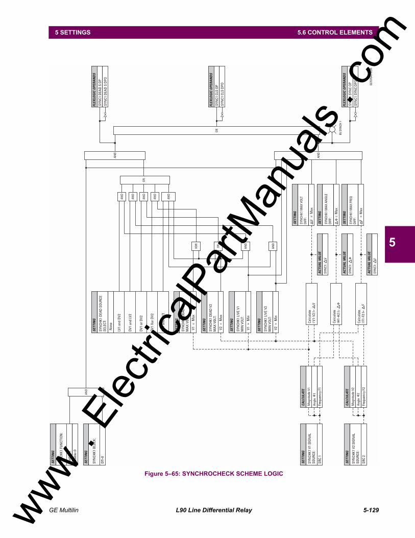
SYNCHROCHECKMax Volt Difference: 0 to 100000 V in steps of 1Max Angle Difference: 0 to 100° in steps of 1Max Freq Difference: 0.00 to 2.00 Hz in steps of 0.01Dead Source Function: None, LV1 & DV2, DV1 & LV2, DV1 or
DV2, DV1 xor DV2, DV1 & DV2 (L=Live, D=Dead)
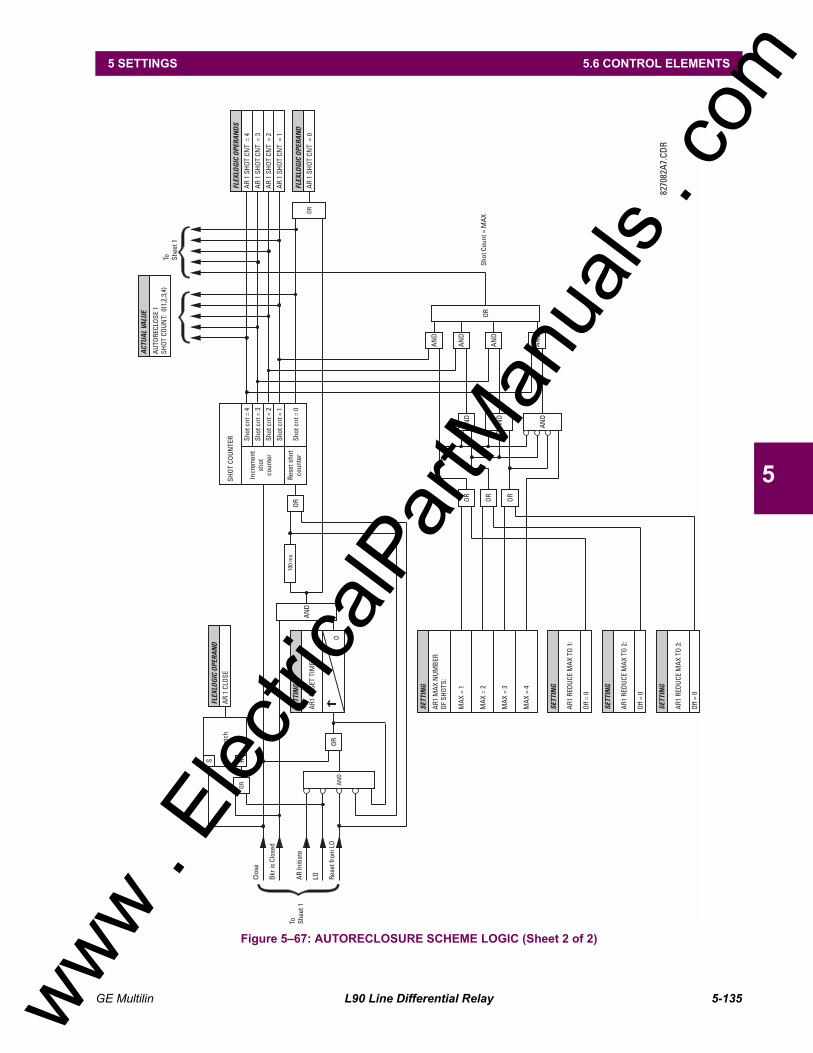
AUTORECLOSURESingle breaker applications, 3-pole tripping schemes.Up to 4 reclose attempts before lockout.Independent dead time setting before each shot.Possibility of changing protection settings after each shot with
FlexLogic.
POWER SWING DETECTFunctions: Power swing block, Out-of-step tripMeasured Impedance: Positive-sequenceBlocking & Tripping Modes: 2-step or 3-stepTripping Mode: Early or DelayedCurrent Supervision:
Pickup Level: 0.050 to 30.000 pu in steps of 0.001Dropout Level: 97 to 98% of Pickup
Fwd / Reverse Reach (sec. Ω): 0.10 to 500.00 Ω in steps of 0.01Impedance Accuracy: ±5%Fwd / Reverse Angle Impedances: 40 to 90° in steps of 1Angle Accuracy: ±2°Characteristic Limit Angles: 40 to 140° in steps of 1Timers: 0.000 to 65.535 s in steps of 0.001Timing Accuracy: ±3% or 4 ms, whichever is greater
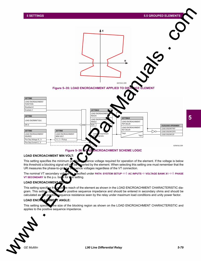
LOAD ENCROACHMENTMeasured Impedance: Positive-sequenceMinumum Voltage: 0.000 to 3.000 pu in steps of 0.001Reach (sec. Ω): 0.02 to 250.00 Ω in steps of 0.01Impedance Accuracy: ±5%Angle: 5 to 50° in steps of 1Angle Accuracy: ±2°Pickup Delay: 0 to 65.535 s in steps of 0.001Reset Delay: 0 to 65.535 s in steps of 0.001Time Accuracy: ±3% or ±4 ms, whichever is greaterOperate Time: < 30 ms at 60 Hz
FLEXLOGICProgramming language: Reverse Polish Notation with graphical
visualization (keypad programmable)Lines of code: 512Number of Internal Variables: 64Supported operations: NOT, XOR, OR (2 to 16 inputs), AND (2
to 16 inputs), NOR (2 to 16 inputs), NAND (2 to 16 inputs), LATCH (Reset dominant), EDGE DETECTORS, TIM-ERS
Inputs: any logical variable, contact, or virtual input
Number of timers: 32Pickup delay: 0 to 60000 (ms, sec., min.) in steps of 1Dropout delay: 0 to 60000 (ms, sec., min.) in steps of 1
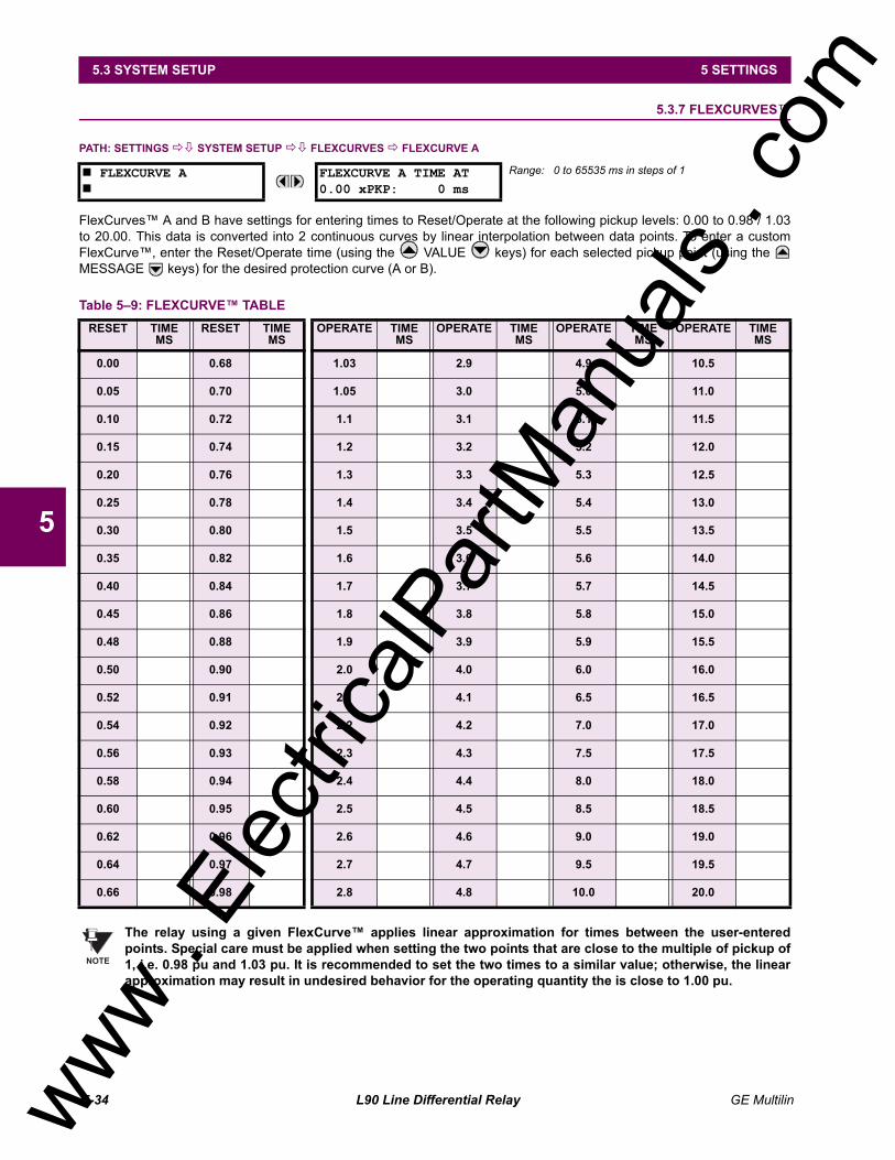
FLEXCURVESNumber: 2 (A and B)Number of reset points: 40 (0 through 1 of pickup)Number of operate points: 80 (1 through 20 of pickup)Time delay: 0 to 65535 ms in steps of 1
FLEXELEMENTSNumber of elements: 8Operating signal: any analog actual value, or two values in
differential modeOperating signal mode: Signed or Absolute ValueOperating mode: Level, DeltaComparator direction: Over, UnderPickup Level: 30.000 to 30.000 pu in steps of 0.001Hysteresis: 0.1 to 50.0% in steps of 0.1Delta dt: 20 ms to 60 daysPickup and dropout delay: 0.000 to 65.535 in steps of 0.001
FLEX STATESNumber: up to 256 logical variables grouped
under 16 Modbus addressesProgrammability: any logical variable, contact, or virtual
input
USER-PROGRAMMABLE LEDSNumber: 48 plus Trip and AlarmProgrammability: from any logical variable, contact, or vir-
tual inputReset mode: Self-reset or Latched
USER-DEFINABLE DISPLAYSNumber of displays: 8Lines of display: 2 × 20 alphanumeric charactersParameters up to 5, any Modbus register addresses
2.6.3 MONITORING
OSCILLOGRAPHYMax. No. of Records: 64Sampling Rate: 64 samples per power cycleTriggers: Any element pickup, dropout or operate
Digital input change of stateDigital output change of stateFlexLogic equation
Data: AC input channelsElement stateDigital input stateDigital output state
Data Storage: In non-volatile memory
EVENT RECORDERCapacity: 1024 eventsTime-tag: to 1 microsecondTriggers: Any element pickup, dropout or operate
Digital input change of stateDigital output change of stateSelf-test events
Data Storage: In non-volatile memory
DATA LOGGERNumber of Channels: 1 to 16Parameters: Any available analog Actual ValueSampling Rate: 1 sec.; 1, 5, 10, 15, 20, 30, 60 min.Storage Capacity: (NN is dependent on memory)
1-second rate: 01 channel for NN days16 channels for NN days
RMS CURRENT: PHASE, NEUTRAL, AND GROUNDAccuracy at0.1 to 2.0 × CT rating: ±0.25% of reading or ±0.1% of rated
(whichever is greater)> 2.0 × CT rating: ±1.0% of reading
RMS VOLTAGEAccuracy: ±0.5% of reading from 10 to 208 V
APPARENT POWER VAAccuracy: ±1.0% of reading
REAL POWER WATTAccuracy: ±1.0% of reading at
0.8 < PF ≤ 1.0 and 0.8 < PF ≤ 1.0
REACTIVE POWER VARAccuracy: ±1.0% of reading 0.2 ≤ PF ≤ 0.2
WATT-HOURS (POSITIVE & NEGATIVE)Accuracy: ±2.0% of readingRange: ±0 to 2 × 10⁹ MWhParameters: 3-phase onlyUpdate Rate: 50 ms
VAR-HOURS (POSITIVE & NEGATIVE)Accuracy: ±2.0% of readingRange: ±0 to 2 × 10⁹ MvarhParameters: 3-phase onlyUpdate Rate: 50 ms
DEMANDMeasurements: Phases A, B, and C present and maxi-
mum measured currents3-Phase Power (P, Q, and S) present and maximum measured currents
Accuracy: ±2.0%
FREQUENCYAccuracy at
V = 0.8 to 1.2 pu: ±0.01 Hz (when voltage signal is used for frequency measurement)
I = 0.1 to 0.25 pu: ±0.05 HzI > 0.25 pu ±0.02 Hz (when current signal is used for
frequency measurement)
2.6.5 INPUTS
AC CURRENTCT Rated Primary: 1 to 50000 ACT Rated Secondary: 1 A or 5 A by connectionNominal Frequency: 20 to 65 HzRelay Burden: < 0.2 VA at rated secondaryConversion Range:
Standard CT Module: 0.02 to 46 × CT rating RMS symmetricalSensitive Ground Module:
0.002 to 4.6 × CT rating RMS symmetricalCurrent Withstand: 20 ms at 250 times rated
1 sec. at 100 times ratedCont. at 3 times rated
AC VOLTAGEVT Rated Secondary: 50.0 to 240.0 VVT Ratio: 0.1 to 24000.0Nominal Frequency: 20 to 65 HzRelay Burden: < 0.25 VA at 120 VConversion Range: 1 to 275 VVoltage Withstand: cont. at 260 V to neutral
1 min./hr at 420 V to neutral
FOR L90, THE NOMINAL SYSTEM FRE-QUENCY SHOULD BE SELECTED AS 50 HZ OR 60 HZ ONLY.
CONTACT INPUTSDry Contacts: 1000 Ω maximumWet Contacts: 300 V DC maximumSelectable Thresholds: 17 V, 33 V, 84 V, 166 VRecognition Time: < 1 msDebounce Timer: 0.0 to 16.0 ms in steps of 0.5
IRIG-B INPUTAmplitude Modulation: 1 to 10 V pk-pkDC Shift: TTLInput Impedance: 22 kΩ
LOW RANGENominal DC Voltage: 24 to 48 V at 3 AMin./Max. DC Voltage: 20 / 60 VNOTE: Low range is DC only.
HIGH RANGENominal DC Voltage: 125 to 250 V at 0.7 AMin./Max. DC Voltage: 88 / 300 VNominal AC Voltage: 100 to 240 V at 50/60 Hz, 0.7 AMin./Max. AC Voltage: 88 / 265 V at 48 to 62 Hz
ALL RANGESVolt Withstand: 2 × Highest Nominal Voltage for 10 msVoltage Loss Hold-Up: 50 ms duration at nominalPower Consumption: Typical = 35 VA; Max. = 75 VA
INTERNAL FUSERATINGS
Low Range Power Supply: 7.5 A / 600 VHigh Range Power Supply: 5 A / 600 V
INTERRUPTING CAPACITYAC: 100 000 A RMS symmetricalDC: 10 000 A
2.6.7 OUTPUTS
FORM-A RELAYMake and Carry for 0.2 sec.: 30 A as per ANSI C37.90Carry Continuous: 6 ABreak at L/R of 40 ms: 0.25 A DC max.Operate Time: < 4 msContact Material: Silver alloy
FORM-A VOLTAGE MONITORApplicable Voltage: approx. 15 to 250 V DCTrickle Current: approx. 1 to 2.5 mA
FORM-A CURRENT MONITORThreshold Current: approx. 80 to 100 mA
FORM-C AND CRITICAL FAILURE RELAYMake and Carry for 0.2 sec: 10 ACarry Continuous: 6 ABreak at L/R of 40 ms: 0.1 A DC max.Operate Time: < 8 msContact Material: Silver alloy
FAST FORM-C RELAYMake and Carry: 0.1 A max. (resistive load)Minimum Load Impedance:
820 nm LED Multimode ST 1.65 km1300 nm LED Multimode ST 3.8 km1300 nm ELED Singlemode ST 11.4 km1300 nm Laser Singlemode ST 64 km1550 nm Laser Singlemode ST 105 km
Typical distances listed are based on the fol-lowing assumptions for system loss. Asactual losses will vary from one installation toanother, the distance covered by your systemmay vary.
CONNECTOR LOSSES (TOTAL OF BOTH ENDS):ST Connector 2 dB FIBER LOSSES:820 nm Multimode 3 dB/km1300 nm Multimode 1 dB/km1300 nm Singlemode 0.35 dB/km1550 nm Singlemode 0.25 dB/kmSplice losses: One splice every 2 km,
at 0.05 dB loss per splice.SYSTEM MARGIN:
3 dB additional loss added to calcula-tions to compensate for all other losses.
Power Frequency Magnetic Field Immunity:IEC 61000-4-8
Vibration Test (sinusoidal): IEC 60255-21-1Shock and Bump: IEC 60255-21-2
Type test report available upon request.
2.6.12 PRODUCTION TESTS
THERMALProducts go through an environmental test based upon an
Accepted Quality Level (AQL) sampling process.
2.6.13 APPROVALS
APPROVALSUL Listed for the USA and CanadaCE:
LVD 73/23/EEC: IEC 1010-1
EMC 81/336/EEC: EN 50081-2EN 50082-2
2.6.14 MAINTENANCE
Cleaning: Normally, cleaning is not required; but for situations where dust has accumulated on the faceplate display, a dry cloth can be used.
NOTE
www . El
ectric
alPar
tMan
uals
. com
GE Multilin L90 Line Differential Relay 3-1
3 HARDWARE 3.1 DESCRIPTION
3
3 HARDWARE 3.1 DESCRIPTION 3.1.1 PANEL CUTOUT
The relay is available as a 19-inch rack horizontal mount unit or as a reduced size (¾) vertical mount unit, with a removablefaceplate. The modular design allows the relay to be easily upgraded or repaired by a qualified service person. The face-plate is hinged to allow easy access to the removable modules, and is itself removable to allow mounting on doors with lim-ited rear depth. There is also a removable dust cover that fits over the faceplate, which must be removed when attemptingto access the keypad or RS232 communications port.
The vertical and horizontal case dimensions are shown below, along with panel cutout details for panel mounting. Whenplanning the location of your panel cutout, ensure that provision is made for the faceplate to swing open without interfer-ence to or from adjacent equipment.
The relay must be mounted such that the faceplate sits semi-flush with the panel or switchgear door, allowing the operatoraccess to the keypad and the RS232 communications port. The relay is secured to the panel with the use of four screwssupplied with the relay.
Figure 31: L90 VERTICAL MOUNTING AND DIMENSIONS
e UR SERIESUR SERIES
www . El
ectric
alPar
tMan
uals
. com
3-2 L90 Line Differential Relay GE Multilin
3.1 DESCRIPTION 3 HARDWARE
3
Figure 32: L90 VERTICAL SIDE MOUNTING INSTALLATION
www . El
ectric
alPar
tMan
uals
. com
GE Multilin L90 Line Differential Relay 3-3
3 HARDWARE 3.1 DESCRIPTION
3
Figure 33: L90 VERTICAL SIDE MOUNTING REAR DIMENSIONS
Figure 34: L90 HORIZONTAL MOUNTING AND DIMENSIONS
INCHES
(mm)
REMOTE MOUNTING
BEZEL OUTLINE
8x0.156 %%c
0.375
(9.5)
5.000
(127.0)
9.520
(241.8)
14.520
(368.8)
0.375
(9.5)
17.720
(450.1)
0.3
75
(9.5
)
4.7
85
(12
1.5
)
0.3
75
(9.5
)
1.8
75
(47
.6)
6.9
60
(17
6.8
)10.90"
(276.8)
TOP VIEW
9.80"
(248.9)
HORIZONTAL (19" 4RU)
8.97"
(227.8)
Brackets repositioned
for switchgear mtg.17.52"
(445.0)
827704B3.DWG
7.13"
(181.1)CUTOUT
17.75"
(450.8)
PANEL MOUNTING
18.37"
(466.6)
1.57"
(39.8)
4.00"
(101.6)
4x0.28" Dia.
(7.1)
19.00"
(482.6)
7.00"
(177.8)
FRONT VIEW
www . El
ectric
alPar
tMan
uals
. com
3-4 L90 Line Differential Relay GE Multilin
3.1 DESCRIPTION 3 HARDWARE
3
3.1.2 MODULE WITHDRAWAL / INSERTION
Module withdrawal and insertion may only be performed when control power has been removed from theunit. Inserting an incorrect module type into a slot may result in personal injury, damage to the unit or con-nected equipment, or undesired operation!
Proper electrostatic discharge protection (i.e. a static strap) must be used when coming in contact withmodules while the relay is energized!
The relay, being modular in design, allows for the withdrawal and insertion of modules. Modules must only be replaced withlike modules in their original factory configured slots.
The faceplate can be opened to the left, once the sliding latch on the right side has been pushed up, as shown in the figurebelow. This allows for easy accessibility of the modules for withdrawal.
Figure 35: UR MODULE WITHDRAWAL/INSERTION
WITHDRAWAL: The ejector/inserter clips, located at the top and bottom of each module, must be pulled simultaneously torelease the module for removal. Before performing this action, control power must be removed from the relay. Recordthe original location of the module to ensure that the same or replacement module is inserted into the correct slot.
INSERTION: Ensure that the correct module type is inserted into the correct slot position. The ejector/inserter clipslocated at the top and at the bottom of each module must be in the disengaged position as the module is smoothly insertedinto the slot. Once the clips have cleared the raised edge of the chassis, engage the clips simultaneously. When the clipshave locked into position, the module will be fully inserted.
Type 9C and 9D CPU modules are equipped with 10BaseT and 10BaseF Ethernet connectors for communications.These connectors must be individually disconnected from the module before the it can be removed from the chas-sis.
WARNING
WARNING
NOTE
www . El
ectric
alPar
tMan
uals
. com
GE Multilin L90 Line Differential Relay 3-5
3 HARDWARE 3.1 DESCRIPTION
3
3.1.3 REAR TERMINAL LAYOUT
Figure 36: REAR TERMINAL VIEW
Do not touch any rear terminals while the relay is energized!
3.1.4 REAR TERMINAL ASSIGNMENTS
The relay follows a convention with respect to terminal number assignments which are three characters long assigned inorder by module slot position, row number, and column letter. Two-slot wide modules take their slot designation from thefirst slot position (nearest to CPU module) which is indicated by an arrow marker on the terminal block. See the followingfigure for an example of rear terminal assignments.
Figure 37: EXAMPLE OF MODULES IN F & H SLOTS
WARNING
www . El
ectric
alPar
tMan
uals
. com
3-6 L90 Line Differential Relay GE Multilin
3.2 WIRING 3 HARDWARE
3
3.2 WIRING 3.2.1 TYPICAL WIRING DIAGRAM
Figure 38: TYPICAL WIRING DIAGRAM
TRIPPING DIRECTION(5 Amp)
L90 Line Differential Relay
A B C
52
(Rear View)
1
PowerSupply
9
CPU
7
COM
8
CT/VT
6
I/O*
6
I/O*
6
I/O*
6
I/O
6
I/O*
MODULE ARRANGEMENTJU MX LW KV BHT DN GS P FR
Ground atDevice end
Shieldedtwisted pairs
RS-232
DB-9
(front)
UR COMPUTER1
TXD RXDRXD TXD
SGND SGND
1 832
20764522
25 PINCONNECTOR
PERSONALCOMPUTER
9 PINCONNECTOR
2 23 34 45 56 67 78 89 9
TYPICAL CONFIGURATIONTHE AC SIGNAL PATH IS CONFIGURABLE
CONTACTS SHOWNWITH NO
CONTROL POWER
AC or DC
DC
( DC
ON
LY )
TOREMOTE
L90
OPTIONAL
TC
TC
N
2
1
VO
LTAG
E SU
PV.V
OLT &
CU
RR
ENT S
UPV.
1a
2b
1c1b
2c
2a
4a
4c
3b3a
4b
3c
CONTACT IN 5a
CONTACT IN 7a
CONTACT IN 5c
CONTACT IN 7c
CONTACT IN 6a
CONTACT IN 8a
CONTACT IN 6c
CONTACT IN 8c
COMMON 5b
COMMON 7b
SURGE
6a
8a
5b
7b
8b
5aHHHHH
HHHHH
H
HHHHH
HHHHH
HHH
H
H
H
HHHHHHHHHH
7a
6c
8c
5c
7c
1
2
3
4
I
V
I
V
I
V
I
V
DIGITAL I/O 6G
CONTACT IN 7aCONTACT IN 7cCONTACT IN 8aCONTACT IN 8c
COMMON 7b
8a
7b
7aUUUUU
UUUUU
UUU
U
U
U
U
U
UUUUUUUUUUUUUUUU
U
8c
7c 1b
2b
3b
4b
5b
6b
1a
2a
3a
4a
5a
6a
1c
2c
3c
4c
5c
6c
SURGE8b
1
5
2
6
3
4
DIGITAL I/O 6H I
V
I
V
I
V
I
V
I
V
I
V
7a
1a
2b
7c
1c
7b
1b
8c
NNN
N
N
N
N
N
N
N
NNNNNNNNNNNNNNNNNNNNNN
8b
2c
8a
2a
4a
5b
4c
6b
3b3a
6a
4b
5c
5a
3c
6c
6KD
IGIT
AL
I/O
1
5
2
6
3
7
4
8
CRITICALFAILURE
48 VDCOUTPUT
CONTROLPOWER
HILO
POW
ER S
UPP
LY1
FILTERSURGE
3a
1b
8a
6b
8b
6a
BBBBBBBBBB
3b
1a2b
5b
9A
COM
COM
CPU
D3bD4bD5b
D2aD3aD4a
D5aD6aD7b
RS485COM 1
RS485COM 2
IRIG-B
SURGE
8A / 8B
FFFFFF5a 5c 7c6a 7a6c
VA
VB
VC
VOLTAGE INPUTS
VA
VB
VC
1c 4a
FFFFFFFFFFFF
3cCURRENT INPUTS
2c 4c1a 4b1b 2a 3a2b 3b
IA IB IC IGIA5
IA1
IB5
IC5
IG5
IB1
IC1
IG1
GE Power Management
Tx1 Rx1
Tx2 Rx2
L90
COM
. W7A
FIBERCHNL. 2
FIBERCHNL. 1
* Optional
6CD
IGIT
AL
I/O
1
5
2
6
3
7
4
8
7a
1a
2b
7c
1c
7b
1b
8c
SSS
S
S
S
S
S
S
S
SSSSSSSSSSSSSSSSSSSSSS
8b
2c
8a
2a
4a
5b
4c
6b
3b3a
6a
4b
5c
5a
3c
6c
6a
8a
5b
7b
5a
7a
6c
8c
5c
7c
CONTACT IN 1a
CONTACT IN 4c
COMMON 5b
COMMON 7b
COMMON 1b
COMMON 3b
CONTACT IN 2a
CONTACT IN 5a
CONTACT IN 3c
CONTACT IN 6a
CONTACT IN 8a
CONTACT IN 1c
CONTACT IN 3a
CONTACT IN 5c
CONTACT IN 7cCONTACT IN 7a
CONTACT IN 2c
SURGE
CONTACT IN 4a
CONTACT IN 6c
CONTACT IN 8c
1a
8b
4c
2c
3a3c
1c
3b
1b
4a
2a
6DD
IGIT
AL
I/O
LL LL LL LL LL LL LL LL LL L
L LL LL LL LL L
L LL LL LL LL LL
L
831702by.CDRGROUND BUS
No. 10AWGMinimum
MODULES MUST BEGROUNDED IFTERMINAL IS
PROVIDED
This
dia
gram
is b
ased
on
the
follo
win
g or
der c
ode:
L90
-A00
-HC
L-F8
A-H
6G-L
6D-N
6K-S
6C-U
6H-W
7A.
The
purp
ose
of th
is d
iagr
am is
to p
rovi
de a
n ex
ampl
e of
how
the
rela
y is
typi
cally
wire
d, n
ot s
peci
fi-ca
lly h
ow t
o w
ire y
our
own
rela
y. P
leas
e re
fer
to t
he f
ollo
win
g pa
ges
for
exam
ples
to
help
you
wire
your
rela
y co
rrec
tly b
ased
on
your
ow
n re
lay
conf
igur
atio
n an
d or
der c
ode.
CA
UT
ION
www . El
ectric
alPar
tMan
uals
. com
GE Multilin L90 Line Differential Relay 3-7
3 HARDWARE 3.2 WIRING
3
3.2.2 DIELECTRIC STRENGTH RATINGS AND TESTING
a) RATINGS
The dielectric strength of UR module hardware is shown in the following table:
b) TESTING
Filter networks and transient protection clamps are used in module hardware to prevent damage caused by high peak volt-age transients, radio frequency interference (RFI) and electromagnetic interference (EMI). These protective componentscan be damaged by application of the ANSI/IEEE C37.90 specified test voltage for a period longer than the specified oneminute. For testing of dielectric strength where the test interval may exceed one minute, always observe the following pre-cautions:
Test Precautions:
1. The connection from ground to the Filter Ground (Terminal 8b) and Surge Ground (Terminal 8a) must be removedbefore testing.
2. Some versions of the digital I/O module have a Surge Ground connection on Terminal 8b. On these module types, thisconnection must be removed before testing.
3.2.3 CONTROL POWER
CONTROL POWER SUPPLIED TO THE RELAY MUST BE CONNECTED TO THE MATCHING POWER SUPPLYRANGE OF THE RELAY. IF THE VOLTAGE IS APPLIED TO THE WRONG TERMINALS, DAMAGE MAYOCCUR!
The power supply module can be ordered with either of two possible voltage ranges. Each range has a dedicated inputconnection for proper operation. The ranges are as shown below (see the Technical Specifications section for details).
The power supply module provides power to the relay and supplies power for dry contact input connections.
Table 31: DIELECTRIC STRENGTH OF UR MODULE HARDWAREMODULE
TYPEMODULE FUNCTION TERMINALS DIELECTRIC STRENGTH
(AC)FROM TO1 Power Supply High (+); Low (+); () Chassis 2000 V AC for 1 min.
(See Precaution 1)1 Power Supply 48 V DC (+) and () Chassis 2000 V AC for 1 min.
(See Precaution 1)1 Power Supply Relay Terminals Chassis 2000 V AC for 1 min.
(See Precaution 1)2 Reserved for Future N/A N/A N/A3 Reserved for Future N/A N/A N/A4 Reserved for Future N/A N/A N/A5 Analog I/O All except 8b Chassis < 50 V DC6 Digital I/O All (See Precaution 2) Chassis 2000 V AC for 1 min.
7R L90 G.703 All except 2b, 3a, 7b, 8a Chassis 2000 V AC for 1 min.7T L90 RS422 All except 6a, 7b, 8a Chassis < 50 V DC8 CT/VT All Chassis 2000 V AC for 1 min.9 CPU All except 7b Chassis < 50 VDC
Table 32: CONTROL POWER VOLTAGE RANGERANGE NOMINAL VOLTAGELO 24 to 48 V (DC only)HI 125 to 250 V
CAUTION
www . El
ectric
alPar
tMan
uals
. com
3-8 L90 Line Differential Relay GE Multilin
3.2 WIRING 3 HARDWARE
3
Figure 39: CONTROL POWER CONNECTION
The power supply module provides 48 V DC power for dry contact input connections and a critical failure relay (see TYPI-CAL WIRING DIAGRAM). The critical failure relay is a Form-C that will be energized once control power is applied and therelay has successfully booted up with no critical self-test failures. If any of the on-going self-test features detect a criticalfailure or control power is lost, the relay will de-energize.
3.2.4 CT/VT MODULES
A CT/VT module may have voltage inputs on channels 1 through 4 inclusive, or channels 5 through 8 inclusive. Channels 1and 5 are intended for connection to phase A, and are labeled as such in the relay. Channels 2 and 6 are intended for con-nection to phase B, and are labeled as such in the relay. Channels 3 and 7 are intended for connection to phase C and arelabeled as such in the relay. Channels 4 and 8 are intended for connection to a single phase source. If voltage, this channelis labelled the auxiliary voltage (VX). If current, this channel is intended for connection to a CT between a system neutraland ground, and is labelled the ground current (IG).
a) AC CURRENT TRANSFORMER INPUTS
VERIFY THAT THE CONNECTION MADE TO THE RELAY NOMINAL CURRENT OF 1 A OR 5 A MATCHESTHE SECONDARY RATING OF THE CONNECTED CTs. UNMATCHED CTs MAY RESULT IN EQUIPMENTDAMAGE OR INADEQUATE PROTECTION.
The CT/VT module may be ordered with a standard ground current input that is the same as the phase current inputs (type8A) or with a sensitive ground input (type 8B) which is 10 times more sensitive (see the Technical Specifications section formore details). Each AC current input has an isolating transformer and an automatic shorting mechanism that shorts theinput when the module is withdrawn from the chassis. There are no internal ground connections on the current inputs. Cur-rent transformers with 1 to 50000 A primaries and 1 A or 5 A secondaries may be used.
CT connections for both ABC and ACB phase rotations are identical as shown in the TYPICAL WIRING DIAGRAM.
The exact placement of a zero sequence CT so that ground fault current will be detected is shown below. Twisted paircabling on the zero sequence CT is recommended.
The phase voltage channels are used for most metering and protection purposes. The auxiliary voltage channel is used asinput for the Synchrocheck and Volts/Hertz features.
Figure 311: CT/VT MODULE WIRING
Figure 312: CT MODULE WIRING
Wherever a tilde ~ symbol appears, substitute with the Slot Position of the module.
Every digital input/output module has 24 terminal connections. They are arranged as 3 terminals per row, with 8 rows intotal. A given row of three terminals may be used for the outputs of one relay. For example, for Form-C relay outputs, theterminals connect to the normally open (NO), normally closed (NC), and common contacts of the relay. For a Form-A out-put, there are options of using current or voltage detection for feature supervision, depending on the module ordered. Theterminal configuration for contact inputs is different for the two applications. When a digital I/O module is ordered with con-tact inputs, they are arranged in groups of four and use two rows of three terminals. Ideally, each input would be totally iso-lated from any other input. However, this would require that every input have two dedicated terminals and limit the availablenumber of contacts based on the available number of terminals. So, although each input is individually optically isolated,each group of four inputs uses a single common as a reasonable compromise. This allows each group of four outputs to besupplied by wet contacts from different voltage sources (if required) or a mix of wet and dry contacts.
The tables and diagrams on the following pages illustrate the module types (6A, etc.) and contact arrangements that maybe ordered for the relay. Since an entire row is used for a single contact output, the name is assigned using the module slotposition and row number. However, since there are two contact inputs per row, these names are assigned by module slotposition, row number, and column position.
UR RELAY FORM-A OUTPUT CONTACTS
Some Form-A outputs include circuits to monitor the DC voltage across the output contact when it is open, and the DC cur-rent through the output contact when it is closed. Each of the monitors contains a level detector whose output is set to logicOn = 1 when the current in the circuit is above the threshold setting. The voltage monitor is set to On = 1 when the cur-rent is above about 1 to 2.5 mA, and the current monitor is set to On = 1 when the current exceeds about 80 to 100 mA.The voltage monitor is intended to check the health of the overall trip circuit, and the current monitor can be used to seal-inthe output contact until an external contact has interrupted current flow. The block diagrams of the circuits are below abovefor the Form-A outputs with:
a) optional voltage monitor
b) optional current monitor
c) with no monitoring
Figure 313: FORM-A CONTACT FUNCTIONS
Load
I
~#a
+
-
~#b
~#c
If Idc 1mA, Cont Op x Vonotherwise Cont Op x Voff
V
~
827821A4.CDR
a) Voltage with optionalcurrent monitoring Voltage monitoring only
Load
I
+
-V
Both voltage and current monitoring
If Idc 80mA, Cont Op x Ionotherwise Cont Op x Ioff
~
If Idc 1mA, Cont Op x Vonotherwise Cont Op x Voff
~
LoadI
+
-
V
b) Current with optionalvoltage monitoring Current monitoring only Both voltage and current monitoring
(external jumper a-b is required)
If Idc 80mA, Cont Op x Ionotherwise Cont Op x Ioff
~Load
I
-
V
+If Idc 80mA, Cont Op x Ionotherwise Cont Op x Ioff
~
If Idc 1mA, Cont Op x Vonotherwise Cont Op x Voff
~
Load
+
-c) No monitoring
~#a
~#b
~#c
~#a
~#b
~#c
~#a
~#b
~#c
~#a
~#b
~#c
www . El
ectric
alPar
tMan
uals
. com
GE Multilin L90 Line Differential Relay 3-11
3 HARDWARE 3.2 WIRING
3
The operation of voltage and current monitors is reflected with the corresponding FlexLogic operands (Cont Op # Von,Cont Op # Voff, Cont Op # Ion, and Cont Op # Ioff) which can be used in protection, control and alarm logic. The typicalapplication of the voltage monitor is Breaker Trip Circuit Integrity monitoring; a typical application of the Current monitor isseal-in of the control command. Refer DIGITAL ELEMENTS section for an example of how Form A contacts can be appliedfor Breaker Trip Circuit Integrity Monitoring.
Relay contacts must be considered unsafe to touch when the unit is energized!! If the relay contacts needto be used for low voltage accessible applications, it is the customers responsibility to ensure properinsulation levels!
USE OF FORM-A OUTPUTS IN HIGH IMPEDANCE CIRCUITS
For Form-A output contacts internally equipped with a voltage measuring cIrcuit across the contact, the circuit hasan impedance that can cause a problem when used in conjunction with external high input impedance monitoringequipment such as modern relay test set trigger circuits. These monitoring circuits may continue to read the Form-A contact as being closed after it has closed and subsequently opened, when measured as an impedance.
The solution to this problem is to use the voltage measuring trigger input of the relay test set, and connect theForm-A contact through a voltage-dropping resistor to a DC voltage source. If the 48 V DC output of the power sup-ply is used as a source, a 500 Ω, 10 W resistor is appropriate. In this configuration, the voltage across either theForm-A contact or the resistor can be used to monitor the state of the output.
Wherever a tilde ~ symbol appears, substitute with the Slot Position of the module; wherever a numbersign "#" appears, substitute the contact number
When current monitoring is used to seal-in the Form-A contact outputs, the FlexLogic Operand drivingthe contact output should be given a reset delay of 10 ms to prevent damage of the output contact (in situ-ations when the element initiating the contact output is bouncing, at values in the region of the pickupvalue).
Figure 314: DIGITAL I/O MODULE WIRING (SHEET 1 OF 2)
1a
2b
1c1b
2c
2a
4a
4c
3b3a
4b
3c
CONTACT IN 5a
CONTACT IN 7a
CONTACT IN 5c
CONTACT IN 7c
CONTACT IN 6a
CONTACT IN 8a
CONTACT IN 6c
CONTACT IN 8c
COMMON 5b
COMMON 7b
SURGE
6a
8a
5b
7b
8b
5a~~~~~
~~~~~
~
~~~~~
~~~~~
~~~
~
~
~
~~~~~~~~~~
7a
6c
8c
5c
7c
1
2
3
4
I
V
I
V
I
V
I
V
DIGITAL I/O 6G
CONTACT IN 5aCONTACT IN 5cCONTACT IN 6aCONTACT IN 6c
COMMON 5b
CONTACT IN 7aCONTACT IN 7cCONTACT IN 8aCONTACT IN 8c
COMMON 7b
SURGE
6a
8a
5b
7b
8b
5a~~~~~
~~~~~
~
~~~~~
~~~~~
~~~
~
~
~
~~~~~~~~~~
7a
6c
8c
5c
7c
1a
2b
1c1b
2c
2a
4a
4c
3b3a
4b
3c
1
2
3
4
DIGITAL I/O 6E
CONTACT IN 7aCONTACT IN 7cCONTACT IN 8aCONTACT IN 8c
COMMON 7b
8a
7b
7a~~~~~
~~~~~
~~~
~
~
~
~
~
~~~~~~~~~~~~~~~~
~
8c
7c 1b
2b
3b
4b
5b
6b
1a
2a
3a
4a
5a
6a
1c
2c
3c
4c
5c
6c
SURGE8b
1
5
2
6
3
4
DIGITAL I/O 6H I
V
I
V
I
V
I
V
I
V
I
V
I
V
I
V
CONTACT IN 7aCONTACT IN 7cCONTACT IN 8aCONTACT IN 8c
COMMON 7b
DIGITAL I/O 6B1b
2b
3b
4b
5b
6b
1a
2a
3a
4a
5a
6a
1c
2c
3c
4c
5c
6c
1
5
2
6
3
4
8a
7b
7a~~ ~ ~~
~
~
~ ~ ~
~~
~
~
~ ~ ~
~
~~
~~
~ ~ ~~
~
~
~
~
~ ~
~
~~
8c
7c
SURGE8b
6CD
IGIT
AL
I/O
1
5
2
6
3
7
4
8
7a
1a
2b
7c
1c
7b
1b
8c
~~~
~
~
~
~
~
~
~
~~~~~~~~~~~~~~~~~~~~~~
8b
2c
8a
2a
4a
5b
4c
6b
3b3a
6a
4b
5c
5a
3c
6c
6a
8a
5b
7b
5a
7a
6c
8c
5c
7c
CONTACT IN 1a
CONTACT IN 4c
COMMON 5b
COMMON 7b
COMMON 1b
COMMON 3b
CONTACT IN 2a
CONTACT IN 5a
CONTACT IN 3c
CONTACT IN 6a
CONTACT IN 8a
CONTACT IN 1c
CONTACT IN 3a
CONTACT IN 5c
CONTACT IN 7cCONTACT IN 7a
CONTACT IN 2c
SURGE
CONTACT IN 4a
CONTACT IN 6c
CONTACT IN 8c
1a
8b
4c
2c
3a3c
1c
3b
1b
4a
2a
6DD
IGIT
AL
I/O
~~ ~~ ~~ ~~ ~~ ~~ ~~ ~~ ~~ ~
~ ~~ ~~ ~~ ~~ ~
~ ~~ ~~ ~~ ~~ ~~
~
6FD
IGIT
AL
I/O
1
5
2
6
3
7
4
8
7a
1a
2b
7c
1c
7b
1b
8c
~~~
~
~
~
~
~
~
~
~~~~~~~~~~~~~~~~~~~~~~
8b
2c
8a
2a
4a
5b
4c
6b
3b3a
6a
4b
5c
5a
3c
6c
7a
1a
2b
7c
1c
7b
1b
8c
~~~
~
~
~
~
~
~
~
~~~~~~~~~~~~~~~~~~~~~~
8b
2c
8a
2a
4a
5b
4c
6b
3b3a
6a
4b
5c
5a
3c
6c
6KD
IGIT
AL
I/O
1
5
2
6
3
7
4
8
CONTACT IN 5a
CONTACT IN 7a
CONTACT IN 5c
CONTACT IN 7c
CONTACT IN 6a
CONTACT IN 8a
CONTACT IN 6c
CONTACT IN 8c
COMMON 5b
COMMON 7b
SURGE
6a
8a
5b
7b
8b
5a~~~~~
~~~~~
~
~~~~~
~~~~~
~~~
~
~
~
~~~~~~~~~~
7a
6c
8c
5c
7c
6A1
2
3
4
1a
2b
1c1b
2c
2a
4a
4c
3b3a
4b
3c
DIGITAL I/O I
V
I
V
CONTACT IN 7aCONTACT IN 7cCONTACT IN 8aCONTACT IN 8c
COMMON 7b
1b
2b
3b
4b
5b
6b
1a
2a
3a
4a
5a
6a
1c
2c
3c
4c
5c
6c
DIGITAL I/O 6J1
5
2
6
3
4
8a
7b
7a~~~~~
~
~~~~~
~~~
~
~
~
~
~
~~~~~~~~~~~~~~~~
8c
7c
SURGE8b
I
V
I
V
I
V
I
V
I
V
I
V
CONTACT IN 5a
CONTACT IN 7a
CONTACT IN 5c
CONTACT IN 7c
CONTACT IN 6a
CONTACT IN 8a
CONTACT IN 6c
CONTACT IN 8c
COMMON 5b
COMMON 7b
SURGE
6a
8a
5b
7b
8b
5a~~~~~
~~~~~
~
~~~
~
~
~
~~~~~~~~~~
~~~~~
~~~~~
7a
6c
8c
5c
7c
1
2
3
4
1a
2b
1c1b
2c
2a
4a
4c
3b3a
4b
3c
6IDIGITAL I/O
I
V
I
V
I
V
I
V
www . El
ectric
alPar
tMan
uals
. com
3-14 L90 Line Differential Relay GE Multilin
3.2 WIRING 3 HARDWARE
3
Figure 315: DIGITAL I/O MODULE WIRING (SHEET 2 OF 2)
CORRECT POLARITY MUST BE OBSERVED FOR ALL CONTACT INPUT CONNECTIONS OR EQUIP-MENT DAMAGE MAY RESULT.
CONTACT IN 5a
CONTACT IN 7a
CONTACT IN 5c
CONTACT IN 7c
CONTACT IN 6a
CONTACT IN 8a
CONTACT IN 6c
CONTACT IN 8c
COMMON 5b
COMMON 7b
SURGE
6a
8a
5b
7b
8b
5a~
~
~
~
~
~~~~~~~~~~~~
~~~~~
~~~~~
~
~~~~~~
~~~~
7a
6c
8c
5c
7c
6L1
2
3
4
1a
2b
1c1b
2c
2a
4a
4c
3b3a
4b
3c
DIGITAL I/OIV
IV
IV
IV
IV
IV
IV
IV
IV
IV
IV
IV
IV
IV
CONTACT IN 7aCONTACT IN 7cCONTACT IN 8aCONTACT IN 8c
COMMON 7b
DIGITAL I/O 6M1b
2b
3b
4b
5b
6b
1a
2a
3a
4a
5a
6a
1c
2c
3c
4c
5c
6c
1
5
2
6
3
4
8a
7b
7a~~ ~ ~~
~
~
~ ~ ~
~~
~
~
~ ~ ~
~
~~
~~
~ ~ ~~
~
~
~
~
~ ~
~
~~
8c
7c
SURGE8b
CONTACT IN 5a
CONTACT IN 7a
CONTACT IN 5c
CONTACT IN 7c
CONTACT IN 6a
CONTACT IN 8a
CONTACT IN 6c
CONTACT IN 8c
COMMON 5b
COMMON 7b
SURGE
6a
8a
5b
7b
8b
5a~
~
~
~
~
~~~~~~~~~~~~
~~~~~
~~~~~
~
~~~~~~
~~~~
7a
6c
8c
5c
7c
6N1
2
3
4
1a
2b
1c1b
2c
2a
4a
4c
3b3a
4b
3c
DIGITAL I/O
CONTACT IN 7aCONTACT IN 7cCONTACT IN 8aCONTACT IN 8c
COMMON 7b
DIGITAL I/O 6P1b
2b
3b
4b
5b
6b
1a
2a
3a
4a
5a
6a
1c
2c
3c
4c
5c
6c
1
5
2
6
3
4
8a
7b
7a~~ ~ ~~
~
~
~ ~ ~
~~
~
~
~ ~ ~
~
~~
~~
~ ~ ~~
~
~
~
~
~ ~
~
~~
8c
7c
SURGE8b
CONTACT IN 5a
CONTACT IN 7a
CONTACT IN 5c
CONTACT IN 7c
CONTACT IN 6a
CONTACT IN 8a
CONTACT IN 6c
CONTACT IN 8c
COMMON 5b
COMMON 7b
SURGE
6a
8a
5b
7b
8b
5a~
~
~
~
~
~~~~~~~~~~~~
~~~~~
~~~~~
~
~~~~~~
~~~~
7a
6c
8c
5c
7c
6R1
2
3
4
1a
2b
1c1b
2c
2a
4a
4c
3b3a
4b
3c
DIGITAL I/O
CONTACT IN 7aCONTACT IN 7cCONTACT IN 8aCONTACT IN 8c
COMMON 7b
DIGITAL I/O 6S1b
2b
3b
4b
5b
6b
1a
2a
3a
4a
5a
6a
1c
2c
3c
4c
5c
6c
1
5
2
6
3
4
8a
7b
7a~~ ~ ~~
~
~
~ ~ ~
~~
~
~
~ ~ ~
~
~~
~~
~ ~ ~~
~
~
~
~
~ ~
~
~~
8c
7c
SURGE8b
CONTACT IN 5a
CONTACT IN 7a
CONTACT IN 5c
CONTACT IN 7c
CONTACT IN 6a
CONTACT IN 8a
CONTACT IN 6c
CONTACT IN 8c
COMMON 5b
COMMON 7b
SURGE
6a
8a
5b
7b
8b
5a~
~
~
~
~
~~~~~~~~~~~~
~~~~~
~~~~~
~
~~~~~~
~~~~
7a
6c
8c
5c
7c
6T1
2
3
4
1a
2b
1c1b
2c
2a
4a
4c
3b3a
4b
3c
DIGITAL I/O
CONTACT IN 7aCONTACT IN 7cCONTACT IN 8aCONTACT IN 8c
COMMON 7b
DIGITAL I/O 6U1b
2b
3b
4b
5b
6b
1a
2a
3a
4a
5a
6a
1c
2c
3c
4c
5c
6c
1
5
2
6
3
4
8a
7b
7a~~ ~ ~~
~
~
~ ~ ~
~~
~
~
~ ~ ~
~
~~
~~
~ ~ ~~
~
~
~
~
~ ~
~
~~
8c
7c
SURGE8b
827719AR.CDR
Sheet 2 of 2
CAUTION
www . El
ectric
alPar
tMan
uals
. com
GE Multilin L90 Line Differential Relay 3-15
3 HARDWARE 3.2 WIRING
3
A dry contact has one side connected to terminal B3b. This is the positive 48 V DC voltage rail supplied by the power sup-ply module. The other side of the dry contact is connected to the required contact input terminal. Each contact input grouphas its own common (negative) terminal which must be connected to the DC negative terminal (B3a) of the power supplymodule. When a dry contact closes, a current of 1 to 3 mA will flow through the associated circuit.
A wet contact has one side connected to the positive terminal of an external DC power supply. The other side of this contactis connected to the required contact input terminal. In addition, the negative side of the external source must be connectedto the relay common (negative) terminal of each contact input group. The maximum external source voltage for thisarrangement is 300 V DC.
The voltage threshold at which each group of four contact inputs will detect a closed contact input is programmable as17 V DC for 24 V sources, 33 V DC for 48 V sources, 84 V DC for 110 to 125 V sources, and 166 V DC for 250 V sources.
Figure 316: DRY AND WET CONTACT INPUT CONNECTIONS
Wherever a tilde ~ symbol appears, substitute with the Slot Position of the module.
Contact outputs may be ordered as Form-A or Form-C. The Form A contacts may be connected for external circuit supervi-sion. These contacts are provided with voltage and current monitoring circuits used to detect the loss of DC voltage in thecircuit, and the presence of DC current flowing through the contacts when the Form-A contact closes. If enabled, the cur-rent monitoring can be used as a seal-in signal to ensure that the Form-A contact does not attempt to break the energizedinductive coil circuit and weld the output contacts.
827741A4.CDR
CRITICALFAILURE
1bBBBBBBBBBB
1a2b3a -3b +
-
5b HI+6b LO+6a8a8b
48 VDCOUTPUT
CONTROLPOWER
SURGEFILTER PO
WER
SU
PPLY
1
24-250V
(Wet)(Dry)7a
DIGITAL I/O 6B~
~~~~~
~
~~~~~
~~~~~
~
~~~~ 7c
8a8c7b
+
-
8b
++
+
CONTACT IN 7aCONTACT IN 7cCONTACT IN 8aCONTACT IN 8c
COMMON 7b
SURGE
7aDIGITAL I/O 6B
7c8a8c7b
+
-
8b
++
+
CONTACT IN 7aCONTACT IN 7cCONTACT IN 8aCONTACT IN 8c
COMMON 7b
SURGE
NOTE
www . El
ectric
alPar
tMan
uals
. com
3-16 L90 Line Differential Relay GE Multilin
3.2 WIRING 3 HARDWARE
3
3.2.6 TRANSDUCER INPUTS/OUTPUTS
Transducer input/output modules can receive input signals from external dcmA output transducers (dcmA In) or resistancetemperature detectors (RTD). Hardware and software is provided to receive signals from these external transducers andconvert these signals into a digital format for use as required.
Every transducer input/output module has a total of 24 terminal connections. These connections are arranged as three ter-minals per row with a total of eight rows. A given row may be used for either inputs or outputs, with terminals in column "a"having positive polarity and terminals in column "c" having negative polarity. Since an entire row is used for a single input/output channel, the name of the channel is assigned using the module slot position and row number.
Each module also requires that a connection from an external ground bus be made to Terminal 8b. The figure below illus-trates the transducer module types (5C, 5E, and 5F) and channel arrangements that may be ordered for the relay.
Wherever a tilde ~ symbol appears, substitute with the Slot Position of the module.
Figure 317: TRANSDUCER I/O MODULE WIRING
NOTE
Hot
Hot
Comp
Comp
Return
Return
Hot
Hot
Comp
Comp
RTD 5
RTD 7
RTD 6
RTD 8
for RTD 5 & 6
for RTD 7 & 8
Hot
Hot
Comp
Comp
Return
Return
Hot
Hot
Comp
Comp
RTD 1
RTD 3
RTD 2
RTD 4
for RTD 1 & 2
for RTD 3 & 4
5a
7a
5b
7b
8c
4a
6a
5c
7c
8a
4c
6c
SURGE
1a
8b
3b
2a2c
3a
1c
3c
1b
5CA
NA
LOG
I/O
~~ ~
~ ~~~~ ~
~~
~
~ ~~~~ ~
~~ ~
~ ~~~~ ~
~~
~
~ ~~~~
~
~
Hot
Hot
Comp
Comp
Return
Return
Hot
Hot
Comp
Comp
dcmA In 1
dcmA In 2
dcmA In 3
dcmA In 4
RTD 5
RTD 7
RTD 6
RTD 8
for RTD 5 & 6
for RTD 7 & 8
5b
7b
6c
8c
5a
7a
6a
8a
5c
7c
SURGE
1a
8b
4c
2c
3a3c
1c
4a
2a
5EA
NA
LOG
I/O
~~ ~
~~
~
~~ ~
~~ ~
~~ ~
~ ~~~~ ~
~~
~
~ ~~~~
~
~
dcmA In 1
dcmA In 5
dcmA In 2
dcmA In 6
dcmA In 3
dcmA In 7
dcmA In 4
dcmA In 8
6c
5a
6a5c
1a
4c
2c
3a3c
1c
4a
2a
5FA
NA
LOG
I/O
~
~
~
~
~
~
~
~
~
~
~~~~
~~~~
~~~~
~~~
8c
7a
8a7c
SURGE8b
ANALOGIO.CDR
FROM 827831A6.CDR
www . El
ectric
alPar
tMan
uals
. com
GE Multilin L90 Line Differential Relay 3-17
3 HARDWARE 3.2 WIRING
3
3.2.7 RS232 FACEPLATE PROGRAM PORT
A 9 pin RS232C serial port is located on the relays faceplate for programming with a portable (personal) computer. All thatis required to use this interface is a personal computer running the URPC software provided with the relay. Cabling for theRS232 port is shown in the following figure for both 9 pin and 25 pin connectors.
Note that the baud rate for this port is fixed at 19200 bps.
Figure 318: RS232 FACEPLATE PORT CONNECTION
3.2.8 CPU COMMUNICATION PORTS
In addition to the RS232 port on the faceplate, the relay provides the user with two additional communication port(s)depending on the CPU module installed.
Figure 319: CPU MODULE COMMUNICATIONS WIRING
Table 34: CPU COMMUNICATION PORT OPTIONSCPU TYPE COM 1 COM 29A RS485 RS4859C 10BASE-F RS4859D Redundant 10BASE-F RS485
COM1 OR COM2COM1 OR COM2
RELAYPERSONAL
COMPUTER
SERIAL PORTSERIAL PORT
RS232
D CONNECTORD CONNECTORD CONNECTORD CONNECTOR
RS232
9 PIN9 PIN
PROGRAM PORTPROGRAM PORT
FRONT PANELFRONT PANEL
1
2
3
4
5
7
8
9
8
3
2
20
7
6
4
5
22
6
9
8
7
6
5
4
3
2
1
TXD
RXD
SGND
RXD
TXD
SGND
RELAY COMPUTER
RS232 INTERFACERS232 INTERFACE
9 PIN9 PIN
CONNECTOR
25 PIN25 PIN
CONNECTOR
827758A3.DWG
Front panel 9 pin RS232 Program portFront panel 9 pin RS232 Program port
1: N/A1: N/A
2: (TXD)2: (TXD)
3: (RXD)3: (RXD)
4: N/A4: N/A
5: (SGND) Signal Ground5: (SGND) Signal Ground
6: N/A
7: N/A7: N/A
8: N/A8: N/A
9: N/A9: N/A
9A
COM
COM
CP
U
D3b
D4b
D5b
D2a
D3a
D4a
D5a
D6a
D7b
RS485
COM 1
RS485
COM 2
IRIG-B
SURGE SURGE
10BaseT
10BaseF
COM
CP
U9
C
TEST ONLY
NORMAL
RS485
COM 2
IRIG-B
Tx
Rx
D7b
D6a
D4b
D5b
D3b
D5a
COM
1
Tx1
Tx2
Rx1
Rx2
SURGE GROUNDD7b
D6a
D4b
D5b
D3b
10BaseT
10BaseF
10BaseF
D5a
COM
CP
U9
D
COM
1
TEST ONLY
ALTERNATE
NORMAL
RS485
COM 2
IRIG-B
COMMOD.CDR
P/O 827719C2.CDR
www . El
ectric
alPar
tMan
uals
. com
3-18 L90 Line Differential Relay GE Multilin
3.2 WIRING 3 HARDWARE
3
a) RS485 PORTS
RS485 data transmission and reception are accomplished over a single twisted pair with transmit and receive data alternat-ing over the same two wires. Through the use of these port(s), continuous monitoring and control from a remote computer,SCADA system or PLC is possible.
To minimize errors from noise, the use of shielded twisted pair wire is recommended. Correct polarity must also beobserved. For instance, the relays must be connected with all RS485 + terminals connected together, and all RS485 terminals connected together. The COM terminal should be connected to the common wire inside the shield, when pro-vided. To avoid loop currents, the shield should be grounded at one point only. Each relay should also be daisy chained tothe next one in the link. A maximum of 32 relays can be connected in this manner without exceeding driver capability. Forlarger systems, additional serial channels must be added. It is also possible to use commercially available repeaters toincrease the number of relays on a single channel to more than 32. Star or stub connections should be avoided entirely.
Lightning strikes and ground surge currents can cause large momentary voltage differences between remote ends of thecommunication link. For this reason, surge protection devices are internally provided at both communication ports. An iso-lated power supply with an optocoupled data interface also acts to reduce noise coupling. To ensure maximum reliability, allequipment should have similar transient protection devices installed.
Both ends of the RS485 circuit should also be terminated with an impedance as shown below.
Figure 320: RS485 SERIAL CONNECTION
DATA
SCADA/PLC/COMPUTER
COM
CHASSIS GROUND
DATA
RELAYSHIELD
827757A5.DWG
UP TO 32 DEVICES,
MAXIMUM 4000 FEET
LAST DEVICE
ZT
(*) PAIR
EACH END (TYPICALLY 120 Ohms and 1 nF)
(*) TERMINATING IMPEDANCE AT
TWISTED
ZT
(*)
Required
D2a RS485 +
RS485 -D3a
RS485 PORT
SURGED7b
COMP 485COMD4a
RS485 +D2a
485 -D3a
SURGED7b
COMP 485COMD4a
RELAY
485 +D2a
RELAY
485 -D3a
SURGED7b
COMP 485COMD4a
GROUND SHIELD AT
SCADA/PLC/COMPUTER ONLY
OR AT UR RELAY ONLY
36V
www . El
ectric
alPar
tMan
uals
. com
GE Multilin L90 Line Differential Relay 3-19
3 HARDWARE 3.2 WIRING
3
b) 10BASE-F FIBER OPTIC PORT
The fiber optic communication ports allow for fast and efficient communications between relays at 10 Mbps. Optical fibermay be connected to the relay supporting a wavelength of 820 nanometers in multimode. Optical fiber is only available forCPU types 9C and 9D. The 9D CPU has a 10BaseF transmitter and receiver for optical fiber communications and a secondpair of identical optical fiber transmitter and receiver for redundancy.
The optical fiber sizes supported include 50/125 µm, 62.5/125 µm and 100/140 µm. The fiber optic port is designed suchthat the response times will not vary for any core that is 100 µm or less in diameter. For optical power budgeting, splices arerequired every 1 km for the transmitter/receiver pair (the ST type connector contributes for a connector loss of 0.2 dB).When splicing optical fibers, the diameter and numerical aperture of each fiber must be the same. In order to engage or dis-engage the ST type connector, only a quarter turn of the coupling is required.
3.2.9 IRIG-B
Figure 321: IRIG-B CONNECTION
IRIG-B is a standard time code format that allows stamping of events to be synchronized among connected devices within1 millisecond. The IRIG time code formats are serial, width-modulated codes which can be either DC level shifted or ampli-tude modulated (AM). Third party equipment is available for generating the IRIG-B signal; this equipment may use a GPSsatellite system to obtain the time reference so that devices at different geographic locations can also be synchronized.
ENSURE THE DUST COVERS ARE INSTALLED WHEN THE FIBER IS NOT IN USE. DIRTY OR SCRATCHEDCONNECTORS CAN LEAD TO HIGH LOSSES ON A FIBER LINK.
OBSERVING ANY FIBER TRANSMITTER OUTPUT MAY CAUSE INJURY TO THE EYE.CAUTION
CAUTION
RELAY
IRIG-B(-)
RECEIVER
TO OTHER DEVICES
RG58/59 COAXIAL CABLE
GPS SATELLITE SYSTEM
GPS CONNECTION
OPTIONAL
IRIG-B(+)D5a
D6a
+
-
827756A4.CDR
IRIG-B
TIME CODE
GENERATOR
(DC SHIFT OR
AMPLITUDE MODULATED
SIGNAL CAN BE USED)
www . El
ectric
alPar
tMan
uals
. com
3-20 L90 Line Differential Relay GE Multilin
3.3 L90 CHANNEL COMMUNICATION 3 HARDWARE
3
3.3 L90 CHANNEL COMMUNICATION 3.3.1 DESCRIPTION
The L90 relay requires a special communications module which is plugged into slot W for UR-Horizontal or slot R forUR-Vertical. This module is available in several varieties. Relay to relay channel communication is not the same as the10Base-F interface (available as an option with the CPU module). Channel communication is used for sharing data amongrelays.
The above table shows the various Channel Communication interfaces available for the L90 relay. All of the fiber modulesuse ST type connectors. For 2-Terminal applications, each L90 relay requires at least one communications channel.
The L90 Current Differential Function must be Enabled for the Communications Module to work. Refer toSETTINGS !" CONTROL ELEMENTS ! LINE DIFFERENTIAL ! CURRENT DIFFERENTIAL menu.
OBSERVING ANY FIBER TRANSMITTER OUTPUT MAY CAUSE INJURY TO THE EYE.
NOTE
CAUTION
www . El
ectric
alPar
tMan
uals
. com
GE Multilin L90 Line Differential Relay 3-21
3 HARDWARE 3.3 L90 CHANNEL COMMUNICATION
3
3.3.2 FIBER: LED & ELED TRANSMITTERS
The following figure shows the configuration for the 7A, 7B, 7C, 7H, 7I, and 7J fiber-only modules.
Figure 322: LED & ELED FIBER MODULES
3.3.3 FIBER-LASER TRANSMITTERS
The following figure shows the configuration for the 72, 73, 7D, and 7K fiber-laser module.
Figure 323: LASER FIBER MODULES
When using a LASER Interface, attenuators may be necessary to ensure that you do not exceed MaximumOptical Input Power to the receiver.
Module: 7A / 7B / 7C 7H / 7I / 7J
Connection Location: Slot X Slot X
1 Channel 2 Channels
RX1 RX1
RX2
TX1 TX1
TX2
831719A2.CDR
Module:
Connection Location:
73/ 7K
Slot X
72/ 7D
Slot X
1 Channel 2 Channels
RX1 RX1
RX2
TX1 TX1
TX2
831720A3.CDR
WARNING
www . El
ectric
alPar
tMan
uals
. com
3-22 L90 Line Differential Relay GE Multilin
3.3 L90 CHANNEL COMMUNICATION 3 HARDWARE
3
3.3.4 G.703 INTERFACE
a) DESCRIPTION
The following figure shows the 64K ITU G.703 co-directional interface configuration. For 2-Terminal configurations, channel2 is not used.
AWG 22 twisted shielded pair is recommended for external connections, with the shield grounded at only at one end. Con-necting the shield to Pin # X1a or X6a grounds the shield since these pins are internally connected to ground. Thus, if Pin #X1a or X6a is used, do not ground at the other end.
This interface module is protected by surge suppression devices.
Figure 324: G.703 INTERFACE CONFIGURATION
The following figure shows the typical pin interconnection between two G.703 interfaces. For the actual physical arrange-ment of these pins, see the REAR TERMINAL ASSIGNMENTS section earlier in this chapter. All pin interconnections areto be maintained for a connection to a multiplexer.
Figure 325: TYPICAL PIN INTERCONNECTION BETWEEN TWO G.703 INTERFACES
Pin nomenclature may differ from one manufacturer to another. Therefore, it is not uncommon to seepinouts numbered TxA, TxB, RxA and RxB. In such cases, it can be assumed that A is equivalent to +and B is equivalent to .
b) G.703 SELECTION SWITCH PROCEDURE
Step 1: Remove the G.703 module (7R or 7S):The ejector/inserter clips located at the top and at the bottom of each module, must be pulled simultaneously inorder to release the module for removal. Before performing this action, control power must be removed fromthe relay. The original location of the module should be recorded to help ensure that the same or replacementmodule is inserted into the correct slot.
Step 2: Remove the module cover screw.
X
X
X
X
X
X
X
X
X
X
X
X
8a
8b
7R
Rx +
Tx +
Shld.
Tx -
Shld.
Rx -
Tx -
Rx +
Tx +
Rx -
L9
0C
OM
M.
2b
6a
7a
1b
1a
3a
6b
7b
2a
3b
G.703
CHANNEL 2
G.703
CHANNEL 1
SURGE
SURGE
X
X
X
X
X
X
X
X
X
X
X
X
8a
8b
7R
Rx +
Tx +
Shld.
Tx -
Shld.
Rx -
Tx -
Rx +
Tx +
Rx -
L9
0C
OM
M.
2b
6a
7a
1b
1a
3a
6b
7b
2a
3b
G.703
CHANNEL 2
G.703
CHANNEL 1
SURGE
SURGE
X
X
X
X
X
X
X
X
X
X
X
X
8a
8b
7R
Rx +
Tx +
Shld.
Tx -
Shld.
Rx -
Tx -
Rx +
Tx +
Rx -
L9
0C
OM
M.
2b
6a
7a
1b
1a
3a
6b
7b
2a
3b
G.703
CHANNEL 2
G.703
CHANNEL 1
SURGE
SURGE
NOTE
www . El
ectric
alPar
tMan
uals
. com
GE Multilin L90 Line Differential Relay 3-23
3 HARDWARE 3.3 L90 CHANNEL COMMUNICATION
3
Step 3: Remove the top cover by sliding it towards the rear and then lift it upwards.
Step 4: Set the Timing Selection Switches (Channel 1, Channel 2) to the desired timing modes.
Step 5: Replace the top cover and the cover screw.
Step 6: Re-insert the G.703 module:Take care to ensure that the correct module type is inserted into the correct slot position. The ejector/inserterclips located at the top and at the bottom of each module must be in the disengaged position as the module issmoothly inserted into the slot. Once the clips have cleared the raised edge of the chassis, engage the clipssimultaneously. When the clips have locked into position, the module will be fully inserted.
Figure 326: G.703 TIMING SELECTION SWITCH SETTING
c) OCTET TIMING (S1)
If Octet Timing is enabled (ON), this 8 kHz signal will be asserted during the violation of Bit 8 (LSB) necessary for connect-ing to higher order systems. When L90's are connected back to back, Octet Timing should be disabled (OFF).
ON → Octet Timing 8 kHzS5 & S6 S5 = OFF & S6 = OFF → Loop Timing Mode
S5 = ON & S6 = OFF → Internal Timing ModeS5 = OFF & S6 = ON → Minimum Remote Loopback ModeS5 = ON & S6 = ON → Dual Loopback Mode
www . El
ectric
alPar
tMan
uals
. com
3-24 L90 Line Differential Relay GE Multilin
3.3 L90 CHANNEL COMMUNICATION 3 HARDWARE
3
d) TIMING MODES (S5 & S6)
Internal Timing Mode:
System clock generated internally; therefore, the G.703 timing selection should be in the Internal Timing Mode for back toback connections.
Figure 327: BACK TO BACK CONNECTION
For Back to Back Connections: Octet Timing (S1 = OFF); Timing Mode = Internal Timing (S5 = ON & S6 = OFF)
Loop Timing Mode:
System clock derived from the received line signal; therefore, the G.703 timing selection should be in Loop Timing Mode forconnections to higher order systems.
Figure 328: CONNECTION TO HIGHER ORDER SYSTEM
For connection to a higher order system (factory defaults): Octet Timing (S1 = ON); Timing Mode = Loop Timing (S5 = OFF & S6 = OFF)
e) TEST MODES (S5 & S6)
Minimum Remote Loopback Mode:
In Minimum Remote Loopback mode, the multiplexer is enabled to return the data from the external interface without anyprocessing to assist in diagnosing G.703 Line Side problems irrespective of clock rate. Data enters from the G.703 inputs,passes through the data stabilization latch which also restores the proper signal polarity, passes through the multiplexerand then returns to the transmitter. The Differential Received Data is processed and passed to the G.703 Transmitter mod-ule after which point the data is discarded. The G.703 Receiver module is fully functional and continues to process dataand passes it to the Differential Manchester Transmitter module. Since timing is returned as it is received, the timing sourceis expected to be from the G.703 line side of the interface.
Dual Loopback Mode:
In Dual Loopback Mode, the multiplexers are active and the functions of the circuit are divided into two with each Receiver/Transmitter pair linked together to deconstruct and then reconstruct their respective signals. Differential Manchester dataenters the Differential Manchester Receiver module and then is returned to the Differential Manchester Transmitter module.Likewise, G.703 data enters the G.703 Receiver module and is passed through to the G.703 Transmitter module to be
www . El
ectric
alPar
tMan
uals
. com
GE Multilin L90 Line Differential Relay 3-25
3 HARDWARE 3.3 L90 CHANNEL COMMUNICATION
3
returned as G.703 data. Because of the complete split in the communications path and because, in each case, the clocksare extracted and reconstructed with the outgoing data, in this mode there must be two independent sources of timing. Onesource lies on the G.703 line side of the interface while the other lies on the Differential Manchester side of the interface.
3.3.5 RS422 INTERFACE
a) DESCRIPTION
The following figure shows the RS422 2-Terminal interface configuration at 64K baud. For 2-Terminal configurations, chan-nel 2 is not used. AWG 22 twisted shielded pair is recommended for external connections. This interface module is pro-tected by surge suppression devices which optically isolated.
Shield Termination
The shield pins (6a and 7b) are internally connected to the ground pin (8a). Proper shield termination is as follows:
Site 1: Terminate shield to pins 6a and/or 7b.Site 2: Terminate shield to COM pin 2b.
The clock terminating impedance should match the impedance of the line.
Figure 329: RS422 INTERFACE CONFIGURATION
The following figure shows the typical pin interconnection between two RS422 interfaces. All pin interconnections are to bemaintained for a connection to a multiplexer.
Figure 330: TYPICAL PIN INTERCONNECTION BETWEEN TWO RS422 INTERFACES
NOTE
RS422.CDR
p/o 827831A6.CDR
WWWWWWWWWW
WW
WW
7a
2b8a
W7W
Shld.
Shld.
Tx -
Tx -
Rx -
Rx -
Tx +
Tx +
+
com
Rx +
Rx +
-
L90
CO
MM
.
4b
5a
6b
3a3b
6a
4a
7b
8b
2a
5b
RS422CHANNEL 1
RS422CHANNEL 2
CLOCK
SURGE
831728A3.CDR
W
W
W
W
W
W
W
W
W
7a
2b
8a
7T
Shld.
Tx -
Rx -
Tx +
+
com
Rx +
-
L9
0C
OM
M.
4b
3a
3b
6a
8b
2aRS422
CHANNEL 1
CLOCK
SURGE
64 KHz
+
W
W
W
W
W
W
W
W
W
7a
2b
8a
7T
Shld.
Tx -
Rx -
Tx +
+
com
Rx +
-
L9
0C
OM
M.
4b
3a
3b
6a
8b
2aRS422
CHANNEL 1
CLOCK
SURGE
www . El
ectric
alPar
tMan
uals
. com
3-26 L90 Line Differential Relay GE Multilin
3.3 L90 CHANNEL COMMUNICATION 3 HARDWARE
3
b) TWO CHANNEL APPLICATIONS VIA MULTIPLEXERS
The RS422 Interface may be used for 1 channel - 2 terminal or 2 channel - 3 terminal applications over SONET/SDH and/or Multiplexed systems. When used in 1 channel - 2 terminal applications, the RS422 interface links to higher order sys-tems in a typical fashion observing Tx, Rx, and Send Timing connections. However, when used in 2 channel - 3 terminalapplications, certain criteria have to be followed due to the fact that there is 1 clock input for the two RS422 channels. Thesystem will function correctly if the following connections are observed and your Data Module has a feature called TerminalTiming. Terminal Timing is a common feature to most Synchronous Data Units that allows the module to accept timing froman external source. Using the Terminal Timing feature, 2 channel - 3 terminal applications can be achieved if these connec-tions are followed: The Send Timing outputs from the Multiplexer - Data Module 1, will connect to the Clock inputs of the UR- RS422 interface in the usual fashion. In addition, the Send Timing outputs of Data Module 1 will also be paralleled to theTerminal Timing inputs of Data Module 2. By using this configuration the timing for both Data Modules and both UR - RS422channels will be derived from a single clock source. As a result, data sampling for both of the UR - RS422 channels will besynchronized via the Send Timing leads on Data Module 1 as shown in the following figure. If the Terminal Timing feature isnot available or this type of connection is not desired, the G.703 interface is a viable option that does not impose timingrestrictions.
Data Module 1 provides timing to the L90 RS422 interface via the ST(A) and ST(B) outputs. Data Module 1 also providestiming to Data Module 2 TT(A) and TT(B) inputs via the ST(A) and AT(B) outputs.
The Data Module Pin Numbers, in the figure above, have been omitted since they may vary depending onthe manufacturer.
Pin No.
Pin No.
Data Module 1
Data Module 2
Signal Name
Signal Name
SD(A) - Send Data
TT(A) - Terminal Timing
TT(B) - Terminal Timing
SD(B) - Send Data
RD(A) - Received Data
RD(A) - Received Data
SD(A) - Sand Data
SD(B) - Sand Data
RD(B) - Received Data
RD(B) - Received Data
RS(A) - Request to Send (RTS)
RS(A) - Request to Send (RTS)
RT(A) - Receive Timing
CS(A) - Clear To Send
CS(A) - Clear To Send
RT(B) - Receive Timing
CS(B) - Clear To Send
CS(B) - Clear To Send
Local Loopback
Local Loopback
Remote Loopback
Remote Loopback
Signal Ground
Signal Ground
ST(A) - Send Timing
ST(A) - Send Timing
ST(B) - Send Timing
ST(B) - Send Timing
RS(B) - Request to Send (RTS)
RS(B) - Request to Send (RTS)
831022A2.CDR
W7a
W2b
W8a
7W
Shld.
Shld.
Tx1(+)
Tx2(+)
Tx1(-)
Tx2(-)
Rx1(+)
Rx2(+)
+
com
Rx1(-)
Rx2(-)
-
L9
0C
OM
M.
W3a
W5b
W5a
W3b
W2a
W6a
W6b
W7b
W8b
W4b
W4a
RS422
CHANNEL 1
RS422
CHANNEL 2
CLOCK
SURGE
NOTE
www . El
ectric
alPar
tMan
uals
. com
GE Multilin L90 Line Differential Relay 3-27
3 HARDWARE 3.3 L90 CHANNEL COMMUNICATION
3
c) TRANSMIT TIMING
The RS422 Interface accepts one clock input for Transmit Timing. It is important that the rising edge of the 64 kHz TransmitTiming clock of the Multiplexer Interface is sampling the data in the center of the Transmit Data window. Therefore, it isimportant to confirm Clock and Data Transitions to ensure Proper System Operation. For example, the following figureshows the positive edge of the Tx Clock in the center of the Tx Data bit.
Figure 332: CLOCK AND DATA TRANSITIONS
d) RECEIVE TIMING
The RS422 Interface utilizes NRZI-MARK Modulation Code and; therefore, does not rely on an Rx Clock to recapture data.NRZI-MARK is an edge-type, invertible, self-clocking code.
To recover the Rx Clock from the data-stream, an integrated DPLL (Digital Phase Lock Loop) circuit is utilized. The DPLL isdriven by an internal clock, which is over-sampled 16X, and uses this clock along with the data-stream to generate a dataclock that can be used as the SCC (Serial Communication Controller) receive clock.
831733A1 CDR
Tx Clock
Tx Data
www . El
ectric
alPar
tMan
uals
. com
3-28 L90 Line Differential Relay GE Multilin
3.3 L90 CHANNEL COMMUNICATION 3 HARDWARE
3
3.3.6 RS422 & FIBER INTERFACE
The following figure shows the combined RS422 plus Fiber interface configuration at 64K baud. The 7L, 7M, 7N, 7P, and74 modules are used in 2-terminal with a redundant channel or 3-terminal configurations where Channel 1 is employed viathe RS422 interface (possibly with a multiplexer) and Channel 2 via direct fiber.
AWG 22 twisted shielded pair is recommended for external RS422 connections and the shield should be grounded only atone end. For the direct fiber channel, power budget issues should be addressed properly.
Figure 333: RS422 & FIBER INTERFACE CONFIGURATION
3.3.7 G.703 & FIBER INTERFACE
The following figure shows the combined G.703 plus Fiber interface configuration at 64K baud. The 7E, 7F, 7G, 7Q, and 75modules are used in 2-terminal with a redundant channel or 3-terminal configurations where Channel 1 is employed via theG.703 interface (possibly with a multiplexer) and Channel 2 via direct fiber. AWG 22 twisted shielded pair is recommendedfor external G.703 connections connecting the shield to Pin # 1A at one end only. For the direct fiber channel, power budgetissues should be addressed properly. See more details related to G.703 and fiber interfaces in previous sections of thischapter.
Figure 334: G.703 & FIBER INTERFACE CONFIGURATION
When using a LASER Interface, attenuators may be necessary to ensure that you do not exceed MaximumOptical Input Power to the receiver.
When using a LASER Interface, attenuators may be necessary to ensure that you do not exceed MaximumOptical Input Power to the receiver.
WARNING
L907LMNP.CDR
P/O 827831A6.CDR
WWWWW
WW
WW
7a
2b8a
W7L
, M, N
, P a
nd 7
4
Shld.
Tx1 -Rx1 -Tx1 +
+
com
Rx1 +
-
L90
CO
MM
.
4b
3a3b
6a
8b
2a RS422CHANNEL 1
CLOCK(CHANNEL1)
SURGE
Tx2
Rx2
FIBERCHANNEL 2
WARNING
W7E
, F, G
and
QL9
0 C
OM
M.
Tx2
Rx2
FIBERCHANNEL 2
XXXXXX
Rx +
Shld.Tx -Rx -Tx +2b
1b1a
3a
2a
3b
G.703CHANNEL 1
SURGE
G703.CDR
P/O 827831A7.CDR
www . El
ectric
alPar
tMan
uals
. com
GE Multilin L90 Line Differential Relay 4-1
4 HUMAN INTERFACES 4.1 URPC® SOFTWARE INTERFACE
4
4 HUMAN INTERFACES 4.1 URPC® SOFTWARE INTERFACE 4.1.1 GRAPHICAL USER INTERFACE
The URPC software provides a graphical user interface (GUI) as one of two human interfaces to a UR device. The alternatehuman interface is implemented via the devices faceplate keypad and display (see FACEPLATE INTERFACE section inthis chapter).
URPC provides a single facility to configure, monitor, maintain, and trouble-shoot the operation of relay functions, con-nected over local or wide area communication networks. It can be used while disconnected (i.e. off-line) or connected (i.e.on-line) to a UR device. In off-line mode, settings files can be created for eventual downloading to the device. In on-linemode, you can communicate with the device in real-time.
The URPC software, provided with every L90 relay, can be run from any computer supporting Microsoft Windows® 95, 98,or NT. This chapter provides a summary of the basic URPC software interface features. The URPC Help file providesdetails for getting started and using the URPC software interface.
4.1.2 CREATING A SITE LIST
To start using the URPC program, a Site List must first be created. See the instructions in the URPC Help program underthe topic Creating a Site List.
4.1.3 URPC® SOFTWARE OVERVIEW
a) ENGAGING A COMMUNICATING DEVICE
The URPC software may be used in on-line mode (relay connected) to directly communicate with a UR relay. Communicat-ing relays are organized and grouped by communication interfaces and into sites. Sites may contain any number of relaysselected from the UR product series.
b) USING SETTINGS FILES
The URPC software interface supports three ways of handling changes to relay settings:
In off-line mode (relay disconnected) to create or edit relay settings files for later download to communicating relays.
While connected to a communicating relay to directly modify any relay settings via relay data view windows, and thensave the settings to the relay.
You can create/edit settings files and then write them to the relay while the interface is connected to the relay.
Settings files are organized on the basis of file names assigned by the user. A settings file contains data pertaining to thefollowing types of relay settings:
Device Definition
Product Setup
System Setup
FlexLogic
Grouped Elements
Control Elements
Inputs/Outputs
Testing
Factory default values are supplied and can be restored after any changes.
c) CREATING / EDITING FLEXLOGIC EQUATIONS
You can create or edit a FlexLogic equation in order to customize the relay. You can subsequently view the automaticallygenerated logic diagram.
d) VIEWING ACTUAL VALUES
You can view real-time relay data such as input/output status and measured parameters.
www . El
ectric
alPar
tMan
uals
. com
4-2 L90 Line Differential Relay GE Multilin
4.1 URPC® SOFTWARE INTERFACE 4 HUMAN INTERFACES
4
e) VIEWING TRIGGERED EVENTS
While the interface is in either on-line or off-line mode, you can view and analyze data generated by triggered specifiedparameters, via:
Event Recorder facility
The event recorder captures contextual data associated with the last 1024 events, listed in chronological order frommost recent to oldest.
Oscillography facility
The oscillography waveform traces and digital states are used to provide a visual display of power system and relayoperation data captured during specific triggered events.
f) CREATING INTERACTIVE SINGLE LINE DIAGRAMS
The URPC® software provides an icon-based interface facility for designing and monitoring electrical schematic diagramsof sites employing UR relays.
g) FILE SUPPORT
Execution
Any URPC file which is double clicked or opened will launch the application, or provide focus to the already openedapplication. If the file was a settings file (*.urs) which had been removed from the Settings List tree menu, it will beadded back to the Settings List tree menu.
Drag and Drop
The Site List and Settings List control bar windows are each mutually a drag source and a drop target for device-order-code-compatible files or individual menu items. Also, the Settings List control bar window and any Windows Explorerdirectory folder are each mutually a file drag source and drop target.
New files which are dropped into the Settings List window are added to the tree which is automatically sorted alphabet-ically with respect to settings file names. Files or individual menu items which are dropped in the selected device menuin the Site List window will automatically be sent to the on-line communicating device.
h) UR FIRMWARE UPGRADES
The firmware of a UR device can be upgraded, locally or remotely, via the URPC® software. The corresponding instructionsare provided by the URPC® Help program under the topic Upgrading Firmware.
Modbus addresses assigned to firmware modules, features, settings, and corresponding data items (i.e. defaultvalues, min/max values, data type, and item size) may change slightly from version to version of firmware. Theaddresses are rearranged when new features are added or existing features are enhanced or modified. TheEEPROM DATA ERROR message displayed after upgrading/downgrading the firmware is a resettable, self-testmessage intended to inform users that the Modbus addresses have changed with the upgraded firmware. Thismessage does not signal any problems when appearing after firmware upgrades.
NOTE
www . El
ectric
alPar
tMan
uals
. com
GE Multilin L90 Line Differential Relay 4-3
4 HUMAN INTERFACES 4.1 URPC® SOFTWARE INTERFACE
4
4.1.4 URPC® SOFTWARE MAIN WINDOW
The URPC software main window supports the following primary display components:
a. Title bar which shows the pathname of the active data view
b. Main window menu bar
c. Main window tool bar
d. Site List control bar window
e. Settings List control bar window
f. Device data view window(s), with common tool bar
g. Settings File data view window(s), with common tool bar
h. Workspace area with data view tabs
i. Status bar
Figure 41: URPC SOFTWARE MAIN WINDOW
www . El
ectric
alPar
tMan
uals
. com
4-4 L90 Line Differential Relay GE Multilin
4.2 FACEPLATE INTERFACE 4 HUMAN INTERFACES
4
4.2 FACEPLATE INTERFACE 4.2.1 FACEPLATE
The keypad/display/LED interface is one of two alternate human interfaces supported. The other alternate human interfaceis implemented via the URPC software. The UR faceplate interface is available in two configurations: horizontal or vertical.The faceplate interface consists of several functional panels.
The faceplate is hinged to allow easy access to the removable modules. There is also a removable dust cover that fits overthe faceplate which must be removed in order to access the keypad panel. The following two figures show the horizontaland vertical arrangement of faceplate panels.
Figure 42: UR HORIZONTAL FACEPLATE PANELS
Figure 43: UR VERTICAL FACEPLATE PANELS
MENU
HELP
ESCAPE
ENTER VALUE
MESSAGE 4
7
1
.
5
8
2
0
6
9
3
+/-
PICKUP
ALARM
TRIP
TEST MODE
TROUBLE
IN SERVICE
STATUS
USER 3
USER 2
USER 1
RESET
NEUTRAL/GROUND
PHASE C
PHASE B
PHASE A
OTHER
FREQUENCY
CURRENT
VOLTAGE
EVENT CAUSE
LED PANEL 1
KEYPAD
DISPLAYLED PANEL 2 LED PANEL 3
827830A1.C
DR
MENU
HELP
ESCAPE
ENTER VALUE
MESSAGE 4
7
1
.
5
8
2
0
6
9
3
+/-
PICKUP
ALARM
TRIP
TEST MODE
TROUBLE
IN SERVICE
STATUS
USER 3
USER 2
USER 1
RESET
NEUTRAL/GROUND
PHASE C
PHASE B
PHASE A
OTHER
FREQUENCY
CURRENT
VOLTAGE
EVENT CAUSE
KEYPAD
DISPLAY
LED PANEL 2
LED PANEL 3
LED PANEL 1
www . El
ectric
alPar
tMan
uals
. com
GE Multilin L90 Line Differential Relay 4-5
4 HUMAN INTERFACES 4.2 FACEPLATE INTERFACE
4
4.2.2 LED INDICATORS
a) LED PANEL 1
This panel provides several LED indicators, several keys, and a communications port. The RESET key is used to reset anylatched LED indicator or target message, once the condition has been cleared (these latched conditions can also be resetvia the SETTINGS !" INPUT/OUTPUTS !" RESETTING menu). The USER keys are used by the Breaker Control feature. TheRS232 port is intended for connection to a portable PC.
Figure 44: LED PANEL 1
STATUS INDICATORS:
IN SERVICE: Indicates that control power is applied; all monitored I/O and internal systems are OK; the relay has beenprogrammed.
TROUBLE: Indicates that the relay has detected an internal problem.
TEST MODE: Indicates that the relay is in test mode.
TRIP: Indicates that the selected FlexLogic operand serving as a Trip switch has operated. This indicator alwayslatches; the RESET command must be initiated to allow the latch to be reset.
ALARM: Indicates that the selected FlexLogic operand serving as an Alarm switch has operated. This indicator isnever latched.
PICKUP: Indicates that an element is picked up. This indicator is never latched.
EVENT CAUSE INDICATORS:
These indicate the input type that was involved in a condition detected by an element that is operated or has a latched flagwaiting to be reset.
VOLTAGE: Indicates voltage was involved.
CURRENT: Indicates current was involved.
FREQUENCY: Indicates frequency was involved.
OTHER: Indicates a composite function was involved.
PHASE A: Indicates Phase A was involved.
PHASE B: Indicates Phase B was involved.
PHASE C: Indicates Phase C was involved.
NEUTRAL/GROUND: Indicates neutral or ground was involved.
www . El
ectric
alPar
tMan
uals
. com
4-6 L90 Line Differential Relay GE Multilin
4.2 FACEPLATE INTERFACE 4 HUMAN INTERFACES
4
b) LED PANELS 2 & 3
These panels provide 48 amber LED indicators whose operation is controlled by the user. Support for applying a custom-ized label beside every LED is provided.
User customization of LED operation is of maximum benefit in installations where languages other than English are used tocommunicate with operators. Refer to the USER-PROGRAMMABLE LEDs section in Chapter 5 for the settings used toprogram the operation of the LEDs on these panels.
Figure 45: LED PANELS 2 AND 3 (INDEX TEMPLATE)
c) DEFAULT LABELS FOR LED PANEL 2
Figure 46: LED PANEL 2 (DEFAULT LABEL)
The default labels are meant to represent:
GROUP 1...8: The illuminated GROUP is the active settings group.
BREAKER n OPEN: The breaker is open.
BREAKER n CLOSED: The breaker is closed.
BREAKER n TROUBLE: A problem related to the breaker has been detected.
SYNCHROCHECK NO n IN-SYNCH: Voltages have satisfied the synchrocheck element.
RECLOSE ENABLED: The recloser is operational.
RECLOSE DISABLED: The recloser is not operational.
RECLOSE IN PROGRESS: A reclose operation is in progress.
RECLOSE LOCKED OUT: The recloser is not operational and requires a reset.
The relay is shipped with the default label for the LED panel 2. The LEDs, however, are not pre-programmed. To match thepre-printed label, the LED settings must be entered as shown in the USER-PROGRAMMABLE LEDs section of the SET-TINGS chapter in the D60 manual. The LEDs are fully user-programmable. The default labels can be replaced by user-printed labels for both LED panels 2 and 3 as explained in the next section.
GROUP 8
GROUP 7
GROUP 6
GROUP 5
GROUP 4
GROUP 3
GROUP 2
GROUP 1
SETTINGS IN USE
LOCKED OUT
IN PROGRESS
DISABLED
ENABLED
RECLOSE
NO2 IN-SYNCH
NO1 IN-SYNCH
SYNCHROCHECK
TROUBLE
CLOSED
OPEN
BREAKER 2
TROUBLE
CLOSED
OPEN
BREAKER 1
www . El
ectric
alPar
tMan
uals
. com
GE Multilin L90 Line Differential Relay 4-7
4 HUMAN INTERFACES 4.2 FACEPLATE INTERFACE
4
4.2.3 CUSTOM LABELING OF LEDs
Custom labeling of an LED-only panel is facilitated by downloading a zip file from
This file provides templates and instructions for creating appropriate labeling for the LED panel. The following proceduresare contained in the downloadable file. The CorelDRAW panel-templates provide relative LED locations and located exam-ple-text (x) edit boxes. The following procedure demonstrates how to install/uninstall the custom panel labeling.
1. Remove the clear LEXAN FRONT COVER (P/N: 1501-0014).
2. Pop out the LED MODULE and/or BLANK MODULE with a screwdriver as shown below. Be careful not to damage theplastic.
3. Place the left side of the customized module back to the front panel frame, then snap back the right side.
4. Put the clear LEXAN FRONT COVER back into place.
4.2.4 CUSTOMIZING THE DISPLAY MODULE
The following items are required to customize the UR display module:
Black and white or color printer (color preferred)
CorelDRAW version 5.0 or later software
1 each of: 8.5 x 11 white paper, exacto knife, ruler, custom display module (P/N: 1516-0069),custom module cover (P/N: 1502-0015)
1. Open the LED panel customization template in CorelDRAW. Add text in places of the Xs on the template(s) with theEdit > Text menu command. Delete the X place holders as required.Setup the print copy by selecting the File > Printmenu command and pressing the "Properties" button.
2. On the Page Setup tab, choose Paper Size: "Letter" and Orientation: "Landscape" and press "OK".
3. Click the "Options" button and select the Layout tab.
4. For Position and Size enable the "Center image" and "Maintain aspect ratio" check boxes and press "OK", then "OK"once more to print.
5. From the printout, cut-out the BACKGROUND TEMPLATE from the three windows (use the cropmarks as a guide).
Push in
and gently lift
up the cover.
( LED MODULE ) ( BLANK MODULE )
www . El
ectric
alPar
tMan
uals
. com
4-8 L90 Line Differential Relay GE Multilin
4.2 FACEPLATE INTERFACE 4 HUMAN INTERFACES
4
6. Put the BACKGROUND TEMPLATE on top of the custom display module (P/N: 1513-0069) and snap the clear cutomemodule cover (P/N: 1502-0015) over it and the templates.
Figure 47: LED PANEL CUSTOMIZATION TEMPLATES (EXAMPLE)
4.2.5 DISPLAY
All messages are displayed on a 2 × 20 character vacuum fluorescent display to make them visible under poor lighting con-ditions. Messages are displayed in English and do not require the aid of an instruction manual for deciphering. While thekeypad and display are not actively being used, the display will default to defined messages. Any high priority event drivenmessage will automatically override the default message and appear on the display.
4.2.6 KEYPAD
Display messages are organized into pages under the following headings: Actual Values, Settings, Commands, and Tar-gets. The key navigates through these pages. Each heading page is broken down further into logical subgroups.
The MESSAGE keys navigate through the subgroups. The VALUE keys scroll increment or decrementnumerical setting values when in programming mode. These keys also scroll through alphanumeric values in the text editmode. Alternatively, values may also be entered with the numeric keypad.
The key initiates and advance to the next character in text edit mode or enters a decimal point. The key may bepressed at any time for context sensitive help messages. The key stores altered setting values.
Figure 48: KEYPAD
BACKGROUND TEMPLATE
CU
T
CU
T
CUT
CUT
BACKGROUND TEMPLATEBACKGROUND TEMPLATE
CUT OUT
CUT OUT
CUT OUT
CUT OUT
CUT OUT
CUT OUT
CUT OUT
CUT OUT
CUT OUT
xx x
xx x
xx x
xx x
x x
x x
xx x
x x
x x
xx x
x x
x x
xx x
x x
x x
xx x
x x
x x
xx x
x x
x x
xx x
x x
x x
xx x
xx x
xx x
xx
xx
xx
xx
xx
xx
xx
MENU
HELP
ESCAPE
ENTER
1
0 . +/-
2 3
4 5 6
7 8 9
MESSAGE
VALUE
www . El
ectric
alPar
tMan
uals
. com
GE Multilin L90 Line Differential Relay 4-9
4 HUMAN INTERFACES 4.2 FACEPLATE INTERFACE
4
4.2.7 BREAKER CONTROL
The L90 can interface with associated circuit breakers. In many cases the application monitors the state of the breaker,which can be presented on faceplate LEDs, along with a breaker trouble indication. Breaker operations can be manuallyinitiated from faceplate keypad or automatically initiated from a FlexLogic operand. A setting is provided to assign namesto each breaker; this user-assigned name is used for the display of related flash messages. These features are provided fortwo breakers; the user may use only those portions of the design relevant to a single breaker, which must be breaker No. 1.
For the following discussion it is assumed the SETTINGS !" SYSTEM SETUP !" BREAKERS ! BREAKER n ! BREAKER FUNC-TION setting is "Enabled" for each breaker.
a) CONTROL MODE SELECTION & MONITORING
Installations may require that a breaker is operated in the three-pole only mode (3-Pole), or in the one and three-pole (1-Pole) mode, selected by setting. If the mode is selected as 3-pole, a single input tracks the breaker open or closed position.If the mode is selected as 1-Pole, all three breaker pole states must be input to the relay. These inputs must be in agree-ment to indicate the position of the breaker.
For the following discussion it is assumed the SETTINGS !" SYSTEM SETUP !" BREAKERS ! BREAKER n !" BREAKERPUSH BUTTON CONTROL setting is "Enabled" for each breaker..
b) FACEPLATE PUSHBUTTON (USER KEY) CONTROL
After the 30 minute interval during which command functions are permitted after a correct command password, the usercannot open or close a breaker via the keypad. The following discussions begin from the not-permitted state.
c) CONTROL OF TWO BREAKERS
For the following example setup, the symbol (Name) represents the user-programmed variable name.
For this application (setup shown below), the relay is connected and programmed for both breaker No. 1 and breaker No. 2.The USER 1 key performs the selection of which breaker is to be operated by the USER 2 and USER 3 keys. The USER 2key is used to manually close the breaker and the USER 3 key is used to manually open the breaker.
ENTER COMMANDPASSWORD
This message appears when the USER 1, USER 2, or USER 3 key is pressed and aCOMMAND PASSWORD is required; i.e. if COMMAND PASSWORD is enabled and no com-mands have been issued within the last 30 minutes.
Press USER 1To Select Breaker
This message appears if the correct password is entered or if none is required. This mes-sage will be maintained for 30 seconds or until the USER 1 key is pressed again.
BKR1-(Name) SELECTEDUSER 2=CLS/USER 3=OP
This message is displayed after the USER 1 key is pressed for the second time. Threepossible actions can be performed from this state within 30 seconds as per items (1), (2)and (3) below:
(1)USER 2 OFF/ON
To Close BKR1-(Name)If the USER 2 key is pressed, this message appears for 20 seconds. If the USER 2 key ispressed again within that time, a signal is created that can be programmed to operate anoutput relay to close breaker No. 1.
(2)USER 3 OFF/ON
To Open BKR1-(Name)If the USER 3 key is pressed, this message appears for 20 seconds. If the USER 3 key ispressed again within that time, a signal is created that can be programmed to operate anoutput relay to open breaker No. 1.
(3)BKR2-(Name) SELECTEDUSER 2=CLS/USER 3=OP
If the USER 1 key is pressed at this step, this message appears showing that a differentbreaker is selected. Three possible actions can be performed from this state as per (1),(2) and (3). Repeatedly pressing the USER 1 key alternates between available breakers.Pressing keys other than USER 1, 2 or 3 at any time aborts the breaker control function.
NOTE
www . El
ectric
alPar
tMan
uals
. com
4-10 L90 Line Differential Relay GE Multilin
4.2 FACEPLATE INTERFACE 4 HUMAN INTERFACES
4
d) CONTROL OF ONE BREAKER
For this application the relay is connected and programmed for breaker No. 1 only. Operation for this application is identicalto that described for two breakers.
4.2.8 MENUS
a) NAVIGATION
Press the key to select the desired header display page (top-level menu). The header title appears momentarily fol-lowed by a header display page menu item. Each press of the key advances through the main heading pages asillustrated below.
b) HIERARCHY
The setting and actual value messages are arranged hierarchically. The header display pages are indicated by doublescroll bar characters (##), while sub-header pages are indicated by single scroll bar characters (#). The header displaypages represent the highest level of the hierarchy and the sub-header display pages fall below this level. The MESSAGE
and keys move within a group of headers, sub-headers, setting values, or actual values. Continually pressing theMESSAGE key from a header display displays specific information for the header category. Conversely, continuallypressing the MESSAGE key from a setting value or actual value display returns to the header display.
! ! !
ACTUAL VALUES SETTINGS COMMANDS TARGETS
" " " "
## ACTUAL VALUES## STATUS
## SETTINGS## PRODUCT SETUP
## COMMANDS## VIRTUAL INPUTS
No ActiveTargets
!
USER DISPLAYS(when in use)
"
User Display 1
HIGHEST LEVEL LOWEST LEVEL (SETTING VALUE)
## SETTINGS## PRODUCT SETUP
# PASSWORD# SECURITY
ACCESS LEVEL:Restricted
## SETTINGS## SYSTEM SETUP
www . El
ectric
alPar
tMan
uals
. com
GE Multilin L90 Line Differential Relay 4-11
4 HUMAN INTERFACES 4.2 FACEPLATE INTERFACE
4
c) EXAMPLE NAVIGATION
4.2.9 CHANGING SETTINGS
a) ENTERING NUMERICAL DATA
Each numerical setting has its own minimum, maximum, and increment value associated with it. These parameters definewhat values are acceptable for a setting.
Two methods of editing and storing a numerical setting value are available.
0 to 9 and (decimal point): The relay numeric keypad works the same as that of any electronic calculator. A num-ber is entered one digit at a time. The leftmost digit is entered first and the rightmost digit is entered last. Pressing theMESSAGE key or pressing the ESCAPE key, returns the original value to the display.
VALUE : The VALUE key increments the displayed value by the step value, up to the maximum valueallowed. While at the maximum value, pressing the VALUE key again will allow the setting selection to continueupward from the minimum value. The VALUE key decrements the displayed value by the step value, down to the
## ACTUAL VALUES## STATUS
Press the key until the header for the first Actual Values page appears. Thispage contains system and relay status information. Repeatedly press the MESSAGE keys to display the other actual value headers.
"
## SETTINGS## PRODUCT SETUP
Press the key until the header for the first page of Settings appears. This pagecontains settings to configure the relay.
"
## SETTINGS## SYSTEM SETUP
Press the MESSAGE key to move to the next Settings page. This page containssettings for system setup. Repeatedly press the MESSAGE keys to display theother setting headers and then back to the first Settings page header.
"
# PASSWORD# SECURITY
From the Settings page one header (Product Setup), press the MESSAGE keyonce to display the first sub-header (Password Security).
"
ACCESS LEVEL:Restricted
Press the MESSAGE key once more and this will display the first setting for Pass-word Security. Pressing the MESSAGE key repeatedly will display the remainingsetting messages for this sub-header."
# PASSWORD# SECURITY
Press the MESSAGE key once to move back to the first sub-header message.
"
# DISPLAY# PROPERTIES
Pressing the MESSAGE key will display the second setting sub-header associ-ated with the Product Setup header.
"
FLASH MESSAGETIME: 1.0 s
Press the MESSAGE key once more and this will display the first setting for Dis-play Properties.
"
DEFAULT MESSAGEINTENSITY: 25%
To view the remaining settings associated with the Display Properties subheader,repeatedly press the MESSAGE key. The last message appears as shown.
FLASH MESSAGETIME: 1.0 s
For example, select the SETTINGS ! PRODUCT SETUP !" DISPLAY PROPERTIES ! FLASHMESSAGE TIME setting.
"
MINIMUM: 0.5MAXIMUM: 10.0
Press the key to view the minimum and maximum values. Press the keyagain to view the next context sensitive help message.
www . El
ectric
alPar
tMan
uals
. com
4-12 L90 Line Differential Relay GE Multilin
4.2 FACEPLATE INTERFACE 4 HUMAN INTERFACES
4
minimum value. While at the minimum value, pressing the VALUE key again will allow the setting selection to con-tinue downward from the maximum value.
b) ENTERING ENUMERATION DATA
Enumeration settings have data values which are part of a set, whose members are explicitly defined by a name. A set iscomprised of two or more members.
Enumeration type values are changed using the VALUE keys. The VALUE key displays the next selection whilethe VALUE key displays the previous selection.
c) ENTERING ALPHANUMERIC TEXT
Text settings have data values which are fixed in length, but user-defined in character. They may be comprised of uppercase letters, lower case letters, numerals, and a selection of special characters.
In order to allow the relay to be customized for specific applications, there are several places where text messages may beprogrammed. One example is the MESSAGE SCRATCHPAD. To enter alphanumeric text messages, the following proce-dure should be followed:
Example: to enter the text, Breaker #1
1. Press to enter text edit mode.
2. Press the VALUE or VALUE key until the character 'B' appears; press to advance the cursor to the nextposition.
3. Repeat step 2 for the remaining characters: r,e,a,k,e,r, ,#,1.
4. Press to store the text.
5. If you have any problem, press the key to view the context sensitive help. Flash messages will sequentiallyappear for several seconds each. For the case of a text setting message, the key displays how to edit and storea new value.
FLASH MESSAGETIME: 2.5 s
As an example, set the flash message time setting to 2.5 seconds. Press the appropriatenumeric keys in the sequence "2 . 5". The display message will change as the digits arebeing entered."
NEW SETTINGHAS BEEN STORED
Until the key is pressed, editing changes are not registered by the relay. There-fore, press the key to store the new value in memory. This flash message willmomentarily appear as confirmation of the storing process. Numerical values which con-tain decimal places will be rounded-off if more decimal place digits are entered thanspecified by the step value.
ACCESS LEVEL:Restricted
For example, the selections available for ACCESS LEVEL are "Restricted", "Command","Setting", and "Factory Service".
ACCESS LEVEL:Setting
If the ACCESS LEVEL needs to be "Setting", press the VALUE keys until theproper selection is displayed. Press the key at any time for the context sensitivehelp messages.
"
NEW SETTINGHAS BEEN STORED
Changes are not registered by the relay until the key is pressed. Pressing stores the new value in memory. This flash message momentarily appears as confirma-tion of the storing process.
www . El
ectric
alPar
tMan
uals
. com
GE Multilin L90 Line Differential Relay 4-13
4 HUMAN INTERFACES 4.2 FACEPLATE INTERFACE
4
d) ACTIVATING THE RELAY
To change the RELAY SETTINGS: "Not Programmed" mode to "Programmed", proceed as follows:
1. Press the key until the SETTINGS header flashes momentarily and the SETTINGS PRODUCT SETUP messageappears on the display.
2. Press the MESSAGE key until the PASSWORD SECURITY message appears on the display.
3. Press the MESSAGE key until the INSTALLATION message appears on the display.
4. Press the MESSAGE key until the RELAY SETTINGS: Not Programmed message is displayed.
5. After the RELAY SETTINGS: Not Programmed message appears on the display, press the VALUE key or the VALUE key to change the selection to "Programmed".
6. Press the key.
7. When the "NEW SETTING HAS BEEN STORED" message appears, the relay will be in "Programmed" state and theIN SERVICE indicator will turn on.
e) ENTERING INITIAL PASSWORDS
To enter the initial SETTING (or COMMAND) PASSWORD, proceed as follows:
1. Press the key until the 'SETTINGS' header flashes momentarily and the SETTINGS PRODUCT SETUP mes-sage appears on the display.
2. Press the MESSAGE key until the ACCESS LEVEL: message appears on the display.
RELAY SETTINGS:Not Programmed
When the relay is powered up, the TROUBLE indicator will be on, the IN SERVICEindicator off, and this message displayed. This indicates that the relay is in the "NotProgrammed" state and is safeguarding (output relays blocked) against the installationof a relay whose settings have not been entered. This message will remain until therelay is explicitly put in the "Programmed" state.
SETTINGS
"
## SETTINGS## PRODUCT SETUP
# PASSWORD# SECURITY
# DISPLAY# PROPERTIES
# COMMUNICATIONS#
↓
# USER-DEFINABLE# DISPLAYS
# INSTALLATION#
RELAY SETTINGS:Not Programmed
RELAY SETTINGS:Not Programmed
RELAY SETTINGS:Programmed
NEW SETTINGHAS BEEN STORED
www . El
ectric
alPar
tMan
uals
. com
4-14 L90 Line Differential Relay GE Multilin
4.2 FACEPLATE INTERFACE 4 HUMAN INTERFACES
4
3. Press the MESSAGE key until the CHANGE SETTING (or COMMAND) PASSWORD: message appears on thedisplay.
4. After the 'CHANGE...PASSWORD' message appears on the display, press the VALUE key or the VALUE key tochange the selection to Yes.
5. Press the key and the display will prompt you to 'ENTER NEW PASSWORD'.
6. Type in a numerical password (up to 10 characters) and press the key.
7. When the 'VERIFY NEW PASSWORD' is displayed, re-type in the same password and press .
8. When the 'NEW PASSWORD HAS BEEN STORED' message appears, your new SETTING (or COMMAND) PASS-WORD will be active.
f) CHANGING EXISTING PASSWORD
To change an existing password, follow the instructions in the previous section with the following exception. A message willprompt you to type in the existing password (for each security level) before a new password can be entered.
In the event that a password has been lost (forgotten), submit the corresponding Encrypted Password from the PASS-WORD SECURITY menu to the Factory for decoding.
SETTINGS
"
## SETTINGS## PRODUCT SETUP
# PASSWORD# SECURITY
ACCESS LEVEL:Restricted
CHANGE COMMANDPASSWORD: No
CHANGE SETTINGPASSWORD: No
ENCRYPTED COMMANDPASSWORD: ----------
ENCRYPTED SETTINGPASSWORD: ----------
CHANGE SETTINGPASSWORD: No
CHANGE SETTINGPASSWORD: Yes
ENTER NEWPASSWORD: ##########
VERIFY NEWPASSWORD: ##########
NEW PASSWORDHAS BEEN STORED
www . El
ectric
alPar
tMan
uals
. com
GE Multilin L90 Line Differential Relay 5-1
5 SETTINGS 5.1 OVERVIEW
5
5 SETTINGS 5.1 OVERVIEW 5.1.1 SETTINGS MAIN MENU
## SETTINGS## PRODUCT SETUP
# PASSWORD# SECURITY
See page 5-7.
# DISPLAY# PROPERTIES
See page 5-8.
# COMMUNICATIONS#
See page 5-8.
# MODBUS USER MAP#
See page 5-15.
# REAL TIME# CLOCK
See page 5-15.
# FAULT REPORT#
See page 5-15.
# OSCILLOGRAPHY#
See page 5-16.
# DATA LOGGER#
See page 5-18.
# DEMAND#
See page 5-18.
# USER-PROGRAMMABLE# LEDS
See page 5-20.
# FLEX STATE# PARAMETERS
See page 5-21.
# USER-DEFINABLE# DISPLAYS
See page 5-21.
# INSTALLATION#
See page 5-23.
## SETTINGS## SYSTEM SETUP
# AC INPUTS#
See page 5-24.
# POWER SYSTEM#
See page 5-25.
# SIGNAL SOURCES#
See page 5-26.
# L90 POWER SYSTEM#
See page 5-28.
# LINE#
See page 5-30.
# BREAKERS#
See page 5-31.
# FLEXCURVES#
See page 5-34.
www . El
ectric
alPar
tMan
uals
. com
5-2 L90 Line Differential Relay GE Multilin
5.1 OVERVIEW 5 SETTINGS
5
## SETTINGS## FLEXLOGIC
# FLEXLOGIC# EQUATION EDITOR
See page 5-48.
# FLEXLOGIC# TIMERS
See page 5-48.
# FLEXELEMENTS#
See page 5-48.
## SETTINGS## GROUPED ELEMENTS
# SETTING GROUP 1#
See page 5-53.
# SETTING GROUP 2#
↓
# SETTING GROUP 8#
## SETTINGS## CONTROL ELEMENTS
# SETTING GROUPS#
See page 5-125.
# SYNCHROCHECK#
See page 5-126.
# AUTORECLOSE#
See page 5-130.
# DIGITAL ELEMENTS#
See page 5-137.
# DIGITAL COUNTERS#
See page 5-140.
# MONITORING# ELEMENTS
See page 5-142.
# PILOT SCHEMES#
See page 5-148.
## SETTINGS## INPUTS / OUTPUTS
# CONTACT INPUTS#
See page 5-151.
# VIRTUAL INPUTS#
See page 5-153.
# CONTACT OUTPUTS#
See page 5-154.
# VIRTUAL OUTPUTS#
See page 5-155.
# REMOTE DEVICES#
See page 5-155.
# REMOTE INPUTS#
See page 5-156.
# REMOTE OUTPUTS# DNA BIT PAIRS
See page 5-157.
www . El
ectric
alPar
tMan
uals
. com
GE Multilin L90 Line Differential Relay 5-3
5 SETTINGS 5.1 OVERVIEW
55.1.2 INTRODUCTION TO ELEMENTS
In the design of UR relays, the term element is used to describe a feature that is based around a comparator. The com-parator is provided with an input (or set of inputs) that is tested against a programmed setting (or group of settings) to deter-mine if the input is within the defined range that will set the output to logic 1, also referred to as setting the flag. A singlecomparator may make multiple tests and provide multiple outputs; for example, the time overcurrent comparator sets aPickup flag when the current input is above the setting and sets an Operate flag when the input current has been at a levelabove the pickup setting for the time specified by the time-current curve settings. All comparators, except the Digital Ele-ment which uses a logic state as the input, use analog parameter actual values as the input.
Elements are arranged into two classes, GROUPED and CONTROL. Each element classed as a GROUPED element isprovided with eight alternate sets of settings, in setting groups numbered 1 through 8. The performance of a GROUPEDelement is defined by the setting group that is active at a given time. The performance of a CONTROL element is indepen-dent of the selected active setting group.
The main characteristics of an element are shown on the element scheme logic diagram. This includes the input(s), set-tings, fixed logic, and the output operands that are generated (abbreviations used on scheme logic diagrams are defined inAppendix F).
Some settings for current and voltage elements are specified in per-unit (pu) calculated quantities:
pu quantity = (actual quantity) / (base quantity)
For current elements, the base quantity is the nominal secondary or primary current of the CT. Where the currentsource is the sum of two CTs with different ratios, the base quantity will be the common secondary or primary currentto which the sum is scaled (i.e. normalized to the larger of the 2 rated CT inputs). For example, if CT1 = 300 / 5 A andCT2 = 100 / 5 A, then in order to sum these, CT2 is scaled to the CT1 ratio. In this case, the base quantity will be 5 Asecondary or 300 A primary.
For voltage elements, the base quantity is the nominal secondary or primary voltage of the VT.
Some settings are common to most elements and are discussed below:
FUNCTION Setting
This setting programs the element to be operational when selected as "Enabled". The factory default is "Disabled". Onceprogrammed to "Enabled", any element associated with the Function becomes active and all options become available.
# REMOTE OUTPUTS# UserSt BIT PAIRS
See page 5-157.
# DIRECT#
See page 5-158.
# RESETTING#
See page 5-160.
## SETTINGS## TRANSDUCER I/O
# DCMA INPUTS#
See page 5-161.
# RTD INPUTS#
See page 5-162.
## SETTINGS## TESTING
TEST MODEFUNCTION:
See page 5-163.
# FORCE CONTACT# INPUTS
See page 5-163.
# FORCE CONTACT# OUTPUTS
See page 5-163.
# CHANNEL TESTS#
See page 5-164.
www . El
ectric
alPar
tMan
uals
. com
5-4 L90 Line Differential Relay GE Multilin
5.1 OVERVIEW 5 SETTINGS
5
NAME Setting
This setting is used to uniquely identify the element.
SOURCE Setting
This setting is used to select the parameter or set of parameters to be monitored.
PICKUP Setting
For simple elements, this setting is used to program the level of the measured parameter above or below which the pickupstate is established. In more complex elements, a set of settings may be provided to define the range of the measuredparameters which will cause the element to pickup.
PICKUP DELAY Setting
This setting sets a time-delay-on-pickup, or on-delay, for the duration between the Pickup and Operate output states.
RESET DELAY Setting
This setting is used to set a time-delay-on-dropout, or off-delay, for the duration between the Operate output state and thereturn to logic 0 after the input transits outside the defined pickup range.
BLOCK Setting
The default output operand state of all comparators is a logic 0 or flag not set. The comparator remains in this defaultstate until a logic 1 is asserted at the RUN input, allowing the test to be performed. If the RUN input changes to logic 0 atany time, the comparator returns to the default state. The RUN input is used to supervise the comparator. The BLOCK inputis used as one of the inputs to RUN control.
TARGET Setting
This setting is used to define the operation of an element target message. When set to Disabled, no target message or illu-mination of a faceplate LED indicator is issued upon operation of the element. When set to Self-Reset, the target messageand LED indication follow the Operate state of the element, and self-resets once the operate element condition clears.When set to Latched, the target message and LED indication will remain visible after the element output returns to logic 0 -until a RESET command is received by the relay.
EVENTS Setting
This setting is used to control whether the Pickup, Dropout or Operate states are recorded by the event recorder. When setto Disabled, element pickup, dropout or operate are not recorded as events.
When set to Enabled, an event is created for:
(Element) PKP (pickup)
(Element) DPO (dropout)
(Element) OP (operate)
The DPO event is created when the measure and decide comparator output transits from the pickup state (logic 1) to thedropout state (logic 0). This could happen when the element is in the operate state if the reset delay time is not 0.
5.1.3 INTRODUCTION TO AC SOURCES
a) BACKGROUND
The L90 may be used on systems with breaker-and-a-half or ring bus configurations. In these applications, each of the twothree-phase sets of individual phase currents (one associated with each breaker) can be used as an input to a breaker fail-ure element. The sum of both breaker phase currents and 3I_0 residual currents may be required for the circuit relayingand metering functions. For a three-winding transformer application, it may be required to calculate watts and vars for eachof three windings, using voltage from different sets of VTs. All these requirements can be satisfied with a single UR relay,equipped with sufficient CT and VT input channels, by selecting the parameter to be measured. A mechanism is providedto specify the AC parameter (or group of parameters) used as the input to protection/control comparators and some meter-ing elements.
Selection of the parameter(s) to be measured is partially performed by the design of a measuring element or protection/control comparator, by identifying the type of parameter (fundamental frequency phasor, harmonic phasor, symmetricalcomponent, total waveform RMS magnitude, phase-phase or phase-ground voltage, etc.) to be measured. The user com-pletes the selection process by selecting the instrument transformer input channels to be used and some of the parameters
www . El
ectric
alPar
tMan
uals
. com
GE Multilin L90 Line Differential Relay 5-5
5 SETTINGS 5.1 OVERVIEW
5
calculated from these channels. The input parameters available include the summation of currents from multiple inputchannels. For the summed currents of phase, 3I_0 and ground current, current from CTs with different ratios are adjusted toa single ratio before the summation.
A mechanism called a "Source" configures the routing of input CT and VT channels to measurement sub-systems.Sources, in the context of the UR family of relays, refer to the logical grouping of current and voltage signals such that oneSource contains all of the signals required to measure the load or fault in a particular power apparatus. A given Source maycontain all or some of the following signals: three-phase currents, single-phase ground current, three-phase voltages andan auxiliary voltage from a single VT for checking for synchronism.
To illustrate the concept of Sources, as applied to current inputs only, consider the breaker-and-a-half scheme as illustratedin the following figure. In this application, the current flows as shown by the labeled arrows. Some current flows through theupper bus bar to some other location or power equipment, and some current flows into transformer winding 1. The currentinto winding 1 of the power transformer is the phasor sum (or difference) of the currents in CT1 and CT2 (whether the sumor difference is used, depends on the relative polarity of the CT connections). The same considerations apply to trans-former winding 2. The protection elements need access to the net current for the protection of the transformer, but someelements may need access to the individual currents from CT1 and CT2.
Figure 51: BREAKER-AND-A-HALF SCHEME
In conventional analog or electronic relays, the sum of the currents is obtained from an appropriate external connection ofall the CTs through which any portion of the current for the element being protected could flow. Auxiliary CTs are required toperform ratio matching if the ratios of the primary CTs to be summed are not identical. In the UR platform, provisions havebeen included for all the current signals to be brought to the UR device where grouping, ratio correction and summation areapplied internally via configuration settings.
A major advantage of using internal summation is that the individual currents are available to the protection device, as addi-tional information to calculate a restraint current, for example, or to allow the provision of additional protection features thatoperate on the individual currents such as breaker failure.
Given the flexibility of this approach, it becomes necessary to add configuration settings to the platform to allow the user toselect which sets of CT inputs will be added to form the net current into the protected device.
The internal grouping of current and voltage signals forms an internal Source. This Source can be given a specific namethrough the settings, and becomes available to protection and metering elements in the UR platform. Individual names canbe given to each Source to help identify them more clearly for later use. For example, in the scheme shown in theBREAKER-AND-A-HALF SCHEME above, the user would configure one Source to be the sum of CT1 and CT2 and couldname this Source as 'Wdg 1 Current'.
Once the Sources have been configured, the user has them available as selections for the choice of input signal for the pro-tection elements and as metered quantities.
www . El
ectric
alPar
tMan
uals
. com
5-6 L90 Line Differential Relay GE Multilin
5.1 OVERVIEW 5 SETTINGS
5
b) CT/VT MODULE CONFIGURATIONS
CT and VT input channels are contained in CT/VT modules in UR products. The type of input channel can be phase/neu-tral/other voltage, phase/ground current, or sensitive ground current. The CT/VT modules calculate total waveform RMSlevels, fundamental frequency phasors, symmetrical components and harmonics for voltage or current, as allowed by thehardware in each channel. These modules may calculate other parameters as directed by the CPU module.
A CT/VT module can contain up to eight input channels numbered 1 through 8. The numbering of channels in a CT/VTmodule corresponds to the module terminal numbering of 1 through 8 and is arranged as follows; channels 1, 2, 3 and 4are always provided as a group, hereafter called a "bank," and all four are either current or voltage, as are channels 5, 6, 7and 8. Channels 1, 2, 3 and 5, 6, 7 are arranged as phase A, B and C respectively. Channels 4 and 8 are either anothercurrent or voltage.
Banks are ordered sequentially from the block of lower-numbered channels to the block of higher-numbered channels, andfrom the CT/VT module with the lowest slot position letter to the module with the highest slot position letter, as follows:
The UR platform allows for a maximum of three sets of three-phase voltages and six sets of three-phase currents. Theresult of these restrictions leads to the maximum number of CT/VT modules in a chassis to three. The maximum number ofSources is six. A summary of CT/VT module configurations is shown below.
c) CT/VT INPUT CHANNEL CONFIGURATION SETTINGS
Upon startup of the relay, configuration settings for every bank of current or voltage input channels in the relay are automat-ically generated, as determined from the order code. Within each bank, a channel identification label is automaticallyassigned to each bank of channels in a given product. The bank naming convention is based on the physical location ofthe channels, required by the user to know how to connect the relay to external circuits. Bank identification consists of theletter designation of the slot in which the CT/VT module is mounted as the first character, followed by numbers indicatingthe channel, either 1 or 5.
For three-phase channel sets, the number of the lowest numbered channel identifies the set. For example, F1 representsthe three-phase channel set of F1/F2/F3, where F is the slot letter and 1 is the first channel of the set of three channels.
Upon startup, the CPU configures the settings required to characterize the current and voltage inputs, and will display themin the appropriate section in the sequence of the banks (as described above) as shown below for a maximum configuration:
F1, F5, L1, L5, S1, S5
The above section explains how the input channels are identified and configured to the specific application instrumenttransformers and the connections of these transformers. The specific parameters to be used by each measuring elementand comparator, and some actual values are controlled by selecting a specific Source. The Source is a group of current andvoltage input channels selected by the user to facilitate this selection. With this mechanism, a user does not have to makemultiple selections of voltage and current for those elements that need both parameters, such as a distance element or awatt calculation. It also gathers associated parameters for display purposes.
The basic idea of arranging a Source is to select a point on the power system where information is of interest. An applica-tion example of the grouping of parameters in a Source is a transformer winding, on which a three phase voltage is mea-sured, and the sum of the currents from CTs on each of two breakers is required to measure the winding current flow.
INCREASING SLOT POSITION LETTER -->CT/VT MODULE 1 CT/VT MODULE 2 CT/VT MODULE 3< bank 1 > < bank 3 > < bank 5 >< bank 2 > < bank 4 > < bank 6 >
ITEM MAXIMUM NUMBERCT/VT Module 3CT Bank (3 phase channels, 1 ground channel) 6VT Bank (3 phase channels, 1 auxiliary channel) 3
The L90 provides two user levels of password security: Command and Setting. Operations under password supervision areas follows:
COMMAND:
Operating the breakers via faceplate keypad
Changing the state of virtual inputs
Clearing the event records
Clearing the oscillography records
SETTING:
Changing any setting.
The Command and Setting passwords are defaulted to "Null" when the relay is shipped from the factory. When a passwordis set to "Null", the password security feature is disabled.
Programming a password code is required to enable each access level. A password consists of 1 to 10 numerical charac-ters. When a CHANGE ... PASSWORD setting is set to "Yes", the following message sequence is invoked:
1. ENTER NEW PASSWORD: ____________
2. VERIFY NEW PASSWORD: ____________
3. NEW PASSWORD HAS BEEN STORED
To gain write access to a "Restricted" setting, set ACCESS LEVEL to "Setting" and then change the setting, or attempt tochange the setting and follow the prompt to enter the programmed password. If the password is correctly entered, accesswill be allowed. If no keys are pressed for longer than 30 minutes or control power is cycled, accessibility will automaticallyrevert to the "Restricted" level.
If an entered password is lost (or forgotten), consult the factory service department with the corresponding ENCRYPTEDPASSWORD.
If the SETTING password and COMMAND password are set the same, the one password will allow access tocommands and settings.
# PASSWORD# SECURITY
ACCESS LEVEL:Restricted
Range: Restricted, Command, Setting, Factory Service (for factory use only)
MESSAGECHANGE COMMANDPASSWORD: No
Range: No, Yes
MESSAGECHANGE SETTINGPASSWORD: No
Range: No, Yes
MESSAGEENCRYPTED COMMANDPASSWORD: ----------
Range: 0 to 9999999999Note: ---------- indicates no password
MESSAGEENCRYPTED SETTINGPASSWORD: ----------
Range: 0 to 9999999999Note: ---------- indicates no password
Some relay messaging characteristics can be modified to suit different situations using the display properties settings.
Flash messages are status, warning, error, or information messages displayed for several seconds in response to certainkey presses during setting programming. These messages override any normal messages. The time a flash messageremains on the display can be changed to accommodate different reading rates. If no keys are pressed for a period of time,the relay automatically displays a default message. This time can be modified to ensure messages remain on the screenlong enough during programming or reading of actual values.
To extend the life of the phosphor in the vacuum fluorescent display, the brightness can be attenuated when displayingdefault messages. When interacting with the display using the keypad, the display always operates at full brightness.
5.2.3 COMMUNICATIONS
a) SERIAL PORTS
PATH: SETTINGS ! PRODUCT SETUP !" COMMUNICATIONS ! SERIAL PORTS
The L90 is equipped with up to 3 independent serial communication ports. The faceplate RS232 port is intended for localuse and has fixed parameters of 19200 baud and no parity. The rear COM1 port type will depend on the CPU ordered: itmay be either an Ethernet or an RS485 port. The rear COM2 port is RS485. The RS485 ports have settings for baud rateand parity. It is important that these parameters agree with the settings used on the computer or other equipment that isconnected to these ports. Any of these ports may be connected to a personal computer running URPC. This software isused for downloading or uploading setting files, viewing measured parameters, and upgrading the relay firmware to the lat-est version. A maximum of 32 relays can be daisy-chained and connected to a DCS, PLC or PC using the RS485 ports.
For each RS485 port, the minimum time before the port will transmit after receiving data from a host can beset. This feature allows operation with hosts which hold the RS485 transmitter active for some time aftereach transmission.
# DISPLAY# PROPERTIES
FLASH MESSAGETIME: 1.0 s
Range: 0.5 to 10.0 s in steps of 0.1
MESSAGEDEFAULT MESSAGETIMEOUT: 300 s
Range: 10 to 900 s in steps of 1
MESSAGEDEFAULT MESSAGEINTENSITY: 25 %
Range: 25%, 50%, 75%, 100%
# COMMUNICATIONS#
# SERIAL PORTS#
MESSAGERS485 COM1 BAUDRATE: 19200
Range: 300, 1200, 2400, 4800, 9600, 14400, 19200, 28800, 33600,38400, 57600, 115200. Only active if CPU 9A is ordered.
MESSAGERS485 COM1 PARITY:None
Range: None, Odd, EvenOnly active if CPU Type 9A is ordered
MESSAGERS485 COM1 RESPONSEMIN TIME: 0 ms
Range: 0 to 1000 ms in steps of 10Only active if CPU Type 9A is ordered
The Network setting messages will appear only if the UR is ordered with an Ethernet card. The Ethernet Primary and Sec-ondary Link Monitor settings allow internal self test targets to be triggered when either the Primary or Secondary ethernetfibre link status indicates a connection loss. The IP addresses are used with DNP/Network, Modbus/TCP, MMS/UCA2, IEC60870-5-104, TFTP, and HTTP (web server) protocols. The NSAP address is used with the MMS/UCA2 protocol over theOSI (CLNP/TP4) stack only. Each network protocol has a setting for the TCP/UDP PORT NUMBER. These settings are usedonly in advanced network configurations. They should normally be left at their default values, but may be changed ifrequired; for example, to allow access to multiple URs behind a router. By setting a different TCP/UCP Port Number for agiven protocol on each UR, the router can map the URs to the same external IP address. The client software (URPC, forexample) must be configured to use the correct port number if these settings are used.
Do not set more than one protocol to use the same TCP/UDP Port Number, as this will result in unreliableoperation of those protocols.
When the NSAP address, any TCP/UDP Port Number, or any User Map setting (when used with DNP) is changed,it will not become active until power to the relay has been cycled (OFF/ON).
# COMMUNICATIONS#
# NETWORK#
MESSAGEIP ADDRESS:0.0.0.0
Range: Standard IP address formatOnly active if CPU Type 9C or 9D is ordered.
MESSAGESUBNET IP MASK:0.0.0.0
Range: Standard IP address formatOnly active if CPU Type 9C or 9D is ordered.
MESSAGEGATEWAY IP ADDRESS:0.0.0.0
Range: Standard IP address formatOnly active if CPU Type 9C or 9D is ordered.
MESSAGE# OSI NETWORK# ADDRESS (NSAP)
Note: Press the MESSAGE ! key to enter the OSI NETWORKADDRESS. Only active if CPU Type 9C or 9D is ordered.
MESSAGEETHERNET OPERATIONMODE: Half-Duplex
Range: Half-Duplex, Full-DuplexOnly active if CPU Type 9C or 9D is ordered.
MESSAGEETHERNET PRI LINKMONITOR: Disabled
Range: Disabled, EnabledOnly active if CPU Type 9C or 9D is ordered.
MESSAGEETHERNET SEC LINKMONITOR: Disabled
Range: Disabled, EnabledOnly active if CPU Type 9C or 9D is ordered.
The serial communication ports utilize the Modbus protocol, unless configured for DNP operation (see DNP PROTOCOLbelow). This allows the URPC program to be used. UR relays operate as Modbus slave devices only. When using Modbusprotocol on the RS232 port, the L90 will respond regardless of the MODBUS SLAVE ADDRESS programmed. For the RS485ports each L90 must have a unique address from 1 to 254. Address 0 is the broadcast address which all Modbus slavedevices listen to. Addresses do not have to be sequential, but no two devices can have the same address or conflictsresulting in errors will occur. Generally, each device added to the link should use the next higher address starting at 1. Referto Appendix B for more information on the Modbus protocol.
Note: Press the MESSAGE ! key to enter the DNP NETWORKCLIENT ADDRESSES
MESSAGEDNP TCP/UDP PORTNUMBER: 20000
Range: 1 to 65535 in steps of 1
MESSAGEDNP UNSOL RESPONSEFUNCTION: Disabled
Range: Enabled, Disabled
MESSAGEDNP UNSOL RESPONSETIMEOUT: 5 s
Range: 0 to 60 s in steps of 1
MESSAGEDNP UNSOL RESPONSEMAX RETRIES: 10
Range: 1 to 255 in steps of 1
MESSAGEDNP UNSOL RESPONSEDEST ADDRESS: 1
Range: 0 to 65519 in steps of 1
MESSAGEUSER MAP FOR DNPANALOGS: Disabled
Range: Enabled, Disabled
MESSAGENUMBER OF SOURCESIN ANALOG LIST: 1
Range: 1 to 6 in steps of 1
www . El
ectric
alPar
tMan
uals
. com
GE Multilin L90 Line Differential Relay 5-11
5 SETTINGS 5.2 PRODUCT SETUP
5
The L90 supports the Distributed Network Protocol (DNP) version 3.0. The L90 can be used as a DNP slave device con-nected to a single DNP master (usually either an RTU or a SCADA master station). Since the L90 maintains one set of DNPdata change buffers and connection information, only one DNP master should actively communicate with the L90 at onetime. The DNP PORT setting is used to select the communications port assigned to the DNP protocol. DNP can beassigned to a single port only. Once DNP is assigned to a serial port, the Modbus protocol is disabled on that port. Note thatCOM1 can be used only in non-ethernet UR relays. When this setting is set to NETWORK, the DNP protocol can be usedover either TCP/IP or UDP/IP. Refer to Appendix E for more information on the DNP protocol.
The DNP ADDRESS setting is the DNP slave address. This number identifies the L90 on a DNP communications link. EachDNP slave should be assigned a unique address.
The DNP NETWORK CLIENT ADDRESS settings can force the L90 to respond to a maximum of five specific DNP masters.
The DNP UNSOL RESPONSE FUNCTION should be set to "Disabled" for RS485 applications since there is no collision avoid-ance mechanism.
The DNP UNSOL RESPONSE TIMEOUT sets the time the L90 waits for a DNP master to confirm an unsolicited response.
The DNP UNSOL RESPONSE MAX RETRIES setting determines the number of times the L90 will retransmit an unsolicitedresponse without receiving a confirmation from the master. A value of 255 allows infinite re-tries.
The DNP UNSOL RESPONSE DEST ADDRESS setting is the DNP address to which all unsolicited responses are sent. The IPaddress to which unsolicited responses are sent is determined by the L90 from either the current DNP TCP connection orthe most recent UDP message.
MESSAGEDNP CURRENT SCALEFACTOR: 1
Range: 0.01. 0.1, 1, 10, 100, 1000
MESSAGEDNP VOLTAGE SCALEFACTOR: 1
Range: 0.01. 0.1, 1, 10, 100, 1000
MESSAGEDNP CURRENT SCALEFACTOR: 1
Range: 0.01. 0.1, 1, 10, 100, 1000
MESSAGEDNP POWER SCALEFACTOR: 1
Range: 0.01. 0.1, 1, 10, 100, 1000
MESSAGEDNP ENERGY SCALEFACTOR: 1
Range: 0.01. 0.1, 1, 10, 100, 1000
MESSAGEDNP OTHER SCALEFACTOR: 1
Range: 0.01. 0.1, 1, 10, 100, 1000
MESSAGEDNP CURRENT DEFAULTDEADBAND: 30000
Range: 0 to 65535 in steps of 1
MESSAGEDNP VOLTAGE DEFAULTDEADBAND: 30000
Range: 0 to 65535 in steps of 1
MESSAGEDNP POWER DEFAULTDEADBAND: 30000
Range: 0 to 65535 in steps of 1
MESSAGEDNP ENERGY DEFAULTDEADBAND: 30000
Range: 0 to 65535 in steps of 1
MESSAGEDNP OTHER DEFAULTDEADBAND: 30000
Range: 0 to 65535 in steps of 1
MESSAGEDNP TIME SYNC IINPERIOD: 1440 min
Range: 1 to 10080 min. in steps of 1
MESSAGEDNP MESSAGE FRAGMENTSIZE: 240
Range: 30 to 2048 in steps of 1
MESSAGE# DNP BINARY INPUTS# USER MAP
www . El
ectric
alPar
tMan
uals
. com
5-12 L90 Line Differential Relay GE Multilin
5.2 PRODUCT SETUP 5 SETTINGS
5
The USER MAP FOR DNP ANALOGS setting allows the large pre-defined Analog Inputs points list to be replaced by the muchsmaller Modbus User Map. This can be useful for users wishing to read only selected Analog Input points from the L90.See Appendix E for more information
The NUMBER OF SOURCES IN ANALOG LIST setting allows the selection of the number of current/voltage source values thatare included in the Analog Inputs points list. This allows the list to be customized to contain data for only the sources thatare configured. This setting is relevant only when the User Map is not used.
The DNP SCALE FACTOR settings are numbers used to scale Analog Input point values. These settings group the L90 Ana-log Input data into types: current, voltage, power, energy, and other. Each setting represents the scale factor for all AnalogInput points of that type. For example, if the DNP VOLTAGE SCALE FACTOR setting is set to a value of 1000, all DNP AnalogInput points that are voltages will be returned with values 1000 times smaller (e.g. a value of 72000 V on the L90 will bereturned as 72). These settings are useful when Analog Input values must be adjusted to fit within certain ranges in DNPmasters. Note that a scale factor of 0.1 is equivalent to a multiplier of 10 (i.e. the value will be 10 times larger).
The DNP DEFAULT DEADBAND settings are the values used by the L90 to determine when to trigger unsolicited responsescontaining Analog Input data. These settings group the L90 Analog Input data into types: current, voltage, power, energy,and other. Each setting represents the default deadband value for all Analog Input points of that type. For example, in orderto trigger unsolicited responses from the L90 when any current values change by 15 A, the DNP CURRENT DEFAULT DEAD-BAND setting should be set to 15. Note that these settings are the default values of the deadbands. DNP object 34 pointscan be used to change deadband values, from the default, for each individual DNP Analog Input point. Whenever power isremoved and re-applied to the L90, the default deadbands will be in effect.
The DNP TIME SYNC IIN PERIOD setting determines how often the "Need Time" Internal Indication (IIN) bit is set by the L90.Changing this time allows the DNP master to send time synchronization commands more or less often, as required.
The DNP MESSAGE FRAGMENT SIZE setting determines the size, in bytes, at which message fragmentation occurs. Largefragment sizes allow for more efficient throughput; smaller fragment sizes cause more application layer confirmations to benecessary which can provide for more robust data transfer over noisy communication channels.
The DNP BINARY INPUTS USER MAP setting allows for the creation of a custom DNP Binary Inputs points list. The default DNPBinary Inputs list on the L90 contains 928 points representing various binary states (contact inputs and outputs, virtualinputs and outputs, protection element states, etc.). If not all of these points are required in the DNP master, a customBinary Inputs points list can be created by selecting up to 58 blocks of 16 points. Each block represents 16 Binary Inputpoints. Block 1 represents Binary Input points 0 to 15, block 2 represents Binary Input points 16 to 31, block 3 representsBinary Input points 32 to 47, etc. The minimum number of Binary Input points that can be selected is 16 (1 block). If all ofthe BIN INPUT BLOCK X settings are set to "Not Used", the standard list of 928 points will be in effect. The L90 will form theBinary Inputs points list from the BIN INPUT BLOCK X settings up to the first occurrence of a setting value of "Not Used".
When using either of the User Maps for DNP data points (Analog Inputs and/or Binary Inputs), for UR relayswith the ethernet option installed, check the "DNP Points Lists" L90 web page to ensure the desired pointslists have been created. This web page can be viewed using Internet Explorer or Netscape Navigator byentering the L90 IP address to access the L90 "Main Menu", then by selecting the "Device InformationMenu", and then selecting the "DNP Points Lists".
Range: 1 to 60 s in steps of 1See UserSt BIT PAIRS in the REMOTE OUTPUTS section.
MESSAGEUCA LOGICAL DEVICE:UCADevice
Range: Up to 16 alphanumeric characters representing the name ofthe UCA logical device.
MESSAGEUCA/MMS TCP PORTNUMBER: 102
Range: 1 to 65535 in steps of 1
NOTE
www . El
ectric
alPar
tMan
uals
. com
GE Multilin L90 Line Differential Relay 5-13
5 SETTINGS 5.2 PRODUCT SETUP
5
The L90 supports the Manufacturing Message Specification (MMS) protocol as specified by the Utility CommunicationArchitecture (UCA). UCA/MMS is supported over two protocol stacks: TCP/IP over ethernet and TP4/CLNP (OSI) over eth-ernet. The L90 operates as a UCA/MMS server. Appendix C describes the UCA/MMS protocol implementation in moredetail. The REMOTE INPUTS and REMOTE OUTPUT sections of Chapter 5: SETTINGS describes the peer-to-peerGOOSE message scheme.
The UCA LOGICAL DEVICE setting represents the name of the MMS domain (UCA logical device) in which all UCAobjects are located.
f) WEB SERVER HTTP PROTOCOL
PATH: SETTINGS ! PRODUCT SETUP !" COMMUNICATIONS !" WEB SERVER HTTP PROTOCOL
The L90 contains an embedded web server. That is, the L90 is capable of transferring web pages to a web browser such asMicrosoft Internet Explorer or Netscape Navigator. This feature is available only if the L90 has the ethernet option installed.The web pages are organized as a series of menus that can be accessed starting at the L90 "Main Menu". Web pages areavailable showing DNP and IEC 60870-5-104 points lists, Modbus registers, Event Records, Fault Reports, etc. The webpages can be accessed by connecting the UR and a computer to an ethernet network. The Main Menu will be displayed inthe web browser on the computer simply by entering the IP address of the L90 into the "Address" box on the web browser.
The Trivial File Transfer Protocol (TFTP) can be used to transfer files from the UR over a network. The L90 operates as aTFTP server. TFTP client software is available from various sources, including Microsoft Windows NT. The file "dir.txt" is anASCII text file that can be transferred from the L90. This file contains a list and description of all the files available from theUR (event records, oscillography, etc.).
The L90 supports the IEC 60870-5-104 protocol. The L90 can be used as an IEC 60870-5-104 slave device connected to asingle master (usually either an RTU or a SCADA master station). Since the L90 maintains one set of IEC 60870-5-104data change buffers, only one master should actively communicate with the L90 at one time. For situations where a secondmaster is active in a "hot standby" configuration, the UR supports a second IEC 60870-5-104 connection providing thestandby master sends only IEC 60870-5-104 Test Frame Activation messages for as long as the primary master is active.
The NUMBER OF SOURCES IN MMENC1 LIST setting allows the selection of the number of current/voltage source values thatare included in the M_ME_NC_1 (Measured value, short floating point) Analog points list. This allows the list to be custom-ized to contain data for only the sources that are configured.
The IEC ------- DEFAULT THRESHOLD settings are the values used by the UR to determine when to trigger spontaneousresponses containing M_ME_NC_1 analog data. These settings group the UR analog data into types: current, voltage,power, energy, and other. Each setting represents the default threshold value for all M_ME_NC_1 analog points of thattype. For example, in order to trigger spontaneous responses from the UR when any current values change by 15 A, theIEC CURRENT DEFAULT THRESHOLD setting should be set to 15. Note that these settings are the default values of the dead-bands. P_ME_NC_1 (Parameter of measured value, short floating point value) points can be used to change threshold val-ues, from the default, for each individual M_ME_NC_1 analog point. Whenever power is removed and re-applied to the UR,the default thresholds will be in effect.
The IEC 60870-5-104 and DNP protocols can not be used at the same time. When the IEC 60870-5-104FUNCTION setting is set to Enabled, the DNP protocol will not be operational. When this setting is changedit will not become active until power to the relay has been cycled (OFF/ON).
# COMMUNICATIONS#
# IEC 60870-5-104# PROTOCOL
MESSAGEIEC 60870-5-104FUNCTION: Disabled
Range: Enabled, Disabled
MESSAGEIEC TCP PORTNUMBER: 2404
Range: 1 to 65535 in steps of 1
MESSAGEIEC COMMON ADDRESSOF ASDU: 0
Range: 0 to 65535 in steps of 1
MESSAGEIEC CYCLIC DATAPERIOD: 60 s
Range: 1 to 65535 s in steps of 1
MESSAGENUMBER OF SOURCESIN MMENC1 LIST: 1
Range: 1 to 6 in steps of 1
MESSAGEIEC CURRENT DEFAULTTHRESHOLD: 30
Range: 0 to 65535 in steps of 1
MESSAGEIEC VOLTAGE DEFAULTTHRESHOLD: 30000
Range: 0 to 65535 in steps of 1
MESSAGEIEC POWER DEFAULTTHRESHOLD: 30000
Range: 0 to 65535 in steps of 1
MESSAGEIEC ENERGY DEFAULTTHRESHOLD: 30000
Range: 0 to 65535 in steps of 1
MESSAGEIEC OTHER DEFAULTTHRESHOLD: 30000
Range: 0 to 65535 in steps of 1
NOTE
www . El
ectric
alPar
tMan
uals
. com
GE Multilin L90 Line Differential Relay 5-15
5 SETTINGS 5.2 PRODUCT SETUP
5
5.2.4 MODBUS® USER MAP
PATH: SETTINGS ! PRODUCT SETUP !" MODBUS USER MAP
The Modbus® User Map provides up to 256 registers with read only access. To obtain a value for a memory map address,enter the desired location in the ADDRESS line (the value must be converted from hex to decimal format). The correspond-ing value from the is displayed in the VALUE line. A value of 0 in subsequent register ADDRESS lines automatically returnvalues for the previous ADDRESS lines incremented by 1. An address value of 0 in the initial register means none andvalues of 0 will be displayed for all registers.
Different ADDRESS values can be entered as required in any of the register positions.
These settings can also be used with the DNP protocol. See the DNP ANALOG INPUT POINTS section inAppendix E for details.
5.2.5 REAL TIME CLOCK
PATH: SETTINGS ! PRODUCT SETUP !" REAL TIME CLOCK
The date and time for the relay clock can be synchronized to other relays using an IRIG-B signal. It has the same accuracyas an electronic watch, approximately ±1 minute per month.
An IRIG-B signal may be connected to the relay to synchronize the clock to a known time base and to other relays. If anIRIG-B signal is used, only the current year needs to be entered.
See also the COMMANDS " SET DATE AND TIME menu for manually setting the relay clock.
5.2.6 FAULT REPORT
PATH: SETTINGS ! PRODUCT SETUP !" FAULT REPORT
The fault report stores data, in non-volatile memory, pertinent to an event when triggered. The captured data will include:
Name of the relay, programmed by the user
Date and time of trigger
Name of trigger (specific operand)
Active setting group
Pre-fault current and voltage phasors (one-quarter cycle before the trigger)
Fault current and voltage phasors (three-quarter cycle after the trigger)
Target Messages that are set at the time of triggering
Events (9 before trigger and 7 after trigger)
# MODBUS USER MAP#
ADDRESS 1: 0VALUE: 0
Range: 0 to 65535 in steps of 1
↓↓
MESSAGEADDRESS 256: 0VALUE: 0
Range: 0 to 65535 in steps of 1
# REAL TIME# CLOCK
IRIG-B SIGNAL TYPE:None
Range: None, DC Shift, Amplitude Modulated
# FAULT REPORT#
FAULT REPORTSOURCE: SRC 1
Range: SRC 1, SRC 2,..., SRC 6
MESSAGEFAULT REPORT TRIG:Off
Range: FlexLogic operand
NOTE
www . El
ectric
alPar
tMan
uals
. com
5-16 L90 Line Differential Relay GE Multilin
5.2 PRODUCT SETUP 5 SETTINGS
5
The captured data also includes the fault type and the distance to the fault location, as well as the reclose shot number(when applicable) The Fault Locator does not report fault type or location if the source VTs are connected in the Delta con-figuration.
The trigger can be any FlexLogic operand, but in most applications it is expected to be the same operand, usually a vir-tual output, that is used to drive an output relay to trip a breaker. To prevent the over-writing of fault events, the disturbancedetector should not be used to trigger a fault report.
If a number of protection elements are ORed to create a fault report trigger, the first operation of any element causing theOR gate output to become high triggers a fault report. However, If other elements operate during the fault and the first oper-ated element has not been reset (the OR gate output is still high), the fault report is not triggered again. Considering thereset time of protection elements, there is very little chance that fault report can be triggered twice in this manner. As thefault report must capture a usable amount of pre and post-fault data, it can not be triggered faster than every 20 ms.
Each fault report is stored as a file; the relay capacity is ten files. An eleventh trigger overwrites the oldest file. The operandselected as the fault report trigger automatically triggers an oscillography record which can also be triggered independently.
URPC is required to view all captured data. The relay faceplate display can be used to view the date and time of trigger, thefault type, the distance location of the fault, and the reclose shot number
The FAULT REPORT SOURCE setting selects the Source for input currents and voltages and disturbance detection. The FAULTREPORT TRIG setting assigns the FlexLogic operand representing the protection element/elements requiring operationalfault location calculations. The distance to fault calculations are initiated by this signal.
See also SETTINGS " SYSTEM SETUP !" LINE menu for specifying line characteristics and the ACTUAL VALUES " RECORDS! FAULT REPORTS menu.
5.2.7 OSCILLOGRAPHY
PATH: SETTINGS ! PRODUCT SETUP !" OSCILLOGRAPHY
# OSCILLOGRAPHY#
NUMBER OF RECORDS:15
Range: 1 to 64 in steps of 1
TRIGGER MODE:Automatic Overwrite
Range: Automatic Overwrite, Protected
TRIGGER POSITION: 50%
Range: 0 to 100 in steps of 1
TRIGGER SOURCE:Off
Range: FlexLogic operand
AC INPUT WAVEFORMS:16 samples/cycle
Range: Off; 8, 16, 32, 64 samples/cycle
# DIGITAL CHANNELS#
Range: 2 to 63 channels
DIGITAL CHANNEL 2:Off
Range: FlexLogic operand
↓
DIGITAL CHANNEL 63:Off
Range: FlexLogic operand
# ANALOG CHANNELS#
Range: 1 to 16 channels
ANALOG CHANNEL 1:Off
Range: Off, any analog Actual Value parameter
↓
www . El
ectric
alPar
tMan
uals
. com
GE Multilin L90 Line Differential Relay 5-17
5 SETTINGS 5.2 PRODUCT SETUP
5
Oscillography records contain waveforms captured at the sampling rate as well as other relay data at the point of trigger.Oscillography records are triggered by a programmable FlexLogic operand. Multiple oscillography records may be cap-tured simultaneously.
The NUMBER OF RECORDS is selectable, but the number of cycles captured in a single record varies considerably based onother factors such as sample rate and the number of operational CT/VT modules. There is a fixed amount of data storagefor oscillography; the more data captured, the less the number of cycles captured per record. See the ACTUAL VALUES !"RECORDS !" OSCILLOGRAPHY menu to view the number of cycles captured per record. The following table provides sam-ple configurations with corresponding cycles/record.
A new record may automatically overwrite an older record if TRIGGER MODE is set to "Automatic Overwrite".
The TRIGGER POSITION is programmable as a percent of the total buffer size (e.g. 10%, 50%, 75%, etc.). A trigger positionof 25% consists of 25% pre- and 75% post-trigger data.
The TRIGGER SOURCE is always captured in oscillography and may be any FlexLogic parameter (element state, contactinput, virtual output, etc.). The relay sampling rate is 64 samples per cycle.
The AC INPUT WAVEFORMS setting determines the sampling rate at which AC input signals (i.e. current and voltage) arestored. Reducing the sampling rate allows longer records to be stored. This setting has no effect on the internal samplingrate of the relay which is always 64 samples per cycle, i.e. it has no effect on the fundamental calculations of the device.
An ANALOG CHANNEL setting selects the metering actual value recorded in an oscillography trace. The length of each oscil-lography trace depends in part on the number of parameters selected here. Parameters set to Off are ignored. The param-eters available in a given relay are dependent on: (a) the type of relay, (b) the type and number of CT/VT hardware modulesinstalled, and (c) the type and number of Analog Input hardware modules installed. Upon startup, the relay will automati-cally prepare the parameter list. Tables of all possible analog metering actual value parameters are presented in AppendixA: FLEXANALOG PARAMETERS. The parameter index number shown in any of the tables is used to expedite the selec-tion of the parameter on the relay display. It can be quite time-consuming to scan through the list of parameters via the relaykeypad/display - entering this number via the relay keypad will cause the corresponding parameter to be displayed.
All eight CT/VT module channels are stored in the oscillography file. The CT/VT module channels are named as follows:
<slot_letter><terminal_number><I or V><phase A, B, or C, or 4th input>
The fourth current input in a bank is called IG, and the fourth voltage input in a bank is called VX. For example, F2-IB desig-nates the IB signal on terminal 2 of the CT/VT module in slot F. If there are no CT/VT modules and Analog Input modules,no analog traces will appear in the file; only the digital traces will appear.
When changes are made to the oscillography settings, all existing oscillography records will be CLEARED.
ANALOG CHANNEL 16:Off
Range: Off, any analog Actual Value parameter
Table 51: OSCILLOGRAPHY CYCLES/RECORD EXAMPLE# RECORDS # CT/VTS SAMPLE
The data logger samples and records up to 16 analog parameters at a user-defined sampling rate. This recorded data maybe downloaded to the URPC software and displayed with parameters on the vertical axis and time on the horizontal axis.All data is stored in non-volatile memory, meaning that the information is retained when power to the relay is lost.
For a fixed sampling rate, the data logger can be configured with a few channels over a long period or a larger number ofchannels for a shorter period. The relay automatically partitions the available memory between the channels in use.
Changing any setting affecting Data Logger operation will clear any data that is currently in the log.
DATA LOGGER RATE:
This setting selects the time interval at which the actual value data will be recorded.
DATA LOGGER CHNL 1 (to 16):
This setting selects the metering actual value that is to be recorded in Channel 1(16) of the data log. The parameters avail-able in a given relay are dependent on: the type of relay, the type and number of CT/VT hardware modules installed, andthe type and number of Analog Input hardware modules installed. Upon startup, the relay will automatically prepare theparameter list. Tables of all possible analog metering actual value parameters are presented in Appendix A: FLEXANALOGPARAMETERS. The parameter index number shown in any of the tables is used to expedite the selection of the parameteron the relay display. It can be quite time-consuming to scan through the list of parameters via the relay keypad/display entering this number via the relay keypad will cause the corresponding parameter to be displayed.
DATA LOGGER CONFIG:
This display presents the total amount of time the Data Logger can record the channels not selected to "Off" without over-writing old data.
Range: FlexLogic operandNote: for calculation using Method 2a
NOTE
www . El
ectric
alPar
tMan
uals
. com
GE Multilin L90 Line Differential Relay 5-19
5 SETTINGS 5.2 PRODUCT SETUP
5
The relay measures current demand on each phase, and three-phase demand for real, reactive, and apparent power. Cur-rent and Power methods can be chosen separately for the convenience of the user. Settings are provided to allow the userto emulate some common electrical utility demand measuring techniques, for statistical or control purposes. If the CRNTDEMAND METHOD is set to "Block Interval" and the DEMAND TRIGGER is set to Off, Method 2 is used (see below). IfDEMAND TRIGGER is assigned to any other FlexLogic operand, Method 2a is used (see below).
The relay can be set to calculate demand by any of three methods as described below:
CALCULATION METHOD 1: THERMAL EXPONENTIAL
This method emulates the action of an analog peak recording thermal demand meter. The relay measures the quantity(RMS current, real power, reactive power, or apparent power) on each phase every second, and assumes the circuit quan-tity remains at this value until updated by the next measurement. It calculates the 'thermal demand equivalent' based on thefollowing equation:
d(t) = D(1 ekt) d = demand value after applying input quantity for time t (in minutes)D = input quantity (constant)k = 2.3 / thermal 90% response time.
Figure 52: THERMAL DEMAND CHARACTERISTIC
See the 90% thermal response time characteristic of 15 minutes in the figure above. A setpoint establishes the time toreach 90% of a steady-state value, just as the response time of an analog instrument. A steady state value applied for twicethe response time will indicate 99% of the value.
CALCULATION METHOD 2: BLOCK INTERVAL
This method calculates a linear average of the quantity (RMS current, real power, reactive power, or apparent power) overthe programmed demand time interval, starting daily at 00:00:00 (i.e. 12:00 am). The 1440 minutes per day is divided intothe number of blocks as set by the programmed time interval. Each new value of demand becomes available at the end ofeach time interval.
This method calculates a linear average of the quantity (RMS current, real power, reactive power, or apparent power) overthe interval between successive Start Demand Interval logic input pulses. Each new value of demand becomes available atthe end of each pulse. Assign a FlexLogic operand to the DEMAND TRIGGER setting to program the input for the newdemand interval pulses.
If no trigger is assigned in the DEMAND TRIGGER setting and the CRNT DEMAND METHOD is "Block Interval", use cal-culating method #2. If a trigger is assigned, the maximum allowed time between 2 trigger signals is 60 minutes. Ifno trigger signal appears within 60 minutes, demand calculations are performed and available and the algorithmresets and starts the new cycle of calculations. The minimum required time for trigger contact closure is 20 µs.
CALCULATION METHOD 3: ROLLING DEMAND
This method calculates a linear average of the quantity (RMS current, real power, reactive power, or apparent power) overthe programmed demand time interval, in the same way as Block Interval. The value is updated every minute and indicatesthe demand over the time interval just preceding the time of update.
The TRIP and ALARM LEDs are on LED panel 1. Each indicator can be programmed to become illuminated when theselected FlexLogic operand is in the logic 1 state. There are 48 amber LEDs across the relay faceplate LED panels. Eachof these indicators can be programmed to illuminate when the selected FlexLogic operand is in the logic 1 state.
LEDs 1 through 24 inclusive are on LED panel 2; LEDs 25 through 48 inclusive are on LED panel 3.
Refer to the LED INDICATORS section in the HUMAN INTERFACES chapter for the locations of these indexed LEDs. Thismenu selects the operands to control these LEDs. Support for applying user-customized labels to these LEDs is provided.If the LED X TYPE setting is "Self-Reset" (default setting), the LED illumination will track the state of the selected LED oper-and. If the LED X TYPE setting is Latched, the LED, once lit, remains so until reset by the faceplate RESET button, from aremote device via a communications channel, or from any programmed operand, even if the LED operand state de-asserts.
Refer to the CONTROL OF SETTINGS GROUPS example in the CONTROL ELEMENTS section for group activation.
# USER-PROGRAMMABLE# LEDS
# TRIP & ALARM# LEDS
TRIP LED INPUT:OFF
Range: FlexLogic operand
ALARM LED INPUT:OFF
Range: FlexLogic operand
# USER-PROGRAMMABLE# LED 1
LED 1 OPERAND:Off
Range: FlexLogic operand
LED 1 TYPE:Self-Reset
Range: Self-Reset, Latched
# USER-PROGRAMMABLE# LED 2
↓
# USER-PROGRAMMABLE# LED 48
Table 53: RECOMMENDED SETTINGS FOR LED PANEL 2 LABELSSETTING PARAMETER SETTING PARAMETERLED 1 Operand SETTING GROUP ACT 1 LED 13 Operand OffLED 2 Operand SETTING GROUP ACT 2 LED 14 Operand BREAKER 2 OPENLED 3 Operand SETTING GROUP ACT 3 LED 15 Operand BREAKER 2 CLOSEDLED 4 Operand SETTING GROUP ACT 4 LED 16 Operand BREAKER 2 TROUBLELED 5 Operand SETTING GROUP ACT 5 LED 17 Operand SYNC 1 SYNC OPLED 6 Operand SETTING GROUP ACT 6 LED 18 Operand SYNC 2 SYNC OPLED 7 Operand SETTING GROUP ACT 7 LED 19 Operand OffLED 8 Operand SETTING GROUP ACT 8 LED 20 Operand OffLED 9 Operand BREAKER 1 OPEN LED 21 Operand AR ENABLEDLED 10 Operand BREAKER 1 CLOSED LED 22 Operand AR DISABLEDLED 11 Operand BREAKER 1 TROUBLE LED 23 Operand AR RIPLED 12 Operand Off LED 24 Operand AR LO
www . El
ectric
alPar
tMan
uals
. com
GE Multilin L90 Line Differential Relay 5-21
5 SETTINGS 5.2 PRODUCT SETUP
5
5.2.11 FLEX STATE PARAMETERS
PATH: SETTINGS ! PRODUCT SETUP !" FLEX STATE PARAMETERS
This feature provides a mechanism where any of 256 selected FlexLogic operand states can be used for efficient moni-toring. The feature allows user-customized access to the FlexLogic operand states in the relay. The state bits are packedso that 16 states may be read out in a single Modbus register. The state bits can be configured so that all of the stateswhich are of interest to the user are available in a minimum number of Modbus registers.
The state bits may be read out in the "Flex States" register array beginning at Modbus address 900 hex. 16 states arepacked into each register, with the lowest-numbered state in the lowest-order bit. There are 16 registers in total to accom-modate the 256 state bits.
MESSAGEDISP 1 TOP LINE: Range: up to 20 alphanumeric characters
MESSAGEDISP 1 BOTTOM LINE: Range: up to 20 alphanumeric characters
MESSAGEDISP 1 ITEM 1 0
Range: 0 to 65535 in steps of 1
MESSAGEDISP 1 ITEM 2 0
Range: 0 to 65535 in steps of 1
MESSAGEDISP 1 ITEM 3 0
Range: 0 to 65535 in steps of 1
MESSAGEDISP 1 ITEM 4 0
Range: 0 to 65535 in steps of 1
MESSAGEDISP 1 ITEM 5: 0
Range: 0 to 65535 in steps of 1
# USER DISPLAY 2#
↓
# USER DISPLAY 8#
www . El
ectric
alPar
tMan
uals
. com
5-22 L90 Line Differential Relay GE Multilin
5.2 PRODUCT SETUP 5 SETTINGS
5
This menu provides a mechanism for manually creating up to 8 user-defined information displays in a convenient viewingsequence in the USER DISPLAYS menu (between the TARGETS and ACTUAL VALUES top-level menus). The sub-menusfacilitate text entry and Modbus Register data pointer options for defining the User Display content.
Also, any existing system display can be automatically copied into an available User Display by selecting the existing dis-play and pressing the key. The display will then prompt ADD TO USER DISPLAY LIST?. After selecting Yes, amessage will indicate that the selected display has been added to the user display list. When this type of entry occurs, thesub-menus are automatically configured with the proper content - this content may subsequently be edited.
This menu is used to enter user-defined text and/or user-selected Modbus-registered data fields into the particular UserDisplay. Each User Display consists of two 20-character lines (TOP & BOTTOM). The Tilde (~) character is used to markthe start of a data field - the length of the data field needs to be accounted for. Up to 5 separate data fields (ITEM 1...5) canbe entered in a User Display - the nth Tilde (~) refers to the nth ITEM.
A User Display may be entered from the faceplate keypad or the URPC interface (preferred for convenience).
To enter text characters in the TOP LINE and BOTTOM LINE from the faceplate keypad:
1. Select the line to be edited.
2. Press the key to enter text edit mode.
3. Use either VALUE key to scroll through the characters. A space is selected like a character.
4. Press the key to advance the cursor to the next position.
5. Repeat step 3 and continue entering characters until the desired text is displayed.
6. The key may be pressed at any time for context sensitive help information.
7. Press the key to store the new settings.
To enter a numerical value for any of the 5 ITEMs (the decimal form of the selected Modbus Register Address) from thefaceplate keypad, use the number keypad. Use the value of 0 for any ITEMs not being used. Use the key at anyselected system display (Setting, Actual Value, or Command) which has a Modbus address, to view the hexadecimal formof the Modbus Register Address, then manually convert it to decimal form before entering it (URPC usage would conve-niently facilitate this conversion).
Use the key to go to the USER DISPLAYS menu to view the user-defined content. The current user displays willshow in sequence, changing every 4 seconds. While viewing a User Display, press the key and then select the Yesoption to remove the display from the user display list. Use the key again to exit the USER DISPLAYS menu.
EXAMPLE USER DISPLAY SETUP AND RESULT:
# USER DISPLAY 1#
DISP 1 TOP LINE:Current X ~ A
Shows user-defined text with first Tilde marker.
MESSAGEDISP 1 BOTTOM LINE:Current Y ~ A
Shows user-defined text with second Tilde marker.
MESSAGEDISP 1 ITEM 1:
6016Shows decimal form of user-selected Modbus Register Address, corresponding to first Tilde marker.
MESSAGEDISP 1 ITEM 2:
6357Shows decimal form of user-selected Modbus Register Address, corresponding to 2nd Tilde marker.
MESSAGEDISP 1 ITEM 3:
0This item is not being used - there is no corresponding Tilde marker in Top or Bottom lines.
MESSAGEDISP 1 ITEM 4:
0This item is not being used - there is no corresponding Tilde marker in Top or Bottom lines.
MESSAGEDISP 1 ITEM 5:
0This item is not being used - there is no correspondingTilde marker in Top or Bottom lines.
USER DISPLAYS→
Current X 0.850 ACurrent Y 0.327 A
Shows the resultant display content.
www . El
ectric
alPar
tMan
uals
. com
GE Multilin L90 Line Differential Relay 5-23
5 SETTINGS 5.2 PRODUCT SETUP
5
5.2.13 INSTALLATION
PATH: SETTINGS ! PRODUCT SETUP !" INSTALLATION
To safeguard against the installation of a relay whose settings have not been entered, the unit will not allow signaling of anyoutput relay until RELAY SETTINGS is set to "Programmed". This setting is defaulted to "Not Programmed" when the relayleaves the factory. The UNIT NOT PROGRAMMED self-test error message is displayed automatically until the relay is putinto the Programmed state.
The RELAY NAME setting allows the user to uniquely identify a relay. This name will appear on generated reports. This nameis also used to identify specific devices which are engaged in automatically sending/receiving data over the Ethernet com-munications channel using the UCA2/MMS protocol.
# INSTALLATION#
RELAY SETTINGS:Not Programmed
Range: Not Programmed, Programmed
MESSAGERELAY NAME:Relay-1
Range: up to 20 alphanumeric characters
www . El
ectric
alPar
tMan
uals
. com
5-24 L90 Line Differential Relay GE Multilin
5.3 SYSTEM SETUP 5 SETTINGS
5
5.3 SYSTEM SETUP 5.3.1 AC INPUTS
a) CURRENT BANKSPATH: SETTINGS !" SYSTEM SETUP ! AC INPUTS ! CURRENT BANK X1
X = F, M, or U. F, M, and U are module slot position letters. See also the section INTRODUCTION TO AC SOURCES.
Up to 6 banks of phase/ground CTs can be set.
These settings are critical for all features that have settings dependent on current measurements. When the relay isordered, the CT module must be specified to include a standard or sensitive ground input. As the phase CTs are connectedin Wye (star), the calculated phasor sum of the three phase currents (IA + IB + IC = Neutral Current = 3Io) is used as theinput for the neutral overcurrent elements. In addition, a zero sequence (core balance) CT which senses current in all of thecircuit primary conductors, or a CT in a neutral grounding conductor may also be used. For this configuration, the groundCT primary rating must be entered. To detect low level ground fault currents, the sensitive ground input may be used. In thiscase, the sensitive ground CT primary rating must be entered. For more details on CT connections, refer to the HARD-WARE chapter.
Enter the rated CT primary current values. For both 1000:5 and 1000:1 CTs, the entry would be 1000. For correct opera-tion, the CT secondary rating must match the setting (which must also correspond to the specific CT connections used).
If CT inputs (banks of current) are to be summed as one source current, the following rule applies:
EXAMPLE:
SRC1 = F1 + F5 + U1
Where F1, F5, and U1 are banks of CTs with ratios of 500:1, 1000:1 and 800:1 respectively.
1 pu is the highest primary current. In this case, 1000 is entered and the secondary current from the 500:1 and 800:1 ratioCTs will be adjusted to that which would be created by a 1000:1 CT before summation. If a protection element is set up toact on SRC1 currents, then PKP level of 1 pu will operate on 1000 A primary.
The same rule will apply for sums of currents from CTs with different secondary taps (5 A and 1 A).
# CURRENT BANK X1#
PHASE CT X1PRIMARY: 1 A
Range: 1 to 65000 A in steps of 1
MESSAGEPHASE CT X1SECONDARY: 1 A
Range: 1 A, 5 A
MESSAGEGROUND CT X1PRIMARY: 1 A
Range: 1 to 65000 A in steps of 1
MESSAGEGROUND CT X1SECONDARY: 1 A
Range: 1 A, 5 A
www . El
ectric
alPar
tMan
uals
. com
GE Multilin L90 Line Differential Relay 5-25
5 SETTINGS 5.3 SYSTEM SETUP
5
b) VOLTAGE BANKSPATH: SETTINGS !" SYSTEM SETUP ! AC INPUTS !" VOLTAGE BANK X1
X = F, M, or U. F, M, and U are module slot position letters. See also the INTRODUCTION TO AC SOURCES section.
Up to 3 banks of phase/auxiliary VTs can be set.
With VTs installed, the relay can be used to perform voltage measurements as well as power calculations. Enter the PHASEVT xx CONNECTION made to the system as "Wye" or "Delta". An open-delta source VT connection would be entered as"Delta". See the typical wiring diagram in the HARDWARE chapter for details.
The nominal Phase VT Secondary Voltage setting is the voltage across the relay input terminals when nominal volt-age is applied to the VT primary.
For example, on a system with a 13.8 kV nominal primary voltage and with a 14400:120 Volt VT in a Delta connec-tion, the secondary voltage would be 115, i.e. (13800 / 14400) × 120. For a Wye connection, the voltage valueentered must be the phase to neutral voltage which would be 115 / = 66.4.
On a 14.4 kV system with a Delta connection and a VT primary to secondary turns ratio of 14400:120, the voltagevalue entered would be 120, i.e. 14400 / 120.
5.3.2 POWER SYSTEM
PATH: SETTINGS !" SYSTEM SETUP !" POWER SYSTEM
The power system NOMINAL FREQUENCY value is used as a default to set the digital sampling rate if the system frequencycannot be measured from available signals. This may happen if the signals are not present or are heavily distorted. Beforereverting to the nominal frequency, the frequency tracking algorithm holds the last valid frequency measurement for a safeperiod of time while waiting for the signals to reappear or for the distortions to decay.
The phase sequence of the power system is required to properly calculate sequence components and power parameters.The PHASE ROTATION setting matches the power system phase sequence. Note that this setting informs the relay of theactual system phase sequence, either ABC or ACB. CT and VT inputs on the relay, labeled as A, B, and C, must be con-nected to system phases A, B, and C for correct operation.
# VOLTAGE BANK X5#
PHASE VT X5CONNECTION: Wye
Range: Wye, Delta
MESSAGEPHASE VT X5SECONDARY: 66.4 V
Range: 50.0 to 240.0 V in steps of 0.1
MESSAGEPHASE VT X5RATIO: 1.00 :1
Range: 1.00 to 24000.00 in steps of 1.00
MESSAGEAUXILIARY VT X5CONNECTION: Vag
Range: Vn, Vag, Vbg, Vcg, Vab, Vbc, Vca
MESSAGEAUXILIARY VT X5SECONDARY: 66.4 V
Range: 50.0 to 240.0 V in steps of 0.1
MESSAGEAUXILIARY VT X5RATIO: 1.00 :1
Range: 1.00 to 24000.00 in steps of 0.01
# POWER SYSTEM#
NOMINAL FREQUENCY:60 Hz
Range: 25 to 60 Hz in steps of 1
MESSAGEPHASE ROTATION:ABC
Range: ABC, ACB
MESSAGEFREQUENCY AND PHASEREFERENCE: SRC 1
Range: SRC 1, SRC 2,..., SRC 6
MESSAGEFREQUENCY TRACKING:Enabled
Range: Disabled, Enabled
NOTE
3
www . El
ectric
alPar
tMan
uals
. com
5-26 L90 Line Differential Relay GE Multilin
5.3 SYSTEM SETUP 5 SETTINGS
5
The FREQUENCY AND PHASE REFERENCE setting determines which signal source is used (and hence which AC signal) forphase angle reference. The AC signal used is prioritized based on the AC inputs that are configured for the signal source:phase voltages takes precedence, followed by auxiliary voltage, then phase currents, and finally ground current.
For three phase selection, phase A is used for angle referencing ( ), while Clarke transformation of thephase signals is used for frequency metering and tracking ( ) for better performance dur-ing fault, open pole, and VT and CT fail conditions.
The phase reference and frequency tracking AC signals are selected based upon the Source configuration, regardless ofwhether or not a particular signal is actually applied to the relay.
Phase angle of the reference signal will always display zero degrees and all other phase angles will be relative to this sig-nal. If the pre-selected reference signal is not measurable at a given time, the phase angles are not referenced.
The phase angle referencing is done via a phase locked loop, which can synchronize independent UR relays if they havethe same AC signal reference. These results in very precise correlation of time tagging in the event recorder between differ-ent UR relays provided the relays have an IRIG-B connection.
FREQUENCY TRACKING should only be set to "Disabled" in very unusual circumstances; consult the factory for spe-cial variable-frequency applications.
The nominal system frequency should be selected as 50 Hz or 60 Hz only. The FREQUENCY AND PHASE REFERENCEsetting, used as a reference for calculating all angles, must be identical for all terminals. Whenever the 87L functionis "Enabled", the UR Platform frequency tracking function is disabled, and frequency tracking is driven by the L90algorithm (see the THEORY OF OPERATION chapter). Whenever the 87L function is "Disabled", the frequencytracking mechanism reverts to the UR Platform mechanism which uses the FREQUENCY TRACKING setting to pro-vide frequency tracking for all other elements and functions.
5.3.3 SIGNAL SOURCES
PATH: SETTINGS !" SYSTEM SETUP !" SIGNAL SOURCES ! SOURCE 1(6)
There are up to 6 identical Source setting menus available, numbered from 1 to 6.
"SRC 1" can be replaced by whatever name is defined by the user for the associated source.
F, U, and M are module slot position letters. The number following the letter represents either the first bank of four chan-nels (1, 2, 3, 4) called 1 or the second bank of four channels (5, 6, 7, 8) called 5 in a particular CT/VT module. Refer to theINTRODUCTION TO AC SOURCES section at the beginning of this chapter for additional details.
It is possible to select the sum of any combination of CTs. The first channel displayed is the CT to which all others will bereferred. For example, the selection F1+F5 indicates the sum of each phase from channels F1 and F5, scaled towhichever CT has the higher ratio. Selecting None hides the associated actual values.
The approach used to configure the AC Sources consists of several steps; first step is to specify the information about eachCT and VT input. For CT inputs, this is the nominal primary and secondary current. For VTs, this is the connection type,ratio and nominal secondary voltage. Once the inputs have been specified, the configuration for each Source is entered,including specifying which CTs will be summed together.
# SOURCE 1#
SOURCE 1 NAME:SRC 1
Range: up to 6 alphanumeric characters
MESSAGESOURCE 1 PHASE CT:None
Range: None, F1, F5, F1+F5,..., F1+F5+M1+M5+U1+U5Only phase current inputs will be displayed.
MESSAGESOURCE 1 GROUND CT:None
Range: None, F1, F5, F1+F5,..., F1+F5+M1+M5+U1+U5Only ground current inputs will be displayed.
MESSAGESOURCE 1 PHASE VT:None
Range: None, F1, F5, M1, M5, U1, U5Only phase voltage inputs will be displayed.
MESSAGESOURCE 1 AUX VT:None
Range: None, F1, F5, M1, M5, U1, U5Only auxiliary voltage inputs will be displayed.
VANGLE REF VA=VFREQUENCY 2VA VB– VC–( ) 3⁄=
NOTE
NOTE
www . El
ectric
alPar
tMan
uals
. com
GE Multilin L90 Line Differential Relay 5-27
5 SETTINGS 5.3 SYSTEM SETUP
5
USER SELECTION OF AC PARAMETERS FOR COMPARATOR ELEMENTS:
CT/VT modules automatically calculate all current and voltage parameters that can be calculated from the inputs available.Users will have to select the specific input parameters that are to be measured by every element, as selected in the ele-ment settings. The internal design of the element specifies which type of parameter to use and provides a setting for selec-tion of the Source. In some elements where the parameter may be either fundamental or RMS magnitude, such as phasetime overcurrent, two settings are provided. One setting specifies the Source, the second selects between fundamentalphasor and RMS.
AC INPUT ACTUAL VALUES:
The calculated parameters associated with the configured voltage and current inputs are displayed in the current and volt-age input sections of Actual Values. Only the phasor quantities associated with the actual AC physical input channels willbe displayed here. All parameters contained within a configured Source are displayed in the Sources section of Actual Val-ues.
DISTURBANCE DETECTORS (Internal):
The 50DD element is a sensitive current disturbance detector that is used to detect any disturbance on the protected sys-tem. 50DD is intended for use in conjunction with measuring elements, blocking of current based elements (to prevent mal-operation as a result of the wrong settings), and starting oscillography data capture. A disturbance detector is provided forevery Source.
The 50DD function responds to the changes in magnitude of the sequence currents.
The disturbance detector scheme logic is as follows:
Figure 53: DISTURBANCE DETECTOR LOGIC DIAGRAM
EXAMPLE USE OF SOURCES:
An example of the use of Sources, with a relay with three CT/VT modules, is shown in the diagram below. A relay couldhave the following hardware configuration:
INCREASING SLOT POSITION LETTER -->CT/VT MODULE 1 CT/VT MODULE 2 CT/VT MODULE 3CTs CTs VTsCTs VTs ---
827092A2.CDR
SOURCE 1CURRENT PHASOR
SOURCE 2CURRENT PHASOR
SOURCE 6CURRENT PHASOR
LOGIC
LOGIC
LOGIC
ACTUAL
ACTUAL
ACTUAL
FLEXLOGIC OPERAND
FLEXLOGIC OPERAND
FLEXLOGIC OPERAND
I_1
I_1
I_1
SRC 1 50DD OP
SRC 2 50DD OP
SRC 6 50DD OP
I_2
I_2
I_2
I_0
I_0
I_0
OR
OR
OR
Where ’ is 2 cycles oldI
Where ’ is 2 cycles oldI
Where ’ is 2 cycles oldI
I I_1 - _1’ > 0.04pu
I I_1 - _1’ > 0.04pu
I I_1 - _1’ > 0.04pu
I I_2 - _2’ > 0.04pu
I I_2 - _2’ > 0.04pu
I I_2 - _2’ > 0.04pu
I I_0 - _0’ > 0.04pu
I I_0 - _0’ > 0.04pu
I I_0 - _0’ > 0.04pu
www . El
ectric
alPar
tMan
uals
. com
5-28 L90 Line Differential Relay GE Multilin
5.3 SYSTEM SETUP 5 SETTINGS
5
This configuration could be used on a two winding transformer, with one winding connected into a breaker-and-a-half sys-tem. The following figure shows the arrangement of Sources used to provide the functions required in this application, andthe CT/VT inputs that are used to provide the data.
Figure 54: EXAMPLE USE OF SOURCES
5.3.4 L90 POWER SYSTEM
PATH: SETTINGS !" POWER SYSTEM !" L90 POWER SYSTEM
NUMBER OF TERMINALS:
This setting is the number of the terminals of the associated protected line.
# L90 POWER SYSTEM#
NUMBER OF TERMINALS:2
Range: 2, 3
MESSAGENUMBER OF CHANNELS:1
Range: 1, 2
MESSAGECHARGING CURRENTCOMPENSATN: Disabled
Range: Disabled, Enabled
MESSAGEPOS SEQ CAPACITIVEREACTANCE: 0.100 kΩ
Range: 0.100 to 65.535 kΩ in steps of 0.001
MESSAGEZERO SEQ CAPACITIVEREACTANCE: 0.100 kΩ
Range: 0.100 to 65.535 kΩ in steps of 0.001
MESSAGEZERO SEQ CURRENTREMOVAL: Disabled
Range: Disabled, Enabled
MESSAGELOCAL RELAY IDNUMBER: 0
Range: 0 to 255 in steps of 1
MESSAGETERMINAL 1 RELAY IDNUMBER: 0
Range: 0 to 255 in steps of 1
MESSAGETERMINAL 2 RELAY IDNUMBER: 0
Range: 0 to 255 in steps of 1
827794A1.CDR
F 5
F 1DSP Bank
U 1
M 1
M 1
M 5
51BF-1 51BF-2
Source 4
87T
51P
UR Relay
A
V
V
A
W
W
Var
Var
Amps
Source 1
Source 3
Volts Amps
AmpsVolts
Amps
Source 2
www . El
ectric
alPar
tMan
uals
. com
GE Multilin L90 Line Differential Relay 5-29
5 SETTINGS 5.3 SYSTEM SETUP
5
NUMBER OF CHANNELS:
This setting should correspond to the type of communications module installed. If the relay is applied on two terminal lineswith a single communications channel, this setting should be selected as "1". For a two terminal line with a second redun-dant channel for increased dependability, or for three terminal line applications, this setting should be selected as "2".
CHARGING CURRENT COMPENSATION:
This setting enables/disables the charging current calculations and corrections of current phasors. The following diagramshows possible configurations.
Figure 55: CHARGING CURRENT COMPENSATION CONFIGURATIONS
POSITIVE & ZERO SEQUENCE CAPACITIVE REACTANCE:
The values of positive and zero sequence capacitive reactance of the protected line are required for charging current com-pensation calculations. The line capacitive reactance values should be entered in primary kOhms for the total line length.Details of the charging current compensation algorithm can be found in the THEORY OF OPERATION chapter.
If shunt reactors are also installed on the line, the resulting value entered in the POSITIVE and ZERO SEQUENCECAPACITIVE REACTANCE settings should be calculated as follows:
1. 3-reactor arrangement: three identical line reactors (Xreact) solidly connected phase to ground:
2. 4-reactor arrangement: three identical line reactors (Xreact) wye-connected with the fourth reactor (Xreact_n) con-nected between reactor-bank neutral and the ground.
, where:
X1line_capac = the total line positive sequence capacitive reactanceX0line_capac = the total line zero sequence capacitive reactanceXreact = the total reactor inductive reactance per phase. If reactors are installed at both ends of the line and are identi-
cal, the value of the inductive reactance is divided by 2 (or 3 for a 3-terminal line) before using in the aboveequations. If the reactors installed at both ends of the line are different, the following equations apply:
1. For 2 terminal line:
2. For 3 terminal line:
Xreact_n = the total neutral reactor inductive reactance. If reactors are installed at both ends of the line and are identi-cal, the value of the inductive reactance is divided by 2 (or 3 for a 3-terminal line) before using in the aboveequations. If the reactors installed at both ends of the line are different, the following equations apply:
Charging current compensation calculations should be performed for an arrangement where the VTs are connectedto the line side of the circuit; otherwise, opening the breaker at one end of the line will cause a calculation error.
Differential current is significantly decreased when the CHARGING CURRENT COMPENSATION setting is "Enabled" andthe proper reactance values are entered. The effect of charging current compensation can be viewed in the METER-ING !" 87L DIFFERENTIAL CURRENT actual values menu. This effect is very dependent on CT and VT accuracy.
ZERO-SEQUENCE CURRENT REMOVAL:
This setting facilitates application of the L90 to transmission lines with tapped transformer(s) without current measurementat the tap(s). If the tapped transformer is connected in a grounded wye on the line side, it becomes a source of the zero-sequence current for external ground faults. As the transformer current is not measured by the L90 protection system, thezero-sequence current would create a spurious differential signal and may cause a false trip.
This setting, if enabled, forces the L90 relays to remove the zero-sequence current from the phase currents prior to formingtheir differential signals. This ensures stability of the L90 protection on external ground faults. Removal of the zero-sequence current may, however, cause the relays to trip all three phases for internal ground faults. Consequently, a phaseselective operation of the L90 system is not retained if the setting is enabled. This does not impose any limitation, as single-pole tripping is not recommended for lines with tapped transformers.
Refer to the APPLICATION OF SETTINGS chapter for more setting guidelines.
LOCAL (TERMINAL 1 and TERMINAL 2) ID NUMBER:
In installations using multiplexers or modems for communication, it is desirable to ensure the data used by the relays pro-tecting a given line comes from the correct relays. The L90 performs this check by reading the ID number contained in themessages sent by transmitting relays and comparing this ID to the programmed correct ID numbers by the receiving relays.This check is used to block the differential element of a relay, if the channel is inadvertently set to Loopback mode, by rec-ognizing its own ID on a received channel. If an incorrect ID is found on a either channel during normal operation, the Flex-Logic operand 87 CH1(2) ID FAIL is set, driving the event with the same name. The result of channel identification is alsoavailable in ACTUAL VALUES ! STATUS !" CHANNEL TESTS !" VALIDITY OF CHANNEL CONFIGURATION for commissioningpurposes. The default value "0" at local relay ID setting indicates that the channel ID number is not to be checked. Refer tothe CURRENT DIFFERENTIAL section in this chapter for additional information.
5.3.5 LINE
PATH: SETTINGS !" SYSTEM SETUP !" LINE
These settings specify the characteristics of the line. The line impedance value should be entered as secondary ohms.
This data is used for fault location calculations. See the SETTINGS ! PRODUCT SETUP !" FAULT REPORT menu for assigningthe Source and Trigger for fault calculations.
PATH: SETTINGS !" SYSTEM SETUP !" BREAKERS ! BREAKER 1(2)
A description of the operation of the breaker control and status monitoring features is provided in the HUMAN INTER-FACES chapter. Only information concerning programming of the associated settings is covered here. These features areprovided for two breakers; a user may use only those portions of the design relevant to a single breaker, which must bebreaker No. 1.
BREAKER 1 FUNCTION:
Set to "Enable" to allow the operation of any breaker control feature.
BREAKER1 PUSH BUTTON CONTROL:
Set to "Enable" to allow faceplate push button operations.
BREAKER 1 NAME:
# BREAKER 1#
BREAKER 1FUNCTION: Disabled
Range: Disabled, Enabled
MESSAGEBREAKER1 PUSH BUTTONCONTROL: Disabled
Range: Disabled, Enabled
MESSAGEBREAKER 1 NAME:Bkr 1
Range: up to 6 alphanumeric characters
MESSAGEBREAKER 1 MODE:3-Pole
Range: 3-Pole, 1-Pole
MESSAGEBREAKER 1 OPEN:Off
Range: FlexLogic operand
MESSAGEBREAKER 1 CLOSE:Off
Range: FlexLogic operand
MESSAGEBREAKER 1 φA/3-POLE:Off
Range: FlexLogic operand
MESSAGEBREAKER 1 φB:Off
Range: FlexLogic operand
MESSAGEBREAKER 1 φC:Off
Range: FlexLogic operand
MESSAGEBREAKER 1 EXT ALARM:Off
Range: FlexLogic operand
MESSAGEBREAKER 1 ALARMDELAY: 0.000 s
Range: 0.000 to 1 000 000.000 s in steps of 0.001
MESSAGEBREAKER 1 OUT OF SV:Off
Range: FlexLogic operand
MESSAGEMANUAL CLOSE RECAL1TIME: 0.000 s
Range: 0.000 to 1 000 000.000 s in steps of 0.001
# BREAKER 2#
As for Breaker 1 above
# UCA SBO TIMER#
UCA SBO TIMEOUT:30 s
Range: 1 to 60 s in steps of 1
www . El
ectric
alPar
tMan
uals
. com
5-32 L90 Line Differential Relay GE Multilin
5.3 SYSTEM SETUP 5 SETTINGS
5
Assign a user-defined name (up to 6 characters) to the breaker. This name will be used in flash messages related toBreaker No. 1.
BREAKER 1 MODE:
Selects "3-pole" mode, where all breaker poles are operated simultaneously, or "1-pole" mode where all breaker poles areoperated either independently or simultaneously.
BREAKER 1 OPEN:
Selects an operand that creates a programmable signal to operate an output relay to open Breaker No. 1.
BREAKER 1 CLOSE:
Selects an operand that creates a programmable signal to operate an output relay to close Breaker No. 1.
BREAKER 1 ΦA/3-POLE:
Selects an operand, usually a contact input connected to a breaker auxiliary position tracking mechanism. This input can beeither a 52/a or 52/b contact, or a combination the 52/a and 52/b contacts, that must be programmed to create a logic 0when the breaker is open. If BREAKER 1 MODE is selected as "3-Pole", this setting selects a single input as the operand usedto track the breaker open or closed position. If the mode is selected as "1-Pole", the input mentioned above is used to trackphase A and settings BREAKER 1 ΦB and BREAKER 1 ΦC select operands to track phases B and C, respectively.
BREAKER 1 ΦB:
If the mode is selected as 3-pole, this setting has no function. If the mode is selected as 1-pole, this input is used to trackphase B as above for phase A.
BREAKER 1 ΦC:
If the mode is selected as 3-pole, this setting has no function. If the mode is selected as 1-pole, this input is used to trackphase C as above for phase A.
BREAKER 1 EXT ALARM:
Selects an operand, usually an external contact input, connected to a breaker alarm reporting contact.
BREAKER 1 ALARM DELAY:
Sets the delay interval during which a disagreement of status among the three pole position tracking operands will notdeclare a pole disagreement, to allow for non-simultaneous operation of the poles.
BREAKER 1 OUT OF SV:
Selects an operand indicating that Breaker No. 1 is out-of-service.
MANUAL CLOSE RECAL1 TIME:
Sets the interval required to maintain setting changes in effect after an operator has initiated a manual close command tooperate a circuit breaker.
UCA SBO TIMEOUT:
The Select-Before-Operate timer specifies an interval from the receipt of the Breaker Control Select signal (pushbuttonUSER 1 on the relay faceplate) until the automatic de-selection of the breaker, so that the breaker does not remain selectedindefinitely. This setting is active only if BREAKER PUSHBUTTON CONTROL is "Enabled".
www . El
ectric
alPar
tMan
uals
. com
GE Multilin L90 Line Differential Relay 5-33
5 SETTINGS 5.3 SYSTEM SETUP
5
Figure 56: DUAL BREAKER CONTROL SCHEME LOGIC
www . El
ectric
alPar
tMan
uals
. com
5-34 L90 Line Differential Relay GE Multilin
5.3 SYSTEM SETUP 5 SETTINGS
5
5.3.7 FLEXCURVES
PATH: SETTINGS !" SYSTEM SETUP !" FLEXCURVES ! FLEXCURVE A
FlexCurves A and B have settings for entering times to Reset/Operate at the following pickup levels: 0.00 to 0.98 / 1.03to 20.00. This data is converted into 2 continuous curves by linear interpolation between data points. To enter a customFlexCurve, enter the Reset/Operate time (using the VALUE keys) for each selected pickup point (using the MESSAGE keys) for the desired protection curve (A or B).
The relay using a given FlexCurve applies linear approximation for times between the user-enteredpoints. Special care must be applied when setting the two points that are close to the multiple of pickup of1, i.e. 0.98 pu and 1.03 pu. It is recommended to set the two times to a similar value; otherwise, the linearapproximation may result in undesired behavior for the operating quantity the is close to 1.00 pu.
# FLEXCURVE A#
FLEXCURVE A TIME AT0.00 xPKP: 0 ms
Range: 0 to 65535 ms in steps of 1
Table 59: FLEXCURVE TABLERESET TIME
MSRESET TIME
MSOPERATE TIME
MSOPERATE TIME
MSOPERATE TIME
MSOPERATE TIME
MS
0.00 0.68 1.03 2.9 4.9 10.5
0.05 0.70 1.05 3.0 5.0 11.0
0.10 0.72 1.1 3.1 5.1 11.5
0.15 0.74 1.2 3.2 5.2 12.0
0.20 0.76 1.3 3.3 5.3 12.5
0.25 0.78 1.4 3.4 5.4 13.0
0.30 0.80 1.5 3.5 5.5 13.5
0.35 0.82 1.6 3.6 5.6 14.0
0.40 0.84 1.7 3.7 5.7 14.5
0.45 0.86 1.8 3.8 5.8 15.0
0.48 0.88 1.9 3.9 5.9 15.5
0.50 0.90 2.0 4.0 6.0 16.0
0.52 0.91 2.1 4.1 6.5 16.5
0.54 0.92 2.2 4.2 7.0 17.0
0.56 0.93 2.3 4.3 7.5 17.5
0.58 0.94 2.4 4.4 8.0 18.0
0.60 0.95 2.5 4.5 8.5 18.5
0.62 0.96 2.6 4.6 9.0 19.0
0.64 0.97 2.7 4.7 9.5 19.5
0.66 0.98 2.8 4.8 10.0 20.0
NOTE
www . El
ectric
alPar
tMan
uals
. com
GE Multilin L90 Line Differential Relay 5-35
5 SETTINGS 5.4 FLEXLOGIC
5
5.4 FLEXLOGIC 5.4.1 INTRODUCTION TO FLEXLOGIC
To provide maximum flexibility to the user, the arrangement of internal digital logic combines fixed and user-programmedparameters. Logic upon which individual features are designed is fixed, and all other logic, from digital input signals throughelements or combinations of elements to digital outputs, is variable. The user has complete control of all variable logicthrough FlexLogic. In general, the system receives analog and digital inputs which it uses to produce analog and digitaloutputs. The major sub-systems of a generic UR relay involved in this process are shown below.
Figure 57: UR ARCHITECTURE OVERVIEW
The states of all digital signals used in the UR are represented by flags (or FlexLogic operands, which are described laterin this section). A digital "1" is represented by a 'set' flag. Any external contact change-of-state can be used to block an ele-ment from operating, as an input to a control feature in a FlexLogic equation, or to operate a contact output. The state ofthe contact input can be displayed locally or viewed remotely via the communications facilities provided. If a simple schemewhere a contact input is used to block an element is desired, this selection is made when programming the element. Thiscapability also applies to the other features that set flags: elements, virtual inputs, remote inputs, schemes, and humanoperators.
If more complex logic than presented above is required, it is implemented via FlexLogic. For example, if it is desired tohave the closed state of contact input H7a and the operated state of the phase undervoltage element block the operation ofthe phase time overcurrent element, the two control input states are programmed in a FlexLogic equation. This equationANDs the two control inputs to produce a "virtual output" which is then selected when programming the phase time overcur-rent to be used as a blocking input. Virtual outputs can only be created by FlexLogic equations.
Traditionally, protective relay logic has been relatively limited. Any unusual applications involving interlocks, blocking, orsupervisory functions had to be hard-wired using contact inputs and outputs. FlexLogic minimizes the requirement forauxiliary components and wiring while making more complex schemes possible.
www . El
ectric
alPar
tMan
uals
. com
5-36 L90 Line Differential Relay GE Multilin
5.4 FLEXLOGIC 5 SETTINGS
5
The logic that determines the interaction of inputs, elements, schemes and outputs is field programmable through the useof logic equations that are sequentially processed. The use of virtual inputs and outputs in addition to hardware is availableinternally and on the communication ports for other relays to use (distributed FlexLogic).
FlexLogic allows users to customize the relay through a series of equations that consist of operators and operands. Theoperands are the states of inputs, elements, schemes and outputs. The operators are logic gates, timers and latches (withset and reset inputs). A system of sequential operations allows any combination of specified operands to be assigned asinputs to specified operators to create an output. The final output of an equation is a numbered register called a virtual out-put. Virtual outputs can be used as an input operand in any equation, including the equation that generates the output, as aseal-in or other type of feedback.
A FlexLogic equation consists of parameters that are either operands or operators. Operands have a logic state of 1 or 0.Operators provide a defined function, such as an AND gate or a Timer. Each equation defines the combinations of parame-ters to be used to set a VIRTUAL OUTPUT flag. Evaluation of an equation results in either a 1 (= ON, i.e. flag set) or 0 (=OFF, i.e. flag not set). Each equation is evaluated at least 4 times every power system cycle.
Some types of operands are present in the relay in multiple instances; e.g. contact and remote inputs. These types of oper-ands are grouped together (for presentation purposes only) on the faceplate display. The characteristics of the differenttypes of operands are listed in the table: FLEXLOGIC OPERAND TYPES.
Table 510: UR FLEXLOGIC OPERAND TYPES OPERAND TYPE STATE EXAMPLE FORMAT CHARACTERISTICS
[INPUT IS 1 (= ON) IF...]Contact Input On Cont Ip On Voltage is presently applied to the input (external contact
closed).Off Cont Ip Off Voltage is presently not applied to the input (external
Voltage On Cont Op 1 VOn Voltage exists across the contact.Voltage Off Cont Op 1 VOff Voltage does not exists across the contact.Current On Cont Op 1 IOn Current is flowing through the contact.Current Off Cont Op 1 IOff Current is not flowing through the contact.
Element(Analog)
Pickup PHASE TOC1 PKP The tested parameter is presently above the pickup setting of an element which responds to rising values or below the pickup setting of an element which responds to falling values.
Dropout PHASE TOC1 DPO This operand is the logical inverse of the above PKP operand.
Operate PHASE TOC1 OP The tested parameter has been above/below the pickup setting of the element for the programmed delay time, or has been at logic 1 and is now at logic 0 but the reset timer has not finished timing.
Block PH DIR1 BLK The output of the comparator is set to the block function.Element(Digital)
Pickup Dig Element 1 PKP The input operand is at logic 1.Dropout Dig Element 1 DPO This operand is the logical inverse of the above PKP
operand.Operate Dig Element 1 OP The input operand has been at logic 1 for the programmed
pickup delay time, or has been at logic 1 for this period and is now at logic 0 but the reset timer has not finished timing.
Element(Digital Counter)
Higher than Counter 1 HI The number of pulses counted is above the set number.Equal to Counter 1 EQL The number of pulses counted is equal to the set number.Lower than Counter 1 LO The number of pulses counted is below the set number.
Fixed On On Logic 1Off Off Logic 0
Remote Input On REMOTE INPUT 1 On The remote input is presently in the ON state.Virtual Input On Virt Ip 1 On The virtual input is presently in the ON state.Virtual Output On Virt Op 1 On The virtual output is presently in the set state (i.e.
evaluation of the equation which produces this virtual output results in a "1").
www . El
ectric
alPar
tMan
uals
. com
GE Multilin L90 Line Differential Relay 5-37
5 SETTINGS 5.4 FLEXLOGIC
5
The operands available for this relay are listed alphabetically by types in the following table.Table 511: L90 FLEXLOGIC OPERANDS (Sheet 1 of 5)OPERAND TYPE OPERAND SYNTAX OPERAND DESCRIPTIONELEMENT:50DD Supervision
50DD SV Disturbance Detector is supervising
ELEMENT:87L Current Differential
87L DIFF OP87L DIFF OP A87L DIFF OP B87L DIFF OP C 87L DIFF RECVD DTT A87L DIFF RECVD DTT B87L DIFF RECVD DTT C87L DIFF KEY DTT87L DIFF PFLL FAIL87L DIFF CH1 FAIL87L DIFF CH2 FAIL87L DIFF CH1 LOSTPKT87L DIFF CH2 LOSTPKT87L DIFF CH1 CRCFAIL87L DIFF CH2 CRCFAIL87L DIFF CH1 ID FAIL87L DIFF CH2 ID FAIL87L BLOCKED
At least one phase of Current Differential is operatedPhase A of Current Differential has operatedPhase B of Current Differential has operatedPhase C of Current Differential has operatedDirect Transfer Trip Phase A has receivedDirect Transfer Trip Phase B has receivedDirect Transfer Trip Phase C has receivedDirect Transfer Trip is keyedPhase & Frequency Lock Loop has failedChannel 1 has failedChannel 2 has failedExceeded maximum lost packet threshold on channel 1Exceeded maximum lost packet threshold on channel 2Exceeded maximum CRC error threshold on channel 1Exceeded maximum CRC error threshold on channel 2The ID check for a peer L90 on channel 1 has failed.The ID check for a peer L90 on channel 2 has failed.The 87L function is blocked due to communication problems.
ELEMENT:87L Differential Trip
87L TRIP OP 87L TRIP OP A87L TRIP OP B87L TRIP OP C
At least one phase of Trip Output has operatedPhase A of Trip Output has operatedPhase B of Trip Output has operatedPhase C of Trip Output has operated
ELEMENT:Autoreclose(per CT bank)
AR 1 ENABLEDAR 1 RIPAR 1 LOAR 1 BLK FROM MAN CLAR 1 CLOSEAR 1 SHOT CNT=0
↓AR 1 SHOT CNT=4AR 1 DISABLED
Autoreclose 1 is enabledAutoreclose 1 is in progressAutoreclose 1 is locked outAutoreclose 1 is temporarily disabledAutoreclose 1 close command is issuedAutoreclose 1 shot count is 0
Autoreclose 1 shot count is 4Autoreclose 1 is disabled
ELEMENT:Auxiliary OV
AUX OV1 PKPAUX OV1 DPOAUX OV1 OP
Auxiliary Overvoltage element has picked upAuxiliary Overvoltage element has dropped outAuxiliary Overvoltage element has operated
ELEMENT:Auxiliary UV
AUX UV1 PKPAUX UV1 DPOAUX UV1 OP
Auxiliary Undervoltage element has picked upAuxiliary Undervoltage element has dropped outAuxiliary Undervoltage element has operated
ELEMENT:Breaker Arcing
BKR ARC 1 OPBKR ARC 2 OP
Breaker Arcing 1 is operatedBreaker Arcing 2 is operated
Breaker Failure 1 re-trip phase A (only for 1-pole schemes)Breaker Failure 1 re-trip phase B (only for 1-pole schemes)Breaker Failure 1 re-trip phase C (only for 1-pole schemes)Breaker Failure 1 re-trip 3-phaseBreaker Failure 1 Timer 1 is operatedBreaker Failure 1 Timer 2 is operatedBreaker Failure 1 Timer 3 is operatedBreaker Failure 1 trip is operated
BKR FAIL 2... Same set of operands as shown for BKR FAIL 1 ELEMENT:Breaker Control
BREAKER 1 OFF CMDBREAKER 1 ON CMDBREAKER 1 φA CLSDBREAKER 1 φB CLSDBREAKER 1 φC CLSDBREAKER 1 CLOSEDBREAKER 1 OPENBREAKER 1 DISCREPBREAKER 1 TROUBLEBREAKER 1 MNL CLSBREAKER 1 TRIP ABREAKER 1 TRIP BBREAKER 1 TRIP CBREAKER 1 ANY P OPENBREAKER 1 ONE P OPENBREAKER 1 OOS
Breaker 1 OFF commandBreaker 1 ON commandBreaker 1 phase A is closedBreaker 1 phase B is closedBreaker 1 phase C is closedBreaker 1 is closedBreaker 1 is openBreaker 1 has discrepancyBreaker 1 trouble alarmBreaker 1 manual closeBreaker 1 trip phase A commandBreaker 1 trip phase B commandBreaker 1 trip phase C commandAt least one pole of Breaker 1 is openOnly one pole of Breaker 1 is openBreaker 1 is out of service
BREAKER 2 Same set of operands as shown for BREAKER 1
www . El
ectric
alPar
tMan
uals
. com
5-38 L90 Line Differential Relay GE Multilin
5.4 FLEXLOGIC 5 SETTINGS
5
ELEMENT:Continuous Monitor
CONT MONITOR PKPCONT MONITOR OP
Continuous monitor has picked upContinuous monitor has operated
ELEMENT:CT Fail
CT FAIL PKPCT FAIL OP
CT Fail has picked upCT Fail has dropped out
ELEMENT:Digital Counter
Counter 1 HICounter 1 EQLCounter 1 LO
↓Counter 8 HICounter 8 EQLCounter 8 LO
Digital Counter 1 output is more than comparison valueDigital Counter 1 output is equal to comparison valueDigital Counter 1 output is less than comparison value
↓Digital Counter 8 output is more than comparison valueDigital Counter 8 output is equal to comparison valueDigital Counter 8 output is less than comparison value
ELEMENT:Digital Element
Dig Element 1 PKPDig Element 1 OPDig Element 1 DPO
↓Dig Element 16 PKPDig Element 16 OPDig Element 16 DPO
Digital Element 1 is picked upDigital Element 1 is operatedDigital Element 1 is dropped out
↓Digital Element 16 is picked upDigital Element 16 is operatedDigital Element 16 is dropped out
ELEMENT:Disturbance Detector
SRCx 50DD OP Source x Disturbance Detector is operated
Ground Distance Zone 2 has picked upGround Distance Zone 2 has operatedGround Distance Zone 2 phase A has operatedGround Distance Zone 2 phase B has operatedGround Distance Zone 2 phase C has operatedGround Distance Zone 2 phase A has picked upGround Distance Zone 2 phase B has picked upGround Distance Zone 2 phase C has picked upGround Distance Zone 2 neutral is supervisingGround Distance Zone 2 Directional is supervisingGround Distance Zone 2 phase A has dropped outGround Distance Zone 2 phase B has dropped outGround Distance Zone 2 phase C has dropped out
ELEMENT:Ground IOC
GROUND IOC1 PKPGROUND IOC1 OPGROUND IOC1 DPO
Ground Instantaneous Overcurrent 1 has picked upGround Instantaneous Overcurrent 1 has operatedGround Instantaneous Overcurrent 1 has dropped out
GROUND IOC2 Same set of operands as shown for GROUND IOC 1ELEMENT:Ground TOC
GROUND TOC1 PKPGROUND TOC1 OPGROUND TOC1 DPO
Ground Time Overcurrent 1 has picked upGround Time Overcurrent 1 has operatedGround Time Overcurrent 1 has dropped out
GROUND TOC2 Same set of operands as shown for GROUND TOC1ELEMENT:Line Pickup
LINE PICKUP OPLINE PICKUP PKPLINE PICKUP DPOLINE PICKUP UV PKPLINE PICKUP LEO PKP
Line Pickup has operatedLine Pickup has picked upLine Pickup has dropped outLine Pickup Undervoltage has picked upLine Pickup Line End Open has picked up
ELEMENT:Load Encroachment
LOAD ENCRMNT PKPLOAD ENCRMNT OPLOAD ENCRMNT DPO
Load Encroachment has picked upLoad Encroachment has operatedLoad Encroachment has dropped out
ELEMENT:Negative Sequence IOC
NEG SEQ IOC1 PKPNEG SEQ IOC1 OPNEG SEQ IOC1 DPO
Negative Sequence Instantaneous Overcurrent 1 has picked upNegative Sequence Instantaneous Overcurrent 1 has operatedNegative Sequence Instantaneous Overcurrent 1 has dropped out
NEG SEQ IOC2 Same set of operands as shown for NEG SEQ IOC1ELEMENT:Negative Sequence TOC
NEG SEQ TOC1 PKPNEG SEQ TOC1 OPNEG SEQ TOC1 DPO
Negative Sequence Time Overcurrent 1 has picked upNegative Sequence Time Overcurrent 1 has operatedNegative Sequence Time Overcurrent 1 has dropped out
NEG SEQ TOC2 Same set of operands as shown for NEG SEQ TOC1
Table 511: L90 FLEXLOGIC OPERANDS (Sheet 2 of 5)OPERAND TYPE OPERAND SYNTAX OPERAND DESCRIPTION
www . El
ectric
alPar
tMan
uals
. com
GE Multilin L90 Line Differential Relay 5-39
5 SETTINGS 5.4 FLEXLOGIC
5
ELEMENT:Neutral IOC
NEUTRAL IOC1 PKPNEUTRAL IOC1 OPNEUTRAL IOC1 DPO
Neutral Instantaneous Overcurrent 1 has picked upNeutral Instantaneous Overcurrent 1 has operatedNeutral Instantaneous Overcurrent 1 has dropped out
NEUTRAL IOC2 Same set of operands as shown for NEUTRAL IOC1ELEMENT:Neutral OV
NEUTRAL OV1 PKPNEUTRAL OV1 DPONEUTRAL OV1 OP
Neutral Overvoltage element has picked upNeutral Overvoltage element has dropped outNeutral Overvoltage element has operated
ELEMENT:Neutral TOC
NEUTRAL TOC1 PKPNEUTRAL TOC1 OPNEUTRAL TOC1 DPO
Neutral Time Overcurrent 1 has picked upNeutral Time Overcurrent 1 has operatedNeutral Time Overcurrent 1 has dropped out
NEUTRAL TOC2 Same set of operands as shown for NEUTRAL TOC1ELEMENT:Neutral Directional
NTRL DIR OC1 FWDNTRL DIR OC1 REV
Neutral Directional OC1 Forward has operatedNeutral Directional OC1 Reverse has operated
NTRL DIR OC2 Same set of operands as shown for NTRL DIR OC1ELEMENT:Open Pole Detector
OPEN POLE OP ΦAOPEN POLE OP ΦBOPEN POLE OP ΦCOPEN POLE OP
Open pole condition is detected in phase AOpen pole condition is detected in phase BOpen pole condition is detected in phase COpen pole detector is operated
Phase Distance Zone 2 has picked upPhase Distance Zone 2 has operatedPhase Distance Zone 2 phase AB has operatedPhase Distance Zone 2 phase BC has operatedPhase Distance Zone 2 phase CA has operatedPhase Distance Zone 2 phase AB has picked upPhase Distance Zone 2 phase BC has picked upPhase Distance Zone 2 phase CA has picked upPhase Distance Zone 2 phase AB IOC is supervising Phase Distance Zone 2 phase BC IOC is supervisingPhase Distance Zone 2 phase CA IOC is supervisingPhase Distance Zone 2 phase AB has dropped outPhase Distance Zone 2 phase BC has dropped outPhase Distance Zone 2 phase CA has dropped out
ELEMENT:Phase IOC
PHASE IOC1 PKPPHASE IOC1 OPPHASE IOC1 DPOPHASE IOC1 PKP APHASE IOC1 PKP BPHASE IOC1 PKP CPHASE IOC1 OP APHASE IOC1 OP BPHASE IOC1 OP CPHASE IOC1 DPO APHASE IOC1 DPO BPHASE IOC1 DPO C
At least one phase of PHASE IOC1 has picked upAt least one phase of PHASE IOC1 has operatedAt least one phase of PHASE IOC1 has dropped outPhase A of PHASE IOC1 has picked upPhase B of PHASE IOC1 has picked upPhase C of PHASE IOC1 has picked upPhase A of PHASE IOC1 has operatedPhase B of PHASE IOC1 has operatedPhase C of PHASE IOC1 has operatedPhase A of PHASE IOC1 has dropped outPhase B of PHASE IOC1 has dropped outPhase C of PHASE IOC1 has dropped out
PHASE IOC2 Same set of operands as shown for PHASE IOC1ELEMENT:Phase OV
PHASE OV1 PKPPHASE OV1 OPPHASE OV1 DPOPHASE OV1 PKP APHASE OV1 PKP BPHASE OV1 PKP CPHASE OV1 OP APHASE OV1 OP BPHASE OV1 OP CPHASE OV1 DPO APHASE OV1 DPO BPHASE OV1 DPO C
At least one phase of OV1 has picked upAt least one phase of OV1 has operatedAt least one phase of OV1 has dropped outPhase A of OV1 has picked upPhase B of OV1 has picked upPhase C of OV1 has picked upPhase A of OV1 has operatedPhase B of OV1 has operatedPhase C of OV1 has operatedPhase A of OV1 has dropped outPhase B of OV1 has dropped outPhase C of OV1 has dropped out
Table 511: L90 FLEXLOGIC OPERANDS (Sheet 3 of 5)OPERAND TYPE OPERAND SYNTAX OPERAND DESCRIPTION
www . El
ectric
alPar
tMan
uals
. com
5-40 L90 Line Differential Relay GE Multilin
5.4 FLEXLOGIC 5 SETTINGS
5
ELEMENT:Phase TOC
PHASE TOC1 PKPPHASE TOC1 OPPHASE TOC1 DPOPHASE TOC1 PKP APHASE TOC1 PKP BPHASE TOC1 PKP CPHASE TOC1 OP APHASE TOC1 OP BPHASE TOC1 OP CPHASE TOC1 DPO APHASE TOC1 DPO BPHASE TOC1 DPO C
At least one phase of PHASE TOC1 has picked upAt least one phase of PHASE TOC1 has operatedAt least one phase of PHASE TOC1 has dropped outPhase A of PHASE TOC1 has picked upPhase B of PHASE TOC1 has picked upPhase C of PHASE TOC1 has picked upPhase A of PHASE TOC1 has operatedPhase B of PHASE TOC1 has operatedPhase C of PHASE TOC1 has operatedPhase A of PHASE TOC1 has dropped outPhase B of PHASE TOC1 has dropped outPhase C of PHASE TOC1 has dropped out
PHASE TOC2 Same set of operands as shown for PHASE TOC1ELEMENT:Phase UV
PHASE UV1 PKPPHASE UV1 OPPHASE UV1 DPOPHASE UV1 PKP APHASE UV1 PKP BPHASE UV1 PKP CPHASE UV1 OP APHASE UV1 OP BPHASE UV1 OP CPHASE UV1 DPO APHASE UV1 DPO BPHASE UV1 DPO C
At least one phase of UV1 has picked upAt least one phase of UV1 has operatedAt least one phase of UV1 has dropped outPhase A of UV1 has picked upPhase B of UV1 has picked upPhase C of UV1 has picked upPhase A of UV1 has operatedPhase B of UV1 has operatedPhase C of UV1 has operatedPhase A of UV1 has dropped outPhase B of UV1 has dropped outPhase C of UV1 has dropped out
PHASE UV2 Same set of operands as shown for PHASE UV1ELEMENT:POTT
POTT OPPOTT TX
Permissive over-reaching transfer trip has operatedPermissive signal sent
Positive Sequence impedance in outer characteristicPositive Sequence impedance in middle characteristicPositive Sequence impedance in inner characteristicPower Swing Blocking element operatedPower Swing Timer X picked upOut-of-step Tripping operated
ELEMENT:Setting Group
SETTING GROUP ACT 1↓
SETTING GROUP ACT 8
Setting group 1 is active↓
Setting group 8 is activeELEMENT:Stub Bus
STUB BUS OP Stub Bus is operated
ELEMENT:Synchrocheck
SYNC 1 DEAD S OPSYNC 1 DEAD S DPOSYNC 1 SYNC OPSYNC 1 SYNC DPOSYNC 1 CLS OPSYNC 1 CLS DPO
Synchrocheck 1 dead source has operatedSynchrocheck 1 dead source has dropped outSynchrocheck 1 in synchronization has operatedSynchrocheck 1 in synchronization has dropped outSynchrocheck 1 close has operatedSynchrocheck 1 close has dropped out
SYNC 2 Same set of operands as shown for SYNC 1ELEMENT:VTFF
SRCx VT FUSE F OPSRCx VT FUSE F DPO
Source x VT Fuse Failure detector has operatedSource x VT Fuse Failure detector has dropped out
FIXED OPERANDS Off Logic = 0. Does nothing and may be used as a delimiter in an equation list; used as Disable by other features.
On Logic = 1. Can be used as a test setting.INPUTS/OUTPUTS:Contact Inputs
Cont Ip 1 OnCont Ip 2 On
↓Cont Ip 1 OffCont Ip 2 Off
↓
(will not appear unless ordered)(will not appear unless ordered)
↓(will not appear unless ordered)(will not appear unless ordered)
↓
INPUTS/OUTPUTS:Contact Outputs, Current(from detector on Form-A output only)
Cont Op 1 IOnCont Op 2 IOn
↓
(will not appear unless ordered)(will not appear unless ordered)
↓
Cont Op 1 IOffCont Op 2 IOff
↓
(will not appear unless ordered)(will not appear unless ordered)
↓
Table 511: L90 FLEXLOGIC OPERANDS (Sheet 4 of 5)OPERAND TYPE OPERAND SYNTAX OPERAND DESCRIPTION
www . El
ectric
alPar
tMan
uals
. com
GE Multilin L90 Line Differential Relay 5-41
5 SETTINGS 5.4 FLEXLOGIC
5
Some operands can be re-named by the user. These are the names of the breakers in the breaker control feature, the ID(identification) of contact inputs, the ID of virtual inputs, and the ID of virtual outputs. If the user changes the default name/ID of any of these operands, the assigned name will appear in the relay list of operands. The default names are shown inthe FLEXLOGIC OPERANDS table above.
The characteristics of the logic gates are tabulated below, and the operators available in FlexLogic are listed in the FLEX-LOGIC OPERATORS table.
INPUTS/OUTPUTS:Contact Outputs, Voltage(from detector on Form-A output only)
Cont Op 1 VOnCont Op 2 VOn
↓
(will not appear unless ordered)(will not appear unless ordered)
↓
Cont Op 1 VOffCont Op 2 VOff
↓
(will not appear unless ordered)(will not appear unless ordered)
↓
INPUTS/OUTPUTS:Direct Input
Direct I/P 1-1 On↓
Direct I/P 1-8 On
(appears only when L90 Comm card is used)↓
(appears only when L90 Comm card is used)Direct I/P 2-1 On
↓Direct I/P 2-8 On
(appears only when L90 Comm card is used)↓
(appears only when L90 Comm card is used)INPUTS/OUTPUTS:Remote Inputs
REMOTE INPUT 1 On↓
REMOTE INPUT 32 On
Flag is set, logic=1↓
Flag is set, logic=1INPUTS/OUTPUTS:Virtual Inputs
Virt Ip 1 On↓
Virt Ip 32 On
Flag is set, logic=1↓
Flag is set, logic=1INPUTS/OUTPUTS:Virtual Outputs
Virt Op 1 On↓
Virt Op 64 On
Flag is set, logic=1↓
Flag is set, logic=1REMOTE DEVICES REMOTE DEVICE 1 On
↓REMOTE DEVICE 16 On
Flag is set, logic=1↓
Flag is set, logic=1REMOTE DEVICE 1 Off
↓REMOTE DEVICE 16 Off
Flag is set, logic=1↓
Flag is set, logic=1RESETTING RESET OP
RESET OP (COMMS)RESET OP (OPERAND)RESET OP (PUSHBUTTON)
Reset command is operated (set by all 3 operands below)Communications source of the reset commandOperand source of the reset commandReset key (pushbutton) source of the reset command
SELF-DIAGNOSTICS
ANY MAJOR ERRORANY MINOR ERRORANY SELF-TESTLOW ON MEMORYWATCHDOG ERRORPROGRAM ERROREEPROM DATA ERRORPRI ETHERNET FAILSEC ETHERNET FAILBATTERY FAILSYSTEM EXCEPTIONUNIT NOT PROGRAMMEDEQUIPMENT MISMATCHFLEXLGC ERROR TOKENPROTOTYPE FIRMWAREUNIT NOT CALIBRATEDNO DSP INTERRUPTSDSP ERRORIRIG-B FAILUREREMOTE DEVICE OFFLINE
Any of the major self-test errors generated (major error)Any of the minor self-test errors generated (minor error)Any self-test errors generated (generic, any error)See description in the COMMANDS chapter.See description in the COMMANDS chapter.See description in the COMMANDS chapter.See description in the COMMANDS chapter.See description in the COMMANDS chapter.See description in the COMMANDS chapter.See description in the COMMANDS chapter.See description in the COMMANDS chapter.See description in the COMMANDS chapter.See description in the COMMANDS chapter.See description in the COMMANDS chapter.See description in the COMMANDS chapter.See description in the COMMANDS chapter.See description in the COMMANDS chapter.See description in the COMMANDS chapter.See description in the COMMANDS chapter.See description in the COMMANDS chapter.
Table 511: L90 FLEXLOGIC OPERANDS (Sheet 5 of 5)OPERAND TYPE OPERAND SYNTAX OPERAND DESCRIPTION
www . El
ectric
alPar
tMan
uals
. com
5-42 L90 Line Differential Relay GE Multilin
5.4 FLEXLOGIC 5 SETTINGS
5
Table 512: FLEXLOGIC GATE CHARACTERISTICSGATES NUMBER OF INPUTS OUTPUT IS 1 (= ON) IF...
NOT 1 input is 0OR 2 to 16 any input is 1
AND 2 to 16 all inputs are 1NOR 2 to 16 all inputs are 0
NAND 2 to 16 any input is 0XOR 2 only one input is 1
Table 513: FLEXLOGIC OPERATORS OPERATORTYPE
OPERATORSYNTAX
DESCRIPTION NOTES
Editor INSERT Insert a parameter in an equation list.DELETE Delete a parameter from an equation list.
End END The first END encountered signifies the last entry in the list of FlexLogic parameters that is processed.
One Shot POSITIVE ONE SHOT
One shot that responds to a positive going edge. A one shot refers to a single input gate that generates a pulse in response to an edge on the input. The output from a one shot is True (positive) for only one pass through the FlexLogic equation. There is a maximum of 32 one shots.
NEGATIVE ONE SHOT
One shot that responds to a negative going edge.
DUAL ONE SHOT
One shot that responds to both the positive and negative going edges.
Logic Gate NOT Logical Not Operates on the previous parameter.OR(2)
↓OR(16)
2 input OR gate↓
16 input OR gate
Operates on the 2 previous parameters.↓
Operates on the 16 previous parameters.AND(2)
↓AND(16)
2 input AND gate↓
16 input AND gate
Operates on the 2 previous parameters.↓
Operates on the 16 previous parameters.
NOR(2)↓
NOR(16)
2 input NOR gate↓
16 input NOR gate
Operates on the 2 previous parameters.↓
Operates on the 16 previous parameters.NAND(2)
↓NAND(16)
2 input NAND gate↓
16 input NAND gate
Operates on the 2 previous parameters.↓
Operates on the 16 previous parameters.XOR(2) 2 input Exclusive OR gate Operates on the 2 previous parameters.LATCH (S,R) Latch (Set, Reset) - reset-dominant The parameter preceding LATCH(S,R) is
the Reset input. The parameter preceding the Reset input is the Set input.
Timer TIMER 1↓
TIMER 32
Timer as configured with FlexLogic Timer 1 settings.
↓Timer as configured with FlexLogic Timer 32 settings.
The timer is started by the preceding parameter. The output of the timer is TIMER #.
Assign Virtual Output
= Virt Op 1↓
= Virt Op 64
Assigns previous FlexLogic parameter to Virtual Output 1.
↓Assigns previous FlexLogic parameter to Virtual Output 64.
The virtual output is set by the preceding parameter
www . El
ectric
alPar
tMan
uals
. com
GE Multilin L90 Line Differential Relay 5-43
5 SETTINGS 5.4 FLEXLOGIC
5
5.4.2 FLEXLOGIC RULES
When forming a FlexLogic equation, the sequence in the linear array of parameters must follow these general rules:
1. Operands must precede the operator which uses the operands as inputs.
2. Operators have only one output. The output of an operator must be used to create a virtual output if it is to be used asan input to two or more operators.
3. Assigning the output of an operator to a Virtual Output terminates the equation.
4. A timer operator (e.g. "TIMER 1") or virtual output assignment (e.g. " = Virt Op 1") may only be used once. If this rule isbroken, a syntax error will be declared.
5.4.3 FLEXLOGIC EVALUATION
Each equation is evaluated in the order in which the parameters have been entered.
5.4.4 FLEXLOGIC PROCEDURE EXAMPLE
This section provides an example of implementing logic for a typical application. The sequence of the steps is quite impor-tant as it should minimize the work necessary to develop the relay settings. Note that the example presented in the figurebelow is intended to demonstrate the procedure, not to solve a specific application situation.
In the example below, it is assumed that logic has already been programmed to produce Virtual Outputs 1 and 2, and isonly a part of the full set of equations used. When using FlexLogic, it is important to make a note of each Virtual Outputused a Virtual Output designation (1 to 64) can only be properly assigned once.
Figure 58: EXAMPLE LOGIC SCHEME
1. Inspect the example logic diagram to determine if the required logic can be implemented with the FlexLogic opera-tors. If this is not possible, the logic must be altered until this condition is satisfied. Once this is done, count the inputsto each gate to verify that the number of inputs does not exceed the FlexLogic limits, which is unlikely but possible. Ifthe number of inputs is too high, subdivide the inputs into multiple gates to produce an equivalent. For example, if 25inputs to an AND gate are required, connect inputs 1 through 16 to one AND(16), 17 through 25 to another AND(9),and the outputs from these two gates to a third AND(2).
FLEXLOGIC PROVIDES LATCHES WHICH BY DEFINITION HAVE A MEMORY ACTION, REMAINING INTHE SET STATE AFTER THE SET INPUT HAS BEEN ASSERTED. HOWEVER, THEY ARE VOLATILE; I.E.THEY RESET ON THE RE-APPLICATION OF CONTROL POWER.
WHEN MAKING CHANGES TO PROGRAMMING, ALL FLEXLOGIC EQUATIONS ARE RE-COMPILEDWHEN ANY NEW SETTING IS ENTERED, SO ALL LATCHES ARE AUTOMATICALLY RESET. IF IT ISREQUIRED TO RE-INITIALIZE FLEXLOGIC DURING TESTING, FOR EXAMPLE, IT IS SUGGESTED TOPOWER THE UNIT DOWN AND THEN BACK UP.
CAUTION
LATCH
CONTACT INPUT H1cState=Closed
XOR
AND
Reset
SetVIRTUAL OUTPUT 2State=ON
VIRTUAL INPUT 1State=ON
DIGITAL ELEMENT 1State=Pickup
DIGITAL ELEMENT 2State=Operated
OR #2Operate OutputRelay H1
OR #1
(800 ms)
Timer 1
Time Delayon Pickup
(200 ms)
Timer 2
Time Delayon Dropout
VIRTUAL OUTPUT 1State=ON
827025A2.vsd
www . El
ectric
alPar
tMan
uals
. com
5-44 L90 Line Differential Relay GE Multilin
5.4 FLEXLOGIC 5 SETTINGS
5
Inspect each operator between the initial operands and final virtual outputs to determine if the output from the operatoris used as an input to more than one following operator. If so, the operator output must be assigned as a Virtual Output.
For the example shown above, the output of the AND gate is used as an input to both OR#1 and Timer 1, and musttherefore be made a Virtual Output and assigned the next available number (i.e. Virtual Output 3). The final outputmust also be assigned to a Virtual Output as Virtual Output 4, which will be programmed in the contact output sectionto operate relay H1 (i.e. Output Contact H1).
Therefore, the required logic can be implemented with two FlexLogic equations with outputs of Virtual Output 3 andVirtual Output 4 as shown below.
Figure 59: LOGIC EXAMPLE WITH VIRTUAL OUTPUTS
2. Prepare a logic diagram for the equation to produce Virtual Output 3, as this output will be used as an operand in theVirtual Output 4 equation (create the equation for every output that will be used as an operand first, so that when theseoperands are required they will already have been evaluated and assigned to a specific Virtual Output). The logic forVirtual Output 3 is shown below with the final output assigned.
Figure 510: LOGIC FOR VIRTUAL OUTPUT 3
3. Prepare a logic diagram for Virtual Output 4, replacing the logic ahead of Virtual Output 3 with a symbol identified asVirtual Output 3, as shown below.
LATCH
CONTACT INPUT H1cState=Closed
XOR
AND
Reset
SetVIRTUAL OUTPUT 2State=ON
VIRTUAL INPUT 1State=ON
DIGITAL ELEMENT 1State=Pickup
DIGITAL ELEMENT 2State=Operated
OR #2 VIRTUAL OUTPUT 4
OR #1
(800 ms)
Timer 1
Time Delayon Pickup
(200 ms)
Timer 2
Time Delayon Dropout
VIRTUAL OUTPUT 1State=ON
827026A2.VSD
VIRTUAL OUTPUT 3
CONTACT INPUT H1cState=Closed
AND(2)
DIGITAL ELEMENT 2State=Operated
VIRTUAL OUTPUT 3
827027A2.VSD
www . El
ectric
alPar
tMan
uals
. com
GE Multilin L90 Line Differential Relay 5-45
5 SETTINGS 5.4 FLEXLOGIC
5
Figure 511: LOGIC FOR VIRTUAL OUTPUT 4
4. Program the FlexLogic equation for Virtual Output 3 by translating the logic into available FlexLogic parameters.The equation is formed one parameter at a time until the required logic is complete. It is generally easier to start at theoutput end of the equation and work back towards the input, as shown in the following steps. It is also recommended tolist operator inputs from bottom to top. For demonstration, the final output will be arbitrarily identified as parameter 99,and each preceding parameter decremented by one in turn. Until accustomed to using FlexLogic, it is suggested thata worksheet with a series of cells marked with the arbitrary parameter numbers be prepared, as shown below.
Figure 512: FLEXLOGIC WORKSHEET
5. Following the procedure outlined, start with parameter 99, as follows:
99: The final output of the equation is Virtual Output 3, which is created by the operator "= Virt Op n". This parameteris therefore "= Virt Op 3."
98: The gate preceding the output is an AND, which in this case requires two inputs. The operator for this gate is a 2-input AND so the parameter is AND(2). Note that FlexLogic rules require that the number of inputs to mosttypes of operators must be specified to identify the operands for the gate. As the 2-input AND will operate on thetwo operands preceding it, these inputs must be specified, starting with the lower.
97: This lower input to the AND gate must be passed through an inverter (the NOT operator) so the next parameter isNOT. The NOT operator acts upon the operand immediately preceding it, so specify the inverter input next.
96: The input to the NOT gate is to be contact input H1c. The ON state of a contact input can be programmed to beset when the contact is either open or closed. Assume for this example the state is to be ON for a closed contact.The operand is therefore "Cont Ip H1c On".
95: The last step in the procedure is to specify the upper input to the AND gate, the operated state of digital element 2.This operand is "DIG ELEM 2 OP".
Writing the parameters in numerical order can now form the equation for VIRTUAL OUTPUT 3:
LATCH
CONTACT INPUT H1cState=Closed
XOR
Reset
SetVIRTUAL OUTPUT 2State=ON
VIRTUAL INPUT 1State=ON
DIGITAL ELEMENT 1State=Pickup
OR #2VIRTUALOUTPUT 4
OR #1
(800 ms)
Timer 1
Time Delayon Pickup
(200 ms)
Timer 2
Time Delayon Dropout
VIRTUAL OUTPUT 3State=ON
VIRTUAL OUTPUT 1State=ON
827028A2.VSD
01
02
03
04
05
97
98
99
.....
827029A1.VSD
www . El
ectric
alPar
tMan
uals
. com
5-46 L90 Line Differential Relay GE Multilin
5.4 FLEXLOGIC 5 SETTINGS
5
[95] DIG ELEM 2 OP[96] Cont Ip H1c On[97] NOT[98] AND(2)[99] = Virt Op 3
It is now possible to check that this selection of parameters will produce the required logic by converting the set of parame-ters into a logic diagram. The result of this process is shown below, which is compared to figure: LOGIC FOR VIRTUALOUTPUT 3 as a check.
Figure 513: FLEXLOGIC EQUATION & LOGIC FOR VIRTUAL OUTPUT 3
6. Repeating the process described for VIRTUAL OUTPUT 3, select the FlexLogic parameters for Virtual Output 4.
99: The final output of the equation is VIRTUAL OUTPUT 4 which is parameter = Virt Op 4".
98: The operator preceding the output is Timer 2, which is operand TIMER 2". Note that the settings required for thetimer are established in the timer programming section.
97: The operator preceding Timer 2 is OR #2, a 3-input OR, which is parameter OR(3).
96: The lowest input to OR #2 is operand Cont Ip H1c On.
95: The center input to OR #2 is operand TIMER 1".
94: The input to Timer 1 is operand Virt Op 3 On".
93: The upper input to OR #2 is operand LATCH (S,R).
92: There are two inputs to a latch, and the input immediately preceding the latch reset is OR #1, a 4-input OR, whichis parameter OR(4).
91: The lowest input to OR #1 is operand Virt Op 3 On".
90: The input just above the lowest input to OR #1 is operand XOR(2).
89: The lower input to the XOR is operand DIG ELEM 1 PKP.
88: The upper input to the XOR is operand Virt Ip 1 On".
87: The input just below the upper input to OR #1 is operand Virt Op 2 On".
86: The upper input to OR #1 is operand Virt Op 1 On".
85: The last parameter is used to set the latch, and is operand Virt Op 4 On".
The equation for VIRTUAL OUTPUT 4 is:
[85] Virt Op 4 On
[86] Virt Op 1 On[87] Virt Op 2 On
[88] Virt Ip 1 On
[89] DIG ELEM 1 PKP
[90] XOR(2)[91] Virt Op 3 On
[92] OR(4)
[93] LATCH (S,R)[94] Virt Op 3 On
FLEXLOGIC ENTRY n:NOTFLEXLOGIC ENTRY n:AND (2)FLEXLOGIC ENTRY n:=Virt Op 3
97
98
99
FLEXLOGIC ENTRY n:DIG ELEM 2 OPFLEXLOGIC ENTRY n:Cont Ip H1c On
95
96AND
VIRTUALOUTPUT 3
827030A2.VSD
www . El
ectric
alPar
tMan
uals
. com
GE Multilin L90 Line Differential Relay 5-47
5 SETTINGS 5.4 FLEXLOGIC
5
[95] TIMER 1[96] Cont Ip H1c On
[97] OR(3)
[98] TIMER 2[99] = Virt Op 4
It is now possible to check that the selection of parameters will produce the required logic by converting the set of parame-ters into a logic diagram. The result of this process is shown below, which is compared to figure: LOGIC FOR VIRTUALOUTPUT 4, as a check.
Figure 514: FLEXLOGIC EQUATION & LOGIC FOR VIRTUAL OUTPUT 4
7. Now write the complete FlexLogic expression required to implement the required logic, making an effort to assemblethe equation in an order where Virtual Outputs that will be used as inputs to operators are created before needed. Incases where a lot of processing is required to perform considerable logic, this may be difficult to achieve, but in mostcases will not cause problems because all of the logic is calculated at least 4 times per power frequency cycle. Thepossibility of a problem caused by sequential processing emphasizes the necessity to test the performance of Flex-Logic before it is placed in service.
In the following equation, Virtual Output 3 is used as an input to both Latch 1 and Timer 1 as arranged in the ordershown below:
DIG ELEM 2 OPCont Ip H1c OnNOTAND(2)= Virt Op 3Virt Op 4 OnVirt Op 1 OnVirt Op 2 OnVirt Ip 1 OnDIG ELEM 1 PKPXOR(2)
FLEXLOGIC ENTRY n:Virt Op 1 OnFLEXLOGIC ENTRY n:Virt Op 2 OnFLEXLOGIC ENTRY n:Virt Ip 1 On
86
87
88
FLEXLOGIC ENTRY n:Virt Op 4 On85
FLEXLOGIC ENTRY n:=Virt Op 499
FLEXLOGIC ENTRY n:OR (3)FLEXLOGIC ENTRY n:TIMER 2
96
97
98
FLEXLOGIC ENTRY n:Virt Op 3 OnFLEXLOGIC ENTRY n:TIMER 1
94
95
LATCH
Reset
Set
OR
OR
T1
T2 VIRTUALOUTPUT 4
827031A2.VSD
FLEXLOGIC ENTRY n:Cont Ip H1c On
www . El
ectric
alPar
tMan
uals
. com
5-48 L90 Line Differential Relay GE Multilin
5.4 FLEXLOGIC 5 SETTINGS
5
Virt Op 3 OnOR(4)LATCH (S,R)Virt Op 3 OnTIMER 1Cont Ip H1c OnOR(3)TIMER 2= Virt Op 4END
In the expression above, the Virtual Output 4 input to the 4-input OR is listed before it is created. This is typical of aform of feedback, in this case, used to create a seal-in effect with the latch, and is correct.
8. The logic should always be tested after it is loaded into the relay, in the same fashion as has been used in the past.Testing can be simplified by placing an "END" operator within the overall set of FlexLogic equations. The equationswill then only be evaluated up to the first "END" operator.
The "On" and "Off" operands can be placed in an equation to establish a known set of conditions for test purposes, andthe "INSERT" and "DELETE" commands can be used to modify equations.
There are 512 FlexLogic entries available, numbered from 1 to 512, with default END entry settings. If a "Disabled" Ele-ment is selected as a FlexLogic entry, the associated state flag will never be set to 1. The +/ key may be used whenediting FlexLogic equations from the keypad to quickly scan through the major parameter types.
A FlexElement is a universal comparator that can be used to monitor any analog actual value calculated by the relay or anet difference of any two analog actual values of the same type. The effective operating signal could be treated as a signednumber or its absolute value could be used as per user's choice.
The element can be programmed to respond either to a signal level or to a rate-of-change (delta) over a pre-defined periodof time. The output operand is asserted when the operating signal is higher than a threshold or lower than a threshold asper user's choice.
# FLEXELEMENT 1#
FLEXELEMENT 1FUNCTION: Disabled
Range: Disabled, Enabled
MESSAGEFLEXELEMENT 1 NAME:FxE1
Range: up to 6 alphanumeric characters
MESSAGEFLEXELEMENT 1 +INOff
Range: Off, any analog actual value parameter
MESSAGEFLEXELEMENT 1 -INOff
Range: Off, any analog actual value parameter
MESSAGEFLEXELEMENT 1 INPUTMODE: Signed
Range: Signed, Absolute
MESSAGEFLEXELEMENT 1 COMPMODE: Level
Range: Level, Delta
MESSAGEFLEXELEMENT 1DIRECTION: Over
Range: Over, Under
MESSAGEFLEXELEMENT 1PICKUP: 1.000 pu
Range: 90.000 to 90.000 pu in steps of 0.001
MESSAGEFLEXELEMENT 1HYSTERESIS: 3.0%
Range: 0.1 to 50.0% in steps of 0.1
MESSAGEFLEXELEMENT 1 dtUNIT: milliseconds
Range: milliseconds, seconds, minutes
MESSAGEFLEXELEMENT 1 dt:20
Range: 20 to 86400 in steps of 1
MESSAGEFLEXELEMENT 1 PKPDELAY: 0.000 s
Range: 0.000 to 65.535 sec. in steps of 0.001
MESSAGEFLEXELEMENT 1 RSTDELAY: 0.000 s
Range: 0.000 to 65.535 sec. in steps of 0.001
MESSAGEFLEXELEMENT 1BLOCK: Off
Range: FlexLogic operand
MESSAGEFLEXELEMENT 1TARGET: Self-reset
Range: Self-reset, Latched, Disabled
MESSAGEFLEXELEMENT 1EVENTS: Disabled
Range: Disabled, Enabled
www . El
ectric
alPar
tMan
uals
. com
5-50 L90 Line Differential Relay GE Multilin
5.4 FLEXLOGIC 5 SETTINGS
5
Figure 515: FLEXELEMENT SCHEME LOGIC
The FLEXELEMENT 1 +IN setting specifies the first (non-inverted) input to the FlexElement. Zero is assumed as the input ifthis setting is set to "Off". For proper operation of the element at least one input must be selected. Otherwise, the elementwill not assert its output operands.
This FLEXELEMENT 1 IN setting specifies the second (inverted) input to the FlexElement. Zero is assumed as the input ifthis setting is set to "Off". For proper operation of the element at least one input must be selected. Otherwise, the elementwill not assert its output operands. This input should be used to invert the signal if needed for convenience, or to make theelement respond to a differential signal such as for a top-bottom oil temperature differential alarm. The element will notoperate if the two input signals are of different types, for example if one tries to use active power and phase angle to buildthe effective operating signal.
The element responds directly to the differential signal if the FLEXELEMENT 1 INPUT MODE setting is set to "Signed". The ele-ment responds to the absolute value of the differential signal if this setting is set to "Absolute". Sample applications for the"Absolute" setting include monitoring the angular difference between two phasors with a symmetrical limit angle in bothdirections; monitoring power regardless of its direction, or monitoring a trend regardless of whether the signal increases ofdecreases.
The element responds directly to its operating signal as defined by the FLEXELEMENT 1 +IN, FLEXELEMENT 1 IN and FLEX-ELEMENT 1 INPUT MODE settings if the FLEXELEMENT 1 COMP MODE setting is set to "Threshold". The element responds tothe rate of change of its operating signal if the FLEXELEMENT 1 COMP MODE setting is set to "Delta". In this case the FLEXELE-MENT 1 dt UNIT and FLEXELEMENT 1 dt settings specify how the rate of change is derived.
The FLEXELEMENT 1 DIRECTION setting enables the relay to respond to either high or low values of the operating signal. Thefollowing figure explains the application of the FLEXELEMENT 1 DIRECTION, FLEXELEMENT 1 PICKUP and FLEXELEMENT 1 HYS-TERESIS settings.
842004A1.CDR
FLEXELEMENT 1
FUNCTION:
SETTING
Enabled = 1
SETTINGS
FLEXELEMENT 1 INPUT
MODE:
FLEXELEMENT 1 COMP
MODE:
FLEXELEMENT 1
DIRECTION:
FLEXELEMENT 1 PICKUP:
FLEXELEMENT 1 dt UNIT:
FLEXELEMENT 1 dt:
RUN
FLEXELEMENT 1 +IN:
SETTINGS
Actual Value FLEXLOGIC OPERANDS
FLEXELEMENT 1 DPO
FLEXELEMENT 1 OP
FLEXELEMENT 1 PKP
FLEXELEMENT 1 -IN:
Actual Value
+
-
FlexElement 1 OpSig
ACTUAL VALUE
Disabled = 0
FLEXELEMENT 1 BLK:
SETTING
Off = 0
AND
tPKP
tRST
SETTINGS
FLEXELEMENT 1 RST
DELAY:
FLEXELEMENT 1 PKP
DELAY:
FLEXELEMENT 1 INPUT
HYSTERESIS:
www . El
ectric
alPar
tMan
uals
. com
GE Multilin L90 Line Differential Relay 5-51
5 SETTINGS 5.4 FLEXLOGIC
5
Figure 516: FLEXELEMENT DIRECTION, PICKUP, AND HYSTERESIS
In conjunction with the FLEXELEMENT 1 INPUT MODE setting the element could be programmed to provide two extra charac-teristics as shown in the figure below.
Figure 517: FLEXELEMENT INPUT MODE SETTING
FlexElement 1 OpSig
FLEXELEMENT 1 PKP
FLEXELEMENT
DIRECTION = Over
PIC
KU
P
HYSTERESIS = % of PICKUP
FlexElement 1 OpSig
FLEXELEMENT 1 PKP
FLEXELEMENT
DIRECTION = Under
PIC
KU
P
HYSTERESIS = % of PICKUP
842705A1.CDR
FlexElement 1 OpSig
FLEXELEMENT 1 PKP
FLEXELEMENT
DIRECTION = Over;
FLEXELEMENT COMP
MODE = Signed;
FlexElement 1 OpSig
FLEXELEMENT 1 PKP
FLEXELEMENT
DIRECTION = Over;
FLEXELEMENT COMP
MODE = Absolute;
FlexElement 1 OpSig
FLEXELEMENT 1 PKP
FLEXELEMENT
DIRECTION = Under;
FLEXELEMENT COMP
MODE = Signed;
FlexElement 1 OpSig
FLEXELEMENT 1 PKP
FLEXELEMENT
DIRECTION = Under;
FLEXELEMENT COMP
MODE = Absolute;
842706A1.CDR
www . El
ectric
alPar
tMan
uals
. com
5-52 L90 Line Differential Relay GE Multilin
5.4 FLEXLOGIC 5 SETTINGS
5
The FLEXELEMENT 1 PICKUP setting specifies the operating threshold for the effective operating signal of the element. If setto "Over", the element picks up when the operating signal exceeds the FLEXELEMENT 1 PICKUP value. If set to "Under", theelement picks up when the operating signal falls below the FLEXELEMENT 1 PICKUP value.
The FLEXELEMENT 1 HYSTERESIS setting controls the element dropout. It should be noticed that both the operating signaland the pickup threshold can be negative facilitating applications such as reverse power alarm protection. The FlexEle-ment can be programmed to work with all analog actual values measured by the relay. The FLEXELEMENT 1 PICKUP set-ting is entered in pu values using the following definitions of the base units:
The FLEXELEMENT 1 HYSTERESIS setting defines the pickupdropout relation of the element by specifying the width of thehysteresis loop as a percentage of the pickup value as shown in the FLEXELEMENT DIRECTION, PICKUP, AND HYS-TERESIS diagram.
The FLEXELEMENT 1 DT UNIT setting specifies the time unit for the setting FLEXELEMENT 1 dt. This setting is applicable only ifFLEXELEMENT 1 COMP MODE is set to "Delta". The FLEXELEMENT 1 DT setting specifies duration of the time interval for therate of change mode of operation. This setting is applicable only if FLEXELEMENT 1 COMP MODE is set to "Delta".
This FLEXELEMENT 1 PKP DELAY setting specifies the pickup delay of the element. The FLEXELEMENT 1 RST DELAY settingspecifies the reset delay of the element.
Table 514: FLEXELEMENT BASE UNITS87L SIGNALS(Local IA Mag, IB, and IC)(Diff Curr IA Mag, IB, and IC)(Terminal 1 IA Mag, IB, and IC)(Terminal 2 IA Mag, IB and IC)
IBASE = maximum primary RMS value of the +IN and IN inputs (CT primary for source currents, and 87L source primary current for line differential currents)
87L SIGNALS(Op Square Curr IA, IB, and IC)(Rest Square Curr IA, IB, and IC)
BASE = Squared CT secondary of the 87L source
BREAKER ARCING AMPS(Brk X Arc Amp A, B, and C)
BASE = 2000 kA2 × cycle
dcmA BASE = maximum value of the DCMA INPUT MAX setting for the two transducers configured under the +IN and IN inputs.
FREQUENCY fBASE = 1 Hz
PHASE ANGLE ϕBASE = 360 degrees (see the UR angle referencing convention)
POWER FACTOR PFBASE = 1.00
RTDs BASE = 100°CSOURCE CURRENT IBASE = maximum nominal primary RMS value of the +IN and IN inputs
SOURCE POWER PBASE = maximum value of VBASE × IBASE for the +IN and IN inputs
SOURCE VOLTAGE VBASE = maximum nominal primary RMS value of the +IN and IN inputs
SYNCHROCHECK(Max Delta Volts)
VBASE = maximum primary RMS value of all the sources related to the +IN and IN inputs
www . El
ectric
alPar
tMan
uals
. com
GE Multilin L90 Line Differential Relay 5-53
5 SETTINGS 5.5 GROUPED ELEMENTS
5
5.5 GROUPED ELEMENTS 5.5.1 OVERVIEW
Each protection element can be assigned up to 8 different sets of settings according to SETTING GROUP designations 1to 8. The performance of these elements is defined by the active SETTING GROUP at a given time. Multiple setting groupsallow the user to conveniently change protection settings for different operating situations (e.g. altered power system con-figuration, season of the year). The active setting group can be preset or selected via the SETTING GROUPS menu (seethe CONTROL ELEMENTS section). See also the INTRODUCTION TO ELEMENTS section at the front of this chapter.
5.5.2 SETTING GROUP
PATH: SETTINGS " GROUPED ELEMENTS ! SETTING GROUP 1(8)
Each of the 8 SETTING GROUP menus is identical. SETTING GROUP 1 (the default active group) automatically becomesactive if no other group is active (see the CONTROL ELEMENTS section for additional details).
5.5.3 LINE DIFFERENTIAL ELEMENTS
PATH: SETTINGS " GROUPED ELEMENTS ! SETTING GROUP 1(8) ! LINE DIFFERENTIAL ELEMENTS
# SETTING GROUP 1#
# LINE DIFFERENTIAL# ELEMENTS
See page 5-53.
MESSAGE# LINE PICKUP#
See page 5-58.
MESSAGE# DISTANCE#
See page 5-60.
MESSAGE# POWER SWING# DETECT
See page 5-72.
MESSAGE# LOAD ENCROACHMENT#
See page 5-78.
MESSAGE# PHASE CURRENT#
See page 5-86.
MESSAGE# NEUTRAL CURRENT#
See page 5-92.
MESSAGE# GROUND CURRENT#
See page 5-99.
MESSAGE# NEGATIVE SEQUENCE# CURRENT
See page 5-101.
MESSAGE# BREAKER FAILURE#
See page 5-103.
MESSAGE# VOLTAGE ELEMENTS#
See page 5-112.
MESSAGE# SUPERVISING# ELEMENTS
See page 5-118.
# LINE DIFFERENTIAL# ELEMENTS
# CURRENT# DIFFERENTIAL
MESSAGE# STUB BUS#
www . El
ectric
alPar
tMan
uals
. com
5-54 L90 Line Differential Relay GE Multilin
5.5 GROUPED ELEMENTS 5 SETTINGS
5
5.5.4 CURRENT DIFFERENTIAL
PATH: SETTINGS " GROUPED ELEMENTS ! SETTING GROUP 1(8) ! LINE DIFFERENTIAL... ! CURRENT DIFFERENTIAL
CURRENT DIFF FUNCTION:
This setting is used to Enable/Disable operation of current differential element.
CURRENT DIFF SIGNAL SOURCE:
This setting is used to select the source for the local operating current of the current differential element.
CURRENT DIFF BLOCK:
This setting is used to select a FlexLogic Operand to block the operation of the current differential element.
CURRENT DIFF PICKUP:
This setting is used to select current differential pickup value.
CURRENT DIFF CT TAP 1:
This setting is used to adapt remote terminal 1 (communication channel 1) CT ratio to the local one if CT ratios for local andremote 1 terminals are different. Value of TAP 1 setting is determined as CTprim_rem / CTprim_loc for local and remote ter-minal CTs (where CTprim_rem / CTprim_loc is referred to as CT primary rated current). See the CURRENT DIFFEREN-TIAL SETTINGS application example in Chapter 9.
CURRENT DIFF CT TAP 2:
As above for remote terminal 2 (communication channel 2)
# CURRENT# DIFFERENTIAL
CURRENT DIFFFUNCTION: Disabled
Range: Disabled, Enabled
MESSAGECURRENT DIFFSIGNAL SOURCE: SRC 1
Range: SRC 1, SRC 2,..., SRC 6
MESSAGECURRENT DIFF BLOCK:Off
Range: FlexLogic operand
MESSAGECURRENT DIFFPICKUP: 0.20 pu
Range: 0.20 to 4.00 pu in steps of 0.01
MESSAGECURRENT DIFFCT TAP 1: 1.00
Range: 0.20 to 5.00 in steps of 0.01
MESSAGECURRENT DIFFCT TAP 2: 1.00
Range: 0.20 to 5.00 in steps of 0.01
MESSAGECURRENT DIFFRESTRAINT 1: 30%
Range: 1 to 50% in steps of 1
MESSAGECURRENT DIFFRESTRAINT 2: 50%
Range: 1 to 70% in steps of 1
MESSAGECURRENT DIFFBREAK PT: 1.0 pu
Range: 0.0 to 20.0 pu in steps of 0.1
MESSAGECURRENT DIFFDTT: Enabled
Range: Disabled, Enabled
MESSAGECURRENT DIFF KEYDTT: Off
Range: FlexLogic operand
MESSAGECURRENT DIFFTARGET: Self-reset
Range: Self-reset, Latched, Disabled
MESSAGECURRENT DIFFEVENTS: Disabled
Range: Disabled, Enabled
www . El
ectric
alPar
tMan
uals
. com
GE Multilin L90 Line Differential Relay 5-55
5 SETTINGS 5.5 GROUPED ELEMENTS
5
CURRENT DIFF RESTRAINT 1:
This setting is used to select bias characteristics for the first slope.
CURRENT DIFF RESTRAINT 2:
This setting is used to select bias characteristics for the second slope.
CURRENT DIFF BREAK PT:
This setting is used to select an intersection point between the two slopes.
CURRENT DIFF DTT:
This setting is used to Enable/Disable the sending of DTT by current differential element on per single-phase basis toremote relays. To allow the L90 protection system to restart from Master-Master to Master-Slave mode (very important onthree-terminal applications), CURR DIFF DTT must be set to "Enabled".
CURRENT DIFF KEY DTT:
This setting is used to select additional protection element (i.e distance element or breaker failure), which key the DTTbesides the current differential element on per three-phase basis.
www . El
ectric
alPar
tMan
uals
. com
5-56 L90 Line Differential Relay GE Multilin
5.5 GROUPED ELEMENTS 5 SETTINGS
5
Figure 518: CURRENT DIFFERENTIAL SCHEME LOGIC
ΣIA
@Ti
mes
tam
p2
ΣIB
@Ti
mes
tam
p2
ΣIC
@Ti
mes
tam
p2
Char
ging
Cur
rent
DAT
A F
ROM
LOCA
L EN
D
ACT
UA
L VA
LUES
SETT
ING
CURR
ENT
DIF
FPI
CKU
P:
CURR
ENT
DIF
FRE
STRA
INT
1:
CURR
ENT
DIF
FRE
STRA
INT
2:
CURR
ENT
DIF
FB
REA
K PT
:
SETT
ING
SETT
ING
SETT
ING
SETT
ING
SETT
ING
SETT
ING
SETT
ING
SETT
ING
S
Chan
nel 1
OK=
1
Chan
nel 2
OK=
1
ΣIA
@Ti
mes
tam
p2
ΣIA
@Ti
mes
tam
p2
ΣIB
@Ti
mes
tam
p2
ΣIB
@Ti
mes
tam
p2
ΣIC
@Ti
mes
tam
p2
ΣIC
@Ti
mes
tam
p2
DTT
PH
ASE
A
DTT
PH
ASE
A
DTT
PH
ASE
B
DTT
PH
ASE
B
DTT
PH
ASE
C
DTT
PH
ASE
C
CURR
ENT
DIF
FD
TT:
CURR
ENT
DIF
FKE
Y D
TT:
L90
POW
ER S
YSTE
MXC
0 &
XC1
:
CURR
ENT
DIF
FSO
URC
E:
CURR
ENT
DIF
FTA
P 1:
CURR
ENT
DIF
FTA
P 2:
L90
POW
ER S
YSTE
MN
UM
. OF
TERM
INA
LS:
L90
POW
ER S
YSTE
MN
UM
. OF
CHA
NN
ELS:
RUN
RUN
RUN
To R
emot
e Re
lays
chan
nel 1
& 2
8270
56A
9.CD
R
VCG
ICVBG
IB Enab
led=
1
Off
DAT
A F
ROM
REM
OTE
1
DAT
A F
ROM
REM
OTE
2
SET
TIN
G
CU
RR
ENT
DIF
FFU
NC
TIO
N:
Enab
led=
1
Clo
ck A
re S
ynch
roni
zed
Pha
se &
Fre
quen
cyLo
cked
Loo
p P
FLL
is O
K
DTT
PH
AS
E A
DTT
PH
AS
E B
DTT
PH
AS
E C
Off
SET
TIN
G
CLO
CK
SYN
CH
RO
-N
IZA
TIO
N S
YSTE
M
CU
RR
ENT
DIF
FB
LOC
K:
RUN
FLEX
LOG
IC O
PERA
ND
S
87L
DIF
F O
P A
87L
DIF
F O
P B
87L
DIF
F O
P C
87L
DIF
F RE
CVD
DTT
A
87L
DIF
F RE
CVD
DTT
B
87L
DIF
F RE
CVD
DTT
C
87L
DIF
F CH
2 CR
CFA
IL
87L
DIF
F KE
Y D
TT
87L
DIF
F CH
1 CR
CFA
IL
87L
DIF
F CH
2 LO
STPK
T
87L
DIF
F CH
1 LO
STPK
T
87L
DIF
F CH
2 FA
IL
87L
DIF
F CH
1 FA
IL
87L
DIF
F PF
LL F
AIL
87L
DIF
F O
P
OR
AN
D
OR
AN
D
OR
OR
OR
OR OR
OR
OR
OR
OR
AN
D
AN
D
AN
D
AN
D
AN
D
AN
D
AN
D
OR
VAG
IA
Com
pute
Cha
rgin
gCu
rren
t
“3”
= 1
“2”
= 1
Com
pute
Phas
ors
& V
aria
nce
(Loc
al)
Com
pute
Phas
ors
& V
aria
nce
(Rem
ote
1)
Com
pute
Phas
ors
& V
aria
nce
(Rem
ote
2)
IC IC ICIA IA IAIB IB IB
IA O
pera
te
IA R
estr
aint
>1
2 2
IB O
pera
te>1
IB R
estr
aint
2 2
IC O
pera
te>1
IC R
estr
aint
2 2
FLEX
LOG
IC O
PERA
ND
STU
B B
US
OP
To R
emot
e Re
lays
chan
nel 1
& 2
RUN
Proc
ess
Phas
ors
Com
puta
tions
ICIA IB
AN
D
AN
D
AN
D
87L
DIF
F CH
1 ID
FA
IL
87L
DIF
F CH
2 ID
FA
IL
87L
BLO
CKED
AN
D
Chan
nel 1
ID F
ail
Chan
nel 2
ID F
ail
AN
D
AN
D
AN
D AN
D
AN
D
AN
D
AN
DO
R
www . El
ectric
alPar
tMan
uals
. com
GE Multilin L90 Line Differential Relay 5-57
5 SETTINGS 5.5 GROUPED ELEMENTS
5
5.5.5 STUB BUS
PATH: SETTINGS " GROUPED ELEMENTS ! SETTING GROUP 1(8) ! LINE DIFFERENTIAL ELEMENTS !" STUB BUS
The Stub Bus protects for faults between 2 breakers in a breaker-and-a-half or ring bus configuration when the line discon-nect switch is open. At the same time, if the line is still energized through the remote terminal(s), differential protection isstill required (the line may still need to be energized because there is a tapped load on a two terminal line or because theline is a three terminal line with two of the terminals still connected). Correct operation for this condition is achieved by thelocal relay sending zero current values to the remote end(s) so that a local bus fault does not result in tripping the line. Atthe local end, the differential element is disabled and stub bus protection is provided by a user-selected overcurrent ele-ment. If there is a line fault, the remote end(s) will trip on differential but local differential function and DTT signal (ifenabled) to the local end, will be blocked by the stub bus logic allowing the local breakers to remain closed.
There are three requirements for Stub Bus operation: the element be enabled, an indication that the line disconnect isopen, and the STUB BUS TRIGGER setting is set as indicated below. There are two ways of setting the stub bus trigger andthus setting up Stub Bus operation:
1. If STUB BUS TRIGGER is set to "On", the STUB BUS OPERATE operand picks up as soon as the disconnect switchopens, causing zero currents to be transmitted to remote end(s) and DTT receipt from remote end(s) to be perma-nently blocked. An overcurrent element, blocked by disconnect switch closed, provides protection for the local bus.
2. An alternate method is to set STUB BUS TRIGGER to be the pickup of an assigned instantaneous overcurrent element.The IOC element must operate quickly enough to pick up the "STUB BUS OPERATE" operand, disable the local differ-ential, and send zero currents to the other terminal(s). If the bus minimum fault current is above 5 times the IOC pickupsetting, tests have confirmed that the "STUB BUS OPERATE" operand will always pick up correctly for a stub bus faultand prevent tripping of the remote terminal. If minimum stub bus fault current is below this value, then Method 1 shouldbe used. Note also that correct testing of stub bus operation, when this method is used, requires sudden injection of afault currents above 5 times IOC pickup. The assigned current element should be mapped to appropriate output con-tact(s) to trip the stub bus breakers. It should be blocked unless disconnect is open.
STUB BUS DISCONNECT:
This setting selects a FlexLogic operand to represent the open state of auxiliary contact of line disconnect switch (logic1 when line disconnect switch is open). If necessary, simple logic representing not only line disconnect switch but also theclosed state of the breakers can be created with FlexLogic and assigned to this setting.
STUB BUS TRIGGER:
Selects a FlexLogic operand that causes the "STUB BUS OPERATE" operand to pick up if the line disconnect is open.As described above, it can be set either to "On" or to an IOC element. If the IOC to be used for the stub bus protection is setwith a time delay, then STUB BUS TRIGGER should use the IOC PKP (pickup) operand. The source assigned for the currentof this element must cover the stub between current transformers of the associated breakers and disconnect switch.
# STUB BUS#
STUB BUS FUNCTION:Disabled
Range: Disabled, Enabled
MESSAGESTUB BUS DISCONNECT:Off
Range: FlexLogic operand
MESSAGESTUB BUS TRIGGER:Off
Range: FlexLogic operand
MESSAGESTUB BUS TARGET:Self-reset
Range: Self-reset, Latched, Disabled
MESSAGESTUB BUS EVENTS:Disabled
Range: Disabled, Enabled
www . El
ectric
alPar
tMan
uals
. com
5-58 L90 Line Differential Relay GE Multilin
5.5 GROUPED ELEMENTS 5 SETTINGS
5
Figure 519: STUB BUS SCHEME LOGIC
5.5.6 LINE PICKUP
PATH: SETTINGS !" GROUPED ELEMENTS ! SETTING GROUP 1(8) !" LINE PICKUP
The line pickup feature uses a combination of undercurrent and undervoltage to identify a line that has been de-energized(line end open). Three instantaneous overcurrent elements are used to identify a previously de-energized line that hasbeen closed onto a fault which could be due to maintenance grounds that have not been removed. Faults other than close-in faults can be identified satisfactorily by the distance elements which initially will be self or faulted phase polarized andthen become memory polarized when a satisfactory memory signal is available.
# LINE PICKUP#
LINE PICKUPFUNCTION: Disabled
Range: Disabled, Enabled
MESSAGELINE PICKUP SIGNALSOURCE: SRC 1
Range: SRC 1, SRC 2,..., SRC 6
MESSAGEPHASE IOC LINEPICKUP: 1.000 pu
Range: 0.000 to 30.000 pu in steps of 0.001
MESSAGEPOS SEQ UVPICKUP: 0.700 pu
Range: 0.000 to 3.000 pu in steps of 0.001
MESSAGELINE END OPEN PICKUPDELAY: 0.150 s
Range: 0.000 to 65.535 s in steps of 0.001
MESSAGELINE END OPEN RESETDELAY: 0.090 s
Range: 0.000 to 65.535 s in steps of 0.001
MESSAGEPOS SEQ OV PICKUPDELAY: 0.040 s
Range: 0.000 to 65.535 s in steps of 0.001
MESSAGEAR CO-ORD BYPASS:Enabled
Range: Disabled, Enabled
MESSAGEAR CO-ORD PICKUPDELAY: 0.045 s
Range: 0.000 to 65.535 s in steps of 0.001
MESSAGEAR CO-ORD RESETDELAY: 0.005 s
Range: 0.000 to 65.535 s in steps of 0.001
MESSAGELINE PICKUP BLOCK:Off
Range: FlexLogic operand
MESSAGELINE PICKUPTARGET: Self-reset
Range: Self-reset, Latched, Disabled
MESSAGELINE PICKUPEVENTS: Disabled
Range: Disabled, Enabled
www . El
ectric
alPar
tMan
uals
. com
GE Multilin L90 Line Differential Relay 5-59
5 SETTINGS 5.5 GROUPED ELEMENTS
5
Co-ordination features are included to ensure satisfactory operation when high speed automatic reclosure (AR) isemployed. The AR CO-ORD DELAY setting allows the overcurrent setting to be below the expected load current seen afterreclose. Co-ordination is achieved by the POS SEQ OV element picking up and blocking the trip path, before the AR CO-ORD DELAY times out. The AR CO-ORD BYPASS setting is normally enabled. It is disabled if high speed AR is implemented.
The positive sequence undervoltage pickup setting is based on phase to neutral quantities. If Delta VTs are used, then thisper unit pickup is based on the (VT SECONDARY setting) / .
Figure 520: LINE PICKUP LOGIC
3
8370
00A
7.CD
R
Off=
0
V_1
ICIA IBLIN
E PI
CKU
PB
LOCK
:
LIN
E PI
CKU
P SI
GN
AL
SOU
RCE:
LIN
E PI
CKU
PFU
NCT
ION
:
AR
CO-O
RD B
YPA
SS:
POS
SEQ
UV
PICK
UP:
LIN
E EN
D O
PEN
PICK
UP
DEL
AY:
AR
CO-O
RDPI
CKU
P D
ELAY
:LI
NE
END
OPE
NRE
SET
DEL
AY:
AR
CO-O
RD R
ESET
DEL
AY:
POS
SEQ
OV
PICK
UP
DEL
AY:
PHA
SE IO
CLI
NE
PICK
UP:
RUN
SETT
ING
SETT
ING
S
SETT
ING
S
SETT
ING
SETT
ING
SETT
ING
SETT
ING
SETT
ING
FLEX
LOG
IC O
PERA
ND
S
FLEX
LOG
IC O
PERA
ND
FLEX
LOG
IC O
PERA
ND
FLEX
LOG
IC O
PERA
ND
S
SETT
ING
SETT
ING
Enab
led=
1
Enab
led=
1
Dis
able
d=0
Dis
able
d=0
LIN
E PI
CKU
P PK
P
LIN
E PI
CKU
P D
PO
LIN
E PI
CKU
P O
P
LIN
E PI
CKU
P LE
O P
KP
(LEO
=Lin
e En
d O
pen)
LIN
E PI
CKU
P U
V PK
P
GN
D D
IST
Z2 P
KP
PH D
IST
Z2 P
KP
V_1
< SE
TTIN
G
IA >
PIC
KUP
IB >
PIC
KUP
IC >
PIC
KUP
OR
AN
D
AN
D
AN
D
AN
D
AN
D
OR
OR
AN
Dt
t
tPKP
PKP
PKP
t
t
t
RST
RST
RST=
0
IC <
0.0
5 pu
IA <
0.0
5 pu
IB <
0.0
5 pu
RUN
www . El
ectric
alPar
tMan
uals
. com
5-60 L90 Line Differential Relay GE Multilin
5.5 GROUPED ELEMENTS 5 SETTINGS
5
5.5.7 DISTANCE
PATH: SETTINGS !" GROUPED ELEMENTS ! SETTING GROUP 1(8) !" DISTANCE
Two common settings (DISTANCE SOURCE and MEMORY DURATION) and two menus for one zone of phase and ground dis-tance protection are available. The DISTANCE SOURCE identifies the Signal Source for all distance functions.
The MHO distance functions use a dynamic characteristic: the positive-sequence voltage either memorized or actual isused as a polarizing signal. The memory voltage is also used by the built-in directional supervising functions applied forboth the MHO and QUAD characteristics.
The MEMORY DURATION setting specifies the length of time a memorized positive-sequence voltage should be used in thedistance calculations. After this interval expires, the relay checks the magnitude of the actual positive-sequence voltage. Ifit is higher than 10% of the nominal, the actual voltage is used, if lower the memory voltage continues to be used.
The memory is established when the positive-sequence voltage stays above 80% of its nominal value for five power systemcycles. For this reason it is important to ensure that the nominal secondary voltage of the VT is entered correctly under theSETTINGS " SYSTEM SETUP ! AC INPUTS !" VOLTAGE BANK menu.
Set MEMORY DURATION long enough to ensure stability on close-in reverse three-phase faults. For this purpose, the maxi-mum fault clearing time (breaker fail time) in the substation should be considered. On the other hand, the MEMORY DURA-TION cannot be too long as the power system may experience power swing conditions rotating the voltage and currentphasors slowly while the memory voltage is static, as frozen at the beginning of the fault. Keeping the memory in effect fortoo long may eventually cause maloperation of the distance functions.
Figure 521: MEMORY VOLTAGE LOGIC
# DISTANCE#
DISTANCESOURCE: SRC 1
Range: SRC 1, SRC 2,..., SRC 6
MESSAGEMEMORYDURATION: 10 cycles
Range: 5 to 25 cycles in steps of 1
MESSAGE# PHASE DISTANCE Z2#
MESSAGE# GROUND DISTANCE Z2#
827842A2.CDR
DISTANCE SOURCE:
MEMORY DURATION:
Use V_1
Use V_1 mem
AND
AND
AND
OR
S Q
R
SETTING
SETTING
IA IA < 0.05 pu
IB IB < 0.05 pu
IC IC < 0.05 pu
V_1 V_1 > 0.8 pu
V_1 < 0.1 pu
5 cy
RUN
UPDATE MEMORY
0
0
tRST
www . El
ectric
alPar
tMan
uals
. com
GE Multilin L90 Line Differential Relay 5-61
5 SETTINGS 5.5 GROUPED ELEMENTS
5
a) PHASE DISTANCE (ANSI 21P)
PATH: SETTINGS !" GROUPED ELEMENTS ! SETTING GROUP 1(8) !" DISTANCE !" PHASE DISTANCE Z2
The phase MHO distance function uses a dynamic 100% memory-polarized mho characteristic with additional reactance,directional, and overcurrent supervising characteristics. The phase quad distance function is comprised of a reactancecharacteristic, right and left blinders, and 100% memory-polarized directional and current supervising characteristics.
The zone is configured through its own setting menu. All of the settings can be independently modified except:
Signal Source (common for both phase and ground elements of all four zones as entered under SETTINGS !"GROUPED ELEMENTS ! SETTING GROUP 1(8) !" DISTANCE).
Memory duration (common for both phase and ground elements of all four zones as entered under SETTINGS !"GROUPED ELEMENTS ! SETTING GROUP 1(8) !" DISTANCE).
# PHASE DISTANCE Z2#
PHS DIST Z2FUNCTION: Disabled
Range: Disabled, Enabled
MESSAGEPHS DIST Z2DIRECTION: Forward
Range: Forward, Reverse
MESSAGEPHS DIST Z2SHAPE: Mho
Range: Mho, Quad
MESSAGEPHS DIST Z2REACH: 2.00 Ω
Range: 0.02 to 250.00 Ω in steps of 0.01
MESSAGEPHS DIST Z2RCA: 85°
Range: 30 to 90° in steps of 1
MESSAGEPHS DIST Z2COMP LIMIT: 90°
Range: 30 to 90° in steps of 1
MESSAGEPHS DIST Z2DIR RCA: 85°
Range: 30 to 90° in steps of 1
MESSAGEPHS DIST Z2DIR COMP LIMIT: 90°
Range: 30 to 90° in steps of 1
MESSAGEPHS DIST Z2 QUADRGT BLD: 10.00 Ω
Range: 0.02 to 500.00 Ω in steps of 0.01
MESSAGEPHS DIST Z2 QUADRGT BLD RCA: 85°
Range: 60 to 90° in steps of 1
MESSAGEPHS DIST Z2 QUADLFT BLD: 10.00 Ω
Range: 0.02 to 500.00 Ω in steps of 0.01
MESSAGEPHS DIST Z2 QUADLFT BLD RCA: 85°
Range: 60 to 90° in steps of 1
MESSAGEPHS DIST Z2SUPV: 0.200 pu
Range: 0.050 to 30.000 pu in steps of 0.001
MESSAGEPHS DIST Z2 VOLTLEVEL: 0.000 pu
Range: 0.000 to 5.000 pu in steps of 0.001
MESSAGEPHS DIST Z2DELAY: 0.000 s
Range: 0.000 to 65.535 s in steps of 0.001
MESSAGEPHS DIST Z2 BLK:Off
Range: FlexLogic operand
MESSAGEPHS DIST Z2TARGET: Self-reset
Range: Self-reset, Latched, Disabled
MESSAGEPHS DIST Z2EVENTS: Disabled
Range: Disabled, Enabled
www . El
ectric
alPar
tMan
uals
. com
5-62 L90 Line Differential Relay GE Multilin
5.5 GROUPED ELEMENTS 5 SETTINGS
5
The COMMON DISTANCE SETTINGS described earlier must be properly chosen for correct operation of the phase dis-tance elements.
Ensure that the PHASE VT SECONDARY VOLTAGE setting (see the SETTINGS !" SYSTEM SETUP ! AC INPUTS !"VOLTAGE BANK menu) is set correctly to prevent improper operation of associated memory action.
PHS DIST Z2 DIRECTION:
Zone2 is reversible. The forward direction by the PHS DIST Z2 RCA setting, whereas the reverse direction is shifted 180° fromthat angle.
PHS DIST Z2 SHAPE:
This setting selects the shape of the phase distance function between the mho and quad characteristics. The two charac-teristics and their possible variations are shown in the following figures.
This setting defines the zone reach. The reach impedance is entered in secondary ohms. The reach impedance angle isentered as the PHS DIST Z2 RCA setting.
PHS DIST Z2 RCA:
This setting specifies the characteristic angle (similar to the "maximum torque angle" in previous technologies) of the phasedistance characteristic. The setting is an angle of reach impedance as shown in MHO DISTANCE CHARACTERISTIC andQUAD DISTANCE CHARACTERISTIC figures.
This setting is independent from PHS DIST Z2 DIR RCA, the characteristic angle of an extra directional supervising function.
PHS DIST Z2 COMP LIMIT:
This setting shapes the operating characteristic. In particular, it produces the lens-type characteristic of the MHO functionand a tent-shaped characteristic of the reactance boundary of the quad function.
If the mho shape is selected, the same limit angle applies to both the mho and supervising reactance comparators. In con-junction with the mho shape selection, the setting improves loadability of the protected line. In conjunction with the quadcharacteristic, this setting improves security for faults close to the reach point by adjusting the reactance boundary into atent-shape.
PHS DIST Z2 DIR RCA:
This setting select the characteristic angle (or "maximum torque angle") of the directional supervising function. If the mhoshape is applied, the directional function is an extra supervising function as the dynamic mho characteristic itself is a direc-tional one. In conjunction with the quad shape selection, this setting defines the only directional function built into the phasedistance element. The directional function uses the memory voltage for polarization.
This setting typically equals the distance characteristic angle PHS DIST Z2 RCA.
PHS DIST Z2 DIR COMP LIMIT:
This setting selects the comparator limit angle for the directional supervising function.
PHS DIST Z2 QUAD RGT BLD:
This setting defines the right blinder position of the quad characteristic along the resistive axis of the impedance plane (seethe QUAD DISTANCE CHARACTERISTIC figure). The angular position of the blinder is adjustable with the use of the PHSDIST Z2 QUAD RGT BLD RCA setting.
This setting applies only to the quad characteristic and should be set giving consideration to the maximum load current andrequired resistive coverage.
PHS DIST Z2 QUAD RGT BLD RCA:
This setting defines the angular position of the right blinder of the quad characteristic (see the QUAD DISTANCE CHARAC-TERISTIC figure). This setting applies only to the quad characteristic.
PHS DIST Z2 QUAD LFT BLD:
This setting defines the left blinder position of the quad characteristic along the resistive axis of the impedance plane (seethe QUAD DISTANCE CHARACTERISTIC figure). The angular position of the blinder is adjustable with the use of the PHSDIST Z2 QUAD LFT BLD RCA setting. This setting applies only to the quad characteristic and should be set with considerationto the maximum load current.
PHS DIST Z2 QUAD LFT BLD RCA:
This setting defines the angular position of the left blinder of the quad characteristic (see the QUAD DISTANCE CHARAC-TERISTIC figure). This setting applies only to the quad characteristic.
PHS DIST Z2 SUPV:
The phase distance elements are supervised by the magnitude of the line-to-line current (fault loop current used for the dis-tance calculations). For convenience, is accommodated by the pickup (i.e., before being used, the entered value of thethreshold setting is multiplied by ).
If the minimum fault current level is sufficient, the current supervision pickup should be set above maximum full load currentpreventing maloperation under VT fuse fail conditions. This requirement may be difficult to meet for remote faults at the endof Zone 2. If this is the case, the current supervision pickup would be set below the full load current, but this may result inmaloperation during fuse fail conditions.
33
www . El
ectric
alPar
tMan
uals
. com
GE Multilin L90 Line Differential Relay 5-65
5 SETTINGS 5.5 GROUPED ELEMENTS
5
PHS DIST Z2 VOLT LEVEL:
This setting is relevant for applications on series-compensated lines, or in general, if series capacitors are located betweenthe relaying point and a point for which the zone shall not overreach. For plain (non-compensated) lines, this setting shallbe set to zero. Otherwise, the setting is entered in per unit of the phase VT bank configured under the DISTANCE SOURCE.See the THEORY OF OPERATION chapter for more details, and the APPLICATION OF SETTINGS chapter for informationon how to calculate this setting for applications on series compensated lines.
PHS DIST Z2 DELAY:
This setting enables the user to delay operation of the distance elements and implement a stepped distance protection. Thedistance element timer applies a short dropout delay to cope with faults located close to the zone boundary when smalloscillations in the voltages and/or currents could inadvertently reset the timer.
PHS DIST Z2 BLK:
This setting enables the user to select a FlexLogic operand to block a given distance element. VT fuse fail detection isone of the applications for this setting.
Figure 526: PHASE DISTANCE Z2 OP SCHEME
FLEXLOGIC OPERANDS
FLEXLOGIC OPERAND
FLEXLOGIC OPERANDS
SETTING
PH DIST Z2 PKP AB
PH DIST Z2 PKP BC
PH DIST Z2 PKP CA
PH DIST Z2 OP AB
PH DIST Z2 OP BC
PH DIST Z2 OP CA
PH DIST Z2 OP
PHS DIST Z2DELAY:
20 msec
20 msec
20 msec 837020A4.CDR
OR
t
t
t
PKP
PKP
PKP
www . El
ectric
alPar
tMan
uals
. com
5-66 L90 Line Differential Relay GE Multilin
5.5 GROUPED ELEMENTS 5 SETTINGS
5
Figure 527: PHASE DISTANCE Z2 SCHEME LOGIC
FLEX
LOG
IC O
PERA
ND
S
FLEX
LOG
IC O
PERA
ND
S
SETT
ING
S
SETT
ING
SETT
ING
S
SETT
ING
SETT
ING
1 CY
CLE
1 CY
CLE
PHS
DIS
T Z1
QU
AD
RGT
BLD
:
PHS
DIS
T Z1
QU
AD
RGT
BLD
RCA
:
PHS
DIS
T Z1
SUPV
:
8370
02A
A.C
DR
AN
D
AN
D
OR
AN
D
AN
D
OR
DIS
TAN
CE S
OU
RCE:
PHS
DIS
T Z1
BLK
:
PHS
DIS
T Z1
QU
AD
LFT
BLD
:
PHS
DIS
T Z1
QU
AD
LFT
BLD
RCA
:
PHS
DIS
T Z1
RCA
:
PHS
DIS
T Z1
DIR
ECTI
ON
:
PHS
DIS
T Z1
CO
MP
LIM
IT:
PHS
DIS
T Z1
SH
APE
:
IA-I
B VT C
ON
NEC
TIO
N
IB-I
C WYE
VAG
-VB
G
VBG
-VCG
VCG
-VA
G
DEL
TA
VAB
VBC
VCA
IC-I
A
Dis
able
=0
Off=
0
RUN
RUN
RUN
RUN
RUN
RUN
A-B
ELE
MEN
T
B-C
ELE
MEN
T
C-A
ELE
MEN
T
Enab
le=1
MEM
ORY
I_1
V_1
V_1
> 0.
80pu
I_1
> 0.
025p
u
PH D
IST
Z1 P
KP A
B
PH D
IST
Z1 D
PO A
B
PH D
IST
Z1 P
KP B
C
PH D
IST
Z1 D
PO B
C
PH D
IST
Z1 P
KP C
A
PH D
IST
Z1 D
PO C
A
PH D
IST
Z1 P
KP
PHS
DIS
T Z1
FU
NCT
ION
:
PH D
IST
Z1 S
UPN
IAB
PH D
IST
Z1 S
UPN
IBC
PH D
IST
Z1 S
UPN
ICA
II
A -
B
> 3
PIC
KUP
II
B -
C >
3
PIC
KUP
II
C -
A
> 3
PIC
KUP
QU
AD
ON
LY
PHS
DIS
T Z1
DIR
RCA
:
PHS
DIS
T Z1
REA
CH:
In the L60 and L90 relay, all settingsand operands are labeled as Z2
NOTE
www . El
ectric
alPar
tMan
uals
. com
GE Multilin L90 Line Differential Relay 5-67
5 SETTINGS 5.5 GROUPED ELEMENTS
5
b) GROUND DISTANCE (ANSI 21G)
PATH: SETTINGS !" GROUPED ELEMENTS ! SETTING GROUP 1(8) !" DISTANCE !" GROUND DISTANCE Z2
# GROUND DISTANCE Z2#
GND DIST Z2FUNCTION: Disabled
Range: Disabled, Enabled
MESSAGEGND DIST Z2DIRECTION: Forward
Range: Forward, Reverse
MESSAGEGND DIST Z2SHAPE: Mho
Range: Mho, Quad
MESSAGEGND DIST Z2Z0/Z1 MAG: 2.70
Range: 0.50 to 7.00 in steps of 0.01
MESSAGEGND DIST Z2Z0/Z1 ANG: 0°
Range: 90 to 90° in steps of 1
MESSAGEGND DIST Z1ZOM/Z1 MAG: 0.00
Range: 0.00 to 7.00 in steps of 0.01
MESSAGEGND DIST Z1ZOM/Z1 ANG: 0°
Range: 90 to 90° in steps of 1
MESSAGEGND DIST Z2REACH: 2.00 Ω
Range: 0.02 to 250.00 Ω in steps of 0.01
MESSAGEGND DIST Z2RCA: 85°
Range: 30 to 90° in steps of 1
MESSAGEGND DIST Z2COMP LIMIT: 90°
Range: 30 to 90° in steps of 1
MESSAGEGND DIST Z2DIR RCA: 85°
Range: 30 to 90° in steps of 1
MESSAGEGND DIST Z2DIR COMP LIMIT: 90°
Range: 30 to 90° in steps of 1
MESSAGEGND DIST Z2 QUADRGT BLD: 10.00 Ω
Range: 0.02 to 500.00 Ω in steps of 0.01
MESSAGEGND DIST Z2 QUADRGT BLD RCA: 85°
Range: 60 to 90° in steps of 1
MESSAGEGND DIST Z2 QUADLFT BLD: 10.00 Ω
Range: 0.02 to 500.00 Ω in steps of 0.01
MESSAGEGND DIST Z2 QUADLFT BLD RCA: 85°
Range: 60 to 90° in steps of 1
MESSAGEGND DIST Z2SUPV: 0.200 pu
Range: 0.050 to 30.000 pu in steps of 0.001
MESSAGEGND DIST Z2 VOLTLEVEL: 0.000 pu
Range: 0.000 to 5.000 pu in steps of 0.001
MESSAGEGND DIST Z2DELAY:0.000 s
Range: 0.000 to 65.535 s in steps of 0.001
MESSAGEGND DIST Z2 BLK:Off
Range: FlexLogic operand
MESSAGEGND DIST Z2TARGET: Self-Reset
Range: Self-Rest, Latched, Disabled
www . El
ectric
alPar
tMan
uals
. com
5-68 L90 Line Differential Relay GE Multilin
5.5 GROUPED ELEMENTS 5 SETTINGS
5
The ground MHO distance function uses a dynamic 100% memory-polarized mho characteristic with additional reactance,directional, current, and phase selection supervising characteristics. The ground quadrilateral distance function is com-posed of a reactance characteristic, right and left blinders, and 100% memory-polarized directional, overcurrent, and phaseselection supervising characteristics.
The reactance supervision uses zero-sequence current as a polarizing quantity making the characteristic adaptable to thepre-fault power flow. The directional supervision uses memory voltage as polarizing quantity and both zero- and negative-sequence currents as operating quantities.
The phase selection supervision restrains the ground elements during double-line-to-ground faults as they by principlesof distance relaying may be inaccurate in such conditions. The ground distance element applies additional zero-sequencedirectional supervision.
The setting menu configures the basic distance settings except for:
Signal Source (common for both phase and ground elements as entered under the SETTINGS !" GROUPED ELEMENTS! SETTING GROUP 1(8) !" DISTANCE menu).
Memory duration (common for both phase and ground elements as entered under the SETTINGS !" GROUPED ELE-MENTS ! SETTING GROUP 1(8) !" DISTANCE menu).
The common distance settings noted at the start of the DISTANCE section must be properly chosen for correct operation ofthe ground distance elements.
Ensure that the PHASE VT SECONDARY VOLTAGE (see the SETTINGS !" SYSTEM SETUP ! AC INPUTS !" VOLTAGEBANK menu) is set correctly to prevent improper operation of associated memory action.
GND DIST Z2 DIRECTION:
The zone is reversible. The forward direction is defined by the GND DIST Z2 RCA setting and the reverse direction is shiftedby 180° from that angle.
GND DIST Z2 SHAPE:
This setting selects the shape of the ground distance characteristic between the mho and quad characteristics.
GND DIST Z2 Z0/Z1 MAG:
This setting specifies the ratio between the zero-sequence and positive-sequence impedance required for zero-sequencecompensation of the ground distance elements. This setting enables precise settings for tapped, non-homogeneous, andseries compensated lines.
GND DIST Z2 Z0/Z1 ANG:
This setting specifies the angle difference between the zero-sequence and positive-sequence impedance required for zero-sequence compensation of the ground distance elements. The entered value is the zero-sequence impedance angle minusthe positive-sequence impedance angle.
This setting enables precise values for tapped, non-homologous, and series-compensated lines.
GND DIST Z2 ZOM/Z1 MAG:
The ground distance elements can be programmed to apply compensation for the zero-sequence mutual coupling betweenparallel lines. If the compensation is required, the ground current from the parallel line (3I_0) measured in the direction ofzone being compensated must be connected to the ground input CT of the CT bank configured under the DISTANCESOURCE. This setting specifies the ratio between the magnitudes of the mutual zero-sequence impedance between thelines and the positive-sequence impedance of the protected line. It is imperative to set this setting to zero if the compensa-tion is not to be performed.
GND DIST Z2 ZOM/Z1 ANG:
This setting specifies the angle difference between the mutual zero-sequence impedance between the lines and the posi-tive-sequence impedance of the protected line.
MESSAGEGND DIST Z2EVENTS: Disabled
Range: Disabled, Enabled
WARNING
www . El
ectric
alPar
tMan
uals
. com
GE Multilin L90 Line Differential Relay 5-69
5 SETTINGS 5.5 GROUPED ELEMENTS
5
GND DIST Z2 REACH:
This setting defines the reach of the zone. The angle of the reach impedance is entered as the GND DIST Z2 RCA setting. Thereach impedance is entered in secondary ohms.
GND DIST Z2 RCA:
The characteristic angle (similar to the "maximum torque angle" in previous technologies) of the ground distance character-istic is specified by this setting. It is set as an angle of reach impedance as shown in the MHO DISTANCE CHARACTERIS-TIC and QUAD DISTANCE CHARACTERISTIC figures. This setting is independent from the GND DIST Z2 DIR RCA setting(the characteristic angle of an extra directional supervising function).
GND DIST Z2 COMP LIMIT:
This setting shapes the operating characteristic. In particular, it enables a lens-shaped characteristic of the mho functionand a tent-shaped characteristic of the reactance boundary of the quad function.
If the mho shape is selected, the same limit angle applies to mho and supervising reactance comparators. In conjunctionwith the mho shape selection, this setting improves loadability of the protected line. In conjunction with the quad character-istic, this setting improves security for faults close to the reach point by adjusting the reactance boundary into a tent-shape.
GND DIST Z2 DIR RCA:
The characteristic angle (or "maximum torque angle") of the directional supervising function is selected by this setting. If theMHO shape is applied, the directional function is an extra supervising function, as the dynamic mho characteristic itself is adirectional one. In conjunction with the quad shape selection, this setting defines the only directional function built into theground distance element. The directional function uses memory voltage for polarization.
GND DIST Z2 DIR COMP LIMIT:
This setting selects the comparator limit angle for the directional supervising function.
GND DIST Z2 QUAD RGT BLD:
This setting defines the right blinder position of the quad characteristic along the resistive axis of the impedance plane (seethe QUAD DISTANCE CHARACTERISTIC figure). The angular position of the blinder is adjustable with the use of the GNDDIST Z2 QUAD RGT BLD RCA setting.
This setting applies only to the quad characteristic and should be set giving consideration to the maximum load current andrequired resistive coverage.
GND DIST Z2 QUAD RGT BLD RCA:
This setting defines the angular position of the right blinder of the quad characteristic (see the QUAD DISTANCE CHARAC-TERISTIC figure). This setting applies only to the quad characteristic.
GND DIST Z2 QUAD LFT BLD:
This setting defines the left blinder position of the quad characteristic along the resistive axis of the impedance plane (seethe QUAD DISTANCE CHARACTERISTIC figure). The angular position of the blinder is adjustable with the use of the GNDDIST Z2 QUAD LFT BLD RCA setting. This setting applies only to the quad characteristic and should be set with considerationto the maximum load current.
GND DIST Z2 QUAD LFT BLD RCA:
This setting defines the angular position of the left blinder of the quad characteristic (see the QUAD DISTANCE CHARAC-TERISTIC figure). This setting applies only to the quad characteristic.
GND DIST Z2 SUPV:
The ground distance elements are supervised by the magnitude of the neutral (3I_0) current. The current supervisionpickup should be set above the maximum unbalance current under maximum load conditions preventing maloperation dueto VT fuse failure.
GND DIST Z2 VOLT LEVEL:
This setting is relevant for applications on series-compensated lines, or in general, if series capacitors are located betweenthe relaying point and a point for which the zone shall not overreach. For plain (non-compensated) lines, this setting shallbe set to zero. Otherwise, the setting is entered in per unit of the VT bank configured under the DISTANCE SOURCE. See theTHEORY OF OPERATION chapter for more details, and the APPLICATION OF SETTINGS chapter for information on howto calculate this setting for applications on series compensated lines.
www . El
ectric
alPar
tMan
uals
. com
5-70 L90 Line Differential Relay GE Multilin
5.5 GROUPED ELEMENTS 5 SETTINGS
5
GND DIST Z2 DELAY:
This setting enables the user to delay operation of the distance elements and implement a stepped distance backup protec-tion. The distance element timer applies a short drop out delay to cope with faults located close to the boundary of the zonewhen small oscillations in the voltages and/or currents could inadvertently reset the timer.
GND DIST Z2 BLK:
This setting enables the user to select a FlexLogic operand to block the given distance element. VT fuse fail detection isone of the applications for this setting.
Figure 528: GROUND DISTANCE Z2 OP SCHEME
GROUND DIRECTIONAL SUPERVISION:
A dual (zero- and negative-sequence) memory-polarized directional supervision applied to the ground distance protectionelements has been shown to give good directional integrity. However, a reverse double-line-to-ground fault can lead to amaloperation of the ground element in a sound phase if the zone reach setting is increased to cover high resistance faults.
Ground distance Zone 2 uses an additional ground directional supervision to enhance directional integrity. The elementsdirectional characteristic angle is used as a "maximum torque angle" together with a 90° limit angle.
The supervision is biased toward operation in order to avoid compromising the sensitivity of ground distance elements atlow signal levels. Otherwise, the reverse fault condition that generates concern will have high polarizing levels so that a cor-rect reverse fault decision can be reliably made.
PATH: SETTINGS !" GROUPED ELEMENTS ! SETTING GROUP 1(8) !" POWER SWING DETECT
# POWER SWING# DETECT
POWER SWINGFUNCTION: Disabled
Range: Disabled, Enabled
MESSAGEPOWER SWINGSOURCE: SRC 1
Range: SRC 1,..., SRC 6
MESSAGEPOWER SWINGMODE: Two Step
Range: Two Step, Three Step
MESSAGEPOWER SWINGSUPV: 0.600 pu
Range: 0.050 to 30.000 pu in steps of 0.001
MESSAGEPOWER SWING FWDREACH: 50.00 ohms
Range: 0.10 to 500.00 ohms in steps of 0.01
MESSAGEPOWER SWING FWDRCA: 75°
Range: 40 to 90° in steps of 1
MESSAGEPOWER SWING REVREACH: 50.00 ohms
Range: 0.10 to 500.00 ohms in steps of 0.01
MESSAGEPOWER SWING REVRCA: 75°
Range: 40 to 90° in steps of 1
MESSAGEPOWER SWING OUTERLIMIT ANGLE: 120°
Range: 40 to 140° in steps of 1
MESSAGEPOWER SWING MIDDLELIMIT ANGLE: 90°
Range: 40 to 140° in steps of 1
MESSAGEPOWER SWING INNERLIMIT ANGLE: 60°
Range: 40 to 140° in steps of 1
MESSAGEPOWER SWING PICKUPDELAY 1: 0.030 s
Range: 0.000 to 65.535 s in steps of 0.001
MESSAGEPOWER SWING RESETDELAY 1: 0.050 s
Range: 0.000 to 65.535 s in steps of 0.001
MESSAGEPOWER SWING PICKUPDELAY 2: 0.017 s
Range: 0.000 to 65.535 s in steps of 0.001
MESSAGEPOWER SWING PICKUPDELAY 3: 0.009 s
Range: 0.000 to 65.535 s in steps of 0.001
MESSAGEPOWER SWING PICKUPDELAY 4: 0.017 s
Range: 0.000 to 65.535 s in steps of 0.001
MESSAGEPOWER SWING SEAL-INDELAY 1: 0.400 s
Range: 0.000 to 65.535 s in steps of 0.001
MESSAGEPOWER SWING TRIPMODE: Delayed
Range: Early, Delayed
MESSAGEPOWER SWING BLK:Off
Range: Flexlogic operand
MESSAGEPOWER SWINGTARGET: Self-Reset
Range: Self-Reset, Latched, Disabled
MESSAGEPOWER SWINGEVENTS: Disabled
Range: Disabled, Enabled
www . El
ectric
alPar
tMan
uals
. com
GE Multilin L90 Line Differential Relay 5-73
5 SETTINGS 5.5 GROUPED ELEMENTS
5
The Power Swing Detect element provides both power swing blocking and out-of-step tripping functions. The element mea-sures the positive-sequence apparent impedance and traces its locus with respect to either two or three user-selectableoperating characteristic boundaries as per user choice. Upon detecting appropriate timing relations, the blocking and/ortripping indication is given through FlexLogic operands. The POWER SWING OPERATING CHARACTERISTICS andPOWER SWING LOGIC figures should be viewed along with the following discussion to develop an understanding of theoperation of the element.
a) POWER SWING BLOCKING
Three-step operation:
The power swing blocking sequence essentially times the passage of the locus of the positive-sequence impedancebetween the outer and the middle characteristic boundaries. If the locus enters the outer characteristic (as indicated by set-ting of the POWER SWING OUTER FlexLogic operand) but stays outside the middle characteristic (as indicated by set-ting of the POWER SWING MIDDLE FlexLogic operand) for an interval longer than POWER SWING PICKUP DELAY 1 thepower swing blocking signal (POWER SWING BLOCK FlexLogic operand) is established and sealed-in. The blockingsignal resets when the locus leaves the outer characteristic, but not sooner than after POWER SWING RESET DELAY 1 time.
Two-step operation:
If the 2-step mode is selected, the sequence is identical, but it is the outer and inner characteristics that are used to time thepower swing locus.
b) OUT-OF-STEP TRIPPING
Three-step operation:
The out-of-step trip sequence identifies unstable power swings by determining if the impedance locus spends a finite timebetween the outer and middle characteristics and then a finite time between the middle and inner characteristics.
The first step is similar to the power swing blocking sequence. After timer POWER SWING PICKUP DELAY 1 times out, Latch 1is set as long as the impedance stays within the outer characteristic.
If afterwards, at any time (given the impedance stays within the outer characteristic), the locus enters the middle character-istic but stays outside the inner characteristic for a period of time defined as POWER SWING PICKUP DELAY 2, Latch 2 is set aslong as the impedance stays inside the outer characteristic.
If afterwards, at any time (given the impedance stays within the outer characteristic), the locus enters the inner characteris-tic and stays there for a period of time defined as POWER SWING PICKUP DELAY 3, Latch 2 is set as long as the impedancestays inside the outer characteristic - the element is now ready to trip.
If the "Early" trip mode is selected, operand POWER SWING TRIP is set immediately and is sealed-in for the interval estab-lished by setting POWER SWING SEAL-IN DELAY.
If the "Delayed" trip mode is selected, the element waits until the impedance locus leaves the inner characteristic, thentimes out the POWER SWING PICKUP DELAY 2 delay, and sets Latch 4 - the element is now ready to trip. The trip operand willbe set later, when the impedance locus leaves the outer characteristic.
Two-step operation:
The 2-step mode of operation is similar to the 3-step mode with two exceptions. First, the initial stage monitors the timespent by the impedance locus between the outer and inner characteristics. Second, the stage involving timer POWERSWING PICKUP DELAY 2 is bypassed.
It is up to the user to integrate the blocking (POWER SWING BLOCK) and tripping (POWER SWING TRIP) FlexLogicoperands with other protection functions and output contacts in order to make this element fully operational.
www . El
ectric
alPar
tMan
uals
. com
5-74 L90 Line Differential Relay GE Multilin
5.5 GROUPED ELEMENTS 5 SETTINGS
5
Figure 531: POWER SWING DETECT ELEMENT OPERATING CHARACTERISTICS
Figure 532: POWER SWING DETECT LOGIC (1 of 2)
OUTER
MID
DLE
INNER
REV RCA
FWD RCA
REV
REA
CH
INNER LIM
IT ANGLE
MIDDLE LIMIT ANGLE
OUTER LIMIT ANGLE
827843A2.CDR
FWD
REA
CH
R
X
FLEXLOGIC OPERAND
FLEXLOGIC OPERAND
FLEXLOGIC OPERAND
SETTINGS
SETTING
SETTING
SETTING
POWER SWING OUTER
LIMIT ANGLE:
POWER SWING MIDDLE
LIMIT ANGLE:
POWER SWING INNER
LIMIT ANGLE:
OUTER IMPEDANCE
REGION
I_1 > PICKUP
MIDDLE IMPEDANCE
REGION
INNER IMPEDANCE
REGION
RUN
RUN
RUN
RUN
POWER SWING REV
REACH:
POWER SWING FWD
REACH:
POWER SWING
SUPV:
POWER SWING REV
RCA:
POWER SWING FWD
RCA:
POWER SWING
FUNCTION:
POWER SWING SOURCE:
Enabled = 1
Disabled = 0
V_1
I_1POWER SWING OUTER
POWER SWING MIDDLE
POWER SWING INNER
827840A1.CDR
AND
AND
AND
www . El
ectric
alPar
tMan
uals
. com
GE Multilin L90 Line Differential Relay 5-75
5 SETTINGS 5.5 GROUPED ELEMENTS
5
Figure 533: POWER SWING DETECT LOGIC (2 of 2)
NO
TE
:L1
AN
D L
4 LA
TC
HE
S A
RE
SE
T D
OM
INA
NT
L2 A
ND
L3
LAT
CH
ES
AR
E R
ES
ET
DO
MIN
AN
T
FLE
XLO
GIC
OP
ER
AN
D
FLE
XLO
GIC
OP
ER
AN
D
FLE
XLO
GIC
OP
ER
AN
D
FLE
XLO
GIC
OP
ER
AN
D
FLE
XLO
GIC
OP
ER
AN
D
FLEXLOGIC OPERANDS
SE
TT
ING
SE
TT
ING
S
SE
TT
ING
SE
TT
ING
SE
TT
ING
SE
TT
ING
SE
TT
ING
SE
TT
ING
PO
WE
R S
WIN
GS
EA
L-IN
DE
LAY:
PO
WE
R S
WIN
GD
ELA
Y 1
RE
SE
T:
PO
WE
R S
WIN
GD
ELA
Y 1
PIC
KU
P:
PO
WE
R S
WIN
GD
ELA
Y 2
PIC
KU
P:
PO
WE
R S
WIN
GD
ELA
Y 3
PIC
KU
P:
PO
WE
R S
WIN
GD
ELA
Y 4
PIC
KU
P:
PO
WE
R S
WIN
G B
LK:
Off
=0
PO
WE
R S
WIN
G T
RIP
MO
DE
:
PO
WE
R S
WIN
G M
OD
E:
PO
WE
R S
WIN
G T
RIP
PO
WE
R S
WIN
G T
MR
2 P
KP
PO
WE
R S
WIN
G T
MR
4 P
KP
PO
WE
R S
WIN
G T
MR
3 P
KP
PO
WE
R S
WIN
G B
LOC
K
POWER SWING OUTER
8278
41A
2.C
DR
POWER SWING MIDDLE
POWER SWING INNER
AN
D3-
ste
p
Ea
rly
3-st
ep
2-st
ep
De
laye
d
2-st
ep
AN
D
AN
D
AN
DA
ND
0
t PK
P
t PK
P
t PK
P
t PK
P
t RS
T
t RS
T
0 0 0
AN
D
AN
DS
Q4
RS Q
3
RS Q
2
RS Q
1
R
L1 L2 L3 L4
www . El
ectric
alPar
tMan
uals
. com
5-76 L90 Line Differential Relay GE Multilin
5.5 GROUPED ELEMENTS 5 SETTINGS
5
c) SETTINGS
POWER SWING FUNCTION:
This setting enables/disables the entire POWER SWING DETECT protection element. The setting applies to both powerswing blocking and out-of-step tripping functions.
POWER SWING SOURCE:
The source setting identifies the Signal Source for both blocking and tripping functions.
POWER SWING MODE:
This setting selects between the 2-step and 3-step operating modes and applies to both power swing blocking and out-of-step tripping functions.
The 3-step mode applies if there is enough space between the maximum load impedances and distance characteristics ofthe relay that all three (outer, middle, and inner) characteristics can be placed between the load and the distance character-istics. Whether the spans between the outer and middle as well as the middle and inner characteristics are sufficient shouldbe determined by analysis of the fastest power swings expected in correlation with settings of the power swing timers.
The 2-step mode uses only the outer and inner characteristics for both blocking and tripping functions. This leaves morespace in heavily loaded systems to place two power swing characteristics between the distance characteristics and themaximum load, but allows for only one determination of the impedance trajectory.
POWER SWING SUPV:
A common overcurrent pickup level supervises all three power swing characteristics. The supervision responds to the pos-itive sequence current.
POWER SWING FWD REACH:
This setting specifies the forward reach of all three characteristics. For a simple system consisting of a line and two equiva-lent sources, this reach should be higher than the sum of the line and remote source positive-sequence impedances.Detailed transient stability studies may be needed for complex systems in order to determine this setting.
POWER SWING FWD RCA:
This setting specifies the angle of the forward reach impedance. The angle is measured as shown in the POWER SWINGDETECT ELEMENT OPERATING CHARACTERISTICS diagram.
POWER SWING REV REACH:
This setting specifies the reverse reach of all three power detect characteristics. For a simple system consisting of a lineand two equivalent sources, this reach should be higher than the positive-sequence impedance of the local source.Detailed transient stability studies may be needed for complex systems in order to determine this setting.
POWER SWING REV RCA:
This setting specifies the angle of the reverse reach impedance. The angle is measured as shown in the POWER SWINGDETECT ELEMENT OPERATING CHARACTERISTICS diagram.
POWER SWING OUTER LIMIT ANGLE:
This setting defines the outer power swing detect characteristic. The convention depicted in the POWER SWING DETECTELEMENT OPERATING CHARACTERISTICS diagram should be observed: values greater than 90° result in an "apple"shaped characteristic, values lower than 90° result in a lens shaped characteristic. This angle must be selected in consider-ation of to the maximum expected load. If the "maximum load angle" is known, the outer limit angle should be coordinatedwith some 20° security margin. Detailed studies may be needed for complex systems in order to determine this setting.
POWER SWING MIDDLE LIMIT ANGLE:
This setting defines the middle power swing detect characteristic. This setting is relevant only if the 3-step mode isselected. A typical value would be close to the average of the outer and inner limit angles.
POWER SWING INNER LIMIT ANGLE:
This setting defines the inner power swing detect characteristic.
The inner characteristic is used by the out-of-step tripping function: beyond the inner characteristic out-of-step trip action isdefinite (the actual trip may be delayed as per the TRIP MODE setting). Therefore, this angle must be selected in consider-ation to the power swing angle beyond which the system becomes unstable and cannot recover.
www . El
ectric
alPar
tMan
uals
. com
GE Multilin L90 Line Differential Relay 5-77
5 SETTINGS 5.5 GROUPED ELEMENTS
5
The inner characteristic is also used by the power swing blocking function in the 2-step mode. Therefore, this angle mustbe set large enough so that the characteristics of the distance elements are safely enclosed by the inner characteristic.
POWER SWING PICKUP DELAY 1:
All the coordinating timers are related to each other and should be set to detect the fastest expected power swing and pro-duce out-of-step tripping in a secure manner. The timers should be set in consideration to the power swing detect charac-teristics, mode of power swing detect operation and mode of out-of-step tripping.
This timer defines the interval that the impedance locus must spend between the outer and inner characteristics (2-stepoperating mode), or between the outer and middle characteristics (3-step operating mode) before the power swing blockingsignal is established. This time delay must be set shorter than the time required for the impedance locus to travel betweenthe two selected characteristics during the fastest expected power swing.
This setting is relevant for both power swing blocking and out-of-step tripping.
POWER SWING RESET DELAY 1:
This setting defines the dropout delay for the power swing blocking signal. Detection of a condition requiring a Block outputsets Latch 1 after PICKUP DELAY 1 time. When the impedance locus leaves the outer characteristic, timer POWER SWINGRESET DELAY 1 is started. When the timer times-out the latch is reset.
This setting should be selected to give extra security for the power swing blocking action.
POWER SWING PICKUP DELAY 2:
This setting controls the out-of-step tripping function in the 3-step mode only. This timer defines the interval the impedancelocus must spend between the middle and inner characteristics before the second step of the out-of-step tripping sequenceis completed. This time delay must be set shorter than the time required for the impedance locus to travel between the twocharacteristics during the fastest expected power swing.
POWER SWING PICKUP DELAY 3:
This setting controls the out-of-step tripping function only. This timer defines the interval the impedance locus must spendwithin the inner characteristic before the last step of the out-of-step tripping sequence is completed and the element isarmed to trip. The actual moment of tripping is controlled by the TRIP MODE setting.
This time delay is provided for extra security before the out-of-step trip action is executed.
POWER SWING PICKUP DELAY 4:
This setting controls the out-of-step tripping function in the Delayed trip mode only. This timer defines the interval theimpedance locus must spend outside the inner characteristic but within the outer characteristic before the element getsarmed for the Delayed trip. The delayed trip will take place when the impedance leaves the outer characteristic.
This time delay is provided for extra security and should be set considering the fastest expected power swing.
POWER SWING SEAL-IN DELAY:
The out-of-step trip FlexLogic operand (POWER SWING TRIP) is sealed-in for the specified period of time. The sealing-in is crucial in the delayed trip mode, as the original trip signal is a very short pulse occurring when the impedance locusleaves the outer characteristic after the out-of-step sequence is completed.
POWER SWING TRIP MODE:
Selection of the "Early" trip mode results in an instantaneous trip after the last step in the out-of-step tripping sequence iscompleted. The Early trip mode will stress the circuit breakers as the currents at that moment are high (the electromotiveforces of the two equivalent systems are approximately 180° apart).
Selection of the "Delayed" trip mode results in a trip at the moment when the impedance locus leaves the outer character-istic. Delayed trip mode will relax the operating conditions for the breakers as the currents at that moment are low.
The selection should be made considering the capability of the breakers in the system.
POWER SWING BLK:
This setting specifies the FlexLogic operand used for blocking the out-of-step function only. The power swing blockingfunction is operational all the time as long as the element is enabled.
The blocking signal resets the output POWER SWING TRIP operand but does not stop the out-of-step tripping sequence.
www . El
ectric
alPar
tMan
uals
. com
5-78 L90 Line Differential Relay GE Multilin
5.5 GROUPED ELEMENTS 5 SETTINGS
5
5.5.9 LOAD ENCROACHMENT
PATH: SETTINGS !" GROUPED ELEMENTS ! SETTING GROUP 1(8) !" LOAD ENCROACHMENT
The Load Encroachment element responds to the positive-sequence impedance and applies a characteristic shown in thefigure below.
Figure 534: LOAD ENCROACHMENT CHARACTERISTIC
The element operates if the positive-sequence voltage is above a settable level and asserts its output signal that can beused to block selected protection elements such as distance or phase overcurrent. The following figure shows an effect ofthe Load Encroachment characteristics used to block the QUAD distance element.
# LOAD ENCROACHMENT#
LOAD ENCROACHMENTFUNCTION: Disabled
Range: Disabled, Enabled
MESSAGELOAD ENCROACHMENTSOURCE: SRC 1
Range: SRC 1, SRC 2,..., SRC 6
MESSAGELOAD ENCROACHMENTMIN VOLT: 0.250 pu
Range: 0.000 to 3.000 pu in steps of 0.001
MESSAGELOAD ENCROACHMENTREACH: 1.00 Ω
Range: 0.02 to 250.00 ohms in steps of 0.01
MESSAGELOAD ENCROACHMENTANGLE: 30°
Range: 5 to 50° in steps of 1
MESSAGELOAD ENCROACHMENTPKP DELAY: 0.000 s
Range: 0.000 to 65.535 s in steps of 0.001
MESSAGELOAD ENCROACHMENTRST DELAY: 0.000 s
Range: 0.000 to 65.535 s in steps of 0.001
MESSAGELOAD ENCRMNT BLK:Off
Range: Flexlogic operand
MESSAGELOAD ENCROACHMENTTARGET: Self-reset
Range: Self-reset, Latched, Disabled
MESSAGELOAD ENCROACHMENTEVENTS: Disabled
Range: Disabled, Enabled
827846A1.CDR
AN
GLE
AN
GLE
–REACH REACH
LOAD ENCROACHMENTOPERATE
R
X
LOAD ENCROACHMENTOPERATE
www . El
ectric
alPar
tMan
uals
. com
GE Multilin L90 Line Differential Relay 5-79
5 SETTINGS 5.5 GROUPED ELEMENTS
5
Figure 535: LOAD ENCROACHMENT APPLIED TO DISTANCE ELEMENT
Figure 536: LOAD ENCROACHMENT SCHEME LOGIC
LOAD ENCROACHMENT MIN VOLT:
This setting specifies the minimum positive-sequence voltage required for operation of the element. If the voltage is belowthis threshold a blocking signal will not be asserted by the element. When selecting this setting one must remember that theUR measures the phase-to-ground sequence voltages regardless of the VT connection.
The nominal VT secondary voltage as specified under PATH: SYSTEM SETUP !" AC INPUTS ! VOLTAGE BANK X1 !" PHASEVT SECONDARY is the p.u. base for this setting.
LOAD ENCROACHMENT REACH:
This setting specifies the resistive reach of the element as shown in the LOAD ENCROACHMENT CHARACTERISTIC dia-gram. This setting applies to the positive sequence impedance and should be entered in secondary ohms and should becalculated as the positive-sequence resistance seen by the relay under maximum load conditions and unity power factor.
LOAD ENCROACHMENT ANGLE:
This setting specifies the size of the blocking region as shown on the LOAD ENCROACHMENT CHARACTERISTIC andapplies to the positive sequence impedance.
837731A1.CDR
X
R
SETTING
SETTING
SETTING SETTING
SETTINGS
SETTINGS
FLEXLOGIC OPERANDS
LOAD ENCROACHMENTFUNCTION:
LOAD ENCRMNT BLK:
LOAD ENCROACHMENTSOURCE:
LOAD ENCROACHMENTMIN VOLT:
LOAD ENCROACHMENTRST DELAY:
LOAD ENCROACHMENTPKP DELAY:
LOAD ENCROACHMENTREACH:
LOAD ENCROACHMENTANGLE:
Load EncroachmentCharacteristic
LOAD ENCHR OP
LOAD ENCHR DPO
LOAD ENCHR PKP
Off=0
Pos Seq Voltage (V_1) V_1 > Pickup
Pos Seq Current (I_1)
Enabled=1
Disabled=0
827847A2.CDR
RUN
tt
PKPRST
AND
www . El
ectric
alPar
tMan
uals
. com
5-80 L90 Line Differential Relay GE Multilin
5.5 GROUPED ELEMENTS 5 SETTINGS
5
5.5.10 CURRENT ELEMENTS
PATH: SETTINGS !" GROUPED ELEMENTS ! SETTING GROUP 1(8) !
The relay current elements menu consists of time overcurrent (TOC) , instantaneous overcurrent (IOC), and directional cur-rent elements. These elements can be used for tripping, alarming, or other functions.
# PHASE CURRENT#
# PHASE TOC1#
MESSAGE# PHASE TOC2#
MESSAGE# PHASE IOC1#
MESSAGE# PHASE IOC2#
MESSAGE# PHASE# DIRECTIONAL 1
MESSAGE# PHASE# DIRECTIONAL 2
# NEUTRAL CURRENT#
# NEUTRAL TOC1#
MESSAGE# NEUTRAL TOC2#
MESSAGE# NEUTRAL IOC1#
MESSAGE# NEUTRAL IOC2#
MESSAGE# NEUTRAL# DIRECTIONAL OC1
MESSAGE# NEUTRAL# DIRECTIONAL OC2
# GROUND CURRENT#
# GROUND TOC1#
MESSAGE# GROUND TOC2#
MESSAGE# GROUND IOC1#
MESSAGE# GROUND IOC2#
# NEGATIVE SEQUENCE# CURRENT
# NEG SEQ TOC1#
MESSAGE# NEG SEQ TOC2#
MESSAGE# NEG SEQ IOC1#
MESSAGE# NEG SEQ IOC2#
www . El
ectric
alPar
tMan
uals
. com
GE Multilin L90 Line Differential Relay 5-81
5 SETTINGS 5.5 GROUPED ELEMENTS
5
5.5.11 INVERSE TIME OVERCURRENT CURVE CHARACTERISTICS
The inverse time overcurrent curves used by the TOC (time overcurrent) Current Elements are the IEEE, IEC, GE TypeIAC, and I2t standard curve shapes. This allows for simplified coordination with downstream devices. If however, none ofthese curve shapes is adequate, the FlexCurve may be used to customize the inverse time curve characteristics. TheDefinite Time curve is also an option that may be appropriate if only simple protection is required.
A time dial multiplier setting allows selection of a multiple of the base curve shape (where the time dial multiplier = 1) withthe curve shape (CURVE) setting. Unlike the electromechanical time dial equivalent, operate times are directly proportionalto the time multiplier (TD MULTIPLIER) setting value. For example, all times for a multiplier of 10 are 10 times the multiplier 1or base curve values. Setting the multiplier to zero results in an instantaneous response to all current levels above pickup.
Time overcurrent time calculations are made with an internal energy capacity memory variable. When this variable indi-cates that the energy capacity has reached 100%, a time overcurrent element will operate. If less than 100% energy capac-ity is accumulated in this variable and the current falls below the dropout threshold of 97 to 98% of the pickup value, thevariable must be reduced. Two methods of this resetting operation are available: Instantaneous and Timed. The Instan-taneous selection is intended for applications with other relays, such as most static relays, which set the energy capacitydirectly to zero when the current falls below the reset threshold. The Timed selection can be used where the relay mustcoordinate with electromechanical relays.
Graphs of standard time-current curves on 11 × 17 log-log graph paper are available upon request fromthe GE Power Management literature department. The original files are also available in PDF format on theUR Software Installation CD and the GE Power Management Web Page.
Table 515: OVERCURRENT CURVE TYPESIEEE IEC GE TYPE IAC OTHERIEEE Extremely Inv. IEC Curve A (BS142) IAC Extremely Inv. I2tIEEE Very Inverse IEC Curve B (BS142) IAC Very Inverse FlexCurve AIEEE Moderately Inv. IEC Curve C (BS142) IAC Inverse FlexCurve B
IEC Short Inverse IAC Short Inverse Definite Time
NOTE
www . El
ectric
alPar
tMan
uals
. com
5-82 L90 Line Differential Relay GE Multilin
5.5 GROUPED ELEMENTS 5 SETTINGS
5
IEEE CURVES:
The IEEE time overcurrent curve shapes conform to industry standards and the IEEE C37.112-1996 curve classificationsfor extremely, very, and moderately inverse. The IEEE curves are derived from the formulae:
where: T = Operate Time (sec.) TDM = Multiplier SettingI = Input CurrentIpickup = Pickup Current SettingA, B, p = ConstantsTRESET = reset time in sec. (assuming energy capacity is 100% and RESET: Timed) tr = characteristic constant
Table 516: IEEE INVERSE TIME CURVE CONSTANTSIEEE CURVE SHAPE A B P TR
For European applications, the relay offers three standard curves defined in IEC 255-4 and British standard BS142. Theseare defined as IEC Curve A, IEC Curve B, and IEC Curve C. The formulae for these curves are:
where: T = Operate Time (sec.) TDM = Multiplier Setting I = Input CurrentIpickup = Pickup Current Setting K, E = Constants tr = Characteristic ConstantTRESET = Reset Time in sec. (assuming energy capacity is 100% and RESET: Timed)
Table 518: IEC (BS) INVERSE TIME CURVE CONSTANTSIEC (BS) CURVE SHAPE K E TR
IEC CURVE A (BS142) 0.140 0.020 9.7IEC CURVE B (BS142) 13.500 1.000 43.2IEC CURVE C (BS142) 80.000 2.000 58.2IEC SHORT INVERSE 0.050 0.040 0.500
Table 519: IEC CURVE TRIP TIMES (IN SECONDS)MULTIPLIER
The curves for the General Electric type IAC relay family are derived from the formulae:
where: T = Operate Time (sec.) TDM = Multiplier Setting I = Input CurrentIpickup = Pickup Current Setting A to E = Constants tr = Characteristic ConstantTRESET = Reset Time in sec. (assuming energy capacity is 100% and RESET: Timed)
Table 520: GE TYPE IAC INVERSE TIME CURVE CONSTANTSIAC CURVE SHAPE A B C D E TR
The curves for the I2t are derived from the formulae:
where: T = Operate Time (sec.)TDM = Multiplier SettingI = Input CurrentIpickup = Pickup Current SettingTRESET = Reset Time in sec. (assuming energy capacity is 100% and RESET: Timed)
FLEXCURVE:
The custom FlexCurve is described in detail in the FLEXCURVE section of this chapter. The curve shapes for the Flex-Curves are derived from the formulae:
where: T = Operate Time (sec.)TDM = Multiplier SettingI = Input CurrentIpickup = Pickup Current SettingTRESET = Reset Time in seconds (assuming energy capacity is 100% and RESET: Timed)
DEFINITE TIME CURVE:
The Definite Time curve shape operates as soon as the pickup level is exceeded for a specified period of time. The basedefinite time curve delay is in seconds. The curve multiplier of 0.00 to 600.00 makes this delay adjustable from instanta-neous to 600.00 seconds in steps of 10 ms.
T = TDM in seconds, when I > Ipickup
TRESET = TDM in seconds
where: T = Operate Time (sec.)TDM = Multiplier SettingI = Input CurrentIpickup = Pickup Current SettingTRESET = Reset Time in seconds (assuming energy capacity is 100% and RESET: Timed)
Table 522: I2t CURVE TRIP TIMESMULTIPLIER(TDM)
CURRENT ( I / Ipickup)1.5 2.0 3.0 4.0 5.0 6.0 7.0 8.0 9.0 10.0
a) PHASE TOC1 / TOC2 (PHASE TIME OVERCURRENT: ANSI 51P)
PATH: SETTINGS !" GROUPED ELEMENTS ! SETTING GROUP 1(8) ! PHASE CURRENT ! PHASE TOC1
The phase time overcurrent element can provide a desired time-delay operating characteristic versus the applied current orbe used as a simple Definite Time element. The phase current input quantities may be programmed as fundamental phasormagnitude or total waveform RMS magnitude as required by the application.
Two methods of resetting operation are available: Timed and Instantaneous (refer to the INVERSE TOC CURVE CHAR-ACTERISTICS section for details on curve setup, trip times and reset operation). When the element is blocked, the timeaccumulator will reset according to the reset characteristic. For example, if the element reset characteristic is set to "Instan-taneous" and the element is blocked, the time accumulator will be cleared immediately.
The PHASE TOC1 PICKUP setting can be dynamically reduced by a voltage restraint feature (when enabled). This is accom-plished via the multipliers (Mvr) corresponding to the phase-phase voltages of the voltage restraint characteristic curve (seethe figure below); the pickup level is calculated as Mvr times the PICKUP setting. If the voltage restraint feature is dis-abled, the pickup level always remains at the setting value.
# PHASE TOC1#
PHASE TOC1FUNCTION: Disabled
Range: Disabled, Enabled
MESSAGEPHASE TOC1 SIGNALSOURCE: SRC 1
Range: SRC 1, SRC 2,..., SRC 6
MESSAGEPHASE TOC1INPUT: Phasor
Range: Phasor, RMS
MESSAGEPHASE TOC1PICKUP: 1.000 pu
Range: 0.000 to 30.000 pu in steps of 0.001
MESSAGEPHASE TOC1CURVE: IEEE Mod Inv
Range: See OVERCURRENT CURVE TYPES table
MESSAGEPHASE TOC1TD MULTIPLIER: 1.00
Range: 0.00 to 600.00 in steps of 0.01
MESSAGEPHASE TOC1RESET: Instantaneous
Range: Instantaneous, Timed
MESSAGEPHASE TOC1 VOLTAGERESTRAINT: Disabled
Range: Disabled, Enabled
MESSAGEPHASE TOC1 BLOCK A:Off
Range: FlexLogic operand
MESSAGEPHASE TOC1 BLOCK B:Off
Range: FlexLogic operand
MESSAGEPHASE TOC1 BLOCK C:Off
Range: FlexLogic operand
MESSAGEPHASE TOC1TARGET: Self-reset
Range: Self-reset, Latched, Disabled
MESSAGEPHASE TOC1EVENTS: Disabled
Range: Disabled, Enabled
www . El
ectric
alPar
tMan
uals
. com
GE Multilin L90 Line Differential Relay 5-87
5 SETTINGS 5.5 GROUPED ELEMENTS
5
Figure 537: VOLTAGE RESTRAINT CHARACTERISTIC FOR PHASE TOC
Figure 538: PHASE TOC1 SCHEME LOGIC
0.1
0.2
0.3
0.4
0.5
0.6
0.7
0.8
0.9
1.0
0.1 0.2 0.3 0.4 0.5 0.6 0.7 0.8 0.9 1.00
818784A4.CDR
Mu
ltip
lie
rfo
rP
ick
up
Cu
rre
nt
Phase-Phase Voltage ÷ VT Nominal Phase-phase Voltage
SETTING
SETTING
SETTING
SETTING
SETTING
ACTUAL VALUE
MULTIPLY INPUTS
FLEXLOGIC OPERAND
SETTING
PHASE TOC1FUNCTION:
PHASE TOC1BLOCK-A :
PHASE TOC1BLOCK-C:
PHASE TOC1BLOCK-B:
PHASE TOC1 VOLTRESTRAINT:
HARMONIC DERATINGFACTOR
PHASE TOC1 A PKP
PHASE TOC1 A DPO
PHASE TOC1 A OP
PHASE TOC1 B PKP
PHASE TOC1 B DPO
PHASE TOC1 B OP
PHASE TOC1 C PKP
PHASE TOC1 C DPO
PHASE TOC1 C OP
PHASE TOC1 PKP
PHASE TOC1 OP
PHASE TOC1SOURCE:
PHASE TOC1RESET:
PHASE TOC1CURVE:
PHASE TOC1PICKUP:
PHASE TOC1INPUT:
IA
Seq=ABC Seq=ACB
SetMultiplier
SetMultiplier
SetMultiplier
Set PickupMultiplier-Phase A
Calculate
Calculate
Calculate
Set PickupMultiplier-Phase B
Set PickupMultiplier-Phase C
“1” if feature Disabled
RUN
IB
VAB VAC
RUN
IC
VBC VBA
VCA VCBRUN
Off=0
Off=0
Off=0
Enabled
Enabled=1
Disabled=0
OR
AND
AND
AND
OR
827072A2.CDR
PHASE TOC1TD MULTIPLIER:
RUN
RUN
RUN
IA PICKUP
t
t
t
IB PICKUP
IC PICKUP
SETTING
www . El
ectric
alPar
tMan
uals
. com
5-88 L90 Line Differential Relay GE Multilin
5.5 GROUPED ELEMENTS 5 SETTINGS
5
b) PHASE IOC1 / IOC2 (PHASE INSTANTANEOUS OVERCURRENT: ANSI 50P)
PATH: SETTINGS !" GROUPED ELEMENTS ! SETTING GROUP 1(8) ! PHASE CURRENT ! PHASE IOC 1
The phase instantaneous overcurrent element may be used as an instantaneous element with no intentional delay or as aDefinite Time element. The input current is the fundamental phasor magnitude.
Figure 539: PHASE IOC1 SCHEME LOGIC
# PHASE IOC1#
PHASE IOC1FUNCTION: Disabled
Range: Disabled, Enabled
MESSAGEPHASE IOC1 SIGNALSOURCE: SRC 1
Range: SRC 1, SRC 2,..., SRC 6
MESSAGEPHASE IOC1PICKUP: 1.000 pu
Range: 0.000 to 30.000 pu in steps of 0.001
MESSAGEPHASE IOC1 PICKUPDELAY: 0.00 s
Range: 0.00 to 600.00 in steps of 0.01
MESSAGEPHASE IOC1 RESETDELAY: 0.00 s
Range: 0.00 to 600.00 in steps of 0.01
MESSAGEPHASE IOC1 BLOCK A:Off
Range: FlexLogic operand
MESSAGEPHASE IOC1 BLOCK B:Off
Range: FlexLogic operand
MESSAGEPHASE IOC1 BLOCK C:Off
Range: FlexLogic operand
MESSAGEPHASE IOC1TARGET: Self-reset
Range: Self-reset, Latched, Disabled
MESSAGEPHASE IOC1EVENTS: Disabled
Range: Disabled, Enabled
IA ³ PICKUP
SETTINGPHASE IOC1FUNCTION:Enabled = 1Disabled = 0
SETTINGPHASE IOC1SOURCE:IAIBIC
PHASE IOC1BLOCK-A:Off = 0
SETTING
SETTING
IB ³ PICKUP
RUN
PHASE IOC1PICKUP:RUN
IC ³ PICKUP
RUN
PHASE IOC1 PICKUPDELAY:
SETTINGS
PHASE IOC1 RESETDELAY:
tPKP tRST
tPKP tRST
tPKP tRST
827033A5.VSD
FLEXLOGICOPERANDS
PHASE IOC1 B PKP
PHASE IOC1 B DPO
PHASE IOC1 PKP
PHASE IOC1 C PKP
PHASE IOC1 C DPO
PHASE IOC1 A OP
PHASE IOC1 B OP
PHASE IOC1 OP
OR
AND
OR
AND
AND
PHASE IOC1 A DPO
PHASE IOC1 A PKP
PHASE IOC1 C OP
PHASE IOC1BLOCK-B:Off = 0
SETTING
PHASE IOC1BLOCK-C:Off = 0
SETTING
www . El
ectric
alPar
tMan
uals
. com
GE Multilin L90 Line Differential Relay 5-89
5 SETTINGS 5.5 GROUPED ELEMENTS
5
c) PHASE DIRECTIONAL 1(2) (PHASE DIRECTIONAL OVERCURRENT: ANSI 67P)
PATH: SETTINGS !" GROUPED ELEMENTS ! SETTING GROUP 1(8) ! PHASE CURRENT ! PHASE DIRECTIONAL 1
The phase directional elements (one for each of phases A, B, and C) determine the phase current flow direction for steadystate and fault conditions and can be used to control the operation of the phase overcurrent elements via the BLOCK inputsof these elements.
Figure 540: PHASE A DIRECTIONAL POLARIZATION
This element is intended to apply a block signal to an overcurrent element to prevent an operation when current is flowingin a particular direction. The direction of current flow is determined by measuring the phase angle between the current fromthe phase CTs and the line-line voltage from the VTs, based on the 90° or "quadrature" connection. If there is a requirementto supervise overcurrent elements for flows in opposite directions, such as can happen through a bus-tie breaker, twophase directional elements should be programmed with opposite ECA settings.
# PHASE# DIRECTIONAL 1
PHASE DIR 1FUNCTION: Disabled
Range: Disabled, Enabled
MESSAGEPHASE DIR 1 SIGNALSOURCE: SRC 1
Range: SRC 1, SRC 2,..., SRC 6
MESSAGEPHASE DIR 1 BLOCK:Off
Range: FlexLogic operand
MESSAGEPHASE DIR 1ECA: 30
Range: 0 to 359° in steps of 1
MESSAGEPHASE DIR POL V1THRESHOLD:0.050 pu
Range: 0.000 to 3.000 pu in steps of 0.001
MESSAGEPHASE DIR 1 BLOCKWHEN V MEM EXP: No
Range: No, Yes
MESSAGEPHASE DIR 1TARGET: Self-reset
Range: Self-reset, Latched, Disabled
MESSAGEPHASE DIR 1EVENTS: Disabled
Range: Disabled, Enabled
827800A2.CDR
VBGVCG
VAG(Faulted)IA
ECA
set at 30°
ECA = Element Characteristic Angle at 30°
IA = operating current
Phasors for Phase A Polarization:
VPol = VBC (1/_ECA) = polarizing voltage×
Fault angle
set at 60° Lag
VAG (Unfaulted)
OUTPUTS0
1
VBC
VBC
VPol
+90°
–90°
www . El
ectric
alPar
tMan
uals
. com
5-90 L90 Line Differential Relay GE Multilin
5.5 GROUPED ELEMENTS 5 SETTINGS
5
To increase security for three phase faults very close to the location of the VTs used to measure the polarizing voltage, avoltage memory feature is incorporated. This feature remembers the measurement of the polarizing voltage the momentbefore the voltage collapses, and uses it to determine direction. The voltage memory remains valid for one second after thevoltage has collapsed.
The main component of the phase directional element is the phase angle comparator with two inputs: the operating signal(phase current) and the polarizing signal (the line voltage, shifted in the leading direction by the characteristic angle, ECA).
The following table shows the operating and polarizing signals used for phase directional control:
MODE OF OPERATION:
When the Phase Directional function is "Disabled", or the operating current is below 5% × CT Nominal, the elementoutput is "0".
When the Phase Directional function is "Enabled", the operating current is above 5% × CT Nominal and the polarizingvoltage is above the set threshold, the element output depends on the phase angle between the operating and polariz-ing signals as follows:
The element output is logic "0" when the operating current is within polarizing voltage ±90°.
For all other angles, the element output is logic "1".
Once the voltage memory has expired, the phase overcurrent elements under directional control can be set to block ortrip on overcurrent as follows:
When BLOCK WHEN V MEM EXP is set to "Yes", the directional element will block the operation of any phase overcur-rent element under directional control when voltage memory expires. When set to "No", the directional elementallows tripping of phase overcurrent elements under directional control when voltage memory expires.
In all cases, directional blocking will be permitted to resume when the polarizing voltage becomes greater than the "polariz-ing voltage threshold".
SETTINGS:
PHASE DIR 1 SIGNAL SOURCE:
This setting is used to select the source for the operating and polarizing signals.
The operating current for the phase directional element is the phase current for the selected current source. The polarizingvoltage is the line voltage from the phase VTs, based on the 90° or "quadrature" connection and shifted in the leading direc-tion by the Element Characteristic Angle (ECA).
PHASE DIR 1 ECA:
This setting is used to select the Element Characteristic Angle, i.e. the angle by which the polarizing voltage is shifted in theleading direction to achieve dependable operation. In the design of UR elements, a block is applied to an element byasserting logic 1 at the blocking input. This element should be programmed via the ECA setting so that the output is logic 1for current in the non-tripping direction.
PHASE DIR 1 POL V THRESHOLD:
This setting is used to establish the minimum level of voltage for which the phase angle measurement is reliable. The set-ting is based on VT accuracy. The default value is 0.05 pu.
PHASE DIR 1 BLOCK WHEN V MEM EXP:
This setting is used to select the required operation upon expiration of voltage memory. When set to "Yes", the directionalelement blocks the operation of any phase overcurrent element under directional control, when voltage memory expires;when set to "No", the directional element allows tripping of phase overcurrent elements under directional control.
PHASE OPERATINGSIGNAL
POLARIZING SIGNAL VPOLABC PHASE SEQUENCE ACB PHASE SEQUENCE
A Angle of IA Angle of VBC × (1∠ECA) Angle of VCB × (1∠ECA)B Angle of IB Angle of VCA × (1∠ECA) Angle of VAC × 1∠ECA)C Angle of IC Angle of VAB × (1∠ECA) Angle of VBA × (1∠ECA)
www . El
ectric
alPar
tMan
uals
. com
GE Multilin L90 Line Differential Relay 5-91
5 SETTINGS 5.5 GROUPED ELEMENTS
5
The Phase Directional element would respond to the forward load current. In the case of a followingreverse fault, the element needs some time in the order of 8 msec to establish a blocking signal. Someprotection elements such as instantaneous overcurrent may respond to reverse faults before the blockingsignal is established. Therefore, a coordination time of at least 10 msec must be added to all the instanta-neous protection elements under the supervision of the Phase Directional element. If current reversal is ofa concern, a longer delay in the order of 20 msec may be needed.
Figure 541: PHASE DIRECTIONAL SCHEME LOGIC
NOTE
FLEXLOGIC OPERANDS
SETTING
SETTING
SETTING
SETTING
SETTING
SETTING
PHASE DIR 1FUNCTION:
PHASE DIR 1 SOURCE:
PHASE DIR 1 BLOCK OCWHEN V MEM EXP:
PHASE DIR 1BLOCK:
PHASE DIR 1 ECA:
PHASE DIR 1 POL VTHRESHOLD:
PH DIR1 BLK A
PH DIR1 BLK B
PH DIR1 BLK C
Disabled=0
IA
No
Seq=ABC Seq=ACB
Yes
VBC VCB
827078A3.CDR
Off=0
V MINIMUM
-Use V when V Min-Use V memory when
V < Min
I 0.05 pu
Enabled=1
AND
AND
OR
VOLTAGE MEMORYVALID FOR 1 SEC.
1sec0
Vpol
0
I1
RUNAND
PHASE B LOGIC SIMILAR TO PHASE A
PHASE C LOGIC SIMILAR TO PHASE A
www . El
ectric
alPar
tMan
uals
. com
5-92 L90 Line Differential Relay GE Multilin
5.5 GROUPED ELEMENTS 5 SETTINGS
5
5.5.13 NEUTRAL CURRENT
a) NEUTRAL TOC1 / TOC2 (NEUTRAL TIME OVERCURRENT: ANSI 51N)
PATH: SETTINGS !" GROUPED ELEMENTS ! SETTING GROUP 1(8) !" NEUTRAL CURRENT ! NEUTRAL TOC1
The neutral time overcurrent element can provide a desired time-delay operating characteristic versus the applied currentor be used as a simple Definite Time element. The neutral current input value is a quantity calculated as 3Io from the phasecurrents and may be programmed as fundamental phasor magnitude or total waveform RMS magnitude as required by theapplication.
Two methods of resetting operation are available: Timed and Instantaneous (refer to the INVERSE TOC CURVE CHAR-ACTERISTICS section for details on curve setup, trip times and reset operation). When the element is blocked, the timeaccumulator will reset according to the reset characteristic. For example, if the element reset characteristic is set to "Instan-taneous" and the element is blocked, the time accumulator will be cleared immediately.
Figure 542: NEUTRAL TOC1 SCHEME LOGIC
Once picked up, the NEUTRAL TOCx PKP output operand remains picked up until the thermal memory ofthe element resets completely. The PKP operand will not reset immediately after the operating currentdrops below the pickup threshold unless NEUTRL TOCx RESET is set to "Instantaneous".
b) NEUTRAL IOC1 / IOC2 (NEUTRAL INSTANTANEOUS OVERCURRENT: ANSI 50N)
PATH: SETTINGS !" GROUPED ELEMENTS ! SETTING GROUP 1(8) !" NEUTRAL CURRENT !" NEUTRAL IOC1
The Neutral Instantaneous Overcurrent element may be used as an instantaneous function with no intentional delay or as aDefinite Time function. The element essentially responds to the magnitude of a neutral current fundamental frequency pha-sor calculated from the phase currents. A positive-sequence restraint is applied for better performance. A small portion(6.25%) of the positive-sequence current magnitude is subtracted from the zero-sequence current magnitude when formingthe operating quantity of the element as follows:
, where K = 1/16.
The positive-sequence restraint allows for more sensitive settings by counterbalancing spurious zero-sequence currentsresulting from:
system unbalances under heavy load conditions transformation errors of current transformers (CTs) during double-line and three-phase faults switch-off transients during double-line and three-phase faults
The positive-sequence restraint must be considered when testing for pickup accuracy and response time (multiple ofpickup). The operating quantity depends on how test currents are injected into the relay (single-phase injection:
PATH: SETTINGS !" GROUPED ELEMENTS ! SETTING GROUP 1(8) ! NEUTRAL CURRENT !" NEUTRAL DIRECTIONAL OC1
There are two Neutral Directional Overcurrent protection elements available. The element provides both forward andreverse fault direction indications the NEUTRAL DIR OC1 FWD and NEUTRAL DIR OC1 REV operands, respectively. Theoutput operand is asserted if the magnitude of the operating current is above a pickup level (overcurrent unit) and the faultdirection is seen as forward or reverse, respectively (directional unit).
The overcurrent unit responds to the magnitude of a fundamental frequency phasor of the either the neutral current calcu-lated from the phase currents or the ground current. There are two separate pickup settings for the forward- and reverse-looking functions, respectively. If set to use the calculated 3I_0, the element applies a positive-sequence restraint for bet-ter performance: a small portion (6.25%) of the positivesequence current magnitude is subtracted from the zero-sequencecurrent magnitude when forming the operating quantity.
, where K is 1/16.
The positive-sequence restraint allows for more sensitive settings by counterbalancing spurious zero-sequence currentsresulting from:
System unbalances under heavy load conditions.
Transformation errors of Current Transformers (CTs) during double-line and three-phase faults.
Switch-off transients during double-line and three-phase faults.
# NEUTRAL# DIRECTIONAL OC1
NEUTRAL DIR OC1FUNCTION: Disabled
Range: Disabled, Enabled
MESSAGENEUTRAL DIR OC1SOURCE: SRC 1
Range: SRC 1, SRC 2,..., SRC 6
MESSAGENEUTRAL DIR OC1POLARIZING: Voltage
Range: Voltage, Current, Dual
MESSAGENEUTRAL DIR OC1 POLVOLT: Calculated V0
Range: Calculated V0, Measured VX
MESSAGENEUTRAL DIR OC1 OPCURR: Calculated 3I0
Range: Calculated 3I0, Measured IG
MESSAGENEUTRAL DIR OC1OFFSET: 0.00 Ω
Range: 0.00 to 250.00 Ω in steps of 0.01
MESSAGENEUTRAL DIR OC1 FWDECA: 75° Lag
Range: 90 to 90° in steps of 1
MESSAGENEUTRAL DIR OC1 FWDLIMIT ANGLE: 90°
Range: 40 to 90° in steps of 1
MESSAGENEUTRAL DIR OC1 FWDPICKUP: 0.050 pu
Range: 0.002 to 30.000 pu in steps of 0.001
MESSAGENEUTRAL DIR OC1 REVLIMIT ANGLE: 90°
Range: 40 to 90° in steps of 1
MESSAGENEUTRAL DIR OC1 REVPICKUP: 0.050 pu
Range: 0.002 to 30.000 pu in steps of 0.001
MESSAGENEUTRAL DIR OC1 BLK:Off
Range: FlexLogic operand
MESSAGENEUTRAL DIR OC1TARGET: Self-reset
Range: Self-reset, Latched, Disabled
MESSAGENEUTRAL DIR OC1EVENTS: Disabled
Range: Disabled, Enabled
Iop 3 I_0 K I_1×–( )×=
www . El
ectric
alPar
tMan
uals
. com
GE Multilin L90 Line Differential Relay 5-95
5 SETTINGS 5.5 GROUPED ELEMENTS
5
The positive-sequence restraint must be considered when testing for pickup accuracy and response time (multiple ofpickup). The operating quantity depends on the way the test currents are injected into the relay (single-phase injection:Iop = 0.9375 × Iinjected ; three-phase pure zero-sequence injection: Iop = 3 × Iinjected).
The directional unit uses the zero-sequence current (I_0) or ground current (IG) for fault direction discrimination and maybe programmed to use either zero-sequence voltage ("Calculated V0" or "Measured VX"), ground current (IG), or both forpolarizing. The following tables define the Neutral Directional Overcurrent element.
where:
ECA = element characteristic angleIG = ground current
When NEUTRAL DIR OC1 POL VOLT is set to "Measured VX", one-third of this voltage is used in place of V_0.
The following figure explains the usage of the voltage polarized directional unit of the element.
Table 523: QUANTITIES FOR "CALCULATED 3I0" CONFIGURATIONDIRECTIONAL UNIT
OVERCURRENT UNITPOLARIZING MODE DIRECTION COMPARED PHASORS
VoltageForward V_0 + Z_offset × I_0 I_0 × 1∠ECA
Iop = 3 × (|I_0| K × |I_1|)
Reverse V_0 + Z_offset × I_0 I_0 × 1∠ECA
CurrentForward IG I_0Reverse IG I_0
Dual
ForwardV_0 + Z_offset × I_0 I_0 × 1∠ECA
orIG I_0
ReverseV_0 + Z_offset × I_0 I_0 × 1∠ECA
orIG I_0
Table 524: QUANTITIES FOR "MEASURED IG" CONFIGURATIONDIRECTIONAL UNIT
OVERCURRENT UNITPOLARIZING MODE DIRECTION COMPARED PHASORS
The above figure shows the voltage-polarized phase angle comparator characteristics for a phase-A to ground fault, with:
ECA = 90° (Element Characteristic Angle = centerline of operating characteristic)FWD LA = 80° (Forward Limit Angle = the ± angular limit with the ECA for operation)REV LA = 80° (Reverse Limit Angle = the ± angular limit with the ECA for operation)
The element incorporates a current reversal logic: if the reverse direction is indicated for at least 1.25 of a power systemcycle, the prospective forward indication will be delayed by 1.5 of a power system cycle. The element is designed to emu-late an electromechanical directional device. Larger operating and polarizing signals will result in faster directional discrimi-nation bringing more security to the element operation.
The forward-looking function is designed to be more secure as compared to the reverse-looking function, and therefore,should be used for the tripping direction. The reverse-looking function is designed to be faster as compared to the forward-looking function and should be used for the blocking direction. This allows for better protection coordination.
The above bias should be taken into account when using the Neutral Directional Overcurrent element to directionalizeother protection elements.
NEUTRAL DIR OC1 POLARIZING:
This setting selects the polarizing mode for the directional unit.
If "Voltage" polarizing is selected, the element uses the zero-sequence voltage angle for polarization. The user can useeither the zero-sequence voltage V_0 calculated from the phase voltages, or the zero-sequence voltage suppliedexternally as the auxiliary voltage Vx, both from the NEUTRAL DIR OC1 SOURCE.
The calculated V_0 can be used as polarizing voltage only if the voltage transformers are connected in Wye. The aux-iliary voltage can be used as the polarizing voltage provided SYSTEM SETUP ! AC INPUTS !" VOLTAGE BANK !" AUX-ILIARY VT CONNECTION is set to "Vn" and the auxiliary voltage is connected to a zero-sequence voltage source (such asopen delta connected secondary of VTs).
The zero-sequence (V_0) or auxiliary voltage (Vx), accordingly, must be higher than 0.02 pu nominal voltage to be val-idated as a polarizing signal. If the polarizing signal is invalid, neither forward nor reverse indication is given.
If "Current" polarizing is selected, the element uses the ground current angle connected externally and configuredunder NEUTRAL OC1 SOURCE for polarization. The ground current transformer must be connected between the groundand neutral point of an adequate local source of ground current. The ground current must be higher than 0.05 pu to be
827805A1.CDR
VAG
(reference)
VBG
VCG
–3I_0 line
3I_0 line
ECA line
–ECA line
LA
LA
LA
LA
ECA
FWD LA
line
FWD Operating
Region
REV Operating
Region
FWD LA
line
REV LA
line
REV LA
line
–3V_0 line
3V_0 line
www . El
ectric
alPar
tMan
uals
. com
GE Multilin L90 Line Differential Relay 5-97
5 SETTINGS 5.5 GROUPED ELEMENTS
5
validated for use as a polarizing signal. If the polarizing signal is not valid neither forward nor reverse indication isgiven.
For a choice of current polarizing, it is recommended that the polarizing signal be analyzed to ensure that a knowndirection is maintained irrespective of the fault location. For example, if using an autotransformer neutral current as apolarizing source, it should be ensured that a reversal of the ground current does not occur for a high-side fault. Thelow-side system impedance should be assumed minimal when checking for this condition. A similar situation arises fora WYE/DELTA/WYE transformer, where current in one transformer winding neutral may reverse when faults on bothsides of the transformer are considered.
If "Dual" polarizing is selected, the element performs both directional comparisons as described above. A given direc-tion is confirmed if either voltage or current comparators indicate so. If a conflicting (simultaneous forward and reverse)indication occurs, the forward direction overrides the reverse direction.
NEUTRAL DIR OC1 POL VOLT:
Selects the polarizing voltage used by the directional unit when "Voltage" or "Dual" polarizing mode is set. The polarizingvoltage can be programmed to be either the zero-sequence voltage calculated from the phase voltages ("Calculated V0") orsupplied externally as an auxiliary voltage ("Measured VX").
NEUTRAL DIR OC1 OP CURR:
This setting indicates whether the 3I_0 current calculated from the phase currents, or the ground current shall be used bythis protection. This setting acts as a switch between the neutral and ground modes of operation (67N and 67G). If set to"Calculated 3I0" the element uses the phase currents and applies the positive-sequence restraint; if set to "Measured IG"the element uses ground current supplied to the ground CT of the CT bank configured as NEUTRAL DIR OC1 SOURCE. Natu-rally, it is not possible to use the ground current as an operating and polarizing signal simultaneously. Therefore, "Voltage"is the only applicable selection for the polarizing mode under the "Measured IG" selection of this setting.
NEUTRAL DIR OC1 OFFSET:
This setting specifies the offset impedance used by this protection. The primary application for the offset impedance is toguarantee correct identification of fault direction on series compensated lines. See the APPLICATION OF SETTINGSchapter for information on how to calculate this setting.
In regular applications, the offset impedance ensures proper operation even if the zero-sequence voltage at the relayingpoint is very small. If this is the intent, the offset impedance shall not be larger than the zero-sequence impedance of theprotected circuit. Practically, it shall be several times smaller. See the THEORY OF OPERATION chapter for more details.The offset impedance shall be entered in secondary ohms.
NEUTRAL DIR OC1 FWD ECA:
This setting defines the characteristic angle (ECA) for the forward direction in the "Voltage" polarizing mode. The "Current"polarizing mode uses a fixed ECA of 0°.
The ECA in the reverse direction is the angle set for the forward direction shifted by 180°.
NEUTRAL DIR OC1 FWD LIMIT ANGLE:
This setting defines a symmetrical (in both directions from the ECA) limit angle for the forward direction.
NEUTRAL DIR OC1 FWD PICKUP:
This setting defines the pickup level for the overcurrent unit of the element in the forward direction. When selecting this set-ting it must be kept in mind that the design uses a "positive-sequence restraint" technique for the "Calculated 3I0" mode ofoperation.
NEUTRAL DIR OC1 REV LIMIT ANGLE:
This setting defines a symmetrical (in both directions from the ECA) limit angle for the reverse direction.
NEUTRAL DIR OC1 REV PICKUP:
This setting defines the pickup level for the overcurrent unit of the element in the reverse direction. When selecting this set-ting it must be kept in mind that the design uses a "positive-sequence restraint" technique for the "Calculated 3I0" mode ofoperation.
www . El
ectric
alPar
tMan
uals
. com
5-98 L90 Line Differential Relay GE Multilin
5.5 GROUPED ELEMENTS 5 SETTINGS
5
Figure 545: NEUTRAL DIRECTIONAL OC1 SCHEME LOGIC
FLEX
LOG
IC O
PERA
ND
FLEX
LOG
IC O
PERA
ND
SETT
ING
SETT
ING
SETT
ING
SETT
ING
SETT
ING
S
SETT
ING
SETT
ING
NEU
TRA
L D
IR O
C1FU
NCT
ION
:
NEU
TRA
L D
IR O
C1SO
URC
E:
NEU
TRA
L D
IR O
C1 P
OL
VOLT
:
NEU
TRA
L D
IR O
C1 O
PCU
RR:
NEU
TRA
L D
IR O
C1PO
LARI
ZIN
G:
NEU
TRA
L D
IR O
C1 B
LK:
NEU
TRA
L D
IR O
C1 F
WD
LIM
IT A
NG
LE:
NEU
TRA
L D
IR O
C1 F
WD
ECA
:
NEU
TRA
L D
IR O
C1 R
EVLI
MIT
AN
GLE
:
NEU
TRA
L D
IR O
C1O
FFSE
T:
NEU
TRA
L D
IR O
C1 F
WD
PICK
UP:
NEU
TRA
L D
IR O
C1 F
WD
PICK
UP:
NEU
TRA
L D
IR O
C1 O
PCU
RR:
NEU
TRA
L D
IR O
C1 O
PCU
RR:
NEU
TRA
L D
IR O
C1 F
WD
NEU
TRA
L D
IR O
C1 R
EV
Dis
able
d=0
Mea
sure
d VX
Volta
ge
Calc
ulat
ed V
_0
Curr
ent
Gro
und
Crt (
IG)
Zero
Seq
Crt
(I_0
)
Dua
l
NO
TE:
1) C
URR
ENT
POLA
RIZI
NG
IS P
OSS
IBLE
ON
LY IN
REL
AYS
WIT
HTH
E G
ROU
ND
CU
RREN
T IN
PUTS
CO
NN
ECTE
D T
OA
N A
DEQ
UAT
E CU
RREN
T PO
LARI
ZIN
G S
OU
RCE
2) G
ROU
ND
CU
RREN
T CA
N N
OT
BE
USE
D F
OR
POLA
RIZA
TIO
NA
ND
OPE
RATI
ON
SIM
ULT
AN
EOU
SLY
8270
77A
8.CD
R
Off=
0
Enab
led=
1
AN
D
AN
D
AN
D
AN
D
AN
D
AN
D
AN
D
OR
OR
OR
OR
IG
0.05
pu
3(_0
- K
_1 )
P
ICKU
PI
I
3(_0
- K
_1 )
P
ICKU
PI
I
IG
PIC
KUP
IG
PIC
KUP
Volta
ge P
olar
izat
ion
Curr
ent P
olar
izat
ion
-3V_
0
3I_0
FWD
FWD
FWD
REV
REV
REV
RUN
RUN
RUN
OR
OR
RUN
1.25
cy
1.5
cy
www . El
ectric
alPar
tMan
uals
. com
GE Multilin L90 Line Differential Relay 5-99
5 SETTINGS 5.5 GROUPED ELEMENTS
5
5.5.14 GROUND CURRENT
a) GROUND TOC1 / TOC2 (GROUND TIME OVERCURRENT: ANSI 51G)
PATH: SETTINGS !" GROUPED ELEMENTS ! SETTING GROUP 1(8) !" GROUND CURRENT ! GROUND TOC1
This element can provide a desired time-delay operating characteristic versus the applied current or be used as a simpleDefinite Time element. The ground current input value is the quantity measured by the ground input CT and is the funda-mental phasor or RMS magnitude. Two methods of resetting operation are available; Timed and Instantaneous (refer tothe INVERSE TIME OVERCURRENT CURVE CHARACTERISTICS section for details). When the element is blocked, thetime accumulator will reset according to the reset characteristic. For example, if the element reset characteristic is set to"Instantaneous" and the element is blocked, the time accumulator will be cleared immediately.
Figure 546: GROUND TOC1 SCHEME LOGIC
These elements measure the current that is connected to the ground channel of a CT/VT module. This channelmay be equipped with a standard or sensitive input. The conversion range of a standard channel is from 0.02 to 46times the CT rating. The conversion range of a sensitive channel is from 0.002 to 4.6 times the CT rating.
Once picked up, the GROUND TOCx PKP output operand remains picked up until the thermal memory ofthe element resets completely. The PKP operand will not reset immediately after the operating currentdrops below the pickup threshold unless GROUND TOCx RESET is set to "Instantaneous".
# GROUND TOC1#
GROUND TOC1FUNCTION: Disabled
Range: Disabled, Enabled
MESSAGEGROUND TOC1 SIGNALSOURCE: SRC 1
Range: SRC 1, SRC 2,..., SRC 6
MESSAGEGROUND TOC1INPUT: Phasor
Range: Phasor, RMS
MESSAGEGROUND TOC1PICKUP: 1.000 pu
Range: 0.000 to 30.000 pu in steps of 0.001
MESSAGEGROUND TOC1CURVE: IEEE Mod Inv
Range: see OVERCURRENT CURVE TYPES table
MESSAGEGROUND TOC1TD MULTIPLIER: 1.00
Range: 0.00 to 600.00 in steps of 0.01
MESSAGEGROUND TOC1RESET: Instantaneous
Range: Instantaneous, Timed
MESSAGEGROUND TOC1 BLOCK:Off
Range: FlexLogic operand
MESSAGEGROUND TOC1TARGET: Self-reset
Range: Self-reset, Latched, Disabled
MESSAGEGROUND TOC1EVENTS: Disabled
Range: Disabled, Enabled
SETTING
GROUND TOC1
FUNCTION:
Disabled = 0
Enabled = 1
SETTING
GROUND TOC1
SOURCE:
IG
GROUND TOC1
BLOCK:
Off = 0
FLEXLOGIC OPERANDS
GROUND TOC1 DPO
GROUND TOC1 OP
GROUND TOC1
CURVE:
GROUND TOC1
TD MULTIPLIER:
GROUND TOC 1
RESET:
SETTINGS
SETTING
IG ≥ PICKUP
I
t
GROUND TOC1
PICKUP:
RUN
827036A3.VSD
GROUND TOC1
INPUT:
AND
GROUND TOC1 PKP
NOTE
NOTE
www . El
ectric
alPar
tMan
uals
. com
5-100 L90 Line Differential Relay GE Multilin
5.5 GROUPED ELEMENTS 5 SETTINGS
5
b) GROUND IOC1 / IOC2 (GROUND INSTANTANEOUS OVERCURRENT: ANSI 50G)
PATH: SETTINGS !" GROUPED ELEMENTS ! SETTING GROUP 1(8) !" GROUND CURRENT !" GROUND IOC1
The ground instantaneous overcurrent element may be used as an instantaneous element with no intentional delay or as aDefinite Time element. The ground current input value is the quantity measured by the ground input CT and is the funda-mental phasor magnitude.
Figure 547: GROUND IOC1 SCHEME LOGIC
These elements measure the current that is connected to the ground channel of a CT/VT module. This channelmay be equipped with a standard or sensitive input. The conversion range of a standard channel is from 0.02 to 46times the CT rating. The conversion range of a sensitive channel is from 0.002 to 4.6 times the CT rating.
# GROUND IOC1#
GROUND IOC1FUNCTION: Disabled
Range: Disabled, Enabled
MESSAGEGROUND IOC1 SIGNALSOURCE: SRC 1
Range: SRC 1, SRC 2,..., SRC 6
MESSAGEGROUND IOC1PICKUP: 1.000 pu
Range: 0.000 to 30.000 pu in steps of 0.001
MESSAGEGROUND IOC1 PICKUPDELAY: 0.00 s
Range: 0.00 to 600.00 s in steps of 0.01
MESSAGEGROUND IOC1 RESETDELAY: 0.00 s
Range: 0.00 to 600.00 s in steps of 0.01
MESSAGEGROUND IOC1 BLOCK:Off
Range: FlexLogic operand
MESSAGEGROUND IOC1TARGET: Self-reset
Range: Self-reset, Latched, Disabled
MESSAGEGROUND IOC1EVENTS: Disabled
Range: Disabled, Enabled
SETTING
GROUND IOC1
FUNCTION:
Disabled = 0
Enabled = 1
SETTING
GROUND IOC1
SOURCE:
IG
GROUND IOC1
BLOCK:
Off = 0
FLEXLOGIC OPERANDS
GROUND IOIC DPO
GROUND IOC1 OP
SETTING
SETTING
IG ≥ PICKUP
GROUND IOC1
PICKUP:
RUN
GROUND IOC1 PICKUP
DELAY:
SETTINGS
GROUND IOC1 RESET
DELAY:
tPKP
tRST
827037A4.VSD
AND
GROUND IOC1 PKP
NOTE
www . El
ectric
alPar
tMan
uals
. com
GE Multilin L90 Line Differential Relay 5-101
5 SETTINGS 5.5 GROUPED ELEMENTS
5
5.5.15 NEGATIVE SEQUENCE CURRENT
a) NEGATIVE SEQUENCE TOC1 / TOC2 (NEGATIVE SEQUENCE TIME OVERCURRENT: ANSI 51_2)
PATH: SETTINGS " GROUPED ELEMENTS !" SETTING GROUP 1(8) !" NEGATIVE SEQUENCE CURRENT ! NEG SEQ TOC1
The negative sequence time overcurrent element may be used to determine and clear unbalance in the system. The inputfor calculating negative sequence current is the fundamental phasor value.
Two methods of resetting operation are available; Timed and Instantaneous (refer to the INVERSE TIME OVERCUR-RENT CURVE CHARACTERISTICS section for details on curve setup, trip times and reset operation). When the elementis blocked, the time accumulator will reset according to the reset characteristic. For example, if the element reset character-istic is set to "Instantaneous" and the element is blocked, the time accumulator will be cleared immediately.
Figure 548: NEGATIVE SEQUENCE TOC1 SCHEME LOGIC
Once picked up, the NEG SEQ TOCx PKP output operand remains picked up until the thermal memory ofthe element resets completely. The PKP operand will not reset immediately after the operating currentdrops below the pickup threshold unless NEG SEQ TOCx RESET is set to "Instantaneous".
PATH: SETTINGS " GROUPED ELEMENTS ! SETTING GROUP 1(8) !" NEGATIVE SEQUENCE CURRENT !" NEG SEQ OC1
The Negative Sequence Instantaneous Overcurrent element may be used as an instantaneous function with no intentionaldelay or as a Definite Time function. The element responds to the negative-sequence current fundamental frequency pha-sor magnitude (calculated from the phase currents) and applies a positive-sequence restraint for better performance: asmall portion (12.5%) of the positive-sequence current magnitude is subtracted from the negative-sequence current magni-tude when forming the operating quantity:
, where K = 1/8.
The positive-sequence restraint allows for more sensitive settings by counterbalancing spurious negative-sequence cur-rents resulting from:
system unbalances under heavy load conditions transformation errors of current transformers (CTs) during three-phase faults fault inception and switch-off transients during three-phase faults
The positive-sequence restraint must be considered when testing for pickup accuracy and response time (multiple ofpickup). The operating quantity depends on the way the test currents are injected into the relay (single phase injection:
; three phase injection, opposite rotation: ).
Figure 549: NEGATIVE SEQUENCE IOC1 SCHEME LOGIC
# NEG SEQ IOC1#
NEG SEQ IOC1FUNCTION: Disabled
Range: Disabled, Enabled
MESSAGENEG SEQ IOC1 SIGNALSOURCE: SRC 1
Range: SRC 1, SRC 2,..., SRC 6
MESSAGENEG SEQ IOC1PICKUP: 1.000 pu
Range: 0.000 to 30.000 pu in steps of 0.001
MESSAGENEG SEQ IOC1 PICKUPDELAY: 0.00 s
Range: 0.00 to 600.00 s in steps of 0.01
MESSAGENEG SEQ IOC1 RESETDELAY: 0.00 s
Range: 0.00 to 600.00 s in steps of 0.01
MESSAGENEG SEQ IOC1 BLOCK:Off
Range: FlexLogic operand
MESSAGENEG SEQ IOC1TARGET: Self-reset
Range: Self-reset, Latched, Disabled
MESSAGENEG SEQ IOC1EVENTS: Disabled
Range: Disabled, Enabled
Iop I_2 K I_1⋅–=
Iop 0.2917 Iinjected⋅= Iop Iinjected=
FLEXLOGIC OPERANDS
NEG SEQ IOC1 FUNCTION:
NEG SEQ IOC1 PICKUP:
NEG SEQ IOC1 SOURCE:
NEG SEQ IOC1 BLOCK:
NEG SEQ IOC1 DPO
NEG SEQ IOC1 OP
NEG SEQ IOC1 PKP
RUNAND
827058A5.CDR
SETTING
SETTINGEnabled=1
Disabled=0
SETTING
SETTING
I_2
Off=0
SETTING
NEG SEQ IOC1RESET DELAY:
NEG SEQ IOC1PICKUP DELAY:
tPKP
tRSTI I_2 - K _1 PICKUP
www . El
ectric
alPar
tMan
uals
. com
GE Multilin L90 Line Differential Relay 5-103
5 SETTINGS 5.5 GROUPED ELEMENTS
5
5.5.16 BREAKER FAILURE
PATH: SETTINGS !" GROUPED ELEMENTS ! SETTING GROUP 1(8) !" BREAKER FAILURE ! BREAKER FAILURE 1
# BREAKER FAILURE 1#
BF1 FUNCTION:Disabled
Range: Disabled, Enabled
MESSAGEBF1 MODE:3-Pole
Range: 3-Pole, 1-Pole
MESSAGEBF1 SOURCE:SRC 1
Range: SRC 1, SRC 2,..., SRC 6
MESSAGEBF1 USE AMP SUPV:Yes
Range: Yes, No
MESSAGEBF1 USE SEAL-IN:Yes
Range: Yes, No
MESSAGEBF1 3-POLE INITIATE:Off
Range: FlexLogic operand
MESSAGEBF1 BLOCK:Off
Range: FlexLogic operand
MESSAGEBF1 PH AMP SUPVPICKUP: 1.050 pu
Range: 0.001 to 30.000 pu in steps of 0.001
MESSAGEBF1 N AMP SUPVPICKUP: 1.050 pu
Range: 0.001 to 30.000 pu in steps of 0.001
MESSAGEBF1 USE TIMER 1:Yes
Range: Yes, No
MESSAGEBF1 TIMER 1 PICKUPDELAY: 0.000 s
Range: 0.000 to 65.535 s in steps of 0.001
MESSAGEBF1 USE TIMER 2:Yes
Range: Yes, No
MESSAGEBF1 TIMER 2 PICKUPDELAY: 0.000 s
Range: 0.000 to 65.535 s in steps of 0.001
MESSAGEBF1 USE TIMER 3:Yes
Range: Yes, No
MESSAGEBF1 TIMER 3 PICKUPDELAY: 0.000 s
Range: 0.000 to 65.535 s in steps of 0.001
MESSAGEBF1 BKR POS1 φA/3P:Off
Range: FlexLogic operand
MESSAGEBF1 BKR POS2 φA/3P:Off
Range: FlexLogic operand
MESSAGEBF1 BREAKER TEST ON:Off
Range: FlexLogic operand
MESSAGEBF1 PH AMP HISETPICKUP: 1.050 pu
Range: 0.001 to 30.000 pu in steps of 0.001
MESSAGEBF1 N AMP HISETPICKUP: 1.050 pu
Range: 0.001 to 30.000 pu in steps of 0.001
MESSAGEBF1 PH AMP LOSETPICKUP: 1.050 pu
Range: 0.001 to 30.000 pu in steps of 0.001
www . El
ectric
alPar
tMan
uals
. com
5-104 L90 Line Differential Relay GE Multilin
5.5 GROUPED ELEMENTS 5 SETTINGS
5
There are 2 identical Breaker Failure menus available, numbered 1 and 2.
In general, a breaker failure scheme determines that a breaker signaled to trip has not cleared a fault within a definite time,so further tripping action must be performed. Tripping from the breaker failure scheme should trip all breakers, both localand remote, that can supply current to the faulted zone. Usually operation of a breaker failure element will cause clearing ofa larger section of the power system than the initial trip. Because breaker failure can result in tripping a large number ofbreakers and this affects system safety and stability, a very high level of security is required.
Two schemes are provided: one for three-pole tripping only (identified by the name "3BF") and one for three pole plus sin-gle-pole operation (identified by the name "1BF"). The philosophy used in these schemes is identical. The operation of abreaker failure element includes three stages: initiation, determination of a breaker failure condition, and output.
INITIATION STAGE:
A FlexLogic operand representing the protection trip signal initially sent to the breaker must be selected to initiate thescheme. The initiating signal should be sealed-in if primary fault detection can reset before the breaker failure timers havefinished timing. The seal-in is supervised by current level, so it is reset when the fault is cleared. If desired, an incompletesequence seal-in reset can be implemented by using the initiating operand to also initiate a FlexLogic timer, set longerthan any breaker failure timer, whose output operand is selected to block the breaker failure scheme.
Schemes can be initiated either directly or with current level supervision. It is particularly important in any application todecide if a current-supervised initiate is to be used. The use of a current-supervised initiate results in the breaker failure ele-ment not being initiated for a breaker that has very little or no current flowing through it, which may be the case for trans-former faults. For those situations where it is required to maintain breaker fail coverage for fault levels below the BF1 PHAMP SUPV PICKUP or the BF1 N AMP SUPV PICKUP setting, a current supervised initiate should not be used. This featureshould be utilized for those situations where coordinating margins may be reduced when high speed reclosing is used.Thus, if this choice is made, fault levels must always be above the supervision pickup levels for dependable operation ofthe breaker fail scheme. This can also occur in breaker-and-a-half or ring bus configurations where the first breaker closesinto a fault; the protection trips and attempts to initiate breaker failure for the second breaker, which is in the process ofclosing, but does not yet have current flowing through it.
MESSAGEBF1 N AMP LOSETPICKUP: 1.050 pu
Range: 0.001 to 30.000 pu in steps of 0.001
MESSAGEBF1 LOSET TIMEDELAY: 0.000 s
Range: 0.000 to 65.535 s in steps of 0.001
MESSAGEBF1 TRIP DROPOUTDELAY: 0.000 s
Range: 0.000 to 65.535 s in steps of 0.001
MESSAGEBF1 TARGETSelf-Reset
Range: Self-reset, Latched, Disabled
MESSAGEBF1 EVENTSDisabled
Range: Disabled, Enabled
MESSAGEBF1 PH A INITIATE:Off
Range: FlexLogic operandValid only for 1-Pole breaker failure schemes.
MESSAGEBF1 PH B INITIATE:Off
Range: FlexLogic operandValid only for 1-Pole breaker failure schemes.
MESSAGEBF1 PH C INITIATE:Off
Range: FlexLogic operandValid only for 1-Pole breaker failure schemes.
MESSAGEBF1 BKR POS1 φBOff
Range: FlexLogic operandValid only for 1-Pole breaker failure schemes.
MESSAGEBF1 BKR POS1 φCOff
Range: FlexLogic operandValid only for 1-Pole breaker failure schemes.
MESSAGEBF1 BKR POS2 φBOff
Range: FlexLogic operandValid only for 1-Pole breaker failure schemes.
MESSAGEBF1 BKR POS2 φCOff
Range: FlexLogic operandValid only for 1-Pole breaker failure schemes.
www . El
ectric
alPar
tMan
uals
. com
GE Multilin L90 Line Differential Relay 5-105
5 SETTINGS 5.5 GROUPED ELEMENTS
5
When the scheme is initiated, it immediately sends a trip signal to the breaker initially signaled to trip (this feature is usuallydescribed as Re-Trip). This reduces the possibility of widespread tripping that results from a declaration of a failed breaker.
DETERMINATION OF A BREAKER FAILURE CONDITION:
The schemes determine a breaker failure condition via three paths. Each of these paths is equipped with a time delay,after which a failed breaker is declared and trip signals are sent to all breakers required to clear the zone. The delayedpaths are associated with Breaker Failure Timers 1, 2 and 3, which are intended to have delays increasing with increasingtimer numbers. These delayed paths are individually enabled to allow for maximum flexibility.
Timer 1 logic (Early Path) is supervised by a fast-operating breaker auxiliary contact. If the breaker is still closed (as indi-cated by the auxiliary contact) and fault current is detected after the delay interval, an output is issued. Operation of thebreaker auxiliary switch indicates that the breaker has mechanically operated. The continued presence of current indicatesthat the breaker has failed to interrupt the circuit.
Timer 2 logic (Main Path) is not supervised by a breaker auxiliary contact. If fault current is detected after the delay interval,an output is issued. This path is intended to detect a breaker that opens mechanically but fails to interrupt fault current; thelogic therefore does not use a breaker auxiliary contact.
The Timer 1 and 2 paths provide two levels of current supervision, Hiset and Loset, so that the supervision level can bechanged from a current which flows before a breaker inserts an opening resistor into the faulted circuit to a lower level afterresistor insertion. The Hiset detector is enabled after timeout of Timer 1 or 2, along with a timer that will enable the Losetdetector after its delay interval. The delay interval between Hiset and Loset is the expected breaker opening time. Both cur-rent detectors provide a fast operating time for currents at small multiples of the pickup value. The O/C detectors arerequired to operate after the breaker failure delay interval to eliminate the need for very fast resetting O/C detectors.
Timer 3 logic (Slow Path) is supervised by a breaker auxiliary contact and a control switch contact used to indicate that thebreaker is in/out of service, disabling this path when the breaker is out of service for maintenance. There is no current levelcheck in this logic as it is intended to detect low magnitude faults and it is therefore the slowest to operate.
3. OUTPUT:
The outputs from the schemes are:
FlexLogic operands that report on the operation of portions of the scheme
FlexLogic operand used to re-trip the protected breaker
FlexLogic operands that initiate tripping required to clear the faulted zone. The trip output can be sealed-in for anadjustable period.
Target message indicating a failed breaker has been declared
Illumination of the faceplate TRIP LED (and the PHASE A, B or C LED, if applicable)
MAIN PATH SEQUENCE:
Figure 550: BREAKER FAILURE MAIN PATH SEQUENCE
BF1 MODE:
This setting is used to select the breaker failure operating mode: single or three pole.
BF1 USE AMP SUPV:
If set to Yes, the element will only be initiated if current flowing through the breaker is above the supervision pickup level.
BREAKER FAILURE CURRENT DETECTOR PICKUP (1/8 cycle)
BREAKER FAILURE OUTPUT RELAY PICKUP (1/4 cycle)
FAULT
OCCURS
1 2 3 4 5 6 7 8 9 10 110
0
0
AMP
(ASSUMED 3 cycles)
cycles
827083A6.CDR
MARGIN
(Assumed 2 Cycles)
BACKUP BREAKER OPERATING TIME
(Assumed 3 Cycles)
www . El
ectric
alPar
tMan
uals
. com
5-106 L90 Line Differential Relay GE Multilin
5.5 GROUPED ELEMENTS 5 SETTINGS
5
BF1 USE SEAL-IN:
If set to Yes, the element will only be sealed-in if current flowing through the breaker is above the supervision pickup level.
BF1 3-POLE INITIATE:
This setting is used to select the FlexLogic operand that will initiate 3-pole tripping of the breaker.
BF1 PH AMP SUPV PICKUP:
This setting is used to set the phase current initiation and seal-in supervision level. Generally this setting should detect thelowest expected fault current on the protected breaker. It can be set as low as necessary (lower than breaker resistor cur-rent or lower than load current) - Hiset and Loset current supervision will guarantee correct operation.
BF1 N AMP SUPV PICKUP (valid only for 3-pole breaker failure schemes):
This setting is used to set the neutral current initiate and seal-in supervision level. Generally this setting should detect thelowest expected fault current on the protected breaker. Neutral current supervision is used only in the three phase schemeto provide increased sensitivity.
BF1 USE TIMER 1:
If set to Yes, the Early Path is operational.
BF1 TIMER 1 PICKUP DELAY:
Timer 1 is set to the shortest time required for breaker auxiliary contact Status-1 to open, from the time the initial trip signalis applied to the breaker trip circuit, plus a safety margin.
BF1 USE TIMER 2:
If set to Yes, the Main Path is operational.
BF1 TIMER 2 PICKUP DELAY:
Timer 2 is set to the expected opening time of the breaker, plus a safety margin. This safety margin was historicallyintended to allow for measuring and timing errors in the breaker failure scheme equipment. In microprocessor relays thistime is not significant. In UR relays, which use a Fourier transform, the calculated current magnitude will ramp-down to zeroone power frequency cycle after the current is interrupted, and this lag should be included in the overall margin duration, asit occurs after current interruption. The BREAKER FAILURE MAIN PATH SEQUENCE diagram shows a margin of twocycles; this interval is considered the minimum appropriate for most applications.
Note that in bulk oil circuit breakers, the interrupting time for currents less than 25% of the interrupting rating can be signifi-cantly longer than the normal interrupting time.
BF1 USE TIMER 3:
If set to Yes, the Slow Path is operational.
BF1 TIMER 3 PICKUP DELAY:
Timer 3 is set to the same interval as Timer 2, plus an increased safety margin. Because this path is intended to operateonly for low level faults, the delay can be in the order of 300 to 500 ms.
BF1 BKR POS1 φA/3P:
This setting selects the FlexLogic operand that represents the protected breaker early-type auxiliary switch contact (52/a). When using 1-Pole breaker failure scheme, this operand represents the protected breaker early-type auxiliary switchcontact on pole A. This is normally a non-multiplied Form-A contact. The contact may even be adjusted to have the shortestpossible operating time.
BF1 BKR POS2 φA/3P:
This setting selects the FlexLogic operand that represents the breaker normal-type auxiliary switch contact (52/a). Whenusing 1-Pole breaker failure scheme, this operand represents the protected breaker auxiliary switch contact on pole A. Thismay be a multiplied contact.
BF1 BREAKER TEST ON:
This setting is used to select the FlexLogic operand that represents the breaker In-Service/Out-of-Service switch set tothe Out-of-Service position.
www . El
ectric
alPar
tMan
uals
. com
GE Multilin L90 Line Differential Relay 5-107
5 SETTINGS 5.5 GROUPED ELEMENTS
5
BF1 PH AMP HISET PICKUP:
This setting is used to set the phase current output supervision level. Generally this setting should detect the lowestexpected fault current on the protected breaker, before a breaker opening resistor is inserted.
BF1 N AMP HISET PICKUP (valid only for 3-pole breaker failure schemes):
This setting sets the neutral current output supervision level. Generally this setting should detect the lowest expected faultcurrent on the protected breaker, before a breaker opening resistor is inserted. Neutral current supervision is used only inthe three pole scheme to provide increased sensitivity.
BF1 PH AMP LOSET PICKUP:
This setting sets the phase current output supervision level. Generally this setting should detect the lowest expected faultcurrent on the protected breaker, after a breaker opening resistor is inserted (approximately 90% of the resistor current).
BF1 N AMP LOSET PICKUP (valid only for 3-pole breaker failure schemes):
This setting sets the neutral current output supervision level. Generally this setting should detect the lowest expected faultcurrent on the protected breaker, after a breaker opening resistor is inserted (approximately 90% of the resistor current).
BF1 LOSET TIME DELAY:
This setting is used to set the pickup delay for current detection after opening resistor insertion.
BF1 TRIP DROPOUT DELAY:
This setting is used to set the period of time for which the trip output is sealed-in. This timer must be coordinated with theautomatic reclosing scheme of the failed breaker, to which the breaker failure element sends a cancel reclosure signal.Reclosure of a remote breaker can also be prevented by holding a Transfer Trip signal on longer than the "reclaim" time.
BF1 PH A INITIATE / BF1 PH B INITIATE / BF 1 PH C INITIATE: (only valid for 1-pole breaker failure schemes)
These settings select the FlexLogic operand to initiate phase A, B, or C single-pole tripping of the breaker and the phaseA, B, or C portion of the scheme, accordingly.
BF1 BKR POS1 φB / BF1 BKR POS 1 φC (valid only for 1-pole breaker failure schemes):
These settings select the FlexLogic operand to represents the protected breaker early-type auxiliary switch contact onpoles B or C, accordingly. This contact is normally a non-multiplied Form-A contact. The contact may even be adjusted tohave the shortest possible operating time.
BF1 BKR POS2 φB (valid only for 1-pole breaker failure schemes):
Selects the FlexLogic operand that represents the protected breaker normal-type auxiliary switch contact on pole B (52/a). This may be a multiplied contact.
BF1 BKR POS2 φC (valid only for 1-pole breaker failure schemes):
This setting selects the FlexLogic operand that represents the protected breaker normal-type auxiliary switch contact onpole C (52/a). This may be a multiplied contact. For single-pole operation, the scheme has the same overall general con-cept except that it provides re-tripping of each single pole of the protected breaker. The approach shown in the followingsingle pole tripping diagram uses the initiating information to determine which pole is supposed to trip. The logic is segre-gated on a per-pole basis. The overcurrent detectors have ganged settings.
Upon operation of the breaker failure element for a single pole trip command, a 3-pole trip command should be given viaoutput operand BKR FAIL 1 TRIP OP.
www . El
ectric
alPar
tMan
uals
. com
5-108 L90 Line Differential Relay GE Multilin
5.5 GROUPED ELEMENTS 5 SETTINGS
5
Figure 551: BREAKER FAILURE 1-POLE [INITIATE] (Sheet 1 of 2)
SETTING
SETTING
SETTING
SETTING
SETTING
SETTING
SETTING
SETTING
SETTING
FLEXLOGIC OPERAND
FLEXLOGIC OPERANDS
FLEXLOGIC OPERAND
FLEXLOGIC OPERAND
SETTING
BF1 FUNCTION:
BF1 PH A INITIATE:
BF1 USE SEAL-IN:
BF1 USE AMP SUPV:
BF1 BLOCK :
BF1 3-POLE INITIATE :
BF1 PH B INITIATE :
BF1 PH C INITIATE :
BKR FAIL 1 RETRIPA
TRIP PHASE C
In D60 OnlyFrom Trip Output
TRIP PHASE B
TRIP 3-POLE
TRIP PHASE A
BKR FAIL 1 RETRIPB
BKR FAIL 1 RETRIPC
BF1 SOURCE :BF1 PH AMP SUPVPICKUP :
IA IA PICKUPRUN
IB IB PICKUPRUN
IC IC PICKUPRUN
Off=0
Off=0
Off=0
Off=0
Enable=1
Off=0
YES=1
YES=1
Disable=0
NO=0
NO=0
AND
OR
OR
OR
OR
OR
AND
OR
OR
OR
OR
OR
OR
ANDAND
AND
AND
OR
AND
AND
TO SHEET 2 OF 2(Initiated)
Initiated Ph ATO SHEET 2 OF 2
Initiated Ph BTO SHEET 2 OF 2
SEAL-IN PATH
SEAL-IN PATH
SEAL-IN PATH
Initiated Ph CTO SHEET 2 OF 2
TO SHEET 2 OF 2(827070.CDR)827069A5.CDR
www . El
ectric
alPar
tMan
uals
. com
GE Multilin L90 Line Differential Relay 5-109
5 SETTINGS 5.5 GROUPED ELEMENTS
5
Figure 552: BREAKER FAILURE 1-POLE (TIMERS) [Sheet 2 of 2]
SETTING
SETTING
SETTING
FROM SHEET 1 OF 2(Initiated)
FROM SHEET 1 OF 2Initiated Ph A
FROM SHEET 1 OF 2Initiated Ph B
FROM SHEET 1 OF 2Initiated Ph C
SETTING
SETTING
SETTING
SETTING
SETTING
SETTING
SETTING
SETTING
SETTING
FLEXLOGIC OPERAND
FLEXLOGIC OPERAND
FLEXLOGIC OPERAND
FLEXLOGIC OPERAND
SETTING
SETTING
SETTING
SETTING
SETTING
BF1 USE TIMER 1:
BF1 USE TIMER 2:
BF1 USE TIMER 3:
BF1 BKR POS1 A/3P:
BF1 BKR POS2 A/3P:
BF1 BKR POS1 B:
BF1 BKR POS2 B:
BF1 BKR POS1 C:
BF1 BKR POS2 C:
BF1 TIMER 3 PICKUPDELAY:
BF1 TRIP DROPOUTDELAY:
BKR FAIL 1 TRIP OP
BKR FAIL 1 T3 OP
827070A3.CDR
BKR FAIL 1 T2 OP
BKR FAIL 1 T1 OP
BF1 TIMER 2 PICKUPDELAY:
BF1 TIMER 1 PICKUPDELAY:
BF1 BREAKER TEST ON:
FROM SHEET 1 OF 2(827069.CDR)
BF1 PH AMP HISETPICKUP:
BF1 LOSET TIMEDELAY:
BF1 PH AMP LOSETPICKUP :
IA IA PICKUP
IA PICKUP
RUN
RUN
IB IB PICKUP
IB PICKUP
RUN
RUN
IC IC PICKUP
IC PICKUP
RUN
RUN
Off=0
Off=0
Off=0
Off=0
Off=0
Off=0
Off=0
YES=1
NO=0
YES=1
NO=0
YES=1
NO=0
AND 0
0
0
0
0
00
AND
AND
AND
AND
AND
AND
AND
OR
OR
OR
OR
0
www . El
ectric
alPar
tMan
uals
. com
5-110 L90 Line Differential Relay GE Multilin
5.5 GROUPED ELEMENTS 5 SETTINGS
5
Figure 553: BREAKER FAILURE 3-POLE [INITIATE] (Sheet 1 of 2)
www . El
ectric
alPar
tMan
uals
. com
GE Multilin L90 Line Differential Relay 5-111
5 SETTINGS 5.5 GROUPED ELEMENTS
5
Figure 554: BREAKER FAILURE 3-POLE [TIMERS] (Sheet 2 of 2)
www . El
ectric
alPar
tMan
uals
. com
5-112 L90 Line Differential Relay GE Multilin
5.5 GROUPED ELEMENTS 5 SETTINGS
5
5.5.17 VOLTAGE ELEMENTS
PATH: SETTINGS !" GROUPED ELEMENTS ! SETTING GROUP 1(8) !" VOLTAGE ELEMENTS
These protection elements can be used for a variety of applications such as:
Undervoltage Protection: For voltage sensitive loads, such as induction motors, a drop in voltage increases the drawncurrent which may cause dangerous overheating in the motor. The undervoltage protection feature can be used to eithercause a trip or generate an alarm when the voltage drops below a specified voltage setting for a specified time delay.
Permissive Functions: The undervoltage feature may be used to block the functioning of external devices by operating anoutput relay when the voltage falls below the specified voltage setting. The undervoltage feature may also be used to blockthe functioning of other elements through the block feature of those elements.
Source Transfer Schemes: In the event of an undervoltage, a transfer signal may be generated to transfer a load from itsnormal source to a standby or emergency power source.
The undervoltage elements can be programmed to have a Definite Time delay characteristic. The Definite Time curve oper-ates when the voltage drops below the pickup level for a specified period of time. The time delay is adjustable from 0 to600.00 seconds in steps of 10 ms. The undervoltage elements can also be programmed to have an inverse time delaycharacteristic. The undervoltage delay setting defines the family of curves shown below.
Figure 555: INVERSE TIME UNDERVOLTAGE CURVES
# VOLTAGE ELEMENTS#
# PHASE# UNDERVOLTAGE1
MESSAGE# PHASE# UNDERVOLTAGE2
MESSAGE# PHASE# OVERVOLTAGE1
MESSAGE# NEUTRAL OV1#
MESSAGE# AUXILIARY UV1#
MESSAGE# AUXILIARY OV1#
D=5.0 2.0 1.0
0.0
2.0
4.0
6.0
8.0
10.0
12.0
14.0
16.0
18.0
20.0
0 10 20 30 40 50 60 70 80 90 100 110
% of V pickup
Tim
e(s
eco
nd
s)
where: T = Operating TimeD = Undervoltage Delay Setting
(D = 0.00 operates instantaneously)V = Secondary Voltage applied to the relayVpickup = Pickup Level
At 0% of pickup, the operating time equals theUNDERVOLTAGE DELAY setting.
T D
1 VVpickup------------------–
----------------------------------=
NOTE
www . El
ectric
alPar
tMan
uals
. com
GE Multilin L90 Line Differential Relay 5-113
5 SETTINGS 5.5 GROUPED ELEMENTS
5
5.5.18 PHASE VOLTAGE
a) PHASE UV1 / UV2 (PHASE UNDERVOLTAGE: ANSI 27P)
PATH: SETTINGS !" GROUPED ELEMENTS ! SETTING GROUP 1(8) !" VOLTAGE ELEMENTS ! PHASE UNDERVOLTAGE1
The phase undervoltage element may be used to give a desired time-delay operating characteristic versus the applied fun-damental voltage (phase to ground or phase to phase for Wye VT connection, or phase to phase only for Delta VT connec-tion) or as a simple Definite Time element. The element resets instantaneously if the applied voltage exceeds the dropoutvoltage. The delay setting selects the minimum operating time of the phase undervoltage element. The minimum voltagesetting selects the operating voltage below which the element is blocked (a setting of 0 will allow a dead source to be con-sidered a fault condition).
Figure 556: PHASE UV1 SCHEME LOGIC
# PHASE# UNDERVOLTAGE1
PHASE UV1FUNCTION: Disabled
Range: Disabled, Enabled
MESSAGEPHASE UV1 SIGNALSOURCE: SRC 1
Range: SRC 1, SRC 2,..., SRC 6
MESSAGEPHASE UV1 MODE:Phase to Ground
Range: Phase to Ground, Phase to Phase
MESSAGEPHASE UV1PICKUP: 1.000 pu
Range: 0.000 to 3.000 pu in steps of 0.001
MESSAGEPHASE UV1CURVE: Definite Time
Range: Definite Time, Inverse Time
MESSAGEPHASE UV1DELAY: 1.00 s
Range: 0.00 to 600.00 s in steps of 0.01
MESSAGEPHASE UV1 MINIMUMVOLTAGE: 0.100 pu
Range: 0.000 to 3.000 pu in steps of 0.001
MESSAGEPHASE UV1 BLOCK:Off
Range: FlexLogic operand
MESSAGEPHASE UV1TARGET: Self-reset
Range: Self-reset, Latched, Disabled
MESSAGEPHASE UV1EVENTS: Disabled
Range: Disabled, Enabled
PHASE UV1FUNCTION:
PHASE UV1BLOCK:
PHASE UV1 SOURCE:
PHASE UV1 MODE:
PHASE UV1PICKUP:
PHASE UV1CURVE:
PHASE UV1DELAY:
PHASE UV1MINIMUM VOLTAGE:
Disabled = 0
Off = 0
Source VT = Delta
Phase to Ground Phase to Phase
RUN
RUN
VCG or VCA PICKUP
VBG or VBC PICKUP
VAG or VAB Minimum
VBG or VBC Minimum
VCG or VCA MinimumSource VT = Wye
VAG VAB
VBG VBC
VCG VCA
Enabled = 1
VAB
VBC
VCA
PHASE UV1 A PKP
PHASE UV1 B PKP
PHASE UV1 C PKP
PHASE UV1 PKP
PHASE UV1 A DPO
PHASE UV1 B DPO
PHASE UV1 C DPO
PHASE UV1 A OP
PHASE UV1 B OP
PHASE UV1 C OP
PHASE UV1 OP
AND
SETTING
SETTING
SETTING
SETTING
SETTING
SETTING
FLEXLOGIC OPERANDS
FLEXLOGIC OPERAND
FLEXLOGIC OPERAND
827039A9.CDR
OR
OR
OR
<
<
<
<
<
t
V
t
t
V
V
VAG or VAB PICKUP<RUN
www . El
ectric
alPar
tMan
uals
. com
5-114 L90 Line Differential Relay GE Multilin
5.5 GROUPED ELEMENTS 5 SETTINGS
5
b) PHASE OV1 (PHASE OVERVOLTAGE: ANSI 59P)
PATH: SETTINGS !" GROUPED ELEMENTS ! SETTING GROUP 1(8) !" VOLTAGE ELEMENTS !" PHASE OVERVOLTAGE1
The phase overvoltage element may be used as an instantaneous element with no intentional time delay or as a DefiniteTime element. The input voltage is the phase-to-phase voltage, either measured directly from Delta-connected VTs or ascalculated from phase-to-ground (Wye) connected VTs. The specific voltages to be used for each phase are shown on thelogic diagram.
Figure 557: PHASE OV1 SCHEME LOGIC
# PHASE# OVERVOLTAGE1
PHASE OV1FUNCTION: Disabled
Range: Disabled, Enabled
MESSAGEPHASE OV1 SIGNALSOURCE: SRC 1
Range: SRC 1, SRC 2,..., SRC 6
MESSAGEPHASE OV1PICKUP: 1.000 pu
Range: 0.000 to 3.000 pu in steps of 0.001
MESSAGEPHASE OV1 PICKUPDELAY: 1.00 s
Range: 0.00 to 600.00 s in steps of 0.01
MESSAGEPHASE OV1 RESETDELAY: 1.00 s
Range: 0.00 to 600.00 s in steps of 0.01
MESSAGEPHASE OV1 BLOCK:Off
Range: FlexLogic Operand
MESSAGEPHASE OV1TARGET: Self-reset
Range: Self-reset, Latched, Disabled
MESSAGEPHASE OV1EVENTS: Disabled
Range: Disabled, Enabled
V ≥ PICKUP
V ≥ PICKUP
V ≥ PICKUP
SETTING
PHASE OV1
FUNCTION:
Disabled = 0
Enabled = 1
SETTING
PHASE OV1
SOURCE:
Sequence=ABC Sequence=ACB
VAB VAC
VBC VCB
PHASE OV1
BLOCK:
Off = 0
SETTING
SETTING
RUN
PHASE OV1
PICKUP:
RUN
RUN
PHASE OV1 PICKUP
DELAY:
SETTINGS
PHASE OV1 RESET
DELAY:
tPKP
tRST
tPKP
tRST
tPKP
tRST
827066A2.VSD
FLEXLOGIC
OPERANDS
PHASE OV1 B PKP
PHASE OV1 B DPO
PHASE OV1 PKP
PHASE OV1 C PKP
PHASE OV1 C DPO
PHASE OV1 A OP
PHASE OV1 B OP
PHASE OV1 OP
OR
AND
OR
AND
AND
PHASE OV1 A DPO
PHASE OV1 A PKP
PHASE OV1 C OP
VCA VBA
www . El
ectric
alPar
tMan
uals
. com
GE Multilin L90 Line Differential Relay 5-115
5 SETTINGS 5.5 GROUPED ELEMENTS
5
5.5.19 NEUTRAL VOLTAGE
a) NEUTRAL OV1 (NEUTRAL OVERVOLTAGE: ANSI 59N)
PATH: SETTINGS !" GROUPED ELEMENTS ! SETTING GROUP 1(8) !" VOLTAGE ELEMENTS !" NEUTRAL OV1
The Neutral Overvoltage element can be used to detect asymmetrical system voltage condition due to a ground fault or tothe loss of one or two phases of the source.
The element responds to the system neutral voltage (3V_0), calculated from the phase voltages. The nominal secondaryvoltage of the phase voltage channels entered under SETTINGS !" SYSTEM SETUP ! AC INPUTS !" VOLTAGE BANK !PHASE VT SECONDARY is the p.u. base used when setting the pickup level.
VT errors and normal voltage unbalance must be considered when setting this element. This function requires the VTs tobe Wye connected.
Figure 558: NEUTRAL OVERVOLTAGE SCHEME LOGIC
# NEUTRAL OV1#
NEUTRAL OV1FUNCTION: Disabled
Range: Disabled, Enabled
MESSAGENEUTRAL OV1 SIGNALSOURCE: SRC 1
Range: SRC 1, SRC 2,..., SRC 6
MESSAGENEUTRAL OV1 PICKUP:0.300 pu
Range: 0.000 to 1.250 pu in steps of 0.001
MESSAGENEUTRAL OV1 PICKUP:DELAY: 1.00 s
Range: 0.00 to 600.00 s in steps of 0.01
MESSAGENEUTRAL OV1 RESET:DELAY: 1.00 s
Range: 0.00 to 600.00 s in steps of 0.01
MESSAGENEUTRAL OV1 BLOCK:Off
Range: FlexLogic operand
MESSAGENEUTRAL OV1 TARGET:Self-reset
Range: Self-reset, Latched, Disabled
MESSAGENEUTRAL OV1 EVENTS:Disabled
Range: Disabled, Enabled
827848A1.CDR
FLEXLOGIC OPERANDS
NEUTRAL OV1FUNCTION:
NEUTRAL OV1 BLOCK:
NEUTRAL OV1 SIGNALSOURCE:
NEUTRAL OV1 PICKUP:
NEUTRAL OV1 DPO
NEUTRAL OV1 OP
NEUTRAL OV1 PKP
RUNAND
SETTING
SETTING
NEUTRAL OV1 RESETDELAY :
NEUTRAL OV1 PICKUPDELAY :
SETTING
Enabled=1
Disabled=0
tPKP
tRST
SETTING
SETTING
Off=0
ZERO SEQ VOLT (V_0)
3V_0 Pickup<
www . El
ectric
alPar
tMan
uals
. com
5-116 L90 Line Differential Relay GE Multilin
5.5 GROUPED ELEMENTS 5 SETTINGS
5
5.5.20 AUXILIARY VOLTAGE
a) AUXILIARY UV1 (AUXILIARY UNDERVOLTAGE: ANSI 27X)
PATH: SETTINGS !" GROUPED ELEMENTS ! SETTING GROUP 1(8) !" VOLTAGE ELEMENTS !" AUXILIARY UV1
This element is intended for monitoring undervoltage conditions of the auxiliary voltage. The PICKUP selects the voltagelevel at which the time undervoltage element starts timing. The nominal secondary voltage of the auxiliary voltage channelentered under SETTINGS " SYSTEM SETUP ! AC INPUTS "! VOLTAGE BANK X5 / AUXILIARY VT X5 SECONDARY is the p.u. baseused when setting the pickup level.
The DELAY setting selects the minimum operating time of the phase undervoltage element. Both PICKUP and DELAY settingsestablish the operating curve of the undervoltage element. The auxiliary undervoltage element can be programmed to useeither Definite Time Delay or Inverse Time Delay characteristics. The operating characteristics and equations for both Defi-nite and Inverse Time Delay are as for the Phase Undervoltage Element.
The element resets instantaneously. The minimum voltage setting selects the operating voltage below which the element isblocked.
Figure 559: AUXILIARY UNDERVOLTAGE SCHEME LOGIC
# AUXILIARY UV1#
AUX UV1FUNCTION: Disabled
Range: Disabled, Enabled
MESSAGEAUX UV1 SIGNALSOURCE: SRC 1
Range: SRC 1, SRC 2,..., SRC 6
MESSAGEAUX UV1 PICKUP:0.700 pu
Range: 0.000 to 3.000 pu in steps of 0.001
MESSAGEAUX UV1 CURVE:Definite Time
Range: Definite Time, Inverse Time
MESSAGEAUX UV1 DELAY:
1.00 sRange: 0.00 to 600.00 s in steps of 0.01
MESSAGEAUX UV1 MINIMUM:VOLTAGE: 0.100 pu
Range: 0.000 to 3.000 pu in steps of 0.001
MESSAGEAUX UV1 BLOCK:Off
Range: FlexLogic operand
MESSAGEAUX UV1TARGET: Self-reset
Range: Self-reset, Latched, Disabled
MESSAGEAUX UV1EVENTS: Disabled
Range: Disabled, Enabled
827849A2.CDR
FLEXLOGIC OPERANDS
AUX UV1FUNCTION:
AUX UV1 BLOCK:
AUX UV1 SIGNALSOURCE:
AUX UV1 MINIMUMVOLTAGE:
AUX UV1 DPO
AUX UV1 OP
AUX UV1 PKPRUN
SETTING
SETTING
AUX UV1 CURVE:
AUX UV1 DELAY:
AUX UV1 PICKUP:
SETTING
Enabled=1
Disabled=0
SETTING
SETTING
Off=0
AUX VOLT Vx Vx Minimum
Vx Pickup
t
V
<
<AND
www . El
ectric
alPar
tMan
uals
. com
GE Multilin L90 Line Differential Relay 5-117
5 SETTINGS 5.5 GROUPED ELEMENTS
5
b) AUXILIARY OV1 (AUXILIARY OVERVOLTAGE: ANSI 59X)
PATH: SETTINGS !" GROUPED ELEMENTS ! SETTING GROUP 1(8) !" VOLTAGE ELEMENTS !" AUXILIARY OV1
This element is intended for monitoring overvoltage conditions of the auxiliary voltage. A typical application for this elementis monitoring the zero-sequence voltage (3V_0) supplied from an open-corner-delta VT connection. The nominal secondaryvoltage of the auxiliary voltage channel entered under SETTINGS !" SYSTEM SETUP ! AC INPUTS "! VOLTAGE BANK X5 "!AUXILIARY VT X5 SECONDARY is the p.u. base used when setting the pickup level.
Figure 560: AUXILIARY OVERVOLTAGE SCHEME LOGIC
# AUXILIARY OV1#
AUX OV1FUNCTION: Disabled
Range: Disabled, Enabled
MESSAGEAUX OV1 SIGNALSOURCE: SRC 1
Range: SRC 1, SRC 2,..., SRC 6
MESSAGEAUX OV1 PICKUP:0.300 pu
Range: 0.000 to 3.000 pu in steps of 0.001
MESSAGEAUX OV1 PICKUPDELAY: 1.00 s
Range: 0.00 to 600.00 s in steps of 0.01
MESSAGEAUX OV1 RESETDELAY: 1.00 s
Range: 0.00 to 600.00 s in steps of 0.01
MESSAGEAUX OV1 BLOCK:Off
Range: FlexLogic operand
MESSAGEAUX OV1TARGET: Self-reset
Range: Self-reset, Latched, Disabled
MESSAGEAUX OV1EVENTS: Disabled
Range: Disabled, Enabled
827836A2.CDR
FLEXLOGIC OPERANDS
AUX OV1FUNCTION:
AUX OV1 BLOCK:
AUX OV1 SIGNALSOURCE:
AUX OV1 PICKUP:
AUX OV1 DPO
AUX OV1 OP
AUX OV1 PKP
RUNAND
SETTING
SETTING
AUX OV1 RESETDELAY :
AUX OV1 PICKUPDELAY :
SETTING
Enabled=1
Disabled=0
tPKP
tRST
SETTING
SETTING
Off=0
AUXILIARY VOLT (Vx)
Vx Pickup<
www . El
ectric
alPar
tMan
uals
. com
5-118 L90 Line Differential Relay GE Multilin
5.5 GROUPED ELEMENTS 5 SETTINGS
5
5.5.21 SUPERVISING ELEMENTS
PATH: SETTINGS " GROUPED ELEMENTS !" SUPERVISING ELEMENTS
a) DISTURBANCE DETECTOR
PATH: SETTINGS !" GROUPED ELEMENTS !" SUPERVISING ELEMENTS ! DISTURBANCE DETECTOR
The DD element is an 87L-dedicated sensitive current disturbance detector that is used to detect any disturbance on theprotected system. This detector is intended for such functions as; trip output supervision, VT and CT failure supervision,starting oscillography data capture, and providing a continuous monitor feature to the relays.
If the disturbance detector is used to supervise the operation of the 87L function, it is recommended that the 87L TRIP logicelement be used. The 50DD SV disturbance detector FlexLogic output operand must then be assigned to an 87L TRIPSUPV setting.
The DD function measures the magnitude of the negative sequence current (I_2), the magnitude of the zero sequence cur-rent (I_0), the change in negative sequence current (∆I_2), the change in zero sequence current (∆I_0), and the change inpositive sequence current (∆I_1).
The DD element uses the same source of computing currents as that for the current differential scheme 87L.
The Adaptive Level Detector operates as follows:
When the absolute level increases above 0.12 pu for I_0 or I_2, the Adaptive Level Detector output is active and thenext highest threshold level is increased 8 cycles later from 0.12 to 0.24 pu in steps of 0.02 pu. If the level exceeds0.24 pu, the current Adaptive Level Detector setting remains at 0.24 pu and the output remains active (as well as theDD output) when the measured value remains above the current setting.
When the absolute level is decreasing from in range from 0.24 to 0.12 pu, the lower level is set every 8 cycles withoutthe Adaptive Level Detector active. Note that the 50DD output remains inactive during this change as long as the deltachange is less than 0.04 pu.
The Delta Level Detectors (∆I) detectors are designed to pickup for the 0.04 pu change in I_1, I_2, and I_0 currents. The ∆Iis measured by comparing the present value to the value calculated 4 cycles earlier.
DD FUNCTION:
This setting is used to Enable/Disable the operation of the Disturbance Detector.
DD NON-CURRENT SUPV:
This setting is used to select a FlexLogic operand which will activate the output of the Disturbance Detector upon events(such as frequency or voltage change) not accompanied by a current change.
# SUPERVISING# ELEMENTS
# DISTURBANCE# DETECTOR
MESSAGE# OPEN POLE DETECTOR#
MESSAGE# 87L TRIP#
# DISTURBANCE# DETECTOR
DDFUNCTION: Disabled
Range: Disabled, Enabled
MESSAGEDD NON-CURRENT SUPV:Off
Range: FlexLogic operand
MESSAGEDD CONTROL LOGIC:Off
Range: FlexLogic operand
MESSAGEDD LOGIC SEAL-IN:Off
Range: FlexLogic operand
MESSAGEDDEVENTS: Disabled
Range: Disabled, Enabled
www . El
ectric
alPar
tMan
uals
. com
GE Multilin L90 Line Differential Relay 5-119
5 SETTINGS 5.5 GROUPED ELEMENTS
5
DD CONTROL LOGIC:
This setting is used to prevent operation of I_0 and I_2 logic of Disturbance Detector during conditions such as singlebreaker pole being open which leads to unbalanced load current in single pole tripping schemes. Breaker auxiliary contactcan be used for such scheme.
DD LOGIC SEAL-IN:
This setting is used to maintain Disturbance Detector output for such conditions as balanced 3-phase fault, low level TOCfault, etc. whenever the Disturbance Detector might reset. Output of the Disturbance Detector will be maintained until thechosen FlexLogic Operand resets.
The user may disable the DD EVENTS setting as the DD element will respond to any current disturbance on thesystem which may result in filling the Events buffer and thus cause the possible loss of any more valuable data.
Figure 561: DISTURBANCE DETECTOR SCHEME LOGIC
NOTE
827044A6.CDR
SETTING
SETTING
SETTING
Off=0
Off=0
Off=0
DD NON-CURRENTSUPV:
DD CONTROLLOGIC:
DD LOGICSEAL-IN:
DD FUNCTION:
COMPUTE SEQ.CURRENTS
DELTA LEVELDETECTOR
ADAPTIVE LEVELDETECTOR
RUN
RUN
LOGIC
LOGIC
SETTING
ACTUAL
FLEXLOGIC OPERAND
Enabled=1
I_1
Disabled=0
50DD SV
I_2
I_0
ABS (I_1-I_1')>0.04 pu(I_1' is 4 cycles old)
I_0 > 0.12 to 0.24 pu
I_2 > 0.12 to 0.24 pu
ABS (I_2-I_2')>0.04 pu(I_2' is 4 cycles old)
ABS (I_0-I_0')>0.04 pu(I_0' is 4 cycles old)
NOTE:ADJUSTMENTS AREMADE ONCE EVERY8 CYCLES TO THENEXT LEVEL (HIGHEROR LOWER) IN 0.02 puSTEPS USING THEHIGHEST VALUE OFI_0 AND I_2.
AND
AND
OR
OR
OR
OR
AND
www . El
ectric
alPar
tMan
uals
. com
5-120 L90 Line Differential Relay GE Multilin
5.5 GROUPED ELEMENTS 5 SETTINGS
5
b) OPEN POLE DETECTOR
PATH: SETTINGS " GROUPED ELEMENTS !" SUPERVISING ELEMENTS !" OPEN POLE DETECTOR
The Open Pole Detector logic is designed to detect if any pole of the associated circuit breaker is opened or the conductoris broken on the protected power line and cable. The output FlexLogic operands can be used in three phase and singlephase tripping schemes, in reclosing schemes, in blocking some elements (like CT failure) and in signaling or indicationschemes. In single-pole tripping schemes, if OPEN POLE flag is set, any other subsequent fault should cause a three-phase trip regardless of fault type.
This element's logic is built on detecting absence of current in one phase during presence of current in other phases.Phases A, B and C breaker auxiliary contacts (if available) are used in addition to make a logic decision for single-pole trip-ping applications. If voltage input is available, Low Voltage function is used to detect absence of the monitoring voltage inthe associated pole of the breaker.
OPEN POLE FUNCTION:
This setting is used to Enable/Disable operation of the element.
OPEN POLE BLOCK:
This setting is used to select a FlexLogic operand that blocks operation of the element.
OPEN POLE CURRENT SOURCE:
This setting is used to select the source for the current for the element.
# OPEN POLE DETECTOR#
OPEN POLE FUNCTION:Disabled
Range: Disabled, Enabled
MESSAGEOPEN POLE BLOCK:Off
Range: FlexLogic operand
MESSAGEOPEN POLE CURRENTSOURCE: SRC 1
Range: SRC 1, SRC 2,..., SRC 6
MESSAGEOPEN POLE CURRENTPKP: 0.20 pu
Range: 0.05 to 20.00 pu in steps of 0.01
MESSAGEOPEN POLE BROKENCONDUCTOR: Disabled
Range: Disabled, Enabled
MESSAGEOPEN POLE VOLTAGEINPUT: Disabled
Range: Disabled, Enabled
MESSAGEOPEN POLE VOLTAGESOURCE: SRC 1
Range: SRC 1, SRC 2,..., SRC 6
MESSAGEOPEN POLE φA AUX CO:Off
Range: FlexLogic operand
MESSAGEOPEN POLE φB AUX CO:Off
Range: FlexLogic operand
MESSAGEOPEN POLE φC AUX CO:Off
Range: FlexLogic operand
MESSAGEOPEN POLE PICKUPDELAY: 0.060 s
Range: 0.000 to 65.535 s in steps of 0.001
MESSAGEOPEN POLE RESETDELAY: 0.100 s
Range: 0.000 to 65.535 s in steps of 0.001
MESSAGEOPEN POLE TARGET:Self-reset
Range: Self-reset, Latched, Disabled
MESSAGEOPEN POLE EVENTS:Disabled
Range: Disabled, Enabled
www . El
ectric
alPar
tMan
uals
. com
GE Multilin L90 Line Differential Relay 5-121
5 SETTINGS 5.5 GROUPED ELEMENTS
5
OPEN POLE CURRENT PICKUP:
This setting is used to select the pickup value of the phase current. Pickup setting is the minimum of the range and likely tobe somewhat above of the charging current of the line.
OPEN POLE BROKEN CONDUCTOR:
This setting enables or disables detection of Broken Conductor or Remote Pole Open conditions.
OPEN POLE VOLTAGE INPUT:
This setting is used to Enable/Disable voltage input in making a logical decision. If line VT (not bus VT) is available, voltageinput can be set to "Enable".
OPEN POLE VOLTAGE SOURCE:
This setting is used to select the source for the voltage for the element.
OPEN POLE φA AUX CONTACT:
This setting is used to select a FlexLogic operand reflecting the state of phase A circuit breaker auxiliary contact 52b type(closed when main breaker contact is open) for single-pole tripping applications. If 2 breakers per line are being employed,both breaker auxiliary contacts feeding into the AND gate (representing auxiliary contacts connected in series) are to beassigned.
OPEN POLE φB AUX CONTACT:
As above for phase B for single-pole tripping applications.
OPEN POLE φC AUX CONTACT:
As above for phase C for single-pole tripping applications.
OPEN POLE PICKUP DELAY:
This setting is used to select the pickup delay of the element.
OPEN POLE RESET DELAY:
This setting is used to select the reset delay of the element. Depending on the particular application and whether 1-pole or3-pole tripping mode is used, this setting should be thoroughly considered. It should comprise the reset time of the operat-ing elements it used in conjunction with the breaker opening time and breaker auxiliary contacts discrepancy with the maincontacts.
www . El
ectric
alPar
tMan
uals
. com
5-122 L90 Line Differential Relay GE Multilin
5.5 GROUPED ELEMENTS 5 SETTINGS
5
Figure 562: OPEN POLE DETECTOR SCHEME LOGIC
SETTING
SETTING
SETTING
SETTING
SETTING
SETTING
FLEXLOGIC OPERAND
OPEN POLEFUNCTION:
OPEN POLE AAUX CONTACT:
OPEN POLE BAUX CONTACT:
OPEN POLE CAUX CONTACT:
OPEN POLE BLOCK:
OPEN POLECURRENT SOURCE:
OPEN POLECURRENT PICKUP:
OPEN POLEPICKUP DELAY:
OPEN POLERESET DELAY:
ANY PHASE
A
B
C
OPEN POLEVOLTAGE INPUT:
OPEN POLEVOLTAGE SOURCE:
OPEN POLE OP
OPEN POLE OP C
OPEN POLE OP B
OPEN POLE OP A
WYE DELTA
VA < 75% Nominal
VB < 75% Nominal
VC < 75% Nominal
RUN
RUN
VAG or VAB
VBG or VBC
VCG or VCA
Off=0
Off=0
IA IA > SETTING
IB IB > SETTING
IC IC > SETTING
Enable=1
Enable=1
Disable=0
Disable=0
OR
OR
AND
AND
AND
AND
AND
AND
AND
AND
AND
AND
AND
827047A6.CDR
SETTING
SETTING
SETTING
SETTING
Off=0
Off=0
OR
OR
OR
OPEN POLE BROKENCONDUCTOR:
Enable=1
Disable=0
SETTING
www . El
ectric
alPar
tMan
uals
. com
GE Multilin L90 Line Differential Relay 5-123
5 SETTINGS 5.5 GROUPED ELEMENTS
5
c) 87L TRIP
PATH: SETTINGS !" GROUPED ELEMENTS !" SUPERVISING ELEMENTS !" 87L TRIP
The 87L Trip element must be used to secure the generation of tripping outputs. It is especially recommended for use in allsingle-pole tripping applications. It provides the user with the capability of maintaining the trip signal while the fault currentis still flowing, to choose single-pole or three-pole tripping, to employ the received Direct Transfer Trip signals, to assignsupervising trip elements like 50DD, etc. The logic is used to ensure that the relay will:
trip the faulted phase for a single line to ground fault, as detected by the line differential element
trip all three phases for any internal multiphase fault
trip all three phases for a second single line to ground fault during or following a single pole trip cycle
For maximum security, it is recommended the Disturbance Detector (plus other elements if required) be assigned to see achange in system status before a trip output is permitted. This ensures the relay will not issue a trip signal as a result ofincorrect settings, incorrect manipulations with a relay, or inter-relay communications problems (for example, extremelynoisy channels). The Open Pole Detector provides forcing of three-pole tripping for Sequential faults and Close onto Fault ifdesired. The Open Pole Detector feature must be employed and adequately programmed for proper operation of this fea-ture.
If DTT is not required to cause the 87L Trip scheme to operate, it should be disabled at the remote relay via theCURRENT DIFFERENTIAL menu (see SETTINGS !" CONTROL ELEMENTS ! LINE DIFFERENTIAL ELEMENTS).
87L TRIP FUNCTION:
This setting is used to enable/disable the element.
87L TRIP SOURCE:
This setting is used to assign a source for seal-in function.
87L TRIP MODE:
This setting is used to select either three-pole or single-pole mode of operation.
87L TRIP SUPV:
This setting is used to assign a trip supervising element. FlexLogic operand 50DD SV is recommended (the element hasto be enabled); otherwise elements like IOC, Distance, etc. can be used.
# 87L TRIP#
87L TRIP FUNCTION:Disabled
Range: Disabled, Enabled
MESSAGE87L TRIP SOURCE:SRC 1
Range: SRC 1, SRC 2,..., SRC 6
MESSAGE87L TRIP MODE:3-Pole
Range: 3-Pole, 1-Pole
MESSAGE87L TRIP SUPV:Off
Range: FlexLogic operand
MESSAGE87L TRIP FORCE 3-φ:Off
Range: FlexLogic operand
MESSAGE87L TRIP SEAL-IN:Disabled
Range: Disabled, Enabled
MESSAGE87L TRIP SEAL-INPICKUP: 0.20 pu
Range: 0.20 to 0.80 pu in steps of 0.01
MESSAGE87L TRIP TARGET:Self-reset
Range: Self-reset, Latched, Disabled
MESSAGE87L TRIP EVENTS:Disabled
Range: Disabled, Enabled
NOTE
www . El
ectric
alPar
tMan
uals
. com
5-124 L90 Line Differential Relay GE Multilin
5.5 GROUPED ELEMENTS 5 SETTINGS
5
87L TRIP FORCE 3-φ:
This setting is used to select an element forcing 3-pole tripping if any type fault occurs when this element is active. Autore-closure Disabled can be utilized, or Autoreclosure Counter if second trip for example is required to be a 3-pole signal, orelement representing change in the power system configuration, etc. can be considered to be applied.
87L TRIP SEAL-IN:
This setting is used to enable/disable seal-in of the trip signal by measurement of the current flowing.
87L TRIP SEAL-IN PICKUP:
This setting is used to select a pickup setting of the current seal-in function.
Figure 563: 87L TRIP SCHEME LOGIC
www . El
ectric
alPar
tMan
uals
. com
GE Multilin L90 Line Differential Relay 5-125
5 SETTINGS 5.6 CONTROL ELEMENTS
5
5.6 CONTROL ELEMENTS 5.6.1 OVERVIEW
CONTROL elements are generally used for control rather than protection. See the INTRODUCTION TO ELEMENTS sec-tion at the front of this chapter for further information.
5.6.2 SETTING GROUPS
PATH: SETTINGS !" CONTROL ELEMENTS ! SETTINGS GROUPS
The Setting Groups menu controls the activation/deactivation of up to eight possible groups of settings in the GROUPED ELE-MENTS settings menu. The faceplate SETTINGS IN USE LEDs indicate which active group (with a non-flashing energizedLED) is in service.
The SETTING GROUPS BLK setting prevents the active setting group from changing when the FlexLogic parameter is set to"On". This can be useful in applications where it is undesirable to change the settings under certain conditions, such as thebreaker being open.
Each GROUP ~ ACTIVATE ON setting selects a FlexLogic operand which, when set, will make the particular setting groupactive for use by any grouped element. A priority scheme ensures that only one group is active at a given time the high-est-numbered group which is activated by its ACTIVATE ON parameter takes priority over the lower-numbered groups.There is no "activate on" setting for group 1 (the default active group), because group 1 automatically becomes active if noother group is active.
The relay can be set up via a FlexLogic equation to receive requests to activate or de-activate a particular non-defaultsettings group. The following FlexLogic equation (see the figure below) illustrates requests via remote communications(e.g. VIRTUAL INPUT 1) or from a local contact input (e.g. H7a) to initiate the use of a particular settings group, andrequests from several overcurrent pickup measuring elements to inhibit the use of the particular settings group. Theassigned VIRTUAL OUTPUT 1 operand is used to control the ON state of a particular settings group.
Figure 564: EXAMPLE FLEXLOGIC CONTROL OF A SETTINGS GROUP
# SETTING GROUPS#
SETTING GROUPSFUNCTION: Disabled
Range: Disabled, Enabled
MESSAGESETTING GROUPS BLK:Off
Range: FlexLogic operand
MESSAGEGROUP 2 ACTIVATE ON:Off
Range: FlexLogic operand
↓
MESSAGEGROUP 8 ACTIVATE ON:Off
Range: FlexLogic operand
MESSAGESETTING GROUPEVENTS: Disabled
Range: Disabled, Enabled
www . El
ectric
alPar
tMan
uals
. com
5-126 L90 Line Differential Relay GE Multilin
5.6 CONTROL ELEMENTS 5 SETTINGS
5
5.6.3 SYNCHROCHECK
PATH: SETTINGS !" CONTROL ELEMENTS !" SYNCHROCHECK ! SYNCHROCHECK 1(2)
SYNCHK1 V1 SOURCE:
This setting selects the source for voltage V1 (see NOTES below).
SYNCHK1 V2 SOURCE:
This setting selects the source for voltage V2, which must not be the same as used for the V1 (see NOTES below).
SYNCHK1 MAX VOLT DIFF:
This setting selects the maximum voltage difference in kV between the two sources. A voltage magnitude differencebetween the two input voltages below this value is within the permissible limit for synchronism.
SYNCHK1 MAX ANGLE DIFF:
This setting selects the maximum angular difference in degrees between the two sources. An angular difference betweenthe two input voltage phasors below this value is within the permissible limit for synchronism.
SYNCHK1 MAX FREQ DIFF:
This setting selects the maximum frequency difference in Hz between the two sources. A frequency difference betweenthe two input voltage systems below this value is within the permissible limit for synchronism.
# SYNCHROCHECK 1#
SYNCHK1 FUNCTION:Disabled
Range: Disabled, Enabled
MESSAGESYNCHK1 BLOCK:Off
Range: FlexLogic operand
MESSAGESYNCHK1 V1 SOURCE:SRC 1
Range: SRC 1, SRC 2,..., SRC 6
MESSAGESYNCHK1 V2 SOURCE:SRC 2
Range: SRC 1, SRC 2,..., SRC 6
MESSAGESYNCHK1 MAX VOLTDIFF: 10000 V
Range: 0 to 100000 V in steps of 1
MESSAGESYNCHK1 MAX ANGLEDIFF: 30°
Range: 0 to 100° in steps of 1
MESSAGESYNCHK1 MAX FREQDIFF: 1.00 Hz
Range: 0.00 to 2.00 Hz in steps of 0.01
MESSAGESYNCHK1 DEAD SOURCESELECT: LV1 and DV2
Range: None, LV1 and DV2, DV1 and LV2, DV1 or DV2,DV1 Xor DV2, DV1 and DV2
MESSAGESYNCHK1 DEAD V1MAX VOLT: 0.30 pu
Range: 0.00 to 1.25 pu in steps of 0.01
MESSAGESYNCHK1 DEAD V2MAX VOLT: 0.30 pu
Range: 0.00 to 1.25 pu in steps of 0.01
MESSAGESYNCHK1 LIVE V1MIN VOLT: 0.70 pu
Range: 0.00 to 1.25 pu in steps of 0.01
MESSAGESYNCHK1 LIVE V2MIN VOLT: 0.70 pu
Range: 0.00 to 1.25 pu in steps of 0.01
MESSAGESYNCHK1 TARGET:Self-reset
Range: Self-reset, Latched, Disabled
MESSAGESYNCHK1 EVENTS:Disabled
Range: Disabled, Enabled
www . El
ectric
alPar
tMan
uals
. com
GE Multilin L90 Line Differential Relay 5-127
5 SETTINGS 5.6 CONTROL ELEMENTS
5
SYNCHK1 DEAD SOURCE SELECT:
This setting selects the combination of dead and live sources that will by-pass synchronism check function and permit thebreaker to be closed when one or both of the two voltages (V1 or/and V2) are below the maximum voltage threshold. Adead or live source is declared by monitoring the voltage level.
Six options are available:
None: Dead Source function is disabledLV1 and DV2: Live V1 and Dead V2DV1 and LV2: Dead V1 and Live V2DV1 or DV2: Dead V1 or Dead V2DV1 Xor DV2: Dead V1 exclusive-or Dead V2 (one source is Dead and the other is Live)DV1 and DV2: Dead V1 and Dead V2
SYNCHK1 DEAD V1 MAX VOLT:
This setting establishes a maximum voltage magnitude for V1 in pu. Below this magnitude, the V1 voltage input used forsynchrocheck will be considered "Dead" or de-energized.
SYNCHK1 DEAD V2 MAX VOLT:
This setting establishes a maximum voltage magnitude for V2 in pu. Below this magnitude, the V2 voltage input used forsynchrocheck will be considered "Dead" or de-energized.
SYNCHK1 LIVE V1 MIN VOLT:
This setting establishes a minimum voltage magnitude for V1 in pu. Above this magnitude, the V1 voltage input used forsynchrocheck will be considered "Live" or energized.
SYNCHK1 LIVE V2 MIN VOLT:
This setting establishes a minimum voltage magnitude for V2 in pu. Above this magnitude, the V2 voltage input used forsynchrocheck will be considered "Live" or energized.
NOTES:
1. The selected Sources for synchrocheck inputs V1 and V2 (which must not be the same Source) may include both athree-phase and an auxiliary voltage. The relay will automatically select the specific voltages to be used by the syn-chrocheck element in accordance with the following table.
The voltages V1 and V2 will be matched automatically so that the corresponding voltages from the two Sources will beused to measure conditions. A phase to phase voltage will be used if available in both sources; if one or both of theSources have only an auxiliary voltage, this voltage will be used. For example, if an auxiliary voltage is programmed toVAG, the synchrocheck element will automatically select VAG from the other Source. If the comparison is required on aspecific voltage, the user can externally connect that specific voltage to auxiliary voltage terminals and then use this"Auxiliary Voltage" to check the synchronism conditions.
If using a single CT/VT module with both phase voltages and an auxiliary voltage, ensure that only the auxiliary voltageis programmed in one of the Sources to be used for synchrocheck.
Exception: Synchronism cannot be checked between Delta connected phase VTs and a Wye connectedauxiliary voltage.
NO. V1 OR V2(SOURCE Y)
V2 OR V1(SOURCE Z)
AUTO-SELECTEDCOMBINATION
AUTO-SELECTED VOLTAGE
SOURCE Y SOURCE Z1 Phase VTs and
Auxiliary VTPhase VTs and
Auxiliary VTPhase Phase VAB
2 Phase VTs and Auxiliary VT
Phase VT Phase Phase VAB
3 Phase VT Phase VT Phase Phase VAB4 Phase VT and
Auxiliary VTAuxiliary VT Phase Auxiliary V auxiliary
(as set for Source z)5 Auxiliary VT Auxiliary VT Auxiliary Auxiliary V auxiliary
(as set for selected sources)
www . El
ectric
alPar
tMan
uals
. com
5-128 L90 Line Differential Relay GE Multilin
5.6 CONTROL ELEMENTS 5 SETTINGS
5
2. The relay measures frequency and Volts/Hz from an input on a given Source with priorities as established by the con-figuration of input channels to the Source. The relay will use the phase channel of a three-phase set of voltages ifprogrammed as part of that Source. The relay will use the auxiliary voltage channel only if that channel is pro-grammed as part of the Source and a three-phase set is not.
The are two identical synchrocheck elements available, numbered 1 and 2.
The synchronism check function is intended for supervising the paralleling of two parts of a system which are to be joinedby the closure of a circuit breaker. The synchrocheck elements are typically used at locations where the two parts of thesystem are interconnected through at least one other point in the system.
Synchrocheck verifies that the voltages (V1 and V2) on the two sides of the supervised circuit breaker are within set limitsof magnitude, angle and frequency differences.
The time while the two voltages remain within the admissible angle difference is determined by the setting of the phaseangle difference ∆Φ and the frequency difference ∆F (slip frequency). It can be defined as the time it would take the voltagephasor V1 or V2 to traverse an angle equal to 2 × ∆Φ at a frequency equal to the frequency difference ∆F. This time can becalculated by:
where: ∆Φ = phase angle difference in degrees; ∆F = frequency difference in Hz.
As an example; for the default values (∆Φ = 30°, ∆F = 0.1 Hz), the time while the angle between the two voltages will beless than the set value is:
If one or both sources are de-energized, the synchrocheck programming can allow for closing of the circuit breaker usingundervoltage control to by-pass the synchrocheck measurements (Dead Source function).
PATH: SETTINGS !" CONTROL ELEMENTS !" AUTORECLOSE ! AUTORECLOSE 1
# AUTORECLOSE 1#
AR1 FUNCTION:Disabled
Range: Disabled, Enabled
MESSAGEAR1 INITIATE:Off
Range: FlexLogic operand
MESSAGEAR1 BLOCK:Off
Range: FlexLogic operand
MESSAGEAR1 MAX NUMBER OFSHOTS: 1
Range: 1, 2, 3, 4
MESSAGEAR1 REDUCE MAX TO 1:Off
Range: FlexLogic operand
MESSAGEAR1 REDUCE MAX TO 2:Off
Range: FlexLogic operand
MESSAGEAR1 REDUCE MAX TO 3:Off
Range: FlexLogic operand
MESSAGEAR1 MANUAL CLOSE:Off
Range: FlexLogic operand
MESSAGEAR1 MNL RST FRM LO:Off
Range: FlexLogic operand
MESSAGEAR1 RESET LOCKOUT IFBREAKER CLOSED: Off
Range: Off, On
MESSAGEAR1 RESET LOCKOUT ONMANUAL CLOSE: Off
Range: Off, On
MESSAGEAR1 BKR CLOSED:Off
Range: FlexLogic operand
MESSAGEAR1 BKR OPEN:Off
Range: FlexLogic operand
MESSAGEAR1 BLK TIME UPONMNL CLS: 10.000 s
Range: 0.00 to 655.35 s in steps of 0.01
MESSAGEAR1 DEAD TIME 1:1.000 s
Range: 0.00 to 655.35 s in steps of 0.01
MESSAGEAR1 DEAD TIME 2:2.000 s
Range: 0.00 to 655.35 s in steps of 0.01
MESSAGEAR1 DEAD TIME 3:3.000 s
Range: 0.00 to 655.35 s in steps of 0.01
MESSAGEAR1 DEAD TIME 4:4.000 s
Range: 0.00 to 655.35 s in steps of 0.01
MESSAGEAR1 ADD DELAY 1:Off
Range: FlexLogic operand
MESSAGEAR1 DELAY 1:0.000 s
Range: 0.00 to 655.35 s in steps of 0.01
MESSAGEAR1 ADD DELAY 2:Off
Range: FlexLogic operand
www . El
ectric
alPar
tMan
uals
. com
GE Multilin L90 Line Differential Relay 5-131
5 SETTINGS 5.6 CONTROL ELEMENTS
5
a) FUNCTION
The autoreclosure feature is intended for use with transmission and distribution lines, in three-pole tripping schemes for sin-gle breaker applications. Up to four selectable reclosures "shots" are possible prior to locking out. Each shot has an inde-pendently settable dead time. The protection settings can be changed between shots if so desired, using FlexLogic.Logic inputs are available for disabling or blocking the scheme.
Faceplate panel LEDs indicate the state of the autoreclose scheme as follows:
RECLOSE ENABLED: The scheme is enabled and may reclose if initiated.
RECLOSE DISABLED: The scheme is disabled.
RECLOSE IN PROGRESS: An autoreclosure has been initiated but the breaker has not yet been signaled to close.
RECLOSE LOCKED OUT: The scheme has generated the maximum number of breaker closures allowed and, as thefault persists, will not close the breaker again; known as "Lockout". The scheme may also be sent in "Lockout" whenthe incomplete sequence timer times out or when a block signal occurs while in "Reclose in Progress". The schememust be reset from Lockout in order to perform reclose for further faults.
RECLOSE ENABLED:
The reclosure scheme is considered enabled when all of the following conditions are true:
The "AR Function" is set to Enabled.
The scheme is not in the "Lockout" state.
The "Block" input is not asserted.
The "AR Block Time Upon Manual Close" timer is not active.
RECLOSE INITIATION:
The autoreclose scheme is initiated by a trip signal from any selected protection feature operand. The scheme is initiatedprovided the circuit breaker is in the closed state before protection operation.
RECLOSE IN PROGRESS (RIP):
RIP is set when a reclosing cycle begins following a reclose initiate signal. Once the cycle is successfully initiated, the RIPsignal will seal-in and the scheme will continue through its sequence until one of the following conditions is satisfied:
The close signal is issued when the dead timer times out.
The scheme goes to lockout.
While RIP is active, the scheme checks that the breaker is open and the shot number is below the limit, and then beginsmeasuring the dead time.
DEAD TIME:
Each of the four possible shots has an independently settable dead time. Two additional timers can be used to increase theinitial set dead times 1 to 4 by a delay equal to AR1 DELAY 1 or AR1 DELAY 2 or the sum of these two delays depending on theselected settings. This offers enhanced setting flexibility using FlexLogic operands to turn the two additional timers "on"and "off". These operands may possibly include "AR x SHOT CNT =n", "SETTING GROUP ACT x", etc.
MESSAGEAR1 DELAY 2:0.000 s
Range: 0.00 to 655.35 s in steps of 0.01
MESSAGEAR1 RESET LOCKOUTDELAY: 60.000
Range: 0.00 to 655.35 s in steps of 0.01
MESSAGEAR1 RESET TIME:60.000 s
Range: 0.00 to 655.35 s in steps of 0.01
MESSAGEAR1 INCOMPLETE SEQTIME: 5.000 s
Range: 0.00 to 655.35 s in steps of 0.01
MESSAGEAR1 EVENTS:Disabled
Range: Disabled, Enabled
www . El
ectric
alPar
tMan
uals
. com
5-132 L90 Line Differential Relay GE Multilin
5.6 CONTROL ELEMENTS 5 SETTINGS
5
The autoreclose provides up to maximum 4 selectable shots. Maximum number of shots can be dynamically modifiedthrough the settings AR1 REDUCE MAX TO 1 (2, 3), using the appropriate FlexLogic operand.
LOCKOUT:
Scheme lockout will block all phases of the reclosing cycle, preventing automatic reclosure, if any of the following condi-tions occurs:
The maximum shot number was reached.
A "Block" input is in effect (for instance; Breaker Failure, bus differential protection operated, etc.).
The "Incomplete Sequence" timer times out.
The recloser will be latched in the Lockout state until a "Reset from lockout" signal is asserted, either from a manual closeof the breaker or from a manual reset command (local or remote). The reset from lockout can be accomplished:
by operator command
by manually closing the breaker
whenever the breaker has been closed and stays closed for a preset time.
CLOSE:
After the dead time elapses, the scheme issues the close signal. The close signal is latched until the breaker closes or thescheme goes to Lockout.
RESET TIME:
A reset timer output resets the recloser following a successful reclosure sequence. The reset time is based on the breaker"reclaim time" which is the minimum time required between successive reclose sequences.
b) SETTINGS
AR1 INITIATE:
Selects the FlexLogic Operand that initiates the scheme, typically the trip signal from protection.
AR1 BLOCK:
Selects the FlexLogic Operand that blocks the Autoreclosure initiate (it could be from the Breaker Failure, Bus differentialprotection, etc.).
AR1 MAX NUMBER OF SHOTS:
Specifies the number of reclosures that can be attempted before reclosure goes to "Lockout" because the fault is perma-nent.
AR1 REDUCE MAX TO 1:
Selects the FlexLogic operand that changes the maximum number of shots from the initial setting to 1.
AR1 REDUCE MAX TO 2:
Selects the FlexLogic operand that changes the maximum number of shots from the initial setting to 2.
AR1 REDUCE MAX TO 3:
Selects the FlexLogic operand that changes the maximum number of shots from the initial setting to 3.
AR1 MANUAL CLOSE:
Selects the logic input set when the breaker is manually closed.
AR1 MNL RST FRM LO:
Selects the FlexLogic Operand that resets the autoreclosure from Lockout condition. Typically this is a manual reset fromlockout, local or remote.
AR1 RESET LOCKOUT IF BREAKER CLOSED:
This setting allows the autoreclose scheme to reset from Lockout if the breaker has been manually closed and stays closedfor a preset time. In order for this setting to be effective, the next setting (AR1 RESET LOCKOUT ON MANUAL CLOSE) should bedisabled.
www . El
ectric
alPar
tMan
uals
. com
GE Multilin L90 Line Differential Relay 5-133
5 SETTINGS 5.6 CONTROL ELEMENTS
5
AR 1 RESET LOCKOUT ON MANUAL CLOSE:
This setting allows the autoreclose scheme to reset from Lockout when the breaker is manually closed regardless if thebreaker remains closed or not. This setting overrides the previous setting (AR1 RESET LOCKOUT IF BREAKER CLOSED).
AR1 BLK TIME UPON MNL CLS:
The autoreclose scheme can be disabled for a programmable time delay after the associated circuit breaker is manuallyclosed. This prevents reclosing onto a fault after a manual close. This delay must be longer than the slowest expected tripfrom any protection not blocked after manual closing. If no overcurrent trips occur after a manual close and this timeexpires, the autoreclose scheme is enabled.
AR1 DEAD TIME 1:
This is the intentional delay before first breaker automatic reclosure (1st shot) and should be set longer than the estimateddeionizing time following a three pole trip.
AR1 DEAD TIME 2:
This is the intentional delay before second breaker automatic reclosure (2nd shot) and should be set longer than the esti-mated deionizing time following a three pole trip.
AR1 DEAD TIME 3:
This is the intentional delay before third breaker automatic reclosure (3rd shot) and should be set longer than the estimateddeionizing time following a three pole trip.
AR1 DEAD TIME 4:
This is the intentional delay before fourth breaker automatic reclosure (4th shot) and should be set longer than the esti-mated deionizing time following a three pole trip.
AR1 ADD DELAY 1:
This setting selects the FlexLogic operand that introduces an additional delay (DELAY 1) to the initial set Dead Time (1 to4). When this setting is "Off", DELAY 1 is by-passed.
AR1 DELAY 1:
This setting establishes the extent of the additional dead time DELAY 1.
AR1 ADD DELAY 2:
This setting selects the FlexLogic operand that introduces an additional delay (DELAY 2) to the initial set Dead Time (1 to4). When this setting is "Off", DELAY 2 is by-passed.
AR1 DELAY 2:
This setting establishes the extent of the additional dead time DELAY 2.
AR1 RESET LOCKOUT DELAY:
This setting establishes how long the breaker should stay closed after a manual close command, in order for the autore-closer to reset from Lockout.
AR1 RESET TIME:
A reset timer output resets the recloser following a successful reclosure sequence. The setting is based on the breaker"reclaim time" which is the minimum time required between successive reclose sequences.
AR1 INCOMPLETE SEQ TIME:
This timer is used to set the maximum time interval allowed for a single reclose shot. It is started whenever a reclosure isinitiated and is active when the scheme is in the "RECLOSE IN PROGRESS" state. If all conditions allowing a breaker clo-sure are not satisfied when this time expires, the scheme goes to "Lockout".
This timer must be set to a delay less than the reset timer.
NOTE
www . El
ectric
alPar
tMan
uals
. com
5-134 L90 Line Differential Relay GE Multilin
5.6 CONTROL ELEMENTS 5 SETTINGS
5
Figure 566: AUTORECLOSURE SCHEME LOGIC (Sheet 1 of 2)
Shot
cnt
= M
ax
SETT
ING
SETT
ING
SETT
ING
SETT
ING
SETT
ING
SETT
ING
SETT
ING
SETT
ING
SETT
ING
AR1
FU
NCT
ION
:
AR1
BKR
CLO
SED
:
AR1
BKR
OPE
N:
AR1
MN
L RS
T FR
OM
LO
:
AR1
RES
ET L
OCK
OU
T O
NM
AN
UA
L CL
OSE
:
AR1
RES
ET L
OCK
OU
T IF
BRE
AKE
R CL
OSE
D:
AR1
BLO
CK:
AR1
MA
NU
AL
CLO
SE:
AR1
INIT
IATE
:
Enab
le=1
FLEX
LOG
IC O
PERA
ND
FLEX
LOG
IC O
PERA
ND
FLEX
LOG
IC O
PERA
ND
FLEX
LOG
IC O
PERA
ND
FLEX
LOG
IC O
PERA
ND
Off
= 0
Off
= 0
Off
= 0
On=
1
On=
1
Off
= 0
Off
= 0
Off
= 0
Dis
able
=0
AR
1 EN
AB
LED
AR
1 D
ISA
BLE
D
AR
1 B
LK F
ROM
MA
N C
L
Enab
led
(Def
ault)
Dis
able
d(D
efau
lt)
AR
1 RI
P
AR
1 LO
LO
AN
D
AN
D
AN
D
AN
D
OR
O
O O O OO
O O
Off
= 0
Off
= 0
SETT
ING
SETT
ING
SETT
ING
SETT
ING
SETT
ING
SETT
ING
SETT
ING
SETT
ING
SETT
ING
SETT
ING
SETT
ING
AR1
BLK
TIM
E U
PON
MN
L CL
OSE
:
AR1
RES
ET L
OCK
OU
TD
ELAY
:
AR1
DEA
D T
IME
4:
AR1
DEL
AY 1
:
AR1
DEL
AY 2
:
AR1
AD
D D
ELAY
1:
AR1
AD
D D
ELAY
2:
Shot
cnt
= 3
Shot
cnt
= 2
Shot
cnt
= 1
Shot
cnt
= 0
In p
rogr
ess
(Def
ault)
Lock
ed o
ut(D
efau
lt)
To Shee
t 2
Rese
t Fro
m L
O
8270
81A
C.CD
R
LOClos
e
AR
Initi
ate
Bkr
Is C
lose
d
From
Shee
t 2
AR1
INCO
MPL
ETE
SEQ
TIM
E:
AR1
DEA
D T
IME
3:
AR1
DEA
D T
IME
2:
AR1
DEA
D T
IME
1:
LO
AN
D
AN
D
AN
D
AN
D
AN
D
AN
D
AN
D
AN
D
OR
OR
AN
D
AN
D
AN
D
AN
D
AN
D
AN
D0
OR
OR
OR
OR
www . El
ectric
alPar
tMan
uals
. com
GE Multilin L90 Line Differential Relay 5-135
5 SETTINGS 5.6 CONTROL ELEMENTS
5
Figure 567: AUTORECLOSURE SCHEME LOGIC (Sheet 2 of 2)
SHO
T CO
UN
TER
FLEX
LOG
IC O
PERA
ND
S
FLEX
LOG
IC O
PERA
ND
To Shee
t 1
Shot
Cou
nt =
MA
X
ACT
UA
L VA
LUE
FLEX
LOG
IC O
PERA
ND
Shot
cnt
= 4
AR
1 SH
OT
CNT
= 4
AR
1 SH
OT
CNT
= 2
AR
1 SH
OT
CNT
= 3
AR
1 SH
OT
CNT
= 1
AR
1 SH
OT
CNT
= 0
Incr
emen
tsh
otco
unte
rSh
ot c
nt =
2
Shot
cnt
= 1
Shot
cnt
= 0
Rese
t sho
tco
unte
r
Shot
cnt
= 3
AU
TORE
CLO
SE 1
SHO
T CO
UN
T: 0
(1,2
,3,4
)
AR
1 CL
OSE
AN
D
AN
D
AN
D
AN
D
AN
D
AN
D
AN
D
AN
D
100
ms
AN
D
OR
OR
OR O
R
OR
OR
OR
OR
SETT
ING
SETT
ING
SETT
ING
SETT
ING
SETT
ING
AR1
RES
ET T
IME:
AR1
MA
X N
UM
BER
OF
SHO
TS:
AR1
RED
UCE
MA
X TO
1:
AR1
RED
UCE
MA
X TO
2:
AR1
RED
UCE
MA
X TO
3:
MA
X =
1
Off
= 0
Off
= 0
Off
= 0
MA
X =
2
MA
X =
3
MA
X =
4
Clos
e
Bkr
is C
lose
d
AR
Initi
ate
LO Rese
t fro
m L
O
To Shee
t 1
RS
Latc
h
O
8270
82A
7.CD
R
www . El
ectric
alPar
tMan
uals
. com
5-136 L90 Line Differential Relay GE Multilin
5.6 CONTROL ELEMENTS 5 SETTINGS
5
Figure 568: SINGLE SHOT AUTORECLOSING SEQUENCE - PERMANENT FAULT
BRE
AKE
RST
ATU
S
BKR
CLO
SED
FAU
LTO
CCU
RSTR
IPCO
MM
AN
D
FAU
LT D
URA
TIO
NFA
ULT
DU
RATI
ON
CON
TACT
SSE
PARA
TE
OPE
NIN
G T
IME
CLO
SIN
G T
IME
PRO
T TI
ME
OPE
NIN
G T
IME
PRO
T TI
ME
ARC
EXTI
NG
UIS
HES
ARC
EXTI
NG
UIS
HES
CLO
SECO
MM
AN
D
CLO
SED
CO
MM
AN
DB
KR C
LOSE
DA
R IN
ITIA
TE
AR
GO
ES T
OLO
CKO
UT:
SHO
T CO
UN
T=M
AX
RESE
T FR
OM
LO
CKO
UT
AR
ENA
BLE
D
LOCK
OU
TRI
P
INCO
MPL
. SEQ
. TIM
ING
RESE
T TI
MER
IS T
IMIN
G
INCO
MPL
ETE
SEQ
UEN
CE IS
TIM
ING
DEA
D T
IME
RECL
OSE
IN P
ROG
RESS
CON
TACT
SCL
OSE
TRIP
COM
MA
ND
CON
TACT
SSE
PARA
TE
BKR
OPE
N AR
ENA
BLE
D
AU
TO R
ECLO
SE
AR
INIT
IATE
BKR
OPE
N
8278
02A
2.CD
R
www . El
ectric
alPar
tMan
uals
. com
GE Multilin L90 Line Differential Relay 5-137
5 SETTINGS 5.6 CONTROL ELEMENTS
5
5.6.5 DIGITAL ELEMENTS
PATH: SETTINGS !" CONTROL ELEMENTS !" DIGITAL ELEMENTS
There are 16 identical Digital Elements available, numbered 1 to 16. A Digital Element can monitor any FlexLogic oper-and and present a target message and/or enable events recording depending on the output operand state. The digital ele-ment settings include a name which will be referenced in any target message, a blocking input from any selectedFlexLogic operand, and a timer for pickup and reset delays for the output operand.
DIGITAL ELEMENT 1 INPUT: Selects a FlexLogic operand to be monitored by the Digital Element.
DIGITAL ELEMENT 1 PICKUP DELAY: Sets the time delay to pickup. If a pickup delay is not required, set to "0".
DIGITAL ELEMENT 1 RESET DELAY: Sets the time delay to reset. If a reset delay is not required, set to "0".
Figure 569: DIGITAL ELEMENT SCHEME LOGIC
# DIGITAL ELEMENTS#
# DIGITAL ELEMENT 1#
MESSAGEDIGITAL ELEMENT 1FUNCTION: Disabled
Range: Disabled, Enabled
MESSAGEDIG ELEM 1 NAME:Dig Element 1
Range: 16 alphanumeric characters
MESSAGEDIG ELEM 1 INPUT:Off
Range: FlexLogic operand
MESSAGEDIG ELEM 1 PICKUPDELAY: 0.000 s
Range: 0.000 to 999999.999 s in steps of 0.001
MESSAGEDIG ELEM 1 RESETDELAY: 0.000 s
Range: 0.000 to 999999.999 s in steps of 0.001
MESSAGEDIG ELEM 1 BLOCK:Off
Range: FlexLogic operand
MESSAGEDIGITAL ELEMENT 1TARGET: Self-reset
Range: Self-reset, Latched, Disabled
MESSAGEDIGITAL ELEMENT 1EVENTS: Disabled
Range: Disabled, Enabled
# DIGITAL ELEMENT 2#
↓
# DIGITAL ELEMENT 16#
SETTING
DIGITAL ELEMENT 01
FUNCTION:
Disabled = 0
Enabled = 1
DIGITAL ELEMENT 01
BLOCK:
Off = 0
FLEXLOGIC OPERANDS
DIG ELEM 01 DPO
DIG ELEM 01 PKP
SETTING
827042A1.VSD
DIGITAL ELEMENT 01
INPUT:
Off = 0
SETTING
INPUT = 1
RUN tPKP
tRST
DIGITAL ELEMENT 01
PICKUP DELAY:
SETTINGS
DIGITAL ELEMENT 01
RESET DELAY:
AND
SETTING
DIGITAL ELEMENT 01
NAME:
DIG ELEM 01 OP
www . El
ectric
alPar
tMan
uals
. com
5-138 L90 Line Differential Relay GE Multilin
5.6 CONTROL ELEMENTS 5 SETTINGS
5
a) CIRCUIT MONITORING APPLICATIONS
Some versions of the digital input modules include an active Voltage Monitor circuit connected across Form-A contacts.The Voltage Monitor circuit limits the trickle current through the output circuit (see Technical Specifications for Form-A).
As long as the current through the Voltage Monitor is above a threshold (see Technical Specifications for Form-A), the Flex-Logic operand "Cont Op # VOn" will be set. (# represents the output contact number). If the output circuit has a highresistance or the DC current is interrupted, the trickle current will drop below the threshold and the FlexLogic operand"Cont Op # VOff" will be set. Consequently, the state of these operands can be used as indicators of the integrity of the cir-cuits in which Form-A contacts are inserted.
b) BREAKER TRIP CIRCUIT INTEGRITY MONITORING EXAMPLE 1
In many applications it is desired to monitor the breaker trip circuit integrity so problems can be detected before a trip oper-ation is required. The circuit is considered to be healthy when the Voltage Monitor connected across the trip output contactdetects a low level of current, well below the operating current of the breaker trip coil. If the circuit presents a high resis-tance, the trickle current will fall below the monitor threshold and an alarm would be declared.
In most breaker control circuits, the trip coil is connected in series with a breaker auxiliary contact which is open when thebreaker is open (see diagram below). To prevent unwanted alarms in this situation, the trip circuit monitoring logic mustinclude the breaker position.
Figure 570: TRIP CIRCUIT EXAMPLE 1
Assume the output contact H1 is a trip contact. Using the contact output settings, this output will be given an ID name, e.g."Cont Op 1". Assume a 52a breaker auxiliary contact is connected to contact input H7a to monitor breaker status. Using thecontact input settings, this input will be given an ID name, e.g. "Cont Ip 1" and will be set "ON" when the breaker is closed.Using Digital Element 1 to monitor the breaker trip circuit, the settings will be:
# DIGITAL ELEMENT 1#
DIGITAL ELEMENT 1FUNCTION: Enabled
MESSAGEDIG ELEM 1 NAME:Bkr Trip Cct Out
MESSAGEDIG ELEM 1 INPUT:Cont Op 1 VOff
MESSAGEDIG ELEM 1 PICKUPDELAY: 0.200 s
MESSAGEDIG ELEM 1 RESETDELAY: 0.100 s
MESSAGEDIG ELEM 1 BLOCK:Cont Ip 1 Off
Trip
Coil
52a
V
I
H1a
H1b
H1c
UR Relay - Form-A
V = Voltage Monitor
I = Current Monitor
DC+
DC–827073A1.vsd
www . El
ectric
alPar
tMan
uals
. com
GE Multilin L90 Line Differential Relay 5-139
5 SETTINGS 5.6 CONTROL ELEMENTS
5
NOTE: The PICKUP DELAY setting should be greater than the operating time of the breaker to avoid nuisance alarms.
c) BREAKER TRIP CIRCUIT INTEGRITY MONITORING EXAMPLE 2
If it is required to monitor the trip circuit continuously, independent of the breaker position (open or closed), a method tomaintain the monitoring current flow through the trip circuit when the breaker is open must be provided (as shown in Figure:TRIP CIRCUIT - EXAMPLE 2). This can be achieved by connecting a suitable resistor (as listed in the VALUES OF RESIS-TOR R table) across the auxiliary contact in the trip circuit. In this case, it is not required to supervise the monitoring circuitwith the breaker position - the BLOCK setting is selected to Off. In this case, the settings will be:
PATH: SETTINGS !" CONTROL ELEMENTS !" DIGITAL COUNTERS ! COUNTER 1(8)
There are 8 identical digital counters, numbered from 1 to 8. A digital counter counts the number of state transitions fromLogic 0 to Logic 1. The counter is used to count operations such as the pickups of an element, the changes of state of anexternal contact (e.g. breaker auxiliary switch), or pulses from a watt-hour meter.
COUNTER 1 UNITS:
Assigns a label to identify the unit of measure pertaining to the digital transitions to be counted. The units label will appearin the corresponding Actual Values status.
COUNTER 1 PRESET:
Sets the count to a required preset value before counting operations begin, as in the case where a substitute relay is to beinstalled in place of an in-service relay, or while the counter is running.
COUNTER 1 COMPARE:
Sets the value to which the accumulated count value is compared. Three FlexLogic output operands are provided to indi-cate if the present value is more than (HI), equal to (EQL), or less than (LO) the set value.
COUNTER 1 UP:
Selects the FlexLogic operand for incrementing the counter. If an enabled UP input is received when the accumulatedvalue is at the limit of +2,147,483,647 counts, the counter will rollover to 2,147,483,648.
COUNTER 1 DOWN:
Selects the FlexLogic operand for decrementing the counter. If an enabled DOWN input is received when the accumu-lated value is at the limit of 2,147,483,648 counts, the counter will rollover to +2,147,483,647.
Selects the FlexLogic operand for blocking the counting operation. All counter operands are blocked.
CNT1 SET TO PRESET:
Selects the FlexLogic operand used to set the count to the preset value. The counter will be set to the preset value in thefollowing situations:
1. When the counter is enabled and the CNT1 SET TO PRESET operand has the value 1 (when the counter is enabled andCNT1 SET TO PRESET is 0, the counter will be set to 0.)
2. When the counter is running and the CNT1 SET TO PRESET operand changes the state from 0 to 1 (CNT1 SET TO PRESETchanging from 1 to 0 while the counter is running has no effect on the count).
3. When a reset or reset/freeze command is sent to the counter and the CNT1 SET TO PRESET operand has the value 1(when a reset or reset/freeze command is sent to the counter and the CNT1 SET TO PRESET operand has the value 0,the counter will be set to 0).
COUNTER 1 RESET:
Selects the FlexLogic operand for setting the count to either 0 or the preset value depending on the state of the CNT1SET TO PRESET operand.
COUNTER 1 FREEZE/RESET:
Selects the FlexLogic operand for capturing (freezing) the accumulated count value into a separate register with the dateand time of the operation, and resetting the count to 0.
COUNTER 1 FREEZE/COUNT:
Selects the FlexLogic operand for capturing (freezing) the accumulated count value into a separate register with the dateand time of the operation, and continuing counting. The present accumulated value and captured frozen value with theassociated date/time stamp are available as actual values. If control power is interrupted, the accumulated and frozen val-ues are saved into non-volatile memory during the power down operation.
Figure 572: DIGITAL COUNTER SCHEME LOGIC
827065A1.VSD
FLEXLOGICOPERANDSCOUNTER 1 HI
COUNTER 1 EQL
COUNTER 1 LO
SETTING
COUNTER 1 FUNCTION:
Disabled = 0
Enabled = 1
COUNTER 1 BLOCK:
COUNTER 1 UP:
COUNTER 1 DOWN:
COUNTER 1 RESET:
COUNT1 FREEZE/RESET:
COUNT1 FREEZE/COUNT:
Off = 0
COUNTER 1 UNITS:COUNTER 1 PRESET:
CALCULATEVALUE
RUN
SET TO PRESET VALUE
STORE DATE & TIME
COUNTER 1 NAME:
COUNTER 1 COMPARE:
Count more than Comp.
Count equal to Comp.
Count less than Comp.
COUNTER 1 FROZEN:
Date & Time
CNT 1 SET TO PRESET:
SET TO ZERO
SETTING
SETTING
SETTING
SETTING
SETTING
SETTING
SETTING
SETTINGS
Off = 0
Off = 0
Off = 0
Off = 0
Off = 0
Off = 0
ACTUAL VALUES
COUNTER 1 ACCUM:
ACTUAL VALUE
SETTING
AND
OR
OR
AND
AND
www . El
ectric
alPar
tMan
uals
. com
5-142 L90 Line Differential Relay GE Multilin
5.6 CONTROL ELEMENTS 5 SETTINGS
5
5.6.7 MONITORING ELEMENTS
PATH: SETTINGS !" CONTROL ELEMENTS !" MONITORING ELEMENTS
5.6.8 BREAKER ARCING CURRENT
PATH: SETTINGS !" CONTROL ELEMENTS !" MONITORING ELEMENTS ! BREAKER 1 ARCING CURRENT
There are 2 identical Breaker Arcing Current features available for Breakers 1 and 2. This element calculates an estimateof the per-phase wear on the breaker contacts by measuring and integrating the current squared passing through thebreaker contacts as an arc. These per-phase values are added to accumulated totals for each phase and compared to aprogrammed threshold value. When the threshold is exceeded in any phase, the relay can set an output operand to "1".The accumulated value for each phase can be displayed as an actual value.
The operation of the scheme is shown in the following logic diagram. The same output operand that is selected to operatethe output relay used to trip the breaker, indicating a tripping sequence has begun, is used to initiate this feature. A timedelay is introduced between initiation and the starting of integration to prevent integration of current flow through thebreaker before the contacts have parted. This interval includes the operating time of the output relay, any other auxiliaryrelays and the breaker mechanism. For maximum measurement accuracy, the interval between change-of-state of theoperand (from 0 to 1) and contact separation should be measured for the specific installation. Integration of the measuredcurrent continues for 100 milliseconds, which is expected to include the total arcing period.
BKR 1 ARC AMP INIT:
Selects the same output operand that is selected to operate the output relay used to trip the breaker.
# MONITORING# ELEMENTS
# BREAKER 1# ARCING CURRENT
MESSAGE# BREAKER 2# ARCING CURRENT
MESSAGE# CONTINUOUS MONITOR#
MESSAGE# CT FAILURE# DETECTOR
MESSAGE# VT FUSE FAILURE#
# BREAKER 1# ARCING CURRENT
BKR 1 ARC AMPFUNCTION: Disabled
Range: Disabled, Enabled
MESSAGEBKR 1 ARC AMPSOURCE: SRC 1
Range: SRC 1, SRC 2,..., SRC 6
MESSAGEBKR 1 ARC AMP INIT:Off
Range: FlexLogic operand
MESSAGEBKR 1 ARC AMPDELAY: 0.000 s
Range: 0.000 to 65.535 s in steps of 0.001
MESSAGEBKR 1 ARC AMP LIMIT:1000 kA2-cyc
Range: 0 to 50000 kA2-cycle in steps of 1
MESSAGEBKR 1 ARC AMP BLOCK:Off
Range: FlexLogic operand
MESSAGEBKR 1 ARC AMPTARGET: Self-reset
Range: Self-reset, Latched, Disabled
MESSAGEBKR 1 ARC AMPEVENTS: Disabled
Range: Disabled, Enabled
www . El
ectric
alPar
tMan
uals
. com
GE Multilin L90 Line Differential Relay 5-143
5 SETTINGS 5.6 CONTROL ELEMENTS
5
BKR 1 ARC AMP DELAY:
This setting is used to program the delay interval between the time the tripping sequence is initiated and the time thebreaker contacts are expected to part, starting the integration of the measured current.
BKR 1 ARC AMP LIMIT:
Selects the threshold value above which the output operand is set.
Figure 573: ARCING CURRENT MEASUREMENT
Figure 574: BREAKER ARCING CURRENT SCHEME LOGIC
Initiate
BreakerContacts
PartArc
Extinguished
100 msProgrammableStart Delay
StartIntegration
StopIntegration
Total Area =BreakerArcingCurrent(kA·cycle)
SETTING
SETTING
SETTING
SETTING
COMMAND
ACTUAL VALUE
FLEXLOGIC OPERAND
SETTING
BREAKER 1 ARCINGAMP FUNCTION:
BREAKER 1 ARCINGAMP BLOCK:
BREAKER 1 ARCINGAMP INIT:
BREAKER 1 ARCINGAMP LIMIT:
CLEAR BREAKER 1ARCING AMPS: BKR 1 ARCING AMP A
BKR 1 ARCING AMP B
BKR 1 ARCING AMP C
BKR1 ARC OP
BREAKER 1 ARCINGAMP SOURCE:
IA
IB
IC
Off=0
Off=0
NO=0
YES=1
Enabled=1
Disabled=0
AND
AND
OR
827071A2.CDR
KA Cycle Limit2
*
SETTING
BREAKER 1 ARCINGAMP DELAY: 100 ms
0 0
Set All To Zero
Add toAccumulator
IntegrateSelectHighestValue
Integrate
Integrate
RUN
IB -Cycle
IA -Cycle
IC -Cycle
2
2
2
www . El
ectric
alPar
tMan
uals
. com
5-144 L90 Line Differential Relay GE Multilin
5.6 CONTROL ELEMENTS 5 SETTINGS
5
5.6.9 CONTINUOUS MONITOR
PATH: SETTINGS !" CONTROL ELEMENTS !" MONITORING ELEMENTS !" CONTINUOUS MONITOR
The Continuous Monitor logic is intended to detect the operation of any tripping element that has operated under normalload conditions; that is, when the DD disturbance detector has not operated. Because all tripping is supervised by the DDfunction, no trip will be issued under these conditions. This could occur when an element is incorrectly set so that it maymisoperate under load. The Continuous Monitor can detect this state and issue an alarm and/or block the tripping of therelay.
Figure 575: CONTINUOUS MONITOR SCHEME LOGIC
# CONTINUOUS MONITOR#
CONT MONITORFUNCTION: Disabled
Range: Disabled, Enabled
MESSAGECONT MONITOR I-OP:Off
Range: FlexLogic operandAny Current Element(s) OP
MESSAGECONT MONITOR I-SUPV:Off
Range: FlexLogic operandTo supervise current logic, use 50DD OP
MESSAGECONT MONITOR V-OP:Off
Range: FlexLogic operandAny Voltage Element(s) OP
MESSAGECONT MONITOR V-SUPV:Off
Range: FlexLogic operand. To supervise voltage logic,use VT FUSE FAIL OP
MESSAGECONT MONITORTARGET: Self-reset
Range: Self-reset, Latched, Disabled
MESSAGECONT MONITOREVENTS: Disabled
Range: Disabled, Enabled
SETTING
CONT MONITOR
FUNCTION:
Disabled = 0
Enabled = 1
SETTING
CONSTANT
CONT
MONITOR
TIMER
tpkp
= 1 sec
tRST
= 0
CONT MONITOR
I_SUPV:
Off = 0
SETTING
CONT MONITOR
I_OP:
Off = 0
SETTING
CONT MONITOR
V_SUPV:
Off = 0
SETTING
CONT MONITOR
V_OP:
Off = 0AND
OR
AND
AND
AND
827049A3.vsd
FLEXLOGIC OPERANDS
CONT MONITOR PKP
CONT MONITOR DPO
CONT MONITOR OP
www . El
ectric
alPar
tMan
uals
. com
GE Multilin L90 Line Differential Relay 5-145
5 SETTINGS 5.6 CONTROL ELEMENTS
5
5.6.10 CT FAILURE DETECTOR
PATH: SETTINGS !" CONTROL ELEMENTS !" MONITORING ELEMENTS !" CT FAILURE DETECTOR
The CT FAIL logic is designed to detect problems with the system current transformers used to supply current to the relay.This logic detects the presence of a zero sequence current at the supervised source of current without a simultaneous zerosequence current at another source, zero sequence voltage or some protection element condition.
CT FAIL logic (see figure below) is based on the presence of the zero sequence current in the supervised CT source andabsence of one of three or all three conditions as follows:
zero sequence current at different source current (may be different set of CTs or different CT core of the same CT)
zero sequence voltage at the assigned source
appropriate protection element or remote signal
CT FAIL FUNCTION:
This setting is used to Enable/Disable operation of the element.
CT FAIL BLOCK:
This setting is used to select a FlexLogic operand that blocks operation of the element during some conditions (i.e. openpole in process of the single pole tripping-reclosing) when CT Fail should be blocked. Remote signals representing opera-tion of some remote current protection elements via communication channel or local ones can be chosen as well.
CT FAIL 3I0 INPUT 1:
This setting is used to select the source for the current for input 1. Most important protection element of the relay should beassigned to the same source.
CT FAIL 3I0 INPUT 1 PICKUP:
This setting is used to select the pickup value for 3I_0 for the input 1 (main supervised CT source) of the relay.
# CT FAILURE# DETECTOR
CT FAIL FUNCTION:Disabled
Range: Disabled, Enabled
MESSAGECT FAIL BLOCK:Off
Range: FlexLogic operand
MESSAGECT FAIL 3I0 INPUT 1:SRC 1
Range: SRC 1, SRC 2,..., SRC 6
MESSAGECT FAIL 3I0 INPUT 1PKP: 0.2 pu
Range: 0.0 to 2.0 pu in steps of 0.1
MESSAGECT FAIL 3I0 INPUT 2:SRC 2
Range: SRC 1, SRC 2,..., SRC 6
MESSAGECT FAIL 3I0 INPUT 2PKP: 0.2 pu
Range: 0.0 to 2.0 pu in steps of 0.1
MESSAGECT FAIL 3V0 INPUT:SRC 1
Range: SRC 1, SRC 2,..., SRC 6
MESSAGECT FAIL 3V0 INPUTPKP: 0.2 pu
Range: 0.0 to 2.0 pu in steps of 0.1
MESSAGECT FAIL PICKUPDELAY: 1.000 s
Range: 0.000 to 65.535 s in steps of 0.001
MESSAGECT FAIL TARGET:Self-reset
Range: Self-reset, Latched, Disabled
MESSAGECT FAIL EVENTS:Disabled
Range: Disabled, Enabled
www . El
ectric
alPar
tMan
uals
. com
5-146 L90 Line Differential Relay GE Multilin
5.6 CONTROL ELEMENTS 5 SETTINGS
5
CT FAIL 3I0 INPUT 2:
This setting is used to select the source for the current for input 2. Input 2 should use different set of CTs or different CTcore of the same CT. Against absence at input 2 CT source (if exists), 3I_0 current logic is built.
CT FAIL 3I0 INPUT 2 PICKUP:
This setting is used to select the pickup value for 3I_0 for the input 2 (different CT input) of the relay.
CT FAIL 3V0 INPUT:
This setting is used to select the source for the voltage.
CT FAIL 3V0 INPUT PICKUP:
This setting is used to select the pickup value for 3V_0 source.
CT FAIL PICKUP DELAY:
This setting is used to select the pickup delay of the element.
Figure 576: CT FAILURE DETECTOR SCHEME LOGIC
CT FAIL FUNCTION:
CT FAIL BLOCK:
CT FAIL 3IO INPUT1: CT FAIL 3IO INPUT1 PKP:
CT FAIL 3VO INPUT: CT FAIL 3VO INPUT:
CT FAIL 3IO INPUT2: CT FAIL 3IO INPUT2 PKP:
CT FAIL PICKUP DELAY:
AND
OR
SETTING
Enabled=1
Disabled=0
SETTING
SETTING SETTING
SETTING SETTING
SETTING SETTING
SETTINGOff=0
SRC1 RUN 3IO > PICKUP
3IO > PICKUP
3VO > PICKUPSRC1 RUN
SRC2 RUN
FLEXLOGIC OPERANDS
CT FAIL OP
CT FAIL PKP
827048A6.CDR
0
www . El
ectric
alPar
tMan
uals
. com
GE Multilin L90 Line Differential Relay 5-147
5 SETTINGS 5.6 CONTROL ELEMENTS
5
5.6.11 VT FUSE FAILURE
PATH: SETTINGS !" CONTROL ELEMENTS !" MONITORING ELEMENTS !" VT FUSE FAILURE
Every signal source includes a fuse failure scheme.
The VT fuse failure detector can be used to raise an alarm and/or block elements that may operate incorrectly for a full orpartial loss of AC potential caused by one or more blown fuses. Some elements that might be blocked (via the BLOCKinput) are distance, voltage restrained overcurrent, and directional current.
There are two classes of fuse failure that may occur: (A) loss of one or two phases, and (B) loss of all three phases. A dif-ferent means of detection is required for each class. An indication of class A failures is a significant level of negativesequence voltage, whereas an indication of class B failures is when positive sequence current is present and there is aninsignificant amount of positive sequence voltage. These noted indications of fuse failure could also be present when faultsare present on the system, so a means of detecting faults and inhibiting fuse failure declarations during these events is pro-vided. Once the fuse failure condition is declared, it will be sealed-in until the cause that generated it disappears.
An additional condition is introduced to inhibit a fuse failure declaration when the monitored circuit is de-energized; positivesequence voltage and current are both below threshold levels.
The common FUNCTION setting will Enable/Disable the fuse failure feature for all 6 sources.
Figure 577: VT FUSE FAIL SCHEME LOGIC
# VT FUSE FAILURE#
VT FUSE FAILUREFUNCTION: Disabled
Range: Disabled, Enabled
827093A5.CDR
VT FUSE FAILUREFUNCTION:
V_2 > 0.25 p.u.
V_1 < 0.05 p.u.
V_1 < 0.7 p.u.
I_1 > 0.075 p.u.
I_1 < 0.05 p.u.
RUN
RUN
RUN
RUN
RUN
SETTING
COMPARATORSSOURCE 1
FLEXLOGIC OPERANDFLEXLOGIC OPERAND
Disabled=0
Enabled=1
SRC1 VT FUSE F OP
SRC1 VT FUSE F DPO
FUSE FAIL
FAULT
SRC1 50DD OP
AND
AND
AND
AND
AND
AND
OR
OR
OR
V_1
I_1
V_2
20 CYCLES
0
www . El
ectric
alPar
tMan
uals
. com
5-148 L90 Line Differential Relay GE Multilin
5.6 CONTROL ELEMENTS 5 SETTINGS
5
5.6.12 PILOT SCHEMES
a) PERMISSIVE OVER-REACHING TRANSFER TRIP (POTT)
PATH: SETTINGS " CONTROL ELEMENTS !" PILOT SCHEMES !" POTT SCHEME
This scheme is intended for two-terminal line applications only. It uses an over-reaching Zone 2 distance element to essen-tially compare the direction to a fault at both the ends of the line. Ground directional overcurrent functions available in therelay can be used in conjunction with the Zone 2 distance element to key the scheme and initiate its operation. This pro-vides increased coverage for high-resistance faults.
For proper scheme operation, the Zone 2 phase and ground distance elements must be enabled, configured, and set perthe rules of distance relaying. The Line Pickup element should be enabled, configured and set properly to detect line-end-open/weak-infeed conditions. If used by this scheme, the selected ground directional overcurrent function(s) must beenabled, configured, and set accordingly.
POTT PERMISSIVE ECHO:
If set to "Enabled" this setting will result in sending a permissive echo signal to the remote end. The permissive signal isechoed back upon receiving a reliable POTT RX signal from the remote end while the line-end-open condition is identifiedby the Line Pickup logic. The Permissive Echo is programmed as a one-shot logic. The echo is sent only once and then theecho logic locks out for a settable period of time (ECHO LOCKOUT setting). The duration of the echo pulse does not dependon the duration or shape of the received POTT RX signal but is settable as ECHO DURATION.
POTT RX PICKUP DELAY:
This setting enables the relay to cope with spurious receive signals. The delay should be set longer than the longest spuri-ous TX signal that can occur simultaneously with the zone 2 pickup. The selected delay will increase the response time ofthe scheme.
# POTT SCHEME#
POTT SCHEMEFUNCTION: Disabled
Range: Disabled, Enabled
MESSAGEPOTT PERMISSIVEECHO: Disabled
Range: Disabled, Enabled
MESSAGEPOTT RX PICKUPDELAY: 0.000 s
Range: 0.000 to 65.535 s in steps of 0.001
MESSAGETRANS BLOCK PICKUPDELAY: 0.020 s
Range: 0.000 to 65.535 s in steps of 0.001
MESSAGETRANS BLOCK RESETDELAY: 0.090 s
Range: 0.000 to 65.535 s in steps of 0.001
MESSAGEECHO DURATION:0.100 s
Range: 0.000 to 65.535 s in steps of 0.001
MESSAGEECHO LOCKOUT:0.250 s
Range: 0.000 to 65.535 s in steps of 0.001
MESSAGELINE END OPEN PICKUPDELAY: 0.050 s
Range: 0.000 to 65.535 s in steps of 0.001
MESSAGEPOTT SEAL-INDELAY: 0.400 s
Range: 0.000 to 65.535 s in steps of 0.001
MESSAGEGND DIR O/C FWD:Off
Range: FlexLogic operand
MESSAGEPOTT RX:Off
Range: FlexLogic operand
www . El
ectric
alPar
tMan
uals
. com
GE Multilin L90 Line Differential Relay 5-149
5 SETTINGS 5.6 CONTROL ELEMENTS
5
TRANS BLOCK PICKUP DELAY:
This setting defines a transient blocking mechanism embedded in the POTT scheme for coping with the exposure of aground directional overcurrent function (if used) to current reversal conditions. The transient blocking mechanism applies tothe ground overcurrent path only as the reach settings for the zone 2 distance functions is not expected to be long for two-terminal applications, and the security of the distance functions is not endangered by the current reversal conditions.
Upon receiving the POTT RX signal, the transient blocking mechanism allows the RX signal to be passed and aligned withthe GND DIR O/C FWD indication only for a period of time defined as TRANS BLOCK PICKUP DELAY. After that the ground direc-tional overcurrent path will be virtually disabled for a period of time specified as TRANS BLOCK RESET DELAY.
The TRANS BLOCK PICKUP DELAY should be long enough to give the selected ground directional overcurrent function time tooperate, but not longer than the fastest possible operation time of the protection system that can create current reversalconditions within the reach of the selected ground directional overcurrent function. This setting should take into account thePOTT RX PICKUP DELAY. The POTT RX signal is shaped for aligning with the ground directional indication as follows: Theoriginal RX signal is delayed by the POTT RX PICKUP DELAY, then terminated at TRANS BLOCK PICKUP DELAY after the pickupof the original POTT TX signal, and eventually, locked-out for TRANS BLOCK RESET DELAY.
TRANS BLOCK RESET DELAY:
This setting defines a transient blocking mechanism embedded in the POTT scheme for coping with the exposure of aground directional overcurrent function (if used) to current reversal conditions (see also the TRANS BLOCK PICKUP DELAY).
This delay should be selected long enough to cope with transient conditions including not only current reversals but alsospurious negative- and zero-sequence currents occurring during breaker operations. The breaker failure time of the sur-rounding protection systems within the reach of the ground directional function used by the POTT scheme may be consid-ered to make sure that the ground directional function is not jeopardized during delayed breaker operations.
ECHO DURATION:
This setting defines the guaranteed and exact duration of the echo pulse. The duration does not depend on the durationand shape of the received POTT RX signal. This setting enables the relay to avoid a permanent lock-up of the transmit/receive loop.
ECHO LOCKOUT:
This setting defines the lockout period for the echo logic after sending the echo pulse.
LINE END OPEN PICKUP DELAY:
This setting defines the pickup setting for validation of the line end open conditions as detected by the Line Pickup logicthrough the LINE PICKUP LEO PKP FlexLogic operand. The validated line end open condition is a requirement for thePOTT scheme to return a received echo signal (if the ECHO feature is enabled).
The value of this setting should take into account the principle of operation and settings of the LINE PICKUP element.
POTT SEAL-IN DELAY:
The output FlexLogic operand (POTT OP) is produced according to the POTT scheme logic. A seal-in time delay isapplied to this operand for coping with noisy communication channels. The POTT SEAL-IN DELAY defines a minimumguaranteed duration of the POTT OP pulse.
GND DIR O/C FWD:
This setting defines the FlexLogic operand (if any) of a protection element used in addition to Zone 2 for identifying faultson the protected line, and thus, for keying the communication channel and initiating operation of the scheme. Good direc-tional integrity is the key requirement for an over-reaching forward-looking protection element used as GND DIR O/C FWD.
Even though any FlexLogic operand could be used as GND DIR O/C FWD allowing the user to combine responses of vari-ous protection elements, or to apply extra conditions through FlexLogic equations, this extra signal is primarily meant tobe the output operand from either the Negative-Sequence Directional IOC or Neutral Directional IOC. Both of these ele-ments have separate forward (FWD) and reverse (REV) output operands. The forward indication should be used (NEG SEQDIR OC1 FWD or NEUTRAL DIR OC1 FWD).
POTT RX:
This setting enables the user to select the FlexLogic operand that represents the receive signal (RX) for the scheme.Typically an input contact interfacing with a signaling system is used. Other choices include Remote Inputs and FlexLogicequations. The POTT transmit signal (TX) should be appropriately interfaced with the signaling system by assigning theoutput FlexLogic operand (POTT TX) to an output contact. The Remote Output mechanism is another choice.
www . El
ectric
alPar
tMan
uals
. com
5-150 L90 Line Differential Relay GE Multilin
5.6 CONTROL ELEMENTS 5 SETTINGS
5
The output operand from the scheme (POTT OP) must be configured to interface with other relay functions, output contactsin particular, in order to make the scheme fully operational. Typically, the output operand should be programmed to initiatea trip, breaker fail, and autoreclose, and drive a user-programmable LED as per user application.
Figure 578: POTT SCHEME LOGIC
SE
TT
ING
FLE
XLO
GIC
OP
ER
AN
DS
SE
TT
ING
FLE
XLO
GIC
OP
ER
AN
D
FLE
XLO
GIC
OP
ER
AN
D
FLE
XLO
GIC
OP
ER
AN
D
FLE
XLO
GIC
OP
ER
AN
D
SE
TT
ING
PO
TT
SC
HE
ME
FUN
CT
ION
:
En
ab
led
= 1
En
ab
led
= 1
PH
DIS
T Z
2 P
KP
GN
D D
IR O
/C F
WD
:
PO
TT
RX
:
LIN
E P
ICK
UP
LE
O P
KP
PO
TT
TX
PO
TT
OP
PO
TT
PE
RM
ISS
IVE
EC
HO
:
Dis
ab
led
= 0
Dis
ab
led
= 0
8370
14A
9.C
DR
GN
D D
IST
Z2
PK
P
Off
= 0
Off
= 0
SE
TT
ING
S
SE
TT
ING
S
SE
TT
ING
S
SE
TT
ING
S
SE
TT
ING
S
PO
TT
RX
PIC
KU
P
DE
LAY:
TR
AN
S B
LOC
K P
ICK
UP
DE
LAY:
LIN
E E
ND
OP
EN
PIC
KU
P
DE
LAY:
EC
HO
DU
RA
TIO
N:
TR
AN
S B
LOC
K R
ES
ET
DE
LAY:
PO
TT
SE
AL-
IN
DE
LAY:
AN
D
AN
D
OR
OR
AN
D
AN
D
AN
D
AN
D
AN
D
OR
0
t RS
T 0
t RS
T
t PK
P
t PK
P
t PK
P
0 EC
HO
LO
CK
OU
T:
Ec
ho
du
rati
on
an
d lo
cko
ut
log
ic
www . El
ectric
alPar
tMan
uals
. com
GE Multilin L90 Line Differential Relay 5-151
5 SETTINGS 5.7 INPUTS / OUTPUTS
5
5.7 INPUTS / OUTPUTS 5.7.1 CONTACT INPUTS
PATH: SETTINGS !" INPUTS/OUTPUTS ! CONTACT INPUTS
The contact inputs menu contains configuration settings for each contact input as well as voltage thresholds for each groupof four contact inputs. Upon startup, the relay processor determines (from an assessment of the installed modules) whichcontact inputs are available and then display settings for only those inputs.
An alphanumeric ID may be assigned to a contact input for diagnostic, setting, and event recording purposes. The "ContactIp X On" (Logic 1) FlexLogic operand corresponds to contact input "X" being closed, while "Contact Input X Off" corre-sponds to contact input "X" being open. The CONTACT INPUT DEBNCE TIME defines the time required for the contact to over-come contact bouncing conditions. As this time differs for different contact types and manufacturers, set it as a maximumcontact debounce time (per manufacturer specifications) plus some margin to ensure proper operation. If CONTACT INPUTEVENTS is set to "Enabled", every change in the contact input state will trigger an event.
A raw status is scanned for all Contact Inputs synchronously at the constant rate of 0.5 ms as shown in the figure below.The DC input voltage is compared to a user-settable threshold. A new contact input state must be maintained for a user-settable debounce time in order for the L90 to validate the new contact state. In the figure below, the debounce time is setat 2.5 ms; thus the 6th sample in a row validates the change of state (mark no.1 in the diagram). Once validated (de-bounced), the contact input asserts a corresponding FlexLogic operand and logs an event as per user setting.
A time stamp of the first sample in the sequence that validates the new state is used when logging the change of the con-tact input into the Event Recorder (mark no. 2 in the diagram).
Protection and control elements, as well as FlexLogic equations and timers, are executed eight times in a power systemcycle. The protection pass duration is controlled by the frequency tracking mechanism. The FlexLogic operand reflectingthe debounced state of the contact is updated at the protection pass following the validation (marks no. 3 and 4 on the fig-ure below). The update is performed at the beginning of the protection pass so all protection and control functions, as wellas FlexLogic equations, are fed with the updated states of the contact inputs.
# CONTACT INPUTS#
# CONTACT INPUT H5a#
MESSAGECONTACT INPUT H5a ID:Cont Ip 1
Range: up to 12 alphanumeric characters
MESSAGECONTACT INPUT H5aDEBNCE TIME: 2.0 ms
Range: 0.0 to 16.0 ms in steps of 0.5
MESSAGECONTACT INPUT H5aEVENTS: Disabled
Range: Disabled, Enabled
↓
# CONTACT INPUT xxx#
# CONTACT INPUT# THRESHOLDS
MESSAGEIps H5a,H5c,H6a,H6cTHRESHOLD: 33 Vdc
Range: 17, 33, 84, 166 Vdc
MESSAGEIps H7a,H7c,H8a,H8cTHRESHOLD: 33 Vdc
Range: 17, 33, 84, 166 Vdc
↓
MESSAGEIps xxx,xxx,xxx,xxxTHRESHOLD: 33 Vdc
Range: 17, 33, 84, 166 Vdc
www . El
ectric
alPar
tMan
uals
. com
5-152 L90 Line Differential Relay GE Multilin
5.7 INPUTS / OUTPUTS 5 SETTINGS
5
The FlexLogic operand response time to the contact input change is equal to the debounce time setting plus up to oneprotection pass (variable and depending on system frequency if frequency tracking enabled). If the change of state occursjust after a protection pass, the recognition is delayed until the subsequent protection pass; that is, by the entire duration ofthe protection pass. If the change occurs just prior to a protection pass, the state is recognized immediately. Statistically adelay of half the protection pass is expected. Owing to the 0.5 ms scan rate, the time resolution for the input contact isbelow 1msec.
For example, 8 protection passes per cycle on a 60 Hz system correspond to a protection pass every 2.1 ms. With a con-tact debounce time setting of 3.0 ms, the FlexLogic operand-assert time limits are: 3.0 + 0.0 = 3.0 ms and 3.0 + 2.1 = 5.1ms. These time limits depend on how soon the protection pass runs after the debouncing time.
Regardless of the contact debounce time setting, the contact input event is time-stamped with a 1 µs accuracy using thetime of the first scan corresponding to the new state (mark no. 2 below). Therefore, the time stamp reflects a change in theDC voltage across the contact input terminals that was not accidental as it was subsequently validated using the debouncetimer. Keep in mind that the associated FlexLogic operand is asserted/de-asserted later, after validating the change.
The debounce algorithm is symmetrical: the same procedure and debounce time are used to filter the LOW-HIGH (marksno.1, 2, 3, and 4 in the figure below) and HIGH-LOW (marks no.5, 6, 7, and 8 below) transitions.
Figure 579: INPUT CONTACT DEBOUNCING MECHANISM AND TIME-STAMPING SAMPLE TIMING
Contact inputs are isolated in groups of four to allow connection of wet contacts from different voltage sources for eachgroup. The CONTACT INPUT THRESHOLDS determine the minimum voltage required to detect a closed contact input. Thisvalue should be selected according to the following criteria: 17 for 24 V sources, 33 for 48 V sources, 84 for 110 to 125 Vsources and 166 for 250 V sources.
For example, to use contact input H5a as a status input from the breaker 52b contact to seal-in the trip relay and record it inthe Event Records menu, make the following settings changes:
There are 32 virtual inputs that can be individually programmed to respond to input signals from the keypad (COMMANDSmenu) and non-UCA2 communications protocols only. All virtual input operands are defaulted to OFF = 0 unless the appro-priate input signal is received. Virtual input states are preserved through a control power loss.
VIRTUAL INPUT 1 FUNCTION:
If set to Disabled, the input will be forced to 'OFF' (Logic 0) regardless of any attempt to alter the input. If set to Enabled, theinput will operate as shown on the scheme logic diagram, and generate output FlexLogic operands in response toreceived input signals and the applied settings.
VIRTUAL INPUT 1 TYPE:
There are two types of operation, Self-Reset and Latched. If set to Self-Reset, when the input signal transits from OFF = 0to ON = 1, the output operand will be set to ON = 1 for only one evaluation of the FlexLogic equations and then return toOFF = 0. If set to Latched, the virtual input sets the state of the output operand to the same state as the most recentreceived input, ON =1 or OFF = 0.
Virtual Input operating mode Self-Reset generates the output operand for a single evaluation of the Flex-Logic equations. If the operand is to be used anywhere other than internally in a FlexLogic equation, itwill most probably have to be lengthened in time. A FlexLogic Timer with a delayed reset can performthis function.
The Select-Before-Operate timer sets the interval from the receipt of an Operate signal to the automatic de-selection of thevirtual input, so that an input does not remain selected indefinitely (this is used only with the UCA Select-Before-Operatefeature).
Upon startup of the relay, the main processor will determine from an assessment of the modules installed in the chassiswhich contact outputs are available and present the settings for only these outputs.
An ID may be assigned to each contact output. The signal that can OPERATE a contact output may be any FlexLogicoperand (virtual output, element state, contact input, or virtual input). An additional FlexLogic operand may be used toSEAL-IN the relay. Any change of state of a contact output can be logged as an Event if programmed to do so.
EXAMPLE:
The trip circuit current is monitored by providing a current threshold detector in series with some Form-A contacts (see theTRIP CIRCUIT EXAMPLE in the DIGITAL ELEMENTS section). The monitor will set a flag (see Technical Specifications forForm-A). The name of the FlexLogic operand set by the monitor, consists of the output relay designation, followed by thename of the flag; e.g. Cont Op 1 IOn or Cont Op 1 IOff.
In most breaker control circuits, the trip coil is connected in series with a breaker auxiliary contact used to interrupt currentflow after the breaker has tripped, to prevent damage to the less robust initiating contact. This can be done by monitoringan auxiliary contact on the breaker which opens when the breaker has tripped, but this scheme is subject to incorrect oper-ation caused by differences in timing between breaker auxiliary contact change-of-state and interruption of current in thetrip circuit. The most dependable protection of the initiating contact is provided by directly measuring current in the trippingcircuit, and using this parameter to control resetting of the initiating relay. This scheme is often called "trip seal-in".
This can be realized in the UR using the Cont Op 1 IOn FlexLogic operand to seal-in the Contact Output. For example,
There are 64 virtual outputs that may be assigned via FlexLogic. If not assigned, the output will be forced to OFF (Logic0). An ID may be assigned to each virtual output. Virtual outputs are resolved in each pass through the evaluation of theFlexLogic equations. Any change of state of a virtual output can be logged as an event if programmed to do so.
For example, if Virtual Output 1 is the trip signal from FlexLogic and the trip relay is used to signal events, the settingswould be programmed as follows:
5.7.6 REMOTE DEVICES
a) REMOTE INPUTS/OUTPUTS OVERVIEW
Remote inputs and outputs, which are a means of exchanging information regarding the state of digital points betweenremote devices, are provided in accordance with the Electric Power Research Institutes (EPRI) UCA2 Generic Object Ori-ented Substation Event (GOOSE) specifications.
The UCA2 specification requires that communications between devices be implemented on Ethernet com-munications facilities. For UR relays, Ethernet communications is provided only on the type 9C and 9D ver-sions of the CPU module.
The sharing of digital point state information between GOOSE equipped relays is essentially an extension to FlexLogic toallow distributed FlexLogic by making operands available to/from devices on a common communications network. Inaddition to digital point states, GOOSE messages identify the originator of the message and provide other informationrequired by the communication specification. All devices listen to network messages and capture data from only those mes-sages that have originated in selected devices.
GOOSE messages are designed to be short, high priority and with a high level of reliability. The GOOSE message structurecontains space for 128 bit pairs representing digital point state information. The UCA specification provides 32 DNA bitpairs, which are status bits representing pre-defined events. All remaining bit pairs are UserSt bit pairs, which are statusbits representing user-definable events. The UR implementation provides 32 of the 96 available UserSt bit pairs.
The UCA2 specification includes features that are used to cope with the loss of communication between transmitting andreceiving devices. Each transmitting device will send a GOOSE message upon a successful power-up, when the state ofany included point changes, or after a specified interval (the default update time) if a change-of-state has not occurred.The transmitting device also sends a hold time which is set to three times the programmed default time, which is requiredby the receiving device.
Receiving devices are constantly monitoring the communications network for messages they require, as recognized by theidentification of the originating device carried in the message. Messages received from remote devices include the mes-sage hold time for the device. The receiving relay sets a timer assigned to the originating device to the hold time interval,and if it has not received another message from this device at time-out, the remote device is declared to be non-communi-cating, so it will use the programmed default state for all points from that specific remote device. This mechanism allows areceiving device to fail to detect a single transmission from a remote device which is sending messages at the slowest pos-sible rate, as set by its default update timer, without reverting to use of the programmed default states. If a message isreceived from a remote device before the hold time expires, all points for that device are updated to the states containedin the message and the hold timer is restarted. The status of a remote device, where Offline indicates non-communicat-ing, can be displayed.
The GOOSE facility provides for 64 remote inputs and 32 remote outputs.
# VIRTUAL OUTPUT 1#
VIRTUAL OUTPUT 1 IDVirt Op 1
Range: Up to 12 alphanumeric characters
MESSAGEVIRTUAL OUTPUT 1EVENTS: Disabled
Range: Disabled, Enabled
# VIRTUAL OUTPUT 1#
VIRTUAL OUTPUT 1 IDTrip
MESSAGEVIRTUAL OUTPUT 1EVENTS: Disabled
NOTE
www . El
ectric
alPar
tMan
uals
. com
5-156 L90 Line Differential Relay GE Multilin
5.7 INPUTS / OUTPUTS 5 SETTINGS
5
The L90 provides an additional method of sharing digital point state information among different relays: Direct messages.Direct messages are only used between UR relays inter-connected via dedicated type 7X communications modules, usu-ally between substations. The digital state data conveyed by direct messages are 'Direct Inputs' and 'Direct Outputs'.
b) DIRECT MESSAGES
Direct messages are only used between UR relays containing the 7X UR communications module (for example, the L90).These messages are transmitted every one-half of the power frequency cycle (10 ms for 50 Hz and 8.33 ms for 60 Hz) Thisfacility is of particular value for pilot schemes and transfer tripping. Direct messaging is available on both single channeland dual channel communications modules. The inputs and outputs on communications channel No. 1 are numbered 1-1through 1-8, and the inputs and outputs on communications channel No. 2 are numbered 2-1 through 2-8.
Settings associated with Direct Messages are automatically presented in accordance with the number ofchannels provided in the communications module in a specific relay.
c) LOCAL DEVICES: DEVICE ID FOR TRANSMITTING GOOSE MESSAGES
In a UR relay, the device ID that identifies the originator of the message is programmed in the SETTINGS ! PRODUCT SETUP!" INSTALLATION !" RELAY NAME setting.
d) REMOTE DEVICES: DEVICE ID FOR RECEIVING GOOSE MESSAGES
Sixteen Remote Devices, numbered from 1 to 16, can be selected for setting purposes. A receiving relay must be pro-grammed to capture messages from only those originating remote devices of interest. This setting is used to select specificremote devices by entering (bottom row) the exact identification (ID) assigned to those devices.
Remote Inputs which create FlexLogic operands at the receiving relay, are extracted from GOOSE messages originatingin remote devices. The relay provides 32 Remote Inputs, each of which can be selected from a list consisting of 64 selec-tions: DNA-1 through DNA-32 and UserSt-1 through UserSt-32. The function of DNA inputs is defined in the UCA2 specifi-cations and is presented in the UCA2 DNA ASSIGNMENTS table in the Remote Outputs section. The function of UserStinputs is defined by the user selection of the FlexLogic operand whose state is represented in the GOOSE message. Auser must program a DNA point from the appropriate operand.
Remote Input 1 must be programmed to replicate the logic state of a specific signal from a specific remote device for localuse. This programming is performed via the three settings shown above.
REMOTE IN 1 DEVICE selects the number (1 to 16) of the Remote Device which originates the required signal, as previouslyassigned to the remote device via the setting REMOTE DEVICE NN ID (see REMOTE DEVICES section). REMOTE IN 1 BIT PAIRselects the specific bits of the GOOSE message required. REMOTE IN 1 DEFAULT STATE selects the logic state for this point ifthe local relay has just completed startup or the remote device sending the point is declared to be non-communicating.
For more information on GOOSE specifications, see REMOTE INPUTS/OUTPUTS OVERVIEW in theREMOTE DEVICES section.
# REMOTE DEVICE 1#
REMOTE DEVICE 1 ID:Remote Device 1
Range: up to 20 alphanumeric characters
# REMOTE INPUT 1#
REMOTE IN 1 DEVICE:Remote Device 1
Range: 1 to 16 inclusive
MESSAGEREMOTE IN 1 BITPAIR: None
Range: None, DNA-1 to DNA-32, UserSt-1 to UserSt-32
MESSAGEREMOTE IN 1 DEFAULTSTATE: Off
Range: On, Off
MESSAGEREMOTE IN 1EVENTS: Disabled
Range: Disabled, Enabled
NOTE
NOTE
www . El
ectric
alPar
tMan
uals
. com
GE Multilin L90 Line Differential Relay 5-157
5 SETTINGS 5.7 INPUTS / OUTPUTS
5
5.7.8 REMOTE OUTPUTS: DNA BIT PAIRS
PATH: SETTINGS !" INPUTS/OUTPUTS !" REMOTE OUTPUTS DNA BIT PAIRS ! REMOTE OUPUTS DNA- 1 BIT PAIR
Remote Outputs (1 to 32) are FlexLogic operands inserted into GOOSE messages that are transmitted to remotedevices on a LAN. Each digital point in the message must be programmed to carry the state of a specific FlexLogic oper-and. The above operand setting represents a specific DNA function (as shown in the following table) to be transmitted.
For more information on GOOSE specifications, see REMOTE INPUTS/OUTPUTS OVERVIEW in theREMOTE DEVICES section.
# REMOTE OUTPUTS# DNA- 1 BIT PAIR
DNA- 1 OPERAND:Off
Range: FlexLogic Operand
MESSAGEDNA- 1 EVENTS:Disabled
Range: Disabled, Enabled
Table 526: UCA DNA2 ASSIGNMENTSDNA DEFINITION INTENDED FUNCTION LOGIC 0 LOGIC 11 OperDev Trip Close2 Lock Out LockoutOff LockoutOn3 Initiate Reclosing Initiate remote reclose sequence InitRecloseOff InitRecloseOn4 Block Reclosing Prevent/cancel remote reclose sequence BlockOff BlockOn5 Breaker Failure Initiate Initiate remote breaker failure scheme BFIOff BFIOn6 Send Transfer Trip Initiate remote trip operation TxXfrTripOff TxXfrTripOn7 Receive Transfer Trip Report receipt of remote transfer trip command RxXfrTripOff RxXfrTripOn8 Send Perm Report permissive affirmative TxPermOff TxPermOn9 Receive Perm Report receipt of permissive affirmative RxPermOff RxPermOn10 Stop Perm Override permissive affirmative StopPermOff StopPermOn11 Send Block Report block affirmative TxBlockOff TxBlockOn12 Receive Block Report receipt of block affirmative RxBlockOff RxBlockOn13 Stop Block Override block affirmative StopBlockOff StopBlockOn14 BkrDS Report breaker disconnect 3-phase state Open Closed15 BkrPhsADS Report breaker disconnect phase A state Open Closed16 BkrPhsBDS Report breaker disconnect phase B state Open Closed17 BkrPhsCDS Report breaker disconnect phase C state Open Closed18 DiscSwDS Open Closed19 Interlock DS DSLockOff DSLockOn20 LineEndOpen Report line open at local end Open Closed21 Status Report operating status of local GOOSE device Offline Available22 Event EventOff EventOn23 Fault Present FaultOff FaultOn24 Sustained Arc Report sustained arc SustArcOff SustArcOn25 Downed Conductor Report downed conductor DownedOff DownedOn26 Sync Closing SyncClsOff SyncClsOn27 Mode Report mode status of local GOOSE device Normal Test28→32 Reserved
NOTE
www . El
ectric
alPar
tMan
uals
. com
5-158 L90 Line Differential Relay GE Multilin
5.7 INPUTS / OUTPUTS 5 SETTINGS
5
5.7.9 REMOTE OUTPUTS: UserSt BIT PAIRS
PATH: SETTINGS !" INPUTS/OUTPUTS !" REMOTE OUTPUTS UserSt BIT PAIRS ! REMOTE OUTPUTS UserSt- 1 BIT PAIR
Remote Outputs 1 to 32 originate as GOOSE messages to be transmitted to remote devices. Each digital point in the mes-sage must be programmed to carry the state of a specific FlexLogic operand. The setting above is used to select theoperand which represents a specific UserSt function (as selected by the user) to be transmitted.
The following setting represents the time between sending GOOSE messages when there has been no change of state ofany selected digital point. This setting is located in the PRODUCT SETUP !" COMMUNICATIONS !" UCA/MMS PROTOCOL set-tings menu.
For more information on GOOSE specifications, see REMOTE INPUTS/OUTPUTS OVERVIEW in theREMOTE DEVICES section.
5.7.10 DIRECT INPUTS/OUTPUTS
The relay provides eight Direct Inputs that are conveyed on communications channel No. 1, numbered 1-1 through 1-8 andeight Direct Inputs that are conveyed on communications channel No. 2, numbered 2-1 through 2-8. A user must programthe remote relay connected to channels 1 and 2 of the local relay by assigning the desired FlexLogic operand to be sentvia the selected communications channel.
This relay allows the user to create distributed protection and control schemes via dedicated communications channels.Some examples are directional comparison pilot schemes and transfer tripping.
It should be noted that failures of communications channels will affect Direct I/O functionality. The 87L function must beenabled to utilize the direct inputs.
Direct I/O FlexLogic operands to be used at the local relay are assigned as follows:
Direct I/O 1-1 through Direct I/O 1-8 for communications channel 1
Direct I/O 2-1 through Direct I/O 2-8 for communications channel 2
a) DIRECT INPUTS
PATH: SETTINGS " INPUTS/OUTPUTS !" DIRECT ! DIRECT INPUTS
The DIRECT INPUT 1-1 DEFAULT setting selects the logic state of this particular bit used for this point if the local relay has justcompleted startup or the local communications channel is declared to have failed.
# REMOTE OUTPUTS# UserSt- 1 BIT PAIR
UserSt- 1 OPERAND:Off
Range: FlexLogic operand
MESSAGEUserSt- 1 EVENTS:Disabled
Range: Disabled, Enabled
DEFAULT GOOSE UPDATETIME: 60 s
Range: 1 to 60 s in steps of 1
# DIRECT INPUTS#
DIRECT INPUT 1-1DEFAULT: Off
Range: Off, On
↓
MESSAGEDIRECT INPUT 1-8DEFAULT: Off
Range: Off, On
MESSAGEDIRECT INPUT 2-1DEFAULT: Off
Range: Off, On
↓
MESSAGEDIRECT INPUT 2-8DEFAULT: Off
Range: Off, On
NOTE
www . El
ectric
alPar
tMan
uals
. com
GE Multilin L90 Line Differential Relay 5-159
5 SETTINGS 5.7 INPUTS / OUTPUTS
5
Setting DIRECT INPUT 1-X DEFAULT to "On" means that the corresponding local FlexLogic operand (DIRECT I/P 1-x) willhave logic state "1" on relay startup or during communications channel failure. When the channel is restored, the operandlogic state reflects the actual state of the corresponding remote direct output. The Direct Input/Ouput logic is shown in theDIRECT INPUTS/OUTPUTS LOGIC diagram.
b) DIRECT OUTPUTS
PATH: SETTINGS " INPUTS/OUTPUTS !" DIRECT !" DIRECT OUTPUTS
The relay provides eight Direct Outputs that are conveyed on communications channel No. 1, numbered 1-1 through 1-8and eight Direct Outputs that are conveyed on communications channel No. 2, numbered 2-1 through 2-8. Each digitalpoint in the message must be programmed to carry the state of a specific FlexLogic operand. The setting above is usedto select the operand which represents a specific function (as selected by the user) to be transmitted.
Figure 581: DIRECT INPUTS/OUTPUTS LOGIC
# DIRECT OUTPUTS#
DIRECT OUTPUT 1-1:Off
Range: FlexLogic operand
↓↓
MESSAGEDIRECT OUTPUT 1-8:Off
Range: FlexLogic operand
MESSAGEDIRECT OUTPUT 2-1:Off
Range: FlexLogic operand
↓↓
MESSAGEDIRECT OUTPUT 2-8:Off
Range: FlexLogic operand
831024A1.CDR
SETTING
DIRECT OUTPUT 1-1:(same for 1-2...1-8)
Off (Flexlogic Operand)
FLEXLOGIC OPERAND
DIRECT I/P 1-1(same for 1-2...1-8)
L90-1
(87L is Enabled)
L90 communication channel
SETTING
DIRECT INPUT 1-1DEFAULT:(same for 1-2...1-8)
On
Off
ACTUAL VALUES
CHANNEL 1 STATUS:
Fail
OKOR
SETTING
DIRECT OUTPUT 1-1:(same for 1-2...1-8)
Off (Flexlogic Operand)
FLEXLOGIC OPERAND
DIRECT I/P 1-1(same for 1-2...1-8)
L90-2
SETTING
DIRECT INPUT 1-1DEFAULT:(same for 1-2...1-8)
On
OffFail
OK OR
ACTUAL VALUES
CHANNEL 1 STATUS:
www . El
ectric
alPar
tMan
uals
. com
5-160 L90 Line Differential Relay GE Multilin
5.7 INPUTS / OUTPUTS 5 SETTINGS
5
5.7.11 RESETTING
PATH: SETTINGS !" INPUTS/OUTPUTS !" RESETTING
Some events can be programmed to latch the faceplate LED event indicators and the target message on the display. Onceset, the latching mechanism will hold all of the latched indicators or messages in the set state after the initiating conditionhas cleared until a RESET command is received to return these latches (not including FlexLogic latches) to the resetstate. The RESET command can be sent from the faceplate RESET button, a remote device via a communications chan-nel, or any programmed operand.
When the RESET command is received by the relay, two FlexLogic operands are created. These operands, which arestored as events, reset the latches if the initiating condition has cleared. The three sources of RESET commands each cre-ate the FlexLogic operand "RESET OP". Each individual source of a RESET command also creates its individual oper-and RESET OP (PUSHBUTTON), RESET OP (COMMS) or RESET OP (OPERAND) to identify the source of thecommand. The setting shown above selects the operand that will create the RESET OP (OPERAND) operand.
# RESETTING#
RESET OPERAND:Off
Range: FlexLogic operand
www . El
ectric
alPar
tMan
uals
. com
GE Multilin L90 Line Differential Relay 5-161
5 SETTINGS 5.8 TRANSDUCER I/O
5
5.8 TRANSDUCER I/O 5.8.1 DCMA INPUTS
PATH: SETTINGS !" TRANSDUCER I/O !" DCMA INPUTS
Hardware and software is provided to receive signals from external transducers and convert these signals into a digital for-mat for use as required. The relay will accept inputs in the range of 1 to +20 mA DC, suitable for use with most commontransducer output ranges; all inputs are assumed to be linear over the complete range. Specific hardware details are con-tained in the HARDWARE chapter.
Before the DCMA input signal can be used, the value of the signal measured by the relay must be converted to the rangeand quantity of the external transducer primary input parameter, such as DC voltage or temperature. The relay simplifiesthis process by internally scaling the output from the external transducer and displaying the actual primary parameter.
DCMA input channels are arranged in a manner similar to CT and VT channels. The user configures individual channelswith the settings shown here.
The channels are arranged in sub-modules of two channels, numbered from 1 through 8 from top to bottom. On power-up,the relay will automatically generate configuration settings for every channel, based on the order code, in the same generalmanner that is used for CTs and VTs. Each channel is assigned a slot letter followed by the row number, 1 through 8 inclu-sive, which is used as the channel number. The relay generates an actual value for each available input channel.
Settings are automatically generated for every channel available in the specific relay as shown below for the first channel ofa type 5F transducer module installed in slot M.
The function of the channel may be either "Enabled" or "Disabled." If Disabled, there will not be an actual value created forthe channel. An alphanumeric "ID" is assigned to the channel - this ID will be included in the display of the channel actualvalue, along with the programmed "UNITS" associated with the parameter measured by the transducer, such as Volt, °C,MegaWatts, etc. This ID is also used to reference the channel as the input parameter to features designed to measure thistype of parameter. The RANGE setting is used to select the specific mA DC range of the transducer connected to the inputchannel.
The MIN VALUE and MAX VALUE settings are used to program the span of the transducer in primary units. For example, atemperature transducer might have a span from 0 to 250°C; in this case the MIN value would be 0 and the MAX value 250.Another example would be a Watt transducer with a span from 20 to +180 MW; in this case the MIN value would be 20and the MAX value 180. Intermediate values between the MIN and MAX are scaled linearly.
# DCMA INPUTS#
# DCMA INPUT H1#
↓↓
MESSAGE# DCMA INPUT U8#
# DCMA INPUT M1#
DCMA INPUT M1FUNCTION: Disabled
Range: Disabled, Enabled
MESSAGEDCMA INPUT M1 ID:DCMA Ip 1
Range: Up to 20 alphanumeric characters
MESSAGEDCMA INPUT M1UNITS: µA
Range: 6 alphanumeric characters
MESSAGEDCMA INPUT M1RANGE: 0 to -1 mA
Range: 0 to 1 mA, 0 to +1 mA, 1 to +1 mA, 0 to 5 mA,0 to 10 mA, 0 to 20 mA, 4 to 20 mA
MESSAGEDCMA INPUT M1 MINVALUE: 0.000
Range: 9999.999 to +9999.999 in steps of 0.001
MESSAGEDCMA INPUT M1 MAXVALUE: 0.000
Range: 9999.999 to +9999.999 in steps of 0.001
www . El
ectric
alPar
tMan
uals
. com
5-162 L90 Line Differential Relay GE Multilin
5.8 TRANSDUCER I/O 5 SETTINGS
5
5.8.2 RTD INPUTS
PATH: SETTINGS !" TRANSDUCER I/O !" RTD INPUTS
Hardware and software is provided to receive signals from external Resistance Temperature Detectors and convert thesesignals into a digital format for use as required. These channels are intended to be connected to any of the RTD types incommon use. Specific hardware details are contained in the HARDWARE chapter.
RTD input channels are arranged in a manner similar to CT and VT channels. The user configures individual channels withthe settings shown here.
The channels are arranged in sub-modules of two channels, numbered from 1 through 8 from top to bottom. On power-up,the relay will automatically generate configuration settings for every channel, based on the order code, in the same generalmanner that is used for CTs and VTs. Each channel is assigned a slot letter followed by the row number, 1 through 8 inclu-sive, which is used as the channel number. The relay generates an actual value for each available input channel.
Settings are automatically generated for every channel available in the specific relay as shown below for the first channel ofa type 5C transducer module installed in slot M.
The function of the channel may be either "Enabled" or "Disabled." If Disabled, there will not be an actual value created forthe channel. An alphanumeric "ID" is assigned to the channel - this ID will be included in the display of the channel actualvalue. This ID is also used to reference the channel as the input parameter to features designed to measure this type ofparameter. Selecting the type of RTD connected to the channel configures the channel.
The relay provides test settings to verify that the relay is functional using simulated conditions to test all contact inputs andoutputs. While the relay is in Test Mode (TEST MODE FUNCTION: "Enabled"), the feature being tested overrides normal func-tioning of the relay. During this time the Test Mode LED will remain on. Once out of Test Mode (TEST MODE FUNCTION: "Dis-abled"), the normal functioning of the relay will be restored.
5.9.2 FORCE CONTACT INPUTS
PATH: SETTINGS !" TESTING !" FORCE CONTACT INPUTS
The Force Contact Inputs feature provides a method of performing checks on the function of all contact inputs. Onceenabled, the relay is placed into Test Mode, allowing this feature to override the normal function of contact inputs. The TestMode LED will be ON indicating that the relay is in test mode. The state of each contact input may be programmed as Dis-abled, Open, or Closed. All contact input operations return to normal when all settings for this feature are disabled.
5.9.3 FORCE CONTACT OUTPUTS
PATH: SETTINGS !" TESTING !" FORCE CONTACT OUTPUTS
The Force Contact Output feature provides a method of performing checks on all contact outputs. Once enabled, the relayis placed into Test Mode, allowing this feature to override the normal contact outputs functions. The TEST MODE LED willbe ON. The state of each contact output may be programmed as Disabled, Energized, De-energized, or Freeze. TheFreeze option maintains the output contact in the state at which it was frozen. All contact output operations return to normalwhen all the settings for this feature are disabled.
## SETTINGS## TESTING
TEST MODEFUNCTION: Disabled
Range: Disabled, Enabled
# FORCE CONTACT# INPUTS
FORCE Cont Ip 1: Disabled
Range: Disabled, Open, Closed
MESSAGEFORCE Cont Ip 2: Disabled
Range: Disabled, Open, Closed
↓
MESSAGEFORCE Cont Ip xx: Disabled
Range: Disabled, Open, Closed
# FORCE CONTACT# OUTPUTS
FORCE Cont Op 1:Disabled
Range: Disabled, Energized, De-energized, Freeze
MESSAGEFORCE Cont Op 2:Disabled
Range: Disabled, Energized, De-energized, Freeze
↓
MESSAGEFORCE Cont Op xx:Disabled
Range: Disabled, Energized, De-energized, Freeze
www . El
ectric
alPar
tMan
uals
. com
5-164 L90 Line Differential Relay GE Multilin
5.9 TESTING 5 SETTINGS
5
5.9.4 CHANNEL TESTS
PATH: SETTINGS " TESTING !" CHANNEL TESTS
This function performs checking of the communications established by both relays.
# CHANNEL TESTS#
# LOCAL LOOPBACK#
MESSAGE# REMOTE LOOPBACK#
# LOCAL LOOPBACK#
LOCAL LOOPBACKFUNCTION: No
Range: Yes, No
MESSAGELOCAL LOOPBACKCHANNEL NUMBER: 1
Range: 1, 2
# REMOTE LOOPBACK#
REMOTE LOOPBACKFUNCTION: No
Range: Yes, No
MESSAGEREMOTE LOOPBACKCHANNEL NUMBER: 1
Range: 1, 2
www . El
ectric
alPar
tMan
uals
. com
GE Multilin L90 Line Differential Relay 6-1
6 ACTUAL VALUES 6.1 OVERVIEW
6
6 ACTUAL VALUES 6.1 OVERVIEW 6.1.1 ACTUAL VALUES MAIN MENU
## ACTUAL VALUES## STATUS
# CONTACT INPUTS#
See page 6-3.
# VIRTUAL INPUTS#
See page 6-3.
# REMOTE INPUTS#
See page 6-3.
# DIRECT INPUTS#
See page 6-4.
# CONTACT OUTPUTS#
See page 6-4.
# VIRTUAL OUTPUTS#
See page 6-4.
# AUTORECLOSE#
See page 6-5.
# REMOTE DEVICES# STATUS
See page 6-5.
# REMOTE DEVICES# STATISTICS
See page 6-5.
# CHANNEL TESTS#
See page 6-6.
# DIGITAL COUNTERS#
See page 6-7.
# FLEX STATES#
See page 6-7.
# ETHERNET#
See page 6-7.
## ACTUAL VALUES## METERING
# 87L DIFFERENTIAL# CURRENT
See page 6-11.
# SOURCE SRC 1#
See page 6-12.
# SOURCE SRC 2#
# SOURCE SRC 3#
# SOURCE SRC 4#
# SOURCE SRC 5#
# SOURCE SRC 6#
# SYNCHROCHECK#
See page 6-15.
www . El
ectric
alPar
tMan
uals
. com
6-2 L90 Line Differential Relay GE Multilin
6.1 OVERVIEW 6 ACTUAL VALUES
6
# TRACKING FREQUENCY#
See page 6-16.
# FLEXELEMENTS#
See page 6-16.
# TRANSDUCER I/O# DCMA INPUTS
See page 6-17.
# TRANSDUCER I/O# RTD INPUTS
See page 6-17.
## ACTUAL VALUES## RECORDS
# FAULT REPORTS#
See page 6-18.
# EVENT RECORDS#
See page 6-20.
# OSCILLOGRAPHY#
See page 6-20.
# DATA LOGGER#
See page 6-20.
# MAINTENANCE#
See page 6-21.
## ACTUAL VALUES## PRODUCT INFO
# MODEL INFORMATION#
See page 6-22.
# FIRMWARE REVISIONS#
See page 6-22.
www . El
ectric
alPar
tMan
uals
. com
GE Multilin L90 Line Differential Relay 6-3
6 ACTUAL VALUES 6.2 STATUS
6
6.2 STATUS
For status reporting, On represents Logic 1 and Off represents Logic 0.
6.2.1 CONTACT INPUTS
PATH: ACTUAL VALUES ! STATUS ! CONTACT INPUTS
The present status of the contact inputs is shown here. The first line of a message display indicates the ID of the contactinput. For example, Cont Ip 1 refers to the contact input in terms of the default name-array index. The second line of thedisplay indicates the logic state of the contact input.
6.2.2 VIRTUAL INPUTS
PATH: ACTUAL VALUES ! STATUS !" VIRTUAL INPUTS
The present status of the 32 virtual inputs is shown here. The first line of a message display indicates the ID of the virtualinput. For example, Virt Ip 1 refers to the virtual input in terms of the default name-array index. The second line of the dis-play indicates the logic state of the virtual input.
6.2.3 REMOTE INPUTS
PATH: ACTUAL VALUES ! STATUS !" REMOTE INPUTS
The present state of the 32 remote inputs is shown here.
The state displayed will be that of the remote point unless the remote device has been established to be "Offline" in whichcase the value shown is the programmed default state for the remote input.
# CONTACT INPUTS#
Cont Ip 1Off
↓↓
MESSAGECont Ip xxOff
# VIRTUAL INPUTS#
Virt Ip 1Off
↓↓
MESSAGEVirt Ip 32Off
# REMOTE INPUTS#
REMOTE INPUT 1STATUS: Off
Range: On, Off
↓↓
MESSAGEREMOTE INPUT 32STATUS: Off
Range: On, Off
NOTE
www . El
ectric
alPar
tMan
uals
. com
6-4 L90 Line Differential Relay GE Multilin
6.2 STATUS 6 ACTUAL VALUES
6
6.2.4 DIRECT INPUTS
PATH: ACTUAL VALUES " STATUS !" DIRECT INPUTS
The present state of the Direct Inputs from communications channels 1 and 2 are shown here. The state displayed will bethat of the remote point unless channel 1 or 2 has been declared to have failed, in which case the value shown is the pro-grammed default state defined in the SETTINGS !" INPUTS/OUTPUTS !" DIRECT ! DIRECT INPUTS menu.
6.2.5 CONTACT OUTPUTS
PATH: ACTUAL VALUES ! STATUS !" CONTACT OUTPUTS
The present state of the contact outputs is shown here.
The first line of a message display indicates the ID of the contact output. For example, Cont Op 1 refers to the contact out-put in terms of the default name-array index. The second line of the display indicates the logic state of the contact output.
For Form-A outputs, the state of the voltage(V) and/or current(I) detectors will show as: Off, VOff, IOff, On,VOn, and/or IOn. For Form-C outputs, the state will show as Off or On.
6.2.6 VIRTUAL OUTPUTS
PATH: ACTUAL VALUES ! STATUS !" VIRTUAL OUTPUTS
The present state of up to 64 virtual outputs is shown here. The first line of a message display indicates the ID of the virtualoutput. For example, Virt Op 1 refers to the virtual output in terms of the default name-array index. The second line of thedisplay indicates the logic state of the virtual output, as calculated by the FlexLogic equation for that output.
# DIRECT INPUTS#
DIRECT INPUT 1-1:Off
Range: On, Off
↓↓
MESSAGEDIRECT INPUT 1-8:Off
Range: On, Off
MESSAGEDIRECT INPUT 2-1:Off
Range: On, Off
↓↓
MESSAGEDIRECT INPUT 2-8:Off
Range: On, Off
# CONTACT OUTPUTS#
Cont Op 1Off
↓
MESSAGECont Op xxOff
# VIRTUAL OUTPUTS#
Virt Op 1Off
↓
MESSAGEVirt Op 64Off
NOTE
www . El
ectric
alPar
tMan
uals
. com
GE Multilin L90 Line Differential Relay 6-5
6 ACTUAL VALUES 6.2 STATUS
6
6.2.7 AUTORECLOSE
PATH: ACTUAL VALUES ! STATUS !" AUTORECLOSE ! AUTORECLOSE 1
The automatic reclosure shot count is shown here.
6.2.8 REMOTE DEVICES STATUS
PATH: ACTUAL VALUES ! STATUS !" REMOTE DEVICES STATUS
The present state of up to 16 programmed Remote Devices is shown here. The ALL REMOTE DEVICES ONLINE message indi-cates whether or not all programmed Remote Devices are online. If the corresponding state is "No", then at least onerequired Remote Device is not online.
6.2.9 REMOTE DEVICES STATISTICS
PATH: ACTUAL VALUES ! STATUS !" REMOTE DEVICES STATISTICS ! REMOTE DEVICE 1(16)
Statistical data (2 types) for up to 16 programmed Remote Devices is shown here.
The StNum number is obtained from the indicated Remote Device and is incremented whenever a change of state ofat least one DNA or UserSt bit occurs.
The SqNum number is obtained from the indicated Remote Device and is incremented whenever a GOOSE messageis sent. This number will rollover to zero when a count of 4,294,967,295 is incremented.
# AUTORECLOSE 1#
AUTORECLOSE 1SHOT COUNT: 0
Range: 0, 1, 2, 3, 4
# REMOTE DEVICES# STATUS
All REMOTE DEVICESONLINE: No
Range: Yes, No
MESSAGEREMOTE DEVICE 1STATUS: Offline
Range: Online, Offline
↓
MESSAGEREMOTE DEVICE 16STATUS: Offline
Range: Online, Offline
# REMOTE DEVICE 1#
REMOTE DEVICE 1StNum: 0
MESSAGEREMOTE DEVICE 1SqNum: 0
www . El
ectric
alPar
tMan
uals
. com
6-6 L90 Line Differential Relay GE Multilin
6.2 STATUS 6 ACTUAL VALUES
6
6.2.10 CHANNEL TESTS
PATH: ACTUAL VALUES ! STATUS !" CHANNEL TESTS
Status information for 2 channels is shown here. The following is a brief description of each actual value:
CHANNEL 1/2 STATUS:
This represents the receiver status of each channel. If the value is OK, the 87L Differential element is enabled and data isbeing received from the remote terminal; If the value is FAIL, the 87L element is enabled and data is not being receivedfrom the remote terminal. If n/a, the 87L element is disabled.
CHANNEL 1/2 LOST PACKETS:
Current, timing and control data is transmitted to the remote terminals in data packets at a rate of 2 packets/cycle. Thenumber of lost packets represents data packets lost in transmission; this count can be reset through the COMMANDS !"CLEAR RECORDS menu.
CHANNEL 1/2 LOCAL LOOPBACK STATUS:
The result of the local loopback test is displayed here.
CHANNEL 1/2 REMOTE LOOPBACK STATUS:
The result of the remote loopback test is displayed here.
CHANNEL 1/2 LOOP DELAY:
Displays the round trip channel delay (including loopback processing time of the remote relay) computed during a remoteloopback test under normal relay operation, in milliseconds (ms).
# CHANNEL TESTS#
CHANNEL 1STATUS: n/a
Range: n/a, FAIL, OK
MESSAGECHANNEL 1 LOSTPACKETS: 0
Range: 0 to 65535 in steps of 1. Reset count to 0 throughthe COMMANDS !" CLEAR RECORDS menu.
MESSAGECHANNEL 1 LOCALLOOPBCK STATUS: n/a
Range: n/a, FAIL, OK
MESSAGECHANNEL 1 REMOTELOOPBCK STATUS: n/a
Range: n/a, FAIL, OK
MESSAGECHANNEL 1LOOP DELAY: 0.0 ms
MESSAGECHANNEL 2STATUS: n/a
Range: n/a, FAIL, OK
MESSAGECHANNEL 2 LOSTPACKETS: 0
Range: 0 to 65535 in steps of 1. Reset count to 0 throughthe COMMANDS !" CLEAR RECORDS menu.
MESSAGECHANNEL 2 LOCALLOOPBCK STATUS: n/a
Range: n/a, FAIL, OK
MESSAGECHANNEL 2 REMOTELOOPBCK STATUS: n/a
Range: n/a, FAIL, OK
MESSAGECHANNEL 2LOOP DELAY: 0.0 ms
MESSAGEVALIDITY OF CHANNELCONFIGURATION: FAIL
Range: n/a, FAIL, OK
MESSAGEPFLLSTATUS: n/a
Range: n/a, FAIL, OK
www . El
ectric
alPar
tMan
uals
. com
GE Multilin L90 Line Differential Relay 6-7
6 ACTUAL VALUES 6.2 STATUS
6
VALIDITY OF CHANNEL CONFIGURATION:
The current state of the communications channel identification check, and hence validity, is displayed here. If a remoterelay ID number does not match the programmed number at the local relay, the "FAIL" value will be displayed. The "n/a"value appears if the Local relay ID is set to a default value of "0" or if the 87L element is disabled. Refer to SETTINGS !"SYSTEM SETUP !" L90 POWER SYSTEM section for more information
PFLL STATUS:
This value represents the status of the Phase & Frequency Locked Loop Filter which uses timing information from local &remote terminals to synchronize the clocks of all terminals. If PFLL STATUS is OK, the clocks of all terminals are synchro-nized and 87L protection is enabled. If it is FAIL, the clocks of all terminals are not synchronized and 87L protection is dis-abled. If n/a, then PFLL is disabled.
At startup, the clocks of all terminals are not synchronized and the PFLL status displayed is FAIL. It takesapproximately 1 to 2 minutes after startup for the value displayed to change from FAIL to OK.
6.2.11 DIGITAL COUNTERS
PATH: ACTUAL VALUES ! DIGITAL COUNTERS !" DIGITAL COUNTERS ! DIGITAL COUNTERS Counter 1(8)
The present status of the 8 digital counters is shown here. The status of each counter, with the user-defined counter name,includes the accumulated and frozen counts (the count units label will also appear). Also included, is the date/time stampfor the frozen count. The Counter n MICROS value refers to the microsecond portion of the time stamp.
6.2.12 FLEX STATES
PATH: ACTUAL VALUES ! STATUS !" FLEX STATES
There are 256 FlexState bits available. The second line value indicates the state of the given FlexState bit.
6.2.13 ETHERNET
PATH: ACTUAL VALUES ! STATUS !" ETHERNET
# DIGITAL COUNTERS# Counter 1
Counter 1 ACCUM:0
MESSAGECounter 1 FROZEN:
0
MESSAGECounter 1 FROZEN:YYYY/MM/DD HH:MM:SS
MESSAGECounter 1 MICROS:
0
# FLEX STATES#
PARAM 1: OffOff
Range: Off, On
↓
MESSAGEPARAM 256: OffOff
Range: Off, On
# ETHERNET#
ETHERNET PRI LINKSTATUS: OK
Range: Fail, OK
MESSAGEETHERNET SEC LINKSTATUS: OK
Range: Fail, OK
NOTE
www . El
ectric
alPar
tMan
uals
. com
6-8 L90 Line Differential Relay GE Multilin
6.3 METERING 6 ACTUAL VALUES
6
6.3 METERING 6.3.1 METERING CONVENTIONS
a) UR CONVENTION FOR MEASURING POWER AND ENERGY
The following figure illustrates the conventions established for use in UR relays.
Figure 61: FLOW DIRECTION OF SIGNED VALUES FOR WATTS AND VARS
827239AC.CDR
PER IEEE CONVENTIONSPARAMETERS AS SEEN
BY THE UR RELAY
Voltage
WATTS = PositiveVARS = PositivePF = Lag
Current
Voltage
WATTS = PositiveVARS = NegativePF = Lead
Current
Voltage
WATTS = NegativeVARS = NegativePF = Lag
Current
Voltage
WATTS = NegativeVARS = PositivePF = Lead
Current
Generator
Generator
Inductive
Inductive Resistive
Resistive
Generator
Generator
UR RELAY
UR RELAY
UR RELAY
UR RELAY
G
G
M
M
G
G
VCG
IC
VAG
IA
VBG
IB
1-
VCG
IC
VAG
IA
VBG
IB
2-
VCG
IC
VAG
IA
VBG
IB
3-
VCG
IC
VAG
IA
VBG
IB
4-
+Q
+Q
+Q
+Q
PF = Lead
PF = Lead
PF = Lead
PF = Lead
PF = Lag
PF = Lag
PF = Lag
PF = Lag
PF = Lag
PF = Lag
PF = Lag
PF = Lag
PF = Lead
PF = Lead
PF = Lead
PF = Lead
-Q
-Q
-Q
-Q
-P
-P
-P
-P
+P
+P
+P
+P
IA
IA
IA
IA
S=VI
S=VI
S=VI
S=VI
LOAD
LOAD
Resistive
Resistive
LOAD
LOAD
www . El
ectric
alPar
tMan
uals
. com
GE Multilin L90 Line Differential Relay 6-9
6 ACTUAL VALUES 6.3 METERING
6
b) UR CONVENTION FOR MEASURING PHASE ANGLES
All phasors calculated by UR relays and used for protection, control and metering functions are rotating phasors that main-tain the correct phase angle relationships with each other at all times.
For display and oscillography purposes, all phasor angles in a given relay are referred to an AC input channel pre-selectedby the SETTINGS !" SYSTEM SETUP !" POWER SYSTEM !" FREQUENCY AND PHASE REFERENCE setting. This settingdefines a particular Source to be used as the reference.
The relay will first determine if any "Phase VT" bank is indicated in the Source. If it is, voltage channel VA of that bank isused as the angle reference. Otherwise, the relay determines if any "Aux VT" bank is indicated; if it is, the auxiliary voltagechannel of that bank is used as the angle reference. If neither of the two conditions is satisfied, then two more steps of thishierarchical procedure to determine the reference signal include "Phase CT" bank and "Ground CT" bank.
If the AC signal pre-selected by the relay upon configuration is not measurable, the phase angles are not referenced. Thephase angles are assigned as positive in the leading direction, and are presented as negative in the lagging direction, tomore closely align with power system metering conventions. This is illustrated below.
Figure 62: UR PHASE ANGLE MEASUREMENT CONVENTION
c) UR CONVENTION FOR SYMMETRICAL COMPONENTS
UR relays calculate voltage symmetrical components for the power system phase A line-to-neutral voltage, and symmetri-cal components of the currents for the power system phase A current. Owing to the above definition, phase angle relationsbetween the symmetrical currents and voltages stay the same irrespective of the connection of instrument transformers.This is important for setting directional protection elements that use symmetrical voltages.
For display and oscillography purposes the phase angles of symmetrical components are referenced to a common refer-ence as described in the previous sub-section.
WYE-Connected Instrument Transformers:
The above equations apply to currents as well.
ABC phase rotation: ACB phase rotation:
827845A1.CDR
UR phase angle
reference
0o
-45o
-90o
-135o
-270o
-225o
-180o
-315o
positive
angle
direction
V_0 13--- VAG VBG VCG+ +( )=
V_1 13--- VAG aVBG a2VCG+ +( )=
V_2 13--- VAG a2VBG aVCG+ +( )=
V_0 13--- VAG VBG VCG+ +( )=
V_1 13--- VAG a2VBG aVCG+ +( )=
V_2 13--- VAG aVBG a2VCG+ +( )=
www . El
ectric
alPar
tMan
uals
. com
6-10 L90 Line Differential Relay GE Multilin
6.3 METERING 6 ACTUAL VALUES
6
DELTA-Connected Instrument Transformers:
The zero-sequence voltage is not measurable under the DELTA connection of instrument transformers and is defaulted tozero. The table below shows an example of symmetrical components calculations for the ABC phase rotation.
* The power system voltages are phase-referenced for simplicity to VAG and VAB, respectively. This, however, is arelative matter. It is important to remember that the UR displays are always referenced as specified under SETTINGS!" SYSTEM SETUP !" POWER SYSTEM !" FREQUENCY AND PHASE REFERENCE.
The example above is illustrated in the following figure.
Figure 63: ILLUSTRATION OF THE UR CONVENTION FOR SYMMETRICAL COMPONENTS
ABC phase rotation: ACB phase rotation:
Table 61: CALCULATING VOLTAGE SYMMETRICAL COMPONENTS EXAMPLESYSTEM VOLTAGES, SEC. V * VT
CONN.UR INPUTS, SEC. V SYMM. COMP, SEC. V
VAG VBG VCG VAB VBC VCA F5AC F6AC F7AC V0 V1 V2
13.9∠0°
76.2∠125°
79.7∠250°
84.9∠313°
138.3∠97°
85.4∠241°
WYE 13.9∠0°
76.2∠125°
79.7∠250°
19.5∠192°
56.5∠7°
23.3∠187°
UNKNOWN (only V1 and V2 can be determined)
84.9∠0°
138.3∠144°
85.4∠288°
DELTA 84.9∠0°
138.3∠144°
85.4∠288°
N/A 56.5∠54°
23.3∠234°
V_0 N/A=
V_1 1 30– °∠3 3
-------------------- VAB aVBC a2VCA+ +( )=
V_2 1 30°∠3 3
----------------- VAB a2VBC aVCA+ +( )=
V_0 N/A=
V_1 1 30°∠3 3
----------------- VAB a2VBC aVCA+ +( )=
V_2 1 30– °∠3 3
-------------------- VAB aVBC a2VCA+ +( )=
827844A1.CDR
A
B
C
WYE VTs
1
02
A
B
C
DELTA VTs
1
2
SYSTEM VOLTAGES SYMMETRICAL
COMPONENTS
UR p
hase
ang
lere
fere
nce
UR p
hase
ang
lere
fere
nce
UR phase angle
reference
UR phase angle
reference
www . El
ectric
alPar
tMan
uals
. com
GE Multilin L90 Line Differential Relay 6-11
6 ACTUAL VALUES 6.3 METERING
6
6.3.2 87L DIFFERENTIAL CURRENT
PATH: ACTUAL VALUES " METERING !" 87L DIFFERENTIAL CURRENT
Primary real current values measured are displayed here for all line terminals in fundamental phasor form. All angles areshown with respect to the reference common for all UR relays, i.e. frequency, Source currents and voltages chosen. Realmeasured primary differential current is displayed for the local relay.
Terminal 1 refers to the communication channel 1 interface to a remote L90 at terminal 1. Terminal 2 refersto the communication channel 2 interface to a remote L90 at terminal 2.
# 87L DIFFERENTIAL# CURRENT
LOCAL IA:0.000 A 0.0°
MESSAGELOCAL IB:0.000 A 0.0°
MESSAGELOCAL IC:0.000 A 0.0°
MESSAGETERMINAL 1 IA:0.000 A 0.0°
MESSAGETERMINAL 1 IB:0.000 A 0.0°
MESSAGETERMINAL 1 IC:0.000 A 0.0°
MESSAGETERMINAL 2 IA:0.000 A 0.0°
MESSAGETERMINAL 2 IB:0.000 A 0.0°
MESSAGETERMINAL 2 IC:0.000 A 0.0°
MESSAGEIA DIFF. CURRENT:0.000 A 0.0°
MESSAGEIB DIFF. CURRENT:0.000 A 0.0°
MESSAGEIC DIFF. CURRENT:0.000 A 0.0°
NOTE
www . El
ectric
alPar
tMan
uals
. com
6-12 L90 Line Differential Relay GE Multilin
6.3 METERING 6 ACTUAL VALUES
6
6.3.3 SOURCES
PATH: ACTUAL VALUES !" METERING ! SOURCE SRC 1 !
Because energy values are accumulated, these values should be recorded and then reset immediatelyprior to changing CT or VT characteristics.
# PHASE CURRENT# SRC 1
SRC 1 RMS Ia: 0.000b: 0.000 c: 0.000 A
MESSAGESRC 1 RMS Ia:0.000 A
MESSAGESRC 1 RMS Ib:0.000 A
MESSAGESRC 1 RMS Ic:0.000 A
MESSAGESRC 1 RMS In:0.000 A
MESSAGESRC 1 PHASOR Ia:0.000 A 0.0°
MESSAGESRC 1 PHASOR Ib:0.000 A 0.0°
MESSAGESRC 1 PHASOR Ic:0.000 A 0.0°
MESSAGESRC 1 PHASOR In:0.000 A 0.0°
MESSAGESRC 1 ZERO SEQ I0:0.000 A 0.0°
MESSAGESRC 1 POS SEQ I1:0.000 A 0.0°
MESSAGESRC 1 NEG SEQ I2:0.000 A 0.0°
# GROUND CURRENT# SRC 1
SRC 1 RMS Ig:0.000 A
MESSAGESRC 1 PHASOR Ig:0.000 A 0.0°
MESSAGESRC 1 PHASOR Igd:0.000 A 0.0°
# PHASE VOLTAGE# SRC 1
SRC 1 RMS Vag:0.000 V
MESSAGESRC 1 RMS Vbg:0.000 V
MESSAGESRC 1 RMS Vcg:0.000 V
MESSAGESRC 1 PHASOR Vag:0.000 V 0.0°
NOTE
www . El
ectric
alPar
tMan
uals
. com
GE Multilin L90 Line Differential Relay 6-13
6 ACTUAL VALUES 6.3 METERING
6
MESSAGESRC 1 PHASOR Vbg:0.000 V 0.0°
MESSAGESRC 1 PHASOR Vcg:0.000 V 0.0°
MESSAGESRC 1 RMS Vab:0.000 V
MESSAGESRC 1 RMS Vbc:0.000 V
MESSAGESRC 1 RMS Vca:0.000 V
MESSAGESRC 1 PHASOR Vab:0.000 V 0.0°
MESSAGESRC 1 PHASOR Vbc:0.000 V 0.0°
MESSAGESRC 1 PHASOR Vca:0.000 V 0.0°
MESSAGESRC 1 ZERO SEQ V0:0.000 V 0.0°
MESSAGESRC 1 POS SEQ V1:0.000 V 0.0°
MESSAGESRC 1 NEG SEQ V2:0.000 V 0.0°
# AUXILIARY VOLTAGE# SRC 1
SRC 1 RMS Vx:0.000 V
MESSAGESRC 1 PHASOR Vx:0.000 V 0.0°
# POWER# SRC 1
SRC 1 REAL POWER3φ: 0.000 W
MESSAGESRC 1 REAL POWERφa: 0.000 W
MESSAGESRC 1 REAL POWERφb: 0.000 W
MESSAGESRC 1 REAL POWERφc: 0.000 W
MESSAGESRC 1 REACTIVE PWR3φ: 0.000 var
MESSAGESRC 1 REACTIVE PWRφa: 0.000 var
MESSAGESRC 1 REACTIVE PWRφb: 0.000 var
MESSAGESRC 1 REACTIVE PWRφc: 0.000 var
www . El
ectric
alPar
tMan
uals
. com
6-14 L90 Line Differential Relay GE Multilin
6.3 METERING 6 ACTUAL VALUES
6
MESSAGESRC 1 APPARENT PWR3φ: 0.000 VA
MESSAGESRC 1 APPARENT PWRφa: 0.000 VA
MESSAGESRC 1 APPARENT PWRφb: 0.000 VA
MESSAGESRC 1 APPARENT PWRφc: 0.000 VA
MESSAGESRC 1 POWER FACTOR3φ: 1.000
MESSAGESRC 1 POWER FACTORφa: 1.000
MESSAGESRC 1 POWER FACTORφb: 1.000
MESSAGESRC 1 POWER FACTORφc: 1.000
# ENERGY# SRC 1
SRC 1 POS WATTHOUR:0.000 Wh
MESSAGESRC 1 NEG WATTHOUR:0.000 Wh
MESSAGESRC 1 POS VARHOUR:0.000 varh
MESSAGESRC 1 NEG VARHOUR:0.000 varh
# DEMAND# SRC 1
SRC 1 DMD IA:0.000 A
MESSAGESRC 1 DMD IA MAX:0.000 A
MESSAGESRC 1 DMD IA DATE:200/07/31 16:30:07
MESSAGESRC 1 DMD IB:0.000 A
MESSAGESRC 1 DMD IB MAX:0.000 A
MESSAGESRC 1 DMD IB DATE:200/07/31 16:30:07
MESSAGESRC 1 DMD IC:0.000 A
MESSAGESRC 1 DMD IC MAX:0.000 A
MESSAGESRC 1 DMD IC DATE:200/07/31 16:30:07
www . El
ectric
alPar
tMan
uals
. com
GE Multilin L90 Line Differential Relay 6-15
6 ACTUAL VALUES 6.3 METERING
6
A maximum of 6 identical Source menus are available, numbered from SRC 1 to SRC 6. "SRC 1" will be replaced by what-ever name was programmed by the user for the associated source (see SETTINGS !" SYSTEM SETUP !" SIGNALSOURCES).
The relay measures (absolute values only) SOURCE DEMAND on each phase and average three phase demand for real,reactive, and apparent power. These parameters can be monitored to reduce supplier demand penalties or for statisticalmetering purposes. Demand calculations are based on the measurement type selected in the SETTINGS " PRODUCT SETUP!" DEMAND menu. For each quantity, the relay displays the demand over the most recent demand time interval, the maxi-mum demand since the last maximum demand reset, and the time and date stamp of this maximum demand value. Maxi-mum demand quantities can be reset to zero with the COMMANDS " CLEAR RECORDS !" CLEAR DEMAND RECORDScommand.
SOURCE FREQUENCY is measured via software-implemented zero-crossing detection of an AC signal. The signal is either aClarke transformation of three-phase voltages or currents, auxiliary voltage, or ground current as per source configuration(see SETTINGS !" SYSTEM SETUP !" POWER SYSTEM). The signal used for frequency estimation is low-pass filtered. Thefinal frequency measurement is passed through a validation filter that eliminates false readings due to signal distortions andtransients.
6.3.4 SYNCHROCHECK
PATH: ACTUAL VALUES !" METERING !" SYNCHROCHECK ! SYNCHROCHECK 1
The Actual Values menu for SYNCHROCHECK2 is identical to that of SYNCHROCHECK1. If a Synchrocheck Functionsetting is set to "Disabled", the corresponding Actual Values menu item will not be displayed.
MESSAGESRC 1 DMD W:0.000 W
MESSAGESRC 1 DMD W MAX:0.000 W
MESSAGESRC 1 DMD W DATE:200/07/31 16:30:07
MESSAGESRC 1 DMD VAR:0.000 var
MESSAGESRC 1 DMD VAR MAX:0.000 var
MESSAGESRC 1 DMD VAR DATE:200/07/31 16:30:07
MESSAGESRC 1 DMD VA:0.000 VA
MESSAGESRC 1 DMD VA MAX:0.000 VA
MESSAGESRC 1 DMD VA DATE:200/07/31 16:30:07
# FREQUENCY# SRC 1
SRC 1 FREQUENCY:0.00 Hz
# SYNCHROCHECK1#
SYNCHROCHECK 1 DELTAVOLT: 0.000 V
MESSAGESYNCHROCHECK 1 DELTAPHASE: 0.0°
MESSAGESYNCHROCHECK 1 DELTAFREQ: 0.00 Hz
www . El
ectric
alPar
tMan
uals
. com
6-16 L90 Line Differential Relay GE Multilin
6.3 METERING 6 ACTUAL VALUES
6
6.3.5 TRACKING FREQUENCY
PATH: ACTUAL VALUES !" METERING !" TRACKING FREQUENCY
The tracking frequency is displayed here. The frequency is tracked based on configuration of the reference source. SeeSETTINGS !" SYSTEM SETUP !" POWER SYSTEM for more details on frequency metering and tracking. With three-phaseinputs configured the frequency is measured digitally using a Clarke combination of all three-phase signals for optimizedperformance during faults, open pole, and VT fuse fail conditions.
6.3.6 FLEXELEMENTS
PATH: ACTUAL VALUES !" METERING !" FLEXELEMENTS ! FLEXELEMENT 1(8)
The operating signals for the FlexElements are displayed in pu values using the following definitions of the base units.
# TRACKING FREQUENCY#
TRACKING FREQUENCY:60.00 Hz
# FLEXELEMENT 1#
FLEXELEMENT 1 OpSig:0.000 pu
Table 62: FLEXELEMENT BASE UNITS87L SIGNALS(Local IA Mag, IB, and IC)(Diff Curr IA Mag, IB, and IC)(Terminal 1 IA Mag, IB, and IC)(Terminal 2 IA Mag, IB and IC)
IBASE = maximum primary RMS value of the +IN and IN inputs (CT primary for source currents, and 87L source primary current for line differential currents)
87L SIGNALS(Op Square Curr IA, IB, and IC)(Rest Square Curr IA, IB, and IC)
BASE = Squared CT secondary of the 87L source
BREAKER ARCING AMPS(Brk X Arc Amp A, B, and C)
BASE = 2000 kA2 × cycle
dcmA BASE = maximum value of the DCMA INPUT MAX setting for the two transducers configured under the +IN and IN inputs.
FREQUENCY fBASE = 1 Hz
PHASE ANGLE ϕBASE = 360 degrees (see the UR angle referencing convention)
POWER FACTOR PFBASE = 1.00
RTDs BASE = 100°CSOURCE CURRENT IBASE = maximum nominal primary RMS value of the +IN and IN inputs
SOURCE POWER PBASE = maximum value of VBASE × IBASE for the +IN and IN inputs
SOURCE VOLTAGE VBASE = maximum nominal primary RMS value of the +IN and IN inputs
SYNCHROCHECK(Max Delta Volts)
VBASE = maximum primary RMS value of all the sources related to the +IN and IN inputs
www . El
ectric
alPar
tMan
uals
. com
GE Multilin L90 Line Differential Relay 6-17
6 ACTUAL VALUES 6.3 METERING
6
6.3.7 TRANSDUCER I/O
PATH: ACTUAL VALUES !" METERING !" TRANSDUCER I/O DCMA INPUTS ! DCMA INPUT xx
Actual values for each DCMA input channel that is Enabled are displayed with the top line as the programmed channel "ID"and the bottom line as the value followed by the programmed units.
PATH: ACTUAL VALUES !" METERING !" TRANSDUCER I/O RTD INPUTS ! RTD INPUT xx
Actual values for each RTD input channel that is Enabled are displayed with the top line as the programmed channel "ID"and the bottom line as the value.
# DCMA INPUT xx#
DCMA INPUT xx0.000 mA
# RTD INPUT xx#
RTD INPUT xx-50 °C
www . El
ectric
alPar
tMan
uals
. com
6-18 L90 Line Differential Relay GE Multilin
6.4 RECORDS 6 ACTUAL VALUES
6
6.4 RECORDS 6.4.1 FAULT REPORTS
PATH: ACTUAL VALUES !" RECORDS ! FAULT REPORTS !
The latest 10 fault reports can be stored. The most recent fault location calculation (when applicable) is displayed in thismenu, along with the date and time stamp of the event which triggered the calculation. See the SETTINGS ! PRODUCTSETUP !" FAULT REPORT menu for assigning the Source and Trigger for fault calculations. Refer to the COMMANDS !"CLEAR RECORDS menu for clearing fault reports.
a) FAULT LOCATOR OPERATION
Fault Type determination is required for calculation of Fault Location the algorithm uses the angle between the negativeand positive sequence components of the relay currents. To improve accuracy and speed of operation, the fault compo-nents of the currents are used, i.e., the pre-fault phasors are subtracted from the measured current phasors. In addition tothe angle relationships, certain extra checks are performed on magnitudes of the negative and zero sequence currents.
The single-ended fault location method assumes that the fault components of the currents supplied from the local (A) andremote (B) systems are in phase. The figure below shows an equivalent system for fault location.
Figure 64: EQUIVALENT SYSTEM FOR FAULT LOCATION
The following equations hold true for this equivalent system.
eqn. 1
where: m = sought pu distance to fault, Z = positive sequence impedance of the line.
The currents from the local and remote systems can be parted between their fault (F) and pre-fault load (pre) components:
eqn. 2
and neglecting shunt parameters of the line:
eqn. 3
NO FAULTS TO REPORT
or# FAULT REPORT ##
FAULT # DATE:2000/08/11
Range: YYYY/MM/DD
MESSAGEFAULT # TIME:00:00:00.000000
Range: HH:MM:SS.ssssss
MESSAGEFAULT # TYPE:ABG
Range: where applicable; not seen if the source VTsare in the "Delta" configuration
MESSAGEFAULT # LOCATION
00.0 kmRange: where applicable; not seen if the source VTs
are in the "Delta" configuration
MESSAGEFAULT # RECLOSESHOT: 0
Range: where applicable
mZ (1 – m)Z
RF
ZA
ZB
EA
EB
VA
VB
VF
IA
IB
Local
Bus
Remote
Bus
distance to fault
VA m Z IA⋅ ⋅ RF IA IB+( )⋅+=
IA IAF IApre+=
IB IBF IApre–=
www . El
ectric
alPar
tMan
uals
. com
GE Multilin L90 Line Differential Relay 6-19
6 ACTUAL VALUES 6.4 RECORDS
6
Inserting equations 2 and 3 into equation 1 and solving for the fault resistance yields:
eqn. 4
Assuming the fault components of the currents, IAF and IBF are in phase, and observing that the fault resistance, as imped-ance, does not have any imaginary part gives:
eqn. 5
where: Im() represents the imaginary part of a complex number. Equation 5 solved for the unknown m creates the followingfault location algorithm:
eqn. 6
where: * denotes the complex conjugate and: eqn. 7
Depending on the fault type, appropriate voltage and current signals are selected from the phase quantities before applyingequations 6 and 7 (the superscripts denote phases, the subscripts denote stations):
For AG faults: eqn. 8a
For BG faults: eqn. 8b
For CG faults: eqn. 8c
For AB and ABG faults: eqn. 8d
For BC and BCG faults: eqn. 8e
For CA and CAG faults: eqn. 8fwhere K0 is the zero sequence compensation factor (for equations 8a to 8f)
For ABC faults, all three AB, BC, and CA loops are analyzed and the final result is selected based upon consistency ofthe results
The element calculates the distance to the fault (with m in miles or kilometers) and the phases involved in the fault.
Figure 65: FAULT LOCATOR SCHEME
As fault locator algorithm is based on the single-end measurement method, in 3-terminal configuration theestimation of fault location may not be correct at all 3 terminals especially if fault occurs behind the line'stap respective to the given relay.
RFVA m Z IA⋅ ⋅–
IAF 1IBFIAF--------+
⋅-----------------------------------=
ImVA m Z IA⋅ ⋅–
IAF-----------------------------------
mIm VA IAF∗⋅( )
Im Z IA IAF∗⋅ ⋅( )----------------------------------------=
IAF IA IApre–=
VA VAA
= , IA IAA K0 I0A⋅+=
VA VAB
= , IA IAB K0 I0A⋅+=
VA VAC
= , IA IABC K0 I0A⋅+=
VA VAA VA
B–= , IA IA
A IAB
–=
VA VAB VA
C–= , IA IA
B IAC
–=
VA VAC VA
A–= , IA IA
C IAA
–=
SETTING
SETTING
FAULT REPORTSOURCE:
SHOT # FROMAUTO RECLOSURE
FAULT REPORTTRIG:
IA
3 _0IICIB
SRC X 50DD OP
VA
VC
VB
827094A1.CDR
Off=0
AND
FAULTLOCATOR
RUN
0
1 SEC
ACTUAL VALUES
DATE
TIME
FAULT TYPE
FAULT LOCATION
FAULT# RECLOSE SHOT
FAULT REPORT #
NOTE
www . El
ectric
alPar
tMan
uals
. com
6-20 L90 Line Differential Relay GE Multilin
6.4 RECORDS 6 ACTUAL VALUES
6
6.4.2 EVENT RECORDS
PATH: ACTUAL VALUES !" RECORDS !" EVENT RECORDS
The Event Records menu shows the contextual data associated with up to the last 1024 events, listed in chronologicalorder from most recent to oldest. If all 1024 event records have been filled, the oldest record will be removed as a newrecord is added. Each event record shows the event identifier/sequence number, cause, and date/time stamp associatedwith the event trigger. Refer to the COMMANDS CLEAR RECORDS menu for clearing event records.
6.4.3 OSCILLOGRAPHY
PATH: ACTUAL VALUES !" RECORDS !" OSCILLOGRAPHY
This menu allows the user to view the number of triggers involved and number of oscillography traces available. Thecycles per record value is calculated to account for the fixed amount of data storage for oscillography. See the OSCIL-LOGRAPHY section of Chapter 5.
A trigger can be forced here at any time by setting "Yes" to the FORCE TRIGGER? command. Refer to the COMMANDS !"CLEAR RECORDS menu for clearing the oscillography records.
6.4.4 DATA LOGGER
PATH: ACTUAL VALUES !" RECORDS !" DATA LOGGER
The OLDEST SAMPLE TIME is the time at which the oldest available samples were taken. It will be static until the log gets full,at which time it will start counting at the defined sampling rate. The NEWEST SAMPLE TIME is the time the most recent sam-ples were taken. It counts up at the defined sampling rate. If Data Logger channels are defined, then both values are static.
Refer to the COMMANDS !" CLEAR RECORDS menu for clearing data logger records.
# EVENT RECORDS#
EVENT: XXXXRESET OP(PUSHBUTTON)
↓
MESSAGEEVENT: 3POWER ON
EVENT 3DATE: 2000/07/14
MESSAGEEVENT: 2POWER OFF
EVENT 3TIME: 14:53:00.03405
MESSAGEEVENT: 1EVENTS CLEARED
Date and Time Stamps
# OSCILLOGRAPHY#
FORCE TRIGGER?No
Range: No, Yes
MESSAGENUMBER OF TRIGGERS:
0
MESSAGEAVAILABLE RECORDS:
0
MESSAGECYCLES PER RECORD:
0.0
MESSAGELAST CLEARED DATE:2000/07/14 015:40:16
# DATA LOGGER#
OLDEST SAMPLE TIME:2000/01/14 13:45:51
MESSAGENEWEST SAMPLE TIME:2000/01/14 15:21:19
www . El
ectric
alPar
tMan
uals
. com
GE Multilin L90 Line Differential Relay 6-21
6 ACTUAL VALUES 6.4 RECORDS
6
6.4.5 MAINTENANCE
a) BREAKER 1(2)
PATH: ACTUAL VALUES !" RECORDS !" MAINTENANCE ! BREAKER 1
There is an identical Actual Value menu for each of the 2 Breakers. The BKR 1 ARCING AMP values are in units of kA2-cycles. Refer to the COMMANDS !" CLEAR RECORDS menu for clearing breaker arcing current records.
# BREAKER 1#
BKR 1 ARCING AMP φA:0.00 kA2-cyc
MESSAGEBKR 1 ARCING AMP φB:0.00 kA2-cyc
MESSAGEBKR 1 ARCING AMP φC:0.00 kA2-cyc
www . El
ectric
alPar
tMan
uals
. com
6-22 L90 Line Differential Relay GE Multilin
6.5 PRODUCT INFORMATION 6 ACTUAL VALUES
6
6.5 PRODUCT INFORMATION 6.5.1 MODEL INFORMATION
PATH: ACTUAL VALUES !" PRODUCT INFO ! MODEL INFORMATION
The product order code, serial number, Ethernet MAC address, date/time of manufacture, and operating time are shownhere.
6.5.2 FIRMWARE REVISIONS
PATH: ACTUAL VALUES !" PRODUCT INFO !" FIRMWARE REVISIONS
The shown data is illustrative only. A modification file number of 0 indicates that, currently, no modifications have beeninstalled.
# MODEL INFORMATION#
ORDER CODE LINE 1:L90-A00-HCH-F8A-H6A
Example code shown
MESSAGEORDER CODE LINE 2:
MESSAGEORDER CODE LINE 3:
MESSAGEORDER CODE LINE 4:
MESSAGESERIAL NUMBER:
MESSAGEETHERNET MAC ADDRESS000000000000
MESSAGEMANUFACTURING DATE:0
Range: YYYY/MM/DD HH:MM:SS
MESSAGEOPERATING TIME:
0:00:00
# FIRMWARE REVISIONS#
L90 Line RelayREVISION: B8
Range: 0.00 to 655.35Revision number of the application firmware.
MESSAGEMODIFICATION FILENUMBER: 0
Range: 0 to 65535 (ID of the MOD FILE)Value is 0 for each standard firmware release.
MESSAGEBOOT PROGRAMREVISION: 1.12
Range: 0.00 to 655.35Revision number of the boot program firmware.
MESSAGEFRONT PANEL PROGRAMREVISION: 0.08
Range: 0.00 to 655.35Revision number of faceplate program firmware.
MESSAGECOMPILE DATE:2000/09/08 04:55:16
Range: Any valid date and time.Date and time when product firmware was built.
MESSAGEBOOT DATE:2000/05/11 16:41:32
Range: Any valid date and time.Date and time when the boot program was built.
www . El
ectric
alPar
tMan
uals
. com
GE Multilin L90 Line Differential Relay 7-1
7 COMMANDS AND TARGETS 7.1 COMMANDS
7
7 COMMANDS AND TARGETS 7.1 COMMANDS 7.1.1 COMMANDS MENU
The COMMANDS menu contains relay directives intended for operations personnel. All commands can be protected fromunauthorized access via the Command Password; see the PASSWORD SECURITY menu description in the PRODUCTSETUP section of Chapter 5. The following flash message appears after successfully command entry:
7.1.2 VIRTUAL INPUTS
PATH: COMMANDS " COMMANDS VIRTUAL INPUTS
The states of up to 32 virtual inputs are changed here. The first line of the display indicates the ID of the virtual input. Thesecond line indicates the current or selected status of the virtual input. This status will be a logical state Off (0) or On (1).
7.1.3 CLEAR RECORDS
PATH: COMMANDS " COMMANDS CLEAR RECORDS
COMMANDS
"
MESSAGE## COMMANDS## VIRTUAL INPUTS
MESSAGE## COMMANDS## CLEAR RECORDS
MESSAGE## COMMANDS## SET DATE AND TIME
MESSAGE## COMMANDS## RELAY MAINTENANCE
COMMANDEXECUTED
## COMMANDS## VIRTUAL INPUTS
Virt Ip 1Off
Range: Off, On
↓↓
MESSAGEVirt Ip 32Off
Range: Off, On
## COMMANDS## CLEAR RECORDS
CLEAR FAULT REPORTS?No
Range: No, Yes
CLEAR EVENT RECORDS?No
Range: No, Yes
CLEAR OSCILLOGRAPHY?No
Range: No, Yes
CLEAR DATA LOGGER?No
Range: No, Yes
www . El
ectric
alPar
tMan
uals
. com
7-2 L90 Line Differential Relay GE Multilin
7.1 COMMANDS 7 COMMANDS AND TARGETS
7
This menu contains commands for clearing historical data such as the Event Records. Data is cleard by changing a com-mand setting to "Yes" and pressing the key. After clearing data, the command setting automatically reverts to "No".
7.1.4 SET DATE AND TIME
PATH: COMMANDS " SET DATE AND TIME
The date and time can be entered here via the faceplate keypad, provided that the IRIG-B signal is not being used. Thetime setting is based on the 24-hour clock. The complete date, as a minimum, must be entered to allow execution of thiscommand. The new time will take effect at the moment the key is clicked.
7.1.5 RELAY MAINTENANCE
PATH: COMMANDS " RELAY MAINTENANCE
This menu contains commands for relay maintenance purposes. Commands are activated by changing a command settingto "Yes" and pressing the key. The command setting will then automatically revert to "No".
The PERFORM LAMPTEST command turns on all faceplate LEDs and display pixels for a short duration. The UPDATEORDER CODE command causes the relay to scan the backplane for the hardware modules and update the order code tomatch. If an update occurs, the following message is shown.
There is no impact if there have been no changes to the hardware modules. When an update does not occur, the followingmessage will be shown.
CLEAR BREAKER 1ARCING AMPS? No
Range: No, Yes
CLEAR BREAKER 2ARCING AMPS? No
Range: No, Yes
CLEAR DEMANDRECORDS?: No
Range: No, Yes
CLEAR CHANNEL TESTRECORDS?: No
Range: No, Yes
CLEAR ENERGY?No
Range: No, Yes
## COMMANDS## SET DATE AND TIME
SET DATE AND TIME:2000/01/14 13:47:03
(YYYY/MM/DD HH:MM:SS)
## COMMANDS## RELAY MAINTENANCE
PERFORM LAMPTEST?No
Range: No, Yes
UPDATE ORDER CODE?No
Range: No, Yes
UPDATING...PLEASE WAIT
ORDER CODENOT UPDATED
www . El
ectric
alPar
tMan
uals
. com
GE Multilin L90 Line Differential Relay 7-3
7 COMMANDS AND TARGETS 7.2 TARGETS
7
7.2 TARGETS 7.2.1 TARGETS MENU
The status of any active targets will be displayed in the TARGETS menu. If no targets are active, the display will read:
a) TARGET MESSAGES
When there are no active targets, the first target to become active will cause the display to immediately default to that mes-sage. If there are active targets and the user is navigating through other messages, and when the default message timertimes out (i.e. the keypad has not been used for a determined period of time), the display will again default back to the tar-get message.
The range of variables for the target messages is described below. Phase information will be included if applicable. If a tar-get message status changes, the status with the highest priority will be displayed.
If a self test error is detected, a message appears indicating the cause of the error. For example:
7.2.2 RELAY SELF-TESTS
The relay performs a number of self-test diagnostic checks to ensure device integrity. The two types of self-tests (major andminor) are listed in the tables below. When either type of self-test error occurs, the TROUBLE indicator will turn on and atarget message displayed. All errors record an event in the event recorder. Latched errors can be cleared by pressing theRESET key, providing the condition is no longer present.
Major self-test errors also result in the following:
the critical fail relay on the power supply module is de-energized all other output relays are de-energized and are prevented from further operation the faceplate IN SERVICE indicator is turned off a RELAY OUT OF SERVICE event is recorded
TARGETS
"
MESSAGEDIGITAL ELEMENT 1:LATCHED
Displayed only if targets for this element are active.Example shown.
MESSAGEDIGITAL ELEMENT 16:LATCHED
Displayed only if targets for this element are active.Example shown.
MESSAGE ↓↓
No ActiveTargets
Table 71: TARGET MESSAGE PRIORITY STATUSPRIORITY ACTIVE STATUS DESCRIPTION
1 OP element operated and still picked up2 PKP element picked up and timed out3 LATCHED element had operated but has dropped out
UNIT NOT PROGRAMMED:Self Test Error
www . El
ectric
alPar
tMan
uals
. com
7-4 L90 Line Differential Relay GE Multilin
7.2 TARGETS 7 COMMANDS AND TARGETS
7
Table 72: MAJOR SELF-TEST ERROR MESSAGES SELF-TEST ERROR MESSAGE
LATCHED TARGET MSG?
DESCRIPTION OF PROBLEM
HOW OFTEN THETEST IS PERFORMED
WHAT TO DO
UNIT NOT PROGRAMMED No PRODUCT SETUP !" INSTALLATION setting indicates relay is not in a programmed state.
On power up and whenever the RELAY PROGRAMMED setting is altered.
Program all settings (especially those under PRODUCT SETUP !" INSTALLATION).
EQUIPMENT MISMATCHwith 2nd-line detail message
No Configuration of modules does not match the order code stored in the CPU.
On power up; thereafter, the backplane is checked for missing cards every 5 seconds.
Check all module types against the order code, ensure they are inserted properly, and cycle control power (if problem persists, contact the factory).
UNIT NOT CALIBRATED No Settings indicate the unit is not calibrated.
On power up. Contact the factory.
FLEXLOGIC ERR TOKENwith 2nd-line detail message
No FlexLogic equations do not compile properly.
Event driven; whenever Flex-Logic equations are modified.
Finish all equation editing and use self test to debug any errors.
DSP ERRORS:A/D RESET FAILUREA/D CAL FAILUREA/D INT. MISSINGA/D VOLT REF. FAILNO DSP INTERRUPTSDSP CHECKSUM FAILEDDSP FAILED
Yes CT/VT module with digital signal processor may have a problem.
Every 1/8th of a cycle. Cycle the control power (if the problem recurs, contact the factory).
PROGRAM MEMORYTest Failed
Yes Error was found while checking Flash memory.
Once flash is uploaded with new firmware.
Contact the factory.
Table 73: MINOR SELF-TEST ERROR MESSAGES SELF-TEST ERROR MESSAGE
LATCHED TARGET MSG?
DESCRIPTION OF PROBLEM HOW OFTEN THETEST IS PERFORMED
WHAT TO DO
EEPROM CORRUPTED
Yes The non-volatile memory has been corrupted.
On power up only. Contact the factory.
IRIG-B FAILURE No Bad IRIG-B input signal. Monitored whenever an IRIG-B signal is received.
Ensure the IRIG-B cable is con-nected to the relay.
Check functionality of the cable(i.e. look for physical damage orperform a continuity test).
Ensure the IRIG-B receiver isfunctioning properly.
Check the input signal level; itmay be lower than specification.
If none of the above items apply, contact the factory.
PRIM ETHERNET FAIL
No Primary Ethernet connection failed
Monitored every 2 seconds Check connections.
SEC ETHERNET FAIL
No Secondary Ethernet connection failed
Monitored every 2 seconds Check connections.
BATTERY FAIL No Battery is not functioning. Monitored every 5 seconds. Reported after 1 minute if problem persists.
Replace the battery located in the power supply module (1H or 1L).
PROTOTYPE FIRMWARE
Yes A prototype version of the firmware is loaded.
On power up only. Contact the factory.
SYSTEM EXCEPTION orABNORMAL RESTART
Yes Abnormal restart due to modules being removed/inserted when powered-up, abnormal DC supply, or internal relay failure.
Event driven. Contact the factory.
LOW ON MEMORY Yes Memory is close to 100% capacity Monitored every 5 seconds. Contact the factory.WATCHDOG ERROR
No Some tasks are behind schedule Event driven. Contact the factory.
REMOTE DEVICE OFFLINE
Yes One or more GOOSE devices are not responding
Event driven. Occurs when a device programmed to receive GOOSE messages stops receiving message. Time is 1 to 60 sec. depending on GOOSE protocol packets.
Check GOOSE setup
www . El
ectric
alPar
tMan
uals
. com
GE Multilin L90 Line Differential Relay 8-1
8 THEORY OF OPERATION 8.1 OVERVIEW
8
8 THEORY OF OPERATION 8.1 OVERVIEW 8.1.1 INTRODUCTION
All differential techniques rely on the fact that under normal conditions, the sum of the currents entering each phase of atransmission line from all connected terminals is equal to the charging current for that phase. Beyond the fundamental dif-ferential principle, the three most important technical considerations are; data consolidation, restraint characteristic, andsampling synchronization. The L90 uses new and unique concepts in these areas.
Data consolidation refers to the extraction of appropriate parameters to be transmitted from raw samples of transmissionline phase currents. By employing data consolidation, a balance is achieved between transient response and bandwidthrequirements. Consolidation is possible along two dimensions: time and phases. Time consolidation consists of combininga time sequence of samples to reduce the required bandwidth. Phase consolidation consists of combining information fromthree phases and neutral. Although phase consolidation is possible, it is generally not employed in digital schemes,because it is desired to detect which phase is faulted. The L90 relay transmits data for all three phases.
Time consolidation reduces communications bandwidth requirements. Time consolidation also improves security by elimi-nating the possibility of falsely interpreting a single corrupted data sample as a fault.
The L90 relay system uses a new consolidation technique called phaselets. Phaselets are partial sums of the termsinvolved in a complete phasor computation. The use of phaselets in the L90 design improves the transient response perfor-mance without increasing the bandwidth requirements.
Phaselets themselves are not the same as phasors, but they can be combined into phasors over any time window that isaligned with an integral number of phaselets (see PHASELET COMPUTATION section for details). The number of phase-lets that must be transmitted per cycle per phase is the number of samples per cycle divided by the number of samples perphaselet. The L90 design uses 64 samples per cycle and 32 samples per phaselet, leading to a phaselet communicationbandwidth requirement of 2 phaselets per cycle. Two phaselets per cycle fits comfortably within a communications band-width of 64 Kbaud, and can be used to detect faults within a half cycle plus channel delay.
The second major technical consideration is the restraint characteristic, which is the decision boundary between situationsthat are declared to be a fault and those that are not. The L90 uses an innovative new adaptive decision process based onan on-line computation of the sources of measurement error. In this adaptive approach, the restraint region is an ellipsewith variable major axis, minor axis, and orientation. Parameters of the ellipse vary with time to make best use of the accu-racy of current measurements.
The third major element of L90 design is sampling synchronization. In order for a differential scheme to work, the databeing compared must be taken at the same time. This creates a challenge when data is taken at remote locations.
The GE approach to clock synchronization relies upon distributed synchronization. Distributed synchronization is accom-plished by synchronizing the clocks to each other rather than to a master clock. Clocks are phase synchronized to eachother and frequency synchronized to the power system frequency. Each relay compares the phase of its clock to the phaseof the other clocks and compares the frequency of its clock to the power system frequency and makes appropriate adjust-ments. As long as there are enough channels operating to provide protection, the clocks will be synchronized.
8.1.2 ARCHITECTURE
The L90 system uses a peer to peer architecture in which the relays at every terminal are identical. Each relay computesdifferential current and clocks are synchronized to each other in a distributed fashion. The peer to peer architecture isbased on two main concepts that reduce the dependence of the system on the communication channels: replication of pro-tection and distributed synchronization.
Replication of protection means that each relay is designed to be able to provide protection for the entire system, and doesso whenever it has enough information. Thus a relay provides protection whenever it is able to communicate directly withall other relays. For a multi-terminal system, the degree of replication is determined by the extent of communication inter-connection. If there is a channel between every pair of relays, every relay provides protection. If channels are not providedbetween every pair of relays, only those relays that are connected to all other relays provide protection.
Each L90 relay measures three phase currents 64 times per cycle. Ground current is derived from phase currents at eachrelay. Synchronization in sampling is maintained throughout the system via the distributed synchronization technique.
www . El
ectric
alPar
tMan
uals
. com
8-2 L90 Line Differential Relay GE Multilin
8.1 OVERVIEW 8 THEORY OF OPERATION
8
The next step in the process is the removal of any decaying offset from each phase current measurement. This is doneusing a digital simulation of the so-called mimic circuit, which is based on the differential equation of the inductive circuitwhich generates the offset. Next, phaselets are computed by each L90 relay for each phase from the outputs of the mimiccalculation, and transmitted to the other relay terminals. Also, the sum of the squares of the raw data samples is computedfor each phase, and transmitted with the phaselets.
At the receiving relay, the received phaselets are combined into phasors. Also, ground current is reconstructed from phaseinformation. An elliptical restraint region is computed by combining sources of measurement error. In addition to therestraint region, a separate disturbance detector is used to enhance security.
The possibility of a fault is indicated by the detection of a disturbance as well as the sum of the current phasors falling out-side of the elliptical restraint region. The statistical distance from the phasor to the restraint region is an indication of theseverity of the fault. To provide speed of response that is commensurate with fault severity, the distance is filtered. For mildfaults, filtering improves measurement precision at the expense of a slight delay, on the order of one cycle. Severe faultsare detected within a single phaselet.
Whenever the sum of phasors falls within the elliptical restraint region, the system assumes there is no fault, and useswhatever information is available for fine adjustment of the clocks.
8.1.3 REMOVAL OF DECAYING OFFSET
The inductive behavior of power system transmission lines gives rise to decaying exponential offsets during transient con-ditions, which could lead to errors and interfere with the determination of how well measured current fits a sinewave.
The current signals are pre-filtered using an improved digital MIMIC filter. The filter removes effectively the DC compo-nent(s) guaranteeing transient overshoot below 2% regardless of the initial magnitude and time constant of the dc compo-nent(s). The filter has significantly better filtering properties for higher frequencies as compared with a classical MIMIC filter.This was possible without introducing any significant phase delay thanks to the high sampling rate used by the relay. Theoutput of the MIMIC calculation is the input for the phaselet computation. The MIMIC computation is applied to the datasamples for each phase at each terminal. The equation shown is for one phase at one terminal.
8.1.4 PHASELET COMPUTATION
Phaselets are partial sums in the computation for fitting a sine function to measured samples. Each slave computes phase-lets for each phase current and transmits phaselet information to the master for conversion into phasors. Phaselets enablethe efficient computation of phasors over sample windows that are not restricted to an integer multiple of a half cycle at thepower system frequency. Determining the fundamental power system frequency component of current data samples byminimizing the sum of the squares of the errors gives rise to the first frequency component of the Discrete Fourier Trans-form (DFT). In the case of a data window that is a multiple of a half cycle, the computation is simply sine and cosineweighted sums of the data samples. In the case of a window that is not a multiple of a half-cycle, there is an additional cor-rection that results from the sine and cosine functions not being orthogonal over such a window. However, the computationcan be expressed as a two by two matrix multiplication of the sine and cosine weighted sums.
Phaselets and sum of squares are computed for each phase at each terminal from the output of the mimic computations asfollows:
where: Re(Phaseletp) = real component of the pth phaseletIm(Phaseletp) = imaginary component of the pth phaseletPartialSumOfSquaresp = the pth partial sum of squaresp = phaselet index: there are N / P phaselets per cycleP = number of phaselets per cycleImimick = kth sample of the mimic output, taken N samples per cycle
Re Phaseletp( ) 2πN------ k 1
2---–
⋅ cos Imimick⋅
k p P P– 1+⋅=
∑=
Im Phaseletp( ) 2πN------ k 1
2---–⋅sin Imimick⋅–
k p P P– 1+⋅=
p P⋅
∑=
PartialSumOfSquaresp Imimick2
k P P 1
p P⋅
∑=
www . El
ectric
alPar
tMan
uals
. com
GE Multilin L90 Line Differential Relay 8-3
8 THEORY OF OPERATION 8.1 OVERVIEW
8
The computation of phaselets and sum of squares is basically a consolidation process. The phaselet sums are convertedinto stationary phasors by multiplying by a precomputed matrix. Phaselets and partial sums of squares are computed andtime stamped at each relay and communicated to the remote relay terminals, where they are added and the matrix multipli-cation is performed. Since the sampling clocks are synchronized, the time stamp is simply a sequence number.
8.1.5 ADAPTIVE STRATEGY
The L90 uses an adaptive restraint in which the system uses measured statistical parameters to improve performance. Inparticular, the system is able to adjust the restraint boundary dynamically to reflect measurement error. Also, in the peer topeer architecture, fine adjustments are made to the sampling clocks to compensate for residual timing errors. Finally, thedata sampling frequency tracks the power system frequency to improve the accuracy of the phasors.
Adjustment of the restraint boundary is based on computing and adding all sources of current measurement error. (Seesection on On-Line Estimate of Measurement Errors for sources and details of this calculation.) Each relay performs thiscalculation from phaselets and sum of squares each time new information is available from remote terminals. The L90 relaycomputes current phasor covariance parameters for all sources of measurement error for each phase of each terminal:
CRR = expected value of the square of the error in the real part of a phasor
CRI = CIR = expected value of the product of the errors in the real and imaginary parts
CII = expected value of the square of the error in the imaginary part of a phasor
Covariance parameters for each terminal are added together for each phase, and are used to establish an ellipticalrestraint boundary for each phase.
Each L90 relay digital clock is phase synchronized to every other L90 relay clock and frequency synchronized to the powersystem. Phase synchronization controls the uncertainty in phase angle measurements and frequency synchronization elim-inates errors in phasor measurement when samples do not span one exact cycle.
8.1.6 DISTURBANCE DETECTION
A disturbance detection algorithm is used to enhance security and to improve transient response. Conditions for a distur-bance include the magnitude of zero sequence current, the magnitude of negative sequence current, and changes in posi-tive, negative, or zero sequence current. When a disturbance is detected, the phaselet computation is reset and faultdetection is enabled.
8.1.7 FAULT DETECTION
Normally, the sum of the current phasors from all terminals is zero for each phase at every terminal. A fault is detected for aphase when the sum of the current phasors from each terminal for that phase falls outside of a dynamic elliptical restraintboundary for that phase, based on a statistical analysis. The severity of the fault is computed from covariance parametersand the sum of the current phasor for each phase as follows.
This equation is based on the covariance matrix and yields an elliptical restraint characteristic, as shown in Figure 83. Theelliptical area is the restraint region. When the covariance of the current measurements is small, the restraint regionshrinks.
When the covariance increases, the restraint region grows to reflect the uncertainty of the measurement. The computedseverity increases with the probability that the sum of the measured currents indicates a fault. With the exception ofRestraint, all quantities are defined in previous sections. Restraint is a restraint multiplier, analogous to the slope settingof traditional differential approaches, for adjusting the sensitivity of the relay. For most applications, a value of 1 is recom-mended. Raising the restraint multiplier corresponds statistically to demanding a greater confidence interval, and has theeffect of decreasing sensitivity while lowering it is equivalent to relaxing the confidence interval and increases sensitivity.Thus, the restraint multiplier is an application adjustment that is used to achieve the desired balance between sensitivityand security.
Severity Re Phasor( )2 Re Phasor( ) Im Phasor( ) 2CR1
min CRR C11,( )--------------------------------------⋅ ⋅ ⋅–=
+ Im Phasor( )2 18 Restraint2 maxCRR CII,⋅ ⋅–
www . El
ectric
alPar
tMan
uals
. com
8-4 L90 Line Differential Relay GE Multilin
8.1 OVERVIEW 8 THEORY OF OPERATION
8
The sum of the first and the third term of the severity equation is analogous to the operate quantity of a conventionalapproach, and the last term is analogous to the restraint quantity of a conventional approach. The second term arises fromthe orientation of the ellipse. The equation yields an adaptive elliptical restraint characteristic. The size, shape, and orienta-tion of the ellipse adapt to power system conditions. The computed severity is zero when the operate phasor is on the ellip-tical boundary, is negative inside the boundary, and positive outside the boundary. Outside of the restraint boundary, thecomputed severity grows as the square of the fault current. The restraint area grows as the square of the error in the mea-surements.
It is interesting to compare the severity equation with conventional approaches that are based on operate and restraintterms. For example, one typical operating characteristic based on restraint and operating quantities is shown in Figure 81.The restraint current in the conventional approach is derived from the sum of the magnitudes of the terminal currents, andis analogous to the last term in the elliptical severity equation. The operating current for the conventional scheme is derivedfrom the sum of the currents, and is analogous to the first and third term of the elliptical severity equation.
Figure 81: CONVENTIONAL RESTRAINT CHARACTERISTIC
Another way of plotting the conventional restraint curve as a region in the complex plane is shown in Figure 82. Therestraint region is the area inside the circle. Whenever the sum of the current phasors falls within the circle, the conven-tional approach is restrained. The diameter of the circle depends on the restraint current.
Figure 82: CONVENTIONAL RESTRAINT CHARACTERISTIC IN TERMS OF PHASORS
The adaptive elliptical restraint has several advantages over the conventional approach. Although both the adaptiveapproach and the conventional approach have a restraint region that changes size, the adaptive elliptical restraint regionmore accurately reflects the sources of measurement error. For example, the conventional approach does not take intoaccount the effects of traveling waves and switching surges on the accuracy of measurements. The adaptive ellipticalrestraint region provides the best statistical confidence and is more sensitive and more secure than the conventionalapproach.
Operating Zone
Opera
ting
Curr
ent
Restraint Current
Imaginary
current
Real current
www . El
ectric
alPar
tMan
uals
. com
GE Multilin L90 Line Differential Relay 8-5
8 THEORY OF OPERATION 8.1 OVERVIEW
8
The conventional approach does not take into account the elliptical shape of the distribution of uncertainty that arises fromseparate uncertainty parameters in the magnitude and the phase angle of a current measurement, but rather assumes acircular distribution. In order to be secure, the diameter of the circle in the conventional approach must be at least as largeas the major axis of the adaptive ellipse. This means that with the conventional restraint characteristic, the power system isunprotected for fault current phasors that fall within the region between the circle and the ellipse shown in Figure 83.
Figure 83: IMPROVED FAULT COVERAGE OF ADAPTIVE ELLIPTICAL RESTRAINT
The dynamic behavior of fault detection is controlled by filtering the severity quantity, yielding an inverse square dynamicresponse, with response times that vary inversely with the fault severity. Transient response time is 2 cycles for a fault thatis twice as large as the restraint, going down to 0.5 cycle for a fault that is ten times as large as the restraint.
8.1.8 CLOCK SYNCHRONIZATION
Synchronization of data sampling clocks is needed in a digital differential protection scheme, because measurements mustbe made at the same time. Synchronization errors show up as phase angle and transient errors in phasor measurements atthe terminals. By phase angle errors, we mean that identical currents produce phasors with different phase angles. By tran-sient errors, we mean that when currents change at the same time, the effect is seen at different times at different measure-ment points. For best results, samples should be taken simultaneously at all terminals.
In the case of peer to peer architecture, synchronization is accomplished by synchronizing the clocks to each other ratherthan to a master clock. Each relay compares the phase of its clock to the phase of the other clocks and compares the fre-quency of its clock to the power system frequency and makes appropriate adjustments. The frequency and phase trackingalgorithm keeps the measurements at all relays within a plus or minus 25 microsecond error during normal conditions for a2 or 3 terminal system. For 4 or more terminals the error may be somewhat higher, depending on the quality of the commu-nications channels. The algorithm is unconditionally stable. In the case of 2 and 3 terminal systems, asymmetric communi-cations channel delay is automatically compensated for. In all cases, an estimate of phase error is computed and used toautomatically adapt the restraint region to compensate. Frequency tracking is provided that will accommodate any fre-quency shift normally encountered in power systems.
Imaginary
Current
Real
Current
www . El
ectric
alPar
tMan
uals
. com
8-6 L90 Line Differential Relay GE Multilin
8.1 OVERVIEW 8 THEORY OF OPERATION
8
8.1.9 FREQUENCY TRACKING AND PHASE LOCKING
Each relay has a digital clock that determines when to take data samples and which is phase synchronized to all otherclocks in the system and frequency synchronized to the power system frequency. Phase synchronization drives the relativetiming error between clocks to zero, and is needed to control the uncertainty in the phase angle of phasor measurements,which will be held to under 26 microseconds (0.6 degrees). Frequency synchronization to the power system eliminates asource of error in phasor measurements that arises when data samples do not exactly span one cycle.
The block diagram for clock control for a two terminal system is shown in Figure 84. Each relay makes a local estimate ofthe difference between the power system frequency and the clock frequency based on the rotation of phasors. Each relayalso makes a local estimate of the time difference between its clock and the other clocks either by exchanging timing infor-mation over communications channels or from information that is in the current phasors, depending on whichever one ismore accurate at any given time. A loop filter then uses the frequency and phase angle deviation information to make fineadjustments to the clock frequency.
Figure 84: BLOCK DIAGRAM FOR CLOCK SYNCHRONIZATION IN A 2-TERMINAL SYSTEM
8.1.10 FREQUENCY DETECTION
Estimation of frequency deviation is done locally at each relay based on rotation of positive sequence current, or on rotationof positive sequence voltage, if it is available. The counter clockwise rotation rate is proportional to the difference betweenthe desired clock frequency and the actual clock frequency. With the peer to peer architecture, there is redundant frequencytracking, so it is not necessary that all terminals perform frequency detection.
Normally each relay will detect frequency deviation, but if there is no current flowing nor voltage measurement available ata particular relay, it will not be able to detect frequency deviation. In that case, the frequency deviation input to the loop filteris set to zero and frequency tracking is still achieved because of phase locking to the other clocks. If frequency detection islost at all terminals because there is no current flowing then the clocks continue to operate at the frequency present at thetime of the loss of frequency detection. Tracking will resume as soon as there is current.
+ +
omega2
(phi2 – phi1)/2
current phasors
omega
time stamps
Compute
Frequency
Deviation
System
Frequency
Ping-Pong
Phase
Deviation
Current
Phase
Deviation
Phase Frequency
Loop Filter
Phase Frequency
Loop Filter
omega
omega – omega1 omega – omega2
omega1
(phi1 – phi2)/2
(phi1 – phi2)/2(phi2 – phi1)/2
phi1 phi2
++
++
+
_
+
_Compute
Frequency
Deviation
Ping-Pong
Phase
Deviation
Current
Phase
Deviation
www . El
ectric
alPar
tMan
uals
. com
GE Multilin L90 Line Differential Relay 8-7
8 THEORY OF OPERATION 8.1 OVERVIEW
8
The rotational rate of phasors is equal to the difference between the power system frequency and the ratio of the samplingfrequency divided by the number of samples per cycle. The correction is computed once per power system cycle at eachrelay. For conciseness, we use a phasor notation:
Each terminal computes positive sequence current:
Each relay computes a quantity derived from the positive sequence current that is indicative of the amount of rotation fromone cycle to the next, by computing the product of the positive sequence current times the complex conjugate of the posi-tive sequence current from the previous cycle:
The angle of the deviation phasor for each relay is proportional to the frequency deviation at that terminal. Since the clocksynchronization method maintains frequency synchronism, the frequency deviation is approximately the same for eachrelay. The clock deviation frequency is computed from the deviation phasor:
Note that a four quadrant arctangent can be computed by taking the imaginary and the real part of the deviation separatelyfor the two arguments of the four quadrant arctangent. Also note that the input to the loop filter is in radian frequency whichis two pi times the frequency in cycles per second:
So the radian frequency deviation can be calculated simply as:
8.1.11 PHASE DETECTION
There are two separate sources of clock phase information; exchange of time stamps over the communications channelsand the current measurements themselves (although voltage measurements can be used to provide frequency information,they cannot be used for phase detection). Current measurements can generally provide the most accurate information, butare not always available and may contain large errors during faults or switching transients. Time stamped messages arethe most reliable source of phase information but suffer from a phase offset due to a difference in the channel delays ineach direction between a pair of relays. In some cases, one or both directions may be switched to a different physical path,leading to gross phase error.
For two or three terminal systems, the approach is:
The primary source of phase information is current measurements (when available) and the secondary source is thetime-tagged messages. The filter uses a single input that is switched back and forth between the two sources of phaseangle information. This makes the system immune to changes in communications delays as long as current informa-tion is available. The rules for switching between the sources are:
Phase angle deviations from both current information and ping-long information are always computed. The ping-pongalgorithm has a wider range of validity, and is used to help decide which source of phase angle information is to beused by the filter.
Phase angle deviation computed from currents is used whenever it is valid. Otherwise, phase angle information fromthe ping-pong algorithm is used.
Phase angle deviation computed from currents is deemed valid whenever the currents are large enough, and whenthe deviation computed from the ping-pong information is below a fixed threshold (this threshold is ± half-cycle.)
I n( ) Re Phasorn( ) j Im Phasorn( )⋅+=
Ia k, n( ) I n( )= for phase a from the kth terminal at time step n
Ib k, n( ) I n( )= for phase b from the kth terminal at time step n
Ic k, n( ) I n( )= for phase c from the kth terminal at time step n
ω∆ f∆ tan 1– Im Deviation( ) Re Deviation( )⁄( )⋅=
www . El
ectric
alPar
tMan
uals
. com
8-8 L90 Line Differential Relay GE Multilin
8.1 OVERVIEW 8 THEORY OF OPERATION
8
For four or more terminals, the approach is:
The only source of phase information is the time tagged message exchange, which is used for clock adjustment.
During start up, the relays measure the minimum round trip channel delay. Channel delay in each direction is assumedto be 1/2 the round trip delay.
During operation, the phase error is estimated as half the absolute value of the difference between the round trip chan-nel delay and the start-up value.
In both cases, frequency deviation information is also used whenever available. The phase difference between a pair ofclocks is computed by an exchange of time stamps. Each relay exchanges time stamps with all other relays that can bereached.
It is not necessary to exchange stamps with every relay, and the method works even with some of the channels failed. Foreach relay that a given relay can exchange time stamps with, the clock deviation is computed each time a complete set oftime stamps arrives. The net deviation is the total deviation divided by the total number of relays involved in the exchange.
For example, in the case of two terminals, each relay computes a single time deviation from time stamps, and divides theresult by two. In the case of three terminals, each relay computes two time deviations and divides the result by three. If achannel is lost, the single deviation that remains is divided by two.
Four time stamps are needed to compute round trip delay time and phase deviation. Three stamps are included in the mes-sage in each direction. The fourth time stamp is the time when the message is received. Each time a message is receivedthe oldest two stamps of the four time stamps are saved to become the first two time stamps of the next outgoing message.The third time stamp of an outgoing message is the time when the message is transmitted. A fixed time shift is allowedbetween the stamp values and the actual events, provided the shift for outgoing message time stamps is the same for allrelays, and the shift incoming message time stamps is also identical.
To reduce bandwidth requirements, time stamps are spread over 3 messages. In the case of systems with 4 messages percycle, time stamps are sent out on three of the four messages, so a complete set is sent once per cycle. In the case of sys-tems with 1 message per cycle, three time stamps are sent out each cycle in a single message. The transmit and receivetime stamps are based on the first message in the sequence.
One of the strengths of this approach is that it is not necessary to explicitly identify or match time stamp messages. Usually,two of the time stamps in an outgoing message are simply taken from the last incoming message. The third time stamp isthe transmittal time. However, there are two circumstances when these time stamps are not available. One situation iswhen the first message is transmitted by a given relay. The second is when the exchange is broken long enough to invali-date the last received set of time stamps (if the exchange is broken for longer than 66 ms, the time stamps from a givenclock could roll over twice, invalidating time difference computations). In either of these situations, the next outgoing set oftime stamps is a special start-up set containing transmittal time only. When such a message is received, nothing is com-puted from it, except the message time stamp and the received time stamp are saved for the next outgoing message (it isneither necessary nor desirable to reset the local clock when such a message is received).
Error analysis shows that time stamp requirements are not very stringent because of the smoothing behavior of the phaselocked loop. The time stamp can be basically a sample count with enough bits to cover the worst round trip, including chan-nel delay and processing delay. An 8 bit time stamp with 1 bit corresponding to 1/64 of a cycle will accommodate a roundtrip delay of up to 4 cycles, which should be more than adequate.
The computation of round trip delay and phase offset from four time stamps is as follows:
The Ts are the time stamps, with Ti the newest. Delta is the round trip delay. Theta is the clock offset, and is the correct signfor the feedback loop. Note that the time stamps are unsigned numbers that wrap around while a and b could be positiveor negative. Delta must be positive. Theta could be positive or negative. Some care must be taken in the arithmetic to takeinto account possible roll over of any of the time stamps. If Ti-2 is greater than Ti-1, there was a roll over in the clockresponsible for those two time stamps.
a Ti 2– Ti 3––=
b Ti Ti 1––=
δi a b+=
θia b–
2------------=
www . El
ectric
alPar
tMan
uals
. com
GE Multilin L90 Line Differential Relay 8-9
8 THEORY OF OPERATION 8.1 OVERVIEW
8
To correct for the roll over, subtract 256 from the round trip and subtract 128 from the phase angle. If Ti-3 is greater than Ti,add 256 to the round trip and add 128 to the phase angle. Also, if the above equations are computed using integer valuesof time stamps, a conversion to phase angle in radians is required by multiplying by π over 32.
Time stamp values are snapshots of the local 256 bit sample counter taken at the time of the transmission or receipt of thefirst message in a time stamp sequence. This could be done either in software or hardware, provided the jitter is limited toless than plus or minus 130 µs. A fixed bias in the time stamp is acceptable, provided it is the same for all terminals.
Another source of phase information in the case of a 2 or 3 terminal system are the current measurements. In the case of atwo terminal system, phase angle deviation at a terminal is computed as follows:
Again, it is possible to use a four quadrant arctangent, in which case the minus signs are needed on the imaginary and thereal part as shown. The subscript 1 refers to the current at the local peer and the subscript 2 refers to the current at theremote peer.
In the case of a three terminal system, the phase deviation at each terminal is computed as:
Numbering of the terminals is not critical. Subscript 1 refers to the local peer. Subscripts 2 and 3 refer to the other 2 peers.Swapping 2 and 3, flips the sign of both the numerator and the denominator.
In the case of 4 or more terminals, no phase information can be derived from the current measurements.
Regarding timing of the computations, the latest available phase and frequency deviation information is furnished to theloop filter once per cycle in the case of a 64 Kbaud communications channel, and once every 3 cycles in the case of a 9600baud communications channel.
φ1 n( ) 12--- tan 1– Im Ipos 2, n( ) Ipos 1, n( )∗⋅( )–
Re Ipos 2, n( ) Ipos 1, n( )∗⋅( )–---------------------------------------------------------------------
Figure 85: ROUND TRIP DELAY & CLOCK OFFSET COMPUTATION FROM TIME STAMPS
8.1.12 PHASE LOCKING FILTER
Filters are used in the phase locked loop to assure stability, to reduce phase and frequency noise. This is well known tech-nology. The primary feedback mechanism shown in the Loop Block Diagram is phase angle information through the wellknown proportional plus integral (PI) filter. (The Z in the diagram refers to a unit delay, and 1 / (Z 1) represents a simpledigital first order integrator.) This loop is used to provide stability and zero steady state error. The filter is similar to the onedescribed in reference [1], except in our application there is no need for an adaptive bandwidth. Also, we have extendedthe filter to include a frequency deviation input to provide frequency tracking.
A PI filter has two time parameters that determine dynamic behavior: the gain for the proportional term and the gain for theintegral. Depending on the gains, the transient behavior of the loop can be underdamped, critically damped, or overdamped. For this application, critically damped is a good choice.
This sets a constraint relating the two parameters. A second constraint is derived from the desired time constant of theloop. By considering the effects of both phase and frequency noise in this application it can be shown that optimum behav-ior results with a time constant for the main loop of about 10 seconds.
The primary loop uses a single input that is switched back and forth between the two sources of phase angle deviationwhich are; a) that computed from timestamps in the ping-pong algorithm and b) that computed from current measurements.This approach makes the current information the primary source, when it is available. This makes the system immune tochanges in communications delays, as long as current information is available. The rules for switching are:
Phase angle deviations from both current information and ping-pong information are always computed. The ping-pongalgorithm has a wider range of validity, and is used to help decide which source of phase angle information is to beused by the filter.
www . El
ectric
alPar
tMan
uals
. com
GE Multilin L90 Line Differential Relay 8-11
8 THEORY OF OPERATION 8.1 OVERVIEW
8
Phase angle deviation computed from currents is used whenever it is valid. Otherwise, phase angle information fromthe ping-pong algorithm is used.
Phase angle deviation computed from currents is deemed valid whenever the currents are large enough, and when thedeviation computed from the ping-pong information is below a fixed threshold (this threshold is plus or minus half-cycle).
A secondary loop is formed through the frequency deviation input of the filter. Whenever frequency deviation information isavailable, it is used for this input. Otherwise, the input is zero. Because frequency is the derivative of phase information, theappropriate filter for frequency deviation is simply an integrator, which is combined with the integrator of the PI filter for thephase. It is very important to combine these two integrators into a single function because it can be shown if two separateintegrators are used, they can drift in opposite directions into saturation, because the loop would only drive their sum tozero.
In normal operation, frequency tracking at each terminal matches the tracking at all other terminals, because all terminalswill measure approximately the same frequency deviation. However, if there is not enough current at a terminal to computefrequency deviation, frequency tracking at that terminal is accomplished indirectly via phase locking to other terminals. Asmall phase deviation must be present for the tracking to occur. To keep the deviation from exceeding the target of 0.01radians, the slew rate of frequency tracking should be limited to about 0.0001 Hz per second. With a worst case stepchange of 0.1 Hz, the time constant of frequency tracking should be at least 1000 seconds.
Also shown in the loop is the clock itself, because it behaves like an integrator. The clock is implemented in hardware andsoftware with a crystal oscillator and a counter.
Because the ratio of the time step of the integrators (1/60 second) to the shortest time constant (10 seconds) is so small (1/600), integrators can be implemented simply as the simple summations with a gain multiplier of the time step (1/60 sec-ond).
Figure 86: BLOCK DIAGRAM OF LOOP FILTER
There are 4 gains in the filter that must be selected once and for all as part of the design of the system. The gains are deter-mined by the time step of the integrators, and the desired time constants of the system as follows:
+
+
+
+
+
+delta omega
delta phi time
SWITCHKI
KF 1/(Z–1)
omega
1/(Z–1)
[this is the clock]
phi
KP
delta phi current
KITrepeat
Tphase2
------------------=
KP 2Tphase-----------------=
KFTrepeat
Tfrequency--------------------------=
www . El
ectric
alPar
tMan
uals
. com
8-12 L90 Line Differential Relay GE Multilin
8.1 OVERVIEW 8 THEORY OF OPERATION
8
where: Trepeat = the time between execution of the filter algorithmTphase = time constant for the primary phase locked loopTfrequency = time constant for the frequency locked loop
The recommended time constants are 10 seconds for the time stamp phase locking, and 1000 seconds for frequency track-ing. The time step for the integrators is 1/60 of a second, so all of the integrator gains are small.
8.1.13 CLOCK IMPLEMENTATION
Another new invention in the L90 relay system is the clock. Using the conventional approach to implementing a digital clockto achieve the desired goal for phase uncertainty of 0.01 radians. A variation of the concept used in sigma delta modulationcan be used to greatly extend the effective resolution of the clock. For example, it is possible to get the effective resolutionof a 32 bit counter and a 400 GHz oscillator without much trouble.
The concept is to implement a fractional count. The concept as applied in the L90 digital current differential relay is dis-cussed below:
The existing crystal clock and 16 bit counter are used to control both time stamping and data sampling. The counter isloaded with a desired period, which is in effect for four data samples. Each time the period is counted out, data is sampled.After 4 samples (1/16 of a cycle), the counter is reloaded, possibly with a new value. The new idea is implemented com-pletely in software.
Time periods between data samples are computed as a 32 bit multiple of the period of the clock, with a 16 bit integer and a16 fraction. Two separate 16 bit registers are used to control the clock. One register controls the integer portion of the timeperiod, the other is used to control the fractional portion. The integer register is used to reload the hardware counter everyfour samples.
There are two possible reload values for the counter: either the value in the integer register is used directly, or one is addedto it, depending on the contents of the fraction register. The fraction register is used to carry a running total of the fractionalportion of the desired time period. Each time the hardware counter is reloaded, the fractional portion of the desired period isadded to the fractional register, occasionally generating a carry. Whenever a carry is generated, the counter reload valuefor the next period is increased by one for that period only. The fractional register is never reset, even when the desiredperiod changes. Other clock related functions include time stamps and sequence numbers.
Phase noise analysis indicates that not many bits are needed for time stamps because of the smoothing effects of the loopfilter. Basically, a simple integer count of the number of samples is adequate. That is, a resolution of 260 microseconds inthe time stamps is adequate. Assuming a worst round trip channel delay of 4 cycles, an 8 bit counter is adequate for timestamping. Every 1/64 of a cycle when data is sampled, an 8 bit counter should be incremented and allowed to simply rollover to 0 after a count of 255 which should occur exactly every 4 cycles at the beginning of the cycle. Whenever a timestamp is needed, the time stamp counter is simply read.
A message sequence number is also needed with a granularity of 1/2 cycle. A message sequence number can be simplyextracted from the 4 high order bits of the time stamp counter. Since the time stamps may or may not have any relationshipto the message sequence number in a message, both are needed.
8.1.14 MATCHING PHASELETS
An algorithm is needed to match phaselets, detect lost messages, and detect communications channel failure. Channelfailure is defined by a sequence of lost messages, where the length of the sequence is a design parameter. In any case, thesequence should be no longer than the maximum sequence number (4 cycles) in order to be able to match up messageswhen the channel is assumed to be operating normally.
A channel failure can be simply detected by a watchdog software timer which times the interval between consecutiveincoming messages. If the interval exceeds a maximum limit, channel failure is declared and the channel recovery processis initiated.
While the channel is assumed to be operating normally, it is still possible for an occasional message to be lost, in whichcase fault protection is suspended for the time period that depends on that message, and is resumed on the next occa-sional message. A lost message is detected simply by looking at the sequence numbers of incoming messages. A lostmessage will show up as a gap in the sequence.
Sequence numbers are also used to match messages for the protection computation. Whenever a complete set of currentmeasurements from all terminals with matching sequence numbers are available, the differential protection function is com-puted using that set of measurements.
www . El
ectric
alPar
tMan
uals
. com
GE Multilin L90 Line Differential Relay 8-13
8 THEORY OF OPERATION 8.1 OVERVIEW
8
8.1.15 START-UP
Initialization in our peer to peer architecture is done independently at each terminal. Relays can be turned on in any orderwith the power system either energized or de-energized. Synchronization and protection functions are accomplished auto-matically whenever enough information is available.
After a relay completes other initialization tasks such as resetting of buffer pointers and determining relay settings, initialvalues are computed for any state variables in the loop filters or the protection functions. The relay starts its clock at thenominal power system frequency. Phaselet information is computed and transmitted.
Outgoing messages over a given channel are treated in the same way as during the channel recovery process. Thespecial start-up message is sent each time containing only a single time step value.
When incoming messages begin arriving over a channel, that channel is placed in service and the loop filters arestarted up for that channel.
Whenever the total clock uncertainty is less than a fixed threshold, the phase locking filter is declared locked and differ-ential protection is enabled.
8.1.16 HARDWARE AND COMMUNICATION REQUIREMENTS
The average total channel delay in each direction is not critical, provided the total round trip delay is less than 4 power sys-tem cycles. The jitter is important, and should be less than plus or minus 130 microseconds in each direction. The effect ofa difference in the average delay between one direction and the other depends on the number of terminals. In the case of a2 or 3 terminal system, the difference is not critical, and can even vary with time. In the case of a 4 or more terminal system,variation in the difference limits the sensitivity of the system.
The allowable margin of 130 microseconds jitter includes jitter in servicing the interrupt generated by an incoming mes-sage. For both incoming and outgoing messages, the important parameter is the jitter between when the time stamp isread and when the message begins to go out or to come in.
The quality of the crystal driving the clock and software sampling is not critical, because of the compensation providedby the phase and frequency tracking algorithm, unless it is desired to perform under or over frequency protection.From the point of view of current differential protection only, the important parameter is the rate of drift of crystal fre-quency, which should be less than 100 parts per million per minute.
A 6 Mhz clock with a 16 bit hardware counter is adequate, provided the method is used for achieving the 32 bit resolu-tion that is described in this document.
An 8 bit time stamp is adequate provided time stamp messages are exchanged once per cycle.
A 4 bit message sequence number is adequate.
Channel asymmetry (the difference in the transmitting and receiving paths channel delay) cannot be higher than 1 to 1.5ms.
8.1.17 ON-LINE ESTIMATE OF MEASUREMENT ERRORS
GE's adaptive elliptical restraint characteristic is a good approximation to the cumulative effects of various sources of errorin determining phasors. Sources of error include power system noise, transients, line charging current, current sensor gain,phase and saturation error, clock error, and asynchronous sampling. Errors that can be controlled are driven to zero by thesystem. For errors that cannot be controlled, the master computes the covariance matrix for each source of error for eachphase. A total covariance matrix is computed for each phase by adding the matrices from each source.
The system computes the covariance matrix for errors caused by power system noise, harmonics, and transients. Theseerrors arise because power system currents are not always exactly sinusoidal. The intensity of these errors varies withtime, growing during fault conditions, switching operations, or load variations, for example. The system treats these errorsas a Gaussian distribution in the real and in the imaginary part of each phasor, with a standard deviation that is estimatedfrom the sum of the squares of the differences between the data samples and the sine function that is used to fit them. Thiserror has a spectrum of frequencies. Current transformer saturation is included with noise and transient error.
www . El
ectric
alPar
tMan
uals
. com
8-14 L90 Line Differential Relay GE Multilin
8.1 OVERVIEW 8 THEORY OF OPERATION
8
The covariance matrix for noise, harmonics, transients, and current transformer saturation is computed as follows. First, thesum of the squares of the errors in the data samples is computed from the sum of squares information, phaselets, and pha-sors for each phase for each terminal at each time step n:
The covariance matrix is then computed as a function of the time index and window size using the previously defined trans-formation.
8.1.18 CT SATURATION DETECTION
Current differential protection is inherently dependent on adequate CT performance at all terminals of the protected lineespecially during external faults. CT saturation, particularly if happens at one terminal of the line only, introduces a spuriousdifferential current that may cause the differential protection to misoperate.
The L90 applies a dedicated mechanism to cope with CT saturation and ensure security of the protection for external faults.The relay dynamically increases the weight of the square of errors (so-called sigma) portion in the total restraint quantitybut for external faults only.
The following logic is applied:
First, the terminal currents are compared against a threshold of 3 pu to detect overcurrent conditions that may becaused by a fault and may lead to CT saturation.
For all the terminal currents that are above the 3 pu level, the relative angle difference is calculated. If all three termi-nals see significant current, then all three pairs (1, 2), (2, 3), and (1, 3) are considered and the maximum angle differ-ence is used in further calculations.
Depending on the angle difference between the terminal currents, the value of sigma used to calculate the adaptiverestraint current is increased by the factor of 1, 3 or 5 as shown in the figure below. As it is seen from the figure, forinternal faults factor "1" is used, but for external-"3" or "5". This allows relay to be sensitive for internal faults whilerobust for external faults with a possible CT saturation.
The basic premise for the operation of differential protection schemes in general, and of the L90 line differential element inparticular, is that the sum of the currents entering the protected zone is zero. In the case of a power system transmissionline, this is not entirely true because of the capacitive charging current of the line. For short transmission lines the chargingcurrent is a small factor and can therefore be treated as an unknown error. In this application the L90 can be deployed with-out voltage sensors and the line charging current is included as a constant term in the total variance, increasing the differ-ential restraint current. For long transmission lines the charging current is a significant factor, and should be computed toprovide increased sensitivity to fault current.
En2 SumOfSquaresn Re PhaseletSumn( ) Re Phasorn( )⋅ Im PhaseletSumn( ) Im Phasorn( )⋅+( )–=
831744A1.CDR
Sigma=1*E2
Sigma=3*E2
Sigma=5*E2
Arg( )=180 deg.I /I1 2
Arg( )=0 deg.I /I1 2
www . El
ectric
alPar
tMan
uals
. com
GE Multilin L90 Line Differential Relay 8-15
8 THEORY OF OPERATION 8.1 OVERVIEW
8
Compensation for charging current requires the voltage at the terminals be supplied to the relays. The algorithm calculates for each phase, which is then subtracted from the measured currents at both ends of the line. This is a simple
approach that provides adequate compensation of the capacitive current at the fundamental power system frequency. Trav-elling waves on the transmission line are not compensated for, and contribute to restraint by increasing the measurement oferrors in the data set.
The underlying single phase model for compensation for a two and three terminal system are shown below.
Figure 88: 2-TERMINAL TRANSMISSION LINE SINGLE PHASE MODEL FOR COMPENSATION
Figure 89: 3-TERMINAL TRANSMISSION LINE SINGLE PHASE MODEL FOR COMPENSATION
Apportioning the total capacitance among the terminals is not critical for compensation of the fundamental power systemfrequency charging current as long as the total capacitance is correct. Compensation at other frequencies will be approxi-mate.
If the VTs are connected in wye, the compensation is accurate for both balanced conditions (i.e. all positive, negative andzero sequence components of the charging current are compensated). If the VTs are connected in delta, the compensationis accurate for positive and negative sequence components of the charging current. Since the zero sequence voltage is notavailable, the L90 cannot compensate for the zero sequence current.
The compensation scheme continues to work with the breakers open, provided the voltages are measured on the line sideof the breakers.
For very long lines, the distributed nature of the line leads to the classical transmission line equations which can be solvedfor voltage and current profiles along the line. What is needed for the compensation model is the effective positive and zerosequence capacitance seen at the line terminals.
Finally, in some applications the effect of shunt reactors needs to be taken into account. With very long lines shunt reactorsmay be installed to provide some of the charging current required by the line. This reduces the amount of charging currentflowing into the line. In this application, the setting for the line capacitance should be the residual capacitance remainingafter subtracting the shunt inductive reactance from the total capacitive reactance at the power system frequency.
C dv dt⁄×
Is Ir
Vs Vr
RC/2 C/2
L
L00011a1.vsd
C/3
C/3
C/3
831019A1.CDR
www . El
ectric
alPar
tMan
uals
. com
8-16 L90 Line Differential Relay GE Multilin
8.1 OVERVIEW 8 THEORY OF OPERATION
8
8.1.20 DIFFERENTIAL ELEMENT CHARACTERISTICS
The differential element is completely dependent on receiving data from the relay at the remote end of the line, therefore,upon startup, the differential element is disabled until the time synchronization system has aligned both relays to a commontime base. After synchronization is achieved, the differential is enabled. Should the communications channel delay timeincrease, such as caused by path switching in a SONET system or failure of the communications power supply, the relaywill act as outlined in the next section.
The L90 incorporates an adaptive differential algorithm based on the traditional percent differential principle. In the tradi-tional percent differential scheme, the operating parameter is based on the phasor sum of currents in the zone and therestraint parameter is based on the scalar (or average scalar) sum of the currents in the protected zone - when the operat-ing parameter divided by the restraint parameter is above the slope setting, the relay will operate. During an external fault,the operating parameter is relatively small compared to the restraint parameter, whereas for an internal fault, the operatingparameter is relatively large compared to the restraint parameter. Because the traditional scheme is not adaptive, the ele-ment settings must allow for the maximum amount of error anticipated during an out-of-zone fault, when CT errors may behigh and/or CT saturation may be experienced.
The major difference between the L90 differential scheme and a percent differential scheme is the use of an estimate oferrors in the input currents to increase the restraint parameter during faults, permitting the use of more sensitive settingsthan those used in the traditional scheme. The inclusion of the adaptive feature in the scheme produces element character-istic equations that appear to be different from the traditional scheme, but the differences are minimal during systemsteady-state conditions. The element equations are shown in the OPERATING CONDITION CALCULATIONS section.
8.1.21 RELAY SYNCHRONIZATION
On startup of the relays, the channel status will be checked first. If channel status is OK, and BER and CRC values arebelow their limits, all relays will send a special "startup" message and the synchronization process will be initiated. It willtake about 2 minutes to declare PFLL status as OK and to start performing current differential calculations. If one of therelays was powered off during the operation, the synchronization process will restart from the beginning. Relays toleratechannel delay (resulting sometimes in step change in communication paths) or interruptions up to 4 power cycles round triptime (about 66 ms at 60 Hz) without any deterioration in performance. If communications are interrupted for more than 4cycles, the following applies:
In 2-terminal mode:
1. With second redundant channel, relays will not lose functionality at all if second channel is live.
2. With one channel only, relays have a 5 second time window. If the channel is restored within this time, it takes about 2-3 power cycles of valid PFLL calculations (and if estimated error is still within margin) to declare that PFLL is OK. If thechannel is restored later than 5 seconds, PFLL at both relays will be declared as failed and the re-synch process willbe initiated (about 2 minutes) after channel status becomes OK.
In 3-terminal mode:
1. If one of the channels fails, the configuration reverts from Master-Master to Master-Slave where the Master relay hasboth channels live. The Master relay PFLL keeps the 2 Slave relays in synchronization, and therefore there is no timelimit for functionality. The PFLL of the Slave relays will be "suspended" (87L function will not be performed at theserelays but they can still trip via DTT from the Master relay) until the channel is restored. If the estimated error is withinmargin upon channel restoration and after 2-3 power cycles of valid PFLL calculations, the PFLL will be declared asOK and the configuration will revert back to Master-Master.
2. If 2 channels fail, PFLL at all relays will be declared as failed and when the channels are back into service, the re-synch process will be initiated (about 2 minutes) after channel status becomes OK.
Depending on the system configuration (number of terminals and channels), the 87L function operability depends on thestatus of channel(s), status of synchronization, and status of channel(s) ID validation. All these states are available as Flex-Logic operands, for viewing in Actual Values, logged in the event recorder (if events are enabled in 87L menu), and alsotrigger Targets (if targets are enabled in 87L menu). These FlexLogic operands are readily to be used to trigger alarm, litLED and to be captured in oscillography.
There is, however, a single FlexLogic operand 87L BLOCKED, reflecting whether or not the local current differential func-tion is blocked due to communications or settings problems. The state of this operand is based on the combination of con-ditions outlined above and it is recommended that it be used to enable backup protection if 87L is not available.
www . El
ectric
alPar
tMan
uals
. com
GE Multilin L90 Line Differential Relay 8-17
8 THEORY OF OPERATION 8.1 OVERVIEW
8
The FlexLogic operand 87L BLOCKED is set when the 87L function is enabled and any of the following three conditionsapply:
1. Channel fail as indicated below:
At least one channel failed either at 3 Terminal or 2 Terminal-1 Channel systems.
Both channels failed at 2 Terminal-2 Channels
2. PFFL fail or suspended,
3. Channel ID failure detected on at least one channel at either system.
www . El
ectric
alPar
tMan
uals
. com
8-18 L90 Line Differential Relay GE Multilin
8.2 OPERATING CONDITION CALCULATIONS 8 THEORY OF OPERATION
= Dynamic correction factor for local phasor error estimated by the covariance matrix
= Dynamic correction factor for remote phasor error estimated by the covariance matrix
= Remote 1 current phasor
= Remote 2 current phasor
= Dynamic correction factor for remote 1 phasor error estimated by the covariance matrix
= Dynamic correction factor for remote 2 phasor error estimated by the covariance matrix
where (see Section 8.1.18)
Trip Condition: ; Restraint Condition:
The relays at all terminals are arranged so that current into the protected circuit is defined as positive flow. Thismeans that on a two terminal installation with a through current flow, a given phase current angle will be different by180°. For this condition, the angle of the terminal with flow into the line could be 0° and the other terminal would be180°.
8.2.2 2 TERMINAL MODE
The operating parameter is estimated with the following equation:
The restraining parameter is calculated with one of the following four equations depending on which correspondingcondition is met:
1. If and
then
2. If and
then
3. If and
Iop2
Irest2
I_L
I_R
S1
S2
P
BP
σloc
σrem
I_R1
I_R2
σrem1
σrem2
σ SumOfSquaresn Re PhaseletSumn( ) Re Phasorn( )⋅ Im PhaseletSumn( ) Im Phasorn( )⋅+( )–=
8.2 OPERATING CONDITION CALCULATIONS 8 THEORY OF OPERATION
8
7. If and and , then
8. If and and , then
Characteristics of differential elements can be shown in the complex plane. The operating characteristics of the L90 arefundamentally dependant on the relative ratios of the local and remote current phasor magnitudes and the angles of /
as shown in the following figure (RESTRAINT CHARACTERISTICS).
The main factors affecting the trip-restraint decisions are:
1. Difference in angles (+ real represents pure internal fault when currents are essentially in phase, real representsexternal fault when currents are 180° apart).
2. The magnitude of remote current.3. The magnitude of the local current.4. Dynamically estimated errors in calculations.5. Settings.
The following figure also shows the relay's capability to handle week-infeed conditions by increasing the restraint ellipsewhen the remote current is relatively small (1.5 pu). Therefore, uncertainty is greater when compared with higher remotecurrents (3 pu). The characteristic shown is also dependant on settings. The second graph shows how the relay's trip-restraint calculation is made with respect to the variation in angle difference between local and remote currents. The char-acteristic for 3 terminal mode is similar where both remote currents are combined together.
8 THEORY OF OPERATION 8.2 OPERATING CONDITION CALCULATIONS
8
Figure 810: RESTRAINT CHARACTERISTICS
8317
26A
1.C
DR
(An
gle
be
twe
en
loc
an
dre
mis
ide
ally
0fo
rin
tern
alfa
ult
)
II
o
1-
Fo
rre
m=
1.5
pu
an
da
ng
le0
-36
0w
ith
resp
ect
tolo
cI
Io
2-
Fo
rre
m=
3p
ua
nd
an
gle
0-3
60
wit
hre
sp
ect
tolo
cI
Io
OP
ER
AT
E
Iloc
Ire
m-3
II
loc
-re
m
180
150
120
90 60 30 -30
-60
-90
-120
-150
-180
12
34
0
I Iloc
rem
RE
ST
RA
INT
RE
ST
RA
INT
1
2
Bo
un
da
ryp
oin
t(a
ng
leb
etw
ee
nlo
ca
nd
rem
ab
ou
t1
30
)I
Io
Tri
pp
oin
t(a
ng
leb
etw
ee
nlo
ca
nd
rem
0)
II
o
Bo
un
da
ryp
oin
t(a
ng
leb
etw
ee
nlo
ca
nd
rem
ab
ou
t1
40
)I
Io
OP
ER
AT
E
1
2
I Iloc
rem
Ima
gin
ary
-223
12
34
I Iloc
rem
Re
al
-1-2
Re
str
ain
tp
oin
t(a
ng
leb
etw
ee
nlo
ca
nd
rem
18
0)
II
o
-3-4
1 -1
RE
ST
RA
INT
0
www . El
ectric
alPar
tMan
uals
. com
8-22 L90 Line Differential Relay GE Multilin
8.2 OPERATING CONDITION CALCULATIONS 8 THEORY OF OPERATION
8
8.2.3 TRIP DECISION EXAMPLE
Settings: S1 = 10%, S2 = 10%, BP = 5 pu secondary, P = 0.5 pu
Assumed Current: I_L= 4.0 pu ∠0°, I_R= 0.8 pu ∠0°
The assumed condition is a radial line with a high resistance fault, source at the local end only, and through resistive loadcurrent.
As the current at both ends is less than the breakpoint of 5.0, equation (1), for 2-terminal mode, is used to calculaterestraint.
where = 0, assuming a pure sine wave.
8.2.4 TRIP DECISION TEST
The use of the CURRENT DIFF PICKUP, CURRENT DIFF RESTRAINT 1, CURRENT DIFF RESTRAINT 2, and CUR-RENT DIFF BREAK PT are discussed in the SETTINGS chapter.
The following figure shows how the relay's main settings are affecting the restraint characteristics. Remote and local cur-rents are 180° apart which represent an external fault. The breakpoint between two slopes indicates the point where therestraint area is becoming wider to override uncertainties coming from CT saturation, fault noise, harmonics etc. Increasingthe slope percentage makes the restraint area wider.
Figure 811: SETTINGS IMPACT ON RESTRAINT CHARACTERISTIC
9 APPLICATION OF SETTINGS 9.1 L90 CT REQUIREMENTS 9.1.1 INTRODUCTION
In general, proper selection of CTs is required to provide both adequate fault sensitivity and prevention of operation onhigh-current external faults that could result from CT saturation. The use of high quality CTs, such as class X, improvesrelay stability during transients and CT saturation, and can increase relay sensitivity. A current differential scheme is highlydependent on adequate signals from the source CTs. Ideally, CTs used for line current differential should be chosen basedon good application practice as described below. If the available CTs do not meet the described criteria, the L90 will stillprovide good security for CT saturation for external faults. Its adaptive restraint characteristics, based on estimates of mea-surement errors and CT saturation detection, allow the relay to be secure on external faults while maintaining excellent per-formance for severe internal faults. Where CT characteristics do not meet criteria or where CTs at both ends may havedifferent characteristics, the differential settings should be adjusted as per Section 9.2.1.
The capability of the CTs, and the connected burden, should be checked as follows:
1. The CTs should be class TPX or TPY (class TPZ should only be used after discussion with both the manufacturer ofthe CT and GE Multilin) or IEC class 5P20 or better.
2. The CT primary current rating should be somewhat higher than the maximum continuous current, but not extremelyhigh relative to maximum load because the differential element minimum sensitivity setting is approximately 0.2 × CTrating (the L90 relay allows for different CT ratings at each of the terminals).
3. The VA rating of the CTs should be above the Secondary Burden × CT Rated Secondary Current. The maximum sec-ondary burden for acceptable performance is:
where: Rb = total (two-way) wiring resistance plus any other loadRr = relay burden at rated secondary current
4. The CT kneepoint voltage (per the Vk curves from the manufacturer) should be higher than the maximum secondaryvoltage during a fault. This can be estimated by:
where: Ifp = maximum secondary phase-phase fault currentIfg = maximum secondary phase-ground fault currentX / R = primary system reactance / resistance ratioRCT = CT secondary winding resistanceRL = AC secondary wiring resistance (one-way)
9.1.2 CALCULATION EXAMPLE 1
To check performance of a class C400 ANSI/IEEE CT, ratios 2000/1800/1600/1500 : 5 A connected at 1500:5, and where:
maximum Ifp = 14 000 A
maximum Ifg = 12 000 A
impedance angle of source and line = 78°
CT secondary leads are 75 m of AWG No. 10.
BURDEN CHECK:
ANSI/IEEE class C400 requires that the CT can deliver 1 to 20 times the rated secondary current to a standard B-4 burden(4 Ω or lower) without exceeding a maximum ratio error of 10%.
V 14000 Aratio of 300:1----------------------------------- 4.71 1+( ) 0.75 0.26 0.008 Ω+ +( )×× 271.26 V (< 300 V, which is OK)= =
V 12000 Aratio of 300:1----------------------------------- 4.71 1+( ) 0.75 0.52 0.008 Ω+ +( )×× 291.89 V (< 300 V, which is OK)= =
Burden 15 VA5 A( )2
---------------- 0.6 Ω at the 5 A rated current= =
www . El
ectric
alPar
tMan
uals
. com
GE Multilin L90 Line Differential Relay 9-3
9 APPLICATION OF SETTINGS 9.2 CURRENT DIFFERENTIAL (87L) SETTINGS
9
9.2 CURRENT DIFFERENTIAL (87L) SETTINGS 9.2.1 INTRODUCTION
A program is available from the GE Multilin website that is quite helpful in selecting settings for the specificapplication. Checking the performance of selected element settings with respect to known power systemfault parameters makes it relatively simple to choose the optimum settings for the application.
This program is also very useful for establishing test parameters. It is strongly recommended this programbe downloaded.
The differential characteristic is primarily defined by four settings: CURRENT DIFF PICKUP, CURRENT DIFFRESTRAINT 1, CURRENT DIFF RESTRAINT 2 and CURRENT DIFF BREAK PT (Breakpoint). As is typical for current-based differential elements, the settings are a trade-off between operation on internal faults against restraint during externalfaults.
9.2.2 CURRENT DIFF PICKUP
This setting established the sensitivity of the element to high impedance faults, and it is therefore desirable to choose a lowlevel, but this can cause a maloperation for an external fault causing CT saturation. The selection of this setting is influ-enced by the decision to use charging current compensation. If charging current compensation is Enabled, pickup shouldbe set to a minimum of 150% of the steady-state line charging current, to a lower limit of 10% of CT rating. If charging cur-rent compensation is Disabled, pickup should be set to a minimum of 250% of the steady-state line charging current to alower limit of 10% of CT rating.
If the CT at one terminal can saturate while the CTs at other terminals do not, this setting should be increased by approxi-mately 20 to 50% (depending on how heavily saturated the one CT is while the other CTs are not saturated) of CT rating toprevent operation on a close-in external fault.
9.2.3 CURRENT DIFF RESTRAINT 1
This setting controls the element characteristic when current is below the breakpoint, where CT errors and saturationeffects are not expected to be significant. The setting is used to provide sensitivity to high impedance internal faults, orwhen system configuration limits the fault current to low values. A setting of 10 to 20% is appropriate in most cases, but thisshould be raised to 30% if the CTs can perform quite differently during faults.
9.2.4 CURRENT DIFF RESTRAINT 2
This setting controls the element characteristic when current is above the breakpoint, where CT errors and saturationeffects are expected to be significant. The setting is used to provide security against high current external faults. A settingof 30 to 40% is appropriate in most cases, but this should be raised to 50% if the CTs can perform quite differently duringfaults.
Note: settings RESTRAINT 1 and RESTRAINT 2 at the same value reverts dual slope bias characteristics into single slopebias characteristics.
9.2.5 CURRENT DIFF BREAK PT
This setting controls the threshold where the relay changes from using the Restraint 1 to the Restraint 2 characteristics,and is very important. Two approaches can be considered
1. Setting at 150 to 200% of the maximum emergency load current on the line, on the assumption that a maintained cur-rent above this level is a fault
2. Setting below the current level where CT saturation and spurious transient differential currents can be expected.
The first approach gives comparatively more security and less sensitivity; the second approach provides less security formore sensitivity.
NOTE
www . El
ectric
alPar
tMan
uals
. com
9-4 L90 Line Differential Relay GE Multilin
9.2 CURRENT DIFFERENTIAL (87L) SETTINGS 9 APPLICATION OF SETTINGS
9
9.2.6 CT TAP
If the CT ratios at the line terminals are different, the CURRENT DIFF CT TAP 1 (2) setting must be used to correct theratios to a common base. In this case, a user should modify the setting CURRENT DIFF BREAK PT because the local cur-rent phasor is used as a reference to determine which differential equation is to be used. If the setting is not modified, theresponses of individual relays during an external fault can be asymmetrical, as one relay can be below the breakpoint andthe other above the breakpoint. There are two methods to overcome this potential problem:
1. Set RESTRAINT 1 and RESTRAINT 2 to the same value (say 40% or 50%). This converts the relay characteristicsfrom dual slope into single slope and the breakpoint becomes immaterial.
2. Individually set the breakpoint in each relay in accordance with the local CT ratio and the CT TAP setting.
For example:
2-Terminal Configuration
CTRELAY1 = 1000/5, CTRELAY2 = 2000/5, consequently CT TAP 1RELAY1 = 2 and CT TAP 1RELAY2 = 0.5. Choosing theRELAY1 as a reference with break point BREAK PTRELAY1 = 5.0, the break point at RELAY2 must be chosen asBREAK PTRELAY2 = BREAK PTRELAY1 x CTRELAY1 / CTRELAY2 = 2.5. The simple check for this is as follows: BREAKPTRELAY1 x CTRELAY1 should be equal to BREAK PTRELAY2 x CTRELAY2.
CT TAP 1RELAY1 = 2.0 CT TAP 1RELAY2 = 0.5 CT TAP 1RELAY3 = 2.0CT TAP 2RELAY1 = 0.5 CT TAP 2RELAY2 = 0.25 CT TAP 2RELAY3 = 4.0
where: for RELAY1, Channel 1 communicates to RELAY2 and Channel 2 to RELAY3for RELAY2, Channel 1 communicates to RELAY1 and Channel 2 to RELAY3for RELAY3, Channel 1 communicates to RELAY1 and Channel 2 to RELAY2
Choosing RELAY1 as a reference with a break point BREAK PTRELAY1 = 5.0 pu, the break points for RELAY2 andRELAY3 are determined as follows:
BREAK PTRELAY2 = BREAK PTRELAY1 x CTRELAY1 / CTRELAY2 = 2.5 puBREAK PTRELAY3 = BREAK PTRELAY1 x CTRELAY1 / CTRELAY3 = 10.0 pu
Check;
BREAK PTRELAY1 x CTRELAY1 = 5.0 x 1000/5 = 1000BREAK PTRELAY2 x CTRELAY2 = 2.5 x 2000/5 = 1000BREAK PTRELAY3 x CTRELAY3 = 10.0 x 500/5 = 1000
During on-load tests, the differential current at all terminals should be the same and generally equal to the chargingcurrent, if the TAP and CT ratio settings are chosen correctly.
www . El
ectric
alPar
tMan
uals
. com
GE Multilin L90 Line Differential Relay 9-5
9 APPLICATION OF SETTINGS 9.3 DISTANCE BACKUP/SUPERVISION
9
9.3 DISTANCE BACKUP/SUPERVISION 9.3.1 DESCRIPTION
Many high voltage lines have transformers tapped to the line serving as an economic approach to the supply of customerload. A typical configuration is shown in the figure below.
Figure 91: TYPICAL HV LINE CONFIGURATION
Two distinctly different approaches are available, Distance Backup and Distance Supervision, depending on which con-cerns are dominant. In either case, the distance function can provide a definite time backup feature to give a timed clear-ance for a failure of the L90 communications. Additionally, a POTT (Permissive Over-reaching Transfer Trip) scheme canbe selected and activated after detection of an L90 communications failure, if an alternate lower bandwidth communica-tions channel is available.
If Distance Backup is employed, dependability concerns usually relate to a failure of the communications. The distanceelements can then effectively provide a means of fault identification and clearance. However, for a line with tapped trans-formers, a number of other issues need to be considered to ensure stability for the L90.
Any differential scheme has a potential problem when a LV fault occurs at the tapped transformer location, and the currentat the tap is not measured. Because the transformer size can become quite large, the required increase in the differentialsetting to avoid operation for the LV bus fault can result in a loss of sensitivity.
If the tapped transformer is a source of zero sequence infeed, then the L90 zero-sequence current removal has to enabledas described in the next section.
The zero sequence infeed creates an apparent impedance setting issue for the backup ground distance and the zerosequence compensation term is also not accurate, so that the positive sequence reach setting must be increased to com-pensate. The phase distance reach setting may also have to be increased to cope with a transfer across the two transform-ers, but this is dependent on the termination and configuration of the parallel line.
Three terminal line applications generally will result in larger reach settings for the distance backup and require a calcula-tion of the apparent impedance for a remote fault. This should be carried out for each of the three terminals, as the calcu-lated apparent impedance will be different at each terminal.
Distance Supervision essentially offers a solution for the LV fault condition, but the differential setting must still beincreased to avoid operation for an external L-g or L-L-g fault external ground fault. In addition, the distance element reachsetting must still see all faults within the protected line and be less than the impedance for a LV bus fault
The effective SIR (source impedance ratio) for the LV fault generally is not high, so that CVT transients do not contribute tomeasuring errors.
If the distance supervision can be set to avoid operation for a transformer LV fault, then generally the filtering associatedwith the distance measuring algorithm will ensure no operation under magnetizing inrush conditions. The distance elementcan be safely set up to 2.5 × Vnom / Ipeak, where Vnom is the system nominal voltage and Ipeak is the peak value of the mag-netizing inrush current.
For those applications where the tapped station is close to one terminal, then it may be difficult to set the distance supervi-sion to reach the end of the line, and at the same time avoid operation for a LV fault. For this system configuration, a 3-ter-minal L90 should be utilized; the third terminal is then fed from CT on the high side of the tapped transformer.
831021A1.CDR
Terminal 1 Terminal 2
www . El
ectric
alPar
tMan
uals
. com
9-6 L90 Line Differential Relay GE Multilin
9.3 DISTANCE BACKUP/SUPERVISION 9 APPLICATION OF SETTINGS
9
9.3.2 PHASE DISTANCE
a) PHASE CURRENT SUPERVISION AND USE OF THE FUSE FAILURE ELEMENT
The phase-to-phase (delta) current is used to supervise the phase distance element, primarily to ensure that in a de-ener-gized state the distance element will not be picked up due to noise or induced voltages, on the line.
However, this supervision feature may also be employed to prevent operation under fuse failure conditions. This obviouslyrequires that the setting must be above maximum load current and less than the minimum fault conditions for which opera-tion is expected. This potential problem may be avoided by the use of a separate fuse fail function, which means that thephase current supervision can be set much lower, typically 2 times the capacitance charging current of the line.
The usage of the fuse fail function is also important during double-contingency events such as an external fault during fusefail conditions. The current supervision alone would not prevent maloperation in such circumstances.
It must be kept in mind that the Fuse Failure element provided on the L90 needs some time to detect fuse fail conditions.This may create a race between the Zone 2 and the Fuse Failure element. Therefore, for maximum security, it is recom-mended to both set the current supervision above the maximum load current and use the Fuse Failure function. The currentsupervision prevents maloperation immediately after the fuse fail condition giving some time for the Fuse Failure element totake over and block the distance elements permanently. This is of a secondary importance for time-delayed Zone 2 as theFuse Failure element has some extra time for guaranteed operation. The current supervision may be set below the maxi-mum load current for the time delayed zones.
Blocking distance elements during fuse fail conditions may not be acceptable in some applications and/or under some pro-tection philosophies. Applied solutions may vary from not using the Fuse Failure element for blocking at all; through using itand modifying through FlexLogic and multiple setting groups mechanisms other protection functions or other relays toprovide some protection after detecting fuse fail conditions and blocking the distance elements; to using it and acceptingthe fact that the distance protection will not respond to subsequent internal faults until the problem is addressed.
To be fully operational, the Fuse Failure element must be enabled, and its output FlexLogic operand must be indi-cated as the blocking signal for the selected protection elements.
For convenience, the current supervision threshold incorporates the square root of 3 factor.
b) PHASE DISTANCE ZONE 2
The Zone 2 is an overreaching element, which essentially covers the whole of the line length with a time delay. The addi-tional function for the Zone 2 is as a timed backup for faults on the remote bus. Typically the reach is set to 125% of thepositive sequence impedance of the line, to ensure operation, with an adequate margin, for a fault at 100% of the linelength. The necessary time delay must ensure that coordination is achieved with the clearance of a close-in fault on thenext line section, including the breaker operating time.
9.3.3 GROUND DISTANCE
a) NEUTRAL CURRENT SUPERVISION
The current supervision for the ground distance elements responds to an internally calculated neutral current (3 x I_0). Thesetting for this element should be based on twice the zero-sequence line capacitance current or the maximum zero-sequence unbalance under maximum load conditions. This element should not be used to prevent an output when the loadimpedance is inside the distance characteristic on a steady state basis.
b) GROUND DISTANCE ZONE 2
To ensure that the Zone 2 can see 100% of the line, inter-circuit mutual effects must be considered, as they can contributeto a significant under-reach. Typically this may occur on double circuit lines, when both lines may carry the same current.An analytical study should be carried out to determine the appropriate reach setting.
The main purpose of this element is to operate for faults beyond the reach of the local Zone 1 element, and therefore a timedelay must be used similar to the phase fault case.
NOTE
www . El
ectric
alPar
tMan
uals
. com
GE Multilin L90 Line Differential Relay 9-7
9 APPLICATION OF SETTINGS 9.4 POTT SIGNALING SCHEME
9
9.4 POTT SIGNALING SCHEME 9.4.1 DESCRIPTION
This scheme is intended for two-terminal line applications only.
This scheme uses an over-reaching Zone 2 distance element to essentially compare the direction to a fault at both the endsof the line.
Ground directional overcurrent functions available in the relay can be used in conjunction with the Zone 2 distance elementto key the scheme and initiate its operation. This provides increased coverage for high-resistance faults.
Good directional integrity is the key requirement for an over-reaching forward-looking protection element used to supple-ment Zone 2. Even though any FlexLogic operand could be used for this purpose allowing the user to combineresponses of various protection elements, or to apply extra conditions through FlexLogic equations, this extra signal isprimarily meant to be the output operand from the Neutral Directional IOC. Both of these elements have separate forward(FWD) and reverse (REV) output operands. The forward indication should be used (NEUTRAL DIR OC1 FWD).
An important consideration is when one of the line terminals is open. It is then necessary to identify this condition andarrange for a continuous sending of the permissive signal or use a slower but more secure echo feature to send a signal tothe other terminal, which is producing the fault infeed. With any echo scheme however, a means must be provided to avoida permanent lock up of the transmit/receive loop. The echo co-ordination (ECHO DURATION) and lock-out (ECHO LOCK-OUT) timers perform this function by ensuring that the permissive signal is echoed once for a guaranteed duration of timebefore going to a lockout for a settable period of time.
It should be recognized that in ring bus or breaker and a half situations, it may be the line disconnect or a combination ofthe disconnect and/or the breaker(s) status that is the indication that the terminal is open.
The POTT RX PICKUP DELAY timer is included in the permissive receive path to ride through spurious receive outputs thatmay be produced during external faults, when power line carrier is utilized as the communications medium.
No current reversal logic is included for the overreaching phase and ground distance elements, because long reaches arenot usually required for two terminal lines. A situation can occur however, where the ground distance element will have anextended reach. This situation is encountered when it is desired to account for the zero sequence inter-circuit mutual cou-pling. This is not a problem for the ground distance elements in the L90 which do have a current reversal logic built intotheir design as part of the technique used to improve ground fault directionality.
Unlike the distance protection elements the ground directional overcurrent functions do not have their reach well defined,therefore the current reversal logic is incorporated for the extra signal supplementing Zone 2 in the scheme. The transientblocking approach for this POTT scheme is to recognize that a permissive signal has been received and then allow a setta-ble time TRANS BLOCK PICKUP DELAY for the local forward looking directional element to pick up.
The scheme generates an output operand (POTT TX) that is used to transmit the signal to the remote end. Choices of com-munications channel include Remote Inputs/Outputs and telecommunications interfaces. When used with telecommunica-tions facilities the output operand should be assigned to operate an output contact connected to key the transmitter at theinterface. Power Line Carrier (PLC) channels are not recommended for this scheme since the PLC signal can be inter-rupted by a fault.
For proper operation of the scheme the Zone 2 phase and ground distance elements must be enabled, configured and setper rules of distance relaying. The LINE PICKUP element should be enabled, configured and set properly to detect line-end-open/weak-infeed conditions.
If used by this scheme, the selected ground directional overcurrent function(s) must be enabled, configured and set accord-ingly The output operand from the scheme (POTT OP) must be configured to interface with other relay functions, outputcontacts in particular, in order to make the scheme fully operational. Typically, the output operand should be programmed toinitiate a trip, breaker fail, and auto-reclose, and drive a user-programmable LED as per user application.
www . El
ectric
alPar
tMan
uals
. com
9-8 L90 Line Differential Relay GE Multilin
9.5 SERIES COMPENSATED LINES 9 APPLICATION OF SETTINGS
9
9.5 SERIES COMPENSATED LINES 9.5.1 DISTANCE SETTINGS ON SERIES COMPENSATED LINES
Traditionally, the reach setting of an underreaching distance function shall be set based on the net inductive impedancebetween the potential source of the relay and the far-end busbar, or location for which the zone must not overreach. Faultsbehind series capacitors on the protected and adjacent lines need to be considered for this purpose. For further illustrationa sample system shown in the figure below is considered.
Figure 92: SAMPLE SERIES COMPENSATED SYSTEM
Assuming 20% security margin, the underreaching zone shall be set as follows.
At the SENDING BUS one must consider an external fault at F1 as the 5 Ω capacitor would contribute to the overreachingeffect. Any fault behind F1 is less severe as extra inductive line impedance increases the apparent impedance:
Reach Setting: 0.8 x (10 3 5) = 1.6 Ω if the line-side (B) VTs are usedReach Setting: 0.8 x (10 4 3 5) = 1.6 Ω if the bus-side (A) VTs are used
The negative value means that an underreaching zone cannot be used as the circuit between the potential source of therelay and an external fault for which the relay must not pick-up, is overcompensated, i.e. capacitive.
At the RECEIVING BUS, one must consider a fault at F2:
Reach Setting: 0.8 x (10 4 2) = 3.2 Ω if the line-side (B) VTs are usedReach Setting: 0.8 x (10 4 3 2) = 0.8 Ω if the bus-side (A) VTs are used
Practically, however, to cope with the effect of sub-synchronous oscillations, one may need to reduce the reach even more.As the characteristics of sub-synchronous oscillations are in complex relations with fault and system parameters, no solidsetting recommendations are given with respect to extra security margin for sub-synchronous oscillations. It is strongly rec-ommended to use a power system simulator to verify the reach settings or to use an adaptive L90 feature for dynamicreach control.
If the adaptive reach control feature is used, the PHS DIST Z1 VOLT LEVEL setting shall be set accordingly.
This setting is a sum of the overvoltage protection levels for all the series capacitors located between the relay potentialsource and the far-end busbar, or location for which the zone must not overreach. The setting is entered in pu of the phaseVT nominal voltage (RMS, not peak value).
If a minimum fault current level (phase current) is causing a voltage drop across a given capacitor that prompts its air gap toflash over or its MOV to carry practically all the current, then the series capacitor shall be excluded from the calculations(the capacitor is immediately by-passed by its overvoltage protection system and does not cause any overreach problems).
If a minimum fault current does not guarantee an immediate capacitor by-pass, then the capacitor must be included in thecalculation: its overvoltage protection level, either air gap flash-over voltage or MOV knee-point voltage, shall be used(RMS, not peak value).
Assuming none of the series capacitors in the sample system is guaranteed to get by-passed, the following calculationsapply:
For the SENDING BUS: 0.5 + 0.7 = 1.2 pu if the line-side (B) VTs are used0.6 + 0.5 + 0.7 = 1.8 pu if the bus-side (A) VTs are used
For the RECEIVING BUS: 0.6 + 0.5 = 1.1 pu if the line-side (B) VTs are used0.6 + 0.5 + 0.5 = 1.6 pu if the bus-side (A) VTs are used
10 Ω-4 Ω -3 Ω -5 Ω
7 Ω-2 Ω
3 Ω
SENDING
BUS
RECEIVING
BUS
Protected Line
A B B A
INF
INIT
E
BU
SIN
FIN
ITE
BU
S
F1F2
0.5 pu 0.6 pu 0.5 pu 0.7 pu
reactance
voltage
protection
level
www . El
ectric
alPar
tMan
uals
. com
GE Multilin L90 Line Differential Relay 9-9
9 APPLICATION OF SETTINGS 9.6 LINES WITH TAPPED TRANSFORMERS
9
9.6 LINES WITH TAPPED TRANSFORMERS 9.6.1 DESCRIPTION
The L90 protection system could be applied to lines with tapped transformer(s) even if the latter has its windings connectedin a grounded wye on the line side and the transformer(s) currents are not measured by the L90 protection system. The fol-lowing approach is recommended.
If the setting SYSTEM SETUP !" L90 POWER SYSTEM !" ZERO-SEQ CURRENT REMOVAL is "Enabled", all relays at the line ter-minals are calculating zero-sequence for both local and remote currents and are removing this current from the phase cur-rents. This ensures the differential current is immune to the zero-sequence current outfeed caused by the in-zonetransformer with a primary wye-connected winding solidly grounded neutral.
At all terminals the following is being performed:
Now, the I_PHASE I_0 values (for Local and Remote) are being used instead of pure phase currents for differential andrestraint current calculations. See the THEORY OF OPERATION chapter for additional details.
For example, the operating current in phase A is determined as:
where: I_L_A = "local" current phase AI_R_A = "remote" current phase AI_L_0 = local zero-sequence currentI_R_0 = remote zero-sequence currentI2op_A = operating (differential) squared current phase A
The restraint current is calculated in a similar way.
When the ZERO-SEQ CURRENT REMOVAL feature is enabled, the modified (I_0 removed) differential current in allthree phases is shown in the ACTUAL VALUES !" METERING ! 87L DIFFERENTIAL CURRENT menu. Local and remotecurrents values are not changed.
9.6.2 TRANSFORMER LOAD CURRENTS
As the tapped line may be energized from one terminal only, or there may be a low current flowing through the line, theslope setting of the differential characteristic would not guarantee stability of the relay on transformer load currents. Conse-quently, a pickup setting must be risen accordingly in order to prevent maloperation. The L90 forms its restraint current in aunique way as explained in the THEORY OF OPERATION chapter. Unlike traditional approaches, the effects of slope andpickup settings are combined: the higher the slope, the lower the pickup setting required for the same restraining effect.
Assuming the line energized from one terminal and the current is below the lower break-point of the characteristic oneshould consider the following stability conditions in order to select the pickup (P) and slope (S1) settings (ILOAD is a maxi-mum total load current of the tapped transformer(s)).
The above calculations should take into account the requirement for the pickup setting resulting from line charging currents.Certainly, a security factor must be applied to the above stability conditions. Alternatively, distance supervision can be con-sidered to prevent maloperation due to transformer load currents.
9.6 LINES WITH TAPPED TRANSFORMERS 9 APPLICATION OF SETTINGS
9
9.6.3 FAULTS AT THE LV SIDE OF THE TRANSFORMER(S)
Distance supervision should be used to prevent maloperation of the L90 protection system during faults on the LV side ofthe transformer(s). As explained in the DISTANCE BACKUP/SUPERVISION section, the distance elements should be setto overreach all the line terminals and at the same time safely underreach the LV busbars of all the tapped transformers.This may present some challenge particularly for long lines and large transformer tapped close to the substations. If theL90 system retrofits distance relays, there is a good chance that one can set the distance elements to satisfy the imposedrequirements.
If more than one transformer is tapped, particularly on parallel lines, and the LV sides are interconnected, detailed short cir-cuit studies may be needed to determine the distance settings.
9.6.4 EXTERNAL GROUND FAULTS
External ground faults behind the line terminals will be seen by the overreaching distance elements. At the same time, thetapped transformer(s), if connected in a grounded wye, will feed the zero-sequence current. This current is going to beseen at one L90 terminal only, will cause a spurious differential signal, and consequently, may cause maloperation.
The L90 ensures stability in such a case by removing the zero-sequence current from the phase cur-rents prior to calculat-ing the operating and restraining signals (SETTINGS !" SYSTEM SETUP !" L90 POWER SYSTEM !" ZERO-SEQ CURRENTREMOVAL = "Enabled"). Removing the zero-sequence component from the phase currents may cause the L90 to overtriphealthy phases on internal ground fault. This is not a limitation, as the single-pole tripping is not recommended for lines withtapped transformers.
www . El
ectric
alPar
tMan
uals
. com
GE Multilin L90 Line Differential Relay 10-1
10 COMMISSIONING 10.1 PRODUCT SETUP
10
10 COMMISSIONING 10.1 PRODUCT SETUP
The following tables are provided to keep a record of settings to be used on a relay.
10.1.1 PRODUCT SETUP
Table 101: PRODUCT SETUP (Sheet 1 of 14)SETTING VALUEPASSWORD SECURITYAccess LevelCommand PasswordSetting PasswordEncrypted Command PasswordEncrypted Setting PasswordDISPLAY PROPERTIESFlash Message TimeDefault Message TimeoutDefault Message IntensityREAL TIME CLOCKIRIG-B Signal TypeCOMMUNICATIONS > SERIAL PORTSRS485 COM1 Baud RateRS485 COM1 ParityRS485 COM2 Baud RateRS485 COM2 ParityCOMMUNICATIONS > NETWORKIP AddressSubnet IP MaskGateway IP AddressOSI Network Address (NSAP)
Ethernet Operation ModeEthernet Primary Link MonitorEthernet Secondary Link MonitorCOMMUNICATIONS > MODBUS PROTOCOLModbus Slave AddressModbus TCP Port NumberCOMMUNICATIONS > DNP PROTOCOLDNP PortDNP AddressDNP Network Client Address 1DNP Network Client Address 2DNP TCP/UDP Port NumberDNP Unsol Response FunctionDNP Unsol Response TimeoutDNP Unsol Response Max RetriesUnsol Response Dest AddressUser Map for DNP AnalogsNumber of Sources in Analog List
DNP Current Scale FactorDNP Voltage Scale FactorDNP Power Scale FactorDNP Energy Scale FactorDNP Other Scale FactorDNP Current Default DeadbandDNP Voltage Default DeadbandDNP Power Default DeadbandDNP Energy Default DeadbandDNP Other Default DeadbandDNP Time Sync In IIN PeriodDNP Message Fragment SizeCOMMUNICATIONS > UCA/MMS PROTOCOLDefault GOOSE Update TimeUCA Logical DeviceUCA/MMS TCP Port NumberCOMMUNICATIONS > WEB SERVER HTTP PROT.HTTP TCP Port NumberCOMMUNICATIONS > TFTP PROTOCOLTFTP Main UDP Port NumberTFTP Data UDP Port 1 NumberTFTP Data UDP Port 2 NumberCOMMUNICATIONS > IEC 60870-5-104 PROTOCOLIEC 60870-5-104 FunctionIEC TCP Port NumberIEC Common Address of ASDUIEC Cyclic Data PeriodNumber of Sources in MMENC1 ListIEC Current Default ThresholdIEC Voltage Default ThresholdIEC Power Default ThresholdIEC Energy Default ThresholdIEC Other Default ThresholdOSCILLOGRAPHYNumber of RecordsTrigger ModeTrigger PositionTrigger SourceAC Input WaveformsFAULT REPORTFault Report Source
Table 101: PRODUCT SETUP (Sheet 2 of 14)SETTING VALUE
Table 101: PRODUCT SETUP (Sheet 6 of 14)SETTING VALUE
www . El
ectric
alPar
tMan
uals
. com
10-4 L90 Line Differential Relay GE Multilin
10.1 PRODUCT SETUP 10 COMMISSIONING
10
LED 40 TypeLED 41 OperandLED 41 TypeLED 42 OperandLED 42 TypeLED 43 OperandLED 43 TypeLED 44 OperandLED 44 TypeLED 45 OperandLED 45 TypeLED 46 OperandLED 46 TypeLED 47 OperandLED 47 TypeLED 48 OperandLED 48 TypeFLEX STATE PARAMETERSFlex State Parameter 1Flex State Parameter 2Flex State Parameter 3Flex State Parameter 4Flex State Parameter 5Flex State Parameter 6Flex State Parameter 7Flex State Parameter 8Flex State Parameter 9Flex State Parameter 10Flex State Parameter 11Flex State Parameter 12Flex State Parameter 13Flex State Parameter 14Flex State Parameter 15Flex State Parameter 16Flex State Parameter 17Flex State Parameter 18Flex State Parameter 19Flex State Parameter 20Flex State Parameter 21Flex State Parameter 22Flex State Parameter 23Flex State Parameter 24Flex State Parameter 25Flex State Parameter 26Flex State Parameter 27Flex State Parameter 28Flex State Parameter 29
Table 101: PRODUCT SETUP (Sheet 7 of 14)SETTING VALUE
Flex State Parameter 30Flex State Parameter 31Flex State Parameter 32Flex State Parameter 33Flex State Parameter 34Flex State Parameter 35Flex State Parameter 36Flex State Parameter 37Flex State Parameter 38Flex State Parameter 39Flex State Parameter 40Flex State Parameter 41Flex State Parameter 42Flex State Parameter 43Flex State Parameter 44Flex State Parameter 45Flex State Parameter 46Flex State Parameter 47Flex State Parameter 48Flex State Parameter 49Flex State Parameter 50Flex State Parameter 51Flex State Parameter 52Flex State Parameter 53Flex State Parameter 54Flex State Parameter 55Flex State Parameter 56Flex State Parameter 57Flex State Parameter 58Flex State Parameter 59Flex State Parameter 60Flex State Parameter 61Flex State Parameter 62Flex State Parameter 63Flex State Parameter 64Flex State Parameter 65Flex State Parameter 66Flex State Parameter 67Flex State Parameter 68Flex State Parameter 69Flex State Parameter 70Flex State Parameter 71Flex State Parameter 72Flex State Parameter 73Flex State Parameter 74Flex State Parameter 75Flex State Parameter 76
Table 101: PRODUCT SETUP (Sheet 8 of 14)SETTING VALUE
www . El
ectric
alPar
tMan
uals
. com
GE Multilin L90 Line Differential Relay 10-5
10 COMMISSIONING 10.1 PRODUCT SETUP
10
Flex State Parameter 77Flex State Parameter 78Flex State Parameter 79Flex State Parameter 80Flex State Parameter 81Flex State Parameter 82Flex State Parameter 83Flex State Parameter 84Flex State Parameter 85Flex State Parameter 86Flex State Parameter 87Flex State Parameter 88Flex State Parameter 89Flex State Parameter 90Flex State Parameter 91Flex State Parameter 92Flex State Parameter 93Flex State Parameter 94Flex State Parameter 95Flex State Parameter 96Flex State Parameter 97Flex State Parameter 98Flex State Parameter 99Flex State Parameter 100Flex State Parameter 101Flex State Parameter 102Flex State Parameter 103Flex State Parameter 104Flex State Parameter 105Flex State Parameter 106Flex State Parameter 107Flex State Parameter 108Flex State Parameter 109Flex State Parameter 110Flex State Parameter 111Flex State Parameter 112Flex State Parameter 113Flex State Parameter 114Flex State Parameter 115Flex State Parameter 116Flex State Parameter 117Flex State Parameter 118Flex State Parameter 119Flex State Parameter 120Flex State Parameter 121Flex State Parameter 122Flex State Parameter 123
Table 101: PRODUCT SETUP (Sheet 9 of 14)SETTING VALUE
Flex State Parameter 124Flex State Parameter 125Flex State Parameter 126Flex State Parameter 127Flex State Parameter 128Flex State Parameter 129Flex State Parameter 130Flex State Parameter 131Flex State Parameter 132Flex State Parameter 133Flex State Parameter 134Flex State Parameter 135Flex State Parameter 136Flex State Parameter 137Flex State Parameter 138Flex State Parameter 139Flex State Parameter 140Flex State Parameter 141Flex State Parameter 142Flex State Parameter 143Flex State Parameter 144Flex State Parameter 145Flex State Parameter 146Flex State Parameter 147Flex State Parameter 148Flex State Parameter 149Flex State Parameter 150Flex State Parameter 151Flex State Parameter 152Flex State Parameter 153Flex State Parameter 154Flex State Parameter 155Flex State Parameter 156Flex State Parameter 157Flex State Parameter 158Flex State Parameter 159Flex State Parameter 160Flex State Parameter 161Flex State Parameter 162Flex State Parameter 163Flex State Parameter 164Flex State Parameter 165Flex State Parameter 166Flex State Parameter 167Flex State Parameter 168Flex State Parameter 169Flex State Parameter 170
Table 101: PRODUCT SETUP (Sheet 10 of 14)SETTING VALUE
www . El
ectric
alPar
tMan
uals
. com
10-6 L90 Line Differential Relay GE Multilin
10.1 PRODUCT SETUP 10 COMMISSIONING
10
Flex State Parameter 171Flex State Parameter 172Flex State Parameter 173Flex State Parameter 174Flex State Parameter 175Flex State Parameter 176Flex State Parameter 177Flex State Parameter 178Flex State Parameter 179Flex State Parameter 180Flex State Parameter 181Flex State Parameter 182Flex State Parameter 183Flex State Parameter 184Flex State Parameter 185Flex State Parameter 186Flex State Parameter 187Flex State Parameter 188Flex State Parameter 189Flex State Parameter 190Flex State Parameter 191Flex State Parameter 192Flex State Parameter 193Flex State Parameter 194Flex State Parameter 195Flex State Parameter 196Flex State Parameter 197Flex State Parameter 198Flex State Parameter 199Flex State Parameter 200Flex State Parameter 201Flex State Parameter 202Flex State Parameter 203Flex State Parameter 204Flex State Parameter 205Flex State Parameter 206Flex State Parameter 207Flex State Parameter 208Flex State Parameter 209Flex State Parameter 210Flex State Parameter 211Flex State Parameter 212Flex State Parameter 213Flex State Parameter 214Flex State Parameter 215Flex State Parameter 216Flex State Parameter 217
Table 101: PRODUCT SETUP (Sheet 11 of 14)SETTING VALUE
Flex State Parameter 218Flex State Parameter 219Flex State Parameter 220Flex State Parameter 221Flex State Parameter 222Flex State Parameter 223Flex State Parameter 224Flex State Parameter 225Flex State Parameter 226Flex State Parameter 227Flex State Parameter 228Flex State Parameter 229Flex State Parameter 230Flex State Parameter 231Flex State Parameter 232Flex State Parameter 233Flex State Parameter 234Flex State Parameter 235Flex State Parameter 236Flex State Parameter 237Flex State Parameter 238Flex State Parameter 239Flex State Parameter 240Flex State Parameter 241Flex State Parameter 242Flex State Parameter 243Flex State Parameter 244Flex State Parameter 245Flex State Parameter 246Flex State Parameter 247Flex State Parameter 248Flex State Parameter 249Flex State Parameter 250Flex State Parameter 251Flex State Parameter 252Flex State Parameter 253Flex State Parameter 254Flex State Parameter 255Flex State Parameter 256USER DISPLAY 1Disp 1 Top LineDisp 1 Bottom LineDisp 1 Item 1Disp 1 Item 2Disp 1 Item 3Disp 1 Item 4Disp 1 Item 5
Table 101: PRODUCT SETUP (Sheet 12 of 14)SETTING VALUE
Table 106: GROUPED ELEMENTS (Sheet 6 of 11)SETTING VALUE
www . El
ectric
alPar
tMan
uals
. com
10-24 L90 Line Differential Relay GE Multilin
10.4 GROUPED ELEMENTS 10 COMMISSIONING
10
NEG SEQ IOC2Neg. Seq. IOC2 FunctionNeg. Seq. IOC2 Signal SourceNeg. Seq. IOC2 PickupNeg. Seq. IOC2 Pickup DelayNeg. Seq. IOC2 Reset DelayNeg. Seq. IOC2 BlockNeg. Seq. IOC2 TargetNeg. Seq. IOC2 EventsCURRENT DIRECTIONALSPHASE DIRECTIONAL 1Phase Dir 1 FunctionPhase Dir 1 Signal SourcePhase Dir 1 BlockPhase Dir 1 ECAPhase Dir Pol V1 ThresholdPhase Dir 1 Block When V Mem ExpPhase Dir 1 TargetPhase Dir 1 EventsPHASE DIRECTIONAL 2Phase Dir 2 FunctionPhase Dir 2 Signal SourcePhase Dir 2 BlockPhase Dir 2 ECAPhase Dir Pol V2 ThresholdPhase Dir 2 Block When V Mem ExpPhase Dir 2 TargetPhase Dir 2 EventsNEUTRAL DIRECTIONAL OC1Neutral Dir OC1 FunctionNeutral Dir OC1 SourceNeutral Dir OC1 PolarizingNeutral Dir OC1 Pol VoltNeutral Dir OC1 Op CurrNeutral Dir OC1 OffesetNeutral Dir OC1 Fwd ECANeutral Dir OC1 Fwd Limit AngleNeutral Dir OC1 Fwd PickupNeutral Dir OC1 Rev Limit AngleNeutral Dir OC1 Rev PickupNeutral Dir OC1 BlkNeutral Dir OC1 TargetNeutral Dir OC1 EventsNEUTRAL DIRECTIONAL OC2Neutral Dir OC2 FunctionNeutral Dir OC2 SourceNeutral Dir OC2 Polarizing
Table 106: GROUPED ELEMENTS (Sheet 7 of 11)SETTING VALUE
Neutral Dir OC2 Pol VoltNeutral Dir OC2 Op CurrNeutral Dir OC2 OffesetNeutral Dir OC2 Fwd ECANeutral Dir OC2 Fwd Limit AngleNeutral Dir OC2 Fwd PickupNeutral Dir OC2 Rev Limit AngleNeutral Dir OC2 Rev PickupNeutral Dir OC2 BlkNeutral Dir OC2 TargetNeutral Dir OC2 EventsBREAKER FAILURE ELEMENTSBREAKER FAILURE 1BF1 FunctionBF1 ModeBF1 SourceBF1 Use Amp SupvBF1 Use Seal-InBF1 3-Pole InitiateBF1 BlockBF1 Ph Amp Supv PickupBF1 N Amp Supv PickupBF1 Use Timer 1BF1 Timer 1 Pickup DelayBF1 Use Timer 2BF1 Timer 2 Pickup DelayBF1 Use Timer 3BF1 Timer 3 Pickup DelayBF1 Bkr POS1 ΦA/3PBF1 Bkr POS2 ΦA/3PBF1 Breaker Test OnBF1 Ph Amp Hiset PickupBF1 N Amp Hiset PickupBF1 Ph Amp Loset PickupBF1 N Amp Loset PickupBF1 Loset Time DelayBF1 Trip Dropout DelayBF1 TargetBF1 EventsBF1 Ph A InitiateBF1 Ph B InitiateBF1 Ph C InitiateBF1 Bkr POS1 ΦBBF1 Bkr POS1 ΦCBF1 Bkr POS2 ΦBBF1 Bkr POS2 ΦCBREAKER FAILURE 2
Table 106: GROUPED ELEMENTS (Sheet 8 of 11)SETTING VALUE
www . El
ectric
alPar
tMan
uals
. com
GE Multilin L90 Line Differential Relay 10-25
10 COMMISSIONING 10.4 GROUPED ELEMENTS
10
BF2 FunctionBF2 ModeBF2 SourceBF2 Use Amp SupvBF2 Use Seal-InBF2 3-Pole InitiateBF2 BlockBF2 Ph Amp Supv PickupBF2 N Amp Supv PickupBF2 Use Timer 1BF2 Timer 1 Pickup DelayBF2 Use Timer 2BF2 Timer 2 Pickup DelayBF2 Use Timer 3BF2 Timer 3 Pickup DelayBF2 Bkr POS1 ΦA/3PBF2 Bkr POS2 ΦA/3PBF2 Breaker Test OnBF2 Ph Amp Hiset PickupBF2 N Amp Hiset PickupBF2 Ph Amp Loset PickupBF2 N Amp Loset PickupBF2 Loset Time DelayBF2 Trip Dropout DelayBF2 TargetBF2 EventsBF2 Ph A InitiateBF2 Ph B InitiateBF2 Ph C InitiateBF2 Bkr POS1 ΦBBF2 Bkr POS1 ΦCBF2 Bkr POS2 ΦBBF2 Bkr POS2 ΦCVOLTAGE ELEMENTSPHASE UNDERVOLTAGE 1Phase UV1 FunctionPhase UV1 Signal SourcePhase UV1 ModePhase UV1 PickupPhase UV1 CurvePhase UV1 DelayPhase UV1 Minimum VoltagePhase UV1 BlockPhase UV1 TargetPhase UV1 EventsPHASE UNDERVOLTAGE 2Phase UV2 Function
Table 106: GROUPED ELEMENTS (Sheet 9 of 11)SETTING VALUE
Table 106: GROUPED ELEMENTS (Sheet 10 of 11)SETTING VALUE
www . El
ectric
alPar
tMan
uals
. com
10-26 L90 Line Differential Relay GE Multilin
10.4 GROUPED ELEMENTS 10 COMMISSIONING
10
SUPERVISING ELEMENTSDISTURBANCE DETECTORDD FunctionDD Non-Current SupervisionDD Control LogicDD Logic Seal-InDD EventsOPEN POLE DETECTOROpen Pole FunctionOpen Pole BlockOpen Pole Current SourceOpen Pole Current PkpOpen Pole Broken ConductorOpen Pole Voltage InputOpen Pole Voltage SourceOpen Pole ΦA Aux Co.Open Pole ΦB Aux Co.Open Pole ΦC Aux Co.Open Pole Pickup DelayOpen Pole TargetOpen Pole Events87L TRIP87L Trip Function87L Trip Source87L Trip Mode87L Trip Supervision87L Trip Force 3-phase87L Trip Seal-In87L Trip Seal-In Pickup87L Trip Target87L Trip Events
Table 106: GROUPED ELEMENTS (Sheet 11 of 11)SETTING VALUE
www . El
ectric
alPar
tMan
uals
. com
GE Multilin L90 Line Differential Relay 10-27
10 COMMISSIONING 10.5 CONTROL ELEMENTS
10
10.5 CONTROL ELEMENTS 10.5.1 SETTINGS TABLE
Table 107: CONTROL ELEMENTS (Sheet 1 of 9)SETTING VALUESETTING GROUPSSetting Groups FunctionSetting Groups BlockGroup 2 Activate OnGroup 3 Activate OnGroup 4 Activate OnGroup 5 Activate OnGroup 6 Activate OnGroup 7 Activate OnGroup 8 Activate OnSetting Group EventsSYNCHROCHECK 1Synchk1 FunctionSynchk1 BlockSynchk1 V1 SourceSynchk1 V2 SourceSynchk1 Max Volt DiffSynchk1 Max Angle DiffSynchk1 Max Freq DiffSynchk1 Dead Source SelectSynchk1 Dead V1 Max VoltSynchk1 Dead V2 Max VoltSynchk1 Line V1 Min VoltSynchk1 Line V2 Min VoltSynchk1 TargetSynchk1 EventsSYNCHROCHECK 2Synchk2 FunctionSynchk2 BlockSynchk2 V1 SourceSynchk2 V2 SourceSynchk2 Max Volt DiffSynchk2 Max Angle DiffSynchk2 Max Freq DiffSynchk2 Dead Source SelectSynchk2 Dead V1 Max VoltSynchk2 Dead V2 Max VoltSynchk2 Line V1 Min VoltSynchk2 Line V2 Min VoltSynchk2 TargetSynchk2 EventsAUTORECLOSE 1FunctionInitiate
BlockMax. Number of ShotsReduce Maximum to 1Reduce Maximum to 2Reduce Maximum to 3Manual CloseManual Reset from LockoutReset Lockout If Breaker ClosedReset Lockout on Manual CloseBreaker ClosedBreaker OpenBlock Time Upon Manual CloseDead Time 1Dead Time 2Dead Time 3Dead Time 4Add Delay 1Delay 1Add Delay 2Delay 2Reset Lockout DelayReset TimeIncomplete Sequence TimeEventsDIGITAL ELEMENT 1Digital Element 1 FunctionDig Elem 1 NameDig Elem 1 InputDig Elem 1 Pickup DelayDig Elem 1 Reset DelayDig Elem 1 BlockDigital Element 1 TargetDigital Element 1 EventsDIGITAL ELEMENT 2Digital Element 2 FunctionDig Elem 2 NameDig Elem 2 InputDig Elem 2 Pickup DelayDig Elem 2 Reset DelayDig Elem 2 BlockDigital Element 2 TargetDigital Element 2 EventsDIGITAL ELEMENT 3Digital Element 3 Function
Table 107: CONTROL ELEMENTS (Sheet 2 of 9)SETTING VALUE
www . El
ectric
alPar
tMan
uals
. com
10-28 L90 Line Differential Relay GE Multilin
10.5 CONTROL ELEMENTS 10 COMMISSIONING
10
Dig Elem 3 NameDig Elem 3 InputDig Elem 3 Pickup DelayDig Elem 3 Reset DelayDig Elem 3 BlockDigital Element 3 TargetDigital Element 3 EventsDIGITAL ELEMENT 4Digital Element 4 FunctionDig Elem 4 NameDig Elem 4 InputDig Elem 4 Pickup DelayDig Elem 4 Reset DelayDig Elem 4 BlockDigital Element 4 TargetDigital Element 4 EventsDIGITAL ELEMENT 5Digital Element 5 FunctionDig Elem 5 NameDig Elem 5 InputDig Elem 5 Pickup DelayDig Elem 5 Reset DelayDig Elem 5 BlockDigital Element 5 TargetDigital Element 5 EventsDIGITAL ELEMENT 6Digital Element 6 FunctionDig Elem 6 NameDig Elem 6 InputDig Elem 6 Pickup DelayDig Elem 6 Reset DelayDig Elem 6 BlockDigital Element 6 TargetDigital Element 6 EventsDIGITAL ELEMENT 7Digital Element 7 FunctionDig Elem 7 NameDig Elem 7 InputDig Elem 7 Pickup DelayDig Elem 7 Reset DelayDig Elem 7 BlockDigital Element 7 TargetDigital Element 7 EventsDIGITAL ELEMENT 8Digital Element 8 FunctionDig Elem 8 NameDig Elem 8 Input
Table 107: CONTROL ELEMENTS (Sheet 3 of 9)SETTING VALUE
Dig Elem 8 Pickup DelayDig Elem 8 Reset DelayDig Elem 8 BlockDigital Element 8 TargetDigital Element 8 EventsDIGITAL ELEMENT 9Digital Element 9 FunctionDig Elem 9 NameDig Elem 9 InputDig Elem 9 Pickup DelayDig Elem 9 Reset DelayDig Elem 9 BlockDigital Element 9 TargetDigital Element 9 EventsDIGITAL ELEMENT 10Digital Element 10 FunctionDig Elem 10 NameDig Elem 10 InputDig Elem 10 Pickup DelayDig Elem 10 Reset DelayDig Elem 10 BlockDigital Element 10 TargetDigital Element 10 EventsDIGITAL ELEMENT 11Digital Element 11 FunctionDig Elem 11 NameDig Elem 11 InputDig Elem 11 Pickup DelayDig Elem 11 Reset DelayDig Elem 11 BlockDigital Element 11 TargetDigital Element 11 EventsDIGITAL ELEMENT 12Digital Element 12 FunctionDig Elem 12 NameDig Elem 12 InputDig Elem 12 Pickup DelayDig Elem 12 Reset DelayDig Elem 12 BlockDigital Element 12 TargetDigital Element 12 EventsDIGITAL ELEMENT 13Digital Element 13 FunctionDig Elem 13 NameDig Elem 13 InputDig Elem 13 Pickup DelayDig Elem 13 Reset Delay
Table 107: CONTROL ELEMENTS (Sheet 4 of 9)SETTING VALUE
www . El
ectric
alPar
tMan
uals
. com
GE Multilin L90 Line Differential Relay 10-29
10 COMMISSIONING 10.5 CONTROL ELEMENTS
10
Dig Elem 13 BlockDigital Element 13 TargetDigital Element 13 EventsDIGITAL ELEMENT 14Digital Element 14 FunctionDig Elem 14 NameDig Elem 14 InputDig Elem 14 Pickup DelayDig Elem 14 Reset DelayDig Elem 14 BlockDigital Element 14 TargetDigital Element 14 EventsDIGITAL ELEMENT 15Digital Element 15 FunctionDig Elem 15 NameDig Elem 15 InputDig Elem 15 Pickup DelayDig Elem 15 Reset DelayDig Elem 15 BlockDigital Element 15 TargetDigital Element 15 EventsDIGITAL ELEMENT 16Digital Element 16 FunctionDig Elem 16 NameDig Elem 16 InputDig Elem 16 Pickup DelayDig Elem 16 Reset DelayDig Elem 16 BlockDigital Element 16 TargetDigital Element 16 EventsDIGITAL COUNTER 1Counter 1 FunctionCounter 1 NameCounter 1 UnitsCounter 1 PresetCounter 1 CompareCounter 1 UpCounter 1 DownCounter 1 BlockCounter 1 Set to PresetCounter 1 ResetCounter 1 Freeze/ResetCounter 1 Freeze/CountDIGITAL COUNTER 2Counter 2 FunctionCounter 2 NameCounter 2 Units
Table 107: CONTROL ELEMENTS (Sheet 5 of 9)SETTING VALUE
The communications system transmits and receives data between two or three terminals for the 87L function. The systemis designed to work with multiple channel options including direct and multiplexed optical fiber, G.703, and RS422. Thespeed is 64 Kbaud in a transparent synchronous mode with automatic synchronous character detection and CRC insertion.
The Local Loopback Channel Test verifies the L90 communication modules are working properly. The Remote LoopbackChannel Test verifies the communication link between the relays meets requirements (BER less than 104).
All tests are verified by using the internal channel monitoring and the monitoring in the actual values CHANNEL STATUSsection. All of the tests presented in this section must be either OK or PASSED.
TEST PROCEDURES:
1. Verify that a type W module is placed in slot 'W' in both relays (e.g. W7J).
2. Interconnect the two relays using the proper media (e.g. single mode fiber cable) observing correct connection ofreceiving (Rx) and transmitting (Tx) communications paths and turn power on to both relays.
3. Verify that the Order Code in both relays is correct.
4. Cycle power off/on in both relays.
5. Verify and record that both relays indicate IN SERVICE on the front display.
6. Make the following setting change in both relays:
GROUPED ELEMENTS !" GROUP 1 !" CURRENT DIFFERENTIAL ELEMENTS ! CURRENT DIFFERENTIAL! CURRENT DIFF FUNCTION: "Enabled"
7. Verify and record that both relays have established communications with the following status checks:
ACTUAL VALUES !" STATUS !" CHANNEL TESTS !" CHANNEL 1 STATUS: "OK"ACTUAL VALUES !" STATUS !" CHANNEL TESTS !" CHANNEL 2 STATUS: "OK" (If used)
8. Make the following setting change in both relays: TESTING ! TEST MODE: "Enabled"
9. Make the following setting change in both relays:
TESTING !" CHANNEL TESTS !" LOCAL LOOPBACK TEST !" LOCAL LOOPBACK CHANNEL NUMBER: "1"
10. Initiate the Local Loopback Channel Tests by making the following setting change:
TESTING !" CHANNEL TESTS !" LOCAL LOOPBACK TEST !" LOCAL LOOPBACK FUNCTION: "Yes"
Expected result: In a few seconds Yes should change to Local Loopback Test PASSED and then to No, signify-ing the test was successfully completed and the communication modules operated properly.
11. If Channel 2 is used, make the following setting change and repeat Step 10 for Channel 2 as performed for channel 1:
TESTING !" CHANNEL TESTS !" LOCAL LOOPBACK TEST !" LOCAL LOOPBACK CHANNEL NUMBER: "2"
12. Verify and record that the Local Loopback Test was performed properly with the following status check:
ACTUAL VALUES !" STATUS !" CHANNEL TESTS !" CHANNEL 1(2) LOCAL LOOPBACK STATUS: "OK"
13. Make the following setting change in both relays:
Expected result: The "Running Remote Loopback Test" message appears; within 60 to 100 seconds the "RemoteLoopback Test PASSED" message appears for a few seconds and then changes to "No", signifyingthe test was successfully completed and communications with the remote relay were successfullyestablished. The "Remote Loopback Test FAILED" message indicates that either the communicationlink quality does not meet requirements (BER less than 104) or the channel is not established check the communications link connections.
15. If Channel 2 is used, make the following setting change and repeat Step 14 for Channel 2 as performed for channel 1:
16. Verify and record the Remote Loopback Test was performed properly with the following status check:
ACTUAL VALUES !" STATUS !" CHANNEL TESTS !" CHANNEL 1(2) REMOTE LOOPBACK STATUS: "OK"
17. Verify and record that Remote Loopback Test fails during communications failures as follows: start test as per Steps 13to 14 and in 10 to 30 seconds disconnect the fiber Rx cable on the corresponding channel.
Expected result: The "Running Remote Loopback Test" message appears. When the channel is momentarily cut off,the "Remote Loopback Test FAILED" message is displayed. The status check should read as fol-lows: ACTUAL VALUES " STATUS " CHANNEL TESTS ! CHANNEL 1(2) LOCAL LOOPBACK STATUS: "Fail"
18. Re-connect the fiber Rx cable. Repeat Steps 13 to 14 and verify that Remote Loopback Test performs properly again.
19. Verify and record that Remote Loopback Test fails if communications are not connected properly by disconnecting thefiber Rx cable and repeating Steps 13 to 14.
Expected result: The ACTUAL VALUES !" STATUS !" CHANNEL TESTS !" CHANNEL 1(2) REMOTE LOOPBACK TEST:"Fail" message should be constantly on the display.
20. Repeat Steps 13 to 14 and verify that Remote Loopback Test is correct.
21. Make the following setting change in both relays: TESTING ! TEST MODE: "Disabled"
During channel tests, verify in the ACTUAL VALUES !" STATUS !" CHANNEL TESTS ! CHANNEL 1(2) LOST PACK-ETS display that the values are very low even 0. If values are comparatively high, settings of communica-tions equipment (if applicable) should be checked.
10.9.2 CLOCK SYNCHRONIZATION TESTS
The 87L clock synchronization is based upon a peer-to-peer architecture in which all relays are Masters. The relays aresynchronized in a distributed fashion. The clocks are phase synchronized to each other and frequency synchronized to thepower system frequency. The performance requirement for the clock synchronization is a maximum error of ±130 µs.
All tests are verified by using PFLL STATUS displays. All PFLL STATUS displays must be either OK or Fail.
TEST PROCEDURE:
1. Ensure that Steps 1 through 7 inclusive of the previous section are completed.
2. Verify and record that both relays have established communications with the following checks after 60 to 120 seconds:
ACTUAL VALUES / STATUS / CHANNEL TESTS / CHANNEL 1(2) STATUS: "OK"ACTUAL VALUES / STATUS / CHANNEL TESTS / REMOTE LOOPBACK STATUS: "n/a"ACTUAL VALUES / STATUS / CHANNEL TESTS / PFLL STATUS: "OK"
3. Disconnect the fiber Channel 1(2) Tx cable for less than 66 ms.
Expected result: ACTUAL VALUES / STATUS / CHANNEL TESTS / CHANNEL 1(2) STATUS: "OK"ACTUAL VALUES / STATUS / CHANNEL TESTS / REMOTE LOOPBACK STATUS: "n/a"ACTUAL VALUES / STATUS / CHANNEL TESTS / PFLL STATUS: "OK"
If fault conditions are applied to the relay during these tests, it trips with a specified 87L operation time.
4. Disconnect the fiber Channel 1(2) Tx cable for more than 66 ms but less than 5 seconds.
Expected result: ACTUAL VALUES / STATUS / CHANNEL TESTS / CHANNEL 1(2) STATUS: "OK"ACTUAL VALUES / STATUS / CHANNEL TESTS / REMOTE LOOPBACK STATUS: "n/a"ACTUAL VALUES / STATUS / CHANNEL TESTS / PFLL STATUS: "OK"
If fault conditions are applied to the relay (after the channel is brought back) during these tests, it trips with a specified87L operation time plus 50 to 80 ms required for establishing PFLL after such interruption.
5. Disconnect the fiber Channel 1(2) Tx cable for more than 5 seconds.
Expected result: ACTUAL VALUES / STATUS / CHANNEL TESTS / CHANNEL 1(2) STATUS: "OK"ACTUAL VALUES / STATUS / CHANNEL TESTS / REMOTE LOOPBACK STATUS: "n/a"ACTUAL VALUES / STATUS / CHANNEL TESTS / PFLL STATUS: "Fail"
6. Reconnect the fiber Channel 1(2) Tx cable and in 60 to 120 seconds confirm that the relays have re-established com-munications again with the following status checks:
NOTE
www . El
ectric
alPar
tMan
uals
. com
GE Multilin L90 Line Differential Relay 10-45
10 COMMISSIONING 10.9 L90 COMMISSIONING TESTS
10
ACTUAL VALUES / STATUS / CHANNEL TESTS / CHANNEL 1(2) STATUS: "OK"ACTUAL VALUES / STATUS / CHANNEL TESTS / REMOTE LOOPBACK STATUS: "n/a"ACTUAL VALUES / STATUS / CHANNEL TESTS / PFLL STATUS: "OK"
7. Apply a current of 0.5 pu at a frequency 1 to 3% higher or lower than nominal only to local relay phase A to verify thatfrequency tracking will not affect PFLL when only one relay has a current input. Wait 200 sec. and verify the following:
ACTUAL VALUES / STATUS / CHANNEL TESTS / PFLL STATUS: "OK"ACTUAL VALUES / METERING / TRACKING FREQUENCY: "50 Hz" or "60 Hz" (nominal)
For 3-terminal configuration, the above-indicated tests should be carried out accordingly.
10.9.3 CURRENT DIFFERENTIAL
The 87L element has adaptive restraint and dual slope characteristics. The pickup slope settings and the breakpoint set-tings determine the element characteristics. The relay displays both local and remote current magnitudes and angles andthe differential current which helps with start-up activities.
When a differential condition is detected, the output operands from the element will be asserted along with energization offaceplate event indicators.
TEST PROCEDURE:
1. Ensure that relay will not issue any undesired signals to other equipment.
2. Ensure that relays are connected to the proper communication media, communications tests have been performedand the CHANNEL and PFLL STATUS displays indicate OK.
3. Minimum pickup test with local current only:
Ensure that all 87L setting are properly entered into the relay.
Connect a test set to the relay to inject current into phase A.
Slowly increase the current until the relay operates, and note the pickup value. The theoretical value of operating cur-rent below the breakpoint is given by the following formula, where P is the pickup setting and S1 is the slope 1 set-ting (in decimal format):
Repeat the above test for different slope and pickup settings, if desired.
Repeat the above tests for phases B and C.
4. Minimum pickup test with local current and simulated remote current (pure internal fault simulation):
Disconnect the local relay from the communications channel.
Loop back the transmit signal to the receive input on the back of the relay.
Wait until the CHANNEL and PFLL status displays indicate OK.
Slowly increase the current until the relay operates and note the pickup value. The theoretical value of operating cur-rent below breakpoint is given by the following formula:
Repeat the above test for different slope and pickup settings, if desired.
During the tests observe that the current phasor at ACTUAL VALUES / METERING / 87L DIFF CURRENT / LOCAL IA. Thisphasor should also be displayed at ACTUAL VALUES / METERING / 87L DIFF CURRENT / TERMINAL 1(2) IA. A phasor oftwice the magnitude should be displayed at ACTUAL VALUES / METERING / 87L DIFF CURRENT / IA DIFF.
Repeat the above tests for phases B and C.
Restore the communication circuits to normal.
NOTE
Iop 2 P2
1 2S12
–-------------------×=
IopP2
2 1 S12
–( )------------------------=
www . El
ectric
alPar
tMan
uals
. com
10-46 L90 Line Differential Relay GE Multilin
10.9 L90 COMMISSIONING TESTS 10 COMMISSIONING
10
Download the L90 Test software from the GE Power Management website (www.GEindustrial.com/pm) or con-tact GE Power Management for information about the L90 current differential test program which allows the user tosimulate different operating conditions for verifying correct responses of the relays during commissioning activities.
10.9.4 LOCAL-REMOTE RELAY TESTS
a) DIRECT TRANSFER TRIP (DTT) TESTS
The direct transfer trip is a function by which one relay sends a signal to a remote relay to cause a trip of remote equipment.
The local relay trip outputs will close upon receiving a Direct Transfer Trip from the remote relay.
TEST PROCEDURE:
1. Ensure that relay will not issue any undesired signals to other equipment and all previous tests have been completedsuccessfully.
2. Cycle power off/on in both relays.
3. Verify and record that both relays indicate IN SERVICE on the faceplate display.
4. Make the following setting change in both relays:
SETTINGS / GROUPED ELEMENTS / LINE DIFFERENTIAL ELEMENTS / CURRENT DIFFERENTIAL / FUNCTION: Enabled
5. Verify and record that both relays have established communications by performing the following status check:
ACTUAL VALUES / STATUS / CHANNEL TESTS / CHANNEL 1(2) STATUS: OK
6. At the remote relay, make the following setting change:
SETTINGS / GROUPED ELEMENTS / LINE DIFFERENTIAL ELEMENTS / CURRENT DIFFERENTIAL DTT: Enabled
7. At the Local relay set"
SETTINGS / INPUTS/OUTPUTS / CONTACT OUTPUT N1 to operand 87L DIFF RECVD DTT A.SETTINGS / INPUTS/OUTPUTS / CONTACT OUTPUT N2 to operand 87L DIFF RECVD DTT B.SETTINGS / INPUTS/OUTPUTS / CONTACT OUTPUT N3 to operand 87L DIFF RECVD DTT C.
8. At the Local relay, observe ACTUAL VALUES / STATUS / CONTACT OUTPUTS / CONT OP N1 is in the Off state.
9. Apply current to phase A of the remote relay and increase until 87L operates.
10. At the Local relay, observe ACTUAL VALUES / STATUS / CONTACT OUTPUTS / CONT OP N1 is now in the On state.
11. Repeat steps 8 through 10 for phases A and B and observe Contact Outputs N2 and N3, respectively.
12. Repeat steps 8 through 11 with the Remote and Local relays inter-changed.
13. Make the following setting change in both relays:
SETTINGS / GROUPED ELEMENTS / CURRENT DIFFERENTIAL / FUNCTION: "Disabled"
14. At the Remote relay, set SETTINGS / INPUTS/OUTPUTS / CONTACT INPUT N1 to operand CURRENT DIFF KEY DTT.
15. At the Local relay, observe under ACTUAL VALUES / STATUS / CONTACT OUTPUTS that CONTACT OUTPUT N1, N2 and N3 areOff.
16. At the Remote relay, set SETTINGS / TESTING / FORCE CONTACT INPUTS / FORCE CONTACT INPUT N1 to Closed.
17. At the Local relay, observe under ACTUAL VALUES / STATUS / CONTACT OUTPUTS that CONTACT OUTPUT N1, N2 and N3 arenow On.
18. At both the Local and Remote relays, return all settings to normal.
b) FINAL TESTS
As proper operation of the relay is fundamentally dependent on the correct installation and wiring of the CTs, it must be con-firmed that correct data is brought into the relays by an on-load test in which simultaneous measurements of current andvoltage phasors are made at all line terminals. These phasors and differential currents can be monitored at the ACTUALVALUES / METERING / 87L DIFFERENTIAL CURRENT menu where all current magnitudes and angles can be observed and con-clusions of proper relay interconnections can be made.
NOTE
www . El
ectric
alPar
tMan
uals
. com
GE Multilin L90 Line Differential Relay A-1
APPENDIX A A.1 PARAMETER LIST
AAPPENDIX A FLEXANALOG PARAMETERSA.1 PARAMETER LIST A.1.1 FLEXANALOG PARAMETER LIST
Table A1: FLEXANALOG PARAMETERS (Sheet 1 of 4)SETTING DISPLAY TEXT DESCRIPTION
6144 SRC 1 Ia RMS SRC 1 Phase A Current RMS (A)6146 SRC 1 Ib RMS SRC 1 Phase B Current RMS (A)6148 SRC 1 Ic RMS SRC 1 Phase C Current RMS (A)6150 SRC 1 In RMS SRC 1 Neutral Current RMS (A)6152 SRC 1 Ia Mag SRC 1 Phase A Current Magnitude (A)6154 SRC 1 Ia Angle SRC 1 Phase A Current Angle (°)6155 SRC 1 Ib Mag SRC 1 Phase B Current Magnitude (A)6157 SRC 1 Ib Angle SRC 1 Phase B Current Angle (°)6158 SRC 1 Ic Mag SRC 1 Phase C Current Magnitude (A)6160 SRC 1 Ic Angle SRC 1 Phase C Current Angle (°)6161 SRC 1 In Mag SRC 1 Neutral Current Magnitude (A)6163 SRC 1 In Angle SRC 1 Neutral Current Angle (°)6164 SRC 1 Ig RMS SRC 1 Ground Current RMS (A)6166 SRC 1 Ig Mag SRC 1 Ground Current Magnitude (A)6168 SRC 1 Ig Angle SRC 1 Ground Current Angle (°)6169 SRC 1 I_0 Mag SRC 1 Zero Sequence Current Magnitude (A)6171 SRC 1 I_0 Angle SRC 1 Zero Sequence Current Angle (°)6172 SRC 1 I_1 Mag SRC 1 Positive Sequence Current Magnitude (A)6174 SRC 1 I_1 Angle SRC 1 Positive Sequence Current Angle (°)6175 SRC 1 I_2 Mag SRC 1 Negative Sequence Current Magnitude (A)6177 SRC 1 I_2 Angle SRC 1 Negative Sequence Current Angle (°)6178 SRC 1 Igd Mag SRC 1 Differential Ground Current Magnitude (A)6180 SRC 1 Igd Angle SRC 1 Differential Ground Current Angle (°)6208 SRC 2 Ia RMS SRC 2 Phase A Current RMS (A)6210 SRC 2 Ib RMS SRC 2 Phase B Current RMS (A)6212 SRC 2 Ic RMS SRC 2 Phase C Current RMS (A)6214 SRC 2 In RMS SRC 2 Neutral Current RMS (A)6216 SRC 2 Ia Mag SRC 2 Phase A Current Magnitude (A)6218 SRC 2 Ia Angle SRC 2 Phase A Current Angle (°)6219 SRC 2 Ib Mag SRC 2 Phase B Current Magnitude (A)6221 SRC 2 Ib Angle SRC 2 Phase B Current Angle (°)6222 SRC 2 Ic Mag SRC 2 Phase C Current Magnitude (A)6224 SRC 2 Ic Angle SRC 2 Phase C Current Angle (°)6225 SRC 2 In Mag SRC 2 Neutral Current Magnitude (A)6227 SRC 2 In Angle SRC 2 Neutral Current Angle (°)6228 SRC 2 Ig RMS SRC 2 Ground Current RMS (A)6230 SRC 2 Ig Mag SRC 2 Ground Current Magnitude (A)6232 SRC 2 Ig Angle SRC 2 Ground Current Angle (°)6233 SRC 2 I_0 Mag SRC 2 Zero Sequence Current Magnitude (A)6235 SRC 2 I_0 Angle SRC 2 Zero Sequence Current Angle (°)6236 SRC 2 I_1 Mag SRC 2 Positive Sequence Current Magnitude (A)6238 SRC 2 I_1 Angle SRC 2 Positive Sequence Current Angle (°)6239 SRC 2 I_2 Mag SRC 2 Negative Sequence Current Magnitude (A)6241 SRC 2 I_2 Angle SRC 2 Negative Sequence Current Angle (°)6242 SRC 2 Igd Mag SRC 2 Differential Ground Current Magnitude (A)6244 SRC 2 Igd Angle SRC 2 Differential Ground Current Angle (°)6656 SRC 1 Vag RMS SRC 1 Phase AG Voltage RMS (V)6658 SRC 1 Vbg RMS SRC 1 Phase BG Voltage RMS (V)
www . El
ectric
alPar
tMan
uals
. com
A-2 L90 Line Differential Relay GE Multilin
A.1 PARAMETER LIST APPENDIX A
A6660 SRC 1 Vcg RMS SRC 1 Phase CG Voltage RMS (V)6662 SRC 1 Vag Mag SRC 1 Phase AG Voltage Magnitude (V)6664 SRC 1 Vag Angle SRC 1 Phase AG Voltage Angle (°)6665 SRC 1 Vbg Mag SRC 1 Phase BG Voltage Magnitude (V)6667 SRC 1 Vbg Angle SRC 1 Phase BG Voltage Angle (°)6668 SRC 1 Vcg Mag SRC 1 Phase CG Voltage Magnitude (V)6670 SRC 1 Vcg Angle SRC 1 Phase CG Voltage Angle (°)6671 SRC 1 Vab RMS SRC 1 Phase AB Voltage RMS (V)6673 SRC 1 Vbc RMS SRC 1 Phase BC Voltage RMS (V)6675 SRC 1 Vca RMS SRC 1 Phase CA Voltage RMS (V)6677 SRC 1 Vab Mag SRC 1 Phase AB Voltage Magnitude (V)6679 SRC 1 Vab Angle SRC 1 Phase AB Voltage Angle (°)6680 SRC 1 Vbc Mag SRC 1 Phase BC Voltage Magnitude (V)6682 SRC 1 Vbc Angle SRC 1 Phase BC Voltage Angle (°)6683 SRC 1 Vca Mag SRC 1 Phase CA Voltage Magnitude (V)6685 SRC 1 Vca Angle SRC 1 Phase CA Voltage Angle (°)6686 SRC 1 Vx RMS SRC 1 Auxiliary Voltage RMS (V)6688 SRC 1 Vx Mag SRC 1 Auxiliary Voltage Magnitude (V)6690 SRC 1 Vx Angle SRC 1 Auxiliary Voltage Angle (°)6691 SRC 1 V_0 Mag SRC 1 Zero Sequence Voltage Magnitude (V)6693 SRC 1 V_0 Angle SRC 1 Zero Sequence Voltage Angle (°)6694 SRC 1 V_1 Mag SRC 1 Positive Sequence Voltage Magnitude (V)6696 SRC 1 V_1 Angle SRC 1 Positive Sequence Voltage Angle (°)6697 SRC 1 V_2 Mag SRC 1 Negative Sequence Voltage Magnitude (V)6699 SRC 1 V_2 Angle SRC 1 Negative Sequence Voltage Angle (°)6720 SRC 2 Vag RMS SRC 2 Phase AG Voltage RMS (V)6722 SRC 2 Vbg RMS SRC 2 Phase BG Voltage RMS (V)6724 SRC 2 Vcg RMS SRC 2 Phase CG Voltage RMS (V)6726 SRC 2 Vag Mag SRC 2 Phase AG Voltage Magnitude (V)6728 SRC 2 Vag Angle SRC 2 Phase AG Voltage Angle (°)6729 SRC 2 Vbg Mag SRC 2 Phase BG Voltage Magnitude (V)6731 SRC 2 Vbg Angle SRC 2 Phase BG Voltage Angle (°)6732 SRC 2 Vcg Mag SRC 2 Phase CG Voltage Magnitude (V)6734 SRC 2 Vcg Angle SRC 2 Phase CG Voltage Angle (°)6735 SRC 2 Vab RMS SRC 2 Phase AB Voltage RMS (V)6737 SRC 2 Vbc RMS SRC 2 Phase BC Voltage RMS (V)6739 SRC 2 Vca RMS SRC 2 Phase CA Voltage RMS (V)6741 SRC 2 Vab Mag SRC 2 Phase AB Voltage Magnitude (V)6743 SRC 2 Vab Angle SRC 2 Phase AB Voltage Angle (°)6744 SRC 2 Vbc Mag SRC 2 Phase BC Voltage Magnitude (V)6746 SRC 2 Vbc Angle SRC 2 Phase BC Voltage Angle (°)6747 SRC 2 Vca Mag SRC 2 Phase CA Voltage Magnitude (V)6749 SRC 2 Vca Angle SRC 2 Phase CA Voltage Angle (°)6750 SRC 2 Vx RMS SRC 2 Auxiliary Voltage RMS (V)6752 SRC 2 Vx Mag SRC 2 Auxiliary Voltage Magnitude (V)6754 SRC 2 Vx Angle SRC 2 Auxiliary Voltage Angle (°)6755 SRC 2 V_0 Mag SRC 2 Zero Sequence Voltage Magnitude (V)6757 SRC 2 V_0 Angle SRC 2 Zero Sequence Voltage Angle (°)6758 SRC 2 V_1 Mag SRC 2 Positive Sequence Voltage Magnitude (V)6760 SRC 2 V_1 Angle SRC 2 Positive Sequence Voltage Angle (°)6761 SRC 2 V_2 Mag SRC 2 Negative Sequence Voltage Magnitude (V)
Table A1: FLEXANALOG PARAMETERS (Sheet 2 of 4)SETTING DISPLAY TEXT DESCRIPTION
www . El
ectric
alPar
tMan
uals
. com
GE Multilin L90 Line Differential Relay A-3
APPENDIX A A.1 PARAMETER LIST
A6763 SRC 2 V_2 Angle SRC 2 Negative Sequence Voltage Angle (°)7168 SRC 1 P SRC 1 Three Phase Real Power (W)7170 SRC 1 Pa SRC 1 Phase A Real Power (W)7172 SRC 1 Pb SRC 1 Phase B Real Power (W)7174 SRC 1 Pc SRC 1 Phase C Real Power (W)7176 SRC 1 Q SRC 1 Three Phase Reactive Power (var)7178 SRC 1 Qa SRC 1 Phase A Reactive Power (var)7180 SRC 1 Qb SRC 1 Phase B Reactive Power (var)7182 SRC 1 Qc SRC 1 Phase C Reactive Power (var)7184 SRC 1 S SRC 1 Three Phase Apparent Power (VA)7186 SRC 1 Sa SRC 1 Phase A Apparent Power (VA)7188 SRC 1 Sb SRC 1 Phase B Apparent Power (VA)7190 SRC 1 Sc SRC 1 Phase C Apparent Power (VA)7192 SRC 1 PF SRC 1 Three Phase Power Factor7193 SRC 1 Phase A PF SRC 1 Phase A Power Factor7194 SRC 1 Phase B PF SRC 1 Phase B Power Factor7195 SRC 1 Phase C PF SRC 1 Phase C Power Factor7200 SRC 2 P SRC 2 Three Phase Real Power (W)7202 SRC 2 Pa SRC 2 Phase A Real Power (W)7204 SRC 2 Pb SRC 2 Phase B Real Power (W)7206 SRC 2 Pc SRC 2 Phase C Real Power (W)7208 SRC 2 Q SRC 2 Three Phase Reactive Power (var)7210 SRC 2 Qa SRC 2 Phase A Reactive Power (var)7212 SRC 2 Qb SRC 2 Phase B Reactive Power (var)7214 SRC 2 Qc SRC 2 Phase C Reactive Power (var)7216 SRC 2 S SRC 2 Three Phase Apparent Power (VA)7218 SRC 2 Sa SRC 2 Phase A Apparent Power (VA)7220 SRC 2 Sb SRC 2 Phase B Apparent Power (VA)7222 SRC 2 Sc SRC 2 Phase C Apparent Power (VA)7224 SRC 2 PF SRC 2 Three Phase Power Factor7225 SRC 2 Phase A PF SRC 2 Phase A Power Factor7226 SRC 2 Phase B PF SRC 2 Phase B Power Factor7227 SRC 2 Phase C PF SRC 2 Phase C Power Factor7552 SRC 1 Frequency SRC 1 Frequency (Hz)7553 SRC 2 Frequency SRC 2 Frequency (Hz)8704 Brk 1 Arc Amp A Breaker 1 Arcing Amp Phase A (kA2-cyc)8706 Brk 1 Arc Amp B Breaker 1 Arcing Amp Phase B (kA2-cyc)8708 Brk 1 Arc Amp C Breaker 1 Arcing Amp Phase C (kA2-cyc)8710 Brk 2 Arc Amp A Breaker 2 Arcing Amp Phase A (kA2-cyc)8712 Brk 2 Arc Amp B Breaker 2 Arcing Amp Phase B (kA2-cyc)8714 Brk 2 Arc Amp C Breaker 2 Arcing Amp Phase C (kA2-cyc)9216 Synchchk 1 Delta V Synchrocheck 1 Delta Voltage (V)9218 Synchchk 1 Delta F Synchrocheck 1 Delta Frequency (Hz)9219 Synchchk 1 Delta Phs Synchrocheck 1 Delta Phase (°)9220 Synchchk 2 Delta V Synchrocheck 2 Delta Voltage (V)9222 Synchchk 2 Delta F Synchrocheck 2 Delta Frequency (Hz)9223 Synchchk 2 Delta Phs Synchrocheck 2 Delta Phase (°)9248 1 S1 S2 Angle Power Swing S1 S2 Angle (°)9344 Local IA Mag Local IA Magnitude (A)9346 Local IB Mag Local IB Magnitude (A)9348 Local IC Mag Local IC Magnitude (A)
Table A1: FLEXANALOG PARAMETERS (Sheet 3 of 4)SETTING DISPLAY TEXT DESCRIPTION
www . El
ectric
alPar
tMan
uals
. com
A-4 L90 Line Differential Relay GE Multilin
A.1 PARAMETER LIST APPENDIX A
A9350 Terminal 1 IA Mag Remote1 IA Magnitude (A)9352 Terminal 1 IB Mag Remote1 IB Magnitude (A)9354 Terminal 1 IC Mag Remote1 IC Magnitude (A)9356 Terminal 2 IA Mag Remote2 IA Magnitude (A)9358 Terminal 2 IB Mag Remote2 IB Magnitude (A)9360 Terminal 2 IC Mag Remote2 IC Magnitude (A)9362 Diff Curr IA Mag Differential Current IA Magnitude (A)9364 Diff Curr IB Mag Differential Current IB Magnitude (A)9366 Diff Curr IC Mag Differential Current IC Magnitude (A)9368 Local IA Angle Local IA Angle (°)9369 Local IB Angle Local IB Angle (°)9370 Local IC Angle Local IC Angle (°)9371 Terminal 1 IA Angle Remote1 IA Angle (°)9372 Terminal 1 IB Angle Remote1 IB Angle (°)9373 Terminal 1 IC Angle Remote1 IC Angle (°)9374 Terminal 2 IA Angle Remote2 IA Angle (°)9375 Terminal 2 IB Angle Remote2 IB Angle (°)9376 Terminal 2 IC Angle Remote2 IC Angle (°)9377 Diff Curr IA Angle Differential Current IA Angle (°)9378 Diff Curr IB Angle Differential Current IB Angle (°)9379 Diff Curr IC Angle Differential Current IC Angle (°)9380 Op Square Curr IA Op Square Current IA ()9382 Op Square Curr IB Op Square Current IB ()9384 Op Square Curr IC Op Square Current IC ()9386 Rest Square Curr IA Restraint Square Current IA ()9388 Rest Square Curr IB Restraint Square Current IB ()9390 Rest Square Curr IC Restraint Square Current IC ()
Table A1: FLEXANALOG PARAMETERS (Sheet 4 of 4)SETTING DISPLAY TEXT DESCRIPTION
www . El
ectric
alPar
tMan
uals
. com
GE Multilin L90 Line Differential Relay B-1
APPENDIX B B.1 OVERVIEW
B
APPENDIX B MODBUS® RTU PROTOCOLB.1 OVERVIEW B.1.1 INTRODUCTION
The UR series relays support a number of communications protocols to allow connection to equipment such as personalcomputers, RTUs, SCADA masters, and programmable logic controllers. The Modicon Modbus RTU protocol is the mostbasic protocol supported by the UR. Modbus is available via RS232 or RS485 serial links or via ethernet (using the Mod-bus/TCP specification). The following description is intended primarily for users who wish to develop their own master com-munication drivers and applies to the serial Modbus RTU protocol. Note that:
The UR always acts as a slave device, meaning that it never initiates communications; it only listens and responds torequests issued by a master computer.
For Modbus®, a subset of the Remote Terminal Unit (RTU) protocol format is supported that allows extensive monitor-ing, programming, and control functions using read and write register commands.
B.1.2 PHYSICAL LAYER
The Modbus® RTU protocol is hardware-independent so that the physical layer can be any of a variety of standard hard-ware configurations including RS232 and RS485. The relay includes a faceplate (front panel) RS232 port and two rear ter-minal communications ports that may be configured as RS485, fiber optic, 10BaseT, or 10BaseF. Data flow is half-duplex inall configurations. See Chapter 3: HARDWARE for details on wiring.
Each data byte is transmitted in an asynchronous format consisting of 1 start bit, 8 data bits, 1 stop bit, and possibly 1 paritybit. This produces a 10 or 11 bit data frame. This can be important for transmission through modems at high bit rates (11 bitdata frames are not supported by many modems at baud rates greater than 300).
The baud rate and parity are independently programmable for each communications port. Baud rates of 300, 1200, 2400,4800, 9600, 14400, 19200, 28800, 33600, 38400, 57600, or 115200 bps are available. Even, odd, and no parity are avail-able. Refer to the COMMUNICATIONS section of the SETTINGS chapter for further details.
The master device in any system must know the address of the slave device with which it is to communicate. The relay willnot act on a request from a master if the address in the request does not match the relays slave address (unless theaddress is the broadcast address see below).
A single setting selects the slave address used for all ports, with the exception that for the faceplate port, the relay willaccept any address when the Modbus® RTU protocol is used.
B.1.3 DATA LINK LAYER
Communications takes place in packets which are groups of asynchronously framed byte data. The master transmits apacket to the slave and the slave responds with a packet. The end of a packet is marked by dead-time on the communica-tions line. The following describes general format for both transmit and receive packets. For exact details on packet format-ting, refer to subsequent sections describing each function code.
SLAVE ADDRESS
This is the address of the slave device that is intended to receive the packet sent by the master and to perform the desiredaction. Each slave device on a communications bus must have a unique address to prevent bus contention. All of therelays ports have the same address which is programmable from 1 to 254; see Chapter 5 for details. Only the addressedslave will respond to a packet that starts with its address. Note that the faceplate port is an exception to this rule; it will acton a message containing any slave address.
Table B1: MODBUS PACKET FORMATDESCRIPTION SIZESLAVE ADDRESS 1 byteFUNCTION CODE 1 byteDATA N bytesCRC 2 bytesDEAD TIME 3.5 bytes transmission time
www . El
ectric
alPar
tMan
uals
. com
B-2 L90 Line Differential Relay GE Multilin
B.1 OVERVIEW APPENDIX B
B
A master transmit packet with a slave address of 0 indicates a broadcast command. All slaves on the communication linkwill take action based on the packet, but none will respond to the master. Broadcast mode is only recognized when associ-ated with FUNCTION CODE 05h. For any other function code, a packet with broadcast mode slave address 0 will beignored.
FUNCTION CODE
This is one of the supported functions codes of the unit which tells the slave what action to perform. See the SUPPORTEDFUNCTION CODES section for complete details. An exception response from the slave is indicated by setting the highorder bit of the function code in the response packet. See the EXCEPTION RESPONSES section for further details.
DATA
This will be a variable number of bytes depending on the function code. This may include actual values, settings, oraddresses sent by the master to the slave or by the slave to the master.
CRC
This is a two byte error checking code. The RTU version of Modbus® includes a 16 bit cyclic redundancy check (CRC-16)with every packet which is an industry standard method used for error detection. If a Modbus® slave device receives apacket in which an error is indicated by the CRC, the slave device will not act upon or respond to the packet thus preventingany erroneous operations. See the CRC-16 ALGORITHM section for a description of how to calculate the CRC.
DEAD TIME
A packet is terminated when no data is received for a period of 3.5 byte transmission times (about 15 ms at 2400 bps, 2 msat 19200 bps, and 300 µs at 115200 bps). Consequently, the transmitting device must not allow gaps between bytes longerthan this interval. Once the dead time has expired without a new byte transmission, all slaves start listening for a newpacket from the master except for the addressed slave.
www . El
ectric
alPar
tMan
uals
. com
GE Multilin L90 Line Differential Relay B-3
APPENDIX B B.1 OVERVIEW
B
B.1.4 CRC-16 ALGORITHM
The CRC-16 algorithm essentially treats the entire data stream (data bits only; start, stop and parity ignored) as one contin-uous binary number. This number is first shifted left 16 bits and then divided by a characteristic polynomial(11000000000000101B). The 16 bit remainder of the division is appended to the end of the packet, MSByte first. Theresulting packet including CRC, when divided by the same polynomial at the receiver will give a zero remainder if no trans-mission errors have occurred. This algorithm requires the characteristic polynomial to be reverse bit ordered. The most sig-nificant bit of the characteristic polynomial is dropped, since it does not affect the value of the remainder.
Note: A C programming language implementation of the CRC algorithm will be provided upon request.
Table B2: CRC-16 ALGORITHMSYMBOLS: --> data transfer
A 16 bit working registerAlow low order byte of AAhigh high order byte of ACRC 16 bit CRC-16 resulti,j loop counters(+) logical EXCLUSIVE-OR operatorN total number of data bytesDi i-th data byte (i = 0 to N-1)G 16 bit characteristic polynomial = 1010000000000001 (binary) with MSbit dropped and bit order reversedshr (x) right shift operator (th LSbit of x is shifted into a carry flag, a '0' is shifted into the MSbit of x, all other bits
are shifted right one location)
ALGORITHM: 1. FFFF (hex) --> A2. 0 --> i3. 0 --> j4. Di (+) Alow --> Alow5. j + 1 --> j6. shr (A)7. Is there a carry? No: go to 8
Yes: G (+) A --> A and continue.8. Is j = 8? No: go to 5
Yes: continue9. i + 1 --> i10. Is i = N? No: go to 3
Yes: continue11. A --> CRC
www . El
ectric
alPar
tMan
uals
. com
B-4 L90 Line Differential Relay GE Multilin
B.2 FUNCTION CODES APPENDIX B
B
B.2 FUNCTION CODES B.2.1 SUPPORTED FUNCTION CODES
Modbus® officially defines function codes from 1 to 127 though only a small subset is generally needed. The relay supportssome of these functions, as summarized in the following table. Subsequent sections describe each function code in detail.
B.2.2 03/04H: READ ACTUAL VALUES/SETTINGS
This function code allows the master to read one or more consecutive data registers (actual values or settings) from a relay.Data registers are always 16 bit (two byte) values transmitted with high order byte first. The maximum number of registersthat can be read in a single packet is 125. See the section MODBUS® MEMORY MAP for exact details on the data regis-ters.
Since some PLC implementations of Modbus® only support one of function codes 03h and 04h, the relay interpretationallows either function code to be used for reading one or more consecutive data registers. The data starting address willdetermine the type of data being read. Function codes 03h and 04h are therefore identical.
The following table shows the format of the master and slave packets. The example shows a master device requesting 3register values starting at address 4050h from slave device 11h (17 decimal); the slave device responds with the values 40,300, and 0 from registers 4050h, 4051h, and 4052h, respectively.
FUNCTION CODE MODBUS DEFINITION GE POWER MANAGEMENT DEFINITIONHEX DEC03 3 Read Holding Registers Read Actual Values or Settings04 4 Read Holding Registers Read Actual Values or Settings05 5 Force Single Coil Execute Operation06 6 Preset Single Register Store Single Setting10 16 Preset Multiple Registers Store Multiple Settings
Table B3: MASTER AND SLAVE DEVICE PACKET TRANSMISSION EXAMPLEMASTER TRANSMISSION SLAVE RESPONSEPACKET FORMAT EXAMPLE (HEX) PACKET FORMAT EXAMPLE (HEX)SLAVE ADDRESS 11 SLAVE ADDRESS 11FUNCTION CODE 04 FUNCTION CODE 04DATA STARTING ADDRESS - hi 40 BYTE COUNT 06DATA STARTING ADDRESS - lo 50 DATA #1 - hi 00NUMBER OF REGISTERS - hi 00 DATA #1 - lo 28NUMBER OF REGISTERS - lo 03 DATA #2 - hi 01CRC - lo A7 DATA #2 - lo 2CCRC - hi 4A DATA #3 - hi 00
DATA #3 - lo 00CRC - lo 0DCRC - hi 60
www . El
ectric
alPar
tMan
uals
. com
GE Multilin L90 Line Differential Relay B-5
APPENDIX B B.2 FUNCTION CODES
B
B.2.3 05H: EXECUTE OPERATION
This function code allows the master to perform various operations in the relay. Available operations are in the table SUM-MARY OF OPERATION CODES.
The following table shows the format of the master and slave packets. The example shows a master device requesting theslave device 11H (17 dec) to perform a reset. The hi and lo CODE VALUE bytes always have the values FF and 00respectively and are a remnant of the original Modbus® definition of this function code.
B.2.4 06H: STORE SINGLE SETTING
This function code allows the master to modify the contents of a single setting register in an relay. Setting registers arealways 16 bit (two byte) values transmitted high order byte first.
The following table shows the format of the master and slave packets. The example shows a master device storing thevalue 200 at memory map address 4051h to slave device 11h (17 dec).
Table B4: MASTER AND SLAVE DEVICE PACKET TRANSMISSION EXAMPLEMASTER TRANSMISSION SLAVE RESPONSEPACKET FORMAT EXAMPLE (HEX) PACKET FORMAT EXAMPLE (HEX)SLAVE ADDRESS 11 SLAVE ADDRESS 11FUNCTION CODE 05 FUNCTION CODE 05OPERATION CODE - hi 00 OPERATION CODE - hi 00OPERATION CODE - lo 01 OPERATION CODE - lo 01CODE VALUE - hi FF CODE VALUE - hi FFCODE VALUE - lo 00 CODE VALUE - lo 00CRC - lo DF CRC - lo DFCRC - hi 6A CRC - hi 6A
0000 NO OPERATION Does not do anything.0001 RESET Performs the same function as the faceplate RESET key.
0005 CLEAR EVENT RECORDS Performs the same function as the faceplate CLEAR EVENT RECORDS menu command.
0006 CLEAR OSCILLOGRAPHY Clears all oscillography records.1000 to 101F VIRTUAL IN 1-32 ON/OFF Sets the states of Virtual Inputs 1 to 32 either ON or OFF.
Table B6: MASTER AND SLAVE DEVICE PACKET TRANSMISSION EXAMPLEMASTER TRANSMISSION SLAVE RESPONSEPACKET FORMAT EXAMPLE (HEX) PACKET FORMAT EXAMPLE (HEX)SLAVE ADDRESS 11 SLAVE ADDRESS 11FUNCTION CODE 06 FUNCTION CODE 06DATA STARTING ADDRESS - hi 40 DATA STARTING ADDRESS - hi 40DATA STARTING ADDRESS - lo 51 DATA STARTING ADDRESS - lo 51DATA - hi 00 DATA - hi 00DATA - lo C8 DATA - lo C8CRC - lo CE CRC - lo CECRC - hi DD CRC - hi DD
www . El
ectric
alPar
tMan
uals
. com
B-6 L90 Line Differential Relay GE Multilin
B.2 FUNCTION CODES APPENDIX B
B
B.2.5 10H: STORE MULTIPLE SETTINGS
This function code allows the master to modify the contents of a one or more consecutive setting registers in a relay. Settingregisters are 16-bit (two byte) values transmitted high order byte first. The maximum number of setting registers that can bestored in a single packet is 60. The following table shows the format of the master and slave packets. The example showsa master device storing the value 200 at memory map address 4051h, and the value 1 at memory map address 4052h toslave device 11h (17 dec).
B.2.6 EXCEPTION RESPONSES
Programming or operation errors usually happen because of illegal data in a packet. These errors result in an exceptionresponse from the slave. The slave detecting one of these errors sends a response packet to the master with the high orderbit of the function code set to 1.
The following table shows the format of the master and slave packets. The example shows a master device sending theunsupported function code 39h to slave device 11.
Table B7: MASTER AND SLAVE DEVICE PACKET TRANSMISSION EXAMPLEMASTER TRANSMISSION SLAVE RESPONSEPACKET FORMAT EXAMPLE (HEX) PACKET FORMAT EXMAPLE (HEX)SLAVE ADDRESS 11 SLAVE ADDRESS 11FUNCTION CODE 10 FUNCTION CODE 10DATA STARTING ADDRESS - hi 40 DATA STARTING ADDRESS - hi 40DATA STARTING ADDRESS - lo 51 DATA STARTING ADDRESS - lo 51NUMBER OF SETTINGS - hi 00 NUMBER OF SETTINGS - hi 00NUMBER OF SETTINGS - lo 02 NUMBER OF SETTINGS - lo 02BYTE COUNT 04 CRC - lo 07DATA #1 - high order byte 00 CRC - hi 64DATA #1 - low order byte C8DATA #2 - high order byte 00DATA #2 - low order byte 01CRC - low order byte 12CRC - high order byte 62
Table B8: MASTER AND SLAVE DEVICE PACKET TRANSMISSION EXAMPLEMASTER TRANSMISSION SLAVE RESPONSEPACKET FORMAT EXAMPLE (HEX) PACKET FORMAT EXAMPLE (HEX)SLAVE ADDRESS 11 SLAVE ADDRESS 11FUNCTION CODE 39 FUNCTION CODE B9CRC - low order byte CD ERROR CODE 01CRC - high order byte F2 CRC - low order byte 93
CRC - high order byte 95
www . El
ectric
alPar
tMan
uals
. com
GE Multilin L90 Line Differential Relay B-7
APPENDIX B B.3 FILE TRANSFERS
B
B.3 FILE TRANSFERS B.3.1 OBTAINING UR FILES USING MODBUS® PROTOCOL
The UR relay has a generic file transfer facility, meaning that you use the same method to obtain all of the different types offiles from the unit. The Modbus registers that implement file transfer are found in the "Modbus File Transfer (Read/Write)"and "Modbus File Transfer (Read Only)" modules, starting at address 3100 in the Modbus Memory Map. To read a file fromthe UR relay, use the following steps:
1. Write the filename to the "Name of file to read" register using a write multiple registers command. If the name is shorterthan 80 characters, you may write only enough registers to include all the text of the filename. Filenames are not casesensitive.
2. Repeatedly read all the registers in "Modbus File Transfer (Read Only)" using a read multiple registers command. It isnot necessary to read the entire data block, since the UR relay will remember which was the last register you read. The"position" register is initially zero and thereafter indicates how many bytes (2 times the number of registers) you haveread so far. The "size of..." register indicates the number of bytes of data remaining to read, to a maximum of 244.
3. Keep reading until the "size of..." register is smaller than the number of bytes you are transferring. This condition indi-cates end of file. Discard any bytes you have read beyond the indicated block size.
4. If you need to re-try a block, read only the "size of.." and "block of data", without reading the position. The file pointer isonly incremented when you read the position register, so the same data block will be returned as was read in the pre-vious operation. On the next read, check to see if the position is where you expect it to be, and discard the previousblock if it is not (this condition would indicate that the UR relay did not process your original read request).
The UR relay retains connection-specific file transfer information, so files may be read simultaneously on multiple Modbusconnections.
a) OBTAINING FILES FROM THE UR USING OTHER PROTOCOLS
All the files available via Modbus may also be retrieved using the standard file transfer mechanisms in other protocols (forexample, TFTP or MMS).
b) COMTRADE, OSCILLOGRAPHY AND DATA LOGGER FILES
Oscillography and data logger files are formatted using the COMTRADE file format per IEEE PC37.111 Draft 7c (02 Sep-tember 1997). The files may be obtained in either text or binary COMTRADE format.
c) READING OSCILLOGRAPHY FILES
Familiarity with the oscillography feature is required to understand the following description. Refer to the OSCILLOGRA-PHY section in the SETTINGS chapter for additional details.
The Oscillography_Number_of_Triggers register is incremented by one every time a new oscillography file is triggered(captured) and cleared to zero when oscillography data is cleared. When a new trigger occurs, the associated oscillographyfile is assigned a file identifier number equal to the incremented value of this register; the newest file number is equal to theOscillography_Number_of_Triggers register. This register can be used to determine if any new data has been captured byperiodically reading it to see if the value has changed; if the number has increased then new data is available.
The Oscillography_Number_of_Records setting specifies the maximum number of files (and the number of cycles of dataper file) that can be stored in memory of the relay. The Oscillography_Available_Records register specifies the actual num-ber of files that are stored and still available to be read out of the relay.
Writing Yes (i.e. the value 1) to the Oscillography_Clear_Data register clears oscillography data files, clears both theOscillography_Number_of_Triggers and Oscillography_Available_Records registers to zero, and sets theOscillography_Last_Cleared_Date to the present date and time.
To read binary COMTRADE oscillography files, read the following filenames:
OSCnnnn.CFG
OSCnnn.DAT
Replace "nnn" with the desired oscillography trigger number. For ASCII format, use the following file names
OSCAnnnn.CFG
OSCAnnn.DAT
www . El
ectric
alPar
tMan
uals
. com
B-8 L90 Line Differential Relay GE Multilin
B.3 FILE TRANSFERS APPENDIX B
B
d) READING DATA LOGGER FILES
Familiarity with the data logger feature is required to understand this description. Refer to the DATA LOGGER section ofChapter 5 for details. To read the entire data logger in binary COMTRADE format, read the following files.
datalog.cfg
datalog.dat
To read the entire data logger in ASCII COMTRADE format, read the following files.
dataloga.cfg
dataloga.dat
To limit the range of records to be returned in the COMTRADE files, append the following to the filename before writing it:
To read from a specific time to the end of the log: <space> startTime
To read a specific range of records: <space> startTime <space> endTime
Replace <startTime> and <endTime> with Julian dates (seconds since Jan. 1 1970) as numeric text.
e) READING EVENT RECORDER FILES
To read the entire event recorder contents in ASCII format (the only available format), use the following filename:
EVT.TXT
To read from a specific record to the end of the log, use the following filename:
EVTnnn.TXT (replace "nnn" with the desired starting record number)
f) READING FAULT REPORT FILES
Fault report data has been available via the UR file retrieval mechanism since firmware version 2.00. The file name isfaultReport#####.htm. The ##### refers to the fault report record number. The fault report number is a counter thatindicates how many fault reports have ever occurred. The counter rolls over at a value of 65535. Only the last ten faultreports are available for retrieval; a request for a non-existent fault report file will yield a null file. The current value faultreport counter is available in Number of Fault Reports Modbus register at location 0x3020.
For example, if 14 fault reports have occurred then the files faultReport5.htm, faultReport6.htm, up tofaultReport14.htm are available to be read. The expected use of this feature has an external master periodically poll-ing the Number of Fault Reports' register. If the value changes, then the master reads all the new files.
The contents of the file is in standard HTML notation and can be viewed via any commercial browser.
B.3.2 MODBUS® PASSWORD OPERATION
The COMMAND password is set up at memory location 4000. Storing a value of "0" removes COMMAND password protec-tion. When reading the password setting, the encrypted value (zero if no password is set) is returned. COMMAND securityis required to change the COMMAND password. Similarly, the SETTING password is set up at memory location 4002.These are the same settings and encrypted values found in the SETTINGS ! PRODUCT SETUP !" PASSWORD SECURITYmenu via the keypad. Enabling password security for the faceplate display will also enable it for Modbus, and vice-versa.
To gain COMMAND level security access, the COMMAND password must be entered at memory location 4008. To gainSETTING level security access, the SETTING password must be entered at memory location 400A. The entered SETTINGpassword must match the current SETTING password setting, or must be zero, to change settings or download firmware.
COMMAND and SETTING passwords each have a 30-minute timer. Each timer starts when you enter the particular pass-word, and is re-started whenever you use it. For example, writing a setting re-starts the SETTING password timer andwriting a command register or forcing a coil re-starts the COMMAND password timer. The value read at memory location4010 can be used to confirm whether a COMMAND password is enabled or disabled (0 for Disabled). The value read atmemory location 4011 can be used to confirm whether a SETTING password is enabled or disabled.
COMMAND or SETTING password security access is restricted to the particular port or particular TCP/IP connection onwhich the entry was made. Passwords must be entered when accessing the relay through other ports or connections, andthe passwords must be re-entered after disconnecting and re-connecting on TCP/IP.
www . El
ectric
alPar
tMan
uals
. com
GE Multilin L90 Line Differential Relay B-9
APPENDIX B B.4 MEMORY MAPPING
B
B.4 MEMORY MAPPING B.4.1 MODBUS® MEMORY MAP
Table B9: MODBUS MEMORY MAP (Sheet 1 of 38)ADDR REGISTER NAME RANGE UNITS STEP FORMAT DEFAULT
Product Information (Read Only)0000 UR Product Type 0 to 65535 --- 1 F001 0 0002 Product Version 0 to 655.35 --- 0.01 F001 1
Product Information (Read Only -- Written by Factory)0010 Serial Number --- --- --- F203 "0" 0020 Manufacturing Date 0 to 4294967295 --- 1 F050 0 0022 Modification Number 0 to 65535 --- 1 F001 0 0040 Order Code --- --- --- F204 "Order Code x " 0090 Ethernet MAC Address --- --- --- F072 0 0093 Reserved (13 items) --- --- --- F001 0 00A0 CPU Module Serial Number --- --- --- F203 (none) 00B0 CPU Supplier Serial Number --- --- --- F203 (none) 00C0 Ethernet Sub Module Serial Number (8 items) --- --- --- F203 (none)
Self Test Targets (Read Only)0200 Self Test States (2 items) 0 to 4294967295 0 1 F143 0
Front Panel (Read Only)0204 LED Column x State (9 items) 0 to 65535 --- 1 F501 0 0220 Display Message --- --- --- F204 (none)
Keypress Emulation (Read/Write)0280 Simulated keypress write zero before each keystroke 0 to 26 --- 1 F190 0 (No key use
between real key)Virtual Input Commands (Read/Write Command) (32 modules)
0400 Virtual Input x State 0 to 1 --- 1 F108 0 (Off) 0401 ...Repeated for module number 2 0402 ...Repeated for module number 3 0403 ...Repeated for module number 4 0404 ...Repeated for module number 5 0405 ...Repeated for module number 6 0406 ...Repeated for module number 7 0407 ...Repeated for module number 8 0408 ...Repeated for module number 9 0409 ...Repeated for module number 10 040A ...Repeated for module number 11 040B ...Repeated for module number 12 040C ...Repeated for module number 13 040D ...Repeated for module number 14 040E ...Repeated for module number 15 040F ...Repeated for module number 16 0410 ...Repeated for module number 17 0411 ...Repeated for module number 18 0412 ...Repeated for module number 19 0413 ...Repeated for module number 20 0414 ...Repeated for module number 21 0415 ...Repeated for module number 22 0416 ...Repeated for module number 23 0417 ...Repeated for module number 24 0418 ...Repeated for module number 25 0419 ...Repeated for module number 26 041A ...Repeated for module number 27 041B ...Repeated for module number 28 041C ...Repeated for module number 29
www . El
ectric
alPar
tMan
uals
. com
B-10 L90 Line Differential Relay GE Multilin
B.4 MEMORY MAPPING APPENDIX B
B
041D ...Repeated for module number 30 041E ...Repeated for module number 31 041F ...Repeated for module number 32
Digital Counter States (Read Only Non-Volatile) (8 modules)0800 Digital Counter x Value 2147483647 to
2147483647--- 1 F004 0
0802 Digital Counter x Frozen 2147483647 to 2147483647
--- 1 F004 0
0804 Digital Counter x Frozen Time Stamp 0 to 4294967295 --- 1 F050 0 0806 Digital Counter x Frozen Time Stamp us 0 to 4294967295 --- 1 F003 0 0808 ...Repeated for module number 2 0810 ...Repeated for module number 3 0818 ...Repeated for module number 4 0820 ...Repeated for module number 5 0828 ...Repeated for module number 6 0830 ...Repeated for module number 7 0838 ...Repeated for module number 8
Flex States (Read Only)0900 Flex State Bits (16 items) 0 to 65535 --- 1 F001 0
Element States (Read Only)1000 Element Operate States (64 items) 0 to 65535 --- 1 F502 0
Digital I/O States (Read Only1500 Contact Input States (6 items) 0 to 65535 --- 1 F500 0 1508 Virtual Input States (2 items) 0 to 65535 --- 1 F500 0 1510 Contact Output States (4 items) 0 to 65535 --- 1 F500 0 1518 Contact Output Current States (4 items) 0 to 65535 --- 1 F500 0 1520 Contact Output Voltage States (4 items) 0 to 65535 --- 1 F500 0 1528 Virtual Output States (4 items) 0 to 65535 --- 1 F500 0 1530 Contact Output Detectors (4 items) 0 to 65535 --- 1 F500 0
Remote I/O States (Read Only)1540 Remote Device x States 0 to 65535 --- 1 F500 0 1542 Remote Input x States (2 items) 0 to 65535 --- 1 F500 0 1550 Remote Devices Online 0 to 1 --- 1 F126 0 (No)
Remote Device Status (Read Only) (16 modules)1551 Remote Device x StNum 0 to 4294967295 --- 1 F003 0 1553 Remote Device x SqNum 0 to 4294967295 --- 1 F003 0 1555 ...Repeated for module number 2 1559 ...Repeated for module number 3 155D ...Repeated for module number 4 1561 ...Repeated for module number 5 1565 ...Repeated for module number 6 1569 ...Repeated for module number 7 156D ...Repeated for module number 8 1571 ...Repeated for module number 9
Table B9: MODBUS MEMORY MAP (Sheet 2 of 38)ADDR REGISTER NAME RANGE UNITS STEP FORMAT DEFAULT
www . El
ectric
alPar
tMan
uals
. com
GE Multilin L90 Line Differential Relay B-11
APPENDIX B B.4 MEMORY MAPPING
B
1575 ...Repeated for module number 10 1579 ...Repeated for module number 11 157D ...Repeated for module number 12 1581 ...Repeated for module number 13 1585 ...Repeated for module number 14 1589 ...Repeated for module number 15 158D ...Repeated for module number 16
Direct I/O States (Read Only)15A0 Direct Input x 1 State 0 to 1 --- 1 F108 0 (Off) 15A1 Direct Input x 2 State 0 to 1 --- 1 F108 0 (Off)
Ethernet Fibre Channel Status (Read/Write)1610 Ethernet Primary Fibre Channel Status 0 to 2 --- 1 F134 0 (Fail) 1611 Ethernet Secondary Fibre Channel Status 0 to 2 --- 1 F134 0 (Fail)
Data Logger Actuals (Read Only)1618 Data Logger Channel Count 0 to 16 CHNL 1 F001 0 1619 Time of oldest available samples 0 to 4294967295 seconds 1 F050 0 161B Time of newest available samples 0 to 4294967295 seconds 1 F050 0 161D Data Logger Duration 0 to 999.9 DAYS 0.1 F001 0
L90 Channel Status (Read Only)1620 L90 Channel 1 Status 0 to 2 --- 1 F134 1 (OK) 1621 L90 Channel 1 Number of lost packets 0 to 65535 --- 1 F001 0 1622 Channel 1 Local Loopback Status 0 to 2 --- 1 F134 2 (n/a) 1623 Channel 1 Remote Loopback Status 0 to 2 --- 1 F134 2 (n/a) 1626 L90 Channel 1 Loop Delay 0 to 200 ms 0.1 F001 0 1627 L90 Channel 2 Status 0 to 2 --- 1 F134 2 (n/a) 1628 L90 Channel 2 Number of lost packets 0 to 65535 --- 1 F001 0 1629 Channel 2 Local Loopback Status 0 to 2 --- 1 F134 2 (n/a) 162A Channel 2 Remote Loopback Status 0 to 2 --- 1 F134 2 (n/a) 162B L90 Network Status 0 to 2 --- 1 F134 1 (OK) 162D L90 Channel 2 Loop Delay 0 to 200 ms 0.1 F001 0 162E Channel PFLL Status 0 to 2 --- 1 F134 1 (OK)
L90 Channel Status (Read/Write Command)162F L90 Channel Status Clear 0 to 1 --- 1 F126 0 (No)
Source Current (Read Only) (6 modules)1800 Phase A Current RMS 0 to 999999.999 A 0.001 F060 0 1802 Phase B Current RMS 0 to 999999.999 A 0.001 F060 0 1804 Phase C Current RMS 0 to 999999.999 A 0.001 F060 0 1806 Neutral Current RMS 0 to 999999.999 A 0.001 F060 0 1808 Phase A Current Magnitude 0 to 999999.999 A 0.001 F060 0 180A Phase A Current Angle -359.9 to 0 ° 0.1 F002 0 180B Phase B Current Magnitude 0 to 999999.999 A 0.001 F060 0 180D Phase B Current Angle -359.9 to 0 ° 0.1 F002 0 180E Phase C Current Magnitude 0 to 999999.999 A 0.001 F060 0 1810 Phase C Current Angle -359.9 to 0 ° 0.1 F002 0 1811 Neutral Current Magnitude 0 to 999999.999 A 0.001 F060 0 1813 Neutral Current Angle -359.9 to 0 ° 0.1 F002 0 1814 Ground Current RMS 0 to 999999.999 A 0.001 F060 0 1816 Ground Current Magnitude 0 to 999999.999 A 0.001 F060 0 1818 Ground Current Angle -359.9 to 0 ° 0.1 F002 0 1819 Zero Sequence Current Magnitude 0 to 999999.999 A 0.001 F060 0 181B Zero Sequence Current Angle -359.9 to 0 ° 0.1 F002 0 181C Positive Sequence Current Magnitude 0 to 999999.999 A 0.001 F060 0 181E Positive Sequence Current Angle -359.9 to 0 ° 0.1 F002 0 181F Negative Sequence Current Magnitude 0 to 999999.999 A 0.001 F060 0
Table B9: MODBUS MEMORY MAP (Sheet 3 of 38)ADDR REGISTER NAME RANGE UNITS STEP FORMAT DEFAULT
www . El
ectric
alPar
tMan
uals
. com
B-12 L90 Line Differential Relay GE Multilin
B.4 MEMORY MAPPING APPENDIX B
B
1821 Negative Sequence Current Angle -359.9 to 0 ° 0.1 F002 0 1822 Differential Ground Current Magnitude 0 to 999999.999 A 0.001 F060 0 1824 Differential Ground Current Angle -359.9 to 0 ° 0.1 F002 0 1825 Reserved (27 items) --- --- --- F001 0 1840 ...Repeated for module number 2 1880 ...Repeated for module number 3 18C0 ...Repeated for module number 4 1900 ...Repeated for module number 5 1940 ...Repeated for module number 6
Source Voltage (Read Only) (6 modules)1A00 Phase AG Voltage RMS 0 to 999999.999 V 0.001 F060 0 1A02 Phase BG Voltage RMS 0 to 999999.999 V 0.001 F060 0 1A04 Phase CG Voltage RMS 0 to 999999.999 V 0.001 F060 0 1A06 Phase AG Voltage Magnitude 0 to 999999.999 V 0.001 F060 0 1A08 Phase AG Voltage Angle -359.9 to 0 ° 0.1 F002 0 1A09 Phase BG Voltage Magnitude 0 to 999999.999 V 0.001 F060 0 1A0B Phase BG Voltage Angle -359.9 to 0 ° 0.1 F002 0 1A0C Phase CG Voltage Magnitude 0 to 999999.999 V 0.001 F060 0 1A0E Phase CG Voltage Angle -359.9 to 0 ° 0.1 F002 0 1A0F Phase AB or AC Voltage RMS 0 to 999999.999 V 0.001 F060 0 1A11 Phase BC or BA Voltage RMS 0 to 999999.999 V 0.001 F060 0 1A13 Phase CA or CB Voltage RMS 0 to 999999.999 V 0.001 F060 0 1A15 Phase AB or AC Voltage Magnitude 0 to 999999.999 V 0.001 F060 0 1A17 Phase AB or AC Voltage Angle -359.9 to 0 ° 0.1 F002 0 1A18 Phase BC or BA Voltage Magnitude 0 to 999999.999 V 0.001 F060 0 1A1A Phase BC or BA Voltage Angle -359.9 to 0 ° 0.1 F002 0 1A1B Phase CA or CB Voltage Magnitude 0 to 999999.999 V 0.001 F060 0 1A1D Phase CA or CB Voltage Angle -359.9 to 0 ° 0.1 F002 0 1A1E Auxiliary Voltage RMS 0 to 999999.999 V 0.001 F060 0 1A20 Auxiliary Voltage Magnitude 0 to 999999.999 V 0.001 F060 0 1A22 Auxiliary Voltage Angle -359.9 to 0 ° 0.1 F002 0 1A23 Zero Sequence Voltage Magnitude 0 to 999999.999 V 0.001 F060 0 1A25 Zero Sequence Voltage Angle -359.9 to 0 ° 0.1 F002 0 1A26 Positive Sequence Voltage Magnitude 0 to 999999.999 V 0.001 F060 0 1A28 Positive Sequence Voltage Angle -359.9 to 0 ° 0.1 F002 0 1A29 Negative Sequence Voltage Magnitude 0 to 999999.999 V 0.001 F060 0 1A2B Negative Sequence Voltage Angle -359.9 to 0 ° 0.1 F002 0 1A2C Reserved (20 items) --- --- --- F001 0 1A40 ...Repeated for module number 2 1A80 ...Repeated for module number 3 1AC0 ...Repeated for module number 4 1B00 ...Repeated for module number 5 1B40 ...Repeated for module number 6
Source Power (Read Only) (6 modules)1C00 Three Phase Real Power -1000000000000 to
1000000000000W 0.001 F060 0
1C02 Phase A Real Power -1000000000000 to 1000000000000
W 0.001 F060 0
1C04 Phase B Real Power -1000000000000 to 1000000000000
W 0.001 F060 0
1C06 Phase C Real Power -1000000000000 to 1000000000000
W 0.001 F060 0
1C08 Three Phase Reactive Power -1000000000000 to 1000000000000
var 0.001 F060 0
1C0A Phase A Reactive Power -1000000000000 to 1000000000000
var 0.001 F060 0
Table B9: MODBUS MEMORY MAP (Sheet 4 of 38)ADDR REGISTER NAME RANGE UNITS STEP FORMAT DEFAULT
www . El
ectric
alPar
tMan
uals
. com
GE Multilin L90 Line Differential Relay B-13
APPENDIX B B.4 MEMORY MAPPING
B
1C0C Phase B Reactive Power -1000000000000 to 1000000000000
var 0.001 F060 0
1C0E Phase C Reactive Power -1000000000000 to 1000000000000
var 0.001 F060 0
1C10 Three Phase Apparent Power -1000000000000 to 1000000000000
VA 0.001 F060 0
1C12 Phase A Apparent Power -1000000000000 to 1000000000000
VA 0.001 F060 0
1C14 Phase B Apparent Power -1000000000000 to 1000000000000
VA 0.001 F060 0
1C16 Phase C Apparent Power -1000000000000 to 1000000000000
VA 0.001 F060 0
1C18 Three Phase Power Factor -0.999 to 1 --- 0.001 F013 0 1C19 Phase A Power Factor -0.999 to 1 --- 0.001 F013 0 1C1A Phase B Power Factor -0.999 to 1 --- 0.001 F013 0 1C1B Phase C Power Factor -0.999 to 1 --- 0.001 F013 0 1C1C Reserved (4 items) --- --- --- F001 0 1C20 ...Repeated for module number 2 1C40 ...Repeated for module number 3 1C60 ...Repeated for module number 4 1C80 ...Repeated for module number 5 1CA0 ...Repeated for module number 6
Source Energy (Read Only Non-Volatile) (6 modules)1D00 Positive Watthour 0 to 1000000000000 Wh 0.001 F060 0 1D02 Negative Watthour 0 to 1000000000000 Wh 0.001 F060 0 1D04 Positive Varhour 0 to 1000000000000 varh 0.001 F060 0 1D06 Negative Varhour 0 to 1000000000000 varh 0.001 F060 0 1D08 Reserved (8 items) --- --- --- F001 0 1D10 ...Repeated for module number 2 1D20 ...Repeated for module number 3 1D30 ...Repeated for module number 4 1D40 ...Repeated for module number 5 1D50 ...Repeated for module number 6
Energy Commands (Read/Write Command)1D60 Energy Clear Command 0 to 1 --- 1 F126 0 (No)
Source Frequency (Read Only) (6 modules)1D80 Frequency 2 to 90 Hz 0.01 F001 0 1D81 ...Repeated for module number 2 1D82 ...Repeated for module number 3 1D83 ...Repeated for module number 4 1D84 ...Repeated for module number 5 1D85 ...Repeated for module number 6
Source Demand (Read Only) (6 modules)1E00 Demand Ia 0 to 999999.999 A 0.001 F060 0 1E02 Demand Ib 0 to 999999.999 A 0.001 F060 0 1E04 Demand Ic 0 to 999999.999 A 0.001 F060 0 1E06 Demand Watt 0 to 999999.999 W 0.001 F060 0 1E08 Demand Var 0 to 999999.999 var 0.001 F060 0 1E0A Demand Va 0 to 999999.999 VA 0.001 F060 0 1E0C Reserved (4 items) --- --- --- F001 0 1E10 ...Repeated for module number 2 1E20 ...Repeated for module number 3 1E30 ...Repeated for module number 4 1E40 ...Repeated for module number 5 1E50 ...Repeated for module number 6
Table B9: MODBUS MEMORY MAP (Sheet 5 of 38)ADDR REGISTER NAME RANGE UNITS STEP FORMAT DEFAULT
www . El
ectric
alPar
tMan
uals
. com
B-14 L90 Line Differential Relay GE Multilin
B.4 MEMORY MAPPING APPENDIX B
B
Source Demand Peaks (Read Only Non-Volatile) (6 modules)1E80 SRC X Demand Ia Max 0 to 999999.999 A 0.001 F060 0 1E82 SRC X Demand Ia Max Date 0 to 4294967295 --- 1 F050 0 1E84 SRC X Demand Ib Max 0 to 999999.999 A 0.001 F060 0 1E86 SRC X Demand Ib Max Date 0 to 4294967295 --- 1 F050 0 1E88 SRC X Demand Ic Max 0 to 999999.999 A 0.001 F060 0 1E8A SRC X Demand Ic Max Date 0 to 4294967295 --- 1 F050 0 1E8C SRC X Demand Watt Max 0 to 999999.999 W 0.001 F060 0 1E8E SRC X Demand Watt Max Date 0 to 4294967295 --- 1 F050 0 1E90 SRC X Demand Var 0 to 999999.999 var 0.001 F060 0 1E92 SRC X Demand Var Max Date 0 to 4294967295 --- 1 F050 0 1E94 SRC X Demand Va Max 0 to 999999.999 VA 0.001 F060 0 1E96 SRC X Demand Va Max Date 0 to 4294967295 --- 1 F050 0 1E98 Reserved (8 items) --- --- --- F001 0 1EA0 ...Repeated for module number 2 1EC0 ...Repeated for module number 3 1EE0 ...Repeated for module number 4 1F00 ...Repeated for module number 5 1F20 ...Repeated for module number 6
Breaker Arcing Current Actuals (Read Only Non-Volatile) (2 modules)2200 Breaker x Arcing Amp Phase A 0 to 99999999 kA2-cyc 1 F060 0 2202 Breaker x Arcing Amp Phase B 0 to 99999999 kA2-cyc 1 F060 0 2204 Breaker x Arcing Amp Phase C 0 to 99999999 kA2-cyc 1 F060 0 2206 ...Repeated for module number 2
Breaker Arcing Current Commands (Read/Write Command) (2 modules)220C Breaker x Arcing Clear Command 0 to 1 --- 1 F126 0 (No) 220D ...Repeated for module number 2
Fault Location (Read Only)2350 Prefault Phase A Current Magnitude 0 to 999999.999 --- 0.001 F060 0 2352 Prefault Phase B Current Magnitude 0 to 999999.999 --- 0.001 F060 0 2354 Prefault Phase C Current Magnitude 0 to 999999.999 --- 0.001 F060 0 2356 Prefault Zero Seq Current 0 to 999999.999 --- 0.001 F060 0 2358 Prefault Pos Seq Current 0 to 999999.999 --- 0.001 F060 0 235A Prefault Neg Seq Current 0 to 999999.999 --- 0.001 F060 0 235C Prefault Phase A Voltage 0 to 999999.999 --- 0.001 F060 0 235E Prefault Phase B Voltage 0 to 999999.999 --- 0.001 F060 0 2360 Prefault Phase C Voltage 0 to 999999.999 --- 0.001 F060 0
Synchrocheck Actuals (Read Only) (2 modules)2400 Synchrocheck X Delta Voltage -1000000000000 to
1000000000000V 1 F060 0
2402 Synchrocheck X Delta Frequency 0 to 655.35 Hz 0.01 F001 0 2403 Synchrocheck X Delta Phase 0 to 359.9 ° 0.1 F001 0 2404 ...Repeated for module number 2
Autoreclose Status (Read Only) (6 modules)2410 Autoreclose Count 0 to 65535 --- 1 F001 0 2411 ...Repeated for module number 2 2412 ...Repeated for module number 3 2413 ...Repeated for module number 4 2414 ...Repeated for module number 5 2415 ...Repeated for module number 6
L90 Current Differential (Read Only)2480 Local IA Magnitude 0 to 999999.999 A 0.001 F060 0 2482 Local IB Magnitude 0 to 999999.999 A 0.001 F060 0 2484 Local IC Magnitude 0 to 999999.999 A 0.001 F060 0
Table B9: MODBUS MEMORY MAP (Sheet 6 of 38)ADDR REGISTER NAME RANGE UNITS STEP FORMAT DEFAULT
www . El
ectric
alPar
tMan
uals
. com
GE Multilin L90 Line Differential Relay B-15
APPENDIX B B.4 MEMORY MAPPING
B
2486 Terminal 1 IA Magnitude 0 to 999999.999 A 0.001 F060 0 2488 Terminal 1 IB Magnitude 0 to 999999.999 A 0.001 F060 0 248A Terminal 1 IC Magnitude 0 to 999999.999 A 0.001 F060 0 248C Terminal 2 IA Magnitude 0 to 999999.999 A 0.001 F060 0 248E Terminal 2 IB Magnitude 0 to 999999.999 A 0.001 F060 0 2490 Terminal 2 IC Magnitude 0 to 999999.999 A 0.001 F060 0 2492 Differential Current IA Magnitude 0 to 999999.999 A 0.001 F060 0 2494 Differential Current IB Magnitude 0 to 999999.999 A 0.001 F060 0 2496 Differential Current IC Magnitude 0 to 999999.999 A 0.001 F060 0 2498 Local IA Angle -359.9 to 0 º 0.1 F002 0 2499 Local IB Angle -359.9 to 0 º 0.1 F002 0 249A Local IC Angle -359.9 to 0 º 0.1 F002 0 249B Terminal 1 IA Angle -359.9 to 0 º 0.1 F002 0 249C Terminal 1 IB Angle -359.9 to 0 º 0.1 F002 0 249D Terminal 1 IC Angle -359.9 to 0 º 0.1 F002 0 249E Terminal 2 IA Angle -359.9 to 0 º 0.1 F002 0 249F Terminal 2 IB Angle -359.9 to 0 º 0.1 F002 0 24A0 Terminal 2 IC Angle -359.9 to 0 º 0.1 F002 0 24A1 Differential Current IA Angle -359.9 to 0 º 0.1 F002 0 24A2 Differential Current IB Angle -359.9 to 0 º 0.1 F002 0 24A3 Differential Current IC Angle -359.9 to 0 º 0.1 F002 0 24A4 Op Square Current IA 0 to 999999.999 --- 0.001 F060 0 24A6 Op Square Current IB 0 to 999999.999 --- 0.001 F060 0 24A8 Op Square Current IC 0 to 999999.999 --- 0.001 F060 0 24AA Restraint Square Current IA 0 to 999999.999 --- 0.001 F060 0 24AC Restraint Square Current IB 0 to 999999.999 --- 0.001 F060 0 24AE Restraint Square Current IC 0 to 999999.999 --- 0.001 F060 0
Expanded FlexStates (Read Only)2B00 FlexStates, one per register (256 items) 0 to 1 --- 1 F108 0 (Off)
Expanded Digital I/O states (Read Only)2D00 Contact Input States, one per register (96 items) 0 to 1 --- 1 F108 0 (Off) 2D80 Contact Output States, one per register (64 items) 0 to 1 --- 1 F108 0 (Off) 2E00 Virtual Output States, one per register (64 items) 0 to 1 --- 1 F108 0 (Off)
Expanded Remote I/O Status (Read Only)2F00 Remote Device States, one per register (16 items) 0 to 1 --- 1 F155 0 (Offline) 2F80 Remote Input States, one per register (32 items) 0 to 1 --- 1 F108 0 (Off)
Oscillography Values (Read Only)3000 Oscillography Number of Triggers 0 to 65535 --- 1 F001 0 3001 Oscillography Available Records 0 to 65535 --- 1 F001 0 3002 Oscillography Last Cleared Date 0 to 400000000 --- 1 F050 0 3004 Oscillography Number Of Cycles Per Record 0 to 65535 --- 1 F001 0
Oscillography Commands (Read/Write Command)3005 Oscillography Force Trigger 0 to 1 --- 1 F126 0 (No) 3011 Oscillography Clear Data 0 to 1 --- 1 F126 0 (No)
Fault Report Indexing (Read Only Non-Volatile)3020 Number Of Fault Reports 0 to 65535 --- 1 F001 0
Fault Reports (Read Only Non-Volatile) (10 modules)3030 Fault Time 0 to 4294967295 --- 1 F050 0 3032 ...Repeated for module number 2 3034 ...Repeated for module number 3 3036 ...Repeated for module number 4 3038 ...Repeated for module number 5 303A ...Repeated for module number 6 303C ...Repeated for module number 7
Table B9: MODBUS MEMORY MAP (Sheet 7 of 38)ADDR REGISTER NAME RANGE UNITS STEP FORMAT DEFAULT
www . El
ectric
alPar
tMan
uals
. com
B-16 L90 Line Differential Relay GE Multilin
B.4 MEMORY MAPPING APPENDIX B
B
303E ...Repeated for module number 8 3040 ...Repeated for module number 9 3042 ...Repeated for module number 10
Modbus File Transfer (Read/Write)3100 Name of file to read --- --- --- F204 (none)
Modbus File Transfer (Read Only)3200 Character position of current block within file 0 to 4294967295 --- 1 F003 0 3202 Size of currently-available data block 0 to 65535 --- 1 F001 0 3203 Block of data from requested file (122 items) 0 to 65535 --- 1 F001 0
Event Recorder (Read Only)3400 Events Since Last Clear 0 to 4294967295 --- 1 F003 0 3402 Number of Available Events 0 to 4294967295 --- 1 F003 0 3404 Event Recorder Last Cleared Date 0 to 4294967295 --- 1 F050 0
DCMA Input Values (Read Only) (24 modules)34C0 DCMA Inputs x Value -9999.999 to 9999.999 --- 0.001 F004 0 34C2 ...Repeated for module number 2 34C4 ...Repeated for module number 3 34C6 ...Repeated for module number 4 34C8 ...Repeated for module number 5 34CA ...Repeated for module number 6 34CC ...Repeated for module number 7 34CE ...Repeated for module number 8 34D0 ...Repeated for module number 9 34D2 ...Repeated for module number 10 34D4 ...Repeated for module number 11 34D6 ...Repeated for module number 12 34D8 ...Repeated for module number 13 34DA ...Repeated for module number 14 34DC ...Repeated for module number 15 34DE ...Repeated for module number 16 34E0 ...Repeated for module number 17 34E2 ...Repeated for module number 18 34E4 ...Repeated for module number 19 34E6 ...Repeated for module number 20 34E8 ...Repeated for module number 21 34EA ...Repeated for module number 22 34EC ...Repeated for module number 23 34EE ...Repeated for module number 24
RTD Input Values (Read Only) (48 modules)34F0 RTD Inputs x Value -32768 to 32767 °C 1 F002 0 34F1 ...Repeated for module number 2 34F2 ...Repeated for module number 3 34F3 ...Repeated for module number 4 34F4 ...Repeated for module number 5 34F5 ...Repeated for module number 6 34F6 ...Repeated for module number 7 34F7 ...Repeated for module number 8 34F8 ...Repeated for module number 9 34F9 ...Repeated for module number 10 34FA ...Repeated for module number 11 34FB ...Repeated for module number 12 34FC ...Repeated for module number 13
Table B9: MODBUS MEMORY MAP (Sheet 8 of 38)ADDR REGISTER NAME RANGE UNITS STEP FORMAT DEFAULT
www . El
ectric
alPar
tMan
uals
. com
GE Multilin L90 Line Differential Relay B-17
APPENDIX B B.4 MEMORY MAPPING
B
34FD ...Repeated for module number 14 34FE ...Repeated for module number 15 34FF ...Repeated for module number 16 3500 ...Repeated for module number 17 3501 ...Repeated for module number 18 3502 ...Repeated for module number 19 3503 ...Repeated for module number 20 3504 ...Repeated for module number 21 3505 ...Repeated for module number 22 3506 ...Repeated for module number 23 3507 ...Repeated for module number 24 3508 ...Repeated for module number 25 3509 ...Repeated for module number 26 350A ...Repeated for module number 27 350B ...Repeated for module number 28 350C ...Repeated for module number 29 350D ...Repeated for module number 30 350E ...Repeated for module number 31 350F ...Repeated for module number 32 3510 ...Repeated for module number 33 3511 ...Repeated for module number 34 3512 ...Repeated for module number 35 3513 ...Repeated for module number 36 3514 ...Repeated for module number 37 3515 ...Repeated for module number 38 3516 ...Repeated for module number 39 3517 ...Repeated for module number 40 3518 ...Repeated for module number 41 3519 ...Repeated for module number 42 351A ...Repeated for module number 43 351B ...Repeated for module number 44 351C ...Repeated for module number 45 351D ...Repeated for module number 46 351E ...Repeated for module number 47 351F ...Repeated for module number 48
Ohm Input Values (Read Only) (2 modules)3520 Ohm Inputs x Value 0 to 65535 Ω 1 F001 0 3521 ...Repeated for module number 2
Passwords (Read Only)4010 Command Password Status 0 to 1 --- 1 F102 0 (Disabled) 4011 Setting Password Status 0 to 1 --- 1 F102 0 (Disabled)
Preferences (Read/Write Setting)4050 Flash Message Time 0.5 to 10 s 0.1 F001 10 4051 Default Message Timeout 10 to 900 s 1 F001 300 4052 Default Message Intensity 0 to 3 --- 1 F101 0 (25%)
Communications (Read/Write Setting)407E COM1 minimum response time 0 to 1000 ms 10 F001 0
Table B9: MODBUS MEMORY MAP (Sheet 9 of 38)ADDR REGISTER NAME RANGE UNITS STEP FORMAT DEFAULT
www . El
ectric
alPar
tMan
uals
. com
B-18 L90 Line Differential Relay GE Multilin
B.4 MEMORY MAPPING APPENDIX B
B
407F COM2 minimum response time 0 to 1000 ms 10 F001 0 4080 Modbus Slave Address 1 to 254 --- 1 F001 254 4083 RS485 Com1 Baud Rate 0 to 11 --- 1 F112 5 (19200) 4084 RS485 Com1 Parity 0 to 2 --- 1 F113 0 (None) 4085 RS485 Com2 Baud Rate 0 to 11 --- 1 F112 5 (19200) 4086 RS485 Com2 Parity 0 to 2 --- 1 F113 0 (None) 4087 IP Address 0 to 4294967295 --- 1 F003 56554706 4089 IP Subnet Mask 0 to 4294967295 --- 1 F003 4294966272 408B Gateway IP Address 0 to 4294967295 --- 1 F003 56554497 408D Network Address NSAP --- --- --- F074 0 4097 Default GOOSE Update Time 1 to 60 s 1 F001 60 4098 Ethernet Primary Fibre Channel Link Monitor 0 to 1 --- 1 F102 0 (Disabled) 4099 Ethernet Secondary Fibre Channel Link Monitor 0 to 1 --- 1 F102 0 (Disabled) 409A DNP Port 0 to 4 --- 1 F177 0 (NONE) 409B DNP Address 0 to 65519 --- 1 F001 255409C DNP Client Addresses (2 items) 0 to 4294967295 --- 1 F003 040A0 TCP Port Number for the Modbus protocol 1 to 65535 --- 1 F001 502 40A1 TCP/UDP Port Number for the DNP Protocol 1 to 65535 --- 1 F001 20000 40A2 TCP Port Number for the UCA/MMS Protocol 1 to 65535 --- 1 F001 102 40A3 TCP Port No. for the HTTP (Web Server) Protocol 1 to 65535 --- 1 F001 80 40A4 Main UDP Port Number for the TFTP Protocol 1 to 65535 --- 1 F001 69 40A5 Data Transfer UDP Port Numbers for the TFTP Protocol
(zero means "automatic") (2 items)0 to 65535 --- 1 F001 0
40A7 DNP Unsolicited Responses Function 0 to 1 --- 1 F102 0 (Disabled) 40A8 DNP Unsolicited Responses Timeout 0 to 60 s 1 F001 5 40A9 DNP Unsolicited Responses Max Retries 1 to 255 --- 1 F001 10 40AA DNP Unsolicited Responses Destination Address 0 to 65519 --- 1 F001 1 40AB Ethernet Operation Mode 0 to 1 --- 1 F192 0 (Half-Duplex) 40AC DNP User Map Function 0 to 1 --- 1 F102 0 (Disabled) 40AD DNP Number of Sources used in Analog points list 1 to 6 --- 1 F001 1 40AE DNP Current Scale Factor 0 to 5 --- 1 F194 2 (1) 40AF DNP Voltage Scale Factor 0 to 5 --- 1 F194 2 (1) 40B0 DNP Power Scale Factor 0 to 5 --- 1 F194 2 (1) 40B1 DNP Energy Scale Factor 0 to 5 --- 1 F194 2 (1) 40B2 DNP Other Scale Factor 0 to 5 --- 1 F194 2 (1) 40B3 DNP Current Default Deadband 0 to 65535 --- 1 F001 30000 40B4 DNP Voltage Default Deadband 0 to 65535 --- 1 F001 30000 40B5 DNP Power Default Deadband 0 to 65535 --- 1 F001 30000 40B6 DNP Energy Default Deadband 0 to 65535 --- 1 F001 30000 40B7 DNP Other Default Deadband 0 to 65535 --- 1 F001 30000 40B8 DNP IIN Time Sync Bit Period 1 to 10080 min 1 F001 1440 40B9 DNP Message Fragment Size 30 to 2048 --- 1 F001 240 40BA DNP Client Address 3 0 to 4294967295 --- 1 F003 0 40BC DNP Client Address 4 0 to 4294967295 --- 1 F003 0 40BE DNP Client Address 5 0 to 4294967295 --- 1 F003 0 40C0 DNP Communications Reserved (8 items) 0 to 1 --- 1 F001 0 40C8 UCA Logical Device Name --- --- --- F203 "UCADevice" 40D0 UCA Communications Reserved (16 items) 0 to 1 --- 1 F001 0 40E0 TCP Port Number for the IEC 60870-5-104 Protocol 1 to 65535 --- 1 F001 2404 40E1 IEC 60870-5-104 Protocol Function 0 to 1 --- 1 F102 0 (Disabled) 40E2 IEC 60870-5-104 Protocol Common Addr of ASDU 0 to 65535 --- 1 F001 0 40E3 IEC 60870-5-104 Protocol Cyclic Data Tx Period 1 to 65535 s 1 F001 60 40E4 IEC No. of Sources used in M_ME_NC_1 point list 1 to 6 --- 1 F001 1 40E5 IEC Current Default Threshold 0 to 65535 --- 1 F001 30000
Table B9: MODBUS MEMORY MAP (Sheet 10 of 38)ADDR REGISTER NAME RANGE UNITS STEP FORMAT DEFAULT
www . El
ectric
alPar
tMan
uals
. com
GE Multilin L90 Line Differential Relay B-19
APPENDIX B B.4 MEMORY MAPPING
B
40E6 IEC Voltage Default Threshold 0 to 65535 --- 1 F001 30000 40E7 IEC Power Default Threshold 0 to 65535 --- 1 F001 30000 40E8 IEC Energy Default Threshold 0 to 65535 --- 1 F001 30000 40E9 IEC Other Default Threshold 0 to 65535 --- 1 F001 30000 40EA IEC Communications Reserved (22 items) 0 to 1 --- 1 F001 0 4100 DNP Binary Input Block of 16 Points (58 items) 0 to 58 --- 1 F197 0 (Not Used)
Data Logger Commands (Read/Write Command)4170 Clear Data Logger 0 to 1 --- 1 F126 0 (No)
Data Logger (Read/Write Setting)4180 Data Logger Rate 0 to 7 --- 1 F178 1 (1 min) 4181 Data Logger Channel Settings (16 items) --- --- --- F600 0
Clock (Read/Write Command)41A0 RTC Set Time 0 to 235959 --- 1 F003 0
Clock (Read/Write Setting)41A2 SR Date Format 0 to 4294967295 --- 1 F051 0 41A4 SR Time Format 0 to 4294967295 --- 1 F052 0 41A6 IRIG-B Signal Type 0 to 2 --- 1 F114 0 (None)
Fault Report Settings and Commands (Read/Write Setting)41B0 Fault Report Source 0 to 5 --- 1 F167 0 (SRC 1) 41B1 Fault Report Trigger 0 to 65535 --- 1 F300 0
Fault Report Settings and Commands (Read/Write Command)41B2 Fault Reports Clear Data Command 0 to 1 --- 1 F126 0 (No)
Oscillography (Read/Write Setting)41C0 Oscillography Number of Records 1 to 64 --- 1 F001 15 41C1 Oscillography Trigger Mode 0 to 1 --- 1 F118 0 (Auto Overwrite)41C2 Oscillography Trigger Position 0 to 100 % 1 F001 50 41C3 Oscillography Trigger Source 0 to 65535 --- 1 F300 0 41C4 Oscillography AC Input Waveforms 0 to 4 --- 1 F183 2 (16 samples/cycle) 41D0 Oscillography Analog Channel X (16 items) 0 to 65535 --- 1 F600 0 4200 Oscillography Digital Channel X (63 items) 0 to 65535 --- 1 F300 0
Trip and Alarm LEDs (Read/Write Setting)4260 Trip LED Input FlexLogic Operand 0 to 65535 --- 1 F300 0 4261 Alarm LED Input FlexLogic Operand 0 to 65535 --- 1 F300 0
User Programmable LEDs (Read/Write Setting) (48 modules)4280 FlexLogic Operand to Activate LED 0 to 65535 --- 1 F300 0 4281 User LED type (latched or self-resetting) 0 to 1 --- 1 F127 1 (Self-Reset) 4282 ...Repeated for module number 2 4284 ...Repeated for module number 3 4286 ...Repeated for module number 4 4288 ...Repeated for module number 5 428A ...Repeated for module number 6 428C ...Repeated for module number 7 428E ...Repeated for module number 8 4290 ...Repeated for module number 9 4292 ...Repeated for module number 10 4294 ...Repeated for module number 11 4296 ...Repeated for module number 12 4298 ...Repeated for module number 13 429A ...Repeated for module number 14 429C ...Repeated for module number 15 429E ...Repeated for module number 16 42A0 ...Repeated for module number 17 42A2 ...Repeated for module number 18 42A4 ...Repeated for module number 19
Table B9: MODBUS MEMORY MAP (Sheet 11 of 38)ADDR REGISTER NAME RANGE UNITS STEP FORMAT DEFAULT
www . El
ectric
alPar
tMan
uals
. com
B-20 L90 Line Differential Relay GE Multilin
B.4 MEMORY MAPPING APPENDIX B
B
42A6 ...Repeated for module number 20 42A8 ...Repeated for module number 21 42AA ...Repeated for module number 22 42AC ...Repeated for module number 23 42AE ...Repeated for module number 24 42B0 ...Repeated for module number 25 42B2 ...Repeated for module number 26 42B4 ...Repeated for module number 27 42B6 ...Repeated for module number 28 42B8 ...Repeated for module number 29 42BA ...Repeated for module number 30 42BC ...Repeated for module number 31 42BE ...Repeated for module number 32 42C0 ...Repeated for module number 33 42C2 ...Repeated for module number 34 42C4 ...Repeated for module number 35 42C6 ...Repeated for module number 36 42C8 ...Repeated for module number 37 42CA ...Repeated for module number 38 42CC ...Repeated for module number 39 42CE ...Repeated for module number 40 42D0 ...Repeated for module number 41 42D2 ...Repeated for module number 42 42D4 ...Repeated for module number 43 42D6 ...Repeated for module number 44 42D8 ...Repeated for module number 45 42DA ...Repeated for module number 46 42DC ...Repeated for module number 47 42DE ...Repeated for module number 48
Installation (Read/Write Setting)43E0 Relay Programmed State 0 to 1 --- 1 F133 0 (Not Programmed) 43E1 Relay Name --- --- --- F202 "Relay-1"
CT Settings (Read/Write Setting) (6 modules)4480 Phase CT Primary 1 to 65000 A 1 F001 1 4481 Phase CT Secondary 0 to 1 --- 1 F123 0 (1 A) 4482 Ground CT Primary 1 to 65000 A 1 F001 1 4483 Ground CT Secondary 0 to 1 --- 1 F123 0 (1 A) 4484 ...Repeated for module number 2 4488 ...Repeated for module number 3 448C ...Repeated for module number 4 4490 ...Repeated for module number 5 4494 ...Repeated for module number 6
VT Settings (Read/Write Setting) (3 modules)4500 Phase VT Connection 0 to 1 --- 1 F100 0 (Wye) 4501 Phase VT Secondary 50 to 240 V 0.1 F001 664 4502 Phase VT Ratio 1 to 24000 :1 1 F060 1 4504 Auxiliary VT Connection 0 to 6 --- 1 F166 1 (Vag) 4505 Auxiliary VT Secondary 50 to 240 V 0.1 F001 664 4506 Auxiliary VT Ratio 1 to 24000 :1 1 F060 1 4508 ...Repeated for module number 2 4510 ...Repeated for module number 3
Table B9: MODBUS MEMORY MAP (Sheet 12 of 38)ADDR REGISTER NAME RANGE UNITS STEP FORMAT DEFAULT
www . El
ectric
alPar
tMan
uals
. com
GE Multilin L90 Line Differential Relay B-21
APPENDIX B B.4 MEMORY MAPPING
B
4584 Source Ground CT 0 to 63 --- 1 F400 0 4585 Source Phase VT 0 to 63 --- 1 F400 0 4586 Source Auxiliary VT 0 to 63 --- 1 F400 0 4587 ...Repeated for module number 2 458E ...Repeated for module number 3 4595 ...Repeated for module number 4 459C ...Repeated for module number 5 45A3 ...Repeated for module number 6
Power System (Read/Write Setting)4600 Nominal Frequency 25 to 60 Hz 1 F001 60 4601 Phase Rotation 0 to 1 --- 1 F106 0 (ABC) 4602 Frequency And Phase Reference 0 to 5 --- 1 F167 0 (SRC 1) 4603 Frequency Tracking 0 to 1 --- 1 F102 1 (Enabled)
L90 Power System (Read/Write Setting)4610 L90 Number of Terminals 2 to 3 --- 1 F001 2 4611 L90 Number of Channels 1 to 2 --- 1 F001 1 4612 Charging Current Compensation 0 to 1 --- 1 F102 0 (Disabled) 4613 Positive Sequence Reactance 0.1 to 65.535 kÞ 0.001 F001 100 4614 Zero Sequence Reactance 0.1 to 65.535 kÞ 0.001 F001 100 4615 Zero Sequence Current Removal 0 to 1 --- 1 F102 0 (Disabled) 4616 Local Relay ID 0 to 255 --- 1 F001 0 4617 Terminal 1 ID 0 to 255 --- 1 F001 0 4618 Terminal 2 ID 0 to 255 --- 1 F001 0
Line (Read/Write Setting)46D0 Line Pos Seq Impedance 0.01 to 250 Þ 0.01 F001 300 46D1 Line Pos Seq Impedance Angle 25 to 90 ° 1 F001 75 46D2 Line Zero Seq Impedance 0.01 to 650 Þ 0.01 F001 900 46D3 Line Zero Seq Impedance Angle 25 to 90 ° 1 F001 75 46D4 Line Length Units 0 to 1 --- 1 F147 0 (km) 46D5 Line Length 0 to 2000 --- 0.1 F001 1000
Breaker Control Global Settings (Read/Write Setting)46F0 UCA XCBR x SelTimOut 1 to 60 s 1 F001 30
Breaker Control (Read/Write Setting) (2 modules)4700 Breaker x Function 0 to 1 --- 1 F102 0 (Disabled) 4701 Breaker x Name --- --- --- F206 "Bkr 1 " 4704 Breaker x Mode 0 to 1 --- 1 F157 0 (3-Pole) 4705 Breaker x Open 0 to 65535 --- 1 F300 0 4706 Breaker x Close 0 to 65535 --- 1 F300 0 4707 Breaker x Phase A 3 Pole 0 to 65535 --- 1 F300 0 4708 Breaker x Phase B 0 to 65535 --- 1 F300 0 4709 Breaker x Phase C 0 to 65535 --- 1 F300 0 470A Breaker x External Alarm 0 to 65535 --- 1 F300 0 470B Breaker x Alarm Delay 0 to 1000000 s 0.001 F003 0 470D Breaker x Push Button Control 0 to 1 --- 1 F102 0 (Disabled) 470E Breaker x Manual Close Recal Time 0 to 1000000 s 0.001 F003 0 4710 Breaker x UCA XCBR x SBOClass 1 to 2 --- 1 F001 1 4711 Breaker x UCA XCBR x SBOEna 0 to 1 --- 1 F102 0 (Disabled) 4712 Breaker x Out Of Service 0 to 65535 --- 1 F300 0 4713 Reserved (5 items) 0 to 65535 1 F001 0 4718 ...Repeated for module number 2
Table B9: MODBUS MEMORY MAP (Sheet 13 of 38)ADDR REGISTER NAME RANGE UNITS STEP FORMAT DEFAULT
www . El
ectric
alPar
tMan
uals
. com
B-22 L90 Line Differential Relay GE Multilin
B.4 MEMORY MAPPING APPENDIX B
B
4783 Synchrocheck Max Volt Diff 0 to 100000 V 1 F060 10000 4785 Synchrocheck Max Angle Diff 0 to 100 ° 1 F001 30 4786 Synchrocheck Max Freq Diff 0 to 2 Hz 0.01 F001 100 4787 Synchrocheck Dead Source Select 0 to 5 --- 1 F176 1 (LV1 and DV2) 4788 Synchrocheck Dead V1 Max Volt 0 to 1.25 pu 0.01 F001 30 4789 Synchrocheck Dead V2 Max Volt 0 to 1.25 pu 0.01 F001 30 478A Synchrocheck Live V1 Min Volt 0 to 1.25 pu 0.01 F001 70 478B Synchrocheck Live V2 Min Volt 0 to 1.25 pu 0.01 F001 70 478C Synchrocheck Target 0 to 2 --- 1 F109 0 (Self-reset) 478D Synchrocheck Events 0 to 1 --- 1 F102 0 (Disabled) 478E Synchrocheck Block 0 to 65535 --- 1 F300 0 478F Synchrocheck X Reserved 0 to 65535 --- 1 F001 0 4790 ...Repeated for module number 2
Demand (Read/Write Setting)47D0 Demand Current Method 0 to 2 --- 1 F139 0 (Thrm Exponential) 47D1 Demand Power Method 0 to 2 --- 1 F139 0 (Thrm Exponential) 47D2 Demand Interval 0 to 5 --- 1 F132 2 (15 MIN) 47D3 Demand Input 0 to 65535 --- 1 F300 0
Demand (Read/Write Command)47D4 Demand Clear Record 0 to 1 --- 1 F126 0 (No)
Flexcurve A (Read/Write Setting)4800 FlexCurve A (120 items) 0 to 65535 ms 1 F011 0
Flexcurve B (Read/Write Setting)48F0 FlexCurve B (120 items) 0 to 65535 ms 1 F011 0
Modbus User Map (Read/Write Setting)4A00 Modbus Address Settings for User Map (256 items) 0 to 65535 --- 1 F001 0
User Displays Settings (Read/Write Setting) (8 modules)4C00 User display top line text --- --- --- F202 " " 4C0A User display bottom line text --- --- --- F202 " " 4C14 Modbus addresses of displayed items (5 items) 0 to 65535 --- 1 F001 0 4C19 Reserved (7 items) --- --- --- F001 0 4C20 ...Repeated for module number 24C40 ...Repeated for module number 34C60 ...Repeated for module number 44C80 ...Repeated for module number 54CA0 ...Repeated for module number 64CC0 ...Repeated for module number 74CE0 ...Repeated for module number 8
FlexLogic Timers (Read/Write Setting) (32 modules)5800 Timer x Type 0 to 2 --- 1 F129 0 (millisecond) 5801 Timer x Pickup Delay 0 to 60000 --- 1 F001 0 5802 Timer x Dropout Delay 0 to 60000 --- 1 F001 0 5803 Timer x Reserved (5 items) 0 to 65535 --- 1 F001 0 5808 ...Repeated for module number 2 5810 ...Repeated for module number 3 5818 ...Repeated for module number 4 5820 ...Repeated for module number 5 5828 ...Repeated for module number 6 5830 ...Repeated for module number 7 5838 ...Repeated for module number 8 5840 ...Repeated for module number 9 5848 ...Repeated for module number 10
Table B9: MODBUS MEMORY MAP (Sheet 14 of 38)ADDR REGISTER NAME RANGE UNITS STEP FORMAT DEFAULT
www . El
ectric
alPar
tMan
uals
. com
GE Multilin L90 Line Differential Relay B-23
APPENDIX B B.4 MEMORY MAPPING
B
5850 ...Repeated for module number 11 5858 ...Repeated for module number 12 5860 ...Repeated for module number 13 5868 ...Repeated for module number 14 5870 ...Repeated for module number 15 5878 ...Repeated for module number 16 5880 ...Repeated for module number 17 5888 ...Repeated for module number 18 5890 ...Repeated for module number 19 5898 ...Repeated for module number 20 58A0 ...Repeated for module number 21 58A8 ...Repeated for module number 22 58B0 ...Repeated for module number 23 58B8 ...Repeated for module number 24 58C0 ...Repeated for module number 25 58C8 ...Repeated for module number 26 58D0 ...Repeated for module number 27 58D8 ...Repeated for module number 28 58E0 ...Repeated for module number 29 58E8 ...Repeated for module number 30 58F0 ...Repeated for module number 31 58F8 ...Repeated for module number 32
Phase TOC (Read/Write Grouped Setting) (6 modules)5900 Phase TOC Function 0 to 1 --- 1 F102 0 (Disabled) 5901 Phase TOC Signal Source 0 to 5 --- 1 F167 0 (SRC 1) 5902 Phase TOC Input 0 to 1 --- 1 F122 0 (Phasor) 5903 Phase TOC Pickup 0 to 30 pu 0.001 F001 1000 5904 Phase TOC Curve 0 to 14 --- 1 F103 0 (IEEE Mod Inv) 5905 Phase TOC Multiplier 0 to 600 --- 0.01 F001 100 5906 Phase TOC Reset 0 to 1 --- 1 F104 0 (Instantaneous) 5907 Phase TOC Voltage Restraint 0 to 1 --- 1 F102 0 (Disabled) 5908 Phase TOC Block For Each Phase (3 items) 0 to 65535 --- 1 F300 0 590B Phase TOC Target 0 to 2 --- 1 F109 0 (Self-reset) 590C Phase TOC Events 0 to 1 --- 1 F102 0 (Disabled) 590D Reserved (3 items) 0 to 1 --- 1 F001 0 5910 ...Repeated for module number 2 5920 ...Repeated for module number 3 5930 ...Repeated for module number 4 5940 ...Repeated for module number 5 5950 ...Repeated for module number 6
Phase IOC (Read/Write Grouped Setting) (12 modules)5A00 Phase IOC1 Function 0 to 1 --- 1 F102 0 (Disabled) 5A01 Phase IOC1 Signal Source 0 to 5 --- 1 F167 0 (SRC 1) 5A02 Phase IOC1 Pickup 0 to 30 pu 0.001 F001 1000 5A03 Phase IOC1 Delay 0 to 600 s 0.01 F001 0 5A04 Phase IOC1 Reset Delay 0 to 600 s 0.01 F001 0 5A05 Phase IOC1 Block For Each Phase (3 items) 0 to 65535 --- 1 F300 0 5A08 Phase IOC1 Target 0 to 2 --- 1 F109 0 (Self-reset) 5A09 Phase IOC1 Events 0 to 1 --- 1 F102 0 (Disabled) 5A0A Reserved (6 items) 0 to 1 --- 1 F001 0 5A10 ...Repeated for module number 2 5A20 ...Repeated for module number 3 5A30 ...Repeated for module number 4 5A40 ...Repeated for module number 5
Table B9: MODBUS MEMORY MAP (Sheet 15 of 38)ADDR REGISTER NAME RANGE UNITS STEP FORMAT DEFAULT
www . El
ectric
alPar
tMan
uals
. com
B-24 L90 Line Differential Relay GE Multilin
B.4 MEMORY MAPPING APPENDIX B
B
5A50 ...Repeated for module number 6 5A60 ...Repeated for module number 7 5A70 ...Repeated for module number 8 5A80 ...Repeated for module number 9 5A90 ...Repeated for module number 10 5AA0 ...Repeated for module number 11 5AB0 ...Repeated for module number 12
Neutral TOC (Read/Write Grouped Setting) (6 modules)5B00 Neutral TOC1 Function 0 to 1 --- 1 F102 0 (Disabled) 5B01 Neutral TOC1 Signal Source 0 to 5 --- 1 F167 0 (SRC 1) 5B02 Neutral TOC1 Input 0 to 1 --- 1 F122 0 (Phasor) 5B03 Neutral TOC1 Pickup 0 to 30 pu 0.001 F001 1000 5B04 Neutral TOC1 Curve 0 to 14 --- 1 F103 0 (IEEE Mod Inv) 5B05 Neutral TOC1 Multiplier 0 to 600 --- 0.01 F001 100 5B06 Neutral TOC1 Reset 0 to 1 --- 1 F104 0 (Instantaneous) 5B07 Neutral TOC1 Block 0 to 65535 --- 1 F300 0 5B08 Neutral TOC1 Target 0 to 2 --- 1 F109 0 (Self-reset) 5B09 Neutral TOC1 Events 0 to 1 --- 1 F102 0 (Disabled) 5B0A Reserved (6 items) 0 to 1 --- 1 F001 0 5B10 ...Repeated for module number 2 5B20 ...Repeated for module number 3 5B30 ...Repeated for module number 4 5B40 ...Repeated for module number 5 5B50 ...Repeated for module number 6
Neutral IOC (Read/Write Grouped Setting) (12 modules)5C00 Neutral IOC1 Function 0 to 1 --- 1 F102 0 (Disabled) 5C01 Neutral IOC1 Signal Source 0 to 5 --- 1 F167 0 (SRC 1) 5C02 Neutral IOC1 Pickup 0 to 30 pu 0.001 F001 1000 5C03 Neutral IOC1 Delay 0 to 600 s 0.01 F001 0 5C04 Neutral IOC1 Reset Delay 0 to 600 s 0.01 F001 0 5C05 Neutral IOC1 Block 0 to 65535 --- 1 F300 0 5C06 Neutral IOC1 Target 0 to 2 --- 1 F109 0 (Self-reset) 5C07 Neutral IOC1 Events 0 to 1 --- 1 F102 0 (Disabled) 5C08 Reserved (8 items) 0 to 1 --- 1 F001 0 5C10 ...Repeated for module number 2 5C20 ...Repeated for module number 3 5C30 ...Repeated for module number 4 5C40 ...Repeated for module number 5 5C50 ...Repeated for module number 6 5C60 ...Repeated for module number 7 5C70 ...Repeated for module number 8 5C80 ...Repeated for module number 9 5C90 ...Repeated for module number 10 5CA0 ...Repeated for module number 11 5CB0 ...Repeated for module number 12
Ground TOC (Read/Write Grouped Setting) (6 modules)5D00 Ground TOC1 Function 0 to 1 --- 1 F102 0 (Disabled) 5D01 Ground TOC1 Signal Source 0 to 5 --- 1 F167 0 (SRC 1) 5D02 Ground TOC1 Input 0 to 1 --- 1 F122 0 (Phasor) 5D03 Ground TOC1 Pickup 0 to 30 pu 0.001 F001 1000 5D04 Ground TOC1 Curve 0 to 14 --- 1 F103 0 (IEEE Mod Inv) 5D05 Ground TOC1 Multiplier 0 to 600 --- 0.01 F001 100 5D06 Ground TOC1 Reset 0 to 1 --- 1 F104 0 (Instantaneous) 5D07 Ground TOC1 Block 0 to 65535 --- 1 F300 0
Table B9: MODBUS MEMORY MAP (Sheet 16 of 38)ADDR REGISTER NAME RANGE UNITS STEP FORMAT DEFAULT
www . El
ectric
alPar
tMan
uals
. com
GE Multilin L90 Line Differential Relay B-25
APPENDIX B B.4 MEMORY MAPPING
B
5D08 Ground TOC1 Target 0 to 2 --- 1 F109 0 (Self-reset) 5D09 Ground TOC1 Events 0 to 1 --- 1 F102 0 (Disabled) 5D0A Reserved (6 items) 0 to 1 --- 1 F001 0 5D10 ...Repeated for module number 2 5D20 ...Repeated for module number 3 5D30 ...Repeated for module number 4 5D40 ...Repeated for module number 5 5D50 ...Repeated for module number 6
Ground IOC (Read/Write Grouped Setting) (12 modules)5E00 Ground IOC1 Signal Source 0 to 5 --- 1 F167 0 (SRC 1) 5E01 Ground IOC1 Function 0 to 1 --- 1 F102 0 (Disabled) 5E02 Ground IOC1 Pickup 0 to 30 pu 0.001 F001 1000 5E03 Ground IOC1 Delay 0 to 600 s 0.01 F001 0 5E04 Ground IOC1 Reset Delay 0 to 600 s 0.01 F001 0 5E05 Ground IOC1 Block 0 to 65535 --- 1 F300 0 5E06 Ground IOC1 Target 0 to 2 --- 1 F109 0 (Self-reset) 5E07 Ground IOC1 Events 0 to 1 --- 1 F102 0 (Disabled) 5E08 Reserved (8 items) 0 to 1 --- 1 F001 0 5E10 ...Repeated for module number 2 5E20 ...Repeated for module number 3 5E30 ...Repeated for module number 4 5E40 ...Repeated for module number 5 5E50 ...Repeated for module number 6 5E60 ...Repeated for module number 7 5E70 ...Repeated for module number 8 5E80 ...Repeated for module number 9 5E90 ...Repeated for module number 10 5EA0 ...Repeated for module number 11 5EB0 ...Repeated for module number 12
L90 Trip Logic (Read/Write Grouped Setting)5EE0 87L Trip Function 0 to 1 --- 1 F102 0 (Disabled) 5EE1 87L Trip Source 0 to 5 --- 1 F167 0 (SRC 1) 5EE2 87L Trip Mode 0 to 1 --- 1 F157 0 (3-Pole) 5EE3 87L Trip Supervision 0 to 65535 --- 1 F300 0 5EE4 87L Trip Force 3 Phase 0 to 65535 --- 1 F300 0 5EE5 87L Trip Seal In 0 to 1 --- 1 F102 0 (Disabled) 5EE6 87L Trip Seal In Pickup 0.2 to 0.8 pu 0.01 F001 20 5EE7 87L Trip Target 0 to 2 --- 1 F109 0 (Self-reset) 5EE8 87L Trip Events 0 to 1 --- 1 F102 0 (Disabled)
Stub Bus (Read/Write Grouped Setting)5F10 Stub Bus Function 0 to 1 --- 1 F102 0 (Disabled) 5F11 Stub Bus Disconnect 0 to 65535 --- 1 F300 0 5F12 Stub Bus Trigger --- --- 1 F300 0 5F13 Stub Bus Target 0 to 2 --- 1 F109 0 (Self-reset) 5F14 Stub Bus Events 0 to 1 --- 1 F102 0 (Disabled)
Disturbance Detector (Read/Write Grouped Setting)5F20 DD Function 0 to 1 --- 1 F102 0 (Disabled) 5F21 DD Non Cur Supervision 0 to 65535 --- 1 F300 0 5F22 DD Control Logic 0 to 65535 --- 1 F300 0 5F23 DD Logic Seal In 0 to 65535 --- 1 F300 0 5F24 DD Events 0 to 1 --- 1 F102 0 (Disabled)
Differential 87L (Read/Write Grouped Setting)6000 87L Function 0 to 1 --- 1 F102 0 (Disabled) 6001 87L Block 0 to 65535 --- 1 F300 0
Table B9: MODBUS MEMORY MAP (Sheet 17 of 38)ADDR REGISTER NAME RANGE UNITS STEP FORMAT DEFAULT
www . El
ectric
alPar
tMan
uals
. com
B-26 L90 Line Differential Relay GE Multilin
B.4 MEMORY MAPPING APPENDIX B
B
6002 87L Signal Source 0 to 5 --- 1 F167 0 (SRC 1) 6003 87L Minimum Phase Current Sensitivity 0.2 to 4 pu 0.01 F001 20 6004 87L Tap Setting 0.2 to 5 --- 0.01 F001 100 6005 87L Phase Percent Restraint1 1 to 50 % 1 F001 30 6006 87L Phase Percent Restraint2 1 to 70 % 1 F001 50 6007 87L Phase Dual Slope Breakpoint 0 to 20 pu 0.1 F001 10 600C 87L Key DTT 0 to 1 --- 1 F102 1 (Enabled) 600D 87L Diff Ext Key DTT 0 to 65535 --- 1 F300 0 600E 87L Diff Target 0 to 2 --- 1 F109 0 (Self-reset) 600F 87L Differential Event 0 to 1 --- 1 F102 0 (Disabled) 6010 87L Tap2 Setting 0.2 to 5 --- 0.01 F001 100
Open Pole Detect (Read/Write Grouped Setting)6040 Open Pole Detect Function 0 to 1 --- 1 F102 0 (Disabled) 6041 Open Pole Detect Block 0 to 65535 --- 1 F300 0 6042 Open Pole Detect A Aux Co 0 to 65535 --- 1 F300 0 6043 Open Pole Detect B Aux Co 0 to 65535 --- 1 F300 0 6044 Open Pole Detect C Aux Co 0 to 65535 --- 1 F300 0 6045 Open Pole Detect Current Source 0 to 5 --- 1 F167 0 (SRC 1) 6046 Open Pole Detect Current Pickup 0.05 to 20 pu 0.01 F001 20 6047 Open Pole Detect Voltage Source 0 to 5 --- 1 F167 0 (SRC 1) 6048 Open Pole Detect Voltage Input 0 to 1 --- 1 F102 0 (Disabled) 6049 Open Pole Detect Pickup Delay 0 to 65.535 s 0.001 F001 60 604A Open Pole Detect Reset Delay 0 to 65.535 s 0.001 F001 100 604B Open Pole Detect Target 0 to 2 --- 1 F109 0 (Self-reset) 604C Open Pole Detect Events 0 to 1 --- 1 F102 0 (Disabled) 604D Open Pole Detect Broken Co 0 to 1 --- 1 F102 0 (Disabled)
CT Fail (Read/Write Setting)6120 CT Fail Function 0 to 1 --- 1 F102 0 (Disabled) 6121 CT Fail Block 0 to 65535 --- 1 F300 0 6122 CT Fail Current Source 1 0 to 5 --- 1 F167 0 (SRC 1) 6123 CT Fail Current Pickup 1 0 to 2 pu 0.1 F001 2 6124 CT Fail Current Source 2 0 to 5 --- 1 F167 1 (SRC 2) 6125 CT Fail Current Pickup 2 0 to 2 pu 0.1 F001 2 6126 CT Fail Voltage Source 0 to 5 --- 1 F167 0 (SRC 1) 6127 CT Fail Voltage Pickup 0 to 2 pu 0.1 F001 2 6128 CT Fail Pickup Delay 0 to 65.535 s 0.001 F001 1000 6129 CT Fail Target 0 to 2 --- 1 F109 0 (Self-reset) 612A CT Fail Events 0 to 1 --- 1 F102 0 (Disabled)
Cont Monitor (Read/Write Setting)6130 Cont Monitor Function 0 to 1 --- 1 F102 0 (Disabled) 6131 Cont Monitor I OP 0 to 65535 --- 1 F300 0 6132 Cont Monitor I Supervision 0 to 65535 --- 1 F300 0 6133 Cont Monitor V OP 0 to 65535 --- 1 F300 0 6134 Cont Monitor V Supervision 0 to 65535 --- 1 F300 0 6135 Cont Monitor Target 0 to 2 --- 1 F109 0 (Self-reset) 6136 Cont Monitor Events 0 to 1 --- 1 F102 0 (Disabled)
Autoreclose (Read/Write Setting) (6 modules)6240 Autoreclose Function 0 to 1 --- 1 F102 0 (Disabled) 6241 Autoreclose Initiate 0 to 65535 --- 1 F300 0 6242 Autoreclose Block 0 to 65535 --- 1 F300 0 6243 Autoreclose Max Number of Shots 1 to 4 --- 1 F001 1 6244 Autoreclose Manual Close 0 to 65535 --- 1 F300 0 6245 Autoreclose Manual Reset from LO 0 to 65535 --- 1 F300 0 6246 Autoreclose Reset Lockout if Breaker Closed 0 to 1 --- 1 F108 0 (Off)
Table B9: MODBUS MEMORY MAP (Sheet 18 of 38)ADDR REGISTER NAME RANGE UNITS STEP FORMAT DEFAULT
www . El
ectric
alPar
tMan
uals
. com
GE Multilin L90 Line Differential Relay B-27
APPENDIX B B.4 MEMORY MAPPING
B
6247 Autoreclose Reset Lockout On Manual Close 0 to 1 --- 1 F108 0 (Off) 6248 Autoreclose Breaker Closed 0 to 65535 --- 1 F300 0 6249 Autoreclose Breaker Open 0 to 65535 --- 1 F300 0 624A Autoreclose Block Time Upon Manual Close 0 to 655.35 s 0.01 F001 1000 624B Autoreclose Dead Time Shot 1 0 to 655.35 s 0.01 F001 100 624C Autoreclose Dead Time Shot 2 0 to 655.35 s 0.01 F001 200 624D Autoreclose Dead Time Shot 3 0 to 655.35 s 0.01 F001 300 624E Autoreclose Dead Time Shot 4 0 to 655.35 s 0.01 F001 400 624F Autoreclose Reset Lockout Delay 0 to 655.35 --- 0.01 F001 6000 6250 Autoreclose Reset Time 0 to 655.35 s 0.01 F001 6000 6251 Autoreclose Incomplete Sequence Time 0 to 655.35 s 0.01 F001 500 6252 Autoreclose Events 0 to 1 --- 1 F102 0 (Disabled) 6253 Autoreclose Reduce Max 1 0 to 65535 --- 1 F300 0 6254 Autoreclose Reduce Max 2 0 to 65535 --- 1 F300 0 6255 Autoreclose Reduce Max 3 0 to 65535 --- 1 F300 0 6256 Autoreclose Add Delay 1 0 to 65535 --- 1 F300 0 6257 Autoreclose Delay 1 0 to 655.35 s 0.01 F001 0 6258 Autoreclose Add Delay 2 0 to 65535 --- 1 F300 0 6259 Autoreclose Delay 2 0 to 655.35 s 0.01 F001 0 625A Autoreclose Reserved (4 items) 0 to 0.001 --- 0.001 F001 0 625E ...Repeated for module number 2 627C ...Repeated for module number 3 629A ...Repeated for module number 4 62B8 ...Repeated for module number 5 62D6 ...Repeated for module number 6
Negative Sequence TOC (Read/Write Grouped Setting) (2 modules)6300 Negative Sequence TOC1 Function 0 to 1 --- 1 F102 0 (Disabled) 6301 Negative Sequence TOC1 Signal Source 0 to 5 --- 1 F167 0 (SRC 1) 6302 Negative Sequence TOC1 Pickup 0 to 30 pu 0.001 F001 1000 6303 Negative Sequence TOC1 Curve 0 to 14 --- 1 F103 0 (IEEE Mod Inv) 6304 Negative Sequence TOC1 Multiplier 0 to 600 --- 0.01 F001 100 6305 Negative Sequence TOC1 Reset 0 to 1 --- 1 F104 0 (Instantaneous) 6306 Negative Sequence TOC1 Block 0 to 65535 --- 1 F300 0 6307 Negative Sequence TOC1 Target 0 to 2 --- 1 F109 0 (Self-reset) 6308 Negative Sequence TOC1 Events 0 to 1 --- 1 F102 0 (Disabled) 6309 Reserved (7 items) 0 to 1 --- 1 F001 0 6310 ...Repeated for module number 2
Negative Sequence IOC (Read/Write Grouped Setting) (2 modules)6400 Negative Sequence IOC1 Function 0 to 1 --- 1 F102 0 (Disabled) 6401 Negative Sequence IOC1 Signal Source 0 to 5 --- 1 F167 0 (SRC 1) 6402 Negative Sequence IOC1 Pickup 0 to 30 pu 0.001 F001 1000 6403 Negative Sequence IOC1 Delay 0 to 600 s 0.01 F001 0 6404 Negative Sequence IOC1 Reset Delay 0 to 600 s 0.01 F001 0 6405 Negative Sequence IOC1 Block 0 to 65535 --- 1 F300 0 6406 Negative Sequence IOC1 Target 0 to 2 --- 1 F109 0 (Self-reset) 6407 Negative Sequence IOC1 Events 0 to 1 --- 1 F102 0 (Disabled) 6408 Reserved (8 items) 0 to 1 --- 1 F001 0 6410 ...Repeated for module number 2
Power Swing Detect (Read/Write Grouped Setting)65C0 Power Swing Function 0 to 1 --- 1 F102 0 (Disabled) 65C1 Power Swing Source 0 to 5 --- 1 F167 0 (SRC 1) 65C2 Power Swing Mode 0 to 1 --- 1 F513 0 (Two Step) 65C3 Power Swing Supv 0.05 to 30 pu 0.001 F001 600 65C4 Power Swing Fwd Reach 0.1 to 500 ohms 0.01 F001 5000
Table B9: MODBUS MEMORY MAP (Sheet 19 of 38)ADDR REGISTER NAME RANGE UNITS STEP FORMAT DEFAULT
www . El
ectric
alPar
tMan
uals
. com
B-28 L90 Line Differential Relay GE Multilin
B.4 MEMORY MAPPING APPENDIX B
B
65C5 Power Swing Fwd Rca 40 to 90 º 1 F001 75 65C6 Power Swing Rev Reach 0.1 to 500 ohms 0.01 F001 5000 65C7 Power Swing Rev Rca 40 to 90 º 1 F001 75 65C8 Outer Limit Angle 40 to 140 º 1 F001 120 65C9 Middle Limit Angle 40 to 140 º 1 F001 90 65CA Inner Limit Angle 40 to 140 º 1 F001 60 65CB Delay 1 Pickup 0 to 65.535 s 0.001 F001 30 65CC Delay 1 Reset 0 to 65.535 s 0.001 F001 50 65CD Delay 2 Pickup 0 to 65.535 s 0.001 F001 17 65CE Delay 3 Pickup 0 to 65.535 s 0.001 F001 9 65CF Delay 4 Pickup 0 to 65.535 s 0.001 F001 17 65D0 Seal In Delay 0 to 65.535 s 0.001 F001 400 65D1 Trip Mode 0 to 1 --- 1 F514 0 (Delayed) 65D2 Power Swing Block 0 to 65535 --- 1 F300 0 65D3 Power Swing Target 0 to 2 --- 1 F109 0 (Self-reset) 65D4 Power Swing Event 0 to 1 --- 1 F102 0 (Disabled)
Load Encroachment (Read/Write Grouped Setting)6700 Load Encroachment Function 0 to 1 --- 1 F102 0 (Disabled) 6701 Load Encroachment Source 0 to 5 --- 1 F167 0 (SRC 1) 6702 Load Encroachment Min Volt 0 to 3 pu 0.001 F001 250 6703 Load Encroachment Reach 0.02 to 250 Þ 0.01 F001 100 6704 Load Encroachment Angle 5 to 50 ° 1 F001 30 6705 Load Encroachment Pkp Delay 0 to 65.535 s 0.001 F001 0 6706 Load Encroachment Rst Delay 0 to 65.535 s 0.001 F001 0 6707 Load Encroachment Block 0 to 65535 --- 1 F300 0 6708 Load Encroachment Target 0 to 2 --- 1 F109 0 (Self-reset) 6709 Load Encroachment Events 0 to 1 --- 1 F102 0 (Disabled) 670A Load Encroachment Reserved (6 items) 0 to 65535 --- 1 F001 0
Phase Undervoltage (Read/Write Grouped Setting) (2 modules)7000 Phase UV1 Function 0 to 1 --- 1 F102 0 (Disabled) 7001 Phase UV1 Signal Source 0 to 5 --- 1 F167 0 (SRC 1) 7002 Phase UV1 Pickup 0 to 3 pu 0.001 F001 1000 7003 Phase UV1 Curve 0 to 1 --- 1 F111 0 (Definite Time) 7004 Phase UV1 Delay 0 to 600 s 0.01 F001 100 7005 Phase UV1 Minimum Voltage 0 to 3 pu 0.001 F001 100 7006 Phase UV1 Block 0 to 65535 --- 1 F300 0 7007 Phase UV1 Target 0 to 2 --- 1 F109 0 (Self-reset) 7008 Phase UV1 Events 0 to 1 --- 1 F102 0 (Disabled) 7009 Phase UV Measurement Mode 0 to 1 --- 1 F186 0 (Phase to Ground) 700A Reserved (6 items) 0 to 1 --- 1 F001 0 7010 ...Repeated for module number 2
Phase Overvoltage (Read/Write Grouped Setting)7100 Phase OV1 Function 0 to 1 --- 1 F102 0 (Disabled) 7101 Phase OV1 Source 0 to 5 --- 1 F167 0 (SRC 1) 7102 Phase OV1 Pickup 0 to 3 pu 0.001 F001 1000 7103 Phase OV1 Delay 0 to 600 s 0.01 F001 100 7104 Phase OV1 Reset Delay 0 to 600 s 0.01 F001 100 7105 Phase OV1 Block 0 to 65535 --- 1 F300 0 7106 Phase OV1 Target 0 to 2 --- 1 F109 0 (Self-reset) 7107 Phase OV1 Events 0 to 1 --- 1 F102 0 (Disabled) 7108 Reserved (8 items) 0 to 1 --- 1 F001 0
Distance (Read/Write Grouped Setting)7120 Distance Signal Source 0 to 5 --- 1 F167 0 (SRC 1) 7121 Memory Duration 5 to 25 cycles 1 F001 10
Table B9: MODBUS MEMORY MAP (Sheet 20 of 38)ADDR REGISTER NAME RANGE UNITS STEP FORMAT DEFAULT
www . El
ectric
alPar
tMan
uals
. com
GE Multilin L90 Line Differential Relay B-29
APPENDIX B B.4 MEMORY MAPPING
B
Line Pickup (Read/Write Grouped Setting)71F0 Line Pickup Function 0 to 1 --- 1 F102 0 (Disabled) 71F1 Line Pickup Signal Source 0 to 5 --- 1 F167 0 (SRC 1) 71F2 Line Pickup Phase IOC Pickup 0 to 30 pu 0.001 F001 1000 71F3 Line Pickup Pos Seq UV Pickup 0 to 3 pu 0.001 F001 700 71F4 Line End Open Pickup Delay 0 to 65.535 s 0.001 F001 150 71F5 Line End Open Reset Delay 0 to 65.535 s 0.001 F001 90 71F6 Line Pickup Pos Seq OV Pickup Delay 0 to 65.535 s 0.001 F001 40 71F7 Autoreclose Coordination Pickup Delay 0 to 65.535 s 0.001 F001 45 71F8 Autoreclose Coordination Reset Delay 0 to 65.535 s 0.001 F001 5 71F9 Autoreclose Coordination Bypass 0 to 1 --- 1 F102 1 (Enabled) 71FA Line Pickup Block 0 to 65535 --- 1 F300 0 71FB Line Pickup Target 0 to 2 --- 1 F109 0 (Self-reset) 71FC Line Pickup Events 0 to 1 --- 1 F102 0 (Disabled)
Breaker Failure (Read/Write Grouped Setting) (2 modules)7200 Breaker Failure x Function 0 to 1 --- 1 F102 0 (Disabled) 7201 Breaker Failure x Mode 0 to 1 --- 1 F157 0 (3-Pole) 7208 Breaker Failure x Source 0 to 5 --- 1 F167 0 (SRC 1) 7209 Breaker Failure x Amp Supervision 0 to 1 --- 1 F126 1 (Yes) 720A Breaker Failure x Use Seal-In 0 to 1 --- 1 F126 1 (Yes) 720B Breaker Failure x Three Pole Initiate 0 to 65535 --- 1 F300 0 720C Breaker Failure x Block 0 to 65535 --- 1 F300 0 720D Breaker Failure x Phase Amp Supv Pickup 0.001 to 30 pu 0.001 F001 1050 720E Breaker Failure x Neutral Amp Supv Pickup 0.001 to 30 pu 0.001 F001 1050 720F Breaker Failure x Use Timer 1 0 to 1 --- 1 F126 1 (Yes) 7210 Breaker Failure x Timer 1 Pickup 0 to 65.535 s 0.001 F001 0 7211 Breaker Failure x Use Timer 2 0 to 1 --- 1 F126 1 (Yes) 7212 Breaker Failure x Timer 2 Pickup 0 to 65.535 s 0.001 F001 0 7213 Breaker Failure x Use Timer 3 0 to 1 --- 1 F126 1 (Yes) 7214 Breaker Failure x Timer 3 Pickup 0 to 65.535 s 0.001 F001 0 7215 Breaker Failure x Breaker Status 1 Phase A/3P 0 to 65535 --- 1 F300 0 7216 Breaker Failure x Breaker Status 2 Phase A/3P 0 to 65535 --- 1 F300 0 7217 Breaker Failure x Breaker Test On 0 to 65535 --- 1 F300 0 7218 Breaker Failure x Phase Amp Hiset Pickup 0.001 to 30 pu 0.001 F001 1050 7219 Breaker Failure x Neutral Amp Hiset Pickup 0.001 to 30 pu 0.001 F001 1050 721A Breaker Failure x Phase Amp Loset Pickup 0.001 to 30 pu 0.001 F001 1050 721B Breaker Failure x Neutral Amp Loset Pickup 0.001 to 30 pu 0.001 F001 1050 721C Breaker Failure x Loset Time 0 to 65.535 s 0.001 F001 0 721D Breaker Failure x Trip Dropout Delay 0 to 65.535 s 0.001 F001 0 721E Breaker Failure x Target 0 to 2 --- 1 F109 0 (Self-reset) 721F Breaker Failure x Events 0 to 1 --- 1 F102 0 (Disabled) 7220 Breaker Failure x Phase A Initiate 0 to 65535 --- 1 F300 0 7221 Breaker Failure x Phase B Initiate 0 to 65535 --- 1 F300 0 7222 Breaker Failure x Phase C Initiate 0 to 65535 --- 1 F300 0 7223 Breaker Failure x Breaker Status 1 Phase B 0 to 65535 --- 1 F300 0 7224 Breaker Failure x Breaker Status 1 Phase C 0 to 65535 --- 1 F300 0 7225 Breaker Failure x Breaker Status 2 Phase B 0 to 65535 --- 1 F300 0 7226 Breaker Failure x Breaker Status 2 Phase C 0 to 65535 --- 1 F300 0 7227 ...Repeated for module number 2
Phase Directional (Read/Write Grouped Setting) (2 modules)7260 Phase DIR 1 Function 0 to 1 --- 1 F102 0 (Disabled) 7261 Phase DIR 1 Source 0 to 5 --- 1 F167 0 (SRC 1) 7262 Phase DIR 1 Block 0 to 65535 --- 1 F300 0 7263 Phase DIR 1 ECA 0 to 359 --- 1 F001 30
Table B9: MODBUS MEMORY MAP (Sheet 21 of 38)ADDR REGISTER NAME RANGE UNITS STEP FORMAT DEFAULT
www . El
ectric
alPar
tMan
uals
. com
B-30 L90 Line Differential Relay GE Multilin
B.4 MEMORY MAPPING APPENDIX B
B
7264 Phase DIR 1 Pol V Threshold 0 to 3 pu 0.001 F001 50 7265 Phase DIR 1 Block OC 0 to 1 --- 1 F126 0 (No) 7266 Phase DIR 1 Target 0 to 2 --- 1 F109 0 (Self-reset) 7267 Phase DIR 1 Events 0 to 1 --- 1 F102 0 (Disabled) 7268 Reserved (8 items) 0 to 1 --- 1 F001 0 7270 ...Repeated for module number 2
Neutral Directional OC (Read/Write Grouped Setting) (2 modules)7280 Neutral DIR OC1 Function 0 to 1 --- 1 F102 0 (Disabled) 7281 Neutral DIR OC1 Source 0 to 5 --- 1 F167 0 (SRC 1) 7282 Neutral DIR OC1 Polarizing 0 to 2 --- 1 F230 0 (Voltage) 7283 Neutral DIR OC1 Forward ECA -90 to 90 ° Lag 1 F002 75 7284 Neutral DIR OC1 Forward Limit Angle 40 to 90 ° 1 F001 90 7285 Neutral DIR OC1 Forward Pickup 0.002 to 30 pu 0.001 F001 50 7286 Neutral DIR OC1 Reverse Limit Angle 40 to 90 ° 1 F001 90 7287 Neutral DIR OC1 Reverse Pickup 0.002 to 30 pu 0.001 F001 50 7288 Neutral DIR OC1 Target 0 to 2 --- 1 F109 0 (Self-reset) 7289 Neutral DIR OC1 Block 0 to 65535 --- 1 F300 0 728A Neutral DIR OC1 Events 0 to 1 --- 1 F102 0 (Disabled) 728B Neutral DIR OC X Polarizing Voltage 0 to 1 --- 1 F231 0 (Calculated V0) 728C Neutral DIR OC X Op Current 0 to 1 --- 1 F196 0 (Calculated 3I0) 728D Neutral DIR OC X Offset 0 to 250 Þ 0.01 F001 0 728E Reserved (2 items) 0 to 1 --- 1 F001 0 7290 ...Repeated for module number 2
Breaker Arcing Current Settings (Read/Write Setting) (2 modules)72C0 Breaker x Arcing Amp Function 0 to 1 --- 1 F102 0 (Disabled) 72C1 Breaker x Arcing Amp Source 0 to 5 --- 1 F167 0 (SRC 1) 72C2 Breaker x Arcing Amp Init 0 to 65535 --- 1 F300 0 72C3 Breaker x Arcing Amp Delay 0 to 65.535 s 0.001 F001 0 72C4 Breaker x Arcing Amp Limit 0 to 50000 kA2-cyc 1 F001 1000 72C5 Breaker x Arcing Amp Block 0 to 65535 --- 1 F300 0 72C6 Breaker x Arcing Amp Target 0 to 2 --- 1 F109 0 (Self-reset) 72C7 Breaker x Arcing Amp Events 0 to 1 --- 1 F102 0 (Disabled) 72C8 ...Repeated for module number 2
DCMA Inputs (Read/Write Setting) (24 modules)7300 DCMA Inputs x Function 0 to 1 --- 1 F102 0 (Disabled) 7301 DCMA Inputs x ID --- --- --- F205 "DCMA Ip 1 " 7307 DCMA Inputs x Reserved 1 (4 items) 0 to 65535 --- 1 F001 0 730B DCMA Inputs x Units --- --- --- F206 "mA" 730E DCMA Inputs x Range 0 to 6 --- 1 F173 6 (4 to 20 mA) 730F DCMA Inputs x Minimum Value -9999.999 to 9999.999 --- 0.001 F004 4000 7311 DCMA Inputs x Maximum Value -9999.999 to 9999.999 --- 0.001 F004 20000 7313 DCMA Inputs x Reserved (5 items) 0 to 65535 --- 1 F001 0 7318 ...Repeated for module number 2 7330 ...Repeated for module number 3 7348 ...Repeated for module number 4 7360 ...Repeated for module number 5 7378 ...Repeated for module number 6 7390 ...Repeated for module number 7 73A8 ...Repeated for module number 8 73C0 ...Repeated for module number 9 73D8 ...Repeated for module number 10 73F0 ...Repeated for module number 11 7408 ...Repeated for module number 12 7420 ...Repeated for module number 13
Table B9: MODBUS MEMORY MAP (Sheet 22 of 38)ADDR REGISTER NAME RANGE UNITS STEP FORMAT DEFAULT
www . El
ectric
alPar
tMan
uals
. com
GE Multilin L90 Line Differential Relay B-31
APPENDIX B B.4 MEMORY MAPPING
B
7438 ...Repeated for module number 14 7450 ...Repeated for module number 15 7468 ...Repeated for module number 16 7480 ...Repeated for module number 17 7498 ...Repeated for module number 18 74B0 ...Repeated for module number 19 74C8 ...Repeated for module number 20 74E0 ...Repeated for module number 21 74F8 ...Repeated for module number 22 7510 ...Repeated for module number 23 7528 ...Repeated for module number 24
RTD Inputs (Read/Write Setting) (48 modules)7540 RTD Inputs x Function 0 to 1 --- 1 F102 0 (Disabled) 7541 RTD Inputs x ID --- --- --- F205 "RTD Ip 1 " 7547 RTD Inputs x Reserved 1 (4 items) 0 to 65535 --- 1 F001 0 754B RTD Inputs x Type 0 to 3 --- 1 F174 0 (100 Ω Platinum) 754C RTD Inputs x Reserved 2 (4 items) 0 to 65535 --- 1 F001 0 7550 ...Repeated for module number 2 7560 ...Repeated for module number 3 7570 ...Repeated for module number 4 7580 ...Repeated for module number 5 7590 ...Repeated for module number 6 75A0 ...Repeated for module number 7 75B0 ...Repeated for module number 8 75C0 ...Repeated for module number 9 75D0 ...Repeated for module number 10 75E0 ...Repeated for module number 11 75F0 ...Repeated for module number 12 7600 ...Repeated for module number 13 7610 ...Repeated for module number 14 7620 ...Repeated for module number 15 7630 ...Repeated for module number 16 7640 ...Repeated for module number 17 7650 ...Repeated for module number 18 7660 ...Repeated for module number 19 7670 ...Repeated for module number 20 7680 ...Repeated for module number 21 7690 ...Repeated for module number 22 76A0 ...Repeated for module number 23 76B0 ...Repeated for module number 24 76C0 ...Repeated for module number 25 76D0 ...Repeated for module number 26 76E0 ...Repeated for module number 27 76F0 ...Repeated for module number 28 7700 ...Repeated for module number 29 7710 ...Repeated for module number 30 7720 ...Repeated for module number 31 7730 ...Repeated for module number 32 7740 ...Repeated for module number 33 7750 ...Repeated for module number 34 7760 ...Repeated for module number 35 7770 ...Repeated for module number 36 7780 ...Repeated for module number 37 7790 ...Repeated for module number 38
Table B9: MODBUS MEMORY MAP (Sheet 23 of 38)ADDR REGISTER NAME RANGE UNITS STEP FORMAT DEFAULT
www . El
ectric
alPar
tMan
uals
. com
B-32 L90 Line Differential Relay GE Multilin
B.4 MEMORY MAPPING APPENDIX B
B
77A0 ...Repeated for module number 39 77B0 ...Repeated for module number 40 77C0 ...Repeated for module number 41 77D0 ...Repeated for module number 42 77E0 ...Repeated for module number 43 77F0 ...Repeated for module number 44 7800 ...Repeated for module number 45 7810 ...Repeated for module number 46 7820 ...Repeated for module number 47 7830 ...Repeated for module number 48
Ohm Inputs (Read/Write Setting) (2 modules)7840 Ohm Inputs x Function 0 to 1 --- 1 F102 0 (Disabled) 7841 Ohm Inputs x ID --- --- --- F205 "Ohm Ip 1 " 7847 Ohm Inputs x Reserved (9 items) 0 to 65535 --- 1 F001 0 7850 ...Repeated for module number 2
Backup Phase Distance (Read/Write Grouped Setting)7A20 Phase Distance Z2 Function 0 to 1 --- 1 F102 0 (Disabled) 7A21 Phase Distance Z2 Current Supervision 0.05 to 30 pu 0.001 F001 200 7A22 Phase Distance Z2 Reach 0.02 to 250 Þ 0.01 F001 200 7A23 Phase Distance Z2 Direction 0 to 1 --- 1 F154 0 (Forward) 7A24 Phase Distance Z2 Comparator Limit 30 to 90 ° 1 F001 90 7A25 Phase Distance Z2 Delay 0 to 65.535 s 0.001 F001 0 7A26 Phase Distance Z2 Block 0 to 65535 --- 1 F300 0 7A27 Phase Distance Z2 Target 0 to 2 --- 1 F109 0 (Self-reset) 7A28 Phase Distance Z2 Events 0 to 1 --- 1 F102 0 (Disabled) 7A29 Phase Distance Z2 Shape 0 to 1 --- 1 F120 0 (Mho) 7A2A Phase Distance Z2 RCA 30 to 90 ° 1 F001 85 7A2B Phase Distance Z2 DIR RCA 30 to 90 ° 1 F001 85 7A2C Phase Distance Z2 DIR Comp Limit 30 to 90 ° 1 F001 90 7A2D Phase Distance Z2 Quad Right Blinder 0.02 to 500 Þ 0.01 F001 1000 7A2E Phase Distance Z2 Quad Right Blinder RCA 60 to 90 ° 1 F001 85 7A2F Phase Distance Z2 Quad Left Blinder 0.02 to 500 Þ 0.01 F001 1000 7A30 Phase Distance Z2 Quad Left Blinder RCA 60 to 90 ° 1 F001 85 7A31 Phase Distance Z2 Volt Limit 0 to 5 pu 0.001 F001 0
Backup Ground Distance (Read/Write Grouped Setting)7A40 Ground Distance Z2 Function 0 to 1 --- 1 F102 0 (Disabled) 7A41 Ground Distance Z2 Current Supervision 0.05 to 30 pu 0.001 F001 200 7A42 Ground Distance Z2 Reach 0.02 to 250 Þ 0.01 F001 200 7A43 Ground Distance Z2 Direction 0 to 1 --- 1 F154 0 (Forward) 7A44 Ground Distance Z2 Comp Limit 30 to 90 ° 1 F001 90 7A45 Ground Distance Z2 Delay 0 to 65.535 s 0.001 F001 0 7A46 Ground Distance Z2 Block 0 to 65535 --- 1 F300 0 7A47 Ground Distance Z2 Target 0 to 2 --- 1 F109 0 (Self-reset) 7A48 Ground Distance Z2 Events 0 to 1 --- 1 F102 0 (Disabled) 7A49 Ground Distance Z2 Shape 0 to 1 --- 1 F120 0 (Mho) 7A4A Ground Distance Z2 Z0/Z1 Mag 0.5 to 7 --- 0.01 F001 270 7A4B Ground Distance Z2 Z0/Z1 Ang -90 to 90 ° 1 F002 0 7A4C Ground Distance Z2 RCA 30 to 90 ° 1 F001 85 7A4D Ground Distance Z2 DIR RCA 30 to 90 ° 1 F001 85 7A4E Ground Distance Z2 DIR Comp Limit 30 to 90 ° 1 F001 90 7A4F Ground Distance Z2 Quad Right Blinder 0.02 to 500 Þ 0.01 F001 1000 7A50 Ground Distance Z2 Quad Right Blinder RCA 60 to 90 ° 1 F001 85 7A51 Ground Distance Z2 Quad Left Blinder 0.02 to 500 Þ 0.01 F001 1000 7A52 Ground Distance Z2 Quad Left Blinder RCA 60 to 90 ° 1 F001 85
Table B9: MODBUS MEMORY MAP (Sheet 24 of 38)ADDR REGISTER NAME RANGE UNITS STEP FORMAT DEFAULT
www . El
ectric
alPar
tMan
uals
. com
GE Multilin L90 Line Differential Relay B-33
APPENDIX B B.4 MEMORY MAPPING
B
7A53 Ground Distance Z2 Z0M Z1 Mag 0 to 7 --- 0.01 F001 0 7A54 Ground Distance Z2 Z0M Z1 Ang -90 to 90 ° 1 F002 0 7A55 Ground Distance Z2 Volt Level 0 to 5 pu 0.001 F001 0
Frequency (Read Only)8000 Tracking Frequency 2 to 90 Hz 0.01 F001 0
FlexElement (Read/Write Setting) (16 modules)9000 FlexElement Function 0 to 1 --- 1 F102 0 (Disabled) 9001 FlexElement Name --- --- --- F206 "FxE \x040" 9004 FlexElement InputP 0 to 65535 --- 1 F600 0 9005 FlexElement InputM 0 to 65535 --- 1 F600 0 9006 FlexElement Compare 0 to 1 --- 1 F516 0 (LEVEL) 9007 FlexElement Input 0 to 1 --- 1 F515 0 (SIGNED) 9008 FlexElement Direction 0 to 1 --- 1 F517 0 (OVER) 9009 FlexElement Hysteresis 0.1 to 50 % 0.1 F001 30 900A FlexElement Pickup -90 to 90 pu 0.001 F004 1000 900C FlexElement DeltaT Units 0 to 2 --- 1 F518 0 (Milliseconds) 900D FlexElement DeltaT 20 to 86400 --- 1 F003 20 900F FlexElement Pkp Delay 0 to 65.535 s 0.001 F001 0 9010 FlexElement Rst Delay 0 to 65.535 s 0.001 F001 0 9011 FlexElement Block 0 to 65535 --- 1 F300 0 9012 FlexElement Target 0 to 2 --- 1 F109 0 (Self-reset) 9013 FlexElement Events 0 to 1 --- 1 F102 0 (Disabled) 9014 ...Repeated for module number 2 9028 ...Repeated for module number 3 903C ...Repeated for module number 4 9050 ...Repeated for module number 5 9064 ...Repeated for module number 6 9078 ...Repeated for module number 7 908C ...Repeated for module number 8 90A0 ...Repeated for module number 9 90B4 ...Repeated for module number 10 90C8 ...Repeated for module number 11 90DC ...Repeated for module number 12 90F0 ...Repeated for module number 13 9104 ...Repeated for module number 14 9118 ...Repeated for module number 15 912C ...Repeated for module number 16
FlexElement Actuals (Read Only) (16 modules)9A01 FlexElement Actual -2147483.647 to
2147483.647--- 0.001 F004 0
9A03 ...Repeated for module number 2 9A05 ...Repeated for module number 3 9A07 ...Repeated for module number 4 9A09 ...Repeated for module number 5 9A0B ...Repeated for module number 6 9A0D ...Repeated for module number 7 9A0F ...Repeated for module number 8 9A11 ...Repeated for module number 9 9A13 ...Repeated for module number 10 9A15 ...Repeated for module number 11 9A17 ...Repeated for module number 12 9A19 ...Repeated for module number 13
Table B9: MODBUS MEMORY MAP (Sheet 25 of 38)ADDR REGISTER NAME RANGE UNITS STEP FORMAT DEFAULT
www . El
ectric
alPar
tMan
uals
. com
B-34 L90 Line Differential Relay GE Multilin
B.4 MEMORY MAPPING APPENDIX B
B
9A1B ...Repeated for module number 14 9A1D ...Repeated for module number 15 9A1F ...Repeated for module number 16
Setting Groups (Read/Write Setting)A000 Setting Group for Modbus Comm (0 means group 1) 0 to 7 --- 1 F001 0 A001 Setting Groups Block 0 to 65535 --- 1 F300 0 A002 FlexLogic Operands to Activate Grps 2 to 8 (7 items) 0 to 65535 --- 1 F300 0 A009 Setting Group Function 0 to 1 --- 1 F102 0 (Disabled) A00A Setting Group Events 0 to 1 --- 1 F102 0 (Disabled)
Setting Groups (Read Only)A00B Current Setting Group 0 to 7 --- 1 F001 0
VT Fuse Failure (Read/Write Setting) (6 modules)A040 VT Fuse Failure Function 0 to 1 --- 1 F102 0 (Disabled) A041 ...Repeated for module number 2 A042 ...Repeated for module number 3 A043 ...Repeated for module number 4 A044 ...Repeated for module number 5 A045 ...Repeated for module number 6
Pilot POTT (Read/Write Setting)A070 POTT Scheme Function 0 to 1 --- 1 F102 0 (Disabled) A071 POTT Permissive Echo 0 to 1 --- 1 F102 0 (Disabled) A072 POTT Rx Pickup Delay 0 to 65.535 s 0.001 F001 0 A073 POTT Transient Block Pickup Delay 0 to 65.535 s 0.001 F001 20 A074 POTT Transient Block Reset Delay 0 to 65.535 s 0.001 F001 90 A075 POTT Echo Duration 0 to 65.535 s 0.001 F001 100 A076 POTT Line End Open Pickup Delay 0 to 65.535 s 0.001 F001 50 A077 POTT Seal In Delay 0 to 65.535 s 0.001 F001 400 A078 POTT Ground Direction OC Forward 0 to 65535 --- 1 F300 0 A079 POTT Rx 0 to 65535 --- 1 F300 0 A07A POTT Echo Lockout 0 to 65.535 s 0.001 F001 250
Digital Elements (Read/Write Setting) (16 modules)B000 Digital Element x Function 0 to 1 --- 1 F102 0 (Disabled) B001 Digital Element x Name --- --- --- F203 "Dig Element 1 " B015 Digital Element x Input 0 to 65535 --- 1 F300 0 B016 Digital Element x Pickup Delay 0 to 999999.999 s 0.001 F003 0 B018 Digital Element x Reset Delay 0 to 999999.999 s 0.001 F003 0 B01A Digital Element x Block 0 to 65535 --- 1 F300 0 B01B Digital Element x Target 0 to 2 --- 1 F109 0 (Self-reset) B01C Digital Element x Events 0 to 1 --- 1 F102 0 (Disabled) B01D Digital Element x Reserved (3 items) --- --- --- F001 0 B020 ...Repeated for module number 2 B040 ...Repeated for module number 3 B060 ...Repeated for module number 4 B080 ...Repeated for module number 5 B0A0 ...Repeated for module number 6 B0C0 ...Repeated for module number 7 B0E0 ...Repeated for module number 8 B100 ...Repeated for module number 9 B120 ...Repeated for module number 10 B140 ...Repeated for module number 11 B160 ...Repeated for module number 12 B180 ...Repeated for module number 13 B1A0 ...Repeated for module number 14 B1C0 ...Repeated for module number 15
Table B9: MODBUS MEMORY MAP (Sheet 26 of 38)ADDR REGISTER NAME RANGE UNITS STEP FORMAT DEFAULT
www . El
ectric
alPar
tMan
uals
. com
GE Multilin L90 Line Differential Relay B-35
APPENDIX B B.4 MEMORY MAPPING
B
B1E0 ...Repeated for module number 16Digital Counter (Read/Write Setting) (8 modules)
B300 Digital Counter x Function 0 to 1 --- 1 F102 0 (Disabled) B301 Digital Counter x Name --- --- --- F205 "Counter 1 " B307 Digital Counter x Units --- --- --- F206 (none) B30A Digital Counter x Block 0 to 65535 --- 1 F300 0 B30B Digital Counter x Up 0 to 65535 --- 1 F300 0 B30C Digital Counter x Down 0 to 65535 --- 1 F300 0 B30D Digital Counter x Preset -2147483647 to
2147483647--- 1 F004 0
B30F Digital Counter x Compare -2147483647 to 2147483647
--- 1 F004 0
B311 Digital Counter x Reset 0 to 65535 --- 1 F300 0 B312 Digital Counter x Freeze/Reset 0 to 65535 --- 1 F300 0 B313 Digital Counter x Freeze/Count 0 to 65535 --- 1 F300 0 B314 Digital Counter Set To Preset 0 to 65535 --- 1 F300 0 B315 Digital Counter x Reserved (11 items) --- --- --- F001 0 B320 ...Repeated for module number 2 B340 ...Repeated for module number 3 B360 ...Repeated for module number 4 B380 ...Repeated for module number 5 B3A0 ...Repeated for module number 6 B3C0 ...Repeated for module number 7 B3E0 ...Repeated for module number 8
Contact Inputs (Read/Write Setting) (96 modules)C000 Contact Input x Name --- --- --- F205 "Cont Ip 1 " C006 Contact Input x Events 0 to 1 --- 1 F102 0 (Disabled) C007 Contact Input x Debounce Time 0 to 16 ms 0.5 F001 20 C008 ...Repeated for module number 2 C010 ...Repeated for module number 3 C018 ...Repeated for module number 4 C020 ...Repeated for module number 5 C028 ...Repeated for module number 6 C030 ...Repeated for module number 7 C038 ...Repeated for module number 8 C040 ...Repeated for module number 9 C048 ...Repeated for module number 10 C050 ...Repeated for module number 11 C058 ...Repeated for module number 12 C060 ...Repeated for module number 13 C068 ...Repeated for module number 14 C070 ...Repeated for module number 15 C078 ...Repeated for module number 16 C080 ...Repeated for module number 17 C088 ...Repeated for module number 18 C090 ...Repeated for module number 19 C098 ...Repeated for module number 20 C0A0 ...Repeated for module number 21 C0A8 ...Repeated for module number 22 C0B0 ...Repeated for module number 23 C0B8 ...Repeated for module number 24 C0C0 ...Repeated for module number 25 C0C8 ...Repeated for module number 26 C0D0 ...Repeated for module number 27 C0D8 ...Repeated for module number 28
Table B9: MODBUS MEMORY MAP (Sheet 27 of 38)ADDR REGISTER NAME RANGE UNITS STEP FORMAT DEFAULT
www . El
ectric
alPar
tMan
uals
. com
B-36 L90 Line Differential Relay GE Multilin
B.4 MEMORY MAPPING APPENDIX B
B
C0E0 ...Repeated for module number 29 C0E8 ...Repeated for module number 30 C0F0 ...Repeated for module number 31 C0F8 ...Repeated for module number 32 C100 ...Repeated for module number 33 C108 ...Repeated for module number 34 C110 ...Repeated for module number 35 C118 ...Repeated for module number 36 C120 ...Repeated for module number 37 C128 ...Repeated for module number 38 C130 ...Repeated for module number 39 C138 ...Repeated for module number 40 C140 ...Repeated for module number 41 C148 ...Repeated for module number 42 C150 ...Repeated for module number 43 C158 ...Repeated for module number 44 C160 ...Repeated for module number 45 C168 ...Repeated for module number 46 C170 ...Repeated for module number 47 C178 ...Repeated for module number 48 C180 ...Repeated for module number 49 C188 ...Repeated for module number 50 C190 ...Repeated for module number 51 C198 ...Repeated for module number 52 C1A0 ...Repeated for module number 53 C1A8 ...Repeated for module number 54 C1B0 ...Repeated for module number 55 C1B8 ...Repeated for module number 56 C1C0 ...Repeated for module number 57 C1C8 ...Repeated for module number 58 C1D0 ...Repeated for module number 59 C1D8 ...Repeated for module number 60 C1E0 ...Repeated for module number 61 C1E8 ...Repeated for module number 62 C1F0 ...Repeated for module number 63 C1F8 ...Repeated for module number 64 C200 ...Repeated for module number 65 C208 ...Repeated for module number 66 C210 ...Repeated for module number 67 C218 ...Repeated for module number 68 C220 ...Repeated for module number 69 C228 ...Repeated for module number 70 C230 ...Repeated for module number 71 C238 ...Repeated for module number 72 C240 ...Repeated for module number 73 C248 ...Repeated for module number 74 C250 ...Repeated for module number 75 C258 ...Repeated for module number 76 C260 ...Repeated for module number 77 C268 ...Repeated for module number 78 C270 ...Repeated for module number 79 C278 ...Repeated for module number 80 C280 ...Repeated for module number 81 C288 ...Repeated for module number 82
Table B9: MODBUS MEMORY MAP (Sheet 28 of 38)ADDR REGISTER NAME RANGE UNITS STEP FORMAT DEFAULT
www . El
ectric
alPar
tMan
uals
. com
GE Multilin L90 Line Differential Relay B-37
APPENDIX B B.4 MEMORY MAPPING
B
C290 ...Repeated for module number 83 C298 ...Repeated for module number 84 C2A0 ...Repeated for module number 85 C2A8 ...Repeated for module number 86 C2B0 ...Repeated for module number 87 C2B8 ...Repeated for module number 88 C2C0 ...Repeated for module number 89 C2C8 ...Repeated for module number 90 C2D0 ...Repeated for module number 91 C2D8 ...Repeated for module number 92 C2E0 ...Repeated for module number 93 C2E8 ...Repeated for module number 94 C2F0 ...Repeated for module number 95 C2F8 ...Repeated for module number 96
Contact Input Thresholds (Read/Write Setting)C600 Contact Input x Threshold (24 items) 0 to 3 --- 1 F128 1 (33 Vdc)
Virtual Inputs Global Settings (Read/Write Setting)C680 Virtual Inputs SBO Timeout 1 to 60 s 1 F001 30
Virtual Inputs (Read/Write Setting) (32 modules)C690 Virtual Input x Function 0 to 1 --- 1 F102 0 (Disabled) C691 Virtual Input x Name --- --- --- F205 "Virt Ip 1 " C69B Virtual Input x Programmed Type 0 to 1 --- 1 F127 0 (Latched) C69C Virtual Input x Events 0 to 1 --- 1 F102 0 (Disabled) C69D Virtual Input x UCA SBOClass 1 to 2 --- 1 F001 1 C69E Virtual Input x UCA SBOEna 0 to 1 --- 1 F102 0 (Disabled) C69F Virtual Input x Reserved --- --- --- F001 0 C6A0 ...Repeated for module number 2 C6B0 ...Repeated for module number 3 C6C0 ...Repeated for module number 4 C6D0 ...Repeated for module number 5 C6E0 ...Repeated for module number 6 C6F0 ...Repeated for module number 7 C700 ...Repeated for module number 8 C710 ...Repeated for module number 9 C720 ...Repeated for module number 10 C730 ...Repeated for module number 11 C740 ...Repeated for module number 12 C750 ...Repeated for module number 13 C760 ...Repeated for module number 14 C770 ...Repeated for module number 15 C780 ...Repeated for module number 16 C790 ...Repeated for module number 17 C7A0 ...Repeated for module number 18 C7B0 ...Repeated for module number 19 C7C0 ...Repeated for module number 20 C7D0 ...Repeated for module number 21 C7E0 ...Repeated for module number 22 C7F0 ...Repeated for module number 23 C800 ...Repeated for module number 24 C810 ...Repeated for module number 25 C820 ...Repeated for module number 26 C830 ...Repeated for module number 27 C840 ...Repeated for module number 28 C850 ...Repeated for module number 29
Table B9: MODBUS MEMORY MAP (Sheet 29 of 38)ADDR REGISTER NAME RANGE UNITS STEP FORMAT DEFAULT
www . El
ectric
alPar
tMan
uals
. com
B-38 L90 Line Differential Relay GE Multilin
B.4 MEMORY MAPPING APPENDIX B
B
C860 ...Repeated for module number 30 C870 ...Repeated for module number 31 C880 ...Repeated for module number 32
Virtual Outputs (Read/Write Setting) (64 modules)CC90 Virtual Output x Name --- --- --- F205 "Virt Op 1 " CC9A Virtual Output x Events 0 to 1 --- 1 F102 0 (Disabled) CC9B Virtual Output x Reserved (5 items) --- --- --- F001 0 CCA0 ...Repeated for module number 2 CCB0 ...Repeated for module number 3 CCC0 ...Repeated for module number 4 CCD0 ...Repeated for module number 5 CCE0 ...Repeated for module number 6 CCF0 ...Repeated for module number 7 CD00 ...Repeated for module number 8 CD10 ...Repeated for module number 9 CD20 ...Repeated for module number 10 CD30 ...Repeated for module number 11 CD40 ...Repeated for module number 12 CD50 ...Repeated for module number 13 CD60 ...Repeated for module number 14 CD70 ...Repeated for module number 15 CD80 ...Repeated for module number 16 CD90 ...Repeated for module number 17 CDA0 ...Repeated for module number 18 CDB0 ...Repeated for module number 19 CDC0 ...Repeated for module number 20 CDD0 ...Repeated for module number 21 CDE0 ...Repeated for module number 22 CDF0 ...Repeated for module number 23 CE00 ...Repeated for module number 24 CE10 ...Repeated for module number 25 CE20 ...Repeated for module number 26 CE30 ...Repeated for module number 27 CE40 ...Repeated for module number 28 CE50 ...Repeated for module number 29 CE60 ...Repeated for module number 30 CE70 ...Repeated for module number 31 CE80 ...Repeated for module number 32 CE90 ...Repeated for module number 33 CEA0 ...Repeated for module number 34 CEB0 ...Repeated for module number 35 CEC0 ...Repeated for module number 36 CED0 ...Repeated for module number 37 CEE0 ...Repeated for module number 38 CEF0 ...Repeated for module number 39 CF00 ...Repeated for module number 40 CF10 ...Repeated for module number 41 CF20 ...Repeated for module number 42 CF30 ...Repeated for module number 43 CF40 ...Repeated for module number 44 CF50 ...Repeated for module number 45 CF60 ...Repeated for module number 46 CF70 ...Repeated for module number 47 CF80 ...Repeated for module number 48
Table B9: MODBUS MEMORY MAP (Sheet 30 of 38)ADDR REGISTER NAME RANGE UNITS STEP FORMAT DEFAULT
www . El
ectric
alPar
tMan
uals
. com
GE Multilin L90 Line Differential Relay B-39
APPENDIX B B.4 MEMORY MAPPING
B
CF90 ...Repeated for module number 49 CFA0 ...Repeated for module number 50 CFB0 ...Repeated for module number 51 CFC0 ...Repeated for module number 52 CFD0 ...Repeated for module number 53 CFE0 ...Repeated for module number 54 CFF0 ...Repeated for module number 55 D000 ...Repeated for module number 56 D010 ...Repeated for module number 57 D020 ...Repeated for module number 58 D030 ...Repeated for module number 59 D040 ...Repeated for module number 60 D050 ...Repeated for module number 61 D060 ...Repeated for module number 62 D070 ...Repeated for module number 63 D080 ...Repeated for module number 64
Mandatory (Read/Write Setting)D280 Test Mode Function 0 to 1 --- 1 F102 0 (Disabled)
Contact Outputs (Read/Write Setting) (64 modules)D290 Contact Output x Name --- --- --- F205 "Cont Op 1 " D29A Contact Output x Operation 0 to 65535 --- 1 F300 0 D29B Contact Output x Seal-In 0 to 65535 --- 1 F300 0 D29C Reserved --- --- 1 F001 0 D29D Contact Output x Events 0 to 1 --- 1 F102 1 (Enabled) D29E Reserved (2 items) --- --- --- F001 0 D2A0 ...Repeated for module number 2 D2B0 ...Repeated for module number 3 D2C0 ...Repeated for module number 4 D2D0 ...Repeated for module number 5 D2E0 ...Repeated for module number 6 D2F0 ...Repeated for module number 7 D300 ...Repeated for module number 8 D310 ...Repeated for module number 9 D320 ...Repeated for module number 10 D330 ...Repeated for module number 11 D340 ...Repeated for module number 12 D350 ...Repeated for module number 13 D360 ...Repeated for module number 14 D370 ...Repeated for module number 15 D380 ...Repeated for module number 16 D390 ...Repeated for module number 17 D3A0 ...Repeated for module number 18 D3B0 ...Repeated for module number 19 D3C0 ...Repeated for module number 20 D3D0 ...Repeated for module number 21 D3E0 ...Repeated for module number 22 D3F0 ...Repeated for module number 23 D400 ...Repeated for module number 24 D410 ...Repeated for module number 25 D420 ...Repeated for module number 26 D430 ...Repeated for module number 27 D440 ...Repeated for module number 28 D450 ...Repeated for module number 29 D460 ...Repeated for module number 30
Table B9: MODBUS MEMORY MAP (Sheet 31 of 38)ADDR REGISTER NAME RANGE UNITS STEP FORMAT DEFAULT
www . El
ectric
alPar
tMan
uals
. com
B-40 L90 Line Differential Relay GE Multilin
B.4 MEMORY MAPPING APPENDIX B
B
D470 ...Repeated for module number 31 D480 ...Repeated for module number 32 D490 ...Repeated for module number 33 D4A0 ...Repeated for module number 34 D4B0 ...Repeated for module number 35 D4C0 ...Repeated for module number 36 D4D0 ...Repeated for module number 37 D4E0 ...Repeated for module number 38 D4F0 ...Repeated for module number 39 D500 ...Repeated for module number 40 D510 ...Repeated for module number 41 D520 ...Repeated for module number 42 D530 ...Repeated for module number 43 D540 ...Repeated for module number 44 D550 ...Repeated for module number 45 D560 ...Repeated for module number 46 D570 ...Repeated for module number 47 D580 ...Repeated for module number 48 D590 ...Repeated for module number 49 D5A0 ...Repeated for module number 50 D5B0 ...Repeated for module number 51 D5C0 ...Repeated for module number 52 D5D0 ...Repeated for module number 53 D5E0 ...Repeated for module number 54 D5F0 ...Repeated for module number 55 D600 ...Repeated for module number 56 D610 ...Repeated for module number 57 D620 ...Repeated for module number 58 D630 ...Repeated for module number 59 D640 ...Repeated for module number 60 D650 ...Repeated for module number 61 D660 ...Repeated for module number 62 D670 ...Repeated for module number 63 D680 ...Repeated for module number 64
Reset (Read/Write Setting)D800 FlexLogic operand which initiates a reset 0 to 65535 --- 1 F300 0
Force Contact Inputs (Read/Write Setting)D8B0 Force Contact Input x State (96 items) 0 to 2 --- 1 F144 0 (Disabled)
Force Contact Outputs (Read/Write Setting)D910 Force Contact Output x State (64 items) 0 to 3 --- 1 F131 0 (Disabled)
L90 Channel Tests (Read/Write)DA00 Local Loopback Function 0 to 1 --- 1 F126 0 (No) DA01 Local Loopback Channel 1 to 2 --- 1 F001 1 DA03 Remote Loopback Function 0 to 1 --- 1 F126 0 (No) DA04 Remote Loopback Channel 1 to 2 --- 1 F001 1
Direct I/O Settings (Read/Write Setting)DB00 Direct Input Default States (8 items) 0 to 1 --- 1 F108 0 (Off) DB08 Direct Input Default States (8 items) 0 to 1 --- 1 F108 0 (Off) DB10 Direct Output x 1 Operand (8 items) 0 to 65535 --- 1 F300 0 DB18 Direct Output x 2 Operand (8 items) 0 to 65535 --- 1 F300 0
Remote Devices (Read/Write Setting) (16 modules)E000 Remote Device x ID --- --- --- F202 "Remote Device 1 " E00A ...Repeated for module number 2 E014 ...Repeated for module number 3
Table B9: MODBUS MEMORY MAP (Sheet 32 of 38)ADDR REGISTER NAME RANGE UNITS STEP FORMAT DEFAULT
www . El
ectric
alPar
tMan
uals
. com
GE Multilin L90 Line Differential Relay B-41
APPENDIX B B.4 MEMORY MAPPING
B
E01E ...Repeated for module number 4 E028 ...Repeated for module number 5 E032 ...Repeated for module number 6 E03C ...Repeated for module number 7 E046 ...Repeated for module number 8 E050 ...Repeated for module number 9 E05A ...Repeated for module number 10 E064 ...Repeated for module number 11 E06E ...Repeated for module number 12 E078 ...Repeated for module number 13 E082 ...Repeated for module number 14 E08C ...Repeated for module number 15 E096 ...Repeated for module number 16
Remote Inputs (Read/Write Setting) (32 modules)E100 Remote Input x Device 1 to 16 --- 1 F001 1 E101 Remote Input x Bit Pair 0 to 64 --- 1 F156 0 (None) E102 Remote Input x Default State 0 to 1 --- 1 F108 0 (Off) E103 Remote Input x Events 0 to 1 --- 1 F102 0 (Disabled) E104 ...Repeated for module number 2 E108 ...Repeated for module number 3 E10C ...Repeated for module number 4 E110 ...Repeated for module number 5 E114 ...Repeated for module number 6 E118 ...Repeated for module number 7 E11C ...Repeated for module number 8 E120 ...Repeated for module number 9 E124 ...Repeated for module number 10 E128 ...Repeated for module number 11 E12C ...Repeated for module number 12 E130 ...Repeated for module number 13 E134 ...Repeated for module number 14 E138 ...Repeated for module number 15 E13C ...Repeated for module number 16 E140 ...Repeated for module number 17 E144 ...Repeated for module number 18 E148 ...Repeated for module number 19 E14C ...Repeated for module number 20 E150 ...Repeated for module number 21 E154 ...Repeated for module number 22 E158 ...Repeated for module number 23 E15C ...Repeated for module number 24 E160 ...Repeated for module number 25 E164 ...Repeated for module number 26 E168 ...Repeated for module number 27 E16C ...Repeated for module number 28 E170 ...Repeated for module number 29 E174 ...Repeated for module number 30 E178 ...Repeated for module number 31 E17C ...Repeated for module number 32
Remote Output DNA Pairs (Read/Write Setting) (32 modules)E600 Remote Output DNA x Operand 0 to 65535 --- 1 F300 0 E601 Remote Output DNA x Events 0 to 1 --- 1 F102 0 (Disabled) E602 Remote Output DNA x Reserved (2 items) 0 to 1 --- 1 F001 0 E604 ...Repeated for module number 2
Table B9: MODBUS MEMORY MAP (Sheet 33 of 38)ADDR REGISTER NAME RANGE UNITS STEP FORMAT DEFAULT
www . El
ectric
alPar
tMan
uals
. com
B-42 L90 Line Differential Relay GE Multilin
B.4 MEMORY MAPPING APPENDIX B
B
E608 ...Repeated for module number 3 E60C ...Repeated for module number 4 E610 ...Repeated for module number 5 E614 ...Repeated for module number 6 E618 ...Repeated for module number 7 E61C ...Repeated for module number 8 E620 ...Repeated for module number 9 E624 ...Repeated for module number 10 E628 ...Repeated for module number 11 E62C ...Repeated for module number 12 E630 ...Repeated for module number 13 E634 ...Repeated for module number 14 E638 ...Repeated for module number 15 E63C ...Repeated for module number 16 E640 ...Repeated for module number 17 E644 ...Repeated for module number 18 E648 ...Repeated for module number 19 E64C ...Repeated for module number 20 E650 ...Repeated for module number 21 E654 ...Repeated for module number 22 E658 ...Repeated for module number 23 E65C ...Repeated for module number 24 E660 ...Repeated for module number 25 E664 ...Repeated for module number 26 E668 ...Repeated for module number 27 E66C ...Repeated for module number 28 E670 ...Repeated for module number 29 E674 ...Repeated for module number 30 E678 ...Repeated for module number 31 E67C ...Repeated for module number 32
Remote Output UserSt Pairs (Read/Write Setting) (32 modules)E680 Remote Output UserSt x Operand 0 to 65535 --- 1 F300 0 E681 Remote Output UserSt x Events 0 to 1 --- 1 F102 0 (Disabled) E682 Remote Output UserSt x Reserved (2 items) 0 to 1 --- 1 F001 0 E684 ...Repeated for module number 2 E688 ...Repeated for module number 3 E68C ...Repeated for module number 4 E690 ...Repeated for module number 5 E694 ...Repeated for module number 6 E698 ...Repeated for module number 7 E69C ...Repeated for module number 8 E6A0 ...Repeated for module number 9 E6A4 ...Repeated for module number 10 E6A8 ...Repeated for module number 11 E6AC ...Repeated for module number 12 E6B0 ...Repeated for module number 13 E6B4 ...Repeated for module number 14 E6B8 ...Repeated for module number 15 E6BC ...Repeated for module number 16 E6C0 ...Repeated for module number 17 E6C4 ...Repeated for module number 18 E6C8 ...Repeated for module number 19 E6CC ...Repeated for module number 20 E6D0 ...Repeated for module number 21
Table B9: MODBUS MEMORY MAP (Sheet 34 of 38)ADDR REGISTER NAME RANGE UNITS STEP FORMAT DEFAULT
www . El
ectric
alPar
tMan
uals
. com
GE Multilin L90 Line Differential Relay B-43
APPENDIX B B.4 MEMORY MAPPING
B
E6D4 ...Repeated for module number 22 E6D8 ...Repeated for module number 23 E6DC ...Repeated for module number 24 E6E0 ...Repeated for module number 25 E6E4 ...Repeated for module number 26 E6E8 ...Repeated for module number 27 E6EC ...Repeated for module number 28 E6F0 ...Repeated for module number 29 E6F4 ...Repeated for module number 30 E6F8 ...Repeated for module number 31 E6FC ...Repeated for module number 32
Factory Service Password Protection (Read/Write)F000 Modbus Factory Password 0 to 4294967295 --- 1 F003 0
Factory Service Password Protection (Read Only)F002 Factory Service Password Status 0 to 1 --- 1 F102 0 (Disabled)
Factory Service - Initialization (Read Only -- Written by Factory)F008 Load Default Settings 0 to 1 --- 1 F126 0 (No) F009 Reboot Relay 0 to 1 --- 1 F126 0 (No)
Factory Service - Calibration (Read Only -- Written by Factory)F010 Calibration 0 to 1 --- 1 F102 0 (Disabled) F011 DSP Card to Calibrate 0 to 15 --- 1 F172 0 (F) F012 Channel to Calibrate 0 to 7 --- 1 F001 0 F013 Channel Type 0 to 6 --- 1 F140 0 (Disabled) F014 Channel Name --- --- --- F201 "0"
Factory Service - Calibration (Read Only)F018 A/D Counts -32767 to 32767 --- 1 F002 0
Factory Service - Calibration (Read Only -- Written by Factory)F019 Offset -32767 to 32767 --- 1 F002 0 F01B Gain Stage 0 to 1 --- 1 F135 0 (x1) F01C CT Winding 0 to 1 --- 1 F123 0 (1 A)
Factory Service - Calibration (Read Only)F01D Measured Input 0 to 300 --- 0.0001 F060 0
Factory Service - Calibration (Read Only -- Written by Factory)F01F Gain Parameter 0.8 to 1.2 --- 0.0001 F060 1
Factory Service - Calibration (Read Only)F02A DSP Calibration Date 0 to 4294967295 --- 1 F050 0
Factory Service - Debug Data (Read Only -- Written by Factory)F040 Debug Data 16 (16 items) -32767 to 32767 --- 1 F002 0 F050 Debug Data 32 (16 items) -2147483647 to
2147483647--- 1 F004 0
Transducer Calibration (Read Only -- Written by Factory)F0A0 Transducer Calibration Function 0 to 1 --- 1 F102 0 (Disabled) F0A1 Transducer Card to Calibrate 0 to 15 --- 1 F172 0 (F) F0A2 Transducer Channel to Calibrate 0 to 7 --- 1 F001 0 F0A3 Transducer Channel to Calibrate Type 0 to 3 --- 1 F171 0 (dcmA IN) F0A4 Transducer Channel to Calibrate Gain Stage 0 to 1 --- 1 F170 0 (LOW)
Transducer Calibration (Read Only)F0A5 Transducer Channel to Calibrate Counts 0 to 4095 --- 1 F001 0
Transducer Calibration (Read Only -- Written by Factory)F0A6 Transducer Channel to Calibrate Offset -4096 to 4095 --- 1 F002 0 F0A7 Transducer Channel to Calibrate Value -1.1 to 366.5 --- 0.001 F004 0 F0A9 Transducer Channel to Calibrate Gain 0.8 to 1.2 --- 0.0001 F060 1 F0AB Transducer Calibration Date 0 to 4294967295 --- 1 F050 0
Table B9: MODBUS MEMORY MAP (Sheet 35 of 38)ADDR REGISTER NAME RANGE UNITS STEP FORMAT DEFAULT
www . El
ectric
alPar
tMan
uals
. com
B-44 L90 Line Differential Relay GE Multilin
B.4 MEMORY MAPPING APPENDIX B
B
Transducer Calibration (Read Only)F0AD Transducer Channel to Calibrate Units --- --- --- F206 (none)
Factory Service Software Revisions (Read Only)F0F0 Compile Date 0 to 4294967295 --- 1 F050 0 F0F3 Boot Version 0 to 655.35 --- 0.01 F001 1 F0F4 Front Panel Version 0 to 655.35 --- 0.01 F001 1 F0F5 Boot Date 0 to 4294967295 --- 1 F050 0
Factory Service - Serial EEPROM (Read Only -- Written by Factory)F100 Serial EEPROM Enable 0 to 1 --- 1 F102 0 (Disabled) F101 Serial EEPROM Slot 0 to 15 --- 1 F172 0 (F) F102 Serial EEPROM Load Factory Defaults 0 to 1 --- 1 F126 0 (No) F110 Serial EEPROM Module Serial Number --- --- --- F203 (none) F120 Serial EEPROM Supplier Serial Number --- --- --- F203 (none) F130 Serial EEPROM Sub Module Serial Number (8 items) --- --- --- F203 (none)
Factory Service CPU Diagnostics (Read Only Non-Volatile)F200 Operating Hours 0 to 4294967295 --- 1 F050 0
Factory Service CPU Diagnostics (Read Only)F210 DSP Spurious Interrupt Counter 0 to 4294967295 --- 1 F003 0
Factory Service CPU Diagnostics (Read Only -- Written by Factory)F220 Real Time Profiling 0 to 1 --- 1 F102 0 (Disabled) F221 Enable Windview 0 to 1 --- 1 F102 0 (Disabled) F222 Factory Reload Cause --- --- --- F200 (none) F236 Clear Diagnostics 0 to 1 --- 1 F126 0 (No)
Factory Service CPU Performance (Read Only)F300 CPU Utilization 0 to 100 % 0.1 F001 0
Factory Service CPU Performance (Read/Write)F301 CPU Overload 0 to 6553.5 % 0.1 F001 0
Factory Service CPU Performance (Read Only)F302 Protection Pass Time 0 to 65535 us 1 F001 0
Factory Service CPU Performance (Read/Write)F303 Protection Pass Worst Time 0 to 65535 us 1 F001 0
Factory Service DSP Diagnostics (Read Only) (3 modules)F380 DSP Checksum Error Counter 0 to 4294967295 --- 1 F003 0 F382 DSP Corrupt Settings Counter 0 to 4294967295 --- 1 F003 0 F384 DSP Out Of Sequence Error Counter 0 to 4294967295 --- 1 F003 0 F386 DSP Flags Error Counter 0 to 4294967295 --- 1 F003 0 F38D DSP Error Flags 0 to 65535 --- 1 F001 0 F38E DSP Error Code 0 to 65535 --- 1 F001 0 F38F DSP Usage 0 to 100 --- 0.1 F001 0 F390 ...Repeated for module number 2 F3A0 ...Repeated for module number 3
Factory Service FlexAnalog Distance (Read Only)F800 Distance Iab Magnitude 0 to 999999.999 pu 1 F060 0 F802 Distance Iab Angle -180 to 180 ° 0.01 F002 0 F803 Distance Ibc Magnitude 0 to 999999.999 pu 1 F060 0 F805 Distance Ibc Angle -180 to 180 ° 0.01 F002 0 F806 Distance Ica Magnitude 0 to 999999.999 pu 1 F060 0 F808 Distance Ica Angle -180 to 180 ° 0.01 F002 0 F809 Distance IabZ Vab Angle (4 items) -180 to 180 ° 0.01 F002 0 F80D Distance IbcZ Vbc Angle (4 items) -180 to 180 ° 0.01 F002 0 F811 Distance IcaZ Vca Angle (4 items) -180 to 180 ° 0.01 F002 0 F815 Distance IagZ Vag Angle (4 items) -180 to 180 ° 0.01 F002 0 F819 Distance IbgZ Vbg Angle (4 items) -180 to 180 ° 0.01 F002 0 F81D Distance IcgZ Vcg Angle (4 items) -180 to 180 ° 0.01 F002 0
Table B9: MODBUS MEMORY MAP (Sheet 36 of 38)ADDR REGISTER NAME RANGE UNITS STEP FORMAT DEFAULT
Modbus File Transfer Area 2 (Read/Write)FA00 Name of file to read --- --- --- F204 (none)
Modbus File Transfer Area 2 (Read Only)FB00 Character position of current block within file 0 to 4294967295 --- 1 F003 0 FB02 Size of currently-available data block 0 to 65535 --- 1 F001 0 FB03 Block of data from requested file (122 items) 0 to 65535 --- 1 F001 0
Neutral Overvoltage (Read/Write Grouped Setting) (3 modules)FC00 Neutral OV X Function 0 to 1 --- 1 F102 0 (Disabled) FC01 Neutral OV X Signal Source 0 to 5 --- 1 F167 0 (SRC 1) FC02 Neutral OV X Pickup 0 to 1.25 pu 0.001 F001 300 FC03 Neutral OV X Pickup Delay 0 to 600 s 0.01 F001 100 FC04 Neutral OV X Reset Delay 0 to 600 s 0.01 F001 100 FC05 Neutral OV X Block 0 to 65535 --- 1 F300 0 FC06 Neutral OV X Target 0 to 2 --- 1 F109 0 (Self-reset) FC07 Neutral OV X Events 0 to 1 --- 1 F102 0 (Disabled) FC08 Neutral OV Reserved (8 items) 0 to 65535 --- 1 F001 0 FC10 ...Repeated for module number 2 FC20 ...Repeated for module number 3
Auxiliary Overvoltage (Read/Write Grouped Setting) (3 modules)FC30 Auxiliary OV X Function 0 to 1 --- 1 F102 0 (Disabled) FC31 Auxiliary OV X Signal Source 0 to 5 --- 1 F167 0 (SRC 1) FC32 Auxiliary OV X Pickup 0 to 3 pu 0.001 F001 300 FC33 Auxiliary OV X Pickup Delay 0 to 600 s 0.01 F001 100 FC34 Auxiliary OV X Reset Delay 0 to 600 s 0.01 F001 100 FC35 Auxiliary OV X Block 0 to 65535 --- 1 F300 0 FC36 Auxiliary OV X Target 0 to 2 --- 1 F109 0 (Self-reset) FC37 Auxiliary OV X Events 0 to 1 --- 1 F102 0 (Disabled) FC38 Auxiliary OV X Reserved (8 items) 0 to 65535 --- 1 F001 0 FC40 ...Repeated for module number 2 FC50 ...Repeated for module number 3
Auxiliary Undervoltage (Read/Write Grouped Setting) (3 modules)FC60 Auxiliary UV X Function 0 to 1 --- 1 F102 0 (Disabled) FC61 Auxiliary UV X Signal Source 0 to 5 --- 1 F167 0 (SRC 1)
Table B9: MODBUS MEMORY MAP (Sheet 37 of 38)ADDR REGISTER NAME RANGE UNITS STEP FORMAT DEFAULT
FC62 Auxiliary UV X Pickup 0 to 3FC63 Auxiliary UV X Delay 0 to 600FC64 Auxiliary UV X Curve 0 to 1FC65 Auxiliary UV X Minimum Voltage 0 to 3FC66 Auxiliary UV X Block 0 to 65535FC67 Auxiliary UV X Target 0 to 2FC68 Auxiliary UV X Events 0 to 1FC69 Auxiliary UV X Reserved (7 items) 0 to 65535FC70 ...Repeated for module number 2 FC80 ...Repeated for module number 3
Table B9: MODBUS MEMORY MAP (Sheet 38 of 38)ADDR REGISTER NAME RANGE
www . El
ectric
alPar
tMan
uals
. com
B-46 L90 Line Differential Relay GE Multilin
B.4 MEMORY MAPPING APPENDIX B
B
B.4.2 MODBUS® MEMORY MAP DATA FORMATS
F001UR_UINT16 UNSIGNED 16 BIT INTEGER
F002UR_SINT16 SIGNED 16 BIT INTEGER
F003UR_UINT32 UNSIGNED 32 BIT INTEGER (2 registers)
High order word is stored in the first register. Low order word is stored in the second register.
F004UR_SINT32 SIGNED 32 BIT INTEGER (2 registers)
High order word is stored in the first register/Low order word is stored in the second register.
F005UR_UINT8 UNSIGNED 8 BIT INTEGER
F006UR_SINT8 SIGNED 8 BIT INTEGER
F011UR_UINT16 FLEXCURVE DATA (120 points)
A FlexCurve is an array of 120 consecutive data points (x, y) whichare interpolated to generate a smooth curve. The y-axis is the userdefined trip or operation time setting; the x-axis is the pickup ratioand is pre-defined. Refer to format F119 for a listing of the pickupratios; the enumeration value for the pickup ratio indicates the off-set into the FlexCurve base address where the corresponding timevalue is stored.
MSB indicates the SI units as a power of ten. LSB indicates thenumber of decimal points to display.
Example: Current values are stored as 32 bit numbers with threedecimal places and base units in Amps. If the retrieved value is12345.678 A and the display scale equals 0x0302 then the dis-played value on the unit is 12.35 kA.
F013POWER_FACTOR PWR FACTOR (SIGNED 16 BIT INTEGER)
Positive values indicate lagging power factor; negative values indi-cate leading.
F040UR_UINT48 48-BIT UNSIGNED INTEGER
F050UR_UINT32 TIME and DATE (UNSIGNED 32 BIT INTEGER)
Gives the current time in seconds elapsed since 00:00:00 January1, 1970.
F051UR_UINT32 DATE in SR format (alternate format for F050)
First 16 bits are Month/Day (MM/DD/xxxx). Month: 1=January,2=February,...,12=December; Day: 1 to 31 in steps of 1Last 16 bits are Year (xx/xx/YYYY): 1970 to 2106 in steps of 1
F052UR_UINT32 TIME in SR format (alternate format for F050)
First 16 bits are Hours/Minutes (HH:MM:xx.xxx).Hours: 0=12am, 1=1am,...,12=12pm,...23=11pm;Minutes: 0 to 59 in steps of 1
Last 16 bits are Seconds (xx:xx:.SS.SSS): 0=00.000s,1=00.001,...,59999=59.999s)
F140ENUMERATION: CURRENT, SENS CURRENT, VOLTAGE,DISABLED
0 = Disabled, 1 = Current 46A, 2 = Voltage 280V, 3 = Current 4.6A4 = Current 2A, 5 = Notched 4.6A, 6 = Notched 2A
F141ENUMERATION: SELF TEST ERROR
F142ENUMERATION: EVENT RECORDER ACCESS FILE TYPE
0 = All Record Data, 1 = Headers Only, 2 = Numeric Event Cause
F143UR_UINT32: 32 BIT ERROR CODE (F141 specifies bit number)
A bit value of 0 = no error, 1 = error
F144ENUMERATION: FORCED CONTACT INPUT STATE
0 = Disabled, 1 = Open, 2 = Closed
F145ENUMERATION: ALPHABET LETTER
F146ENUMERATION: MISC. EVENT CAUSES
F147ENUMERATION: LINE LENGTH UNITS
0 = km, 1 = miles
F148ENUMERATION: FAULT TYPE
bitmask error0 ANY SELF TESTS 1 IRIG-B FAILURE 2 DSP ERROR 4 NO DSP INTERRUPTS 5 UNIT NOT CALIBRATED 9 PROTOTYPE FIRMWARE 10 FLEXLOGIC ERR TOKEN 11 EQUIPMENT MISMATCH 13 UNIT NOT PROGRAMMED 14 SYSTEM EXCEPTION 19 BATTERY FAIL 20 PRI ETHERNET FAIL 21 SEC ETHERNET FAIL 22 EEPROM DATA ERROR 23 SRAM DATA ERROR 24 PROGRAM MEMORY 25 WATCHDOG ERROR 26 LOW ON MEMORY 27 REMOTE DEVICE OFF 30 ANY MINOR ERROR 31 ANY MAJOR ERROR
bitmask type bitmask type bitmask type bitmask type
0 null 7 G 14 N 21 U1 A 8 H 15 O 22 V2 B 9 I 16 P 23 W3 C 10 J 17 Q 24 X4 D 11 K 18 R 25 Y5 E 12 L 19 S 26 Z6 F 13 M 20 T
bitmask definition0 EVENTS CLEARED1 OSCILLOGRAPHY TRIGGERED2 DATE/TIME CHANGED3 DEF SETTINGS LOADED4 TEST MODE ON5 TEST MODE OFF6 POWER ON7 POWER OFF8 RELAY IN SERVICE9 RELAY OUT OF SERVICE
bitmask Input Point Block0 Not Used1 Virtual Inputs 1 to 162 Virtual Inputs 17 to 323 Virtual Outputs 1 to 164 Virtual Outputs 17 to 325 Virtual Outputs 33 to 486 Virtual Outputs 49 to 647 Contact Inputs 1 to 168 Contact Inputs 17 to 329 Contact Inputs 33 to 48
10 Contact Inputs 49 to 6411 Contact Inputs 65 to 8012 Contact Inputs 81 to 9613 Contact Outputs 1 to 1614 Contact Outputs 17 to 3215 Contact Outputs 33 to 4816 Contact Outputs 49 to 6417 Remote Inputs 1 to 1618 Remote Inputs 17 to 3219 Remote Devs 1 to 1620 Elements 1 to 1621 Elements 17 to 3222 Elements 33 to 4823 Elements 49 to 6424 Elements 65 to 8025 Elements 81 to 9626 Elements 97 to 11227 Elements 113 to 12828 Elements 129 to 14429 Elements 145 to 16030 Elements 161 to 17631 Elements 177 to 19232 Elements 193 to 20833 Elements 209 to 22434 Elements 225 to 24035 Elements 241 to 25636 Elements 257 to 27237 Elements 273 to 28838 Elements 289 to 30439 Elements 305 to 32040 Elements 321 to 33641 Elements 337 to 35242 Elements 353 to 36843 Elements 369 to 38444 Elements 385 to 40045 Elements 401 to 406
The FlexLogic BASE type is 6 bits and is combined with a 9 bitdescriptor and 1 bit for protection element to form a 16 bit value.The combined bits are of the form: PTTTTTTDDDDDDDDD,where P bit if set, indicates that the FlexLogic type is associatedwith a protection element state and T represents bits for the BASEtype, and D represents bits for the descriptor.
The values in square brackets indicate the base type with P prefix[PTTTTTT] and the values in round brackets indicate the descrip-tor range.
[0] Off(0) this is boolean FALSE value [0] On (1)This is boolean TRUE value [2] CONTACT INPUTS (1 - 96) [3] CONTACT INPUTS OFF (1-96) [4] VIRTUAL INPUTS (1-64) [6] VIRTUAL OUTPUTS (1-64) [10] CONTACT OUTPUTS VOLTAGE DETECTED (1-64) [11] CONTACT OUTPUTS VOLTAGE OFF DETECTED (1-64) [12] CONTACT OUTPUTS CURRENT DETECTED (1-64) [13] CONTACT OUTPUTS CURRENT OFF DETECTED (1-64) [14] REMOTE INPUTS (1-32) [28] INSERT (Via Keypad only) [32] END [34] NOT (1 INPUT) [36] 2 INPUT XOR (0) [38] LATCH SET/RESET (2 INPUTS) [40] OR (2-16 INPUTS) [42] AND (2-16 INPUTS) [44] NOR (2-16 INPUTS) [46] NAND (2-16 INPUTS) [48] TIMER (1-32) [50] ASSIGN VIRTUAL OUTPUT (1 - 64) [52] SELF-TEST ERROR (See F141 for range) [56] ACTIVE SETTING GROUP (1-8) [62] MISCELLANEOUS EVENTS (See F146 for range) [64-127] ELEMENT STATES
(Refer to Memory Map Element States Section)
46 Elements 417 to 43247 Elements 433 to 44848 Elements 449 to 46449 Elements 465 to 48050 Elements 481 to 49651 Elements 497 to 51252 Elements 513 to 52853 Elements 529 to 54454 Elements 545 to 56055 LED States 1 to 1656 LED States 17 to 3257 Self Tests 1 to 1658 Self Tests 17 to 32
bitmask Input Point Block
www . El
ectric
alPar
tMan
uals
. com
B-56 L90 Line Differential Relay GE Multilin
B.4 MEMORY MAPPING APPENDIX B
B
F400UR_UINT16 CT/VT BANK SELECTION
F500UR_UINT16 PACKED BITFIELD
First register indicates I/O state with bits 0(MSB)-15(LSB) corre-sponding to I/0 state 1-16. The second register indicates I/O statewith bits 0-15 corresponding to I/0 state 17-32 (if required) Thethird register indicates I/O state with bits 0-15 corresponding to I/0state 33-48 (if required). The fourth register indicates I/O state withbits 0-15 corresponding to I/0 state 49-64 (if required).
The number of registers required is determined by the specificdata item. A bit value of 0 = Off, 1 = On
F501UR_UINT16 LED STATUS
Low byte of register indicates LED status with bit 0 representingthe top LED and bit 7 the bottom LED. A bit value of 1 indicatesthe LED is on, 0 indicates the LED is off.
F502BITFIELD ELEMENT OPERATE STATES
Each bit contains the operate state for an element. See the F124format code for a list of element IDs. The operate bit for element IDX is bit [X mod 16] in register [X/16].
F504BITFIELD 3 PHASE ELEMENT STATE
F505BITFIELD CONTACT OUTPUT STATE
0 = Contact State, 1 = Voltage Detected, 2 = Current Detected
F506|BITFIELD 1 PHASE ELEMENT STATE
0 = Pickup, 1 = Operate
F507BITFIELD COUNTER ELEMENT STATE
0 = Count Greater Than, 1 = Count Equal To, 2 = Count Less Than
F509BITFIELD SIMPLE ELEMENT STATE
0 = Operate
F510BITFIELD 87L ELEMENT STATE
F511BITFIELD 3 PHASE SIMPLE ELEMENT STATE
0 = Operate, 1 = Operate A, 2 = Operate B, 3 = Operate C
F513ENUMERATION POWER SWING MODE
0 = Two Step, 1 = Three Step
F514ENUMERATION POWER SWING TRIP MODE
0 = Delayed, 1 = Early
bitmask bank selection0 Card 1 Contact 1 to 41 Card 1 Contact 5 to 82 Card 2 Contact 1 to 43 Card 2 Contact 5 to 84 Card 3 Contact 1 to 45 Card 3 Contact 5 to 8
10 Channel 1 Lost Packet11 Channel 2 Lost Packet12 Channel 1 CRC Fail13 Channel 2 CRC Fail
www . El
ectric
alPar
tMan
uals
. com
GE Multilin L90 Line Differential Relay B-57
APPENDIX B B.4 MEMORY MAPPING
B
F515ENUMERATION ELEMENT INPUT MODE
0 = SIGNED, 1 = ABSOLUTE
F516ENUMERATION ELEMENT COMPARE MODE
0 = LEVEL, 1 = DELTA
F517ENUMERATION ELEMENT DIRECTION OPERATION
0 = OVER, 1 = UNDER
F518ENUMERATION FlexElement Units
0 = Milliseconds, 1 = Seconds, 2 = Minutes
F600UR_UINT16 FlexAnalog Parameter
The 16-bit value corresponds to the modbus address of the valueto be used when this parameter is selected. Only certain valuesmay be used as FlexAnalogs (basically all the metering quantitiesused in protection)
MMI_FLASH ENUMERATIONFlash message definitions for Front-panel MMI
MMI_PASSWORD_TYPE ENUMERATIONPassword types for display in password prompts
MMI_SETTING_TYPE ENUMERATIONSetting types for display in web pages
bitmask Flash Message1 ADJUSTED VALUE HAS BEEN STORED2 ENTERED PASSCODE IS INVALID 3 COMMAND EXECUTED 4 DEFAULT MESSAGE HAS BEEN ADDED 5 DEFAULT MESSAGE HAS BEEN REMOVED 6 INPUT FUNCTION IS ALREADY ASSIGNED 7 PRESS [ENTER] TO ADD AS DEFAULT 8 PRESS [ENTER] TO REMOVE MESSAGE 9 PRESS [ENTER] TO BEGIN TEXT EDIT 10 ENTRY MISMATCH - CODE NOT STORED 11 PRESSED KEY IS INVALID HERE
12 INVALID KEY: MUST BE IN LOCAL MODE 13 NEW PASSWORD HAS BEEN STORED 14 PLEASE ENTER A NON-ZERO PASSCODE 15 NO ACTIVE TARGETS (TESTING LEDS) 16 OUT OF RANGE - VALUE NOT STORED 17 RESETTING LATCHED CONDITIONS 18 SETPOINT ACCESS IS NOW ALLOWED 19 SETPOINT ACCESS DENIED (PASSCODE) 20 SETPOINT ACCESS IS NOW RESTRICTED 21 NEW SETTING HAS BEEN STORED 22 SETPOINT ACCESS DENIED (SWITCH) 23 DATA NOT ACCEPTED 24 NOT ALL CONDITIONS HAVE BEEN RESET 25 DATE NOT ACCEPTED IRIGB IS ENABLED 26 NOT EXECUTED 27 DISPLAY ADDED TO USER DISPLAY LIST 28 DISPLAY NOT ADDED TO USER DISPLAY LIST 29 DISPLAY REMOVED FROM USER DISPLAY LIST
The Utility Communications Architecture (UCA) version 2 represents an attempt by utilities and vendors of electronicequipment to produce standardized communications systems. There is a set of reference documents available from theElectric Power Research Institute (EPRI) and vendors of UCA/MMS software libraries that describe the complete capabili-ties of the UCA. Following, is a description of the subset of UCA/MMS features that are supported by the UR relay. The ref-erence document set includes:
Introduction to UCA version 2
Generic Object Models for Substation & Feeder Equipment (GOMSFE)
Common Application Service Models (CASM) and Mapping to MMS
UCA Version 2 Profiles
These documents can be obtained from ftp://www.sisconet.com/epri/subdemo/uca2.0. It is strongly recommended that allthose involved with any UCA implementation obtain this document set.
COMMUNICATION PROFILES:
The UCA specifies a number of possibilities for communicating with electronic devices based on the OSI Reference Model.The UR relay uses the seven layer OSI stack (TP4/CLNP and TCP/IP profiles). Refer to the "UCA Version 2 Profiles" refer-ence document for details.
The TP4/CLNP profile requires the UR relay to have a network address or Network Service Access Point (NSAP) in orderto establish a communication link. The TCP/IP profile requires the UR relay to have an IP address in order to establish acommunication link. These addresses are set in the SETTINGS ! PRODUCT SETUP !" COMMUNICATIONS !" NETWORKmenu. Note that the UR relay supports UCA operation over the TP4/CLNP or the TCP/IP stacks and also supports opera-tion over both stacks simultaneously. It is possible to have up to two simultaneous connections. This is in addition to DNPand Modbus/TCP (non-UCA) connections.
C.1.2 MMS
The UCA specifies the use of the Manufacturing Message Specification (MMS) at the upper (Application) layer for trans-fer of real-time data. This protocol has been in existence for a number of years and provides a set of services suitable forthe transfer of data within a substation LAN environment. Data can be grouped to form objects and be mapped to MMS ser-vices. Refer to the GOMSFE and CASM reference documents for details.
SUPPORTED OBJECTS:
The "GOMSFE" document describes a number of communication objects. Within these objects are items, some of whichare mandatory and some of which are optional, depending on the implementation. The UR relay supports the followingGOMSFE objects:
UCA data can be accessed through the "UCADevice" MMS domain.
DI (device identity) PHIZ (high impedance ground detector) GCTL (generic control) PIOC (instantaneous overcurrent relay) GIND (generic indicator) POVR (overvoltage relay) GLOBE (global data) PTOC (time overcurrent relay) MMXU (polyphase measurement unit) PUVR (under voltage relay) PBRL (phase balance current relay) PVPH (volts per hertz relay) PBRO (basic relay object) ctRATO (CT ratio information) PDIF (differential relay) vtRATO (VT ratio information) PDIS (distance) RREC (reclosing relay) PDOC (directional overcurrent) RSYN (synchronizing or synchronism-check relay) PFRQ (frequency relay) XCBR (circuit breaker)
www . El
ectric
alPar
tMan
uals
. com
C-2 L90 Line Differential Relay GE Multilin
C.1 UCA/MMS OVERVIEW APPENDIX C
C
PEER-TO-PEER COMMUNICATION:
Peer-to-peer communication of digital state information, using the UCA GOOSE data object, is supported via the use of theUR Remote Inputs/Outputs feature. This feature allows digital points to be transferred between any UCA conformingdevices.
FILE SERVICES:
MMS file services are supported to allow transfer of Oscillography, Event Record, or other files from a UR relay.
COMMUNICATION SOFTWARE UTILITIES:
The exact structure and values of the implemented objects implemented can be seen by connecting to a UR relay with anMMS browser, such as the MMS Object Explorer and AXS4-MMS DDE/OPC server from Sisco Inc.
NON-UCA DATA:
The UR relay makes available a number of non-UCA data items. These data items can be accessed through the "UR" MMSdomain. UCA data can be accessed through the "UCADevice" MMS domain.
a) PROTOCOL IMPLEMENTATION AND CONFORMANCE STATEMENT (PICS)
The UR relay functions as a server only; a UR relay cannot be configured as a client. Thus, the following list of sup-ported services is for server operation only:
This section provides details of the UCA object models supported by the UR relay. Note that not all of the protective devicefunctions are applicable to all UR relays.
Actual instantiation of GCTL objects is as follows:
GCTL1 = Virtual Inputs (32 total points SI1 to SI32); includes SBO functionality.
Table C1: DEVICE IDENTITY DINAME M/O RWECName m rwClass o rwd o rwOwn o rwLoc o rwVndID m rCommID o rw
Table C2: GENERIC CONTROL GCTLFC NAME CLASS RWECS DESCRIPTIONST BO<n> SI rw Generic Single Point IndicationCO BO<n> SI rw Generic Binary OutputCF BO<n> SBOCF rw SBO ConfigurationDC LN d rw Description for brick
BO<n> d rw Description for each point
NOTE
www . El
ectric
alPar
tMan
uals
. com
C-4 L90 Line Differential Relay GE Multilin
C.1 UCA/MMS OVERVIEW APPENDIX C
C
Actual instantiation of GIND objects is as follows:
GIND1 = Contact Inputs (96 total points SIG1 to SIG6)GIND2 = Contact Outputs (64 total points SIG1 to SIG4)GIND3 = Virtual Inputs (32 total points SIG1 to SIG2)GIND4 = Virtual Outputs (64 total points SIG1 to SIG4)GIND5 = Remote Inputs (32 total points SIG1 to SIG2)GIND6 = Flexstates (16 total points SIG1 representing Flexstates 1 to 16)
Actual instantiation of MMXU objects is as follows:
1 MMXU per Source (as determined from the product order code)
Table C3: GENERIC INDICATOR GINDFC NAME CLASS RWECS DESCRIPTIONST SIG<n> SIG r Generic Indication (block of 16)DC LN d rw Description for brickRP BrcbST BasRCB rw Controls reporting of STATUS
Table C4: GLOBAL DATA GLOBEFC OBJECT NAME CLASS RWECS DESCRIPTIONST ModeDS SIT r Device is: in test, off-line, available, or unhealthy
LocRemDS SIT r The mode of control, local or remote (DevST)ActSG INT8U r Active Settings GroupEditSG INT8u r Settings Group selected for read/write operation
CO CopySG INT8U w Selects Settings Group for read/writer operationIndRs BOOL w Resets ALL targets
CF ClockTOD BTIME rw Date and timeRP GOOSE PACT rw Reports IED Inputs and Ouputs
Table C5: MEASUREMENT UNIT (POLYPHASE) MMXUOBJECT NAME CLASS RWECS DESCRIPTIONV WYE rw Voltage on phase A, B, C to GPPV DELTA rw Voltage on AB, BC, CAA WYE rw Current in phase A, B, C, and NW WYE rw Watts in phase A, B, CTotW AI rw Total watts in all three phasesVar WYE rw Vars in phase A, B, CTotVar AI rw Total vars in all three phasesVA WYE rw VA in phase A, B, CTotVA AI rw Total VA in all 3 phasesPF WYE rw Power Factor for phase A, B, CAvgPF AI rw Average Power Factor for all three phasesHz AI rw Power system frequencyAll MMXU.MX ACF rw Configuration of ALL included MMXU.MXLN d rw Description for brickAll MMXU.MX d rw Description of ALL included MMXU.MXBrcbMX BasRCB rw Controls reporting of measurements
NOTE
NOTE
www . El
ectric
alPar
tMan
uals
. com
GE Multilin L90 Line Differential Relay C-5
APPENDIX C C.1 UCA/MMS OVERVIEW
CThe following GOMSFE objects are defined by the object model described via the above table: PBRO (basic relay object) PDIF (differential relay) PDIS (distance) PDOC (directional overcurrent) PFRQ (frequency relay) PHIZ (high impedance ground detector) PIOC (instantaneous overcurrent relay) POVR (over voltage relay) PTOC (time overcurrent relay) PUVR (under voltage relay) RSYN (synchronizing or synchronism-check relay) POVR (overvoltage) PVPH (volts per hertz relay) PBRL (phase balance current relay)
Actual instantiation of these objects is determined by the number of the corresponding elements present in the URas per the product order code.
Actual instantiation of ctRATO objects is as follows:
1 ctRATO per Source (as determined from the product order code).
Actual instantiation of vtRATO objects is as follows:
1 vtRATO per Source (as determined from the product order code).
Table C6: PROTECTIVE ELEMENTSFC OBJECT NAME CLASS RWECS DESCRIPTIONST Out BOOL r 1 = Element operated, 2 = Element not operated
Tar PhsTar r Targets since last resetFctDS SIT r Function is enabled/disabledPuGrp INT8U r Settings group selected for use
CO EnaDisFct DCO w 1 = Element function enabled, 0 = disabledRsTar BO w Reset ALL Elements/TargetsRsLat BO w Reset ALL Elements/Targets
DC LN d rw Description for brickElementSt d r Element state string
Table C7: CT RATIO INFORMATION ctRATOOBJECT NAME CLASS RWECS DESCRIPTIONPhsARat RATIO rw Primary/secondary winding ratioNeutARat RATIO rw Primary/secondary winding ratioLN d rw Description for brick
Table C8: VT RATIO INFORMATION vtRATOOBJECT NAME CLASS RWECS DESCRIPTIONPhsVRat RATIO rw Primary/secondary winding ratioLN d rw Description for brick
NOTE
NOTE
NOTE
www . El
ectric
alPar
tMan
uals
. com
C-6 L90 Line Differential Relay GE Multilin
C.1 UCA/MMS OVERVIEW APPENDIX C
CActual instantiation of RREC objects is determined by the number of autoreclose elements present in the UR as perthe product order code.
Also note that the SHOTS class data (i.e. Tmr1, Tmr2, Tmr3, Tmr4, RsTmr) is specified to be of type INT16S (16 bitsigned integer); this data type is not large enough to properly display the full range of these settings from the UR.Numbers larger than 32768 will be displayed incorrectly.
C.1.3 UCA REPORTING
A built-in TCP/IP connection timeout of two minutes is employed by the UR to detect "dead" connections. If there is no datatraffic on a TCP connection for greater than two minutes, the connection will be aborted by the UR. This frees up the con-nection to be used by other clients. Therefore, when using UCA reporting, clients should configure BasRCB objects suchthat an integrity report will be issued at least every 2 minutes (120000 ms). This ensures that the UR will not abort the con-nection. If other MMS data is being polled on the same connection at least once every 2 minutes, this timeout will not apply.
Table C9: RECLOSING RELAY RRECFC OBJECT NAME CLASS RWECS DESCRIPTIONST Out BOOL r 1 = Element operated, 2 = Element not operated
FctDS SIT r Function is enabled/disabledPuGrp INT8U r Settings group selected for use
SG ReclSeq SHOTS rw Reclosing SequenceCO EnaDisFct DCO w 1 = Element function enabled, 0 = disabled
RsTar BO w Reset ALL Elements/TargetsRsLat BO w Reset ALL Elements/Targets
CF ReclSeq ACF rw Configuration for RREC.SGDC LN d rw Description for brick
ElementSt d r Element state string
NOTE
www . El
ectric
alPar
tMan
uals
. com
GE Multilin L90 Line Differential Relay D-1
APPENDIX D D.1 IEC 60870-5-104 POINTS LIST
D
APPENDIX D IEC 60870-5-104D.1 IEC 60870-5-104 POINTS LIST D.1.1 INTEROPERABILTY DOCUMENT
This document is adapted from the IEC 60870-5-104 standard. For ths section the boxes indicate the following: usedin standard direction; not used; cannot be selected in IEC 60870-5-104 standard.
Link Transmission Procedure: Address Field of the Link:
Balanced Transmision
Unbalanced Transmission
Not Present (Balanced Transmission Only)
One Octet
Two Octets
Structured
Unstructured
Frame Length (maximum length, number of octets): Not selectable in companion IEC 60870-5-104 standard
www . El
ectric
alPar
tMan
uals
. com
D-2 L90 Line Differential Relay GE Multilin
D.1 IEC 60870-5-104 POINTS LIST APPENDIX D
D
When using an unbalanced link layer, the following ADSU types are returned in class 2 messages (low priority) with theindicated causes of transmission:
The standard assignment of ADSUs to class 2 messages is used as follows:
A special assignment of ADSUs to class 2 messages is used as follows:
5. APPLICATION LAYER
Transmission Mode for Application Data:Mode 1 (least significant octet first), as defined in Clause 4.10 of IEC 60870-5-4, is used exclusively in this companionstanadard.
Common Address of ADSU:
One Octet
Two Octets
Information Object Address:
One Octet Structured
Two Octets Unstructured
Three Octets
Cause of Transmission:
One Octet
Two Octets (with originator address). Originator address is set to zero if not used.
Maximum Length of APDU: 253 (the maximum length may be reduced by the system.
Selection of standard ASDUs:
For the following lists, the boxes indicate the following: used in standard direction; not used; cannot beselected in IEC 60870-5-104 standard.
Process information in monitor direction <1> := Single-point information M_SP_NA_1
<2> := Single-point information with time tag M_SP_TA_1
<3> := Double-point information M_DP_NA_1
<4> := Double-point information with time tag M_DP_TA_1
<5> := Step position information M_ST_NA_1
<6> := Step position information with time tag M_ST_TA_1
<7> := Bitstring of 32 bits M_BO_NA_1
<8> := Bitstring of 32 bits with time tag M_BO_TA_1
<9> := Measured value, normalized value M_ME_NA_1
<10> := Measured value, normalized value with time tag M_NE_TA_1
<11> := Measured value, scaled value M_ME_NB_1
<12> := Measured value, scaled value with time tag M_NE_TB_1
<13> := Measured value, short floating point value M_ME_NC_1
<14> := Measured value, short floating point value with time tag M_NE_TC_1
<15> := Integrated totals M_IT_NA_1
<16> := Integrated totals with time tag M_IT_TA_1
<17> := Event of protection equipment with time tag M_EP_TA_1
<18> := Packed start events of protection equipment with time tag M_EP_TB_1
<19> := Packed output circuit information of protection equipment with time tag M_EP_TC_1
<20> := Packed single-point information with status change detection M_SP_NA_1
www . El
ectric
alPar
tMan
uals
. com
GE Multilin L90 Line Differential Relay D-3
APPENDIX D D.1 IEC 60870-5-104 POINTS LIST
D
Either the ASDUs of the set <2>, <4>, <6>, <8>, <10>, <12>, <14>, <16>, <17>, <18>, and <19> or of the set<30> to <40> are used.
Process information in control direction
Either the ASDUs of the set <45> to <51> or of the set <58> to <64> are used.
System information in monitor direction
System information in control direction
<21> := Measured value, normalized value without quantity descriptor M_ME_ND_1
<30> := Single-point information with time tag CP56Time2a M_SP_TB_1
<31> := Double-point information wiht time tag CP56Time2a M_DP_TB_1
<32> := Step position information with time tag CP56Time2a M_ST_TB_1
<33> := Bitstring of 32 bits with time tag CP56Time2a M_BO_TB_1
<34> := Measured value, normalized value with time tag CP56Time2a M_ME_TD_1
<35> := Measured value, scaled value with time tag CP56Time2a M_ME_TE_1
<36> := Measured value, short floating point value with time tag CP56Time2a M_ME_TF_1
<37> := Integrated totals with time tag CP56Time2a M_IT_TB_1
<38> := Event of protection equipment with time tag CP56Time2a M_EP_TD_1
<39> := Packed start events of protection equipment with time tag CP56Time2a M_EP_TE_1
<40> := Packed output circuit information of protection equipment with time tag CP56Time2a M_EP_TF_1
<45> := Single command C_SC_NA_1
<46> := Double command C_DC_NA_1
<47> := Regulating step command C_RC_NA_1
<48> := Set point command, normalized value C_SE_NA_1
<49> := Set point command, scaled value C_SE_NB_1
<50> := Set point command, short floating point value C_SE_NC_1
<51> := Bitstring of 32 bits C_BO_NA_1
<58> := Single command with time tag CP56Time2a C_SC_TA_1
<59> := Double command with time tag CP56Time2a C_DC_TA_1
<60> := Regulating step command with time tag CP56Time2a C_RC_TA_1
<61> := Set point command, normalized value with time tag CP56Time2a C_SE_TA_1
<62> := Set point command, scaled value with time tag CP56Time2a C_SE_TB_1
<63> := Set point command, short floating point value with time tag CP56Time2a C_SE_TC_1
<64> := Bitstring of 32 bits with time tag CP56Time2a C_BO_TA_1
<70> := End of initialization M_EI_NA_1
<100> := Interrogation command C_IC_NA_1
<101> := Counter interrogation command C_CI_NA_1
<102> := Read command C_RD_NA_1
<103> := Clock synchronization command (see Clause 7.6 in standard) C_CS_NA_1
<104> := Test command C_TS_NA_1
<105> := Reset process command C_RP_NA_1
<106> := Delay acquisition command C_CD_NA_1
<107> := Test command with time tag CP56Time2a C_TS_TA_1
www . El
ectric
alPar
tMan
uals
. com
D-4 L90 Line Differential Relay GE Multilin
D.1 IEC 60870-5-104 POINTS LIST APPENDIX D
D
Parameter in control direction
File transfer
Type identifier and cause of transmission assignments(station-specific parameters)
In the following table:
Shaded boxes are not required.
Black boxes are not permitted in this companion standard.
Blank boxes indicate functions or ASDU not used.
X if only used in the standard direction
<110> := Parameter of measured value, normalized value PE_ME_NA_1
<111> := Parameter of measured value, scaled value PE_ME_NB_1
<112> := Parameter of measured value, short floating point value PE_ME_NC_1
Double transmission of information objects with cause of transmission spontaneous:
The following type identifications may be transmitted in succession caused by a single status change of an informationobject. The particular information object addresses for which double transmission is enabled are defined in a project-specific list.
Single point information: M_SP_NA_1, M_SP_TA_1, M_SP_TB_1, and M_PS_NA_1
Double point information: M_DP_NA_1, M_DP_TA_1, and M_DP_TB_1
Step position information: M_ST_NA_1, M_ST_TA_1, and M_ST_TB_1
Bitstring of 32 bits: M_BO_NA_1, M_BO_TA_1, and M_BO_TB_1 (if defined for a specific project)
Measured value, normalized value: M_ME_NA_1, M_ME_TA_1, M_ME_ND_1, and M_ME_TD_1
Measured value, scaled value: M_ME_NB_1, M_ME_TB_1, and M_ME_TE_1
Measured value, short floating point number: M_ME_NC_1, M_ME_TC_1, and M_ME_TF_1
Station interrogation:
Clock synchronization:
Clock synchronization (optional, see Clause 7.6)
Command transmission:
Direct command transmission
Direct setpoint command transmission
Select and execute command
Select and execute setpoint command
C_SE ACTTERM used
No additional definition
Short pulse duration (duration determined by a system parameter in the outstation)
Long pulse duration (duration determined by a system parameter in the outstation)
Persistent output
Supervision of maximum delay in command direction of commands and setpoint commands
Maximum allowable delay of commands and setpoint commands: 10 s
Global
Group 1 Group 5 Group 9 Group 13
Group 2 Group 6 Group 10 Group 14
Group 3 Group 7 Group 11 Group 15
Group 4 Group 8 Group 12 Group 16
www . El
ectric
alPar
tMan
uals
. com
D-8 L90 Line Differential Relay GE Multilin
D.1 IEC 60870-5-104 POINTS LIST APPENDIX D
D
Transmission of integrated totals:
Mode A: Local freeze with spontaneous transmission
Mode B: Local freeze with counter interrogation
Mode C: Freeze and transmit by counter-interrogation commands
Mode D: Freeze by counter-interrogation command, frozen values reported simultaneously
Counter read
Counter freeze without reset
Counter freeze with reset
Counter reset
General request counter
Request counter group 1
Request counter group 2
Request counter group 3
Request counter group 4
Parameter loading:
Threshold value
Smoothing factor
Low limit for transmission of measured values
High limit for transmission of measured values
Parameter activation:
Activation/deactivation of persistent cyclic or periodic transmission of the addressed object
Test procedure:
Test procedure
File transfer:
File transfer in monitor direction:
Transparent file
Transmission of disturbance data of protection equipment
Transmission of sequences of events
Transmission of sequences of recorded analog values
File transfer in control direction:
Transparent file
Background scan:
Background scan
Acquisition of transmission delay:
Acquisition of transmission delay
www . El
ectric
alPar
tMan
uals
. com
GE Multilin L90 Line Differential Relay D-9
APPENDIX D D.1 IEC 60870-5-104 POINTS LIST
D
Definition of time outs:
Maximum range of values for all time outs: 1 to 255 s, accuracy 1 s
Maximum number of outstanding I-format APDUs k and latest acknowledge APDUs (w):
Maximum range of values k: 1 to 32767 (215 1) APDUs, accuracy 1 APDU
Maximum range of values w: 1 to 32767 APDUs, accuracy 1 APDURecommendation: w should not exceed two-thirds of k.
Portnumber:
RFC 2200 suite:
RFC 2200 is an official Internet Standard which describes the state of standardization of protocols used in the Internetas determined by the Internet Architecture Board (IAB). It offers a broad spectrum of actual standards used in the Inter-net. The suitable selection of documents from RFC 2200 defined in this standard for given projects has to be chosenby the user of this standard.
Ethernet 802.3
Serial X.21 interface
Other selection(s) from RFC 2200 (list below if selected)
PARAMETER DEFAULT VALUE
REMARKS SELECTED VALUE
t0 30 s Timeout of connection establishment 120 s
t1 15 s Timeout of send or test APDUs 15 s
t2 10 s Timeout for acknowlegements in case of no data messages t2 < t1 10 s
t3 20 s Timeout for sending test frames in case of a long idle state 20 s
PARAMETER DEFAULT VALUE
REMARKS SELECTED VALUE
k 12 APDUs Maximum difference receive sequence number to send state variable 12 APDUs
w 8 APDUs Latest acknowledge after receiving w I-format APDUs 8 APDUs
PARAMETER VALUE REMARKS
Portnumber 2404 In all cases
www . El
ectric
alPar
tMan
uals
. com
D-10 L90 Line Differential Relay GE Multilin
D.1 IEC 60870-5-104 POINTS LIST APPENDIX D
D
D.1.2 POINTS LIST
Table D1: IEC 60870-5-104 POINTS LIST (Sheet 1 of 4)POINTS DESCRIPTION UNITS
M_ME_NC_1 POINTS2000 SRC 1 Phase A Current RMS A
2001 SRC 1 Phase B Current RMS A
2002 SRC 1 Phase C Current RMS A
2003 SRC 1 Neutral Current RMS A
2004 SRC 1 Phase A Current Magnitude A
2005 SRC 1 Phase A Current Angle degrees
2006 SRC 1 Phase B Current Magnitude A
2007 SRC 1 Phase B Current Angle degrees
2008 SRC 1 Phase C Current Magnitude A
2009 SRC 1 Phase C Current Angle degrees
2010 SRC 1 Neutral Current Magnitude A
2011 SRC 1 Neutral Current Angle degrees
2012 SRC 1 Ground Current RMS A
2013 SRC 1 Ground Current Magnitude A
2014 SRC 1 Ground Current Angle degrees
2015 SRC 1 Zero Seq Current Magnitude A
2016 SRC 1 Zero Sequence Current Angle degrees
2017 SRC 1 Positive Seq Current Magnitude A
2018 SRC 1 Positive Seq Current Angle degrees
2019 SRC 1 Negative Seq Current Magnitude A
2020 SRC 1 Negative Seq Current Angle degrees
2021 SRC 1 Diff Ground Current Magnitude A
2022 SRC 1 Diff Ground Current Angle degrees
2023 SRC 1 Phase AG Voltage RMS V
2024 SRC 1 Phase BG Voltage RMS V
2025 SRC 1 Phase CG Voltage RMS V
2026 SRC 1 Phase AG Voltage Magnitude V
2027 SRC 1 Phase AG Voltage Angle degrees
2028 SRC 1 Phase BG Voltage Magnitude V
2029 SRC 1 Phase BG Voltage Angle degrees
2030 SRC 1 Phase CG Voltage Magnitude V
2031 SRC 1 Phase CG Voltage Angle degrees
2032 SRC 1 Phase AB Voltage RMS V
2033 SRC 1 Phase BC Voltage RMS V
2034 SRC 1 Phase CA Voltage RMS V
2035 SRC 1 Phase AB Voltage Magnitude V
2036 SRC 1 Phase AB Voltage Angle degrees
2037 SRC 1 Phase BC Voltage Magnitude V
2038 SRC 1 Phase BC Voltage Angle degrees
2039 SRC 1 Phase CA Voltage Magnitude V
2040 SRC 1 Phase CA Voltage Angle degrees
2041 SRC 1 Auxiliary Voltage RMS V
2042 SRC 1 Auxiliary Voltage Magnitude V
2043 SRC 1 Auxiliary Voltage Angle degrees
2044 SRC 1 Zero Seq Voltage Magnitude V
2045 SRC 1 Zero Sequence Voltage Angle degrees
2046 SRC 1 Positive Seq Voltage Magnitude V
2047 SRC 1 Positive Seq Voltage Angle degrees
2048 SRC 1 Negative Seq Voltage Magnitude V
2049 SRC 1 Negative Seq Voltage Angle degrees
2050 SRC 1 Three Phase Real Power W
2051 SRC 1 Phase A Real Power W
2052 SRC 1 Phase B Real Power W
2053 SRC 1 Phase C Real Power W
2054 SRC 1 Three Phase Reactive Power var
2055 SRC 1 Phase A Reactive Power var
2056 SRC 1 Phase B Reactive Power var
2057 SRC 1 Phase C Reactive Power var
2058 SRC 1 Three Phase Apparent Power VA
2059 SRC 1 Phase A Apparent Power VA
2060 SRC 1 Phase B Apparent Power VA
2061 SRC 1 Phase C Apparent Power VA
2062 SRC 1 Three Phase Power Factor none
2063 SRC 1 Phase A Power Factor none
2064 SRC 1 Phase B Power Factor none
2065 SRC 1 Phase C Power Factor none
2066 SRC 1 Frequency Hz
2067 Breaker 1 Arcing Amp Phase A kA2-cyc
2068 Breaker 1 Arcing Amp Phase B kA2-cyc
2069 Breaker 1 Arcing Amp Phase C kA2-cyc
2070 Breaker 2 Arcing Amp Phase A kA2-cyc
2071 Breaker 2 Arcing Amp Phase B kA2-cyc
2072 Breaker 2 Arcing Amp Phase C kA2-cyc
2073 Synchrocheck 1 Delta Voltage V
2074 Synchrocheck 1 Delta Frequency Hz
2075 Synchrocheck 1 Delta Phase degrees
2076 Synchrocheck 2 Delta Voltage V
2077 Synchrocheck 2 Delta Frequency Hz
2078 Synchrocheck 2 Delta Phase degrees
2079 Power Swing S1 S2 Angle degrees
2080 Local IA Magnitude A
2081 Local IB Magnitude A
2082 Local IC Magnitude A
2083 Remote1 IA Magnitude A
2084 Remote1 IB Magnitude A
2085 Remote1 IC Magnitude A
2086 Remote2 IA Magnitude A
2087 Remote2 IB Magnitude A
2088 Remote2 IC Magnitude A
2089 Differential Current IA Magnitude A
2090 Differential Current IB Magnitude A
Table D1: IEC 60870-5-104 POINTS LIST (Sheet 2 of 4)POINTS DESCRIPTION UNITS
www . El
ectric
alPar
tMan
uals
. com
GE Multilin L90 Line Differential Relay D-11
APPENDIX D D.1 IEC 60870-5-104 POINTS LIST
D
2091 Differential Current IC Magnitude A
2092 Local IA Angle degrees
2093 Local IB Angle degrees
2094 Local IC Angle degrees
2095 Remote1 IA Angle degrees
2096 Remote1 IB Angle degrees
2097 Remote1 IC Angle degrees
2098 Remote2 IA Angle degrees
2099 Remote2 IB Angle degrees
2100 Remote2 IC Angle degrees
2101 Differential Current IA Angle degrees
2102 Differential Current IB Angle degrees
2103 Differential Current IC Angle degrees
2104 Op Square Current IA
2105 Op Square Current IB
2106 Op Square Current IC
2107 Restraint Square Current IA
2108 Restraint Square Current IB
2109 Restraint Square Current IC
2110 Tracking Frequency Hz
2111 FlexElement 1 Actual none
2112 FlexElement 2 Actual none
2113 FlexElement 3 Actual none
2114 FlexElement 4 Actual none
2115 FlexElement 5 Actual none
2116 FlexElement 6 Actual none
2117 FlexElement 7 Actual none
2118 FlexElement 8 Actual none
2119 FlexElement 9 Actual none
2120 FlexElement 10 Actual none
2121 FlexElement 11 Actual none
2122 FlexElement 12 Actual none
2123 FlexElement 13 Actual none
2124 FlexElement 14 Actual none
2125 FlexElement 15 Actual none
2126 FlexElement 16 Actual none
2127 Current Setting Group none
P_ME_NC_1 POINTS5000 - 5127 Threshold values for M_ME_NC_1
The following table provides a Device Profile Document in the standard format defined in the DNP 3.0 Subset DefinitionsDocument.
Table E1: DNP V3.00 DEVICE PROFILE (Sheet 1 of 3)
(Also see the IMPLEMENTATION TABLE in the following section)
Vendor Name: General Electric Power Management
Device Name: UR Series Relay
Highest DNP Level Supported:
For Requests: Level 2For Responses: Level 2
Device Function:
MasterSlave
Notable objects, functions, and/or qualifiers supported in addition to the Highest DNP Levels Supported (the completelist is described in the attached table):
Data Link Confirm: None Fixed at 3 s Variable ConfigurableComplete Appl. Fragment: None Fixed at ____ Variable ConfigurableApplication Confirm: None Fixed at 4 s Variable ConfigurableComplete Appl. Response: None Fixed at ____ Variable Configurable
Others:
Transmission Delay: No intentional delayInter-character Timeout: 50 msNeed Time Delay: Configurable (default = 24 hrs.)Select/Operate Arm Timeout: 10 sBinary input change scanning period: 8 times per power system cyclePacked binary change process period: 1 sAnalog input change scanning period: 500 msCounter change scanning period: 500 msFrozen counter event scanning period: 500 msUnsolicited response notification delay: 500 msUnsolicited response retry delay configurable 0 to 60 sec.
Sends/Executes Control Operations:
WRITE Binary Outputs Never Always Sometimes ConfigurableSELECT/OPERATE Never Always Sometimes ConfigurableDIRECT OPERATE Never Always Sometimes ConfigurableDIRECT OPERATE NO ACK Never Always Sometimes Configurable
Count > 1 Never Always Sometimes ConfigurablePulse On Never Always Sometimes ConfigurablePulse Off Never Always Sometimes ConfigurableLatch On Never Always Sometimes ConfigurableLatch Off Never Always Sometimes Configurable
Queue Never Always Sometimes ConfigurableClear Queue Never Always Sometimes Configurable
Explanation of Sometimes: Object 12 points are mapped to UR Virtual Inputs. The persistence of Virtual Inputs isdetermined by the VIRTUAL INPUT X TYPE settings. Both Pulse On and Latch On operations perform the same func-tion in the UR; that is, the appropriate Virtual Input is put into the On state. If the Virtual Input is set to "Self-Reset",it will reset after one pass of FlexLogic. The On/Off times and Count value are ignored. "Pulse Off" and "Latch Off"operations put the appropriate Virtual Input into the "Off" state. "Trip" and "Close" operations both put the appropriateVirtual Input into the "On" state.
Table E1: DNP V3.00 DEVICE PROFILE (Sheet 2 of 3)
www . El
ectric
alPar
tMan
uals
. com
GE Multilin L90 Line Differential Relay E-3
APPENDIX E E.1 DNP DEVICE PROFILE
E
Reports Binary Input Change Events when nospecific variation requested:
NeverOnly time-tagged Only non-time-taggedConfigurable
Reports time-tagged Binary Input Change Events when nospecific variation requested:
NeverBinary Input Change With TimeBinary Input Change With Relative TimeConfigurable (attach explanation)
Sends Unsolicited Responses:
Never ConfigurableOnly certain objects Sometimes (attach explanation)ENABLE/DISABLE unsolicited Function codes supported
Sends Static Data in Unsolicited Responses:
NeverWhen Device RestartsWhen Status Flags Change
No other options are permitted.
Default Counter Object/Variation:
No Counters ReportedConfigurable (attach explanation)Default Object: 20Default Variation: 1Point-by-point list attached
Counters Roll Over at:
No Counters ReportedConfigurable (attach explanation)16 Bits (Counter 8)32 Bits (Counters 0 to 7, 9)Other Value: _____Point-by-point list attached
The following table identifies the variations, function codes, and qualifiers supported by the UR in both request messagesand in response messages. For static (non-change-event) objects, requests sent with qualifiers 00, 01, 06, 07, or 08, will beresponded with qualifiers 00 or 01. Static object requests sent with qualifiers 17 or 28 will be responded with qualifiers 17 or28. For change-event objects, qualifiers 17 or 28 are always responded.Table E2: IMPLEMENTATION TABLE (Sheet 1 of 4)OBJECT REQUEST RESPONSEOBJECT
NO.VARIATION
NO.DESCRIPTION FUNCTION
CODES (DEC)QUALIFIER CODES (HEX)
FUNCTION CODES (DEC)
QUALIFIER CODES (HEX)
1 0 Binary Input (Variation 0 is used to request default variation)
1 (read)22 (assign class)
00, 01 (start-stop)06 (no range, or all)07, 08 (limited qty)17, 28 (index)
1 Binary Input 1 (read)22 (assign class)
00, 01 (start-stop)06 (no range, or all)07, 08 (limited qty)17, 28 (index)
129 (response) 00, 01 (start-stop)17, 28 (index)
(see Note 2)
2 Binary Input with Status(default see Note 1)
1 (read)22 (assign class)
00, 01 (start-stop)06 (no range, or all)07, 08 (limited qty)17, 28 (index)
129 (response) 00, 01 (start-stop)17, 28 (index)
(see Note 2)
2 0 Binary Input Change (Variation 0 is used to request default variation)
1 (read) 06 (no range, or all)07, 08 (limited qty)
1 Binary Input Change without Time 1 (read) 06 (no range, or all)07, 08 (limited qty)
129 (response)130 (unsol. resp.)
17, 28 (index)
2 Binary Input Change with Time(default see Note 1)
1 (read) 06 ( no range, or all)07, 08 (limited qty)
129 (response130 (unsol. resp.)
17, 28 (index)
10 0 Binary Output Status (Variation 0 is used to request default variation)
1 (read) 00, 01(start-stop)06 (no range, or all)07, 08 (limited qty)17, 28 (index)
2 Binary Output Status(default see Note 1)
1 (read) 00, 01 (start-stop)06 (no range, or all)07, 08 (limited qty)17, 28 (index)
00, 01 (start-stop)06 (no range, or all)07, 08 (limited qty)17, 28 (index)
129 (response) 00, 01 (start-stop)17, 28 (index)
(see Note 2)
Note 1: A Default variation refers to the variation responded when variation 0 is requested and/or in class 0, 1, 2, or 3 scans. Type 30 (Analog Input) data is limited to data that is actually possible to be used in the UR, based on the product order code. For example, Signal Source data from source numbers that cannot be used is not included. This optimizes the class 0 poll data size.
Note 2: For static (non-change-event) objects, qualifiers 17 or 28 are only responded when a request is sent with qualifiers 17 or 28, respec-tively. Otherwise, static object requests sent with qualifiers 00, 01, 06, 07, or 08, will be responded with qualifiers 00 or 01 (for change-event objects, qualifiers 17 or 28 are always responded.)
Note 3: Cold restarts are implemented the same as warm restarts the UR is not restarted, but the DNP process is restarted.
00, 01 (start-stop)06 (no range, or all)07, 08 (limited qty)17, 28 (index)
129 (response) 00, 01 (start-stop)17, 28 (index)
(see Note 2)
5 32-Bit Binary Counter without Flag 1 (read)7 (freeze)8 (freeze noack)9 (freeze clear)10 (frz. cl. noack)22 (assign class)
00, 01 (start-stop)06 (no range, or all)07, 08 (limited qty)17, 28 (index)
129 (response) 00, 01 (start-stop)17, 28 (index)
(see Note 2)
6 16-Bit Binary Counter without Flag 1 (read)7 (freeze)8 (freeze noack)9 (freeze clear)10 (frz. cl. noack)22 (assign class)
00, 01 (start-stop)06 (no range, or all)07, 08 (limited qty)17, 28 (index)
129 (response) 00, 01 (start-stop)17, 28 (index)
(see Note 2)
21 0 Frozen Counter(Variation 0 is used to request default variation)
1 (read)22 (assign class)
00, 01 (start-stop)06 (no range, or all)07, 08 (limited qty)17, 28 (index)
1 32-Bit Frozen Counter(default see Note 1)
1 (read)22 (assign class)
00, 01 (start-stop)06 (no range, or all)07, 08 (limited qty)17, 28 (index)
129 (response) 00, 01 (start-stop)17, 28 (index)
(see Note 2)
2 16-Bit Frozen Counter 1 (read)22 (assign class)
00, 01 (start-stop)06 (no range, or all)07, 08 (limited qty)17, 28 (index)
129 (response) 00, 01 (start-stop)17, 28 (index)
(see Note 2)
9 32-Bit Frozen Counter without Flag 1 (read)22 (assign class)
00, 01 (start-stop)06 (no range, or all)07, 08 (limited qty)17, 28 (index)
129 (response) 00, 01 (start-stop)17, 28 (index)
(see Note 2)
10 16-Bit Frozen Counter without Flag 1 (read)22 (assign class)
00, 01 (start-stop)06 (no range, or all)07, 08 (limited qty)17, 28 (index)
129 (response) 00, 01 (start-stop)17, 28 (index)
(see Note 2)
22 0 Counter Change Event (Variation 0 is used to request default variation)
1 (read) 06 (no range, or all)07, 08 (limited qty)
1 32-Bit Counter Change Event(default see Note 1)
1 (read) 06 (no range, or all)07, 08 (limited qty)
129 (response)130 (unsol. resp.)
17, 28 (index)
5 32-Bit Counter Change Event with Time 1 (read) 06 (no range, or all)07, 08 (limited qty)
129 (response)130 (unsol. resp.)
17, 28 (index)
23 0 Frozen Counter Event (Variation 0 is used to request default variation)
1 (read) 06 (no range, or all)07, 08 (limited qty)
1 32-Bit Frozen Counter Event(default see Note 1)
1 (read) 06 (no range, or all)07, 08 (limited qty)
129 (response)130 (unsol. resp.)
17, 28 (index)
5 32-Bit Frozen Counter Event with Time 1 (read) 06 (no range, or all)07, 08 (limited qty)
129 (response)130 (unsol. resp.)
17, 28 (index)
Table E2: IMPLEMENTATION TABLE (Sheet 2 of 4)OBJECT REQUEST RESPONSEOBJECT
NO.VARIATION
NO.DESCRIPTION FUNCTION
CODES (DEC)QUALIFIER CODES (HEX)
FUNCTION CODES (DEC)
QUALIFIER CODES (HEX)
Note 1: A Default variation refers to the variation responded when variation 0 is requested and/or in class 0, 1, 2, or 3 scans. Type 30 (Analog Input) data is limited to data that is actually possible to be used in the UR, based on the product order code. For example, Signal Source data from source numbers that cannot be used is not included. This optimizes the class 0 poll data size.
Note 2: For static (non-change-event) objects, qualifiers 17 or 28 are only responded when a request is sent with qualifiers 17 or 28, respec-tively. Otherwise, static object requests sent with qualifiers 00, 01, 06, 07, or 08, will be responded with qualifiers 00 or 01 (for change-event objects, qualifiers 17 or 28 are always responded.)
Note 3: Cold restarts are implemented the same as warm restarts the UR is not restarted, but the DNP process is restarted.
www . El
ectric
alPar
tMan
uals
. com
E-6 L90 Line Differential Relay GE Multilin
E.2 DNP IMPLEMENTATION TABLE APPENDIX E
E
30 0 Analog Input (Variation 0 is used to request default variation)
1 (read)22 (assign class)
00, 01 (start-stop)06 (no range, or all)07, 08 (limited qty)17, 28 (index)
1 32-Bit Analog Input(default see Note 1)
1 (read)22 (assign class)
00, 01 (start-stop)06 (no range, or all)07, 08 (limited qty)17, 28 (index)
129 (response) 00, 01 (start-stop)17, 28 (index)
(see Note 2)
2 16-Bit Analog Input 1 (read)22 (assign class)
00, 01 (start-stop)06 (no range, or all)07, 08 (limited qty)17, 28 (index)
129 (response) 00, 01 (start-stop)17, 28 (index)
(see Note 2)
3 32-Bit Analog Input without Flag 1 (read)22 (assign class)
00, 01 (start-stop)06 (no range, or all)07, 08 (limited qty)17, 28 (index)
129 (response) 00, 01 (start-stop)17, 28 (index)
(see Note 2)
4 16-Bit Analog Input without Flag 1 (read)22 (assign class)
00, 01 (start-stop)06 (no range, or all)07, 08 (limited qty)17, 28 (index)
129 (response) 00, 01 (start-stop)17, 28 (index)
(see Note 2)
5 short floating point 1 (read)22 (assign class)
00, 01 (start-stop)06(no range, or all)07, 08(limited qty)17, 28(index)
129 (response) 00, 01 (start-stop)17, 28 (index)
(see Note 2)
32 0 Analog Change Event (Variation 0 is used to request default variation)
1 (read) 06 (no range, or all)07, 08 (limited qty)
1 32-Bit Analog Change Event without Time (default see Note 1)
1 (read) 06 (no range, or all)07, 08 (limited qty)
129 (response)130 (unsol. resp.)
17, 28 (index)
2 16-Bit Analog Change Event without Time 1 (read) 06 (no range, or all)07, 08 (limited qty)
129 (response)130 (unsol. resp.)
17, 28 (index)
3 32-Bit Analog Change Event with Time 1 (read) 06 (no range, or all)07, 08 (limited qty)
129 (response)130 (unsol. resp.)
17, 28 (index)
4 16-Bit Analog Change Event with Time 1 (read) 06 (no range, or all)07, 08 (limited qty)
129 (response)130 (unsol. resp.)
17, 28 (index)
5 short floating point Analog Change Event without Time
1 (read) 06 (no range, or all)07, 08 (limited qty)
129 (response)130 (unsol. resp.)
17, 28 (index)
7 short floating point Analog Change Event with Time
1 (read) 06 (no range, or all)07, 08 (limited qty)
129 (response)130 (unsol. resp.)
17, 28 (index)
34 0 Analog Input Reporting Deadband(Variation 0 is used to request default variation)
1 (read) 00, 01 (start-stop)06 (no range, or all)07, 08 (limited qty)17, 28 (index)
1 16-bit Analog Input Reporting Deadband(default see Note 1)
1 (read) 00, 01 (start-stop)06 (no range, or all)07, 08 (limited qty)17, 28 (index)
Table E2: IMPLEMENTATION TABLE (Sheet 3 of 4)OBJECT REQUEST RESPONSEOBJECT
NO.VARIATION
NO.DESCRIPTION FUNCTION
CODES (DEC)QUALIFIER CODES (HEX)
FUNCTION CODES (DEC)
QUALIFIER CODES (HEX)
Note 1: A Default variation refers to the variation responded when variation 0 is requested and/or in class 0, 1, 2, or 3 scans. Type 30 (Analog Input) data is limited to data that is actually possible to be used in the UR, based on the product order code. For example, Signal Source data from source numbers that cannot be used is not included. This optimizes the class 0 poll data size.
Note 2: For static (non-change-event) objects, qualifiers 17 or 28 are only responded when a request is sent with qualifiers 17 or 28, respec-tively. Otherwise, static object requests sent with qualifiers 00, 01, 06, 07, or 08, will be responded with qualifiers 00 or 01 (for change-event objects, qualifiers 17 or 28 are always responded.)
Note 3: Cold restarts are implemented the same as warm restarts the UR is not restarted, but the DNP process is restarted.
www . El
ectric
alPar
tMan
uals
. com
GE Multilin L90 Line Differential Relay E-7
APPENDIX E E.2 DNP IMPLEMENTATION TABLE
E
34cont
2 32-bit Analog Input Reporting Deadband(default see Note 1)
1 (read) 00, 01 (start-stop)06 (no range, or all)07, 08 (limited qty)17, 28 (index)
3 Short floating point Analog Input Reporting Deadband
1 (read) 00, 01 (start-stop)06 (no range, or all)07, 08 (limited qty)17, 28 (index)
129 (response) 00, 01 (start-stop)17, 28 (index)
(see Note 2)
50 0 Time and Date 1 (read) 00, 01 (start-stop)06 (no range, or all)07, 08 (limited qty)17, 28 (index)
129 (response) 00, 01 (start-stop)17, 28 (index)
(see Note 2)
1 Time and Date(default see Note 1)
1 (read)2 (write)
00, 01 (start-stop)06 (no range, or all)07 (limited qty=1)08 (limited qty)17, 28 (index)
129 (response) 00, 01 (start-stop)17, 28 (index)
(see Note 2)
52 2 Time Delay Fine 129 (response) 07 (limited qty)(qty = 1)
60 0 Class 0, 1, 2, and 3 Data 1 (read)20 (enable unsol)21 (disable unsol)22 (assign class)
06 (no range, or all)
1 Class 0 Data 1 (read)22 (assign class)
06 (no range, or all)
2 Class 1 Data 1 (read)20 (enable unsol)21 (disable unsol)22 (assign class)
06 (no range, or all)07, 08 (limited qty)
3 Class 2 Data 1 (read)20 (enable unsol)21 (disable unsol)22 (assign class)
06 (no range, or all)07, 08 (limited qty)
4 Class 3 Data 1 (read)20 (enable unsol)21 (disable unsol)22 (assign class)
06 (no range, or all)07, 08 (limited qty)
80 1 Internal Indications 2 (write) 00 (start-stop)(index must =7)
--- No Object (function code only)see Note 3
13 (cold restart)
--- No Object (function code only) 14 (warm restart)
--- No Object (function code only) 23 (delay meas.)
Table E2: IMPLEMENTATION TABLE (Sheet 4 of 4)OBJECT REQUEST RESPONSEOBJECT
NO.VARIATION
NO.DESCRIPTION FUNCTION
CODES (DEC)QUALIFIER CODES (HEX)
FUNCTION CODES (DEC)
QUALIFIER CODES (HEX)
Note 1: A Default variation refers to the variation responded when variation 0 is requested and/or in class 0, 1, 2, or 3 scans. Type 30 (Analog Input) data is limited to data that is actually possible to be used in the UR, based on the product order code. For example, Signal Source data from source numbers that cannot be used is not included. This optimizes the class 0 poll data size.
Note 2: For static (non-change-event) objects, qualifiers 17 or 28 are only responded when a request is sent with qualifiers 17 or 28, respec-tively. Otherwise, static object requests sent with qualifiers 00, 01, 06, 07, or 08, will be responded with qualifiers 00 or 01 (for change-event objects, qualifiers 17 or 28 are always responded.)
Note 3: Cold restarts are implemented the same as warm restarts the UR is not restarted, but the DNP process is restarted.
www . El
ectric
alPar
tMan
uals
. com
E-8 L90 Line Differential Relay GE Multilin
E.3 DNP POINT LISTS APPENDIX E
E
E.3 DNP POINT LISTS E.3.1 BINARY INPUT POINTS
The following table lists both Binary Counters (Object 20) and Frozen Counters (Object 21). When a freeze function is per-formed on a Binary Counter point, the frozen value is available in the corresponding Frozen Counter point.
BINARY INPUT POINTS
Static (Steady-State) Object Number: 1
Change Event Object Number: 2
Request Function Codes supported: 1 (read), 22 (assign class)
Static Variation reported when variation 0 requested: 2 (Binary Input with status)
Change Event Variation reported when variation 0 requested: 2 (Binary Input Change with Time)
Change Event Scan Rate: 8 times per power system cycle
268 Remote Input 13 1269 Remote Input 14 1270 Remote Input 15 1271 Remote Input 16 1272 Remote Input 17 1273 Remote Input 18 1274 Remote Input 19 1275 Remote Input 20 1276 Remote Input 21 1277 Remote Input 22 1278 Remote Input 23 1279 Remote Input 24 1280 Remote Input 25 1281 Remote Input 26 1282 Remote Input 27 1283 Remote Input 28 1284 Remote Input 29 1285 Remote Input 30 1286 Remote Input 31 1287 Remote Input 32 1288 Remote Device 1 1289 Remote Device 2 1290 Remote Device 3 1291 Remote Device 4 1292 Remote Device 5 1293 Remote Device 6 1294 Remote Device 7 1295 Remote Device 8 1296 Remote Device 9 1297 Remote Device 10 1298 Remote Device 11 1299 Remote Device 12 1300 Remote Device 13 1301 Remote Device 14 1302 Remote Device 15 1303 Remote Device 16 1304 PHASE IOC1 Element OP 1305 PHASE IOC2 Element OP 1320 PHASE TOC1 Element OP 1321 PHASE TOC2 Element OP 1328 PH DIR1 Element OP 1329 PH DIR2 Element OP 1336 NEUTRAL IOC1 Element OP 1337 NEUTRAL IOC2 Element OP 1352 NEUTRAL TOC1 Element OP 1353 NEUTRAL TOC2 Element OP 1360 NTRL DIR OC1 Element OP 1361 NTRL DIR OC2 Element OP 1368 GROUND IOC1 Element OP 1369 GROUND IOC2 Element OP 1384 GROUND TOC1 Element OP 1
Table E3: BINARY INPUTS (Sheet 7 of 10)POINTINDEX
NAME/DESCRIPTION CHANGE EVENT CLASS (1/2/3/NONE)
385 GROUND TOC2 Element OP 1400 NEG SEQ IOC1 Element OP 1401 NEG SEQ IOC2 Element OP 1416 NEG SEQ TOC1 Element OP 1417 NEG SEQ TOC2 Element OP 1444 AUX UV1 Element OP 1448 PHASE UV1 Element OP 1449 PHASE UV2 Element OP 1452 AUX OV1 Element OP 1456 PHASE OV1 Element OP 1460 NEUTRAL OV1 Element OP 1465 PH DIST Z2 Element OP 1472 LINE PICKUP Element OP 1481 GND DIST Z2 Element OP 1484 LOAD ENCHR Element OP 1490 POTT Element OP 1494 POWER SWING Element OP 1528 SRC1 VT FUSE FAIL Elem OP 1529 SRC2 VT FUSE FAIL Elem OP 1530 SRC3 VT FUSE FAIL Elem OP 1531 SRC4 VT FUSE FAIL Elem OP 1532 SRC5 VT FUSE FAIL Elem OP 1533 SRC6 VT FUSE FAIL Elem OP 1536 SRC1 50DD Element OP 1537 SRC2 50DD Element OP 1538 SRC3 50DD Element OP 1539 SRC4 50DD Element OP 1540 SRC5 50DD Element OP 1541 SRC6 50DD Element OP 1544 87L DIFF Element OP 1545 87L DIFF Element OP 1546 OPEN POLE Element OP 1548 50DD Element OP 1549 CONT MONITOR Element OP 1550 CT FAIL Element OP 1553 87L TRIP Element OP 1554 STUB BUS Element OP 1576 BREAKER 1 Element OP 1577 BREAKER 2 Element OP 1584 BKR FAIL 1 Element OP 1585 BKR FAIL 2 Element OP 1592 BKR ARC 1 Element OP 1593 BKR ARC 2 Element OP 1608 AR 1 Element OP 1609 AR 2 Element OP 1610 AR 3 Element OP 1611 AR 4 Element OP 1612 AR 5 Element OP 1613 AR 6 Element OP 1616 SYNC 1 Element OP 1617 SYNC 2 Element OP 1
Table E3: BINARY INPUTS (Sheet 8 of 10)POINTINDEX
NAME/DESCRIPTION CHANGE EVENT CLASS (1/2/3/NONE)
www . El
ectric
alPar
tMan
uals
. com
E-12 L90 Line Differential Relay GE Multilin
E.3 DNP POINT LISTS APPENDIX E
E
640 SETTING GROUP Element OP 1641 RESET Element OP 1704 FLEXELEMENT 1 Element OP 1705 FLEXELEMENT 2 Element OP 1706 FLEXELEMENT 3 Element OP 1707 FLEXELEMENT 4 Element OP 1708 FLEXELEMENT 5 Element OP 1709 FLEXELEMENT 6 Element OP 1710 FLEXELEMENT 7 Element OP 1711 FLEXELEMENT 8 Element OP 1816 DIG ELEM 1 Element OP 1817 DIG ELEM 2 Element OP 1818 DIG ELEM 3 Element OP 1819 DIG ELEM 4 Element OP 1820 DIG ELEM 5 Element OP 1821 DIG ELEM 6 Element OP 1822 DIG ELEM 7 Element OP 1823 DIG ELEM 8 Element OP 1824 DIG ELEM 9 Element OP 1825 DIG ELEM 10 Element OP 1826 DIG ELEM 11 Element OP 1827 DIG ELEM 12 Element OP 1828 DIG ELEM 13 Element OP 1829 DIG ELEM 14 Element OP 1830 DIG ELEM 15 Element OP 1831 DIG ELEM 16 Element OP 1848 COUNTER 1 Element OP 1849 COUNTER 2 Element OP 1850 COUNTER 3 Element OP 1851 COUNTER 4 Element OP 1852 COUNTER 5 Element OP 1853 COUNTER 6 Element OP 1854 COUNTER 7 Element OP 1855 COUNTER 8 Element OP 1864 LED State 1 (IN SERVICE) 1865 LED State 2 (TROUBLE) 1866 LED State 3 (TEST MODE) 1867 LED State 4 (TRIP) 1868 LED State 5 (ALARM) 1869 LED State 6(PICKUP) 1880 LED State 9 (VOLTAGE) 1881 LED State 10 (CURRENT) 1882 LED State 11 (FREQUENCY) 1883 LED State 12 (OTHER) 1884 LED State 13 (PHASE A) 1885 LED State 14 (PHASE B) 1886 LED State 15 (PHASE C) 1887 LED State 16 (NTL/GROUND) 1899 BATTERY FAIL 1900 PRI ETHERNET FAIL 1901 SEC ETHERNET FAIL 1
Table E3: BINARY INPUTS (Sheet 9 of 10)POINTINDEX
NAME/DESCRIPTION CHANGE EVENT CLASS (1/2/3/NONE)
902 EPROM DATA ERROR 1903 SRAM DATA ERROR 1904 PROGRAM MEMORY 1905 WATCHDOG ERROR 1906 LOW ON MEMORY 1907 REMOTE DEVICE OFF 1910 ANY MINOR ERROR 1911 ANY MAJOR ERROR 1912 ANY SELF-TESTS 1913 IRIG-B FAILURE 1914 DSP ERROR 1915 NOT USED916 NO DSP INTERUPTS 1917 UNIT NOT CALIBRATED 1921 PROTOTYPE FIRMWARE 1922 FLEXLOGIC ERR TOKEN 1923 EQUIPMENT MISMATCH 1925 UNIT NOT PROGRAMMED 1926 SYSTEM EXCEPTION 1
Table E3: BINARY INPUTS (Sheet 10 of 10)POINTINDEX
NAME/DESCRIPTION CHANGE EVENT CLASS (1/2/3/NONE)
www . El
ectric
alPar
tMan
uals
. com
GE Multilin L90 Line Differential Relay E-13
APPENDIX E E.3 DNP POINT LISTS
E
E.3.2 BINARY OUTPUT AND CONTROL RELAY OUTPUT
Supported Control Relay Output Block fields: Pulse On, Pulse Off, Latch On, Latch Off, Paired Trip, Paired Close.
BINARY OUTPUT STATUS POINTSObject Number: 10Request Function Codes supported: 1 (read)Default Variation reported when variation 0 requested: 2 (Binary Output Status)CONTROL RELAY OUTPUT BLOCKSObject Number: 12Request Function Codes supported: 3 (select), 4 (operate), 5 (direct operate),6 (direct operate, noack)
Table E4: BINARY/CONTROL OUTPUT POINT LISTPOINTINDEX
The following table lists both Binary Counters (Object 20) and Frozen Counters (Object 21). When a freeze function is per-formed on a Binary Counter point, the frozen value is available in the corresponding Frozen Counter point.
Note that a counter freeze command has no meaning for counters 8 and 9.
BINARY COUNTERS
Static (Steady-State) Object Number: 20
Change Event Object Number: 22
Request Function Codes supported: 1 (read), 7 (freeze), 8 (freeze noack), 9 (freeze and clear),10 (freeze and clear, noack), 22 (assign class)
Static Variation reported when variation 0 requested: 1 (32-Bit Binary Counter with Flag)
Change Event Variation reported when variation 0 requested: 1 (32-Bit Counter Change Event without time)
Change Event Buffer Size: 10
Default Class for all points: 2
FROZEN COUNTERS
Static (Steady-State) Object Number: 21
Change Event Object Number: 23
Request Function Codes supported: 1 (read)
Static Variation reported when variation 0 requested: 1 (32-Bit Frozen Counter with Flag)
Change Event Variation reported when variation 0 requested: 1 (32-Bit Frozen Counter Event without time)
Change Event Buffer Size: 10
Default Class for all points: 2
Table E5: BINARY and FROZEN COUNTERSPOINTINDEX
NAME/DESCRIPTION
0 Digital Counter 11 Digital Counter 22 Digital Counter 33 Digital Counter 44 Digital Counter 55 Digital Counter 66 Digital Counter 77 Digital Counter 88 Oscillography Trigger Count9 Events Since Last Clear
www . El
ectric
alPar
tMan
uals
. com
GE Multilin L90 Line Differential Relay E-15
APPENDIX E E.3 DNP POINT LISTS
E
E.3.4 ANALOG INPUTS
The following table lists Analog Inputs (Object 30). It is important to note that 16-bit and 32-bit variations of Analog Inputsare transmitted through DNP as signed numbers. Even for analog input points that are not valid as negative values, themaximum positive representation is 32767. This is a DNP requirement.
The deadbands for all Analog Input points are in the same units as the Analog Input quantity. For example, an Analog Inputquantity measured in volts has a corresponding deadband in units of volts. This is in conformance with DNP Technical Bul-letin 9809-001 Analog Input Reporting Deadband. Relay settings are available to set default deadband values according todata type. Deadbands for individual Analog Input Points can be set using DNP Object 34.
When using the UR in DNP systems with limited memory, the ANALOG INPUT POINTS LIST below may be replaced witha user-definable list. This user-definable list uses the same settings as the Modbus User Map and can be configured withthe MODBUS USER MAP settings. When used with DNP, each entry in the Modbus User Map represents the starting Mod-bus address of a data item available as a DNP Analog Input point. To enable use of the Modbus User Map for DNP AnalogInput points, set the USER MAP FOR DNP ANALOGS setting to Enabled (this setting is in the PRODUCT SETUP !" COMMUNICA-TIONS !" DNP PROTOCOL menu). The new DNP Analog points list can be checked via the "DNP Analog Input Points List"webpage, accessible from the "Device Information menu" webpage.
After changing the USER MAP FOR DNP ANALOGS setting, the relay must be powered off and then back on for the set-ting to take effect.
Only Source 1 data points are shown in the following table. If the NUMBER OF SOURCES IN ANALOG LIST setting is increased,data points for subsequent sources will be added to the list immediately following the Source 1 data points.
Table E6: ANALOG INPUT POINTS (Sheet 1 of 3)POINT DESCRIPTION
0 SRC 1 Phase A Current RMS1 SRC 1 Phase B Current RMS2 SRC 1 Phase C Current RMS3 SRC 1 Neutral Current RMS4 SRC 1 Phase A Current Magnitude5 SRC 1 Phase A Current Angle6 SRC 1 Phase B Current Magnitude7 SRC 1 Phase B Current Angle8 SRC 1 Phase C Current Magnitude9 SRC 1 Phase C Current Angle10 SRC 1 Neutral Current Magnitude11 SRC 1 Neutral Current Angle12 SRC 1 Ground Current RMS13 SRC 1 Ground Current Magnitude14 SRC 1 Ground Current Angle15 SRC 1 Zero Sequence Current Magnitude16 SRC 1 Zero Sequence Current Angle17 SRC 1 Positive Sequence Current Magnitude18 SRC 1 Positive Sequence Current Angle19 SRC 1 Negative Sequence Current Magnitude20 SRC 1 Negative Sequence Current Angle21 SRC 1 Differential Ground Current Magnitude22 SRC 1 Differential Ground Current Angle23 SRC 1 Phase AG Voltage RMS24 SRC 1 Phase BG Voltage RMS25 SRC 1 Phase CG Voltage RMS26 SRC 1 Phase AG Voltage Magnitude27 SRC 1 Phase AG Voltage Angle28 SRC 1 Phase BG Voltage Magnitude29 SRC 1 Phase BG Voltage Angle30 SRC 1 Phase CG Voltage Magnitude31 SRC 1 Phase CG Voltage Angle32 SRC 1 Phase AB Voltage RMS33 SRC 1 Phase BC Voltage RMS34 SRC 1 Phase CA Voltage RMS35 SRC 1 Phase AB Voltage Magnitude36 SRC 1 Phase AB Voltage Angle37 SRC 1 Phase BC Voltage Magnitude38 SRC 1 Phase BC Voltage Angle39 SRC 1 Phase CA Voltage Magnitude40 SRC 1 Phase CA Voltage Angle41 SRC 1 Auxiliary Voltage RMS42 SRC 1 Auxiliary Voltage Magnitude43 SRC 1 Auxiliary Voltage Angle44 SRC 1 Zero Sequence Voltage Magnitude45 SRC 1 Zero Sequence Voltage Angle46 SRC 1 Positive Sequence Voltage Magnitude
www . El
ectric
alPar
tMan
uals
. com
GE Multilin L90 Line Differential Relay E-17
APPENDIX E E.3 DNP POINT LISTS
E
47 SRC 1 Positive Sequence Voltage Angle48 SRC 1 Negative Sequence Voltage Magnitude49 SRC 1 Negative Sequence Voltage Angle50 SRC 1 Three Phase Real Power51 SRC 1 Phase A Real Power52 SRC 1 Phase B Real Power53 SRC 1 Phase C Real Power54 SRC 1 Three Phase Reactive Power55 SRC 1 Phase A Reactive Power56 SRC 1 Phase B Reactive Power57 SRC 1 Phase C Reactive Power58 SRC 1 Three Phase Apparent Power59 SRC 1 Phase A Apparent Power60 SRC 1 Phase B Apparent Power61 SRC 1 Phase C Apparent Power62 SRC 1 Three Phase Power Factor63 SRC 1 Phase A Power Factor64 SRC 1 Phase B Power Factor65 SRC 1 Phase C Power Factor66 SRC 1 Positive Watthour67 SRC 1 Negative Watthour68 SRC 1 Positive Varhour69 SRC 1 Negative Varhour70 SRC 1 Frequency71 SRC 1 Demand Ia72 SRC 1 Demand Ib73 SRC 1 Demand Ic74 SRC 1 Demand Watt75 SRC 1 Demand Var76 SRC 1 Demand Va77 Breaker 1 Arcing Amp Phase A78 Breaker 1 Arcing Amp Phase B79 Breaker 1 Arcing Amp Phase C80 Breaker 2 Arcing Amp Phase A81 Breaker 2 Arcing Amp Phase B82 Breaker 2 Arcing Amp Phase C83 Synchrocheck 1 Delta Voltage84 Synchrocheck 1 Delta Frequency85 Synchrocheck 1 Delta Phase86 Synchrocheck 2 Delta Voltage87 Synchrocheck 2 Delta Frequency88 Synchrocheck 2 Delta Phase89 Local IA Magnitude90 Local IB Magnitude91 Local IC Magnitude92 Remote1 IA Magnitude93 Remote1 IB Magnitude
Table E6: ANALOG INPUT POINTS (Sheet 2 of 3)POINT DESCRIPTION
www . El
ectric
alPar
tMan
uals
. com
E-18 L90 Line Differential Relay GE Multilin
E.3 DNP POINT LISTS APPENDIX E
E
94 Remote1 IC Magnitude95 Remote2 IA Magnitude96 Remote2 IB Magnitude97 Remote2 IC Magnitude98 Differential Current IA Magnitude99 Differential Current IB Magnitude100 Differential Current IC Magnitude101 Local IA Angle102 Local IB Angle103 Local IC Angle104 Remote1 IA Angle105 Remote1 IB Angle106 Remote1 IC Angle107 Remote2 IA Angle108 Remote2 IB Angle109 Remote2 IC Angle110 Differential Current IA Angle111 Differential Current IB Angle112 Differential Current IC Angle113 Op Square Current IA114 Op Square Current IB115 Op Square Current IC116 Restraint Square Current IA117 Restraint Square Current IB118 Restraint Square Current IC119 Tracking Frequency120 FlexElement 1 Actual121 FlexElement 2 Actual122 FlexElement 3 Actual123 FlexElement 4 Actual124 FlexElement 5 Actual125 FlexElement 6 Actual126 FlexElement 7 Actual127 FlexElement 8 Actual128 FlexElement 9 Actual129 FlexElement 10 Actual130 FlexElement 11 Actual131 FlexElement 12 Actual132 FlexElement 13 Actual133 FlexElement 14 Actual134 FlexElement 15 Actual135 FlexElement 16 Actual136 Current Setting Group
Table E6: ANALOG INPUT POINTS (Sheet 3 of 3)POINT DESCRIPTION
www . El
ectric
alPar
tMan
uals
. com
GE Multilin L90 Line Differential Relay F-1
APPENDIX F F.1 CHANGE NOTES
F
APPENDIX F MISCELLANEOUSF.1 CHANGE NOTES F.1.1 REVISION HISTORY
F.1.2 CHANGES TO L90 MANUAL
Table F1: REVISION HISTORYMANUAL P/N L90 REVISION RELEASE DATE ECO1601-0081-A1 1.0X 04 November 1998 N/A1601-0081-A2 1.0X 09 December 1998 URL-0391601-0081-A3 1.5X 25 June 1999 URL-0511601-0081-A4 1.5X 10 August 1999 URL-0551601-0081-A5 1.5X 02 September 1999 URL-0571601-0081-A6 2.0X 17 December 1999 URL-0631601-0081-A7 2.0X 26 January 2000 URL-0641601-0081-A7-2 2.0X 07 April 2000 URL-0681601-0081-A8 2.2X 12 May 2000 URL-0671601-0081-A9 2.2X 14 June 2000 URL-0701601-0081-A9-2 2.2X 21 June 2000 URL-0711601-0081-A9-2a 2.2X 28 June 2000 URL-071a1601-0081-B1 2.4X 08 September 2000 URL-0751601-0081-B2 2.4X 03 November 2000 URL-0771601-0081-B3 2.6X 08 March 2001 URL-0791601-0081-B4 2.8X 24 September 2001 URL-0881601-0081-B5 2.9X 03 December 2001 URL-0901601-0081-B8 2.9X 10 September 2004 URX-162
Table F2: MAJOR UPDATES FOR L90 MANUAL-B8 PAGE(B5)
CHANGE DESCRIPTION
Title Update Manual part number from B5 to B8
E-8 Update Updated BINARY INPUTS table
Table F3: MAJOR UPDATES FOR L90 MANUAL-B5 (Sheet 1 of 2)PAGE(s)(B4)
CHANGE DESCRIPTION
Title Update Manual part number from B4 to B5
2-5 Update Updated ORDER CODES table to include 7T Inter-Relay Communications option2-8 Update Updated CHANNEL MONITOR section
5-29 Update Updated description for Local ID Number in L90 POWER SYSTEM section5-36 Update Updated FLEXLOGIC OPERANDS table5-53 to 5-55 Update Updated CURRENT DIFFERENTIAL section to reflect updates to description and scheme logic5-60 Update Updated PHASE DISTANCE Z2 sub-section5-66 Update Updated GROUND DISTANCE Z2 sub-section to reflect updates to settings5-115 Update Updated description for DISTURBANCE DETECTOR sub-section
8-6 Update Updated BLOCK DIAGRAM FOR CLOCK SYNCHRONIZATION to reflect 2.9X firmware8-16 Update Updated RELAY SYNCHRONIZATION section
www . El
ectric
alPar
tMan
uals
. com
F-2 L90 Line Differential Relay GE Multilin
F.1 CHANGE NOTES APPENDIX F
F
9-1 Update Updated INTRODUCTION TO L90 CT REQUIREMENTS section9-6 Add Added PHASE DISTANCE, GROUND DISTANCE, POTT SIGNALING SCHEMES, and SERIES
COMPENSATED LINES sections
10-1 Update Updated COMMISSIONING chapter to reflect changes to revision 2.9X firmware
Table F4: MAJOR UPDATES FOR L90 MANUAL-B4 (Sheet 1 of 2)PAGE(B3)
CHANGE DESCRIPTION
Title Update Manual part number from B3 to B4
2-3 Update Updated SINGLE LINE DIAGRAM from 813706AR to 813706AS2-4 Update Updated DEVICE NUMBERS AND FUNCTIONS table2-4 Update Updated ADDITIONAL DEVICE FUNCTIONS table2-5 Update Updated ORDER CODES table2-6 Update Updated ORDER CODES FOR REPLACEMENT MODULES table2-19 Add Added specifications for NEUTRAL OVERVOLTAGE, AUXILIARY UNDERVOLTAGE, AUXILIARY
OVERVOLTAGE, and LOAD ENCROACHMENT elements2-20 Add Added USER-PROGRAMMABLE ELEMENTS section2-21 Add Added specifications for TRANSDUCER I/O2-23 Update Updated INTER-RELAY COMMUNICATIONS specifications for 1550 nm Fiber
3-14 Update Updated DIGITAL I/O MODULE WIRING diagram to 827719CR3-17 Add Added TRANSDUCER I/O module section3-22 Update Updated LASER FIBER MODULES diagram from 812703A2 to 812703A33-30 Add Added G.703 & FIBER INTERFACE section
4-10 Remove Removed DEFAULT LABELS FOR LED PANEL 3 section
5-11 Update Updated COMMUNICATIONS section to include updated settings for DNP 3.0 and IEC 60870-5-104 communications protocols
5-41 Update Updated FLEXLOGIC OPERANDS table5-55 Update Updated FLEXLOGIC EQUATION EDITOR section5-57 Add Added FLEXELEMENTS settings section5-61 Update Updated CURRENT DIFFERENTIAL SCHEME LOGIC diagram to 827056A85-67 Update Updated PHASE DISTANCE Z2 sub-section to reflect new settings and scheme logic5-70 Update Updated GROUND DISTANCE Z2 sub-section to reflect new settings and scheme logic5-80 Add Added LOAD ENCROACHMENT section5-96 Update Updated NEUTRAL TOC SCHEME LOGIC diagram to 827034A35-99 Update Updated NEUTRAL DIRECTIONAL OC1/OC2 sub-section to reflect new settings and scheme logic5-122 Update Updated VOLTAGE ELEMENTS menu to reflect Auxiliary UV/OV and Neutral OV elements5-126 Add Added AUXILIARY UV1 sub-section5-126 Add Added AUXILIARY OV1 sub-section5-126 Add Added NEUTRAL OVERVOLTAGE sub-section5-127 Update Updated DISTURBANCE DETECTOR sub-section5-131 Update Updated OPEN POLE DETECTOR SCHEME LOGIC diagram to 827047A65-146 Update Updated AUTORECLOSE SCHEME LOGIC (Sheet 1 of 2) diagram to 827081AC5-180 Add Added TRANSDUCER I/O settings section
Table F3: MAJOR UPDATES FOR L90 MANUAL-B5 (Sheet 2 of 2)PAGE(s)(B4)
CHANGE DESCRIPTION
www . El
ectric
alPar
tMan
uals
. com
GE Multilin L90 Line Differential Relay F-3
APPENDIX F F.1 CHANGE NOTES
F
6-7 Update Updated description for CHANNEL TESTS6-17 Add Added FLEXELEMENTS actual values section6-17 Add Added TRANSDUCER I/O actual values section
7-4 Update Updated MAJOR and MINOR SELF-TEST ERROR MESSAGES tables
Table F4: MAJOR UPDATES FOR L90 MANUAL-B4 (Sheet 2 of 2)PAGE(B3)
CHANGE DESCRIPTION
www . El
ectric
alPar
tMan
uals
. com
F-4 L90 Line Differential Relay GE Multilin
F.2 STANDARD ABBREVIATIONS APPENDIX F
F
F.2 STANDARD ABBREVIATIONS F.2.1 ABBREVIATIONS
A..................... ampereAC .................. alternating currentA/D ................. analog to digitalAE .................. accidental energizationAE .................. application entityAMP ............... ampereANSI............... American National Standards InstituteAR .................. automatic reclosureAUTO ............. automaticAUX................ auxiliaryAVG................ average
BER................ bit error rateBF................... breaker failBFI.................. breaker failure initiateBKR................ breakerBLK ................ blockBLKG.............. blockingBPNT.............. breakpoint of a characteristic
CAP................ capacitorCC .................. coupling capacitorCCVT ............. coupling capacitor voltage transformerCFG................ configure / configurable.CFG............... file name extension for oscillography filesCHK................ checkCHNL ............. channelCLS ................ closeCLSD.............. closedCMND ............ commandCMPRSN........ comparisonCO.................. contact outputCOM............... communicationCOMM............ communicationsCOMP ............ compensatedCONN............. connectionCO-ORD......... coordinationCPU................ central processing unitCRT, CRNT .... currentCT .................. current transformerCVT ................ capacitive voltage transformer
D/A ................. digital to analogDC (dc)........... direct currentDD .................. disturbance detectorDFLT .............. defaultDGNST........... diagnosticsDI.................... digital inputDIFF ............... differentialDIR ................. directionalDISCREP ....... discrepancyDIST ............... distanceDMD ............... demandDPO ............... dropoutDSP................ digital signal processorDTT ................ direct transfer tripDUTT.............. direct under-reaching transfer trip
EPRI............... Electric Power Research Institute.EVT ............... file name extension for event recorder filesEXT ................ extension
I...................... instantaneousI_0.................. zero sequence currentI_1.................. positive sequence currentI_2.................. negative sequence currentIA ................... phase A currentIAB ................. phase A minus B currentIB ................... phase B currentIBC................. phase B minus C currentIC ................... phase C currentICA................. phase C minus A currentID ................... identificationIEEE............... Institute of Electrical & Electronic EngineersIG ................... ground (not residual) currentIgd.................. differential ground currentIN ................... CT residual current (3Io) or inputINC SEQ ........ incomplete sequenceINIT ................ initiateINST............... instantaneousINV................. inverseI/O .................. input/outputIOC ................ instantaneous overcurrentIOV................. instantaneous overvoltageIRIG ............... inter-range instrumentation groupIUV................. instantaneous undervoltage
K0 .................. zero sequence current compensationkA................... kiloAmperekV................... kiloVolt
LED................ light emitting diodeLEO................ line end openLOOP............. loopbackLPU................ line pickupLRA................ locked-rotor currentLTC ................ load tap-changer
P..................... phasePC .................. phase comparison, personal computerPCNT ............. percentPF................... power factor (total 3-phase)PF_A .............. power factor (phase A)PF_B .............. power factor (phase B)PF_C.............. power factor (phase C)PHS................ phasePKP................ pickupPLC ................ power line carrierPOS................ positivePOTT.............. permissive over-reaching transfer tripPRESS........... pressurePROT ............. protectionPSEL.............. presentation selectorpu ................... per unitPUIB............... pickup current blockPUIT............... pickup current tripPUTT.............. permissive under-reaching transfer tripPWM .............. pulse width modulatedPWR............... power
R..................... rate, reverseREM ............... remoteREV................ reverseRI.................... reclose initiateRIP ................. reclose in progressROD ............... remote open detectorRST................ resetRSTR ............. restrainedRTD................ resistance temperature detectorRTU................ remote terminal unitRX (Rx) .......... receive, receiver
s ..................... secondS..................... sensitiveSAT ................ CT saturationSBO................ select before operateSEL ................ select / selector / selectionSENS ............. sensitiveSEQ................ sequenceSIR ................. source impedance ratioSRC................ sourceSSB................ single side bandSSEL.............. session selectorSTATS ............ statisticsSUPN ............. supervision
U .....................underUC...................undercurrentUCA ................Utility Communications ArchitectureUNBAL............unbalanceUR...................universal relay.URS ...............file name extension for settings filesUV...................undervoltage
V/Hz ................Volts per HertzV_0 .................zero sequence voltageV_1 .................positive sequence voltageV_2 .................negative sequence voltageVA ...................phase A voltageVAB.................phase A to B voltageVAG ................phase A to ground voltageVARH ..............var-hour voltageVB...................phase B voltageVBA.................phase B to A voltageVBG ................phase B to ground voltageVC...................phase C voltageVCA ................phase C to A voltageVCG................phase C to ground voltageVF ...................variable frequencyVIBR ...............vibrationVT ...................voltage transformerVTFF...............voltage transformer fuse failureVTLOS............voltage transformer loss of signal
WDG...............windingWH..................Watt-hourw/ opt ..............with optionWRT................with respect to
X .....................reactanceXDUCER.........transducerXFMR..............transformer
Z......................impedance
www . El
ectric
alPar
tMan
uals
. com
F-6 L90 Line Differential Relay GE Multilin
F.3 TABLES AND FIGURES APPENDIX F
F
F.3 TABLES AND FIGURES F.3.1 LIST OF TABLES
Table: 21 DEVICE NUMBERS AND FUNCTIONS ........................................................................................................................... 2-4Table: 22 ADDITIONAL DEVICE FUNCTIONS ................................................................................................................................ 2-4Table: 23 ORDER CODES .............................................................................................................................................................. 2-5Table: 24 ORDER CODES FOR REPLACEMENT MODULES ...................................................................................................... 2-6Table: 31 DIELECTRIC STRENGTH OF UR MODULE HARDWARE ............................................................................................. 3-7Table: 32 CONTROL POWER VOLTAGE RANGE .......................................................................................................................... 3-7Table: 33 DIGITAL I/O MODULE ASSIGNMENTS......................................................................................................................... 3-11Table: 34 CPU COMMUNICATION PORT OPTIONS .................................................................................................................... 3-17Table: 35 CHANNEL COMMUNICATION OPTIONS...................................................................................................................... 3-20Table: 36 G.703 TIMING SELECTIONS ......................................................................................................................................... 3-23Table: 51 OSCILLOGRAPHY CYCLES/RECORD EXAMPLE ....................................................................................................... 5-17Table: 53 RECOMMENDED SETTINGS FOR LED PANEL 2 LABELS ......................................................................................... 5-20Table: 59 FLEXCURVE TABLE................................................................................................................................................... 5-34Table: 510 UR FLEXLOGIC OPERAND TYPES ....................................................................................................................... 5-36Table: 511 L90 FLEXLOGIC OPERANDS .................................................................................................................................. 5-37Table: 512 FLEXLOGIC GATE CHARACTERISTICS................................................................................................................. 5-42Table: 513 FLEXLOGIC OPERATORS ..................................................................................................................................... 5-42Table: 514 FLEXELEMENT BASE UNITS .................................................................................................................................. 5-52Table: 515 OVERCURRENT CURVE TYPES ................................................................................................................................ 5-81Table: 516 IEEE INVERSE TIME CURVE CONSTANTS............................................................................................................... 5-82Table: 517 IEEE CURVE TRIP TIMES (IN SECONDS) ................................................................................................................. 5-82Table: 518 IEC (BS) INVERSE TIME CURVE CONSTANTS......................................................................................................... 5-83Table: 519 IEC CURVE TRIP TIMES (IN SECONDS).................................................................................................................... 5-83Table: 520 GE TYPE IAC INVERSE TIME CURVE CONSTANTS ................................................................................................ 5-84Table: 521 IAC CURVE TRIP TIMES ............................................................................................................................................. 5-84Table: 522 I2t CURVE TRIP TIMES................................................................................................................................................ 5-85Table: 523 QUANTITIES FOR "CALCULATED 3I0" CONFIGURATION........................................................................................ 5-95Table: 524 QUANTITIES FOR "MEASURED IG" CONFIGURATION ............................................................................................ 5-95Table: 525 VALUES OF RESISTOR R ....................................................................................................................................... 5-139Table: 526 UCA DNA2 ASSIGNMENTS....................................................................................................................................... 5-157Table: 61 CALCULATING VOLTAGE SYMMETRICAL COMPONENTS EXAMPLE ..................................................................... 6-10Table: 62 FLEXELEMENT BASE UNITS .................................................................................................................................... 6-16Table: 71 TARGET MESSAGE PRIORITY STATUS........................................................................................................................ 7-3Table: 72 MAJOR SELF-TEST ERROR MESSAGES ...................................................................................................................... 7-4Table: 73 MINOR SELF-TEST ERROR MESSAGES....................................................................................................................... 7-4Table: 101 PRODUCT SETUP ..................................................................................................................................................... 10-1Table: 102 SYSTEM SETUP .......................................................................................................................................................... 10-8Table: 103 FLEXCURVE TABLE............................................................................................................................................... 10-10Table: 104 FLEXCURVE TABLE............................................................................................................................................... 10-11Table: 105 FLEXLOGIC ............................................................................................................................................................ 10-12Table: 106 GROUPED ELEMENTS.............................................................................................................................................. 10-21Table: 107 CONTROL ELEMENTS .............................................................................................................................................. 10-27Table: 108 CONTACT INPUTS..................................................................................................................................................... 10-32Table: 109 VIRTUAL INPUTS....................................................................................................................................................... 10-33Table: 1010 UCA SBO TIMER...................................................................................................................................................... 10-33Table: 1011 CONTACT OUTPUTS............................................................................................................................................... 10-34Table: 1012 VIRTUAL OUTPUTS................................................................................................................................................. 10-35Table: 1013 REMOTE DEVICES .................................................................................................................................................. 10-36Table: 1014 REMOTE INPUTS..................................................................................................................................................... 10-37Table: 1015 REMOTE OUTPUTS................................................................................................................................................. 10-38Table: 1016 DIRECT MESSAGING .............................................................................................................................................. 10-39Table: 1017 DCMA INPUTS ......................................................................................................................................................... 10-40Table: 1018 RTD INPUTS............................................................................................................................................................. 10-41Table: 1019 FORCE CONTACT INPUTS ..................................................................................................................................... 10-42Table: 1020 FORCE CONTACT OUTPUTS ................................................................................................................................. 10-42Table: 1021 CHANNEL TESTS .................................................................................................................................................... 10-42Table: A1 FLEXANALOG PARAMETERS ........................................................................................................................................A-1Table: B1 MODBUS PACKET FORMAT ..........................................................................................................................................B-1Table: B2 CRC-16 ALGORITHM ......................................................................................................................................................B-3Table: B3 MASTER AND SLAVE DEVICE PACKET TRANSMISSION EXAMPLE .........................................................................B-4Table: B4 MASTER AND SLAVE DEVICE PACKET TRANSMISSION EXAMPLE .........................................................................B-5Table: B5 SUMMARY OF OPERATION CODES (FUNCTION CODE 05H) ....................................................................................B-5
www . El
ectric
alPar
tMan
uals
. com
GE Multilin L90 Line Differential Relay F-7
APPENDIX F F.3 TABLES AND FIGURES
F
Table: B6 MASTER AND SLAVE DEVICE PACKET TRANSMISSION EXAMPLE .........................................................................B-5Table: B7 MASTER AND SLAVE DEVICE PACKET TRANSMISSION EXAMPLE .........................................................................B-6Table: B8 MASTER AND SLAVE DEVICE PACKET TRANSMISSION EXAMPLE .........................................................................B-6Table: B9 MODBUS MEMORY MAP................................................................................................................................................B-9Table: C1 DEVICE IDENTITY DI ...................................................................................................................................................C-3Table: C2 GENERIC CONTROL GCTL.........................................................................................................................................C-3Table: C3 GENERIC INDICATOR GIND .......................................................................................................................................C-4Table: C4 GLOBAL DATA GLOBE ................................................................................................................................................C-4Table: C5 MEASUREMENT UNIT (POLYPHASE) MMXU............................................................................................................C-4Table: C6 PROTECTIVE ELEMENTS ..............................................................................................................................................C-5Table: C7 CT RATIO INFORMATION ctRATO..............................................................................................................................C-5Table: C8 VT RATIO INFORMATION vtRATO..............................................................................................................................C-5Table: C9 RECLOSING RELAY RREC .........................................................................................................................................C-6Table: D1 IEC 60870-5-104 POINTS LIST .....................................................................................................................................D-10Table: E1 DNP V3.00 DEVICE PROFILE.........................................................................................................................................E-1Table: E2 IMPLEMENTATION TABLE .............................................................................................................................................E-4Table: E3 BINARY INPUTS ..............................................................................................................................................................E-8Table: E4 BINARY/CONTROL OUTPUT POINT LIST ...................................................................................................................E-13Table: E5 BINARY and FROZEN COUNTERS ..............................................................................................................................E-14Table: E6 ANALOG INPUT POINTS...............................................................................................................................................E-16Table: F1 REVISION HISTORY........................................................................................................................................................ F-1Table: F2 MAJOR UPDATES FOR L90 MANUAL-B5 ...................................................................................................................... F-1Table: F3 MAJOR UPDATES FOR L90 MANUAL-B4 ...................................................................................................................... F-2
F.3.2 LIST OF FIGURES
Figure 11: REAR NAME-PLATE (EXAMPLE)................................................................................................................................... 1-1Figure 12: UR CONCEPT BLOCK DIAGRAM .................................................................................................................................. 1-3Figure 13: UR SCAN OPERATION................................................................................................................................................... 1-4Figure 14: RELAY COMMUNICATIONS OPTIONS ......................................................................................................................... 1-8Figure 21: SINGLE LINE DIAGRAM................................................................................................................................................. 2-3Figure 22: COMMUNICATION PATHS DIAGRAM........................................................................................................................... 2-8Figure 23: L90 BLOCK DIAGRAM.................................................................................................................................................. 2-11Figure 24: MAIN SOFTWARE MODULES...................................................................................................................................... 2-12Figure 31: L90 VERTICAL MOUNTING AND DIMENSIONS ........................................................................................................... 3-1Figure 32: L90 VERTICAL SIDE MOUNTING INSTALLATION........................................................................................................ 3-2Figure 33: L90 VERTICAL SIDE MOUNTING REAR DIMENSIONS................................................................................................ 3-3Figure 34: L90 HORIZONTAL MOUNTING AND DIMENSIONS...................................................................................................... 3-3Figure 35: UR MODULE WITHDRAWAL/INSERTION ..................................................................................................................... 3-4Figure 36: REAR TERMINAL VIEW.................................................................................................................................................. 3-5Figure 37: EXAMPLE OF MODULES IN F & H SLOTS.................................................................................................................... 3-5Figure 38: TYPICAL WIRING DIAGRAM.......................................................................................................................................... 3-6Figure 39: CONTROL POWER CONNECTION................................................................................................................................ 3-8Figure 310: ZERO-SEQUENCE CORE BALANCE CT INSTALLATION.......................................................................................... 3-9Figure 311: CT/VT MODULE WIRING.............................................................................................................................................. 3-9Figure 312: CT MODULE WIRING ................................................................................................................................................... 3-9Figure 313: FORM-A CONTACT FUNCTIONS .............................................................................................................................. 3-10Figure 314: DIGITAL I/O MODULE WIRING (SHEET 1 OF 2) ....................................................................................................... 3-13Figure 315: DIGITAL I/O MODULE WIRING (SHEET 2 OF 2) ....................................................................................................... 3-14Figure 316: DRY AND WET CONTACT INPUT CONNECTIONS.................................................................................................. 3-15Figure 317: TRANSDUCER I/O MODULE WIRING ....................................................................................................................... 3-16Figure 318: RS232 FACEPLATE PORT CONNECTION................................................................................................................ 3-17Figure 319: CPU MODULE COMMUNICATIONS WIRING............................................................................................................ 3-17Figure 320: RS485 SERIAL CONNECTION................................................................................................................................... 3-18Figure 321: IRIG-B CONNECTION................................................................................................................................................. 3-19Figure 322: LED & ELED FIBER MODULES.................................................................................................................................. 3-21Figure 323: LASER FIBER MODULES........................................................................................................................................... 3-21Figure 324: G.703 INTERFACE CONFIGURATION....................................................................................................................... 3-22Figure 325: TYPICAL PIN INTERCONNECTION BETWEEN TWO G.703 INTERFACES ............................................................ 3-22Figure 326: G.703 TIMING SELECTION SWITCH SETTING ........................................................................................................ 3-23Figure 327: BACK TO BACK CONNECTION ................................................................................................................................. 3-24Figure 328: CONNECTION TO HIGHER ORDER SYSTEM.......................................................................................................... 3-24Figure 329: RS422 INTERFACE CONFIGURATION ..................................................................................................................... 3-25Figure 330: TYPICAL PIN INTERCONNECTION BETWEEN TWO RS422 INTERFACES........................................................... 3-25
Figure 554: BREAKER FAILURE 3-POLE [TIMERS] (Sheet 2 of 2) ............................................................................................ 5-111Figure 555: INVERSE TIME UNDERVOLTAGE CURVES........................................................................................................... 5-112Figure 556: PHASE UV1 SCHEME LOGIC .................................................................................................................................. 5-113Figure 557: PHASE OV1 SCHEME LOGIC.................................................................................................................................. 5-114Figure 558: NEUTRAL OVERVOLTAGE SCHEME LOGIC ......................................................................................................... 5-115Figure 559: AUXILIARY UNDERVOLTAGE SCHEME LOGIC..................................................................................................... 5-116Figure 560: AUXILIARY OVERVOLTAGE SCHEME LOGIC ....................................................................................................... 5-117Figure 561: DISTURBANCE DETECTOR SCHEME LOGIC........................................................................................................ 5-119Figure 562: OPEN POLE DETECTOR SCHEME LOGIC............................................................................................................. 5-122Figure 563: 87L TRIP SCHEME LOGIC ....................................................................................................................................... 5-124Figure 564: EXAMPLE FLEXLOGIC CONTROL OF A SETTINGS GROUP............................................................................ 5-125Figure 565: SYNCHROCHECK SCHEME LOGIC........................................................................................................................ 5-129Figure 566: AUTORECLOSURE SCHEME LOGIC (Sheet 1 of 2) ............................................................................................... 5-134Figure 567: AUTORECLOSURE SCHEME LOGIC (Sheet 2 of 2) ............................................................................................... 5-135Figure 568: SINGLE SHOT AUTORECLOSING SEQUENCE - PERMANENT FAULT ............................................................... 5-136Figure 569: DIGITAL ELEMENT SCHEME LOGIC ...................................................................................................................... 5-137Figure 570: TRIP CIRCUIT EXAMPLE 1 ...................................................................................................................................... 5-138Figure 571: TRIP CIRCUIT EXAMPLE 2 ...................................................................................................................................... 5-139Figure 572: DIGITAL COUNTER SCHEME LOGIC...................................................................................................................... 5-141Figure 573: ARCING CURRENT MEASUREMENT ..................................................................................................................... 5-143Figure 574: BREAKER ARCING CURRENT SCHEME LOGIC.................................................................................................... 5-143Figure 575: CONTINUOUS MONITOR SCHEME LOGIC ............................................................................................................ 5-144Figure 576: CT FAILURE DETECTOR SCHEME LOGIC............................................................................................................. 5-146Figure 577: VT FUSE FAIL SCHEME LOGIC............................................................................................................................... 5-147Figure 578: POTT SCHEME LOGIC............................................................................................................................................. 5-150Figure 579: INPUT CONTACT DEBOUNCING MECHANISM AND TIME-STAMPING SAMPLE TIMING .................................. 5-152Figure 580: VIRTUAL INPUTS SCHEME LOGIC......................................................................................................................... 5-153Figure 581: DIRECT INPUTS/OUTPUTS LOGIC......................................................................................................................... 5-159Figure 61: FLOW DIRECTION OF SIGNED VALUES FOR WATTS AND VARS ............................................................................ 6-8Figure 62: UR PHASE ANGLE MEASUREMENT CONVENTION ................................................................................................... 6-9Figure 63: ILLUSTRATION OF THE UR CONVENTION FOR SYMMETRICAL COMPONENTS ................................................. 6-10Figure 64: EQUIVALENT SYSTEM FOR FAULT LOCATION........................................................................................................ 6-18Figure 65: FAULT LOCATOR SCHEME......................................................................................................................................... 6-19Figure 81: CONVENTIONAL RESTRAINT CHARACTERISTIC....................................................................................................... 8-4Figure 82: CONVENTIONAL RESTRAINT CHARACTERISTIC IN TERMS OF PHASORS............................................................ 8-4Figure 83: IMPROVED FAULT COVERAGE OF ADAPTIVE ELLIPTICAL RESTRAINT................................................................. 8-5Figure 84: BLOCK DIAGRAM FOR CLOCK SYNCHRONIZATION IN A 2-TERMINAL SYSTEM ................................................... 8-6Figure 85: ROUND TRIP DELAY & CLOCK OFFSET COMPUTATION FROM TIME STAMPS ................................................... 8-10Figure 86: BLOCK DIAGRAM OF LOOP FILTER........................................................................................................................... 8-11Figure 87: CT SATURATION ADAPTIVE RESTRAINT MULTIPLIER............................................................................................ 8-14Figure 88: 2-TERMINAL TRANSMISSION LINE SINGLE PHASE MODEL FOR COMPENSATION ............................................ 8-15Figure 89: 3-TERMINAL TRANSMISSION LINE SINGLE PHASE MODEL FOR COMPENSATION ............................................ 8-15Figure 810: RESTRAINT CHARACTERISTICS.............................................................................................................................. 8-21Figure 811: SETTINGS IMPACT ON RESTRAINT CHARACTERISTIC ........................................................................................ 8-22Figure 91: TYPICAL HV LINE CONFIGURATION............................................................................................................................ 9-5Figure 92: SAMPLE SERIES COMPENSATED SYSTEM................................................................................................................ 9-8
www . El
ectric
alPar
tMan
uals
. com
F-10 L90 Line Differential Relay GE Multilin
F.4 WARRANTY APPENDIX F
F
F.4 WARRANTY F.4.1 GE POWER MANAGEMENT WARRANTY
GE MULTILIN RELAY WARRANTYGeneral Electric Multilin Inc. (GE Multilin) warrants each relay it manufactures to be free fromdefects in material and workmanship under normal use and service for a period of 24 months fromdate of shipment from factory.
In the event of a failure covered by warranty, GE Multilin will undertake to repair or replace the relayproviding the warrantor determined that it is defective and it is returned with all transportationcharges prepaid to an authorized service centre or the factory. Repairs or replacement under war-ranty will be made without charge.
Warranty shall not apply to any relay which has been subject to misuse, negligence, accident,incorrect installation or use not in accordance with instructions nor any unit that has been alteredoutside a GE Multilin authorized factory outlet.
GE Multilin is not liable for special, indirect or consequential damages or for loss of profit or forexpenses sustained as a result of a relay malfunction, incorrect application or adjustment.
For complete text of Warranty (including limitations and disclaimers), refer to the GE Multilin Stan-dard Conditions of Sale.
see entry for AUTORECLOSEARCHITECTURE ............................................................. 5-35ARCING CURRENT ....................................................... 5-142AUTORECLOSE
DATE ................................................................................ 7-2DCMA INPUTS .................................................................6-17
MODEL INFORMATION .................................................... 6-22MODIFICATION FILE NUMBER ........................................ 6-22MODULES
MONITORING ELEMENTS ............................................. 5-142MOUNTING........................................................................ 3-1
NNAMEPLATE...................................................................... 1-1NEGATIVE SEQUENCE IOC
PERMISSIVE FUNCTIONS..............................................5-112PERMISSIVE OVERREACH TRANSFER TRIP
see entry for POTTPER-UNIT QUANTITY ........................................................ 5-3PFLL STATUS ................................................................... 6-7PHASE .............................................................................2-15PHASE ANGLE METERING ............................................... 6-9PHASE CURRENT METERING .........................................6-12
POWER METERINGModbus registers ........................................................... B-12specifications ................................................................ 2-17values ........................................................................... 6-13
POWER SUPPLYdescription ...................................................................... 3-7low range ...................................................................... 2-18specifications ................................................................ 2-18
POWER SWING BLOCKING .....................................2-15, 5-73POWER SWING DETECT
SERIAL NUMBER ............................................................ 6-22SERIAL PORTS ........................................................ 5-8, B-17SETTING GROUPS ..................................... 5-53, 5-125, 10-27
SIGNAL TYPES.................................................................. 1-3SINGLE-LINE DIAGRAM .................................................... 2-3SITE LIST, CREATING ....................................................... 4-1SOFTWARE
see entry for URPCSOFTWARE ARCHITECTURE ............................................ 1-4SOFTWARE MODULES .................................................... 2-12SOFTWARE, PC
see entry for URPCSOURCE TRANSFER SCHEMES .................................... 5-112SOURCES
description....................................................................... 5-4example use of .............................................................. 5-27metering ........................................................................ 6-12Modbus registers ..................................................B-11, B-12settings ......................................................................... 5-27
SPECIFICATIONS ............................................................ 2-13ST TYPE CONNECTORS ................................................. 3-19STANDARD ABBREVIATIONS ............................................F-4START-UP ....................................................................... 8-13STATUS INDICATORS ....................................................... 4-5STUB BUS