28
GE Oil & Gas 496 Series Masoneilan * Position Transmitter and Limit Switch ATEX Instruction Manual

GE Oil & Gas
496 SeriesMasoneilan* Position Transmitter and Limit Switch ATEX Instruction Manual

THESE INSTRUCTIONS PROVIDE THE CUSTOMER/OPERATOR WITH IMPORTANT PROJECT-SPECIFIC REFERENCE INFORMATION IN ADDITION TO THE CUSTOMER/OPERATOR’S NORMAL OPERATION AND MAINTENANCE PROCEDURES. SINCE OPERATION AND MAINTENANCE PHILOSOPHIES VARY, GE (GENERAL ELECTRIC COMPANY AND ITS SUBSIDIARIES AND AFFILIATES) DOES NOT ATTEMPT TO DICTATE SPECIFIC PROCEDURES, BUT TO PROVIDE BASIC LIMITATIONS AND REQUIREMENTS CREATED BY THE TYPE OF EQUIPMENT PROVIDED.
THESE INSTRUCTIONS ASSUME THAT OPERATORS ALREADY HAVE A GENERAL UNDERSTANDING OF THE REQUIREMENTS FOR SAFE OPERATION OF MECHANICAL AND ELECTRICAL EQUIPMENT IN POTENTIALLY HAZARDOUS ENVIRONMENTS. THEREFORE, THESE INSTRUCTIONS SHOULD BE INTERPRETED AND APPLIED IN CONJUNCTION WITH THE SAFETY RULES AND REGULATIONS APPLICABLE AT THE SITE AND THE PARTICULAR REQUIREMENTS FOR OPERATION OF OTHER EQUIPMENT AT THE SITE.
THESE INSTRUCTIONS DO NOT PURPORT TO COVER ALL DETAILS OR VARIATIONS IN EQUIPMENT NOR TO PROVIDE FOR EVERY POSSIBLE CONTINGENCY TO BE MET IN CONNECTION WITH INSTALLATION, OPERATION OR MAINTENANCE. SHOULD FURTHER INFORMATION BE DESIRED OR SHOULD PARTICULAR PROBLEMS ARISE WHICH ARE NOT COVERED SUFFICIENTLY FOR THE CUSTOMER/OPERATOR'S PURPOSES THE MATTER SHOULD BE REFERRED TO GE.
THE RIGHTS, OBLIGATIONS AND LIABILITIES OF GE AND THE CUSTOMER/OPERATOR ARE STRICTLY LIMITED TO THOSE EXPRESSLY PROVIDED IN THE CONTRACT RELATING TO THE SUPPLY OF THE EQUIPMENT. NO ADDITIONAL REPRESENTATIONS OR WARRANTIES BY GE REGARDING THE EQUIPMENT OR ITS USE ARE GIVEN OR IMPLIED BY THE ISSUE OF THESE INSTRUCTIONS.
THESE INSTRUCTIONS CONTAIN PROPRIETARY INFORMATION OF GE, AND ARE FURNISHED TO THE CUSTOMER/OPERATOR SOLELY TO ASSIST IN THE INSTALLATION, TESTING, OPERATION, AND/OR MAINTENANCE OF THE EQUIPMENT DESCRIBED. THIS DOCUMENT SHALL NOT BE REPRODUCED IN WHOLE OR IN PART NOR SHALL ITS CONTENTS BE DISCLOSED TO ANY THIRD PARTY WITHOUT THE WRITTEN APPROVAL OF GE.
2 | GE Oil & Gas

NOTICE!
For valve configurations not listed in this manual, please contact your local MARC or GE sales office for assistance.
All the USCS values are converted to metric values using the following conversion factors:
Metric values using the following
conversion factors:Conversion Factor Metric Unit
in. 25.4 mm
lb. 0.4535924 kg
in2 6.4516 cm2
ft3/min 0.02831685 m3/min
gal/min 3.785412 L/min
lb/hr 0.4535924 kg/hr
psig 0.06894757 barg
ft lb 1.3558181 Nm
°F 5/9 (°F-32) °C
Conversion Table
Note 1: Multiply USCS value with conversion factor to get metric value.
496 Series Masoneilan* Position Transmitter and Limit Switch ATEX Instruction Manual (March 2014) | 3

4 | GE Oil & Gas 496 Series Masoneilan* Position Transmitter and Limit Switch ATEX Instruction Manual (February 2014) | 4
Contents
1. Instrument Operation . . . . . . . . . . . . . . . . . . . . . . . . . . . . . . . . . . . . . . . . . . . . . . . . . . . . . . . . . . .6
2. Numbering System . . . . . . . . . . . . . . . . . . . . . . . . . . . . . . . . . . . . . . . . . . . . . . . . . . . . . . . . . . . . .6
3. Technical Specification . . . . . . . . . . . . . . . . . . . . . . . . . . . . . . . . . . . . . . . . . . . . . . . . . . . . . . . . . .7
4. ATEX Intrinsic Safety Marking and Electrical Safety Parameters . . . . . . . . . . . . . . . . . . . . .8
5. ATEX Flameproof Marking and Electrical Safety Parameters . . . . . . . . . . . . . . . . . . . . . . . 10
6. Position Transmitter 496-8../. Electrical data . . . . . . . . . . . . . . . . . . . . . . . . . . . . . . . . . . . . 11
7. Electrical Connection, Installation and Start-up . . . . . . . . . . . . . . . . . . . . . . . . . . . . . . . . . . 12
8. Calibration. . . . . . . . . . . . . . . . . . . . . . . . . . . . . . . . . . . . . . . . . . . . . . . . . . . . . . . . . . . . . . . . . . . 15
9. Maintenance . . . . . . . . . . . . . . . . . . . . . . . . . . . . . . . . . . . . . . . . . . . . . . . . . . . . . . . . . . . . . . . . . 21
10. Special Conditions of Work . . . . . . . . . . . . . . . . . . . . . . . . . . . . . . . . . . . . . . . . . . . . . . . . . . . . 21
11. Special Conditions of Use . . . . . . . . . . . . . . . . . . . . . . . . . . . . . . . . . . . . . . . . . . . . . . . . . . . . . . 22
Annex I . . . . . . . . . . . . . . . . . . . . . . . . . . . . . . . . . . . . . . . . . . . . . . . . . . . . . . . . . . . . . . . . . . . . . . . . . . . . 24
Annex II . . . . . . . . . . . . . . . . . . . . . . . . . . . . . . . . . . . . . . . . . . . . . . . . . . . . . . . . . . . . . . . . . . . . . . . . . . . 26
Annex III . . . . . . . . . . . . . . . . . . . . . . . . . . . . . . . . . . . . . . . . . . . . . . . . . . . . . . . . . . . . . . . . . . . . . . . . . . . 27
496 Series Masoneilan* Position Transmitter and Limit Switch ATEX Instruction Manual (February 2014) | 5
WarningBEFORE installing, using or carrying out any maintenance tasks associated with this instrument, READ THE INSTRUCTIONS CAREFULLY.
These instruments comply with the essential safety requirements of the European Directive ATEX 94/9/CE. It is certified to be used in Gas or Dust explosive atmospheres, groups IIA, IIB, IIC and IIIC:
• CategoryII1GD–zones0,1,2,20,21and22 for the protection mode “ia”
• CategoryII2GD–zones1,2,21and22fortheprotection mode “d” and “tb”
They also comply with the essential safety requirements of the European Directive EMC 2004/108/EC as amended, for use within an industrial environment.
Products certified as explosion proof equipment MUST BE:
a) Installed, put into service, used and maintained in compliance with European and/or national and local regulations and in accordance with the recommendations contained in the relevant standards concerning potentially explosive atmospheres.
b) Used only in situations those comply with the certification conditions shown in this document and after verification of their compatibility with the zoneofintendeduseandthepermittedmaximumambient temperature.
c) Installed, put into service and maintained by qualified and competent professionals who have undergone suitable training for instrumentation used in areas with potentially explosive atmosphere. Such trainings are not supported by GE.
It is the end user’s responsibility to:
• Verifymaterialcompatibilitywiththeapplication
• Ensureproperuseoffallprotectionwhenworkingat heights, per Safe Site Work Practices
• EnsureuseofproperPersonalProtectiveEquipment
• Taketheappropriateactionstoensurethatsite personnel who are performing installation, commissioning and maintenance have been trained in proper site procedures for working with and around equipment, per Safe Site Work Practices
GE reserves the right to discontinue manufacture of any product or change product materials, design, or specifications without notice.
Under certain operating conditions, the use of damaged instruments could cause a degradation of the performances of the system which may lead to personal injury or death.
Use only GE’s Masoneilan replacement parts to ensure that the products comply with the essential safety requirements of the European Directives mentioned above.
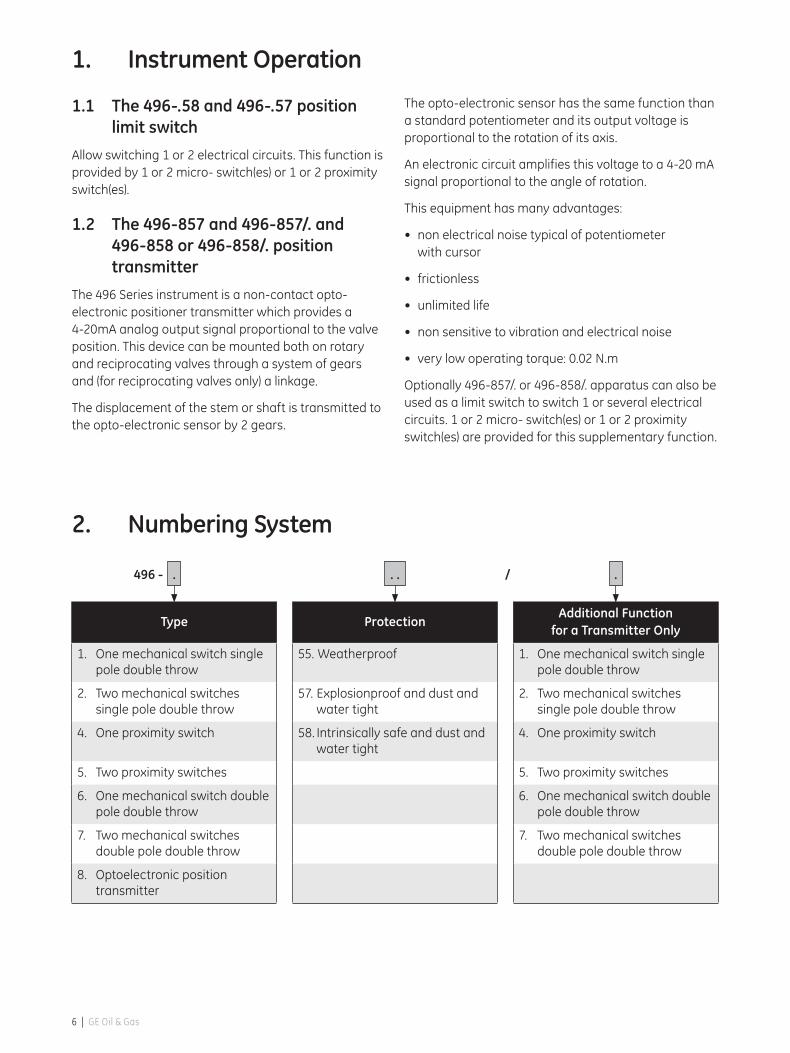
1. Instrument Operation
1.1 The 496-.58 and 496-.57 position limit switch
Allow switching 1 or 2 electrical circuits. This function is provided by 1 or 2 micro- switch(es) or 1 or 2 proximity switch(es).
1.2 The 496-857 and 496-857/. and 496-858 or 496-858/. position transmitter
The 496 Series instrument is a non-contact opto-electronic positioner transmitter which provides a 4-20mA analog output signal proportional to the valve position. This device can be mounted both on rotary and reciprocating valves through a system of gears and (for reciprocating valves only) a linkage.
The displacement of the stem or shaft is transmitted to the opto-electronic sensor by 2 gears.
The opto-electronic sensor has the same function than a standard potentiometer and its output voltage is proportional to the rotation of its axis.
An electronic circuit amplifies this voltage to a 4-20 mA signal proportional to the angle of rotation.
This equipment has many advantages:
• nonelectricalnoisetypicalofpotentiometer with cursor
• frictionless
• unlimitedlife
• nonsensitivetovibrationandelectricalnoise
• verylowoperatingtorque:0.02N.m
Optionally 496-857/. or 496-858/. apparatus can also be used as a limit switch to switch 1 or several electrical circuits. 1 or 2 micro- switch(es) or 1 or 2 proximity switch(es) are provided for this supplementary function.
2. Numbering System
Type ProtectionAdditional Function
for a Transmitter Only
1. One mechanical switch single pole double throw
55. Weatherproof 1. One mechanical switch single pole double throw
2. Two mechanical switches single pole double throw
57. Explosionproof and dust and water tight
2. Two mechanical switches single pole double throw
4. One proximity switch 58. Intrinsically safe and dust and water tight
4. One proximity switch
5. Two proximity switches 5. Two proximity switches
6. One mechanical switch double pole double throw
6. One mechanical switch double pole double throw
7. Two mechanical switches double pole double throw
7. Two mechanical switches double pole double throw
8. Optoelectronic position transmitter
. .. .496 - /
6 | GE Oil & Gas

3. Technical Specification
Internal components for limit switch and position transmitter are mounted inside an IP66/IP67 enclosure.
Performances of position transmitter type 496-857 or 496-857/. and 496-858 or 496-858/.
• Outputsignal:4-20mA(2wires)
• Acceptablespanonthecommandaxle:from25°to90°forrotaryorreciprocatingvalves
• Rotation:clockwiseorcounterclockwise
• Linearity:≤±0.5%forarotaryangleof25°to90°(typically±0.3%forarotaryangle≥60°)
• Hysteresis:≤0.1%
• Deadband:≤0.1%
• Repeatability:≤0.1%
• Totaldriftintemperature:0.02%/°Cor200ppm/°C(zeroandspanrange)
• Operatingtemperaturerange:-40°Cto+80°C
Electrical characteristics and temperature range of the position transmitter with micro-switch(es) or proximity switch(es) are given in the following sections.
496 Series Masoneilan* Position Transmitter and Limit Switch ATEX Instruction Manual (March 2014) | 7
4. ATEX Intrinsic Safety Marking and Electrical Safety Parameters
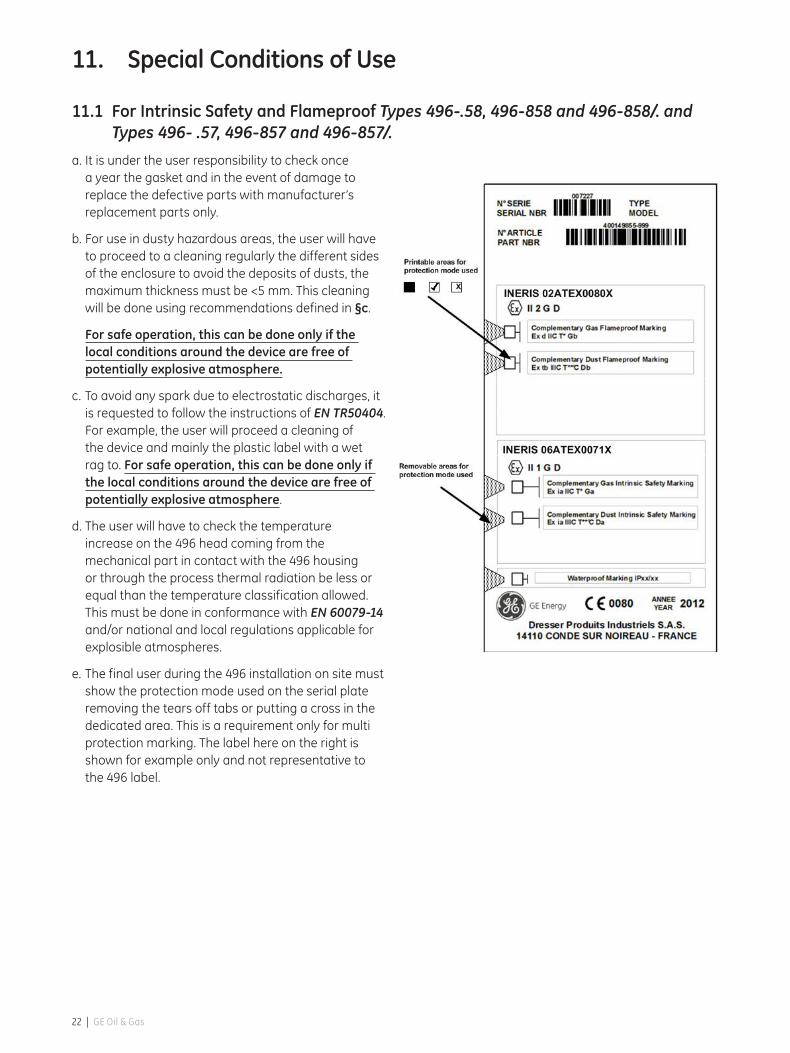
4.1 MarkingThe marking is on the serial plate stamped on the 496 cover (rep 14).
• Nameandaddressofthemanufacturer: Dresser Produits Industriels S.A.S. 14110 CONDE SUR NOIREAU - FRANCE
• Typedesignation:
– 496-858 for transmitter,
– 496-858/•for transmitter with additional function(s)
– 496-•58 for position switches
the “•” can take the values 1, 2, 4, 5.
• Basicandcomplementarymarking:
– Transmitteraloneorwithmechanicalswitch(es)(additional function):
II 1 GD
Ex ia IIC T.* Ga Tamb = -..°C à +..°C *
Ex ia IIIC T..°C* Da
– Transmitteraloneorwithproximityswitch(es)(additional function):
II 1G* or II 2G*
Ex ia IIC T.* Ga Tamb = -..°C à +..°C *
– Positionmechanicalswitch(es):
II 1 GD
Ex ia IIC T.* Ga Tamb = -..°C à +..°C *
Ex ia IIIC T..°C* Da
– Positionproximityswitch(es)(additionalfunction):
II 1G*, II 2G*
Ex ia IIC T.* Ga Tamb = -..°C à +..°C *
* Ambient temperatures ranges and surface temperatures for the temperature classifications T6, T5 and T4 are given in ANNEX I with:
– Tables1,2and3forthetransmitteralone,themechanical switch(es) alone and the proximity switch(es) alone.
– Tables4and5forthetransmitterwithmechanicalswitch(es) and for the transmitter with proximity switch(es).
• Serialnumber
• Yearofmanufacturing
• Numberofnotifiedbody ••••
• EC-Typeexaminationcertificatenumber
Warning:
AVERTISSEMENT : DANGER POTENTIEL DE CHARGES ELECTROSTATIQUES–VOIRINSTRUCTIONS
WARNING: POTENTIAL DANGER OF ELECTROSTATIC CHARGES. SEE INSTRUCTIONS
4.2 Electrical safety parameters
4.2.1 Type 496-.58
4.2.1.1 Option with 1 or 2 Micro-Switch(es)
• Typeidentificationis:496-158and496-258.
• Mechanicalswitch(es):typeBZ-2R72-A2,manufacturer: HONEYWELL
• Theyaresuppliedbyacertifiedpowersourceforexplosible atmospheres group IIC with the maximal characteristics:
– Constantpowersupply:Ui=30V,Ii=0.5A,Ci=0FandLi=0H
– Alternativepowersupply:Ui=90V,Ii=1.4A,Ci=0FandLi=0H
• Thewiringconnectionisdonedirectlyonmechanicalswitch(es).
4.2.1.2 Option with 1 or 2 Proximity Switch(es)
• Typeidentificationis:496-458 and 496-558.
• ThesedetectorsfromPEPPERL&FUCHSare defined as:
– II1GExiaIICT6Ga
– II2GExiaIICT6Gb
• ECtypeexaminationcertificate:
– PTB00ATEX2048X (II1G,II2G)
PTB 00 ATEX 2049 X (II1G, II2G)
8 | GE Oil & Gas

• Theyaresuppliedbyacertifiedpowersource* for explosible atmospheres with the maximal characteristics:
Ui=16V;Ii=0.052A;Pi=0.169W.
* The power source (Control circuit) must be one manufactured by Pepperl & Fuchs below:
WE 77/EX 1 or WE 77/EX 2
• Thewiringconnectionisdoneononeortwoterminalconnector type: MK3;2.5mm2;380volts;manufacturer:WEIDMULLER or equivalent product.
4.2.1.3 Maximum Input Characteristics
VariationUi (V)
Ii (A)
Ci (nF)
Li (μH)
Pi (W)
With Micro-switch
DC Source 30 0.5 0 0 –
AC Source Peak Value
90 1.4 0 0 -
With Proximity Switch 16 0.052 120 200 0.169
4.2.2 Types 496-858 and 496-858/. :
4.2.2.1 Type 496-8:
The position transmitter is connected to a linear tension sourceofacertifiedtypeforuseingroupIIChazardouslocations and its output circuit must be intrinsically safe approved per EN 60079-11.
Maximum input characteristics at terminal block:
Ui(V) Ii(A) Ci(nF) Li(μH) Pi(W)
28 0.11 36 0 0.77
4.2.2.2 Type 496-858/. :
The additional functions of position transmitters are identical to type 496-•58
Maximum input characteristics at terminal block of additional function:
VariationUi (V)
Ii (A)
Ci (nF)
Li (μH)
Pi (W)
With Micro-switch
DC Source 30 0.5 0 0 -
AC Source Peak Value
90 1.4 0 0 -
With Proximity Switch 16 0.052 120 200 0.169
4. ATEX Intrinsic Safety Marking and Electrical SafetyParameters(Contd)
496 Series Masoneilan* Position Transmitter and Limit Switch ATEX Instruction Manual (March 2014) | 9
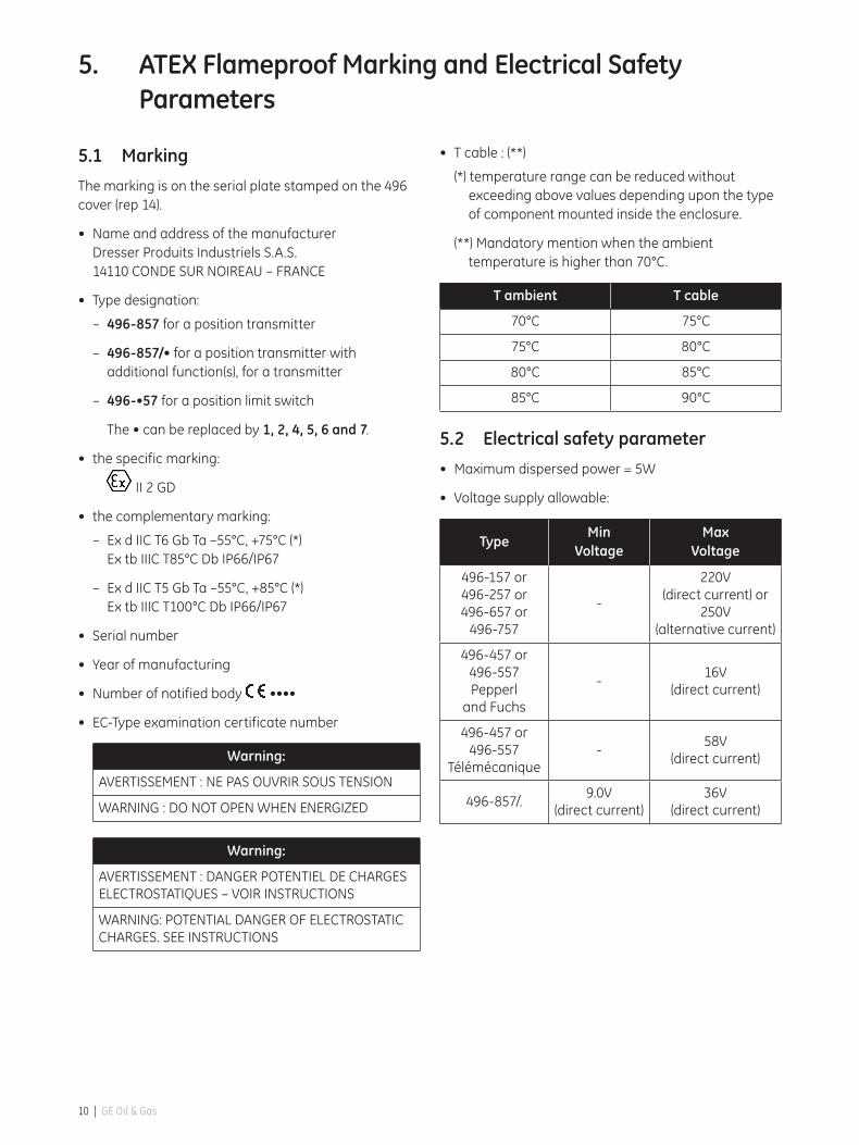
5. ATEX Flameproof Marking and Electrical Safety Parameters
5.1 MarkingThe marking is on the serial plate stamped on the 496 cover (rep 14).
• Nameandaddressofthemanufacturer Dresser Produits Industriels S.A.S. 14110CONDESURNOIREAU–FRANCE
• Typedesignation:
– 496-857 for a position transmitter
– 496-857/• for a position transmitter with additional function(s), for a transmitter
– 496-•57 for a position limit switch
The•canbereplacedby1, 2, 4, 5, 6 and 7.
• thespecificmarking:
II 2 GD
• thecomplementarymarking:
– ExdIICT6GbTa–55°C,+75°C(*) Ex tb IIIC T85°C Db IP66/IP67
– ExdIICT5GbTa–55°C,+85°C(*) Ex tb IIIC T100°C Db IP66/IP67
• Serialnumber
• Yearofmanufacturing
• Numberofnotifiedbody ••••
• EC-Typeexaminationcertificatenumber
Warning:
AVERTISSEMENT : NE PAS OUVRIR SOUS TENSION
WARNING : DO NOT OPEN WHEN ENERGIZED
Warning:
AVERTISSEMENT : DANGER POTENTIEL DE CHARGES ELECTROSTATIQUES–VOIRINSTRUCTIONS
WARNING: POTENTIAL DANGER OF ELECTROSTATIC CHARGES. SEE INSTRUCTIONS
• Tcable:(**)
(*) temperature range can be reduced without exceeding above values depending upon the type of component mounted inside the enclosure.
(**) Mandatory mention when the ambient temperature is higher than 70°C.
T ambient T cable
70°C 75°C
75°C 80°C
80°C 85°C
85°C 90°C
5.2 Electrical safety parameter• Maximumdispersedpower=5W
• Voltagesupplyallowable:
TypeMin
VoltageMax
Voltage
496-157 or 496-257 or496-657 or
496-757
-
220V (direct current) or
250V (alternative current)
496-457 or 496-557Pepperl
and Fuchs
-16V
(direct current)
496-457 or 496-557
Télémécanique-
58V (direct current)
496-857/.9.0V
(direct current)36V
(direct current)
10 | GE Oil & Gas
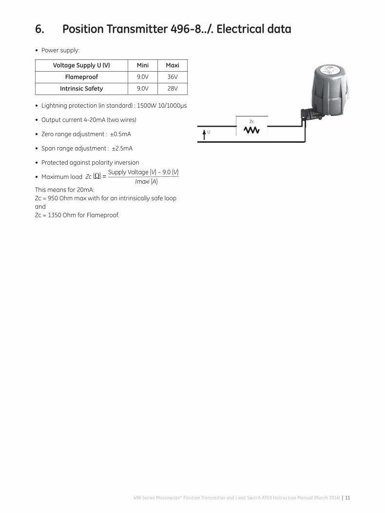
6. Position Transmitter 496-8../. Electrical data
• Powersupply:
VoltageSupplyU(V) Mini Maxi
Flameproof 9.0V 36V
Intrinsic Safety 9.0V 28V
• Lightningprotection(instandard):1500W10/1000µs
• Outputcurrent4-20mA(twowires)
• Zerorangeadjustment:±0.5mA
• Spanrangeadjustment:±2.5mA
• Protectedagainstpolarityinversion
• Maximumload
This means for 20mA:Zc=950Ohmmaxwithforanintrinsicallysafeloopand Zc=1350OhmforFlameproof.
Imaxi (A)Supply Voltage (V) – 9.0 (V)
Zc (Ω) =
Zc
U
496 Series Masoneilan* Position Transmitter and Limit Switch ATEX Instruction Manual (March 2014) | 11
7. Electrical Connection, Installation and Start-up
• Complywithcurrentnationalandlocalregulationsforelectricalinstallationwork.
• MustbeinstalledandputintoserviceinconformancewithEN60079-14and/ornationalandlocalregulations applicable for explosible atmospheres.
• Beforecarryingoutanyworkonthedevice,powerofftheinstrumentormakesurethatthelocalconditions in the potentially explosive atmosphere permit – the safe opening of the cover.
• Connectthewirestotheinstrumentterminals,takingcareofcomplyingwithpolaritiesandmaximumvoltage allowed.
• Beforepoweruporafterdoinganyworkonthedevicealwayscheckthecover(12)isfullyscrewed,O-ring(10)isfreeofanydamageandsecurityscrew(9)iswelllocked.
Note: Before installation, check that the device is undamaged. In the event of damage, inform the manufacturer whose address is shown on the serial plate.
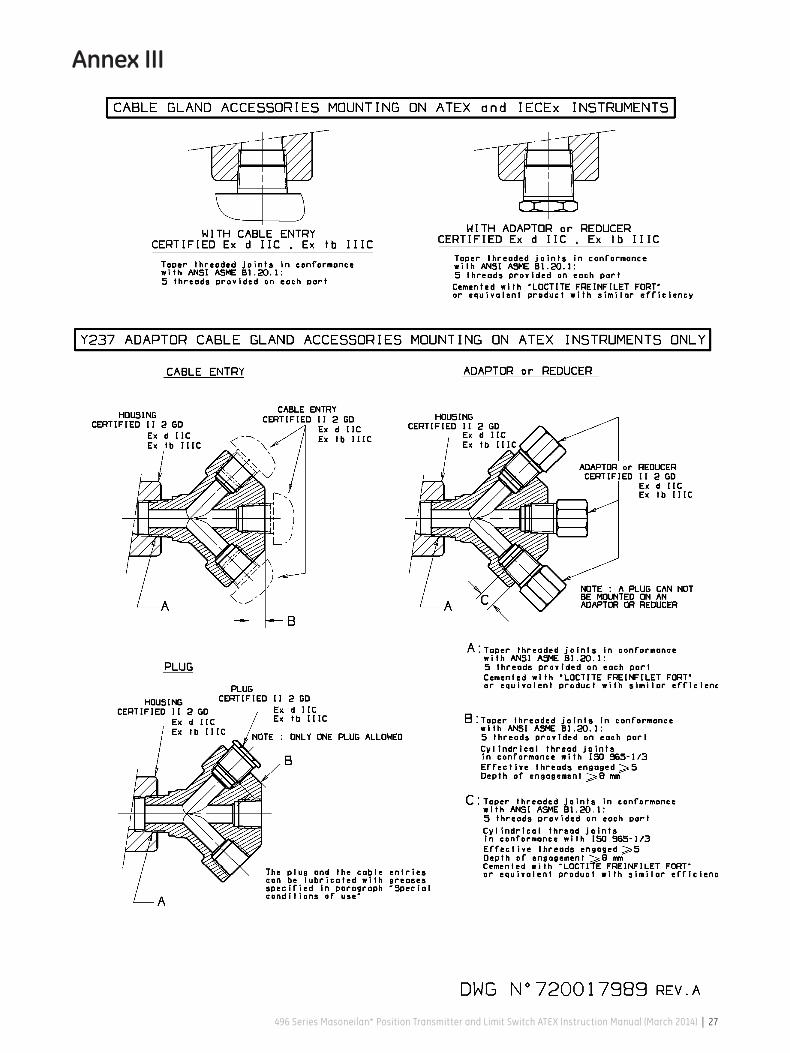
7.1 Conduit entry in flameproof applicationThe connections can be done with different variations taking into account approved manufacturer and requested approvals:
• AcableentryofacertifiedtypeEx d IIC / Ex tb IIIC can be mounted directly on the single ¾" NPT (ANSI/ASME B1.20.1) housing conduit connection.
• Foranadaptororreducerneed,thesecomponentare allowed:
Adaptor or Reducer
Manufacturer CertificationATEX
CertificateIECEx
Certificate
REDAPTEx d IIC
Ex tb IIIC
SIRA 99 ATEX
1115U
IECEx SIR 05.0042U
Other adaptors or reducers if apparatus certified ATEX or IECEx (CooperCAPRICODEC).
• Formultiplecableentries(3maximum),theadaptorY237 “Masoneilan” can be used for ATEX application only.
– IfoneY237 input is not used, the conduit will be closed by the followed plugs:
Plug
Manufacturer CertificationATEX
CertificateIECEx
Certificate
REDAPTEx d IIC
Ex tb IIIC
SIRA 99 ATEX
1115U
IECEx SIR 05.0042U
Others plugs if apparatus certified ATEX or IECEx (type Cooper CAPRI CODEC).
– IftwoY237inputsarenotused,theY237mustbesuppressed.
• Thecableentrywithorwithoutitsadaptor/reducerand the Y237 with its cable entry must be installed in conformance with Annex III.
12 | GE Oil & Gas

7. ElectricalConnection,InstallationandStart-up(Contd)
7.2 Electrical connection for type 496-.57 or 496-.58
• Theelectricalcablesareconnectedeitherdirectlyon to the micro switch(es) or to the proximity switch terminal block.
• Connectthedevicetotheearthusingtheearthconnections provided inside and outside the housing of the device.
• Basicruleforwiring:
– Must be used in addition to local regulation for electrical installation
– Connector slot approval:
– Insulation must be free of any damage along the wires inside the housing
– Tightening must be sufficient to bring constant contact in time without being excessive to cut or damage connection.
7.3 Electrical connection for type 496-857 or 496-857/. and 496-858 or 496-858/.
Connect the electrical cables to the position transmitter terminal block located on the printed circuit board. Respectthepolarities+and–andthemaximumvoltage allowed.
When a position transmitter is provided with an additional function, the electrical cables are connected either directly on to the micro switch(es) or to the proximity switch terminal block.
Connect the device to the earth using the earth connections provided inside the housing and on the outside of the device.
• Basicruleforwiring:
– Must be used in addition to local regulation for electrical installation
– Connector slot approval:
– Insulation must be free of any damage along the wires inside the housing
– Tightening must be sufficient to bring constant contact in time without being excessive to cut or damage connection.
496 Series Masoneilan* Position Transmitter and Limit Switch ATEX Instruction Manual (March 2014) | 13
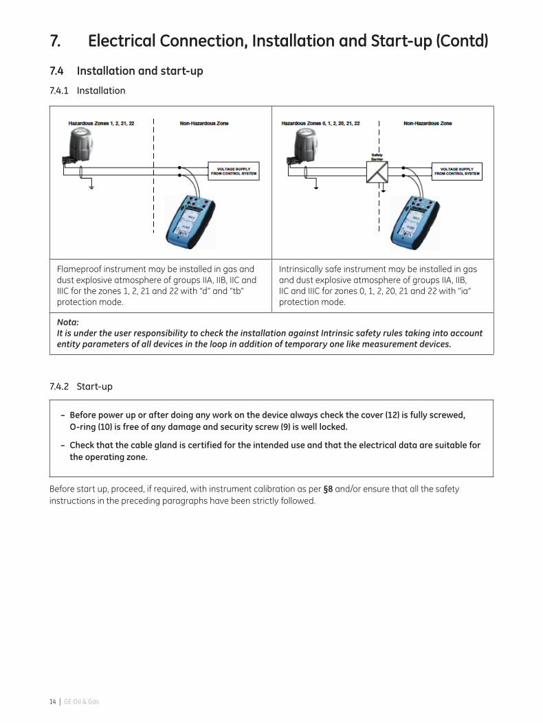
7.4 Installation and start-up
7.4.1 Installation
7.4.2 Start-up
– Beforepoweruporafterdoinganyworkonthedevicealwayscheckthecover(12)isfullyscrewed,O-ring(10)isfreeofanydamageandsecurityscrew(9)iswelllocked.
– Check that the cable gland is certified for the intended use and that the electrical data are suitable for the operating zone.
Before start up, proceed, if required, with instrument calibration as per §8 and/or ensure that all the safety instructions in the preceding paragraphs have been strictly followed.
7. ElectricalConnection,InstallationandStart-up(Contd)
Flameproof instrument may be installed in gas and dust explosive atmosphere of groups IIA, IIB, IIC and IIICforthezones1,2,21and22with“d”and“tb”protection mode.
Intrinsically safe instrument may be installed in gas and dust explosive atmosphere of groups IIA, IIB, IICandIIICforzones0,1,2,20,21and22with“ia”protection mode.
Nota: It is under the user responsibility to check the installation against Intrinsic safety rules taking into account entity parameters of all devices in the loop in addition of temporary one like measurement devices.
14 | GE Oil & Gas

8. Calibration
Before power up the device to proceed with calibration carefully read the following safety warnings.
– Comply with current national and local regulations for electrical installation work.
– Must be installed and put into service in conformance with EN 60079-14 and / or national and local regulations applicable for explosible atmospheres.
– Before carrying out any work on the device, power off the instrument or make sure that the local conditions in the potentially explosive atmosphere permit- the safe opening of the cover.
– Connect the wires to the instrument’s terminals, taking care of complying with polarities and maximum voltage allowed.
– Before power up or after doing any work on thedevicealwayscheckthecover(12)isfullyscrewed,O-ring(10)isfreeofanydamageandsecurityscrew(9)iswelllocked.
8.1 Calibration of rotary limit switch 496-.57 and 496-.58 equipped with microswitch(es)
• Theconcaveportionofthelever(5)mustbestrictlyconcentric to the cam (13) when the micro-switch is actuated.
• Thisisanimportantcautiontomakesuretheleverisproperly depressed when not actuated.
• Ifnot,loosenthescrews(3&17)andslightlymovethe lever upwards or downwards. Tighten the screws.
• Slightlyloosenthecamlockingscrew(1)usinga3/32” socket hex head wrench.
• Movetheplugstemtothepositionrequiredtoactuate the switch.
• Itisimportanttonotethatthecamoperatingtheright hand micro-switch must actuate the lever (5) at the end of the counterclockwise rotation. (See detail figure below).
• Thismakessurethescrew(2)hasfreethelever(5)when the valve is throttling. The remaining concave portion only ensures micro-switch actuation in case of over travel. Conversely, the cam operating the left hand micro-switch must actuate the lever (5) at the end of the clockwise rotation. (See front view below).
• Tomeettheaboverequirementwhenonlyonemicro-switch is provided (type 496-158) it may be necessary to change the location of the micro-switch.
• Rotatethecam(13)untilthemicro-switchisactuated. Lock the cam (13) tightening the screw (1).
• Finetuneadjustmentwithscrew(2).Usea1/16”socket hex head wrench. The screw (2) must come out the cam enough to properly depress the lever (5).
• Strictly follow safety instructions under §7.4 before putting into service.
496 Series Masoneilan* Position Transmitter and Limit Switch ATEX Instruction Manual (March 2014) | 15
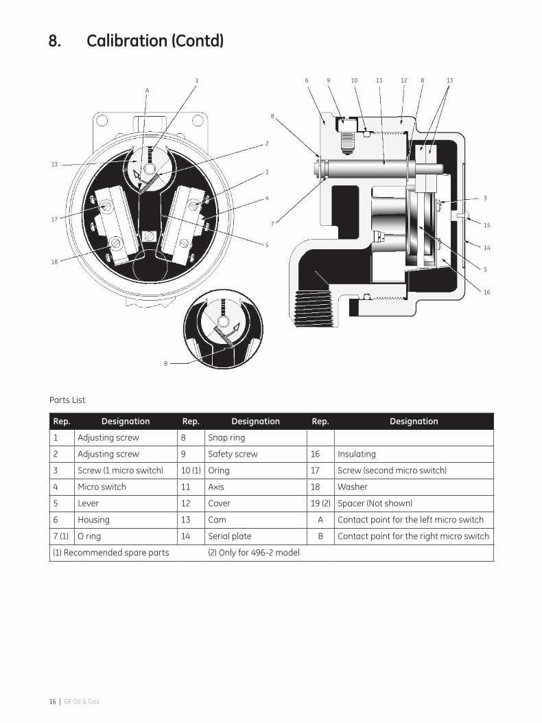
Parts List
Rep. Designation Rep. Designation Rep. Designation
1 Adjusting screw 8 Snap ring
2 Adjusting screw 9 Safety screw 16 Insulating
3 Screw (1 micro switch) 10 (1) Oring 17 Screw (second micro switch)
4 Micro switch 11 Axis 18 Washer
5 Lever 12 Cover 19 (2) Spacer (Not shown)
6 Housing 13 Cam A Contact point for the left micro switch
7 (1) O ring 14 Serial plate B Contact point for the right micro switch
(1) Recommended spare parts (2) Only for 496-2 model
8. Calibration(Contd)
A
1 6 9 10 11 12 8
8
2
3
4
7
5
13
17
18
3
15
14
5
16
B
13
16 | GE Oil & Gas

8. Calibration(Contd)
8.2 Calibration of rotary limit switch 496-.57 and 496-.58 equipped with proximityswitch(es)
8.2.1 Type 496-4
• Actuatethevalvetothedesiredtriggeringpositionand check the sense of rotation when the arm leaves the proximity sensor.
• Thefigurebelowshowsthelocationoftheproximitysensor and of the arm when triggering as a function of the sense of rotation.
• Slowlymovethearmtowardstheproximitysensoruntil it triggers. Triggering occurs when the arm overlaps approximately 1/3 of the proximity switch.
• Strictly follow safety instructions under §7.4 before putting into service.
Rep. Designation Rep. Designation
33 Arm 34 Proximity switch
8.2.2 Type 496-5
During adjustment make sure that the proximity switch with the red spot is triggered by the arm with the red spot.
• Adjustmentofthefirstproximityswitch
– Thefirstswitchisadjustedatthebeginningof the stroke.
– Checkwhatwillbethesenseofrotationwhenthevalve is actuated. Figure (b, c) below shows the proximity sensor and the arm assigned to the first triggering point for a given the sense of rotation.
– Slowlymovethearmtowardstheproximityswitchuntil it triggers.
• Adjustmentofthesecondproximityswitch
– Thesecondswitchisadjustedattheendoftheactuator stroke.
– Immobilizethefirstarmpreviouslyadjustedandslowly move the second arm towards the second proximity sensor until it triggers.
– Makesurethefirstproximityswitchisstill correctly adjusted.
• Strictly follow safety instructions under §7.4 before putting into service.
Rep. Designation Rep. Designation
A Red spot B First triggering point
34 34
33
A
a
b cB
B
496 Series Masoneilan* Position Transmitter and Limit Switch ATEX Instruction Manual (March 2014) | 17

8. Calibration(Contd)
8.2.3 Air-gap adjustment
Air-gap between the proximity switch and the arm is factory adjusted. If new adjustment is required proceed as follows:
• Loosentheproximitysensornut(37A),locatedonthefront of the bracket (36).
• Unscrewafewturnsthelocknut(37B)locatedontheback of the bracket.
• Positionthearmabovetheproximitysensorandpush the shaft end (11) towards the outside of the housing so as to eliminate the longitudinal play.
• Holdinpositiontheproximitysensorandscrewthenut (37A). Adjust air gap to 0,3 mm using a shim
• Tightenthelocknut(37B).
3
7
25 14
15
36
33
32
31
3
24
8
6 9 10 11 12 8 30 37A
34 37B 19
Parts List
Rep. Designation Rep. Designation Rep. Designation
3 Screw 12 Cover 31 Snap ring
6 Housing 14 Serial plate 32 Washer
7 (1) O-ring 33 Arm
8 Snap ring 19 Spacer 34 Proximity sensor
9 Safety screw 24 Terminal block 35 (2) Spacer (Not shown)
10 (1) O-ring 25 Terminal block 36 Sensor bracket
11 Axis 30 Spacer 37 Nut
(1) Recommended spare parts (2) Only for 496-4 model
18 | GE Oil & Gas

8. Calibration(Contd)
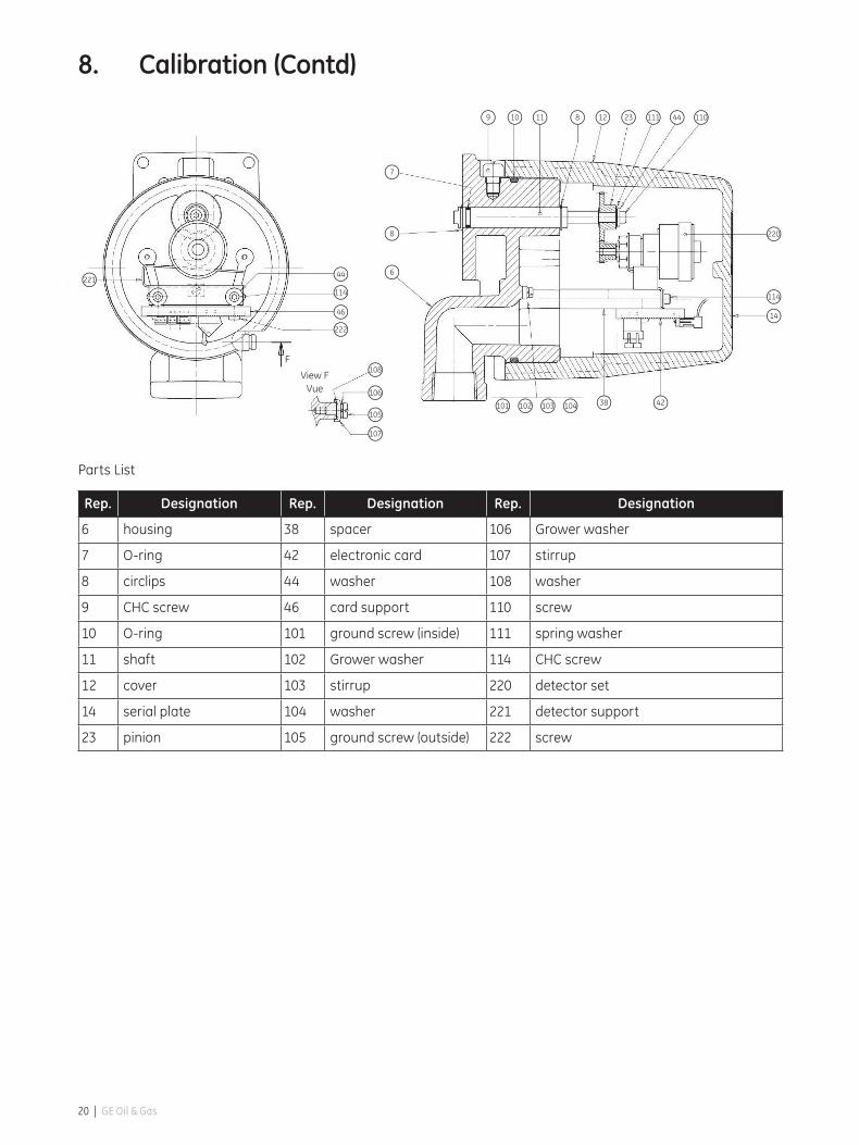
8.3 Calibration of position transmitter 496-858 or 496-858/
• Action
The action sense of the valve (open or closed valve, compared to the 4 - 20 mA of the loop signal), determines the position of the connector 3 points of the optoelectronic sensor on one of the two connectors of electronic circuit A or B.
The operation rule is: for a clockwise rotation of the pinion of the control shaft (view cover side), the output current increases (4→20 mA) when the connector of the optoelectronic sensor is connected in A and decreases when connected in B.
• Linkageadjustment
When mounted on reciprocating valves, adjust the turnbuckle to get the instrument lever perpendicular to the plug stem at mid-travel.
• Positiontransmitteradjustment
– Positiontheconnector3pointsonconnectorA or B in function of the chosen action.
– Presetmidtravelthezeroadjustment(Z) if necessary *.
– Presetmidtravelthespanadjustment(S)ifnecessary **.
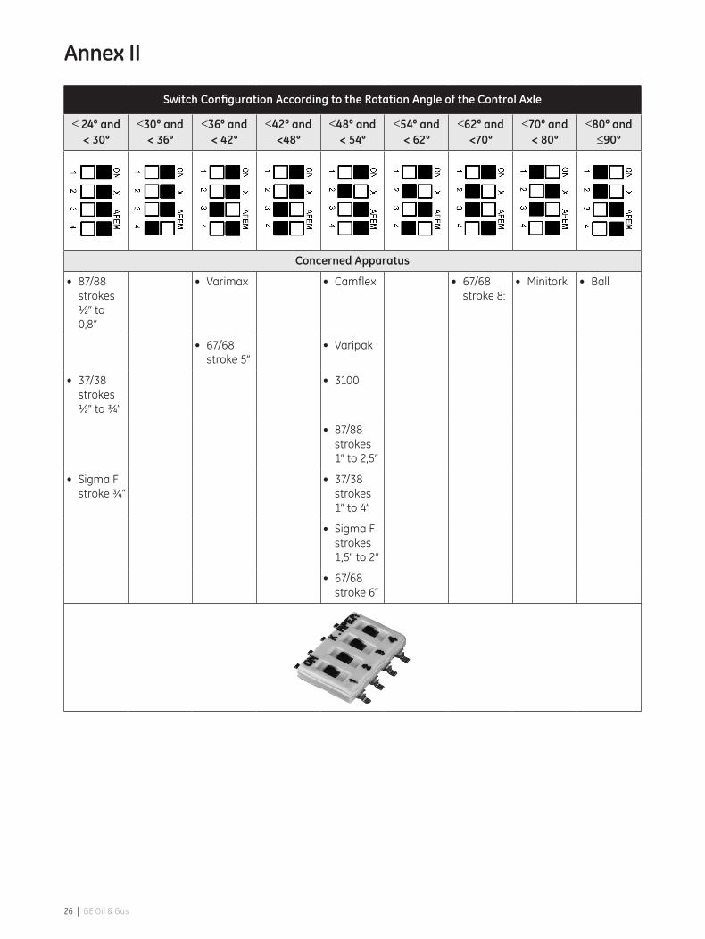
– ConfiguretheswitchC(seeannexII)ontherotation angle of the control axle.
– Positionthevalvetotheoriginoftravelthatshouldcorrespond to the minimum of the signal (4 mA).
– Installamilliampmeterinseriesintheloopandpower up the instrument.
– Rotatetheprimarypiniononthecontrolaxletoget an output signal around 4 mA
– Finetune-upofthe4mAsignalwiththezeropotentiometer (Z).
– Fullstrokethevalvetotheratedtravelandadjust the output signal to 20 mA with the span potentiometer (S).
– Checkthezeroandspancalibrationcomparedtothevalvestroke.Repeatthezeroandspancalibration operations if necessary.
* In case of problem of Zero adjustment due to the physical limits of the potentiometer, turn of 5 turns in the reverse direction that desired and turn the primary pinion to obtain an output current nearest to 4 mA.
** In case of problem of span adjustment due to the physical limits of the potentiometer, turn of 5 turns in the reverse direction that desired and configure the switch C (see annex II) for a higher or lower angle than that basis.
• Adjustmentofmicro-switch(es)orproximityswitch(es)
Refer to paragraph §8.1 or §8.2 to adjust micro-switches or proximity switch(es).
• Strictlyfollowsafetyinstructionsunder§7.4beforeputting into service.
Mas
onei
lan
C
Z
-
+
S
PN:
BA
496 Series Masoneilan* Position Transmitter and Limit Switch ATEX Instruction Manual (March 2014) | 19
8. Calibration(Contd)
Parts List
Rep. Designation Rep. Designation Rep. Designation
6 housing 38 spacer 106 Grower washer
7 O-ring 42 electronic card 107 stirrup
8 circlips 44 washer 108 washer
9 CHC screw 46 card support 110 screw
10 O-ring 101 ground screw (inside) 111 spring washer
11 shaft 102 Grower washer 114 CHC screw
12 cover 103 stirrup 220 detector set
14 serial plate 104 washer 221 detector support
23 pinion 105 ground screw (outside) 222 screw
101 102 103 104 38 42
14
114
220
6
8
7
222
46
114
44
107
221
105
106
108
9 10 11 8 12 23 111 44 110
F
View FVue
20 | GE Oil & Gas

9. Maintenance
– Before carrying out any work on the device, power off the instrument or make sure the local conditions are free of potentially explosive atmosphere for safe opening of the cover.
– These operations must be done in conformance with EN 60079-17 and / or national and local regulations applicable for explosible atmospheres.
– Before power up or after doing any work onthedevicealwayscheckthecover(12)isfullyscrewed,O-ring(10)isfreeofanydamageandsecurityscrew(9)iswelllocked.
• Checkthatnopartofthe496isdamaged.
In the event of damage replace the defective parts with genuine manufacturer’s replacement part.
• Payparticularattentiontothefollowing:
– Checkdevice,mechanicallinkandgeneralaspect.
– Checkthecableglandandtheelectricalconnections.
– ChecktheconditionoftheO-ring(10)of cover (12) and O-ring (7) of the shaft (11).
– Makesurethatshaft(11)isnotwornout or damaged.
– Iftheshaft(11)mustberemoved,makesuretheoriginal circlips (8) is put back in place. Check that neither the housing nor the shaft are damaged.
• Instrumentsinstalledinzones20,21and22mustbecleaned to prevent any dust build up on the walls. See instruction §11.1 b&c for safe cleaning.
10. Special Conditions of Work
Based on 94/9/EC directive, a training session must be followedbypersonusuallyrecognizedtouseapparatusin explosible atmospheres.
This training session is not supported par Dresser Produits Industriels S.A.S.
496 Series Masoneilan* Position Transmitter and Limit Switch ATEX Instruction Manual (March 2014) | 21
11. Special Conditions of Use
11.1 For Intrinsic Safety and Flameproof Types 496-.58, 496-858 and 496-858/. and Types 496- .57, 496-857 and 496-857/.
a. It is under the user responsibility to check once a year the gasket and in the event of damage to replace the defective parts with manufacturer’s replacement parts only.
b.Foruseindustyhazardousareas,theuserwillhaveto proceed to a cleaning regularly the different sides of the enclosure to avoid the deposits of dusts, the maximum thickness must be <5 mm. This cleaning will be done using recommendations defined in §c.
For safe operation, this can be done only if the local conditions around the device are free of potentially explosive atmosphere.
c. To avoid any spark due to electrostatic discharges, it is requested to follow the instructions of EN TR50404. For example, the user will proceed a cleaning of the device and mainly the plastic label with a wet rag to. For safe operation, this can be done only if the local conditions around the device are free of potentially explosive atmosphere.
d. The user will have to check the temperature increase on the 496 head coming from the mechanical part in contact with the 496 housing or through the process thermal radiation be less or equal than the temperature classification allowed. This must be done in conformance with EN 60079-14 and/or national and local regulations applicable for explosible atmospheres.
e. The final user during the 496 installation on site must show the protection mode used on the serial plate removing the tears off tabs or putting a cross in the dedicated area. This is a requirement only for multi protection marking. The label here on the right is shown for example only and not representative to the 496 label.
22 | GE Oil & Gas

11.2 Intrinsically safe apparatus: Types 496-.58, 496-858 and 496-858/.• Thecableentrymusthaveaprotectionlevelatleast
equal to IP6X according to EN 60529 standards.
• Forthe496housingwithaluminummaterial,theuser will have to determine the use of the device for groupIIcategory1(zone0)against potential inflammable source causing by sparks in the event of impact or friction.
• Thevoltagesupplyconnectedoneach496connectors must be certified for use in group IIC and the loop intrinsic safety approved. The entity parameters of the voltage supply must be compatible with the entity parameters of the 496 described §4.2.
11.3 Explosion proof apparatus: Types 496-.57, 496-857 and 496-857/.
• Whentheambienttemperatureishigherthan70°C,the user will have to choose a cable entry and a cable compatible with the data of the table below:
T ambient T cable
70°C 75°C
75°C 80°C
80°C 85°C
85°C 90°C
• Theminimaltemperatureofthecableisindicatedonthe serial plate.
• Whentheambienttemperatureislowerthan-20°C,the user will have to choose a cable entry and a cable compatible with the ambient temperature specified on the marking plate.
• Thecableentrymusthaveadegreeofprotectionatleast equal to IP66/67.
• Useonlythefollowinggreasesfortheexplosion-proof gaskets, shaft, cover threads, cable gland and plug for Y237:
Type Manufacturer
SI 33 ORAPI
GRAPHENE 702 ORAPI
MOLYKOTE 111 COMPOUND MOLYKOTE®
MULTILUB MOLYKOTE®
GRIPCOTT NF MOLYDAL
• Allmechanicalpartscoupledwiththelimitswitchortransmitter and likely to generate a spark or a hot surface will have to be the object, on behalf of the user, an analysis of the risks in agreement with the Directive 94/9/CE. The user will have to follow the conformitymoduleadaptedtothezoneinwhichitwill be installed.
• Theshaftjointtoleranceislowerthanonedefinedbythe standard EN 60079-1. It must be respected with a maximum radial gap of 0.133mm.
• Thelengthofexplosion-proofgasketsisgreaterthanthe one defined in the sheet of EN 60079-1.
11. SpecialConditionsofUse(Contd.)
496 Series Masoneilan* Position Transmitter and Limit Switch ATEX Instruction Manual (March 2014) | 23

24 | GE Oil & Gas
Annex I
Table 1 MinandMaxAmbientTemperatures(°C)
Type 496-858Ci Li 1G/2G/1D 1G/2G 1D
nF µH MIN T6 T5 T4 T85°C T100°C
Transmitter 30 0 -40 70 80 80 70 80
Table 2 MinandMaxAmbientTemperatures(°C)
Type 496-158 and 496-258
Ci Li 1G/2G/1D 1G/2G 1D
nF µH MIN T6 T5 T4 T85°C T100°C
BZ-2R-72-A2 0 0 -55 80 80 80 70 80
Table 3 MinandMaxAmbientTemperatures(°C)
Type 496-458 and 496-558Ci Li 1G/2G 1G 2G 1D
nF µH MIN T6 T5 T4 T6 T5 T4 T85°C T100°C
NJ2-11-N-G 30 50 -25 45 57 81 62 77 81
NJ2-11-SN-G 50 150 -40 45 57 81 62 77 81
NJ2-12GK-N 45 50 -25 51 66 80
NJ2-12GK-SN 50 150 -40 34 46 74 51 66 80
NJ2-12GM-N 30 50 -25 45 57 81 62 77 81
NCB2-12GM35 NO 90 100 -25 45 57 81 62 77 81
NJ3-18-GK-S1N 70 200 -25 34 46 74 51 66 80
NJ4-12GK-N 45 50 -25 51 66 80
NJ4-12GK-SN 70 150 -50 34 46 74 51 66 80
NJ5-18GK-N 70 50 -25 34 46 74 51 66 80
NJ5-18GK-SN 120 200 -40 34 46 74 51 66 80
NJ5-18GM-N 70 50 -25 45 57 81 62 77 81
NJ5-30GK-S1N 100 200 -25 34 46 74 51 66 80
NCB5-18GM40 NO 95 100 -25 45 57 81 62 77 81
496 Series Masoneilan* Position Transmitter and Limit Switch ATEX Instruction Manual (March 2014) | 25
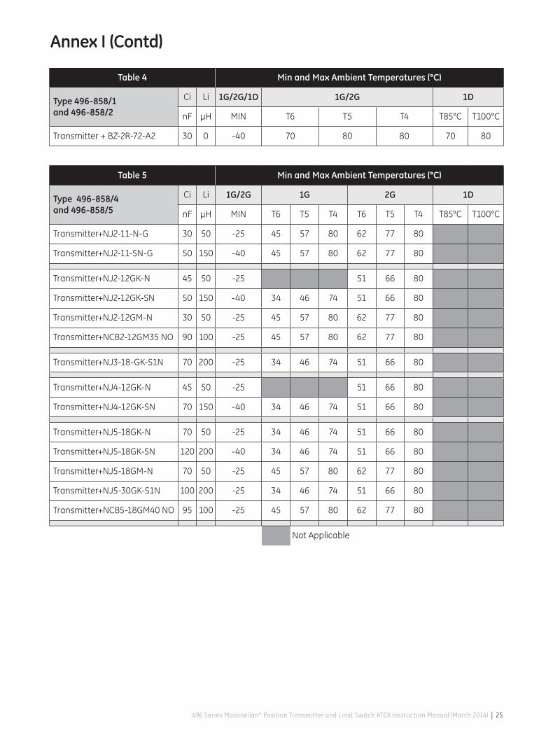
Table 4 MinandMaxAmbientTemperatures(°C)
Type 496-858/1 and 496-858/2
Ci Li 1G/2G/1D 1G/2G 1D
nF µH MIN T6 T5 T4 T85°C T100°C
Transmitter+BZ-2R-72-A2 30 0 -40 70 80 80 70 80
Table 5 MinandMaxAmbientTemperatures(°C)
Type 496-858/4 and 496-858/5
Ci Li 1G/2G 1G 2G 1D
nF µH MIN T6 T5 T4 T6 T5 T4 T85°C T100°C
Transmitter+NJ2-11-N-G 30 50 -25 45 57 80 62 77 80
Transmitter+NJ2-11-SN-G 50 150 -40 45 57 80 62 77 80
Transmitter+NJ2-12GK-N 45 50 -25 51 66 80
Transmitter+NJ2-12GK-SN 50 150 -40 34 46 74 51 66 80
Transmitter+NJ2-12GM-N 30 50 -25 45 57 80 62 77 80
Transmitter+NCB2-12GM35NO 90 100 -25 45 57 80 62 77 80
Transmitter+NJ3-18-GK-S1N 70 200 -25 34 46 74 51 66 80
Transmitter+NJ4-12GK-N 45 50 -25 51 66 80
Transmitter+NJ4-12GK-SN 70 150 -40 34 46 74 51 66 80
Transmitter+NJ5-18GK-N 70 50 -25 34 46 74 51 66 80
Transmitter+NJ5-18GK-SN 120 200 -40 34 46 74 51 66 80
Transmitter+NJ5-18GM-N 70 50 -25 45 57 80 62 77 80
Transmitter+NJ5-30GK-S1N 100 200 -25 34 46 74 51 66 80
Transmitter+NCB5-18GM40NO 95 100 -25 45 57 80 62 77 80
Not Applicable
AnnexI(Contd)
26 | GE Oil & Gas
Switch Configuration According to the Rotation Angle of the Control Axle
≤ 24° and < 30°
≤30° and < 36°
≤36° and < 42°
≤42° and <48°
≤48° and < 54°
≤54° and < 62°
≤62° and <70°
≤70° and < 80°
≤80° and ≤90°
Concerned Apparatus
• 87/88strokes ½” to 0,8”
• Varimax • Camflex • 67/68stroke 8:
• Minitork • Ball
• 67/68stroke 5”
• Varipak
• 37/38strokes ½” to ¾”
• 3100
• 87/88strokes 1” to 2,5”
• SigmaFstroke ¾”
• 37/38strokes 1” to 4”
• SigmaFstrokes 1,5” to 2”
• 67/68stroke 6”
Annex II
496 Series Masoneilan* Position Transmitter and Limit Switch ATEX Instruction Manual (March 2014) | 27
Annex III

AUSTRALIABrisbanePhone: +61-7-3001-4319Fax: +61-7-3001-4399
PerthPhone: +61-8-6595-7018Fax: +61-8-6595-7299
MelbournePhone: +61-3-8807-6002Fax: +61-3-8807-6577
BELGIUMPhone: +32-2-344-0970Fax: +32-2-344-1123
BRAZILPhone: +55-11-2146-3600Fax: +55-11-2146-3610
CHINAPhone: +86-10-5689-3600Fax: +86-10-5689-3800
FRANCECourbevoiePhone: +33-1-4904-9000Fax: +33-1-4904-9010
GERMANYRatingenPhone: +49-2102-108-0Fax: +49-2102-108-111
INDIAMumbaiPhone: +91-22-8354790Fax: +91-22-8354791
New DelhiPhone: +91-11-2-6164175Fax: +91-11-5-1659635
ITALYPhone: +39-081-7892-111Fax: +39-081-7892-208
JAPANChiba Phone: +81-43-297-9222Fax: +81-43-299-1115
KOREAPhone: +82-2-2274-0748Fax: +82-2-2274-0794
MALAYSIAPhone: +60-3-2161-0322Fax: +60-3-2163-6312
MEXICOPhone: +52-55-3640-5060
THE NETHERLANDSPhone: +0031-15-3808666Fax: +0031-18-1641438
RUSSIAVeliky NovgorodPhone: +7-8162-55-7898Fax: +7-8162-55-7921
MoscowPhone: +7495-585-1276Fax: +7495-585-1279
SAUDI ARABIAPhone: +966-3-341-0278Fax: +966-3-341-7624
SINGAPOREPhone: +65-6861-6100Fax: +65-6861-7172
SOUTH AFRICAPhone: +27-11-452-1550Fax: +27-11-452-6542
SOUTH & CENTRAL AMERICA AND THE CARIBBEANPhone: +55-12-2134-1201Fax: +55-12-2134-1238
SPAINPhone: +34-93-652-6430Fax: +34-93-652-6444
UNITED ARAB EMIRATESPhone: +971-4-8991-777Fax: +971-4-8991-778
UNITED KINGDOMWooburn GreenPhone: +44-1628-536300Fax: +44-1628-536319
UNITED STATESMassachusettsPhone: +1-508-586-4600Fax: +1-508-427-8971
Corpus Christi, Texas Phone: +1-361-881-8182Fax: +1-361-881-8246
Deer Park, TexasPhone: +1-281-884-1000Fax: +1-281-884-1010
Houston, TexasPhone: +1-281-671-1640Fax: +1-281-671-1735
DIRECT SALES OFFICE LOCATIONS
GEA31058A 03/2014
Visit us online at:
www.geoilandgas.com/valves
*Masoneilan is a registered trademarks of the General Electric Company.
Other company names and product names used in this document are the
registered trademarks or trademarks of their respective owners.
© 2014 General Electric Company. All rights reserved.


