128 Safety relief valves VARIVENT ® safety relief valves have been specifically developed for the requirements of the food, beverage and pharmaceuticals industries and meet the requirements of the relevant rules, such as DIN 11866 or ASME BPE. Due to the inlet area free from dead zones, the unique elastomer bellows and the optional pneumatic lifting, the valves are characterized by very good cleaning ability (CIP/SIP). Many connections permit best adjustment of the valves to different tasks. Application examples Safety relief valves protect from excess pressure, e.g. for vessels within a sterilization process or during filling. They secure fermentation tanks in case of unexpected faults. Safety relief valves are also used for inner pressure relief of vessels and other process equipment for curing media such as chocolate. Function of the valve Full stroke safety relief valves are used in areas where surge flows or very fast pressure increases occur, due to their quick opening response. The main application is in pressure relief of steams and gases.Since the full stroke safety relief valve performs a full stroke after opening – no matter the pending flow rate – the full flow rate can be discharged even at a slight pressure increase. Normal safety relief valves are ideal pressure relief valves. Their large proportional range leads to a continuous operating method and relief of pressure spikes specifically in liquids. The valves have a full stroke charge after an expanded proportional phase and thus reach a higher flow rate. They are also used as overflow valves and are used when the smallest design of the full stroke safety relief valve is too large already. To ensure hygienic cleaning (CIP) or sterilization (SIP) of all surfaces in the system, the safety relief valves are available with a pneumatic lifting mechanism. Special features High-quality materials and surface finish Manual or pneumatic lifting Insensitive to temperature Welded housing in CIP-able design Self-draining housing shape free of dead zones ensures free drain GEA Tuchenhagen VARIVENT ® Valves with Special Function Overview VARIVENT ® Safety Relief Valves
Transcript
128
Safety relief valves
VARIVENT® safety relief valves have been specifically developed for the requirements of the food, beverage and pharmaceuticals industries and meet the requirements of the relevant rules, such as DIN 11866 or ASME BPE. Due to the inlet area free from dead zones, the unique elastomer bellows and the optional pneumatic lifting, the valves are characterized by very good cleaning ability (CIP/SIP). Many connections permit best adjustment of the valves to different tasks.
Application examples
Safety relief valves protect from excess pressure, e.g. for vessels within a sterilization process or during filling. They secure fermentation tanks in case of unexpected faults.
Safety relief valves are also used for inner pressure relief of vessels and other process equipment for curing media such as chocolate.
Function of the valve
Full stroke safety relief valves are used in areas where surge flows or very fast pressure increases occur, due to their quick opening response. The main application is in pressure relief of steams and gases.Since the full stroke safety relief valve performs a full stroke after opening – no matter the pending flow rate – the full flow rate can be discharged even at a slight pressure increase.
Normal safety relief valves are ideal pressure relief valves. Their large proportional range leads to a continuous operating method and relief of pressure spikes specifically in liquids. The valves have a full stroke charge after an expanded proportional phase and thus reach a higher flow rate. They are also used as overflow valves and are used when the smallest design of the full stroke safety relief valve is too large already.
To ensure hygienic cleaning (CIP) or sterilization (SIP) of all surfaces in the system, the safety relief valves are available with a pneumatic lifting mechanism.
Special features
High-quality materials and surface finish
Manual or pneumatic lifting
Insensitive to temperature
Welded housing in CIP-able design
Self-draining housing shape free of dead zones ensures free drain
GEA Tuchenhagen VARIVENT® Valves with Special Function
Overview VARIVENT® Safety Relief Valves
4.5
129
HyTight Assembly
Ease of cleaning – this is a requirement for the design of the VARIVENT® safety relief valves type 488. They are equipped with HyTight Assembly and therefore offer the best cleaning opportunities.
HyTight means Hygienic and Tight.
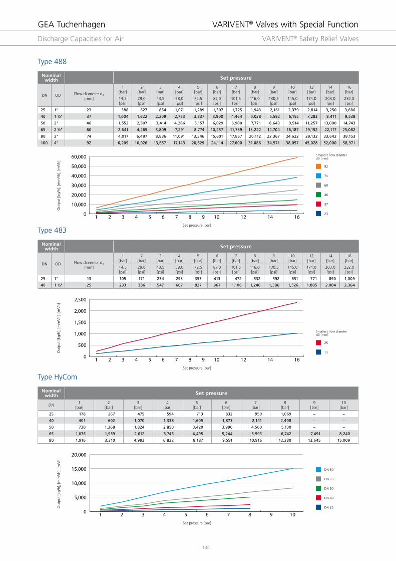
Full stroke safety relief valve type 488
The safety relief valves in the series 488 has been developed in close cooperation with system operators and manufacturers. They reliably protect process systems from excess pressure without putting hygienic requirements at risk. The whole series has been configured and officially approved according to international standards (DGR 97/23/CG, ASME, GOST et al.). A version for steam, gases and liquids of each valve has been type-tested by TÜV in accordance with German regulations. They comply with the EU directive for pressure equipment and bear the CE symbol.
The VARIVENT® safety relief valve type 488 more than meets the special hygienic and performance requirements of the food, brewery and beverage industries. The valves have been developed for a great performance range and are mostly used in large plants, breweries and the beverage industry.
Benefits of the elastomer bellows
Increased tightness by O-ring seal
Elastomer bellows to protect difficult-to-clean components in the guide and spring cap
Low contamination by bacteria and other contaminations
Minimized dead space in the inlet and flush installation possibility
Gap-free design of the internal assembly
Medium-contacting surface requirements according to DIN 11866 and ASME BPE
Use of FDA compliant elastomers
One-part spindle for higher setting accuracy and less friction
Valve stem and guide protected by EPDM bellows
Approvals worldwide
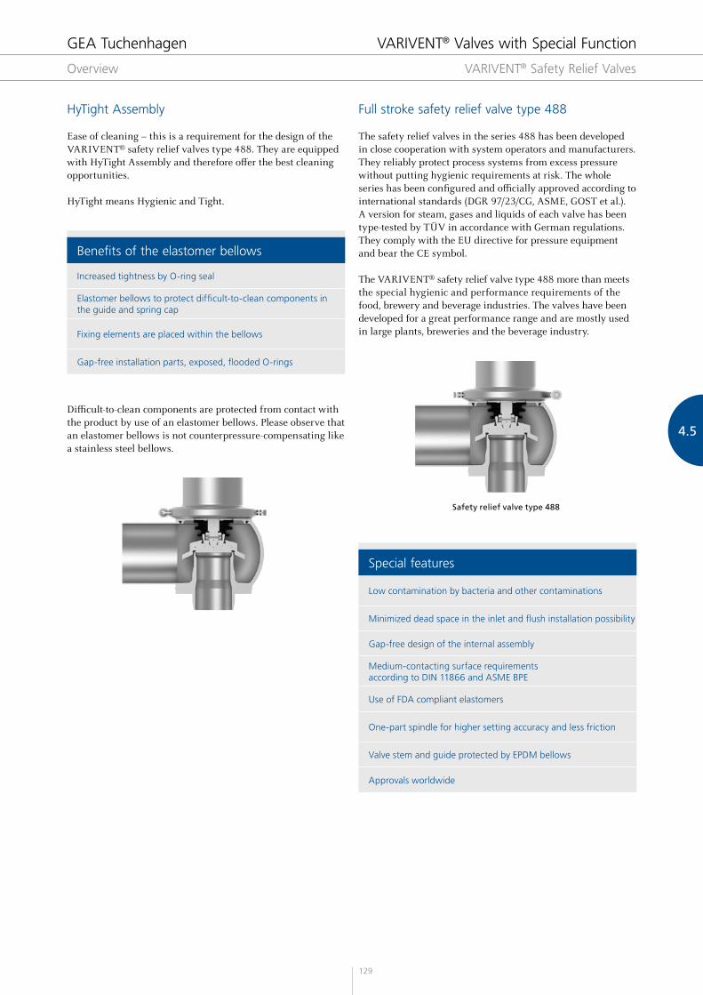
Difficult-to-clean components are protected from contact with the product by use of an elastomer bellows. Please observe that an elastomer bellows is not counterpressure-compensating like a stainless steel bellows.
Safety relief valve type 488
GEA Tuchenhagen VARIVENT® Valves with Special Function
Overview VARIVENT® Safety Relief Valves
130
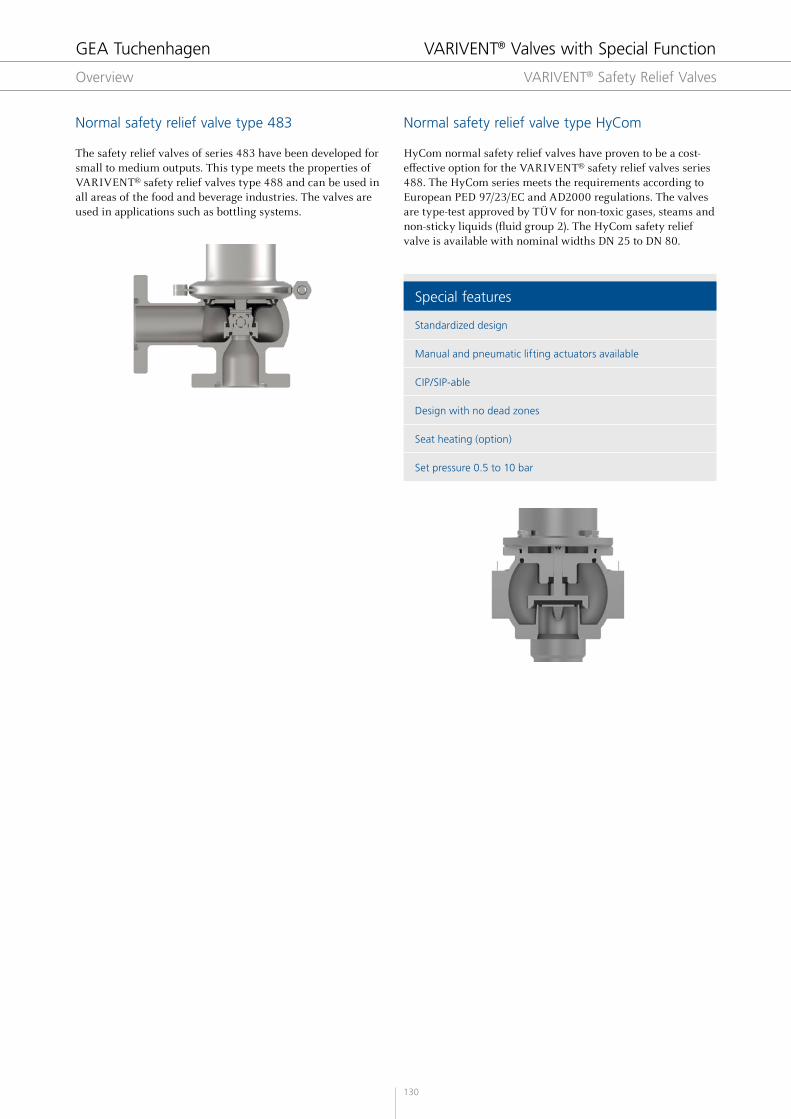
Normal safety relief valve type 483
The safety relief valves of series 483 have been developed for small to medium outputs. This type meets the properties of VARIVENT® safety relief valves type 488 and can be used in all areas of the food and beverage industries. The valves are used in applications such as bottling systems.
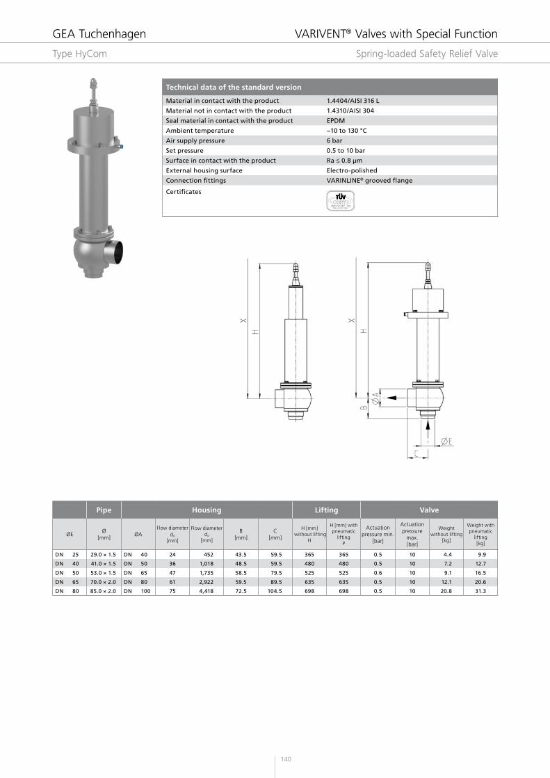
Normal safety relief valve type HyCom
HyCom normal safety relief valves have proven to be a cost-effective option for the VARIVENT® safety relief valves series 488. The HyCom series meets the requirements according to European PED 97/23/EC and AD2000 regulations. The valves are type-test approved by TÜV for non-toxic gases, steams and non-sticky liquids (fluid group 2). The HyCom safety relief valve is available with nominal widths DN 25 to DN 80.
Special features
Standardized design
Manual and pneumatic lifting actuators available
CIP/SIP-able
Design with no dead zones
Seat heating (option)
Set pressure 0.5 to 10 bar
GEA Tuchenhagen VARIVENT® Valves with Special Function
Overview VARIVENT® Safety Relief Valves
4.5
131
Liftings
The safety relief valves of the series VARIVENT® are equipped with a gas-tight lifting of the valve disc. This design characteristic permits cleaning media (steam or cleaning liquid) to flow through the valve during the cleaning process.
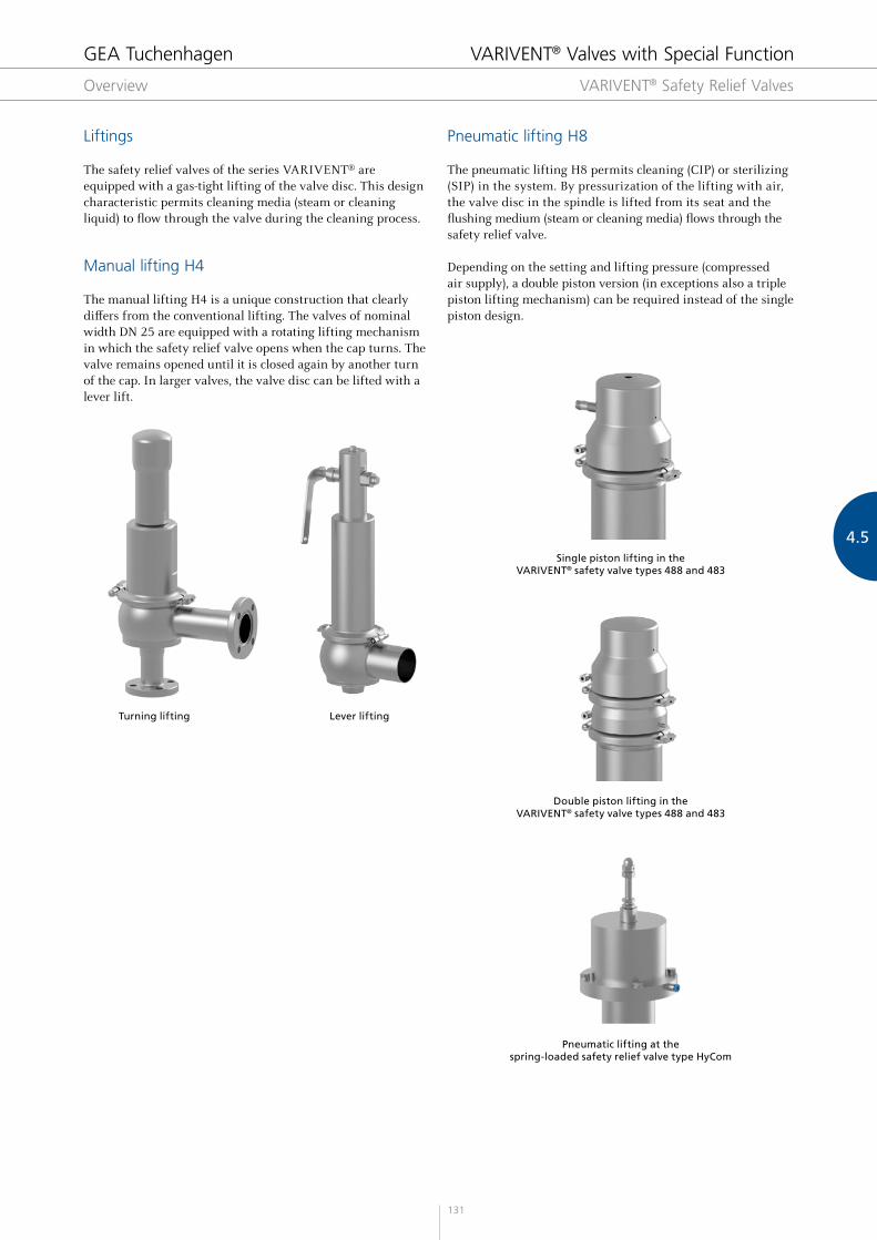
Manual lifting H4
The manual lifting H4 is a unique construction that clearly differs from the conventional lifting. The valves of nominal width DN 25 are equipped with a rotating lifting mechanism in which the safety relief valve opens when the cap turns. The valve remains opened until it is closed again by another turn of the cap. In larger valves, the valve disc can be lifted with a lever lift.
Pneumatic lifting H8
The pneumatic lifting H8 permits cleaning (CIP) or sterilizing (SIP) in the system. By pressurization of the lifting with air, the valve disc in the spindle is lifted from its seat and the flushing medium (steam or cleaning media) flows through the safety relief valve.
Depending on the setting and lifting pressure (compressed air supply), a double piston version (in exceptions also a triple piston lifting mechanism) can be required instead of the single piston design.
Turning lifting Lever lifting
Single piston lifting in the VARIVENT® safety valve types 488 and 483
Double piston lifting in the VARIVENT® safety valve types 488 and 483
Pneumatic lifting at the spring-loaded safety relief valve type HyCom
GEA Tuchenhagen VARIVENT® Valves with Special Function
GEA Tuchenhagen VARIVENT® Valves with Special Function
Discharge Capacities for Water VARIVENT® Safety Relief Valves
136
* Weights refer to the valve without connection fitting ** The nominal widths in inch are only available with the connection type clamping flange ISO 2852 (CO)!
Technical data of the standard version
Material in contact with the product 1.4404/AISI 316 L
Material not in contact with the product 1.4310, 1.4401
K (J40) with proximity switch holder M12×1 (for DN 40–100, lifting H8)
* Connections in OD-nominal widths
The code is composed as follows, depending on the chosen configuration:
Position 1 2 3 4 5 6 7 8 9
Code 488 - - / - - /52 +
GEA Tuchenhagen VARIVENT® Valves with Special Function
VARIVENT® Safety Relief Valve, Type 488 Full Stroke Safety Relief Valve
138
* Weights refer to the valve without connection fitting ** The nominal widths in inch are only available with the connection type clamping flange ISO 2852 (CO)!
Technical data of the standard version
Material in contact with the product 1.4404/AISI 316 L
Material not in contact with the product 1.4310, 1.4401
GEA Tuchenhagen VARIVENT® Valves with Special Function
Type HyCom Spring-loaded Safety Relief Valve
4.5
141
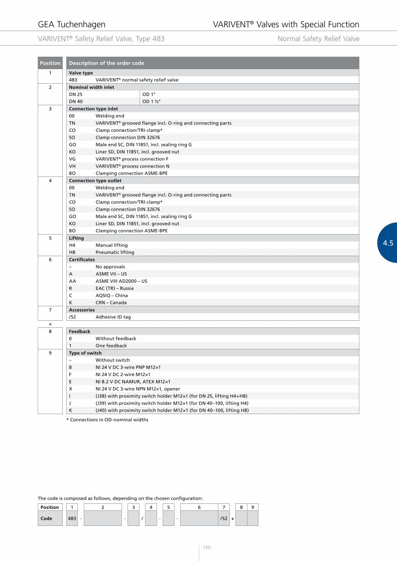
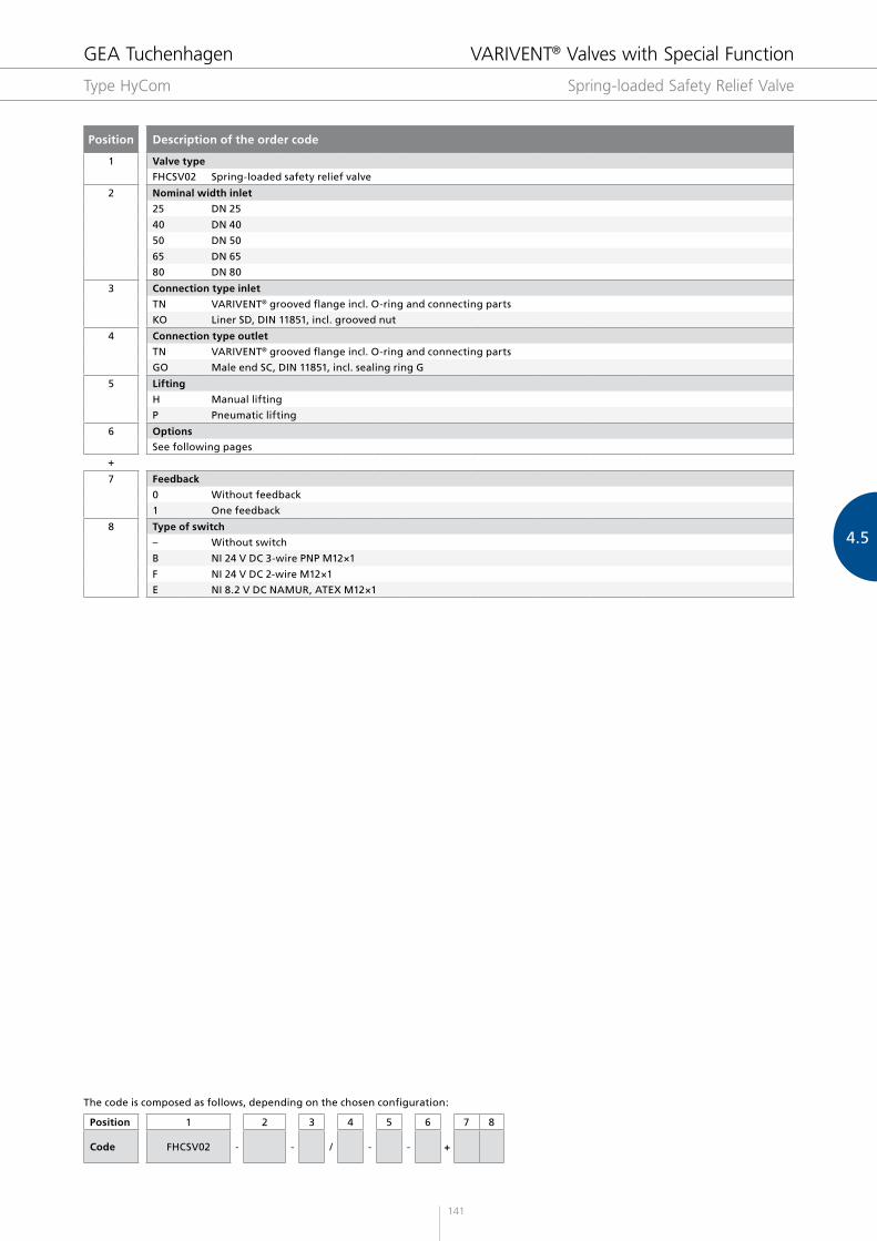
Position Description of the order code
1 Valve type
FHCSV02 Spring-loaded safety relief valve
2 Nominal width inlet
25 DN 25
40 DN 40
50 DN 50
65 DN 65
80 DN 80
3 Connection type inlet
TN VARIVENT® grooved flange incl. O-ring and connecting parts
KO Liner SD, DIN 11851, incl. grooved nut
4 Connection type outlet
TN VARIVENT® grooved flange incl. O-ring and connecting parts
GO Male end SC, DIN 11851, incl. sealing ring G
5 Lifting
H Manual lifting
P Pneumatic lifting
6 Options
See following pages
+
7 Feedback
0 Without feedback
1 One feedback
8 Type of switch
– Without switch
B NI 24 V DC 3-wire PNP M12×1
F NI 24 V DC 2-wire M12×1
E NI 8.2 V DC NAMUR, ATEX M12×1
The code is composed as follows, depending on the chosen configuration:
Position 1 2 3 4 5 6 7 8
Code FHCSV02 - - / - - +
GEA Tuchenhagen VARIVENT® Valves with Special Function
Type HyCom Spring-loaded Safety Relief Valve
142
Surface quality of the housing inlet in contact with the product
Ra ≤ 0.8 μm Electro-polished
Ra ≤ 0.4 μm Electro-polished
Technical data
Voltage 24 V
Power 30 W per heating rod
Nominal width Number of heating rods
DN 25 1
DN 40 2
DN 50 2
DN 65 2
DN 80 2
Available valve types
Type 488
Type 483
Available valve types
Type 488
Available valve types
Type HyCom
Surface quality
Limit stop
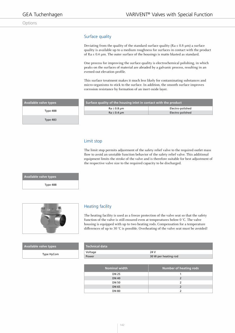
Heating facility
Deviating from the quality of the standard surface quality (Ra ≤ 0.8 μm) a surface quality is available up to a medium roughness for surfaces in contact with the product of Ra ≤ 0.4 μm. The outer surface of the housings is matte blasted as standard.
One process for improving the surface quality is electrochemical polishing, in which peaks on the surfaces of material are abraded by a galvanic process, resulting in an evened-out elevation profile.
This surface treatment makes it much less likely for contaminating substances and micro-organisms to stick to the surface. In addition, the smooth surface improves corrosion resistance by formation of an inert oxide layer.
The limit stop permits adjustment of the safety relief valve to the required outlet mass flow to avoid an unstable function behavior of the safety relief valve. This additional equipment limits the stroke of the valve and is therefore suitable for best adjustment of the respective valve size to the required capacity to be discharged.
The heating facility is used as a freeze protection of the valve seat so that the safety function of the valve is still ensured even at temperatures below 0 °C. The valve housing is equipped with up to two heating rods. Compensation for a temperature differences of up to 30 °C is possible. Overheating of the valve seat must be avoided!
GEA Tuchenhagen VARIVENT® Valves with Special Function