24
GEAR DESIGN SOLUTIONS RELEASE 5.3 2016 *NEW FOR V5.3: 5 Axis Simulation with G-Code Search function in Tool Database Force balancing in Hob and Grind Load Analysis and more...

GEAR DESIGN SOLUTIONS
RELEASE 5.3 2016
*NEW FOR V5.3:5 Axis Simulation with G-Code
Search function in Tool DatabaseForce balancing in Hob and Grind
Load Analysis and more...

Dontyne Offices HQ,
Newcastle, England
“Dontyne’s software brought us a huge improvement in productivity: reducing hours of work to seconds. The visual representations make the software very intuitive to use and understand, and the results are quite accurate. The endeavour was so successful that more collaboration is inevitable.”
Eaton Corporation
“The gear metrology expertise from Dontyne and the applications experience of Renishaw was an ideal combination to produce software that offers a high level of functionality and exploits the benefits of Renishaw’s co-ordinate measuring machine (CMM) scanning systems.”
Renishaw plc
“The lead times and accuracy made possible by the introduction of the Optimal calculation would simply not have been possible without the software.”
Gaudlitz GmbH
For a list of references and technical papers associated with Dontyne Systems products and personnel refer to our website www.dontynesystems.com/publications
GEARBOX SYSTEM MODEL
GEAR DESIGN
ANALYSIS AND OPTIMIZATION
SOFTWARE TOOLS
TRAINING AND SUPPORT
1

2
Dontyne Systems is proud to become a Tier 2 member of the Advanced Manufacturing Research Centre (AMRC) based at Sheffield University, UK. This institution has some top names in the engineering world looking at using modern materials and machine tools to improve production efficiency and performance. This is also the motivation behind Dontyne Systems and we believe the Gear Production Suite will provide a suitable platform for the work in years to come. We also look forward to contributing as consultants to some projects as and when required. Exciting times.
Following from the PRI show, Dontyne has supported Mazak Inc at several events in-house and with agencies in Florence, Los Angeles, Windsor Locks , Schaumberg, and Detroit. Dontyne is working on a system fully compatible with their equipment, which will dramatically reduce lead times for gear production of batch size up to at least 500 pairs. The initial phase of this was rolled out at the IMTS show in Chicago in September 2016. Contact us at [email protected] for a demonstration of the latest developments.
Direct export to Mazak machine tools for accelerated production
Dontyne Systems becomes Tier 2 member of AMRC
Dr. Michael Fish,Director & Co-Founder,Dontyne Systems Ltd
As Dontyne Systems launches its latest update to its acclaimed Gear Production Suite, Director and Co-Founder, Dr. Michael Fish talks about what customers can expect from this update and what lies ahead for Dontyne Systems Ltd.
I have always felt that one of the key benefits of the Dontyne Systems business model is our ability to be flexible and responsive to our customer’s requirements. Our updates to the GPS software are not arbitrary, but rather the result of our close relationship and regular contact with clients and listening to what they are looking for and what we can provide to help them achieve the results they are looking for. We are still getting very strong demand for design and analysis products. The recent addition of Planetary Transmission Error Model in GPS 5.2 has already sparked considerable interest. We are also seeing strong demand for Hob & Grind Manufacturing simulations. We have found these are particularly popular with clients around the world. The recent introduction of an Advanced level, which looks at Tool Balancing for more accurate profile generation, is proving very popular. We are also seeing strong uptake in our software to produce a Closed Loop Manufacturing System, which uses measurement data to create a more accurate component, compensating for inherent inaccuracies in the production. This has already proven especially popular in the Drop Forging and Injection Moulding industry, where we can use data to improve tool accuracy, resulting in large savings of time and resources. Additionally, we will be introducing a new tool with the 5.3 release - a Multi-Axis Machine Tool Simulation. We launched this at the IMTS show in Chicago (12th-17th September 2016) and followed it up at various events including JIMTOF in November. The introduction of this tool, we believe, will save many hundreds of thousands of pounds in production and enable hundreds of companies which were previously limited by cost and resources to start producing gears in-house. Dontyne Systems Ltd already have one eye on the future and an all new V6 release of the Gear Production Suite software. We hope this sees a new approach, utilizing all the most modern software capabilities to deliver improved function and presentation.

GEARBOX DESIGNER
Gearbox Concept tool
Drag and drop concept level layout of gearbox system for rapid development of transmissions to determine speed, torque, clutching, and power to analyse efficiency with live test for valid connections.
This is a specialist module to help in the very earliest stages of gear box design. It allows a transmission layout to be constructed in several minutes, with no need to create a spreadsheet specific arrangement. A system model can then be constructed from the concept layout.
Static Deflection Model
This tool can create a gear box layout and uses a fully coupled matrix to determine the deformation through the gear, shaft, bearing and housing. It is possible to import a stiffness matrix from 3rd party software. Controls exist to indicate power through the system and emphasise both torsion and linear deflection. The Advanced level of the tool links directly to detailed design and analysis tools within the Suite.
8 Speed Lepelletier Automatic
3D graphical interface
Gearbox view of motor sport transmissionGearbox contains spur and spiral bevel gears
3

Standard Features include :-
Spur, Helical and Bevel gears
Shaft Deflections
Misalignments in Line of Action
Forces
Shaft Stresses
Fully Coupled Housing Stiffness Matrix
3D Gearbox Graphics
Deflected Plots
Concept or Detailed Gears
Import Nastran data from CAD*
Shaft Assembly DesignerThe shaft sections, gear positions and supports are input
Shaft calculations for gear misalignment
Power flow plot
4

SPUR AND HELICAL
GEAR DESIGN PRO
Features include :-
Involute internal and external spur and helical gear geometryISO 6336 rating (inc. 2008 updates)AGMA 2001 – D 04 ratingTolerances to ISO 1328Tolerances to AGMA 2015Standardized tooth proportions or calculate for maximum contact ratioPlots of gears in 2D and 3DDXF output of transverse tooth profileCo-ordinates output of tooth profileMeasurement over balls and chordal span including contact heightMetric or Imperial (English) unitsGear sizingFlash temperature calculations Graphical plot of specific slidingPlot of theoretical path of contactMaterial database (user defined)SN fatigue curve plotsComprehensive micro-pitting model originally developed by Dave Barnett based on results of a British Gear Association research program
Inspection
Design
Rating
5

PLANETARY
Features include :-
Involute spur and helical gear geometryAssembly check for equal spacingSingle or double planet arrangementInterference checks for outer diametersSpeed and torque of all componentsISO 6336 rating (inc. 2008 updates)Tolerances to ISO 1328Cumulative damage and safety factor Standardized tooth proportions or calculate for maximum contact ratioPlots of gears in 2D and 3DDXF output of transverse tooth profileCo-ordinates output of tooth profileMeasurement over balls and chordal pan including contact heightMetric or Imperial (English) unitsMaterial database (user defined)Phasing calculation
Single Stage Layout
The wear due to progressive mircopitting can be viewed in 3D at any stage.
Experimentally validated model of micropitting
6

ISO/AGMA 23509-A08 BEVEL
GENERIC BEVEL
GEAR DESIGN PRO
Straight Bevel Zerol BevelSpiral Bevel
The “Generic” bevel gear
Generic bevel refers to the fact that the geometry is not specific to a machine process but is the true theoretical form of the gear with full line conjugation between components without any virtual back plane approximations. The spiral types can be defined as straight, logarithmic (equal angle), circular, or involute.
In addition, typical modifications such as profile crowning, face crowning, and slope can be applied to modify the load bearing pattern shape and position. If there is a requirement for small batch then these forms can be produced on modern 5-Axis CNC milling machines. Face milling or face hobbing gear generating machines are not required.
7

GENERIC BEVEL ANALYSIS
Define Conjugate Surface
Contact lines shown
Create a small interference
Apply Micro-Geometry
Features include :-
Straight bevel3 spiral types (logarithmic, circular, involute)Micro modificationsConjugation check90 or non-90 degree designVariable root radius from toe to heel*Extend / Crop Tooth Form*
Export Surface to machine centre and inspection equipment
DXF 3D line gridIGES Bspline surfaceASCII X,Y,Z Co-ordinatesG-Code*
8
Specifying Marking Pattern
Cropped Tooth Form

CONNECTIONSSPLINES
Features include :-
ISO 4156 SplinesDIN 5480 SplinesANSI B92.1 1970 SplinesCalculation of load distribution in the bearingConsideration of centrifugal forces for high speed ball bearingsSubsurface stresses for large bearings with surface hardening Calculation for bearing sets like multiple angular contact bearingsLoad spectraExtension of contact ellipsis and contact angle under load Calculation with elastic outer ring for track rollersFull integration of bearing analysis including non-linear bearing stiffness in shaft toolCalculation of natural frequencies with gyroscopic effectCombined calculation of multiple coupled coaxial shaftsAxial and shear deformations are taken into account
Produce spline designs to ISO 4156, DIN 5480 and ANSI B92.1 1970 with an ANSI rating system. The side, inner and outer variants are considered. The root rounding can be arbitrarily adjusted to user preference. All profiles can be exported as DXF to wire erosion machines.
Variable tooth forms including helical thread
9

Rolling bearing calculation according ISO/TS 16281
The bearing life calculation according ISO/TS 16281 (2008) is the latest standardized version of a bearing life calculation. The bearing life is calculated using the load distribution on each rolling element and is therefore not limited to an external force but can also consider tilting moments and the influence of clearance or pretension. For each of the five degrees of freedom either a load or a displacement/rotation can be specified.
As in the calculation according ISO 281 (2007) the influence of the lubricant can be considered. Either the ratio or the specific film thickness can be used. The life with and without consideration of the lubricant will be provided as a result.
MESYS Shaft Calculation
The shaft calculation allows the calculation of displacements, forces and strength according to DIN 743 and bearing life for several connected coaxial shafts. The
MESYS Rolling Bearing Calculation according ISO/TS 16281 is included in the software and the nonlinear stiffness of rolling bearings in considered.
Because of the nonlinear bearing stiffness shafts with more than two bearings can be calculated with accurate bearing forces as result. Pretension of bearings can be considered. Combinations of angular contact bearings can be easily considered as bearing set:
ROLLING BEARING CALCULATION SOFTWARE
10

The load analysis program calculates the deformation of gear tooth components and their consequences on properties such as stress and transmission error (accuracy of ratio) under load. Versatile graphics and reporting features offer a quick interpretation of the resulting analysis and formatting
for customer reports. Links to metrology and manufacturing equipment enable evaluation of existing gear components as well as newly designed components. The Advanced level of this module incorporates the FE calculation GATES originally developed and experimentally validated at The
Design Unit, Newcastle-Upon-Tyne, England. Already implemented by some of the most trusted gear design and manufacturing institutions in the UK, the program has been used in the development of an extensive range of marine, industrial and automotive applications.
GATES , Gear Analysis for Transmission Error and Stress
Features include :-
Surface definition, (profile and flank line modification)Contact stressRoot bending stress3D FE model of tooth stiffnessPower loss and efficiencySurface topological modification definitionMultiple load casesDouble helical gearsEffect of gear misalignmentVarious graphical interfacesImport of measured gear surface
LOAD ANALYSIS MODEL
Gear contact stress Bearing load pattern Power loss and efficiency
Specific film thickness calculation and ISO
TR- 15144 micro-pitting method A
11

Surface modification can be applied to
minimise transmissions error (and hence noise
and vibration effects) at a specific load
Up to 4 different modification options
can be stored with each component*
Calculation of micro
geometry due to flank
twist effect
Surface modifications defined by :-
Normal pressure angle change Linear / parabolic profile modification4th degree polynomialCalculated bias (flank twist)A user model exported to GPS formatMeasured data compatible to common manufacturing systems
Nominal 3D surface modification / 3D surface with simulated or measured bias
Micro-geometry definition
12

ADVANCED LOAD ANALYSIS MODELMICRO GEOMETRY OPTIMISATION
Up to 10 increments for each parameter
Available surface Modifications
Pinion and wheel can be linked so that steps change together
Up to 9 load cases for each modification
Tooth surface stress
Transmission Error (TE)
User selects results for optimum modification parameters
Up to 20,000 micro geometry variations can be defined for each batch run
13

NON INVOLUTE LTCA
Involute User DefinedLoaded Tooth Contact Analysis for user defined tooth profiles for Spur and Helical gears. Profiles can be imported from user data files or embedded geometry routine under licence (e.g. Convoloid below). Other modules can define tooling for machining and inspection to create a control system for production.
EXAMPLE OF CUSTOMER DEFINED PROFILE®
Dontyne Systems has completed several projects to develop customer specific applications or integrate functionality into the Gear Production Suite under licence.One example is an exclusive agreement on Convoloid gearing from Genesis Partners (US). Convoloid technology has the potential to dramatically improve performance in helical systems, while gear components can be produced using common machine tools and production methods.
Reduced stress enables more power
Low tooth numbers and optimized root forms (no undercut)
Increase life potential
Reduced weight
Reduced centre distance
Improvement over involute for same ratio and face width
Analysis used to establish envelope of operation where advantage is maintained.Centre distance tolerance
-0.075 mm
+0.075 mm
14

ADVANCED LOAD ANALYSIS MODELBEVEL GEAR LTCALoaded Tooth Contact Analysis for bevel gears showing marking pattern stress concentrations, and transmission error
Apply crowning to profile and lead.
Apply bias weighted to heel or toe.
Contact Stress*
The contact model can include deflections entered directly or passed from Gearbox Model tool
Transmission Error under load
Contact region under load
15

PLANETARY GEAR LTCA
Phasing 1Shows offset along base tangent for each mesh
Phasing 2Phasing offset plotted in transverse section with line of action scale for comparison
Planetary Load shareThe torque split due to variation in tooth stiffness as the planetary system rotates
The Planetary LTCA model can be used to investigate phase of engagement, critical to optimising design parameters for a given arrangement
16

Features include :-
Tool designTool databaseSimulation of profile generation and micro geometryAnalysis of max/min tolerances on generated profileProtuberance and short lead hobbing techniques on profileUse tool generated profile in bending stress calculation for accurate rating
MACHINE CENTRE
Tool Database
Search and select tool
Define new tool
Gear hobbing generated
profile to check tool design,
including continuous
grinding and dressing
TOOL DESIGN
17
Features include :-
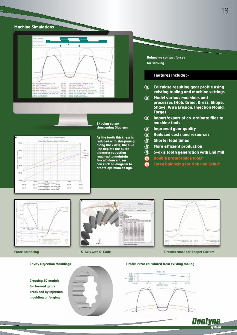
Calculate resulting gear profile using existing tooling and machine settingsModel various machines and processes (Hob, Grind, Dress, Shape, Shave, Wire Erosion, Injection Mould, Forge)Import/export of co-ordinate files to machine toolsImproved gear qualityReduced costs and resources Shorter lead timesMore efficient production5-axis tooth generation with End MillDouble protubrance tools*Force balancing for Hob and Grind*
Force Balancing
Cavity (Injection Moulding) Profile error calculated from existing tooling
Creating 3D models
for formed gears
produced by injection
moulding or forging
Balancing contact forces
for shaving
Shaving cutter sharpening Diagram
As the tooth thickness is reduced with sharpening along the x axis, the blue line depicts the outer diameter reduction required to maintain force balance. User can click on diagram to create optimum design.
Machine Simulations
18
5-Axis with G-Code Protuberance for Shaper Cutters

INSPECTIONCENTRE
Features include :-
Interfacing to gear measuring machines and co-ordinate measuring machines Evaluation of linear errors Profile/flank/pitch to common standards (ISO, DIN, AGMA)2D scan for full form inspection in root 3D Surface inspection Simulation of physical inspection (measurement over balls, tooth span)Simulation of contact testingStatistical analysis of productionDefinition of master surfaceDiagnostics and optimization of tool and machining process by compensation of errors
Co-ordinate Evaluation Direct from Gear Inspection and CMM Equipment
Standard parameter evaluation
Virtual testing – tooth span, measurement over balls, transmission error
19

The Gear Production Suite can interface to a variety of measuring devices for a range of geared tooth components. The adjacent picture shows an Equator® using 3D models from Dontyne Systems Gear Production Suite demonstrating the comparison of:
Bevel gears
Internal spline
10 tooth Convoloid gear
Advanced Analysis Functions
Statistical evaluation of multiple measurements and creating a master surface
Simulating dynamic tests such as contact marking with virtual master or other measured component
20
Projection Heat Map

OPTIMAL
GEAR PRODUCTION SUITE (Key)
Gear Design ProDesign and rate gear components using common standardsLoad Analysis ModelSimulate operating characteristics of gear pairsInspection CentreDefine component quality and simulate testing procedureMachine CentreCalculation of component form based on machine and tool settingsOptimalCalculate optimum machine and tool settings
Each module is a powerful tool in it’s own right and can be individually licensed, but there is additional benefit to utilising all modules together. Data gathered at the machining and inspection stage can be compared to the design specification and the contact models by networking in-house or even via Internet using the Gear Production Suite as a process control platform. The data can be used for many purposes other than direct design such as correct tooling or machining errors (see opposite). The software can be used to optimise both product quality and performance giving direct return on investment.
21

The calculation can be applied to multiple layers or a complete surface model for corrections to a 3D volume
Tool corrected by mapping error to previous tool surface for higher accuracy tool in a 2D plain
Before CalculationThe theoretical surface (black) and tool surface (blue) can be designed in Gear Production Suite or imported from CAD, measured data imported from measuring equipment
After CalculationThe error between theoretical and measured surface is mapped by a vector (green) and used to create modified tool surface
Error vectors mapping theoretical and measured surface
New toolsurface
Old tool
Distorted gear due to shrinkage Invert errors on mould Improved quality gear
22

DONTYNE SYSTEMS LIMITED IS A COMPANY REGISTERED IN ENGLAND AND WALES WITH COMPANY NUMBER 05973058REGISTERED OFFICE: ROTTERDAM HOUSE, 116 QUAYSIDE, NEWCASTLE UPON TYNE NE1 3DYVAT REGISTRATION NUMBER: 902 9027 45
UKEMAIL : [email protected] : +44 191 206 4021
GEARBOX SYSTEM MODEL
GEAR DESIGN
ANALYSIS AND OPTIMIZATION
SOFTWARE TOOLS
TRAINING AND SUPPORT
www.dontynesystems.com


![WELCOME [static1.squarespace.com]static1.squarespace.com/.../1437491522647/AOG2015_Program.pdf · WELCOME A marketplace, performance space and a gathering place for friends and families,](https://static.documents.pub/doc/80x56/5b79a5a97f8b9a703b8e12b1/welcome-welcome-a-marketplace-performance-space-and-a-gathering-place-for.jpg)


