1 Power transmission Components used to transmit power: gears, belt, clutch and brakes. Gear Objective: Student must be able to do force analysis, stress analysis using basic formula (Lewis) and AGMA (bending stress and surface stress) Type of gear: Spur gear only a) Spur Gear b) Helical gear c) Bevel gear Teeth is parallel to axis of rotation Can transmit power from one shaft to another parallel shaft Teeth is inclined to the axis of rotation Smoother than spur Develop thrust load (helix angle) Can transmit power from one shaft to a parallel and non-parallel shaft
Transcript
1
Power transmission Components used to transmit power: gears, belt, clutch and brakes.
Gear Objective: Student must be able to do force analysis, stress analysis using basic formula (Lewis) and AGMA (bending stress and surface stress) Type of gear: Spur gear only
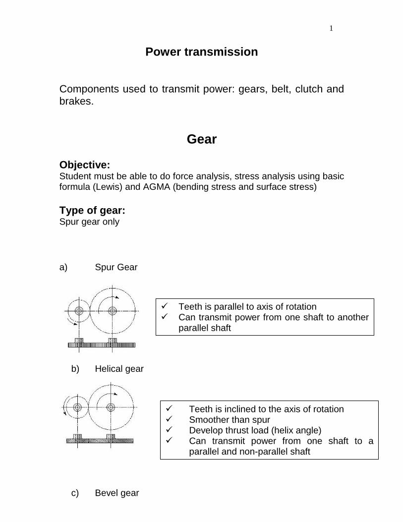
a) Spur Gear
b) Helical gear
c) Bevel gear
Teeth is parallel to axis of rotation Can transmit power from one shaft to another
parallel shaft
Teeth is inclined to the axis of rotation Smoother than spur Develop thrust load (helix angle) Can transmit power from one shaft to a
parallel and non-parallel shaft
2
d) Worm gear
Teeth on conical surfaces Transmit power between two intersecting
shafts
Transmit power between two intersecting shafts
3
Formation of Spur Gear i. Friction drive
Represented by two pitch circles. Smaller gear: pinion (denoted by letter p) Larger gear: gear (denoted by letter g)
ii. Belt Drive:
Another base circle is introduces represent the base circle of the pulley.
iii. Involute gear tooth drive:
4
Terminologies
A pair of gears can be represented as 2 circles Metric Pinion d2 = N2m Gear d3 = N3m where: N: number of teeth m: module in mm
note: mating gear must have same m English Unit
Pinion P
Nd 22
Gear P
Nd 33
Where P is diametral pitch (in-1) Relationship between diametral pitch and m
P
m4.25
2 3
5
Module: is the ratio if diametral pitch and number of teeth m = d/N [mm] Face Width (F) : width of the tooth Addendum [a] : distance between top face of the tooth to pitch circle Dedendum [b] : distance between pitch diameter to bottom of the gear In the following : we only concentrates on full depth gear
Full depth tooth
6
When the offset occurs between pitch. not full-depth tooth, which is called stub Undercut: resulted from number of tooth is less than the minimum number of tooth suggested. Results: higher stresses at the root of the tooth. (Refer to section 13-7 interference)
Backlash : gap between mating tooth. The gap can be used for lubrication
Contact Ratio: the number of tooth in contact during meshing. Roughly spur gear (1.4 to 1.8 )
7
Pinion and Gear : pinion is the smaller gear and gear is the bigger gear
Gear Parameters Metric Unit Module m = d/N
English Unit Diametral Pitch P= N/d (inverse to module)
One pair of gear must have the same module
Pressure Angle: 200, 22.5o, 250
English Unit SI
Available Size
8 12 pitch gear 12 teeth per inch of pitch
diameter
Means 12 pitch gear
1 in pitch diameter will have 12T
1.5 in pitch diameter will have 18T
6 mm module
Fillet at the root of the tooth = 0.35/P = m/3
Range of face width
9
The addendum circle arra
Where ra: addendum circle radius
r: pitch circle radius
a: addendum
The addendum is a = 1/P or a = m
The maximum addendum circle without interference is
)sin(22
(max) crr ba
If ra > ra(max) interference
Undercut happens when pinion is less than 18T for 20o pressure angle, less than
12T for 25o pressure angle.
Contact ratio id
10
Example
An 18T pinion having 20o pressure angle with a 36T gear. If the maximum center to
center is set 6 in. The pinion has stub teeth and full depth.
a. Determine the suitable dimetral pitch and its center to center distance
b. Check whether interference will occur
c. Determine the contact ratio
Gear Train
2 3
V2 = V3 Known that
itmin/revolution:n:where
60
dnV
3322
3322
ndnd
ndnd
Equation 1
For a pair of gear m2 = m3
3
3
2
2
N
d
N
d Equation 2
11
From Eq 1 and 2
2
3
3
2
3
2
n
n
N
N
d
d
Significance: d increases N increase d increases n reduces to reduce rpm requires small
pinion and larger gear and vice versa.
12
Gear Train (continued)
2 3 4
V2 = V3 and V3 = V4
Therefore V2 = V3 = V4
From previous formula:
3322
2
3
3
2
nNnN
n
n
N
N
Gear 2 and 3
2
3
2
3n
N
Nn … (1)
Gear 3 and 4
3
4
3
4n
N
Nn …(2)
Eq (1) in eq (2)
2
3
2
4
3
4n
N
N
N
Nn
FLn
numberstoothdrivenofproduct
numberstoothdrivingofproductn
where: nL : rotational speed of last gear (output) nF : rotational speed of first gear (input)
Train value numberstoothdrivenofproduct
numberstoothdrivingofproducte
13
Planetary Gear
Gear 2: Sun gear Gear 3: Arm Gear 4: Planet Gear Gear 5: Ring Gear
Assumption Arm Fixed:
2
3
4 5
Train value 654
542
NNN
NNNe
4
2
3
5
14
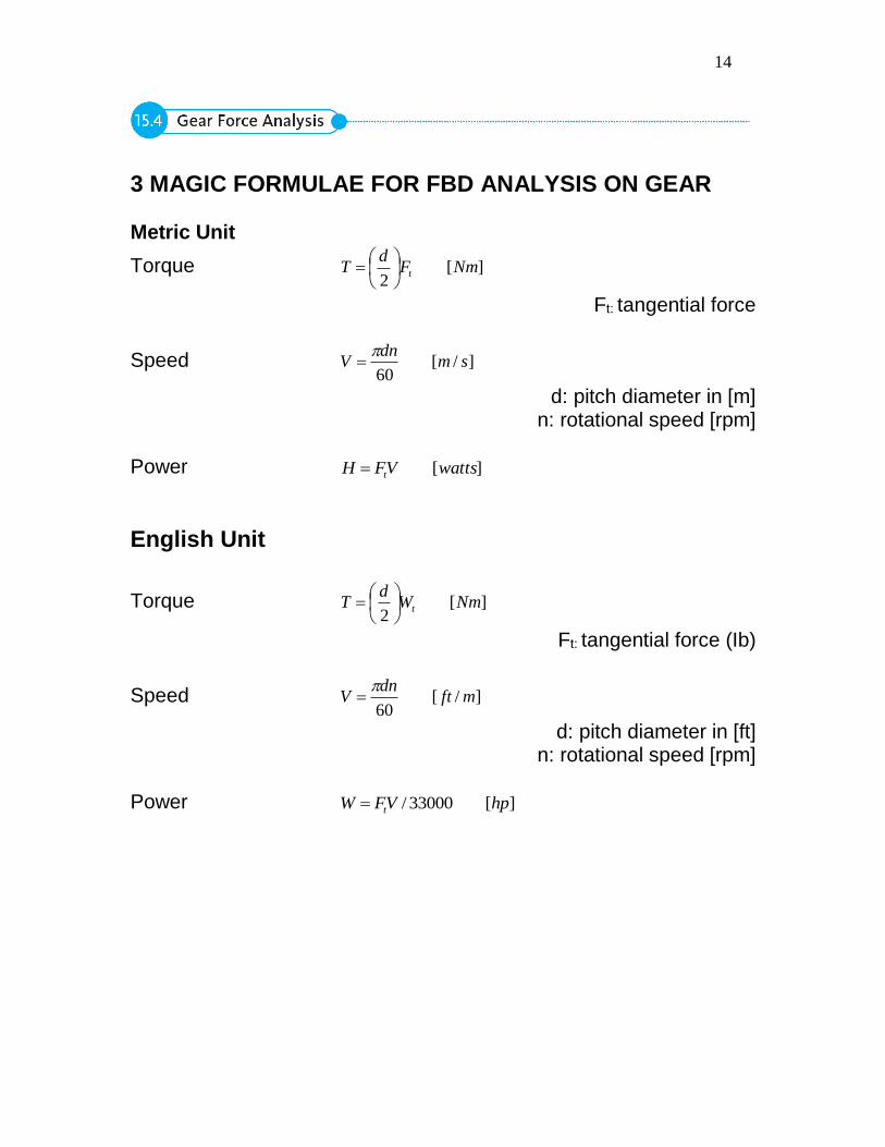
3 MAGIC FORMULAE FOR FBD ANALYSIS ON GEAR Metric Unit
Torque ][2
NmFd
T t
Ft: tangential force
Speed ]/[60
smdn
V
d: pitch diameter in [m] n: rotational speed [rpm]
Power ][wattsVFH t
English Unit
Torque ][2
NmWd
T t
Ft: tangential force (Ib)
Speed ]/[60
mftdn
V
d: pitch diameter in [ft] n: rotational speed [rpm]
Power ][33000/ hpVFW t
15
Force Analysis (Free Body Diagram)
Input rpm direction: cw
To transfer power, T must exist. When the pinion rotates, tooth from gear against the movement direction Wt32 must against the direction of rotation
Wt32 = H / V T2 = Wt32. d2/2
Due to pressure angle, Wr32 (radial force) is generated
Wr32 = Wt32 tan
16
On Gear 3,
Wt23 and Wr23 must in the opposite direction. To be statically analytical, T3 is against Wt23
T3 = Wt23. d3/2 Note: Wt23 can be calculated using Wt32= H/ V, please remember that all the parameters must be based on gear 3.