Gear Navigation System 0. Abstract In some cases, a dress gear with dimensions that differ from those of the work gear, or a dress gear modified with a complicated process such as bias correction, may be used in a honing operation. However, in reality, the degree of machining accuracy can be judged only by checking the actual machined gears. The Gear Navigation System solves these problems simply. 1. Introduction Gear Navigation System software simulates gear cutting by hob, pinion cutter, shaving cutter, and honing, and analyzes it. Then, it is possible to simulate the gear meshing. In addition, it is possible to search the tool database for a desired tool with the tool management function. In honing, modifications of the tooth profile and tooth trace and tooth form after tooth surface modifications will be calculated and displayed graphically. A Gear Navigation System window is shown in Fig. 1.1. Fig. 1.1 Gear Navigation System 2. The Application Gear ・Spur and Helical Gears (Involute) ・External and Internal Gears 3. The Tool 3.1 Hob (1) Standard hob (2) Semi-topping hob (Bottom form is R or C) (3) Protuberance hob (4) Protuberance semi-topping hob (5) Tooth profile shift hob (6) Tooth modification hob 3.2 Pinion Cutter (1) Standard pinion cutter (2) Semi-topping pinion cutter (Bottom form is R or C) (3) Protuberance pinion cutter (4) Protuberance semi-topping pinion cutter (5) The pinion cutter is applied to external gears and internal gears. 3.3 Shaving cutter 3.4 Honing For dress gear, profile modification, tooth trace modification and tooth surface modification can be analyzed. And, it is possible to set the dress gear dimensions different from that of the work gear. 4. Gear dimensions setting The gear dimension input window is shown in Fig. 4.1. Fig. 4.1 Gear dimensions setting 5. Tool dimension setting 5.1 Hob dimension The hob setting is shown in Figs 5.1-5.4. It is possible to set the hob dimension for up to 3 processes. Fig. 5.1 Standard hob Fig. 5.2 Semi-topping hob Fig. 5.3 Protuberance Hob Fig. 5.4 Protuberance semi-topping Hob 5.2 Pinion cutter dimensions The pinion cutter setting are shown in Fig.5.5-5.8. The pinion cutter dimension can be set for up to 3 processes. 2
Transcript
Gear Navigation System
0. Abstract In some cases, a dress gear with dimensions that differ from those of the work gear, or a dress gear modified with a complicated process such as bias correction, may be used in a honing operation. However, in reality, the degree of machining accuracy can be judged only by checking the actual machined gears. The Gear Navigation System solves these problems simply.
1. Introduction Gear Navigation System software simulates gear cutting by hob, pinion cutter, shaving cutter, and honing, and analyzes it. Then, it is possible to simulate the gear meshing. In addition, it is possible to search the tool database for a desired tool with the tool management function. In honing, modifications of the tooth profile and tooth trace and tooth form after tooth surface modifications will be calculated and displayed graphically.
A Gear Navigation System window is shown in Fig. 1.1.
Fig. 1.1 Gear Navigation System
2. The Application Gear ・Spur and Helical Gears (Involute) ・External and Internal Gears
3. The Tool 3.1 Hob (1) Standard hob (2) Semi-topping hob (Bottom form is R or C) (3) Protuberance hob (4) Protuberance semi-topping hob (5) Tooth profile shift hob (6) Tooth modification hob 3.2 Pinion Cutter (1) Standard pinion cutter (2) Semi-topping pinion cutter (Bottom form is R or C) (3) Protuberance pinion cutter (4) Protuberance semi-topping pinion cutter (5) The pinion cutter is applied to external gears and internal gears. 3.3 Shaving cutter 3.4 Honing
For dress gear, profile modification, tooth trace modification and tooth surface modification can be analyzed. And, it is possible to set the dress gear dimensions different from that of the work gear.
4. Gear dimensions setting The gear dimension input window is shown in Fig. 4.1.
Fig. 4.1 Gear dimensions setting
5. Tool dimension setting 5.1 Hob dimension
The hob setting is shown in Figs 5.1-5.4. It is possible to set the hob dimension for up to 3 processes.
Fig. 5.1 Standard hob Fig. 5.2 Semi-topping hob Fig. 5.3 Protuberance Hob Fig. 5.4 Protuberance semi-topping Hob 5.2 Pinion cutter dimensions The pinion cutter setting are shown in Fig.5.5-5.8. The pinion cutter dimension can be set for up to 3 processes.
2
Fig. 5.5 Standard pinion cutter Fig. 5.6 Semi-topping pinion cutter Fig. 5.7 Protuberance Fig. 5.8 Protuberance pinion cutter semi-topping pinion cutter 5.3 Shaving cutter The settings for the shaving cutter are shown in Fig. 5.9.
Fig. 5.9 Shaving cutter 5.4 Honing
The honing dimension setting sets dress gear dimension and honing grinding stone dimension. The honing dress gear and grinding stone dimensions can be set for up to 2 processes. The following are shown in Figs 5.10 to 5.13: Dressing gear dimension, dressing gear modification setting, dressing gear modification topography, and honing grinding stone dimension.
Fig. 5.10 Dressing gear dimension
Fig. 5.11 Dressing gear modification on flank
Fig. 5.12 Topography of modified dressing gear
Fig. 5.13 Honing dimension
6. Setting of finishing gear tooth thickness For measurement of thickness of tooth finished by hobbing, shaving, or honing, you can select either of the following methods: base tangent length, dimension over balls, circular thickness. Fig. 6.1 shows the window for the finished gear tooth thickness setting. In this example, hobbing, shaving, and honing are carried out once. The rough cutting of the gear by hob with target base tangentlength of W1=19.350 mm and the honing procedure for finishing target base tangent length of W3=19.287 mm are shown.
Fig. 6.1 Setting window for finishing tooth thickness of work gear
3
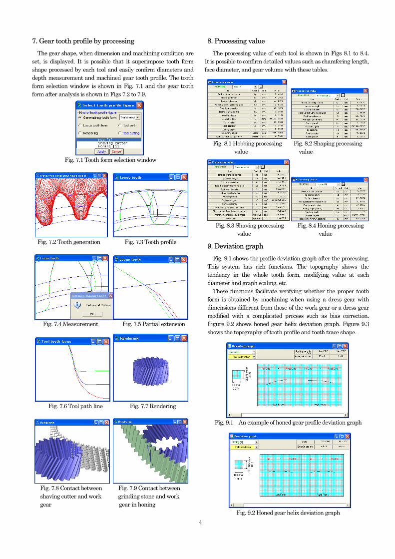
7. Gear tooth profile by processing The gear shape, when dimension and machining condition are set, is displayed. It is possible that it superimpose tooth form shape processed by each tool and easily confirm diameters and depth measurement and machined gear tooth profile. The tooth form selection window is shown in Fig. 7.1 and the gear tooth form after analysis is shown in Figs 7.2 to 7.9.
Fig. 7.1 Tooth form selection window
Fig. 7.2 Tooth generation Fig. 7.3 Tooth profile Fig. 7.4 Measurement Fig. 7.5 Partial extension Fig. 7.6 Tool path line Fig. 7.7 Rendering Fig. 7.8 Contact between Fig. 7.9 Contact between shaving cutter and work grinding stone and work gear gear in honing
8. Processing value The processing value of each tool is shown in Figs 8.1 to 8.4. It is possible to confirm detailed values such as chamfering length, face diameter, and gear volume with these tables.
Fig. 8.1 Hobbing processing Fig. 8.2 Shaping processing value value
Fig. 8.3 Shaving processing Fig. 8.4 Honing processing value value
9. Deviation graph Fig. 9.1 shows the profile deviation graph after the processing. This system has rich functions. The topography shows the tendency in the whole tooth form, modifying value at each diameter and graph scaling, etc. These functions facilitate verifying whether the proper tooth form is obtained by machining when using a dress gear with dimensions different from those of the work gear or a dress gear modified with a complicated process such as bias correction. Figure 9.2 shows honed gear helix deviation graph. Figure 9.3 shows the topography of tooth profile and tooth trace shape.
Fig. 9.1 An example of honed gear profile deviation graph
Fig. 9.2 Honed gear helix deviation graph 4
Fig. 9.3 Topography Fig. 10.1 Output tooth form coordinates file
10. Outputting tooth form coodinate file It is possible to output tooth form coordinate value after the processing as a CAD data file and the file types DXF and IGES are supported. A tooth form coordinates file output window is shown in Fig. 10.1.
11. Gear contacting Using stored cutting simulation data, it is possible to do a meshing simulation. The meshing simulation window is shown in Fig. 11.1.
Fig. 11.1 Gear contact simulation
12. Selecting gear data for contact simulation Select the data of gear to be contacted from the registered gear data and configure the setting. The data setting window is shown in Fig. 12.1.
Fig. 12.1 Gear setting window for meshing simulation.
13. Gear contact Fig. 13.1 shows the tooth form selection window. You can display the gear selected at (12) in 2D gear meshing, 3D meshing model, rotary motion locus of the driven gear, and/or continuous rotation. The 2D gear meshing figure supports partial extension, distance measuring function and drawing function of the circle, and it is possible to confirm the meshing conditions in detail. Gear contacting windows and motion locus windows are shown in Figs 13.2 to 13.8.
Fig. 13.1 Tooth form selection window Fig. 13.2 Gear contacting Fig. 13.3 Extension Fig. 13.4 Measurement Fig. 13.5 Rendering (Top clearance measurement) Fig. 13.6 Rotary motion Fig. 13.7 Part extension locus of the driven gear Fig. 14.1 Output files Fig. 13.8 Continuous rotation in contacting
5
14. Output files in contacting gear data It is possible to output the tooth data of contacting gear into DXF and IGES file format as a CAD data. The Output files window is shown in Fig. 14.1.
15. Tool management By registering the retention tool dimension in the database, Gear Navigation System can search for the tool suitable for common use calculation and conditions such as chamfering length after the processing and effective tooth surface length in the processing simulation. The setting items for tool management are shown in Figs 15.1 to 15.5.
Fig. 15.1 Tool management window
Fig. 15.2 Hob dimension
Fig. 15.3 Pinion shape cutter dimension
Fig. 15.4 Shaving cutter dimension
Fig. 15.5 Base disk dimension
16. Other functions Hob setting angle calculation Setting angle of the profile shifted hob is calculated.
Fig. 16.1 Hob setting angle calculation
17. System requirements ① Operating system Windows 2000, Windows XP ② Hardware
Personal computer with Pentium processor 800 MHz or above running Windows
③ CD-ROM drive ④ Display resolution 1024×768 or higher ⑤ At least 1 GB physical RAM ⑥ Hard disk area 2 GB up ⑦ Mouse or other pointing device ⑧ Printer