H2 Series H2 Series Gearmotor / Reducer Right Angle Shaft H2 B1 ■Gearmotor / Gearmotor with Brake / Water-resistant, Outdoor (IP65) Gearmotor / Gearmotor with Brake Model and Type Designation 0.1kW‒0.4kW Model and Type Designation 0.75kW‒2.2kW Model and Type Designation 0.75kW‒2.2kW Standard Model Lineup Indoor Type Standard Model Lineup Water-resistant Type 3-Phase Performance Table 3-Phase Outer Dimension Diagram 1-Phase Performance Table 1-Phase Outer Dimension Diagram ■Reducer (Double Shaft Type) Model and Type Designation Standard Model Lineup Performance Table Outer Dimension Diagram ■S-Type Reducer (Designated Motor Attachable Type) Model and Type Designation Standard Model Lineup Performance Table Outer Dimension Diagram IE3 (Premium Efficiency) IE1 (Standard Efficiency) P. P. P. P. P. P. P. P. P. P. P. P. P. P. P. P. P. B4 B5 B6 B8 B9 B12 B16 B28 B30 B36 B37 B40 B42 B48 B49 B52 B54
Transcript
H2Series
H2 SeriesGearmotor / Reducer
Right Angle Shaft H2
B1
■Gearmotor / Gearmotor with Brake / Water-resistant, Outdoor (IP65) Gearmotor / Gearmotor with Brake Model and Type Designation 0.1kW‒0.4kWModel and Type Designation 0.75kW‒2.2kWModel and Type Designation 0.75kW‒2.2kWStandard Model Lineup Indoor TypeStandard Model Lineup Water-resistant Type3-Phase Performance Table3-Phase Outer Dimension Diagram1-Phase Performance Table1-Phase Outer Dimension Diagram
■Reducer (Double Shaft Type)Model and Type Designation Standard Model LineupPerformance TableOuter Dimension Diagram
■S-Type Reducer (Designated Motor Attachable Type)Model and Type DesignationStandard Model LineupPerformance TableOuter Dimension Diagram
IE3 (Premium Efficiency)IE1 (Standard Efficiency)
P.P.P.P.P.P.P.P.P.
P.P.P.P.
P.P.P.P.
B4B5B6B8B9B12B16B28B30
B36B37B40B42
B48B49B52B54
B2
H2Series
B3
3-Phase0.1kWー2.2kW
Class B
Direct Start
Totally enclosed fan-cooled (totally enclosed only for 0.1kW without brake)
4
Continuous Rating
Hypoid Gear and Helical Gear
Grease Lubrication (Maintenance Free)
New JIS Key (JIS 1301-1996 Standard) Note) Key materials are included.
: Without Brake: With Brake: With Brake Manual Release Device (Option): With Water-resistant Motor (Output Shaft Materia SUS420J2): With Water-resistant Brake (Output Shaft Material SUS420J2): With Outdoor Motor (Output Shaft Material S43C): With Outdoor Brake Motor (Output Shaft Material S43C)
3-Phase : 380V/50Hz, 400V/50Hz, 400V/60Hz, 440V/60Hz(Note) High Voltage with 200V brake specifications is "W".
WZ: High Voltage With Z Model Terminal Box (For Use with Models with a Brake Built-in Rectifier Type) 3-Phase: 380V/50Hz, 400V/50Hz, 400V/60Hz, 440V/60Hz
: Standard Specifications: Mark for Special Additional Specs
BlankX
B4
Model and Type Designation H2 Series (Right Angle Shaft)
Model andType Designation
Gear Head
Motor
With the output shaft protruding from the left when looking from the input shaft side ( )
With the output shaft protruding from the right when looking from the input shaft side ( )
With the output shafts protruding from both sides when looking from the input shaft side ( )
⑧⑨Options・Power Supply Voltage(* Please inquire regarding other voltages/frequencies.)・Terminal Box Please specify A or Z for indoor specifications.
L R T
Note 3) If using an inverter, be sure to specify "AC Switching (A)" when placing an order (specially ordered specification).An inverter cannot be used with "AC Switching (B)" or "DC Switching".Please refer to 〈pages E26, E27, and E52〉 for details.This option is for 200V brake specification only.Not available for 400V brake specification.
0.1kW-0.4kW
If you wish to have a terminal box included, specify either A or Z.For terminal box model numbers and specifications, please refer to the following pages.• Without brake: page E19• With brake motor: page E25• Built-in rectifier: page E26-E30
Note 1)
Note 2) For 1-phase motors, a terminal box is not included in the standard specifications.A terminal box can be acquired through special order.
A: Standard Voltage With A Model Terminal Box3-Phase : 200V/50Hz, 200V/60Hz, 220V/60Hz
E: Standard Voltage With E Model Terminal Box3-Phase : 200V/50Hz, 200V/60Hz, 220V/60Hz
WE: High Voltage With E Model Terminal Box3-Phase : 380V/50Hz, 400V/50Hz, 400V/60Hz, 440V/60Hz
PE : High Voltage With A Model Terminal Box3-Phase : 380V/50Hz, 400V/50Hz, 400V/60Hz, 440V/60Hz(Note) High Voltage with 200V brake specifications is "WE".
Z : Standard Voltage With Z Model Terminal Box3-Phase : 200V/50Hz, 200V/60Hz, 220V/60Hz
Note 3)If using an inverter, be sure to specify "AC Switching (A)" when placing an order.
WA: High Voltage With A Model Terminal Box3-Phase : 380V/50Hz, 400V/50Hz, 400V/60Hz, 440V/60Hz
PA : High Voltage With A Model Terminal Box 3-Phase: 380V/50Hz, 400V/50Hz, 400V/60Hz, 440V/60Hz(Note) High Voltage with 200V brake specifications is "WA".
Terminal Box Positioning MarkPlease refer to the lists of specification marks on 〈page E40,E42〉 for details.
B5
Model andType Designation
0.75kW-2.2kWH2 series 0.75kW‒2.2kW gearmotors and gearmotors with a brake are classified by codes as shown below. Specify these codes in your inquiry and order.
①Series Name②Classification by Mount Form
⑥Classification by Motor Type
⑦Motor Specs.
③Frame No. and Diameter of Output Shaft
④Output Shaft Material
⑤Reduction Ratio
⑧Motor Capacity
⑨Number of Phase
⑩Power Supply Voltage
⑪Standard
⑫Terminal Box
⑬Brake Specs
⑭Auxiliary Mark
⑮Spec. Designation
H2
Terminal Box Positioning Mark Please refer to the list of specification marks on 〈page E41,E43〉 for details
Built-in Rectifier Hardwiring Indication Mark Please refer to the list of specification marks on 〈page E28,E29,E38,E39〉 for details.
BlankX
NB2B4V2V4J2J4
TE
N
NW
T
081522
P
MW
5 : 1/5 - 450 : 1/450
Output Shaft (Outer) DiameterL
: H2 Series (Right Angle Shaft)
: Standard Specifications: Mark for Special Additional Specs
: T Model Terminal Box (Steel Plate): E Model Terminal Box (Aluminium)
: Japanese, European (CE Marking)
: 3-Phase
: IE3 Efficiency (Premium Efficiency)
: Induction Standard Motor (IP44): Induction Water-resistant Motor (IP65)
: Leg Mount
For models with a brake, the brake lead wire is housed inside the terminal Box. Please refer to 〈page E37〉.
Gear Head Type
Series
H2
H2
H2
①
L
L
L
Mount
②
32
40
50
FrameNumber
③
L
R
T
ShaftLocation
④
5
50
25
ReductionRatio
⑤
BrakeSpecs.
⑬
N
B4
N
Brake
Option
⑭
X
X
AuxiliaryMark
⑮
AA
T9HZ
Spec.Designation
⑫
T
T
E
TerminalBox
⑥
M
M
W
Motor Type
⑦
P
P
P
Motor Specs.
⑧
08
15
22
Capacity
⑨
T
T
T
Number ofPhase
⑩
N
W
N
Power SupplyVoltage
⑪
N
N
N
Standard
Motor Model
Note) There are no 1.5kW or 2.2kW gearmotors with a brake.
L R TH M B
Gear Head
Motor
With the output shaft protruding from the left when looking from the input shaft side ( )
With the output shaft protruding from the right when looking from the input shaft side ( )
With the output shafts protruding from both sides when looking from the input shaft side ( )
S43CSUS420J2
ShaftLocation
Wiring method Type Designation at Time of Order (Example)Standard (External Placement of the Rectifier)Alternating Current B (AC Switching B)Direct Current (DC Switching)Alternating Current A (AC Switching A)
H2L32T50-WP08TNNEV2H2L32T50-WP08TNNEV2X ABH2L32T50-WP08TNNEV2X DCH2L32T50-WP08TNNEV2X AA
For terminal boxes with a brake motor, it is standard practice to place the rectifier outside of the terminal box.If you wish to have a built-in rectifier included, please indicate so using the points in the table below for the hardwiring performed beforehand. Please refer to 〈pages E28,E29〉 for details.
If you wish to have a built-in rectifier included, please indicate so by selecting the hardwiring method from above.Auxiliary Mark "X" is shown at the end of the model name on the nameplate, but ⑮ Spec. Designation is not shown.It is shown in the Spec. Designation column. Please refer to 〈page E11〉 for how to read the nameplate.In addition, the Spec. Designation column is also used for Terminal Box Positioning Marks and other specifications.
H2 series 0.75kW‒2.2kW gearmotors and gearmotors with a brake are classified by codes as shown below. Specify these codes in your inquiry and order.
Series
H2
H2
H2
①
L
F
L
Mount
②
22
40
50
FrameNumber
④
L
R
T
Shaft Location
⑤
5
60
30
ReductionRatio
⑥
M
B
W
Motor Type
③
075
150
220
Capacity
⑦ ⑧
W
P
Option
⑨
E
TerminalBox
⑩
X
X
AuxiliaryMark
⑪
T9HZ
AA
Spec.Designation
①Series Name②Classification by Mount Form
③Classification by Motor Type
④Frame No. and Diameter of Output Shaft
⑤Output Shaft Placement Marks
⑥Reduction Ratio
⑦Motor Capacity
⑩Auxiliary Mark
⑪Spec. Designation
H2
P
W
Indoor Specification Terminal Box Terminal Box with Water-resistant, Outdoor Specification
075150220
5 : 1/5 - 450 : 1/450
Output Shaft (Outer) Diameter
MBJWVGH
L
Blank : Standard SpecificationsX : Mark for Special Additional Specs.
: H2 Series (Right Angle Shaft)
: High Voltage With Terminal Box For 400V Brake Specifications
: High Voltage With Terminal Box
: 3-Phase 0.75kW: 3-Phase 1.5kW: 3-Phase 2.2kW
: Without Brake: With Brake: With Brake Manual Release Device (Option): With Water-resistant Motor (Output Shaft Material SUS420J2): With Water-resistant Brake (Output Shaft Material SUS420J2): With Outdoor Motor (Output Shaft Material S43C): With Outdoor Brake Motor (Output Shaft Material S43C)
: Leg Mount
Terminal Box Positioning Mark Please refer to the list of specification marks on 〈page E40,E42〉 for details.
⑧⑨Options・Power Supply Voltage (*Please inquire regarding other voltages/frequencies.)
L R T
0.75kW-2.2kW IE1 (Standard Efficiency)
Gear Head
Motor
With the output shaft protruding from the left when looking from the input shaft side ( )
With the output shaft protruding from the right when looking from the input shaft side ( )
With the output shafts protruding from both sides when looking from the input shaft side ( )
Blank : Standard Voltage With Terminal Box
3-Phase : 380V/50Hz, 400V/50Hz, 400V/60Hz, 440V/60Hz(Note) High Voltage with 200V brake specifications is "W"
B7
Model andType Designation
B8
1/50
Type 4P Motor Capacity
Output Shaft Positioning
FrameNumber Reduction Ratio
1/401/301/251/20
1/2401/2001/1601/120
1/151/101/5
1/1001/801/6022
3-Phase 0.1kW1/4501/3751/30028
1-Phase 100W
1/15001/12001/9001/7501/60032Note 2)
RT
L
RT
L
RT
L
1/501/401/301/251/201/151/101/5
1/6032
3-Phase 0.75kW 1/1201/1001/80 1/2401/2001/16040
3-Phase 1.5kW
1/4501/3751/30050
RT
L
RT
L
RT
L
1/501/401/301/251/201/151/101/5
1/6040
1/1201/1001/80 1/2401/2001/16050
3-Phase 2.2kW
RT
L
1/501/401/301/251/201/151/101/5
1/60 1/80 1/100 1/12050 R
T
L
RT
L
1/501/401/301/251/201/151/101/5
1/6022
3-Phase 0.2kW
1-Phase 200W
3-Phase 0.4kW
1-Phase 400W
1/2401/2001/1601/1201/1001/8028
RT
L
RT
L
1/4501/3751/30032 RT
L
1/15001/12001/9001/7501/60040 RT
L
1/501/401/301/251/201/151/101/5
1/6028
1/2401/2001/1601/1201/1001/8032
RT
L
RT
L
1/4501/3751/30040 RT
L
1/15001/12001/9001/7501/60050 RT
L
Gearmotor
Gearmotor with Brake
Gearmotor Equipped with Brake Manual Release Device
Flange mount type (H2F) is also available for Frame No. 22 only.High reduction ratio (1/300 and above) is not available for 1-Phase 100WThe models enclosed with " " are the low torque type. Special care should be given to the allowable torque in the performance table.
Note 1)2)3)
Note 1)
Note 1)
Standard Model Lineup
Standard ModelLineup
Indoor Type
Flange mount type (H2F) is also available for Frame No. 22 only.1.5kW and 2.2kW are without a brake.The models enclosed with " " are the low torque type. Special care should be given to the allowable torque in the performance table.
B9
1/50
Type 4P Motor Capacity
Output Shaft Positioning
FrameNumber Reduction Ratio
1/401/301/251/20
1/2401/2001/1601/120
1/151/101/5
1/1001/801/6022
3-Phase 0.1kW 1/4501/3751/30028
1/15001/12001/9001/7501/60032
RT
L
RT
L
RT
L
1/501/401/301/251/201/151/101/5
1/6032
3-Phase 0.75kW 1/1201/1001/80 1/2401/2001/16040
3-Phase 1.5kW
1/4501/3751/30050
1/501/401/301/251/201/151/101/5
1/6040
1/1201/1001/80 1/2401/2001/16050
3-Phase 2.2kW1/501/401/301/251/201/151/101/5
1/60 1/80 1/100 1/12050
1/501/401/301/251/201/151/101/5
1/6022
3-Phase 0.2kW
3-Phase 0.4kW
1/2401/2001/1601/1201/1001/8028
RT
L
RT
L
1/4501/3751/30032 RT
L
1/15001/12001/9001/7501/60040 RT
L
1/501/401/301/251/201/151/101/5
1/6028
1/2401/2001/1601/1201/1001/8032
RT
L
RT
L
1/4501/3751/30040 RT
L
1/15001/12001/9001/7501/60050 RT
L
Water-resistant Gearmotor
Note 1)
Note 1)
Note 1)2)3)
Note 2)
Note 2)
防水ギアモータ
RT
L
RT
L
RT
L
RT
L
RT
L
RT
L
MB
H
MB
H
MB
H
MB
H
MB
H
MB
H
Standard ModelLineup
Water-resistant Type
Water-resistant Gearmotor with
Brake
Outdoor Gearmotor
Outdoor Gearmotor with
Brake
Water-resistant Gearmotor
Water-resistant Gearmotor with
Brake
Water-resistant Gearmotor
B10
H2Series
B11
●Values in the parenthesis in the performance table / dimension diagram are the values of gearmotors with a brake.●The output shaft rotation speed is the value corresponding to the motor synchronous speed and the nominal reduction ratio.●The areas shaded with in the performance table show that the L shaft rotates clockwise, and the R and T shafts rotate counterclockwise when viewing from the output shaft side if hardwired as shown on 〈page E18〉 (normal rotation). (Refer to the diagram shown below.)
【Remarks】
Performance Table / Dimension Diagram
GearmotorGearmotor with BrakeWater-resistant, OutdoorGearmotorGearmotor with Brake
Right Angle Shaft
H, M, and B shafts for output shaft material SUS420J2L, R, and T shafts for output shaft material S43C
The allowable O.H.L. are the values in the central position of the output shaft.Please be sure to read the remarks stated on 〈page B11〉 regarding the rotation method of output shaft.The models marked with * are limited torque type. Be sure to refer to the allowable torque in the performance table.
The allowable O.H.L. are the values in the central position of the output shaft.Please be sure to read the remarks stated on 〈page B11〉 regarding the rotation method of output shaft.The models marked with * are limited torque type. Be sure to refer to the allowable torque in the performance table.
The allowable O.H.L. are the values in the central position of the output shaft.Please be sure to read the remarks stated on 〈page B11〉 regarding the rotation method of output shaft.The models marked with * are limited torque type. Be sure to refer to the allowable torque in the performance table.
Standard Specs
B15
Standard Specs
B16
Indoor Specification Without Brake
H2LM-22 -5~240-T010(W)
H2LM-22 -5~60-T020(W)
234.5
325.5
115
141
30.5
36
114.5
127
6.5kg
11kg
3-Phase 0.1kW
3-Phase 0.2kW
CapacityType A B C D Weight
The values within parentheses are of those with brake motors.
Indoor Specification With Brake
H2LB-22 -5~240-T010(W,P)
H2LB-22 -5~60-T020(W,P)
297.5
345
135
141
30.5
36
114.5
127
8kg
12.5kg
3-Phase 0.1kW
3-Phase 0.2kW
CapacityType (A)
1
2
Fig. Number
1
2
Fig. Number (B) C D Weight
図-1
The values within parentheses are of those with brake motors.
図-1
Note) 0.1kW does not have a fan cover.
Indoor Specification With Brake
H2LB-28 -300~450-T010(W,P)
H2LB-28 -80~240-T020(W,P)
H2LB-28 -5~60-T040(W,P)
351.5
310
345
135
135
141
8.5
39
36
128
114.5
127
11.5kg
11kg
12.5kg
3-Phase 0.1kW
3-Phase 0.2kW
3-Phase 0.4kW
CapacityType (A)
1
2
2
Fig. Number B C D
─
67.5
70.5
E
─
167.5
170.5
F Weight
Indoor Specification Without Brake
H2LM-28 -300~450-T010(W)
H2LM-28 -80~240-T020(W)
H2LM-28 -5~60-T040(W)
311.5
293
325.5
115
135
141
8.5
39
36
128
114.5
127
10kg
9.5kg
11kg
3-Phase 0.1kW
3-Phase 0.2kW
3-Phase 0.4kW
CapacityType A
1
2
2
Fig. Number B C D
─
67.5
70.5
E
─
167.5
170.5
F Weight
Note) 0.1kW does not have a fan cover.
L Shaft R Shaft T Shaft
(A)
(200 )
(B)
6
24.5 150105±0.2
106
180
12 12 12
90 90 9045 45 45 45116 116 116
φB
59 90 90 57.5 90 90
φ22h 6 φ22h 6 φ22h 6 φ22h 6
40 40 40 40
70
35 35 35 35
A
100
φD φDφDC
φ4- 11
147.5149(157.5) (157.5)
φ
φ4- 11
40 4040
45 45 4545
4035 353535
9090
90 90
9090180
φ22h 6 φ22h 6 φ22h 6 φ22h 6
φD φD φD
12 12 12
6
105±0.2150
116 116 1169070
157.5157.5A(A)
106100
67.567.5
24.5C
φB
L Shaft R Shaft T Shaft
(200 )
100 6445
(179) (179)
8
125
120±0.2
100100
100
1515
64
φ4- 11
200
126126
φBφ(B)
φ28h6 φ28h6 φ28h6φ28h 6
5050
40
100
100100
15
126
45
5050
404540
40
45
31
A
(A)
174.5
100
φD φD φD
80
C
L Shaft R Shaft T Shaft
164(167.5)
164(167.5)
(200 )
φ4- 11
EE
φ28h 6 φ28h 6 φ28h 6 φ28h 6
45 45 4545
50
40 40 40 40
126 126 126
100 100200
100
100 100100
100
50 50 50
8
15 15 15
125
120±0.2
80
A(A)
174.5
F F
31C
φB
L Shaft R Shaft T Shaft
Dφ DφφD
100(200 )
LRT
LRT
LRT
LRT
LRT
LRT
LRT
LRT
LRT
LRT
Outer DimensionDiagrams
Leg Mount Type Gearmotor / Gearmotor with BrakeRight Angle Shaft H2 Series
Frame No. 22Fig.1
Fig.2
Frame No. 28Fig.1
Fig.2
B17
The values within parentheses are of those with brake motors.
Indoor Specification With Brake
H2LB-32 -600~1500-T010(W,P)
H2LB-32 -300~450-T020(W,P)
H2LB-32 -80~240-T040(W,P)
H2L32 5~60-MP08TN(W)NTB2(B4)
H2LB-32 -5~60-075(W,P)
370.5
412.5
364
412
381
135
135
141
156
162
17.5
8
45
42
42
128
142
127
─
142
14.5kg
15kg
15.5kg
23.5kg
20kg
3-Phase 0.1kW
3-Phase 0.2kW
3-Phase 0.4kW
3-Phase 0.75kW【IE3】
3-Phase 0.75kW【IE1】
CapacityType (A)
1
1
2
3
4
Fig. Number B C D
─
─
75
135
120
E
─
─
195
─
─
F Weight
Indoor Specification Without Brake
H2LM-32 -600~1500-T010(W)
H2LM-32 -300~450-T020(W)
H2LM-32 -80~240-T040(W)
H2L32 5~60-MP08TN(W)NTN
H2LM-32 -5~60-075(W)
330.5
395.5
344.5
402
374
115
135
141
156
162
17.5
8
45
42
42
128
142
127
─
142
13kg
13.5kg
14kg
21kg
17.5kg
3-Phase 0.1kW
3-Phase 0.2kW
3-Phase 0.4kW
3-Phase 0.75kW【IE3】
3-Phase 0.75kW【IE1】
CapacityType A
1
1
2
3
4
Fig. Number B C D
─
─
75
135
120
E
─
─
195
─
─
F Weight
Note) 0.1kW does not have a fan cover.
10
152
140±0.2
φ4- 13
φBφ( B)
35
A
(A)
205
100
95
C
L Shaft R Shaft T Shaft
120
120120
120195 195
1818
7575240
150150
φ32h6 φ32h6 φ32h6 φ32h6
55
6060
50
120
120120
18
150
55
6060
5550 5050
55
φD φD φD
(200 )
φ4- 13 120 120
120 120120
120
120
150 150150
F F 240
18 18
φ32h 6 φ32h 6 φ32h6 φ32h6
55 55 5555EE
50 50 5050
φD φD φD
60 60 6060
10
18
152
140±0.2
C35
95
A(A)
205φB
L Shaft R Shaft T Shaft
100(200 )
φ32h6 φ32h6
18
5055 55
50
120
255
120135
Cable Opening φ27 4-φ13
A(A)
□B
15295
205140±0.2
C
φ32h6
18
E120
213
5550
60 120150
78
φ32h6
18
150120
120255
E
60
5055
L Shaft R Shaft T Shaft15012060 60
φ32h6 φ32h6 φ32h6 φ32h6
18 18 18
55E E 120 120122
242 201 240
120 120 120
505550
5550
5550
60 60 60 60150 150 150
φD φD φD
81
122 122
L Shaft R Shaft T Shaft
φB
4-φ13
205
140±0.2
95152
A(A)
10
C35
(200 )
LRT
LRT
LRT
LRT
LRT
LRT
LRT
LRT
LRT
LRT
Outer DimensionDiagrams
Frame No. 32Fig.1
Fig.2
Fig.3
Fig.4
B18
Outer DimensionDiagrams
Leg Mount Type Gearmotor / Gearmotor with BrakeRight Angle Shaft H2 Series
The values within parentheses are of those with brake motors.
Indoor Specification With Brake
H2LB-40 -600~1500-T020(W,P)
H2LB-40 -300~450-T040(W,P)
H2L40 80~240-MP08TN(W)NTB2(B4)
H2L40 5~60-MP15TN(W)NTB2(B4)
H2LB-40 -80~240-075(W,P)
H2LB-40 -5~60-150(W,P)
431
475.5
430.5
518
399.5
477
135
141
156
178
162
186
19.5
7.5
53.5
49.5
53.5
49.5
142
165
─
─
142
165
23.5kg
26kg
32kg
40kg
28.5kg
36.5kg
3-Phase 0.2kW
3-Phase 0.4kW
3-Phase 0.75kW【IE3】
3-Phase 1.5kW【IE3】
3-Phase 0.75kW【IE1】
3-Phase 1.5kW【IE1】
CapacityType (A)
1
1
2
2
3
3
Fig.Number B C D
─
─
135
142
122
133
E
─
─
275
282
262
273
─
─
140
142
90
93
─
─
230
232
230
233
─
─
280
282
─
─
F G H I Weight
Indoor Specification Without Brake
H2LM-40 -600~1500-T020(W)
H2LM-40 -300~450-T040(W)
H2L40 80~240-MP08TN(W)NTN
H2L40 5~60-MP15TN(W)NTN
H2LM-40 -80~240-075(W)
H2LM-40 -5~60-150(W)
414
456
420.5
493
392.5
456.5
135
141
156
178
162
186
19.5
7.5
53.5
49.5
53.5
49.5
142
165
─
─
142
165
22kg
24.5kg
29.5kg
36.5kg
26kg
33kg
3-Phase 0.2kW
3-Phase 0.4kW
3-Phase 0.75kW【IE3】
3-Phase 1.5kW【IE3】
3-Phase 0.75kW【IE1】
3-Phase 1.5kW【IE1】
CapacityType A
1
1
2
2
3
3
Fig.Number B C D
─
─
135
142
122
133
E
─
─
275
282
262
273
F
─
─
140
142
90
93
G
─
─
230
232
230
233
H
─
─
280
282
─
─
I Weight
φ4- 15 180 180140 140
180140
140 140 140 140
φ40h6 φ40h6 φ40h6 φ40h6
70 70 70 70
90 90
φD φD φD
230 230 280
20 20 20
60 60 60 6065 65 65 65
12
165±0.2
180120
A(A)
242.5
100
43
CφB
L Shaft R Shaft T Shaft
(200 )
20
φ40h6 φ40h6
6560
70
IG
180140
140
60
70
65
135
φ40h6
20
140180
90H
60
70
G65
13520
φ40h6
F
140180
140
60
70
65E
4-φ15
242.5
165±0.2
A(A)
180120Cable Opening φ27
□BC
L Shaft R Shaft T Shaft
φ40h6 φ40h6φ40h6
140 140280
6560
6560
E 140F
6560
φ40h6
140 GH
6560
2020
70 70140180
20
70140
180
70 140180
φDφDφD
4-φ15
L Shaft R Shaft T Shaft
φB
A(A)
242.5
165±0.2
120180
C43
12
(200 )
LRT
LRT
LRT
LRT
LRT
LRT
LRT
LRT
LRT
LRT
LRT
LRT
Frame No. 40Fig.1
Fig.2
Fig.3
B19
Outer DimensionDiagrams
The values within parentheses are of those with brake motors.
Indoor Specification With Brake
H2LB-50 -600~1500-T040(W,P)
H2L50 300~450-MP08TN(W)NTB2(B4)
H2L50 80~240-MP15TN(W)NTB2(B4)
H2L50 5~120-MP22TN(W)NTB2(B4)
H2LB-50 -300~450-075(W,P)
H2LB-50 -80~240-150(W,P)
H2LB-50 -5~120-220(W,P)
494.5
543.5
537
570.5
512.5
496
521
141
156
178
192
162
186
186
23
65
65
65
14
65
65
165
─
─
─
165
165
165
56kg
64.5kg
69kg
76kg
61kg
65.5kg
69kg
3-Phase 0.4kW
3-Phase 0.75kW【IE3】
3-Phase 1.5kW【IE3】
3-Phase 2.2kW【IE3】
3-Phase 0.75kW【IE1】
3-Phase 1.5kW【IE1】
3-Phase 2.2kW【IE1】
CapacityType (A)
1
2
3
3
1
4
4
Fig.Number B C D
115
135
142
153
122
133
133
E
280
300
307
318
287
298
298
F Weight
Indoor Specification Without Brake
H2LM-50 -600~1500-T040(W)
H2L50 300~450-MP08TN(W)NTN
H2L50 80~24-MP15TN(W)NTN
H2L50 5~120-MP22TN(W)NTN
H2LM-50 -300~450-075(W)
H2LM-50 -80~240-150(W)
H2LM-50 -5~120-220(W)
475
533.5
512
545.5
505.5
475.5
500.5
141
156
178
192
162
186
186
23
65
65
65
14
65
65
165
─
─
─
165
165
165
54.5kg
62kg
65.5kg
72.5kg
58.5kg
62kg
65.5kg
3-Phase 0.4kW
3-Phase 0.75kW【IE3】
3-Phase 1.5kW【IE3】
3-Phase 2.2kW【IE3】
3-Phase 0.75kW【IE1】
3-Phase 1.5kW【IE1】
3-Phase 2.2kW【IE1】
CapacityType A
1
2
3
3
1
4
4
Fig.Number B C D
115
135
142
153
122
133
133
E
280
300
307
318
287
298
298
F Weight
φ4- 18
165 165 165330
165
180
φ50h6 φ50h6 φ50h6 φ50h6
25 25 25
75 75 75
75 75
75
75 7570 70 70 70
φD φD φD
115E
230180230
180230
F 280
14
φB308
150
A(A)
C
210
200±0.253.5
L Shaft R Shaft T Shaft
100(200 )
75
135
φ50h6 φ50h6
25
330165165
180230
7570
7570
7575
135
φ50h6
25
7570
180230
165280
115
φ50h6
25
75180230
165F
7570
E
□B
A(A)
150210
4-φ18
φ20
Cable Opening φ27
308
200±0.2
14
C
L Shaft R Shaft T Shaft
R Shaft T ShaftL Shaft
142
φ50h6 φ50h6
2575180
23075
330165165
7075
7075
4-φ18
φ20
Cable Opening φ27 150210
A(A)
308
200±0.2□B
142
φ50h6
25
23018075
165280
115
7075
φ50h6
25
230180 75
7075
F165E
C
L Shaft R Shaft T Shaft
A(A)
14
308
200±0.2
C53.5
150210
4-φ18
330165 165
7570
7570
25
75 75180230
φ50h6 φ50h6
φD
280165 115
7570
25
75 180230
φ50h6
φD
FE 165
7570
25
75180230
φ50h6
φDφB
(200 )
LRT
LRT
LRT
LRT
LRT
LRT
LRT
LRT
LRT
LRT
LRT
LRT
LRT
LRT
Frame No. 50Fig.1
Fig.2
Fig.3
Fig.4
B20
Outer DimensionDiagrams Leg Mount Type Water-resistant, Outdoor Gearmotor
Water-resistant, Outdoor Gearmotor With Brake
Right Angle Shaft H2 Series
Water-resistant, Outdoor Specification without Brakes
H2LW(G)-22 -5~240-T010(W)E
H2LW(G)-22 -5~60-T020(W)E
234.5
280
115
135
30.5
30.5
114.5
114.5
6.5kg
7.5kg
3-Phase 0.1kW
3-Phase 0.2kW
CapacityType A B C D Weight
The values within parentheses are of those with brake motors.
Water-resistant, Outdoor Specification with Brakes
H2LV(H)-22 -5~240-T010(W,P)E
H2LV(H)-22 -5~60-T020(W,P)E
286
330
115
135
30.5
30.5
114.5
114.5
8kg
9kg
3-Phase 0.1kW
3-Phase 0.2kW
CapacityType (A)
1
2
Fig.Number
1
2
Fig.Number B C D Weight
The values within parentheses are of those with brake motors.
図-1
Note) 0.1kW does not have a fan cover.
Water-resistant, Outdoor Specification with Brakes
H2LV(H)-28 -300~450-T010(W,P)E
H2LV(H)-28 -80~240-T020(W,P)E
H2LV(H)-28 -5~60-T040(W,P)E
363
342.5
382
115
135
141
8.5
39
36
128
114.5
127
11.5kg
11kg
12.5kg
3-Phase 0.1kW
3-Phase 0.2kW
3-Phase 0.4kW
CapacityType (A)
1
2
2
Fig.Number B C D
─
108.5
114.5
E
─
208.5
214.5
F Weight
Water-resistant, Outdoor Specification without Brakes
H2LW(G)-28 -300~450-T010(W)E
H2LW(G)-28 -80~240-T020(W)E
H2LW(G)-28 -5~60-T040(W)E
311.5
292.5
324
115
135
141
8.5
39
36
128
114.5
127
10kg
9.5kg
11kg
3-Phase 0.1kW
3-Phase 0.2kW
3-Phase 0.4kW
CapacityType A
1
2
2
Fig.Number B C D
─
108.5
114.5
E
─
208.5
214.5
F
─
108.5
114.5
G
─
108.5
114.5
G
─
67.5
70.5
H
─
67.5
70.5
H
─
176
185
I
─
176
185
I
─
108.5
114.5
J
─
108.5
114.5
J
─
208.5
214.5
K
─
208.5
214.5
K Weight
Note) 0.1kW does not have a fan cover.
198.5108.5 90
φ22h6
40
(A)A
6
150
106φ4- 11
φB
70
24.5C
35
12
90 45116
L Shaft
φD
45116
108.5 5890
35
40
φD
166.5
R Shaft
90
1212
4545116
108.5
φ22h6
90 90
35
40
35
40
φD
198.5
T Shaft
90
φ22h6φ22h6
105±0.2
L Shaft R Shaft T Shaft
198.5108.5 90
φ22h 6
40
35
12
90 45116
φD
176108.5
9067.5
40
35
12
9045116
φD
198.5108.5
90
φ22h 635
12
90 4545116
φD
φ22h 6 φ22h 6
90
35
40 40
(A)A
6
150
106φ4- 11
φB 24.5C
70
105±0.2
L Shaft R Shaft T Shaft
φ28h6
15
126
45
(A)A
8
174.5
125φ4- 11
φB31
80
C
Dφ
64172.5
15
108.5
126
45
Dφ
40
100
100208.5
15
108.5
12650
45
Dφ
40φ28h6 φ28h6
100
10050
208.5108.5
45
φ28h6
100 100
40 40
100 5050
120±0.2
L Shaft R Shaft T Shaft
FE 100
φ28h6
45
40
45
40
15 15
100 50126
φD
IG H
φ28h6
45100
40
15
10050126
φD
KJ
φ28h6
45100 100
40
10050 50126
φD
φ28h6
φB
(A)A
8
174.5
1254-φ11
31C
80
120±0.2
LRT
LRT
LRT
LRT
LRT
LRT
LRT
LRT
LRT
LRT
Frame No. 22
Frame No. 28
Fig.1
Fig.2
Fig.1
Fig.2
B21
Outer DimensionDiagrams
The values within parentheses are of those with brake motors.
Water-resistant, Outdoor Specification with Brakes
H2LV(H)-32 -600~1500-T010(W,P)E
H2LV(H)-32 -300~450-T020(W,P)E
H2LV(H)-32 -80~240-T040(W,P)E
H2L32 5~60-WP08TN(W)NEV2(V4)
H2LV(H)-32 -5~60-075(W,P)E
382
445
401
472
442
115
135
141
156
162
17.5
42
45
42
42
128
142
127
─
142
14.5kg
15kg
15.5kg
23.5kg
20kg
3-Phase 0.1kW
3-Phase 0.2kW
3-Phase 0.4kW
3-Phase 0.75kW【IE3】
3-Phase 0.75kW【IE1】
CapacityType (A)
1
1
2
3
4
Fig.Number B C D Weight
Water-resistant, Outdoor Specification without Brakes
H2LW(G)-32 -600~1500-T010(W)E
H2LW(G)-32 -300~450-T020(W)E
H2LW(G)-32 -80~240-T040(W)E
H2L32 5~60-WP08TN(W)NEN
H2LW(G)-32 -5~60-075(W)E
330.5
395
343
402
372.5
115
135
141
156
162
17.5
42
45
42
42
128
142
127
─
142
13kg
13.5kg
14kg
21kg
17.5kg
3-Phase 0.1kW
3-Phase 0.2kW
3-Phase 0.4kW
3-Phase 0.75kW【IE3】
3-Phase 0.75kW【IE1】
CapacityType A
1
1
2
3
4
Fig.Number B C D Weight
Note) 0.1kW does not have a fan cover.
L Shaft R Shaft T Shaft
228.5108.5 120
φ32h 6
55
50
18
120 60150
φD
195120 75
φ32h 6
55
108.5108.5
50
18
12060150
φD
240120 120
φ32h 6
55
50
18
120 6060150
φD
φ32h 6
55
50
φB
(A)A
108
205
95152
φ4- 13
35C
140±0.2
L Shaft R Shaft T Shaft
(A)A
10
205
152φ4- 13
φB 35C
95
234.5114.5 120
φ32h 6
55
50
18
60
φD
120150
195120 75
φ32h 650
1860
114.5
φD
120150
240120 120
φ32h 6
50
60 60
114.5
φD
120150
φ32h 650
55 55 55
18140±0.2
18
φ32h6
208.5
120130.5
150120
78
5550
60
18
φ32h6
250.5120130.5
150120
5055
60
18
φ32h6 φ32h6
120 120
250.5130.5
150120
5550
5550
60 60
L Shaft R Shaft T ShaftH Shaft M Shaft B Shaft
□B
4-φ13
205
140±0.2
15295
C
A(A)
L Shaft R Shaft T Shaft
246.5126.5 120
φ32h6
55
50
18 18
12060150
φD
207.5126.5 81
φ32h6
50
18
12060 150
φD
55120
246.5126.5
φ32h6
50
1206060150
φD
55120
φ32h6
50
55120
(A)A
10
205
15295 φ4- 13
φB C35
140±0.2
LRT
LRT
LRT
LRT
( )HMB
LRT
LRT
LRT
LRT
LRT
( )HMB
LRT
Frame No. 32Fig.1
Fig.2
Fig.3
Fig.4
B22
Outer DimensionDiagrams Leg Mount Type Water-resistant, Outdoor Gearmotor
Water-resistant, Outdoor Gearmotor With Brake
Right Angle Shaft H2 Series
The values within parentheses are of those with brake motors.
Water-resistant, Outdoor Specification with Brakes
H2LV(H)-40 -600~1500-T020(W,P)E
H2LV(H)-40 -300~450-T040(W,P)E
H2L32 80~240-WP08TN(W)NEV2(V4)
H2LV(H)-40 -80~240-075(W,P)E
3-Phase 0.2kW
3-Phase 0.4kW
3-Phase 0.75kW【IE3】
3-Phase 0.75kW【IE1】
CapacityType
Water-resistant, Outdoor Specification without Brakes
H2LW(G)-40 -600~1500-T020(W)E
H2LW(G)-40 -300~450-T040(W)E
H2L40 80~240-WP08TN(W)NEN
H2L40 5~60-WP15TN(W)NEN
H2LW(G)-40 -80~240-075(W)E
H2LW(G)-40 -5~60-150(W)E
3-Phase 0.2kW
3-Phase 0.4kW
3-Phase 0.75kW【IE3】
3-Phase 1.5kW【IE3】
3-Phase 0.75kW【IE1】
3-Phase 1.5kW【IE1】
CapacityType
L Shaft R Shaft T Shaft
GF 140
φ40h6
65
60
20
140 70180
φE
230140 90
φ40h6
60
20 114.5
14070180
φE
280140140
φ40h6
65
60
20
140 7070180
φE
65
114.5
φ40h6
60
65
(A)A
12
252
180120 φ4- 15
φBC
D
43165±0.2
L Shaft R Shaft T ShaftH Shaft M Shaft B Shaft
φ40h6
20
E
180140
D 140
6065
70
φ40h6 φ40h6
20137.5
18014070 70
6065
6065
280140 140
137.5
φ40h6
20
229
140180
140 89
70
6560
φ20
4-φ15180
A(A)
120
252
165±0.2□B
C
FE 140
φ40h6
65
60
20 20
140 70180
233140 93
20
140180
φ40h6
60
65
280
70
137.5
180
φ40h6
60
65140 140
φ40h6
65
60
70
137.5
12
252
165±0.2
180120 φ4- 15
43C
φB
A(A)
φD φD
140
φD
L Shaft R Shaft T Shaft
70
463.5
512.5
490.5
460.5
135
141
156
162
53.5
49.5
53.5
53.5
19.5
7.5
130.5
142
23.5kg
26kg
32kg
28.5kg
(A)
1
1
2
3
Fig.Number B C D
142
165
270.5
126.5
E
108.5
114.5
─
266.5
F Weight
248.5
254.5
─
─
G
413.5
454.5
420.5
493
391
455.5
135
141
156
178
162
186
53.5
49.5
53.5
49.5
53.5
49.5
19.5
7.5
130.5
137.5
142
165
22kg
24.5kg
29.5kg
36.5kg
26kg
33kg
A
1
1
2
2
3
3
Fig.Number B C D
142
165
270.5
277.5
126.5
137.5
E
108.5
114.5
─
─
266.5
277.5
F Weight
248.5
254.5
─
─
─
─
GLRT
LRT
LRT
LRT
( )HMB
LRT
( )HMB
LRT
LRT
LRT
LRT
( )HMB
LRT
Frame No. 40Fig.1
Fig.2
Fig.3
B23
Outer DimensionDiagrams
The values within parentheses are of those with brake motors.
Fig.2
Water-resistant, Outdoor Specification with Brakes
H2LV(H)-50 -600~1500-T040(W,P)E
H2L50 300~450-WP08TN(W)NEV2(V4)
H2LV(H)-50 -300~450-075(W,P)E
531.5
603.5
573.5
141
156
162
65
65
65
165
─
165
56kg
64.5kg
61kg
3-Phase 0.4kW
3-Phase 0.75kW【IE3】
3-Phase 0.75kW【IE1】
CapacityType (A)
1
2
1
Fig.Number B C D Weight
Water-resistant, Outdoor Specification without Brakes
H2LW(G)-50 -600~1500-T040(W)E
H2L50 300~450-WP08TN(W)NEN
H2L50 80~240-WP15TN(W)NEN
H2L50 5~120-WP22TN(W)NEN
H2LW(G)-50 -300~450-075(W)E
H2LW(G)-50 -80~240-150(W)E
H2LW(G)-50 -5~120-220(W)E
473.5
533.5
512
545.5
504
474.5
499.5
141
156
178
192
162
186
186
65
65
65
65
65
65
65
165
─
─
─
165
165
165
54.5kg
62kg
65.5kg
72.5kg
58.5kg
62kg
65.5kg
3-Phase 0.4kW
3-Phase 0.75kW【IE3】
3-Phase 1.5kW【IE3】
3-Phase 2.2kW【IE3】
3-Phase 0.75kW【IE1】
3-Phase 1.5kW【IE1】
3-Phase 2.2kW【IE1】
CapacityType A
1
2
3
3
1
4
4
Fig.Number B C D Weight
L Shaft R Shaft T Shaft
279.5114.5 165
φ50h6
75
70
25
180 75230
φD
280165 115
φ50h6
75
70
25
180
114.5
75230
φD
330165 165
φ50h
75
7070
25
180 7575230
φD
φ50h6 6
75
114.5
(A)A
14
308
210150 φ4- 18
φB C23
53.5200±0.2
2525
φ50h6
295.5165130.5
230180
7075
75
130.525
φ50h6
280115
230180
165
7075
75
130.5 25
φ50h6 φ50h6
180230
330165165
7075
7075
L Shaft R Shaft T ShaftH Shaft M Shaft B Shaft
75 75
(A)
□B
4-φ18150210
308
200±0.2
14
C
φ20A
L Shaft R Shaft T ShaftH Shaft M Shaft B Shaft
148.5
φ50h6 φ50h6
25
7075
7075
330165165
180230
75 75
148.5
φ50h6
25
7075
115165280
75230
180
φ50h6
25
7075
D 165E
752301804-φ18
φ20
308
A
210150
200±0.2□B
C
L Shaft R Shaft T Shaft
A
14
308
200±0.2
210150 φ4- 18
φB 53.5C
280165 115
18075230
70
75
137.5137.5
330165 165
18075 75230
70
75
302.5137.5 165
25
70
75
φ50h6φ50h6φ50h6
70φ50h6
75
φDφD
25
φD
25
180 75230
LRT
LRT
LRT
LRT
( )HMB
LRT
( )HMB
LRT
( )HMB
LRT
LRT
LRT
( )HMB
LRT
Frame No. 50Fig.1
Fig.3
Fig.4
B24
The values within parentheses are of those with brake motors.
Indoor Specification With BrakeCapacity
Indoor Specification Without Brake
H2FM-22 -5~240-T010(W)
H2FM-22 -5~60-T020(W)
H2FB-22 -5~240-T010(W,P)
H2FB-22 -5~60-T020(W,P)
3-Phase 0.1kW
3-Phase 0.2kW
3-Phase 0.1kW
3-Phase 0.2kW
Capacity
Note) 0.1kW does not have a fan cover.
278.5
301.5
135
135
30.5
30.5
157.5
148
8kg
9kg
Type (A) B C D
157.5
157.5
E Weight
238.5
284.5
115
135
30.5
30.5
148
148
6.5kg
7.5kg
Type (A) B C D
147.5
157.5
E Weight
φ4- 11
180D
φ22h 6 φ22h 6 φ22h 6 φ22h 63535
35
40 40
4040
585858
9090
φ114.5φ114.5
φ114.5
6
32
35
32
12 12 129.5 9.5 9.5 114
14478
90
42
A(A) E
100
67.5
24.5C
φB
L Shaft R Shaft T Shaft(200 )
LRT
LRT
LRT
LRT
Outer DimensionDiagrams
Flange Mount Type Gearmotor / Gearmotor with Brake Right Angle Shaft H2 Series
Frame No. 22
B25
The values within parentheses are of those with brake motors.
Water-resistant, Outdoor Specification with BrakesCapacity
Water-resistant, Outdoor Specification without Brakes
H2FW(G)-22 -5~240-T010(W)E
H2FW(G)-22 -5~60-T020(W)E
H2FV(H)-22 5~240-T010(W,P)E
H2FV(H)-22 5~60-T020(W,P)E
3-Phase 0.1kW
3-Phase 0.2kW
3-Phase 0.1kW
3-Phase 0.2kW
Capacity
Note) 0.1kW does not have a fan cover.
290
334
115
135
30.5
30.5
114.5
114.5
8kg
9kg
Type (A) B C D Weight
238.5
284
115
135
30.5
30.5
114.5
114.5
6.5kg
7.5kg
Type A
1
2
Fig.Number
1
2
Fig.Number B C D Weight
L Shaft R Shaft
198.550.5
40
12
14858 90
φ22h6
35
φD
16650.5
12
115.55832 57.5
φ22h6
φD
35
40
T Shaft
198.550.5
12
1485832 90
φ22h6
φD
35
40
φ22h6
40
35
(A)A
6
144
42
78
114φ4- 11
φB 24.5
90
C
L Shaft R Shaft T Shaft
198.550.5 148
9058
φ22h6
40
12
35
φD
17650.5 125.5
67.558
φ22h6
32
12
35
φD40
198.550.5 148
9058
φ22h6
32
12
35
φD40
φ22h6
40
35
(A)A
6
144
42
78
114φ4- 11
24.5
90
CφB
LRT
LRT
LRT
LRT
Outer DimensionDiagramsFlange Mount Type Water-resistant, Outdoor Gearmotor
Water-resistant, Outdoor Gearmotor With Brake
Right Angle Shaft H2 Series
Frame No. 22Fig.1
Fig.2
B26
H2Series
GearmotorGearmotor with Brake
Right Angle Shaft
Performance Table / Dimension Diagram
B27
●Values in the parenthesis in the performance table / dimension diagram are the values of gearmotor with brake.●The output shaft rotation speed is the value corresponding to the motor synchronous speed and the nominal reduction ratio.●The areas shaded with in the performance table show that the L shaft rotates clockwise, and the R and T shafts rotate counterclockwise when viewing from the output shaft side if hardwired as shown on 〈page E18〉 (normal rotation). (Refer to the diagram shown below.)●1-Phase 100W uses a capacitor-operated motor, making starting torque 60‒80%.
Gearmotor, Gearmotor with Brake 1-Phase Performance Table
Right Angle Shaft H2 Series
Note 1)2)3)
The allowable O.H.L. are the values in the central position of the output shaft.Please be sure to read the remarks stated on 〈page B27〉 regarding the rotation method of output shaft.The models marked with * are limited torque type. Be sure to refer to the allowable torque in the performance table.
Standard Specs
B29
Standard Specs
B30
Outer DimensionDiagrams
Leg Mount Type Gearmotor / Gearmotor with Brake [1-Phase]Right Angle Shaft H2 Series
Indoor Specification Without Brake
H2LM-22 -5~240-S100(W)
H2LM-22 -5~60-200(W)
265.5
330.5
135
135
30.5
30.5
114.5
114.5
7kg
9.5kg
1-Phase 100W
1-Phase 200W
CapacityType A B C D Weight
The values within parentheses are of those with brake motors.
Indoor Specification With Brake
H2LB-22 -5~240-S100(W)
H2LB-22 -5~60-200(W)
274.5
347.5
135
135
30.5
30.5
114.5
114.5
8kg
11kg
1-Phase 100W
1-Phase 200W
CapacityType (A)
1
2
Fig. Number
1
2
Fig. Number B C D Weight
The values within parentheses are of those with brake motors.
Indoor Specification Without Brake
H2LM-28 -80~240-200(W)
H2LM-28 -5~60-400(W)
343
402.5
135
162
39
36
114.5
127
11.5kg
16.5kg
1-Phase 200W
1-Phase 400W
CapacityType A B C D Weight
Indoor Specification With Brake
H2LB-28 -80~240-200(W)
H2LB-28 -5~60-400(W)
360
409.5
135
162
39
36
114.5
127
13kg
19kg
1-Phase 200W
1-Phase 400W
CapacityType (A) B C D Weight
φ4- 11
180
φ22h6 φ22h6 φ22h6 φ22h6
45 45 45 45
40 40 40 40
φD φD
116 116 116
35 35 35 35
90 90 90
90 90 90 90
6
12 12 12
φB
106
105±0.2150
70
A(A)157.5 157.5
100
24.5
67.5 67.5
CDφ
L Shaft R Shaft T Shaft(200 )
40 4035 35
12 12
L Shaft R Shaft T Shaft
φ22h6 φ22h6 φ22h6
φ114.5
16676 90
φ22h6
φD
90 45 45116
44.5
157.567.590
90116 116
φD
18090 90
4035
φD
4035
12
45 45904-φ11100
6
150
105±0.2
70106
24.5C
A(A)
φB
(200 )
L Shaft R Shaft T Shaft
4540
4540
4540
4540
15 15 15
4-φ11100
8 φ28h6 φ28h6 φ28h6 φ28h6
A(A)
174.5120±0.2
80125
φBC
31
50 50 50 50100 100 100126 126 126
181 181 20069 81100 100 100 100
72
φD φD
72 72
φD
(200 )
LRT
LRT
LRT
LRT
LRT
LRT
LRT
LRT
Frame No. 22Fig.1
Fig.2
Frame No. 28
B31
Outer DimensionDiagrams
Indoor Specification Without Brake
H2LM-32 -300~450-200(W)
H2LM-32 -80~240-400(W)
1-Phase 200W
1-Phase 400W
CapacityType
The values within parentheses are of those with brake motors.
Indoor Specification With Brake
H2LB-32 -300~450-200(W)
H2LB-32 -80~240-400(W)
1-Phase 200W
1-Phase 400W
CapacityType
Indoor Specification Without Brake
H2LM-40 -600~1500-200(W)
H2LM-40 -300~450-400(W)
1-Phase 200W
1-Phase 400W
CapacityType
The values within parentheses are of those with brake motors.
Indoor Specification With Brake
H2LB-40 -600~1500-200(W)
H2LB-40 -300~450-400(W)
1-Phase 200W
1-Phase 400W
CapacityType
Indoor Specification Without Brake
552 162 23 165 60kg1-Phase 400W
CapacityType A B C D Weight
The values within parentheses are of those with brake motors.
No Restrictions in the Mounting Angle, Such as Horizontal, Vertical, Inclined, or Other Angles
Reducer
Ambient Conditions
Painting
Mounting Direction
Reduction Method
Lubrication Method
Output Shaft
Output Shaft Material
Case Material
Ambient Temperature
Ambient Humidity
Altitude
Installation Location
Painting Method
Painting Color
Environment Well ventilated place free from corrosive gas,explosive gas, vapors and/or dust.
The Capacity of 4P Equivalent Motor
B36
H2 series Double Shaft Type Reducers are classified by codes as shown below. Specify these codes in your inquiry and order.
①Series Name
②Classification by Mount Form
③Motor Type
④Frame No. and Diameter of Output Shaft
⑤Shaft Positioning
⑥Reduction Ratio
⑦Motor Name and Capacity
⑧⑨Options
⑩Auxiliary Mark
⑪Spec. Designation
Blank
X
Blank
Blank
220
150
075
040
020
5 : 1/5 - 1500 : 1/1500
Diameter of Output Shaft
Blank
F
L
H2
: Standard Specifications
: Mark for Special Additional Specs.
: Standard Specifications
: Standard Specifications
: 2.2kW or equiv.
: 1.5kW or equiv.
: 0.75kW or equiv.
: 0.4kW or equiv.
: 0.2kW or equiv.
: Without Motor(Double Shaft Type)
: Flange Mount(Frame No. 22 Only)
: Leg Mount
: H2 Series(Right Angle Shaft)
No option is available.
Note)Spec. Designation is not shown as a part of the product model name on the nameplate. It is shown in the Spec. Designation column on the nameplate.
Series
H2
H2
①
L
F
Mount
②
32
22
FrameNumber
④
L
T
ShaftPositioning
⑤
200
50
ReductionRatio
⑥
Motor Type
③
040
020
Capacity
⑦ ⑧
Option
⑨
TerminalBox
⑩
AuxiliaryMark
⑪
Spec.Designation
X
With the output shaft protruding from the left when looking from the input shaft side ( )
Model and Type Designation H2 Series (Right Angle Shaft)
Model andType Designation
With the output shafts protruding from both sides when looking from the input shaft side ( )
L R T
With the output shaft protruding from the right when looking from the input shaft side ( )
Standard Model Lineup
B37
Type Output Shaft Positioning
FrameNumber Reduction Ratio
1/501/401/301/251/201/151/101/5
1/6032
0.75kW 1/1201/1001/80 1/2401/2001/16040
1.5kW
1/4501/3751/30050
RT
L
RT
L
RT
L
1/501/401/301/251/201/151/101/5
1/6040
1/1201/1001/80 1/2401/2001/16050
2.2kW
RT
L
1/501/401/301/251/201/151/101/5
1/60 1/80 1/100 1/12050 R
T
L
RT
L
1/501/401/301/251/201/151/101/5
1/6022
0.2kW
0.4kW
1/2401/2001/1601/1201/1001/8028
RT
L
RT
L
1/4501/3751/30032 RT
L
1/15001/12001/9001/7501/60040 RT
L
1/501/401/301/251/201/151/101/5
1/6028
1/2401/2001/1601/1201/1001/8032
RT
L
RT
L
1/4501/3751/30040 RT
L
1/15001/12001/9001/7501/60050 RT
LReducer (Double Shaft Type)
Note 1)
4P Motor Capacity
Standard ModelLineup
Flange mount type (H2F) is also available for Frame No. 22 only.The models enclosed with " " are the low torque type. Special care should be given to the allowable torque in the performance table.
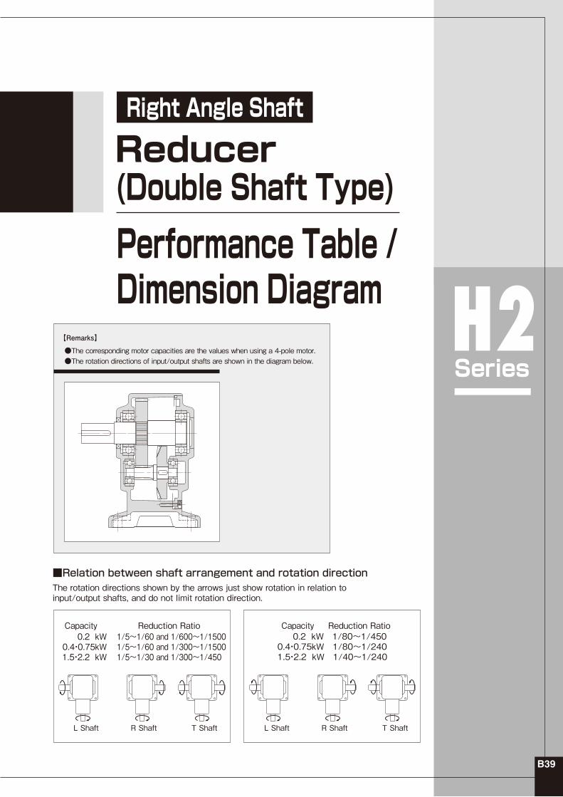
■Relation between shaft arrangement and rotation directionThe rotation directions shown by the arrows just show rotation in relation to input/output shafts, and do not limit rotation direction.
0.2 kW0.4・0.75kW1.5・2.2 kW
1/5~1/60 and 1/600~1/15001/5~1/60 and 1/300~1/15001/5~1/30 and 1/300~1/450
●The corresponding motor capacities are the values when using a 4-pole motor.●The rotation directions of input/output shafts are shown in the diagram below.
Double Shaft Type Performance TableRight Angle Shaft H2 Series
Note 1)2)3)
The allowable O.H.L. are the values in the central position of the output shaft.Please be sure to read the remarks stated on 〈page B39〉 regarding the rotation method of output shaft.The models marked with * are limited torque type. Be sure to refer to the allowable torque in the performance table.
The allowable O.H.L. are the values in the central position of the output shaft.Please be sure to read the remarks stated on 〈page B39〉 regarding the rotation method of output shaft.The models marked with * are limited torque type. Be sure to refer to the allowable torque in the performance table.
Standard Specs
B42
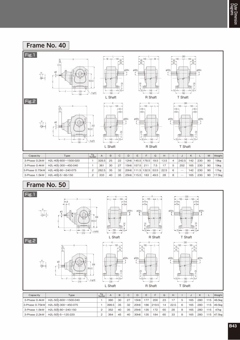
Outer DimensionDiagrams
Leg Mount Type Reducer (Double Shaft Type)Right Angle Shaft H2 Series
No Restrictions in the Mounting Angle, Such as Horizontal, Vertical, Inclined, or Other Angles
Reducer
Ambient Conditions
Painting
Mounting Direction
Reduction Method
Lubrication Method
Output Shaft
Output Shaft Material
Case Material
Ambient Temperature
Ambient Humidity
Altitude
Installation Location
Painting Method
Painting Color
Environment Well ventilated place free from corrosive gas,explosive gas, vapors and/or dust.
The Capacity of 4P Equivalent Motor
: H2 Series(Right Angle Shaft)
: Leg Mount
: Flange Mount(Frame No. 22 Only)
: Designated Motor Attachable Type (S-Type)
: Standard Specifications
: Standard Specifications
: 2.2kW or equiv.
: 1.5kW or equiv.
: 0.75kW or equiv.
: 0.4kW or equiv.
: 0.2kW or equiv.
B48
H2 series S-Type Reducers are classified by codes as shown below. Specify these codes in your inquiry and order.
①Series Name
②Classification by Mount Form
③Motor Type
④Frame No. and Diameter of Output Shaft
⑤Shaft Positioning
⑥Reduction Ratio
⑦Motor Name and Capacity
⑧⑨Options
⑩Auxiliary Mark
⑪Spec. Designation
H2
L
F
S
Diameter of Output Shaft
5 : 1/5 - 1500 : 1/1500
020
040
075
150
220
Blank
Blank
: Standard SpecificationsBlank
Model and Type Designation H2 Series (Right Angle Shaft)
Model andType Designation
Series
H2
H2
①
L
F
Mount
②
32
22
FrameNumber
④
L
T
ShaftPositioning
⑤
200
50
ReductionRatio
⑥
S
S
Motor Type
③
040
020
Capacity
⑦ ⑧
Option
⑨
TerminalBox
⑩
AuxiliaryMark
⑪
Spec.Designation
L R T
Note)Spec. Designation is not shown as a part of the product model name on the nameplate. It is shown in the Spec. Designation column on the nameplate.
With the output shaft protruding from the left when looking from the input shaft side ( )
With the output shaft protruding from the right when looking from the input shaft side ( )
With the output shafts protruding from both sides when looking from the input shaft side ( )
B49
S-Type Reducer
Type 4P Motor Capacity
Output Shaft Positioning
FrameNumber Reduction Ratio
1/501/401/301/251/201/151/101/5
1/6032
0.75kW 1/1201/1001/80 1/2401/2001/16040
1.5kW
1/4501/3751/30050
RT
L
RT
L
RT
L
1/501/401/301/251/201/151/101/5
1/6040
1/1201/1001/80 1/2401/2001/16050
2.2kW
RT
L
1/501/401/301/251/201/151/101/5
1/60 1/80 1/100 1/12050 R
T
L
RT
L
1/501/401/301/251/201/151/101/5
1/6022
0.2kW
0.4kW
1/2401/2001/1601/1201/1001/8028
RT
L
RT
L
1/4501/3751/30032 RT
L
1/15001/12001/9001/7501/60040 RT
L
1/501/401/301/251/201/151/101/5
1/6028
1/2401/2001/1601/1201/1001/8032
RT
L
RT
L
1/4501/3751/30040 RT
L
1/15001/12001/9001/7501/60050 RT
L
Note 1)
Standard Model LineupStandard ModelLineup
Flange mount type (H2F) is also available for Frame No. 22 only.The models enclosed with " " are the low torque type. Special care should be given to the allowable torque in the performance table.
Note 1)2)
B50
H2Series
Right Angle Shaft
Performance Table / Dimension Diagram
B51
【Remarks】
S-Type Reducer(Designated Motor Attachable Type)
●Please refer to 〈page B39〉 for the rotation direction of input/output shafts.●The values of output shaft allowable torque indicate the values during operation of a 4-pole motor.●If used with motors other than a 4-pole motor, the value with the torque correction coefficient on 〈page E54〉 multiplied to it is the rotation's output shaft allowable torque.
B52
CapacityMotor
SpecificationLeg Mount Flange Mount
FlameNo.
ReductionRatio
ActualReduction Ratio
Note 1)2)3)
The allowable O.H.L. are the values in the central position of the output shaft.Please be sure to read the remarks stated on 〈page B51〉 regarding the rotation method of output shaft.The models marked with * are limited torque type. Be sure to refer to the allowable torque in the performance table.
The allowable O.H.L. are the values in the central position of the output shaft.Please be sure to read the remarks stated on 〈page B51〉 regarding the rotation method of output shaft.The models marked with * are limited torque type. Be sure to refer to the allowable torque in the performance table.
Standard Specs
B54
Outer DimensionDiagrams
Leg Mount Type S-Type ReducerRight Angle Shaft H2 Series