34
Gears and Gearing Part 3
Gears and Gearing
Part 3
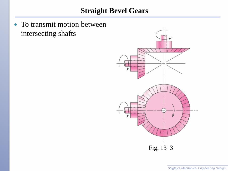
Straight Bevel Gears
To transmit motion between
intersecting shafts
Shigley’s Mechanical Engineering Design
Fig. 13–3
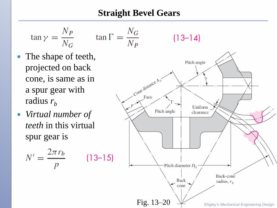
Straight Bevel Gears
The shape of teeth,
projected on back
cone, is same as in
a spur gear with
radius rb
Virtual number of
teeth in this virtual
spur gear is
Shigley’s Mechanical Engineering Design Fig. 13–20
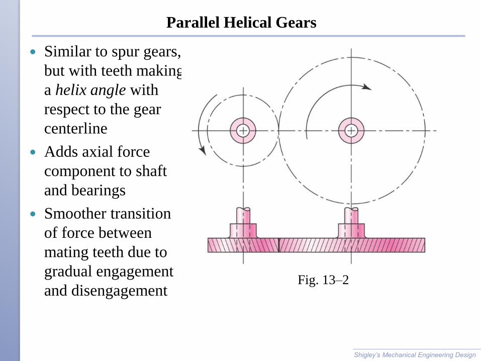
Parallel Helical Gears
Similar to spur gears,
but with teeth making
a helix angle with
respect to the gear
centerline
Adds axial force
component to shaft
and bearings
Smoother transition
of force between
mating teeth due to
gradual engagement
and disengagement
Shigley’s Mechanical Engineering Design
Fig. 13–2
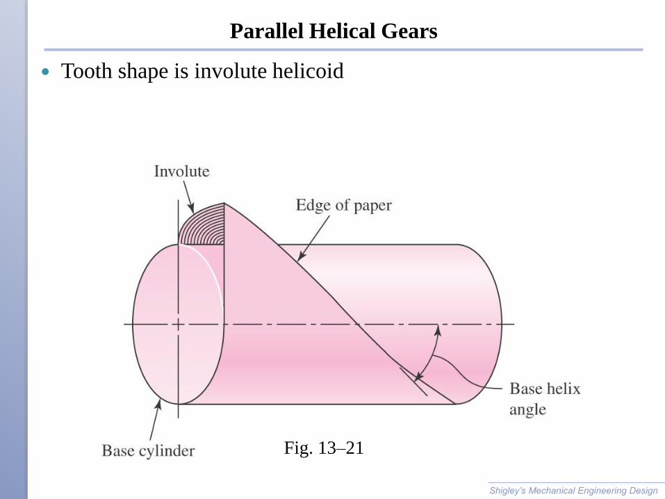
Parallel Helical Gears
Tooth shape is involute helicoid
Shigley’s Mechanical Engineering Design
Fig. 13–21

Parallel Helical Gears
Transverse circular pitch pt is
in the plane of rotation
Normal circular pitch pn is in
the plane perpendicular to the
teeth
Axial pitch px is along the
direction of the shaft axis
Normal diametral pitch
Shigley’s Mechanical Engineering Design
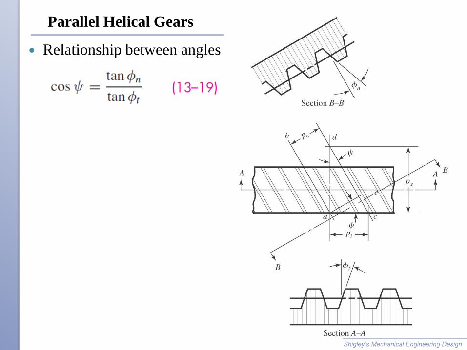
Parallel Helical Gears
Relationship between angles
Shigley’s Mechanical Engineering Design
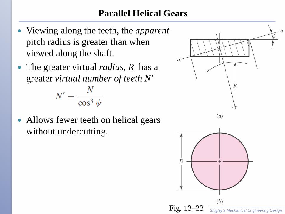
Parallel Helical Gears
Viewing along the teeth, the apparent
pitch radius is greater than when
viewed along the shaft.
The greater virtual radius, R has a
greater virtual number of teeth N'
Allows fewer teeth on helical gears
without undercutting.
Shigley’s Mechanical Engineering Design Fig. 13–23
Example 13–2
Shigley’s Mechanical Engineering Design
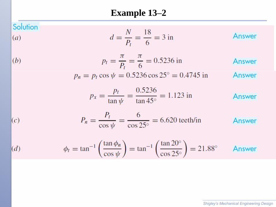
Example 13–2
Shigley’s Mechanical Engineering Design
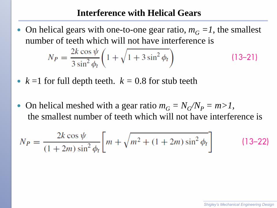
Interference with Helical Gears
On helical gears with one-to-one gear ratio, mG =1, the smallest
number of teeth which will not have interference is
k =1 for full depth teeth. k = 0.8 for stub teeth
On helical meshed with a gear ratio mG = NG/NP = m>1,
the smallest number of teeth which will not have interference is
Shigley’s Mechanical Engineering Design
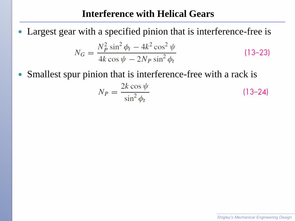
Interference with Helical Gears
Largest gear with a specified pinion that is interference-free is
Smallest spur pinion that is interference-free with a rack is
Shigley’s Mechanical Engineering Design
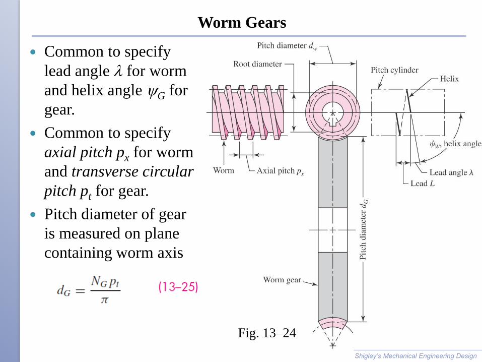
Worm Gears
Common to specify
lead angle l for worm
and helix angle G for
gear.
Common to specify
axial pitch px for worm
and transverse circular
pitch pt for gear.
Pitch diameter of gear
is measured on plane
containing worm axis
Shigley’s Mechanical Engineering Design
Fig. 13–24

Worm Gears
Worm may have any pitch diameter.
Recommend buying Worm and Gear as a set
Relation between lead L and lead angle l,
Lead angle per tooth lt = l/Nw < 6 degrees/ tooth,
then usually self-locking
Shigley’s Mechanical Engineering Design
Forces on gears
Shigley’s Mechanical Engineering Design
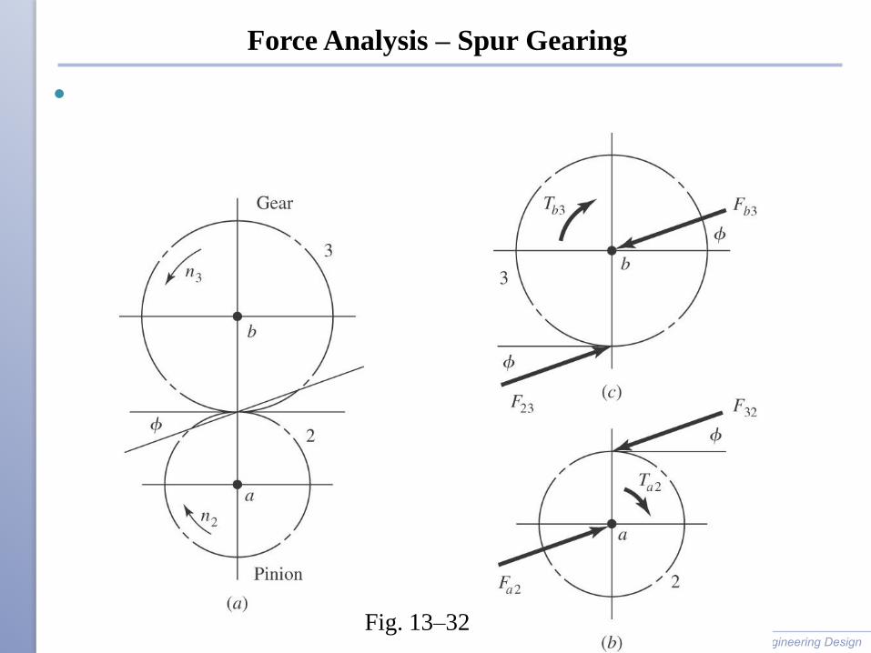
Force Analysis – Spur Gearing
Shigley’s Mechanical Engineering Design
Fig. 13–32
Force Analysis – Spur Gearing
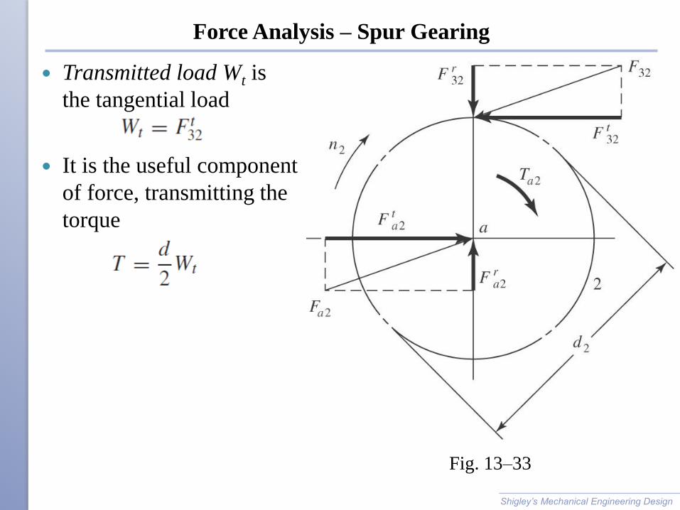
Transmitted load Wt is
the tangential load
It is the useful component
of force, transmitting the
torque
Shigley’s Mechanical Engineering Design
Fig. 13–33
Power in Spur Gearing
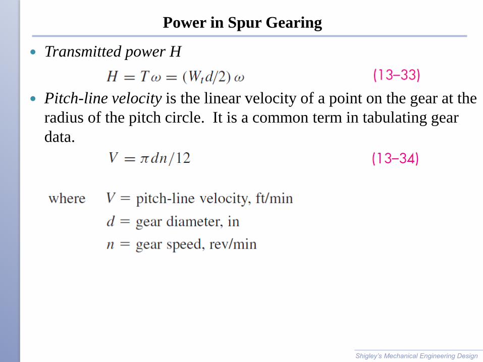
Transmitted power H
Pitch-line velocity is the linear velocity of a point on the gear at the
radius of the pitch circle. It is a common term in tabulating gear
data.
Shigley’s Mechanical Engineering Design
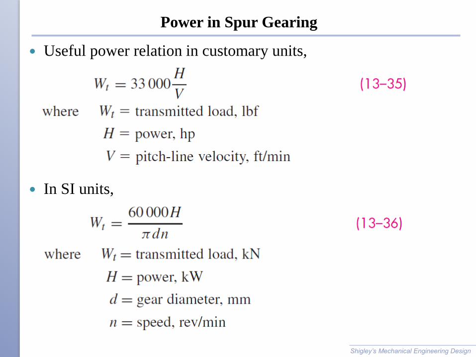
Power in Spur Gearing
Useful power relation in customary units,
In SI units,
Shigley’s Mechanical Engineering Design
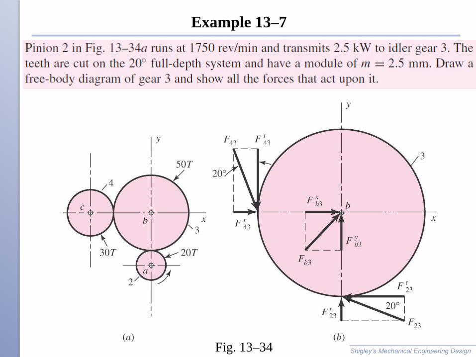
Example 13–7
Shigley’s Mechanical Engineering Design Fig. 13–34
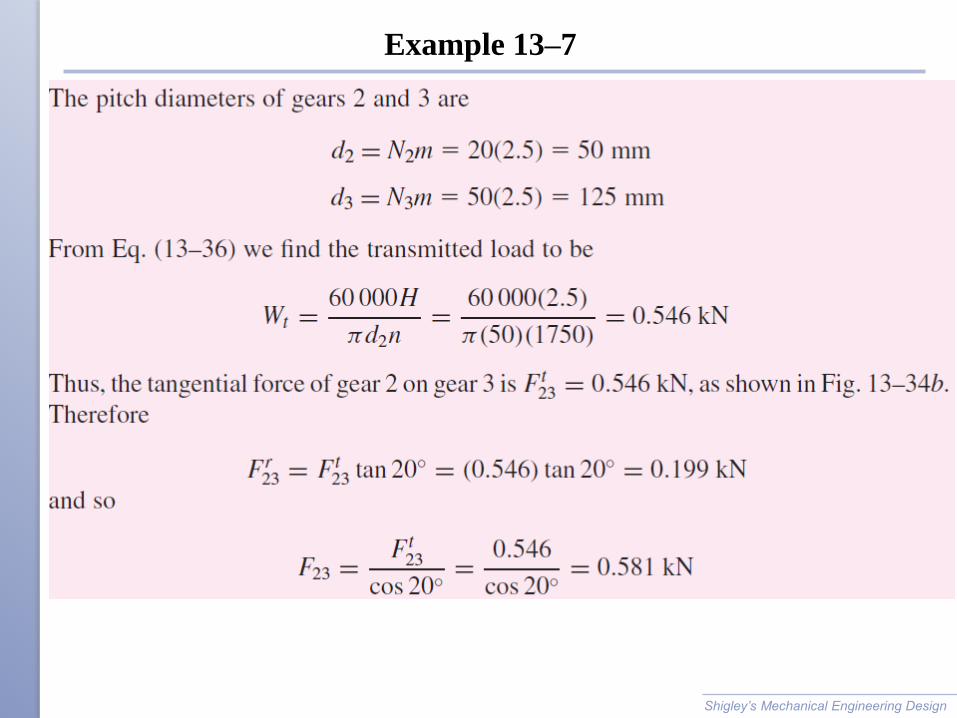
Example 13–7
Shigley’s Mechanical Engineering Design
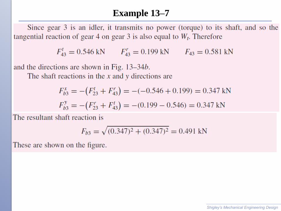
Example 13–7
Shigley’s Mechanical Engineering Design

Force Analysis – Bevel Gearing
Shigley’s Mechanical Engineering Design Fig. 13–35
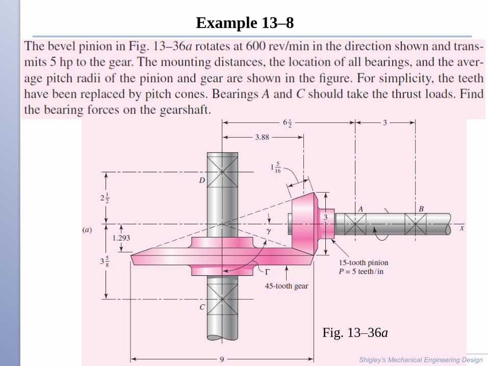
Example 13–8
Shigley’s Mechanical Engineering Design
Fig. 13–36a
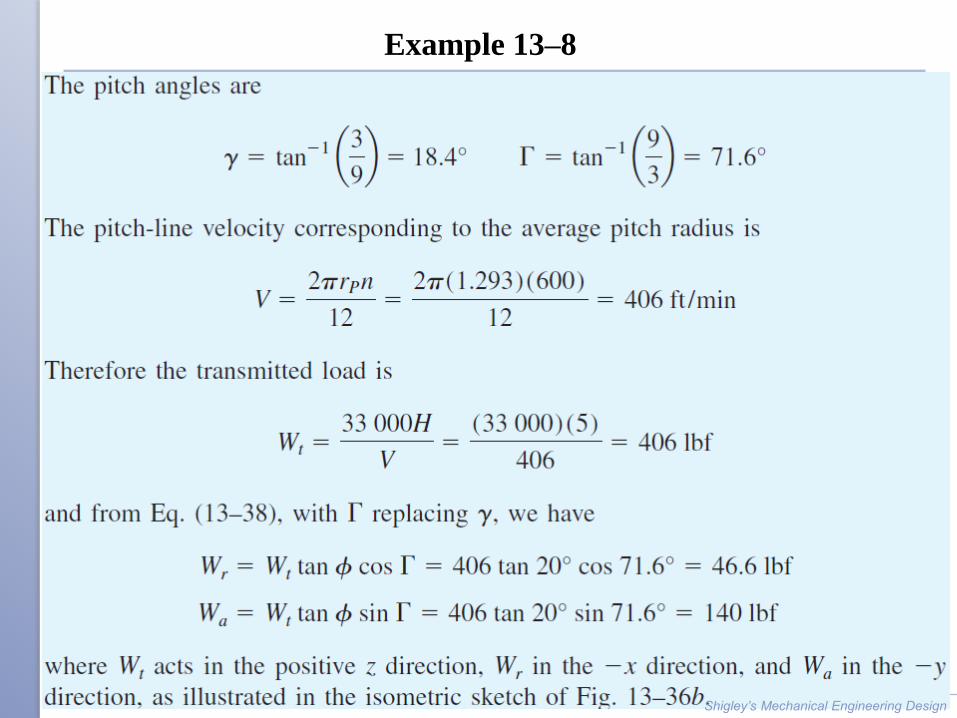
Example 13–8
Shigley’s Mechanical Engineering Design
Example 13–8
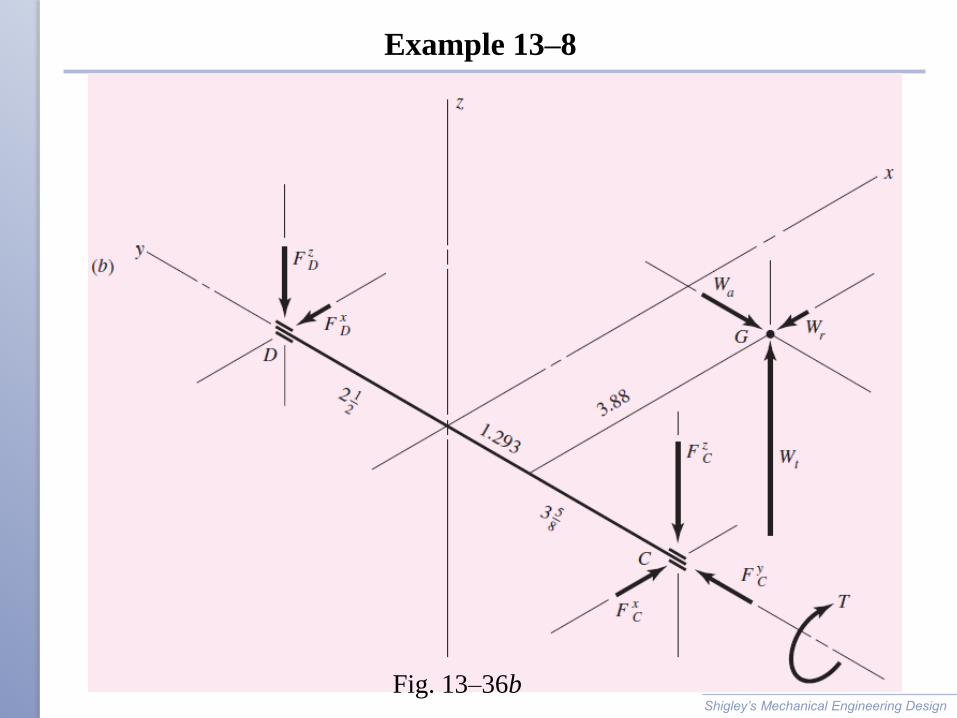
Shigley’s Mechanical Engineering Design
Fig. 13–36b
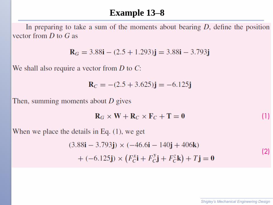
Example 13–8
Shigley’s Mechanical Engineering Design
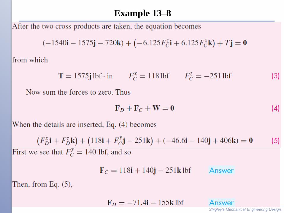
Example 13–8
Shigley’s Mechanical Engineering Design
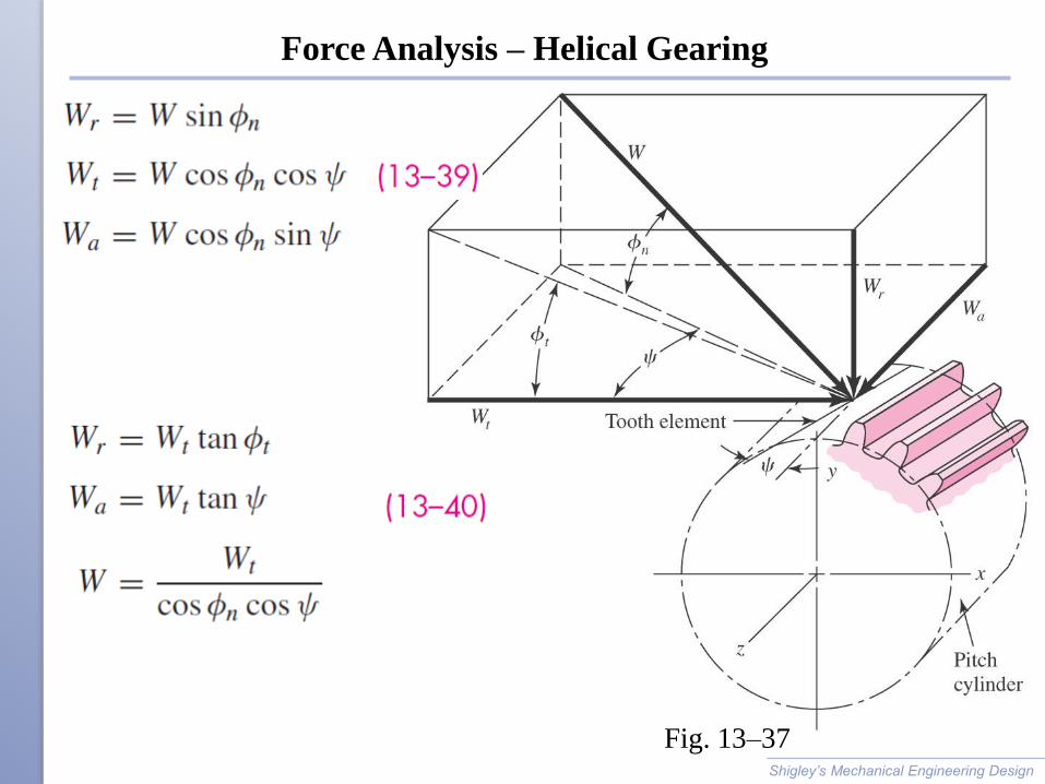
Force Analysis – Helical Gearing
Shigley’s Mechanical Engineering Design
Fig. 13–37
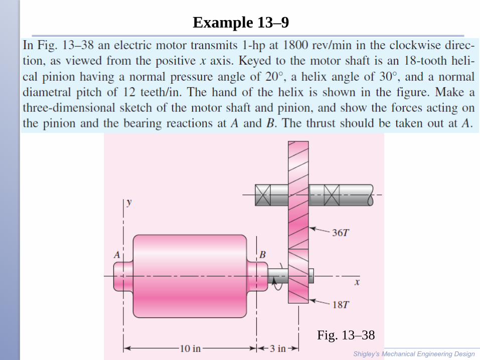
Example 13–9
Shigley’s Mechanical Engineering Design
Fig. 13–38
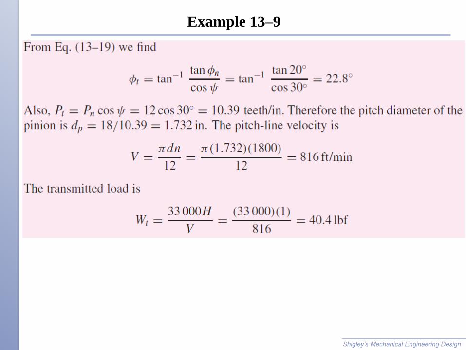
Example 13–9
Shigley’s Mechanical Engineering Design
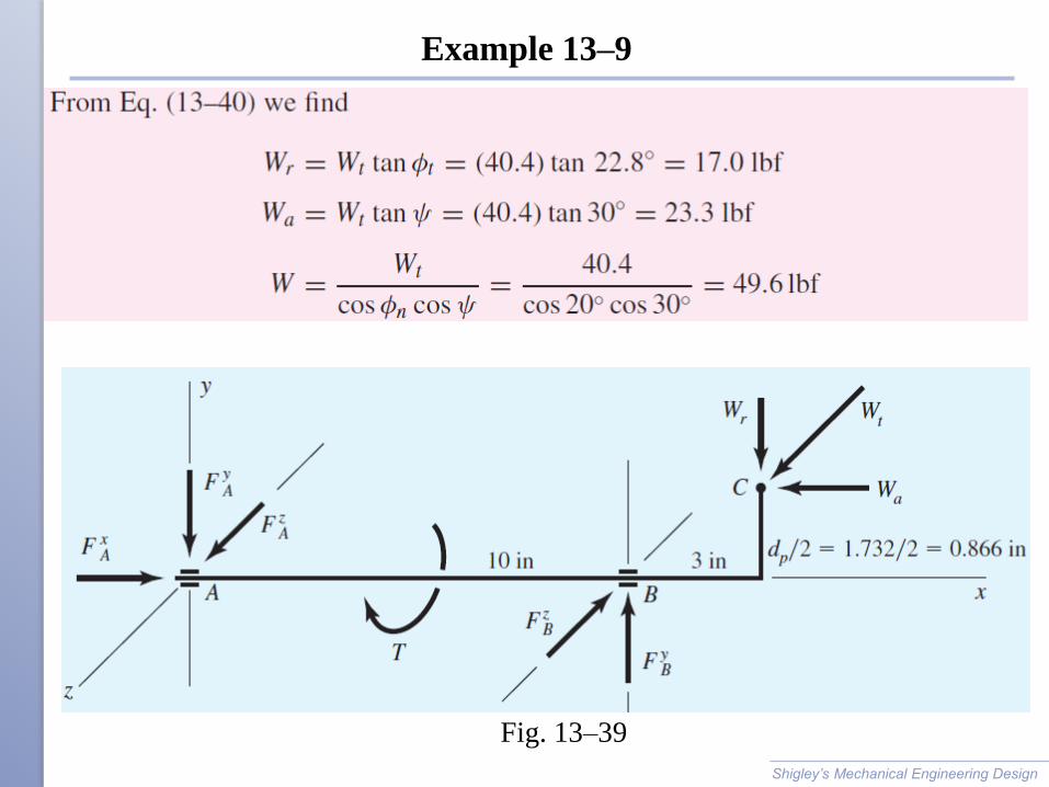
Example 13–9
Shigley’s Mechanical Engineering Design
Fig. 13–39
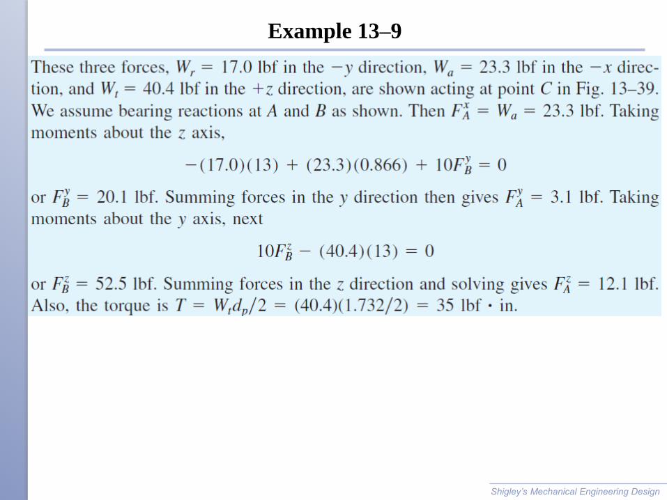
Example 13–9
Shigley’s Mechanical Engineering Design

Example 13–9
Shigley’s Mechanical Engineering Design


