154
GE Consumer & Industrial AF-300 P11 User’s Guide
| Date post: | 02-Jun-2018 |
| Category: |
Documents |
| Upload: | mark-izsm-amerson |
| View: | 212 times |
| Download: | 0 times |

8/11/2019 GEI-100364
http://slidepdf.com/reader/full/gei-100364 1/154
GE Consumer & Industrial
AF-300 P11
User’s Guide

8/11/2019 GEI-100364
http://slidepdf.com/reader/full/gei-100364 2/154
Data subject to change without notice 7/07. © 2007 GE Drives
© 2007 by GE Drives, Inc. All rights reserved.
These instructions do not purport to cover all details or variations in equipment, nor to provide every possiblecontingency to be met during installation, operation, and maintenance. If further information is desired, or if particular problems arise that are not covered sufficiently for the purchaser’s purpose, the matter should be referred to GE Drives, Plainville, CT USA.
This document contains proprietary information of GE Drives and is furnished to its customer solely to assist that customer in the installation, testing, operation, and/or maintenance of the equipment described. This document shall not be reproduced in whole or in part, nor shall its contents be disclosed to any third party without the written approval of GE Drives.
AF-300 P11 is a trademark of GE DrivesEnergy $aver is a registered trademark of General Electric Company, USA.Genius is a registered trademark of GE Fanuc Automation North America, Inc.Profibus is a trademark of Profibus International.X$D is a trademark of General Electric Company, USA.

8/11/2019 GEI-100364
http://slidepdf.com/reader/full/gei-100364 3/154
Data subject to change without notice 7/07. © 2007 GE Drives
WARNING:
This equipment contains a potential hazard of electric shock or burn. Only personnel who are adequately trainedand thoroughly familiar with the equipment and the instructions should install, operate, or maintain this equipment.
Isolation of test equipment from the equipment under test presents potential electrical hazards. If the test equipmentcannot be grounded to the equipment under test, the test equipment’s case must be shielded to prevent contact bypersonnel.
To minimize hazard of electrical shock or burn, approved grounding practices and procedures must be strictlyfollowed.
WARNING:
To prevent personal injury or equipment damage caused by equipment malfunction, only adequately trained person-
nel should modify any programmable machine.
8/11/2019 GEI-100364
http://slidepdf.com/reader/full/gei-100364 4/154
Data subject to change without notice 7/07. © 2007 GE Drives
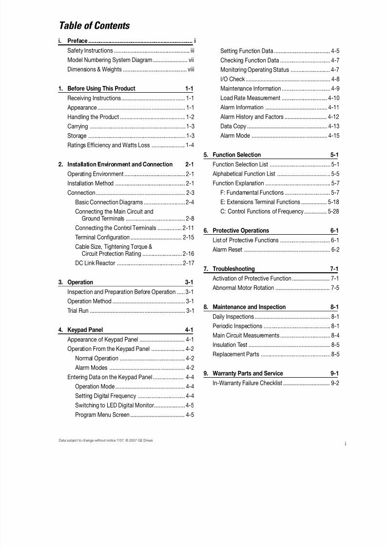
i. Preface .................................................................... i
Safety Instructions .................................................. iii
Model Numbering System Diagram....................... vii
Dimensions & Weights .......................................... viii
1. Before Using This Product 1-1
Receiving Instructions.................................... ...... 1-1
Appearance .................................... ...................... 1-1
Handling the Product ........................................... 1-2
Carrying ...............................................................1-3
Storage ................................................................1-3
Ratings Efficiency and Watts Loss ...................... 1-4
2. Installation Environment and Connection 2-1
Operating Environment ........................................ 2-1Installation Method .............................................. 2-1
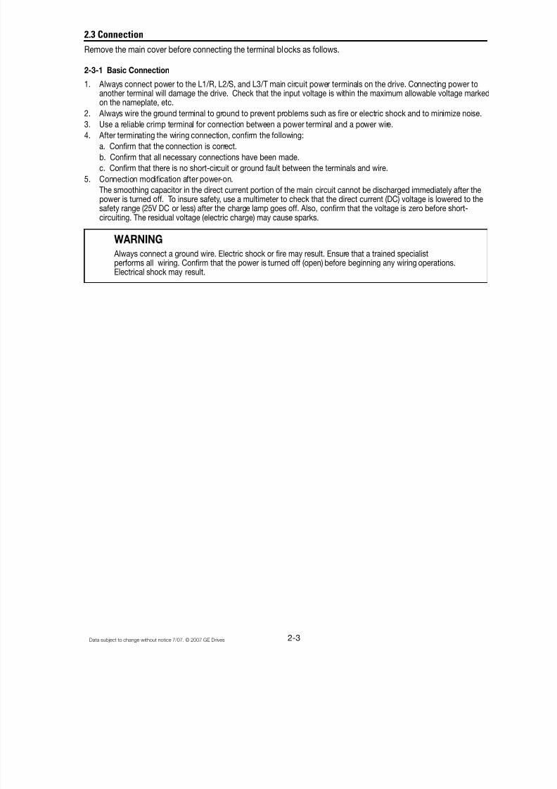
Connection................................ ........................... 2-3
Basic Connection Diagrams ........................... 2-4
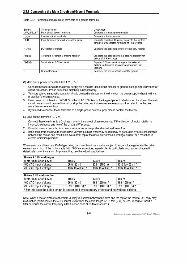
Connecting the Main Circuit andGround Terminals ....................................... 2-8
Connecting the Control Terminals ................ 2-11
Terminal Configuration .................................. 2-15
Cable Size, Tightening Torque & Circuit Protection Rating .......................... 2-16
DC Link Reactor ...........................................2-17
3. Operation 3-1
Inspection and Preparation Before Operation ..... 3-1
Operation Method .................................... ............ 3-1
Trial Run .................................... ........................... 3-1
4. Keypad Panel 4-1
Appearance of Keypad Panel .............................. 4-1
Operation From the Keypad Panel ...................... 4-2
Normal Operation ........................................... 4-2
Alarm Modes .................................. ................ 4-2
Entering Data on the Keypad Panel .................... 4-4
Operation Mode ................................. ............. 4-4
Setting Digital Frequency ............................... 4-4
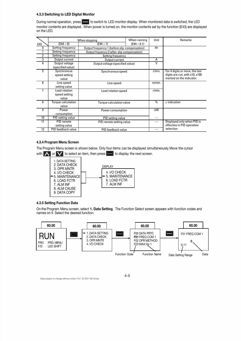
Switching to LED Digital Monitor....................4-5
Program Menu Screen .................................... 4-5
Setting Function Data ..................................... 4-5
Checking Function Data ................................. 4-7
Monitoring Operating Status .......................... 4-7
I/O Check .................................... .................... 4-8
Maintenance Information ................................ 4-9Load Rate Measurement .............................. 4-10
Alarm Information .................................. ....... 4-11
Alarm History and Factors ............................ 4-12
Data Copy ....................................... .............. 4-13
Alarm Mode .................................... .............. 4-15
5. Function Selection 5-1
Function Selection List ........................................ 5-1
Alphabetical Function List ................................. .. 5-5Function Explanation ........................................... 5-7
F: Fundamental Functions .............................. 5-7
E: Extensions Terminal Functions ................. 5-18
C: Control Functions of Frequency ............... 5-28
6. Protective Operations 6-1
List of Protective Functions ................................. 6-1
Alarm Reset .................................... ..................... 6-2
7. Troubleshooting 7-1
Activation of Protective Function ......................... 7-1
Abnormal Motor Rotation .................................... 7-5
8. Maintenance and Inspection 8-1
Daily Inspections .................................... .............. 8-1
Periodic Inspections ............................................ 8-1
Main Circuit Measurements ................................. 8-4
Insulation Test ................................. ..................... 8-5
Replacement Parts .............................................. 8-5
9. Warranty Parts and Service 9-1
In-Warranty Failure Checklist ............................... 9-2
Table of Contents
i
8/11/2019 GEI-100364
http://slidepdf.com/reader/full/gei-100364 5/154

8/11/2019 GEI-100364
http://slidepdf.com/reader/full/gei-100364 6/154
Data subject to change without notice 7/07. © 2007 GE Drives
Safety Instructions
Read this manual carefully before installing, connecting (wiring), operating, servicing, or inspecting the drive.
Familiarize yourself with all safety features before using the drive.
In this manual, safety messages are classified as follows:
WARNING Improper operation may result in serious personal injury or death.
CAUTION Improper operation may result in slight to medium personal injury or property damage.
Situations more serious than those covered by CAUTION will depend on prevailing circumstances. Always follow instructions.
Instructions on Use
WARNING
• This drive is designed to drive a 3-phase induction motor and is not suitable for a single-phase orother types of motors.
• This drive may not be used as a component of a life-support system or other medical device directlyaffecting the personal welfare of the user.
• This drive is manufactured under strict quality control standards. However, safety equipment must beinstalled or the failure of this device may result in personal injury, property damage, or risk an accident.
Instructions on Installation
WARNING• Mount this drive on an incombustible material such as metal, otherwise a risk of fire may result.
• Do not place combustible or flammable material near this drive, as fire may result.
CAUTION• Do not hold or carry this drive by its cover. Do not drop the converter, as injury may result.
• Ensure that the drive and heat sink surfaces are kept free of foreign matter (lint, paper dust, small chips ofwood or metal, and dust), as fire or accident may result.
• Do not install or operate a damaged drive or a drive with missing parts, as electric shock or
injury may occur.
iii

8/11/2019 GEI-100364
http://slidepdf.com/reader/full/gei-100364 7/154
Data subject to change without notice 7/07. © 2007 GE Drives
Instructions on Wiring
WARNING• Connect the drive to power via a line-protection molded-case circuit breaker or fuse, as fire may result.
Always connect a ground wire, as electric shock or fire may result.
• A licensed specialist must perform all wiring work, as electric shock may result.
• Turn off the power before wiring, as electric shock may result.
• Wire the drive after mechanical installation is complete, as electric shock or injury may occur.
CAUTION• Confirm that the number of phases and rated voltage of this product match those of the AC power supply,
otherwise injury may result.
• Do not connect the AC power supply to the output terminals (U, V, and W), as injury may result.
• Do not directly connect a braking resistor to the DC terminals (P(+) and N(-)), as fire may result.
• Ensure that the noise generated by the drive, motor, or wiring does not adversely affect peripheralsensors and equipment, as an accident may result.
Instructions on Operation
WARNING• Be sure to install the cover before turning on the power. Do not remove the cover while power to the drive
is turned on. Electric shock may occur.
• Do not operate switches with wet hands, as electric shock may result. When the retry function is selected,the drive may restart automatically after tripping. Design the machine to ensure personal safety in theevent of restart. Accident may result.
• When the torque limiting function is selected, operating conditions may differ from preset parameters(acceleration/deceleration time or speed). In this case, personal safety must be assured.
An accident may result.• The STOP key is only effective when a function setting has been established. Install an independent
emergency switch to disable the STOP key on the keypad panel when an operation is selected via theexternal signal terminal, otherwise an accident may result.
• Operations can start up suddenly, after an alarm is reset, if there is a run signal present.Confirm that the run signal input is not present before resetting the alarm. Accident may result.
• Do not touch drive terminals when energized, even if the drive has stopped. Electric shock may result.
CAUTION• Do not start or stop the drive using the main circuit power. Failure may result.
• Do not touch the heat sink or braking resistor because they become very hot. Burns may result.• Since the drive can reach high speed operation easily, carefully check the performance of motor or
machine before changing any speed settings. Injury may result.
• Do not use the drive braking function for mechanical holding. Injury may result.
iv
8/11/2019 GEI-100364
http://slidepdf.com/reader/full/gei-100364 8/154
Data subject to change without notice 7/07. © 2007 GE Drives
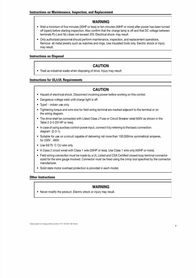
Instructions on Maintenance, Inspection, and Replacement
WARNING• Wait a minimum of five minutes (30HP or less) or ten minutes (40HP or more) after power has been turned
off (open) before starting inspection. Also confirm that the charge lamp is off and that DC voltage betweenterminals P(+) and N(-) does not exceed 25V. Electrical shock may result.
• Only authorized personnel should perform maintenance, inspection, and replacement operations.
Remove all metal jewelry such as watches and rings. Use insulated tools only. Electric shock or injurymay result.
Instructions on Disposal
CAUTION• Treat as industrial waste when disposing of drive. Injury may result.
Instructions for UL/cUL Requirements
CAUTION• Hazard of electrical shock. Disconnect incoming power before working on this control.
• Dangerous voltage exist until charge light is off.
• Type1 - indoor use only.
• Tightening torque and wire size for field wiring terminal are marked adjacent to the terminal or onthe wiring diagram.
• The drive shall be connected with Listed Class J Fuse or Circuit Breaker rated 600V as shown in theTable 2-3-5 (30 HP or less).
• In case of using auxiliary control-power input, connect it by referring to the basic connectiondiagram (2-3-1).
• Suitable for use on a circuit capable of delivering not more than 100,000rms symmetrical amperes,for 230V , 460V.
• Use 60/75 °C CU wire only.
• A Class 2 circuit wired with Class 1 wire (30HP or less). Use Class 1 wire only (40HP or more).
• Field wiring connection must be made by a UL Listed and CSA Certified closed-loop terminal connectorsized for the wire gauge involved. Connector must be fixed using the crimp tool specified by the connectormanufacturer.
• Solid state motor overload protection is provided in each model.
Other Instructions
WARNING• Never modify the product. Electric shock or injury may result.
v
8/11/2019 GEI-100364
http://slidepdf.com/reader/full/gei-100364 9/154
Data subject to change without notice 7/07. © 2007 GE Drives
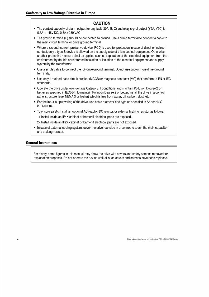
Conformity to Low Voltage Directive in Europe
CAUTION• The contact capacity of alarm output for any fault (30A, B, C) and relay signal output (Y5A, Y5C) is
0.5A at 48V DC, 0.3A ! 250 VAC
• The ground terminal (G) should be connected to ground. Use a crimp terminal to connect a cable tothe main circuit terminal or drive ground terminal.
• Where a residual-current protective device (RCD) is used for protection in case of direct or indirectcontact, only a type B device is allowed on the supply side of this electrical equipment. Otherwise,another protective measure shall be applied such as separation of the electrical equipment from theenvironment by double or reinforced insulation or isolation of the electrical equipment and supplysystem by the transformer.
• Use a single cable to connect the (G) drive ground terminal. Do not use two or more drive groundterminals.
• Use only a molded-case circuit breaker (MCCB) or magnetic contactor (MC) that conform to EN or IECstandards.
• Operate the drive under over-voltage Category III conditions and maintain Pollution Degree 2 orbetter as specified in IEC664. To maintain Pollution Degree 2 or better, install the drive in a control
panel structure (level NEMA 3 or higher) which is free from water, oil, carbon, dust, etc.
• For the input-output wiring of the drive, use cable diameter and type as specified in Appendix Cin EN60204.
• To ensure safety, install an optional AC reactor, DC reactor, or external braking resistor as follows:
1) Install inside an IP4X cabinet or barrier if electrical parts are exposed.
2) Install inside an IP2X cabinet or barrier if electrical parts are not exposed.
• In case of external cooling system, cover the drive rear side in order not to touch the main capacitorand braking resistor.
General Instructions
For clarity, some figures in this manual may show the drive with covers and safety screens removed forexplanation purposes. Do not operate the device until all such covers and screens have been replaced.
vi

8/11/2019 GEI-100364
http://slidepdf.com/reader/full/gei-100364 10/154
Data subject to change without notice 7/07. © 2007 GE Drives
AF-300 P11 ™ Model Numbering System Diagram
Description 6K P11 N N (X/N)NN X N X N
GE Product Code
AF-300 Drive Family
Input Voltage
2 = 230V 50/60 Hz
4 = 460V 50/60 Hz
Input Phases
3 = 3 Phase
Horsepower F50 = 1/2 Hp
010 = 10 Hp
100 = 100 Hp
Factory Installed Options
N = None
X = Keypad
B = to be determined
Enclosure Type
1 = NEMA 1 (UL Type 1)
2 = NEMA 12 (UL Type 12)
4 = NEMA 4 (UL Type 4)
8 = IP00 with NEMA 12 heatsink
9 = IP00
Product Revision
A = 1st Revision
B = 2nd Revision
Minor Product Revision1 = 1st Minor Revision
2 = 2nd Minor Revision
vii
8/11/2019 GEI-100364
http://slidepdf.com/reader/full/gei-100364 11/154
Data subject to change without notice 7/07. © 2007 GE Drives
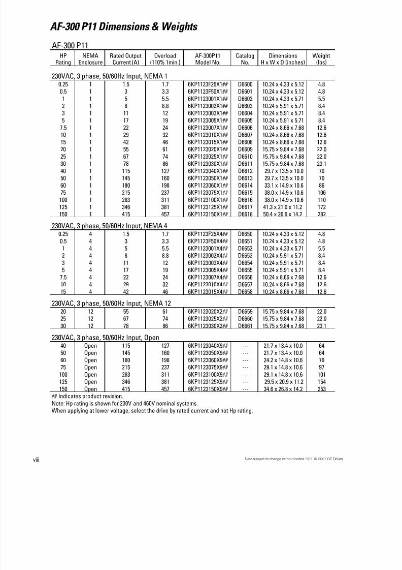
AF-300 P11 Dimensions & Weights
viii
AF-300 P11HP
RatingNEMA
EnclosureRated Output
Current (A)Overload
(110% 1min.)AF-300P11Model No.
CatalogNo.
DimensionsH x W x D (inches)
Weight(lbs)
230VAC, 3 phase, 50/60Hz Input, NEMA 10.25 1 1.5 1.7 6KP1123F25X1## D6600 10.24 x 4.33 x 5.12 4.8
0.5 1 3 3.3 6KP1123F50X1## D6601 10.24 x 4.33 x 5.12 4.81 1 5 5.5 6KP1123001X1## D6602 10.24 x 4.33 x 5.71 5.52 1 8 8.8 6KP1123002X1## D6603 10.24 x 5.91 x 5.71 8.4
3 1 11 12 6KP1123003X1## D6604 10.24 x 5.91 x 5.71 8.45 1 17 19 6KP1123005X1## D6605 10.24 x 5.91 x 5.71 8.4
7.5 1 22 24 6KP1123007X1## D6606 10.24 x 8.66 x 7.68 12.610 1 29 32 6KP1123010X1## D6607 10.24 x 8.66 x 7.68 12.6
15 1 42 46 6KP1123015X1## D6608 10.24 x 8.66 x 7.68 12.620 1 55 61 6KP1123020X1## D6609 15.75 x 9.84 x 7.68 22.0
25 1 67 74 6KP1123025X1## D6610 15.75 x 9.84 x 7.68 22.030 1 78 86 6KP1123030X1## D6611 15.75 x 9.84 x 7.68 23.1
40 1 115 127 6KP1123040X1## D6612 29.7 x 13.5 x 10.0 7050 1 145 160 6KP1123050X1## D6613 29.7 x 13.5 x 10.0 70
60 1 180 198 6KP1123060X1## D6614 33.1 x 14.9 x 10.6 8675 1 215 237 6KP1123075X1## D6615 38.0 x 14.9 x 10.6 106
100 1 283 311 6KP1123100X1## D6616 38.0 x 14.9 x 10.6 110125 1 346 381 6KP1123125X1## D6617 41.3 x 21.0 x 11.2 172150 1 415 457 6KP1123150X1## D6618 50.4 x 26.9 x 14.2 282
230VAC, 3 phase, 50/60Hz Input, NEMA 40.25 4 1.5 1.7 6KP1123F25X4## D6650 10.24 x 4.33 x 5.12 4.8
0.5 4 3 3.3 6KP1123F50X4## D6651 10.24 x 4.33 x 5.12 4.81 4 5 5.5 6KP1123001X4## D6652 10.24 x 4.33 x 5.71 5.52 4 8 8.8 6KP1123002X4## D6653 10.24 x 5.91 x 5.71 8.4
3 4 11 12 6KP1123003X4## D6654 10.24 x 5.91 x 5.71 8.45 4 17 19 6KP1123005X4## D6655 10.24 x 5.91 x 5.71 8.4
7.5 4 22 24 6KP1123007X4## D6656 10.24 x 8.66 x 7.68 12.610 4 29 32 6KP1123010X4## D6657 10.24 x 8.66 x 7.68 12.6
15 4 42 46 6KP1123015X4## D6658 10.24 x 8.66 x 7.68 12.6
230VAC, 3 phase, 50/60Hz Input, NEMA 1220 12 55 61 6KP1123020X2## D6659 15.75 x 9.84 x 7.68 22.025 12 67 74 6KP1123025X2## D6660 15.75 x 9.84 x 7.68 22.0
30 12 78 86 6KP1123030X2## D6661 15.75 x 9.84 x 7.68 23.1
230VAC, 3 phase, 50/60Hz Input, Open40 Open 115 127 6KP1123040X9## --- 21.7 x 13.4 x 10.0 6450 Open 145 160 6KP1123050X9## --- 21.7 x 13.4 x 10.0 64
60 Open 180 198 6KP1123060X9## --- 24.2 x 14.8 x 10.6 79
75 Open 215 237 6KP1123075X9## --- 29.1 x 14.8 x 10.6 97100 Open 283 311 6KP1123100X9## --- 29.1 x 14.8 x 10.6 101125 Open 346 381 6KP1123125X9## --- 29.5 x 20.9 x 11.2 154
150 Open 415 457 6KP1123150X9## --- 34.6 x 26.8 x 14.2 253 ## Indicates product revision.
Note: Hp rating is shown for 230V and 460V nominal systems.When applying at lower voltage, select the drive by rated current and not Hp rating.
8/11/2019 GEI-100364
http://slidepdf.com/reader/full/gei-100364 12/154

8/11/2019 GEI-100364
http://slidepdf.com/reader/full/gei-100364 13/154
Data subject to change without notice 7/07. © 2007 GE Drives
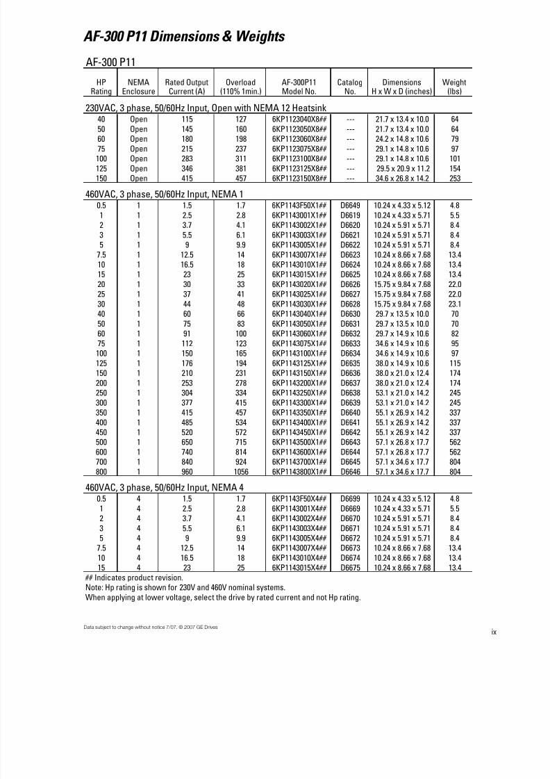
AF-300 P11 Dimensions & Weights
x
AF-300 P11
HPRating
NEMAEnclosure
Rated OutputCurrent (A)
Overload(110% 1min.)
AF-300P11Model No.
CatalogNo.
DimensionsH x W x D (inches)
Weight(lbs)
460VAC, 3 phase, 50/60Hz Input, NEMA 1220 12 30 33 6KP1143020X2## D6676 15.75 x 9.84 x 7.68 22.0
25 12 37 41 6KP1143025X2## D6677 15.75 x 9.84 x 7.68 22.030 12 44 48 6KP1143030X2## D6678 15.75 x 9.84 x 7.68 23.1
460VAC, 3 phase, 50/60Hz Input, Open40 Open 60 66 6KP1143040X9## --- 21.7 x 13.4 x 10.0 64
50 Open 75 83 6KP1143050X9## --- 21.7 x 13.4 x 10.0 6460 Open 91 100 6KP1143060X9## --- 21.7 x 14.8 x 10.6 75
75 Open 112 123 6KP1143075X9## --- 26.6 x 14.8 x 10.6 86100 Open 150 165 6KP1143100X9## --- 26.6 x 14.8 x 10.6 88
125 Open 176 194 6KP1143125X9## --- 29.1 x 14.8 x 10.6 106150 Open 210 231 6KP1143150X9## --- 29.1 x 20.9 x 12.4 154
200 Open 253 278 6KP1143200X9## --- 29.1 x 20.9 x 12.4 154250 Open 304 334 6KP1143250X9## --- 39.4 x 20.9 x 14.2 220
300 Open 377 415 6KP1143300X9## --- 39.4 x 20.9 x 14.2 220350 Open 415 457 6KP1143350X9## --- 39.4 x 26.8 x 14.2 308
400 Open 485 534 6KP1143400X9## --- 39.4 x 26.8 x 14.2 308450 Open 520 572 6KP1143450X9## --- 39.4 x 26.8 x 14.2 308
500 Open 650 715 6KP1143500X9## --- 55.1 x 26.8 x 17.7 551600 Open 740 814 6KP1143600X9## --- 55.1 x 26.8 x 17.7 551
700 Open 840 924 6KP1143700X9## --- 55.1 x 35.6 x 17.7 793800 Open 960 1056 6KP1143800X9## --- 55.1 x 35.6 x 17.7 793
460VAC, 3 phase, 50/60Hz Input, Open with NEMA 12 Heatsink40 Open 60 66 6KP1143040X8## --- 21.7 x 13.4 x 10.0 6450 Open 75 83 6KP1143050X8## --- 21.7 x 13.4 x 10.0 64
60 Open 91 100 6KP1143060X8## --- 21.7 x 14.8 x 10.6 7575 Open 112 123 6KP1143075X8## --- 26.6 x 14.8 x 10.6 86
100 Open 150 165 6KP1143100X8## --- 26.6 x 14.8 x 10.6 88125 Open 176 194 6KP1143125X8## --- 29.1 x 14.8 x 10.6 106150 Open 210 231 6KP1143150X8## --- 29.1 x 20.9 x 12.4 154
200 Open 253 278 6KP1143200X8## --- 29.1 x 20.9 x 12.4 154250 Open 304 334 6KP1143250X8## --- 39.4 x 20.9 x 14.2 220
300 Open 377 415 6KP1143300X8## --- 39.4 x 20.9 x 14.2 220350 Open 415 457 6KP1143350X8## --- 39.4 x 26.8 x 14.2 308
400 Open 485 534 6KP1143400X8## --- 39.4 x 26.8 x 14.2 308450 Open 520 572 6KP1143450X8## --- 39.4 x 26.8 x 14.2 308
500 Open 650 715 6KP1143500X8## --- 55.1 x 26.8 x 17.7 551600 Open 740 814 6KP1143600X8## --- 55.1 x 26.8 x 17.7 551
700 Open 840 924 6KP1143700X8## --- 55.1 x 35.6 x 17.7 793800 Open 960 1056 6KP1143800X8## --- 55.1 x 35.6 x 17.7 793
## Indicates product revision.Note: Hp rating is shown for 230V and 460V nominal systems.
When applying at lower voltage, select the drive by rated current and not Hp rating.
8/11/2019 GEI-100364
http://slidepdf.com/reader/full/gei-100364 14/154
1-1Data subject to change without notice 7/07. © 2007 GE Drives
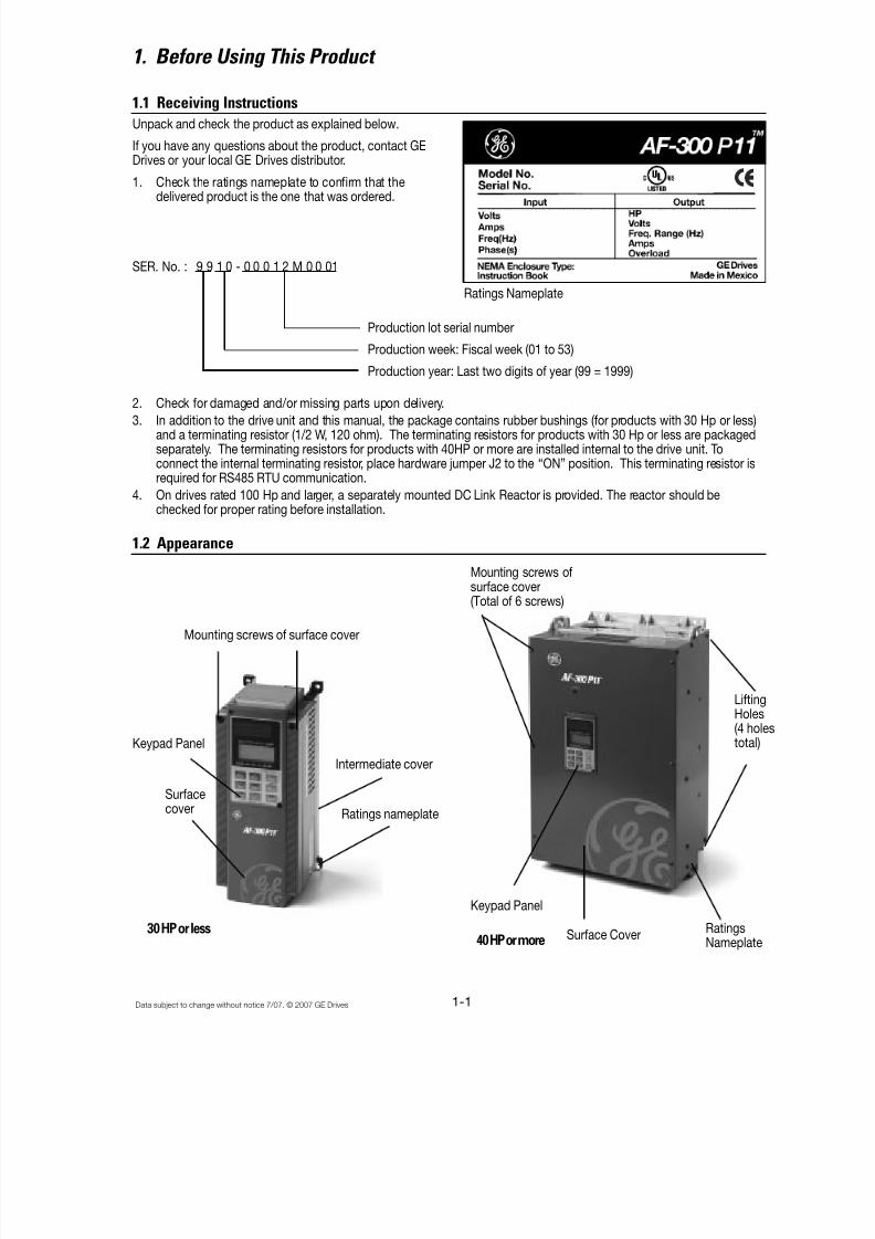
1. Before Using This Product
1.1 Receiving Instructions
40 HP or more
LiftingHoles(4 holestotal)
RatingsNameplate
Surface Cover
Keypad Panel
Mounting screws of surface cover
Keypad Panel
Surfacecover
Intermediate cover
Ratings nameplate
30 HP or less
Ratings Nameplate
Unpack and check the product as explained below.
If you have any questions about the product, contact GEDrives or your local GE Drives distributor.
1. Check the ratings nameplate to confirm that the
delivered product is the one that was ordered.
2. Check for damaged and/or missing parts upon delivery.3. In addition to the drive unit and this manual, the package contains rubber bushings (for products with 30 Hp or less)
and a terminating resistor (1/2 W, 120 ohm). The terminating resistors for products with 30 Hp or less are packagedseparately. The terminating resistors for products with 40HP or more are installed internal to the drive unit. Toconnect the internal terminating resistor, place hardware jumper J2 to the “ON” position. This terminating resistor isrequired for RS485 RTU communication.
4. On drives rated 100 Hp and larger, a separately mounted DC Link Reactor is provided. The reactor should bechecked for proper rating before installation.
1.2 Appearance
SER. No. : 9 9 1 0 - 0 0 0 1 2 M 0 0 01
Production lot serial number
Production week: Fiscal week (01 to 53)
Production year: Last two digits of year (99 = 1999)
Mounting screws ofsurface cover
(Total of 6 screws)
8/11/2019 GEI-100364
http://slidepdf.com/reader/full/gei-100364 15/154
1-2 Data subject to change without notice 7/07. © 2007 GE Drives
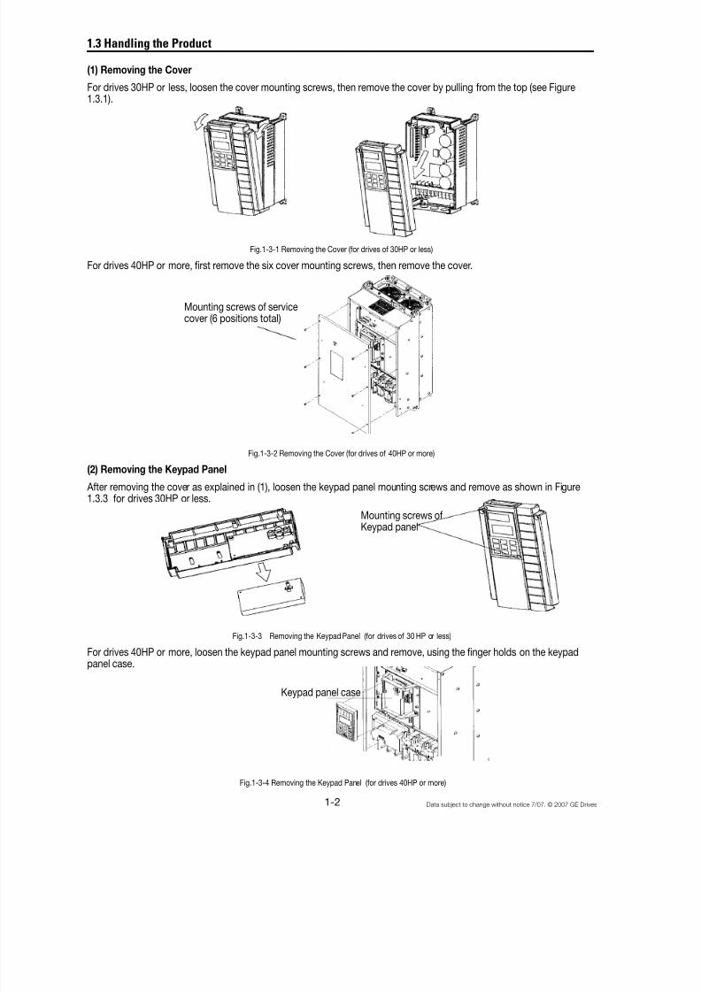
1.3 Handling the Product
(1) Removing the Cover
For drives 30HP or less, loosen the cover mounting screws, then remove the cover by pulling from the top (see Figure1.3.1).
Fig.1-3-1 Removing the Cover (for drives of 30HP or less)
For drives 40HP or more, first remove the six cover mounting screws, then remove the cover.
Fig.1-3-2 Removing the Cover (for drives of 40HP or more)
(2) Removing the Keypad Panel
After removing the cover as explained in (1), loosen the keypad panel mounting screws and remove as shown in Figure1.3.3 for drives 30HP or less.
Fig.1-3-3 Removing the Keypad Panel (for drives of 30 HP or less)
For drives 40HP or more, loosen the keypad panel mounting screws and remove, using the finger holds on the keypadpanel case.
Mounting screws of service
cover (6 positions total)
Mounting screws ofKeypad panel
Keypad panel case
Fig.1-3-4 Removing the Keypad Panel (for drives 40HP or more)

8/11/2019 GEI-100364
http://slidepdf.com/reader/full/gei-100364 16/154
1-3Data subject to change without notice 7/07. © 2007 GE Drives
1.4 Carrying
Carry the product by the main unit. Do not carry the product by its cover or parts other than the main unit. Use a crane orhoist to carry a product equipped with hanging holes.
1.5 Storage
Temporary Storage
Temporary storage of this product must meet the conditions listed in Table 1-5-1.
Table 1-5-1 Storage Environment
Item Specifications
Ambient Temperature -10° to +50°C(+14° to +122°F)
Condensation or freezing, as a result of sudden temperaturechanges, must not occur.
Storage Temperature -25° to +65°C1
(-4° to +149°F)
Relative Humidity 5 to 95%2
Atmosphere The standard product must not be exposed to dust, direct sunlight, corrosivegas, flammable gas, oil mist, vapor, water drops, or vibration. The salt content
in the atmosphere should be minimized.
Note 1: The storage temperature applies only to short periods of time, such as during transport. Refer to comments onextended storage guidelines.
Note 2: Since a large change in temperature within this humidity range may result in condensation or freezing, do notstore where such temperature changes may occur.
1. Do not place this product directly on the floor.
2. To store the product in an extreme environment, pack in vinyl sheeting, etc.
3. If the product is stored in a high-humidity environment, insert a drying agent (e.g., silica gel) and pack the product invinyl sheeting.
Long-term StorageIf the product is to be stored for an extended period of time after purchase, the method of storage depends primarily onthe storage location.
The general long-term storage method is as follows:
1. The above conditions for temporary storage must be satisfied.If the storage period exceeds three months, the upperlimit of ambient temperature must be reduced to 30°C (86°F) to prevent the deterioration of the electrolytic capaci-tors.
2. Pack the product thoroughly to eliminate exposure to moisture and include a drying agent to ensure a relativehumidity of about 70% or less.
3. Do not leave the product mounted in a control panel and exposed to the elements like moisture or dust (particularlyon a construction site). In this case, remove the product and store in a suitable environment.
4. Electrolytic capacitors will deteriorate if not provided with power for an extended period of time. Do not store
electrolytic capacitors for one year or longer without providing power.

8/11/2019 GEI-100364
http://slidepdf.com/reader/full/gei-100364 17/154
1-4 Data subject to change without notice 7/07. © 2007 GE Drives
1.6 AF-300 P11 Drive Ratings Efficiency and Watts Loss
HP Rating
Rated OutputCurrent (A)
Rated OutputPower (KVA)
Efficiency at 2KHz(%)
Efficiency at15KHz (%)
Watts Loss at2KHz (W)
Watts Loss at15KHz (W) Internal DB (W)
230VAC0.25 1.5 0.59 92.0 90.5 25 30 N/A
0.5 3 1.1 93.5 91.7 35 45 N/A
1 5 1.9 94.9 94.0 50 60 N/A
2 8 3.1 95.7 94.1 80 110 N/A3 11 4.3 95.9 94.9 110 140 N/A
5 17 6.7 96.2 95.4 170 210 N/A
7.5 22 8.7 96.2 95.2 210 280 N/A
10 29 11 96.5 95.3 290 370 N/A
15 42 16 96.4 95.2 410 550 N/A
20 55 21 96.9 95.9 500 670 N/A
25 67 26 96.8 95.8 630 840 N/A
30 78 31 96.5 95.5 770 1030 N/A
2KHz (%) 10KHz (%) 2KHz (W) 10KHz (W)
40 115 45 97.2 96.8 950 1100 N/A
50 145 57 97.0 96.7 1250 1400 N/A
60 180 71 97.1 96.6 1500 1750 N/A
75 215 85 97.3 96.6 1700 1950 N/A
100 283 112 97.4 97.0 2200 2500 N/A
2KHz (%) 6KHz (%) 2KHz (W) 6KHz (W)
125 346 137 97.4 97.2 2650 2800 N/A
150 415 165 97.4 97.3 3200 3350 N/A
460VAC0.5 1.5 1.1 93.5 89.3 35 60 N/A
1 2.5 1.9 95.4 91.7 45 85 N/A
2 3.7 2.9 96.7 94.1 60 110 N/A
3 5.5 4.3 97.0 94.5 80 150 N/A
5 9 7.1 97.1 95.0 130 230 N/A
7.5 12.5 9.9 97.3 95.3 160 290 N/A
10 16.5 13.1 97.3 95.4 210 370 N/A
15 23 18.3 97.6 95.9 300 520 N/A
20 30 23.9 97.9 96.5 360 610 N/A
25 37 29.4 97.8 96.4 460 770 N/A
30 44 35 97.8 96.4 530 870 N/A
2KHz (%) 10KHz (%) 2KHz (W) 10KHz (W)
40 60 47 97.8 96.9 750 1050 N/A50 75 59 97.7 96.9 950 1300 N/A
60 91 72 97.8 97.0 1100 1550 N/A
75 112 89 97.8 97.0 1350 1900 N/A
100 150 119 97.8 97.1 1800 2450 N/A
2KHz (%) 6KHz (%) 2KHz (W) 6KHz (W)
125 176 140 98.1 97.8 1850 2200 N/A
150 210 167 98.0 97.8 2400 2750 N/A
200 253 202 98.0 97.7 2900 3350 N/A
250 304 242 98.1 97.8 3250 3800 N/A
300 377 300 98.1 97.8 4250 4900 N/A
350 415 330 98.2 97.9 4350 5100 N/A
400 485 386 98.1 97.8 5100 5900 N/A
450 520 414 98.1 97.8 5700 6650 N/A
500 650 518 98.2 97.9 6900 8050 N/A
600 740 590 98.1 97.8 8050 9350 N/A
700 840 669 98.2 97.9 8900 10400 N/A800 960 765 98.1 97.8 10300 12100 N/A

8/11/2019 GEI-100364
http://slidepdf.com/reader/full/gei-100364 18/154

8/11/2019 GEI-100364
http://slidepdf.com/reader/full/gei-100364 19/154
2-2 Data subject to change without notice 7/07. © 2007 GE Drives
A drive of 40HP or more can be converted to externalcooling simply by moving the upper and lower mountingbrackets as shown in Fig. 2-2-3. Remove the M6 bracketscrews, move the brackets, then secure the bracketsusing the M5 case mounting screws. (The bracket screwsare no longer required after changing the bracket mount-ing position.)
Fig. 2-2-3
In an external cooling system, a heat sink radiating about70% of total drive heat (total loss) can be placed outsidethe device or control panel, as shown in Fig. 2-2-2.
7. For drives of 30HP or less, remove the ventilatingcovers if ambient temperature exceeds +40°C (104°F).
1. Removing the Ventilating CoversOne ventilating cover is mounted on top of the drive and
two or three are mounted at the bottom. Remove the
main cover and then remove ventilating covers by
popping out the cover inserts as shown in Fig. 2-2-4.
Fig. 2-2-4 Removing the ventilating cover
Bracket Screws (M6)
Case mountingscrews (M5)10 screws total
Mounting
Mountingbracket
Fig.2.2.5
Fig. 2.2.6
Installation of Open Type with NEMA 12 Heatsink Drive(40 Hp and above)
1. Remove adhesive protection strip from gasket andthen mount gasket to panel/enclosure, carefullyaligning cutout and mounting holes.
2. Install the drive unit and tighten the mounting boltand nut. (Tightening torque: 119 lbs-inch [M8], 425lbs-inch [M12] ). Mounting hardware to be suppliedby customer. (refer to figure 2.2.5)
3. After proper torque has been applied to all mountinghardware, seal the outside end of the hardware withsilicon glue. Silicon glue to be supplied by thecustomer. (Refer to Fig. 2.2.6)
8/11/2019 GEI-100364
http://slidepdf.com/reader/full/gei-100364 20/154
8/11/2019 GEI-100364
http://slidepdf.com/reader/full/gei-100364 21/154
2-4 Data subject to change without notice 7/07. © 2007 GE Drives
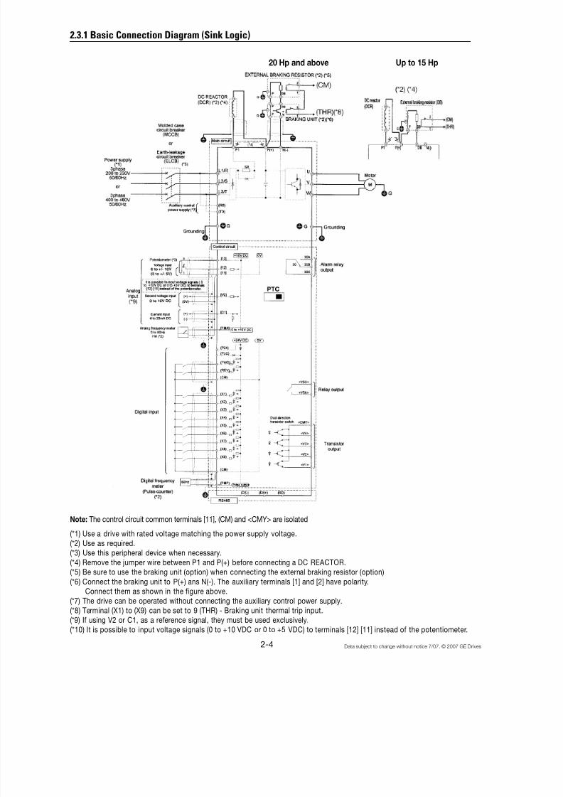
Note: The control circuit common terminals [11], (CM) and <CMY> are isolated
(*1) Use a drive with rated voltage matching the power supply voltage.
(*2) Use as required.
(*3) Use this peripheral device when necessary.
(*4) Remove the jumper wire between P1 and P(+) before connecting a DC REACTOR.
(*5) Be sure to use the braking unit (option) when connecting the external braking resistor (option)
(*6) Connect the braking unit to P(+) ans N(-). The auxiliary terminals [1] and [2] have polarity.
Connect them as shown in the figure above.
(*7) The drive can be operated without connecting the auxiliary control power supply.
(*8) Terminal (X1) to (X9) can be set to 9 (THR) - Braking unit thermal trip input.
(*9) If using V2 or C1, as a reference signal, they must be used exclusively.
(*10) It is possible to input voltage signals (0 to +10 VDC or 0 to +5 VDC) to terminals [12] [11] instead of the potentiometer.
2.3.1 Basic Connection Diagram (Sink Logic)
20 Hp and above Up to 15 Hp

8/11/2019 GEI-100364
http://slidepdf.com/reader/full/gei-100364 22/154
2-5Data subject to change without notice 7/07. © 2007 GE Drives
Basic Connection Diagram to PLC (Sink Logic)
See page 2-4 for notes
20 Hp and above Up to 15 Hp
8/11/2019 GEI-100364
http://slidepdf.com/reader/full/gei-100364 23/154
2-6 Data subject to change without notice 7/07. © 2007 GE Drives
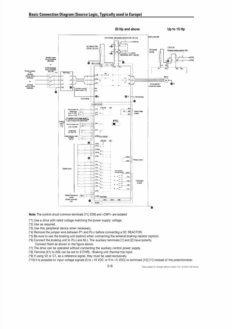
Basic Connection Diagram (Source Logic, Typically used in Europe)
Note: The control circuit common terminals [11], (CM) and <CMY> are isolated
(*1) Use a drive with rated voltage matching the power supply voltage.
(*2) Use as required.
(*3) Use this peripheral device when necessary.
(*4) Remove the jumper wire between P1 and P(+) before connecting a DC REACTOR.
(*5) Be sure to use the braking unit (option) when connecting the external braking resistor (option).
(*6) Connect the braking unit to P(+) ans N(-). The auxiliary terminals [1] and [2] have polarity.
Connect them as shown in the figure above.
(*7) The drive can be operated without connecting the auxiliary control power supply.
(*8) Terminal (X1) to (X9) can be set to 9 (THR) - Braking unit thermal trip input.
(*9) If using V2 or C1, as a reference signal, they must be used exclusively.
(*10) It is possible to input voltage signals (0 to +10 VDC or 0 to +5 VDC) to terminals [12] [11] instead of the potentiometer.
20 Hp and above Up to 15 Hp
8/11/2019 GEI-100364
http://slidepdf.com/reader/full/gei-100364 24/154
2-7Data subject to change without notice 7/07. © 2007 GE Drives
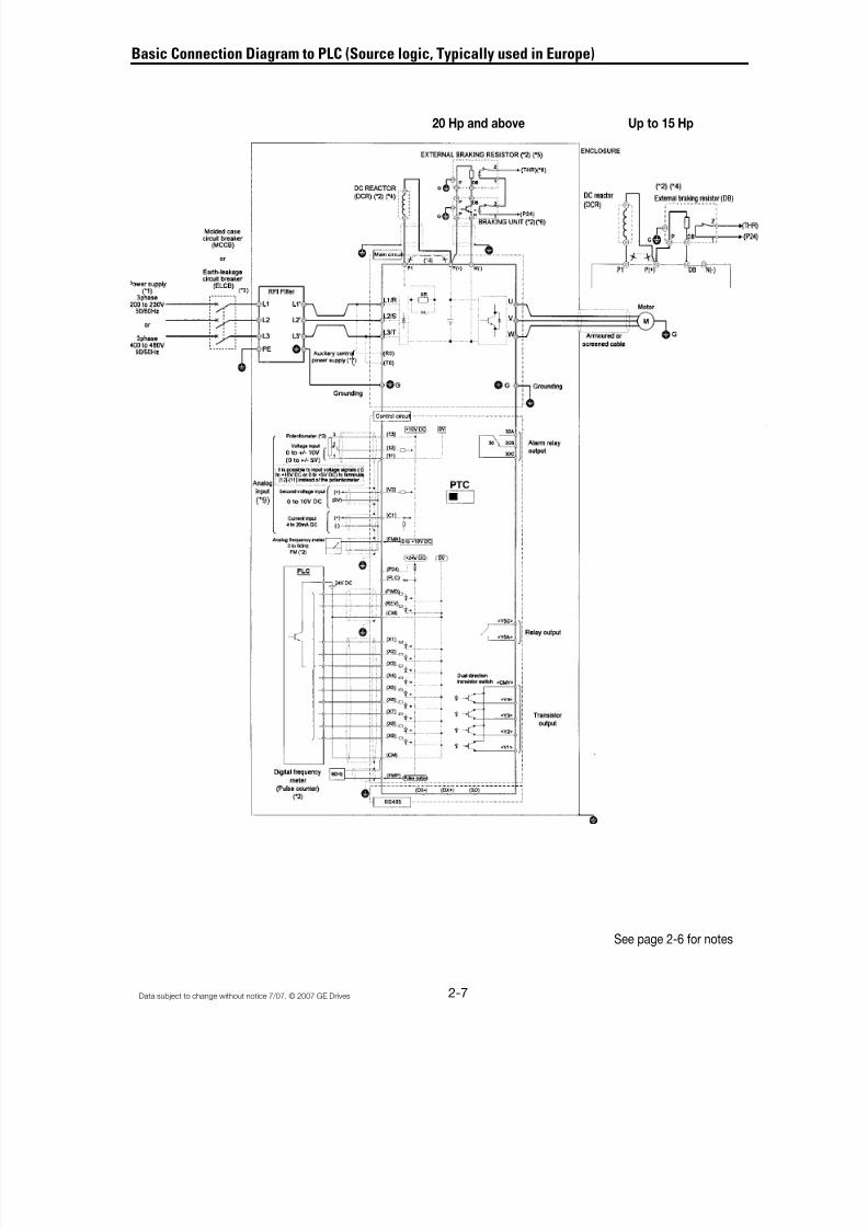
Basic Connection Diagram to PLC (Source logic, Typically used in Europe)
See page 2-6 for notes
20 Hp and above Up to 15 Hp
8/11/2019 GEI-100364
http://slidepdf.com/reader/full/gei-100364 25/154
8/11/2019 GEI-100364
http://slidepdf.com/reader/full/gei-100364 26/154
2-9Data subject to change without notice 7/07. © 2007 GE Drives
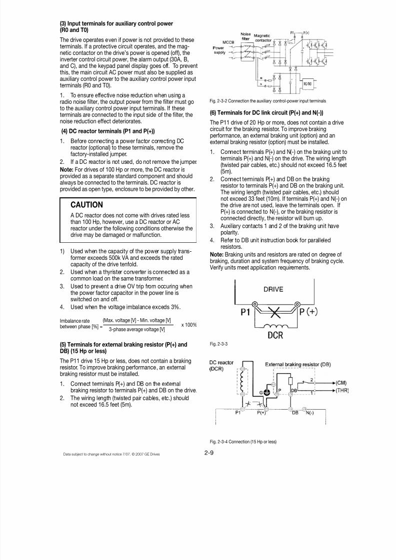
(3) Input terminals for auxiliary control power(R0 and T0)
The drive operates even if power is not provided to theseterminals. If a protective circuit operates, and the mag-netic contactor on the drive’s power is opened (off), theinverter control circuit power, the alarm output (30A, B,and C), and the keypad panel display goes off. To preventthis, the main circuit AC power must also be supplied asauxiliary control power to the auxiliary control power inputterminals (R0 and T0).
1. To ensure effective noise reduction when using aradio noise filter, the output power from the filter must goto the auxiliary control power input terminals. If theseterminals are connected to the input side of the filter, thenoise reduction effect deteriorates.
(4) DC reactor terminals (P1 and P(+))
1. Before connecting a power factor correcting DCreactor (optional) to these terminals, remove thefactory-installed jumper.
2. If a DC reactor is not used, do not remove the jumper.
Note: For drives of 100 Hp or more, the DC reactor isprovided as a separate standard component and shouldalways be connected to the terminals. DC reactor isprovided as open type, enclosure to be provided by other.
CAUTION
A DC reactor does not come with drives rated lessthan 100 Hp, however, use a DC reactor or ACreactor under the following conditions otherwise thedrive may be damaged or malfunction.
1) Used when the capacity of the power supply trans-former exceeds 500k VA and exceeds the ratedcapacity of the drive tenfold.
2. Used when a thyrister converter is connected as acommon load on the same transformer.
3. Used to prevent a drive OV trip from occuring whenthe power factor capacitor in the power line isswitched on and off.
4. Used when the voltage imbalance exceds 3%.
(5) Terminals for external braking resistor (P(+) andDB) (15 Hp or less)
The P11 drive 15 Hp or less, does not contain a brakingresistor. To improve braking performance, an externalbraking resistor must be installed.
1. Connect terminals P(+) and DB on the externalbraking resistor to terminals P(+) and DB on the drive.
2. The wiring length (twisted pair cables, etc.) shouldnot exceed 16.5 feet (5m).
(6) Terminals for DC link circuit (P(+) and N(-))
The P11 drive of 20 Hp or more, does not contain a drivecircuit for the braking resistor. To improve brakingperformance, an external braking unit (option) and anexternal braking resistor (option) must be installed.
1. Connect terminals P(+) and N(-) on the braking unit toterminals P(+) and N(-) on the drive. The wiring length(twisted pair cables, etc.) should not exceed 16.5 feet(5m).
2. Connect terminals P(+) and DB on the brakingresistor to terminals P(+) and DB on the braking unit.The wiring length (twisted pair cables, etc.) shouldnot exceed 33 feet (10m). If terminals P(+) and N(-) onthe drive are not used, leave the terminals open. IfP(+) is connected to N(-), or the braking resistor isconnected directly, the resistor will burn up.
3. Auxiliary contacts 1 and 2 of the braking unit havepolarity.
4. Refer to DB unit instruction book for paralleledresistors.
Note: Braking units and resistors are rated on degree ofbraking, duration and system frequency of braking cycle.
Verify units meet application requirements.
Imbalance ratebetween phase [%] =
(Max. voltage [V] - Min. voltage [V]
3-phase average voltage [V] x 100%
Fig. 2-3-2 Connection the auxiliary control-power input terminals
Fig. 2-3-3
Fig. 2-3-4 Connection (15 Hp or less)

8/11/2019 GEI-100364
http://slidepdf.com/reader/full/gei-100364 27/154
2-10 Data subject to change without notice 7/07. © 2007 GE Drives
Fig. 2-3-6
Factory Shipment Status Connector CN UX: U1
<Enlarged view of part A>
<3D view of part A>
When shipped from thefactory, CN UX is con-nected to the U1 side.
RO-TO L1/R-L3T
U1 U2
+
CN UX (red)
Fig. 2-3-5 Connection 20 Hp or more, 100 Hp or moreparallel resistors, 200 Hp or more parallel braking units.
(7) Ground terminal
The grounding connector should be sized in accordancewith the NEC or Canadian Electrical Code. The connec-tion should be made by a UL listed or CSA certifiedclosed-loop terminal connector sized for the wire gaugeinvolved. The connector is to be fixed using the crimp toolspecified by the connector manufacturer.
(8) Auxiliary power switching connector (CN UX) (for
drives of 40 Hp or more)
When a drive of 40 Hp or more requires main circuitpower voltage as listed below, disconnect the auxiliarypower switching connector CN UX from U1 and connectto U2. For the switching method, see Fig. 2-3-6.
Table 2-3-3 Main Voltage Requiring Auxiliary Power Switching Connector
Frequency [Hz] Power Voltage Range [VAC]
50 380 - 398
60 380 - 430
CN UX
CAUTION• Check that the number of phases and rated
voltage match those of the AC power supply.
• Do not connect the AC power supply to theoutput terminals (U, V, W). Injury may result.
• Do not directly connect a braking resistor tothe DC terminals (P[+] and N[-]). Fire mayresult.
The switching connectors are mounted on the power PCBabove the control PCB as shown on the right.
Note: To remove a connector, unlock the connector (usingthe locking mechanism) and pull. To install, firmly push the
connector until it clicks into place.
8/11/2019 GEI-100364
http://slidepdf.com/reader/full/gei-100364 28/154
2-11Data subject to change without notice 7/07. © 2007 GE Drives
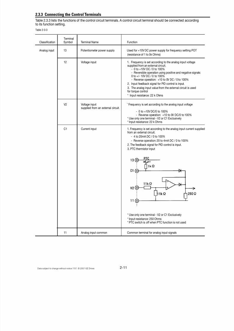
2.3.3 Connecting the Control Terminals
Table 2.3.3 lists the functions of the control circuit terminals. A control circuit terminal should be connected accordingto its function setting.
Table 2-3-3
TerminalClassification Symbol Terminal Name Function
Analog input 13 Potentiometer power supply Used for +10V DC power supply for frequency setting POT
(resistance of 1 to 5k Ohms)
12 Voltage input 1. Frequency is set according to the analog input voltagesupplied from an external circuit.
- 0 to +10V DC / 0 to 100%- Reversible operation using positive and negative signals:0 to +/- 10V DC / 0 to 100%- Reverse operation: +10 to 0V DC / 0 to 100%
2. Input feedback signal for PID control is input.
3. The analog input value from the external circuit is usedfor torque control
* Input resistance: 22 k Ohms
V2 Voltage input ¨ Frequency is set according to the analog input voltagesupplied from an external circuit.
- 0 to +10V DC/0 to 100%- Reverse operation: +10 to 0V DC/0 to 100%
* Use only one terminal - V2 or C1 Exclusively* Input resistance: 22 k Ohms
C1 Current input 1. Frequency is set according to the analog input current suppliedfrom an external circuit.
- 4 to 20mA DC / 0 to 100%
- Reverse operation: 20 to 4mA DC / 0 to 100%
2. The feedback signal for PID control is input.
3. PTC thermistor input
* Use only one terminal - V2 or C1 Exclusively
* Input resistance: 250 Ohms* PTC switch is off when PTC function is not used
11 Analog input common Common terminal for analog input signals

8/11/2019 GEI-100364
http://slidepdf.com/reader/full/gei-100364 29/154
2-12 Data subject to change without notice 7/07. © 2007 GE Drives
Digital input FWD Forward operation / Used for forward operation (when FWD-CM is on) orStop command deceleration and stop (when FWD-CM is opened)
REV Reverse operation / Used for reverse operation (when REV-CM is on) or
Stop command deceleration and stop (when REV-CM is opened)
X1 Digital input 1 The coast-to-stop command, external alarm, alarm reset, multi-step frequency selection, and other functions (from an externalcircuit) can be assigned to terminals X1 to X9. For details, see"Setting the Terminal Functions E01 to E09" in Section 5.2Function Explanation.<Specifications of digital input circuit>
X2 Digital input 2
X3 Digital input 3
X4 Digital input 4
X5 Digital input 5
X6 Digital input 6
X7 Digital input 7
X8 Digital input 8
X9 Digital input 9
P24 Control Unit power Supply +24VDC power supply for control input. Maximum output current 100mA
PLC PLC signal power Used to connect PLC power supply for output signals; rated nominalvoltage = 24 VDC (22 to 27 V DC range) at sink logic operation.
CM Digital input common Common terminal for digital input signals and P24
Analog output FMA Analog monitor Outputs monitor signal using analog DC voltage 0 to +10V DC.The signal indicates one of the following:
(11: common - Output frequency (before slip compensation)terminal) - Load factor
- Output frequency (after slip compensation)
- Power consumption- Output current- PID feedback value- Output voltage- PG feedback value- Output torque- DC link circuit voltage* Connectable impedance: min. 5k ohms
Pulse output FMP Frequency monitor Outputs a monitor signal using the pulse waveform.
(CM: common (pulse waveform output) This signal has the same function as the FMA signal.
terminal)
Item min. typ. max.
Operating voltage ON 0V – 2V
OFF 22V 24V 27V
Maximum load current ON – 3.2mA 4.5 mA
Leakage current OFF – – 0.5 mA
8/11/2019 GEI-100364
http://slidepdf.com/reader/full/gei-100364 30/154
2-13Data subject to change without notice 7/07. © 2007 GE Drives
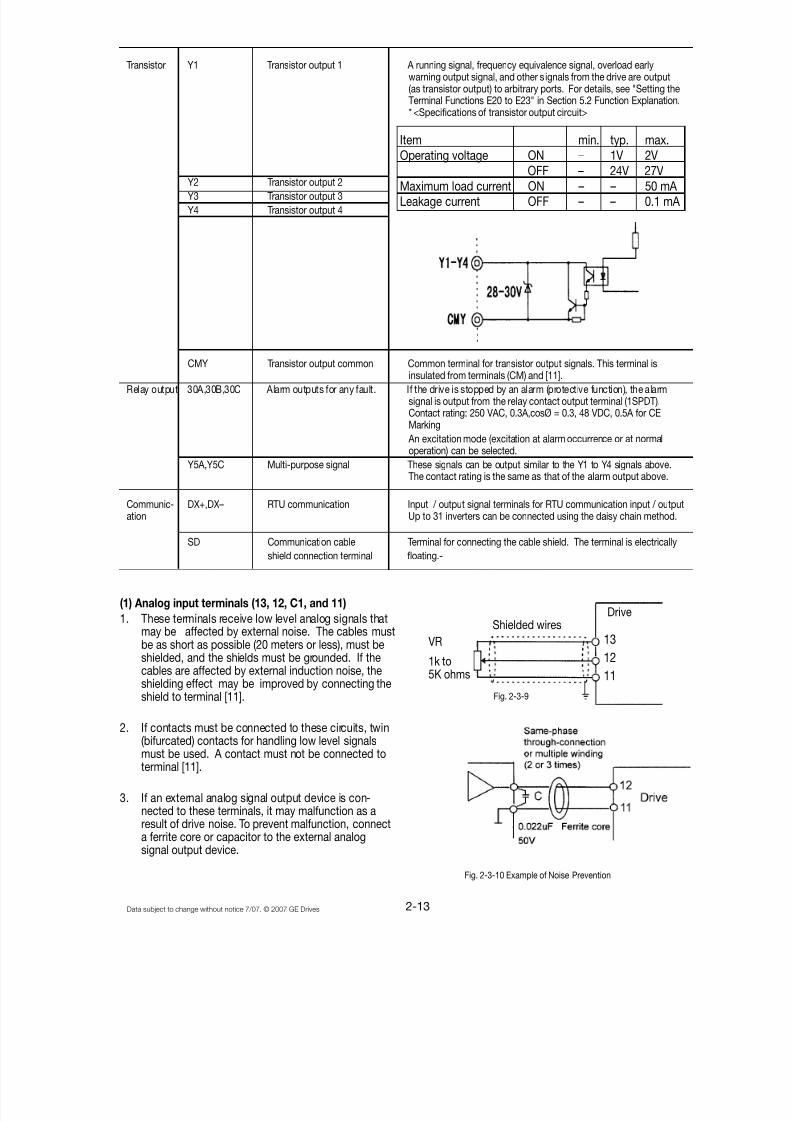
(1) Analog input terminals (13, 12, C1, and 11)
1. These terminals receive low level analog signals thatmay be affected by external noise. The cables mustbe as short as possible (20 meters or less), must beshielded, and the shields must be grounded. If thecables are affected by external induction noise, theshielding effect may be improved by connecting theshield to terminal [11].
2. If contacts must be connected to these circuits, twin(bifurcated) contacts for handling low level signalsmust be used. A contact must not be connected toterminal [11].
3. If an external analog signal output device is con-nected to these terminals, it may malfunction as aresult of drive noise. To prevent malfunction, connecta ferrite core or capacitor to the external analogsignal output device.
Item min. typ. max.Operating voltage ON – 1V 2V
OFF – 24V 27VMaximum load current ON – – 50 mA Leakage current OFF – – 0.1 mA
Fig. 2-3-10 Example of Noise Prevention
VR
1k to5K ohms
Drive
13
12
11
Shielded wires
Fig. 2-3-9
Transistor Y1 Transistor output 1 A running signal, frequency equivalence signal, overload earlywarning output signal, and other s ignals from the drive are output(as transistor output) to arbitrary ports. For details, see "Setting theTerminal Functions E20 to E23" in Section 5.2 Function Explanation.* <Specifications of transistor output circuit>
Y2 Transistor output 2Y3 Transistor output 3
Y4 Transistor output 4
CMY Transistor output common Common terminal for transistor output signals. This terminal isinsulated from terminals (CM) and [11].
Relay output 30A,30B,30C Alarm outputs for any fault. If the drive is stopped by an alarm (protective function), the alarmsignal is output from the relay contact output terminal (1SPDT).Contact rating: 250 VAC, 0.3A,cosØ = 0.3, 48 VDC, 0.5A for CEMarking
An excitation mode (excitation at alarm occurrence or at normaloperation) can be selected.
Y5A,Y5C Multi-purpose signal These signals can be output similar to the Y1 to Y4 signals above.The contact rating is the same as that of the alarm output above.
Communic- DX+,DX– RTU communication Input / output signal terminals for RTU communication input / outputation Up to 31 inverters can be connected using the daisy chain method.
SD Communication cable Terminal for connecting the cable shield. The terminal is electricallyshield connection terminal floating.-

8/11/2019 GEI-100364
http://slidepdf.com/reader/full/gei-100364 31/154
2-14 Data subject to change without notice 7/07. © 2007 GE Drives
(2) Digital input terminals (FWD, REV, X1 to X9, PLC,and CM)
1. Digital input terminals (e.g., FWD, REV, X1 to X9) aregenerally turned on or off by connecting or discon-necting the line to or from the CM terminal.
If digital input terminals are turned on or off byswitching the PLC’s open collector output using anexternal power supply, a resulting bypass circuit maycause the drive to malfunction. To prevent a malfunc-tion, connect the PLC terminal as shown in Fig. 2-3-
11.
Fig. 2-3-12 The Control Wiring Route
Fig. 2-3-13 Securing Positions for Inverter Control Circuit Wiring (40 HP or more)
Fig. 2-3-11 Prevention of Bypass Current by External Power
2. When using a contact input, a high-quality relay withreliable contacts must be used.
(3) Transistor output terminals (Y1 to Y4, CMY)
1. These terminals have a circuit configuration as shownin Table 2-3-3, "Transistor Output". Confirm thepolarity of the external power supply.
2. To connect a control relay, connect a surge absorbingdiode to both ends of its exciting coil.
(4) Sink or Source Logic Selection.
1. Set SWI for Sink or Source Connection to the PLC.The factory default setting is Sink and this instructionmanual explains Sink logic function only.
2. When you need to connect source type logic, refer toBasic Connection Diagram Fig. 2-3-3 and Fig. 2-3-4and Technical Information Manual. (Sink Logic iscommonly used in the USA and Source Logic iscommonly used in Europe.)
(5) Others
1. To prevent a malfunction as a result of noise, controlterminal cables must be placed as far as possiblefrom the main circuit cables.
2. The control cables inside the inverter must besecured to prevent direct contact with the main circuit(e.g., main circuit terminal block).
wiringCable ties
Cablebinding
Hole A Cable binding
Hole B
(6) Wiring of control circuit (inverter of 40 Hp or more)
1. Pull out the control circuit wiring along the left panelas shown in Fig. 2-3-12.
2. Secure the cable to cable binding hole A (on the leftwall of the main circuit terminal block) using a cable-tie(e.g., Insulock). The cable-tie must not exceed 0.14"(3.5mm) in width and 0.06" (1.5mm) in thickness.
3. When the optional PC board is mounted, the signal
lines must be secured to cable binding hole B.
WARNINGControl lines generally do not have enhancedinsulation. If the insulation of a control line isdamaged, the control signals may be exposed tohigh voltage in the main circuit. The Low VoltageDirective in Europe also restricts the exposure tohigh voltage. Electric shock may result
CAUTIONThe inverter, motor, and cables generate noise.Check that the ambient sensors and devices donot malfunction. Accident may result.
8/11/2019 GEI-100364
http://slidepdf.com/reader/full/gei-100364 32/154
2-15Data subject to change without notice 7/07. © 2007 GE Drives
Screw size G = M10Other terminals = M12
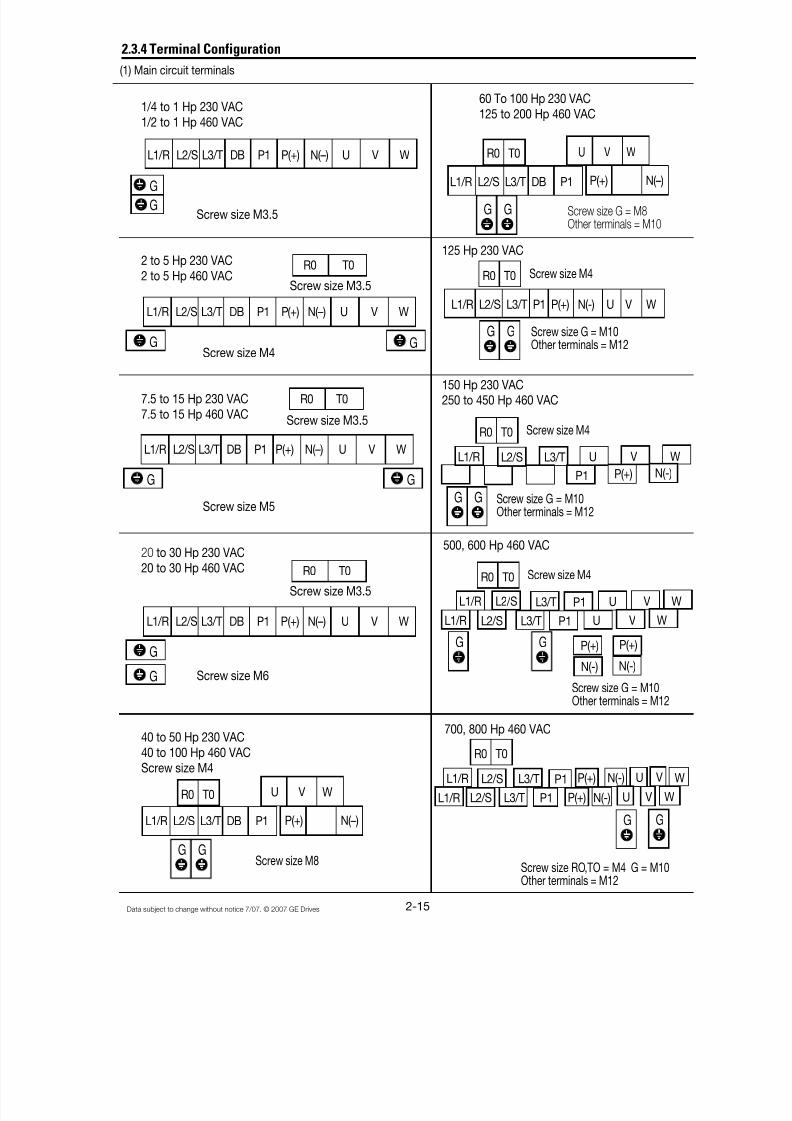
2.3.4 Terminal Configuration
(1) Main circuit terminals
1/4 to 1 Hp 230 VAC1/2 to 1 Hp 460 VAC
Screw size M3.5
2 to 5 Hp 230 VAC2 to 5 Hp 460 VAC
Screw size M4
7.5 to 15 Hp 230 VAC7.5 to 15 Hp 460 VAC
Screw size M5
20 to 30 Hp 230 VAC20 to 30 Hp 460 VAC
Screw size M6
40 to 50 Hp 230 VAC40 to 100 Hp 460 VACScrew size M4
L1/R L2/S L3/T DB P1 P(+) N(–) U V W
G
G
L1/R L2/S L3/T DB P1 P(+) N(–) U V W
G G
R0 T0
L1/R L2/S L3/T DB P1 P(+) N(–) U V W
G G
R0 T0
L1/R L2/S L3/T DB P1 P(+) N(–) U V W
G
G
R0 T0
L1/R L2/S L3/T DB P1 P(+) N(–)
U V WR0 T0
G GScrew size M8
Screw size M3.5
Screw size M3.5
Screw size M3.5
P(+) N(–)
60 To 100 Hp 230 VAC125 to 200 Hp 460 VAC
L1/R L2/S L3/T DB P1
U V WR0 T0
Screw size G = M8
Other terminals = M10
125 Hp 230 VAC
R0 T0
L1/R L2/S L3/T P1 P(+) N(-) U V W
G G
G G
Screw size M4
Screw size G = M10Other terminals = M12
150 Hp 230 VAC250 to 450 Hp 460 VAC
R0 T0 Screw size M4
L1/R L2/S L3/T U V W
P1 P(+) N(-)
Screw size G = M10Other terminals = M12
G G
500, 600 Hp 460 VAC
Screw size M4
N(-)N(-)
700, 800 Hp 460 VAC
Screw size RO,TO = M4 G = M10Other terminals = M12
R0 T0
L1/R L2/S L3/T U V WP1
L1/R L2/S L3/T U V WP1
G G P(+) P(+)
R0 T0
L1/R L2/S L3/T U V WP1
L1/R L2/S L3/T U V WP1
G G
P(+) N(-)
P(+) N(-)

8/11/2019 GEI-100364
http://slidepdf.com/reader/full/gei-100364 33/154
2-16 Data subject to change without notice 7/07. © 2007 GE Drives
(2) Control circuit terminals
30A Y5A CMY Y3 Y1 C1 FMA FMP PLC X1 X2 X3 X4 X5 X6 X7 X8 X9
30C 30B Y5C Y4 Y2 11 12 13 V2 CM CM FWD REV P24 P24 DX- DX+ SD
2.3.5 AF-300 P11 Drive Cable Size, Tightening Torque and Circuit Protection Rating
Incoming Device Tightening Torque lb-Inch (Nm) Cable size AWG
Input Fuse
L1/R, L2/S, L3/T(Nominal)
L1/R, L2/S, L3/T(Maximum) (*1)
AuxiliaryInputR0, T0
230 VAC Input0.25 3 3 3 15 10.6 (1.2) 10.6 - 6.2 (0.7) 16 16 - 220.5 5 6 3 15 (1.2) - -1 10 15 3 20 - -2 15 20 3 30 20.8 (2.36) 20.8 10.6 (1.2) 143 20 30 3 40 (2.36) 14 145 35 50 3 60 10
7.5 60 80 3 100 31.0 (3.5) 31.0 810 70 125 3 125 (3.5) 615 100 150 3 175 420 125 200 3 225 325 150 225 3 250 230 175 250 3 300 1
40 200 - 5 200 4/0 1/0 2/0 1050 225 - 5 225 Qty2 - 1 3/0 4/0 1060 300 - 5 300 239(27) 119(13.5) 119 Qty2 - 2/0 4/0 Qty2 - 175 350 - 5 350 (13.5) Qty2 - 3/0 Qty2 - 1/0 Qty2 - 2/0 8100 300 - 5 300 Qty 2 - 2/0 Qty2 - 3/0 Qty2 - 4/0 6125 400 - 5 400 425(48) 239(27) Qty2 - 4/0 Qty2 - 4/0 Qty2 - 250 4150 450 - 5 450 Qty2 - 250 Qty2 - 300 Qty2 - 350
460 VAC Input0.5 3 3 3 15 10.6 (1.2) 10.6 - 6.2 (0.7) 16 16 - 221 5 6 3 15 (1.2) - -2 10 10 3 15 20.8 (2.36) 20.8 10.6 (1.2) 143 15 15 3 20 (2.36)5 20 25 3 35 14 14
7.5 30 45 3 50 31.0 (3.5) 31.0 1210 40 60 3 70 (3.5) 1015 50 90 3 9020 70 110 3 110 825 80 125 3 150 630 100 125 3 175 440 100 - 10 100 119(13.5) 2 3 3 1050 125 - 10 125 1 2 260 150 - 10 150 51.3 2/0 2 175 175 - 10 175 (5.8) 3/0 1/0 2/0100 150 - 10 150 2/0 3/0 4/0125 200 - 10 200 239(27) 119(13.5) 3/0 4/0 Qty2 - 1 10150 225 - 10 225 239(27) 119 Qty2 - 1/0 Qty2 - 1/0 Qty2 - 1/0 8200 300 - 10 300 (13.5) Qty2 - 1/0 Qty2 - 2/0 Qty2 - 3/0250 400 - 10 400 425(48) 239 Qty2 - 3/0 Qty2 - 3/0 Qty2 - 4/0 6300 450 - 10 450 (27) Qty2 - 4/0 Qty2 - 250 Qty2 - 300 4350 500 - 10 500 Qty2 - 250 Qty2 - 300 Qty2 - 350400 600 - 10 600 (*3) Qty2 - 350 Qty2 - 350 Qty2 - 500 (*3)450 700 - 10 700 Qty2 - 350 Qty2 - 400 Qty2 - 500
500 700 - 10 700 Qty2 - 500 Qty3 - 300 Qty3 - 300
600 1000 - 10 1000 Qty3 - 300 Qty3 - 350 Qty3 - 500
700 1000 - 10 1000 Qty3 - 400 Qty3 - 500 Qty3 - 600800 1200 - 10 1200 Qty3 - 500 Qty3 - 600 Qty3 - 600
(*1)Class J Fuse or Circuit Breaker reted 600V with the maximum current rating as shown in the above table shall be connected to the drive for 30HP and less.(*2)Based on GE Fuji standard DB unit and DB resistor designs. Other rating require careful review.(*3) Consult factoryDevice ratings such as system coordination, short-circuit rating and type must be carefully reviewed by the user.
Wire size from NEC tables 310-16. Copper wire rated 60 Deg. C for 100amps or less, 75 Deg. C for over 100 amps in 30 Deg. C ambient and 1.25 times Drive rated amps.These are minimum wire sizes : consult and conform to local and national codes.
ControlU, V, W DC ReactorP1, P(+)
DB circuit(*2) P(+),N(-), DB
R0,T0
DB circuit(*2) P(+),N(-), DB
R0, T0 ControlL1/R, L2/S,
L3/T
51.3 (5.8)
119(13.5)
51.3 (5.8)
HP Input CircuitBreaker (*1)
L1/R, L2/S,L3/T, U, V,W, P1, P(+)
E(G)

8/11/2019 GEI-100364
http://slidepdf.com/reader/full/gei-100364 34/154

8/11/2019 GEI-100364
http://slidepdf.com/reader/full/gei-100364 35/154
2-18 Data subject to change without notice 7/07. © 2007 GE Drives
Notes
8/11/2019 GEI-100364
http://slidepdf.com/reader/full/gei-100364 36/154
3-1Data subject to change without notice 7/07. © 2007 GE Drives
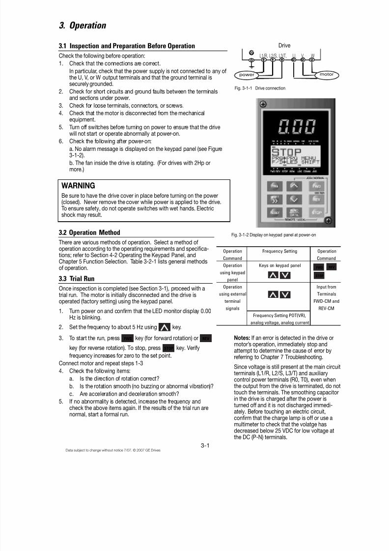
3.2 Operation Method
There are various methods of operation. Select a method ofoperation according to the operating requirements and specifica-tions; refer to Section 4-2 Operating the Keypad Panel, andChapter 5 Function Selection. Table 3-2-1 lists general methods
of operation.
3.3 Trial Run
Once inspection is completed (see Section 3-1), proceed with atrial run. The motor is initially disconnected and the drive isoperated (factory setting) using the keypad panel.
1. Turn power on and confirm that the LED monitor display 0.00Hz is blinking.
2. Set the frequency to about 5 Hz using key.
3. To start the run, press FWD key (for forward rotation) or REV
key (for reverse rotation). To stop, press STOP key. Verify
frequency increases for zero to the set point.Connect motor and repeat steps 1-3
4. Check the following items:
a. Is the direction of rotation correct?
b. Is the rotation smooth (no buzzing or abnormal vibration)?
c. Are acceleration and deceleration smooth?
5. If no abnormality is detected, increase the frequency andcheck the above items again. If the results of the trial run arenormal, start a formal run.
3. Operation
3.1 Inspection and Preparation Before Operation
Check the following before operation:
1. Check that the connections are correct.
In particular, check that the power supply is not connected to any ofthe U, V, or W output terminals and that the ground terminal issecurely grounded.
2. Check for short circuits and ground faults between the terminalsand sections under power.
3. Check for loose terminals, connectors, or screws.
4. Check that the motor is disconnected from the mechanicalequipment.
5. Turn off switches before turning on power to ensure that the drivewill not start or operate abnormally at power-on.
6. Check the following after power-on:
a. No alarm message is displayed on the keypad panel (see Figure3-1-2).
b. The fan inside the drive is rotating. (For drives with 2Hp ormore.)
WARNING
Be sure to have the drive cover in place before turning on the power(closed). Never remove the cover while power is applied to the drive.To ensure safety, do not operate switches with wet hands. Electricshock may result.
Operation Frequency Setting Operation
Command Command
Operation Keys on keypad panelusing keypad
panel
Operation Input from
using external Terminals
terminal FWD-CM and
signals REV-CM
Frequency Setting POT(VR),
analog voltage, analog current
FWD REV
STOP
Fig. 3-1-1 Drive connection
Drive
L1/R, L2/S, L3/T, U, V, W
power motor
Fig. 3-1-2 Display on keypad panel at power-on
Notes: If an error is detected in the drive ormotor’s operation, immediately stop andattempt to determine the cause of error byreferring to Chapter 7 Troubleshooting.
Since voltage is still present at the main circuitterminals (L1/R, L2/S, L3/T) and auxiliarycontrol power terminals (R0, T0), even whenthe output from the drive is terminated, do nottouch the terminals. The smoothing capacitorin the drive is charged after the power isturned off and it is not discharged immedi-ately. Before touching an electric circuit,confirm that the charge lamp is off or use amultimeter to check that the volatge hasdecreased below 25 VDC for low voltage atthe DC (P-N) terminals.

8/11/2019 GEI-100364
http://slidepdf.com/reader/full/gei-100364 37/154
3-2Data subject to change without notice 7/07. © 2007 GE Drives
Notes
8/11/2019 GEI-100364
http://slidepdf.com/reader/full/gei-100364 38/154
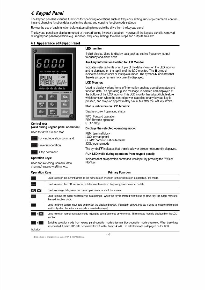
4-1Data subject to change without notice 7/07. © 2007 GE Drives
The keypad panel has various functions for specifying operations such as frequency setting, run/stop command, confirm-ing and changing function data, confirming status, and copying function code settings.
Review the use of each function before attempting to operate the drive from the keypad panel.
The keypad panel can also be removed or inserted during inverter operation. However, if the keypad panel is removedduring keypad panel operation (e.g., run/stop, frequency setting), the drive stops and outputs an alarm.
Control keys(valid during keypad panel operation):
Used for drive run and stop
FWD Forward operation command
REV Reverse operation
STOP Stop command
Operation keys:
Used for switching screens, datachange,frequency setting, etc.
4.1 Appearance of Keypad Panel
Operation Keys Primary Function
PRG Used to switch the current screen to the menu screen or switch to the initial screen in operation / trip mode.
FUNC
DATAUsed to switch the LED monitor or to determine the entered frequency, function code, or data
Used to change data, move the cursor up or down, or scroll the screen
SHIFT Used to move the cursor horizontally at data change. When this key is pressed with the up or down key, the cursor moves to
the next function block.
RESET Used to cancel current input data and switch the displayed screen. If an alarm occurs, this key is used to reset the trip status
(valid only when the initial alarm mode screen is displayed)
STOP + Used to switch normal operation mode to jogging operation mode or vice versa. The selected mode is displayed on the LCD
monitor.
STOP + RESET Switches operation mode (from keypad panel operation mode to terminal block operation mode or reverse). When these keys
are operated, function F02 data is switched from 0 to 3 or from 1-4 to 0. The selected mode is displayed on the LCD
indicator.
4. Keypad Panel
LED monitor
4-digit display. Used to display data such as setting frequency, outputfrequency and alarm code.
Auxiliary Information Related to LED Monitor
Indicates selected units or multiple of the data shown on the LED monitorand is displayed on the top line of the LCD monitor. The ■ symbolindicates selected units or multiple number. The symbol indicates thatthere is an upper screen not currently displayed.
LCD Monitor:
Used to display various items of information such as operation status andfunction data. An operating guide message, is scrolled and displayed atthe bottom of the LCD monitor. This LCD monitor has a backlight featurewhich turns on when the control power is applied or any keypad key ispressed, and stays on approximately 5 minutes after the last key stroke.
Status Indicators on LCD Monitor:
Displays current operating status:
FWD: Forward operationREV: Reverse operationSTOP: Stop
Displays the selected operating mode:
REM: terminal blockLOC: keypad panel
COMM: communication terminalJOG: jogging mode
The symbol indicates that there is a lower screen not currently displayed.
RUN LED (valid during operation from keypad panel):
Indicates that an operation command was input by pressing the FWD orREV key.

8/11/2019 GEI-100364
http://slidepdf.com/reader/full/gei-100364 39/154
4-2Data subject to change without notice 7/07. © 2007 GE Drives
4.2 Operation From the Keypad Panel (LCD Screen, Level Structure)
4.2.1 Normal Operation
The keypad panel operating system (screen transition, level structure) is structured as follows:
4.2.2 Alarm Modes
If an alarm is activated, operation is changed from normal keypad panel operation to an alarm mode operation. The alarmmode screen appears and alarm information is displayed.
The program menu, function screens, and supplementary screens remain unchanged as during normal operation, thoughthe switching method from program menu to alarm mode is limited to PRG.
Operation Mode
60.00
Program Menu
Alarm
SupplementaryScreen
Alarm Alarm
Alarm mode
Alarm
Screen for each
Function
PRG
DAT
RESET FUNCDATA
RESET
Alarm isactivated
PRGFUNCDATA
RESET
FUNCDATA
Alarm mode processing ( including )
Keypad panel operating system during normal operation
Program Menu
60.00
Supplementary
Screen
60.0060.00
Operation Mode
60.00
Screen for each
Function
PRG
PRG
FUNC
DATA FUNC
DATA
RESET RESET FUNC
DATA
RESET
8/11/2019 GEI-100364
http://slidepdf.com/reader/full/gei-100364 40/154

8/11/2019 GEI-100364
http://slidepdf.com/reader/full/gei-100364 41/154
4-4Data subject to change without notice 7/07. © 2007 GE Drives
4.3 Entering Data on the Keypad Panel
4.3.1 Operation Mode
The screen for normal inverter operation includes a screen for displaying drive operating status and a screen for graphi-cally displaying the status in the form of a bar graph. The operator can switch between both screens by using the function(E45).
1) Operating Status (E45=0)
2) Bar Graph (E45=1)
4.3.2 Setting Digital Frequency
On the operation mode screen, press or to display the set frequency on the LED. Data is increased or
decreased in the smallest possible unit, depending on which key is pressed. The adjustments in data will occur rapidly if
the operator holds down or . To select a digit use SHIFT and then data can be set directly. To save the
frequency settings press FUNC
DATA.
Press RESET and PRG to to return to the operation mode. If keypad panel settings are not selected, the present frequency
setting mode appears on the LCD. When selecting the PID function, the PID command can be set with a process value
(refer to technical documentation for details).
1) Digital (keypad panel) settings (F01=0 or C30=0)
2) Non-digital setting
Direction of rotation = blank (no command) or FWD/REVOperating status = STOP (no command) or RUN
Output frequency (maximum frequency at full-scale)Output current (200% of inverter rating at full-scale)Torque calculation (200% of motor rating at full-scale)
PRG PRGMENUF/D LED SHIFT
60.00
STOPPRG PRGMENUF/D LED SHIFT
60.00
Hz
A
%
Fout/Iout/TRQ
60.00
RUN FWD
Frequency setting value
Screen explanationPresent frequency setting mode
Operations guide
60.00
RUNPRG PRGMENUF/D LED SHIFT
FWD
60.00
F/D DATA SET
<DIG>SET Hz>LOCAL50 - 400
F/D DATA SET
<DIG>SET Hz>LOCAL
50 - 400
STORING...
56.89 Frequency setting value
Screen explanationPresent frequency setting modeFrequency setting range
Operations guide
WhenFUNC
DATA pressed and writing
60.00
RUNPRG PRG MENUF/D LED SHIFT
60.00
F/D DATA SET
<REMOTE REF>12+V1
8/11/2019 GEI-100364
http://slidepdf.com/reader/full/gei-100364 42/154

8/11/2019 GEI-100364
http://slidepdf.com/reader/full/gei-100364 43/154
4-6Data subject to change without notice 7/07. © 2007 GE Drives
The function code consists of alphanumeric characters with unique letters assigned to each function group.
Table 4-3-1
Function Code Function Remarks
F00 - F42 Fundamental functions
E01 - E47 Terminal Extension Functions
C01 - C33 Frequency Control Functions
P01 - P09 Motor Parameters
H03 - H39 High Performance Functions
A01 - A18 Alternative Motor Parameters
o01 - o29 Optional Functions Can only be selected with an option connected
To scroll the Function Select screen rapidly, use + or + to move the screen as a unit sorted
alphabetically.
Select the desired function and press FUNC
DATA to switch to the Data Setting screen.
On the Data Setting screen, the data values on the LCD can be increased or decreased in the smallest possible unit by
pressing or . Holding down or causes the values to increase or decrease more rapidly. Other-
wise, select the digit to be modified using and then set data directly. When data is modified, the value before
modification will be displayed at the same time for reference purpose. To save the data, press FUNC
DATA. Pressing cancels
the changes made and returns control to the Function Select screen. The modified data will be effective in inverter
operation after the data has been saved by FUNC
DATA. If the data is not saved, there is no change to the inverter operation.
When data setting is disabled in the case of “Data protected” or “Data setting invalid during inverter running,” make thenecessary changes as indicated in Table 4-3-2 below.
Table 4.3.2
Display Reason for No Modification Release MethodLINK ACTIVE Currently writing from RS-485 / RTU option to
function is being madeSend a cancel command to function writing from RS-485 RTU. Stops a “write” operation from the linkcommunication option.
NO SIGNAL(WE) The edit enabling command function is selectedusing a general-purpose input terminal
For functions E01 to E09, turn data terminal 19 (editenabling command selection) ON
DATA PRTCTD Data protection is selected for function F00. Change function F00 to 0INV RUNNING An attempt was made to change a function that
cannot be changed during inverter operation.Stop inverter operation
FWD/REV ON An attempt was made to change a function thatcannot be changed with the FWD/REV commandon.
Turn FWD/REV command off
F00 DATA PRTCF01 FREQ CMD 1F02 OPR METHODF03 MAX Hz-1
F00 DATA PRTCF01 FREQ CMD 1F02 PPR METHODF03 MAX Hz-1
F42 TRQ VECTOR 1E01 X1 FUNCE02 X2 FUNCE03 X3 FUNC
A18 SLIP COMP 2F00 DATA PRTCF01 DATA PRTCF02 OPR METHOD
+ +
8/11/2019 GEI-100364
http://slidepdf.com/reader/full/gei-100364 44/154
4-7Data subject to change without notice 7/07. © 2007 GE Drives
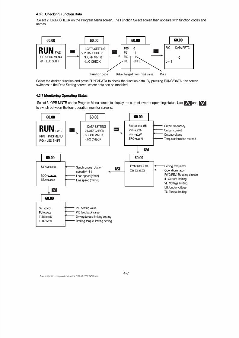
4.3.6 Checking Function Data
Select 2. DATA CHECK on the Program Menu screen. The Function Select screen then appears with function codes andnames.
Select the desired function and press FUNC/DATA to check the function data. By pressing FUNC/DATA, the screenswitches to the Data Setting screen, where data can be modified.
4.3.7 Monitoring Operating Status
Select 3. OPR MNTR on the Program Menu screen to display the current inverter operating status. Use and
to switch between the four operation monitor screens.
60.00
RUNPRG > PRG MENU
F/D > LED SHIFT
FWD
60.00 60.00
F00 0
F01 *1
F02 *1
F03 60 Hz
60.00
F00 DATA PRTC
00 - 1
Function code Data changed from initial value Data
RUNPRG > PRG MENU
F/D > LED SHIFT
FWD
1.DATA SETTING
> 2.DATA CHECK3. OPR MNTR
4.I/O CHECK
1.DATA SETTING
2.DATA CHECK
> 3. OPR MNTR
4.I/O CHECK
60.00 60.00 60.00
Fout=xxxx.xHz
Iout=x.xxA
Vout=xxxV
TRQ=xxx%
Output frequency
Output current
Output voltage
Torque calculation method
60.0060.00
SYN=xxxxxx
LOD=xxxxxx
LIN=xxxxxx
Synchronous rotation
speed (r/min)
Load speed (r/min)
Line speed (m/min)
Fref=xxxx.x Hz
xxx xx xx xx
Setting frequency
Operation status
FWD/REV: Rotating direction
IL: Current limiting
VL: Voltage limiting
LU: Under voltage
TL: Torque limiting
60.00
SV=xxxxx
PV=xxxxx
TLD=xxx%TLB=xxx%
PID setting value
PID feedback value
Driving torque limiting settingBraking torque limiting setting
PRG FUNC
DATA
FUNC
DATA
PRGFUNC
DATA
8/11/2019 GEI-100364
http://slidepdf.com/reader/full/gei-100364 45/154
4-8Data subject to change without notice 7/07. © 2007 GE Drives
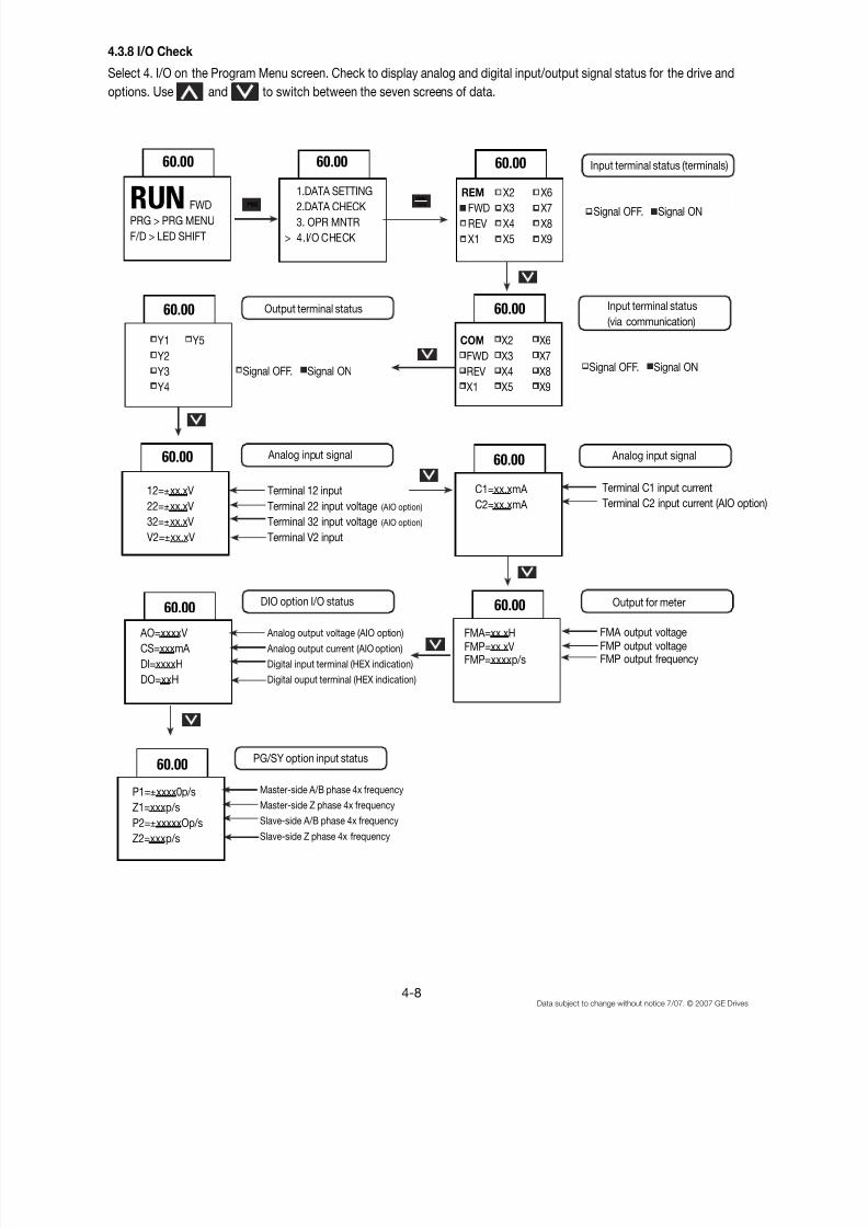
4.3.8 I/O Check
Select 4. I/O on the Program Menu screen. Check to display analog and digital input/output signal status for the drive and
options. Use and to switch between the seven screens of data.
60.00 60.00 60.00
RUNPRG > PRG MENU
F/D > LED SHIFT
FWD
1.DATA SETTING
2.DATA CHECK
3. OPR MNTR
> 4.I/O CHECK
REM X2 X6FWD X3 X7
REV X4 X8
X1 X5 X9
Signal OFF. Signal ON
Input terminal status (terminals)
60.00
Signal OFF. Signal ON Signal OFF. Signal ON
Y1 Y5
Y2
Y3
Y4
Output terminal status 60.00
COM X2 X6
FWD X3 X7
REV X4 X8
X1 X5 X9
Input terminal status
(via communication)
60.00
12=±xx.xV
22=±xx.xV
32=±xx.xV
V2=±xx.xV
Analog input signal
Terminal 12 input
Terminal 22 input voltage (AIO option)
Terminal 32 input voltage (AIO option)
Terminal V2 input
60.00
C1=xx.xmA
C2=xx.xmA
Terminal C1 input current
Terminal C2 input current (AIO option)
Analog input signal
60.00
AO=xxxxV
CS=xxxmA
DI=xxxxH
DO=xxH
Analog output voltage (AIO option)
Analog output current (AIO option)
Digital input terminal (HEX indication)
Digital ouput terminal (HEX indication)
DIO option I/O status 60.00
FMA=xx.xHFMP=xx.xVFMP=xxxxp/s
Output for meter
FMA output voltageFMP output voltageFMP output frequency
PRGFUNC
DATA
60.00
Master-side A/B phase 4x frequencyMaster-side Z phase 4x frequency
Slave-side A/B phase 4x frequency
Slave-side Z phase 4x frequency
PG/SY option input status
P1=±xxxx0p/sZ1=xxxp/s
P2=±xxxxxOp/s
Z2=xxxp/s

8/11/2019 GEI-100364
http://slidepdf.com/reader/full/gei-100364 46/154

8/11/2019 GEI-100364
http://slidepdf.com/reader/full/gei-100364 47/154
4-10Data subject to change without notice 7/07. © 2007 GE Drives
4.3.10 Load Rate Measurement
Select 6. Load Rate Measurement (LOAD FCTR) on the Program Menu screen. The maximum current, average current,and average braking power during the set measuring time are measured and displayed.
60.00
T=3600s
Imax=0.00A
Iave=0.00A BPave=0.0%
60.00
T=150s
Imax=0.00A
Iave=0.00A
BPave=0.0%
60.00
T=600s
Imax=0.00A
Iave=0.00A
BPave=0.0%
60.00
T=3600s
Imax=56.4A
Iave=23.5A
BPave=10.4%
Display returns to initial value
Maximum current
Average current
Average braking power
(Motor rated output/100%
Displays the remaining
measuring tim, when
reaches zero, ends the
measurement.
(Measures maximum current, average
current and average braking power in
600s intervals.)
Change measuring using and
and
Measuring time
Set measuring timeStart measuring
60.00
RUNPRG > PRG MENU
F/D > LED SHIFT
FWD1.DATA SETTING
2.DATA CHECK
3. OPR MNTR4. I/O CHECK
5. MAINTENANCE
> 6. LOAD FCTR
60.00
PRG FUNC
DATA
FUNC
DATA
8/11/2019 GEI-100364
http://slidepdf.com/reader/full/gei-100364 48/154
4-11Data subject to change without notice 7/07. © 2007 GE Drives
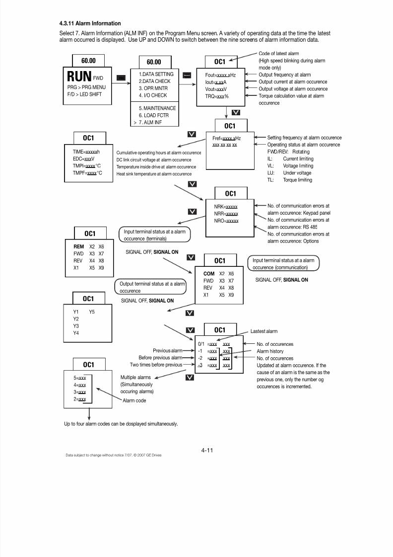
4.3.11 Alarm Information
Select 7. Alarm Information (ALM INF) on the Program Menu screen. A variety of operating data at the time the latestalarm occurred is displayed. Use UP and DOWN to switch between the nine screens of alarm information data.
60.00
1.DATA SETTING
2.DATA CHECK
3. OPR MNTR4. I/O CHECK
5. MAINTENANCE
6. LOAD FCTR
> 7. ALM INF
60.00 OC1
Fout=xxxx.xHz
Iout=x.xxA
Vout=xxxVTRQ=xxx%
Code of latest alarm
(High speed blinking during alarm
mode only)
Output frequency at alarm
Output current at alarm occurence
Output voltage at alarm occurenceTorque calculation value at alarm
occurence
RUNPRG > PRG MENUF/D > LED SHIFT
FWD
OC1
TIME=xxxxxh
EDC=xxxV
TMPI=xxxx°C
TMPF=xxxx°C
Cumulative operating hours at alarm occurence
DC link circuit voltage at alarm occurence
Temperature inside drive at alarm occurence
Heat sink temperature at alarm occurence
Fref=xxxx.xHzxxx xx xx xx
OC1
Setting frequency at alarm occurence
Operating status at alarm occurence
FWD/REV: Rotating
IL: Current limiting
VL: Voltage limiting
LU: Under voltage
TL: Torque limiting
OC1
REM X2 X6
FWD X3 X7
REV X4 X8
X1 X5 X9
SIGNAL OFF, SIGNAL ON
Input terminal status at a alarm
occurence (terminals)
No. of communication errors at
alarm occurence: Keypad panel
No. of communication errors at
alarm occurence: RS 485
No. of communication errors at
alarm occurence: Options
OC1
NRK=xxxxx
NRR=xxxxx
NRO=xxxxx
Input terminal status at a alarm
occurence (communication)
SIGNAL OFF, SIGNAL ON
OC1
COM X2 X6
FWD X3 X7
REV X4 X8
X1 X5 X9
Output terminal status at a alarm
occurence
SIGNAL OFF, SIGNAL ONOC1
Y1 Y5
Y2
Y3
Y4 OC1
0/1 =xxx xxx
-1 =xxx xxx
-2 =xxx xxx-3 =xxx xxx
Previous alarm
Before previous alarmTwo times before previous
No. of occurences
Alarm history
No. of occurencesUpdated at alarm occurence. If the
cause of an alarm is the same as the
previous one, only the number og
occurences is incremented.
Multiple alarms
(Simultaneously
occuring alarms)
Alarm code
Up to four alarm codes can be dosplayed simultaneously.
OC1
5=xxx
4=xxx
3=xxx
2=xxx
Lastest alarm
PRG
FUNC
DATA

8/11/2019 GEI-100364
http://slidepdf.com/reader/full/gei-100364 49/154
4-12Data subject to change without notice 7/07. © 2007 GE Drives
4.3.12 Alarm History and Factors
Select 8. Alarm Cause on the Program Menu screen, to display the alarm history.
Press FUNC/DATA to display troubleshooting information for the alarm selected.
60.00
1.DATA SETTING2.DATA CHECK
3. OPR MNTR
4. I/O CHECK
5. MAINTENANCE
6. LOAD FCTR
7. ALM INF
> 8. ALM CAUSE
60.00
0.1=xxx xxx-1=xxx xxx
-2=xxx xxx
-3=xxx xxx
RUNPRG > PRG MENU
F/D > LED SHIFT
FWD
60.00
Lastest alarm
Alarm history
60.00
5=xxx
4=xxx
3=xxx
2=xxx
0.1=xxx xxx
-1=xxx xxx
-2=xxx xxx
-3=xxx xxx
Multiple alarms
(simultaneously occuring alarms)
Move the cursor using
and to select one of the
alarm occured
Alarm code of the
selected alarm
Alarm occurence factor
of the selected alarm
xxxxxxxxxxxxx
xxxxxxxxxxxxx
xxxxxxxxxxxxx
xxxxxxxxxxxxx
OC1
PRG FUNC
DATA
FUNC
DATA
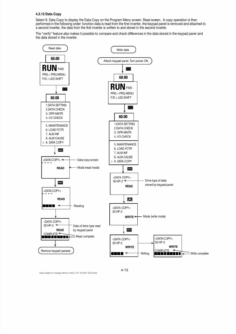
8/11/2019 GEI-100364
http://slidepdf.com/reader/full/gei-100364 50/154
4-13Data subject to change without notice 7/07. © 2007 GE Drives
4.3.13 Data Copy
Select 9. Data Copy to display the Data Copy on the Program Menu screen. Read screen. A copy operation is thenperformed in the following order: function data is read from the first inverter, the keypad panel is removed and attached toa second inverter, the data from the first inverter is written to and stored in the second inverter.
The “verify” feature also makes it possible to compare and check differences in the data stored in the keypad panel andthe data stored in the inverter.
Read dataWrite data
Attach keypad panel, Turn power ON.60.00
RUNPRG > PRG MENU
F/D > LED SHIFT
FWD
60.00
1.DATA SETTING
2.DATA CHECK
3. OPR MNTR
4. I/O CHECK
5. MAINTENANCE
6. LOAD FCTR
7. ALM INF
8. ALM CAUSE
> 9. DATA COPY
<DATA COPY>
READ
Data copy screen
Mode (read mode)
<DATA COPY>
READ
Reading
<DATA COPY>
30 HP-2
READ
COMPLETE
Data of drive type read
by keypad panel
Read complete
Remove keypad pananel
60.00
RUNPRG > PRG MENU
F/D > LED SHIFT
FWD
60.00
1.DATA SETTING
2.DATA CHECK
3. OPR MNTR
4. I/O CHECK
5. MAINTENANCE
6. LOAD FCTR
7. ALM INF
8. ALM CAUSE
> 9. DATA COPY
READ
<DATA COPY>
30 HP-2
WRITE
<DATA COPY>
30 HP-2
WRITE
<DATA COPY>
30 HP-2
<DATA COPY>30 HP-2
WRITE
COMPLETEWrite completeWriting
Mode (write mode)
Drive type of data
stored by keypad panel
PRG
PRG
PRG
FUNC
DATA
FUNC
DATA
FUNC
DATA
FUNC
DATA
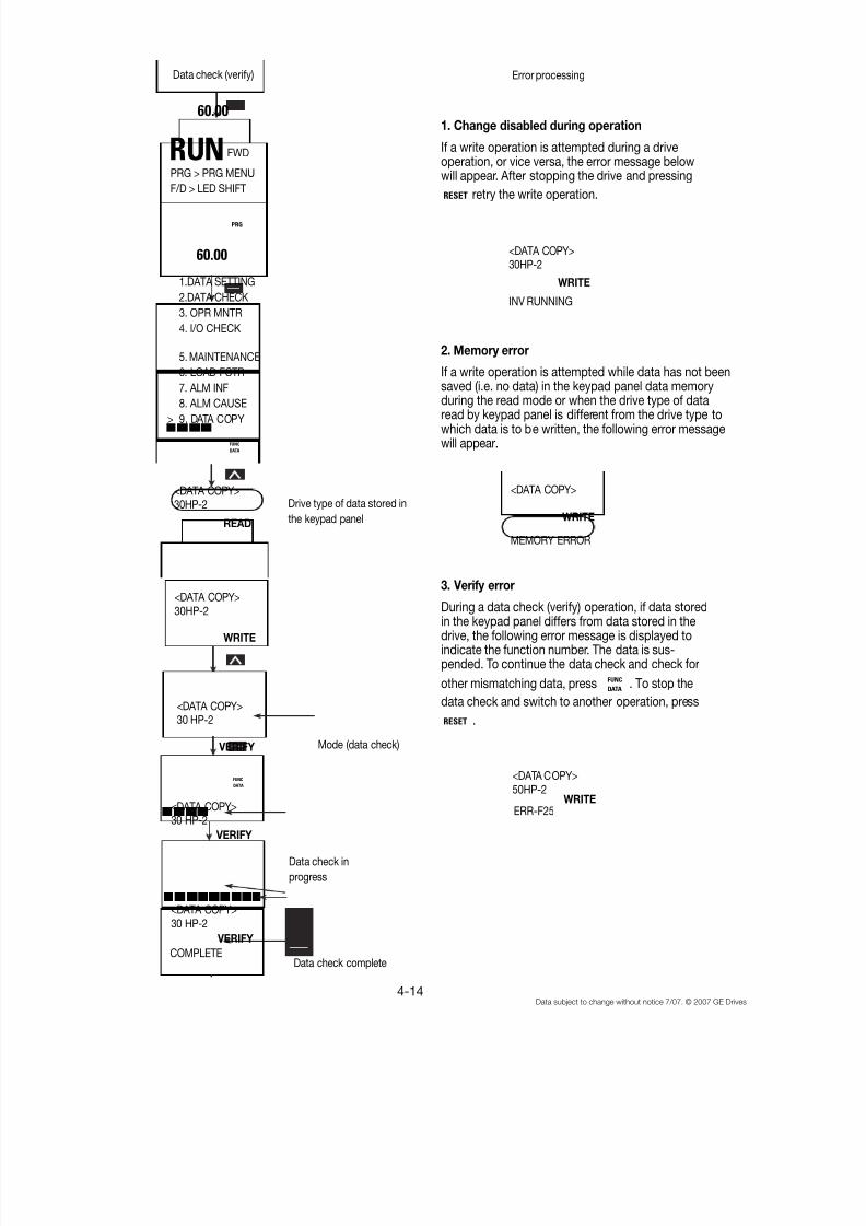
8/11/2019 GEI-100364
http://slidepdf.com/reader/full/gei-100364 51/154
4-14Data subject to change without notice 7/07. © 2007 GE Drives
Data check (verify)
60.00
60.00
1.DATA SETTING
2.DATA CHECK
3. OPR MNTR
4. I/O CHECK
5. MAINTENANCE
6. LOAD FCTR
7. ALM INF
8. ALM CAUSE
> 9. DATA COPY
READ
<DATA COPY>30HP-2
WRITE
<DATA COPY>
30 HP-2
VERIFY
COMPLETE
<DATA COPY>30 HP-2
VERIFY
<DATA COPY>30 HP-2
VERIFY
<DATA COPY>30HP-2 Drive type of data stored in
the keypad panel
Mode (data check)
Data check in
progress
Data check complete
Error processing
<DATA COPY>30HP-2
WRITE
INV RUNNING
<DATA COPY>
WRITE
MEMORY ERROR
<DATA COPY>
50HP-2 WRITEERR-F25
1. Change disabled during operation
If a write operation is attempted during a driveoperation, or vice versa, the error message belowwill appear. After stopping the drive and pressing
RESET retry the write operation.
2. Memory error
If a write operation is attempted while data has not beensaved (i.e. no data) in the keypad panel data memoryduring the read mode or when the drive type of dataread by keypad panel is different from the drive type towhich data is to be written, the following error messagewill appear.
3. Verify error
During a data check (verify) operation, if data storedin the keypad panel differs from data stored in thedrive, the following error message is displayed toindicate the function number. The data is sus-pended. To continue the data check and check for
other mismatching data, press FUNC
DATA. To stop the
data check and switch to another operation, press
RESET .
RUNPRG > PRG MENU
F/D > LED SHIFT
FWD
PRG
FUNC
DATA
FUNC
DATA
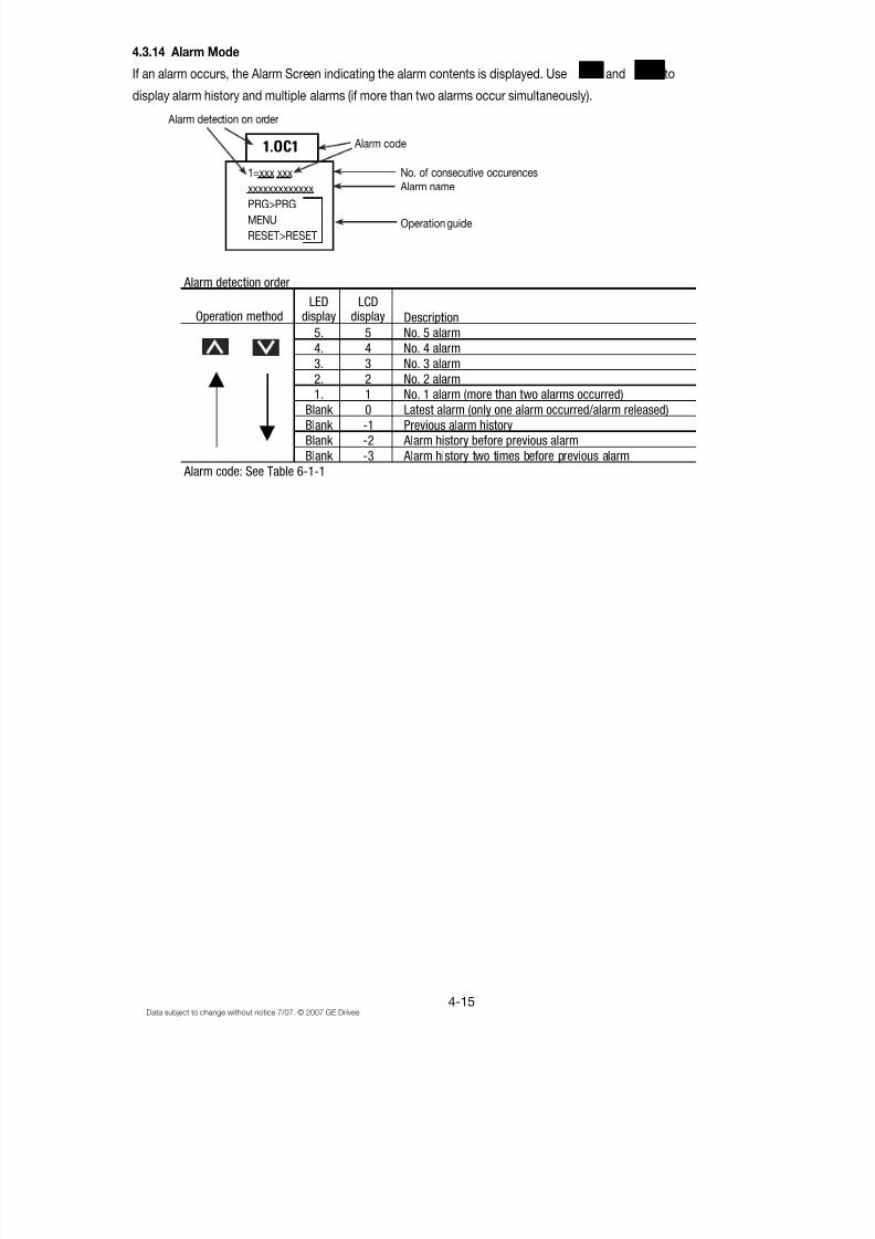
8/11/2019 GEI-100364
http://slidepdf.com/reader/full/gei-100364 52/154
4-15Data subject to change without notice 7/07. © 2007 GE Drives
4.3.14 Alarm Mode
If an alarm occurs, the Alarm Screen indicating the alarm contents is displayed. Use and to
display alarm history and multiple alarms (if more than two alarms occur simultaneously).
!!!! """"
1.OC1
1=xxx xxx
xxxxxxxxxxxxx
PRG>PRG
MENU
RESET>RESET
Alarm detection on order
Alarm code
No. of consecutive occurences
Alarm name
Operation guide
Operation methodLED
displayLCD
display Description
5. 5 No. 5 alarm
4. 4 No. 4 alarm
3. 3 No. 3 alarm
2. 2 No. 2 alarm
1. 1 No. 1 alarm (more than two alarms occurred)Blank 0 Latest alarm (only one alarm occurred/alarm released)
Blank -1 Previous alarm history
Blank -2 Alarm history before previous alarm
Blank -3 Alarm history two times before previous alarm
Alarm code: See Table 6-1-1
Alarm detection order

8/11/2019 GEI-100364
http://slidepdf.com/reader/full/gei-100364 53/154
4-16Data subject to change without notice 7/07. © 2007 GE Drives
Notes:
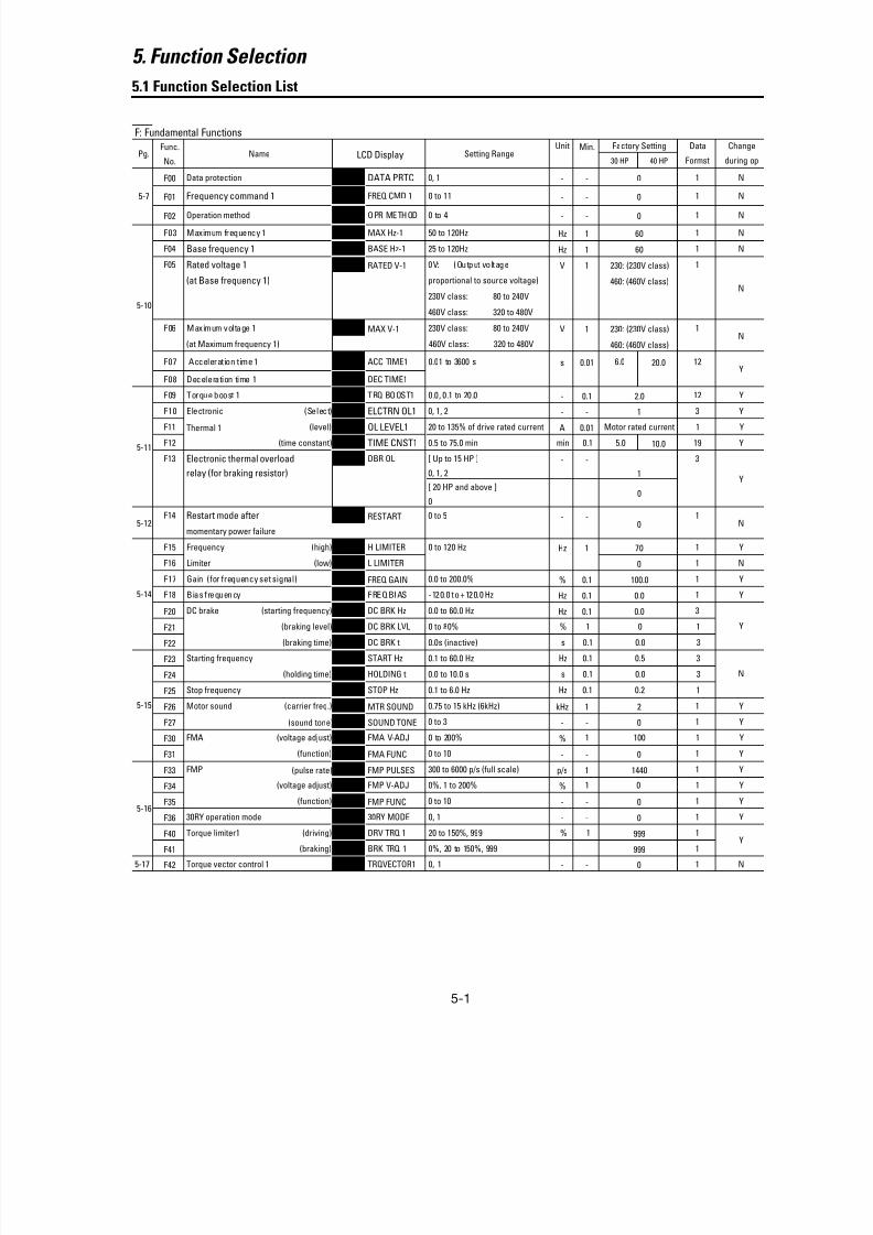
8/11/2019 GEI-100364
http://slidepdf.com/reader/full/gei-100364 54/154
5-1
5. Function Selection
5.1 Function Selection List
F: Fundamental Functions
Func. Unit Min. Factory Setting Data Change
No. 30 HP 40 HP Formst during op
F00 Data protection F00 DATA PRTC 0, 1 - - 0 1 N
F01 Frequency command 1 F01 FREQ CMD 1 0 to 11 - - 0 1 N
F02 Operation method F02 OPR METHOD 0 to 4 - - 0 1 N
F03 Maximum frequency 1 F03 MAX Hz-1 50 to 120Hz Hz 1 60 1 N
F04 Base frequency 1 F04 BASE Hz-1 25 to 120Hz Hz 1 60 1 N
F05 Rated voltage 1 F05 RATED V-1 0V: (Output voltage V 1 230: (230V class) 1
(at Base frequency 1) proportional to source voltage) 460: (460V class)
230V class: 80 to 240V
460V class: 320 to 480V
F06 Maximum voltage 1 F06 MAX V-1 230V class: 80 to 240V V 1 230: (230V class) 1
(at Maximum frequency 1) 460V class: 320 to 480V 460: (460V class)
F07 Acceleration time 1 F07 ACC TIME1 0.01 to 3600 s s 0.01 6.0 20.0 12
F08 Deceleration time 1 F08 DEC TIME1
F09 Torque boost 1 F09 TRQ BOOST1 0.0, 0.1 to 20.0 - 0.1 2.0 12 YF10 Electronic (Select) F10 ELCTRN OL1 0, 1, 2 - - 1 3 Y
F11 Thermal 1 (level) F11 OL LEVEL1 20 to 135% of drive rated current A 0.01 Motor rated current 1 Y
F12 (time constant) F12 TIME CNST1 0.5 to 75.0 min min 0.1 5.0 10.0 19 Y
F13 Electronic thermal overload F13 DBR OL [ Up to 15 HP ] - - 3
relay (for braking resistor) 0, 1, 2 1
[ 20 HP and above ]
0
F14 Restart mode after F14 RESTART 0 to 5 - - 1
momentary power failure
F15 Frequency (high) F15 H LIMITER 0 to 120 Hz Hz 1 70 1 Y
F16 Limiter (low) F16 L LIMITER 0 1 N
F17 Gain (for frequency set signal) F17 FREQ GAIN 0.0 to 200.0% % 0.1 100.0 1 Y
F18 Bias frequency F18 FREQ BIAS -120.0 to +120.0 Hz Hz 0.1 0.0 1 Y
F20 DC brake (starting frequency) F20 DC BRK Hz 0.0 to 60.0 Hz Hz 0.1 0.0 3
F21 (braking level) F21 DC BRK LVL 0 to 80% % 1 0 1
F22 (braking time) F22 DC BRK t 0.0s (inactive) s 0.1 0.0 3
F23 Starting frequency F23 START Hz 0.1 to 60.0 Hz Hz 0.1 0.5 3
F24 (holding time) F24 HOLDING t 0.0 to 10.0 s s 0.1 0.0 3
F25 Stop frequency F25 STOP Hz 0.1 to 6.0 Hz Hz 0.1 0.2 1
F26 Motor sound (carrier freq.) F26 MTR SOUND 0.75 to 15 kHz (6kHz) kHz 1 2 1 Y
F27 (sound tone) F27 SOUND TONE 0 to 3 - - 0 1 Y
F30 FMA (voltage adjust) F30 FMA V-ADJ 0 to 200% % 1 100 1 Y
F31 (function) F31 FMA FUNC 0 to 10 - - 0 1 Y
F33 FMP (pulse rate) F33 FMP PULSES 300 to 6000 p/s (full scale) p/s 1 1440 1 Y
F34 (voltage adjust) F34 FMP V-ADJ 0%, 1 to 200% % 1 0 1 Y
F35 (function) F35 FMP FUNC 0 to 10 - - 0 1 Y
F36 30RY operation mode F36 30RY MODE 0, 1 - - 0 1 Y
F40 Torque limiter1 (driving) F40 DRV TRQ 1 20 to 150%, 999 % 1 999 1
F41 (braking) F41 BRK TRQ 1 0%, 20 to 150%, 999 999 1
5-17 F42 Torque vector control 1 F42 TRQVECTOR1 0, 1 - - 0 1 N
Name LCD Display Setting Range
Y
Y
Y
N
N
Y
N
N
0
0
5-7
5-10
5-11
Pg.
5-12
5-14
5-15
5-16
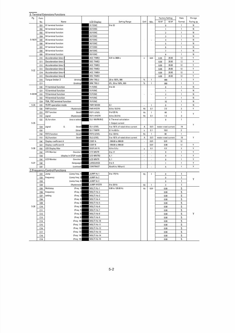
8/11/2019 GEI-100364
http://slidepdf.com/reader/full/gei-100364 55/154
5-2
E: Terminal Extensions Functions
Pg. Func. Factory Setting Data Change
No. Setting Range Unit Min. 30 HP 40 HP Format During op
E01 X1 terminal function E01 X1 FUNC 0 to 32 0 1 N
E02 X2 terminal function E02 X2 FUNC 1 1 N
E03 X3 terminal function E03 X3 FUNC 2 1 N
E04 X4 terminal function E04 X4 FUNC 3 1 N
E05 X5 terminal function E05 X5 FUNC - - 4 1 N
E06 X6 terminal function E06 X6 FUNC 5 1 N
E07 X7 terminal function E07 X7 FUNC 6 1 N
E08 X8 terminal function E08 X8 FUNC 7 1 N
E09 X9 terminal function E09 X9 FUNC 8 1 N
E10 Acceleration time 2 E10 ACC TIME2 0.01 to 3600 s s 0.01 6.00 20.00 12 Y
E11 Deceleration time 2 E11 DEC TIME2 6.00 20.00 12 Y
E12 Acceleration time 3 E12 ACC TIME3 6.00 20.00 12 Y
E13 Deceleration time 3 E13 DEC TIME3 6.00 20.00 12 Y
E14 Acceleration time 4 E14 ACC TIME4 6.00 20.00 12 Y
E15 Deceleration time 4 E15 DEC TIME4 6.00 20.00 12 Y
E16 Torque limiter 2 (driving) E16 DRV TRQ 2 20 to 150%, 999 % 1 999 1 Y
E17 (braking) E17 BRK TRQ 2 0%, 20 to 150%, 999 % 1 999 1 Y
E20 Y1 terminal function E20 Y1 FUNC 0 to 33 0 1 N
E21 Y2 terminal function E21 Y2 FUNC 1 1 N
E22 Y3 terminal function E22 Y3 FUNC - - 2 1 N
E23 Y4 terminal function E23 Y4 FUNC 7 1 N
E24 Y5A, Y5C terminal function E24 Y5 FUNC 10 1 N
5-24 E25 Y5 RY operation mode E25 Y5RY MODE 0,1 - 1 0 1 N
E30 FAR function (Hysteresis) E30 FAR HYSTR 0.0 to 10.0 Hz Hz 0.1 2.5 3 Y
E31 FDT function (level) E31 FDT1 LEVEL 0 to120 Hz Hz 1 60 1
E32 signal (Hysteresis) E32 FDT1 HYSTR 0.0 to 30.0 Hz Hz 0.1 1.0 3
E33 OL function (mode select) E33 OL1 WARNING 0 : Thermal ca lculat ion - - 0 1
1: Output current
E34 signal (L (level) E34 OL1 LEVEL 5 to 150% of rated drive current A 0.01 motor rated current 19
E35 (timer) E35 OL1 TIMER 0.1 to 60.0 s s 0.1 10.0 3
E36 FDT2 function (level) E36 FDT2 LEVEL 0 to 120 Hz Hz 1 60 1
E37 OL2 function (level) E37 OL2 LEVEL 5 to 150% of rated drive current A 0.01 motor rated current 19
E40 Display coefficient A E40 COEF A -999.00 to 999.00 - 0.01 0.01 12
E41 Display coefficient B E41 COEF B -999.00 to 999.00 - 0.01 0.00 12 Y
E42 LED Display filter E42 DISPLAY FL 0.0 to 5.0 s s 0.1 0.5 3 Y
E43 LED Monitor (function) E43 LED MNTR 0 to 12 - - 0 1 Y
E44 (display in STOP mode) E44 LED MNTR2 0, 1 - - 0 1 Y
E45 LCD Monitor (function) E45 LCD MNTR 0, 1 - - 0 1 Y
E46 (language) E46 LANGUAGE 0 to 5 - - 1 1 Y
E47 (contrast) E47 CONTRAST 0(soft) to 10(hard) - - 5 1 Y
C:Frequency Control FunctionsC01 Jump (Jump freq. 1) C01 JUMP Hz 1 0 to 120 Hz Hz 1 0 1
C02 frequency (Jump freq. 2) C02 JUMP Hz 2 0 1
C03 (Jump freq. 3) C03 JUMP Hz 3 0 1
C04 (Hysteresis) C04 JUMP HYSTR 0 to 30 Hz Hz 1 3 1
C05 Multistep (Freq. 1) C05 MULTI Hz-1 0.00 to 120.00 Hz Hz 0.01 0.00 5
C06 frequency (Freq. 2) C06 MULTI Hz-2 0.00 5
C07 setting (Freq. 3) C07 MULTI Hz-3 0.00 5
C08 (Freq. 4) C08 MULTI Hz-4 0.00 5
C09 (Freq. 5) C09 MULTI Hz-5 0.00 5
C10 (Freq. 6) C10 MULTI Hz-6 0.00 5
C11 (Freq. 7) C11 MULTI Hz-7 0.00 5
C12 (Freq. 8) C12 MULTI Hz-8 0.00 5C13 (Freq. 9) C13 MULTI Hz-9 0.00 5
C14 (Freq. 10) C14 MULTI Hz-10 0.00 5
C15 (Freq. 11) C15 MULTI Hz-11 0.00 5
C16 (Freq. 12) C16 MULTI Hz-12 0.00 5
C17 (Freq. 13) C17 MULTI Hz-13 0.00 5
C18 (Freq. 14) C18 MULTI Hz-14 0.00 5
C19 (Freq. 15) C19 MULTI Hz-15 0.00 5
Y
Y
Y
Name LCD Display
Y
Y
5-26
5-27
5-28
5-18/21
5-22
5-22/24
5-25
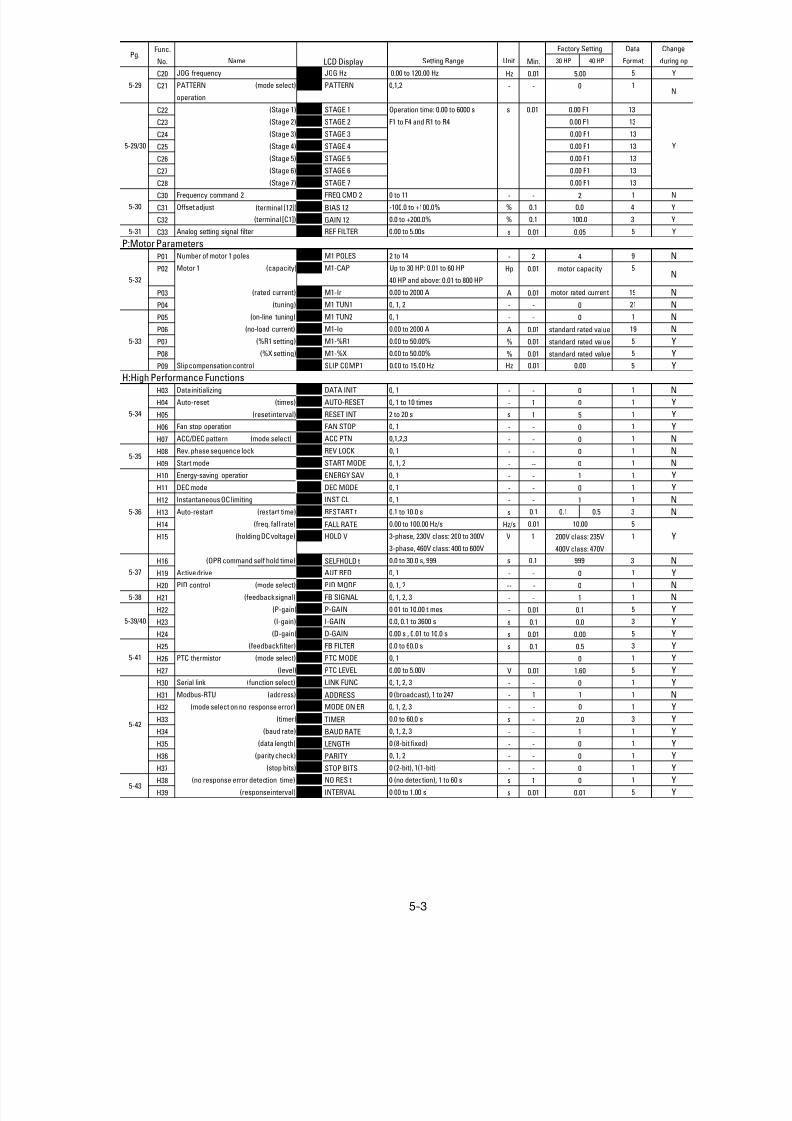
8/11/2019 GEI-100364
http://slidepdf.com/reader/full/gei-100364 56/154

8/11/2019 GEI-100364
http://slidepdf.com/reader/full/gei-100364 57/154
5-4
A: Alternative Motor Parameters
Pg. Func. Factory Setting Data Change
No. Setting Range Unit Min. 30 HP 40 HP Format During op
A01 Maximum frequency 2 A01 MAX Hz-2 50 to 120 Hz Hz 1 60 1 N
A02 Base frequency 2 A02 BASE Hz-2 25 to 120 Hz Hz 1 60 1 N
A03 Rated voltage 2 A03 RATED V-2 0 V 1 230V class: 230 1
(at Base frequency 2 ) 230V class: 80 to 240V 460V class: 460
460V class: 320 to 480V
A04 Maximum voltage 2 A04 MAX V-2 230V class: 80 to 240V V 1 230V class: 230 1 N
460V class: 320 to 480V 460V class: 460
A05 Torque boost 2 A05 TRQ BOOST2 0.0 , 0 .1 to 20.0 - - 2.0 3 Y
A06 Electronic (select) A06 ELCTRN OL2 0, 1, 2 - - 1 1 Y
A 07 thermal 2 (level) A07 OL LEVEL2 20% to 135% if INV rated current A 0.01 motor rated current 19 Y
A08 (thermal time constant) A08 TIME CNST2 0.5 to 75.0 min min 0.1 5.0 10.0 3 Y
A09 Torque vector control 2 A09 TRQVECTOR2 0, 1 - - 0 1 N
A10 Number of motor 2 poles A10 M2 POLES 2 to 14 poles pole 2 4 9 N
A11 Motor 2 (capacity) A11 M2-CAP Up to 30 HP: 0.01 to 60 HP HP 0.01 motor capacity 5
40 HP and above: 0.01 to 600 HP
A12 (rated current) A12 M2-Ir 0.00 to 2000 A A 0.01 motor rated current 19 N
A13 (tuning) A13 M2 TUN1 0, 1, 2 - - 0 21 N
A14 (on-line tuning) A14 M2 TUN2 0, 1 - - 0 1 N
A15 (no-load current) A15 M2-Io 0.00 to 2000 A A 0.01 standard rated value 19 N
A16 (%R1 setting) A16 M2-%R1 0.00 to 50.00% % 0.01 standard rated value 5 Y
A17 (%X setting) A17 M2-%X 0.00 to 50.00% % 0.01 standard rated value 5 Y
A18 (slip compensation control 2) A18 SLIP COMP2 0.00 to 15.00 Hz Hz 0.01 0.00 5 Y
N
N
5-45
Name LCD Display
5-44
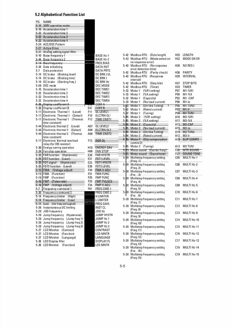
8/11/2019 GEI-100364
http://slidepdf.com/reader/full/gei-100364 58/154
5-5
5.2 Alphabetical Function List
PG. NAME
5-16 30RY operation mode F36 30RY MODE5-10 Acceleration time 1 F07 ACC TIME1
5-22 Acceleration time 2 E10 ACC TIME25-22 Acceleration time 3 E12 ACC TIME3
5-22 Acceleration time 4 E14 ACC TIME45-34 ACC/DEC Pattern H07 ACC PTN
5-37 Active Drive H19 AUT RED
5-31 Analog setting signal filter C33 REF FILTER5-10 Base frequency 1 F04 BASE Hz-1
5-44 Base frequency 2 A02 BASE Hz-25-14 Bias frequency F18 FREQ BIAS
5-34 Data initializing H03 DATA INIT5-7 Data protection F00 DATA PRTC
5-14 DC brake (Braking level) F21 DC BRK LVL
5-14 DC brake (Braking time) F22 DC BRK t5-14 DC brake (Starting freq.) F20 DC BRK Hz
5-36 DEC mode H11 DEC MODE5-10 Deceleration time 1 F08 DEC TIME1
5-22 Deceleration time 2 E11 DEC TIME25-22 Deceleration time 3 E13 DEC TIME3
5-22 Deceleration time 4 E15 DEC TIME4
5-26 Display coefficient A E40 COEF A5-26 Display coefficient B E41 COEF B
5-11 Electronic Thermal 1 (Level) F11 OL LEVEL15-11 Electronic Thermal 1 (Select) F10 ELCTRN OL1
5-11 Electronic Thermal 1 (Thermal time constant)
F12 TIME CNST1
5-44 Electronic thermal 2 (Level) A07 OL LEVEL25-44 Electronic thermal 2 (Select) A06 ELCTRN OL2
5-44 Electronic thermal 2 (Thermal time constant)
A08 TIME CNST2
5-11 Electronic thermal overloadrelay (for DB resistor)
F13 DBR OL
5-36 Energy-saving operation H10 ENERGY SAV5-34 Fan stop operation H06 FAN STOP
5-25 FAR function (Hysteresis) E30 FAR HYSTR
5-25 FDT function (Level) E31 FDT1 LEVEL5-25 FDT signal (Hysteresis) E32 FDT1 HYSTR
5-25 FDT2 function (Level) E36 FDT2 LEVEL5-15 FMA (Voltage adjust) F30 FMA V-ADJ
5-15 FMA (Function) F31 FMA FUNC5-16 FMP (Function) F35 FMP FUNC
5-16 FMP (Pulse rate) F33 FMP PULSES5-16 FMP (Voltage adjust) F34 FMP V-ADJ
5-7 Frequency command 1 F01 FREQ CMD 1
5-30 Frequency command 2 C30 FREQ CMD 25-14 Frequency limiter (High) F15 H LIMITER
5-14 Frequency limiter (Low) F16 L LIMITER5-14 Gain (for freq set signal) F17 FREQ GAIN
5-36 Instantaneous OC limiting H12 INST CL
5-29 JOG frequency C20 JOG Hz5-28 Jump frequency (Hysteresis) C04 JUMP HYSTR5-28 Jump frequency (Jump freq 1) C01 JUMP Hz 1
5-28 Jump frequency (Jump freq 2) C02 JUMP Hz 2
5-28 Jump frequency (Jump freq 3) C03 JUMP Hz 35-27 LCD Monitor (Contrast) E47 CONTRAST
5-27 LCD Monitor (Function) E45 LCD MNTR5-27 LCD Monitor (Language) E46 LANGUAGE
5-26 LED Display filter E42 DISPLAY FL5-26 LED Monitor (Function) E43 LED MNTR
LCD Display PG. NAME
5-26 LED Monitor (Display @ STOPmode)
E44 LED MNTR2
5-10 Maximum frequency 1 F03 MAX Hz-15-44 Maximum frequency 2 A01 MAX Hz-2
5-10 Maximum voltage 1 F06 MAX V-15-44 Maximum voltage 2 A04 MAX V-2
5-42 Modbus-RTU (Address) H31 ADDRESS5-42 Modbus-RTU (Baud rate) H34 BAUD RATE
5-42 Modbus-RTU (Data length) H35 LENGTH
5-42 Modbus-RTU (Mode select onno response error)
H32 MODE ON ER
5-43 Modbus-RTU (No responseerror detection time)
H38 NO RES t
5-42 Modbus-RTU (Parity check) H36 PARITY
5-43 Modbus-RTU (Responseinterval)
H39 INTERVAL
5-42 Modbus-RTU (Stop bits) H37 STOP BITS5-42 Modbus-RTU (Timer) H33 TIMER
5-33 Motor 1 (%R1 setting) P07 M1-%R15-33 Motor 1 (%X setting) P08 M1-%X
5-32 Motor 1 (Capacity) P02 M1 -CAP5-33 Motor 1 (No-load current) P06 M1-lo
5-33 Motor 1 (On-line Tuning) P05 M1 TUN25-32 Motor 1 (Rated current) P03 M1-lr5-32 Motor 1 (Tuning) P04 M1 TUN1
5-45 Motor 2 (%R1 setting) A16 M2-%R15-45 Motor 2 (%X setting) A17 M2-%X
5-44 Motor 2 (Capacity) A11 M2-CAP5-45 Motor 2 (No-load current) A15 M2-Io
5-45 Motor 2 (On-line Tuning) A14 M2 TUN2
5-44 Motor 2 (Rated current) A12 M2-Ir5-45 Motor 2 (Slip compensation
control 2)A18 SLIP COMP2
5-45 Motor 2 (Tuning) A13 M2 TUN15-15 Motor sound (Carrier freq.) F26 MTR SOUND
5-15 Motor sound (Sound tone) F27 SOUND TONE
5-28 Multistep frequency setting(Freq. 1) C05 MULTI Hz-1
5-28 Multistep frequency setting(Freq. 2)
C06 MULTI Hz-2
5-28 Multistep frequency setting(Fre . 3)
C07 MULTI Hz-3
5-28 Multistep frequency setting(Freq. 4)
C08 MULTI Hz-4
5-28 Multistep frequency setting(Freq. 5)
C09 MULTI Hz-5
5-28 Multistep frequency setting(Fre . 6)
C10 MULTI Hz-6
5-28 Multistep frequency setting(Freq. 7)
C11 MULTI Hz-7
5-28 Multistep frequency setting(Freq. 8)
C12 MULTI Hz-8
5-28 Multistep frequency setting(Freq. 9)
C13 MULTI Hz-9
5-28 Multistep frequency setting(Freq.10)
C14 MULTI Hz-10
5-28 Multistep frequency setting(Freq.11)
C15 MULTI Hz-11
5-28 Multistep frequency setting(Freq.12)
C16 MULTI Hz-12
5-28 Multistep frequency setting(Freq.13)
C17 MULTI Hz-13
5-28 Multistep frequency setting(Fre .14)
C18 MULTI Hz-14
5-28 Multistep frequency setting(Freq.15)
C19 MULTI Hz-15
LCD Display
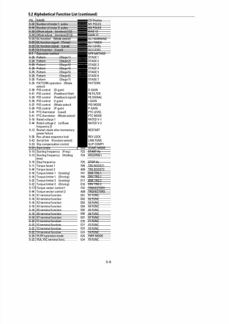
8/11/2019 GEI-100364
http://slidepdf.com/reader/full/gei-100364 59/154
5-6
5.2 Alphabetical Function List (continued)
PG. NAME5-32 Number of motor 1 poles P01 M1 POLES
5-44 Number of motor 2 poles A10 M2 POLES
5-30 Offset adjust (terminal [12]) C31 BIAS 125-30 Offset adjust (terminal [C1]) C32 GAIN 12
5-25 OL function (Mode select) E33 OL1 WARNING5-25 OL function siganl (Timer) E35 OL1 TIMER
5-25 OL function signal (Level) E34 OL1 LEVEL5-25 OL2 function (Level) E37 OL2 LEVEL
5-7 Operation method F02 OPR METHOD
5-29 Pattern (Stage 1) C22 STAGE 15-29 Pattern (Stage 2) C23 STAGE 2
5-29 Pattern (Stage 3) C24 STAGE 35-29 Pattern (Stage 4) C25 STAGE 4
5-29 Pattern (Stage 5) C26 STAGE 55-29 Pattern (Stage 6) C27 STAGE 6
5-29 Pattern (Stage 7) C28 STAGE 7
5-29 PATTERN operation (Modeselect)
C21 PATTERN
5-39 PID control (D-gain) H24 D-GAIN
5-41 PID control (Feedback filter) H25 FB FILTER5-38 PID control (Feedback signal) H21 FB SIGNAL
5-39 PID control (I-gain) H23 I-GAIN
5-37 PID control (Mode select) H20 PID MODE5-39 PID control (P-gain) H22 P-GAIN
5-41 PTC thermistor (Level) H27 PTC LEVEL5-41 PTC thermistor (Mode select) H26 PTC MODE
5-10 Rated voltage 1 F05 RATED V-15-44 Rated voltage 2 (at Base
frequency 2)A03 RATED V-2
5-12 Restart mode after momentarypower failure
F14 RESTART
5-35 Rev. phase sequence lock H08 REV LOCK
5-42 Serial link (Function select) H30 LINK FUNC
5-33 Slip compensation control P09 SLIP COMP15-35 Start mode H09 START MODE
5-15 Starting frequency (Freq.) F23 START Hz
5-15 Starting frequency (Holding time) F24 HOLDING t
5-15 Stop frequency F25 STOP Hz
5-11 Torque boost 1 F09 TRQ BOOST15-44 Torque boost 2 A05 TRQ BOOST2
5-16 Torque limiter 1 (braking) F41 BRK TRQ 15-16 Torque limiter 1 (Driving) F40 DRV TRQ 1
5-22 Torque limiter 2 (braking) E17 BRK TRQ 25-22 Torque limiter 2 (Driving) E16 DRV TRQ 2
5-177 Torque vector control 1 F42 TRQVECTOR1
5-44 Torque vector control 2 A09 TRQVECTOR25-18 X1 terminal function E01 X1 FUNC
5-18 X2 terminal function E02 X2 FUNC5-18 X3 terminal function E03 X3 FUNC
5-18 X4 terminal function E04 X4 FUNC
5-18 X5 terminal function E05 X5 FUNC5-18 X6 terminal function E06 X6 FUNC
5-18 X7 terminal function E07 X7 FUNC5-22 Y1 terminal function E20 Y1 FUNC
5-22 Y2 terminal function E21 Y2 FUNC5-22 Y3 terminal function E22 Y3 FUNC
5-22 Y4 terminal function E23 Y4 FUNC5-24 Y5 RY operation mode E25 Y5RY MODE
5-22 Y5A, Y5C terminal func. E24 Y5 FUNC
LCD Display

8/11/2019 GEI-100364
http://slidepdf.com/reader/full/gei-100364 60/154
5-7
F00 Data protection
F 0 0 D A T A P R T C
Setting range 0 : data can be changed1 : data cannot be changed
This function protects the system by blocking any datachanges from the keypad panel.
Setting procedure:
0 to 1: Press the STOP and keys simultaneously tochange the value from 0 to 1, then press
theFUNC
DATA to validate the change.
1 to 0: Press the STOP and keys simultaneously
to change the value from 1 to 0, then press
the FUNC
DATA key to validate the change.
F01 Frequency setting 1
F 0 1 F R E Q C M D 1
This function determines the method to be used for settingfrequency.
NOTE: Use only one terminal - V2 or C1, exclusively.
0: Keypad operation ( or key)
1: Voltage input (terminal 12 and V2) (0 to +10 VDC,0 to +5VDC)
2: Current input (terminal C1) (4 to 20 mA DC)3: Voltage and current input (terminals 12 and C1)
4: Reversible operation with polarity (terminal 12)
(0 to ± 10 VDC)
5: Reversible operation with polarity (terminal 12 and V1option) (0 to ± 10 VDC)
Related functions E01 to E09 (Set values 21)
6: Inverse mode operation (terminal 12 and V2)
(+10 to 0 VDC)
7: Inverse mode operation ( terminal C1)(20 to 4 mA DC)
8: UP/DOWN control 1 (initial freq. = 0 Hz9: UP/DOWN control 2 (initial freq. = last value)
Related functions E01 to E09 (Set values 17, 18)
10. PATTERN operation
Related functions: C21 to C28
11: DI option or Pulse train input
For details, see instruction manual on options.
F02 Operation method
F 0 2 O P R M E T H O D
This function determines the input method for operationcommands.
0: Keypad operation ( FWD or REV or STOP key)
1: Terminal operation ( STOP key active)
2: Terminal operation ( STOP key inactive)
3: Terminal operation ( STOP key active) with GE start
software
4: Terminal operation ( STOP key inactive) with GE start
software
Note: GE start software prevents drive from restartingwhen power is applied.
This function can only be changed when terminals FWD
and REV are open.
REMOTE/LOCAL switching from the keypad panelautomatically changes the set value from 0 to 3 of thisfunction.
5.3 Function Explanation
F: Fundamental Functions
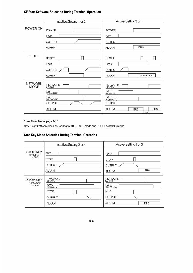
8/11/2019 GEI-100364
http://slidepdf.com/reader/full/gei-100364 61/154
5-8
GE Start Software Selection During Terminal Operation
Stop Key Mode Selection During Terminal Operation
* See Alarm Mode, page 4-15.
Note: Start Software does not work at AUTO RESET mode and PROGRAMMING mode
POWER ON
RESET
NETWORK
MODE
Inactive: Setting 1 or 2 Active: Setting 3 or 4
POWER
FWD
OUTPUT
ALARM
POWER
FWD
OUTPUT
ALARM
RESET
FWD
OUTPUT
ALARM
RESET
FWD
OUTPUT
ALARM
NETWORK
FWD
FWD
OUTPUT
ALARM
ER6
Multi Alarms*
(LE-CM)
(TERMINAL)
(NETWORK)
ER6 ER6RESET
NETWORK
FWD
FWD
OUTPUT
ALARM
(LE-CM)
(TERMINAL)
(NETWORK)
NETWORK
FWD
STOP
OUTPUT
ALARM
(LE-CM)
(TERMINAL)
NETWORK
FWD
STOP
OUTPUT
ALARM
(LE-CM)
(TERMINAL)
FWD
STOP
OUTPUT
ALARM
FWD
STOP
OUTPUT
ALARM
Inactive: Setting 2 or 4 Active: Setting 1 or 3
STOP KEY
STOP KEY
TERMINAL MODE
NETWORKMODE
ER6
ER6

8/11/2019 GEI-100364
http://slidepdf.com/reader/full/gei-100364 62/154
5-9
Frequency Setting Block Diagram

8/11/2019 GEI-100364
http://slidepdf.com/reader/full/gei-100364 63/154
5-10
F03 Maximum output frequency 1
F 0 3 M A X H z – 1
Setting range 50 to 120 Hz
This function sets the maximum output frequency forMotor 1.
Setting a value higher than the rated value of the deviceto be driven may damage the motor or machine. Match
the device rating when setting this function.F04 Base frequency 1
F 0 4 B A S E H z – 1
Setting range 25 to 120Hz
This function sets the maximum output frequency in theconstant torque range of Motor 1 or the output frequencyat the rated output voltage. Match the motor rating.
Note: If the value of Base frequency 1 is set higher thanthat of Maximum output frequency 1, the output voltagedoes not increase to the rated voltage. The maximumfrequency limits the output frequency.
F05 Rated voltage 1
F 0 5 R A T E D V – 1
Setting range 230V AC series: 0, 80 to 240V
460 V series: 0, 320 to 480V
This function sets the rated value of the voltage output toMotor 1. Note that a voltage greater than the supply(input) voltage cannot be output.
Value 0 terminates operation of the voltage regulatorfunction, thereby resulting in the output of a voltageproportional to the supply voltage.
Note: If the value of Rated voltage 1 is set higher thanMaximum output voltage 1, the output voltage does notincrease to the rated voltage. The maximum outputvoltage limits the output voltage.
FO6 Maximum output voltage 1
F 0 6 M A X V – 1
Setting range 230 V AC series: 80 to 240 VAC460 VAC series: 320 to 480 VAC
This function sets the maximum value of the voltageoutput for Motor 1. Note that a voltage higher than thesupply (input) voltage cannot be output.
FO7 Acceleration time 1
F08 Deceleration time 1
Setting range ACC TIME1: 0.01 to 3,600 secondsDEC TIME1: 0.01 to 3,600 seconds
These functions set the acceleration time for the outputfrequency from startup to maximum frequency, as well asthe deceleration time from maximum frequency tooperation stop.
Acceleration and deceleration times are represented bythe three most significant (high-order) digits.
Set acceleration and deceleration times with respect tomaximum frequency. The relationship between the setfrequency value and acceleration/deceleration times isas follows:
Set frequency = maximum frequency
The actual operation time matches the set value.
Set frequency < maximum frequency
The actual operation time differs from the set value.
Acceleration *deceleration operation time = set value x(set frequency/maximum frequency)
Note: If the set acceleration and deceleration times areset too low, even though the resistance torque andmoment of inertia of the load are great, if the torquelimiting functions or stall prevention function are acti-vated, it prolongs the operation time beyond the setvalue.
FWD
STOP
F 0 7 A C C T I M E 1
F 0 8 D E C T I M E 1

8/11/2019 GEI-100364
http://slidepdf.com/reader/full/gei-100364 64/154
5-11
F09 Torque Boost 1
F 0 9 T R Q B O O S T 1
This is a Motor 1 function. The following can be se-lected:
Selection of load characteristics such as automatictorque boost, square law reduction torque load, propor-tional torque load, constant torque load.
Enhancement of torque (V/f characteristics), which is
lowered during low-speed operation. Insufficient mag-netic flux of the motor due to a voltage drop in the low-frequency range can be compensated.
Setting Range Characteristics Selected0.0 Automatic torque boost, where the torque
boost value of a constant torque load (alinear change) is automatically adjusted.
0.1 to 0.9 Square law reduction torque for fan andpump loads
1.0 to 1.9 Proportional torque for middle class loadsbetween square law reduction torque and
constant torque (linear change)
2.0 to 20.0 Constant torque (linear change)
Since a large torque boost value creates over-excitationin the low-speed range, continued operation may causethe motor to overheat. Check the characteristics of thedriven motor.
F10 Electric thermal O/L relay (operation selection)
F11 Electric thermal O/L relay (level)
F12 Electric thermal O/L relay (thermal time)
The electronic thermal O/L relay manages the outputfrequency, output current, and operation time of theinverter to prevent the motor from overheating when150% of the set current value flows for the time set byF12 (thermal time constant).
F 1 0 E L C T R N O L 1
Setting range 0: Inactive1: Active (for general-purpose motor)2: Active (for forced air motor)
This function specifies whether to operate the electronicthermal O/L relay and selects the target motor. When ageneral-purpose motor is selected, the operation level islowered in the low speed range according to the coolingcharacteristics of the motor.
F 1 1 O L L E V E L 1
The setting range is 20 to 135% of the rated drive current.
This function sets the operation level current for theelectronic thermal O/L relay. Enter a value from 1 to 1.1times the rated motor current value.
F 1 2 T I M E C N S T 1
The setting range is 0.5 to 75.0 minutes (in 0.1 minuteincrements).
The time from when 150% of the operation level currentflows continuously to when the electronic thermal O/Lrelay activates can be set with this function.
F13 Electric thermal O/L relay (for braking)F 1 3 D B R O L
This function controls the frequent use and continuousoperating time of the braking resistor to prevent theresistor from overheating.
Drive Capacity Operation15 Hp or less 0: Inactive
1: Inactive
2: Active (external braking resistor)
20 Hp or more 0: Inactive
Torque characteristics< Square law reduction torque > < Proportional torque >
< Constant torque >
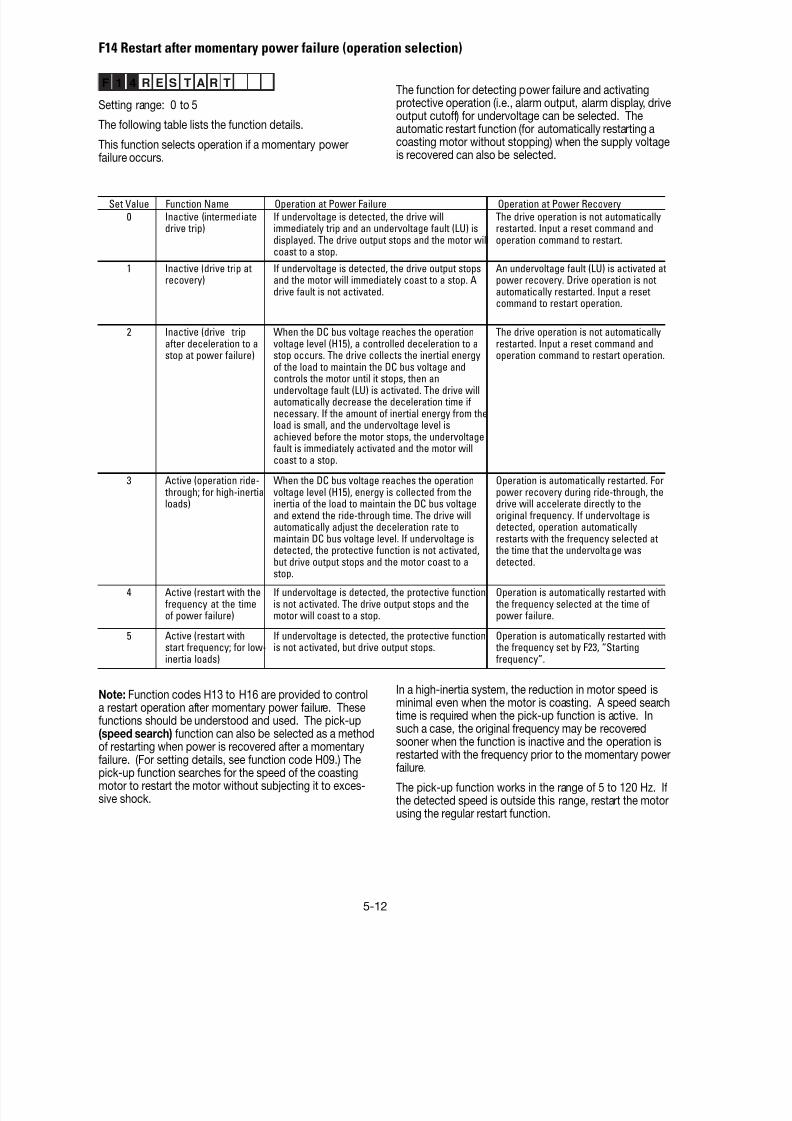
8/11/2019 GEI-100364
http://slidepdf.com/reader/full/gei-100364 65/154
5-12
F 1 4 R E S T A R T
Setting range: 0 to 5
The following table lists the function details.
This function selects operation if a momentary powerfailure occurs.
F14 Restart after momentary power failure (operation selection)
Note: Function codes H13 to H16 are provided to controla restart operation after momentary power failure. These
functions should be understood and used. The pick-up(speed search) function can also be selected as a methodof restarting when power is recovered after a momentaryfailure. (For setting details, see function code H09.) Thepick-up function searches for the speed of the coastingmotor to restart the motor without subjecting it to exces-sive shock.
Set Value Function Name Operation at Power Failure Operation at Power Recovery
0 Inactive (intermediatedrive trip)
If undervoltage is detected, the drive willimmediately trip and an undervoltage fault (LU) isdisplayed. The drive output stops and the motor willcoast to a stop.
The drive operation is not automaticallyrestarted. Input a reset command andoperation command to restart.
1 Inactive (drive trip atrecovery)
If undervoltage is detected, the drive output stopsand the motor will immediately coast to a stop. Adrive fault is not activated.
An undervoltage fault (LU) is activated atpower recovery. Drive operation is notautomatically restarted. Input a resetcommand to restart operation.
2 Inactive (drive tripafter deceleration to astop at power failure)
When the DC bus voltage reaches the operationvoltage level (H15), a controlled deceleration to astop occurs. The drive collects the inertial energyof the load to maintain the DC bus voltage andcontrols the motor until it stops, then anundervoltage fault (LU) is activated. The drive willautomatically decrease the deceleration time ifnecessary. If the amount of inertial energy from theload is small, and the undervoltage level isachieved before the motor stops, the undervoltagefault is immediately activated and the motor willcoast to a stop.
The drive operation is not automaticallyrestarted. Input a reset command andoperation command to restart operation.
3 Active (operation ride- through; for high-inertialoads)
When the DC bus voltage reaches the operationvoltage level (H15), energy is collected from theinertia of the load to maintain the DC bus voltageand extend the ride-through time. The drive willautomatically adjust the deceleration rate to
maintain DC bus voltage level. If undervoltage isdetected, the protective function is not activated,but drive output stops and the motor coast to astop.
Operation is automatically restarted. Forpower recovery during ride-through, thedrive will accelerate directly to theoriginal frequency. If undervoltage isdetected, operation automatically
restarts with the frequency selected at the time that the undervoltage wasdetected.
4 Active (restart with thefrequency at the timeof power failure)
If undervoltage is detected, the protective functionis not activated. The drive output stops and themotor will coast to a stop.
Operation is automatically restarted with the frequency selected at the time ofpower failure.
5 Active (restart withstart frequency; for low-inertia loads)
If undervoltage is detected, the protective functionis not activated, but drive output stops.
Operation is automatically restarted with the frequency set by F23, “Startingfrequency”.
In a high-inertia system, the reduction in motor speed isminimal even when the motor is coasting. A speed searchtime is required when the pick-up function is active. Insuch a case, the original frequency may be recoveredsooner when the function is inactive and the operation isrestarted with the frequency prior to the momentary powerfailure.
The pick-up function works in the range of 5 to 120 Hz. Ifthe detected speed is outside this range, restart the motorusing the regular restart function.
The function for detecting power failure and activatingprotective operation (i.e., alarm output, alarm display, driveoutput cutoff) for undervoltage can be selected. Theautomatic restart function (for automatically restarting acoasting motor without stopping) when the supply voltageis recovered can also be selected.
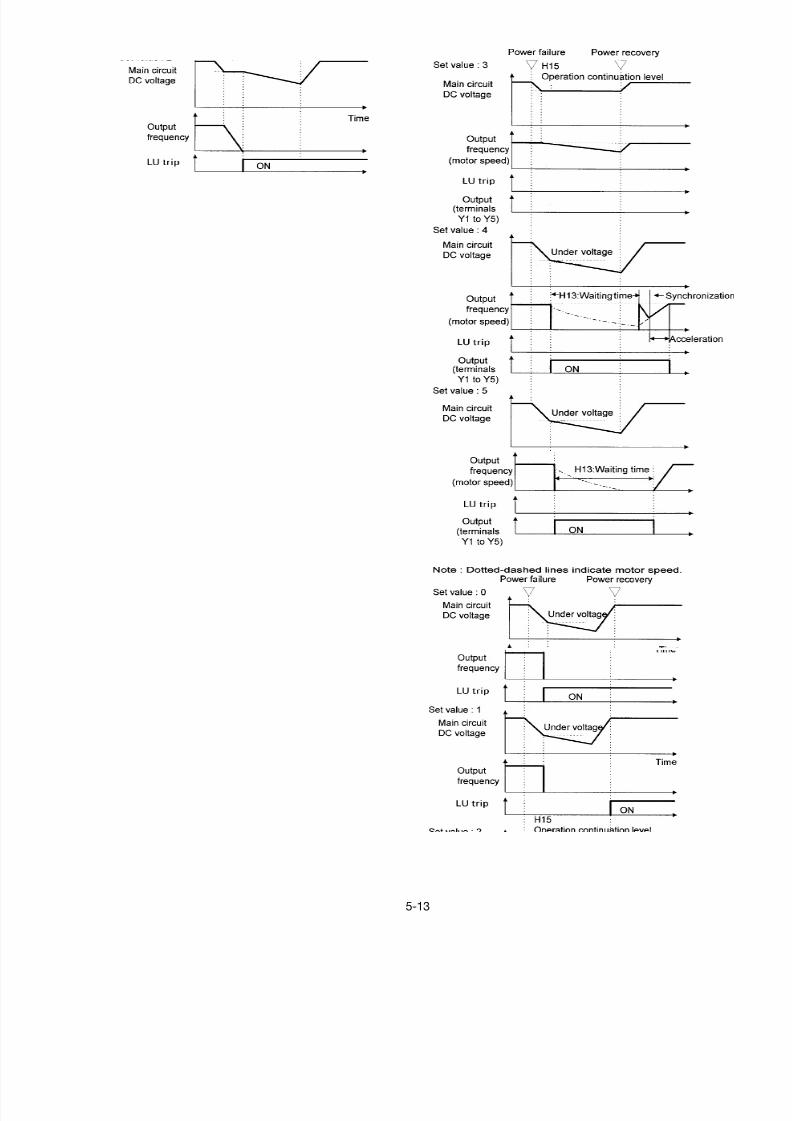
8/11/2019 GEI-100364
http://slidepdf.com/reader/full/gei-100364 66/154
5-13
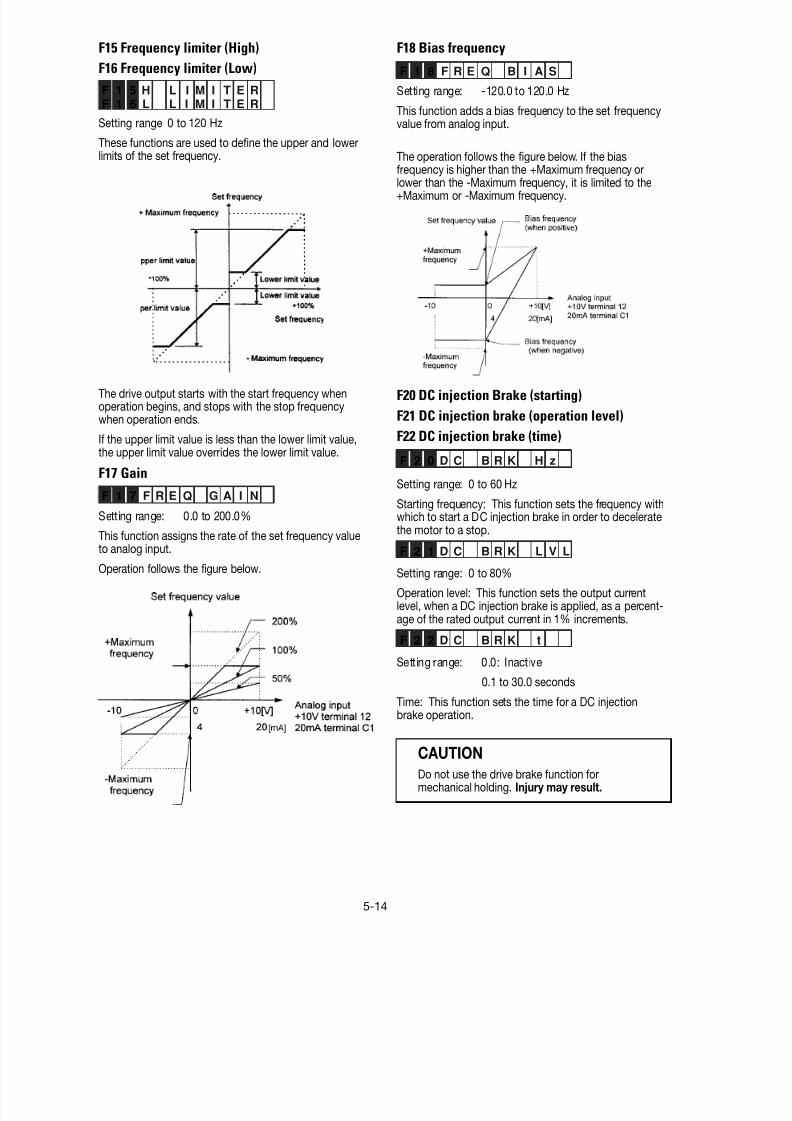
8/11/2019 GEI-100364
http://slidepdf.com/reader/full/gei-100364 67/154
5-14
F15 Frequency limiter (High)
F16 Frequency limiter (Low)
F 1 5 H L I M I T E R
F 1 6 L L I M I T E R
Setting range 0 to 120 Hz
These functions are used to define the upper and lowerlimits of the set frequency.
The drive output starts with the start frequency whenoperation begins, and stops with the stop frequencywhen operation ends.
If the upper limit value is less than the lower limit value,the upper limit value overrides the lower limit value.
F17 Gain
F 1 7 F R E Q G A I N
Setting range: 0.0 to 200.0%
This function assigns the rate of the set frequency valueto analog input.
Operation follows the figure below.
F18 Bias frequency
F 1 8 F R E Q B I A S
Setting range: -120.0 to 120.0 Hz
This function adds a bias frequency to the set frequencyvalue from analog input.
The operation follows the figure below. If the biasfrequency is higher than the +Maximum frequency or
lower than the -Maximum frequency, it is limited to the+Maximum or -Maximum frequency.
F20 DC injection Brake (starting)
F21 DC injection brake (operation level)
F22 DC injection brake (time)
F 2 0 D C B R K H z
Setting range: 0 to 60 Hz
Starting frequency: This function sets the frequency withwhich to start a DC injection brake in order to deceleratethe motor to a stop.
F 2 1 D C B R K L V L
Setting range: 0 to 80%
Operation level: This function sets the output currentlevel, when a DC injection brake is applied, as a percent-age of the rated output current in 1% increments.
F 2 2 D C B R K t
Setting range: 0.0: Inactive
0.1 to 30.0 seconds
Time: This function sets the time for a DC injectionbrake operation.
CAUTION
Do not use the drive brake function formechanical holding. Injury may result.
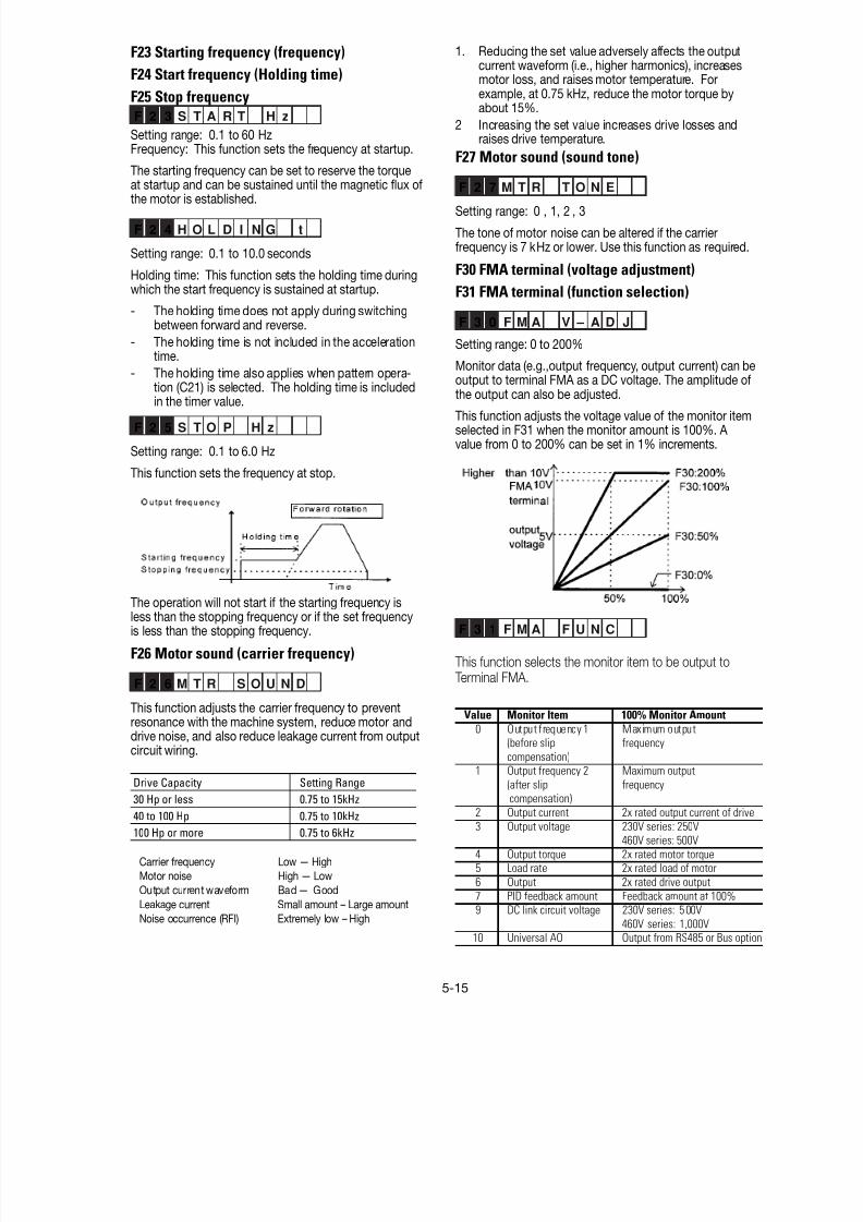
8/11/2019 GEI-100364
http://slidepdf.com/reader/full/gei-100364 68/154
5-15
F23 Starting frequency (frequency)
F24 Start frequency (Holding time)
F25 Stop frequencyF 2 3 S T A R T H z
Setting range: 0.1 to 60 HzFrequency: This function sets the frequency at startup.
The starting frequency can be set to reserve the torqueat startup and can be sustained until the magnetic flux of
the motor is established.
F 2 4 H O L D I N G t
Setting range: 0.1 to 10.0 seconds
Holding time: This function sets the holding time duringwhich the start frequency is sustained at startup.
- The holding time does not apply during switchingbetween forward and reverse.
- The holding time is not included in the accelerationtime.
- The holding time also applies when pattern opera-
tion (C21) is selected. The holding time is includedin the timer value.
F 2 5 S T O P H z
Setting range: 0.1 to 6.0 Hz
This function sets the frequency at stop.
The operation will not start if the starting frequency isless than the stopping frequency or if the set frequencyis less than the stopping frequency.
F26 Motor sound (carrier frequency)
F 2 6 M T R S O U N D
This function adjusts the carrier frequency to preventresonance with the machine system, reduce motor anddrive noise, and also reduce leakage current from outputcircuit wiring.
Drive Capacity Setting Range30 Hp or less 0.75 to 15kHz
40 to 100 Hp 0.75 to 10kHz
100 Hp or more 0.75 to 6kHz
Carrier frequency Low — High
Motor noise High — Low
Output current waveform Bad — Good
Leakage current Small amount – Large amount
Noise occurrence (RFI) Extremely low – High
1. Reducing the set value adversely affects the outputcurrent waveform (i.e., higher harmonics), increasesmotor loss, and raises motor temperature. Forexample, at 0.75 kHz, reduce the motor torque byabout 15%.
2 Increasing the set value increases drive losses andraises drive temperature.
F27 Motor sound (sound tone)
F 2 7 M T R T O N E
Setting range: 0 , 1, 2 , 3
The tone of motor noise can be altered if the carrierfrequency is 7 kHz or lower. Use this function as required.
F30 FMA terminal (voltage adjustment)
F31 FMA terminal (function selection)
F 3 0 F M A V – A D J
Setting range: 0 to 200%
Monitor data (e.g.,output frequency, output current) can beoutput to terminal FMA as a DC voltage. The amplitude of
the output can also be adjusted.
This function adjusts the voltage value of the monitor itemselected in F31 when the monitor amount is 100%. A value from 0 to 200% can be set in 1% increments.
F 3 1 F M A F U N C
This function selects the monitor item to be output to Terminal FMA.
Value Monitor Item 100% Monitor Amount0 Output frequency 1 Maximum output
(before slip frequency
compensation)1 Output frequency 2 Maximum output
(after slip frequency compensation)
2 Output current 2x rated output current of drive
3 Output voltage 230V series: 250V460V series: 500V
4 Output torque 2x rated motor torque5 Load rate 2x rated load of motor
6 Output 2x rated drive output
7 PID feedback amount Feedback amount at 100%9 DC link circuit voltage 230V series: 5 00V
460V series: 1,000V10 Universal AO Output from RS485 or Bus option
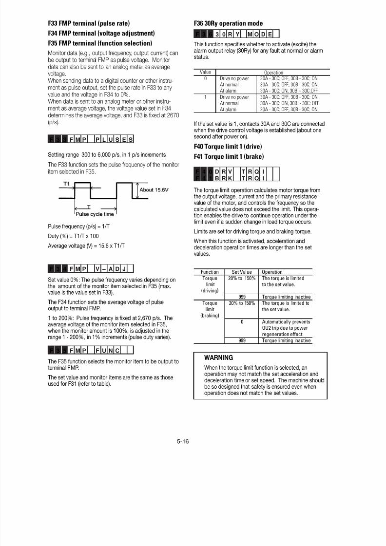
8/11/2019 GEI-100364
http://slidepdf.com/reader/full/gei-100364 69/154
5-16
F33 FMP terminal (pulse rate)
F34 FMP terminal (voltage adjustment)
F35 FMP terminal (function selection)
Monitor data (e.g., output frequency, output current) canbe output to terminal FMP as pulse voltage. Monitordata can also be sent to an analog meter as averagevoltage.When sending data to a digital counter or other instru-
ment as pulse output, set the pulse rate in F33 to anyvalue and the voltage in F34 to 0%.When data is sent to an analog meter or other instru-ment as average voltage, the voltage value set in F34determines the average voltage, and F33 is fixed at 2670(p/s).
F 3 3 F M P P L U S E S
Setting range 300 to 6,000 p/s, in 1 p/s increments
The F33 function sets the pulse frequency of the monitoritem selected in F35.
Pulse frequency (p/s) = 1/T
Duty (%) = T1/T x 100
Average voltage (V) = 15.6 x T1/T
F 3 4 F M P V – A D J
Set value 0%: The pulse frequency varies depending onthe amount of the monitor item selected in F35 (max.value is the value set in F33).
The F34 function sets the average voltage of pulseoutput to terminal FMP.
1 to 200%: Pulse frequency is fixed at 2,670 p/s. Theaverage voltage of the monitor item selected in F35,when the monitor amount is 100%, is adjusted in therange 1 - 200%, in 1% increments (pulse duty varies).
F 3 5 F M P F U N C
The F35 function selects the monitor item to be output toterminal FMP.
The set value and monitor items are the same as thoseused for F31 (refer to table).
F36 30Ry operation mode
F 3 6 3 0 R Y M O D E
This function specifies whether to activate (excite) thealarm output relay (30Ry) for any fault at normal or alarmstatus.
Value
0 Drive no power 30A - 30C: OFF, 30B - 30C: ON
At normal 30A - 30C: OFF, 30B - 30C: ONAt alarm 30A - 30C: ON, 30B - 30C:OFF
1 Drive no power 30A - 30C: OFF, 30B - 30C: ONAt normal 30A - 30C: ON, 30B - 30C: OFF
At alarm 30A - 30C: OFF, 30B - 30C: ON
Operation
If the set value is 1, contacts 30A and 30C are connectedwhen the drive control voltage is established (about onesecond after power on).
F40 Torque limit 1 (drive)
F41 Torque limit 1 (brake)
F 4 0 D R V T R Q I
F 4 1 B R K T R Q I
The torque limit operation calculates motor torque fromthe output voltage, current and the primary resistancevalue of the motor, and controls the frequency so thecalculated value does not exceed the limit. This opera-tion enables the drive to continue operation under thelimit even if a sudden change in load torque occurs.
Limits are set for driving torque and braking torque.
When this function is activated, acceleration anddeceleration operation times are longer than the setvalues.
Function Set Value Operation
Torque 20% to 150% The torque is limited limit to the set value.
(driving)
999 Torque limiting inactiveTorque 20% to 150% The torque is limited to
limit the set value.(braking)
0 Automatically preventsOU2 trip due to power
regeneration effect
999 Torque limiting inactive
WARNING
When the torque limit function is selected, anoperation may not match the set acceleration anddeceleration time or set speed. The machine shouldbe so designed that safety is ensured even whenoperation does not match the set values.

8/11/2019 GEI-100364
http://slidepdf.com/reader/full/gei-100364 70/154
5-17
F42 Torque vector control 1
F 4 2 T R Q V E C T O R 1
To obtain the most efficient motor torque, the torquevector control calculates torque according to load, toadjust the voltage and current vectors to optimum valuesbased on the calculated value.
Value Operation
0 inactive
1 active
Related Functions P01 to P09
If F42 = 1 (active), the following functions are affected:
1. F09 Torque boost 1 is automatically set to 0.0
(automatic torque boosting).
2. P09 Slip compensation control is automaticallyactivated. If set to 0.0, the amount of slip compensa-
tion for a standard 3-phase Fuji motor is applied.Otherwise, the set value is applied.
Use the torque vector control function under the followingconditions:
1. There can only be one motor.
Connection of two or more motors makes accurate
control difficult.
2. The function data (rated current P03, no-load currentP06,, %R1 P07, and %X P08) for Motor 1 must becorrect.
If a standard 3-phase GE motor is used, setting thecapacity (Function P02) ensures entry of the abovedata. An auto-tuning operation should be performedfor other motors.
3. The rated current of the motor must not be signifi-cantly less than the rated current of the drive. A motor two sizes lower in capacity than the nominalmotor indicated for the drive is the smallest thatshould be used.
4. To prevent leakage current and ensure accuratecontrol,, the length of the cable between the drive andmotor should not exceed 50 m.
5. If a reactor is connected between the drive and themotor and wiring impedance cannot be disregarded,use P04 Auto tuning to reset data.
If these conditions are not satisfied, set F42 = 0 (Inactive).
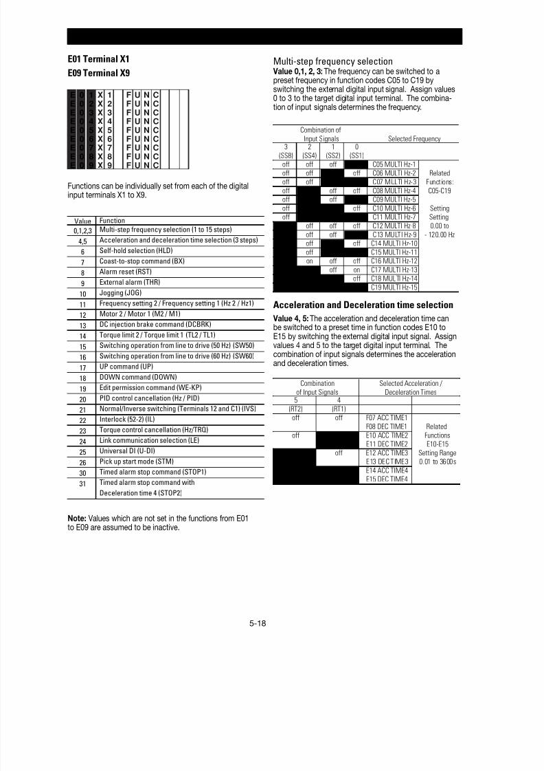
8/11/2019 GEI-100364
http://slidepdf.com/reader/full/gei-100364 71/154
5-18
E: Extension Terminal Functions
E01 Terminal X1
E09 Terminal X9
E 0 1 X 1 F U N CE 0 2 X 2 F U N CE 0 3 X 3 F U N C
E 0 4 X 4 F U N CE 0 5 X 5 F U N CE 0 6 X 6 F U N CE 0 7 X 7 F U N CE 0 8 X 8 F U N CE 0 9 X 9 F U N C
Functions can be individually set from each of the digitalinput terminals X1 to X9.
Value Function
0,1,2,3 Multi-step frequency selection (1 to 15 steps)
4,5 Acceleration and deceleration time selection (3 steps)
6 Self-hold selection (HLD)
7 Coast-to-stop command (BX)
8 Alarm reset (RST)
9 External alarm (THR)
10 Jogging (JOG)
11 Frequency setting 2 / Frequency setting 1 (Hz 2 / Hz1)
12 Motor 2 / Motor 1 (M2 / M1)
13 DC injection brake command (DCBRK)
14 Torque limit 2 / Torque limit 1 (TL2 / TL1)
15 Switching operation from line to drive (50 Hz) (SW50)
16 Switching operation from line to drive (60 Hz) (SW60)
17 UP command (UP)
18 DOWN command (DOWN)
19 Edit permission command (WE-KP)
20 PID control cancellation (Hz / PID)
21 Normal/Inverse switching (Terminals 12 and C1) (IVS)
22 Interlock (52-2) (IL)
23 Torque control cancellation (Hz/TRQ)
24 Link communication selection (LE)
25 Universal DI (U-DI)
26 Pick up start mode (STM)
30 Timed alarm stop command (STOP1)
31 Timed alarm stop command with
Deceleration time 4 (STOP2)
Note: Values which are not set in the functions from E01to E09 are assumed to be inactive.
Multi-step frequency selection Value 0,1, 2, 3: The frequency can be switched to apreset frequency in function codes C05 to C19 byswitching the external digital input signal. Assign values0 to 3 to the target digital input terminal. The combina-tion of input signals determines the frequency.
3 2 1 0(SS8) (SS4) (SS2) (SS1)
off off off on C05 MULTI Hz-1off off on off C06 MULTI Hz-2 Related
off off on on C07 MULTI Hz-3 Functions:
off on off off C08 MULTI Hz-4 C05-C19off on off on C09 MULTI Hz-5
off on on off C10 MULTI Hz-6 Settingoff on on on C11 MULTI Hz-7 Setting
on off off off C12 MULTI Hz-8 0.00 to
on off off on C13 MULTI Hz-9 - 120.00 Hzon off on off C14 MULTI Hz-10
on off on on C15 MULTI Hz-11on on off off C16 MULTI Hz-12
on on off on C17 MULTI Hz-13on on on off C18 MULTI Hz-14
on on on on C19 MULTI Hz-15
Combination of
Input Signals Selected Frequency
Acceleration and Deceleration time selection
Value 4, 5: The acceleration and deceleration time canbe switched to a preset time in function codes E10 toE15 by switching the external digital input signal. Assignvalues 4 and 5 to the target digital input terminal. Thecombination of input signals determines the accelerationand deceleration times.
5 4
(RT2) (RT1)off off F07 ACC TIME1
F08 DEC TIME1 Related
off on E10 ACC TIME2 FunctionsE11 DEC TIME2 E10-E15
on off E12 ACC TIME3 Setting RangeE13 DEC TIME3 0.01 to 3600s
on on E14 ACC TIME4E15 DEC TIME4
Combination
of Input Signals
Selected Acceleration /
Deceleration Times
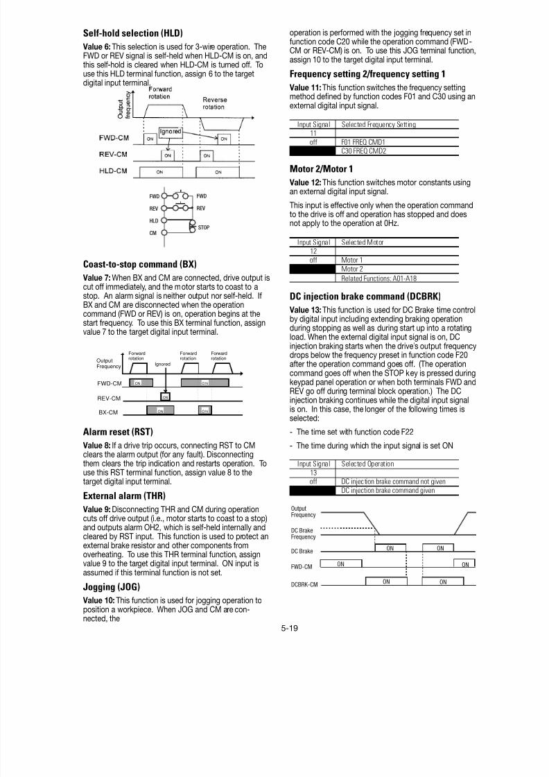
8/11/2019 GEI-100364
http://slidepdf.com/reader/full/gei-100364 72/154
5-19
Self-hold selection (HLD)
Value 6: This selection is used for 3-wire operation. TheFWD or REV signal is self-held when HLD-CM is on, andthis self-hold is cleared when HLD-CM is turned off. Touse this HLD terminal function, assign 6 to the targetdigital input terminal.
Coast-to-stop command (BX)
Value 7: When BX and CM are connected, drive output iscut off immediately, and the motor starts to coast to astop. An alarm signal is neither output nor self-held. IfBX and CM are disconnected when the operationcommand (FWD or REV) is on, operation begins at thestart frequency. To use this BX terminal function, assignvalue 7 to the target digital input terminal.
Alarm reset (RST)
Value 8: If a drive trip occurs, connecting RST to CMclears the alarm output (for any fault). Disconnectingthem clears the trip indication and restarts operation. Touse this RST terminal function, assign value 8 to thetarget digital input terminal.
External alarm (THR) Value 9: Disconnecting THR and CM during operationcuts off drive output (i.e., motor starts to coast to a stop)and outputs alarm OH2, which is self-held internally andcleared by RST input. This function is used to protect anexternal brake resistor and other components fromoverheating. To use this THR terminal function, assignvalue 9 to the target digital input terminal. ON input isassumed if this terminal function is not set.
Jogging (JOG)
Value 10: This function is used for jogging operation toposition a workpiece. When JOG and CM are con-nected, the
operation is performed with the jogging frequency set infunction code C20 while the operation command (FWD-CM or REV-CM) is on. To use this JOG terminal function,assign 10 to the target digital input terminal.
Frequency setting 2/frequency setting 1
Value 11: This function switches the frequency settingmethod defined by function codes F01 and C30 using anexternal digital input signal.
Input Signal Selected Frequency Setting11
off F01 FREQ CMD1on C30 FREQ CMD2
Motor 2/Motor 1
Value 12: This function switches motor constants usingan external digital input signal.
This input is effective only when the operation commandto the drive is off and operation has stopped and doesnot apply to the operation at 0Hz.
Input Signal Selected Motor
12off Motor 1
on Motor 2
Related Functions: A01-A18
DC injection brake command (DCBRK)
Value 13: This function is used for DC Brake time controlby digital input including extending braking operationduring stopping as well as during start up into a rotatingload. When the external digital input signal is on, DCinjection braking starts when the drive’s output frequencydrops below the frequency preset in function code F20after the operation command goes off. (The operation
command goes off when the STOP key is pressed duringkeypad panel operation or when both terminals FWD andREV go off during terminal block operation.) The DCinjection braking continues while the digital input signalis on. In this case, the longer of the following times isselected:
- The time set with function code F22
- The time during which the input signal is set ON
Input Signal Selected Operation
13off DC injection brake command not given
on DC injection brake command given
FWD
REV
HLD
CM
FWD
REV
STOP
OutputFrequency
DC BrakeFrequency
DC Brake
FWD-CM
DCBRK-CM
ON
ON ON
ON
ON ON
Forwardrotation
ON
ONON
ONONFWD-CM
REV-CM
BX-CM
OutputFrequency Ignored
Forwardrotation
Forwardrotation

8/11/2019 GEI-100364
http://slidepdf.com/reader/full/gei-100364 73/154
5-20
Edit permission command (data changepermission)(WE-KP) (data protection)
Value 19: This function allows the data to be changedonly when input is received from an external signal,thereby preventing function code data changes.
19 Selected Function
off Prohibit data changeson Allow data changes
Note: If a terminal is assigned the value 19, the datacannot be changed. To change data, turn the terminal onand change its setting to another number.
PID control cancellation (Hz/PID)
Value 20: The PID control can be disabled by an externaldigital input signal.
Input Signal Selected Function
20 [Related Functions: H20-H25]
off Enable PID control
on Disable PID control
(When the PID control is disabled, the frequency is setfrom keypad panel)
Normal operation/inverse
Value 21: Analog input (Terminals 12 and C1) can beswitched between normal and inverse operations using anexternal digital input signal.
Input Signal Selected Function
21 [Related Function: F01]
off orma opera on norma opera on sset and vice versa
on nverse opera on norma opera on sset and vice versa
Interlock (52-2)
Value 22: When a contactor is installed on the output sideof the drive, the contactor opens at the time of a momen-tary power failure. This prevents the reduction of the DCcircuit voltage and may prevent the detection of a powerfailure and a correct restart operation after power isrecovered. The restart operation, in the event of amomentary power failure, can be performed effectivelywith power failure information provided by an externaldigital input signal.
Torque limit 2/torque limit 1
Value 14: Frequency setting 2/frequency setting 1. Thisfunction switches the torque limit value set with functioncodes F40, F41, E16, and E17, using an external digitalinput signal.
Input Signal14
off F40 DRV TRQ1 Related FunctionsF41 BRK TRQ1 F40-F41, E16-E17
Setting Range
on E16 DRV TRQ2 DRV 20 to 200% ,999E17 DRV TRQ2 BRK0, 20 to 200%, 999
Selected Torque Limit Value
Switching operation from line drive(60Hz)(SW60)/(50Hz)(SW50)
Value 15, 16: Motor operation can be switched from 60Hz/50 Hz commercial power to drive operation withoutstopping the motor by switching the external digital inputsignal.
Input Signal Function
16off > on Drive operation to line operation (60 Hz)/(50 Hz)on > off Line operation to drive operation (60 Hz)/(50 Hz)
Following a momentary power failure, if the digital inputsignal goes off, 50 or 60 Hz (according to the inputsignal) is output after the restart waiting time (functioncode H13). The motor is then directed to drive opera-tion.
UP command (UP)/DOWN command (DOWN)
Value 17, 18: When an operation command is input (on),the output frequency can be increased or decreasedusing an external digital input signal.
The change ranges from 0 to maximum frequency.Operation in the opposite direction, of the operationcommand is not allowed.
Selected Function
(when operation command is on)
18 17off off Holds the output frequency
off on
on off
on on Holds the output frequency
Increases the output frequencyaccording to the acceleration time
Decreases the output frequencyaccording to the deceleration time
Combination
of Input Signals
There are the two types of UP/DOWN operations asshown below. Select the desired type by setting thefrequency (F01 or C30).
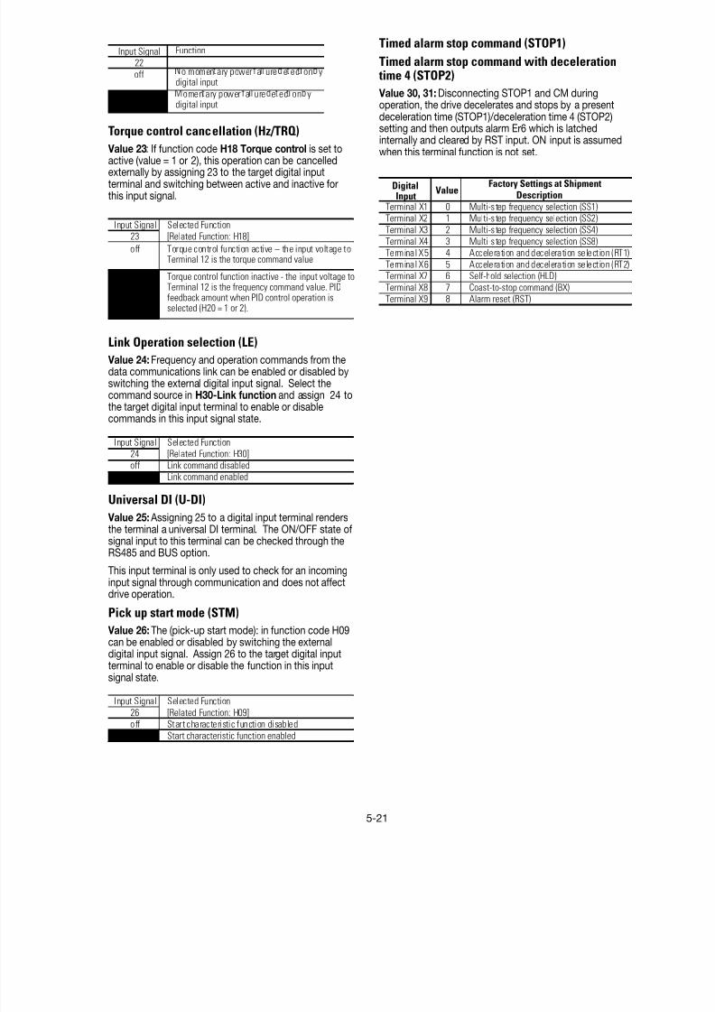
8/11/2019 GEI-100364
http://slidepdf.com/reader/full/gei-100364 74/154
5-21
Input Signal Function
22
off o momen ary power a ure e ec on ydigital input
on omen ary power a ure e ec on ydigital input
Torque control cancellation (Hz/TRQ)
Value 23: If function code H18 Torque control is set to
active (value = 1 or 2), this operation can be cancelledexternally by assigning 23 to the target digital inputterminal and switching between active and inactive forthis input signal.
Input Signal Selected Function23 [Related Function: H18]
off Torque control function active – the input voltage toTerminal 12 is the torque command value
on Torque control function inactive - the input voltage toTerminal 12 is the frequency command value. PIDfeedback amount when PID control operation isselected (H20 = 1 or 2).
Link Operation selection (LE)
Value 24: Frequency and operation commands from thedata communications link can be enabled or disabled byswitching the external digital input signal. Select thecommand source in H30-Link function and assign 24 tothe target digital input terminal to enable or disablecommands in this input signal state.
Input Signal Selected Function24 [Related Function: H30]
off Link command disabledon Link command enabled
Universal DI (U-DI)
Value 25: Assigning 25 to a digital input terminal rendersthe terminal a universal DI terminal. The ON/OFF state ofsignal input to this terminal can be checked through theRS485 and BUS option.
This input terminal is only used to check for an incominginput signal through communication and does not affectdrive operation.
Pick up start mode (STM)
Value 26: The (pick-up start mode): in function code H09can be enabled or disabled by switching the external
digital input signal. Assign 26 to the target digital inputterminal to enable or disable the function in this inputsignal state.
Input Signal Selected Function
26 [Related Function: H09]off Start characteristic function disabled
on Start characteristic function enabled
Timed alarm stop command (STOP1)
Timed alarm stop command with deceleration time 4 (STOP2)
Value 30, 31: Disconnecting STOP1 and CM duringoperation, the drive decelerates and stops by a presentdeceleration time (STOP1)/deceleration time 4 (STOP2)setting and then outputs alarm Er6 which is latchedinternally and cleared by RST input. ON input is assumedwhen this terminal function is not set.
Factory Settings at Shipment Description
Terminal X1 0 Multi-step frequency selection (SS1)Terminal X2 1 Multi-step frequency selection (SS2)
Terminal X3 2 Multi-step frequency selection (SS4)
Terminal X4 3 Multi-step frequency selection (SS8)Terminal X5 4 Acceleration and deceleration selection (RT1)
Terminal X6 5 Acceleration and deceleration selection (RT2)Terminal X7 6 Self-hold selection (HLD)
Terminal X8 7 Coast-to-stop command (BX)Terminal X9 8 Alarm reset (RST)
ValueDigitalInput
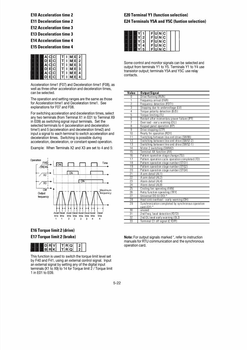
8/11/2019 GEI-100364
http://slidepdf.com/reader/full/gei-100364 75/154
5-22
E10 Acceleration time 2
E11 Deceleration time 2
E12 Acceleration time 3
E13 Deceleration time 3
E14 Acceleration time 4
E15 Deceleration time 4
E 1 0 A C C T I M E 2E 1 1 D E C T I M E 2
E 1 2 A C C T I M E 3
E 1 3 D E C T I M E 3
E 1 4 A C C T I M E 4
E 1 5 D E C T I M E 4
Acceleration time1 (F07) and Deceleration time1 (F08), aswell as three other acceleration and deceleration times,can be selected.
The operation and setting ranges are the same as thosefor Acceleration time1 and Deceleration time1. Seeexplanations for F07 and F08.
For switching acceleration and deceleration times, selectany two terminals (from Terminal X1 in E01 to Terminal X9in E09) as switching signal input terminals. Set theselected terminals to 4 (acceleration and decelerationtime1) and 5 (acceleration and deceleration time2) andinput a signal to each terminal to switch acceleration anddeceleration times. Switching is possible duringacceleration, deceleration, or constant speed operation.
Example: When Terminals X2 and X3 are set to 4 and 5:
E16 Torque limit 2 (drive)
E17 Torque limit 2 (brake)
E 1 6 D R V T R Q 2E 1 7 B R K T R Q 2
This function is used to switch the torque limit level setby F40 and F41, using an external control signal. Inputan external signal by setting any of the digital inputterminals (X1 to X9) to 14 for Torque limit 2 / Torque limit1 in E01 to E09.
E20 Terminal Y1 (function selection)
E24 Terminals Y5A and Y5C (funtion selection)
E 2 0 Y 1 F U N CE 2 1 Y 2 F U N CE 2 2 Y 3 F U N CE 2 3 Y 4 F U N CE 2 4 Y 5 F U N C
Some control and monitor signals can be selected andoutput from terminals Y1 to Y5. Terminals Y1 to Y4 usetransistor output; terminals Y5A and Y5C use relaycontacts.
Value Output Signal0 Drive Running (RUN)1 Frequency arrival (FAR)2 Frequency detection (FDT1)3 Stopping due to undervoltage (LV)
4 Torque polarity detection (B/D )5 Torque limiting (TL)6 Restart after momentary power failure (IPF)7 Overload - early warning (OLI)8 Keypad panel operation (KP)9 Drive stopping (STP)
10 Ready for operation (RDY)11 Switching between line and drive (SW88)12 Switching between line and drive (SW52-2)13 Switching between line and drive (SW52-1)14 Motor 2 switching (SWM2)15 Terminal AX function (AX)16 Pattern operation stage change (TU)17 Pattern operation cycle operation completed (TO)18 Pattern operation stage number (STG1)19 Pattern operation stage number (STG2)
20 Pattern operation stage number (STG4)21 Alarm detail (AL1)22 Alarm detail (AL2)23 Alarm detail (AL4)24 Alarm detail (AL8)25 Cooling fan operating (FAN)26 Retry function operating (TRY)27 Universal DO (U-DO) *28 Heat sink overheat - early warning (OH)
29 Synchronization completed by synchronous operationcard (SY) *
30 unused31 2nd Freq. level detect ion (FDT2)32 2nd OL level early warning (OL2)33 Terminal C1 off signal (C1OFF)
Note: For output signals marked *, refer to instructionmanuals for RTU communication and the synchronousoperation card.
8/11/2019 GEI-100364
http://slidepdf.com/reader/full/gei-100364 76/154
5-23
Drive running (RUN)
Value 0: The RUN signal is output when there is outputspeed (drive is outputting a frequency). When the DCinjection brake function is active, the RUN signal is off.
Frequency arrival (FAR)
Value 1: See the explanation for function code E30(frequency arrival [detection width]).
Frequency detection (FDT1)
Value 2: See the explanation for function codes E31 andE32 (frequency detection).
Stopping due to undervoltage (LV)
Value 3: If the undervoltage protective function activates,i.e. if the main circuit DC voltage falls below theundervoltage detection level, an ON signal is output. Thesignal goes off when the voltage recovers and increasesabove the detection level. The ON signal is retained aslong as the undervoltage protective function is active.
Undervoltage detection level: 230V series: 200V460V series: 400V
Torque polarity detection (B/D) Value 4: This function determines the torque polaritycalculated in the drive and outputs a signal indicatingdriving or braking torque. An OFF signal is output fordriving torque; an ON signal is output for braking torque.
Torque limiting (TL)
Value 5: When torque limiting is active, the stall preven-tion function is automatically activated to change theoutput frequency. The torque limiting signal is output tolighten the load and also used to display overloadconditions on the monitor device. This ON signal isoutput while the current or torque is limited or power
regeneration is prevented.Restart after momentary power failure (IPF)
Value 6: Following a momentary power failure, thisfunction reports the start of restart mode, the occurrenceof an automatic pull-in, and the completion of therecovery operation.
Following a momentary power failure, an ON signal isoutput when power is recovered and a synchronization(pull-in) operation is performed. The signal goes off aftera frequency level equal to that prior to power failure hasbeen recovered.
For 0 Hz restart at power recovery, no signal is output
because synchronization ends when power is recovered.The frequency is not recovered to the level before thepower failure occurred.
Overload early warning (OL1)
Value 7: Before the motor is stopped by a trip operationof an electronic thermal O/L relay, this function outputsan ON signal when the load reaches the overload earlywarning level.
Either the electronic thermal O/L relay early warning oroutput current overload early warning can be selected.
For setting procedure, see E33 Overload early warning(operation selection) and E34 Overload early warning(operation level).
Note: This function is only effective for Motor 1.
Keypad panel operation
Value 8: An ON signal is output when the operationcommand keys (FWD, REV and STOP) on the keypadpanel can be used (i.e., F02 Operation = 0) to issueoperation and stop commands.
Drive stopping (STOP)
Value 9: This function outputs an inverted signal to RUNto indicate zero speed. An ON signal is output when theDC injection brake function is operating.
Ready for operation (RDY)
Value 10: This function outputs an ON signal when thedrive is ready to operate. The drive is ready to operateafter the main circuit and control circuit power have beenestablished where the drive protective function is notactivated.
About one second is required from power-on to ready for
operation under normal conditions.
Switching between the AC line and the drive
(SW88)(SW52-2)(SW52-1) Value 11, 12, 13: To perform a transfer between the lineand the drive, the relay sequence can be accomplishedusing values 11, 12 and 13 on the “Y” outputs. Thesevalues will provide outputs that can be used for openingand closing contactors in the transfer sequence. For adetailed explanation of these outputs please refer to thefactory.
Motor 2 switching (SWM2)
Value 14: When a signal for switching to Motor 2 is inputfrom the terminal selected by Terminals X1 to X9, thisfunction selects and outputs the signal to switch themagnetic contactor for the motor. Since this switchingsignal is not output during running, including when the DCinjection braking function is operating, a signal must be re-input after output stops.
Terminal AX function (AX)
Value 15: When an operation command (FWD or REV) isentered, this function outputs an ON signal. When a stopcommand is entered, the signal goes off after drive outputstops. When a coast-to-stop command is entered, andthe drive protective function is operating, the signal goes
off immediately.Pattern operation stage change (TU)
Value 16: When the pattern operation stage changes, thisfunction outputs a one-shot, 100ms ON signal to report astage change.

8/11/2019 GEI-100364
http://slidepdf.com/reader/full/gei-100364 77/154
5-24
Pattern operation cycle operation completed(TO)
Value 17: After the seven stages of a pattern operationhave been completed, this function outputs a one-shot,100 ms ON signal to report the completion of all stages.
Pattern operation stage number
(STG1)(STG2)(STG4)
Value 18, 19, 20: During pattern operation, this function
reports the stage (operation process) being operated.
PatternOperationStage No. STG1 STG2 STG4Stage 1 on off off
Stage 2 off on offStage 3 on on off
Stage 4 off off onStage 5 on off on
Stage 6 off on on
Stage 7 on on on
Output Terminal
When pattern operation is not activated (i.e., no stage has
been selected), the terminals do not output a signal.Alarm detail (AL1)(AL2)(AL4)(AL8)
Value 21, 22, 23, 24: This function reports the operatingstatus of the drive protective function.
Alarm Detail
(Drive Protective Function AL1 AL2 AL4 AL8
Overcurrent, ground fault, blown fuse on off off off
Overvoltage off on off off
Undervoltage shortage, input phasefailure
on on off off
Motor 1 and Motor 2 overload off off on off
drive overload on off on offHeat sink overheating, driveoverheating internally
off on on off
External alarm input, braking resistoroverheating
on on on off
Memory error, CPU error off off off onKeypad panel communication error,o tion communication error
on off off on
Option error off on off on
Output wiring error off off on on
RTU communication error on off on on
Overspeed, PG disconnection off on on on
Output Terminal
Under normal operation, terminals do not output a signa
Cooling fan operating (FAN)
Value 25: When used with H06 Cooling fan ON/OFFcontrol, this function outputs a signal while the cooling fanis operating.
Retry function operating (TRY)
Value 26: When H04 Retry operating is set to 1 or higher,the signal is output during the retry operation, if the driveprotective function has been activated.
Universal DO(U-DO)
Value 27: Assigning a value of 27 to a transistor outputterminal renders the terminal a universal DO terminal.
This function enables ON/OFF through the RS485 andBUS option.
This function serves only to turn the transistor output onor off through communication and is not related to driveoperation.
Heat sink overheat early warning (OH) Value 28: This function outputs an early warning signalwhen the heat sink temperature (overheat detection level)is within 10°C of the overtemp trip point.
2nd Freq. level detection (FDT2)
Vallue 31: This function sets the 2nd Freq. level detection.See the explanation of Function Code E36 and E37Hysteresis width is same as FDT1 (E32).
2nd OL level early warning (OL2)
Value 32: This function sets the 2nd overload early
warning. See the explanation of “overload early warning(OL)”, E37.
Terminal C1 off signal (C1OFF)
Value 33: This function outputs an ON signal, when theC1 current input is smaller than 2mA.
Y1-Y5 SETTINGS WHEN SHIPPED FROM THE FACTORY
Digital Output
Value Description
Terminal Y1 0 Operating (RUN)
Terminal Y2 1 Frequency arrival (FAR)Terminal Y3 2 Frequency detection (FDT)
Terminal Y4 7 Overload early warning (OL)
Terminal Y5 15 Terminal AX function (AX)
Factory Setting at Shipment
E25 Y5 Ry operation mode
E 2 5 Y 5 R Y M O D E
This function specifies whether to excite the Y5 relay at“ON signal mode” or “OFF signal mode”
Set Value Operation
0 At “OFF signal mode” Y5A - Y5C: OFF
At “ON signal mode” Y5A - Y5C: ON
1 At “OFF signal mode” Y5A - Y5C: ON
At “ON signal mode” Y5A - Y5C: OFF

8/11/2019 GEI-100364
http://slidepdf.com/reader/full/gei-100364 78/154
5-25
E33 Overload early warning (operation)
E 3 3 O L L E V E L
Setting range: 0: Electronic thermal O/L relay
Select one of the following two types of overload earlywarning: early warning by electronic thermal O/L relayfunction or early warning by output current.1: Output current
Value Function Description0 Electronic
thermalO/L relay
Overload early warning by electronic thermalO/L relay (with inverse time characteristics)to output current. The operation selection andthermal time constant for the inverse timecharacteristics are the same as those of theelectronic thermal O/L relay for motorprotection (F10 and F12).
1 Outputcurrent
An overload early warning is issued whenoutput current exceeds the set current valuefor the set time.
E34 Overload early warning (operation level)
E 3 4 O L 1 L E V E LSetting range: Drive rated output current x (5 to 150%)
This function determines the operation level for theelectronic thermal O/L relay or output current.The operation release level is 90% of the set value.
E35 Overload early warning (operation time)
E 3 5 O L T I M E R
Setting range: 0.0 to 60.0 seconds
This function is used when E33 Overload early warning(operation selection) is set to 1.
Sets the time from when the operation level is attaineduntil the overload early warning function is activated.
E36 Frequency detection 2 (operation level)
E 3 6 F D T 2 L E V E L
This function determines the operation (detection) level 2of the output frequency for operation release. Thisfunction operates the same as “E31 Frequency detection1 (operation level)”. For details, see the explanation forE31.
E37 Overload early warning 2
(operationlevel)
E 3 7 O L 2 L E V E L
This function determines the operation level 2 of theoutput current. This function operates same as E33output current and E35 setting.
When the set value is 1, contacts Y5A and Y5C areconnected when the drive control voltage is established(about one second after power on).
E30 Frequency arrival (detection width)
E 3 0 F A R H Y S T R
Setting range: 0.0 to 10.0 Hz
This function adjusts the detection width when the output
frequency is the same as the set operating frequency. Thedetection width can be adjusted from 0 to ±10 Hz of thesetting frequency.
When the frequency is within the detection width, an ONsignal can be selected and output from terminals [Y1] to[Y5]
E31 Frequency detection (operation level)
E32 Frequency detection (hysteresis width)
E 3 1 F D T L E V E LE 3 2 F D T H Y S T R
Setting range (Operation level): 0 to 120 Hz
These functions determine the operation level of theoutput frequency and hysteresis width for operationrelease. If the output frequency exceeds the set operationlevel, an ON signal can be output from terminals Y1 to Y5.
(Hysteresis width): 0.0 to 30.0 Hz
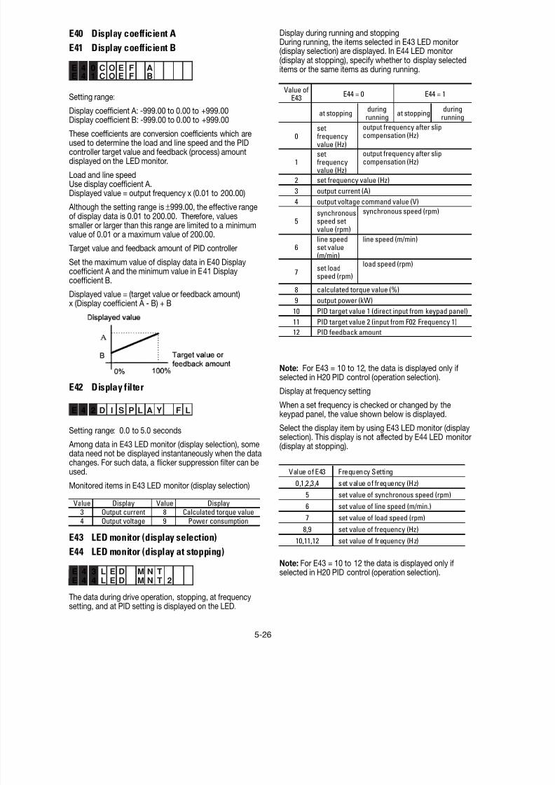
8/11/2019 GEI-100364
http://slidepdf.com/reader/full/gei-100364 79/154
5-26
E40 Display coefficient A
E41 Display coefficient B
E 4 0 C O E F AE 4 1 C O E F B
Setting range:
Display coefficient A: -999.00 to 0.00 to +999.00Display coefficient B: -999.00 to 0.00 to +999.00
These coefficients are conversion coefficients which areused to determine the load and line speed and the PIDcontroller target value and feedback (process) amountdisplayed on the LED monitor.
Load and line speedUse display coefficient A.Displayed value = output frequency x (0.01 to 200.00)
Although the setting range is±999.00, the effective rangeof display data is 0.01 to 200.00. Therefore, valuessmaller or larger than this range are limited to a minimumvalue of 0.01 or a maximum value of 200.00.
Target value and feedback amount of PID controller
Set the maximum value of display data in E40 Displaycoefficient A and the minimum value in E41 Displaycoefficient B.
Displayed value = (target value or feedback amount)x (Display coefficient A - B) + B
E42 Display filter
E 4 2 D I S P L A Y F L
Setting range: 0.0 to 5.0 seconds
Among data in E43 LED monitor (display selection), somedata need not be displayed instantaneously when the datachanges. For such data, a flicker suppression filter can beused.
Monitored items in E43 LED monitor (display selection)
Value Display Value Display3 Output current 8 Calculated torque value
4 Output voltage 9 Power consumption
E43 LED monitor (display selection)
E44 LED monitor (display at stopping)
E 4 3 L E D M N TE 4 4 L E D M N T 2
The data during drive operation, stopping, at frequencysetting, and at PID setting is displayed on the LED.
Display during running and stoppingDuring running, the items selected in E43 LED monitor(display selection) are displayed. In E44 LED monitor(display at stopping), specify whether to display selecteditems or the same items as during running.
Value ofE43
0setfrequencyvalue (Hz)
1setfrequencyvalue (Hz)
2
3
4
5synchronousspeed setvalue (rpm)
6line speedset value(m/min)
7set loadspeed (rpm)
8
9
10
11
12
output frequency after slipcompensation (Hz)
output frequency after slipcompensation (Hz)
E44 = 1E44 = 0
output power (kW)
set frequency value (Hz)
output current (A)
output voltage command value (V)
synchronous speed (rpm)
PID target value 1 (direct input from keypad panel)
PID target value 2 (input from F02 Frequency 1)
PID feedback amount
duringrunning
at stoppingduring
runningat stopping
line speed (m/min)
load speed (rpm)
calculated torque value (%)
Note: For E43 = 10 to 12, the data is displayed only if
selected in H20 PID control (operation selection).Display at frequency setting
When a set frequency is checked or changed by thekeypad panel, the value shown below is displayed.
Select the display item by using E43 LED monitor (displayselection). This display is not affected by E44 LED monitor(display at stopping).
Value of E43 Frequency Setting
0,1,2,3,4 set value of frequency (Hz)
5 set value of synchronous speed (rpm)
6 set value of line speed (m/min.)7 set value of load speed (rpm)
8,9 set value of frequency (Hz)
10,11,12 set value of frequency (Hz)
Note: For E43 = 10 to 12 the data is displayed only ifselected in H20 PID control (operation selection).

8/11/2019 GEI-100364
http://slidepdf.com/reader/full/gei-100364 80/154
5-27
E45 LCD monitor (display selection)
E 4 5 L C D M N T R
This function selects the items to be displayed on theLCD monitor in operation mode.
Value Display Items
0
Operation status, direction of rotation,operation guide
1
Output frequency before slip compensation,output current, calculated torque in bar graph
Set value: 0During running When stopping
E 4 6
E 4 7
E46 LCD monitor (language)
E 4 6 L A N G U A G E
This function selects the language for data display on theLCD monitor.
Value Language Value Language0 Japanese 3 French
1 English 4 Spanish
2 German 5 Italian
Note: English language is used for all LCD screens inthis manual.
E47 LCD monitor (contrast adjustment)
E 4 7 C O N T R A S T
This function adjusts the LCD contrast. Increase the setvalue to raise contrast and decrease to lower contrast.
Value 0, 1, 2 • • • • • • 8, 9, 10
Screen Low High
60.00
STOPPRG PRGMENU
F/D LED SHIFT
60.00
Hz
A
%
Fout/Iout/TRQ
60.00
RUN FWD
Set value: 1
Full scale value of bar graph
Display item Full scale
Output frequency Maximum frequencyOutput current 200% of drive rated valueCalculated torque value 200% of motor rated value
Note: The scale cannot be adjusted.

8/11/2019 GEI-100364
http://slidepdf.com/reader/full/gei-100364 81/154
5-28
This function makes the set frequency jump so that thedrive’s output frequency does not match the mechanicalresonance point of the load.
Up to three jump points can be set.
This function is ineffective if jump frequencies 1 to 3 areset to 0 Hz.
A jump does not occur during acceleration or decelera-tion.
If a jump frequency setting range overlaps another range,both ranges are added to determine the actual jump area.
C05-C19 Multi-step frequency 1 to 15
C 0 5 M U L T I H z – 1C 0 6 M U L T I H z – 2C 0 7 M U L T I H z – 3C 0 8 M U L T I H z – 4C 0 9 M U L T I H z – 5
C 1 0 M U L T I H z – 6C 1 1 M U L T I H z – 7C 1 2 M U L T I H z – 8C 1 3 M U L T I H z – 9C 1 4 M U L T I H z 1 0C 1 5 M U L T I H z 1 1C 1 6 M U L T I H z 1 2C 1 7 M U L T I H z 1 3C 1 8 M U L T I H z 1 4C 1 9 M U L T I H z 1 5
C01 Jump frequency 1
C02 Jump frequency 2
C03 Jump frequency 3
C04 Jump frequency hysteresis
C: Control Functions of Frequency
Jump frequency 3
➝
➝
Jump frequency 2
➝
➝
Output frequency(Hz)
Jump frequencywidth
Jump frequencywidth
Jump frequencywidth
Jump frequency 1
Set frequency (Hz)
➝
➝
➝
➝
➝
➝
➝
➝ ➝
➝
➝
➝
➝
➝ ➝
➝
➝
➝
➝
➝ ➝
➝
Output Frequency
(Hz)
FWD-CM
SS1-CM
SS2-CM
SS4-CM
SS8-CM
ON
ON ON ON ON ON ON ON ON
ON ON ON ON
ON ON
ON
C05
C13
C12
C11
C10
C09
C08
C07
C06
C14
C15
C16
C17
C18
C19
➝
➝
➝
➝
Jump frequency 2
Jump frequency 1
Set frequency (Hz)
Jump frequencywidth
➝
➝
➝
➝
➝
➝
Output frequency(Hz) ➝
➝
➝
➝
➝
➝
➝
➝
Actual jump width
Setting range: 0 to 120 Hz in 1Hz increments (min.)
C 0 4 J U M P H Y S T R
Setting range: 0 to 30 Hz in 1Hz increments (min.)
C 0 1 J U M P H z 1
C 0 2 J U M P H z 2
C 0 3 J U M P H z 3
Setting range: 0 to 120 Hz In 0.01 Hz increments (min.)
Multistep frequencies 1 to 15 can be switched by turningterminal functions SS1, SS2, SS4, and SS8 on and off.(See E01 to E09 for terminal function definitions.)
OFF is the default value any undefined SS1, SS2, SS4,and SS8 terminals.
Related functions: E01 to E09 (Set value: 0 to 3)
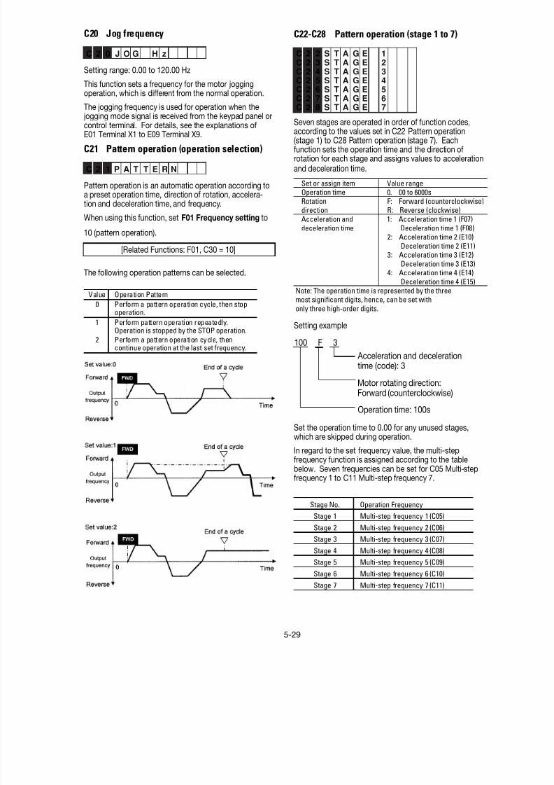
8/11/2019 GEI-100364
http://slidepdf.com/reader/full/gei-100364 82/154
5-29
C20 Jog frequency
C 2 0 J O G H z
Setting range: 0.00 to 120.00 Hz
This function sets a frequency for the motor joggingoperation, which is different from the normal operation.
The jogging frequency is used for operation when the jogging mode signal is received from the keypad panel or
control terminal. For details, see the explanations ofE01 Terminal X1 to E09 Terminal X9.
C21 Pattern operation (operation selection)
C 2 1 P A T T E R N
Pattern operation is an automatic operation according toa preset operation time, direction of rotation, accelera-tion and deceleration time, and frequency.
When using this function, set F01 Frequency setting to
10 (pattern operation).
[Related Functions: F01, C30 = 10]
The following operation patterns can be selected.
Value Operation Pattern
0 Perform a pattern operation cycle, then stopoperation.
1 Perform pattern operation repeatedly.Operation is stopped by the STOP operation.
2 Perform a pattern operation cycle, thencontinue operation at the last set frequency.
C22-C28 Pattern operation (stage 1 to 7)
C 2 2 S T A G E 1
C 2 3 S T A G E 2
C 2 4 S T A G E 3
C 2 5 S T A G E 4
C 2 6 S T A G E 5
C 2 7 S T A G E 6
C 2 8 S T A G E 7
Seven stages are operated in order of function codes,according to the values set in C22 Pattern operation(stage 1) to C28 Pattern operation (stage 7). Eachfunction sets the operation time and the direction ofrotation for each stage and assigns values to accelerationand deceleration time.
Set or assign item Value rangeOperation time 0. 00 to 6000s
Rotation F: Forward (counterclockwise)direction R: Reverse (clockwise)
Acceleration and 1: Acceleration time 1 (F07)
deceleration time Deceleration time 1 (F08)2: Acceleration time 2 (E10)
Deceleration time 2 (E11)
3: Acceleration time 3 (E12) Deceleration time 3 (E13)4: Acceleration time 4 (E14)
Deceleration time 4 (E15)
Note: The operation time is represented by the threemost significant digits, hence, can be set with
only three high-order digits.
Set the operation time to 0.00 for any unused stages,which are skipped during operation.
In regard to the set frequency value, the multi-stepfrequency function is assigned according to the tablebelow. Seven frequencies can be set for C05 Multi-stepfrequency 1 to C11 Multi-step frequency 7.
Stage No. Operation FrequencyStage 1 Multi-step frequency 1 (C05)
Stage 2 Multi-step frequency 2 (C06)
Stage 3 Multi-step frequency 3 (C07)
Stage 4 Multi-step frequency 4 (C08)
Stage 5 Multi-step frequency 5 (C09)
Stage 6 Multi-step frequency 6 (C10)
Stage 7 Multi-step frequency 7 (C11)
Setting example
100 F 3
Acceleration and decelerationtime (code): 3
Motor rotating direction:Forward (counterclockwise)
Operation time: 100s

8/11/2019 GEI-100364
http://slidepdf.com/reader/full/gei-100364 83/154

8/11/2019 GEI-100364
http://slidepdf.com/reader/full/gei-100364 84/154
5-31
Notes
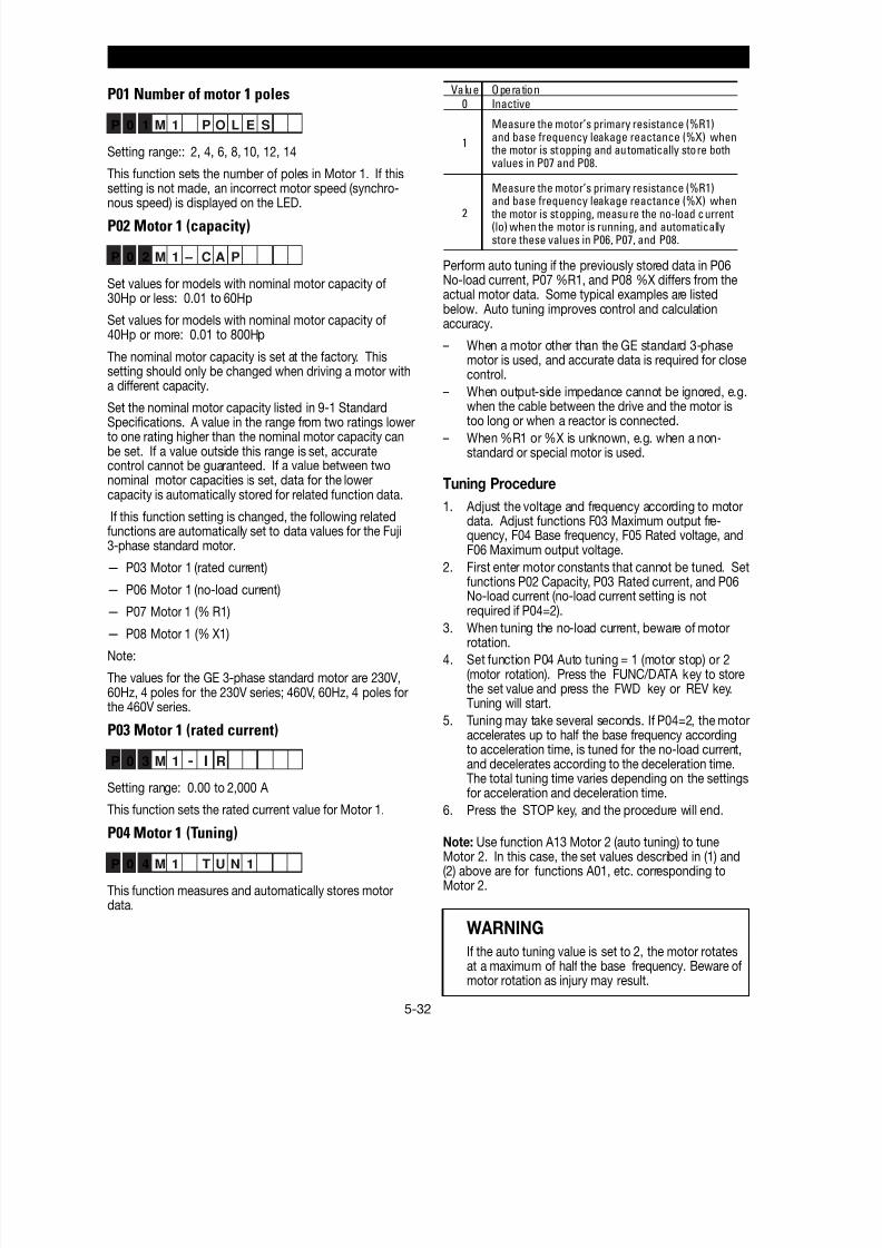
8/11/2019 GEI-100364
http://slidepdf.com/reader/full/gei-100364 85/154
5-32
Motor 1 (P: Motor Parameters)
P01 Number of motor 1 poles
P 0 1 M 1 P O L E S
Setting range:: 2, 4, 6, 8, 10, 12, 14
This function sets the number of poles in Motor 1. If thissetting is not made, an incorrect motor speed (synchro-
nous speed) is displayed on the LED.
P02 Motor 1 (capacity)
P 0 2 M 1 – C A P
Set values for models with nominal motor capacity of30Hp or less: 0.01 to 60Hp
Set values for models with nominal motor capacity of40Hp or more: 0.01 to 800Hp
The nominal motor capacity is set at the factory. Thissetting should only be changed when driving a motor witha different capacity.
Set the nominal motor capacity listed in 9-1 StandardSpecifications. A value in the range from two ratings lowerto one rating higher than the nominal motor capacity canbe set. If a value outside this range is set, accuratecontrol cannot be guaranteed. If a value between twonominal motor capacities is set, data for the lowercapacity is automatically stored for related function data.
If this function setting is changed, the following relatedfunctions are automatically set to data values for the Fuji3-phase standard motor.
— P03 Motor 1 (rated current)
— P06 Motor 1 (no-load current)
— P07 Motor 1 (% R1)
— P08 Motor 1 (% X1)
Note:
The values for the GE 3-phase standard motor are 230V,60Hz, 4 poles for the 230V series; 460V, 60Hz, 4 poles forthe 460V series.
P03 Motor 1 (rated current)
P 0 3 M 1 RI-
Setting range: 0.00 to 2,000 A
This function sets the rated current value for Motor 1.
P04 Motor 1 (Tuning)
P 0 4 M 1 T U N 1
This function measures and automatically stores motordata.
Perform auto tuning if the previously stored data in P06No-load current, P07 %R1, and P08 %X differs from theactual motor data. Some typical examples are listedbelow. Auto tuning improves control and calculationaccuracy.
– When a motor other than the GE standard 3-phasemotor is used, and accurate data is required for closecontrol.
– When output-side impedance cannot be ignored, e.g.when the cable between the drive and the motor istoo long or when a reactor is connected.
– When %R1 or %X is unknown, e.g. when a non-standard or special motor is used.
Tuning Procedure
1. Adjust the voltage and frequency according to motordata. Adjust functions F03 Maximum output fre-quency, F04 Base frequency, F05 Rated voltage, andF06 Maximum output voltage.
2. First enter motor constants that cannot be tuned. Setfunctions P02 Capacity, P03 Rated current, and P06
No-load current (no-load current setting is notrequired if P04=2).
3. When tuning the no-load current, beware of motorrotation.
4. Set function P04 Auto tuning = 1 (motor stop) or 2(motor rotation). Press the FUNC/DATA key to storethe set value and press the FWD key or REV key.Tuning will start.
5. Tuning may take several seconds. If P04=2, the motoraccelerates up to half the base frequency accordingto acceleration time, is tuned for the no-load current,and decelerates according to the deceleration time.The total tuning time varies depending on the settingsfor acceleration and deceleration time.
6. Press the STOP key, and the procedure will end.
Note: Use function A13 Motor 2 (auto tuning) to tuneMotor 2. In this case, the set values described in (1) and(2) above are for functions A01, etc. corresponding toMotor 2.
WARNING
If the auto tuning value is set to 2, the motor rotatesat a maximum of half the base frequency. Beware ofmotor rotation as injury may result.
Value Operation0 Inactive
1
Measure the motor’s primary resistance (%R1)and base frequency leakage reactance (%X) when
the motor is stopping and automatically store bothvalues in P07 and P08.
2
Measure the motor’s primary resistance (%R1)
and base frequency leakage reactance (%X) when the motor is stopping, measure the no-load current(lo) when the motor is running, and automaticallystore these values in P06, P07, and P08.
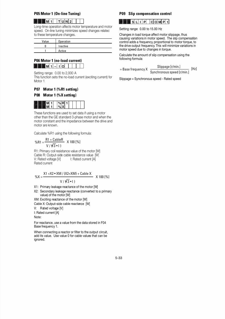
8/11/2019 GEI-100364
http://slidepdf.com/reader/full/gei-100364 86/154
5-33
P05 Motor 1 (On-line Tuning)
P 0 5 M 1 T U N 2
Long-time operation affects motor temperature and motorspeed. On-line tuning minimizes speed changes relatedto these temperature changes.
Value Operation
0 Inactive
1 Active
P06 Motor 1 (no-load current)
P 0 6 M 1 – I O
Setting range: 0.00 to 2,000 A This function sets the no-load current (exciting current) forMotor 1.
P07 Motor 1 (%R1 setting)
P08 Motor 1 (%X setting)
P 0 7 M 1 % R 1P 0 8 M 1 % X
These functions are used to set data if using a motorother than the GE standard 3-phase motor and when themotor constant and the impedance between the drive andmotor are known.
Calculate %R1 using the following formula:
%R1 =R1 + CableR
V / ( 3 • I )X 100 [%]
R1: Primary coil resistance value of the motor [W]
Cable R: Output-side cable resistance value [W] V: Rated voltage [V] I: Rated current [A]Rated current
%X =X1 +X2 • XM / (X2+XM) + Cable X
V / ( 3 • I )
X 100 [%]
X1: Primary leakage reactance of the motor [W]
X2: Secondary leakage reactance (converted to a primaryvalue) of the motor [W]
XM: Exciting reactance of the motor [W]
Cable X: Output-side cable reactance [W]V: Rated voltage [V]
I: Rated current [A]
Note:
For reactance, use a value from the data stored in F04Base frequency 1.
When connecting a reactor or filter to the output circuit,add its value. Use value 0 for cable values that can beignored.
P09 Slip compensation control
P 0 9 S L I P C O M P 1
Setting range: 0.00 to 15.00 Hz
Changes in load torque affect motor slippage, thuscausing variations in motor speed. The slip compensationcontrol adds a frequency, proportional to motor torque, tothe drive output frequency. This will minimize variations inmotor speed due to changes in torque.
Calculate the amount of slip compensation using thefollowing formula:
= Base frequency XSlippage [r/min.]
[Hz]Synchronous speed [r/min.]
Slippage = Synchronous speed - Rated speed
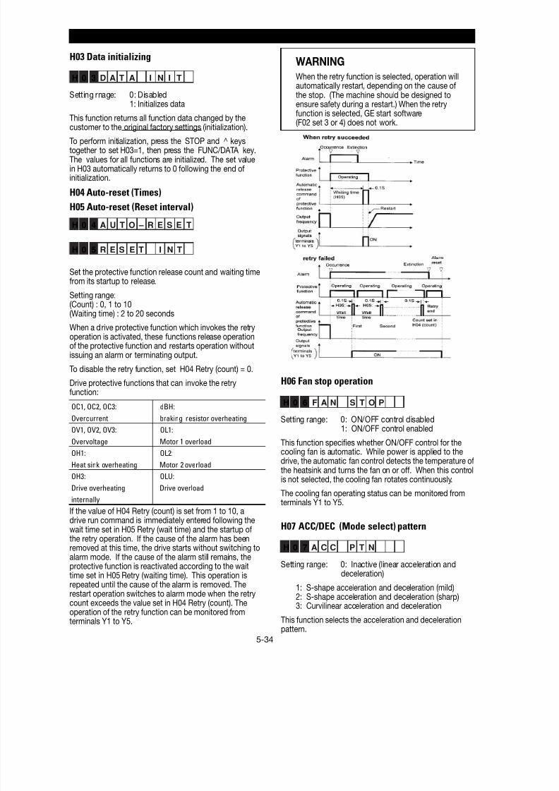
8/11/2019 GEI-100364
http://slidepdf.com/reader/full/gei-100364 87/154
5-34
H03 Data initializing
H 0 3 D A T A I N I T
Setting rnage: 0: Disabled1: Initializes data
This function returns all function data changed by the
customer to the original factory settings (initialization).To perform initialization, press the STOP and ^ keystogether to set H03=1, then press the FUNC/DATA key.The values for all functions are initialized. The set valuein H03 automatically returns to 0 following the end ofinitialization.
H04 Auto-reset (Times)
H05 Auto-reset (Reset interval)
H 0 4 A U T O – R E S E T
H 0 5 R E S E T I N T
Set the protective function release count and waiting timefrom its startup to release.
Setting range:(Count) : 0, 1 to 10(Waiting time) : 2 to 20 seconds
When a drive protective function which invokes the retryoperation is activated, these functions release operationof the protective function and restarts operation withoutissuing an alarm or terminating output.
To disable the retry function, set H04 Retry (count) = 0.
Drive protective functions that can invoke the retryfunction:
OC1, OC2, OC3: dBH:
Overcurrent braking resistor overheating
OV1, OV2, OV3: OL1:
Overvoltage Motor 1 overload
OH1: OL2:
Heat sink overheating Motor 2 overload
OH3: OLU:
Drive overheating Drive overload
internally
If the value of H04 Retry (count) is set from 1 to 10, adrive run command is immediately entered following thewait time set in H05 Retry (wait time) and the startup ofthe retry operation. If the cause of the alarm has beenremoved at this time, the drive starts without switching toalarm mode. If the cause of the alarm still remains, theprotective function is reactivated according to the waittime set in H05 Retry (waiting time). This operation isrepeated until the cause of the alarm is removed. Therestart operation switches to alarm mode when the retrycount exceeds the value set in H04 Retry (count). Theoperation of the retry function can be monitored fromterminals Y1 to Y5.
WARNING
When the retry function is selected, operation willautomatically restart, depending on the cause ofthe stop. (The machine should be designed toensure safety during a restart.) When the retryfunction is selected, GE start software(F02 set 3 or 4) does not work.
H06 Fan stop operation
H 0 6 F A N S T O P
Setting range: 0: ON/OFF control disabled1: ON/OFF control enabled
This function specifies whether ON/OFF control for thecooling fan is automatic. While power is applied to thedrive, the automatic fan control detects the temperature ofthe heatsink and turns the fan on or off. When this controlis not selected, the cooling fan rotates continuously.
The cooling fan operating status can be monitored fromterminals Y1 to Y5.
H07 ACC/DEC (Mode select) pattern
H 0 7 A C C P T N
Setting range: 0: Inactive (linear acceleration anddeceleration)
1: S-shape acceleration and deceleration (mild)2: S-shape acceleration and deceleration (sharp)3: Curvilinear acceleration and deceleration
This function selects the acceleration and decelerationpattern.
H: High Performance function
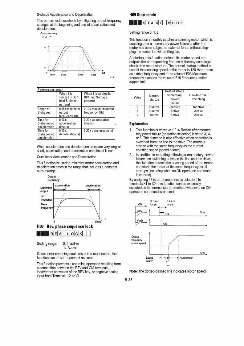
8/11/2019 GEI-100364
http://slidepdf.com/reader/full/gei-100364 88/154
5-35
S-shape Acceleration and Deceleration
This pattern reduces shock by mitigating output frequencychanges at the beginning and end of acceleration anddeceleration.
Pattern constants>When 1 isselcted in H07(mid S-shapepattern)
When 2 is selcted inH07 (mid S-shapepattern)
Range of
S-shaped
0.05 x maximum
outputfrequency (Hz)
0.10 x maximum output
frequency (Hz)
Time forS-shaped atacceleration
0.10 xacceleration
time (s)
0.20 x acceleration time (s)
Time forS-shaped atdeceleration
0.10 xdeceleration (s)
0.20 x deceleration (s)
*
When acceleration and deceleration times are very long orshort, acceleration and deceleration are almost linear.
Curvilinear Acceleration and Deceleration
This function is used to minimize motor acceleration and
deceleration times in the range that includes a constantoutput range.
H08 Rev. phase sequence lock
H 0 8 R E V L O C K
Setting range: 0: Inactive1: Active
If accidental reversing could result in a malfunction, thisfunction can be set to prevent reversal.
This function prevents a reversing operation resulting froma connection between the REV and CM terminals,inadvertent activation of the REV key, or negative analoginput from Terminals 12 or V1.
H09 Start mode
H 0 9 S T A R T M O D E
Setting range 0, 1, 2
This function smoothly catches a spinning motor which iscoasting after a momentary power failure or after themotor has been subject to external force, without stop-ping the motor, i.e. windmilling fan.
At startup, this function detects the motor speed andoutputs the corresponding frequency, thereby enabling ashock-free motor startup. The normal startup method isused if the coasting speed of the motor is 120 Hz or moreas a drive frequency and if the value of F03 Maximumfrequency exceeds the value of F15 Frequency limiter(upper limit).
Restart after amomentary Line-to-drive
power switchingfailure
0 Inactive Inactive Inactive
1 Inactive Active Active2 Active Active Active
Value Normalstartup
Explanation
1. This function is effective if F14 Restart after momen-tary power failure (operation selection) is set to 3, 4,or 5. This function is also effective when operation isswitched from the line to the drive. The motor isstarted with the same frequency as the currentcoasting speed (speed search).
2. In addition to restarting following a momentary powerfailure and switching between the line and the drive,this function detects the coasting speed of the motor
and starts the motor at the same frequency as allstartups (including when an ON operation commandis entered).
By assigning 26 (start characteristics selection) toterminals X1 to X9, this function can be externallyselected as the normal startup method whenever an ONoperation command is entered.
Note: The dotted-dashed line indicates motor speed.
deceleration
Outputfrequency
accelerationMaximumoutput
Setfrequency
Basefrequency
0 t [sec]
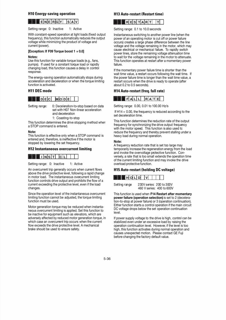
8/11/2019 GEI-100364
http://slidepdf.com/reader/full/gei-100364 89/154
5-36
H13 Auto-restart (Restart time)
H 1 3 R E S T A R T T
Setting range: 0.1 to 10.0 seconds
Instantaneous switching to another power line (when thepower of an operating motor is cut off or power failureoccurs) creates a large phase difference between the linevoltage and the voltage remaining in the motor, which maycause electrical or mechanical failure. To rapidly switchpower lines, store the remaining voltage attenuation timeto wait for the voltage remaining in the motor to attenuate.This function operates at restart after a momentary powerfailure.
If the momentary power failure time is shorter than thewait time value, a restart occurs following the wait time. Ifthe power failure time is longer than the wait time value, arestart occurs when the drive is ready to operate (afterabout 0.2 to 0.5 seconds).
H14 Auto-restart (freq. fall rate)
H 1 4 F A L L R A T E
Setting range: 0.00, 0.01 to 100.00 Hz/s
If H14 = 0.00, the frequency is reduced according to theset deceleration time.
This function determines the reduction rate of the outputfrequency for synchronizing the drive output frequencywith the motor speed. This function is also used toreduce the frequency and thereby prevent stalling under aheavy load during normal operation.
Note: A frequency reduction rate that is set too large maytemporarily increase the regeneration energy from the loadand invoke the overvoltage protective function. Con-versely, a rate that is too small extends the operation timeof the current limiting function and may invoke the driveoverload protective function.
H15 Auto-restart (holding DC voltage)
H 1 5 H O L D V
Setting range 230V series: 200 to 300V460 V series: 400 to 600V
This function is used when F14 Restart after momentary power failure (operation selection) is set to 2 (decelera-tion-to-stop at power failure) or 3 (operation continuation).
Either function starts a control operation if the main circuitDC voltage drops below the set operation continuationlevel.
If power supply voltage to the drive is high, control can bestabilized even under an excessive load by raising theoperation continuation level. However, if the level is toohigh, this function activates during normal operation andcauses unexpected motion. Please contact GE Fujibefore changing the factory default value.
H10 Energy-saving operation
H 1 0 E N E R G Y S A V
Setting range: 0: Inactive 1: Active
With constant-speed operation at light loads (fixed outputfrequency), this function automatically reduces the outputvoltage while minimizing the product of voltage andcurrent (power).
[Exception: If F09 Torque boost 1 = 0.0]Notes:Use this function for variable torque loads (e.g., fans,pumps). If used for a constant torque load or rapidlychanging load, this function causes a delay in controlresponse.
The energy-saving operation automatically stops duringacceleration and deceleration or when the torque limitingfunction is activated.
H11 DEC mode
H 1 1 D E C M O D E
Setting range: 0: Deceleration-to-stop based on dataset with H07 Non-linear accelerationand deceleration
1: Coasting-to-stop
This function determines the drive stopping method whena STOP command is entered.
Note:This function is effective only when a STOP command isentered and, therefore, is ineffective if the motor isstopped by lowering the set frequency.
H12 Instantaneous overcurrent limiting
H 1 2 I N S T C L
Setting range: 0: Inactive 1: Active
An overcurrent trip generally occurs when current flowsabove the drive protective level, following a rapid changein motor load. The instantaneous overcurrent limitingfunction controls drive output and prohibits the flow of acurrent exceeding the protective level, even if the loadchanges.
Since the operation level of the instantaneous overcurrentlimiting function cannot be adjusted, the torque limitingfunction must be used.
Motor generation torque may be reduced when instanta-neous overcurrent limiting is applied. Set this function tobe inactive for equipment such as elevators, which areadversely affected by reduced motor generation torque, inwhich case an overcurrent trip occurs when the currentflow exceeds the drive protective level. A mechanicalbrake should be used to ensure safety.
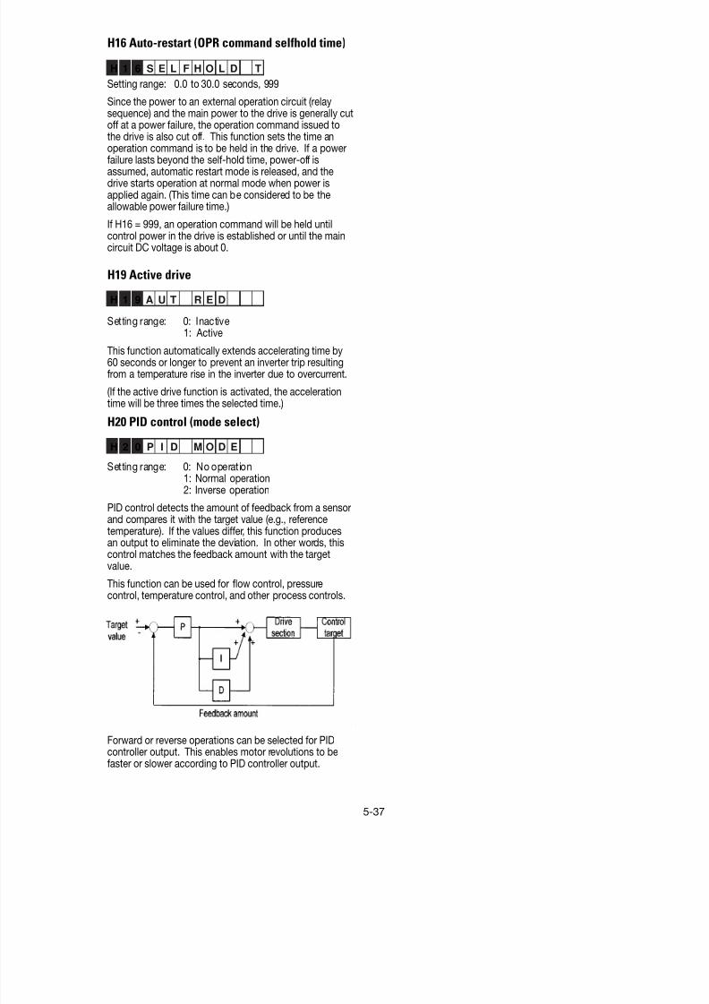
8/11/2019 GEI-100364
http://slidepdf.com/reader/full/gei-100364 90/154
5-37
H16 Auto-restart (OPR command selfhold time)
H 1 6 S E L F H O L D T
Setting range: 0.0 to 30.0 seconds, 999
Since the power to an external operation circuit (relaysequence) and the main power to the drive is generally cutoff at a power failure, the operation command issued tothe drive is also cut off. This function sets the time anoperation command is to be held in the drive. If a power
failure lasts beyond the self-hold time, power-off isassumed, automatic restart mode is released, and thedrive starts operation at normal mode when power isapplied again. (This time can be considered to be theallowable power failure time.)
If H16 = 999, an operation command will be held untilcontrol power in the drive is established or until the maincircuit DC voltage is about 0.
H19 Active drive
H 1 9 A U T R E D
Setting range: 0: Inactive1: Active
This function automatically extends accelerating time by60 seconds or longer to prevent an inverter trip resultingfrom a temperature rise in the inverter due to overcurrent.
(If the active drive function is activated, the accelerationtime will be three times the selected time.)
H20 PID control (mode select)
H 2 0 P I D M O D E
Setting range: 0: No operation1: Normal operation2: Inverse operation
PID control detects the amount of feedback from a sensorand compares it with the target value (e.g., referencetemperature). If the values differ, this function producesan output to eliminate the deviation. In other words, thiscontrol matches the feedback amount with the targetvalue.
This function can be used for flow control, pressurecontrol, temperature control, and other process controls.
Forward or reverse operations can be selected for PIDcontroller output. This enables motor revolutions to befaster or slower according to PID controller output.
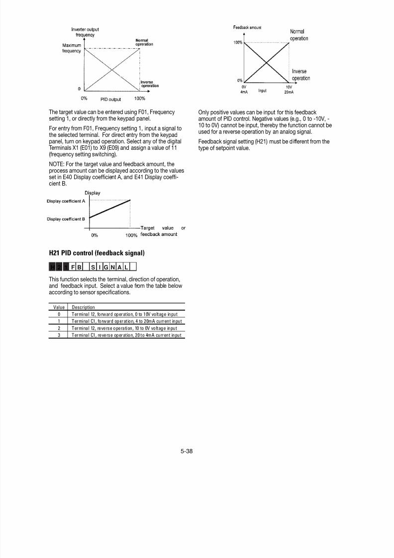
8/11/2019 GEI-100364
http://slidepdf.com/reader/full/gei-100364 91/154
5-38
The target value can be entered using F01, Frequencysetting 1, or directly from the keypad panel.
For entry from F01, Frequency setting 1, input a signal tothe selected terminal. For direct entry from the keypadpanel, turn on keypad operation. Select any of the digitalTerminals X1 (E01) to X9 (E09) and assign a value of 11(frequency setting switching).
NOTE: For the target value and feedback amount, theprocess amount can be displayed according to the values
set in E40 Display coefficient A, and E41 Display coeffi-cient B.
H21 PID control (feedback signal)
H 2 1 F B S I G N A L
This function selects the terminal, direction of operation,and feedback input. Select a value from the table belowaccording to sensor specifications.
Value Description
0 Terminal 12, forward operation, 0 to 10V voltage input
1 Terminal C1, forward operation, 4 to 20mA current input
2 Terminal 12, reverse operation, 10 to 0V voltage input
3 Terminal C1, reverse operation, 20 to 4mA current input
Only positive values can be input for this feedbackamount of PID control. Negative values (e.g., 0 to -10V, -10 to 0V) cannot be input, thereby the function cannot beused for a reverse operation by an analog signal.
Feedback signal setting (H21) must be different from thetype of setpoint value.

8/11/2019 GEI-100364
http://slidepdf.com/reader/full/gei-100364 92/154
5-39
H22 PID control (P-gain)
H23 PID control (I-gain)
H24 PID control (D-gain)
These functions are not generally used alone but arecombined like P control, PI control, PD control, and PIDcontrol.
P-gain operation
An operation using an output frequency proportional todeviation is called P operation, which outputs anoperation amount proportional to deviation, though it
cannot eliminate deviation alone.
H 2 2 P – G A I N
Setting range: 0.01 to 10.0 times
P (gain) is the parameter that determines the response
level for the deviation of P operation. Although anincrease in gain speeds up response, an excessive gaincauses vibration, and a decrease in gain delays re-sponse.
I-gain operation
An operation where the change speed of the outputfrequency is proportional to the deviation is called an I
operation. An I operation outputs an operation amount asthe integral of deviation and, therefore, has the effect ofmatching the feedback control amount to the target value(e.g., set frequency), though it deteriorates response forsignificant changes in deviation.
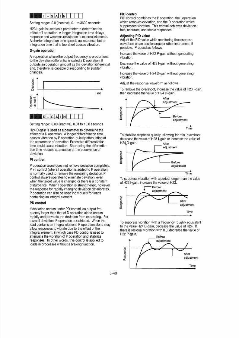
8/11/2019 GEI-100364
http://slidepdf.com/reader/full/gei-100364 93/154
5-40
H 2 3 I – G A I N
Setting range: 0.0 (Inactive), 0.1 to 3600 seconds
H23 I-gain is used as a parameter to determine theeffect of I operation. A longer integration time delaysresponse and weakens resistance to external elements. A shorter integration time speeds up response, but anintegration time that is too short causes vibration.
D-gain operation
An operation where the output frequency is proportionalto the deviation differential is called a D operation. Itoutputs an operation amount as the deviation differentialand, therefore, is capable of responding to suddenchanges.
H 2 4 D – G A I N
Setting range: 0.00 (Inactive), 0.01 to 10.0 seconds
H24 D-gain is used as a parameter to determine theeffect of a D operation. A longer differentiation timecauses vibration by P operation quickly attenuating atthe occurrence of deviation. Excessive differentiationtime could cause vibration. Shortening the differentia-tion time reduces attenuation at the occurrence ofdeviation.
PI control
P operation alone does not remove deviation completely.P + I control (where I operation is added to P operation)is normally used to remove the remaining deviation. PIcontrol always operates to eliminate deviation, evenwhen the target value is changed or there is a constantdisturbance. When I operation is strengthened, however,the response for rapidly changing deviation deteriorates.P operation can also be used individually for loadscontaining an integral element.
PD control
If deviation occurs under PD control, an output fre-quency larger than that of D operation alone occurs
rapidly and prevents the deviation from expanding. Fora small deviation, P operation is restricted. When theload contains an integral element, P operation alone mayallow responses to vibrate due to the effect of theintegral element, in which case PD control is used toattenuate the vibration of P operation and stabilizeresponses. In other words, this control is applied toloads in processes without a braking function.
PID controlPID control combines the P operation, the I operationwhich removes deviation, and the D operation whichsuppresses vibration. This control achieves deviation-free, accurate, and stable responses.
Adjusting PID value Adjust the PID value while monitoring the responsewaveform on an oscilloscope or other instrument, ifpossible. Proceed as follows:
Increase the value of H22 P-gain without generatingvibration.
Decrease the value of H23 I-gain without generatingvibration.
Increase the value of H24 D-gain without generatingvibration.
Adjust the response waveform as follows:
To remove the overshoot, increase the value of H23 I-gain,then decrease the value of H24 D-gain.
To stabilize response quickly, allowing for min. overshoot,decrease the value of H23 I-gain or increase the value ofH24 D-gain.
To suppress vibration with a period longer than the valueof H23 I-gain, increase the value of H23.
To suppress vibration with a frequency roughly equivalentto the value H24 D-gain, decrease the value of H24. Ifthere is residual vibration with 0.0, decrease the value ofH22 P-gain.

8/11/2019 GEI-100364
http://slidepdf.com/reader/full/gei-100364 94/154
5-41
H25 PID control (Feedback filter)
H 2 5 F B F I L T E R
Setting range: 0.0 to 60.0 seconds
This filter is for feedback signal input from Terminals 12 orC1. This filter stabilizes operation of the PID controlsystem. A set value that is too large, however, deterio-rates response.
H26 PTC thermistor (mode select)
H 2 6 P T C M O D E
Setting range: 0: Inactive1: Active
Set this function active when the motor has a PTCthermistor for overheat protection
Connect the PTC thermistor as shown in the figure below.Turn on switch PTC on the control PCB. The trip mode isactivated by OH2: External thermal relay tripped.
Note: Must be 0 setting when using 4-20mA reference orfeedback signal and the PTC switch must be off.
H27 PTC thermistor (level select)
H 2 7 P T C L E V E L
Setting range: 0.00 to 5.00V
The voltage input to Terminal C1 is compared to the setvoltage level. If the input voltage is equal to or greaterthan the set voltage, H26 PTC thermistor (Mode select)starts.
The PTC thermistor has its own alarm temperature. Theinternal resistance value of the thermistor largely changesat the alarm temperature. The operation voltage level isset using this change in the resistance value.
The figure above for H26 PTC thermistor (Mode select)shows that a 250W resistor and the thermistor (resistancevalue Rp) are connected in parallel. Hence, voltage Vc1 atTerminal C1 can be calculated using the following formula:
Vc1 X 10 [V]
250 • Rp
250 + Rp
1000+250 • Rp
250 + Rp
The operation level can be set by bringing Rp in the Vc1calculation formula into the following range.
Rp1 < Rp < Rp2
To calculate Rp, use the following formula:
RpRp1 + Rp2
[Ohm]2
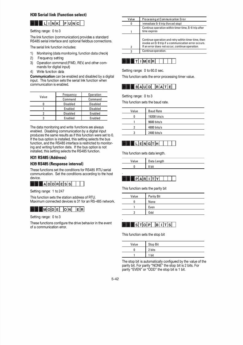
8/11/2019 GEI-100364
http://slidepdf.com/reader/full/gei-100364 95/154
5-42
H30 Serial link (Function select)
H 3 0 L I N K F U N C
Setting range: 0 to 3
The link function (communication) provides a standardRS485 serial interface and optional fieldbus connections.
The serial link function includes:
1) Monitoring (data monitoring, function data check)
2) Frequency setting
3) Operation command (FWD, REV, and other com-mands for digital input)
4) Write function data
Communication can be enabled and disabled by a digitalinput. This function sets the serial link function whencommunication is enabled.
Frequency Operation
Command Command
0 Disabled Disabled
1 Enabled Disabled
2 Disabled Enabled
3 Enabled Enabled
Value
The data monitoring and write functions are alwaysenabled. Disabling communication by a digital inputproduces the same results as if this function were set to 0.If the bus option is installed, this setting selects the busfunction, and the RS485 interface is restricted to monitor-ing and writing function data. If the bus option is notinstalled, this setting selects the RS485 function.
H31 RS485 (Address)
H39 RS485 (Response interval)
These functions set the conditions for RS485 RTU serialcommunication. Set the conditions according to the hostdevice.
H 3 1 A D D R E S S
Setting range: 1 to 247
This function sets the station address of RTU.Maximum connected devices is 31 for an RS-485 network.
H 3 2 M O D E O N E R
Setting range: 0 to 3
These functions configure the drive behavior in the eventof a communication error.
Value Processing at Communication Error
0 Immediate Er 8 trip (forced stop)
1
Continue operation within timer time, Er 8 trip after time expires
2
Continue operation and retry within timer time, theninvoke an Er 8 trip if a communication error occurs.If an error does not occur, continue operation.
3 Continue operation.
H 3 3 T I M E R
Setting range: 0 to 60.0 sec.
This function sets the error processing timer value.
H 3 4 B A U D R A T E
Setting range: 0 to 3
This function sets the baud rate.
Value Baud Rate0 19200 bits/s
1 9600 bits/s
2 4800 bits/s
3 2400 bits/s
H 3 5 L E N G T H
This function sets data length.
Value Data Length
0 8 bit
.
H 3 6 P A R I T Y
This function sets the parity bit
Value Parity Bit
0 None
1 Even
2 Odd
.
H 3 7 S T O P B I T S
This function sets the stop bit
Value Stop Bit
0 2 bits
1 1 bit
The stop bit is automatically configured by the value of theparity bit. For parity “NONE” the stop bit is 2 bits. Forparity “EVEN” or “ODD” the stop bit is 1 bit.

8/11/2019 GEI-100364
http://slidepdf.com/reader/full/gei-100364 96/154
5-43
H 3 8 N O R E S T
Setting range: 0 (no detection)
1 to 60 seconds
In a system where the drive is continuously polled within aspecific time, this function detects that access wasstopped due to an open circuit or other network fault andresults in an Er 8 trip.
H 3 9 I N T E R V A L
Setting range: 0.00 to 1.00 second
This function sets the time from when a request is issuedfrom the host device to when a response is returned.

8/11/2019 GEI-100364
http://slidepdf.com/reader/full/gei-100364 97/154

8/11/2019 GEI-100364
http://slidepdf.com/reader/full/gei-100364 98/154
5-45
A13 Motor 2 (Tuning)
A 1 3 M 2 T U N 1
This function sets online tuning for Motor 2. It operates
the same as for P04 Motor 1 (Tuning). For details, see the
explanation for P04.
A14 Motor 2 (On-line tuning)
A 1 4 M 2 T U N 2
This function sets online tuning for Motor 2. It operates
the same as P05 Motor 1 (On-line tuning). For details, see
the explanation for P05.
A15 Motor 2 (No-load current)
A 1 5 M 2 I O
This function sets the no-load current for Motor 2. Itoperates the same as P06 Motor 1 (No-load current). For
details, see the explanation for P06.
A16 Motor 2 (%R1 setting)
A17 Motor 2 (%X setting)
A 1 6 M 2 – % R 1
A 1 7 M 2 – % X
These functions set %R1 and %X for Motor 2. It operates
the same as P07 Motor 1 (%R1 setting) and P08 Motor 1(%X setting). For details, see the explanations for P07 and
P08.
A18 Slip compensation control 2
A 1 8 S L I P C O M P 2
This function sets the amount of slip compensation for
Motor 2. It operates the same as P09 Slip compensation
control. For details, see the explanation for P09.

8/11/2019 GEI-100364
http://slidepdf.com/reader/full/gei-100364 99/154
5-46
Notes

8/11/2019 GEI-100364
http://slidepdf.com/reader/full/gei-100364 100/154
6-1Data subject to change without notice 7/07. © 2007 GE Drives
6. Protective Operations
LED LCD
OC1 OC DURING ACC During acceleration
OC2 OC DURING DEC During deceleration
OC3 OC AT SET SPDRunning at constantspeed
Ground fault EF GROUND FAULT
Running at constantspeed
Undervoltage LU UNDERVOLTAGE
Input phase loss Lin PHASE LOSS
Overheating of heatsink
OH1 FIN OVERHEAT
External alarm OH2 EXT ALARM
Overheating
internally OH3 HIGH AMB TEMP
Overheating ofbraking resistor
dbH DBR OVERHEAT
Motor 1 overload OL1 MOTOR1 OL
Motor 2 overload OL2 MOTOR2 OL
Drive overload OLU INVERTER OL
Blown fuse FUS DC FUSE OPEN
Memory error Er1 MEMORY ERRORKeypad panel
communicationerror
Er2 KEYPD COM ERR
CPU error Er3 CPU ERROR
Option error Er4 OPTN COM ERR
Er5 OPTION ERROR
Operating error Er6 OPR PROCD ERR
Output wiring error Er7 TUNING ERROR
Modbus RTU error Er8 RS485 COM ERR If an error occurs while using Modbus-RTU, the protective function is activated.
Error occurred while using an optional unit.
During acceleration
During deceleration
If a CPU error occurs due to noise, etc., the protective function is activated.
Detects drive operating procedure error during drive startup. FWD or REV connected to terminal CMwhen Main power is applied to drive (F02 setting 3 or 4). Stop key on keypad is pressed in terminaloperation (F02 setting 1 or 3). Detected timed alarm stop command.
If there is an open circuit or connection error in the inverter output wiring during an auto-tuningprocedure, the protective function is activated.
If a communication error or interrupt between the keypad panel and control circuit is detected, theprotective function is activated.
If the fuse in the inverter is blown out following a short-circuit or damage to the internal circuit, theprotective function is activated (for 40 Hp or more only).
If a memory error occurs, such as missing or invalid data, the protective function is activated.
If the inverter output current momentarily exceeds the overcurrent detectionlevel, due to an overcurrent in the motor, or a short-circuit or ground fault in theoutput circuit, the protective function is activated during heavy load.
If the DC link voltage in the main circuit exceeds the overvoltage detection level(230V series: 400V DC, 460V series: 800V DC), due to an increase in theregenerating current from the motor, the output is shut down. However,protection against inadvertent overvoltage (e.g., high-voltage line) may not beprovided
If the DC link voltage in the main circuit falls below the undervoltage detection level (230V series: 400VDC, 460V series: 800V DC) due to a lowered power supply, the output is shut down. If function F14Restart after momentary power failure was selected, an alarm is not displayed. In addition, if the supplyvoltage falls to a level unable to maintain control power, an alarm may not be displayed.
If a ground fault in the inverter output circuit is detected, the protective function is activated (for 40 Hpor more only). If a ground fault occurs in an inverter rated at 30 Hp or less, the inverter is protected by
the overcurrent protection. If protection against personal injury or property damage is required, installa separate ground-fault protective relay or ground leakage circuit breaker.
Table 6.1.1 List of Alarms and Causes
The protective function is activated if the motor current exceeds the preset level, provided thatelectronic thermal O/L relay 1 function F10 has been selected.
If the external alarm contacts on the braking unit, braking resistor, or external thermal O/L relay areconnected to the control circuit terminals (THR), the contacts will be actuated according to contactsignals.
If the temperature inside the inverter rises due to poor ventilation, etc., the protective function is
activated.If electronic thermal O/L relay (for braking resistor) function F13 is selected, the protective function isactivated to prevent the resistor from burning due to overheating caused by frequent use of the brakingresistor.
If input power L1/R, L2/S and L3/T has any phase of the 3 phase power "OPEN" or if there is a significantdisparity between the phases, the retifying diodes or smoothing capacitors may be damaged. An Alarmis displayed and the protective function is activated during heavy load.
If the temperature of the heat sink rises due to a cooling fan failure, or the temperature of the heatsinkis too low, the protective function is activated during heavy load.
Keypad Panel DisplayCause of Activation
OV DURING ACC
Alarm Name
If the second motor current exceeds the preset level when the operation is switched to drive thesecond motor, the protective function is activated, provided that electronic thermal O/L relay 2 offunction A04 was selected.
If the output current exceeds the rated overload current, the protective function is activated to provide thermal protection against overheating of the semiconductor elements in the inverter’s main circuit.
OV DURING DEC
OV AT SET SPD
Overcurrent
OU1
OU2
OU3
Overvoltage
Note: Number in fron of Alarm Code indicates multiple alarms. See page 4-15.
6.1 List of Protective Functions
In the event of an abnormality in the inverter’s operation, the protective function will activate immediately to trip theinverter and display the alarm name on the LED monitor while the motor coasts to a stop. A list of the alarms with theirexplanations is included in the table below, and troubleshooting charts in Section 7.

8/11/2019 GEI-100364
http://slidepdf.com/reader/full/gei-100364 101/154
6-2Data subject to change without notice 7/07. © 2007 GE Drives
6.2 Alarm Reset
To release the trip status, enter the reset command bypressing the RESET key on the keypad panel or sendingthe appropriate signal to the RST terminal after removingthe cause of the trip. Since the reset command is anedge operation, input a command sequence such asOFF-ON-OFF as shown in Fig.6-2-1.
When releasing the trip status, set the operation com-mand to OFF. If the operation command is set to ON,
inverter will start operation after resetting.
10ms or more
OFF ON OFFReset command
Keypad panel display
Alarm output Alarm display
Normal display(Operable)
OFF ON OFF
TripFig. 6-2-1
WARNING
If the alarm reset is activated with the operation signal ON, the inverter will restart suddenly,which may be dangerous. To ensure safety, disable the operating signal when releasing the trip status,as accident may result.

8/11/2019 GEI-100364
http://slidepdf.com/reader/full/gei-100364 102/154
7-1Data subject to change without notice 7/07. © 2007 GE Drives
7. Troubleshooting
7.1 Activation of Protective Function
(1) Overcurrent
Overcurrent duringacceleration OC1
(2) Ground fault
(3) Fuse brown
Note: The ground fault protective function is provided only for drive for nominal applied motors rated at40 HP or more.
Overcurrent duringdeceleration OC2
Overcurrent running atconstant speed OC3
Are the motor connecting terminals (U, V, W) short-circuited or grounded?
Is the load excessive?
Overcurrent duringacceleration OC1
Is the acceleration timesetting too short
compared with the load?
Is the deceleration timesetting too short
compared with the load?
Has the load changedsuddenly?
Can the acceleration timesetting be prolonged?
Remove the short-circuitand ground fault.
Reduce the load or increasethe drive capacity?
Can the torque boostamount be reduced?
Reduce the torque boost.
Faulty drive or error due tonoise. Consult with GE Drive.
Prolong time settings.
Reduce the load or increasethe drive capacity.
Can the deceleration timesetting be prolonged?
The braking methodrequires inspection.Contact GE Drive.
Remove the grounded part.
Ground faultEF
Is a part in the drive output circuit(cable, motor) grounded?
Faulty drive or error due to noise.Contact GE Drivei.
Reduce the load or increasethe drive capacity.
Possible short-circuitwithin the drive.
Contact GE Drive.
Fuse brownFUS
YES
NO
YES
YES
NO
NO
NONONO
NO
NO
YES
YES
YES
YES
NO
NO
YES
NO
YES
NO
YES
NO

8/11/2019 GEI-100364
http://slidepdf.com/reader/full/gei-100364 103/154

8/11/2019 GEI-100364
http://slidepdf.com/reader/full/gei-100364 104/154
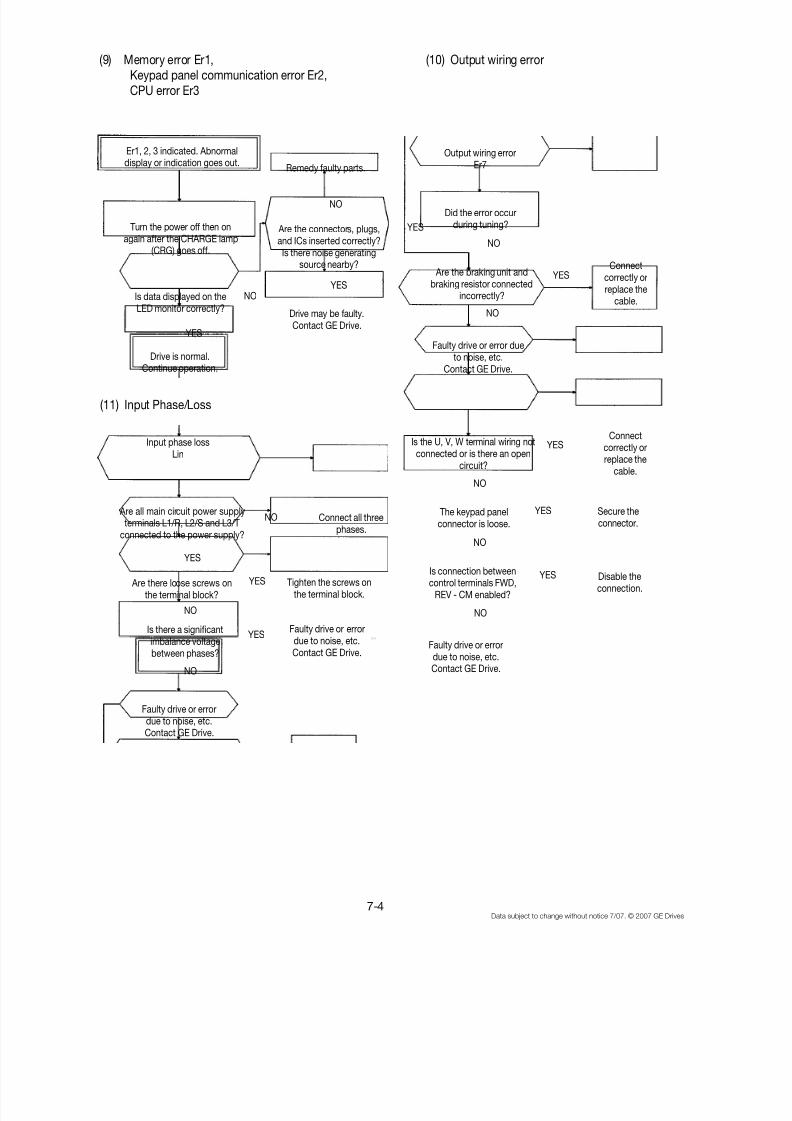
8/11/2019 GEI-100364
http://slidepdf.com/reader/full/gei-100364 105/154
7-4Data subject to change without notice 7/07. © 2007 GE Drives
(9) Memory error Er1, Keypad panel communication error Er2, CPU error Er3
(10) Output wiring error
(11) Input Phase/Loss
Remedy faulty parts.
Er1, 2, 3 indicated. Abnormaldisplay or indication goes out.
Are there loose screws onthe terminal block?
Turn the power off then onagain after the CHARGE lamp
(CRG) goes off.
Is data displayed on theLED monitor correctly?
Drive is normal.Continue operation.
Are the connectors, plugs,and ICs inserted correctly?Is there noise generating
source nearby?
Drive may be faulty.Contact GE Drive.
Output wiring errorEr7
Did the error occurduring tuning?
Are the braking unit andbraking resistor connected
incorrectly?
Faulty drive or error due
to noise, etc.Contact GE Drive.
Connectcorrectly orreplace the
cable.
Input phase lossLin
Are all main circuit power supplyterminals L1/R, L2/S and L3/T
connected to the power supply?
Is the U, V, W terminal wiring notconnected or is there an open
circuit?
The keypad panelconnector is loose.
Connect all threephases.
Connectcorrectly orreplace the
cable.
Secure theconnector.
Disable theconnection.
Is connection betweencontrol terminals FWD,
REV - CM enabled?
Tighten the screws onthe terminal block.
Faulty drive or errordue to noise, etc.Contact GE Drive.
Is there a significantimbalance voltagebetween phases?
Faulty drive or errordue to noise, etc.Contact GE Drive.
Faulty drive or error
due to noise, etc.Contact GE Drive.
YES
YES
NO
NO
NO
NO
YES
YES
YES
YES
YES
NO
NO
NO
YES
YES
YES
NO
NO
NO
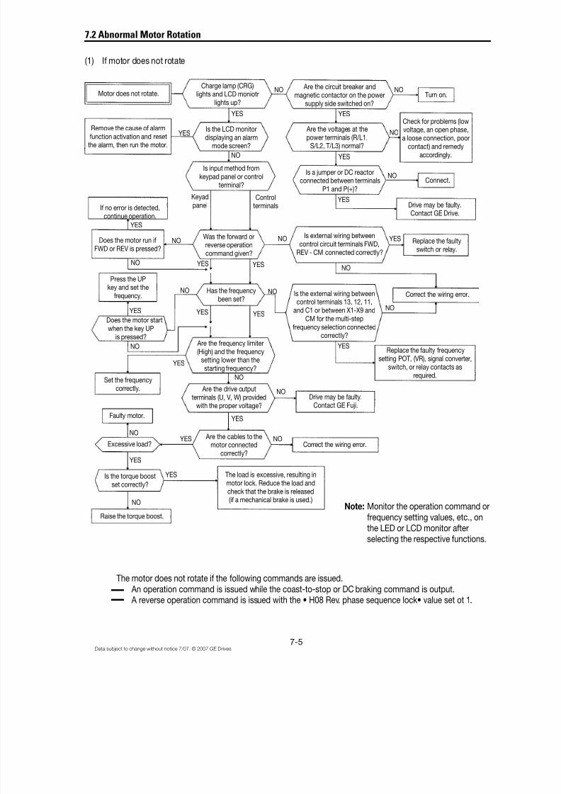
8/11/2019 GEI-100364
http://slidepdf.com/reader/full/gei-100364 106/154
7-5Data subject to change without notice 7/07. © 2007 GE Drives
Check for problems (low
voltage, an open phase,a loose connection, poor
contact) and remedyaccordingly.
7.2 Abnormal Motor Rotation
(1) If motor does not rotate
The motor does not rotate if the following commands are issued. An operation command is issued while the coast-to-stop or DC braking command is output. A reverse operation command is issued with the • H08 Rev. phase sequence lock• value set ot 1.
Motor does not rotate.Charge lamp (CRG)
lights and LCD moniotrlights up?
Are the circuit breaker andmagnetic contactor on the power
supply side switched on?
Turn on.
Are the voltages at thepower terminals (R/L1,
S/L2, T/L3) normal?
Is the LCD monitordisplaying an alarm
mode screen?
Is a jumper or DC reactorconnected between terminals
P1 and P(+)?
Connect.
Drive may be faulty.Contact GE Drive.
Is input method fromkeypad panel or control
terminal?
Remove the cause of alarmfunction activation and resetthe alarm, then run the motor.
If no error is detected,continue operation.
Was the forward orreverse operation
command given?
Is external wiring betweencontrol circuit terminals FWD,
REV - CM connected correctly?
Correct the wiring error.
Replace the faultyswitch or relay.
Has the frequencybeen set?
Press the UPkey and set the
frequency.
Does the motor run ifFWD or REV is pressed?
Does the motor startwhen the key UP
is pressed? Are the frequency limiter(High) and the frequency
setting lower than thestarting frequency?
Is the external wiring betweencontrol terminals 13, 12, 11,
and C1 or between X1-X9 andCM for the multi-step
frequency selection connectedcorrectly?
Replace the faulty frequencysetting POT, (VR), signal converter,
switch, or relay contacts asrequired.
Are the drive outputterminals (U, V, W) provided
with the proper voltage?
Set the frequencycorrectly.
Faulty motor.
Are the cables to themotor connected
correctly?
Correct the wiring error.
The load is excessive, resulting inmotor lock. Reduce the load andcheck that the brake is released(if a mechanical brake is used.)
Is the torque boostset correctly?
Excessive load?
Raise the torque boost.
Note: Monitor the operation command orfrequency setting values, etc., onthe LED or LCD monitor afterselecting the respective functions.
Drive may be faulty.Contact GE Fuji.
Keyadpanel
Controlterminals
NO
YES
YES YES
YES
YES
YES YES
YES
NO
NO
NO
NONO
NO
NO NO
NO
NO
NO
NO
NO
NO
YES
YES
YES
NO
YES
YES
YES
YESYESYES
NO
NO
YES
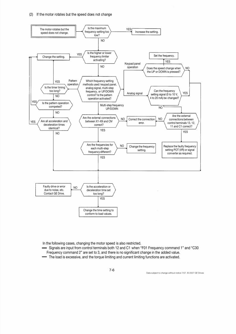
8/11/2019 GEI-100364
http://slidepdf.com/reader/full/gei-100364 107/154

8/11/2019 GEI-100364
http://slidepdf.com/reader/full/gei-100364 108/154
7-7Data subject to change without notice 7/07. © 2007 GE Drives
(3) If the motor stalls during acceleration
The motor stalls duringacceleration.
YES
NO
Is the acceleration timetoo short?
Prolong the time.
Is the inertia moment of themotor or the load excessive?
Is a special motor used? Contact GE Drive.
Use a thicker cable betweenthe drive and the motor orshorten the cable length.
Has the motor terminalvoltage dropped?
Reduce the inertia momentof the load or increase the
drive capacity.
Is the torque of the loadexcessive?
Reduce the torque of theload or increase the drive
capacity.
Is the torque boostset correctly?
Faulty drive or error dueto noise, etc.
Contact GE Drive.
Increase the torque boost.
The motor generatesabnormal heat.
Is the torque boostexcessive?
Reduce the torque boost.
Has the motor beenoperating continuously at a
very low speed?
Use a motor exclusiveto the drive.
Is the load excessive?Reduce the load or increase
motor capacity.
Is the drive output voltage.Terminals (U, V, W)
balanced?
Faulty motor.
Faulty drive or errordue to noise, etc.Contact GE Drive.
Note: Motor overheating following ahigher frequency setting is likely theresult of the current wave form.Contact GE Drives.
YES
NO
YES
NO
YES
NO
NO
NO
YES
YES
YES
YES
YES
YES
NO
NO
NO
NO

8/11/2019 GEI-100364
http://slidepdf.com/reader/full/gei-100364 109/154
8/11/2019 GEI-100364
http://slidepdf.com/reader/full/gei-100364 110/154
8-1Data subject to change without notice 7/07. © 2007 GE Drives
8. Maintenance and Inspection
Proceed with daily inspection and periodic inspection to prevent malfunction and ensure long-term reliability. Some tipsregarding things to look for during these inspections are listed below.
8.1 Daily Inspections
During operation, a visual inspection for abnormal operation can take place externally without removing the covers.The inspection should cover the following areas:
(1) The performance, according to standard specifications,is as expected.
(2) The environment conforms to standard specifications.
(3) The keypad panel display is normal.
(4) There are no abnormal sounds, vibrations, or odors.
(5) There are no indications of overheating or discoloration.
8.2 Periodic Inspections
Periodic inspections should be made after stopping operations, cutting off the power source, and removing the surface
cover.Note that after turning off the power, the smoothing capacitors in the DC section of the main circuit take time to dis-charge. To prevent electric shock, confirm with a multimeter that the voltage has dropped below the safety value (25 VDC or below) after the charge lamp (CRG) goes off.
WARNING
• Start the inspection at least five minutes after turning off the power supply for inverters rated at 30Hp or less. Wait at least ten minutes for inverters rated at 40 Hp or more. Check that the chargelamp (CRG) went off and that the voltage is 25V DC or less between terminals P(+) and N(-). Electricshock may result.
• Only authorized personnel should perform maintenance and component replacement operations.
Remove metal jewelry such as watches and rings, and always use insulated tools.• Never modify the drive. Electric shock or injury may result.

8/11/2019 GEI-100364
http://slidepdf.com/reader/full/gei-100364 111/154
8-2 Data subject to change without notice 7/07. © 2007 GE Drives
Environment
Voltage
Keypad panel
Structure(frame or cover)
Common
Conductorsand wiring
Terminal block
Smoothingcapacitor
Resistor
Transformerand reactor
Magneticconductorand relay
Control PCboard andconnector
Cooling fan
Ventilation
1) Check the ambient temperature, humidity,vibration, atmosphere (dust, gas, oil mist,water drops).
2) Is the area surrounding the equipment free of foreign objects.
Are the voltages in the main circuit and thecontrol circuit normal?
1) Is the display hard to read?2) Are the characters complete?
1) Is there abnormal sound or vibration?2) Are nuts or bolts loose?3) Is there deformation or damage?4) Is there discoloration as a result of overheat-
ing?5) Are there stains or dust?
1) Are there loose or missing nuts or bolts?2) Are there deformations, cracks, damage, or
discoloration due to overheating or deteriora-tion in the equipment and insulation?
3) Are there stains and dust?
1) Is there discoloration or distortion of aconductor due to overheating?
2) Are there cracks, crazing or discoloration of the cable sheath?
Is there damage?
1) Is there electrolyte leakage, discoloration,crazing, or swelling in the case?
2) Is the safety valve not protruding, or arevalves protruding too far?
3) Measure the capacitance if necessary.
1) Is there any unusual odor or damage to theinsulation by overheating?
2) Is there an open circuit?
Is there abnormal buzzing or an unpleasantsmell?
1) Is there a rattling noise during operation?2) Are the contacts rough?
1) Are there any loose screws or connectors?2) Is there an unusual odor or discoloration?3) Are there cracks, damage, deformation, or
excessive rust?4) Is there electrolyte leakage or damage to the
capacitor?
1) Is there abnormal sound or vibration?2) Are nuts or bolts loose?3) Is there discoloration due to overheating?
Is there foreign matter on the heat sink or intakeand exhaust ports?
1) Conduct a visual inspection and useappropriate meters.
2) Visual inspection
Measure with a multi-meter.
1) Visual inspection2) Visual inspection
1) Visual and aural inspection2) Tighten3), 4), 5) Visual inspection
1) Tighten.2), 3) Visual inspection
1), 2) Visual inspection
Visual inspection
1), 2) Visual inspection3) *Estimate life expectancy from
maintenance information and frommeasurements using capacitancemeasuring equipment.
1) Visual and olfactory inspection2) Conduct a visual inspection or use a
multi-meter by removing the connectionon one side.
Aural, olfactory, and visual inspection
1) Aural inspection.2) Visual inpection.
1) Aural inspection.2) Visual and olfactory inspection3) Visual inspection
4) *Estimate life expectancy by visualinspection and maintenace information
1) Aural and visual inspection. Turnmanually (confirm the poewr is off).
2) Tighten.3) Visual inspection4) *Estimate life expectancy by mainte-
nance information
Visual inspection
1) Results comply with allstandard specifications.
2) The area is clear.
Results comply with allstandard specifications.
1), 2) The display can beeasily read and charactersare normal.
1), 2), 3), 4), 5)No abnormalities
1), 2), 3) No abnormalitiesNote: Discolorationof the
bus bar does notindicate a problem.
1), 2) No abnormalities
No abnormalities
1), 2) No abnormalities3) Capacitance is within
85% of initial value
1) No abnormalities2) Less than about ±10%
of the indicatedresistance value
No abnormalities
1), 2) No abnormalities
1), 2), 3), 4)No abnormalities
1) The fan must rotatesmoothly.
2), 3) No abnormalities
No abnormalities
Area to Check Items to Check How to inspect Evaluation Criteria
See additional notes on following page.
CoolingSystem
ControlCircuit
Ma
inCircuit

8/11/2019 GEI-100364
http://slidepdf.com/reader/full/gei-100364 112/154
8-3Data subject to change without notice 7/07. © 2007 GE Drives
Note: If equipment is stained, wipe with a clean cloth. Use a vacuum to remove dust. *Estimate of life expectancy basedon maintenance information.
The maintenance information is stored in the drive keypad panel. It indicates the electrostatic capacitance of the maincircuit capacitors and the life expectancy of the electrolytic capacitors on the control PC board and the cooling fans. Usethis data as the basis to estimate the life expectancy of parts.
1) Determining the capacitance of the main circuit capacitors
This drive is equipped with a function to automatically indicate the capacitance of the capacitors installed in the main
circuit when powering up the drive after disconnecting the power according to the prescribed conditions.The initial capacitance values are set in the drive when shipped from the factory, and the decrease ratio (%) to thosevalues can be displayed.
Use this function as follows:
(1) Remove any option boards from the inverter. Disconnect the DC bus connections to the main circuit [TerminalsP(+) and N(-)] from the braking unit or other inverters, if connected. The power factor correcting reactor (DCreactor) does not need be disconnected.
A power supply introduced to the auxiliary input [Terminals R0, T0] that provides control power shouldbe isolated.
(2) Disable all the digital inputs (FWD, REV, X1-X9) on the control terminals. Also disconnect RS485 serialcommunication, if used.
Turn on the main power supply. Confirm that the cooling fan is rotating and that the inverter is not operating.(There is no problem if the “OH2 External thermal relay tripped” function is activated by the digital input terminal.)
(3) Turn the main power off.(4) Turn on the main power again after verifying that the charge lamp is completely off.
(5) Open the maintenance information on the keypad panel and confirm the capacitance values of thebuilt-in capacitors.
2) Life expectancy of the PC control board
The actual capacitance of a capacitor is not measured in this case. However, the integrated operating hours for thecontrol power supply, multiplied by the life expectancy coefficient as defined by the temperature inside the inverter,will be displayed. Hence, the hours displayed may not agree with the actual operating hours, depending on theoperational environment.
Since the integrated hours are counted in unit hours, power input for less than one hour will be disregarded.
3) Life expectancy of cooling fanThe integrated operating hours of the cooling fan are displayed. Since the integrated hours are counted in unit hours,power input for less than one hour will be disregarded.
The displayed value should be considered a rough estimate because the actual life of a cooling fan is influencedsignificantly by the temperature.
Table 8..-2 Rough estimate of life expectancy using maintenance information
Parts Recommended Level
Capacitor in main circuit 85% or less of the initial value
Electrolytic capacitor on control PC board 61,000 hours
Cooling fan 40,000 hours (5 Hp or less), 25,000 hours (Over 7.5 Hp)*
* Estimated life expectancy of a ventilation-fan at inverter ambient temperature of 40°C
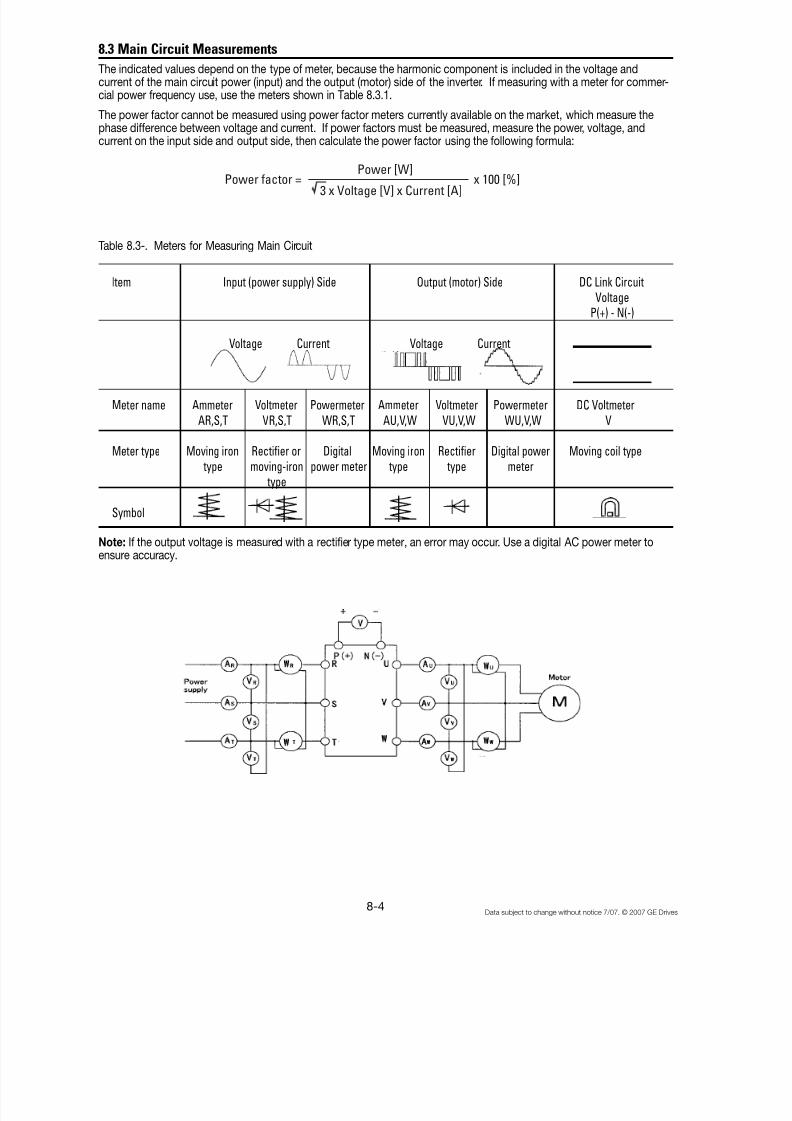
8/11/2019 GEI-100364
http://slidepdf.com/reader/full/gei-100364 113/154
8-4 Data subject to change without notice 7/07. © 2007 GE Drives
8.3 Main Circuit Measurements
The indicated values depend on the type of meter, because the harmonic component is included in the voltage andcurrent of the main circuit power (input) and the output (motor) side of the inverter. If measuring with a meter for commer-cial power frequency use, use the meters shown in Table 8.3.1.
The power factor cannot be measured using power factor meters currently available on the market, which measure thephase difference between voltage and current. If power factors must be measured, measure the power, voltage, andcurrent on the input side and output side, then calculate the power factor using the following formula:
Table 8.3-. Meters for Measuring Main Circuit
I tem Input (power supply) Side Output (motor) Side DC Link CircuitVoltage
P(+) - N(-)
Voltage Current Voltage Current
Meter name Ammeter Voltmeter Powermeter Ammeter Voltmeter Powermeter DC VoltmeterAR,S,T VR,S,T WR,S,T AU,V,W VU,V,W WU,V,W V
Meter type Moving iron Rectifier or Digital Moving iron Rectifier Digital power Moving coil type type moving-iron power meter type type meter
type
Symbol
Note: If the output voltage is measured with a rectifier type meter, an error may occur. Use a digital AC power meter toensure accuracy.
Power factor =
Power [W]
x 100 [%] 3 x Voltage [V] x Current [A]
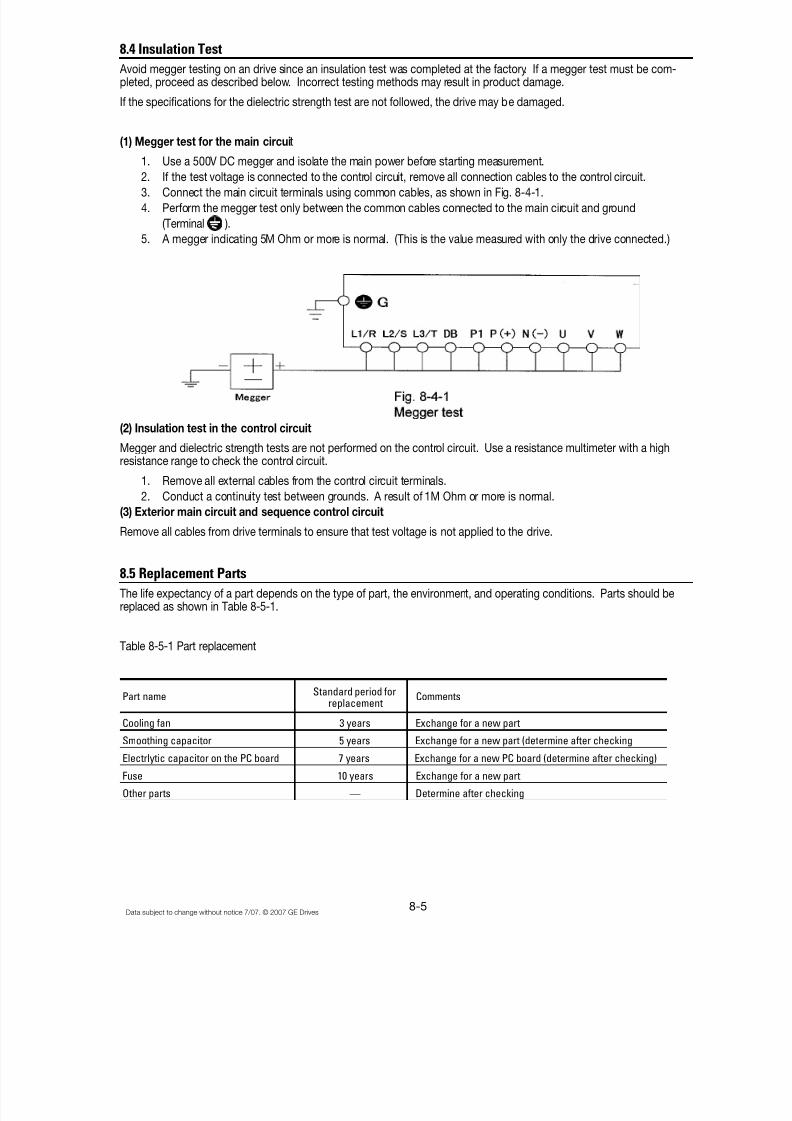
8/11/2019 GEI-100364
http://slidepdf.com/reader/full/gei-100364 114/154

8/11/2019 GEI-100364
http://slidepdf.com/reader/full/gei-100364 115/154
8-6 Data subject to change without notice 7/07. © 2007 GE Drives
Notes:
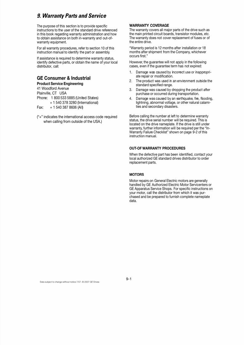
8/11/2019 GEI-100364
http://slidepdf.com/reader/full/gei-100364 116/154
9-1Data subject to change without notice 7/07. © 2007 GE Drives
9. Warranty Parts and Service
The purpose of this section is to provide specificinstructions to the user of the standard drive referencedin this book regarding warranty administration and howto obtain assistance on both in-warranty and out-of-warranty equipment.
For all warranty procedures, refer to section 10 of thisinstruction manual to identify the part or assembly.
If assistance is required to determine warranty status,identify defective parts, or obtain the name of your localdistributor, call:
GE Consumer & IndustrialProduct Service Engineering
41 Woodford AvenuePlainville, CT USA Phone: 1 800 533 5885 (United States)
+ 1 540 378 3280 (International)Fax: + 1 540 387 8606 (All)
(“+” indicates the international access code requiredwhen calling from outside of the USA.)
WARRANTY COVERAGEThe warranty covers all major parts of the drive such asthe main printed circuit boards, transistor modules, etc.The warranty does not cover replacement of fuses or ofthe entire drive.
“Warranty period is 12 months after installation or 18months after shipment from the Company, whichever
occurs first.”
However, the guarantee will not apply in the followingcases, even if the guarantee term has not expired:
1. Damage was caused by incorrect use or inappropri-ate repair or modification.
2. The product was used in an environment outside thestandard specified range.
3. Damage was caused by dropping the product afterpurchase or occurred during transportation.
4. Damage was caused by an earthquake, fire, flooding,lightning, abnormal voltage, or other natural calami-ties and secondary disasters.
Before calling the number at left to determine warrantystatus, the drive serial number will be required. This islocated on the drive nameplate. If the drive is still underwarranty, further information will be required per the “In-Warranty Failure Checklist” shown on page 9-2 of thisinstruction manual.
OUT-OF WARRANTY PROCEDURES
When the defective part has been identified, contact yourlocal authorized GE standard drives distributor to orderreplacement parts.
MOTORS
Motor repairs on General Electric motors are generallyhandled by GE Authorized Electric Motor Servicenters orGE Apparatus Service Shops. For specific instructions onyour motor, call the distributor from which it was pur-chased and be prepared to furnish complete nameplatedata.
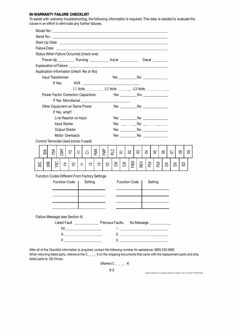
8/11/2019 GEI-100364
http://slidepdf.com/reader/full/gei-100364 117/154
9-2Data subject to change without notice 7/07. © 2007 GE Drives
IN-WARRANTY FAILURE CHECKLIST
To assist with warranty troubleshooting, the following information is required. This data is needed to evaluate thecause in an effort to eliminate any further failures.
Model No.: ______________________________________________________________________
Serial No.: ______________________________________________________________________
Start-Up Date: __________________________________________________________________
Failure Date: ____________________________________________________________________
Status When Failure Occurred (check one):Power-Up__________ Running ___________ Accel ___________ Decel _________
Explanation of Failure ____________________________________________________________
Application Information (check Yes or No)
Input Transformer: Yes ___________No _______________
If Yes: KVA ___________________________________
L1 Volts ___________ L2 Volts ________ L3 Volts ______________
Power Factor Correction Capacitors: Yes __________No _______________
If Yes: Microfarrad______________________________
Other Equipment on Same Power Yes __________No _______________ If Yes, what?
Line Reactor on Input Yes __________ No _______________
Input Starter Yes __________No _______________
Output Starter Yes __________No _______________
Motor Overloads Yes __________No _______________
Control Terminals Used (circle if used)
Function Codes Different From Factory Settings
Function Code Setting Function Code Setting
Failure Message (see Section 4)
Latest Fault _______________ Previous Faults: No Message _____________
Hz ______________________ 1. _____________________________
A _______________________ 2. _____________________________
V _______________________ 3. _____________________________
After all of the Checklist information is acquired, contact the following number for assistance: (800) 533-5885
When returning failed parts, reference the C_ _ _ _ # on the shipping documents that came with the replacement parts and ship
failed parts to: GE Drives.
(Marked C _ _ _ _ #)
3 0 C
3 0 B
Y 5 C
Y 4
Y 2
1 1
1 2
1 3
V 2
C M
C M
F W D
R E V
P 2 4
P 2 4
D X
D X
S D
3 0 A
Y 5 A
C M Y
Y 3
Y 1
C 1
F M A
F M P
P L C
X 1
X 2
X 3
X 4
X 5
X 6
X 7
X 8
X 9
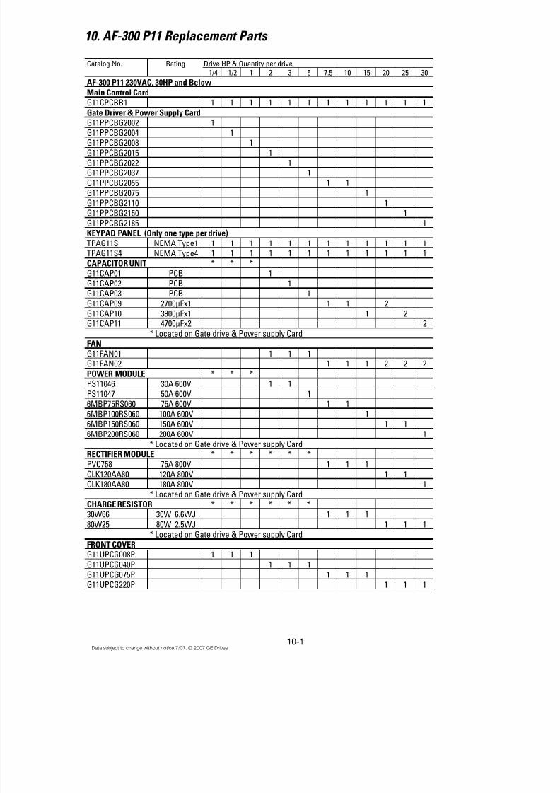
8/11/2019 GEI-100364
http://slidepdf.com/reader/full/gei-100364 118/154
10-1Data subject to change without notice 7/07. © 2007 GE Drives
10. AF-300 P11 Replacement Parts
Catalog No. Rating Drive HP & Quantity per drive1/4 1/2 1 2 3 5 7.5 10 15 20 25 30
AF-300 P11 230VAC, 30HP and BelowMain Control CardG11CPCBB1 1 1 1 1 1 1 1 1 1 1 1 1
Gate Driver & Power Supply CardG11PPCBG2002 1
G11PPCBG2004 1G11PPCBG2008 1
G11PPCBG2015 1G11PPCBG2022 1G11PPCBG2037 1
G11PPCBG2055 1 1G11PPCBG2075 1
G11PPCBG2110 1G11PPCBG2150 1
G11PPCBG2185 1KEYPAD PANEL (Only one type per drive)TPAG11S NEMA Type1 1 1 1 1 1 1 1 1 1 1 1 1
TPAG11S4 NEMA Type4 1 1 1 1 1 1 1 1 1 1 1 1CAPACITOR UNIT * * *G11CAP01 PCB 1
G11CAP02 PCB 1G11CAP03 PCB 1
G11CAP09 2700µFx1 1 1 2G11CAP10 3900µFx1 1 2G11CAP11 4700µFx2 2
* Located on Gate drive & Power supply CardFAN
G11FAN01 1 1 1G11FAN02 1 1 1 2 2 2
POWER MODULE * * *
PS11046 30A 600V 1 1PS11047 50A 600V 16MBP75RS060 75A 600V 1 1
6MBP100RS060 100A 600V 16MBP150RS060 150A 600V 1 1
6MBP200RS060 200A 600V 1* Located on Gate drive & Power supply Card
RECTIFIER MODULE * * * * * *PVC758 75A 800V 1 1 1
CLK120AA80 120A 800V 1 1CLK180AA80 180A 800V 1
* Located on Gate drive & Power supply Card
* * * * * *
30W66 30W 6.6WJ 1 1 180W25 80W 2.5WJ 1 1 1
* Located on Gate drive & Power supply Card
FRONT COVERG11UPCG008P 1 1 1
G11UPCG040P 1 1 1G11UPCG075P 1 1 1
G11UPCG220P 1 1 1
CHARGE RESISTOR
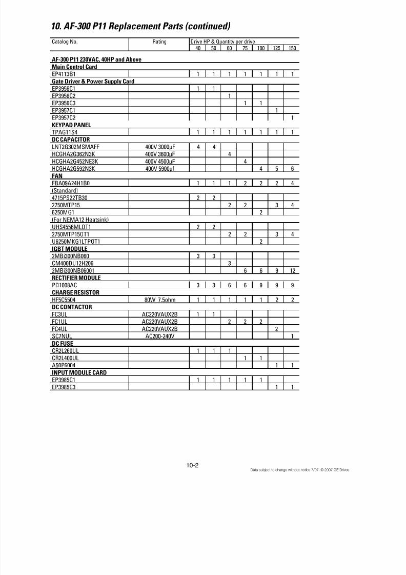
8/11/2019 GEI-100364
http://slidepdf.com/reader/full/gei-100364 119/154
10-2Data subject to change without notice 7/07. © 2007 GE Drives
Catalog No. Rating Drive HP & Quantity per drive
40 50 60 75 100 125 150
AF-300 P11 230VAC, 40HP and AboveMain Control CardEP4113B1 1 1 1 1 1 1 1
Gate Driver & Power Supply CardEP3956C1 1 1
EP3956C2 1EP3956C3 1 1
EP3957C1 1EP3957C2 1
KEYPAD PANELTPAG11S4 1 1 1 1 1 1 1DC CAPACITORLNT2G302MSMAFF 400V 3000µF 4 4HCGHA2G362N3K 400V 3600µF 4
HCGHA2G452NE3K 400V 4500µF 4HCGHA2G592N3K 400V 5900µf 4 5 6
FAN
FBA09A24H1B0 1 1 1 2 2 2 4(Standard)4715PS22TB30 2 2
2750MTP15 2 2 3 46250MG1 2
(For NEMA12 Heatsink)UHS4556MLOT1 2 2
2750MTP15OT1 2 2 3 4U6250MKG1LTPOT1 2
IGBT MODULE
2MBi300NB060 3 3CM400DU12H206 3
2MBi300NB06001 6 6 9 12
RECTIFIER MODULE PD1008AC 3 3 6 6 9 9 9CHARGE RESISTORHF5C5504 80W 7.5ohm 1 1 1 1 1 2 2DC CONTACTORFC3UL AC220VAUX2B 1 1FC1UL AC220VAUX2B 2 2 2
FC4UL AC220VAUX2B 2SC7NUL AC200-240V 1
DC FUSECR2L260UL 1 1 1
CR2L400UL 1 1A50P6004 1 1
INPUT MODULE CARDEP3985C1 1 1 1 1 1EP3985C3 1 1
10. AF-300 P11 Replacement Parts (continued)

8/11/2019 GEI-100364
http://slidepdf.com/reader/full/gei-100364 120/154
10-3Data subject to change without notice 7/07. © 2007 GE Drives
Catalog No. Rating Drive HP & Quantity per drive
1/2 1 2 3 5 7.5 10 15 20 25 30
AF-300 P11 460VAC, 30HP and BelowMain Control CardG11CPCBB1 1 1 1 1 1 1 1 1 1 1 1
Gate Driver & Power Supply CardG11PPCBG4004 1
G11PPCBG4008 1G11PPCBG4015 1
G11PPCBG4022 1G11PPCBG4037 1G11PPCBG4055 1 1
G11PPCBG4075 1G11PPCBG4110 1
G11PPCBG4150 1G11PPCBG4185 1
KEYPAD PANEL (Only one type per drive)TPAG11S NEMA Type1 1 1 1 1 1 1 1 1 1 1 1
TPAG11S4 NEMA Type4 1 1 1 1 1 1 1 1 1 1 1
CAPACITOR UNIT * *G11CAP04 PCB 1G11CAP05 PCB 1
G11CAP06 PCB 1G11CAP07 1500µFx2 2 2
G11CAP08 2000µFx2 2G11CAP09 2700µFx2 2
G11CAP10 3900µFx2 2G11CAP11 4700µFx2 2
* Located on Gate drive & Power supply Card
FAN G11FAN01 1 1 1
G11FAN02 1 1 1 2 2 2
POWER MODULE * *PS12046 15A 1200V 1 1PS12047 25A 1200V 1
6MBP50RS120 50A 1200V 1 1 16MBP75RS120 75A 1200V 1 1
6MBP100RS120 100A 1200V 1* Located on Gate drive & Power supply Card
RECTIFIER MODULE * * * * *PVC7516 75A 1600V 1 1 1
CLK70AA160 70A 1600V 1 1CLK100AA160 100A 1600V 1
* Located on Gate drive & Power supply CardCHARGE RESISTOR * * * * *
30W200 30W 20WJ 1 1 180W100 80W 10WJ 1 1 1
* Located on Gate drive & Power supply Card
FRONT COVERG11UPCG008P 1 1
G11UPCG040P 1 1 1G11UPCG075P 1 1 1
G11UPCG220P 1 1 1
10. AF-300 P11 Replacement Parts (continued)
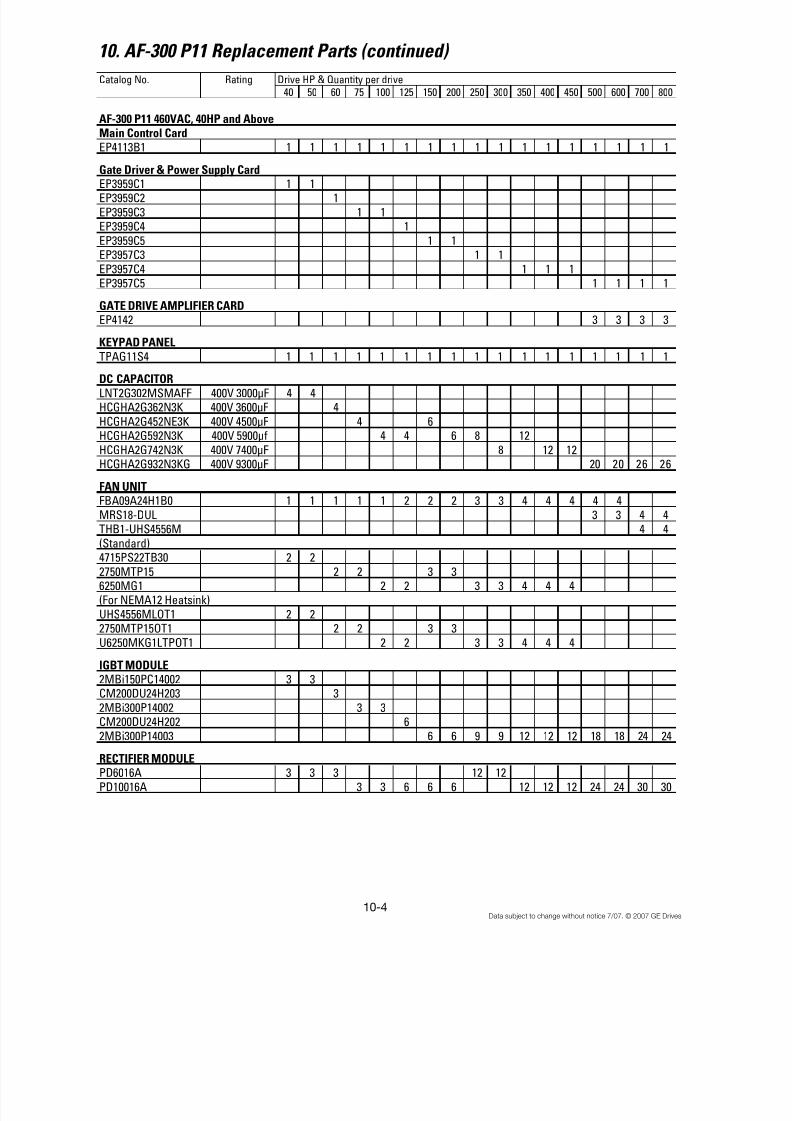
8/11/2019 GEI-100364
http://slidepdf.com/reader/full/gei-100364 121/154
10-4Data subject to change without notice 7/07. © 2007 GE Drives
10. AF-300 P11 Replacement Parts (continued)
Catalog No. Rating Drive HP & Quantity per drive40 50 60 75 100 125 150 200 250 300 350 400 450 500 600 700 800
AF-300 P11 460VAC, 40HP and AboveMain Control CardEP4113B1 1 1 1 1 1 1 1 1 1 1 1 1 1 1 1 1 1
Gate Driver & Power Supply Card
EP3959C1 1 1EP3959C2 1
EP3959C3 1 1EP3959C4 1
EP3959C5 1 1EP3957C3 1 1
EP3957C4 1 1 1EP3957C5 1 1 1 1
GATE DRIVE AMPLIFIER CARDEP4142 3 3 3 3
KEYPAD PANEL
TPAG11S4 1 1 1 1 1 1 1 1 1 1 1 1 1 1 1 1 1DC CAPACITORLNT2G302MSMAFF 400V 3000µF 4 4HCGHA2G362N3K 400V 3600µF 4
HCGHA2G452NE3K 400V 4500µF 4 6HCGHA2G592N3K 400V 5900µf 4 4 6 8 12
HCGHA2G742N3K 400V 7400µF 8 12 12HCGHA2G932N3KG 400V 9300µF 20 20 26 26
FAN UNIT FBA09A24H1B0 1 1 1 1 1 2 2 2 3 3 4 4 4 4 4
MRS18-DUL 3 3 4 4THB1-UHS4556M 4 4
(Standard)4715PS22TB30 2 2
2750MTP15 2 2 3 36250MG1 2 2 3 3 4 4 4(For NEMA12 Heatsink)
UHS4556MLOT1 2 22750MTP15OT1 2 2 3 3
U6250MKG1LTPOT1 2 2 3 3 4 4 4
IGBT MODULE 2MBi150PC14002 3 3CM200DU24H203 3
2MBi300P14002 3 3
CM200DU24H202 62MBi300P14003 6 6 9 9 12 12 12 18 18 24 24
PD6016A 3 3 3 12 12
PD10016A 3 3 6 6 6 12 12 12 24 24 30 30
RECTIFIER MODULE

8/11/2019 GEI-100364
http://slidepdf.com/reader/full/gei-100364 122/154
10-5Data subject to change without notice 7/07. © 2007 GE Drives
10. AF-300 P11 Replacement Parts (continued)
Catalog No. Rating Drive HP & Quantity per drive
40 50 60 75 100 125 150 200 250 300 350 400 450 500 600 700 800
AF-300 P11 460VAC, 40HP and Above
IGBT MODULE2MBi150PC14002 3 3
CM200DU24H203 32MBi300p14002 3 3CM200DU24H202 6
2MBi300P14003 6 6 9 9 12 12 12 18 18 24 24
RECTIFIER MODULEPD6016A 3 3 3 12 12
PD10016A 3 3 6 6 6 12 12 12 24 24 30 30
CHARGE RESISTORHF5C5504 80W 7.5ohm 1 1 1 1 1 1 2 2 2 3 3 4 4GRZG400 2 2 2 2
DC CONTACTOR
FC1UL AC220VAUX2B 1 1 1 1 1 2 2 2FC4UL AC220VAUX2B 2 2SC7NUL AC200-240V 1
SC8NUL AC200-240V 1 1SCN8 AC200-240V 2 2 2 2
DC FUSECR6L150UL 600V 150A 1 1 1CR6L200UL 600V 200A 1CR6L300UL 600V 300A 1 1
A70Q4004 1 1A70Q5004 1
A70Q6004 1 1A70QS8004 1 1
A70P16004TA 1 1A70P20004 1 1
TRANSFORMERHF5C55025512VA 1 1HF5C550312524VA 1 1 1 1HF5B661330016VA 1 1 1 1 1 1 1
HF5B395170020VA 1 1 1 1
INPUT MODULE CARDEP3985C2 1 1 1 1 1 1 1 1
EP3985C4 1 1 1 1 1 1 1 1 1

8/11/2019 GEI-100364
http://slidepdf.com/reader/full/gei-100364 123/154
10-6Data subject to change without notice 7/07. © 2007 GE Drives
Notes:

8/11/2019 GEI-100364
http://slidepdf.com/reader/full/gei-100364 124/154
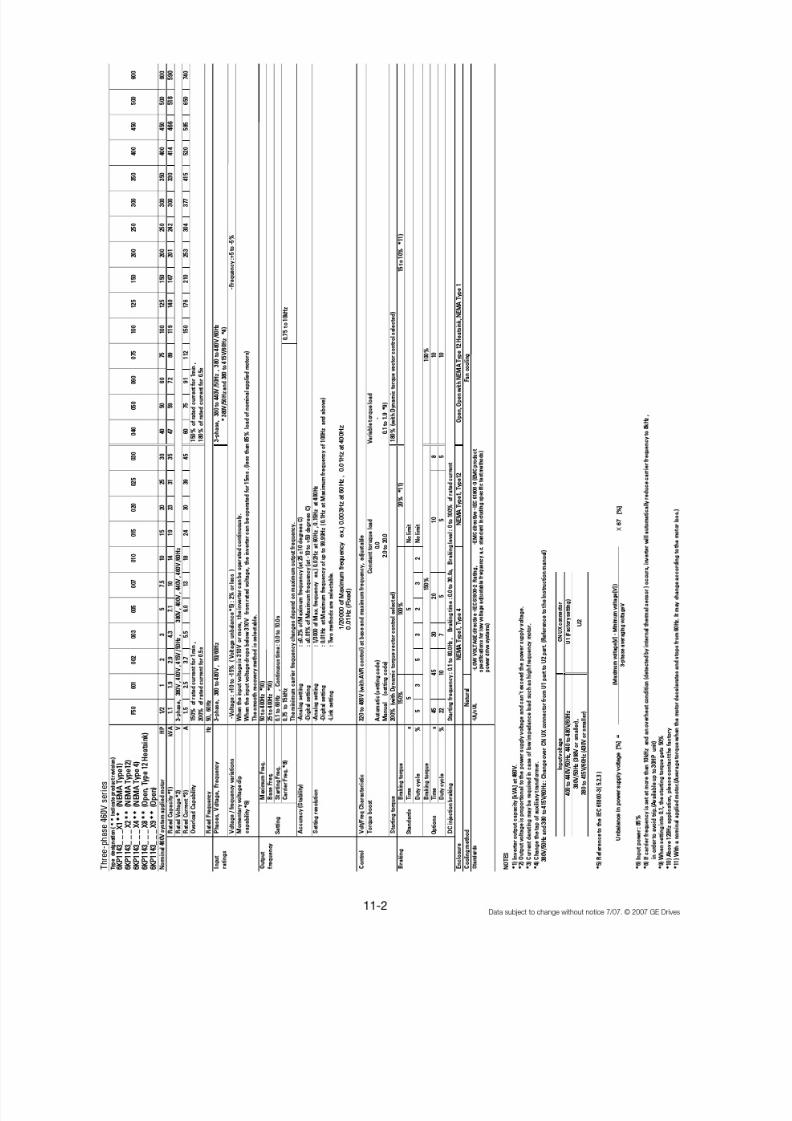
8/11/2019 GEI-100364
http://slidepdf.com/reader/full/gei-100364 125/154
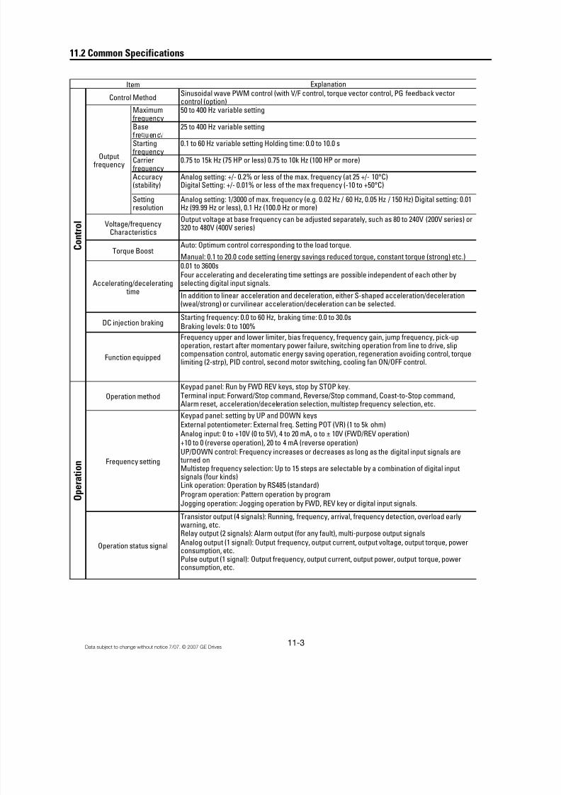
8/11/2019 GEI-100364
http://slidepdf.com/reader/full/gei-100364 126/154
11-3Data subject to change without notice 7/07. © 2007 GE Drives
11.2 Common Specifications
Explanation
Sinusoidal wave PWM control (with V/F control, torque vector control, PG feedback vectorcontrol (option)
Maximumfrequency
50 to 400 Hz variable setting
Basefre uenc
25 to 400 Hz variable setting
Startingfrequency
0.1 to 60 Hz variable setting Holding time: 0.0 to 10.0 s
Carrierfrequency
0.75 to 15k Hz (75 HP or less) 0.75 to 10k Hz (100 HP or more)
Accuracy(stability)
Analog setting: +/- 0.2% or less of the max. frequency (at 25 +/- 10°C)Digital Setting: +/- 0.01% or less of the max frequency (-10 to +50°C)
Settingresolution
Analog setting: 1/3000 of max. frequency (e.g. 0.02 Hz / 60 Hz, 0.05 Hz / 150 Hz) Digital setting: 0.01Hz (99.99 Hz or less), 0.1 Hz (100.0 Hz or more)
Output voltage at base frequency can be adjusted separately, such as 80 to 240V (200V series) or320 to 480V (400V series)
Auto: Optimum control corresponding to the load torque.
Manual: 0.1 to 20.0 code setting (energy savings reduced torque, constant torque (strong) etc.)0.01 to 3600sFour accelerating and decelerating time settings are possible independent of each other byselecting digital input signals.
In addition to linear acceleration and deceleration, either S-shaped acceleration/deceleration(weal/strong) or curvilinear acceleration/deceleration can be selected.
Starting frequency: 0.0 to 60 Hz, braking time: 0.0 to 30.0s
Braking levels: 0 to 100%
Frequency upper and lower limiter, bias frequency, frequency gain, jump frequency, pick-upoperation, restart after momentary power failure, switching operation from line to drive, slipcompensation control, automatic energy saving operation, regeneration avoiding control, torquelimiting (2-strp), PID control, second motor switching, cooling fan ON/OFF control.
Keypad panel: Run by FWD REV keys, stop by STOP key.Terminal input: Forward/Stop command, Reverse/Stop command, Coast-to-Stop command,Alarm reset, acceleration/deceleration selection, multistep frequency selection, etc.
Keypad panel: setting by UP and DOWN keys
External potentiometer: External freq. Setting POT (VR) (1 to 5k ohm)
Analog input: 0 to +10V (0 to 5V), 4 to 20 mA, o to ± 10V (FWD/REV operation)+10 to 0 (reverse operation), 20 to 4 mA (reverse operation)
UP/DOWN control: Frequency increases or decreases as long as the digital input signals are turned onMultistep frequency selection: Up to 15 steps are selectable by a combination of digital inputsignals (four kinds)Link operation: Operation by RS485 (standard)
Program operation: Pattern operation by program
Jogging operation: Jogging operation by FWD, REV key or digital input signals.
Transistor output (4 signals): Running, frequency, arrival, frequency detection, overload earlywarning, etc.Relay output (2 signals): Alarm output (for any fault), multi-purpose output signals
Analog output (1 signal): Output frequency, output current, output voltage, output torque, powerconsumption, etc.Pulse output (1 signal): Output frequency, output current, output power, output torque, powerconsumption, etc.
Item
C o n t r o l
O p e r a t i o n Frequency setting
Operation status signal
Control Method
Outputfrequency
Voltage/frequencyCharacteristics
Torque Boost
Accelerating/decelerating time
Function equipped
Operation method
DC injection braking
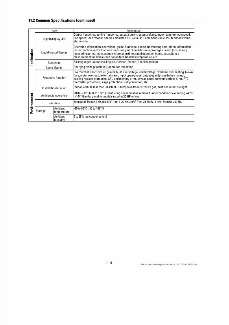
8/11/2019 GEI-100364
http://slidepdf.com/reader/full/gei-100364 127/154
11-4 Data subject to change without notice 7/07. © 2007 GE Drives
11.2 Common Specifications (continued)
Explanation
Output frequency, setting frequency, output current, output voltage, motor synchronous speed,line speed, load rotation speed, calculated PID value, PID command value, PID feedback value,alarm code.
Operation information, operational guide, functional code/name/setting data, alarm information, tester function, motor load rate measuring function (Maximum/average current (rms) duringmeasuring period, maintenance information (integrated operation hours, capacitancemeasurement for main circuit capacitors, heatsink temperature, etc.
Six languages (Japanese, English, German, French, Spanish, Italian)
Charging (voltage residual), operation indication
Overcurrent, short-circuit, ground fault, overvoltage, undervoltage, overload, overheating, blownfuse, motor overload, external alarm, input open-phase, output open0phase (when tuning),braking resistor protection, CPU and memory error, keypad panel communications error, PTC
thermistor protection, surge protection, stall prevention, etc.
Indoor, altitude less than 3300 feet (1000m), free from corrosive gas, dust and direct sunlight.
-10 to +50°C (+14 to 122°F) (ventilating cover must be removed under conditions exceeding +40°C(+104°F) in the panel for models rated at 30 HP or less)
3mm peak from 2-9 Hz, 9.8 m/s2 from 9-20 Hz, 2m/s2 from 20-55 Hz, 1 m/s2 from 55-200 Hz,
StorageAmbient
temperature-25 to 65°C (-13 to 149°F)
Ambienthumidity
5 to 95% (no condensation)
Installation location
Ambient temperature
Vibration
E n v i r o
n m e n t
I n d i c a t i o
n
Item
Liquid crystal display
Digital display LED
Language
Lamp display
Protective function
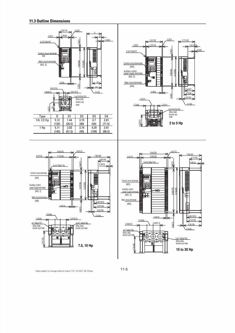
8/11/2019 GEI-100364
http://slidepdf.com/reader/full/gei-100364 128/154
11-5Data subject to change without notice 7/07. © 2007 GE Drives
11.3 Outline Dimensions
0.24(6)
0
. 2 8 ( 7 )
1 0 . 2
5 ( 2 6 0 )
9 . 6
9 ( 2 4 6 )
4.29(109)
3.43(87)
3.74(95)
0.31(8)
0 . 2
8 ( 7 )
0.28(6)
1.22(31)
1.73(44) 1.22(31)
3-ø”0.87(ø”22)
3 . 9
2 ( 9 9 . 5
)
0.28(7)
3.78(96)
4.34(110)
0.28(7)
0.24(6)
1.56(39.5)
0 . 2
8 ( 7 )
0.61(15.5)
D2
3-ø”0.87(ø”22)
D 4
1 . 0
6 ( 2 7
)
D
D1
0.24(6)
2.42 (61.5)
5.71(145)
0 . 2
8 ( 7 )
1 0 . 2
5 ( 2 6 0 )
9 . 6
9 ( 2 4 6 )
0.61(15.5)
5.91(150)
5.35(136)
2-ø”0.24(ø”6)
0.28(7)
0.31(8)
0.47(12)
9.84(250)
8.90(226)
0.47(12)7.68(195)
4.17(106)
0.39(10)
0 . 4
4 ( 1 1 )
1 5 . 7
6 ( 4 0 0 )
1 4 . 8
8 ( 3 7 8 )
2-ø”0.39(ø”10)
5.06(128.5)
5.12(130)
6.26(159) 0 . 4
4 ( 1 1 )
2.17(55)
0.39(10)
2.54(64.5) 2.42(61.5)
ø”1.34(ø”34)
2-ø”1.65(ø”42)
5 . 7
5 ( 1 4 6 )
D3
0.31(8)
0.47(12)
8.66(220)
7.72(196)
2-ø”0.39(ø”10)
0.47(12)
0 . 4
4 ( 1 1 ) 4.09(104)
0.39(10)
7.68(195)
5.49(139.5)
5.67(144)
6.26(159)
0.31(8)
0 . 4
4 ( 1 1 )
2.07(52.5)
2-ø”1.34(ø”34)
1.81(46)
2.28(58)
ø”1.06(ø”27)
5 . 5
1 ( 1 4 0 )
1 0 . 2
5 ( 2 6 0 )
9 . 3
7 ( 2 3 8 )
0.39(10)
(M3, 5)
(M5)
(M3)
(M4)
(M3, 5)
(M3)
Main circuit terminals
Wire inletknock outhole
Wire inletKnock outhole
Auxiliary controlpower supply terminals
Wire inletknock out hole
Auxiliary controlpower supply terminals
Main circuit terminals
Control circuit terminals
M3
(M3, 5)
Control circuit terminals
Main circuit terminals
NP
NP
NP
NP
Control circuit terminals
0.28(7)
2-ø”0.24(ø”6)
Wire inletknock out hole
Wire inletknock out hole
Wire inletknock out hole
(M3, 5)
(M5)
(M3)
Auxiliary controlpower supply terminals
Main circuit terminals
Control circuit terminals
2 to 5 Hp
7.5, 10 Hp15 to 30 Hp
Type D D1 D2 D3 D4
1/4, 1/2 Hp 5.12 1.44 3.15 3.7 2.81(130) (26.5) (80) (94) (71.5)
1 Hp 5.71 2.03 3.74 4.29 3.41
(145) (51.5) (95) (109) (86.5)
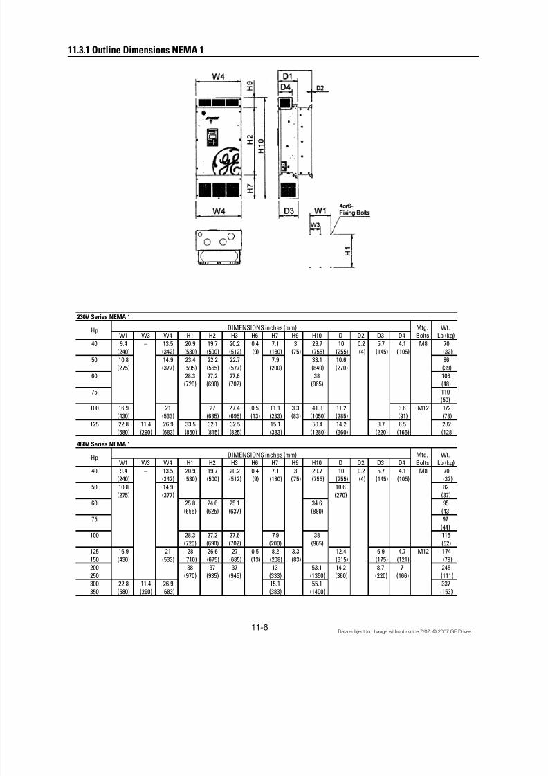
8/11/2019 GEI-100364
http://slidepdf.com/reader/full/gei-100364 129/154
11-6 Data subject to change without notice 7/07. © 2007 GE Drives
11.3.1 Outline Dimensions NEMA 1
230V Series NEMA 1
Mtg. Wt.
W1 W3 W4 H1 H2 H3 H6 H7 H9 H10 D D2 D3 D4 Bolts Lb (kg)
40 9.4 – 13.5 20.9 19.7 20.2 0.4 7.1 3 29.7 10 0.2 5.7 4.1 M8 70
(240) (342) (530) (500) (512) (9) (180) (75) (755) (255) (4) (145) (105) (32)
50 10.8 14.9 23.4 22.2 22.7 7.9 33.1 10.6 86
(275) (377) (595) (565) (577) (200) (840) (270) (39)
60 28.3 27.2 27.6 38 106(720) (690) (702) (965) (48)
75 110
(50)
100 16.9 21 27 27.4 0.5 11.1 3.3 41.3 11.2 3.6 M12 172
(430) (533) (685) (695) (13) (283) (83) (1050) (285) (91) (78)
125 22.8 11.4 26.9 33.5 32.1 32.5 15.1 50.4 14.2 8.7 6.5 282
(580) (290) (683) (850) (815) (825) (383) (1280) (360) (220) (166) (128)
460V Series NEMA 1
Mtg. Wt.
W1 W3 W4 H1 H2 H3 H6 H7 H9 H10 D D2 D3 D4 Bolts Lb (kg)
40 9.4 – 13.5 20.9 19.7 20.2 0.4 7.1 3 29.7 10 0.2 5.7 4.1 M8 70
(240) (342) (530) (500) (512) (9) (180) (75) (755) (255) (4) (145) (105) (32)
50 10.8 14.9 10.6 82
(275) (377) (270) (37)
60 25.8 24.6 25.1 34.6 95
(655) (625) (637) (880) (43)
75 97
(44)
100 28.3 27.2 27.6 7.9 38 115
(720) (690) (702) (200) (965) (52)
125 16.9 21 28 26.6 27 0.5 8.2 3.3 12.4 6.9 4.7 M12 174
150 (430) (533) (710) (675) (685) (13) (208) (83) (315) (175) (121) (79)
200 38 37 37 13 53.1 14.2 8.7 7 245
250 (970) (935) (945) (333) (1350) (360) (220) (166) (111)
300 22.8 11.4 26.9 15.1 55.1 337
350 (580) (290) (683) (383) (1400) (153)
Hp
Hp
DIMENSIONS inches (mm)
DIMENSIONS inches (mm)
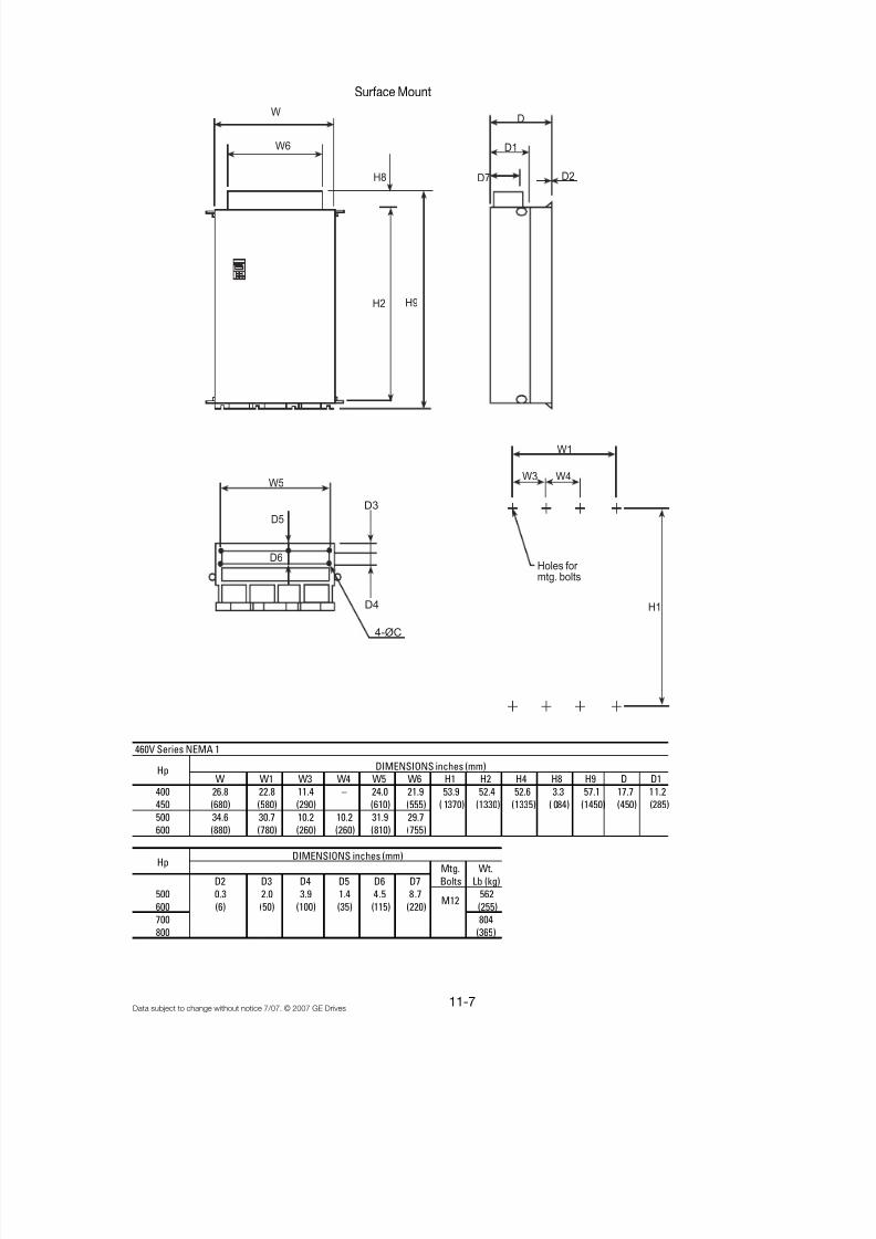
8/11/2019 GEI-100364
http://slidepdf.com/reader/full/gei-100364 130/154
11-7Data subject to change without notice 7/07. © 2007 GE Drives
Surface Mount
460V Series NEMA 1
W W1 W3 W4 W5 W6 H1 H2 H4 H8 H9 D D1
400 26.8 22.8 11.4 – 24.0 21.9 53.9 52.4 52.6 3.3 57.1 17.7 11.2
450 (680) (580) (290) (610) (555) ( 1370) (1330) (1335) ( 084) (1450) (450) (285)
500 34.6 30.7 10.2 10.2 31.9 29.7
600 (880) (780) (260) (260) (810) (755)
Mtg. Wt.
D2 D3 D4 D5 D6 D7 Bolts Lb (kg)
500 0.3 2.0 3.9 1.4 4.5 8.7 562
600 (6) (50) (100) (35) (115) (220) (255)
700 804
800 (365)
Hp
M12
Hp DIMENSIONS inches (mm)
DIMENSIONS inches (mm)
W
W6
H8
H2 H9
D7
D1
D2
D
D3
D4
4-ØC
W5
D5
D6
W1
W3 W4
H1
Holes for mtg. bolts

8/11/2019 GEI-100364
http://slidepdf.com/reader/full/gei-100364 131/154
11-8 Data subject to change without notice 7/07. © 2007 GE Drives
11.3.2 Outline Dimensions Open Type
Surface Mount Through Panel Mount
230V Series
Hp Mtg. Weight
230V W W1 W2 W3 H H1 H2 H3 H4 H5 H6 D D1 D2 C Bolts Lb (kg)
40 13.4 9.4 12.8 21.7 20.9 19.7 20.2 0.5 1 0.4 10 5.7 0.2 0.4 M8 64
(340) (240) (326) (550) (530) (500) (512) (12) (25) (9) (255) (145) (4) (10) (29)
50 14.8 10.8 14.2 24.2 23.4 22.2 22.7 10.6 79
(375) (275) (361) (615) (595) (565) (577) (270) (36)60 29.1 28.3 27.2 27.6 97
(740) (720) (690) (702) (44)
75 101
(46)
100 20.9 16.9 20.1 29.5 27 27.4 0.6 1.3 0.5 11.2 0.6 M12 154
(530) (430) (510) (750) (685) (695) (16) (33) (13) (285) (15) (70)
125 26.8 22.8 26 34.6 33.5 32.1 32.5 14.2 8.7 253
(680) (580) (660) (880) (850) (815) (825) (360) (220) (115)
460V Series
Hp Mtg. Weight
460V W W1 W2 W3 H H1 H2 H3 H4 H5 H6 D D1 D2 C Bolts Lb (kg)
40 13.4 9.4 12.8 21.7 20.9 19.7 20.2 0.5 1 0.4 10 5.7 0.2 0.4 M8 64
(340) (240) (326) (550) (530) (500) (512) (12) (25) (9) (255) (145) (4) (10) (29)
50 14.8 10.8 14.2 10.6 75
(375) (275) (361) (270) (34)
60 26.6 25.8 24.6 25.1 86
(675) (655) (625) (637) (39)
75 88
(40)
100 29.1 28.3 27.2 27.6 106
(740) (720) (690) (702) (48)
125 20.9 16.9 20.1 28 26.6 27 0.6 1.3 0.5 12.4 6.9 0.6 M12 154
150 (530) (430) (510) (710) (675) (682) (16) (33) (13) (315) (175) (15) (70)
200 39.4 38.2 36.8 37.2 14.2 8.7 220
250 (1000) (970) (935) (945) (360) (220) (100)
300 26.8 22.8 26 11.4 308
350 (680) (580) (660) (290) (140)
DIMENSION Inch (mm)
DIMENSION Inch (mm)
H1

8/11/2019 GEI-100364
http://slidepdf.com/reader/full/gei-100364 132/154
11-9Data subject to change without notice 7/07. © 2007 GE Drives
460V Series Open Type
W W1 W2 W3 W4 W5 H H1 H2 H3 H4 H5 H6 H7 D D1
400 26.8 22.8 26.0 11.4 24.0 55.1 53.9 52.4 52.8 52.6 0.6 1.4 0.6 17.7 11.2
450 (680) (580) (660) (290) (610) (1400) (1370) (1330) (1340) (1335) (016) (035) (015) (450) (285)
500 34.6 30.7 33.8 10.2 10.2 31.9
600 (880) (780) (860) (260) (260) (810)
Mtg. Wt.
D2 D3 D4 D5 D6 C Bolts Lb (kg)
400 0.3 2 3.9 1.4 4.5 0.6 551
450 (6) (50) (100) (35) (115) (015) (250)
500 793
600 (360)
Hp DIMENSIONS inches (mm)
M12
–
Hp DIMENSIONS inches (mm)
W
W1
W3 W4
H2 H1 H
C
W5
D5
D6
D3
D4
3 or 4 dia. C
D2
D1
D
W1
W3 W4
H1
Holes for mtg. bolts
D2
D1
W2
W1
W3 W4
Holes for mtg. bolts
H7
H3 H1
D2
D1
4-dia.1.4 (35)Lifting bolts
W2
W
H7W3 W4
H4
Holes for mtg. bolts
4-ØC
H4
H6H6
Surface Mount Through Panel Mount
Alternative ThroughPanel Mount (bottombracket support bycustomer supply.
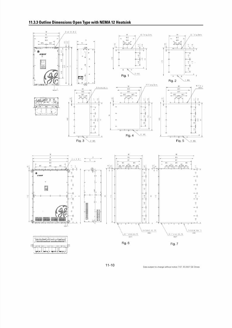
8/11/2019 GEI-100364
http://slidepdf.com/reader/full/gei-100364 133/154
11-10 Data subject to change without notice 7/07. © 2007 GE Drives
11.3.3 Outline Dimensions Open Type with NEMA 12 Heatsink
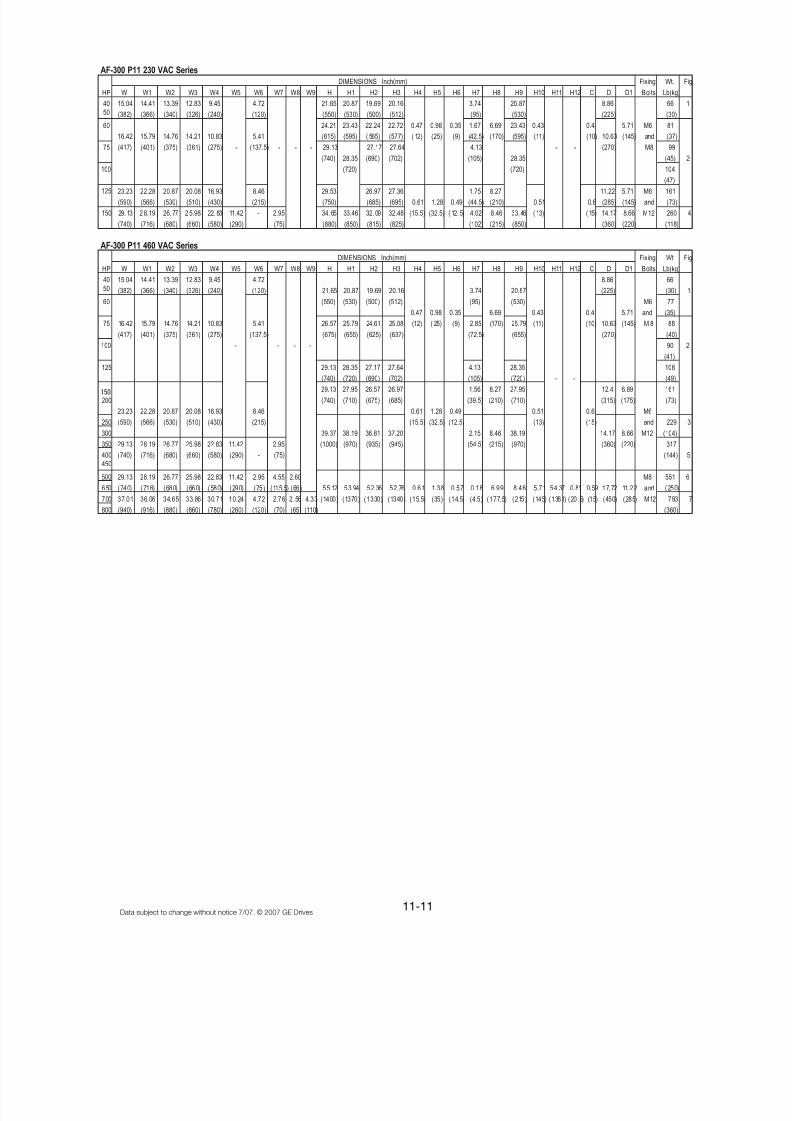
8/11/2019 GEI-100364
http://slidepdf.com/reader/full/gei-100364 134/154
11-11Data subject to change without notice 7/07. © 2007 GE Drives
AF-300 P11 230 VAC Series
DIMENSIONS Inch(mm) Fixing Wt. Fig
W W1 W2 W3 W4 W5 W6 W7 W8 W9 H H1 H2 H3 H4 H5 H6 H7 H8 H9 H10 H11 H12 C D D1 Bolts Lb(kg)
40
50
15.04 14.41 13.39 12.83 9.45 4.72 21.65 20.87 19.69 20.16 3.74 20.87 8.86 66 1
(382) (366) (340) (326) (240) (120) (550) (530) (500) (512) (95) (530) (225) (30)
60 24.21 23.43 22.24 22.72 0.47 0.98 0.35 1.67 6.69 23.43 0.43 0.4 5.71 M6 81
16.42 15.79 14.76 14.21 10.83 5.41 (615) (595) ( 565) (577) ( 12) (25) (9) (42.5) (170) (595) (11) (10) 10.63 (145) and (37)
75 (417) (401) (375) (361) (275) - (137.5) - - - 29.13 27.17 27.64 4.13 - - (270) M8 99
(740) 28.35 (690) (702) (105) 28.35 (45) 2
100 (720) (720) 104
(47)125 23.23 22.28 20.87 20.08 16.93 8.46 29.53 26.97 27.36 1.75 8.27 11.22 5.71 M6 161
(590) (566) (530) (510) (430) (215) (750) (685) (695) 0.61 1.28 0.49 (44.5) (210) 0.51 0.6 (285) (145) and (73)
150 29. 13 2 8.19 26. 77 2 5.98 22. 83 11.42 - 2.95 34. 65 33.46 32. 09 32.48 (15.5) (32.5) ( 12. 5) 4.02 8.46 33. 46 ( 13) ( 15) 14.17 8.66 M12 260 4
(740) (716) (680) (660) (580) (290) (75) (880) (850) (815) (825) (102) (215) (850) (360) (220) (118)
AF-300 P11 460 VAC Series
DIMENSIONS Inch(mm) Fixing Wt Fig
W W1 W2 W3 W4 W5 W6 W7 W8 W9 H H1 H2 H3 H4 H5 H6 H7 H8 H9 H10 H11 H12 C D D1 Bolts Lb(kg)
40
50
15.04 14.41 13.39 12.83 9.45 4.72 8.86 66
(382) (366) (340) (326) (240) (120) 21.65 20.87 19.69 20.16 3.74 20.87 (225) (30) 1
60 (550) (530) (500) (512) (95) (530) M6 77
0.47 0.98 0.35 6.69 0.43 0.4 5.71 and (35)
75 16.42 15.79 14.76 14.21 10.83 5.41 26.57 25.79 24.61 25.08 (12) ( 25) (9) 2.85 (170) 25.79 (11) (10) 10.63 (145) M 8 88
(417) (401) (375) (361) (275) (137.5) (675) (655) (625) (637) (72.5) (655) (270) (40)
100 - - - - 90 2
(41)
125 29.13 28.35 27.17 27.64 4.13 28.35 108
(740) (720) (690) (702) (105) (720) - - (49)
29.13 27.95 26.57 26.97 1.56 8.27 27.95 12.4 6.89 161
200 (740) (710) (675) (685) (39.5) (210) (710) (315) (175) (73)
23.23 22.28 20.87 20.08 16.93 8.46 0.61 1.28 0.49 0.51 0.6 M6
250 (590) (566) (530) (510) (430) (215) (15.5) (32.5) (12.5) (13) (15) and 229 3
300 39.37 38.19 36.81 37.20 2.15 8.46 38.19 14.17 8.66 M12 (104)
350 29.13 28.19 26.77 25.98 22.83 11.42 2.95 (1000) (970) (935) (945) (54.5) (215) (970) (360) (220) 317
400
450
(740) (716) (680) (660) (580) (290) - (75) (144) 5
500 29.13 28.19 26.77 25.98 22.83 11.42 2.95 4.55 2.60 M8 551 6
650 (740) (716) (680) (660) (580) (290) (75) (115.5) (66) 55.12 53.94 52.36 52.76 0.61 1.38 0.57 0.18 6.99 8.46 5.71 54.37 0.81 0.59 17.72 11.22 and (250)
700 37.01 36.06 34.65 33.86 30.71 10.24 4.72 2.76 2.56 4.33 (1400) (1370) (1330) (1340) (15.5) (35) (14.5) (4.5) (177.5) (215) (145) (1381) (20.5) (15) (450) (285) M12 793 7
800 (940) (916) (880) (860) (780) (260) (120) (70) (65) (110) (360)
HP
HP
150
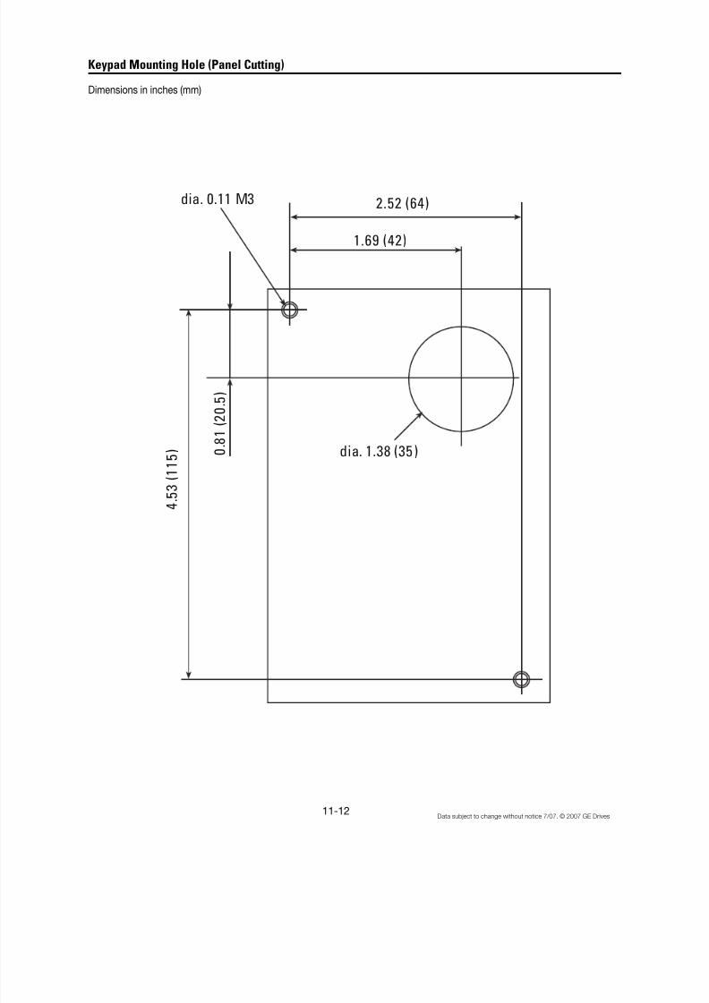
8/11/2019 GEI-100364
http://slidepdf.com/reader/full/gei-100364 135/154
11-12 Data subject to change without notice 7/07. © 2007 GE Drives
Keypad Mounting Hole (Panel Cutting)
Dimensions in inches (mm)
2.52 (64)
1.69 (42)
dia. 0.11 M3
0 . 8
1 (
2 0 . 5
)
4 . 5
3 (
1 1 5 ) dia. 1.38 (35)

8/11/2019 GEI-100364
http://slidepdf.com/reader/full/gei-100364 136/154
12-1Data subject to change without notice 7/07. © 2007 GE Drives
The serial interface supports operation, configuration and monitoring of drive functions through an EIA/RS485 connec-tion. The serial interface is based on Modbus RTU protocol. This protocol allows the drive to function as an RTU slaveon an industrial network.
12.1 Transmission Specification
Item Specification
Physical level EIA/RS485
Transmission distance 500 m max.
Number of nodes 32 total
Transmission speed 19200, 9600, 4800, 2400 [bits/s]
Transmission mode Half duplex
Transmission protocol Modbus RTU
Character code Binary
Character length 8 bitsError check CRC
12.2 ConnectionConnection methodUse shielded wire and connect to the control terminals (DX-, DX+ and SD). A termination resistor should be addedbetween the data lines on the each end of the network. The value of the termination resistor depends on the character-istic impedance of the cable. A common value for termination resistors is 120 ohms.
Control terminals
Terminalmarking Terminal name Function description
DX+ RS485 communication data (+) Input/output terminals for RS485
DX- RS485 communication data (–) communication.
SD Cable shield Electrically floating
12.3 Serial Interface ConfigurationDrive function codes H30 to H39 are used to configure the serial interface parameters, such as device address, baudrate and error response.
12.4 Modbus RTU FunctionsThe following RTU functions are supported. The maximum number of consecutive parameters for function 03 and 16messages is 16.
Code Description
03 Read Holding Registers (16 registers maximum)
06 Preset Single Register
16 Preset Multiple Registers (16 registers maximum)
12. RS485 Modbus RTU Serial Communications
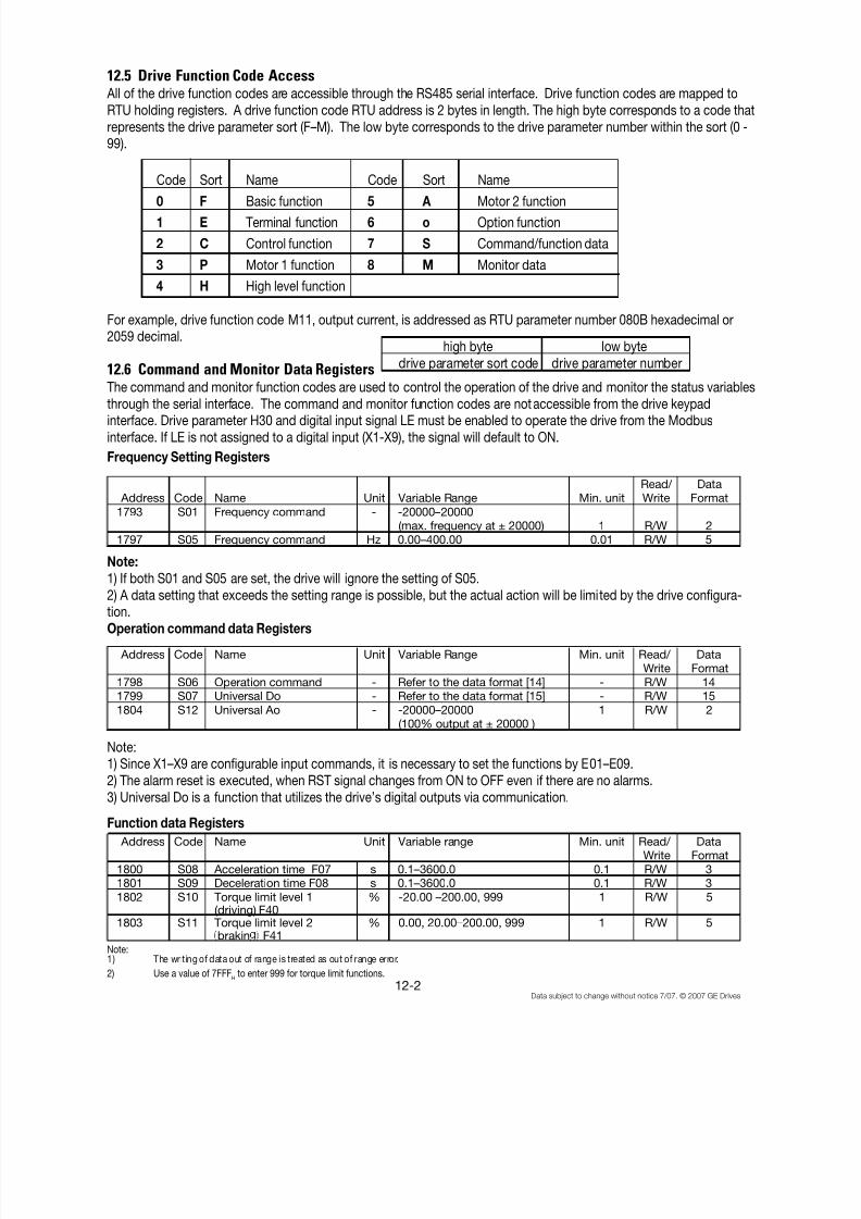
8/11/2019 GEI-100364
http://slidepdf.com/reader/full/gei-100364 137/154
12-2Data subject to change without notice 7/07. © 2007 GE Drives
12.5 Drive Function Code Access All of the drive function codes are accessible through the RS485 serial interface. Drive function codes are mapped toRTU holding registers. A drive function code RTU address is 2 bytes in length. The high byte corresponds to a code thatrepresents the drive parameter sort (F–M). The low byte corresponds to the drive parameter number within the sort (0 -99).
Code Sort Name Code Sort Name
0 F Basic function 5 A Motor 2 function
1 E Terminal function 6 o Option function
2 C Control function 7 S Command/function data
3 P Motor 1 function 8 M Monitor data
4 H High level function
For example, drive function code M11, output current, is addressed as RTU parameter number 080B hexadecimal or2059 decimal.
12.6 Command and Monitor Data Registers
The command and monitor function codes are used to control the operation of the drive and monitor the status variablesthrough the serial interface. The command and monitor function codes are not accessible from the drive keypadinterface. Drive parameter H30 and digital input signal LE must be enabled to operate the drive from the Modbusinterface. If LE is not assigned to a digital input (X1-X9), the signal will default to ON.
Frequency Setting Registers
Read/ Data Address Code Name Unit Variable Range Min. unit Write Format
1793 S01 Frequency command - -20000–20000(max. frequency at ± 20000) 1 R/W 2
1797 S05 Frequency command Hz 0.00–400.00 0.01 R/W 5
Note:
1) If both S01 and S05 are set, the drive will ignore the setting of S05.2) A data setting that exceeds the setting range is possible, but the actual action will be limited by the drive configura-tion.Operation command data Registers
Address Code Name Unit Variable Range Min. unit Read/ DataWrite Format
1798 S06 Operation command - Refer to the data format [14] - R/W 141799 S07 Universal Do - Refer to the data format [15] - R/W 15
1804 S12 Universal Ao - -20000–20000 1 R/W 2(100% output at ± 20000 )
Note:1) Since X1–X9 are configurable input commands, it is necessary to set the functions by E01–E09.
2) The alarm reset is executed, when RST signal changes from ON to OFF even if there are no alarms.3) Universal Do is a function that utilizes the drive’s digital outputs via communication.
Function data Registers
Address Code Name Unit Variable range Min. unit Read/ DataWrite Format
1800 S08 Acceleration time F07 s 0.1–3600.0 0.1 R/W 31801 S09 Deceleration time F08 s 0.1–3600.0 0.1 R/W 3
1802 S10 Torque limit level 1(driving) F40
% -20.00 –200.00, 999 1 R/W 5
1803 S11 Torque limit level 2brakin F41
% 0.00, 20.00–200.00, 999 1 R/W 5
Note:1) The writing of data out of range is treated as out of range error.
2) Use a value of 7FFFH to enter 999 for torque limit functions.
high byte low bytedrive parameter sort code drive parameter number

8/11/2019 GEI-100364
http://slidepdf.com/reader/full/gei-100364 138/154
12-3Data subject to change without notice 7/07. © 2007 GE Drives
Monitoring parameter registers
Address Code Description Unit Range Min. unit Read Data
/ Write Format2049 M01 Frequency command (final
command)- - 20000–20000 (max. frequency
at ± 20000)1 R 2
2053 M05 Frequency command (finalcommand
Hz 0–400.00 0.01 R 5
2054 M06 Actual frequency - - 20000–20000 1 R 2(max. frequency at ± 20000)
2055 M07 Actual torque value % - 200.00–200.00 0.01 R 62056 M08 Torque current % - 200.00–200.00 0.01 R 6
2057 M09 Output frequency Hz 0.00–400.00 0.01 R 52058 M10 Motor output (input
electric ower% 0.00–200.00 0.01 R 5
2059 M11 Output current r. m. s. % 0.00–200.00 (inverter rating at100.00)
0.01 R 5
2060 M12 Output voltage r. m. s. V 0.0–600.0 1 R 32061 M13 Operation command (final
command)- Refer to data format [14] - R 14
2062 M14 Operating state - Refer to data format [16] - R 162063 M15 Universal output terminal
data- Refer to data format [15] - R 15
2064 M16 Fault memory 0 - Refer to data format [10] - R 10
2065 M17 Fault memory 1 - 10
2066 M18 Fault memory 2 - 102067 M19 Fault memory 3 - 102068 M20 Integrated operating time h 0–65535 1 R 1
2069 M21 DC link voltage V 0–1000 1 R 12071 M23 Type code - Refer to data format [17] - R 17
2072 M24 Drive capacity code - Refer to data format [11] - R 112073 M25 ROM version - 0–64999 1 R 12074 M26 Transmission error
rocessin code- Refer to data format [20] - R 20
2075 M27 Frequency command atalarm (final command)
- - 20000–20000 (max. frequencyat ±20000 )
1 R 2
2079 M31 Frequency command atalarm final command
Hz 0–400.00 0.01 R 5
2080 M32 Actual frequency at alarm - - 20000–20000 1 R 2
(max. frequency a t ± 20000)2081 M33 Actual torque at alarm % - 200.00 – 200.00 0.01 R 62082 M34 Torque current at alarm % - 200.00 – 200.00 0.01 R 62083 M35 Output frequency at alarm Hz 0.00 – 400. 0.01 R 5
2084 M36 Motor output at alarm(input power)
% 0.00–200.00 0.01 R 5
2085 M37 Output current r.m.s. atalarm
% 0.00 – 200.00 (inverter rating at100.00)
0.01 R 5
2086 M38 Output voltage effectivevalue at alarm
V 0.0 – 600.0 1 R 3
2087 M39 Operation command atalarm
- Refer to data format [14] - R 14
2088 M40 Operating state at alarm - Refer to data format [16] - R 16
2089 M41 Universal output terminal
data at alarm
- Refer to data format [15] - R 15
2090 M42 Integrated operation timeat alarm
h 0–65535 1 R 1
2091 M43 DC link voltage at alarm V 0–1000 1 R 1
2092 M44 Inverter internal air temp.at alarm
°C 0–120 1 R 1
2093 M45 Cooling fin temp. at alarm °C 0–120 1 R 1
2094 M46 Life of main circuitca acitor.
% 0.0–100.0 0.1 R 3
2095 M47 Life of printed circuitboard capacitor.
h 0–65535 1 R 1
2096 M48 Life of cooling fan. h 0–65535 1 R 1

8/11/2019 GEI-100364
http://slidepdf.com/reader/full/gei-100364 139/154
12-4Data subject to change without notice 7/07. © 2007 GE Drives
12.7 Data Format Specification All data in the data field of communication frame shall be represented by a 16 bit length word.
15 14 13 12 11 10 9 8 7 6 5 4 3 2 1 0
Data format [1] Unsigned Integer data (Positive): Min. unit 1
Example If F15 (Frequency limit, upper)= 60Hz60 = 003C
H
Data format [2] ] Integer data (Positive, negative): Min. unit 1
Example data = -20-20 = FFEC
H
Data format [3] Unsigned Decimal data (Positive): Min. unit 0.1
Example: If F17 (frequency gain setting signal) = 100.0%
100.0 X 10 = 1000 = 03E8H
Data format [4] Decimal data (Positive, negative): Min. unit 0.1
Example If: C31 (Analog input offset adjust, terminal12) = - 5.0%- 5.0 X 10= - 50 = FFCE
H
Data format [5] Unsigned Decimal data (Positive): Min. unit 0.01
Example: If C05 (multi-step frequency 1) = 50.25Hz50.25 X 100 = 5025 = 13A1
H
Data format [6] Decimal data (Positive, negative): Min. unit 0.01
Example: If M07 (actual torque value)= - 85.38%- 85.38 X 100= - 8538=DEA6
H
Data format [7] Unsigned Decimal data (Positive): Min. unit 0.001
Example: If o05 (follow - up side ASR 1 constant) = 0.105s0.105 X 1000 = 105 = 0069
H
Data format [8] Decimal data (Positive, negative): Min. unit 0.001
Example: Data = -1.234- 1.234 X 1000 = - 1234 = FB2E
H
Data format [9] Unsigned Integer data (Positive): Min. unit 2
Example If P01 (Motor 1 number of poles) =2pole2 = 0002
H
Data format [10] Alarm Code
16 bits binary data

8/11/2019 GEI-100364
http://slidepdf.com/reader/full/gei-100364 140/154
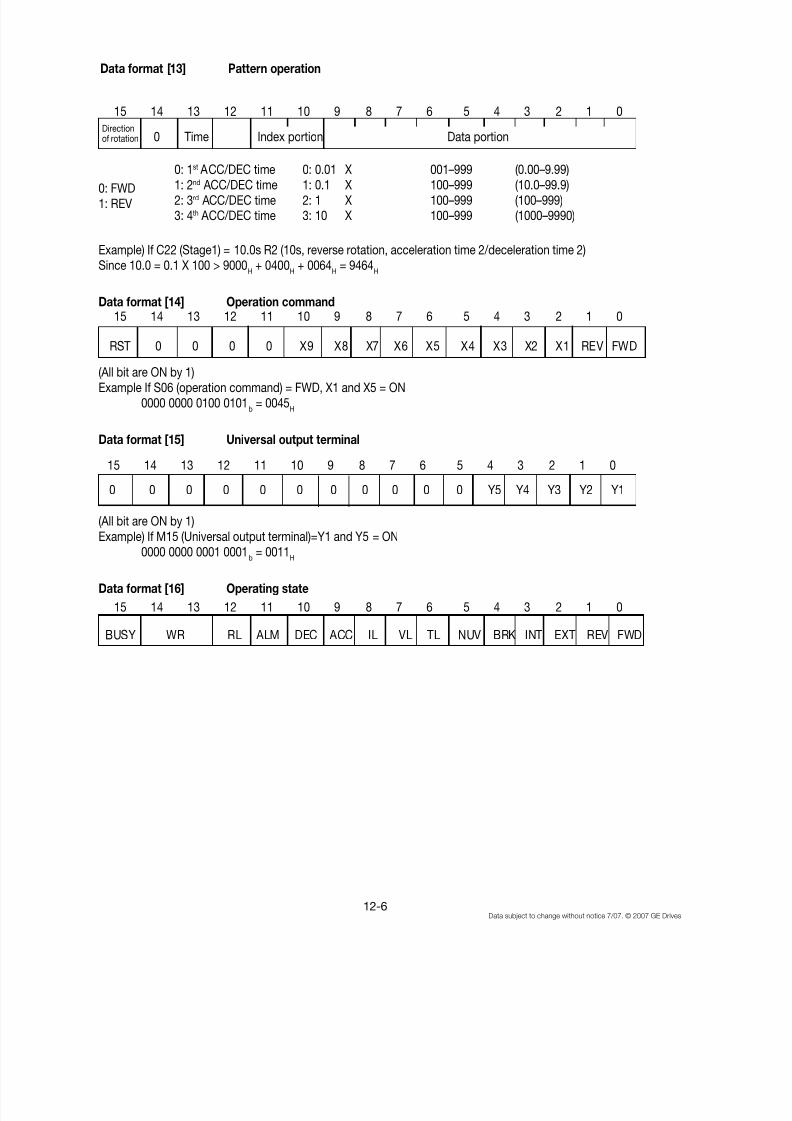
8/11/2019 GEI-100364
http://slidepdf.com/reader/full/gei-100364 141/154
12-6Data subject to change without notice 7/07. © 2007 GE Drives
BUSY WR RL ALM DEC ACC IL VL TL NUV BRK INT EXT REV FWD
RST 0 0 0 0 X9 X8 X7 X6 X5 X4 X3 X2 X1 REV FWD
0 0 0 0 0 0 0 0 0 0 0 Y5 Y4 Y3 Y2 Y1
Data format [13] Pattern operation
0: FWD1: REV
Example) If C22 (Stage1) = 10.0s R2 (10s, reverse rotation, acceleration time 2/deceleration time 2)Since 10.0 = 0.1 X 100 > 9000
H + 0400
H + 0064
H = 9464
H
Data format [14] Operation command
(All bit are ON by 1)Example If S06 (operation command) = FWD, X1 and X5 = ON
0000 0000 0100 0101b = 0045
H
Data format [15] Universal output terminal
(All bit are ON by 1)
Example) If M15 (Universal output terminal)=Y1 and Y5 = ON0000 0000 0001 0001b = 0011
H
Data format [16] Operating state
15 14 13 12 11 10 9 8 7 6 5 4 3 2 1 0
Directionof rotation 0 Time Index portion Data portion
15 14 13 12 11 10 9 8 7 6 5 4 3 2 1 0
15 14 13 12 11 10 9 8 7 6 5 4 3 2 1 0
15 14 13 12 11 10 9 8 7 6 5 4 3 2 1 0
0: 1st ACC/DEC time 0: 0.01 X 001–999 (0.00–9.99)
1: 2nd ACC/DEC time 1: 0.1 X 100–999 (10.0–99.9)2: 3rd ACC/DEC time 2: 1 X 100–999 (100–999)3: 4th ACC/DEC time 3: 10 X 100–999 (1000–9990)
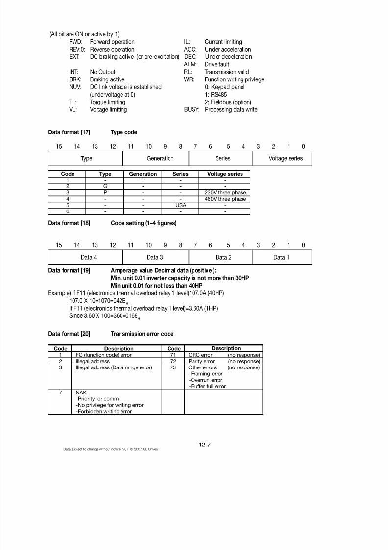
8/11/2019 GEI-100364
http://slidepdf.com/reader/full/gei-100364 142/154

8/11/2019 GEI-100364
http://slidepdf.com/reader/full/gei-100364 143/154

8/11/2019 GEI-100364
http://slidepdf.com/reader/full/gei-100364 144/154
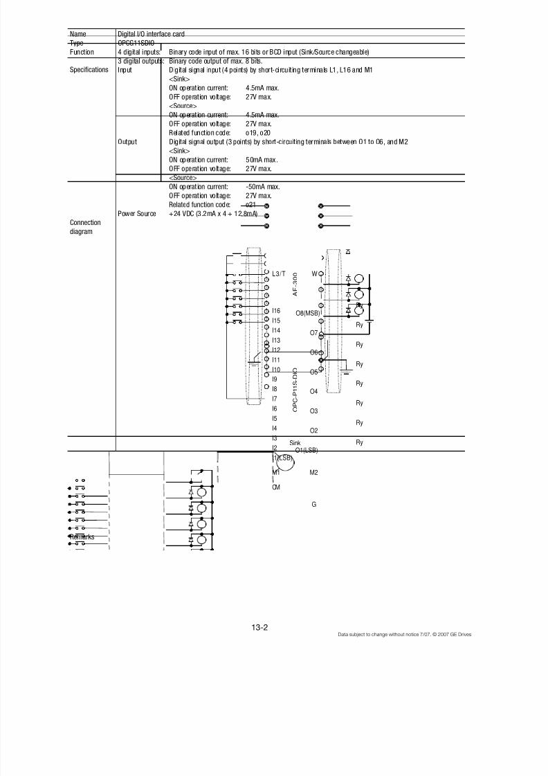
8/11/2019 GEI-100364
http://slidepdf.com/reader/full/gei-100364 145/154
13-2Data subject to change without notice 7/07. © 2007 GE Drives
Name Digital I/O interface card
Type OPCG11SDIO
Function 4 digital inputs: Binary code input of max. 16 bits or BCD input (Sink/Source changeable)
3 digital outputs: Binary code output of max. 8 bits.
Input Digital signal input (4 points) by short-circuiting terminals L1, L16 and M1
<Sink>
ON operat ion current: 4.5mA max.
OFF operation voltage: 27V max.
<Source>
ON operat ion current: 4.5mA max.
OFF operation voltage: 27V max.Related function code: o19, o20
Output Digital signal output (3 points) by short-circuiting terminals between O1 to O6, and M2
<Sink>
ON operat ion current: 50mA max.
OFF operation voltage: 27V max.
<Source>
ON operat ion current: -50mA max.
OFF operation voltage: 27V max.
Related function code: o21
Power Source +24 VDC (3.2mA x 4 + 12.8mA)
Connection
diagram
Remarks
Specifications
L1/R
L2/S
L3/T
U
V
W
I16
I15
I14
I13
I12
I11
I10
I9
I8
I7
I6
I5
I4
I3
I2
I1(LSB)
M1
O8(MSB)
O7
O6
O5
O4
O3
O2
O1(LSB)
Ry
Ry
Ry
Ry
Ry
Ry
Ry
Ry
M2
CM
A F - 3 0 0
P 1 1
O P C - P 1 1 S - D I O
Sink
G
M
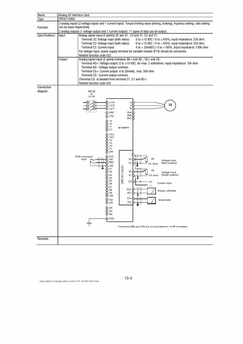
8/11/2019 GEI-100364
http://slidepdf.com/reader/full/gei-100364 146/154
13-3Data subject to change without notice 7/07. © 2007 GE Drives
Name Analog I/O Interface Card
Type
Function
2 analog outputs (1 voltage output and 1 current output): 11 types of data can be output.
Specifications Input Analog signal input (3 points) 32 and 31, 22 and 21, C2 and 21.
Terminal 32: Voltage input (both sides): 0 to ±10 VDC / 0 to ±100%, input impedance: 22k ohm.
Terminal 22: Voltage input (both sides): 0 to +10 VDC / 0 to +100%, input impedance: 22k ohm.
Terminal C2: Current input: 4 to + 20mADC / 0 to +100%, input impedance: 250k ohm.
For voltage input, power supply terminal for variable resistor (P10) should be connected.
Related function code o22Output Analog signal input (2 points) between AO+ and AO-, CS+ and CS-
Terminal AO+: Voltage output: 0 to ±10 VDC, for max. 2 voltmeters, input impedance: 10k ohm
Terminal AO-: Voltage output common.
Terminal CS+: Current output: 4 to 20mAdc, max. 500 ohm
Terminal CS-: Current output common
(Terminal CS- is isloated from terminal 21, 31 and AO-)
Related function code o23
Connection
diagram
Remarks
3 analog inputs (2 voltage inputs and 1 current input): Torque limiting value (driving, braking), frquency setting, ratio settingcan be input respectively.
OPCG11SAIO
X9
X8
X7
X6
X5
X4 X3
X2
X1
E(G)
SD
DX
DX
FM
FM
CM
CM
REV
FW
PLC
CM
AO-
AO+
C2
21
22
31
32
Y1
Y2Y3
Y4
Y5C
Y5A
C1
11
1213
30C
30B
30A
(T0) *
AF-300P11
MCCBor
ELCB
* Termina ls [R0] and [T0] are no t provided for 1.0 HP or smaller.
RUN commandinput
(R0) *
MU
V
WL3/T
L2/S
L1/R
CS+
CS-
(+)
(-)
(+)
VR
VR
(1k ohm)
(1k ohm)
Voltage input(Single polarity)
Voltage input(Both polarity)
Current input
Analog voltmeter
Anammeter
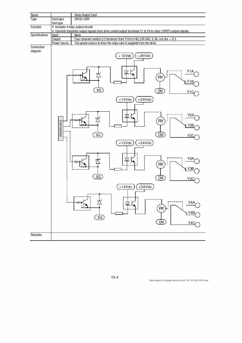
8/11/2019 GEI-100364
http://slidepdf.com/reader/full/gei-100364 147/154
13-4Data subject to change without notice 7/07. © 2007 GE Drives
Name Relay Output Card
Type Card type OPCG11SRY
Unit type
Function
• Converts transistor output signals from drive control output terminals Y1 to Y4 to relay (1SPDT) output signals.
Specifications Input None
Output Four-channel contact (12 terminals from Y1A to Y4C) 250 VAC, 0.3A, ocs dia. = 0.3
Power source The power source to drive the relay card is supplied from the drive.
Connection
diagram
Remarks
• Includes 4 relay output circuits
RY
+ 13Vdc
5G
Y1A
Y1C
Y1B
5G
5G
5G
C onn e c t or
+ 24Vdc
CM
RY
+13Vdc
Y2A
Y2C
Y2B
+24Vdc
CM
RY
+13Vdc
Y3A
Y3C
Y3B
+24Vdc
CM
RY
+13Vdc
Y4A
Y4C
Y4B
+24Vdc
CM
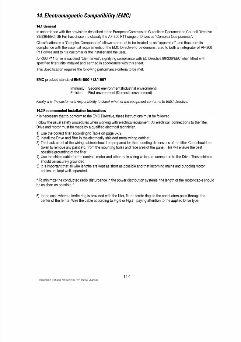
8/11/2019 GEI-100364
http://slidepdf.com/reader/full/gei-100364 148/154
14-1Data subject to change without notice 7/07. © 2007 GE Drives
14. Electromagnetic Compatibility (EMC)
14.1 General
In accordance with the provisions described in the European Commission Guidelines Document on Council Directive89/336/EEC, GE Fuji has chosen to classify the AF-300 P11 range of Drives as “Complex Components”.
Classification as a “Complex Components” allows a product to be treated as an “apparatus”, and thus permitscompliance with the essential requirements of the EMC Directive to be demonstrated to both an integrator of AF-300P11 drives and to his customer or the installer and the user.
AF-300 P11 drive is supplied ‘CE-marked’, signifying compliance with EC Directive 89/336/EEC when fitted withspecified filter units installed and earthed in accordance with this sheet.
This Specification requires the following performance criteria to be met.
EMC product standard EN61800-/13/1997
Immunity: Second environment (Industrial environment)Emision: First environment (Domestic environment)
Finally, it is the customer’s responsibility to check whether the equipment conforms to EMC directive.
14.2 Recommended Installation InstructionsIt is necessary that to conform to the EMC Directive, these instructions must be followed.
Follow the usual safety procedures when working with electrical equipment. All electrical connections to the filter,Drive and motor must be made by a qualified electrical technician.
1) Use the correct filter according to Table on page 6-39.2) Install the Drive and filter in the electrically shielded metal wiring cabinet.3) The back panel of the wiring cabinet should be prepared for the mounting dimensions of the filter. Care should be
taken to remove any paint etc. from the mounting holes and face area of the panel. This will ensure the bestpossible grounding of the filter.
4) Use the shield cable for the control , motor and other main wiring which are connected to the Drive. These shieldsshould be securely grounded.
5) It is important that all wire lengths are kept as short as possible and that incoming mains and outgoing motorcables are kept well separated.
“ To minimize the conducted radio disturbance in the power distribution systems, the length of the motor-cable shouldbe as short as possible. “
6) In the case where a ferrite ring is provided with the filter, fit the ferrite ring so the conductors pass through thecenter of the ferrite. Wire the cable according to Fig.6 or Fig.7 , paying attention to the applied Drive type.
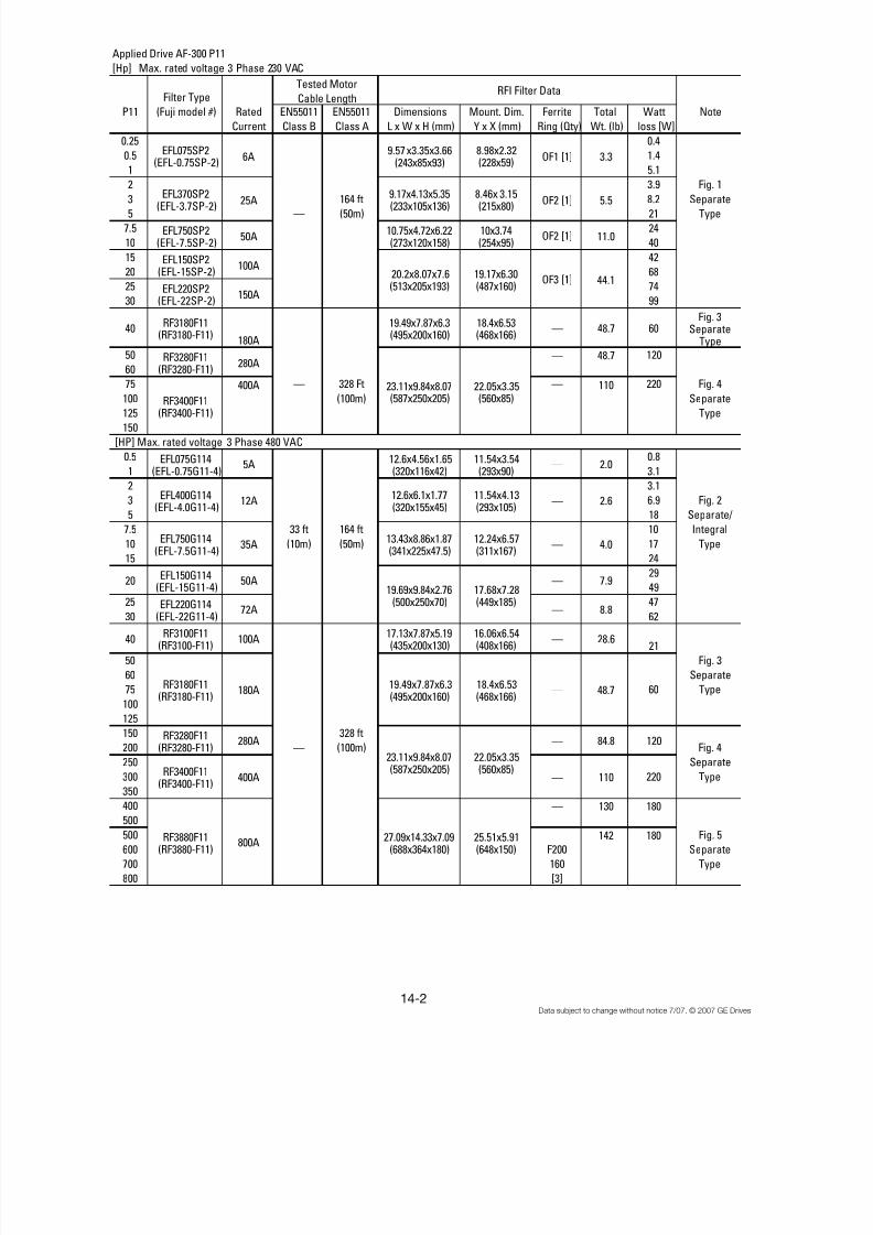
8/11/2019 GEI-100364
http://slidepdf.com/reader/full/gei-100364 149/154
14-2Data subject to change without notice 7/07. © 2007 GE Drives
Applied Drive AF-300 P11
[Hp] Max. rated voltage 3 Phase 230 VAC
Filter Type
P11 (Fuji model #) Rated EN55011 EN55011 Dimensions Mount. Dim. Ferrite Total Watt Note
Current Class B Class A L x W x H (mm) Y x X (mm) Ring (Qty) Wt. (lb) loss [W]
0.25 0.4
0.5 1.4
1 5.1
2 3.9 Fig. 1
3 164 ft 8.2 Separate5 — (50m) 21 Type
7.5 24
10 40
15 42
20 68
25 74
30 99
40RF3180F11
(RF3180-F11)180A
19.49x7.87x6.3(495x200x160)
18.4x6.53(468x166)
— 48.7 60Fig. 3
SeparateType
50 — 48.7 120
60
75 400A — 328 Ft — 110 220 Fig. 4
100 (100m) Separate125 Type
150
[HP] Max. rated voltage 3 Phase 480 VAC
0.5 0.8
1 3.1
2 3.1
3 6.9 Fig. 2
5 18 Separate/
7.5 33 ft 164 ft 10 Integral
10 (10m) (50m) 17 Type
15 24
29
49
25 47
30 62
40RF3100F11
(RF3100-F11)100A
17.13x7.87x5.19(435x200x130)
16.06x6.54(408x166)
— 28.621
50 Fig. 3
60 Separate
75 60 Type
100
125
150 328 ft
200 — (100m) Fig. 4
250 Separate
300 220 Type
350400 — 130 180
500
500 142 180 Fig. 5
600 F200 Separate
700 160 Type
800 [3]
20
RF3880F11(RF3880-F11)
27.09x14.33x7.09(688x364x180)
25.51x5.91(648x150)
800A
RF3400F11(RF3400-F11)
23.11x9.84x8.07
(587x250x205)
22.05x3.35
(560x85)
2.0
2.6
4.0
7.9
8.8
48.7
84.8
110
—
—
—
—
—
—
—
—
19.49x7.87x6.3(495x200x160)
18.4x6.53(468x166)
23.11x9.84x8.07(587x250x205)
22.05x3.35(560x85)
13.43x8.86x1.87(341x225x47.5)
12.24x6.57(311x167)
19.69x9.84x2.76(500x250x70)
17.68x7.28(449x185)
12.6x4.56x1.65(320x116x42)
11.54x3.54(293x90)
12.6x6.1x1.77(320x155x45)
11.54x4.13(293x105)
180A
280A
400A
12A
35A
50A
72A
RF3180F11(RF3180-F11)
RF3280F11(RF3280-F11)
RF3400F11(RF3400-F11)
EFL400G114(EFL-4.0G11-4)
EFL750G114(EFL-7.5G11-4)
EFL150G114(EFL-15G11-4)
EFL220G114(EFL-22G11-4)
EFL075G114(EFL-0.75G11-4)
5A
6A
25A
50A
100A
150A
11.0
Tested Motor
Cable Length
EFL220SP2(EFL-22SP-2)
OF2 [1]
OF3 [1]
RFI Filter Data
EFL075SP2(EFL-0.75SP-2)
EFL370SP2(EFL-3.7SP-2)
EFL150SP2(EFL-15SP-2)
OF1 [1]
OF2 [1]
3.3
5.5
10x3.74(254x95)
19.17x6.30(487x160)
280A
EFL750SP2(EFL-7.5SP-2)
RF3280F11(RF3280-F11)
120
9.57 x3.35x3.66(243x85x93)
10.75x4.72x6.22(273x120x158)
9.17x4.13x5.35(233x105x136)
20.2x8.07x7.6(513x205x193)
44.1
8.98x2.32(228x59)
8.46x 3.15(215x80)
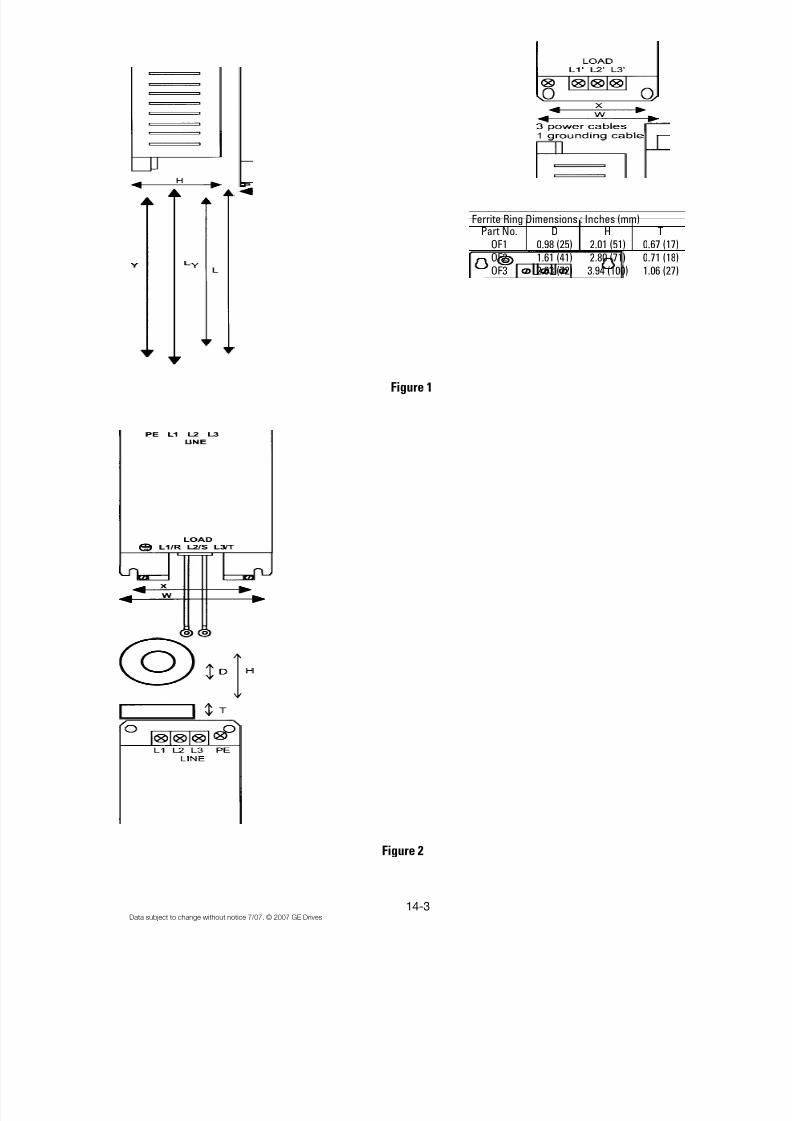
8/11/2019 GEI-100364
http://slidepdf.com/reader/full/gei-100364 150/154
14-3Data subject to change without notice 7/07. © 2007 GE Drives
Part No. D H TOF1 0.98 (25) 2.01 (51) 0.67 (17)OF2 1.61 (41) 2.80 (71) 0.71 (18)OF3 2.83 (72) 3.94 (100) 1.06 (27)
Ferrite Ring Dimensions : Inches (mm)
Figure 1
Figure 2
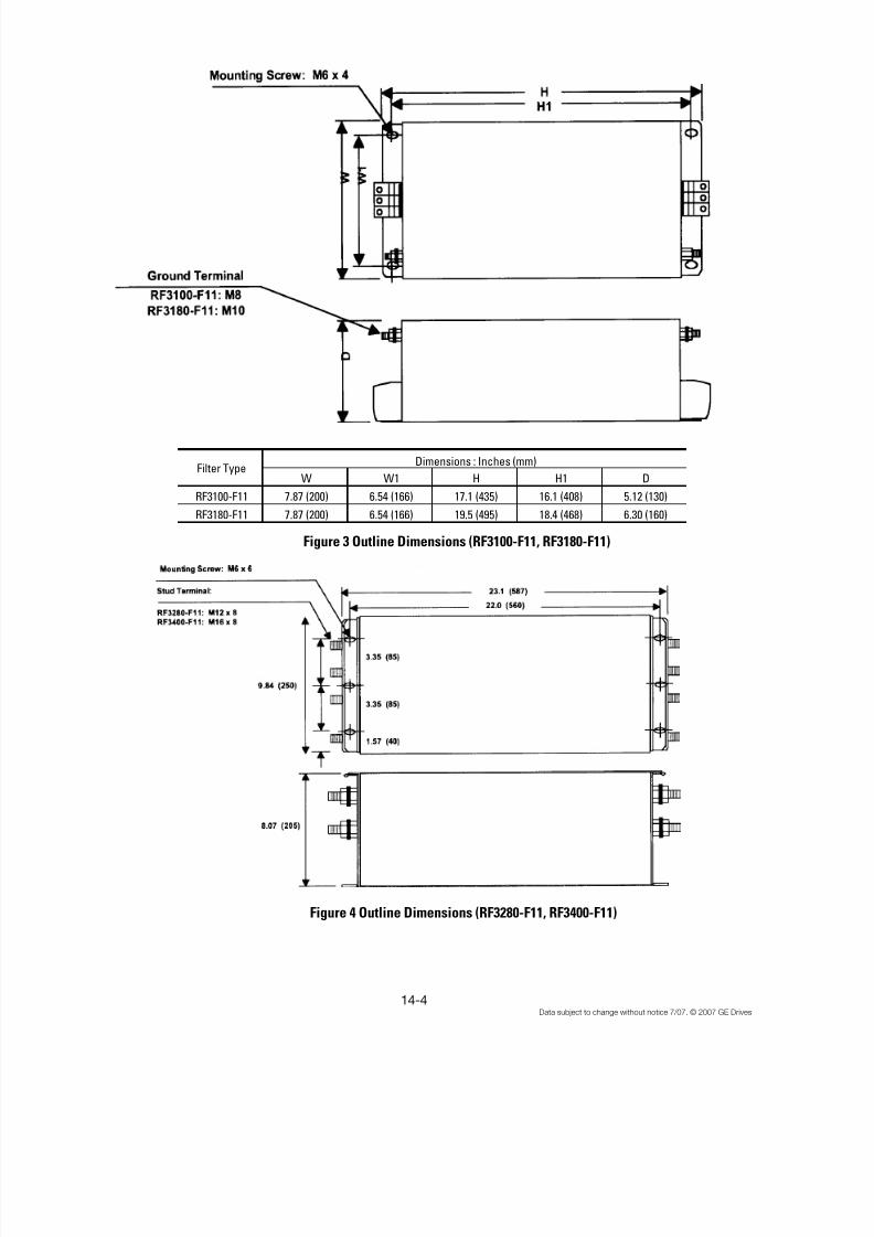
8/11/2019 GEI-100364
http://slidepdf.com/reader/full/gei-100364 151/154
14-4Data subject to change without notice 7/07. © 2007 GE Drives
W W1 H H1 D
RF3100-F11 7.87 (200) 6.54 (166) 17.1 (435) 16.1 (408) 5.12 (130)
RF3180-F11 7.87 (200) 6.54 (166) 19.5 (495) 18.4 (468) 6.30 (160)
Dimensions : Inches (mm)Filter Type
Figure 3 Outline Dimensions (RF3100-F11, RF3180-F11)
Figure 4 Outline Dimensions (RF3280-F11, RF3400-F11)
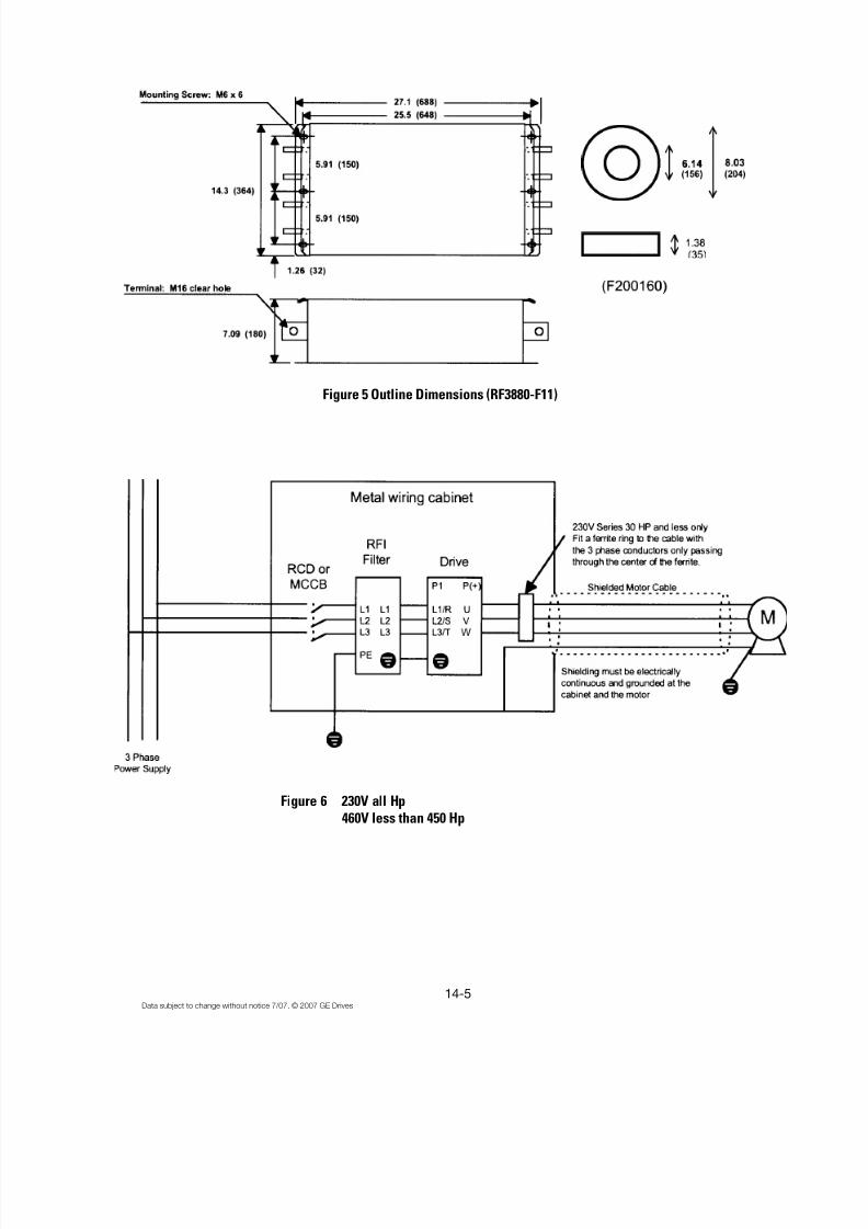
8/11/2019 GEI-100364
http://slidepdf.com/reader/full/gei-100364 152/154
14-5Data subject to change without notice 7/07. © 2007 GE Drives
Figure 5 Outline Dimensions (RF3880-F11)
Figure 6 230V all Hp460V less than 450 Hp

8/11/2019 GEI-100364
http://slidepdf.com/reader/full/gei-100364 153/154
14-6Data subject to change without notice 7/07. © 2007 GE Drives
Figure 7 AF-300 P11 460V 500 Hp and higher

8/11/2019 GEI-100364
http://slidepdf.com/reader/full/gei-100364 154/154
GE Consumer & Industrial
41 Woodford Avenue, Plainville, CT 06062
www.geelectrical.com


