88
GEM Muon Group Meeting - SSCL January 24, 1992 Abstract: GEM TN-92-60 · Transparencies and agenda for the GEM Muon Group Meeting on January 24, 1992 held at the SSCL.
GEM Muon Group Meeting - SSCL
January 24, 1992
Abstract:
GEM TN-92-60 ·
Transparencies and agenda for the GEM Muon Group Meeting on January 24, 1992 held at the SSCL.
GE n., t1'1 ~ Htt.rd "'14.'I' ~
}'h.1..d~~
c;,,_ ,_ . •. J R~ .,.... ...... ~, IR i D j
• l. ,._.r .(.a. .,. ,· _, /T ~ d--.:1 :--..., ~ {,,t;il- f2..w; Ma.r
F...,, •. .,. .J1-.Jo l.i:lif
TIR ~ M-c G~. Ja.:-ls-J,,.-" """"
rDT Rf\)
l $Dr 'Rt{)
~Pl: R.; D
csc ~iD
~.,.hf'.. f c....~ / Jt,,:r, silM ...
(..,~, ~,"4.af., ~'4-c..-, ...... • c,t,JJC.~
L1,,,:s ~ L.,,t' ,,,
(~] ~~.&J"
'rt" w:.,, ('/.-...
s c.ait w L.: I .J..""-'

Looi:, 5, C»furnt ~ 17-25.J-2.39{
sUJJ.t wA.J~ (vir-) 5s-~- &!i1r,
1),&1e, fetid (<P!&Jt..) ~!S')>7'f-5~~
'IJ.r.v;µ A f tc-s5{1-t1rJ 611-2r?-2.5t:.7
~·, (_ l£.r L:LJ Z. ll\ 10'G ;So I I
;;z-;.q~/.~//.e/ (21t;) 7t?2'-6c:J2:?
Ch I c..k.: ,t "1 Ct8 ;S<!Wt;.
(-,~ R.. 0,..est
0'36~1-n-et!: J1.ltTLll/S
seorrw ~lL?t-IYe..
HI T /,.Al-$ : : ?Le -5_5
~ I (be.Le:( SSC v 'i. I
5°fe-k'e1a 55Cf/Y/
13,..,~ .:S,.,.., ~ ~t66S -~ z;t:.11~C4.LV~17£JEC>/U /Jlt/t..6&JV
Fran~ /'11lhlll-eij (fot7) 2S8-l~f:i /0/l'?-8t.eT7@/)/?~.t:J.Elf?, C!'t:?M
NCll11r1r1Ab No Ht!rf11All I S"/(" - {; 3 2- 8tcJ j. S & lflZP .' ! rtaH ffrtrll'r D f
6 l "t 3 5? 60;;!8
~ H-:~Ct~ 21y- ]08- ,00(
Ma.(Jed fJi1~,._ 5'1b z~z 3067
,f)__O y a!et n.9 fet IA. f-( 3 7 4 i ~} 8)
V l VJ viit:.- ?oJyo~ronQ.lc) '[1 (-2 KJ-3 i fJ
C@cpz cl~-{!)-i/ ~:J~:J-e:z3r Kar/ 'Va1t Btfiber £lo - 42 3'- 89'/-9
617 - '3~/-5-lf01
(114) 70 f ()Of
S5C-"0" I ! I "1 I 7 J~H/f!-11~
·~ (2. lfJNl DAc;_
tfm~ ,;. fl ~u~ Po LY c, H eo /\/~ IS /\l'l... M--l<
CH c; L~v @\fXtER.-lV

~ ""'?':=-= ..................... ~ ~
~ ' " '
L
/
De&ector
ElectraDia
--~/ /
,,. / 7 ,
"" ~
~:~~~~:~~~~~*.'i~~~~ff/;¥~~~~~~:~:~~:~~~~:~:~:~;~~:~~~~- ~~~~~~-:~~~:~~~~-~~~~~~~t~~~:~{i~ff!:~:~~f · ~~~~~g~~~:*~~~~~~~~~{~~*~~~~~~~*~i ··t~~~~}~~~~~:~~~i{~~~~~:~~~z;f~~~~:~~~~::~~~~$~::~~~~~~~~~~~~~~~$::~
G.13.AS.IOOJ
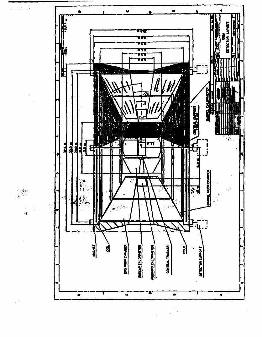
GEM Configuration Option Study Liquid Argon Calorimeter
Integral Calorimeter Version
f=' .t.,..f"'f'~S :
•
•
j )1 t ~ 3 '('J .,.,, .. ,,.. c.e. • .,,,. ~ S"l'l',,,.t; Sfrwc+Mr-e
~-f J 1~ 0 i 1~ ?
Q t"C"1"Eefltlf/\ENNl~j
Ce S• ( .J ."h. (.-. ? • .ft ""I u...c"'" f,._/"'
-

Wk.t 1$ "".11..&J.J) f~,,. bas~ 1:-e. S(,1.e;f;~ 3/f /f'L
•
•
•
•
•
f' (,pc~ s~
~:~.c. 1 "'1-k1wf 1 tk•1tn.J "o.....t" 11( dA ... 1,,.,,s
d~""''"'s -le Dr-rA1 "'' 217/T~ 'F.JI. Loe.wt~ .... •t ~ .... 44., ;.,.. ...... ,....,J
RI I
~ f I
F. tJ. Drap'-~ brl ~/11r/'l2. ~"· ,..,._.. ~ & Ir ""*''•J
c,....,clff+...J J ... :7- •t d..-. .. J,....,. si.r,.,.,..rs ~rJ./'b"-f""' .. " ,_,,,,,,-:.
tt.t;'""' ~~ r.....c~ ( ~~ ~ 1'!' , GT.J .! s-or) f.tJ./ t>.-_,. .... "'1 -,.11r}f ~
~"Mo-f,Js:s: o.f. 'itfi./f.1. ( ~ P/p)
- w • dl. 'Q-f;~ (J st..r,-c . - f'~: s.Atc. c.t, ...,,,..,....., lie.~~ f x 0
L.R./1.~S./FiT S,·.,..'4ti"'s 1/1/f 2
• l-t ~d~ p\/Wi ,,t.. Ol,,.oJ!' A c.,/ ( P~, fAr, Fc / W?) R.lhcr.rl. s.·~..,t-t;._, 'S/'1-/ ''2.
• ""~--<~s•~ e/ L"·;-;:;} °""?f ~ll~c:ts c sc -V.P. /s. w. , PDT- s."fl. 1 L soT-fi.r:
• 13 - .f:~ (J ,.,.,. • .,,,,,, .. J j.b.S. IP. lh. I LJ ('"tS6" /LR.
• Co~+ ...:fi "*-*-c. F.rJ. /Pry-... &,~ ?>/7../72-, T t' i 1~ c.,,.,. c~ -r.P. /1tJ. "i: ?rt..t.Ji,,., ~ '"3/ -a.{ 'f '2-
• GE th r- '-t"""" ~ /;""' P-..t-t ·s/l-/'12 1· . . FE. i Wtf/ C.....p: Jc
/O ~ '2o ,,.. ,.... ( ";y?.e:: S I rt~(;, I J"'""' i ~ 'S "' )
R ~ 1J ~ .. J'f'" ~
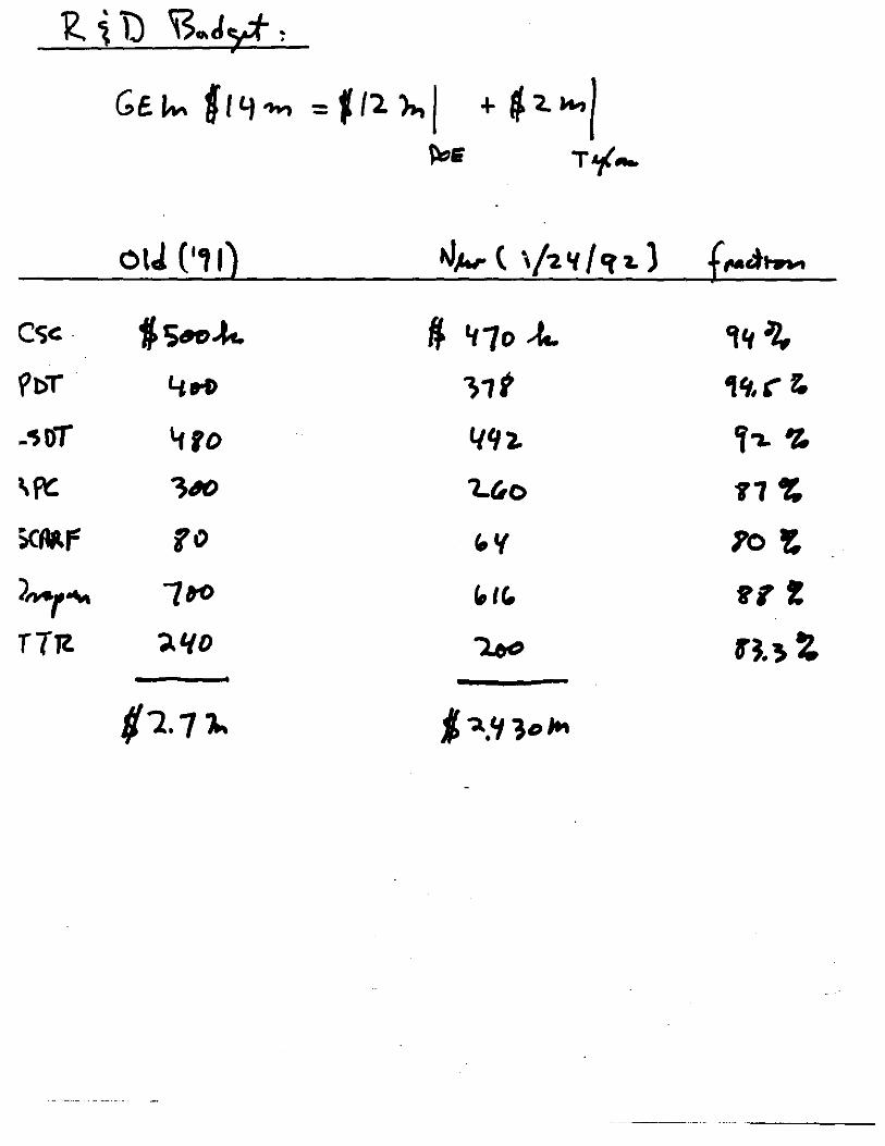
Ge~ ft Y..,,, = J /'2. ),., I + f '- ""'/ ~& T'f-.
OlJ ('11) >J,,.,. ( '/7. " /er i. l f_..am..
Cc;c: ~Sn~ fl. '11o .-t... ,,, .lJ. ~bT 4ri> )1t 1'1. (" z, .-soT '110 l/'12. Y-i. ~ \~ ;40 't.iio .,, ~ iCMr yo ,. '( 10 t
)~'""" 1to " IC., gy !
TTTt "J.L/D Leo rJ.~ i
f/'2. 71' j-.,'11°,.,

EFFECT OF GEM MAGNET ASSEMBLY OPTIONS
ON GEM MUON SYSTEM
F. Nlmblett 20 Jan 92
ORIGINAL MAGNET CONCEPJ: 1WO MAG'.'IET HALVES ASSEMBLED Willi CENTRAL WEB PRIOR TO INSTALLATION OF LIQUID ARGON CALORIMETER
':;-.... . • Muon System lnstaRallon can occur only after calorimeter Is Installed and SHORT U~E~ ~ nt
1 movecL .-.r.. .··.·.,, ~ ,;;' .;~.
' -" 1~'1f:j' -~-- -·. '-~:fi; . .·.l:~r'. '.!..~ ·;-,.,.~·\'~··: .
• Cslorimeter Cabling and Cryo Pipe Concemt .. H they exit the central web, affects magnet assy •• Exit at 30° Muon split line causes serial assy.
with central muon, services and endcap muon syst.
• Access Requirements after Installation .. Removal of Quad or possibly a cantilevered Quad. •• Retraction of Pole 0·f •• Removal of at least one endce.p muon sector module unless
there Is adequate acce111 cpace at the 30° split line plus gymnastic ability for the technicians.
• Global Alignment of modules (approx. 1 mm) Is most likely to be maintained In this system Ill
• Central tracker access requires slgn!flcant disassembly on both ends of the muon system, services, service support structures plus the addition of fixturing to remove the endcap calorimeters and finally the central tracker; THE WORST OPTION TO ADDRESS THIS CONCERN II
1/21/92 1

I I
.. . ~:·;
I
I
'
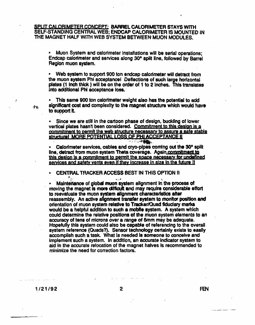
SPLIT CALORIMETER CONCEPT: BARREL CALORIMETER STAYS WITH SELF-STANDING CENTRAL WEB; ENDCAP CALORIMETER IS MOUNTED IN lliE MAGNET HALF Willi WEB SYSTEM BETWEEN MUON MODULES.
• Muon System and calorimeter installations will be serial operations; Endcap calorimeter and services along 30° split line, followed by Barrel Region muon system.
• Web system to support 900 ton endcap calorimeter will detract from the muon system Phi acceptance! Deflections of such large horizontal plates (1 Inch thick ) will be on the order of 1 to 2 Inches. This translates into additional Phi acceptance loss.·
• This same 900 ton calorimeter weight also has the potential to add significant cost and complexity to the magnet structul'8 which would have to support It. ·
• Since we are still in the cartoon phase of design, buckling of lower vertical plates hasn't been considered. eommltment to this dglgn is a commitment to rumnlt the web structure naca&sary to assum a safe stable struc1u!J!I MORE POTENTIAL LOSS Of PHI ACCEPTANCE II
''" _, .. _., • Calorimeter services, cables and cryo-plpn coming out the 30° split line, detract from muon system Theta coverage. Again commttm•m to this d&slgn Is a commitment to pacmlt the space nece"''Y for undefined serylces and safety vents even H they increase In size In the Mull! II
• CENTRAL TRACKER ACCESS BEST IN THIS OPTION II " . 1: .... ,--.i ~
• Maintenance of globd muon system alignment In the process of moving the magnet is more dfficull and may require considerable effort to reevaluate the muon ~em allgnmem characteristics after reassembly. An active alignment transfer system to monitor position and orientation of muon system relative to Tracker/Quad fiduciary marks would be a helpful addition to such a l1loblle system. A system which could determine the relative positions of the muon system elements to an accuracy of tens of microns over a range of Smm may be adequate. Hopefully this system could also be capable of referencing to the overall system reference (Quads?). Sensor technology certainly exists to easily accomplish such a task. What is needed Is someone to conceive and implement such a system. In addition, an accurate Indicator system to aid in the accurate relocation of the magnet halves is recommended to minimize the need for correction factors.
1/21/92 2
• u • I
.. .
..
..
I I I I ~ ! l
•
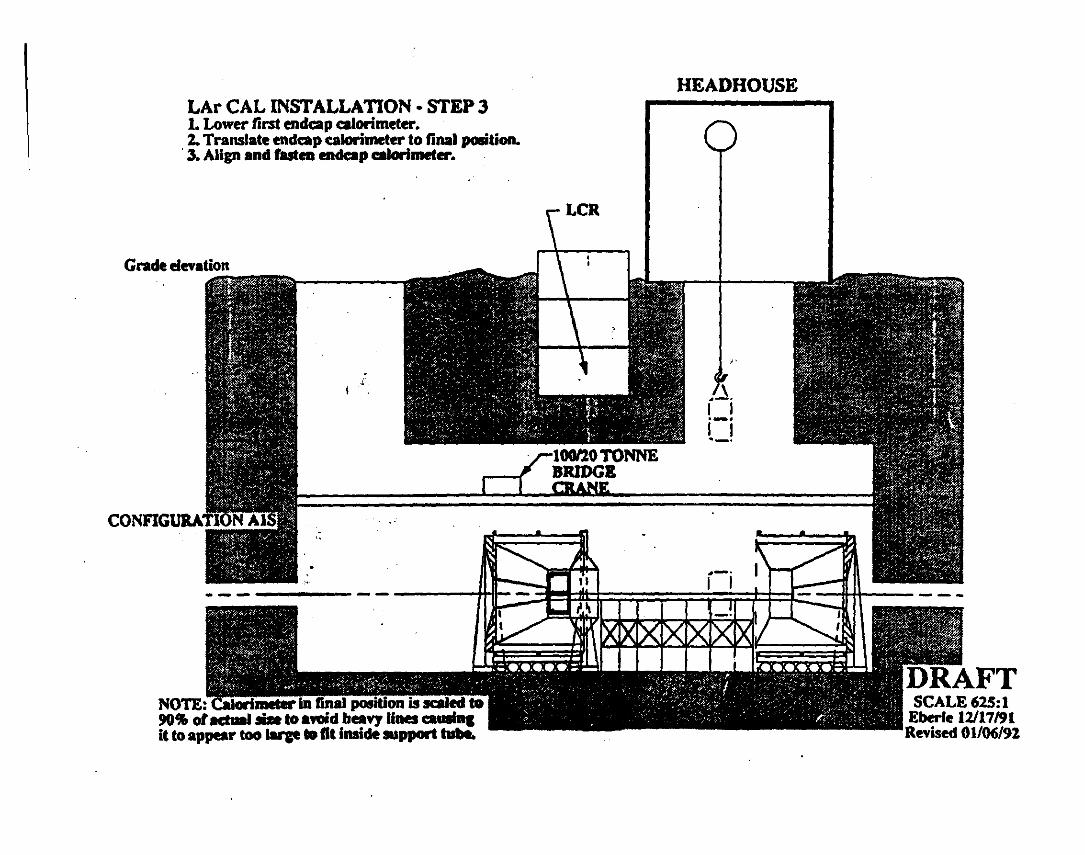
LAr CAL INSTALLATION· STEP J 1. Lower first endcap calorimeter. 2. Translate endcap calorimeter to final position.
· 3. Align and fasten endeap calorimeter. .
Grade elevation
•
NOTE:-Glonmeter lft-f[liitl PCJlition is saiJed to !IOIJJ of actml lilit to atOid heavy lines c:auslq it to appeiar too larp •It inside 111pport tobe.
HEADHOUSE
.~. I I ·-· I I ·-·
·-· I I
SCALE625:1 Eberle 12117/91 Revised 01/06/92
~,._
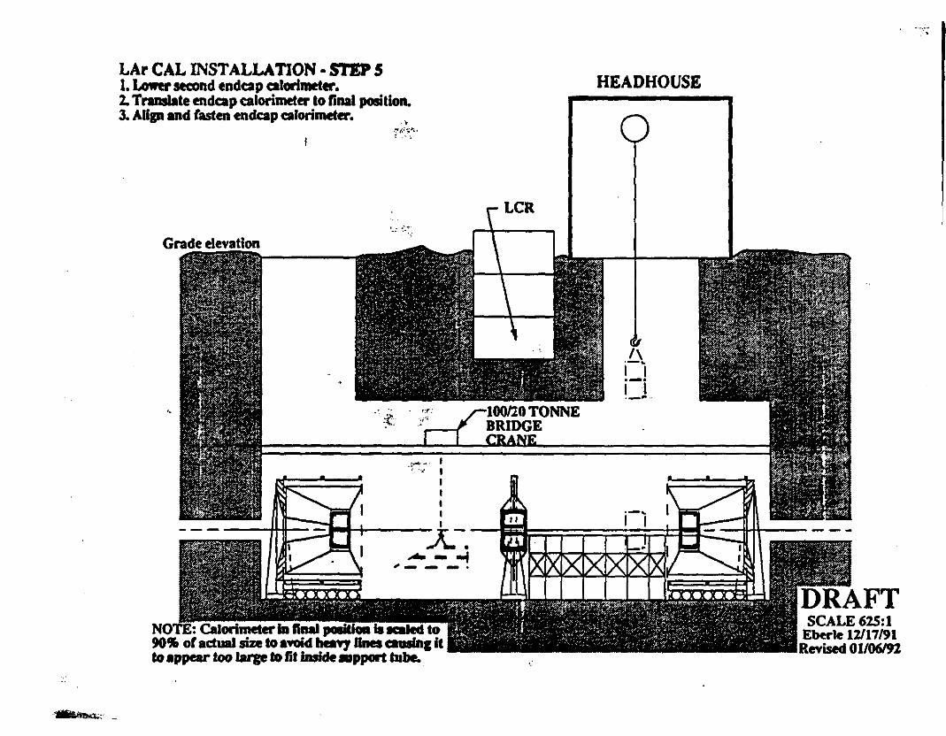
LAr CAL INSTALLATION· SI EP 5 1. Lower second endcap calorimeter. 2. Translate endcap calorimeter to final position. 3. Align and fasten endcap calorimeter.
Grade elevation
'•
• !"'f,;';"1-·
f - ' '
,.- - I ·: , I
I I I I I :x.-.
- - -I ,_ - - .
NOTE: Calorimeter la ftnal poeidoll la 1e111ed to 90 .. or actual si7.e to a~ heaY1 Ones camin& it to appear too large to lit inside mpport tube.
LCR
HEAD HOUSE
/\ i-i i-i --~
SCALE62S:l Eberle 12117/91 Revised 01/06/92
- -:.·;

,I I I
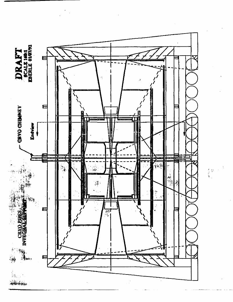
ENDCAPCRYOEXHAUST CRYO CHIMNEY
CRYOPIPES· SPLIT SUPPORT
End view DRAFT SCALE 160:1
EBERLE 01/07/'2
I I I
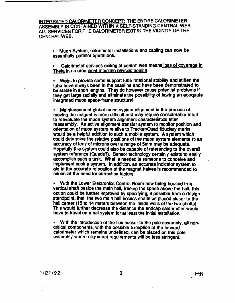
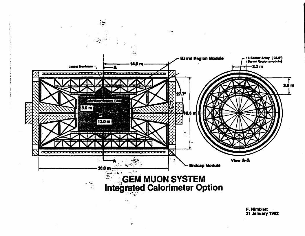
INJEGRATEQ CALORIMETER CONCEPT: THE ENTIRE CALORIMETER ASSEMBLY IS CONTAINED WITHIN A SELF-STANDING CENTRAL WEB. All SERVICES FOR THE CALORIMETER EXIT IN THE VICINITY OF THE CENTRAL WEB.
• Muon System, calorimeter installations and cabling can now be essentially parallel operations.
• Calorimeter services exiting at central web means loss of coverage In Theta in an area least af(ectjng physjcs goals!!
• Webs to provide some support tube rotational stability and stiffen the tube have always been In the baseline and have been demonstrated to be stable In short lengths. They do however cause potential problems H they get large radially and eliminate the possibility of having an adequate Integrated muon space-frame structure!
• Maintenance of global muon system alignment in the process of moving the magnet is more difficult and may require considerable effort to reevaluate the muon system alignment characteristics after reassembly. An active alignment transfer system to monitor position and orientation of muon system relative to Tracker/Quad fiduciary marks would be a helpful addition to such a mobile system. A system which could determine the relative positions of the muon system elements t~ an accuracy of tens of microns over a range of 5mm may be adequate. Hopefully this system could also be capable of referencing to the overall system reference (Quads?). Sensor technology certainly exists to easily accomplish such a task. What Is needed is someone to conceive and Implement such a system. In addition, an accurate Indicator system to aid In the accurate relocation of the magnet halves Is recommended to minimize the need for correction factors.
• With the Lower Electronics Control Room now being housed In a vertical shaft beside the main hall, freeing the space above the hail, this option could be further improved by specifying, If possible from a design standpoint, that the two main hall access shafts be placed closer to the hall center (13 to 14 meters between the Inside walls of the two shafts). This would further decrease the distance the endcap calorimeter would have to travel on a rail system for at least the initial Installation.
• With the introduction of the flux-sucker to the pole assembly, all noncritical components, with the possible exception of the forward calorimeter which remains undefined, can be placed on this pole assembly where ali;inment requirements will be less stringent.
1/21/92 3 FEN
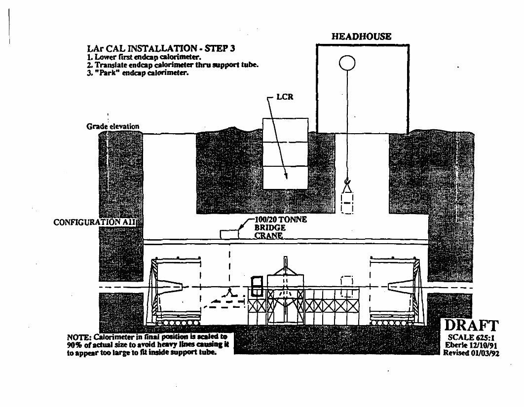
HEAD HOUSE LAr CAL INSTALLATION· STEP 3 1. Lower first endcap calorimeter. 2. Translate endcap calorimeter thru 1111pport tube. 3. "Park" endcap calorimeter •
-.-- A...ffi~ ',=-:.--'"'!~ Uil .,.J ••
NOTE: Calorimeter in final position ii acaled lo 901Jli or actual sb:e to aYOid hany lines callliD1 II to appear too large to fit inside 1111pport tube.
SCALE625:1 Eberle 12110/91 Revised 01/03192

··--~~'!~- .;f.t,
LAr CAL INSTALLATION· STEP 5 L Lower second endc:ap calorimeter. 2. Translate endcap calorimeter almmt to support tube. 3. "Parle• endcap c:alorimeter. . · . · .
~ .. ~ .
'
~.·J:•; .. • ii. :
' ': '(
HEAD HOUSE
LCR
. ~ -~ ~---~--.: ~m!V51vMC7' I ~LI"-~~ -~' -F ii I' Q I I
I.
SCALE62S:I Eberle 12116191 Rnised 01/03/92

HEADHOUSE LAr CAL INSTALLATION· STEP 8 1. Translate endcap calorimden to ftaal position. 2. Align and flllten endcap calcwbaet.., 3. Connect endcap calorimeter• •kif 4. Perform calorimeter tesdnlo 9
-+...-r..· .. :[i: ~- ,.
Gracie elevation - ..
· .....
·~
.r~~::
.~~~~- -~:;: -
(;.
-~~:;~~-
[~ . i -;,;;~~-~~-~ # {~·-.·~~!-~:~
..,,...._
~~f-:-:~; ~ I ~~ - _,
SxxxxxJtlll SCALE625:1
Eberle 12116191 Rm ... 01/03/92
..·, ·:.f
. ~. ;-.:!. :.- ... ~--_.;,.·· ~
"!:

HEADHOUSE
9
SCALE625:1 Eberle 01102192 Revised 01/06/92

.I ••
.,
•"-" - ---------- -----
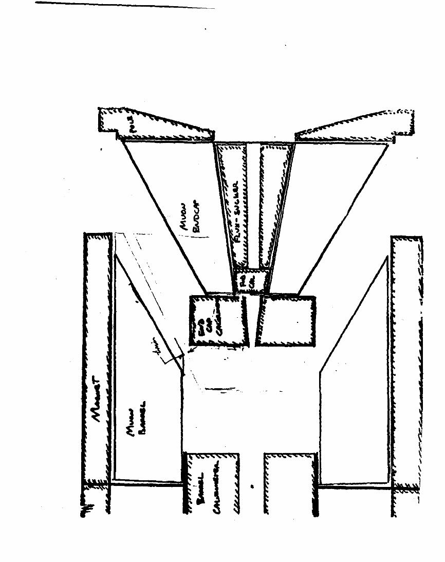
SPLIT CALORIMETER WITH flUX SUCKER : ENQCAP MUON SYSTEM ATTACHED TO THE POLE PIECE: ENDCAP CALORIMETER IS CANTELEVERED OFF THE POLE PIECE, HELD UP BY CONICAL STRUCTURE OR A COMBINATION OF FLUX-SUCKER AND RADIAL WEBS.
• Endcap Muon System mounted to the pole has been rejected on the basis of difficulty in isolating from the pole piece motion due to magnetic forces. Attachment to the Barrel Region muon structure appears more stable (NOT ANALYZED).
• Conical support structure option limits options at the 30° split line and cuts Into Theta coverage.
• Calorimeter services would take additional space along the 30° split line, further detracting from the Theta muon acceptance.
• Aux-sucker/radial webs option Introduces the same problems discussed in the other split options. Probable large horizontal web deformations or possible buckling of the lower vertical webs remain an issue. Commjtment to thjs design js agajn a cgmmitment tg germH the web structure necessarv to essyra a sa(e stal>le structural MORE POTENTIAL LOSS OF PHI AQCEPJANCE In the ervtrap raQlonl!
• This option creates another separate problem of moving a very large mass along with a relatively delicate assembly (slmDar to the barrel region) with care and accuracy In a less desirable cantilevered configuration.
• Alignment problems on reassembly of the pole assembly will be similar to the problems associated with any of these options except the original non-separable option. They should be slightly less since they are In prtnc:lple limited to the endcap region, but there are no guaranl8'1 on that. •·• '
• This system, while better for Central Tracker access, still leaves tht problem of Inserting a 9 meter long bridge over the exposed barrel region muon chambers In order to get to the tracker to work on It .or to remove IL
1/21/92 4
~- f\ . --- --·, ' . \
I
l
\
\ "\ ' \
-\
"' JJ
-·
' -- ..
.. ~ x \ \ ' 1
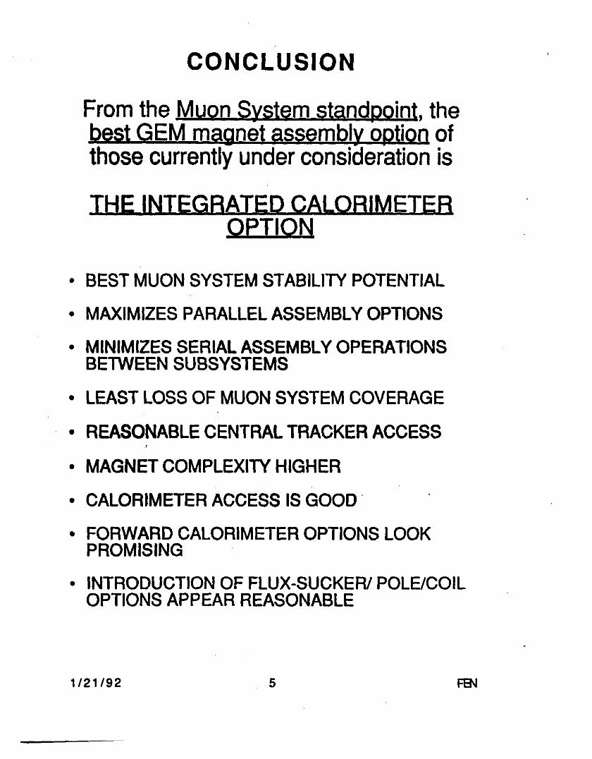
CONCLUSION
From the Muon System standpoint, the best GEM magnet assembly option of those currently under consideration is
THE INTEGRATED CALORIMETER OPTION
• BESTMUON SYSTEM STABILITY POTENTIAL
• MAXIMIZES PARALLEL ASSEMBLY OPTIONS
• MINIMIZES SERIAL ASSEMBLY OPERATIONS BETWEEN SUBSYSTEMS
• LEAST LOSS OF MUON SYSTEM COVERAGE
• REASONABLE CENTRAL TRACKER ACCESS '
• MAGNET COMPLEXITY HIGHER
• CALORIMETER ACCESS IS GOOD .
• FORWARD CALORIMETER OPTIONS LOOK PROMISING
• INTRODUCTION OF FLUX-SUCKER/ POLE/COIL OPTIONS APPEAR REASONABLE
1/21/92 . 5
·,~,
,:.r~
. :t,.~~ .,1 -
Barrel Region Module 1-----14.I m .I"'
11!' ! '(' (' ! '!' ! '!' ! '! '"g';' P.7!~'1l'ILI
•
·A -~· ·~~~~~-: . -----30.0m ···. ..,., ... Endcap Module
-~
'•
. . ..: ';,.; ... . ~·-•'<"···~·~·· . :.:~ ..
~. ~~GEM MUON SYSTEM lnteg~~d Calorimeter Option
.. -~ .
11 s.ctar Arrey I 22.1") ( ..... Region module)
I I I 3.2m
VlewA-A
F. Nlmblett 21January1112
3.lm

·• ..
, .. -
Q w ..J .. i:f.
•-,•'
.... _ "'' ,;.i.1 :·.-.. '
'·!!"'
' .. ~.:
~' . . ~, • · r. • r.1..\:
i.,......,....,"'"" ...... ,,..,..l"ri.,..,..r'rTTT"irTTTT'lrrt-Ct
.... ,
• !.:,..·: . .,.,
.,. ·.
.'? .. ~-
' .... \ \
...
. '.\ .....
... ' ' '•, '
, ~l!fv:L. :;, q.·-
, ..
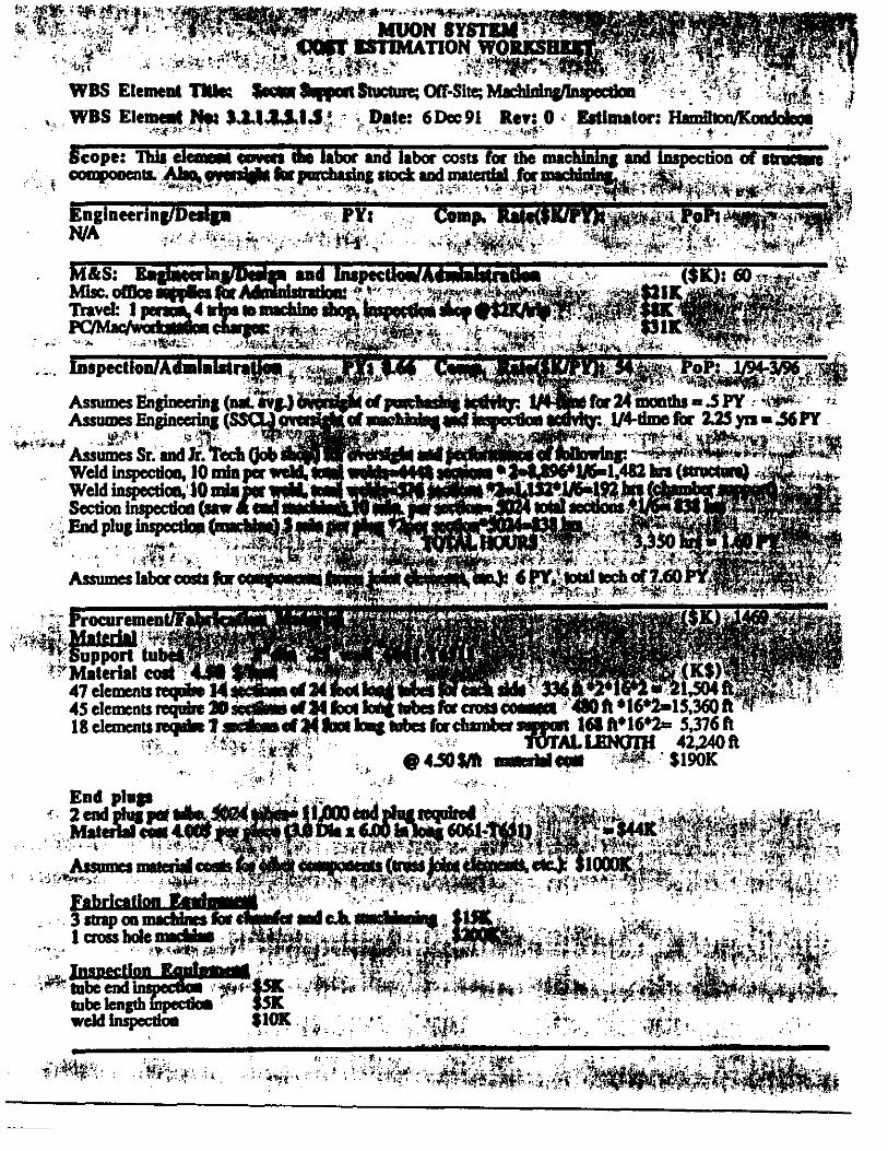
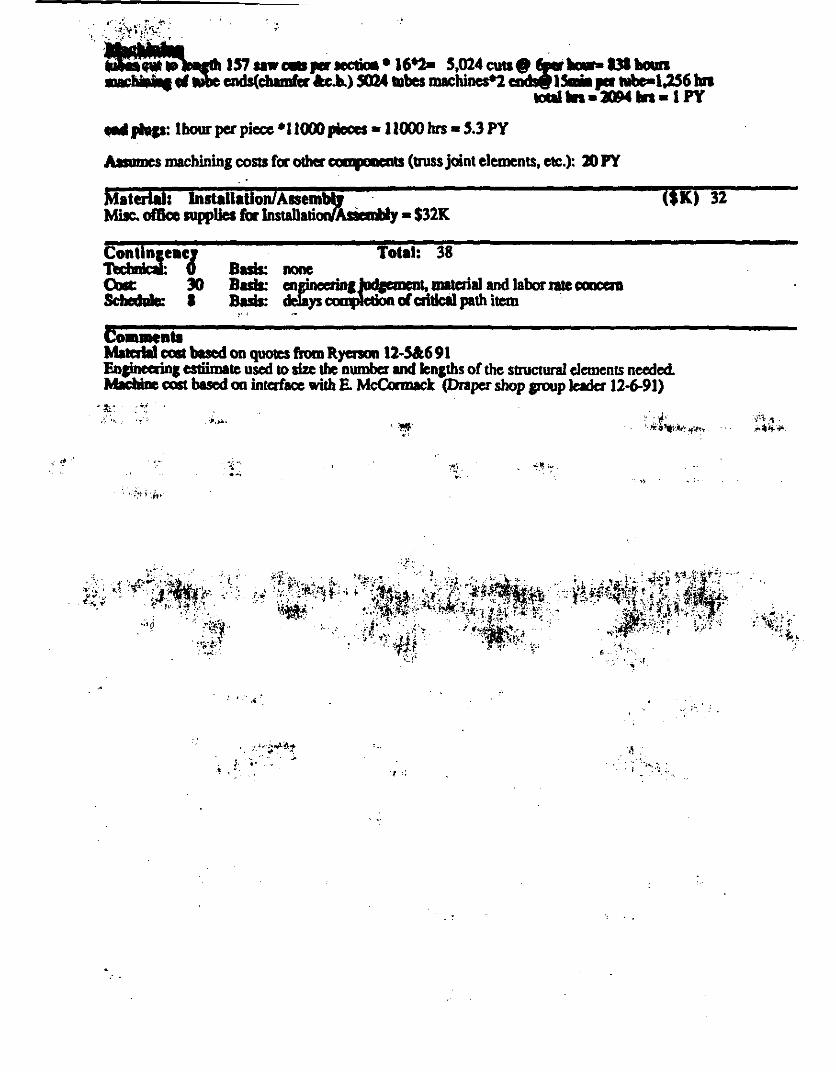
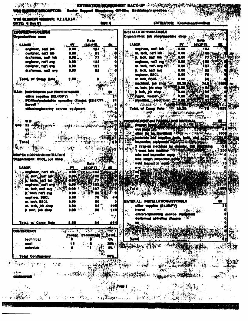
... )lhp: lbour per piece •11000 pioces • l 1000 hrs• ,,3 PY
AISIJ!DCS machining costs for other "'"tCJllClltS (truss joint elements, etc.): lO PY
Mattrlati lnstallatioRIAssemlQ · · ($K) 32 Mile. olBco supplies for lnstallali~y • $32K
Total: 38 Basis: none Bull: Basis:
~~=iilCnt, mater.ill and labor 1a1e cauct.m ys of cdtlcll path item .
I''
Commtnla Materta1 cost bucd on qUOlcS from R.yenon 12-S&6 91 Enpnca-ing esliimate used to size the nwnbcr llld lengths of the strucnmd dements needed. Mriine cost based on intafacc with E. McCormack (Diaper shop group leader 12-6-91)
,;. .... .. ,.
...
.' '. ,,; ·.
. r .,. ·! v
·:~· .. -• .N:'1 " •·
' ·.~ .
.. ;·· .
-u..··· ..... -. ...., ... ........ ..... .. .......... ...., .. ...... -.""' .. ...... ..., .. dl"*"-1...., ..
. '"" "' °""' ..... '. :i.\.c;·y. •··· :fm; . ... . •.
', .... :.:·'.· ~:r..• ' :,i~~-'1/ .•.
lechnloal -· ldledule
:~~··, 1· -,~J) .. "!
:-..!!'·" . . ... , . ........ , .... ·'· . ... . ... •••• i~.,'
. ·~ . ~ ....
,. ,.

•
•
•
ENGINEERING COORDINATION
COMMUNICATION OF ENGINEERING DESIGN PROGRESS IN SUBSYSTEMS UUST IMPROVE
IN ORDER TO SUPPORT THE MUON SYSTEM, IT IS NECESSARY TO KNOW WHAT IT LOOKS LIKEll
I NEED MffONAB§:E SKiJRMf9 OF ANTICIPATED MUON BER TRUCTDESIGNS.
• SYSTEM BLOCK DIAGRAMS OF CHAMBERS WHICH RELATE T~ re WBS WOULD AID OREA TLY IN UNDERST N ING THE SYSTEM AS WELL AS COSTING OF THE SYSTEM. ,
:-. .• . -~-- r;' .;t~ . ·~i.-.'.; ; . •'..- ..
• AS I INDICATED AT THE LAST MUON MEETING, I NEED ·UP· TO-DATE INFORMATION ON THE CHAMBER SUBSYSTEMS lt4 ORDER TO REACT TO THE DESIGNS. , ~ ~ti. · .
• AGAIN. I WOULD LIKE. 'Ii . flEQUEST A MONTHLY ·REPORT, .
IT ER SUBGROUP;\t; I E R P SICIST. SINCE I WILL BE THE
, " MUON INTEGRATION COORDINATOR, REPORTING . OF lltlS PROGRESS EARLY EACH MONTH WILL BE
PART OF MY RESPONSIBILTIES. I WILL NEED INPUT ~ . Li,IHE~j,PD8!9 T~.}aEM PROGRAM ·
(THE REPORl SHOULD START THIS MONTH)
• SEND TO: FRANK NIMBLETT DRAPER LABORATORY 555 TECHNOLOGY SQ. MS #23 CAMBRIDGE, MASS. 02139 EMAIL [email protected] TEL· (617) 258-1393 FAX • (617) 258-1131
.
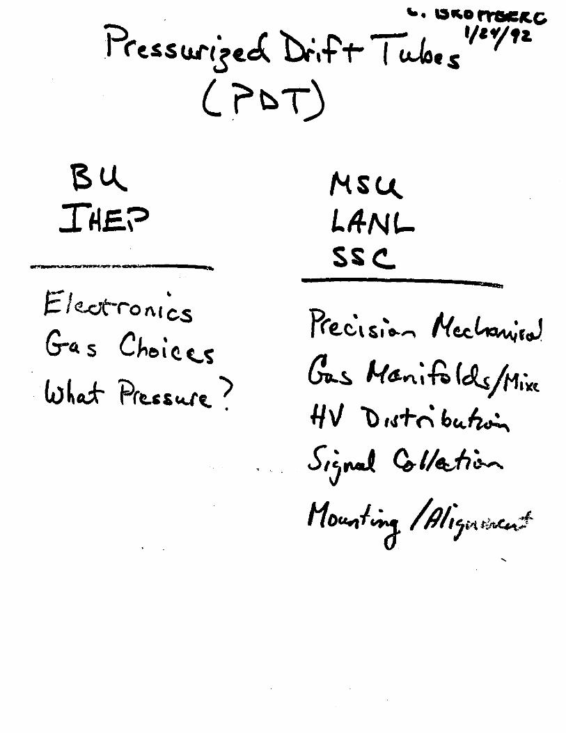
PresSW'tje.c( h:.t't-. (_ ?~T)
-----' t=' I <!.J:Jt·ro t\ 1 cs
G-c.. s Che& cc...~ . ) LJ~cd- 'Prc..cs~~ .
Pr~c:,,,'." H«.~rJ
(!_~ #-/tJ.~;f;. (cls/M1ict
I/ v 1) ,,.,.." b'4~
S, .. ~ G.-1/~fl~ . . j
H~I~ /111,;,,.,~ ....
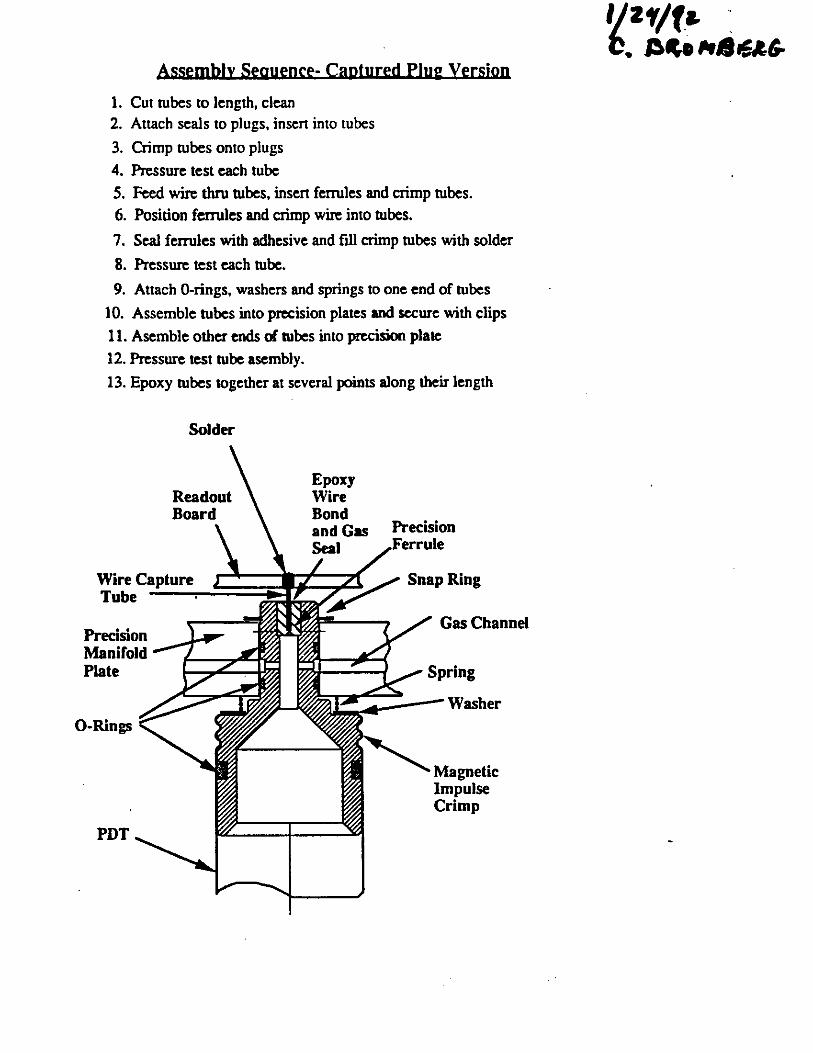
Assembly Seguence- Captured Plug versjon
1. Cut tubes to length, clean 2. Attach seals to plugs, inscn into tubes
3. Crimp tubes onto plugs
4. Pressure test each tube
5. Feed wire thru tubes, insen fcnules and crimp tubes.
6. Position ferrules and crimp wire into tubes.
7. Seal ferrules with adhesive and fill crimp tubes with solder
8. Pressure test each tube.
9. Attach 0-rings, washers and springs to one end of tubes
10. Assemble tubes into precision plates and secure with clips
11. Asemble other ends of rubes into precision plate
12. Pressure test tube ascmbly.
13. Epoxy tubes together at several points along their length
Precision Manifold Plate
0-Rings
PDT
Solder
Epoxy Wire Bond and Gas ~I
Precision Ferrule
Magnetic Impulse Crimp
~~r,f
i) }tJO /JltA.,,~u. .. r.1,~ ..,, ;2.Z. ... "'.
'l''I'" C. R•rttlA&'-
/.~'' ~ ... Joo .-M w-.//
3. f '"' /0111; • ..
Li~~,,._~ (b~ '61.e
e~ ,c:;,'1..; Pl~ht. r~ l.) pi,_ s .,. µ,."'·· Pc,lcf. ;>14
I"' It ·- s..c fW'I~ J

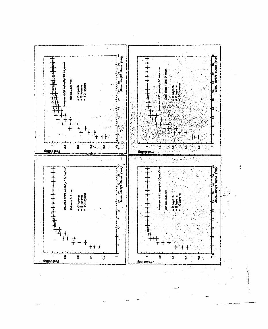
GEM MUON DETECTOR R&D PROGRAM ON 1992 at LNP JINR DUBNA
DETECTOR STUDIES
"'.'"DRIFT TUBE CHAMBER
-* design and tests of the small prototypes based on high pressure drift .tubes . , . · :. · ·· ·
*intrinsic resolution vs pressure ( up to 10 atm), ', '. . * drift tube parameters optimization ( gaz mixture, wire-
tube_ d~eters, .•.• ) :,. , .·· . , · <·.:: , · . , ' ' , ... · ... '
~ .·: .,. ,,_., - i."· - . -.. · '. <: •
-PROFILED CATHODE DETECTORS
* gas mixture'< fast for trigger ) · * design and tests of the frototypes * drift and strip read-out r_esolution
-: MODULE DESIGN AND ALIGNMENT STUDIES '·
- FROl\fT-END ELECTRONICS STUDY If
MC SIMULATION OF A MUON SYSTEM PERFORMANCE
.-::
. · .. ~·-, " -' '
.,,, .#'
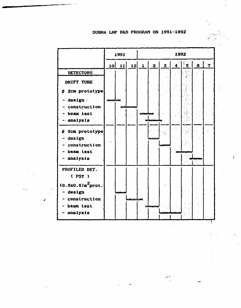
DUBNA LNP R&D PROGRAM ON 1991-1992 . '"·· .. ·. / ,,
1991 I 1992
101 , ,
I 11 12 1 2 3 4 ,' 5 6 7 -- - - - - -DETECTORS , ...
·~; .
DRIFT TUBE
ID 2cm prototype . ·.i
- design'
- construction
- beam test ,,
analysis - - - - -u- - - - -ID 5cm prototype , ,
,
- design
- construction I
- beam test - analysis I
PROFILED DET. ( PST )
(0.5x0.5lm2prot.
- design
; - construction I
- bealll test
- analysis
l

-·
·:··· ... ~
~ •
;_ l ~ ~
' § ..
I ,, i .;
s ' 00
[od1ww) .. -, ..
l ·~:. .,,
... '· i ; ·. " ' . ' ~ ...
~-1 ,,
§ .. .. ··,, II
I § ..
I? ~
s ' ' 2 [..i, ... ] ••
~
I
~T ~
f ~ .. I .. ;I
~
II ' 2 oO
c ... , .... 1 ••
• l • a
;_ ; l
~ .. I i <l
L-~11-l.__,i!:--.L..-~~~oo
[.d, .... ] ••
..
~ ' i ~ ~
t
11

---··- --·--- W" -.-•w ---------- --------
---------- --------
I
I I
. ·'.
I . -C\l Y.l
. . I
. ' ' . : L.-------· L-------· .. ... 1-------'"-------1 """" E-t
.t . '" ~ ·.:.- ~-------+-------· en E-t
t..-------· L-------· '
C\l E-t
L-------· L-------· CD ........ E-t
. .__ I I
cP ........ cP Y.l

•.
'
ffi f.;11J----=:::i u: Rl-----:::1 ~ 14-----~·1'4----, <t
, ~·~ .. • .. .. .

Run= 9,Type= 1,Pressure- 1,Voltoge-= 3300,Nev= 20000 ..
+10 3
2.8
2.4
2.
1.6
1.2
0.8
0.4
0. '·
0 25
• ...
AV=77.168, RMS==20.693
. ·'-' ' ~ ..
50 75 1 00 125 150 175 200
2
---- ·----·----
Run= 9,Type=1,Pressure= 1,Voltoge= 3.300,Nev= 20000
40 35
30 25
20 15
10
5
AV=646.69, RMS==267 .03
0 L-.1.111.L..L__,L__J___.l!_~ 0. 0.5 1. 1.5 ~10 3
6 --
. . .. ~ ;..1~· .. i ·, .
. / ·. · .. :. '
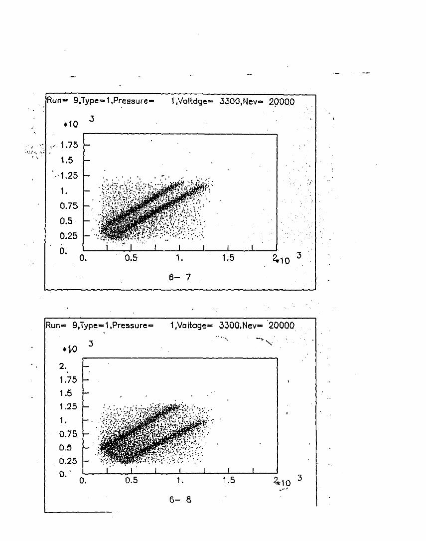
Run- 9,Type= 1,Pressure• 1,Voltdge- 3300,Nev= 2900.0
+10 .3
..• j. 1.75
;;f{•; ':•
'" 1.5
"1.25 . :.·. ·,\
1.
0.75
0.5 '
0.25 '
0. o. 0.5 1 • 1.5 2*to 3
6- 7
Run- 9,Type-1,Pressure .. 1,Voll:oge= 3300,Nev- 20000 ... . ,
'-~ ' . •1-0 .3 '
2.
1.75 1.5
1.25
1.
0.75 0.5
0.25 0 ..
0. 0.5 1. 1.5 ..., '*10
3 .... ~
6- 8

..
Run= 9,Type= 1,Pressure=
J +10'
2. 1.75
1.5
1.25
1. . 0.75
0.5 .0.25
o.
·.
0.5.
Run= 9,Type= 1,Pressure•
+10 3
2.
1.75
1.5 ...
1.25
1. 0.75
0.5 0.25
D. 0. 0.5
':..~··· • .. '.' ...
1,Voltage= 3300,Nev= 20000
' .
1. 1.5 *10 3
7- 9
l
1,Voltage= 3300,Nev~ 20000
.. '
' . . "'
1. 1.5 2 .. *10 3
8- 9 .. -~
...
;' '
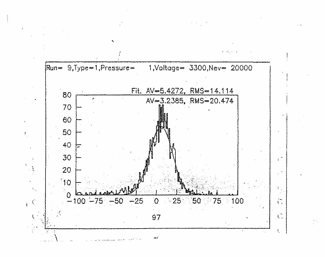
Run= 9,Type= 1,Pressure= 11Voltage= 3300,Nev= 20000
Fit. AV=5.4272, RMS= 14.114 80 I ,.
AV=3.2385, RMS. 20.474 70
60
I I 50
4o Ir 30
... l 20 "
'10 ..... ~: . . ;'
~-
0 lo !!. n..j !!i J;,ftn6.L' YJPI: I .. . . ··. .. . . .·. . . . .
-100 :....75 -50 -25 0 ·--25· '50 :75 . 100.
97 ( . ' ' ·I'
' 1 ··· ~ ·:·. ·.·.
\
\ -· ·- - ··----~ ···- ~-- - -- .. --
-· l. '
(~
I.
' '

...
'..
FAST LOW-NOISE CURRENT PREAMPLIFIER . ;
GAIN COEFFICIENT 10-80.
THE EQUIVALENT NOISE CHARGE (ENC GD=O} . ::- 2000:.~~ R.M.s.
INPUT DYNAMICS RANGE
OUTPUT
INPUT PROTECTION
,., -'' ·'.
.· - . BIP~LA~, ~O~. TWISTED '~- PAIREs;(p;~::110 n }
· · ·. · ·. · · ? ~\ -~0~f Pt''. · :'. " •. .· ,. .. _,. ·-- ·-·~- .. >· > -·
EXSISTS
POWER SUPPLY + 12 v . •
. .... ,.
..
-~·
f ~
0 . jt " .~ ~ J ...
i I! I! -
' • Ill . . . ,, t D
~.4t I 3 ..,.,_ • 0.
'ti-·+ '+t--+· .. ':tj. '1·· -f··. ·+ .,.. ,o.
+. + ,. .... + .. I +. 't' t ++ 't
~. ~ A!mt»QOJ,{
~' . """"'·· ~
{ • c ., •
f : ~ ~ 'I! ,, I! f .. " ~il ~ • " 1 • - 0
~. IOID-.. 0 •.
·:++: + 11· .. +~ ...........
. I o
t ·t· ' ++ t ~ ~ ~ ~ 0
A;n"llQOJ,{
~..,.,
.! ll j
:t ~~ ft
• . .. ..
" ' ~ ::~.·
. .. •'·
4': ';
0 ~~·. o· ~-~-.
t '· 1
11""
i:ij !It ~
.,.~
a !
!!
..
..
.. ..
...... , .. r. ..
t-. . . '' ' ...
......... d. .· 0 .· : ,' ;-•· ..
;· .. \ ... ··
····.
··tt+ .J.. +· 1"' T
+ ++
• -~ ... ,
•
. ··.;~.
ft .
" . •
• ..
--~~ .......... ..._. ...... ..._....._....._....,......_ ..... ..._......,D ...
. .
• E j::
.... • • Q
flJ ::l. -flJ 0 co -• -c
" 0 u
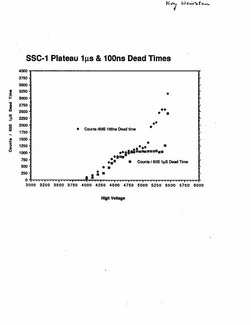
SSC-1 Plateau 1µs & 100ns Dead Times 4000
3750'
3500
3250
3000
2750
2500
2250
2000
1750
1500
1250
1000
750.
500
250
0 3000
• • •
•
•• • •
• Counts 160S 1 OOns Dead time
•
•• •
• • II •• • ••g&-.•11mm11mm•1111 ....... •m• 11 Counts I 60S 1 µS Dead Time
111 I •
• • • • • • • • • ' ' •
.
.
.
. ~-
-~ -
3250 3500 3750 4000 4250 4500 4750 5000 5250 5500 5750 6000
High VoHage
• -;ii;~;-: .::n) -~r·~:;t~-~;· ; ·,
~---~::~·1.>:'. :·ti":'.'(·;~ <·-;~_;:: ·~. -~;:·-1~:~·r~ ·:~'._:~~~f'..~:;::~:::··-:~ ·,'-~ ·.-.v: .. t·~~~· ~~~- .. fi ";'·' ; . .': t:. . ··: .i - -.... _ .• · .. ·:·:.~~~:._:r ;~ J~~t-~· ,~. -_· -. -; (. ·::-: ;~,~~ ; : . _ .. _:_·.· ,, ':~~·~e· : ,,;.;'JI·~· {_My.<QleN. ~ ~!.~;.~.,_ ·,~~ .
' . - ; .
.. ·. . : ·:~-: ..:- ·!.. : ·,.' .•
. . ~ . . . ' ~. .
. - ··i- ~· .-:':·-~· •• 1·- -~ • : :"'" .. -., . -'··«·-.~ ~~: '· •..
' . .
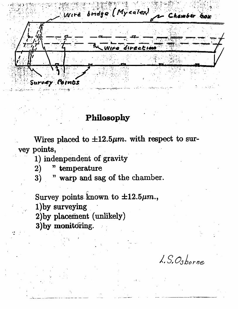
Philosophy
Wires placed to ±12.Sµm. with respect to sur-vey points,
1) indenpendent of gravity 2) " temperature 3) " warp and sag of the chamber.
f'•
Survey. points known to ±12.5µm., 1) by surveying . 2)by placement (unlikely) 3)hy monitdring.
··-·"-- -- ·------·-··-· -· - ·----·-- ·-- -----
·. >•:

II. R & D Program.
A, The Tasks
We list the tasks we expect to complete adding in parenthesis the institution( s) bearing
the responsibility:
1) Finish assembly and test of 2, 0.5 m. wide chambers.(MIT)
2) Measure chamber tube performance in magnetic fields.(MIT)
3) Design and build (D & B) 2, 1 meter wide chambers.(MIT)
4) D & B pick-up strip plane.(MIT)
5) Investigate and make thinner cathodes.(MIT & UNY-SB)
6) D & B optical window system.(MIT)
7) D & B tiltable chamber stand as a cosmic ray muon telescope.(MIT)
· 8) Adjoin prototype optical alignment system to the chambers.(MIT, with the help of
Draper Lab.)
9) Design of apparatus for mass production of chambers; estimate production costs.(U.
of Houston)
10) Investigate various materials for use as cathodes.(MIT)
11) Analyse the data from both; 1) runs taken at Fermilab on a small prototype, and 2)
data with cosmic rays on the 0.5 m. and 1.0 m. chambers.(MIT, UNY-SB, & LSU)
12) Simulation studies of the muon system directed toward optimization of the subsystem .
and integration with the rest of the detector.(MIT)
13) Provide chamber electronics, investigate state of the art electronics for TDC's, and
examine scenarios for the use of chambers in a level l trigger system.(LeCroy,MIT)
4

..
.: .. ~. ··•
""'""
.. · ..
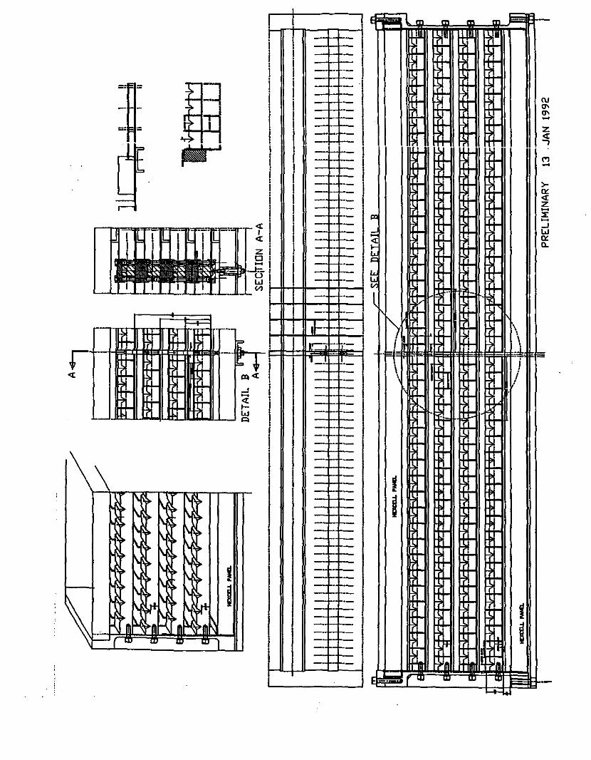
LSDT
C-UNE #12018 -TOPPER"
---···-----"
• •
R ~ D ~~rk.,
.. ; .. _, __ ., -·------· ... . ... .... . . .. : ... :, 1·
1 :-:,:r : ' -i~1 . :;.._~:.-'
'
... i
i. .•• - . . ... . ;; .,::::~ .· .. : ' . . ::'' .• , i Milestones(all in 192): ( ;.,,,,.. fN/'l•cJ C. TNA'ti!J ,. ; .. ·: .... ·. '?~t~t\
I.'" ,. .: • ..:.•_· ···-- .•. . •.• • I
Delivery of LeCroy electro~ics for 0.5 m. c:hmhn.. 1 ~·;~.,< ·~ · · ·:. · · · ~.:~f'.;J ' C'
Design of thin cathodes ..
Desigriof.1.0 m. chamber
Assembly of 0.5 m. chambers
Assembly of 1.0 m. chambers
Delivery of 1.0 m. chamber to SSCL
Set final specs. on chambers
Assemble cost :figures for EDR
-.• ..
.....
"
c,Jan . ..,.~ ;t,, ".,,,,, ·.· . ·.. . . )~!.;'.: 'Sa/*6 .lraditea 11 ••t:t••t/§ · .. :' .~:,.<
Jan. I• ,,., :·•• .1'11111/11/~ ·:··· ·· '>frL~
Feb. ,,,L;z,~~~~ · ,,,,-Ercgp~j~i:~:· March
May
Aug.
Sept.
'
··-:.-·
... . ·-·· .•'
·.·.;;,..:-··:::"'""
,._ ..
.. ·.-. '"
.--:. . ": ~-
. .-., ~ '·
•'. .
:· .. · .. • !' .
~:-~f.~~:~.·;.. ·~: · .. :.

-· .....
-· -· -· .....
1--~~~~~~~~~~~~~~~11.7DIC111F>~~~~~~~~~~~~~~~--,
-
,_ ..
"'°' ClllFl
&715 ClllFl
CATllm 8B1'll ...... 11V11MLL ft
~11-.s IDMW ....... -- 111 aJlm !- IW ,_.ca,._....., 0 ...._......__
LABORATORY f'DR NUCLEAR SCID llASSADIJSETIS JNrT11UTE IF TEIBll
G:i 11&11 I CAHIRillGE'. ""' Ol!l39
.... ,o.liijt"
IM IAD..EY 14111111
PROTOTYPE MUON CHAHBI PARTIAL SECTION
END VIEW' CSC91-(M
DkAlllNG NO,
-+-·r·-
- ---
... t---,..... I""·-
--;---·r·-
-+-T-- --+-"r-- .. ---r----
- .... -.. r--- ----+--r----.--.--
I-. ,.. !-,..
,... m: .. .. -
-...
+ --
I . i-
-
-I"' - ... --r ,..
--
-.. ,...
-I"'
I
~ t -
,..
-,..
....... I"'
~
I"'
~ -
... r
r ,.. r
~ ... -,.. ,..
-
-I
p' --
r
(\/ (1\ (1\ -('] -
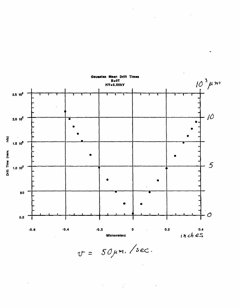
2.5 1o' I I I ... ... -...
2.0 102 • ...
... -
" ... ,,
<: 1.5 1o'- ...
I! ... .. .5. ... .. ,_ ~ 1.0 10•
l5 ,_ ,_ --
so ---- . . .
o.o
-0.6 -0.4
I I
• •
-
. .
I
G•ut1•l•n Meen Drlfl Tlmn a.oT
HV.S.s&kV
I I I
I •
•
• .. -
• . . . .
-0.2 0
Mlcromelerz
I I I I I I
---- /{) ·--• -
• ----··· -
-• I
--
I - "l" .. -• 5 --
• --
--~
-r----~ '--
• -. • • . . .
0.2 0.4
I 11 ch "'2S
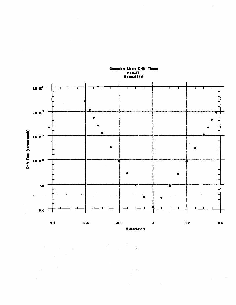
2.5 1o' • I I I I
'" -- I
2.0 10•
- I • - • -
.. .,, - I • ... - • c
1.5 1o' 8 : -!! -I! -• -E I= 1.0 10• = "C -0 -
- I -50 -
-'" -
• • • • . 0.0
-0.6 -0.4
G•UHl•n Mean Drift TlmH BaO.BT
HVa5.58kY
I I I I
I I I
•
-
•
-· ' ~ •
• . . .
-0.2 0
Mlcrometerz
I
• .
I • I I • ----
• -• -
-• -• --• --
• I --
• I -I -
i ----. . ' • '
0.2 0.4
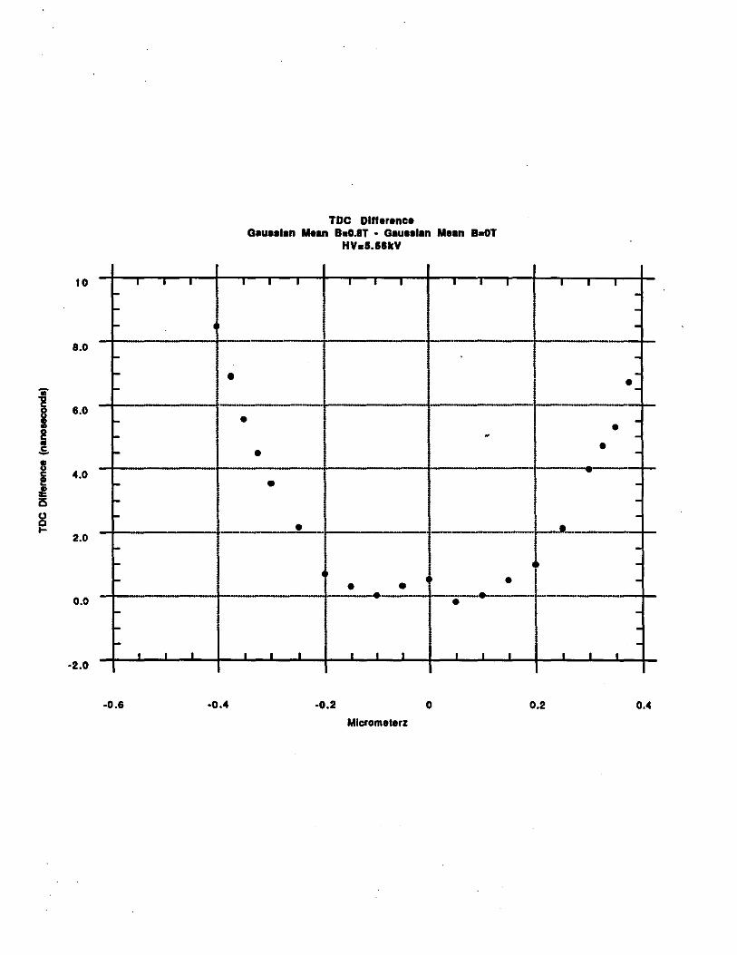
10 ' ' I I ,_ -- '
8.0 -- • .. -
"2 6.0 I - •
~ -.s -I 4.0 -! i5 -8 -....
2.0 ---
0.0 --,_
I ' ' I
·2.0
-0.6 •0.4
TDC Difference Geuealen MHn a~0.8T • Gauaalan Mean B~T
HV.S.HkV
I I ' I ' ' '
. e
•
•
• • - --· •
I ' I I I I I
·0.2 0
Mlcrometerz
' ' I I . ----• --• -• -
• ---
I
-• -
• ----
---
I I I I
0.2 0.4

3.0 I I I I I
----
2.5 loo .. ..,
c
I - D
- a D
- D
~ 2.0 .E. -.. j =
- • - • il -C> -1.5 • - • -..
loo
1.0 loo
--loo
• ' • • • 0.50
·0.6 -0.4
closed clrcle•: G1u1sl1n a BsOT open oquorH: Gau1sl1n a Bs0.8T
HVd.56kV
I I I I I I '
____,. • I
I I
I I a
a
1 • Cl D D D • • • • •
• i;i . .. • I •
• . • . I . I
-0.2 0
Mlcrometerz
I I ' ' ' ------
a_
-______ a.._ -I a -• l D -D I -I • • I -
-D-t--~--·-~--Cl --
• t -• --·-
---. . . . . .
0.2 0.4

,.· -'\ ~
~
•• 5.: Ji • II I n e
! % ;; • • > n
i c • • • c • c • • 0 • •
t m
"' 0 c >
> "' "' "' 0, 0 0 ;:
" x
~ 0 .... 0
.... iii C>
"' z .... :;: "' .... "' "'
~ :~~~

.. : ;·:::: ::;::::·. :·. ., :z:
' ;
LU . . '
' f . '
' ..
N ,.. -' c " :
r :
p
I
Le C.1-",Y ho.$ T oc s 1-ea.d?"
le. C"" )' wor /r1'H'!f o "' /: 1-13 Jt!.r
S/ S /; t! -,.,,.,.
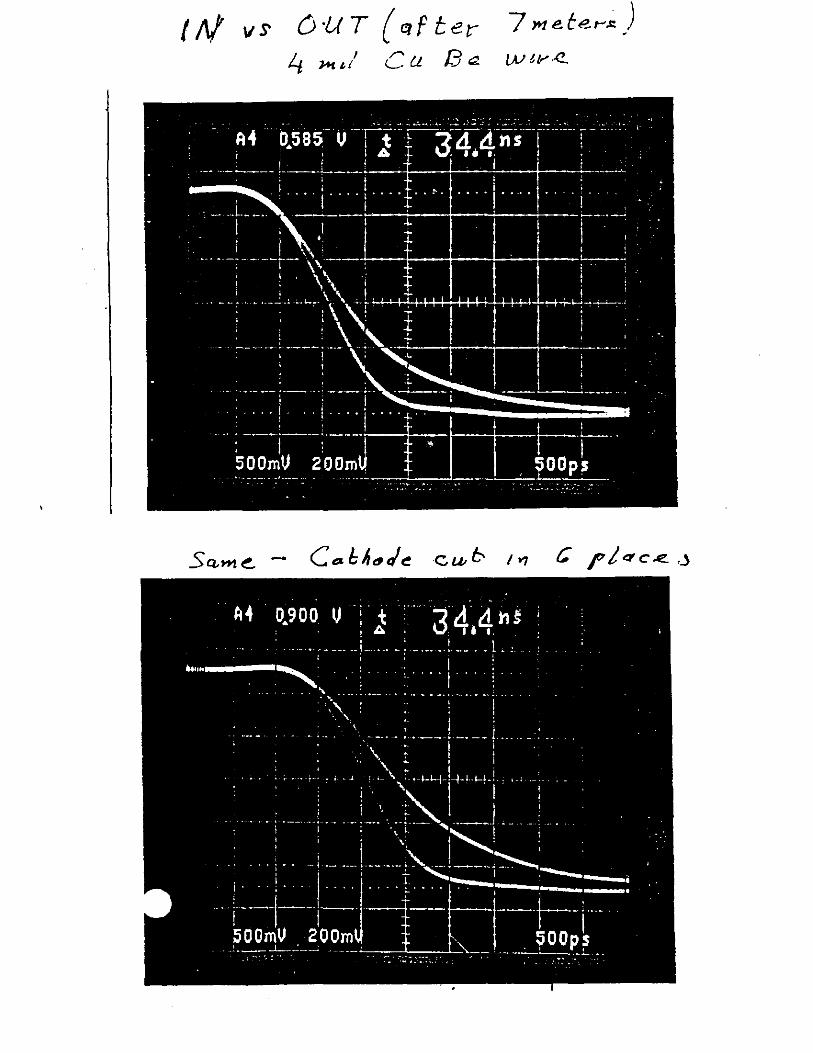
I/\/ vs 0 ·l( T { r!1 f t er 7 me te,..,J:) 4 ,,.. • / c lL 13 .:I. LAl t fr' A2.

"-.' J _.r..; ~ \.!> I ,.M,. ·... ~-· ~\. ..._b. I 1J "
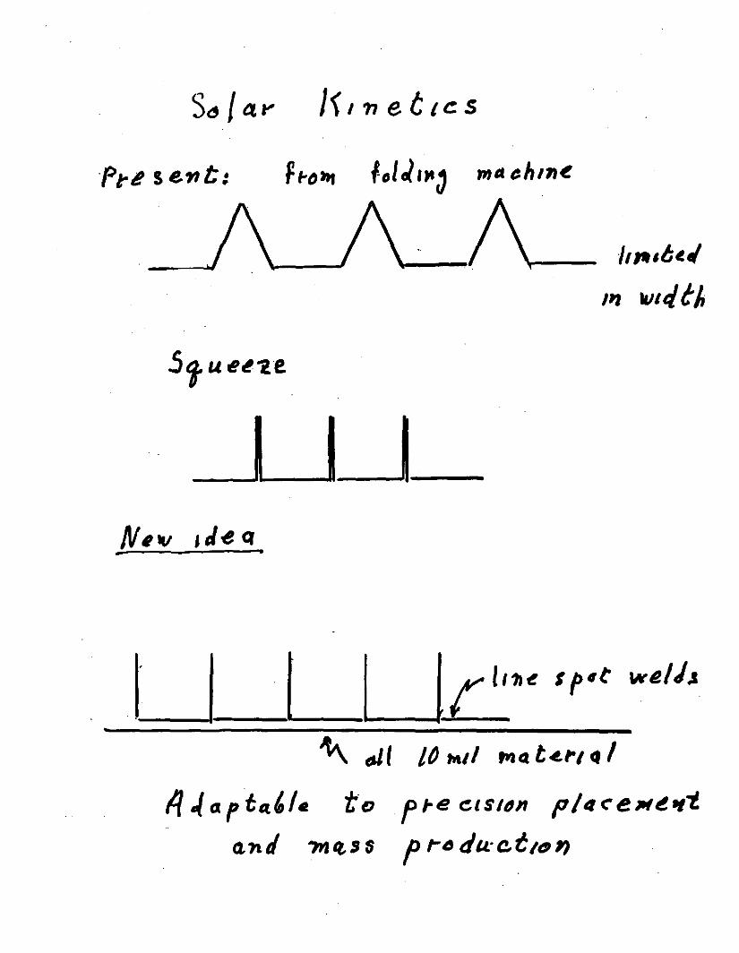
So / 4 ., / { / n e t 1 c s
·f1:~ sent:
I l_J_
,,,.,t~I
,,, "''" t ~
"\.\. 6' I !O ""'' ~ o. t ~,,., " I fl ,,( o. p ta.' I. t· o f ,. e ~1st tJ n p I 11 ~ e ,., ~ tt"'I.
o,ntl ?ntts s f ,.." du·et10'1

Ca.thoJe 1'1ate1-14/
h I 1.rs
? •

GEM: LIMITED STREAMER DRIFT TUBE GROUP
(Proposal to TNRLC-Dec. 9, 1991)
III. The Budget (Revised Jan. 21, 1992)
Institution Item Time in Cost Sub-total
man-months in kS
Univ. of Houston Mech.Eng. 9 80 80
LeCroy Corp. Elec.Eng 20 20
& Electronics
Louisiana State Univ. Student 4 5 5
Mass. Inst. of Tech. 381
Mech. Eng 6 36
Draftsman 5 30
Elec. Eng. 4 30
Mech. Tech. 12 45
Mach.Shop(Mlff') 30
Elec. Tech. 12 80
Student help 15 25
Chamber parts & 50
outside work
Alignment Tools 35
Optical Alig. 20
U. of N. Y. at Stonybrook Student 3 5 5
Total 491
1

.. ...
. "iitf .,,.·.
..... · ,_
·,.
"»~-·~: . -- . '_·.' -, :.\l~''.:'! ~-:·.:,.,·~:,./~~:~:.f:?; . .-r.: !
. .
.. ··_\J~·:' '
i···.J.. ..
.._ .. •., . .,.· . , \_ . .: ·.., - ..
~ .. _"/"fit''-'"· :
•• .- ;: f'! "·: ,·, . , ..
... ; .. ~. ~ .. ....
_,
, . .:. •:. - ~- -
.. . .
:~:..; ... ·' .· - '
-~'
';.
i
111 sa0a1c~ t11t1 0(!1'01 8
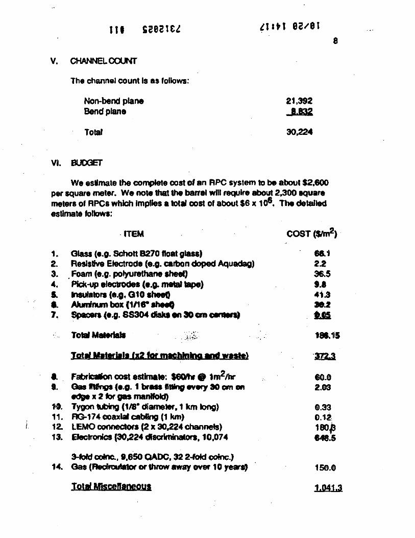
v. CHANNEL COUNT
The channel count Is as follows:
Non-bend plane 21,392 Bend plane 1.m
Total 30.224
VI. BUOOET
We estimate the complete cost of an RPC system to be about $2,600 per square meter. We note that the barrel will require about 2,300 square meters or RPCs which lmplles a total coat or about $6 x 1 o6. The detailed estimate follows:
·ITEM
1. Glass (e.g. Schott 8270 float glass) 2. Resistive Electrode (e.g. carbon doped Aquadag) 3. . Foam (e.g. polyurethane sheet) 4. Pick-up elecbode• (e.g. metal tape) I. lnlulators (e.g. 010 sheeO I. Alumlrun box (1/1r aheef.) 7. Specers (e.g. SS304 diakt en ~cm c:e Q8l'I)
TotalMeteriall .. ~· .... , . . :-11·~,,..
Toti! Mattrltll fg2 for mecblnQI ""' waste)
I. . Fabrlctlon cost estimate: $60ttw 0 1m211:tr t. Gas n1ngs (e.g. 1 brMS lllllnsJ .,_, ao cm ... ~ x 2 tor gas manifold)
1't. Tygon Uling (118• diameter, 1 km long) 11. ftG.174coaxlalcabling (1 km) 12. LEMO connectors (2 x 30,224 channets) 13. EJecJronlcs {30,224 disc:rlminators, 10,074
3-tord colnc., t,650 OADC. 32 2-fold c:ofnc.) 14. Oas (Aedn:ulatororthrowaway over 10 ye•Sl)
Toti! Mtscenaneous
COST(W)
68.1 2.2 36.5 9.1 41.3 39.2 t.H
181.1i5
·m.3
80.0 2.ll>S
11.33 0.12 180/3 148.5
1 SC!l.0
1.041.3
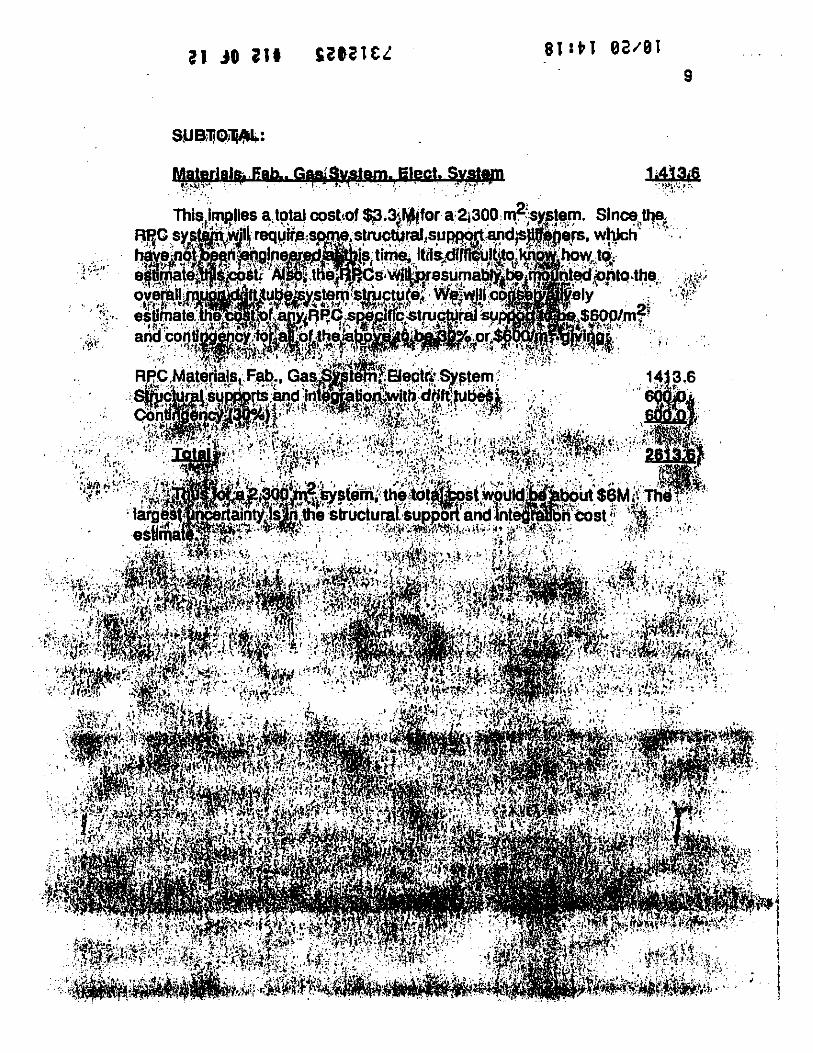
al Jll i11 9

.,.. "' - - I _, ",,,_ ' I I - -
;f;v J) D -
I . J2_ I ~ € T I /VI 6 .T I TTE .R_ {_ / - 2. /V'.-1/CIP 5C-to/l/JJ S f )
l.. I e f F 1 c , c/..J c. y (f!JU% 1 J
3. G /\ s - /./fJtv Fl /JAt'-'1 /t :El e=
4. N OJ 'jc ,Aµo If &-IN f:r
( /\/&1~~rl/ /tJ )( C()~f"11'- ;Z./tY ~ /r Ir I /V 6- .1 )
S · · M II .x ' f111 A ts v /{/ r 1 ~tr ;z A- re ( N J e o HeJl. /r / CtLt 'L ~ )
DESCOPED SSC R & D PROPOSAL FOR THE GEM MUON BEAM TAGGING TRIGGER AND Z·COORDINATE MEASURING SYSTEM
USING RESISTIVE PLATE COUNTERS (COMPLETE VERSION)
14 November 1991
I. . . COLLABORATION .
The collaboration proposing .thls R & D program consists of the following groups: · · · ·
,·.
Brown University · M. Widgoff
Indiana University E. D. Alyea
MIT· . Y. H. Chang
E. S. Hafen P .. Haridas I. A. Pless•
•co-spokespersons
' . ~ •. :.
~ ..
. '
=: ..
' . ·•'.'
.,
. ·,
LLNL E. Ables K. van Bibber R. Bionta 0. Fackler D. Makowiecki C.:Wuest•
University of Tennessee S. Berridge W. Bugg P.Y.C.Du
..
".. '
. ,·
.••.,.·
EUROPEAN ORGANIS>. TION FOR NUCLEAR RESEAROI
CER. 'll/DRDC9 I ·.5J RD-SI Status Report January 13th, 1992
Status report.of the RDS Experiment . ' .
A. B<ihrer. R Faissner, T. Moen, R. Priem. H. Reithler, R. Schleichen. H. Schwanhoff •. · H. Tuchscherer and H. Wasner.
Ill. Physikallscltls llisti1ut A, R'WTH Aacltln, Germany
Ciy.L. Bencze2>, M. Della Nesra•>. K. Eaaen. A. Herv~. H. PIOlhow • Besch, E. Radennacherll
'.
· · · · and C. Seezl) . C~N. Geneva, Swirztrland
M. Aa).scc, R. Brenner, A. Hen1incn. I. Hiccanen, V. Karimlki, R. Kinnunen. I. Lindgycn, K. Oscerberg, M. Pimil. C. ROnnqvist.1. Tuominiemi, T. Tuuva and M. Vqutilainen
Research lnsrinuefor High Energy Physics. SEFT, Universiry of Helsinki and Abo Akademi, · . . . . FinlaNI . · .
A. Fetrando, L. Martinez-Laso, E.Torrente Lujan CIEMAT, Madrid, Spain
H. van der CiruI, G.A.A. Wineman, R. Berpan, C. Brouwer, A. Kania. C. L. A. Pols · · • and T. Wijnen
. NIKHEF·H and Univtrsiry of Nijm41t11, TM Nerltlrlands
A. Bettini, P. Casoli. S. Cenat1. R. Martinelli. A. Meneguzzo and P. Zono. · Dipanimlnso di Fisica. Universird di Padova, lraly
C. Bacci, F. Ceradini, G. Ciapeni, F. Lacava, A. Nisali, E. Pell'Olo, L. Pon1ecorvo, S. Veneziano and L. Zllaello
Dipanimauo di Fisica, Ulliversi1d di Roma "La Sapilnza" and INFN •. lca/y I
R. Cardarelli; A. Di Ciaccio and R. Santonico DipanilMlllO di Fisica, Ulliwrsil4 di ROIJllJ 'Ttw Ver1ara• and INFN, lraly .
D. Oine, $. Lazic and $. Otwinowsld . . U.CLA., Los Angeles, USA
W. Gorn, I. Lay1er and 8. C. Shen · U.C .. Riverside, USA ·
M. Andlinger, A. Kluge, F. Szoncso, G. Walzel and C.· E. Wulz HEP HY, Osre"eichiscltl Akademie der Wisse11Sc/rafte11, Vienna, Austria ..
W. Dominik, K. Doroba. M. Oorski, J. YJOlikowski, L. Ropelewslci, R. Szwed and G. Wrochna l11Slinut of Experimental Physics, Warsaw University, Poland ·
I) Joint spokesmen 2) Visitor from Central Resean:h Inst. for Physics, KFKL Budapest. Hungary . 3) Visitor from Imperial College, London, U.K. · ·
..
.. ·

'· •.··
..
field shapin& cathodes (-SlcV and· 71cV) at the edges of the tube auarantees a drift velocity of
S:? µm/ns constant within 3% over the whole width of the tube. The maximum drift time is l . .S µs. The sinale point resolution is on average 400 µm for tracks with the angular distribution
of beam particles at RDS (all muons were used without cuts on track quality). The detection efficiency of each tube is about 99% over the whole width of die tube. . .
In January 1991 the modules together with the original readout. ll'igger electronics and cabling were moved from the UA I. experiment to the RDS area and were installed in lhe
H:? beam. In order to test and .operate the c!lambers indepcndcndy online programs (one based
on the OS9, the other based on the MacUAI system) were developed to test the multiple time
di&itizers (MTD). Anolher imponaiit tool w~ a program to &ive test pulses to each of the SSS
wires and read baclc the response. This implied i check of the whole chain swtina from the wires and ending at the wire pauems fOI' each chamber. ln the middle of June '91 systematic tests were started. Only four dead wires were found. This number was reduced to rwo •
. corresponding to 0.3S % of all wiles. At the end of July a local monitoring program including . . . hit, wire and time distributions as weU as an event display was ready. The chambers were filled with gas mixture and were tested wilh high voltage. During lhe run lhe high voltage was
· conirolled by program. Both the low voltaae for me sianal preamplifierlifiers as well as the
. high voltage were monitored by proifUD. There were no problems with the high voltaae or
low voltaic during the run. After having the chambers, the read out and lhe control programs ready we aiUered
locally on cosmic and parasitic muons in the beam. From the beginning we saw at the event
. . display clean muon iracks in all dtree modules. In lddilion the hit, wire and time disaibutions
showed the expected shapes. This situ&tiOll was monitored over the whole run period and
stayed stable.
The ~ve plattchamben
Sixteen planes or Resistive P!ate Chamben (RPCs) were installed in 199 l. Each
plane measures 2•2 ml and bu 64 read out scrips of 31 mm pitch. The planes are coupled in
pairs providing one meuure111ent in the. hori1ontal projectioa, 1, and one in the venical · projection, y. Station l (see Fig. 1) has four pairs wilh rwo y-z measurements before and after
the muon drift chamben. There is one y-z pair in each of the two slots in the iron toroid.
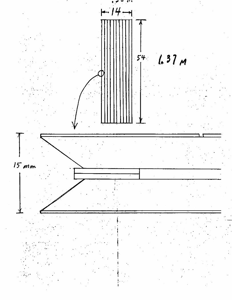
.Station 2 has iwo y-z pairs with one measurement on either side of lhe drift chlllJlben. Each plane is made of two RPCs or dimensions l x 2 m2 assembled as shown in Fi1. . . .
16. The RPCs (10) are made from two bakelite plates of l x 2 m2 surface and 2 mm · . thickness. The plates have a volume resistivity of' about 1011 0 cm. The sensitive 1as volume
" ., ' · ls a ~ mm .Jap between the rwo plates. ln order to separate the plates by a fixed distance over · the whole surface, PVC.disks of 12 mm diameter are glued on the plates. The gas gap is
·: · closed ar the edges with a PVC Crame.
• . • I
Pagt8
· .. :
";
.....
... .....
·' •'.
·. , ..... .
The ou1er surface of the resistive plates are coa1ed wilh a graphite solution wilh a surface resistivicy of• 100 kn. lbe two pphile electrodes, transparent to the fas1 component
of the discharge pulse, are connected to the hiah voltaae power supply to produce lhe electric field. A thin foil of PVC is alued on the. paphi1e surface 10 provide isolation of the hiah voltage electrodes.
The n:ad out elecll'Ode is sepnented in10 thin aluminwn strips of 29 mm widlh and 31 .
mm pitch. The saip plane is separated fl'OIJI the outer around shield with a roam plate 10 nun . . thick. Each strip is 1erminated on SO non either end and one side is connected 10 the &ooiend
· elecaonics. The propagation lime of tht n.n•mission line Is about .5 ns/m and there is no anenuation of pulses from lhe induction point 10 the end. A sec:liOll of lhe chamber is shown in . Fi&. 17.
The fron1end elec110nics is shown in Fi1. 18; Each plane provides a fast uigaer
· sianal made with the wired OR from lhe diseriminator outputs of the 64 strips. The diJilll
sianals from the individual saips are 100 ns Iona and are read out with VME registen saobed
by the scintillator hodoscope trigger. When the experiment trigger arrives to the input repsier
.in the VME crate, die data are sc:nt to lhe data acquisition system via optical fiber. The chamben have been operated with a 1u mixt~ of .58~ araon, 38., n-butane
·and 4., of freon. The supply volta1e was 7.1 kV. In these conditions, the sinale rate
measured with 1he fast OR si&nals was on aven1e 10 ltHz per plane dependin1 on the
. . resistivity of the elecuode plates. The problbilty of accidenlll hits, measured wilh a random . tri11er, was between l<>-4 and 10-l per plane.
The efficiency, averaaed over lhe whole surface of the chambersi measured wilh lhe . ·· fast OR sianals with muons of lhe beam hllo, wu on average 96.,.
The meas~ment of the sinale chamber efficiency as a function of lhe particle flux
. was done by tracking hi&h momen~ muons (l(X).300 OeV/c) through the differen1 planes of
RPC chambers. Sianals ~ adjace~t suips were grouped in clusters, lhen · tracks were
defined wilh a leas1 square fit to a ~trai&ht line in both projections. Fi&. 19 shows the disU'ibu\\Oll of the residuals from lhe fitted ncks. 1be averaae r.m.s space resolution is about .
8 mm. The single plane efficiency was measured by rcquirin& that a hit is found wilhin four .. strips.cen!Rd on the expected· beam PQsitioo. Al low beam intensity, smaller lhan 10 HzJcml, ·
the efficiency for the different chambers varies between 96% and 9911..
· Chambers with two dWerent resislivilies for ii: electtode plates were tested. The ·
resistiyity of the elecuodes is an imponant parameter that defines the recovery time of the
· elecuic field after a local discharge. Low resislivicy chambers were placed in station l while
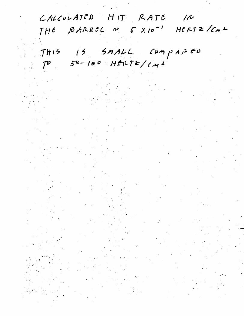
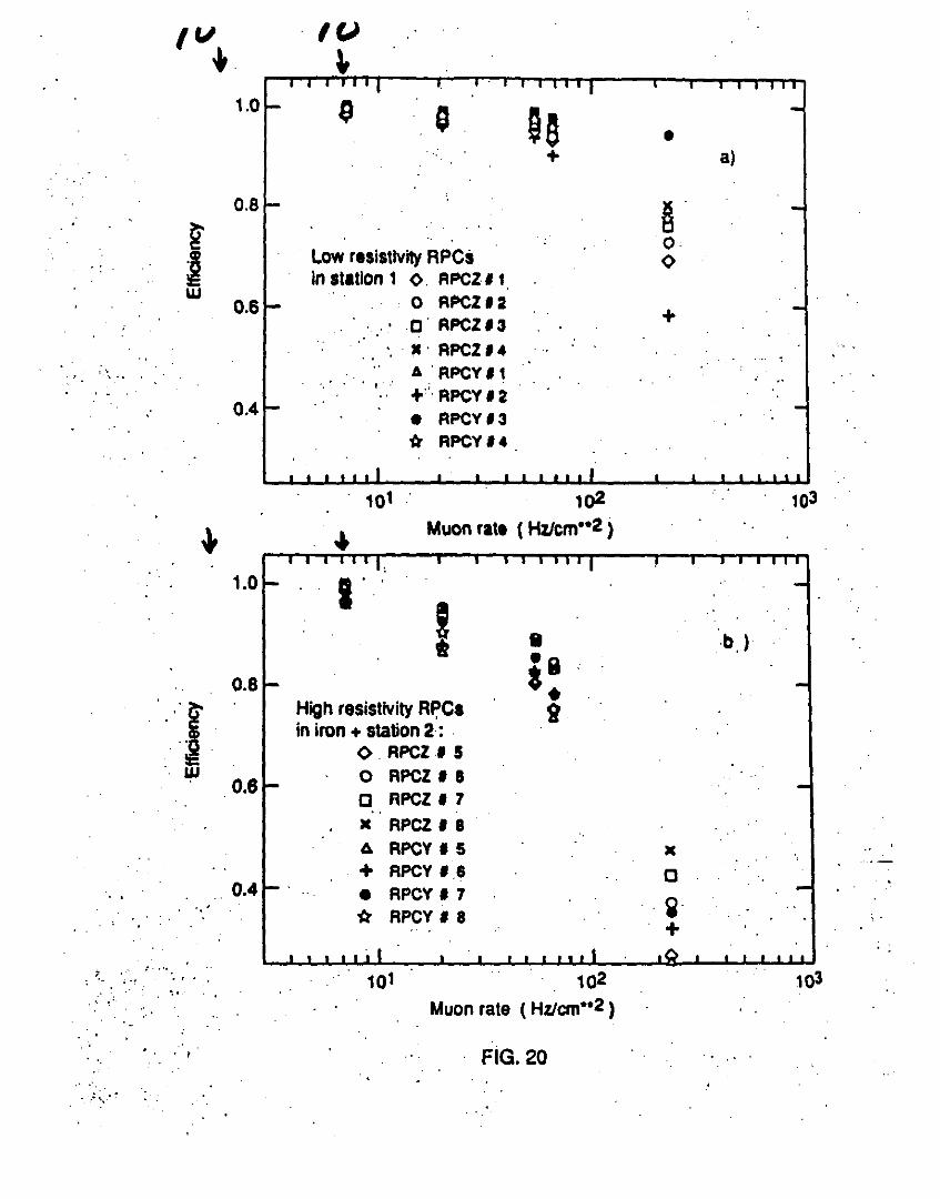
the chambers in the slots of the iron magne1 and in station 2 have resistivity a factor S lar1er. . . . · Fia. 20 shows the efficiency as a function of the muon flux in different chamben. A sianificant degradatioq in efficiency is. observed in the chambers with high resislivity electrodes for particle fluxes larger than SO Hz/cml. In the low resistivity RPCs the efficiencies degrade only at fluxes laraer than 100 Hz/cml (11,12). lt shoull be noted that the drop in efficiency at high rates does not affect. the hadron punchthrough measurements, since,
. '
Poae9

.. ... ...
.. "' ·~
' ,, _p
j
J (..) IO
'Ill I· C\l lb
{ • 1
"t
I -\...
l ct .i..
C\l
t . -. ~ ·;; IO
j - ..£: ~ ~. '-1
..... Ji I-
i... ...... ..... Ill Ill IU >. ;.... >.
ct .. ~·. '° <d «:I - - -
::t ::t ::t ..
0 , .. -·· . • ... • IO .. . .
' -iH. ::t
0 0 D 0
.. '
0 • 0
0 ..... C\)
0 I I ..... M o I - .o 0 - 0 ...... .....

. I.' I·' : 1 rl I I I I ~ I j· . I
• "' • • • al . •
\--;i I • • " • . . &l, • • • 0 ""' • • . . ...
• • • II)
• • ... • • ... .s·. l!
"'. ~ 111· ~: .i:; • c •• ":l· .. • '!.: Q~ .
' H . . • • • • I • • . .
• ... • • • • • •
; .• • • 0 ' • . . • 0 • • •
,<.. • • • ... ........ • • • " N • • • .,
• • • 1-t - • • • t'D • • • ., • • • "tj
• • • .._.. • • • • • • q,
• • • • • • ,]\
• • \\> • • • 0 .....
• • • -• • ; II) ·' • • • bl_ • • • • • • • • • • • • • • •
I,\-')--, • • • • • •
• • • • • • • • • • • • •
0 ,, ...... 0 ... N
0 0 I I ... .... 0 0 .... ....
2wo /(zll) 9lllll
. . ·~
~ ..
lJ-' .. · ..... ,.
. .. . ·
.. . .
c. /Jt. c II L- A 7 r)) 1-J I T. /2... A r e, I /'v
TH6 ;o/1P..JZ.eL · rv f" .x 10- 1 HtP..7 e: /c,., ~
.... ~ •..
' ' .
I ~ ~ ."1 /J £. L- £" ..-., f " iJ. r o ~- 1e o · 1-1.e-1i Ti:/ t""'"' ·
. .
. .
. . ' . . . .
! ' .... :I .
. •.
. .
. ,! ..... ~ . • .
/V ~
1.0 ~ G ea • + a)
0.8 ~· g ...
Low resistivity RPCs 0
~ <> In station 1 <> FIPCZI 1
w 0 FIPCZl:Z 0.6 ' o· RPCZl3 +
· X · FIPCZI• .. ... ..
A . FIPCY I 1 ' .. . ' . +'' RPCYl2 0.4 • RPCYl3
ti RPCYI•
101 1o2 103
+ ~ Muon ratt ( Hz/cm••2 )
1.0 •• ! II -b,) •9
0.8 *· . ," ~ High resistivity R~Cs i I» in iron + station 2 : . -~ . O.RPCZIS w 0 RPCZ I 8 0.6 a RPCZ I 7 ..
x RPCZ I 8 A RPCY I 5 x + RPCY I .8 a
0.4 • RPCY I 7 tr RPCY I 8
. . ~-
+
: ~~ . . ~ ..... ... 101 102 103 .. " ' Muon rate ( Hztcm••2 )
. . . , FIG. 20 ... .. «.
·. ,: ~.-·
. '. •. · .... '
. . . ~ .
. ' . '
. .. . . ....
~--· '; ·-~ .; ... , ·: ~ . . ' : .· ~.
. '• ~
. . : ;: .. ~
\ . . /
, - .... . . . .
·i'--' /Lf~.·
. . . ' .
, ! ..
., .
I. ' ' . : i
. .· . : . I .
. .
. .. . . . . . 1· . ' .
j ... I
. -
' .
. . . .

..
. .
,, '
•
..... 6
I
6 I
x -I .~
' I
:E I
• I -• L I
• • -• ..;.. . • . . ,.. • -• -• -• -• .,.. • -• -' I
.... .:::1111 111 11:11 1111 I .' . -I + • •
' • ; -• -I -~
. . " -- • . 'i. ·~ I ...
·~ ... --• ~- .. I ... ' ~ .. .. ·- . .. - ,_ -I ... .. . .. • . ..
_;__ I "
'j c
i
.. ~
. • .
.. >e· ~ ..... .....
g ..
·-3 I . . .. = ··- ...
~_i_i I ·I
' • • , . .,
1\ I HI· 11:11
• \1:1+ .. .. l_ • • ~ I
• I ··-:--..
• I ...
-. .
.... •'
. '
->> ~ NN ~ • • >
8~ ~
I ' -• .. • • • .. • -- --· • I -. I I ..
~-·-·
',-:
. '
. .
'.
. . '
...
•· '
I ' . . ...
I 6 6 I
x
' ' I I I
- '- . +f~n.· . ---... .. I I I
I •
\t ' . •· I .. 'S..
I .;; r--I I .. I
I . I
I
' I I
~m > •• oi z .. ' ~~ ...
··1 I I '
c '"4
2
..
.. •
•• ... ..... •• '
:;: ' ± .. ~ ...
i . -\-'-I--:;::
- - - ·~ - . , . 1:~1-1 •• ; ; ; I· . ·-... ·--.... .. ·• . .. ...
' ... . -.• -1 •• r--±
_¥ __ ~
' .
. . ~
..
1i ·o . . C\I
I .... g · ..
..
-· I I \._:_ . -· ._ . •1· I ' I f '!\
I I
~·~ ·-I
I • I I
~-H-~ . .. , '- - . - -----
. I I I I
I
• .. • • --··
'
~ . ·-~ :' · .
->> ~ C\I C\I fil . .
> '"4
8~ ~
. OJ C\10 ""'. .~ ~
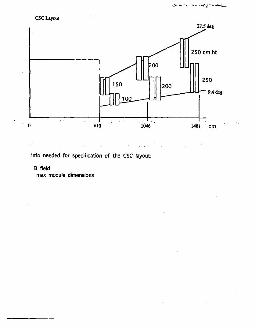
CSCLayout
27.S deg
250 cm ht
200
250 150 200
9.4 deg 100
0 610 1046 1481 cm
Info needed for specification of the CSC layout:
B field max module dimensions

Radial resolution contribution to Momentum Resolution
I I - >
i I
I I
I I
I
I I
I
I I
I I
.....
I
--- D
--- -....
• .!. 2....
-
~~
. -- -
- eAIJ> VIEW -
+ I I I I I I !+-• I I I ·
LI I
'•.
I WIR.65
+ t.3-A(
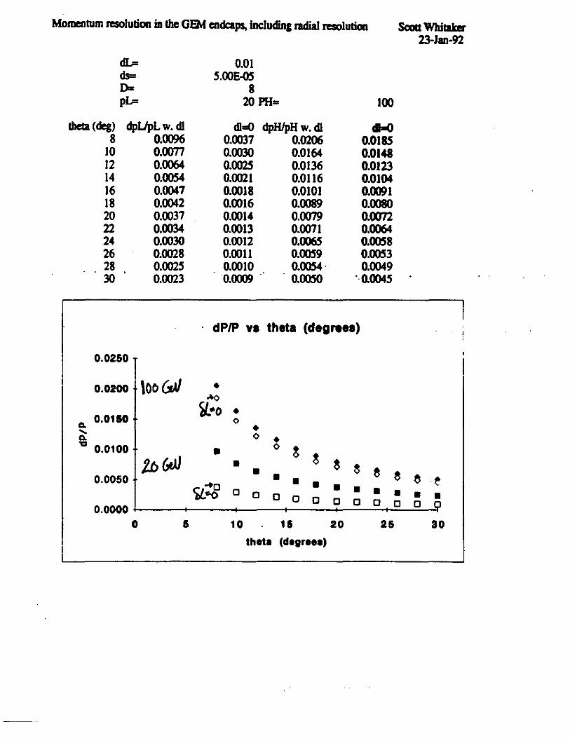
Momentum resolution in the GEM endcaps, Including radial raoluliCJll Scou Whitaker 23-Jan-92
dL= 0.01 els= S.OOE-OS D= 8 pL= 20 PH= 100
theta (deg) dpUpLw.dl cD=O dpH/pHw.cD ~ 8 0.0096 0.0037 0.0206 0.0185
10 0.0077 0.0030 0.0164 0.0148 12 0.0064 0.002S 0.0136 0.0123 14 0.0054 0.0021 0.0116 0.0104 16 0.0047 0.0018 0.0101 0.0091 18 0.0042 0.0016 0.0089 0.0080 20 0.0037 0.0014 0.0079 0.0072 22 0.0034 0.0013 0.0071 0.0064 24 0.0030 0.0012 0.006S O.OOS8 26 0.0028 0.0011 O.OOS9 0.0053 28 0.002S 0.0010 0.0054· 0.0049 30 0.0023 0.0009 . o.ooso "0.004S
· dP/P va theta (degrees)
0.0250
0.0200 \oo&N • -'O
fJ.•o • a. 0.0110 0 • " 0 a. • "Cl 0.0100 • 0
~ 2b (,VJ • g g
~ • e e 0.0050 • • e ·~ 9..-:g • • • 0 • • a a a • • a a a a a a 0.0000 0 I 10 11 20 25 30
theta (degree•)
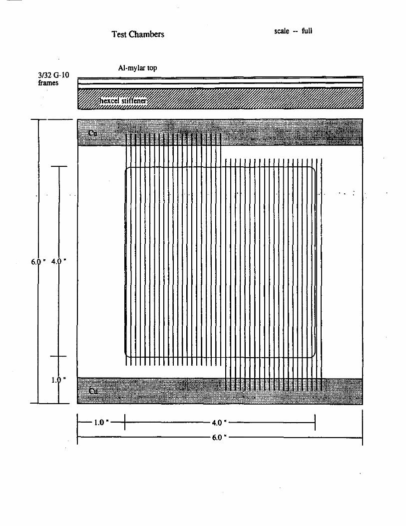
3/32 G-10 frames
6 .• 4 .•
1. •
Test Chambers scale -- full
Al-mylar top
-
..
r i.o. --t--------4.0. ---------l r-r------------6.0. ------------1
r
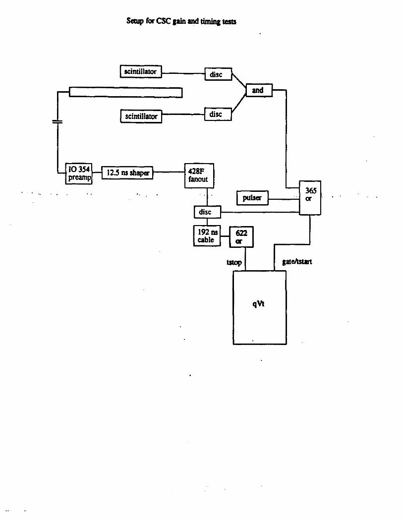
S«up for CSC lain and timina tests
scintillator
scintillator
12.S ns shaper 1-----1 428F fanout
disc
disc
disc
and
365 pulser or
192 ns 622 cable er
qVt

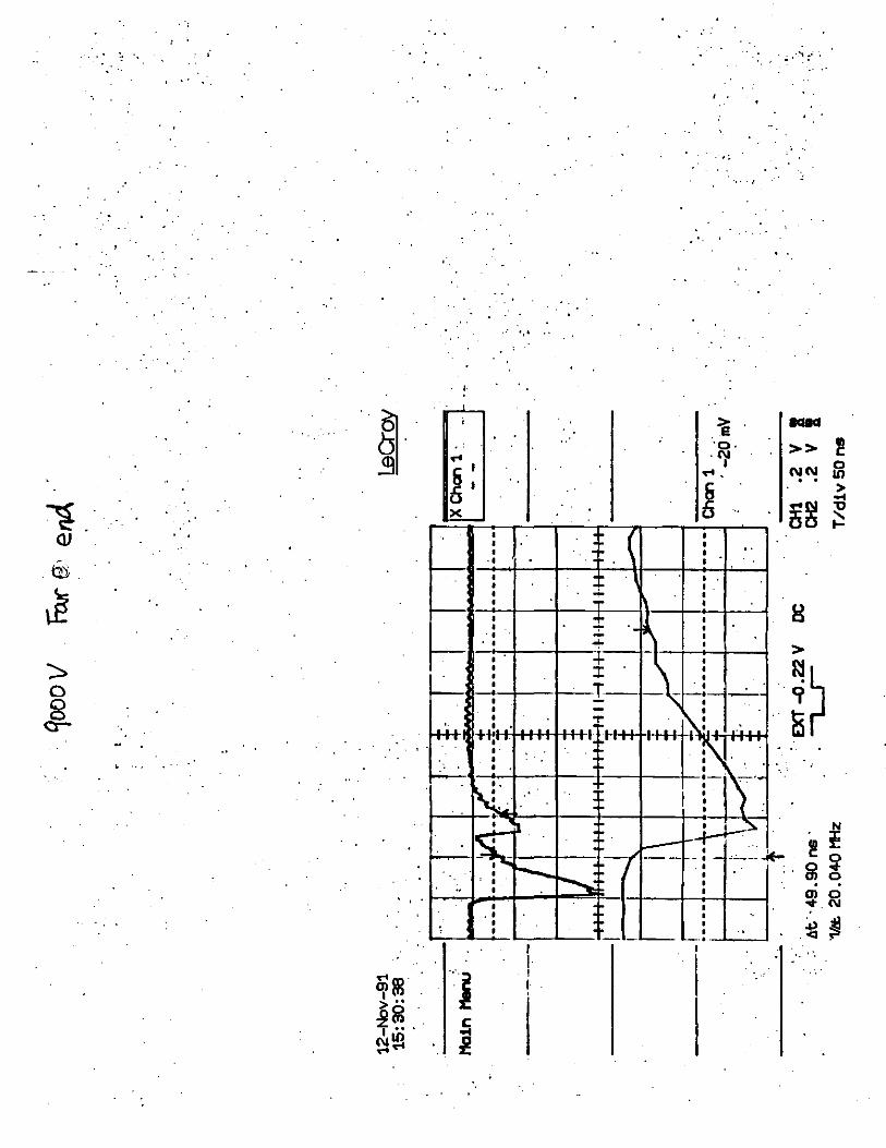
. . . . . ,.. 8Jl.S ~a.&'v.w "' s ¥' 0
t.~~m ea.StM<meJ-
Cosmic Ray Spectrum 25" CF4 2900 V 50..._. ........................... ~ ........................................... -
40
so
10
·-- 0 L..1-L...L...L.. 0 200 400 800 800 1000
qVl Chamlel
---------
Fe-55 Spectrum 253 CF4 2900 V
-----800
-- ---·-·---· -- - --- ---- -
- -- --------
" 200
100
0 !""'-~~1..1....L"":'=::"""......iu...... ......... ..i...... .......... UJ 0 200 400 800 800 1000
qVl Chll!lllel

50
40
! 30
20
10
...
Stop Tirr." ns
Time Distribution 25% CF4 2900 V 200r-T--r-.,....,r-r--r-...,...., .......... ""T"""r-T"-r-T"""T-r-...,....,....,..~
150
100
50
50 100 150 200 Stop Time ns
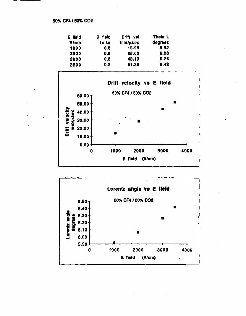
50% CF4 / 50% C02
E lleld B field Drift vel Theta L V/cm Te Isa mmtµ.sec degrees 1000 0.8 13.98 5.92 2000 0.8 28.00 6.06 3000 0.8 '3.13 6.26 3500 0.8 51.36 6.42
Drift velocity vs E field
60.00. 50% CF4 / 50% C02
SO.OD • ~o • Ci • 40.00 -~ ~ = - 30.00 • E !: E 20.00 .. • c 10.00
0.00 0 1000 2000 3000 4000
E field (V/cm)
Lorentz angle YI E fleld
8.50 50% CF4 / 50% C02
8.40 • .! ii 6.30 • JS i 1.20 ~,, 8.10 • 0 8.00 _,
5.90 •
0 1000 2000 3000 4000
E field (V/cm)
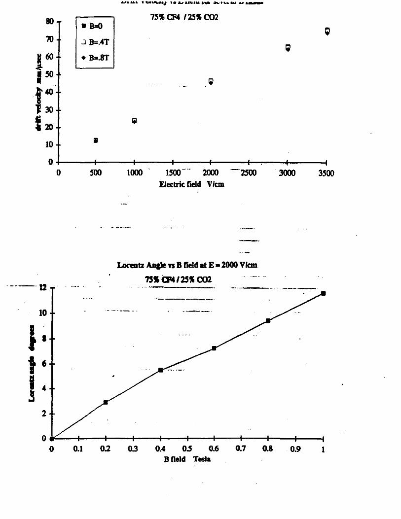
80 7!1S a:4 / 2!1S C02 • B=O
70 .J B=.4T
• B=.8T
II 10
0"'-~~4-~~-+-~~-+-~~--+-~~-+__,.~--f~~---f
0
-------12
10
0
!100 1000 . 1!100- .. 2000 --2!!00 3000 FJectric field V /cm
Lorentz An&le n B lleld at E • 2000 Vkm 7SS CP4/2!11 C02 -- --· -
·-------·-- ---··· --------·--------··
~1 ~ ~ U ~ M U M M Bfield Tesla
3!100
1


