Command Descriptions 57 Command Descriptions A Acceleration Type Motion Syntax <a_><!>A<r> Units r = revs/sec/sec (linear motors: see page 44 for linear/rotary conversion) Range 0.0001 – 9999.9999 Default 10.0000 Response A: *A10.0000 See Also AA, AD, ADA, DMEPIT, DRES, ERES, GO, IF, MC, VARI, WAIT Product Rev GT n/a GV n/a GT6 1.50 GV6 1.50 The Acceleration (A) command specifies the acceleration rate to be used upon executing the next GO command. If the Deceleration (AD) command has not been entered, the acceleration (A) command will set the deceleration rate. Once the deceleration (AD) command has been entered, the acceleration (A) command no longer affects deceleration. ON-THE-FLY CHANGES: You can change acceleration on the fly (while motion is in progress) in two ways. One way is to send an immediate acceleration command (!A) followed by an immediate go command (!GO). The other way is to enable the continuous command execution mode (COMEXC1) and execute a buffered acceleration command (A) followed by a buffered go command (GO). The A command value may be used in variable (VARI) assignments, and in IF and WAIT conditional statements. In addition, VARI variables may be substituted for the A command value. For details, see page 24. Example: DEL PROG7 ; Delete program #7 DEF PROG7 ; Begin definition of program #7 MA0 ; Incremental positioning mode MC0 ; Preset positioning mode A40 ; Set the acceleration to 40 revs/sec/sec AD16 ; Set the deceleration to 16 revs/sec/sec V1 ; Set the velocity to 1 revs/sec D100000 ; Set the distance to 100000 counts GO1 ; Initiate motion END ; End definition of program #7 AA Average Acceleration Type Motion (S-Curve) Syntax <a_><!>AA<r> Units r = revs/sec/sec (linear motors: see page 44 for linear/rotary conversion) Range 0, or 0.0001 – 9999.9999 Default 10.0000 (default is trapezoidal profiling, where AA tracks A; to restore trapezoidal profiling, set AA = 0) Response AA: *AA10.0000 See Also A, AD, ADA, DMEPIT Product Rev GT n/a GV n/a GT6 1.50 GV6 1.50 The Average Acceleration (AA) command allows you to specify the average acceleration for an S-curve motion profile. S-curve profiling provides smoother motion control by reducing the rate of change in
Transcript
Command Descriptions 57
Command Descriptions
A AccelerationType MotionSyntax <a_><!>A<r>Units r = revs/sec/sec
(linear motors: see page 44 for linear/rotary conversion)Range 0.0001 – 9999.9999Default 10.0000Response A: *A10.0000
See Also AA, AD, ADA, DMEPIT, DRES, ERES, GO, IF, MC, VARI, WAIT
Product Rev
GT n/aGV n/aGT6 1.50GV6 1.50
The Acceleration (A) command specifies the acceleration rate to be used upon executing the next GOcommand.
If the Deceleration (AD) command has not been entered, the acceleration (A) command will set thedeceleration rate. Once the deceleration (AD) command has been entered, the acceleration (A) command nolonger affects deceleration.
ON-THE-FLY CHANGES: You can change acceleration on the fly (while motion is in progress) in twoways. One way is to send an immediate acceleration command (!A) followed by an immediate go command(!GO). The other way is to enable the continuous command execution mode (COMEXC1) and execute abuffered acceleration command (A) followed by a buffered go command (GO).
The A command value may be used in variable (VARI) assignments, and in IF and WAIT conditionalstatements. In addition, VARI variables may be substituted for the A command value. For details, see page 24.
Example:DEL PROG7 ; Delete program #7DEF PROG7 ; Begin definition of program #7MA0 ; Incremental positioning modeMC0 ; Preset positioning modeA40 ; Set the acceleration to 40 revs/sec/secAD16 ; Set the deceleration to 16 revs/sec/secV1 ; Set the velocity to 1 revs/secD100000 ; Set the distance to 100000 countsGO1 ; Initiate motionEND ; End definition of program #7
AA Average AccelerationType Motion (S-Curve)Syntax <a_><!>AA<r>Units r = revs/sec/sec
(linear motors: see page 44 for linear/rotary conversion)Range 0, or 0.0001 – 9999.9999Default 10.0000 (default is trapezoidal profiling, where AA tracks A;
to restore trapezoidal profiling, set AA = 0)Response AA: *AA10.0000
See Also A, AD, ADA, DMEPIT
Product Rev
GT n/aGV n/aGT6 1.50GV6 1.50
The Average Acceleration (AA) command allows you to specify the average acceleration for an S-curvemotion profile. S-curve profiling provides smoother motion control by reducing the rate of change in
58 Gemini Series Programmer’s Reference
acceleration and deceleration; this accel/decel rate of change is known as jerk. Refer to page 53 for detailson S-curve profiling.
ON-THE-FLY CHANGES: You can change acceleration on the fly (while motion is in progress) in twoways. One way is to send an immediate acceleration command (!AA) followed by an immediate gocommand (!GO). The other way is to enable the continuous command execution mode (COMEXC1) andexecute a buffered acceleration command (AA) followed by a buffered go command (GO).
Example:; In this example, program #1 executes a pure S-curve and takes 1 second; to reach a velocity of 5 rps; program #2 executes a trapezoidal profile; and takes 0.5 seconds to reach a velocity of 5 rps.DEL PROG1 ; Delete program #1DEF PROG1 ; Begin definition of program #1MA0 ; Select incremental positioning modeD40000 ; Set distance to 40,000 positive-direction countsA10 ; Set max. accel to 10 revs/sec/secAA5 ; Set avg. accel to 5 revs/sec/secAD10 ; Set max. decel to 10 revs/sec/secADA5 ; Set avg. decel to 5 revs/sec/secV5 ; Set velocity to 5 revs/secGO1 ; Execute motionEND ; End definition of program #1
DEL PROG2 ; Delete program #2DEF PROG2 ; Begin definition of program #2MA0 ; Select incremental positioning modeD40000 ; Set distance to 40,000 positive-direction countsA10 ; Set max. accel to 10 revs/sec/secAA10 ; Set avg. accel to 10 revs/sec/secAD10 ; Set max. decel to 10 revs/sec/secADA10 ; Set avg. decel to 10 rev/sec/secV5 ; Set velocity to 5 revs/secGO1 ; Execute motionEND ; End definition of program #2
AD DecelerationType MotionSyntax <a_><!>AD<r>Units r = revs/sec/sec
(linear motors: see page 44 for linear/rotary conversion)Range 0, or 0.0001 – 9999.9999Default 10.0000 (AD tracks A; to restore tracking, set AD = 0)Response AD: *AD10.0000
See Also A, AA, ADA, DMEPIT, DRES, ERES, GO, IF, LHAD, LSAD, MC, VARI,WAIT
Product Rev
GT n/aGV n/aGT6 1.50GV6 1.50
The Deceleration (AD) command specifies the deceleration rate to be used upon executing the next GOcommand.
If the deceleration (AD) command has not been entered, the acceleration (A) command will set thedeceleration rate. Once the deceleration (AD) command has been entered, the acceleration (A) command nolonger affects deceleration. If the AD command is set to zero (AD0), then the deceleration will once againtrack whatever the A command is set to.
ON-THE-FLY CHANGES: You can change deceleration on the fly (while motion is in progress) in twoways. One way is to send an immediate deceleration command (!AD) followed by an immediate gocommand (!GO). The other way is to enable the continuous command execution mode (COMEXC1) andexecute a buffered deceleration command (AD) followed by a buffered go command (GO).
The AD command value may be used in variable (VARI) assignments, and in IF and WAIT conditionalstatements. In addition, VARI variables may be substituted for the AD command value. For details, refer topage 24.
Command Descriptions 59
Example:DEL PROG7 ; Delete program #7DEF PROG7 ; Begin definition of program #7MA0 ; Incremental positioning modeMC0 ; Preset positioning modeA40 ; Set the acceleration to 40 revs/sec/secAD16 ; Set the deceleration to 16 revs/sec/secV1 ; Set the velocity to 1 revs/secD100000 ; Set the distance to 100000 countsGO1 ; Initiate motionEND ; End definition of program #7
ADA Average DecelerationType Motion (S-Curve)Syntax <a_><!>ADA<r>Units r = revs/sec/sec
(linear motors: see page 44 for linear/rotary conversion)Range 0, or 0.0001 – 9999.9999Default 10.0000 (default is a constant deceleration ramp, where ADA
tracks AA; to restore tracking, set ADA = 0)Response ADA: *ADA10.0000
See Also A, AA, AD, DMEPIT, LHADA, LSADA
Product Rev
GT n/aGV n/aGT6 1.50GV6 1.50
The Average Deceleration (ADA) command allows you to specify the average deceleration for an S-curvemotion profile. S-curve profiling provides smoother motion control by reducing the rate of change inacceleration and deceleration; this accel/decel rate of change is known as jerk. Refer to page 53 for details onS-curve profiling.
ON-THE-FLY CHANGES: You can change deceleration on the fly (while motion is in progress) in twoways. One way is to send an immediate deceleration command (!ADA) followed by an immediate gocommand (!GO). The other way is to enable the continuous command execution mode (COMEXC1) andexecute a buffered deceleration command (ADA) followed by a buffered go command (GO).
Example: (refer to the AA command description)
ADDR Multiple Unit Auto-AddressType Communication InterfaceSyntax <a_><!>ADDR<i>Units i = unit number (address)Range 0-99Default 0Response ADDR: *ADDR0
See Also E
Product Rev
GT 1.02GV 1.00GT6 1.50GV6 1.50
The factory default address for a Gemini drive is address zero (0). The ADDR command automaticallyconfigures unit addresses for a daisy-chain or multi-drop. This command allows up to 99 units on a chain tobe uniquely addressed. After unique addresses are established, you can address commands to specific unitsby prefixing the commands with the unit’s address followed by an underscore (e.g., 2_TAS checks the statuson unit #2).
RS-232C Daisy Chain:Sending ADDRi to the first unit in the chain sets its address to be (i). The first unit in turn transmitsADDR(i + 1) to the next unit to set its address to (i + 1). This continues down the daisy chain untilthe last unit of (n) daisy-chained units has its address set to (i + n - 1).
RS-485 Multi-Drop:To use the ADDR command, you must address each unit individually before it is connected on the multi
60 Gemini Series Programmer’s Reference
drop. For example, given that each product is shipped configured with address zero, you could set upa 4-unit multi-drop with the commands below, and then connect them in a multi drop:
1. Connect the unit that is to be unit #1 and transmit the Ø_ADDR1 command to it.2. Connect the unit that is to be unit #2 and transmit the Ø_ADDR2 command to it.3. Connect the unit that is to be unit #3 and transmit the Ø_ADDR3 command to it.4. Connect the unit that is to be unit #4 and transmit the Ø_ADDR4 command to it.
If you need to replace a unit in the multi drop, send the Ø_ADDRi command to it, where “i” is theaddress you wish the new unit to have.
To send a Gemini command from the master unit to a specific unit in the multi-drop, prefix thecommand with the unit address and an underscore (e.g., 3_OUTØ turns off output #1 on unit #3). Themaster unit (if it is not a Gemini product) may receive data from a multi-drop unit.
For more information on controlling multiple Gemini Series drives in an RS-232 daisy-chain or RS-485multi-drop, refer to your Gemini drive’s Hardware Installation Guide.
Example:ADDR1 ; Set the address of the first unit in the daisy-chain to 1.
; Subsequent units in the chain are automatically numbered; 2, 3, 4, 5, and so on, in their order in the chain.
ANICDB Analog Input Center DeadbandType Drive ConfigurationSyntax <a_><!>ANICDB<r>Units voltsRange 0.00 – 10.00Default 0.04Response ANICDB: *ANICDB0.04
See Also DCMDZ, DMTSCL, DMVSCL
Product Rev
GT 1.61GV 1.70GT6 n/aGV6 n/a
ANICDB allows the user to specify the voltage deadband for the command input. ANICDB is used withDCMDZ to configure the command input for DMODE2 and DMODE4. In DMODE4, the commanded velocity,Velcommand, is calculated from the input voltage, Vin, using DMVSCL as follows:
( ) ( )( ) ( )
( ) ( )ANICDB-DCMDZDMVSCL
ANICDBDCMDZ
ANICDBDCMDZANICDB-DCMDZ
ANICDBDCMDZDMVSCL
ANICDBDCMDZ
<∗+−=
+≤≤=
+>∗−−=
inincommand
incommand
inincommand
VVVel
VVel
VVVel
when10
when0
when10
Similarly, the commanded torque in DMODE2 is calculated using DMTSCL in the above equations.
BOT Beginning of Transmission CharactersType Communication InterfaceSyntax <i>BOT<i>,<i>,<i>Units i = numeric equivalent for ASCII characterRange i = 0-255Default 0,0,0Response BOT: *BOT0,0,0
See Also EOT, ERROK, ERRBAD, EOL
Product Rev
GT 1.02GV 1.00GT6 1.50GV6 1.50
The Beginning of Transmission Characters (BOT) command designates the characters to be placed at thebeginning of every response. Up to 3 characters can be placed before the first line of a multi-line response,or before all single-line responses. The characters are designated with their ASCII equivalent. For example,a carriage return is ASCII 13, a line feed is ASCII 10, a Ctrl-Z is ASCII 26, and no terminating character isdesignated with a zero. If the first field is a zero, the drive will only accept zeros from the other two fields.
Command Descriptions 61
NOTE: This command is intended to be used only during live terminal communication with the drive. Donot download this command to the drive, or place it in a program.
For a more complete list of ASCII Equivalents, refer to the ASCII Table in Appendix C.
Example:BOT13,10,26 ; Place a carriage return, line feed, and Ctrl-Z before
; the first line of a multi-line response, and before; all single line responses
C Continue Command ExecutionType Program Flow ControlSyntax <a_>!CUnits n/aRange n/aDefault n/aResponse n/a
See Also COMEXR, COMEXS, INFNC, PS, S
Product Rev
GT n/aGV n/aGT6 1.50GV6 1.50
The Continue (!C) command ends a pause state (PS), or a stopped (S) condition. When the Gemini is in apaused state, no commands from the command buffer are executed. All immediate commands, however, arestill processed. By sending a !C command, command processing will resume, starting with the firstcommand after the PS command. If a stop (S) command has been issued, motion and command processingcan be resumed by issuing a !C command, only if COMEXS has been enabled.
Example:PS ; Stop execution of command buffer until !C commandMA0 ; Select incremental positioning modeD10000 ; Set distance to 10000 countsGO1 ; Initiate motion
No buffered commands after the PS command will be executed until a !C command is received.!C ; Restart execution of command buffer
COMEXS1 ; Enable command processing on stopD50000 ; Set distance to 50000 countsGO1 ; Initiate motion!S ; Stop motion
When the Gemini drive processes the !S command, motion on all axes will be stopped. If the desireddistance has not been reached, motion can be resumed by issuing the !C command. If motion and commandprocessing are to stop, a Kill (!K) command can be issued.
The CERRLG command erases the stored contents of the error log. Clearing the error log is a helpfuldiagnostic tool; it allows you to start the diagnostic process when the error log is in a known state so thatyou can check the error log in response to subsequent events.
The error log is updated every time an error occurs. The TERRLG command displays the last ten errorconditions that the drive has experienced, as recorded in these status registers:
• TAS (axis status binary report)• TASX (extended axis status binary report)• TDHRS (number of hours since the drive was powered up or RESET)• TDTEMP (measured temperature of the drive in centigrade)• TMTEMP (estimated temperature of the motor in centigrade - GV only; GT always reports zero)
See Also A, AA, AD, ADA, COMEXL, COMEXS, D, ERRORP, GO, GOWHEN, MA, MC,V
Product Rev
GT n/aGV n/aGT6 1.50GV6 1.50
Use COMEXC to enable or disable Continuous Command Execution Mode. Under default operation(COMEXC0), when a motion command is received, command processing is temporarily paused until themotion is complete. In continuous command execution mode (COMEXC1), however, command processingcontinues while motion is taking place. NOTE: Command processing will be slower and some motionparameters cannot be changed while motion is in progress; the list below identifies all parameters that cannotbe changed while motion is in progress.
The Continuous Command Processing Mode is useful in the following situations:
• When trying to check the status of inputs while the Gemini product is commanding motion.
• Performing calculations ahead of time, possibly decreasing cycle time.
• Executing buffered on-the-fly acceleration (A, AA), and deceleration (AD, ADA), distance (D),positioning mode (MA & MC), and velocity (V) changes. (The buffered A, AA, AD, ADA, D, MA, MC, orV change can be executed only with a buffered Go (GO) command.) For more information abouton-the-fly motion changes, refer to page 42.
• Pre-processing the next move while the current move is in progress (see CAUTION note below).This reduces the processing time for the subsequent move to only a few microseconds.
CAUTION: Avoid Executing Moves Prematurely
With continuous command execution enabled (COMEXC1), if you wish motion to stop beforeexecuting the subsequent move, place a WAIT(AS.1=b0) statement before the subsequentGO command. If you wish to ensure the load settles adequately before the next move, use theWAIT(AS.24=b1) command instead (this requires you to define end-of-move settling criteria— see STRGTE command or the Target Zone section on page 37 for details).
Example:DEL PROG8 ; Delete program #8DEF PROG8 ; Begin definition of program #8COMEXC1 ; Enable continuous command execution modeL50 ; Loop 50 timesD50000 ; Set distance to 50000 countsGO1 ; Initiate motion; Normally at this point, the Gemini drive would wait for the motion to complete; before processing the next command. However, with continuous command execution; enabled (COMEXC1), processing will continue with the statements that follow.IF(IN.1=b1) ; Check for input #1 becoming activeOUT.3-1 ; If it does, turn on output #3ELSE ;OUT.1-1 ; If input #1 is not on, turn on output #1WAIT(AS.1=b0) ; Wait for no commanded motionLN ; End loop
Command Descriptions 63
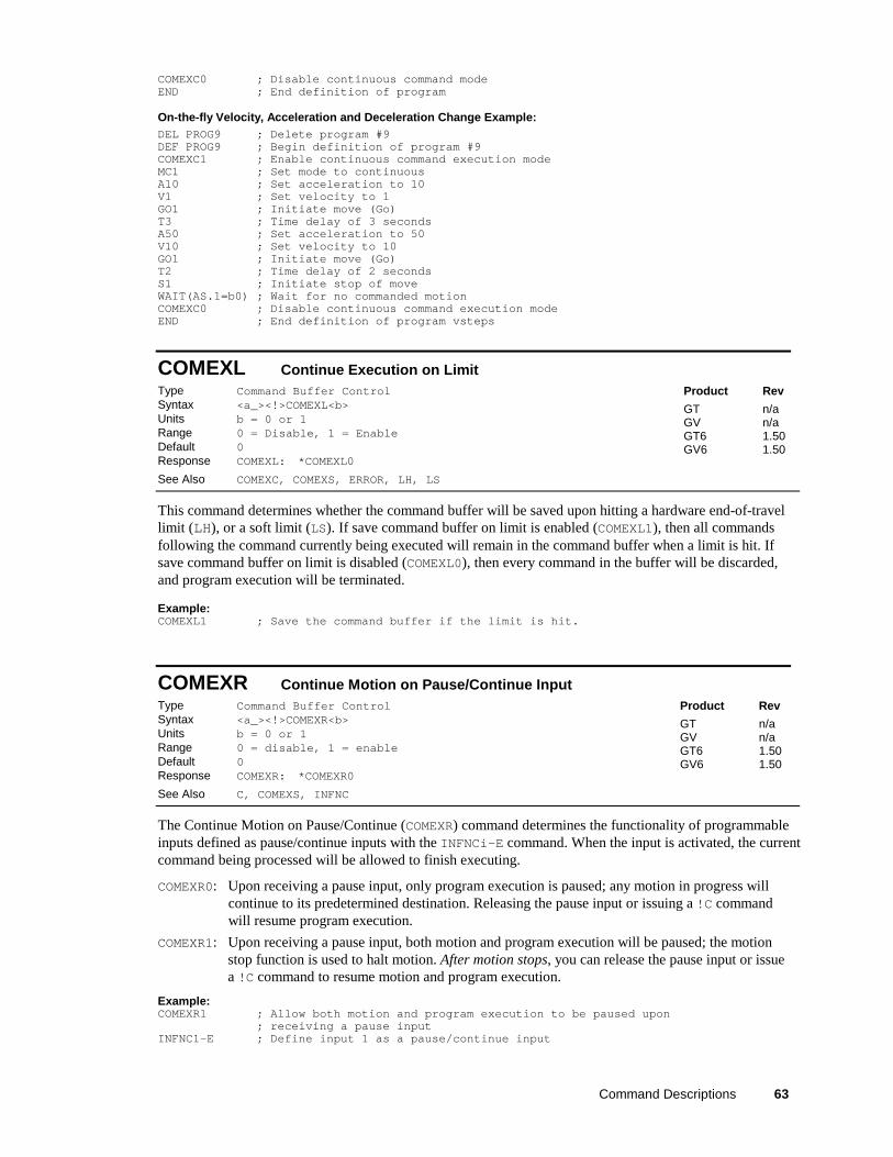
COMEXC0 ; Disable continuous command modeEND ; End definition of program
On-the-fly Velocity, Acceleration and Deceleration Change Example:DEL PROG9 ; Delete program #9DEF PROG9 ; Begin definition of program #9COMEXC1 ; Enable continuous command execution modeMC1 ; Set mode to continuousA10 ; Set acceleration to 10V1 ; Set velocity to 1GO1 ; Initiate move (Go)T3 ; Time delay of 3 secondsA50 ; Set acceleration to 50V10 ; Set velocity to 10GO1 ; Initiate move (Go)T2 ; Time delay of 2 secondsS1 ; Initiate stop of moveWAIT(AS.1=b0) ; Wait for no commanded motionCOMEXC0 ; Disable continuous command execution modeEND ; End definition of program vsteps
COMEXL Continue Execution on LimitType Command Buffer ControlSyntax <a_><!>COMEXL<b>Units b = 0 or 1Range 0 = Disable, 1 = EnableDefault 0Response COMEXL: *COMEXL0
See Also COMEXC, COMEXS, ERROR, LH, LS
Product Rev
GT n/aGV n/aGT6 1.50GV6 1.50
This command determines whether the command buffer will be saved upon hitting a hardware end-of-travellimit (LH), or a soft limit (LS). If save command buffer on limit is enabled (COMEXL1), then all commandsfollowing the command currently being executed will remain in the command buffer when a limit is hit. Ifsave command buffer on limit is disabled (COMEXL0), then every command in the buffer will be discarded,and program execution will be terminated.
Example:COMEXL1 ; Save the command buffer if the limit is hit.
COMEXR Continue Motion on Pause/Continue InputType Command Buffer ControlSyntax <a_><!>COMEXR<b>Units b = 0 or 1Range 0 = disable, 1 = enableDefault 0Response COMEXR: *COMEXR0
See Also C, COMEXS, INFNC
Product Rev
GT n/aGV n/aGT6 1.50GV6 1.50
The Continue Motion on Pause/Continue (COMEXR) command determines the functionality of programmableinputs defined as pause/continue inputs with the INFNCi-E command. When the input is activated, the currentcommand being processed will be allowed to finish executing.
COMEXR0: Upon receiving a pause input, only program execution is paused; any motion in progress willcontinue to its predetermined destination. Releasing the pause input or issuing a !C commandwill resume program execution.
COMEXR1: Upon receiving a pause input, both motion and program execution will be paused; the motionstop function is used to halt motion. After motion stops, you can release the pause input or issuea !C command to resume motion and program execution.
Example:COMEXR1 ; Allow both motion and program execution to be paused upon
; receiving a pause inputINFNC1-E ; Define input 1 as a pause/continue input
64 Gemini Series Programmer’s Reference
COMEXS Continue Execution on StopType Command Buffer ControlSyntax <a_><!>COMEXS<i>Units i = function identifierRange 0, 1, or 2Default 0Response COMEXS: *COMEXS0
See Also C, COMEXC, COMEXL, COMEXR, INFNC, S
Product Rev
GT n/aGV n/aGT6 1.50GV6 1.50
The COMEXS command determines the impact on motion, program execution, and the command buffer whenthe Gemini drive receives a Stop command (S, !S, S1, or !S1) or an external stop input (INFNCi-D).
COMEXS0: Under factory default conditions (COMEXS0), when the Gemini drive receives a stop command(S, !S, S1, or !S1) or a stop input (input assigned a stop function with INFNCi-D), thefollowing will happen:
• Motion decelerates to a stop, using the present AD and ADA deceleration values. Themotion profile cannot be resumed.
• If S, !S or Stop input: – All commands in the Gemini drive’s command buffer are discarded. – Program execution is terminated and cannot be resumed.
• If S1, or !S1: – All commands in the Gemini drive’s command buffer are retained. – Program execution continues.
COMEXS1: Using the COMEXS1 mode, the drive allows more flexibility in responding to stop conditions,depending on the stop method (see table below).
Stop Method What Stops?Motion Program
Resume Motion Profile.Allow resume with a !Ccommand or a resumeinput (INFNCi-E).
Resume Program.Allow resume with a !Ccommand or a resumeinput (INFNCi-E).
Save Command Buffer.Save the commands thatwere in the commandbuffer when the stop wascommanded.
!S or S Yes Yes Yes Yes Yes!S1 or S1 Yes No No No YesStop input Yes Yes Yes Yes YesPause input *(if COMEXR1)
Yes Yes Yes Yes Yes
Pause input *(if COMEXR0)
No Yes No Yes Yes
* A Pause input is an input configured with the INFNCi-E command. This is also the input that can be used toresume motion and program execution after a stop.
COMEXS2: Using the COMEXS2 mode, the drive responds as it does in the COMEXS0 mode, with theexception that you can still use the BCD inputs to select programs (INSELP value is retained).For more details on BCD program selection, refer to INFNC and INSELP.
Command Descriptions 65
D DistanceType MotionSyntax <a_><!>D<r>Units r = distance (counts)Range -2,147,483,648 to +2,147,483,647Default 4000Response D: *D+4000
See Also DMEPIT, DRES, ERES, GO, IF, MA, MC, PSET, VARI, WAIT
Product Rev
GT n/aGV n/aGT6 1.50GV6 1.50
The Distance (D) command defines either the number of counts the motor will move or the absolute positionit will seek after a GO command. In the incremental mode (MAØ), the distance value represents the totalnumber of units you wish the motor to move. In the absolute mode (MA1) the distance value represents theabsolute position the motor will end up at; the actual distance traveled will vary depending on the absoluteposition of the motor before the move is initiated.
In the incremental mode (MAØ), you can specify a negative distance by placing a dash or hyphen (-) in frontof the distance value (e.g., D-10000). Otherwise, the direction is considered positive. You can changedirection without changing the distance value by using the +, -, or ~ operators (e.g. D+, or D-, or D~); thetilde (~) is a means of toggling the direction.
The D command value may be used in variable (VARI) assignments, and in IF and WAIT conditionalstatements. In addition, VARI variables may be substituted for the D command value. For details, see page 24.
ON-THE-FLY CHANGES: You can change distance on the fly (while motion is in progress) in two ways.One way is to send an immediate distance command (!D) followed by an immediate go command (!GO).The other way is to enable the continuous command execution mode (COMEXC1) and execute a buffereddistance command (D) followed by a buffered go command (GO).
Direction of Motion for Rotary Motors:Positive distance values (e.g., D20000) represent clockwise motion andnegative values (e.g., D-20000) represent counter-clockwise motion. Thisassumes you connected the motor (and feedback device for servos) accordingto the Hardware Installation Guide instructions.
��$������.����
/����� ���$��0
���.����
/(���� ���$��0
Example:DEL PROG2 ; Delete program #2DEF PROG2 ; Begin definition of program #2MA0 ; Select incremental positioning modeD40000 ; Set distance to 40,000 positive-direction countsA10 ; Set max. accel to 10 revs/sec/secAA10 ; Set avg. accel to 10 revs/sec/secAD10 ; Set max. decel to 10 revs/sec/secADA10 ; Set avg. decel to 10 rev/sec/secV5 ; Set velocity to 5 revs/secGO1 ; Execute motionEND ; End definition of program #2
DABSD Enable ABS DampingType Drive ConfigurationSyntax <a_><!>DABSD<b>Units b = enable bitRange 0 (disable) or 1 (enable)Default 0 (disabled)Response DABSD: *DABSD1
See Also DACTDP, DDAMPA, DELVIS
Product Rev
GT 1.02GV n/aGT6 1.50GV6 n/a
The DABSD command enables or disables the ABS damping function. ABS is a damping technique designedfor use at very low to zero speed. ABS damping requires no additional user setup or configuration. Whenenabled (DABSD1), ABS damping takes precedence over electronic viscosity (DELVIS) at speeds less thanapproximately 0.2 revs/sec (motor dependent). ABS damping can be disabled during acceleration with theDDAMPA0 command (DDAMPA0 is the factory default setting).
66 Gemini Series Programmer’s Reference
Gemini Damping Features: The Gemini drive provides damping features that reduce vibration, increaselow-speed smoothness, and decrease load settling time. (A procedure for configuring damping settings isprovided in the Configuration chapter of your drive’s Hardware Installation Guide.)
Command Damping Function Velocity * Default Related Parameters *
DABSD ABS Damping. Load-independent dampingat extreme low speeds. This feature targetsapplications that require minimal zero-speedsettling (e.g., pick-and-place applications).
0 to 0.2 revs/sec ** Disabled DMTRES, DMTIND
DELVIS Electronic Viscosity. This feature targetsapplications that require reduced low-speedvelocity ripple and increased smoothness,as well as aggressive low-speed damping.(NOTE: If ABS Damping is enabled, itoverrides electronic viscosity in the 0-0.2rev/sec velocity range.) Start with DELVISset to zero, and increase until the requiredperformance is achieved.
0 to 3 revs/sec ** Disabled DMTJ, DMTSTT, DPOLE,DMTIC, DMTIND,LJRAT
DACTDP Active Damping. This feature targetsapplications that require high accelerations,fast settling at commanded speed,mechanical vibration rejection, and highlystable (non-resonant) motion. Startconfiguration with a low DACTDP value, ashighly aggressive damping can lead tomechanical failure.
> 3 revs/sec Enabled,gain = 4
DMTJ, DMTIND,DMTSTT, LJRAT
DDAMPA Damping During Acceleration. Whenenabled, ABS Damping and ElectronicViscosity are allowed to function at acceland decel rates greater than 50revs/sec/sec. If your application requiresmore responsive acceleration anddeceleration (full motor torque) above 50revs/sec/sec, you can disable this feature;but be aware that doing so increases jerk inyour mechanical system.
Affects damping ataccelerations> 50 revs/sec/sec
Disabled n/a
* These features are based on motor and load parameters that you set up with the configuration utility in MotionPlanner (see page 6) or Pocket Motion Planner (see page 11). For optimum damping performance, accurate motorand load parameters are required. NOTE: If you select a Parker motor with the configuration utility, all of themotor parameters (excluding LJRAT, which sets the load-to-rotor ratio) are automatically set accordingly.
** Actual transition velocity is based on motor and load parameters, and is therefore application dependent.
DACTDP Active DampingType Drive ConfigurationSyntax <a_><!>DACTDP<i>Units i = gainRange 0-40; 0 disables active dampingDefault 4Response DACTDP *DACTDP0
See Also DABSD, DELVIS, DMTR, LJRAT
Product Rev
GT 1.02GV n/aGT6 1.50GV6 n/a
The DACTDP command controls the gain of the Active Damping function for a specific motor and load.Active damping works at speeds greater than 3 revolutions per second.
NOTE: To be fully effective, the active damping function requires that you first set the system inertia ratio(LJRAT) and configure your motor parameters. Motor parameters are automatically configured when youselect a Parker motor with the DMTR command (if you are not using a Parker motor you must individuallyconfigure each command listed in the DMTR command description). With a setting of DACTDP20, the nominalgains (calculated based on LJRAT and the motor parameters) give the best performance over the entire speedrange, but you may adjust the DACTDP setting further as your application warrants.
An overview of the GT/GT6 damping features is provided in the DABSD command description; see page 65.
Command Descriptions 67
DAUTOS Auto Current StandbyType Drive ConfigurationSyntax <a_><!>DAUTOS<r>Units r = % reduction of motor currentRange 0.00-99.99 : ±0.01Default 0.00 (no current reduction)Response DAUTOS *DAUTOS0
See Also
Product Rev
GT 1.02GV n/aGT6 1.50GV6 n/a
The DAUTOS command allows you to let the motor cool when it is not moving. When automatic currentstandby is set to a value other than 0.00 (default), the motor current will be reduced by that percentage whenthe drive has not received a step pulse for one second. Full commanded current is restored upon the firststep pulse that the drive receives.
WARNING: Motor torque is reduced when the motor current is reduced. Applications with vertical loadsor loads that require holding torque at zero speed should not use this feature.
DCLRLR Clear the Latched Status Register BitsType Drive ConfigurationSyntax <a_><!>DCLRLRUnits n/aRange n/aDefault n/aResponse n/a
See Also DMODE, DMTLIM, DMVLIM, DIFOLD, TASX, TTRQ
Product Rev
GT 1.02GV 1.00GT6 1.50GV6 1.50
TASX status register bits 18, 19, 20 and 31 (see descriptions below) indicate conditions in which driveprotective software has engaged, but drive operation continues. These status bits remain set (latched),regardless of whether the conditions persist, and are cleared with the DCLRLR command or when you issue aRESET command, cycle power, or activate the Reset input.
TASX bit 18 Commanded Velocity Exceeds DMVLIM Limit (GV/GV6 and GT/GT6):Bit 18 is set when the velocity demand from a controller or the internal Gemini control loopsexceeds the limits set by the DMVLIM command. The GV/GV6 drive responds to this conditionby invoking the “Override Mode,” in which the drive software clamps the maximum allowablevelocity command to the value set by DMVLIM. The Override Mode feature is applicable to theGV or GV6 drive in all operating modes (DMODE).
TASX bit 19 Bridge is in Foldback Mode (GV/GV6 only):When a Gemini drive produces more than its rated continuous current, a software algorithmdetermines on an ongoing basis the amount of power being delivered by the drive to themotor. When this value exceeds the safe threshold for the drive, the drive either goes intoFoldback Mode or faults, depending on the DIFOLD command. For motion profiles that pushthe limits of the drive’s capabilities, the drive might go into Foldback Mode for a short periodof time. Bit 19 stays latched, however, so that the user can determine that foldback occurred.
TASX bit 20 Power Dissipation Circuit Active (GV/GV6 and GT/GT6):When a Gemini drive attempts to slow a motor down, the stored energy in the motor and loadmust be absorbed by the drive. This regenerative energy will increase the bus voltage in thedrive until either a regenerative power dissipation circuit dissipates the energy or a drive over-voltage fault (reported in TASX bit 13) occurs. In all GT drives, the GV-L3, and the GV-H20,internal regenerative power dissipation circuitry is provided to dissipate this energy; when thiscircuitry is activated, TASX bit 20 is set and latched. In the GV-U3, GV-U6, and GV-U12drives, the external ‘Gemini Power Dissipation Module’ or ‘GPDM’ option can be used todissipate this energy — TASX bit 20 does not get set for these drives.
TASX bit 31 Commanding Maximum Torque/Force (GV/GV6):When the Gemini’s commanded torque/force reaches the limit set by DMTLIM(TTRQ = DMTLIM), TAS bit #31 is set. This is not considered a fault condition.
68 Gemini Series Programmer’s Reference
DCMDZ Zero the Drive Command OffsetType Drive ConfigurationSyntax <a_><!>DCMDZ<r>Units voltsRange -10.00 – 10.00Default 0.00Response n/a
See Also ANICDB, DMODE
Product Rev
GT 1.02GV 1.00GT6 n/aGV6 n/a
The DCMDZ command sets the zero point for the command input. When in velocity mode (DMODE4) ortorque/force mode (DMODE2), this will minimize motor drift.
Executing the DCMDZ command without an argument sets the zero reference point to the last voltage read at thecommand input. For this command to be executed correctly, the Command + and Command - inputs must be shortedtogether, or zero volts must be commanded from the servo controller.
DCMDZ can also be used to set the zero point to an arbitrary voltage by entering that value. For example,DCMDZ0.5 will make 0.5 volts equal to a commanded velocity of zero rps. Note that this value is theinternal level and will not take into account any offsets in the incoming command signal.
DDAMPA Damping During Acceleration/DecelerationType Drive ConfigurationSyntax <a_><!>DDAMPA<b>Units b = enable bitRange 0 (disable damping) or 1 (enable damping)Default 0 disabled)Response DDAMPA: *DDAMPA1
See Also DABSD, DELVIS
Product Rev
GT 1.02GV n/aGT6 1.50GV6 n/a
When Damping During Acceleration is enabled (DDAMPA1), ABS damping (DABSD) and ElectronicViscosity (DELVIS) function normally.
If your application requires more responsive acceleration and deceleration, you can disable DampingDuring Accel/Decel with the DDAMPA0 command (DDAMPA0 is the factory default setting). This disablesABS damping and Electronic Viscosity during acceleration and deceleration rates greater than 50revs/sec/sec when the commanded speed exceeds 0.03 revs/sec.
Be aware that the DDAMPA0 mode allows increased jerk in your mechanical system.
An overview of the GT’s damping features is provided on page 66.
DEF PROF Begin Profile DefinitionType Compiled MotionSyntax <a_><!>DEF PROF<i>Units i = profile ID numberRange 1-16Default n/aResponse n/a
See Also DEF PROG, DEL PROF, END, GOBUF, PRUN PROF, TDIR, TMEM, TSS(see Compiled Motion section on page 49)
Product Rev
GT n/aGV n/aGT6 1.50GV6 1.50
The DEF PROF command marks the beginning of a profile definition. For example, the DEF PROF6 commandbegins definition of profile #6. Up to 16 profiles may be defined.
As soon as the Gemini drive receives a subsequent END command, the profile is compiled and stored in the“profile” partition of the Gemini’s non-volatile memory. Profiles remain stored until you deleted them with theDEL PROF command or issue an RFS command. To check the status of stored profiles, use the TMEM command.To report the names of all stored profiles, use the TDIR command.
Command Descriptions 69
NOTE
When defining a profile and the memory limitation is reached, the drive will respond withthe ERRBAD prompt (default prompt is “?”), and the profile will be stored up to the pointwhere the memory limitation was reached.
To execute a specific profile, issue the PRUN PROF command or the PROF command (e.g., you can use eitherPRUN PROF6 or PROF6 to execute compiled profile #6).
NOTE: The profile must be deleted (e.g., DEL PROF6) before it can be redefined.
Example:DEL PROF1 ; Delete profile #1DEF PROF1 ; Begin definition of profile #1MC0 ; Preset positioning modeD50000 ; Distance is 50000A10 ; Acceleration is 10 revs/sec/secAD10 ; Deceleration is 10 revs/sec/secV5 ; Velocity is 5 revs/secGOBUF1 ; 1st motion segmentD30000 ; Distance is 30000V2 ; Velocity is 2 revs/secGOBUF1 ; 2nd motion segmentD40000 ; Distance is 40000V4 ; Velocity is 4 revs/secGOBUF1 ; 3rd motion segmentEND ; End program definition
DEF PROG Begin Program DefinitionType Program DefinitionSyntax <a_><!>DEF PROG<i>Units i = program ID numberRange 1-32Default n/aResponse n/a
See Also DEF PROF, DEL PROG, END, GOSUB, JUMP, RUN PROG, STARTP, TDIR,TMEM, TPROG, TSS
Product Rev
GT n/aGV n/aGT6 1.50GV6 1.50
The DEF PROG command marks the beginning of a program definition. For example, the DEF PROG3command begins definition of program #3. Up to 32 programs may be defined.
All programs are stored in a binary fashion within the Gemini product. When you display a stored program(TPROG), or upload it to the Motion Planner or Pocket Motion Planner editor, it may not look identical tothe originally defined program. However, the program is functionally identical. Programs are stored in theGemini drive’s memory, and remain stored until you deleted them with the DEL PROG command or issue anRFS command. To check the status of stored programs, use the TMEM command. To report the names of allstored profiles, use the TDIR command.
NOTE
When defining a program and the memory limitation is reached, the drive will respond with theERRBAD prompt (default prompt is “?”), and the program will be stored up to the point where thememory limitation was reached.
Stored programs may be executed in different ways:
• Issue the RUN PROG command to start executing a program (e.g., RUN PROG3 executes program #3).
• Execute a specific program number by activating the corresponding “BCD Program Select” input(see INFNC and INSELP command descriptions).
• Branch to (“call”) the program from within another program. Use one of these options:− Call as a subroutine with RUN PROG, PROG, or GOSUB PROG (e.g., RUN PROG3, PROG3, or
GOSUB PROG3). These three commands are identical in function – they cause program flow tobranch to the called program. After the called program is executed, processing returns to the
70 Gemini Series Programmer’s Reference
calling program at the next command after the branch command. Up to 16 nested subroutinesare allowed.
− JUMP PROG (e.g., JUMP PROG3). The JUMP PROG command branches to the specified program.All nested If conditions (IF), loops (L), and subroutines are cleared. Thus the program that theJUMP PROG command initiates will not return control to the calling program; instead, thecalled program will end.
• Assign the program as the “Startup Program” with the STARTP command (e.g., STARTP PROG3assigns program #3 as the startup program). When the Gemini drive is reset or powered up, theassigned STARTP program is automatically executed.
NOTE: The program must be deleted (e.g., DEL PROG3) before it can be redefined.
Example:DEL PROG3 ; Delete program number 3DEF PROG3 ; Begin definition of program number 3GO1 ; Initiate motionEND ; End program definitionRUN PROG3 ; Execute program number 3
DEL PROF Delete ProfileType Compiled MotionSyntax <a_><!>DEF PROF<i>Units i = profile ID numberRange 1-16Default n/aResponse n/a
See Also DEF PROF, END, PRUN PROF, TDIR, TMEM, TSS,(Compiled Motion overview on page 49)
Product Rev
GT n/aGV n/aGT6 1.50GV6 1.50
The DEL PROF command deletes the specified profile from the Gemini drive’s memory. For example, the DELPROF3 command deletes profile #3. The DEL PROF command cannot be placed inside a program.
NOTE: To edit an existing profile, you must first delete with the DEL PROF command.
Example:DEL PROF1 ; Delete profile #1DEF PROF1 ; Begin definition of profile #1MC0 ; Preset positioning modeD50000 ; Distance is 50000A10 ; Acceleration is 10 revs/sec/secAD10 ; Deceleration is 10 revs/sec/secV5 ; Velocity is 5 revs/secGOBUF1 ; 1st motion segmentD30000 ; Distance is 30000V2 ; Velocity is 2 revs/secGOBUF1 ; 2nd motion segmentD40000 ; Distance is 40000V4 ; Velocity is 4 revs/secGOBUF1 ; 3rd motion segmentEND ; End program definition
DEL PROG Delete ProgramType Program DefinitionSyntax <a_><!>DEF PROG<i>Units i = program ID numberRange 1-32Default n/aResponse n/a
See Also DEF PROG, END, RUN PROG, TDIR, TMEM, TPROG, TSS
Product Rev
GT n/aGV n/aGT6 1.50GV6 1.50
The DEL PROG command deletes the specified program from the Gemini drive’s memory. For example, theDEL PROG3 command deletes program #3. The DEL PROG command cannot be placed inside a program.
NOTE: To edit an existing program, you must first delete with the DEL PROG command.
Example: (see DEF PROG example)
Command Descriptions 71
DELVIS Electronic ViscosityType Drive ConfigurationSyntax <a_><!>DELVIS<i>Units i = gainRange 0-7 (0 disables Electronic Viscosity)Default 0 (disabled)Response DELVIS *DELVIS0
See Also DACTDP, DABSD, DDAMPA, DMTR, LJRAT
Product Rev
GT 1.02GV n/aGT6 1.50GV6 n/a
When the DELVIS command is set to a non-zero value (DELVIS1 through DELVIS7), Electronic Viscosityis invoked at speeds below 3 revs/sec. Electronic Viscosity is superseded by the ABS damping function(enabled with the DABSD1 command) at speeds below approximately 0.2 revs/sec.
If Damping During Acceleration is disabled (DDAMPA0), Electronic Viscosity is disabled duringaccelerations greater than 50 revs/sec/sec (DDAMPA0 is the factory default setting).
An overview of the GT’s damping features is provided on page 66.
NOTE: To be fully effective, the electronic viscosity function requires that you first set the system inertiaratio (LJRAT) and configure your motor parameters. Motor parameters are automatically configured whenyou select a Parker motor with the configuration tool in Pocket Motion Planner or Motion Planner (if youare not using a Parker motor you must individually configure each command listed in the DMTR commanddescription). With a setting of DELVIS5, the nominal gains (calculated based on LJRAT and the motorparameters) give the best performance over the entire speed range, but you may adjust the DELVIS settingfurther as your application warrants.
DIBW Current Loop BandwidthType TuningSyntax <a_><!>DIBW<i>Units i = HzRange 0-5000 (motor dependent)Default 0 (DIBW of 0 results in motor configuration error)Response DIBW: *DIBW1000
See Also DMTLIM, DMTSCL, DMVLIM, DNOTAF, DNOTAQ, DNOTLD, DNOTLG, DPBW,DVBW, SGIRAT, TASX, TCS, TGAIN, TSGSET
Product Rev
GT n/aGV 1.00GT6 n/aGV6 1.50
AUTO-SETUP: This command is automatically set according to the Parker motor selected with theconfiguration utility in Motion Planner (see page 6) or Pocket Motion Planner (see page 11). If you did not usethe configuration utility or are not using a Parker Motor, this command is set to zero and you will have tomanually set this parameter. (Refer to DMTR for a list of auto-configured commands.) If the drive is poweredup when this command is set to zero (for instance, if RFS is executed), the drive reports a motor configurationerror with TASX bit 7, writes –32259 to TCS, and shuts down the drive (DRIVE0).
The DIBW command sets the bandwidth of the current loop, in Hertz. The drive current will be progressivelyless responsive to inputs or disturbances above this frequency. Fast, short moves may require highersettings, while systems with mechanical resonance may require lower settings, or the use of filters (seeDNOTAF, DNOTAQ, DNOTBF, DNOTBQ, DNOTLD, DNOTLG).
Low current loop bandwidth can limit the bandwidth and stiffness that can be attained in the velocity andposition loops. High bandwidths can emphasize resonance and system noise, add to heating of both motorand drive, and increase acoustic noise produced by the motor.
NOTE: Attempting to set this value too low for the selected motor will result in a motor configuration error.This will set TASX bit #7 and write error -32259 in the TCS configuration status register.
Working with servo gains.
• Servo tuning process: refer to your Gemini drive’s Hardware Installation Guide.• Check the values of all active gains (DIBW is one of many servo gains): use TGAIN.• Creating and invoking gain sets: see SGSET, SGENB, TGAIN, TSGSET.
72 Gemini Series Programmer’s Reference
DIFOLD Current Foldback EnableType Drive ConfigurationSyntax <a_><!>DIFOLD<b>Units b = enable bitRange 0 (disable) or 1 (enable)Default 0Response DIFOLD: *DIFOLD0
See Also
Product Rev
GT n/aGV 1.00GT6 n/aGV6 1.50
The DIFOLD command enables (1) or disables (0) the drive’s current foldback protection feature. The currentfoldback feature reduces the drive’s continuous current output by 20% when sustained current has thepotential to overheat the drive.
Each drive has the following specifications. Note that current ratings are for the drive, not for the motor.
Maximum Time at Peak Current Rating Seconds 6 6 6 6 6
* peak of the sinewave
If your drive is operating above its continuous rating, use the figure below to predict the number of secondsuntil foldback will occur. For example, the figure shows that at the drive’s peak current rating (250% ofcontinuous), foldback will occur after six seconds.
1 10 100 10 3 10 40
Peak Rating = 250 %
150 %
200 %
Continuous Rating = 100 %
50 %
Time (seconds)
Drive Current Rating vs. Time
DIGN Current Loop GainType TuningSyntax <a_><!>DIGNc<r>Units c = gain identifier letter (required);
r = gain valueRange c = A, B, C, or D;
DIGNA, DIGNB, DIGNC : r = 0.000 to 15.000 : ±0.001DIGND : r = 0.000 to 1.000 : ±0.001
Default r = 0.000 (DIGNc of 0 results in motor config. warning)Response DIGNA: *DIGNA2.306
See Also DMTR, TASX, TCS
Product Rev
GT 1.02GV n/aGT6 1.50GV6 n/a
AUTO-SETUP: This command is automatically set according to the Parker motor selected with theconfiguration utility in Motion Planner (see page 6) or Pocket Motion Planner (see page 11). If you did not usethe configuration utility or are not using a Parker Motor, this command is set to zero and you will have tomanually set this parameter. (Refer to DMTR for a list of auto-configured commands.) If the drive is powered upwhen this command is set to zero (for instance, if RFS is executed), the drive reports a motor configurationwarning with TASX bit 28, and writes a value to the TCS register (46 for DIGNA, 47 for DIGNB, 48 for DIGNC, or49 for DIGND).
The DIGN command sets the values of the gain terms for the stepper current loop. This allows driveperformance to be optimized for a specific motor.
Command Descriptions 73
Setting DIGN values for Non-Parker Motors:
NOTES
• The drive must be disabled (DRIVE0) before making any changes to the DIGN values.
• When making changes to DIGNA, DIGNB and DIGNC values, the ratio between thevalues must remain constant. That is, multiply or divide all three gain values by the sameamount.
• Increasing the DIGN values can improve system performance; however, setting anexcessive DIGN value will cause the motor to “sing” (emit a high-pitched squeal orscreech) when it is at rest and to heat unnecessarily
Calculating initial values * : DIGNA = Inductance (in mH)
2DIGNB = DIGNA * 0.0896DIGNC = DIGNA * 0.3578DIGND = 0.98 (this value will not be changed again)
* If these initial values cause the motor to “sing,” immediately disable the drive (DRIVE0)and lower DIGNA, DIGNB and DIGNC by the same factor; repeat as necessary.
If motor performance is not as high as expected, increase DIGNA, DIGNB and DIGNC by the same factor(keeping the initial ratio) until system performance is acceptable.
For additional assistance in determining DIGNc values for your motor, please consult the factory.
DMEPIT Motor Electrical PitchType Motor (Linear only)Syntax <a_><!>DMEPIT<r> (does not take effect until RESET or cycle power)Units r = millimetersRange 0 to 327.68 : ±0.01Default 0Response DMEPIT: *DMEPIT40.00
See Also ERES, D, DRES
Product Rev
GT n/aGV 1.01GT6 n/aGV6 1.50
NOTE: This command does not take effect until you cycle power to the drive, or issue a RESET command.
AUTO-SETUP: This command is automatically set according to the Parker motor selected with theconfiguration utility in Motion Planner (see page 6) or Pocket Motion Planner (see page 11). If you did not usethe configuration utility or are not using a Parker linear servo motor, this command is set to 0 and assumes arotary motor. Refer to DMTR for a list of auto-configured commands.
The DMEPIT command sets the electrical pitchof the magnets for use with permanent magnetbrushless linear motors. The DMEPIT value isrequired to convert between linear units androtary units. The electrical pitch can be equatedto one revolution in a rotary motor.Mechanically, the definition of the electricalpitch is the linear distance between two magnetscomprising a full magnetic cycle. Theillustration (left) shows an example of anelectrical pitch of 42mm (DMEPIT42).
Definition of DMEPIT (Electrical Pitch)
Linear motor track
��N S
��N S
42 mm
����N S
��N S
For all rotary motors, DMEPIT is set to zero.
74 Gemini Series Programmer’s Reference
Converting Between Rotary and Linear Values
The Gemini drive operates in rotary units; therefore, it expects to receive commands in rotary units andreports operating conditions in rotary units. The setup wizard in Motion Planner (page 6) and theconfiguration tool in Pocket Motion Planner (page 11) make it easy to perform the setup in linear units. Thesetup/configuration tool automatically converts your setup parameters (in linear units) to the appropriateGemini code in rotary units. You then download the generated code/file to the drive. If you arecommunicating to the Gemini drive over a live serial link, you must convert certain command values fromlinear to rotary units before you send them to the drive. Likewise, when you query the drive for certainconditions, or if you upload the configuration file from the drive, the command values are reported in rotaryunits. Use the following table as a guide.
Command/Parameter To convert rotary to linear,multiply by:
If you are constructing your own motor data files, use the formulas from the table below. The keyconversion parameter is r and is defined as:
( )2 1000
DMEPIT mmr
π=
⋅
Linear Motor Convert to rotary unitsGeneral Motion Equation F Ma Dv= + T J Bα ω= +
Position x m= xradians
rθ = =
Velocity
sec
mv =
sec
v radians
rω = =
Acceleration2sec
ma =
2sec
a radians
rα = =
Force / Torque F N= T F r Nm= ⋅ =Mass / Inertia kgM = 2 2J m r kgm= ⋅ =
Damping
sec
ND
m= 2
sec
NmB D r
radians= ⋅ =
Flux constant ,_
sec
peake linear
VK
mφ φ−= ,
_
2 1000
60peak
e e Linear
VK r K
krpmφ φπ −= ⋅ ⋅ =
Command Descriptions 75
DMODE Drive Control ModeType Drive ConfigurationSyntax <a_><!>DMODE<i>Units i = control mode settingRange 1-17 (see table below)Default GT: 6
GV: 2GT6 & GV6: 12
Response DMODE: *DMODE6See Also ANICDB, DCMDZ, DRES, SRSET
Product Rev
GT 1.02GV 1.00GT6 1.50GV6 1.50
Use the DMODE command to select the drive control mode for your Gemini drive. Refer to the table belowfor drive mode descriptions and drive compatibility.
DMODE Mode Description GT GV GT6 GV6
1 RESERVED ---------------- -- -- -- --2** Torque/Force Control (±10V)
— default for GV driveAllows direct command of rotary motor torque or linearmotor force.
-- X -- --
3 RESERVED ---------------- -- -- -- --4** Velocity Control (±10V) Allows direct command of the motor velocity. X X -- --5 RESERVED ---------------- -- -- -- --6 Position Control (step & direction)
— default for GT driveAllows direct command of the motor position. X X -- --
7 Position Control (step & direction, withthe direction command inverted)
See option 6 above. Allows for changing the sense of thedirection signal.
X X -- --
8 Position Control (positive/negative) Same as option 6, except separate step signals aresupplied based on the desired direction.
X X -- --
9 Encoder Tracking Allows a quadrature encoder signal to be used as theposition command. The resulting position command isscaled by this ratio: ERES / DRES.
X X -- --
10 RESERVED ---------------- -- -- -- --11 Feedback Alignment Mode (requires a resolver card to be installed)
This mode allows you to automatically set the resolveroffset angle with the SRSET command.
-- X -- X
12 Controller/Drive — default for GT6 & GV6 drives
Programmed motion using internal trajectory generator. -- -- X X
13 Autorun Rotates the motor at 1 rps/mps. Current is reduced by10%. Refer also to your drive’s Installation Guide.
X X X X
14 RESERVED ---------------- -- -- -- --15 Torque/Force Tuning Mode 10 Hz step input of 25% rated motor current for
17 Position Tuning Mode 1 Hz ± 1/4 rev/epitch step position command for positionmode tuning. *
-- X -- X
* Refer to the servo tuning procedures in the drive’s Hardware Installation Guide for details.** For ±10V operation (modes 2 or 4), you may need to zero the drive command offset to keep the motor from drifting
initially. See the ANICDB and DCMDZ commands.
DMONAS Analog Monitor Output A — ScalingType OutputsSyntax <a_><!>DMONAS<i>Units i = scale percentage (%)Range -2000 to 2000Default 100 (no scaling)Response DMONAS: *DMONAS100See Also DMONAV, DMONBS, DMONBV
Product Rev
GT 1.02GV 1.00GT6 1.50GV6 1.50
The DMONAS command sets the amount by which the variable selected with the DMONAV command is scaled.For example, DMONAS200 doubles the amplitude of the selected output signal. The maximum scaled outputvoltage is approximately ±10V.
Monitor waveform clipping will occur if DMONAS scaling results in an output greater than ±10V.
76 Gemini Series Programmer’s Reference
DMONAV Analog Monitor Output A — VariableType OutputsSyntax <a_><!>DMONAV<i>Units i = variable numberRange 0-24 (0 = turn off output)Default 0 (turn off output)Response DMONAV: *DMONAV0
See Also DMEPIT, DMONAS, DMONBS, DMONBV
Product Rev
GT 1.02GV 1.00GT6 1.50GV6 1.50
The DMONAV command selects the function (or signal) that will be presented at the 8-bit DAC “Analog Out A”terminal (pin 21 on DRIVE I/O connector), referenced to analog ground (pin 25 on DRIVE I/O connector).
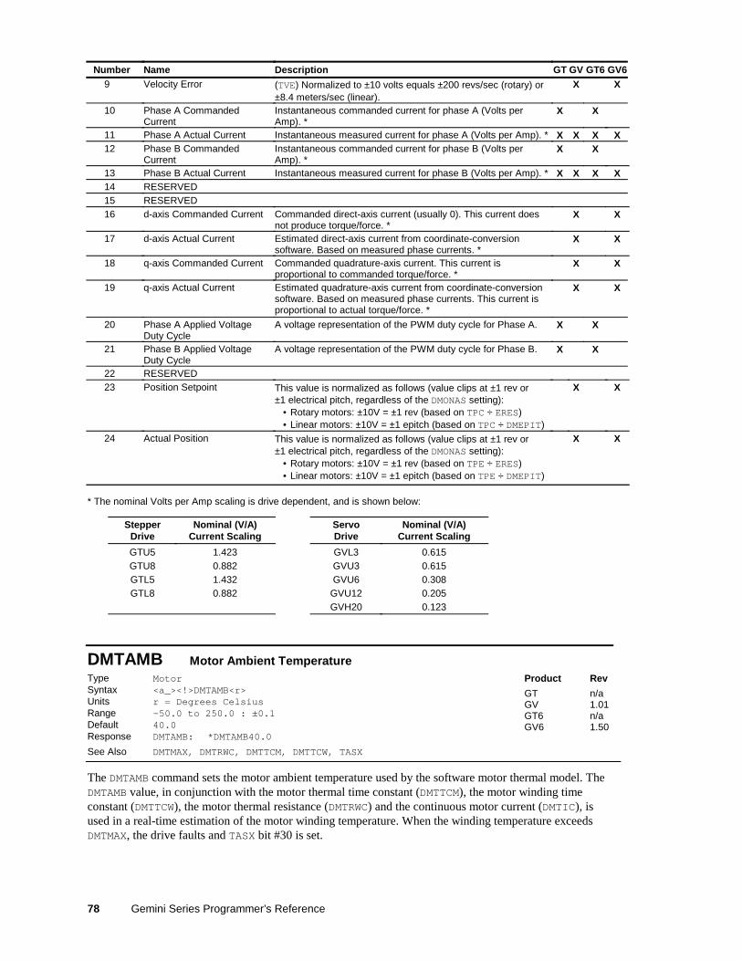
Number Name Description GT GV GT6 GV60 Unused / Turn off output No output function selected X X X X1 Motor Temperature (TMTEMP) Estimated motor winding temperature based on a
second-order thermal model (see Hardware Installation Guide fordetails). Normalized to ±10 volts equals ±250 oC.
3 Position Error This value is normalized as follows (value clips at ±1 rev or±1 electrical pitch, regardless of the DMONAS setting): • Rotary motors: ±10V = ±1 rev (based on TPER ÷ ERES) • Linear motors: ±10V = ±1 epitch (based on TPER ÷ DMEPIT)
X X
4 Velocity Setpoint (TVEL) User commanded velocity. Normalized to ±10 voltsequals ±200 revs/sec (rotary) or ±8.4 meters/sec (linear).
X X X X
5 Estimated Actual Velocity (TVELA) Output of velocity estimator, based on encoder data.Normalized to ±10 volts equals ±200 revs/sec (rotary) or ±8.4meters/sec (linear).
X X
6 Acceleration Setpoint (TACC) User commanded acceleration. X X7 Torque/Force Setpoint (TTRQ) User commanded torque/force. X X8 Actual Torque/Force (TTRQA) Calculated torque/force based on measured motor
current and motor Ke (DMTKE). Scaled as a % of DMTSCL.X X
Instantaneous commanded current for phase A (Volts per Amp).*
X X
11 Phase A Actual Current Instantaneous measured current for phase A (Volts per Amp). * X X X X12 Phase B Commanded
CurrentInstantaneous commanded current for phase B (Volts per Amp).*
X X
13 Phase B Actual Current Instantaneous measured current for phase B (Volts per Amp). * X X X X14 RESERVED
15 RESERVED
16 d-axis CommandedCurrent
Commanded direct-axis current (usually 0). This current does notproduce torque/force. *
X X
17 d-axis Actual Current Estimated direct-axis current from coordinate-conversionsoftware. Based on measured phase currents. *
X X
18 q-axis CommandedCurrent
Commanded quadrature-axis current. This current is proportionalto commanded torque/force. *
X X
19 q-axis Actual Current Estimated quadrature-axis current from coordinate-conversionsoftware. Based on measured phase currents. This current isproportional to actual torque/force. *
X X
20 Phase A Applied VoltageDuty Cycle
A voltage representation of the PWM duty cycle for Phase A. X X
21 Phase B Applied VoltageDuty Cycle
A voltage representation of the PWM duty cycle for Phase B. X X
22 RESERVED
23 Position Setpoint This value is normalized as follows (value clips at ±1 rev or±1 electrical pitch, regardless of the DMONAS setting): • Rotary motors: ±10V = ±1 rev (based on TPC ÷ ERES) • Linear motors: ±10V = ±1 epitch (based on TPC ÷ DMEPIT)
X X
24 Actual Position This value is normalized as follows (value clips at ±1 rev or±1 electrical pitch, regardless of the DMONAS setting): • Rotary motors: ±10V = ±1 rev (based on TPE ÷ ERES) • Linear motors: ±10V = ±1 epitch (based on TPE ÷ DMEPIT)
X X
Command Descriptions 77
* The nominal Volts per Amp scaling is drive dependent, and is shown below:
DMONBS Analog Monitor Output B — ScalingType OutputsSyntax <a_><!>DMONBS<i>Units i = scale percentage (%)Range -2000 to 2000Default 100 (no scaling)Response DMONBS: *DMONBS100
See Also DMONAS, DMONAV, DMONBV
Product Rev
GT 1.02GV 1.00GT6 1.50GV6 1.50
The DMONBS command sets the amount by which the variable selected with the DMONBV command is scaled.The maximum scaled output voltage is ±10V.
Monitor waveform clipping will occur if DMONBS scaling results in an output greater than ±10V.
DMONBV Analog Monitor Output B — VariableType OutputsSyntax <a_><!>DMONBV<i>Units i = variable numberRange 0-24 (0 = turn off output)Default 0 (turn off output)Response DMONBV: *DMONBV0
See Also DMONAS, DMONAV , DMONBS
Product Rev
GT 1.02GV 1.00GT6 1.50GV6 1.50
The DMONBV command selects the function (or signal) that will be presented at the “Analog Out B” terminal(pin 22 on the DRIVE I/O connector), referenced to analog ground (pin 25 on the DRIVE I/O connector).
Number Name Description GT GV GT6 GV60 Unused / Turn off output No output function selected X X X X1 Motor Temperature (TMTEMP) Estimated motor winding temperature based on a
second-order thermal model (see Hardware Installation Guidefor details). Normalized to ±10 volts equals ±250 oC.
3 Position Error This value is normalized as follows (value clips at ±1 rev or±1 electrical pitch, regardless of the DMONAS setting): • Rotary motors: ±10V = ±1 rev (based on TPER ÷ ERES) • Linear motors: ±10V = ±1 epitch (based on TPER ÷ DMEPIT)
X X
4 Velocity Setpoint (TVEL) User commanded velocity. Normalized to ±10 voltsequals ±200 revs/sec (rotary) or ±8.4 meters/sec (linear).
X X X X
5 Estimated Actual Velocity (TVELA) Output of velocity estimator, based on encoder data.Normalized to ±10 volts equals ±200 revs/sec (rotary) or ±8.4meters/sec (linear).
X X
6 Acceleration Setpoint (TACC) User commanded acceleration. X X7 Torque/Force Setpoint (TTRQ) User commanded torque/force. X X8 Actual Torque/Force (TTRQA) Calculated torque/force based on measured motor
current and motor Ke (DMTKE). Scaled as a % of DMTSCL.X X
Continued …
78 Gemini Series Programmer’s Reference
Number Name Description GT GV GT6 GV69 Velocity Error (TVE) Normalized to ±10 volts equals ±200 revs/sec (rotary) or
±8.4 meters/sec (linear).X X
10 Phase A CommandedCurrent
Instantaneous commanded current for phase A (Volts perAmp). *
X X
11 Phase A Actual Current Instantaneous measured current for phase A (Volts per Amp). * X X X X12 Phase B Commanded
CurrentInstantaneous commanded current for phase B (Volts perAmp). *
X X
13 Phase B Actual Current Instantaneous measured current for phase B (Volts per Amp). * X X X X14 RESERVED15 RESERVED16 d-axis Commanded Current Commanded direct-axis current (usually 0). This current does
not produce torque/force. *X X
17 d-axis Actual Current Estimated direct-axis current from coordinate-conversionsoftware. Based on measured phase currents. *
X X
18 q-axis Commanded Current Commanded quadrature-axis current. This current isproportional to commanded torque/force. *
X X
19 q-axis Actual Current Estimated quadrature-axis current from coordinate-conversionsoftware. Based on measured phase currents. This current isproportional to actual torque/force. *
X X
20 Phase A Applied VoltageDuty Cycle
A voltage representation of the PWM duty cycle for Phase A. X X
21 Phase B Applied VoltageDuty Cycle
A voltage representation of the PWM duty cycle for Phase B. X X
22 RESERVED23 Position Setpoint This value is normalized as follows (value clips at ±1 rev or
±1 electrical pitch, regardless of the DMONAS setting): • Rotary motors: ±10V = ±1 rev (based on TPC ÷ ERES) • Linear motors: ±10V = ±1 epitch (based on TPC ÷ DMEPIT)
X X
24 Actual Position This value is normalized as follows (value clips at ±1 rev or±1 electrical pitch, regardless of the DMONAS setting): • Rotary motors: ±10V = ±1 rev (based on TPE ÷ ERES) • Linear motors: ±10V = ±1 epitch (based on TPE ÷ DMEPIT)
X X
* The nominal Volts per Amp scaling is drive dependent, and is shown below:
DMTAMB Motor Ambient TemperatureType MotorSyntax <a_><!>DMTAMB<r>Units r = Degrees CelsiusRange -50.0 to 250.0 : ±0.1Default 40.0Response DMTAMB: *DMTAMB40.0
See Also DMTMAX, DMTRWC, DMTTCM, DMTTCW, TASX
Product Rev
GT n/aGV 1.01GT6 n/aGV6 1.50
The DMTAMB command sets the motor ambient temperature used by the software motor thermal model. TheDMTAMB value, in conjunction with the motor thermal time constant (DMTTCM), the motor winding timeconstant (DMTTCW), the motor thermal resistance (DMTRWC) and the continuous motor current (DMTIC), isused in a real-time estimation of the motor winding temperature. When the winding temperature exceedsDMTMAX, the drive faults and TASX bit #30 is set.
Command Descriptions 79
DMTD Motor DampingType MotorSyntax <a_><!>DMTD<r> (does not take effect until RESET or cycle power)Units Rotary motor: r = Nm/rad/sec
Linear motor: r = N/meter/secRange Rotary motor: 0.000000 to 0.010000 : ±0.000001
Linear motor: DMEPIT (electrical pitch) dependentDefault 0.000000Response DMTD: *DMTD0.002000
See Also DMTR, LDAMP
Product Rev
GT n/aGV 1.00GT6 n/aGV6 1.50
NOTE: This command does not take effect until you cycle power to the drive, or issue a RESET command.
AUTO-SETUP: This command is automatically set according to the Parker motor selected with theconfiguration utility in Motion Planner (see page 6) or Pocket Motion Planner (see page 11). If you did not usethe configuration utility or are not using a Parker Motor, this command is set to zero and you will have tomanually set this parameter. (Refer to DMTR for a list of auto-configured commands.)
The DMTD command specifies the damping of the motor itself. This includes both magnetic losses andbearing losses. (The load damping is specified with the LDAMP command.)
DMTIC Continuous CurrentType MotorSyntax <a_><!>DMTIC<r>Units r = Amps-RMSRange 0.00 to 100.00 : ±0.01Default 0.00 (DMTIC of 0 results in motor configuration warning)Response DMTIC: *DMTIC6.50
See Also DMTICD, TASX, TCS, TDICNT
Product Rev
GT 1.02GV 1.00GT6 1.50GV6 1.50
GV/GV6 Only: This command does not take effect until you cycle power to the drive, or issue a RESET.GT/GT6 Only: This command takes effect immediately.
AUTO-SETUP: This command is automatically set according to the Parker motor selected with theconfiguration utility in Motion Planner (see page 6) or Pocket Motion Planner (see page 11). If you did not usethe configuration utility or are not using a Parker Motor, this command is set to zero and you will have tomanually set this parameter. (Refer to DMTR for a list of auto-configured commands.) If the drive is poweredup when this command is set to zero (for instance, if RFS is executed), the drive reports a motor configurationwarning with TASX bit 28, and writes 40 to TCS.
The DMTIC command sets the continuous operating current for a motor. For a servo drive operating a rotarymotor continuously at this current, the internal winding temperature will reach 125°C with a specifiedheatsink (see the Gemini Motor Reference Manual for heatsink dimensions) in a 40°C ambient. For linearservo motors, the winding will reach 90°C in a 25°C ambient.
The continuous current of a motor that is designed to provide a long service life depends on many factors.Among them are motor ambient temperature, the degree of heatsinking provided by the motor mountingsurface, and airflow over the motor. In a stepper, the continuous current is flowing in the motorcontinuously. In a servo, the continuous current is used in calculations to protect the motor from thermaldamage, and has no immediate effect on performance.
GV: If DMTIC is set higher than the full-scale value calculated by DMTSCL (torque/force scale) the new DMTICvalue will be ignored (but not overwritten), the status warning bit 28 in TASX will be set, a value of 400 willbe written to the TCS register, and the full-scale value calculated from DMTSCL will be used internally.
GT: If DMTIC is set higher than the drive maximum current (TDICNT), the new DMTIC value will be ignored(but not overwritten), the status warning bit 28 in TASX will be set, a value of 400 will be written to the TCSregister, and the maximum drive current will be used internally.
Example:DMTIC5 ; Set the motor current to 5 amps RMS (equates to 7.07 amps peak)
80 Gemini Series Programmer’s Reference
DMTICD Continuous Current DeratingType MotorSyntax <a_><!>DMTICD<i> (does not take effect until RESET or cycle power)Units i = % derating at rated speedRange 0.00 to 100.00 : ±0.01Default 0.00 (DMTICD of 0 results in no current derating)Response DMTICD: *DMTICD5
See Also DMTIC, DMTIP, DMTW
Product Rev
GT n/aGV 1.00GT6 n/aGV6 1.50
NOTE: This command does not take effect until you cycle power to the drive, or issue a RESET command.
AUTO-SETUP: This command is automatically set according to the Parker motor selected with theconfiguration utility in Motion Planner (see page 6) or Pocket Motion Planner (see page 11). If you did not usethe configuration utility or are not using a Parker Motor, this command is set to zero and you will have tomanually set this parameter. (Refer to DMTR for a list of auto-configured commands.)
The DMTICD command sets the percentage current derating at rated speed (DMTW). This value sets the extentto which continuous current must be reduced at speed to compensate velocity-related losses in the motor.
For example, DMTICD3 sets the motor’s continuous current derating to 3% (or 97% of continuous valueDMTIC) at the motor’s rated speed (DMTW). At half this speed, it will be reduced 1.5%.
DMTIND Motor InductanceType MotorSyntax <a_><!>DMTIND<r> (does not take effect until RESET or cycle power)Units r = mHRange 0.0 to 200.0 : ±0.1Default 0.0 (DMTIND of 0 results in motor config. error)Response DMTIND *DMTIND10
See Also DMTLMN, DMTLMX, DMTR, TASX, TCS
Product Rev
GT 1.02GV n/aGT6 1.50GV6 n/a
NOTE: This command does not take effect until you cycle power to the drive, or issue a RESET command.
AUTO-SETUP: This command is automatically set according to the Parker motor selected with theconfiguration utility in Motion Planner (see page 6) or Pocket Motion Planner (see page 11). If you did not usethe configuration utility or are not using a Parker Motor, this command is set to zero and you will have tomanually set this parameter. (Refer to DMTR for a list of auto-configured commands.) If the drive is poweredup when this command is set to zero (for instance, if RFS is executed), the drive reports a motor configurationerror with TASX bit 7, writes a value of –32726 to the TCS register, and shuts down the drive (DRIVE0).
The DMTIND command sets the motor inductance for stepper motors only (servo motor inductance is setwith DMTLMN and DMTLMX). The motor inductance entered is the motor inductance you measure across aphase at the motor terminals of the drive. The inductance value is the “small signal inductance” as measuredby a hand-held or bench-top inductance meter at 1 KHz.
A procedure for configuring motor inductance (for non-Parker motors) is provided in Configuration chapter ofyour drive’s Hardware Installation Guide.
Command Descriptions 81
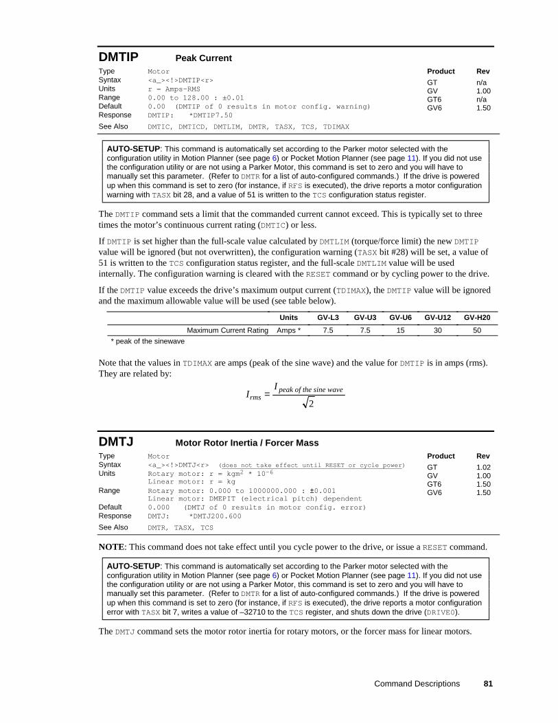
DMTIP Peak CurrentType MotorSyntax <a_><!>DMTIP<r>Units r = Amps-RMSRange 0.00 to 128.00 : ±0.01Default 0.00 (DMTIP of 0 results in motor config. warning)Response DMTIP: *DMTIP7.50
See Also DMTIC, DMTICD, DMTLIM, DMTR, TASX, TCS, TDIMAX
Product Rev
GT n/aGV 1.00GT6 n/aGV6 1.50
AUTO-SETUP: This command is automatically set according to the Parker motor selected with theconfiguration utility in Motion Planner (see page 6) or Pocket Motion Planner (see page 11). If you did not usethe configuration utility or are not using a Parker Motor, this command is set to zero and you will have tomanually set this parameter. (Refer to DMTR for a list of auto-configured commands.) If the drive is poweredup when this command is set to zero (for instance, if RFS is executed), the drive reports a motor configurationwarning with TASX bit 28, and a value of 51 is written to the TCS configuration status register.
The DMTIP command sets a limit that the commanded current cannot exceed. This is typically set to threetimes the motor’s continuous current rating (DMTIC) or less.
If DMTIP is set higher than the full-scale value calculated by DMTLIM (torque/force limit) the new DMTIPvalue will be ignored (but not overwritten), the configuration warning (TASX bit #28) will be set, a value of51 is written to the TCS configuration status register, and the full-scale DMTLIM value will be usedinternally. The configuration warning is cleared with the RESET command or by cycling power to the drive.
If the DMTIP value exceeds the drive’s maximum output current (TDIMAX), the DMTIP value will be ignoredand the maximum allowable value will be used (see table below).
Units GV-L3 GV-U3 GV-U6 GV-U12 GV-H20
Maximum Current Rating Amps * 7.5 7.5 15 30 50
* peak of the sinewave
Note that the values in TDIMAX are amps (peak of the sine wave) and the value for DMTIP is in amps (rms).They are related by:
Irms =I peak of the sine wave
2
DMTJ Motor Rotor Inertia / Forcer MassType MotorSyntax <a_><!>DMTJ<r> (does not take effect until RESET or cycle power)Units Rotary motor: r = kgm2 * 10-6
Linear motor: r = kgRange Rotary motor: 0.000 to 1000000.000 : ±0.001
Linear motor: DMEPIT (electrical pitch) dependentDefault 0.000 (DMTJ of 0 results in motor config. error)Response DMTJ: *DMTJ200.600
See Also DMTR, TASX, TCS
Product Rev
GT 1.02GV 1.00GT6 1.50GV6 1.50
NOTE: This command does not take effect until you cycle power to the drive, or issue a RESET command.
AUTO-SETUP: This command is automatically set according to the Parker motor selected with theconfiguration utility in Motion Planner (see page 6) or Pocket Motion Planner (see page 11). If you did not usethe configuration utility or are not using a Parker Motor, this command is set to zero and you will have tomanually set this parameter. (Refer to DMTR for a list of auto-configured commands.) If the drive is poweredup when this command is set to zero (for instance, if RFS is executed), the drive reports a motor configurationerror with TASX bit 7, writes a value of –32710 to the TCS register, and shuts down the drive (DRIVE0).
The DMTJ command sets the motor rotor inertia for rotary motors, or the forcer mass for linear motors.
82 Gemini Series Programmer’s Reference
DMTKE Motor KeType MotorSyntax <a_><!>DMTKE<r> (does not take effect until RESET or cycle power)Units Rotary motor: r = volts (0-peak) / krpm
Linear motor: r = volts/meter/secRange Rotary motor: 0.0 to 200.0 : ±0.1
Linear motor: DMEPIT (electrical pitch) dependentDefault 0.0 (DMTKE of 0 results in motor config. error)Response DMTKE: *DMTKE15.0
See Also DMONAV, DMONBV, DMTSCL, DMTR, TASX, TCS
Product Rev
GT n/aGV 1.00GT6 n/aGV6 1.50
NOTE: This command does not take effect until you cycle power to the drive, or issue a RESET command.
AUTO-SETUP: This command is automatically set according to the Parker motor selected with theconfiguration utility in Motion Planner (see page 6) or Pocket Motion Planner (see page 11). If you did not usethe configuration utility or are not using a Parker Motor, this command is set to zero and you will have tomanually set this parameter. (Refer to DMTR for a list of auto-configured commands.) If the drive is poweredup when this command is set to zero (for instance, if RFS is executed), the drive reports a motor configurationerror with TASX bit 7, writes a value of –32727 to the TCS register, and shuts down the drive (DRIVE0).
The DMTKE command specifies the motor voltage constant (Ke). This defaults to the nominal Ke of themotor selected with the DMTR command.
The motor’s torque/force constant (Kt) is derived from the motor’s voltage constant (Ke) by the followingrelationship:
Rotary motors:
value peak*
)/(*200
33)/( ** krpmVoltsKeANmKt
π=
Linear motors:
value peak*
sec))//((*200
33)/( ** meterVoltsKeANKt
π=
DMTLIM Torque/Force LimitType SystemSyntax <a_><!>DMTLIM<r>Units Rotary motor: r = Nm
Linear motor: r = NRange Rotary motor: 0.0 to 500.0 (motor/drive dependent) : ±0.1
Linear motor: DMEPIT (electrical pitch) dependentDefault 500.0Response DMTLIM: *DMTLIM10.5
See Also DCLRLR, DMODE, DMTIP, DMTKE, DMTR, DMTSCL, TASX, TGAIN,TSGSET, TTRQ, TTRQA
Product Rev
GT n/aGV 1.00GT6 n/aGV6 1.50
AUTO-SETUP: This command is automatically set according to the Parker motor selected with theconfiguration utility in Motion Planner (see page 6) or Pocket Motion Planner (see page 11). If you did not usethe configuration utility or are not using a Parker Motor, this command is set to zero and you will have tomanually set this parameter. Refer to DMTR (page 84) for a list of auto-configured commands.
The DMTLIM command sets a maximum torque/force limit for the system. Requests for higher torque/forcewill be clamped to this value. This command will default automatically to a value appropriate to the motorselection (DMTR) and the Gemini drive you are using, and no changes are required in many cases.
If your mechanical system has torque/force limitations (due, for example, to the limitations of a coupler orbelt), you can use this command to limit system torque/force without affecting system scaling or gains.
Command Descriptions 83
During initial tuning, this command can be used to limit the torque/force produced if the system becomesunstable, reducing the rate of motor heating and allowing more reaction time for the person tuning thesystem, and reducing the chances of damage to the mechanical system.
When the Gemini’s commanded torque/force reaches the limit set by DMTLIM (TTRQ = DMTLIM), TASXbit #31 is set. TASX bit #31 remains set until you clear it with the DCLRLR command, cycle power, or issue aRESET. This is not considered a fault condition.
If DMTLIM is set higher than the value allowed by the motor’s peak current times the motor’s Kt, or thedrive’s peak current times the motor’s Kt (whichever is lower), the new DMTLIM value will be ignored (butnot overwritten), the status warning bit #28 in TASX will be set, and the maximum internal value will beused. This warning is cleared with the RESET command or by cycling power to the drive.
The motor’s torque/force constant (Kt) is derived from the motor’s voltage constant (Ke, which is set by theDMTKE command) by the following relationship (note: Ke is set with the DMTKE command):
Rotary motors:
peak value*
** )/(*200
33)/( krpmVoltsKeANmKt
π=
Linear motors:
peak value*
** sec))//((*200
33)/( meterVoltsKeANKt
π=
Working with servo gains.
• Servo tuning process: refer to your Gemini drive’s Hardware Installation Guide.• Check the values of all active gains (DMTLIM is one of many servo gains): use TGAIN.• Creating and invoking gain sets: see SGSET, SGENB, TGAIN, TSGSET.
DMTLMN Minimum Motor InductanceType MotorSyntax <a_><!>DMTLMN<r> (does not take effect until RESET or cycle power)Units r = mHRange 0.1 to 200.0 (motor dependent) : ±0.1Default 0.0 (DMTLMN of 0 results in motor config. error)Response DMTLMN: *DMTLMN10.0
See Also DMTLMX, DMTR, TASX, TCS
Product Rev
GT n/aGV 1.00GT6 n/aGV6 1.50
NOTE: This command does not take effect until you cycle power to the drive, or issue a RESET command.
AUTO-SETUP: This command is automatically set according to the Parker motor selected with theconfiguration utility in Motion Planner (see page 6) or Pocket Motion Planner (see page 11). If you did not usethe configuration utility or are not using a Parker Motor, this command is set to zero and you will have tomanually set this parameter. (Refer to DMTR for a list of auto-configured commands.) If the drive is poweredup when this command is set to zero (for instance, if RFS is executed), the drive reports a motor configurationerror with TASX bit 7, writes a value of -32715 to the TCS register, and shuts down the drive (DRIVE0).
The DMTLMN command specifies the minimum value of motor inductance. This will usually differ from thenominal nameplate value because actual inductance is usually position dependent.
84 Gemini Series Programmer’s Reference
DMTLMX Maximum Motor InductanceType MotorSyntax <a_><!>DMTLMX<r> (does not take effect until RESET or cycle power)Units r = mHRange 0.1 to 200.0 (motor dependent) : ±0.1Default 0.0 (DMTLMX of 0 results in motor config. error)Response DMTLMX: *DMTLMX10.0
See Also DMTLMN, DMTR, TASX, TCS
Product Rev
GT n/aGV 1.00GT6 n/aGV6 1.50
NOTE: This command does not take effect until you cycle power to the drive, or issue a RESET command.
AUTO-SETUP: This command is automatically set according to the Parker motor selected with theconfiguration utility in Motion Planner (see page 6) or Pocket Motion Planner (see page 11). If you did not usethe configuration utility or are not using a Parker Motor, this command is set to zero and you will have tomanually set this parameter. (Refer to DMTR for a list of auto-configured commands.) If the drive is poweredup when this command is set to zero (for instance, if RFS is executed), the drive reports a motor configurationerror with TASX bit 7, writes a value of -32714 to the TCS register, and shuts down the drive (DRIVE0).
The DMTLMX command specifies the maximum value of motor inductance. This will usually differ from thenominal nameplate value since actual inductance is usually position dependent.
DMTMAX Maximum Motor Winding TemperatureType MotorSyntax <a_><!>DMTMAX<r>Units r = Degrees CelsiusRange -50.0 to 250.0 : ±0.1Default 125.0Response DMTMAX: *DMTMAX125.0
See Also DMTAMB, DMTIC, DMTRWC, DMTTCM, DMTTCW, TASX
Product Rev
GT n/aGV 1.01GT6 n/aGV6 1.50
AUTO-SETUP: This command is automatically set according to the Parker motor selected with theconfiguration utility in Motion Planner (see page 6) or Pocket Motion Planner (see page 11). If you did not usethe configuration utility or are not using a Parker Motor, you will have to manually set this parameter. (Referto DMTR for a list of auto-configured commands.)
The DMTMAX command sets the maximum motor winding temperature allowed. The DMTMAX value, inconjunction with the motor thermal time constant (DMTTCM), the motor winding time constant (DMTTCW), themotor thermal resistance (DMTRWC) and the continuous motor current (DMTIC), is used in a real-timeestimation of the motor winding temperature. When the winding temperature exceeds DMTMAX, the drivefaults and TASX bit #30 is set.
Command Descriptions 85
DMTR Identify (and Load) MotorType Drive ConfigurationSyntax <a_><!>DMTR<i>Units i = Parker motor identification numberRange 0-2000Default -1 (motor config. parameters are not configured)Response DMTR: *DMTR50
See Also (see parameter table below), DRIVE, RESET, RFS, TASX, TCS
Product Rev
GT 1.02GV 1.00GT6 1.50GV6 1.50
The purpose of the DMTR command is to record and report the identification number of the Parker motoryou selected in the setup tool in Motion Planner (see page 6) or Pocket Motion Planner (see page 11).
When you select a specific Parker motor using the Motion Planner or Pocket Motion Planner setup tool, theDMTR setting and various motor parameters (see list below) are automatically configured for the associatedmotor and saved in a configuration file. After you download the configuration file to the Gemini drive, youmust cycle drive power or issue a RESET command for the DMTR and all the motor parameter commands totake effect. (NOTE: If you do not select a Parker motor, the default setting, DMTR-1, is used and you mustset all relevant motor parameters manually.) Avoid using the DMTR command to change the motor number,because the new DMTR value may not represent the actual motor parameters that are currently loaded in thedrive.
Stepper Motor Data Parameters Servo Motor Data ParametersDIGNA....... Current Loop Gain ADIGNB....... Current Loop Gain BDIGNC....... Current Loop Gain CDIGND....... Current Loop Gain DDMTIC....... Continuous CurrentDMTIND..... Motor InductanceDMTJ ......... Motor Rotor InertiaDMTRES..... Motor Winding ResistanceDMTSTT..... Motor Static TorqueDMVLIM..... Velocity LimitDMVSCL..... Velocity ScalingDPOLE....... Number of Motor Pole Pairs
DIBW ...........Current Loop Bandwidth DMTTCM .... Motor Thermal Time ConstantDMEPIT.......Motor Electrical Pitch DMTTCW .... Motor Winding Time ConstantDMTD ...........Motor Damping DMTW......... Motor Rated SpeedDMTIC .........Continuous Current DMVLIM .... Velocity LimitDMTICD.......Continuous Current Derating DMVSCL .... Velocity ScalingDMTIP .........Peak Current DPBW......... Position Loop BandwidthDMTJ ...........Motor Rotor Inertia DPOLE ...... Number of Motor Pole PairsDMTKE .........Motor Ke DRES......... Drive ResolutionDMTLIM.......Torque/Force Limit DVBW......... Velocity Loop BandwidthDMTLMN.......Minimum Motor Inductance ERES......... Encoder ResolutionDMTLMX.......Maximum Motor Inductance ORES......... Encoder Output ResolutionDMTMAX.......Maximum Motor Winding Temp. SFB ........... Feedback Source SelectionDMTRES.......Motor Winding Resistance SRSET ...... Resolver Offset AngleDMTRWC.......Motor Winding Thermal ResistanceDMTSCL.......Torque/Force Scaling
Although these command values are auto-configured when you select a Parker motor (using the setup tool in Motion Planner or PocketMotion Planner), you may individually set the command values with the respective configuration command.
Motor Configuration Error
For many of the above motor parameters, if they are not configured (i.e., a command is left at its factory defaultvalue, or an RFS command is executed) when the Gemini drive is powered up, a motor configuration “error” or“warning” is reported in TASX bit #7 or bit #28 (an “error” also disables the drive – DRIVE0). To resolve the error orwarning condition, you must select a Parker motor with Motion Planner or Pocket Motion Planner (or configure eachmotor parameter command with a value other than zero – using a Gemini terminal emulator), download the resultingconfiguration information and then cycle power or issue the RESET command.
Updating the motor data table. The motor information for the parameters list above is located in a filenamed “GEM_motors.mtr” and is used by Motion Planner and Pocket Motion Planner to configure theGemini drive. Updates to this file are maintained on the Compumotor web site (http://www.compumotor.com) —search for “GEM_motors.mtr”. If you need to update the information, download an updated motor table file.If you are using Motion Planner, place the updated file in the Motion Planner directory (default location is\Program Files\Compumotor\Motion Planner). If you are using Pocket Motion Planner, transfer the updated file toyour hand-held PC and copy it to the \My Documents\Gemini directory.
The DMTR values for all available Parker motors are listed in the GEM_motors.mtr file.
DMTRES Motor Winding ResistanceType MotorSyntax <a_><!>DMTRES<r> (does not take effect until RESET or cycle power)Units r = OhmRange 0.00 to 50.00 : ±0.01Default 0.00 (DMTRES of 0 results in motor config. error)Response DMTRES: *DMTRES7.50
See Also DMTR, TASX, TCS
Product Rev
GT 1.02GV 1.00GT6 1.50GV6 1.50
NOTE: This command does not take effect until you cycle power to the drive, or issue a RESET command.
AUTO-SETUP: This command is automatically set according to the Parker motor selected with theconfiguration utility in Motion Planner (see page 6) or Pocket Motion Planner (see page 11). If you did not usethe configuration utility or are not using a Parker Motor, this command is set to zero and you will have tomanually set this parameter. (Refer to DMTR for a list of auto-configured commands.) If the drive is poweredup when this command is set to zero (for instance, if RFS is executed), the drive reports a motor configurationerror with TASX bit 7, writes a value of –32725 to the TCS register, and shuts down the drive (DRIVE0).
The DMTRES command sets the motor winding resistance. The resistance value is the resistance of onemotor phase as measured at 25 °C at the drive end of the motor cable (motor cable included). For steppers,this would be A+ to A-; for servos, U to V.
NOTE: Disconnect the motor cable from the drive before attempting to make this measurement. For bestaccuracy, and to avoid injury, this measurement must be made with the motor cable disconnected from thedrive.
DMTRWC Motor Winding Thermal ResistanceType MotorSyntax <a_><!>DMTRWC<r> (does not take effect until RESET or cycle power)Units r = Degrees Celsius/Watt (°C/W)Range 0.00 to 50.00 : ±0.01Default 0.00Response DMTRWC: *DMTRWC23.60
See Also DMTR, DMTTCM, DMTTCW, TASX, TCS
Product Rev
GT n/aGV 1.00GT6 n/aGV6 1.50
NOTE: This command does not take effect until you cycle power to the drive, or issue a RESET command.
AUTO-SETUP: This command is automatically set according to the Parker motor selected with theconfiguration utility in Motion Planner (see page 6) or Pocket Motion Planner (see page 11). If you did not usethe configuration utility or are not using a Parker Motor, this command is set to zero and you will have tomanually set this parameter. (Refer to DMTR for a list of auto-configured commands.)
DMTRWC specifies the temperature rise of the motor winding above motor case temperature per watt ofwinding power dissipation. Motor heatsinking does not affect this value.
Linear motor: r = NRange Rotary motor: 0.0 to 500.0 (motor/drive dependent) : ±0.1
Linear motor: DMEPIT (electrical pitch) dependentDefault 0Response DMTSCL: *DMTSCL20.0
See Also DMEPIT, DMODE, DMTKE, DMTLIM, TTRQ, TTRQA
Product Rev
GT n/aGV 1.00GT6 n/aGV6 1.50
AUTO-SETUP: This command is automatically set according to the Parker motor selected with theconfiguration utility in Motion Planner (see page 6) or Pocket Motion Planner (see page 11). If you did not usethe configuration utility or are not using a Parker Motor, this command is set to zero and you will have tomanually set this parameter. (Refer to DMTR for a list of auto-configured commands.)
GV and GV6: The DMTSCL command scales the torque/force (TTRQ and TTRQA).
GV only (n/a to GV6): DMTSCL is also applied when the drive is set to DMODE2 (±10V torque/force).
The DMTSCL command scales the torque/force command input. It sets the full-scaletorque/force that will be produced from a 10-volt input command. It controls the gain appliedto the input. This can be used to scale the input to match application needs. For example, if atorque/force sensor produces 2 volts per Newton-meter, the drive could be scaled to match thisby using DMTSCL5 — this sets 10V = 5 Nm (0.5 Nm/Volt).
DMTLIM may limit torque/force to less than this full-scale value. Note that changing this valueaffects many gain terms including position loop tuning values; tuning may need to be repeatedafter changing DMTSCL. It should ideally be set before tuning the system.
NOTE: To configure the drive in torque/force mode so that a 10-volt torque/force commandwill produce the rated peak current of the drive (without reference to motor parameters) enterfor DMTSCL the result of the following calculation:
Rotary motors: DMTKETDIMAXDMTSCL *200
33*
π= (for V*/KRPM)
Linear motors: DMTKEDMEPIT
TDIMAXDMTSCL ∗=1000
*8
6*
π (for V*/meter/sec)
* peak value
DMTSTT Motor Static TorqueType Drive ConfigurationSyntax <a_><!>DMTSTT<r> (does not take effect until RESET or cycle power)Units r = oz-inRange 0.0 to 5000.0 : ±0.02Default 0.0 (DMTSTT of 0 results in motor config. error)Response DMTSTT *DMTSTT410.0
See Also DMTR, TASX, TCS
Product Rev
GT 1.02GV n/aGT6 1.50GV6 n/a
NOTE: This command does not take effect until you cycle power to the drive, or issue a RESET command.
AUTO-SETUP: This command is automatically set according to the Parker motor selected with theconfiguration utility in Motion Planner (see page 6) or Pocket Motion Planner (see page 11). If you did not usethe configuration utility or are not using a Parker Motor, this command is set to zero and you will have tomanually set this parameter. (Refer to DMTR for a list of auto-configured commands.) If the drive is poweredup when this command is set to zero (for instance, if RFS is executed), the drive reports a motor configurationerror with TASX bit 7, writes a value of –32729 to the TCS register, and shuts down the drive (DRIVE0).
The DMTSTT command sets the motor static torque. The motor static torque is the motor holding torquemeasured in the “one phase on” condition. The “one phase on” condition is measured with the peak motorcurrent in one phase.
88 Gemini Series Programmer’s Reference
DMTTCM Motor Thermal Time ConstantType MotorSyntax <a_><!>DMTTCM<r> (does not take effect until RESET or cycle power)Units r = minutesRange 0.0 to 300.0 : ±0.1Default 0.0Response DMTTCM: *DMTTCM30.4
See Also DMTR, DMTTCW
Product Rev
GT n/aGV 1.00GT6 n/aGV6 1.50
NOTE: This command does not take effect until you cycle power to the drive, or issue a RESET command.
AUTO-SETUP: This command is automatically set according to the Parker motor selected with theconfiguration utility in Motion Planner (see page 6) or Pocket Motion Planner (see page 11). If you did not usethe configuration utility or are not using a Parker Motor, this command is set to zero and you will have tomanually set this parameter. (Refer to DMTR for a list of auto-configured commands.)
The DMTTCM command specifies the thermal time constant of the motor and its mounting. This value is usedto help protect the motor from thermal damage. It describes the length of time the motor takes to reach 63%of it’s final temperature, given constant power. Note that motor mounting will affect this.
Continuous current ratings and published time constants for Parker motors are specified when mounted to a10" x 10" x ¼" aluminum plate in 25 °C free air. If your mounting surface provides heatsinking or thermalmass significantly different than this, a different value may be appropriate to your application. Note alsothat the time constant of the motor winding itself (DMTTCW) is much faster than this; therefore, the rise inwinding temperature will initially be much faster than DMTTCM would suggest.
DMTTCW Motor Winding Time ConstantType MotorSyntax <a_><!>DMTTCW<r> (does not take effect until RESET or cycle power)Units r = minutesRange 0.00 to 100.00 : ±0.01Default 0.00Response DMTTCW: *DMTTCW28.40
See Also DMTR, DMTTCM, DMTRWC
Product Rev
GT n/aGV 1.00GT6 n/aGV6 1.50
NOTE: This command does not take effect until you cycle power to the drive, or issue a RESET command.
AUTO-SETUP: This command is automatically set according to the Parker motor selected with theconfiguration utility in Motion Planner (see page 6) or Pocket Motion Planner (see page 11). If you did not usethe configuration utility or are not using a Parker Motor, this command is set to zero and you will have tomanually set this parameter. (Refer to DMTR for a list of auto-configured commands.)
The DMTTCW command specifies the time constant of the motor winding alone. This is the time for thewinding to reach 63% of it’s final temperature rise above the rest of the motor, given constant power. Notethat this is NOT the time constant usually specified in motor data sheets (see DMTTCM); the DMTTCW value istypically much faster.
Command Descriptions 89
DMTW Motor Rated SpeedType MotorSyntax <a_><!>DMTW<r> (does not take effect until RESET or cycle power)Units Rotary motor: r = revs/sec
Linear motor: r = meters/secRange Rotary motor: 0.0 to 200.0 : ±0.1
Linear motor: DMEPIT (electrical pitch) dependentDefault 0.0 (DMTW of 0 results in motor config. error)Response DMTW: *DMTW150.0
See Also DMEPIT, DMTICD, DMTR, TASX, TCS
Product Rev
GT n/aGV 1.00GT6 n/aGV6 1.50
NOTE: This command does not take effect until you cycle power to the drive, or issue a RESET command.
AUTO-SETUP: This command is automatically set according to the Parker motor selected with theconfiguration utility in Motion Planner (see page 6) or Pocket Motion Planner (see page 11). If you did not usethe configuration utility or are not using a Parker Motor, this command is set to zero and you will have tomanually set this parameter. (Refer to DMTR for a list of auto-configured commands.) If the drive is poweredup when this command is set to zero (for instance, if RFS is executed), the drive reports a motor configurationerror with TASX bit 7, writes a value of –32718 to the TCS register, and shuts down the drive (DRIVE0).
The DMTW command specifies the rated speed of the motor. This is the lesser of:
• (rotary motor) The motor mechanical limit of 7500 RPM (125 rps)• (rotary motor) The encoder limit of 6000 rpm (100 rps) for a 1000-line encoder• Linear motor speed limitations include encoder resolution and track length.• The corner of the continuous speed-torque/force curve (the point where the continuous torque/force
breaks downward).
The DMTW value is used in conjunction with DMTICD to protect the motor from thermal damage.
DMVLIM Velocity LimitType SystemSyntax <a_><!>DMVLIM<r>Units Rotary motor: r = revs/sec
Linear motor: r = meters/secRange Rotary motor: GT/GT6: 0.000000 to 60.000000 : ±0.000001
See Also DCLRLR, DMODE, DMTR, DMVSCL, DVBW, SGVRAT, TASX, TGAIN, TSGSET
Product Rev
GT 1.02GV 1.00GT6 1.50GV6 1.50
AUTO-SETUP: This command is automatically set according to the Parker motor selected with theconfiguration utility in Motion Planner (see page 6) or Pocket Motion Planner (see page 11). If you did not usethe configuration utility or are not using a Parker Motor, this command is set to zero and you will have tomanually set this parameter. Refer to DMTR (page 84) for a list of auto-configured commands.
The DMVLIM command sets a limit that commanded velocity cannot exceed, without affecting gains orscaling. This is typically used to protect parts of the mechanical system.
In velocity mode (DMODE4), position modes (DMODE6, DMODE7, DMODE8 or DMODE9), or controller/drivemode (DMODE12), DMVLIM clamps the command to the specified value.
GV only: In torque/force mode (DMODE2), this command can be used to set a velocity override limit. Thiscontrols system velocity in the event that load friction and commanded torque/force combined would resultin excessive velocity.
If the velocity demand from a controller or the internal Gemini control loops exceeds the limits set byDMVLIM, then TASX bit 18 will be set. The GV/GV6 drive responds to this condition by invoking the
90 Gemini Series Programmer’s Reference
“Override Mode,” in which the drive software clamps the maximum allowable velocity command to thevalue set by DMVLIM. Bit 18 stays latched until a DCLRLR is issued or a drive reset occurs.
GT6 & GV6 only: Changes to the DMVLIM command are not allowed while motion is in progress.
Working with servo gains.
• Servo tuning process: refer to your Gemini drive’s Hardware Installation Guide.• Check the values of all active gains (DMVLIM is one of many servo gains): use TGAIN.• Creating and invoking gain sets: see SGSET, SGENB, TGAIN, TSGSET.
AUTO-SETUP: This command is automatically set according to the Parker motor selected with theconfiguration utility in Motion Planner (see page 6) or Pocket Motion Planner (see page 11). If you did not usethe configuration utility or are not using a Parker Motor, this command is set to zero and you will have tomanually set this parameter. (Refer to DMTR for a list of auto-configured commands.)
The DMVSCL command scales the velocity command input signal only in the ±10V velocity mode (DMODE4).This sets the full-scale value of the input by changing the gain applied to it. This functions like a “tach gain”control, changing the velocity that will result from a given input voltage — for example to 50 rps per 10volts (5rps/volt, or 300RPM/volt).
NOTE
The input Analog-to-Digital converter is 12 bits; therefore, the “effective” velocityresolution is calculated as follows:
2048 ""
DMVSCLresolutioneffective =
Example: If DMVSCL is set to 50.000000 revs/sec, the effective internal resolution is± ~.024 rps (1.46 rpm).
GV: Changing the DMVSCL value will affect overall position loop response when used with the driveoperating in the ±10V Velocity Mode (DMODE4), so it should ideally be set before tuning.
Command Descriptions 91
DNOTAD Notch Filter A DepthType TuningSyntax <a_><!>DNOTAD<i>Units n/aRange 0.0000 - 1.0000Default 0.0000 (depth is zero)Response DNOTAD: *DNOTAD.5
See Also DMODE, DNOTAF, DNOTAQ, DNOTBD, DNOTBF, DNOTBQ, DNOTLD, DNOTLG,DPBW, DVBW, TGAIN, TSGSET
Product Rev
GT n/aGV 1.01GT6 n/aGV6 1.50
The DNOTAD command sets the depth for the commanded torque/force notch filter A. Setting this to 0disables the filter. This command is useful in adjusting the maximum allowable attenuation and phase shiftthrough the filter. The deeper the notch depth, the more attenuation and phase shift. In general, the notchdepth is increased until the resonance is diminished. Increasing the depth further, might increase the phaseshift to an unacceptable level and decrease the overall system performance.
There are two cascaded notch filters labeled “A” and “B”. Both filters operate in exactly the same way. Thediagram below shows the topology of these filters.
VelocityLimit
Check
+/- 10VInput
Command
NOTCHFilter A
NOTCH FilterCommand
Input Torque
Digital Inputs: Torque, Velocity, and Position
Analog Inputs: Torque, and Velocity
Low Pass Filter
NOTCH FilterCommand
Output Torque
Lag/LeadFilter
NOTCHFilter B
TorqueLimit
Check
ActualTorque
Command
The graphs below illustrate the transfer function for the magnitude and phase of the notch filter commandoutput torque/force vs. the notch filter command input torque/force. In this example, the notch depths areset to .3, .6, and .9 (DNOTAD.3, DNOTAD.6, DNOTAD.9). The notch center frequency is set to 200 Hz(DNOTAF200) and the “Q” is set to 1 (DNOTAQ1).
100
101
102
103
104
30
25
20
15
10
5
0
5
10
Frequency, Hz
Mag
nitu
de, d
B
DNOTAD.3
DNOTAD.6
DNOTAD.9
100
101
102
103
104
-80
-60
-40
-20
0
20
40
60
80
Frequency, Hz
Pha
se s
hift,
deg
rees
DNOTAD.6
DNOTAD.9
DNOTAD.3
These filters operate in all DMODE settings, except Torque/Force Tuning mode (DMODE15).
CAUTION: In velocity mode (DMODE4) and the position modes (DMODE5,6,7,8 or 9), setting the notchfilter’s center frequency (DNOTAF) lower than either the velocity loop bandwidth (DVBW) or position loopbandwidth (DPBW), respectively, may cause unstable behavior.
Working with servo gains.• Servo tuning process: refer to your Gemini drive’s Hardware Installation Guide.• Check the values of all active gains (DNOTAD is one of many servo gains): use TGAIN.• Creating and invoking gain sets: see SGSET, SGENB, TGAIN, TSGSET.
92 Gemini Series Programmer’s Reference
DNOTAF Notch Filter A FrequencyType TuningSyntax <a_><!>DNOTAF<i>Units i = HzRange 0 (disable), or 60-1000Default 0 (filter is disabled)Response DNOTAF: *DNOTAF200
See Also DNOTAD, DNOTAQ, DNOTBD, DNOTBF, DNOTBQ, DNOTLD, DNOTLG, TASX,TCS, TGAIN, TSGSET
Product Rev
GT n/aGV 1.00GT6 n/aGV6 1.50
The DNOTAF command sets the center frequency for the commanded torque/force notch filter A. Setting thisto 0 disables the filter. If setting a value results in an internal calculation error, the last valid value is used,TASX bit #28 is set, and a value of 551 is written to the TCS register.
There are two cascaded notch filters labeled “A” and “B”. Both filters operate in exactly the same way. Thegraphs below illustrate the transfer function (magnitude and phase) of the internal commanded torque/forcevs. the user commanded torque/force. In this example, the notch frequency is set to 150 Hz (DNOTAF150)and the “Q” is set to 1 (DNOTAQ1).
Filte
r R
espo
nse,
dB
Frequency, Hz
1 10 100 103
10440
30
20
10
0
10
DNOTAF150
Phas
e sh
ift,
degr
ees
100
806040
200
204060
80100
Frequency, Hz
1 10 100 103
104
DNOTAF150
These filters operate in all DMODE settings, except Autorun (DMODE13) and Torque/Force Tuning mode(DMODE15).
Caution: In velocity mode (DMODE4) and the position modes (DMODE5,6,7,8 or 9), setting the notch filter’scenter frequency (DNOTAF) lower than either the velocity loop bandwidth (DVBW) or position loopbandwidth (DPBW), respectively, will cause unpredictable results.
Working with servo gains.
• Servo tuning process: refer to your Gemini drive’s Hardware Installation Guide.• Check the values of all active gains (DNOTAF is one of many servo gains): use TGAIN.• Creating and invoking gain sets: see SGSET, SGENB, TGAIN, TSGSET.
DNOTAQ Notch Filter A Quality FactorType TuningSyntax <a_><!>DNOTAQ<r>Units r = quality factorRange 0.5 to 2.5Default 1Response DNOTAQ: *DNOTAQ1.5
See Also DNOTAD, DNOTAF, DNOTBD, DNOTBF, DNOTBQ, DNOTLD, DNOTLG, TGAIN,TSGSET
Product Rev
GT n/aGV 1.00GT6 n/aGV6 1.50
The DNOTAQ command sets the quality factor (Q) for notch filter A. For a description of the filter’s transferfunction characteristics, refer to the DNOTAF command description.
Working with servo gains.
• Servo tuning process: refer to your Gemini drive’s Hardware Installation Guide.• Check the values of all active gains (DNOTAQ is one of many servo gains): use TGAIN.• Creating and invoking gain sets: see SGSET, SGENB, TGAIN, TSGSET.
Command Descriptions 93
DNOTBD Notch Filter B DepthType TuningSyntax <a_><!>DNOTBD<i>Units n/aRange 0.0000 - 1.0000Default 0.0000 (depth is zero)Response DNOTBD: *DNOTBD.5
See Also DNOTAD, DNOTAF, DNOTAQ, DNOTBF, DNOTBQ, DNOTLD, DNOTLG, TGAIN,TSGSET
Product Rev
GT n/aGV 1.01GT6 n/aGV6 1.50
The DNOTBD command sets the depth for the commanded torque/force notch filter B. Refer to DNOTAD for acomplete description of the notch filter depth.
Working with servo gains.
• Servo tuning process: refer to your Gemini drive’s Hardware Installation Guide.• Check the values of all active gains (DNOTBD is one of many servo gains): use TGAIN.• Creating and invoking gain sets: see SGSET, SGENB, TGAIN, TSGSET.
DNOTBF Notch Filter B FrequencyType TuningSyntax <a_><!>DNOTBF<i>Units i = HzRange 0 (disable), or 60-1000Default 0 (filter is disabled)Response DNOTBF: *DNOTBF200
See Also DNOTAD, DNOTAF, DNOTAQ , DNOTBD, DNOTBQ, DNOTLD, DNOTLG,TGAIN, TSGSET
Product Rev
GT n/aGV 1.00GT6 n/aGV6 1.50
The DNOTBF command sets the center frequency for notch filter B. Setting this to 0 disables the filter. For adescription of the filter’s transfer function characteristics, refer to the DNOTAF command description.
Working with servo gains.
• Servo tuning process: refer to your Gemini drive’s Hardware Installation Guide.• Check the values of all active gains (DNOTBF is one of many servo gains): use TGAIN.• Creating and invoking gain sets: see SGSET, SGENB, TGAIN, TSGSET.
DNOTBQ Notch Filter B Quality FactorType TuningSyntax <a_><!>DNOTBQ<r>Units r = quality factorRange 0.5 to 2.5Default 1Response DNOTBQ: *DNOTBQ1.5
See Also DNOTAF, DNOTAQ, DNOTBD, DNOTBF, DNOTLD, DNOTLG, TGAIN, TSGSET
Product Rev
GT n/aGV 1.00GT6 n/aGV6 1.50
The DNOTBQ command sets the quality factor (Q) for notch filter B. For a description of the filter’s transferfunction characteristics, refer to the DNOTAF command description.
Working with servo gains.
• Servo tuning process: refer to your Gemini drive’s Hardware Installation Guide.• Check the values of all active gains (DNOTBQ is one of many servo gains): use TGAIN.• Creating and invoking gain sets: see SGSET, SGENB, TGAIN, TSGSET.
94 Gemini Series Programmer’s Reference
DNOTLD Notch Lead Filter Break FrequencyType TuningSyntax <a_><!>DNOTLD<i>Units i = HzRange 0 (disable), or 80-1000Default 0 (filter is disabled)Response DNOTLD: *DNOTLD200
See Also DNOTAD, DNOTAF, DNOTAQ, DNOTBD, DNOTBF, DNOTLG, TASX, TGAIN,TSGSET
Product Rev
GT n/aGV 1.00GT6 n/aGV6 1.50
The DNOTLD command sets the break frequency of the lead filter. This filter cannot be used alone, but mustbe used in conjunction with the DNOTLG lag filter. The DNOTLG lag filter must be configured before theDNOTLD lead filter is configured.
The DNOTLD value must be less than or equal to 4 times the DNOTLG (notch lag frequency) value; otherwise,the new DNOTLD value will be ignored (but not overwritten), the configuration warning bit (TASX bit #28)will be set, and the last valid DNOTLD value will be used internally.
This filter operates in all DMODE settings, except Autorun (DMODE13) and Torque/Force Tuning mode(DMODE15).
In the graphs below, the transfer function is shown relating the internal commanded torque/force vs. the usercommanded torque/force. In this example, the lag frequency was set first to 40 Hz (DNOTLG40) and then thelead filter was set to 160 Hz (DNOTLD).
Filte
r R
espo
nse,
dB
1 10 100 103
10420
15
10
5
0
5
Frequency, Hz
DNOTLG40
DNOTLD160
Phas
e sh
ift,
Deg
rees
45
403530
2520
15105
05
DNOTLG40DNOTLD160
1 10 100 103
104
Frequency, Hz
Working with servo gains.
• Servo tuning process: refer to your Gemini drive’s Hardware Installation Guide.• Check the values of all active gains (DNOTLD is one of many servo gains): use TGAIN.• Creating and invoking gain sets: see SGSET, SGENB, TGAIN, TSGSET.
Command Descriptions 95
DNOTLG Notch Lag Filter Break FrequencyType TuningSyntax <a_><!>DNOTLG<i>Units i = HzRange 0 (disable), or 20-1000Default 0 (filter is disabled)Response DNOTLG: *DNOTLG400
See Also DNOTAD, DNOTAF, DNOTAQ, DNOTBD, DNOTBF, DNOTBQ, DNOTLD, TGAIN,TSGSET
Product Rev
GT n/aGV 1.00GT6 n/aGV6 1.50
The DNOTLG command sets the break frequency of the lag filter. This filter can be used alone, or inconjunction with lead filter (DNOTLD) to improve the phase response of the notch filters. In this case, the lagvalue (DNOTLG) must be greater than or equal to ¼ of the lead value (DNOTLD), but not greater than theDNOTLD value.
If DNOTLG is lower than ¼ the value of DNOTLD, the new DNOTLG value will be ignored (but notoverwritten), the configuration warning bit (TASX bit #28) will be set, and the last valid DNOTLG value willbe used internally.
This filter operates in all DMODE settings, except Autorun (DMODE13) and Torque/Force Tuning mode(DMODE15).
Working with servo gains.
• Servo tuning process: refer to your Gemini drive’s Hardware Installation Guide.• Check the values of all active gains (DNOTLG is one of many servo gains): use TGAIN.• Creating and invoking gain sets: see SGSET, SGENB, TGAIN, TSGSET.
DPBW Position Loop BandwidthType TuningSyntax <a_><!>DPBW<r>Units r = HzRange 1.00 to 100.00 : ±0.01Default 5.00Response DPBW: *DPBW10.00
See Also DIBW, DMTR, DVBW, SGPRAT, LJRAT, TGAIN, TSGSET
Product Rev
GT n/aGV 1.00GT6 n/aGV6 1.50
AUTO-SETUP: This command is automatically set according to the Parker motor selected with theconfiguration utility in Motion Planner (see page 5) or Pocket Motion Planner (see page 9). If you did not usethe configuration utility or are not using a Parker Motor, this command is set to zero and you will have tomanually set this parameter. Refer to DMTR (page 84) for a list of auto-configured commands.
The DPBW command sets the bandwidth of the position loop. Higher values will increase responsiveness anddynamic stiffness. Excessive position loop bandwidth can result in reduced stability, causing long settlingtimes; this is particularly true in applications with resonant mechanics.
Working with servo gains.
• Servo tuning process: refer to your Gemini drive’s Hardware Installation Guide.• Check the values of all active gains (DPBW is one of many servo gains): use TGAIN.• Creating and invoking gain sets: see SGSET, SGENB, TGAIN, TSGSET.
96 Gemini Series Programmer’s Reference
DPHBAL Phase BalanceType Drive ConfigurationSyntax <a_><!>DPHBAL<r>Units r = % of (peak) nominal commanded currentRange 90.0 to 110.0 : ±0.1Default 100.0Response DPHBAL: *DPHBAL100.0
See Also DPHOFA, DPHOFB, DWAVEF
Product Rev
GT 1.02GV n/aGT6 1.50GV6 n/a
The DPHBAL command adjusts the current amplitude of phase B with respect to phase A.
A procedure for configuring Phase Balance is provided in the Configuration chapter of your drive’sHardware Installation Guide.
Example:DPHBAL110 ; sets the current amplitude of phase B to 110%
; of the current in phase A.
DPHOFA Phase A Current OffsetType Drive ConfigurationSyntax <a_><!>DPHOFA<r>Units r = no unitsRange -10.000 to 10.000 : ±0.001Default 0.000Response DPHOFA: *DPHOFA5.000
See Also DPHBAL, DPHOFB, DWAVEF
Product Rev
GT 1.02GV n/aGT6 1.50GV6 n/a
The DPHOFA command adjusts the current offset of phase A.
A procedure for configuring phase offset is provided in the Configuration chapter of your drive’s HardwareInstallation Guide.
DPHOFB Phase B Current OffsetType Drive ConfigurationSyntax <a_><!>DPHOFB<r>Units r = no unitsRange -10.000 to 10.000 : ±0.001Default 0.000Response DPHOFB: *DPHOFB5.000
See Also DPHBAL, DPHOFA, DWAVEF
Product Rev
GT 1.02GV n/aGT6 1.50GV6 n/a
The DPHOFB command adjusts the current offset of phase B.
A procedure for configuring phase offset is provided in the Configuration chapter of your drive’s HardwareInstallation Guide.
Command Descriptions 97
DPOLE Number or Motor Pole PairsType MotorSyntax <a_><!>DPOLE<i> (does not take effect until RESET or cycle power)Units i = pole pairsRange 1-200Default 0 (DPOLE of 0 results in motor config. error)Response DPOLE: *DPOLE50
See Also DMTR, TASX, TCS
Product Rev
GT 1.02GV 1.00GT6 1.50GV6 1.50
NOTE: This command does not take effect until you cycle power to the drive, or issue a RESET command.
AUTO-SETUP: This command is automatically set according to the Parker motor selected with theconfiguration utility in Motion Planner (see page 6) or Pocket Motion Planner (see page 11). If you did not usethe configuration utility or are not using a Parker Motor, this command is set to zero and you will have tomanually set this parameter. (Refer to DMTR for a list of auto-configured commands.) If the drive is poweredup when this command is set to zero (for instance, if RFS is executed), the drive reports a motor configurationerror with TASX bit 7, writes a value of –32723 to the TCS register, and shuts down the drive (DRIVE0).
The DPOLE command sets the number of motor pole pairs. The number ofpole pairs is defined as the number of poles (P), divided by 2 (or, P/2). Theelectrical frequency of the current (ωe) is related to the mechanical speed (ωm)of the motor by the pole pairs (P/2). The equation (right) shows thisrelationship.
ω ωe mP=
2
*
NOTES:• A 1.8o step motor will have 50 pole pairs, a 0.9o step motor will have 100 pole pairs.• All linear motors, regardless of the number of stator poles, are considered to be one pole pair
(DPOLE1) machines.
DPWM Drive PWM FrequencyType Drive ConfigurationSyntax <a_>DPWM <i> (does not take effect until RESET or cycle power)Units KHzRange 0, 8, 16, 20 or 40Default 0 (use the drive’s default frequency):
GV-U3, GV-U6, GV-U12 and GV-H20: 8 KHzGV-L3: 40 KHz
Response DPWM8
See Also
Product Rev
GT n/aGV 1.01GT6 n/aGV6 1.50
NOTE: This command does not take effect until you cycle power to the drive, or issue a RESET command.
Use the DPWM command to select the drive’s PWM frequency. This value is the internal PWM frequency asseen at the motor windings; the motor ripple current is twice this frequency. In general, for a given drivepower level, the higher the switching frequency, the lower the motor ripple current heating and the lowerboth the peak and continuous current ratings.
The table below lists the drive’s continuous current and peak current ratings for different PWM frequencies.
CONTINUOUS CURRENT PEAK CURRENT Drive Input Voltage DPWM8 DPWM16 DPWM20 DPWM40 DPWM8 DPWM16 DPWM20 DPWM40
Note: All currents are peak of the sine wave values.
98 Gemini Series Programmer’s Reference
DRES Drive ResolutionType Drive ConfigurationSyntax <a_><!>DRES<i> (does not take effect until RESET or cycle power)Units Rotary motor: i = counts/rev
Linear motor: i = counts/electrical pitchRange GT/GT6: 200-128000; GV: 200-1024000Default GT/GT6: 25000; GV: 4000Response DRES: *DRES25000
See Also DMEPIT, DMODE, ERES
Product Rev
GT 1.02GV 1.00GT6 1.50GV6 n/a
NOTE: This command does not take effect until you cycle power to the drive, or issue a RESET command.
GT/GT6: The drive resolution represents counts/rev.
GV: The DRES command is used by the GV drive only when it is configured for step and directioninput (DMODE6, DMODE7, DMODE8, or DMODE9). The drive resolution for GV rotary motors isrepresented as counts/rev and for GV linear motors as counts per electrical pitch. Forexample, a GV drive configured for a rotary motor, operating in DMODE6 and connected to astep and direction source with a resolution of 50,000 counts/rev, would have the driveresolution set to DRES50000. AUTO-SETUP: DRES is automatically configured to the samevalue as ERES, according to the Parker motor selected with the configuration utility in PocketMotion Planner or Motion Planner.
If the drive is operating in the Encoder Tracking Mode (DMODE9), the resulting positioncommand is scaled by this ratio: encoder resolution (ERES) / drive resolution (DRES).
DRIVE Drive EnableType Drive ConfigurationSyntax <a_><!>DRIVE<b>Units b = enable bitRange 0 (shutdown the drive) or 1 (enable the drive)Default 1 (enabled - if hardware enable interlock is closed)Response DRIVE *DRIVE1
See Also ESK, FLTDSB, FLTSTP, TAS, TASX, TER, TPC, TPE, TPER
Product Rev
GT 1.02GV 1.00GT6 1.50GV6 1.50
The DRIVE command allows you to enable or disable (shut down) the drive.
If the hardware enable input interlock (pin 1 to pin 2 on the DRIVE I/O connector) is closed on power up, thedrive is automatically enabled (generates a DRIVE1 command). To disable the drive, either issue theDRIVE0 command or open the hardware enable interlock.
Conversely, if the hardware enable input interlock is open on power up, the drive is disabled (DRIVE0). Toenable the drive, close the hardware enable interlock.
GV: Issuing a DRIVE1 command from a DRIVE0 condition will set the position error to zero (TPER = 0).
All of these “Fault Conditions” automatically cause a shut down (DRIVE0), as well as activate the “fault”output (output #2) and open the dry contact relay (“RELAY N.O.”):
• Certain axis “fault” conditions – refer to the status bits denoted with an asterisk (*) in the TAS andTASX descriptions.
• (GT & GV only) If operating in the FLTSTP1 mode and the drive received incoming indexer pulsesduring power up or drive enable (DRIVE1).
• If operating in the FLTDSB1 mode and the drive received a DRIVE0 command or the hardware enableinput interlock was opened.
• (GT only) If operating in the ESK1 mode and stall is detected.
The DSTALL command sets the sensitivity of the stall detection function. A setting of 0 disables the stalldetect function. Stall “sensitivity” is an empirical metric; therefore, you must iteratively try different settingsto identify the sensitivity setting that works best for your application. Stalls are reported in TASX bit #17.GT6: If error-checking bit #1 is enabled (ERROR1), a stall causes the Gemini to branch to the ERRORPprogram.
If the Fault on Stall mode is enabled (ESK1), when the Gemini drive detects a stall, it will:
• Immediately stop pulses from being sent to the motor• Set axis status (TAS) bit #12 and error status (TER) bit #1• GT only: Fault the drive (disable the drive with DRIVE0, and activate output #2 and the relay output)• GT6 only: Execute a Kill (!K). If Disable Drive on Kill is enabled (KDRIVE1) it disables the drive.
AUTO-SETUP: This command is automatically set according to the Parker motor selected with theconfiguration utility in Motion Planner (see page 6) or Pocket Motion Planner (see page 11). If you did not usethe configuration utility or are not using a Parker Motor, this command is set to zero and you will have tomanually set this parameter. (Refer to DMTR for a list of auto-configured commands.)
The DVBW command sets the bandwidth of the velocity loop. If the velocity loop mode (DMODE4) is used, itsbandwidth must be well below that of the current loop (DIBW) for non-interacting performance. If thebandwidth of the current loop is less than 10 times that of the velocity loop, current loop performance maylimit velocity loop performance.
Working with servo gains.
• Servo tuning process: refer to your Gemini drive’s Hardware Installation Guide.• Check the values of all active gains (DVBW is one of many servo gains): use TGAIN.• Creating and invoking gain sets: see SGSET, SGENB, TGAIN, TSGSET.
The DWAVEF command sets the percentage of 3rd harmonic included in the commanded motor currentwaveform. A procedure for configuring the Waveform is provided in your drive’s Hardware InstallationGuide; refer to the section entitled “Motor Control Settings”.
100 Gemini Series Programmer’s Reference
E Enable CommunicationType Communication InterfaceSyntax <a_><!>E<b>Units b = enable bitRange 0 (serial communication off) or 1 (serial communication on)Default 1Response n/a
See Also ADDR, ECHO, XONOFF
Product Rev
GT 1.02GV 1.00GT6 1.50GV6 1.50
The E command allows you to enable and disable serial communication on the Gemini drive. To enable allunits in the RS-232 daisy-chain or RS-485 multi-drop at one time, you can use the E1 command.
ECHO Communication Echo EnableType Communication InterfaceSyntax <a_><!>ECHO<b>Units b = enable bitRange 0 (disable) or 1 (enable)Default 1Response ECHO: *ECHO1
See Also EOL, EOT, ERRLVL, TSS
Product Rev
GT 1.02GV 1.00GT6 1.50GV6 1.50
The ECHO command enables/disables command echo.
• If using an RS-232 daisy-chain, ENABLE echo.• If using an RS-485 multi-drop, DISABLE echo.
Consult the Hardware Installation Guide for RS-232 and RS-485 wiring instructions.
NOTE: The ECHO command has no obvious effect in the Motion Planner and Pocket Motion Plannerterminal programs. In these programs, you will always see the characters that you type echoed on thescreen. Only after you send a command delimiter (colon, carriage return or line feed) will a command linebe sent to the Gemini drive.
ELSE Else Condition of IF StatementType Program Flow ControlSyntax <a_><!>ELSEUnits n/aRange n/aDefault n/aResponse n/a
See Also IF, NIF
Product Rev
GT n/aGV n/aGT6 1.50GV6 1.50
ELSE is used in conjunction with the IF and NIF commands to provide conditional branching. If theexpression contained within the parentheses of the IF command evaluates true, then the commands betweenthe IF and the ELSE are executed, and the commands after the ELSE until the NIF are ignored. If theexpression evaluates false, the commands between the ELSE and the NIF are executed, and the commandsbetween IF and ELSE are ignored. The ELSE command is optional and does not have to be included in theIF statement. IF( )...ELSE...NIF commands can be nested up to 16 levels deep.
Example:IF(IN.1=b1) ; Specify condition: if input #1 is onT5 ; If condition evaluates true, wait 5 secondsELSE ; Else part of IF conditionTPE ; If condition does not evaluate true transfer encoder positionNIF ; End IF statement
Command Descriptions 101
END End Program/Profile DefinitionType Program DefinitionSyntax <a_><!>ENDUnits n/aRange n/aDefault n/aResponse n/a
See Also DEF PROF, DEF PROG, DEL PROF, DEF PROG, GOSUB, PRUN, RUN
Product Rev
GT n/aGV n/aGT6 1.50GV6 1.50
The END command marks the ending point of a program or profile definition. All commands between theDEF and the END statements will be considered in a program or profile.
Example (for programs):DEL PROG3 ; Delete program number 3DEF PROG3 ; Begin definition of program number 3GO1 ; Initiate motionEND ; End program definitionRUN PROG3 ; Execute program number 3
EOL End of Line Terminating CharactersType Communication InterfaceSyntax <!>EOL<i>,<i>,<i>Units n/aRange i = 0-255Default 13,10,0Response EOL: *EOL13,10,0
See Also BOT, EOT, ERRLVL, XONOFF
Product Rev
GT 1.02GV 1.00GT6 1.50GV6 1.50
The End of Line Terminating Characters (EOL) command designates the characters to be placed at the endof each line, but not the last line, in a multi-line response. The last line of a multi-line response has the EOTcharacters. Up to 3 characters can be placed at the end of each line. The characters are designated with theirASCII equivalent (no character that has a value of zero [Ø] will be output). For example, a carriage return isASCII 13, a line feed is ASCII 10, and no terminating character is designated with a zero. (For example,EOL13,0,0 places a carriage return after each line of a response.) If the first field is a zero, the drive willonly accept zeros from the other two fields.
NOTE: Although you may issue a single command, like TERRLG, each line of the response will have theEOL characters. The last line in the response will have the EOT characters. If the response is onlyone line long, the EOT characters will be placed after the response, not the EOL characters.
Character ASCII Equivalent
Line Feed 10Carriage Return 13Ctrl-Z 26
For a more complete list of ASCII Equivalents,refer to the ASCII Table on page 193.
NOTE: This command is intended to be used only during live terminal communication with the drive. Donot download this command to the drive, or place it in a program.
EOT End of Transmission CharactersType Communication InterfaceSyntax <!>EOT<i>,<i>,<i>Units n/aRange i = 0-255Default 13,0,0Response EOT: *EOT13,0,0
See Also BOT, EOL, ERRLVL
Product Rev
GT 1.02GV 1.00GT6 1.50GV6 1.50
The End of Transmission Terminating Characters (EOT) command designates the characters to be placed atthe end of every response. Up to 3 characters can be placed after the last line of a multi-line response, orafter all single-line response. The characters are designated with their ASCII equivalent (no character thathas a value of zero [Ø] will be output). For example, a carriage return is ASCII 13, a line feed is ASCII 10,
102 Gemini Series Programmer’s Reference
a Ctrl-Z is ASCII 26, and no terminating character is designated with a zero. If the first field is a zero, thedrive will only accept zeros from the other two fields.
NOTE: Although you may issue a single command, like TERRLG, each line of the response will have theEOL characters. The last line in the response will have the EOT characters. If the response is onlyone line long, the EOT characters will be placed after the response, not the EOL characters.
Character ASCII Equivalent
Line Feed 10Carriage Return 13Ctrl-Z 26
For a more complete list of ASCII Equivalents,refer to the ASCII Table on page 193.
NOTE: This command is intended to be used only during live terminal communication with the drive. Donot download this command to the drive, or place it in a program.
Example:EOT13,10,26 ; Place a carriage return, line feed, and Ctrl-Z after the last line
; of a multi-line response, and after all single-line responses
ERASE Erase All Programs and ProfilesType Subroutine or Program DefinitionSyntax <a_><!>ERASEUnits n/aRange n/aDefault n/aResponse n/a
See Also DEF PROF, DEF PROG, DEL PROF, DEL PROG, RFS
Product Rev
GT n/aGV n/aGT6 1.70GV6 1.70
The Erase All Programs and Profiles (ERASE) command deletes all programs and profiles created with theDEF command. If you do not want to erase all of the programs and all of the profiles, you can use the DELcommand to selectively delete programs or profiles. The RFS command will erase all programs and reset allvalues to factory defaults.
ERES Encoder/Resolver ResolutionType Encoder ConfigurationSyntax <a_><!>ERES<i> (does not take effect until RESET or cycle power)Units Rotary motor: i = counts/rev
Linear motor: i = counts/electrical pitchRange 200-1024000Default 4000 (If SFB4, the default is 4096 counts/rev)Response ERES: *ERES4000
See Also DMEPIT, DMTR, DRES, ORES, SFB, SMPER, TPE, TPER
Product Rev
GT n/aGV 1.00GT6 n/aGV6 1.50
NOTE: This command does not take effect until you cycle power to the drive, or issue a RESET command.
AUTO-SETUP for GV Drives only: This command is automatically set according to the Parker motorselected with the configuration utility in Motion Planner (see page 6) or Pocket Motion Planner (see page 11).If you did not use the configuration utility or are not using a Parker Motor, this command is set to zero and youwill have to manually set this parameter (if SFB1) or this command is set to 4096 counts/rev (if SFB4). Referto DMTR (page 84) for a list of auto-configured commands.
Use the ERES command to establish the encoder or resolver resolution (post quadrature) in counts/rev orcounts/electrical pitch. (To set a linear motor’s electrical pitch, refer to the DMEPIT command).
If you are using resolver feedback (SFB4), the ERES value is automatically set to 4096 counts/rev (post quad).
Resolutions for Parker-supplied encoders – SFB1 (refer also to the Gemini Motor Reference Manual):
• BE Series Servo Motors ..................................... BExxxxJ-xxxx: ERES8000• G Series Servo Motors ....................................... GxxxxK-xxxx: ERES8192• SM, N or J Series Servo Motors ........................ SM/N/JxxxxD-xxxx: ERES2000
• For linear servo motors, use the following equation to determine the proper ERES, based on both theencoder resolution and the motor’s electrical (or magnetic) pitch (DMEPIT).
)( _
)(
countmmresolutionEncoder
mmDMEPITERES =
Example: Linear encoder resolution (post quad) is 1 µm and the electricalpitch is 42mm (DMEPIT42). ERES is calculated as:
42000
)( 101
)( 423-
=⋅
=count
mmmm
ERES
Resolutions for Parker-supplied resolvers – SFB4: ERES4096 (BE, SM, N, J and G Series motors)
ERRBAD Error PromptType Communication InterfaceSyntax <!>ERRBAD<i>,<i>,<i>,<i>Units n/aRange i = 0-255Default 13,10,63,32Response ERRBAD: *ERRBAD13,10,63,32
See Also BOT, EOT, ERRDEF, ERRLVL, ERROK
Product Rev
GT 1.02GV 1.00GT6 1.50GV6 1.50
The ERRBAD command designates the characters to be placed into the output buffer after an erroneouscommand has been entered. Up to 4 characters can be placed in the output buffer. These characters serve as aprompt for the next command. The characters are designated with their ASCII equivalent. For example, acarriage return is ASCII 13, a line feed is ASCII 10, a question mark is ASCII 63, a space is ASCII 32, and noterminating character is designated with a zero. If the first field is a zero, the drive will only accept zeros fromthe other two fields. For a more complete list of ASCII equivalents, refer to the ASCII Table on page 193.
NOTE: This command is intended to be used only during live terminal communication with the drive. Donot download this command to the drive, or place it in a program.
ERRDEF Program Definition PromptType Communication InterfaceSyntax <!>ERRDEF<i>,<i>,<i>,<i>Units n/aRange i = 0-255Default 13,10,45,32Response ERRDEF: *ERRDEF13,10,45,32
See Also BOT, DEF PROG, DEF PROF, END, EOT, ERRBAD, ERRLVL, ERROK
Product Rev
GT 1.02GV 1.00GT6 1.50GV6 1.50
The ERRDEF command designates the characters to be placed into the output buffer after a DEF has beenentered. Up to 4 characters can be placed in the output buffer. These characters will continue to be placed intothe output buffer after each command, until the END command is processed. The characters are designatedwith their ASCII equivalent. For example, a carriage return is ASCII 13, a line feed is ASCII 10, a hyphen isASCII 45, a space is ASCII 32, and no terminating character is designated with a zero. If the first field is azero, the drive will only accept zeros from the other two fields. For a more complete list of ASCII equivalents,refer to the ASCII Table on page 193.
NOTE: This command is intended to be used only during live terminal communication with the drive. Donot download this command to the drive, or place it in a program.
104 Gemini Series Programmer’s Reference
ERRLVL Error Detection LevelType Error HandlingSyntax <a_><!>ERRLVL<i>Units i = error level settingRange i = 0, 2, 3 or 4Default 4Response ERRLVL: *ERRLVL4
See Also BOT, EOL, EOT, ERRBAD, ERROK
Product Rev
GT 1.02GV 1.00GT6 1.50GV6 1.50
In each command description, there is a “Response” field that identifies the potential response(s) given whenthe command is executed. For example, configuration commands may be executed without parameters toreport the current configuration; transfer commands may be executed to report certain status conditions.Under factory default conditions (error detection level 4, selected with the ERRLVL4 command), theresponse characters are transmitted in the following order:
1. BOT (beginning of transmission) characters. The default setting is for no characters to be transmitted.2. Asterisk (*) immediately preceding the response text.3. Response text (root text of the response).4. EOT (end of transmission) characters. The default EOT transmission is a carriage return.
If the response comprises more than one line (e.g., TERRLG has a multi-line response), the EOL (endof line) characters are placed at the end of each line, except for the last line—EOT characters arealways placed at the end of the last line. The default EOL characters are carriage return and line feed.
5. If certain error conditions are detected, an error message is transmitted. Refer to page 15 for a list ofpossible error messages and their causes.
6. If an error is detected, the ERRBAD characters are transmitted. The default ERRBAD transmissioncharacters are (in order of transmission): carriage return, line feed, “?” prompt, and space.If an error is not detected, the ERROK characters are transmitted. The default ERROK transmissioncharacters are (in order of transmission): carriage return, line feed, “>” prompt, and space.
Although the root text identified in each command’s “Response” field is always transmitted, the ERRLVLcommand allows you to include or exclude other elements of the response (refer also to the table below):
• BOT, EOL, and EOT characters (these characters are always transmitted when no error is detected).• Asterisk (*), transmitted at the beginning of each line of the Response (e.g., *ERRLVL4).• ERROK character(s) transmitted when no error is detected, and whenever you press the ENTER key.• ERRBAD character(s) transmitted when an error is detected.• Error message (see page 15).
Characters when no error is detected Characters when error is detectedBOT/EOT/EOL * ERROK BOT/EOT/EOL ERRBAD Error Msg.
ERRLVL4 √ √ √ √ √ √ERRLVL3 √ √ √ √ERRLVL2 √ √ERRLVL0 * √* ERRLVL0 is recommended when uploading parameters from the drive for use in program or text file, as only thecommand name and set value will be reported. ERRLVL0 can not be used with RS-232 daisy chains.
NOTE: This command is intended to be used only during live terminal communication with the drive. Donot download this command to the drive, or place it in a program.
If you are using RS-485 Multi-Drop …
Using ERRLVL4 (factory default setting), you will have to address each command to its respectiveunit in the multi-drop (e.g., send 2_TASX to unit #2 in the chain). As an alternative, ERRLVL2eliminates the need to address each command to the specific unit, but be aware that when you useERRLVL2 there will be no ERROK or ERRBAD prompts and no error messages.
Command Descriptions 105
ERROK Good PromptType Communication InterfaceSyntax <!>ERROK<i>,<i>,<i>,<i>Units n/aRange i = 0-255Default 13,10,62,32Response ERROK: *ERROK13,10,62,32
See Also ERRBAD, ERRLVL
Product Rev
GT 1.02GV 1.00GT6 1.50GV6 1.50
The Good Prompt (ERROK) command designates the characters to be placed into the output buffer after acommand has been entered correctly. Up to 4 characters can be placed in the output buffer. Thesecharacters serve as a prompt for the next command. The characters are designated with their ASCIIequivalent. For example, a carriage return is ASCII 13, a line feed is ASCII 10, a greater than symbol isASCII 62, a space is ASCII 32, and no terminating character is designated with a zero. If the first field is azero, the drive will only accept zeros from the other three fields. For a more complete list of ASCIIequivalents, refer to the ASCII Table on page 193.
GT6/GV6 only: The ERROK characters are not transmitted if you send an immediate command (e.g., !TAS)to the product while it is executing a program.
NOTE: This command is intended to be used only during live terminal communication with the drive. Donot download this command to the drive, or place it in a program.
106 Gemini Series Programmer’s Reference
ERROR Error-Checking EnableType Error HandlingSyntax <a_><!>ERROR<b><b>...<b><b> (32 bits)Units n/aRange b = 0 (disable), 1 (enable), or X (don't change)Default 0Response ERROR: *ERROR0000_0000_0000_0000_0000_0000_0000_0000
See Also [ ASX ], ERRORP, GOWHEN, INFNC, K, LH, LS, S, TASX, TER, TRGFN
Product Rev
GT n/aGV n/aGT6 1.50GV6 1.50
When an error-checking bit is enabled (set to 1), the operating system will respond to a specific executionerror by branching to the error program assigned with the ERRORP command (see table below). Each bitcorresponds to a different error condition. For example, to enable checking for hard limit (bit #2) and softlimit (bit #3) error conditions, you would use the ERRORx11 command.
ERRORbbbb_bbbb_bbbb_bbbb_bbbb_bbbb_bbbb_bbbb
Bit 32Bit 1
Bit # Function (Error bits 13-18 and 20-32 are reserved.) Branch Type
1 * Stall Detected. (GT6 only) GOSUB
2 Hard Limit Hit: When an input is defined as an end-of-travel input (INFNCi-R orINFNCi-S), and that input becomes active. Hard limits must be enabled (LH3).
JUMP if COMEXL0;GOSUB if COMEXL1
3 Soft Limit Hit: Functions when soft limits are enabled (LS3). JUMP if COMEXL0;GOSUB if COMEXL1
4 Drive Fault: Detected only if the drive is enabled (DRIVE1). JUMP
5 Commanded Kill or Commanded Stop (a K, !K, S, or !S command is sent). !K = JUMP;!S = JUMP if COMEXS0;!S = GOSUB ifCOMEXS1, but need !C
6 Input Kill: When an input is defined as a KILL input (INFNCi-C), and that inputbecomes active.
JUMP
7 User Fault Input: When an input is defined as a user fault input (INFNCi-F), and thatinput becomes active.
JUMP
8 Stop Input: When an input is defined as a stop input (INFNCi-D), and that inputbecomes active.
JUMP
9 Enable input is activated (not grounded). See also TINO bit #6. JUMP
10 Pre-emptive (on-the-fly) GO or registration move profile not possible at the time ofattempted execution.
GOSUB
11 ** Target Zone Settling Timeout Period (set with the STRGTT command) is exceeded. GOSUB
12 ** Maximum Position Error (set with the SMPER command) is exceeded. GOSUB
19 Fieldbus Error JUMP
* GT6 drive only; ** GV6 drive only
Example:DEF PROG8 ; Define program 8 (which will be the error program)IF(ER=bXX1) ; If error is soft limit (bit #3 set to one), back off soft limit,
; reset position, & continueD~ ; Change direction in preparation to back off the soft limitD1 ; Set distance to 1 step (just far enough to back off the soft limit)GO1 ; Initiate the 1-step move to back off the soft limitPSET0 ; Reset the position to zeroNIF ; End IF statementEND ; End definition of error program err1ERRORP PROG8 ; Assign PROG8 as error program. Branch to PROG8 upon hitting a
; soft limit.ERRORXX1 ; Set error condition bit #3 to check for a soft limit
Command Descriptions 107
ERRORP Error Program AssignmentType Error HandlingSyntax <a_><!>ERRORP PROG<i>Units i = number of the program created with DEF PROGRange 0, 1-32 (0 clears the existing program assignment)Default 0 (no program is assigned)Response ERRORP: *ERRORP PROG8
See Also DEF PROG, DEL PROG, ERRLVL, ERROR, TER
Product Rev
GT n/aGV n/aGT6 1.50GV6 1.50
Using the ERRORP PROG command, you can assign any previously defined program (DEF PROG) as the errorprogram. For example, to assign a previously defined program #8 as the error program, enter theERRORP PROG8 command. If you later decide not to have an error program, issue the ERRORP PROG0command; after the ERRORP PROG0 command, no error program will be called until you assign a new one.
The purpose of the error program is to provide a programmed response to certain error conditions (see tablebelow) that may occur during the operation of your system. Programmed responses typically include actionssuch as shutting down the drive, activating or de-activating outputs, etc. To detect and respond to the errorconditions, the corresponding error-checking bit(s) must be enabled with the ERROR command (refer to theERROR Bit # column in the table below). It is the programmer’s responsibility to determine the cause of theerror, and take action based on the error. The error condition can be determined using the ER evaluation in anIF statement (e.g., IF(ER=b1ØX)). An error program set-up example is provided on page 26.
When an error condition occurs and the associated error-checking bit has been enabled with the ERRORcommand, the Gemini drive will branch to the error program. Depending on the error condition, the branchwill be either a JUMP or GOSUB. If the error condition calls for a GOSUB, then after the ERRORP programis executed, program control returns to the point at which the error occurred. If you do not want to return tothe point at which the error occurred, you can use the JUMP command to go to a different program. If theerror condition calls for a JUMP, there is no way to return to the point at which the error occurred.
The ERRORP assignment is saved in EEPROM memory. If the program that is identified as the ERRORPprogram is deleted with the DEL PROG command, the ERRORP assignment is automatically cleared.
NOTES
• Where to include the ERROR and ERRORP commands: (we recommend one ofthese options)- Add these commands to the setup/configuration file generated when using the
configuration wizard. If using Motion Planner, see step 6 on page 7 to modify thesetup file. If using Pocket Motion Planner (see page 11), you can edit theconfiguration file in a text editor (it has a “.pmp” extension and is located in thedirectory with GEMINI.EXE).
- Add these commands as the first two commands in the program that is assignedas the start-up program with the STARTP command.
• When to branch: If you wish the branch to the error program to occur at the time theerror condition is detected, use the continuous command execution mode(COMEXC1). Otherwise, the branch will not occur until motion has stopped.
• Using “Keep Alive”: If the drive is being powered from AC power alone, when ACpower is removed, the ERRORP program is only partially executed. To ensure theERRORP program is fully executed when AC power is removed, always have +24VDCpower present on the “Keep Alive” input (the +24V DC and 24V RTN pins).
Canceling the Branch to the Error Program: The error program will be continuously called/repeateduntil you cancel the branch to the error program. (This is true for all cases except error condition #9, Enableinput activated, in which case the error program is called only once.) There are three ways to cancel thebranch:
• Disable the error-checking bit with the ERROR command. For example, to disable error checking for the killinput activation (bit #6), issue the ERRORxxxxx0 command. To re-enable the error-checking bit, issue theERRORxxxxx1 command.
108 Gemini Series Programmer’s Reference
• Delete the program assigned as the ERRORP program (DEL PROGn).
• Satisfy the How to Remedy the Error requirement identified in the table below.
NOTE
In addition to canceling the branch to the error program, you must also remedy thecause of the error; otherwise, the error program will be called again when you resumeoperation. Refer to the How to Remedy the Error column in the table below for details.
ERRORBit # Cause of the Error Branch Type to ERRORP How to Remedy the Error
1 GT6 only. Stall detected. Gosub Issue a GO command.
2 Hard Limit Hit. An input is definedas an end-of-travel input(INFNCi-R or INFNCi-S), andthat input became active. Hardlimits must be enabled (see LH).
If COMEXL0, then Jump;If COMEXL1, then Gosub
Change direction & issue GO command; orissue LH0.
3 Soft Limit Hit (soft limits mustbe enabled first—see LS).
If COMEXL0, then Jump;If COMEXL1, then Gosub
Change direction & issue GO command; orissue LS0.
4 Drive Fault (Detected only if driveenabled – DRIVE1).
Jump Check the cause with TASX, remedy the faultcondition, then issue a DRIVE1 command.
5 Commanded Stop or Kill(whenever a K, !K, S, or !Scommand is sent).
If !K, then Jump;If !S & COMEXS0,then Jump;If !S & COMEXS1, thenGosub, but need !C
No fault condition is present—there is noerror to clear.
If you want the program to stop, you mustopen the Enable Interlock.
6 Kill Input Activated (see INFNCi-C). Jump Deactivate the kill input.
7 User Fault Input Activated(see INFNCi-F).
Jump Deactivate the user fault input, or disable itby assigning it a different INFNC function.
8 Stop Input Activated(see INFNCi-D).
Jump Deactivate the stop input, or disable it byassigning it a different INFNC function.
9 Enable input not grounded. Jump Re-ground the enable input, and issue aDRIVE1 command.
10 Pre-emptive (on-the-fly) GO orregistration move profile notpossible at the time of attemptedexecution.
Gosub Issue another GO command.
11 GV6 only. Target Zone Timeout(STRGTT value has beenexceeded).
Gosub Issue these commands in this order:STRGTEØ, DØ, GO, STRGTE1
Branching Types: If the error condition calls for a GOSUB, then after the ERRORP program is executed,program control returns to the point at which the error occurred. If you do not want to return to the point atwhich the error occurred, you can use the K command to end program execution or you can use the JUMPcommand to go to a different program. If the error condition calls for a JUMP, there is no way to return tothe point at which the error occurred.
Command Descriptions 109
Example:DEF PROG8 ; Define program 8 (which will be the error program)IF(ER=bXX1) ; If error is soft limit (bit #3 set to one), back off soft limit,
; reset position, & continueD~ ; Change direction in preparation to back off the soft limitD1 ; Set distance to 1 step (just far enough to back off the soft limit)GO1 ; Initiate the 1-step move to back off the soft limitPSET0 ; Reset the position to zeroNIF ; End IF statementEND ; End definition of error program err1ERRORP PROG8 ; Set program #8 to be the error program.
; Branch to program #8 upon hitting a soft limit.ERRORXX1 ; Set error condition bit #3 to check for a soft limit
ESK Fault on StallType Drive ConfigurationSyntax <a_><!>ESK<b>Units b = enable bitRange 0 (disable) or 1 (enable)Default 1Response ESK: *ESK0
See Also DRIVE, DSTALL, TAS, TASX, TER
Product Rev
GT 1.02GV n/aGT6 1.50GV6 n/a
Use ESK to enable/disable the Fault on Stall mode. If the Fault on Stall mode is enabled (ESK1), the occurrenceof a stall will immediately stop pulses from being sent to the motor and will disable the drive (DRIVE0).
Factory default settings for stall detection:
• Status Reporting: Stalls are reported in TAS bit #12 and TER bit #1if ESK1 mode is enabled. Stallsare always reported with TASX bit #17, regardless of the ESK setting. All three of these status bit arecleared with a DRIVE1 command.
• DSTALL0: Stall detection is disabled.• ESK1: When a stall occurs, kill pulses to the motor. The GT responds with a “fault” (disables the
drive with DRIVE0, and activates output #2 and the relay output). The GT6 responds with a kill (!K),and if Disable Drive on Kill is enabled (KDRIVE1) it disables the drive (DRIVE0).
FLTDSB Fault on Drive Disable (DRIVE0)Type Drive ConfigurationSyntax <a_><!>FLTDSB<b>Units b = enable bitRange 0 (disable) or 1 (enable)Default 1Response FLTDSB: *FLTDSB1
See Also DRIVE, FLTSTP, TAS, TASX, TER
Product Rev
GT 1.02GV 1.00GT6 1.50GV6 1.50
Use the FLTDSB command to enable/disable the Fault on Drive Disable mode. If Fault on Drive Disable isenabled (FLTDSB1 – the default setting), and the drive is disabled via the DRIVE0 command or the “Enable”input (pin 1 on the DRIVE I/O connector), output #2 (pin 43 on the DRIVE I/O connector) is activated and thedry contact relay (labeled “RELAY COM” and “RELAY N.O.” on the 4-pin removable connector) is opened.
FLTSTP Fault on Startup Incoming Indexer PulsesType Drive ConfigurationSyntax <a_><!>FLTSTP<b> (does not take effect until RESET or cycle power)Units b = enable bitRange 0 (disable) or 1 (enable)Default 1Response FLTSTP: *FLTSTP1
See Also DMODE, DRIVE, FLTDSB, TAS, TASX, TER
Product Rev
GT 1.02GV 1.00GT6 n/aGV6 n/a
NOTE: This command does not take effect until you cycle power to the drive, or issue a RESET command.
110 Gemini Series Programmer’s Reference
Use the FLTSTP command to enable/disable the Fault on Incoming Indexer Pulses mode. If this mode isenabled (default setting), a drive fault will occur if the drive is receiving step pulses in excess of 20 pulsesper second during power up or drive enable (DRIVE1). The drive fault comprises the following :
• Set these status bits: TAS bits #13 and #14TER bit #4TASX bit #8
• Activate output #2 (pin 43 on the DRIVE I/O connector), and opens the dry contact relay (labeled“RELAY COM” and “RELAY N.O.”) on the 4-pin removable connector.
• Disable the drive (DRIVE0).
The FLTSTP command is only applicable to DMODE6, DMODE7, DMODE8, and DMODE9.
GO Initiate MotionType MotionSyntax <a_><!>GO<b>Units n/aRange b = 0 (don't go) or 1 (go)Default 1Response GO: No response; instead, motion is initiated
See Also A, AA, AD, ADA, COMEXC, D, GOBUF, GOWHEN, K, LH, LS, MA, MC,PSET, S, TAS, V
Product Rev
GT 1.02GV 1.00GT6 1.50GV6 1.50
The Initiate Motion (GO) command instructs the motor to make a move using motion parameters that havebeen previously entered. Several commands affect the motion that will occur when a GO is received: A, AA,AD, ADA, D, V, LH, LS, MA, and MC.
The GO1 command and the GO command both start motion.
If motion does not occur after a GO command has been issued, check TAS bits 15-18 to ascertain if thehardware or software end-of-travel limits have been encountered.
On-The-Fly (Pre-emptive GO) Motion Profiling
While motion is in progress (regardless of the positioning mode), you can change these motionparameters to affect a new profile:
• Acceleration (A) — S-curve acceleration is not supported in OTF motion changes• Deceleration (AD) — S-curve acceleration is not supported in OTF motion changes• Velocity (V)• Distance (D)• Preset or Continuous Positioning Mode Selection (MC)• Incremental or Absolute Positioning Mode Selection (MA)
The motion parameters can be changed by sending the respective command (e.g., A, V, D, MC, etc.)followed by the GO command. If the continuous command execution mode is enabled (COMEXC1), youcan execute buffered commands; otherwise, you must prefix each command with an immediatecommand identifier (e.g., !A, !V, !D, !MC, etc., followed by !GO). The new GO command pre-empts themotion profile in progress with a new profile based on the new motion parameter(s).
For more information, refer to page 44.
Example:DEL PROG1 ; Delete program #1DEF PROG1 ; Begin definition of program #1MA0 ; Incremental positioning modeMC0 ; Preset positioning modeA10 ; Set the acceleration to 10 revs/sec/secV1 ; Set the velocity to 1 revs/secD100000 ; Set the distance to 100000 countsGO1 ; Initiate motionEND ; End definition of program #1
Command Descriptions 111
GOBUF Store a Motion Segment in Compiled MemoryType Compiled MotionSyntax <a_><!>GOBUF<b>Units n/aRange b = 0 (don't go) or 1 (go)Default 1Response n/a
See Also DEF PROF, END, MA, MC, POUTA, PRUN PROF, TAS, TER, TRGFN, TSS,VF, (Compiled Motion overview on page 49)
Product Rev
GT n/aGV n/aGT6 1.50GV6 1.50
The GOBUF command creates a motion segment as part of a profile and places it in a segment of compiledmemory, to be executed after all previous GOBUF motion segments have been executed. When a GOBUFcommand is executed, the distance from the new D command is added to the profile’s current goal positionas soon as the GOBUF command is executed, thus extending the overall move distance of the profile underconstruction.
GOBUF is not a stand-alone command; it can only be executed within profiles defined with the DEF PROFcommand.
Each GOBUF motion segment may have its own distance to travel, velocity, acceleration and deceleration.The end of a preset motion (MCØ) segment is determined by the distance or position specified; a compiledMCØ GOBUF motion segment is finished when the “D” goal is reached. The end of a continuous motion (MC1)segment is determined by the velocity specified; a compiled MC1 GOBUF motion segment is finished whenthe velocity goal is reached. If either a preset segment or continuous segment is followed by a compiledGOWHEN command, motion will continue at the last velocity until the GOWHEN condition becomes true, andthe next segment begins.
The GOBUF command is not allowed during absolute positioning mode (MA1).
Triggered GOBUF segments with an input: If you wish a GOBUF segment to be initiated with a triggerinterrupt input, use the TRGFNc1 command. For more information, refer to the TRGFN commanddescription.
Starting velocity of a GOBUF segmentEvery GOBUF motion segment will start at a velocity equal to the previous segment’s end velocity. If theprevious GOBUF segment uses the VFØ command, then it will end at zero velocity; otherwise, the endvelocity will be equal to the goal velocity (V) of the previous segment.
Ending velocity of a GOBUF segmentPreset Positioning Mode (MCØ)
A preset motion segment starts at the previous motion segment’s end velocity, attempts to reach thegoal velocity (V) with the programmed acceleration and deceleration (A and AD) values, and isconsidered completed when the distance (D) goal is reached.
The last preset GOBUF segment always ends at zero velocity, but if you wish the velocity betweenintermediate GOBUF segments to end at zero velocity, use the VFØ command.
Each GOBUF will build a motion segment that, by default, becomes known as the last segment in theprofile. The last motion segment in a profile must end at zero velocity.
Continuous Positioning Mode (MC1)A continuous segment starts at the previous motion segment’s end velocity, and is consideredcomplete when it reaches the goal velocity (V) at the programmed accel (A) or decel (AD) values.
You may use a mode continuous (MC1) non-zero velocity segment as the last motion segment in aprofile (no error will result). The axis will just continue traveling at the goal velocity.
NOTE: Each GOBUF motion segment can consume 12 bytes of compiled memory. If there is no more spaceleft in compiled memory, the drive will respond with the ERRBAD prompt (default prompt is “?”).
112 Gemini Series Programmer’s Reference
Example:
DEL PROF1 ; Delete profile #1DEF PROF1 ; Begin definition, profile #1MC0 ; Preset positioning modeD50000 ; Distance is 50000A10 ; Acceleration is 10 rps/sAD10 ; Deceleration is 10 rps/sV5 ; Velocity is 5 rpsGOBUF1 ; 1st motion segmentD30000 ; Distance is 30000V2 ; Velocity is 2 rpsGOBUF1 ; 2nd motion segmentD40000 ; Distance is 40000V4 ; Velocity is 4 rpsGOBUF1 ; 3rd motion segmentEND ; End program definition
PRUN PROF1 ; Run profile #1
The resulting profile from this program:
v
t0
1
2
3
4
5
D50000
D30000D40000
GOSUB Call a SubroutineType Program Flow ControlSyntax <a_><!>GOSUB PROG<i>Units i = number of the program created with DEF PROGRange 1-32Default n/aResponse n/a
See Also DEF PROG, END, ERROR, ERRORP, JUMP, RUN PROG
Product Rev
GT n/aGV n/aGT6 1.50GV6 1.50
The GOSUB PROG command, executed within a program, branches to (“calls”) the specified program as asubroutine. After the “called” program/subroutine is completed, program control returns to the “calling”program at the command immediately following GOSUB PROG. If an invalid program number is entered, nobranch will occur and processing will continue with the line after GOSUB PROG.
Up to 16 levels of subroutine calls can be made without receiving an error.
An alternative to using the GOSUB PROG command is to use the RUN PROG command or the PROG command.These two additional methods function identically to GOSUB PROG.
If you wish to create a branch to a program and not return to the calling program, use the JUMP PROGcommand.
Example:DEF PROG1 ; Begin definition of program #1 to be used as a subroutineCOMEXC0 ; Disable continuous command processing modeA10 ; Set acceleration to 10 revs/sec/secV1 ; Set velocity to 1 rev/secD4000 ; Set distance to 4000 countsL10 ; Loop 10 timesGO1 ; Initiate motionGOSUB PROG2 ; GOSUB to program #2 as a subroutineLN ; End loopEND ; End subroutine definition of program #1DEF PROG2 ; Begin definition of program #2OUT1 ; Turn on output #1T1 ; Time delay of 1 secondOUT0 ; Turn off output #1END ; End subroutine definition of program #2RUN PROG1 ; Execute program #1; After program #1 is initiated, and the first move of 4000 counts is complete, a; GOSUB will occur causing the execution of program #2. After program #2 finishes,; control will be passed back to program #1, to the command immediately following; the GOSUB.
Command Descriptions 113
GOWHEN Conditional GOBUFType Compiled MotionSyntax <a_><!>GOWHEN(T = <i>)Units i = time in millisecondsRange 1 to 999999Default n/aResponse n/a
See Also COMEXC, GOBUF, T, TAS, TER, TRGFN, WAIT
Product Rev
GT n/aGV n/aGT6 1.50GV6 1.50
In compiled motion profiles, you can use the GOWHEN command to delay execution of the subsequent GOBUFstatement until the specified time delay (in milliseconds) has been satisfied. During the time delay, theprofile in progress continues at constant velocity. For example, when progress through the profile reachesthe GOWHEN(T=500) command, execution of the subsequent GOBUF is paused for ½ second.
A preset GOBUF command that is already in motion can start a new profile using the GOWHEN and GOBUFsequence of commands. Continuous moves (MC1) already in progress can change to a new velocity basedupon the GOWHEN and GO sequence. Both preset and continuous moves can be started from rest with theGOWHEN and GOBUF sequence.
While a subsequent GOBUF command is suspended (waiting for the GOWHEN conditional expression to betrue), axis status (TAS) bit #26 is set. This bit is cleared when the GOWHEN condition evaluates true, or if astop (!S) or a kill (!K) is executed.
NOTE: If you wish motion to be triggered with a trigger input, use the TRGFNc1 command.
HOM Go HomeType HomingSyntax <a_><!>HOM<b>Units n/aRange b = 0 (home in positive direction), or
1 (home in negative direction)Default n/aResponse n/a
See Also HOMA, HOMBAC, HOMDF, HOMEDG, HOMV, HOMVF, HOMZ, INLVL, PSET,TAS, TIN
Product Rev
GT n/aGV n/aGT6 1.50GV6 1.50
The HOM command instructs the Gemini to search for the home position in the specified direction.
If an end-of-travel limit is activated while searching for the home limit, the drive will reverse direction andsearch for home in the opposite direction. However, if a second end-of-travel limit is encountered, after thechange of direction, the homing operation will be aborted.
The status of the homing operation is provided by bit 5 of each axis status register (refer to the TAScommand). When the homing operation is successfully completed, the absolute position register is set tozero (equivalent to PSETØ).
NOTE
Pause and resume functions are not recommended during the homing operation. APause command or input will pause the homing motion; however, when the subsequentResume command or input occurs, motion will resume at the beginning of the homingmotion sequence.
114 Gemini Series Programmer’s Reference
The homing operation has several parameters that determine the homing algorithm:• Home acceleration & deceleration (HOMA)• Home velocity (HOMV)• Final home velocity (HOMVF)• Home reference edge (HOMEDG)• Backup to home (HOMBAC)• Final home direction (HOMDF)• Active state of home input (INLVL)• Home to encoder Z-channel (HOMZ) – GV6 only
For more information on homing, including sample scenarios, refer to the Homing section (page 31).
Example:DEL PROG20 ; Delete program #20DEF PROG20 ; Begin definition of program #20MA0 ; Select incremental positioning modeMC0 ; Select preset positioning modeHOMA10 ; Set home acceleration/deceleration to 10 revs/sec/secHOMBAC1 ; Enable backup to home switchHOMEDG0 ; Stop on the positive-direction edge of the home switchHOMDF0 ; Set final home direction to positiveHOMZ0 ; Disable homing to encoder Z-channel (GV6 only)INFNC4-T ; Assign input #4 to function as the home inputINLVLxxx0 ; Set home input active level to lowHOMV1 ; Set home velocity to 1 revs/secHOMVF.1 ; Set home final velocity to 0.1 revs/secHOM0 ; Execute go home in positive-directionEND ; End definition of program #20
HOMA Home AccelerationType HomingSyntax <a_><!>HOMA<r>Units r = revs/sec/sec
(linear motors: see page 44 for linear/rotary conversion)Range 0.0001 – 9999.9999Default 10.0000Response HOMA: *HOMA10.0000
See Also DMEPIT, HOM, HOMBAC, HOMDF, HOMEDG, HOMV, HOMVF, HOMZ
Product Rev
GT n/aGV n/aGT6 1.50GV6 1.50
The Home Acceleration (HOMA) command specifies the acceleration and deceleration rate to be used uponexecuting the next go home (HOM) command. The motion will be trapezoidal (s-curve accel/decel is notavailable for homing profiles).
Example: Refer to the go home (HOM) command example.
HOMBAC Home Backup EnableType HomingSyntax <a_><!>HOMBAC<b>Units n/aRange b = 0 (disable) or 1 (enable)Default 0Response HOMBAC: *HOMBAC0
See Also HOM, HOMA, HOMDF, HOMEDG, HOMV, HOMVF, HOMZ
Product Rev
GT n/aGV n/aGT6 1.50GV6 1.50
The Home Backup Enable (HOMBAC) command enables or disables the backup to home switch function. Whenthis function is enabled, the motor will decelerate to a stop after encountering the active edge of the homeregion, and then move the motor in the opposite direction at the home final velocity (HOMVF) until the activeedge of the home region is encountered. This motion will occur regardless of whether or not the home input isactive at the end of the deceleration of the initial go home move.
Example: Refer to the go home (HOM) command example.
Command Descriptions 115
HOMDF Home Final DirectionType HomingSyntax <a_><!>HOMDF<b>Units n/aRange b = 0 (positive-direction) or 1 (negative-direction)Default 0Response HOMDF: *HOMDF0
See Also HOM, HOMA, HOMBAC, HOMEDG, HOMV, HOMVF, HOMZ, INFNC, INLVL
Product Rev
GT n/aGV n/aGT6 1.50GV6 1.50
The Home Final Direction (HOMDF) command specifies the direction to be traveling when the homealgorithm does its final approach. This command is operational when backup to home (HOMBAC) is enabled,or when homing to an encoder Z channel (HOMZ).
Example: Refer to the go home (HOM) command example.
HOMEDG Home Reference EdgeType HomingSyntax <a_><!>HOMEDG<b>Units n/aRange b = 0 (positive-direction edge) or 1 (negative-direction edge)Default 0Response HOMEDG: *HOMEDG0
See Also HOM, HOMA, HOMBAC, HOMDF, HOMV, HOMVF, HOMZ, INFNC, INLVL
Product Rev
GT n/aGV n/aGT6 1.50GV6 1.50
The Home Reference Edge (HOMEDG) command specifies which edge of the home switch the homingoperation will consider as its final destination.
As illustrated below, the positive-direction edge of the home switch is defined as the first switch transitionseen by the Gemini drive when traveling off of the positive-direction end-of-travel limit in the negativedirection. The negative-direction edge of the home switch is defined as the first switch transition seen by thedrive when traveling off of the negative-direction end-of-travel limit in the positive-direction. Thiscommand is operational when backup to home (HOMBAC) is enabled.
Home SwitchActive Region
Negative DirectionEnd-of-Travel Limit
Positive DirectionEnd-of-Travel Limit
Negative DirectionEdge of Home
Positive DirectionEdge of Home
Example: Refer to the go home (HOM) command example.
HOMV Home VelocityType HomingSyntax <a_><!>HOMV<r>Units r = revs/sec
(linear motors: see page 44 for linear/rotary conversion)Range 0.0000-200.0000Default 1.0000Response HOMV: *HOMV1.0000
See Also DMEPIT, HOM, HOMA, HOMBAC, HOMDF, HOMEDG, HOMVF, HOMZ
Product Rev
GT n/aGV n/aGT6 1.50GV6 1.50
The Home Velocity (HOMV) command specifies the velocity to use when the home algorithm begins its initialgo home (HOM) move. The velocity remains set until you change it with a subsequent home velocity command.
Example: Refer to the go home (HOM) command example.
116 Gemini Series Programmer’s Reference
HOMVF Home Final VelocityType HomingSyntax <a_><!>HOMVF<r>Units r = revs/sec
(linear motors: see page 44 for linear/rotary conversion)Range 0.0000-200.0000Default 0.1000Response HOMVF: *HOMVF0.1000
See Also DMEPIT, HOM, HOMA, HOMBAC, HOMDF, HOMEDG, HOMV, HOMZ
Product Rev
GT n/aGV n/aGT6 1.50GV6 1.50
The Home Final Velocity (HOMVF) command specifies the velocity to use when the home algorithm does itsfinal approach. This command is only operational when backup to home (HOMBAC) is enabled, or whenhoming to an encoder Z channel (HOMZ).
Example: Refer to the go home (HOM) command example.
HOMZ Home to Encoder Z-channel EnableType HomingSyntax <a_><!>HOMZ<b>Units n/aRange b = 0 (disable) or 1 (enable)Default 0Response HOMZ: *HOMZ0
See Also HOM, HOMA, HOMBAC, HOMDF, HOMEDG, HOMV, HOMVF, INFNC, INLVL
Product Rev
GT n/aGV n/aGT6 n/aGV6 1.50
This command enables homing to an encoder z-channel after the initial home input has gone active.NOTE: The home limit input is required to go active prior to homing to the Z channel.
Example: Refer to the go home (HOM) command example.
IF IF StatementType Program Flow Control; Conditional BranchingSyntax <a_><!>IF(expression)Units (see syntax examples below)Range (see syntax examples below)Default n/aResponse n/a
See Also A, AD, D, ELSE, NIF, TAS, TASX, TER, TIN, TPC, TPE, TPER, TSS,V, VARI
Product Rev
GT n/aGV n/aGT6 1.50GV6 1.50
The IF command is used in conjunction with the ELSE and NIF commands to provide conditionalbranching. If the IF expression evaluates true, then the commands between the IF and the NIF areexecuted. If the expression evaluates false, the commands between the IF and the NIF are ignored, andcommand processing continues with the first command following the NIF.
When the ELSE command is used in conjunction with the IF command, true IF evaluations cause thecommands between the IF and ELSE commands to be executed, and the commands after the ELSE until theNIF are ignored. False IF evaluations cause commands between the ELSE and the NIF to be executed, andthe commands between the IF and the ELSE are ignored. The ELSE command is optional and does not haveto be included in the IF statement.
The IF( ).. ELSE .. NIF structure can be nested up to 16 levels deep.
IF statement programming order: IF(expression)...commands...NIF
Multiple parentheses may not be used within the IF command.
Command Descriptions 117
Syntax Example:Binary Data
In this example, the IF condition evaluates true when bit #12 of the Axis Status registeris set (binary value is “1”).
IF (AS = bxxxxxxxxxxx1)
Operand for the selected status register.Options are:
AS .....Axis status (see TAS)ASX ...Extended axis status (see TASX)ER .....Error status (see TER)IN ..... Input status (see TIN)FBS ...Fieldbus status (see TFBS)SS .....System status (see TSS) “b” is required to prefix the binary state.
Binary state.0 = bit is false, or not set1 = bit is true, or setX = ignore bit (mask)
The bit pattern is numbered 1-n, left to right.This example evaluates true if bit #12 is set.
“=” is required.
Syntax Example, using the binary bit-select shortcut:IF (AS.12 = b0)
AS = Axis Status register
Bit select operator (.)is required
Bit #12 is selected
Bit state (0 = false, 1 = true)
“b” is required to prefixthe binary state
“=” is required
Syntax Example:Integer/Variable Data Comparison
(This capability is available as of OS rev 1.60)
In this example, the IF condition compares the presentencoder position (PE) with the value of integer variable #5(VARI5). The condition evaluates true when the integer valueof the encoder position is less than the value of VAR5.
Operand options (left & right):• Numeric constant
• Integer variable (VARIn)
• System variables options (e.g., VARI5=PC):A ......... Programmed acceleration (see A)AD....... Programmed deceleration (see AD)V ......... Programmed velocity (see V)D ......... Programmed distance (see D)ANI..... Analog input(see TANI)PC....... Commanded position (see TPC)PE....... Encoder/resolver position (see TPE)PER..... Position error (see TPER)
Operator options:= ....... Equals<> ..... Not equal to> ....... Greater than< ....... Less than>= ..... Greater than or equal to<= ..... Less than or equal to
IF (PE < VARI5)
NOTESystem variables A, AD, and V, are real numbers, with a resolution of 0.0001. When comparingthe value of these variables, the IF condition uses the integer representation (removes thedecimal point). For example, if the commanded velocity is 5.0000 units/sec, the integer observedby an IF evaluation would be 50000. Thus, if you want the IF condition to evaluate true whenthe commanded velocity (V) is <= 5.0000 units/sec, use this syntax: IF(V<=50000).
Example:IF(IN=b1X0) ; If input 1 is ON and input 3 is OFF (IF statement evaluates
; true), run program #13. If the IF statement evaluates false,; turn on output #3.
PROG13 ; Run program #13 ELSE ; If the IF condition evaluates false, execute the subsequent
; commands until the NIF. OUTxx1 ; Turn on output #3 NIF ; End IF statement
118 Gemini Series Programmer’s Reference
INDEB Input Debounce TimeType InputsSyntax <a_><!>INDEB<i>Units i = time in milliseconds (ms)Range i = 2-250Default 50Response INDEB: *INDEB50
See Also INFNC, INLVL, TIN
Product Rev
GT 1.02GV 1.00GT6 1.50GV6 1.50
The INDEB command governs the debounce time for the digital inputs on the DRIVE I/O connector:
Input # Pin # GT & GV Function (fixed) GT6 & GV6 Function ( INFNC default )
1 28 Positive end-of-travel limit INFNC1-R (Positive end-of-travel limit)2 29 Negative end-of-travel limit INFNC2-S (Negative end-of-travel limit)3 31 User fault INFNC3-T (Home limit)4 34 (input not available) INFNC4-H (Trigger interrupt)5 35 (input not available) INFNC5-A (General-purpose)6 37 (input not available) INFNC6-A (General-purpose)7 38 (input not available) INFNC7-A (General-purpose)8 39 (input not available) INFNC8-A (General-purpose)
GT/GV: Only input #3 (User Fault input) is debounced by INDEB (INDEB is n/a to inputs #1 and #2).
GT6/GV6: Inputs defined as limit inputs (INFNCi-R, INFNCi-S, or INFNCi-T) will not be debounced.
The debounce is the period of time that the input must be held in a fixed state before the drive recognizes itand reports the state with the TIN command. The default setting is 50 ms.
INFNC Input FunctionType InputSyntax <a_><!>INFNC<i>-<c>Units i = general-purpose input #;
c = function identifier letterRange i = 1-8;
c = A, B, C, D, E, F, H, R, S, TDefault Input 1 = R (positive direction end-of-travel limit)
Input 2 = S (negative direction end-of-travel limit)Input 3 = T (home limit)Input 4 = H (trigger interrupt)All other inputs set to A (general purpose)
Response INFNC6: *INFNC6-A NO FUNCTION - STATUS OFF(NOTE: input # must be specified for report back)
See Also COMEXR, COMEXS, ERROR, INDEB, INLVL, INSELP, INUFD, K, LH,PSET, TER, TIN, TRGFN, TRGLOT, TSS
Product Rev
GT n/aGV n/aGT6 1.50GV6 1.50
The Input Function (INFNC) command defines the function of each of the 8 general-purpose inputs locatedon the DRIVE I/O connector. For example, the INFNC6-D command defines input #6 as a stop input(identified by function “D”).
Input Debounce. Using the Input Debounce Time (INDEB) command, you can change the input debouncetime for all general-purpose inputs. The debounce is the period of time that the input must be held in acertain state before the Gemini recognizes it. This directly affects the rate at which the inputs can changestate and be recognized. Inputs that are assigned the “Trigger Interrupt” function (INFNCi-H), are insteaddebounced by the TRGLOT value. Inputs defined as limit inputs (INFNCi-R, INFNCi-S, or INFNCi-T) willnot be debounced.
Input Scan Rate. The programmable inputs are scanned once per millisecond.
Input Active Level. The active level for each input is set with the INLVL command.
Status. Check the binary status report with the TIN command.
Command Descriptions 119
Default Function Assignments. (pin numbers refer to the DRIVE I/O connector)
The BCD program select function allows you to execute defined programs by activating theprogram select inputs. BCD program select inputs are assigned BCD weights, with the leastweight (1) on the smallest numbered input. The next BCD weight is assigned to the next inputdefined as a BCD input. To execute a particular program, you activate the combination ofinputs to achieve the BCD weight that corresponds to the number of the program. Theprogram number is determined by the DEF PROGn command, where “n” is the number of theprogram (e.g., DEF PROG16 begins the definition of program #16).
To execute the maximum possible number of stored programs (32), you would need six inputsconfigured as BCD program select inputs. For example, the table below shows the BCDweights if inputs 3-8 are configured as BCD program select inputs.
1 ← least significant bit value2481020 ← most significant bit value
Examples: Activating inputs 7 and 4 would execute program #12,activating inputs 4, 7 and 8 would execute program #32.
Before you can execute programs using the BCD program select inputs, you must first enablescanning with the INSELP1 command. Once enabled, the Gemini will continuously scan theBCD inputs and execute the program (by number) according to the weight of the currentlyactive BCD inputs. After executing and completing the selected program, the Gemini will scanthe inputs again. NOTE: To disable scanning, execute the !INSELP0 command, or place theINSELP0 command in a program that can be selected with BCD inputs.
The INSELP command also determines how long the BCD program select input level must bemaintained before the Gemini executes the program. This delay is referred to as debouncetime (but is not affected by the INDEB setting).
INFNCi-C Kill
When a Kill input goes active:
• Motion stops (using the LHAD and LHADA decel rate). This is an edge detection function and isnot intended to inhibit motion; to inhibit motion, use the Pause/Resume function (INFNCi-E).
• The program currently in progress is terminated.• Commands currently in the command buffer are eliminated.• The drive is left in the enabled state (DRIVE1), unless the “disable drive on kill” function
is enabled with the KDRIVE1 command.• Error bit #6 in the error status register (see TER) is set.• If error-checking bit #6 is enabled (e.g., ERRORxxxxx1), the error program (assigned
with the ERRORP command) will be executed to respond to the error condition.
120 Gemini Series Programmer’s Reference
INFNCi-D Stop
A Stop input stops motion. Motion deceleration during the stop is controlled by the AD & ADAcommands. Activating a Stop input sets error bit #8 (see TER). If error-checking bit #8 isenabled (ERRORxxxxxxx1), activating a Stop input will cause a branch to the ERRORPprogram. The stop input function is effected by the COMEXS setting, as follows:
• COMEXS0 (factory default setting): Motion stops. The motion profile cannot be resumed.Program execution is terminated and commands in the command buffer are discarded.Program execution cannot be resumed.
• COMEXS1: Motion stops. The motion profile can be resumed with the !C command or aresume input (INFNCi-E). Program execution stops, but the commands in the commandbuffer are saved. Program execution can be resumed with !C or a resume input(INFNCi-E).
• COMEXS2: The drive responds as it does in the COMEXS0 mode, with the exception thatyou can still use the BCD inputs to select programs (INSELP value is retained). Formore details on BCD program selection, refer to the INFNCi-B function (above) andINSELP.
INFNCi-E Pause/Continue
A Pause/Continue input will affect motion and program execution depending on the COMEXRcommand setting, as described below. In both cases, when the input is activated, thecommand being processed will be allowed to finish executing before the program is paused.
• COMEXR0: Only program execution is paused; motion in progress continues to itsprogrammed destination. Release the pause input or execute!C to resume program execution.
• COMEXR1: Both motion and program execution are paused; the motion stop function isused to halt motion. After motion stops, release the pause input or execute !C to resumemotion and program execution.
INFNCi-F User Fault
When a User Fault input goes active:
• Motion stops (using the LHAD and LHADA deceleration rate).• The program currently in progress is terminated.• Commands currently in the command buffer are eliminated.• Error Status (TER) bit #7 is set, and Extended Axis Status (TASX) bit #23 is set.
These status bits are cleared when the input is deactivated.• If error-checking bit #7 is enabled (e.g., ERRORxxxxxx1), the error program (assigned
with the ERRORP command) will be executed to respond to the error condition.• The drive will continue to send current to the motor windings for the time specified
by INUFD.• The drive is disabled (DRIVE0). CAUTION: This allows the load to freewheel to a stop.
INFNCi-H Trigger Interrupt
A Trigger Interrupt input can be used for these purposes:
• Registration. (see RE description or page 49 for details)• Trigger a pending GOBUF in compiled motion. (see TRGFN description for details)
Trigger Interrupt Debounce: The “Trigger Interrupt” input debounce is governed by theTRGLOT command setting (default is 24 ms). The TRGLOT setting overrides the existing INDEBsetting for only the general-purpose inputs that are assigned the “Trigger Interrupt” function.
Command Descriptions 121
Restriction: Multiple trigger interrupt inputs may be used for TRGFN functions; however, only oneof the inputs may be used for triggering a registration move (the lowest number trigger interruptinput is used). (e.g., if INFNC4-H and INFNC5-H, only input #4 may be used for registration)
INFNCi-R End-of-Travel Limit, Positive Direction
This assigns the positive-direction end-of-travel limit input function. For example, INFNC1-Rassigns the “Positive EOT limit” function to general-purpose input #1. “Positive direction”correlates to motion in the positive-counting direction as reported with TPE and TPC.REMEMBER: Once an input is assigned a limit function, it is no longer debounced (INDEBhas no effect), and it must be enabled with an LH command before being active.
INFNCi-S End-of-Travel Limit, Negative Direction
This assigns the negative-direction end-of-travel limit input function. For example, INFNC2-Sassigns the “Negative EOT limit” function to general-purpose input #2. “Negative direction”correlates to motion in the negative-counting direction as reported with TPE and TPC.REMEMBER: Once an input is assigned a limit function, it is no longer debounced (INDEBhas no effect), and it must be enabled with an LH command before being active.
INFNCi-T Home Limit
This assigns the home limit input function. For example, INFNC3-T assigns the “Home limit”function to general-purpose input #3. REMEMBER: Once an input is assigned a limitfunction, it is no longer debounced (INDEB has no effect). For more information homing, referto the HOM command and to the homing feature overview on page 31.
INLVL Input Active LevelType InputSyntax <a_><!>INLVL<bbbbbbbb>Units n/aRange b = 0 (active low) or 1 (active high)Default 11000000Response INLVL: *INLVL1100_0000
See Also INDEB, INFNC, TIN
Product Rev
GT 1.02GV 1.00GT6 1.50GV6 1.50
The INLVL command defines the active state of the general-purpose inputs on the DRIVE I/O connector.Example: INLVL11000000 sets the active level for inputs 1 & 2 to active high, all other inputs are set to active low.
INLVL bit assignments (bits are numbered 1-8 from left to right):
INLVLbbbb_bbbb
Input # Pin # GT & GV Function (fixed) GT6 & GV6 Function ( INFNC default )
1 28 Positive end-of-travel limit INFNC1-R (Positive end-of-travel limit)2 29 Negative end-of-travel limit INFNC2-S (Negative end-of-travel limit)3 31 User fault INFNC3-T (Home limit)4 34 (input not available) INFNC4-H (Trigger interrupt)5 35 (input not available) INFNC5-A (General-purpose)6 37 (input not available) INFNC6-A (General-purpose)7 38 (input not available) INFNC7-A (General-purpose)8 39 (input not available) INFNC8-A (General-purpose)
NOTE: If you do not address all of the available inputs with the INLVL command (e.g., INLVL01 addressesonly inputs 1 and 2), the remaining input levels will be set to active low. GV & GT only: If you attempt tochange an unused bit (bits 4-8) to “1”, the drive will respond with the “?” error prompt and will notimplement the INLVL command.
122 Gemini Series Programmer’s Reference
Active Level Sinking/Sourcing * Switch TIN and IN statusActive LevelRelationships
INLVL0 (active low) Sourcing Closed (connected to ground) 1
INLVL0 (active low) Sourcing Open 0
INLVL1 (active high) Sourcing Closed (connected to ground) 0
INLVL1 (active high) Sourcing Open 1
INLVL0 (active low) Sinking Closed (connected to +V) 0
INLVL0 (active low) Sinking Open 1
INLVL1 (active high) Sinking Closed (connected to +V) 1
INLVL1 (active high) Sinking Open 0
* The inputs are factory configured to source current. If you wish the inputs to sink current, connect the pull-upterminals (pins 27 and 33) on the DRIVE I/O connector to ground (see your drive’s Hardware Installation Guide forwiring instructions). Pin 27 is the pull up for inputs 1-3, and pin 33 is the pull up for inputs 4-8.
INSELP Select Program EnableType InputSyntax <a_><!>INSELP<b>,<i>Units b = strobe enable/disable bit
i = strobe time in millisecondsRange b = 0 (disable) or 1 (enable)
i = 0-5000Default 0,0Response INSELP: *INSELP1,40
See Also COMEXS, DEF PROG, INFNC, INLVL, TSS
Product Rev
GT n/aGV n/aGT6 1.50GV6 1.50
The INSELP command enables program selection with BCD inputs (that is, inputs configured as BCDprogram select inputs with the INFNCi-B command). In addition, the INSELP command establishes thestrobe time for the BCD inputs. When programs are selected by BCD values, each input defined by theINFNCi-B command will contribute to the BCD value, which corresponds to the program number (1-32).
The BCD input must be active at the end of the strobe time for it to be recognized as a valid selection. Theinputs are scanned once per system update (1 millisecond).
The Kill (!K) command releases this mode, in addition to INSELP0. The Stop (!S) command or an inputdefined as a stop input (INFNCi-D) will also release this mode, as long as COMEXS has been disabled(COMEXS0). This mode will always be disabled after a reset
Example:DEL PROG1 ; Delete program #1DEF PROG1 ; Begin definition of program #1TAS ; Transfer axis statusEND ; End programDEL PROG2 ; Delete program #2DEF PROG2 ; Begin definition of program #2TREV ; Transfer operating system revisionEND ; End programDEL PROG3 ; Delete program #3DEF PROG3 ; Begin definition of program #3TPC ; Transfer commanded positionEND ; End programINFNC1-B ; Assign input 1 as a BCD program select inputINFNC2-B ; Assign input 2 as a BCD program select inputINSELP1,50 ; Enable scanning BCD inputs, levels must be maintained for 50ms; You can now execute the programs by activating the correct; combination of inputs:; * Activate only input 1 (BCD weight of 1) to execute program #1; * Activate only input 2 (BCD weight of 2) to execute program #2; * Activate inputs 1 & 2 (BCD weight of 3) to execute program #3
The INUFD command specifies the amount of time that current will remain in the motor windings after a userfault input (INFNCn-F) is seen. The fault output (OUTFNCn-F) will still be immediately asserted. Thiscommand is intended to be used in vertical applications, where the brake must be enabled while the motor stillhas torque so that the load is always supported. This is the complement to the OUTBD command.
JUMP Jump to a Program (and do not return)Type Program Definition; Program Flow ControlSyntax <a_><!>JUMP PROG<i>Units i = program numberRange 1-32Default n/aResponse n/a
See Also DEF PROG, DEL PROG, END, ERROR, ERRORP, GOSUB, IF, L, RUN PROG
Product Rev
GT n/aGV n/aGT6 1.50GV6 1.50
The JUMP PROG command, executed within a program, branches to (“calls”) the specified program.
All nested IFs, loops (L), and GOSUB subroutines are cleared; thus, the program that the JUMP PROG initiateswill not return control to the line after JUMP PROG, when the program completes operation. Instead, theprogram will end.
If an invalid program number is entered, JUMP PROG will be ignored, and processing will continue with theline after JUMP PROG.
If you wish to create a branch to a program and return to the calling program, use the GOSUB PROGcommand.
Example; ***********************************************************************************; * In this example, program #23 is executed and calls program #21 as a subroutine. *; * Program #21 then initiates motion (GO1) and jumps to program #22 to turn on *; * output #2. Then, because the JUMP PROG command cleared the Program 21 *; * subroutine, program execution is terminated instead of returning to program #23.*; ***********************************************************************************DEL PROG21 ; Delete program #21DEF PROG21 ; Begin definition program #21GO1 ; Initiate motionJUMP PROG22 ; Jump to program #22END ; End subroutine definitionDEL PROG22 ; Delete program #22DEF PROG22 ; Begin definition of program #22OUTx1 ; Turn on output #2END ; End program definitionDEL PROG23 ; Delete program #23DEF PROG23 ; Begin definition of program #23GOSUB PROG21 ; Gosub to program #21GO1 ; Initiate motionEND ; End subroutine definitionRUN PROG23 ; Execute program #23
124 Gemini Series Programmer’s Reference
K Kill MotionType MotionSyntax <a_><!>K<b>Units n/aRange b = 0 (don't kill) or 1 (kill)Default n/aResponse n/a
See Also ERROR, ERRORP, GO, KDRIVE, LHAD, LHADA, S, TAS, TER
Product Rev
GT n/aGV n/aGT6 1.50GV6 1.50
The Kill Motion (K) command instructs the drive to stop motion. Two types of Kill are available:
• Kill motion only: K1 (buffered) or !K1 (immediate).
• Kill motion and terminate program: !K (immediate), K (buffered).Additional methods include: activate a kill input (INFNCi-C), activate a user fault input(INFNCi-F), or open the Enable input connection.
When a kill is initiated, motion is stopped at the rate set with the LHADA and LHAD commands, and errorstatus (TER) bit #5 is set. If error-checking bit #5 is enabled (e.g., ERRORxxxx1), executing a Kill commandwill cause a branch to the ERRORP program.
If you want the drive to be disabled upon executing a Kill command, enable the Disable Dive on Kill modewith the KDRIVE1 command. CAUTION: In the KDRIVE1 mode, a Kill command or Kill inputimmediately shuts down the drive (DRIVE0) and allows the load to free wheel to a stop.
Example:A2 ; Set acceleration to 2 revs/sec/secAD2 ; Set deceleration to 2 revs/sec/secV1 ; Set velocity to 1 rev/secD100000 ; Set distance to 100,000 countsGO1 ; Initiate motion -- motion begins.
; After a short period the Kill command is sent.!K ; Kill motion (stop at the LHADA/LHAD decel)
KDRIVE Disable Drive on KillType Drive ConfigurationSyntax <a_><!>KDRIVE<b>Units b = enable bitRange 0 (disable) or 1 (enable)Default 0Response KDRIVE: *KDRIVE0
See Also DRIVE, INFNC, K
Product Rev
GT n/aGV n/aGT6 1.50GV6 1.50
If you enable the Disable Drive on Kill function (KDRIVE1), then when a kill command (K or !K) isprocessed or a kill input (INFNCi-C) is activated, the drive will be disabled immediately. CAUTION: Thiscuts all control to the motor and allows the load to freewheel to a stop (although stepper motors have somedetent torque).
To re-enable the drive, issue the DRIVE1 command.
If you leave the KDRIVE command in its default state (Ø, disabled), the kill function behaves in its normalmanner, leaving the drive enabled.
Example:KDRIVE1 ; De-energize the drive when a kill occursK ; Kill is performed and drive is de-energized
Command Descriptions 125
L LoopType Loops; Program Flow ControlSyntax <a_><!>L<i>Units i = number of times to loopRange 0-999,999,999 (o = infinite loop)Default 0Response L: No response; instead, this has the same function as L0
See Also C, COMEXS, GOSUB, LN, PLOOP, PS, S, VARI
Product Rev
GT n/aGV n/aGT6 1.50GV6 1.50
When you combine the Loop (L) command with the end of loop (LN) command, all of the commandsbetween L and LN will be repeated the number of times specified by L<i>. If <i> = Ø, or if no argument isspecified, all the commands between L and LN will be repeated indefinitely. The loop can be stopped byissuing an immediate Kill (!K) command.
The loop can be paused by issuing an immediate Pause (!PS) command or a Stop (!S) command, but onlyin the COMEXS1 mode. The loop can then be resumed with the immediate Continue (!C) command.
You may nest loops up to 16 levels deep.
VARI variables may be substituted for the L command value (e.g., L(VARI5)). For details, see page 24.
Example:DEL PROG18 ; Delete program #18DEF PROG18 ; Begin definition of program #18L5 ; Repeat the commands between L and LN five timesA20 ; Set acceleration to 20 revs/secD8300 ; Set distance to 8300 countsWAIT(AS.1=b0) ; Wait until no motion is commandedOUTxxx1 ; Turn on output #4T.75 ; Dwell for 0.75 secondsOUTxxx0 ; Turn off output #4LN ; End loopEND ; End definition
LDAMP Load DampingType SystemSyntax <a_><!>LDAMP<r>Units Rotary motor: r = Nm/rad/sec
Linear motor: r = N/meter/secRange Rotary motor: 0.0000 to 1.0000 : ±0.0001
Linear motor: DMEPIT (electrical pitch) dependentDefault 0.0000Response LDAMP: *LDAMP0.2000
See Also DMTD, SGPRAT, SGVRAT, TGAIN, TSGSET
Product Rev
GT n/aGV 1.00GT6 n/aGV6 1.50
The LDAMP command specifies the damping provided by the mechanical load only, not including the motoritself (which is specified by DMTD).
Working with servo gains.
• Servo tuning process: refer to your Gemini drive’s Hardware Installation Guide.• Check the values of all active gains (LDAMP is one of many servo gains): use TGAIN.• Creating and invoking gain sets: see SGSET, SGENB, TGAIN, TSGSET.
GT & GV Only: The end-of-travel limit inputs are located on the DRIVE I/O connector:
• Input #1 (pin 28) is the positive-direction end-of-travel limit.• Input #2 (pin 29) is the negative-direction end-of-travel limit.
GT6 & GV6 Only: The “end-of-travel limit” functions are assigned with the INFNC command to two of theeight inputs on the DRIVE I/O connector. The factory default INFNC assignments are as follows (but any of theeight inputs could be re-assigned as end-of-travel inputs):
• Input #1 (pin 28) is the positive-direction end-of-travel limit (INFNC1-R).• Input #2 (pin 29) is the negative-direction end-of-travel limit (INFNC2-S).
With limits disabled, motion will not be restricted. When a specific limit is enabled (positive- or negative-direction), and the limit wiring for the enabled limit is a physical open circuit, motion will be restricted(assuming the default active level of INLVL11). The INLVL command controls the active level of the limitinputs.
NOTES
• GT & GV only: If a hardware limit (either positive or negative) is encountered whilelimits are enabled, motion will stop, regardless of direction of motion. No subsequentmotion is allowed. If limits are disabled (LH0), you are free to make a move in eitherdirection. When a hardware limit is encountered, the drive faults and sets TAS bit 15or 16, as well as TER bit 2. To clear these status bits, you can issue the DRIVE1command or disable the active limit with an LH command. If a limit is active after aRESET or DRIVE1, the drive will not fault; instead, subsequent motion is allowed onlyin the opposite direction of the active limit.
• GT6 & GV6 only: If a hardware limit is encountered while limits are enabled, motionmust occur in the opposite direction; then you can make a move in the originaldirection. If limits are disabled (LH0), you are free to make a move in either direction.When a hardware limit is encountered, the drive sets TAS bit 15 or 16, as well as TERbit 2. To clear these status bits, you can execute a GO in the opposite direction ordisable the limits with the LH0 command.
Command Descriptions 127
LHAD Hard Limit DecelerationType EOT LimitSyntax <a_><!>LHAD<r>Units r = revs/sec/sec
(linear motors: see page 44 for linear/rotary conversion)Range 0.0001 – 9999.9999Default 100.0000Response LHAD: *LHAD100.0000
See Also AD, DMEPIT, DRES, INFNC, INLVL, K, KDRIVE, LH, LHADA, LSAD
Product Rev
GT n/aGV n/aGT6 1.50GV6 1.50
The LHAD command determines the value at which to decelerate after a hardware end-of-travel limit hasbeen hit. The hardware end-of-travel limits are:
GT & GV Only: The end-of-travel limit inputs are located on the DRIVE I/O connector:
• Input #1 (pin 28) is the positive-direction end-of-travel limit.• Input #2 (pin 29) is the negative-direction end-of-travel limit.
GT6 & GV6 Only: The “end-of-travel limit” functions are assigned with the INFNC command to two of theeight inputs on the DRIVE I/O connector. The factory default INFNC assignments are as follows (but any ofthe eight inputs could be re-assigned as end-of-travel inputs):
• Input #1 (pin 28) is the positive-direction end-of-travel limit (INFNC1-R).• Input #2 (pin 29) is the negative-direction end-of-travel limit (INFNC2-S).
When a drive fault, a Kill command (K or !K), or a Kill input (INFNCi-C) occurs, motion is stopped at therate set with the LHAD and LHADA commands. However, if the Disable Drive on Kill mode is enabled(KDRIVE1), the drive is immediately shut down upon a Kill command or Kill input and allows themotor/load to freewheel to a stop without a controlled deceleration.
LHADA Hard Limit Average DecelerationType Motion (S-Curve)Syntax <a_><!>LHADA<r>Units r = revs/sec/sec
(linear motors: see page 44 for linear/rotary conversion)Range 0.0001 – 9999.9999Default 100.0000 (default is a constant deceleration ramp, where LHADA
tracks LHAD; to restore tracking, set AA = 0)Response LHADA: *LHADA100.0000
See Also AA, ADA, DMEPIT, INFNC, INLVL, K, LHAD, LSADA
Product Rev
GT n/aGV n/aGT6 1.50GV6 1.50
The LHADA command allows you to specify the average deceleration for an S-curve deceleration profilewhen a hardware end-of-travel limit is hit. The hardware end-of-travel limits are:
GT & GV Only: The end-of-travel limit inputs are located on the DRIVE I/O connector:
• Input #1 (pin 28) is the positive-direction end-of-travel limit.• Input #2 (pin 29) is the negative-direction end-of-travel limit.
GT6 & GV6 Only: The “end-of-travel limit” functions are assigned with the INFNC command to two of theeight inputs on the DRIVE I/O connector. The factory default INFNC assignments are as follows (but any ofthe eight inputs could be re-assigned as end-of-travel inputs):
• Input #1 (pin 28) is the positive-direction end-of-travel limit (INFNC1-R).• Input #2 (pin 29) is the negative-direction end-of-travel limit (INFNC2-S).
S-curve profiling provides smoother motion control by reducing the rate of change in deceleration; thisdecel rate of change is known as jerk. Refer to page 53 for details on S-curve profiling.
Example:LHAD10 ; Set the maximum deceleration to 10 revs/sec/secLHADA5 ; Set the average deceleration to 5 revs/sec/sec
128 Gemini Series Programmer’s Reference
LJRAT System Load-to-Rotor/Forcer Inertia/Mass RatioType SystemSyntax <a_><!>LJRAT<r>Units Rotary motor: r = ratio of load inertia to motor rotor inertia
Linear motor: r = ratio of load mass to forcer massRange 0.0 - 100.0Default 0.0Response LJRAT: *LJRAT4
See Also DACTDP, DELVIS, TGAIN, TSGSET
Product Rev
GT 1.02GV 1.00GT6 1.50GV6 1.50
The LJRAT command sets the system’s load-to-rotor inertia ratio (rotary motors) or load-to-forcer massratio (linear motors). The ratio is expressed in the following equation:
Rotary Motors:
LJRAT = load inertia / motor rotor inertia
(Total system inertia = load inertia + motor rotor inertia)
Linear Motors:
LJRAT = load mass / forcer mass
(Total system mass = load mass + forcer mass)
GT/GT6 NOTE: LJRAT must be set in order for the Electronic Viscosity (DELVIS) and Active Damping(DACTDP) features to function properly.
Working with servo gains.
• Servo tuning process: refer to your Gemini drive’s Hardware Installation Guide.• Check the values of all active gains (LJRAT is one of many servo gains): use TGAIN.• Creating and invoking gain sets: see SGSET, SGENB, TGAIN, TSGSET.
LN End of LoopType Loops; Program Flow ControlSyntax <a_><!>LNUnits n/aRange n/aDefault n/aResponse n/a
See Also GOSUB, JUMP, L, PLN
Product Rev
GT n/aGV n/aGT6 1.50GV6 1.50
The LN command marks the end of a loop. You must use this command in conjunction with the Loop (L)command. All buffered commands that you enter between the L and LN commands are executed as manytimes as the number that you enter following the L command. You may nest loops up to 16 levels deep.
Example:L5 ; Repeat the commands between L and LN five timesGO1 ; Start motionLN ; End loop
Command Descriptions 129
LS Soft Limit EnableType EOT LimitSyntax <a_><!>LS<i>Units n/aRange i = 0 (disable both), 1 (disable positive-direction),
2 (disable negative-direction) or 3 (enable both)Default 0Response LS: *LS0
See Also LH, LSAD, LSADA, LSNEG, LSPOS, PSET, TAS, TER
Product Rev
GT n/aGV n/aGT6 1.50GV6 1.50
The LS command determines the status of the programmable soft move distance limits. With soft limitsdisabled, motion will not be restricted. After a soft limit absolute position limits have been programmed(LSPOS and LSNEG), and the soft limits have been enabled (LS3), a move will be restricted upon reachingthe programmed soft limit absolute position. The rate at which motion is decelerated to a stop uponreaching a soft limit is determined by the LSAD and LSADA commands.
Disable negative- and positive-direction soft limits i = 0Enable negative-direction, disable positive-direction soft limit i = 1Enable positive-direction, disable negative-direction soft limit i = 2Enable negative- and positive-direction soft limits i = 3
NOTE: The Gemini drive maintains an absolute count, even though you may be programming in theincremental mode (MAØ). The soft limits will also function in incremental mode (MAØ) or continuous mode(MC1). The soft limit position references the commanded position (TPC), not the position as measured by afeedback device, such as an encoder (TPE).
NOTE
If a soft limit is encountered while limits are enabled, motion must occur in the opposite directionbefore a move in the original direction is allowed. You cannot use the PSET command to clear thesoft limit condition. If limits are disabled, you are free to make a move in either direction.
Example:LSPOS500000 ; Set soft limit positive-direction absolute position to be
; 500000 counts (soft limits are always absolute)LSNEG-500000 ; Set soft limit negative-direction absolute position to
; be –500000 counts (soft limits are always absolute)LS3 ; Enable both soft limitsLSAD100 ; Set soft limit decel to 100 revs/sec/secPSET0 ; Set absolute position to 0A10 ; Set accel to 10 revs/sec/secV1 ; Set velocity to 1 rev/secD100000 ; Set distance to 100000 countsGO1 ; Initiate motion
(linear motors: see page 44 for linear/rotary conversion)Range 0.0001 – 9999.9999Default 100.0000Response LSAD: *LSAD100.0000
See Also DMEPIT, DRES, LHAD, LS, LSADA, LSNEG, LSPOS
Product Rev
GT n/aGV n/aGT6 1.50GV6 1.50
The LSAD command determines the value at which to decelerate after a programmed soft limit (LSPOS orLSNEG) has been hit.
Example: Refer to the soft limit enable (LS) command example.
130 Gemini Series Programmer’s Reference
LSADA Soft Limit Average DecelerationType EOT Limit; Motion (S-Curve)Syntax <a_><!>LSADA<r>Units r = revs/sec/sec
(linear motors: see page 44 for linear/rotary conversion)Range 0.0001 – 9999.9999Default 100.0000 (default is a constant deceleration ramp, where LSADA
tracks LSAD; to restore tracking, set AA = 0)Response LSADA: *LSADA100.0000
See Also AA, ADA, DMEPIT, LHADA, LS, LSAD
Product Rev
GT n/aGV n/aGT6 1.50GV6 1.50
The LSADA command allows you to specify the average deceleration for an S-curve deceleration profilewhen a soft limit is hit. S-curve profiling provides smoother motion control by reducing the rate of changein deceleration; this decel rate of change is known as jerk. Refer to page 53 for details on S-curve profiling.
Example:LSAD10 ; Set the maximum deceleration to 10 revs/sec/secLSADA5 ; Set the average deceleration to 5 revs/sec/sec
LSNEG Soft Limit Negative Travel RangeType EOT LimitSyntax <a_><!>LSNEG<r>Units r = distance (counts)Range -2,147,483,648 to +2,147,483,647Default +0Response LSNEG: *LSNEG+0
See Also LS, LSAD, LSADA, LSPOS, PSET
Product Rev
GT n/aGV n/aGT6 1.50GV6 1.50
The LSNEG command specifies the absolute position at which motion will be restricted when traveling in anegative-travel direction. The reference position used to determine absolute position is set to zero uponpower-up and after a successful homing operation, and can be reset using the PSET command. Be sure toset the LSPOS value greater than the LSNEG value.
All soft limit values entered are in absolute distance counts. The soft limit position references thecommanded position (TPC), not the position as measured by a feedback device, such as an encoder (TPE).
Example: Refer to the soft limit enable (LS) command example.
LSPOS Soft Limit Positive Travel RangeType EOT LimitSyntax <a_><!>LSPOS<r>Units r = distance (counts)Range -2,147,483,648 to +2,147,483,647Default +0Response LSPOS: *LSPOS+0
See Also LS, LSAD, LSADA, LSNEG, PSET
Product Rev
GT n/aGV n/aGT6 1.50GV6 1.50
The LSPOS command specifies the absolute position at which motion will be restricted when traveling in apositive-travel direction. The reference position used to determine absolute position is set to zero uponpower-up and after a successful homing operation, and can be reset using the PSET command. Be sure toset the LSPOS value greater than the LSNEG value.
All soft limit values entered are in absolute distance counts. The soft limit position references thecommanded position (TPC), not the position as measured by a feedback device, such as an encoder (TPE).
Example: Refer to the soft limit enable (LS) command example.
Command Descriptions 131
MA Absolute/Incremental Mode EnableType MotionSyntax <a_><!>MA<b>Units n/aRange b = 0 (incremental mode) or 1 (absolute mode)Default 0Response MA: *MA0
See Also COMEXC, D, GO, GOBUF, PSET
Product Rev
GT n/aGV n/aGT6 1.50GV6 1.50
The MA command specifies whether the subsequent motion will be made with respect to current position(incremental mode) or with respect to an absolute zero position (absolute mode).
In incremental mode (MAØ), all moves are made with respect to the position at the beginning of the move.This mode is useful for repeating moves of the same distance.
In absolute mode (MA1), all moves are made with respect to the absolute zero position. The absolute zeroposition is equal to zero upon power up and after a successful homing operation, and can be redefined withthe PSET command. An internal counter keeps track of absolute position.
ON-THE-FLY CHANGES: You can change positioning modes on the fly (while motion is in progress) intwo ways. One way is to send an immediate command (!MA) followed by an immediate go command (!GO).The other way is to enable the continuous command execution mode (COMEXC1) and execute a bufferedcommand (MA) followed by a buffered go command (GO).
Example:PSET0 ; Set the present position to be absolute position zeroMA1 ; Enable absolute positioning modeA2 ; Set acceleration to 2 revs/sec/secAD7 ; Set deceleration to 7 revs/sec/secV1 ; Set velocity to 1 rev/secD4000 ; Set the setpoint distance to absolute position 4000GO1 ; Start motion: (move 4000 counts in the positive direction)D2000 ; Set the setpoint distance to absolute position 2000GO1 ; Start motion: (move 2000 counts in the negative direction)D8000 ; Set the setpoint distance to absolute position 8000GO1 ; Start motion: (move 6000 counts in the positive direction)MA0 ; Enable incremental positioning modeD4000 ; Set incremental distance to 4000 counts, positive directionGO1 ; Start motion: (move 4000 counts in the positive direction
; and finish at absolute position 12000)GO1 ; Start motion again: (move 4000 counts in the positive direction
; and finish at absolute position 16000)
MC Preset/Continuous Mode EnableType MotionSyntax <a_><!>MC<b>Units n/aRange b = 0 (preset mode) or 1 (continuous mode)Default 0Response MC: *MC0
See Also A, AD, COMEXC, COMEXS, D, GO, GOBUF, K, MA, PSET, S, V
Product Rev
GT n/aGV n/aGT6 1.50GV6 1.50
The MC command causes subsequent moves to go a specified distance (MCØ), or a specified velocity (MC1).
In the Preset Mode (MCØ), all moves will go a specific distance. The actual distance traveled is specified bythe D and MA commands.
In the Continuous Mode (MC1), all moves will go to a specific velocity (V) with the Distance (D) commandestablishing the direction (D+ or D-).
Motion will stop with an immediate Stop (!S) command, an immediate Kill (!K) command, or byspecifying a velocity of zero (V0) followed by a GO command. Motion can also be stopped with a bufferedStop (S) or Kill (K) command if the continuous command processing mode (COMEXC) is enabled.
132 Gemini Series Programmer’s Reference
ON-THE-FLY CHANGES (see also page 44): You can change positioning modes on the fly (whilemotion is in progress) in two ways. One way is to send an immediate command (!MC) followed by animmediate go command (!GO). The other way is to enable the continuous command execution mode(COMEXC1) and execute a buffered command (MC) followed by a buffered go command (GO).
Example:DEL PROG11 ; Delete program #11DEF PROG11 ; Begin definition of program #11COMEXC0 ; Disable continuous command processing modeMA0 ; Enable incremental positioning modeMC0 ; Enable preset positioning modeA20 ; Set acceleration to 20 revs/sec/secAD7 ; Set deceleration to 7 revs/sec/secV2 ; Set velocity to 2 revs/secD10000 ; Set distance 10,000 countsGO1 ; Initiate motion (move 10,000 counts in positive direction)COMEXC1 ; Enable continuous command processing modeMC1 ; Enable continuous positioning modeA12 ; Set acceleration to 12 revs/sec/secAD8 ; Set deceleration to 8 revs/sec/secV5 ; Set velocity to 5 revs/secGO1 ; Initiate motion (travel at a velocity of 5 revs/sec)T5 ; Wait 5 secondsV9 ; Set velocity to 9 revs/sec (when the next GO is executed)GO1 ; Change to the new velocity of 9 revs/secT2 ; Wait 2 secondsV0 ; Set velocity to zeroGO1 ; Go to zero velocityWAIT(AS.1=b0) ; Wait until no motion is commandedCOMEXC0 ; Disable continuous command processing modeEND ; End definition of program #11
NIF End IF StatementType Program Flow Control; Conditional BranchingSyntax <a_><!>NIFUnits n/aRange n/aDefault n/aResponse n/a
See Also ELSE, IF
Product Rev
GT n/aGV n/aGT6 1.50GV6 1.50
NIF is used in conjunction with the IF and ELSE commands to provide conditional program flow. If theexpression contained within the parentheses of the IF command evaluates true, then the commands between theIF and the ELSE are executed, and the commands between the ELSE and the NIF are ignored. If the IFexpression evaluates false, the commands between the ELSE and the NIF are executed, and the commandsbetween IF and ELSE are ignored. The ELSE command is optional and does not have to be included in the IFstatement.
The IF( ).. ELSE .. NIF structure can be nested up to 16 levels deep.
Example:IF(IN=b1X0) ; If input 1 is ON and input 3 is OFF (IF statement evaluates
; true), run program #13. If the IF statement evaluates false,; turn on output #3.
PROG13 ; Run program #13 ELSE ; If the IF condition evaluates false, execute the subsequent
; commands until the NIF. OUTxx1 ; Turn on output #3 NIF ; End IF statement
Command Descriptions 133
ORES Resolution of Step & Direction Output (GT) or Encoder Output (GV)Type Drive Configuration; OutputsSyntax <a_><!>ORES<i> (does not take effect until RESET or cycle power)Units Rotary motors: i = counts/rev
Linear motors: i = counts/electrical pitchRange GT: 200-128000; 0 to disable
GV: 200-1024000; 0 to disableDefault GT: 0
GV: 4000Response ORES *ORES4000
See Also DMEPIT, DMTR, DRES, ERES, TASX, TER, TPC, TPE
Product Rev
GT 1.02GV 1.00GT6 1.50GV6 1.50
NOTE: This command does not take effect until you cycle power to the drive, or issue a RESET command.
AUTO-SETUP for GV Drives: This command is automatically set according to the Parker motor selectedwith the configuration utility in Motion Planner (see page 6) or Pocket Motion Planner (see page 11). If you didnot use the configuration utility or are not using a Parker Motor, this command is set to zero and you will haveto manually set this parameter. Refer to DMTR (page 84) for a list of auto-configured commands.
NOTE: ORES0 disables this output function.
GT: The ORES command sets the resolution of the auxiliary step & direction output (pins 14-17 on theDRIVE I/O connector).
GV: The ORES command sets the resolution of the encoder output (pins 14-19 on the DRIVE I/O connector).
Maximum Frequency:
The Maximum output frequency (post quadrature) of the hardware generating the ORESfunctionality is 2.5 MHz. If the maximum output frequency is exceeded, the drive will fault (causesa DRIVE0 and sets TASX bit #29). The following equation dictates the maximum allowable ORESvalue for a given maximum motor velocity:
2500000
Maximum Velocity≤ORES
For example, if a rotary application requires a maximum velocity of 100 revs/sec, the maximumORES value would be ORES25000.
Maximum Frequency in Bypass Mode: When ORES = ERES, the encoder bypass mode isactivated, which allows the native encoder counts to pass directly through the drive. The maximumencoder frequency in encoder bypass is 2.0 MHz pre-quadrature (8 MHz post-quadrature). Forresolver motors, the native resolution of the R/D converter (4096 counts/rev post quad) is passedthrough directly.
Refer to the Gemini drive’s Installation Guide for specifications and installation instructions for the encoderoutput.
134 Gemini Series Programmer’s Reference
OUT Output StateType OutputsSyntax <a_><!>OUT<b><b><b><b><b><b><b>
<a_><!>OUT.<i>-<b>Units b = enable/disable bit
i = # of the outputRange b = 0 (off), 1 (on) or X (don't change)
i = 1-7Default 0Response n/a
See Also OUTFNC, OUTLVL, POUTA, TOUT
Product Rev
GT n/aGV n/aGT6 1.50GV6 1.50
You can use the OUT command to turn on/off one or more of the digital outputs on the DRIVE I/O connector, aswell as the relay output (labeled “RELAY COM” and “RELAY N.O.”) on the 4-pin removable connector.
NOTE: You may use OUT to control only the outputs defined as “general-purpose” outputs with the OUTFNCi-Acommand. If you attempt to change the state of an output that is not defined as general-purpose output, the drivewill ignore the change to that output.
If you wish to affect only one output, instead of all outputs, use the bit select (.) operator followed by thenumber of the specific output. For example, OUT.5-1 turns on output #5.
OUTLVL Setting OUT State * Current TOUT statusRelationships:OUTLVL0 (default) OUT1 Sinking current 1OUTLVL0 OUT0 No current flow 0OUTLVL1 OUT1 No current flow 1OUTLVL1 OUT0 Sinking current 0
* The output is “active” when it is commanded by the OUT command(for example, OUTxx1 activates output #3).
Example:OUTFNC1-A ; Define output #1 as a general-purpose outputOUTFNC2-A ; Define output #2 as a general-purpose outputOUT11 ; Turn on outputs 1 & 2OUT.2-0 ; Turn off output 2
The OUTBD command specifies the amount of time that the fault output (OUTFNCn-F) will remain assertedafter the current is applied to the motor windings with the DRIVE1 command. This allows torque to build up inthe motor while the fault output is still high. This is important in vertical applications, where the motor mustbe able to support the load before the brake is released This is the complement to the INUFD command.
NOTE: When using the OUTBD command with a 6K controller, the DRFEN value for that axis should be setto 0 on the 6K. Otherwise, the 6K may not enable the drive.
Command Descriptions 135
OUTFNC Output FunctionType OutputsSyntax <a_><!>OUTFNC<i>-<c>Units i = output #
c = function identifier (letter)Range i = 1-7
c = A-IDefault (see table below)Response OUTFNC1 *OUTFNC1-A PROGRAMMABLE OUTPUT - STATUS OFF
See Also INFNC, OUT, OUTLVL, POUTA, SMPER, TAS, TASX, TFBS, TOUT
Product Rev
GT n/aGV n/aGT6 1.50GV6 1.50
Use the OUTFNC command to define the function for each output. For example, the OUTFNC6-B commanddefines output #6 as an “Moving/Not Moving” output (identified by function “B”).
Output Scan Rate: The programmable outputs are scanned once per system update (1 millisecond).
Status. Check the binary status report with the TOUT command.
Default Function Assignments. (pin numbers refer to the DRIVE I/O connector)
A General Purpose output is used as a standard output, where you can turn it on or off withthe OUT or POUTA commands to affect processes external to the Gemini.
OUTFNCi-B Moving/Not Moving
When assigned the Moving/Not Moving function, the output will activate when the axis iscommanded to move. As soon as the move is completed, the output will change to theopposite state.
If the target zone mode is enabled (STRGTE1), the output will not change state until the movecompletion criteria set with the STRGTD and STRGTV commands has been met. (For moreinformation, refer to the Target Zone section on page 37.) In this manner, the Moving/NotMoving output functions as an In Position output.
Program example: The code example below defines outputs 1 and 2 as General Purposeoutputs and output 3 as a Moving/Not Moving output. Before the motor moves 4,000 counts,output 1 turns on and output 2 turns off. These outputs remain in this state until the move iscompleted, then output 1 turns off and output 2 turns on. While the motor/load is moving,output 3 remains on.
MC0 ; Select preset positioning modeMA0 ; Select incremental positioning modeA10 ; Set acceleration to 10V5 ; Set velocity to 5D4000 ; Set distance to 4,000 countsOUTFNC1-A ; Set output 1 as a general purpose outputOUTFNC2-A ; Set output 2 as a general purpose outputOUTFNC3-B ; Set output 3 as a Moving/Not Moving outputOUT10 ; Turn output 1 on and output 2 offGO1 ; Initiate moveOUT01 ; Turn output 1 off and output 2 on
136 Gemini Series Programmer’s Reference
OUTFNCi-C Program in Progress
A Program in Progress output will activate when a program is being executed. After theprogram is finished, the output’s state is reversed. The action of executing a program is alsoreported with system status bit #3 (see TSS).
OUTFNCi-D End-of-Travel Limit Encountered
A Limit Hit output activates when a hardware or software end-of-travel limit has beenencountered. For details on setting up end-of-travel limits, refer to page 29.
When a limit is encountered, you will not be able to move the motor in that same directionuntil you clear the limit by changing direction (D~) and issuing a GO command. An alternativeis to disable the limits with the LH0 command (hard limits) or the LS0 command (soft limits),but this is recommended only if the motor is not coupled to the load.
The event of encountering an end-of-travel limit is also reported with TAS bits 15-18:Bit #15 indicates if a positive direction hardware limit was encountered.Bit #16 indicates if a negative direction hardware limit was encountered.Bit #17 indicates if a positive direction software limit was encountered.Bit #18 indicates if a negative direction software limit was encountered.
OUTFNCi-E Stall Detected (GT6 only)
A Stall output activates when a stall is detected (also reported with TASX bit #17). For detailson stall detection, refer to DSTALL.
OUTFNCi-F Fault Detected
A Fault output will activate when one or more of these fault conditions exist:
• A User Fault input becomes active. The user fault input is a general-purpose inputdefined as a user fault input with the INFNCi-F command.
• The drive was shut down (DRIVE0) or the Enable input was opened (reported with TASbit #13), but only if the “fault on drive disable” function is enabled with FLTDSB1.
• Drive fault(s) occurred (TAS bit 14 is set).
• Other drive and motor fault conditions – refer to the status bits denoted with an asterisk(*) in the TAS and TASX descriptions.
OUTFNCi-G Position Error Exceeded the Max. Allowable SMPER Limit (GV6 only)
A Position Error output activates when the maximum allowable position error, as definedwith the SMPER command, is exceeded.
The position error (TPER) is defined as the difference between the commanded position(TPC) and the actual position (TPE) as measured by the feedback device.
When the maximum position error is exceeded (usually due to instability or loss of positionfeedback from the feedback device), the drive is shut down (DRIVE0), and TER (error status)bit #12 and TAS (axis status) bit #23 are set. If the SMPER command is set to zero (SMPER0),the position error will not be monitored; thus, the Position Error output function will not beusable.
OUTFNCi-I Fieldbus Error
A Fieldbus Error output activates when the drive detects an error with the fieldbus interface.See TFBS for the specific error condition.
Command Descriptions 137
OUTLVL Output Active LevelType OutputsSyntax <a_><!>OUTLVL<bbbbbbb>Units n/aRange b = 0 (active low) or 1 (active high)Default 0000000
GT & GV: By default, the setup wizards in Motion Planner and Pocket MotionPlanner change output #2 (fault output) to active high (OUTLVL0100000).
Response OUTLVL: *OUTLVL0000_000
See Also OUT, OUTFNC, POUTA, TOUT
Product Rev
GT 1.02GV 1.00GT6 1.50GV6 1.50
The OUTLVL command defines the active state of Gemini drive’s digital outputs on the DRIVE I/O connector,as well as the relay output (labeled “RELAY COM” and “RELAY N.O.”) on the 4-pin removable connector. Thefactory default state is active low for the digital outputs, and normally open for the relay output.
NOTE: If you do not address all of the outputs with the OUTLVL command (e.g., OUTLVL011 addresses onlyoutputs 1-3), the remaining output levels will be set to the factory default value of “0” (active low).GT & GV only: If you attempt to change an unused bit (bits 1, 5 & 6) to “1”, the drive will respond with the“?” error prompt and will not implement the OUTLVL command.
OUTLVL bit assignments (bits are numbered 1-7 from left to right):
GT & GV:OUTLVLbbbb_bbb
Output #3 (pin #45):Activates when an end-of-travel limit hit.
Output #2 (pin #43):Activates when a drive or motor faultcondition exists (see TAS and TASX).
Bits 1, 5, & 6 are not used.
bit 7
bit 4
bit 3
bit 2
Output #4 (pin #46):Activates when a stall is detected (GTonly), or when the max. position errorset by SMPER is exceeded (GV only).
Relay Output: Activates when drive or motorfault conditions exist (see TAS and TASX).
OUTLVL Setting OUT State * Current TOUT statusRelationships:
OUTLVL0 (default) OUT1 Sinking current 1OUTLVL0 OUT0 No current flow 0OUTLVL1 OUT1 No current flow 1OUTLVL1 OUT0 Sinking current 0
* The output is “active” when it is commanded by the OUT command(for example, OUTxx1 activates output #3).
138 Gemini Series Programmer’s Reference
PLN End of Loop, Compiled MotionType Compiled MotionSyntax <a_>PLNUnits n/aRange n/aDefault n/aResponse n/a
See Also DEF PROF, PLOOP
Product Rev
GT n/aGV n/aGT6 1.50GV6 1.50
Use the PLN command to specify the end of a compiled motion profile loop, as initiated with the PLOOPcommand.
Programming Example: see PLOOP.
PLOOP Beginning of Loop, Compiled MotionType Compiled MotionSyntax <a_>PLOOP<i>Units i = number of times to loopRange 0-999,999,999 (0 = infinite loop)Default 0Response n/a
See Also DEF PROF, GOBUF, PLN, PRUN PROF
Product Rev
GT n/aGV n/aGT6 1.50GV6 1.50
The PLOOP command specifies the beginning of a profile loop. All subsequent segments defined betweenthe PLOOP and PLN commands are included within that loop. The PLOOP value specifies the number ofloops to be executed. If that number is a zero or blank, then the loop will be executed infinitely. The PLOOPcommand cannot be nested within a profile.
WARNING: When using compiled loops (PLOOP and PLN), the last segment within the loop must end atzero velocity or there must be a final GOBUF segment placed outside (after) the loop. Otherwise, after thefinal segment is completed, the motor will continue moving at the last segment’s velocity.
The PLOOP command will consume one segment of compiled space.
An overview of Compiled Motion is provided on page 49.
Example:DEF PROF1 ; Begin definition of compiled profile #1V1 ; Set velocity to 1 unit/secD1000 ; Set distance to 1000 countsGOBUF1 ; Segment of motion sent to buffer
PLOOP3 ; Start loop of the subsequent move profile
V10 ; Set velocity to 10 revs/sec D25000 ; Set distance to 25000 counts GOBUF1 ; First segment within loop sent to buffer
V2 ; Set velocity to 2 revs/sec D1000 ; Set distance to 1000 counts GOBUF1 ; Second segment of motion within loop sent to buffer
V1 ; Set velocity to 1 revs/sec D25000 ; Set distance to 25000 counts GOBUF1 ; Third segment within loop sent to buffer
PLN1 ; Close loop
V.5 ; Set velocity to 0.5 revs/secD100 ; Set distance to 100 countsGOBUF1 ; Segment of motion sent to buffer (outside loop)
i = output numberRange b = 0 (off), 1 (on), or X (don't change);
i = 1-7Default 0Response n/a
See Also DEF PROF, GOBUF, OUT, OUTFNC, OUTLVL, PRUN PROF
Product Rev
GT n/aGV n/aGT6 1.50GV6 1.50
Use the POUTA command to control outputs during Compiled Motion. The outputs that can be controlledare the digital outputs on the DRIVE I/O connector, as well as the relay output (labeled “RELAY COM” and“RELAY N.O.”) on the 4-pin removable connector.
NOTE: You may use POUTA to control only the outputs defined as “general-purpose” outputs with theOUTFNCi-A command. If you attempt to change the state of an output that is not defined as general-purposeoutput, the drive will ignore the change to that output.
If you wish to affect only one output, instead of all outputs, use the bit select (.) operator followed by thenumber of the specific output. For example, POUTA.5-1 turns on output #5.
The POUT command consumes one segment of compiled memory.
The outputs are sampled once per “system update” (1 ms).
Example:OUTFNC3-A ; Default output function for onboard output 3OUTFNC6-A ; Default output function for onboard output 6DEL PROF1 ; Delete profile #1DEF PROF1 ; Define profile #1D1000 ; Set distance to travelGOBUF1 ; Motion segmentPOUTA.3-1 ; Turn on output 3 when the axis travels to 1000 countsD2000 ; New distance commandedGOBUF1 ; Motion segmentPOUTA.3-0 ; When the axis has traveled 2000 additional counts,POUTA.6-1 ; turn off output 3 and turn on output 6D1000 ; New distance commandedGOBUF1 ; Motion segmentPOUTA.6-0 ; Turn off output 6 when the axis travels 1000 additional countsEND ; End profile definition
PRUN PROF1 ; Execute stored/compiled profile #1
If you desire to “pulse” an output (turn on for a given amount of time), then use the POUTA command alongwith the GOWHEN(T=n) command. For example:
POUTA.3-1 ; Turn on output #3GOWHEN(T=120) ; Wait for 120 millisecondsPOUTA.3-0 ; Turn off output #3
140 Gemini Series Programmer’s Reference
PRUN PROF Run a Compiled ProfileType Compiled MotionSyntax <a_><!>PRUN PROF<i>
<a_><!>PROF<i>Units i = profile ID numberRange 1-16Default n/aResponse n/a
See Also COMEXC, DEF PROF, DEL PROF, END, GOBUF, TDIR, TMEM, TSS,(Compiled Motion overview on page 49)
Product Rev
GT n/aGV n/aGT6 1.50GV6 1.50
Use the PRUN PROF command to start execution of a compiled profile previously defined/compiled with theDEF PROF command. If the axis is not ready (drive is shut down or motion is in progress), a GOBUF profilewill not be executed. When execution of a pre-compiled profile begins, the axis becomes busy until motionis completed.
COMEXC1 mode must be enabled in order for command processing to continue once a motion invokingcommand has been initiated with PRUN PROF. If you use the PRUN PROF command within a program whilein COMEXC1 mode, it functions as a GO and returns control back to the original program after the embeddedprogram’s motion is started (control is returned to the first command immediately following the PRUN PROFcommand). If in COMEXCØ mode, command processing will not continue until the motion invokingcommand has completed its movement.
Example:DEL PROF6 ; Delete profile number 6DEF PROF6 ; Begin definition of profile number 6MC0 ; Preset positioning modeD50000 ; Distance is 50000A10 ; Acceleration is 10 revs/sec/secAD10 ; Deceleration is 10 revs/sec/secV5 ; Velocity is 5 revs/secGOBUF1 ; 1st motion segmentD30000 ; Distance is 30000V2 ; Velocity is 2 revs/secGOBUF1 ; 2nd motion segmentEND ; End profile definition
PRUN PROF6 ; Execute profile number 6
PS Pause Program ExecutionType Program Flow ControlSyntax <a_><!>PSUnits n/aRange n/aDefault n/aResponse n/a
See Also C, COMEXR, COMEXS, K, S, [ SS ], TSS
Product Rev
GT n/aGV n/aGT6 1.50GV6 1.50
The PS command pauses execution of commands in the command buffer. If a PS command is executed, nocommands after the PS will be executed until a !C command is received. However, additional commandsmay still be placed in the command buffer.
The PS command does not pause motion. In order for motion to be paused, the S and the COMEXScommands should be used.
Example:PS ; Stop execution of command buffer until !C commandMA0 ; Select incremental positioning modeD10000 ; Set distance to 10000 countsGO1 ; Initiate motion; ********************************************************************; * NOTE: *; * No commands after the PS command will be executed until a !C *; * command is received. *; ********************************************************************
Command Descriptions 141
PSET Establish Absolute PositionType MotionSyntax <a_><!>PSET<r>Units r = counts (absolute position)Range -2,147,483,648 to +2,147,483,647Default n/aResponse n/aSee Also D, GO, HOM, INFNC, MA, MC, TPC, TPE
Product Rev
GT n/aGV n/aGT6 1.50GV6 1.50
Use the PSET command to offset the current absolute position to establish an absolute position reference.All PSET values entered are in counts.
VARI variables may be substituted for the PSET command value. For details, see page 24.
GT6: The PSET command will define the present commanded position (TPC) to be the absolute positionentered.
GV6: The PSET command defines a new absolute position reference. If the drive is enabled (DRIVE1), thepresent commanded position (TPC) is used as the reference point. If the drive is disabled (DRIVE0),the present feedback device position (TPE) is used as the reference point.
If a software end-of-travel limit has been hit, the PSET command will not remove the error condition. Theerror condition is removed by commanding motion in the opposite direction.
Example:PSET0 ; Wherever the present actual or commanded position happens to be,
; consider that position to have an absolute position of zero.
RE Registration EnableType RegistrationSyntax <a_><!>RE<b>Units n/aRange b = 0 (disable), 1 (enable)Default 0Response RE: *RE0See Also COMEXC, INFNC, REG, REGLOD, TAS, TER, TRGLOT
Product Rev
GT n/aGV n/aGT6 1.50GV6 1.50
The RE command enables the registration feature. When a registration input (an input assigned the “TriggerInterrupt” function with the INFNCi-H command) is activated, the motion profile currently being executedis replaced by a registration profile with its own distance (REG), acceleration (A & AA), deceleration (AD &ADA), and velocity (V) values. The registration move may interrupt any preset (MC0) or continuous (MC1)move in progress. However, a registration (REG) move in progress cannot be interrupted by a secondaryregistration move.
The registration move does not alter the rest of the program being executed when registration occurs, nordoes it affect commands being executed in the background if the Gemini is operating in the continuouscommand execution mode (COMEXC1).
Registration moves will not be executed while the drive is not performing a move, or while decelerating dueto a stop, kill, soft limit, or hard limit.
How to Set up a Registration Move1. Configure one of the inputs to function as a “trigger interrupt” input; this is done with the INFNCi-H
command, where i is the input bit number. If more than one input is assigned the “trigger interrupt”function, only the lowest numbered input may be used to trigger a registration move (e.g., ifINFNC4-H and INFNC5-H, only input #4 may be used for registration).
2. Specify the distance of the registration move with the REG command. NOTE: The registration move isexecuted using the A, AA, AD, ADA, and V values that are in effect when the REG command is entered.
3. Enable the registration function with the RE1 command. Registration is performed only whenthere is a non-zero distance specified with the REG command.
142 Gemini Series Programmer’s Reference
Registration Move Accuracy (see also Registration Move Status below)
The accuracy of the registration move distance specified with the REG command:
• GV6: ±1 encoder count• GT6: ±50µs x velocity at the time of the registration input
RULE OF THUMB: To prevent position overshoot, make sure the REG distance is greater than 2 msmultiplied by the incoming velocity.
The lapse between activating the registration input and commencing the registration move (this doesnot affect the move accuracy) is less than one position sample period (1 ms).
Preventing Unwanted Registration Moves (methods)• Registration Input Debounce: By default, the registration inputs are debounced for 24 ms before
another input on the same trigger is recognized. (The debounce time is the time required betweenan input’s initial active transition and its secondary active transition.) If your application requires ashorter debounce time, you can change it with the TRGLOT command.
• Registration Lockout Distance: The REGLOD command specifies what distance an axis must travelbefore any input assigned as a registration input will be recognized. Refer to the REGLOD commanddescription for further details and an application example.
Registration Move Status & Error HandlingAxis Status — Bit #28: This status bit is set when a registration move has been initiated by theregistration input. This status bit is cleared with the next GO1 command.
AS.28 ...... Comparison operand for IF and WAIT conditional expressions (e.g., WAIT(AS.28=b1)).TAS .......... Binary report of each status bit (bits 1-32 from left to right). See bit #28.
Axis Status — Bit #30: If, when the registration input is activated, the registration move profile cannotbe performed with the specified motion parameters, the Gemini drive will kill the move in progressand set axis status bit #30. This status bit is cleared with the next GO1 command.
AS.30 ...... Comparison operand for IF and WAIT conditional expressions (e.g., IF(AS.30=b1)).TAS .......... Binary report of each status bit (bits 1-32 from left to right). See bit #30.
Input Status — Bits #1-8: Check the status of the assigned input to ascertain if it has been activated.The status reports the present state of the input.
IN.n ........ Comparison operand for IF and WAIT conditional expressions (e.g., IF(IN.3=b1)).TIN .......... Binary report of each status bit (bits 1-8 from left to right).
Error Status — Bit #10: This status bit may be set if axis status bit #30 is set. The error status ismonitored and reported only if you enable error-checking bit #10 with the ERROR command (e.g.,ERROR.10-1). NOTE: When the error occurs, the Gemini will branch to the error program (assignedwith the ERRORP command). This status bit is cleared with the next GO1 command.
ER.10 ...... Comparison operand for IF conditional expressions (e.g., IF(ER.10=b1)).TER .......... Binary report of each status bit (bits 1-32 from left to right). See bit #10.
Example:In this example, while executing a 50,000-count move, input 1 is activated and executes a registration move to slow theload’s movement. An open container of volatile liquid is then placed on the conveyor belt before the conveyor stops aftera registration move distance of 10,000 counts.
DEL PROG19 ; Delete program #19DEF PROG19 ; Begin program definition
Command Descriptions 143
D50000 ; Set distance to 50000 countsGO1 ; Initiate motionEND ; End program definition
Registration Profile:
0 5000 10000 15000
0
2
4
6
8
10
Registrationinput occurs
Pick upcontainer here
V
D
REG Registration DistanceType RegistrationSyntax <a_><!>REG<i>Units i = distance (counts)Range 0 to 2,147,483,647 (positive direction only)Default 0 (do not make a registration move)Response REG: *REG0
See Also INFNC, RE, REGLOD, TAS, TER, TIN, TRGLOT
Product Rev
GT n/aGV n/aGT6 1.50GV6 1.50
The REG command specifies the distance to travel after receiving a registration input. For example,REG4000 sets up a 4000-count registration move to be initiated when the registration input is activated.
NOTE: The registration move is executed using the A, AA, AD, ADA, and V values that were in effect whenthe REG command was entered. To see an example, refer to the programming sample in the RE commanddescription.
RULE OF THUMB: To prevent position overshoot, make sure the REG distance is greater than 2 msmultiplied by the incoming velocity.
VARI variables may be substituted for the REG command value. For details, see page 24.
For additional details on Registration (including programming examples), refer to the RE commanddescription and to the Registration section on page 49.
144 Gemini Series Programmer’s Reference
REGLOD Registration Lock-Out DistanceType RegistrationSyntax <a_><!>REGLOD<i>Units i = distance (counts)Range 0 to +2,147,483,647Default 0Response REGLOD: *REGLOD0
See Also INFNC, RE, REG, TRGLOT
Product Rev
GT n/aGV n/aGT6 1.50GV6 1.50
The REGLOD command specifies the distance to travel before a registration input will be recognized. Thelock-out distance is measured incrementally from the start of motion to the commanded position (TPC).
Example:A print wheel uses registration to initiate each print cycle. From the beginning of motion, the Gemini should ignore allregistration marks before traveling 5000 counts.
DEL PROG19 ; Delete program #19DEF PROG19 ; Begin program definitionINFNC1-H ; Define input #1 as a "trigger interrupt" inputA40 ; Set acceleration to 40 revs/sec/secAD5 ; Set deceleration to 5 revs/sec/secV1 ; Set velocity to 1 rev/secREG10000 ; Set registration distance to 10,000 counts
; (registration move will use the A, AD, & V values above)REGLOD5000 ; Set registration lockout distance to 5000 countsRE1 ; Enable registrationA50 ; Set acceleration to 50 revs/sec/secAD50 ; Set deceleration to 50 revs/sec/secV10 ; Set velocity to 10 revs/secD50000 ; Set distance to 50000 countsGO1 ; Initiate motionEND ; End program definition
Registration Profile:
0 5000 10000 15000
0
2
4
6
8
10
Registration input occurs prematurely (and is ignored).
Printing startshere
V
D
Registration input occurs again, after the 5,000-countlockout distance, and starts the registration move.
Lockout Distance
Command Descriptions 145
RESET ResetType Communication InterfaceSyntax <a_><!>RESETUnits n/aRange n/aDefault n/aResponse RESET: (RS-232: TREV response. RS-485: No response)
See Also RFS, STARTP, TAS, TASX, TREV
Product Rev
GT 1.02GV 1.00GT6 1.50GV6 1.50
The RESET command affects the Gemini drive the same as cycling power, or activating the hardware Resetinput (pin 3 on the DRIVE I/O connector).
GT & GV only:All data-related commands (commands that accept binary or numeric data fields) are retained inEEPROM memory.
GT6 & GV6 only:Programs: The drive’s programs (DEF PROG) and profiles (DEF PROF) are retained in EEPROMmemory. One of the programs can be assigned as the “Startup Program” (see STARTP command),which is automatically executed on power up or reset.
Commands: Some data-related commands (commands that accept binary or numeric data fields) areautomatically retained in EEPROM memory, but only if they are executed outside of a program;these commands are denoted with “ ” in the list on page 187. For those commands that are notautomatically saved in EEPROM, they may be executed on power up or reset by placing them in aprogram (DEF PROG) and assigning the program as the “Startup Program” (see STARTP command).NOTE: Any command executed inside a program or profile is not stored in EEPROM memory.
After the reset, the drive responds with the TREV report over the RS-232 interface (if multiple drives areconnected in daisy chain, the TREV report comes from unit #0 only). If RS-485 is used, no TREV is reported.Wait until you see the TREV report (or if using RS-485, wait at least 2 seconds) before communicating withthe product. GT6 & GV6: If a STARTP program is assigned, the STARTP program is executed after theTREV is transmitted.
See Also DEF PROF, DEF PROG, ERROK, RESET, TDHRS, TREV
Product Rev
GT 1.02GV 1.00GT6 1.50GV6 1.50
The RFS command returns all settings to factory default, with the exception of the ERROK prompt and theTDHRS value. GT6/GV6: All stored programs (DEF PROG) and profiles (DEF PROF) are deleted. A RESETcommand is automatically issued following this command; therefore, no prompt will be returned. After thereset, the drive responds with the TREV report (if multiple drives are connected, the TREV report comes fromunit #0 only; if RS-485 is used, no TREV is reported).
When is the RFS event finished? The RFS process can take several seconds. During RFS, the right-handstatus LED illuminates yellow. When RFS is finished, the left-hand status LED illuminates red and the drivetransmits the TREV report.
Recommendation: When you complete the drive configuration procedure in Motion Planner (see page 6) orPocket Motion Planner (see page 11), be sure to save the configuration file (GT6 & GV6 users: save yourprogram files also) to your PC’s hard drive for safe keeping. If, after executing the RFS command, you need torestore the previous configuration or stored programs, re-download the configuration file and program files toyour drive (REMEMBER: You must reset the drive to invoke new configuration settings).
146 Gemini Series Programmer’s Reference
RUN PROG Run a ProgramType Program DefinitionSyntax <a_><!>RUN PROG<i>
<a_><!>PROG<i>Units i = program ID numberRange 1-32Default n/aResponse n/a
See Also DEF PROG, DEL PROG, END, GOSUB, JUMP, PRUN PROF, STARTP, TDIR, TMEM
Product Rev
GT n/aGV n/aGT6 1.50GV6 1.50
The RUN PROG command executes a program defined with the DEF PROG command. The RUN PROGcommand can be used inside a program or subroutine. The RUN PROG command functions similar to aGOSUB PROG command in that control returns to the original program (at the command immediatelyfollowing RUN PROG) when the called program finishes.
Stored programs may be executed in different ways:
• Issue the RUN PROG command to start executing a program (e.g., RUN PROG3 executes program #3).
• Execute a specific program number by activating the corresponding “BCD Program Select” input(see INFNC and INSELP command descriptions).
• Branch to (“call”) the program from within another program. Use one of these options:− Call as a subroutine with RUN PROG, PROG, or GOSUB PROG (e.g., RUN PROG3, PROG3, or
GOSUB PROG3). These three commands are identical in function – they cause program flow tobranch to the called program. After the called program is executed, processing returns to thecalling program at the next command after the branch command. Up to 16 nested subroutinesare allowed.
− JUMP PROG (e.g., JUMP PROG3). The JUMP command branches to the specified program. Allnested If conditions (IF), loops (L), and subroutines are cleared. Thus the program that theJUMP initiates will not return control to the calling program; instead, the called program willend.
• Assign the program as the “Startup Program” with the STARTP command (e.g., STARTP PROG3assigns program #3 as the startup program). When the Gemini drive is reset or powered up, theassigned STARTP program is automatically executed.
Example:DEL PROG3 ; Delete program number 3DEF PROG3 ; Begin definition of program number 3GO1 ; Initiate motionEND ; End program definitionRUN PROG3 ; Execute program number 3
Command Descriptions 147
S Stop MotionType MotionSyntax <a_><!>S<b>Units n/aRange b = 0 (do not stop) or 1 (stop)Default 1Response n/a
See Also C, COMEXC, COMEXS, GO, K
Product Rev
GT n/aGV n/aGT6 1.50GV6 1.50
The S command instructs the motor to stop motion. The S command will bring the axis to rest using the lastdeceleration values (AD and ADA) entered.
NOTE
Since all commands are buffered, the next command does not begin until the previouscommand has finished. This is important because if you place a Stop (S) command aftera Go (GO) command in a program, the Stop command will have no effect. For the Stopcommand to have an effect within a program, continuous command processing modemust be enabled (COMEXC1). If the Stop (S) command is to be used external to theprogram, the immediate command identifier must be used (!S or !S1).
Effect of COMEXS:
COMEXS0: Under factory default conditions (COMEXS0), when the Gemini drive receives a stop command(S, !S, S1, or !S1) or a stop input (input assigned a stop function with INFNCi-D), thefollowing will happen:
• Motion decelerates to a stop, using the present AD and ADA deceleration values. Themotion profile cannot be resumed.
• If S, !S or Stop input: – All commands in the Gemini drive’s command buffer are discarded. – Program execution is terminated and cannot be resumed.
• If S1, or !S1: – All commands in the Gemini drive’s command buffer are retained. – Program execution continues.
COMEXS1: Using the COMEXS1 mode, the drive allows more flexibility in responding to stop conditions,depending on the stop method (see table below).
Stop Method What Stops?Motion Program
Resume Motion Profile.Allow resume with a !Ccommand or a resumeinput (INFNCi-E).
Resume Program.Allow resume with a !Ccommand or a resumeinput (INFNCi-E).
Save Command Buffer.Save the commands thatwere in the commandbuffer when the stop wascommanded.
!S or S Yes Yes Yes Yes Yes!S1 or S1 Yes No No No YesStop input Yes Yes Yes Yes YesPause input *(if COMEXR1)
Yes Yes Yes Yes Yes
Pause input *(if COMEXR0)
No Yes No Yes Yes
* A Pause input is an input configured with the INFNCi-E command. This is also the input that can be used toresume motion and program execution after a stop.
COMEXS2: Using the COMEXS2 mode, the drive responds as it does in the COMEXS0 mode, with theexception that you can still use the BCD inputs to select programs (INSELP value is retained).For more details on BCD program selection, refer to INFNC and INSELP.
AUTO-SETUP: This command is automatically set according to the Parker motor selected with theconfiguration utility in Motion Planner (see page 6) or Pocket Motion Planner (see page 11). If you did not usethe configuration utility or are not using a Parker Motor, this command is set to 1 and you will have tomanually set this parameter. (Refer to DMTR for a list of auto-configured commands.)
Use the SFB command to select the source for position feedback. The options are:
See Also DMTJ, LJRAT, SGENB, SGSET, SGVF, TGAIN, TSGSET
Product Rev
GT n/aGV n/aGT6 n/aGV6 1.50
Use the SGAF command to set the gain for the acceleration feedforward term in the servo control algorithm.Introducing acceleration feedforward control improves position tracking performance when the system iscommanded to accelerate or decelerate. Acceleration feedforward control does not affect the servo system’sstability, nor does it have any effect at constant velocity.
The SGAF value is multiplied by the commanded acceleration calculated by the GV6’s move profile routineto produce an estimated torque command that is added to the servo control signal. The value is normalizedto the current setting of both the motor inertia and load inertia ratio (DMTJ and LJRAT, respectively) asshown in the equation below.
Setting SGAF to 100% will theoretically produce zero following error during the acceleration anddeceleration part of a move profile. This assumes that the drive or motor are not being current limited, thevalues for inertia are accurate and the models used for analysis are correct. The value of SGAF can beadjusted from zero to as high as 5 times or 500% (SGAF500) of the theoretical value. For example,SGAF200 sets the acceleration feedforward to 200% of theoretical value.
Working with servo gains.
• Servo tuning process: refer to your product’s Hardware Installation Guide.• Check the values of all active gains (SGAF is one of many servo gains): use TGAIN.• Creating and invoking gain sets: see SGSET, SGENB, TGAIN, TSGSET.
Command Descriptions 149
SGENB Enable a Gain SetType TuningSyntax <a_><!>SGENB<i>Units i = gain set identification number (see SGSET command)Range 1-3Default n/aResponse n/a
See Also SGSET, TGAIN, TSGSET, (see list below)
Product Rev
GT n/aGV n/aGT6 n/aGV6 1.50
SGENB allows you to enable one of the three gain sets. The gain sets are established with the SGSETcommand. A gain set can be enabled during motion at any specified point in the profile, or when not inmotion. For example, you could use one set of gain parameters for the constant velocity portion of theprofile, and when you approach the target position a different set of gains can be enabled.
Gain Set Elements:
• DIBW (current loop bandwidth)• DMTLIM (torque/force limit)• DMVLIM (velocity limit)• DNOTAD (notch filter A depth)• DNOTAF (notch filter A frequency)• DNOTAQ (notch filter A quality factor)• DNOTBD (notch filter B depth)• DNOTBF (notch filter B frequency)• DNOTBQ (notch filter A quality factor)• DNOTLD (notch lead filter break frequency)• DNOTLG (notch lag filter break frequency)
For help with servo tuning procedures, refer to your Gemini drive’s Hardware Installation Guide.
Example:SGVF5 ; Set the velocity feedforward gainSGAF1 ; Set the acceleration feedforward gainSGSET3 ; Assign SGVF & SGAF gains to servo gain set #3SGVF9 ; Set the velocity feedforward gainSGAF18 ; Set the acceleration feedforward gainSGSET1 ; Assign SGAF & SGVF gains to servo gain set #1SGENB1 ; Enable gain set #1 to be in effectTSGSET3 ; Display the value for all gains in gain set #3.
; (see sample response in TSGSET command description)
SGINTE Integrator EnableType TuningSyntax <a_><!>SGINTE<b>Units b = enable bitRange 0 (disable), 1 (enable) or 2 (enable only at end of move)Default 1 (enabled)Response SGINTE: *SGINTE1
See Also DVBW, LDAMP, SGPRAT, SGVRAT, TGAIN, TSGSET
Product Rev
GT n/aGV 1.00GT6 n/aGV6 1.50
The SGINTE command enables/disables the integrator in the velocity and position loops. When enabled (thedefault), the integrator progressively reduces the velocity error in proportion to how long the error haspersisted. This helps to reduce the effects of load friction on performance. This effect is most noticeablewhen a constant velocity is commanded for a significant period of time.
Because position error causes the generation of a corrective velocity command, the integrator also reducessteady-state position error to zero, and will result in more accurate final positioning in applications wherefriction is present. If you use the SGINTE2 setting, the integrator will be disabled during the move, and willbe enabled only at the end of the move.
150 Gemini Series Programmer’s Reference
In some situations, the integrator can reduce stability, especially if there is high stiction (non-linear friction).In this case, a limit-cycle can result. This will typically take the form of a square-wave oscillation aroundthe final position. (Most other causes of instability result in nearly sinusoidal oscillations.) In such cases,disabling the integrator can improve performance.
Working with servo gains.
• Servo tuning process: refer to your Gemini drive’s Hardware Installation Guide.• Check the values of all active gains (SGINTE is one of many servo gains): use TGAIN.• Creating and invoking gain sets: see SGSET, SGENB, TGAIN, TSGSET.
SGIRAT Current Damping RatioType TuningSyntax <a_><!>SGIRAT<r>Units r = ratioRange 0.500 to 2.000 : ±0.001Default 1.000Response SGIRAT: *SGIRAT.775
See Also DIBW, DVBW, SGPSIG, SGPRAT, SGVRAT, TGAIN, TSGSET
Product Rev
GT n/aGV 1.00GT6 n/aGV6 1.50
The SGIRAT command sets the damping ratio (Zeta) of the current loop. Higher values produce a more stablecurrent loop response. Lower values provide faster current response but increase current overshoot.
Working with servo gains.
• Servo tuning process: refer to your Gemini drive’s Hardware Installation Guide.• Check the values of all active gains (SGIRAT is one of many servo gains): use TGAIN.• Creating and invoking gain sets: see SGSET, SGENB, TGAIN, TSGSET.
SGPRAT Position Damping RatioType TuningSyntax <a_><!>SGPRAT<r>Units r = ratioRange 0.500 to 2.000 : ±0.001Default 1.000Response SGPRAT: *SGPRAT.542
See Also DPBW, LDAMP, LJRAT, SGIRAT, SGPSIG, SGVRAT, TGAIN, TSGSET
Product Rev
GT n/aGV 1.00GT6 n/aGV6 1.50
The SGPRAT command sets the damping ratio (Zeta) of the position loop. Higher values produce a morestable position loop. Lower values provide faster position response but increase position overshoot.
Working with servo gains.
• Servo tuning process: refer to your Gemini drive’s Hardware Installation Guide.• Check the values of all active gains (SGPRAT is one of many servo gains): use TGAIN.• Creating and invoking gain sets: see SGSET, SGENB, TGAIN, TSGSET.
SGPSIG Velocity/Position Bandwidth RatioType TuningSyntax <a_><!>SGPSIG<r>Units r = ratioRange 0.100 to 2.000 : ±0.001Default 1.000Response SGPSIG: *SGPSIG1.250
See Also DMODE, DPBW, DVBW, SGIRAT, SGPRAT, SGVRAT, TGAIN, TSGSET
Product Rev
GT n/aGV 1.00GT6 n/aGV6 1.50
The SGPSIG command sets the ratio (frequency spread) between the velocity loop bandwidth (DVBW) andthe position loop bandwidth (DPBW). When operating in one of the position modes (see list below), thevelocity loop bandwidth will track position loop bandwidth adjustments, with the ratio set by SGPSIG.
Command Descriptions 151
Position modes are DMODE6, DMODE7, DMODE8, DMODE9, DMODE12, and DMODE17 (see DMODE fordescriptions).
Working with servo gains.
• Servo tuning process: refer to your Gemini drive’s Hardware Installation Guide.• Check the values of all active gains (SGPSIG is one of many servo gains): use TGAIN.• Creating and invoking gain sets: see SGSET, SGENB, TGAIN, TSGSET.
SGSET Save a Gain SetType TuningSyntax <a_><!>SGSET<i>Units i = gain set identification numberRange 1-3Default n/aResponse n/a
See Also SGENB, TGAIN, TSGSET, (see list below)
Product Rev
GT n/aGV n/aGT6 n/aGV6 1.50
The SGSET command saves the presently active gain values (see list below) as a set of gains. Up to threesets of gains can be saved. Any gain set can be displayed using the TSGSET command. To report thepresently active gain values, enter the TGAIN command.
Any gain set can be enabled with the SGENB command during motion at any specified point in the profile, orwhen not in motion. For example, you could use one set of gain parameters for the constant velocity portionof the profile, and when you approach the target position a different set of gains can be enabled.
Gain Set Elements:
• DIBW (current loop bandwidth)• DMTLIM (torque/force limit)• DMVLIM (velocity limit)• DNOTAD (notch filter A depth)• DNOTAF (notch filter A frequency)• DNOTAQ (notch filter A quality factor)• DNOTBD (notch filter B depth)• DNOTBF (notch filter B frequency)• DNOTBQ (notch filter A quality factor)• DNOTLD (notch lead filter break frequency)• DNOTLG (notch lag filter break frequency)
For help with servo tuning procedures, refer to your Gemini drive’s Hardware Installation Guide.
Example:SGVF5 ; Set the velocity feedforward gainSGAF1 ; Set the acceleration feedforward gainSGSET3 ; Assign SGVF & SGAF gains to servo gain set #3SGVF9 ; Set the velocity feedforward gainSGAF18 ; Set the acceleration feedforward gainSGSET1 ; Assign SGAF & SGVF gains to servo gain set #1SGENB1 ; Enable gain set #1 to be in effectTSGSET3 ; Display the value for all gains in gain set #3.
; (see sample response in TSGSET command description)
See Also DMTD, LDAMP, SGAF, SGENB, SGSET, TGAIN, TSGSET
Product Rev
GT n/aGV n/aGT6 n/aGV6 1.50
Use the SGVF command to set the velocity feedforward gain. Velocity feedforward control improvesposition tracking performance when the system is commanded to move at constant velocity. The velocitytracking error is mainly attributed to viscous friction.
The SGVF value is multiplied by the commanded velocity calculated by the GV6’s move profile routine toproduce an estimated torque command that gets added to the servo control signal. The value is normalizedto the current setting of both the motor and load viscous damping terms (DMTD and LDAMP, respectively) asshown in the equation below.
Setting SGVF to 100% will theoretically produce zero following error during the constant velocity portion ofa move profile. This assumes that the drive or motor are not being current limited, the values for viscousdamping are accurate and the models used for analysis are correct. The value of SGVF can be adjusted fromzero to as high as 5 times or 500% (SGVF500) of the theoretical value.
Working with servo gains.
• Servo tuning process: refer to your Gemini drive’s Hardware Installation Guide.• Check the values of all active gains (SGVF is one of many servo gains): use TGAIN.• Creating and invoking gain sets: see SGSET, SGENB, TGAIN, TSGSET.
Example:SGVF200 ; Set velocity feedforward to 200% of theoretical value
SGVRAT Velocity Damping RatioType TuningSyntax <a_><!>SGVRAT<r>Units r = ratioRange 0.500 to 2.000 : ±0.001Default 1.000Response SGVRAT: *SGVRAT.224
See Also DVBW, LDAMP, LJRAT, SGIRAT, SGPSIG, SGPRAT, SGSET, TGAIN,TSGSET
Product Rev
GT n/aGV 1.00GT6 n/aGV6 1.50
The SGVRAT command sets the damping ratio (Zeta) of the velocity loop. Higher values produce a morestable velocity loop. Lower values provide faster velocity response but increase velocity overshoot.
Working with servo gains.
• Servo tuning process: refer to your Gemini drive’s Hardware Installation Guide.• Check the values of all active gains (SGVRAT is one of many servo gains): use TGAIN.• Creating and invoking gain sets: see SGSET, SGENB, TGAIN, TSGSET.
Command Descriptions 153
SHALL Hall Sensor ConfigurationType Drive ConfigurationSyntax <a_><!>SHALL<i> (does not take effect until RESET or cycle power)Units i = control option #Range 0 (do not invert)
1 (invert)Default 0Response SHALL: *SHALL0
See Also THALL
Product Rev
GT n/aGV 1.02GT6 n/aGV6 1.50
NOTE: This command does not take effect until you cycle power to the drive, or issue a RESET command.
The SHALL command controls the logic sense of the Hall sensors. To invert the sensors, use the SHALL1command. To check the present value of the Hall sensors, use the THALL command.
SMPER Maximum Allowable Position ErrorType Drive ConfigurationSyntax <a_><!>SMPER<i>Units i = feedback device countsRange 0 to 2,147,483,647
(0 = do not monitor position error condition)Default 4000Response SMPER: *SMPER4000
See Also DRES, ERES, ERROR, ERRORP, TAS, TER, TERRLG, TPC, TPE, TPER
Product Rev
GT n/aGV 1.00GT6 n/aGV6 1.50
SMPER determines the maximum position error (in feedback device counts) allowed before an error conditionoccurs. The position error is the difference between the commanded position (TPC) scaled by the ratio ofDRES/ERES and the actual position (TPE) as read by the feedback device. When the position error exceedsthe value entered by the SMPER command, an error condition is latched (see TAS bit #23 and TER bit #12)and the drive faults (issues a shutdown – DRIVE0). The DRIVE1 command re-enables the drive, clears TASbit #23 and TER bit #12, and sets the commanded position (TPC) equal to the actual feedback device position(TPE) – incremental devices will be zeroed.
GV only: SMPER command does not apply to GV operating in DMODE2 or DMODE4.
GV6 only: You can enable ERROR command bit #12 to continually check for the position error condition,and when it occurs to branch to the program assigned with the ERRORP program.
You can check the present position error with the TPER command.
CAUTION: If the SMPER value is set to zero (SMPER0), the position error condition is not monitored,allowing the position error to accumulate without causing a fault.
Example:ERES4000 ; Set feedback resolution to 4000 counts/revSMPER4000 ; Set maximum allowable position error to 1 rev before
; a fault condition will occur.
154 Gemini Series Programmer’s Reference
SMVER Maximum Allowable Velocity ErrorType Drive ConfigurationSyntax <a_><!>SMVER<r>Units r = feedback device revs/sec
(linear motors: see DMEPIT for linear/rotary conversion)Range 0.000000 to 200.000000 : ±0.000001Default 0.000000 (do not monitor velocity error condition)Response SMVER: *SMVER10.000000
See Also DMEPIT, TASX, TVE, TVEL, TVELA
Product Rev
GT n/aGV 1.00GT6 n/aGV6 1.50
SMVER determines the maximum velocity error allowed before an error condition occurs. The velocity erroris the difference between the commanded velocity (TVEL) and estimated actual velocity (TVELA). If the errorexceeds this value, a fault will result in which the drive is shut down (DRIVE0) and TASX bit #9 is set. TheDRIVE1 command re-enables the drive, clears TASX bit #9, and sets TVEL equal to TVELA.
You can check the actual velocity error with the TVE command.
If the SMVER value is set to zero (SMVER0), the velocity error condition is not monitored, allowing thevelocity error to accumulate without causing a fault.
GV only: SMVER command does not apply to GV operating in DMODE2.
SRSET Resolver Offset AngleType Drive ConfigurationSyntax <a_><!>SRSET<r>Units r = angle in degreesRange -180.0 to +180.0 : ±0.1
(no value = use auto align if in DMODE11)Default 0Response SRSET: (returns the calculated value only if in DMODE11)
See Also DMODE, SFB, TSROFF
Product Rev
GT n/aGV 1.60GT6 n/aGV6 1.60
AUTO-SETUP: This command is automatically set according to the Parker motor selected with theconfiguration utility in Motion Planner (see page 6) or Pocket Motion Planner (see page 11). If you did not usethe configuration utility or are not using a Parker Motor, this command is set to zero. (Refer to DMTR for a listof auto-configured commands.)
The SRSET value becomes the new resolver offset angle. When no value is specified, and the drive is inDMODE11 (feedback alignment mode), then a routine is executed to automatically set the resolver angle.WARNING: Motion (less than 1 rev) will occur when you initiate the auto alignment mode. To ascertain theactual offset angle, use the TSROFF command.
Command Descriptions 155
STARTP Start-Up ProgramType Program DefinitionSyntax <a_><!>STARTP PROG<i>Units i = program ID #Range 0, 1-32 (0 clears the existing program assignment)Default 0 (no program is assigned)Response STARTP: *STARTP PROG3
See Also DEF PROG, DEL PROG, RESET
Product Rev
GT n/aGV n/aGT6 1.50GV6 1.50
The STARTP PROG command assigns an existing program to be executed automatically when the Geminidrive is powered up or reset. A reset may be invoked by sending the RESET command or activating thehardware Reset input (pin 3 on the DRIVE I/O connector). For example, STARTP PROG12 assigns program#12 (previously defined with DEF PROG12) as the startup program.
If the program that is identified as the STARTP program is deleted with the DEL PROG command, theSTARTP assignment is automatically cleared.
Example:DEL PROG12 ; Delete program #12DEF PROG12 ; Begin definition of program #12INFNC1-B ; Assign input #1 as a BCD program select inputINFNC2-B ; Assign input #2 as a BCD program select inputINFNC3-B ; Assign input #3 as a BCD program select inputEND ; End program definitionSTARTP PROG12 ; Assign program #12 as the startup program
See Also ERROR, ERRORP, STRGTE, STRGTT, STRGTV, TAS, TER, TSTLT
Product Rev
GT n/aGV n/aGT6 n/aGV6 1.50
STRGTD sets the target distance zone used in the Target Zone Settling Mode. The target distance zone is arange of positions around the desired endpoint that the load must be within before motion is consideredcomplete.
When using the Target Zone Mode, the load’s actual position (TPE) and actual velocity (TVELA) must bewithin the target zone (that is, within the distance zone defined by STRGTD and within the velocity zonedefined by STRGTV) before motion can be determined complete. Axis status bit #24 (see TAS) indicateswhen the axis is within the zone specified with STRGTD and STRGTV; this status bit is usable even if theTarget Zone Mode is not enabled (STRGTE0).
If the load does not settle into the target zone before the timeout period set by STRGTT, the Gemini drivedetects an error (see TAS bit #25 and TER bit #11). If this error occurs, you can prevent subsequentcommand and/or move execution by enabling bit #11 in the ERROR command to continually check for thiserror condition (ERRORxxxxxxxxxx1), and when it occurs to branch to a programmed response defined inthe ERRORP program. (Refer to the ERRORP command description for an example of using an errorprogram.)
*** For more information on target zone operation, refer to page 37.
Example (see STRGTE):
156 Gemini Series Programmer’s Reference
STRGTE Enable Target Zone Settling ModeType Target ZoneSyntax <a_><!>STRGTE<b>Units n/aRange b = 0 (disable) or 1 (enable)Default 0Response STRGTE: *STRGTE0
See Also ERROR, STRGTD, STRGTT, STRGTV, TAS, TER, TSTLT
Product Rev
GT n/aGV n/aGT6 n/aGV6 1.50
STRGTE enables or disables the Target Zone Settling Mode. When using the target zone settling criterion,the load’s actual position (TPE) and actual velocity (TVELA) must be within the target zone (that is, withinthe distance zone defined by STRGTD and within the velocity zone defined by STRGTV) before motion canbe determined complete. Axis status bit #24 (see TAS) indicates when the axis is within the zone specifiedwith STRGTD and STRGTV; this status bit is usable even if the Target Zone Mode is not enabled (STRGTE0).
If the load does not settle into the target zone before the timeout period set by STRGTT, the Gemini drivedetects an error (see TAS bit #25 and TER bit #11). If this error occurs, you can prevent subsequentcommand and/or move execution by enabling bit #11 in the ERROR command to continually check for thiserror condition (ERRORxxxxxxxxxx1), and when it occurs to branch to a programmed response defined inthe ERRORP program. (Refer to the ERRORP command description for an example of using an errorprogram.)
*** For more information on target zone operation, refer to page 37.
Example:STRGTD5 ; Set the distance target zone to +/-5 countsSTRGTV.01 ; Set the velocity target zone to <= 0.01 revs/secSTRGTT10 ; Set the timeout period to 10 millisecondsSTRGTE1 ; Enable the target zone criteria; Given these target zone commands, a move with a distance of 8,000 counts; (D8000) must end up between position 7,995 and 8,005 and settle down; to <=0.01 revs/sec within 10 ms after the commanded profile is complete.
See Also ERROR, ERRORP, STRGTD, STRGTE, STRGTV, TAS, TER, TSTLT
Product Rev
GT n/aGV n/aGT6 n/aGV6 1.50
STRGTT sets the maximum time allowed for the load to settle within the defined target zone; exceeding thistime period will generate an error condition. This command is useful only if Target Zone Settling Mode isenabled with the STRGTE command.
When using the Target Zone Mode, the load’s actual position (TPE) and actual velocity (TVELA) must bewithin the target zone (that is, within the distance zone defined by STRGTD and within the velocity zonedefined by STRGTV) before motion can be determined complete. Axis status bit #24 (see TAS) indicateswhen the axis is within the zone specified with STRGTD and STRGTV; this status bit is usable even if theTarget Zone Mode is not enabled (STRGTE0).
If the load does not settle into the target zone before the timeout period set by STRGTT, the Gemini drivedetects an error (see TAS bit #25 and TER bit #11). If this error occurs, you can prevent subsequentcommand and/or move execution by enabling bit #11 in the ERROR command to continually check for thiserror condition (ERRORxxxxxxxxxx1), and when it occurs to branch to a programmed response defined inthe ERRORP program. (Refer to the ERRORP command description for an example of using an errorprogram.)
*** For more information on target zone operation, refer to page 37.
Example (see STRGTE):
Command Descriptions 157
STRGTV Target Velocity ZoneType Target ZoneSyntax <a_><!>STRGTV<r>Units r = revs/sec
(linear motors: see page 44 for linear/rotary conversion)Range 0.0000-200.0000Default 1.0000Response STRGTV: *STRGTV1.0000
See Also DMEPIT, ERROR, ERRORP, STRGTD, STRGTE, STRGTT, TAS, TER, TSTLT
Product Rev
GT n/aGV n/aGT6 n/aGV6 1.50
This command sets the target velocity zone for use in the Target Zone Settling Mode. The target velocityzone is a velocity range that the load must be within before motion is considered complete.
When using the Target Zone Mode, the load’s actual position (TPE) and actual velocity (TVELA) must bewithin the target zone (that is, within the distance zone defined by STRGTD and less than or equal to thevelocity defined by STRGTV) before motion can be determined complete. Axis status bit #24 (see TAS)indicates when the axis is within the zone specified with STRGTD and STRGTV; this status bit is usable evenif the Target Zone Mode is not enabled (STRGTE0).
If the load does not settle into the target zone before the timeout period set by STRGTT, the Gemini drivedetects an error (see TAS bit #25 and TER bit #11). If this error occurs, you can prevent subsequent commandand/or move execution by enabling bit #11 in the ERROR command to continually check for this errorcondition (ERRORxxxxxxxxxx1), and when it occurs to branch to a programmed response defined in theERRORP program. (Refer to the ERRORP command description for an example of using an error program.)
*** For more information on target zone operation, refer to page 37.
Example: (see STRGTE)
T Time Delay (Dwell)Type Program Flow ControlSyntax <a_><!>T<r>Units r = secondsRange 0.001-999.999Default n/aResponse n/a
See Also GOWHEN, PS, TSS, VARI, WAIT
Product Rev
GT n/aGV n/aGT6 1.50GV6 1.50
The Time Delay (T) command pauses command processing for r seconds before continuing commandexecution. Once the elapsed time has expired, the command after the T command will be executed.
The minimum resolution of the T command is 1 millisecond (ms).
VARI variables may be substituted for the T command value (e.g., T(VARI5)). For details, see page 24.
Example:T2 ; Wait 2 seconds before executing TPE commandTPE ; Transfer position of all encoders to the terminal
TACC Transfer Commanded AccelerationType TransferSyntax <a_><!>TACCUnits revs/sec/sec
(linear motors: see DMEPIT for linear/rotary conversion)Range n/aDefault n/aResponse TACC: *TACC100
See Also A, AD, DMEPIT, HOMA, LHAD, LSAD, TACCA, TVEL
Product Rev
GT n/aGV n/aGT6 1.50GV6 1.50
TACC reports the commanded acceleration.
158 Gemini Series Programmer’s Reference
TACCA Transfer Actual AccelerationType TransferSyntax <a_><!>TACCAUnits revs/sec/sec
(linear motors: see DMEPIT for linear/rotary conversion)Range n/aDefault n/aResponse TACCA: *TACCA100See Also A, AD, DMEPIT, HOMA, LHAD, LSAD, TACC, TPE, TVELA
Product RevGT n/aGV n/aGT6 n/aGV6 1.50
TACCA reports the actual acceleration as calculated by using the feedback device.
TANI Transfer Analog Input VoltageType TransferSyntax <a_><!>TANIUnits VoltsRange -10V to +10VDefault n/aResponse TANI: *TANI+9.8See Also DCMDZ
Product RevGT 1.02GV 1.02GT6 1.50GV6 1.50
TANI reports the actual voltage received on pins #23 and #24 of the DRIVE I/O connector. The TANI value isnot affected by the DCMDZ offset.
This value is also available as a system variable for use in variable assignments, conditional expression, etc.The ANI value is the actual output of the 12-bit A/D converter, ranging from –2048 to 2047. Any scalingmust be done using variables.Example:VARI5 = ANI*49 ; Read the analog input value and scale it so that VARI5 = 100,000 for 10V.
TAS Transfer Axis StatusType TransferSyntax <a_><!>TASUnits n/aRange n/aDefault n/aResponse TAS: *TAS 0000_0000_0000_0000_0000_0000_0000_0000See Also TASX
Product RevGT 1.02GV 1.00GT6 1.50GV6 1.50
The TAS command returns the status of the axis.
*TASbbbb_bbbb_bbbb_bbbb_bbbb_bbbb_bbbb_bbbb
Bit 32Bit 1
Bit #(left to right) Function (1 = Yes; Ø = No) GT GV GT6 GV6 To Clear This Bit:
1 Motion is commanded. (CAUTION: This bit could be clearedeven while the motor is still “moving” – e.g., due to end-of-move settling.)
-- -- X X ----------
2 Negative/positive-direction (1 = negative, Ø = positive). -- -- X X ---------- 3 Accelerating (commanded acceleration only – TACC). This bit
does not indicate commanded deceleration (bit is set to 0during decel); to check if the axis is decelerating, the state ofTAS bits 1, 3 and 4 should be: TAS1x00.
-- -- X X ----------
4 At commanded velocity (TVEL). -- -- X X ----------
5 Home Successful (HOM) (YES/NO) -- -- X X ---------- 6 Absolute/Incremental (MA) position mode selected.
8 RESERVED -- -- -- -- ----------(continued on next page)
Command Descriptions 159
Bit #(left to right) Function (1 = Yes; Ø = No) G
TGV G
T6GV6 To Clear This Bit:
9 RESERVED -- -- -- -- ----------10 RESERVED -- -- -- -- ----------11 RESERVED -- -- -- -- ----------12 Stall detected if ESK1 enabled. Also sets TER bit 1.
GT only: This is a “Fault Condition” (see note below * ).GT6 only: This is not a “fault condition”; instead, it performs a kill(!K).
X -- X -- GT: DRIVE1GT6: GO
13 Drive shut down. NOTE: If operating in the FLTDSB1 mode, ashutdown (DRIVE0 or open the Enable input interlock) will causea “fault condition” – see note * below.
X X X X DRIVE1
14 * Drive Faults occurred.Check the TASX response to identify which fault(s) occurred.
X X X X DRIVE1
15 Positive-direction hardware limit hit.GT/GV only: This is a “Fault Condition” (see note below * ).GT6/GV6 only: This is not a “fault condition”.
X X X X GT/GV: DRIVE1 or LHØ.GT6/GV6: LHØ or GO inopposite direction.
16 Negative-direction hardware limit hit.GT/GV only: This is a “Fault Condition” (see note below * ).GT6/GV6 only: This is not a “fault condition”.
X X X X GT/GV: DRIVE1 or LHØ.GT6/GV6: LHØ or GO inopposite direction.
17 Positive-direction Software Limit (LSPOS) Hit. -- -- X X GT6/GV6: LSØ or GO inopposite direction.
18 Negative-direction Software Limit (LSNEG) Hit. -- -- X X GT6/GV6: LSØ or GO inopposite direction.
21 RESERVED -- -- -- -- ---------22 RESERVED -- -- -- -- ---------23 * Position error exceeded (SMPER). -- X -- X DRIVE1
24 In Target Zone (defined with STRGTD & STRGTV). This bit is setonly after the successful completion of a move (if STRGTD andSTRGTV criteria have been satisfied). This bit is usable even ifthe Target Zone mode is not enabled (STRGTE0).
-- -- -- X GO1
25 Target Zone Timeout occurred (STRGTT). -- -- -- X GO1
26 Change in motion is suspended, pending a TRGFN triggerinterrupt event or a GOWHEN condition. This bit is cleared whenthe TRGFN trigger is activated or the GOWHEN condition evaluatestrue, or if a stop (!S) or a Kill (!K) is executed.
-- -- X X (see description)
27 RESERVED -- -- -- -- ---------28 Registration move initiated by trigger since last GO command.
This bit is cleared with the next GO command.-- -- X X GO1
29 RESERVED -- -- -- -- ---------30 Pre-emptive (OTF) GO or Registration profile not possible. -- -- X X GO1
* FAULT CONDITIONS: If one or more of these conditions exist, the drive automatically disables (DRIVE0), it activatesoutput #2 (pin 43 on the DRIVE I/O connector), and it opens the dry contact relay (labeled “RELAY COM” and“RELAY N.O.”) on the 4 pin removable connector.
160 Gemini Series Programmer’s Reference
TASF Transfer Axis Status (full-text report)Type TransferSyntax <a_><!>TASFUnits n/aRange n/aDefault n/aResponse TASF: (see example below)
See Also TAS, TASX, TASXF, TER, TERF, TSS, TSSF
Product Rev
GT 1.70GV 1.70GT6 1.70GV6 1.70
The TASF command returns a text-based status report. This is an alternative to the binary report (TAS).Example TASF response:
*TASFBit 1: Moving NOBit 2: Direction NEG NOBit 3: Accelerating NOBit 4: At Commanded Velocity NOBit 5: Home Successful NOBit 6: Mode Absolute NOBit 7: Mode Continuous NOBit 8: Reserved NOBit 9: Reserved NOBit 10: Reserved NOBit 11: Reserved NOBit 12: Stall Detected NOBit 13: Drive Shutdown NOBit 14: Drive Faulted NOBit 15: POS Hardware Limit Hit NOBit 16: NEG Hardware Limit Hit NOBit 17: POS Software Limit Hit NOBit 18: NEG Software Limit Hit NOBit 19: Reserved NOBit 20: Reserved NOBit 21: Reserved NOBit 22: Reserved NOBit 23: Position Error Limit Exceeded NOBit 24: In Target Zone YESBit 25: Target Zone Timeout NOBit 26: GOWHEN Is Pending NOBit 27: Reserved NOBit 28: Registration Move Commanded NOBit 29: Reserved NOBit 30: Move Not Allowed NOBit 31: Reserved NOBit 32: Reserved NO
5 * Resolver failed (disconnected). -- X -- X RESET or cycle power
6 RESERVED -- -- -- -- ---------- 7 * Motor configuration error occurred (checked on power up).
Use TCS to ascertain the cause of the error. This is a faultcondition which causes a drive shutdown (DRIVE0).
X X X X Resolve error condition (seeTCS) and issue RESET or cyclepower
8 Incoming steps during startup or drive enable (DRIVE1).NOTE: If operating in the FLTSTP1 mode, incoming stepswill cause a “fault condition” – see * note below.
X X -- -- DRIVE1
9 * Velocity error limit (SMVER value) has been exceeded. -- X -- X DRIVE1
10 * Bridge fault (hardware signal from the bridge) X X X X RESET or cycle power
11 * Bridge temperature fault (this is a software control). -- X -- X DRIVE1
12 * Over-voltage. -- X -- X RESET or cycle power
13-16 RESERVED -- -- -- -- ----------
17 Stall detected, regardless of ESK setting. X -- X -- DRIVE1
19 Bridge is in foldback mode. -- X -- X DCLRLR or RESET or cycle power20 Power Dissipation Circuit has been active –
not applicable to GV-U3, GV-U6, and GV-U12 drivesX X X X DCLRLR or RESET or cycle power
21 * Bad Hall state detected. (Use THALL for diagnostics.) -- X -- X RESET or cycle power
22 * Unrecognized hardware — consult factory X X X X RESET or cycle power
23 * User Fault input activated (GT/GV: input #3; GT6/GV6: INFNCi-F) X X X X GT/GV: DRIVE1GT6/GV6: Deactivate the input
24 Keep Alive active (User supplied +24VDC) X X X X ----------
25 * Power dissipation circuit fault (excessive power dissipation) X X X X DRIVE1
26 RESERVED -- -- -- -- ----------27 Fieldbus Error -- -- X X Issue RESET or cycle power28 Motor configuration warning resulting from trying to run the
motor beyond acceptable limits. Use TCS to ascertain thecause of the warning.
X X X X Resolve error condition (seeTCS) and issue RESET or cyclepower.
29 * ORES failure (encoder output or step & direction outputexceeds the maximum output frequency).
X X X X DRIVE1
30 * Motor Thermal model fault. -- X -- X Let the motor cool, then issueDRIVE1.
31 Commanded torque/force is at limit (TTRQ = DMTLIM). -- X -- X DCLRLR or RESET or cycle power
32 RESERVED -- -- -- -- ---------
* FAULT CONDITIONS: If one or more of these conditions exist, the drive automatically disables (DRIVE0), it activates output#2 (pin 43 on the DRIVE I/O connector), and it opens the dry contact relay (labeled “RELAY COM” and “RELAY N.O.”) onthe 4 pin removable connector.
162 Gemini Series Programmer’s Reference
TASXF Transfer Extended Axis Status, (full-text report)Type TransferSyntax <a_><!>TASXFUnits n/aRange n/aDefault n/aResponse TASXF: (see example below)See Also TAS, TASF, TASX, TER, TERF, TSS, TSSF
Product Rev
GT 1.70GV 1.70GT6 1.70GV6 1.70
The TASXF command returns a text-based status report. This is an alternative to the binary report (TASX).Example TASXF response:
*TASXBit 1: Motor Temperature Switch NOBit 2: Low Voltage Fault NOBit 3: Drive Termperature Fault NOBit 4: Reserved NOBit 5: Feedback Failure NOBit 6: Reserved NOBit 7: Motor Configuration Error NOBit 8: Incoming Steps at Enable NOBit 9: Velocity Error Limit Exceeded NOBit 10: Bridge Hardware Fault NOBit 11: Bridge Temperature Fault NOBit 12: Drive Overvoltage NOBit 13: Reserved NOBit 14: Reserved NOBit 15: Reserved NOBit 16: Reserved NOBit 17: Stall Detected NOBit 18: Velocity Override NOBit 19: Bridge Foldback NOBit 20: Power Regeneration Active NOBit 21: Bad Hall State NOBit 22: Unrecognized Hardware NOBit 23: User Fault NOBit 24: Keep-Alive Mode NOBit 25: Power Regeneration Fault NOBit 26: Reserved NOBit 27: Fieldbus Error NOBit 28: Motor Configuration Warning NOBit 29: ORES Failure NOBit 30: Motor Thermal Model Fault NOBit 31: Maximum Torque Commanded NOBit 32: Reserved NO
TCS Transfer Configuration StatusType TransferSyntax <a_><!>TCSUnits Fault/Warning code (see table below)Range n/aDefault n/aResponse TCS: *TCS46See Also DMTR, TASX
Product Rev
GT 1.02GV 1.00GT6 1.50GV6 1.50
TASX bit #7 is set when a motor configuration error occurs. TASX bit #28 is set when a motor configurationwarning occurs. An error causes the drive to be shut down (DRIVE0). A warning means the drive attemptedto control the motor outside of safe operating limits (in this case, the maximum safe configuration value isused). To help ascertain the cause of the error or warning, the TCS command reports any existingconfiguration error or warning conditions (refer to the following table).
Command Descriptions 163
NOTE: TCS reports only one code. If there is more than one error or warning condition present, errors willoverwrite warnings. Therefore, to resolve multiple error or warning conditions:
1. Resolve the known error.2. Cycle power to the drive, issue a RESET command, or activate the Reset input.3. If another error condition presents itself (e.g., the drive will not enable), check for subsequent errors
with the TCS command.
CodeFault /Warning
DriveType* Condition Method to clear
TASXBit Set
-32158 Fault GV6-PBGT6-PB
Too many bytes in FBPIC Redefine FBPIC Bit 27
-32168 Fault GV6-PBGT6-PB
Too many bytes in FBPOC Redefine FBPOC Bit 27
-32228 Fault GV/GV6 ERES ≠ 4096 during SFB4 Change ERES to 4096 (ERES4096). Bit 7
-32238 Fault GV/GV6 Internal position loop gains ≤ 0. Increase one or all of: DPBW,SGPRAT, SGPSIG. Recheck DMTKE,DMTJ, LJRAT, DMTD, LDAMP.
Bit 7
-32248 Fault GV/GV6 Internal velocity loop gains ≤ 0. Increase one or all of: DVBW,SGVRAT. Recheck DMTKE, DMTJ,LJRAT, DMTD, LDAMP.
560 Warning GV/GV6 Lead frequency (DNOTLD) < 20 Hz.The last good value is used. (0 = disable)
Increase DNOTLD. Bit 28
561 Warning GV/GV6 Lead frequency (DNOTLD) > 4 timesthe lag frequency (DNOTLG). Thelast good value is used. (0 = disable)
Lower DNOTLD or turn off LeadFilter (DNOTLD = 0).
Bit 28
* All GV6 conditions apply to GV6-PB; All GT6 conditions apply to GT6-PB.
164 Gemini Series Programmer’s Reference
TDHRS Transfer Operating HoursType TransferSyntax <a_><!>TDHRSUnits Lifetime operating hours
(resolution is ¼ or 0.25 hours)Range Hour counter rolls over at 16384.00 hoursDefault n/aResponse TDHRS: *TDHRS16.5
See Also RESET, TERRLG
Product Rev
GT 1.02GV 1.00GT6 1.50GV6 1.50
The TDHRS command reports the lifetime number of hours (to the nearest ¼ hour) that the Gemini drive hashad power applied (AC mains or 24 Volt keep-alive).
NOTE: The hour count rolls over at 16,384.00 hours.
TDICNT Transfer Continuous Current RatingType TransferSyntax <a_><!>TDICNTUnits Amps peakRange n/aDefault n/aResponse TDICNT: *TDICNT10
See Also DMTIC, DMTIP, TDIMAX
Product Rev
GT 1.02GV 1.00GT6 1.50GV6 1.50
The TDICNT command reports the continuous current rating of the drive in amps peak. Note that most othercurrent-related parameters (e.g., DMTIC, DMTIP) are in amps RMS.
TDIMAX Transfer Maximum Current RatingType TransferSyntax <a_><!>TDIMAXUnits Amps peakRange n/aDefault n/aResponse TDIMAX: *TDIMAX10
See Also DMTIP, DMTIP, TDICNT
Product Rev
GT n/aGV 1.00GT6 n/aGV6 1.50
The TDIMAX command reports the maximum current rating of the drive in amps peak.
Note that most other current-related parameters (e.g., DMTIC, DMTIP) are in amps RMS.
TDIR Transfer Programs/Profiles Stored in MemoryType TransferSyntax <a_><!>TDIRUnits n/aRange n/aDefault n/aResponse TDIR: *PROG1
See Also DEF PROF, DEF PROG
Product Rev
GT n/aGV n/aGT6 1.50GV6 1.50
TDIR reports the names of the programs (DEF PROG) and profiles (DEF PROF) stored in the Gemini drive’sEEPROM memory. NOTE: TDIR is not allowed inside a program.
The Gemini drive has two internal temperature sensors. One is located on the drive’s power block, the otheron the DSP board. TDTEMP reports the higher temperature from the two sensors. The drive’sovertemperature fault takes effect at 80°C (or 90°C for GV/GV6-H20).
TDVBUS Transfer Bus VoltageType TransferSyntax <a_><!>TDVBUSUnits VoltsRange n/aDefault n/aResponse TDVBUS: *TDVBUS170
See Also
Product Rev
GT 1.02GV 1.00GT6 1.50GV6 1.50
GT/GT6: TDVBUS reports the currently measured bus voltage of the drive.GV/GV6: TDVBUS reports the nominal DC bus voltage (see calculation below) when the drive is firstpowered up.
169 2 120V ( * )= or 339 2 240V ( * )=
166 Gemini Series Programmer’s Reference
TER Transfer Error StatusType TransferSyntax <a_><!>TERUnits n/aRange n/aDefault n/aResponse TER: *TER0000_0000_0000_0000_0000_0000_0000_0000
See Also ERROR, ERRORP, ESK, LH, SMPER, TASX, TERRLG
Product Rev
GT 1.02GV 1.00GT6 1.50GV6 1.50
The TER command returns the status of the 32 error bits. The TER status command reports a binary bitreport.
*TERbbbb_bbbb_bbbb_bbbb_bbbb_bbbb_bbbb_bbbb
Bit 32Bit 1
Bit #(left to right) Function (1 = Yes; Ø = No) GT GV GT6 GV6 To Clear This Bit:
1 Stall detected if ESK1 enabled. X -- X -- GT: DRIVE1GT6: GO
2 Hardware end-of-travel limit hit. This condition is detectableonly when the limits are enabled (LH3).
X X X X GT/GV: DRIVE1 or LHØ.GT6/GV6: LHØ or GO inopposite direction.
3 Software end-of-travel limit hit. This condition is detectable onlywhen the limits are enabled (LS3).
-- -- X X GT6/GV6: LSØ or GO inopposite direction.
4 Drive fault — refer to TASX to ascertain which fault(s) occurred. X X X X Varies with Fault –refer to TASX
5 Commanded Kill or Commanded Stop (a K, !K, S, or !Scommand was executed). (see also, ERROR and ERRORPcommand descriptions)
-- -- X X Cleared when theERRORP program isexecuted (requiresERROR bit #5 to be set)
6 Kill input activated. An input defined as a Kill input (INFNCi-C)was activated.
-- -- X X Deactivate input
7 User Fault input activated. GT/GV: Input #3. GT6/GV6: Inputmust be assigned the user fault function (INFNCi-F).
X X X X GT/GV: DRIVE1GT6/GV6: Deactivateinput
8 Stop input activated. An input defined as a Stop input(INFNCi-D) was activated.
-- -- X X Deactivate input
9 Enable input is not grounded. X X X X Ground the EnableInput
10 Pre-emptive (on-the-fly) GO or registration move profile notpossible.
-- -- X X Issue another GOcommand
11 Target Zone Settling Timeout Period (set with the STRGTTcommand) is exceeded.
-- -- -- X STRGTE0 : D0 : GO :STRGTE1
12 Maximum position error (set with the SMPER command) isexceeded.
-- X -- X DRIVE1
13 – 18 RESERVED -- -- -- -- ---------19 Fieldbus error -- -- X X Reset the drive
20 – 32 RESERVED -- -- -- -- ---------
Error Handling: Each TER status bit has a corresponding error-checking bit that can be enabled with theERROR command. If an error-checking bit is enabled and the error occurs, the Gemini drive will branch tothe “error program,” which is assigned with the ERRORP command. For additional details on handlingerrors, refer to the ERROR and ERRORP command descriptions, and the Error Handling section on page 26.
Command Descriptions 167
TERF Transfer Error Status (full-text report)Type TransferSyntax <a_><!>TERFUnits n/aRange n/aDefault n/aResponse TERF: (see example below)
See Also TAS, TASF, TASX, TASXF, TER, TSS, TSSF
Product Rev
GT 1.70GV 1.70GT6 1.70GV6 1.70
The TERF command returns a text-based status report. This is an alternative to the binary report (TER).Example TERF response:
*TERFBit 1: Stall Detected NOBit 2: Hardware Limit Hit NOBit 3: Software Limit Hit NOBit 4: Drive Fault NOBit 5: Commanded Kill or Stop NOBit 6: Kill Input Active NOBit 7: User Fault Input Active NOBit 8: Stop Input Active NOBit 9: Enable Input Open NOBit 10: Move Not Possible NOBit 11: Target Zone Timeout NOBit 12: Position Error Limit Exceeded NOBit 13: Reserved NOBit 14: Reserved NOBit 15: Reserved NOBit 16: Reserved NOBit 17: Reserved NOBit 18: Reserved NOBit 19: Fieldbus Error NOBit 21: Reserved NOBit 22: Reserved NOBit 23: Reserved NOBit 24: Reserved NOBit 25: Reserved NOBit 26: Reserved NOBit 27: Reserved NOBit 28: Reserved NOBit 29: Reserved NOBit 30: Reserved NOBit 31: Reserved NOBit 32: Reserved NO
The error log is updated every time an error occurs. The TERRLG command displays the last ten errorconditions, most recent at the top, which the drive has experienced, as recorded in these status registers:
• TAS (axis status binary report)• TASX (extended axis status binary report)• TDHRS (number of lifetime hours the drive has been powered)• TDTEMP (temperature of the drive in degrees centigrade)• TMTEMP (temperature of the motor in degrees centigrade - GV only)
The CERRLG command erases the stored contents of the error log. Clearing the error log is a helpfuldiagnostic tool; it allows you to start the diagnostic process when the error log is in a known state so thatyou can check the error log in response to subsequent events.
NOTE: TERRLG may not be stored in a program.
TGAIN Transfer Active GainsType TransferSyntax <a_><!>TGAINUnits n/aRange n/aDefault n/aResponse (list of all gain values)
See Also SGENB, SGSET, TSGSET, (see list below)
Product Rev
GT n/aGV 1.03GT6 n/aGV6 1.50
This command allows you to display the value of each of the gains presently in effect (see list below). Eachtime an individual gain is entered, the TGAIN register is updated accordingly. When a gain set is enabledwith the SGENB command, the present value of each gain is set to the values saved in that particular gain set.
• DIBW (current loop bandwidth)• DMTLIM (torque/force limit)• DMVLIM (velocity limit)• DNOTAD (notch filter A depth)• DNOTAF (notch filter A frequency)• DNOTAQ (notch filter A quality factor)• DNOTBD (notch filter B depth)• DNOTBF (notch filter B frequency)• DNOTBQ (notch filter A quality factor)• DNOTLD (notch lead filter break frequency)• DNOTLG (notch lag filter break frequency)
THALL Transfer Hall Sensor ValuesType TransferSyntax <a_><!>THALLUnits n/aRange 1-6 (0 or 7 is a fault condition – see TASX bit #21)Default n/aResponse THALL: *THALL6
See Also SHALL, TASX
Product Rev
GT n/aGV 1.50GT6 n/aGV6 1.50
The THALL command reports the present Hall sensor value. There are six distinct Hall states, from 1 to 6.Rotating the motor shaft clockwise, the Hall state order should be 6, 2, 3, 1, 5, 4, 6, 2, 3, 1, 5, 4, 6 (and so on).
THALL values 0 and 7 are invalid and will fault the drive and set TASX bit #21 (in case of this fault, checkthe Hall wiring or grounding/noise conditions).
For a complete description on how to troubleshoot Hall sensors, especially for non-Compumotor motors,refer to the GV Series Drive Hardware Installation Guide (p/n 88-017791-01) section on using non-Compumotor motors.
TIN Transfer Input StatusType TransferSyntax <a_><!>TINUnits n/aRange n/aDefault n/aResponse TIN: *TIN0000_0000
See Also INDEB, INFNC, INLVL, TINO
Product Rev
GT 1.02GV 1.00GT6 1.50GV6 1.50
The TIN command returns the status (active or inactive) of the digital inputs on the DRIVE I/O connector.
TIN response (bits are numbered 1-8 from left to right):
*TINbbbb_bbbb
Input # Pin # GT & GV Function (fixed) GT6 & GV6 Function ( INFNC default )
1 28 Positive end-of-travel limit INFNC1-R (Positive end-of-travel limit)2 29 Negative end-of-travel limit INFNC2-S (Negative end-of-travel limit)3 31 User fault INFNC3-T (Home limit)4 34 (input not available) INFNC4-H (Trigger interrupt)5 35 (input not available) INFNC5-A (General-purpose)6 37 (input not available) INFNC6-A (General-purpose)7 38 (input not available) INFNC7-A (General-purpose)8 39 (input not available) INFNC8-A (General-purpose)
Active Level Sinking/Sourcing * Switch TIN and IN statusRelationships:
INLVL0 (active low) Sourcing Closed (connected to ground) 1
INLVL0 (active low) Sourcing Open 0
INLVL1 (active high) Sourcing Closed (connected to ground) 0
INLVL1 (active high) Sourcing Open 1
INLVL0 (active low) Sinking Closed (connected to +V) 0
INLVL0 (active low) Sinking Open 1
INLVL1 (active high) Sinking Closed (connected to +V) 1
INLVL1 (active high) Sinking Open 0
* The inputs are factory configured to source current. If you wish the inputs to sink current, connect the pull-upterminals (pins 27 and 33) on the DRIVE I/O connector to ground (see your drive’s Hardware Installation Guide forwiring instructions). Pin 27 is the pull up for inputs 1-3, and pin 33 is the pull up for inputs 4-8.
170 Gemini Series Programmer’s Reference
TINO Transfer Other Input StatusType TransferSyntax <a_><!>TINOUnits (bit #6 = ENABLE input. 1 = OK for motion)Range n/aDefault n/aResponse TINO: *TINO0000_0100
See Also TIN
Product Rev
GT 1.02GV 1.00GT6 1.50GV6 1.50
The Transfer Other Input Status (TINO) command returns the status of the Enable input (bit #6). This bit isset (1) when the input is grounded and motion is allowable. All other TINO status bits (1-5 and 7-8) are notused and are always cleared (0). The Enable input is located at pin #1 on the DRIVE I/O connector.
TINO response (bits are numbered 1-8 from left to right):*TINObbbb_bbbb
Enable input (1 = OK for motion)bit 6
NOTE: When an over-voltage condition occurs (TASX.12 = 1), TINO will respond with TINO0000_0000,regardless of the state of the enable switch.
The TMEM command reports the amount of available memory forstoring programs (programs defined with DEF PROG) and forstoring compiled profiles (profiles defined/compiled withDEF PROF). To ascertain which programs and profiles are storedin EEPROM memory, use the TDIR command.
*TMEM1379,1709
Bytes available forstoring programs
Bytes available forstoring profiles
TMTEMP Transfer Motor TemperatureType TransferSyntax <a_><!>TMTEMPUnits Degrees CRange n/aDefault n/aResponse TMTEMP: *TMTEMP45
See Also DMONAV, DMONBV, DMTRWC, DMTTCM, DMTTCW, TASX, TERRLG
Product Rev
GT n/aGV 1.00GT6 n/aGV6 1.50
The TMTEMP reports the predicted temperature of the motor winding for Parker motors. The temperature isestimated using the winding and motor time constants, the rated continuous current, and the windingthermal resistance. The motor will fault (reported with TASX bit 30) at an estimated winding temperature ofDMTMAX, assuming the ambient temperature is DMTAMB.
If you are using a non-Parker motor, the TMTEMP value depends on customer-supplied values for theDMTRWC, DMTTCM and the DMTTCW parameters.
Command Descriptions 171
TOUT Transfer Output StatusType TransferSyntax <a_><!>TOUTUnits n/aRange n/aDefault n/aResponse TOUT: *TOUT0000_000
See Also OUTFNC, OUTLVL, SMPER, TAS, TASX, TIN, TINO
Product Rev
GT 1.02GV 1.00GT6 1.50GV6 1.50
The Transfer Output Status (TOUT) command returns the present status (active or inactive) of the outputs onthe DRIVE I/O connector, as well as the dry contact relay output (labeled “RELAY COM” and “RELAY N.O.”)on the 4-pin removable connector. The TOUT response (bits are numbered 1-7 from left to right) is:
GT & GV:*TOUTbbbb_bbb
Output #3 (pin #45):Activates when an end-of-travel limit hit.
Output #2 (pin #43):Activates when a drive or motor faultcondition exists (see TAS and TASX).
bit 4
bit 3
bit 2
Output #4 (pin #46):Activates when a stall is detected (GTonly), or when the max. position errorset by SMPER is exceeded (GV only).
Relay Output: Activates when drive or motorfault conditions exist (see TAS and TASX).
OUTLVL Setting OUT State * Current TOUT statusRelationships:
OUTLVL0 (default) OUT1 Sinking current 1OUTLVL0 OUT0 No current flow 0OUTLVL1 OUT1 No current flow 1OUTLVL1 OUT0 Sinking current 0
* The output is “active” when it is commanded by the OUT command(for example, OUTxx1 activates output #3).
172 Gemini Series Programmer’s Reference
TPC Transfer Position CommandedType TransferSyntax <a_><!>TPCUnits Reported value represents distance units (counts)Range n/aDefault n/aResponse TPC: *TPC+0
See Also DRES, ERES, IF, SMPER, TAS, TPE, TPER, VARI, WAIT
Product Rev
GT 1.02GV 1.00GT6 1.50GV6 1.50
This command allows you to display the commanded position. TPC is not applicable while the drive isoperating in the torque/force modes (DMODE2 and DMODE15) or velocity modes (DMODE4 and DMODE16).
GT & GT6: The reported value is measured in commanded counts (AKA: “motor counts”).
GV: The reported TPC value is measured in drive counts (resolution set with DRES). Commandedposition is scaled by the ratio of ERES over DRES as shown below, before the servo control actsupon it.
ERES
DRES +-
TPER = Position Error(based on ERES)
TPE = Encoder Position(based on ERES)
TPC = Commanded Position(based on DRES)
ServoControl
Motor
Encoder
S
Position error: If DRES = ERES, then TPER = TPC – TPE; otherwise, TPER = TPC *
DRES
ERES – TPE.
GV6: The reported TPC value is measured in feedback device counts (resolution set with ERES). Theposition error calculation is always: TPER = TPC – TPE.
Example (assuming DRES = ERES):TPC ; Display the commanded position. Example is: *TPC4000TPE ; Display the actual position. Example is: *TPE4004TPER ; Display position error: Example is: *TPER-4
TPE Transfer Position of Encoder/ResolverType TransferSyntax <a_><!>TPEUnits Encoder or resolver countsRange n/aDefault n/aResponse TPE: *TPE+0
See Also ERES, IF, SFB, TPC, TPER, VARI, WAIT
Product Rev
GT n/aGV 1.00GT6 n/aGV6 1.50
The TPE command reports the present feedback device position, based on the encoder/resolver resolution (ERES).
GV: ERES
DRES +-
TPER = Position Error(based on ERES)
TPE = Encoder Position(based on ERES)
TPC = Commanded Position(based on DRES)
ServoControl
Motor
Encoder
S
Position error: If DRES = ERES, then TPER = TPC – TPE; otherwise, TPER = TPC *
DRES
ERES – TPE.
GV6: The position error calculation is always: TPER = TPC – TPE.
Command Descriptions 173
TPER Transfer Position ErrorType TransfersSyntax <a_><!>TPERUnits CountsRange n/aDefault n/aResponse TPER: *TPER+0
See Also DMODE, DMONAV, DMONBV, DRES, ERES, IF, SFB, SMPER, TAS, TPE,TPC, VARI, WAIT
Product Rev
GT n/aGV 1.00GT6 n/aGV6 1.50
The TPER command reports the present position error. The error is reported in feedback device counts andis based on the encoder/resolver resolution (ERES). The position error is calculated every 250 µs.
GV: When the drive is set to DMODE6, 7, or 8, the position error is the difference between the commandedposition (scaled by the ratio of ERES/DRES) and the actual position read by the feedback device.TPER does not apply in DMODE2 (torque/force control mode) and in DMODE4 (velocity control mode);TPER reports zero in these modes.
ERES
DRES +-
TPER = Position Error(based on ERES)
TPE = Encoder Position(based on ERES)
TPC = Commanded Position(based on DRES)
ServoControl
Motor
Encoder
S
Position error calc.: If DRES = ERES, then TPER = TPC – TPE; otherwise, TPER = TPC *
DRES
ERES – TPE.
GV6: The position error calculation is always: TPER = TPC – TPE.
Example (assuming DRES = ERES):TPC ; Display the commanded position. Example is: *TPC4000TPE ; Display the actual position. Example is: *TPE4004TPER ; Display position error: Example is: *TPER-4
TPRA returns the actual resolver reading. For resolver drives, the command will be valid even if encoderfeedback has been selected with the SFB command. For servo drives without resolver feedback, thiscommand will always return 0.
TPROG Transfer Program ContentsType TransferSyntax <a_><!>TPROG PROG<i>Units i = program ID numberRange 1-32Default n/aResponse (contents of specified program are displayed)
See Also DEF PROG, TDIR, TMEM
Product Rev
GT n/aGV n/aGT6 1.50GV6 1.50
The TPROG PROG command displays the contents of the program specified. For example, to display tocontents of program #3, issue the TPROG PROG3 command. If there is no such program, the drive respondswith the ERRBAD prompt (default is “?”). To check the memory usage for the existing program, use theTMEM command. To report the programs and profiles stored in EEPROM memory, use the TDIR command.
NOTE: TPROG cannot be used to display the contents of defined profiles (DEF PROF).
174 Gemini Series Programmer’s Reference
TRACE Program Trace ModeType Program Debug ToolSyntax <a_><!>TRACE<b>Units n/aRange b = 0 (disable), 1 (enable)Default 0Response TRACE: *TRACE0
See Also TSS
Product Rev
GT n/aGV n/aGT6 1.50GV6 1.50
The TRACE command enables/disables Program Trace mode. When in program trace mode, all commandsexecuted are transferred out the serial connection (RS-232 or RS-485). TSS bit #8 is set when the tracemode is enabled.
Example:DEL PROG22 ; Delete program #22DEF PROG22 ; Begin definition of program #22L ; Begin loop IF(IN.3=b1) ; If input #3 is activated ... JUMP PROG6 ; Jump to program #6 ELSE ; If input #3 is not activated, continue with loop MC0 ; Select preset positioning mode MA0 ; Select incremental positioning mode A45 ; Set acceleration to 45 revs/sec/sec AD20 ; Set deceleration to 20 revs/sec/sec V7 ; Set velocity to 7 revs/sec GO1 ; Initiate motion NIFLN ; End loopEND ; End definition of program
DEL PROG6 ; Delete program #6DEF PROG6 ; Begin definition of program #6K1 ; Kill motion onlyTERRLG ; Display the error logEND ; End definition of program
TRACE1 ; Enable trace modeRUN PROG22 ; Run program #22
After enabling the trace mode, executing RUN PROG22 places the following information in the output buffer:(assume input #3 is not activated)
*L*IF(IN.3=b1)*ELSE*MC0*MA0*A45(continues)
Command Descriptions 175
TREV Transfer Revision LevelType TransferSyntax <a_><!>TREVUnits n/aRange n/aDefault n/aResponse TREV: *TREV-GV6-L3E_D1.50_F1.00 (response varies by product)
See Also RESET, RFS
Product Rev
GT 1.02GV 1.00GT6 1.50GV6 1.50
The Transfer Revision Level (TREV) command reports the following information:
To update your drive operating system: The operating system file is located in the software downloadsection of the Compumotor Online web site (http://www.compumotor.com). The file name is in this format:GEM_nnn.ops (example: the operating system file for version 1.02 is called GEM_1_02.ops). Downloadthe file to your hard drive and follow the relevant download procedure:
• Motion Planner users: refer to page 8.• Pocket Motion Planner users: refer to page 13.• Communications Server (COM6SRVR.EXE) users: use the SendOS method described on page 198.
TRGFN Trigger Interrupt FunctionsType Inputs; Compiled MotionSyntax <a_><!>TRGFN<c><b>Units c = letter corresponding to one of the 8 inputs;
b = bit to select Conditional GOBUF functionRange c = A-H, corresponding to inputs 1-8, respectively;
b = 0 (disable function) or 1 (enable function)Default c = D (default function for input 4 is "trigger interrupt");
b = 0Response n/a
See Also DEF PROF, GOBUF, INFNC, TAS, TIN, TRGLOT
Product Rev
GT n/aGV n/aGT6 1.50GV6 1.50
Use the TRGFN command to assign the “Conditional GOBUF” function to a specific input. The ConditionalGOBUF function suspends execution of the next GOBUF command (motion continues at constant velocity)until the specified trigger input goes active. The trigger function is cleared once the GOBUF is executed. Touse the trigger function again, the TRGFNc1 command must be given again. If you need execution to betriggered after a time delay (dwell) use the GOWHEN command.
Axis status (TAS) bit #26 is set to one (1) when there is a pending “Conditional GOBUF” condition initiatedby a TRGFN command; this bit is cleared when the trigger is activated or when a stop command (S) or a killcommand (K) is issued.
NOTE
The input used in this command must first be defined as a Trigger Interrupt input withthe INFNCi-H command (where “i” is the input number).
TRGFN c 1
Input # Pin # “c” Letter Factory Default Input Function1 28 A INFNC1-R (positive direction end-of-travel limit)2 29 B INFNC2-S (negative direction end-of-travel limit)3 31 C INFNC3-T (home limit)4 34 D INFNC4-H (trigger interrupt)5 35 E INFNC5-A (general-purpose input)6 37 F INFNC6-A (general-purpose input)7 38 G INFNC7-A (general-purpose input)8 39 H INFNC8-A (general-purpose input)
Example:DEL PROF1 ; Delete profile #1DEF PROF1 ; Define profile #1INFNC4-H ; Define input #4 as a trigger interrupt inputTRGFND1 ; When input #4 (represented by the letter "D") is activated,
; execute the move commanded with the subsequent GOBUF command.GOBUF1 ; The move is commanded, but will not execute until
; input #4 goes active.END ; End definition of profile #1
Command Descriptions 177
TRGLOT Trigger Interrupt Lockout TimeType InputsSyntax <a_><!>TRGLOT<i>Units i = time in millisecondsRange 0-250Default 24Response TRGLOT: *TRGLOT24
See Also INDEB, INFNC, RE, REG, TIN, TRGFN
Product Rev
GT n/aGV n/aGT6 1.50GV6 1.50
The TRGLOT command configures the amount of time in which all “trigger interrupt” inputs (all inputsconfigured with the INFNCi-H command) are disabled between its initial active transition and its secondaryactive transition. This allows rapid recognition of a trigger interrupt input, but prevents subsequentbouncing of the input from causing a false TRGFN event. The lockout time affects only those triggersconfigured as H (trigger interrupt) with the INFNC command during those interrupt actions (registration,TRGFN).
The TRGLOT setting overrides the existing INDEB setting for only the trigger inputs that are assigned the“Trigger Interrupt” function.
Example:INFNC1-H ; Assign input #1 as a "trigger interrupt" inputTRGLOT40 ; Set lockout time for all "trigger interrupt" inputs
; to be 40 milliseconds
TSGSET Transfer Gain SetType TransferSyntax <a_><!>TSGSET<i>Units i = gain set identification number (see SGSET command)Range 1-3Default n/aResponse (reports all gains in the specified set)
See Also SGENB, SGSET, TGAIN, (see list below)
Product Rev
GT n/aGV n/aGT6 n/aGV6 1.50
This command allows you to display any of the 3 gain sets that you saved with the SGSET command. Up to3 gain sets can be saved with the SGSET command. Each gain set contains these gain parameters:
• DIBW (current loop bandwidth)• DMTLIM (torque/force limit)• DMVLIM (velocity limit)• DNOTAD (notch filter A depth)• DNOTAF (notch filter A frequency)• DNOTAQ (notch filter A quality factor)• DNOTBD (notch filter B depth)• DNOTBF (notch filter B frequency)• DNOTBQ (notch filter A quality factor)• DNOTLD (notch lead filter break frequency)• DNOTLG (notch lag filter break frequency)
NOTE: To report the present gain values in effect, use the TGAIN command.
178 Gemini Series Programmer’s Reference
TSROFF Transfer Resolver Offset AngleType TransferSyntax <a_><!>TSROFFUnits angle offset, in degreesRange -180.0 to +180.0Default n/aResponse TSROFF: *TSROFF-90.0See Also DMODE, SRSET
Product Rev
GT n/aGV 1.60GT6 n/aGV6 1.60
Use the TSROFF command to ascertain the actual resolver offset angle. SRSET sets the resolver offset angle.When a non-zero value is specified for SRSET, it becomes the new offset angle. When no value is specified,and the drive is in DMODE11 (feedback alignment mode), then a routine is executed to automatically set theresolver angle.
WARNING: Motion (less than 1 rev) will occur when you initiate the auto alignment mode.
TSS Transfer System StatusType TransferSyntax <a_><!>TSSUnits n/aRange n/aDefault n/aResponse TSS: *TSS1000_1100_0000_0000_0000_0000_0000_0000See Also TAS
Product Rev
GT 1.02GV 1.00GT6 1.50GV6 1.50
The TSS command provides information on the 32 system status bits. TSS reports a binary bit report.
*TSSbbbb_bbbb_bbbb_bbbb_bbbb_bbbb_bbbb_bbbb
Bit 32Bit 1
BIT (Left to Right) Function (1 = yes, Ø = no) GT/GV GT6/GV6
1 System Ready (powered up and ready to receive commands). X X2 RESERVED -- --3 Executing a Program -- X4 RESERVED -- --
5 RESERVED, always = 1 -- --6 In Echo Mode (ECHO1). X X7 Defining a program (DEF PROG) -- X8 Trace Mode is enabled (TRACE1) -- X
9-12 RESERVED -- --
13 Pause is active (PS command or pause input, INFNCi-E) or!S is active when COMEXS1 is set
-- X
14 Wait is in progress (WAIT) -- X15 RESERVED -- --16 RESERVED -- --
17 RESERVED -- --18 External Program Select Mode is enabled (INSELP1) -- X19 Dwell is in progress (T) -- X20 RESERVED -- --
21 RESERVED -- --22 EEPROM Memory Error.
To clear this bit, issue a RESET or cycle power.X X
23 RESERVED -- --24 RESERVED -- --
25-32 RESERVED -- --
Command Descriptions 179
TSSF Transfer System Status (full-text report)Type TransferSyntax <a_><!>TSSFUnits n/aRange n/aDefault n/aResponse TSSF: (see example below)
See Also TAS, TASF, TASX, TASXF, TER, TERF, TSS
Product Rev
GT 1.70GV 1.70GT6 1.70GV6 1.70
The TSSF command returns a text-based status report. This is an alternative to the binary report (TSS).
TSTLT Transfer Settling TimeType TransferSyntax <a_><!>TSTLTUnits Reported value represents millisecondsRange n/aDefault n/aResponse TSTLT: *TSTLT502
See Also STRGTD, STRGTE, STRGTT, STRGTV
Product Rev
GT n/aGV n/aGT6 n/aGV6 1.50
TSTLT allows you to display the actual time it took the last move to settle into the target zone (that is, withinthe distance zone defined by STRGTD and less than or equal to the velocity defined by STRGTV). Thereported value represents milliseconds. This command is usable whether or not the Target ZoneSettling Mode is enabled with the STRGTE1 command.
*** For more information on target zone operation, refer to page 37.
180 Gemini Series Programmer’s Reference
TTRQ Transfer Commanded Torque/ForceType TransferSyntax <a_><!>TTRQUnits % of the DMTSCL valueRange -100.00% to +100.00% : ±0.01Default n/aResponse TTRQ: *TTRQ50.00
See Also DMODE, DMONAV, DMONBV, DMTLIM, DMTSCL, TTRQ
Product Rev
GT n/aGV 1.00GT6 n/aGV6 1.50
In Torque/Force mode (DMODE2), TTRQ reports back the commanded ±10V value from the user before anyinternal limits are checked. In Autorun mode (DMODE13) and Torque/Force Tuning mode (DMODE15), TTRQ= 0. In all other DMODE modes, TTRQ reports the actual internal torque/force setpoint as a percentage ofDMTSCL. Several commands may limit the maximum value of TTRQ. These commands include DMTLIM,DMVLIM, DMTIC, DMTIP, TDICNT, TDIMAX.
TTRQA Transfer Actual Torque/ForceType TransferSyntax <a_><!>TTRQAUnits % of full-scale torque/force set by DMTSCL commandRange -100.00% to +100.00% : ±0.01Default n/aResponse TTRQA: *TTRQA55
See Also DMONAV, DMONBV, DMTKE, DMTLIM, DMTSCL, TTRQ
Product Rev
GT n/aGV 1.00GT6 n/aGV6 1.50
The TTRQA command reports the calculated torque/force, based on q-axis current and the motor’s Ke, as apercentage of the full-scale torque/force set by DMTSCL command.
TVE Transfer Velocity ErrorType TransferSyntax <a_><!>TVEUnits Revs/sec
(linear motors: see DMEPIT for linear/rotary conversion)Range -200 to 200Default n/aResponse TVE: *TVE3
See Also DMEPIT, DMONAV, DMONBV, DMVLIM, DMVSCL, SMVER, TVEL, TVELA, V
Product Rev
GT n/aGV 1.00GT6 n/aGV6 1.50
The TVE command reports velocity error in revs/sec (rotary) or meters/sec (linear). The velocity error is thedifference between the commanded velocity (TVEL) and estimated actual velocity (TVELA). TVE is notapplicable while the drive is operating in the torque/force mode (DMODE2) – TVE reports zero in this mode.
If operating in velocity mode (DMODE4), be sure your maximum allowable velocity is set higher than yoursetpoint. If this is not the case, the velocity error (TVE) will be internally limited to DMVLIM - TVELA.
The maximum allowable velocity error limit is established with the SMVER command.
Command Descriptions 181
TVEL Transfer Commanded VelocityType TransferSyntax <a_><!>TVELUnits Revs/sec
(linear motors: see DMEPIT for linear/rotary conversion)Range -200.000000 to 200.000000 : ±0.000001Default n/aResponse TVEL: *TVEL23.345000
See Also DMEPIT, DMONAV, DMONBV, DMVLIM, ERES, TVELA, V
Product Rev
GT 1.02GV 1.00GT6 1.50GV6 1.50
The TVEL command reports the commanded velocity. TVEL is not applicable while the drive is operating inthe torque/force modes (DMODE2 and DMODE15). It is not the programmed velocity (V).
In velocity mode (DMODE4), TVEL reports back the commanded ±10V value from the user before anyinternal limits are checked. In velocity tuning mode (DMODE16), the commanded velocity is fixed at±2 revs/sec (for rotary motors).
In position mode (DMODE6-9,12,17), TVEL reports the internal velocity command and is limited by DMVLIM.
TVELA Transfer Actual VelocityType TransferSyntax <a_><!>TVELAUnits Revs/sec
(linear motors: see DMEPIT for linear/rotary conversion)Range -200.000000 to 200.000000 : ±0.000001Default n/aResponse TVELA: *TVELA+1.55
See Also DMEPIT, DMONAV, DMONBV, DMVLIM, DMVSCL, TPE, TVE, TVEL, V
Product Rev
GT n/aGV 1.00GT6 n/aGV6 1.50
The TVELA command reports the velocity as derived from the feedback device. The sign determines thedirection of motion (+ for positive-counting direction, – for negative-counting direction).
Rotary Motors:Positive values represent clockwise motion and negative values representcounter-clockwise motion (assuming you connected the feedback deviceper the Hardware Installation Guide instructions). ��$������.����
/����� ���$��0
���.����
/(���� ���$��0
You can use the TVELA command at all times; therefore, even if no motion is being commanded, TVELAcould still report a non-zero value as it detects the servoing action.
V VelocityType MotionSyntax <a_><!>V<r>Units revs/sec
(linear motors: see page 44 for linear/rotary conversion)Range 0.0000 to 200.0000 : ±0.0001Default 1.0000Response V: *V1.0000
See Also DMEPIT, GO, IF, MC, TVEL, TVELA, VF, VARI, WAIT
Product Rev
GT n/aGV n/aGT6 1.50GV6 1.50
The Velocity (V) command defines the speed at which the motor will run when given a GO command. Themotor will attempt to accelerate at a predefined acceleration (A) rate, before reaching the velocity (V) specified.
The V command value may be used in variable (VARI) assignments, and in IF and WAIT conditionalstatements. In addition, VARI variables may be substituted for the V command value. For details, see page 24.
ON-THE-FLY CHANGES: While running in the continuous mode (MC1), you can change velocity on thefly (while motion is in progress) in two ways. One way is to send an immediate velocity command (!V)followed by an immediate go command (!GO). The other, and more common, way is to enable the
182 Gemini Series Programmer’s Reference
continuous command execution mode (COMEXC1) and execute a buffered velocity command (V) followed bya buffered go command (GO).
Example:DEL PROG2 ; Delete program #2DEF PROG2 ; Begin definition of program #2MA0 ; Incremental positioning modeMC0 ; Preset positioning modeA10 ; Set the acceleration to 10 revs/sec/secV1 ; Set the velocity to 1 rev/secD100000 ; Set the distance to 100,000 countsGO1 ; Initiate motionEND ; End definition of program
VARCLR resets all variables (VARI) to the default value of zero.
VARI Variable (Integer)Type VariablesSyntax <a_><!>VARI<i><=i>Units 1st i = variable number. 2nd i = integer value (assignment).Range 1st i = 1-99. 2nd i = -2,147,483,648 to +2,147,483,647.Default 0 (not stored in EEPROMResponse VARI1: *+32
See Also A, AD, D, IF, L, T, TPC, TPE, TPER, V, VARCLR, WAIT
Product Rev
GT n/aGV n/aGT6 1.60GV6 1.60
The GT6 and GV6 drives allow you to define up to 99 user variables (integer variables) . Integer variablesare represented by the syntax VARIn, where “n” is the number of the variable (range is 1-99). All VARIvariables are set to zero at reset, and are not stored in EEPROM.
Integer variables may be used for:
• Variable assignments and math operations.VARIn = <assignment>
Number of theinteger variable.Range is 1-99.
“=” is required.
Assignment options are:• Integer constant, range is -2,147,483,648 to
+2,147,483,647 (e.g., VARI8=150).
• System variables (e.g., VARI5=PC):A ......... Programmed acceleration (see A)AD ....... Programmed deceleration (see AD)V ......... Programmed velocity (see V)D ......... Programmed distance (see D)PC ....... Commanded position (see TPC)PE ....... Encoder/resolver position (see TPE)PER..... Position error (see TPER)
• Math operation between integers, other VARIvariables, and system variables (listed above).Available math operations are:+ ......... Add (e.g., VARI2=VARI2+1)- ......... Subtract (e.g., VARI6=PE-PER)* ......... Multiply (e.g., VARI4=A*VARI7)/ ......... Divide (e.g., VARI3=PC/2)
Command Descriptions 183
• Command value substitutions. Variable substitution allows you to substitute the value of aVARI variable as the parameter value for certain commands (applicable to T, L, D, A, AD,REG,PSET and V only). For example, if VARI9 is substituted for the L loop parameter L(VARI9), andthe value of VARI9 is 7 when the L command is executed, the Gemini will initiate a 7-iterationloop. For more examples, see page 24.
• Variable comparisons in conditional expressions. Variable comparison allows program flowto be affected by IF and WAIT conditional expressions, based on comparisons between integervariables and system variables or integer values. Relative to variable comparisons, the optionsfor the comparison operands (left and right) and the comparison operator are:
(<left operand> <operator> <right operand>)
Operand options:• Numeric constant
• Integer variable (VARIn)
• System variables options (e.g., VARI5=PC):A ......... Programmed acceleration (see A)AD....... Programmed deceleration (see AD)V ......... Programmed velocity (see V)D ......... Programmed distance (see D)ANI..... Analog input (see TANI)PC....... Commanded position (see TPC)PE....... Encoder/resolver position (see TPE)PER..... Position error (see TPER)
WAIT(expression)IF(expression)
Operator options:= ....... Equals<> ..... Not equal to> ....... Greater than< ....... Less than>= ..... Greater than or equal to<= ..... Less than or equal to
Examples:
IF(VARI5<PE) ............Compares the value of integer variable #5 (VARI5) with the presentencoder position (PE). The condition evaluates true when the value ofVAR5 is less than the integer value of the encoder position.
WAIT(PE>=16000) .....Command execution pauses until the encoder or resolver position isgreater than or equal to 16000.
NOTE
A, AD, V and T command values are real numbers (resolution of A, AD, and V is 0.0001, resolution ofT is 0.001). When substituting or comparing integer variables, the integer is applied to the fulldecimal range (for example, if the value of VARI5 is 136298, the substitution A(VARI5) yields anacceleration value of A13.6298). The converse is true when assigning the value of A, AD, or V to aninteger variable (for example, if the value of A is 22.0000, the integer assignment VARI4=A yields aVARI4 value of 220000).
Programming Example: See page 25
184 Gemini Series Programmer’s Reference
VF Final VelocityType Compiled MotionSyntax <a_><!>VF<r>Units n/aRange 0 (non-zero values result in error message)Default 0Response n/a
See Also GOBUF, V, (Compiled Motion overview on page 49)
Product Rev
GT n/aGV n/aGT6 1.50GV6 1.50
The Final Velocity (VF) command designates that the motor will move the load the programmed distance ina preset GOBUF segment, completing the move at a final speed of zero. VF applies only to the next(subsequent) GOBUF, which marks an intermediate “end of move” within a profile. VF is used only inconjunction with the GOBUF command. Normal preset GO moves always finish with zero velocity.
The VF command remains in effect for the affected axis until a GOBUF is executed on that axis, or until youissue a RESET command.
Any non-zero value that is entered for VF will result in an immediate error message.
WAIT Wait for a Specific ConditionType Program Flow ControlSyntax <a_><!>WAIT(expression)Units (see syntax examples below)Range (see syntax examples below)Default n/aResponse n/a
See Also A, AD, D, GOWHEN, IF, T, TAS, TASX, TIN, TPC, TPE, TPER, TSS,V, VARI
Product Rev
GT n/aGV n/aGT6 1.50GV6 1.50
Use the WAIT command to wait for a specific expression to evaluate true. No commands, except forimmediate commands, after the WAIT command will be processed until the expression contained within theparentheses of the WAIT command evaluates true. The COMEXC command has no effect on the WAITcommand. When a wait condition is pending, system status (TSS) bit #14 is set.
Syntax Example:Binary Data
In this example, the WAIT condition evaluates true when bit #12 of the Axis Statusregister is set (binary value is “1”).
WAIT (AS = bxxxxxxxxxxx1)
Operand for the selected status register.Options are:
• AS (axis status – see TAS)• ASX (extended axis status – see TASX)• FBS (fieldbus status – see TFBS)• IN (input status – see TIN)• SS (system status – see TSS)
“b” is required to prefix the binary state.
Binary state.0 = bit is false, or not set1 = bit is true, or setX = ignore bit (mask)
The bit pattern is numbered 1-n, left to right.This example evaluates true if bit #12 is set.
“=” is required.
Syntax Example, using the binary bit-select shortcut:WAIT (AS.12 = b0)
AS = Axis Status register
Bit select operator (.)
Bit #12 is selected
Bit state (0 = false, 1 = true)
“b” is required to prefixthe binary state
“=” is required
Command Descriptions 185
Syntax Example:Integer/Variable Data Comparison
(This capability is available as of OS rev 1.60)
In this example, the IF condition compares the presentencoder/resolver position (PE) with a numeric constant(16000). The condition evaluates true when the integer valueof the encoder position is greater than or equal to 16000.
Operand options (left & right):
• Numeric constant
• Integer variable (VARIn)
• System variables options (e.g., VARI5=PC):A ......... Programmed acceleration (see A)AD....... Programmed deceleration (see AD)V ......... Programmed velocity (see V)D ......... Programmed distance (see D)ANI..... Analog input (see TANI)PC....... Commanded position (see TPC)PE....... Encoder/resolver position (see TPE)PER..... Position error (see TPER)
Operator options:= ....... Equals<> ..... Not equal to> ....... Greater than< ....... Less than>= ..... Greater than or equal to<= ..... Less than or equal to
WAIT (PE >= 16000)
NOTESystem variables A, AD, and V, are real numbers, with a resolution of 0.0001. Whencomparing the value of these variables, the WAIT condition uses the integer representation(removes the decimal point). For example, if the commanded velocity is 5.0000 units/sec,the integer observed by a WAIT evaluation would be 50000. Thus, if you want to wait untilthe commanded velocity (V) is <= 5.0000 units/sec, use this syntax: WAIT(V<=50000).
Example:MC1 ; Mode continuousCOMEXC1 ; Enable continuous command modeGO1 ; Initiate motionWAIT(IN=b1) ; Wait for input 1 to be activeS1 ; Stop motionWAIT(AS.1=b0) ; Wait for no commanded motionCOMEXC0 ; Disable continuous command execution mode
XONOFF Enable/Disable XON / XOFFType Communication InterfaceSyntax <a_><!>XONOFF<b>Units b = enable bitRange 0 (disable) or 1 (enable)Default 1Response XONOFF: *XONOFF1
See Also BOT, E, EOT, ERRBAD, ERROK
Product Rev
GT 1.02GV 1.01GT6 1.50GV6 1.50
Use the XONOFF command to enable or disable XON/XOFF (ASCII handshaking). XONOFF1 enablesXON/XOFF, which allows the Gemini product to recognize ASCII handshaking control characters.XONOFFØ disables XON/XOFF.NOTE: If you are using RS-485 multi-drop or RS-232 daisy-chain, disable XON/XOFF with XONOFFØ.