step by step training of designing a pit wit gemcom
47
Pit and Dump Design Version 6.2 January 2009 Gemcom Software International Inc. Tel +1 604.684.6550 1066 West Hastings Street, Suite 1100 Fax +1 604.684.3541 Vancouver, BC Canada V6E 3X1 www.gemcomsupport.com
Transcript
Pit and Dump Design
Version 6.2 January 2009
Gemcom Software International Inc. Tel +1 604.684.6550 1066 West Hastings Street, Suite 1100 Fax +1 604.684.3541 Vancouver, BC Canada V6E 3X1 www.gemcomsupport.com
All Rights Reserved. This publication, or parts thereof, may not be reproduced in any form, by any method, in whole or in part, for any purpose.
Gemcom Software International Inc. makes no warranty, either expressed or implied, including but not limited to implied warranties of merchantability or fitness for a particular purpose, regarding these materials.
In no event shall Gemcom Software International Inc. be liable to anyone for special, collateral, incidental, or consequential damages in connection with or arising out of the use of these materials. The sole and exclusive liability to Gemcom Software International Inc., regardless of the form of action, shall not exceed the purchase price of the materials described herein.
Gemcom Software International Inc. reserves the right to revise and improve its products as it deems appropriate. This publication describes the state of this product at the time of publication for the version number stated, and may not reflect the product at all times in the future.
Gemcom Software International Inc. Suite 1100 – 1066 West Hastings Street Tel: +1 604.684.6550 Vancouver, BC Canada V6E 3X1 Fax: +1 604.684.3541
Web site: www.gemcomsupport.com
Gemcom, the Gemcom logo, combinations thereof, and GEMS are trademarks of Gemcom Software International Inc.
Pit Design Components ............................................................................................................. 9 Pit and Dumps Node in the Project View Area ......................................................................................... 9 Pits/Dumps Design Menu ......................................................................................................................... 9 Custom Menu ......................................................................................................................................... 10 Toolbar .................................................................................................................................................... 10 Pit or Dump? ........................................................................................................................................... 10
Pit Design Theory in a Nutshell ............................................................................................... 11 Pit Slopes Terminology ........................................................................................................................... 11
Use of Whittle Shells in Pit Design ......................................................................................... 14 Creating Surfaces from Whittle Pit Shells .............................................................................................. 14
New Pit or Dump Creation ....................................................................................................... 21 Creating a New Pit/Dump ....................................................................................................................... 21 Designing a Simple Pit ........................................................................................................................... 24
Bottom-up or Top-down Design? ......................................................................................................... 24 How Many Benches? ........................................................................................................................... 24
Designing the First Bench – A Toe with a Ramp Entrance .................................................................... 25 Next Benches ......................................................................................................................................... 27
Creating a Surface from Pit Designs ...................................................................................... 29 Create a pit surface ................................................................................................................................ 29 Combine the pit surface with topography ............................................................................................... 29 Surface Creation Errors .......................................................................................................................... 30
Typical Pit Design Issues ........................................................................................................ 32 Fillet Problems ........................................................................................................................................ 32 Crossing Line Segments ........................................................................................................................ 32 Lines that Don’t Project (“My line doesn’t project”)................................................................................. 32
Advanced Pit Design ................................................................................................................ 34 Single Pit Splitting into Multiple Pits ....................................................................................................... 34
Example: Pit with No ramps ................................................................................................................. 34 Example: Pit with Ramps ..................................................................................................................... 34
Course Overview The Gemcom GEMS Pit Design course is a two-day course designed for mine engineers who design and manage pit designs. Such activities include designing pits, ramps, and dumps. Additionally volumetric calculations of ore and concentrate stockpiles within these designs will be investigated.
Course Prerequisites
Before taking this course, you require the following:
• Successful completion of GEMS Foundation course. • Knowledge of polyline concepts. • Knowledge of CAD tools.
Expected Outcomes
Upon completion of this course, you will be able to accomplish the following:
• Assign design parameters such as berm width, pit slope angle, and batter angle to pit designs. • Create final pit designs complete with toes, crests, ramps, switchbacks, and slots. • Create a surface triangulation from the pit design. • Obtain volumes, tonnages, and grades reported by bench, rock type, and grade range from the pit
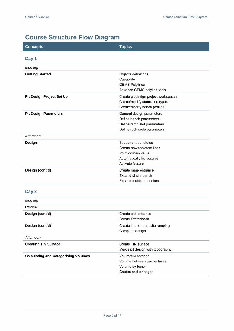
Design (cont’d) Create line for opposite ramping Complete design
Afternoon
Creating TIN Surface Create TIN surface Merge pit design with topography
Calculating and Categorising Volumes Volumetric settings Volume between two surfaces Volume by bench Grades and tonnages
Course Overview Course Structure Flow Diagram
Page 7 of 47
Concepts Topics
Creating Dumps General dump design parameters Define bench parameters Set current bench/toe Create new toe/crest lines Create ramp entrance Expand single bench Expand multiple benches
Introduction The Pit Design Module enables the engineer to quickly design multiple pits. In GEMS, use the Project View Area to access as well as organise the designs into different folders. Multiple designs can be loaded into memory simultaneously, and these can be saved together as a new design. The user may load multiple pits and alternate between which is being designed by selecting one as the active design.
The module uses workspaces to store the pit design parameters and design lines. Pit design uses two workspaces, one for holding the lines that belong to a particular design, and the other containing all the design parameters for any number of pit designs that are stored in that workspace. Once these are created the pit designer may begin using a practical design toolbar to design their pits.
Pit Design is based on polylines, and as a result, you will use the tools in the Polyline menu extensively during the creation of a pit design. The following describes a typical workflow:
The following describes a typical workflow:
1. Select the current bench and set it as then bench toe
2. Create a design line. This will allow the user to digitise a toe line (if step 1 was a crest of a bench, it would create a crest line. The user must change the line type of a digitised slot line to the chosen “slot” line-type profile.
3. Smooth the toe line to resemble a realistic outline.
4. Insert a ramp entrance. Usually, the ramp entrance also requires some editing.
5. Project lines up (down if the active line is a crest) to the next bench.
6. Check the projection for any errors.
7. Smooth the new toe line before projecting again.
8. Once the design is complete, the pit design is triangulated (creation of a surface). 9. The design is combined with a topography triangulation.
10. Volumes are calculated between surfaces.
This manual covers the following topics:
• Pit Design Components • Pit Design Theory in a Nutshell • Use of Whittle Shells in Pit Design • Prerequisites for Pit/Dump Design • New Pit or Dump Creation • Creating a Surface from Pit Designs • Pit Design Symbols • Advanced Pit Design • Single to Multi Pit Designs • Variable Pit SlopesW • Multi-Benching
Page 8 of 47
Pit Design Components The following section describes the pit design components.
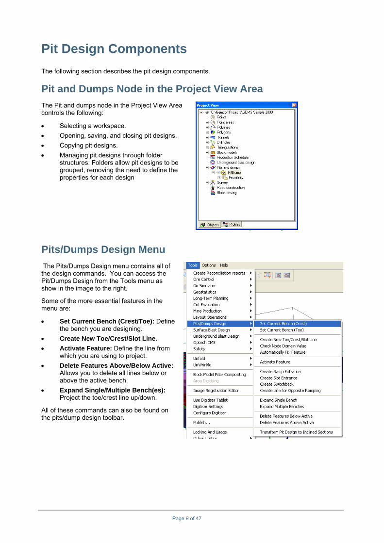
Pit and Dumps Node in the Project View Area The Pit and dumps node in the Project View Area controls the following:
• Selecting a workspace. • Opening, saving, and closing pit designs. • Copying pit designs. • Managing pit designs through folder
structures. Folders allow pit designs to be grouped, removing the need to define the properties for each design
Pits/Dumps Design Menu The Pits/Dumps Design menu contains all of the design commands. You can access the Pit/Dumps Design from the Tools menu as show in the image to the right.
Some of the more essential features in the menu are:
• Set Current Bench (Crest/Toe): Define the bench you are designing.
• Create New Toe/Crest/Slot Line. • Activate Feature: Define the line from
which you are using to project. • Delete Features Above/Below Active:
Allows you to delete all lines below or above the active bench.
• Expand Single/Multiple Bench(es): Project the toe/crest line up/down.
All of these commands can also be found on the pits/dump design toolbar.
Page 9 of 47
Pit Design Components Custom Menu
Page 10 of 47
Custom Menu GEMS provides a custom Pit Design menu that combines elements from the Polyline menu, which helps improve your efficiency when working on pit designs.
To access the menu, choose Options > Toolbar > Custom Menu > Pit Design.
Toolbar The pit design application features a toolbar that can be activated by right-clicking on the Pit and dumps node in the Project View Area.
The pit design toolbar has the following buttons:
Button Name Button Name
Set current bench (Crest)
Create switchback
Set current bench (Toe)
Create line for opposite ramping
Create new design line
Expand one bench
Check slope angle
Expand multiple benches
Fix feature
Delete features below active
Activate feature
Delete features above active
Create ramp entrance
Transform to Inclined Sections
Create slot entrance
Pit or Dump? The only difference between a pit and dump is that a dump projects outwards from a crest and inward from a toe, and a pit does the reverse.
Follow these steps to modify the display properties.
1. In the Project View Area, right-click on Pit and dumps, and choose Properties. 2. In the Pit Environment Properties, click any of the display options to enable them.
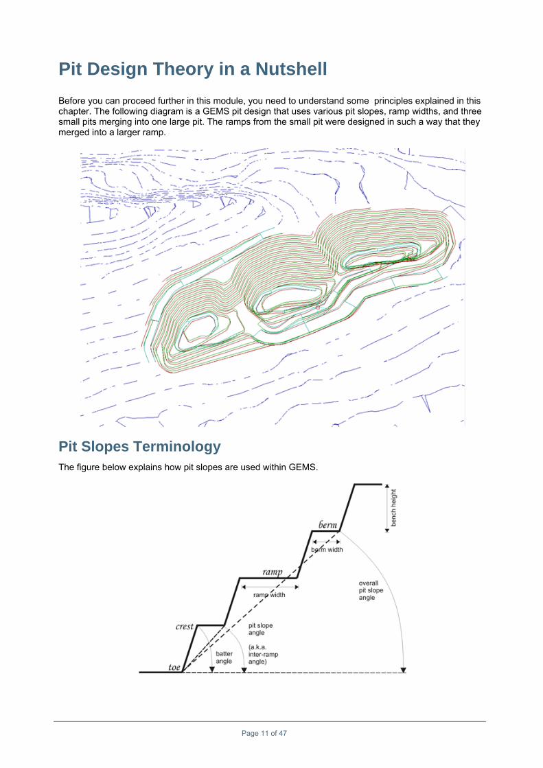
Pit Design Theory in a Nutshell Before you can proceed further in this module, you need to understand some principles explained in this chapter. The following diagram is a GEMS pit design that uses various pit slopes, ramp widths, and three small pits merging into one large pit. The ramps from the small pit were designed in such a way that they merged into a larger ramp.
Pit Slopes Terminology The figure below explains how pit slopes are used within GEMS.
Page 11 of 47
Pit Design Theory in a Nutshell Pit Slopes Terminology
Page 12 of 47
Pit Slope Angle Pit slope is determined by rock competency and the resulting slope stability. Slope stability is primarily compromised by weak rock, or by geotechnical features such as joint sets, faults, and slip planes (rock or soil that allows overlying material to slide more easily). Geotechnical engineers provide the long-term planner or mine designer with models for adjusting the pit design to the geotechnical ground conditions. GEMS can deal with various slope angles and ‘blend’ one angle to the next while it is projecting a bench.
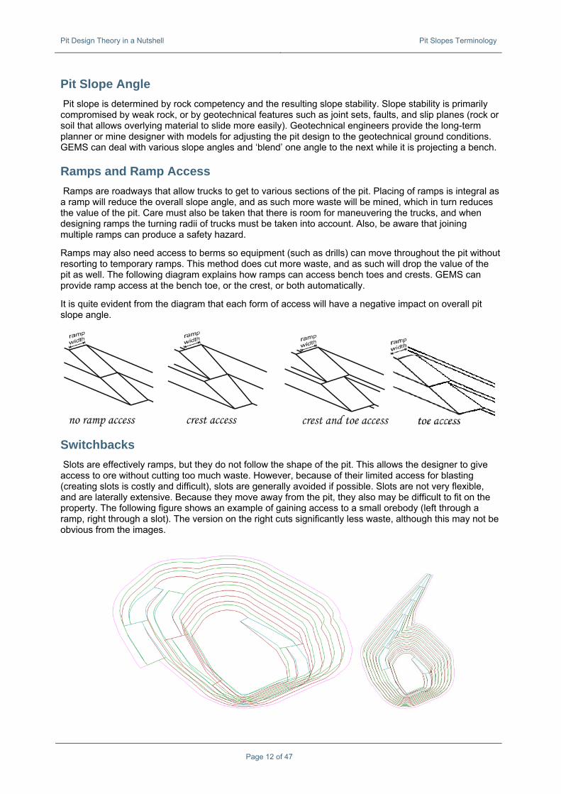
Ramps and Ramp Access Ramps are roadways that allow trucks to get to various sections of the pit. Placing of ramps is integral as a ramp will reduce the overall slope angle, and as such more waste will be mined, which in turn reduces the value of the pit. Care must also be taken that there is room for maneuvering the trucks, and when designing ramps the turning radii of trucks must be taken into account. Also, be aware that joining multiple ramps can produce a safety hazard.
Ramps may also need access to berms so equipment (such as drills) can move throughout the pit without resorting to temporary ramps. This method does cut more waste, and as such will drop the value of the pit as well. The following diagram explains how ramps can access bench toes and crests. GEMS can provide ramp access at the bench toe, or the crest, or both automatically.
It is quite evident from the diagram that each form of access will have a negative impact on overall pit slope angle.
Switchbacks Slots are effectively ramps, but they do not follow the shape of the pit. This allows the designer to give access to ore without cutting too much waste. However, because of their limited access for blasting (creating slots is costly and difficult), slots are generally avoided if possible. Slots are not very flexible, and are laterally extensive. Because they move away from the pit, they also may be difficult to fit on the property. The following figure shows an example of gaining access to a small orebody (left through a ramp, right through a slot). The version on the right cuts significantly less waste, although this may not be obvious from the images.
Pit Design Theory in a Nutshell Pit Slopes Terminology
Page 13 of 47
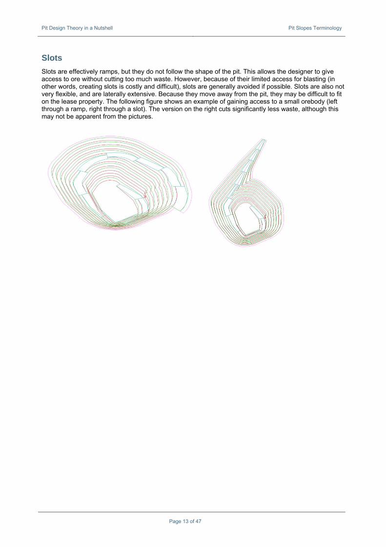
Slots Slots are effectively ramps, but they do not follow the shape of the pit. This allows the designer to give access to ore without cutting too much waste. However, because of their limited access for blasting (in other words, creating slots is costly and difficult), slots are generally avoided if possible. Slots are also not very flexible, and are laterally extensive. Because they move away from the pit, they may be difficult to fit on the lease property. The following figure shows an example of gaining access to a small orebody (left through a ramp, right through a slot). The version on the right cuts significantly less waste, although this may not be apparent from the pictures.
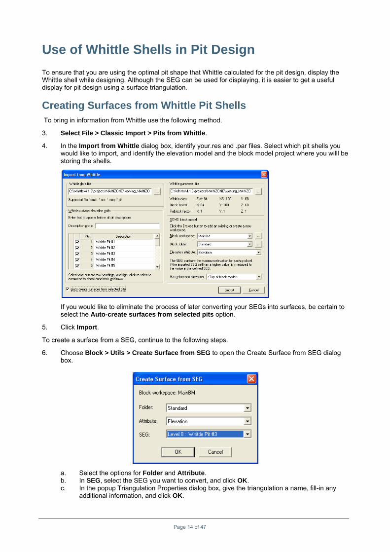
Use of Whittle Shells in Pit Design To ensure that you are using the optimal pit shape that Whittle calculated for the pit design, display the Whittle shell while designing. Although the SEG can be used for displaying, it is easier to get a useful display for pit design using a surface triangulation.
Creating Surfaces from Whittle Pit Shells To bring in information from Whittle use the following method.
3. Select File > Classic Import > Pits from Whittle.
4. In the Import from Whittle dialog box, identify your.res and .par files. Select which pit shells you would like to import, and identify the elevation model and the block model project where you willl be storing the shells.
If you would like to eliminate the process of later converting your SEGs into surfaces, be certain to select the Auto-create surfaces from selected pits option.
5. Click Import.
To create a surface from a SEG, continue to the following steps.
6. Choose Block > Utils > Create Surface from SEG to open the Create Surface from SEG dialog box.
a. Select the options for Folder and Attribute. b. In SEG, select the SEG you want to convert, and click OK. c. In the popup Triangulation Properties dialog box, give the triangulation a name, fill-in any
additional information, and click OK.
Page 14 of 47
Use of Whittle Shells in Pit Design Creating Surfaces from Whittle Pit Shells
Page 15 of 47
To save the workspace, right-click the triangulations workspace icon in the Project View Area, and select Save.
Prerequisites for Pit/Dump Design You need to set up the following items before you can use pit/dump design in GEMS (for further details, please refer to latter sections of this manual) :
• Line types and corresponding line display profiles for the following lines: ♦ TOE (normally RED) ♦ CREST (normally GREEN) ♦ SLOT (normally LIGHT BLUE) ♦ RAMP (normally CYAN)
• Pit/Dump Design workspace. • Polyline workspace (subtype Pit/Dump Design). • Plan views for design.
In addition to setting up these items, you need to complete the following actions:
• Add the Pit/Dump Design workspace to the Project View Area. • Link the Pit/Dump Design workspace to the Polyline (subtype Pit/Dump Design) workspace. • Create and open a Pit/Dump Design from the Project View Area.
Note: The Pit Design menu (Tools > Pits/Dumps Design) will not be activated until you have set up and completed the required actions for the workspaces.
Creating Workspaces for Pit Design Pit design in GEMS needs two types of workspaces:
• Polyline workspace, subtype Pit/Dump design – This workspace stores all the design lines. • Pit/Dump Design workspace – This workspace stores all the parameters that go with the designs
1. Choose Workspaces > Create or Modify Workspace to open the Structure Editor. 2. Choose Workspace > New to open the Workspace Wizard. 3. Select Set up a group of workspaces in one step, and click Next.
4. Select Pit and dump design, and click Next.
Page 16 of 47
Prerequisites for Pit/Dump Design Linking Pit Design Workspaces
Page 17 of 47
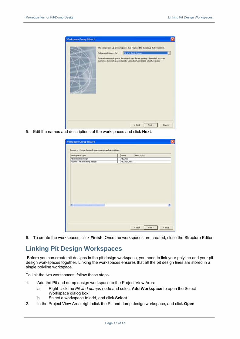
5. Edit the names and descriptions of the workspaces and click Next.
6. To create the workspaces, click Finish. Once the workspaces are created, close the Structure Editor.
Linking Pit Design Workspaces Before you can create pit designs in the pit design workspace, you need to link your polyline and your pit design workspaces together. Linking the workspaces ensures that all the pit design lines are stored in a single polyline workspace.
To link the two workspaces, follow these steps.
1. Add the Pit and dump design workspace to the Project View Area: a. Right-click the Pit and dumps node and select Add Workspace to open the Select
Workspace dialog box. b. Select a workspace to add, and click Select.
2. In the Project View Area, right-click the Pit and dump design workspace, and click Open.
Prerequisites for Pit/Dump Design Creating Benches (Plan Views)
Page 18 of 47
Note: If you don’t select ALL records when opening the workspace, GEMS will give a warning that there are no records in the workspace. This should not prevent you going to the next step. If it does, open the workspace with ALL records.
3. In the Project View Area, right-click the Pit and dump design workspace again. Notice that the quick-menu has changed and shows more options. Click Properties.
4. Click Browse, to browse to the polylines workspace where you want to store all of the design lines you create.
5. Click OK.
Creating Benches (Plan Views) In GEMS, bench height is controlled by the plan view definition. The elevations for toe and crest are also calculated from the definition. If plan views for the benches have not been defined, then you must create them. For more information on plan views, refer to the GEMS Foundation Manual.
To create a plan view, follow these steps.
1. Select View > Plan View > Define Plan Views to open the Plan View Editor dialog box.
2. To create a new profile, click New Profile, give the profile a name, and click OK.
3. Enter values for the reference, upper and lower elevations. Note that for pit design the thickness of a plan (the difference between the upper and lower limits) will be used as the bench height. Under the Volume Calculations section enter in a unique number for this series of views.
Prerequisites for Pit/Dump Design Creating Benches (Plan Views)
Page 19 of 47
4. Click Apply.
5. Repeat steps 2 to 4 to add more profiles. 6. In the Project View Area, click the Profiles tab and expand the Plan Views folder. You will also
need to expand the different series to find your desired plan view. 7. Right-click the new plan view, and choose Set Active.
8. To create a series of plan views which are parallel to the view that was created, select View > Create Sections > Parallel Sections.
9. When you are prompted to generate parallel plan views, click Yes.
10. In the Parallel Section Creation dialog box, enter the values as needed to generate the plan views, and click OK.
Prerequisites for Pit/Dump Design Creating Benches (Plan Views)
Page 20 of 47
11. When complete, your list of plan views can be found in the Profile tab of the Project View. It will be located under its series number. You can set any of these planes as the “active section”.
Note: A positive spacing for plan views will automatically create sections that are below the original. To create sections towards your view (i.e., UP if you are in a plan view), enter a negative value for Spacing Between Sections. Place Reference Plane allows you to set the reference elevation at either the toe (far end), crest (near end) or middle.
New Pit or Dump Creation
Creating a New Pit/Dump To create a new pit/dump, follow these steps.
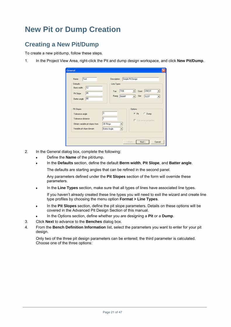
1. In the Project View Area, right-click the Pit and dump design workspace, and click New Pit/Dump.
2. In the General dialog box, complete the following: ♦ Define the Name of the pit/dump. ♦ In the Defaults section, define the default Berm width, Pit Slope, and Batter angle.
The defaults are starting angles that can be refined in the second panel.
Any parameters defined under the Pit Slopes section of the form will override these parameters.
♦ In the Line Types section, make sure that all types of lines have associated line types.
If you haven’t already created these line types you will need to exit the wizard and create line type profiles by choosing the menu option Format > Line Types.
♦ In the Pit Slopes section, define the pit slope parameters. Details on these options will be covered in the Advanced Pit Design Section of this manual.
♦ In the Options section, define whether you are designing a Pit or a Dump. 3. Click Next to advance to the Benches dialog box. 4. From the Bench Definition Information list, select the parameters you want to enter for your pit
design.
Only two of the three pit design parameters can be entered; the third parameter is calculated. Choose one of the three options:
Page 21 of 47
New Pit or Dump Creation Creating a New Pit/Dump
Page 22 of 47
♦ Enter Batter Angle and Berm Width: Pit Slope Angle is calculated ♦ Enter Pit Slope Angle and Berm Width: Batter Angle is calculated ♦ Enter Pit Slope Angle and Batter Angle: Berm Width is calculated
5. To add the benches (i.e., plan views) that will be used in the pit design, click Add Benches.
You should always add your benches after selecting your bench definition method, as the calculated parameter will not be adjusted if you switch methods.
6. In the Select Plan Views dialog box, select one or more plan views, and click OK.
The values for each bench will be entered automatically based on the default pit design parameters you entered on the previous panel.
You can make changes to both of the non-calculated variables. The calculated value will then automatically adjust.
If you want to fill a column with all of the same values, enter the desired value in the column’s first row, then right-click on the column header to autofill all rows within that value.
The following are explanations for some terms: ♦ Bench Height: This value is taken from the plan view definition’s thickness. This value
cannot be changed without changing the plane profile. ♦ Ramp Access: The ramp access in this dialog box overrides any ramp access information
specified in the Ramp/Slot dialog box (next screen). ♦ Calc Method: GEMS can calculate both crests and toes when it is projecting, or only crest
or only toe. The latter options are provided to save calculation time, but can only be used if there are no berms on the bench. Under normal circumstances (and with current computer speeds), Crest & Toe should be used.
New Pit or Dump Creation Creating a New Pit/Dump
Page 23 of 47
7. Click Next to advance to the Ramp/Slot dialog box.
8. Specify the following parameters for each ramp or slot: • Name: Choose a meaningful name. This name will help if you use multiple ramps in your
pit design. It is recommended to use the ramp width in the name, or to use the ramp nomenclature that is applied at the mine.
• Description: Use this to add any additional details. • Type: Select Slot or Ramp. • Start width: This is the width of the ramp starts with on the toe (ramping up) or crest
(ramping down). • End width: This is the width of the ramp at the crest (ramping up) or toe (ramping down). • Grade: This is the gradient of the ramp in percent (%). • Top access: Whether this ramp should have top access (i.e., crest access). This
parameter is overridden by the bench definition in the previous panel. Refer to the Ramp Access section of the manual for details.
♦ Bottom access: Whether this ramp should have bottom access (i.e., toe access)? This parameter is overridden by the bench definition in the previous panel. Refer to the Ramp Access section of the manual for details.
9. Click Finish.
New Pit or Dump Creation Designing a Simple Pit
Page 24 of 47
Designing a Simple Pit Pit design is an art which requires experience and common sense. Before performing your first GEMS pit design, this section will discuss the following questions:
• How do you make sure that you follow the optimal pit shell provided by Whittle? • How do you decide where your ramps need to start? • How do you decide where your ramps need to end? • How do you get your ramps to fit between start and end? • How do you make sure your pit design fits the geotechnical constraints? • How many benches are necessary?
Bottom-up or Top-down Design? Pit design tries to answer to the following questions:
To make sure that you follow your optimal pit shell shape, you need to start with a minimally-sized outline at the bottom of the pit. This will allow you to adjust the design as you go up. This will also ensure that you do not cut too much waste.
However, when you start at the bottom, you don’t know where the ramp entry is going to be. Usually, you are limited in the choice of access. This means you do not have many options as to where the ramp(s) can finish. To make sure the ramp is in the correct place, you need to start at the top.
This creates a circular problem that can be resolved through iteration:
1. Start at the bottom to ensure a proper pit shape. 2. Once the pit meets the topography, delete all the lines below the top, and start designing
downwards with adjustments for your ramp access. 3. Re-iterate this process until the pit design is stable and well worked-out.
How Many Benches? This may seem like a simple question, but it’s one that most people get wrong on their first design. There are two things you need to consider:
• What will be the first (deepest) bench? • What will be the top bench?
First (Deepest) Bench
To decide the first bench users will often look to the lowest elevation of their ultimate pit shell. Pit shells, however, do not ordinarily meet specific mining restrictions and are often too narrow at the bottom for equipment. This means that the lowest bench cannot necessarily be mined. The design engineer will be responsible for deciding what is the deepest, mine-able bench based on equipment and geotechnical constraints.
Some ideas for creating a smaller footprint at the bottom of the pit design are:
• Different mining method for the last narrow part of the pit. • Equipment to be used and/or the possibility of smaller equipment in order to realize smaller ramp
diameters. • Necessity of ramp access at the pit bottom. • Turning radii for the equipment and ramp entrance size at pit bottom.
Consider any cut made into the pit bottom wall will have a significant impact on the stripping ratio for that bench (because it is so small). As a result, practical access may render the bench unviable.
New Pit or Dump Creation Designing the First Bench – A Toe with a Ramp Entrance
Page 25 of 47
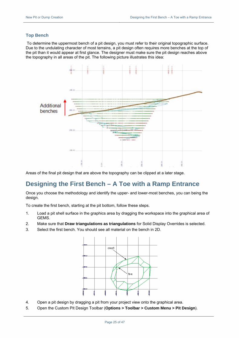
Top Bench
To determine the uppermost bench of a pit design, you must refer to their original topographic surface. Due to the undulating character of most terrains, a pit design often requires more benches at the top of the pit than it would appear at first glance. The designer must make sure the pit design reaches above the topography in all areas of the pit. The following picture illustrates this idea:
Areas of the final pit design that are above the topography can be clipped at a later stage.
Designing the First Bench – A Toe with a Ramp Entrance Once you choose the methodology and identify the upper- and lower-most benches, you can being the design.
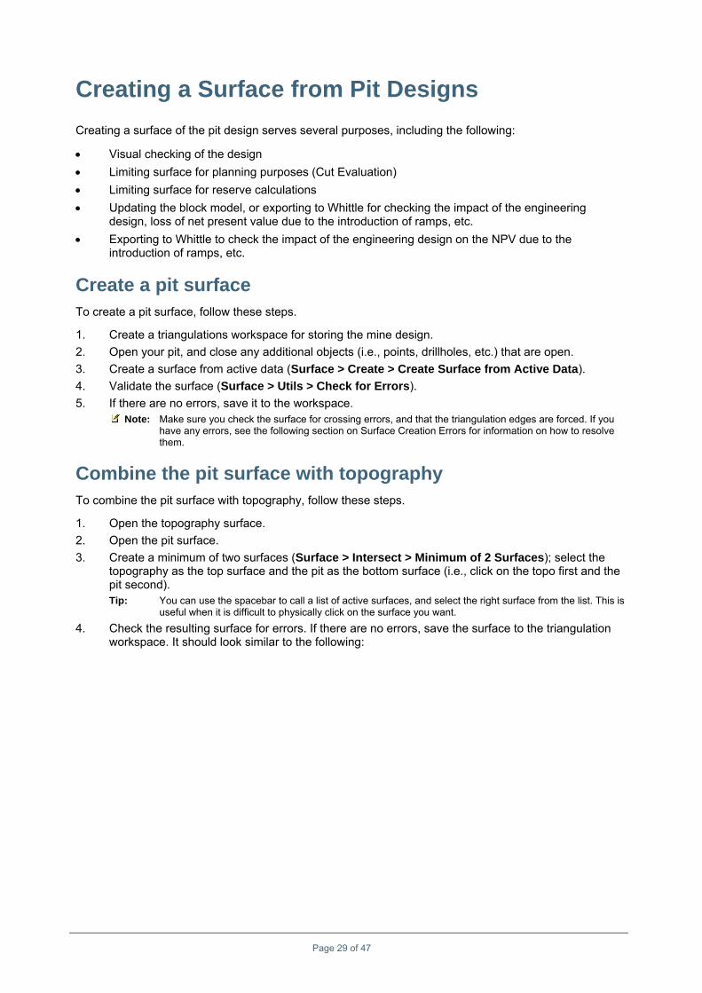
To create the first bench, starting at the pit bottom, follow these steps.
1. Load a pit shell surface in the graphics area by dragging the workspace into the graphical area of GEMS.
2. Make sure that Draw triangulations as triangulations for Solid Display Overrides is selected. 3. Select the first bench. You should see all material on the bench in 2D.
4. Open a pit design by dragging a pit from your project view onto the graphical area. 5. Open the Custom Pit Design Toolbar (Options > Toolbar > Custom Menu > Pit Design).
New Pit or Dump Creation Next Benches
Page 26 of 47
6. Click Set Current Bench (Toe) icon. From the Plan View dialog box, select a plan view to act as your lowest bench, and click OK. If the data disappears, click Zoom to Extents to get it back.
Note: Because you are designing the Toe, you should note that any lines you create will be located at the plan view’s lower elevation -- not the reference elevation. As such when you “set the current bench…”, the corresponding triangulation data will be displayed.
7. Choose Tools > Pits/Dumps Design > Create Toe/Crest/Slot Line or select the icon, and digitise the toe line.
Note: Do NOT use the normal Polyline > Create > Contour Line command.
8. To smooth the line, use Polyline > Vertex > Fillet, and click on the vertices that you want to fillet. 9. Locate (or create) a kink in the toeline as a starting point to insert a ramp.
10. Insert a ramp entrance ( Create Ramp Entrance) at this point. From the list, select a ramp style, and then choose a direction and an entrance radius.
New Pit or Dump Creation Next Benches
Page 27 of 47
Next Benches To add benches, follow these steps.
1. To project the bench up to the next level, click the Expand One Bench icon. You will notice that the plan view jumps after the expansion. In 3D, the design will look similar to the following:
2. Choose Select View > Set Large Projection to the whole design. 3. To adjust the design to match the Whittle pit, choose the following commands from the Polyline
menu: ♦ Line > Delete Segment; to eliminate part of a line ♦ Vertex > Insert; to add onto an existing line ♦ Vertex > 2D Move; to move a vertex along the current plane ♦ Vertex > Delete; to delete an existing vertex ♦ Vertex > Fillet; to smooth a sharp edge
4. Expand the design by one or multiple benches 5. Repeat steps 1 to 4 until you have expanded up to the top bench.
New Pit or Dump Creation Next Benches
Page 28 of 47
6. Save the pit design. The resulting pit should look similar to the following:
Creating a Surface from Pit Designs Creating a surface of the pit design serves several purposes, including the following:
• Visual checking of the design • Limiting surface for planning purposes (Cut Evaluation) • Limiting surface for reserve calculations • Updating the block model, or exporting to Whittle for checking the impact of the engineering
design, loss of net present value due to the introduction of ramps, etc. • Exporting to Whittle to check the impact of the engineering design on the NPV due to the
introduction of ramps, etc.
Create a pit surface To create a pit surface, follow these steps.
1. Create a triangulations workspace for storing the mine design. 2. Open your pit, and close any additional objects (i.e., points, drillholes, etc.) that are open. 3. Create a surface from active data (Surface > Create > Create Surface from Active Data). 4. Validate the surface (Surface > Utils > Check for Errors). 5. If there are no errors, save it to the workspace.
Note: Make sure you check the surface for crossing errors, and that the triangulation edges are forced. If you have any errors, see the following section on Surface Creation Errors for information on how to resolve them.
Combine the pit surface with topography To combine the pit surface with topography, follow these steps.
1. Open the topography surface. 2. Open the pit surface. 3. Create a minimum of two surfaces (Surface > Intersect > Minimum of 2 Surfaces); select the
topography as the top surface and the pit as the bottom surface (i.e., click on the topo first and the pit second). Tip: You can use the spacebar to call a list of active surfaces, and select the right surface from the list. This is
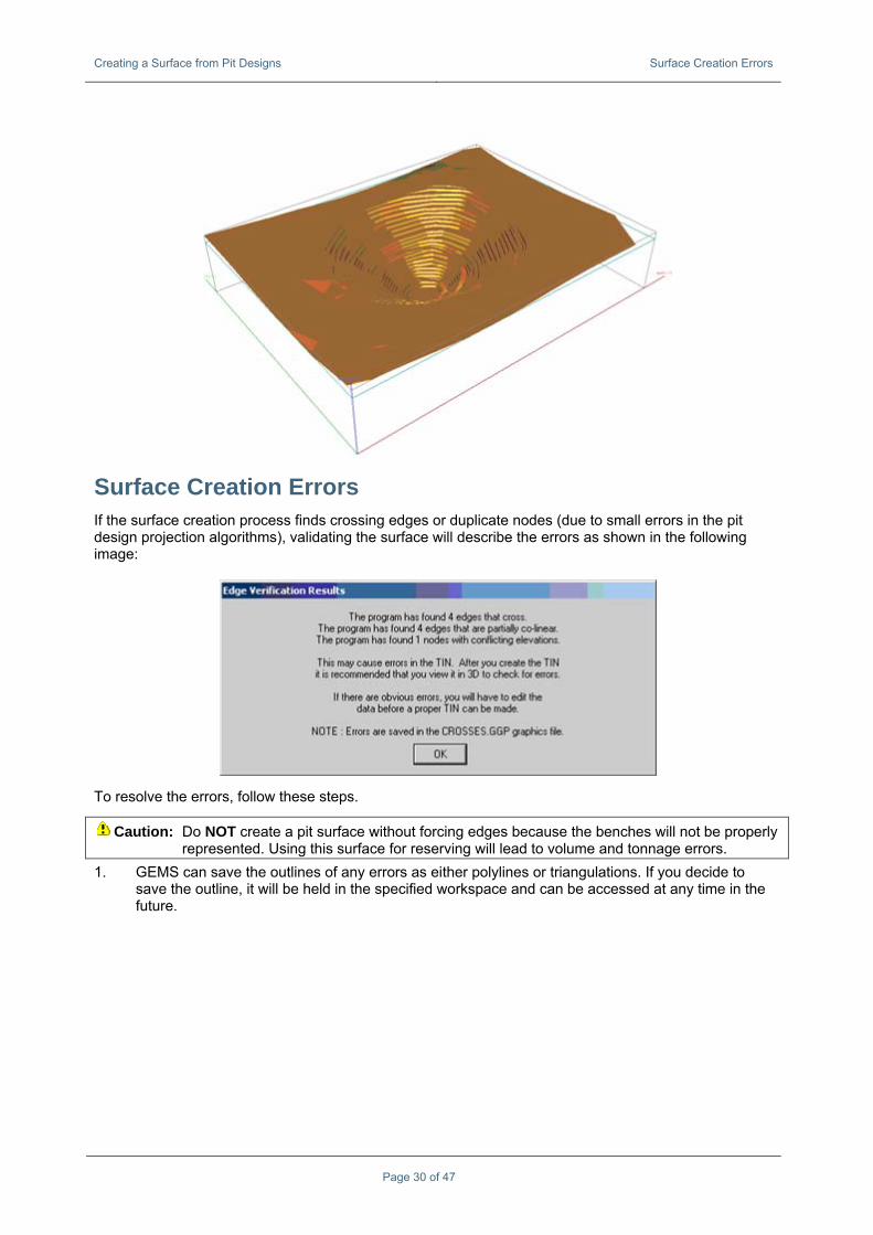
useful when it is difficult to physically click on the surface you want. 4. Check the resulting surface for errors. If there are no errors, save the surface to the triangulation
workspace. It should look similar to the following:
Page 29 of 47
Creating a Surface from Pit Designs Surface Creation Errors
Page 30 of 47
Surface Creation Errors If the surface creation process finds crossing edges or duplicate nodes (due to small errors in the pit design projection algorithms), validating the surface will describe the errors as shown in the following image:
To resolve the errors, follow these steps.
Caution: Do NOT create a pit surface without forcing edges because the benches will not be properly represented. Using this surface for reserving will lead to volume and tonnage errors.
1. GEMS can save the outlines of any errors as either polylines or triangulations. If you decide to save the outline, it will be held in the specified workspace and can be accessed at any time in the future.
Creating a Surface from Pit Designs Surface Creation Errors
Page 31 of 47
2. If you choose to Cancel in the Solid Verification Options box, the area with the error will still be highlighted with a cyan outline and purple fill until the View > Redraw Picture option is selected.
3. Once the location with the problem is identified you should use the Polyline tools to correct the polylines that are causing the error. Once the lines are fixed, you can create another surface.
Alternatively, if there is only one “bad triangle,” you may choose to simply delete a surface vertex (choose Surface > Utils > Delete Surface Vertex, and click one of the “bad” vertices) instead. Be careful with this option as the move you make will not affect the polylines, so you won’t be able to replicate this change in the future.
4. After the change has been made, check the new surface for errors.
Typical Pit Design Issues This section summarises pit design issues you may encounter.
Fillet Problems The following types of error messages are normally due to the fact that there are points too close to the point you are trying to fillet. Filleting will not delete any points.
Crossing Line Segments When lines cross over themselves a cross surrounded by a circle will show up on the design. These crossovers need to be removed manually to prevent self-intersecting pit designs.
Lines that Don’t Project (“My line doesn’t project”) One reason this happens is because you may have used the Polyline menu to create the pit design line. Since polyline workspaces for pit design are not listed in the polyline node, it is easy to save the line to
the wrong workspace. This is the main reason why you should always use Tools > Pits/Dumps Design > Create New Toe/Crest/Slot Line.
Another reason lines may not project is that you have not activated the line. Use Tools > Pits/Dumps Design > Activate Feature and click the feature to make sure that the correct line is projecting.
Page 32 of 47
Pit Design Symbols If GEMS detects any issues, the following symbols show during pit design.
Name Description
Cross A cross signifies that the node represents a ramp or slot node. A ramp or slot will
be or already has been created from this node.
Triangle A triangle represents a very sharp bend in the polyline at the highlighted node. Although not an actual error, this is a warning that the condition may lead to problems in the next expansion. It is recommended that any jagged polylines be corrected before expanding to the next bench.
Quartered Circles A quartered circle indicates an error with the polyline. The polyline intersects
itself at the highlighted node. This type of error must be repaired before you can proceed. These errors usually occur when there is a bend in the active feature polyline that could not be corrected automatically by the program or when there was a jagged edge left in the last bench.
Diamond A diamond signifies a problem with a ramp or a slot. Errors occur if a slot
centreline is too short or if a centreline could not be found for the slot node. A diamond can also be a warning that the ramp gradient could not be maintained.
Page 33 of 47
Advanced Pit Design The following section provides advanced information for pit design.
Single Pit Splitting into Multiple Pits The following examples demonstrate how you blend multiple pits into one. The first example starts with no ramps. The second example has ramps.
Example: Pit with No ramps To blend multiple pits into one without ramps, follow these steps.
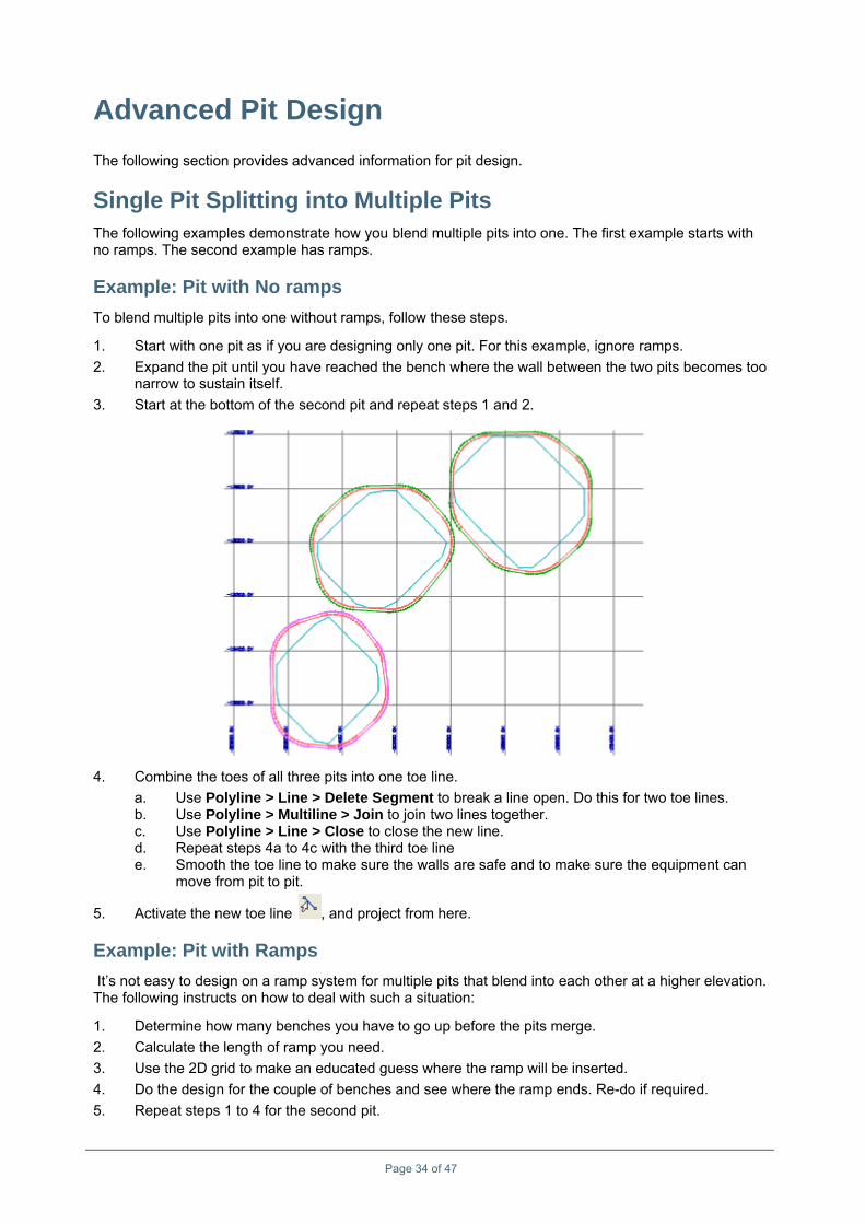
1. Start with one pit as if you are designing only one pit. For this example, ignore ramps. 2. Expand the pit until you have reached the bench where the wall between the two pits becomes too
narrow to sustain itself. 3. Start at the bottom of the second pit and repeat steps 1 and 2.
4. Combine the toes of all three pits into one toe line. a. Use Polyline > Line > Delete Segment to break a line open. Do this for two toe lines. b. Use Polyline > Multiline > Join to join two lines together. c. Use Polyline > Line > Close to close the new line. d. Repeat steps 4a to 4c with the third toe line e. Smooth the toe line to make sure the walls are safe and to make sure the equipment can
move from pit to pit.
5. Activate the new toe line , and project from here.
Example: Pit with Ramps It’s not easy to design on a ramp system for multiple pits that blend into each other at a higher elevation. The following instructs on how to deal with such a situation:
1. Determine how many benches you have to go up before the pits merge. 2. Calculate the length of ramp you need. 3. Use the 2D grid to make an educated guess where the ramp will be inserted. 4. Do the design for the couple of benches and see where the ramp ends. Re-do if required. 5. Repeat steps 1 to 4 for the second pit.
Page 34 of 47
Advanced Pit Design Single Pit Splitting into Multiple Pits
Page 35 of 47
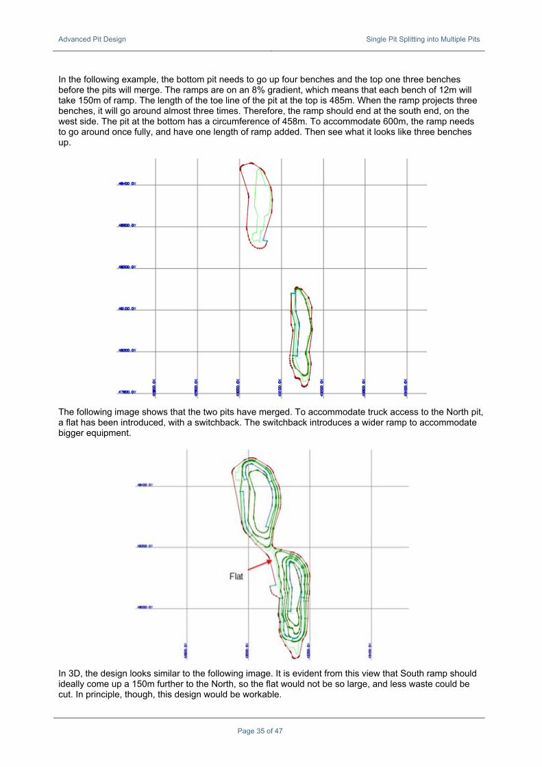
In the following example, the bottom pit needs to go up four benches and the top one three benches before the pits will merge. The ramps are on an 8% gradient, which means that each bench of 12m will take 150m of ramp. The length of the toe line of the pit at the top is 485m. When the ramp projects three benches, it will go around almost three times. Therefore, the ramp should end at the south end, on the west side. The pit at the bottom has a circumference of 458m. To accommodate 600m, the ramp needs to go around once fully, and have one length of ramp added. Then see what it looks like three benches up.
The following image shows that the two pits have merged. To accommodate truck access to the North pit, a flat has been introduced, with a switchback. The switchback introduces a wider ramp to accommodate bigger equipment.
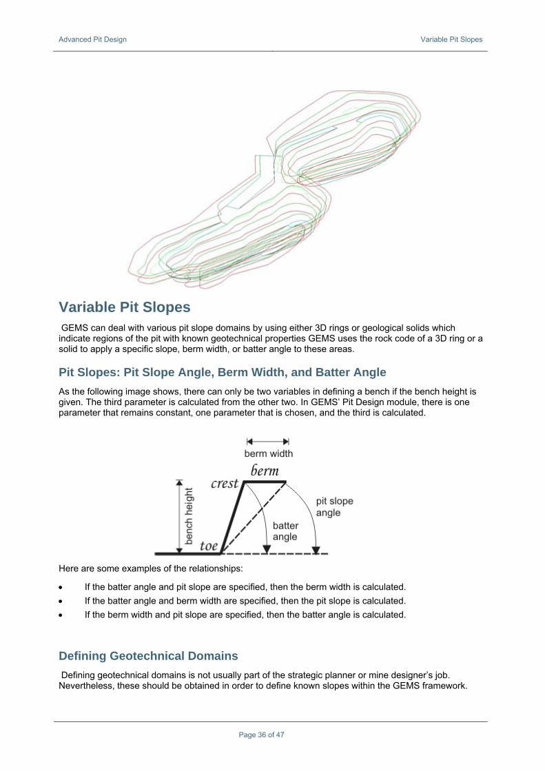
In 3D, the design looks similar to the following image. It is evident from this view that South ramp should ideally come up a 150m further to the North, so the flat would not be so large, and less waste could be cut. In principle, though, this design would be workable.
Advanced Pit Design Variable Pit Slopes
Page 36 of 47
Variable Pit Slopes GEMS can deal with various pit slope domains by using either 3D rings or geological solids which indicate regions of the pit with known geotechnical properties GEMS uses the rock code of a 3D ring or a solid to apply a specific slope, berm width, or batter angle to these areas.
Pit Slopes: Pit Slope Angle, Berm Width, and Batter Angle As the following image shows, there can only be two variables in defining a bench if the bench height is given. The third parameter is calculated from the other two. In GEMS’ Pit Design module, there is one parameter that remains constant, one parameter that is chosen, and the third is calculated.
Here are some examples of the relationships:
• If the batter angle and pit slope are specified, then the berm width is calculated. • If the batter angle and berm width are specified, then the pit slope is calculated. • If the berm width and pit slope are specified, then the batter angle is calculated.
Defining Geotechnical Domains Defining geotechnical domains is not usually part of the strategic planner or mine designer’s job. Nevertheless, these should be obtained in order to define known slopes within the GEMS framework.
Advanced Pit Design Variable Pit Slopes
Page 37 of 47
Although it is possible to use actual structural geological models for defining pit slope domains, it is more common to rework the structural geological model into a geotechnical model (as local geotechnical parameters such as joints and faults contribute to slope stability).
For this reason, the usual method of handling slope regions is as follows:
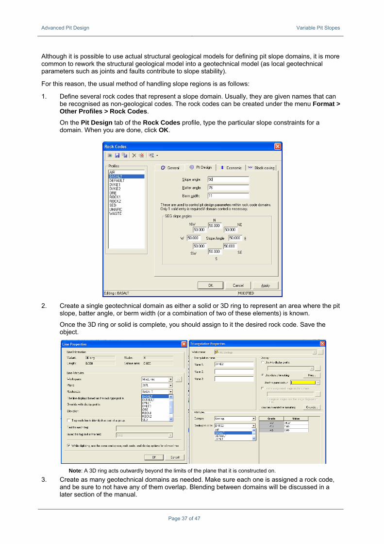
1. Define several rock codes that represent a slope domain. Usually, they are given names that can be recognised as non-geological codes. The rock codes can be created under the menu Format > Other Profiles > Rock Codes.
On the Pit Design tab of the Rock Codes profile, type the particular slope constraints for a domain. When you are done, click OK.
2. Create a single geotechnical domain as either a solid or 3D ring to represent an area where the pit slope, batter angle, or berm width (or a combination of two of these elements) is known.
Once the 3D ring or solid is complete, you should assign to it the desired rock code. Save the object.
Note: A 3D ring acts outwardly beyond the limits of the plane that it is constructed on.
3. Create as many geotechnical domains as needed. Make sure each one is assigned a rock code, and be sure to not have any of them overlap. Blending between domains will be discussed in a later section of the manual.
Advanced Pit Design Variable Pit Slopes
Page 38 of 47
4. Open all of your geotechnical lines/solids. 5. Create a new pit, and choose the appropriate object type for pit slopes generation from the list of
the pit Properties.
6. When you proceed with your pit design, the slope properties of your 3D Rings/Solids will be observed. Please refer to the following Blending and Variable Pit Slope Domain sections of this manual for details on how these values are applied.
Advanced Pit Design Variable Pit Slopes
Page 39 of 47
Blending? The term blending is used for letting GEMS gradually vary the pit slope, berm width, or batter angle between two domains. The figure explains the term.
Defining Slope Domains for Your Pit In the “Pit” Properties dialog box (right-click the pit, and select Properties), select the General tab to define wherefore the variable slope domain is obtained (Obtain variable pit slopes from). The options are as follow:
• 3D rings (refer to all space, not just a specific elevation) • Geology solids • Defaults (no variable pit slopes)
The Variable pit slope domain is the value that comes from your rock code profile. Depending on which of the three is chosen, three different operations will occur:
Advanced Pit Design Multi-Benching
Page 40 of 47
Selected Variable Slope Domain
Calculated Domain Constant Domain
Batter angle Pit slope angle Berm width
Pit slope angle Batter angle Berm width
Berm width Pit slope angle Batter angle
The “constant domain” is obtained from the bench parameters listed off on the Bench Definition Information tab in the properties for each pit.
The third domain is calculated based on the two known values.
If at any point during your design, you are unsure if you are inside a geologic domain, you can click Check Slope Angle.
Multi-Benching Pit/Ramp Design has the ability to perform multi-benching should the wall rock prove competent. This flexibility specifies that some benches do not need berms. Double-benching is the ability to eliminate the berm from every second bench. Similarly, triple-benching means putting a safety berm only every third bench.
Pay special attention when multi-benching with Pit/Ramp Design. To correctly set up the bench parameters in the Bench Editor (“Pit” Properties dialog box, Benches tab), you must specify the batter angle and berm width as the variables to edit manually, and have the program compute the different pit slope angles.
Before you multi-bench in GEMS you’ll need to perform some additional calculations in order to find an appropriate batter angle to achieve the desired pit slope. To calculate this batter angle you’ll have to assume a berm width of 0 every other bench (for double benching, or for each two out of three benches when triple-benching). In the image below a double-bench is shown.
The following equations can be used to calculate your batter angle, α.
anglebatter where, tan
tantan
widthBerm W height) berm-to-(bermHeight H
heightbench bangle slopepit Overall
1 =⎟⎠⎞
⎜⎝⎛
−=
====
− αθ
θα
θ
WHH
Once the benching pattern is decided (triple-benching; two benches each with a berm width of zero followed by one bench with a berm width of 20 metres), enter this and all other pit design information into the Benches tab in your pit properties.
Advanced Pit Design Adding Ramps, Slots, and Switchbacks
Page 41 of 47
When designing, after having completed bench expansions (using the Expand tools), benches with and without berms will be produced.
Single benching (without choosing the option to use variable pit slope regions) uses the same pit slope angle, berm width, and batter angle for each bench. Thus, the overall pit slope angle equals the pit slope angle in the Bench Editor.
In multi-benching; however, the berm width changes from bench to bench. Therefore, the pit slope angle can vary from bench to bench.
Caution: Each pit slope angle, batter angle, and berm width in the bench editor refers to the value of only one bench. The pit slope angle is always measured from the toe of the current bench to the toe of the next bench. When triple benching, for example, the pit slope angle does not refer to the toe of the first bench to the toe of the third bench (the one with the berm).
Adding Ramps, Slots, and Switchbacks Ramps GEMS will create and project a ramp if a vertex in a toe or crest line has a ramp attribute. Choose Polyline> Vertex > View/Edit (Real Coordinates) to open the Pit Design Feature Vertex Editor dialog box, which allows you to view the attribute.
Advanced Pit Design Adding Ramps, Slots, and Switchbacks
Page 42 of 47
The ramp node is shown in GEMS by a diagonal cross (see below). Ramp nodes always lie on crest/toe lines.
Creating a Ramp Entrance
You can create a ramp entrance clicking or Tools > Pits and Dump Design > Create Ramp Entrance, as well as clicking the crest/toe line for the entrance.
The polyline tool Polyline > Line > Create Ramp Entrance is another creation method which is used to convert a portion of an existing line to the ramp entrance. .
User-created ramp entrance, showing the ramp node as a cross
Ending a Ramp
If you do not want your ramp/slot to continue to the next bench, use the following procedure:
1. To end a ramp, click the ramp node cross, and choose Polyline> Vertex > View/Edit (Real Coordinates).
2. The name of the ramp will show up under Ramp/Slot Name. Change this to the blank.
Advanced Pit Design Adding Ramps, Slots, and Switchbacks
Page 43 of 47
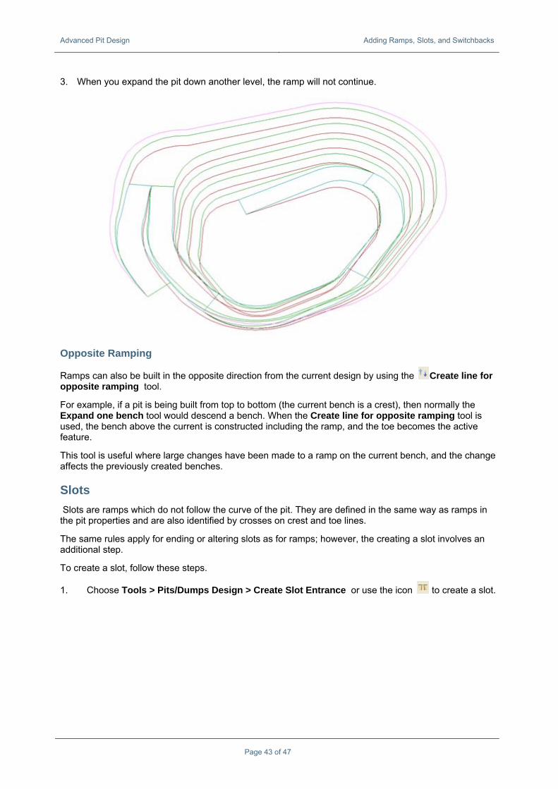
3. When you expand the pit down another level, the ramp will not continue.
Opposite Ramping
Ramps can also be built in the opposite direction from the current design by using the Create line for opposite ramping tool.
For example, if a pit is being built from top to bottom (the current bench is a crest), then normally the Expand one bench tool would descend a bench. When the Create line for opposite ramping tool is used, the bench above the current is constructed including the ramp, and the toe becomes the active feature.
This tool is useful where large changes have been made to a ramp on the current bench, and the change affects the previously created benches.
Slots Slots are ramps which do not follow the curve of the pit. They are defined in the same way as ramps in the pit properties and are also identified by crosses on crest and toe lines.
The same rules apply for ending or altering slots as for ramps; however, the creating a slot involves an additional step.
To create a slot, follow these steps.
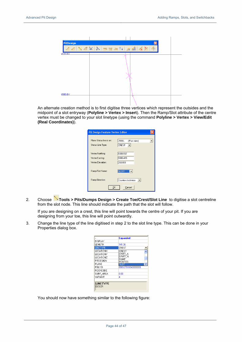
1. Choose Tools > Pits/Dumps Design > Create Slot Entrance or use the icon to create a slot.
Advanced Pit Design Adding Ramps, Slots, and Switchbacks
Page 44 of 47
An alternate creation method is to first digitise three vertices which represent the outsides and the midpoint of a slot entryway (Polyline > Vertex > Insert). Then the Ramp/Slot attribute of the centre vertex must be changed to your slot linetype (using the command Polyline > Vertex > View/Edit (Real Coordinates)).
2. Choose Tools > Pits/Dumps Design > Create Toe/Crest/Slot Line to digitise a slot centreline from the slot node. This line should indicate the path that the slot will follow.
If you are designing on a crest, this line will point towards the centre of your pit. If you are designing from your toe, this line will point outwardly.
3. Change the line type of the line digitised in step 2 to the slot line type. This can be done in your Properties dialog box.
You should now have something similar to the following figure:
Advanced Pit Design Adding Ramps, Slots, and Switchbacks
Page 45 of 47
4. Make your crest/toe the active feature again by clicking Tools > Pits/Dumps Design > Activate Feature.
5. Expand the benches.
Switchbacks Choose Tools > Pits/Dumps Design > Create Switchback for automatic switchback creation. After GEMS has created the switchback, you can click on the ramp node, provide the turning radius, and edit the switchback by hand if required.
Creating a switchback can also be done by hand editing. This involves stopping the current ramp (delete the ramp name by editing the vertex), inserting points to provide room for the trucks to turn, and changing the Ramp/Slot attribute for one of the points on the inside of the new ramp.