Page 1
GEN9539
No Sheet! You can do that with the SSM in AutoCAD
Sam Lucido CAD Services Manager, Haley and Aldrich, Inc. (Detroit, MI)
Do you still open drawings one at a time? Do you print drawings one at a time? Do you update the index sheet
on a drawing package when a drawing name changes? If you answered yes to any of those questions then this
class is for you. The Sheet Set Manager (SSM) in AutoCAD® is your ultimate document management tool. The
SSM is an electronic database of all your project information which can be added to a template file eliminating
the chance for error and populating data throughout the project. In this class we will setup a design project
using a template, organize all of the sheets, and publish the entire set to pdf when complete. At the end of this
class, you will be able to take your existing company title blocks and create a template to use on all projects
increasing your productivity and efficiency.
Description All design and drafting projects have a set of drawings that are required to complete the report, presentation or
design. The SSM can be used as an organizational tool similar to setting up a folder in windows where you can
access the files quickly and create subfolders to manage the project. The real power behind the SSM is creating a
template and populating project data throughout the entire package, using this electronic database of
information to streamline the design process. By using the SSM with your design projects you will build a custom
template that you can bring back to the office and use as a guide as you customize your company standard title
blocks. You will save time, be efficient and be that go to guy or gal when you get back to the office
Learning Objectives
Describe and identify the functions of the SSM.
Create a sheet set from a template and existing drawings using the SSM.
Populate data throughout the entire project using the SSM.
Publish the entire drawing package to a pdf file using the SSM.
Your AU Expert
Sam Lucido presents workshops on CAD standards, tools, and productivity techniques to managers and users by holding hands on labs as well as live presentations. He has more than 20 years of CAD experience involving production design, drafting, user support, and standards coordination. Sam continues to be very self-motivated and enjoys working in a team environment collaborating on design and creating high quality deliverables. He is the owner of CADproTips.com and is an AutoCAD Certified Professional as well as an Autodesk Expert Elite Member.
[email protected] http://www.haleyaldrich.com http://www.CadProtips.com @CADproTips
Page 2
GEN9539: No Sheet! You can do that with the SSM in AutoCAD
2
Table of Contents
Introduction 3
Templates 4
Page Setups 11
Sheet Sets and Fields 14
Save the Template 35
Setup a New Project with the SSM 38
Link the Page Setups, Callout Blocks, and the Template 51
Insert a Sheet Index Table 54
Publishing the Sheet Set 58
Conclusion 62
Appendices
Appendix A: Using the Publish Dialog Box for printing your Project 63
Appendix B: Placing Sheet Views from the Model Tab using the SSM 65
Appendix C: Archiving a Sheet Set 69
Appendix D: Using the Model View Tab 73
Appendix E: Sheet Set Fields Cheat Sheet 75
Video Tutorials (Select the link to be taken to a video on the topic)
No Sheet! There really is more than one tab in the SSM.
No Sheet! You can insert your entire projects sheet list table from the SSM.
No Sheet! You really can add pdf files to your design with the SSM.
No Sheet! You can tell the SSM where to send those output files (plotter, pdf, dwf)!
No Sheet! You can use Page Setup overrides to print all sheets in the SSM with on-click!
No Sheet! You really can collapse and expand subsets from the scrollbar!
No Sheet! You can preview drawings without having them open in the SSM!
No Sheet! You really can save all your drawings and references to a zip file from the SSM!
No Sheet! I can click hyperlinks in the No Sheet handout to view all of the information about the SSM!
No Sheet! There is a Q&A with CADProTips (aka Sam Lucido) on the SSM.
Page 3
GEN9539: No Sheet! You can do that with the SSM in AutoCAD
3
Figure 1: Application Menu
Figure 2: Menu Bar Figure 3: SSM Palette
Introduction
Any design project you work on requires a set of drawings and specifications to accompany the report which specifies the
intent of the design. All of these aspects require preparation and good document and project organization. A Sheet Set is a
great tool to manage your drawings from start to finish in your design. If you use Sheet Sets in the most basic way you are
just taking drawing files and organizing them in proper order so they can be easily accessed when working through your
project. With Sheet Sets you can have others on your team work on one subset while you work on another making
collaboration and managing your design package an easy task.
The Sheet set manager can be found on the ribbon under the application menu as shown in Figure 1. If you use the
menubar you can find it under the file section shown in Figure 2. Finally, for those of you who use the command prompt
type SSM. After you successfully create a sheet set you can view your Sheet Set through the SSM Palette as shown in Figure
3 to the right.
NOTE: In this tutorial you will see highlighted portions of text; these portions of text will notify you to perform a
specific task within AutoCAD. As you go through the tutorial, additional information about each task you perform
will be included in that highlighted body of text. Also, this document contains sections to take notes, look for the
table at the end of several pages where you can add your personal notes and ideas on the topic covered.
Page 4
GEN9539: No Sheet! You can do that with the SSM in AutoCAD
4
Figure 4: Sheet Set Wizard
Templates
The one thing we have to keep in mind is that when we create our sheet set template (.dws) file we need to link
that to our company title block (.dwt) template file. Keeping these two files linked together will help us
populate the data and link the fields as we start new projects in AutoCAD. To understand and effectively apply
sheet sets, you must understand templates, layouts, fields, blocks, attributes, views, and external references. As
you work through sheet sets take time to review some of the topics above to make yourself more comfortable
as you work through the sheet set process. Let’s start by creating the sheet set template first after that is
complete we will bring in our title block and link that to the sheet set file.
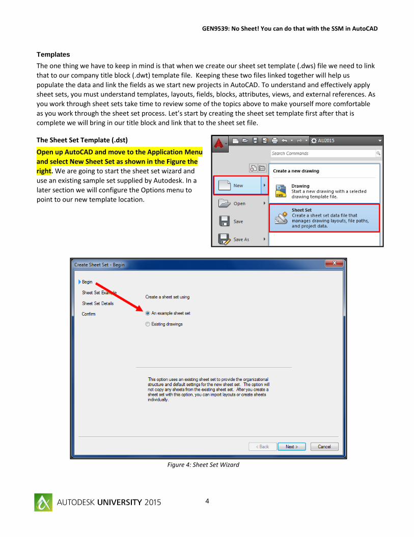
The Sheet Set Template (.dst)
Open up AutoCAD and move to the Application Menu
and select New Sheet Set as shown in the Figure the
right. We are going to start the sheet set wizard and
use an existing sample set supplied by Autodesk. In a
later section we will configure the Options menu to
point to our new template location.
Page 5
GEN9539: No Sheet! You can do that with the SSM in AutoCAD
5
Figure 4: Sheet Set Wizard
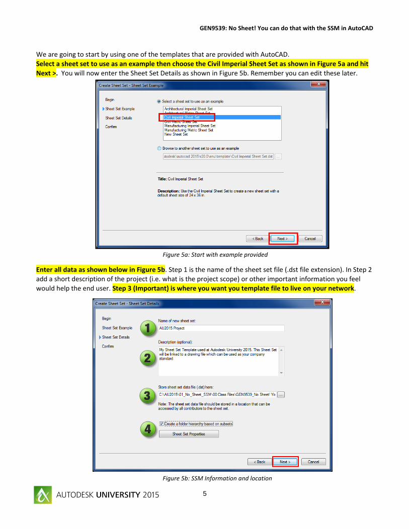
We are going to start by using one of the templates that are provided with AutoCAD.
Select a sheet set to use as an example then choose the Civil Imperial Sheet Set as shown in Figure 5a and hit
Next >. You will now enter the Sheet Set Details as shown in Figure 5b. Remember you can edit these later.
Enter all data as shown below in Figure 5b. Step 1 is the name of the sheet set file (.dst file extension). In Step 2
add a short description of the project (i.e. what is the project scope) or other important information you feel
would help the end user. Step 3 (Important) is where you want you template file to live on your network.
Figure 5a: Start with example provided
Figure 5b: SSM Information and location
Page 6
GEN9539: No Sheet! You can do that with the SSM in AutoCAD
6
Figure 6a: Save the .dst file to your project folder
Figure 6b: Save the .dst file to your project folder
In Step 3 select the ellipses as shown and save the drawing to the root folder of our project as shown in Figure
6a below.
In this tutorial we will be saving our Sheet Set file (.dst) to the root project folder where our CAD files will be
located as shown below in Figure 6b. They DO NOT have to be in the same location but good practice is to keep
those together since they have common information which will be shared throughout the design project.
Page 7
GEN9539: No Sheet! You can do that with the SSM in AutoCAD
7
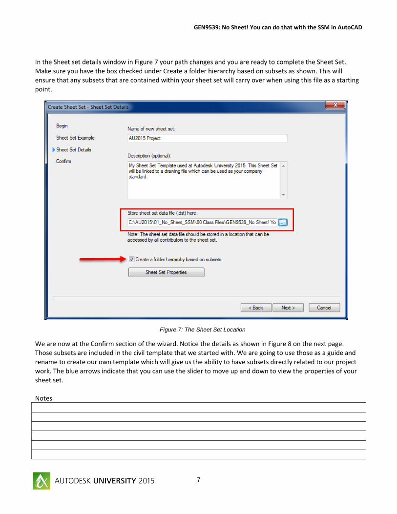
In the Sheet set details window in Figure 7 your path changes and you are ready to complete the Sheet Set.
Make sure you have the box checked under Create a folder hierarchy based on subsets as shown. This will
ensure that any subsets that are contained within your sheet set will carry over when using this file as a starting
point.
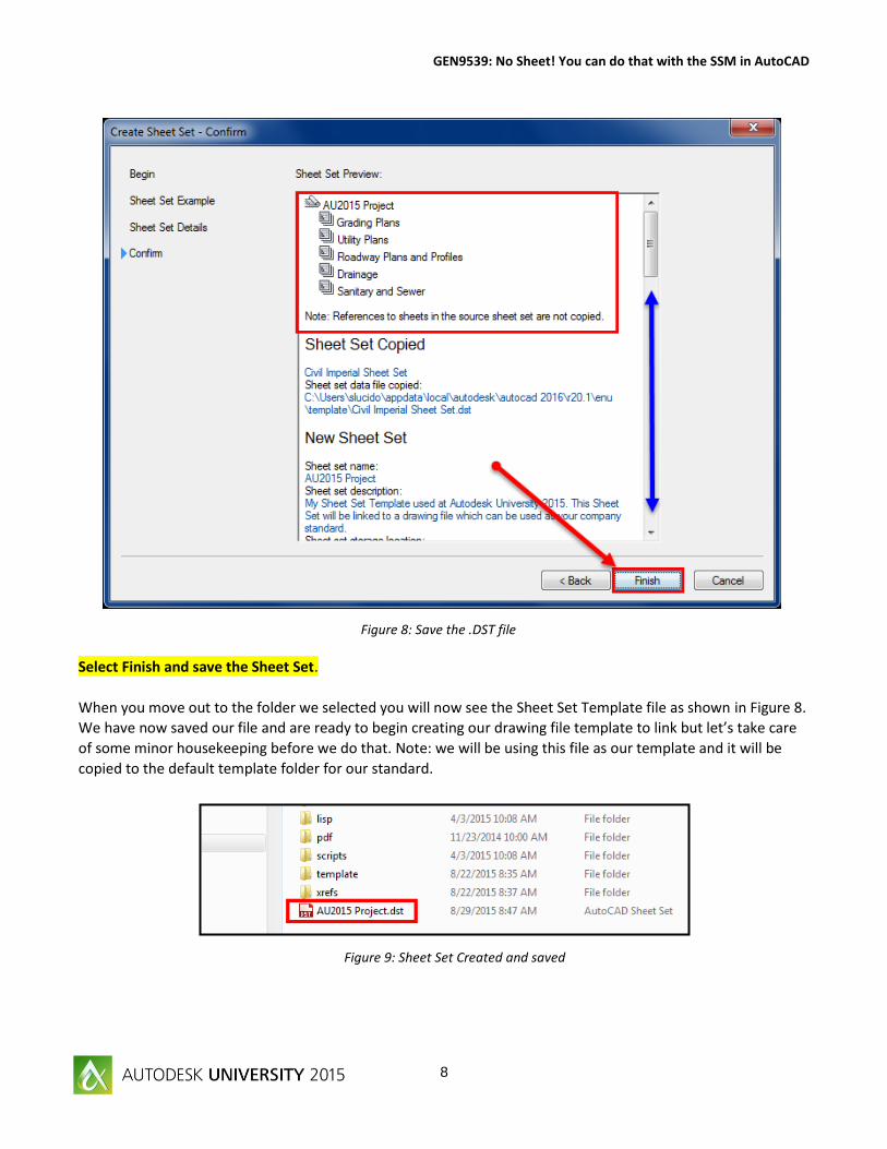
We are now at the Confirm section of the wizard. Notice the details as shown in Figure 8 on the next page.
Those subsets are included in the civil template that we started with. We are going to use those as a guide and
rename to create our own template which will give us the ability to have subsets directly related to our project
work. The blue arrows indicate that you can use the slider to move up and down to view the properties of your
sheet set.
Notes
Figure 7: The Sheet Set Location
Page 8
GEN9539: No Sheet! You can do that with the SSM in AutoCAD
8
Select Finish and save the Sheet Set.
When you move out to the folder we selected you will now see the Sheet Set Template file as shown in Figure 8.
We have now saved our file and are ready to begin creating our drawing file template to link but let’s take care
of some minor housekeeping before we do that. Note: we will be using this file as our template and it will be
copied to the default template folder for our standard.
Figure 8: Save the .DST file
Figure 9: Sheet Set Created and saved
Page 9
GEN9539: No Sheet! You can do that with the SSM in AutoCAD
9
You should now all have AutoCAD Open and have the AU2014 Project Sheet Set open. Notice how all of the
subsets have been pulled from the civil template we selected in the beginning. We are going to rename those
by selecting the subset and right clicking as shown in the images below.
Perform steps 1 through 5 as shown below in Figure 9.
You have now completed the start of the template for your sheet set. Next we need to bring in our title block
and connect the files together and introduce sheet set fields.
Subsets
Underneath your AU2015 project you have a list of names or subsets (Title Sheet, Site Plans, Details and working files). Subsets provide a way in the sheet set manager to organize all of your project files similar to folders in windows explorer. Subsets are not required although they can provide significant help in organizing different phases of the project. For example, Title sheet and legend, process, mechanical, electrical and details. All of these items can be placed in subsets for easy organization and the benefit is you can print or plot each subset with the click of the mouse. Many times in design projects these different parts are reviewed by different people specializing in each discipline. What I like to do is have a working file subset and check the Do not publish in sheet set and keep all of my working files organized in there until completion of the project.
Figure 9: Rename the Subsets
1. Right-click and rename Grading Plans to Title Sheet.
2. Right-click and rename Utility Plans to Site Plans.
3. Right-click and rename Roadway Plans and Profiles to Details.
4. Right-click and rename Drainage to Working files.
5. Right-click and delete Sanitary and Sewer.
Page 10
GEN9539: No Sheet! You can do that with the SSM in AutoCAD
10
The Template File: Title block drawing template (.dwt)
Open up drawing 01_ANSID_TitleBlock-Complete.dwg located in the dwg folder.
This drawing file is a standard 22 x 34 D size drawing with attributes added. We are going to take that drawing
and use to create our template for the project.
Save this drawing to the root folder where your sheet set is located and name it 12042015_C-100. We are
going to create our first page for our design set.
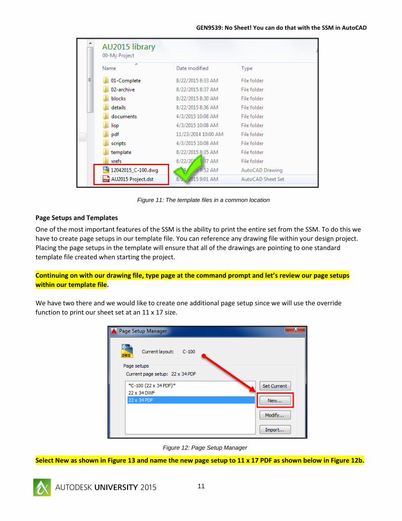
We have now saved our drawing and we also have our sheet set open as shown in Figure 11 from windows
explorer. Notice how our sheet set file is saved in the same location as our template. The sheet set template
(.dst) does not have to be located along with the drawing files. I like to have this in the same location as my
design files for better organization. I have seen others use folders named Sheets, SSM, Setup, etc. Use the
method that works for workflow on your current project and company standards.
Notes
Figure 10: Save your drawing file.
Page 11
GEN9539: No Sheet! You can do that with the SSM in AutoCAD
11
Page Setups and Templates
One of the most important features of the SSM is the ability to print the entire set from the SSM. To do this we
have to create page setups in our template file. You can reference any drawing file within your design project.
Placing the page setups in the template will ensure that all of the drawings are pointing to one standard
template file created when starting the project.
Continuing on with our drawing file, type page at the command prompt and let’s review our page setups
within our template file.
We have two there and we would like to create one additional page setup since we will use the override
function to print our sheet set at an 11 x 17 size.
Select New as shown in Figure 13 and name the new page setup to 11 x 17 PDF as shown below in Figure 12b.
Figure 11: The template files in a common location
Figure 12: Page Setup Manager
Page 12
GEN9539: No Sheet! You can do that with the SSM in AutoCAD
12
We are going to use 3 simple steps as shown below to complete our new 11 x 17 page setup.
Step 1: Name the page setup to 11 x 17 PDF
Step 2: Change the paper size the ANSI B (17 x 11 inches)
Step 3: Change the plot scale from 1:2.
Why 1:2? We are starting with a page in our design that is 22 x 34 in size and we want the ability to print half
size as we move through the project. Practice: Select New again and create an 11 x 17 DWF page setup.
Figure 13: Plot dialog box (Page Setup)
Figure 14: Plot dialog box
Page 13
GEN9539: No Sheet! You can do that with the SSM in AutoCAD
13
Hit OK to complete the page setup and you will have a new page to use in our overrides setting. Review your
project and add all of the page options you feel you will need in the beginning then you will not have any
questions when you are working though the design.
You can add these quickly through the SSM if you forget one or two along the way.
Save your drawing file (i.e. 12042014_C-100.dwg).
Notes:
Page 14
GEN9539: No Sheet! You can do that with the SSM in AutoCAD
14
Introduction to Sheet Sets and Fields
There is a drawing for you to practice with name 01_ANSID_TitleBlock.dwg. Use this drawing to add all of the
attributes, one at a time, and then link those to the .dst file. The more you practice the better you will become
at the process. We started with the complete file but I also wanted to provide a blank file for you to get started
with. You can add the attributes as you populate the Sheet Set template. I like to complete my template first to
make sure I am in compliance with all my company standards. The attributes added into our file are as shown in
Figure and I also have provided the field name (in blue) to show you what field will be linked to that section of
our file.
1. Drawing name.
CurrentSheetDescription
2. Project name CurrentSheetSetProjectName
3. Second line in title - Phase
CurrentSheetProjectPhase
4. Drawn by CurrentSheetCustom
5. Checked by CurrentSheetCustom
6. Sheet number CurrentSheetNumber
7. Sheet total CurrentSheetSetCustom
8. Drawing number
CurrentSheetTitle
9. Date CurrentSheetSetProjectMilestone
10. Scale CurrentSheetSetCustom
11. Revision number CurrentSheetSetCustom
12. Revision description CurrentSheetSetCustom
13. Revision date CurrentSheetSetCustom
We are going to continue with the same drawing and start adding our custom properties.
If you want to start with a new file open drawing 02_ANSID_TitleBlock-Pagesetups.dwg located in the
template folder of our project setup. This file is a standard 22 x 34 D size drawing with attributes and page
setups complete. You will need to save over the existing 12042014_C-100.dwg file in our project folder.
Figure 15: Introduction to Fields
Page 15
GEN9539: No Sheet! You can do that with the SSM in AutoCAD
15
Your screen should look like something as shown below in Figure 15. We have our SSM open with our AU2014
project and our drawing file open with our page setups and attributes. We are now going to update the data
within the drawing file then save to a template. Save our drawing file and if you started with a new one
overwrite the existing file in our template folder. First thing we have to do is bring that layout into our sheet set.
This will be our first drawing and the drawing we will save as our
template. We have to keep it connected to the sheet set until we
get all of the properties set.
Right-Click on the Title Sheet Subset and select Import Layout as
Sheet…as shown to the right
Figure 16: Sheet Set Manager and Drawing file
Page 16
GEN9539: No Sheet! You can do that with the SSM in AutoCAD
16
Browse to our drawing file in explorer (i.e. 12042014_C-100.dwg and select the file. You will be importing
layout C-100 into our sheet set as shown in Figure 17a. Check the box under drawing name and Import Layout.
Keep in mind that the drawing file we started with contained a layout; you must have a layout (sheet) in your
drawing to be able to import the sheet.
The layout will be imported into the set and now is linked. We can right-click and rename the sheet as we are
going to use the properties of the renamed layout to populate our title bock.
Right click your drawing file and rename as shown in Figure 17b. Take a look below as I have shown you a read
more section. If you have this box checked your drawing file (out on the network) will be renamed. Be careful as
I have learned from experience that leaving this checked will confuse other users not realizing that they are
actually changing the name of the file.
Figure 17a: Import Layout as Sheets
Figure 17b: Rename the Sheet and Layout
Page 17
GEN9539: No Sheet! You can do that with the SSM in AutoCAD
17
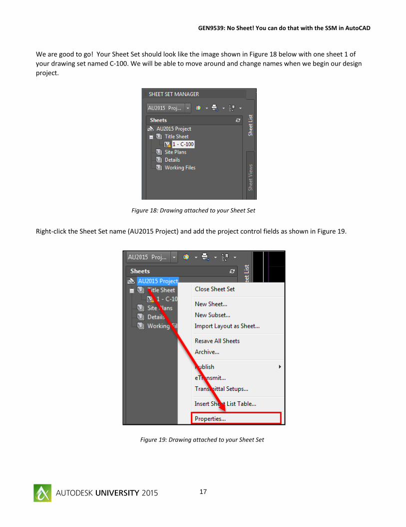
We are good to go! Your Sheet Set should look like the image shown in Figure 18 below with one sheet 1 of
your drawing set named C-100. We will be able to move around and change names when we begin our design
project.
Right-click the Sheet Set name (AU2015 Project) and add the project control fields as shown in Figure 19.
Figure 18: Drawing attached to your Sheet Set
Figure 19: Drawing attached to your Sheet Set
Page 18
GEN9539: No Sheet! You can do that with the SSM in AutoCAD
18
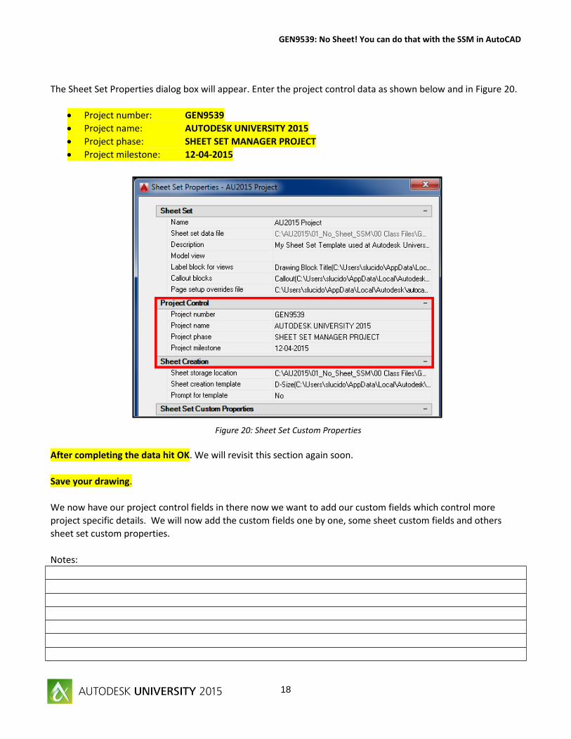
The Sheet Set Properties dialog box will appear. Enter the project control data as shown below and in Figure 20.
Project number: GEN9539
Project name: AUTODESK UNIVERSITY 2015
Project phase: SHEET SET MANAGER PROJECT
Project milestone: 12-04-2015
After completing the data hit OK. We will revisit this section again soon.
Save your drawing.
We now have our project control fields in there now we want to add our custom fields which control more
project specific details. We will now add the custom fields one by one, some sheet custom fields and others
sheet set custom properties.
Notes:
Figure 20: Sheet Set Custom Properties
Page 19
GEN9539: No Sheet! You can do that with the SSM in AutoCAD
19
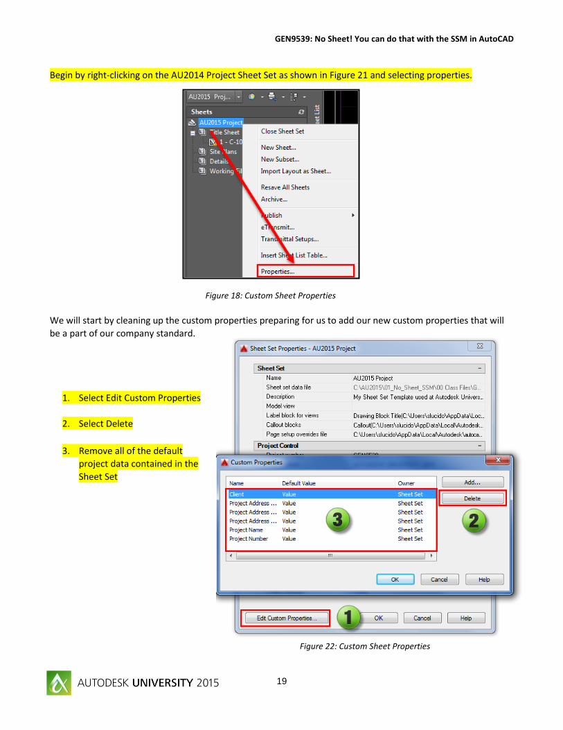
Begin by right-clicking on the AU2014 Project Sheet Set as shown in Figure 21 and selecting properties.
We will start by cleaning up the custom properties preparing for us to add our new custom properties that will
be a part of our company standard.
1. Select Edit Custom Properties
2. Select Delete
3. Remove all of the default
project data contained in the
Sheet Set
Figure 18: Custom Sheet Properties
Figure 22: Custom Sheet Properties
Page 20
GEN9539: No Sheet! You can do that with the SSM in AutoCAD
20
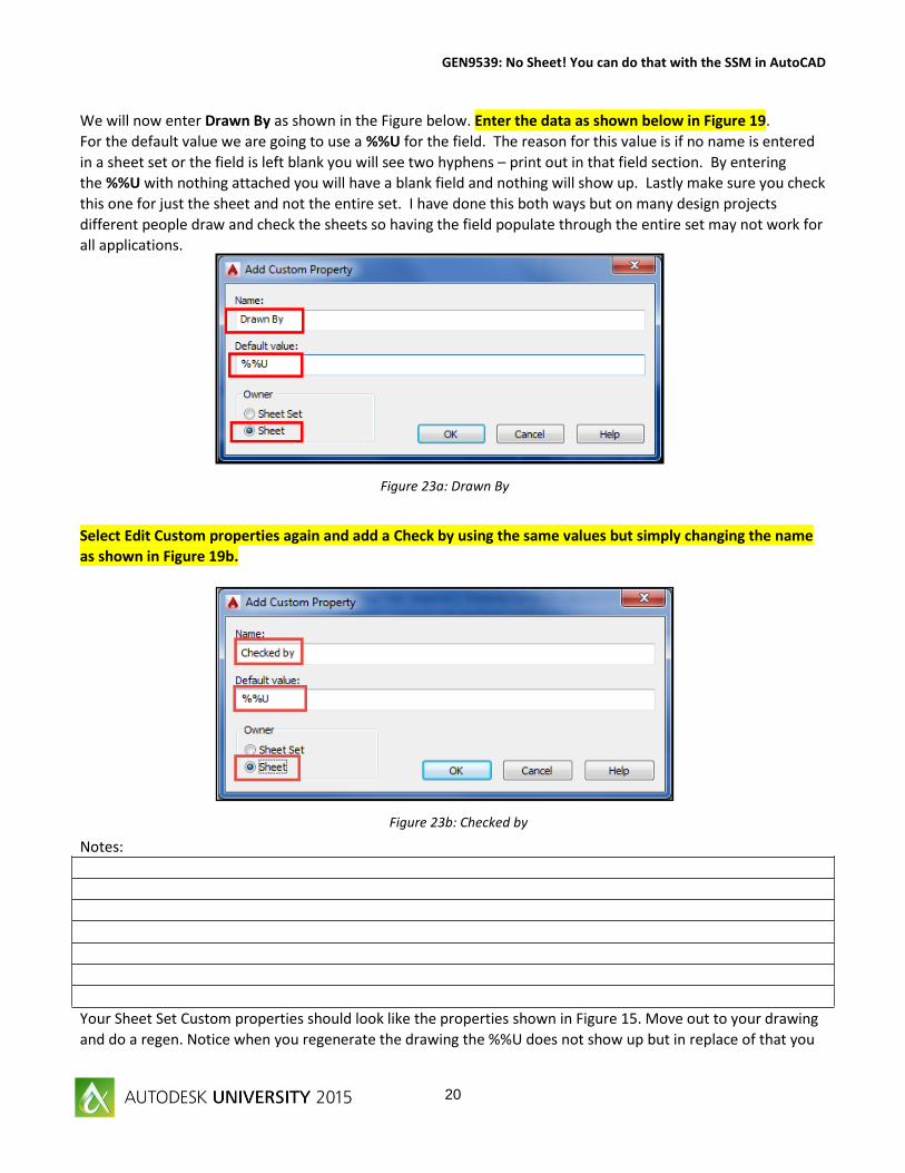
We will now enter Drawn By as shown in the Figure below. Enter the data as shown below in Figure 19.
For the default value we are going to use a %%U for the field. The reason for this value is if no name is entered
in a sheet set or the field is left blank you will see two hyphens – print out in that field section. By entering
the %%U with nothing attached you will have a blank field and nothing will show up. Lastly make sure you check
this one for just the sheet and not the entire set. I have done this both ways but on many design projects
different people draw and check the sheets so having the field populate through the entire set may not work for
all applications.
Select Edit Custom properties again and add a Check by using the same values but simply changing the name
as shown in Figure 19b.
Notes:
Your Sheet Set Custom properties should look like the properties shown in Figure 15. Move out to your drawing
and do a regen. Notice when you regenerate the drawing the %%U does not show up but in replace of that you
Figure 23a: Drawn By
Figure 23b: Checked by
Page 21
GEN9539: No Sheet! You can do that with the SSM in AutoCAD
21
get a period. This will ensure that a blank field will not print when you run your print.
Save your drawing and Sheet Set.
We are next going to edit some sheet set custom
properties. Let’s take a look at our image again as
shown in Figure 21. We already have items 4 and 5
added as sheet custom properties. We will NOT
enter Numbers 6 (Sheet number), 8 (Sheet Title),
and 9 (Project Milestone, i.e. date) are already
controlled by the overall sheet set properties and
will not have to be entered as custom. We are
going to now enter items 7 and 10 into our custom
template.
Right click your sheet set template and select edit custom properties and let’s add numbers 6 and 9 as shown in
Figure 21, the total number of sheets and the drawing scale. Number 6 is the total number of sheets within our
drawing set. Notice how I entered a 01 in front of the Sheet Title. One flaw I have noticed is you cannot move
the custom properties around once they are in the set. They are controlled alphabetically or numerically.
Figure 24: Sheet Custom Properties
Figure 25: Sheet Set Custom Fields
Page 22
GEN9539: No Sheet! You can do that with the SSM in AutoCAD
22
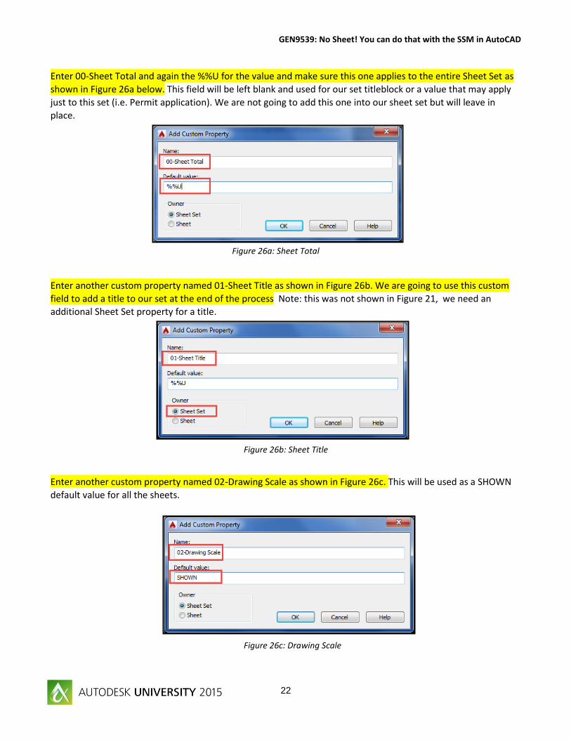
Enter 00-Sheet Total and again the %%U for the value and make sure this one applies to the entire Sheet Set as
shown in Figure 26a below. This field will be left blank and used for our set titleblock or a value that may apply
just to this set (i.e. Permit application). We are not going to add this one into our sheet set but will leave in
place.
Enter another custom property named 01-Sheet Title as shown in Figure 26b. We are going to use this custom
field to add a title to our set at the end of the process Note: this was not shown in Figure 21, we need an
additional Sheet Set property for a title.
Enter another custom property named 02-Drawing Scale as shown in Figure 26c. This will be used as a SHOWN
default value for all the sheets.
Figure 26c: Drawing Scale
Figure 26b: Sheet Title
Figure 26a: Sheet Total
Page 23
GEN9539: No Sheet! You can do that with the SSM in AutoCAD
23
Excellent, we have now completed steps 6 and 9 on our Figure 25 image. Next up, let’s add those revisions
which are numbers 11, 12 and 13 in Figure 27.Follow the same rules as previously. We are now going to apply to
the entire sheet set. Keep in mind there are projects that go through different phases where (as with the drawn
by and checked by) you may need to add a sheet custom property. For this example we are simply going to add
these to the entire sheet set.
Right click on the AU2015 project and enter custom properties again.
Next enter the data one at a time as shown in in Figure 28 following the steps shown in the green circles with
numbers 1, 2, and 3. Enter Name, Default value and make sure the Owner is the Sheet Set and not the Sheet.
Figure 28: Revision Properties
Figure 27: Revision field data
Page 24
GEN9539: No Sheet! You can do that with the SSM in AutoCAD
24
We have now completed entering custom properties. Keep in mind you can add many more. Revisions are a
perfect example of how you can have up to 10 revision lines in title blocks. Let’s hope you all don’t have any
more than that number on your designs. Also, when completing the revision section take time up front whether
to enter this as a sheet custom property or a sheet set property. All depends on the project and your design.
When you are done hit OK to complete the custom properties for the sheet set. Right click on your sheet set
and your image should look like Figure 29 as shown below.
There are so many custom options that you can include within Sheet sets. We are creating a template that links
to a sheet set template file which can be duplicated on projects. What we need to realize is a template is a guide
and we need to modify that just as we are in this session to accomidate the needs of the project or the design
process. Continue on with the same draiwng and we now will populate our data within our title block to create
the template.
Figure 29: Sheet Set Properties
Page 25
GEN9539: No Sheet! You can do that with the SSM in AutoCAD
25
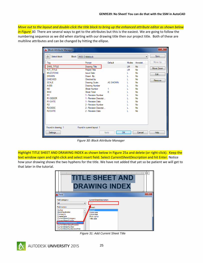
Move out to the layout and double-click the title block to bring up the enhanced attribute editor as shown below
in Figure 30. There are several ways to get to the attributes but this is the easiest. We are going to follow the
numbering sequence as we did when starting with our drawing title then our project title. Both of these are
multiline attributes and can be changed by hitting the ellipse.
Highlight TITLE SHEET AND DRAWING INDEX as shown below in Figure 25a and delete (or right-click). Keep the
text window open and right-click and select insert field. Select CurrentSheetDescription and hit Enter. Notice
how your drawing shows the two hyphens for the title. We have not added that yet so be patient we will get to
that later in the tutorial.
Figure 30: Block Attribute Manager
Figure 31: Add Current Sheet Title
Page 26
GEN9539: No Sheet! You can do that with the SSM in AutoCAD
26
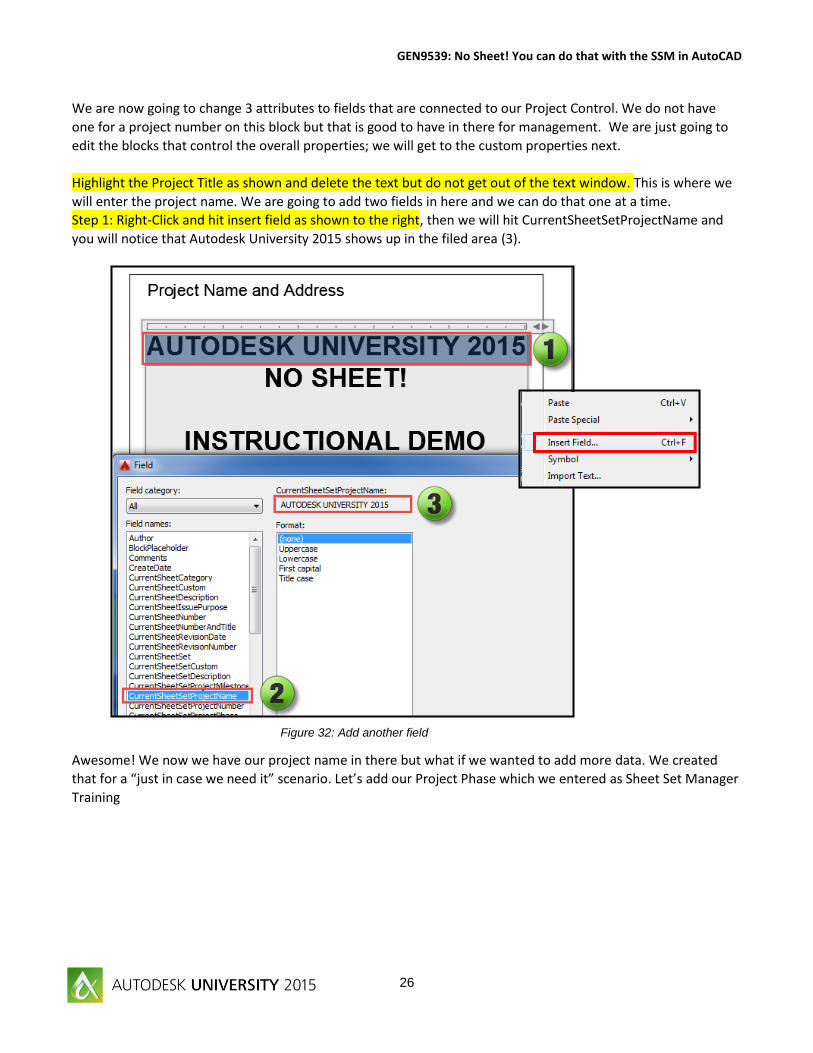
We are now going to change 3 attributes to fields that are connected to our Project Control. We do not have
one for a project number on this block but that is good to have in there for management. We are just going to
edit the blocks that control the overall properties; we will get to the custom properties next.
Highlight the Project Title as shown and delete the text but do not get out of the text window. This is where we
will enter the project name. We are going to add two fields in here and we can do that one at a time.
Step 1: Right-Click and hit insert field as shown to the right, then we will hit CurrentSheetSetProjectName and
you will notice that Autodesk University 2015 shows up in the filed area (3).
Awesome! We now we have our project name in there but what if we wanted to add more data. We created
that for a “just in case we need it” scenario. Let’s add our Project Phase which we entered as Sheet Set Manager
Training
Figure 32: Add another field
Page 27
GEN9539: No Sheet! You can do that with the SSM in AutoCAD
27
ouble click again to bring up the text editor as shown. We are going to use the multi-line functionality to add
another line which is controlled by our Sheet Set.
Move your cursor to right under the field you added and right-click and hit Insert Field again as shown in
Figure 26.
Enter the project phase as shown and hit enter. Notice how our Sheet Set Manager project name was added
below are title block into the section as shown.
Figure 33: CurrentSheetSetProjectPhase
Figure 34: CurrentSheetSetProjectPhase
Page 28
GEN9539: No Sheet! You can do that with the SSM in AutoCAD
28
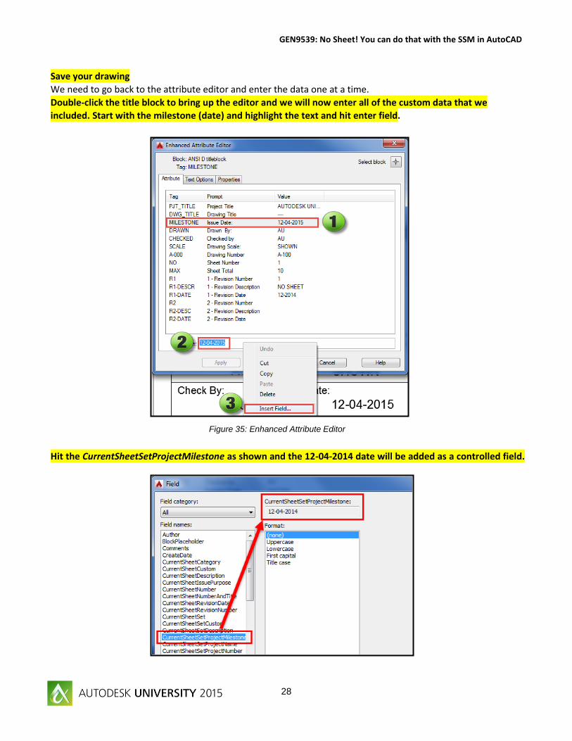
Save your drawing
We need to go back to the attribute editor and enter the data one at a time.
Double-click the title block to bring up the editor and we will now enter all of the custom data that we
included. Start with the milestone (date) and highlight the text and hit enter field.
Hit the CurrentSheetSetProjectMilestone as shown and the 12-04-2014 date will be added as a controlled field.
Figure 35: Enhanced Attribute Editor
Page 29
GEN9539: No Sheet! You can do that with the SSM in AutoCAD
29
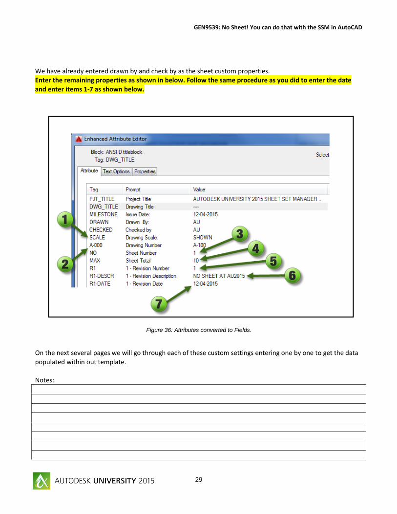
We have already entered drawn by and check by as the sheet custom properties.
Enter the remaining properties as shown in below. Follow the same procedure as you did to enter the date
and enter items 1-7 as shown below.
On the next several pages we will go through each of these custom settings entering one by one to get the data
populated within out template.
Notes:
Figure 36: Attributes converted to Fields.
Page 30
GEN9539: No Sheet! You can do that with the SSM in AutoCAD
30
1. SCALE:
CurrentSheetCustom
02-Drawing Scale
2. C-000 CurrentSheetTitle
Page 31
GEN9539: No Sheet! You can do that with the SSM in AutoCAD
31
3. NO CurrentSheetNumber
4. MAX CurrentSheetSetCustom
00-Sheet Total
Page 32
GEN9539: No Sheet! You can do that with the SSM in AutoCAD
32
5. R1 CurrentSheetSetCustom
03a-Rev1_No
6. R1-DESCR CurrentSheetSetCustom
03b-Rev1_Desc
Page 33
GEN9539: No Sheet! You can do that with the SSM in AutoCAD
33
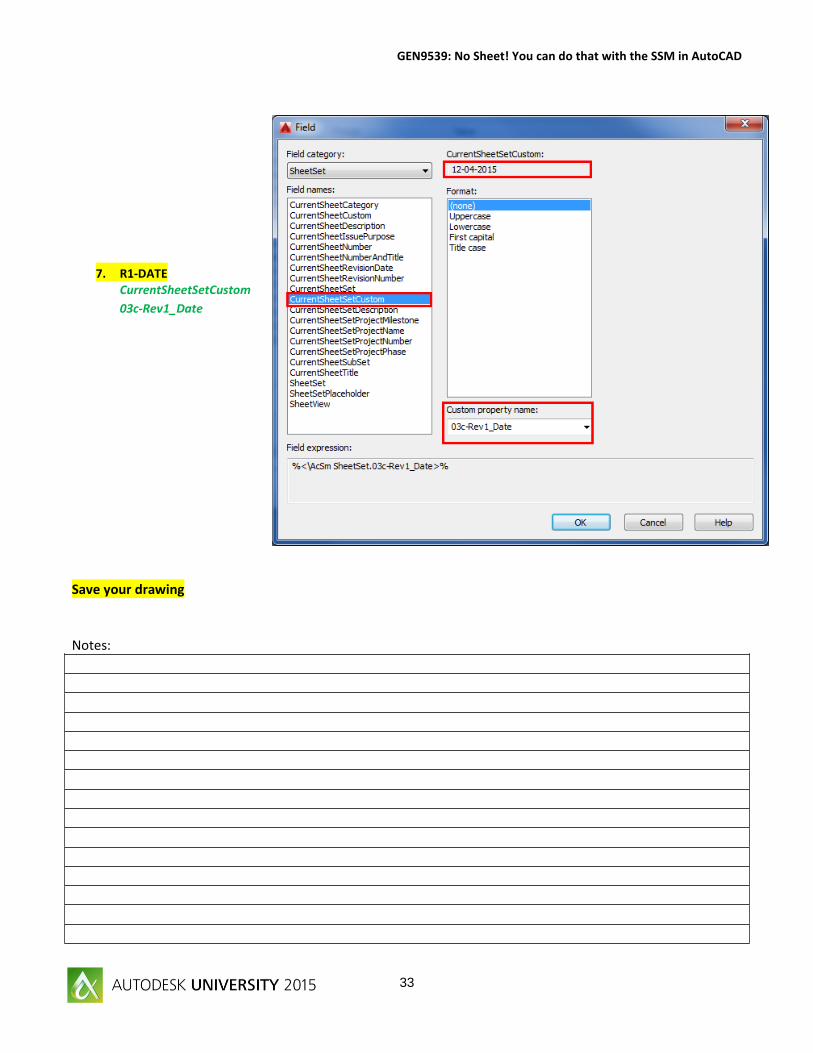
7. R1-DATE CurrentSheetSetCustom
03c-Rev1_Date
Save your drawing
Notes:
Page 34
GEN9539: No Sheet! You can do that with the SSM in AutoCAD
34
Our sheet set should look like Figure X as shown below. We now need to separate the drawing from the sheet
set and save the Sheet Set Template (.dst) file and our title block template (.dwt) files to secure locations where
we can use on our future projects.
Right click on your 1-C-100 Sheet and select Remove Sheet as shown in Figure 37. Don’t worry this does not
delete your drawing or remove all of the hard work already completed. We are just going to separate the couple
to only bring them back together on a future project.
Figure 37: Separate the template files
Page 35
GEN9539: No Sheet! You can do that with the SSM in AutoCAD
35
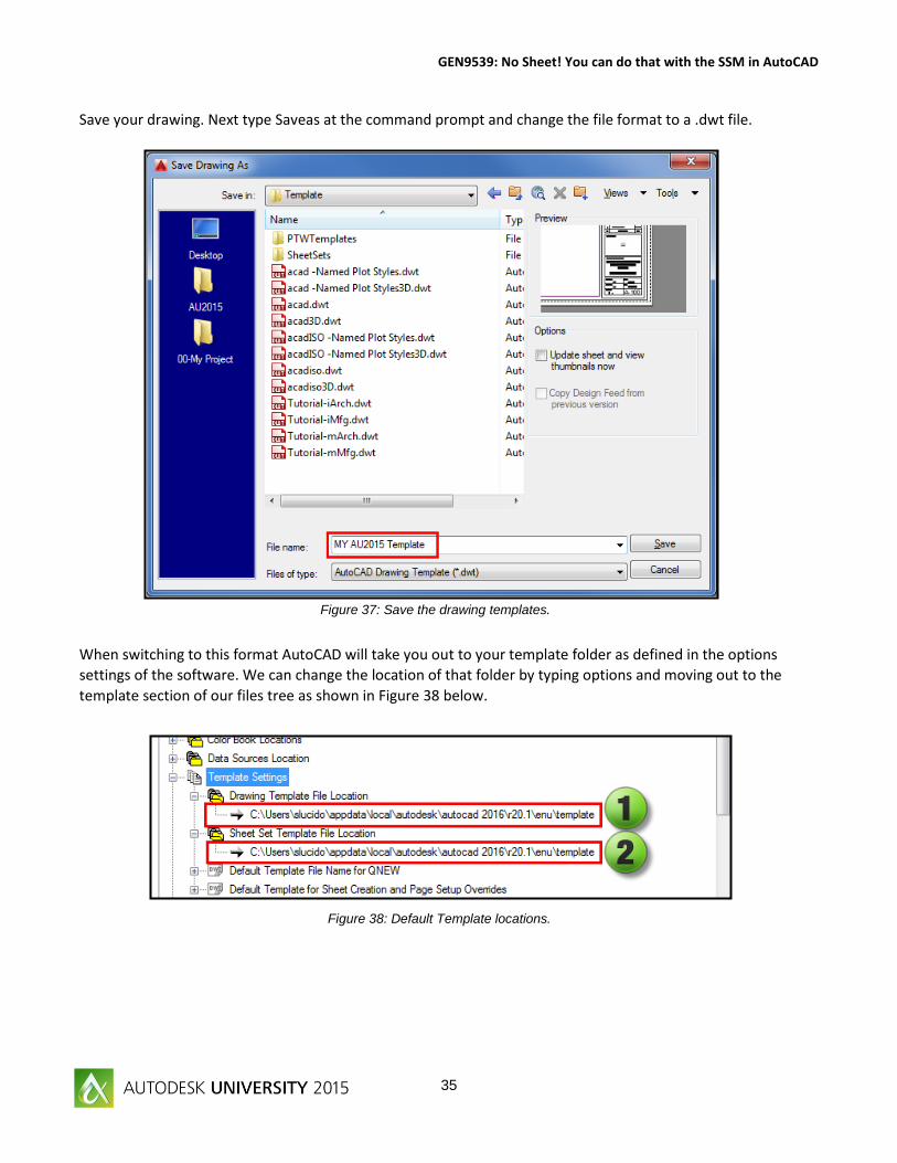
Save your drawing. Next type Saveas at the command prompt and change the file format to a .dwt file.
When switching to this format AutoCAD will take you out to your template folder as defined in the options
settings of the software. We can change the location of that folder by typing options and moving out to the
template section of our files tree as shown in Figure 38 below.
Figure 37: Save the drawing templates.
Figure 38: Default Template locations.
Page 36
GEN9539: No Sheet! You can do that with the SSM in AutoCAD
36
You will be prompted with the Template Options dialog box as shown in Figure 39. Please give the file a
description so other users can benefit from the new tools you have created. You can also set the New Layer
Notification within this window as well.
At this point you are thinking what do I do with the Sheet Set template file? I already have saved that to a
project folder. Yes we did that to keep organized while we were developing our data. You are simply going to
copy and paste that file to your Sheet Set template folder.
Figure 39: Save the Template
Figure 40: Copy the .dst file to the template folder
Page 37
GEN9539: No Sheet! You can do that with the SSM in AutoCAD
37
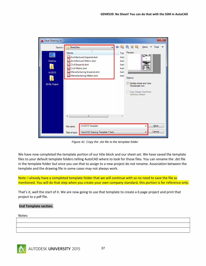
We have now completed the template portion of our title block and our sheet set. We have saved the template
files to your default template folders telling AutoCAD where to look for those files. You can rename the .dst file
in the template folder but once you use that to assign to a new project do not rename. Association between the
template and the drawing file in some cases may not always work.
Note: I already have a completed template folder that we will continue with so no need to save the file as
mentioned. You will do that step when you create your own company standard, this portion is for reference only.
That’s it, well the start of it. We are now going to use that template to create a 6 page project and print that
project to a pdf file.
End Template section.
Notes:
Figure 41: Copy the .dst file to the template folder
Page 38
GEN9539: No Sheet! You can do that with the SSM in AutoCAD
38
Figure 1: Create Sheet Set - Begin
My Sheet Set Project
Within the first section of our tutorial we created a Sheet Set Template and a Drawing Template to be used in
conjunction with each other to start a new project. It is time to use our templates to create our New Project.
For this section we will begin with task numbers and the images will be renamed starting at 1. Highlighted
sections indicate that you are to perform a task in AutoCAD.
1. Start a new drawing in AutoCAD.
2. Select the Application Menu and Choose New Sheet Set.
3. Select Example Sheet Set and hit Next >
Page 39
GEN9539: No Sheet! You can do that with the SSM in AutoCAD
39
Figure 2: Sheet Set Example
Figure 3: Select the new Template
4. Select the AU2015 Project Sheet Set as our example.
5. If you choose to use a sheet set that is from another project simply select the Browse to another sheet
set as an example and browse out to where the project and or sheet set is located, select the sheet set
as shown.
Page 40
GEN9539: No Sheet! You can do that with the SSM in AutoCAD
40
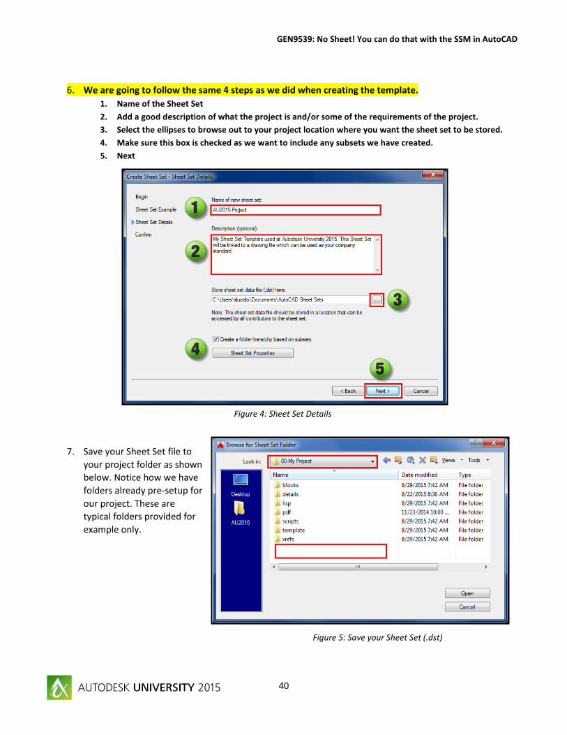
Figure 4: Sheet Set Details
Figure 5: Save your Sheet Set (.dst)
6. We are going to follow the same 4 steps as we did when creating the template.
1. Name of the Sheet Set
2. Add a good description of what the project is and/or some of the requirements of the project.
3. Select the ellipses to browse out to your project location where you want the sheet set to be stored.
4. Make sure this box is checked as we want to include any subsets we have created.
5. Next
7. Save your Sheet Set file to
your project folder as shown
below. Notice how we have
folders already pre-setup for
our project. These are
typical folders provided for
example only.
Page 41
GEN9539: No Sheet! You can do that with the SSM in AutoCAD
41
Figure 6: Sheet Set Project
Figure 7: Start a new drawing
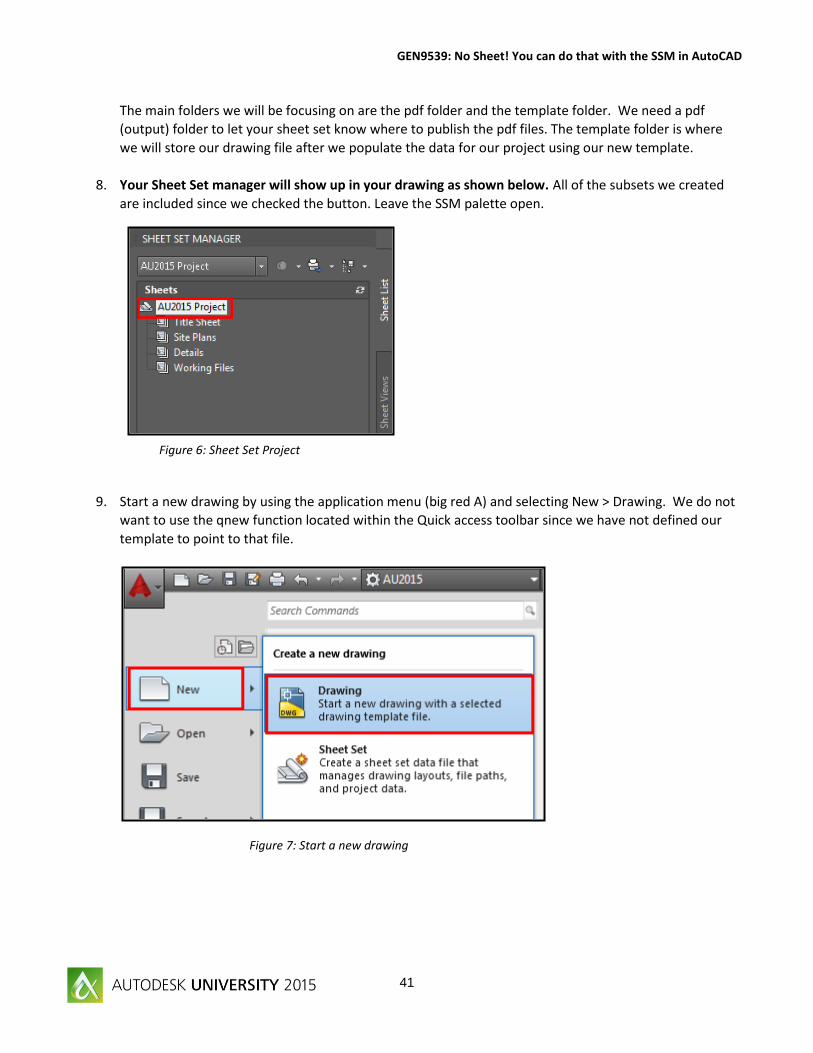
The main folders we will be focusing on are the pdf folder and the template folder. We need a pdf
(output) folder to let your sheet set know where to publish the pdf files. The template folder is where
we will store our drawing file after we populate the data for our project using our new template.
8. Your Sheet Set manager will show up in your drawing as shown below. All of the subsets we created
are included since we checked the button. Leave the SSM palette open.
9. Start a new drawing by using the application menu (big red A) and selecting New > Drawing. We do not
want to use the qnew function located within the Quick access toolbar since we have not defined our
template to point to that file.
Page 42
GEN9539: No Sheet! You can do that with the SSM in AutoCAD
42
Figure 8: Select the template
Figure 9: Save the drawing file
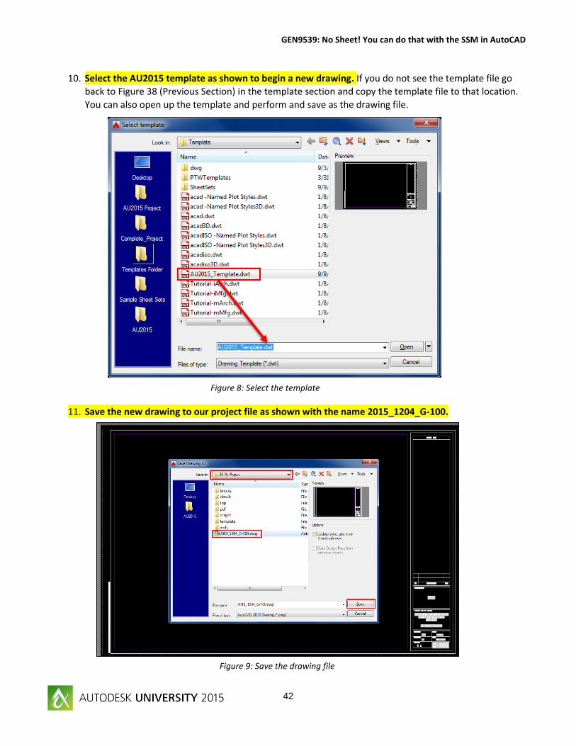
10. Select the AU2015 template as shown to begin a new drawing. If you do not see the template file go
back to Figure 38 (Previous Section) in the template section and copy the template file to that location.
You can also open up the template and perform and save as the drawing file.
11. Save the new drawing to our project file as shown with the name 2015_1204_G-100.
Page 43
GEN9539: No Sheet! You can do that with the SSM in AutoCAD
43
Figure 10: Save the drawing file
Figure 11: Setup Project Files
12. Save the drawing to the project folder along with your Sheet Set as shown below. You now have two
files within our root folder as shown; our sheet set template and the first drawing in our design.
13. Save the drawing again as 2015_1204_C-100 and 2015_1204_C-200. The 100 series will be used for
our site plans and the 200 series we are going to use for our details.
Page 44
GEN9539: No Sheet! You can do that with the SSM in AutoCAD
44
Figure 12: Copy the Layout
Figure 13: Import Layout as Sheet
14. Open up the 2015_1204_C-100 drawing and create tabs named C-101 and C-102. Don’t worry about
renaming the layouts we will let the SSM take care of that.
15. We only have one detail sheet for this project so we are going to leave Sheet C-200 as is.
16. Right click Title Sheet subset and import G-100 as shown below. This is the drawing we will use to link
the page setup overrides as well as create new sheet section.
17. Your sheet set
Page 45
GEN9539: No Sheet! You can do that with the SSM in AutoCAD
45
Figure 14: Sheet Imported
Figure 15: Check for page setups
Figure 16: Project Control Settings
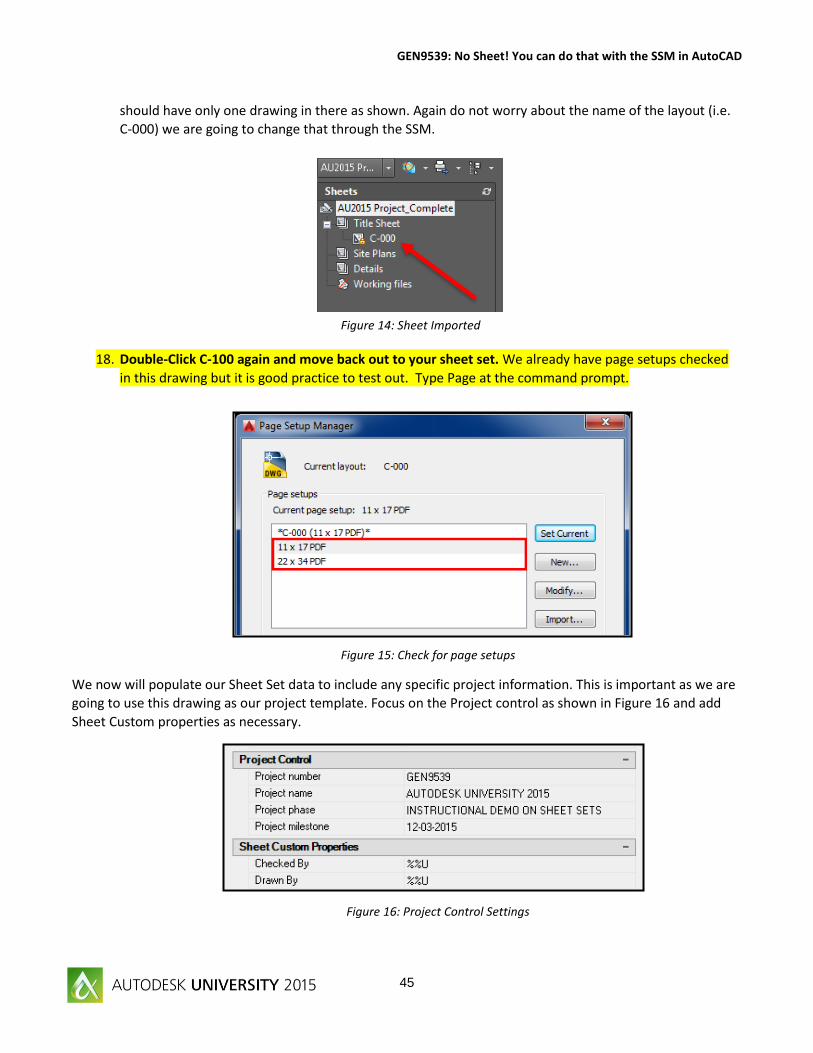
should have only one drawing in there as shown. Again do not worry about the name of the layout (i.e.
C-000) we are going to change that through the SSM.
18. Double-Click C-100 again and move back out to your sheet set. We already have page setups checked
in this drawing but it is good practice to test out. Type Page at the command prompt.
We now will populate our Sheet Set data to include any specific project information. This is important as we are
going to use this drawing as our project template. Focus on the Project control as shown in Figure 16 and add
Sheet Custom properties as necessary.
Page 46
GEN9539: No Sheet! You can do that with the SSM in AutoCAD
46
Figure 17: Save the Template
If additional page setups and custom settings are needed complete the task now prior to saving your specific
project template file.
19. Save your drawing.
20. Next, save the drawing file as a .dwg file then as a template file into your template folder of your
project. We are saving as a drawing first then a template just for backup and in the event we need to
change the file we will start with the drawing.
Close the drawing file, and then close the template file. We will refer back to each of these in a later section.
Notes:
Page 47
GEN9539: No Sheet! You can do that with the SSM in AutoCAD
47
Figure 19: Import the Detail Sheet
Figure 18: Save the Template
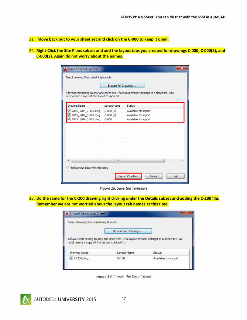
21. Move back out to your sheet set and click on the C-000 to keep it open.
22. Right-Click the Site Plans subset and add the layout tabs you created for drawings C-000, C-000(2), and
C-000(3). Again do not worry about the names.
23. Do the same for the C-200 drawing right clicking under the Details subset and adding the C-200 file.
Remember we are not worried about the layout tab names at this time.
Page 48
GEN9539: No Sheet! You can do that with the SSM in AutoCAD
48
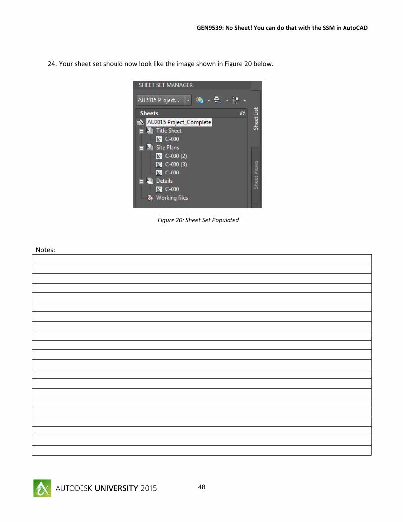
Figure 20: Sheet Set Populated
24. Your sheet set should now look like the image shown in Figure 20 below.
Notes:
Page 49
GEN9539: No Sheet! You can do that with the SSM in AutoCAD
49
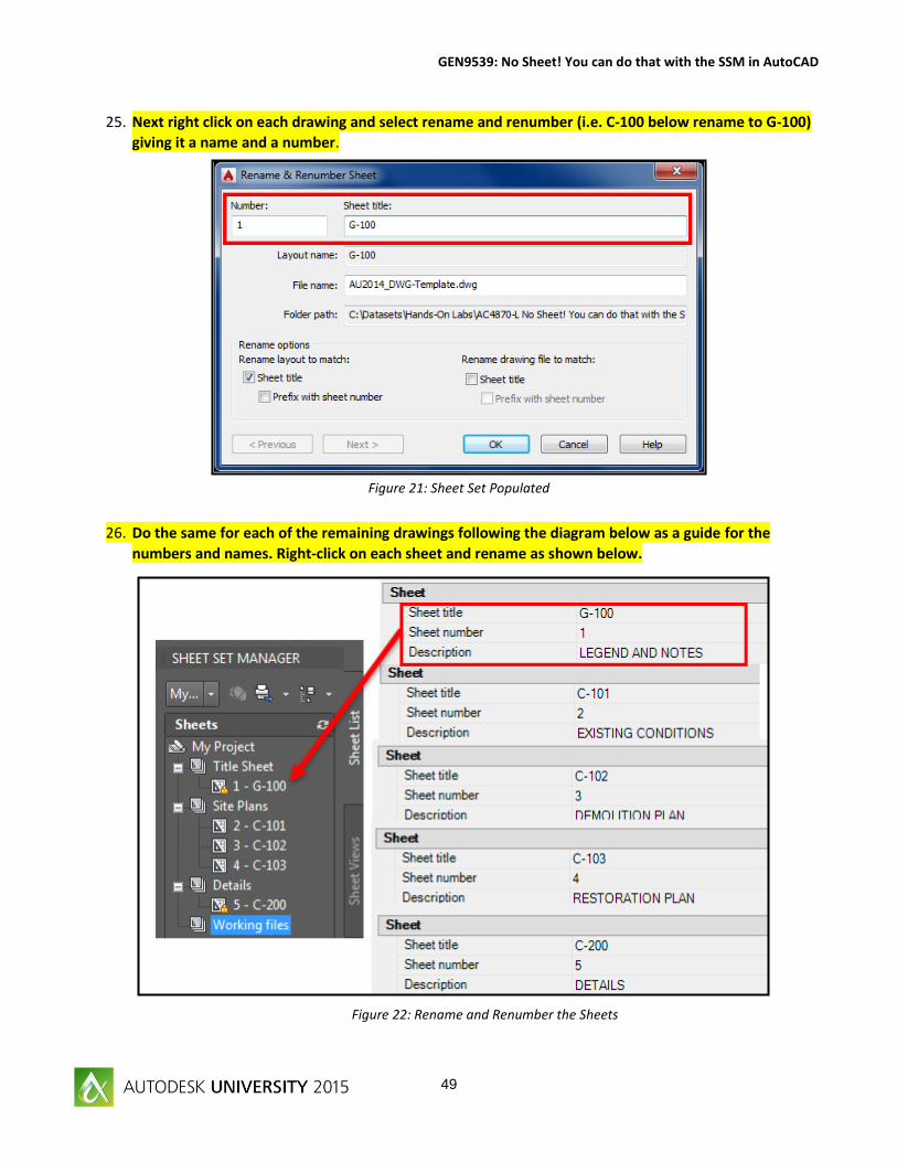
Figure 22: Rename and Renumber the Sheets
Figure 21: Sheet Set Populated
25. Next right click on each drawing and select rename and renumber (i.e. C-100 below rename to G-100)
giving it a name and a number.
26. Do the same for each of the remaining drawings following the diagram below as a guide for the
numbers and names. Right-click on each sheet and rename as shown below.
Page 50
GEN9539: No Sheet! You can do that with the SSM in AutoCAD
50
Figure 24: Sheet Set Complete
Figure 24: Sheet Set Title
27. Your final sheet set should look like the image shown in Figure 39. We have now setup our project.
28. Right-click on your sheet and enter the Sheet Properties. Enter the titles as shown in the guide under
Figure 24. Yes, you could have entered this data all at once using properties I wanted to provide an
example of both ways to enter the data.
29. Right-click on your sheet set and save all Sheets in the set.
Notes:
Page 51
GEN9539: No Sheet! You can do that with the SSM in AutoCAD
51
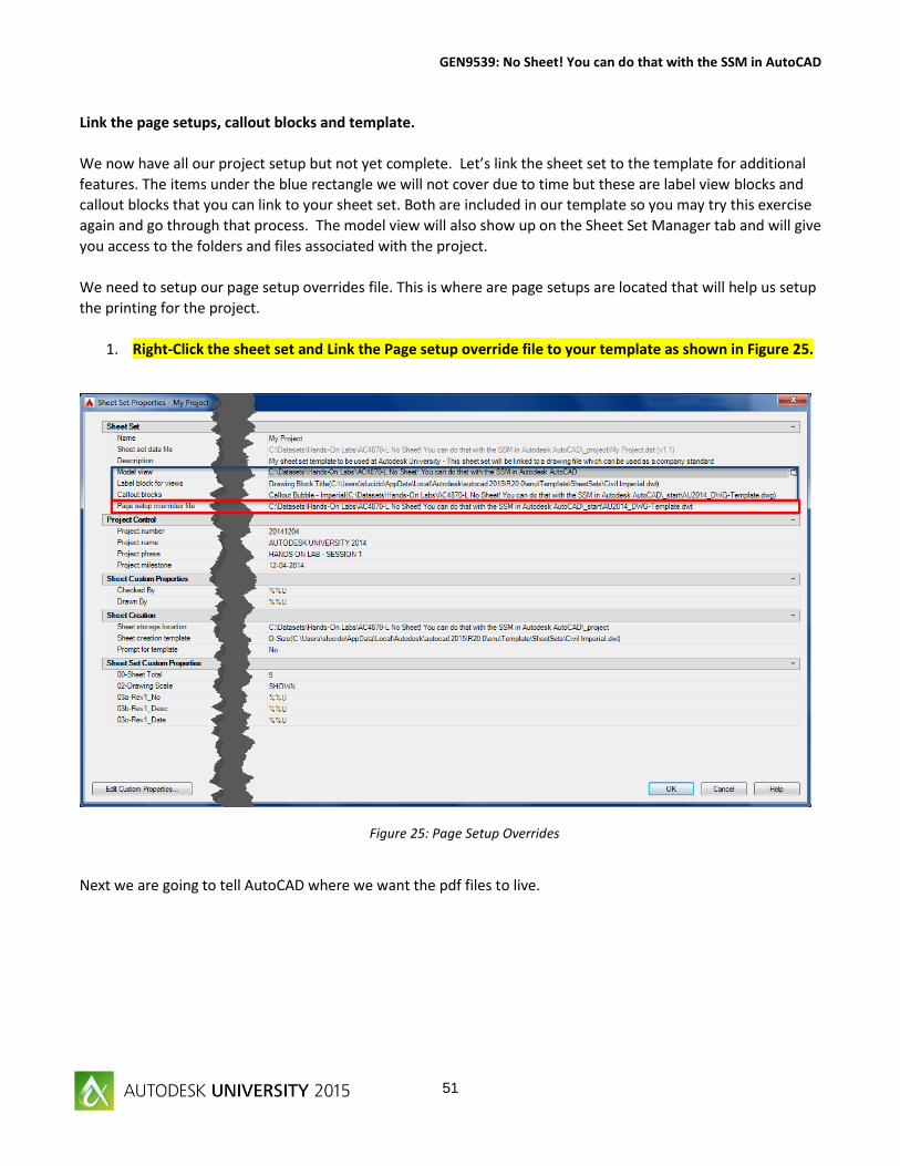
Figure 25: Page Setup Overrides
Link the page setups, callout blocks and template.
We now have all our project setup but not yet complete. Let’s link the sheet set to the template for additional
features. The items under the blue rectangle we will not cover due to time but these are label view blocks and
callout blocks that you can link to your sheet set. Both are included in our template so you may try this exercise
again and go through that process. The model view will also show up on the Sheet Set Manager tab and will give
you access to the folders and files associated with the project.
We need to setup our page setup overrides file. This is where are page setups are located that will help us setup
the printing for the project.
1. Right-Click the sheet set and Link the Page setup override file to your template as shown in Figure 25.
Next we are going to tell AutoCAD where we want the pdf files to live.
Page 52
GEN9539: No Sheet! You can do that with the SSM in AutoCAD
52
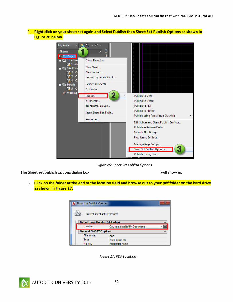
Figure 26: Sheet Set Publish Options
Figure 27: PDF Location
2. Right click on your sheet set again and Select Publish then Sheet Set Publish Options as shown in
Figure 26 below.
The Sheet set publish options dialog box will show up.
3. Click on the folder at the end of the location field and browse out to your pdf folder on the hard drive
as shown in Figure 27.
Page 53
GEN9539: No Sheet! You can do that with the SSM in AutoCAD
53
Figure 29: Select the Template
4. Navigate out to the project folder and select the pdf folder as shown to the right in Figure 42b. We will
now be able to publish the files to the pdf location.
Lastly, we need to link the Sheet creation template to our project specific template by right-clicking the sheet
set and clicking the Sheet creation template field as shown. In most cases you will start with a G-100 or C-100
and populate the data for the project then save to a template folder and use that moving forward.
5. Select the template you created in Figure 29 as the Sheet creation template.
Figure 28: The pdf folder
Page 54
GEN9539: No Sheet! You can do that with the SSM in AutoCAD
54
Figure 30: Insert the Table
Figure 31: Table Style
Sheet Index Table
We have named all of our drawings now we would like a sheet index placed on the cover page and linked to the
sheet set. Why do things twice, right? I have already placed a table within our template name Sheet Index. You
don’t have to do this but when working on future projects for your design you should create your table
according to you company standard. The generic table will get you what you need but some up front formatting
can help you with consistency and efficiency.
1. Move to sheet G-100 and right-click on your Sheet Set then Insert Sheet List Table as shown in
Figure 30.
2. Bring up the Sheet List Table dialog box as shown below in Figure 45. Change the Table style name
to Sheet Index as shown below. You can setup a table to your company standard.
Page 55
GEN9539: No Sheet! You can do that with the SSM in AutoCAD
55
Figure 33: Change Headings
Figure 32: Data Type
3. Move over to the right (Item 1) and add another element. You can add this to a template but I
wanted to show how you can add several different options within the table style. After you add
the element move to item 2 and pull down the window and select the Sheet Description Field.
4. Now change the headings on your sheet list table to what you want to present. Change the 4
items as shown below in Figure 46b.
Page 56
GEN9539: No Sheet! You can do that with the SSM in AutoCAD
56
Figure 34: Insert the Table
Figure 35: Sheet Set Title
5. All set, hit OK and insert your Sheet List table on your drawing heading as shown in Figure 46c.
6. Remember that 01-Sheet Title field? We are going to add that in now as our project title.
Insert the block sheet title at 0,0 on the title sheet and explode.
Take the words MY PROJECT on Sheet G-100 and change the filed to that Custom Data.
Page 57
GEN9539: No Sheet! You can do that with the SSM in AutoCAD
57
Figure 37: Download from Source
Figure 38: Update Table
Sheet Index Table Updates
During the design project there may be times you will need to add sheets, remove sheets, change names and
numbers. Once your table has been setup in the original drawing AutoCAD will handle that as a linked reference.
There are several ways to update this. Simply get out of AutoCAD and get back in and the table will update just
like an external reference.
1. The first way is to just download from source from the table cell contextual ribbon. The ribbon will
appear when you select your table.
2. The second is to touch the corner of your table and right-click to bring up the menu and you will see a
Sheet List Table section as shown below. Select the Update Sheet List Table and your table will be
updated.
Page 58
GEN9539: No Sheet! You can do that with the SSM in AutoCAD
58
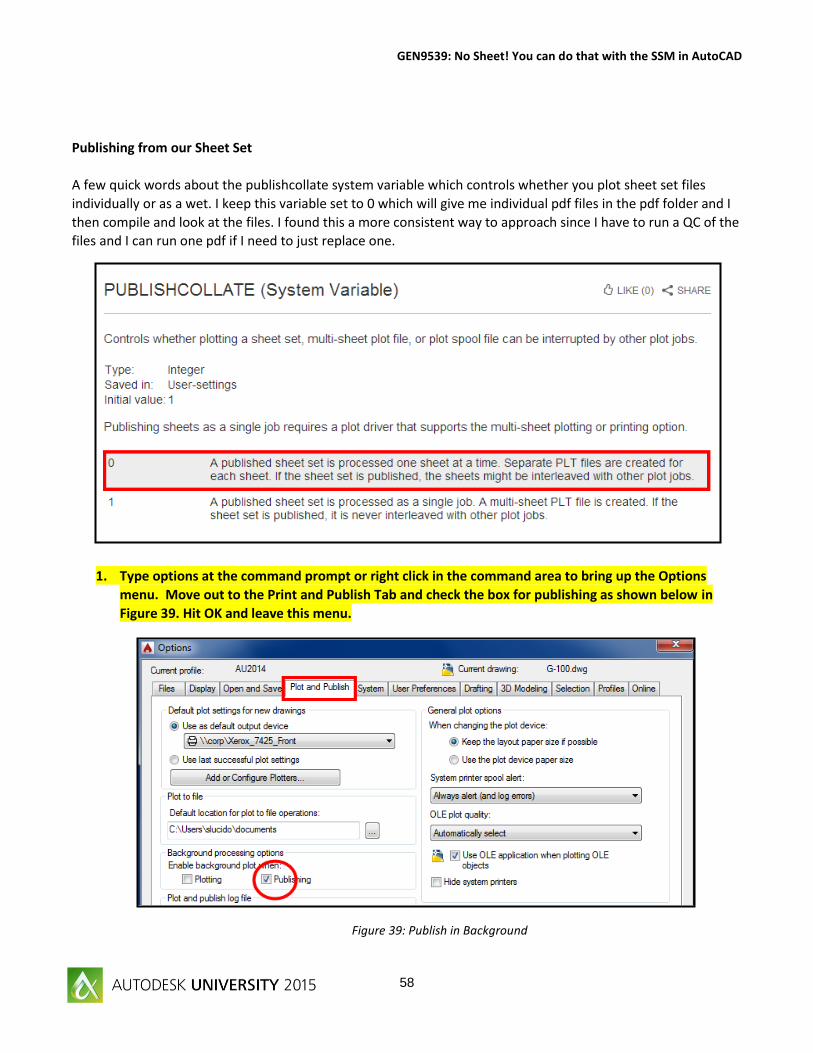
Figure 39: Publish in Background
Publishing from our Sheet Set
A few quick words about the publishcollate system variable which controls whether you plot sheet set files
individually or as a wet. I keep this variable set to 0 which will give me individual pdf files in the pdf folder and I
then compile and look at the files. I found this a more consistent way to approach since I have to run a QC of the
files and I can run one pdf if I need to just replace one.
1. Type options at the command prompt or right click in the command area to bring up the Options
menu. Move out to the Print and Publish Tab and check the box for publishing as shown below in
Figure 39. Hit OK and leave this menu.
Page 59
GEN9539: No Sheet! You can do that with the SSM in AutoCAD
59
Figure 40: Publish Options
Figure 41: Publish Location
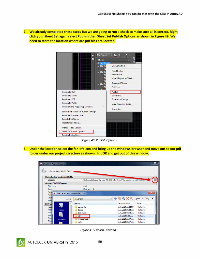
2. We already completed these steps but we are going to run a check to make sure all is correct. Right
click your Sheet Set again select Publish then Sheet Set Publish Options as shown in Figure 49. We
need to store the location where are pdf files are located.
3. Under the location select the far left icon and bring up the windows browser and move out to our pdf
folder under our project directory as shown. Hit OK and get out of this window.
Page 60
GEN9539: No Sheet! You can do that with the SSM in AutoCAD
60
Figure 42: Use the Override
Figure 43: Name your pdf file
Earlier we already setup our template file to contain page setups for our override file.
4. Right-click the Sheet set again and Select Publish – Publishing using Page Setup Override – 22 x 34 PDF.
5. Your publishcollate variable is set to
1 which means you will be asked for
a pdf file name. This will compile all
of your drawings in a pdf format. I
like to set this to 0 to have individual
files print as shown below. Notice
how when you print separately the
pdf files take on the drawing name
and number as setup in the Sheet
Set Manager.
Page 61
GEN9539: No Sheet! You can do that with the SSM in AutoCAD
61
Figure 45: Mission Accomplished
Figure 44: Your Project is Printing
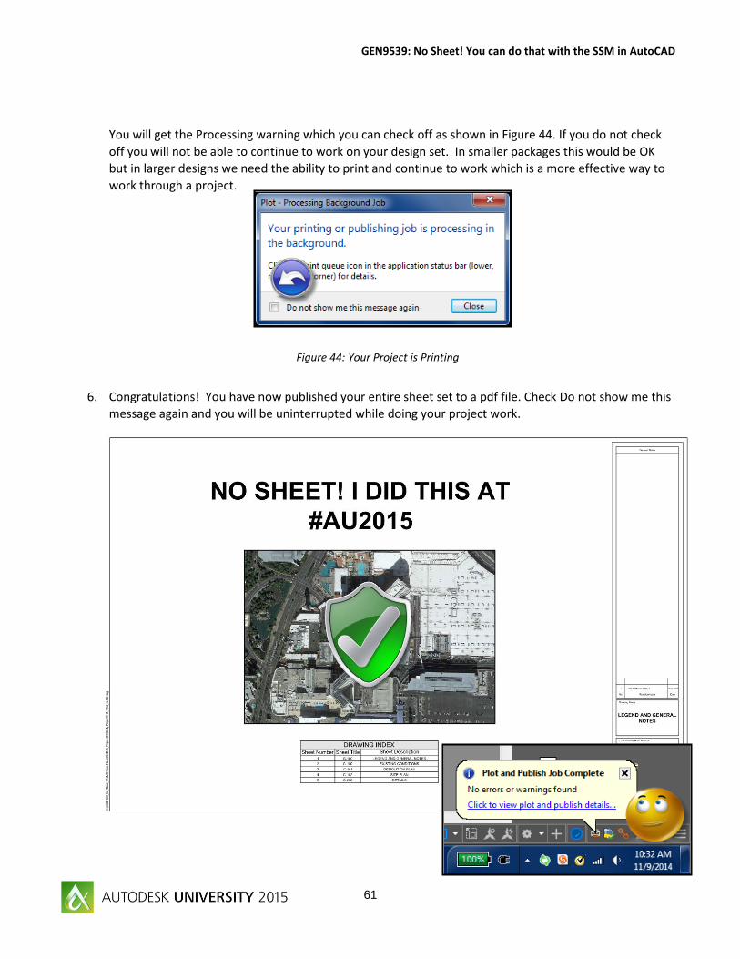
You will get the Processing warning which you can check off as shown in Figure 44. If you do not check
off you will not be able to continue to work on your design set. In smaller packages this would be OK
but in larger designs we need the ability to print and continue to work which is a more effective way to
work through a project.
6. Congratulations! You have now published your entire sheet set to a pdf file. Check Do not show me this
message again and you will be uninterrupted while doing your project work.
Page 62
GEN9539: No Sheet! You can do that with the SSM in AutoCAD
62
Conclusion
Autodesk first introduced the Sheet Set concept back with AutoCAD 2005. In my opinion, at first this did not go
over very well, a whole new way of looking at layouts in drawings and yes there were some bugs. We are now at
the 2015 version of AutoCAD and the SSM functionality is stable and greatly improved. Even if you just use the
SSM as an organizational tool you will be able to access files quickly and efficiently. The real power is behind the
properties of the SSM which allow you to share data and automate your data through the use of sheet sets. We
went through creating a template, linking the template (.dwt) to the Sheet Set (.dst) to create reusable content
on projects existing and new. We also review creating layout and model views, using etransmit and archive, as
well as creating the index sheet. Think about workflow and what you do every day at work. How about having
the ability to access files quickly without even opening the drawing? Removing a sheet and having the ability to
renumber through the SSM and not even opening drawings. Think about how many times you apply that task
during the design process, and then think about how many designs you work on in one year. Being efficient and
productive will only make you more valuable and provide profit to the company you work for.
Time is money and you have just learned how to save a little of both.
“Well I tell them there’s no problem, only solutions” John Lennon
Learn Connect and Explore at Autodesk University 2015!
Page 63
GEN9539: No Sheet! You can do that with the SSM in AutoCAD
63
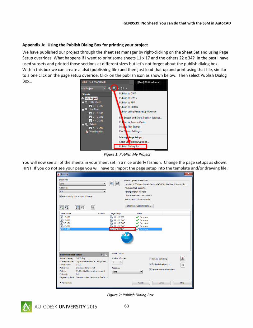
Appendix A: Using the Publish Dialog Box for printing your project
We have published our project through the sheet set manager by right-clicking on the Sheet Set and using Page
Setup overrides. What happens if I want to print some sheets 11 x 17 and the others 22 x 34? In the past I have
used subsets and printed those sections at different sizes but let’s not forget about the publish dialog box.
Within this box we can create a .dsd (publishing file) and then just load that up and print using that file, similar
to a one click on the page setup override. Click on the publish icon as shown below. Then select Publish Dialog
Box…
You will now see all of the sheets in your sheet set in a nice orderly fashion. Change the page setups as shown.
HINT: If you do not see your page you will have to import the page setup into the template and/or drawing file.
Figure 1: Publish My Project
Figure 2: Publish Dialog Box
Page 64
GEN9539: No Sheet! You can do that with the SSM in AutoCAD
64
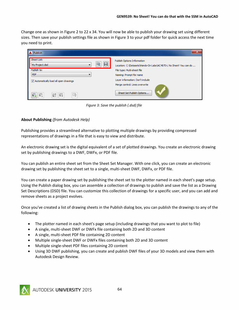
Change one as shown in Figure 2 to 22 x 34. You will now be able to publish your drawing set using different
sizes. Then save your publish settings file as shown in Figure 3 to your pdf folder for quick access the next time
you need to print.
About Publishing (from Autodesk Help)
Publishing provides a streamlined alternative to plotting multiple drawings by providing compressed
representations of drawings in a file that is easy to view and distribute.
An electronic drawing set is the digital equivalent of a set of plotted drawings. You create an electronic drawing
set by publishing drawings to a DWF, DWFx, or PDF file.
You can publish an entire sheet set from the Sheet Set Manager. With one click, you can create an electronic
drawing set by publishing the sheet set to a single, multi-sheet DWF, DWFx, or PDF file.
You can create a paper drawing set by publishing the sheet set to the plotter named in each sheet's page setup.
Using the Publish dialog box, you can assemble a collection of drawings to publish and save the list as a Drawing
Set Descriptions (DSD) file. You can customize this collection of drawings for a specific user, and you can add and
remove sheets as a project evolves.
Once you've created a list of drawing sheets in the Publish dialog box, you can publish the drawings to any of the
following:
The plotter named in each sheet's page setup (including drawings that you want to plot to file)
A single, multi-sheet DWF or DWFx file containing both 2D and 3D content
A single, multi-sheet PDF file containing 2D content
Multiple single-sheet DWF or DWFx files containing both 2D and 3D content
Multiple single-sheet PDF files containing 2D content
Using 3D DWF publishing, you can create and publish DWF files of your 3D models and view them with
Autodesk Design Review.
Figure 3: Save the publish (.dsd) file
Page 65
GEN9539: No Sheet! You can do that with the SSM in AutoCAD
65
Appendix B: Placing Sheet Views from the Model Tab using the SSM
The sheet set manager has includes a model tab where you can place sheet views into your drawing. The first thing you
need to do is create the views within your xref or basemap. Open up X-basemap.dwg in the xref folder. Using the view
command create two views; a North Side and South Side of the site as shown in Figure 1; save your drawing when complete.
Note: your view will be imported using the current annotation scale but you can change that with a simple right click when
you place on the sheet.
Now that we have our views created move back out to our project and the SSM palette.
1. Set the model location view tab in the sheet set manager to current.
2. Add a new location which will be the path as shown (just like a folder in Windows Explorer).
3. Pull out the xref tab and notice your views.
Figure 1: Create the views in your basemap
Figure 2: Model Views in SSM
Page 66
GEN9539: No Sheet! You can do that with the SSM in AutoCAD
66
Move back out to your project and create a new sheet. Make sure there are no viewports in the sheet.
Move to the model tab and right click on North Side and select Place on Sheet as shown in Figure 3.
You will see you view as shown by the check mark in Figure 4. Right click when you see your view to change the scale of the
view to your desired scale. Place the view on the sheet, that is it! The view will be placed on your sheet at the correct scale
as an external reference.
Notice how when we placed our drawing in AutoCAD the Callout label has fields added to it as show in Figure 5 with the
correct name and scale.
Figure 4: Right-click and input the scale
Figure 3: Place on Sheet
Figure 5: Drawing Title Block
Page 67
GEN9539: No Sheet! You can do that with the SSM in AutoCAD
67
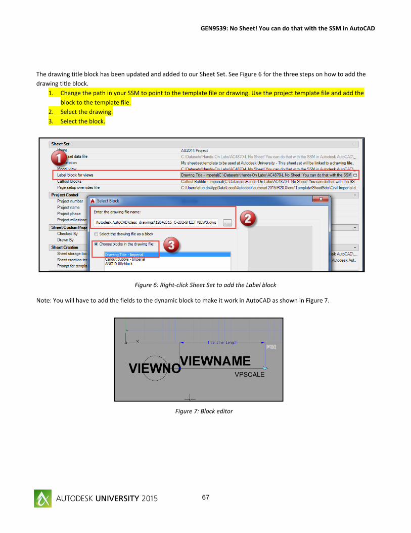
The drawing title block has been updated and added to our Sheet Set. See Figure 6 for the three steps on how to add the
drawing title block.
1. Change the path in your SSM to point to the template file or drawing. Use the project template file and add the
block to the template file.
2. Select the drawing.
3. Select the block.
Note: You will have to add the fields to the dynamic block to make it work in AutoCAD as shown in Figure 7.
Figure 6: Right-click Sheet Set to add the Label block
Figure 7: Block editor
Page 68
GEN9539: No Sheet! You can do that with the SSM in AutoCAD
68
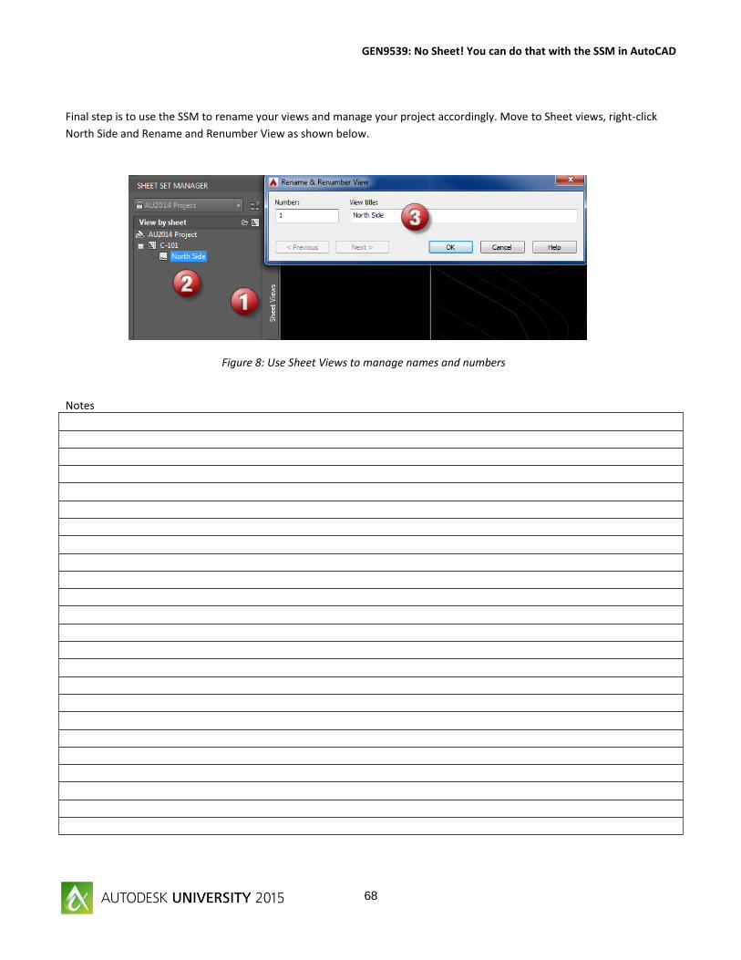
Final step is to use the SSM to rename your views and manage your project accordingly. Move to Sheet views, right-click
North Side and Rename and Renumber View as shown below.
Notes
Figure 8: Use Sheet Views to manage names and numbers
Page 69
GEN9539: No Sheet! You can do that with the SSM in AutoCAD
69
Appendix C: Archiving a Sheet Set
Archiving drawing sets during a design project becomes a necessary task, especially when we have those unexpected
changes and “lock ups” where we need to go back a version just to see what was completed. Create a folder named archive
in your project folder. Right click on your sheet set. Access the Archive command by right clicking your project and selecting
archive as shown in Figure 1.
In Figure 2 we show how AutoCAD will gather the information from the sheet set, including images, xrefs, fonts, and
templates.
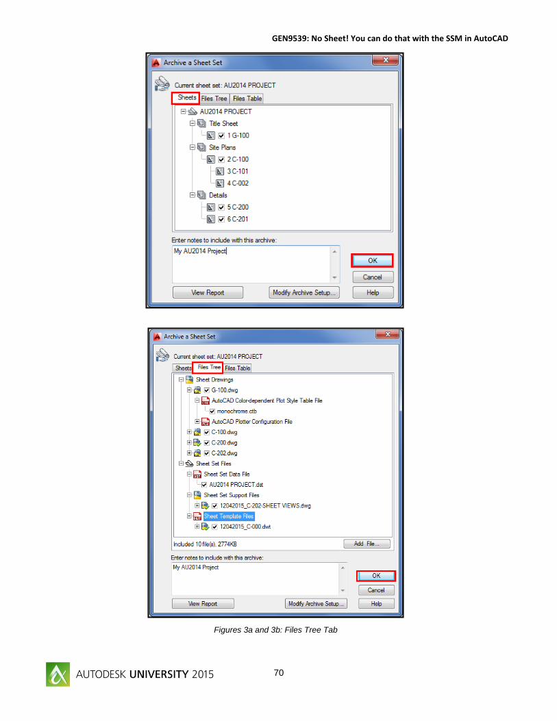
After AutoCAD has compiled all of the file locations you will see the Archive a Sheet Set dialog box. From this box you can
select and earlier version of AutoCAD for the File Format, the location of the archive file, and a notes section for you to
document the deliverable. The archive a sheet set dialog box has three separate tabs. The first tab shown in Figure 3a is
where you select the files that need to be included in your archive. At times when using a Sheet Set we may have some
sections (i.e. design or working folders) that would be included in the sheet set but not necessary to archive. The second tab
shown in Figure 3b is the files tree tab. This section is where you can uncheck items that you do not wish to archive (i.e. pe
stamps).
Figure 1: Archive the Sheet Set
Figure 2: Getting Archive Information
Page 70
GEN9539: No Sheet! You can do that with the SSM in AutoCAD
70
Figures 3a and 3b: Files Tree Tab
Page 71
GEN9539: No Sheet! You can do that with the SSM in AutoCAD
71
In the last tab is the files table. The actual files that are included when you archive in a table or list format as shown in
Figure 3c.
Name your set in the notes section with a date and select OK as shown in Figure 4. AutoCAD will now process all of your
files and archive into one package.
Figure 3c: Files Table Tab
Figure 4: Archive Package Creation
Page 72
GEN9539: No Sheet! You can do that with the SSM in AutoCAD
72
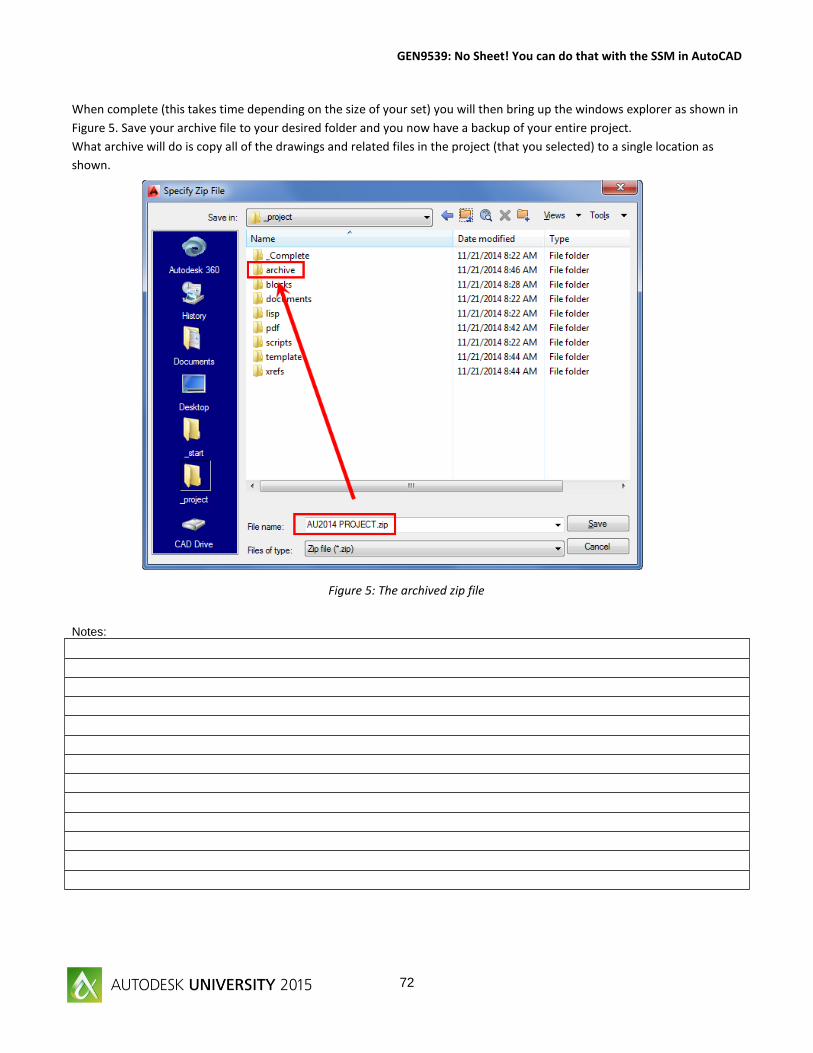
When complete (this takes time depending on the size of your set) you will then bring up the windows explorer as shown in
Figure 5. Save your archive file to your desired folder and you now have a backup of your entire project.
What archive will do is copy all of the drawings and related files in the project (that you selected) to a single location as
shown.
Notes:
Figure 5: The archived zip file
Page 73
GEN9539: No Sheet! You can do that with the SSM in AutoCAD
73
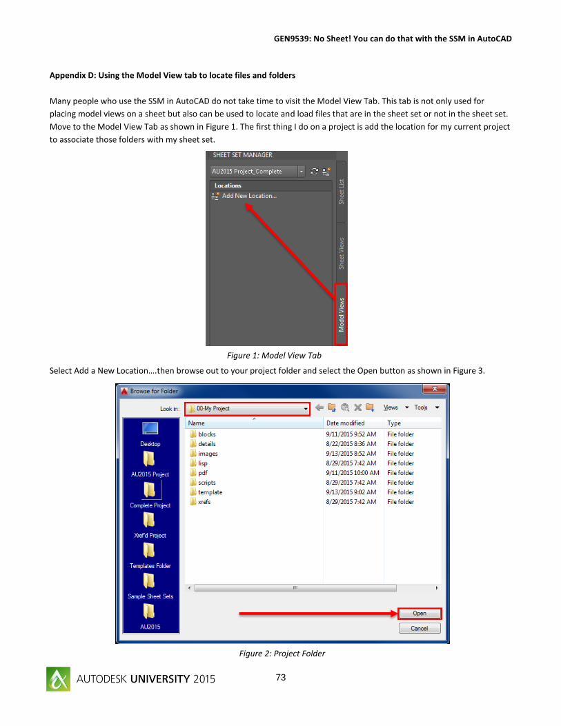
Appendix D: Using the Model View tab to locate files and folders
Many people who use the SSM in AutoCAD do not take time to visit the Model View Tab. This tab is not only used for
placing model views on a sheet but also can be used to locate and load files that are in the sheet set or not in the sheet set.
Move to the Model View Tab as shown in Figure 1. The first thing I do on a project is add the location for my current project
to associate those folders with my sheet set.
Select Add a New Location….then browse out to your project folder and select the Open button as shown in Figure 3.
Figure 1: Model View Tab
Figure 2: Project Folder
Page 74
GEN9539: No Sheet! You can do that with the SSM in AutoCAD
74
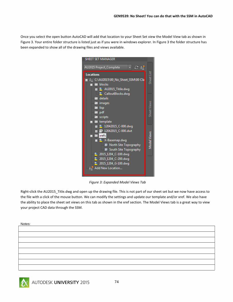
Once you select the open button AutoCAD will add that location to your Sheet Set view the Model View tab as shown in
Figure 3. Your entire folder structure is listed just as if you were in windows explorer. In Figure 3 the folder structure has
been expanded to show all of the drawing files and views available.
Right-click the AU2015_Title.dwg and open up the drawing file. This is not part of our sheet set but we now have access to
the file with a click of the mouse button. We can modify the settings and update our template and/or xref. We also have
the ability to place the sheet set views on this tab as shown in the xref section. The Model Views tab is a great way to view
your project CAD data through the SSM.
Notes:
Figure 3: Expanded Model Views Tab
Page 75
GEN9539: No Sheet! You can do that with the SSM in AutoCAD
75
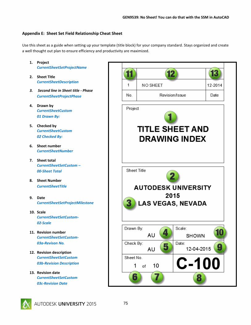
Appendix E: Sheet Set Field Relationship Cheat Sheet
Use this sheet as a guide when setting up your template (title block) for your company standard. Stays organized and create
a well thought out plan to ensure efficiency and productivity are maximized.
1. Project CurrentSheetSetProjectName
2. Sheet Title CurrentSheetDescription
3. Second line in Sheet title - Phase
CurrentSheetProjectPhase
4. Drawn by CurrentSheetCustom
01 Drawn By:
5. Checked by CurrentSheetCustom
02 Checked By:
6. Sheet number CurrentSheetNumber
7. Sheet total CurrentSheetSetCustom –
00-Sheet Total
8. Sheet Number
CurrentSheetTitle
9. Date CurrentSheetSetProjectMilestone
10. Scale CurrentSheetSetCustom-
02-Scale
11. Revision number CurrentSheetSetCustom-
03a-Revison No.
12. Revision description CurrentSheetSetCustom
03b-Revision Description
13. Revision date CurrentSheetSetCustom
03c-Revision Date