F-042-GL-E, T-045-GL-E & T-041-GL-E For Dual Band 33° Beamwidth Panel Antennas
General
This instruction sheet contains all necessary information required to assist in the correct installation of the Large Dual Band 33° Beamwidth Panel Antennas. These antennas are supplied with AISG-compatible remotely controlled electrical beam downtilt (RET). Mechanical downtilt is also available if required, depending on the type of mounting kit selected.
Following symbols can be found next to text outlining important information.
Please follow the procedure marked with this symbol precisely. Non-compliance may lead to damage of the product.
Handy tips when installing product.
Unpacking
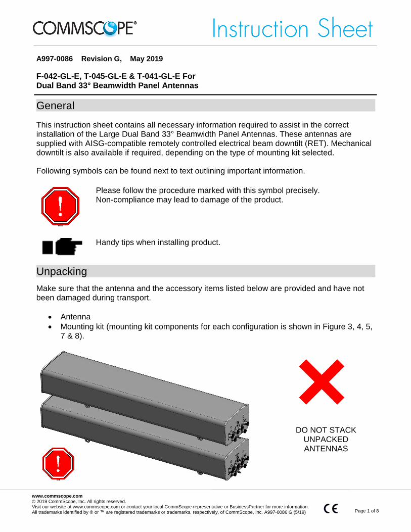
Make sure that the antenna and the accessory items listed below are provided and have not been damaged during transport.
• Antenna
• Mounting kit (mounting kit components for each configuration is shown in Figure 3, 4, 5, 7 & 8).
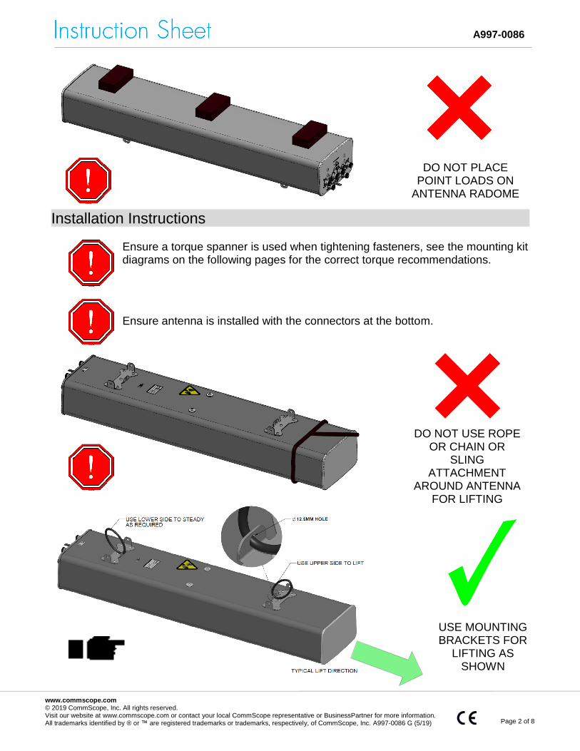
Installation Instructions Ensure a torque spanner is used when tightening fasteners, see the mounting kit diagrams on the following pages for the correct torque recommendations. Ensure antenna is installed with the connectors at the bottom.
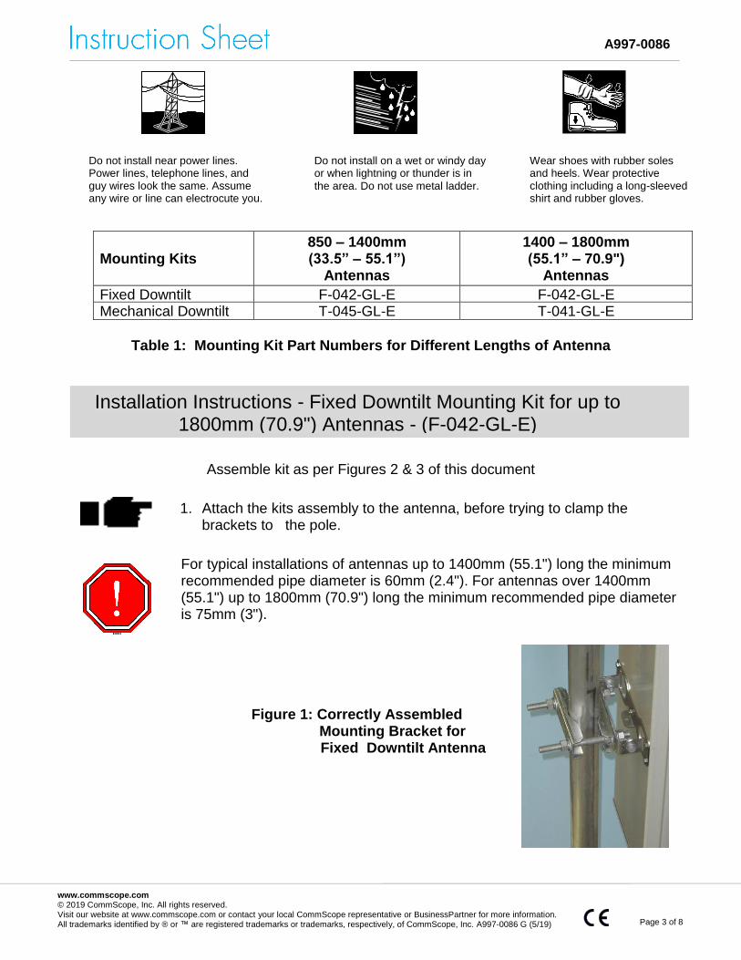
Table 1: Mounting Kit Part Numbers for Different Lengths of Antenna
Assemble kit as per Figures 2 & 3 of this document
1. Attach the kits assembly to the antenna, before trying to clamp the
brackets to the pole.
For typical installations of antennas up to 1400mm (55.1") long the minimum recommended pipe diameter is 60mm (2.4"). For antennas over 1400mm (55.1") up to 1800mm (70.9") long the minimum recommended pipe diameter is 75mm (3").
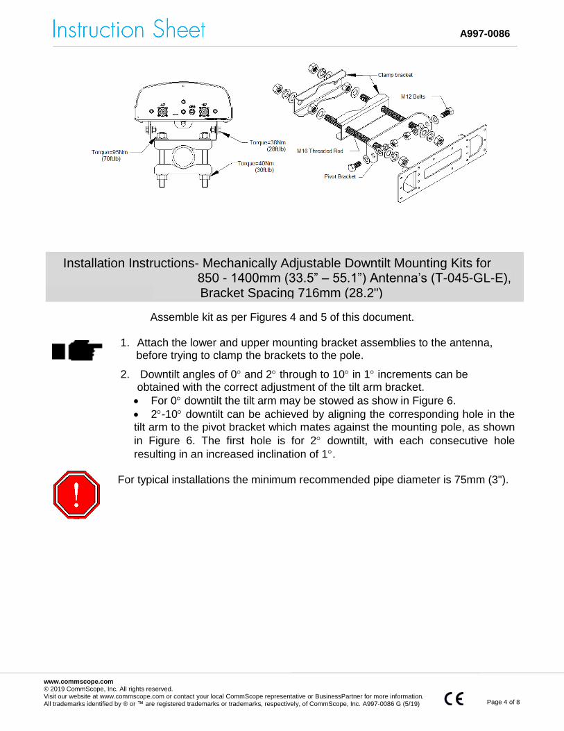
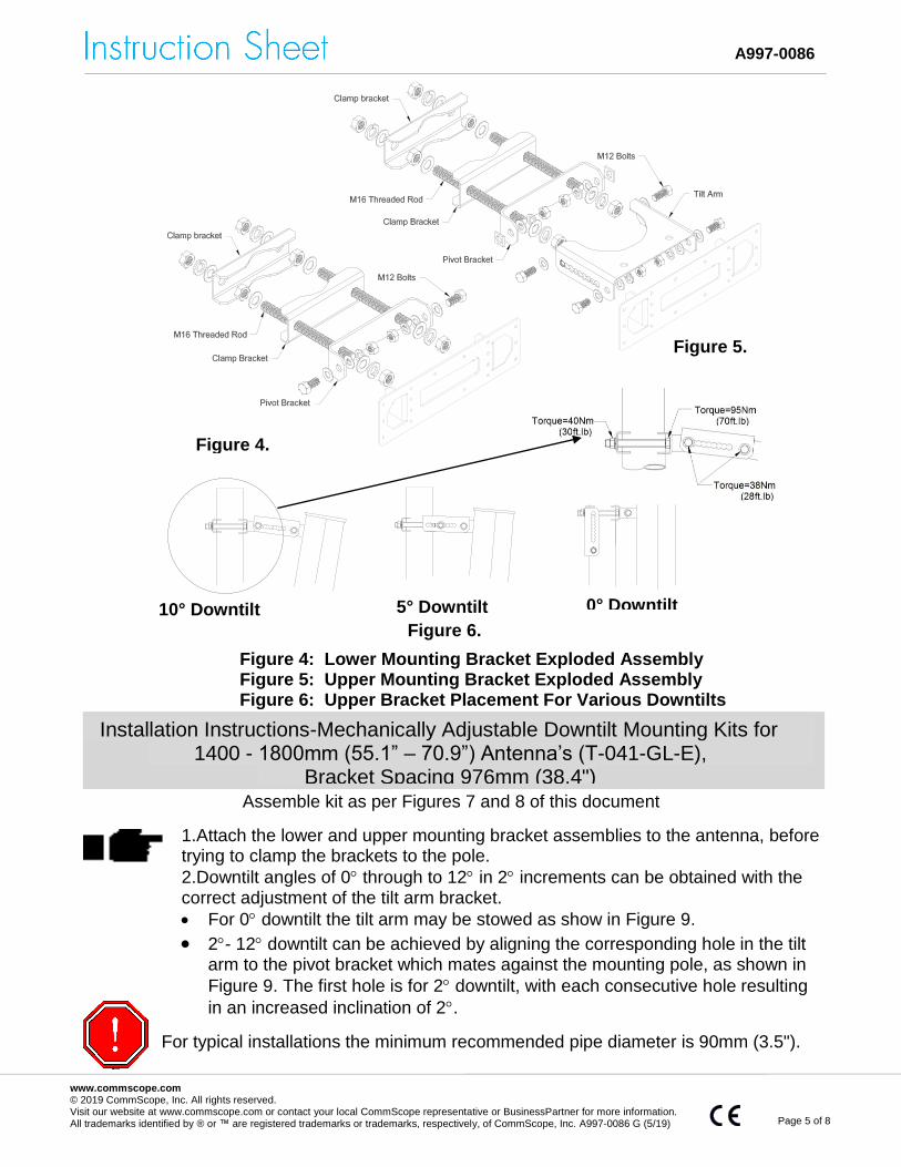
Assemble kit as per Figures 4 and 5 of this document. 1. Attach the lower and upper mounting bracket assemblies to the antenna, before trying to clamp the brackets to the pole.
2. Downtilt angles of 0 and 2 through to 10 in 1 increments can be obtained with the correct adjustment of the tilt arm bracket.
• For 0 downtilt the tilt arm may be stowed as show in Figure 6.
• 2-10 downtilt can be achieved by aligning the corresponding hole in the tilt arm to the pivot bracket which mates against the mounting pole, as shown
in Figure 6. The first hole is for 2 downtilt, with each consecutive hole
resulting in an increased inclination of 1. For typical installations the minimum recommended pipe diameter is 75mm (3").
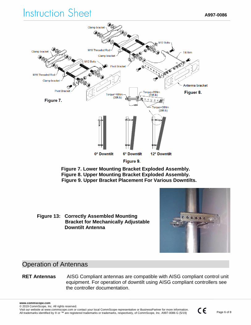
Assemble kit as per Figures 7 and 8 of this document
1.Attach the lower and upper mounting bracket assemblies to the antenna, before trying to clamp the brackets to the pole. 2.Downtilt angles of 0 through to 12 in 2 increments can be obtained with the correct adjustment of the tilt arm bracket. • For 0 downtilt the tilt arm may be stowed as show in Figure 9.
• 2- 12 downtilt can be achieved by aligning the corresponding hole in the tilt arm to the pivot bracket which mates against the mounting pole, as shown in
Figure 9. The first hole is for 2 downtilt, with each consecutive hole resulting
in an increased inclination of 2.
For typical installations the minimum recommended pipe diameter is 90mm (3.5").
Figure 4.
Figure 5.
Figure 6.
10° Downtilt 5° Downtilt 0° Downtilt
I Installation Instructions-Mechanically Adjustable Downtilt Mounting Kits for 1400 - 1800mm (55.1” – 70.9”) Antenna’s (T-041-GL-E),
Figure 9. Upper Bracket Placement For Various Downtilts.
Figure 13: Correctly Assembled Mounting Bracket for Mechanically Adjustable
Downtilt Antenna Operation of Antennas RET Antennas AISG Compliant antennas are compatible with AISG compliant control unit equipment. For operation of downtilt using AISG compliant controllers see the controller documentation.
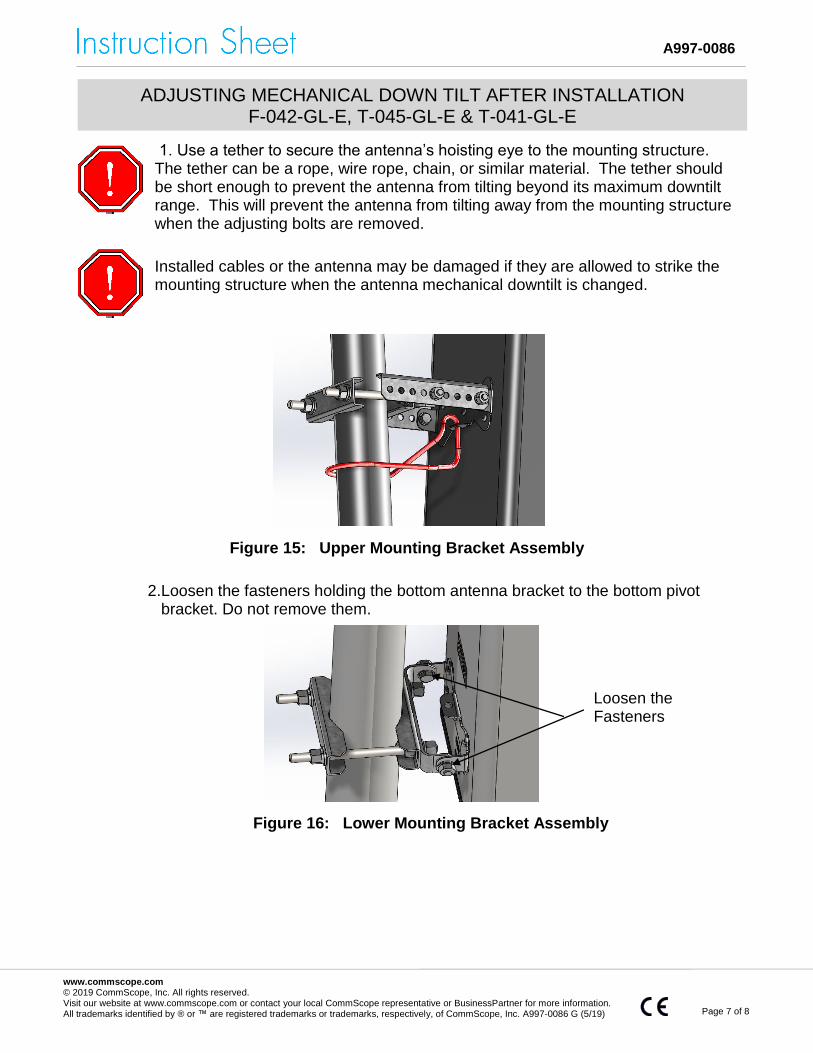
1. Use a tether to secure the antenna’s hoisting eye to the mounting structure. The tether can be a rope, wire rope, chain, or similar material. The tether should be short enough to prevent the antenna from tilting beyond its maximum downtilt range. This will prevent the antenna from tilting away from the mounting structure when the adjusting bolts are removed. Installed cables or the antenna may be damaged if they are allowed to strike the mounting structure when the antenna mechanical downtilt is changed.
Figure 15: Upper Mounting Bracket Assembly
2.Loosen the fasteners holding the bottom antenna bracket to the bottom pivot bracket. Do not remove them.
Figure 16: Lower Mounting Bracket Assembly
ADJUSTING MECHANICAL DOWN TILT AFTER INSTALLATION F-042-GL-E, T-045-GL-E & T-041-GL-E
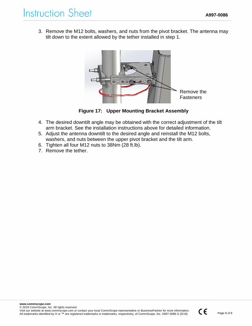
3. Remove the M12 bolts, washers, and nuts from the pivot bracket. The antenna may tilt down to the extent allowed by the tether installed in step 1.
Figure 17: Upper Mounting Bracket Assembly
4. The desired downtilt angle may be obtained with the correct adjustment of the tilt arm bracket. See the installation instructions above for detailed information.
5. Adjust the antenna downtilt to the desired angle and reinstall the M12 bolts, washers, and nuts between the upper pivot bracket and the tilt arm.
6. Tighten all four M12 nuts to 38Nm (28 ft.lb). 7. Remove the tether.