26
GENERAL DESCRIPTION AND INSTRUCTIONS FOR KFG CONTROL PANELS JUNE 2000

GENERAL DESCRIPTION AND
INSTRUCTIONS FOR
KFG CONTROL PANELS
JUNE 2000

KFG – AP Boiler Instrument Panel
Page 2 17/07/00
The company reserves the right to change the specification and dimensions without prior notice.
Contents General Information 3
Modular in Design 3
Technical Data 3
Installation Options 3
Description of Controls and Operation 4
Safety Instructions 5
Control Module Options 6
Control Module Diagrams 7
Installation of an Electronic Control Module 8
Room Devices 8
Electrical Wiring 9
Terminal Diagram 10
Wiring Diagram 11
Appendix of abbreviations / terms used 12
Description of G 22K Module (for 2 stage high/low, boiler only operation) 13
G22K Operation and Installation 14
G22K Functions 15
G22K Installations and Electrical 16
Description of Gamma 1B Module (for 1 stage On/Off, combination, bicalor boilers) 17
Mounting and Operating instructions for Gamma 1B Module 18
Gamma 1B Functions in automatic mode 21
Description of Gamma 22BC Module (for 2stage high/low, combination, bicalor boilers) 22
Gamma 22BC Operation and Installation 23
Temperature Setting 24
Time adjustment 25
Pre-set and Free Set Switching 26

KFG – AP Boiler Instrument Panel
Page 3 17/07/00
The company reserves the right to change the specification and dimensions without prior notice.
General information The KFG-AP instrument panel has been developed especially for the Ca 6S, Ca 7S, and RU boiler series and satisfies the control requirements of modern heating systems. In the design, due consideration has been taken to meet the requirements of the user and all relevant standards: • Easy and quick mounting • Simple and understandable operation • Easy extension possibilities • Programming and service possible via a Data
interface • CE approved. Modular in design One of the most important advantages of this digital controller is the ease in which the controls for further heating circuits can be added. Up to 5 weather compensated GAMMA control modules can be interconnected. This will enable a system of up to a maximum of 10 mixed heating circuits and 5 HWS circuits to be achieved. According to the type of boiler, the Standard instrument panel has space for 2 or 3 pre-wired GAMMA control modules.
Technical data
Type KFG 2233b GK Nominal voltage 230V~+6 -10%
Nominal frequency 50 Hz Nominal elec. Power 6 A, cos. phi≥0.8
Installation options: Ca 6S 2 GAMMA modules BCa 6S 2 GAMMA modules Ca 7S 2 GAMMA modules BCa 7S 2 GAMMA modules RU 1S/ 2S/ 3S 3 GAMMA modules BRU 1S/ 2S 2 GAMMA modules.
KFG – AP Boiler Instrument Panel
Page 4 17/07/00
The company reserves the right to change the specification and dimensions without prior notice.
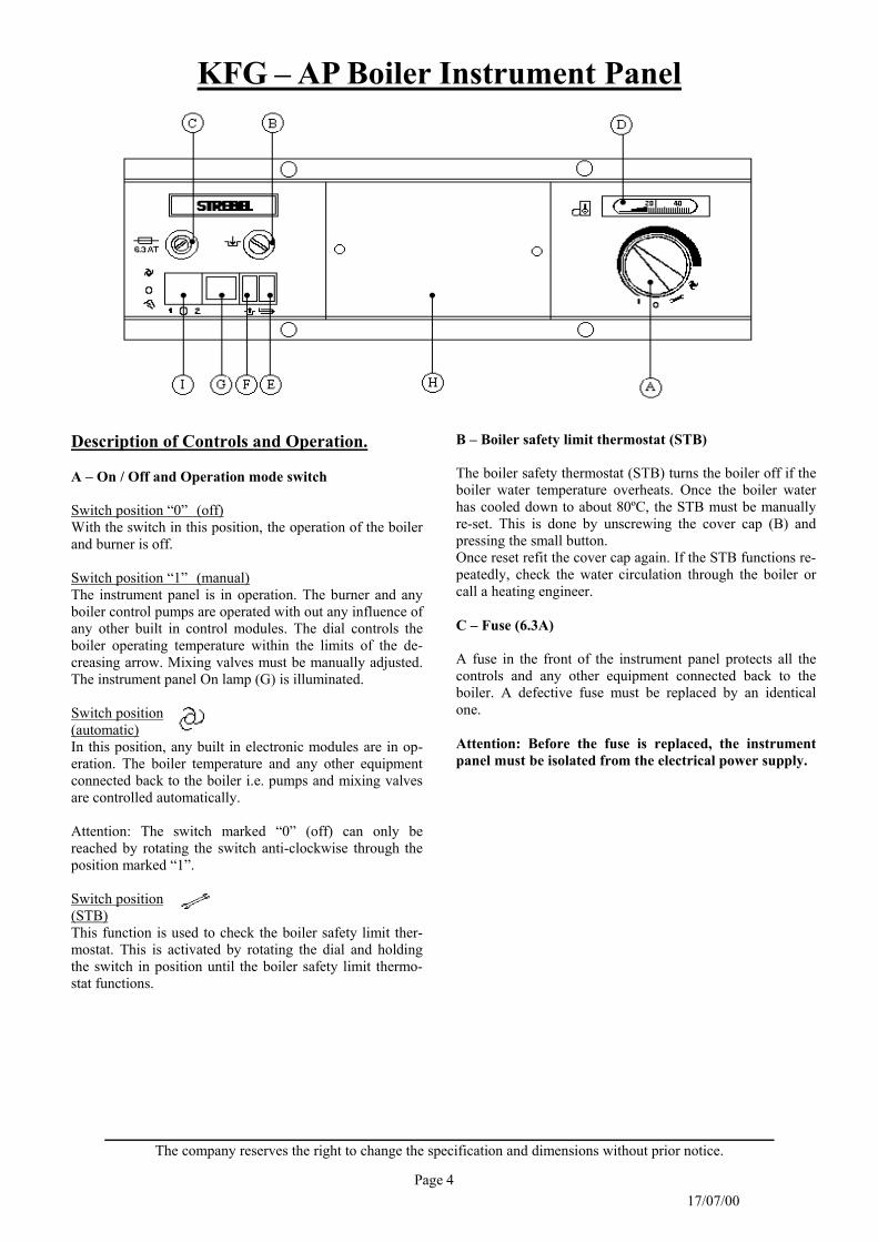
Description of Controls and Operation. A – On / Off and Operation mode switch Switch position “0” (off) With the switch in this position, the operation of the boiler and burner is off. Switch position “1” (manual) The instrument panel is in operation. The burner and any boiler control pumps are operated with out any influence of any other built in control modules. The dial controls the boiler operating temperature within the limits of the de-creasing arrow. Mixing valves must be manually adjusted. The instrument panel On lamp (G) is illuminated. Switch position (automatic) In this position, any built in electronic modules are in op-eration. The boiler temperature and any other equipment connected back to the boiler i.e. pumps and mixing valves are controlled automatically. Attention: The switch marked “0” (off) can only be reached by rotating the switch anti-clockwise through the position marked “1”. Switch position (STB) This function is used to check the boiler safety limit ther-mostat. This is activated by rotating the dial and holding the switch in position until the boiler safety limit thermo-stat functions.
B – Boiler safety limit thermostat (STB) The boiler safety thermostat (STB) turns the boiler off if the boiler water temperature overheats. Once the boiler water has cooled down to about 80ºC, the STB must be manually re-set. This is done by unscrewing the cover cap (B) and pressing the small button. Once reset refit the cover cap again. If the STB functions re-peatedly, check the water circulation through the boiler or call a heating engineer. C – Fuse (6.3A) A fuse in the front of the instrument panel protects all the controls and any other equipment connected back to the boiler. A defective fuse must be replaced by an identical one. Attention: Before the fuse is replaced, the instrument panel must be isolated from the electrical power supply.

KFG – AP Boiler Instrument Panel
Page 5 17/07/00
The company reserves the right to change the specification and dimensions without prior notice.
Safety instructions Any servicing on the boiler instrument panel (wiring, re-pairs, changes) should be carried out by a competent person. If any works are carried out the mains supply to the boiler must be isolated and secured against accidental switching on. The proper function of the boiler instrument panel is only guaranteed according to our general guarantee conditions and only if the installation and operation is carried out in ac-cordance with these instructions.
D – Boiler thermometer It shows the actual boiler water temperature and has no in-fluence on the boiler temperature control. E – Burner lock out lamp (red) The red lamp will illuminate when the burner has gone out (burner fault), the red lamp will go off once the burner re-set button has been pressed. F – high limit lamp (orange) If the boiler safety limit thermostat (STB) is activated, the orange control lamp will be illuminated. The orange lamp will go off once the STB button has been pressed and reset. G – Instrument panel “On” lamp (green) This will be illuminated when the instrument panel is switched on, the main On – Off switch (A) turned from “0” to “1”. H – Blank cover The standard version of the boiler instrument panels are supplied with blank covers. Terminal blocks X3 and X4 connect to dummy connection pins on the rear side to prevent short circuits. When using an additional electronic control module, this blank cover should be removed. Terminal blocks X3 and X4 should then be con-nected to the replacement module along with X1 and X2 (in the designated positions). I – Blank cover When a Gamma 1B control module is used, this blank cover must be removed. A Summer/Winter switch is fitted here.

KFG – AP Boiler Instrument Panel
Page 6 17/07/00
The company reserves the right to change the specification and dimensions without prior notice.
Two stage burner operation G22K Electronic two stage thermostat for constant tem-perature boiler operation. (illustration on page 7) Gamma 22B Weather compensated control for two stage op-eration for one heating circuit and HWS control. Gamma 223B Weather compensated control for two stage op-eration for one heating circuit, one mixing valve and HWS control. (illustration on page 7) Gamma 2233B Weather compensated control for two stage op-eration for one heating circuit, two mixing valves and HWS control. (illustration on page 7) Gamma 33B Weather compensated control for two heating cir-cuits both with mixing valves. This is an addi-tional control module, suitable only in addition to a basic electronic control module. Mounting and operating instructions are sup-plied with the electronic controls.
Control module options Single stage burner operation Gamma 1B HWS control, temperature range 20 – 80ºC, HWS priority, pump overrun of calorifier pri-mary pump, boiler control thermostat. (illustration on page 7) Gamma 2B Weather compensated control for one heating circuit and HWS control. Gamma 23B Weather compensated control for one heating circuit, one mixing valve and HWS control. Gamma 233B Weather compensated control for one heating circuit, two mixing valves and HWS control. Gamma 233BS Weather compensated control for one heating circuit, two mixing valves, HWS control, tem-perature difference control for solar units and combination with solid fuel boilers. Gamma 33B Weather compensated control for two heating circuits both with mixing valves. This is an addi-tional control module, suitable only in addition to a basic electronic control module.
KFG – AP Boiler Instrument Panel
Page 7 17/07/00
The company reserves the right to change the specification and dimensions without prior notice.
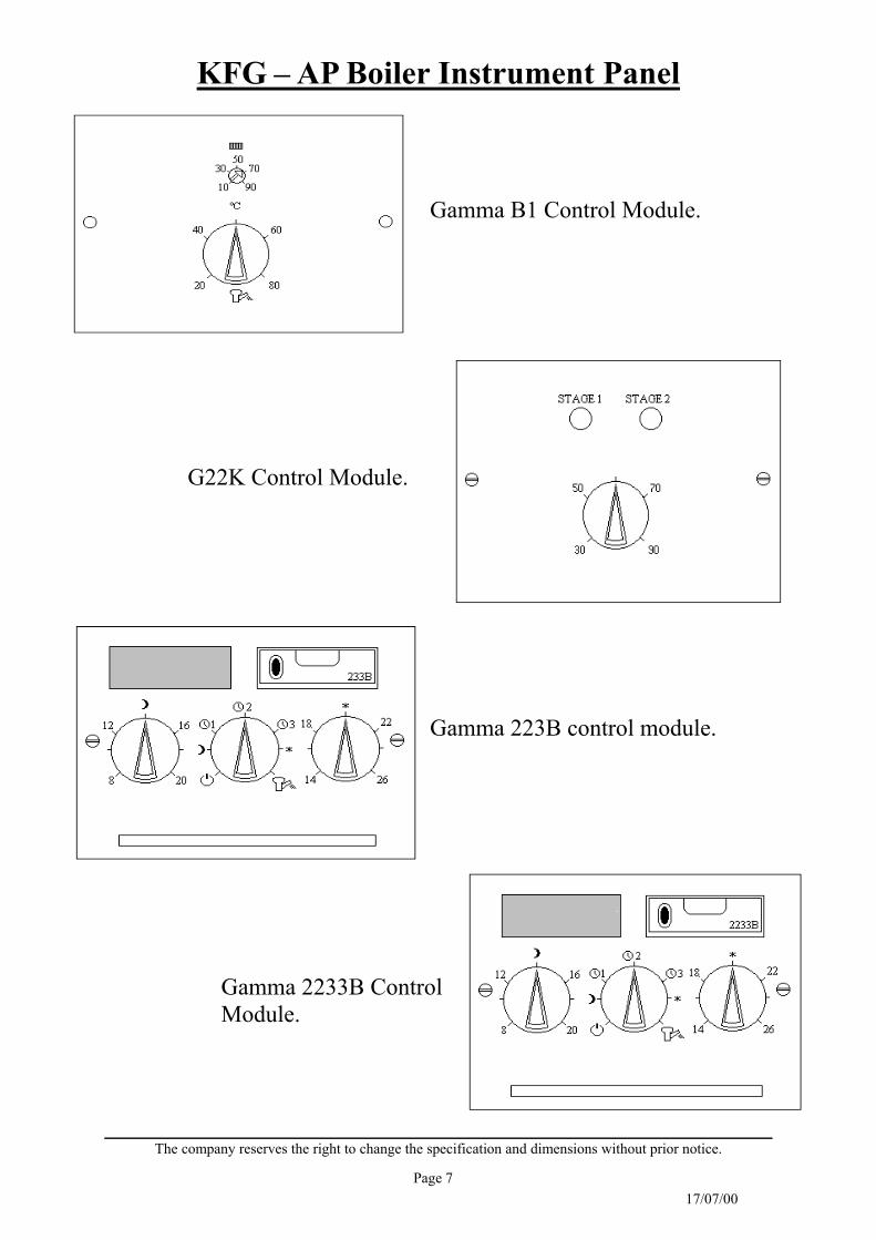
Gamma B1 Control Module.
G22K Control Module.
Gamma 223B control module.
Gamma 2233B Control Module.

KFG – AP Boiler Instrument Panel
Page 8 17/07/00
The company reserves the right to change the specification and dimensions without prior notice.
Room devices RFF 40S Room sensor with remote operation. RS 10 Room station. Installation and operating instructions are sup-plied with all room devices. Connections should be carried out according to the terminal wiring diagram on page 10.
Installation of an electronic control module Gamma B1 First the blank cover on the boiler needs to be re-moved. Use a screwdriver with light pressure turning anti-clockwise the screws on the left and the right side of the blank cover. Then remove the blank cover carefully as there is wiring connected to the back. Remove the plugs X3 and X4 from the back of the blank cover. Connect the plugs X1, X2, X3, and X4 from the boiler instrument panel to the back of the control module. Insert the electronic control module into the opening and fix it by turning the two screws under light pressure clockwise by 90º. The electronic control module unit is now fixed to the boiler instrument panel. If a further control module is to be added, open the top metal cover of the boiler instrument panel by removing the 6 screws. Screw the terminal block X11 that is supplied with the additional control module onto the red marked part of the terminal rail inside the boiler instrument panel, and likewise the X12 onto the blue marked part (2.9 x 19mm screws are sup-plied with the additional control module). Con-nect the plugs X9.1 and X10.1 that are on the leads to the boiler instrument panel with X9.2 and X10.2 plugs and leads from the additional control module. If a second extension module is used, connect the clips of the second one. Re-move the central blank cover and connect the plugs X1, X2, X3 and X4 to the module. Install the module as described above. (Wiring accord-ing to the terminal diagram on page 10).

KFG – AP Boiler Instrument Panel
Page 9 17/07/00
The company reserves the right to change the specification and dimensions without prior notice.
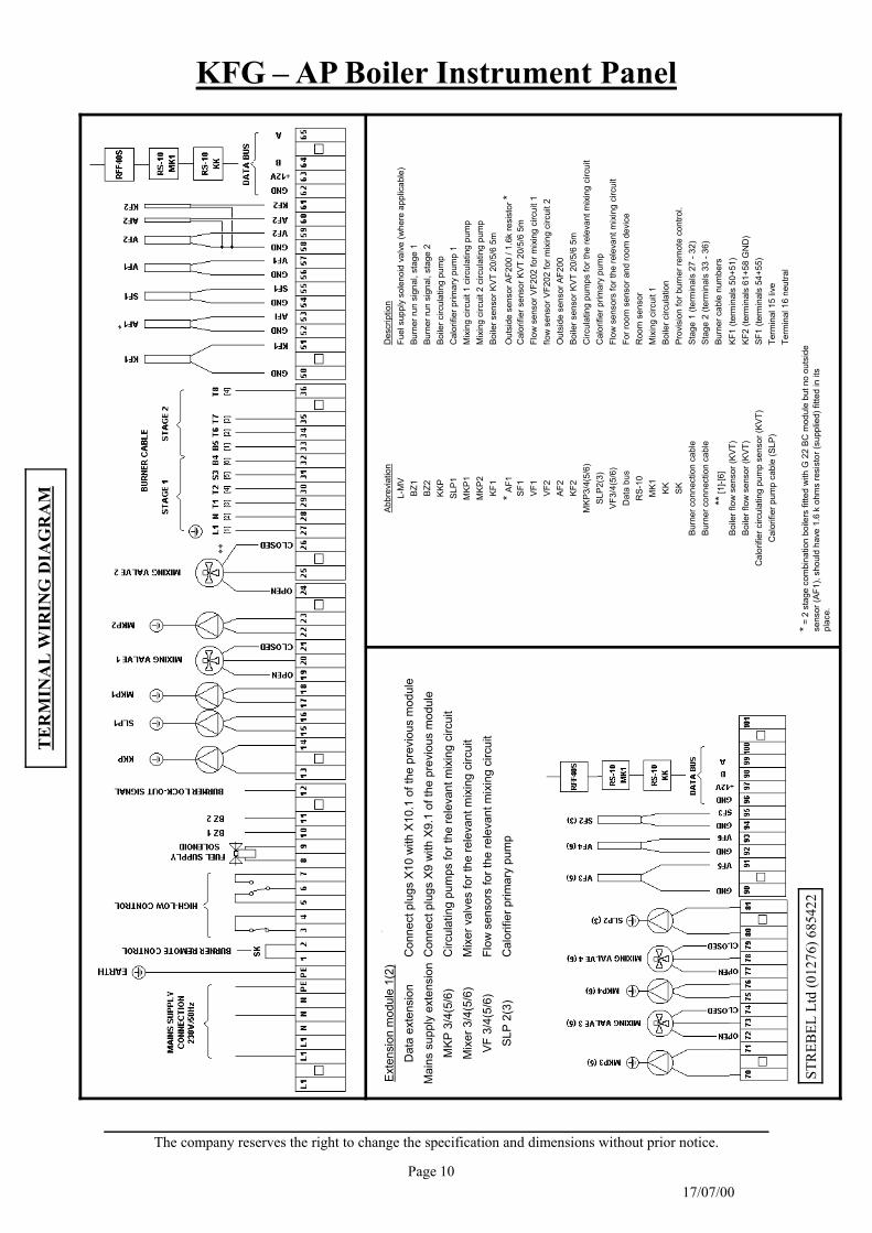
The interconnecting wiring between the boiler in-strument panel and the burner is done using the 7 way plug and loom for single stage burners, or 7 and 4 way plug and looms for two stage burners. The number, which is on the wire insulation, is the one that counts for the connection of the burner cable to the terminal strip. It must be made ac-cording to the square inscription shown above ter-minals 27 to 36 on the terminal wiring diagram on page 8. If the boiler or burner stage need to be controlled remotely, then the appropriate link(s) need to be removed from the terminals 3 to 7 and controls by others connected. There are also terminals for burner run signals, stage 1 (terminal 10) and stage 2 (terminal 11) with terminal 12 giving a burner lock out signal. Further details on wiring diagram on page 11.
Electrical wiring The electrical wiring, must be carried out by competent persons to current I.E.E and CE regu-lations, British standards and Local Authority Regulations. Remove the boiler instrument panel cover for ac-cess to the connection terminals. On the back of the cover there is a terminal wiring diagram (see also on page 10). Isolate the electrical mains supply to the boiler instrument control panel and turn main switch (A) into position “0” before you start to work on the wiring. Warning: During the installation be very careful to note the difference between mains supply and low voltage. Mains terminals are marked red and low voltage terminals blue. The earth rail is available for all earth connec-tions including for the burner. The connection between the PE (potential earth) and the earth rail is particularly important.
KFG – AP Boiler Instrument Panel
Page 10 17/07/00
The company reserves the right to change the specification and dimensions without prior notice.
TE
RM
INA
L W
IRIN
G D
IAG
RA
M
Exte
nsio
n m
odul
e 1(
2)
Dat
a ex
tens
ion
Con
nect
plu
gs X
10 w
ith X
10.1
of t
he p
revi
ous
mod
ule
Mai
ns s
uppl
y ex
tens
ion
Con
nect
plu
gs X
9 w
ith X
9.1
of th
e pr
evio
us m
odul
e M
KP 3
/4(5
/6)
Circ
ulat
ing
pum
ps fo
r the
rele
vant
mix
ing
circ
uit
Mix
er 3
/4(5
/6)
Mix
er v
alve
s fo
r the
rele
vant
mix
ing
circ
uit
VF 3
/4(5
/6)
Flow
sen
sors
for t
he re
leva
nt m
ixin
g ci
rcui
t SL
P 2(
3)
Cal
orifi
er p
rimar
y pu
mp
**
STR
EBEL
Ltd
(012
76) 6
8542
2
Abbr
evia
tion
Des
crip
tion
L-M
V Fu
el s
uppl
y so
leno
id v
alve
(whe
re a
pplic
able
) BZ
1 Bu
rner
run
sign
al, s
tage
1
BZ2
Burn
er ru
n si
gnal
, sta
ge 2
KK
P Bo
iler c
ircul
atin
g pu
mp
SLP1
C
alor
ifier
prim
ary
pum
p 1
MKP
1 M
ixin
g ci
rcui
t 1 c
ircul
atin
g pu
mp
MKP
2 M
ixin
g ci
rcui
t 2 c
ircul
atin
g pu
mp
KF1
Boile
r sen
sor K
VT 2
0/5/
6 5m
* AF1
O
utsi
de s
enso
r AF2
00 /
1.6k
resi
stor
* SF
1 C
alor
ifier
sen
sor K
VT 2
0/5/
6 5m
VF
1 Fl
ow s
enso
r VF2
02 fo
r mix
ing
circ
uit 1
VF
2 flo
w s
enso
r VF2
02 fo
r mix
ing
circ
uit 2
AF
2 O
utsi
de s
enso
r AF2
00
KF2
Boile
r sen
sor K
VT 2
0/5/
6 5m
M
KP3/
4(5/
6)
Circ
ulat
ing
pum
ps fo
r the
rele
vant
mix
ing
circ
uit
SLP2
(3)
Cal
orifi
er p
rimar
y pu
mp
VF3/
4(5/
6)
Flow
sen
sors
for t
he re
leva
nt m
ixin
g ci
rcui
t D
ata
bus
For r
oom
sen
sor a
nd ro
om d
evic
e R
S-10
R
oom
sen
sor
MK1
M
ixin
g ci
rcui
t 1
KK
Boile
r circ
ulat
ion
SK
Prov
isio
n fo
r bur
ner r
emot
e co
ntro
l. Bu
rner
con
nect
ion
cabl
e
Stag
e 1
(term
inal
s 27
- 32
) Bu
rner
con
nect
ion
cabl
e
Stag
e 2
(term
inal
s 33
- 36
)
** [1
]-[6]
Bu
rner
cab
le n
umbe
rs
Boile
r flo
w s
enso
r (KV
T)
KF1
(term
inal
s 50
+51)
Bo
iler f
low
sen
sor (
KVT)
KF
2 (te
rmin
als
61+5
8 G
ND
) C
alor
ifier
circ
ulat
ing
pum
p se
nsor
(KVT
) SF
1 (te
rmin
als
54+5
5)
Cal
orifi
er p
ump
cabl
e (S
LP)
Term
inal
15
live
Te
rmin
al 1
6 ne
utra
l
* = 2
sta
ge c
ombi
natio
n bo
ilers
fitte
d w
ith G
22
BC m
odul
e bu
t no
outs
ide
sens
or (A
F1),
shou
ld h
ave
1.6
k oh
ms
resi
stor
(sup
plie
d) fi
tted
in it
s pl
ace.

Abb
revi
atio
n:
Des
crip
tion:
F1
MAI
NS
SU
PPLY
FU
SE
(6.3
A)
S1
O
N/O
FF S
WIT
CH
/MA
NU
AL/
AU
TO/S
TB T
EST
SWIT
CH
WIT
H B
OIL
ER
CO
NTR
OL
THER
MO
STA
T.
S2
B
OIL
ER S
AFE
TY L
IMIT
TH
ER
MO
STA
T 11
0ºC
S
3
B
OIL
ER S
AFE
TY L
IMIT
TH
ER
MO
STA
T (2
) H
1
INTR
UM
EN
T P
ANE
L “O
N” L
AM
P
H2
BU
RN
ER
LO
CK
OU
T LA
MP
H
3
B
OIL
ER H
IGH
LIM
IT L
AMP
A1
G
AMM
A E
LEC
TRO
NIC
MO
DU
LE
X1
G
AMM
A C
ON
TRO
L C
ON
NE
CTI
ON
S (S
ENSO
RS
) X2
GAM
MA
CO
NTR
OL
CO
NN
EC
TIO
NS
(MAI
NS
SU
PP
LY)
X3
G
AMM
A C
ON
TRO
L C
ON
NE
CTI
ON
(MIX
ING
GR
OU
P 1
) X4
GAM
MA
CO
NTR
OL
CO
NN
EC
TIO
N (M
IXIN
G G
RO
UP
2)
X5
TE
RM
INAL
S F
OR
MA
IN S
UP
PLY
(20
TER
MIN
ALS
) X6
TER
MIN
AL F
OR
PU
MPS
/MIX
ING
VA
LVE
S (1
2 TE
RM
INAL
S)
X7
TE
RM
IAN
LS F
OR
BU
RN
ER
STA
GES
1&
2 (1
2 TE
RM
INAL
S)
X8
TE
RM
INAL
S F
OR
SEN
SOR
/ R
OO
M D
EVI
CE
(16
TER
MIN
ALS
) X9
CO
NN
EC
TIO
N T
ER
MIN
AL M
AIN
S E
XTE
NS
ION
SU
PPL
Y (3
TE
RM
INA
LS)
X10
CO
NN
EC
TIO
N T
ER
MIN
ALS
BU
S C
ON
NE
CTI
ON
(4 T
ER
MIN
ALS
) X1
1
CO
NN
EC
TIO
N S
TB2
(EXT
ERN
AL)
FS
FU
EL
SU
PPL
Y S
OLE
NO
ID V
ALV
E
KFG
-AP
Boi
ler
Inst
rum
ent P
anel
In
tern
al W
iring
Dia
gram

KFG – AP Boiler Instrument Panel
Page 12 17/07/00
The company reserves the right to change the specification and dimensions without prior notice.
Abbreviation Description 1 - 6 Burner cable numbers A1 Gamma electronic control module
AF1 Outside sensor AF200 AF2 Outside sensor AF200 BZ1 Burner run signal, stage 1 BZ2 Burner run signal, stage 2
Data Bus For room sensor and room device F1 Mains supply fuse 6.3A FS Fuel supply solenoid valve H1 Instrument panel "On" lamp H2 Burner lock out lamp H3 Boiler high limit lamp KF1 Boiler sensor KVT20/5/6/ 5m KF2 Boiler sensor KVT20/5/6/ 5m KK Boiler circulation
KKP Boiler circulation pump L-MV Fuel supply solenoid valve (where applicable) MK1 Mixing circuit 1
MKP1 Mixing circuit 1 circulating pump MKP2 Mixing circuit 2 circulating pump
MKP 3/4(5/6) Circulating pumps for the relevant mixing circuit RS-10 Room sensor
S1 On/Off switch/Manual/Automatic/STB test switch with boiler control thermostat S2 Boiler safety limit thermostat 110ºC S3 Boiler safety limit thermostat (2) SK Remote burner circuit
SLP1 Calorifier primary pump 1 SLP2(3) Calorifier primary pump
VF1 Flow sensor VF202 for mixing circuit 1 VF2 Flow sensor VF202 for mixing circuit 2
VF3/4 (5/6) Flow sensors for the relevant mixing circuits X1 Gamma control connection (sensors) X2 Gamma control connection (Mains supply) X3 Gamma control connection for mixing group 1 X4 Gamma conrol connection for mixing group 2 X5 Terminals for mains supply (20 terminals) X6 Terminals for pumps/mixing valves (12 terminals) X7 Terminals for burner stages 1+2 (12 terminals) X8 Terminals for sensor/room device (16 terminals) X9 Connection terminals mains extension supply (3 terminals)
X10 Connection terminals bus connection (4 terminals) X11 Connection STB2 (external)
Appendix of abbreviations used (in alphabetical order)

KFG – AP Boiler Instrument Panel
Page 13 17/07/00
The company reserves the right to change the specification and dimensions without prior notice.
Description of G22K MODULE
for a Two Stage (high/low) Boiler Only, Operation

KFG – AP Boiler Instrument Panel
Page 14 17/07/00
The company reserves the right to change the specification and dimensions without prior notice.
Operation Instructions General: The G22K module is an electronic 2 stage thermostat for use in KFG – AP instrument panels for Ca6S, 7S and RU boilers. It allows a constant, load dependant operation with separately adjustable control of ON – OFF respectively STAGE 1 – STAGE 2. Nominal range (set at the factory) : SD1 (on – off) ±2K SD2 ( 1st stage – 2nd stage) ±4K KEY:
A – Boiler temperature control ( allows setting of required boiler temperature) B – Operation Mode Stage 1 C – Operation Mode Stage 2
Installation Wiring When wiring the unit, it is very important to allow separate connecting of cables, low voltage cables and mains voltage cables. Common cable conduits or cable tubes are not allowed and can cause disturbance by induction. Ambience temperature The Ambience temperature near the unit must not exceed 50ºC. Technical data Connection voltage: 230V +6% / -10% Nominal frequency: 50 – 60 Hz Protection fuse max: 6.3 A/inert Relay exits: Max contact load 8A(±0.8)
B A C
Gamma G22K Control
Gamma G22K Control Module Boiler Temperature Control

KFG – AP Boiler Instrument Panel
Page 15 17/07/00
The company reserves the right to change the specification and dimensions without prior notice.
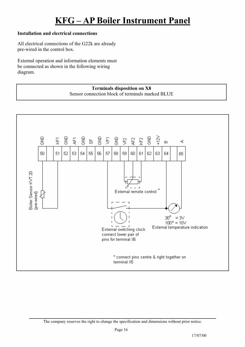
Function and additional function The adjustment of the required boiler temperature is made by the power meter (A) of the G22K. For 2 stage operation the operation mode switch on instrument panel must be in position “automatic”. In switch position 1 (manual operation), the burner operates at one stage only. 1. Power meter SD1 Serves to set the internal switching difference (modulating 2 point operation) Adjustment range: 1 – 5K. ATTENTION: The adjusted value refers to ±K, i.e. the value 3 refers to a switching difference of 6K. 2. Power meter SD2 Serves to set the external switching difference (connection or disconnection of stages) Adjustment range: 2 – 10K. ATTENTION: The adjusted value refers to ±K, i.e the value 3 refers to a switching difference of 6K. 3. Power meter Tvz II Delay for the second stage can be adjusted between 0 and 20 minutes. (works only of start with both stages) 4. External nominal value setter for the boiler temperature If an external nominal value setter is used, the terminal X5 must be connected to the right (seen from behind). See wiring diagram for its connection. With external operation the internal power meter is out of operation.
The external nominal value setter is available as an accessory in a built-in and a built-up version (power meter 2.2kΩ.) 5. External switching clock If a room thermostat or an external switching clock is to be connected, the terminal X6 must be connected downside (seen from behind) See the wiring diagram for the connection of an external switching clock. ATTENTION: Connect volt free. Contact open – boiler turned off Contact closed – night mode Boiler starts – day mode 6. Digital boiler temperature reading through measured value converter. The integrated measured value converter for the digital indication of the boiler temperature supplies a control tension of 1-10.7V. This corresponds to a boiler temperature of 10-107ºC. (0.1V = 1ºC) Excedding temperatures may differ. See wiring diagram for the connection.
KFG – AP Boiler Instrument Panel
Page 16 17/07/00
The company reserves the right to change the specification and dimensions without prior notice.
Installation and electrical connections All electrical connections of the G22k are already pre-wired in the control box. External operation and information elements must be connected as shown in the following wiring diagram.
Terminals disposition on X8 Sensor connection block of terminals marked BLUE

KFG – AP Boiler Instrument Panel
Page 17 17/07/00
The company reserves the right to change the specification and dimensions without prior notice.
Description of GAMMA 1B MODULE
for Single Stage (Off/On) Combination (Bicalor)
Boilers

KFG – AP Boiler Instrument Panel
Page 18 17/07/00
The company reserves the right to change the specification and dimensions without prior notice.
Mounting and operating instructions for Gamma 1B module
(for heating and domestic water) General The gamma 1B module is for domestic hot water temperature control for storage calorifiers and for control of the heating circuit (constant or with room thermostat). Mounting The module is connected (see electrical connection) and then introduced from the front into its opening on the instrument panel. It is fixed under slight pressure with a quarter turn to the right with two fast clip devices (1) on both sides. Dismounting is made the other way round. Electrical connection It is made with the help of the connections X1, X2 and X3 in the instrument panel. Make sure that the number of terminals correspond exactly with those of the connection pins. Attention: The blue block of terminals X1 is for low voltage and must never be in touch with tension from the mains. If this is not observed, the unit is destroyed. X1 block of terminals (blue) KEY : 23 – GND common connection for the boiler and calorifier sensors and the room thermostat. 36 – SF Calorifier sensor KVT 20/5/6 37 – KF Boiler sensor KVT 20/2/6 38 – RT Room thermostat (optional) X2 block of terminals (red)
KEY: 22 – L1 (phase) 230V – Mains connection 23 – N (zero) 230V - Mains connection X3 block of terminals (red) KEY: 1 – Burner relay, volt free entrance 2 – Burner relay, volt free exit 3 – HKP Heating circuit pump 230V 5 – SLP Calorifier loading pump 230V 6 – L1 (phase) 230V feed for heating circuit pump and calorifier loading pump. The electrical connection to the units of the installation is made on the main connection rail in the boiler. For EG, EC boiler series: Connection with the numbered counter plug supplied Calorifier sensor…………..counter plug 11 Calorifier loading pump…..counter plug 7 Room thermostat………….counter plug 14 For boiler series with KSPG: Connection directly to the following terminals:

KFG – AP Boiler Instrument Panel
Page 19 17/07/00
The company reserves the right to change the specification and dimensions without prior notice.
Calorifier sensor X8-54/55 block of terminals Calorifier loading pump X6-15/16 block of terminals Room thermostat X8-52/53 block of terminals Summer / Winter Switch Heating can be stopped or released with this switch. Application: Interruption of heating in summer. Mounting and electrical connection − Remove left switch cover (1 2) in the
instrument panel − Lead the connection cables (S/W) of the
Gamma 1B through the switch opening and stick it to the switch optionally on the left or right side.
− Click switch into place ATTENTION: Rocker switch mark downward! Resulting function: Switch position: Winter operation Heating and HWS ready for operation Switch position: Summer operation HWS ready for use, heating interrupted.
Operating start Automatic mode Put the mechanical boiler temperature control on the right hand side of the instrument panel into position (Automatic operation – max. value = 95ºC) Manual mode In case of disturbance, manual mode may be used. Adjust the mechanical boiler temperature control switch within the range of the curved arrow (left 8ºC, right 95ºC). The heating circuit pump and the calorifier loading pump are constantly in operation. The temperature in the calorifiers goes up to the adjusted boiler temperature. In this position the control module has no function. Operation elements (front side)
1 2 3 1 KEY: 1 – Fast clip devices 2 – Domestic hot water temperature required 3 – Heating circuit temperature

KFG – AP Boiler Instrument Panel
Page 20 17/07/00
The company reserves the right to change the specification and dimensions without prior notice.
Operation elements (rear)
KEY: 4 – Calorifier temperature limit 5 – After-running of calorifier loading pump 6 – Bridge switch W2 Position 1: Calorifier priority Position 2: Calorifier parallel operation 7 – Bridge switch W1 Position 1: without room thermostat Position 2: with room thermostat 8 – Connection flex for Summer / Winter switch 9 – Connection terminal X1 (sensor) 10 – Connection terminal X2 (mains) 11 – Connection terminal X3 (burner/pumps)
10 4 11 8 5 6 7 9

KFG – AP Boiler Instrument Panel
Page 21 17/07/00
The company reserves the right to change the specification and dimensions without prior notice.
Function (only in automatic mode) A – Hot water demand The unit measures the temperature in the calorifier and boiler with the two sensors KVT20. The burner will start as soon as the temperature in the calorifier drops below the required temperature set. The calorifier loading pump will only start when the boiler temperature reaches the required calorifier temperature (calorifier discharging protection). As long as the required calorifier temperature is not reached, the boiler temperature will go up until it reaches the calorifier loading temperature limitation (4) which can be adjusted on the rear side of the module between 70ºC and 90ºC and is only operational in case of HWS demand. The burner is off when this set value is reached and will start again if the temperature drops by about 4K. As soon as the required HWS temperature is reached, the loading calorifier stops. The calorifier loading pump will stop a certain time afterwards only in order to avoid a safety stop if the boiler temperature still goes up somewhat (calofifier loading pump after-running). The time of the after-running can be adjusted on the rear side of the module (5) between 10 seconds and about 10 minutes. Calorfier priority / parallel operation The unit is set for calorifier priority. During the heating of the calorifier, the boiler circulating pump is stopped. If the heating is to continue during the loaing of the calorifier (parallel operation), the bridge plug W2 (6) on the rear of the module must be turned right into position 2. Watch the room temperature which might go up too much, if the calorifier temperature is set at a high value and there is no thermostat valves on the radiators. B – Heating mode
Constant boiler temperature As long as there is no demand from the calorifier and the after-running of the clorifier pump is finished, the heating mode is released. The boiler temperature will be controlled acording to the value set for the heating circuit temperature (3) on the front of the module. It can be adjusted between 10ºC and 90ºC and is only operational in the heating mode. Control by means of a room thermostat The control module offers the possiblity of connection to a room thermostat or a clock thermostat with reduced night temperature. Therefore the bridge plug W1 (7) on the rear side of the module must be switched to position 2 (right). The electrical connection of the room thermostat must be made to the terminals for the outside sensors on the main conection rail of the boiler. Important remark: In case of control by a room thermostat, the boiler temperature in automatic mode will be limited to the set value of the heating circuit (3). If with cold weather the required room temperature is not reached, higher values should be set. Furthermore there is no integrated minimum temperature limit. In case of need this must be made on site. It will have to be connected in parallel with the room thermostat.

KFG – AP Boiler Instrument Panel
Page 22 17/07/00
The company reserves the right to change the specification and dimensions without prior notice.
Description of GAMMA 22BC MODULE
for Two Stage (high/low) Combination (Bicalor)
Boiler Operation

KFG – AP Boiler Instrument Panel
Page 23 17/07/00
The company reserves the right to change the specification and dimensions without prior notice.
General The G22BC Module is used with the KFG-AP instrument panel, for operation with 2 stage burners and hot water control at constant boiler temperature. It is supplied with the following nominal switching values: P6 (on/off) 4K P7 (1st and 2nd stage) 8K Boiler temperature 70ºC (see parameters of the operators control level) The G22BC is a modified temperature control unit supplied with a resistance simulating an outside temperature of 0ºC and therefore operating under frost protection conditions. It is exclusively influenced by the maximum and minimum boiler temperature. Installation: Wiring Sensors and other low voltage conduits must be fully separated from wires from the mains. Ambient temperature It may not exceed 50ºC. Technical data Connection tension 230V+6%/-10% Nominal frequency 50 – 60 Hz Fuse 6.3A inert Relay exits Max. contact load 8A (cos Φ≥0.8)
Installation of the module Fix it to the KFG panel as described on page 8 of this manual. The resistance (R=1.6kΩ) must be connected to the terminals 52 and 53 of the KFG panel. The calorifier sensor must be connected to the terminals 54 and 55. The sensor goes into the sensor sleeve of the calorifier. The burner cable of the 2nd stage is connected to the terminals 32-35 according to the terminal diagram (page 10) The mode switch of the KFG panel must be in automatic position when the G22BC is used. Description:
(KEY over page).

KFG – AP Boiler Instrument Panel
Page 24 17/07/00
The company reserves the right to change the specification and dimensions without prior notice.
KEY: Day temperature (not to be used) Night temperature (not to be used) Mode switch: must always be in one of the following positions: constant requirement of heat and hot water control. Hot water priority daily from 4:30 am until 22:00pm Hot water tap – Summer operation: Only hot water at the above mentioned day time. Manual operation: Circulation pump and hot water pump are constantly in operation and the boiler temperature is set at 95ºC which is the maximum from the thermostat. LCD Information Cover Yellow program button Blue program button Connection for data bus Temperature setting Calorifier temperature required: Press the blue program button for about 5 seconds to reach the operators control level. Press the yellow button briefly to reach any following parameter. If the parameter value shown is to be increased (gradual reduction is impossible) briefly press the blue button . If you wish to set the counters back, press the blue button for about 5 seconds.
Parameters at the operators control level: 1. Heating curve (nominal value: 1.50)
2. Reduced operation (nominal value: ECO)
3. Nominal value HWS (supplied with 50ºC)
4. Protection against legionella (supplied with
OFF)
5. 0:CL The above mentioned parameters can
be set back to the supplied values
mentioned. Next parameter: Yellow button.
6. Operating hours counter, stage 1
7. Burner starts counter, stage 1
8. Operating hours counter, stage 2
9. Burner starts counter, stage 2
Exit from the operators control level by briefly pressing the Yellow button. If during one minute none of the buttons on the module is pressed it will automatically jump into automatic mode. Setting of the required boiler temperature: Minimum and maximum boiler temperature must be set at the required value, as described below: Setting of the minimum boiler temperature: Switch off the electrical mains supply and press the Yellow button of the module. Switch the mains supply on, holding the Yellow button down until the boiler minimum temperature shows. (supplied from factory with 70ºC) Set the minimum temperature required with the help of the Blue button. (if less than 70ºC is required, go beyond the maximum temperature to scroll round to start again at the minimum). Switch off again with the main switch and then back on without pressing any button. Setting of the maximum boiler temperature: Press the Yellow button and at the same time the
1. 2. 3. 4. 5. 6. 7. 8.
KFG – AP Boiler Instrument Panel
Page 25 17/07/00
The company reserves the right to change the specification and dimensions without prior notice.
Blue button for about 5 seconds to get into the installers level , where the relative parameters will show. Briefly press the Yellow button to get to the following parameter. Change the value shown with the help of the Blue button, bearing in mind that changes are only allowed upwards. Parameters of the installers level: 1. Frost protection limit (nominal value 3ºC) 2. Summer switch off (nominal value 20ºC) 3. Boiler start relief (always on) 4. Boiler minimum temperature (adjustments
as described before, supplied with 70ºC) 5. Boiler maximum temperature (adjustments
with the Blue button, as described before, supplied with 70ºC)
6. Difference 1st and 2nd stage of burner (supplied with 4K)
7. Burner ON/OFF difference (supplied with 8K)
8. Retarding of 2nd burner stage (supplied with 0 min.)
9. Burner minimum running time (supplied with 2 mins.)
10. Calorifier priority (ON) or parallel operation (OFF).
11. Calorifier start relief (supplied with 5 mins) 12. After–running for shunt pump and HWS
loading pump (supplied with 5 mins) 13. B u s a d d r e s s ( a l w a y s : 1 )
14. Automatic Summer / Winter time change
(supplied : ON)
Exit from installers level by pressing twice the Yellow button. If during one minute no button is pressed, the module will jump back into automatic mode. Adjustments of time: The time is shown if the yellow button is pressed. Pressing it for about 5 seconds, you reach the time switching level. The Yellow button is always for the next step and the Blue one for the change for the indicated or blinking values. 1. Minutes adjustment 2. Hours adjustment 3. Week day setting 4. Calendar setting 5. Calendar day 6. Calendar month 7. Calendar year Pressing once more, the display shows the tap. Press the Blue button to reach the time switching level. Now the 1st time for switching on the HWS demand is shown. Next switching time: Yellow button Change: Blue button For each day, 2 times settings for switching ON and OFF are possible. For exit, press the Yellow button twice or more (according to the parameter you are in), or wait for about 1 minute.

KFG – AP Boiler Instrument Panel
Page 27 17/07/00
The company reserves the right to change the specification and dimensions without prior notice.
STREBEL Ltd. 1F Albany Park Industrial Estate Frimley Road, Camberley Surrey GU16 7PB Telephone: (01276) 685422 Fax: (01276) 685405 E-mail: [email protected] Website: www.strebel.co.uk


