2
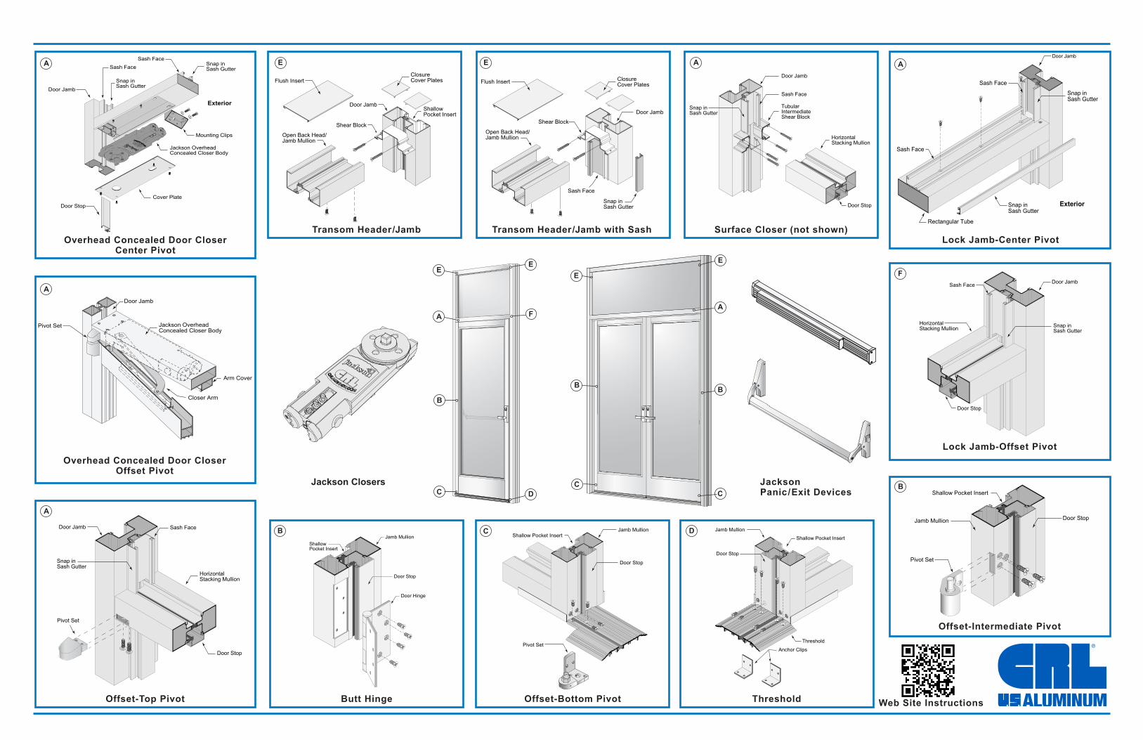
GENERAL DOOR INSTALLATION For all Narrow, Medium, and Wide Stile Non-Thermal and Thermal Entrance Doors Thank you for choosing C.R. Laurence / U.S. Aluminum as you entrance door supplier. We hope you find this guide useful. It is intended as a general installation guide. Your particular installation may vary. Questions? Call our Technical Sales at: (800)-262-5151 Ext.5305 for door assistance and Ext.7520 for door hardware questions. DOOR INSTALLATION DOOR OPENING AND REFERENCE POINT 1. Verify that the opening prepared for the door is square and plumb. The finished door frame should allow for shims and a 3/8" (9.5 mm) caulk joint around perimeter within the opening. Single or multiple door frames should be placed and attached to the opening before proceeding with the adjacent sidelite and window frames. 2. Determine the reference points for each door location by marking the door centerlines at the perimeter head and sill. DOOR FRAME PREPARATION 1. Assemble the frame using screw race and/or shear block construction. Apply Cat. No. RTV408 sealant to the ends of all horizontal members before attachment. NOTE: All frame joints that are not factory assembled must be sealed. 2. Install snap-in door stops. SET FRAME 1. Position door frame in opening and mark threshold anchor holes. Remove frame, drill holes, then insert anchors. 2 Remove dust and debris from opening. Clean all surfaces to be sealed with Isopropyl Alcohol. Apply a primary bead of Cat. No. 95C sealant to the bottom front edge of the aluminum threshold and a generous continuous secondary bead of Cat. No. 95C sealant to the floor substrate or sill flashing across the exterior and interior boundaries. A 1" (25.4 mm) gap in the sealant may be required on each side of the exterior bead for weeping if using sill flashing. Finally, inject sealant into all predrilled screw hole locations. 3. Place assembled frame into the wet threshold sealant. Shim as necessary and secure threshold with appropriate fasteners. Maintain minimum 1/32" (0.8 mm) shim at threshold. Secure frame at jambs and header with holes 6" (152.4 mm) from ends. Do not exceed 36" (914.4 mm) centerline to centerline. Place shims at each fastener location as necessary and make sure frame is set plumb and level. Maintain 3/8" (9.5 mm) reveal for caulk joint. NOTE: Insert minimum 1/32" (0.8 mm) shims or flashing at all bottom threshold/sill/jamb conditions where metal may contact concrete to prevent future aluminum deterioration. 4. Apply a continuous bead of sealant, Cat. No. 95C, to the bottom surface and attach to top of the transom bar with 1/2" (12.7 mm) self tapping button head screws. Fasteners may need to be cut off at bottom if installing a Jackson Overhead Concealed Closer. Seal top of screw heads with Cat. No. 95C sealant. 5. Complete all anchoring. (Do not distort frame by overtightening fasteners.) 6. Trim all shims 3/8" (9.5 mm) back from edge of frame, to allow a consistent caulk joint. ATTACH HARDWARE/INSTALL DOOR 1. Install hinges i.e. butt hinge, top and bottom pivot, continuous geared hinge, to frame. 2. Install closer(s) NOTE: Floor closers must be installed prior to door frame. 3. Install door into frame and check perimeter clearances. Adjust shims and fasteners as necessary. CAULKING FRAME 1. Wipe all perimeter surfaces with Isopropyl Alcohol. 2. Apply primer if required. 3. Insert Cat. No. EF12C 1/2" closed cell backer rod at the head and jambs. 4. Apply 3/8" (9.5 mm) bead of Cat. No. 95C sealant and tool sealant at the perimeter of frame at both the interior and exterior. 5. Complete caulking of all frame joints. GLAZING DOOR AND TRANSOM MEASURING DOOR GLASS (with stops in place) Measure the distance, in both width and height, of the Day Light Opening (D.L.O.) (Include Glass Stops). Add 7/8" (22.2 mm) to width, and add 7/8" (22.2 mm) to height for 1" (25.4 mm) IGU. DOOR GLAZING, INSTALLING GLASS IN DOOR FRAME 1. Identify and separate interior from exterior door stops. 2. Install the interior stops, starting with the full length vertical stops, and then the horizontal stops. 3. Retract the door adjustment screw in the top rail prior to setting glass. 4. Note any tempering bug should be in lower left hand exterior corner of glass when installed. 5. With door in a secure closed position set the glass on and within the pre-installed setting blocks at bottom and vertical edges of door. 6. Firmly hold glass in place at all times until exterior stops are installed. 7. Install the glass stops starting with the full length verticals and then the horizontals. Tilt the stops slightly forward with the bulb vinyl edge to glass surface and align extruded grooves on stop and door frame. Starting at one end, with firm inboard pressure on door stop, tap along the outside edge with a rubber mallet, working your way down to the other end. Make sure that each stop is snapped in completely. MEASURING TRANSOM GLASS Measure the distance, in both width and height, of the Day Light Opening (D.L.O.) (Include Glass Stops). Add 7/8" (22.2 mm) to width, and add 7/8" (22.2 mm) to height. INSTALL GLASS IN DOOR TRANSOM 1. Use suction cup(s) to set the glass horizontally. Evenly stab the vertical edge into the 1" (25.4 mm) deep pocket and swing in opposite side, clearing top and bottom. Center the glass in the opening from side-to-side. 2. Install the 3/8" (9.5 mm) x 1/2" (12.7 mm) x 2" (50.8 mm) setting blocks at 1/4 points and adjust as necessary. 3. Install bottom sash and sash stop. ADJUST DOOR IN FRAME 1. With the doors in place, check clearance. Door clearance 1/8" (3.2 mm) at Door Header; 1/8" (3.2 mm) at Lock Stile; 3/16" (4.7 mm) between Double Doors. 2. Swing the door(s) to ensure hinge, latch, and lock hardware are aligned and operating correctly. 3. Adjust door pivots up or down if necessary. 4. Use the adjustment screw in the top rail of door to adjust alignment. A) Turning the screw clockwise will raise leading edge of door frame and pull towards the top hinge/pivot side. B) Turning the screw counter clockwise will drop the door's leading edge, increasing the hinge side gap. 5. Adjust astragal(s) after a pair of doors are installed. Phone: (800) 262-5151 • Fax: (866) 262-3299 crlaurence.com • usalum.com • crl-arch.com Premium Balanced Doors Durafront Entrance Doors Impact Resistant Terrace Doors Premium Thermal Entrance Doors Visit our Web Site at crlaurence.com/manuals for additional installation information Standard Entrance Doors ALUMINUM Phone: (800) 262-5151 • Fax: (866) 262-3299 crlaurence.com • usalum.com • crl-arch.com QSS0100