DTSXM Distributed Temperature Sensor Middle Range System
GENERAL This General Specification (GS) describes the DTSXM Distributed Temperature Sensor Middle Range System. For information on its associated software, read GS 39J02B45-01E.
FEATURES The DTSXM Distributed Temperature Sensor Middle Range System (DTSXM System) measures the temperature distribution over the length of an optical fiber using the optical fiber itself as the sensing element. The module can be combined with appropriate power supply and optical switch modules to configure a required system. It can be accessed using the optional DTSX200 Control Visualization Software (DTAP200) or via the communications interface of a host computer. - Easy to integrate in process control system - Wide Temperature range operation - Compact and low power consumption
CONFIGURATION The following table lists the hardware and software for configuring a DTSXM System.
Component Quantity Description Distributed temperature sensor (DTSX200) 1 Required
Optical switch module (DTOS2, DTOS4, DTOS16)
1 Optional. Select one optical switch module unit for switching between 2, 4 or 16 channels.
Base module (DTSBM10) 1 Required Power supply module (NFPW426, NFPW441, NFPW442, NFPW444)
1 One power supply module is required (*1). For details, see GS 34P02Q12-01E or GS 34P02Q13-01E.
CPU module (NFCP050) 1 Optional. For details, see GS 34P02Q13-01E.
Rack mount kit (DTRK10) 1 Optional tray for mounting optical fiber cables. DTSX200 Control Visualization Software (DTAP200)
1 Optional software for configuring measurement and displaying measurement results. For details, see GS 39J02B45-01E.
DTSX200 data conversion software (DTAP200D)
1 Optional software for converting measurement data into WITSML format. For details, see GS 39J02B45-01E.
*1: Dual-redundant configuration is not allowed for the power supply module.
System Application Example The DTSXM System performs temperature profile measurement according to instructions from control and monitoring stations. A control and monitoring station polls the DTSX200 of the DTSXM System constantly and when measurement data is available, it retrieves and displays the data. The DTSX200 can also convert data to WITSML format (when used with the optional DTAP200D data conversion software) for transmission to a host data server.
DTSXM
DTAP200 (*1, *2)(for DTSX200 configuration, control & data
display)
DTAP200D (*1, *2)(for data
conversion configuration &
operation)
Ethernet
Modbus Serial(ASCII, RTU)
SSH, SFTP,SCP
SSH, SFTP,SCP
Web browser (*2)(for maintenance)
HTTP
STARDOM,CENTUM (*1, *2)
(for control)
Modbus/TCP
Control device
RS-232C
System Configuration Example (*1) Requires separate purchase. (*2) Neither hardware nor software is included in this specification. With built-in support for the Modbus protocol, the DTSX200 can communicate with STARDOM and CENTUM. If a CPU module (NFCP050) is connected to the base module (DTSBM10), the CPU module can communicate with the DTSX200 Distributed Temperature Sensor using the Modbus (Modbus serial or Modbus/TCP) protocol via an RS-232C or Ethernet connection.
System Requirements for DTSXM System Maintenance The DTSX200 can be accessed using a Web browser for backup, restore, network configuration and other maintenance operations.
Operation -40 to +65°C (*2) Transportation/storage -40 to +70°C
Ambient humidity Operation 20 to 80%RH (no condensation) Transportation/storage 5 to 85%RH (no condensation)
Rate of change in temperature
Operation Within ±10°C/h Transportation/storage Within ±20°C/h
Dust 0.3 mg/m3 or less Protection class IP20
Resistance to corrosive gases ANSI/ISA S71.04 Class G2 (Standard) (ANSI/ISA S71.04 Class G3, option)
Resistance to vibration 0.15mm P-P (5 to 58 Hz), 1 G (58 to 150 Hz)
Resistance to shock 15 G, 11 ms (during power-off, for sine half-waves in XYZ-directions)
Altitude 3000 m or less (*3)
Noise Electric field 3 V/m or less (26 MHz to 1 GHz) Magnetic field 30 A/m (AC) or less, 400 A/m (DC) or less Electrostatic discharge 4 kV or less contact discharge, 8 kV or less aerial discharge
Grounding Type D (100 Ω or less) (*4) Cooling Natural air cooling
*1: Not applicable to DTFB10. *2: 0 to +50°C when optical switch module DTOS16 is used. 0 to +55°C when power supply module NFPW441, NFPW442 or NFPW444 is used. The ambient temperature and humidity range requirements for operation and storage of
the DTOS2 and DTOS4 optical switch modules are indicated by solid lines and dashed lines respectively in the figure on the right.
*3: 2000 m or less when power supply module NFPW441, NFPW442 or NFPW444 is used. *4: Applicable to DTSBM10.
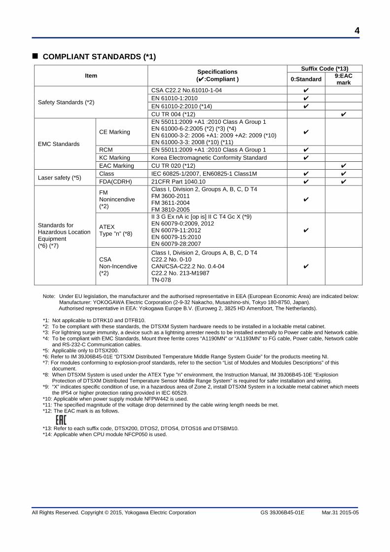
CSA C22.2 No.61010-1-04 ✔ EN 61010-1:2010 ✔ EN 61010-2:2010 (*14) ✔ CU TR 004 (*12) ✔
EMC Standards
CE Marking
EN 55011:2009 +A1 :2010 Class A Group 1 EN 61000-6-2:2005 (*2) (*3) (*4) EN 61000-3-2: 2006 +A1: 2009 +A2: 2009 (*10) EN 61000-3-3: 2008 (*10) (*11)
✔
RCM EN 55011:2009 +A1 :2010 Class A Group 1 ✔ KC Marking Korea Electromagnetic Conformity Standard ✔ EAC Marking CU TR 020 (*12) ✔
Laser safety (*5) Class IEC 60825-1/2007, EN60825-1 Class1M ✔ ✔ FDA(CDRH) 21CFR Part 1040.10 ✔ ✔
Standards for Hazardous Location Equipment (*6) (*7)
FM Nonincendive (*2)
Class I, Division 2, Groups A, B, C, D T4 FM 3600-2011 FM 3611-2004 FM 3810-2005
✔
ATEX Type ”n” (*8)
II 3 G Ex nA ic [op is] II C T4 Gc X (*9) EN 60079-0:2009, 2012 EN 60079-11:2012 EN 60079-15:2010 EN 60079-28:2007
✔
CSA Non-Incendive (*2)
Class I, Division 2, Groups A, B, C, D T4 C22.2 No. 0-10 CAN/CSA-C22.2 No. 0.4-04 C22.2 No. 213-M1987 TN-078
✔
Note: Under EU legislation, the manufacturer and the authorised representative in EEA (European Economic Area) are indicated below:
Manufacturer: YOKOGAWA Electric Corporation (2-9-32 Nakacho, Musashino-shi, Tokyo 180-8750, Japan). Authorised representative in EEA: Yokogawa Europe B.V. (Euroweg 2, 3825 HD Amersfoort, The Netherlands).
*1: Not applicable to DTRK10 and DTFB10. *2: To be compliant with these standards, the DTSXM System hardware needs to be installed in a lockable metal cabinet. *3: For lightning surge immunity, a device such as a lightning arrester needs to be installed externally to Power cable and Network cable. *4: To be compliant with EMC Standards, Mount three ferrite cores “A1190MN” or “A1193MN” to FG cable, Power cable, Network cable
and RS-232-C Communication cables. *5: Applicable only to DTSX200. *6: Refer to IM 39J06B45-01E “DTSXM Distributed Temperature Middle Range System Guide” for the products meeting NI. *7: For modules conforming to explosion-proof standards, refer to the section “List of Modules and Modules Descriptions” of this
document. *8: When DTSXM System is used under the ATEX Type ”n” environment, the Instruction Manual, IM 39J06B45-10E “Explosion
Protection of DTSXM Distributed Temperature Sensor Middle Range System” is required for safer installation and wiring. *9: “X” indicates specific condition of use, in a hazardous area of Zone 2, install DTSXM System in a lockable metal cabinet which meets
the IP54 or higher protection rating provided in IEC 60529. *10: Applicable when power supply module NFPW442 is used. *11: The specified magnitude of the voltage drop determined by the cable wiring length needs be met. *12: The EAC mark is as follows.
*13: Refer to each suffix code, DTSX200, DTOS2, DTOS4, DTOS16 and DTSBM10. *14: Applicable when CPU module NFCP050 is used.
General The DTSX200 measures temperature distribution using a 50/125µmGI optical fiber cable (not included in this specification) as the sensing element.
Model and Suffix Codes Description Model DTSX200 DTSX200 Distributed Temperature Sensor
Suffix Codes
-N Standard type 0 Standard type 9 EAC mark
E E2000/APC N Basic type G With ISA Standard G3 option
Specifications
Items Specifications
Distributed temperature measurements
Distance
Measurement distance range 1 km, 2 km, 3 km, 4 km, 6 km (*1)(*2)
Sampling resolution 10 cm, 20 cm, 50 cm, 1 m (*1) Spatial resolution 1 m (10 to 90%) (*3)
Temperature
Measurement temperature range -200 to +800°C (*4)
Temperature resolution
Range Time 1 km 3 km 6 km 10sec 0.5 1.1 4.2 °C 1min 0.3 0.6 2.1 10min 0.1 0.2 0.7 (1sigma, without optical switch) (*5)
Sensor optical fiber
Optical fiber (*6) 50/125 µm GI (No reflection at end of optical fiber)
Optical connector E2000/APC
Interface
Serial (RS-232C)
3 ports, non-isolated, RJ45 modular jacks Full duplex, asynchronous
SERIAL 1 Function: Communication (Modbus) Baud rate: 1.2, 2.4, 4.8, 9.6, 19.2, 38.4 57.6, 115.2 kbps
SERIAL 2 Function: Communication (Modbus) Baud rate: 1.2, 2.4, 4.8, 9.6, 19.2, 38.4 kbps
SERIAL 3 (*7) Function: Maintenance (Private)
Ethernet interface LAN
1 port, 10BASE-T (*9) or 100BASE-TX, RJ45 modular jacks, automatic negotiation, automatic MDI, with Network power switch (ON/OFF)
Display LEDs: HRDY, RDY, LASER ON
Power supply Consumption Operating mode 10 W Power save mode 2.1 W
Dimensions (W x H x D) 197.8 x 132.0 x 162.2 mm (6 slots width) (*8) Weight 2.5 kg Temperature calibration of the Sensor Optical Fiber for DTSX200 is required before temperature distribution measurement. *1: Indicated nominal values vary with the length and refractive index of the optical fiber. *2: Spatial range is selectable from 1, 2 and 3 km when sampling resolution is 10 cm. *3: The spatial resolution is the distance between the 10% and 90% points on the DTS response to a step temperature change for the
near end section of the optical fiber. *4: This range depends on the temperature range of the sensor optical fiber. *5: The given values indicate one standard deviation over distance for measurements of constant temperature 20°C with no coupling
loss and optical fiber attenuation of 1.25 dB/km for stokes light and 1.465B/km for anti-stokes light. Time values indicate hardware measurement time in fast measurement mode at sampling resolution of 1 meter. A 100 meter section each at the near end and the far end of the optical fiber is excluded.
*6: Fusion splicing of optical fiber with coupling loss of 0.3 dB max. (0.15 dB max. on average) *7: SERIAL 3 of RS-232C is dedicated for maintenance use. *8: Dimensions exclude protective cap of optical connector. *9: A repeater hub cannot connect.
Optical switch control (*1) Controls channel switching by optical switch DTOS2, DTOS4 or
DTOS16. Measurement control Starts measurement and stops measurement (Global) measurement settings
Settings for channel combination, measurement sequence, measurement mode (single-ended or double-ended), measurement interval and measurement start time
Channel settings Measurement condition settings (repetition rate, measurement time (*2) or averaging times, distance range and sampling resolution) Sensor optical fiber settings (optical fiber length, wave number, group index, loss correction, temperature offset correction and winding coefficient (distance-depth conversion factor))
WITSML data conversion configuration (*3)
WITSML data conversion configuration, destination server configuration for data transfer by HTTP client
LAS data conversion configuration
LAS data conversion settings and destination server configuration for data transfer by HTTP client
Data processing functions
Temperature data calculation
Calculates temperature by applying various defined corrections.
Generated data Temperature distribution data, temperature alarm data and zone temperature data
Zone temperature data generation (up to 100 zones can be defined)
Data generation zones can be defined with the temperature output data type (average, maximum, minimum, difference or slope) selected for each zone
Detection functions Temperature alarm settings (Up to 10 alarm zones can be defined)
Alarm detection zones can be defined with temperature high limit, low limit, rise limit, fall limit and difference limit values specified for each zone.
Optical fiber failure detection
An error and alarm is generated if optical fiber loss exceeds a specified threshold value.
Data management functions
Configuration data Various settings LAS data Data files in LAS (Log ASCII Standard) format.
More than 100 files can be saved. With 1 m sampling over 3 km range, more than 1000 files can be saved.
WITSML data (*3) Data files in WITSML (Wellsite Information Transfer Standard Markup Language) format. More than 100 files can be saved. With 1 m sampling over 3 km range, more than 1000 files can be saved.
WITSML data conversion function (*3) Conversion of configuration and temperature distribution data into WITSML format (WITSML version 1.3.1.1 compatible).
LAS data conversion function Conversion of configuration and temperature distribution data into LAS format (LAS version 2.0 compatible).
Data transfer functions Transfers LAS data files or WITSML data files (*3) to HTTP server using PUT or POST.
RAS functions Fault diagnosis, self-diagnosis, log data generation, error handling and watchdog timer
Maintenance functions Firmware upgrade, power management, reset processing, time setting and maintenance functions
Authentication functions SSH, SFTP, SCP and HTTPS; authentication using username and password
User registration functions Up to 10 users can be registered for use with HTTPS server and SSH server.
*1: Available when DTSX200 is used with optical switch DTOS2, DTOS4 or DTOS16. *2: The measurement time setting refers to pure measurement time.
It does not include time for hardware ready, temperature calculation, alarm decision, zone data creation, file creation, data conversion, data transfer and other auxiliary time.
*3: Available when DTSX200 is used with the DTSX200 Data Conversion Software (DTAP200D).
Network Function (Ethernet) Purpose Ethernet is used for connecting the DTSX200 to the DTSX200 Control Visualization Software (DTAP200), the DTSX200 Data Conversion Software (DTAP200D), autonomous controllers FCN/FCJ and various types of PLCs. It is also used for maintenance of the DTSX200. Communication Functions
Destination Maximum Number of Connections (*1)
Description
1 DTSX200 Control Visualization Software (DTAP200)
4 Enables measurement configuration, control and data display for the DTSX200.
2 DTSX200 Data Conversion Software (DTAP200D)
4 Enables configuration of data conversion by DTSX200.
3 Modbus/TCP client 4 The DTSX200 runs as a Modbus/TCP server. 4 SSH client 4 The DTSX200 runs as an SSH server. 5 SFTP client 4 The DTSX200 runs as an SSH server. 6 SCP client 4 The DTSX200 runs as an SSH server. 7 Web browser No restriction Enables display of DTSX200 system settings and status.
Moreover, modification of system settings, as well as backup/restore and other maintenance operations are allowed when connected with administrator privileges.
8 HTTP server 1 The DTSX200 runs as an HTTP client and transfers measurement data files in LAS format or converted to WITSML format (*2) to the HTTP server using PUT or POST.
9 SNTP server 3 The DTSX200 runs as an SNTP client to synchronize its time with an SNTP server.
*1: Up to 4 connections of types 1 to 6 combined are allowed. *2: Available only when the DTSX200 is used with the DTSX200 Data Conversion Software (DTAP200D).
Network Function (serial port) The DTSX200 can exchange data with other devices via the serial port. Number of ports: Two (RS-232-C) communications ports One port dedicated for maintenance
Destination Description Modbus master The DTSX200 runs as a Modbus serial slave.
Modbus Connection Function
The DTSX200 can connect with Modbus master devices and Modbus client devices supporting the Modbus communications protocol.
Item Description Destination device Modbus compliant devices Connection ports Serial port
Ethernet port Available registers Input registers (300001 to 365535)
Holding registers (400001 to 465535) The following communications functions are supported.
Communications Type Communications Mode Communications Functions Serial communications ASCII mode Slave
RTU mode Slave Ethernet communications Modbus/TCP Server
The DTSX200 supports time synchronization between SNTP (Simple Network Time Protocol) enabled devices. The DTSX200 can run as an SNTP client.
Item Client Functions Communications protocol SNTP (Simple Network Time Protocol)
UDP port: 123 Unicast mode (*1) Available Number of connections 3 servers Time accuracy ±1s Time correction method Time retrieval from the server at hourly intervals (unicast mode) (*2)
*1: An SNTP client sends a time request to the SNTP server periodically. *2: Smooth time transition is adopted to avoid sudden change in time. However, immediate time change (immediate change to specified
time) is adopted at startup and exit.
CONFIGURATION TOOLS
Operating Environment The table below shows the system requirements for running configuration tools such as the Maintenance web page on a PC.
Item Specification Personal computer IBM PC/AT compatible CPU Dual-core 32-bit processor 2 GHz or better RAM 2 GB or more Hard disk free space 2 GB or more Ethernet adaptor 100BASE-TX or 10BASE-T OS Windows7 Home Premium SP1(x86 / x64)
Software Media The DTSX200 user manual, the DTSX200 software and the DTSX200 Configurator are supplied on a CD-ROM. - DTSX200 user manual (electronic document) - DTSX200 software - DTSX200 Configurator
LED Indicator Color Description HRDY Green Lit when the hardware is operating normally. RDY Green Lit when the system is operating normally. Laser ON Green Lit when the laser is on.
LAN status indicators (near RJ45 modular jacks)
LED Indicator Color Description NETWORK ON/OF
Green Lit in normal communication mode. Unlit in power down mode.
LINK & ACT Green Lit when a LINK is established. Blinks when transmitting or receiving.
General Installing an optical switch module (2, 4 or 16-channel model) allows monitoring of multiple optical fibers using a single DTSX200. An optical switch module can also be used in double-ended measurement using DTSX200.
Interface Control Controlled by DTSX200 Display LEDs: HRDY, RDY, Alarm, Active channel
Power supply Consumption 1 W 1 W Operating 4.5 W
Power save 1 W
Dimensions (W x H x D) (*4) 65.8 x 130.0 x 160.3 mm (2 slots width)
65.8 x 130.0 x 160.3 mm (2 slots width)
65.8 x 130.0 x 160.3 mm (2 slots width)
Weight 0.6 kg 0.64 kg 0.75 kg Note: As a guideline, the module should be replaced periodically every 4.7, 6 and 9.5 years for continuous operation of 15-second,
20-second and 30-second measurements, respectively. *1: One-way loss *2: These values indicate typical performance at 23°C ambient temperature but are not performance specification values. *3: When used with DTSX200, the specification and notes of DTSX200 are applicable. *4: Dimensions exclude protective cap of optical connector.
LED Indicator Color Description HRDY Green Lit when the hardware is operating normally. RDY Green Lit when the system is operating normally. ALARM Green Flashes when an alarm condition is present. Active Channel Green Indicates an active channel.
External Dimensions
DTOS2 DTOS4 DTOS16 Unit: mm Other Information
The optical switch module cannot be mounted on a STARDOM base module.
General The base module for DTSX200 is used for mounting various function modules including the DTSX200 Distributed Temperature Sensor, power supply modules, optical switch modules and CPU modules.
Model and Suffix Codes Description Model DTSBM10 Base module for DTSX200
Suffix Codes
-N Standard type 0 Standard type 9 EAC mark N Basic type G With ISA Standard G3 option
Specification
Item Specifications Power supply Consumption 0.3 W Dimensions (W x H x D) 482.6 x 132.5 x 55.0 mm Weight 2.3 kg
External Dimensions
Unit: mm
Other Information Only power supply modules (NFPW426, NFPW441, NFPW442 and NFPW444) and CPU modules (NFCP050) but no other STARDOM module can be mounted on the base module (DTSBM10). Dual-redundant configuration for power supply modules and DIN rail mounting are not allowed.
General The optical fiber for DTSX is used for checking the operation of the DTSX200.
Model and Suffix Codes Description Model DTFB10 Optical Fiber for DTSX
Suffix Codes -N Basic type 1 Basic type E E2000/APC
Specifications
Item Specifications Optical Connector E2000/APC Optical Fiber 50/125 µm GI Dimensions (W x H x D) 133.4 x 35.4 x 181 mm (1*) Weight 0.4 kg
*1: Dimensions exclude protective cap of optical connector
External Dimensions
Unit: mm
POWER SUPPLY MODULE One of the following power supply modules must be selected when configuring a DTSXM System. Dual-redundant configuration is not allowed for the power supply module.
Model Reference (Input voltage range) NFPW426 10 to 30 VDC NFPW441 100 to 120 VAC NFPW442 220 to 240 VAC NFPW444 21.6 to 31.2 VDC
For the specifications of the power supply modules, see GS 34P02Q13-01E and GS 34P02Q12-01E.
CPU MODULE This is the CPU module for the autonomous controller. One CPU module of the following model may be optionally installed onto the DTSBM10 base module.
Model NFCP050 For details on the specifications of the CPU module, see GS 34P02Q13-01E. Dual-redundant configuration is not allowed for the CPU module. STARDOM modules including I/O modules, bus repeater modules and serial communication modules cannot be mounted on the DTSBM10 base module.
COMBINING SYSTEM COMPONENTS The tables below show how components can be combined to configure a DTSXM System to suit different applications.
Product Model Selection Operating Temperature Range DTSX200 Distributed Temperature Sensor
DTSX200 ◎ -40 to +65°C
Power supply module NFPW426 ○ -40 to +65°C NFPW441
NFPW442 NFPW444
○
○
○
0 to +55°C 0 to +55°C 0 to +55°C
Base module DTSBM10 ◎ -40 to +65°C Optical switch module DTOS2 ▲ -40 to + 65°C DTOS4 ▲ -40 to +65°C DTOS16 ▲ 0 to +50°C CPU module NFCP050 △ -40 to +70°C Rack mount kit DTRK10 △ Optical fiber for DTSX DTFB10 △ Control Visualization Software DTAP200 △ Data conversion software DTAP200D △
◎: Required ○: Required, select one unit of any model ▲: Optional, select one unit of any model △: Optional
CPU module NFCP050 CPU module レ レ レ Rack mount kit DTRK10 Rack mount for optical fiber N.A. N.A. N.A. Optical fiber for DTSX DTFB10 Optical fiber for DTSX N.A. N.A. N.A.
レ: conforming - : Not conforming yet N.A.: Not applicable For the details of the power supply modules and the CPU module, see GS 34P02Q13-01E and GS 34P02Q12-01E.
CABLING AND INSTALLATION PRECAUTIONS For details on cable connection and installation procedures, see IM 39J06B45-01E. For details on how to install power supply modules and CPU modules, also see TI 34P02Q91E.
OPTICAL FIBER HANDLING PRECAUTIONS - Use optical connectors and optical fibers specified in the product specification. - Clean the endface of the optical connector to remove dirt, dust, oil film and other contaminants before
connection. - Ensure that the endface of the optical connector is free of scratch marks. Otherwise, it may damage the
peer optical connector. - Ensure that optical connectors are securely connected and locked. - Follow proper procedures when laying optical fiber cables. Do not subject the cable to excessive tension,
ORDERING INFORMATION Specify the model and suffix codes when placing an order.
TRADEMARKS - DTSX, STARDOM and CENTUM are trademarks of Yokogawa Electric Corporation. - Ethernet is a registered trademark of Xerox Corporation. - Windows is a registered trademark of Microsoft Corporation in the United States and other countries. - Modbus is a registered trademark of AEG Schneider. - E2000 is a trademark of Swiss Diamond. - Other company and product names appearing in this document are trademarks or registered trademarks of
their respective holders.
PRECAUTIONS - Open-source software included in this product is redistributed by Yokogawa pursuant to the license of the
software. Read the licensing terms carefully before use and use the software within the scope of its license. - The warranty terms of open-source software included in this product, including parts modified by
Yokogawa, follows the license of the software. For instance, the GPL (GNU General Public License) provides no warranty so open-source software
provided under the GPL, even though bundled with this product, is not covered by Yokogawa’s product warranty.


![[MS-DFSNM]: Distributed File System (DFS): Namespace ...... · Distributed File System (DFS): Namespace Management Protocol Intellectual Property Rights Notice for Open Specifications](https://static.documents.pub/doc/80x56/5f72fe76b29be002120c0115/ms-dfsnm-distributed-file-system-dfs-namespace-distributed-file.jpg)
![[MC-DRT]: Distributed Routing Table (DRT) Version 1€¦ · Distributed Routing Table (DRT) Version 1.0 Intellectual Property Rights Notice for Open Specifications Documentation](https://static.documents.pub/doc/80x56/603ec42a19edb942e54403aa/mc-drt-distributed-routing-table-drt-version-1-distributed-routing-table-drt.jpg)


