METRIC/ I INCH-POUND I National Aeronautics and NASA-STD-5006 Space Administration FEBRUARY 17,1999 GENERAL FUSION WELDING REQUIREMENTS FOR AEROSPACE MATERIALS USED IN FLIGHT HARDWARE NASA TECHNICAL STANDARD Copyright National Aeronautics and Space Administration (NASA) Licensee=NASA BOM Manager MSFC/9972545005, User=Wright, Amber Not for Resale, 10/11/2018 13:17:24 MDT No reproduction or networking permitted without license from IHS --```,``,,`,,`,,```,```,`,,,,``,-`-`,,`,,`,`,,`---
Transcript
METRIC/ I INCH-POUND I National Aeronautics and NASA-STD-5006 Space Administration FEBRUARY 17,1999
GENERAL FUSION WELDING REQUIREMENTS FOR
AEROSPACE MATERIALS USED IN FLIGHT HARDWARE
NASA TECHNICAL STANDARD
Copyright National Aeronautics and Space Administration (NASA) Provided by IHS Licensee=NASA BOM Manager MSFC/9972545005, User=Wright, Amber
Not for Resale, 10/11/2018 13:17:24 MDTNo reproduction or networking permitted without license from IHS
This standard is approved for use by NASA Headquarters and all NASA Centers and is intended to provide a common framework for consistent practices across NASA programs.
This standard was developed by the NASA Materials and Processes Standards Group to provide the NASA Centers with a common standard for welds on flight hardware components. This standard does not provide the detailed process and quality assurance requirements for weldments on flight hardware. Instead, it is intended as a higher level document which states minimum requirements for the design of welded hardware. This standard provides general directions and describes the type of information that NASA expects for welded structures. When this standard is specified on contract documents, the contractor shall submit a detailed weld process specification which meets the intent of this standard. Industry, Government, and company specifications can be used for welding flight hardware if they contain the information required by this standard. This document is the original release of this standard.
NOTICE. The Government drawings, specifications, and/or data are prepared for the official use by, or on the behalf of, the United States Government. The Government neither warrants these Government drawings, specifications, or other data, nor assumes any responsibility or obligation for their use for purposes other than the Government project for which they were prepared and/or provided by the Government, or an activity directly related thereto. The fact that the Government may have formulated, furnished, or in any way supplied the said drawings, specifications, or other data is not to be regarded, by implication or otherwise, as licensing in any manner the holder or any other person or corporation, nor conveying the right or permission, to manufacture, use, or sell any patented invention that may relate thereto.
Requests for information, corrections, or additions to this standard should be directed to the Materials and Processes Laboratory, Mail Code EH41, Marshall Space Flight Center, AL, 3581 2. Requests for additional copies of this standard should be sent to NASA Engineering Standards, ELO1, MSFC, AL, 3581 2 (telephone 256-544-2448). This and other NASA standards may be viewed and downloaded, free-of-charge, from our NASA Standards Homepage: http://standards.nasa.gov.
Daniel R. Mulville Chief Engineer
I
Copyright National Aeronautics and Space Administration (NASA) Provided by IHS Licensee=NASA BOM Manager MSFC/9972545005, User=Wright, Amber
Not for Resale, 10/11/2018 13:17:24 MDTNo reproduction or networking permitted without license from IHS
TABLE OF CONTENTS ............................................................................
LIST OF FIGURES AND TABLES .............................................................
SCOPE ...................................................................................................... Scope ............................................................................................... Applicability ....................................................................................... Applicable processes ........................................................................ Applicable materials .......................................................................... Joint classes ..................................................................................... Class A ............................................................................................. Class B ............................................................................................. Class C .............................................................................................
APPLICABLE DOCUMENTS ..................................................................... General ............................................................................................. References ....................................................................................... Order of precedence .........................................................................
GENERAL FUSION WELDING REQUIREMENTS FOR AEROSPACE MATERIALS USED IN FLIGHT HARDWARE
1. SCOPE
1.1 Scope. This standard establishes the processing and quality assurance requirements for manual, automatic, machine, and semiautomatic fusion welding for space flight applications and special test equipment used for testing flight hardware within NASA.
1.2 Applicability. This standard recommends engineering practices for NASA programs and projects. It may be cited in contracts and program documents as a technical requirement or as a reference for guidance. Determining the suitability of this standard and its provisions is the responsibility of program/project management and the performing organization. Individual provisions of this standard may be tailored (¡.e., modified or deleted) by contract or program specifications to meet specific program/project needs and constraints.
1.3 Applicable processes. This standard covers all fusion processes used for joining metallic materials. This includes, but is not limited to: arc welding (AW), solid state welding (SSW), resistance welding (RW), and high energy density welding (HEDW).
1.4 Applicable materials. This standard covers all metallic materials used in the manufacture of spaceflight hardware only.
1.5 Joint classes. Welding performed using this standard shall be classified in accordance with the service of the joints as follows:
1.5.1 Class A. Class A joints are critical and structural. Failure of a Class A joint would result in loss of life, mission, spacecraft, etc. Class A joints shall have the highest level of scrutiny appropriate to criticality of performance including internal and external weld integrity verification.
1.5.2 Class B. Class B joints are noncritical and structural and shall be considered fail safe. Class B joints shall require weld integrity verification (either external, internal, or both) appropriate for the intended use.
1.5.3 Class C. Class C joints are noncritical and nonstructural and are contained so that failure will not affect other flight elements or personnel. These joints shall require minimal weld integrity verification.
2. APPLICABLE DOCUMENTS
2.1 General. No subtier documents are imposed by this standard. The contractors are responsible for demonstrating their ability to satisfy the requirements of this standard. Contractors must provide company specifications, plans, industry standards, etc., to the procuring agency upon submission of the contract proposal or preliminary design review as required for evaluation of adequacy in meeting this standard.
1
Copyright National Aeronautics and Space Administration (NASA) Provided by IHS Licensee=NASA BOM Manager MSFC/9972545005, User=Wright, Amber
Not for Resale, 10/11/2018 13:17:24 MDTNo reproduction or networking permitted without license from IHS
2.2 References. The documents listed in Table I may be referenced for detailed process requirements.
TABLE I. Reference Specifications
MARSHALL SPACE FLIGHT CENTER MSFC-SPEC-504C Welding Aluminum Alloys MSFC-SPEC-560A Fusion Welding of Steels, Corrosion and Heat Resistant Alloys MSFC-SPEC-766 Welding Titanium Alloys
JOHNSON SPACE CENTER JSC-PRC-0001 Process Specification for the Manual Arc Welding of Aluminum Alloy Flight
Hardware JSC-PRC-0004 Process Specification for the Manual Arc Welding of Titanium Alloy flight Hardware JSC-PRC-0006 Process Specification for the Manual Arc Welding of Steel and Nickel Alloy Flight
Hardware JSC-PRC-0009 Process Specification for the Resistance Spot Welding of Battery Assemblies JSC-PRC-001 O Process Specification for the Orbital Arc Welding of steel and Nickel Alloy Tubular
Flight Hardware FEDERAL
BB-0925 Oxygen, Technical, Gas and Liquid BB-H-886 Hvdroaen Gas
2
Copyright National Aeronautics and Space Administration (NASA) Provided by IHS Licensee=NASA BOM Manager MSFC/9972545005, User=Wright, Amber
Not for Resale, 10/11/2018 13:17:24 MDTNo reproduction or networking permitted without license from IHS
NATIONAL AEROSPACE STANDARDS (NAS) NAS-41 O Nondestructive Testing Personnel Qualification and Certification NAS 1514 Radiographic Standard for Classification of Fusion Weld Discontinuities
ANSI/RWS A5.10-80 Electrodes, Welding, Bare, Aluminum Alloys AMERICAN NATIONAL STANDARDS INSTITUTE (ANSI)
SOCIETY OF AUTOMOTIVE ENGINEERS (SAE)
AMS 2680 Electron Beam Welding for Fatigue Critical Applications AMS 2681 Electron Beam Welding
AMs-STD-1595 Qualification of Aircraft, Missile, and Aerospace Fusion Welders
AMs-2801 Heat Treatment of Titanium Alloys AMs-H-6088 Heat Treatment of Aluminum Allovs
2.3 Order of precedence. Where this document is adopted or imposed by contract on a program or project, the technical guidelines of this document take precedence, in the case of conflict, over the technical guidelines cited in other referenced documents.
3. DEFINITIONS
3.1 Automatic weldinq. Welding with equipment that performs the welding operation without adjustment of the controls by a welding operator.
3.2 Concave root surface . A weld root with penetration not extending beyond the thickness of the parent metal. Sometimes referred to as suckback.
3.3 Essential variables. Weld process parameters which directly influence the weld process and resulting weld properties. Some examples are current, voltage, travel speed, etc.
3.4 Fail safe. A condition shown by analysis or test that, due to structural redundancy, the structure remaining after failure of the one part can sustain the new limit loads with an ultimate factor of safety equal to or greater than 1 .O and the remaining structure has sufficient fatigue life to complete the mission.
3.5 Heat input. Quantity of energy introduced per unit length of weld from a traveling heat source, expressed in joules per millimeter (joules per inch). Computed as the ratio of the total input power of the heat source in watts to the travel velocity in millimeters per second (inches per minute).
3.6 Heat sensitive alloys. Alloys which demonstrate a reduction in mechanical properties or corrosion resistance due to exposure to elevated temperatures associated with welding.
3.7 Incomplete fusion. A weld discontinuity in which fusion did not occur between weld metal and fusion faces or adjoining weld beads.
3.8 Incomplete ioint penetration. A weld depth extending from its face into the joint, exclusive of reinforcement, which is less than the joint thickness.
3.9 Lack of fill. A weld face surface not extending beyond the thickness of the parent metal
3.1 O Machine weldinq. Welding with equipment that performs the welding operation under the constant observation and control of a welding operator.
3
Copyright National Aeronautics and Space Administration (NASA) Provided by IHS Licensee=NASA BOM Manager MSFC/9972545005, User=Wright, Amber
Not for Resale, 10/11/2018 13:17:24 MDTNo reproduction or networking permitted without license from IHS
3.1 1 Manual weldinq. A welding operation performed and controlled completely by hand.
3.12 Material thickness. The minimum material thickness of a joint member per drawing tolerance. The thinner of the joint members with different thicknesses is designated "t".
3.13 Mismatch. The linear distortion of the components resulting from welding. Mismatch is calculated as the difference in the alignment of the center lines of the two parts having been welded. Mismatch should not be confused with the difference in center lines as a result of welding two different thickness components.
3.1 4 Peakinq. The angular distortion of the components resulting from welding. Peaking is calculated as the angle resulting from the intersection of tangents taken from the surface of the two components being welded.
3.1 5 Procedure qualification record (PQR). A document providing the actual welding variables used to produce an acceptable test weld and the results of tests conducted on the weld for the purpose of demonstrating process and procedural capability and repeatability. Demonstration of capability qualifies the welding procedure.
3.1 6 Qualified inspector. A certified individual with the responsibility and ability to judge the quality of the welded specimens in relation to some form of written specification. Welding inspectors shall be certified to AWS QC1 or equivalent and Non Destructive Evaluation inspectors shall be certified to NAS-41 O or equivalent.
3.1 7 Semiautomatic weldinq. Welding with equipment that controls only the filler metal feed. The advance of welding is manually controlled.
3.1 8 Undercut. A groove melted into the base metal adjacent to the weld toe or weld root and left unfilled by weld metal.
3.1 9 Welder performance qualification (WPQ). The demonstration of a welder's ability to produce welds meeting prescribed standards.
3.20 Weld procedure specification (WPS). A document providing in detail the required variables for a specific application to ensure repeatability by properly trained welders and welding operators.
3.21 Weld zone. The weld metal fusion zone plus the heat-affected zone.
4. REQUIREMENTS
4.1 Equipment.
4.1.1 Weldinq equipment. Automatic, semiautomatic, and machine welding shall be accomplished using equipment containing calibrated dials, meters, or recorders that quantitatively indicate process parameters. All joining equipment (including manual) shall be capable of producing joints that meet the requirements specified herein.
4
Copyright National Aeronautics and Space Administration (NASA) Provided by IHS Licensee=NASA BOM Manager MSFC/9972545005, User=Wright, Amber
Not for Resale, 10/11/2018 13:17:24 MDTNo reproduction or networking permitted without license from IHS
4.1.1.1 Acceptance testinq. New, repaired, relocated, or modified welding machines for automatic, semiautomatic and machine welding shall be acceptance tested prior to processing of flight hardware. Machines shall meet the requirements of the applicable purchase specification, design specification, or modification order. Power supplies and supporting components (electrical or mechanical or both) shall be capable of operating reliably within the range of parameters and duty cycle to be used for joining production parts.
4.1.1.2 Calibration. Measuring instruments, meters, gages, or direct reading electrical control circuits to be used for automatic, semiautomatic, and machine joining operations shall be initially calibrated and periodically recalibrated to maintain adequate performance or when any maintenance is performed that may have changed calibration.
4.1.1.3 Maintenance and records. Records shall be maintained and made available to the procuring agency or its representative upon request. Welding machines shall be provided with adequate periodic maintenance service so that acceptable welds can be produced using qualified welding procedure specifications. A current record of each maintenance repair or functional check shall be maintained for each welding machine. Records shall be located on the welding machines.
4.1.2 Toolinq and fixtures. Tooling and fixtures used in the joining operation shall be constructed of nonmagnetic materials that do not affect the welding arc or beam, or that are not detrimental to the weld quality. Tooling and fixtures shall not be a source of contamination of the joint. Magnetic materials, when used, shall be degaussed prior to welding. Degausing shall be controlled by the WPS when necessary for the successful completion of the weld. Tooling and fixtures shall ensure compliance with dimensional requirements of 4.6.3 and shall be identified on the WPS.
4.2 Materials.
4.2.1 Base metals. Unless otherwise specified or approved by the procuring agency, base metal alloy shall conform to applicable Government and/or industry specifications for each given alloy group. The base metal, material condition, and appropriate specification shall be recorded as a part of the WPS. Weld start and runoff tabs, when used, shall be of the same alloy as the material being joined and shall be welded with the same filler metal specified on the drawing or WPS. Backing material may be used when verified by procedure qualification.
4.2.2 Filler metals. Unless otherwise specified or approved by the procuring agency, filler metal alloy shall conform to applicable Government and/or industry specifications for each given alloy group. Specifications used to procure filler metals shall preclude the opportunity for incorrect filler wire chemistry to get mixed into spooled filler wire or filler rod cartons. Weld filler metals and the appropriate specifications shall be recorded on the WPS.
4.2.3 Shieldinq qas. Welding-grade gases conforming to the applicable industry or military specifications shall be used for gas shielding when required. The shield gas type and flow rates shall be recorded as a part of the WPS.
4.2.4 Tunqsten electrodes. Tungsten electrodes shall conform to the applicable industry or military specifications. The electrode diameter, electrode tip shape, and alloy composition shall be recorded as a part of the WPS.
5
Copyright National Aeronautics and Space Administration (NASA) Provided by IHS Licensee=NASA BOM Manager MSFC/9972545005, User=Wright, Amber
Not for Resale, 10/11/2018 13:17:24 MDTNo reproduction or networking permitted without license from IHS
4.3.1 Welder performance qualification. Operators of automatic, semiautomatic, machine, or manual welding equipment shall be certified for the applicable process. Certification criteria and proof of operator certification shall be provided to the procuring agency prior to welding of flight hardware.
4.3.2 Weld procedure specification (WPS). Prior to first production of parts, or when changes to essential variables of the WPS are made, qualification joints shall be made to establish a satisfactory WPS for each different configuration of Classes A, B, and C welds. Figure 1 contains an example of a WPS (for reference only). Variables considered essential shall be so identified on the WPS.
4.3.2.1 Classes A, B, and C ioints. Classes A, B, and C joints shall be qualified with joints that simulate the production part with respect to section thickness, alloy, heat-treat condition, joint preparation, preweld cleaning, fit-up, and postweld operations. The joints shall be processed in either the actual production fixture or in a test fixture simulating the production fixture using the production welding equipment. Base metal for qualification joining tests shall be identified by lot or heat number, type, and condition and shall maintain identification through all evaluation processes. The qualification weld shall be subjected to metallurgical evaluation and the same postweld inspections and processes as the production parts, including reinforcement removal, mechanical deformation, stress relief, and thermal treatments associated with artificial aging or any operation affecting mechanical properties.
4.3.2.2 Joininq parameters. As a minimum, all essential joining variables (such as voltage, current, rate of travel, and filler-wire feed rate) shall be recorded during qualification welding. Manual weld parameters and operating parameter ranges shall be established during the weld procedure specification qualification. The WPS shall document all prewelding operations, setup conditions, welding equipment, and any pertinent information about the welding system used which affects the joining operation.
4.3.2.3 Parameter tolerances. For automatic, semiautomatic, and machine joining, parameter tolerances may be used and shall be listed in the qualified WPS. Test samples representing the minimum and maximum heat input shall be processed to verify acceptable welds and the results shall be documented in the PQR.
4.3.3 WPS qualification. All test and inspection results used to verify the weld integrity shall be recorded on the PQR.
4.3.4 Records. WPS and PQR records shall be signed and dated by the initiating organization and a qualified inspector as an accurate record of the welding and testing of the procedure test weldment. Records shall be maintained and made available to the procuring agency upon request.
The WPS and PQR shall be prepared and retained as a permanent record in accordance with contract requirements. WPS’s and PQR’s shall be provided to the procuring agency prior to production of flight hardware. One current copy of each shall be maintained at the welding station.
6
Copyright National Aeronautics and Space Administration (NASA) Provided by IHS Licensee=NASA BOM Manager MSFC/9972545005, User=Wright, Amber
Not for Resale, 10/11/2018 13:17:24 MDTNo reproduction or networking permitted without license from IHS
4.4.1 Joint desiqn. Acceptable joint designs are butt, lap, corner, tee, and edge. All joints shall be documented on a WPS, design drawing, or other suitable document.
4.4.2 Preweld cleaninq. Preweld cleaning of contaminants detrimental to weld quality on filler materials and surfaces to be welded shall be accomplished in an environment which will not degrade the quality of the weld. Cleanliness shall be maintained during welding. Preweld and interpass cleaning requirements shall be included in the WPS.
4.5 Production weldinq.
4.5.1 Equipment operational check. A welding equipment operational readiness check shall be made immediately prior to a production weld to verify the equipment is operating properly. The equipment operational readiness check criteria shall be provided to the procuring agency.
4.5.2 Temperature control. Preheat, interpass, and postheat temperatures shall be controlled so as not to degrade the properties of the material being welded. These parameters shall be recorded in an applicable WPS.
4.5.3 Tack weldinq. Tack welding shall be allowed and shall become a part of the finished weld (¡.e., tack welds must be completely consumed by the final weldment). After the weldment is completed, the tack areas shall be evaluated to the requirements of the finished weld. Tack welding requirements shall be included in the WPS.
4.5.4 Weldinq techniques.
4.5.4.1 Classes A and B ioints. The technique of welding the initial passes from both sides where the weld roots overlap beneath the exposed surfaces (reference Figure 2 [A]) shall not be allowed. Joints which have prepared grooves from one or both sides (reference Figure 2 [B] and [C]) and/or multi-pass welds shall have a weld land which is completely penetrated on the initial pass. Partial penetration welds from one side are permissible provided the opposite side is machined into the penetration root prior to completing the weld. Adequate nondestructive evaluation (NDE) procedures shall be employed to ensure that the weld root has been exposed by machining. All penetration weld passes shall have no visual evidence of improper fusion or presence of dross. Square groove welds shall be completely penetrated from one side (reference Figure 2 [D]).
4.5.4.2 Class C ioints. The technique of welding and joint geometry shall be as stated on the engineering drawing, the WPS, and/or as determined by the contractor. Partial penetration groove welds shall be used only for Class C joints.
8
Copyright National Aeronautics and Space Administration (NASA) Provided by IHS Licensee=NASA BOM Manager MSFC/9972545005, User=Wright, Amber
Not for Resale, 10/11/2018 13:17:24 MDTNo reproduction or networking permitted without license from IHS
4.5.5 Weldinq procedure. Production welding shall be accomplished according to a qualified WPS. A specific WPS for each weld is required for production welding Classes A, B, and C.
A Not Permitted
e D
FIGURE 2. Weldinq Techniques
4.5.6 Procedure departure. Departure from the qualified WPS during production welding shall require withholding the part for Material Review Board disposition. The cause for departure shall be determined, and corrective action shall be taken prior to further production welding.
4.6 Postweld operations.
4.6.1 Inspection. Each completed weldment and the base metal for a minimum 12.5 mm (0.5 inch) on either side of the weld interface shall be inspected to ensure compliance with the requirements of 4.6.2, 4.6.3, 4.8, and as dictated by the class of the weld.
4.6.2 General workmanship requirements. When employing visual inspection, weld deposits, buildup, and root reinforcement shall display a uniform appearance. The edge of the weld deposit shall blend into the base metal without unfused overlaps or undercut. The face and root sides shall be free of surface cracks, crater cracks, and other defects open to the surface. The deposits shall be free of open voids or unfused overlapping folds. Undercutting, concavity, lack of fill, or suckback shall be unacceptable in any weld where it occurs as a sharp notch or where the depth reduces the material thickness below the minimum thickness specified on the applicable drawing.
9
Copyright National Aeronautics and Space Administration (NASA) Provided by IHS Licensee=NASA BOM Manager MSFC/9972545005, User=Wright, Amber
Not for Resale, 10/11/2018 13:17:24 MDTNo reproduction or networking permitted without license from IHS
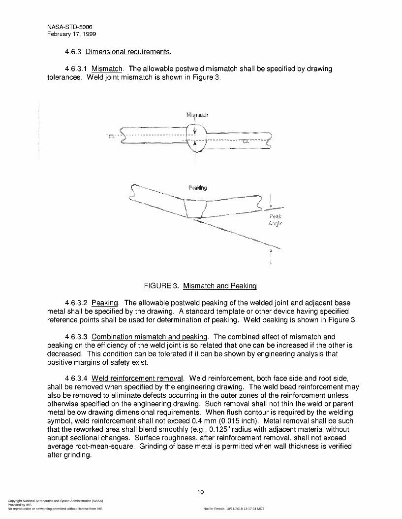
4.6.3.1 Mismatch. The allowable postweld mismatch shall be specified by drawing tolerances. Weld joint mismatch is shown in Figure 3.
FIGURE 3. Mismatch and Peakinq
4.6.3.2 Peakinq. The allowable postweld peaking of the welded joint and adjacent base metal shall be specified by the drawing. A standard template or other device having specified reference points shall be used for determination of peaking. Weld peaking is shown in Figure 3.
4.6.3.3 Combination mismatch and peakinq. The combined effect of mismatch and peaking on the efficiency of the weld joint is so related that one can be increased if the other is decreased. This condition can be tolerated if it can be shown by engineering analysis that positive margins of safety exist.
4.6.3.4 Weld reinforcement removal. Weld reinforcement, both face side and root side, shall be removed when specified by the engineering drawing. The weld bead reinforcement may also be removed to eliminate defects occurring in the outer zones of the reinforcement unless otherwise specified on the engineering drawing. Such removal shall not thin the weld or parent metal below drawing dimensional requirements. When flush contour is required by the welding symbol, weld reinforcement shall not exceed 0.4 mm (0.01 5 inch). Metal removal shall be such that the reworked area shall blend smoothly (e.g., O. 125” radius with adjacent material without abrupt sectional changes. Surface roughness, after reinforcement removal, shall not exceed average root-mean-square. Grinding of base metal is permitted when wall thickness is verified after grinding.
10
Copyright National Aeronautics and Space Administration (NASA) Provided by IHS Licensee=NASA BOM Manager MSFC/9972545005, User=Wright, Amber
Not for Resale, 10/11/2018 13:17:24 MDTNo reproduction or networking permitted without license from IHS
4.6.3.5 Fillet welds. Continuous fillet welds, including outside corner joints, lap joints, and tee joints, shall have a minimum of 1 O percent penetration into the root of the joint 100 percent of the length (reference Figure 4). Intermittent fillet welds shall have fusion of the root throughout the specified length. Unless otherwise specified on the engineering drawing, the fillet may be extended by 6 mm (0.25 inch) at each end without penetration in the extension. The minimum acceptable fillet size shall be that specified by the engineering drawing. The maximum acceptable fillet size shall be the size specified plus 50 percent or 4.8 mm (0.188 inch), whichever is less, as permitted in 4.9. The minimum acceptable actual throat shall equal or exceed the theoretical throat (reference Figure 4). Fillet weld fusion of the root (reference Figure 4) shall be determined by evaluation of transverse sections taken from the qualification welds.
4.6.4 Weldment straiqhteninq. Welds and adjacent base metal which have been deformed by the welding operation may be straightened; however, prior to implementation, it shall be verified by nondestructive testing, destructive testing, and metallurgical evaluation that the process used for straightening shall not degrade the weld and surrounding material below the specified design requirements. Following weldment straightening, the weld and adjacent base metal shall be inspected in accordance with 4.6.1. Weldments in which defects have been revealed by such operations shall not be acceptable.
4.6.5 Postweld heat treat requirements. Weldments subject to heat treatment operations shall subsequently be inspected to the surface quality requirements of 4.9. Postweld heat treatment processing shall be included in the WPS.
4.7 Weld ioint strenqth requirements.
4.7.1 Butt ioints. Weld joint strength requirements shall be established by design requirements. Qualified WPS’s shall be established to demonstrate the weld meets the strength required by design.
4.7.2 Fillet welds. Unless otherwise directed by the procuring agency, fillet weld shear strength shall meet 60 percent of the ultimate tensile requirements of the weld. Where ultimate tensile strength values vary for different thicknesses of the same temper, 60 percent of the minimum value shall apply.
Copyright National Aeronautics and Space Administration (NASA) Provided by IHS Licensee=NASA BOM Manager MSFC/9972545005, User=Wright, Amber
Not for Resale, 10/11/2018 13:17:24 MDTNo reproduction or networking permitted without license from IHS
4.8 Weldment quality requirements. Weldment quality requirements shall be established to ensure the weld meets design requirements for strength and integrity. The weld quality requirements shall be shown by engineering analysis (e.g., stress and fracture mechanics analyses) and verified by mechanical testing to result in structural properties that are adequate for intended applications. Supporting test data and rationale shall be approved by the procuring agency.
4.9 Repair weldinq.
4.9.1 Allowable repair weldinq. Additional welding operations shall be permitted to correct any unacceptable condition established per 4.8 provided the repair welding parameters and procedures are specified in a qualified repair WPS, and the repair is contained within the original weld zone. Complete records of the repair welding operation, including identification of the repaired weldment, type of defect, and location of the repair weld shall be retained in permanent records. Examples of typical weld defects requiring repair are listed below.
a. Undercut
b. Lack of fill
c. Concave root surface
d. Incomplete joint penetration
e. Crack and crack-like defects
f. Oxides and porosity
g. Lack of fusion
4.9.2 Repair weldinq requirinq disposition. The following conditions require disposition by the procuring agency:
a. When more than two weld repair attempts have been performed on any one location on materials known to be heat sensitive.
b. When the wrong filler metal has been used.
c. When a weldment has been postweld heat treated to increase the strength and cannot be returned to drawing requirements with additional heat treatments after reweld.
d. When finish machining has been completed prior to rewelding.
e. When the repair extends outside the original weld zone.
4.9.3 Repair weldinq reinspection. Reinspection of all repair weld areas shall be performed using the same methodshequirements as the original weld.
4.9.4 Multiple weldinq repairs. It shall be demonstrated that design strength requirements are met in any given area subjected to multiple repairs.
13
Copyright National Aeronautics and Space Administration (NASA) Provided by IHS Licensee=NASA BOM Manager MSFC/9972545005, User=Wright, Amber
Not for Resale, 10/11/2018 13:17:24 MDTNo reproduction or networking permitted without license from IHS
4.1 O Quality assurance. The supplier is responsible for the performance of all inspection requirements as specified herein. Except as otherwise specified, the supplier shall use inspection facilities and services acceptable to and approved by the procuring agency. Inspection and test records shall be kept complete and, upon request, made available to the procuring agency or its designated representative. The procuring agency or its designated representative reserves the right to perform any or all of the inspections set forth in the specification to ensure that the end item conforms to the prescribed requirements. Nondestructive testing procedures to be employed in inspection for weldment internal and surface quality requirements shall be qualified/validated as being capable of detecting the weldment quality criteria prescribed prior to inspection of the first production weld. The documented proof of capability shall be retained as a permanent record.
4.10.1 Preweld and weld inspection. Documentation relative to the production weld shall be inspected for conformance with section 4. The contractor shall certify that each production weld was made within the range of operating parameters established in the WPS. All departures shall be noted and referred to the procuring agency for disposition.
4.1 0.2 Postweld inspection.
4.10.2.1 Visual inspection. The weld metal and adjacent base metal for a minimum of 12.5 mm (0.5 inch) on either side of the weld interface shall be visually inspected to ensure compliance with the requirements of 4.6.2 for all weld classes. The weld shall be in the as- welded condition for the initial inspection, except that surface smut and loose oxide shall have been removed in such a way that does not smear metal or change the quality of the weld. Titanium weld deposit and heat-affected zone shall be a light straw or bright silver color.
4.1 0.2.2 Dimensional inspection. Dimensional inspection shall be performed on weldments to ensure compliance with the requirements of the design drawing for all weld classes.
4.1 0.2.3 Internal quality inspection. Nondestructive inspection shall be performed to ensure the weldment meets design requirements for Class A and Class B welds as applicable. Nondestructive inspection procedures and techniques shall be qualified. Qualification of NDE capability includes verification of detectability of critical flaw size. When reliability of inspection and critical flaw detection so dictate, redundant and/or complementing inspection techniques and procedures shall be employed.
4.1 0.2.4 Surface quality inspection. Nondestructive inspection shall be performed to ensure compliance with the surface quality requirements of the design drawing established per 4.8 for Class A and Class B welds. Nondestructive inspection procedures shall be qualified. Qualification of NDE capability includes verification of detectability of critical flaw size. When reliability of inspection and critical flaw detection so dictate, redundant and/or complementing inspection techniques and procedures shall be employed. Weldments which are machined, ground, or otherwise mechanically worked causing disruption or smearing of the material surface shall be etched to remove the masking material prior to penetrant application.
14
Copyright National Aeronautics and Space Administration (NASA) Provided by IHS Licensee=NASA BOM Manager MSFC/9972545005, User=Wright, Amber
Not for Resale, 10/11/2018 13:17:24 MDTNo reproduction or networking permitted without license from IHS
4.1 0.2.5 Records. A continuous audit of weldment production quality shall be maintained. Resulting records shall include, but not be limited to, the location of repairs, type of defects repaired, procedures used, and inches of repair per total inches of weld. These records shall be summarily accounted on a quarterly basis, with such accounting made available to the procuring agency upon request.
5. NOTES
(This section contains information of a general or explanatory nature that may be helpful but is not mandatory.)
5.1. Intended use. This standard provides weld guidelines and acceptance criteria for aerospace flight hardware.
5.2 Orderinq data. Procurement documents shall specify the title, number, and date of this standard.
5.3 Chanqes. Requests for deviation from, or waiver of, applicable paragraphs of this specification shall be directed to the procuring agency together with supporting information.
5.4 Keyword listinq
arc welding (AC) high energy density welding (HEDW) nondestructive evaluation (NDE) procedure qualification record (PQR) resistance welding (RW) solid state welding (SSW) welder performance qualification (WPQ) welder procedure specification (WPS)
15
Copyright National Aeronautics and Space Administration (NASA) Provided by IHS Licensee=NASA BOM Manager MSFC/9972545005, User=Wright, Amber
Not for Resale, 10/11/2018 13:17:24 MDTNo reproduction or networking permitted without license from IHS