76
General Gear Pumps and Motors Technical Information
General Gear Pumps and Motors
Technical Information
2 520L0557 • Rev. B • 10/2005
General Gear Pumps and MotorsTechnical Information
© 2005, Sauer-Danfoss. All rights reserved. Printed in Europe.
Sauer-Danfoss accepts no responsibility for possible errors in catalogs, brochures and other printed material. Sauer -Danfoss reserves the right to alter its products without prior notice. This also applies to products already ordered provided that such alterations can be made without affecting agreed specifications. All trademarks in this material are properties of their respective owners. Sauer-Danfoss and the Sauer-Danfoss logotype are trademarks of the Sauer-Danfoss Group.
Front cover illustrations: F005 037, F005 033, F005 018, F005 028, F005 021, F005 019, F005 030, F005 026, F005 068, P005 051.
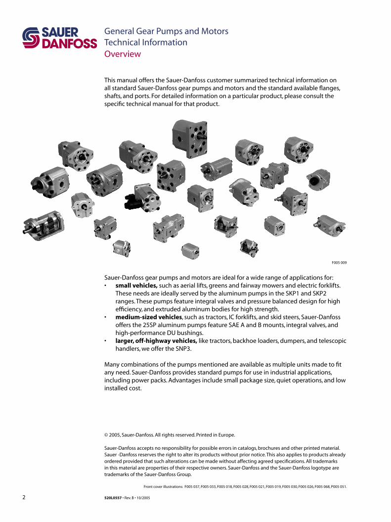
This manual offers the Sauer-Danfoss customer summarized technical information on all standard Sauer-Danfoss gear pumps and motors and the standard available flanges, shafts, and ports. For detailed information on a particular product, please consult the specific technical manual for that product.
Overview
Sauer-Danfoss gear pumps and motors are ideal for a wide range of applications for:• small vehicles, such as aerial lifts, greens and fairway mowers and electric forklifts.
These needs are ideally served by the aluminum pumps in the SKP1 and SKP2 ranges. These pumps feature integral valves and pressure balanced design for high efficiency, and extruded aluminum bodies for high strength.
• medium-sized vehicles, such as tractors, IC forklifts, and skid steers, Sauer-Danfoss offers the 25SP aluminum pumps feature SAE A and B mounts, integral valves, and high-performance DU bushings.
• larger, off-highway vehicles, like tractors, backhoe loaders, dumpers, and telescopic handlers, we offer the SNP3.
Many combinations of the pumps mentioned are available as multiple units made to fit any need. Sauer-Danfoss provides standard pumps for use in industrial applications, including power packs. Advantages include small package size, quiet operations, and low installed cost.
F005 009
3520L0557 • Rev. B • 10/2005
General Gear Pumps and MotorsTechnical InformationContents
GENERAL INFORMATION
MODEL CODE
GROUP 0.5
GROUP 1
GROUP 2
Range ................................................................................................................................................................. 5Benefits ............................................................................................................................................................. 5
Aluminum gear pumps and motors ................................................................................................. 5Cast-iron gear pumps and motors ..................................................................................................... 5
Pump displacements ................................................................................................................................... 6Motor displacements ................................................................................................................................... 7
Single pumps and motors – Groups 0.5, 1, 2, 3 ................................................................................... 8
Overview ........................................................................................................................................................10Design .............................................................................................................................................................10Features ..........................................................................................................................................................10Technical data ...............................................................................................................................................10Dimensions ....................................................................................................................................................11
TFP50 – CI01 ............................................................................................................................................11
Overview ........................................................................................................................................................12Design .............................................................................................................................................................12Features ..........................................................................................................................................................12Technical data for pumps .........................................................................................................................13Technical data for motors ........................................................................................................................14Gear pump dimensions ...........................................................................................................................15
SNP1 – CO01 and SC01 ........................................................................................................................15SKP1 – CO02 and CI02 ..........................................................................................................................16SNP1, SEP1 – FR03 ..................................................................................................................................17SKP1 – CI06 and SC06 ...........................................................................................................................18
Gear motor dimensions ............................................................................................................................19SKM1 – CO01 and SC01 .......................................................................................................................19SKM1, SKU1 – CO02 and CI02 ............................................................................................................20SKM1 – CI06 and SC06 .........................................................................................................................21
Group 1 pump ports ..................................................................................................................................22Group 1 motor ports ..................................................................................................................................23Shaft and flange availability ...................................................................................................................24
Overview ........................................................................................................................................................25Design .............................................................................................................................................................25Features ..........................................................................................................................................................25Technical data for pumps .........................................................................................................................26Technical data for motors .........................................................................................................................27Gear pump dimensions ...........................................................................................................................28
SNP2 – CO01, CI01 and SC01 .............................................................................................................28SNP2 – CO02 and SC02 ......................................................................................................................29SNP2 – CO04/05 and SC04/05 ...........................................................................................................31SNP2 – SC06, CI06 and SKP2 – SC06 ................................................................................................32SNP2 – SC06 LCX_G ...............................................................................................................................33SNP2 – CO09 ............................................................................................................................................34SNP2 – CO09 (variant BBM) ................................................................................................................35SNP2 – CO0B ............................................................................................................................................36
4 520L0557 • Rev. B • 10/2005
General Gear Pumps and MotorsTechnical InformationContents
GROUP 2 (CONT.)
GROUP 2.5
GROUP 3
MULTI-STAGE PUMPS
Gear motor dimensions ............................................................................................................................37SNM2 – SC01, CI01 and CO01 ............................................................................................................37SNM2 – SC02 and CO02 ......................................................................................................................38SNM2 – FR03 ............................................................................................................................................39SNM2 – CO04/05 and SC04/05 ..........................................................................................................40SNM2 – SC06 and CI06 .........................................................................................................................41
Group 2 pump ports ..................................................................................................................................42Group 2 motor ports ..................................................................................................................................43Shaft options .................................................................................................................................................44Shaft and flange availability ...................................................................................................................44
Shaft and flange availability and torque capability ...................................................................44
Overview ........................................................................................................................................................46Design .............................................................................................................................................................46Features ..........................................................................................................................................................46Technical data ...............................................................................................................................................47Model Code Designation ..........................................................................................................................48Shaft, flange, and port configuration ...................................................................................................50Dimensions ....................................................................................................................................................51Shaft options .................................................................................................................................................52Ports options ................................................................................................................................................52Priority Flow Divider Cover Port Options ............................................................................................53Shaft and flange availability ...................................................................................................................53
Overview ........................................................................................................................................................54Design .............................................................................................................................................................54Features ..........................................................................................................................................................54Technical data for pumps .........................................................................................................................55Technical data for motors .........................................................................................................................56Gear pump dimensions ............................................................................................................................57
SNP3 – CI01, CO01, SC01 and SEP3 – CO01 ................................................................................57SNP3 – CO02, CI02 and SC02 .............................................................................................................58SNP3 – CO03, CI03 and SC03 .............................................................................................................59SNP3 – CO06 and SC06 ........................................................................................................................60SNP3 – CI07, SC07 and SEP3 – SC07 ................................................................................................61
Gear motor dimensions ...........................................................................................................................62SNM3 – CI01, SC01 and CO01 ...........................................................................................................62SNM3 – CI02, SC02 and CO02 ............................................................................................................63SNM3 – CI03, SC03 and CO03 ............................................................................................................64SNM3 – CO07, CI07 and SC07 ............................................................................................................66
Group 3 pump ports ..................................................................................................................................67Group 3 motor ports ..................................................................................................................................69Shaft and flange availability ...................................................................................................................70
Shaft and flange availability and torque capacity .....................................................................70
Overview ........................................................................................................................................................71Multi-stage pump model code ..............................................................................................................72Multi-stage pumps with European standard front flange (01) ...................................................74
5520L0557 • Rev. B • 10/2005
General Gear Pumps and MotorsTechnical InformationGeneral Information
Sauer-Danfoss offers a wide range of gear products to meet most application needs. The catalogue highlights the range of aluminum and cast iron gear pumps and motors available from Sauer-Danfoss. Detailed specifications are included for all products. Many other configurations are available that are not included in this catalogue. For further information, please contact your Sauer-Danfoss representative.
Aluminum gear pumps and motorsThere are six families of aluminum pumps currently available. Some can be combined to make multiple pumps.
There are three families of aluminum motors: Group 1, Group 2 and Group 3.
Pumps and motors with extruded aluminum housing provide the necessary strength construction while providing a very high power-to-weight ratio and increased heat dissipation. At production test, the gear teeth cut their own track in the aluminum body for maximum radial gear tip sealing and high volumetric efficiency.
Cast-iron gear pumps and motorsD Series pumps and motors are of cast-iron construction. The CP180 and CP222 pumps, and the MYCP motor, have cast-iron bodies with aluminum flanges and covers. All pumps and motors feature a pressure-balanced design for high volumetric and mechanical efficiencies.
Sauer-Danfoss offers gear pumps and motors throughout a wide range of displacements. Each has its own unique benefits that, briefly, include in part or total: • Large displacement range (from 0.25 to 162 cm3/rev [0.015 to 9.886 in3/rev])• High performance and cost effective• Efficient pressure-balanced design• Proven reliability and performance• Optimum product configurations• Full range of auxiliary features• Compact, lightweight• Modular product design• Quiet operation• Worldwide manufacture, sales and service
Sauer-Danfoss pumps and motors pressure-balanced design provides high efficiency throughout a given range of displacements.
One-piece gear/shaft construction provides both high strength and an accurate profile. Each integral gear/shaft is constructed of bearing-quality hardened-steel that is machined to precise tolerances for minimum leakage. This one-piece design also eliminates the potential problems of stress-fatigue often associated with two-piece designs.
All Sauer-Danfoss gear pumps use hydrodynamic journal bearings that have an oil film maintained between the gear/shaft and bearing surfaces at all times. If this oil film is sufficiently sustained through proper system maintenance and operating within recommended limits a long pump life can be expected.
RANGE
BENEFITS
6 520L0557 • Rev. B • 10/2005
General Gear Pumps and MotorsTechnical InformationGeneral Information
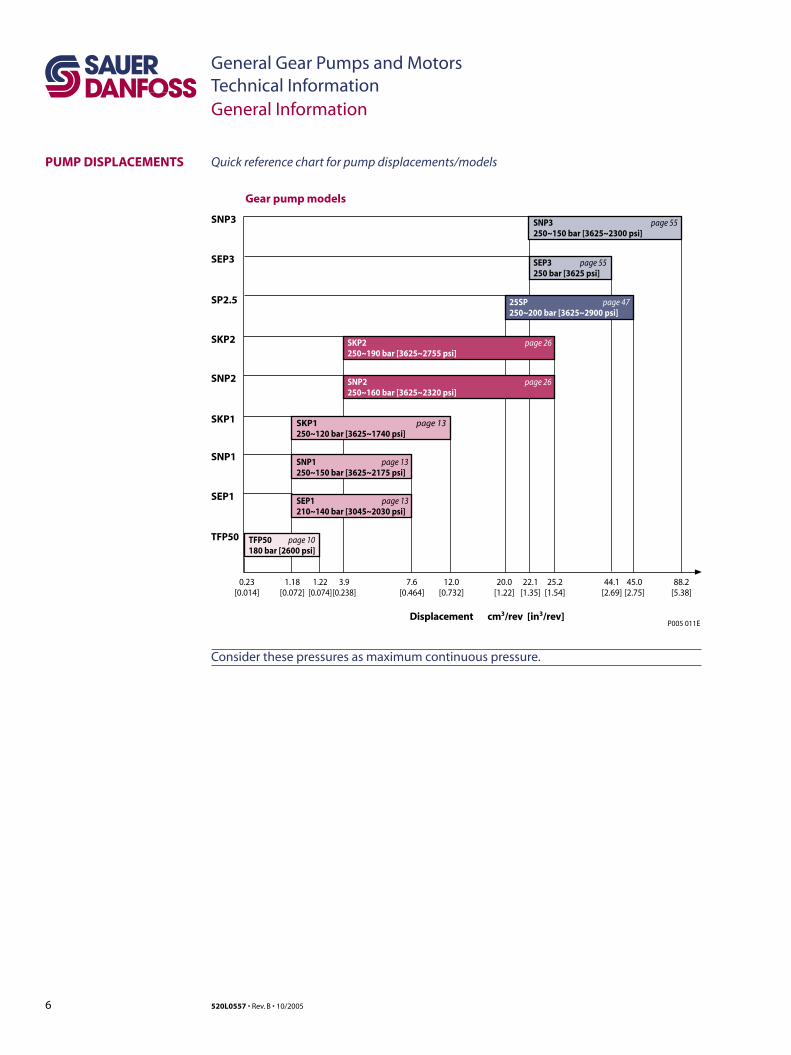
PUMP DISPLACEMENTS Quick reference chart for pump displacements/models
Consider these pressures as maximum continuous pressure.
0.23[0.014]
1.18[0.072]
1.22[0.074]
3.9[0.238]
7.6[0.464]
12.0[0.732]
20.0[1.22]
22.1[1.35]
25.2[1.54]
44.1[2.69]
45.0[2.75]
88.2[5.38]
TFP50 page 10180 bar [2600 psi]
SKP1 page 13250~120 bar [3625~1740 psi]
SNP2 page 26250~160 bar [3625~2320 psi]
SEP3 page 55250 bar [3625 psi]
25SP page 47250~200 bar [3625~2900 psi]
Displacement cm3/rev [in3/rev]
Gear pump models
TFP50
SKP1
SNP2
SP2.5
SNP3
SEP3
SNP1 page 13250~150 bar [3625~2175 psi]
SNP1
SEP1
SKP2 page 26250~190 bar [3625~2755 psi]
SKP2
SNP3 page 55250~150 bar [3625~2300 psi]
SEP1 page 13210~140 bar [3045~2030 psi]
P005 011E

7520L0557 • Rev. B • 10/2005
General Gear Pumps and MotorsTechnical Information
MOTOR DISPLACEMENTS Quick reference chart for motor displacements/models
General Information
SKU1 page 14250~120 bar [3625~1740 psi]
SNM2 page 27250~160 bar [3625~2320 psi]
SKM1 page 14250~130 bar [3625~1895 psi]
SKU1
SNM2
SKU2
SNU2
SNM3
SNU3
SKM1
SNU3 page 56250~150 bar [3625~2175 psi]
SNM3 page 56250~150 bar [3625~2175 psi]
SKU2 page 27250~160 bar [3625~2320 psi]
SNU2 page 27250~160 bar [3625~2320 psi]
Gear motor models
0
P005 012E
2.62[0.074]
6.0[0.366]
8.4[0.513]
12.0[0.732]
22.1[1.35]
25.2[1.538]
88.2[5.38]
Displacement cm3/rev [in3/rev]
Consider these pressures as maximum continuous pressure.
8 520L0557 • Rev. B • 10/2005
General Gear Pumps and MotorsTechnical InformationModel Code
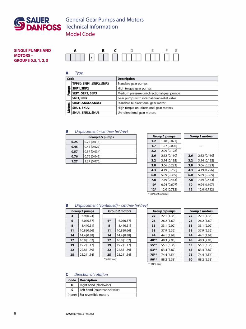
SINGLE PUMPS AND MOTORS – GROUPS 0.5, 1, 2, 3
A B C D E F G
/
A TypeCode Description
Pu
mp
s
TFP50, SNP1, SNP2, SNP3 Standard gear pumps
SKP1, SKP2 High torque gear pumps
SEP1, SEP2, SEP3 Medium pressure uni-directional gear pumps
SNI1, SNI2 Gear pumps with internal drain relief valve
Mo
tors SKM1, SNM2, SNM3 Standard bi-directional gear motor
SKU1, SKU2 High torque uni-directional gear motors
SNU1, SNU2, SNU3 Uni-directional gear motors
B Displacement – cm3/rev [in3/rev]Group 0.5 pumps
0.25 0.25 [0.015]
0.45 0.45 [0.027]
0.57 0.57 [0.034]
0.76 0.76 [0.045]
1.27 1.27 [0.075]
B Displacement (continued) – cm3/rev [in3/rev] Group 2 pumps Group 2 motors
4 3.9 [0.24] –
6 6.0 [0.37] 6* 6.0 [0.37]
8 8.4 [0.51] 8 8.4 [0.51]
11 10.8 [0.66] 11 10.8 [0.66]
14 14.4 [0.88] 14 14.4 [0.88]
17 16.8 [1.02] 17 16.8 [1.02]
19 19.2 [1.17] 19 19.2 [1.17]
22 22.8 [1.39] 22 22.8 [1.39]
25 25.2 [1.54] 25 25.2 [1.54]* SNM2 only
Group 1 pumps Group 1 motors
1.2 1.18 [0.072]
–1.7 1.57 [0.096]
2.2 2.09 [0.128]
2.6 2.62 [0.160] 2.6 2.62 [0.160]
3.2 3.14 [0.192] 3.2 3.14 [0.192]
3.8 3.66 [0.223] 3.8 3.66 [0.223]
4.3 4.19 [0.256] 4.3 4.19 [0.256]
6.0 5.89 [0.359] 6.0 5.89 [0.359]
7.8 7.59 [0.463] 7.8 7.59 [0.463]
10* 0.94 [0.607] 10 9.94 [0.607]
12* 12.0 [0.732] 12 12.0 [0.732]* SEP1 not available
Group 3 pumps Group 3 motors
22 22.1 [1.35] 22 22.1 [1.35]
26 26.2 [1.60] 26 26.2 [1.60]
33 33.1 [2.02] 33 33.1 [2.02]
38 37.9 [2.32] 38 37.9 [2.32]
44 44.1 [2.69] 44 44.1 [2.69]
48** 48.3 [2.93] 48 48.3 [2.93]
55** 55.1 [3.36] 55 55.1 [3.36]
63** 63.4 [3.87] 63 63.4 [3.87]
75** 74.4 [4.54] 75 74.4 [4.54]
90** 88.2 [5.38] 90 88.2 [5.38]** SNP3 only
C Direction of rotationCode Description
D Right hand (clockwise)
S Left hand (counterclockwise)
(none) For reversible motors
9520L0557 • Rev. B • 10/2005
General Gear Pumps and MotorsTechnical Information
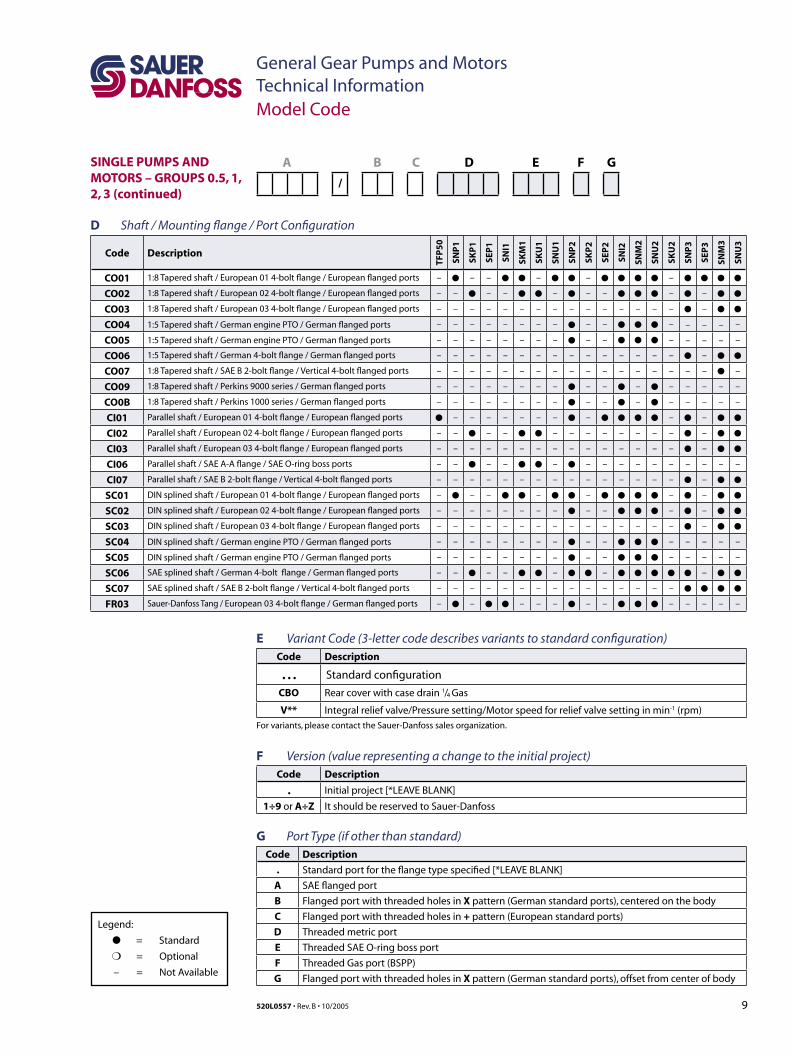
Legend:
● = Standard
❍ = Optional
– = Not Available
SINGLE PUMPS AND MOTORS – GROUPS 0.5, 1, 2, 3 (continued)
A B C D E F G
/
D Shaft / Mounting flange / Port Configuration
Code Description
TFP
50
SNP
1
SKP
1
SEP
1
SNI1
SKM
1
SKU
1
SNU
1
SNP
2
SKP
2
SEP
2
SNI2
SNM
2
SNU
2
SKU
2
SNP
3
SEP
3
SNM
3
SNU
3
CO01 1:8 Tapered shaft / European 01 4-bolt flange / European flanged ports – ● – – ● ● – ● ● – ● ● ● ● – ● ● ● ●
CO02 1:8 Tapered shaft / European 02 4-bolt flange / European flanged ports – – ● – – ● ● – ● – – ● ● ● – ● – ● ●
CO03 1:8 Tapered shaft / European 03 4-bolt flange / European flanged ports – – – – – – – – – – – – – – – ● – ● ●
CO04 1:5 Tapered shaft / German engine PTO / German flanged ports – – – – – – – – ● – – ● ● ● – – – – –
CO05 1:5 Tapered shaft / German engine PTO / German flanged ports – – – – – – – – ● – – ● ● ● – – – – –
CO06 1:5 Tapered shaft / German 4-bolt flange / German flanged ports – – – – – – – – – – – – – – – ● – ● ●
CO07 1:8 Tapered shaft / SAE B 2-bolt flange / Vertical 4-bolt flanged ports – – – – – – – – – – – – – – – – – ● –
CO09 1:8 Tapered shaft / Perkins 9000 series / German flanged ports – – – – – – – – ● – – ● – ● – – – – –
CO0B 1:8 Tapered shaft / Perkins 1000 series / German flanged ports – – – – – – – – ● – – ● – ● – – – – –
CI01 Parallel shaft / European 01 4-bolt flange / European flanged ports ● – – – – – – – ● – ● ● ● ● – ● – ● ●
CI02 Parallel shaft / European 02 4-bolt flange / European flanged ports – – ● – – ● ● – – – – – – – – ● – ● ●
CI03 Parallel shaft / European 03 4-bolt flange / European flanged ports – – – – – – – – – – – – – – – ● – ● ●
CI06 Parallel shaft / SAE A-A flange / SAE O-ring boss ports – – ● – – ● ● – ● – – – – – – – – – –
CI07 Parallel shaft / SAE B 2-bolt flange / Vertical 4-bolt flanged ports – – – – – – – – – – – – – – – ● – ● ●
SC01 DIN splined shaft / European 01 4-bolt flange / European flanged ports – ● – – ● ● – ● ● – ● ● ● ● – ● – ● ●
SC02 DIN splined shaft / European 02 4-bolt flange / European flanged ports – – – – – – – – ● – – ● ● ● – ● – ● ●
SC03 DIN splined shaft / European 03 4-bolt flange / European flanged ports – – – – – – – – – – – – – – – ● – ● ●
SC04 DIN splined shaft / German engine PTO / German flanged ports – – – – – – – – ● – – ● ● ● – – – – –
SC05 DIN splined shaft / German engine PTO / German flanged ports – – – – – – – – ● – – ● ● ● – – – – –
SC06 SAE splined shaft / German 4-bolt flange / German flanged ports – – ● – – ● ● – ● ● – ● ● ● ● ● – ● ●
SC07 SAE splined shaft / SAE B 2-bolt flange / Vertical 4-bolt flanged ports – – – – – – – – – – – – – – – ● ● ● ●
FR03 Sauer-Danfoss Tang / European 03 4-bolt flange / German flanged ports – ● – ● ● – – – ● – – ● ● ● – – – – –
E Variant Code (3-letter code describes variants to standard configuration)Code Description
. . . Standard configuration
CBO Rear cover with case drain 1/4 Gas
V** Integral relief valve/Pressure setting/Motor speed for relief valve setting in min-1 (rpm)
For variants, please contact the Sauer-Danfoss sales organization.
F Version (value representing a change to the initial project)Code Description
. Initial project [*LEAVE BLANK]
1÷9 or A÷Z It should be reserved to Sauer-Danfoss
G Port Type (if other than standard)Code Description
. Standard port for the flange type specified [*LEAVE BLANK]
A SAE flanged port
B Flanged port with threaded holes in X pattern (German standard ports), centered on the body
C Flanged port with threaded holes in + pattern (European standard ports)
D Threaded metric port
E Threaded SAE O-ring boss port
F Threaded Gas port (BSPP)
G Flanged port with threaded holes in X pattern (German standard ports), offset from center of body
Model Code
10 520L0557 • Rev. B • 10/2005
General Gear Pumps and MotorsTechnical InformationGroup 0.5
FEATURES
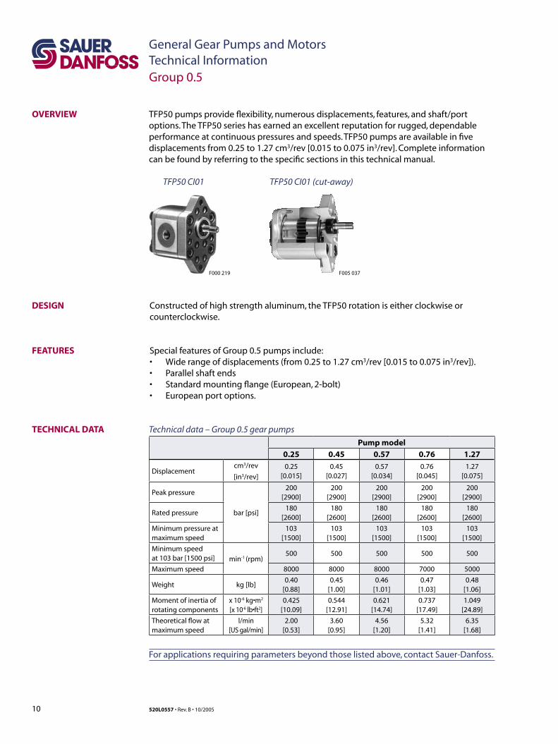
Constructed of high strength aluminum, the TFP50 rotation is either clockwise or counterclockwise.
Special features of Group 0.5 pumps include:• Wide range of displacements (from 0.25 to 1.27 cm3/rev [0.015 to 0.075 in3/rev]). • Parallel shaft ends• Standard mounting flange (European, 2-bolt)• European port options.
OVERVIEW TFP50 pumps provide flexibility, numerous displacements, features, and shaft/port options. The TFP50 series has earned an excellent reputation for rugged, dependable performance at continuous pressures and speeds. TFP50 pumps are available in five displacements from 0.25 to 1.27 cm3/rev [0.015 to 0.075 in3/rev]. Complete information can be found by referring to the specific sections in this technical manual.
DESIGN
TFP50 CI01
F005 037F000 219
TFP50 CI01 (cut-away)
Technical data – Group 0.5 gear pumps
Pump model
0.25 0.45 0.57 0.76 1.27
Displacementcm3/rev
[in3/rev]
0.25[0.015]
0.45[0.027]
0.57[0.034]
0.76[0.045]
1.27[0.075]
Peak pressure
bar [psi]
200[2900]
200[2900]
200[2900]
200[2900]
200[2900]
Rated pressure180
[2600]180
[2600]180
[2600]180
[2600]180
[2600]
Minimum pressure atmaximum speed
103[1500]
103[1500]
103[1500]
103[1500]
103[1500]
Minimum speed at 103 bar [1500 psi] min-1 (rpm)
500 500 500 500 500
Maximum speed 8000 8000 8000 7000 5000
Weight kg [lb]0.40
[0.88]0.45
[1.00]0.46
[1.01]0.47
[1.03]0.48
[1.06]
Moment of inertia ofrotating components
x 10-6 kg•m2
[x 10-6 lb•ft2]0.425
[10.09]0.544
[12.91]0.621
[14.74]0.737
[17.49]1.049
[24.89]
Theoretical flow atmaximum speed
l/min[US gal/min]
2.00[0.53]
3.60[0.95]
4.56[1.20]
5.32[1.41]
6.35[1.68]
For applications requiring parameters beyond those listed above, contact Sauer-Danfoss.
TECHNICAL DATA
11520L0557 • Rev. B • 10/2005
General Gear Pumps and MotorsTechnical Information
mm[in]
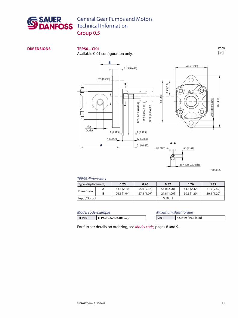
DIMENSIONS
P005 052E
11.5 [0.453]
7.5 [0.295]
49.5 [1.95]
TFP 50
Inlet
Outlet8 [0.315]8 [0.315]
4 [0.157] 17 [0.669]
21 [0.827]A - A
2 [0.0787] H8 4.3 [0.169]
B
A
66 [2
.6]
25.5
[1.0
]
80 [3
.15]
Ø 6
.5 [D
ia 0
.256
]
Ø 2
2 [0
.866
] f 7
Ø 7
.9 [D
ia 0
.311
]
M7
x 0.
75 [0
.029
5]
Ø 7 [Dia 0.276] h6
AA
TFP50 dimensionsType (displacement) 0.25 0.45 0.57 0.76 1.27
DimensionA 53.5 [2.10] 55.0 [2.16] 56.0 [2.20] 61.5 [2.42] 61.5 [2.42]
B 26.5 [1.04] 27.3 [1.07] 27.8 [1.09] 30.5 [1.20] 30.5 [1.20]
Input/Output M10 x 1
Model code exampleTFP50 TFP50/0.57 D CI01 ..._.
For further details on ordering, see Model code, pages 8 and 9.
Group 0.5
TFP50 – CI01Available CI01 configuration only.
Maximum shaft torqueCI01 4.5 N•m [39.8 lb•in]
12 520L0557 • Rev. B • 10/2005
General Gear Pumps and MotorsTechnical InformationGroup 1
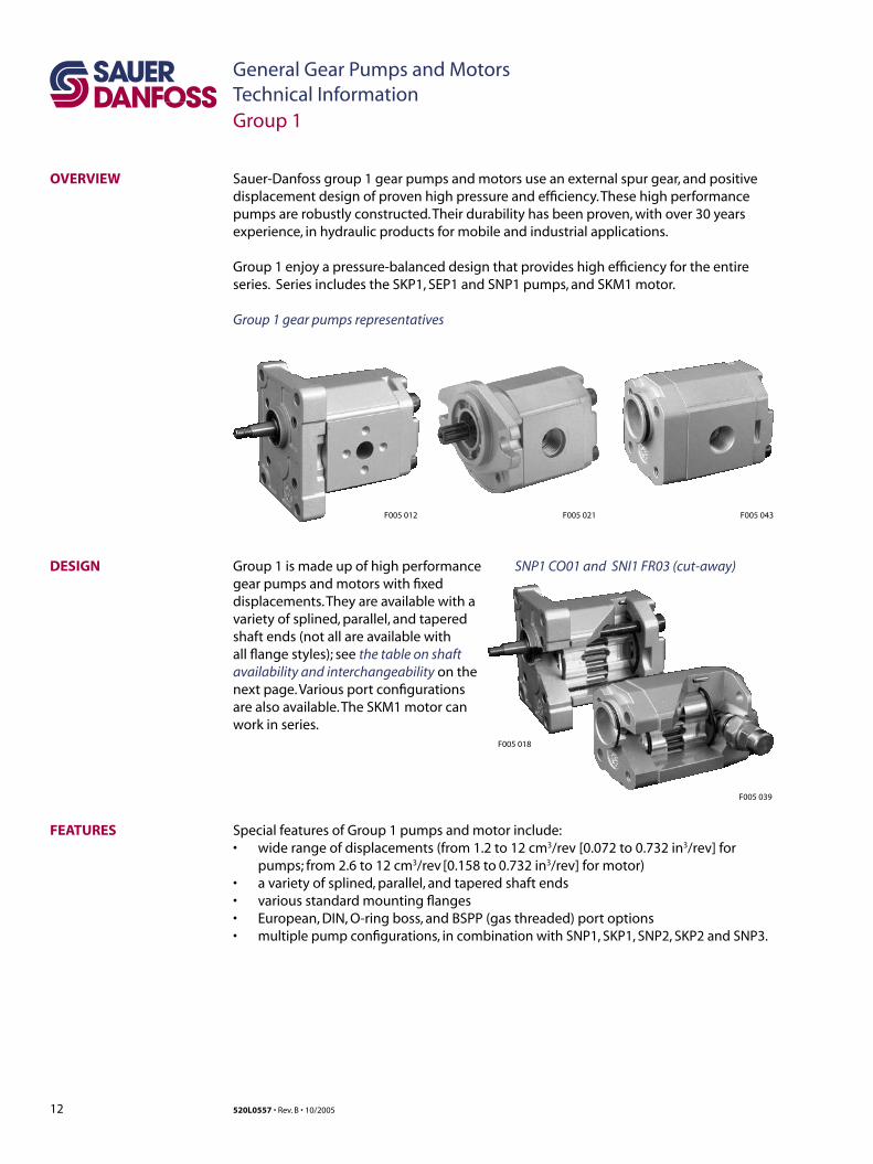
OVERVIEW Sauer-Danfoss group 1 gear pumps and motors use an external spur gear, and positive displacement design of proven high pressure and efficiency. These high performance pumps are robustly constructed. Their durability has been proven, with over 30 years experience, in hydraulic products for mobile and industrial applications.
Group 1 enjoy a pressure-balanced design that provides high efficiency for the entire series. Series includes the SKP1, SEP1 and SNP1 pumps, and SKM1 motor.
Group 1 gear pumps representatives
FEATURES
Group 1 is made up of high performance gear pumps and motors with fixed displacements. They are available with a variety of splined, parallel, and tapered shaft ends (not all are available with all flange styles); see the table on shaft availability and interchangeability on the next page. Various port configurations are also available. The SKM1 motor can work in series.
DESIGN
Special features of Group 1 pumps and motor include:• wide range of displacements (from 1.2 to 12 cm3/rev [0.072 to 0.732 in3/rev] for
pumps; from 2.6 to 12 cm3/rev [0.158 to 0.732 in3/rev] for motor)• a variety of splined, parallel, and tapered shaft ends• various standard mounting flanges• European, DIN, O-ring boss, and BSPP (gas threaded) port options• multiple pump configurations, in combination with SNP1, SKP1, SNP2, SKP2 and SNP3.
F005 043F005 021F005 012
F005 018
F005 039
SNP1 CO01 and SNI1 FR03 (cut-away)
13520L0557 • Rev. B • 10/2005
General Gear Pumps and MotorsTechnical Information
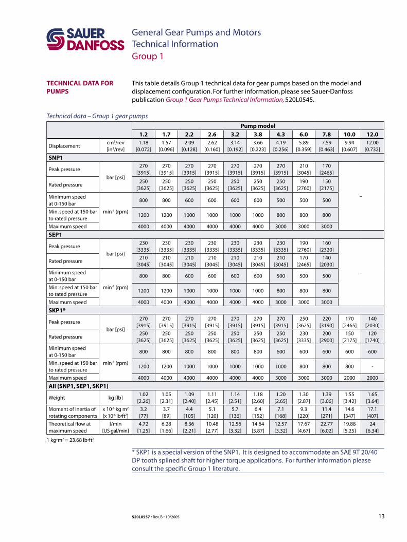
TECHNICAL DATA FOR PUMPS
This table details Group 1 technical data for gear pumps based on the model and displacement configuration. For further information, please see Sauer-Danfoss publication Group 1 Gear Pumps Technical Information, 520L0545.
1 kg•m2 = 23.68 lb•ft2
Group 1
Pump model
1.2 1.7 2.2 2.6 3.2 3.8 4.3 6.0 7.8 10.0 12.0
Displacementcm3/rev[in3/rev]
1.18[0.072]
1.57[0.096]
2.09[0.128]
2.62[0.160]
3.14[0.192]
3.66[0.223]
4.19[0.256]
5.89[0.359]
7.59[0.463]
9.94[0.607]
12.00[0.732]
SNP1
Peak pressure
bar [psi]
270[3915]
270[3915]
270[3915]
270[3915]
270[3915]
270[3915]
270[3915]
210[3045]
170[2465]
–
Rated pressure250
[3625]250
[3625]250
[3625]250
[3625]250
[3625]250
[3625]250
[3625]190
[2760]150
[2175]
Minimum speedat 0-150 bar
min-1 (rpm)
800 800 600 600 600 600 500 500 500
Min. speed at 150 bar to rated pressure
1200 1200 1000 1000 1000 1000 800 800 800
Maximum speed 4000 4000 4000 4000 4000 4000 3000 3000 3000
SEP1
Peak pressure
bar [psi]
230[3335]
230[3335]
230[3335]
230[3335]
230[3335]
230[3335]
230[3335]
190[2760]
160[2320]
–
Rated pressure210
[3045]210
[3045]210
[3045]210
[3045]210
[3045]210
[3045]210
[3045]170
[2465]140
[2030]
Minimum speedat 0-150 bar
min-1 (rpm)
800 800 600 600 600 600 500 500 500
Min. speed at 150 bar to rated pressure
1200 1200 1000 1000 1000 1000 800 800 800
Maximum speed 4000 4000 4000 4000 4000 4000 3000 3000 3000
SKP1*
Peak pressure
bar [psi]
270[3915]
270[3915]
270[3915]
270[3915]
270[3915]
270[3915]
270[3915]
250[3625]
220[3190]
170[2465]
140[2030]
Rated pressure250
[3625]250
[3625]250
[3625]250
[3625]250
[3625]250
[3625]250
[3625]230
[3335]200
[2900]150
[2175]120
[1740]
Minimum speedat 0-150 bar
min-1 (rpm)
800 800 800 800 800 800 600 600 600 600 600
Min. speed at 150 bar to rated pressure
1200 1200 1000 1000 1000 1000 1000 800 800 800 -
Maximum speed 4000 4000 4000 4000 4000 4000 3000 3000 3000 2000 2000
All (SNP1, SEP1, SKP1)
Weight kg [lb]1.02
[2.26]1.05
[2.31]1.09
[2.40]1.11
[2.45]1.14
[2.51]1.18
[2.60]1.20
[2.65]1.30
[2.87]1.39
[3.06]1.55
[3.42]1.65
[3.64]
Moment of inertia ofrotating components
x 10-6 kg m2
[x 10-6 lb•ft2]3.2[77]
3.7[89]
4.4[105]
5.1[120]
5.7[136]
6.4[152]
7.1[168]
9.3[220]
11.4[271]
14.6[347]
17.1[407]
Theoretical flow atmaximum speed
l/min[US gal/min]
4.72[1.25]
6.28[1.66]
8.36[2.21]
10.48[2.77]
12.56[3.32]
14.64[3.87]
12.57[3.32]
17.67[4.67]
22.77[6.02]
19.88[5.25]
24[6.34]
Technical data – Group 1 gear pumps
* SKP1 is a special version of the SNP1. It is designed to accommodate an SAE 9T 20/40 DP tooth splined shaft for higher torque applications. For further information please consult the specific Group 1 literature.
14 520L0557 • Rev. B • 10/2005
General Gear Pumps and MotorsTechnical Information
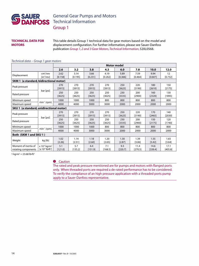
TECHNICAL DATA FOR MOTORS
Motor model
2.6 3.2 3.8 4.3 6.0 7.8 10.0 12.0
Displacementcm3/rev[in3/rev]
2.62[0.158]
3.14[0.195]
3.66[0.231]
4.19[0.262]
5.89[0.366]
7.59[0.464]
9.94[0.607]
12[0.732]
SKM 1 (a standard, bidirectional motor)
Peak pressure
bar [psi]
270[3915]
270[3915]
270[3915]
270[3915]
250[3625]
220[3190]
180[2610]
150[2175]
Rated pressure250
[3625]250
[3625]250
[3625]250
[3625]230
[3335]200
[2900]160
[2320]130
[1895]
Minimum speedmin-1 (rpm)
1000 1000 1000 800 800 800 800 800
Maximum speed 4000 4000 3000 3000 2000 2000 2000 2000
SKU 1 (a standard, unidirectional motor)
Peak pressure
bar [psi]
270[3915]
270[3915]
270[3915]
270[3915]
250[3625]
220[3190]
170[2465]
140[2030]
Rated pressure250
[3625]250
[3625]250
[3625]250
[3625]230
[3335]200
[2900]150
[2175]120
[1740]
Minimum speedmin-1 (rpm)
1000 1000 1000 800 800 800 800 800
Maximum speed 4000 4000 3000 3000 2000 2000 2000 2000
Both (SKM 1 and SKU 1 )
Weight kg [lb]1.02
[2.26]1.14
[2.51]1.18
[2.60]1.20
[2.65]1.30
[2.87]1.39
[3.06]1.55
[3.42]1.65
[3.64]
Moment of inertia ofrotating components
x 10-6 kg•m2
[x 10-6 lb•ft2]5.1
[121.0]5.7
[135.2]6.4
[151.9]7.1
[168.5]9.3
[220.7]11.4
[270.5]14.6
[339.4]17.1
[405.8]
1 kg•m2 = 23.68 lb•ft2
This table details Group 1 technical data for gear motors based on the model and displacement configuration. For further information, please see Sauer-Danfoss publication Group 1, 2 and 3 Gear Motors, Technical Information, 520L0568.
Technical data – Group 1 gear motors
C CautionThe rated and peak pressure mentioned are for pumps and motors with flanged ports only. When threaded ports are required a de-rated performance has to be considered. To verify the compliance of an high pressure application with a threaded ports pump apply to a Sauer-Danfoss representative.
Group 1

15520L0557 • Rev. B • 10/2005
General Gear Pumps and MotorsTechnical Information
mm[in]
GEAR PUMP DIMENSIONS SNP1 – CO01 and SC01This drawing shows the standard porting for CO01 and SC01Available in Series SNP1 only.
CO01 SC01
1:8
Co
ne
refe
ren
ce d
iam
eter
to cone reference diameterDistance from front flange
29 [1.14]
M7-
6g
14.4 [0.583] 5.2 [0.205]
12.4 [0.488]
X
Pilot width
-0.0
41-0
.020
16.5 [0.65]4.2 [0.165]
XØ
0.7
5 [0
.029
5]
body widht
69.4 [2.73] max
52.4 [2.06]
88.1
[3.4
7] m
ax
74.5
[2.9
3] m
ax
(53.
8 [2
.12]
max
)(3
4.3
[1.3
5] m
ax)
(71.
9 [2
.83]
26.2
[1.0
3]45
.7 [1
.8]
68 ±0.25 [2.68 ±0.010]
5.5 [0.217 ]+0.15-0.25
+0.0059-0.0098
-0.00982.41 [0.0949 ] 0-0.025
0
D/d
E/e
C/c
Spline:
Z=15 M=0.75 alfa=30°Circular tooth thickness:
1.028-1.068 [0.04 0-0.042]
Internal spline dia:
9.8-10 [0.386-0.394]
to shoulderfront flangeDistance from
4.5 [0.177]
14 [0.551]
21.5 [0.846]
(min full thd 10 [0.394] deep)
±0.50 [0.020]
±0.20 [0.008]
P005 053E
B max
A
A
A
A-A
Ø 2
5.4
[1.0
]
Ø 9
.82
[0.3
87]
10.8
±0.
50 [0
.425
±0.
020]
Ø 1
1.9
[0.4
69
]
Ø 7
.2 -
8 [0
.283
-0.3
15]
0 -0.1
100 -0
.004
-0.0
016
-0.0
008
SNP1 – CO01 and SC01 dimensionsType (displacement) 1.2 1.7 2.2 2.6 3.2 3.8 4.3 6.0 7.8
Dimension
A37.75
[1.486]38.5
[1.516]39.5
[1.555]40.5
[1.634]41.5
[1.634]42.5
[1.673]43.5
[1.713]46.75
[1.841]50.0
[1.969]
B79.5
[3.130]81.0
[3.189]83.0
[3.268]85.0
[3.346]87.0
[3.425]89.0
[3.504]91.0
[3.583]97.5
[3.839]104.0
[4.094]
Inlet/Outlet
C/c 12 [0.472]
D/d 26 [1.024]
E/e M5
Group 1
Maximum shaft torque
CO01N•m [lb•in]
25 [221]
SC01 35 [310]
Model code example
SNP1SNP1/2.2 D CO01 ..._.SNP1/6 S SC01 ..._.
For further details on ordering, see Model code, pages 8 and 9.
16 520L0557 • Rev. B • 10/2005
General Gear Pumps and MotorsTechnical Information
mm[in]
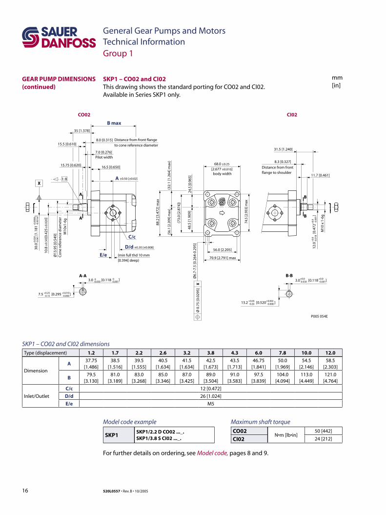
SKP1 – CO02 and CI02This drawing shows the standard porting for CO02 and CI02.Available in Series SKP1 only.
12.0
[0
.472
]
+0.
0
+0.
0-0
.018
-0
.001
M10
x 1
-6g
11.7 [0.461]
8.3 [0.327]
Distance from front flange to shoulder
31.5 [1.240]
3.0 [0.118 ]+0.0 +0.0-0.030 -0.001
13.2 [0.520 ]+0.05 +0.002-0.20 -0.008
88.2
[3.4
72] m
ax
7.5 [0.295 ]+0.25 +0.010-0.15 -0.006
3.0 [0.118 ]0 0-0.030 -0.001
C/c
D/d
E/e
A
16.5 [0.650]
7.0 [0.276]Pilot width
8.0 [0.315] Distance from front flange
to cone reference diameter
B max
M10
x1-6
g
Ø13
.95
[0.5
49]
Co
ne
refe
ren
ce d
iam
eter
10.8
[0
.425
30.0
[1
.181
]
-0.0
20
-
0.00
08-0
.041
-0.
0016
68.0 ±0.25
[2.677 ±0.010]body width
74.5
[2.9
33] m
ax56.0 [2.205]
70.9 [2.791] max
24.5
[0.9
65]
48.5
[1.9
09]
(73.
0 [2
.874
])
(32.
1 [1
.264
] max
)(5
6.1
[2.2
09] m
ax)
Ø6.
7-7.
5 [0
.264
-0.2
95]
1: 8
35 [1.378]
15.75 [0.620]
15.5 [0.610]
P005 054E
±0.20 [±0.008]
±0.
50
±0.
020]
±0.50 [±0.02]
CO02 CI02
(min full thd 10 mm [0.394] deep)
A
A
A-A
B
B
B-B
XØ
0.7
5 [0
.029
5]
X
SKP1 – CO02 and CI02 dimensionsType (displacement) 1.2 1.7 2.2 2.6 3.2 3.8 4.3 6.0 7.8 10.0 12.0
Dimension
A37.75
[1.486]38.5
[1.516]39.5
[1.555]40.5
[1.634]41.5
[1.634]42.5
[1.673]43.5
[1.713]46.75
[1.841]50.0
[1.969]54.5
[2.146]58.5
[2.303]
B79.5
[3.130]81.0
[3.189]83.0
[3.268]85.0
[3.346]87.0
[3.425]89.0
[3.504]91.0
[3.583]97.5
[3.839]104.0
[4.094]113.0
[4.449]121.0
[4.764]
Inlet/Outlet
C/c 12 [0.472]
D/d 26 [1.024]
E/e M5
Group 1
GEAR PUMP DIMENSIONS (continued)
Maximum shaft torque
CO02N•m [lb•in]
50 [442]
CI02 24 [212]
Model code example
SKP1SKP1/2.2 D CO02 ..._.SKP1/3.8 S CI02 ..._.
For further details on ordering, see Model code, pages 8 and 9.
17520L0557 • Rev. B • 10/2005
General Gear Pumps and MotorsTechnical Information
mm[in]
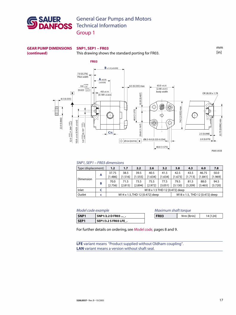
SNP1, SEP1 – FR03This drawing shows the standard porting for FR03.
C/c 2.5 [0.098]
22.7
5 [0
.896
] min
2.0 [0.079]
OR 28.30 x 1.78
P005 055E
8.5 [0.335]
22.0
[0.8
66]
body width
74.5
[2.9
33] m
ax
Ø8.5-9.0 [0.335-0.354]
40.0 [1.575]
40.
0 [1
.575
]
29.6
5 [1
.167
]10
.35
[0.4
07]
8.5 [0.335] max
A ±0.50
[±0.020]
B ±1.0 [±0.039]
10.8
±0.
50 [0
.425
±0.
020]
63.0 ±0.25
[2.48 ±0.01]4.8 ±0.10
[0.189 ±0.004]
0.6 -0.30
[0.023 -0.012 ]
7.0 [0.276]Pilot width
5.0
-0.0
80 [0
.197
-0.0
03]
+0.
020
+0.
001
+0.040
+0.016
32.0
-0.0
50 [1
.260
-0.0
02]
-0.0
25-0
.001
XØ 0.4 [0.016]
FR03
X
SNP1, SEP1 – FR03 dimensionsType (displacement) 1.2 1.7 2.2 2.6 3.2 3.8 4.3 6.0 7.8
Dimension
A37.75
[1.486]38.5
[1.516]39.5
[1.555]40.5
[1.634]41.5
[1.634]42.5
[1.673]43.5
[1.713]46.75
[1.841]50.0
[1.969]
B70.0
[2.756]71.5
[2.815]73.5
[2.894]75.5
[2.972]77.5
[3.051]79.5
[3.130]81.5
[3.209]88.0
[3.465]94.5
[3.720]
Inlet C M18 x 1.5 THD 12 [0.472] deep
Outlet c M14 x 1.5, THD 12 [0.472] deep M18 x 1.5, THD 12 [0.472] deep
Group 1
GEAR PUMP DIMENSIONS (continued)
Maximum shaft torque
FR03 N•m [lb•in] 14 [124]
Model code example
SNP1 SNP1/2.2 D FR03 ..._.
SEP1 SEP1/3.2 S FR03 LFE_.
For further details on ordering, see Model code, pages 8 and 9.
LFE variant means “Product supplied without Oldham coupling“. LAN variant means a version without shaft seal.
18 520L0557 • Rev. B • 10/2005
General Gear Pumps and MotorsTechnical Information
mm[in]
12.3
44
[0
.486
]
0
0 0
0 -0.0
5
Splined: SAE J498-9T-20/40DPFlat root side fitCircular tooth thickness:0.127mm [0.005]less than class 1 fit
15.6 [0.614]
19.1 [0.752]
7.9 [0.311]
27.0 [1.063]
74.5
[2.9
33] m
axbody width
R 32.1 [1.26] max
82.55 [3.258]
103.4 [4.071] max
80.2
[3.1
57] m
ax
X
10.2
-10.
8 [.4
02-.4
25]
Ø 0.75 [0.030]
3.2 [0.126 ]-0.025 -0.126
13.94-14.20 [0.549-0.559]
Straight thread
O-Ring boss
8.0 [0.315]
6.0 [0.236]
Pilot width
7.9 [0.311] Distance from front flange to shoulder
Distance from front flange to shoulder
19.1 [0.752]
27.0 [1.063]
12.7
[
0.50
0
]-0
.025
-0
.001
10.8
±0.
50 [0
.425
±0.
020]
68.0 ±0.25 [2.677 ±0.010]
50.8
[
2.0
]
0
0-0
.050
-0
.002
P005 056E
CI06 SC06
C/c
±0.50 [0.020]
B max
A
A
A
A-A
-0.1
27
00
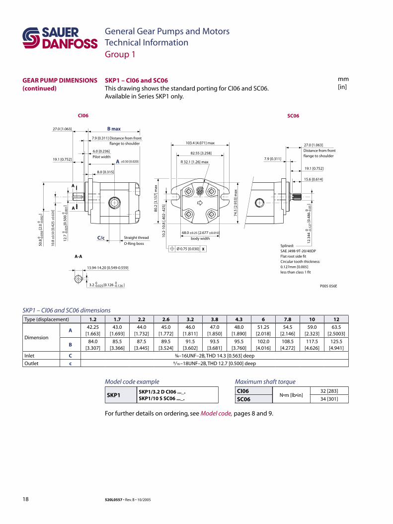
SKP1 – CI06 and SC06 dimensionsType (displacement) 1.2 1.7 2.2 2.6 3.2 3.8 4.3 6 7.8 10 12
Dimension
A42.25
[1.663]43.0
[1.693]44.0
[1.732]45.0
[1.772]46.0
[1.811]47.0
[1.850]48.0
[1.890]51.25
[2.018]54.5
[2.146]59.0
[2.323]63.5
[2.5003]
B84.0
[3.307]85.5
[3.366]87.5
[3.445]89.5
[3.524]91.5
[3.602]93.5
[3.681]95.5
[3.760]102.0
[4.016]108.5
[4.272]117.5
[4.626]125.5
[4.941]
Inlet C ¾–16UNF–2B, THD 14.3 [0.563] deep
Outlet c 9/ 16 –18UNF–2B, THD 12.7 [0.500] deep
SKP1 – CI06 and SC06This drawing shows the standard porting for CI06 and SC06.Available in Series SKP1 only.
Group 1
GEAR PUMP DIMENSIONS (continued)
Maximum shaft torque
CI06N•m [lb•in]
32 [283]
SC06 34 [301]
Model code example
SKP1SKP1/3.2 D CI06 ..._.SKP1/10 S SC06 ..._.
For further details on ordering, see Model code, pages 8 and 9.
19520L0557 • Rev. B • 10/2005
General Gear Pumps and MotorsTechnical Information
mm[in]
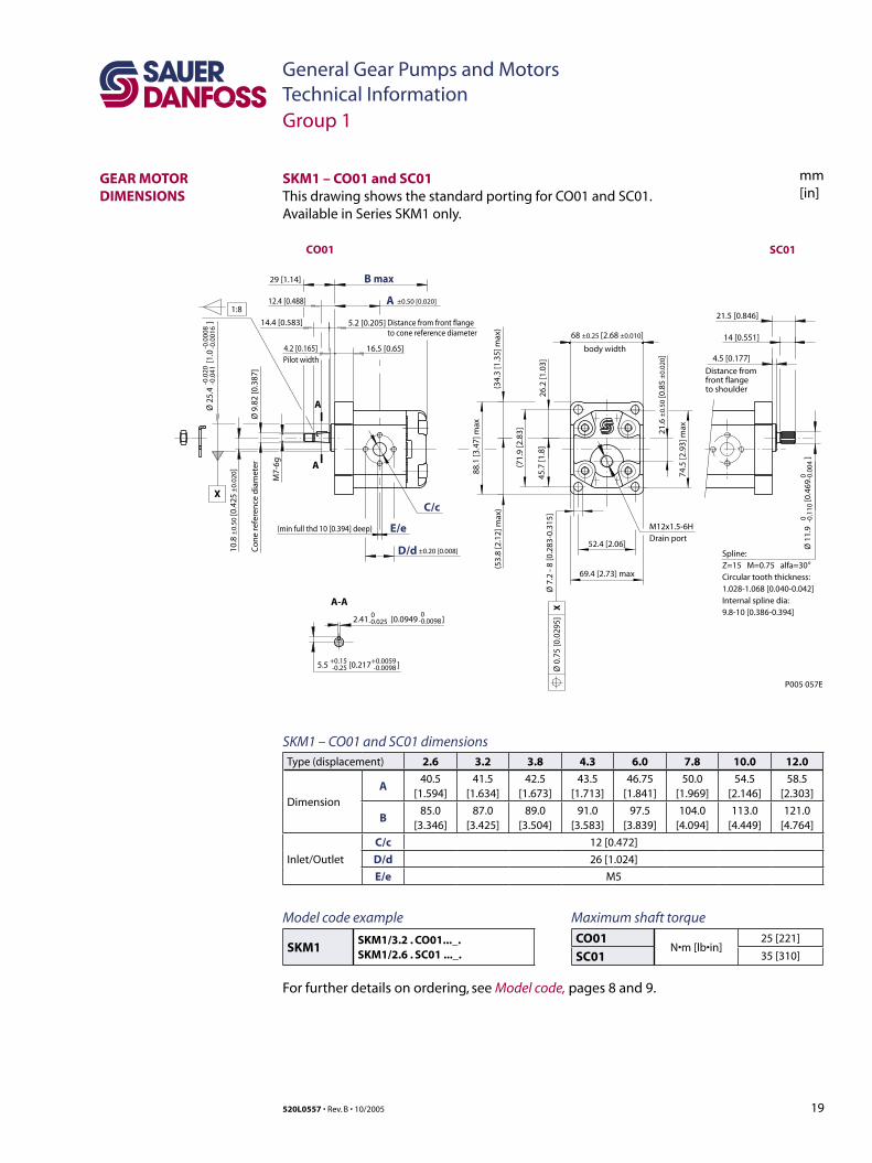
SKM1 – CO01 and SC01This drawing shows the standard porting for CO01 and SC01.Available in Series SKM1 only.
SKM1 – CO01 and SC01 dimensionsType (displacement) 2.6 3.2 3.8 4.3 6.0 7.8 10.0 12.0
Dimension
A40.5
[1.594]41.5
[1.634]42.5
[1.673]43.5
[1.713]46.75
[1.841]50.0
[1.969]54.5
[2.146]58.5
[2.303]
B85.0
[3.346]87.0
[3.425]89.0
[3.504]91.0
[3.583]97.5
[3.839]104.0
[4.094]113.0
[4.449]121.0
[4.764]
Inlet/Outlet
C/c 12 [0.472]
D/d 26 [1.024]
E/e M5
CO01 SC01
1:8
Co
ne
refe
ren
ce d
iam
eter
to cone reference diameterDistance from front flange
29 [1.14]M
7-6g
14.4 [0.583] 5.2 [0.205]
12.4 [0.488]
X
Pilot width
-0.0
41-0
.020
16.5 [0.65]4.2 [0.165]
XØ
0.7
5 [0
.029
5]
body width
69.4 [2.73] max
52.4 [2.06]
88.1
[3.4
7] m
ax
74.5
[2.9
3] m
ax
(53.
8 [2
.12]
max
)(3
4.3
[1.3
5] m
ax)
(71.
9 [2
.83]
26.2
[1.0
3]45
.7 [1
.8]
68 ±0.25 [2.68 ±0.010]
21.6
±0.
50 [0
.85
±0.
020]
5.5 [0.217 ]+0.15
-0.25+0.0059-0.0098
-0.00982.41 [0.0949 ] 0-0.025
0
D/d
E/e
C/c
Spline:Z=15 M=0.75 alfa=30°Circular tooth thickness: 1.028-1.068 [0.040-0.042] Internal spline dia: 9.8-10 [0.386-0.394]
to shoulderfront flangeDistance from
4.5 [0.177]
14 [0.551]
21.5 [0.846]
(min full thd 10 [0.394] deep)
±0.50 [0.020]
±0.20 [0.008]
P005 057E
B max
A
A
A
A-A
Ø 2
5.4
[1.0
]
Ø 9
.82
[0.3
87]
10.8
±0.
50 [0
.425
±0.
020]
Ø 1
1.9
[0.4
69
]
Ø 7
.2 -
8 [0
.283
-0.3
15]
0 -0.1
100 -0
.004
-0.0
016
-0.0
008
M12x1.5-6HDrain port
Group 1
GEAR MOTOR DIMENSIONS
Maximum shaft torque
CO01N•m [lb•in]
25 [221]
SC01 35 [310]
Model code example
SKM1SKM1/3.2 . CO01..._.SKM1/2.6 . SC01 ..._.
For further details on ordering, see Model code, pages 8 and 9.
20 520L0557 • Rev. B • 10/2005
General Gear Pumps and MotorsTechnical Information
mm[in]
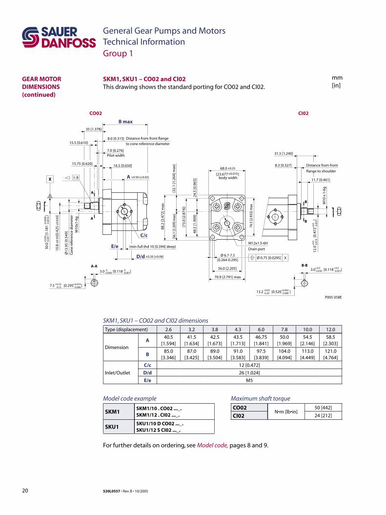
SKM1, SKU1 – CO02 and CI02This drawing shows the standard porting for CO02 and CI02.
SKM1, SKU1 – CO02 and CI02 dimensionsType (displacement) 2.6 3.2 3.8 4.3 6.0 7.8 10.0 12.0
Dimension
A40.5
[1.594]41.5
[1.634]42.5
[1.673]43.5
[1.713]46.75
[1.841]50.0
[1.969]54.5
[2.146]58.5
[2.303]
B85.0
[3.346]87.0
[3.425]89.0
[3.504]91.0
[3.583]97.5
[3.839]104.0
[4.094]113.0
[4.449]121.0
[4.764]
Inlet/Outlet
C/c 12 [0.472]
D/d 26 [1.024]
E/e M5
12.0
[0
.472
]
+0.
0
+0.
0-0
.018
-0
.001
M10
x 1
-6g
11.7 [0.461]
8.3 [0.327] Distance from front
flange to shoulder
31.5 [1.240]
3.0 [0.118 ]+0.0 +0.0-0.030 -0.001
13.2 [0.520 ]+0.05 +0.002-0.20 -0.008
88.2
[3.4
72] m
ax
7.5 [0.295 ]+0.25 +0.010-0.15 -0.006
3.0 [0.118 ]0 0-0.030 -0.001
C/c
D/d
E/e
A
A
A
A-A
16.5 [0.650]
7.0 [0.276]Pilot width
8.0 [0.315] Distance from front flange
to cone reference diameter
B max
M10
x1-6
g
Ø13
.95
[0.5
49]
Con
e re
fere
nce
dia
met
er
10.8
[0
.425
30.0
[1
.181
]
-0.0
20
-
0.00
08-0
.041
-0.
0016
68.0
[23.677 ]body width
74.5
[2.9
33] m
ax
56.0 [2.205]
70.9 [2.791] max
24.5
[0.9
65]
48.5
[1.9
09]
(73.
0 [2
.874
])
(32.
1 [1
.264
] max
)(5
6.1
[2.2
09] m
ax)
Ø 6.7-7.5[0.264-0.295]
1: 8
35 [1.378]
15.75 [0.620]
15.5 [0.610]
P005 058E
±0.25
±0.20 [±0.08]
±0.
50
±0.
020]
±0.50 [±0.02]±0.010
CO02 CI02
(min full thd 10 [0.394] deep)
XØ 0.75 [0.0295]
M12x1.5-6H
Drain port
B
B
B-B
X
Group 1
GEAR MOTOR DIMENSIONS (continued)
Maximum shaft torque
CO02N•m [lb•in]
50 [442]
CI02 24 [212]
Model code example
SKM1SKM1/10 . CO02 ..._.SKM1/12 . CI02 ..._.
SKU1SKU1/10 D CO02 ..._.SKU1/12 S CI02 ..._.
For further details on ordering, see Model code, pages 8 and 9.

21520L0557 • Rev. B • 10/2005
General Gear Pumps and MotorsTechnical Information
mm[in]
SKM1 – CI06 and SC06This drawing shows the standard porting for CI06 and SC06.Available in Series SKM1 only.
SKM1 – CI06 and SC06 dimensionsType (displacement) 2.6 3.2 3.8 4.3 6.0 7.8 10.0 12.0
Dimension
A45
[1.771]46
[1.811]47
[1.850]48
[1.889]51.25
[2.017]54.5
[2.145]59
[2.322]63.5
[2.500]
B89.5
[3.523]91.5
[3.602]93.5
[3.681]95.5
[3.759]102
[4.015]108.5
[4.271]117.5
[4.625]125.5
[4.940]
Inlet/Outlet C/c ¾–16UNF–2B, THD 14.3 [0.563] deep
12.3
44
[0
.486
]
0
0 0
0 -0.0
5
Splined: SAE J498-9T-20/40DPFlat root side fitCircular tooth thickness:0.127 [0.005]less than class 1 fit
15.6 [0.614]
19.1 [0.752]
7.9 [0.311]
27.0 [1.063]
74.5
[2.9
33] m
ax
body width
R 32.1 [1.26] max
82.55 [3.258]
103.4 [4.071] max
80.2
[3.1
57] m
ax
X10
.2-1
0.8
[.402
-.425
]Ø
0.7
5 [0
.030
]
3.2 [0.126 ]-0.025 -0.126
13.94-14.20[0.549-0.559]
Straight thread O-Ring boss
8.0 [0.315]
6.0 [0.236]
Pilot width
7.9 [0.311]
Distance from front flange to shoulder
Distance from front flange to shoulder19.1
[0.752]
27.0 [1.063]
12.7
[
0.50
0
]-0
.025
-0
.001
10.8
±0.
50 [0
.425
±0.
020]
68.0 ±0.25 [2.677 ±0.010]
50.8
[
2.0
]
00
-0.0
50
-0.0
02
P005 059E
CI06 SC06
C/c
±0.50 [0.020]
B max
A
A
A
A-A
-0.1
27
00
7/16-20UNF-2BDrain port
X
Group 1
GEAR MOTOR DIMENSIONS (continued)
Maximum shaft torque
CI06N•m [lb•in]
32 [283]
SC06 34 [301]
Model code example
SKM1SKM1/10 . CI06 ..._.SKM1/12 . SC06 ..._.
For further details on ordering, see Model code, pages 8 and 9.
22 520L0557 • Rev. B • 10/2005
General Gear Pumps and MotorsTechnical Information
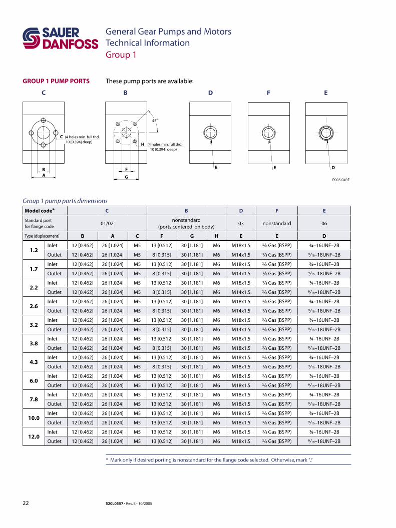
These pump ports are available:
Group 1 pump ports dimensions
Model code* C B D F E
Standard portfor flange code
01/02nonstandard
(ports centered on body)03 nonstandard 06
Type (displacement) B A C F G H E E D
1.2Inlet 12 [0.462] 26 [1.024] M5 13 [0.512] 30 [1.181] M6 M18x1.5 3/ 8 Gas (BSPP) ¾–16UNF–2B
Outlet 12 [0.462] 26 [1.024] M5 8 [0.315] 30 [1.181] M6 M14x1.5 3/ 8 Gas (BSPP) 9/ 16–18UNF–2B
1.7Inlet 12 [0.462] 26 [1.024] M5 13 [0.512] 30 [1.181] M6 M18x1.5 3/ 8 Gas (BSPP) ¾–16UNF–2B
Outlet 12 [0.462] 26 [1.024] M5 8 [0.315] 30 [1.181] M6 M14x1.5 3/ 8 Gas (BSPP) 9/ 16–18UNF–2B
2.2Inlet 12 [0.462] 26 [1.024] M5 13 [0.512] 30 [1.181] M6 M18x1.5 3/ 8 Gas (BSPP) ¾–16UNF–2B
Outlet 12 [0.462] 26 [1.024] M5 8 [0.315] 30 [1.181] M6 M14x1.5 3/ 8 Gas (BSPP) 9/ 16–18UNF–2B
2.6Inlet 12 [0.462] 26 [1.024] M5 13 [0.512] 30 [1.181] M6 M18x1.5 3/ 8 Gas (BSPP) ¾–16UNF–2B
Outlet 12 [0.462] 26 [1.024] M5 8 [0.315] 30 [1.181] M6 M14x1.5 3/ 8 Gas (BSPP) 9/ 16–18UNF–2B
3.2Inlet 12 [0.462] 26 [1.024] M5 13 [0.512] 30 [1.181] M6 M18x1.5 3/ 8 Gas (BSPP) ¾–16UNF–2B
Outlet 12 [0.462] 26 [1.024] M5 8 [0.315] 30 [1.181] M6 M14x1.5 3/ 8 Gas (BSPP) 9/ 16–18UNF–2B
3.8Inlet 12 [0.462] 26 [1.024] M5 13 [0.512] 30 [1.181] M6 M18x1.5 3/ 8 Gas (BSPP) ¾–16UNF–2B
Outlet 12 [0.462] 26 [1.024] M5 8 [0.315] 30 [1.181] M6 M18x1.5 3/ 8 Gas (BSPP) 9/ 16–18UNF–2B
4.3Inlet 12 [0.462] 26 [1.024] M5 13 [0.512] 30 [1.181] M6 M18x1.5 3/ 8 Gas (BSPP) ¾–16UNF–2B
Outlet 12 [0.462] 26 [1.024] M5 8 [0.315] 30 [1.181] M6 M18x1.5 3/ 8 Gas (BSPP) 9/ 16–18UNF–2B
6.0Inlet 12 [0.462] 26 [1.024] M5 13 [0.512] 30 [1.181] M6 M18x1.5 3/ 8 Gas (BSPP) ¾–16UNF–2B
Outlet 12 [0.462] 26 [1.024] M5 13 [0.512] 30 [1.181] M6 M18x1.5 3/ 8 Gas (BSPP) 9/ 16–18UNF–2B
7.8Inlet 12 [0.462] 26 [1.024] M5 13 [0.512] 30 [1.181] M6 M18x1.5 3/ 8 Gas (BSPP) ¾–16UNF–2B
Outlet 12 [0.462] 26 [1.024] M5 13 [0.512] 30 [1.181] M6 M18x1.5 3/ 8 Gas (BSPP) 9/ 16–18UNF–2B
10.0Inlet 12 [0.462] 26 [1.024] M5 13 [0.512] 30 [1.181] M6 M18x1.5 3/ 8 Gas (BSPP) ¾–16UNF–2B
Outlet 12 [0.462] 26 [1.024] M5 13 [0.512] 30 [1.181] M6 M18x1.5 3/ 8 Gas (BSPP) 9/ 16–18UNF–2B
12.0Inlet 12 [0.462] 26 [1.024] M5 13 [0.512] 30 [1.181] M6 M18x1.5 3/ 8 Gas (BSPP) ¾–16UNF–2B
Outlet 12 [0.462] 26 [1.024] M5 13 [0.512] 30 [1.181] M6 M18x1.5 3/ 8 Gas (BSPP) 9/ 16–18UNF–2B
* Mark only if desired porting is nonstandard for the flange code selected. Otherwise, mark ‘.’
GROUP 1 PUMP PORTS
B
C B D F E
C
A
(4 holes min. full thd.10 [0.394] deep)
F
H
E
G
45o
(4 holes min. full thd.10 [0.394] deep)
E D
P005 049E
Group 1
23520L0557 • Rev. B • 10/2005
General Gear Pumps and MotorsTechnical Information
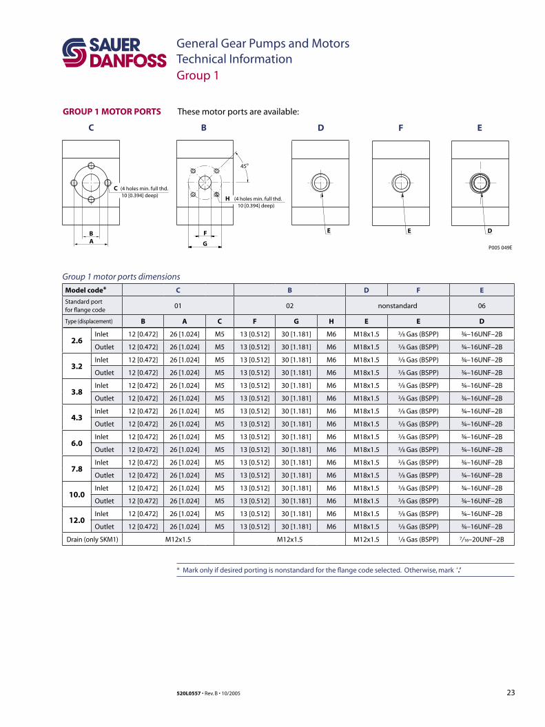
GROUP 1 MOTOR PORTS
Group 1 motor ports dimensions
Model code* C B D F E
Standard portfor flange code
01 02 nonstandard 06
Type (displacement) B A C F G H E E D
2.6Inlet 12 [0.472] 26 [1.024] M5 13 [0.512] 30 [1.181] M6 M18x1.5 3/ 8 Gas (BSPP) ¾–16UNF–2B
Outlet 12 [0.472] 26 [1.024] M5 13 [0.512] 30 [1.181] M6 M18x1.5 3/ 8 Gas (BSPP) ¾–16UNF–2B
3.2Inlet 12 [0.472] 26 [1.024] M5 13 [0.512] 30 [1.181] M6 M18x1.5 3/ 8 Gas (BSPP) ¾–16UNF–2B
Outlet 12 [0.472] 26 [1.024] M5 13 [0.512] 30 [1.181] M6 M18x1.5 3/ 8 Gas (BSPP) ¾–16UNF–2B
3.8Inlet 12 [0.472] 26 [1.024] M5 13 [0.512] 30 [1.181] M6 M18x1.5 3/ 8 Gas (BSPP) ¾–16UNF–2B
Outlet 12 [0.472] 26 [1.024] M5 13 [0.512] 30 [1.181] M6 M18x1.5 3/ 8 Gas (BSPP) ¾–16UNF–2B
4.3Inlet 12 [0.472] 26 [1.024] M5 13 [0.512] 30 [1.181] M6 M18x1.5 3/ 8 Gas (BSPP) ¾–16UNF–2B
Outlet 12 [0.472] 26 [1.024] M5 13 [0.512] 30 [1.181] M6 M18x1.5 3/ 8 Gas (BSPP) ¾–16UNF–2B
6.0Inlet 12 [0.472] 26 [1.024] M5 13 [0.512] 30 [1.181] M6 M18x1.5 3/ 8 Gas (BSPP) ¾–16UNF–2B
Outlet 12 [0.472] 26 [1.024] M5 13 [0.512] 30 [1.181] M6 M18x1.5 3/ 8 Gas (BSPP) ¾–16UNF–2B
7.8Inlet 12 [0.472] 26 [1.024] M5 13 [0.512] 30 [1.181] M6 M18x1.5 3/ 8 Gas (BSPP) ¾–16UNF–2B
Outlet 12 [0.472] 26 [1.024] M5 13 [0.512] 30 [1.181] M6 M18x1.5 3/ 8 Gas (BSPP) ¾–16UNF–2B
10.0Inlet 12 [0.472] 26 [1.024] M5 13 [0.512] 30 [1.181] M6 M18x1.5 3/ 8 Gas (BSPP) ¾–16UNF–2B
Outlet 12 [0.472] 26 [1.024] M5 13 [0.512] 30 [1.181] M6 M18x1.5 3/ 8 Gas (BSPP) ¾–16UNF–2B
12.0Inlet 12 [0.472] 26 [1.024] M5 13 [0.512] 30 [1.181] M6 M18x1.5 3/ 8 Gas (BSPP) ¾–16UNF–2B
Outlet 12 [0.472] 26 [1.024] M5 13 [0.512] 30 [1.181] M6 M18x1.5 3/ 8 Gas (BSPP) ¾–16UNF–2B
Drain (only SKM1) M12x1.5 M12x1.5 M12x1.5 1/ 8 Gas (BSPP) 7/ 16–20UNF–2B
These motor ports are available:
B
C B D F E
C
A
(4 holes min. full thd.10 [0.394] deep)
F
H
E
G
45o
(4 holes min. full thd.10 [0.394] deep)
E D
P005 049E
Group 1
* Mark only if desired porting is nonstandard for the flange code selected. Otherwise, mark ‘.’

24 520L0557 • Rev. B • 10/2005
General Gear Pumps and MotorsTechnical Information
SHAFT AND FLANGE AVAILABILITY
This table details the standard Group 1 shafts and flange combinations that are currently available with the maximum shaft torque limits. For further information, please see Sauer-Danfoss publications Group 1 Gear Pumps Technical Information, 520L0545 and Group 1, 2 and 3 Gear Motors, Technical Information, 520L0568.
Shaft and flange availability and torque capacity
Shaft Mounting flange code with maximum torque in Nm [lb•in]
Description Code 01 02 03 06
Taper 1:8 CO 25 [221] 50 [442] - -
Spline 15-T SC 35 [310] - - -
SAE spline J/498-9T-20/40 DP SC - - - 34 [301]
Parallel 12 mm CI - 24 [212] - -
Parallel 12.7 mm CI - - - 32 [ 283]
Sauer-Danfoss Tang FR - - 14 [124] -
Group 1
25520L0557 • Rev. B • 10/2005
General Gear Pumps and MotorsTechnical Information
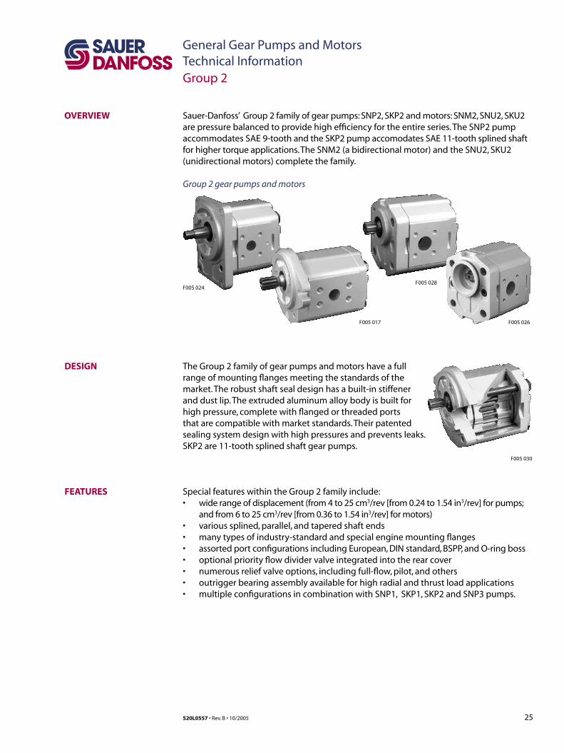
OVERVIEW Sauer-Danfoss’ Group 2 family of gear pumps: SNP2, SKP2 and motors: SNM2, SNU2, SKU2 are pressure balanced to provide high efficiency for the entire series. The SNP2 pump accommodates SAE 9-tooth and the SKP2 pump accomodates SAE 11-tooth splined shaft for higher torque applications. The SNM2 (a bidirectional motor) and the SNU2, SKU2 (unidirectional motors) complete the family.
Group 2 gear pumps and motors
DESIGN
FEATURES
Group 2
The Group 2 family of gear pumps and motors have a full range of mounting flanges meeting the standards of the market. The robust shaft seal design has a built-in stiffener and dust lip. The extruded aluminum alloy body is built for high pressure, complete with flanged or threaded ports that are compatible with market standards. Their patented sealing system design with high pressures and prevents leaks. SKP2 are 11-tooth splined shaft gear pumps.
Special features within the Group 2 family include: • wide range of displacement (from 4 to 25 cm3/rev [from 0.24 to 1.54 in3/rev] for pumps;
and from 6 to 25 cm3/rev [from 0.36 to 1.54 in3/rev] for motors)• various splined, parallel, and tapered shaft ends• many types of industry-standard and special engine mounting flanges• assorted port configurations including European, DIN standard, BSPP, and O-ring boss• optional priority flow divider valve integrated into the rear cover• numerous relief valve options, including full-flow, pilot, and others• outrigger bearing assembly available for high radial and thrust load applications• multiple configurations in combination with SNP1, SKP1, SKP2 and SNP3 pumps.
F005 030
F005 026
F005 028
F005 017
F005 024
26 520L0557 • Rev. B • 10/2005
General Gear Pumps and MotorsTechnical Information
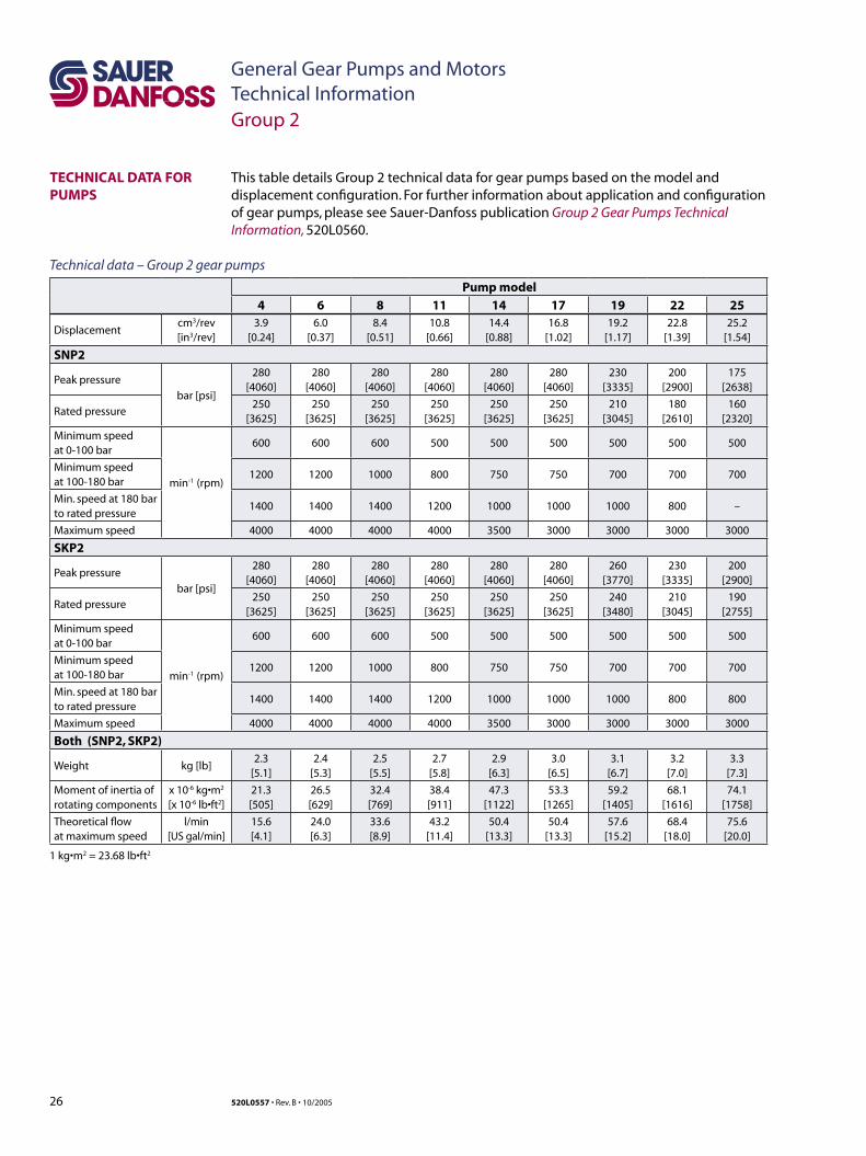
TECHNICAL DATA FOR PUMPS
This table details Group 2 technical data for gear pumps based on the model and displacement configuration. For further information about application and configuration of gear pumps, please see Sauer-Danfoss publication Group 2 Gear Pumps Technical Information, 520L0560.
Pump model
4 6 8 11 14 17 19 22 25
Displacementcm3/rev[in3/rev]
3.9[0.24]
6.0[0.37]
8.4[0.51]
10.8[0.66]
14.4[0.88]
16.8[1.02]
19.2[1.17]
22.8[1.39]
25.2[1.54]
SNP2
Peak pressure
bar [psi]
280[4060]
280[4060]
280[4060]
280[4060]
280[4060]
280[4060]
230[3335]
200[2900]
175[2638]
Rated pressure250
[3625]250
[3625]250
[3625]250
[3625]250
[3625]250
[3625]210
[3045]180
[2610]160
[2320]
Minimum speedat 0-100 bar
min-1 (rpm)
600 600 600 500 500 500 500 500 500
Minimum speed at 100-180 bar
1200 1200 1000 800 750 750 700 700 700
Min. speed at 180 bar to rated pressure
1400 1400 1400 1200 1000 1000 1000 800 –
Maximum speed 4000 4000 4000 4000 3500 3000 3000 3000 3000
SKP2
Peak pressure
bar [psi]
280[4060]
280[4060]
280[4060]
280[4060]
280[4060]
280[4060]
260[3770]
230[3335]
200[2900]
Rated pressure250
[3625]250
[3625]250
[3625]250
[3625]250
[3625]250
[3625]240
[3480]210
[3045]190
[2755]
Minimum speedat 0-100 bar
min-1 (rpm)
600 600 600 500 500 500 500 500 500
Minimum speed at 100-180 bar
1200 1200 1000 800 750 750 700 700 700
Min. speed at 180 bar to rated pressure
1400 1400 1400 1200 1000 1000 1000 800 800
Maximum speed 4000 4000 4000 4000 3500 3000 3000 3000 3000
Both (SNP2, SKP2)
Weight kg [lb]2.3
[5.1]2.4
[5.3]2.5
[5.5]2.7
[5.8]2.9
[6.3]3.0
[6.5]3.1
[6.7]3.2
[7.0]3.3
[7.3]
Moment of inertia of rotating components
x 10-6 kg•m2
[x 10-6 lb•ft2]21.3[505]
26.5[629]
32.4[769]
38.4[911]
47.3[1122]
53.3[1265]
59.2[1405]
68.1[1616]
74.1[1758]
Theoretical flow at maximum speed
l/min[US gal/min]
15.6[4.1]
24.0[6.3]
33.6[8.9]
43.2[11.4]
50.4[13.3]
50.4[13.3]
57.6[15.2]
68.4[18.0]
75.6[20.0]
Technical data – Group 2 gear pumps
1 kg•m2 = 23.68 lb•ft2
Group 2

27520L0557 • Rev. B • 10/2005
General Gear Pumps and MotorsTechnical Information
TECHNICAL DATA FOR MOTORS
This table details the performance of the Group 2 gear motors. For further information about application and configuration of gear motors, please see Sauer-Danfoss publication Group 1, 2 and 3 Gear Motors, Technical Information, 520L0568.
Motor model6 8 11 14 17 19 22 25
Displacementcm3/rev[in3/rev]
6.0[0.36]
8.4[0.513]
10.8[0.659]
14.4[0.879]
16.8[1.025]
19.2[1.171]
22.8[1.391]
25.2[1.538]
SNM2 (a bidirectional motor)
Peak pressure
bar [psi]
280[4060]
280[4060]
280[4060]
280[4060]
260[3770]
230[3335]
200[2900]
180[2610]
Rated pressure250
[3625]250
[3625]250
[3625]250
[3625]230
[3335]210
[3000]180
[2610]160
[2320]
Outlet pressure250
[3625]250
[3625]250
[3625]250
[3625]230
[3335]210
[3000]180
[2610]160
[2320]
Minimum speedmin-1 (rpm)
700 700 700 700 500 500 500 500
Maximum speed 4000 4000 4000 4000 4000 3500 3500 3500
SNU2 (a unidirectional motor)
Peak pressure
bar [psi]
–
280[4060]
280[4060]
280[4060]
260[3770]
230[3335]
200[2900]
180[2610]
Rated pressure250
[3625]250
[3625]250
[3625]230
[3335]210
[3000]180
[2610]160
[2320]
Minimum speedmin-1 (rpm)
600 600 600 500 500 500 500
Maximum speed 3500 3500 3500 3000 3000 3000 2500
SKU2 (a unidirectional motor)
Peak pressure
bar [psi]
–
280[4060]
280[4060]
280[4060]
260[3770]
230[3335]
200[2900]
175[2815]
Rated pressure250
[3625]250
[3625]250
[3625]230
[3335]210
[3000]180
[2610]160
[2320]
Minimum speedmin-1 (rpm)
600 600 600 500 500 500 500
Maximum speed 3500 3500 3500 3000 3000 3000 2500
All (SNM2, SNU2, SKU2)
Weight kg [lb]2.4
[5.3]2.5
[5.5]2.7
[5.5]2.9
[6.3]3.0
[6.5]3.1
[6.7]3.2
[7.0]3.3
[7.3]
Moment of inertia ofrotating components
x 10-6 kg•m2
[x 10-6 lb•ft2]26.5[629]
32.4[769]
38.4[911]
47.3[1122]
53.3[1265]
59.2[1405]
68.1[1616]
74.1[1758]
Theoretical flow atmaximum speed
l/min[US gal/min]
24[6.3]
33.6[8.9]
43.2[11.4]
50.4[13.3]
50.4[13.3]
57.6[15.2]
68.4[18.0]
75.6[20.0]
Technical data – Group 2 gear motors
1 kg•m2 = 23.68 lb•ft2
C CautionThe rated and peak pressure mentioned are for pumps and motors with flanged ports only. When threaded ports are required a de-rated performance has to be considered. To verify the compliance of an high pressure application with a threaded ports pump apply to a Sauer-Danfoss representative.
Group 2
28 520L0557 • Rev. B • 10/2005
General Gear Pumps and MotorsTechnical Information
mm[in]
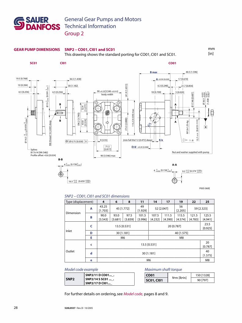
SNP2 – CO01, CI01 and SC01 dimensionsType (displacement) 4 6 8 11 14 17 19 22 25
Dimension
A43.25
[1.703]45 [1.772]
49[1.929]
52 [2.047]56
[2.205]59 [2.323]
B90.0
[3.543]93.0
[3.681]97.5
[3.839]101.5
[3.996]107.5
[4.232]111.5
[4.390]115.5
[4.574]121.5
[4.783]125.5
[4.941]
Inlet
C 13.5 [0.531] 20 [0.787]23.5
[0.925]
D 30 [1.181] 40 [1.575]
E M6 M8
Outlet
c 13.5 [0.531]20
[0.787]
d 30 [1.181]40
[1.575]
e M6 M8
SNP2 – CO01, CI01 and SC01This drawing shows the standard porting for CO01, CI01 and SC01.
[0.374 ]+0.15 +0.006-0.25 -0.010
[1.4
38
]
-0.0
25-0
.050
-0.0
01-0
.002
9 [3.55]
Nut and washer supplied with pump
[0.6
19
]
A
A
(min full thd 12 [0.472] deep) 1 : 8
A-A
M12
x1.2
5-6g
E/e
40.5 [1.596]
6.3 [0.248] 21.7 [0.854]
17 [0.670]
18 [0.709] 5 [0.020]
C/c
M6
thre
ad 1
6 [.6
30] d
eep
B-B
B
B
6.5 [0.256]
30 [1.182]
36.5 [1.438]
Spline:B17x14 DIN 5482Profile offset +0.6 [0.024]
6.5 [0.256]
10 [0.394]
19.5 [0.768]
body width
(96.
2 [3
.790
])
115.
2 [4
.539
] max
90 [3.546] max
D/d ±0.20 [0.008]
(41.
9 [1
.651
])
71.5[2.817]
63.8
[2.5
14]
32.4
[1.2
77]
(73.
3 [2
.888
])
90 ±0.25[3.546 ±0.010]
15.7
±0.
50±
0.02
0
4 0 0-0.030 [0.158 ]-0.001 9.5
Ø 1
6.5
[
0.65
0
]0 -0
.110
0 -0.0
04
Ø 3
6.5
Ø 1
7.46
[0.6
87]
Ø 1
5
[0.5
91
]0 -0
.018
0 -0.0
01
X
Ø 0.75 [0.030] X
CO01
±0.50 [0.020]
P005 060E
B max
A
CI01SC01
[0.650 ]16.5 +0.10-0.20
+0.004-0.008
4 0-0.030
0-0.001[0.158 ]
Group 2
GEAR PUMP DIMENSIONS
Maximum shaft torque
CO01N•m [lb•in]
150 [1328]
SC01, CI01 90 [797]
Model code example
SNP2SNP2/11 D CO01..._.SNP2/14 S SC01 ..._.SNP2/17 D CI01..._
For further details on ordering, see Model code, pages 8 and 9.
29520L0557 • Rev. B • 10/2005
General Gear Pumps and MotorsTechnical Information
mm[in]
3 [0.118 ]
Ø 8
0
[3.1
50
]
9 [0.354]
Ø 1
6.5
[
0.65
0
]
Spline:B17x14 DIN 5482profile offset +0.6 [.024]
13.5 [0.531]
23.5 [0.952]
1 : 5
A
A-A
A
M12
x1.2
5-6g
16.5 [0.650]
E/e
C/c
17.4
6[0
.687
]
38 [1.496]B max
12.5 [0.492] 7.2 [0.283]
5.7 [0.224] 19.3 [0.760]
45˚
body width
(100
[3.9
37])
D/d ±0.20 [±0.008]
A
72[2.835]
120
[4.7
24] m
ax
92 [3.622] max
(44.
5 [1
.72]
)
65.5
[2.5
79]
34.5
[1.3
58]
(75.
5 [2
.972
])
90 ±0.25 [3.543 ±0.010]
0 -0.1
100 -0
.004
-0.0
60-0
.090
-0.0
02-0
.003
0-0.025
0-0.001
9
[0.
354
]
+0.
30-0
.10
+0.
012
-0.0
04
15.7
[
0.61
8
]±
0.50
±0.
02
Ø 0.75 [0.030] X
X
(min full thd 12 [0.472] deep)
Nut and washer supplied with pump
P005 061E
SC02 CO02
±0.50 [±0.02]
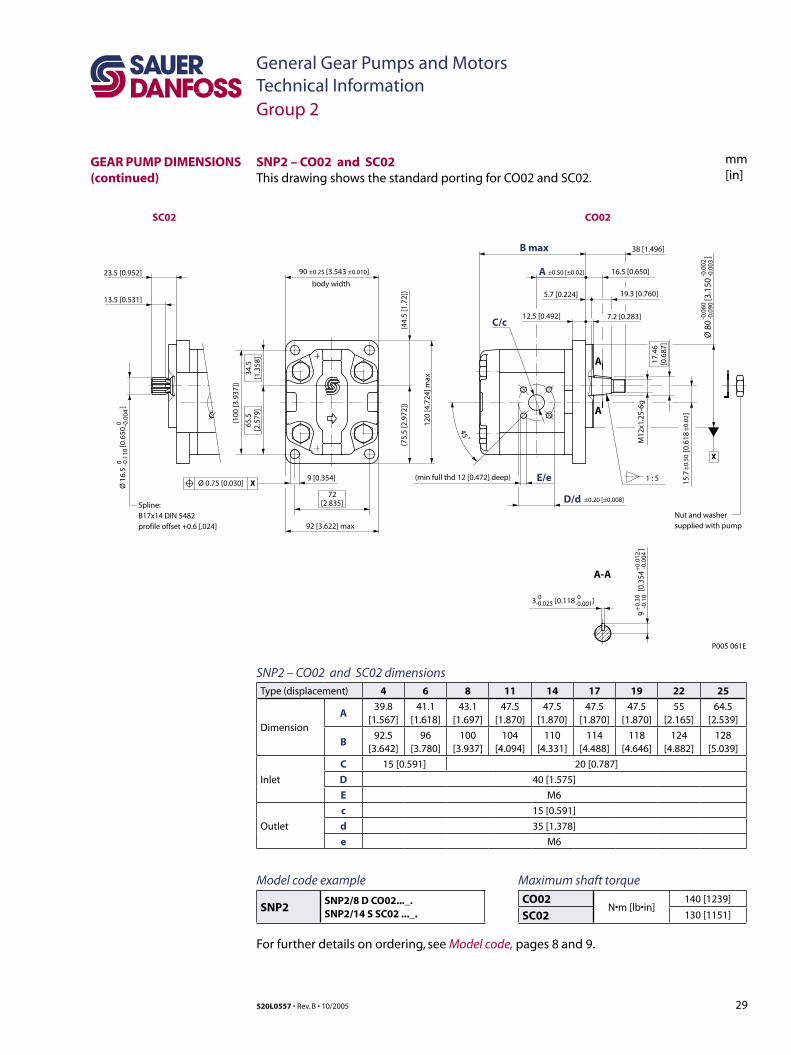
SNP2 – CO02 and SC02 dimensionsType (displacement) 4 6 8 11 14 17 19 22 25
Dimension
A39.8
[1.567]41.1
[1.618]43.1
[1.697]47.5
[1.870]47.5
[1.870]47.5
[1.870]47.5
[1.870]55
[2.165]64.5
[2.539]
B92.5
[3.642]96
[3.780]100
[3.937]104
[4.094]110
[4.331]114
[4.488]118
[4.646]124
[4.882]128
[5.039]
Inlet
C 15 [0.591] 20 [0.787]
D 40 [1.575]
E M6
Outlet
c 15 [0.591]
d 35 [1.378]
e M6
SNP2 – CO02 and SC02This drawing shows the standard porting for CO02 and SC02.
GEAR PUMP DIMENSIONS (continued)
Group 2
Maximum shaft torque
CO02N•m [lb•in]
140 [1239]
SC02 130 [1151]
Model code example
SNP2SNP2/8 D CO02..._.SNP2/14 S SC02 ..._.
For further details on ordering, see Model code, pages 8 and 9.
30 520L0557 • Rev. B • 10/2005
General Gear Pumps and MotorsTechnical Information
mm[in]
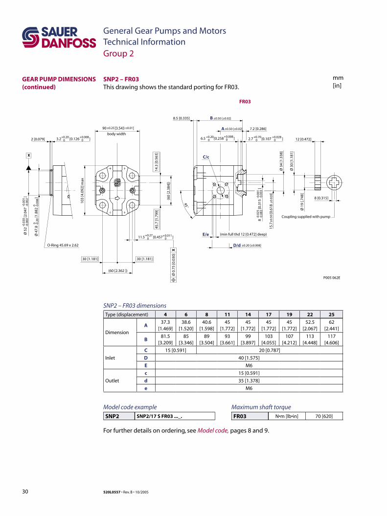
SNP2 – FR03This drawing shows the standard porting for FR03.
3.2 [0.126 ]+0.200
+0.00802 [0.079]
(min full thd 12 [0.472] deep)
Ø 3
4 [1
.338
]
7.2 [0.286]
Ø 1
9 [.7
48]
Ø 3
0 [1
.181
]
12 [0.472]
45˚
X
O-Ring 45.69 x 2.62
body width
(60
[2.3
84])
B8.5 [0.335] ±0.50 [±0.02]
A
(60 [2.362 ])
103
[4.0
92] m
ax
Ø 5
2
[2.
047
]
-0.0
30-0
.060
-0.0
01-0
.002
8
[0.
315
]
-0.0
25-0
.083
-0.0
01-0
.003
11.5 [0.457 ]+0.270
+0.0110
2.7 [0.107 ]+0.70
0+0.028
06.5 [0.258 ]+0.200
+0.0080
Ø 4
7.8
[1
.882
]
0 -0.2
00 -0
.008
15.7
[0
.618
]±
0.50
±0.
020
90 [3.543 ]±0.25 ±0.01
Ø 0
.75
[0.0
30]
X
8 [0.315]
Coupling supplied with pump
P005 062E
±0.50 [±0.02]
D/d
E/e
C/c
±0.20 [±0.008]
FR03
45.7
[1.7
99]
14.3
[0.5
63]
30 [1.181]30 [1.181]
SNP2 – FR03 dimensionsType (displacement) 4 6 8 11 14 17 19 22 25
Dimension
A37.3
[1.469]38.6
[1.520]40.6
[1.598]45
[1.772]45
[1.772]45
[1.772]45
[1.772]52.5
[2.067]62
[2.441]
B81.5
[3.209]85
[3.346]89
[3.504]93
[3.661]99
[3.897]103
[4.055]107
[4.212]113
[4.448]117
[4.606]
Inlet
C 15 [0.591] 20 [0.787]
D 40 [1.575]
E M6
Outlet
c 15 [0.591]
d 35 [1.378]
e M6
GEAR PUMP DIMENSIONS (continued)
Group 2
Maximum shaft torque
FR03 N•m [lb•in] 70 [620]
Model code example
SNP2 SNP2/17 S FR03 ..._.
For further details on ordering, see Model code, pages 8 and 9.
31520L0557 • Rev. B • 10/2005
General Gear Pumps and MotorsTechnical Information
mm[in]
3 [0.118 ]
11.5 [0.453 ]
Ø 1
6.5
[
0.65
0
]
A ±0.50 [±0.02]
B8.5 [0.335] ±0.50 [0.02]
+0.27 0
+0.0110
Spline: B17x14 DIN 5482profile offset +0.6 [0.024]
13.5 [0.531]
26 [1.024]
A-A
A
A
1 : 5
X
(min full thd 12 [0.472] deep)
M12
x1.2
5-6g
17.4
6 [0
.687
]
19 [0.748]
E/e
C/c7.2 [0.283]
40.5 [1.594]
8.2 [0.323] 19.3 [0.760]
45°
body width
(60
[2.3
62])
D/d ±0.20 [±0.008]
90 ±0.50 [3.543 ±0.010]
(60 [2.362])
103
[4.0
55] m
ax
45.7
[1.7
99]
14.3
[0.5
63]
30 [1.181]
Ø0.75 [0.030] X
0 -0.1
100 -0
.004
-0.0
25-0
.064
Ø 5
0
[1
.969
]
-0.0
01-0
.002
5
+0.
30-0
.10
9
[0.3
54
]+
0.01
2-0
.004
0
-0.0250
-0.001
Nut and washer supplied with pump
P005 063E
SC04/05 ..04 Body
..05 Body
CO04/05
15.7
±0.
50 [0
.618
±0.
02]
30 [1.181]
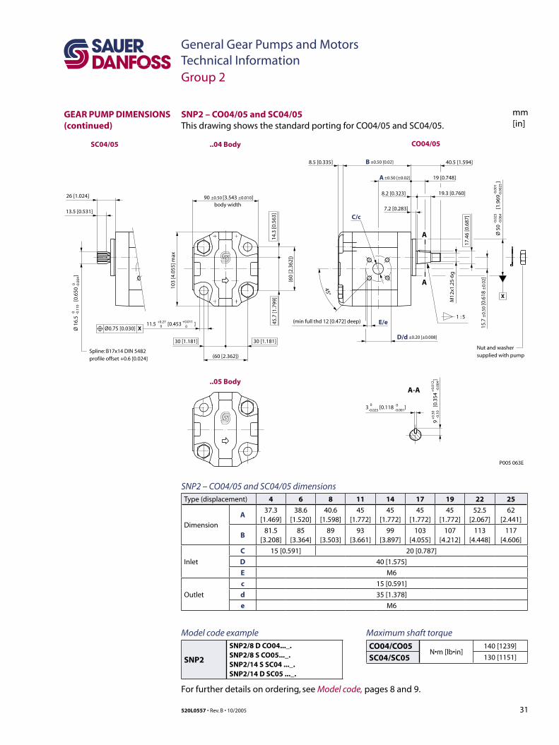
SNP2 – CO04/05 and SC04/05 dimensionsType (displacement) 4 6 8 11 14 17 19 22 25
Dimension
A37.3
[1.469]38.6
[1.520]40.6
[1.598]45
[1.772]45
[1.772]45
[1.772]45
[1.772]52.5
[2.067]62
[2.441]
B81.5
[3.208]85
[3.364]89
[3.503]93
[3.661]99
[3.897]103
[4.055]107
[4.212]113
[4.448]117
[4.606]
Inlet
C 15 [0.591] 20 [0.787]
D 40 [1.575]
E M6
Outlet
c 15 [0.591]
d 35 [1.378]
e M6
SNP2 – CO04/05 and SC04/05This drawing shows the standard porting for CO04/05 and SC04/05.
GEAR PUMP DIMENSIONS (continued)
Group 2
Maximum shaft torque
CO04/CO05N•m [lb•in]
140 [1239]
SC04/SC05 130 [1151]
Model code example
SNP2
SNP2/8 D CO04..._.SNP2/8 S CO05..._.SNP2/14 S SC04 ..._.SNP2/14 D SC05 ..._.
For further details on ordering, see Model code, pages 8 and 9.
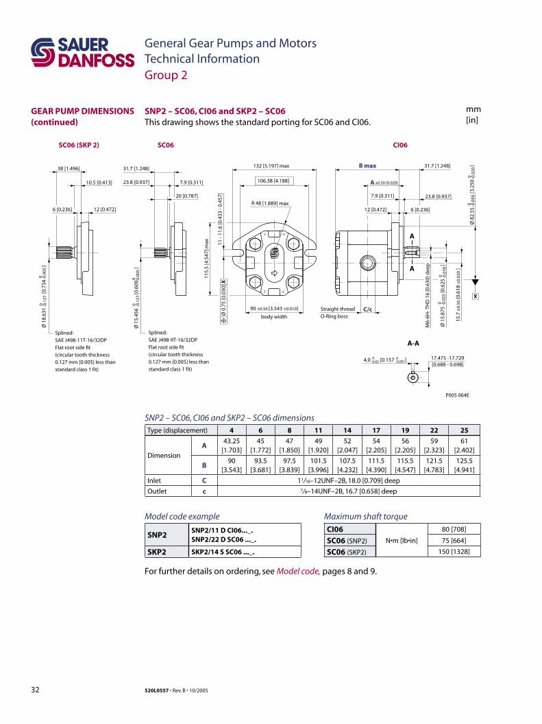
32 520L0557 • Rev. B • 10/2005
General Gear Pumps and MotorsTechnical Information
mm[in]
SNP2 – SC06, CI06 and SKP2 – SC06This drawing shows the standard porting for SC06 and CI06.
SNP2 – SC06, CI06 and SKP2 – SC06 dimensionsType (displacement) 4 6 8 11 14 17 19 22 25
Dimension
A43.25
[1.703]45
[1.772]47
[1.850]49
[1.920]52
[2.047]54
[2.205]56
[2.205]59
[2.323]61
[2.402]
B90
[3.543]93.5
[3.681]97.5
[3.839]101.5
[3.996]107.5
[4.232]111.5
[4.390]115.5
[4.547]121.5
[4.783]125.5
[4.941]
Inlet C 11/ 16–12UNF–2B, 18.0 [0.709] deep
Outlet c 7/ 8–14UNF–2B, 16.7 [0.658] deep
A
A
A-A
7.9 [0.311] 23.8 [0.937]
B max 31.7 [1.248]
C/c
M6-
6H- T
HD
16
[0.6
30] d
eep
17.475 -17.729[0.688 - 0.698]
12 [0.472] 6 [0.236]
body width
11 -
11.6
[0.4
33 -
0.45
7]
A ±0.50 [0.020]
132 [5.197] max
106.38 [4.188]
115.
5 [4
.547
] max
Ø 8
2.55
[3.2
50
]0 -0
.050
0 -0.0
20
4.0 [0.157 ]0-0.03
0-0.001
Ø 1
5.87
5
[0.
625
]
0 -0.0
250 -0
.010
15.7
±0.
50 [0
.618
±0.
020
]
Ø 0
.75
[0.0
30] X
X
Straight thread O-Ring boss
P005 064E
SC06
12 [0.472]6 [0.236]
Splined:SAE J498-11T-16/32DPFlat root side fit(circular tooth thickness0.127 mm [0.005] less thanstandard class 1 fit)
38 [1.496]
10.5 [0.413]
Ø 1
8.63
1
[0.
734
]
0 -0.1
270 -0
.005
SC06 (SKP 2) CI06
20 [0.787]
31.7 [1.248]
23.8 [0.937] 7.9 [0.311]
Ø 1
5.45
6
[0.
609
]
0 -0.1
270 -0
.005
90 ±0.50 [3.543 ±0.010]
R 48 [1.889] max
Splined:SAE J498-9T-16/32DPFlat root side fit(circular tooth thickness0.127 mm [0.005] less thanstandard class 1 fit)
GEAR PUMP DIMENSIONS (continued)
Group 2
Maximum shaft torque
CI06N•m [lb•in]
80 [708]
SC06 (SNP2) 75 [664]
SC06 (SKP2) 150 [1328]
Model code example
SNP2SNP2/11 D CI06..._.SNP2/22 D SC06 ..._.
SKP2 SKP2/14 S SC06 ..._.
For further details on ordering, see Model code, pages 8 and 9.
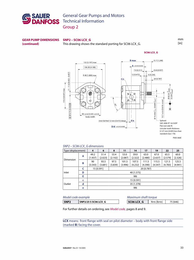
33520L0557 • Rev. B • 10/2005
General Gear Pumps and MotorsTechnical Information
mm[in]
LCX means: front flange with seal on pilot diameter – body with front flange side (marked B) facing the cover.
SNP2 – SC06 LCX_G dimensionsType (displacement) 4 6 8 11 14 17 19 22 25
Dimension
A49.2
[1.937]51.4
[2.023]53.4
[2.102]53.0
[2.087]59.0
[2.322]63.0
[2.480]67.0
[2.637]65.5
[2.579]60.0
[2.326]
B90
[3.543]93.5
[3.681]97.5
[3.839]101.5
[3.996]107.5
[4.232]111.5
[4.390]115.5
[4.547]121.5
[4.783]125.5
[4.941]
Inlet
C 15 [0.591] 20 [0.787]
D 40 [1.575]
E M6
Outlet
c 15 [0.591]
d 35 [1.378]
e M6
X
P005 066E
20 [0.787]45°
E/e
C/c
B max
D/d
A
SC06 LCX_G
7.9 [0.311] 23.8 [0.937]
31.7 [1.248]
12 [0.472] 6 [0.236]
11 -
11.6
[0.4
33 -
0.45
7]
±0.50 [0.020]
132 [5.197] max
106.38 [4.188]
115.
5 [4
.547
] max
Ø 8
2.55
[3.2
50
]
0 -0.0
500 -0
.020
Ø 0
.75
[0.0
30] X
Splined:SAE J498-9T-16/32DPFlat root side fit(circular tooth thickness0.127 mm [0.005] less thanstandard class 1 fit)
body width
90 ±0.50 [3.543 ±0.010]
(min full thd 12 mm [0.472] deep)
±0.20 [0.008]
R 48 [1.889] max
Ø 1
5.45
6
[0.6
09
]0 -0
.127
0 -0.0
05
15.7
±0.
50 [0
.618
±0.
020]
SNP2 – SC06 LCX_GThis drawing shows the standard porting for SC06 LCX_G.
GEAR PUMP DIMENSIONS (continued)
Group 2
Maximum shaft torque
SC06 LCX_G N•m [lb•in] 75 [646]
Model code example
SNP2 SNP2/25 S SC06 LCX_G
For further details on ordering, see Model code, pages 8 and 9.
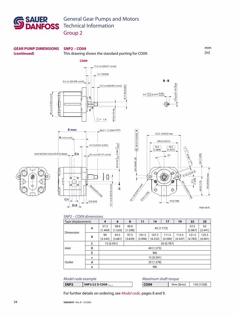
34 520L0557 • Rev. B • 10/2005
General Gear Pumps and MotorsTechnical Information
mm[in]
1.7 [0.067 ]
1: 8
B
B
B - B
Ø 1
7.46
[0.6
87]
M12
x1.2
5-6g
21.7 [0.854]
14-15 [0.551-0.591]
9 [0.354]
R 10.5 [0.413]
19°
31.5
[1.2
40]
3/8-
16U
NC
-2B
122.5 [4.823] max
(99.6 [3.921])
103
[4.0
55] m
ax
(69
[2.7
17])
(34
[1.3
39])
19 [0.748]
P005 067E
(R11.45 [0.451] max)
(R 1
1.45
[0.4
51] m
ax)
R 35 [1
.378]
49.2[1.937]
50.4[1.984]
17.2 ±0.75[0.677 ±0.030]
40.5 [1.594 ]±1 ±0.039
90 ±
0.25
[3.5
43 ±
0.01
0]
12.5 ±0.50[0.492 ±0.020]
6.3 ±0.75[0.248 ±0.030]
15.7
±0.
50 [0
.618
±0.
020 ]
4.5 ±0.25 [0.177 ±0.010]
9.5 [0.374 ]+0.15 +0.006-0.25 -0.010
+0.15
+0.006
0
0
3
[0.1
18
]0
0-0
.025
-0.0
01
Ø 5
2.34
[2
.061
]
00
-0.0
5-0
.002 Ø
0.7
5 [0
.030
] X
X
(min full thd 12mm [0.472] deep)
B max
A
C/c
E/e
D/d
±0.50 [±0.020]
CO09
R0.8 [0.031] max
SNP2 – CO09 dimensionsType (displacement) 4 6 8 11 14 17 19 22 25
Dimension
A37.3
[1.469]38.6
[1.520]40.6
[1.598]45 [1.772]
52.5[2.067]
62[2.441]
B90
[3.543]93.5
[3.681]97.5
[3.839]101.5
[3.996]107.5
[4.232]111.5
[4.390]115.5
[4.547]121.5
[4.783]125.5
[4.941]
Inlet
C 15 [0.591] 20 [0.787]
D 40 [1.575]
E M6
Outlet
c 15 [0.591]
d 35 [1.378]
e M6
SNP2 – CO09This drawing shows the standard porting for CO09.
GEAR PUMP DIMENSIONS (continued)
Group 2
Maximum shaft torque
CO09 N•m [lb•in] 150 [1328]
Model code example
SNP2 SNP2/22 D CO09 ..._.
For further details on ordering, see Model code, pages 8 and 9.

35520L0557 • Rev. B • 10/2005
General Gear Pumps and MotorsTechnical Information
mm[in]
1:8
B
B
B - B
21.7 [0.854]
M12
x1.2
5-6g
Ø 1
7.46
[0.6
87]
3
[0.
118
]
00
-0.0
25-0
.001
9.5 [0.374 ]+0.15 +0.006-0.25 -0.010
90
[3.5
43
]±
0.25
±0.
010
R0.8 [0.031] max
14-15 [0.551-0.591]
3/8-
16U
NC
-2B
(99.6 [3.921])
122.5 [4.823] max
P005 068E
109
[4.2
91] m
ax
R38
[1.4
96] m
ax
(R11.45 [0.451] max)
13˚
50.4[1.984]
49.2[1.937]
3.85 [0.152 ]+0.15 +0.006
0 0
Ø 5
2.34
[
2.06
1
]0
0-0
.05
-0.0
02
15.7
[
0.61
8
]
±0.
50±
0.02
040.5 [1.594 ]±1.0 ±0.039
X
Ø 0
.75
[0.0
30]
XMin. full thread12mm [0.472] deep
E/e
C/c
D/d
B max
A
CO09 (variant BBM)
±0.50 [0.020]
4.0 ±0.50 [0.157 ±0.02]
17.2 ±0.50 [0.677 ±0.02]
6.3 ±0.75 [0.248 ±0.030]
12.5 ±0.50 [0.492 ±0.02]
SNP2 – CO09 (variant BBM) dimensionsType (displacement) 4 6 8 11 14 17 19 22 25
Dimension
A37.3
[1.469]38.6
[1.520]40.6
[1.598]45
[1.772]52.5
[2.067]62.0
[2.441]
B90
[3.543]93.5
[3.681]97.5
[3.839]101.5
[3.996]107.5
[4.232]111.5
[4.390]115.5
[4.547]121.5
[4.783]125.5
[4.941]
Inlet
C 15 [0.591] 20 [0.787]
D 40 [1.575]
E M6
Outlet
c 15 [0.591]
d 35 [1.378]
e M6
SNP2 – CO09 (variant BBM)This drawing shows the standard porting for CO09 (variant BBM).
GEAR PUMP DIMENSIONS (continued)
Group 2
Maximum shaft torque
CO09 (variant BBM) N•m [lb•in] 150 [1328]
Model code example
SNP2 SNP2/25 S CO09 ..._.
For further details on ordering, see Model code, pages 8 and 9.
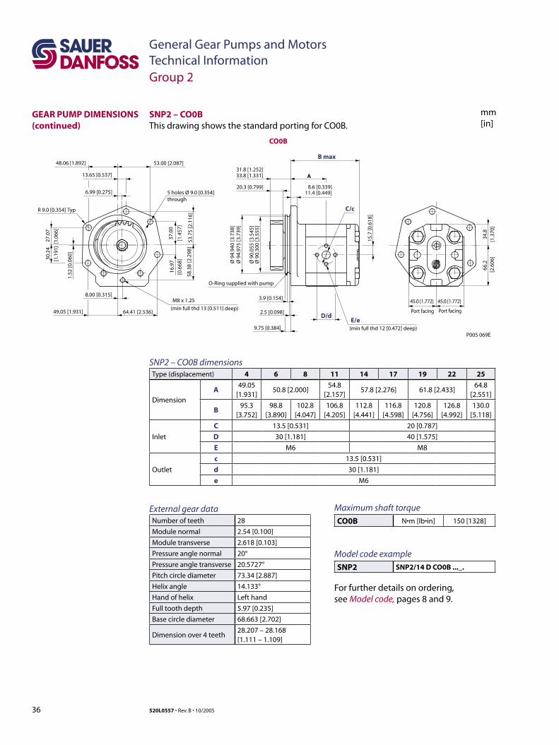
36 520L0557 • Rev. B • 10/2005
General Gear Pumps and MotorsTechnical Information
mm[in]
34.8
[1.3
70]
66.2
[2.6
06]
Port facing Port facing
45.0 [1.772] 45.0 [1.772]3.9 [0.154]
2.5 [0.098]
A
20.3 [0.799]
9.75 [0.384]
15.7
[0.6
18]
through
1.52
[0.0
60]
6.99 [0.275]58
.38
[2.2
98]
16.9
7
[0.6
68]
37.0
0
[1.4
57]
53.7
5 [2
.116
]
27.0
7
[1.0
66]
64.41 [2.536]
48.06 [1.892]
49.05 [1.931]
8.00 [0.315]
53.00 [2.087]
13.65 [0.537]
30.2
4
[1.1
91]
M8 x 1.25
R 9.0 [0.354] Typ
5 holes Ø 9.0 [0.354]
33.8 [1.331]31.8 [1.252]
11.4 [0.449]8.6 [0.339]
C/c
D/dE/e
(min full thd 12 [0.472] deep)
Ø 9
4.94
0 [3
.738
]Ø
94.
975
[3.7
39]
Ø 9
0.05
5 [3
.545
]Ø
90.
300
[3.5
55]
O-Ring supplied with pump
P005 069E
B max
CO0B
(min full thd 13 [0.511] deep)
SNP2 – CO0B dimensionsType (displacement) 4 6 8 11 14 17 19 22 25
Dimension
A49.05
[1.931]50.8 [2.000]
54.8[2.157]
57.8 [2.276] 61.8 [2.433]64.8
[2.551]
B95.3
[3.752]98.8
[3.890]102.8
[4.047]106.8
[4.205]112.8
[4.441]116.8
[4.598]120.8
[4.756]126.8
[4.992]130.0
[5.118]
Inlet
C 13.5 [0.531] 20 [0.787]
D 30 [1.181] 40 [1.575]
E M6 M8
Outlet
c 13.5 [0.531]
d 30 [1.181]
e M6
SNP2 – CO0BThis drawing shows the standard porting for CO0B.
GEAR PUMP DIMENSIONS (continued)
Group 2
Maximum shaft torque
CO0B N•m [lb•in] 150 [1328]
Model code example
SNP2 SNP2/14 D CO0B ..._.
For further details on ordering, see Model code, pages 8 and 9.
External gear dataNumber of teeth 28
Module normal 2.54 [0.100]
Module transverse 2.618 [0.103]
Pressure angle normal 20°
Pressure angle transverse 20.5727°
Pitch circle diameter 73.34 [2.887]
Helix angle 14.133°
Hand of helix Left hand
Full tooth depth 5.97 [0.235]
Base circle diameter 68.663 [2.702]
Dimension over 4 teeth28.207 – 28.168[1.111 – 1.109]
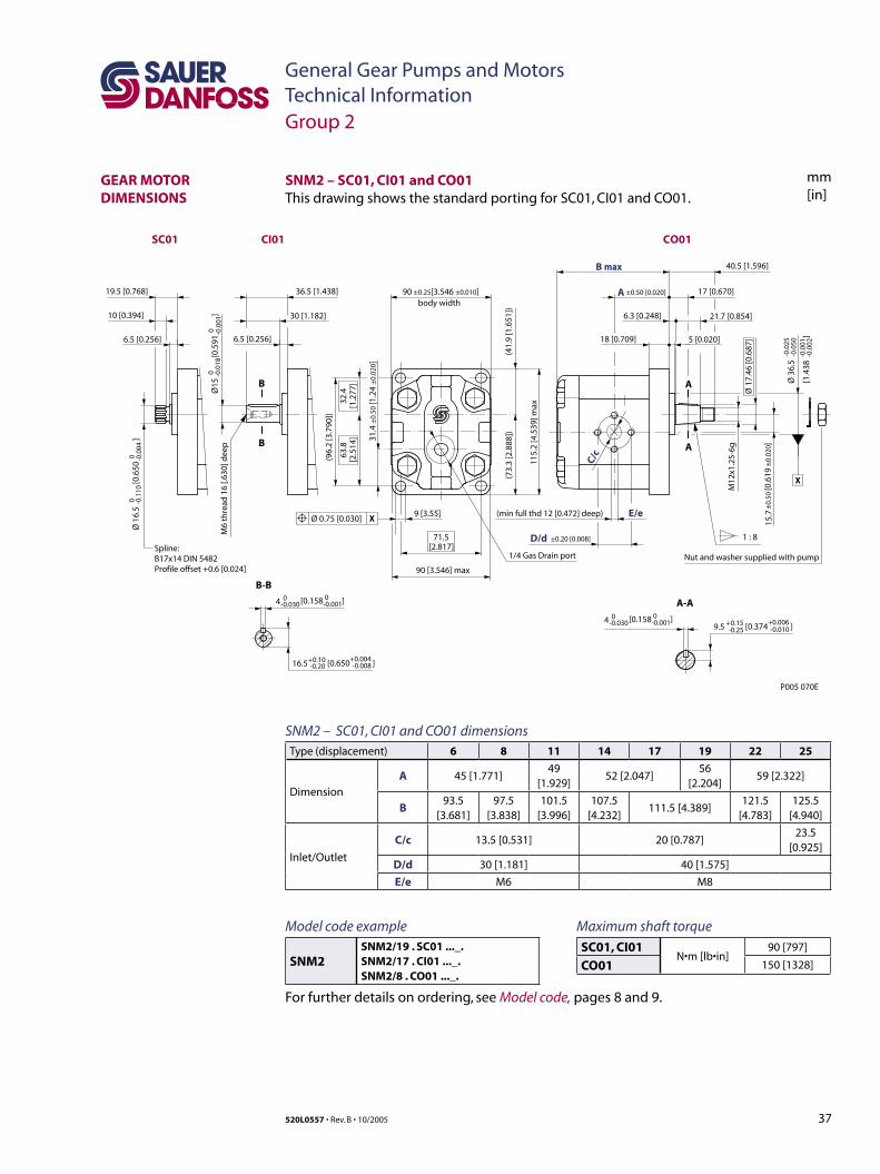
37520L0557 • Rev. B • 10/2005
General Gear Pumps and MotorsTechnical Information
mm[in]
SNM2 – SC01, CI01 and CO01 dimensionsType (displacement) 6 8 11 14 17 19 22 25
Dimension
A 45 [1.771]49
[1.929]52 [2.047]
56 [2.204]
59 [2.322]
B93.5
[3.681]97.5
[3.838]101.5
[3.996]107.5
[4.232]111.5 [4.389]
121.5[4.783]
125.5[4.940]
Inlet/Outlet
C/c 13.5 [0.531] 20 [0.787]23.5
[0.925]
D/d 30 [1.181] 40 [1.575]
E/e M6 M8
[1.4
38
]
-0.0
25-0
.050
-0.0
01-0
.002
9 [3.55]
Nut and washer supplied with pump
[0.6
19
]A
A
[0.650 ]
(min full thd 12 [0.472] deep)
1 : 8
A-A
M12
x1.2
5-6g
E/e
40.5 [1.596]
6.3 [0.248] 21.7 [0.854]
17 [0.670]
18 [0.709] 5 [0.020]
C/c
M6
thre
ad 1
6 [.6
30] d
eep
B-B
B
B
6.5 [0.256]
30 [1.182]
36.5 [1.438]
Spline:B17x14 DIN 5482Profile offset +0.6 [0.024]
6.5 [0.256]
10 [0.394]
19.5 [0.768]body width
(96.
2 [3
.790
])
115.
2 [4
.539
] max
90 [3.546] max
D/d ±0.20 [0.008]
(41.
9 [1
.651
])
71.5[2.817]
63.8
[2.5
14]
32.4
[1.2
77]
(73.
3 [2
.888
])
90 ±0.25[3.546 ±0.010]
15.7
±0.
50±
0.02
0
Ø 1
6.5
[
0.65
0
]0 -0
.110
0 -0.0
04
Ø 3
6.5
Ø 1
7.46
[0.6
87]
16.5+0.10-0.20
+0.004 -0.008
[0.374 ]9.5 +0.15-0.25
+0.006 -0.010
Ø15
[
0.59
1
]0 -0
.018
0 -0.0
01
4 0-0.030
0-0.001[0.158 ]
4 0-0.030
0-0.001[0.158 ]
X
Ø 0.75 [0.030] X
CO01
±0.50 [0.020]
P005 070E
B max
A
CI01SC01
1/4 Gas Drain port
31.4
±0.
50 [1
.24
±0.
020]
SNM2 – SC01, CI01 and CO01This drawing shows the standard porting for SC01, CI01 and CO01.
Group 2
GEAR MOTOR DIMENSIONS
Maximum shaft torque
SC01, CI01N•m [lb•in]
90 [797]
CO01 150 [1328]
Model code example
SNM2SNM2/19 . SC01 ..._.SNM2/17 . CI01 ..._.SNM2/8 . CO01 ..._.
For further details on ordering, see Model code, pages 8 and 9.
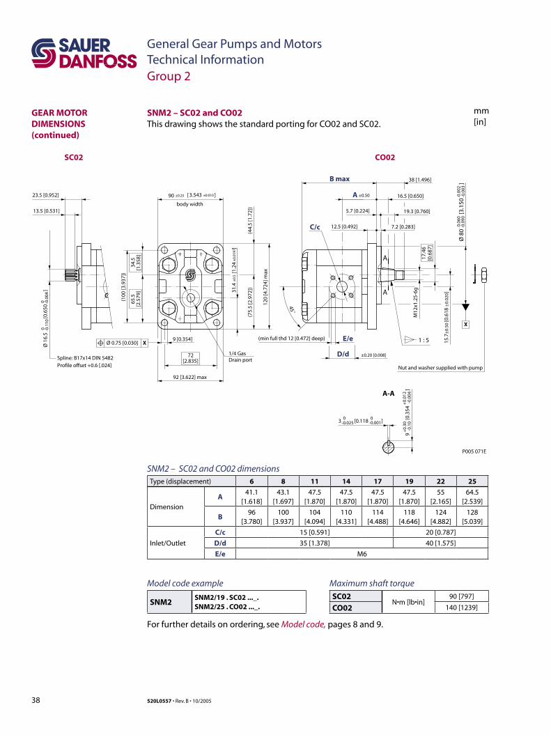
38 520L0557 • Rev. B • 10/2005
General Gear Pumps and MotorsTechnical Information
mm[in]
SNM2 – SC02 and CO02 dimensionsType (displacement) 6 8 11 14 17 19 22 25
Dimension
A41.1
[1.618]43.1
[1.697]47.5
[1.870]47.5
[1.870]47.5
[1.870]47.5
[1.870]55
[2.165]64.5
[2.539]
B96
[3.780]100
[3.937]104
[4.094]110
[4.331]114
[4.488]118
[4.646]124
[4.882]128
[5.039]
Inlet/Outlet
C/c 15 [0.591] 20 [0.787]
D/d 35 [1.378] 40 [1.575]
E/e M6
3 [0.118 ]
Ø 8
0
[3.1
50
]
9 [0.354]
Ø 1
6.5
[
0.65
0
]
Spline: B17x14 DIN 5482Profile offset +0.6 [.024]
13.5 [0.531]
23.5 [0.952]
1 : 5
A
A-A
A
M12
x1.2
5-6g
16.5 [0.650]
E/e
17.4
6[0
.687
]
38 [1.496]B max
12.5 [0.492] 7.2 [0.283]
5.7 [0.224] 19.3 [0.760]
C/c
45˚
body width
(100
[3.9
37])
D/d ±0.20 [0.008]
A ±0.50
72[2.835]
120
[4.7
24] m
ax
92 [3.622] max
(44.
5 [1
.72]
)
65.5
[2.5
79]
34.5
[1.3
58]
(75.
5 [2
.972
])
90 ±0.25 ±0.0103.543[ ]
0 -0.1
100 -0
.004
-0.0
60-0
.090
-0.0
02-0
.003
0-0.025
0-0.001
9
[0.3
54
]
+0.
30-0
.10
+0.
012
-0.0
04
15.7
±0.
50 [0
.618
±0.
020]
Ø 0.75 [0.030] X
X
(min full thd 12 [0.472] deep)
Nut and washer supplied with pump
SC02 CO02
1/4 GasDrain port
31.4
[1.
24
]±
0.5
±0.
0197
P005 071E
SNM2 – SC02 and CO02 This drawing shows the standard porting for CO02 and SC02.
Group 2
GEAR MOTOR DIMENSIONS (continued)
Maximum shaft torque
SC02N•m [lb•in]
90 [797]
CO02 140 [1239]
Model code example
SNM2SNM2/19 . SC02 ..._.SNM2/25 . CO02 ..._.
For further details on ordering, see Model code, pages 8 and 9.
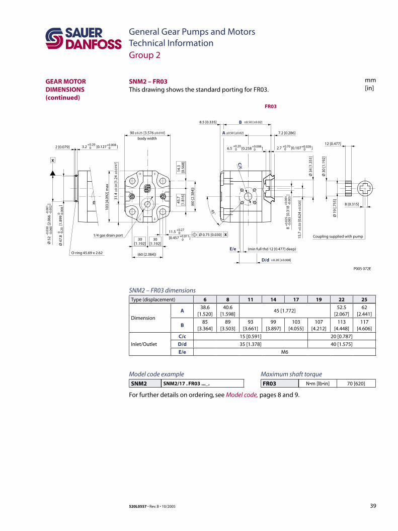
39520L0557 • Rev. B • 10/2005
General Gear Pumps and MotorsTechnical Information
mm[in]
SNM2 – FR03 dimensionsType (displacement) 6 8 11 14 17 19 22 25
Dimension
A38.6
[1.520]40.6
[1.598]45 [1.772]
52.5[2.067]
62[2.441]
B85
[3.364]89
[3.503]93
[3.661]99
[3.897]103
[4.055]107
[4.212]113
[4.448]117
[4.606]
Inlet/Outlet
C/c 15 [0.591] 20 [0.787]
D/d 35 [1.378] 40 [1.575]
E/e M6
3.2 [0.127 ]+0.20
0+0.008
02 [0.079]
(min full thd 12 [0.477] deep)E/e
Ø 3
4 [1
.351
]
7.2 [0.286]
Ø 1
9 [.7
55]
Ø 3
0 [1
.192
]
12 [0.477]
C/c
45˚
X
O-ring 45.69 x 2.62
body width
(60
[2.3
84])
D/d ±0.20 [±0.008]
B8.5 [0.335] ±0.50 [±0.02]
A
(60 [2.384])
103
[4.0
92] m
ax
30[1.192]
45.7
[1.8
16]
14.3
[0.5
68]
30[1.192]Ø
52
[2.0
66
]
-0.0
30-0
.060
-0.0
01-0
.002
8
[0
.318
]+
0.02
5-0
.083
+0.
001
-0.0
03
11.5
[0.457 ]
+0.270+0.011
0
2.7 [0.107 ]+0.700
+0.02806.5 [0.258 ]
+0.200
+0.0080
Ø 4
7.8
[1
.899
]
0 -0.2
00 -0
.008
15.7
±0.
50 [0
.624
±0.
020]
90 [3.576 ]±0.25 ±0.010
Ø 0.75 [0.030] X
8 [0.315]
Coupling supplied with pump
±0.50 [±0.02]
1/4 gas drain port
31.4
±0.
50 [1
.24
±0.
0197
]
P005 072E
FR03
SNM2 – FR03This drawing shows the standard porting for FR03.
Group 2
GEAR MOTOR DIMENSIONS (continued)
Maximum shaft torque
FR03 N•m [lb•in] 70 [620]
Model code example
SNM2 SNM2/17 . FR03 ..._.
For further details on ordering, see Model code, pages 8 and 9.
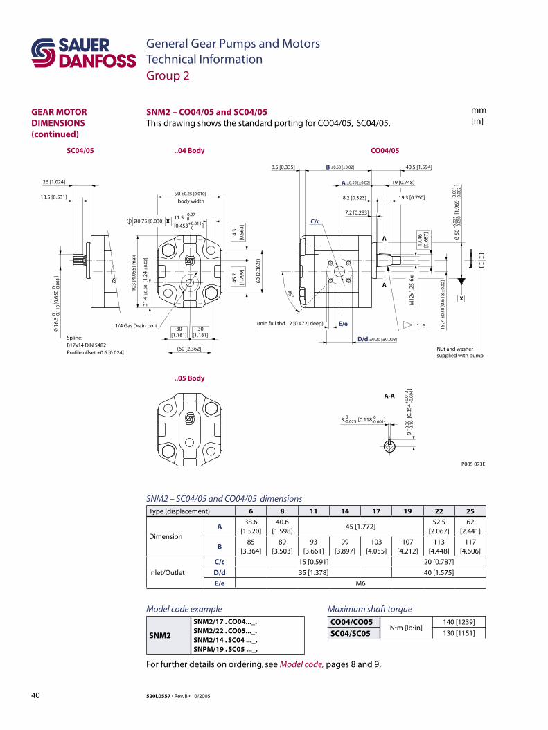
40 520L0557 • Rev. B • 10/2005
General Gear Pumps and MotorsTechnical Information
mm[in]
SNM2 – SC04/05 and CO04/05 dimensionsType (displacement) 6 8 11 14 17 19 22 25
Dimension
A38.6
[1.520]40.6
[1.598]45 [1.772]
52.5[2.067]
62[2.441]
B85
[3.364]89
[3.503]93
[3.661]99
[3.897]103
[4.055]107
[4.212]113
[4.448]117
[4.606]
Inlet/Outlet
C/c 15 [0.591] 20 [0.787]
D/d 35 [1.378] 40 [1.575]
E/e M6
3 [0.118 ]
11.5
[0.453 ]
Ø 1
6.5
[0
.650
]
±0.
50±
0.02
A
B8.5 [0.335]
±0.50 [±0.02]
±0.50 [±0.02]
+0.270+0.011
0
Spline: B17x14 DIN 5482Profile offset +0.6 [0.024]
13.5 [0.531]
26 [1.024]
A-A
A
A
1 : 5
X
(min full thd 12 [0.472] deep)
M12
x1.2
5-6g
17.4
6[0
.687
]
19 [0.748]
E/e
C/c
7.2 [0.283]
40.5 [1.594]
8.2 [0.323] 19.3 [0.760]
45˚
body width
(60
[2.3
62])
D/d ±0.20 [±0.008]
90 ±0.25 [0.010]
(60 [2.362])
103
[4.0
55] m
ax
45.7
[1.7
99]
14.3
[0.5
63]
30[1.181]
30[1.181]
Ø0.75 [0.030] X
0 -0.1
100 -0
.004
-0.0
25-0
.050
Ø 5
0
[1
.969
]-0
.001
-0.0
02
+0.
30-0
.10
9
[0.
354
]
+0.
012
-0.0
04
0-0.025
0-0.001
Nut and washer supplied with pump
P005 073E
SC04/05 ..04 Body
..05 Body
CO04/05
15.7
[
0.61
8
]
1/4 Gas Drain port
31.4
±0.
50 [
1.24
±0.
02]
SNM2 – CO04/05 and SC04/05This drawing shows the standard porting for CO04/05, SC04/05.
Group 2
GEAR MOTOR DIMENSIONS (continued)
Maximum shaft torque
CO04/CO05N•m [lb•in]
140 [1239]
SC04/SC05 130 [1151]
Model code example
SNM2
SNM2/17 . CO04..._.SNM2/22 . CO05..._.SNM2/14 . SC04 ..._.SNPM/19 . SC05 ..._.
For further details on ordering, see Model code, pages 8 and 9.
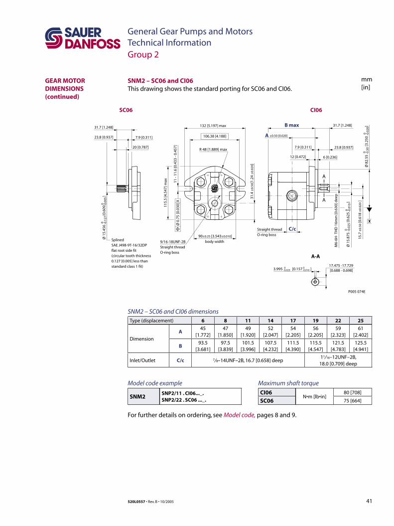
41520L0557 • Rev. B • 10/2005
General Gear Pumps and MotorsTechnical Information
mm[in]
A
A
A-A
7.9 [0.311] 23.8 [0.937]
B max 31.7 [1.248]
C/c
17.475 -17.729[0.688 - 0.698]
12 [0.472] 6 [0.236]
body width
11 -
11.6
[0.4
33 -
0.45
7]
A ±0.50 [0.020]
132 [5.197] max
106.38 [4.188]
115.
5 [4
.547
] max
R 48 [1.889] max
3.995 [0.157 ]0-0.025
0-0.010
90±0.25 [3.543±0.010]
Ø 0
.75
[0.0
30] X
X
P005 074E
SC06
SplinedSAE J498-9T-16/32DPflat root side fit(circular tooth thickness0.127 [0.005] less thanstandard class 1 fit)
CI06
20 [0.787]
31.7 [1.248]
23.8 [0.937] 7.9 [0.311]
Ø 1
5.45
6
[0.6
09
]0 -0
.127
0 -0.0
05
9/16-18UNF-2BStraight thread O-ring boss
Straight thread O-ring boss
31.4
±0.
50[1
.24
±0.
020]
M6-
6H- T
HD
16m
m [0
.630
] dee
p
Ø 8
2.55
[3
.250
]
00 -0
.020
Ø 1
5.87
5
[0.
625
]
0 -0.0
250 -0
.010
15.7
±0.
50 [0
.618
±0.
020
]
-0.5
0
SNM2 – SC06 and CI06 dimensionsType (displacement) 6 8 11 14 17 19 22 25
Dimension
A45
[1.772]47
[1.850]49
[1.920]52
[2.047]54
[2.205]56
[2.205]59
[2.323]61
[2.402]
B93.5
[3.681]97.5
[3.839]101.5
[3.996]107.5
[4.232]111.5
[4.390]115.5
[4.547]121.5
[4.783]125.5
[4.941]
Inlet/Outlet C/c 7/ 8–14UNF–2B, 16.7 [0.658] deep11/ 16–12UNF–2B, 18.0 [0.709] deep
SNM2 – SC06 and CI06This drawing shows the standard porting for SC06 and CI06.
Group 2
GEAR MOTOR DIMENSIONS (continued)
Maximum shaft torque
CI06N•m [lb•in]
80 [708]
SC06 75 [664]
Model code example
SNM2SNP2/11 . CI06..._.SNP2/22 . SC06 ..._.
For further details on ordering, see Model code, pages 8 and 9.
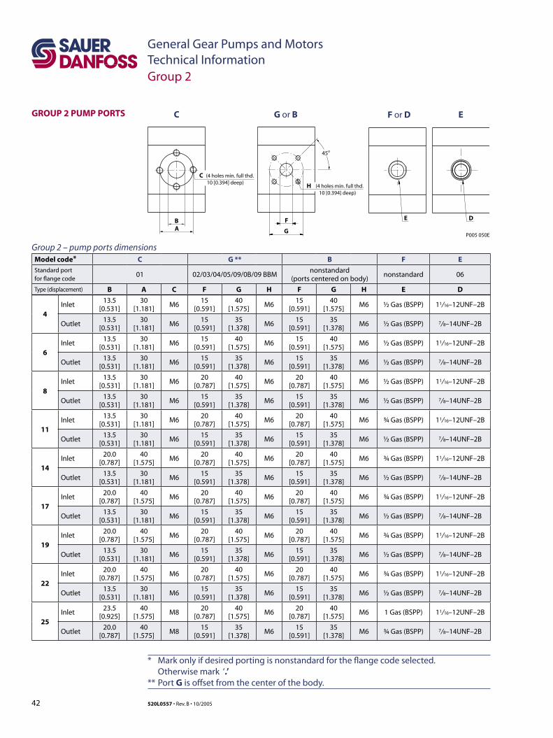
42 520L0557 • Rev. B • 10/2005
General Gear Pumps and MotorsTechnical Information
GROUP 2 PUMP PORTS
Model code* C G ** B F E
Standard portfor flange code
01 02/03/04/05/09/0B/09 BBMnonstandard
(ports centered on body)nonstandard 06
Type (displacement) B A C F G H F G H E D
4Inlet
13.5 [0.531]
30 [1.181]
M615
[0.591]40
[1.575]M6
15 [0.591]
40 [1.575]
M6 ½ Gas (BSPP) 11/ 16–12UNF–2B
Outlet13.5
[0.531]30
[1.181]M6
15 [0.591]
35 [1.378]
M615
[0.591]35
[1.378]M6 ½ Gas (BSPP) 7/ 8–14UNF–2B
6Inlet
13.5 [0.531]
30 [1.181]
M615
[0.591]40
[1.575]M6
15 [0.591]
40 [1.575]
M6 ½ Gas (BSPP) 11/ 16–12UNF–2B
Outlet13.5
[0.531]30
[1.181]M6
15 [0.591]
35 [1.378]
M615
[0.591]35
[1.378]M6 ½ Gas (BSPP) 7/ 8–14UNF–2B
8Inlet
13.5 [0.531]
30 [1.181]
M620
[0.787]40
[1.575]M6
20 [0.787]
40 [1.575]
M6 ½ Gas (BSPP) 11/ 16–12UNF–2B
Outlet13.5
[0.531]30
[1.181]M6
15 [0.591]
35 [1.378]
M615
[0.591]35
[1.378]M6 ½ Gas (BSPP) 7/ 8–14UNF–2B
11Inlet
13.5 [0.531]
30 [1.181]
M620
[0.787]40
[1.575]M6
20 [0.787]
40 [1.575]
M6 ¾ Gas (BSPP) 11/ 16–12UNF–2B
Outlet13.5
[0.531]30
[1.181]M6
15 [0.591]
35 [1.378]
M615
[0.591]35
[1.378]M6 ½ Gas (BSPP) 7/ 8–14UNF–2B
14Inlet
20.0 [0.787]
40 [1.575]
M620
[0.787]40
[1.575]M6
20 [0.787]
40 [1.575]
M6 ¾ Gas (BSPP) 11/ 16–12UNF–2B
Outlet13.5
[0.531]30
[1.181]M6
15 [0.591]
35 [1.378]
M615
[0.591]35
[1.378]M6 ½ Gas (BSPP) 7/ 8–14UNF–2B
17Inlet
20.0 [0.787]
40 [1.575]
M620
[0.787]40
[1.575]M6
20 [0.787]
40 [1.575]
M6 ¾ Gas (BSPP) 11/ 16–12UNF–2B
Outlet13.5
[0.531]30
[1.181]M6
15 [0.591]
35 [1.378]
M615
[0.591]35
[1.378]M6 ½ Gas (BSPP) 7/ 8–14UNF–2B
19Inlet
20.0 [0.787]
40 [1.575]
M620
[0.787]40
[1.575]M6
20 [0.787]
40 [1.575]
M6 ¾ Gas (BSPP) 11/ 16–12UNF–2B
Outlet13.5
[0.531]30
[1.181]M6
15 [0.591]
35 [1.378]
M615
[0.591]35
[1.378]M6 ½ Gas (BSPP) 7/ 8–14UNF–2B
22Inlet
20.0 [0.787]
40 [1.575]
M620
[0.787]40
[1.575]M6
20 [0.787]
40 [1.575]
M6 ¾ Gas (BSPP) 11/ 16–12UNF–2B
Outlet13.5
[0.531]30
[1.181]M6
15 [0.591]
35 [1.378]
M615
[0.591]35
[1.378]M6 ½ Gas (BSPP) 7/ 8–14UNF–2B
25Inlet
23.5 [0.925]
40 [1.575]
M820
[0.787]40
[1.575]M6
20 [0.787]
40 [1.575]
M6 1 Gas (BSPP) 11/ 16–12UNF–2B
Outlet20.0
[0.787]40
[1.575]M8
15 [0.591]
35 [1.378]
M615
[0.591]35
[1.378]M6 ¾ Gas (BSPP) 7/ 8–14UNF–2B
* Mark only if desired porting is nonstandard for the flange code selected. Otherwise mark ‘.’ ** Port G is offset from the center of the body.
B
C G or B F or D E
C
A
(4 holes min. full thd.10 [0.394] deep)
F
H
G
45o
(4 holes min. full thd.10 [0.394] deep)
E D
P005 050E
Group 2 – pump ports dimensions
Group 2
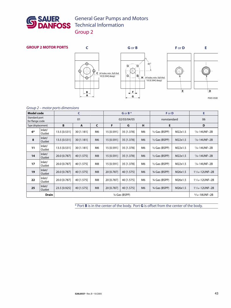
43520L0557 • Rev. B • 10/2005
General Gear Pumps and MotorsTechnical Information
GROUP 2 MOTOR PORTS
Model code C G or B * F or D EStandard portfor flange code
01 02/03/04/05 nonstandard 06
Type (displacement) B A C F G H E D
6*Inlet/Outlet
13.5 [0.531] 30 [1.181] M6 15 [0.591] 35 [1.378] M6 ½ Gas (BSPP) M22x1.5 7/ 8–14UNF–2B
8Inlet/Outlet
13.5 [0.531] 30 [1.181] M6 15 [0.591] 35 [1.378] M6 ½ Gas (BSPP) M22x1.5 7/ 8–14UNF–2B
11Inlet/Outlet
13.5 [0.531] 30 [1.181] M6 15 [0.591] 35 [1.378] M6 ½ Gas (BSPP) M22x1.5 7/ 8–14UNF–2B
14Inlet/Outlet
20.0 [0.787] 40 [1.575] M8 15 [0.591] 35 [1.378] M6 ½ Gas (BSPP) M22x1.5 7/ 8–14UNF–2B
17Inlet/Outlet
20.0 [0.787] 40 [1.575] M8 15 [0.591] 35 [1.378] M6 ½ Gas (BSPP) M22x1.5 7/ 8–14UNF–2B
19Inlet/Outlet
20.0 [0.787] 40 [1.575] M8 20 [0.787] 40 [1.575] M6 ¾ Gas (BSPP) M26x1.5 11/ 16–12UNF–2B
22Inlet/Outlet
20.0 [0.787] 40 [1.575] M8 20 [0.787] 40 [1.575] M6 ¾ Gas (BSPP) M26x1.5 11/ 16–12UNF–2B
25Inlet/Outlet
23.5 [0.925] 40 [1.575] M8 20 [0.787] 40 [1.575] M6 ¾ Gas (BSPP) M26x1.5 11/ 16–12UNF–2B
Drain ¼ Gas (BSPP) 9/ 16–18UNF–2B
* Port B is in the center of the body. Port G is offset from the center of the body.
B
C G or B F or D E
C
A
(4 holes min. full thd.10 [0.394] deep)
F
H
G
45o
(4 holes min. full thd.10 [0.394] deep)
E D
P005 050E
Group 2 – motor ports dimensions
Group 2
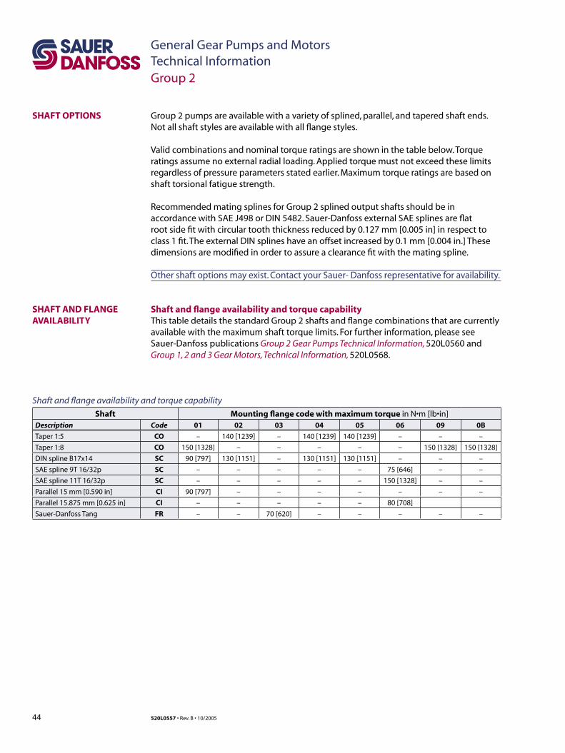
44 520L0557 • Rev. B • 10/2005
General Gear Pumps and MotorsTechnical Information
Group 2 pumps are available with a variety of splined, parallel, and tapered shaft ends. Not all shaft styles are available with all flange styles.
Valid combinations and nominal torque ratings are shown in the table below. Torque ratings assume no external radial loading. Applied torque must not exceed these limits regardless of pressure parameters stated earlier. Maximum torque ratings are based on shaft torsional fatigue strength.
Recommended mating splines for Group 2 splined output shafts should be in accordance with SAE J498 or DIN 5482. Sauer-Danfoss external SAE splines are flat root side fit with circular tooth thickness reduced by 0.127 mm [0.005 in] in respect to class 1 fit. The external DIN splines have an offset increased by 0.1 mm [0.004 in.] These dimensions are modified in order to assure a clearance fit with the mating spline.
Other shaft options may exist. Contact your Sauer- Danfoss representative for availability.
Shaft and flange availability and torque capabilityThis table details the standard Group 2 shafts and flange combinations that are currently available with the maximum shaft torque limits. For further information, please see Sauer-Danfoss publications Group 2 Gear Pumps Technical Information, 520L0560 and Group 1, 2 and 3 Gear Motors, Technical Information, 520L0568.
SHAFT AND FLANGE AVAILABILITY
SHAFT OPTIONS
Shaft and flange availability and torque capability
Shaft Mounting flange code with maximum torque in N•m [lb•in]Description Code 01 02 03 04 05 06 09 0B
Taper 1:5 CO – 140 [1239] – 140 [1239] 140 [1239] – – –
Taper 1:8 CO 150 [1328] – – – – – 150 [1328] 150 [1328]
DIN spline B17x14 SC 90 [797] 130 [1151] – 130 [1151] 130 [1151] – – –
SAE spline 9T 16/32p SC – – – – – 75 [646] – –
SAE spline 11T 16/32p SC – – – – – 150 [1328] – –
Parallel 15 mm [0.590 in] CI 90 [797] – – – – – – –
Parallel 15.875 mm [0.625 in] CI – – – – – 80 [708]
Sauer-Danfoss Tang FR – – 70 [620] – – – – –
Group 2

45520L0557 • Rev. B • 10/2005
General Gear Pumps and MotorsTechnical InformationNotes
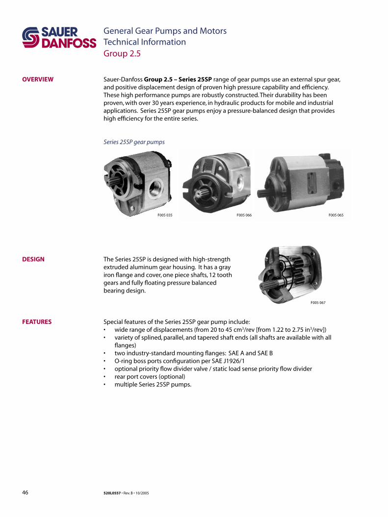
46 520L0557 • Rev. B • 10/2005
General Gear Pumps and MotorsTechnical Information
OVERVIEW Sauer-Danfoss Group 2.5 – Series 25SP range of gear pumps use an external spur gear, and positive displacement design of proven high pressure capability and efficiency. These high performance pumps are robustly constructed. Their durability has been proven, with over 30 years experience, in hydraulic products for mobile and industrial applications. Series 25SP gear pumps enjoy a pressure-balanced design that provides high efficiency for the entire series.
Series 25SP gear pumps
DESIGN The Series 25SP is designed with high-strength extruded aluminum gear housing. It has a gray iron flange and cover, one piece shafts, 12 tooth gears and fully floating pressure balanced bearing design.
FEATURES
Group 2.5
F005 067
F005 065F005 066F005 035
Special features of the Series 25SP gear pump include: • wide range of displacements (from 20 to 45 cm3/rev [from 1.22 to 2.75 in3/rev]) • variety of splined, parallel, and tapered shaft ends (all shafts are available with all
flanges)• two industry-standard mounting flanges: SAE A and SAE B• O-ring boss ports configuration per SAE J1926/1• optional priority flow divider valve / static load sense priority flow divider• rear port covers (optional)• multiple Series 25SP pumps.
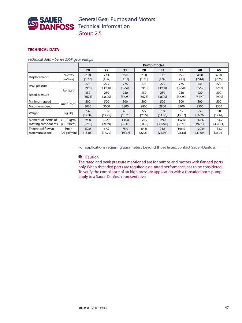
47520L0557 • Rev. B • 10/2005
General Gear Pumps and MotorsTechnical Information
TECHNICAL DATA
For applications requiring parameters beyond those listed, contact Sauer-Danfoss.
Group 2.5
Technical data – Series 25SP gear pumps
Pump model
20 22 25 28 31 35 40 45
Displacementcm3/rev
[in3/rev]20.0
[1.22]22.4
[1.37]25.0
[1.53]28.0
[1.71]31.5
[1.92]35.5
[2.17]40.0
[2.44]45.0
[2.75]
Peak pressure
bar [psi]
275[3950]
275[3950]
275[3950]
275[3950]
275[3950]
275[3950]
245[3552]
225[3262]
Rated pressure250
[3625]250
[3625]250
[3625]250
[3625]250
[3625]250
[3625]220
[3190]200
[2900]
Minimum speedmin-1 (rpm)
500 500 500 500 500 500 500 500
Maximum speed 3000 3000 2800 2800 2800 2700 2500 2500
Weight kg [lb]5.6
[12.34]5.8
[12.79]6.0
[13.236.5
[20.5]6.8
[14.33]7.2
[15.87]7.6
[16.76]8.0
[17.64]
Moment of inertia ofrotating components
x 10-6 kg•m2
[x 10-6 lb•ft2]94.8
[2250]102.8 [2439]
148.8 [3531]
127.7 [3030]
139.3 [3305.6]
152.6 [3621]
167.6 [3977.1]
184.2 [4371.1]
Theoretical flow atmaximum speed
l/min[US gal/min]
60.0 [15.85]
67.2 [17.79]
75.0 [19.87]
84.0 [22.21]
94.5 [24.94]
106.5 [28.18]
120.0 [31.69]
135.0 [35.71]
C CautionThe rated and peak pressure mentioned are for pumps and motors with flanged ports only. When threaded ports are required a de-rated performance has to be considered. To verify the compliance of an high pressure application with a threaded ports pump apply to a Sauer-Danfoss representative.
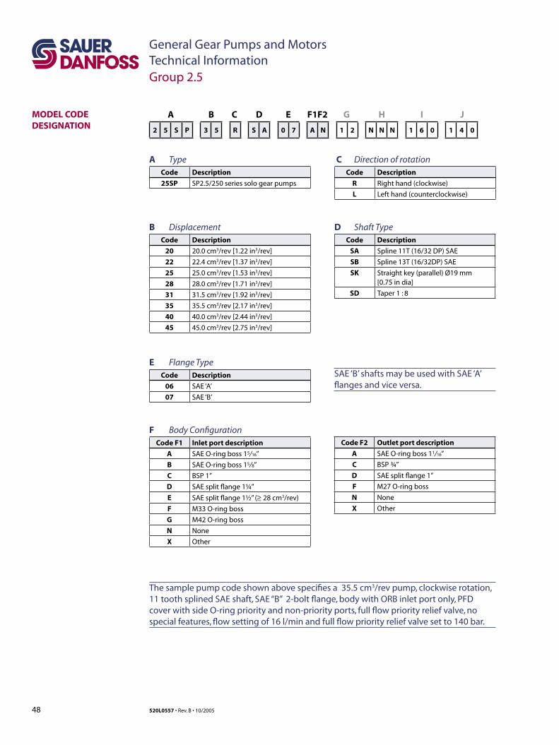
48 520L0557 • Rev. B • 10/2005
General Gear Pumps and MotorsTechnical Information
Code F2 Outlet port description
A SAE O-ring boss 11/ 16”
C BSP ¾”
D SAE split flange 1”
F M27 O-ring boss
N None
X Other
SAE ‘B’ shafts may be used with SAE ‘A’ flanges and vice versa.
MODEL CODE DESIGNATION
A B C D E F1F2 G H I J
2 5 S P 3 5 R S A 0 7 A N 1 2 N N N 1 6 0 1 4 0
A TypeCode Description
25SP SP2.5/250 series solo gear pumps
B Displacement Code Description
20 20.0 cm3/rev [1.22 in3/rev]
22 22.4 cm3/rev [1.37 in3/rev]
25 25.0 cm3/rev [1.53 in3/rev]
28 28.0 cm3/rev [1.71 in3/rev]
31 31.5 cm3/rev [1.92 in3/rev]
35 35.5 cm3/rev [2.17 in3/rev]
40 40.0 cm3/rev [2.44 in3/rev]
45 45.0 cm3/rev [2.75 in3/rev]
C Direction of rotationCode Description
R Right hand (clockwise)
L Left hand (counterclockwise)
D Shaft TypeCode Description
SA Spline 11T (16/32 DP) SAE
SB Spline 13T (16/32DP) SAE
SK Straight key (parallel) Ø19 mm [0.75 in dia]
SD Taper 1 : 8
The sample pump code shown above specifies a 35.5 cm3/rev pump, clockwise rotation, 11 tooth splined SAE shaft, SAE “B” 2-bolt flange, body with ORB inlet port only, PFD cover with side O-ring priority and non-priority ports, full flow priority relief valve, no special features, flow setting of 16 l/min and full flow priority relief valve set to 140 bar.
E Flange TypeCode Description
06 SAE ‘A’
07 SAE ‘B’
F Body ConfigurationCode F1 Inlet port description
A SAE O-ring boss 15/ 16”
B SAE O-ring boss 15/ 8”
C BSP 1”
D SAE split flange 1¼”
E SAE split flange 1½” (≥ 28 cm3/rev)
F M33 O-ring boss
G M42 O-ring boss
N None
X Other
Group 2.5
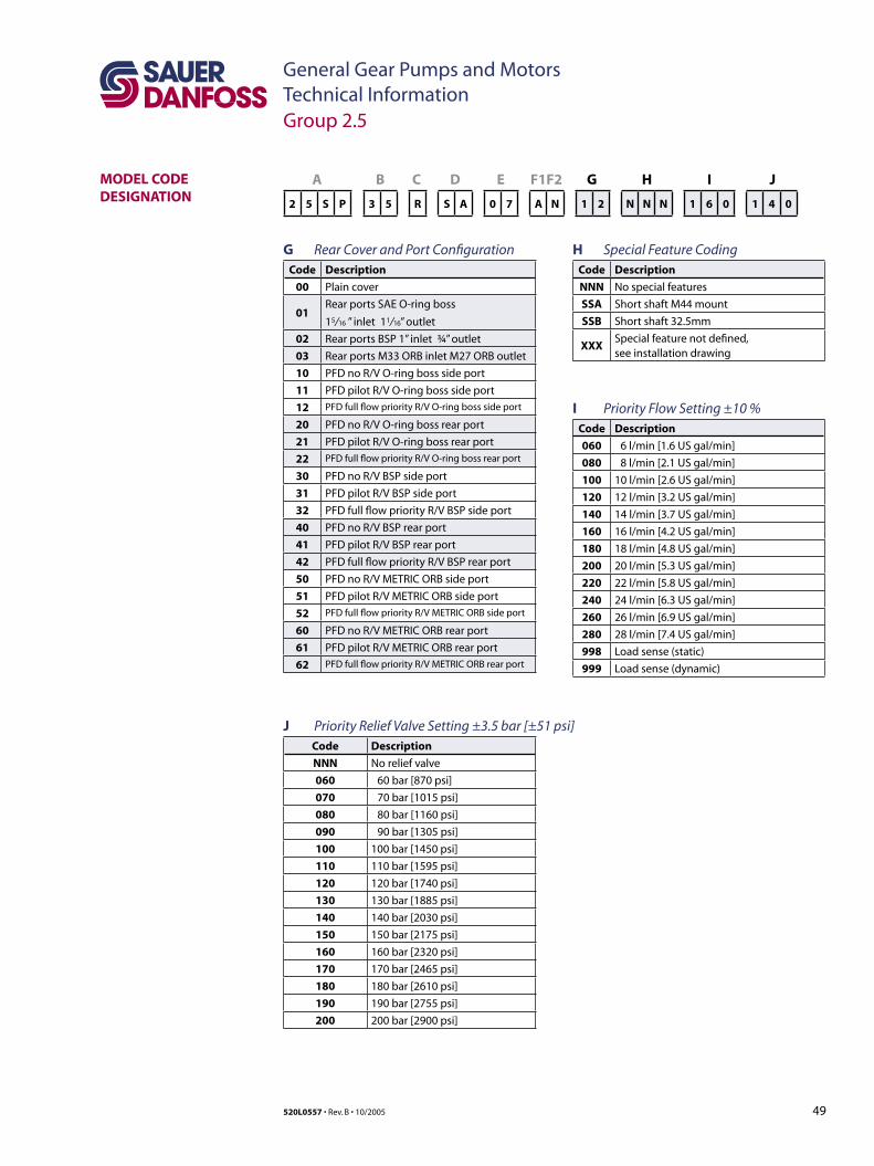
49520L0557 • Rev. B • 10/2005
General Gear Pumps and MotorsTechnical Information
MODEL CODE DESIGNATION
A B C D E F1F2 G H I J
2 5 S P 3 5 R S A 0 7 A N 1 2 N N N 1 6 0 1 4 0
G Rear Cover and Port ConfigurationCode Description
00 Plain cover
01Rear ports SAE O-ring boss
15/ 16 ” inlet 11/ 16” outlet
02 Rear ports BSP 1” inlet ¾” outlet
03 Rear ports M33 ORB inlet M27 ORB outlet
10 PFD no R/V O-ring boss side port
11 PFD pilot R/V O-ring boss side port
12 PFD full flow priority R/V O-ring boss side port
20 PFD no R/V O-ring boss rear port
21 PFD pilot R/V O-ring boss rear port
22 PFD full flow priority R/V O-ring boss rear port
30 PFD no R/V BSP side port
31 PFD pilot R/V BSP side port
32 PFD full flow priority R/V BSP side port
40 PFD no R/V BSP rear port
41 PFD pilot R/V BSP rear port
42 PFD full flow priority R/V BSP rear port
50 PFD no R/V METRIC ORB side port
51 PFD pilot R/V METRIC ORB side port
52 PFD full flow priority R/V METRIC ORB side port
60 PFD no R/V METRIC ORB rear port
61 PFD pilot R/V METRIC ORB rear port
62 PFD full flow priority R/V METRIC ORB rear port
J Priority Relief Valve Setting ±3.5 bar [±51 psi]Code Description
NNN No relief valve
060 60 bar [870 psi]
070 70 bar [1015 psi]
080 80 bar [1160 psi]
090 90 bar [1305 psi]
100 100 bar [1450 psi]
110 110 bar [1595 psi]
120 120 bar [1740 psi]
130 130 bar [1885 psi]
140 140 bar [2030 psi]
150 150 bar [2175 psi]
160 160 bar [2320 psi]
170 170 bar [2465 psi]
180 180 bar [2610 psi]
190 190 bar [2755 psi]
200 200 bar [2900 psi]
Group 2.5
H Special Feature Coding Code Description
NNN No special features
SSA Short shaft M44 mount
SSB Short shaft 32.5mm
XXXSpecial feature not defined, see installation drawing
I Priority Flow Setting ±10 % Code Description
060 6 l/min [1.6 US gal/min]
080 8 l/min [2.1 US gal/min]
100 10 l/min [2.6 US gal/min]
120 12 l/min [3.2 US gal/min]
140 14 l/min [3.7 US gal/min]
160 16 l/min [4.2 US gal/min]
180 18 l/min [4.8 US gal/min]
200 20 l/min [5.3 US gal/min]
220 22 l/min [5.8 US gal/min]
240 24 l/min [6.3 US gal/min]
260 26 l/min [6.9 US gal/min]
280 28 l/min [7.4 US gal/min]
998 Load sense (static)
999 Load sense (dynamic)
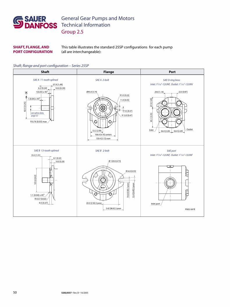
50 520L0557 • Rev. B • 10/2005
General Gear Pumps and MotorsTechnical Information
This table illustrates the standard 25SP configurations for each pump (all are interchangeable):
SHAFT, FLANGE, AND PORT CONFIGURATION
Group 2.5
Shaft Flange Port
65.0 [2.56] 2 posn
3.42 [86.8] 2 posn
12.4
[0.4
9] 2
pos
n
14.6
[0.5
8] 2
pos
n
Ø 120.0 [4.73]
R14.0 [0.55]
10.0 [0.39]
8.1 [0.32]33.3 [1.31]
1.1 [0.04] x 45o
R 0.57 [0.02]
9.5 [0.37]
101.
6 [4
.0]
1[0.05] x 45o
1 [0.04] x 45o
6.2 [0.24] 10.0 [0.39]
37.9 [1.49]
see spline data, page 52
82.5
[3.2
5]
R 0.76 [0.03] max
A 22.0 [0.87]29.0 [1.14]
56.0 [2.20] 56.0 [2.20]Inlet
Inlet port
Outlet
85.1
[3.3
5]47
.0 [1
.85]
106.4 [4.19] centers
130.4 [5.13] nom
53.2 [2.09]
9.5 [0.37]
11.0 [0.43]
Ø95.0 [3.74]
R 12.0 [0.47]
R 5.5 [0.22]
SAE O-ring boss
Inlet: 15/16”-12UNF, Outlet: 11/16”-12UNV
SAE port
Inlet: 15/16”-12UNF, Outlet: 11/16”-12UNF
SAE A 2-bolt
SAE B 2-bolt
SAE A 11-tooth splined
SAE B 13-tooth splined
P005 047E
Shaft, flange and port configuration – Series 25SP
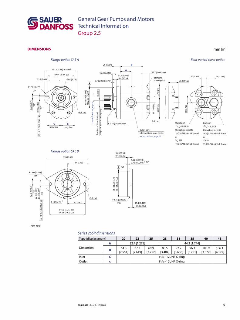
51520L0557 • Rev. B • 10/2005
General Gear Pumps and MotorsTechnical InformationGroup 2.5
Series 25SP dimensionsType (displacement) 20 22 25 28 31 35 40 45
Dimension
A 32.4 [1.275] 44.3 [1.744]
B64.8
[2.551]67.3
[2.649]69.9
[2.752]88.5
[3.484]92.2
[3.630]96.3
[3.791]100.9
[3.972]106.1
[4.177]
Inlet C 15/ 16 –12UNF O-ring
Outlet c 11/ 16 –12UNF O-ring
Standard cover option
X
Flange option SAE A
Flange option SAE B
Rear ported cover option
body facebody face
85 [2
.283
]47
[1.8
5]
19.1
[ 0.
751]
19 [
0.74
8]
s e
e sh
aft o
ptio
ns, p
age
50
53.2 [2.094]
38.1
[1.5
]Po
sitio
n of
driv
e sh
aft a
ndsp
igot
on
antic
lock
wis
e pu
mp
29 [1.141]22 [0.866]
40.0 [1.968]
Inlet port
15/16"-12UN-2B
O-ring boss to j514b
19.0 [ 0.748] min full thread
or
1" BSP
19.0 [ 0.748] min full thread
Outlet port
11/16"-12UN-2B
O-ring boss to j514b
19.0 [ 0.748] min full thread
or3/4" BSP
19.0 [ 0.748] min full thread
Outlet portInlet port is on same centresee port options, page 50
B
A
P005 075E
Ø 120 [4.72]
Ø 1
01.6
0 [4
.0]
Ø 1
01.5
5 [4
.0]
72 [2.83] 11.4 [0.449] 8.6 [0.339]
9.65 [0.38]9.14 [0.36]
1.52 [0.0598]0.76 [0.0299] x 45o
0.7 [0.0276] x 45o
6.22 [0.245]
25 [0.984]
27.7 [1.09] max
R 0.75 [0.0295] max
R 0.76 [0.0299] max
Full rad
Full rad
174 [6.85]
CC
87 [3.43]
146.0 [5.75] ctrs142.8 [5.62] ctrs
106.4 [4.19] ctrs
131.6 [5.18] max ref
12.5
[0.4
92]
typ
11.0
[0.4
33]
typ
9.5
[0.3
74]
typ
14.6
[0.5
75]
14.
1 [0
.555
] ty
p
R 14.0 [0.551]typ
R12.0 [0.472]typ
11.4 [0.449] 8.6 [0.339]Ø95 [3.74]
Ø 8
2.55
[3.2
48]
Ø82
.50
[3.2
50]
X Ref
Ø 0
.75
[0.0
30]
XØ
0.7
5 [0
.030
] X
Full rad
DIMENSIONS mm [in]
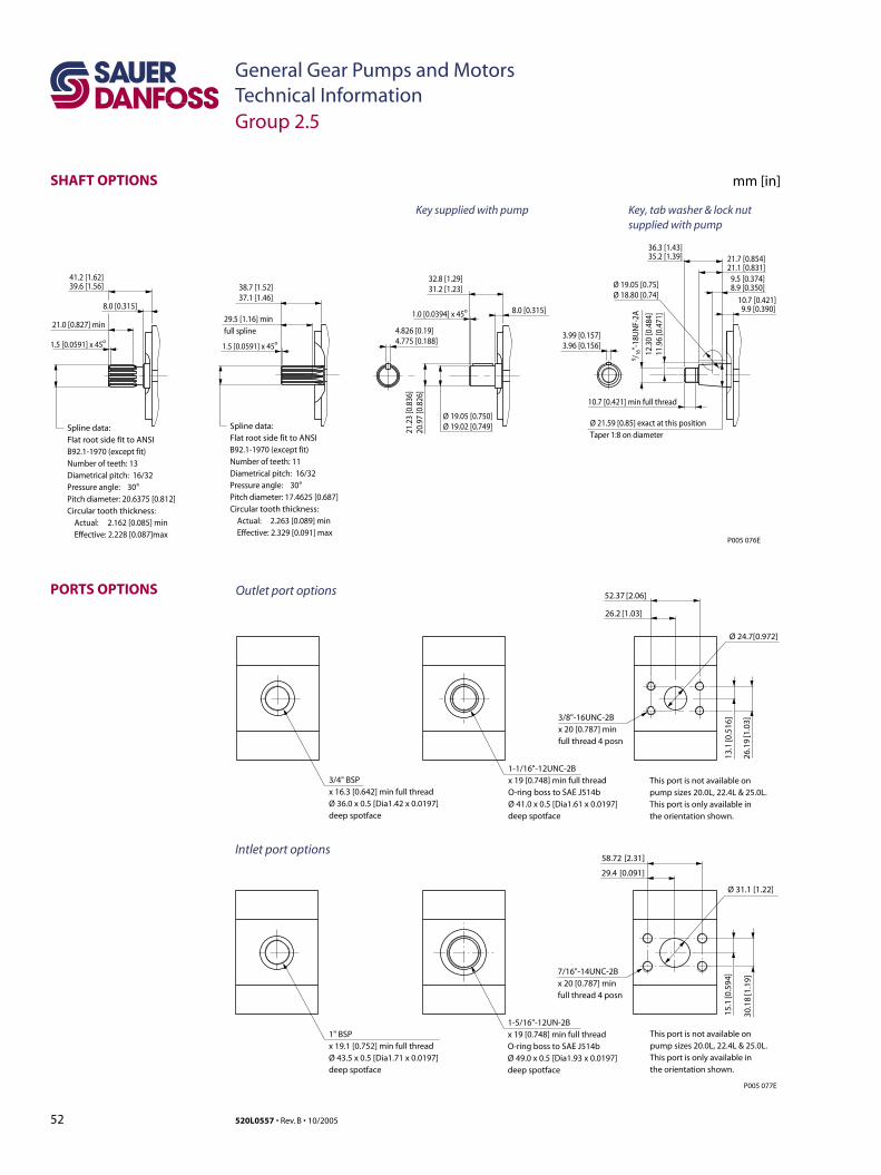
52 520L0557 • Rev. B • 10/2005
General Gear Pumps and MotorsTechnical InformationGroup 2.5
PORTS OPTIONS
P005 077E
Ø 24.7[0.972]
Ø 31.1 [1.22]
52.37 [2.06]
58.72 [2.31]
29.4 [0.091]
3/8"-16UNC-2Bx 20 [0.787] min full thread 4 posn
This port is not available onpump sizes 20.0L, 22.4L & 25.0L.This port is only available inthe orientation shown.
3/4" BSPx 16.3 [0.642] min full thread Ø 36.0 x 0.5 [Dia1.42 x 0.0197] deep spotface
1-1/16"-12UNC-2Bx 19 [0.748] min full thread O-ring boss to SAE J514bØ 41.0 x 0.5 [Dia1.61 x 0.0197] deep spotface
26.2 [1.03]
26.1
9 [1
.03]
13.1
[0.5
16]
30.1
8 [1
.19]
15.1
[0.5
94]7/16"-14UNC-2B
x 20 [0.787] min full thread 4 posn
This port is not available onpump sizes 20.0L, 22.4L & 25.0L.This port is only available inthe orientation shown.
1" BSPx 19.1 [0.752] min full thread Ø 43.5 x 0.5 [Dia1.71 x 0.0197] deep spotface
1-5/16"-12UN-2Bx 19 [0.748] min full thread O-ring boss to SAE J514bØ 49.0 x 0.5 [Dia1.93 x 0.0197] deep spotface
Outlet port options
Intlet port options
Spline data:Flat root side fit to ANSIB92.1-1970 (except fit)Number of teeth: 13Diametrical pitch: 16/32Pressure angle: 30°Pitch diameter: 20.6375 [0.812]Circular tooth thickness: Actual: 2.162 [0.085] min Effective: 2.228 [0.087]max
Spline data:Flat root side fit to ANSIB92.1-1970 (except fit)Number of teeth: 11Diametrical pitch: 16/32Pressure angle: 30°Pitch diameter: 17.4625 [0.687]Circular tooth thickness: Actual: 2.263 [0.089] min Effective: 2.329 [0.091] max
Key, tab washer & lock nut supplied with pump
Key supplied with pump
Ø 19.05 [0.750]Ø 19.02 [0.749]
Ø 19.05 [0.75]Ø 18.80 [0.74]
Ø 21.59 [0.85] exact at this position Taper 1:8 on diameter
10.7 [0.421] min full thread
32.8 [1.29]31.2 [1.23]
36.3 [1.43]35.2 [1.39] 21.7 [0.854]
21.1 [0.831]
10.7 [0.421] 9.9 [0.390]
9.5 [0.374]8.9 [0.350]38.7 [1.52]
37.1 [1.46]
4.826 [0.19]4.775 [0.188]
3.99 [0.157]3.96 [0.156]
41.2 [1.62]39.6 [1.56]
8.0 [0.315]
21.0 [0.827] min29.5 [1.16] minfull spline
8.0 [0.315]1.0 [0.0394] x 45o
1.5 [0.0591] x 45o1.5 [0.0591] x 45o
21.2
3 [0
.836
] 2
0.97
[0.8
26]
12.3
0 [0
.484
] 1
1.96
[0.4
71]
9 / 16"
-18U
NF-
2A
P005 076E
SHAFT OPTIONS mm [in]
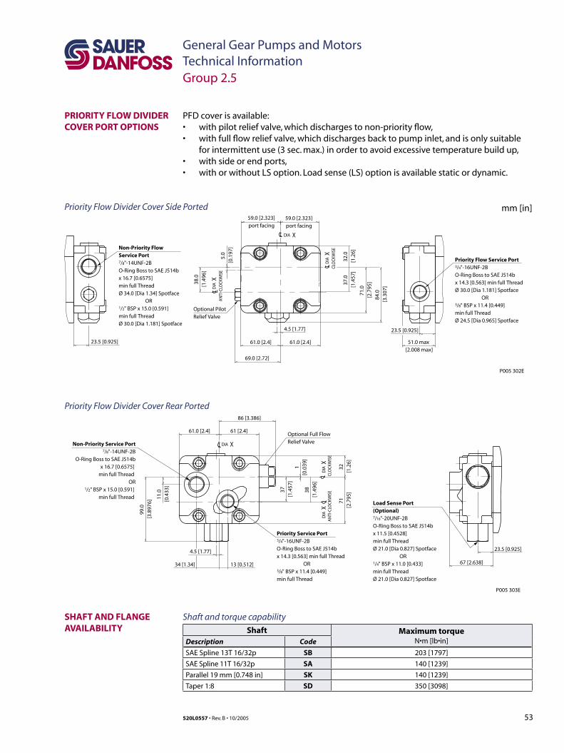
53520L0557 • Rev. B • 10/2005
General Gear Pumps and MotorsTechnical InformationGroup 2.5
SHAFT AND FLANGE AVAILABILITY
Shaft and torque capability
Shaft Maximum torqueN•m [lb•in]Description Code
SAE Spline 13T 16/32p SB 203 [1797]
SAE Spline 11T 16/32p SA 140 [1239]
Parallel 19 mm [0.748 in] SK 140 [1239]
Taper 1:8 SD 350 [3098]
Priority Flow Divider Cover Side Ported
PFD cover is available: • with pilot relief valve, which discharges to non-priority flow,• with full flow relief valve, which discharges back to pump inlet, and is only suitable
for intermittent use (3 sec. max.) in order to avoid excessive temperature build up,• with side or end ports,• with or without LS option. Load sense (LS) option is available static or dynamic.
PRIORITY FLOW DIVIDER COVER PORT OPTIONS
mm [in]
�������������������������������������������������
�����������������������������������������������������������
������������������������������
���������������������������
����� ������������������������������������ ����
��������������������� �� ����������
��������������������� �� ����������
������������������������� �� ����������
��������� �� ����������
���������������������������������������
���������������������������������������
�������������������������� ���������������������������������������������������������������� ��������������������������������������������������������������������������������������
�������������������������������������������������������������������������������������� ������������������������� ����������������������������������������������������������������������������������
����������������������������������������
����
��������������
�� ��
���������
��������������������������������������������������������������������������������������������������������������������������������������������������������������������������������������������������������������������
������������������������������������������������������������������������������������������������������������������������������������������������������������������������������������������������������������������������
���������
������������
������������
��������������������
�����������������������
�����������
���������� ����������
����������
�����������������������
�����
������
�����
�������
�����
�������
����
�������
�����
�������
�����
�������
���������������������������
��� �
���������
��� �
����
���������
�� ��
��������������
��������������������������������������������������������������������������������������������������������������������������������������������������������
��������������������������������������
��������������������������������������������������������������������������������
����������������������������������������
����������
���������� ��������
����������
����������������������
��������� ����������
���
������
�����
�������
���
�������
���
�������
��������
���
�������
�����
������� �
������������������������������
���������������������������������������������������������������������������������������������������������������������������������������������������������������������������������������������������������������������
�������
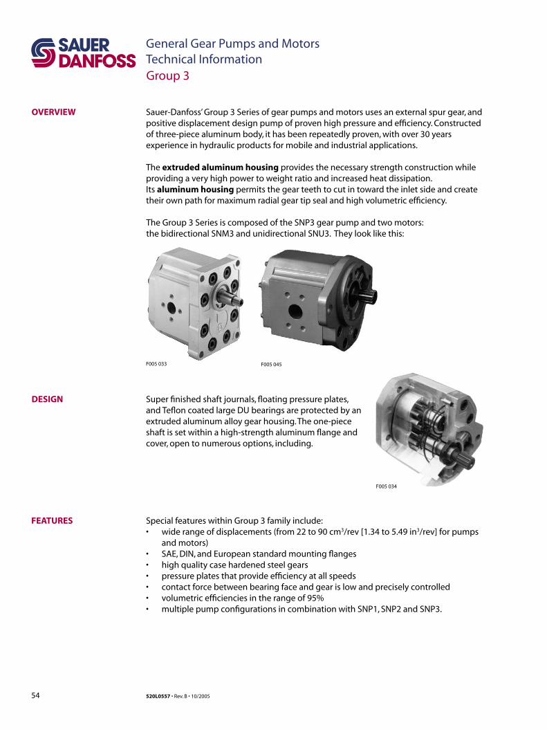
54 520L0557 • Rev. B • 10/2005
General Gear Pumps and MotorsTechnical Information
Sauer-Danfoss’ Group 3 Series of gear pumps and motors uses an external spur gear, and positive displacement design pump of proven high pressure and efficiency. Constructed of three-piece aluminum body, it has been repeatedly proven, with over 30 years experience in hydraulic products for mobile and industrial applications.
The extruded aluminum housing provides the necessary strength construction while providing a very high power to weight ratio and increased heat dissipation. Its aluminum housing permits the gear teeth to cut in toward the inlet side and create their own path for maximum radial gear tip seal and high volumetric efficiency.
OVERVIEW
The Group 3 Series is composed of the SNP3 gear pump and two motors: the bidirectional SNM3 and unidirectional SNU3. They look like this:
DESIGN Super finished shaft journals, floating pressure plates, and Teflon coated large DU bearings are protected by an extruded aluminum alloy gear housing. The one-piece shaft is set within a high-strength aluminum flange and cover, open to numerous options, including.
FEATURES
Group 3
Special features within Group 3 family include:• wide range of displacements (from 22 to 90 cm3/rev [1.34 to 5.49 in3/rev] for pumps
and motors)• SAE, DIN, and European standard mounting flanges• high quality case hardened steel gears• pressure plates that provide efficiency at all speeds• contact force between bearing face and gear is low and precisely controlled• volumetric efficiencies in the range of 95%• multiple pump configurations in combination with SNP1, SNP2 and SNP3.
F005 033 F005 045
F005 034
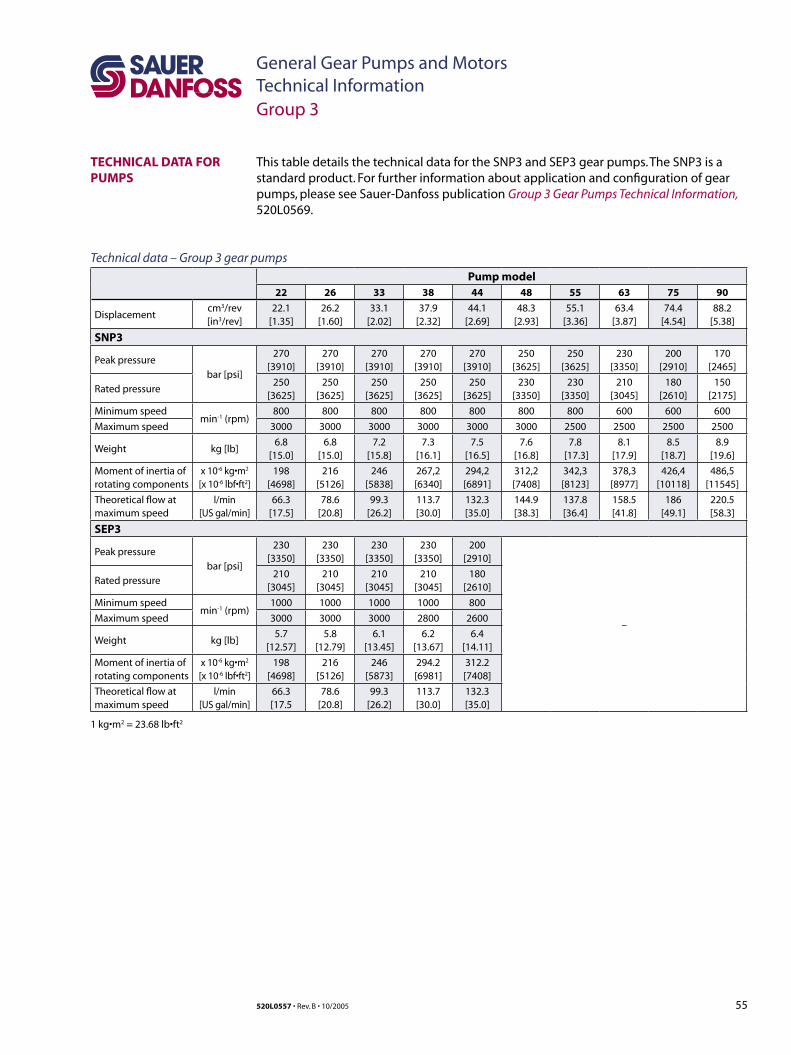
55520L0557 • Rev. B • 10/2005
General Gear Pumps and MotorsTechnical Information
TECHNICAL DATA FOR PUMPS
This table details the technical data for the SNP3 and SEP3 gear pumps. The SNP3 is a standard product. For further information about application and configuration of gear pumps, please see Sauer-Danfoss publication Group 3 Gear Pumps Technical Information, 520L0569.
Technical data – Group 3 gear pumps
Pump model22 26 33 38 44 48 55 63 75 90
Displacementcm3/rev[in3/rev]
22.1[1.35]
26.2[1.60]
33.1[2.02]
37.9[2.32]
44.1[2.69]
48.3[2.93]
55.1[3.36]
63.4[3.87]
74.4 [4.54]
88.2 [5.38]
SNP3
Peak pressure
bar [psi]
270[3910]
270[3910]
270[3910]
270[3910]
270[3910]
250 [3625]
250 [3625]
230 [3350]
200 [2910]
170 [2465]
Rated pressure250
[3625]250
[3625]250
[3625]250
[3625]250
[3625]230
[3350]230
[3350]210
[3045]180
[2610]150
[2175]
Minimum speedmin-1 (rpm)
800 800 800 800 800 800 800 600 600 600
Maximum speed 3000 3000 3000 3000 3000 3000 2500 2500 2500 2500
Weight kg [lb]6.8
[15.0]6.8
[15.0]7.2
[15.8]7.3
[16.1]7.5
[16.5]7.6
[16.8]7.8
[17.3]8.1
[17.9]8.5
[18.7]8.9
[19.6]
Moment of inertia ofrotating components
x 10-6 kg•m2
[x 10-6 lbf•ft2]198
[4698]216
[5126]246
[5838]267,2[6340]
294,2[6891]
312,2[7408]
342,3[8123]
378,3[8977]
426,4[10118]
486,5[11545]
Theoretical flow atmaximum speed
l/min[US gal/min]
66.3 [17.5]
78.6 [20.8]
99.3 [26.2]
113.7[30.0]
132.3[35.0]
144.9[38.3]
137.8[36.4]
158.5[41.8]
186[49.1]
220.5[58.3]
SEP3
Peak pressure
bar [psi]
230 [3350]
230 [3350]
230 [3350]
230 [3350]
200[2910]
–
Rated pressure210
[3045]210
[3045]210
[3045]210
[3045]180
[2610]
Minimum speedmin-1 (rpm)
1000 1000 1000 1000 800
Maximum speed 3000 3000 3000 2800 2600
Weight kg [lb]5.7
[12.57]5.8
[12.79]6.1
[13.45]6.2
[13.67]6.4
[14.11]
Moment of inertia ofrotating components
x 10-6 kg•m2
[x 10-6 lbf•ft2]198
[4698]216
[5126]246
[5873]294.2[6981]
312.2[7408]
Theoretical flow atmaximum speed
l/min[US gal/min]
66.3[17.5
78.6[20.8]
99.3[26.2]
113.7[30.0]
132.3[35.0]
Group 3
1 kg•m2 = 23.68 lb•ft2
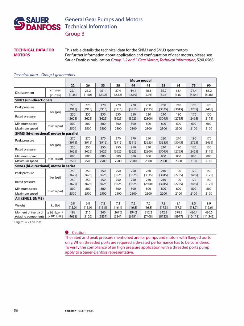
56 520L0557 • Rev. B • 10/2005
General Gear Pumps and MotorsTechnical Information
TECHNICAL DATA FOR MOTORS
This table details the technical data for the SNM3 and SNU3 gear motors. For further information about application and configuration of gear motors, please see Sauer-Danfoss publication Group 1, 2 and 3 Gear Motors, Technical Information, 520L0568.
Technical data – Group 3 gear motors
Motor model22 26 33 38 44 48 55 63 75 90
Displacementcm3/rev
[in3/rev]
22.1[1.35]
26.2[1.60]
33.1[2.02]
37.9[2.32]
44.1[2.69]
48.3[2.93]
55.2[3.36]
63.4[3.87]
74.4[4.54]
88.2[5.38]
SNU3 (uni-directional)
Peak pressure
bar [psi]
270[3915]
270[3915]
270[3915]
270[3915]
270[3915]
250[3625]
230[3335]
210[3045]
190[2755]
170[2465]
Rated pressure250
[3625]250
[3625]250
[3625]250
[3625]250
[3625]230
[2800]210
[3045]190
[2755]170
[2465]150
[2175]
Minimum speedmin-1 (rpm)
800 800 800 800 800 800 800 600 600 600
Maximum speed 2500 2500 2500 2500 2300 2300 2300 2300 2100 2100
SNM3 (bi-directional) motor in parallel
Peak pressure
bar [psi]
270[3915]
270[3915]
270[3915]
270[3915]
270[3915]
250[3625]
230[3335]
210[3045]
190[2755]
170[2465]
Rated pressure250
[3625]250
[3625]250
[3625]250
[3625]250
[3625]230
[2800]210
[3045]190
[2755]170
[2465]150
[2175]
Minimum speedmin-1 (rpm)
800 800 800 800 800 800 800 800 800 800
Maximum speed 2500 2500 2500 2500 2300 2300 2300 2300 2100 2100
SNM3 (bi-directional) motor in series
Peak pressure
bar [psi]
250 [3625]
250 [3625]
250[3625]
250[3625]
250[3625]
230[3335]
210[3045]
190[2755]
170[2465]
150[2175]
Rated pressure250
[3625]250
[3625]250
[3625]250
[3625]250
[3625]230
[2800]210
[3045]190
[2755]170
[2465]150
[2175]
Minimum speedmin-1 (rpm)
800 800 800 800 800 800 800 800 800 800
Maximum speed 2500 2500 2500 2500 2300 2300 2200 2100 2100 2100
All (SNU3, SNM3)
Weight kg [lb]6.8
[15.0]6.8
[15.0]7.2
[15.8]7.3
[16.1]7.5
[16.5]7.6
[16.8]7.8
[17.3]8.1
[17.9]8.5
[18.7]8.9
[19.6]
Moment of inertia ofrotating components
x 10-6 kg•m2
[x 10-6 lb•ft2]198
[4698]216
[5126]246
[5837]267.2[6341]
294.2[6981]
312.2[7408]
342.3[8123]
378.3[8977]
426.4[10 118]
486.5[11 545]
1 kg•m2 = 23.68 lb•ft2
C CautionThe rated and peak pressure mentioned are for pumps and motors with flanged ports only. When threaded ports are required a de-rated performance has to be considered. To verify the compliance of an high pressure application with a threaded ports pump apply to a Sauer-Danfoss representative.
Group 3
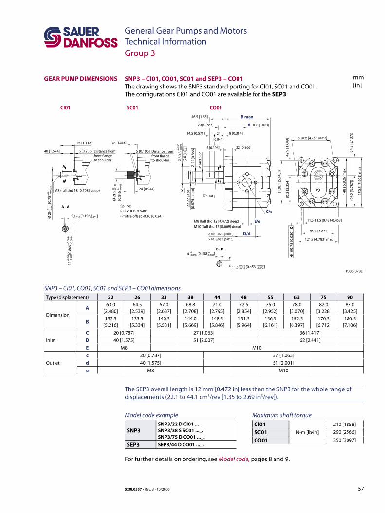
57520L0557 • Rev. B • 10/2005
General Gear Pumps and MotorsTechnical Information
mm[in]
Group 3
GEAR PUMP DIMENSIONS
SNP3 – CI01, CO01, SC01 and SEP3 – CO01dimensionsType (displacement) 22 26 33 38 44 48 55 63 75 90
Dimension
A63.0
[2.480]64.5
[2.539]67.0
[2.637]68.8
[2.708]71.0
[2.795]72.5
[2.854]75.0
[2.952]78.0
[3.070]82.0
[3.228]87.0
[3.425]
B132.5
[5.216]135.5
[5.334]140.5
[5.531]144.0
[5.669]148.5
[5.846]151.5
[5.964]156.5
[6.161]162.5
[6.397]170.5
[6.712]180.5
[7.106]
Inlet
C 20 [0.787] 27 [1.063] 36 [1.417]
D 40 [1.575] 51 [2.007] 62 [2.441]
E M8 M10
Outlet
c 20 [0.787] 27 [1.063]
d 40 [1.575] 51 [2.001]
e M8 M10
SNP3 – CI01, CO01, SC01 and SEP3 – CO01 The drawing shows the SNP3 standard porting for CI01, SC01 and CO01. The configurations CI01 and CO01 are available for the SEP3.
46.5 [1.83]
34 [1.338]46 [1.118]
6 [0.236]40 [1.574]
24 [0.944]
5 [0.196]
20 [0.787]
24
[0.944]
14.5 [0.571] 8 [0.314]
22 [0.866]5 [0.196]
±0.75 [±0.03]
121.5 [4.783] max
P005 078E
98.4 [3.874]
115 ±0.25 [4.527 ±0.010]
Ø 5
0.8
[2.0
]
-0.0
30-0
.076
-0.0
01-0
.003
Ø 2
0
[
0.78
7
]0 -0
.021
0 -0.0
008
Ø 2
2 [0
.866
]
M8 (full thd 12 [0.472] deep)M10 (full thd 17 [0.669] deep)
E/e
C/c
B max
D/d
A
CO01SC01CI01
< 40: ±0.20 [0.008]
> 40: ±0.25 [0.010]
85.2
[3.3
54]
42.9
[1.6
89]
(128
.1 [5
.043
])
(54.
3 [2
.137
])
148
[ 5.8
26] m
ax
(96.
2 [3
.787
])
150.
5 [5
.925
] ma xM
14x1
.5-6
g
22.2
2 ±
0.50
[0.8
74 ±
0.02
0]1:8
B - B
A - A
B
B
A
A
11.0-11.5 [0.433-0.453]
Spline:B22x19 DIN 5482(Profile offset -0.10 [0.024])
Ø0.
75 [0
.030
] X
Distance from front flange to shoulder
Distance from front flange to shoulder
5 [0.196 ]0-0.030
0-0.001
-0.0
0822
[0.
866
]
+0.
10-0
.20
+0.
004
Ø 2
1.5
[0.8
46
]
0 -0.1
300 -0
.005
M8 (full thd 18 [0.708] deep)
[0.453 ]+0.30 +0.010-0.10 -0.004
4 0 0-0.030 [0.158 ]-0.001
11.5
X
Maximum shaft torque
CI01N•m [lb•in]
210 [1858]
SC01 290 [2566]
CO01 350 [3097]
Model code example
SNP3SNP3/22 D CI01 ..._.SNP3/38 S SC01 ..._.SNP3/75 D CO01 ..._.
SEP3 SEP3/44 D CO01 ..._.
For further details on ordering, see Model code, pages 8 and 9.
The SEP3 overall length is 12 mm [0.472 in] less than the SNP3 for the whole range of displacements (22.1 to 44.1 cm3/rev [1.35 to 2.69 in3/rev]).

58 520L0557 • Rev. B • 10/2005
General Gear Pumps and MotorsTechnical Information
mm[in]
SNP3 – CO02, CI02 and SC02This drawing shows the standard porting for CO02, CI02 and SC02
46.5 [1.83]
34 [1.338]46 [1.118]
6 [0.236]40 [1.574]
24 [0.944]
5 [0.196]
20 [0.787]
24
[0.944]
14.5 [0.571] 8 [0.314]
22 [0.866]5 [0.196]
±0.75 [±0.03]
P005 079E
115 ±0.25 [4.527 ±0.010]
Ø 5
0.8
[2.0
]
-0.0
30-0
.076
-0.0
01-0
.003
Ø 2
0
[
0.78
7
]0 -0
.021
0 -0.0
008
Ø 2
2 [0
.866
]
M8 (full thd 12 [0.472] deep)M10 (full thd 17 [0.669] deep)
E/e
C/c
B max
D/d
A
< 40: ±0.20 [0.008]
> 40: ±0.25 [0.010]
148
[ 5.8
26] m
ax
M14
x1.5
-6g
22.2
2 ±
0.50
[0.8
74 ±
0.02
0]
1:8
B - B
A - A
B
B
A
A
11.0-11.5 [0.433-0.453]
Spline:B22x19 DIN 5482(Profile offset -0.10 [0.024])
Ø0.
75 [0
.030
] X
Distance from front flange to shoulder
Distance from front flange to shoulder
5 [0.196 ]0-0.030
0-0.001
-0.0
0822
[0.
866
]
+0.
10-0
.20
+0.
004
Ø 2
1.5
[0.8
46
]
0 -0.1
300 -0
.005
M8 (full thd 18 [0.708] deep)
[0.453 ]+0.30 +0.010-0.10 -0.004
4 0 0-0.030 [0.158 ]-0.001
11.5
X
body width
124.5 [4.9] max
98.4 [3.87]
58 [2
.28]
max
105
[4.1
3] m
ax
163
[6.4
2] m
ax
(137
[5.3
9])
92 [3
.62]
44.4
4 ±
0.75
[1.7
5 ±
0.03
]
45 [1
.77]
CO02SC02CI02
SNP3 – CO02, CI02 and SC02 dimensionsType (displacement) 22 26 33 38 44 48 55 63 75 90
Dimension
A63.0
[2.480]64.5
[2.539]67.0
[2.637]68.8
[2.70871.0
[2.795]72.5
[2.854]75.0
[2.952]78.0
[3.070]82.0
[3.228]87.0
[3.425]
B132.5
[5.216]135.5
[5.334]140.5
[5.531]144.0
[5.669]148.5
[5.846]151.5
[5.964]156.5
[6.161]162.5
[6.397]170.5
[6.712]180.5
[7.106]
Inlet
C 20 [0.787] 27 [1.063] 36 [1.417]
D 40 [1.575] 51 [2.007] 62 [2.441]
E M8 M10
Outlet
c 20 [0.787] 27 [1.063]
d 40 [1.575] 51 [2.001]
e M8 M10
Group 3
GEAR PUMP DIMENSIONS (continued)
Maximum shaft torque
CI02N•m [lb•in]
210 [1858]
SC02 290 [2566]
CO02 350 [3097]
Model code example
SNP3SNP3/22 D CI02 ..._.SNP3/38 S SC02 ..._.SNP3/75 D CO02 ..._.
For further details on ordering, see Model code, pages 8 and 9.
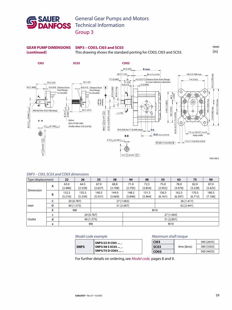
59520L0557 • Rev. B • 10/2005
General Gear Pumps and MotorsTechnical Information
mm[in]
SNP3 – CO03, CI03 and SC03This drawing shows the standard porting for CO03, CI03 and SC03.
X
P005 080 E
body width
Distance from front flange to cone reference diameter
-0.0
30-0
.076
-0.0
12-0
.003
A
D/d ±0.25 [±0.010]
B max
22.2
2 ±0
.50
[0.8
75 ±
0.02
0]
44.4
4 ±0
.75
[1.7
5 ±0
.030
]
Ø60
.3
[2.3
74
]
115 ±0.25[4.527 ±0.010]E/e
C/c
Ø 2
5 [0
.984
]
M16
x1.5
-6g
22 [0.866]
60 [2.362]
146.5 [5.768] max
114.3 [4.5]
9 [0.354]50 [1.968]
59 [2.323] 50 1.97]
28.5 [1.122]
28[1.102]
14.5 [0.571]17.5 [0.689]
1:8
M10 (full thd 17 [0.669] deep)
34 [1.351]
±0.75 [±0.030]
8 [0.315]8 [0.315]
B-B
B
B 148
[ 5.8
26] m
ax
(149
.5 [
5.88
5])
100
[ 3.9
37]
49.5
[ 1
.949
]
116
[4.5
66] m
ax65
.5 [2
.578
] max
181.
5 [ 7
.145
] max
4.79 [0.189 ]0-0.30
0-0.012
-0.01013.5 [0.532 ] +0.15-0.25
+0.006
Ø 2
2
[
0.86
6
]0 -0
.021
0 -0.0
008
A - A
A
A
Spline:B22x19 DIN 5482(Profile offset: 0.45 [0.018])
Distance from front flange to shoulder
Distance from front flange to shoulder
5 [0.196 ]0-0.030
0-0.001
-0.0
0824
[0.
945
]
+0.
10-0
.20
+0.
004
Ø 2
4.5
[0.9
65
]
0 -0.1
300 -0
.005
M8 (full thd 18 [0.708] deep)
11.0-11.5 [0.433-0.453]Ø0.75 [0.030] X
CO03SC03CI03
Group 3
GEAR PUMP DIMENSIONS (continued)
SNP3 – CI03, SC03 and CO03 dimensionsType (displacement) 22 26 33 38 44 48 55 63 75 90
Dimension
A63.0
[2.480]64.5
[2.539]67.0
[2.637]68.8
[2.708]71.0
[2.795]72.5
[2.854]75.0
[2.952]78.0
[3.070]82.0
[3.228]87.0
[3.425]
B132.5
[5.216]135.5
[5.334]140.5
[5.531]144.0
[5.669]148.5
[5.846]151.5
[5.964]156.5
[6.161]162.5
[6.397]170.5
[6.712]180.5
[7.106]
Inlet
C 20 [0.787] 27 [1.063] 36 [1.417]
D 40 [1.575] 51 [2.007] 62 [2.441]
E M8 M10
Outlet
c 20 [0.787] 27 [1.063]
d 40 [1.575] 51 [2.001]
e M8 M10
Maximum shaft torque
CI03N•m [lb•in]
300 [2655]
SC03 380 [3363]
CO03 500 [4425]
Model code example
SNP3SNP3/22 D CI03 ..._.SNP3/38 S SC03 ..._.SNP3/75 D CO03 ..._.
For further details on ordering, see Model code, pages 8 and 9.
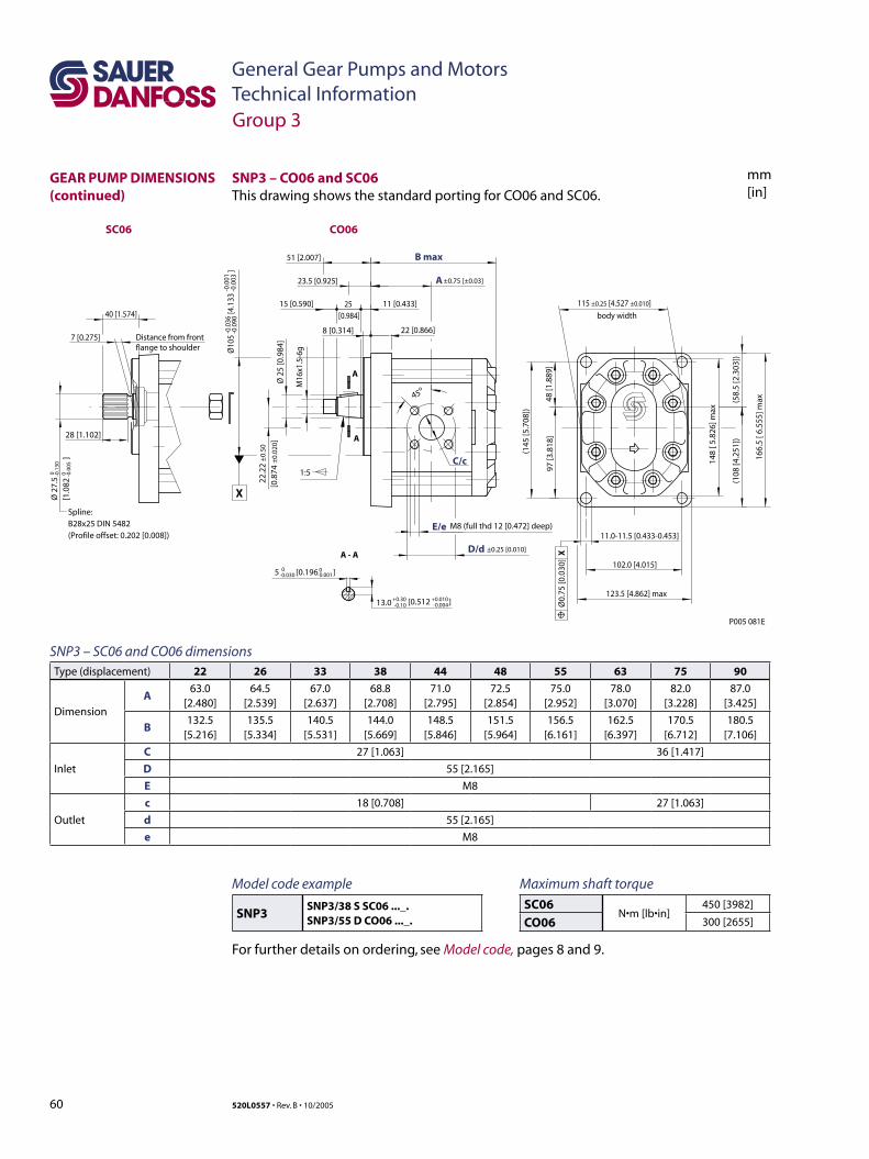
60 520L0557 • Rev. B • 10/2005
General Gear Pumps and MotorsTechnical Information
mm[in]
P005 081E
11.0-11.5 [0.433-0.453]
Ø0.
75 [0
.030
] X
40 [1.574]
1:5
45o
28 [1.102]
8 [0.314] 22 [0.866]
25 [0.984]
51 [2.007]
23.5 [0.925]
15 [0.590] 11 [0.433]
7 [0.275]
±0.75 [±0.03]
M8 (full thd 12 [0.472] deep)E/e
C/c
B max
D/d
A
A - A
A
A
Spline:B28x25 DIN 5482(Profile offset: 0.202 [0.008])
Distance from front flange to shoulder
5 [0.196 ]0-0.030
0-0.001
Ø 2
7.5
[1.0
82
]
0 -0.1
300 -0
.005
[0.512 ]+0.30 +0.010-0.10 -0.00413.0
123.5 [4.862] max
102.0 [4.015]
115 ±0.25 [4.527 ±0.010]
±0.25 [0.010]
22.2
2 ±
0.50
[0.8
74 ±
0.02
0]
X
body width
-0.0
36-0
.090
-0.0
01-0
.003
Ø10
5
[4.
133
]
Ø 2
5 [0
.984
]
M16
x1.5
-6g
(108
[4.2
51])
(58.
5 [2
.303
])
148
[ 5.8
26] m
ax
166.
5 [ 6
.555
] ma x
(145
[5.7
08])
97 [3
.818
]48
[1.8
89]
CO06SC06
SNP3 – CO06 and SC06This drawing shows the standard porting for CO06 and SC06.
Group 3
GEAR PUMP DIMENSIONS (continued)
SNP3 – SC06 and CO06 dimensionsType (displacement) 22 26 33 38 44 48 55 63 75 90
Dimension
A63.0
[2.480]64.5
[2.539]67.0
[2.637]68.8
[2.708]71.0
[2.795]72.5
[2.854]75.0
[2.952]78.0
[3.070]82.0
[3.228]87.0
[3.425]
B132.5
[5.216]135.5
[5.334]140.5
[5.531]144.0
[5.669]148.5
[5.846]151.5
[5.964]156.5
[6.161]162.5
[6.397]170.5
[6.712]180.5
[7.106]
Inlet
C 27 [1.063] 36 [1.417]
D 55 [2.165]
E M8
Outlet
c 18 [0.708] 27 [1.063]
d 55 [2.165]
e M8
Maximum shaft torque
SC06N•m [lb•in]
450 [3982]
CO06 300 [2655]
Model code example
SNP3SNP3/38 S SC06 ..._.SNP3/55 D CO06 ..._.
For further details on ordering, see Model code, pages 8 and 9.
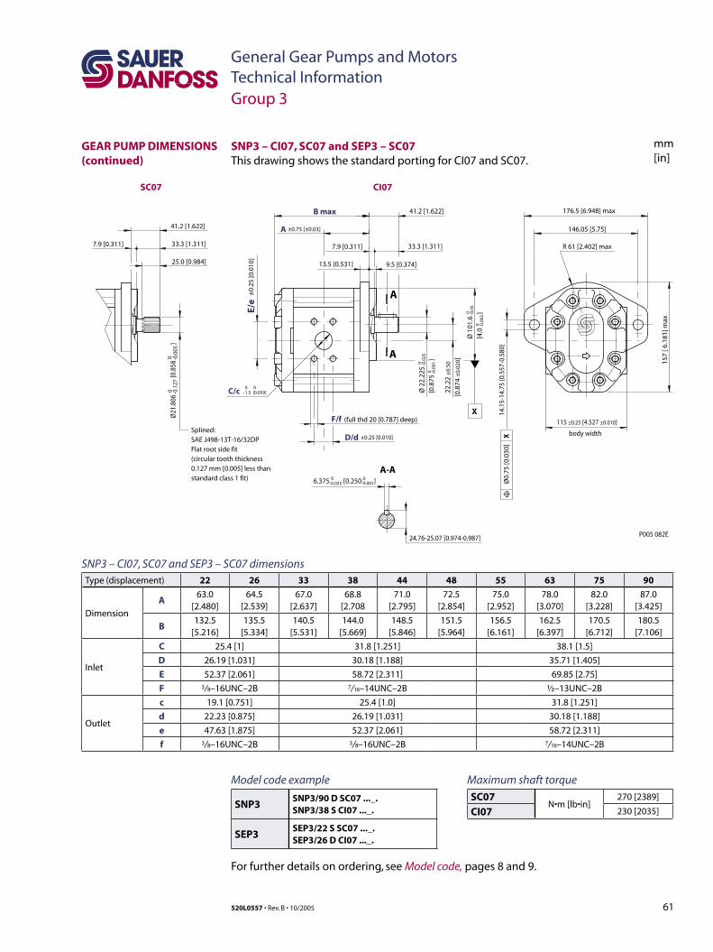
61520L0557 • Rev. B • 10/2005
General Gear Pumps and MotorsTechnical Information
mm[in]
SNP3 – CI07, SC07 and SEP3 – SC07 dimensionsType (displacement) 22 26 33 38 44 48 55 63 75 90
Dimension
A63.0
[2.480]64.5
[2.539]67.0
[2.637]68.8
[2.70871.0
[2.795]72.5
[2.854]75.0
[2.952]78.0
[3.070]82.0
[3.228]87.0
[3.425]
B132.5
[5.216]135.5
[5.334]140.5
[5.531]144.0
[5.669]148.5
[5.846]151.5
[5.964]156.5
[6.161]162.5
[6.397]170.5
[6.712]180.5
[7.106]
Inlet
C 25.4 [1] 31.8 [1.251] 38.1 [1.5]
D 26.19 [1.031] 30.18 [1.188] 35.71 [1.405]
E 52.37 [2.061] 58.72 [2.311] 69.85 [2.75]
F 3/ 8–16UNC–2B 7/ 16–14UNC–2B ½–13UNC–2B
Outlet
c 19.1 [0.751] 25.4 [1.0] 31.8 [1.251]
d 22.23 [0.875] 26.19 [1.031] 30.18 [1.188]
e 47.63 [1.875] 52.37 [2.061] 58.72 [2.311]
f 3/ 8–16UNC–2B 3/ 8–16UNC–2B 7/ 16–14UNC–2B
SNP3 – CI07, SC07 and SEP3 – SC07This drawing shows the standard porting for CI07 and SC07.
±0.75 [±0.03]
(full thd 20 [0.787] deep)F/f
B max
D/d
A
6.375 [0.250 ]0-0.025
0 0-1.5 [0.059]
0-0.001
115 ±0.25 [4.527 ±0.010]
±0.25 [0.010]
C/c
E/e
±0.
25 [0
.010
]
22.2
2 ±
0.50
[0.8
74 ±
0.02
0]
body width
0 -0.1
270 -0
.005
Ø21
.806
[0.8
58
]
176.5 [6.948] max
R 61 [2.402] max
146.05 [5.75]
41.2 [1.622]
41.2 [1.622]
33.3 [1.311]33.3 [1.311]
25.0 [0.984]
7.9 [0.311]7.9 [0.311]
13.5 [0.531] 9.5 [0.374]
157
[ 6.1
81] m
ax
14.1
5-14
.75
[0.5
57-0
.580
]
24.76-25.07 [0.974-0.987]
Ø0.
75 [0
.030
] X
Ø 2
2.22
5[0
.875
]
0 -0.0
250 -0
.001
Ø 1
01.6
[4.0
]0 -0
.05
0 -0.0
02
X
A
A
A-A
Splined:SAE J498-13T-16/32DPFlat root side fit(circular tooth thickness0.127 mm [0.005] less thanstandard class 1 fit)
P005 082E
CI07SC07
Group 3
GEAR PUMP DIMENSIONS (continued)
Maximum shaft torque
SC07N•m [lb•in]
270 [2389]
CI07 230 [2035]
Model code example
SNP3SNP3/90 D SC07 ..._.SNP3/38 S CI07 ..._.
SEP3SEP3/22 S SC07 ..._.SEP3/26 D CI07 ..._.
For further details on ordering, see Model code, pages 8 and 9.
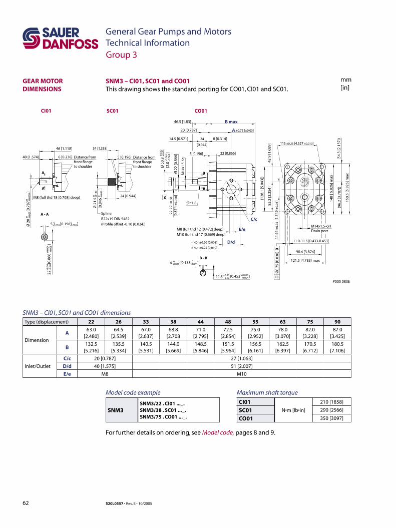
62 520L0557 • Rev. B • 10/2005
General Gear Pumps and MotorsTechnical Information
mm[in]
SNM3 – CI01, SC01 and CO01 dimensionsType (displacement) 22 26 33 38 44 48 55 63 75 90
Dimension
A63.0
[2.480]64.5
[2.539]67.0
[2.637]68.8
[2.70871.0
[2.795]72.5
[2.854]75.0
[2.952]78.0
[3.070]82.0
[3.228]87.0
[3.425]
B132.5
[5.216]135.5
[5.334]140.5
[5.531]144.0
[5.669]148.5
[5.846]151.5
[5.964]156.5
[6.161]162.5
[6.397]170.5
[6.712]180.5
[7.106]
Inlet/Outlet
C/c 20 [0.787] 27 [1.063]
D/d 40 [1.575] 51 [2.007]
E/e M8 M10
SNM3 – CI01, SC01 and CO01 This drawing shows the standard porting for CO01, CI01 and SC01.
46.5 [1.83]
34 [1.338]46 [1.118]
6 [0.236]40 [1.574]
24 [0.944]
5 [0.196]
20 [0.787]
24
[0.944]
14.5 [0.571] 8 [0.314]
22 [0.866]5 [0.196]
±0.75 [±0.03]
121.5 [4.783] max
P005 083E
98.4 [3.874]
115 ±0.25 [4.527 ±0.010]
Ø 5
0.8
[2.0
]
-0.0
30-0
.076
-0.0
01-0
.003
Ø 2
0
[
0.78
7
]0 -0
.021
0 -0.0
008
Ø 2
2 [0
.866
]
M8 (full thd 12 [0.472] deep)M10 (full thd 17 [0.669] deep)
E/e
C/c
B max
D/d
A
< 40: ±0.20 [0.008]
> 40: ±0.25 [0.010]
85.2
[3.3
54]
42.9
[1.6
89]
(128
.1 [5
.043
])
(54.
3 [2
.137
])
148
[ 5.8
26] m
ax
(96.
2 [3
.787
])
150.
5 [5
.925
] maxM
14x1
.5-6
g
22.2
2 ±
0.50
[0.8
74 ±
0.02
0]
44.4
4 ±
0.75
[1.
749
±0.
03]
1:8
B - B
A - A
B
B
A
A
11.0-11.5 [0.433-0.453]
Spline:B22x19 DIN 5482(Profile offset -0.10 [0.024])
Ø0.
75 [0
.030
] X
Distance from front flange to shoulder
Distance from front flange to shoulder
5 [0.196 ]0-0.030
0-0.001
-0.0
0822
[0.
866
]
+0.
10-0
.20
+0.
004
Ø 2
1.5
[0.8
46
]
0 -0.1
300 -0
.005
M8 (full thd 18 [0.708] deep)
[0.453 ]+0.30 +0.010-0.10 -0.004
4 0 0-0.030 [0.158 ]-0.001
11.5
X
M14x1.5-6HDrain port
CO01SC01CI01
Group 3
GEAR MOTOR DIMENSIONS
Maximum shaft torque
CI01N•m [lb•in]
210 [1858]
SC01 290 [2566]
CO01 350 [3097]
Model code example
SNM3SNM3/22 . CI01 ..._.SNM3/38 . SC01 ..._.SNM3/75 . CO01 ..._.
For further details on ordering, see Model code, pages 8 and 9.
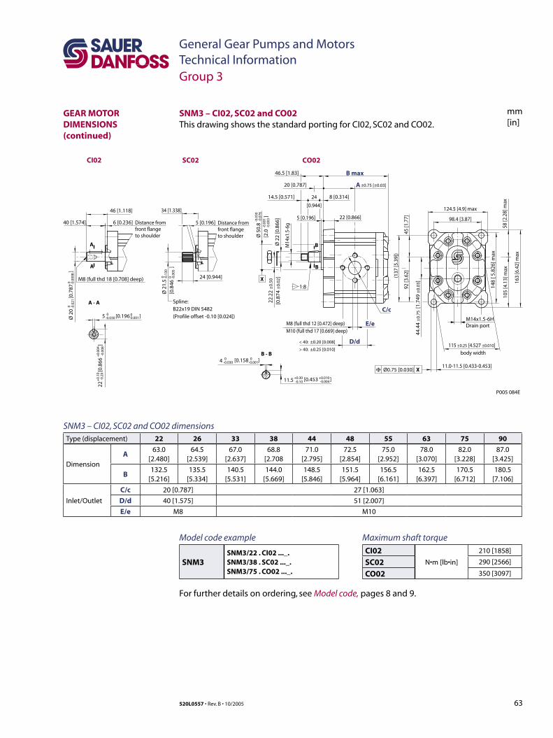
63520L0557 • Rev. B • 10/2005
General Gear Pumps and MotorsTechnical Information
mm[in]
SNM3 – CI02, SC02 and CO02 dimensionsType (displacement) 22 26 33 38 44 48 55 63 75 90
Dimension
A63.0
[2.480]64.5
[2.539]67.0
[2.637]68.8
[2.70871.0
[2.795]72.5
[2.854]75.0
[2.952]78.0
[3.070]82.0
[3.228]87.0
[3.425]
B132.5
[5.216]135.5
[5.334]140.5
[5.531]144.0
[5.669]148.5
[5.846]151.5
[5.964]156.5
[6.161]162.5
[6.397]170.5
[6.712]180.5
[7.106]
Inlet/Outlet
C/c 20 [0.787] 27 [1.063]
D/d 40 [1.575] 51 [2.007]
E/e M8 M10
SNM3 – CI02, SC02 and CO02This drawing shows the standard porting for CI02, SC02 and CO02.
46.5 [1.83]
34 [1.338]46 [1.118]
6 [0.236]40 [1.574]
24 [0.944]
5 [0.196]
20 [0.787]
24
[0.944]
14.5 [0.571] 8 [0.314]
22 [0.866]5 [0.196]
±0.75 [±0.03]
P005 084E
115 ±0.25 [4.527 ±0.010]
Ø 5
0.8
[2.0
]
-0.0
30-0
.076
-0.0
01-0
.003
Ø 2
0
[
0.78
7
]0 -0
.021
0 -0.0
008
Ø 2
2 [0
.866
]
M8 (full thd 12 [0.472] deep)M10 (full thd 17 [0.669] deep)
E/e
C/c
B max
D/d
A
< 40: ±0.20 [0.008]
> 40: ±0.25 [0.010]
148
[ 5.8
26] m
ax
M14
x1.5
-6g
22.2
2 ±
0.50
[0.8
74 ±
0.02
]
1:8
B - B
A - A
B
B
A
A
11.0-11.5 [0.433-0.453]
Spline:B22x19 DIN 5482(Profile offset -0.10 [0.024])
Ø0.75 [0.030] X
Distance from front flange to shoulder
Distance from front flange to shoulder
5 [0.196 ]0-0.030
0-0.001
-0.0
0822
[0.
866
]
+0.
10-0
.20
+0.
004
Ø 2
1.5
[0.8
46
]
0 -0.1
300 -0
.005
M8 (full thd 18 [0.708] deep)
[0.453 ]+0.30 +0.010-0.10 -0.004
4 0 0-0.030 [0.158 ]-0.001
11.5
X
body width
124.5 [4.9] max
98.4 [3.87]
58 [2
.28]
max
105
[4.1
3] m
ax
163
[6.4
2] m
ax
(137
[5.3
9])
92 [3
.62]
45 [1
.77]
44.4
4 ±
0.75
[1.
749
±0.
03]
M14x1.5-6HDrain port
CO02SC02CI02
Group 3
GEAR MOTOR DIMENSIONS (continued)
Maximum shaft torque
CI02N•m [lb•in]
210 [1858]
SC02 290 [2566]
CO02 350 [3097]
Model code example
SNM3SNM3/22 . CI02 ..._.SNM3/38 . SC02 ..._.SNM3/75 . CO02 ..._.
For further details on ordering, see Model code, pages 8 and 9.
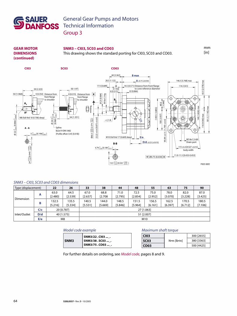
64 520L0557 • Rev. B • 10/2005
General Gear Pumps and MotorsTechnical Information
mm[in]
SNM3 – CI03, SC03 and CO03This drawing shows the standard porting for CI03, SC03 and CO03.
X
P005 085E
body width
Distance from front flange to cone reference diameter
-0.0
30-0
.076
-0.0
12-0
.003
A
D/d ±0.25 [±0.010]
B max
22.2
2 ±0
.50
[0.8
75 ±
0.02
0]
Ø60
.3
[2.3
74
]
115 ±0.25[4.527 ±0.010]
E/e
C/c
Ø 2
5 [0
.984
]
M16
x1.5
-6g
22 [0.866]
60 [2.362]
146.5 [5.768] max
114.3 [4.5]
9 [0.354]50 [1.968]
59 [2.323] 50 1.97]
28.5 [1.122]
28[1.102]
14.5 [0.571]17.5 [0.689]
1:8
M10 (full thd 17 [0.669] deep)
34 [1.351]
±0.75 [±0.030]
8 [0.315]8 [0.315]
B-B
B
B 148
[ 5.8
26] m
ax
(149
.5 [
5.88
5])
100
[ 3.9
37]
49.5
[ 1
.949
]
116
[4.5
66] m
ax65
.5 [2
.578
] max
181.
5 [ 7
.145
] max
4.79 [0.189 ]0-0.30
0-0.012
-0.01013.5 [0.532 ] +0.15-0.25
+0.006
Ø 2
2
[
0.86
6
]0 -0
.021
0 -0.0
008
A - A
A
A
Spline:B22x19 DIN 5482(Profile offset: 0.45 [0.018])
Distance from front flange to shoulder
Distance from front flange to shoulder
5 [0.196 ]0-0.030
0-0.001
-0.0
0824
[0.
945
]
+0.
10-0
.20
+0.
004
Ø 2
4.5
[0.9
65
]
0 -0.1
300 -0
.005
M8 (full thd 18 [0.708] deep)
11.0-11.5 [0.433-0.453]Ø0.75 [0.030] X
44.4
4 ±
0.75
[1.
749
±0.
03]
M14x1.5-6HDrain port
CO03SC03CI03
Group 3
GEAR MOTOR DIMENSIONS (continued)
Maximum shaft torque
CI03N•m [lb•in]
300 [2655]
SC03 380 [3363]
CO03 500 [4425]
Model code example
SNM3SNM3/22 . CI03 ..._.SNM3/38 . SC03 ..._.SNM3/75 . CO03 ..._.
For further details on ordering, see Model code, pages 8 and 9.
SNM3 – CI03, SC03 and CO03 dimensionsType (displacement) 22 26 33 38 44 48 55 63 75 90
Dimension
A63.0
[2.480]64.5
[2.539]67.0
[2.637]68.8
[2.70871.0
[2.795]72.5
[2.854]75.0
[2.952]78.0
[3.070]82.0
[3.228]87.0
[3.425]
B132.5
[5.216]135.5
[5.334]140.5
[5.531]144.0
[5.669]148.5
[5.846]151.5
[5.964]156.5
[6.161]162.5
[6.397]170.5
[6.712]180.5
[7.106]
Inlet/Outlet
C/c 20 [0.787] 27 [1.063]
D/d 40 [1.575] 51 [2.007]
E/e M8 M10
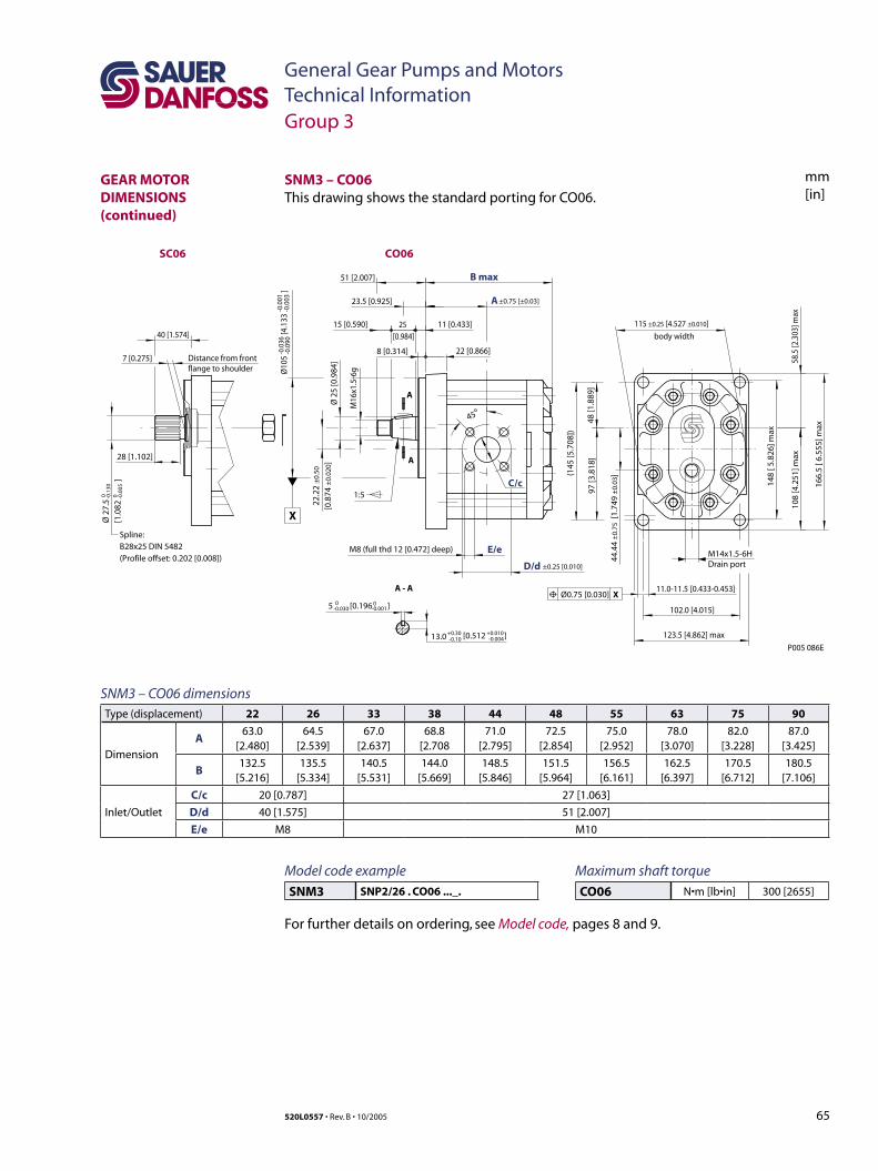
65520L0557 • Rev. B • 10/2005
General Gear Pumps and MotorsTechnical Information
mm[in]
SNM3 – CO06 dimensionsType (displacement) 22 26 33 38 44 48 55 63 75 90
Dimension
A63.0
[2.480]64.5
[2.539]67.0
[2.637]68.8
[2.70871.0
[2.795]72.5
[2.854]75.0
[2.952]78.0
[3.070]82.0
[3.228]87.0
[3.425]
B132.5
[5.216]135.5
[5.334]140.5
[5.531]144.0
[5.669]148.5
[5.846]151.5
[5.964]156.5
[6.161]162.5
[6.397]170.5
[6.712]180.5
[7.106]
Inlet/Outlet
C/c 20 [0.787] 27 [1.063]
D/d 40 [1.575] 51 [2.007]
E/e M8 M10
SNM3 – CO06This drawing shows the standard porting for CO06.
P005 086E
11.0-11.5 [0.433-0.453]Ø0.75 [0.030] X
40 [1.574]
1:5
45o
28 [1.102]
8 [0.314] 22 [0.866]
25 [0.984]
51 [2.007]
23.5 [0.925]
15 [0.590] 11 [0.433]
7 [0.275]
±0.75 [±0.03]
M8 (full thd 12 [0.472] deep) E/e
C/c
B max
D/d
A
A - A
A
A
Spline:B28x25 DIN 5482(Profile offset: 0.202 [0.008])
Distance from front flange to shoulder
5 [0.196 ]0-0.030
0-0.001
Ø 2
7.5
[1.0
82
]
0 -0.1
300 -0
.005
[0.512 ]+0.30 +0.010-0.10 -0.00413.0 123.5 [4.862] max
102.0 [4.015]
115 ±0.25 [4.527 ±0.010]
±0.25 [0.010]
22.2
2 ±
0.50
[0.8
74 ±
0.02
0]
X
body width
-0.0
36-0
.090
-0.0
01-0
.003
Ø10
5
[4.
133
]
Ø 2
5 [0
.984
]
M16
x1.5
-6g
108
[4.2
51] m
ax58
.5 [2
.303
] max
148
[ 5.8
26] m
ax
166.
5 [ 6
.555
] max
(145
[5.7
08])
97 [3
.818
]48
[1.8
89]
44.4
4 ±
0.75
[1.
749
±0.
03]
M14x1.5-6HDrain port
CO06SC06
Group 3
GEAR MOTOR DIMENSIONS (continued)
Maximum shaft torque
CO06 N•m [lb•in] 300 [2655]
Model code example
SNM3 SNP2/26 . CO06 ..._.
For further details on ordering, see Model code, pages 8 and 9.
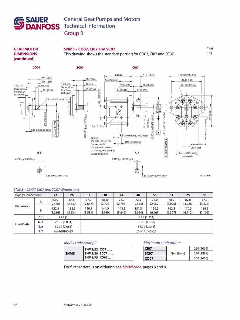
66 520L0557 • Rev. B • 10/2005
General Gear Pumps and MotorsTechnical Information
mm[in]
SNM3 – CO07, CI07 and SC07 dimensionsType (displacement) 22 26 33 38 44 48 55 63 75 90
Dimension
A63.0
[2.480]64.5
[2.539]67.0
[2.637]68.8
[2.70871.0
[2.795]72.5
[2.854]75.0
[2.952]78.0
[3.070]82.0
[3.228]87.0
[3.425]
B132.5
[5.216]135.5
[5.334]140.5
[5.531]144.0
[5.669]148.5
[5.846]151.5
[5.964]156.5
[6.161]162.5
[6.397]170.5
[6.712]180.5
[7.106]
Inlet/Outlet
C/c 25.4 [1] 31.8 [1.251]
D/d 26.19 [1.031] 30.18 [1.188]
E/e 52.37 [2.061] 58.72 [2.311]
F/f 3/ 8–16UNC–2B 7/ 16–14UNC–2B
SNM3 – CO07, CI07 and SC07This drawing shows the standard porting for CO07, CI07 and SC07.
±0.75 [±0.03]
(full thd 20 [0.787] deep)F/f
B max
D/d
A
6.375 [0.250 ]0-0.025
0 0-1.5 [0.059]
0-0.001
115 ±0.25 [4.527 ±0.010]
±0.25 [0.010]
C/c
E/e
±0.
25 [0
.010
]
22.2
2 ±
0.50
[0.8
74 ±
0.02
0 ]
body width
0 -0.1
270 -0
.005
Ø21
.806
[0.8
58
]
176.5 [6.948] max
R 61 [2.402] max
146.05 [5.75]
41.2 [7.622]
41.2 [7.622]
33.3 [1.311]33.3 [1.311]
25.0 [0.984]
7.9 [0.311]7.9 [0.311]7.9 [0.311]
13.5 [0.531] 9.5 [0.374]
157
[ 6.1
81] m
ax
14.1
5-14
.75
[0.5
57-0
.580
]
6.35-5.25 [0.25-0.206]
24.76-25.07 [0.974-0.987]
Ø0.
75 [0
.030
] X
Ø 2
2.22
5[0
.875
]
0 -0.0
250 -0
.001
Ø 1
01.6
[4.0
]0 -0
.05
0 -0.0
02
X
A
A
B
B
A-A
6.375 [0.250 ]0-0.025
0-0.001
3.33-3.07 [0.131-0.120]
B-B
Splined:SAE J498-13T-16/32DPFlat root side fit(circular tooth thickness0.127 mm [0.005] less thanstandard class 1 fit)
P005 087E
9/16-18UNF-2BDrain port
5/8-
18U
NF-
2A
28.4 [1.118]
59.4 [2.338]
42.9 [1.689]
23.1 [0.909]
Ø 2
2.22
5 [0
.875
]
Co
ne
refe
ren
ce d
iam
eter
Distance from front flange to shoulder
Distance from front flange to shoulder
Ø 4 ±0.1[0.157 ±0.004]
44.4
4 ±0
.75
[1.7
49 ±
0.03
]
CI07SC07CO07
Group 3
GEAR MOTOR DIMENSIONS (continued)
Maximum shaft torque
CI07N•m [lb•in]
230 [2035]
SC07 270 [2389]
CO07 300 [2655]
Model code example
SNM3SNM3/22 . CI07 ..._.SNM3/38 . SC07 ..._.SNM3/75 . CO07 ..._.
For further details on ordering, see Model code, pages 8 and 9.
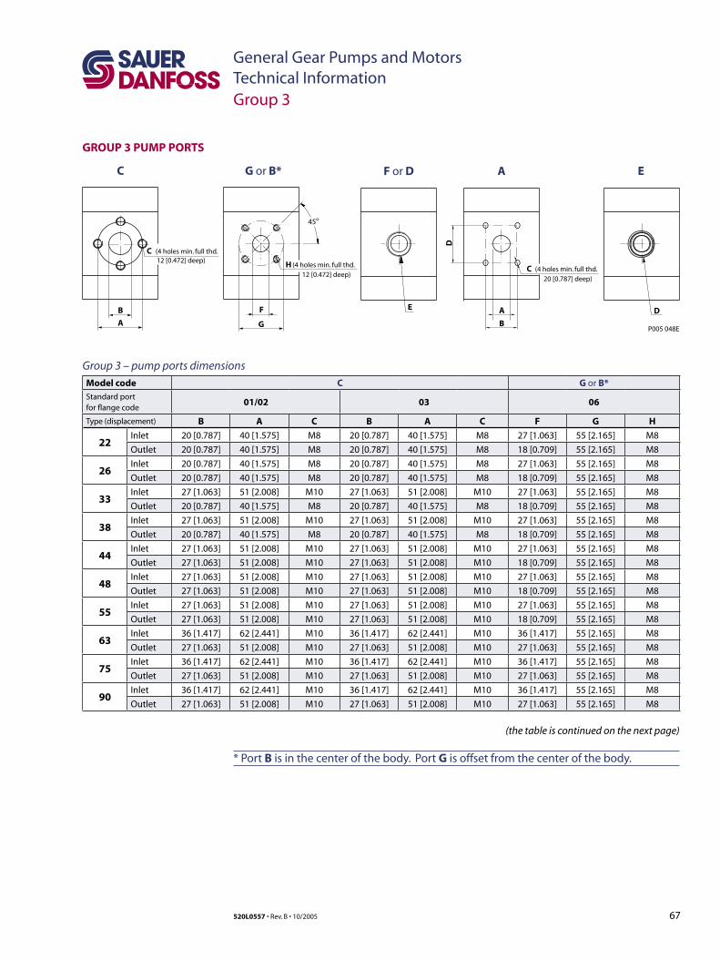
67520L0557 • Rev. B • 10/2005
General Gear Pumps and MotorsTechnical Information
GROUP 3 PUMP PORTS
B
C G or B* F or D E
C
A
(4 holes min. full thd.12 [0.472] deep)
F
H
G
45o
(4 holes min. full thd.12 [0.472] deep)
P005 048E
E D
A
A
C (4 holes min. full thd. 20 [0.787] deep)
B
D
Model code C G or B*Standard portfor flange code
01/02 03 06
Type (displacement) B A C B A C F G H
22Inlet 20 [0.787] 40 [1.575] M8 20 [0.787] 40 [1.575] M8 27 [1.063] 55 [2.165] M8
Outlet 20 [0.787] 40 [1.575] M8 20 [0.787] 40 [1.575] M8 18 [0.709] 55 [2.165] M8
26Inlet 20 [0.787] 40 [1.575] M8 20 [0.787] 40 [1.575] M8 27 [1.063] 55 [2.165] M8
Outlet 20 [0.787] 40 [1.575] M8 20 [0.787] 40 [1.575] M8 18 [0.709] 55 [2.165] M8
33Inlet 27 [1.063] 51 [2.008] M10 27 [1.063] 51 [2.008] M10 27 [1.063] 55 [2.165] M8
Outlet 20 [0.787] 40 [1.575] M8 20 [0.787] 40 [1.575] M8 18 [0.709] 55 [2.165] M8
38Inlet 27 [1.063] 51 [2.008] M10 27 [1.063] 51 [2.008] M10 27 [1.063] 55 [2.165] M8
Outlet 20 [0.787] 40 [1.575] M8 20 [0.787] 40 [1.575] M8 18 [0.709] 55 [2.165] M8
44Inlet 27 [1.063] 51 [2.008] M10 27 [1.063] 51 [2.008] M10 27 [1.063] 55 [2.165] M8
Outlet 27 [1.063] 51 [2.008] M10 27 [1.063] 51 [2.008] M10 18 [0.709] 55 [2.165] M8
48Inlet 27 [1.063] 51 [2.008] M10 27 [1.063] 51 [2.008] M10 27 [1.063] 55 [2.165] M8
Outlet 27 [1.063] 51 [2.008] M10 27 [1.063] 51 [2.008] M10 18 [0.709] 55 [2.165] M8
55Inlet 27 [1.063] 51 [2.008] M10 27 [1.063] 51 [2.008] M10 27 [1.063] 55 [2.165] M8
Outlet 27 [1.063] 51 [2.008] M10 27 [1.063] 51 [2.008] M10 18 [0.709] 55 [2.165] M8
63Inlet 36 [1.417] 62 [2.441] M10 36 [1.417] 62 [2.441] M10 36 [1.417] 55 [2.165] M8
Outlet 27 [1.063] 51 [2.008] M10 27 [1.063] 51 [2.008] M10 27 [1.063] 55 [2.165] M8
75Inlet 36 [1.417] 62 [2.441] M10 36 [1.417] 62 [2.441] M10 36 [1.417] 55 [2.165] M8
Outlet 27 [1.063] 51 [2.008] M10 27 [1.063] 51 [2.008] M10 27 [1.063] 55 [2.165] M8
90Inlet 36 [1.417] 62 [2.441] M10 36 [1.417] 62 [2.441] M10 36 [1.417] 55 [2.165] M8
Outlet 27 [1.063] 51 [2.008] M10 27 [1.063] 51 [2.008] M10 27 [1.063] 55 [2.165] M8
(the table is continued on the next page)
Group 3 – pump ports dimensions
* Port B is in the center of the body. Port G is offset from the center of the body.
Group 3
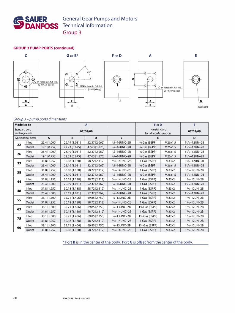
68 520L0557 • Rev. B • 10/2005
General Gear Pumps and MotorsTechnical Information
GROUP 3 PUMP PORTS (continued)
Model code A F or D E
Standard portfor flange code
07/08/09nonstandard
for all configuration07/08/09
Type (displacement) A B D C E D
22Inlet 25.4 [1.000] 26.19 [1.031] 52.37 [2.062] 3/ 8–16UNC–2B ¾ Gas (BSPP) M26x1.5 15/ 16–12UN–2B
Outlet 19.1 [0.752] 22.23 [0.875] 47.63 [1.875] 3/ 8–16UNC–2B ¾ Gas (BSPP) M26x1.5 11/ 16–12UN–2B
26Inlet 25.4 [1.000] 26.19 [1.031] 52.37 [2.062] 3/ 8–16UNC–2B ¾ Gas (BSPP) M26x1.5 15/ 16–12UN–2B
Outlet 19.1 [0.752] 22.23 [0.875] 47.63 [1.875] 3/ 8–16UNC–2B ¾ Gas (BSPP) M26x1.5 11/ 16–12UN–2B
33Inlet 31.8 [1.252] 30.18 [1.188] 58.72 [2.312] 7/ 16–14UNC–2B 1 Gas (BSPP) M33x2 15/ 8– 12UN–2B
Outlet 25.4 [1.000] 26.19 [1.031] 52.37 [2.062] 3/ 8–16UNC–2B ¾ Gas (BSPP) M26x1.5 15/ 16–12UN–2B
38Inlet 31.8 [1.252] 30.18 [1.188] 58.72 [2.312] 7/ 16–14UNC–2B 1 Gas (BSPP) M33x2 15/ 8–12UN–2B
Outlet 25.4 [1.000] 26.19 [1.031] 52.37 [2.062] 3/ 8–16UNC–2B ¾ Gas (BSPP) M26x1.5 15/ 16–12UN–2B
44Inlet 31.8 [1.252] 30.18 [1.188] 58.72 [2.312] 7/ 16–14UNC–2B 1 Gas (BSPP) M33x2 15/ 8–12UN–2B
Outlet 25.4 [1.000] 26.19 [1.031] 52.37 [2.062] 3/ 8–16UNC–2B 1 Gas (BSPP) M33x2 15/ 16–12UN–2B
48Inlet 31.8 [1.252] 30.18 [1.188] 58.72 [2.312] 7/ 16–14UNC–2B 1 Gas (BSPP) M33x2 15/ 8–12UN–2B
Outlet 25.4 [1.000] 26.19 [1.031] 52.37 [2.062] 3/ 8–16UNC–2B 1 Gas (BSPP) M33x2 15/ 16–12UN–2B
55Inlet 38.1 [1.500] 35.71 [1.406] 69.85 [2.750] ½–13UNC–2B 1 Gas (BSPP) M33x2 17/ 8–12UN–2B
Outlet 31.8 [1.252] 30.18 [1.188] 58.72 [2.312] 7/ 16–14UNC–2B 1 Gas (BSPP) M33x2 15/ 8–12UN–2B
63Inlet 38.1 [1.500] 35.71 [1.406] 69.85 [2.750] ½–13UNC–2B 1¼ Gas (BSPP) M42x2 17/ 8–12UN–2B
Outlet 31.8 [1.252] 30.18 [1.188] 58.72 [2.312] 7/ 16–14UNC–2B 1 Gas (BSPP) M33x2 15/ 8–12UN–2B
75Inlet 38.1 [1.500] 35.71 [1.406] 69.85 [2.750] ½–13UNC–2B 1¼ Gas (BSPP) M42x2 17/ 8–12UN–2B
Outlet 31.8 [1.252] 30.18 [1.188] 58.72 [2.312] 7/ 16–14UNC–2B 1 Gas (BSPP) M33x2 15/ 8–12UN–2B
90Inlet 38.1 [1.500] 35.71 [1.406] 69.85 [2.750] ½–13UNC–2B 1¼ Gas (BSPP) M42x2 17/ 8–12UN–2B
Outlet 31.8 [1.252] 30.18 [1.188] 58.72 [2.312] 7/ 16–14UNC–2B 1 Gas (BSPP) M33x2 15/ 8–12UN–2B
B
C G or B* F or D E
C
A
(4 holes min. full thd.12 [0.472] deep)
F
H
G
45o
(4 holes min. full thd.12 [0.472] deep)
P005 048E
E D
A
A
C (4 holes min. full thd. 20 [0.787] deep)
B
D
* Port B is in the center of the body. Port G is offset from the center of the body.
Group 3 – pump ports dimensions
Group 3

69520L0557 • Rev. B • 10/2005
General Gear Pumps and MotorsTechnical Information
GROUP 3 MOTOR PORTS
Model code C G or B F or D E A
Standard portfor flange code
01/02/03 06 nonstandardSAE J518cvertical 07
Type (displacement) B A C F G H E E D “
22Inlet/Outlet
20 [0.787] 40 [1.575] M8 27 [1.063] 55 [2.165] M8 ¾ Gas (BSPP) M26x1.5 15/ 16–12UN–2B 1
26Inlet/Outlet
20 [0.787] 40 [1.575] M8 27 [1.063] 55 [2.165] M8 ¾ Gas (BSPP) M26x1.5 15/ 16–12UN–2B 1¼
33Inlet/Outlet
27 [1.063] 51 [2.008] M10 27 [1.063] 55 [2.165] M8 1 Gas (BSPP) M33x2 15/ 8–12UN–2B 1¼
38Inlet/Outlet
27 [1.063] 51 [2.008] M10 27 [1.063] 55 [2.165] M8 1 Gas (BSPP) M33x2 15/ 8–12UN–2B 1¼
44Inlet/Outlet
27 [1.063] 51 [2.008] M10 27 [1.063] 55 [2.165] M8 1 Gas (BSPP) M33x2 15/ 8–12UN–2B 1¼
48Inlet/Outlet
27 [1.063] 51 [2.008] M10 27 [1.063] 55 [2.165] M8 1 Gas (BSPP) M33x2 15/ 8–12UN–2B 1¼
55Inlet/Outlet
27 [1.063] 51 [2.008] M10 27 [1.063] 55 [2.165] M8 1 Gas (BSPP) M33x2 15/ 8–12UN–2B 1¼
63Inlet/Outlet
27 [1.063] 51 [2.008] M10 27 [1.063] 55 [2.165] M8 1 Gas (BSPP) M33x2 15/ 8–12UN–2B 1¼
75Inlet/Outlet
27 [1.063] 51 [2.008] M10 27 [1.063] 55 [2.165] M8 1 Gas (BSPP) M33x2 15/ 8–12UN–2B 1¼
90Inlet/Outlet
27 [1.063] 51 [2.008] M10 27 [1.063] 55 [2.165] M8 1 Gas (BSPP) M33x2 15/ 8–12UN–2B 1¼
Drain M14 x 1.5 9/ 16–18UNF–2B
B
C G or B* F or D E
C
A
(4 holes min. full thd.12 [0.472] deep)
F
H
G
45o
(4 holes min. full thd.12 [0.472] deep)
P005 048E
E D
A
A
C (4 holes min. full thd. 20 [0.787] deep)
B
D
Group 3 – motor ports dimensions
Group 3
* Port B is in the center of the body. Port G is offset from the center of the body.
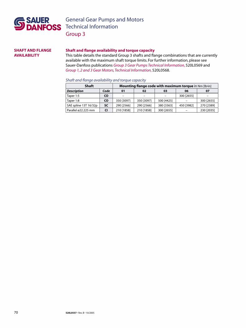
70 520L0557 • Rev. B • 10/2005
General Gear Pumps and MotorsTechnical Information
SHAFT AND FLANGE AVAILABILITY
Shaft and flange availability and torque capacityThis table details the standard Group 3 shafts and flange combinations that are currently available with the maximum shaft torque limits. For further information, please see Sauer-Danfoss publications Group 3 Gear Pumps Technical Information, 520L0569 and Group 1, 2 and 3 Gear Motors, Technical Information, 520L0568.
Shaft and flange availability and torque capacity
Shaft Mounting flange code with maximum torque in Nm [lb•in]
Description Code 01 02 03 06 07
Taper 1:5 CO – – – 300 [2655] –
Taper 1:8 CO 350 [3097] 350 [3097] 500 [4425] – 300 [2655]
SAE spline 13T 16/32p SC 290 [2566] 290 [2566] 380 [3363] 450 [3982] 270 [2389]
Parallel ø22.225 mm CI 210 [1858] 210 [1858] 300 [2655] – 230 [2035]
Group 3

71520L0557 • Rev. B • 10/2005
General Gear Pumps and MotorsTechnical Information
Sauer-Danfoss multi-stage pumps can be combined of group 1, 2, and 3. In addition to the standard range (presented in the following), first stage can be supplied with a splined, a tapered or a parallel shaft. Also versions with suction connection and other hydraulic connections and flange assembly or centralized threads are available.
The representatives of Sauer-Danfoss multi-stage pumps are shown below:
Tandem pump PTT SC46
Multi-Stage Pumps
OVERVIEW
F005 011
F005 069
Triple pump PFRN CO31
Tandem pump PNT CO31(cut-away)
F005 068
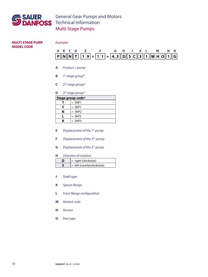
72 520L0557 • Rev. B • 10/2005
General Gear Pumps and MotorsTechnical Information
MULTI-STAGE PUMP MODEL CODE
Multi-Stage Pumps
Example:
A B C D E F G H J K L M N O
A Product = pump
B 1st stage group*
C 2nd stage group*
D 3rd stage group*
Stage group code*T = SNP1
Y = SKP1
N = SNP2
L = SKP2
R = SNP3
E Displacement of the 1st pump
F Displacement of the 2nd pump
G Displacement of the 3rd pump
H Direction of rotation
D = right (clockwise)
S = left (counterclockwise)
J Shaft type
K Spacer flange
L Front flange configuration
M Variant code
N Version
O Port type
P N N T 1 9 + 1 1 + 4. 3 S C W H O 1 GD 3 1
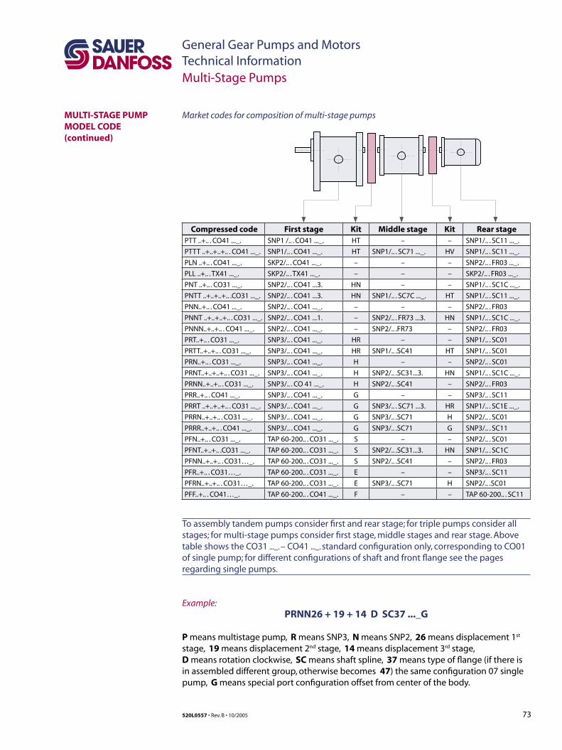
73520L0557 • Rev. B • 10/2005
General Gear Pumps and MotorsTechnical Information
Market codes for composition of multi-stage pumps
Compressed code First stage Kit Middle stage Kit Rear stagePTT ..+.. . CO41 ..._. SNP1 /.. . CO41 ..._. HT – – SNP1/.. . SC11 ..._.
PTTT ..+..+..+.. . CO41 ..._. SNP1/.. . CO41 ..._. HT SNP1/.. . SC71 ..._. HV SNP1/.. . SC11 ..._.
PLN ..+.. . CO41 ..._. SKP2/.. . CO41 ..._. – – – SNP2/.. . FR03 ..._.
PLL ..+.. . TX41 ..._. SKP2/.. . TX41 ..._. – – – SKP2/.. . FR03 ..._.
PNT ..+.. . CO31 ..._. SNP2/.. . CO41 ...3. HN – – SNP1/.. . SC1C ..._.
PNTT ..+..+..+.. .CO31 ..._. SNP2/.. . CO41 ...3. HN SNP1/.. . SC7C ..._. HT SNP1/.. . SC11 ..._.
PNN..+.. . CO41 ..._. SNP2/.. . CO41 ..._. – – – SNP2/.. . FR03
PNNT ..+..+..+.. . CO31 ..._. SNP2/.. . CO41 ...1. – SNP2/.. . FR73 ...3. HN SNP1/.. . SC1C ..._.
PNNN..+..+.. . CO41 ..._. SNP2/.. . CO41 ..._. – SNP2/.. .FR73 – SNP2/.. . FR03
PRT..+.. . CO31 ..._. SNP3/.. . CO41 ..._. HR – – SNP1/.. . SC01
PRTT..+..+.. . CO31 ..._. SNP3/.. . CO41 ..._. HR SNP1/.. .SC41 HT SNP1/.. . SC01
PRN..+.. . CO31 ..._. SNP3/.. . CO41 ..._. H – – SNP2/.. . SC01
PRNT..+..+..+.. . CO31 ..._. SNP3/.. . CO41 ..._. H SNP2/.. .SC31...3. HN SNP1/.. . SC1C ..._.
PRNN..+..+.. . CO31 ..._. SNP3/.. . CO 41 ..._. H SNP2/.. .SC41 – SNP2/.. . FR03
PRR..+.. . CO41 ..._. SNP3/.. . CO41 ..._. G – – SNP3/.. . SC11
PRRT ..+..+..+.. . CO31 ..._. SNP3/.. . CO41 ..._. G SNP3/.. . SC71 ...3. HR SNP1/.. . SC1E ..._.
PRRN..+..+.. . CO31 ..._. SNP3/.. . CO41 ..._. G SNP3/.. .SC71 H SNP2/.. . SC01
PRRR..+..+.. . CO41 ..._. SNP3/.. . CO41 ..._. G SNP3/.. .SC71 G SNP3/.. . SC11
PFN..+.. . CO31 ..._. TAP 60-200.. . CO31 ..._. S – – SNP2/.. . SC01
PFNT..+..+.. .CO31 ..._. TAP 60-200.. . CO31 ..._. S SNP2/.. .SC31...3. HN SNP1/.. . SC1C
PFNN..+..+.. . CO31…_. TAP 60-200.. . CO31 ..._. S SNP2/.. .SC41 – SNP2/.. . FR03
PFR..+.. . CO31…_. TAP 60-200.. . CO31 ..._. E – – SNP3/.. . SC11
PFRN..+..+.. . CO31…_. TAP 60-200.. . CO31 ..._. E SNP3/.. .SC71 H SNP2/.. .SC01
PFF..+.. . CO41…_. TAP 60-200.. . CO41 ..._. F – – TAP 60-200.. . SC11
To assembly tandem pumps consider first and rear stage; for triple pumps consider all stages; for multi-stage pumps consider first stage, middle stages and rear stage. Above table shows the CO31 ..._. – CO41 ..._. standard configuration only, corresponding to CO01 of single pump; for different configurations of shaft and front flange see the pages regarding single pumps.
Example:PRNN26 + 19 + 14 D SC37 ..._G
P means multistage pump, R means SNP3, N means SNP2, 26 means displacement 1st stage, 19 means displacement 2nd stage, 14 means displacement 3rd stage, D means rotation clockwise, SC means shaft spline, 37 means type of flange (if there is in assembled different group, otherwise becomes 47) the same configuration 07 single pump, G means special port configuration offset from center of the body.
MULTI-STAGE PUMP MODEL CODE(continued)
Multi-Stage Pumps
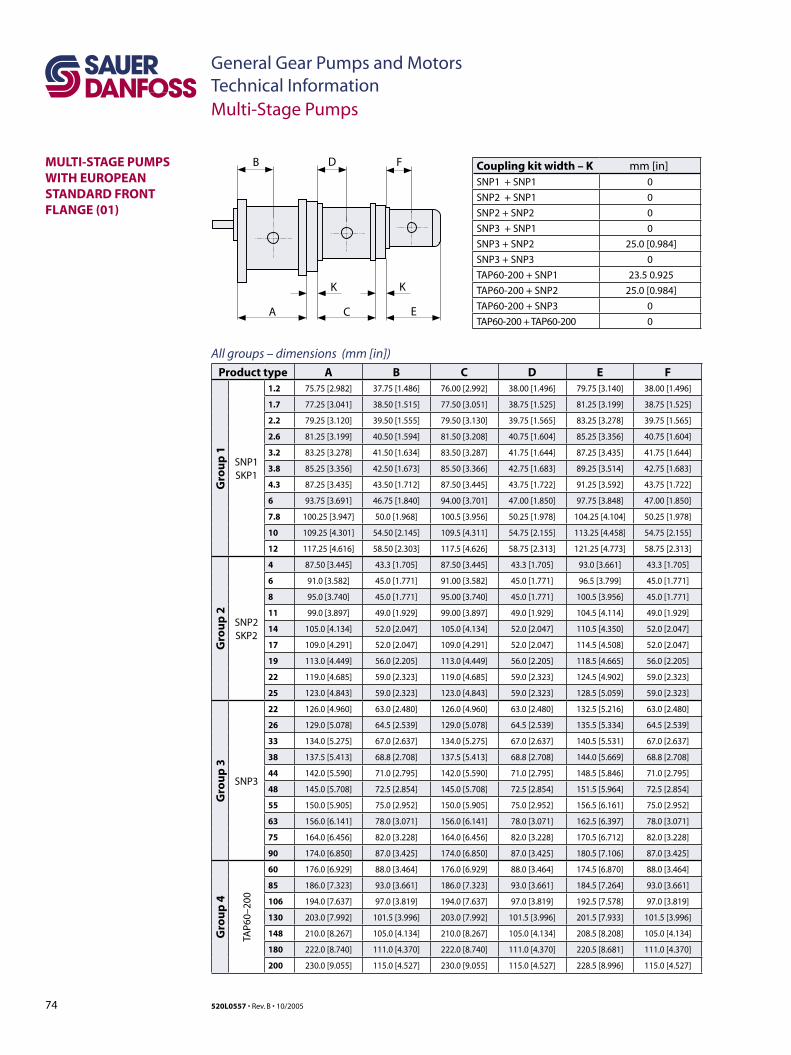
74 520L0557 • Rev. B • 10/2005
General Gear Pumps and MotorsTechnical Information
MULTI-STAGE PUMPS WITH EUROPEAN STANDARD FRONT FLANGE (01)
Multi-Stage Pumps
B D F
A C E
K K
All groups – dimensions (mm [in])
Product type A B C D E F
Gro
up
1
SNP1SKP1
1.2 75.75 [2.982] 37.75 [1.486] 76.00 [2.992] 38.00 [1.496] 79.75 [3.140] 38.00 [1.496]
1.7 77.25 [3.041] 38.50 [1.515] 77.50 [3.051] 38.75 [1.525] 81.25 [3.199] 38.75 [1.525]
2.2 79.25 [3.120] 39.50 [1.555] 79.50 [3.130] 39.75 [1.565] 83.25 [3.278] 39.75 [1.565]
2.6 81.25 [3.199] 40.50 [1.594] 81.50 [3.208] 40.75 [1.604] 85.25 [3.356] 40.75 [1.604]
3.2 83.25 [3.278] 41.50 [1.634] 83.50 [3.287] 41.75 [1.644] 87.25 [3.435] 41.75 [1.644]
3.8 85.25 [3.356] 42.50 [1.673] 85.50 [3.366] 42.75 [1.683] 89.25 [3.514] 42.75 [1.683]
4.3 87.25 [3.435] 43.50 [1.712] 87.50 [3.445] 43.75 [1.722] 91.25 [3.592] 43.75 [1.722]
6 93.75 [3.691] 46.75 [1.840] 94.00 [3.701] 47.00 [1.850] 97.75 [3.848] 47.00 [1.850]
7.8 100.25 [3.947] 50.0 [1.968] 100.5 [3.956] 50.25 [1.978] 104.25 [4.104] 50.25 [1.978]
10 109.25 [4.301] 54.50 [2.145] 109.5 [4.311] 54.75 [2.155] 113.25 [4.458] 54.75 [2.155]
12 117.25 [4.616] 58.50 [2.303] 117.5 [4.626] 58.75 [2.313] 121.25 [4.773] 58.75 [2.313]
Gro
up
2
SNP2SKP2
4 87.50 [3.445] 43.3 [1.705] 87.50 [3.445] 43.3 [1.705] 93.0 [3.661] 43.3 [1.705]
6 91.0 [3.582] 45.0 [1.771] 91.00 [3.582] 45.0 [1.771] 96.5 [3.799] 45.0 [1.771]
8 95.0 [3.740] 45.0 [1.771] 95.00 [3.740] 45.0 [1.771] 100.5 [3.956] 45.0 [1.771]
11 99.0 [3.897] 49.0 [1.929] 99.00 [3.897] 49.0 [1.929] 104.5 [4.114] 49.0 [1.929]
14 105.0 [4.134] 52.0 [2.047] 105.0 [4.134] 52.0 [2.047] 110.5 [4.350] 52.0 [2.047]
17 109.0 [4.291] 52.0 [2.047] 109.0 [4.291] 52.0 [2.047] 114.5 [4.508] 52.0 [2.047]
19 113.0 [4.449] 56.0 [2.205] 113.0 [4.449] 56.0 [2.205] 118.5 [4.665] 56.0 [2.205]
22 119.0 [4.685] 59.0 [2.323] 119.0 [4.685] 59.0 [2.323] 124.5 [4.902] 59.0 [2.323]
25 123.0 [4.843] 59.0 [2.323] 123.0 [4.843] 59.0 [2.323] 128.5 [5.059] 59.0 [2.323]
Gro
up
3
SNP3
22 126.0 [4.960] 63.0 [2.480] 126.0 [4.960] 63.0 [2.480] 132.5 [5.216] 63.0 [2.480]
26 129.0 [5.078] 64.5 [2.539] 129.0 [5.078] 64.5 [2.539] 135.5 [5.334] 64.5 [2.539]
33 134.0 [5.275] 67.0 [2.637] 134.0 [5.275] 67.0 [2.637] 140.5 [5.531] 67.0 [2.637]
38 137.5 [5.413] 68.8 [2.708] 137.5 [5.413] 68.8 [2.708] 144.0 [5.669] 68.8 [2.708]
44 142.0 [5.590] 71.0 [2.795] 142.0 [5.590] 71.0 [2.795] 148.5 [5.846] 71.0 [2.795]
48 145.0 [5.708] 72.5 [2.854] 145.0 [5.708] 72.5 [2.854] 151.5 [5.964] 72.5 [2.854]
55 150.0 [5.905] 75.0 [2.952] 150.0 [5.905] 75.0 [2.952] 156.5 [6.161] 75.0 [2.952]
63 156.0 [6.141] 78.0 [3.071] 156.0 [6.141] 78.0 [3.071] 162.5 [6.397] 78.0 [3.071]
75 164.0 [6.456] 82.0 [3.228] 164.0 [6.456] 82.0 [3.228] 170.5 [6.712] 82.0 [3.228]
90 174.0 [6.850] 87.0 [3.425] 174.0 [6.850] 87.0 [3.425] 180.5 [7.106] 87.0 [3.425]
Gro
up
4
TAP6
0–20
0
60 176.0 [6.929] 88.0 [3.464] 176.0 [6.929] 88.0 [3.464] 174.5 [6.870] 88.0 [3.464]
85 186.0 [7.323] 93.0 [3.661] 186.0 [7.323] 93.0 [3.661] 184.5 [7.264] 93.0 [3.661]
106 194.0 [7.637] 97.0 [3.819] 194.0 [7.637] 97.0 [3.819] 192.5 [7.578] 97.0 [3.819]
130 203.0 [7.992] 101.5 [3.996] 203.0 [7.992] 101.5 [3.996] 201.5 [7.933] 101.5 [3.996]
148 210.0 [8.267] 105.0 [4.134] 210.0 [8.267] 105.0 [4.134] 208.5 [8.208] 105.0 [4.134]
180 222.0 [8.740] 111.0 [4.370] 222.0 [8.740] 111.0 [4.370] 220.5 [8.681] 111.0 [4.370]
200 230.0 [9.055] 115.0 [4.527] 230.0 [9.055] 115.0 [4.527] 228.5 [8.996] 115.0 [4.527]
Coupling kit width – K mm [in]SNP1 + SNP1 0
SNP2 + SNP1 0
SNP2 + SNP2 0
SNP3 + SNP1 0
SNP3 + SNP2 25.0 [0.984]
SNP3 + SNP3 0
TAP60-200 + SNP1 23.5 0.925
TAP60-200 + SNP2 25.0 [0.984]
TAP60-200 + SNP3 0
TAP60-200 + TAP60-200 0
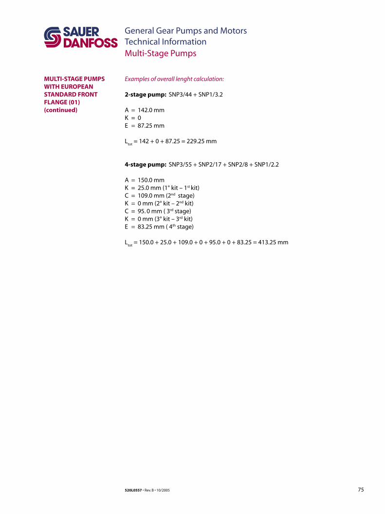
75520L0557 • Rev. B • 10/2005
General Gear Pumps and MotorsTechnical Information
Examples of overall lenght calculation:
2-stage pump: SNP3/44 + SNP1/3.2
A = 142.0 mmK = 0E = 87.25 mm
Ltot
= 142 + 0 + 87.25 = 229.25 mm
4-stage pump: SNP3/55 + SNP2/17 + SNP2/8 + SNP1/2.2
A = 150.0 mmK = 25.0 mm (1° kit – 1st kit)C = 109.0 mm (2nd stage)K = 0 mm (2° kit – 2nd kit)C = 95. 0 mm ( 3rd stage)K = 0 mm (3° kit – 3rd kit)E = 83.25 mm ( 4th stage)
Ltot
= 150.0 + 25.0 + 109.0 + 0 + 95.0 + 0 + 83.25 = 413.25 mm
MULTI-STAGE PUMPS WITH EUROPEAN STANDARD FRONT FLANGE (01)(continued)
Multi-Stage Pumps
Sauer-Danfoss Hydraulic Power Systems– Market Leaders Worldwide
Sauer-Danfoss is a comprehensive supplier providing complete systems to the global mobile market.
Sauer-Danfoss serves markets such as agriculture, construction, road building, material handling, municipal, forestry, turf care, and many others.
We offer our customers optimum solutions for their needs and develop new products and systems in close cooperation and partnership with them.
Sauer-Danfoss specializes in integrating a full range of system components to provide vehicle designers with the most advanced total system design.
Sauer-Danfoss provides comprehensive worldwide service for its products through an extensive network of Authorized Service Centers strategically located in all parts of the world.
Sauer-Danfoss (US) Company2800 East 13th StreetAmes, IA 50010, USAPhone: +1 515 239-6000, Fax: +1 515 239 6618
Sauer-Danfoss (Neumünster) GmbH & Co. OHGPostfach 2460, D-24531 NeumünsterKrokamp 35, D-24539 Neumünster, GermanyPhone +49 4321 871-0, Fax: +49 4321 871 122
Sauer-Danfoss (Nordborg) ApSDK-6430 Nordborg, DenmarkPhone: +45 7488 4444, Fax: +45 7488 4400
www.sauer-danfoss.com
OUR PRODUCTS
Hydrostatic transmissions
Hydraulic power steering
Electric power steering
Electrohydraulic power steering
Closed and open circuit axial piston pumps and motors
Gear pumps and motors
Bent axis motors
Orbital motors
Transit mixer drives
Planetary compact gears
Proportional valves
Directional spool valves
Cartridge valves
Hydraulic integrated circuits
Hydrostatic transaxles
Integrated systems
Fan drive systems
Electrohydraulics
Microcontrollers and software
Electric motors and inverters
Joysticks and control handles
Displays
Sensors
520L0557 • Rev. B • 10/2005


