11


GENERAL INFORMATION
T6000 SERIES TRANSDUCERElectro-Pneumatic (I/P, E/P)
APPLICATIONS
The T6000 Series Electro-Pneumatic Transducer converts a DC current or voltage input signalto a directly proportional pneumatic output.
The T6000 Series is designed for precision applications, providing maximum versatility. Themodular construction permits any basic unit to be used in the explosion-proof, rack, wall, pipe,panel, DIN rail or 3, 5, 10 or 15 unit manifold configurations. Servicing or calibration is quickand easy.
The compact size reduces weight and space requirements, simplifying the piping layout to theunit. External access to the restrictor orifice simplifies unit maintenance.
FEATURES
Performance• Field Reversible Feature provides output which is directly or inversely proportional to the input signal.• RFI/EMI Protection eliminates susceptibility to electromagnetic and radio interference.
Functional• Six output pressure ranges meet final control element requirements.• Six input signal ranges meet most process and machine requirements.
Physical• Compact Size permits use in space restricted areas.• Input and Output Ports on both front and rear simplifies pneumatic piping.• Conduit Fitting, Terminal Strip or DIN Connectors allow easy wiring.• Various Mounting Configurations allow installation flexibility for most applications.• Explosion-Proof NEMA 4X, IP65, Type 4 Enclosure available for outdoor and indoor installations.• External Zero and Span Adjustments on front for ease of calibration.
Model T6000 Series 1
Body and Housing . . . . . . . . . . . . . . . . . .
Orifice . . . . . . . . . . . . . . . . . . . . . . . . . . .
Trim . . . . . . . . . . . . . . . . . . . . . . . . . . . . .
Diaphragm . . . . . . . . . . . . . . . . . . . . . .
OutputRange
SupplyPressure
MinimumSpan
Impedance(OHMS) /InputSignal
Air Consumption(per ISA S51.1) SCFH
Supply PressureEffect On Output
Flow Rate(SCFM)
Temperature Range . . . . . . . . . . . . . . . . . . .(per ISA S51.1)
RFI/EMI . . . . .Effect
Materials ofConstruction
OutputRange
IndependentLinearity(per ISA S51.1)
Hysteresis &Repeatability(per ISA S51.1)
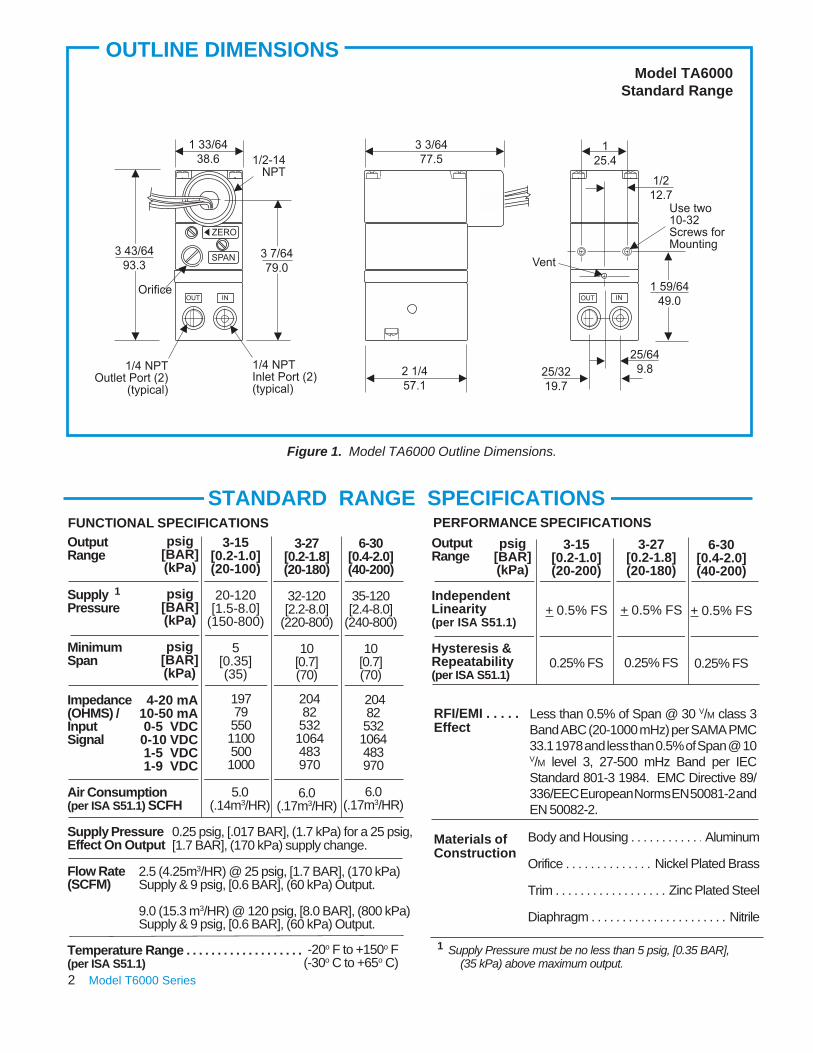
3-27[0.2-1.8](20-180)
+ 0.5% FS
0.25% FS
6-30[0.4-2.0](40-200)
+ 0.5% FS
0.25% FS
3-15[0.2-1.0](20-200)
+ 0.5% FS
0.25% FS
3-27[0.2-1.8](20-180)
32-120[2.2-8.0]
(220-800)
10[0.7](70)
6-30[0.4-2.0](40-200)
35-120[2.4-8.0]
(240-800)
10[0.7](70)
PERFORMANCE SPECIFICATIONS3-15
[0.2-1.0](20-100)
20-120[1.5-8.0]
(150-800)
5[0.35](35)
4-20 mA10-50 mA 0-5 VDC0-10 VDC 1-5 VDC 1-9 VDC
204825321064483970
204825321064483970
1977955011005001000
Less than 0.5% of Span @ 30 V/M class 3Band ABC (20-1000 mHz) per SAMA PMC33.1 1978 and less than 0.5% of Span @ 10V/M level 3, 27-500 mHz Band per IECStandard 801-3 1984. EMC Directive 89/336/EEC European Norms EN 50081-2 andEN 50082-2.
5.0(.14m3/HR)
6.0(.17m3/HR)
-20o F to +150o F(-30o C to +65o C)
psig[BAR](kPa)
psig[BAR](kPa)
psig[BAR](kPa)
STANDARD RANGE SPECIFICATIONS
Figure 1. Model TA6000 Outline Dimensions.
FUNCTIONAL SPECIFICATIONS
OUTLINE DIMENSIONS
6.0(.17m3/HR)
0.25 psig, [.017 BAR], (1.7 kPa) for a 25 psig,[1.7 BAR], (170 kPa) supply change.
2.5 (4.25m3/HR) @ 25 psig, [1.7 BAR], (170 kPa)Supply & 9 psig, [0.6 BAR], (60 kPa) Output.
9.0 (15.3 m3/HR) @ 120 psig, [8.0 BAR], (800 kPa)Supply & 9 psig, [0.6 BAR], (60 kPa) Output.
psig[BAR](kPa)
Model TA6000Standard Range
1
Aluminum
Nickel Plated Brass
Zinc Plated Steel
Nitrile
1 Supply Pressure must be no less than 5 psig, [0.35 BAR], (35 kPa) above maximum output.
2 Model T6000 Series
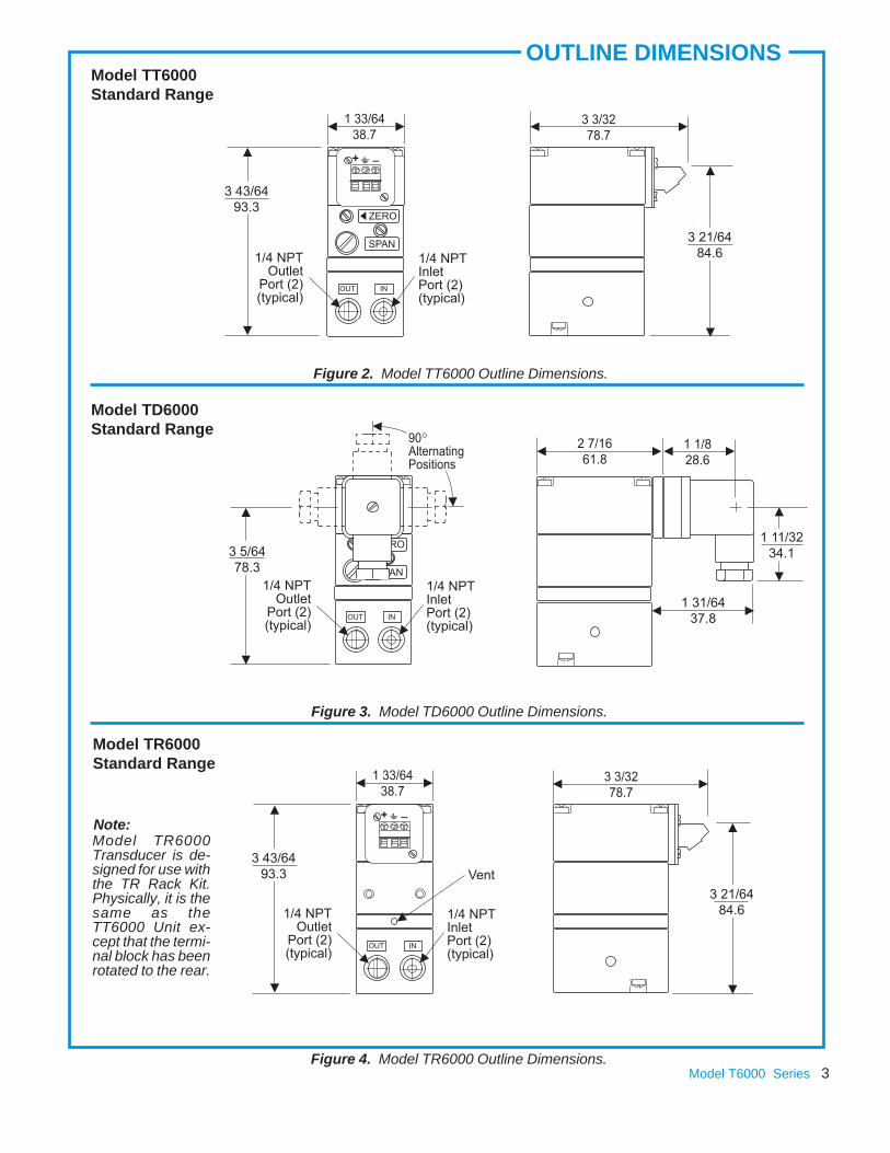
OUTLINE DIMENSIONSModel TT6000Standard Range
Model TR6000Standard Range
Model TD6000Standard Range
Figure 4. Model TR6000 Outline Dimensions.
Figure 2. Model TT6000 Outline Dimensions.
Figure 3. Model TD6000 Outline Dimensions.
Model TR6000Transducer is de-signed for use withthe TR Rack Kit.Physically, it is thesame as theTT6000 Unit ex-cept that the termi-nal block has beenrotated to the rear.
Note:
Model T6000 Series 3
Body and Housing . . . . . . . . . . . . . . . . . . . .
Orifice . . . . . . . . . . . . . . . . . . . . . . . . . . . . .
Trim . . . . . . . . . . . . . . . . . . . . . .
Diaphragm . . . . . . . . . . . . . . . . . . . . . . .
RFI/EMI . . . . .Effect
Materials ofConstruction
OutputRange
SupplyPressure
MinimumSpan
Impedance(OHMS) /InputSignal
Air Consumption(per ISA S51.1) SCFH
SupplyPressureEffect OnOutput
Flow Rate(SCFM)
Temperature Range . . . . . . . . . . . . . . . . . . .(per ISA S51.1)
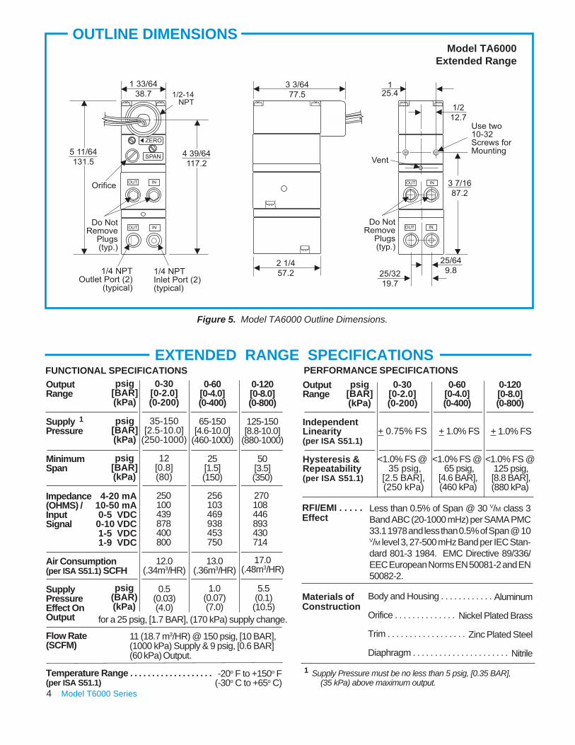
5.5(0.1)(10.5)
0.5(0.03)(4.0)
1.0(0.07)(7.0)
0-60[0-4.0](0-400)
65-150[4.6-10.0]
(460-1000)
25[1.5](150)
0-120[0-8.0](0-800)
+ 1.0% FS
<1.0% FS @ 125 psig, [8.8 BAR],(880 kPa)
OutputRange
IndependentLinearity(per ISA S51.1)
Hysteresis &Repeatability(per ISA S51.1)
PERFORMANCE SPECIFICATIONS0-30
[0-2.0](0-200)
35-150[2.5-10.0]
(250-1000)
12[0.8](80)
0-120[0-8.0](0-800)
125-150[8.8-10.0]
(880-1000)
50[3.5](350)
4-20 mA10-50 mA 0-5 VDC0-10 VDC 1-5 VDC 1-9 VDC
270108446893430714
13.0(.36m3/HR)
11 (18.7 m3/HR) @ 150 psig, [10 BAR],(1000 kPa) Supply & 9 psig, [0.6 BAR](60 kPa) Output.
psig[BAR](kPa)
psig[BAR](kPa)
psig[BAR](kPa)
psig(BAR)(kPa)
EXTENDED RANGE SPECIFICATIONS
Figure 5. Model TA6000 Outline Dimensions.
FUNCTIONAL SPECIFICATIONSpsig
[BAR](kPa)
Less than 0.5% of Span @ 30 V/M class 3Band ABC (20-1000 mHz) per SAMA PMC33.1 1978 and less than 0.5% of Span @ 10V/M level 3, 27-500 mHz Band per IEC Stan-dard 801-3 1984. EMC Directive 89/336/EEC European Norms EN 50081-2 and EN50082-2.
256103469938453750
250100439878400800
12.0(.34m3/HR)
17.0(.48m3/HR)
-20o F to +150o F(-30o C to +65o C)
Model TA6000Extended Range
1
for a 25 psig, [1.7 BAR], (170 kPa) supply change.
0-30[0-2.0](0-200)
+ 0.75% FS
<1.0% FS @ 35 psig,
[2.5 BAR], (250 kPa)
0-60[0-4.0](0-400)
+ 1.0% FS
<1.0% FS @ 65 psig,
[4.6 BAR], (460 kPa)
Aluminum
Nickel Plated Brass
Zinc Plated Steel
Nitrile
1 Supply Pressure must be no less than 5 psig, [0.35 BAR], (35 kPa) above maximum output.
OUTLINE DIMENSIONS
4 Model T6000 Series

OUTLINE DIMENSIONSModel TT6000Extended Range
Model TR6000Extended Range
Model TD6000Extended Range
Figure 8. Model TR6000 Outline Dimensions.
Figure 6. Model TT6000 Outline Dimensions.
Figure 7. Model TD6000 Outline Dimensions.
Model TR6000Transducer is de-signed for use withthe TR Rack Kit.Physically, it is thesame as theTT6000 Unit ex-cept that the termi-nal block has beenrotated to the rear.
Note:
Model T6000 Series 5
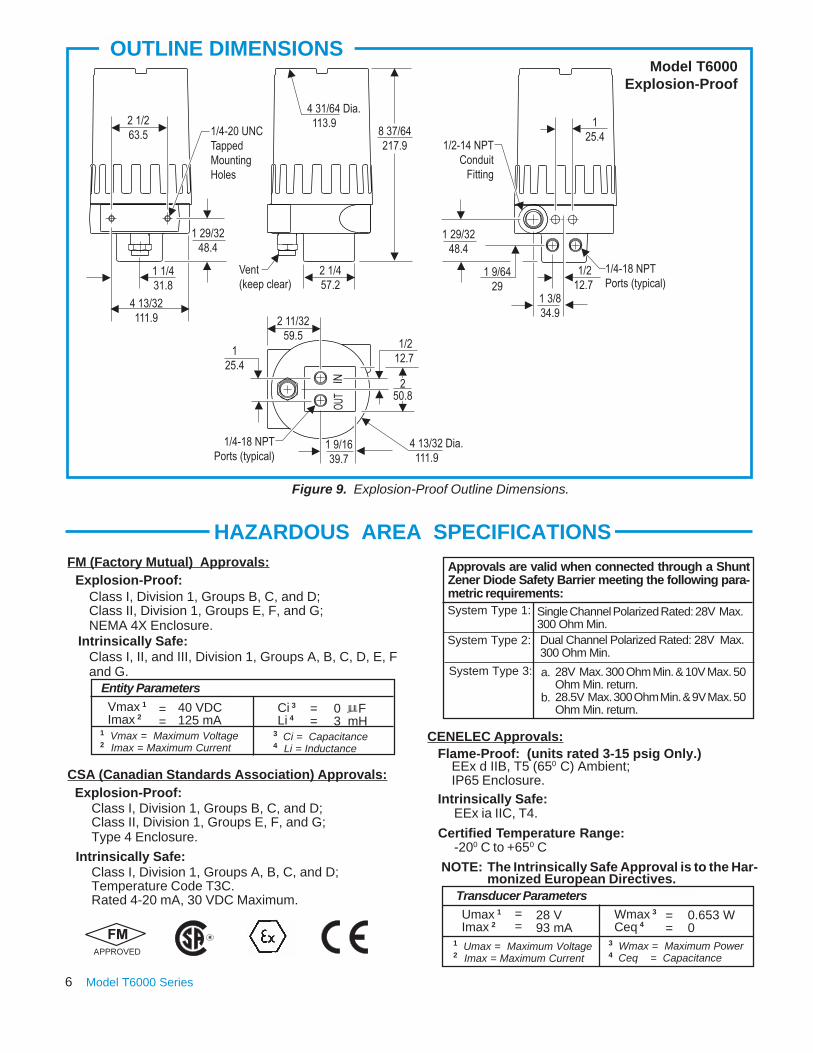
CSA (Canadian Standards Association) Approvals:
OUTLINE DIMENSIONS
Figure 9. Explosion-Proof Outline Dimensions.
Intrinsically Safe:
Class I, Division 1, Groups B, C, and D;Class II, Division 1, Groups E, F, and G;NEMA 4X Enclosure.
Class I, II, and III, Division 1, Groups A, B, C, D, E, Fand G.
Entity ParametersVmax 1
Imax 2
1 Vmax = Maximum Voltage2 Imax = Maximum Current
40 VDC125 mA
==
Ci 3Li 4
0 F3 mH
3 Ci = Capacitance4 Li = Inductance
Explosion-Proof:FM (Factory Mutual) Approvals:
Model T6000Explosion-Proof
Class I, Division 1, Groups B, C, and D;Class II, Division 1, Groups E, F, and G;Type 4 Enclosure.
Explosion-Proof:
Intrinsically Safe:Class I, Division 1, Groups A, B, C, and D;Temperature Code T3C.Rated 4-20 mA, 30 VDC Maximum.
HAZARDOUS AREA SPECIFICATIONS
==
6 Model T6000 Series
Approvals are valid when connected through a ShuntZener Diode Safety Barrier meeting the following para-metric requirements:
System Type 3:
0.653 W0
3 Wmax = Maximum Power4 Ceq = Capacitance
Transducer ParametersUmax 1
Imax 2==
28 V93 mA
Wmax 3
Ceq 4==
1 Umax = Maximum Voltage2 Imax = Maximum Current
System Type 1: Single Channel Polarized Rated: 28V Max.300 Ohm Min.Dual Channel Polarized Rated: 28V Max.300 Ohm Min.
a.
b.
28V Max. 300 Ohm Min. & 10V Max. 50Ohm Min. return.28.5V Max. 300 Ohm Min. & 9V Max. 50Ohm Min. return.
System Type 2:
Flame-Proof: (units rated 3-15 psig Only.)
Certified Temperature Range:
Intrinsically Safe:
EEx d IIB, T5 (650 C) Ambient;IP65 Enclosure.
EEx ia IIC, T4.
NOTE: The Intrinsically Safe Approval is to the Har-monized European Directives.
CENELEC Approvals:
-200 C to +650 C
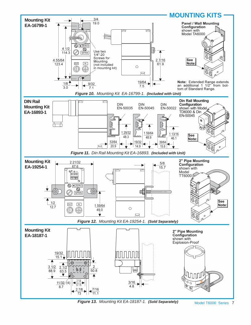
Mounting KitEA-19254-1
Figure 12. Mounting Kit EA-19254-1. (Sold Separately)
Figure 13. Mounting Kit EA-18187-1. (Sold Separately)
Mounting KitEA-18187-1
MOUNTING KITS
Figure 10. Mounting Kit EA-16799-1. (Included with Unit)
DIN RailMounting KitEA-16893-1
Mounting KitEA-16799-1
Figure 11. Din Rail Mounting Kit EA-16893. (Included with Unit)
Model T6000 Series 7

OPERATING PRINCIPLES
CROSS SECTION
Figure 15. Model T6000 Extended RangeFigure 14. Model T6000 Standard Range
Standard RangeThe T6000 Series is an electro-pneumatic device thatconverts a DC input signal to a pneumatic output. Thisdevice is made up of two sections, the Primary ConvertingSection and the Pneumatic Relay Section. The Coil andSuspension Spring, in the Primary Converting Section, isused as a Flapper. Together the Flapper and Nozzle workto control the signal pressure. The signal pressure acts onthe Upper Control Diaphragm, in the Pneumatic RelaySection, which sets the output pressure. The outputpressure is sensed by the Lower Control Diaphragm, inthe Pneumatic Relay Section, which maintains the outputpressure. For more information, see Figure 14. “ModelT6000 Standard Range” above. INSTALLATION
Extended RangeThe Extended Unit is made up of three sections, thePrimary Control Section, the Pneumatic Relay Section,and an additional Pneumatic Relay Section. The addi-tional Relay Section is used to amplify the output pressure.For more information, see Figure 15. “Model T6000 Ex-tended Range” above.
Explosion-ProofThe TX6000 Unit consists of a TT6000 Series Transducerenclosed in an Explosion-Proof/NEMA 4X (IP65) housing.For more information, see Figure 9. “Explosion-ProofOutline Dimensions” on page 6.
For Installation Instructions refer to the Fairchild T6000Standard Range/Explosion-Proof Electro-PneumaticTransducer IOM, IS-50T6000S and the Fairchild T6000Extended Range/Explosion-Proof Electro-PneumaticTransducer IOM, IS-50T6000E.
8 Model T6000 Series
TYPICAL APPLICATIONS MANIFOLD/RACK MOUNTING
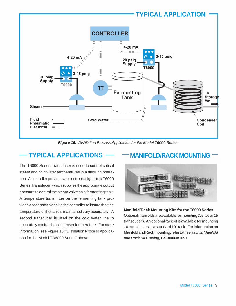
TYPICAL APPLICATION
Figure 16. Distillation Process Application for the Model T6000 Series.
Manifold/Rack Mounting Kits for the T6000 SeriesOptional manifolds are available for mounting 3, 5, 10 or 15transducers. An optional rack kit is available for mounting10 transducers in a standard 19" rack. For information onManifold and Rack mounting, refer to the Fairchild Manifoldand Rack Kit Catalog, CS-4000MRKT.
The T6000 Series Transducer is used to control critical
steam and cold water temperatures in a distilling opera-
tion. A controller provides an electronic signal to a T6000
Series Transducer, which supplies the appropriate output
pressure to control the steam valve on a fermenting tank.
A temperature transmitter on the fermenting tank pro-
vides a feedback signal to the controller to insure that the
temperature of the tank is maintained very accurately. A
second transducer is used on the cold water line to
accurately control the condenser temperature. For more
information, see Figure 16. “Distillation Process Applica-
tion for the Model TA6000 Series” above.
Model T6000 Series 9
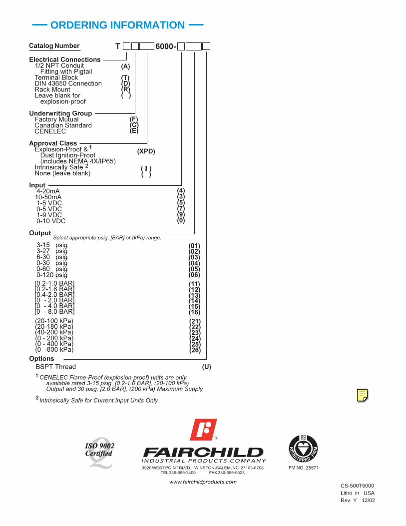
ORDERING INFORMATION
CS-500T6000Litho in USARev. Y 12/02


