Make sure to install new gaskets, O-rings,circlips, cotter pins, etc. whenreassembling.
When tightening bolts or nuts, begin withlarger-diameter to smaller ones at severaltimes, and tighten to the specified torquediagonally.
Use genuine parts and lubricants.
When servicing the motorcycle, be sure touse special tools for removal andinstallation.
After disassembly, clean removed parts.Lubricate sliding surfaces with engine oilbefore reassembly.
Apply or add designated greases andlubricants to the specified lubricationpoints.
After reassembly, check all parts for propertightening and operation.
When two persons work together, payattention to the mutual working safety.
Disconnect the battery negative (-) terminalbefore operation.
When using a spanner or other tools, makesure not to damage the motorcycle surface.
After operation, check all connectingpoints, fasteners, and lines for properconnection and installation.
When connecting the battery, the positive(+) terminal must be connected first.
After connection, apply grease to thebattery terminals.
Terminal caps shall be installed securely.
If the fuse is burned out, find the cause andrepair it. Replace it with a new oneaccording to the specified capacity.
After operation, terminal caps shall beinstalled securely.
When taking out the connector, the lock onthe connector shall be released beforeoperation.
Hold the connector body when connectingor disconnecting it.
Do not pull the connector wire.
Check if any connector terminal is bending,protruding or loose.
The connector shall be insertedcompletely.
If the double connector has a lock, lockit at the correct position.
Check if there is any loose wire.
Before connecting a terminal, check fordamaged terminal cover or loosenegative terminal.
Check the double connector cover forproper coverage and installation.
Insert the terminal completely.
Check the terminal cover for propercoverage.
Do not make the terminal cover openingface up.
Secure wire harnesses to the frame withtheir respective wire bands at thedesignated locations.Tighten the bands so that only the insulatedsurfaces contact the wire harnesses.
After clamping, check each wire to makesure it is secure.
Do not squeeze wires against the weld orits clamp.
After clamping, check each harness tomake sure that it is not interfering with anymoving or sliding parts.
When fixing the wire harnesses, do notmake it contact the parts which willgenerate high heat.
Route wire harnesses to avoid sharp edgesor corners. Avoid the projected ends ofbolts and screws.
Route wire harnesses passing through theside of bolts and screws. Avoid theprojected ends of bolts and screws.
1. GENERAL INFORMATION
1-6
PEOPLE 125/150
Route harnesses so they are neitherpulled tight nor have excessive slack.
Protect wires and harnesses with electricaltape or tube if they contact a sharp edge orcorner.
When rubber protecting cover is used toprotect the wire harnesses, it shall beinstalled securely.
Do not break the sheath of wire.
If a wire or harness is with a broken sheath,repair by wrapping it with protective tapeor replace it.
When installing other parts, do not press orsqueeze the wires.
After routing, check that the wire harnessesare not twisted or kinked.
Wire harnesses routed along withhandlebar should not be pulled tight, haveexcessive slack or interfere with adjacentor surrounding parts in all steeringpositions.
When a testing device is used, make sure tounderstand the operating methodsthoroughly and operate according to theoperating instructions.
Be careful not to drop any parts.
When rust is found on a terminal, removethe rust with sand paper or equivalentbefore connecting.
Do not bend or twist control cables.Damaged control cables will not operatesmoothly and may stick or bind.
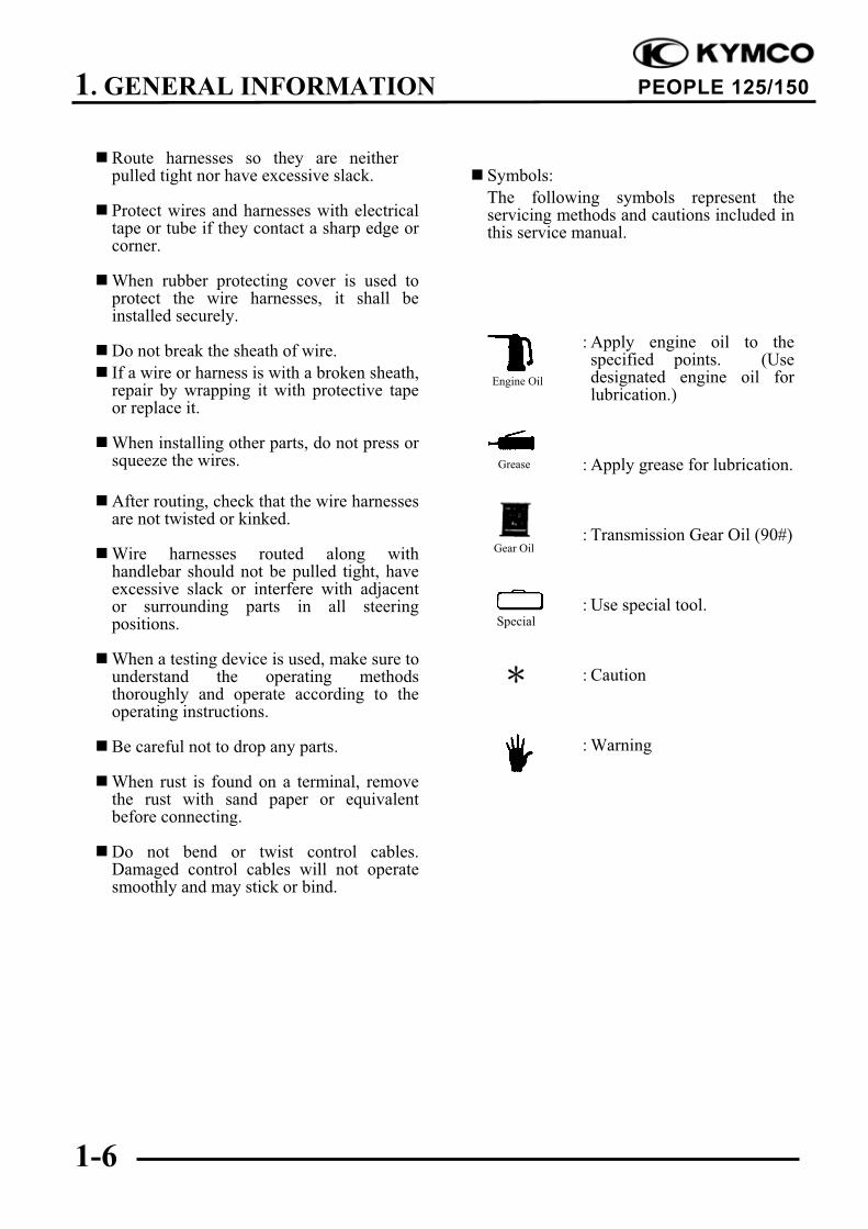
Symbols:
The following symbols represent theservicing methods and cautions included inthis service manual.
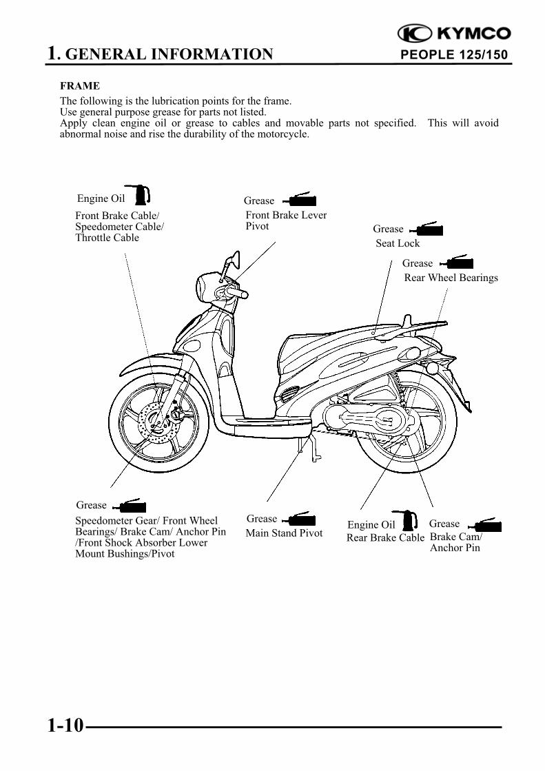
The following is the lubrication points for the frame.Use general purpose grease for parts not listed.Apply clean engine oil or grease to cables and movable parts not specified. This will avoidabnormal noise and rise the durability of the motorcycle.
Seat Lock
Rear Wheel Bearings
Grease
Front Brake Cable/Speedometer Cable/Throttle Cable
Main Stand PivotSpeedometer Gear/ Front WheelBearings/ Brake Cam/ Anchor Pin/Front Shock Absorber LowerMount Bushings/Pivot
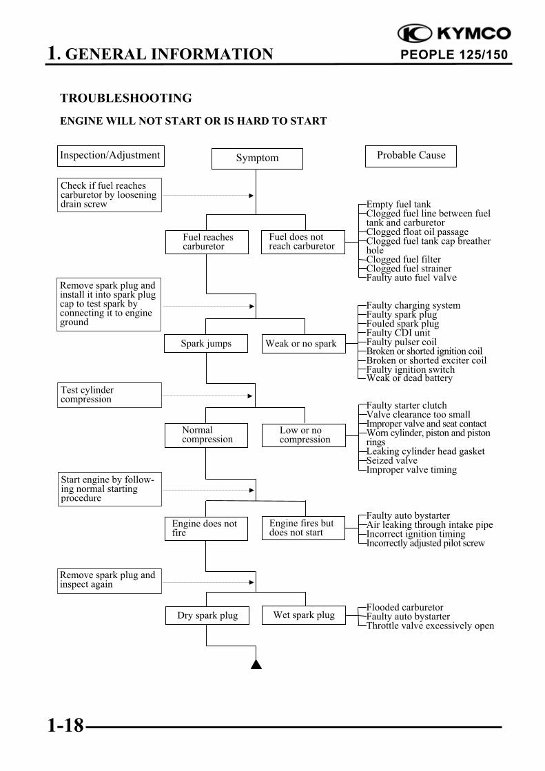
Empty fuel tankClogged fuel line between fueltank and carburetorClogged float oil passageClogged fuel tank cap breatherholeClogged fuel filterClogged fuel strainerFaulty auto fuel valve
Faulty charging systemFaulty spark plugFouled spark plugFaulty CDI unitFaulty pulser coilBroken or shorted ignition coilBroken or shorted exciter coilFaulty ignition switchWeak or dead battery
Faulty starter clutchValve clearance too smallImproper valve and seat contactWorn cylinder, piston and pistonringsLeaking cylinder head gasketSeized valveImproper valve timing
Faulty auto bystarterAir leaking through intake pipeIncorrect ignition timingIncorrectly adjusted pilot screw
Flooded carburetorFaulty auto bystarterThrottle valve excessively open
Check if fuel reachescarburetor by looseningdrain screw
Remove spark plug andinstall it into spark plugcap to test spark byconnecting it to engineground
Inspection/Adjustment Probable Cause
Spark jumps
Normal compression
Engine does not fire
Weak or no spark
Low or no compression
Engine fires but does not start
Test cylindercompression
Start engine by follow-ing normal startingprocedure
Remove spark plug andinspect again
Symptom
Fuel reaches carburetor
Fuel does not reach carburetor
Wet spark plugDry spark plug
1. GENERAL INFORMATION
1-19
PEOPLE 125/150
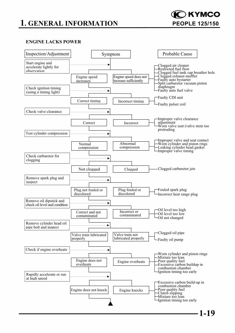
ENGINE LACKS POWER
Clogged air cleanerRestricted fuel flowClogged fuel tank cap breather holeClogged exhaust mufflerFaulty auto bystarterSplit carburetor vacuum pistondiaphragmFaulty auto fuel valve
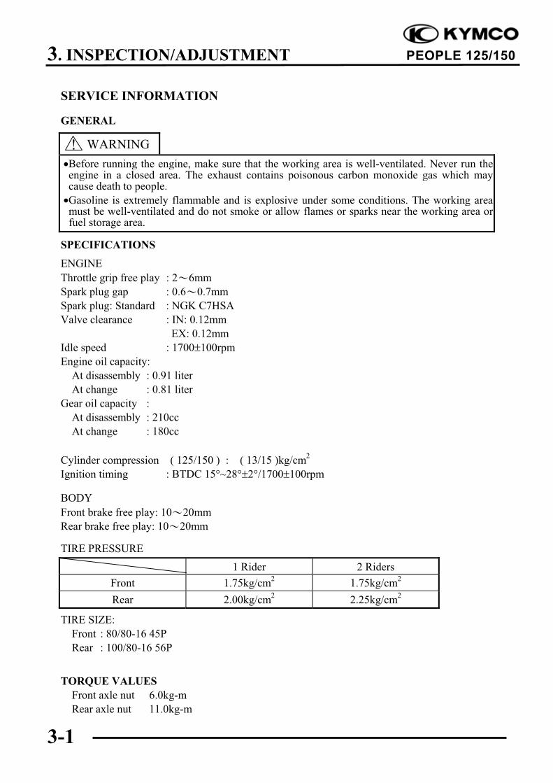
Before running the engine, make sure that the working area is well-ventilated. Never run theengine in a closed area. The exhaust contains poisonous carbon monoxide gas which maycause death to people.
Gasoline is extremely flammable and is explosive under some conditions. The working areamust be well-ventilated and do not smoke or allow flames or sparks near the working area orfuel storage area.
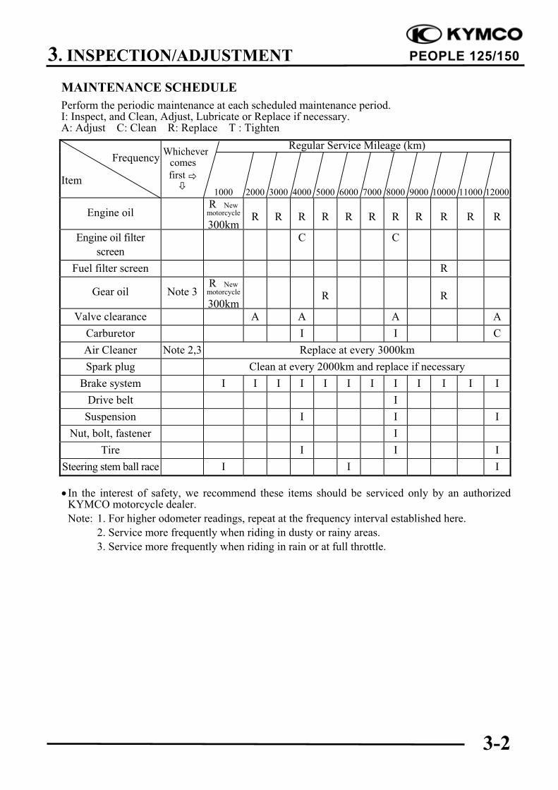
Perform the periodic maintenance at each scheduled maintenance period.I: Inspect, and Clean, Adjust, Lubricate or Replace if necessary.A: Adjust C: Clean R: Replace T : Tighten
Spark plug Clean at every 2000km and replace if necessary
Brake system I I I I I I I I I I I I
Drive belt I
Suspension I I I
Nut, bolt, fastener I
Tire I I I
Steering stem ball race I I I
In the interest of safety, we recommend these items should be serviced only by an authorizedKYMCO motorcycle dealer.
Note: 1. For higher odometer readings, repeat at the frequency interval established here.
2. Service more frequently when riding in dusty or rainy areas.
3. Service more frequently when riding in rain or at full throttle.
Whichever
3. INSPECTION/ADJUSTMENT
3-3
PEOPLE 125/150
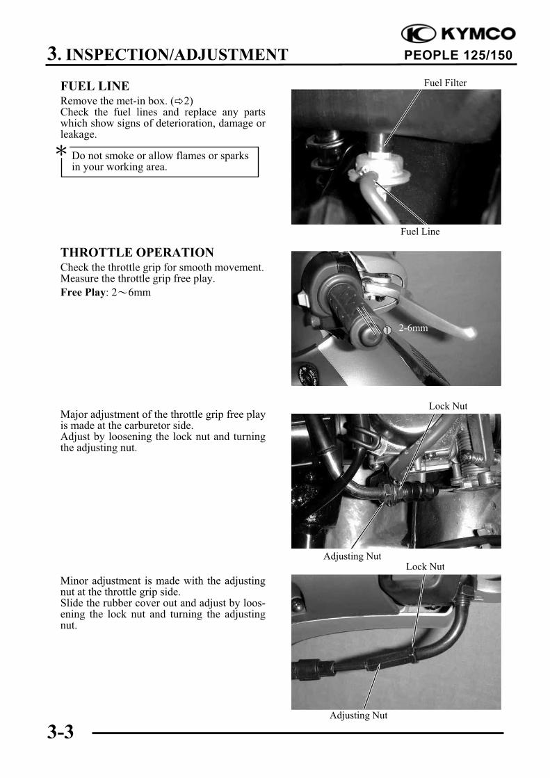
FUEL LINERemove the met-in box. ( 2)Check the fuel lines and replace any partswhich show signs of deterioration, damage orleakage.
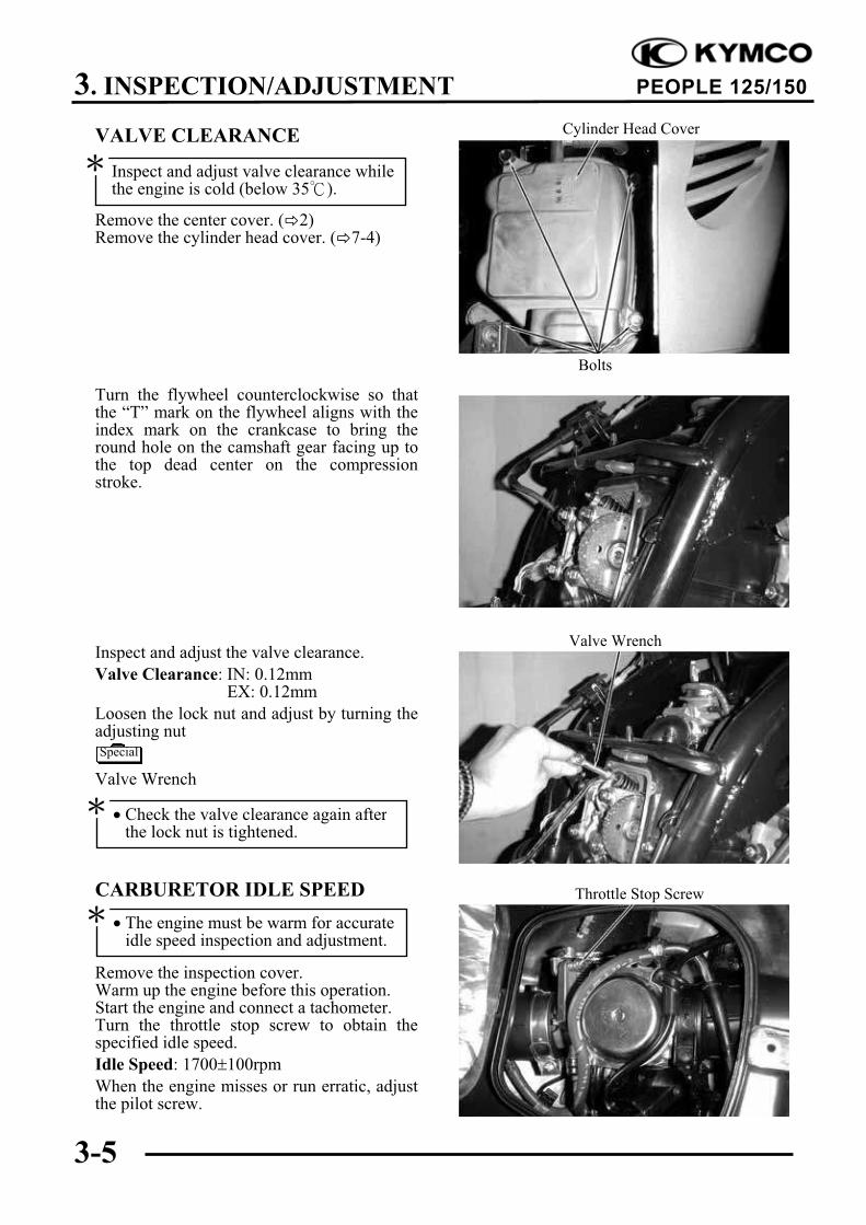
THROTTLE OPERATIONCheck the throttle grip for smooth movement.Measure the throttle grip free play.
Free Play: 2 6mm
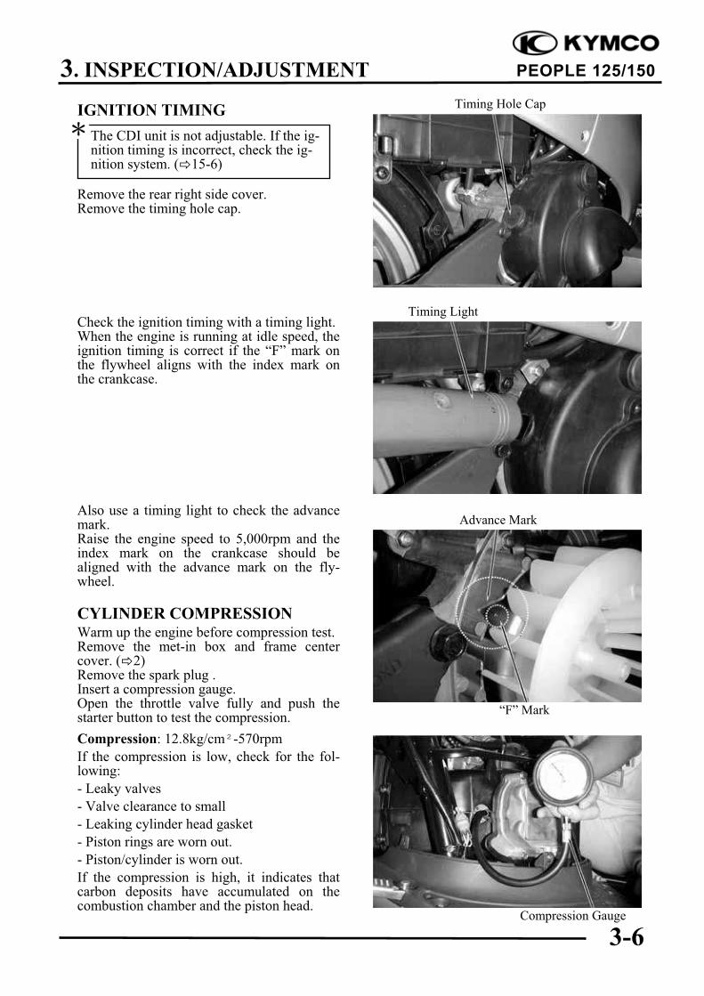
Major adjustment of the throttle grip free playis made at the carburetor side.Adjust by loosening the lock nut and turningthe adjusting nut.
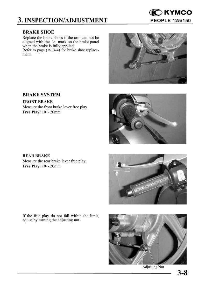
Minor adjustment is made with the adjustingnut at the throttle grip side.Slide the rubber cover out and adjust by loos-ening the lock nut and turning the adjustingnut.
Lock Nut
Adjusting Nut
Fuel Filter
Do not smoke or allow flames or sparksin your working area.
Fuel Line
Lock NutAdjusting Nut
2-6mm
3. INSPECTION/ADJUSTMENT
3-4
PEOPLE 125/150
AIR CLEANERAIR CLEANER REPLACEMENT
Remove the rear side covers. ( 2)Remove the six air cleaner case cover screwsand the cover.
Remove the air cleaner element by removingthe three screws.Check the element and replace it if it is ex-cessively dirty or damaged.
CHANGE INTERVAL
More frequent replacement is required whenriding in unusually dusty or rainy areas.
SPARK PLUGRemove the spark plug.Check the spark plug for wear and foulingdeposits.Clean any fouling deposits with a spark plugcleaner or a wire brush.
Specified Spark Plug: NGK C7HSA
Measure the spark plug gap.
Spark Plug Gap: 0.6 0.7mm
CracksDamage
The air cleaner element has a viscoustype paper element. Do not clean itwith compressed air.
Be sure to install the air cleaner ele-ment and cover securely.
When installing, first screw in the sparkplug by hand and then tighten it with aspark plug wrench.
Screws
Air Cleaner Case Cover
Air Cleaner Element
Washer De-formation
Screws
Gap, Wear, andFouling Deposits
3. INSPECTION/ADJUSTMENT
3-5
PEOPLE 125/150
VALVE CLEARANCE
Remove the center cover. ( 2)Remove the cylinder head cover. ( 7-4)
Turn the flywheel counterclockwise so thatthe “T” mark on the flywheel aligns with theindex mark on the crankcase to bring theround hole on the camshaft gear facing up tothe top dead center on the compressionstroke.
Inspect and adjust the valve clearance.
Valve Clearance: IN: 0.12mmEX: 0.12mm
Loosen the lock nut and adjust by turning theadjusting nut
Valve Wrench
CARBURETOR IDLE SPEED
Remove the inspection cover.Warm up the engine before this operation.Start the engine and connect a tachometer.Turn the throttle stop screw to obtain thespecified idle speed.
Idle Speed: 1700!100rpm
When the engine misses or run erratic, adjustthe pilot screw.
Throttle Stop Screw
Inspect and adjust valve clearance whilethe engine is cold (below 35 ).
Special
Check the valve clearance again afterthe lock nut is tightened.
The engine must be warm for accurateidle speed inspection and adjustment.
Cylinder Head Cover
Bolts
Valve Wrench
3. INSPECTION/ADJUSTMENT
3-6
PEOPLE 125/150
IGNITION TIMING
Remove the rear right side cover.Remove the timing hole cap.
Check the ignition timing with a timing light.When the engine is running at idle speed, theignition timing is correct if the “F” mark onthe flywheel aligns with the index mark onthe crankcase.
Also use a timing light to check the advancemark.Raise the engine speed to 5,000rpm and theindex mark on the crankcase should bealigned with the advance mark on the fly-wheel.
CYLINDER COMPRESSIONWarm up the engine before compression test.Remove the met-in box and frame centercover. ( 2)Remove the spark plug .Insert a compression gauge.Open the throttle valve fully and push thestarter button to test the compression.
Compression: 12.8kg/cm²-570rpm
If the compression is low, check for the fol-lowing:
- Leaky valves
- Valve clearance to small
- Leaking cylinder head gasket
- Piston rings are worn out.
- Piston/cylinder is worn out.
If the compression is high, it indicates thatcarbon deposits have accumulated on thecombustion chamber and the piston head.
Compression Gauge
Timing Light
The CDI unit is not adjustable. If the ig-nition timing is incorrect, check the ig-nition system. ( 15-6)
Timing Hole Cap
Advance Mark
“F” Mark
3. INSPECTION/ADJUSTMENT
3-7
PEOPLE 125/150
FINAL REDUCTION GEAR OILOIL LEVEL CHECK
Stop the engine and remove the oil check bolt.The oil level shall be at the oil check bolthole.If the oil level is low, add the recommendedoil to the proper level.
Recommended Oil:
GEAR OIL VISCOSITY SAE90#
Install the oil check bolt.
OIL CHANGE
Remove the oil check bolt.Remove the oil drain bolt and drain the oilthoroughly.Install the oil drain bolt.Torque: 1.0kg-m
Fill with the recommended oil.
Oil Capacity: At disassembly : 210ccAt change : 180cc
Reinstall the oil check bolt and check for oilleaks.Torque: 1.2kg-m
DRIVE BELTRemove the left crankcase cover. ( 9-3)Inspect the drive belt for cracks or excessivewear.Replace the drive belt with a new one if ne-cessary and in accordance with the Mainte-nance Schedule. Drive Belt
Oil Check Bolt
Place the motorcycle on its main standon level ground for oil level check.
Sealing Washer
Make sure that the sealing washer is ingood condition.
Make sure that the sealing washer is ingood condition.
Oil Check Bolt Hole
Oil Drain Bolt
3. INSPECTION/ADJUSTMENT
3-8
PEOPLE 125/150
BRAKE SHOEReplace the brake shoes if the arm can not bealigned with the mark on the brake panelwhen the brake is fully applied.Refer to page ( 13-4) for brake shoe replace-ment.
BRAKE SYSTEM
FRONT BRAKE
Measure the front brake lever free play.
Free Play: 10 20mm
REAR BRAKE
Measure the rear brake lever free play.
Free Play: 10 20mm
If the free play do not fall within the limit,adjust by turning the adjusting nut.
Adjusting Nut
3. INSPECTION/ADJUSTMENT
3-9
PEOPLE 125/150
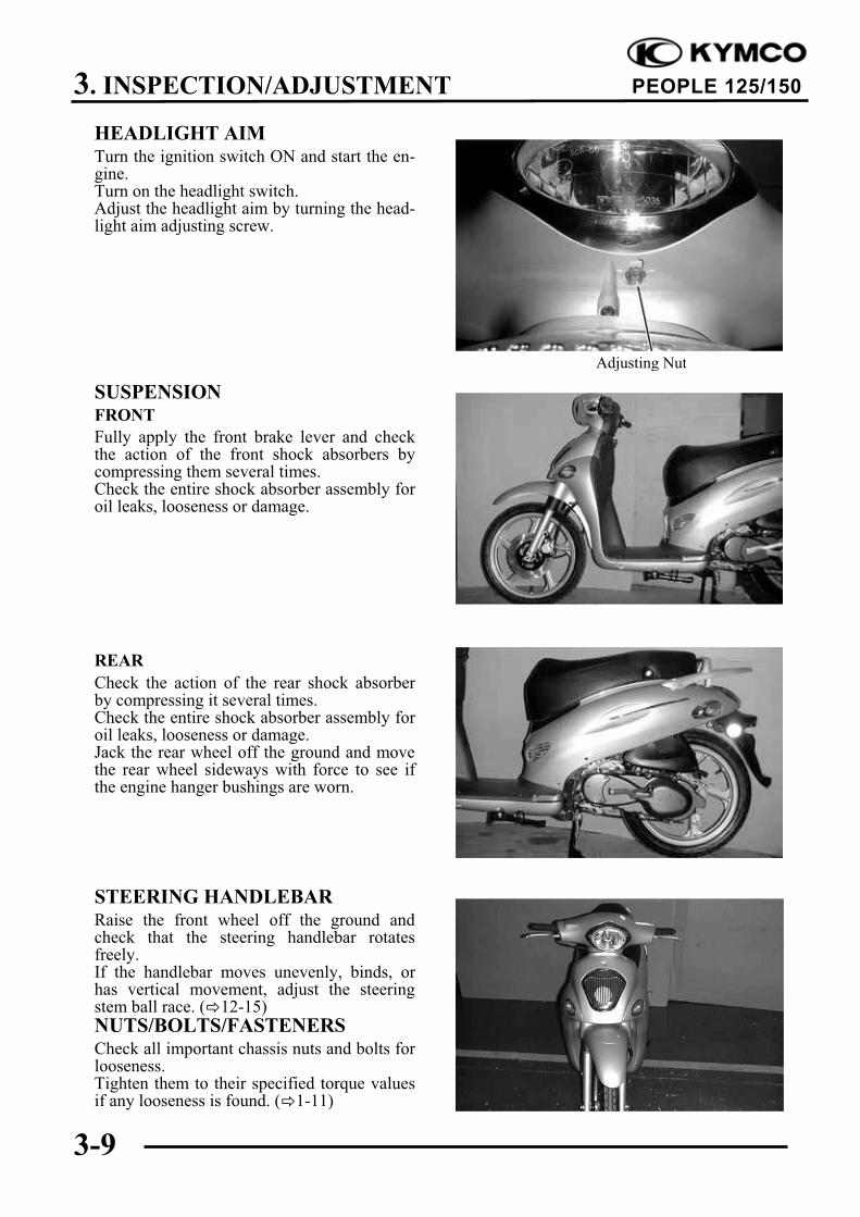
HEADLIGHT AIMTurn the ignition switch ON and start the en-gine.Turn on the headlight switch.Adjust the headlight aim by turning the head-light aim adjusting screw.
SUSPENSIONFRONT
Fully apply the front brake lever and checkthe action of the front shock absorbers bycompressing them several times.Check the entire shock absorber assembly foroil leaks, looseness or damage.
REAR
Check the action of the rear shock absorberby compressing it several times.Check the entire shock absorber assembly foroil leaks, looseness or damage.Jack the rear wheel off the ground and movethe rear wheel sideways with force to see ifthe engine hanger bushings are worn.
STEERING HANDLEBARRaise the front wheel off the ground andcheck that the steering handlebar rotatesfreely.If the handlebar moves unevenly, binds, orhas vertical movement, adjust the steeringstem ball race. ( 12-15)NUTS/BOLTS/FASTENERSCheck all important chassis nuts and bolts forlooseness.Tighten them to their specified torque valuesif any looseness is found. ( 1-11)
Adjusting Nut
3. INSPECTION/ADJUSTMENT
3-10
PEOPLE 125/150
WHEELS/TIRESCheck the tires for cuts, imbedded nails orother damages.
Check the tire pressure.
TIRE PRESSURE
1 Rider 2 Riders
Front 1.75kg/cm2
1.75kg/cm2
Rear 2.00kg/cm2
2.25kg/cm2
TIRE SIZE
Front : 80/80-16 45PRear : 100/80-16 56P
Check the front axle nut for looseness.Check the rear axle nut for looseness.If the axle nuts are loose, tighten them to thespecified torques.
Torques: Front : 6.0kg-m
Rear : 11.0kg-m
Tire pressure should be checked whentires are cold.
Front Axle Nut
4. LUBRICATION SYSTEM
4-0
PEOPLE 125/150
4
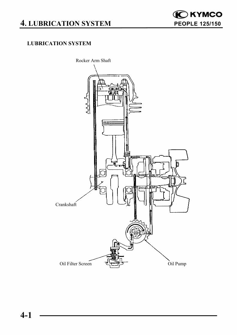
LUBRICATION SYSTEM
SERVICE INFORMATION ................................................................. 4-2
The maintenance of lubrication system can be performed with the engine installed in the frame. Use care when removing and installing the oil pump not to allow dust and foreign matters to
enter the engine and oil line. Do not attempt to disassemble the oil pump. The oil pump must be replaced as a set when it
reaches its service limit. After the oil pump is installed, check each part for oil leaks.
SPECIFICATIONS
Item Standard (mm) Service Limit (mm)
Inner rotor-to-outer rotor clearance ! 0.12
Oil pump Outer rotor-to-pump body clearance ! 0.12
Rotor end-to-pump body clearance 0.05 0.10 0.2
TROUBLESHOOTING
Oil level too low Poor lubrication pressure
Natural oil consumption Oil level too low
Oil leaks Clogged oil filter or oil passages
Worn or poorly installed piston rings Not use the specified oil
Worn valve guide or seal
4. LUBRICATION SYSTEM
4-3
PEOPLE 125/150
Bolts Pulser Coil
Right Crankcase CoverStator
ENGINE OIL/OIL FILTER
OIL LEVEL
Remove the oil dipstick and check the oillevel with the oil dipstick.If the level is near the lower level, fill to theupper level with the specified engine oil.
OIL CHANGE
Remove the oil filter screen cap located onthe bottom of the engine to drain the engineoil thoroughly.
After the oil has been completely drained,check the filter screen O-ring for damage andreplace if necessary.Install the oil filter screen, spring and filterscreen cap.Torque: 1.5kg-mFill with the specified SAE15W40#, API:SG/CD engine oil to the proper level.
Oil Capacity: At disassembly : 0.90 liter
At change : 0.75 liter
Check for oil leaks and then start the engineand let it idle for few minutes.Recheck the oil level.
OIL PUMP
REMOVAL
Remove the A.C. generator flywheel. ( 14-7)Remove the nine right crankcase cover boltsand the right crankcase cover.
Oil Dipstick
Oil Filter Screen Cap
Place the motorcycle upright on levelground for engine oil level check.
Run the engine for 2 3 minutes andcheck the oil level after the engine isstopped for 2 3 minutes.
The engine oil will drain more easilywhile the engine is warm.
Lower LevelUpper Level
4. LUBRICATION SYSTEM
4-4
PEOPLE 125/150
Oil Pump Driven Gear
Bolts
Bolts
Nut
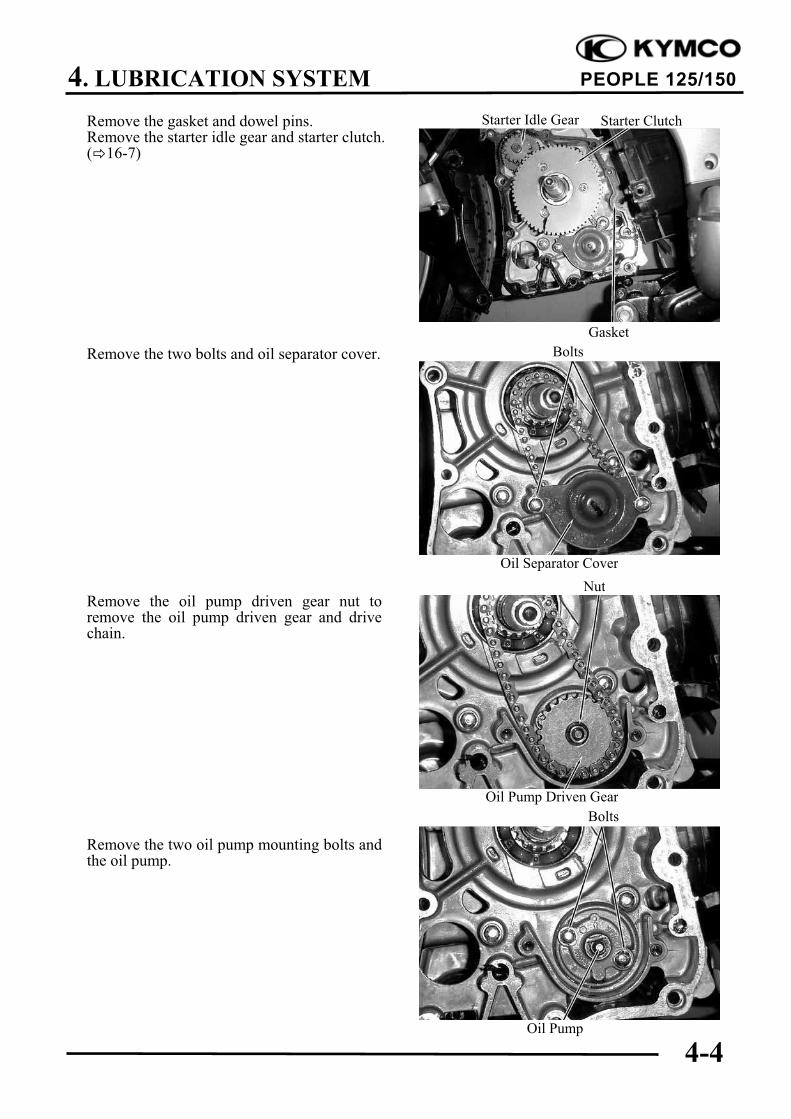
Starter Idle Gear Starter ClutchRemove the gasket and dowel pins.Remove the starter idle gear and starter clutch.( 16-7)
Remove the two bolts and oil separator cover.
Remove the oil pump driven gear nut toremove the oil pump driven gear and drivechain.
Remove the two oil pump mounting bolts andthe oil pump.
Oil Separator Cover
Gasket
Oil Pump
4. LUBRICATION SYSTEM
4-5
PEOPLE 125/150
Outer Rotor
Outer Rotor
Inner Rotor
Pump Body
Screw
DISASSEMBLY
Remove the screw and disassemble the oil
pump.
INSPECTION
Measure the pump body-to-outer rotorclearance.Service Limit: 0.12mm
Measure the inner rotor-to-outer rotorclearance.Service Limit: 0.12mm
Measure the rotor end-to-pump bodyclearance.Service Limit: 0.2mm
Pump Body
4. LUBRICATION SYSTEM
4-6
PEOPLE 125/150
Screw
Inner Rotor
Bolts
Pump CoverOuter Rotor Dowel Pin
Oil Pump Arrow
ScrewASSEMBLY
Install the outer rotor, inner rotor and pumpshaft into the pump body.
Install the dowel pin.
Install the pump cover by aligning the hole inthe cover with the dowel pin.
Tighten the screw to secure the pump cover.Make sure that the pump shaft rotates freelywithout binding.
INSTALLATION
Install the oil pump into the crankcase.
After the oil pump is installed, tighten thetwo mounting bolts.
Insert the pump shaft by aligning the flaton the shaft with the flat in the innerrotor.
Install the oil pump with the arrow onthe pump body facing up and fill the oilpump with engine oil before installation.
4. LUBRICATION SYSTEM
4-7
PEOPLE 125/150
Starter Idle Gear
Bolts
Nut
Pump Driven Gear
Starter Clutch
Bolts Pulser Coil
Right Crankcase CoverStator
Install the pump driven gear and drive chainby aligning the pump driven gear with thecutout in the pump shaft.Install and tighten the pump driven gear nut.
Torque: 1.0kg-m
Install the oil separator cover and tighten thebolts.
Install the starter idle gear and starter clutch.( 16-9)Install the gasket and dowel pins.
Install the right crankcase cover and tightenthe nine bolts.
Torque: 0.9kg-m
Oil Separator Cover
Gasket Dowel Pin
Diagonally tighten the bolts in 2 3times.
5. FUEL SYSTEM
5-0
PEOPLE 125/150
5
FUEL SYSTEM
SERVICE INFORMATION ................................................................. 5-2
FUEL UNIT .......................................................................................... 5-11
AUTO FUEL VALVE.......................................................................... 5-12
AIR CLEANER .................................................................................... 5-13
5
5. FUEL SYSTEM
5-1
PEOPLE 125/150
FUEL SYSTEM
5. FUEL SYSTEM
5-2
PEOPLE 125/150
SERVICE INFORMATION
GENERAL INSTRUCTIONS
Do not bend or twist control cables. Damaged control cables will not operate smoothly.
When disassembling fuel system parts, note the locations of O-rings. Replace them with new
ones during assembly.
Before float chamber disassembly, loosen the drain screw to drain the residual gasoline into a
clean container.
After the carburetor is removed, plug the intake manifold side with a clean towel to prevent
foreign matters from entering.
Remove the vacuum diaphragm before cleaning the carburetor air and fuel passages with
compressed air to avoid damaging the vacuum diaphragm.
When the motorcycle is not used for over one month, drain the residual gasoline from the float
chamber to avoid erratic idling and clogged slow jet due to deteriorated fuel.
The pilot screw is factory pre-set and no adjustment is necessary. During carburetor
disassembly, note the number of turns of the pilot screw and use as a reference when reinstalling
it.
A tachometer must be used when adjusting the engine speed.
Turn the pilot screw in or out slowly to obtain the highest engine speed.
SPECIFICATIONS
125 cc 150 ccItem
Standard Standard
Venturi dia. (mm) 22.1 22.1
Identification number VE052A VE054A
Float level (mm) 17.5 17.5
Main jet #108 #110
Slow jet #35 #35
Idle speed 1700!100rpm 1700!100rpm
Throttle grip free play 2 6mm 2 6mm
Pilot screw opening 3 3/8 2 1/2
SPECIAL TOOL
Float level gauge
Gasoline is very dangerous. When working with gasoline, keep sparks and flames awayfrom the working area.Gasoline is extremely flammable and is explosive under certain conditions. Be sure towork in a well-ventilated area.
5. FUEL SYSTEM
5-3
PEOPLE 125/150
TROUBLESHOOTING
Engine is hard to start Misfiring during acceleration
No spark at plug Faulty ignition system
Compression too low Lean mixture
No fuel to carburetor
"Clogged fuel filter Engine idles roughly, stalls or runs poorly
"Restricted fuel line Clogged fuel system
"Faulty float valve Ignition malfunction
"Incorrectly adjusted float level Rich or lean mixture
Engine flooded with fuel Contaminated fuel
"Clogged air cleaner Intake air leak
"Fuel overflowing Incorrect idle speed
Intake air leak Incorrectly adjusted pilot screw
Contaminated fuel Clogged idle system or auto bystarter passages
Faulty auto bystarter Incorrectly adjusted float level
Clogged idle system or auto bystarter passages
Lean mixture
Rich mixture Clogged fuel jets
Faulty auto bystarter Faulty float valve
Faulty float valve Float level too low
Float level too high Clogged fuel system
Clogged air jets Intake air leak
Dirty air cleaner Faulty vacuum piston
Flooded carburetor Faulty throttle
Backfiring at deceleration
Faulty air cut-off valve
Lean mixture in idle system
5. FUEL SYSTEM
5-4
PEOPLE 125/150
CARBURETOR REMOVAL
Remove the frame body cover. ( 2)Disconnect the auto bystarter wire connector.
Loosen the drain screw and drain the fuelfrom the float chamber.Disconnect the fuel tube and vacuum tube atthe carburetor.
Loosen the throttle cable adjusting nut andlock nut, and disconnect the throttle cablefrom the carburetor.Loosen the carburetor intake manifold bandand air cleaner connecting tube band screwsand then remove the carburetor.
AUTO BYSTARTER
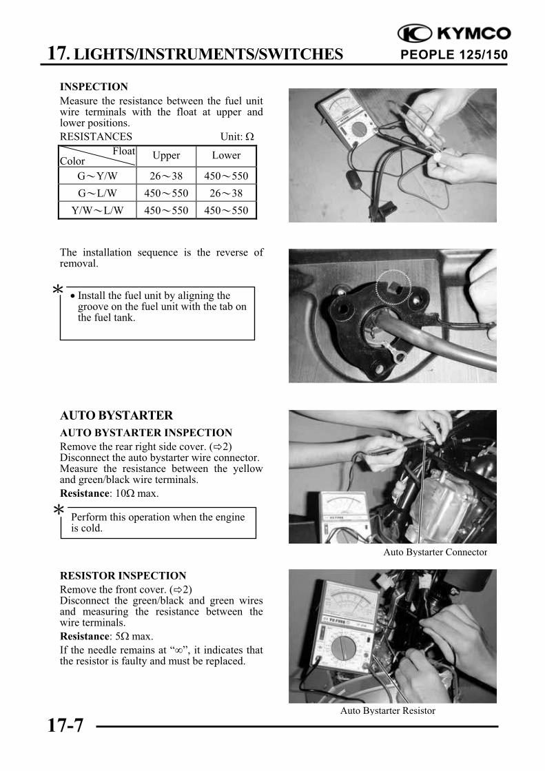
OPERATION INSPECTION
Measure the resistance between the autobystarter wire terminals.
Resistance: 5# max. (10 minutes minimum after stopping the engine)
If the reading is not within the limit, replacethe auto bystarter with a new one.
Auto Bystarter Wire
Adjusting Nut
Fuel Tube
Intake ManifoldBand
Air Cleaner ConnectingTube Band Throttle Cable
Vacuum Tube
Lock Nut
5. FUEL SYSTEM
5-5
PEOPLE 125/150
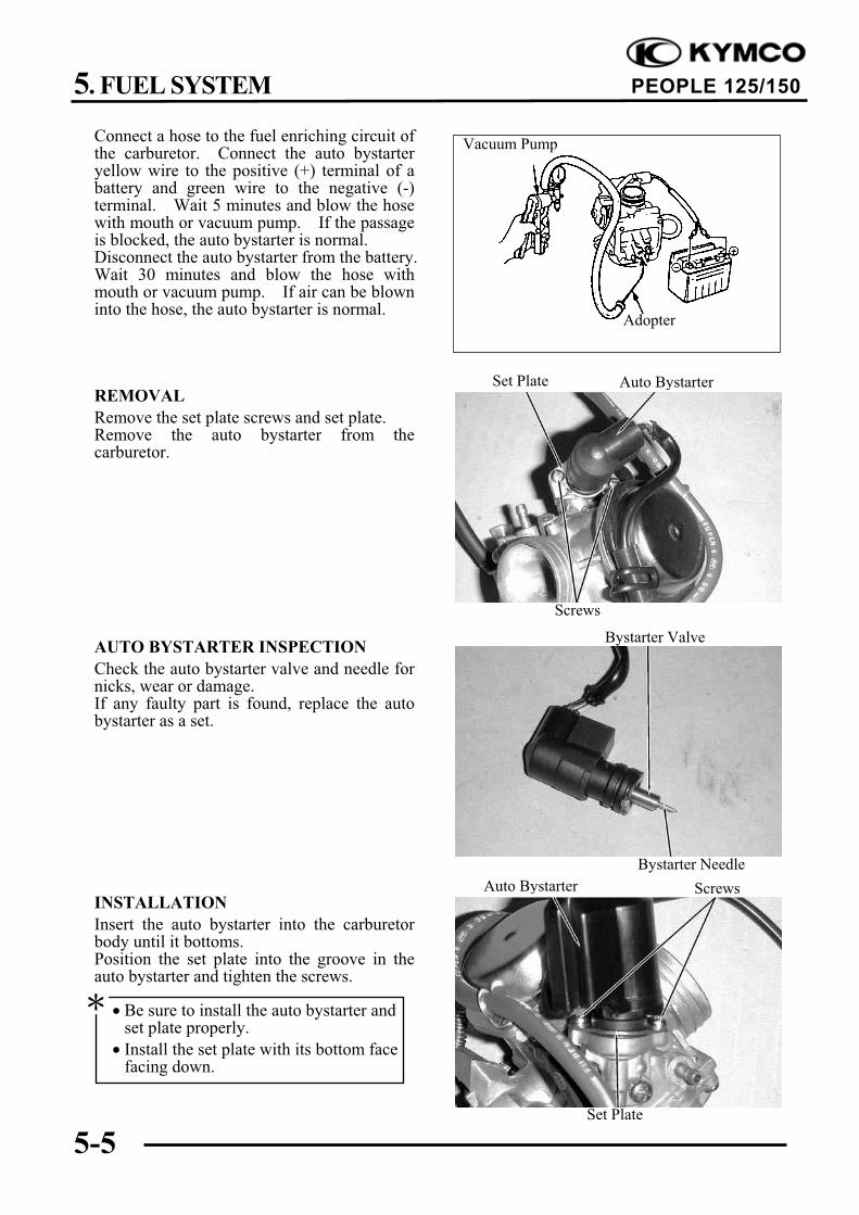
Connect a hose to the fuel enriching circuit ofthe carburetor. Connect the auto bystarteryellow wire to the positive (+) terminal of abattery and green wire to the negative (-)terminal. Wait 5 minutes and blow the hosewith mouth or vacuum pump. If the passageis blocked, the auto bystarter is normal.Disconnect the auto bystarter from the battery.Wait 30 minutes and blow the hose withmouth or vacuum pump. If air can be blowninto the hose, the auto bystarter is normal.
REMOVAL
Remove the set plate screws and set plate.Remove the auto bystarter from thecarburetor.
AUTO BYSTARTER INSPECTION
Check the auto bystarter valve and needle fornicks, wear or damage.If any faulty part is found, replace the autobystarter as a set.
INSTALLATION
Insert the auto bystarter into the carburetorbody until it bottoms.Position the set plate into the groove in theauto bystarter and tighten the screws.
Be sure to install the auto bystarter andset plate properly.
Install the set plate with its bottom facefacing down.
Auto Bystarter
Screws
Bystarter Needle
Bystarter Valve
Auto Bystarter Screws
Set Plate
Vacuum Pump
Adopter
Set Plate
5. FUEL SYSTEM
5-6
PEOPLE 125/150
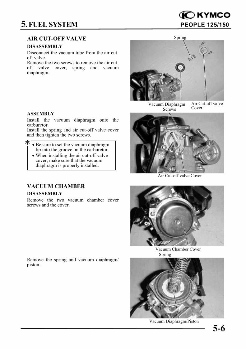
AIR CUT-OFF VALVE
DISASSEMBLY
Disconnect the vacuum tube from the air cut-off valve.Remove the two screws to remove the air cut-off valve cover, spring and vacuumdiaphragm.
ASSEMBLY
Install the vacuum diaphragm onto thecarburetor.Install the spring and air cut-off valve coverand then tighten the two screws.
VACUUM CHAMBER
DISASSEMBLY
Remove the two vacuum chamber coverscrews and the cover.
Remove the spring and vacuum diaphragm/piston.
Spring
ScrewsVacuum Diaphragm
Be sure to set the vacuum diaphragmlip into the groove on the carburetor.
When installing the air cut-off valvecover, make sure that the vacuumdiaphragm is properly installed.
Vacuum Diaphragm/Piston
Air Cut-off valveCover
Spring
Vacuum Chamber Cover
Air Cut-off valve Cover
5. FUEL SYSTEM
5-7
PEOPLE 125/150
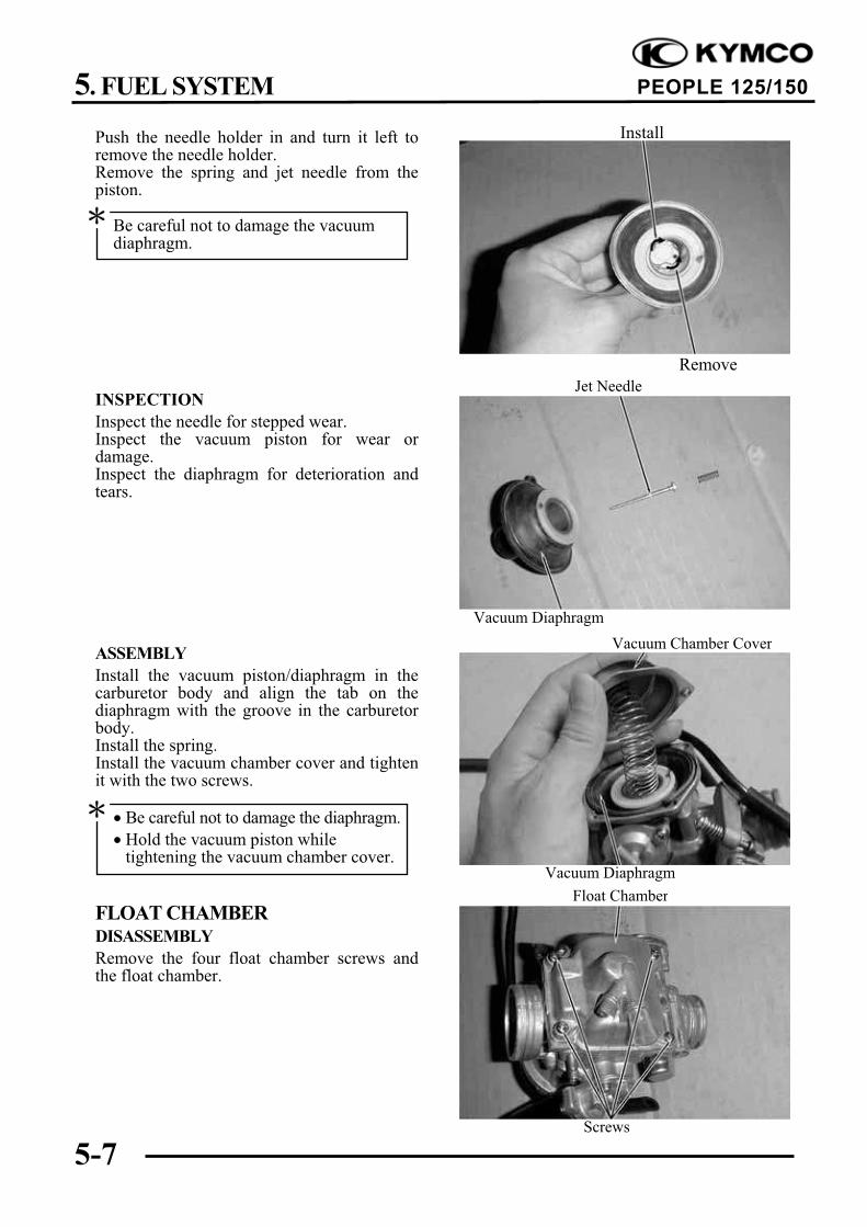
Push the needle holder in and turn it left toremove the needle holder.Remove the spring and jet needle from thepiston.
INSPECTION
Inspect the needle for stepped wear.Inspect the vacuum piston for wear ordamage.Inspect the diaphragm for deterioration andtears.
ASSEMBLY
Install the vacuum piston/diaphragm in thecarburetor body and align the tab on thediaphragm with the groove in the carburetorbody.Install the spring.Install the vacuum chamber cover and tightenit with the two screws.
FLOAT CHAMBERDISASSEMBLY
Remove the four float chamber screws andthe float chamber.
Vacuum Chamber Cover
Be careful not to damage the diaphragm.
Hold the vacuum piston whiletightening the vacuum chamber cover.
Be careful not to damage the vacuumdiaphragm.
Vacuum Diaphragm
Float Chamber
Jet Needle
Screws
Vacuum Diaphragm
Install
Remove
5. FUEL SYSTEM
5-8
PEOPLE 125/150
Remove the float pin, float and float valve.
INSPECTION
Inspect the float valve and valve seat fordamage or clogging.Inspect the float valve and valve seat contactarea for stepped wear or contamination.
Remove the main jet, needle jet holder,needle jet, slow jet and pilot screw.
Clean the removed fuel jets with detergent oiland blow them open with compressed air.Blow compressed air through all passages ofthe carburetor body.
Pilot Screw
Be careful not to damage the fuel jetsand pilot screw.
Before removing, turn the pilot screwin and carefully count the number ofturns until it seats lightly and thenmake a note of this.
Do not force the pilot screw against itsseat to avoid seat damage.
Float Valve
Float
Float Pin
Valve Seat
Also remove and clean the vacuumchamber and air cut-off valve.
Worn or contaminated float valve andvalve seat must be replaced because itwill result in float level too high due toincomplete airtightness.
Slow Jet
Main JetNeedle Jet Holder Needle Jet
5. FUEL SYSTEM
5-9
PEOPLE 125/150
ASSEMBLY
Install the slow jet, needle jet, needle jetholder, main jet and pilot screw.
Standard Opening: 3 3/8 turns
Install the float valve, float and float pin.
Float Valve
Return the pilot screw to the originalposition as noted during removal.
Float Pin
Pilot Screw Slow Jet
Main JetNeedle Jet Holder Needle Jet
5. FUEL SYSTEM
5-10
PEOPLE 125/150
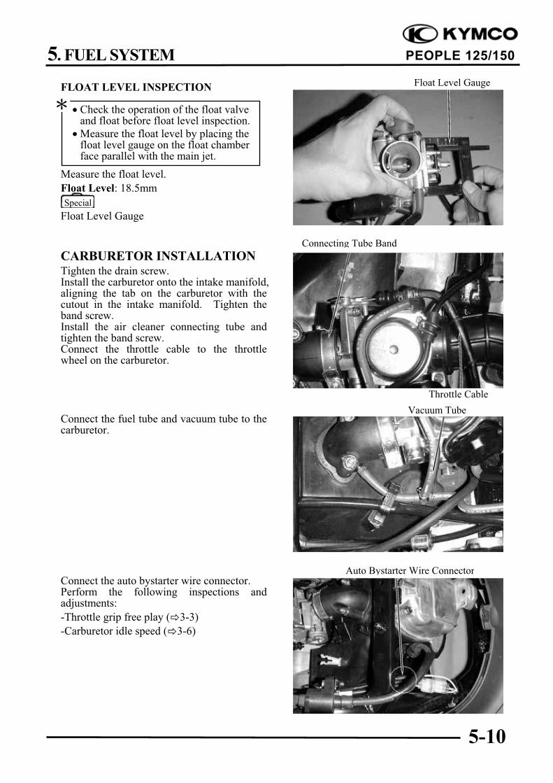
FLOAT LEVEL INSPECTION
Measure the float level.
Float Level: 18.5mm
Float Level Gauge
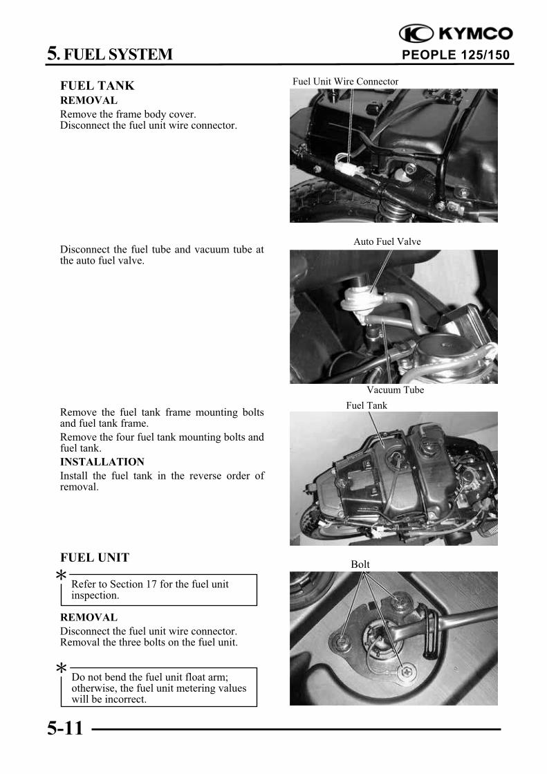
CARBURETOR INSTALLATIONTighten the drain screw.Install the carburetor onto the intake manifold,aligning the tab on the carburetor with thecutout in the intake manifold. Tighten theband screw.Install the air cleaner connecting tube andtighten the band screw.Connect the throttle cable to the throttlewheel on the carburetor.
Connect the fuel tube and vacuum tube to thecarburetor.
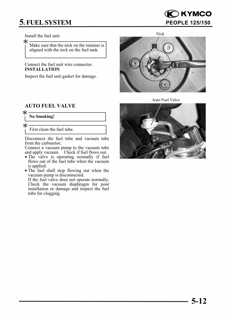
Connect the auto bystarter wire connector.Perform the following inspections andadjustments:
-Throttle grip free play ( 3-3)
-Carburetor idle speed ( 3-6)
Special
Auto Bystarter Wire Connector
Vacuum Tube
Connecting Tube Band
Throttle Cable
Check the operation of the float valveand float before float level inspection.
Measure the float level by placing thefloat level gauge on the float chamberface parallel with the main jet.
Float Level Gauge
5. FUEL SYSTEM
5-11
PEOPLE 125/150
FUEL TANKREMOVAL
Remove the frame body cover.Disconnect the fuel unit wire connector.
Disconnect the fuel tube and vacuum tube atthe auto fuel valve.
Remove the fuel tank frame mounting boltsand fuel tank frame.
Remove the four fuel tank mounting bolts andfuel tank.
INSTALLATION
Install the fuel tank in the reverse order ofremoval.
FUEL UNIT
REMOVAL
Disconnect the fuel unit wire connector.Removal the three bolts on the fuel unit.
Fuel Unit Wire Connector
Fuel Tank
Auto Fuel Valve
Vacuum Tube
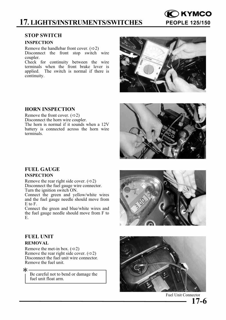
Refer to Section 17 for the fuel unitinspection.
Do not bend the fuel unit float arm;otherwise, the fuel unit metering valueswill be incorrect.
Bolt
5. FUEL SYSTEM
5-12
PEOPLE 125/150
Install the fuel unit.
Connect the fuel unit wire connector.INSTALLATION
Inspect the fuel unit gasket for damage.
AUTO FUEL VALVE
Disconnect the fuel tube and vacuum tubefrom the carburetor.Connect a vacuum pump to the vacuum tubeand apply vacuum. Check if fuel flows out. The valve is operating normally if fuel
flows out of the fuel tube when the vacuumis applied.
The fuel shall stop flowing out when thevacuum pump is disconnected.If the fuel valve does not operate normally,Check the vacuum diaphragm for poorinstallation or damage and inspect the fueltube for clogging.
No Smoking!
Auto Fuel Valve
First clean the fuel tube.
Make sure that the nick on the retainer isaligned with the nick on the fuel tank.
Nick
5. FUEL SYSTEM
5-13
PEOPLE 125/150
AIR CLEANERLoosen the air cleaner connecting tube bandscrew.Disconnect the transmission case breathertube from the air cleaner case.Remove the two bolts and air cleaner case.
The installation sequence is the reverse ofremoval.
Air Cleaner Case
Bolt
6. ENGINE REMOVAL/INSTALLATION
6-0
PEOPLE 125/150
6
ENGINE REMOVAL/INSTALLATION
SERVICE INFORMATION................................................................... 6-2
The engine removal operation is required to support the engine. Be careful not to damage the
motorcycle body, cables and wires during engine removal.
Use shop towels to protect the motorcycle body during engine removal.
Parts requiring engine removal for servicing:
! Crankcase
! Crankshaft
6. ENGINE REMOVAL/INSTALLATION
6-3
PEOPLE 125/150
ENGINE REMOVALDisconnect the battery negative cable.Remove the frame body cover. ( 2)Disconnect the engine negative cable.Disconnect the spark plug high tension wire.Disconnect the auto bystarter wire connector.Disconnect the A.C.G. wire connector.
Disconnect the starter motor cable from thestarter relay.Remove the spark plug cap.
Disconnect the fuel tube at the carburetorside.Disconnect the auto fuel valve vacuum tubefrom the tee tube.Disconnect the throttle cable from thecarburetor.
Loosen the drive belt air cleaner connectingtube band screw and remove the connectingtube.
Starter Relay
Auto Bystarter Wire Connector
Connecting TubeTee Tube
Screw
A.C.G. Wire Connector
6. ENGINE REMOVAL/INSTALLATION
6-4
PEOPLE 125/150
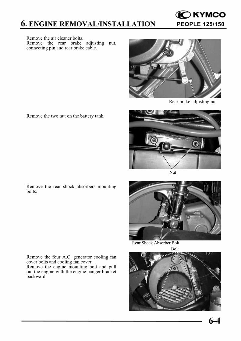
Remove the air cleaner bolts.Remove the rear brake adjusting nut,connecting pin and rear brake cable.
Remove the two nut on the battery tank.
Remove the rear shock absorbers mountingbolts.
Remove the four A.C. generator cooling fancover bolts and cooling fan cover.Remove the engine mounting bolt and pullout the engine with the engine hanger bracketbackward.
Rear Shock Absorber Bolt
Nut
Rear brake adjusting nut
Bolt
6. ENGINE REMOVAL/INSTALLATION
6-5
PEOPLE 125/150
ENGINE HANGER BRACKET
REMOVAL
Remove the ignition coil from the enginehanger.Remove the engine hanger bracket bolt andnut.
Remove the engine hanger bracket.
Inspect the engine hanger bushings andstopper rubbers for wear or damage.
ENGINE HANGER BRACKETINSTALLATION
Install the engine hanger bracket to theengine.Install the engine hanger bracket bolt andtighten the nut.
ENGINE INSTALLATION
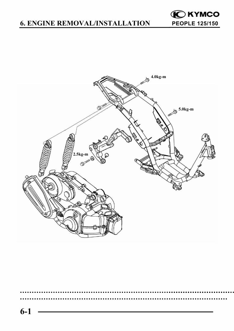
Install the engine and tighten the enginemounting bolts.
Torque: 5.0kg-m
Tighten the rear shock absorbers mountingbolts.
Torque: Up side 4.0kg-mDown side 2.5kg-m
Install the removed parts in the reverse orderof removal.
After installation, inspect and adjust thefollowing:
Throttle grip free play ( 3-3)
Rear brake adjustment ( 3-8)
Bushings
Engine Hanger Bracket Bolt
Bolt Stopper Rubbers
Route the wires and cables properly.• •
Nut
Engine Hanger Bracket
7. CYLINDER HEAD/VALVES
7-0
PEOPLE 125/150
7
CYLINDER HEAD/VALVES
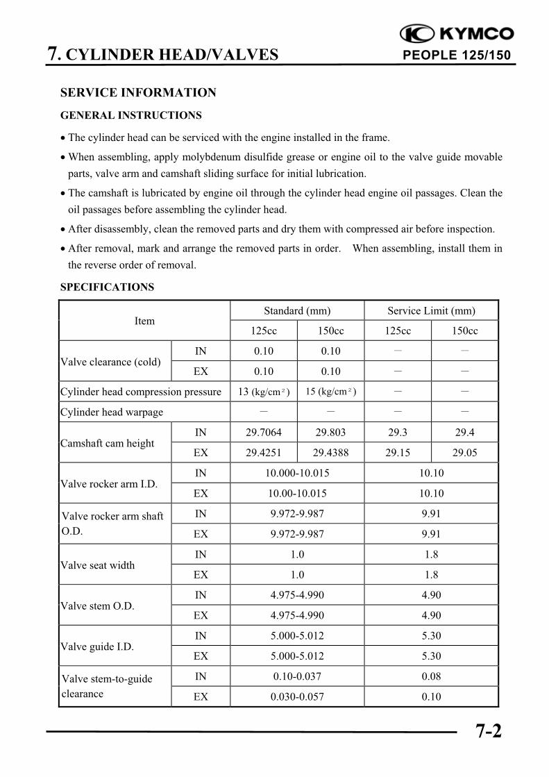
SERVICE INFORMATION ................................................................. 7-2
Burned or bend valves Incorrect valve clearance adjustment
Incorrect valve timing Sticking valve or broken valve spring
Broken valve spring Damaged or worn camshaft
Poor valve and valve seat contact Worn cam chain guide
Leaking cylinder head gasket Worn camshaft and rocker arm
Warped or cracked cylinder head contact surface
Poorly installed spark plug
Compression too high
Excessive carbon build-up in combustion
chamber
7. CYLINDER HEAD/VALVES
7-4
PEOPLE 125/150
CAMSHAFT REMOVALRemove the center cover.Remove the four cylinder head cover bolts toremove the cylinder head cover.
Remove the cam chain tensioner cap screwand the O-ring.
Turn the cam chain tensioner screwclockwise to tighten it.
Turn the flywheel counterclockwise so thatthe “T” mark on the flywheel aligns with theindex mark on the crankcase to bring theround hole on the camshaft gear facing up tothe top dead center on the compressionstroke.
Cylinder Head Cover
O-ring
Tensioner Screw
Round Hole
Camshaft Gear
Punch Marks
bolt
7. CYLINDER HEAD/VALVES
7-5
PEOPLE 125/150
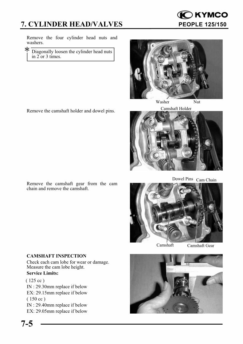
Remove the four cylinder head nuts andwashers.
Remove the camshaft holder and dowel pins.
Remove the camshaft gear from the camchain and remove the camshaft.
CAMSHAFT INSPECTION
Check each cam lobe for wear or damage.Measure the cam lobe height.
Service Limits:
( 125 cc )
IN : 29.30mm replace if below
EX: 29.15mm replace if below
( 150 cc )
IN : 29.40mm replace if below
EX: 29.05mm replace if below
Cam Chain
Camshaft Gear
Camshaft Holder
NutWasher
Dowel Pins
Camshaft
Diagonally loosen the cylinder head nutsin 2 or 3 times.
7. CYLINDER HEAD/VALVES
7-6
PEOPLE 125/150
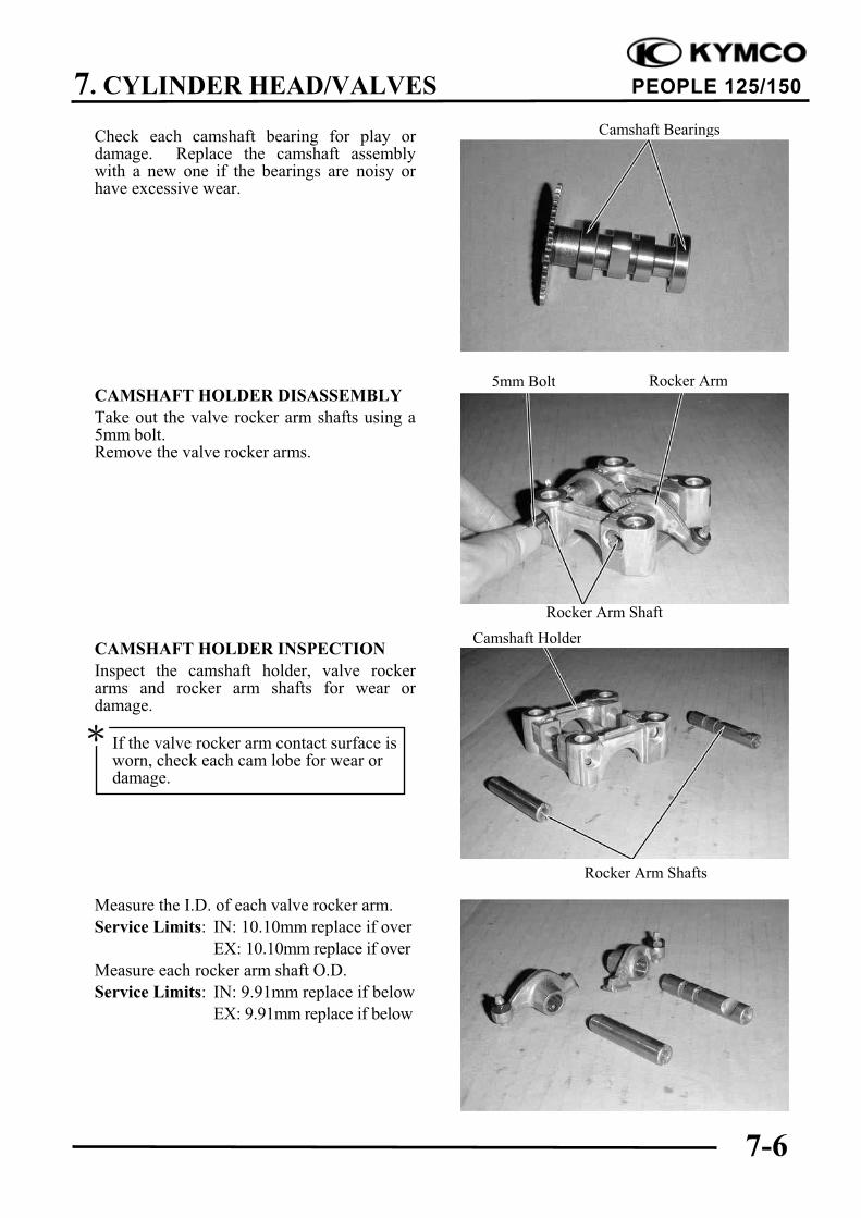
Check each camshaft bearing for play ordamage. Replace the camshaft assemblywith a new one if the bearings are noisy orhave excessive wear.
CAMSHAFT HOLDER DISASSEMBLY
Take out the valve rocker arm shafts using a5mm bolt.Remove the valve rocker arms.
CAMSHAFT HOLDER INSPECTION
Inspect the camshaft holder, valve rockerarms and rocker arm shafts for wear ordamage.
Measure the I.D. of each valve rocker arm.
Service Limits: IN: 10.10mm replace if over
EX: 10.10mm replace if over
Measure each rocker arm shaft O.D.
Service Limits: IN: 9.91mm replace if below
EX: 9.91mm replace if below
Camshaft Holder
If the valve rocker arm contact surface isworn, check each cam lobe for wear ordamage.
Rocker Arm Shafts
Camshaft Bearings
5mm Bolt Rocker Arm
Rocker Arm Shaft
7. CYLINDER HEAD/VALVES
7-7
PEOPLE 125/150
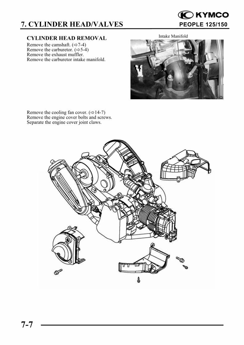
CYLINDER HEAD REMOVALRemove the camshaft. ( 7-4)Remove the carburetor. ( 5-4)Remove the exhaust muffler.Remove the carburetor intake manifold.
Remove the cooling fan cover. ( 14-7)Remove the engine cover bolts and screws.Separate the engine cover joint claws.
Intake Manifold
7. CYLINDER HEAD/VALVES
7-8
PEOPLE 125/150
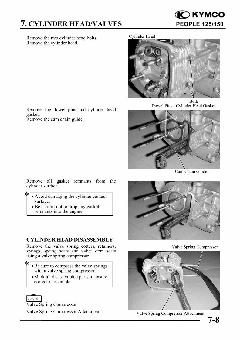
Remove the two cylinder head bolts.Remove the cylinder head.
Remove the dowel pins and cylinder headgasket.Remove the cam chain guide.
Remove all gasket remnants from thecylinder surface.
CYLINDER HEAD DISASSEMBLYRemove the valve spring cotters, retainers,springs, spring seats and valve stem sealsusing a valve spring compressor.
Valve Spring Compressor
Valve Spring Compressor Attachment
Valve Spring Compressor
Cylinder Head
Be sure to compress the valve springswith a valve spring compressor.
Mark all disassembled parts to ensurecorrect reassemble.
Dowel Pins
Avoid damaging the cylinder contactsurface.
Be careful not to drop any gasketremnants into the engine.
Cam Chain Guide
Cylinder Head Gasket
Special
Bolts
Valve Spring Compressor Attachment
7. CYLINDER HEAD/VALVES
7-9
PEOPLE 125/150
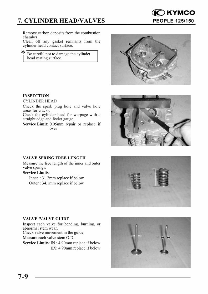
Remove carbon deposits from the combustionchamber.Clean off any gasket remnants from thecylinder head contact surface.
INSPECTION
CYLINDER HEAD
Check the spark plug hole and valve holeareas for cracks.Check the cylinder head for warpage with astraight edge and feeler gauge.
Service Limit: 0.05mm repair or replace ifover
VALVE SPRING FREE LENGTH
Measure the free length of the inner and outervalve springs.
Service Limits:
Inner : 31.2mm replace if below
Outer : 34.1mm replace if below
VALVE /VALVE GUIDE
Inspect each valve for bending, burning, orabnormal stem wear.Check valve movement in the guide.
Measure each valve stem O.D.
Service Limits: IN : 4.90mm replace if below
EX: 4.90mm replace if below
Be careful not to damage the cylinderhead mating surface.
7. CYLINDER HEAD/VALVES
7-10
PEOPLE 125/150
CYLINDER HEAD ASSEMBLY
Install the valve spring seats and valve stemseals.
Lubricate each valve stem with engine oil andinsert the valves into the valve guides.
Be sure to install new valve stem seals.
Tap the valve stems gently with a plastichammer for 2 3 times to firmly seat thecotters.
CYLINDER HEAD INSTALLATIONInstall the dowel pins and a new cylinderhead gasket.Install the cam chain guide.
Install the cylinder head.
CAMSHAFT HOLDER ASSEMBLY
Install the exhaust valve rocker arm to the“EX” mark side of the camshaft holder.Install the intake valve rocker arm and therocker arm shafts.
Gasket
Valve Rocker Arm
Cam Chain Guide
Cylinder Head
Camshaft Holder
Be careful not to damage the valves.
Dowel Pins
Align the cutout on the front end of theintake valve rocker arm shaft with thebolt of the camshaft holder.
Align the cross cutout on the exhaustvalve rocker arm shaft with the bolt ofthe camshaft holder.
7. CYLINDER HEAD/VALVES
7-11
PEOPLE 125/150
CAMSHAFT INSTALLATIONTurn the flywheel so that the “T” mark on theflywheel aligns with the index mark on thecrankcase.Keep the round hole on the camshaft gearfacing up and align the punch marks on thecamshaft gear with the cylinder head surface(Position the intake and exhaust cam lobesdown.) and install the camshaft onto thecylinder head.Install the cam chain over the camshaft gear.
Install the dowel pins.
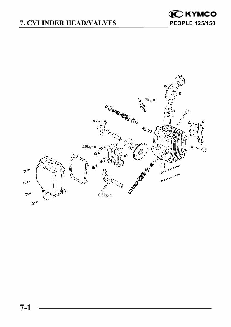
Install the camshaft holder, washers and nutson the cylinder head.Tighten the four cylinder head nuts and twobolts.
Torque: Cylinder head nut: 2.0kg-m
Adjust the valve clearance. ( 3-5)Turn the cam chain tension screw counter-clockwise to release it.
Dowel Pins
NutWasher
Punch Marks
Cam Chain
Round Hole
Apply engine oil to the threads of thecylinder head nuts.
Diagonally tighten the cylinder headnuts in 2 3 times.
Tensioner Screw
Camshaft Gear
Camshaft Holder
7. CYLINDER HEAD/VALVES
7-12
PEOPLE 125/150
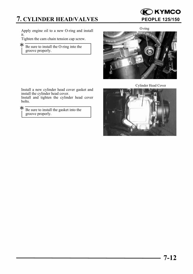
Apply engine oil to a new O-ring and installit.Tighten the cam chain tension cap screw.
Install a new cylinder head cover gasket andinstall the cylinder head cover.Install and tighten the cylinder head coverbolts.
Cylinder Head Cover
O-ring
Be sure to install the gasket into thegroove properly.
Be sure to install the O-ring into thegroove properly.
8. CYLINDER/PISTON
8-0
PEOPLE 125/150
8
CYLINDER/PISTON
SERVICE INFORMATION ................................................................. 8-2
The cylinder and piston can be serviced with the engine installed in the frame.
After disassembly, clean the removed parts and dry them with compressed air before inspection.
TROUBLESHOOTING
When hard starting or poor performance at low speed occurs, check the crankcase breather for
white smoke. If white smoke is found, it means that the piston rings are worn, stuck or broken.
Compression too low White smoke from exhaust muffler
Worn, stuck or broken piston rings Worn or damaged piston rings
Worn or damaged cylinder and piston Worn or damaged cylinder and piston
Compression too high Abnormal noisy piston
Excessive carbon build-up in combustion Worn cylinder, piston and piston rings
chamber or on piston head Worn piston pin hole and piston pin
8. CYLINDER/PISTON
8-3
PEOPLE 125/150
SPECIFICATIONS
Item (125cc) Standard (mm) Service Limit (mm)
I.D. 52.400 52.410 52.50
Warpage ! 0.05
Cylindricity ! 0.05
True roundness ! 0.05
Ring-to-groove Top 0.015 0.055 0.09
clearance Second 0.015 0.055 0.09
Top 0.10 0.25 0.5
Piston, Ring end gap Second 0.10 0.25 0.5
piston ring Oil side rail 0.2 0.7 !
Piston O.D. 52.370 52.390 52.3
Piston O.D. measuring position 9mm from bottom of skirt !
. Piston-to-cylinder clearance 0.010 0.040 0.1
Piston pin hole I.D. 15.002 15.008 15.04
Piston pin O.D 14.994 15.000 14.96
Piston-to-piston pin clearance 0.002 0.014 0.02
Connecting rod small end I.D. bore 15.016 15.034 15.06
Item (150cc) Standard (mm) Service Limit (mm)
I.D. 57.405 57.415 57.50
Warpage ! 0.05
Cylindricity ! 0.05
True roundness ! 0.05
Ring-to-groove Top 0.015 0.055 0.09
clearance Second 0.015 0.055 0.09
Top 0.15 0.30 0.5
Piston, Ring end gap Second 0.15 0.30 0.5
piston ring Oil side rail 0.2 0.7 !
Piston O.D. 57.370 57.390 57.3
Piston O.D. measuring position 9mm from bottom of skirt !
. Piston-to-cylinder clearance 0.010 0.040 0.1
Piston pin hole I.D. 15.002 15.008 15.04
Piston pin O.D 14.994 15.000 14.96
Piston-to-piston pin clearance 0.002 0.014 0.02
Connecting rod small end I.D. bore 15.016 15.034 15.06
Cylinder
Cylinder
8. CYLINDER/PISTON
8-4
PEOPLE 125/150
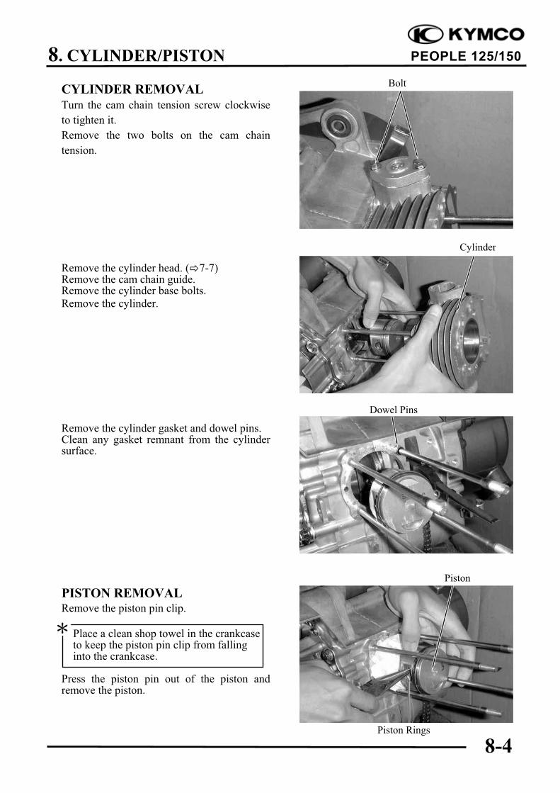
CYLINDER REMOVAL
Turn the cam chain tension screw clockwise
to tighten it.
Remove the two bolts on the cam chain
tension.
Remove the cylinder head. ( 7-7)Remove the cam chain guide.Remove the cylinder base bolts.Remove the cylinder.
Remove the cylinder gasket and dowel pins.Clean any gasket remnant from the cylindersurface.
PISTON REMOVALRemove the piston pin clip.
Press the piston pin out of the piston andremove the piston.
Dowel Pins
Cylinder
Piston
Piston Rings
Place a clean shop towel in the crankcaseto keep the piston pin clip from fallinginto the crankcase.
Bolt
8. CYLINDER/PISTON
8-5
PEOPLE 125/150
Inspect the piston, piston pin and piston rings.Remove the piston rings.
Clean carbon deposits from the piston ringgrooves.
Install the piston rings onto the piston andmeasure the piston ring-to-groove clearance.
Service Limits: Top: 0.09mm replace if over
2nd: 0.09mm replace if over
Remove the piston rings and insert eachpiston ring into the cylinder bottom.
Measure the piston ring end gap.
Service Limit: 0.5mm replace if over
Measure the piston pin hole I.D.
Service Limit: 15.04mm replace if over
Take care not to damage or break thepiston rings during removal.
Use the piston head to push each pistonring into the cylinder.
8. CYLINDER/PISTON
8-6
PEOPLE 125/150
Measure the piston pin O.D.
Service Limit: 14.96mm replace if below
Measure the piston O.D.
(125cc) Service Limit: 52.3mm replace ifbelow
(150cc) Service Limit: 57.3mm replace ifbelow
Measure the piston-to-piston pin clearance.
Service Limit: 0.02mm replace if over
CYLINDER INSPECTION
Inspect the cylinder bore for wear or damage.Measure the cylinder I.D. at three levels oftop, middle and bottom at 90" to the pistonpin (in both X and Y directions).
(125cc) Service Limit: 52.50mm repair orreplace if over(150cc) Service Limit: 57.50mm repair orreplace if overMeasure the cylinder-to-piston clearance.
The true roundness is the difference betweenthe values measured in X and Y directions.The cylindricity (difference between thevalues measured at the three levels) is subjectto the maximum value calculated.
Service Limits:
True Roundness: 0.05mm repair or replaceif over
Cylindricity: 0.05mm repair or replace if over
Take measurement at 9mm from thebottom and 90" to the piston pin hole.
Middle
Bottom
Top
8. CYLINDER/PISTON
8-7
PEOPLE 125/150
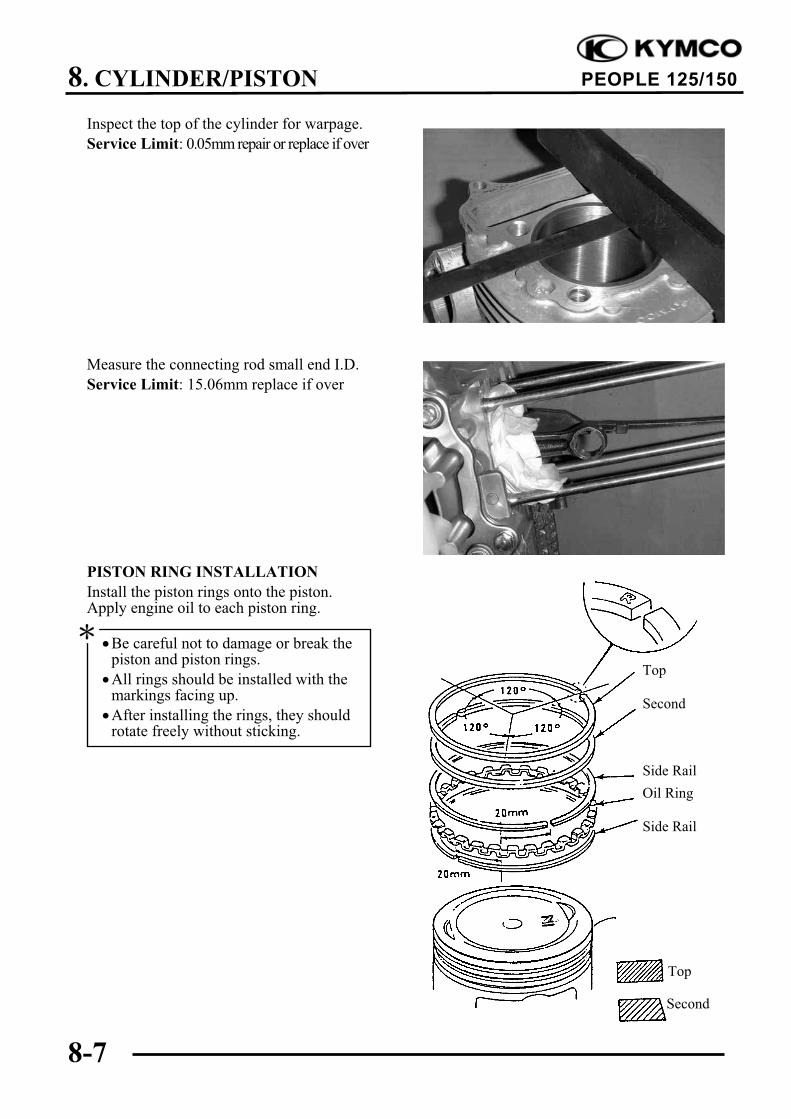
Inspect the top of the cylinder for warpage.
Service Limit: 0.05mm repair or replace if over
Measure the connecting rod small end I.D.
Service Limit: 15.06mm replace if over
PISTON RING INSTALLATION
Install the piston rings onto the piston.Apply engine oil to each piston ring.
Second
Side Rail
Top
Be careful not to damage or break thepiston and piston rings.
All rings should be installed with themarkings facing up.
After installing the rings, they shouldrotate freely without sticking.
Second
Top
Side Rail
Oil Ring
8. CYLINDER/PISTON
8-8
PEOPLE 125/150
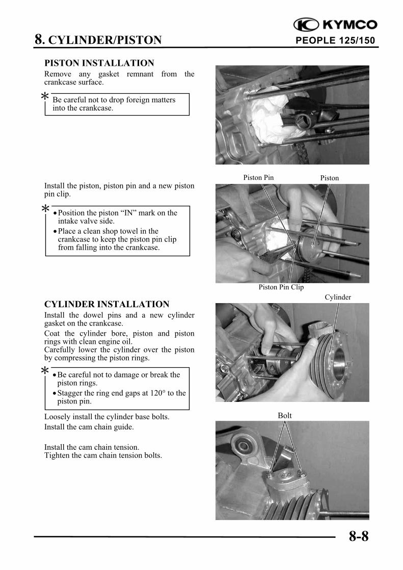
PISTON INSTALLATIONRemove any gasket remnant from thecrankcase surface.
Install the piston, piston pin and a new pistonpin clip.
CYLINDER INSTALLATIONInstall the dowel pins and a new cylindergasket on the crankcase.
Coat the cylinder bore, piston and pistonrings with clean engine oil.Carefully lower the cylinder over the pistonby compressing the piston rings.
Loosely install the cylinder base bolts.
Install the cam chain guide.
Install the cam chain tension.Tighten the cam chain tension bolts.
Cylinder
Be careful not to drop foreign mattersinto the crankcase.
Position the piston “IN” mark on theintake valve side.
Place a clean shop towel in thecrankcase to keep the piston pin clipfrom falling into the crankcase.
Piston Pin
Piston Pin Clip
Piston
Be careful not to damage or break thepiston rings.
Stagger the ring end gaps at 120" to thepiston pin.
Bolt
9. DRIVE AND DRIVEN PULLEYS/KICK STARTER
9-0
PEOPLE 125/150
9
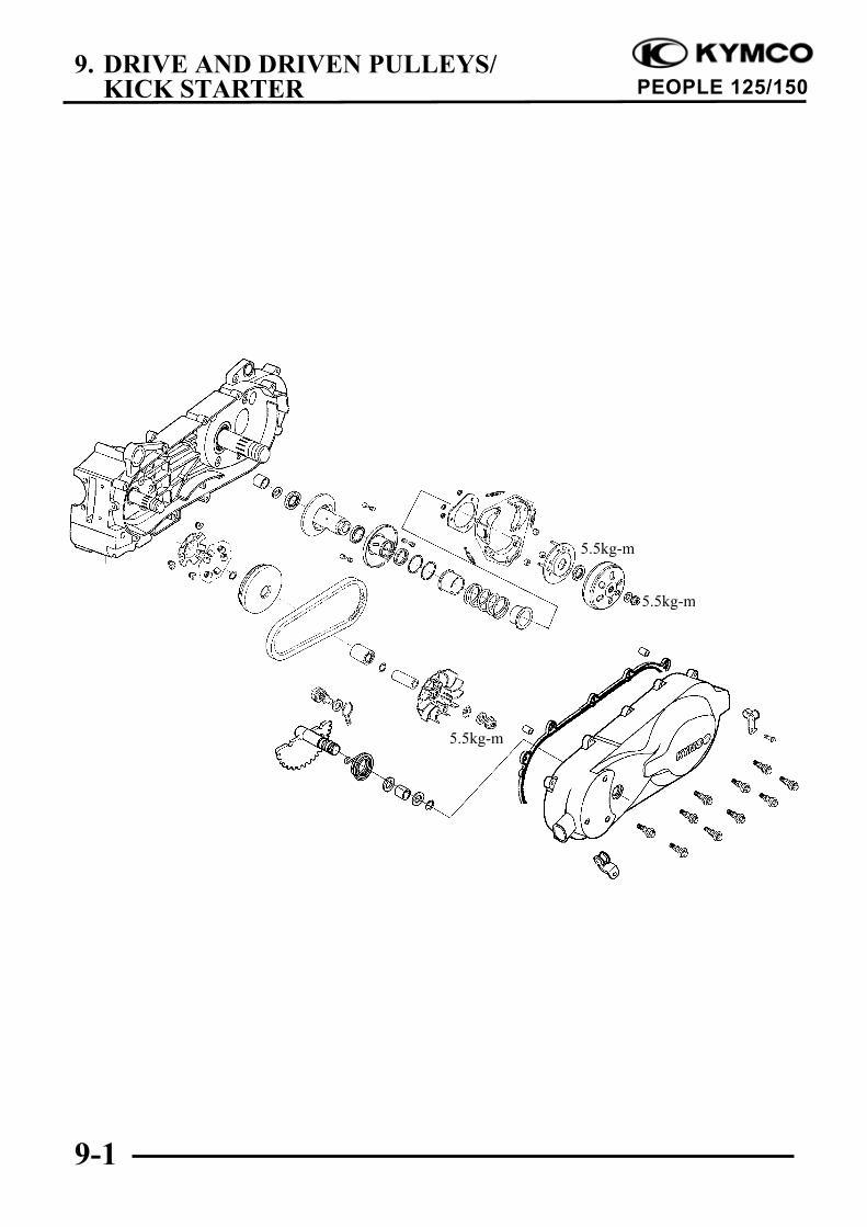
DRIVE AND DRIVEN PULLEYS/KICK STARTER
SERVICE INFORMATION................................................................. 9-2
The drive pulley, clutch and driven pulley can be serviced with the engine installed.
Avoid getting grease and oil on the drive belt and pulley faces. Remove any oil or grease from
them to minimize the slipping of drive belt and drive pulley.
SPECIFICATIONS
Item Standard (mm) Service Limit (mm)
Movable drive face bushing I.D. 24.011 24.052 24.06
Drive face collar O.D. 23.960 23.974 23.94
Drive belt width 20.0 21.0 19.0
Clutch lining thickness ! 1.5
Clutch outer I.D. 125.0 125.2 125.5
Driven face spring free length ! 163.7
Driven face O.D. 33.965 33.485 33.94
Movable driven face I.D. 34.000 34.025 34.06
Weight roller O.D. 17.920 18.080 17.40
TORQUE VALUES
Drive face nut 5.5kg-m
Clutch outer nut 5.5kg-m
SPECIAL TOOLS
Universal holder Clutch spring compressor
Driver handle A Lock nut wrench, 39mm
Pilot, 20mm Flywheel holder
Bearing driver
TROUBLESHOOTING
Engine starts but motorcycle won’t move Lack of power
Worn drive belt Worn drive belt
Broken ramp plate Weak driven face spring
Worn or damaged clutch lining Worn weight roller
Broken driven face spring Fouled drive face
Engine stalls or motorcycle creeps
Broken clutch weight spring
9. DRIVE AND DRIVEN PULLEYS/KICK STARTER
9-3
PEOPLE 125/150
LEFT CRANKCASE COVER
REMOVAL
Loosen the drive belt air tube band screw.
Remove the left crankcase cover bolts andleft crankcase cover.Remove the seal rubber and dowel pins.
DRIVE PULLEY
REMOVAL
Hold the drive pulley using an universalholder and remove the drive face nut andstarting ratchet.Remove the drive pulley face.
Universal Holder
CLUTCH/DRIVEN PULLEY
Remove the drive pulley and drive belt.Hold the clutch outer with the flywheelholder and remove the clutch outer nut.Remove the clutch outer.Remove the clutch/driven pulley and drivebelt.
Flywheel Holder
Left Crankcase Cover
Air Tube Band
Bolts
Drive Pulley Face
Universal Holder
Clutch Outer
Flywheel Holder
Screw
Special
Special
Starting Ratchet
9. DRIVE AND DRIVEN PULLEYS/KICK STARTER
9-4
PEOPLE 125/150
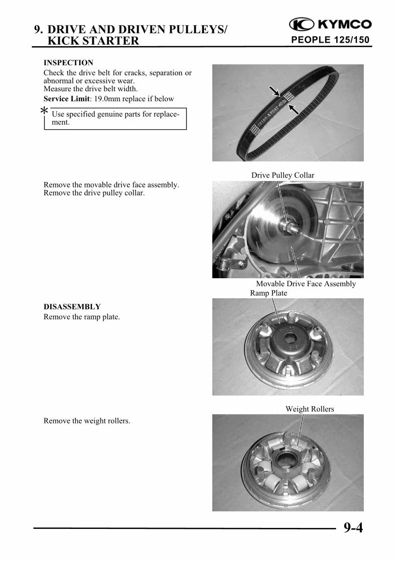
INSPECTION
Check the drive belt for cracks, separation orabnormal or excessive wear.Measure the drive belt width.
Service Limit: 19.0mm replace if below
Remove the movable drive face assembly.Remove the drive pulley collar.
DISASSEMBLY
Remove the ramp plate.
Remove the weight rollers.
Drive Pulley Collar
Movable Drive Face Assembly
Ramp Plate
Weight Rollers
Use specified genuine parts for replace-ment.
9. DRIVE AND DRIVEN PULLEYS/KICK STARTER
9-5
PEOPLE 125/150
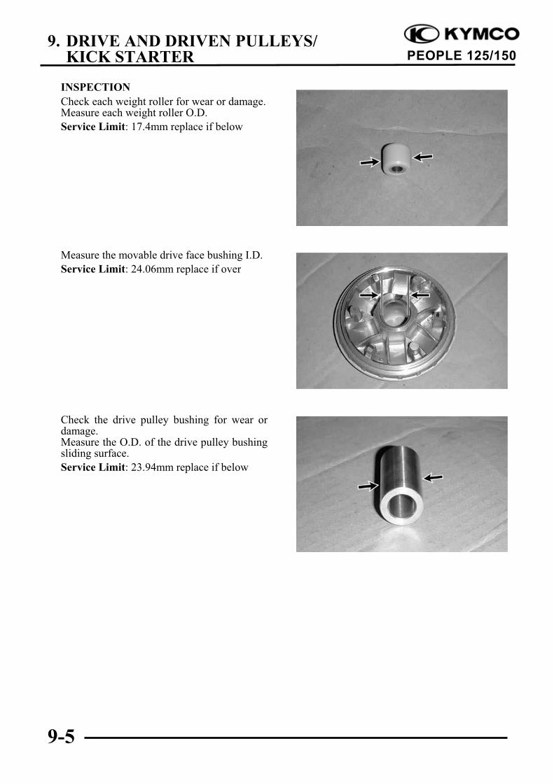
INSPECTION
Check each weight roller for wear or damage.Measure each weight roller O.D.
Service Limit: 17.4mm replace if below
Measure the movable drive face bushing I.D.
Service Limit: 24.06mm replace if over
Check the drive pulley bushing for wear ordamage.Measure the O.D. of the drive pulley bushingsliding surface.
Service Limit: 23.94mm replace if below
9. DRIVE AND DRIVEN PULLEYS/KICK STARTER
9-6
PEOPLE 125/150
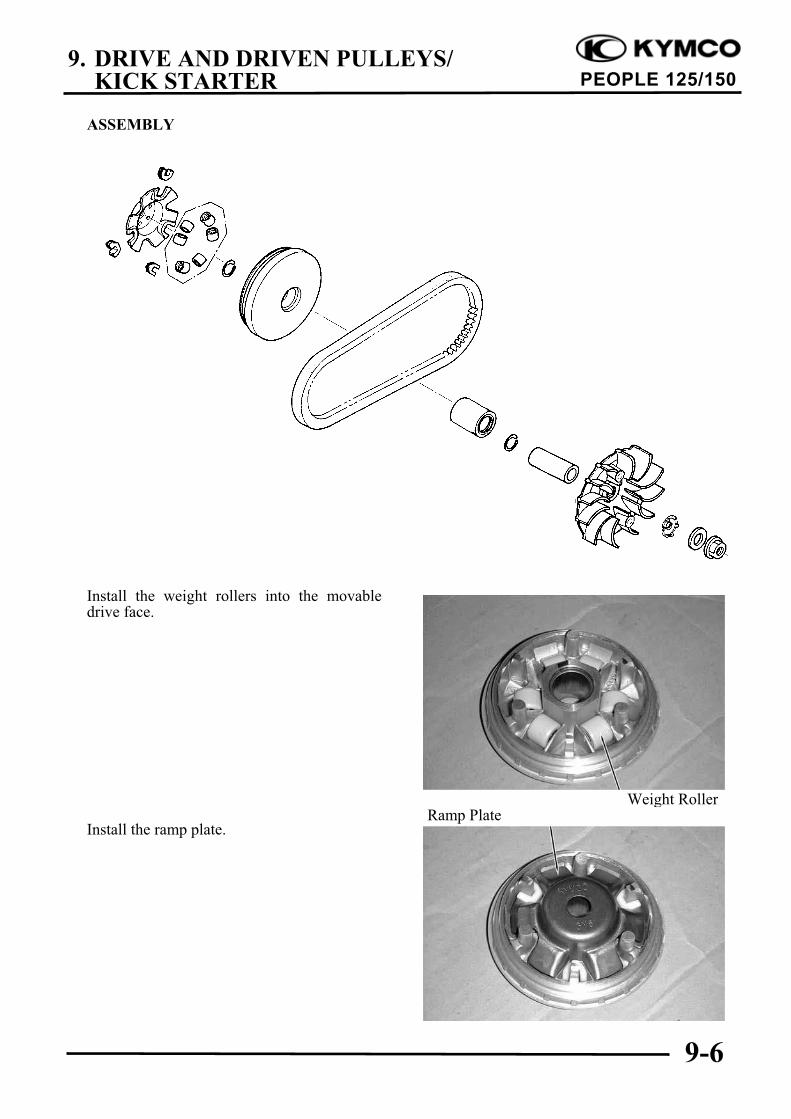
ASSEMBLY
Install the weight rollers into the movabledrive face.
Install the ramp plate.
Weight RollerRamp Plate
9. DRIVE AND DRIVEN PULLEYS/KICK STARTER
9-7
PEOPLE 125/150
Insert the drive pulley collar into the movabledrive face.
INSTALLATION
Install the movable drive face onto thecrankshaft.
INSPECTION
Inspect the clutch outer for wear or damage.Measure the clutch outer I.D.
Service Limit: 125.5mm replace if over
CLUTCH/DRIVEN PULLEYDISASSEMBLY
Drive Pulley Collar
Movable Drive Face Assembly
Clutch
Driven Pulley
9. DRIVE AND DRIVEN PULLEYS/KICK STARTER
9-8
PEOPLE 125/150
Hold the clutch/driven pulley assembly withthe clutch spring compressor.
Clutch Spring Compressor
Set the clutch spring compressor in a vise andremove the clutch drive plate nut.
Lock Nut Wrench, 39mm
Loosen the clutch spring compressor anddisassemble the clutch/driven pulley assembly.Remove the seal collar.
Check the driven face for wear or damage.Measure the clutch lining thickness.
Service Limit: 33.94mm replace if below
Pull out the guide roller pins and guide rollers.Remove the movable driven face from thedriven face.
Movable DrivenF
Clutch Spring Compressor
Guide Roller Pin
Lock Nut Wrench
O-ring
Special
Be sure to use a clutch springcompressor to avoid spring damage.
Special
9. DRIVE AND DRIVEN PULLEYS/KICK STARTER
9-9
PEOPLE 125/150
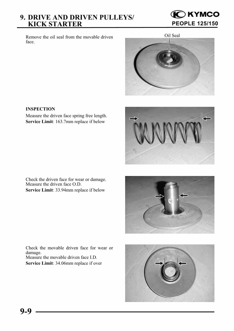
Remove the oil seal from the movable drivenface.
INSPECTION
Measure the driven face spring free length.
Service Limit: 163.7mm replace if below
Check the driven face for wear or damage.Measure the driven face O.D.
Service Limit: 33.94mm replace if below
Check the movable driven face for wear ordamage.Measure the movable driven face I.D.
Service Limit: 34.06mm replace if over
Oil Seal
9. DRIVE AND DRIVEN PULLEYS/KICK STARTER
9-10
PEOPLE 125/150
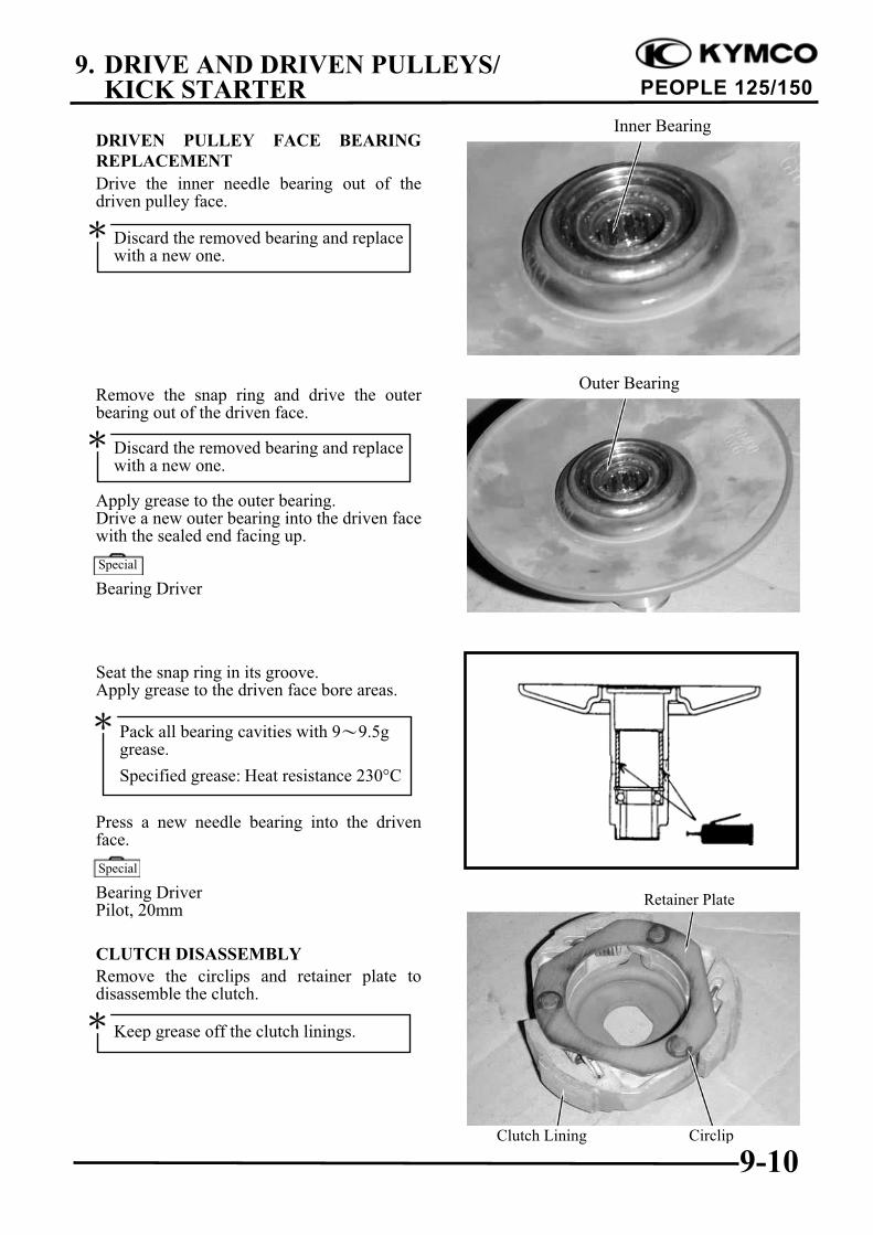
DRIVEN PULLEY FACE BEARING
REPLACEMENT
Drive the inner needle bearing out of thedriven pulley face.
Remove the snap ring and drive the outerbearing out of the driven face.
Apply grease to the outer bearing.Drive a new outer bearing into the driven facewith the sealed end facing up.
Bearing Driver
Seat the snap ring in its groove.Apply grease to the driven face bore areas.
Press a new needle bearing into the drivenface.
Bearing DriverPilot, 20mm
CLUTCH DISASSEMBLY
Remove the circlips and retainer plate todisassemble the clutch.
Circlip
Inner Bearing
Retainer Plate
Outer Bearing
Clutch Lining
Discard the removed bearing and replacewith a new one.
Discard the removed bearing and replacewith a new one.
Special
Pack all bearing cavities with 9 9.5ggrease.
Specified grease: Heat resistance 230"C
Special
Keep grease off the clutch linings.
9. DRIVE AND DRIVEN PULLEYS/KICK STARTER
9-11
PEOPLE 125/150
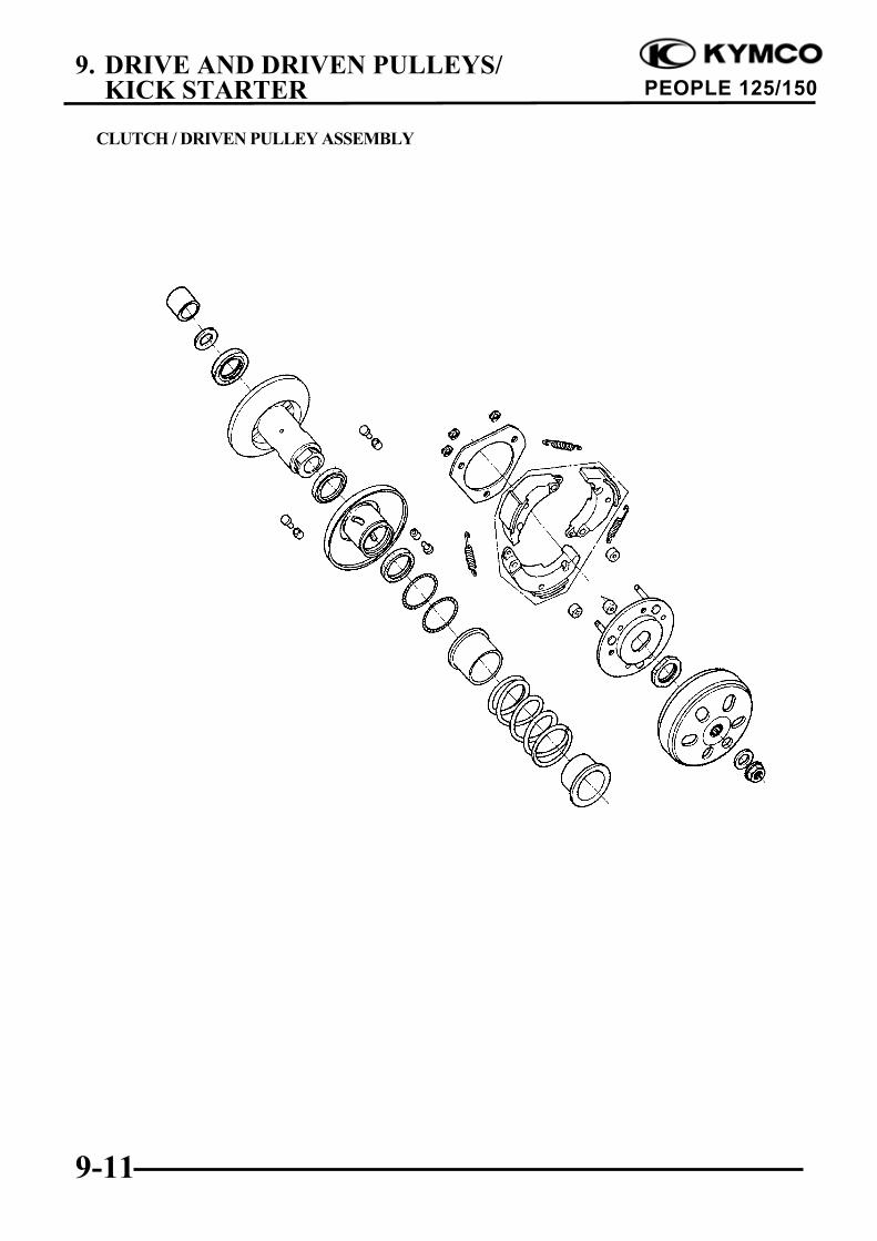
CLUTCH / DRIVEN PULLEY ASSEMBLY
9. DRIVE AND DRIVEN PULLEYS/KICK STARTER
9-12
PEOPLE 125/150
Install the damper rubbers on the drive platepins.Install the clutch weights/shoes and clutchsprings onto the drive plate.Install the retainer plate and secure with thecirclips.
CLUTCH/DRIVEN PULLEY ASSEMBLY
Clean the driven pulley faces and remove anygrease from them.Install the oil seal onto the moveable drivenface.Apply grease to the O-rings and install themonto the moveable driven face.
Install the movable driven face onto thedriven face.Apply grease to the guide rollers and guideroller pins and then install them into the holesof the driven face.
Install the seal collar.Remove any excessive grease.
Set the driven pulley assembly, driven facespring and clutch assembly onto the clutchspring compressor.
Circlip
Oil Seal
Movable Driven Face
Retainer Plate
Guide Roller Pin Guide Roller
Clutch Weights/Shoes Drive Plate
Springs
Driven Face
Movable Driven Face
Be sure to clean the driven face off anygrease.
Align the flat surface of the driven facewith the flat on the clutch drive plate.
9. DRIVE AND DRIVEN PULLEYS/KICK STARTER
9-13
PEOPLE 125/150
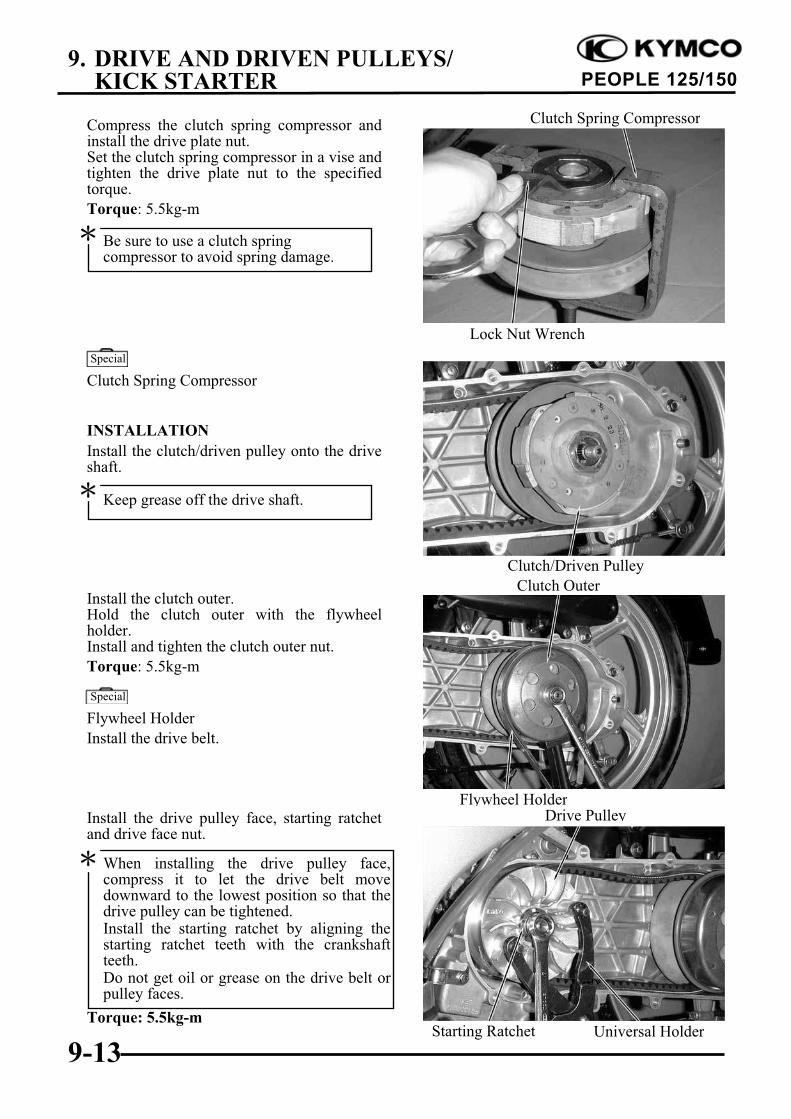
Compress the clutch spring compressor andinstall the drive plate nut.Set the clutch spring compressor in a vise andtighten the drive plate nut to the specifiedtorque.
Torque: 5.5kg-m
Clutch Spring Compressor
INSTALLATION
Install the clutch/driven pulley onto the driveshaft.
Install the clutch outer.Hold the clutch outer with the flywheelholder.Install and tighten the clutch outer nut.
Torque: 5.5kg-m
Flywheel Holder
Install the drive belt.
Install the drive pulley face, starting ratchetand drive face nut.
Torque: 5.5kg-m
Flywheel HolderDrive Pulley
Clutch/Driven Pulley
Clutch Spring Compressor
Lock Nut Wrench
Be sure to use a clutch springcompressor to avoid spring damage.
Keep grease off the drive shaft.
Special
Special
Clutch Outer
When installing the drive pulley face,compress it to let the drive belt movedownward to the lowest position so that thedrive pulley can be tightened.Install the starting ratchet by aligning thestarting ratchet teeth with the crankshaftteeth.Do not get oil or grease on the drive belt orpulley faces.
Universal HolderStarting Ratchet
9. DRIVE AND DRIVEN PULLEYS/KICK STARTER
9-14
PEOPLE 125/150
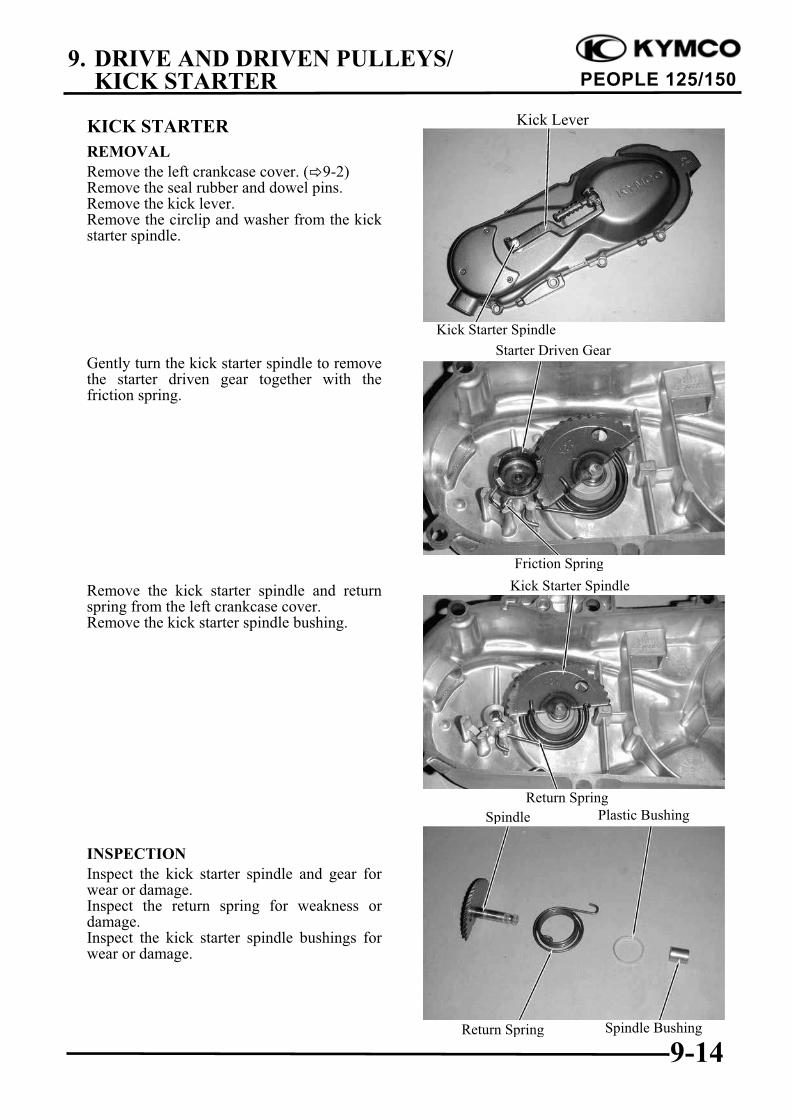
KICK STARTER
REMOVAL
Remove the left crankcase cover. ( 9-2)Remove the seal rubber and dowel pins.Remove the kick lever.Remove the circlip and washer from the kickstarter spindle.
Gently turn the kick starter spindle to removethe starter driven gear together with thefriction spring.
Remove the kick starter spindle and returnspring from the left crankcase cover.Remove the kick starter spindle bushing.
INSPECTION
Inspect the kick starter spindle and gear forwear or damage.Inspect the return spring for weakness ordamage.Inspect the kick starter spindle bushings forwear or damage.
Return Spring
Kick Starter Spindle
Friction Spring
Spindle
Kick Starter Spindle
Return Spring
Plastic Bushing
Spindle Bushing
Starter Driven Gear
Kick Lever
9. DRIVE AND DRIVEN PULLEYS/KICK STARTER
9-15
PEOPLE 125/150
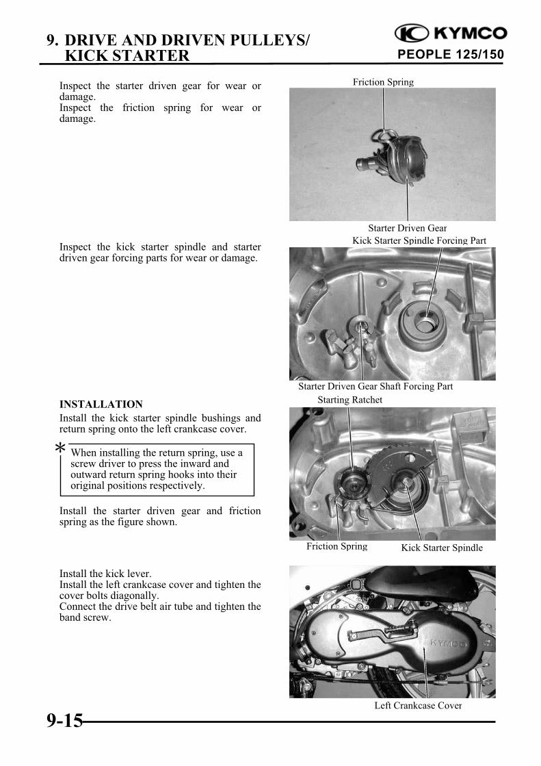
Inspect the starter driven gear for wear ordamage.Inspect the friction spring for wear ordamage.
Inspect the kick starter spindle and starterdriven gear forcing parts for wear or damage.
INSTALLATION
Install the kick starter spindle bushings andreturn spring onto the left crankcase cover.
Install the starter driven gear and frictionspring as the figure shown.
Install the kick lever.Install the left crankcase cover and tighten thecover bolts diagonally.Connect the drive belt air tube and tighten theband screw.
When installing the return spring, use ascrew driver to press the inward andoutward return spring hooks into theiroriginal positions respectively.
Starter Driven Gear Shaft Forcing Part
Friction Spring
Starter Driven Gear
Left Crankcase Cover
Starting Ratchet
Kick Starter Spindle Forcing Part
Friction Spring Kick Starter Spindle
10. FINAL REDUCTION
10-0
PEOPLE 125/150
10
FINAL REDUCTION
SERVICE INFORMATION ............................................................... 10-2
FINAL REDUCTION ASSEMBLY................................................... 10-5
10
10. FINAL REDUCTION
10-1
PEOPLE 125/150
10. FINAL REDUCTION
10-2
PEOPLE 125/150
SERVICE INFORMATION
GENERAL INSTRUCTIONS
When replacing the drive shaft, use a special tool to hold the bearing inner race for this operation.
SPECIFICATIONS
Specified Oil: GEAR OIL SAE 90#
Oil Capacity: At change : 0.181 liter
At disassembly : 0.21 liter
TORQUE VALUES
Transmission case cover bolt 1.2kg-m
SPECIAL TOOLS
Driver handle A
Outer driver, 32x35mm
Outer driver, 37x40mm
Outer driver, 42x47mm
Pilot, 15mm
Pilot, 17mm
Pilot, 20mm
Crankcase assembly tool
! Assembly shaft
! Assembly collar
TROUBLESHOOTING
Engine starts but motorcycle won’t move
Damaged transmission
Seized or burnt transmission
Oil leaks
Oil level too high
Worn or damaged oil seal
10. FINAL REDUCTION
10-3
PEOPLE 125/150
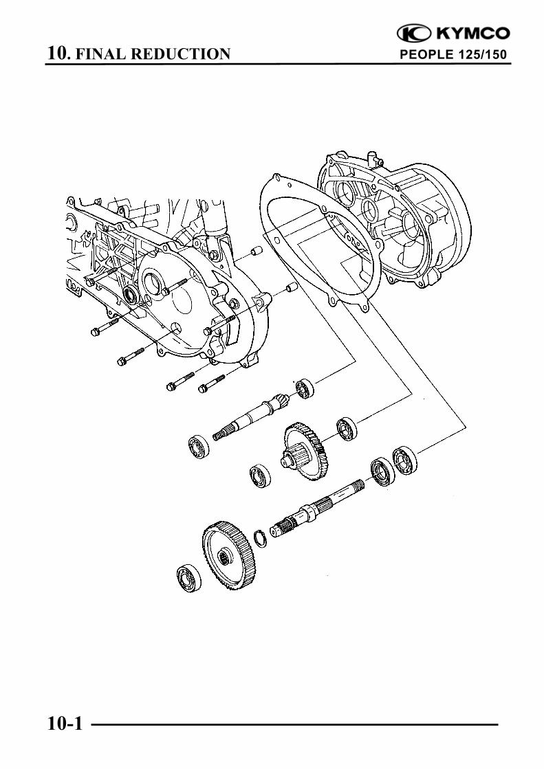
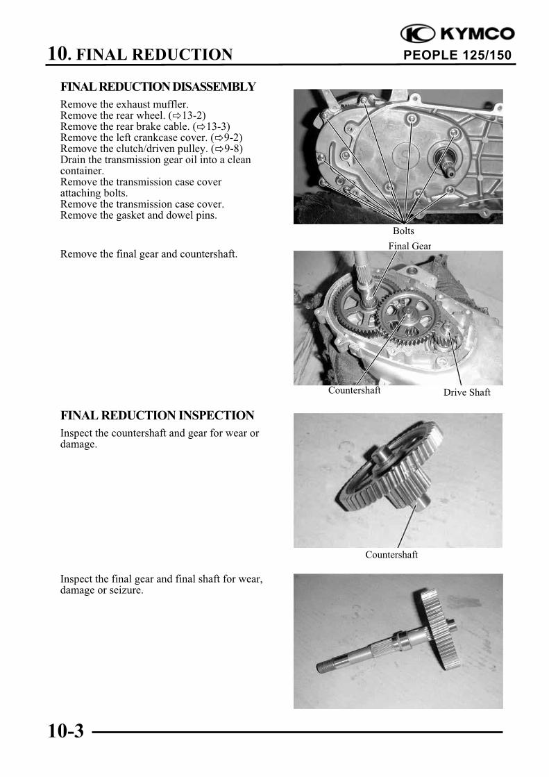
FINAL REDUCTION DISASSEMBLY
Remove the exhaust muffler.Remove the rear wheel. ( 13-2)Remove the rear brake cable. ( 13-3)Remove the left crankcase cover. ( 9-2)Remove the clutch/driven pulley. ( 9-8)Drain the transmission gear oil into a cleancontainer.Remove the transmission case coverattaching bolts.Remove the transmission case cover.Remove the gasket and dowel pins.
Remove the final gear and countershaft.
FINAL REDUCTION INSPECTION
Inspect the countershaft and gear for wear ordamage.
Inspect the final gear and final shaft for wear,damage or seizure.
Final Gear
Countershaft
Drive ShaftCountershaft
Bolts
10. FINAL REDUCTION
10-4
PEOPLE 125/150
Check the left crankcase bearings forexcessive play and inspect the oil seal forwear or damage.
Check the transmission case cover bearingsfor excessive play and inspect the final shaftbearing oil seal for wear or damage.
BEARING REPLACEMENT(TRANSMISSION CASE COVER)Remove the transmission case cover bearingsusing a bearing remover.Remove the final shaft oil seal.
Drive new bearings into the transmission casecover.
Drive Shaft BearingFinal Shaft Bearing
Countershaft Bearing
Drive Shaft Bearing
Outer Driver
Oil Seal
Countershaft Bearing
Do not remove the transmission casecover except for necessary part replace-ment. When replacing the drive shaft,also replace the bearing and oil seal.
Oil Seal
Countershaft Bearing
10. FINAL REDUCTION
10-5
PEOPLE 125/150
BEARING REPLACEMENT (LEFTCRANKCASE)Remove the drive shaft.Remove the drive shaft oil seal.Remove the left crankcase bearings using abearing remover.
Drive new bearings into the left crankcase.Install a new drive shaft oil seal.
FINAL REDUCTION ASSEMBLY
Install the drive shaft into the left crankcase.Inspect the drive shaft and gear for wear ordamage.
Install the final gear and final shaft into theleft crankcase.
Install the countershaft and gear into the leftcrankcase.Install the washer onto the countershaft.Install the dowel pins and a new gasket.
Pilot
Drive Shaft
Bearing Remover, 17mm
Final Gear
Drive ShaftCountershaft
10. FINAL REDUCTION
10-6
PEOPLE 125/150
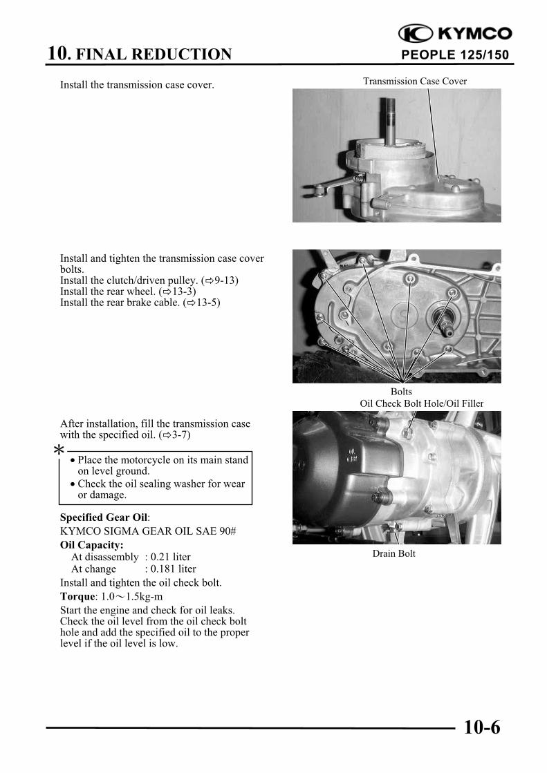
Install the transmission case cover.
Install and tighten the transmission case coverbolts.Install the clutch/driven pulley. ( 9-13)Install the rear wheel. ( 13-3)Install the rear brake cable. ( 13-5)
After installation, fill the transmission casewith the specified oil. ( 3-7)
Start the engine and check for oil leaks.Check the oil level from the oil check bolthole and add the specified oil to the properlevel if the oil level is low.
Drain Bolt
Transmission Case Cover
Oil Check Bolt Hole/Oil Filler
Bolts
Place the motorcycle on its main standon level ground.
Check the oil sealing washer for wearor damage.
11. CRANKCASE/CRANKSHAFT
11-0
PEOPLE 125/150
11
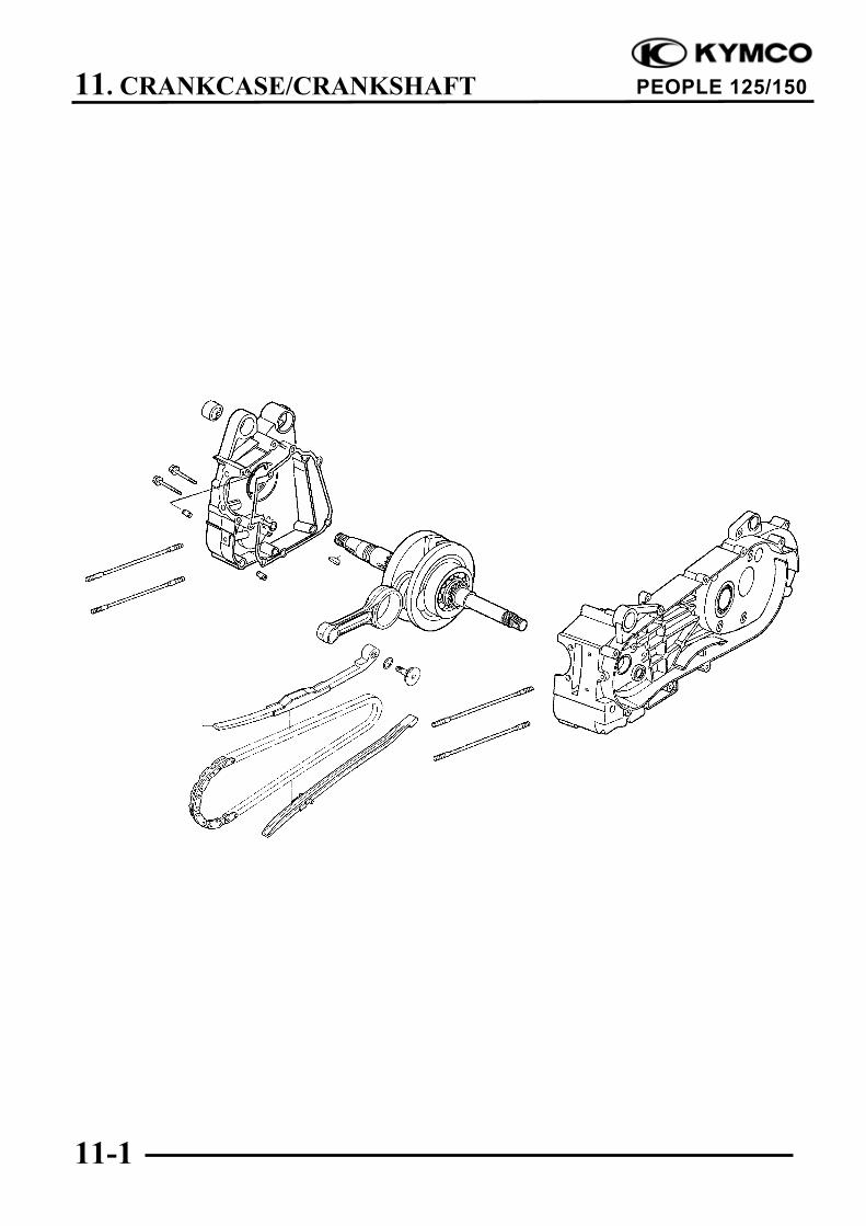
CRANKCASE/CRANKSHAFT
SERVICE INFORMATION ............................................................... 11-2
This section covers crankcase separation to service the crankshaft. The engine must be removed
for this operation.
The following parts must be removed before separating the crankcase.
!Cylinder head ( Section 7)
!Cylinder/piston ( Section 8)
!Drive and driven pulleys ( Section 9)
!A.C. generator ( Section 14)
!Carburetor/air cleaner ( Section 4)
!Rear wheel/rear shock absorber ( Section 13)
!Starter motor ( Section 16)
!Oil pump ( Section 4)
SPECIFICATIONS
Item Standard (mm) Service Limit (mm)
Connecting rod big end side clearance 0.10 0.35 0.55
Crankshaft Connecting rod big end radial clearance 0 0.008 0.05
Runout " 0.10
TORQUE VALUES
Crankcase bolt 0.9kg-m
Cam chain cover bolt 0.9kg-m
TROUBLESHOOTING
Excessive engine noise
Excessive bearing play
Excessive crankpin bearing play
11. CRANKCASE/CRANKSHAFT
11-3
PEOPLE 125/150
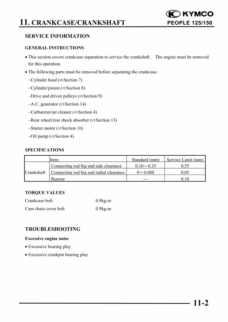
CRANKCASE SEPARATION
Remove the two crankcase attaching bolts.Separate the left and right crankcase halves.
Remove the gasket and dowel pins.
Remove the crankshaft from the leftcrankcase.
Clean off all gasket material from thecrankcase mating surfaces.
Dowel Pins
Crankcase Bolts
Gasket
Do not damage the crankcase gasketsurface.
Avoid damaging the crankcase matingsurfaces.
11. CRANKCASE/CRANKSHAFT
11-4
PEOPLE 125/150
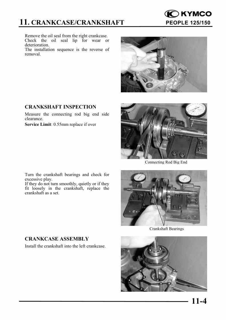
Remove the oil seal from the right crankcase.Check the oil seal lip for wear ordeterioration.The installation sequence is the reverse ofremoval.
CRANKSHAFT INSPECTION
Measure the connecting rod big end sideclearance.
Service Limit: 0.55mm replace if over
Turn the crankshaft bearings and check forexcessive play.If they do not turn smoothly, quietly or if theyfit loosely in the crankshaft, replace thecrankshaft as a set.
CRANKCASE ASSEMBLY
Install the crankshaft into the left crankcase.
Connecting Rod Big End
Crankshaft Bearings
11. CRANKCASE/CRANKSHAFT
11-5
PEOPLE 125/150
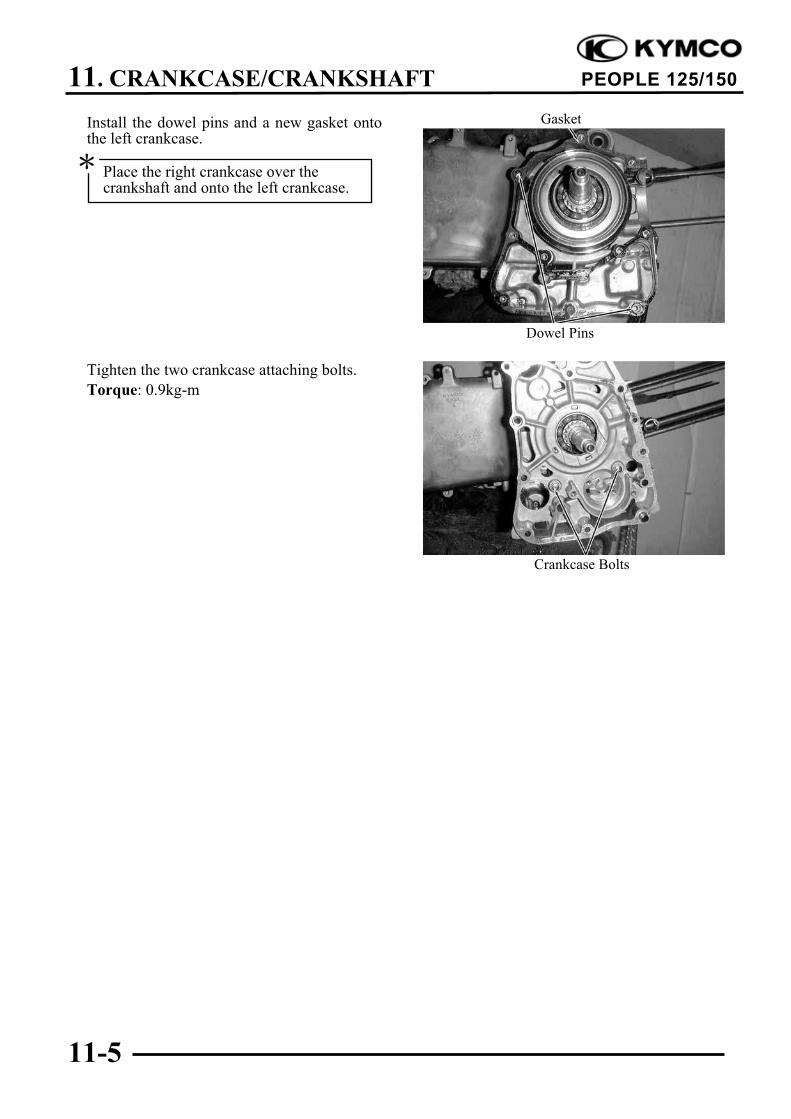
Install the dowel pins and a new gasket ontothe left crankcase.
Tighten the two crankcase attaching bolts.
Torque: 0.9kg-m
Gasket
Crankcase Bolts
Dowel Pins
Place the right crankcase over thecrankshaft and onto the left crankcase.
12. FRONT WHEEL/FRONT BRAKE/FRONT SUSPENSION
12-0
PEOPLE 125/150
12
FRONT WHEEL/FRONT BRAKE/FRONT SUSPENSION
SERVICE INFORMATION............................................................... 12-2
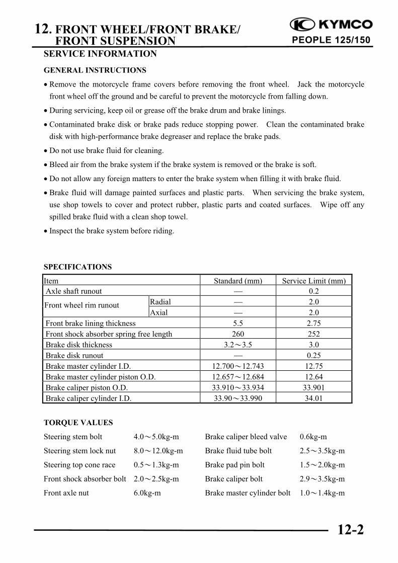
Front axle nut 6.0kg-m Brake master cylinder bolt 1.0 1.4kg-m
Front wheel rim runout
12. FRONT WHEEL/FRONT BRAKE/FRONT SUSPENSION
12-3
PEOPLE 125/150
SPECIAL TOOLS
Lock nut wrench Driver handle A
Outer driver, 28x30mm Pilot, 10mm
Ball race remover Outer driver, 37x40mm
Pliers (close) Bearing remover
Bearing remover head, 10mm
TROUBLESHOOTING
Hard steering (heavy) Front wheel wobbling
Excessively tightened steering stem top Bent rim
cone race Excessive wheel bearing play
Broken steering balls Bent spoke plate
Insufficient tire pressure Faulty tire
Steers to one side or does not track straight Improperly tightened axle nut
Uneven front shock absorbers Soft front shock absorber
Bent front fork Weak shock springs
Bent front axle or uneven tire Insufficient damper oil
Poor brake performance Front shock absorber noise
Incorrectly adjusted brake Slider bending
Worn brake linings Loose fork fasteners
Contaminated brake lining surface Lack of lubrication
Worn brake shoes at cam contacting area
Worn brake drum
Poorly connected brake arm
Poor brake performance (Disk Brake)
Air in brake system
Deteriorated brake fluid
Contaminated brake pads and brake disk
Worn brake pads
Worn brake master cylinder piston oil seal
Clogged brake fluid line
Deformed brake disk
Unevenly worn brake caliper
12. FRONT WHEEL/FRONT BRAKE/FRONT SUSPENSION
12-4
PEOPLE 125/150
FRONT WHEEL
REMOVAL
Jack the motorcycle front wheel off theground.Disconnect the speedometer cable.
Remove the front axle nut and pull out theaxle.Remove the front wheel.Remove the front brake panel.
INSPECTION
AXLE RUNOUT
Set the axle in V blocks and measure therunout using a dial gauge.The actual runout is 1/2 of the total indicatorreading.
Service Limit: 0.2mm replace if over
WHEEL RIMCheck the wheel rim runout.
Service Limits:
Radial: 2.0mm replace if over
Axial: 2.0mm replace if over
Speedometer Cable
Axle Nut
Axle Shaft
12. FRONT WHEEL/FRONT BRAKE/FRONT SUSPENSION
12-5
PEOPLE 125/150
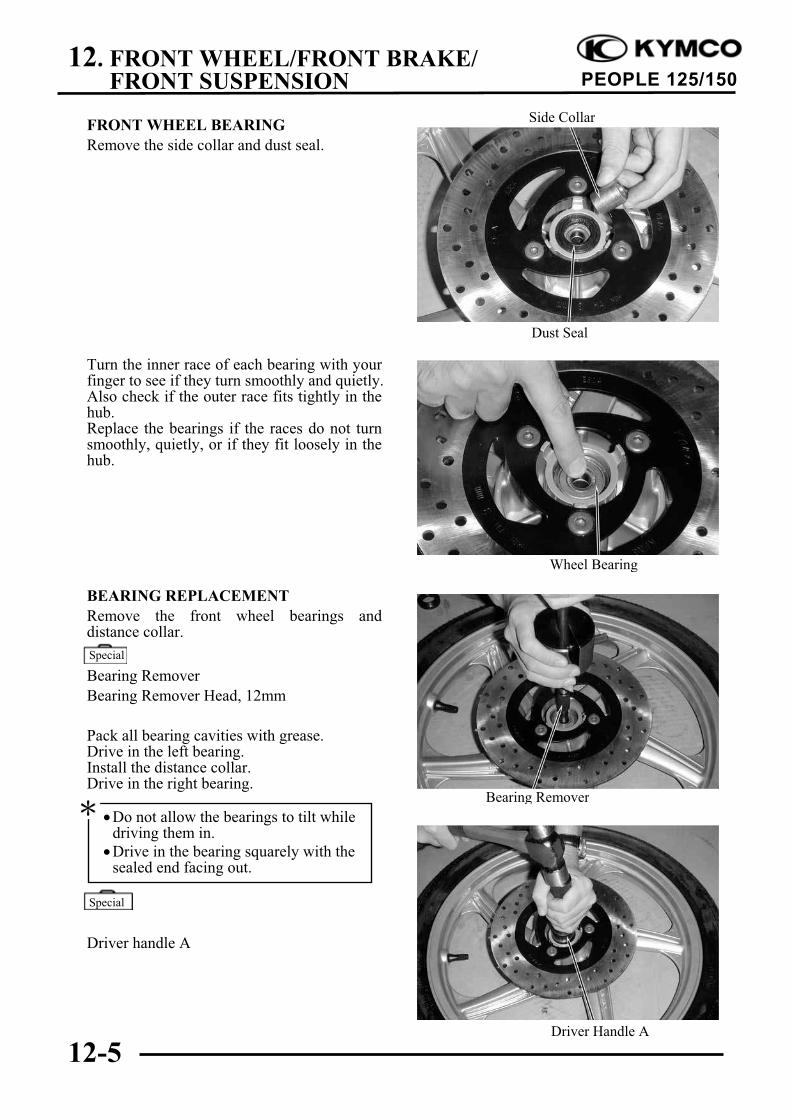
FRONT WHEEL BEARING
Remove the side collar and dust seal.
Turn the inner race of each bearing with yourfinger to see if they turn smoothly and quietly.Also check if the outer race fits tightly in thehub.Replace the bearings if the races do not turnsmoothly, quietly, or if they fit loosely in thehub.
BEARING REPLACEMENT
Remove the front wheel bearings anddistance collar.
Bearing Remover
Bearing Remover Head, 12mm
Pack all bearing cavities with grease.Drive in the left bearing.Install the distance collar.Drive in the right bearing.
Driver handle A
Do not allow the bearings to tilt whiledriving them in.
Drive in the bearing squarely with thesealed end facing out.
Wheel Bearing
Special
Special
Dust Seal
Side Collar
Bearing Remover
Driver Handle A
12. FRONT WHEEL/FRONT BRAKE/FRONT SUSPENSION
12-6
PEOPLE 125/150
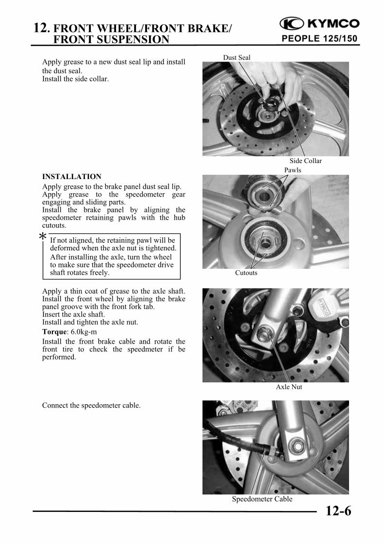
Apply grease to a new dust seal lip and install
the dust seal.Install the side collar.
INSTALLATION
Apply grease to the brake panel dust seal lip.Apply grease to the speedometer gearengaging and sliding parts.Install the brake panel by aligning thespeedometer retaining pawls with the hubcutouts.
Apply a thin coat of grease to the axle shaft.Install the front wheel by aligning the brakepanel groove with the front fork tab.Insert the axle shaft.Install and tighten the axle nut.
Torque: 6.0kg-m
Install the front brake cable and rotate thefront tire to check the speedmeter if beperformed.
Connect the speedometer cable.
Pawls
If not aligned, the retaining pawl will bedeformed when the axle nut is tightened.
After installing the axle, turn the wheelto make sure that the speedometer driveshaft rotates freely. Cutouts
In order to avoid spilling brake fluid, connecta transparent hose to the bleed valve.
Fully apply the brake lever and then loosenthe brake caliper bleed valve to drain thebrake fluid until there is no air bubbles in thebrake fluid. Then, tighten the bleed valve.Repeat these steps until the brake system isfree of air.
BRAKE FLUID REFILLING
Add DOT-3 brake fluid to the brakereservoir.
Make sure to bleed air from the brake system.
BRAKE PAD/DISK REPLACEMENT
Remove the two bolts attaching the brakecaliper.Remove the brake caliper.Compress the brake caliper seat, and pressdown the fixed-reed to take out the brakepads.
When operating the brake lever, thebrake reservoir cap must be tightenedsecurely to avoid splash of brake fluid.
When servicing the brake system, useshop towels to cover plastic parts andcoated surfaces to avoid damagecaused by splash of brake fluid.
Spilled brake fluid on brake pads orbrake disk reduces stopping power.Clean the brake pads and brake disk witha high-performance brake degreaser.
Warning
When bleeding, be careful not to allowair in the brake reservoir flowing intothe brake system.
Never use dirty or unspecified brakefluid or mix different brake fluids be-cause it will damage the brake system.
The brake pads must be replaced as a setto ensure the balance of the brake disk.
Hose
Lower Limit
Front Brake Caliper
Reservoir
Fixed-Reed
12. FRONT WHEEL/FRONT BRAKE/FRONT SUSPENSION
12-9
PEOPLE 125/150
Install the brake pads in the reverse order ofremoval.Tighten the brake pad pin bolt.
Torque: 1.5 2.0kg-m
BRAKE DISK
Measure the brake disk thickness.
Service Limit: 3.0mm
Measure the brake disk runout.
Service Limit: 0.3mm
BRAKE MASTER CYLINDER
REMOVAL
First drain the brake fluid from the hydraulicbrake system.
DISASSEMBLY
Remove the piston rubber cover and snapring from the brake master cylinder.
When servicing the brake system, useshop towels to cover rubber and plasticparts and coated surfaces to avoidbeing contaminated by brake fluid.
When removing the brake fluid tubebolt, be sure to plug the tube end toavoid brake fluid leakage.
Snap Ring
Keep grease or oil off the brake pads toavoid brake failure.
Fixed-Reed
Master Cylinder
Brake Pads
12. FRONT WHEEL/FRONT BRAKE/FRONT SUSPENSION
12-10
PEOPLE 125/150
Remove the main piston and spring from thebrake master cylinder.Clean the inside of the master cylinder andbrake reservoir with brake fluid.
INSPECTION
Measure the brake master cylinder I.D.Inspect the master cylinder for scratches orcracks.
Service Limit: 12.75mm
Measure the brake master cylinder pistonO.D.
Service Limit: 12.75mm
Before assembly, inspect the lst and 2ndrubber cups for wear or damage.
ASSEMBLY
Before assembly, apply brake fluid to allremoved parts.Install the spring together with the 1st rubbercup.
Install the main piston, spring and snap ring.Install the diaphragm.Install the brake lever.
During assembly, the main piston andspring must be installed as a unitwithout exchange.
When assembling the piston, soak thecups in brake fluid for a while.
Install the cups with the cup lips facingthe correct direction.
Main Piston
SpringSnap Ring
Master CylinderDiaphragm
12. FRONT WHEEL/FRONT BRAKE/FRONT SUSPENSION
12-11
PEOPLE 125/150
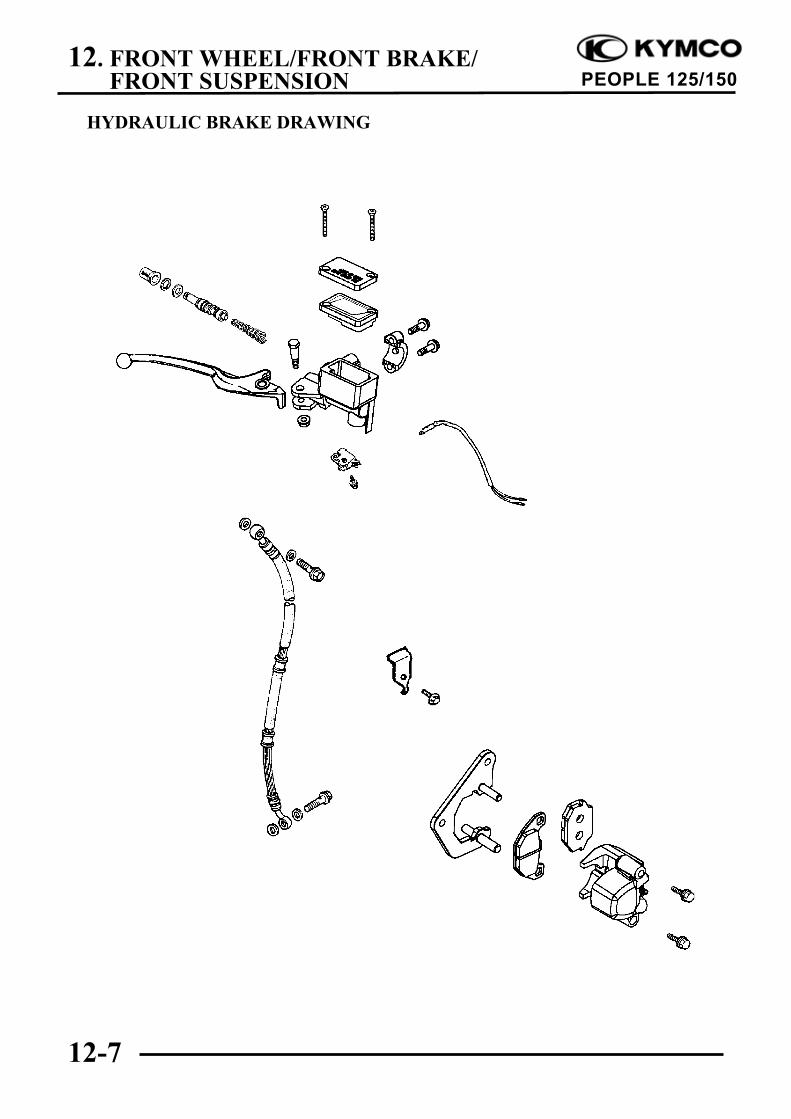
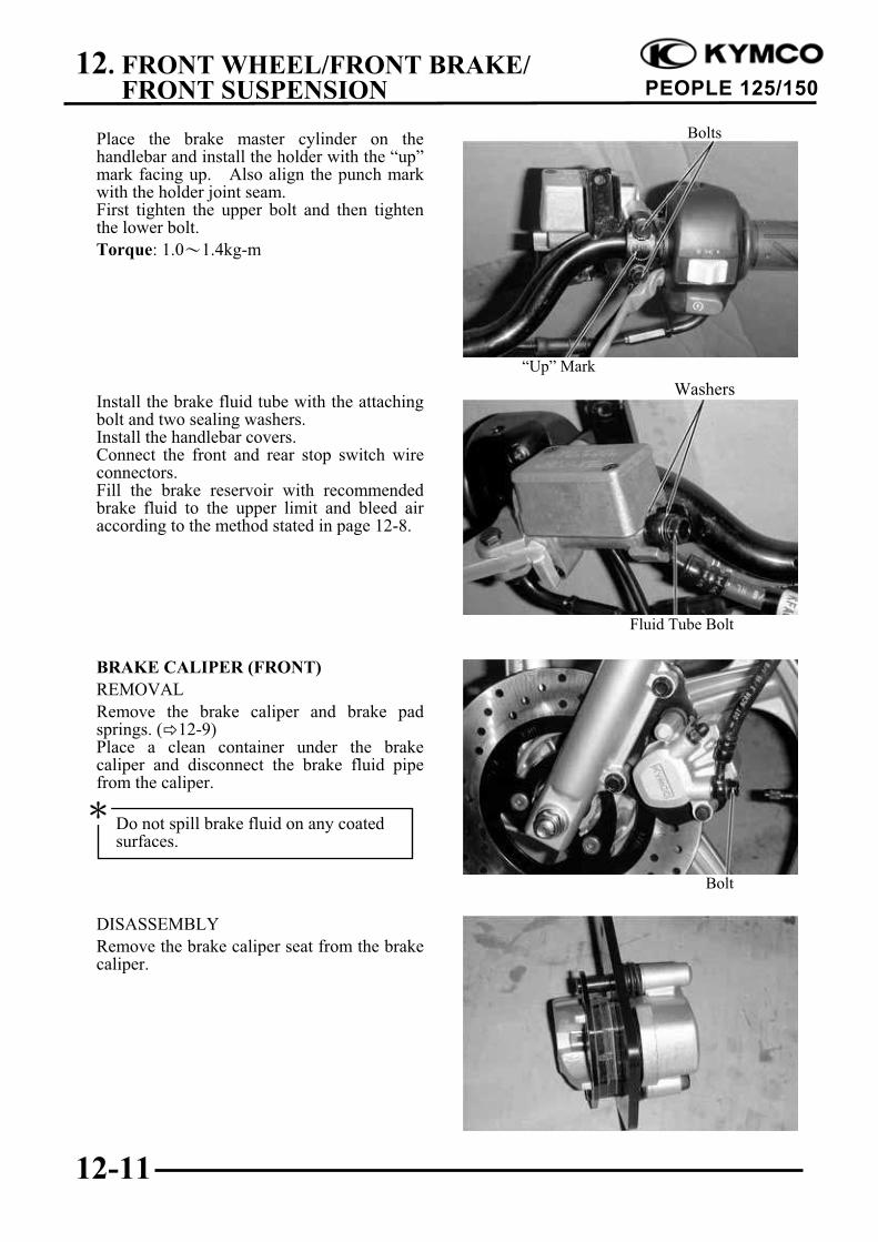
Place the brake master cylinder on thehandlebar and install the holder with the “up”mark facing up. Also align the punch markwith the holder joint seam.First tighten the upper bolt and then tightenthe lower bolt.
Torque: 1.0 1.4kg-m
Install the brake fluid tube with the attachingbolt and two sealing washers.Install the handlebar covers.Connect the front and rear stop switch wireconnectors.Fill the brake reservoir with recommendedbrake fluid to the upper limit and bleed airaccording to the method stated in page 12-8.
BRAKE CALIPER (FRONT)
REMOVAL
Remove the brake caliper and brake padsprings. ( 12-9)Place a clean container under the brakecaliper and disconnect the brake fluid pipefrom the caliper.
DISASSEMBLY
Remove the brake caliper seat from the brakecaliper.
Fluid Tube Bolt
“Up” Mark
Bolt
Do not spill brake fluid on any coatedsurfaces.
Bolts
Washers
12. FRONT WHEEL/FRONT BRAKE/FRONT SUSPENSION
12-12
PEOPLE 125/150
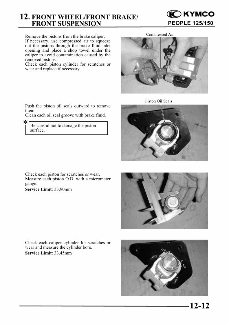
Remove the pistons from the brake caliper.If necessary, use compressed air to squeezeout the pistons through the brake fluid inletopening and place a shop towel under thecaliper to avoid contamination caused by theremoved pistons.Check each piston cylinder for scratches orwear and replace if necessary.
Push the piston oil seals outward to removethem.Clean each oil seal groove with brake fluid.
Check each piston for scratches or wear.Measure each piston O.D. with a micrometergauge.
Service Limit: 33.90mm
Check each caliper cylinder for scratches orwear and measure the cylinder bore.
Service Limit: 33.45mm
Compressed Air
Piston Oil Seals
Be careful not to damage the pistonsurface.
12. FRONT WHEEL/FRONT BRAKE/FRONT SUSPENSION
12-13
PEOPLE 125/150
ASSEMBLY
Clean all removed parts.Apply silicon grease to the pistons and oilseals. Lubricate the brake caliper cylinderinside wall with brake fluid.Install the brake caliper piston with groovedside facing out.
Wipe off excessive brake fluid with a cleanshop towel. Apply silicon grease to thebrake caliper seat pin and caliper inside.Install the brake caliper seat.
INSTALLATION
Install the brake caliper and tighten the twobolts.
Torque: 2.9 3.5kg-m
Connect the brake fluid tube to the brakecaliper and tighten the fluid tube bolt.
Torque: 2.5 3.5kg-m
Fill the brake reservoir with recommendedbrake fluid and bleed air from the brakesystem.
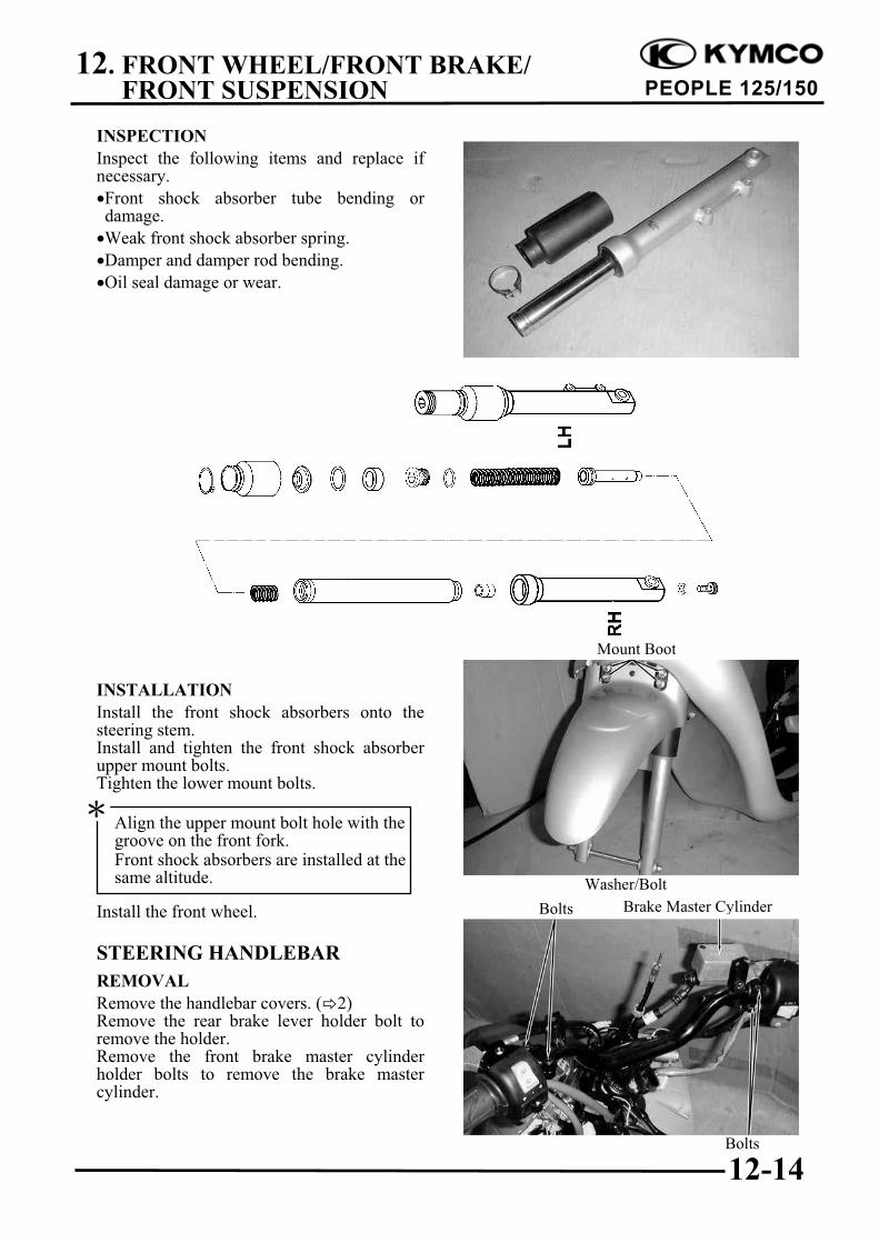
FRONT SHOCK ABSORBER
REMOVAL
Remove the front cover. ( 2)Remove the front wheel.Remove the front shock absorber uppermount bolts.Loosen the lower mount bolts to remove thefront shock absorbers.
Install the piston with its outer endprotruding 3 5mm beyond the brakecaliper cylinder.
Fluid Tube Bolt
Mount Bolt
12. FRONT WHEEL/FRONT BRAKE/FRONT SUSPENSION
12-14
PEOPLE 125/150
INSPECTION
Inspect the following items and replace ifnecessary.
Front shock absorber tube bending ordamage.
Weak front shock absorber spring.
Damper and damper rod bending.
Oil seal damage or wear.
INSTALLATION
Install the front shock absorbers onto thesteering stem.Install and tighten the front shock absorberupper mount bolts.Tighten the lower mount bolts.
Install the front wheel.
STEERING HANDLEBAR
REMOVAL
Remove the handlebar covers. ( 2)Remove the rear brake lever holder bolt toremove the holder.Remove the front brake master cylinderholder bolts to remove the brake mastercylinder.
Mount Boot
Front Shock Absorber
Washer/Bolt
Brake Master CylinderBolts
Align the upper mount bolt hole with thegroove on the front fork.Front shock absorbers are installed at thesame altitude.
Bolts
12. FRONT WHEEL/FRONT BRAKE/FRONT SUSPENSION
12-15
PEOPLE 125/150
Remove the throttle seat screw.
Remove the throttle seat from the handlebarand disconnect the throttle cable from thethrottle pipe.Remove the throttle pipe from the handlebar.
Remove the steering stem lock bolt, collar,nut and the handlebar.
STEERING STEM
REMOVAL
Remove the steering stem lock nut.
Steering Stem Lock Nut Wrench
Lock Nut wrench
Screw
Steering Stem Lock Nut Wrench
Collar
Throttle Pipe
Nut
Bolt
Special
12. FRONT WHEEL/FRONT BRAKE/FRONT SUSPENSION
12-16
PEOPLE 125/150
Remove the top cone race.
Remove the front fork.
BOTTOM CONE RACE REPLACEMENT
Remove the bottom cone race using a chisel.
Drive a new bottom cone race into place witha proper driver.
BALL RACE REPLACEMENT
Drive out the top and bottom ball races.
Drive new top and bottom ball races into thesteering head using the outer driver.
Outer Driver 37x40mm
Bottom Cone Race
Ball Race Remover
Outer Driver, 37x40mm
Top Cone Race
Be careful not to lose the steel balls (26on top race and 19 on bottom race).
Clean the openings of frame coverswith clean shop towels.
Be careful not to damage the steeringstem and front fork.
Special
12. FRONT WHEEL/FRONT BRAKE/FRONT SUSPENSION
12-17
PEOPLE 125/150
INSTALLATION
Install the front mold and the front fender.
Apply grease to the top and bottom ball racesand install 26 steel balls on the top ball raceand 19 steel balls on the bottom ball race.Apply grease to the ball races and install thefront fork.Apply grease to the top cone race and installit.Tighten the top cone race and then turn thesteering stem right and left several times tomake steel balls contact each other closely.
Install the steering stem lock nut and tightenit while holding the top cone race.
Torque: 8.0 12.0kg-m
Install the front wheel. ( 12-15)
HANDLEBAR INSTALLATION
Install the handlebar onto the steering stemtube and then install and tighten the bolt.Torque: 4.5kg-m
Install the front wheel. ( 12-6)Install the brake levers. ( 12-15)Install the handlebar covers.
Front Mold Front Fender
Top Cone Race
Top Cone Race Lock Nut Wrench
Collar Nut
Bolt
Steering Stem Lock Nut Wrench
Check that the steering stem rotatesfreely without vertical play.
13. REAR WHEEL/REAR BRAKE/REAR SUSPENSION
13-0
PEOPLE 125/150
13
REAR WHEEL/REAR BRAKE/ REAR SUSPENSION
SERVICE INFORMATION............................................................... 13-2
During servicing, keep oil or grease off the brake drum and brake linings.
SPECIFICATIONS
Item Standard (mm) Service Limit (mm)
Radial ! 2.0
Rear wheelRim runout
Axial ! 2.0
Rear brake drum I.D 130 131
Rear brake lining thickness 4.204 2.102
Rear shock absorber spring free length 200.5 194
TORQUE VALUES
Rear axle nut 11.0 13.0kg-m
Rear shock absorber upper mount bolt 4.0kg-m
Rear shock absorber lower mount bolt 2.5kg-m
Exhaust muffler joint lock nut 1.2kg-m
Exhaust muffler lock bolt 3.5kg-m
Brake arm bolt 1.0kg-m
TROUBLESHOOTING
Rear wheel wobbling Poor brake performance
Bent rim Brake not adjusted properly
Faulty tire Worn brake linings
Axle not tightened properly Worn brake shoes at cam contacting area
Soft rear shock absorber Worn brake cam
Weak shock absorber spring Worn brake drum
Faulty damper
13. REAR WHEEL/REAR BRAKE/REAR SUSPENSION
13-3
PEOPLE 125/150
REAR WHEEL
REMOVAL
Remove the exhaust muffler joint lock nutsand exhaust muffler lock bolts.Remove the exhaust muffler. ( 2-6)Remove the rear axle nut.Remove the rear shock absorber.Remove the link flake.Remove the rear wheel.
INSPECTION
Measure the rear wheel rim runout.
Service Limits:
Radial:2.0mm replace if over
Axial: 2.0mm replace if over
If the rim runout exceeds the specifiedservice limits, check the final shaft bearingfor excessive play and the final shaft forbending. Inspect the rear wheel and wheelrim for runout.
Turn the inner race of each bearing with yourfinger to see if they turn smoothly and quietly.Also check if the outer race fits tightly in thehub.Replace the bearings if the races do not turnsmoothly, quietly, or if they fit loosely in thehub.
INSTALLATION
Install the rear wheel and apply SAE30#engine oil to the axle shaft threads. Then,tighten the rear axle nut.
Torque: 11.0 13.0kg-m
Install the exhaust muffler. ( 2-6)Tighten the exhaust muffler joint lock nutsand exhaust muffler lock bolt.
Remove the rear wheel. ( 13-3)Inspect the rear brake drum.Measure the rear brake drum I.D.
Service Limits: 131mm replace if over
BRAKE LINING INSPECTION
Measure the brake lining thickness.
Service Limit: 2.0mm replace if below
REAR BRAKE DISASSEMBLY
Remove the rear brake adjusting nut anddisconnect the rear brake cable.Remove the rear brake shoes.
Remove the brake arm bolt to remove thebrake arm.Remove the brake cam.
Adjusting Nut
Brake Shoe
Keep oil or grease off the brake linings.
13. REAR WHEEL/REAR BRAKE/REAR SUSPENSION
13-5
PEOPLE 125/150
REAR BRAKE ASSEMBLY
Apply grease to the anchor pin.Apply grease to the brake cam and install it.Install the brake shoes.
Apply engine oil to the felt seal and install itto the brake cam.Install the brake arm.
Install and tighten the brake arm bolt.
Torque: 1.0kg-m
Install the brake arm return spring.
Install the brake arm pin.Connect the brake cable and install theadjusting nut.Install the rear wheel. ( 13-3)Adjust the rear brake lever free play. ( 3-8)
REAR SHOCK ABSORBER
REMOVAL
Remove the frame body cover. ( 2)Remove the air cleaner case. ( 5-13)
Adjusting Nut Brake Arm Pin
Brake Cable
Brake Cam
Brake Arm
Brake Arm
Align the wide groove on the wearindicator plate with the wide tooth of thebrake cam.
Align the scribed line on the brake armwith the punch mark on the brake cam.
Bolt
Bolt
Bolt
13. REAR WHEEL/REAR BRAKE/REAR SUSPENSION
13-6
PEOPLE 125/150
Remove the rear shock absorber upper andlower mount bolts.Remove the rear shock absorber.
ADJUSTABLE REAR CUSHION
To suit scooter behaviour to load conditionrear cushion could be adjusted in springprelocad.
It is possible to adjust rear cushion in threepositions:
A position “soft”
B position “medium”
C position “hard”
When you adjust rear cushion, the springpreload of rear cushions must be the same.
INSTALLATION
Install the rear shock absorber. First installthe upper mount bolt and then the lowermount bolts and tighten them.Install the air cleaner case and tighten the twobolts.Install the frame body cover.Torque:
Upper Mount Bolt: 4.0kg-m
Lower Mount Bolt: 2.5kg-m
Bolt
Adjust Position
Bolt
14. BATTERY/CHARGING SYSTEM/A.C. GENERATOR
14-0
PEOPLE 125/150
14
BATTERY/CHARGING SYSTEM/A.C. GENERATOR
CHARGING SYSTEM LAYOUT ..................................................... 14-1
SERVICE INFORMATION............................................................... 14-2
A.C. GENERATOR............................................................................. 14-7
14
14. BATTERY/CHARGING SYSTEM/A.C. GENERATOR
14-1
PEOPLE 125/150
CHARGING CIRCUIT
Fuse Regulator/Rectifier
A.C. GeneratorBattery
Resistors
14. BATTERY/CHARGING SYSTEM/A.C. GENERATOR
14-2
PEOPLE 125/150
SERVICE INFORMATION
GENERAL INSTRUCTIONS
The battery can be charged and discharged repeatedly. If a discharged battery is not used for a
long time, its service life will be shortened. Generally, the capacity of a battery will decrease
after it is used for 2 3 years. A capacity-decreased battery will resume its voltage after it is
recharged but its voltage decreases suddenly and then increases when a load is added.
When a battery is overcharged, some symptoms can be found. If there is a short circuit inside
the battery, no voltage is produced on the battery terminals. If the rectifier would not operate,
the voltage will become too high and shorten the battery service life.
If a battery is not used for a long time, it will discharge by itself and should be recharged every 3
months.
A new battery filled with electrolyte will generate voltage within a certain time and it should be
recharged when the capacity is insufficient. Recharging a new battery will prolong its service life.
Inspect the charging system according to the sequence specified in the Troubleshooting.
Do not disconnect and soon reconnect the power of any electrical equipment because the electronic
parts in the regulator/rectifier will be damaged. Turn off the ignition switch before operation.
It is not necessary to check the MF battery electrolyte or fill with distilled water.
Check the load of the whole charging system.
Do not quick charge the battery. Quick charging should only be done in an emergency.
Remove the battery from the motorcycle for charging.
When replacing the battery, do not use a traditional battery.
When charging, check the voltage with an voltmeter.
SPECIFICATIONS
Item Standard
Capacity/Model 12V!6AH
Voltage Fully charged 13.1V
Battery (20 ) Undercharged 12.3V
Charging current STD: 0.7A Quick: 3.0A
Charging time STD: 5 10hr Quick: 30min
Capacity 0.114KW/5000rpm
A.C. Generator Lighting coil resistance (20 ) Yellow Green 0.1 1.0"
Charging coil resistance (20 ) White Green 0.2 1.2"
Type Single-phase half-wave SCR
12.0 14.0V/5000rpm (Electric tester, tachometer)
Limit voltage 10 13.0V/5000rpm
Charging 13.5 15.5V/5000rpm
Resistance (20 ) 5W5" 4.0 6.0"
Resistance (20 ) 30W7.5" 7.0 8.0"
LightingRegulator/Rectifier
Resistor
The battery electrolyte (sulfuric acid) is poisonous and may seriously damage the skin andeyes. Avoid contact with skin, eyes, or clothing. In case of contact, flush with water andget prompt medical attention
14. BATTERY/CHARGING SYSTEM/A.C. GENERATOR
14-3
PEOPLE 125/150
TORQUE VALUES
Pulser coil bolt 0.5kg-m
Coil lock bolt 0.9kg-m
Flywheel nut 5.5kg-m
Cooling fan bolt 0.9kg-m
SPECIAL TOOLS
Universal holder
Flywheel puller
TESTING INSTRUMENTS
Kowa electric tester
Sanwa electric tester
TROUBLESHOOTING
No power Intermittent power
Dead battery Loose battery cable connection
Disconnected battery cable Loose charging system connection
Fuse burned out Loose connection or short circuit in
Faulty ignition switch lighting system
Low power Charging system failure
Weak battery Loose, broken or short circuit wire or
BATTERYREMOVALRemove the frame cover screws.Open the cover and remove the battery coverscrew.First disconnect the battery negative (-) cableand then the positive (+) cable.
The installation sequence is the reverse ofremoval.
BATTERY VOLTAGE (OPEN CIRCUITVOLTAGE) INSPECTION
Open the battery cover and disconnect thebattery cables.Measure the voltage between the batteryterminals.
Fully charged : 13.1VUndercharged : 12.3V max.
CHARGING
Connect the charger positive (+) cable to thebattery positive (+) terminal.Connect the charger negative (-) cable to thebattery negative (-) terminal.
Charging current: Standard : 0.7AQuick : 3.0A
Charging time : Standard : 5 10 hoursQuick : 30 minutes
After charging: Open circuit voltage: 12.8V min.
Battery Cover Screw
When disconnecting the battery positive(+) cable, do not touch the frame withtool; otherwise it will cause short circuitand sparks to fire the fuel.
Keep flames and sparks away from acharging battery.
Turn power ON/OFF at the charger, notat the battery terminals to preventsparks near the battery to avoidexplosion.
Charge the battery according to theifi d h b
Quick charging should only be done inan emergency.
Measure the voltage 30 minutes afterthe battery is charged.
Battery charging inspection must beperformed with a voltmeter.
First connect the positive (+) cable and thennegative (-) cable to avoid short circuit.
14. BATTERY/CHARGING SYSTEM/A.C. GENERATOR
14-5
PEOPLE 125/150
CHARGING SYSTEM
SHORT CIRCUIT TEST
Disconnect the ground wire from the batteryand connect an ammeter across the batterynegative (-) terminal and the ground wire.Turn the ignition switch OFF and check forshort circuit.
If any abnormality is found, check the ignitionswitch and wire harness for short circuit .
CURRENT TEST
This inspection must be performed with anelectric tester when the battery is fullycharged.Warm up the engine for inspection.Connect the electric tester across the batteryterminals. Disconnect the red wire from thefuse terminal and connect an ammeterbetween the red wire lead and the fuseterminal as shown.Attach a tachometer to the engine.Start the engine and gradually increase theengine speed to measure the limit voltage andcurrent.
If the limit voltage is not within the specifiedrange, check the regulator/rectifier. ( 14)
LIGHTING SYSTEM LIMIT VOLTAGEINSPECTION
Remove the headlight cover. ( 2)
Limit Voltage: 12 14V/5000rpm
If the limit voltage is not within the specifiedrange, check the regulator/rectifier. ( 14)
PERFORMANCE TEST
RPM
Position2500 6000
Day 1.0A min. 2.0A min.
Night 1.0A min. 2.0A min.
Perform this test with a fully charged of battery
Connect the electric tester positive (+)terminal to ground wire and the testernegative (-) terminal to the batterynegative (-) terminal.
Measure the voltage with the electrictester in the AC range.
(-) Terminal
Headlight Wire Coupler
14. BATTERY/CHARGING SYSTEM/A.C. GENERATOR
14-6
PEOPLE 125/150
REGULATOR/RECTIFIER
MAIN HARNESS CIRCUIT INSPECTION
Remove the front cover. ( 2-4)Remove the regulator/rectifier 4P coupler andcheck for continuity between the wire harnessterminals according to the following :
Item (Wire Color) Judgement
Between battery (red)and engine ground
Battery hasvoltage
Between ground wire(green) and engine ground
Continuity exists
Between lighting wire(yellow) and engineground (Remove theresistor coupler and autobystarter coupler andturn the lighting switchOFF for inspection)
A.C. generatorcoil hasresistance
Between charging coil(white) and engineground
A.C. generatorcoil hasresistance
REGULATOR/RECTIFIER INSPECTION
If the main harness terminals are normal,check the regulator/rectifier coupler for looseconnection and measure the resistancesbetween the regulator/rectifier terminals.
Replace the regulator/rectifier if the readingsare not within the specifications in the table.
Unit: "Probe#
Probe(-) White Yellow Red Green
White 2K~6K
Yellow 17K~25K
Red
Green 17K~25K
Do not touch the tester probes withyour finger because human body hasresistance.
Use the following specified testers foraccurate testing. Use of an impropertester in an improper range may givefalse readings.! Kowa Electric Tester! Sanwa Electric Tester! Kowa Electric Tester TH-5H
Proper range for testing:! Use XK" range for Sanwa Tester! Use X100" range for Kowa Tester
If the dry battery in the tester is weak,the readings will be incorrect. In thiscase, check the dry battery.
The Kowa tester readings are 100times the actual values. Be carefulduring testing.
Regulator/Rectifier
Yellow
Red Green
White
14. BATTERY/CHARGING SYSTEM/A.C. GENERATOR
14-7
PEOPLE 125/150
A.C. GENERATOR CHARGINGCOIL
INSPECTION
Disconnect the A.C. generator 3P connector.Measure the resistance between the A.C.generator white wire and engine ground withan electric tester.
Standard: 0.2 1.2"(at 20 )
Replace the A.C. generator charging coil ifthe reading is not within the specifications.
A.C. GENERATOR LIGHTINGCOIL
INSPECTION
Disconnect the A.C. generator 3P connector.Measure the resistance between the A.C.generator yellow wire and engine groundwith an electric tester.
Standard: 0.2 1.2"(at 20 )
Replace the A.C. generator lighting coil if thereading is not within the specifications.
RESISTOR INSPECTION
Remove the front cover. ( 2-4)Measure the resistance between the resistorlead and engine ground.
Resistances: 30W7.5": 7.0 8.0"5W5.0": 4.0 6.0"
A.C. GENERATOR
REMOVAL
Remove the rear right side cover. ( 2)Remove the four bolts attaching the coolingfan cover to remove the fan cover.
The inspection of A.C. generatorcharging coil can be made with theengine installed.
The inspection of A.C. generator lightingcoil can be made with the engineinstalled.
Charging Coil Wire (White)
Lighting Coil Wire (Yellow)
Resistor
Fan Cover
Bolts
14. BATTERY/CHARGING SYSTEM/A.C. GENERATOR
14-8
PEOPLE 125/150
Remove the cooling fan by removing the fourcooling fan attaching bolts.
Hold the flywheel with an universal holder.Remove the flywheel nut.
Universal Holder
Remove the A.C. generator flywheel usingthe flywheel puller.Remove the woodruff key.
Flywheel Puller
Remove the A.C. generator wire connector.
Cooling Fan
Special
Special
Universal Holder
Flywheel Puller
A.C. Generator Wire Connector
Bolts
14. BATTERY/CHARGING SYSTEM/A.C. GENERATOR
14-9
PEOPLE 125/150
Remove the A.C. generator wire set plate.Remove the pulser coil bolts.Remove the A.C. generator wire rubbersleeve and pulser coil from the rightcrankcase.Remove the two bolts and A.C. generatorstator.
INSTALLATION
Install the A.C. generator stator and pulsercoil onto the right crankcase.Tighten the stator and pulser coil bolts.
Torques: Pulser Coil : 0.5kg-m
Stator : 0.9kg-m
Install the A.C. generator wire rubber sleeveand A.C. generator wire set plate.
A.C. Generator WireRubber Sleeve
Bolts
Wire Set Plate
Woodruff Key
Flywheel
Cooling Fan
Fan Cover
Stator
A.C. GeneratorWire Set Plate
Bolts
Pulser Coil Set Plate
14. BATTERY/CHARGING SYSTEM/A.C. GENERATOR
14-10
PEOPLE 125/150
Connect the A.C. generator wire connector.
Clean the taper hole in the flywheel off anyburrs and dirt.Install the woodruff key in the crankshaftkeyway.
Install the flywheel onto the crankshaft withthe flywheel hole aligned with the crankshaftwoodruff key.
Hold the flywheel with the universal holderand tighten the flywheel nut.
Torque: 5.5kg-m
Universal Holder
Install the cooling fan.
Torque: 0.9kg-m
Install the fan cover.Install the rear right side cover. ( 2)
Fan Cover
Cooling Fan
Universal Holder
Woodruff Key
Bolts
The inside of the flywheel is magnetic.Make sure that there is no bolt or nutbefore installation.
Special
15. IGNITION SYSTEM
15-0
PEOPLE 125/150
15
IGNITION SYSTEM
SERVICE INFORMATION............................................................... 15-2
Check the ignition system according to the sequence specified in the Troubleshooting. ( 15)
The ignition system adopts CDI unit and the ignition timing cannot be adjusted.
If the timing is incorrect, inspect the CDI unit and A.C. generator and replace any faulty parts.
Loose connector and poor wire connection are the main causes of faulty ignition system. Check
each connector before operation.
Use of spark plug with improper heat range is the main cause of poor engine performance.
The inspections in this section are focused on maximum voltage. The inspection of ignition coil
resistance is also described in this section.
Inspect the ignition switch according to the continuity table specified in page 17-4.
Inspect the spark plug referring to Section 3.
Remove the A.C. generator and pulser coil referring to Section 14.
SPECIFICATIONS
Item Standard
Standard type C7HSA(NGK)
Spark plug Hot type C6HSA(NGK)
Cold type C8HSA(NGK)
Spark plug gap 0.6 0.7mm
Ignition timing“F” markFull advance
13°BTDC/1,700!100rpm27°BTDC/5,000!100rpm
Primary coil 0.1 1.0"
Ignition coil resistance (20 ) Secondary with plug cap 7 12K"
coil without plug cap 2 4K"
Pulser coil resistance (20 ) 70 130"
Ignition coil primary side max. voltage 12V min.
Pulser coil max. voltage 2.1V min.
TESTING INSTRUMENT
Kowa Electric Tester
15. IGNITION SYSTEM
15-3
PEOPLE 125/150
TROUBLESHOOTING
High voltage too low No high voltage
Weak battery or low engine speed Faulty ignition switch
Loose ignition system connection Faulty CDI unit
Faulty CDI unit Poorly connected or broken CDI ground wire
Faulty ignition coil Dead battery or faulty regulator/rectifier
Faulty pulser coil Faulty ignition coil connector
Normal high voltage but no spark at plug Faulty pulser coil
Faulty spark plug
Electric leakage in ignition secondary circuit
Faulty ignition coil
Good spark at plug but engine would not start
Faulty CDI unit or incorrect ignition timing
Improperly tightened A.C. generator flywheel
15. IGNITION SYSTEM
15-4
PEOPLE 125/150
CDI UNIT INSPECTIONRemove the front cover screws.Disconnect the CDI coupler and remove theCDI unit.Measure the resistance between the terminalsusing the electric tester...
Unit: K"
Probe#
(-)Probe
Black/Blue
Black/Yellow
Blue/Yellow
Green
Black/Blue
150~280 20~30
Black/Yellow
75~100 50~70
Blue/Yellow
7~10 50~70
Green
Black/Yellow
Due to the semiconductor in circuit, it isnecessary to use a specified tester foraccurate testing. Use of an impropertester in an improper range may givefalse readings.
Use a Sanwa Electric Tester or KowaElectric Tester.
In this table, “Needle swings thenreturns” indicates that there is a chargingcurrent applied to a condenser. The needlewill then remain at “ ” unless thecondenser is discharged.
Green
CDI Unit
Blue/Yellow
Black/Blue
15. IGNITION SYSTEM
15-5
PEOPLE 125/150
IGNITION COILREMOVAL
Remove the frame body cover. ( 2)Remove the spark plug cap.Disconnect the ignition coil wires and removethe ignition coil bolt and ignition coil.
INSPECTION
CONTINUITY TEST
Measure the resistance between the ignitioncoil primary coil terminals.
Resistance: 0.1 1.0"/20
Measure the secondary coil resistances withand without the spark plug cap.
Resistances:
(with plug cap): 7 12K"/20
(without plug cap): 2 4K"/20
This test is to inspect the continuity ofignition coil.
Ignition Coil
Correctly operate the tester following themanufacturer‘s instructions.
15. IGNITION SYSTEM
15-6
PEOPLE 125/150
PULSER COIL
INSPECTION
Remove the frame body cover. ( 2)Disconnect the A.C. generator connector.Measure the pulser coil resistance betweenthe blue/yellow and green wire terminals.
Resistance: 70 130"/20
Refer to page 14-7 for the A.C. generatorremoval.
IGNITION TIMING INSPECTION
Remove the timing hole cap.
Warm up the engine and check the ignitiontiming with a timing light.When the engine is running at 1700rpm, theignition timing is correct if the “F” markaligns with the index mark within !3$.
Ignition Timing: 13$ BTDC/1700rpm
This test is performed with the statorinstalled in the engine.
Timing Hole Cap
The CDI unit is not adjustable. If theignition timing is incorrect, inspect theCDI unit, pulser coil and A.C. generatorand replace any faulty parts.
16. STARTING SYSTEM
16-0
PEOPLE 125/150
16
SERVICE INFORMATION............................................................... 16-2
The removal of starter motor can be accomplished with the engine installed.
For the starter clutch removal, refer to Section 4.
SPECIFICATIONS
Item Standard (mm) Service Limit (mm)
Starter motor brush length 12.5 8.5
TORQUE VALUES
Starter clutch cover socket bolt 1.2kg-m
Starter clutch lock nut 9.5kg-m
SPECIAL TOOLS
Lock nut wrench
Universal holder
TROUBLESHOOTING
Starter motor would not turn Lack of power
Fuse burned out Weak battery
Weak battery Loose wire or connection
Faulty ignition switch Foreign matter stuck in starter motor
Faulty starter clutch or gear
Faulty front or rear stop switch
Faulty starter relay Starter motor rotates but engine does
Poorly connected, broken or shorted wire not start
Faulty starter motor Faulty starter clutch
Starter motor rotates reversely
Weak battery
16. STARTING SYSTEM
16-3
PEOPLE 125/150
STARTER MOTOR
REMOVAL
Remove the two starter motor mounting boltsand the motor.
Remove the waterproof rubber jacket anddisconnect the starter motor cable connector.
DISASSEMBLY
Remove the two starter motor case screws,front cover, motor case and other parts.
INSPECTION
Inspect the removed parts for wear, damageor discoloration and replace if necessary.Clean the commutator if there is metalpowder between the segments.
Check for continuity between pairs of thecommutator segments and there should becontinuity.Also, make a continuity check betweenindividual commutator segments and thearmature shaft. There should be nocontinuity.
Front Cover
Starter Motor Cable
Bolts
Commutator
Before removing the starter motor, turnthe ignition switch OFF and remove thebattery ground. Then, turn on theignition switch and push the starterbutton to see if the starter motor operatesproperly.
• •
Motor Case Case Screws
16. STARTING SYSTEM
16-4
PEOPLE 125/150
STARTER MOTOR CASE CONTINUITYCHECK
Check to confirm that there is no continuitybetween the starter motor wire terminal andthe motor front cover.Also check for the continuity between thewire terminal and each brush.Replace if necessary.
Measure the length of the brushes.
Service Limit: 8.5mm replace if below
Check for continuity between the brushes. Ifthere is continuity, replace with new ones.
Check if the needle bushing in the front coverturns freely and has no excessive play.Replace if necessary.Check the dust seal for wear or damage.
Bushing
Dust Seal
16. STARTING SYSTEM
16-5
PEOPLE 125/150
ASSEMBLY
Apply grease to the dust seal in the frontcover.Install the brushes onto the brush holders.Apply a thin coat of grease to the two ends ofthe armature shaft.Insert the commutator into the front cover.
Install a new O-ring to the front cover.Install the starter motor case, aligning the tabon the motor case with the groove on thefront cover.Tighten the starter motor case screws.
STARTER RELAYINSPECTION
Remove the frame body cover. ( 2-2)Turn the ignition switch ON and the starterrelay is normal if you hear a click when thestarter button is depressed.If there is no click sound:
Inspect the starter relay voltage
Inspect the starter relay ground circuit
Inspect the starter relay operation
STARTER RELAY VOLTAGE INSPECTION
Place the motorcycle on its main stand.Measure the voltage between the starter relayconnector green/yellow wire (-) and engineground.Turn the ignition switch ON and the batteryvoltage should be normal when the brakelever is fully applied.If the battery has no voltage, inspect the stopswitch continuity and cable.
Front Cover
Groove
Commutator
Tab
Be careful not to damage the brush andarmature shaft mating surfaces.
When installing the commutator, thearmature shaft should not damage thedust seal lip.
• •
When assembling the front cover andmotor case, slightly press down thearmature shaft to assemble them.
• •
DC V
Starter Relay
16. STARTING SYSTEM
16-6
PEOPLE 125/150
STARTER RELAY GROUND CIRCUIT
INSPECTION
Disconnect the starter relay wire connector.Check for continuity between the yellow/redwire terminal and ground.There should be continuity when the starterbutton is depressed.If there is no continuity, check the starterbutton for continuity and inspect the wire.
OPERATION TEST
Connect the electric tester to the starter relaylarger terminals that connect to the batterypositive cable and the starter motor cable.Connect a fully charged battery across thestarter relay yellow/red and green/yellowwire terminals.Check for continuity between the starter relaylarge terminals. The relay is normal if there iscontinuity.
INSTALLATION
Connect the starter motor cable connector andproperly install the waterproof rubber jacket.Check the O-ring for wear or damage andreplace if necessary.Apply grease to the O-ring and install thestarter motor.Tighten the two mounting bolts.
STARTER CLUTCH
REMOVAL
Remove the A.C. generator. ( 14-7)Remove the right crankcase cover. ( 4-3)
Starter Motor Cable
O-ring
The starter motor cable connector mustbe installed properly.
• •
16. STARTING SYSTEM
16-7
PEOPLE 125/150
Remove the starter clutch lock nut.
Lock Nut Wrench
Universal Holder
Remove the starter clutch.Remove the starter idle gear and shaft.
INSPECTION
Inspect the operation of the starter drive gearwhen it is assembled on the clutch.The starter drive gear should turn clockwisefreely and should not turn counterclockwise.
STARTER CLUTCH DISASSEMBLY
Inspect the starter drive gear for wear ordamage and replace if necessary.Measure the starter drive gear I.D.
Service Limit: 32.06mm replace if over
Inspect the needle bearing for wear ordamage and replace if necessary.
CLUTCH BODY DISASSEMBLY
Remove the rollers, plungers and springsfrom the clutch body.Inspect the clutch body for wear or damageand replace if necessary.Inspect each roller and plunger for wear ordamage and check for weak spring.Replace if necessary.
Starter Idle Gear Shaft
Lock Nut Wrench
Starter Drive Gear
Clutch Body
Special
Note that the lock nut is left threaded.• •
Lock Nut
Needle Bearing
RollerSpring
16. STARTING SYSTEM
16-8
PEOPLE 125/150
Measure the clutch cover O.D.
Service Limit: 27.94mm replace if over
Measure the starter idle gear I.D.
Service Limit: 10.05mm replace if over
Measure the starter idle gear shaft O.D.
Service Limit: 9.94mm replace if below
Clutch Cover
Starter Idle Gear
Idle Gear Shaft
Starter Drive Gear
Lock Nut
Needle Bearing
Clutch Body
Roller
Spring
Clutch Cover
Plunger
Cap Bolt
Anchor Pin
16. STARTING SYSTEM
16-9
PEOPLE 125/150
ASSEMBLY
Install the springs, plungers and rollers ontothe clutch body.Install the clutch cover by aligning the clutchcover anchor pin with the hole in the clutchbody. Apply locking agent to the threads ofthe clutch cover bolts and tighten them.
Torque: 1.2kg-m
Apply engine oil to the needle bearing andstarter drive gear and then install them to theclutch body.
INSTALLATION
Install the starter clutch onto the crankshaft.Apply engine oil to the starter idle gear andshaft and then install them.Hold the starter drive gear with the universalholder and tighten the starter clutch lock nut.
An electric tester is needed to measure or test the electric equipment.
Be sure to use fuses and bulbs of the same specifications to avoid damage of electrical
equipment.
After installation of each switch, a continuity check must be performed. A continuity check can
usually be made without removing the part from the motorcycle.
TROUBLESHOOTING
Lights do not come on and horn does not Engine starts but stalls during idling
sound when ignition switch is “ON” Faulty auto bystarter
Faulty ignition switch Faulty auto bystarter resistor
Fuse burned out Poorly connected or broken wire
Weak battery Clogged carburetor
Burned bulb
Faulty switch
Faulty horn
Poorly connected, broken or shorted wire
Fuel gauge pointer does not register
Fuel gauge pointer does not move correctly
Faulty fuel gauge Faulty fuel gauge
Faulty fuel unit Faulty fuel unit
Poorly connected, broken or shorted wire Faulty fuel unit float
17. LIGHTS/INSTRUMENTS/SWITCHES
17-3
PEOPLE 125/150
HEADLIGHT
BULB REPLACEMENT
Remove the handlebar front cover. ( 2)Remove the rubber boot from the bulb socket.Remove the bulb socket by turning it counter-clockwise.Remove the bulb for replacement.Install a new bulb, aligning the groove on thebulb socket with the tab on the bulb.Install the bulb socket.Install the rubber boot.Install the front cover. ( 2)
HEADLIGHT REMOVAL
Remove the handlebar front cover. ( 2)Remove the two screws attaching theheadlight.Remove the headlight unit.Remove adjust the headlight beam bolt.The installation sequence is the reverse ofremoval.After installation, adjust the headlight beam.( 3-9)
FRONT TURN SIGNAL LIGHTRemove the turn signal bulb shell screw.( 2)Remove the front turn signal bulb socket andreplace the bulb.The installation sequence is the reverse ofremoval.
POSITION LIGHT/REAR TURNSIGNAL LIGHTBULB REPLACEMENT
Remove the bulb shell screw.The installation sequence is the reverse ofremoval.
Screw
Bulb Socket
Rubber Boot
Screws
Turn Signal Bulb Shell
Position Light Shell
Bolt
17. LIGHTS/INSTRUMENTS/SWITCHES
17-4
PEOPLE 125/150
IGNITION SWITCH
INSPECTION
Remove the front cover. ( 2-4)Disconnect the ignition switch wire coupler.Check for continuity between the wireterminals.
Replacement
Remove the two mounting bolts to removethe ignition switch holder.Remove the two screws to remove theignition switch for replacement.
HANDLEBAR SWITCHES
HEADLIGHT SWITCH INSPECTION
Remove the handlebar front and rear covers.( 2-4)Disconnect the headlight switch wirecouplers. Check for continuity between thewire terminals.
Ignition Switch Coupler
Ignition Switch Bolts
Headlight Switch
17. LIGHTS/INSTRUMENTS/SWITCHES
17-5
PEOPLE 125/150
STARTER SWITCH
HORN SWITCH
TURN SIGNAL SWITCH
DIMMER SWITCH
Horn Button
Turn Signal Switch
Starter Switch
Dimmer Switch
Headlight Switch
Sky
17. LIGHTS/INSTRUMENTS/SWITCHES
17-6
PEOPLE 125/150
STOP SWITCH
INSPECTION
Remove the handlebar front cover. ( 2)Disconnect the front stop switch wirecoupler.Check for continuity between the wireterminals when the front brake lever isapplied. The switch is normal if there iscontinuity.
HORN INSPECTIONRemove the front cover. ( 2)Disconnect the horn wire coupler.The horn is normal if it sounds when a 12Vbattery is connected across the horn wireterminals.
FUEL GAUGEINSPECTION
Remove the rear right side cover. ( 2)Disconnect the fuel gauge wire connector.Turn the ignition switch ON.Connect the green and yellow/white wiresand the fuel gauge needle should move fromE to F.Connect the green and blue/white wires andthe fuel gauge needle should move from F toE.
FUEL UNIT
REMOVAL
Remove the met-in box. ( 2)Remove the rear right side cover. ( 2)Disconnect the fuel unit wire connector.Remove the fuel unit.
Fuel Unit Connector
Be careful not to bend or damage thefuel unit float arm.
17. LIGHTS/INSTRUMENTS/SWITCHES
17-7
PEOPLE 125/150
INSPECTION
Measure the resistance between the fuel unitwire terminals with the float at upper andlower positions.
RESISTANCES Unit: !
FloatColor
Upper Lower
G Y/W 26 38 450 550
G L/W 450 550 26 38
Y/W L/W 450 550 450 550
The installation sequence is the reverse ofremoval.
AUTO BYSTARTER
AUTO BYSTARTER INSPECTION
Remove the rear right side cover. ( 2)Disconnect the auto bystarter wire connector.Measure the resistance between the yellowand green/black wire terminals.
Resistance: 10! max.
RESISTOR INSPECTION
Remove the front cover. ( 2)Disconnect the green/black and green wiresand measuring the resistance between thewire terminals.
Resistance: 5! max.
If the needle remains at “"”, it indicates thatthe resistor is faulty and must be replaced.
Install the fuel unit by aligning thegroove on the fuel unit with the tab onthe fuel tank.
Perform this operation when the engineis cold.
Auto Bystarter Connector
Auto Bystarter Resistor
17. LIGHTS/INSTRUMENTS/SWITCHES
17-8
PEOPLE 125/150
INSTRUMENTS
BULB REPLACEMENT
Remove the front cover. ( 2)Remove the bulb socket and replace the bulb.The installation sequence is the reverse ofremoval.
INSTRUMENTS REPLACEMENT
Remove the handlebar front cover. ( 2)Remove the handlebar rear cover. ( 2)Disconnect the right and left handlebarswitches wire couplers.Disconnect the speedometer cable.Remove the instrument bulb socketsDisconnect the three fuel gauge wires.Remove the instrument wire clamp screw.
Remove the three screws attaching theinstruments to the handlebar rear cover.Remove the instruments.
ASSEMBLY/INSTALLATION
The assembly and installation sequence is thereverse of removal.
Clamp
Bulb Socket
Speedometer Cable
Bulb Socket
Screws
Instruments
Fuel Gauge WiresDimmer/Passing Wires
Lighting/Start Wires
Stop LightWires
Turn SignalWires
Clamp
17. LIGHTS/INSTRUMENTS/SWITCHES
17-9
PEOPLE 125/150
DISASSEMBLY
Remove the screws to disassemble the instruments.
KYMCO TECHNICAL INFORMATION
Model: ALL MODEL (For EURO 2) Date: 8.JAN.04 Subject:KYMCO Clean Air System (For EURO 2)
NO.: KTI-04002
KYMCO Clean Air System (For EURO 2) The KYMCO Clean Air System is a secondary air suction system that helps the exhaust gases to burn more completely. When the spent fuel charge is released into the exhaust system, it is still hot enough to burn. The system allows extra air into the exhaust system so that the spent fuel charge can continue to burn. This continued burning action tends to burn up a great deal of the normally unburned gases, as well as changing a significant portion of the poisonous carbon monoxide into harmless carbon dioxide.
Secondary Air Suction System Diagram (4-stroke)
1/2
KYMCO TECHNICAL INFORMATION
Model: ALL MODEL (For EURO 2) Date: 8.JAN.04 Subject:KYMCO Clean Air System (For EURO 2)