1. GENERAL INFORMATION
1-0
GRAND DINK 250
1 __________________________________________________________________________________
__________________________________________________________________________________
__________________________________________________________________________________
__________________________________________________________________________________
__________________________________________________________________________________
GENERAL INFORMATION__________________________________________________________________________________
ENGINE SERIAL NUMBER--------------------------------------------- 1-1
SPECIFICATION---------------------------------------------------------- 1-2
SERVICE PRECAUTIONS----------------------------------------------- 1-3
TORQUE VALUES ------------------------------------------------------- 1-7
TOOLS --------------------------------------------------------------------- 1-8
LUBRICATION POINTS------------------------------------------------- 1-9
CABLE & HARNESS ROUTING-----------------------------------------1-11
WIRING DIAGRAM-------------------------------------------------------------------1-16
TROUBLESHOOTING --------------------------------------------------1-17
1
1. GENERAL INFORMATION
1-1
GRAND DINK 250
SERIAL NUMBER
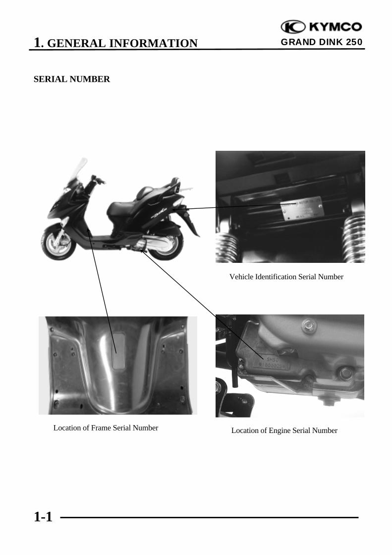
Location of Engine Serial NumberLocation of Frame Serial Number
Vehicle Identification Serial Number
1. GENERAL INFORMATION
1-2
GRAND DINK 250
SPECIFICATIONS
Name & Model No. SH50DAMotorcycle Name & Type GRAND DINK 250Overall length 2060mmOverall width 770mmOverall height 1360mmWheel base 1435mm
Engine type Water cooled 4-stroke,OHC engine
Displacement 249ccFuel Used 92# nonleaded gasoline
Front wheel 58Net weight (kg) Rear wheel 92
Total 150Front wheel 63.5
Gross weight(kg) Rear wheel 99.5Total 163
Front wheel 120/70-12Rear wheel 140/70-12
Ground clearance 140mmPerform-
Braking distance (m) 7.0m/30km/hr
ance Min. turning radius 2350mm
Starting system Starting motor
Type Gasoline, 4-strokeCylinder arrangement Single cylinderCombustion chamber type Semi-sphereValve arrangement O.H.C.Bore x stroke (mm) 72.7 x 60Compression ratio 10.3:1Compression pressure(kg/cm_) 15±2
Max. output (kw/rpm) 13.4/7000Max. torque (N.m/rpm) 19.6/5500
BTDC 8°Port
IntakeABDC 42°
t iming
BBDC 33°Exhaust
ATDC 1°
Valve Intake 0.1clearance (cold) Exhaust 0.1Idle speed (rpm) 1700±100rpm
Lubrication type Forced pressure &wet sump
Oil pump type Inner/outer rotortype
Oil filter type Full-flow filtrationOil capacity 1.1 liters
Cooling Type Water cooling
Air cleaner type & No Paper element, wetFuel capacity 9.1 liters
Type CVKPiston dia. 30Venturi dia. 30 equivalentThrottle type Butterfly typeType CDIIgnition timing repeatedlyContact breaker Non-contact point
type
Spark plug NGKDPR7EA-9
Spark plug gap 0.9mmBattery Capacity 12V10AHClutch Type Dry multi-disc clutch
Type Non-stage transmission
Operation Automaticcentrifugal
Type
Type Two-stage reduction
Reduction 1st 0.83~2.2ratio 2nd 6.98
Front Caster angle 27°Axle Connecting rod
Front 2.00Tire pressure(kg/cm_) Rear 2.25
Turning Left 45°angle Right 45°
Front Disk brakeBrake systemtype Rear Disk brake
Suspension Front Telescopetype Rear Double swing
Shock absorber Front Telescopetype Rear Double swing
Frame type Under bone
Tires
Engine
System
Fuel System
Carburetor
Electrical
Ignition System
Power D
rive System
Transm
is-sion G
earR
eductionG
ear
Moving D
eviceD
amping
Device
1. GENERAL INFORMATION
1-3
GRAND DINK 250
SERVICE PRECAUTIONS
nMake sure to install new gaskets, O-rings,circlips, cotter pins, etc. whenreassembling.
nWhen tightening bolts or nuts, begin withlarger-diameter to smaller ones at severaltimes, and tighten to the specified torquediagonally.
n Use genuine parts and lubricants.
nWhen servicing the motorcycle, be sure touse special tools for removal andinstallation.
n After disassembly, clean removed parts.Lubricate sliding surfaces with engine oilbefore reassembly.
n Apply or add designated greases andlubricants to the specified lubricationpoints.
n After reassembly, check all parts forproper tightening and operation.
nWhen two persons work together, payattention to the mutual working safety.
n Disconnect the battery negative (-) terminalbefore operation.nWhen using a spanner or other tools, make
sure not to damage the motorcycle surface.
n After operation, check all connectingpoints, fasteners, and lines for properconnection and installation.nWhen connecting the battery, the positive
(+) terminal must be connected first.n After connection, apply grease to the
battery terminals.n Terminal caps shall be installed securely.
1. GENERAL INFORMATION
1-4
GRAND DINK 250
n If the fuse is burned out, find the cause andrepair it. Replace it with a new oneaccording to the specified capacity.
n After operation, terminal caps shall beinstalled securely.
nWhen taking out the connector, the lock onthe connector shall be released beforeoperation.
n Hold the connector body when connectingor disconnecting it.n Do not pull the connector wire.
n Check if any connector terminal is bending,protruding or loose.
n The connector shall be insertedcompletely.n If the double connector has a lock, lock
it at the correct position.n Check if there is any loose wire.
n Before connecting a terminal, check fordamaged terminal cover or loose negativeterminal.
n Check the double connector cover forproper coverage and installation.
n Insert the terminal completely.n Check the terminal cover for proper
coverage.n Do not make the terminal cover opening
face up.
n Secure wire harnesses to the frame withtheir respective wire bands at thedesignated locations.Tighten the bands so that only theinsulated surfaces contact the wireharnesses.
ConfirmCapacity
1. GENERAL INFORMATION
1-5
GRAND DINK 250
n After clamping, check each wire to makesure it is secure.
n Do not squeeze wires against the weld orits clamp.
n After clamping, check each harness to makesure that it is not interfering with anymoving or sliding parts.
nWhen fixing the wire harnesses, do notmake it contact the parts which willgenerate high heat.
n Route wire harnesses to avoid sharp edgesor corners. Avoid the projected ends ofbolts and screws.n Route wire harnesses passing through the
side of bolts and screws. Avoid theprojected ends of bolts and screws.
n Route harnesses so they are neitherpulled tight nor have excessive slack.
n Protect wires and harnesses with electricaltape or tube if they contact a sharp edge orcorner.
nWhen rubber protecting cover is used toprotect the wire harnesses, it shall beinstalled securely.
n Do not break the sheath of wire.n If a wire or harness is with a broken sheath,
repair by wrapping it with protective tapeor replace it.
nWhen installing other parts, do not press orsqueeze the wires.
Do not pulltoo tight
No Contact
Do not pressor squeeze thewire
1. GENERAL INFORMATION
1-6
GRAND DINK 250
n After routing, check that the wire harnessesare not twisted or kinked.
nWire harnesses routed along with handlebarshould not be pulled tight, have excessiveslack or interfere with adjacent orsurrounding parts in all steering positions.
nWhen a testing device is used, make sure tounderstand the operating methodsthoroughly and operate according to theoperating instructions.
n Be careful not to drop any parts.
nWhen rust is found on a terminal, removethe rust with sand paper or equivalentbefore connecting.
n Symbols:The following symbols represent theservicing methods and cautions included inthis service manual.
: Apply engine oil to thespecified points. (Usedesignated engine oil forlubrication.)
: Apply grease for lubrication.
: Transmission Gear Oil (90#)
: Use special tool.
: Caution
: Warning
Special
Engine Oil
Grease
Gear Oil
*Do youunderstand theinstrument?
RemoveRust
1. GENERAL INFORMATION
1-7
GRAND DINK 250
TORQUE VALUES
STANDARD TORQUE VALUES
Item Torque (N-m) Item Torque (N-m)
5mm bolt, nut 6mm bolt, nut 8mm bolt, nut 10mm bolt, nut 12mm bolt, nut
4.99.821.634.353.9
5mm screw6mm screw, SH bolt6mm flange bolt, nut8mm flange bolt, nut10mm flange bolt, nut
3.98.811.826.539.2
Torque specifications listed below are for important fasteners.
ENGINE
Item Q‘ty Thread dia.(mm) Torque (N-m) Remarks
Cylinder head bolt ACylinder head bolt BOil filter screen capExhaust muffler joint lock nutCylinder head cap nutValve adjusting lock nutCam chain tensioner slipper boltOil boltClutch outer nutClutch drive plate nutFlywheel nutOil pump boltCylinder head cover boltSpark plugCam chain tensioner boltWater pump impeller
2212421111124111
8830885612121214561068
8.9
8.914.78.824.58.88.812.753.953.958.83.911.817.211.811.8
Double end boltDouble end boltApply oil tothreads
Left hand threads
FRAME
Item Q‘ty Thread dia.(mm) Torque (N-m) Remarks
Steering stem lock nutFront axle nutRear axle nutRear shock absorber upper boltRear shock absorber lower boltFront shock absorber lock boltEngine hanger bolt
1112241
1012141081012
44.168.6127.429.429.424.553.9
U-nutU-nutU-nut
1. GENERAL INFORMATION
1-8
GRAND DINK 250
SPECIAL TOOLS
Tool Name Tool No. Remarks Ref. Page
Valve guide driver Valve guide removal/installationValve guide reamer Valve guide grindingValve spring compressor Valve removalLock nut wrench, 39mm E027 Clutch disassemblyBearing driver Bearing removalBearing remover,10,12,15,18mm
E037 Bearing removal
Clutch spring compressor E027 Clutch disassemblyBall race remover extension Ball race removalBall race remover Ball race removalSpring compressor E038 Spring removal
Mechanical seal driver E014 Water pump mechanical sealremoval/installation
Kick starter spring remover Kick starter spring removalGear remover Starter gear removalValve adjuster E012 Tapper adjustmentFloat level gauge Carburetor fuel level checkValve seat cutter 45° Valve seat refacingValve seat cutter 32° Valve seat refacingValve seat cutter 60° Valve seat refacingCutter clip, 5mmUniversal holder E017 Holding clutch for removalBearing driver (32x35mm) E014 Bearing installationPilot, 12mm E014 Bearing installationPilot, 15mm E014 Bearing installationPilot, 17mm E014 Bearing installationFlywheel puller E003 A.C. generator flywheel removalRear shock absorber compressor F004 Rear shock absorber disassemblySteering head bearing remover F005 Steering head bearing removalFlywheel holder E021 A.C. generator flywheel holdingReamer clipFuel unit wrench Fuel unit removal
1. GENERAL INFORMATION
1-9
GRAND DINK 250
LUBRICATION POINTS
ENGINE
Lubrication Points Lubricant
Valve guide/valve stem movable part
Camshaft protruding surface
Valve rocker arm friction surface
Camshaft drive chain
Cylinder lock bolt and nut
Piston surroundings and piston ring grooves
Piston pin surroundings
Cylinder inside wall
Connecting rod/piston pin hole
Connecting rod big end
Crankshaft
Cranksahft one-way clutch movable part
Oil pump drive chain
Starter reduction gear engaging part
Countershaft gear engaging part
Final gear engaging part
Bearing movable part
O-ring face
Oil seal lip
•Genuine KYMCO Engine Oil (SAE15W-40)
•API SE, SF or SG Egnine Oil
Starter idle gear
Friction spring movable part/shaft movable part
Shaft movable grooved part
Starter spindle movable part
High-temperature resistant grease
Starter one-way clutch threads Thread locking agent
A.C. generator connector
Transmission case breather tubee Adhesive
1. GENERAL INFORMATION
1-10
GRAND DINK 250
FRAMEThe following is the lubrication points for the frame.Use general purpose grease for parts not listed.Apply clean engine oil or grease to cables and movable parts not specified. This will avoidabnormal noise and rise the durability of the motorcycle.
Seat Lock
Rear Wheel Bearing
GreaseSpeedometer CableThrottle Cable
Speedometer Gear/Front Wheel Bearing
Engine Oil
Grease
GreaseGrease
Front Brake Lever Pivot
1. GENERAL INFORMATION
1-11
GRAND DINK 250
CABLE & HARNESS ROUTING
Front Stop Brake
Rear Stop Brake
Throttle Cable
Radiator
Front Brake Fluid Tube Front / Rear BrakeMaster Cylinder
Speedometer Cable
Horn
Pressure TypeRadiator Cap
Radiator AirVentilated Tube
1. GENERAL INFORMATION
1-12
GRAND DINK 250
Front Brake Fluid Tube
Fuel TankInlet Tube
Water Hose
Ignition Switch
Fuel Filler
Water Hoses
Fuel TankBreather Tube
Left Brake Fluid Tube
Ventilated Hose
Reserve Tank
1. GENERAL INFORMATION
1-13
GRAND DINK 250
Throttle Cable
Speedometer Cable
Radiator AirVentilated Tube
Rear Brake FluidTube
Fuel Tank InletTube
Water Hose
Fuel Filler
Fuel TankBreather Tube
Throttle Cable
Wire Harness
Fuel Tank
Rear-view MirrorControl Relay
1. GENERAL INFORMATION
1-14
GRAND DINK 250
Starter Relay
Fuel Tube
Battery (-) Cable
Battery (+) Cable
Ignition Coil
Thermosensor WireThermostat
Carburetor
Regulator/Rectifier
CDI Unit
Fuse Box
Starter Motor
Oil VaporRecovery Tube
1. GENERAL INFORMATION
1-15
GRAND DINK 250
Fuel Tube
Ignition Coil
Thermostat
Carburetor
Fuel Tube
Auto Bystarter
Spark Plug Cap
FuelPump
Wire Harness
Spark Plug Cap
Throttle Cable
Fuel Pump Vacuum Tube
Oil VaporRecovery Tube
Fuel Pump Vacuum Tube
Ignition Coil
Starter RelayT.P.S
Oil VaporRecovery Tube
1. GENERAL INFORMATION
1-17
GRAND DINK 250
TROUBLESHOOTING
ENGINE WILL NOT START OR IS HARD TO START
ÅEmpty fuel tankÇClogged carburetor fuel inlet
tube, vacuum tube or fuel tubeÉClogged auto fuel valveÑClogged float oil passageÖClogged fuel tank cap
breather holeÜClogged fuel straineráClogged fuel filteràFaulty fuel pump
ÅFaulty spark plugÇFouled spark plugÉFaulty CDI unitÑFaulty A.C. generatorÖBroken or shorted ignition coilÜBroken or shorted exciter
coiláFaulty ignition switch
ÅStarter motor idles butcrankshaft does not rotateÇValve clearance too smallÉImproper valve and seat
contactÑWorn cylinder and piston ringsÖBlown cylinder head gasketÜFlaws in cylinder headáSeized valveàImproper valve timing
ÅFaulty auto bystarterÇAir leaking through intake
pipeÉIncorrect ignition timingÑIncorrectly adjusted pilot
screw
ÅFlooded carburetorÇFaulty auto bystarterÉThrottle valve excessively
open
Check if fuel reachescarburetor byloosening drain screw
Remove spark plugand install it intospark plug cap to testspark by connecting itto engine ground
Inspection/Adjustment Probable Cause
Spark jumps
Normal compression
Engine does not fire
Weak or no spark
Low or no compression
Engine fires but does not start
Test cylindercompression
Start engine by follow-ing normal startingprocedure
Remove spark plug andinspect again
Symptom
Fuel reaches carburetor
Fuel does not reach carburetor
Wet spark plugDry spark plug
1. GENERAL INFORMATION
1-18
GRAND DINK 250
ENGINE LACKS POWER
ÅClogged air cleanerÇRestricted fuel flowÉClogged fuel line between fuel
tank and carburetorÑClogged exhaust mufflerÖFaulty auto bystarterÜSplit carburetor vacuum piston
diaphragm
ÅFaulty CDI unitÇFaulty A.C. generator
ÅImproper valve clearanceadjustmentÇWorn valve seat (valve stem too
protruding
ÅImproper valve and seat contactÇWorn cylinder and piston ringsÉBlown cylinder head gasketÑFlaws in cylinder headÖImproper valve timing
ÅClogged carburetor jets
ÅFouled spark plugÇIncorrect heat range plug
ÅOil level too highÇOil level too lowÉOil not changed
ÅClogged oil pipeÇFaulty oil pump
ÅInsufficient coolantÇFaulty thermostatÉWorn cylinder and piston ringsÑMixture too leanÖPoor quality fuelÜExcessive carbon buildup in
combustion chamberáIgnition timing too earlyàAir in cooling system
ÅExcessive carbon build-up incombustion chamberÇPoor quality fuelÉClutch slippingÑMixture too leanÖ Ignition timing too early
Start engine and acceleratelightly for observation
Inspection/Adjustment Symptom Probable Cause
Engine speed increases
Correct timing
Engine speed does not increase sufficiently
Incorrect timing
Check ignition timing(using a timing light)
Test cylinder compression
Check carburetor forclogging
Rapidly accelerate or runat high speed
Remove spark plug andinspect
Check if engine overheats
Check valve clearance
Correct Incorrect
Normal compression
Abnormal compression
Not Clogged Clogged
Remove oil dipstick andcheck oil level and condition
Remove cylinder head oilpipe bolt and inspect
Engine overheats Engine does not overheats
Plug not fouled or discolored
Plug fouled or discolored
Correct and not contaminated
Incorrect or contaminated
Valve train lubricatedproperly
Valve train notlubricated properly
Engine does not knock Engine knocks
1. GENERAL INFORMATION
1-19
GRAND DINK 250
POOR PERFORMANCE (ESPECIALLY AT IDLE AND LOW SPEEDS)
ÅFaulty CDI unitÇFaulty A.C. generator
ÅMixture too rich (turn screwout)ÇMixture too lean (turn screw
in)
ÅDamaged insulator rubberÇCarburetor not securely
tightenedÉFaulty intake manifold
gasketÑDeformed carburetor O-ring
ÅFaulty or fouled spark plugÇFaulty CDI unitÉFaulty A.C. generatorÑFaulty ignition coilÖBroken or shorted high
tension wireÜFaulty ignition switch
ÅDamaged air cut-off valvediaphragmÇDamaged air cut-off valve
spring
Remove spark plugand install it intospark plug cap to testspark by connecting itto engine ground
Inspection/Adjustment Symptom Probable Cause
Check ignition timing
Check carburetor aircut-off valve
Check carburetorgasket for air leaks
Check carburetor pilotscrew adjustment
Correct timing Incorrect timing
Correctly adjusted
No air leak Air leaks
Good spark Weak or inter- mittent spark
Good Faulty
Incorrectly adjusted
1. GENERAL INFORMATION
1-20
GRAND DINK 250
POOR PERFORMANCE (AT HIGH SPEED)
ÅFaulty CDI unitÇFaulty A.C. generator
ÅImproperly adjusted valveclearanceÇWorn valve seat
ÅEmpty fuel tankÇClogged fuel tube or filterÉFaulty fuel pumpÑCracked fuel pump vacuum
tube
ÅClean and unclog
ÅCam timing gear aligningmarks not aligned
ÅFaulty spring
Inspection/Adjustment Symptom Probable Cause
Check ignition timing
Check carburetor jetsfor clogging
Check fuel pump forfuel supply
Correct timing Incorrect timing
Check valve springtension
Check valve clearance
Fuel flows freely Fuel flow restricted
Correct Incorrect
Not clogged Clogged
Correctly adjusted Incorrectly adjusted
Not weakened Weak spring
Check valve timing
1. GENERAL INFORMATION
1-21
GRAND DINK 250
ENGINE NOISE
ÅValve clearance too large
ÇWorn camshaft lobe
ÅWorn piston rings
ÇWorn piston pin and connecting rodsmall endÉExcessive carbon build-up in combustion
chamber
ÅDamaged cam chain tensionerÇWorn cam gear teethÉWorn or damaged cam chainÑExtended cam chain
ÅFaulty crankshaft bearing
ÇWorn crank pin bearing
ÅWorn or damaged final reduction gears
ÇWorn final reduction gear shaft splines
Valve noise
Symptom Probable Cause
Crankshaft noise
Gear noise
Piston noise
Cam chain noise
1. GENERAL INFORMATION
1-22
GRAND DINK 250
CLUTCH, DRIVE AND DRIVEN PULLEYS
ÅWorn or slipping drive beltÇBroken ramp plateÉBroken drive face springÑSeparated clutch liningÖDamaged driven pulley shaft splinesÜDamaged final gearáSeized final gear
ÅBroken shoe spring
ÇClutch outer and clutch weight stuck
ÉSeized pivot
ÅWorn or slipping drive beltÇWorn weight rollersÉSeized drive pulley bearingsÑWeak driven face springÖWorn or seized driven pulley bearings
ÅWorn or slipping drive beltÇWorn weight rollersÉWorn or seized driven pulley bearings
ÅOil or grease fouled drive beltÇWorn drive beltÉWeak driven face springÑWorn or seized driven pulley bearings
Engine starts butmotor-cycle does notmove
Engine lacks power atstart of a grade(poorslope performance)
Symptom Probable Cause
Engine lacks power athigh speed
There is abnormalnoiseor smell while running
Motorcycle creeps orengine starts but soonstops or seems to rushout (Rear wheelrotates when engineidles)
1. GENERAL INFORMATION
1-23
GRAND DINK 250
STARTER MOTOR1. Starter motor won‘t turn
ÅBurned out fuseÇWeak or dead batteryÉFaulty stop switchÑLoose or disconnected
connectorsÖBroken or shorted ignition
switch wire
ÅFaulty or weak battery
ÅPoor starter buttonconnectionÇOpen or shorted starter relayÉLoose or disconnected
connectors
ÅWorn brushesÇOpen or shorted wires or
rotorÉOpen starter motor cableÑLoose connectors
ÅOpen wire harness2. Starter motor turns slowly or idles
ÅWeak or dead battery
ÅLoose connector or terminalÇPoor contact in starter relayÉFaulty starter clutch
ÅSeized cylinder
ÅBroken or shorted startermotor cable
3. Starter motor does not stop turning
ÅFaulty starter pinion
ÅStarter relay shorted or stuck
Inspection/Adjustment
Symptom
Symptom
Symptom
Check operation ofstop switch byapplying brake
Stoplight does notcome on
Stoplight comesonCheck battery
circuit by operatingturn signals
Check batterycircuit by operatingturn signals
Turn ignitionswitchOFF
Probable Cause
Probable Cause
Probable Cause
Signals operate properly
Signals dim, remainon or don‘toperateCheck operation of
starter relay bydepressing starterbutton
Connect startermotor directly tobattery
Starter motor turns slowly
Starter motor turns normally
Signals operate properly
Signals dim, remainon or don‘t operate
Not stopped Stopped
Rotate crankshaft
Starter motorturns
Starter does notturn
Relay operates properly
Relay does not operate
Turns easily Hard to turn
1. GENERAL INFORMATION
1-24
GRAND DINK 250closed
NO SPARK AT SPARK PLUG
ÅFaulty spark plug
ÅFaulty spark plug
ÅPoorly connected coupler
ÅFaulty ignition switchÇFaulty exciter coilÉFaulty pulser coilÑFaulty ignition coil
ÅBroken wire harnessÇPoorly connected coupler
ÅFaulty CDI unit
ÅFaulty ignition coil
Replace with a newspark plug and inspectagain
Check CDI unitcoupler for looseness
Inspection/Adjustment Symptom Probable Cause
Normal
Abnormal
Normal
Abnormal
Normal Abnormal
Abnormal
Measure resistancebetween terminals ofCDI unit coupler
Check related parts
Check ignition coilwith a CDI unit tester
Weak or no spark
Not loose
Good spark
Loose
Good Good
Check spark plug capand high-tension wirefor looseness
Check CDI unit with aCDI unit tester
1. GENERAL INFORMATION
1-25
GRAND DINK 250
POOR CHARGING (BATTERY OVER DISCHARGING OR OVERCHARGING)
Undercharging
ÅFaulty AC generatorÇFaulty regulator/rectifierÉFaulty battery
ÅShorted AC generator coilÇOpen circuit between AC
generator 3 yellow wires
ÅFaulty regulator/rectifierÇFaulty AC generatorÉLoose regulator/rectifier
couplerÑLimit voltage too high
Overcharging
ÅFaulty batteryÇFaulty regulator/rectifierÉBroken or poorly
connectedregulator/rectifier black wire
ÅLimit voltage too high
Start engine and testlimit voltage ofbattery terminals
Measure battery limitvoltage with anelectric tester
Test output voltage ofregulator/rectifiercoupler red wire
Inspection/Adjustment
Symptom
Symptom
Probable Cause
Probable Cause
Normal voltage
Normal
Normal
Voltage does not increase
Abnormal
Resistance toolow
Normal voltage No voltage
Measure resistancebetween AC generatorcoil terminals
Check resistancebetween regulator/rectifier terminals
Normal Abnormal
1. GENERAL INFORMATION
1-26
GRAND DINK 250
FUEL GAUGE1. Pointer does not register correctly (Ignition switch ON)
ÅBurned out fuseÇWeak or dead batteryÉFaulty ignition switchÑLoose or disconnected
connectorsÖBroken wire harness
ÅFaulty float
ÅBroken or shorted fuelunit wire
ÅDisconnected connectorÇIncorrectly connected
connectorÉBroken or shorted wire in
fuel gauge2. Pointer fluctuates or swings (Ignition switch ON)
ÅBurned out fuseÇWeak or dead batteryÉFaulty ignition switchÑLoose or disconnected
connectorÖBroken wire harness
ÅPoor contact in fuel unit
ÅInsufficient damping oil infuel gauge
ÅLoose or disconnectedconnectorÅBroken or shorted wire in
fuel gauge
Inspection/Adjustment
Symptom
Symptom
Remove fuel unit andcheck operation ofpointer by movingfloat up and down
Signals operate properly
Signals dim, remainon or don‘toperate
Signals operate properly
Signals dim,remainon or don‘toperate
Check battery circuitby operating turnsignals
Check battery circuitby operating turnsignals and horn
Probable Cause
Probable Cause
Pointer does not move Pointer moves
Pointer movesPointer does notmove
Check operation ofpointer by opening andshorting fuel unitterminal on wireharness side
Move float up anddown rapidly (1 round/sec.) to check theoperation of pointer
Pointer does not movePointer moves
Pointer does notmove in accord-ance with float
Pointer moves inaccordance withfloat
Good Faulty
Check connectors forproper connection
Check connectors forproper connection.
Good Faulty
Float up: FullFloat down: Empty
1. GENERAL INFORMATION
1-27
GRAND DINK 250
STEERING HANDLEBAR DOES NOT TRACK STRAIGHT
(Front and rear tire pressures are normal)
ÅSteering stem nut too tightÇBroken steering steel balls
ÅExcessive wheel bearing playÇBent rimÉLoose axle nut
ÅMisaligned front and rear wheelsÇBent front fork
POOR SUSPENSION PERFORMANCE
(Front and rear tire pressures are normal)ÅWeak shock springÇExcessive loadÉShock damper oil leaking
ÅBent fork tube or shock rod
ÅFork tube and slider bindingÇFork spring and slider bindingÉDamaged shock stopper rubberÑLoose steering stem nut
POOR BRAKE PERFORMANCE
ÅWorn brake liningsÇForeign matter on brake liningsÉRough brake drum contacting area
ÅWorn brake liningsÇWorn brake cam contacting area on
ÅWorn brake liningsÇForeign matter on brake linings
ÅSluggish or elongated brake cablesÇBrake shoes improperly contactÉWater and mud in brake systemÑOil or grease on brake linings
Steering is heavy
Suspension is too soft
Soft brake lever
Hard brake lever
Poor brakeperformance
Front or rear wheel iswobbling
Symptom
Symptom
Symptom
Probable Cause
Probable Cause
Probable Cause
Steering handlebar pullsto one side
Suspension is too hard
Suspension is noisy
Brake squeaks
Hard to brake