All rights reserved. Reproduction or use, without express permission, of editorial or pictorial content, in any manner, is prohibited. No patent liability is assumed with respect to the use of the information contained herein. While every precaution has been taken in the preparation of this book, the publisher assumes no responsibility for errors or omission. Neither is any liability assumed for damages resulting from use of the information contained herein.
All instructions and diagrams have been checked for accuracy and ease of application; however, success and safety in working with tools depend to a great extent upon individual accuracy, skill and caution. For this reason, the publishers are not able to guarantee the result of any procedure contained herein. Nor can they assume responsibility for any damage to property or injury to persons occasioned from the procedures. Persons engaging in the procedure do so entirely at their own risk.
*Original equipment manufacturer’s names, drawings, colors and part numbers are used for identification purposes only. We are in no way implying that any of our parts are the original equipment manufacturer’s product.
500 SERIES INSTALLATION MANUAL JULY 2016PAGE II
Version 3
Part # 11-660
KONRAD, INC.1421 HANLEY ROAD • HUDSON, WI 54016-9376 USA
1000 Nm (738 lb. ft.) of torque for diesel or gas applications. Maximum operation: 250 hours per year for planing type hulls of highly intermittent operation.Gross weight to horsepower less than 15.2 kg/kw (25 lbs./hp). This classification includes private, non-commercial, non-charter, sport/leisure activity craft. Long range pleasure cruisers, sport fishing charters and commercial service craft are NOT in this service classification. Standard warranty.
Commercial/Military Performance
Maximum recommendation:755 Nm (557 lb. ft.) of torque for semi displacement and planing hulls of intermittent operation. Maximum operation: 1000 hours per year and gross weight to horsepower less than 21.3 kg/kw (35 lbs./hp). This classification includes light commercial charter/sport activity craft, patrol and crew boats. Standard warranty.
Medium Duty PerformanceMaximum operation:
678 Nm (500 lb. ft.) of torque for semi-displacement and displacement mono-hulls of intermittent operation with some variations in engine rpm and power. This classification includes charter and commercial craft. Note: These applications must be approved by the factory. Standard warranty.
520 Classifications
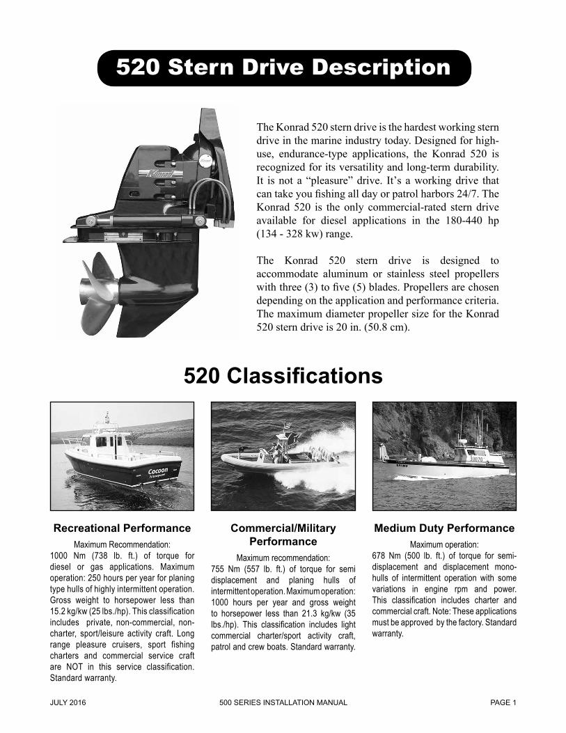
520 Stern Drive Description
The Konrad 520 stern drive is the hardest working stern drive in the marine industry today. Designed for high-use, endurance-type applications, the Konrad 520 is recognized for its versatility and long-term durability. It is not a “pleasure” drive. It’s a working drive that can take you fishing all day or patrol harbors 24/7. The Konrad 520 is the only commercial-rated stern drive available for diesel applications in the 180-440 hp (134 - 328 kw) range.
The Konrad 520 stern drive is designed to accommodate aluminum or stainless steel propellers with three (3) to five (5) blades. Propellers are chosen depending on the application and performance criteria. The maximum diameter propeller size for the Konrad 520 stern drive is 20 in. (50.8 cm).
500 SERIES INSTALLATION MANUALJULY 2016 PAGE 1
The Konrad 540 is specifically designed for high speed applications, both diesel and gasoline. This versatile stern drive is manufactured in two variations: Standard and High Performance. The High Performance model includes a lower hydrodynamic nose cone, and both versions have a lightweight design to deliver superior hole-shot and on-plane performance. The Konrad 540 allows mariners to apply greater power levels, while still delivering performance and reliability.
The Konrad 540 stern drive is designed to accommodate aluminum or stainless steel propellers with three (3) to six (6) blades. Propellers are chosen depending on the application and performance criteria.The maximum diameter propeller size for the Konrad 540 stern drive is 16 in. (40.6 cm).
Commercial PerformanceMaximum recommendation:
755 Nm (557 lb. ft.) of torque for diesel or gas applications. Maximum operation:500 hours per year for planing type hulls of highly intermittent operation. Gross weight to horsepower less than 12.2 kg/kw (20 lbs./hp). This clas-sification includes light commercial charter/sport activity craft, patrol and intercept boats. Standard warranty.
High PerformanceMaximum operation:
100 hours/year for racing applications at highly intermittent operation. Gross weight to horsepower less than 12.2 kg/kw (20 lbs./hp). No warranty.
540 Stern Drive Description
540 Classifications
Recreational PerformanceMaximum recommendation:
1000 Nm (738 lb. ft.) of torque for diesel or gas applications. Maximum operation: 250 hours per year for planing type hulls of highly intermittent operation. Gross weight to horsepower less than 12.2 kg/kw (20 lbs./hp). This classification includes pri-vate, non-commercial, non-charter, sport/leisure activity craft. Long range pleasure cruisers, sport fishing charters and com-mercial service craft are NOT in this ser-vice classification. Standard warranty.
500 SERIES INSTALLATION MANUAL JULY 2016PAGE 2
The Konrad 560 Twin Prop System is engineered to reduce stress on the gears using dual propeller technology, providing a reliable, durable stern drive unit. With counter rotating propellers, the 560 reduces propeller roll, which increases efficiency and control.
The Konrad 560 stern drive features two, one piece propeller shafts that accommodate two stainless steel propellers. The specially designed propellers have one blade configuration: 3 blades on the forward prop and 4 blades on the rear prop. The propeller pitches are manipulated on each application to meet the performance criteria.The maximum diameter of the propellers in the Konrad 560 is 16 in. (40.6 cm) for the forward prop, and 15.25 in. (38.7 cm) for the rear prop.
Commercial PerformanceMaximum recommendation:
755 Nm (557 lb. ft.) of torque for diesel or gas applications. Maximum operation:500 hours per year for planing type hulls of highly intermittent operation. Gross weight to horsepower less than 12.2 kg/kw (20 lbs./hp). This clas-sification includes light commercial charter/sport activity craft, patrol and intercept boats. Standard warranty.
560 Stern Drive Description
560 Classifications
Recreational PerformanceMaximum recommendation:
1000 Nm (738 lb. ft.) of torque for diesel or gas applications. Maximum operation: 250 hours per year for planing type hulls of highly intermittent operation. Gross weight to horsepower less than 12.2 kg/kw (20 lbs./hp). This classification includes pri-vate, non-commercial, non-charter, sport/leisure activity craft. Long range pleasure cruisers, sport fishing charters and com-mercial service craft are NOT in this ser-vice classification. Standard warranty.
500 SERIES INSTALLATION MANUALJULY 2016 PAGE 3
Stern Drive General Information
The Konrad 500 Series stern drives are designed to accommodate engines that generate up to 738 lb. ft. (1000 Nm) of torque.
There is a sixteen degree (16°) trim range to optimize vessel performance while underway. There is an additional 30 degrees (30°) of lift range that may only be used in an emergency or when the stern drive is being serviced or transported.
The Konrad 500 Series stern drives are designed for applications where the vessel transom angle is 14 degrees (14°). Applications that do not meet this criteria may require extra equipment or modifications, or may not be possible at all. The Konrad 520 stern drive is designed to accommodate propellers (aluminum and stainless steel) with a maximum diameter of 20 in (50.8 cm). The Konrad 540 and 560 can accommodate propellers (aluminum and stainless steel) with a maximum diameter of 16 in. (40.6 cm).
General OperationThe engine produces power (clockwise or
counterclockwise) that is transmitted through a reversing transmission. A coaxial planetary-style reversing transmission is normally used in recre-ational applications. A twin shaft vertically offset standard reversing transmission (with coaxial ad-ditions available) is normally used in commercial applications. From this point the transmission is connected via close couple or drive shaft (different shafts are discussed in detail in Step 6 on pages 29 - 32 in this manual). The power is then transmitted through a series of shafts and gears and then to the propeller(s).
Safety NoticesRead and understand all of the safety precau-
tions and warnings before performing any installa-tion or repair.
This list contains the general safety precautions and warnings that MUST be followed to provide personal safety. This list is only a suggested safety guideline. Working conditions vary greatly and safety measures will vary upon your individual cir-cumstances.
ALWAYS USE CAUTION. Make sure the work area surrounding the product is safe. Be aware of hazardous conditions that can exist.
ALWAYS wear protective eyewear and protective footwear when working.
DO NOT wear loose-fitting or torn clothing. Remove all jewelry when working.
DO NOT work on anything that is supported only by lifting jacks or a hoist.
ALWAYS use blocks or proper stands to support the product before performing any service work.
TO AVOID PERSONAL INJURY, use a hoist or get assistance when lifting stern drive components. Make sure all lifting de-vices such as chains, hooks or slings are in good condition and are of the correct lifting capacity.
500 SERIES INSTALLATION MANUAL JULY 2016PAGE 4
500 SERIES INSTALLATION MANUALJULY 2016 PAGE 5
Konrad has an installation tool kit available for purchase. The following is a complete list of all items included in the kit.
Installation Tool Kit30 – 190
NOTE: Additional tools may be required.
Tool box3/8 in. Drill13/64 in. Drill Bit (pilot for lag screws)Jig SawJig Saw Blades (2)3/8 in. Drive Ratchet (quick release)3/8 in. Drive 3 in. Extension3/8 in. Drive 6 in. Wobble Extension3/8 in. Drive to 1/4 in. Drive Reducer1/4 in. Drive 1/4 in. Socket3/8 in. Drive to 5/16 in. Socket3/8 in. Drive 7/16 in. Socket3/8 in. Drive 1/2 in. Deep Socket3/8 in. Drive 1/2 in. Socket3/8 in. Drive 9/16 in. Socket3/8 in. Drive 5/8 in. Deep Socket3/8 in. Drive 3/4 in. Socket3/8 in. Drive 3/4 in. Deep Socket3/8 in. Drive 5/16 in. Allen Head Socket5/16 in. Combination Wrench3/8 in. Combination Wrench7/16 in. Combination Wrench1/2 in. Combination Wrench9/16 in. Combination Wrench5/8 in. Combination Wrench11/16 in. Combination Wrench
3/4 in. Combination Wrench1-7/16 in. Combination Wrench8 in. Adjustable Wrench4 in. Flat Blade Screwdriver6 in. Flat Blade Screwdriver4 in. #2 Phillips Screwdriver6 in. #3 Phillips Screwdriver6 in. #2 Phillips Bit6 in. #3 Phillips Bit7 in. Vice Grips6 in. Slip Joint Pliers12 in. Flat Blade Pry Bar15 in. Pry BarDiagonal Side Cutter1-1/4 in. Putty KnifeCenter Punch/Scratch100 Grit Sandpaper (5) pcs.Black Permanent Marker2 lb. HammerBreathing MaskRasp File (Flat/Half Round)Assortment of Cable Clamps (15)Screws for Cable Clamps (15)Pilot Drill 4/Cable Clamp Screws 3/32 in.8 in. Cable Ties (15)Horseshoe Magnet
Tools Recommended for Installation
500 SERIES INSTALLATION MANUAL JULY 2016PAGE 6
Tools for 30-264 and 30-272 Rubber Coupling Drive Shaft (if applicable)
Tools Recommended for Installation (continued)
TO-066 Adapter, Torque Wrench 12 mm
TO-067 Adapter, Torque Wrench 22 mm.
TO-068 Adapter, Torque Wrench 24 mm.
GO-017, Dial Indicator with Magnetic Stand
500 SERIES INSTALLATION MANUALJULY 2016 PAGE 7
Listed below are the torque specifications for selected fasteners. Additional torque specifications are listed throughout this manual.
Torque Specifications for Selected Fasteners
Description Torque ValueDrive Shaft Flange to Transmission Output Flange Shaft Nuts/Bolts (if applicable) 70 lb. ft. (95 Nm)
Transom Assembly / Gimbal Housing Studs to Inner Transom Plate Nuts (8) 25-30 lb. ft. (34-41 Nm)
Drive Shaft Housing to Gear Housing Nuts and Bolts (8) 35 lb. ft. (47 Nm)
Power Trim Cylinder to Anchor Pin, Nuts (4)Tighten until approx. two (2) threads show. Do not over tighten.
Lifting Bracket Top Cover (and Emergency Tiller Arm if applicable) (6) 20 lb. ft. (27 Nm)
Stern Drive Unit to Bell Housing, Nuts (6) 55 lb. ft. (75 Nm)
1) Ensure that the propeller height is performed according to guidelines detailed in diagrams 10-410 (Figures A and B on pages 9 and 10 in this manual). The height of the propeller is critical to a successful application. If the propeller centerline is too low, excessive drag can occur based on transom assembly location. Intermediate spacers are available for special concerns.
2) Ensure that the water flow to the propeller is clear and consistent without interruptions. Protrusions on the hull surface create a neg-ative pressure area and induce turbulence. Turbulence can cause severe propeller inef-ficiency and excessive torsional vibration.
Common problems are: • Water pickup • Sonar transducers • Retrofitted surfaces which are not properly faired or smoothed • Any hull shape which does not provide smooth transition • In heavy applications, the bow can produce turbulence if the attitude of the vessel is weighted forward. • Improper listing of the vessel due to weight distribution
Installation Guidelines
3) Ensure that the vessel center of gravity is properly placed. Excessive weight forward or aft can significantly affect performance and the efficiency of the propeller.
4) Ensure that the stern drive is trimmed to the correct level. While undertrimming can cause premature u-joint wear, overtrimming can cause propeller inefficiency, porpoising, and premature gear wear.
500 SERIES INSTALLATION MANUAL JANUARY 2010PAGE 8
in.
in.
in.
in.
in.
in.
in.
in.
in.
in.
in. Note: Drawing not to scale.
FIGURE A: 500 Series CUTOUT TEMPLATE
500 SERIES INSTALLATION MANUALJANUARY 2010 PAGE 9
FIGURE B: 500 Series X-DIMENSION GUIDELINES
Note: Drawings not to scale.
500 SERIES INSTALLATION MANUAL JANUARY 2010PAGE 10
A B
C D
1.1 Scribe an arc from points A and B to the bottom center of the transom exterior. Scribe an arc from points C and D to the top center of the transom exterior. Where the previous mentioned arcs intersect, scribe a vertical line approxi-mately 28 in. (71 cm) long. This will represent the center line of the stern drive.
NOTE: For twin application, measure (to the port and starboard) off the vessel verti-cal center line over to the engine crank shaft center line and scribe a vertical center line parallel to the vessel vertical center line. See the lower drawing of Figure B on page 10 in this manual for explanation.
1.2 After establishing the x-dimension (see Figure B on page 10 in this manual), scribe a horizontal line at least 18 in. (46 cm) long, perpendicular and centered on the existing vertical line (scribed in Step 1.1).
NOTE: Specific characteristics of an installation may change the recommended vertical drive position. Please contact Konrad with any specific concerns.
ATTENTION: If you are installing the Konrad “Rear Mount / Tail Piece” assembly, please go to step 19 (page 73 - 74) in this manual.
Step 1: Transom Cutout
FIGURE 1B
FIGURE 1A
500 SERIES INSTALLATION MANUALJANUARY 2010 PAGE 11
500 SERIES INSTALLATION MANUAL JULY 2016PAGE 12
1.3 Place the cutout template (10-455) on the exterior of the transom and position it so the scribed horizontal and ver-tical match up with the scribed center lines on the tem-plate.
1.4 Trace the cut out area and the eight (8) holes. Remove the template.
1.5 Center punch the eight (8) holes traced in Step 1.4. Drill the eight (8) holes through the transom using a 5/8 in. (16 mm) drill bit.
NOTE: Holes must be drilled perpendicular to the tran-som face.
1.6 Using a reciprocating saw, cut out the area traced in Step 1.4. Use a file or rasp to touch up the cutout area.
NOTE: Cut must be made perpendicular to transom
face. NOTE: For fiberglass transoms, it is recommended that
fiberglass epoxy resin be applied to the cut areas. Verify that cutout area is correctly sized and shaped before applying epoxy. Allow proper drying/setup time for epoxy to cure.
Step 1: Transom Cutout (continued)
FIGURE 1A
FIGURE 1C
FIGURE 1B
500 SERIES INSTALLATION MANUALJULY 2016 PAGE 13
2.1 Grease the transom assembly gasket with marine grade grease (see Figure 2A).
NOTE: If the gimbal carrier assembly is not mounted in the gimbal housing bore, it should be done at this time (see Figure 2B).
NOTE: The gimbal carrier flange may differ from the one pictured in Figure 2B per application.
1) Lightly grease the carrier assembly and o-ring, then slide it into the gimbal housing bore. 2) Rotate the carrier assembly to achieve correct
orientation. The brass nipple should be at approximately two o’clock. 3) Torque the three (3) fasteners to 70 lb. ft. (95 Nm). NOTE: The gimbal carrier flange may differ from the one pictured in Figure 2B per application.
2.2 Guide the transom assembly studs through the eight (8) holes in the transom.
NOTE: The weight of the transom assembly is 81 lbs. (36.7 kg). Use caution when lifting.
NOTE: Some installations/applications require an ex-ternal adapter plate.
NOTE: Proper stud length varies due to hull thickness. Stud length is also dictated by peripheral equipment that mounts inside the hull (steering cylinder bracket, inner transom plate, drive shaft shroud, etc.). Verify correct stud length before continuing past this step.
Step 2: Transom Assembly Installation
FIGURE 2B
FIGURE 2C
FIGURE 2A
500 SERIES INSTALLATION MANUAL JULY 2016PAGE 14
2.3 Place the inner transom backing plate (10-357) over the eight (8) studs from the inside of the vessel.
NOTE: If an internal steering cylinder is going to be used, the bracket can be mounted on the upper one (1) or two (2) sets of horizontal studs depending on the steering cylinder style used.
NOTE: The inner transom plate may require modification or elimination depending on steering cylinder assembly used.
NOTE: If an inner transom backing plate is not used, the round washers (10-415) must be replaced with rectangular washers (10-941).
2.4 Secure the transom assembly to the transom by using eight (8) nylock nuts (10-334) and eight (8) flat washers (10-415). Torque to 25-30 lb. ft. (34-41 Nm).
NOTE: Place inner transom backing plate continuity cable between the washer and nylock nut of either of the top two transom assembly studs before tightening (if applicable).
NOTE: Connect the tiller arm continuity cable to the inner transom backing plate by using the small phillips head screw (if applicable).
NOTE: The two (2) oil lines in this photo will be ran and attached in a later step.
Step 2: Transom Assembly Installation (continued)
FIGURE 2D
FIGURE 2E
500 SERIES INSTALLATION MANUALJULY 2016 PAGE 15
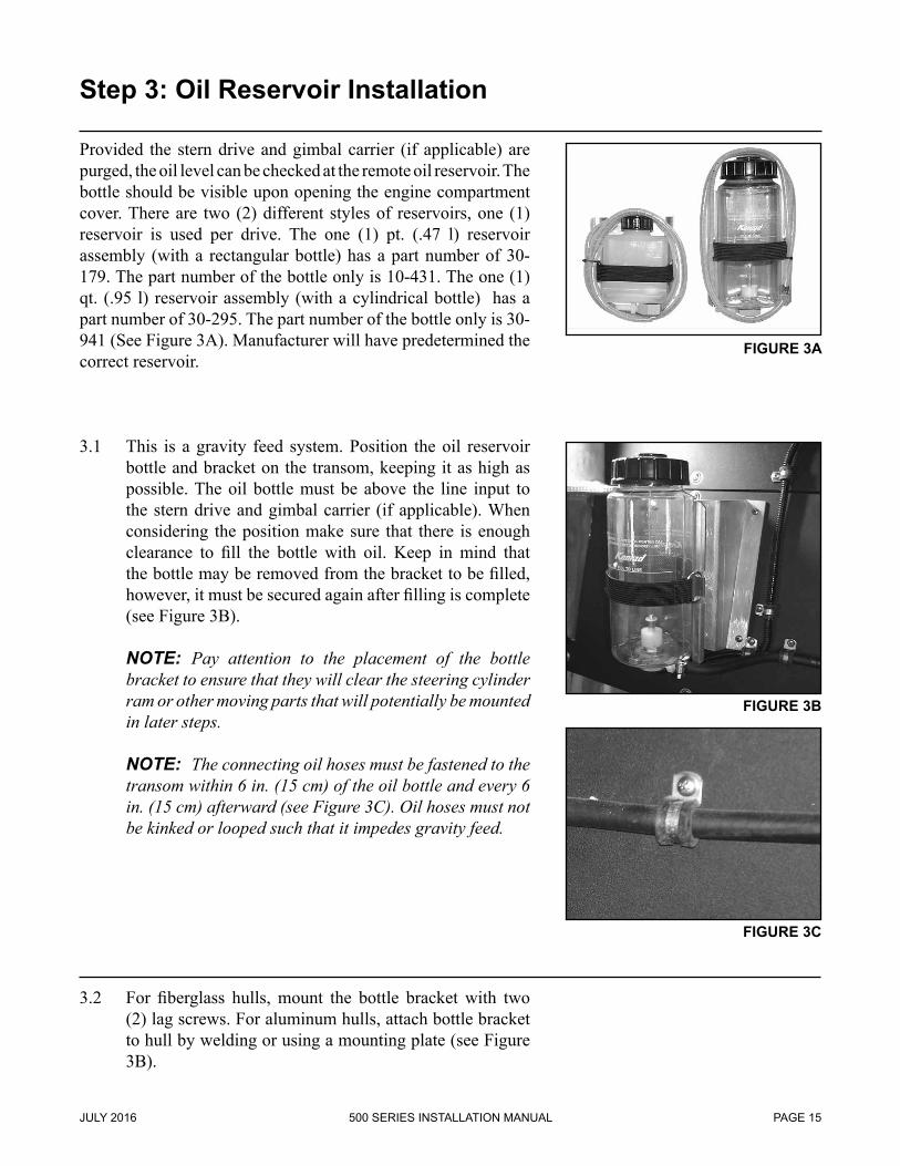
Provided the stern drive and gimbal carrier (if applicable) are purged, the oil level can be checked at the remote oil reservoir. The bottle should be visible upon opening the engine compartment cover. There are two (2) different styles of reservoirs, one (1) reservoir is used per drive. The one (1) pt. (.47 l) reservoir assembly (with a rectangular bottle) has a part number of 30-179. The part number of the bottle only is 10-431. The one (1) qt. (.95 l) reservoir assembly (with a cylindrical bottle) has a part number of 30-295. The part number of the bottle only is 30-941 (See Figure 3A). Manufacturer will have predetermined the correct reservoir.
3.1 This is a gravity feed system. Position the oil reservoir bottle and bracket on the transom, keeping it as high as possible. The oil bottle must be above the line input to the stern drive and gimbal carrier (if applicable). When considering the position make sure that there is enough clearance to fill the bottle with oil. Keep in mind that the bottle may be removed from the bracket to be filled, however, it must be secured again after filling is complete (see Figure 3B).
NOTE: Pay attention to the placement of the bottle bracket to ensure that they will clear the steering cylinder ram or other moving parts that will potentially be mounted in later steps.
NOTE: The connecting oil hoses must be fastened to the transom within 6 in. (15 cm) of the oil bottle and every 6 in. (15 cm) afterward (see Figure 3C). Oil hoses must not be kinked or looped such that it impedes gravity feed.
3.2 For fiberglass hulls, mount the bottle bracket with two (2) lag screws. For aluminum hulls, attach bottle bracket to hull by welding or using a mounting plate (see Figure 3B).
Step 3: Oil Reservoir Installation
FIGURE 3A
FIGURE 3B
FIGURE 3C
500 SERIES INSTALLATION MANUAL JULY 2016PAGE 16
Step 3: Oil Reservoir Installation (continued)
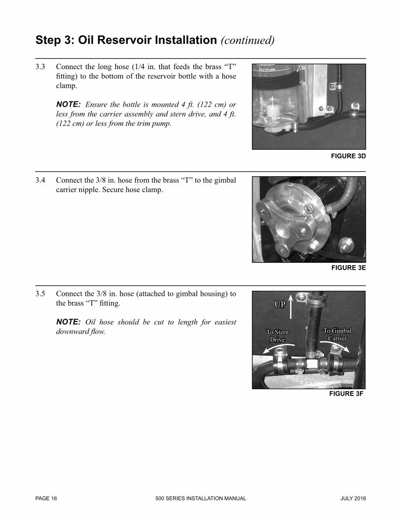
3.3 Connect the long hose (1/4 in. that feeds the brass “T” fitting) to the bottom of the reservoir bottle with a hose clamp.
NOTE: Ensure the bottle is mounted 4 ft. (122 cm) or less from the carrier assembly and stern drive, and 4 ft. (122 cm) or less from the trim pump.
3.4 Connect the 3/8 in. hose from the brass “T” to the gimbal carrier nipple. Secure hose clamp.
3.5 Connect the 3/8 in. hose (attached to gimbal housing) to the brass “T” fitting.
NOTE: Oil hose should be cut to length for easiest downward flow.
FIGURE 3D
FIGURE 3E
FIGURE 3F
UP
To Stern Drive
To Gimbal Carrier
500 SERIES INSTALLATION MANUALJULY 2016 PAGE 17
3.6 For tailpiece application, a gimbal carrier is not utilized. Connect oil bottle to long 1/4 in. hose. Connect 3/8 in. hose which is attached to the gimbal housing to brass reducer coupling, located on 1/4 in. hose.
3.7 Fill oil bottle to “fill” line with Konrad 75W90 synthetic gear lube.
NOTE: In accordance with MSDS regulations and requirements, the stern drive is shipped full of the above mentioned lubricant. Prior to operation, verify that the
entire system is completely purged of air and filled with lubricant. If a different gear oil is chosen for your application, it is recommending that the stern drive is drained and refilled. This may void manufacturer’s warranty. Purge oil line to the stern drive by manually opening connecting valve located on the outside port face of bell housing (outboard side of transom). Open valve until solid oil flow occurs. Refill oil bottle at proper level indicated on bottle.
3.8 Purge the air out of the oil line feeding the stern drive by depressing the check valve nipple, located on the bell housing face, until a solid stream of oil comes out. Refill reservoir bottle to the appropriate level.
FIGURE 3G
FIGURE 3H
Step 3: Oil Reservoir Installation (continued)
FIGURE 3I
500 SERIES INSTALLATION MANUAL JULY 2016PAGE 18
Wire style and gauge shall meet requirements of local, state and national codes.
4.1 Trim pump circuit requires inline fuse/breaker (on the positive lead) of the following values:
1) 12 Volt = 100 Amperes (see Figure 4A) 2) 24 Volt = 50 Amperes (see Figure 4B) This item should be mounted in an accessible and logical
position away from bilge fluid contact. It must also be labeled clearly.
NOTE: Battery, or batteries, must be disconnected while
all electrical connections are being made or serviced (see Figure 4C).
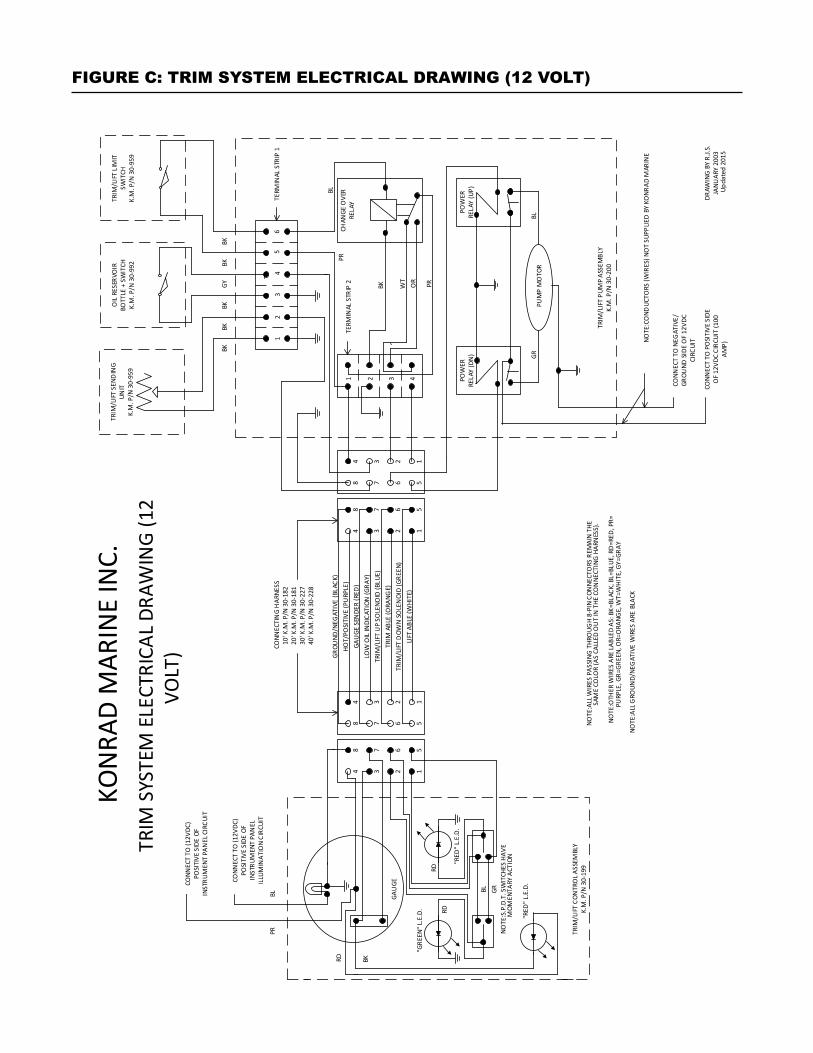
NOTE: Refer to the Trim System Electrical Drawings (Figure C and Figure D on pages 22 and 23 in this manual) for further documentation on this and proceeding instructions.
4.2 Mount trim pump in a location which is: 1) As elevated as possible and away from bilge fluid contact. 2) Is within reach of transom assembly wiring approximately 36 in. (91.4 cm). 3) Is within reach of oil bottle wiring approximately 48 in. (122 cm). 4) Is within reach of transom assembly hydraulic hoses, 32 in. or 48 in. (81.3 cm or 122 cm). Measure to determine length. NOTE: For fiberglass hulls, it is recommended that a
pilot hole be drilled prior to lag screw installation. NOTE: For metal hulls, attach by either welding or us-
ing a mounting plate.
NOTE: The two (2) hydraulic hoses in this photo will be attached in later steps.
Step 4: Trim/Lift Pump Installation
FIGURE 4A
FIGURE 4D
FIGURE 4B
FIGURE 4C
500 SERIES INSTALLATION MANUALJULY 2016 PAGE 19
Step 4: Trim/Lift Pump Installation (continued)
4.3 Remove the cover of the trim/lift pump assembly by removing the front three (3) bolts and lock washers.
4.4 Remove the three (3) rear bolts and lock washers and remove the top portion of the trim/lift pump assembly bracket.
4.5 Attach the positive trim/lift pump power feed (from the breaker/fuse unit) to one of the solenoid bolts on the link-bar side.
NOTE: Coat terminal with corrosion protectant.
4.6 Attach the negative trim/lift pump power feed to the ground bolt.
NOTE: Coat terminal with corrosion protectant.
FIGURE 4E
FIGURE 4F
FIGURE 4G
FIGURE 4H
500 SERIES INSTALLATION MANUAL JULY 2016PAGE 20
Step 4: Trim/Lift Pump Installation (continued)
4.7 Reattach the top portion of the trim/lift pump assembly bracket.
4.8 Route the four (4) wires from the transom assembly to the trim/lift pump. Fasten to the transom or hull every 6 in. (15 cm).
4.9 Route the two (2) wires (color coded black and grey) from the oil reservoir to the trim/lift pump. Fasten to the transom or hull every 6 in. (15 cm). Attach the wires by running them through the upper hole of the trim/lift pump assembly bracket. Connect them to the two (2) terminals on the terminal strip labeled “Oil”.
NOTE: Coat the terminals with corrosion protectant.
4.10 Attach the wires by running them through the upper hole of the trim/lift pump assembly. Connect them to the appropriate terminals of the terminal strip.
NOTE: The two (2) wires coming from the port side switch (color coded blue and purple) on the transom assembly go to the terminals labeled “Port”. The two (2) wires coming from the starboard side switch (color coded red and black) go to the terminals labeled “Star”.
NOTE: Coat the terminals with corrosion protectant.
FIGURE 4J
FIGURE 4L
FIGURE 4K
FIGURE 4I
500 SERIES INSTALLATION MANUALJULY 2016 PAGE 21
4.11 Reattach the trim/lift pump assembly cover plate.
4.12 Route the two (2) hydraulic hoses from the transom assembly to the trim/lift pump. Fasten to the transom or hull every 6 in. (15 cm). Connect the “up” line to the trim/lift pump. Hook the line up according to the “up” label on the line and on the port marked “up” on the trim/lift pump. Ensure not to cross thread. Tighten till snug.
NOTE: The “down” line will be hooked up later during the bleeding process (Step 11 on page 46 in this manual).
NOTE: Be sure to avoid potential moving objects (such as the steering ram or drive shaft if applicable) when routing the trim/lift pump hydraulic lines.
4.13 Connect the appropriate length wire harness (prede-termined) to the trim/lift pump pigtail. Run the harness across the transom (to the starboard side of the vessel) and up through the bilge compartment, or raceway, towards the helm control station. Use wire ties and cable fasteners as necessary. Run the harness up to the helm station and to the location of the trim/lift pump control plate, on the instrument/switch panel (which will be mounted at a later time, Step 10 on pages 42 - 45 in this manual).
NOTE: Wire harness comes in 5 lengths: 3 ft./.91 m (30-183), 10 ft./3 m (30-182), 20 ft./6.1 m (30-181), 30 ft./9.1 m (30-227), 40 ft./12.2 m (30-228).
FIGURE 4N
FIGURE 4O
Step 4: Trim/Lift Pump Installation (continued)
FIGURE 4M
CO
NNEC
TIN
G H
ARNE
SS10
' K.M
. P/N
30-
182
20' K
.M. P
/N 3
0-18
130
' K.M
. P/N
30-
227
40' K
.M. P
/N 3
0-22
8
BKRD
NOTE
:ALL
WIR
ES P
ASSI
NG T
HRO
UGH
8-PI
N CO
NNE
CTO
RS R
EMAI
N T
HE
SA
ME
COLO
R (A
S CA
LLED
OU
T IN
THE
CO
NNE
CTIN
G HA
RNES
S).
NOTE
:OTH
ER W
IRES
ARE
LABL
ED A
S: B
K=BL
ACK,
BL=
BLUE
, RD
=RED
, PR=
PURP
LE, G
R=GR
EEN,
OR=
ORA
NGE,
WT=
WHI
TE, G
Y=GR
AY
NOTE
:ALL
GRO
UND/
NEG
ATIV
E W
IRES
ARE
BLA
CK
KON
RAD
MAR
INE
INC.
TRI
M S
YSTE
M E
LECT
RICA
L DRA
WIN
G (1
2 VO
LT) GR
OUND
/NEG
ATIV
E (B
LACK
)HO
T/PO
SITI
VE (P
URP
LE)
GAU
GE S
ENDE
R (R
ED)
LOW
OIL
INDI
CATI
ON (G
RAY)
TRIM
/LIF
T U
P SO
LENO
ID (B
LUE)
TRIM
ABL
E (O
RANG
E)TR
IM/L
IFT
DOW
N SO
LEN
OID
(GRE
EN)
LIFT
ABL
E (W
HITE
)1234
5678
TRIM
/LIF
T CO
NTR
OL A
SSEM
BLY
K.M
. P/N
30-
199
GAU
GE
CONN
ECT
TO (1
2VDC
) PO
SITI
VE S
IDE
OF
INST
RUM
ENT
PAN
EL
ILLU
MIN
ATIO
N CI
RCUI
T
CONN
ECT
TO (1
2VDC
) PO
SITI
VE S
IDE
OF
INST
RUM
ENT
PAN
EL C
IRCU
IT
BLPR
RDRD
BL GR
OIL
RESE
RVO
IRBO
TTLE
+ S
WIT
CHK.
M. P
/N 3
0-99
2
TRIM
/LIF
T LI
MIT
SWIT
CHK.
M. P
/N 3
0-95
9
TRIM
/LIF
T SE
NDIN
GUN
ITK.
M. P
/N 3
0-95
9
TRIM
/LIF
T PU
MP
ASSE
MBL
YK.
M. P
/N 3
0-20
0
POW
ERRE
LAY
(UP)
POW
ERRE
LAY
(DN
)
1 2 3 4
12
34
56
TERM
INAL
STR
IP 1
TERM
INAL
STR
IP 2
5678
1234
PUM
P M
OTO
R
CHAN
GE O
VER
RELA
Y
CONN
ECT
TO N
EGAT
IVE/
GROU
ND S
IDE
OF
12VD
C CI
RCUI
T
CONN
ECT
TO P
OSI
TIVE
SID
E O
F 12
VDC
CIRC
UIT
(100
AM
P)
DRAW
ING
BY
R.J.S
.JA
NUAR
Y 20
03
NOTE
:CO
NDUC
TORS
(WIR
ES) N
OT
SUPP
LIED
BY K
ONR
AD M
ARIN
E
GRBL
PROR
WT
BK
PRBL
BKBK
BKBK
GYBK
5678
1234
1234
5678
NOTE
:S.P
.D.T
. SW
ITCH
ES H
AVE
MOM
ENTA
RY A
CTIO
N
"RED
" L.E
.D.
"RED
" L.E
.D.
"GRE
EN" L
.E.D
.
Upda
ted
2015
FIGURE C: TRIM SYSTEM ELECTRICAL DRAWING (12 VOLT)
FIGURE D: TRIM SYSTEM ELECTRICAL DRAWING (24 VOLT)
CO
NNEC
TIN
G H
ARNE
SS10
' K.M
. P/N
30-
182
20' K
.M. P
/N 3
0-18
130
' K.M
. P/N
30-
227
40' K
.M. P
/N 3
0-22
8
BKRD
NOTE
:ALL
WIR
ES P
ASSI
NG T
HRO
UGH
8-PI
N CO
NNE
CTO
RS R
EMAI
N T
HE
NOTE
:OTH
ER W
IRES
ARE
LABL
ED A
S: B
K=BL
ACK,
BL=
BLUE
, RD
=RED
, PR=
PURP
LE, G
R=GR
EEN,
OR=
ORA
NGE,
WT=
WHI
TE, G
Y=GR
AY
NOTE
:ALL
GRO
UND/
NEG
ATIV
E W
IRES
ARE
BLA
CK
KON
RAD
MAR
INE
INC.
TRI
M S
YSTE
M E
LECT
RICA
L DRA
WIN
G (2
4 VO
LT) GR
OUND
/NEG
ATIV
E (B
LACK
)HO
T/PO
SITI
VE (P
URP
LE)
GAU
GE S
ENDE
R (R
ED)
LOW
OIL
INDI
CATI
ON (G
RAY)
TRIM
/LIF
T U
P SO
LENO
ID (B
LUE)
TRIM
ABL
E (O
RANG
E)TR
IM/L
IFT
DOW
N SO
LEN
OID
(GRE
EN)
LIFT
ABL
E (W
HITE
)1234
5678
TRIM
/LIF
T CO
NTR
OL A
SSEM
BLY
K.M
. P/N
30-
180
GAU
GE
CONN
ECT
TO (2
4VDC
) PO
SITI
VE S
IDE
OF
INST
UM
ENT
PANE
L IL
LUM
INAT
ION
CIRC
UIT
CONN
ECT
TO (2
4VDC
) PO
SITI
VE S
IDE
OF
INST
UM
ENT
PANE
L CI
RCU
IT
BLPR
RDRD
BL GR
OIL
RESE
RVO
IRBO
TTLE
+ S
WIT
CHK.
M. P
/N 3
0-99
2
TRIM
/LIF
T LI
MIT
SWIT
CHK.
M. P
/N 3
0-95
9
TRIM
/LIF
T SE
NDIN
GUN
ITK.
M. P
/N 3
0-95
9
TRIM
/LIF
T PU
MP
ASSE
MBL
YK.
M. P
/N 3
0-05
4
POW
ERRE
LAY
(UP)
POW
ERRE
LAY
(DN
)
1 2 3 4
12
34
56
TERM
INAL
STR
IP 1
TERM
INAL
STR
IP 2
5678
1234
PUM
P M
OTO
R
CHAN
GE O
VER
RELA
Y
CONN
ECT
TO N
EGAT
IVE/
GROU
ND S
IDE
OF
24VD
C CI
RCUI
T
CONN
ECT
TO P
OSI
TIVE
SID
E O
F 24
VDC
CIRC
UIT
(50
AMP)
DR
AWIN
G B
Y R.
J.S.
JANU
ARY
2003
NOTE
:CO
NDUC
TORS
(WIR
ES) N
OT
SUPP
LIED
BY K
ONR
AD M
ARIN
E
GRBL
PROR
WT
BK
PRBL
BKBK
BKBK
GYBK
5678
1234
1234
5678
NOTE
:S.P
.D.T
. SW
ITCH
ES H
AVE
MOM
ENTA
RY A
CTIO
N
"RED
" L.E
.D.
"RED
" L.E
.D.
"GRE
EN" L
.E.D
.
SAM
E CO
LOR
(AS
CALL
ED O
UT
IN T
HE C
ON
NECT
ING
HARN
ESS)
.
UPDA
TED
2015
500 SERIES INSTALLATION MANUAL JULY 2016PAGE 24
NOTE: If this is a direct couple tailpiece application, do not install the stern drive at this time. Return to this step after completing Step 6A on page 29 in this manual.
5.1 Rig the Konrad drive for lifting. Secure the stern drive to the lifting device with a nylon strap.
NOTE: Optional lifting bracket (12-388) is available to assist in the lifting process (see Figure 5A).
520 Stern Drive Weight is 188 lbs. (85.3 kg) 540 Stern Drive Weight is 153 lbs. (69.4 kg) 560 Stern Drive Weight is 167 lbs. (75.7 kg)
NOTE: An overhead lifting device is the preferred meth-od of lifting the Konrad drive. A lifting cart or forklift may be used as an alternate lifting device.
5.2 Remove the six (6) nuts (10-334) and six (6) washers (10-415) from the bell housing studs (10-250). (These nuts and washers are on the studs when shipped from Konrad).
FIGURE 5A
Step 5: Stern Drive Installation
FIGURE 5B
500 SERIES INSTALLATION MANUALJULY 2016 PAGE 25
Step 5: Stern Drive Installation (continued)
5.3 Using marine grade grease, grease both sides of the gasket (10-305) and slide it over the six (6) studs on the bell housing. Slide it forward until it makes full contact with the bell housing face.
NOTE: Observe proper orientation of gasket.
5.4 Grease the o-rings (10-306) (see Figure 5D) and (10-493) (see Figure 5E).
FIGURE 5C
FIGURE 5E
FIGURE 5D
500 SERIES INSTALLATION MANUAL JULY 2016PAGE 26
5.5 Grease the splined end yoke shaft (10-365).
5.6 Grease one end of the engagement pin (10-494) (see Figure 5G). Insert greased end into the end of the splined end yoke shaft (see Figure 5H). Three quarters (3/4) of the engagement pin should remain beyond the end of the splined end yoke shaft.
Step 5: Stern Drive Installation (continued)
FIGURE 5G
FIGURE 5H
FIGURE 5F
500 SERIES INSTALLATION MANUALJULY 2016 PAGE 27
FIGURE 5I
FIGURE 5J
5.7 Slide drive onto transom assembly. The splined end yoke shaft and u-joint assembly must be held up and guided into the gimbal carrier or tailpiece assembly.
NOTE: It may be necessary to rotate the splined end yoke shaft (this can be achieved by sliding the propeller onto the splined propeller shaft and rotating it back and forth or re-orientating input yoke using a screwdriver as pictured in Figure 5I) or yoke assembly so the splines line up for the drive to be fully seated against the transom assembly.
NOTE: If the stern drive does not engage easily, pull stern drive back, reset engagement pin and reattempt 5.7.
WARNING! Do not impact or apply force to the drive while engaging the input shaft as this will damage the gimbal carrier seal.
5.8 Fasten the stern drive to the transom assembly using the six (6) nuts and six (6) washers provided. Torque to 55 lb. ft. (74 Nm).
NOTE: Be sure to put the continuity cable ring on the
upper starboard stud before putting the washer and nut on.
An alternate method of stern drive installation is to remove the gimbal carrier assembly (non-tailpiece applications) from the gimbal housing (inside of the vessel). This can be done by removing the three (3) S.H.C.S. (10-385). Hold up the splined end yoke shaft and guide it into gimbal carrier as the carrier is reinstalled. Torque the three (3) S.H.C.S. (10-385) to 70 lb. ft. (95 Nm).
Step 5: Stern Drive Installation (continued)
500 SERIES INSTALLATION MANUAL JULY 2016PAGE 28
Alig
nmen
t Spe
cific
atio
ns C
hart
for T
rans
mis
sion
to S
tern
Dri
ve C
oupl
ing
Co
up
ling
Ty
pe
Part
#Le
ng
th(R
ang
e)Pa
ralle
lism
Co
nce
ntr
icit
yA
xial
Slip
C
om
pen
satio
nC
ou
plin
g
Orie
nta
tion
Too
ls
Sug
ges
ted
Torq
ue
(Fas
ten
ers)
Thre
ad L
ock
C
om
po
un
dTr
ansm
issi
on
Ty
pe
Ster
n D
rive
C
arri
er T
ype
Dire
ct
(Rea
r Mou
nt
Tailp
iece
)30
-449
Fixe
d(C
lose
Coup
le)
N/A
N/A
Fixe
dN/
ATO
-094
N/A
N/A
Tail P
iece
Co
axia
lN/
A
Dire
ct
(Rub
ber)
30-2
8630
-287
30-4
64
Fixe
d(C
lose
Coup
le)
< .0
03 in
.<
.076
mm
< .0
03 in
.<
.076
mm
N/A
Yes
(See
St
ep 1
5)
11-2
84G
O-0
1770
ft. l
bs.
95 N
mYe
sO
utpu
t Fl
ange
3-Lo
be30
-301
Drive
shaf
t w/
Rubb
er
Coup
lings
Shor
t(w
/slip
join
t)
30-2
649
- 15
in.
23 -
38 c
m<
.010
in.
< .2
54 m
m<
.010
in.
< .2
54 m
m1
in.
25.4
mm
Yes
(See
St
ep 1
5)
GO
-017
TO-0
9670
ft. l
bs.
95 N
mYe
sO
utpu
t Fl
ange
3-Lo
be30
-301
Drive
shaf
t w/
Rubb
erCo
uplin
gsLo
ng(w
/slip
join
t)
30-2
7215
- 48
in.
38 -
122
cm<
.010
in.
< .2
54 m
m<
.010
in.
< .2
54 m
m1
in.
25.4
mm
Yes
(See
St
ep 1
5)
11-2
84G
O-0
1770
ft. l
bs.
95 N
mYe
sO
utpu
t Fl
ange
3-Lo
be30
-301
Cons
tant
Ve
locit
y (C
V)11
-797
30-3
91>9
.5 -
<55
in.
25.4
- 14
0 cm
Max
2°
Max
Offs
et 2
°1/
16 in
.1.
59 m
mN/
AG
O-0
1785
ft. l
bs.
115
NmYe
sO
utpu
t Fl
ange
30-3
03
U-Jo
int
Card
en30
-043
>9.5
- <6
0 in
.24
- 15
2 cm
< .0
10 in
.<
.254
mm
Com
poun
dO
ffset
be
twee
n .5
°< x
<1°
1 in
.25
.4 m
mYo
ke
Orie
ntat
ion
GO
-017
89 ft
. lbs
.12
1 Nm
Yes
Out
put
Flan
ge30
-303
*NO
TE: I
n m
ost c
ases
, the
use
of a
u-jo
int s
haft
is n
ot re
com
men
ded,
ple
ase
cont
act K
onra
d fo
r app
rova
l pri
or to
inst
alla
tion.
FIGURE E: ALIGNMENT SPECIFICATIONS CHART
500 SERIES INSTALLATION MANUALJULY 2016 PAGE 29
Step 6: Alignment Procedures
NOTE: General vessel installation plans should be di-rected at near straight shaft angles. The shaft’s maximum misalignment tolerances should be reserved for temporary movement of components while the vessel is underway.
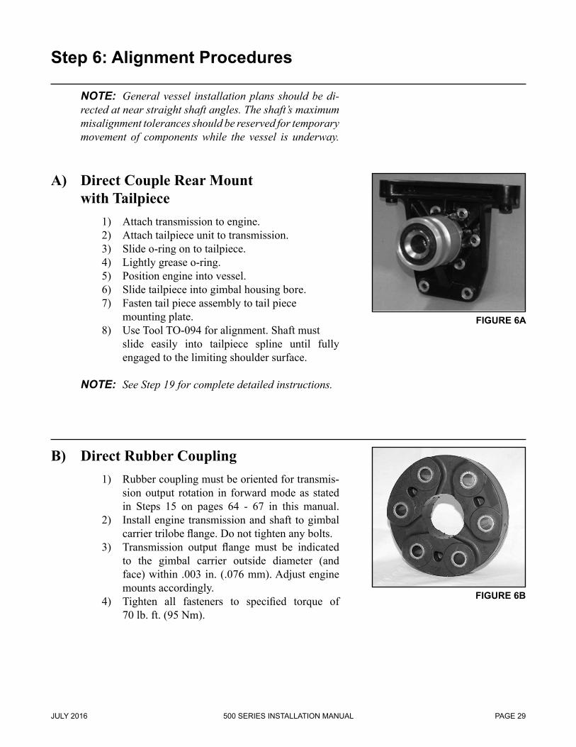
A) Direct Couple Rear Mount with Tailpiece
1) Attach transmission to engine. 2) Attach tailpiece unit to transmission. 3) Slide o-ring on to tailpiece. 4) Lightly grease o-ring. 5) Position engine into vessel. 6) Slide tailpiece into gimbal housing bore. 7) Fasten tail piece assembly to tail piece mounting plate. 8) Use Tool TO-094 for alignment. Shaft must slide easily into tailpiece spline until fully engaged to the limiting shoulder surface.
NOTE: See Step 19 for complete detailed instructions.
B) Direct Rubber Coupling 1) Rubber coupling must be oriented for transmis- sion output rotation in forward mode as stated in Steps 15 on pages 64 - 67 in this manual. 2) Install engine transmission and shaft to gimbal carrier trilobe flange. Do not tighten any bolts. 3) Transmission output flange must be indicated to the gimbal carrier outside diameter (and face) within .003 in. (.076 mm). Adjust engine mounts accordingly. 4) Tighten all fasteners to specified torque of 70 lb. ft. (95 Nm).
FIGURE 6A
FIGURE 6B
500 SERIES INSTALLATION MANUAL JULY 2016PAGE 30
Step 6: Alignment Procedures (continued)
C) Rubber Coupling Extension Shafts 1) Remove frost plug (10-485). 2) Fasten alignment flange (11-284) to gimbal carrier. 3) Fix magnetic base, arm and dial indicator assembly (GO-017) to transmission output flange. Complete assembly must be rigidly fastened. 4) Rotate transmission flange indicating the face of the alignment flange. All facial measurements must be within .010 in. (.25 mm). 5) Rotate transmission flange indicating the circumference of the alignment flange. All measurements must be within .010 in. (.25 mm). 6) Remove alignment flange and install frost plug. 7) Install rubber coupling drive shaft assembly according to Step 15 on pages 64 - 67 in this manual. 8) For longer extension shafts, an extension piece should be attached to the transmission flange. The dial indicator base can be fixed to this extension piece allowing the indicator to reach the alignment flange. The extension piece, dial indicator base and arm must all be rigidly fastened.
Part # 30-264
Part # 30-272NOTE: Drawing shows drive in counterclockwise position
NOTE: Drawing shows drive in clockwise position
500 SERIES INSTALLATION MANUALJULY 2016 PAGE 31
Step 6: Alignment Procedures (continued)
D) U-Joint Extension Shaft NOTE: It is recommended to hold either the horizontal or
vertical offset at zero and achieve the offset in one plane. In most cases it is easier to hold the horizontal measure-ment at zero. In most cases, the use of a u-joint shaft is not recommended, please contact Konrad for approval prior to installation.
1) Transmission output flange and gimbal carrier input flange must be parallel within .010 in. (.25 mm). 2) Transmission output flange and gimbal carrier input flange must have a compounded vertical and horizontal offset angle (a) which is 1.0˚ > (a) > 0.5˚. This dimension is a function of the length of the shaft. 3) To determine vertical offset (see Figure 6D) (x): x = tan a (y - 3.376 in.) or (x): x = tan a (y - 8.575 cm) 4) Fix magnetic base, arm and dial indicator assembly (GO-017) to transmission output flange. 5) Rotate transmission flange indicating the face of the alignment flange. All facial mea- surements must be within .010 in. (.25 mm). 6) Rotate transmission flange indicating the cir- cumference of the alignment flange. All mea- surements must be within .010 in. (.25 mm). Offset measurements are according to calcula- tion in section D3 above. 7) Refer to Step 16 on pages 68 - 69 in this manual for u-joint extension shaft installation.
FIGURE 6C
FIGURE 6D
500 SERIES INSTALLATION MANUAL JULY 2016PAGE 32
Step 6: Alignment Procedures (continued)
E) CV Extension Shaft NOTE: The transmission output flange and gimbal
carrier input flange must be parallel within two de-grees (2°) or manufacturer’s approval dependent on power and RPM levels.
1) A constant velocity joint is recommended over a u-joint shaft because, unlike the u-joint, it has no significant impacts on the stern drive gear sets. 2) The transmission output flange and gimbal car- rier input flange must be concentric within the manufacturer’s recommended specifications. 3) Fix magnetic base, arm and dial indicator assembly (GO-017) to transmission output flange. 4) Rotate transmission flange indicating the face of the alignment flange. All facial measure- ments must be within manufacturer’s require- ments. 5) Rotate transmission flange indicating the circumference of the alignment flange. All measurements must be within the manufac- turer’s requirements. 6) Refer to Step 17 on pages 70 - 71 in this manual for CV extension shaft installation. 7) The axial distance must be within .0625 in. (1.59 mm) of the shaft’s working length (including the adapter flanges).
FIGURE 6E
500 SERIES INSTALLATION MANUALJULY 2016 PAGE 33
7.1 Remove the nut (10-314), the outer retaining washer (10-444), and the outer bushing (10-443) from the forward trim cylinder anchor pin (port and starboard side).
7.2 Locate the rear anchor pin assembly and remove all hardware and bushings. Slide the rear anchor pin through the anchor pin bore in the aft end of the upper housing.
7.3 Following the order listed, place one washer (10-442), spacer (12-535), one washer (10-442) and bushing (10-443) (tapered pointing away from drive) on to the port and starboard side of the rear trim cylinder anchor pin.
7.4 Slide the trim cylinders onto the anchor pins. NOTE: If trim cylinders are at an inappropriate length
to fit onto the anchor pins, the drive must be lifted up manually or the red caps (see Step 7.6 on page 34 in this manual) must be removed and length must be adjusted.
CAUTION: Fluid may run or squirt out of the ports when adjusting length.
NOTE: The end of the trim cylinder with the hydraulic line inputs must be face up and closest the transom.
Step 7: Trim Cylinder Installation
FIGURE 7C
FIGURE 7A
FIGURE 7B
FIGURE 7D
500 SERIES INSTALLATION MANUAL JULY 2016PAGE 34
7.5 Place bushing (10-443), retaining washer (10-444) and nylock nut (10-314) on forward and aft anchor pins. Tighten the forward nuts to 20 lb ft (27 Nm). Tighten the aft nut so the retaining washer (10-444) bottoms out on the shoulder of the anchor pin. Make sure at least two or three (2-3) threads are showing beyond the end of the nuts.
NOTE: Install all four (4) nylock nuts (10-314) before tightening nuts completely.
7.6 Remove the red caps from the trim cylinders if they have not been removed previously (see step 7.4 on page 33 in this manual). The trim cylinders have red plastic caps in the hydraulic line ports when they are shipped from Konrad.
7.7 Hook up the four (4) trim lines (from the transom assembly to the trim cylinders) according to their tags. The line input on the trim cylinders closest to the transom is up.
NOTE: Ensure to not cross thread the hose’s fittings and tighten down until snug. DO NOT overtighten. Check for leaks after the trim pump is bled (Step 11 on pages 46-47 in this manual).
Step 7: Trim Cylinder Installation (continued)
FIGURE 7G
FIGURE 7F
FIGURE 7E
500 SERIES INSTALLATION MANUALJULY 2016 PAGE 35
Complete 30-002 Trim Assembly
FIGURE F: TRIM ASSEMBLY DIAGRAM
UPPORT
DOWNPORT
DOWN HYDRAULIC LINE
UP HYDRAULIC LINE
6
5
3
3
5
6
4
7
8
9
4
12
210
1
11
10
11
2
3
3
2
2
3
3
1
13
1415
1415
500 SERIES INSTALLATION MANUAL JULY 2016PAGE 36
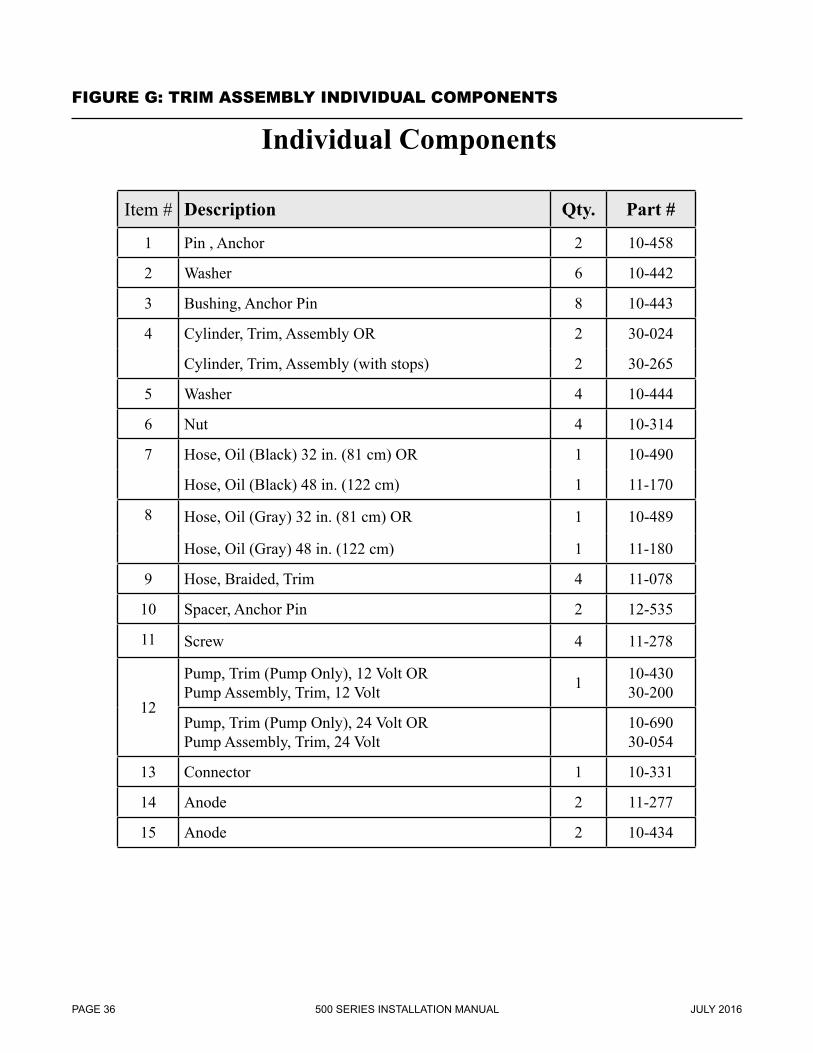
Individual Components
Item # Description Qty. Part #
1 Pin , Anchor 2 10-458
2 Washer 6 10-442
3 Bushing, Anchor Pin 8 10-443
4 Cylinder, Trim, Assembly OR 2 30-024
Cylinder, Trim, Assembly (with stops) 2 30-265
5 Washer 4 10-444
6 Nut 4 10-314
7 Hose, Oil (Black) 32 in. (81 cm) OR 1 10-490
Hose, Oil (Black) 48 in. (122 cm) 1 11-170
8 Hose, Oil (Gray) 32 in. (81 cm) OR 1 10-489
Hose, Oil (Gray) 48 in. (122 cm) 1 11-180
9 Hose, Braided, Trim 4 11-078
10 Spacer, Anchor Pin 2 12-535
11 Screw 4 11-278
12
Pump, Trim (Pump Only), 12 Volt ORPump Assembly, Trim, 12 Volt 1 10-430
30-200
Pump, Trim (Pump Only), 24 Volt ORPump Assembly, Trim, 24 Volt
8.2a Grease splined area and the threads of the propeller shaft.
8.3a Place the propeller on the propeller shaft followed by the appropriate hardware (see below).
8.4a Torque the propeller nut to 80 lb. ft. (109 Nm) for the 520 model. When approaching 80 lb. ft. (109 Nm), 520 model only, make sure that the tabs on the tabbed retaining washer (at least 2 out of 6) line up with the grooves in the splined washer/hub.
NOTE: A block of wood can be placed between the propeller and the lower drive housing to prevent the propeller from spinning, while torquing the propeller nut.
8.5a Torque the propeller nut to 55 lb. ft. (75 Nm) for the 540 model only.
8.6a Bend over the tabs using appropriate tools, 520 model only.
8.1b Slide forward thrust prop onto forward prop shaft so the tapers meet. Some grease can be used on tapers to hold in place.
8.2b Grease splined area and the threads of the forward propeller shaft.
8.3b Place the forward propeller on the propeller shaft until it seats against thrust hub.
8.4b Torque the forward propeller nut to 100 lb.ft (136 Nm) using hex wrench TO-121.
8.5b Slide rear thrust prop onto rear prop shaft so the tapers meet. Some grease can be used on tapers to hold in place.
8.6b Grease splined area and the threads of the forward propeller shaft.
8.7b Place the forward propeller on the propeller shaft until it seats against thrust hub.
8.8b Torque the rear propeller nut to 60 lb.ft (81 Nm) using 17/16” socket wrench.
500 SERIES INSTALLATION MANUALJULY 2016 PAGE 39
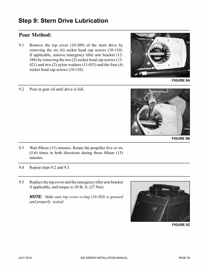
Step 9: Stern Drive Lubrication
Pour Method:
9.1 Remove the top cover (10-209) of the stern drive by removing the six (6) socket head cap screws (10-110). If applicable, remove emergency tiller arm bracket (12-388) by removing the two (2) socket head cap screws (12-421) and two (2) nylon washers (11-033) and the four (4) socket head cap screws (10-110).
9.2 Pour in gear oil until drive is full.
9.3 Wait fifteen (15) minutes. Rotate the propeller five or six (5-6) times in both directions during those fifteen (15) minutes.
9.4 Repeat steps 9.2 and 9.3.
9.5 Replace the top cover and the emergency tiller arm bracket if applicable, and torque to 20 lb. ft. (27 Nm).
NOTE: Make sure top cover o-ring (10-303) is greased and properly seated.
FIGURE 9B
FIGURE 9A
FIGURE 5C
500 SERIES INSTALLATION MANUAL JULY 2016PAGE 40
Step 9: Stern Drive Lubrication (continued)
Pump Method: (Pump Required)
9.1a Remove the upper breather screw (10-010) located on the top port side of the upper housing (see Figure 9D). Remove the lower drain plug (10-155) located on the lower housing under the tip of the nose cone on the 520 model (see Figure 9E), and the starboard side of the lower housing on the 540 and 560 models (see Figure 9F).
FIGURE 9E
FIGURE 9D
FIGURE 9F
500 SERIES INSTALLATION MANUALJULY 2016 PAGE 41
Step 9: Stern Drive Lubrication (continued)
9.2a Pump gear oil into the drive using a pump from the bottom until it comes out of the top breather plug. Let the gear oil settle for ten to fifteen (15) minutes. Pump additional oil until it comes out of the top breather plug.
9.3a Replace upper breather screw (see Figure 9D on page 40 in this manual) and lower drain plug (see Figure 9E or 9F on page 40 in this manual depending on stern drive model).
NOTE: Both drain plug and breather screw seal/gasket
(10-285) must be in place and properly seated when reinstalled.
FIGURE 9G
FIGURE 9H
500 SERIES INSTALLATION MANUAL JULY 2016PAGE 42
Step 10: Trim/Lift Control Module Installation
FIGURE 10A
FIGURE 10B
10.1 Select an appropriate location at the helm to mount the trim/lift control module (the dimensions are 3.125 in. (7.938 cm) x 5.032 in. (12.781 cm) and 4 in. (10 cm) deep, see Figure 10A). The module should be mounted in plain view and reach of the boat operator.
NOTE: For a twin application, it may be desirable to mount both modules next to each other so they can be operated with one hand simultaneously (see Figure 10B).
500 SERIES INSTALLATION MANUALJULY 2016 PAGE 43
Step 10: Trim/Lift Control Module Installation (continued)
10.2 Layout the cutout area and mark the four (4) holes that need to be drilled per the drawing below.
NOTE: Do not scale the drawing or use it as a template.
10.3 Use a reciprocating saw to cut out the area laid out in the previous step. Drill the four (4) holes laid out in the previous step.
NOTE: Touch up and remove burs from the cutout area with a file.
4x R3/8(R9.5mm)
4x 011/64(04.5mm)
2.563(65.1mm)
4.375(111.1mm)
2.510(63.8mm)
2.247(57.1mm)
4.494(114.1mm)
1.255(31.9mm)
500 SERIES INSTALLATION MANUAL JULY 2016PAGE 44
FIGURE 10C
10.4 Mount the module in the cutout area using the hardware provided.
NOTE: If access under the panel is limited, the module may need to be wired before mounting.
10.5 Connect the purple wire to a +12 VDC or +24 VDC source (whichever is the operating voltage of the vessel) that is powered when the ignition key is in the “on” position.
NOTE: Refer to the Trim System Electrical Drawings (Figure C and Figure D on pages 22 and 23 in this manual) for further documentation on this and proceeding instructions.
NOTE: Battery or batteries must be disconnected while all electrical connections are being made.
10.6 Connect the blue wire to the positive side of the instrument panel illumination circuit.
Step 10: Trim/Lift Control Module Installation (continued)
FIGURE 10D
FIGURE 10E
500 SERIES INSTALLATION MANUALJULY 2016 PAGE 45
10.7 Connect the eight (8) wire harness (run in Step 4.13) to the eight (8) wire pigtail on the trim/lift control module.
NOTE: Bundle, cable tie and secure any excess harness.
10.8 Mount the module in the cutout area using the hardware provided (if not done in Step 10.4 on page 44 in this manual).
Step 10: Trim/Lift Control Module Installation (continued)
11.1 Fill the trim/lift pump reservoir with Automatic Trans-mission Fluid type Dextron III or a non-foaming light hy-draulic fluid.
NOTE: If ATF Dextron III is not used, it is recommended that the trim cylinders be purged of any fluid since they are shipped new from Konrad with this fluid in them.
11.2 Place the return line of the trim cylinders (the line labeled “down”) in a container to catch any purged fluid. The “up” line should already be attached from Step 4.12 on page 21 in this manual (Trim/Lift Pump Installation). Hold one finger over the “down” line port of the trim/lift pump to prevent the intake of air. Trim the drive all the way up using the toggle switches on the trim/lift control plate.
NOTE: Only the toggle switch whose LED is illuminated can be used to trim or lift the drive.
NOTE: Fluid may need to be added if the reservoir bottle level goes below the minimum.
FIGURE 11A
FIGURE 11B
FIGURE 11C
500 SERIES INSTALLATION MANUALJULY 2016 PAGE 47
11.3 With the drive in the up position, attach the “down” line to the trim/lift pump.
11.4 Cycle the drive all the way to the down position and then all the way to the up position. Repeat this step three to four (3-4) times to purge any remaining air out of the system.
NOTE: Re-check the fluid level of the reservoir. Add fluid if necessary.
NOTE: Check entire trim system (inboard and outboard the transom) for leaks before proceeding.
NOTE: If mechanical trim indicators are used, skip Step 12 and refer to the manufacturers instructions for installation and adjustment.
12.1 Trim the drive all the way to the down position, approxi-mately negative seven degrees (-7º).
NOTE: In the case where trim limiting trim cylinders are used, trim the drive all the way to the down position,
approximately negative two degrees (-2º).
Step 12: Setting Trim/Lift Limit & Sender Switch
FIGURE 12A
FIGURE 12B
500 SERIES INSTALLATION MANUALJULY 2016 PAGE 49
FIGURE 12C
FIGURE 12D
12.2 Loosen the starboard side switch on the transom assembly and rotate the switch until gauge reads DN (farthest down position).
NOTE: If this position cannot be achieved by rotating the switch, it will be necessary to take the switch com-pletely off the transom assembly and rotate the gray star-hex shaped knob until desired position is achieved. Re-mount the switch and fine tune.
12.3 Set the drive at approximately eight degrees (+8°). This can be accomplished by trimming the drive up until the trim cylinder measures 22 in. (56 cm) between the center of the front anchor pin and the center of the rear anchor pin.
NOTE: Alternate method of setting the drive at eight degrees (+8°): Insert a 1 in.(2.54 cm) shim at the front of
the top cover. Place one end of a level on the 1 in. (2.54 cm) shim and the other end on the back of the top cover. Trim the drive up or down until the level indicates levelness.
12.4 Loosen the port side switch on the transom assembly and rotate until the red and green LED’s are on the verge of switching.
NOTE: If this position cannot be achieved by rotating the switch, it will be necessary to take the switch off the transom and rotate the gray star-hex shaped knob until desired position is achieved. Remount the switch and fine tune.
13.1 Steering cylinder bracket should have been mounted when the transom assembly was installed (Step 2.3 on page 13 in this manual). If not, take the two (2) nuts and washers off the transom assembly studs, and mount the steering cylinder bracket at this time.
NOTE: It is also necessary to connect the continuity cable ring to the port side stud (if applicable), if this has not been previously done.
13.2 Install steering cylinder assembly.
13.3 With the steering cylinder ram and tiller arm in the center position, adjust the drag link to the correct length and attach it between the cylinder and the tiller arm with the hardware provided.
NOTE: For a twin engine installation with an internal tie bar, verify center to center stern drive mounting distance (on the fixed transom assembly) and adjust tie bar to length to match. Attach the tie bar to the tiller arms with the hardware provided.
13.4 Connect the long continuity wire from the steering bracket to the tiller arm (if applicable).
Step 13: Manual Hydraulic Steering System Installation
FIGURE 13A
FIGURE 13C
FIGURE 13B
FIGURE 13D
500 SERIES INSTALLATION MANUALJULY 2016 PAGE 51
13.5 Determine the correct mounting location for the helm assembly.
NOTE: Be sure there is adequate clearance under the dash for the helm assembly and hoses.
NOTE: Be sure there is adequate clearance above the dash for the steering wheel.
Lay out and cut/drill the appropriate area described by the template provided from the manufacturer.
13.6 Install the helm assembly with the hardware provided.
13.7 Install the steering wheel with the hardware provided.
13.8 Determine the correct location and mount the reservalve.
13.9 Mark/identify the two (2) steering lines/hoses (port and starboard). Run the two (2) lines from the steering cylinder to the reservalve. Mark/identify the three (3) steering lines/hoses (port, starboard and reservalve). Run the three (3) lines from the reservalve forward through the starboard raceway, and up to the helm assembly. Fasten lines as necessary. Bundle/coil excess and secure if necessary.
13.10 Attach the two (2) hydraulic steering lines to the steering cylinder assembly, observing port and starboard identifi-cation.
NOTE: Please refer to the 30-462R routing diagram (Figure H on page 54 in this manual) for assistance and further explanation.
14.1 Steering cylinder bracket should have been mounted when the transom assembly was installed (Step 2.3 on page 13 in this manual). If not, take the two (2) nuts and washers off the transom assembly studs, and mount the steering cylinder bracket at this time.
NOTE: It is also necessary to connect the continuity cable ring to the port side stud (if applicable), if this has not been previously done.
14.2 Install steering cylinder assembly.
14.3 With the steering cylinder ram and tiller arm in the center position, adjust the drag link to the correct length and attach it between the cylinder and the tiller arm with the hardware provided (see Figure 14C).
NOTE: For a twin engine installation with an internal tie bar, verify center to center stern drive mounting distance and adjust tie bar to length to match. Attach the tie bar to the tiller arms with the hardware provided (see Figure 14D).
Step 14: Power Steering System Installation
FIGURE 14D
FIGURE 14A
FIGURE 14C
FIGURE 14B
500 SERIES INSTALLATION MANUAL JULY 2016PAGE 56
14.4 Connect the long continuity wire from the steering bracket to the tiller arm (if applicable).
14.5 Determine an appropriate location and mount the power steering pump onto the engine using the brackets and hardware provided. Install the belt (if applicable) and verify proper tension.
NOTE: If an electric power steering pump is used (instead of an engine mounted unit) consult with manufacturer for installation details.
14.6 Mount the power steering fluid cooler and plumb it into the cooling system of the engine.
NOTE: A mounting bracket may be fabricated or ob-tained from the engine manufacturer.
Step 14: Power Steering System Installation (continued)
FIGURE 14F
FIGURE 14G
FIGURE 14E
500 SERIES INSTALLATION MANUALJULY 2016 PAGE 57
14.7 Determine an appropriate location and mount the power steering fluid reservoir.
NOTE: The reservoir must be mounted higher than, and in close proximity to, the power steering pump.
NOTE: Be sure the reservoir is in an accessible location for adding and checking fluid.
14.8 Determine an appropriate location and mount the power steering fluid filter.
14.9 Determine the correct mounting location for the helm assembly.
NOTE: Be sure there is adequate clearance under the dash for the helm assembly and hoses.
NOTE: Be sure there is adequate clearance above the dash for the steering wheel.
Lay out and cut/drill the appropriate area described by the template provided from the manufacturer.
Step 14: Power Steering System Installation (continued)
FIGURE 14J
FIGURE 14H
FIGURE 14I
500 SERIES INSTALLATION MANUAL JULY 2016PAGE 58
14.10 Install the helm assembly with the hardware provided.
14.11 Install the steering wheel with the hardware provided.
14.12 Determine an appropriate location and mount the steering lock valve assembly.
NOTE: This should be in close proximity to the helm assembly.
FIGURE 14L
Step 14: Power Steering System Installation (continued)
FIGURE 14M
FIGURE 14K
FIGURE 14N
500 SERIES INSTALLATION MANUALJULY 2016 PAGE 59
FIGURE 14O
Step 14: Power Steering System Installation (continued)
14.13 Mark/identify each of the four (4) steering lines/hoses (high pressure, return, port and starboard) that run forward from the engine compartment. Run the four (4) lines from the engine compartment forward through the starboard raceway, and up to the helm and lock valve assembly. Fasten lines as necessary. Bundle/coil excess and secure if necessary.
14.14 Using the routing diagram 30-390R (Figure I on page 60 in this manual), connect the four (4) lines/hoses run in the previous step. Also using the diagram, hook up the remaining five (5) hoses, numbered 1, 2, 7, 8 and 9.
14.15 Fill the steering fluid reservoir and power steering pump with the appropriate fluid.
14.16 Bleed system per manufacturer’s specifications. NOTE: Additional fluid may need to be added during the
bleeding process.
14.17 Check system for leaks.
500 SERIES INSTALLATION MANUAL JULY 2016PAGE 60
F
P
A
S
L R P T
OR
BIT
RA
L (H
ELM
)U
NIT
PO
WE
RS
TEE
RIN
GP
UM
P
CO
OLE
R
FILT
ER
STE
ER
ING
CY
LIN
DE
R
2
8
7
LOC
K
VA
LVE
56
10 (5
.25"
)
V1
V2
C2
C1
IN OU
T
TL
PR
TOP
BO
TTO
M
SID
E V
IEW
OF
HE
LM U
NIT
& P
OR
TS
T-LO
W P
RE
SS
UR
E R
ETU
RN
L-LE
FT (P
OR
T) C
YLI
ND
ER
LIN
EP
-HIG
H P
RE
SS
UR
E P
UM
PR
-RIG
HT
(STA
RB
OA
RD
) CY
LIN
DE
R
LIN
E
RE
SE
RV
OIR
9
3 41
1-7-
HIG
H P
RE
SS
UR
E H
OS
E8-
1/2"
LO
W P
RE
SS
UR
E H
OS
E9-
3/4"
LO
W P
RE
SS
UR
E H
OS
E
PLE
AS
E C
OR
RE
SP
ON
D Y
OU
RLE
NG
THS
TO
TH
E N
UM
BE
RS
ON
TH
E D
IAG
RA
M
30-3
90R
DR
AWIN
G N
O.
NEX
T AS
S'Y
DR
AWIN
G N
UM
BER
Kon
rad
.X .0
20
.XX
.0
10
.XXX
.0
05
DR
AWN
BY:
S
CAP
P.BY
:SC
ALE:
RO
UTI
NG
DIA
GR
AM
30-3
90R
MAT
'L:
TOLE
RAN
CE
TITL
E:
DAT
E:W
EIG
HT:
12/1
5/05
1:1
DAT
ESY
MR
EVIS
ION
DR
DO
NO
T SC
ALE
DR
AWIN
G
(C) C
OPY
RIG
HT
2004
KO
NR
AD M
ARIN
EAL
L R
IGH
TS R
ESER
VED
THIS
DO
CU
MEN
T AN
D T
HE
INFO
RM
ATIO
NC
ON
TAIN
ED H
EREI
N IS
CO
NFI
DEN
TIAL
AND
PR
OPR
IETA
RY
PRO
PER
TY A
ND
MU
STN
OT
BE U
SED
, REP
RO
DU
CED
, OR
ITS
CO
NTE
NT
DIS
CLO
SED
, IN
WH
OLE
OR
INPA
RT,
WIT
HO
UT
PRIO
R W
RIT
TEN
CO
NSE
NT
OF
KON
RAD
MAR
INE.
FIGURE I: ROUTING DIAGRAM 30-390R
500 SERIES INSTALLATION MANUALJULY 2016 PAGE 61
FIGURE J: HOSES FOR ASSEMBLY KM #30-390
HOSES FOR ASSEMBLY KM #30-390
POWER STEERING HOSE ROUTING -4KM Part # Description QTY#11-852 HOSE, HP, -4 JIC FEMALE SWIvEL / -4 NPT MALE, 5.25 in. 1
(Steering cylinder bypass - #10)
POWER STEERING HOSE ROUTING -6KM Part # Description QTY#30-408-XXXX HOSE, HP, -6 JIC FEMALE SWIvEL BOTH ENDS 2
(Orbitrol to Lock Valve - #1 & #2)
#30-408-XXXX HOSE, HP, -6 JIC FEMALE SWIvEL BOTH ENDS 1
(Orbitrol to Filter - #3)
#30-408-XXXX HOSE, HP, -6 JIC FEMALE SWIvEL BOTH ENDS 1
(Orbitrol to Oil Cooler - #4)
#30-408-XXXX HOSE, HP, -6 JIC FEMALE SWIvEL BOTH ENDS 2
(Lock Valve to Steering Cylinder - #5 & #6)
#30-408-XXXX HOSE, HP, -6 JIC FEMALE SWIvEL BOTH ENDS 1
(Filter to Power Steering Pump - #7)
POWER STEERING HOSE ROUTING - Low PressureKM Part # Description QTY#11-956-XXXX HOSE, LP, 1/2 in. ID 1
(Oil Cooler to Power Steering Pump - #8)
#11-957-XXXX HOSE, LP, 3/4 in. ID 1
(Power Steering Pump to Reservoir - #9)
* EACH KM PART # WILL CORRESPOND TO A LENGTH OF HOSE, FOR EXAMPLE:IF YOU WANT 6m = 19 ft. 8.2 in. OF -6 HOSE, YOUR PART # IS #30-408-19_08
IF YOU WANT 2m = 6 ft. 6.72 in. OF 1/2 in. LP HOSE, YOUR PART # IS #11-956-06_07
500 SERIES INSTALLATION MANUAL JULY 2016PAGE 62
PART NO. DESCRIPTION QTY. 10-484 Rubber Coupling 2 10-486 M-14 H. H. C. S. 12 10-655 Nut 2 10-656 Washer 2 11-187 Adapter Flange 1 11-191 M-14 Belleville Washer 12 11-192 M-16 H. H. C. S. 6 11-193 M-16 Belleville Washer 6 11-194 M-16 Nut 6 11-266 Flange, Female 2 11-267 Shaft, Splined 1
FIGURE K: 30-264 Parts List
500 SERIES INSTALLATION MANUALJULY 2016 PAGE 63
PART NO. DESCRIPTION QTY. 10-247 Grease Fitting 1 10-484 Rubber Coupling 2 10-486 M-14 H. H. C. S. 6 11-187 Adapter Flange 1 11-190 M-14 S. H. C. S. 6 11-191 M-14 Belleville Washer 12 11-192 M-16 H. H. C. S. 6 11-193 M-16 Belleville Washer 6 11-194 M-16 Nut 6 11-308 Adapter Flange, Male 1 20-028 Drive Shaft, Splined 1
FIGURE L: 30-272 Parts List
NOTE: Drawing shows drive in counterclockwise position
NOTE: Verify correct shaft length before proceeding. NOTE: Apply Loctite to all fasteners in this step before
fastening occurs. NOTE: Rotation determined by viewing transmission
flange from stern of vessel. “CCWR” = Counterclockwise rotation “CWR” = Clockwise rotation.
15.1 Install the adapter flange (11-187) onto the back of the transmission using: • Six (6) M-16 H.H.C.S (11-192) • Six (6) M-16 Belleville Washers (11-193) • Six (6) M-16 Nuts (11-194)
15.2 Prior to assembly, place three (3) H.H.C.S. (10-486) and three (3) Belleville washers (11-191) into the rubber coupling (10-484) element according to the clockwise and counterclockwise rotations. These fasteners will attach to the center drive shaft component (11-266 & 11-308). Install the rubber coupling (10-484) to the adapter flange (11-187) using:
30-264 Assembly • Three (3) M-14 H.H.C.S. (10-486) • Three (3) Belleville Washers (11-191) 30-272 Assembly • Three (3) M-14 S.H.C.S. (11-190) • Three (3) Belleville Washers (11-191)
Counterclockwise rotation: The fasteners (10-486 or 11-190) should be inserted through the rubber coupling in the direction of the arrows. When attaching the rubber coupling to the adapter flange (11-187), point arrows on the rubber coupling toward the adapter flange (11-187).
IMPORTANT: Thick section of rubber element should ALWAYS be in compression between driving and driven
500 SERIES INSTALLATION MANUAL JANUARY 2010PAGE 64
Clockwise rotation: The fasteners (10-486 or 11-190) should be inserted through the rubber coupling against the direction of the arrows. When attaching the rubber coupling to the adapter flange (11-187), point arrows on the rubber coupling away from the adapter flange (11-187).
IMPORTANT: Thick section of rubber element should ALWAYS be in compression between driving and driven
bolts.
15.3 Prior to assembly, place three (3) H.H.C.S. (10-486) and three (3) Belleville washers (11-191) into the rubber coupling (10-484) element. These fasteners will attach to the center drive shaft component (11-266; 20-028). Attach the second rubber coupling (10-484) to the gimbal carrier flange (10-466) using:
30-264 Assembly • Three (3) M-14 H.H.C.S. (10-486) • Three (3) Belleville Washers (11-191) 30-272 Assembly • Three (3) M-14 S.H.C.S. (11-190) • Three (3) Belleville Washers (11-191)
Counterclockwise rotation: The fasteners (10-486 or 11-190) should be inserted through the rubber coupling in the direction of the arrows. When attaching the rubber coupling to the gimbal carrier flange (10-466), point arrows on the rubber coupling toward the gimbal carrier flange (10-466).
IMPORTANT: Thick section of rubber element should ALWAYS be in compression between driving and driven
500 SERIES INSTALLATION MANUALJANUARY 2010 PAGE 65
500 SERIES INSTALLATION MANUAL JULY 2016PAGE 66
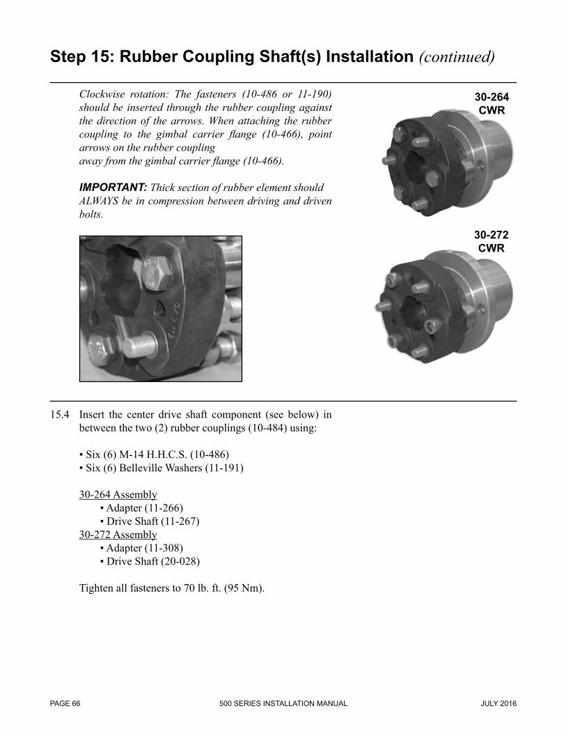
Clockwise rotation: The fasteners (10-486 or 11-190) should be inserted through the rubber coupling against the direction of the arrows. When attaching the rubber coupling to the gimbal carrier flange (10-466), point arrows on the rubber coupling
away from the gimbal carrier flange (10-466).
IMPORTANT: Thick section of rubber element should ALWAYS be in compression between driving and driven
bolts.
15.4 Insert the center drive shaft component (see below) in between the two (2) rubber couplings (10-484) using:
16.1 Verify correct shaft length and installation parameters as defined in the Alignment Specifications Chart (Figure E on page 28 in this manual) and the alignment procedure from Step 6D on page 31 in this manual before proceeding.
16.2 If applicable, bolt transmission output flange adaptor on to the transmission output flange. Apply Loctite to the fasteners before tightening. Torque fasteners correctly according to their size.
16.3 Bolt u-joint shaft on to gimbal carrier flange. Apply Loctite to the four (4) fasteners before tightening. Torque to 88 lb. ft. (120 Nm).
NOTE: Ensure pilot is correctly sized and fully engaged (if applicable).
FIGURE 16A
FIGURE 16B
500 SERIES INSTALLATION MANUALJULY 2016 PAGE 69
16.4 Adjust u-joint shaft to appropriate length and bolt it on to the transmission output flange (or output flange adaptor). Apply Loctite to the four (4) fasteners before tightening. Torque to 88 lb. ft. (120 Nm).
NOTE: Ensure pilot is correctly sized and fully engaged (if applicable).
NOTE: Ensure that the shaft is installed within the working limitations of the slip compensating spline.
16.5 Grease u-joints and extension joint before operation of the shaft occurs.
17.1 Verify correct shaft length and installation parameters as defined in the Alignment Specifications Chart (Figure E on page 28 in this manual) and the alignment procedure from Step 6E on page 32 in this manual before proceeding.
17.2 Connect CV adaptor flange to gimbal carrier flange. Apply Loctite to threads of fasteners. Torque fasteners to 88 lb. ft. (120 Nm).
17.3 Connect CV adaptor flange to transmission output flange. Apply Loctite to threads of fasteners. Torque fasteners correctly according to their size.
FIGURE 17A
FIGURE 17B
500 SERIES INSTALLATION MANUALJULY 2016 PAGE 71
17.4 Place the CV shaft between the adaptor flanges. The shaft may be installed either direction. Fasten the shaft to the adaptor flange on the transmission using the six (6)
S. H. C. S.s and the three (3) 2-hold washer plates provided. Repeat this for the gimbal carrier flange. Apply Loctite to the threads of the fasteners and torque to 85 lb. ft. (115 Nm).
NOTE: In some cases only four (4) of the six (6) fasteners can be installed. Inspect adaptor flanges prior to shaft installation. In this case insert a plastic plug (provided with shaft hardware) in each of the two (2) holes without a fastener.
NOTE: Drive shaft shrouds are optional equipment and are not shipped with Konrad stern drives unless ordered.
18.1 If the drive shaft is already installed, remove the lower plate/strap from the shroud (shrouds are shipped assembled from Konrad). If the drive shaft is not installed, refer to Step 16 on page 68 in this manual.
18.2 Place the shroud over the aft portion of the drive shaft. Position the shroud so end with the tabs or ears are aft. Replace the lower plate/strap removed in the previous step.
18.3 Slide the shroud aft and place it on the four (4) center studs of the transom assembly.
18.4 Secure the shroud using one (1) washer and one (1) nylock nut on each stud.
18.5 Rotate drive shaft to verify adequate clearance.
Step 18: Drive Shaft Shroud Installation
FIGURE 18A
FIGURE 18B
500 SERIES INSTALLATION MANUAL JANUARY 2010PAGE 72
FIGURE M: Rear Mount / Tailpiece CUTOUT TEMPLATE
Note: Drawing not to scale.
500 SERIES INSTALLATION MANUALJANUARY 2010 PAGE 73
500 SERIES INSTALLATION MANUAL JULY 2016PAGE 74
19.1 Use paper template (12-449) to set X-dimension and center the stern drive cutout on the boat transom. Cut hole and drill holes through the transom following the template.
19.2 Bolt transom plate (12-268) on the outside of transom. For the top four (4) holes, use cap screw (12-315), seal washer (10-930), backing plate (10-941), and nut (10-565).
Torqure all fasteners to 35 lb-ft (48 Nm).
NOTE: If a steering plate (20-082 or 12-450) is used, replace top four (4) screws and backing plates with cap screw (11-982) and washer (10-415).
Step 19: Rear Mount / Tailpiece Installation
FIGURE 19A
FIGURE 19B
FIGURE 19C
500 SERIES INSTALLATION MANUALJULY 2016 PAGE 75
19.3 Mount Konrad transom assembly (30-014) to outside of transom plate (12-268). Be sure appropriate hoses and cable are fed through plate and cutout. Tighten washer (10-415) and nut (10-334) to the top two (2) and bottom two (2) studs on the gimbal housing.
Torque to 35 lb-ft (48 Nm).
19.4 Slide tailhousing mount assembly (30-450) onto middle four (4) studs of gimbal housing. Tighten washer (10-415) and nut (10-334) to the middle four (4) studs on the gimbal housing.
19.5 Connect tiller arm continuity cable to inner steering plate using the small Phillips head screw (if applicable).
Step 19: Rear Mount / Tailpiece Installation
FIGURE 19D
FIGURE 19E
FIGURE 19F
500 SERIES INSTALLATION MANUAL JULY 2016PAGE 76
19.6 With Konrad tailpiece assembly (30-807) mounted on the transmission and the transmission mounted on the engine, position the tailpiece on the bore and move into place until the ears on the tailpiece align with the mounts on the tailpiece mount (30-450).
NOTE: It is recommended that Steps 3 and 4 of this manual are completed prior to proceeding with 19.6.
19.7 Insert washer (12-085) and bolt (12-084) through tailpiece ears in two (2) places. Secure with washer (12-085) and nut (12-086) on bottom side of tailpiece mount.
Tighten and torque two (2) bolts to 90 lb-ft (120 Nm).
19.8 For final alignment, slide rod of alignment tool (TO-094) through bell housing and into tailpiece (30-449). Slide disc of alignment tool (TO-094) over rod. Adjust front engine mounts until disc fully slides into bore of bell housing.
The Rear Mount / Tailpiece Installation is complete. Please continue with Step 5 OR Step 3 if not completed yet of this manual to proceed with installation
Step 19: Rear Mount / Tailpiece Installation
FIGURE 19G
FIGURE 19H
FIGURE 19I
500 SERIES INSTALLATION MANUALJULY 2016 PAGE 77
Installation Checklist-Inside of Vessel
20.1 Verify proper position and level of oil in reservoir bottle. Confirm proper routing of hoses and check all connection points for leaks. Make sure hose is secure to transom a minimum of every 6 inches with fasteners.
20.2 Confirm proper amount of ATF fluid (Dexron III) in trim pump and verify proper bleeding of the system.
20.3 Check all internal trim cylinder hoses for proper routing and leaks at connection points.
20.4 Verify 12V or 24V system of vessel and confirm that proper trim pump has been supplied. Confirm circuit breaker (fuse) is installed on trim pump. Check for proper connection points for wiring of trim pump.
20.5 Tilt drives up and down to confirm proper function of trim pump and trim assembly. (Trim Sender) If fitted with mechanical trim senders, verify proper adjustment.
20.6 Confirm connection of continuity cables. Also check for continuity from prop shaft of sterndrive to the gimbal assembly, gimbal housing, trim cylinder and steering cylinder.
20.7 Steering:
A) Confirm proper fluid level B) Verify proper bleeding procedure was done C) Check all hose routing and connection points for leaks D) Verify # of turns lock to lock E) Verify correct rudder indicator position, when compared with the drive position.
20.8 Transmission:
A) Confirm proper fluid level in transmission B) Verify proper routing of lines and check for leaks at connection points C) Confirm proper orientation of lines and that they are going to the correct ports D) (If applicable) Mechanical Shift: Verify proper throw and linkage on mechanical arm. E) Check that the Neutral Safety Switch circuit is correct
20.9 Confirm that engine mounts/vibration isolators (on stringers) are within angular and height tolerance.
20.10 Driveshaft - If applicable A) Confirm Parallelism and Concentricity meet Konrad requirements for specific shaft type and length. Reference Step 6 in this manual for information. B) Confirm proper torque on hardware at both drive and transmission connection. Also, verify that Loctite was used where recommended.
Step 20: Installation Review
500 SERIES INSTALLATION MANUAL JULY 2016PAGE 78
Installation Checklist-Outside of Vessel
20.11 Verify Serial #’s on drives for proper ratio and rotation.
20.12 X-Dimension: Confirm proper height. Verify from application drawing.
20.13 Confirm propeller specs for correct diameter and pitch.
20.14 Verify that alignment was done correctly for close couple or remote mount per your install type.
20.15 Confirm proper oil level in sterndrives.
20.16 External Steering: Confirm torque specs on fasteners. Steering rams, tie bars, etc…
20.17 Twin applications: Confirm centerline distance of drives on transom and take measurement from center to center on propshafts to make sure drives are in-line.
20.18 Inspect all hoses and fittings on trim and steering lines for any leaks at connection points and also proper routing of hoses.
20.19 Confirm proper orientation of bellows and check for secure connection on drive and gimbal assembly. Tighten hose clamps.
20.20 Check stern drive for side to side play. The movement should be minimal to none.
20.21 Check for proper continuity on drive from prop shaft to transom using a volt meter.
20.22 Verify correct adjustment of electrical trim senders.
20.23 Inspect bottom of hull for any protrusions impeding clean water flow to propellers. Ex. Transducers, water pickups, anodes, etc…(See drawing in Installation Guidelines section)
Prepare vessel for sea trail, fill out Application Trial Data Forms on following pages. Send in Konrad Warranty forms and trial forms to Konrad Marine.
Step 20: Installation Review (continued)
ww
w.konradm
arine.comsales@
konradmarine.com
Office: 715-386-4203Fax: 715-386-4219
CH
AR
T 1
CONDITION
DA
TE
STERN
DR
IVEM
OD
ELD
RIVE
RA
TIO
TRA
NS-
MISSIO
NM
AK
E &
MO
DEL
TRA
NS-
MISSIO
NR
ATIO
X-DIM
SPACERS
ENG
INE
HP@
RPM
VESSELR
UN
NIN
GW
EIGH
T(no fuel)
FUEL W
EIGH
T
PERSO
NN
ELA
ND
/ OR
C
AR
GO
WEIG
HT
VESSEL TOTA
L R
UN
NIN
GW
EIGH
T
PROP MFG
NUMBER OF BLADES
DIAMETER & PITCH
PROP MATERIAL (AL or SS)
12345678
Please circle the unit of measure ( K
G ) or ( LB
S ) you are using for entries with w
eights
KO
NR
AD
APPLIC
ATIO
N TR
IAL D
ATA
FOR
M
CO
ND
ITION
DESC
RIPTIO
NS
DE
ALE
R or D
ISTR
IBU
TOR
CO
MP
AN
Y N
AM
E
DE
ALE
R or D
ISTR
IBU
TOR
CO
NTA
CT N
AM
E
DE
ALE
R or D
ISTR
IBU
TOR
EM
AIL:
PR
OJE
CT N
AM
E/N
UM
BE
R:
CLIE
NT N
AM
E:
DA
TE:
KO
NR
AD
AP
PLIC
ATIO
N TR
IAL D
ATA
FOR
M C
HA
RT 1.X
LS
ww
w.k
onra
dmar
ine.
com
sale
s@ko
nrad
mar
ine.
com
Offi
ce: 7
15-3
86-4
203
Fax:
715
-386
-421
9
vE
SS
EL
MA
KE
:H
ULL
TY
PE
:
C
atam
aran
/ M
onoh
ull
(Circ
le)
vE
SS
EL
LEN
GTH
:A
PP
LIC
ATI
ON
:
Sin
gle
/ T
win
(C
ircle
)
CH
AR
T 2
Por
tS
tar
Por
tS
tar
Por
tS
tar
1 2 3 4 5 6 7 8
GP
S @
Idle
GP
S @
100
0 G
PS
@ 1
500
GP
S @
2000
GP
S @
2500
G
PS
@30
00G
PS
@W
OT
RP
M
Kno
ts
GPS
Spe
eds
at V
aryi
ng R
PM
TRIM
PO
SIT
ION
TR
IAL
DA
TA F
OR
MA
X VE
LOC
ITY
AT
VAR
IOU
S C
ON
DIT
ION
S (O
UTL
INED
IN C
HA
RT
1)
MA
XIM
UM
VEL
OC
ITY
REA
DIN
GS
OR
IGIN
AL
HE
AD
ING
(0o )
KO
NR
AD
APP
LIC
ATI
ON
TR
IAL
DA
TA F
OR
M
vE
LOC
ITY
MA
X (K
TS)
ENG
INE
EX
HA
US
TTE
MP
(Co ) A
ND
LO
AD
%
EN
GIN
EB
OO
ST
PR
ES
SU
RE
(kP
a)
CO
ND
ITIO
N(S
ee C
hart
1 fo
rD
escr
iptio
n)
OP
PO
SIT
E H
EA
DIN
G (1
80o )
TIM
E T
O
PLA
NE
(SE
C.)
RP
M (E
NG
INE
)v
ELO
CIT
YM
AX
(KTS
)R
PM
(EN
GIN
E)
ENG
INE
NO
LO
AD
MA
X R
PM
(N
UE
TRA
L)
KO
NR
AD
AP
PLI
CA
TIO
N T
RIA
L D
ATA
FO
RM
CH
AR
T 2.
XLS
ww
w.konradm
arine.comsales@
konradmarine.com
Office: 715-386-4203Fax: 715-386-4219
vE
SS
EL M
AK
E:
HU
LL TYP
E: C
atamaran / M
onohull (Circle)
vE
SS
EL LE
NG
TH:
AP
PLIC
ATIO
N: S
ingle / Twin (C
ircle)
CH
AR
T 2
Port
Star
Port
Star
Port
Star
12345678
GP
S @
IdleG
PS
@ 1000
GP
S @
1500G
PS
@2000
GP
S @
2500 G
PS
@3000
GP
S @
WO
T
TRIA
L DA
TA FO
R C
RU
ISE VELOC
ITY AT VA
RIO
US C
ON
DITIO
NS (O
UTLIN
ED IN
CH
AR
T 1)
CR
UISE VELO
CITY R
EAD
ING
S - MIN
IMU
M 3 R
EAD
ING
S, 200 RPM
INC
REM
ENTS
OR
IGIN
AL H
EA
DIN
G (0
o)
KO
NR
AD
APPLIC
ATIO
N TR
IAL D
ATA
FOR
M
ENG
INE
EX
HA
US
TTE
MP
(Co) A
ND
LO
AD
%
EN
GIN
EB
OO
ST
PR
ES
SU
RE
(kPa)
CO
ND
ITION
(See C
hart 1 for
Description)
OP
PO
SITE
HE
AD
ING
(180o)
TIME
TO
PLA
NE
(SE
C.)
RP
M (E
NG
INE
)
RP
M
Knots
GPS Speeds at Varying R
PM
TRIM
PO
SITIO
Nv
ELO
CITY
CR
UIS
E (K
TS)
vE
LOC
ITYC
RU
ISE
(KTS
)R
PM
(EN
GIN
E)
ENG
INE
NO
LOA
D M
AX
RP
M
(NU
ETR
AL)
KO
NR
AD
AP
PLIC
ATIO
N TR
IAL D
ATA
FOR
M C
HA
RT 2.X
LS
KONRAD, INC.1421 HANLEY ROAD • HUDSON, WI 54016-9376 USA