AN INDUSTRIAL TRAINING REPORT A Training Report Submitted in Partial fulfillment for the award of Bachelor of Engineering in Electrical & Electronics Engineering Submitted to RAJIV GANDHI PROUDYOGIKE VISHWAVIDYALAYA BHOPAL (M.P) MAJOR TRAINING REPORT Submitted By GOURAV JAIN (0157EX071010) Under the Supervision of (14) NAME OF THE GUIDE (14)
Transcript
AN INDUSTRIAL TRAINING REPORT
A Training Report
Submitted in Partial fulfillment for the award of
Bachelor of Engineering in Electrical & Electronics Engineering
1.INTRODUCTION2.ABOUT SUBSTATION3.TRANSFORMER4.CIRCUIT BREAKERS5.ISOLATORS6.INSULATOR7.RELAYS8.LIGHTENING ARREST0RS9.POWER LINE CARRIER COMM.10. BATTERY CHARGERS11. CONTROL ROOM12. SINGLE LINE DIAGRAM13. CONCLUSION
INTRODUCTION
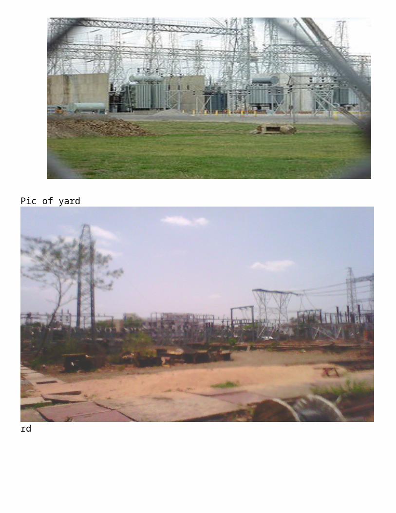
A Substation forms a important part of transmission & distribution system of electric power utility. It may be defined as the assembly of apparatus, which transform the characteristic of electrical energy from one to another. It provides the point for controlling the power at different voltage level along with different roots by means of various equipments, such as transformers, circuit breakers, isolator etc. the AC electrical energy is generated at low voltage (11 kv) but to transmission of voltage is stepped up & for distribution the voltage is step down. The stepping up & stepping down of voltage is done in substation.
An electrical substation is a subsidiary station of an electricity generation, transmission and distribution system where voltage is transformed from high to low or the reverse using transformers. Electric power may flow through several substations between generating plant and consumer, and may be changed in voltage in several steps.
A substation that has a step-up transformer increases the voltage while decreasing the current, while a step-down transformer decreases the voltage while increasing the current for domestic and commercial distribution. The word substation comes from the days before the distribution system became a grid. The first substations were connected to only one power station where the generator was housed, and were subsidiaries of that power station.
Substations usually contain transformers in order to change voltage levels; they are connected to a "bus" via a circuit breaker. Specifically, substations are used for some or all of the following purposes: connection of generators, transmission or distribution lines, and loads to each other; transformation of power from one voltage level to another; interconnection of alternate sources of power; switching for alternate connections and isolation of failed or overloaded lines and equipment; controlling system voltage and power flow; reactive power compensation; suppression of overvoltage; and detection of faults, monitoring, recording of information, power measurements, and remote communications.Minor distribution or transmission equipment installation is not referred to as a substation.
The electricity power production at generating station is quite away from the consumer. For transmission & distribution we need several substation.
The following categories of substation are covered in the transmission & distribution system network.
400 kv /220 kv
220 kv /132 kv
132 kv /33 kv
33 kv /11 kv
11 kv /440 v
ABOUT SUBSTATION
The assembly of apparatus used to change some characteristics (e.g.
voltage al to de freq. p.f. etc) of electric suppy is called subststion….
Contents
Elements of a substation
Transmission substation Distribution substation Collector substation Stations with change of current type Switching substation Outdoor substation Indoor substation Under ground substation Design Layout Switching function Railways See also References and furtherreading
Substations generally have switching, protection and control equipment and one or more transformers. In a large substation,circuit breakers are used to interrupt any short-circuits or overload currents that may occur on the network. Smaller distribution stations may use recloser circuit breakers or fuses for protection of distribution circuits. Substations do not usually have generators, although a power plant may have a substation nearby. Other devices such as capacitors and voltage regulators may also be located at a substation.
Substations may be on the surface in fenced enclosures, underground, or located in special-purpose buildings. High-rise buildings may have several indoor substations. Indoor substations are usually found in urban areas to reduce the noise from the transformers, for reasons of appearance, or to protect switchgear from extreme climate or pollution conditions.
Where a substation has a metallic fence, it must be properly grounded (UK: earthed) to protect people from high voltages that
may occur during a fault in the network. Earth faults at a substation can cause a ground potential rise. Currents flowing in the Earth's surface during a fault can cause metal objects to have a significantly different voltage than the ground under a person's feet; this touch potential presents a hazard of electrocution.
Transmission substation
A transmission substation connects two or more transmission lines. The simplest case is where all transmission lines have the same voltage. In such cases, the substation contains high-voltage switches that allow lines to be connected or isolated for fault clearance or maintenance. A transmission station may have transformers to convert between two transmission voltages, voltage control/power factor correction devices such as capacitors, reactors or static VAr compensators and equipment such as phase shifting transformers to control power flow between two adjacent power systems.
Transmission substations can range from simple to complex. A small "switching station" may be little more than a bus plus some circuit breakers. The largest transmission substations can cover a large area (several acres/hectares) with multiple voltage levels, many circuit breakers and a large amount of protection and control equipment (voltage and currenttransformers, relays and SCADA systems). Modern substations may be implemented using International Standards such as IEC61850.
Distribution substation
A distribution substation transfers power from the transmission system to the distribution system of an area. It is uneconomical to directly connect electricity consumers to the high-voltage main transmission network, unless they use large amounts of power, so the distribution station reduces voltage to a value suitable for local distribution.
The input for a distribution substation is typically at least two transmission or subtransmission lines. Input voltage may be, for example, 115 kV, or whatever is common in the area. The output is a number of feeders. Distribution voltages are typically medium voltage, between 2.4 and 33 kV
depending on the size of the area served and the practices of the local utility.
The feeders will then run overhead, along streets (or under streets, in a city) and eventually power the distribution transformers at or near the customer premises.
Besides changing the voltage, the job of the distribution substation is to isolate faults in either the transmission or distribution systems. Distribution substations may also be the points of voltage regulation, although on long distribution circuits (several km/miles), voltage regulation equipment may also be installed along the line.
Complicated distribution substations can be found in the downtown areas of large cities, with high-voltage switching, and switching and backup systems on the low-voltage side. More typical distribution substations have a switch, one transformer, and minimal facilities on the low-voltage side.
Collector substation
In distributed generation projects such as a wind farm, a collector substation may be required. It somewhat resembles a distribution substation although power flow is in the opposite direction, from many wind turbines up into the transmission grid. Usually for economy of construction the collector system operates around 35 kV, and the collector substation steps up voltage to a transmission voltage for the grid. The collector substation can also provide power factor correction if it is needed, metering and control of the wind farm. In some special cases a collector substation can also contain an HVDC static inverter plant.
Collector substations also exist where multiple thermal or hydroelectric power plants of comparable output power are in proximity. Examples for such substations are Brauweiler in Germany and Hradec in the Czech Republic, where power of lignite fired power plants nearby is collected. if no transformers are installed for increase of voltage to transmission level, the substation is a switching station.
A switching substation is a substation which does not contain transformers and operates only at a single voltage level. Switching substations are sometimes used as collector and distribution stations. Sometimes they are used for switching the current to back-up lines or for paralellizing circuits in case of failure. Example herefore are the switching stations atHVDC Inga-Shaba.
Outdoor Sub-Station
For voltage beyond 66KV, equipment is invariably installed
outdoor.It is because for such Voltage the clearances between
conductor and the spacerequired for switches, C.B. and other
equipment becomes so great that it is noteconomical to installed the
equipment indoor.
Indoor Sub-station
For voltage upto 11KV, the equipment of the s/s is installed indoor
because of economic consideration.However, when the atmosphere
iscontaminated with impurities, these sub-stations can be erected for
voltage upto 66KV.
Under ground sub-station
In thickly populated areas, the space available for equipment
andbuilding is limited and the cost of the land is high.Under such
situations, the sub-station is created underground
The main issues facing a power engineer are reliability and cost. A good design attempts to strike a balance between these two, to achieve sufficient reliability without excessive cost. The design should also allow easy expansion of the station, if required.
Selection of the location of a substation must consider many factors. Sufficient land area is required for installation of equipment with necessary clearances for electrical safety, and for access to maintain large apparatus such as transformers. Where land is costly, such as in urban areas, gas insulated switchgear may save money overall. The site must have room for expansion due to load growth or planned transmission additions. Environmental effects of the substation must be considered, such as drainage, noise and road traffic effects. Grounding (earthing) and ground potential rise must be calculated to protect passers-by during a short-circuit in the transmission system. And of course, the substation site must be reasonably central to the distribution area to be served.
Layout
The first step in planning a substation layout is the preparation of a one-line diagram which shows in simplified form the switching and protection arrangement required, as well as the incoming supply lines and outgoing feeders or transmission lines. It is a usual practice by many electrical utilities to prepare one-line diagrams with principal elements (lines, switches, circuit breakers, transformers) arranged on the page similarly to the way the apparatus would be laid out in the actual station.
Incoming lines will almost always have a disconnect switch and a circuit breaker. In some cases, the lines will not have both; with either a switch or a circuit breaker being all that is considered necessary. A disconnect switch is used to provide isolation, since it cannot interrupt load current. A circuit breaker is used as a protection device to interrupt fault currents automatically, and may be used to switch loads on and off. When a large fault current flows through the circuit breaker, this may be detected through the use of current transformers. The magnitude of the current
transformer outputs may be used to 'trip' the circuit breaker resulting in a disconnection of the load supplied by the circuit break from the feeding point. This seeks to isolate the fault point from the rest of the system, and allow the rest of the system to continue operating with minimal impact. Both switches and circuit breakers may be operated locally (within the substation) or remotely from a supervisory control center.
Once past the switching components, the lines of a given voltage connect to one or more buses. These are sets of bus bars, usually in multiples of three, since three-phase electrical power distribution is largely universal around the world.
The arrangement of switches, circuit breakers and buses used affects the cost and reliability of the substation. For important substations a ring bus, double bus, or so-called "breaker and a half" setup can be used, so that the failure of any one circuit breaker does not interrupt power to branch circuits for more than a brief time, and so that parts of the substation may be de-energized for maintenance and repairs. Substations feeding only a single industrial load may have minimal switching provisions, especially for small installations.
Once having established buses for the various voltage levels, transformers may be connected between the voltage levels. These will again have a circuit breaker, much like transmission lines, in case a transformer has a fault (commonly called a 'short circuit').
Along with this, a substation always has control circuitry needed to command the various breakers to open in case of the failure of some component.
Switching function
An important function performed by a substation is switching, which is the connecting and disconnecting of transmission lines or other components to and from the system. Switching events may be "planned" or "unplanned".
A transmission line or other component may need to be deenergized for maintenance or for new construction; for example, adding or removing a transmission line or a transformer.
To maintain reliability of supply, no company ever brings down its whole system for maintenance. All work to be performed, from routine testing to adding entirely new substations, must be done while keeping the whole system running.
Perhaps more importantly, a fault may develop in a transmission line or any other component. Some examples of this: a line is hit by lightning and develops an arc, or a tower is blown down by a high wind. The function of the substation is to isolate the faulted portion of the system in the shortest possible time.
There are two main reasons: a fault tends to cause equipment damage; and it tends to destabilize the whole system. For example, a transmission line left in a faulted condition will eventually burn down, and similarly, a transformer left in a faulted condition will eventually blow up. While these are happening, the power drain makes the system more unstable.Disconnecting the faulted component, quickly, tends to minimize both of these problems.
Railways
Main article: Traction substation
Electrified railways also use substations, often distribution
substations. In some cases a conversion of the current type takes
place, commonly with rectifiers for DC trains, or rotary converters
for trains using AC other than that of the public grid. Sometimes
they are also transmission substations or collector substations if the
railway network also operates its own grid and generators.
Insulator (electrical) Power station Electricity pylon Transformer Static VAR compensator Vehicle-to-grid Power line carrier communication IEC61850 Static inverter plant Traction substation
References and further reading
Overview of substation design and layout US Department of Agriculture engineering design manual for rural
substations IEEE Green Book - Recommended Practice for Grounding of
Industrial and Commercial Power Systems V.k.mehata
CONCLUSIONIn this way I concluded that my seminar report on Sub-
Station alsowe understand what is mean by Sub-Station,
classification of Sub-Station,comparison between outdoor & indoor
Sub-Station & various components &instrument used in Sub-Station.
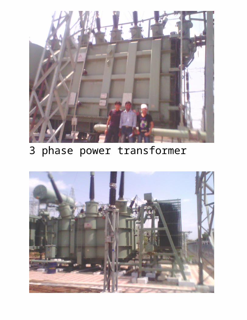
TRANSFORMERElectrical transformers are used to "transform" voltage from one level to another, usually from a higher voltage to a lower voltage. They do this by
applying the principle of magnetic induction between coils to convert voltage and/or current levels.
In this way, electrical transformers are a passive device which transforms alternating current (otherwise known as "AC") electric energy from one circuit into another through electromagnetic induction. An electrical transformer normally consists of a ferromagnetic core and two or more coils called "windings". A changing current in the primary winding creates an alternating magnetic field in the core. In turn, the core multiplies this field and couples the most of the flux through the secondary tranformer windings. This in turn induces alternating voltage (or emf) in each of the secondary coils.
Electrical transformers can be configured as either a single-phase or a three-phase configuration. There are several important specifications to specify when searching for electrical transformers. These include: maximum secondary voltage rating, maximum secondary current rating, maximum power rating, and output type. An electrical transformer may provide more than one secondary voltage value. The Rated Power is the sum of the VA (Volts x Amps) for all of the secondary windings. Output choices include AC or DC. For Alternating Current waveform output, voltage the values are typically given in RMS values. Consult manufacturer for waveform options. For direct current secondary voltage output, consult manufacturer for type of rectification.
A transformer is based on a very simple fact about electricity: when a fluctuating electric current flows through a wire, it generates a magnetic field (an invisible pattern of magnetism) or "magnetic flux" all around it. The strength of the magnetism (which has the rather technical name of magnetic flux density) is directly related to the size of the electric
current. So the bigger the current, the stronger the magnetic field. Now there's another interesting fact about electricity too. When a magnetic field fluctuates around a piece of wire, it generates an electric current in the wire. So if we put a second coil of wire next to the first one, and send a fluctuating electric current into the first coil, we will create an electric current in the second wire. The current in the first coil is usually called the primary current and the current in the second wire is (surprise, surprise) the secondary current. What we've done here is pass an electric current through empty space from one coil of wire to another. This is called electromagnetic induction because the current in the first coil causes (or "induces") a current in the second coil. We can make electrical energy pass more efficiently from one coil to the other by wrapping them around a soft iron bar (sometimes called a core):
To make a coil of wire, we simply curl the wire round into loops or ("turns" as physicists like to call them). If the second coil has the same number of turns as the first coil, the electric current in the second coil will be virtually the same size as the one in the first coil. But (and here's the clever part) if we have more or fewer turns in the second coil, we can make the secondary current and voltage bigger or smaller than the primary current and voltage.
One important thing to note is that this trick works only if the electric current is fluctuating in some way. In other words, you have to use a type of constantly reversing electricity called alternating current (AC) with a transformer. Transformers do not work with direct current (DC), where the current constantly flows in the same direction.
Step-down transformers
If the first coil has more turns that the second coil, the secondary voltage is smaller than the primary voltage:
This is called a step-down transformer. If the second coil has half as many turns as the first coil, the secondary voltage will be half the size of the primary voltage; if the second coil has one tenth as many turns, it has one tenth the voltage. In general:
Secondary voltage ÷ Primary voltage = Number of turns in secondary ÷ Number of turns in primary
The current is transformed the opposite way—increased in size—in a step-down transformer:
Secondary current ÷ Primary current = Number of turns in primary ÷ Number of turns in secondary
Step-up transformers
Reversing the situation, we can make a step-up transformer that boosts a low voltage into a high one:
This time, we have more turns on the secondary coil than the primary. It's still true that:
Secondary voltage ÷ Primary voltage = Number of turns in secondary ÷ Number of turns in primary
and
Secondary current ÷ Primary current = Number of turns in primary ÷ Number of turns in secondary
In a step-up transformer, we use more turns in the secondary than in the primary to get a bigger secondary voltage and a smaller secondary current.
Losses
An ideal transformer would have no losses, and would therefore be 100% efficient. In practice energy is dissipated due both to the resistance of the windings (known as copper loss), and to magnetic effects primarily attributable to the core (known as iron loss). Transformers are in general highly efficient, and large power transformers (around 100 MVA and larger) may attain an efficiency as high as 99.75%. Small transformers such as a plug-in "power brick" used to power small consumer electronics may be less than 85% efficient.
AutotransformerAn autotransformer has a single winding with two end terminals, and
one or more terminals at intermediate tap points. The primary
voltage is applied across two of the terminals, and the secondary
voltage taken from two terminals, almost always having one terminal
in common with the primary voltage. The primary and secondary
circuits therefore have a number of windings turns in common.[46] Since the volts-per-turn is the same in both windings, each
develops a voltage in proportion to its number of turns. In an
autotransformer part of the current flows directly from the input to
the output, and only part is transferred inductively, allowing a
smaller, lighter, cheaper core to be used as well as requiring only a
single winding[47]. However, a transformer with separate windings
isolates the primary from the secondary, which is safer when using
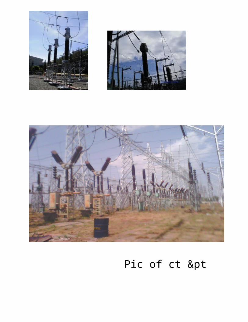
Instrument transformerInstrument transformers are used for measuring voltage and current in electrical power systems, and for power system protection and control. Where a voltage or current is too large to be conveniently used by an instrument, it can be scaled down to a standardized, low value. Instrument transformers isolate measurement, protection and control circuitry from the high currents or voltages present on the circuits being measured or controlled.
Current transformers, designed for placing around conductors
A current transformer is a transformer designed to provide a current in its secondary coil proportional to the current flowing in its primary coil.[54]
Voltage transformers (VTs), also referred to as "potential transformers" (PTs), are designed to have an accurately known transformation ratio in both magnitude and phase, over a range of measuring circuit impedances. A voltage transformer is intended to present a negligible load to the supply being measured. The low secondary voltage allows protective relay equipment and measuring instruments to be operated at a lower voltages.[55]
Both current and voltage instrument transformers are designed to have predictable characteristics on overloads. Proper operation of over-currentprotective relays requires that current transformers provide a predictable transformation ratio even during a short-circuit.
A circuit breaker is an automatically-operated electrical switch designed to protect an electrical circuit from damage caused by overload orshort circuit. Its basic function is to detect a fault condition and, by interrupting continuity, to immediately discontinue electrical flow. Unlike afuse, which operates once and then has to be replaced, a circuit breaker can be reset (either manually or automatically) to resume normal operation. Circuit breakers are made in varying sizes, from small devices that protect an individual household appliance up to large switchgeardesigned to protect high voltage circuits feeding an entire city.
Origins
An early form of circuit breaker was described by Thomas Edison in an 1879 patent application, although his commercial power distribution system used fuses.[1] Its purpose was to protect lighting circuit wiring from accidental short-circuits and overloads.
[edit]Operation
All circuit breakers have common features in their operation, although details vary substantially depending on the voltage class, current rating and type of the circuit breaker.
The circuit breaker must detect a fault condition; in low-voltage circuit breakers this is usually done within the breaker enclosure. Circuit breakers for large currents or high voltages are usually arranged with pilot devices to sense a fault current and to operate the trip opening mechanism. The trip solenoid that releases the latch is usually energized by a separate battery, although some high-voltage circuit breakers are self-contained with current transformers, protection relays, and an internal control power source.
Once a fault is detected, contacts within the circuit breaker must open to interrupt the circuit; some mechanically-stored energy (using something such as springs or compressed air) contained within the breaker is used to separate the contacts, although some of the energy required may be obtained from the fault current itself. Small circuit breakers may be manually operated; larger units have solenoids to trip the mechanism, and electric motors to restore energy to the springs.
Magnetic circuit breaker Thermal magnetic circuit breaker Common trip breakers Medium-voltage circuit breakers High-voltage circuit breakers Sulfur hexafluoride (SF 6) high-voltage circuit-breaker
Low voltage circuit breakersLow voltage (less than 1000 VAC) types are common in domestic, commercial and industrial application, include:
MCB (Miniature Circuit Breaker)—rated current not more than 100 A. Trip characteristics normally not adjustable. Thermal or thermal-magnetic operation. Breakers illustrated above are in this category.
MCCB (Molded Case Circuit Breaker)—rated current up to 2500 A. Thermal or thermal-magnetic operation. Trip current may be adjustable in larger ratings.
Low voltage power circuit breakers can be mounted in multi-tiers in LV switchboards or switchgear cabinets.
The characteristics of LV circuit breakers are given by international standards such as IEC 947. These circuit breakers are often installed in draw-out enclosures that allow removal and interchange without dismantling the switchgea
Magnetic circuit breakerMagnetic circuit breakers use a solenoid (electromagnet) whose pulling force increases with the current. Certain designs utilize electromagnetic forces in addition to those of the solenoid. The circuit breaker contacts are held closed by a latch. As the current in the solenoid increases beyond the rating of the circuit breaker, the solenoid's pull releases the latch which then allows the contacts to open by spring action. Some types of magnetic breakers incorporate a hydraulic time delay feature using a viscous fluid.
Thermal magnetic circuit breakerThermal magnetic circuit breakers, which are the type found in most distribution boards, incorporate both techniques with the electromagnet responding instantaneously to large surges in current (short circuits) and the bimetallic strip responding to less extreme but longer-term over-current condition
Common trip breakers
Three pole common trip breaker for supplying a three-phase device. This breaker has
a 2 A rating
When supplying a branch circuit with more than one live conductor, each live conductor must be protected by a breaker pole. To ensure that all live conductors are interrupted when any pole trips, a "common trip" breaker must be used. These may either contain two or three tripping mechanisms within one case, or for small breakers, may externally tie the poles together via their operating handles. Two pole common trip breakers are common on 120/240 volt systems where 240 volt loads (including major appliances or further distribution boards) span the two live wires. Three-pole common trip breakers are typically used to supply three-phase electric power to large motors or further distribution board
Medium-voltage circuit breakersMedium-voltage circuit breakers rated between 1 and 72 kV may be assembled into metal-enclosed switchgear line ups for indoor use, or may be individual components installed outdoors in a substation
Vacuum circuit breaker—With rated current up to 3000 A, these breakers interrupt the current by creating and extinguishing the arc in a
vacuum container. These are generally applied for voltages up to about 35,000 V,[4] which corresponds roughly to the medium-voltage range of power systems. Vacuum circuit breakers tend to have longer life expectancies between overhaul than do air circuit breakers.
Air circuit breaker—Rated current up to 10,000 A. Trip characteristics are often fully adjustable including configurable trip thresholds and delays. Usually electronically controlled, though some models are microprocessor controlled via an integral electronic trip unit. Often used for main power distribution in large industrial plant, where the breakers are arranged in draw-out enclosures for ease of maintenance.
SF6 circuit breakers extinguish the arc in a chamber filled with sulfur hexafluoride gas
Electrical power transmission networks are protected and controlled by high-voltage breakers. The definition of high voltage varies but in power transmission work is usually thought to be 72.5 kV or higher, according to a recent definition by the International Electrotechnical Commission (IEC). High-voltage breakers are nearly always solenoid-operated, with current sensing protective relaysoperated through current transformers. In substations the protective relay scheme can be complex, protecting equipment and busses from various types of overload or ground/earth fault.
High-voltage breakers are broadly classified by the medium used to extinguish the arc.
A sulfur hexafluoride circuit breaker uses contacts surrounded by sulfur hexafluoride gas to quench the arc. They are most often used for transmission-level voltages and may be incorporated into compact gas-insulated switchgear. In cold climates, supplemental heating or de-rating of the circuit breakers may be required due to liquefaction of the SF6 gas.
In electrical engineering, a disconnector or isolator switch is used to make sure that an electrical circuit can be completely de-energized for service or maintenance. Such switches are often found in electrical distribution and industrial applications where machinery must have its source of driving power removed for adjustment or repair. High-voltage isolation switches are used in electrical substations to allow isolation of apparatus such as circuit breakers and transformers, and transmission lines, for maintenance. Isolating switches are commonly fitted to domestic extractor fans when used in bathrooms in the UK. Often the isolation switch is not intended for normal control of the circuit and is only used for isolation.
Isolator switches have provisions for a padlock so that inadvertent operation is not possible (see: Lock and tag). In high voltage or complex systems, these padlocks may be part of atrapped-key interlock system to ensure proper sequence of operation. In some designs the isolator switch has the additional ability to earth the isolated circuit thereby providing additional safety. Such an arrangement would apply to circuits which inter-connect power distribution systems where both end of the circuit need to be isolated.
The major difference between an isolator and a circuit breaker is that an isolator is an off-load device intended to be opened only after current has been interrupted by some other control device. Safety regulations of the utility must prevent any attempt to open the disconnector while it supplies a circuit.
Standards in some countries for safety may require either local motor isolators or lockable overloads (which can be padlocked
Electronic equipment and signal and power transmission lines can be subjected to
voltage surges induced by lightning, electrostatic discharge,radio frequency transmissions, switching pulses (spikes) and perturbations in power supply.[9] Remote lightning strikes can induce surges up to 10 kV, one thousand times more than the voltage limits of many electronic components.[10] A circuit can also incorporate high voltages by design, in which case it needs safe, reliable means of interfacing its high-voltage components with low-voltage ones.[11]
The main function of an opto-isolator is to block such high voltages and voltage transients, so that a surge in one part of the system will not disrupt or destroy the other parts.[2] Or, according to the authors of The Art of Electronics, "in a nutshell, opto-couplers let you send digital(and sometimes analog) signals between circuits with separate grounds."[12] Historically, this function was delegated to isolation transformers, which use inductive coupling between galvanically isolated input and output sides. Transformers and opto-isolators are the only two classes of electronic devices that offer reinforced protection — they protect both the equipment and the human user operating this equipment.[13] They contain a single physical isolation barrier, but provide protection equivalent to double isolation.[13] Safety, testing and approval of opto-couplers are regulated by national and international standards: IEC 60747-5-2, EN (CENELEC) 60747-5-2, UL 1577, CSA Component Acceptance Notice #5, etc.[14] Opto-isolator specifications published by manufacturers always follow at least one of these regulatory framework
INSULATORAn insulator, also called a dielectric, is a material that resists the flow of electric charge. In insulating materials valence electrons are tightly bonded to their atoms. These materials are used in electrical equipment as insulators or insulation. Their function is to support or separate electrical conductors without allowing current through themselves. The term also refers to insulating supports that attach electric power transmission wires to utility poles or pylons.
Some materials such as glass, paper or Teflon are very good electrical insulators. Even though they may have lower bulk resistivity, a much larger class of materials are still "good enough" to insulate electrical
wiring and cables. Examples include rubber-like polymers and most plastics. Such materials can serve as practical and safe insulators for low to moderate voltages (hundreds, or even thousands, ofvolts).
Uses
Insulators are commonly used as a flexible coating on electric wire and cable. Since air is an insulator, no other substance is needed to keep power where it should be. High-voltage power lines commonly use just air, since a solid (e.g., plastic) coating would be impractical. However, wires which touch each other will produce cross connections, short circuits, and fire hazards. In coaxial cable the center conductor must be supported exactly in the middle of the hollow shield in order to prevent EM wave reflections. And any wires which present voltages higher than 60V can cause human shock and electrocution hazards. Insulating coatings helps to prevent all of these problems.
Some wires have a mechanical covering which has no voltage rating; e.g: service-drop, welding, doorbell, thermostat.
An insulated wire or cable has a voltage rating and a maximum conductor temperature rating. It does not have an ampacity rating, since such is dependent upon the wire or cables environment where installed.
Suspended glass disk insulator unit used in high voltage transmission lines
Suspended wires for electric power transmission are bare, except when connecting to houses, and are insulated by the surrounding air. Insulators are required at the points at which they are supported by utility poles or pylons. Insulators are also required where the wire enters buildings or electrical devices, such as transformers or circuit breakers, to insulate the wire from the case. These hollow insulators with a conductor inside them are called bushings.
[edit]MaterialInsulators used for high-voltage power transmission are made from glass, porcelain, orcomposite polymer materials. Porcelain insulators are made from clay, quartz or aluminaand feldspar, and are covered with a smooth glaze to shed water. Insulators made from porcelain rich in alumina are used where high mechanical strength is a criterion. Porcelain has a dielectric strength of about 4–10 kV/mm.[1] Glass has a higher
dielectric strength, but it attracts condensation and the thick irregular shapes needed for insulators are difficult to cast without internal strains.[2] Some insulator manufacturers stopped making glass insulators in the late 1960s
]Cap and pin insulatorsHigher voltage transmission lines use modular cap and pin insulator designs (see picture above). The wires are suspended from a 'string' of identical disk-shaped insulators which attach to each other with metal clevis pin or ball and socket links. The advantage of this design is that insulator strings with different breakdown voltages, for use with different line voltages, can be constructed by using different numbers of the basic units. Also, if one of the insulator units in the string breaks, it can be replaced without discarding the entire string.
Each unit is constructed of a ceramic or glass disk with a metal cap and pin cemented to opposite sides. In order to make defective units obvious, glass units are designed with Class B construction, so that an overvoltage causes a puncture arc through the glass instead of a flashover. The glass is heat-treated so it will shatter, making the damaged unit visible. However the mechanical strength of the unit is unchanged, so the insulator string will stay together.
Standard disk insulator units are 10 inches (25 cm) in diameter and 53⁄4 in (15 cm) long, can support a load of 80-120 kN (18-27 klbf), have a dry flashover voltage of about 72 kV, and are rated at an operating voltage of 10-12 kV.[4] However, the flashover voltage of a string is less than the sum of its component disks, because the electric field is not distributed evenly across the string but is strongest at the disk nearest to the conductor, which will flashover first. Metal grading rings are sometimes added around the lowest disk, to reduce the electric field across that disk and improve flashover voltage.
Cap and pin insulator string (the vertical string of discs) on a 275 kV suspension pylon.
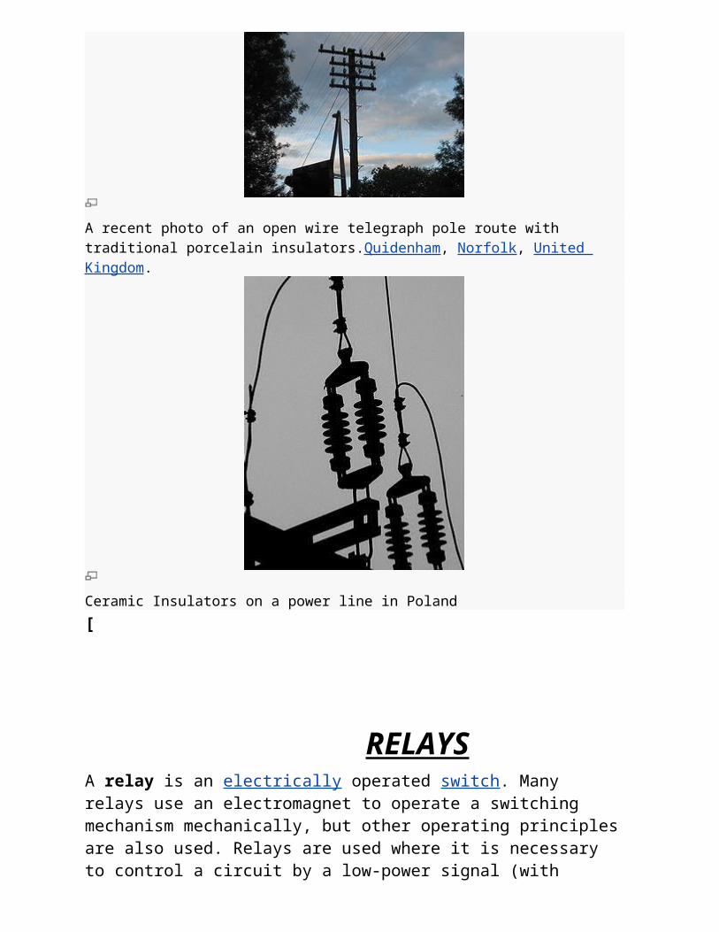
A recent photo of an open wire telegraph pole route with traditional porcelain
insulators.Quidenham, Norfolk, United Kingdom.
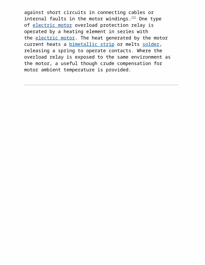
Ceramic Insulators on a power line in Poland
[
RELAYS
A relay is an electrically operated switch. Many relays use an electromagnet to operate a switching mechanism mechanically, but other operating principles are also used. Relays are used where it is necessary to control a circuit by a low-power signal (with complete electrical isolation between control and controlled circuits), or where several circuits must be controlled by one signal. The first relays were used in long distance telegraph circuits, repeating the signal coming in from one circuit and re-
transmitting it to another. Relays were used extensively in telephone exchanges and early computers to perform logical operations.
A type of relay that can handle the high power required to directly drive an electric motor is called a contactor. Solid-state relays control power circuits with no moving parts, instead using a semiconductor device to perform switching. Relays with calibrated operating characteristics and sometimes multiple operating coils are used to protect electrical circuits from overload or faults; in modern electric power systems these functions are performed by digital instruments still called "protective relays".
Latching relay, dust cover removed, showing pawl and ratchet mechanism. The
ratchet operates a cam, which raises and lowers the moving contact arm, seen edge-
on just below it. The moving and fixed contacts are visible at the left side of the image.
A latching relay has two relaxed states (bistable). These are also called "impulse", "keep", or "stay" relays. When the current is switched off, the relay remains in its last state. This is achieved with a solenoid operating a ratchet and cam mechanism, or by having two opposing coils with an over-center spring or permanent magnet to hold the armature and contacts in position while the coil is relaxed, or with a remanent core. In the ratchet and cam example, the first pulse to the coil turns the relay on and the second pulse turns it off. In the two coil example, a pulse to one coil turns the relay on and a pulse to the opposite coil turns the relay off. This type of relay has the advantage that it consumes power only for an instant, while it is being switched, and it retains its last setting across a power outage. A remanent core latching relay requires a current pulse of opposite polarity to make it change state.
[edit]Reed relayA reed relay is a reed switch enclosed in a solenoid. The switch has a set of contacts inside an evacuated or inert gas-filled glass tube which protects the contacts against atmospheric corrosion; the contacts are made of magnetic material that makes them move under the influence of the field of the enclosing solenoid. Reed relays can switch faster than larger relays, require only little power from the control circuit, but have low switching current and voltage ratings.
A mercury-wetted reed relay is a form of reed relay in which the contacts are wetted with mercury. Such relays are used to switch low-voltage signals (one volt or less) where the mercury reduces the contact resistance and associated voltage drop, for low-current signals where surface contamination may make for a poor contact, or for high-speed applications where the mercury eliminates contact bounce. Mercury wetted relays are position-sensitive and must be mounted vertically to work properly. Because of the toxicity and expense of liquid mercury, these relays are now rarely used. See also mercury switch.
[edit]Polarized relayA polarized relay placed the armature between the poles of a permanent magnet to increase sensitivity. Polarized relays were used in middle 20th Century telephone exchanges to detect faint pulses and correct telegraphic distortion. The poles were on screws, so a technician could first adjust them for maximum sensitivity and then apply a bias spring to set the critical current that would operate the relay.
[edit]Machine tool relayA machine tool relay is a type standardized for industrial control of machine tools, transfer machines, and other sequential control. They are characterized by a large number of contacts (sometimes extendable in the field) which are easily converted from normally-open to normally-closed status, easily replaceable coils, and aform factor that allows compactly installing many relays in a control panel. Although such relays once were the backbone of automation in such industries as automobile assembly, theprogrammable logic controller (PLC) mostly displaced the machine tool relay from sequential control applications.
[edit]Contactor relayA contactor is a very heavy-duty relay used for switching electric motors and lighting loads, although contactors are not generally called
relays. Continuous current ratings for common contactors range from 10 amps to several hundred amps. High-current contacts are made with alloys containing silver. The unavoidable arcing causes the contacts to oxidize; however,silver oxide is still a good conductor.[2] Such devices are often used for motor starters. A motor starter is a contactor with overload protection devices attached. The overload sensing devices are a form of heat operated relay where a coil heats a bi-metal strip, or where a solder pot melts, releasing a spring to operate auxiliary contacts. These auxiliary contacts are in series with the coil. If the overload senses excess current in the load, the coil is de-energized. Contactor relays can be extremely loud to operate, making them unfit for use where noise is a chief concern.
[edit]Solid-state relay
Solid state relay, which has no moving parts
25 A or 40 A solid state contactors
A solid state relay (SSR) is a solid state electronic component that provides a similar function to an electromechanical relay but does not have any moving components, increasing long-term reliability. With early SSR's, the tradeoff came from the fact that every transistor has a small voltage drop across it. This voltage drop limited the amount of current a given SSR could handle. As transistors improved, higher current SSR's, able to handle 100 to 1,200 Amperes, have become commercially available. Compared to electromagnetic relays, they may be falsely triggered by transients.
[edit]Solid state contactor relayA solid state contactor is a heavy-duty solid state relay, including the necessary heat sink, used for switching electric heaters, small electric motors and lighting loads; where frequent on/off cycles are required. There are no moving parts to wear out and there is no contact bounce due to vibration. They are activated by AC control signals or DC control signals from Programmable logic controller (PLCs), PCs, Transistor-transistor logic (TTL) sources, or other microprocessor and microcontroller controls.
[edit]Buchholz relayA Buchholz relay is a safety device sensing the accumulation of gas in large oil-filled transformers, which will alarm on slow accumulation of gas or shut down the transformer if gas is produced rapidly in the transformer oil.
[edit]Forced-guided contacts relayA forced-guided contacts relay has relay contacts that are mechanically linked together, so that when the relay coil is energized or de-energized, all of the linked contacts move together. If one set of contacts in the relay becomes immobilized, no other contact of the same relay will be able to move. The function of forced-guided contacts is to enable the safety circuit to check the status of the relay. Forced-guided contacts are also known as "positive-guided contacts", "captive contacts", "locked contacts", or "safety relays".
[edit]Overload protection relayElectric motors need overcurrent protection to prevent damage from over-loading the motor, or to protect against short circuits in connecting cables or internal faults in the motor windings.[3] One type of electric motor overload protection relay is operated by a heating element in series with the electric motor. The heat generated by the motor current heats a bimetallic strip or melts solder, releasing a spring to operate contacts. Where the overload relay is exposed to the same environment as the motor, a useful though crude compensation for motor ambient temperature is provided.
A lightning arrester is a device used on electrical power systems to protect the insulation on the system from the damaging effect of lightning. Metal oxide varistors (MOVs) have been used for power system protection since the mid 1970s. The typical lightning arrester also known as surge arrester has a high voltage terminal and a ground terminal. When a lightning surge or switching surge travels down the power system to the arrester, the current from the surge is diverted around the protected insulation in most cases to earth
Lightning, is a form of visible discharge of electricity between rain clouds or between a rain cloud and the earth. The electric discharge is seen in the form of a brilliant arc, sometimes several kilometres long, stretching between the discharge points. How thunderclouds become charged is not fully understood, but most thunderclouds are negatively charged at the base and positively charged at the top. However formed, the negative charge at the base of the cloud induces a positive charge on the earth beneath it, which acts as the second plate of a huge capacitor.
When the electrical potential between two clouds or between a cloud and the earth reaches a sufficiently high value (about 10,000 V per cm or about 25,000 V per in), the air becomes ionized along a narrow path and a lightning flash results.
Many meteorologists believe that this is how a negative charge is carried to the ground and the total negative charge of the surface of the Earth is maintained.
The possibility of discharge is high on tall trees and buildings rather than
to ground. Buildings are protected from lightning by metallic lightning rods extending to the ground from a point above the highest part of the roof. The conductor has a pointed edge on one side and the other side is connected to a long thick copper strip which runs down the building. The lower end of the strip is properly earthed. When lightning strikes it hits the rod and current flows down through the copper strip. These rods form a low-resistance path for the lightning discharge and prevent it from travelling through the structure itself. — The Hindu S & T Desk
1.What is lightning?Lightning is a high-energy luminous electrical discharge from a thundercloud to the ground accompanied by thunder. In our atmosphere, three types of discharges take place: one within a thundercloud (intra-cloud), the second from one cloud to another (inter-cloud) and the third, from cloud to ground (CG).
2. What Causes lightning?The largest of all types of clouds, namely the Cumulonimbus (Cb) cloud is responsible for lightning. Mainly two types of processes lead to formation of such clouds. Based on the type of formation they are classified as Frontal or Convective thundercloud. Frontal thunderclouds form by the interaction of cold and warm air masses and so such clouds can form at any time of the day or night. The convective Cb cloud formation
commences in the forenoon with the onset of convective cycle initiated due to heating by the solar radiation. Usually they mature by the afternoon. Majority of the lightning strikes from this type occur in the afternoon hours. In Kerala, most of the thunderclouds are of the convective type and are formed mostly during the northeast monsoon. (October to December) and during the premonsoon (March to May). The present year has been an exception with frontal thunder clouds causinglightning at almost all times of the day. Charging mechanisms of the cloud, the number of charged cells formed and the regional meteorology decide the thundercloud formation in a region. Therefore, the Cb cloud behaviour varies over regions of the globe. A typical cumulonimbus cloud grows up to tropopause (15 to 18 km in tropics).
PRECAUTIONS AND GUIDELINESMany aspects of escaping a lightning accident are presented here. One of the most important things to be remembered is that a thunder cloud or lightning will be active in an area only for about one hour. So, observing what is given below for an hour may save one from a serious injury.
1.Locations which provide Protection
(A) Locations with good protection:Locations, surrounded partially or fully by unbroken metallic surfaces or nets do not allow lightning to penetrate to the interior and hence a person is safe inside. (B) Locations Offering at Least a Minimum of Protection:
2. Locations and situations to be avoided during thunderstorms:
Lightning prefers to strike the tallest of all objects in the location of strike. Also it prefers metal objects; the larger the metal more is the preference.
3. Recommended Precautions when Surprised by a Thunderstorm:a. Avoid close proximity to metal objects like umbrellas, scythes, knives and golf clubs; especially if they project above your body. Danger is acute if you see or hear St. Elmo's Fire (corona discharge).b. Crouch on the floor with both feet and knees pressing each other and hands circling the knees with the chin pressing on the knees. The position is shown in figure.
III. LIGHTNING PROTECTIONThere are many locations and buildings, which have to be protected from lightning damage.Storage location of inflammable material is an example. High rise buildings and structures housing equipment etc. also have to be protected as precautions taken for personnel safety is of little use in such places. A device which gives a good amount of protection and which has been in use is the Lightning Conductor.
1. The Lightning Conductor:2. Earthing:3. Cone of Protection:
4. A Special Case for Kerala Region:
5. The Lightning Arrester:
POWER LINE CARRIER COMM.
Power line carrier communication (PLCC) is mainly used for telecommunication, tele-protection and tele-monitoring between electrical substations through power lines at high voltages, such as 110 kV, 220 kV, 400 kV. PLCC integrates the transmission of communication signal and 50/60 Hz power signal through the same electric power cable. The major benefit is the union of two important applications in a single system.
In a PLCC system the communication is established through the power line. The audio frequency is carried by a carrier frequency and the range of carrier frequency is from 50 kHz to 500 kHz. The modulation generally used in these system is amplitude modulation. The carrier frequency range is allocated to include the audio signal, protection and the pilot frequency. The pilot frequency is a signal in the audio range that is transmitted continuously for failure detection.
The voice signal is converted/compressed into the 300 Hz to 4000 Hz range, and this audio frequency is mixed with the carrier frequency. The carrier frequency is again filtered, amplified and transmitted. The transmission of these HF carrier frequencies will be in the range of 0 to +32db. This range is set according to the distance between substations.
PLCC can be used for interconnecting PBXs. The electricity board in India have an internal network PLCC between PBXs
Line trap
It is also called "Wave trap". It is connected in series with the power (transmission) line. It blocks the high frequency carrier waves (24 kHz to 500 kHz) and let power waves (50 Hz - 60 Hz) to pass through. It is basically an inductor of rating in milli henry.
[edit]Coupling capacitor
It provides low impedance path for carrier energy to HV line and blocks the power frequency circuit by being a high impedance path.
[edit]Line matching unit
LMU is a composite unit consisting of Drain Coil, Isolation transformer with Lightning Arrester on its both the sides, a Tuning Device and an earth switch. Tuning Device is the combination of R-L-C circuits which act as filter circuit. LMU is also known as Coupling Device. Together with coupling capaitor, LMU serves the purpose of connecting effectively the Audio/Radio frequency signals to either transmission line or PLC terminal and protection of the PLCC unit from the overvoltages caused due to transients on power system.
[edit]Digital power line carrier
A power line carrier using a power line as transmission media needs to change its transmission system from analog to digital to address rapid
diffusion of IP devices and digital telecommunication devices. With this view, digital power line carrier (DPLC) was developed featuring several technological measures which enable digital transmission via power lines and performed a field evaluation test. As a result, DPLC has the required quality of bit error rate characteristics and transmission ability such as transmitting information from monitored electric-supply stations and images.
BATTERY CHARGERS
All but the smallest substations include auxiliary power supplies. AC power is required for substation building small power, lighting, heating and ventilation, some communications equipment, switchgear operating mechanisms, anticondensation heaters and motors. DC power is used to feed essential services such as circuit breaker trip coils and associated relays, supervisory control and data acquisition (SCADA) and communications equipment. This chapter describes how these auxiliary supplies are derived and explains how to specify such equipment.
Battery and charger configurations
Capital cost and reliability objectives must first be considered before defining the battery and battery charger combination to be used for a specific installation. The comparison given in Table 4.1 describes the advantages and disadvantages of three such combinations.Figure 4.1 details the main electrical features associated with these battery and charger combinations. Charger units are used to supply either just a battery to provide an autonomous DC supply or a battery/inverter combination to provide an autonomous AC supply. The level of ‘autonomy’ is usually defined in terms of the number of hours or minutes the equipment will enable a specified load to function correctly after loss of input mains AC supply. The capacity of the charger must also be such that after a severe discharge it has the capacity to supply the full DC system load current and the full charging current
Type Advantages Disadvantages
1. Single 100% battery Low capital cost No standby DC and 100% charger System outage for
maintenance Need to isolate battery/ charger combination from load under boost charge conditions1 in order to prevent high boost voltages appearing on DC distribution system2
2. Semi-duplicate Medium capital cost 50% capacity on loss of 2 _ 50% batteries and Standby DC provided which one battery during AC 2 _ 100% chargers is 100% capacity on loss source failure
of one charger Each battery or charger can be maintained in turn. Each battery can be isolated
and boost charged in turn without affecting DC output voltage
3. Fully duplicate Full 100% standby DC High capital cost
2 _ 100% batteries and capacity provided under all Greater space requirement 2 _ 100% chargers AC source conditions and Increased maintenance
single component (charger cost or battery) failure
simultaneously. The technique used for battery charging is called ‘float’ charging and involves the battery being permanently connected to the load (possibly via an inverter) in parallel with a charger. Therefore the charger must satisfy the requirements of both the battery and the load. The exact charger functional requirements will depend upon the type of battery (lead acid, nickel cadmium – NiCad, sealed recombination, etc.)
CONTROL ROOM
a protection and control specialist, the emirate’s Water and Electricity Department was considering introducing control systems in its transmission substations. Substation control systems were in an early stage of application in the world, so officials in the department requested a study of their effectiveness.
Our team prepared the study, in which we demonstrated the economic and technical advantages of implementing such a system and replacing some of the conventional control equipment, as noted above. These advantages included:
• Reduction of control room size• Simplified requirements on installation, wiring and testing• Increased reliability of control• User friendly person-system communication.
Success of Initial Implementations
The first applications of the substation control and monitoring systems were in substations E8 132/11 kV (Figure 1), Mussafah 220/33 kV, Sweihan 220/33 kV and Madinat Khalifa 132/11 kV, which were successively commissioned by 1999. The redundant architecture ofeach substation control system provided uninterrupted operation in the case of any single point failure. The systems basically included redundant operator workstations, dual optical loop based local network, numerical bay control units, and dual modems for communication to load dispatch centre (Figure 2).