33
GENERAL INSTRUCTIONS Oval Pool for regular installation
Pantone 5395 C
Pantone 2915 C Pantone 5395 C
Pantone 2915 C
Pantone 5395 C
Pantone 2915 C
White
Black
Black
V2 - Text / Full Color Version V2 - Text / Full Color Version V2 - Text / Black and White Version
V1 - Square / Full Color Version (White Background) V1 - Square / Full Color Version (Black Background)
White
V1 - Square / Black and White Version
GENERAL INSTRUCTIONSOval Pool
for regular installation
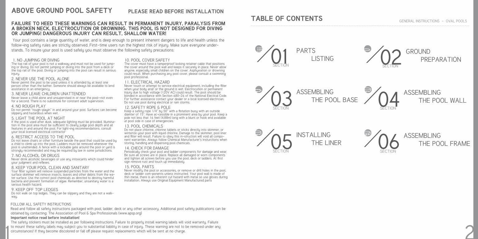
TABLE OF CONTENTS GENERAL INSTRUCTIONS - OVAL POOLS
SECTION
PARTS LISTING
SECTION
ASSEMBLING THE POOL BASE
SECTION
GROUND PREPARATION
SECTION
ASSEMBLING THE POOL WALL
SECTION
INSTALLING THE LINER
1 2
SECTION
ASSEMBLING THE POOL FRAME
ABOVE GROUND POOL SAFETY PLEASE READ BEFORE INSTALLATION
FAILURE TO HEED THESE WARNINGS CAN RESULT IN PERMANENT INJURY, PARALYSIS FROM A BROKEN NECK, ELECTROCUTION OR DROWNING. THIS POOL IS NOT DESIGNED FOR DIVING OR JUMPING! DANGEROUS INJURY CAN RESULT, SHALLOW WATER! Your pool contains a large quantity of water, and is deep enough to present inherent dangers to life and health unless the follow¬ing safety rules are strictly observed. First-time users run the highest risk of injury. Make sure everyone under-stands. To insure your pool is used safely you must observe the following safety precautions:
1. NO JUMPING OR DIVING The top rail of your pool is not a walkway and must not be used for jump-ing or diving. Do not permit jumping or diving into the pool from a deck or the top rail of the pool. Diving or jumping into the pool can result in serious injury.
2. NEVER USE THE POOL ALONE Never permit the pool to be used unless it is attended by at least one person other than the bather. Someone should always be available to lend assistance in an emergency.
3. NEVER LEAVE CHILDREN UNATTENDED Never leave a child alone and unsupervised in or near the pool—not even for a second. There is no substitute for constant adult supervision.
4. NO ROUGH PLAY Do not permit “rough-playin” in and around your pool. Surfaces can become slippery and hazardous when wet.
5. LIGHT THE POOL AT NIGHT If the pool is used after dusk, adequate lighting must be provided. Illumina-tion in the pool area must be sufficient to clearly judge pool depth and all features in and around the pool. For light¬ing recommendations, consult your local licensed electrical contractor
6. RESTRICT ACCESS TO THE POOL Do not leave chairs or other furniture beside the pool that could be used by a child to climb up into the pool. Ladders must be removed whenever the pool is unattended. A fence with a lockable gate around the pool or yard is strongly recommended and may be required by law in some jurisdictions.
7. NO ALCOHOL OR DRUGS Never drink alcoholic beverages or use any intoxicants which could hinder your judgment and reflexes.
8. KEEP YOUR POOL CLEAN AND SANITARY Your filter system will remove suspended particles from the water and the surface skimmer will remove insects, leaves and other debris from the wa-ter surface. Use the correct pool chemicals as directed to destroy harmful bacteria and prevent formation of algae. Remember, unsanitary water is a serious health hazard.
9. KEEP OFF TOP LEDGES Do not walk on top ledges. They can be slippery and they are not a walk-way.
10. POOL COVER SAFETY The cover must have a tamperproof locking retainer cable that positions the cover around the pool wall and keeps it securely in place. Never allow anyone, especially small children on the cover. Asphyxiation or drowning could result. When purchasing any pool cover, please consult a swimming pool professional.
11. ELECTRICAL HAZARD Never touch or attempt to service electrical equipment, including the filter when your body and/ or the ground is wet. Electrocution or permanent injury due to high voltage (120V AC) could result. The pool should be bonded in accordance with Section 680-26 of the National Electical Code. For further assistance contact your dealer or a local licensed electrician. Do not use pool during electrical or rain storms.
12. SAFETY ROPE & POLE Keep a safety rope 1/4” by 50” with a flotation buoy with an outside diamter of 15”. Have ac¬cessible in a prominent area by your pool. Keep a pole not less that 16 feet (4,88m) long with a blunt or hook end available at pool side in case of emergencies.
13. POOL CHEMICALS Do not place chlorine, chlorine tablets or sticks directly into skimmer, or winterize your pool with liquid chlorine. Damage to the skimmer, pool liner and filter will result. Failure to obey this in¬struction will void all compo-nent warranties. Always follow Chemical Manufacturer’s insturctions when storing, handling and dispensing pool chemicals.
14. CHECK FOR DAMAGE Periodically check your pool and ladder components for damage and wear. Be sure all screws are in place. Replace all damaged or worn components and tighten all screws before you use the pool, deck or ladders. At first sign remove rust and touch up immediately.
15. POOL PARTS Never modify the pool or accessories, or remove or drill holes in the pool, deck or ladder com¬ponents unless instructed. Your pool wall is made of thin metal, there is an inherent cut hazard with metal so use gloves during installation. Always use Original Equipment Manufactured parts
FOLLOW ALL SAFETY INSTRUCTIONS Read and follow all safety instructions packaged with pool, ladder, deck or any other accessory. Additional pool safety publications can be obtained by contacting: The Association of Pool & Spa Professionals (www.apsp.org) Important notice read before installation! The safety stickers must be installed as per following instructions. Failure to properly install warning labels will void warranty. Failure to mount these safety labels may subject you to substantial liability in case of injury. These warning are not to be removed under any circumstances! If they become discolored or fall off please request replacements which will be sent at no charge.
01
03
02
04
05 06
01SECTION
GENERAL INSTRUCTIONS - OVAL POOLS
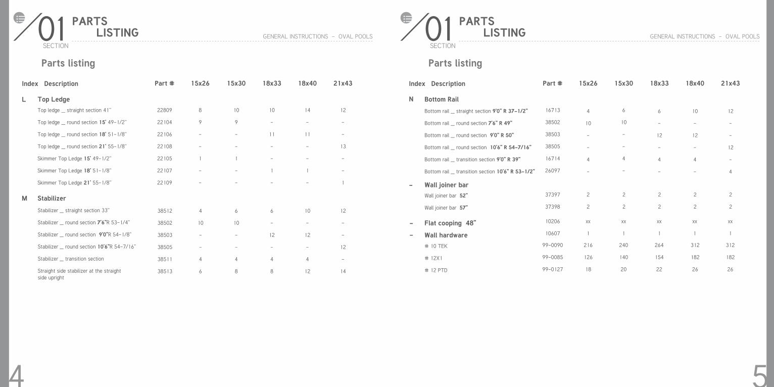
Index Description Part # 15x26 15x30 18x33 18x40 21x43
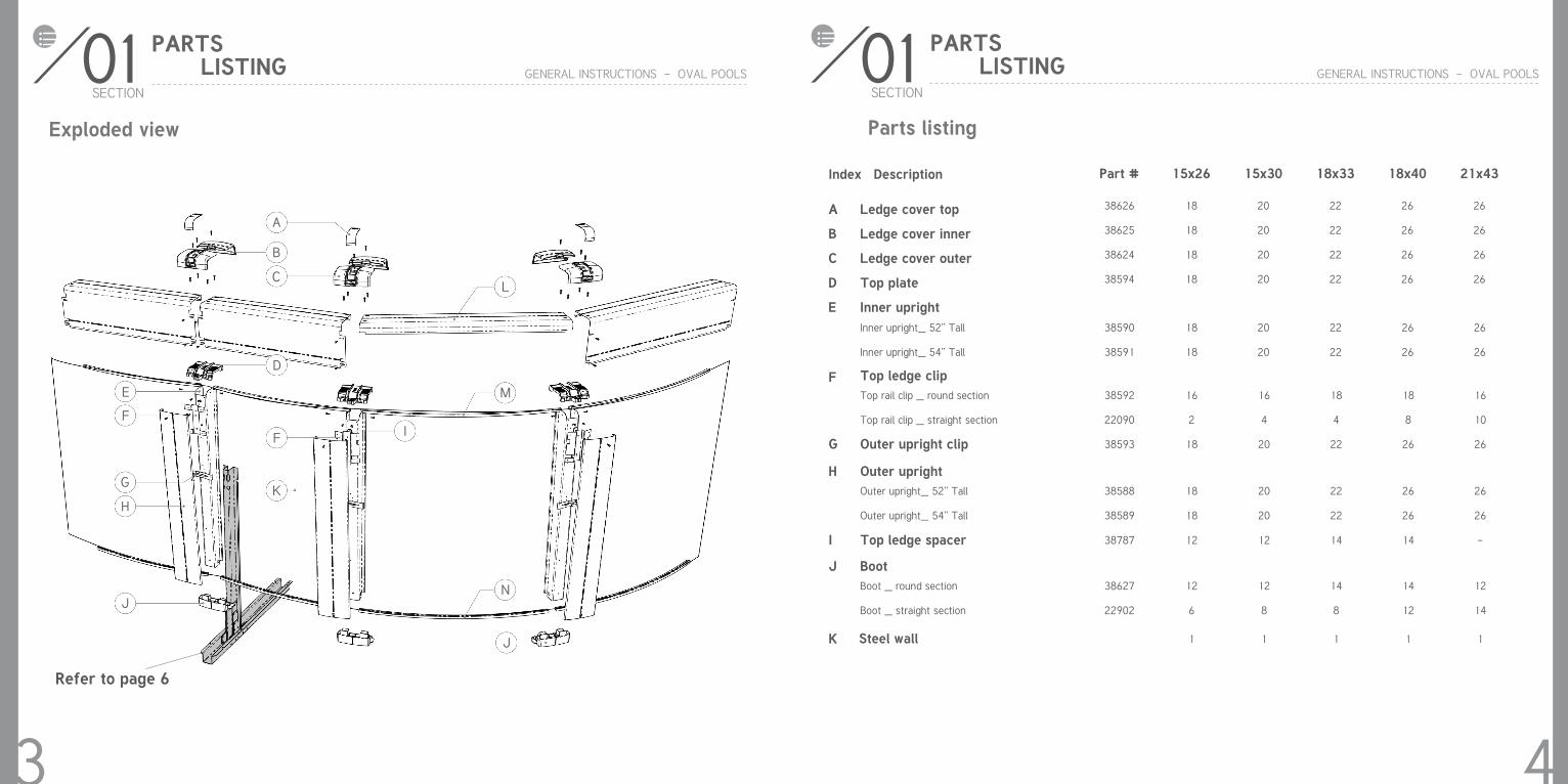
Ledge cover top
Ledge cover inner
Ledge cover outer
Top plate
Inner upright
38626
38625
38624
38594
A
B
C
D
E
18
18
18
18
20
20
20
20
22
22
22
22
26
26
26
26
26
26
26
26
Parts listing
PARTS LISTING
43
01SECTION
GENERAL INSTRUCTIONS - OVAL POOLS
Exploded view
PARTS LISTING
Refer to page 6
Inner upright_ 52’’ Tall
Inner upright_ 54’’ Tall
38590
38591
18
18
20
20
22
22
26
26
26
26
F
H
J
G
K
I
Top ledge clip
Outer upright
Boot
Outer upright clip
Steel wall
Top ledge spacer
Top rail clip _ round section
Top rail clip _ straight section
Outer upright_ 52’’ Tall
Outer upright_ 54’’ Tall
Boot _ round section
Boot _ straight section
38592
22090
38588
38589
38627
22902
38593
38787
16
2
18
18
12
6
18
1
12
16
4
20
20
12
8
20
1
12
18
4
22
22
14
8
22
1
14
18
8
26
26
14
12
26
1
14
16
10
26
26
12
14
26
1
-
A
B
C
D
E
F
G
H
F
K
J
I
L
M
N
J
Bottom rail _ straight section 9’0’’ R 37-1/2’’
Bottom rail _ round section 7’6’’ R 49’’
Bottom rail _ round section 9’0’’ R 50’’
Bottom rail _ round section 10’6’’ R 54-7/16’’
Bottom rail _ transition section 9’0’’ R 39’’
Bottom rail _ transition section 10’6’’ R 53-1/2’’
Stabilizer _ straight section 33’’
Stabilizer _ round section 7’6”R 53-1/4”
Stabilizer _ round section 9’0”R 54-1/8”
Stabilizer _ round section 10’6”R 54-7/16”
Stabilizer _ transition section
Straight side stabilizer at the straight side upright
Stabilizer
01SECTION
GENERAL INSTRUCTIONS - OVAL POOLS
Index Description Part # 15x26 15x30 18x33 18x40 21x43
16713
38502
38503
38505
16714
26097
38512
38502
38503
38505
38511
38513
4
10
-
-
4
-
4
10
-
-
4
6
6
10
-
-
4
-
6
10
-
-
4
8
6
-
12
-
4
-
6
-
12
-
4
8
10
-
12
-
4
-
10
-
12
-
4
12
12
-
-
12
-
4
12
-
-
12
-
14
Parts listing
PARTS LISTING
5
L N
-
-
M
01SECTION
GENERAL INSTRUCTIONS - OVAL POOLS
Index Description
Top Ledge Bottom Rail
Part # 15x26 15x30 18x33 18x40 21x43
Top ledge _ straight section 41’’
Top ledge _ round section 15’ 49-1/2’’
Top ledge _ round section 18’ 51-1/8’’
Top ledge _ round section 21’ 55-1/8’’
Skimmer Top Ledge 15’ 49-1/2’’
Skimmer Top Ledge 18’ 51-1/8’’
Skimmer Top Ledge 21’ 55-1/8’’
22809
22104
22106
22108
22105
22107
22109
8
9
-
-
1
-
-
10
9
-
-
1
-
-
10
-
11
-
-
1
-
14
-
11
-
-
1
-
12
-
-
13
-
-
1
Parts listing
PARTS LISTING
4
Flat cooping 48’’
Wall hardware
10206
10607
xx
1
xx
1
xx
1
xx
1
xx
1
- Wall joiner bar
Wall joiner bar 52’’
Wall joiner bar 57’’
# 10 TEK
# 12X1
# 12 PTD
37397
37398
99-0090
99-0085
99-0127
2
2
216
126
18
2
2
240
140
20
2
2
264
154
22
2
2
312
182
26
2
2
312
182
26
Key Description
02SECTION
GENERAL INSTRUCTIONS - OVAL POOLS
GROUND PREPARATION
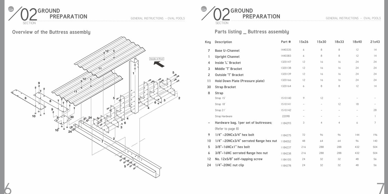
Base U-Channel
Upright Channel
Inside ‘L’ Bracket
Middle ‘T’ Bracket
Outside ‘T’ Bracket
Hold Down Plate (Pressure plate)
Strap Bracket
Strap
Hardware bag, 1per set of buttresses;
(Refer to page 8)
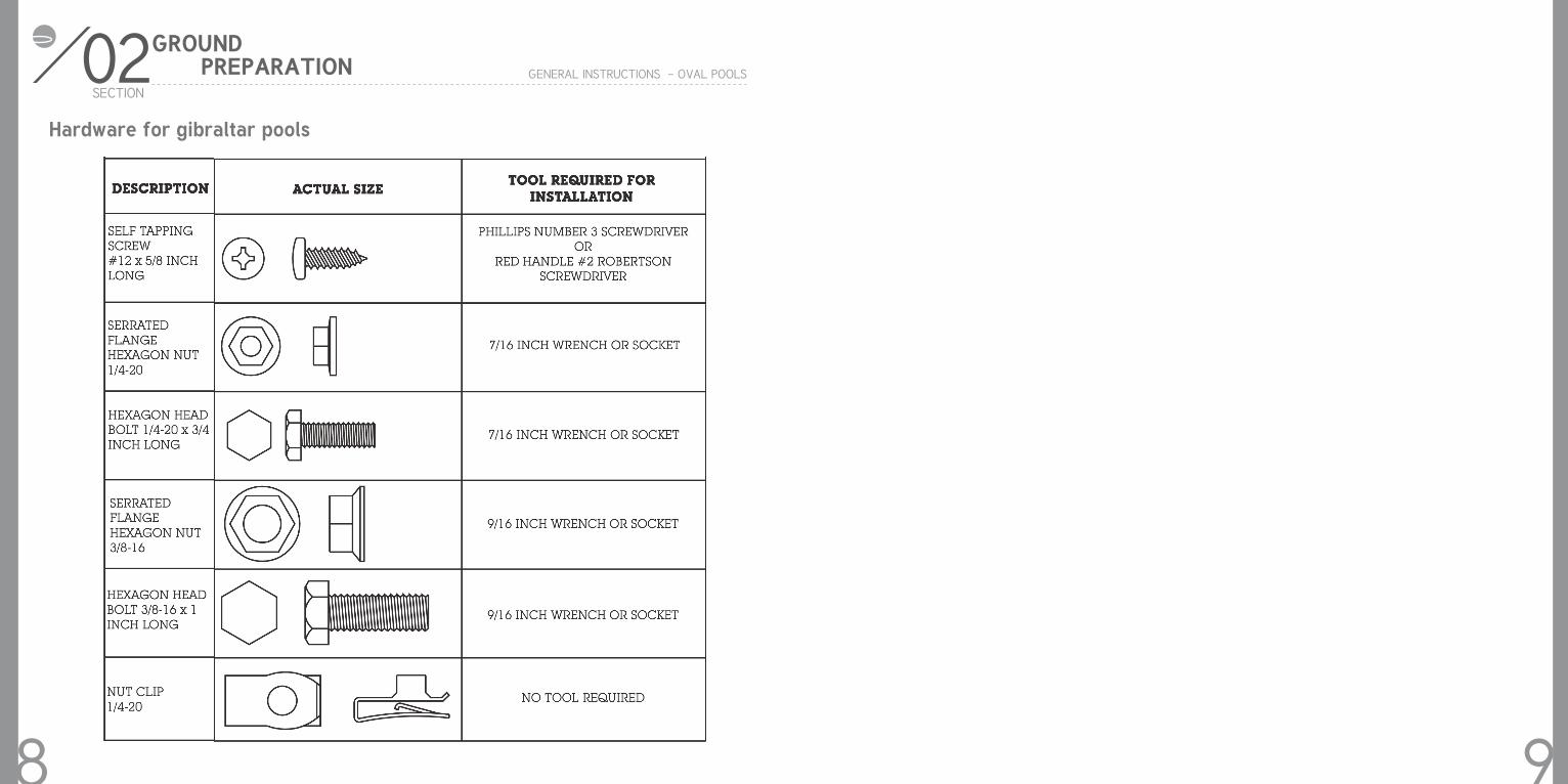
1/4’’ -20NCx3/4’’ hex bolt
1/4’’ -20NCx3/4’’ serrated flange hex nut
3/8’’-16NCx1’’ hex bolt
3/8’’-16NC serrated flange hex nut
No. 12x5/8’’ self-tapping screw
1/4’’-20NC nut clip
7
1
4
3
2
11
30
8
-
9
10
5
6
12
24
7
Parts listing _ Buttress assembly
Part # 15x26 15x30 18x33 18x40 21x43
1440335
1440383
1320147
1320138
1320139
1320166
1320164
1184293
1184275
1184052
1184237
1184238
1184105
1184278
6
6
12
12
12
12
6
3
72
48
216
216
24
24
8
8
16
16
16
16
8
4
96
64
288
288
32
32
8
8
16
16
16
16
8
4
96
64
288
288
32
32
12
12
24
24
24
24
12
6
144
96
432
432
48
48
14
14
24
24
24
24
14
7
196
140
504
504
56
56
02SECTION
GENERAL INSTRUCTIONS - OVAL POOLS
GROUND PREPARATION
Overview of the Buttress assembly
6
Inside of Pool
12
11
12
11
9
9
88
10
10
30
24
24
1
5
5
2
2
3
36
64
4
13
13
7
5
Strap 15’
Strap 18’
Strap 21’
Strap Hardware
1510140
1510141
1510142
22098
9
-
-
-
12
-
-
-
-
12
-
-
-
18
-
-
-
-
28
1
02SECTION
GENERAL INSTRUCTIONS - OVAL POOLS
GROUND PREPARATION
Hardware for gibraltar pools
98
Check local laws on construction and electrical installation. Also make sure that you meet security standards related to fences and pool cover. Select an ap-propriate site for your swimming pool by considering the following points:
GENERAL INSTRUCTIONS - OVAL POOLS
Plan your installation first
Distance from the fence
Overhead electrical wires
Predominant windsAccessory location (filter, decking, …)
Appropriate electrical outletsSurrounding trees (falling leaves and roots)
Underground cables and gas con-
ducts
Do not install your pool on concrete, asphalt, wood, grass turf, top of grass, gravel or chemically treated soil. Avoid also weed and nut grass area.
Avoid areas with poor drainage.
Do not install on windy days
Sun reflection in your yard
Install with 2 or 3 helpers
+
++
++
+
+
++
+
+
Be careful
Ground surface and levelness: it is very important that the ground surface be firm and solid. Pool area must be free of grass, rocks roots or other sharp edges objects. Any parcel of grass left under the pool will rot and release unpleasant odors. Avoid installing your pool on surface which has been treated with oil weed-killer or chemical products. This could affect the vinyl liner among other things.
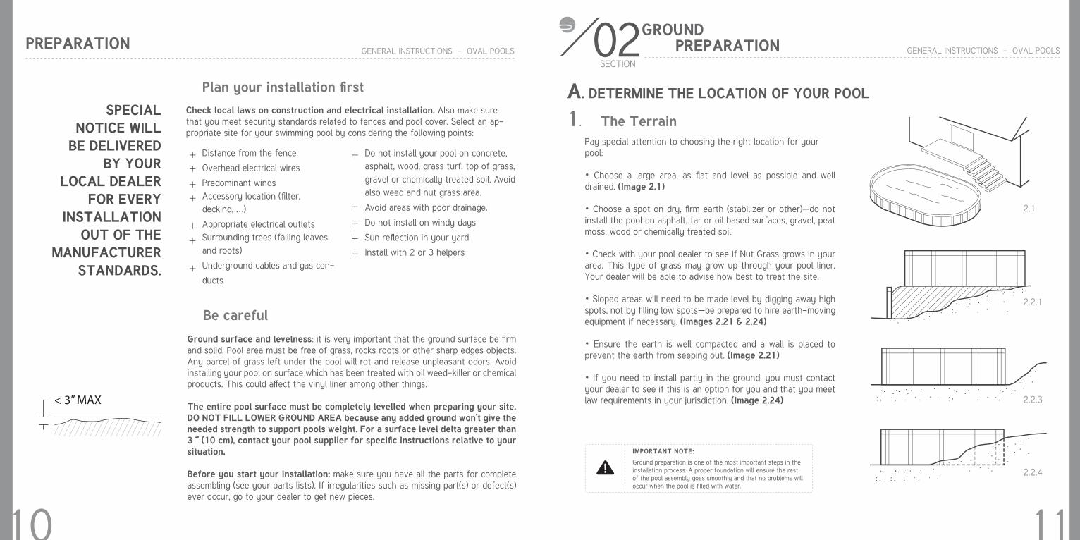
The entire pool surface must be completely levelled when preparing your site. DO NOT FILL LOWER GROUND AREA because any added ground won’t give the needed strength to support pools weight. For a surface level delta greater than 3 ‘’ (10 cm), contact your pool supplier for specific instructions relative to your situation.
Before you start your installation: make sure you have all the parts for complete assembling (see your parts lists). If irregularities such as missing part(s) or defect(s) ever occur, go to your dealer to get new pieces.
< 3’’ MAX
X
SPECIAL NOTICE WILL
BE DELIVERED BY YOUR
LOCAL DEALER FOR EVERY
INSTALLATION OUT OF THE
MANUFACTURER STANDARDS.
PREPARATION
+
02SECTION
GENERAL INSTRUCTIONS - OVAL POOLS
1. The TerrainPay special attention to choosing the right location for yourpool:
• Choose a large area, as flat and level as possible and well drained. (Image 2.1)
• Choose a spot on dry, firm earth (stabilizer or other)—do not install the pool on asphalt, tar or oil based surfaces, gravel, peat moss, wood or chemically treated soil.
• Check with your pool dealer to see if Nut Grass grows in your area. This type of grass may grow up through your pool liner. Your dealer will be able to advise how best to treat the site.
• Sloped areas will need to be made level by digging away high spots, not by filling low spots—be prepared to hire earth-moving equipment if necessary. (Images 2.21 & 2.24)
• Ensure the earth is well compacted and a wall is placed to prevent the earth from seeping out. (Image 2.21)
• If you need to install partly in the ground, you must contact your dealer to see if this is an option for you and that you meet law requirements in your jurisdiction. (Image 2.24)
Ground preparation is one of the most important steps in the installation process. A proper foundation will ensure the rest of the pool assembly goes smoothly and that no problems will occur when the pool is filled with water.
GROUND PREPARATION
2.2.1
A. DETERMINE THE LOCATION OF YOUR POOL
2.1
2.2.3
2.2.4
IMPORTANT NOTE:
10 11
12
02SECTION
GENERAL INSTRUCTIONS - OVAL POOLS
GROUND PREPARATION
2. Things to Avoid
3. Plan Ahead
Do not locate your pool near or on any of the following(Images 2.3.1 to 2.3.3) :
• Overhanging tree branches.
• Overhead wires and clotheslines.
• Buried pipes and wires. Contact your gas, electric and tel-ephone utilities to find buried pipes and wires before you dig.
• Areas with poor drainage.
• Grass, stones and roots. Grass will rot underneath the pool liner, and stones and roots will damage the pool liner.
• Areas recently treated with oil-based weed killers, chemicals or fertilizers.
• Will you be adding an adjacent deck later? Be sure to leave room.
• Will you be using pool accessories or other appliances that need electricity or gas? Locate your pool near these services or plan to have them installed later by a licensed contractor.
When locating the centre of the pool, be sure to take intoconsideration any structures (deck, patio, house) or relevantitems (change rooms, gazebo, etc.) that the pool may needto line up with and ensure that the pool is in the most visualpleasing location for your property.
2.3.1
2.3.2
2.3.3IMPORTANT NOTE:
02SECTION
GENERAL INSTRUCTIONS - OVAL POOLS
GROUND PREPARATION
13
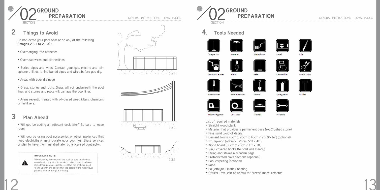
4. Tools Needed
List of required materials• Straight wood plank• Material that provides a permanent base (ex. Crushed stone)• Fine sand (void of debris)• Cement blocks (5cm x 20cm x 40cm / 2”x 8”x16”) (optional)• 2x Plywood (60cm x 120cm /2ft x 4ft)• Wood board (30cm x 20cm / 1ft x 1ft)• Vinyl covered hooks (to hold wall steady)• String and stakes & wooden pegs• Prefabricated cove sections (optional)• Pool carpeting (optional)• Rope• Polyethlyne Plastic Sheeting• Optical Level can be useful for precise measurements
14
02SECTION
GENERAL INSTRUCTIONS - OVAL POOLS
GROUND PREPARATION
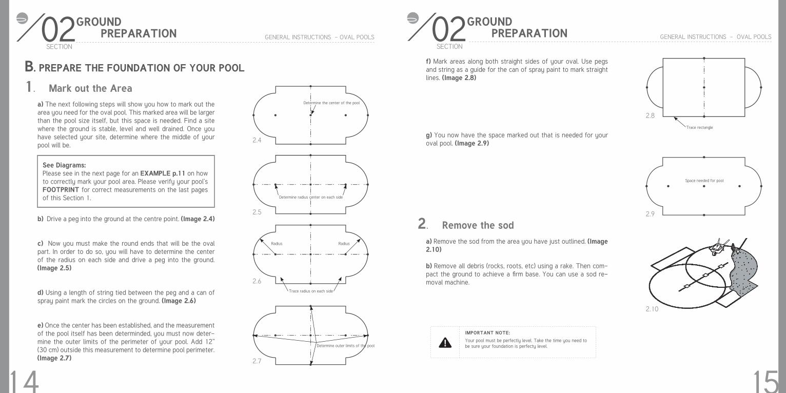
1. Mark out the Areaa) The next following steps will show you how to mark out the area you need for the oval pool. This marked area will be larger than the pool size itself, but this space is needed. Find a site where the ground is stable, level and well drained. Once you have selected your site, determine where the middle of your pool will be.
b) Drive a peg into the ground at the centre point. (Image 2.4)
c) Now you must make the round ends that will be the oval part. In order to do so, you will have to determine the center of the radius on each side and drive a peg into the ground. (Image 2.5)
d) Using a length of string tied between the peg and a can of spray paint mark the circles on the ground. (Image 2.6)
e) Once the center has been established, and the measurement of the pool itself has been determinded, you must now deter-mine the outer limits of the perimeter of your pool. Add 12” (30 cm) outside this measurement to determine pool perimeter. (Image 2.7)
B. PREPARE THE FOUNDATION OF YOUR POOL
See Diagrams:Please see in the next page for an EXAMPLE p.11 on how to correctly mark your pool area. Please verify your pool’s FOOTPRINT for correct measurements on the last pages of this Section 1.
2.4
2.5
2.6
2.7
Determine the center of the pool
Determine radius center on each side
Trace radius on each side
Determine outer limits of the pool
Radius Radius
02SECTION
GENERAL INSTRUCTIONS - OVAL POOLS
GROUND PREPARATION
15
2. Remove the sod
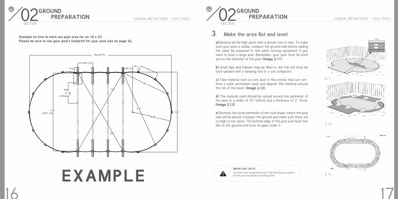
f) Mark areas along both straight sides of your oval. Use pegs and string as a guide for the can of spray paint to mark straight lines. (Image 2.8)
g) You now have the space marked out that is needed for your oval pool. (Image 2.9)
a) Remove the sod from the area you have just outlined. (Image 2.10)
b) Remove all debris (rocks, roots, etc) using a rake. Then com-pact the ground to achieve a firm base. You can use a sod re-moval machine.
Your pool must be perfectly level. Take the time you need tobe sure your foundation is perfecty level.
2.8
2.9
2.10
IMPORTANT NOTE:
Trace rectangle
Space needed for pool
16
02SECTION
GENERAL INSTRUCTIONS - OVAL POOLS
GROUND PREPARATION
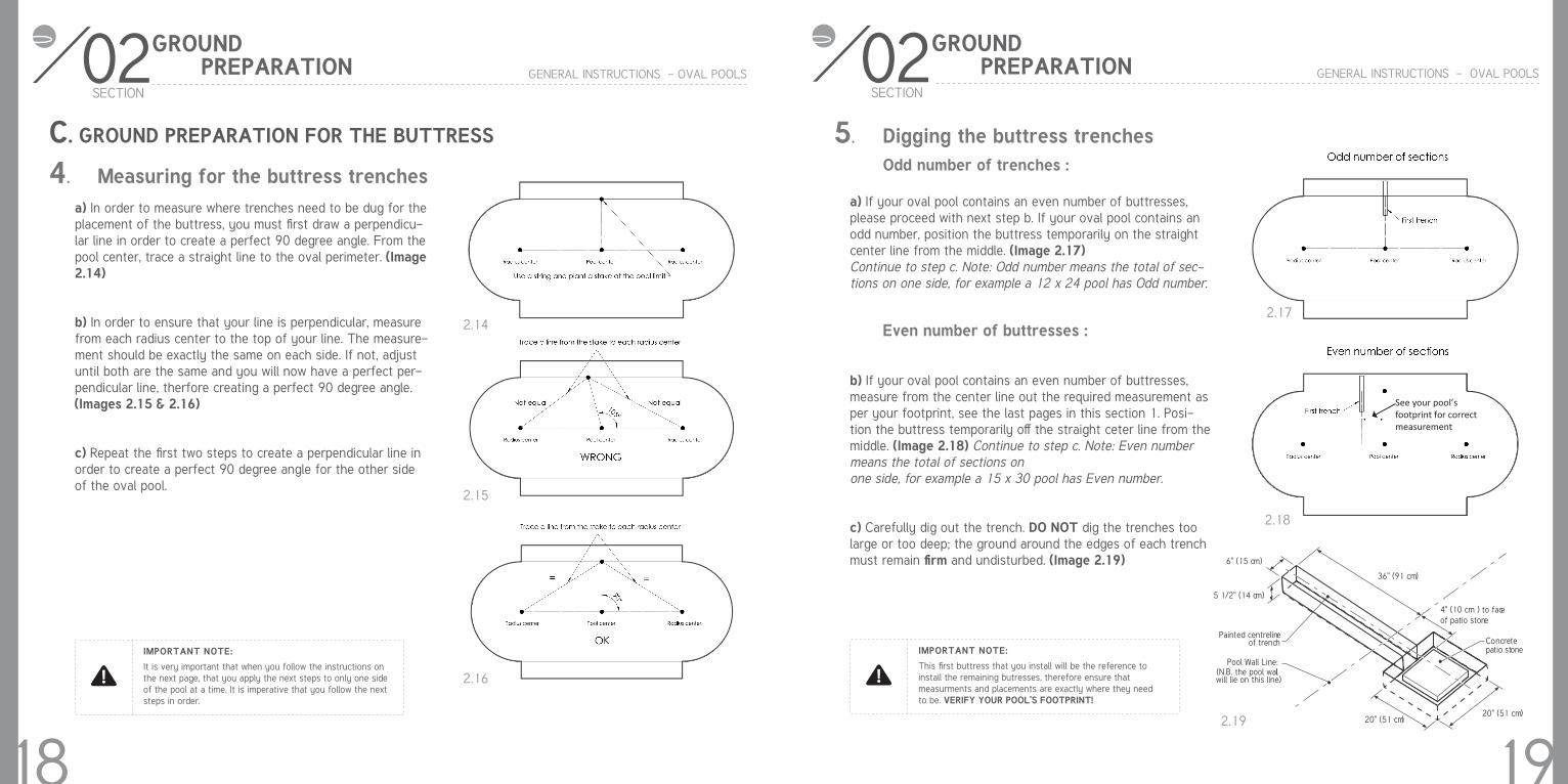
Example on how to mark out pool area for an 18 x 33Please be sure to use your pool’s footprint for your pool size on page 56.
EXAMPLE
02SECTION
GENERAL INSTRUCTIONS - OVAL POOLS
GROUND PREPARATION
17
3. Make the area flat and levela) Remove all the high spots with a shovel, hoe or rake. To make sure your pool is stable, compact the ground well before adding the sand. Be prepared to hire earth moving equipment if you need to level a large area. Remember, your pool must be level across the diameter of the pool. (Image 2.11)
b) Small dips and hollows may be filled in, but the soil must be hard-packed with a tamping tool or a soil compactor.
c) Take material such as rock dust or fine mortar that can con-form a solid, permanent base and deposit this material around the rim of the basin. (Image 2.12)
d) The material used should be spread around the perimeter of the pool to a width of 24” (60cm) and a thickness of 2” (5cm). (Image 2.13)
e) Recheck the outer perimeter of the oval shape, where the pool wall will be placed. Compact the ground and make sure there are no high or low spots. The bottom edge of the pool wall must rest flat on the ground and have no gaps under it.
Your pool must be perfectly level. Take the time you need tobe sure your foundation is perfecty level.
IMPORTANT NOTE:
2.11
2.12
2.13
Level
396 (33 FT.)
42
16 2715
52
136
219218
(18 FT. 2 IN.)
Strap
57 14
(12 Places)
252
252
223
R108
57.2
375
57.2
375
57.2
375
57.2
375
57.2
375
57.2
375
57.2
375
57.2
375
57.2
375
57.2
375
57.2
375
57.2
375
02SECTION
GENERAL INSTRUCTIONS - OVAL POOLS
GROUND PREPARATION
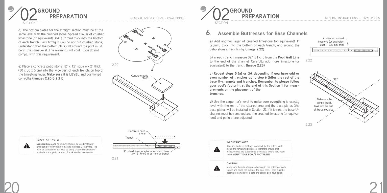
4. Measuring for the buttress trenchesa) In order to measure where trenches need to be dug for the placement of the buttress, you must first draw a perpendicu-lar line in order to create a perfect 90 degree angle. From the pool center, trace a straight line to the oval perimeter. (Image 2.14)
b) In order to ensure that your line is perpendicular, measure from each radius center to the top of your line. The measure-ment should be exactly the same on each side. If not, adjust until both are the same and you will now have a perfect per-pendicular line, therfore creating a perfect 90 degree angle. (Images 2.15 & 2.16)
c) Repeat the first two steps to create a perpendicular line in order to create a perfect 90 degree angle for the other side of the oval pool.
It is very important that when you follow the instructions onthe next page, that you apply the next steps to only one sideof the pool at a time. It is imperative that you follow the nextsteps in order.
IMPORTANT NOTE:
2.14
2.15
2.16
C. GROUND PREPARATION FOR THE BUTTRESS
18
02SECTION
GENERAL INSTRUCTIONS - OVAL POOLS
GROUND PREPARATION
5. Digging the buttress trenches Odd number of trenches :
Even number of buttresses :
a) If your oval pool contains an even number of buttresses, please proceed with next step b. If your oval pool contains an odd number, position the buttress temporarily on the straight center line from the middle. (Image 2.17)Continue to step c. Note: Odd number means the total of sec-tions on one side, for example a 12 x 24 pool has Odd number.
b) If your oval pool contains an even number of buttresses, measure from the center line out the required measurement as per your footprint, see the last pages in this section 1. Posi-tion the buttress temporarily off the straight ceter line from the middle. (Image 2.18) Continue to step c. Note: Even number means the total of sections onone side, for example a 15 x 30 pool has Even number.
c) Carefully dig out the trench. DO NOT dig the trenches toolarge or too deep; the ground around the edges of each trench must remain firm and undisturbed. (Image 2.19)
This first buttress that you install will be the reference toinstall the remaining butresses, therefore ensure thatmeasurments and placements are exactly where they needto be. VERIFY YOUR POOL’S FOOTPRINT!
IMPORTANT NOTE:
See your pool’s footprint for correctmeasurement
2.17
2.18
2.19
19
Concretepatio stone
6" (15 cm)
5 1/2" (14 cm)
36" (91 cm)
4" (10 cm ) to faceof patio stone
20" (51 cm)20" (51 cm)
Painted centrelineof trench
Pool Wall Line:(N.B. the pool wallwill lie on this line)
02SECTION
GENERAL INSTRUCTIONS - OVAL POOLS
GROUND PREPARATION
d) The bottom plates for the straight section must be at the same level with the crushed stone. Spread a layer of crushed limestone (or equivalent) 3/4” (19 mm) thick into the bottom of each trench. Pack firmly. If you do not put crushed stone, understand that the bottom plates all around the pool must be at the same level. The warranty will void if you do not comply with this requirement.
e) Place a concrete patio stone 12” x 12” square x 2” thick (30 x 30 x 5 cm) into the wide part of each trench, on top of the limestone layer. Make sure it is LEVEL and positioned correctly. (Images 2.20 & 2.21)
Crushed limestone or equivalent must be used instead ofbrick sand or vermiculite to backfill the base U-channels. Thelevel of compaction achieved by using crushed limestone orequivalent is superior to that of brick sand or vermiculite.
IMPORTANT NOTE:
2.20
2.21
20
Concrete patiostone
Concrete patiostone
Trench
Crushed limestone (or equivalent) base3/4" (19mm) in bottom of trench
02SECTION
GENERAL INSTRUCTIONS - OVAL POOLS
GROUND PREPARATION
2.22
2.23
6. Assemble Buttresses for Base Channelsa) Add another layer of crushed limestone (or equivalent) 1” (25mm) thick into the bottom of each trench, and around the patio stones. Pack firmly. (Image 2.22)
b) In each trench, measure 32” (81 cm) from the Pool Wall Line to the end of the channel. Carefully add more limestone (or equivalent) to the trench. (Image 2.23)
c) Repeat steps 5 (a) or (b), depending if you have odd or even number of trenches up to step 6 (b)for the rest of the base U-channels and trenches. Remember to please follow your pool’s footprint at the end of this Section 1 for meas-urements on the placement of thetrenches.
d) Use the carpenter’s level to make sure everything is exactly level with the rest of the cleared area and the base plates (the base plates will be installed in Section 2). If it is not, the base U-channel must be removed and the crushed limestone (or equiva-lent) and patio stone adjusted.
This first buttress that you install will be the reference toinstall the remaining butresses, therefore ensure thatmeasurments and placements are exactly where they needto be. VERIFY YOUR POOL’S FOOTPRINT!
Make sure there is adequate drainage in the bottom of each trench and along the sides of the pool area. There must be adequate drainage for a safe and secure pool foundation.
IMPORTANT NOTE:
CAUTION:
21
Additional crushedlimestone (or equivalent )
layer 1" (25 mm) thick
AA
�ool �all �ine�(���� the �ool
�all �ill lie on this line)
�2" (�1 cm)�" (1� cm)
Additional crushedlimestone (or equivalent)
32’’
02SECTION
GENERAL INSTRUCTIONS - OVAL POOLS
GROUND PREPARATION
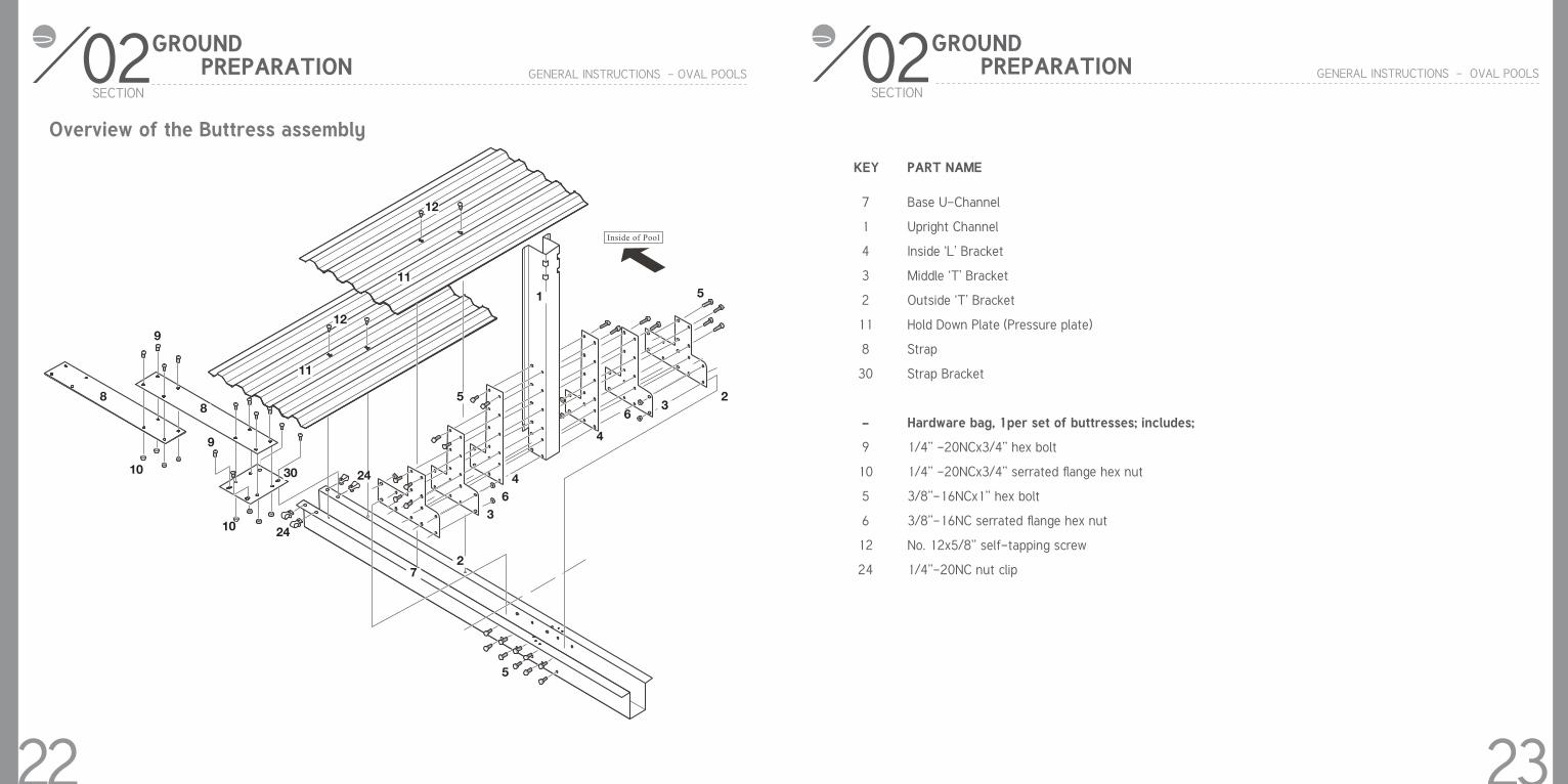
Overview of the Buttress assembly
22
Inside of Pool
12
11
12
11
9
9
88
10
10
30
24
24
1
5
5
2
2
3
36
64
4
13
13
7
5
02SECTION
GENERAL INSTRUCTIONS - OVAL POOLS
GROUND PREPARATION
KEY PART NAME
Base U-Channel
Upright Channel
Inside ‘L’ Bracket
Middle ‘T’ Bracket
Outside ‘T’ Bracket
Hold Down Plate (Pressure plate)
Strap
Strap Bracket
Hardware bag, 1per set of buttresses; includes;
1/4’’ -20NCx3/4’’ hex bolt
1/4’’ -20NCx3/4’’ serrated flange hex nut
3/8’’-16NCx1’’ hex bolt
3/8’’-16NC serrated flange hex nut
No. 12x5/8’’ self-tapping screw
1/4’’-20NC nut clip
7
1
4
3
2
11
8
30
-
9
10
5
6
12
24
23
02SECTION
GENERAL INSTRUCTIONS - OVAL POOLS
GROUND PREPARATION
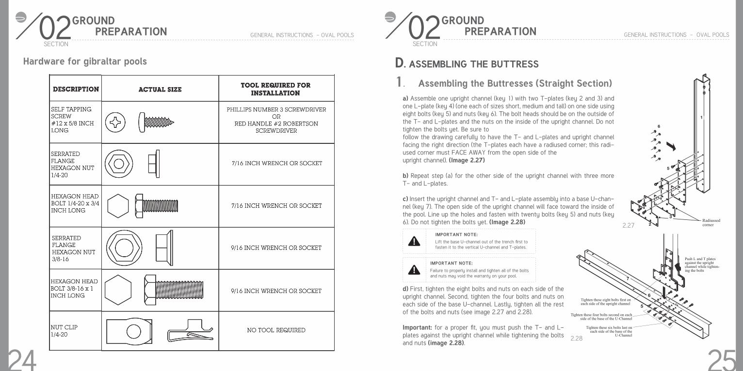
Hardware for gibraltar pools
24
02SECTION
GENERAL INSTRUCTIONS - OVAL POOLS
GROUND PREPARATION
1. Assembling the Buttresses (Straight Section)a) Assemble one upright channel (key 1) with two T-plates (key 2 and 3) and one L-plate (key 4) (one each of sizes short, medium and tall) on one side using eight bolts (key 5) and nuts (key 6). The bolt heads should be on the outside of the T- and L-plates and the nuts on the inside of the upright channel. Do not tighten the bolts yet. Be sure tofollow the drawing carefully to have the T- and L-plates and upright channel facing the right direction (the T-plates each have a radiused corner; this radi-used corner must FACE AWAY from the open side of theupright channel). (Image 2.27)
b) Repeat step (a) for the other side of the upright channel with three more T- and L-plates.
c) Insert the upright channel and T- and L-plate assembly into a base U-chan-nel (key 7). The open side of the upright channel will face toward the inside of the pool. Line up the holes and fasten with twenty bolts (key 5) and nuts (key 6). Do not tighten the bolts yet. (Image 2.28)
d) First, tighten the eight bolts and nuts on each side of the upright channel. Second, tighten the four bolts and nuts on each side of the base U-channel. Lastly, tighten all the rest of the bolts and nuts (see image 2.27 and 2.28).
Important: for a proper fit, you must push the T- and L-plates against the upright channel while tightening the bolts and nuts (image 2.28).
D. ASSEMBLING THE BUTTRESS
Lift the base U-channel out of the trench first to fasten it to the vertical U-channel and T-plates.
Failure to properly install and tighten all of the bolts and nuts may void the warranty on your pool.
IMPORTANT NOTE:
IMPORTANT NOTE:
Radiussedcorner
6
1
5
4
3
2
7
6
5Tighten these eight bolts first on each side of the upright channel
Tighten these four bolts second on each side of the base of the U-Channel
Tighten these six bolts last on each side of the base of the
U-Channel
Push L and T plates against the upright channel while tighten-ing the bolts
2.27
2.28
25

02SECTION
GENERAL INSTRUCTIONS - OVAL POOLS
GROUND PREPARATION
26When measuring the distance to the face of each base plate, use a piece of string longer than required and place a mark on the string at the required distance.
IMPORTANT NOTE :
a) Insert the bottom plate by slidding it on each upright chanel
b) Insert the buttress rails between the buttresses, the bottom rails insert into the bottom plate. Make sure the groove faces up.
c) Insert the transition rails. Slide one end of each rail into the bot-tom plate in the upright channel and slide the other end together with a bottom plate.
2.29
2.30
E
EJ
J
2.31
132. Insert the buttress (Straight Section)
02SECTION
GENERAL INSTRUCTIONS - OVAL POOLS
GROUND PREPARATION
a) Fill the base U-channels and the trenches they sit in with crushed limestone (or equivalent). Fill them up to the top edges of the base U-channels. If the limestone is dry spray it with some water to help with the compaction. Stand on the base U-channel and tamp down the limestone until a solid base is achieved (by standing on the base U-channel your weight helps prevent the base U-channel from moving). Add additional limestone as required. (Im-age 2.32)
b) Make sure the space under the end of the base U-channel is com-pletely filled with crushed limestone. (Image 2.33)
c) Recheck the distances between the base U-channels and make any adjustments you need to make sure the spacing is exactly right.
Crushed limestone or equivalent must be used instead ofbrick sand or vermiculite to backfill the base U-channels. Thelevel of compaction achieved by using crushed limestone orequivalent is superior to that of brick sand or vermiculite.
IMPORTANT NOTE:
27
2.32
2.33
3. Fill the Base U-Channels (Straight Section)
Make sure the space under the end ofthe base U-Channel is completely filledwith crushed limestone (or equivalent)
hard-packedcrushed
limestone
baseU-Channel
22" (55cm) 22" (55cm)
Stand on the base U-Channel
Use a hold down plate to dragthe area to either side of the base U-Channel, smooth and level
02SECTION
GENERAL INSTRUCTIONS - OVAL POOLS
GROUND PREPARATION
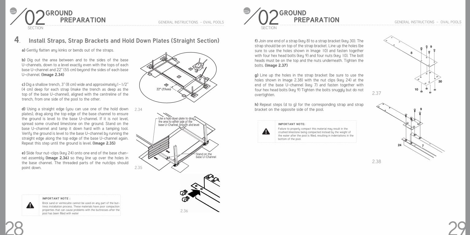
4. Install Straps, Strap Brackets and Hold Down Plates (Straight Section)a) Gently flatten any kinks or bends out of the straps.
b) Dig out the area between and to the sides of the base U-channels, down to a level exactly even with the tops of each base U-channel and 22” (55 cm) beyond the sides of each base U-channel. (Image 2.34)
c) Dig a shallow trench, 3” (8 cm) wide and approximately1-1/2” (4 cm) deep for each strap (make the trench as deep as the top of the base U-channel), aligned with the centreline of the trench, from one side of the pool to the other.
d) Using a straight edge (you can use one of the hold down plates), drag along the top edge of the base channel to ensure the ground is level to the base U-channel. If it is not level, spread some crushed limestone on the ground. Stand on the base U-channel and tamp it down hard with a tamping tool. Verify the ground is level to the base U-channel by running the straight edge along the top edge of the base U-channel again. Repeat this step until the ground is level. (Image 2.35)
e) Slide four nut-clips (key 24) onto one end of the base chan-nel assembly (Image 2.36) so they line up over the holes in the base channel. The threaded parts of the nutclips should point down.
Brick sand or vermiculite cannot be used on any part of the but-tress installation process. These materials have poor compaction properties that can cause problems with the buttresses after the pool has been filled with water
IMPORTANT NOTE :
28
2.34
2.35
2.36
9
24 7
02SECTION
GENERAL INSTRUCTIONS - OVAL POOLS
GROUND PREPARATION
f) Join one end of a strap (key 8) to a strap bracket (key 30). The strap should be on top of the strap bracket. Line up the holes (be sure to use the holes shown in Image 10) and fasten together with four hex head bolts (key 9) and four nuts (key 10). The bolt heads must be on the top and the nuts underneath. Tighten the bolts. (Image 2.37)
g) Line up the holes in the strap bracket (be sure to use the holes shown in Image 2.38) with the nut clips (key 24) at the end of the base U-channel (key 7) and fasten together with four hex head bolts (key 9) Tighten the bolts snuggly but do not overtighten.
h) Repeat steps (d to g) for the corresponding strap and strap bracket on the opposite side of the pool.
Failure to properly compact this material may result in thecrushed limestone being compacted instead by the weight of the water after the pool is filled, resulting in indentations in the bottom of the pool.
IMPORTANT NOTE:
29
2.37
2.38
8
9
10
30

02SECTION
GENERAL INSTRUCTIONS - OVAL POOLS
GROUND PREPARATION
i) Spread 3/4” (19 mm) of crushed limestone (or equivalent) over the dug out area for the hold down plate closest to the centre of the pool. Do not spread any material over the top of the base U-channel. Place the hold down plate as shown in Image 2.39 on top of the crushed limestone.
Make sure each entire hold down plate lies completelyflat in the area dug out explained in previous step 3 (d).The hold down plate must lie flat or it may lift and damagethe pool liner after the pool is filled with water. (Image 34)
IMPORTANT NOTE :
30
2.39
2.40
11
Shift the hold down plateback and forth to make it settle
7
11
11
02SECTION
GENERAL INSTRUCTIONS - OVAL POOLS
GROUND PREPARATION
j) Begin shifting the hold down plate in a forwards and backwards motion (see Image 2.41), while simultaneously applying a downward force on the hold down plate until the plate rests on top of the base U-channel. Check to see that the outside ends of the hold down plate have filled with mate-rial, and insert material into any open areas until they are full. This will prevent any low spots from forming around the hold down plates when the pool is filled with water.
Make sure each entire hold down plate lies completely flat in the area dug out explained in previous step 3 (d). The hold down plate must lie flat or it may lift and damage the pool liner after the pool is filled with water. (Image 2.42)
ONCE AGAIN - IMPORTANT NOTE :
31
Hold down platesmust lie flat in bottomof dug out area
2.41 2.42
02SECTION
GENERAL INSTRUCTIONS - OVAL POOLS
GROUND PREPARATION
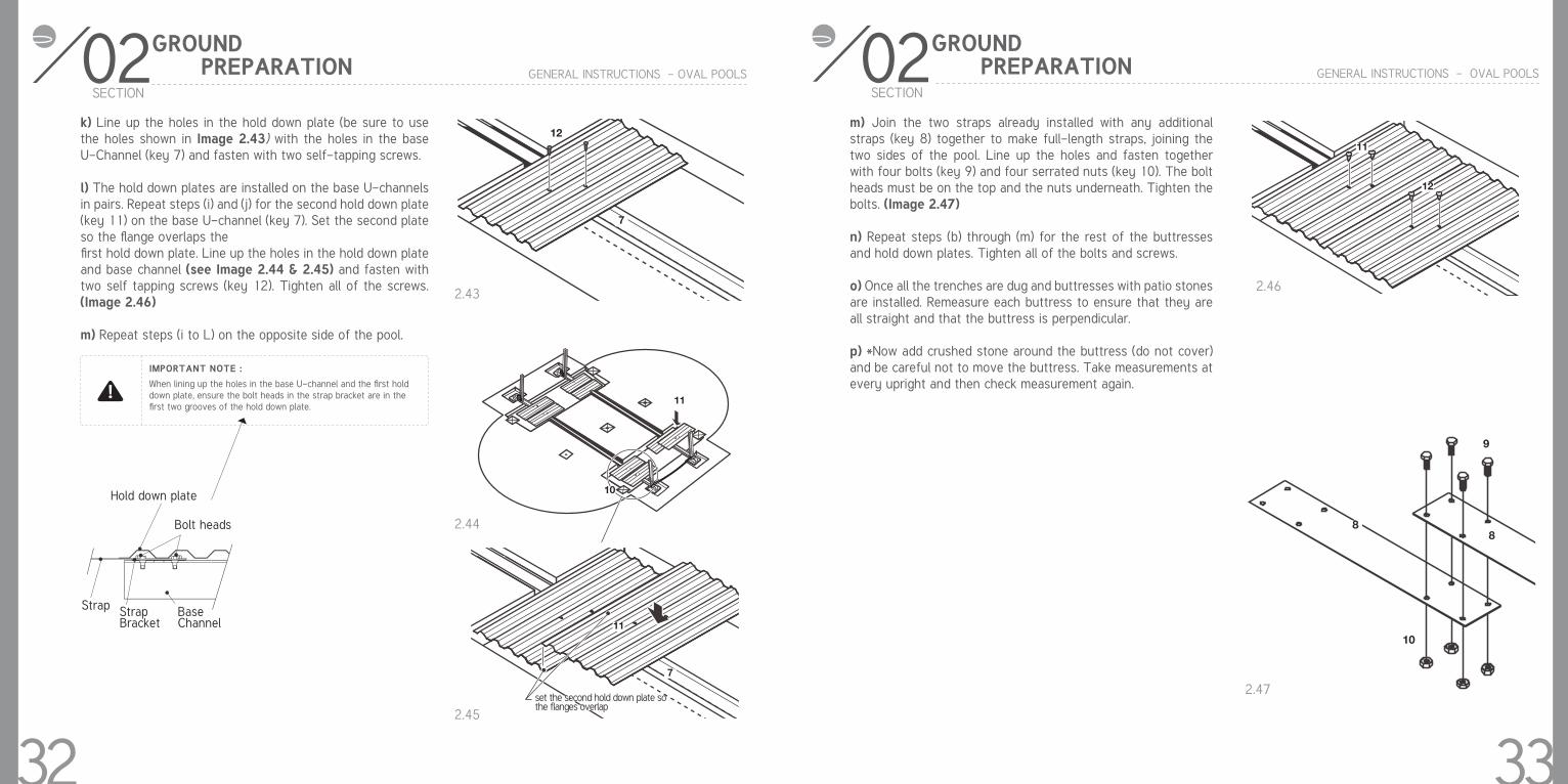
k) Line up the holes in the hold down plate (be sure to use the holes shown in Image 2.43) with the holes in the base U-Channel (key 7) and fasten with two self-tapping screws.
l) The hold down plates are installed on the base U-channels in pairs. Repeat steps (i) and (j) for the second hold down plate (key 11) on the base U-channel (key 7). Set the second plate so the flange overlaps thefirst hold down plate. Line up the holes in the hold down plate and base channel (see Image 2.44 & 2.45) and fasten with two self tapping screws (key 12). Tighten all of the screws. (Image 2.46)
m) Repeat steps (i to L) on the opposite side of the pool.
When lining up the holes in the base U-channel and the first hold down plate, ensure the bolt heads in the strap bracket are in the first two grooves of the hold down plate.
IMPORTANT NOTE :
32set the second hold down plate sothe flanges overlapset the second hold down plate sothe flanges overlap
11
10
11
7
12
11
2.43
2.44
2.45
2.46
8
9
8
10
02SECTION
GENERAL INSTRUCTIONS - OVAL POOLS
GROUND PREPARATION
m) Join the two straps already installed with any additional straps (key 8) together to make full-length straps, joining the two sides of the pool. Line up the holes and fasten together with four bolts (key 9) and four serrated nuts (key 10). The bolt heads must be on the top and the nuts underneath. Tighten the bolts. (Image 2.47)
n) Repeat steps (b) through (m) for the rest of the buttresses and hold down plates. Tighten all of the bolts and screws.
o) Once all the trenches are dug and buttresses with patio stones are installed. Remeasure each buttress to ensure that they are all straight and that the buttress is perpendicular.
p) *Now add crushed stone around the buttress (do not cover) and be careful not to move the buttress. Take measurements at every upright and then check measurement again.
332.47

Buttresses
Transition rail
End railsButtress rails
03SECTION
GENERAL INSTRUCTIONS - OVAL POOLS
ASSEMBLING THE POOL BASE
34
1. Install the curved bottom rails (Round Section)a) Each pool uses three different types of curved bottom rails. (Image 3.1) Please refer to your pool footprint (page 56) in order to recognize where each type of bottom rail should be placed.
Be sure to refer to your pool footprint (at the end of Section 1),in order to recognize where each bottom rail should be placed.
IMPORTANT NOTE :
3.1
03SECTION
GENERAL INSTRUCTIONS - OVAL POOLS
ASSEMBLING THE POOL BASE
35
d) Slide the other end of the transition rail together with a base plate (key 14). (Images 3.6)
e) Lay out the end rails and base plates on both rounds ends of the pool area. Refer to your pool`s footprint (page 51) to ensure correct dimension. (Note: this step will not work on the buttress rails or transition rails.)
f) Insert the end rails. Leave a gap (please see your pool`s footprint for gap measurement) between the ends of the rails.
3.5
3.6
J
N
N
03SECTION
GENERAL INSTRUCTIONS - OVAL POOLS
ASSEMBLING THE POOL BASE
36
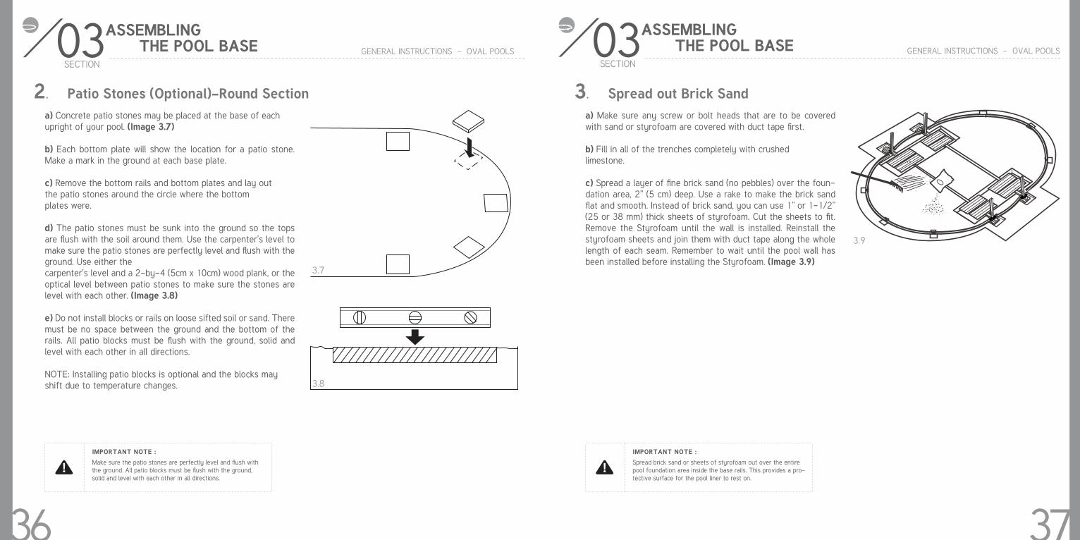
Make sure the patio stones are perfectly level and flush withthe ground. All patio blocks must be flush with the ground,solid and level with each other in all directions.
IMPORTANT NOTE :
2. Patio Stones (Optional)-Round Sectiona) Concrete patio stones may be placed at the base of eachupright of your pool. (Image 3.7)
b) Each bottom plate will show the location for a patio stone. Make a mark in the ground at each base plate.
c) Remove the bottom rails and bottom plates and lay outthe patio stones around the circle where the bottomplates were.
d) The patio stones must be sunk into the ground so the tops are flush with the soil around them. Use the carpenter’s level to make sure the patio stones are perfectly level and flush with the ground. Use either thecarpenter’s level and a 2-by-4 (5cm x 10cm) wood plank, or the optical level between patio stones to make sure the stones are level with each other. (Image 3.8)
e) Do not install blocks or rails on loose sifted soil or sand. There must be no space between the ground and the bottom of the rails. All patio blocks must be flush with the ground, solid and level with each other in all directions.
NOTE: Installing patio blocks is optional and the blocks mayshift due to temperature changes.
3.7
3.8
03SECTION
GENERAL INSTRUCTIONS - OVAL POOLS
ASSEMBLING THE POOL BASE
37
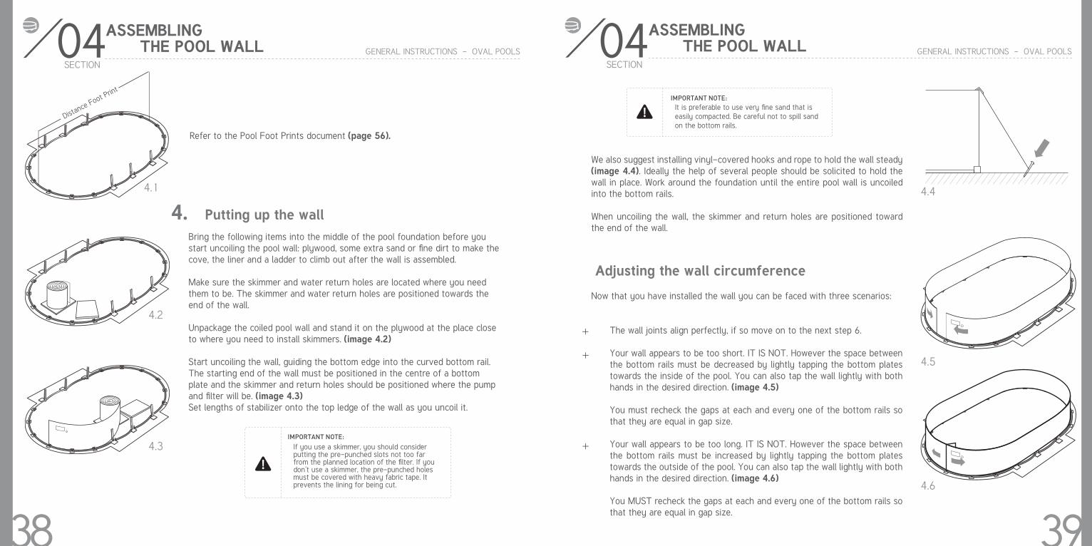
Spread brick sand or sheets of styrofoam out over the entire pool foundation area inside the base rails. This provides a pro-tective surface for the pool liner to rest on.
IMPORTANT NOTE :
3. Spread out Brick Sanda) Make sure any screw or bolt heads that are to be covered with sand or styrofoam are covered with duct tape first.
b) Fill in all of the trenches completely with crushedlimestone.
c) Spread a layer of fine brick sand (no pebbles) over the foun-dation area, 2” (5 cm) deep. Use a rake to make the brick sand flat and smooth. Instead of brick sand, you can use 1” or 1-1/2” (25 or 38 mm) thick sheets of styrofoam. Cut the sheets to fit. Remove the Styrofoam until the wall is installed. Reinstall the styrofoam sheets and join them with duct tape along the whole length of each seam. Remember to wait until the pool wall has been installed before installing the Styrofoam. (Image 3.9)
3.9
4. Putting up the wall
IMPORTANT NOTE:
If you use a skimmer, you should consider putting the pre-punched slots not too far from the planned location of the filter. If you don’t use a skimmer, the pre-punched holes must be covered with heavy fabric tape. It prevents the lining for being cut.
04 GENERAL INSTRUCTIONS - OVAL POOLS
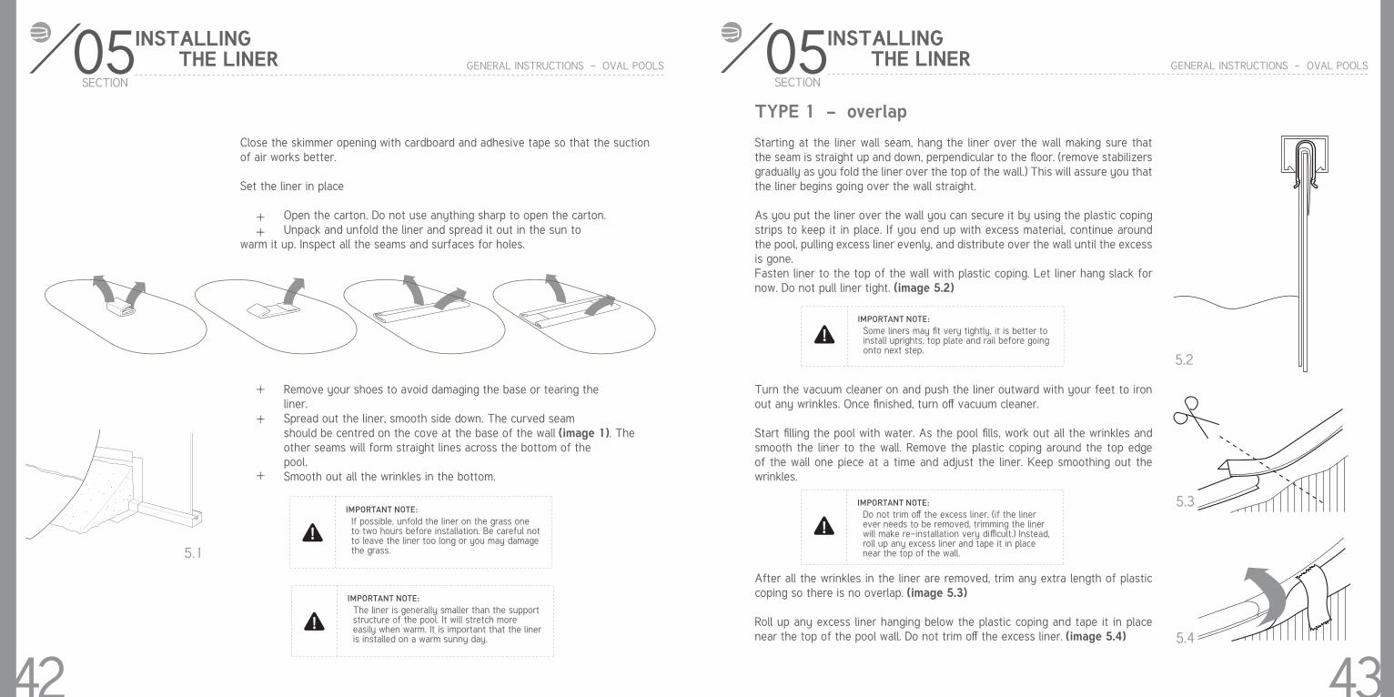
Refer to the Pool Foot Prints document (page 56).
ASSEMBLING THE POOL WALL
4.2
4.3
Bring the following items into the middle of the pool foundation before you start uncoiling the pool wall: plywood, some extra sand or fine dirt to make the cove, the liner and a ladder to climb out after the wall is assembled.
Make sure the skimmer and water return holes are located where you need them to be. The skimmer and water return holes are positioned towards the end of the wall.
Unpackage the coiled pool wall and stand it on the plywood at the place close to where you need to install skimmers. (image 4.2)
Start uncoiling the wall, guiding the bottom edge into the curved bottom rail. The starting end of the wall must be positioned in the centre of a bottom plate and the skimmer and return holes should be positioned where the pump and filter will be. (image 4.3)Set lengths of stabilizer onto the top ledge of the wall as you uncoil it.
4.1
SECTION
38
Distance F
oot Print
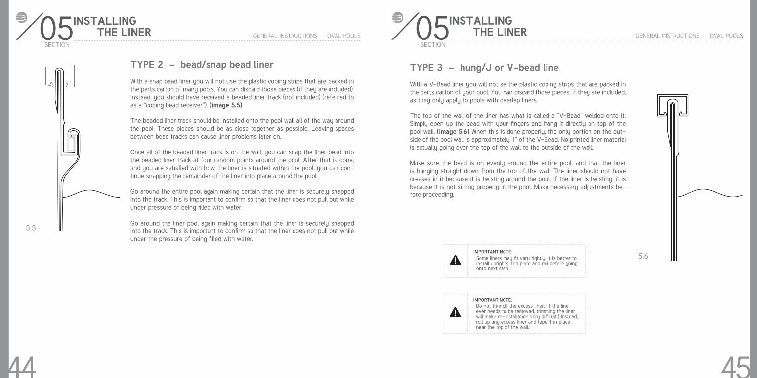
Now that you have installed the wall you can be faced with three scenarios:
The wall joints align perfectly, if so move on to the next step 6.
Your wall appears to be too short. IT IS NOT. However the space between the bottom rails must be decreased by lightly tapping the bottom plates towards the inside of the pool. You can also tap the wall lightly with both hands in the desired direction. (image 4.5)
You must recheck the gaps at each and every one of the bottom rails so that they are equal in gap size.
Your wall appears to be too long. IT IS NOT. However the space between the bottom rails must be increased by lightly tapping the bottom plates towards the outside of the pool. You can also tap the wall lightly with both hands in the desired direction. (image 4.6)
You MUST recheck the gaps at each and every one of the bottom rails so that they are equal in gap size.
+
+
+
04 GENERAL INSTRUCTIONS - OVAL POOLS
Adjusting the wall circumference
ASSEMBLING THE POOL WALL
4.5
4.6
We also suggest installing vinyl-covered hooks and rope to hold the wall steady (image 4.4). Ideally the help of several people should be solicited to hold the wall in place. Work around the foundation until the entire pool wall is uncoiled into the bottom rails.
When uncoiling the wall, the skimmer and return holes are positioned toward the end of the wall.
4.4
IMPORTANT NOTE:It is preferable to use very fine sand that is easily compacted. Be careful not to spill sand on the bottom rails.
SECTION
39

04SECTION
GENERAL INSTRUCTIONS - OVAL POOLS
5. Fasten and seal the wall
When tightening the screws start from either the top and go down or vice versa. Do not start a few screws from top and a few from the bottom to meet in the middle, this can cause problems later on. (image 4.7)
Cover the seam and bolt heads on the inside/interior of the pool wall completely with 2’ (50 cm) duct tape. (image 4.8)
Using a tape measure, measure across the circle at each bottom plate. The pool wall must be round. Adjust the circle by nudging the base plates in or out with your foot. (image 4.9)
IMPORTANT NOTE:Due to the enormous pressure exerted against the steel wall, it is absolutely essential to screw ALL THE BOLT TIGHTLY. DO NOT LEAVE ANY EMPTY HOLES. Bolt heads must be inside and washers outside. Remove all particles of steel from the bolts inside the pool.
ASSEMBLING THE POOL WALL
4.7
4.8
IMPORTANT NOTE:Stick a screwdriver through two of the holes to help line up the ends of the walls.
40
04SECTION
GENERAL INSTRUCTIONS - OVAL POOLS
ASSEMBLING THE POOL WALL
6. Making the coveYou can now spread approximately 2” (5cm) of screened earth or mason’s sand all around the inside of the pool wall. Build a cove of 3” (7,5cm) high, and not less, of well packed screened earth or mason’s sand. (image 4.9)
Water the sand to compact it and use a trowel to spread it evenly.
DO NOT USE THIN SAND. GRASSTURF OR ANY OTHER MATERIAL SO CALLED “POOL BASE” THAT CAN CAUSE DAMAGES TO YOUR POOL. THE LINER COULD EVENTUALLY RUPTURE.
The cove is very important. THE MANUFACTURER WILL NOT BE RESPONSIBLE FOR DAMAGES CAUSED BY OMISSION OF THIS STEP.
If you are using Styrofoam cove pieces instead of sand, insert them in the bot-tom rail and refer to the installation instructions that are provided with them.
7. Vinyl liner installation
A vacuum cleaner can later be used to remove the air from between the liner and the wall (image 4.10). This technique enables you to remove folds on the liner. However the following precautions should be taken:
Do not use an industrial vacuum cleaner which could be too powerful. Tape the end of the vacuum hose before inserting it into the wall so as not damage the liner. Insert the nozzle until it is about 4” (10cm) above the cove (insert through the water return outlet or the skimmer depending on the diameter of your hose.) Make sure you will be able to remove the hose later on. Tape the hose to the wall.
+
+
+
+
8’’- 12’’
3’’- 6’’
4.9
4.10
41
Optional plastic protection
SECTIONGENERAL INSTRUCTIONS - OVAL POOLS
Close the skimmer opening with cardboard and adhesive tape so that the suction of air works better.
Set the liner in place
Open the carton. Do not use anything sharp to open the carton. Unpack and unfold the liner and spread it out in the sun to warm it up. Inspect all the seams and surfaces for holes.
Remove your shoes to avoid damaging the base or tearing the liner. Spread out the liner, smooth side down. The curved seam should be centred on the cove at the base of the wall (image 1). The other seams will form straight lines across the bottom of the pool. Smooth out all the wrinkles in the bottom.
++
+
+
+
IMPORTANT NOTE:If possible, unfold the liner on the grass one to two hours before installation. Be careful not to leave the liner too long or you may damage the grass.
IMPORTANT NOTE:The liner is generally smaller than the support structure of the pool. It will stretch more easily when warm. It is important that the liner is installed on a warm sunny day.
8’’- 12’’
3’’- 6’’
5.1
05INSTALLING THE LINER
42
TYPE 1 - overlap
Starting at the liner wall seam, hang the liner over the wall making sure that the seam is straight up and down, perpendicular to the floor. (remove stabilizers gradually as you fold the liner over the top of the wall.) This will assure you that the liner begins going over the wall straight.
As you put the liner over the wall you can secure it by using the plastic coping strips to keep it in place. If you end up with excess material, continue around the pool, pulling excess liner evenly, and distribute over the wall until the excess is gone.Fasten liner to the top of the wall with plastic coping. Let liner hang slack for now. Do not pull liner tight. (image 5.2)
Turn the vacuum cleaner on and push the liner outward with your feet to iron out any wrinkles. Once finished, turn off vacuum cleaner.
Start filling the pool with water. As the pool fills, work out all the wrinkles and smooth the liner to the wall. Remove the plastic coping around the top edge of the wall one piece at a time and adjust the liner. Keep smoothing out the wrinkles.
After all the wrinkles in the liner are removed, trim any extra length of plastic coping so there is no overlap. (image 5.3)
Roll up any excess liner hanging below the plastic coping and tape it in place near the top of the pool wall. Do not trim off the excess liner. (image 5.4)
05SECTION
GENERAL INSTRUCTIONS - OVAL POOLS
INSTALLING THE LINER
IMPORTANT NOTE:Some liners may fit very tightly, it is better to install uprights, top plate and rail before going onto next step.
IMPORTANT NOTE:Do not trim off the excess liner. (if the liner ever needs to be removed, trimming the liner will make re-installation very difficult.) Instead, roll up any excess liner and tape it in place near the top of the wall.
5.2
5.3
5.4
43
05SECTION
GENERAL INSTRUCTIONS - OVAL POOLS
INSTALLING THE LINER
TYPE 2 - bead/snap bead liner
With a snap bead liner you will not use the plastic coping strips that are packed in the parts carton of many pools. You can discard those pieces (if they are included). Instead, you should have received a beaded liner track (not included) (referred to as a “coping bead receiver”). (image 5.5)
The beaded liner track should be installed onto the pool wall all of the way around the pool. These pieces should be as close together as possible. Leaving spaces between bead tracks can cause liner problems later on.
Once all of the beaded liner track is on the wall, you can snap the liner bead into the beaded liner track at four random points around the pool. After that is done, and you are satisfied with how the liner is situated within the pool, you can con-tinue snapping the remainder of the liner into place around the pool.
Go around the entire pool again making certain that the liner is securely snapped into the track. This is important to confirm so that the liner does not pull out while under pressure of being filled with water.
Go around the liner pool again making certain that the liner is securely snapped into the track. This is important to confirm so that the liner does not pull out while under the pressure of being filled with water.
5.5
44
TYPE 3 - hung/J or V-bead line
With a V-Bead liner you will not se the plastic coping strips that are packed in the parts carton of your pool. You can discard those pieces, if they are included, as they only apply to pools with overlap liners.
The top of the wall of the liner has what is called a “V-Bead” welded onto it. Simply open up the bead with your fingers and hang it directly on top of the pool wall. (image 5.6) When this is done properly, the only portion on the out-side of the pool wall is approximately 1” of the V-Bead. No printed liner material is actually going over the top of the wall to the outside of the wall.
Make sure the bead is on evenly around the entire pool, and that the liner is hanging straight down from the top of the wall. The liner should not have creases in it because it is twisting around the pool. If the liner is twisting, it is because it is not sitting properly in the pool. Make necessary adjustments be-fore proceeding.
IMPORTANT NOTE:Some liners may fit very tightly, it is better to install uprights, top plate and rail before going onto next step.
IMPORTANT NOTE:Do not trim off the excess liner. (if the liner ever needs to be removed, trimming the liner will make re-installation very difficult.) Instead, roll up any excess liner and tape it in place near the top of the wall.
5.6
05SECTION
GENERAL INSTRUCTIONS - OVAL POOLS
INSTALLING THE LINER
45

06SECTION
GENERAL INSTRUCTIONS - OVAL POOLS
ASSEMBLING THE POOL FRAME
46
The wall joints is hidden behind the upright on most pools. This assures that the skimmer and the skimmer return holes are not obstructed.
Insert the upright in the bottom joining plate until the hooks snaps. (image 6.1)
8a. Install the uprights _ Round section
IMPORTANT NOTE:Use the ridges in the pool wall to make sure the upright column is straight up and down.
IMPORTANT NOTE:Ensure to leave a gap between the two bottom rails
6.1
06SECTION
GENERAL INSTRUCTIONS - OVAL POOLS
ASSEMBLING THE POOL FRAME
47
The wall joints is hidden behind the upright on most pools. This assures that the skimmer and the skimmer return holes are not obstructed.
Insert the upright in the bottom joining plate until the hooks snaps. (image 6.2)
8b. Install the uprights _ Straight section
IMPORTANT NOTE:Use the ridges in the pool wall to make sure the upright column is straight up and down.
IMPORTANT NOTE:Ensure to leave a gap between the two bottom rails
6.2
EE
JJ
NN
N
N
06SECTION
GENERAL INSTRUCTIONS - OVAL POOLS
ASSEMBLING THE POOL FRAME
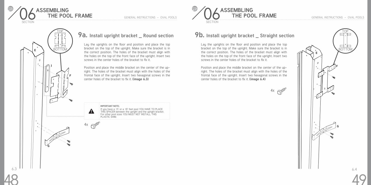
9a. Install upright bracket _ Round section
Lay the uprights on the floor and position and place the top bracket on the top of the upright. Make sure the bracket is in the correct position. The holes of the bracket must align with the holes on the top of the front face of the upright. Insert two screws in the center holes of the bracket to fix it.
Position and place the middle bracket on the center of the up-right. The holes of the bracket must align with the holes of the frontal face of the upright. Insert two hexagonal screws in the center holes of the bracket to fix it. (image 6.3)
6.3
4x
IMPORTANT NOTE:If you have a 15’ or a 18’ feet pool YOU HAVE TO PLACE THIS SPACER between the upright and the upright bracket. For other pool sizes YOU MUST NOT INSTALL THIS PLASTIC SHIM.
TOP
BOTTOM
48
Lay the uprights on the floor and position and place the top bracket on the top of the upright. Make sure the bracket is in the correct position. The holes of the bracket must align with the holes on the top of the front face of the upright. Insert two screws in the center holes of the bracket to fix it.
Position and place the middle bracket on the center of the up-right. The holes of the bracket must align with the holes of the frontal face of the upright. Insert two hexagonal screws in the center holes of the bracket to fix it. (image 6.4)
6.4
4x
TOP
BOTTOM
06SECTION
GENERAL INSTRUCTIONS - OVAL POOLS
ASSEMBLING THE POOL FRAME
49
9b. Install upright bracket _ Straight section
G
G
I
EE
F
F
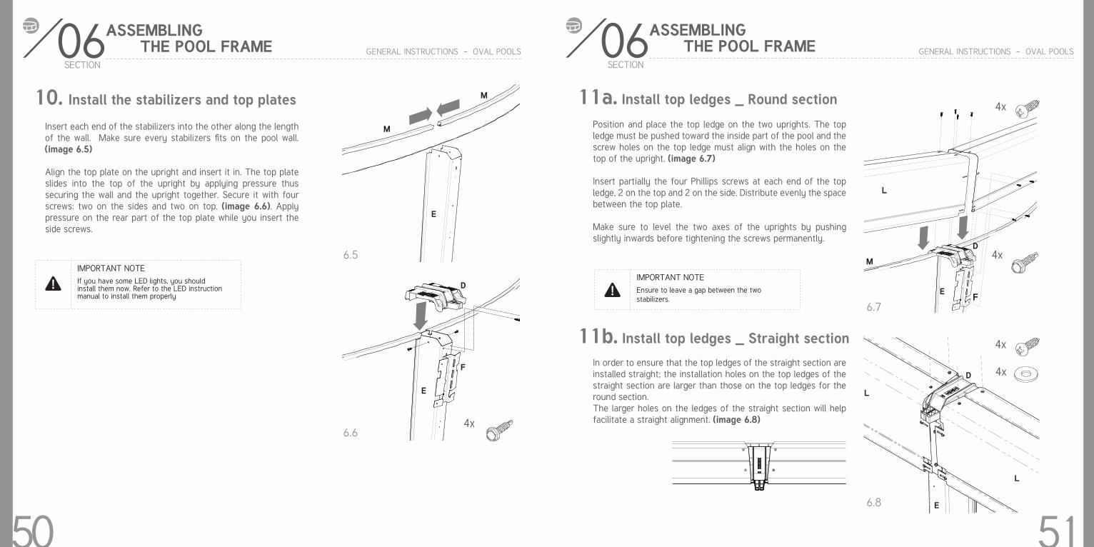
Insert each end of the stabilizers into the other along the length of the wall. Make sure every stabilizers fits on the pool wall. (image 6.5)
Align the top plate on the upright and insert it in. The top plate slides into the top of the upright by applying pressure thus securing the wall and the upright together. Secure it with four screws: two on the sides and two on top. (image 6.6). Apply pressure on the rear part of the top plate while you insert the side screws.
10. Install the stabilizers and top plates
6.5
6.64x
Use the optical level to ensure that the ground is perfectly flat and level .
IMPORTANT NOTE:IMPORTANT NOTEIf you have some LED lights, you should install them now. Refer to the LED instruction manual to install them properly
06SECTION
GENERAL INSTRUCTIONS - OVAL POOLS
ASSEMBLING THE POOL FRAME
50
Position and place the top ledge on the two uprights. The top ledge must be pushed toward the inside part of the pool and the screw holes on the top ledge must align with the holes on the top of the upright. (image 6.7)
Insert partially the four Phillips screws at each end of the top ledge, 2 on the top and 2 on the side. Distribute evenly the space between the top plate.
Make sure to level the two axes of the uprights by pushing slightly inwards before tightening the screws permanently.
In order to ensure that the top ledges of the straight section are installed straight; the installation holes on the top ledges of the straight section are larger than those on the top ledges for the round section.The larger holes on the ledges of the straight section will help facilitate a straight alignment. (image 6.8)
Use the optical level to ensure that the ground is perfectly flat and level .
IMPORTANT NOTE:IMPORTANT NOTEEnsure to leave a gap between the two stabilizers.
11a. Install top ledges _ Round section
11b. Install top ledges _ Straight section
6.7
6.8
06SECTION
GENERAL INSTRUCTIONS - OVAL POOLS
ASSEMBLING THE POOL FRAME
4x
4x
4x
4x
51
M
M
E
D
E
E
E
L
L
L
M
D
D
F
F
06SECTION
GENERAL INSTRUCTIONS - OVAL POOLS
ASSEMBLING THE POOL FRAME
Use the optical level to ensure that the ground is perfectly flat and level .
IMPORTANT NOTE:IMPORTANT NOTEWe suggest that you install all the top ledges on the wall before attaching them.
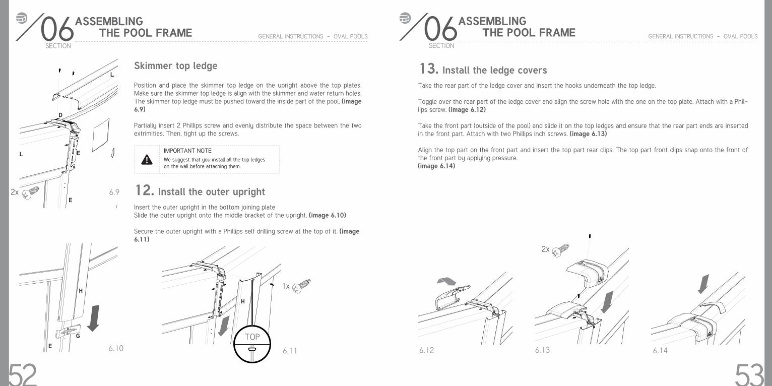
Insert the outer upright in the bottom joining plateSlide the outer upright onto the middle bracket of the upright. (image 6.10)
Secure the outer upright with a Phillips self drilling screw at the top of it. (image 6.11)
12. Install the outer upright
Skimmer top ledge
Position and place the skimmer top ledge on the upright above the top plates. Make sure the skimmer top ledge is align with the skimmer and water return holes. The skimmer top ledge must be pushed toward the inside part of the pool. (image 6.9)
Partially insert 2 Phillips screw and evenly distribute the space between the two extrimities. Then, tight up the screws.
6.9
6.10 6.11
2x
1x
TOP
52
13. Install the ledge coversTake the rear part of the ledge cover and insert the hooks underneath the top ledge.
Toggle over the rear part of the ledge cover and align the screw hole with the one on the top plate. Attach with a Phil-lips screw. (image 6.12)
Take the front part (outside of the pool) and slide it on the top ledges and ensure that the rear part ends are inserted in the front part. Attach with two Phillips inch screws. (image 6.13)
Align the top part on the front part and insert the top part rear clips. The top part front clips snap onto the front of the front part by applying pressure.(image 6.14)
6.12 6.13 6.14
2x
06SECTION
GENERAL INSTRUCTIONS - OVAL POOLS
ASSEMBLING THE POOL FRAME
53
L
L
E
E
D
H
H
G
E
14. Finish filling the pool
Turn off the vacuum and carefully remove it from the pool
Fill the pool with water to 2’’ (5cm) below the lowest opening. Make sure you remove any creases from the liner in the bottom of the pool before the water level gets too high.
Your pool is now installed. You must now install the filter and pump, the skimmer and water return inlet. Please follow the installation instructions that come with these products.
.
IMPORTANT NOTEBefore making any openings in the liner, fill the pool with 24’’ (60cm) of water to stretch the liner fully. When filling your pool, begin with a garden hose until there is about 12’’ (30cm) of water in the pool. This will allow the liner to stretch gradually. You can then use a heavier flow to finish filling it up.
06SECTION
GENERAL INSTRUCTIONS - OVAL POOLS
ASSEMBLING THE POOL FRAME
54
GENERAL INSTRUCTIONS - OVAL POOLS
15. Rules for safe pool use
NECESSARY SAFETY EQUIPMENT:
A light and strong pole not less than 12 ft (3,66m) long with blunt ends.A ring type life preserver with a throwing rope attached to it.Have emergency numbers near the pool and also at the telephone nearest to the pool. (Aviable police, fire and rescue unit, available physician, ambu-lance service and hospital).
WHEN YOU BECOME OWNER OF A POOL, HERE ARE SOME REASONABLE RULES YOU SHOULD BE FAMILIAR WITH:
You should not dive or jump from the top rail of the wading not for diving. You should never allow your children or neighbour’s children to swim under-girded.You should never swim alone.You should always remove pool ladder, or raise safety ladder when the pool is not in use.If you eat, you should wait at least one hour before you go swimming.You should not allow any family pet in the pool.There shouldn’t be any horseplaying or roughhousing around the pool.You should keep all electrical appliances away from the pool.You should keep all glass or metal objects away from the pool.You should not swim when there are risk of lightning : Thunderstorm en-danger swimmer
Unfortunately, pool owners wait for some accidents before setting guidelines. Establish your rules before the first person steps into the pool. If possible, make sure that everyone using the pool has some basic training in the water safety and basic rescue method. Some associations publish booklets about ‘‘Basic rescue and water safety’’ which gives information on assisting a swimmer in difficulty, artificial respiration, first aid for swimmers, family water safety and several other subjects. We strongly recommend you to get one.
+++
++
++
+++++
+
55
GENERAL INSTRUCTIONS - OVAL POOLS
56
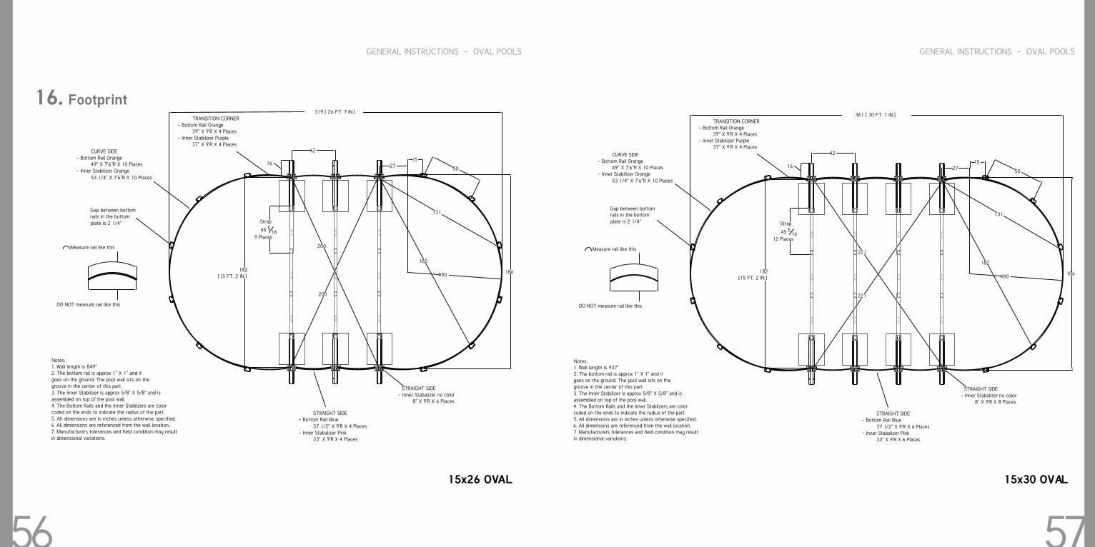
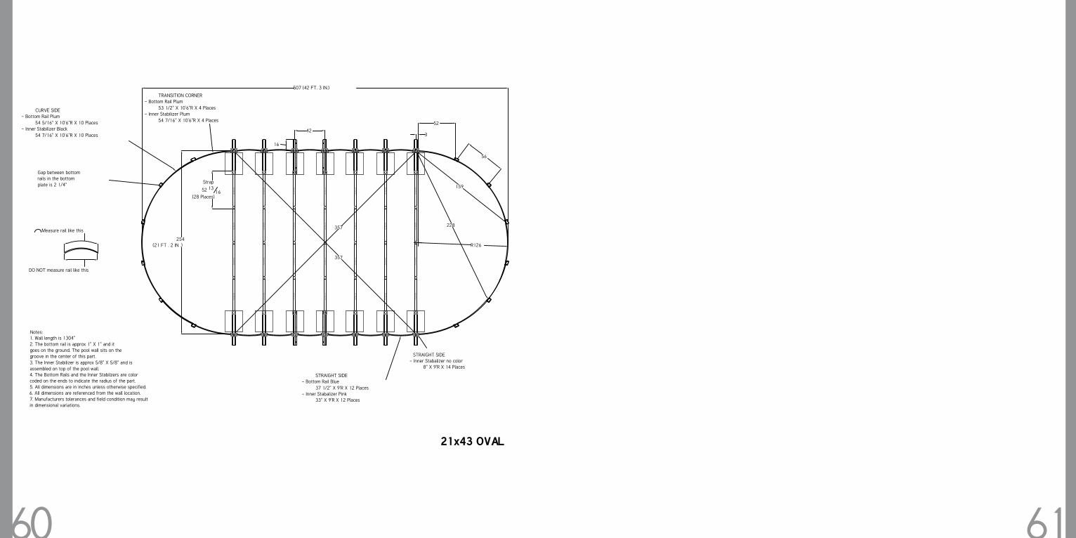
16. Footprint
GENERAL INSTRUCTIONS - OVAL POOLS
57 15x26 OVAL
319 [ 26 FT. 7 IN.]
182 [15 FT. 2 IN.]
Strap
45 516
9 Places
200
200
50
131
182
R90
2715
16
186
42
Notes:
1. Wall length is 849"2. The bottom rail is approx 1" X 1" and it goes on the ground. The pool wall sits on the groove in the center of this part.3. The Inner Stabilizer is approx 5/8" X 5/8" and is
assembled on top of the pool wall.4. The Bottom Rails and the Inner Stabilzers are color
coded on the ends to indicate the radius of the part.5. All dimensions are in inches unless otherwise specified.6. All dimensions are referenced from the wall location.7. Manufacturers tolerances and field condition may result in dimensional variations.
CURVE SIDE- Bottom Rail Orange
49" X 7'6"R X 10 Places- Inner Stabilizer Orange
53 1/4" X 7'6"R X 10 Places
TRANSITION CORNER- Bottom Rail Orange
39" X 9'R X 4 Places- Inner Stabilizer Purple
37" X 9'R X 4 Places
STRAIGHT SIDE- Bottom Rail Blue
37 1/2" X 9'R X 4 Places- Inner Stabalizer Pink
33" X 9'R X 4 Places
STRAIGHT SIDE- Inner Stabalizer no color
8" X 9'R X 6 Places
Gap between bottom rails in the bottom plate is 2 1/4"
Measure rail like this
DO NOT measure rail like this
45.3
045
.30
45.3
0
45.3
045
.30
45.3
0
45.3
045
.30
45.3
0
15x30 OVAL
361 [ 30 FT. 1 IN.]
182 [15 FT. 2 IN.]
Strap
45 516
12 Places
221
221
50
131
182
R90
2715
16
186
42
Notes:
1. Wall length is 937"2. The bottom rail is approx 1" X 1" and it goes on the ground. The pool wall sits on the groove in the center of this part.3. The Inner Stabilizer is approx 5/8" X 5/8" and is
assembled on top of the pool wall.4. The Bottom Rails and the Inner Stabilzers are color
coded on the ends to indicate the radius of the part.5. All dimensions are in inches unless otherwise specified.6. All dimensions are referenced from the wall location.7. Manufacturers tolerances and field condition may result in dimensional variations.
CURVE SIDE- Bottom Rail Orange
49" X 7'6"R X 10 Places- Inner Stabilizer Orange
53 1/4" X 7'6"R X 10 Places
TRANSITION CORNER- Bottom Rail Orange
39" X 9'R X 4 Places- Inner Stabilizer Purple
37" X 9'R X 4 Places
STRAIGHT SIDE- Bottom Rail Blue
37 1/2" X 9'R X 6 Places- Inner Stabalizer Pink
33" X 9'R X 6 Places
STRAIGHT SIDE- Inner Stabalizer no color
8" X 9'R X 8 Places
Gap between bottom rails in the bottom plate is 2 1/4"
Measure rail like this
DO NOT measure rail like this
45.3
045
.30
45.3
0
45.3
045
.30
45.3
0
45.3
045
.30
45.3
0
45.3
045
.30
45.3
0
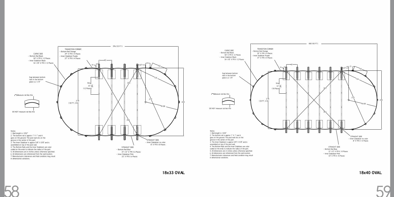
58 59 18x33 OVAL
396 (33 FT.)
Notes: 1. Wall length is 1052"2. The bottom rail is approx 1" X 1" and it goes on the ground. The pool wall sits on the groove in the center of this part.3. The Inner Stabilizer is approx 5/8" X 5/8" and is assembled on top of the pool wall.4. The Bottom Rails and the Inner Stabilzers are color coded on the ends to indicate the radius of the part.5. All dimensions are in inches unless otherwise specified.6. All dimensions are referenced from the wall location.7. Manufacturers tolerances and field condition may result in dimensional variations.
42
16 2715
52
136
219218
(18 FT. 2 IN.)
Strap
57 14
(12 Places)
252
252
223
R108
CURVE SIDE- Bottom Rail Black
50" X 9'R X 12 Places- Inner Stabilizer Black
54 1/8" X 9'R X 12 Places
TRANSITION CORNER- Bottom Rail Orange
39" X 9'R X 4 Places- Inner Stabilizer Purple
37" X 9'R X 4 Places
STRAIGHT SIDE- Bottom Rail Blue
37 1/2" X 9'R X 6 Places- Inner Stabalizer Pink
33" X 9'R X 6 Places
STRAIGHT SIDE- Inner Stabalizer no color
8" X 9'R X 8 Places
Gap between bottom rails in the bottom
plate is 2 1/4"
Measure rail like this
DO NOT measure rail like this
57.2
375
57.2
375
57.2
375
57.2
375
57.2
375
57.2
375
57.2
375
57.2
375
57.2
375
57.2
375
57.2
375
57.2
375
18x40 OVAL
480 (40 FT.)
Notes:
1. Wall length is 1220"2. The bottom rail is approx 1" X 1" and it goes on the ground. The pool wall sits on the groove in the center of this part.3. The Inner Stabilizer is approx 5/8" X 5/8" and is
assembled on top of the pool wall.4. The Bottom Rails and the Inner Stabilzers are color coded on the ends to indicate the radius of the part.5. All dimensions are in inches unless otherwise specified.6. All dimensions are referenced from the wall location.7. Manufacturers tolerances and field condition may result in dimensional variations.
42
16 2715
52
136
219218
(18 FT. 2 IN.)
Strap
57 14
(18 Places)
303
303
223
R108
CURVE SIDE- Bottom Rail Black
50" X 9'R X 12 Places- Inner Stabilizer Black
54 1/8" X 9'R X 12 Places
TRANSITION CORNER- Bottom Rail Orange
39" X 9'R X 4 Places- Inner Stabilizer Purple
37" X 9'R X 4 Places
STRAIGHT SIDE- Bottom Rail Blue
37 1/2" X 9'R X 10 Places- Inner Stabalizer Pink
33" X 9'R X 10 Places
STRAIGHT SIDE- Inner Stabalizer no color
8" X 9'R X 12 Places
Gap between bottom rails in the bottom plate is 2 1/4"
Measure rail like this
DO NOT measure rail like this
57.2
375
57.2
375
57.2
375
57.2
375
57.2
375
57.2
375
57.2
375
57.2
375
57.2
375
57.2
375
57.2
375
57.2
375
57.2
375
57.2
375
57.2
375
57.2
375
57.2
375
57.2
375
60 61
Notes: 1. Wall length is 1304"2. The bottom rail is approx 1" X 1" and it goes on the ground. The pool wall sits on the groove in the center of this part.3. The Inner Stabilizer is approx 5/8" X 5/8" and is assembled on top of the pool wall.4. The Bottom Rails and the Inner Stabilzers are color coded on the ends to indicate the radius of the part.5. All dimensions are in inches unless otherwise specified.6. All dimensions are referenced from the wall location.7. Manufacturers tolerances and field condition may result in dimensional variations.
507 (42 FT. 3 IN.)
16
42
Strap
52 1316
(28 Places)
254 (21 FT . 2 IN .) R126
3
52
56
159
228
357
357
CURVE SIDE- Bottom Rail Plum
54 5/16" X 10'6"R X 10 Places- Inner Stabilizer Black
54 7/16" X 10'6"R X 10 Places
TRANSITION CORNER- Bottom Rail Plum
53 1/2" X 10'6"R X 4 Places- Inner Stabilizer Plum
54 7/16" X 10'6"R X 4 Places
STRAIGHT SIDE- Bottom Rail Blue
37 1/2" X 9'R X 12 Places- Inner Stabalizer Pink
33" X 9'R X 12 Places
STRAIGHT SIDE- Inner Stabalizer no color
8" X 9'R X 14 Places
Gap between bottom rails in the bottom
plate is 2 1/4"
Measure rail like this
DO NOT measure rail like this
52.8
270
52.8
270
52.8
270
52.8
270
52.8
270
52.8
270
52.8
270
52.8
270
52.8
270
52.8
270
52.8
270
52.8
270
52.8
270
52.8
270
52.8
270
52.8
270
52.8
270
52.8
270
52.8
270
52.8
270
52.8
270
52.8
270
52.8
270
52.8
270
52.8
270
52.8
270
52.8
270
52.8
270
21x43 OVAL