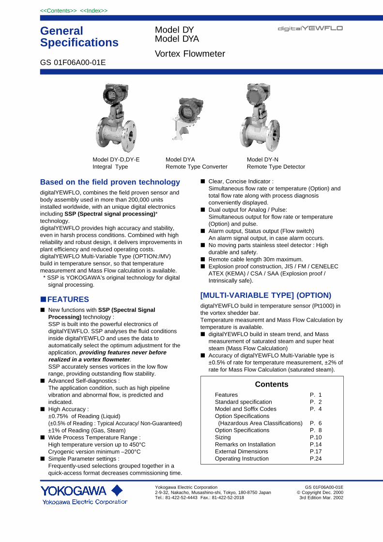
Based on the field proven technologydigitalYEWFLO, combines the field proven sensor andbody assembly used in more than 200,000 unitsinstalled worldwide, with an unique digital electronicsincluding SSP (Spectral signal processing)*technology.digitalYEWFLO provides high accuracy and stability,even in harsh process conditions. Combined with highreliability and robust design, it delivers improvements inplant efficiency and reduced operating costs.digitalYEWFLO Multi-Variable Type (OPTION:/MV)build in temperature sensor, so that temperaturemeasurement and Mass Flow calculation is available. * SSP is YOKOGAWA’s original technology for digital signal processing.
FEATURES New functions with SSP (Spectral Signal
Processing) technology :SSP is built into the powerful electronics ofdigitalYEWFLO. SSP analyses the fluid conditionsinside digitalYEWFLO and uses the data toautomatically select the optimum adjustment for theapplication, providing features never beforerealized in a vortex flowmeter.SSP accurately senses vortices in the low flowrange, providing outstanding flow stability.
Advanced Self-diagnostics :The application condition, such as high pipelinevibration and abnormal flow, is predicted andindicated.
High Accuracy :±0.75% of Reading (Liquid)(±0.5% of Reading : Typical Accuracy/ Non-Guaranteed)
±1% of Reading (Gas, Steam) Wide Process Temperature Range : High temperature version up to 450°C Cryogenic version minimum –200°C Simple Parameter settings :
Frequently-used selections grouped together in aquick-access format decreases commissioning time.
Clear, Concise Indicator :Simultaneous flow rate or temperature (Option) andtotal flow rate along with process diagnosisconveniently displayed.
Dual output for Analog / Pulse:Simultaneous output for flow rate or temperature(Option) and pulse.
Alarm output, Status output (Flow switch)An alarm signal output, in case alarm occurs.
No moving parts stainless steel detector : Highdurable and safety.
Remote cable length 30m maximum. Explosion proof construction, JIS / FM / CENELEC
ATEX (KEMA) / CSA / SAA (Explosion proof /Intrinsically safe).
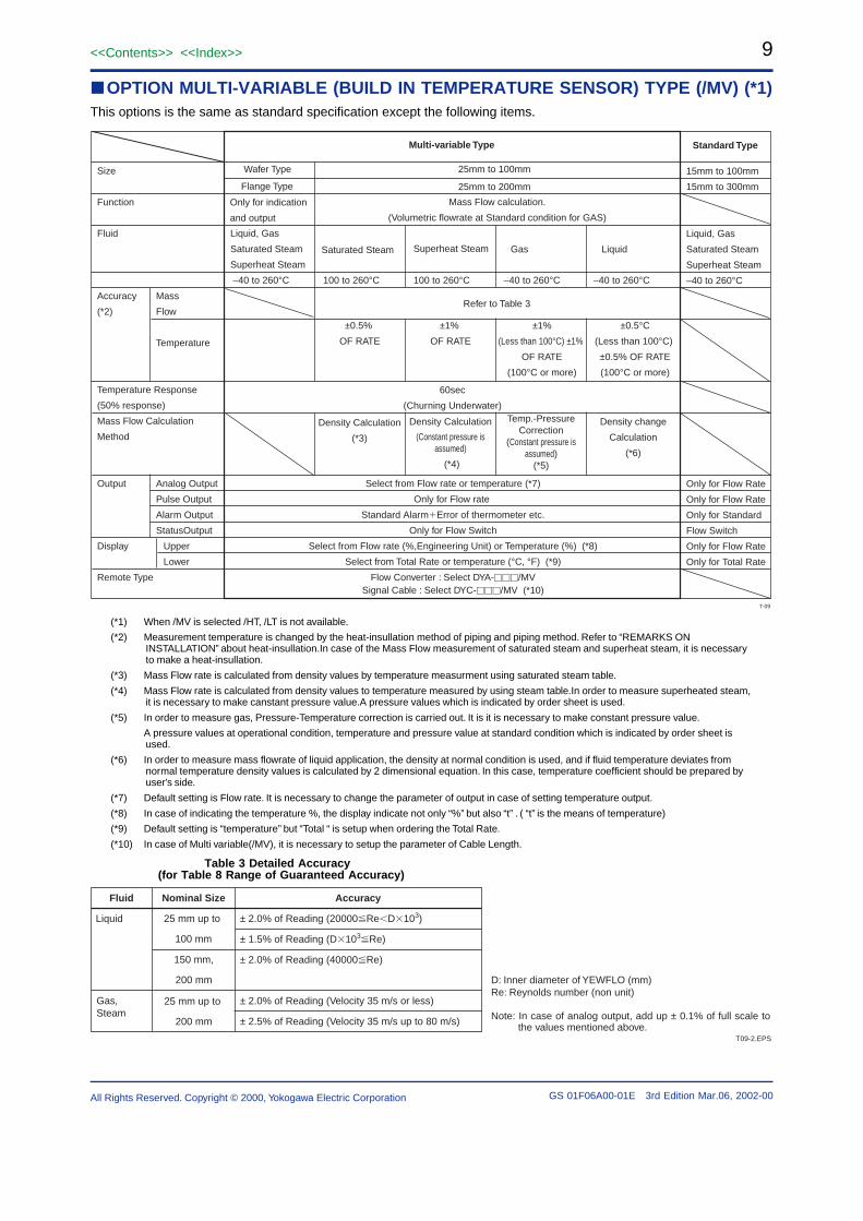
[MULTI-VARIABLE TYPE] (OPTION)digtalYEWFLO build in temperature sensor (Pt1000) inthe vortex shedder bar.Temperature measuremt and Mass Flow Calculation bytemperature is available. digitalYEWFLO build in steam trend, and Mass
measurement of saturated steam and super heatsteam (Mass Flow Calculation)
Accuracy of digtalYEWFLO Multi-Variable type is±0.5% of rate for temperature measurement, ±2% ofrate for Mass Flow Calculation (saturated steam).
ContentsFeatures P. 1Standard specification P. 2Model and Soffix Codes P. 4Option Specifications (Hazardous Area Classifications) P. 6Option Specifications P. 8Sizing P.10Remarks on Installation P.14External Dimensions P.17Operating Instruction P.24
Accuracy : ±0.75% of Reading (Liquid)±1% of Reading (Gas, Steam)Refer to Table 9When Multi-Variable Type is selected,refer to P9.
Repeatability : ± 0.2% of ReadingCalibration :
This flowmeter is factory-calibrated using awater flow.Temperature and flow calibration by waterflow when /MV is selected.
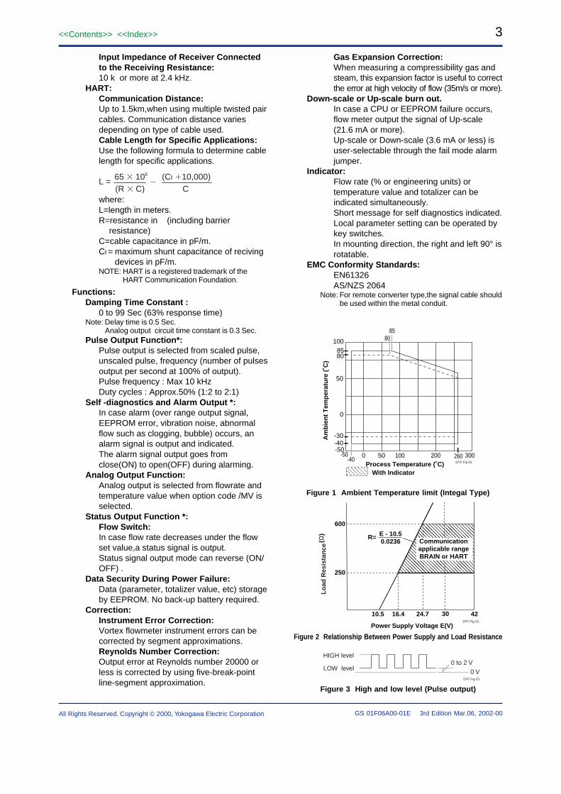
Normal Operating ConditionProcess Temperature Range :
–40 to 260 °C (general)–200 to 100 °C (Cryogenic Version:option)–40 to 450 °C (High Process Temperature
Version:option)When Multi-Variable Type is selected, referto P9.Refer to Figure 1 for integral converter type.
Process Pressure Limit :–0.1MPa (–1 kg/cm2) to flange rating.
Ambient Temperature Range :–40 to 85 °C (Remote type detector, Remote
type converter)–40 to 85 °C (Integral type, refer to Figure 1)–30 to 80 °C (Integral type with Indicator,
refer to Figure 1)Ambient Humidity : 5 to 100% RH (at 40 °C)
(No Condensation)Power Supply Voltage : 10.5 to 42 V DC
(Refer to Figure 2 ; Relationship BetweenPower Supply Voltage and Load Resistance)
Mechanical SpecificationsMaterial (General Type):
Refer to Table.1Body; SCS14A casting stainless steel (equivalent
to CF8M,SUS316)Shedder bar;
Duplex stainless steel(DCS1,only for15mm is DSD1-H,Both equivalent to JISSUS329J1,ASTM CD4MCu)DCS1 and DSD1-H are registered trademarksof Daido Tokusyu Steel Co.
Gasket; JIS SUS316 stainless steel withpolytetrafluoroethylene coating.
Signal Cable:Model DYC cable, used for remote detector andconverter.Max. length : 30 m.Outer Sheath Material: Heat resisting polyethyl-
eneDurable Temperature : –40 to 150 °C
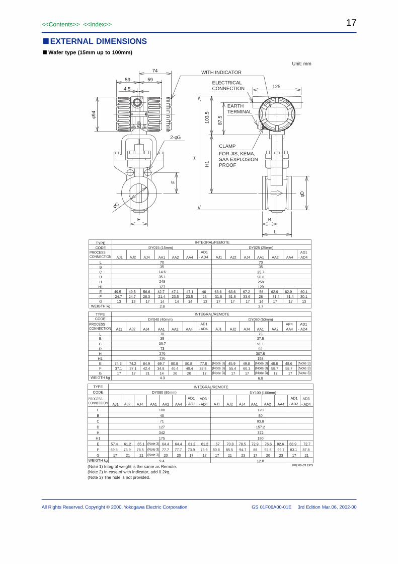
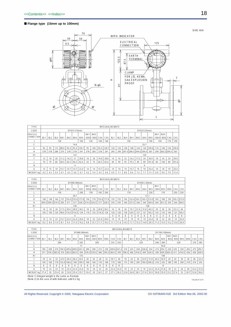
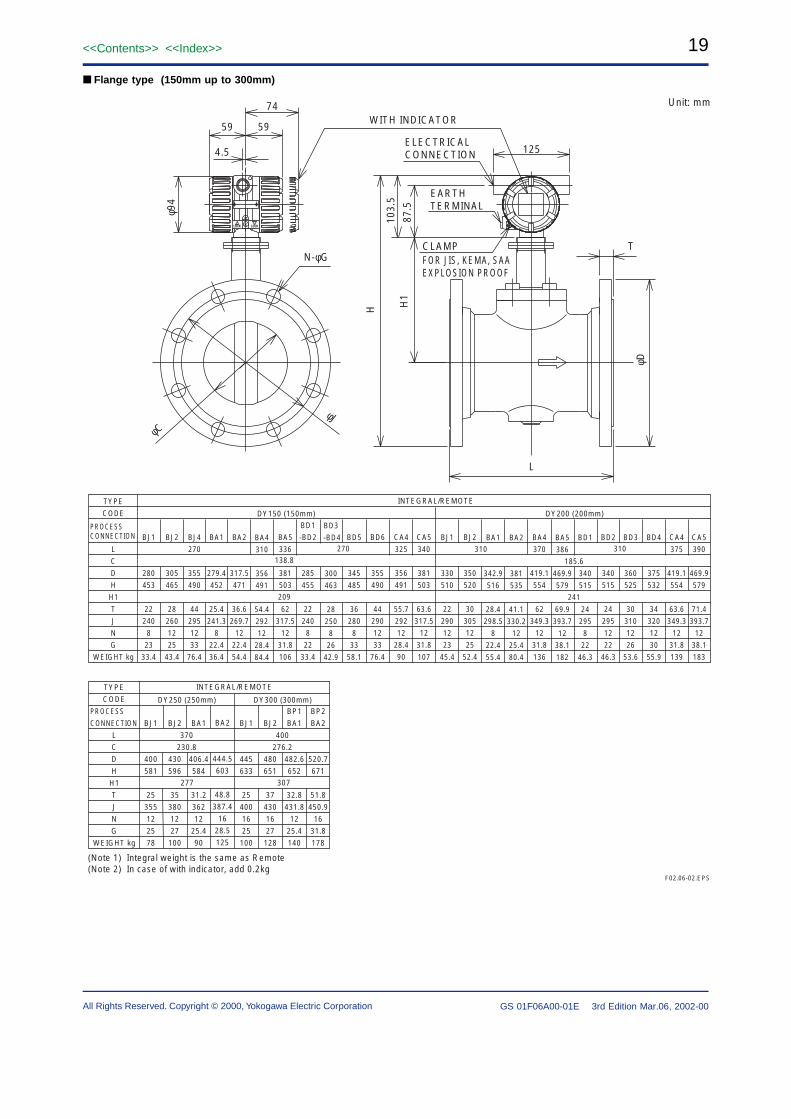
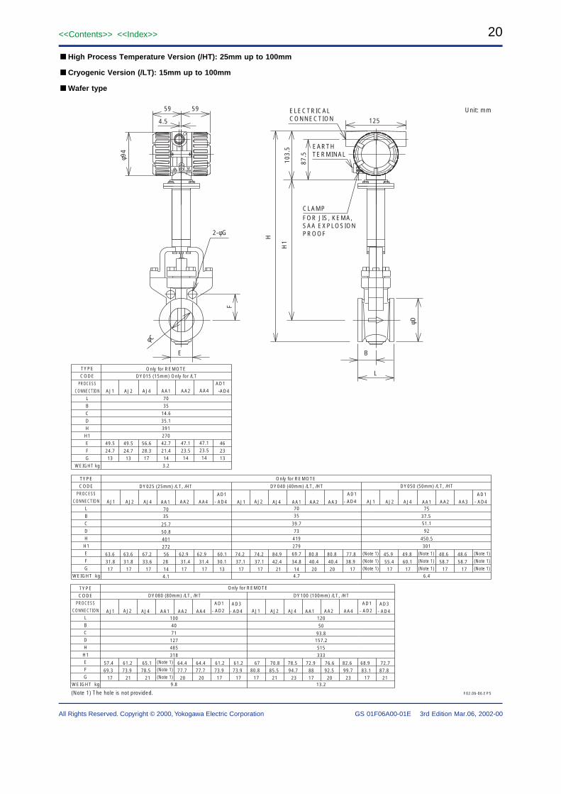
Weight:Refer to item “External Dimensions”.
Mounting:Integral type and Remote type detector :
Flange mounting or wafer mounting byflange adjacent to the pipeline.
Remote type converter : 2 inch pipe mounting.
Electrical SpecificationsNote*: Pulse output,alarm output and status output use
the common terminal, therefore these functionsare not used simultaneously.
Output Signal : Dual Output (Both Analog andTransistor contact output can be obtainedsimultaneously). In this case refer to the item“Remarks on installation” for power supplyand pulse output wiring.
Analog : 4 to 20 mA DC, 2-wire system.Transistor Contact Output* :
Open collector, 3-wire system.Pulse,alarm,status output are selected byparameter setting.Contact rating: 30 V DC, 120 mA DCLow level: 0 to 2 V DC. (refer to Figure3)
Communication Requirement :Communication Signal :
BRAIN or HART communication signal(superimposed on a 4 to 20 mA DCsignal)
Conditions of Communication Line :Load Resistance :250 to 600 (including cable resistance).Refer to Figure 2.Supply Voltage :16.4 to 42 V DC for digital communicationsBRAIN and HART protocols .(16.4 to 30 VDC for intrinsically safe type).Refer to Figure 2.Space from other Power Line: 15cm ormore (Parallel wiring should be avoided.)
BRAIN:Communication Distance :Up to 2 km,when polyethylene insulatedPVC-sheathed cables (CEV cables) areused.Communication distance variesdepending on type of cable used and wiring.Load Capacitance: 0.22 µF or lessLoad Inductance: 3.3 mH or less
Input Impedance of Receiver Connectedto the Receiving Resistance:10 k or more at 2.4 kHz.
HART:Communication Distance:Up to 1.5km,when using multiple twisted paircables. Communication distance variesdepending on type of cable used.Cable Length for Specific Applications:Use the following formula to determine cablelength for specific applications.
65 106 (Cf 10,000) L =
(R C) C
where:L=length in meters.R=resistance in (including barrier
resistance)C=cable capacitance in pF/m.Cf = maximum shunt capacitance of reciving
devices in pF/m.NOTE: HART is a registered trademark of the
HART Communication Foundation.
Functions:Damping Time Constant :
0 to 99 Sec (63% response time)Note: Delay time is 0.5 Sec.
Analog output circuit time constant is 0.3 Sec.Pulse Output Function*:
Pulse output is selected from scaled pulse,unscaled pulse, frequency (number of pulsesoutput per second at 100% of output).Pulse frequency : Max 10 kHzDuty cycles : Approx.50% (1:2 to 2:1)
Self -diagnostics and Alarm Output *:In case alarm (over range output signal,EEPROM error, vibration noise, abnormalflow such as clogging, bubble) occurs, analarm signal is output and indicated.The alarm signal output goes fromclose(ON) to open(OFF) during alarming.
Analog Output Function:Analog output is selected from flowrate andtemperature value when option code /MV isselected.
Status Output Function *:Flow Switch:In case flow rate decreases under the flowset value,a status signal is output.Status signal output mode can reverse (ON/OFF) .
Data Security During Power Failure:Data (parameter, totalizer value, etc) storageby EEPROM. No back-up battery required.
Correction:Instrument Error Correction:Vortex flowmeter instrument errors can becorrected by segment approximations.Reynolds Number Correction:Output error at Reynolds number 20000 orless is corrected by using five-break-pointline-segment approximation.
Gas Expansion Correction:When measuring a compressibility gas andsteam, this expansion factor is useful to correctthe error at high velocity of flow (35m/s or more).
Down-scale or Up-scale burn out.In case a CPU or EEPROM failure occurs,flow meter output the signal of Up-scale(21.6 mA or more).Up-scale or Down-scale (3.6 mA or less) isuser-selectable through the fail mode alarmjumper.
Indicator:Flow rate (% or engineering units) ortemperature value and totalizer can beindicated simultaneously.Short message for self diagnostics indicated.Local parameter setting can be operated bykey switches.In mounting direction, the right and left 90° isrotatable.
EMC Conformity Standards:EN61326AS/NZS 2064
Note: For remote converter type,the signal cable shouldbe used within the metal conduit.
200100500-50-40
100
50
0
300Process Temperature (˚C)
With Indicator
Am
bie
nt
Tem
per
atu
re (
˚C)
85
-50260
-40
85
-30
80
80
DYF Fig-01
Figure 1 Ambient Temperature limit (Integal Type)
R= E - 10.5
0.0236
250
600
10.5 16.4 24.7 42
Power Supply Voltage E(V)
(Ω)
Communicationapplicable rangeBRAIN or HART
30
Lo
ad R
esis
tan
ce
DYF Fig-02
Figure 2 Relationship Between Power Supply and Load Resistance
* 1 : Nominal size, Fluid(Liquid, Gas, Steam), Density, Viscosity, Pressure, Temperature, Flow range, Parameters are set at the factory before
shipment.* 2 : Refer to Table 1. In case of /NC or /HX or /HY or /HT or /LT, select X (others). The body material (SCS14A or CF8M or DIN 1.4452 or WCB) varies
according to each sales area. Please contact to YOKOGAWA sales person.
* 3 : In case of B (CF8M), the process connection is available for ANSI (AA1, AA2, AA4, BA1, BA2, BA4, BA5, CA4, CA5)
* 4 : Refer to Table 1. In case of /NC or /HX or /HY or /HT or /LT, select X (others). The shedder bar material (DCS1 (15mm is DSD1-H), CD4MCu) varies
according to each sales area. Please contact to YOKOGAWA sales person.
* 5 : Refer to Table 2.* 6 : In case of /FF1 or /CF1, the screw length is deeper than ANSI standard
for 0.5 to 3.5 threads.* 7 : Indicator is not available for remote type detector.* 8 : One set of end finish part is attached.* 9 : Fill in two digit figure per 5m unit (for example, 35m, 40m etc). The cable can be cut to required length within 30m at customer side. In this case, select Cable End Code [-0].*10 : An entered digit figure shows required set quantity. Only for Cable End Code [-0].*11 : In case of A (SCS14A), the process connection is available for JIS
(AJ1, AJ2, AJ4, BJ1, BJ2, BJ4)*12 : In case of an explosion protect type, it depends for an electrical
connecion on the kind of an explosion protect type. Refer to “ OPTION SPECIFICATION (HAZARDOUS AREA CLASSIFICATIONS)”
Size 15 mm (1/2 inch)Size 25 mm (1 inch)Size 40 mm (1-1/2 inch)Size 50 mm (2 inch)Size 80 mm (3 inch)Size 100 mm (4 inch)Size 150 mm (6 inch)Size 200 mm (8 inch)Size 250 mm (10 inch)Size 300 mm (12 inch)
OutputSignal/Commu-nication*1
4 to 20 mA DC, Pulse,BRAIN Communication4 to 20 mA DC, Pulse,HART CommunicationRemote type detector
Process Connection
*5
JIS 10 K WaferJIS 20 K WaferJIS 40 K WaferANSI Class 150 WaferANSI Class 300 WaferANSI Class 600 WaferDIN PN10 WaferDIN PN16 WaferDIN PN25 WaferDIN PN40 WaferJIS 10K Flange(Raised Face)JIS 20K Flange(Raised Face)JIS 40K Flange(Raised Face)ANSI Class 150 Flange(Raised Face)ANSI Class 300 Flange(Raised Face)ANSI Class 600 Flange(Raised Face)ANSI Class 900 Flange(Raised Face)DIN PN10 Flange(Raised Face)DIN PN16 Flange(Raised Face)DIN PN25 Flange(Raised Face)DIN PN40 Flange(Raised Face)DIN PN64 Flange(Raised Face)DIN PN100 Flange(Raised Face)ANSI Class 600 Flange(Ring Joint)ANSI Class 900 Flange(Ring Joint)
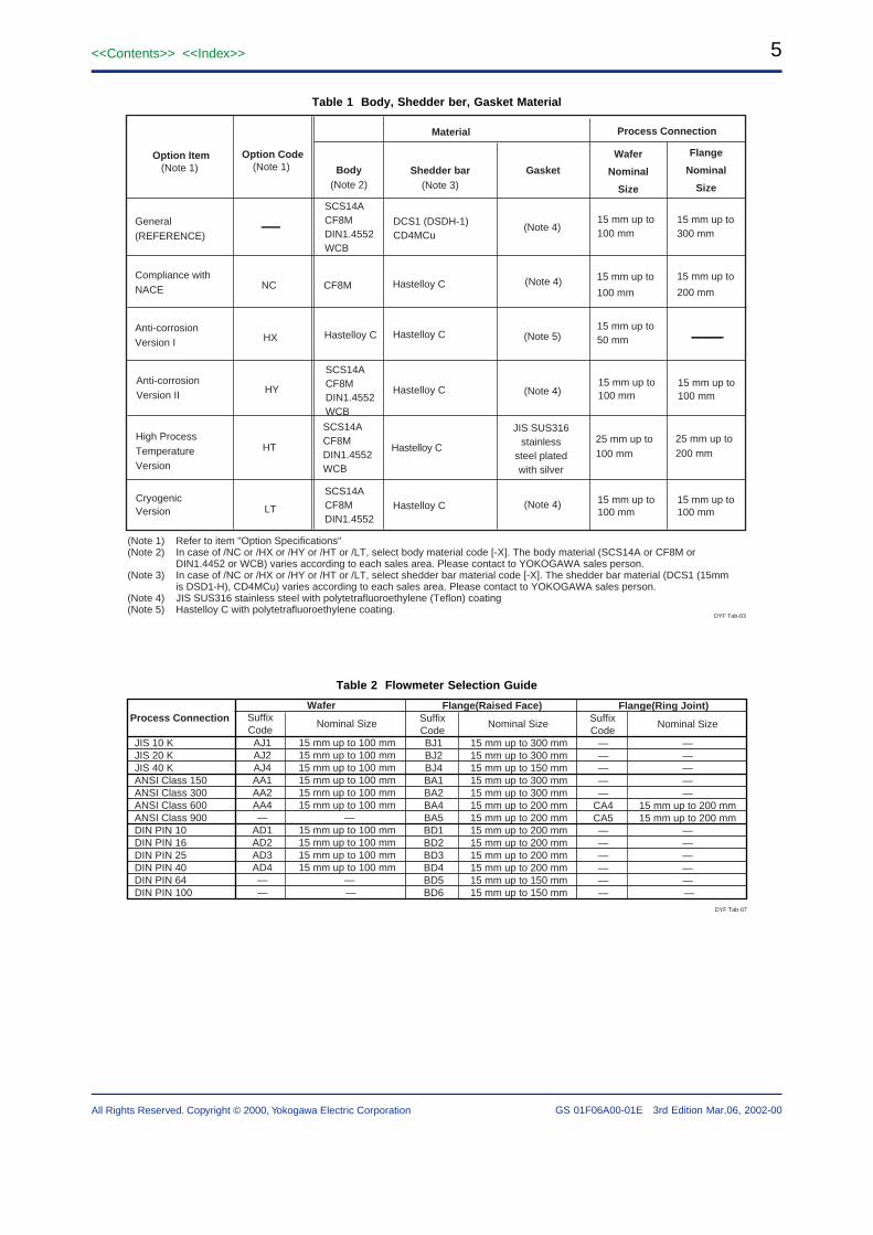
(Note 1) Refer to item "Option Specifications"(Note 2) In case of /NC or /HX or /HY or /HT or /LT, select body material code [-X]. The body material (SCS14A or CF8M or DIN1.4452 or WCB) varies according to each sales area. Please contact to YOKOGAWA sales person.(Note 3) In case of /NC or /HX or /HY or /HT or /LT, select shedder bar material code [-X]. The shedder bar material (DCS1 (15mm is DSD1-H), CD4MCu) varies according to each sales area. Please contact to YOKOGAWA sales person.(Note 4) JIS SUS316 stainless steel with polytetrafluoroethylene (Teflon) coating(Note 5) Hastelloy C with polytetrafluoroethylene coating.
Option Code(Note 1)
SCS14ACF8MDIN1.4552WCB
Body(Note 2)
Shedder bar(Note 3)
DCS1 (DSDH-1)CD4MCu
Hastelloy CCF8M Compliance withNACE
Hastelloy C Hastelloy C
Anti-corrosionVersion II
SCS14ACF8MDIN1.4552WCB
Hastelloy C
High ProcessTemperatureVersion
CryogenicVersion
SCS14ACF8MDIN1.4552WCB
Hastelloy C
NC
HX
HY
HT
LT
SCS14ACF8MDIN1.4552
(Note 5)
JIS SUS316stainless
steel platedwith silver
(Note 4)
(Note 4)
Gasket
(Note 4)
(Note 4)
Process Connection
Wafer
Nominal
Size
15 mm up to 100 mm
15 mm up to
100 mm
15 mm up to 50 mm
15 mm up to 100 mm
25 mm up to 100 mm
15 mm up to 100 mm
Flange
Nominal
Size
15 mm up to 300 mm
15 mm up to
200 mm
15 mm up to 100 mm
25 mm up to 200 mm
15 mm up to 100 mm
Hastelloy C
DYF Tab-03
Table 2 Flowmeter Selection Guide
DYF Tab-07
Process Connection
JIS 10 KJIS 20 KJIS 40 KANSI Class 150ANSI Class 300ANSI Class 600ANSI Class 900DIN PIN 10DIN PIN 16DIN PIN 25DIN PIN 40DIN PIN 64DIN PIN 100
Flange(Ring Joint)
Nominal Size
— —— —— —— —— —
CA4 15 mm up to 200 mmCA5 15 mm up to 200 mm— —— —— —— —— —— —
Wafer
Nominal Size
AJ1 15 mm up to 100 mmAJ2 15 mm up to 100 mmAJ4 15 mm up to 100 mmAA1 15 mm up to 100 mmAA2 15 mm up to 100 mmAA4 15 mm up to 100 mm— —
AD1 15 mm up to 100 mmAD2 15 mm up to 100 mmAD3 15 mm up to 100 mmAD4 15 mm up to 100 mm— —— —
Flange(Raised Face)
Nominal Size
BJ1 15 mm up to 300 mmBJ2 15 mm up to 300 mmBJ4 15 mm up to 150 mmBA1 15 mm up to 300 mmBA2 15 mm up to 300 mmBA4 15 mm up to 200 mmBA5 15 mm up to 200 mmBD1 15 mm up to 200 mmBD2 15 mm up to 200 mmBD3 15 mm up to 200 mmBD4 15 mm up to 200 mmBD5 15 mm up to 150 mmBD6 15 mm up to 150 mm
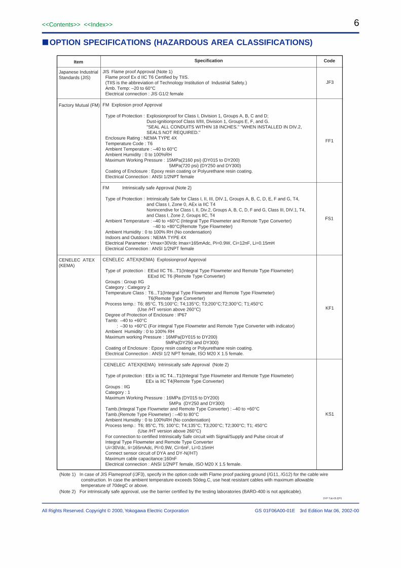
OPTION SPECIFICATIONS (HAZARDOUS AREA CLASSIFICATIONS)
DYF Tab-05.EPS
CodeSpecification
JIS Flame proof Approval (Note 1) Flame proof Ex d IIC T6 Certified by TIIS. (TIIS is the abbreviation of Technology Institution of Industrial Safety.) Amb. Temp: –20 to 60°C Electrical connection : JIS G1/2 female
FM Explosion proof Approval
Type of Protection : Explosionproof for Class I, Division 1, Groups A, B, C and D; Dust-ignitionproof Class II/III, Division 1, Groups E, F, and G. "SEAL ALL CONDUITS WITHIN 18 INCHES." "WHEN INSTALLED IN DIV.2, SEALS NOT REQUIRED." Enclosure Rating : NEMA TYPE 4X Temperature Code : T6 Ambient Temperature : –40 to 60°C Ambient Humidity : 0 to 100%RH Maximum Working Pressure : 15MPa(2160 psi) (DY015 to DY200) 5MPa(720 psi) (DY250 and DY300) Coating of Enclosure : Epoxy resin coating or Polyurethane resin coating. Electrical Connection : ANSI 1/2NPT female
FM Intrinsically safe Approval (Note 2) Type of Protection : Intrinsically Safe for Class I, II, III, DIV.1, Groups A, B, C, D, E, F and G, T4, and Class I, Zone 0, AEx ia IIC T4 Nonincendive for Class I, II, Div.2, Groups A, B, C, D, F and G, Class III, DIV.1, T4, and Class I, Zone 2, Groups IIC, T4 Ambient Temperature : –40 to +60°C (Integral Type Flowmeter and Remote Type Converter) –40 to +80°C(Remote Type Flowmeter) Ambient Humidity : 0 to 100% RH (No condensation) Indoors and Outdoors : NEMA TYPE 4X Electrical Parameter : Vmax=30Vdc Imax=165mAdc, Pi=0.9W, Ci=12nF, Li=0.15mH Electrical Connection : ANSI 1/2NPT female CENELEC ATEX(KEMA) Explosionproof Approval
Type of protection : EExd IIC T6...T1(Integral Type Flowmeter and Remote Type Flowmeter) EExd IIC T6 (Remote Type Converter) Groups : Group IIG Category : Category 2 Temperature Class : T6...T1(Integral Type Flowmeter and Remote Type Flowmeter) T6(Remote Type Converter) Process temp.: T6; 85°C, T5;100°C; T4;135°C; T3;200°C;T2;300°C; T1;450°C (Use /HT version above 260°C) Degree of Protection of Enclosure : IP67 Tamb: –40 to +60°C : –30 to +60°C (For integral Type Flowmeter and Remote Type Converter with indicator) Ambient Humidity : 0 to 100% RH Maximum working Pressure : 16MPa(DY015 to DY200) 5MPa(DY250 and DY300) Coating of Enclosure : Epoxy resin coating or Polyurethane resin coating. Electrical Connection : ANSI 1/2 NPT female, ISO M20 X 1.5 female.
Type of protection : EEx ia IIC T4...T1(Integral Type Flowmeter and Remote Type Flowmeter) EEx ia IIC T4(Remote Type Converter) Groups : IIG Category : 1 Maximum Working Pressure : 16MPa (DY015 to DY200) 5MPa (DY250 and DY300) Tamb.(Integral Type Flowmeter and Remote Type Converter) : –40 to +60°C Tamb.(Remote Type Flowmeter) : –40 to 80°C Ambient Humidity : 0 to 100%RH (No condensation) Process temp.: T6; 85°C, T5; 100°C; T4;135°C; T3;200°C; T2;300°C; T1; 450°C (Use /HT version above 260°C) For connection to certified Intrinsically Safe circuit with Signal/Supply and Pulse circuit of Integral Type Flowmeter and Remote Type Converter Ui=30Vdc, Ii=165mAdc, Pi=0.9W, Ci=6nF, Li=0.15mH Connect sensor circuit of DYA and DY-N(/HT) Maximum cable capacitance:160nF Electrical connection : ANSI 1/2NPT female, ISO M20 X 1.5 female.
Item
Japanese Industrial Standards (JIS)
Factory Mutual (FM)
CENELEC ATEX(KEMA)
(Note 1) In case of JIS Flameproof (/JF3), specify in the option code with Flame proof packing ground (/G11, /G12) for the cable wire construction. In case the ambient temperature exceeds 50deg.C, use heat resistant cables with maximum allowable temperature of 70degC or above.(Note 2) For intrinsically safe approval, use the barrier certified by the testing laboratories (BARD-400 is not applicable).
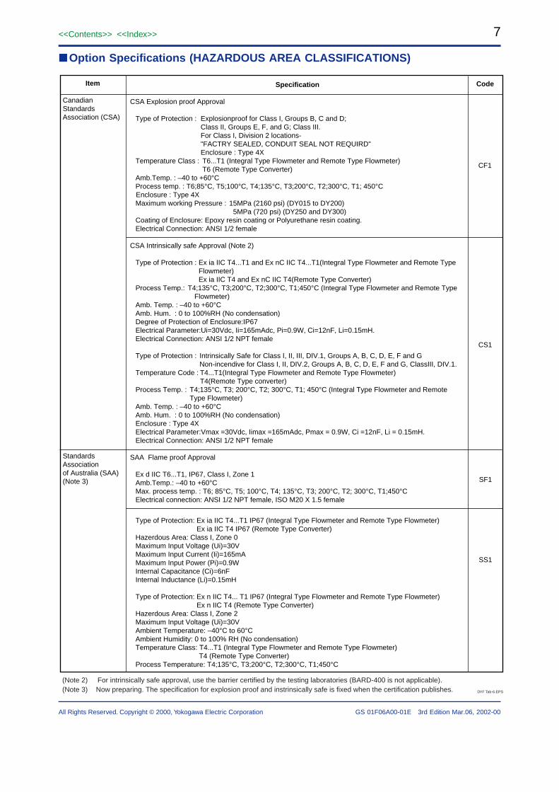
Option Specifications (HAZARDOUS AREA CLASSIFICATIONS)
Item
Canadian Standards Association (CSA)
Standards Association of Australia (SAA)(Note 3)
CodeSpecification
CSA Explosion proof Approval
Type of Protection : Explosionproof for Class I, Groups B, C and D;Class II, Groups E, F, and G; Class III.For Class I, Division 2 locations-"FACTRY SEALED, CONDUIT SEAL NOT REQUIRD"Enclosure : Type 4X
Temperature Class : T6...T1 (Integral Type Flowmeter and Remote Type Flowmeter)T6 (Remote Type Converter)
Enclosure : Type 4XMaximum working Pressure : 15MPa (2160 psi) (DY015 to DY200)
5MPa (720 psi) (DY250 and DY300)Coating of Enclosure: Epoxy resin coating or Polyurethane resin coating.Electrical Connection: ANSI 1/2 female
CSA Intrinsically safe Approval (Note 2)
Type of Protection : Ex ia IIC T4...T1 and Ex nC IIC T4...T1(Integral Type Flowmeter and Remote Type Flowmeter)Ex ia IIC T4 and Ex nC IIC T4(Remote Type Converter)
Process Temp.: T4;135°C, T3;200°C, T2;300°C, T1;450°C (Integral Type Flowmeter and Remote Type Flowmeter)
Amb. Temp. : –40 to +60°CAmb. Hum. : 0 to 100%RH (No condensation)Degree of Protection of Enclosure:IP67Electrical Parameter:Ui=30Vdc, Ii=165mAdc, Pi=0.9W, Ci=12nF, Li=0.15mH.Electrical Connection: ANSI 1/2 NPT female
Type of Protection : Intrinsically Safe for Class I, II, III, DIV.1, Groups A, B, C, D, E, F and G
Non-incendive for Class I, II, DIV.2, Groups A, B, C, D, E, F and G, ClassIII, DIV.1.Temperature Code : T4...T1(Integral Type Flowmeter and Remote Type Flowmeter)
T4(Remote Type converter)Process Temp. : T4;135°C, T3; 200°C, T2; 300°C, T1; 450°C (Integral Type Flowmeter and Remote
Type Flowmeter)Amb. Temp. : –40 to +60°C Amb. Hum. : 0 to 100%RH (No condensation)Enclosure : Type 4XElectrical Parameter:Vmax =30Vdc, Iimax =165mAdc, Pmax = 0.9W, Ci =12nF, Li = 0.15mH.Electrical Connection: ANSI 1/2 NPT female
SAA Flame proof Approval
Ex d IIC T6...T1, IP67, Class I, Zone 1Amb.Temp.: –40 to +60°CMax. process temp. : T6; 85°C, T5; 100°C, T4; 135°C, T3; 200°C, T2; 300°C, T1;450°CElectrical connection: ANSI 1/2 NPT female, ISO M20 X 1.5 female
Type of Protection: Ex ia IIC T4...T1 IP67 (Integral Type Flowmeter and Remote Type Flowmeter)Ex ia IIC T4 IP67 (Remote Type Converter)
Hazerdous Area: Class I, Zone 0Maximum Input Voltage (Ui)=30VMaximum Input Current (Ii)=165mAMaximum Input Power (Pi)=0.9WInternal Capacitance (Ci)=6nFInternal Inductance (Li)=0.15mH
Type of Protection: Ex n IIC T4... T1 IP67 (Integral Type Flowmeter and Remote Type Flowmeter)Ex n IIC T4 (Remote Type Converter)
Hazerdous Area: Class I, Zone 2Maximum Input Voltage (Ui)=30VAmbient Temperature: –40°C to 60°CAmbient Humidity: 0 to 100% RH (No condensation)Temperature Class: T4...T1 (Integral Type Flowmeter and Remote Type Flowmeter)
T4 (Remote Type Converter)Process Temperature: T4;135°C, T3;200°C, T2;300°C, T1;450°C
DYF Tab-6.EPS
(Note 2) For intrinsically safe approval, use the barrier certified by the testing laboratories (BARD-400 is not applicable).(Note 3) Now preparing. The specification for explosion proof and instrinsically safe is fixed when the certification publishes.
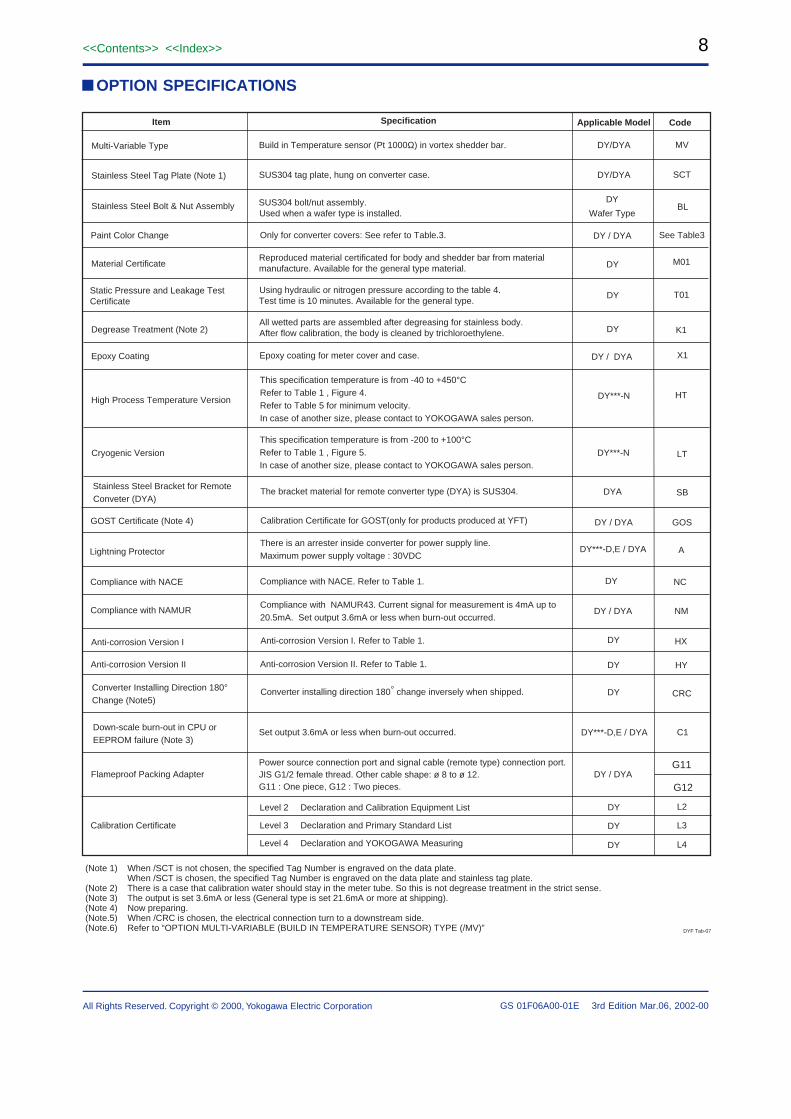
Down-scale burn-out in CPU or EEPROM failure (Note 3)
Set output 3.6mA or less when burn-out occurred. DY***-D,E / DYA C1
Item Specification Code
Stainless Steel Tag Plate (Note 1)
Stainless Steel Bolt & Nut Assembly
Material Certificate
Degrease Treatment (Note 2)
Static Pressure and Leakage TestCertificate
High Process Temperature Version
Cryogenic Version
Paint Color Change
Epoxy Coating
SUS304 tag plate, hung on converter case.
SUS304 bolt/nut assembly.Used when a wafer type is installed.
Reproduced material certificated for body and shedder bar from material manufacture. Available for the general type material.
All wetted parts are assembled after degreasing for stainless body.After flow calibration, the body is cleaned by trichloroethylene.
Using hydraulic or nitrogen pressure according to the table 4.Test time is 10 minutes. Available for the general type.
This specification temperature is from -40 to +450°CRefer to Table 1 , Figure 4.Refer to Table 5 for minimum velocity.In case of another size, please contact to YOKOGAWA sales person.
This specification temperature is from -200 to +100°CRefer to Table 1 , Figure 5.In case of another size, please contact to YOKOGAWA sales person.
Only for converter covers: See refer to Table.3.
Epoxy coating for meter cover and case.
SCT
BL
Stainless Steel Bracket for Remote Conveter (DYA)
The bracket material for remote converter type (DYA) is SUS304.
GOST Certificate (Note 4)
(Note 1) When /SCT is not chosen, the specified Tag Number is engraved on the data plate. When /SCT is chosen, the specified Tag Number is engraved on the data plate and stainless tag plate.(Note 2) There is a case that calibration water should stay in the meter tube. So this is not degrease treatment in the strict sense.(Note 3) The output is set 3.6mA or less (General type is set 21.6mA or more at shipping).(Note 4) Now preparing.(Note.5) When /CRC is chosen, the electrical connection turn to a downstream side.(Note.6) Refer to “OPTION MULTI-VARIABLE (BUILD IN TEMPERATURE SENSOR) TYPE (/MV)”
Calibration Certificate for GOST(only for products produced at YFT)
There is an arrester inside converter for power supply line.Maximum power supply voltage : 30VDCLightning Protector
Compliance with NACE. Refer to Table 1.Compliance with NACE
Compliance with NAMUR43. Current signal for measurement is 4mA up to 20.5mA. Set output 3.6mA or less when burn-out occurred.
Compliance with NAMUR NM
Applicable Model
See Table3
M01
T01
K1
X1
HT
LT
SB
GOS
A
NC
DY
Wafer Type
DY/DYA
Multi-Variable Type Build in Temperature sensor (Pt 1000Ω) in vortex shedder bar. MVDY/DYA
DY / DYA
DY
DYA
DY***-D,E / DYA
DY
DY / DYA
Anti-corrosion Version I. Refer to Table 1.Anti-corrosion Version I HXDY
Anti-corrosion Version II Anti-corrosion Version II. Refer to Table 1. HYDY
DY
DY
DY / DYA
DY***-N
DY***-N
DY / DYA
Converter Installing Direction 180° Change (Note5)
Converter installing direction 180° change inversely when shipped. DY CRC
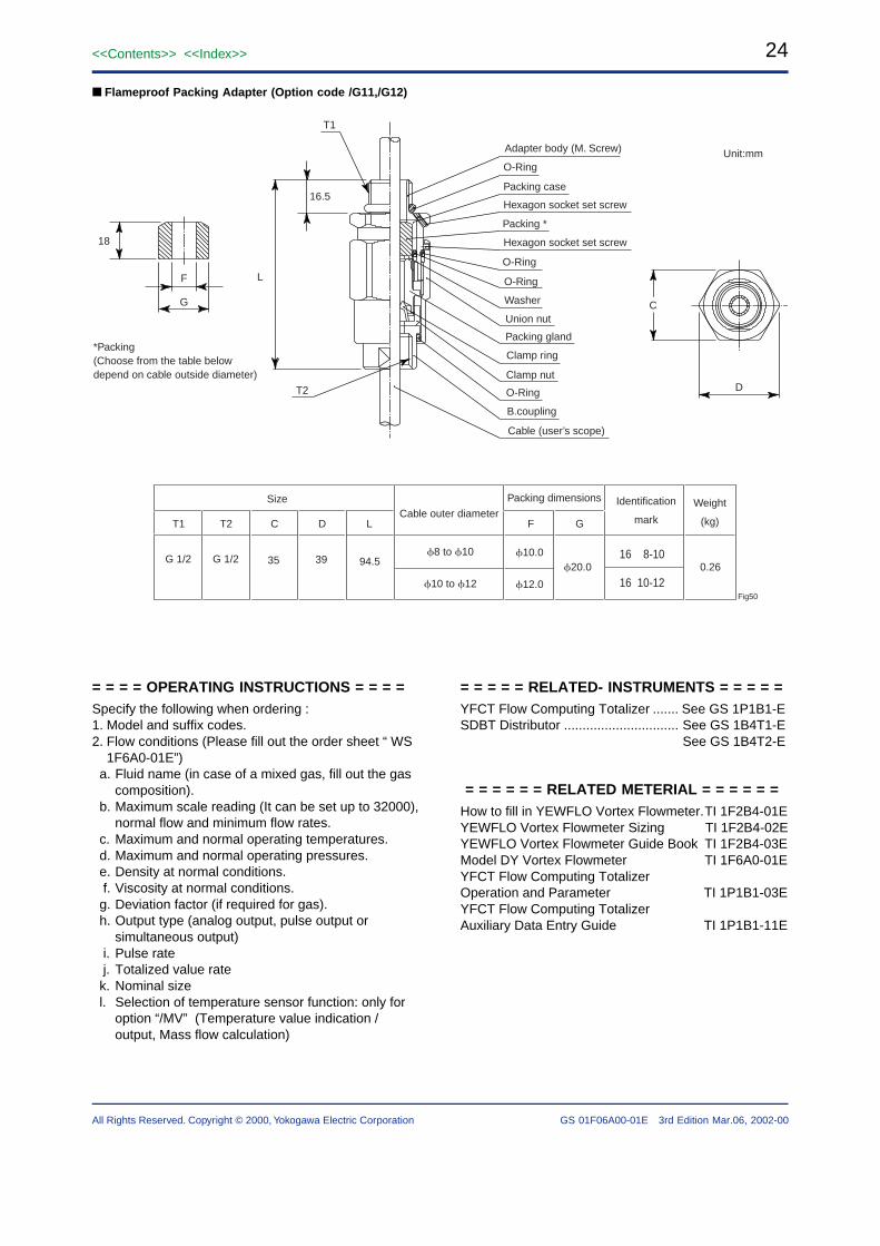
Flameproof Packing AdapterPower source connection port and signal cable (remote type) connection port. JIS G1/2 female thread. Other cable shape: ø 8 to ø 12. G11 : One piece, G12 : Two pieces.
G11
G12DY / DYA
DYF Tab-07
Calibration Certificate
Level 2 Declaration and Calibration Equipment List
(*1) When /MV is selected /HT, /LT is not available.
(*2) Measurement temperature is changed by the heat-insullation method of piping and piping method. Refer to “REMARKS ONINSTALLATION” about heat-insullation.In case of the Mass Flow measurement of saturated steam and superheat steam, it is necessaryto make a heat-insullation.
(*3) Mass Flow rate is calculated from density values by temperature measurment using saturated steam table.
(*4) Mass Flow rate is calculated from density values to temperature measured by using steam table.In order to measure superheated steam,it is necessary to make canstant pressure value.A pressure values which is indicated by order sheet is used.
(*5) In order to measure gas, Pressure-Temperature correction is carried out. It is it is necessary to make constant pressure value.
A pressure values at operational condition, temperature and pressure value at standard condition which is indicated by order sheet isused.
(*6) In order to measure mass flowrate of liquid application, the density at normal condition is used, and if fluid temperature deviates fromnormal temperature density values is calculated by 2 dimensional equation. In this case, temperature coefficient should be prepared byuser’s side.
(*7) Default setting is Flow rate. It is necessary to change the parameter of output in case of setting temperature output.
(*8) In case of indicating the temperature %, the display indicate not only “%” but also “t” . ( “t” is the means of temperature)
(*9) Default setting is “temperature” but “Total “ is setup when ordering the Total Rate.
(*10) In case of Multi variable(/MV), it is necessary to setup the parameter of Cable Length.
Table 3 Detailed Accuracy(for Table 8 Range of Guaranteed Accuracy)
Fluid Nominal Size Accuracy
± 2.0% of Reading (20000ReD103)
± 1.5% of Reading (D103Re)
± 2.0% of Reading (40000Re)
± 2.0% of Reading (Velocity 35 m/s or less)
± 2.5% of Reading (Velocity 35 m/s up to 80 m/s)
Liquid 25 mm up to
100 mm
150 mm,
200 mm
25 mm up to
200 mm
D: Inner diameter of YEWFLO (mm)Re: Reynolds number (non unit)
Note: In case of analog output, add up ± 0.1% of full scale to the values mentioned above.
Figure 4 Fluid temperature range of high processtemperature version
–200 –100 –40 0
0
–50
–20
Fluid temperature (˚C)
Am
bie
nt
tem
per
atu
re (
˚C)
Operating range
+100
DYF Fig-05
Figure 5 Fluid temperature range of cryogenic version
SIZINGThe following items are the basic specifications.In case of the definite sizing, it is neccessary to checkby the sizing software.
Measurable minimum flow velocity
Table 6 Relationship between Minimum Velocity andDensity (Use the Large of the Two Values)
Liquid GAS, Steam
ρ : Density at operating conditions (kg/m3)Liquid density is 400 up to 2000kg/m3
Gas and steam density is 0.5kg/m3 or more.
High Process Temperature
Version(unit: m/s)
––
490/ρ
490/ρ
160/ρ
160/ρ
160/ρ
160/ρ
202.5/ρ
––
––
Nominal size in
mm
15
25
40
50
80
100
150
200
250
300
High Process Temperature
version (unit: m/s)
––
125/ρ or 2
125/ρ or 2
61.3/ρ or 2
61.3/ρ or 2
61.3/ρ or 2
61.3/ρ or 3
80/ρ or 3
––
––
General Type, Cryogenic
Type (unit: m/s)
250 /ρ
122.5/ρ
90/ρ
90/ρ
90/ρ
90/ρ
90/ρ
122.5/ρ
160/ρ
160/ρ
General Type,
Cryogenic Type
(unit: m/s)
80/ρ or 3
45/ρ or 2
31.3/ρ or 2
31.3/ρ or 2
31.3/ρ or 2
31.3/ρ or 2
31.3/ρ or 3
45/ρ or 3
61.3/ρ or 3
61.3/ρ or 3
DYF Tab-10
Table 7 Range of Measurable flow velocity
When the flow velocity is lower than minimum, both the analog output and the pulse output is displayed as zero “0”.(Note) A span setting is available up to 1.5 times of the maximum flow velocity.
Fluid
Liquid
Gas,Steam
Nominal Size
15mm up to
300 mm
15mm up to
300 mm
Maximum flow velocity
(Note)
10 m/s
80 m/s
Minimum flow velocity
"flow velocity obtained from Table.5" or "flow velocity at Reynolds number of 5000", whichever is greater.For liquid Reynolds number of 5000 : Use Figure.6
"flow velocity obtained from Table.5" or "flow velocity at Reynolds number of 5000", whichever is greater.For Gas and steam Reynolds number of 5000 : Use of a calculation formula on the following page.
Calculation formula How to calculate volume flow rate at operating
conditions. υ D2 • Qf = or Qf = 3600 × υ × S 354 How to calculate the velocity of a Reynolds number. • = 5 / D (Reynolds number of 5000)
• = 20 / D (Reynolds number of 20000)
• = 40 / D (Reynolds number of 40000)
however 354 10 3 Qf • Re = ········· (1) D
• = 10 3 ················· (2) ρf
Qf : Volume flow rate at operating conditions (m3/h)D : Inner diameter of YEWFLO (mm)S : Sectional area of YEWFLO(m2)υ : Flow velocity (m/s)
Re : Reynolds number (none unit)pf : Density at operating conditions (kg/m3)µ : Viscosity at operating conditions (mPa·scP) : Kinematic viscosity at operating conditions (10-6m2/scSt)
Table 10 Inner Diameter and Nominal value
Nominal Size InnerDiameter
mm
NominalK-FactorPulse/Lmm inch
Nominal Pulse Rate
Hz/m/s Hz/m3/h
15
25
40
50
80
100
150
200
250
300
1/2
1
1-1/2
2
3
4
6
8
10
12
14.6
25.7
39.7
51.1
71.0
93.8
138.8
185.6
230.8
276.2
376
65.6
18.7
8.95
3.33
1.43
0.441
0.185
0.0966
0.0563
62.7
35.5
23.1
18.3
13.2
9.88
6.67
5.00
4.04
3.37
104
19.1
5.19
2.49
0.925
0.397
0.123
0.0514
0.0268
0.0156
Typical fluid example
Table 11 Range of Measurable Water Flow Rate(At standard condition of 15°C, ρ = 1000 kg/m3)
Nominal Size
mm inch
Range of Guarranted Accuracy FlowRate in m3/h
Measurable Flow Ratein m3/h
15
25
40
50
80
100
150
200
250
300
1/2
1
1-1/2
2
3
4
6
8
10
12
0.30 up to 6
0.65 up to 18
1.3 up to 44
2.2 up to 73
4.3 up to 142
7.5 up to 248
17 up to 544
34 up to 973
60 up to 1506
86 up to 2156
0.94 up to 6
1.7 up to 18
2.6 up to 44
3.3 up to 73
4.6 up to 142
7.5 up to 248
18 up to 544
34 up to 973
60 up to 1506
86 up to 2156DYF Tab-14-b
Guaranteed accuracy at minimum flow velocity
Table 8 Range of Guaranteed Accuracy Flow Velocity
Fluid
Liquid
Gas,Steam
Nominal Size
15 mm up to
100 mm
150 mm up to
300 mm
15 mm up to
100 mm
150 mm up to
300 mm
Maximum flow
velocity
10 m/s
80 m/s
Minimum flow velocity
"flow velocity obtained from Table.5" or " flow velocity at Reynolds number of 20000", whichever is greater.For liquid Reynolds number of 20000 : The value is four times velocity value in Figure.6
"flow velocity obtained from Table.5" or " flow velocity at Reynolds number of40000", whichever is greater.For liquid Reynolds number of 40000 : The value is eight times velocity value in Figure.6
"flow velocity obtained from Table.5" or " flow velocity at Reynolds number of 20000", whichever is greater.For gas and steam Reynolds number of 20000 : Use of a calculation formula
"flow velocity obtained from Table.5" or " flow velocity at Reynolds number of 40000”, whichever is greater.For gas and steam Reynolds number of 40000 : Use of a calculation formula
DYF Tab-12
Table 9 Detailed Accuracy(for Range of Guaranteed Accuracy)
D : Inner diameter of YEWFLO (mm)Re: Reynolds number (non unit)Note: This table shows the accuracy of pulse output. In case of analog output, add up ± 0.1% of full scale to the values mentioned above.
Fluid
Liquid
Gas,Steam
Nominal Size
15mm
25 mm up to
100 mm
150 mm up
to 300 mm
15 mm up to
300 mm
Accuracy
± 1.0% of Reading (20000 Re)
± 1.0% of Reading (20000 Re < D × 103)
± 0.75% of Reading (D × 103 Re )
(± 0.5% of Reading: Typical Accuracy/Non-Guaranteed)
± 1.0% of Reading (40000 Re)
± 1.0% of Reading (Velocity 35m/s or less)
± 1.5% of Reading (Velocity 35m/s up to 80m/s)DYF Tab-13
Flow velocity at Reynolds Number of5000(Liquld)
Kinematic Viscosity : Use of equation(2). When the nominal size is50mm and the Kinematic viscosity is 10cSt, the flow velocity atReynolds number of 5000 is 1m/s using Figure 6.
1 2
15mm 25mm 40mm 50mm 100mm 150mm
200mm250mm
300mm
80mm
3 5 2010 30 30020010050
10
0.3
0.5
1
2
3
5
Kinematic Viscosity (10-6 m2/s cSt)
Flo
w V
elo
city
υ (
m/s
) υ = 5 X
D: YEWFLO internal diameter (mm)
D
DYF Fig-06
Figure 6 Flow velocity at Reynolds number of 5000(Liquid)
Table 12 Range of Measurable Air Flow Rate at Selected Process Pressures
min.
max.
min.
max.
min.
max.
min.
max.
min.
max.
min.
max.
min.
max.
min.
max.
min.
max.
min.
max.
15 mm
25 mm
40 mm
50 mm
80 mm
100 mm
150 mm
200 mm
250 mm
300 mm
NominalSize
FlowRateLimits
Minimum and Maximum Measurable Flow Rate in Nm3/h
0 MPa
4.8(11.1)
48.2
11.0(19.5)
149
21.8(30.0)
356
36.2(38.7)
591
70.1
1140
122
1990
268
4358
575
7792
1037
12049
1485
17256
0.1 MPa
6.7(11.1)
95.8
15.5(19.5)
297
30.8
708
51
1174
98.4
2266
172
3954
377
8659
809
15482
1461
23939
2093
34286
0.2 MPa
8.2(11.1)
143
19.0(19.5)
444
37.8
1060
62.4
1757
120
3391
211
5919
485
12960
990
23172
1788
35833
2561
51317
0.4 MPa
10.5(11.1)
239
24.5
739
48.7
1764
80.5
2922
155
5642
272
9847
808
21559
1445
38549
2306
59611
3303
85370
0.6 MPa
12.5
334
29.0
1034
61.6
2468
102
4088
197
7892
334
13775
1131
30163
2202
53933
3127
83400
4479
119441
0.8 MPa
16.1
429
33.3
1329
79.2
3171
131
5254
254
10143
442
17703
1453
38765
2599
69313
4019
107181
5756
153499
1 MPa
19.7
524
40.6
1624
97
3875
161
6420
310
12394
540
21632
1776
47365
3175
84693
4911
130968
7033
187556
1.5 MPa
28.6
762
59.0
2361
149
5634
233
9335
451
18021
786
31453
2583
68867
4617
123138
7140
190418
10226
272699
2 MPa
37.5
1000
77.5
3098
184
7394
306
12249
591
23648
1031
41274
3389
90373
6059
161591
9370
249881
13419
357856
2.5 MPa
46.4
1238
95.9
3836
229
9153
379
15164
732
29274
1277
51095
4196
111875
7501
200046
11600
309334
16612
443017
(1) At standard conditions STP (0˚C. 1atm).(2) Pressure listed is at process temperature of 0˚C.(3) Maximum flow rate is the lower of 80 m/s.(4) Minimum values are determined from Table 5. The values in parenthesis show the minimum linear flow rates (Re = 20,000 or 40,000)
when they are higher than the minimum measurable flow rate.
DYF Tab-15
Table 13 Range of Measurable Saturated Steam Flow Rate at Selected Process Pressures
min.
max.
min.
max.
min.
max.
min.
max.
min.
max.
min.
max.
min.
max.
min.
max.
min.
max.
min.
max.
15 mm
25 mm
40 mm
50 mm
80 mm
100 mm
150 mm
200 mm
250 mm
300 mm
NominalSize
FlowRateLimits
Minimum and Maximum Measurable Flow Rate in kg/h
0.1 MPa
5.8(10.7)
55.8
13.4(18.9)
169.7
26.5(29.2)
405
44.0
671
84.9
1295
148
2261
324
4950
697
8851
1256
13687
1799
19602
0.2 MPa
7.0(11.1)
80
16.2(20.0)
247.7
32
591
53
979
103
1891
179
3300
392
7226
841
12918
1518
19977
2174
28609
0.4 MPa
8.8(11.6)
129
20.5
400
40.6
954
67.3
1580
130
3050
227
5326
498
11661
1068
20850
1929
32243
2762
46175
0.6 MPa
10.4(12.1)
177
24.1
548
47.7
1310
79
2170
152
4188
267
7310
600
16010
1252
28627
2260
44268
3236
63397
0.8 MPa
11.6(12.3)
225
27.1
696
53.8
1662
89
2753
171
5314
300
9276
761
20315
1410
36325
2546
56172
3646
80445
1 MPa
12.8
272
30
843
59
2012
98
3333
189
6435
330
11232
922
24595
1649
43976
2801
68005
4012
97390
1.5 MPa
15.3
390
36
1209
72
2884
119
4778
231
9224
402
16102
1322
35258
2364
63043
3655
97489
5235
139614
2 MPa
19.1
508
41
1575
93
3759
156
6228
300
12024
524
20986
1723
45953
3081
82165
4764
127058
6823
181960
2.5 MPa
23.6
628
49
1945
116
4640
192
7688
371
14842
647
25907
2127
56729
3803
101433
5882
156854
8423
224633
3 MPa
28.1
748
58
2318
138
5532
229
9166
442
17694
772
30883
2536
67624
4534
120913
7011
186978
10041
267772
(1) Maximum flow rate is the lower of 80 m/s.(3) Minimum values are determined from Table 5. The values in parenthesis show the minimum linear flow rates (Re = 20,000 or 40,000)
when they are higher than the minimum measurable flow rate.
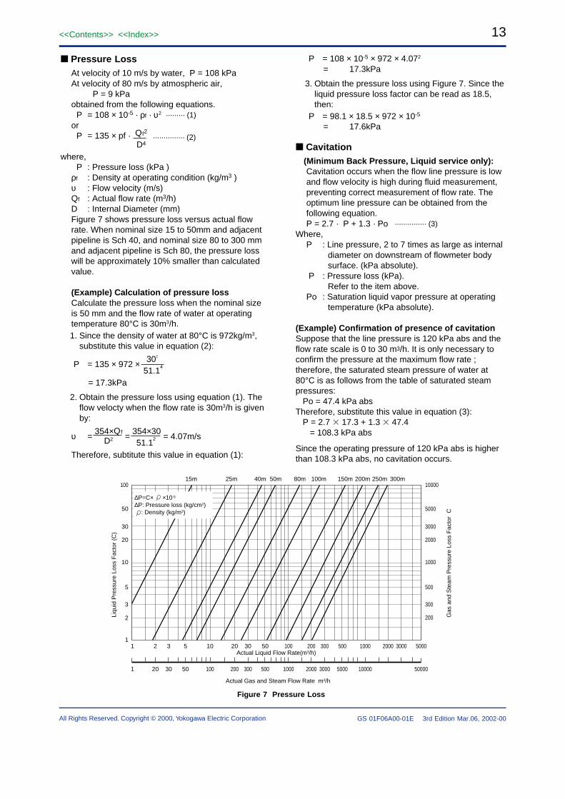
Pressure LossAt velocity of 10 m/s by water, P = 108 kPaAt velocity of 80 m/s by atmospheric air,
P = 9 kPaobtained from the following equations.
P = 108 × 10-5 · ρf · υ2
orP = 135 × pf · Qf2
D4
where,P : Pressure loss (kPa )
ρf : Density at operating condition (kg/m3 )υ : Flow velocity (m/s)Qf : Actual flow rate (m3/h)D : Internal Diameter (mm)Figure 7 shows pressure loss versus actual flowrate. When nominal size 15 to 50mm and adjacentpipeline is Sch 40, and nominal size 80 to 300 mmand adjacent pipeline is Sch 80, the pressure losswill be approximately 10% smaller than calculatedvalue.
(Example) Calculation of pressure lossCalculate the pressure loss when the nominal sizeis 50 mm and the flow rate of water at operatingtemperature 80°C is 30m3/h.1. Since the density of water at 80°C is 972kg/m3,
substitute this value in equation (2):
P = 135 × 972 × 302
51.14
= 17.3kPa
2. Obtain the pressure loss using equation (1). Theflow velocty when the flow rate is 30m3/h is givenby:
υ = 354×Qf
= 354×30
= 4.07m/s D2 51.12
Therefore, subtitute this value in equation (1):
P = 108 × 10-5 × 972 × 4.072
= 17.3kPa
3. Obtain the pressure loss using Figure 7. Since theliquid pressure loss factor can be read as 18.5,then:
P = 98.1 × 18.5 × 972 × 10-5
= 17.6kPa
Cavitation(Minimum Back Pressure, Liquid service only):Cavitation occurs when the flow line pressure is lowand flow velocity is high during fluid measurement,preventing correct measurement of flow rate. Theoptimum line pressure can be obtained from thefollowing equation.P = 2.7 · P + 1.3 · Po
Where,P : Line pressure, 2 to 7 times as large as internal
diameter on downstream of flowmeter bodysurface. (kPa absolute).
P : Pressure loss (kPa).Refer to the item above.
Po : Saturation liquid vapor pressure at operatingtemperature (kPa absolute).
(Example) Confirmation of presence of cavitationSuppose that the line pressure is 120 kPa abs and theflow rate scale is 0 to 30 m3/h. It is only necessary toconfirm the pressure at the maximum flow rate ;therefore, the saturated steam pressure of water at80°C is as follows from the table of saturated steampressures: Po = 47.4 kPa absTherefore, substitute this value in equation (3): P = 2.7 17.3 + 1.3 47.4 = 108.3 kPa abs
Since the operating pressure of 120 kPa abs is higherthan 108.3 kPa abs, no cavitation occurs.
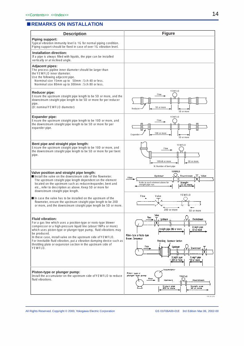
Refer to each element above for straight pipe run.
Reducer pipe:Ensure the upstream straight pipe length to be 5D or more, and the downstream straight pipe length to be 5D or more for per reducer pipe.(D: nominal YEWFLO diameter)
Valve position and straight pipe length: Install the valve on the downstream side of the flowmeter. The upstream straight pipe length dependent on the element located on the upstream such as reducer/expander, bent and etc., refer to description as above. Keep 5D or more for downstream straight pipe length.
In case the valve has to be installed on the upstream of the flowmeter, ensure the upstream straight pipe length to be 20D or more, and the downstream straight pipe length be 5D or more.
Piston-type or plunger pump:Install the accumulator on the upstream side of YEWFLO to reduce fluid vibrations.
Expander pipe:Ensure the upstream straight pipe length to be 10D or more, and the downstream straight pipe length to be 5D or more for per expander pipe.
Bent pipe and straight pipe length:Ensure the upstream straight pipe length to be 10D or more, and the downstream straight pipe length to be 5D or more for per bent pipe.
Fluid vibration:For a gas line which uses a position-type or roots-type blower compressor or a high-pressure liquid line (about 1MPa or more) which uses piston-type or plunger-type pump, fluid vibrations may be produced.In these case, install valve on the upstream side of YEWFLO. For inevitable fluid vibration, put a vibration damping device such as throttling plate or expansion section in the upstream side of YEWFLO.
Piping support:Typical vibration immunity level is 1G for normal piping condition.Piping support should be fixed in case of over 1G vibration level.
Installation direction:If a pipe is always filled with liquids, the pipe can be installed vertically or at inclined angle.
Adjacent pipes:The process pipline inner diameter should be larger than the YEWFLO inner diameter.Use the following adjacent pipe. Norminal size 15mm up to 50mm : Sch 40 or less. Norminal size 80mm up to 300mm : Sch 80 or less.
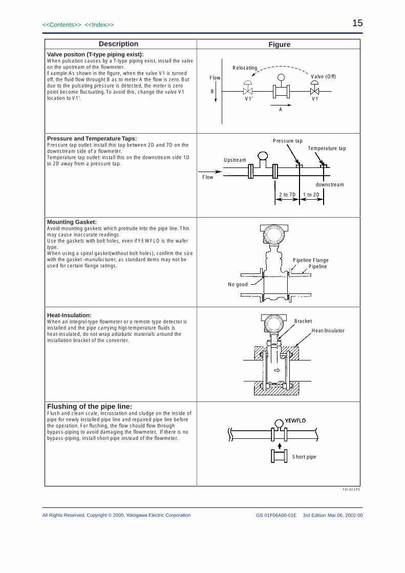
Heat-Insulation:When an integral-type flowmeter or a remote type detector is installed and the pipe carrying higt-temperature fluids is heat-insulated, do not wrap adiabatic materials around the installation bracket of the converter.
Flushing of the pipe line:Flush and clean scale, incrustation and sludge on the inside of pipe for newly installed pipe line and repaired pipe line before the operation. For flushing, the flow should flow through bypass-piping to avoid damaging the flowmeter. If there is no bypass-piping, install short pipe instead of the flowmeter.
Mounting Gasket:Avoid mounting gaskets which protrude into the pipe line. This may cause inaccurate readings.Use the gaskets with bolt holes, even if YEWFLO is the wafer type.When using a spiral gasket(without bolt holes), confirm the size with the gasket -manufacturer, as standard items may not be used for certain flange ratings.
Pressure and Temperature Taps:Pressure tap outlet: install this tap between 2D and 7D on the downstream side of a flowmeter.Temperature tap outlet: install this on the downstream side 1D to 2D away from a pressure tap.
Valve positon (T-type piping exist):When pulsation causes by a T-type piping exist, install the valve on the upstream of the flowmeter.Example:As shown in the figure, when the valve V1 is turned off, the fluid flow throught B as to meter A the flow is zero. But due to the pulsating pressure is detected, the meter is zero point become fluctuating. To avoid this, change the valve V1 location to V1'.
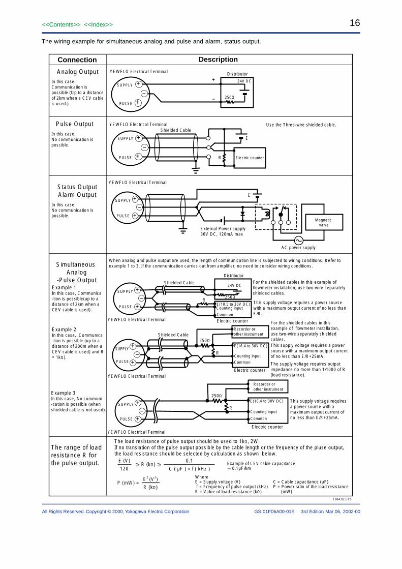
The wiring example for simultaneous analog and pulse and alarm, status output.
250Ω
R +
–+PULSE
SUPPLY
YEWFLO Electrical Terminal
Recorder or other instrument
This supply voltage requires a power sourse with a maximum output current of no less than E/R+25mA.
Electric counter
E(16.4 to 30V DC)
Counting input
Common
+
+
YEWFLO Electrical Terminal
250Ω
24V DC
PULSE
SUPPLY+
–
Distributor
–
+–
+PULSE
SUPPLY
R
E
YEWFLO Electrical Terminal Use the Three-wire shielded cable.
Electric counter
Shielded Cable
PULSE
SUPPLY +–
+Mognetic
valve
AC power supply
External Power supply 30V DC, 120mA max
YEWFLO Electrical Terminal
E
250Ω
R+
–+PULSE
SUPPLY
Counting input
Common
For the shielded cables in this example of flowmeter installation, use two-wire separately shielded cables.This supply voltage requires a power sourse with a maximum output current of no less than E/R+25mA.
Recorder or other instrument
Electric counter
E(16.4 to 30V DC)
Shielded Cable
The supply voltage requires output impedance no more than 1/1000 of R (load resistance).YEWFLO Electrical Terminal
250ΩR
E(10.5 to 30V DC) Counting input
Common
24V DC
PULSE
SUPPLY
For the shielded cables in this example of flowmeter installation, use two-wire separately shielded cables.
This supply voltage requires a power sourse with a maximum output current of no less than E/R.
Distributor
Electric counter
+–
+
Shielded Cable
YEWFLO Electrical Terminal
When analog and pulse output are used, the length of communication line is subjected to wiring conditions. Refer to example 1 to 3. If the communication carries out from amplifier, no need to consider wiring conditions.
Analog Output
Pulse Output
Status OutputAlarm Output
Simultaneous Analog
-Pulse Output
DescriptionConnection
T004.02.EPS
0.1
C ( µF ) × f ( kHz ) R (kΩ)
120
E (V)
The load resistance of pulse output should be used to 1kΩ, 2W.If no translation of the pulse output possible by the cable length or the frequency of the pluse output,the load resistance should be selected by calculation as shown below.
Example of CEV cable capacitance 0.1µF/km
WhereE = Supply voltage (V) f = Frequency of pulse output (kHz)R = Value of load resistance (kΩ)
C = Cable capacitance (µF) P = Power ratio of the load resistance (mW)
P (mW) =R (kΩ)
E2 (V2)
Example 3In this case, No communi-cation is possible (when shielded cable is not used).
The range of load resistance R for the pulse output.
Example 1In this case, Communica-tion is possible(up to adistance of 2km when aCEV cable is used).
Example 2In this case, Communica-tion is possible (up to adistance of 200m when a CEV cable is used) and R = 1kΩ).
In this case, Communication is possible (Up to a distance of 2km when a CEV cable is used.)
= = = = OPERATING INSTRUCTIONS = = = =Specify the following when ordering :1. Model and suffix codes.2. Flow conditions (Please fill out the order sheet “ WS
1F6A0-01E”) a. Fluid name (in case of a mixed gas, fill out the gas
composition). b. Maximum scale reading (It can be set up to 32000),
normal flow and minimum flow rates. c. Maximum and normal operating temperatures. d. Maximum and normal operating pressures. e. Density at normal conditions. f. Viscosity at normal conditions. g. Deviation factor (if required for gas). h. Output type (analog output, pulse output or
simultaneous output) i. Pulse rate j. Totalized value rate k. Nominal size l. Selection of temperature sensor function: only for
option “/MV” (Temperature value indication /output, Mass flow calculation)
= = = = = = RELATED METERIAL = = = = = =How to fill in YEWFLO Vortex Flowmeter.TI 1F2B4-01EYEWFLO Vortex Flowmeter Sizing TI 1F2B4-02EYEWFLO Vortex Flowmeter Guide Book TI 1F2B4-03EModel DY Vortex Flowmeter TI 1F6A0-01EYFCT Flow Computing TotalizerOperation and Parameter TI 1P1B1-03EYFCT Flow Computing TotalizerAuxiliary Data Entry Guide TI 1P1B1-11E